hitachi compute blade 320 software guide
TRANSCRIPT
MK-99BDS320002-07
Hitachi Compute Blade 320 Software Guide

ii
Hitachi Compute Blade 320 Software Guide
© 2011 - 2013 Hitachi, Ltd. All rights reserved.
No part of this publication may be reproduced or transmitted in any form or by any means, electronic or mechanical, including photocopying and recording, or stored in a
database or retrieval system for any purpose without the express written permission of
Hitachi, Ltd.
Hitachi, Ltd., reserves the right to make changes to this document at any time without notice and assumes no responsibility for its use. This document contains the most current
information available at the time of publication. When new or revised information
becomes available, this entire document will be updated and distributed to all registered
users.
Some of the features described in this document might not be currently available. Refer to the most recent product announcement for information about feature and product
availability, or contact Hitachi Data Systems Corporation at https://portal.hds.com.
Notice: Hitachi, Ltd., products and services can be ordered only under the terms and
conditions of the applicable Hitachi Data Systems Corporation agreements. The use of Hitachi, Ltd., products is governed by the terms of your agreements with Hitachi Data
Systems Corporation.
Hitachi is a registered trademark of Hitachi, Ltd., in the United States and other countries.
Hitachi Data Systems is a registered trademark and service mark of Hitachi, Ltd., in the United States and other countries.
Archivas, Essential NAS Platform, HiCommand, Hi-Track, ShadowImage, Tagmaserve,
Tagmasoft, Tagmasolve, Tagmastore, TrueCopy, Universal Star Network, and Universal
Storage Platform are registered trademarks of Hitachi Data Systems Corporation.
AIX, AS/400, DB2, Domino, DS8000, Enterprise Storage Server, ESCON, FICON,
FlashCopy, IBM, Lotus, OS/390, RS6000, S/390, System z9, System z10, Tivoli, VM/ESA,
z/OS, z9, zSeries, z/VM, z/VSE are registered trademarks and DS6000, MVS, and z10 are
trademarks of International Business Machines Corporation.
All other trademarks, service marks, and company names in this document or website are
properties of their respective owners.
Microsoft product screen shots are reprinted with permission from Microsoft Corporation.
iii
In
trod
uctio
n
Introduction
Thank you for purchasing Hitachi system equipment. This manual describes how to use and install Microsoft® Windows Server® 2008 R2/ Microsoft® Windows Server® 2008/ Microsoft® Windows Server® 2003 R2/ Microsoft® Windows Server® 2003, Microsoft® Windows® 2000.
Notations used in the Manual
Descriptions on Symbols
The following explains the symbols used in this manual.
This indicates notes not directly related to injury or severe
damage to the equipment.
This indicates advice to make the most use of the equipment.
Abbreviations for Operating Systems (OS)
In this manual, the following abbreviations are used for OS name.
Microsoft® Windows Server® 2008 R2 Standard (Hereinafter, referred to as Windows Server 2008 R2 Standard)
Microsoft® Windows Server® 2008 R2 Enterprise (Hereinafter, referred to as Windows Server 2008 R2 Enterprise)
Microsoft® Windows Server® 2008 R2 Datacenter (Hereinafter, referred to as Windows Server 2008 R2 Datacenter)
Microsoft® Windows Server® 2008 Standard (Hereinafter, referred to as Windows Server 2008 Standard)
Microsoft® Windows Server® 2008 Enterprise (Hereinafter, referred to as Windows Server 2008 Enterprise)
Microsoft® Windows Server® 2008 Datacenter (Hereinafter, referred to as Windows Server 2008 Datacenter)
Microsoft® Windows Server® 2008 Standard without Hyper-VTM (Hereinafter, referred to as Windows Server 2008 Standard without Hyper-V)
Microsoft® Windows Server® 2008 Enterprise without Hyper-VTM (Hereinafter, referred to as Windows Server 2008 Enterprise without Hyper-V)
Microsoft® Windows Server® 2008 Datacenter without Hyper-VTM (Hereinafter, referred to as Windows Server 2008 Datacenter without Hyper-V)
Microsoft® Windows Server® 2008 Standard 32-bit (Hereinafter, referred to as Windows Server 2008 Standard 32-bit)
Microsoft® Windows Server® 2008 Enterprise 32-bit (Hereinafter, referred to as Windows Server 2008 Enterprise 32-bit)
Microsoft® Windows Server® 2008 Datacenter 32-bit (Hereinafter, referred to as Windows Server 2008 Datacenter 32-bit)
Microsoft® Windows Server® 2008 Standard without Hyper-VTM 32-bit (Hereinafter, referred to as Windows Server 2008 Standard without Hyper-V 32-bit)
!
Note
Tip
iv
In
trod
uctio
n
Microsoft® Windows Server® 2008 Enterprise without Hyper-VTM 32-bit (Hereinafter, referred to as Windows Server 2008 Enterprise without Hyper-V 32-bit)
Microsoft® Windows Server® 2008 Datacenter without Hyper-VTM 32-bit (Hereinafter, referred to as Windows Server 2008 Datacenter without Hyper-V 32-bit)
Microsoft® Windows Server® 2003 R2, Standard x64 Edition (Hereinafter, referred to as Windows Server 2003 R2, Standard x64 Edition)
Microsoft® Windows Server® 2003 R2, Enterprise x64 Edition (Hereinafter, referred to as Windows Server 2003 R2, Enterprise x64 Edition)
Microsoft® Windows Server® 2003 R2, Standard Edition (Hereinafter, referred to as Windows Server 2003 R2, Standard Edition)
Microsoft® Windows Server® 2003 R2, Enterprise Edition (Hereinafter, referred to as Windows Server 2003 R2, Enterprise Edition)
Microsoft® Windows Server® 2003, Standard x64 Edition (Hereinafter, referred to as Windows Server 2003, Standard x64 Edition)
Microsoft® Windows Server® 2003, Enterprise x64 Edition (Hereinafter, referred to as Windows Server 2003, Enterprise x64 Edition)
Microsoft® Windows Server® 2003, Standard Edition (Hereinafter, referred to as Windows Server 2003, Standard Edition)
Microsoft® Windows Server® 2003, Enterprise Edition (Hereinafter, referred to as Windows Server 2003, Enterprise Edition)
Microsoft® Windows Server® 2000 Server Operating System (Hereinafter, referred to as Windows 2000 Server)
Microsoft® Windows Server® 2000 Advanced Server Operating System (Hereinafter, referred to as Windows 2000 Advanced Server)
v
In
trod
uctio
n
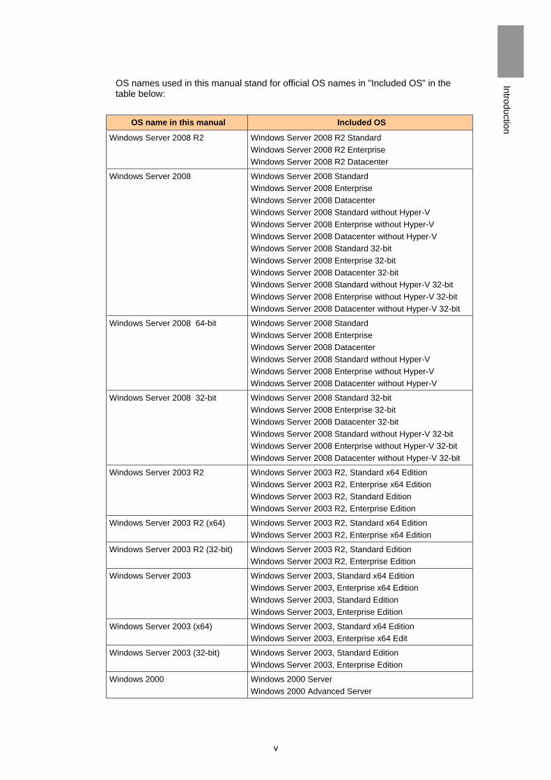
OS names used in this manual stand for official OS names in "Included OS" in the table below:
OS name in this manual Included OS
Windows Server 2008 R2 Windows Server 2008 R2 Standard
Windows Server 2008 R2 Enterprise
Windows Server 2008 R2 Datacenter
Windows Server 2008 Windows Server 2008 Standard
Windows Server 2008 Enterprise
Windows Server 2008 Datacenter
Windows Server 2008 Standard without Hyper-V
Windows Server 2008 Enterprise without Hyper-V
Windows Server 2008 Datacenter without Hyper-V
Windows Server 2008 Standard 32-bit
Windows Server 2008 Enterprise 32-bit
Windows Server 2008 Datacenter 32-bit
Windows Server 2008 Standard without Hyper-V 32-bit
Windows Server 2008 Enterprise without Hyper-V 32-bit
Windows Server 2008 Datacenter without Hyper-V 32-bit
Windows Server 2008 64-bit Windows Server 2008 Standard
Windows Server 2008 Enterprise
Windows Server 2008 Datacenter
Windows Server 2008 Standard without Hyper-V
Windows Server 2008 Enterprise without Hyper-V
Windows Server 2008 Datacenter without Hyper-V
Windows Server 2008 32-bit Windows Server 2008 Standard 32-bit
Windows Server 2008 Enterprise 32-bit
Windows Server 2008 Datacenter 32-bit
Windows Server 2008 Standard without Hyper-V 32-bit
Windows Server 2008 Enterprise without Hyper-V 32-bit
Windows Server 2008 Datacenter without Hyper-V 32-bit
Windows Server 2003 R2 Windows Server 2003 R2, Standard x64 Edition
Windows Server 2003 R2, Enterprise x64 Edition
Windows Server 2003 R2, Standard Edition
Windows Server 2003 R2, Enterprise Edition
Windows Server 2003 R2 (x64) Windows Server 2003 R2, Standard x64 Edition
Windows Server 2003 R2, Enterprise x64 Edition
Windows Server 2003 R2 (32-bit) Windows Server 2003 R2, Standard Edition
Windows Server 2003 R2, Enterprise Edition
Windows Server 2003 Windows Server 2003, Standard x64 Edition
Windows Server 2003, Enterprise x64 Edition
Windows Server 2003, Standard Edition
Windows Server 2003, Enterprise Edition
Windows Server 2003 (x64) Windows Server 2003, Standard x64 Edition
Windows Server 2003, Enterprise x64 Edit
Windows Server 2003 (32-bit) Windows Server 2003, Standard Edition
Windows Server 2003, Enterprise Edition
Windows 2000 Windows 2000 Server
Windows 2000 Advanced Server
vi
In
trod
uctio
n
Contents of the Manual
How to Use the Manual
The following explains how to use the manual of this system.
Windows Server 2008 R2
Windows Server 2008
Windows Server 2003/R2
Red Hat Enterprise Linux Version 4 update 3 / Version 4.5 / Version 4.7 / Version 5.1 / Version 5.3 / Version 5.4 / Version 5.6
Red Hat Enterprise Linux Version 5.6 / Version 5.7 / Version 6.1 / Version 6.2 with the Driver CD
Windows Server 2008/R2 (Xeon) with HVM
Windows Server 2003/R2 (Xeon) with HVM
Red Hat Enterprise Linux Version 5.3 / Version 5.4 / Version 5.6 (Xeon) with HVM
Red Hat Enterprise Linux Version 5.6 / Version 6.1 with HVM using the Driver CD
Each section explains the procedures for turning on and booting each server blade, and for software setup.
When You Need Help
1 Refer to the manual.
Refer to other printed manuals provided with the product.
2 Inquiry.
Contact the reseller from which you have purchased the product.
Contents
Important Notes ...................................................................................................... ii
Registered Trademarks and Trademarks ............................................................... ii
Introduction .................................................................................................................... iii
Notations used in the Manual ................................................................................ iii
Contents of the Manual .......................................................................................... vi
When You Need Help ............................................................................................ vi
Contents ........................................................................................................................ vii
Precautions for Safe Use .............................................................................................. xii
How to Use the Manuals ....................................................................................... xv
1 Windows Server 2008 R2 ..................................................................................... 1
Turning on/off Power ....................................................................................................... 2
Turning off Power .................................................................................................... 2
Turning on Power for Regular Use ......................................................................... 3
Plugging off the Power Cable ................................................................................. 4
Resetting Application/System Forcibly ................................................................... 5
Basic Operations/How to Change Settings of Windows Server 2008 R2 ....................... 6
How to Use Help ..................................................................................................... 6
How to Use Supplied Software ....................................................................................... 7
MegaRAID Storage Manager .................................................................................. 7
Intel(R) PROSet ...................................................................................................... 7
Use of Software ............................................................................................................... 8
Restrictions on Use of Windows Server 2008 R2 ................................................... 8
Multipath I/O (MPIO) with OS in the External Disk Array via iSCSI ...................... 20
iSCSI Initiator Setting ............................................................................................ 22
Restrictions on Use of _Windows Server 2008 R2 SP1 ....................................... 31
Windows Server 2008 R2 Setup ................................................................................... 32
Windows Server 2008 R2 Setup ........................................................................... 33
Details of Windows Server 2008 R2 Setup ........................................................... 35
Driver/Utility Setup ................................................................................................ 49
Windows Hypervisor 2.0 ............................................................................................... 62
Hyper-V 2.0 Overview ........................................................................................... 62
Further Information on Hyper-V 2.0 ...................................................................... 62
System Configuration for Hyper-V 2.0 .......................................................................... 63
Server Blade for Hyper-V 2.0 ................................................................................ 63
Software Configuration ......................................................................................... 63
Physical Hardware Configuration ......................................................................... 64
Virtual Machine Configuration ............................................................................... 65
Hyper-V 2.0 Setup ......................................................................................................... 68
Management OS Setup ........................................................................................ 68
Hyper-V 2.0 Setup ................................................................................................ 68
Virtual Hard Disk Setup ......................................................................................... 69
Virtual Machine Setup ........................................................................................... 69
Guest OS Setup .................................................................................................... 70
Restrictions on Hyper-V 2.0 .......................................................................................... 71
General Restrictions ............................................................................................. 71
viii
C
on
ten
ts
Restrictions only on the Management OS ............................................................ 73
Restrictions only on Guest OS .............................................................................. 73
2 Windows Server 2008 ........................................................................................... 75
Turning on/off Power ..................................................................................................... 76
Turning off Power .................................................................................................. 77
Turning on Power for Regular Use ....................................................................... 78
Plugging off the Power Cable ............................................................................... 78
Terminating Application/System Forcibly .............................................................. 79
Basic Operations/How to Change Settings of Windows Server 2008 .......................... 80
How to Use Help ................................................................................................... 80
How to Use Supplied Software ..................................................................................... 82
MegaRAID Storage Manager ................................................................................ 82
Intel PROSet ......................................................................................................... 82
Use of Software ............................................................................................................. 83
Restrictions on Use of Windows Server 2008 ...................................................... 83
Restrictions on Windows Server 2008 SP2 .......................................................... 96
Multipath I/O (MPIO) with OS in the External Disk Array via iSCSI ...................... 98
iSCSI Initiator Setting .......................................................................................... 100
Windows Server 2008 Setup ...................................................................................... 109
Windows Server 2008 Setup .............................................................................. 110
Details of Windows Server 2008 Setup .............................................................. 112
Driver/Utility Setup .............................................................................................. 126
Windows Server 2008 SP2 Setup ............................................................................... 140
Windows Hypervisor ................................................................................................... 141
Hyper-V Overview ............................................................................................... 141
Further Information on Hyper-V .......................................................................... 141
System Configuration for Hyper-V .............................................................................. 142
System Equipment for Hyper-V .......................................................................... 142
Software Configuration ....................................................................................... 142
Physical Hardware Configuration ....................................................................... 143
Virtual Machine Configuration ............................................................................. 144
Hyper-V Setup ............................................................................................................. 146
Management OS Setup ...................................................................................... 146
Hyper-V Setup .................................................................................................... 146
Virtual Hard Disk Setup ....................................................................................... 148
Virtual Machine Setup ......................................................................................... 148
Guest OS Setup .................................................................................................. 149
Restrictions on Hyper-V .............................................................................................. 151
General Restrictions ........................................................................................... 151
Restrictions only on the Management OS .......................................................... 152
Restrictions only on Guest OS ............................................................................ 152
3 Windows Server 2003/R2, Standard Edition Windows Server 2003/R2, Enterprise Edition ................................ 155
Turning on/off Power ................................................................................................... 156
Turning off Power ................................................................................................ 156
Turning on Power for Regular Use ..................................................................... 158
ix
C
on
ten
ts
Reboot the System Equipment (Reset) ...................................................................... 159
Forcibly Terminate Application............................................................................ 159
Forcibly Reboot the System Equipment ............................................................. 159
Basic Operations/How to Change Settings of Windows Server 2003/R2 ................... 160
Display [Control panel] ........................................................................................ 160
How to Use Help ................................................................................................. 161
How to Use [Display properties].......................................................................... 161
How to Use Supplied Software ................................................................................... 162
MegaRAID Storage Manager .............................................................................. 162
Intel PROSet ....................................................................................................... 162
Use of Software ........................................................................................................... 173
Restrictions on Use of Windows Server 2003/R2 ............................................... 173
Windows Server 2003/R2 Setup ................................................................................. 186
Flow Chart of Windows Server 2003/R2 Setup .................................................. 187
Confirm BIOS Setting .......................................................................................... 188
Details of Windows Server 2003/R2 Setup ......................................................... 188
Windows Server 2003/R2, Enterprise Edition Setup .................................................. 218
Detail of Setup .................................................................................................... 218
4 Red Hat Enterprise Linux Version 4 Update 3 / Version 4.5 / Version 4.7 / Version 5.1 / Version 5.3 / Version 5.4 / Version 5.6 ............................................................................................................................. 219
Version4 Update 3 / Version 4.5 / Version 4.7
How to Create Driver FD ............................................................................................. 223
How to Create Built-in RAID Drive FD ................................................................ 223
How to Install Linux ..................................................................................................... 224
Procedure to Install Linux ................................................................................... 224
How to update the e1000 driver (Intel(R) PRO/1000 Network Driver) ........................ 244
Applicable OS ..................................................................................................... 244
Update the e1000 driver to 7.6.15.5 according to the following procedure ........ 245
Version 5.1 / Version 5.3 / Version 5.4 / Version 5.6
How to Create Driver FD ............................................................................................. 248
How to Create Built-in RAID Driver FD ............................................................... 248
How to Install Linux ..................................................................................................... 252
Procedure to Install Linux ................................................................................... 252
Installing PAE Kernel .......................................................................................... 275
Installing RHEL 5.4.3/5.6.1 Kernel ...................................................................... 278
How to update the e1000/e1000e driver (Intel(R) PRO/1000 Network Driver) ........... 282
Applicable OS ..................................................................................................... 282
Update the e1000e1000e driver to 7.6.15.5/1.0.15 according to the following
procedure ............................................................................................................ 283
How to update the igb driver (Intel(R) Gigabit Ethernet Network Driver) .................... 286
Applicable OS ..................................................................................................... 286
Update the igb driver to 1.3.19.3/2.4.11 according to the following procedure .. 287
How to Update the ixgbe driver (Intel(R) 10 Gigabit PCI Express Network Driver) ... 290
Applicable OS ..................................................................................................... 290
Update the ixgbe driver to 2.0.75.7/3.2.9 according to the following procedure 291
x
C
on
ten
ts
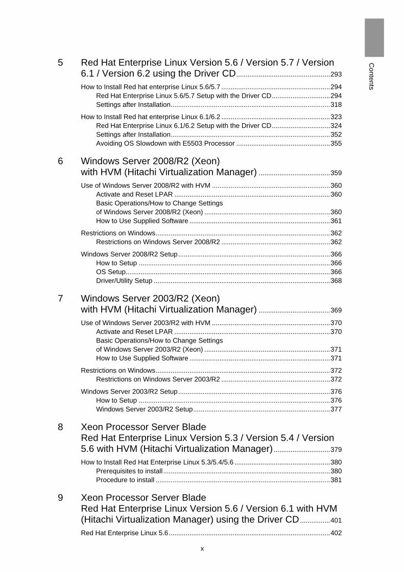
5 Red Hat Enterprise Linux Version 5.6 / Version 5.7 / Version 6.1 / Version 6.2 using the Driver CD .................................................. 293
How to Install Red hat enterprise Linux 5.6/5.7 .......................................................... 294
Red Hat Enterprise Linux 5.6/5.7 Setup with the Driver CD ............................... 294
Settings after Installation ..................................................................................... 318
How to Install Red hat enterprise Linux 6.1/6.2 .......................................................... 323
Red Hat Enterprise Linux 6.1/6.2 Setup with the Driver CD ............................... 324
Settings after Installation ..................................................................................... 352
Avoiding OS Slowdown with E5503 Processor .................................................. 355
6 Windows Server 2008/R2 (Xeon) with HVM (Hitachi Virtualization Manager) ...................................... 359
Use of Windows Server 2008/R2 with HVM ............................................................... 360
Activate and Reset LPAR ................................................................................... 360
Basic Operations/How to Change Settings
of Windows Server 2008/R2 (Xeon) ................................................................... 360
How to Use Supplied Software ........................................................................... 361
Restrictions on Windows ............................................................................................. 362
Restrictions on Windows Server 2008/R2 .......................................................... 362
Windows Server 2008/R2 Setup ................................................................................. 366
How to Setup ...................................................................................................... 366
OS Setup ............................................................................................................. 366
Driver/Utility Setup .............................................................................................. 368
7 Windows Server 2003/R2 (Xeon) with HVM (Hitachi Virtualization Manager) ...................................... 369
Use of Windows Server 2003/R2 with HVM ............................................................... 370
Activate and Reset LPAR ................................................................................... 370
Basic Operations/How to Change Settings
of Windows Server 2003/R2 (Xeon) ................................................................... 371
How to Use Supplied Software ........................................................................... 371
Restrictions on Windows ............................................................................................. 372
Restrictions on Windows Server 2003/R2 .......................................................... 372
Windows Server 2003/R2 Setup ................................................................................. 376
How to Setup ...................................................................................................... 376
Windows Server 2003/R2 Setup ......................................................................... 377
8 Xeon Processor Server Blade Red Hat Enterprise Linux Version 5.3 / Version 5.4 / Version 5.6 with HVM (Hitachi Virtualization Manager) .............................. 379
How to Install Red Hat Enterprise Linux 5.3/5.4/5.6 ................................................... 380
Prerequisites to install ......................................................................................... 380
Procedure to install ............................................................................................. 381
9 Xeon Processor Server Blade Red Hat Enterprise Linux Version 5.6 / Version 6.1 with HVM (Hitachi Virtualization Manager) using the Driver CD ................ 401
Red Hat Enterprise Linux 5.6 ...................................................................................... 402
xi
C
on
ten
ts
Prerequisites for Setup ....................................................................................... 402
Notes and Restrictions on RHEL 5.6 with HVM .................................................. 403
Setting up Red Hat Enterprise Linux 5.6 ............................................................ 404
Red Hat Enterprise Linux 6.1 ...................................................................................... 413
Prerequisites for Setup ....................................................................................... 413
Notes and Restrictions on RHEL 6.1 with HVM .................................................. 414
Setting up Red Hat Enterprise Linux 6.1 ............................................................ 415
Appendix I: Advanced Function for LAN Windows Server 2008
Appendix II: Advanced Function for LAN Windows Server 2008 R2

xii
P
reca
utio
ns fo
r Sa
fe U
se
Precautions for Safe Use
Items of precautions for safe use are indicated with safety alert symbols and headings,
“WARNING”, “CAUTION”, and “NOTICE” as shown below.
This is a safety alert symbol. It calls attention to a potential safety
hazard to humans. In order to avoid possible injury or death, follow the
message provided after this symbol.
WARNING This symbol indicates the presence of a potential risk that might cause
death or severe injury.
CAUTION This symbol indicates the presence of a potential risk that might cause
relatively mild or moderate injury.
NOTICE This symbol indicates the presence of a potential risk that might cause
severe damage to the equipment and/or damage to surrounding
properties.
[Example 1: hazard identification]
The equilateral triangle filled in with yellow indicates a precaution. A
safety alert symbol inside the triangle indicates the type of hazard,
such as “an electric shock hazard”.
[Example 2: prohibition]
The red circle with a red diagonal bar indicates an action that you
must not take. The red diagonal bar is placed over a figure that
depicts the “must-not” item involved, such as a screwdriver to
disassemble a device. The red circle with a red diagonal bar without a
symbol indicates the general prohibition.
[Example 3: mandatory action]
The circle filled in with blue indicates an action to take. A white figure
inside the circle shows the action to take, such as unplugging the
power cable from the outlet. The same circle with an exclamation mark
indicates generally should-take actions.
xiii
P
reca
utio
ns fo
r Sa
fe U
se
Common precautions concerning safety
Please carefully read through these safety instructions to follow:
When operating the equipment, follow the instructions and procedures provided in the manual.
Be sure to follow notes, cautionary statements and advice indicated on the equipment or in the manual.
Referring to manuals attached to other products which you install in or connect to the equipment, follow the instructions described in those manuals.
Failure to follow those instructions can cause injury, fire or damage to property including the equipment.
Operations and actions to perform
Do not perform operations or actions other than those described in the manual. Should you find any problem with the equipment, turn off the power, unplug the power cable from the electrical outlet, and then contact your reseller or call for maintenance personnel.
Pay attention
The equipment and the manual carry notes, cautionary statements and advice that have been fully examined and reviewed. However, unforeseeable situations may occur. When operating the equipment, always stay alert as well as follow instructions.

xiv
P
reca
utio
ns fo
r Sa
fe U
se
Precautions for Safe Use
Warning Signs in the manual
NOTICE
Turning off power
Do not rashly press the [POWER] button to turn off the power. It may cause data to get corrupted or Windows not to start. Perform a shutdown to turn off the power.
Refer to [Chapter 1; Chapter 2; Chapter 3: Turning off Power].
Re-setup
Re-setup causes the hard disk data to disappear. Back up data that you need in advance.
Refer to [Chapter 1: Windows Server 2008 R2 Setup/Setup Steps; Chapter 2: Windows Server 2008 Setup/Setup Steps; Chapter 3: Windows Server 2003/R2 Setup/Setup Steps; Chapter 5: Windows Server 2008/R2 Setup; Chapter 6: Windows Server 2003/R2 Setup].
Red Hat Enterprise Linux
Trouble caused by using media other than Red Hat Enterprise Linux 4 Update 3/4.5/4.7 is not guaranteed.
If the correspondent LSI Logic Software RAID driver is not installed, the hard disk can not be recognized or the data can be lost.
Installation causes data in the HDD to disappear. Back up the important data in advance.
Refer to [Chapter 4: Red Hat Enterprise Linux Version 4 Update 3 / Version 4.5 / Version 4.7 Procedure; Red Hat Enterprise Linux Version 5.1 / Version 5.3 / Version 5.4 Procedure]

xv
H
ow
to U
se
the
Gu
ide
How to Use the Manuals
The User's Guide and Software Guide are available as electronic manuals.
Refer the User’s Guide for the usage of the electronic manuals.
Depending on the configuration of the system equipment, additional manuals may be provided. Read these manuals if necessary.

xvi
H
ow
to U
se
the
Gu
ide
1
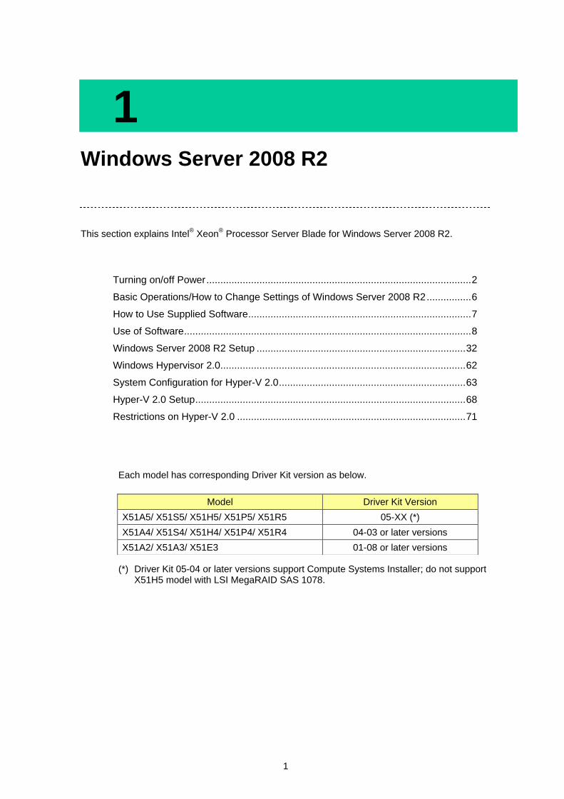
1 Windows Server 2008 R2
This section explains Intel® Xeon
® Processor Server Blade for Windows Server 2008 R2.
Turning on/off Power ............................................................................................... 2
Basic Operations/How to Change Settings of Windows Server 2008 R2 ................ 6
How to Use Supplied Software ................................................................................ 7
Use of Software ....................................................................................................... 8
Windows Server 2008 R2 Setup ........................................................................... 32
Windows Hypervisor 2.0........................................................................................ 62
System Configuration for Hyper-V 2.0 ................................................................... 63
Hyper-V 2.0 Setup ................................................................................................. 68
Restrictions on Hyper-V 2.0 .................................................................................. 71
Each model has corresponding Driver Kit version as below.
(*) Driver Kit 05-04 or later versions support Compute Systems Installer; do not support X51H5 model with LSI MegaRAID SAS 1078.
Model Driver Kit Version
X51A5/ X51S5/ X51H5/ X51P5/ X51R5 05-XX (*)
X51A4/ X51S4/ X51H4/ X51P4/ X51R4 04-03 or later versions
X51A2/ X51A3/ X51E3 01-08 or later versions
2
1
Win
dow
s S
erv
er 2
00
8 R
2
Turning on/off Power
This section explains how to turn on the system and start the OS, how to turn off the system by the OS shutdown, and how to forcibly terminate the applications and system.
Refer to “Turning on/off Power” in User’s Guide for power operation.
Turning off Power
Follow the steps below after completing all tasks on the system equipment to turn off the power.
NOTICE
Do not rashly press the [POWER] button to turn off the power. It may cause data to get corrupted or Windows not to start.
Perform a shutdown to turn off the power.
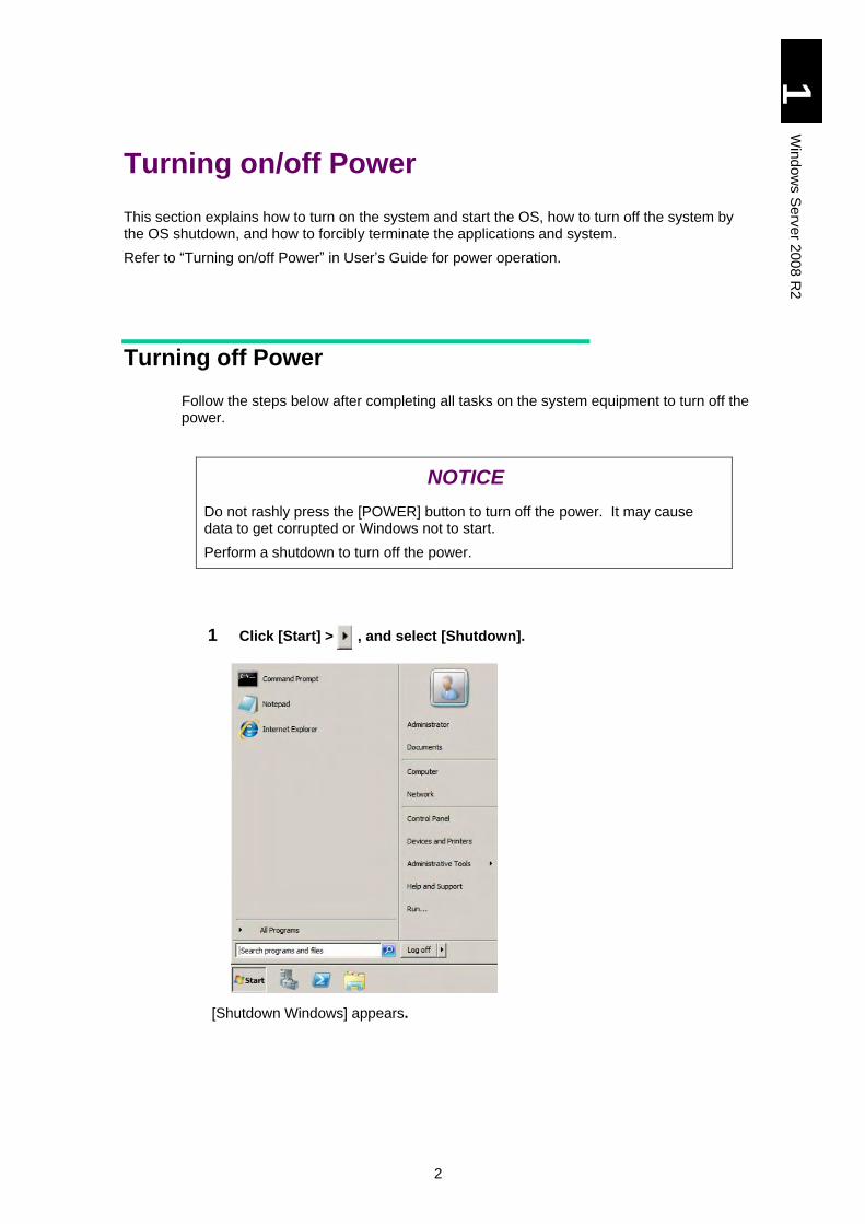
1 Click [Start] > , and select [Shutdown].
[Shutdown Windows] appears.
3
1
Win
dow
s S
erv
er 2
00
8 R
2
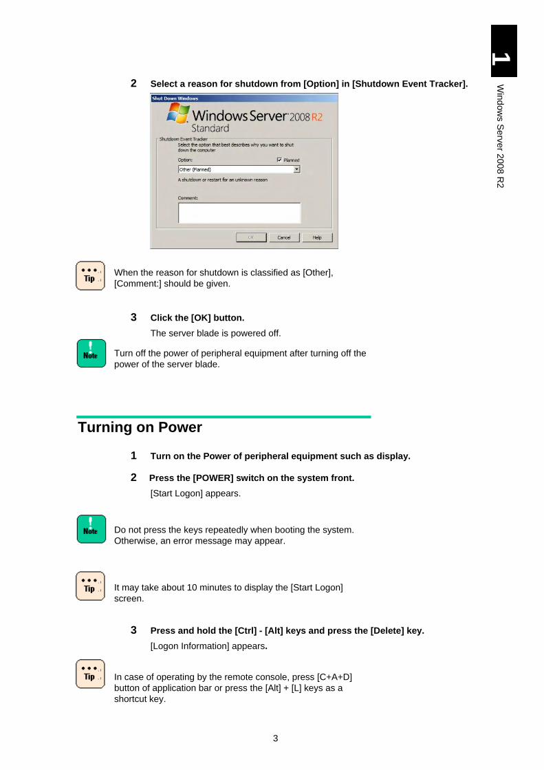
2 Select a reason for shutdown from [Option] in [Shutdown Event Tracker].
When the reason for shutdown is classified as [Other],
[Comment:] should be given.
3 Click the [OK] button.
The server blade is powered off.
Turn off the power of peripheral equipment after turning off the
power of the server blade.
Turning on Power
1 Turn on the Power of peripheral equipment such as display.
2 Press the [POWER] switch on the system front.
[Start Logon] appears.
Do not press the keys repeatedly when booting the system.
Otherwise, an error message may appear.
It may take about 10 minutes to display the [Start Logon]
screen.
3 Press and hold the [Ctrl] - [Alt] keys and press the [Delete] key.
[Logon Information] appears.
In case of operating by the remote console, press [C+A+D]
button of application bar or press the [Alt] + [L] keys as a
shortcut key.

4
1
Win
dow
s S
erv
er 2
00
8 R
2
4 Enter your user name and password, and click the [Enter] key.
Windows boots itself and the Desktop window appears.
Plugging off the Power Cable
Electricity is supplied to some circuits even if the system equipment is turned off.
When the following happens, pull out the power plug from the outlet for the safety.
When you find abnormal heat, smoke, abnormal noise, smell, or abnormal smell
When you do not use the system equipment for a long period of time.
5
1
Win
dow
s S
erv
er 2
00
8 R
2
Resetting Application/System Forcibly
When the system equipment function fails during its processing applications, resetting, which includes terminating applications forcibly or rebooting the server blade forcibly, may work to resume the system to the normal operation.
Forcibly Terminate Application
Right-click the task bar and click [Task Manager] of the shortcut menu. Click the [Application] tab, select an application you want to terminate, and click the [End Task] button.
Forcibly Reboot the Server Blade
When Windows functions abnormally, press the [POWER] button for four seconds or more to turn off the power. The system may not be available, however, if you format the HDD once more.
Do not press the [POWER] switch again until the Windows
reboot is completed except emergency. When resetting, be
sure to boot and terminate Windows properly, and then reboot
it.
6
1
Win
dow
s S
erv
er 2
00
8 R
2
Basic Operations/How to Change Settings of Windows Server 2008 R2
This section explains basic operations and how to change settings of Windows Server 2008 R2.
How to Use Help
Help is available from Windows, in which how to use is described.
Start [Help and Support].
1 Click the [Start] button and then select [Help and Support].
[Windows Help and Support Center] boots itself.
Check Desired Operations
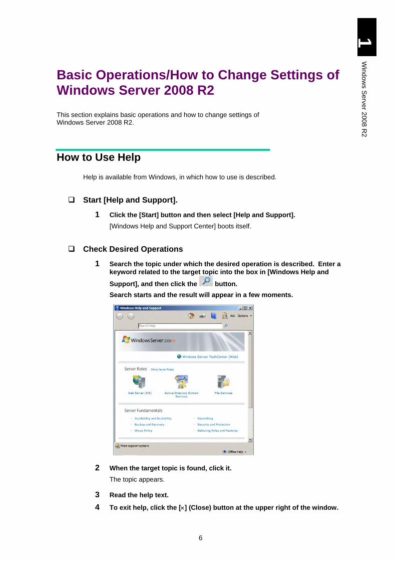
1 Search the topic under which the desired operation is described. Enter a
keyword related to the target topic into the box in [Windows Help and
Support], and then click the button.
Search starts and the result will appear in a few moments.
2 When the target topic is found, click it.
The topic appears.
3 Read the help text.
4 To exit help, click the [] (Close) button at the upper right of the window.
7
1
Win
dow
s S
erv
er 2
00
8 R
2
How to Use Supplied Software
This section explains the software included in this system.
MegaRAID Storage Manager (X51A4/X51H4/X51R4/ X51A5/X51H5/X51R5 models)
This software is necessary to manage the disk array devices. Be sure to install it when the HDD is installed in the server blade. Otherwise, a double-failure might be caused because of non-detection of the hard disk failure, and the failure analysis become difficult. Refer to the file 'MegaRAID Storage Manager Instruction Manual' in the CD-ROM for details of the usage. d: is CD/DVD drive name. d:\MANUAL\MSManager2.pdf [Driver Kit version 05-04 or later]
d:\X51x5\MANUAL\MSManager2.pdf
Intel® PROSet
Intel PROSet is a utility to provide expansion functions such as Dual LAN Redundancy.
Refer to Appendix II to this manual for the details.
8
1
Win
dow
s S
erv
er 2
00
8 R
2
Use of Software
This section explains the restrictions on the use of software.
Restrictions on Use of Windows Server 2008 R2
Server Core
Do not install Server Core, which is not supported.
Datacenter
There are some restrictions on Windows server 2008 R2 Datacenter when used. The following functions for advanced availability are not supported:
Hot Replace Memory
Hot Add Processors
Hot Replace Processors
Windows Server Shutdown
If you shut down Windows while the service registered to start at the boot is still activated, it may not be shut down normally. Be sure to allow a time interval of at least one minute after booting Windows.
Restore the Computer
Step 4 in Setup procedure (click here.) may not be displayed in some OS installation media. When that happens, “Repair your computer” on the step 4 screen is not displayed, so that Windows Recovery Environment (hereinafter, referred to as Windows RE) cannot be started.
http://support.microsoft.com/kb/951495
Start Windows RE as follows, if necessary.
1. In the window of “Select OS to install”, press and hold the [Shift] key and press the [F10] key.
A command prompt is displayed.
2. Enter the following command in the command prompt to execute “recenv.exe”.
> cd /d %SystemDrive%\source\recovery
> RecEnv.exe
3. Windows RE will start.
9
1
Win
dow
s S
erv
er 2
00
8 R
2
Fault Tolerant
Backup regularly. Span volume, Stripe volume, RAID-5 volume and Mirror volume are not supported.
Backup
Windows Server Backup does not support backing up to tape media. When backing up data to a tape device, purchase the backup software.
Backing up to DVD media is also not supported.
Screen Display
After switching the screen display to change a task, the previous display may remain depending on the timing. In such a case, redraw the point in question to display properly.
Depending on the status of use, the message box may be hidden behind other windows.
To change the display color, terminate the application. Otherwise, it can cause strange display of the application. In such a case, redraw by switching the screen for proper display.
When changing refresh rates, confirm that your monitor can display a screen properly.
A screen may remain displayed after stopping the play with some applications that playing animated files. When this happens, change screens such as maximize another window.
Power Saving Function
Do not select [System Standby], [Hybrid Sleep] and [Hibernate]. These three are not supported.
Among power supply options, you can only change the time-out period before the display shutdown.
If you fail to observe two restrictions above, the monitor may not operate properly.
Setting Recovery Operation at System Shutdown
It is recommended that the [Automatically restart] checkbox should be unchecked.
The procedure is as follows:
1. Select [Start] > [Management Tool] > [Server Manager] to open.
2. Select [Change System Property], and open [System Property].
3. Select the [Details Setting] tab, and then click the [Set] button in [Start and Recovery]. [Start and Recovery] will open.
4. Remove the check mark from [Automatically restart], and click the [OK] button.
10
1
Win
dow
s S
erv
er 2
00
8 R
2
Getting Complete Memory Dump in Physical Memory Exceeding 2 GB
When Windows is set on the system equipment installed with 2 GB or larger memory, [Complete Memory Dump] cannot be selected from [Write Debug Information] in [Start and Recovery]. Perform the following procedure when getting [Complete Memory Dump] in an environment where 2 GB or larger Physical Memory is used. Actually, [Complete Memory Dump] is not included in the [Write Debut Information] list.
1 Insert the "Driver Kit" CD-ROM into the CD/DVD drive.
2 Select [Run] from the [Start] menu, enter following file name and click
[OK].
d:\UTILITY\Dump\PMDE.BAT
[With Driver Kit version 05-04 or later]
d:\X51x5\Win2008\Tools\Dump\PMDE.BAT
d: is the CD/DVD drive name.
3 Press any key when the following message appears.
Change the setting to get Complete Memory Dump.
Press any key to continue the operation.
Press the [Ctrl] + [C] keys to cancel the setting.
4 Set [Virtual memory] size. Refer to the following.
Setting "Virtual Memory" Size
Setting "Virtual Memory" Size
When setting Virtual Memory to get the complete memory dump, set the virtual memory file to a size larger than the capacity of the physical memory. If you try to set the file size of the virtual memory smaller than the physical memory, a warning message "If the paging file is disabled or the virtual memory's initial page size: is smaller than xxx MB, system error can occur and useful information to identify the problem cannot be saved. Do you like to continue?" appears. If you select this xxx MB, the complete memory dump may not be obtained correctly. Set the file size larger than [xxx +400] MB.
When setting Virtual Memory to get the kernel memory dump, set enough size for the virtual memory. Otherwise, the kernel memory dump may not be properly collected. Refer to the following URL for the detail.
http://support.microsoft.com/kb/949052/en-us
1 Select [Start] > [Management Tool] > [Server manager], and the [Server Manager] will open.
2 Select [Change System Property], and [System Property] will open.
3 Select the [Details] tab, and click the [Setting] button in [Performance]. [Performance Option] will open.
4 From the same [Details] tab, click the [Setting] button in [Virtual Memory]. [Virtual Memory] will open.
5 Remove the check mark from [Manage automatically all the drive paging file sizes].
11
1
Win
dow
s S
erv
er 2
00
8 R
2
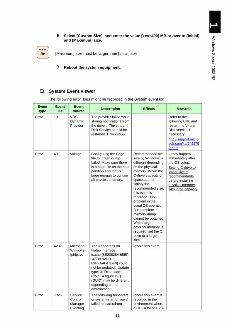
6 Select [Custom Size], and enter the value [xxx+400] MB or over to [Initial] and [Maximum] size.
[Maximum] size must be larger than [Initial] size.
7 Reboot the system equipment.
System Event viewer
The following error logs might be recorded in the System event log.
Event
type
Event
ID
Event
source Descritpion Effects Remarks
Error 10 VDS
Dynamic
Provider
The provider failed while
storing notifications from
the driver. The virtual
Disk Service should be
restarted. Hr=xxxxxxx
Refer to the
following URL and
restart the Virtual
Disk service if
necessary.
http://support.micro
soft.com/kb/948275
/en-us
Error 49 volmgr Configuring the Page
file for crash dump
failed. Make sure there
is a page file on the boot
partition and that is
large enough to contain
all physical memory.
Recommended file
size by Windows is
different depending
on the physical
memory. When the
C-drive capacity or
space cannot
satisfy the
recommended size,
this event is
recorded. No
problem in the
usual OS operation.
But complete
memory dump
cannot be obtained.
When large
physical memory is
required, set the C:
drive to a larger
size.
It may happen
immediately after
the OS setup.
Setting C-drive to
larger size is
recommendable
before installing
physical memory
with large capacity.
Error 4202 Microsoft-
Windows-
Iphlpsvc
The IP address on
Isatap interface
isatap.{8E208284-65BF-
-43D8-92DD-
89FFAAF47DF0} could
not be updated. Update
type: 0; Error code:
0x57. A figure in {}
(GUID) may be different
depending on the
environment.
Ignore this event.
Error 7026 Service
Control
Manager
Eventlog
The following boot-start
or system-start driver(s)
failed to load:cdrom
Ignore this event if
recorded in the
environment where
a CD-ROM or DVD-
12
1
Win
dow
s S
erv
er 2
00
8 R
2
Event
type
Event
ID
Event
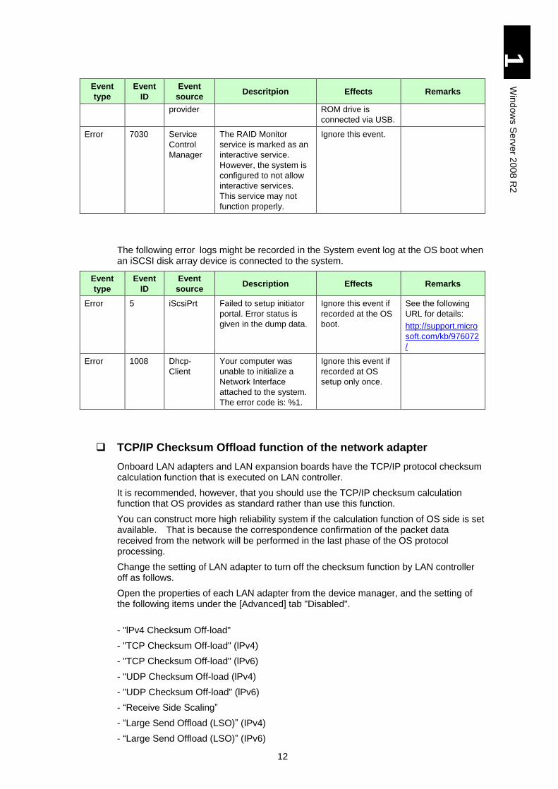
source Descritpion Effects Remarks
provider ROM drive is
connected via USB.
Error 7030 Service
Control
Manager
The RAID Monitor
service is marked as an
interactive service.
However, the system is
configured to not allow
interactive services.
This service may not
function properly.
Ignore this event.
The following error logs might be recorded in the System event log at the OS boot when an iSCSI disk array device is connected to the system.
Event
type
Event
ID
Event
source Description Effects Remarks
Error 5 iScsiPrt Failed to setup initiator
portal. Error status is
given in the dump data.
Ignore this event if
recorded at the OS
boot.
See the following
URL for details:
http://support.micro
soft.com/kb/976072
/
Error 1008 Dhcp-
Client
Your computer was
unable to initialize a
Network Interface
attached to the system.
The error code is: %1.
Ignore this event if
recorded at OS
setup only once.
TCP/IP Checksum Offload function of the network adapter
Onboard LAN adapters and LAN expansion boards have the TCP/IP protocol checksum calculation function that is executed on LAN controller.
It is recommended, however, that you should use the TCP/IP checksum calculation function that OS provides as standard rather than use this function.
You can construct more high reliability system if the calculation function of OS side is set available. That is because the correspondence confirmation of the packet data received from the network will be performed in the last phase of the OS protocol processing.
Change the setting of LAN adapter to turn off the checksum function by LAN controller off as follows.
Open the properties of each LAN adapter from the device manager, and the setting of the following items under the [Advanced] tab "Disabled".
- "lPv4 Checksum Off-load"
- "TCP Checksum Off-load" (lPv4)
- "TCP Checksum Off-load" (lPv6)
- "UDP Checksum Off-load (lPv4)
- "UDP Checksum Off-load" (lPv6)
- “Receive Side Scaling”
- “Large Send Offload (LSO)” (IPv4)
- “Large Send Offload (LSO)” (IPv6)
13
1
Win
dow
s S
erv
er 2
00
8 R
2
- “Large Send Offload (LSO) v2” (IPv4)
- “Large Send Offload (LSO) v2” (IPv6)
Some items may not be displayed depending on the type of a network adapter. Set items displayed with you adapter.
Disable the following items:
"lPv4 Checksum Off-load "
"TCP Checksum Off-load" (lPv4)
"TCP Checksum Off-load" (lPv6)
"UDP Checksum Off-load” (lPv4)
"UDP Checksum Off-load" (lPv6)
“Receive Side Scaling”
“Large Send Offload” (IPv4)
“Large Send Offload” (IPv6)
With 10 Gbps expansion LAN adapter: Intel(R) Ethernet Server Adapter X520-2, have the LAN controller function calculate the checksum of TCP/IP protocol. If you have the OS do it, data transmission may be less than expected due to heavy load on the CPU. The default value of newly installed adapters is all “Enabled”.
To enable the checksum by the LAN controller, follow the
next description.
Open [Properties] of each LAN adapter in [Device
Manager], click the [Advanced] tab, and set the following
items [Enabled]. When Intel(R) PROSet is installed, some
items may be displayed in [Properties] < [TCP/IP Offload
Option] < [Advanced]. Check the checkbox of those items.
lPv4 Checksum Off-load: Receive/Send Enabled
TCP Checksum Off-load (lPv4): Receive/Send Enabled
TCP Checksum Off-load (lPv6): Receive/Send Enabled
UDP Checksum Off-load (lPv4): Receive/Send Enabled
UDP Checksum Off-load (lPv6): Receive/Send Enabled
Large Send Offload (LSO) (IPv4): Enabled
Large Send Offload (LSO) (IPv6): Enabled
Restriction on Changing the Network Adapter Parameter
When the network adapter setting has been changed, communication may not be done properly via the said adapter.
Check the network adapter with the changed setting in the device manager. If “!” is displayed, right-click the said adapter, disable it, and enable it again. Then the adapter will be used.
14
1
Win
dow
s S
erv
er 2
00
8 R
2
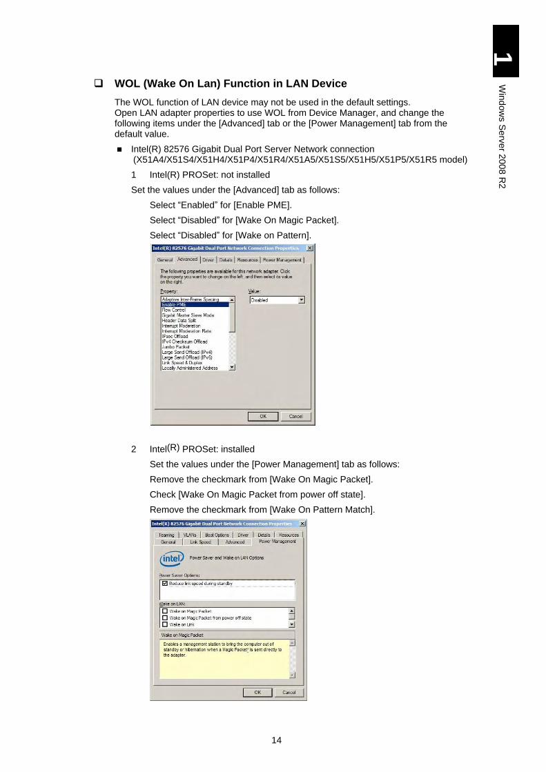
WOL (Wake On Lan) Function in LAN Device
The WOL function of LAN device may not be used in the default settings. Open LAN adapter properties to use WOL from Device Manager, and change the following items under the [Advanced] tab or the [Power Management] tab from the default value.
Intel(R) 82576 Gigabit Dual Port Server Network connection (X51A4/X51S4/X51H4/X51P4/X51R4/X51A5/X51S5/X51H5/X51P5/X51R5 model)
1 Intel(R) PROSet: not installed
Set the values under the [Advanced] tab as follows:
Select “Enabled” for [Enable PME].
Select “Disabled” for [Wake On Magic Packet].
Select “Disabled” for [Wake on Pattern].
2 Intel(R) PROSet: installed
Set the values under the [Power Management] tab as follows:
Remove the checkmark from [Wake On Magic Packet].
Check [Wake On Magic Packet from power off state].
Remove the checkmark from [Wake On Pattern Match].
15
1
Win
dow
s S
erv
er 2
00
8 R
2
To check the version of your Intel(R) PROSet, select [Control
Panel] > [Program and Function].
To check LAN devices, refer to the next description “Local Area Connection”.
Local Area Connection
Select [Control Panel] – [Network and Sharing Center] – [Network Connection Manager] from [Task]. Network connection in the name of "local area connection x" (x is a number) is displayed. The number accompanying the "local area connection" and the LAN device number that is indicated in the "device name" are independent respectively, and they do not necessarily agree with each other. The relationship between the number accompanying the "local area connection" and the Switch/Path-through Module’s service LAN port on the back of the chassis of Compute Blade is also independent. For example, "local area connection" (without number) does not necessarily correspond to the service LAN port of the Switch/Path-through Module located on the right side when viewed from the back of the chassis.
Be sure to check correspondence between "local area connection" and LAN device and service LAN port of SVP module before configuring network for the first time. Since the name of "local area connection" can be changed, it is recommended to assign a recognizable name in the environment after checking.
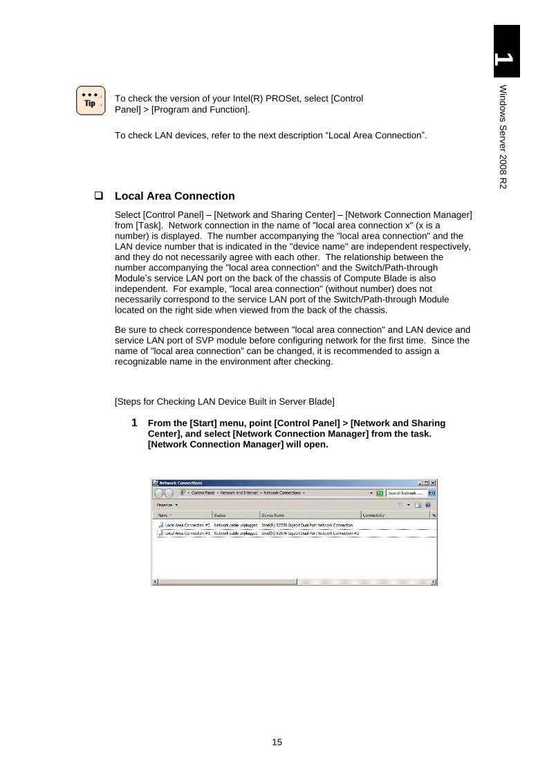
[Steps for Checking LAN Device Built in Server Blade]
1 From the [Start] menu, point [Control Panel] > [Network and Sharing Center], and select [Network Connection Manager] from the task. [Network Connection Manager] will open.
16
1
Win
dow
s S
erv
er 2
00
8 R
2
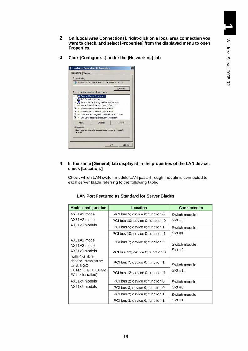
2 On [Local Area Connections], right-click on a local area connection you
want to check, and select [Properties] from the displayed menu to open Properties.
3 Click [Configure…] under the [Networking] tab.
4 In the same [General] tab displayed in the properties of the LAN device, check [Location:].
Check which LAN switch module/LAN pass-through module is connected to each server blade referring to the following table.
LAN Port Featured as Standard for Server Blades
Model/configuration Location Connected to
AX51A1 model
AX51A2 model
AX51x3 models
PCI bus 5; device 0; function 0 Switch module
Slot #0 PCI bus 10; device 0; function 0
PCI bus 5; device 0; function 1 Switch module
Slot #1 PCI bus 10; device 0; function 1
AX51A1 model
AX51A2 model
AX51x3 models
[with 4 G fibre
channel mezzanine
card: GGX-
CCMZFC1/GGCCMZ
FC1-Y installed]
PCI bus 7; device 0; function 0 Switch module
Slot #0 PCI bus 12; device 0; function 0
PCI bus 7; device 0; function 1 Switch module
Slot #1 PCI bus 12; device 0; function 1
AX51x4 models
AX51x5 models
PCI bus 2; device 0; function 0 Switch module
Slot #0 PCI bus 3; device 0; function 0
PCI bus 2; device 0; function 1 Switch module
Slot #1 PCI bus 3; device 0; function 1
17
1
Win
dow
s S
erv
er 2
00
8 R
2
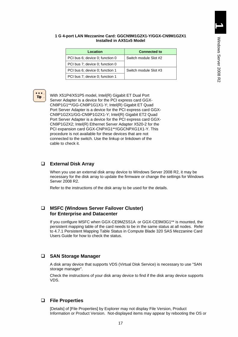
1 G 4-port LAN Mezzanine Card: GGCN9M1G2X1-Y/GGX-CN9M1G2X1 Installed in AX51x5 Model
Location Connected to
PCI bus 6; device 0; function 0 Switch module Slot #2
PCI bus 7; device 0; function 0
PCI bus 6; device 0; function 1 Switch module Slot #3
PCI bus 7; device 0; function 1
With X51P4/X51P5 model, Intel(R) Gigabit ET Dual Port
Server Adapter is a device for the PCI express card GGX-
CN9P1G1**/GG-CN9P1G1X1-Y; Intel(R) Gigabit ET Quad
Port Server Adapter is a device for the PCI express card GGX-
CN9P1G2X1/GG-CN9P1G2X1-Y; Intel(R) Gigabit ET2 Quad
Port Server Adapter is a device for the PCI express card GGX-
CN9P1G2X2; Intel(R) Ethernet Server Adapter X520-2 for the
PCI expansion card GGX-CNPXG1**/GGCNPXG1X1-Y. This
procedure is not available for these devices that are not
connected to the switch. Use the linkup or linkdown of the
cable to check it.
External Disk Array
When you use an external disk array device to Windows Server 2008 R2, it may be necessary for the disk array to update the firmware or change the settings for Windows Server 2008 R2.
Refer to the instructions of the disk array to be used for the details.
MSFC (Windows Server Failover Cluster) for Enterprise and Datacenter
If you configure MSFC when GGX-CE9MZSS1A or GGX-CE9M3G1** is mounted, the persistent mapping table of the card needs to be in the same status at all nodes. Refer to 4.7.1 Persistent Mapping Table Status in Compute Blade 320 SAS Mezzanine Card Users Guide for how to check the status.
SAN Storage Manager
A disk array device that supports VDS (Virtual Disk Service) is necessary to use "SAN storage manager".
Check the instructions of your disk array device to find if the disk array device supports VDS.
File Properties
[Details] of [File Properties] by Explorer may not display File Version, Product Information or Product Version. Not-displayed items may appear by rebooting the OS or
18
1
Win
dow
s S
erv
er 2
00
8 R
2
changing solution/color bits. Rebooting the OS or changing the screen resolution/the number of color bits may work.
Event Log on Network Adapter
\DEVICE {354C76B6-E426-4CEB-8015-BF991BA8D75F} instead of a network adapter name such as Intel® 82566DC-2 Gigabit Network Connection may be displayed in the event log explanation of the network adapter.
This occurs due to the specification, which will not affect the operation.
The network adapter name and the number in brackets (GUID) may be different depending on your environment.
Display of Network Adapter Connection
[Network Connection] or task tray status may not be quickly updated at the network adapter linkup. To find the state, select [View] in [Network Connections]. Then select [Latest Update] to update the connection.
Network Adapter Event Log at OS Boot
Error event may occur in the network adapter at the system boot. The network adapter may be linked down. Check if the targeted network adapter is connected in [Network Connections].
A linkup event may be recorded at the system boot in whatever status the network adapter is linked. Check the connection status of the targeted network adapter in [Network Connection].
Physical Memory Capacity
Microsoft has recommended that Windows Server 2008 R2 should have 2 GB memory. If the memory is not enough, processing may not be completed by the time expected or may be interrupted due to resource shortage at the overload.
Windows RE (Recovery Environment)
With Windows Server 2008 R2, when the system equipment restarts due to failure during the OS startup, a message appears, saying that the computer failed to start and that Windows will attempt to repair it. With no operation, Windows RE (Recovery Environment) instead of Windows Server 2008 R2 starts in 30 seconds.
When Windows RE starts up, the user needs to start Windows Server 2008 R2 manually. If you operate the system with this setting, which automatically restart the system to start Windows Server 2008 R2, it can be troublesome. It is recommended that you should disable the setting because features provided by Windows RE are available using the installation medium. For the procedure to disable it, refer to “Windows Recovery Environment (RE)”. An OS standard command reagentc.exe” can be used to enable or disable the setting. For the details, log on as Administrator, perform reagentc.exe/?, and view the help.
19
1
Win
dow
s S
erv
er 2
00
8 R
2
Multipath
When a multipath (access route) is assigned to LU of an external disk array where to install the OS, change it to a single path before installing the OS. With multiple paths assigned to the LU, the installation fails. Install the OS with a single path, then install multipath software, and release the single-path routing.
When a multipath (access route) is assigned to LU of an external disk array where the OS has been installed, change it to a single-path routing before restoring the OS from the backup files. With multiple paths assigned to the LU, the restoration may fail. Check notes on the backup software referring to the manual beforehand.
It is common to change a multipath to a single-path routing from the management utility of an external disk array. Refer to the manual of the external disk array device.
USB Memory
With a USB memory connected, do not power on the system equipment or perform reboot-up. Boot the OS and then connect the USB memory. After that, confirm that drive letters of other drives are not changed.
iSCSI
An environment with iSCSI connection has the following restrictions.
Do not include a LAN adapter used for iSCSI connection in configuration for a team or VLAN with Intel PROSet.
When an OS is installed in the external disk array device with iSCSI connection, select “Safe Mode with Networking” for booting the OS in safe mode.

20
1
Win
dow
s S
erv
er 2
00
8 R
2
Multipath I/O (MPIO) with OS in the External Disk Array via iSCSI
This subsection describes how to set the multipath I/O (MPIO) when the OS is installed in an external disk array device connected via iSCSI.
Perform setup procedures to Apply Patches before setting MPIO. If you set MPIO before applying patches required for iSCSI, STOP error may occur.
Perform the setup to step 5 with the secondary path disabled (Boot: Disable), not with enabled (Boot: SECONDARY) in iSCSI BIOS Setup Utility. If you enable the secondary path (Boot: SECONDARY) before completing step 5, STOP error may occur.
Even with MPIO enabled, if the secondary path alone is connected due to failure in the path, which is set to Primary (Boot: PRIMARY) in the iSCSI BIOS Setup Utility, memory dumps cannot be collected.
Refer to User’s Guide for further details of iSCSI BIOS Setup Utility.
How to Add Multipath I/O
The following steps show how to add MPIO.
1 Power on the server blade, boot Windows, and log on as Administrator.
2 Click [Start] > [Administrative Tools] > [Server Manager] to open. Select [Features] in [Server Manager], and click [Feature overview] > [Add features].
3 When [Select feature] screen is displayed in [Add Feature Wizard], put a checkmark in [Multipath I/O], and then click [Next]
4 [Confirm Installation Selections] screen is displayed. Check that Multipath I/O in the pane, and click [Install].
5 Soon [Installation Results] screen is displayed. Check that “Installation succeeded” is checked on the screen, and click [Close].
How to Configure Multipath I/O in iSCSI
The following steps show how to configure multipath in iSCSI.
1 Power on the server blade, boot Windows, and log on as Administrator.
2 Click [Start] > [Administrative Tools] > [MPIO] to open [MPIO Properties].
21
1
Win
dow
s S
erv
er 2
00
8 R
2
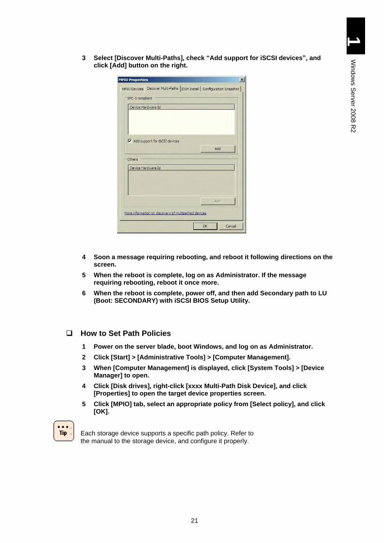
3 Select [Discover Multi-Paths], check “Add support for iSCSI devices”, and click [Add] button on the right.
4 Soon a message requiring rebooting, and reboot it following directions on the screen.
5 When the reboot is complete, log on as Administrator. If the message requiring rebooting, reboot it once more.
6 When the reboot is complete, power off, and then add Secondary path to LU (Boot: SECONDARY) with iSCSI BIOS Setup Utility.
How to Set Path Policies
1 Power on the server blade, boot Windows, and log on as Administrator.
2 Click [Start] > [Administrative Tools] > [Computer Management].
3 When [Computer Management] is displayed, click [System Tools] > [Device Manager] to open.
4 Click [Disk drives], right-click [xxxx Multi-Path Disk Device], and click [Properties] to open the target device properties screen.
5 Click [MPIO] tab, select an appropriate policy from [Select policy], and click [OK].
Each storage device supports a specific path policy. Refer to
the manual to the storage device, and configure it properly.
22
1
Win
dow
s S
erv
er 2
00
8 R
2
iSCSI Initiator Setting
This subsection describes how to use the iSCSI initiator when a data disk is connected.
Starting iSCSI Initiator Service and Adding Target
This section describes how to start the iSCSI initiator service and how to add a target.
Settings on a disk array side may be required. Without proper
settings on a disk array side, an error message may be
generated during the procedure below. If so, set the disk array
properly referring to the manual attached to it.
Memory dump files cannot be output to a data disk connected
via iSCSI. Do not specify the data disk via iSCSI to a
destination to output memory dump files.
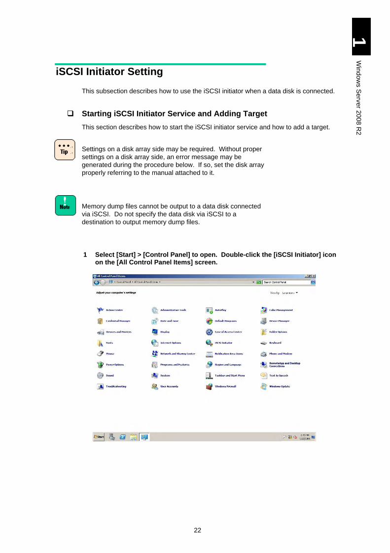
1 Select [Start] > [Control Panel] to open. Double-click the [iSCSI Initiator] icon on the [All Control Panel Items] screen.
23
1
Win
dow
s S
erv
er 2
00
8 R
2
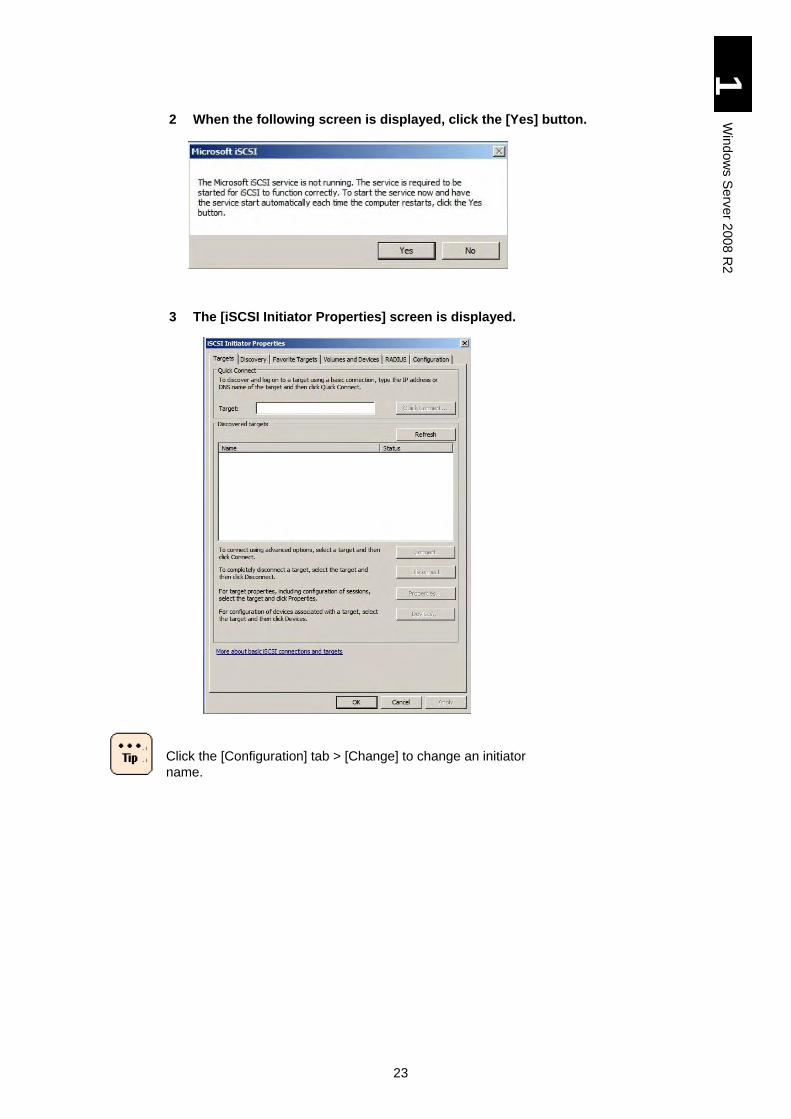
2 When the following screen is displayed, click the [Yes] button.
3 The [iSCSI Initiator Properties] screen is displayed.
Click the [Configuration] tab > [Change] to change an initiator
name.
24
1
Win
dow
s S
erv
er 2
00
8 R
2
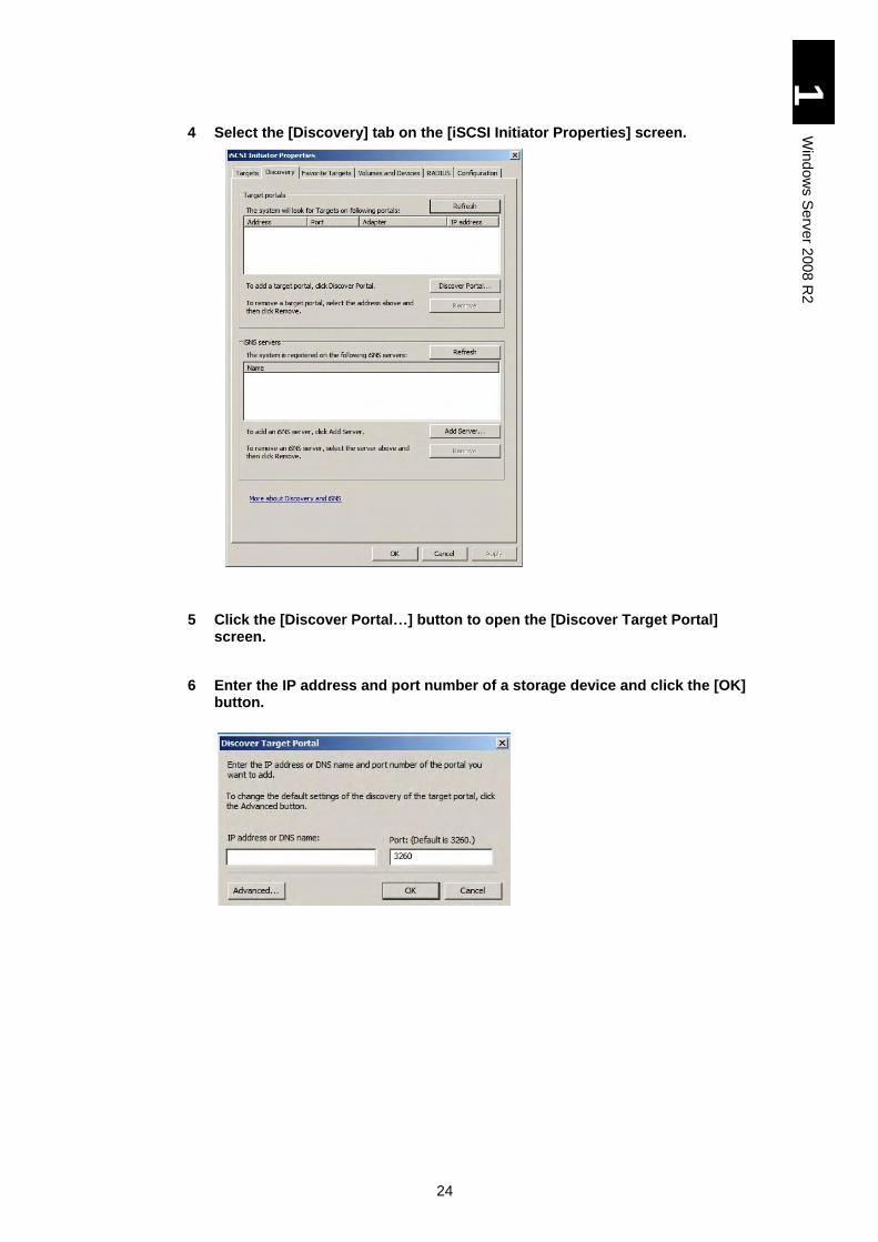
4 Select the [Discovery] tab on the [iSCSI Initiator Properties] screen.
5 Click the [Discover Portal…] button to open the [Discover Target Portal] screen.
6 Enter the IP address and port number of a storage device and click the [OK] button.
25
1
Win
dow
s S
erv
er 2
00
8 R
2
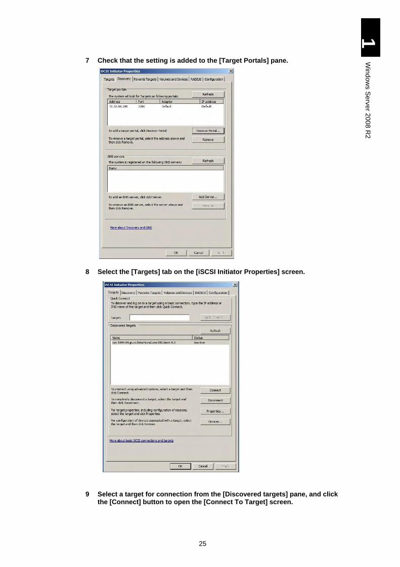
7 Check that the setting is added to the [Target Portals] pane.
8 Select the [Targets] tab on the [iSCSI Initiator Properties] screen.
9 Select a target for connection from the [Discovered targets] pane, and click the [Connect] button to open the [Connect To Target] screen.
26
1
Win
dow
s S
erv
er 2
00
8 R
2
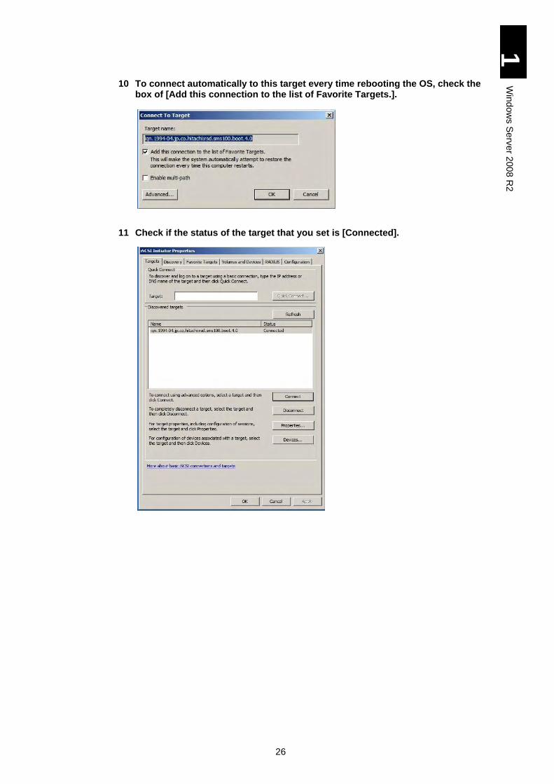
10 To connect automatically to this target every time rebooting the OS, check the box of [Add this connection to the list of Favorite Targets.].
11 Check if the status of the target that you set is [Connected].
27
1
Win
dow
s S
erv
er 2
00
8 R
2
Removing Target Portals
This section describes how to remove a target portal.
1 Select [Start] > [Control Panel] to open. Double-click the [iSCSI Initiator] icon on the [All Control Panel Items] screen to open the [iSCSI Initiator Properties] screen.
When a target in the target portal for removal is not added in the list of Favorite Targets, jump to step 5.
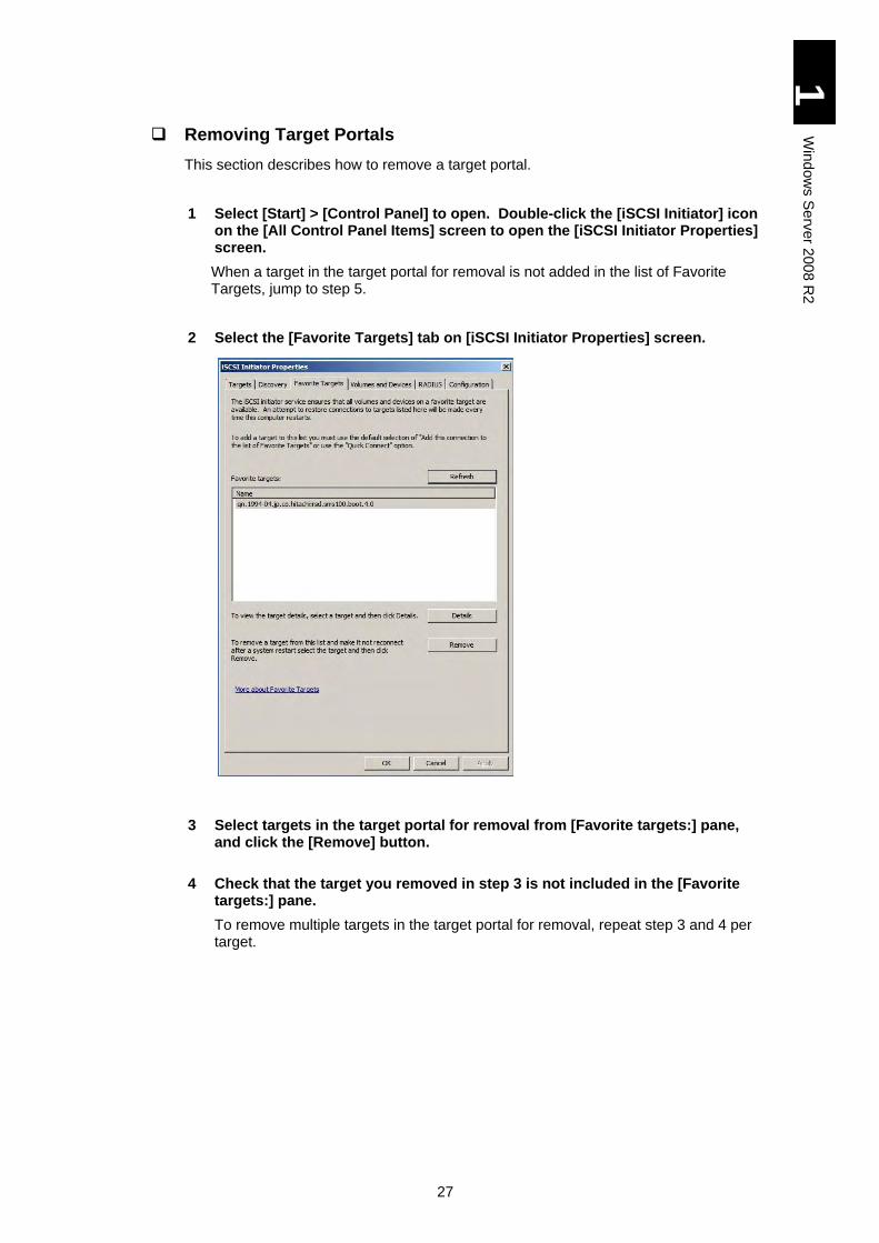
2 Select the [Favorite Targets] tab on [iSCSI Initiator Properties] screen.
3 Select targets in the target portal for removal from [Favorite targets:] pane, and click the [Remove] button.
4 Check that the target you removed in step 3 is not included in the [Favorite targets:] pane.
To remove multiple targets in the target portal for removal, repeat step 3 and 4 per target.
28
1
Win
dow
s S
erv
er 2
00
8 R
2
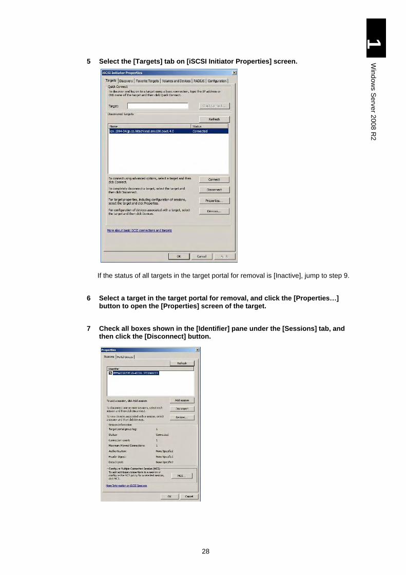
5 Select the [Targets] tab on [iSCSI Initiator Properties] screen.
If the status of all targets in the target portal for removal is [Inactive], jump to step 9.
6 Select a target in the target portal for removal, and click the [Properties…] button to open the [Properties] screen of the target.
7 Check all boxes shown in the [Identifier] pane under the [Sessions] tab, and then click the [Disconnect] button.
29
1
Win
dow
s S
erv
er 2
00
8 R
2
Processing may be interrupted by an error screen because the
target device is in use. If this occurs, re-execute the
processing in the state where the processes to the target
device, such as “write”, are completed.
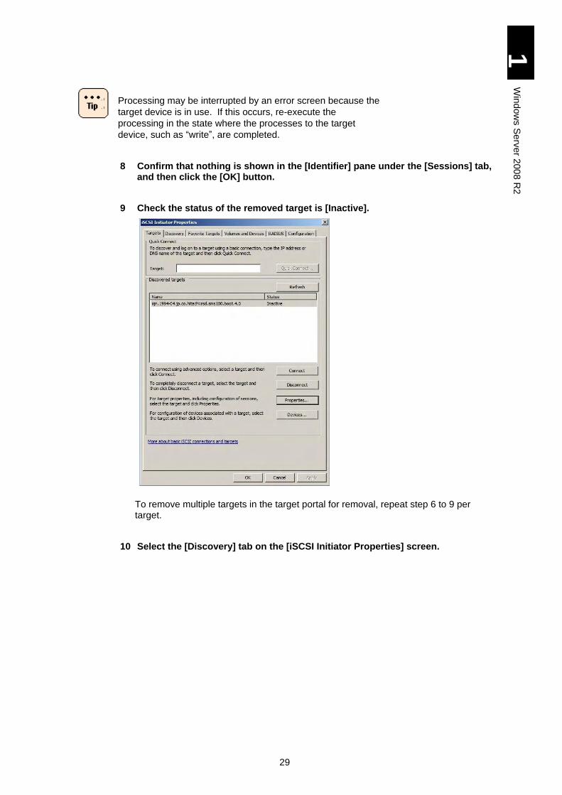
8 Confirm that nothing is shown in the [Identifier] pane under the [Sessions] tab, and then click the [OK] button.
9 Check the status of the removed target is [Inactive].
To remove multiple targets in the target portal for removal, repeat step 6 to 9 per target.
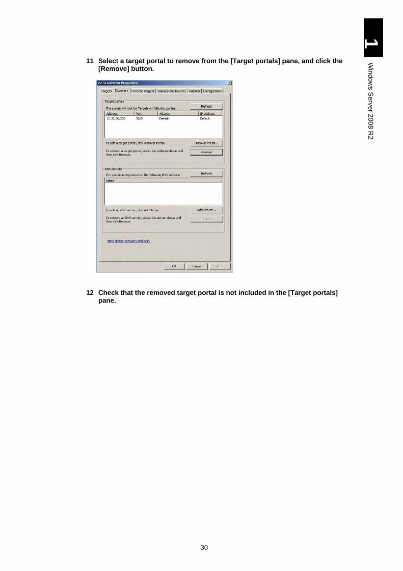
10 Select the [Discovery] tab on the [iSCSI Initiator Properties] screen.
30
1
Win
dow
s S
erv
er 2
00
8 R
2
11 Select a target portal to remove from the [Target portals] pane, and click the [Remove] button.
12 Check that the removed target portal is not included in the [Target portals] pane.
31
1
Win
dow
s S
erv
er 2
00
8 R
2
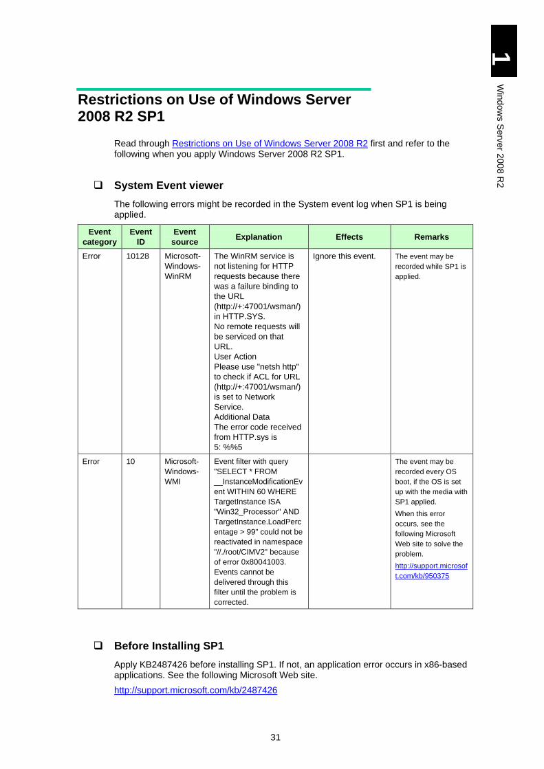
Restrictions on Use of Windows Server 2008 R2 SP1
Read through Restrictions on Use of Windows Server 2008 R2 first and refer to the following when you apply Windows Server 2008 R2 SP1.
System Event viewer
The following errors might be recorded in the System event log when SP1 is being applied.
Event
category
Event
ID
Event
source Explanation Effects Remarks
Error 10128 Microsoft-
Windows-
WinRM
The WinRM service is
not listening for HTTP
requests because there
was a failure binding to
the URL
(http://+:47001/wsman/)
in HTTP.SYS.
No remote requests will
be serviced on that
URL.
User Action
Please use "netsh http"
to check if ACL for URL
(http://+:47001/wsman/)
is set to Network
Service.
Additional Data
The error code received
from HTTP.sys is
5: %%5
Ignore this event. The event may be
recorded while SP1 is
applied.
Error 10 Microsoft-
Windows-
WMI
Event filter with query
"SELECT * FROM
__InstanceModificationEv
ent WITHIN 60 WHERE
TargetInstance ISA
"Win32_Processor" AND
TargetInstance.LoadPerc
entage > 99" could not be
reactivated in namespace
"//./root/CIMV2" because
of error 0x80041003.
Events cannot be
delivered through this
filter until the problem is
corrected.
The event may be
recorded every OS
boot, if the OS is set
up with the media with
SP1 applied.
When this error
occurs, see the
following Microsoft
Web site to solve the
problem.
http://support.microsof
t.com/kb/950375
Before Installing SP1
Apply KB2487426 before installing SP1. If not, an application error occurs in x86-based applications. See the following Microsoft Web site.
http://support.microsoft.com/kb/2487426
32
1
Win
dow
s S
erv
er 2
00
8 R
2
Windows Server 2008 R2 Setup
This section explains the setup for Windows Server 2008 R2.
For the installation procedure of the driver for expanded board, refer to the manual of expanded board.
NOTICE
Re-setup causes the hard disk data to disappear. Back up data that you need in advance.
When installing Windows, drivers, or utility, use the DriverKit
1x-xx. Ask your reseller for the latest version.
Using CD-ROMs with the incorrect version may cause the OS
not to operate properly.
Use the specified driver in the procedure. Otherwise, the
application does not work properly.
33
1
Win
dow
s S
erv
er 2
00
8 R
2
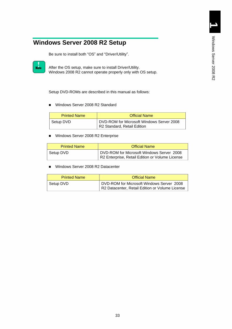
Windows Server 2008 R2 Setup
Be sure to install both “OS” and “Driver/Utility”.
After the OS setup, make sure to install Driver/Utility.
Windows 2008 R2 cannot operate properly only with OS setup.
Setup DVD-ROMs are described in this manual as follows:
Windows Server 2008 R2 Standard
Windows Server 2008 R2 Enterprise
Windows Server 2008 R2 Datacenter
Printed Name Official Name
Setup DVD DVD-ROM for Microsoft Windows Server 2008 R2 Standard, Retail Edition
Printed Name Official Name
Setup DVD DVD-ROM for Microsoft Windows Server 2008 R2 Enterprise, Retail Edition or Volume License
Printed Name Official Name
Setup DVD DVD-ROM for Microsoft Windows Server 2008 R2 Datacenter, Retail Edition or Volume License
34
1
Win
dow
s S
erv
er 2
00
8 R
2
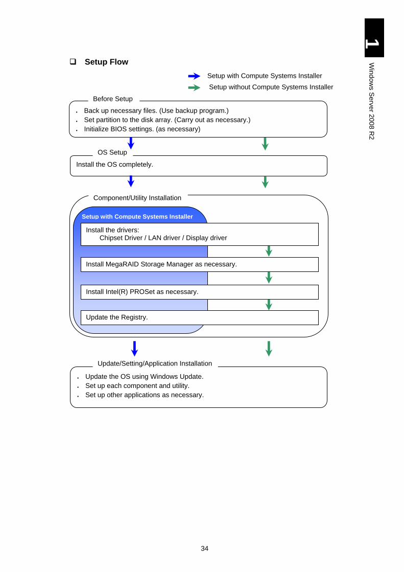
Setup Flow
Setup with Compute Systems Installer
Setup without Compute Systems Installer
Back up necessary files. (Use backup program.)
Set partition to the disk array. (Carry out as necessary.)
Initialize BIOS settings. (as necessary)
Before Setup
Install the OS completely.
OS Setup
Component/Utility Installation
Update the OS using Windows Update.
Set up each component and utility.
Set up other applications as necessary.
Update/Setting/Application Installation
Setup with Compute Systems Installer
Update the Registry.
Install the drivers: Chipset Driver / LAN driver / Display driver
Install MegaRAID Storage Manager as necessary.
Install Intel(R) PROSet as necessary.
35
1
Win
dow
s S
erv
er 2
00
8 R
2
Details of Windows Server 2008 R2 Setup
This section describes how to setup Windows Server 2008 R2.
Restrictions on Setup
At the setup, connect to the server blade using the remote console application. It is recommended that the CD-ROM/DVD-ROM drive should be connected to the USB port on the server blade front panel.
Remote FD of the remote-console application
When you use remote FD of the remote-console application, driver FD cannot be recognized on Windows setup.
Connect the USB FD drive to the USB port on the server blade front panel when you use FD. It is recommended for Windows 2008 R2 that drivers should be read from CD-ROM not from FD.
Capacity of a logical drive for installing the OS
Set the capacity of a logical drive for installing the OS to 2 TB or less. If with more then 2 TB, the OS can recognize just up to 2 TB.
Installing OS into the EXTERNAL DISK ARRAY DEVICE
Set 'one path' to the target LU before installing OS. If several paths set to the target LU, the installation fails. Generally use the management utility of the external disk array device for setting ‘one path’. Refer the external disk array device’s manual for the detail. Install multiple path software after the OS installation, and cancel the one-path setting.
When installing OS, allow the OS only to view the target LU for installation, not allow it to view any other LU than the target one temporarily. Check if you can mask the other LUs or remove them from the LU group temporarily in the external disk array device setting.
When you set up the OS while viewing multiple LUs, multiple disks for installation are displayed. Displayed disk numbers and the order are unstable and always change. Thus, set to block multiple disks from being displayed on the screen beforehand. When you set up the OS with multiple disks displayed, select the target disk by size, not by the disk number or the order.
If you select a wrong disk, the data will be lost. For details, refer to the following Microsoft Web site.
http://support.microsoft.com/kb/937251/en
Set the disk array device to use LUN0 as OS. And, confirm that 'Boot Priority' of the target LU is the first priority at System Boot menu. To display System Boot Menu, press the [F2] key immediately after booting the server blade.
Setting partition (drive)
Install the OS to the first partition of the disk for boot. All programs and data in the partition will be deleted.
Setting write cache
Confirm that the write cache of a disk to in which Windows 2008 R2 is installed is in the write through mode before the setup. If it is in the write back mode, change it to the write through mode. Refer to MegaRAID Storage Manager Instruction Manual for how to change the write mode.
36
1
Win
dow
s S
erv
er 2
00
8 R
2
Refer to the following folder in DriverKit CD-ROM for MegaRAID Storage Manager Instruction Manuals. d: is the CD/DVD drive name.
d:\MANUAL\MSManager2.pdf
[Driver Kit version 05-04 or later] d:\X51x5\MANUAL\MSManager2.pdf
DVD drive
Windows Server 2008 R2 setup requires a DVD-ROM drive (hereinafter referred to as DVD drive).
DVD-ROM ejection
Press the eject button of the DVD drive only when changing DVD-ROM media. Otherwise, the OS setup must be reinstalled.
With multiple disks and partitions (drives)
When multiple disks and partitions (drives) are installed in the system equipment, multiple disks are displayed as the target for installation. The number of a disk and the order of disks, however, are not fixed. When performing the setup with multiple disks viewed, determine the target disk for installation by its size not by the order or its number.
This is why we recommend that you should configure different capacity, per drive, of disk arrays and hard disks installed in the system.
In case that you select a wrong disk or partition as the target, existent partitions, or existent data could be removed. For further details, refer to the following Microsoft website.
http://support.microsoft.com/kb/937251
You can find disk capacity in “MegaRAID WebBIOS” or system BIOS. For details, refer to Chapter 5 “Server Blade Setup” in User’s Guide.
When installing the OS in an external disk array device connected via iSCSI
Settings such as iSCSI BIOS Setup Utility are required before Windows 2008 R2 is installed in an external disk array device connected via iSCSI. Configure those settings referring to User’s Guide.
Set up the OS with the secondary path Disabled (Boot: Disable), not Enabled (Boot: SECONDARY) with iSCSI BIOS Setup Utility. Refer to Multipath I/O (MPIO) with OS in the External Disk Array via iSCSI to enable the secondary path (Boot: SECONDARY). Make sure to perform the setup following the procedure described in this manual since there are some other restrictions to install the OS in an external disk array device connected via iSCSI. If not, STOP error may occur.
37
1
Win
dow
s S
erv
er 2
00
8 R
2
Setup Steps
NOTICE
Re-setup causes the hard disk data to disappear. Back up data that you need in advance.
When an external disk array device or SCSI device is
connected, turn off the device power before starting the setup.
Otherwise, the installing destination may not be recognized
correctly.
1 Turn on the system equipment, and quickly insert the Setup DVD to the
DVD drive.
2 If a message "Press any key to boot from CD or DVD" appears, press any
key without giving a pause.
When pressing the key late, the existing OS starts instead of
the CD-ROM. In that case, go back to step 1.
When pressing the key more than once, [Windows Boot
Manager] may start. In that case, select Windows Setup [EMS
Enabled] and continue the setup.
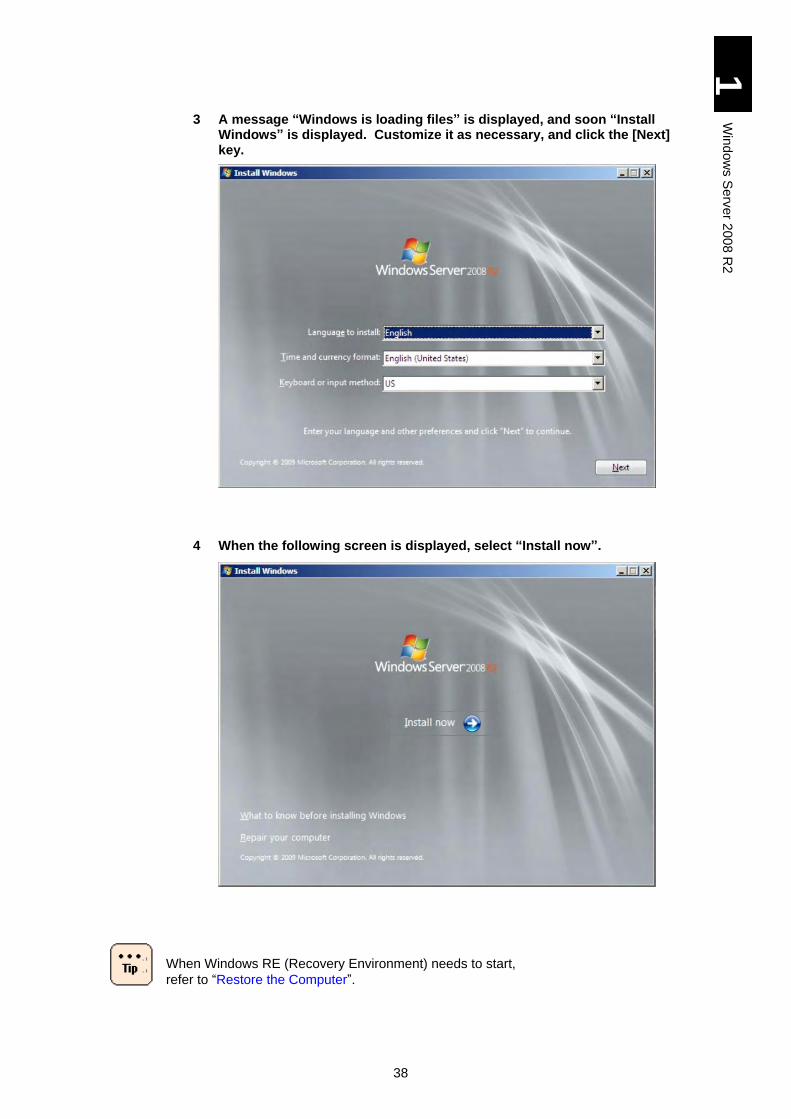
38
1
Win
dow
s S
erv
er 2
00
8 R
2
3 A message “Windows is loading files” is displayed, and soon “Install Windows” is displayed. Customize it as necessary, and click the [Next] key.
4 When the following screen is displayed, select “Install now”.
When Windows RE (Recovery Environment) needs to start,
refer to “Restore the Computer”.
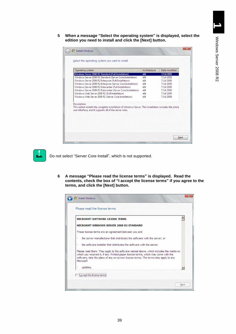
39
1
Win
dow
s S
erv
er 2
00
8 R
2
5 When a message “Select the operating system” is displayed, select the edition you need to install and click the [Next] button.
Do not select “Server Core Install”, which is not supported.
6 A message “Please read the license terms” is displayed. Read the contents, check the box of “I accept the license terms” if you agree to the terms, and click the [Next] button.
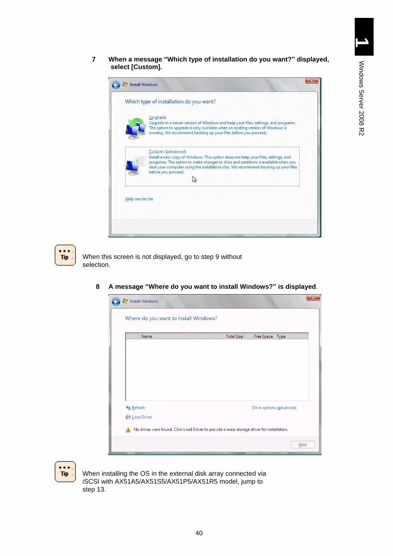
40
1
Win
dow
s S
erv
er 2
00
8 R
2
7 When a message “Which type of installation do you want?” displayed, select [Custom].
When this screen is not displayed, go to step 9 without
selection.
8 A message “Where do you want to install Windows?” is displayed.
When installing the OS in the external disk array connected via
iSCSI with AX51A5/AX51S5/AX51P5/AX51R5 model, jump to
step 13.
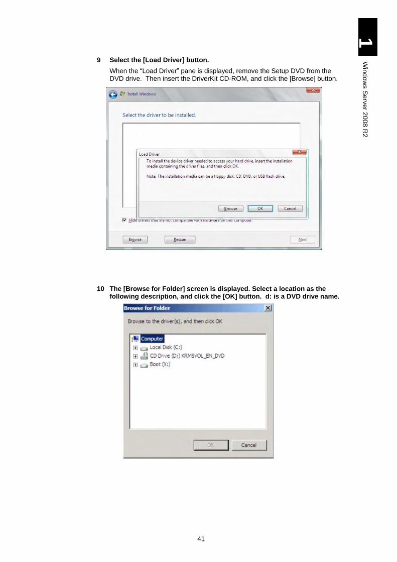
41
1
Win
dow
s S
erv
er 2
00
8 R
2
9 Select the [Load Driver] button.
When the “Load Driver” pane is displayed, remove the Setup DVD from the DVD drive. Then insert the DriverKit CD-ROM, and click the [Browse] button.
10 The [Browse for Folder] screen is displayed. Select a location as the following description, and click the [OK] button. d: is a DVD drive name.
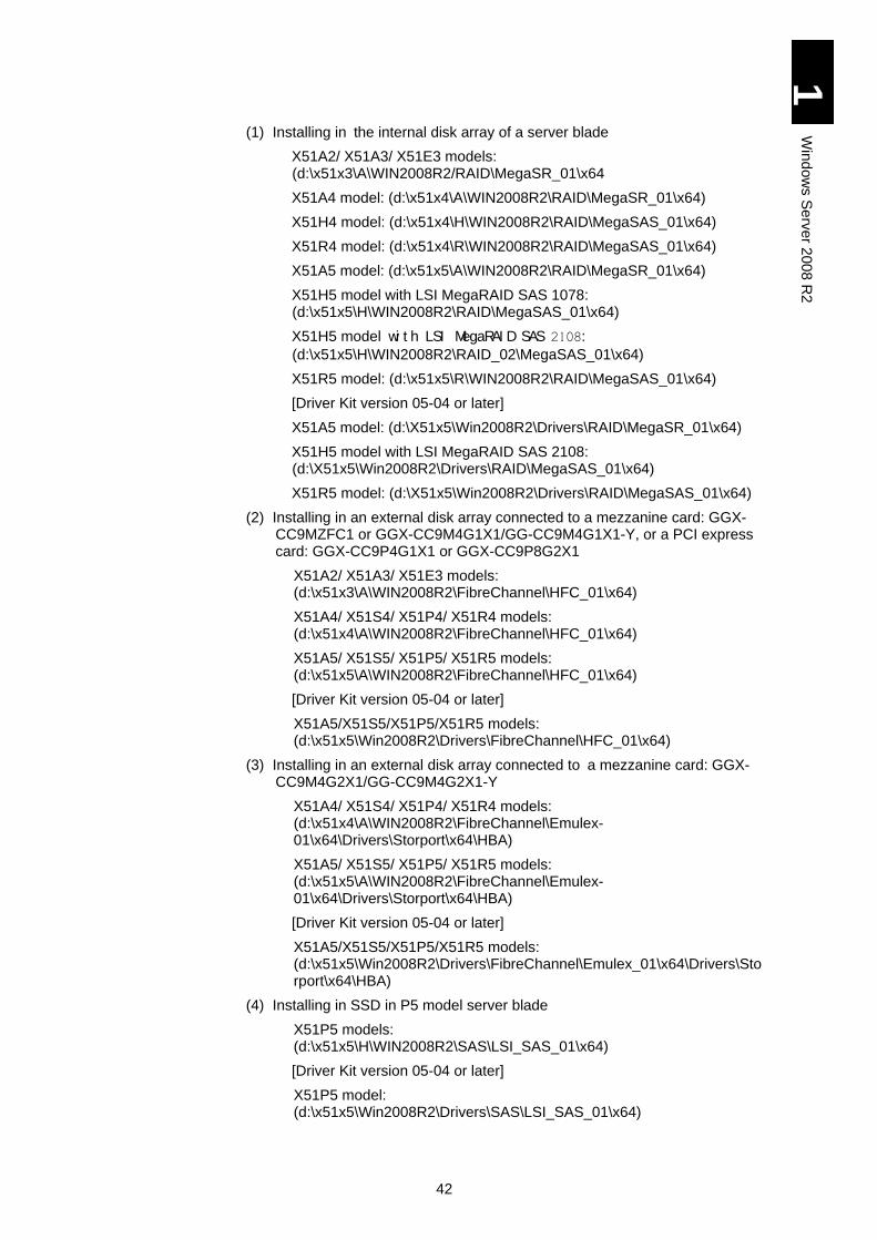
42
1
Win
dow
s S
erv
er 2
00
8 R
2
(1) Installing in the internal disk array of a server blade
X51A2/ X51A3/ X51E3 models: (d:\x51x3\A\WIN2008R2/RAID\MegaSR_01\x64
X51A4 model: (d:\x51x4\A\WIN2008R2\RAID\MegaSR_01\x64)
X51H4 model: (d:\x51x4\H\WIN2008R2\RAID\MegaSAS_01\x64)
X51R4 model: (d:\x51x4\R\WIN2008R2\RAID\MegaSAS_01\x64)
X51A5 model: (d:\x51x5\A\WIN2008R2\RAID\MegaSR_01\x64)
X51H5 model with LSI MegaRAID SAS 1078: (d:\x51x5\H\WIN2008R2\RAID\MegaSAS_01\x64)
X51H5 model wi t h LSI MegaRAI D SAS 2108: (d:\x51x5\H\WIN2008R2\RAID_02\MegaSAS_01\x64)
X51R5 model: (d:\x51x5\R\WIN2008R2\RAID\MegaSAS_01\x64)
[Driver Kit version 05-04 or later]
X51A5 model: (d:\X51x5\Win2008R2\Drivers\RAID\MegaSR_01\x64)
X51H5 model with LSI MegaRAID SAS 2108: (d:\X51x5\Win2008R2\Drivers\RAID\MegaSAS_01\x64)
X51R5 model: (d:\X51x5\Win2008R2\Drivers\RAID\MegaSAS_01\x64)
(2) Installing in an external disk array connected to a mezzanine card: GGX-CC9MZFC1 or GGX-CC9M4G1X1/GG-CC9M4G1X1-Y, or a PCI express card: GGX-CC9P4G1X1 or GGX-CC9P8G2X1
X51A2/ X51A3/ X51E3 models: (d:\x51x3\A\WIN2008R2\FibreChannel\HFC_01\x64)
X51A4/ X51S4/ X51P4/ X51R4 models: (d:\x51x4\A\WIN2008R2\FibreChannel\HFC_01\x64)
X51A5/ X51S5/ X51P5/ X51R5 models: (d:\x51x5\A\WIN2008R2\FibreChannel\HFC_01\x64)
[Driver Kit version 05-04 or later]
X51A5/X51S5/X51P5/X51R5 models: (d:\x51x5\Win2008R2\Drivers\FibreChannel\HFC_01\x64)
(3) Installing in an external disk array connected to a mezzanine card: GGX-CC9M4G2X1/GG-CC9M4G2X1-Y
X51A4/ X51S4/ X51P4/ X51R4 models: (d:\x51x4\A\WIN2008R2\FibreChannel\Emulex-01\x64\Drivers\Storport\x64\HBA)
X51A5/ X51S5/ X51P5/ X51R5 models: (d:\x51x5\A\WIN2008R2\FibreChannel\Emulex-01\x64\Drivers\Storport\x64\HBA)
[Driver Kit version 05-04 or later]
X51A5/X51S5/X51P5/X51R5 models: (d:\x51x5\Win2008R2\Drivers\FibreChannel\Emulex_01\x64\Drivers\Storport\x64\HBA)
(4) Installing in SSD in P5 model server blade
X51P5 models: (d:\x51x5\H\WIN2008R2\SAS\LSI_SAS_01\x64)
[Driver Kit version 05-04 or later]
X51P5 model: (d:\x51x5\Win2008R2\Drivers\SAS\LSI_SAS_01\x64)
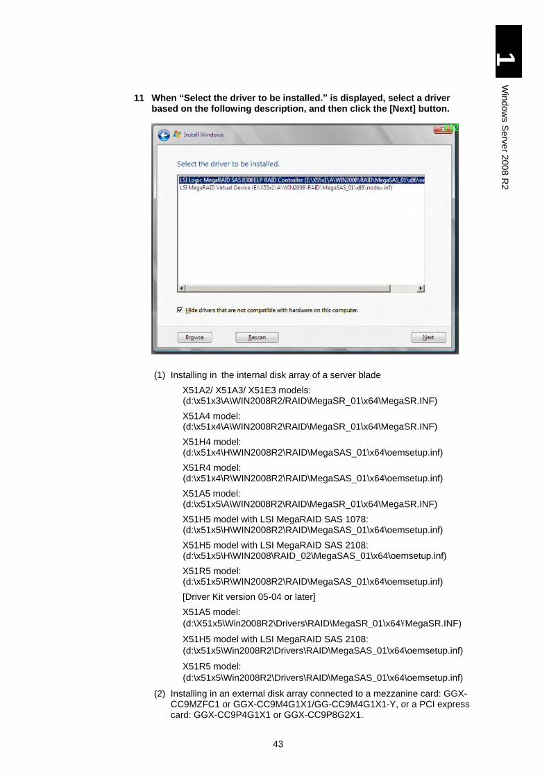
43
1
Win
dow
s S
erv
er 2
00
8 R
2
11 When “Select the driver to be installed.” is displayed, select a driver based on the following description, and then click the [Next] button.
(1) Installing in the internal disk array of a server blade
X51A2/ X51A3/ X51E3 models: (d:\x51x3\A\WIN2008R2/RAID\MegaSR_01\x64\MegaSR.INF)
X51A4 model: (d:\x51x4\A\WIN2008R2\RAID\MegaSR_01\x64\MegaSR.INF)
X51H4 model: (d:\x51x4\H\WIN2008R2\RAID\MegaSAS_01\x64\oemsetup.inf)
X51R4 model: (d:\x51x4\R\WIN2008R2\RAID\MegaSAS_01\x64\oemsetup.inf)
X51A5 model: (d:\x51x5\A\WIN2008R2\RAID\MegaSR_01\x64\MegaSR.INF)
X51H5 model with LSI MegaRAID SAS 1078: (d:\x51x5\H\WIN2008R2\RAID\MegaSAS_01\x64\oemsetup.inf)
X51H5 model with LSI MegaRAID SAS 2108: (d:\x51x5\H\WIN2008\RAID_02\MegaSAS_01\x64\oemsetup.inf)
X51R5 model: (d:\x51x5\R\WIN2008R2\RAID\MegaSAS_01\x64\oemsetup.inf)
[Driver Kit version 05-04 or later]
X51A5 model:
(d:\X51x5\Win2008R2\Drivers\RAID\MegaSR_01\x64\MegaSR.INF)
X51H5 model with LSI MegaRAID SAS 2108:
(d:\x51x5\Win2008R2\Drivers\RAID\MegaSAS_01\x64\oemsetup.inf)
X51R5 model:
(d:\x51x5\Win2008R2\Drivers\RAID\MegaSAS_01\x64\oemsetup.inf)
(2) Installing in an external disk array connected to a mezzanine card: GGX-CC9MZFC1 or GGX-CC9M4G1X1/GG-CC9M4G1X1-Y, or a PCI express card: GGX-CC9P4G1X1 or GGX-CC9P8G2X1.
44
1
Win
dow
s S
erv
er 2
00
8 R
2
X51A2/ X51A3 X51/E3 models: (d:\x51x3\A\WIN2008R2\FibreChannel\HFC_01\x64\hfcwdd.inf)
X51A4/ X51S4/ X51P4/ X51R4 models: (d:\x51x4\A\WIN2008R2\FibreChannel\HFC_01\x64\hfcwdd.inf)
X51A5/ X51S5/ X51P5/ X51R5 models: (d:\x51x5\A\WIN2008R2\FibreChannel\HFC_01\x64\hfcwdd.inf)
[Driver Kit version 05-04 or later]
X51A5/X51S5/X51P5/X51R5 models: (d:\X51x5\Win2008R2\Drivers\FibreChannel\HFC_01\x64\hfcwdd.inf)
(3) Installing in an external disk array connected to a mezzanine card: GGX-CC9M4G2X1/GG-CC9M4G2X1-Y
X51A4/ X51S4/ X51P4/ X51R4 models: (d:\x51x4\A\WIN2008R2\FibreChannel\Emulex-01\x64\Drivers\Storport\x64\HBA)
X51A5/ X51S5/ X51P5/ X51R5 models: (d:\x51x5\A\WIN2008R2\FibreChannel\Emulex-01\x64\Drivers\Storport\x64\HBA)
[Driver Kit version 05-04 or later]
X51A5/X51S5/X51P5/X51R5 models: (d:\x51x5\Win2008R2\Drivers\FibreChannel\Emulex_01\x64\Drivers\Storport\x64\HBA\oemsetup.inf)
(4) Installing in SSD in P5 model server blade
X51P5 models: (d:\x51x5\H\WIN2008R2\SAS\LSI_SAS_01\x64\lsi_sas.inf)
[Driver Kit version 05-04 or later]
X51P5 model: (d:\x51x5\Win2008R2\Drivers\SAS\LSI_SAS_01\x64\lsi_sas.inf)
12 A message “Where do you want to install Windows?” is displayed. Remove the DriverKit CD-ROM from the DVD drive, insert the Setup DVD, and click [Refresh].
There may be some same location names. If you select the location, select any one out of them.
If you do not change media, a message “Unable to install Windows in the disk” is displayed on the bottom of the screen. Then you cannot continue the setup.
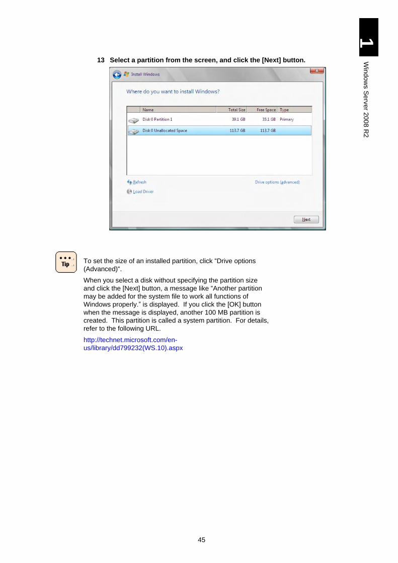
45
1
Win
dow
s S
erv
er 2
00
8 R
2
13 Select a partition from the screen, and click the [Next] button.
To set the size of an installed partition, click “Drive options
(Advanced)“.
When you select a disk without specifying the partition size
and click the [Next] button, a message like “Another partition
may be added for the system file to work all functions of
Windows properly.” is displayed. If you click the [OK] button
when the message is displayed, another 100 MB partition is
created. This partition is called a system partition. For details,
refer to the following URL.
http://technet.microsoft.com/en-
us/library/dd799232(WS.10).aspx
46
1
Win
dow
s S
erv
er 2
00
8 R
2
When multiple disks are displayed, the order of them and the number of each are not always the same. Select the target disk for installation by size not by the order or the disk number. The other way to select the target disk is to set the disk device to view the target disk only beforehand. Refer to Restrictions on Setup in advance. If you select a wrong disk or partition, the existent partition (data) may be removed. For details, refer to the following Web site.
http://support.microsoft.com/kb/937251
You can find disk capacity in “MegaRAID WebBIOS” or
system BIOS. For details, refer to Chapter 5 “Server Blade
Setup” in User’s Guide.
If there are some disks with the same size, follow the steps
below to find out a target disk.
1. Press and hold the [Shift] key and press [F10] to
display the command prompt.
2. Type the following command in the command line to
start “diskpart”.
>diskpart
3. Perform the following command in “diskpart”.
>selectdisk=system
(*) stands for a blank space.
A message like “Diskn is selected.” is displayed.
4. Install the OS in an appropriate partition in the “diskn”
displayed in step 3.
The [Delete] button cannot be used to a partition in the dynamic disk. Refer to the following URL for the details.
http://support.microsoft.com/kb/926190
When you use [Drive Option] to create a partition, installing the OS in the 10GB partition may fail. Therefore, we strongly recommend that a partition with 400 GB or over should be created for OS installation.
If you select a wrong disk or partition, the existent partition (data) may be removed.
When the target disk has not partition 1, “Unallocated Space”
is displayed as Name.
On the target disk, select [Drive Option] > [New] and create a
partition for OS installation.
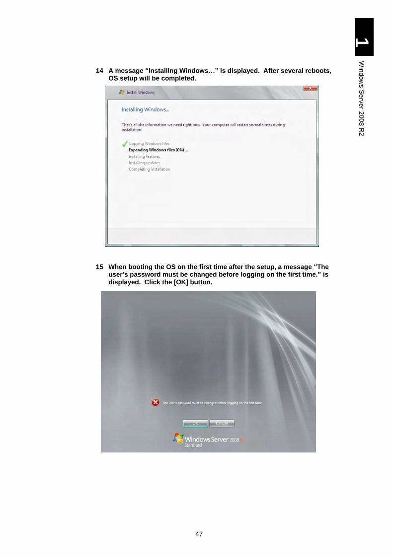
47
1
Win
dow
s S
erv
er 2
00
8 R
2
14 A message “Installing Windows…” is displayed. After several reboots, OS setup will be completed.
15 When booting the OS on the first time after the setup, a message “The user’s password must be changed before logging on the first time.” is displayed. Click the [OK] button.
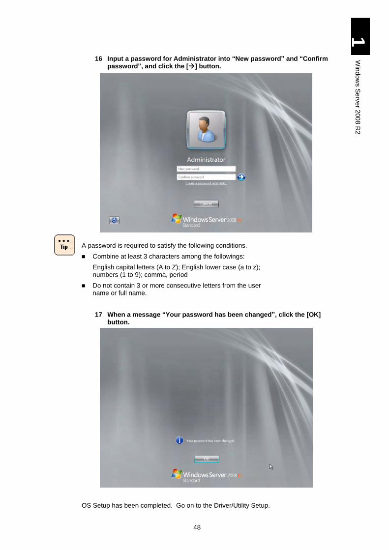
48
1
Win
dow
s S
erv
er 2
00
8 R
2
16 Input a password for Administrator into “New password” and “Confirm password”, and click the [] button.
A password is required to satisfy the following conditions.
Combine at least 3 characters among the followings:
English capital letters (A to Z); English lower case (a to z); numbers (1 to 9); comma, period
Do not contain 3 or more consecutive letters from the user name or full name.
17 When a message “Your password has been changed”, click the [OK] button.
OS Setup has been completed. Go on to the Driver/Utility Setup.
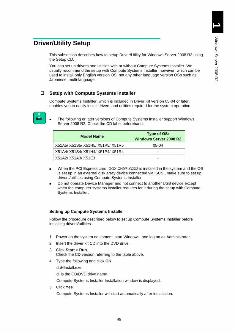
49
1
Win
dow
s S
erv
er 2
00
8 R
2
Driver/Utility Setup
This subsection describes how to setup Driver/Utility for Windows Server 2008 R2 using the Setup CD.
You can set up drivers and utilities with or without Compute Systems Installer. We usually recommend the setup with Compute Systems Installer, however, which can be used to install only English version OS, not any other language version OSs such as Japanese, multi-language.
Setup with Compute Systems Installer
Compute Systems Installer, which is included in Driver Kit version 05-04 or later, enables you to easily install drivers and utilities required for the system operation.
The following or later versions of Compute Systems Installer support Windows Server 2008 R2. Check the CD label beforehand.
When the PCI Express card: GGX-CN9P1G2X2 is installed in the system and the OS is set up in an external disk array device connected via iSCSI, make sure to set up drivers/utilities using Compute Systems Installer.
Do not operate Device Manager and not connect to another USB device except when the computer systems installer requires for it during the setup with Compute Systems Installer.
Setting up Compute Systems Installer
Follow the procedure described below to set up Compute Systems Installer before installing drivers/utilities.
1 Power on the system equipment, start Windows, and log on as Administrator.
2 Insert the driver kit CD into the DVD drive.
3 Click Start > Run. Check the CD version referring to the table above.
4 Type the following and click OK.
d:\HInstall.exe
d: is the CD/DVD drive name.
Compute Systems Installer Installation window is displayed.
5 Click Yes.
Compute Systems Installer will start automatically after installation.
Model Name Type of OS:
Windows Server 2008 R2
X51A5/ X51S5/ X51H5/ X51P5/ X51R5 05-04
X51A4/ X51S4/ X51H4/ X51P4/ X51R4 -
X51A2/ X51A3/ X51E3 -

50
1
Win
dow
s S
erv
er 2
00
8 R
2
Setting up Drivers/Utilities
Set up drivers and utilities with Compute Systems Installer.
When you have installed Compute Systems Installer in Setting up Compute Systems Installer, Compute Systems Installer will start automatically. If so, jump to step 3.
When you start Compute Systems Installer with the Found
New Hardware dialog box open, the installer may not proceed.
If so, click Cancel in the dialog box to remove it.
1 Click Start > Run.
2 Type the following and click OK.
c:\Hitachi\S-INST\SysInst2-exe
c: is the system drive name.
Compute Systems Installer Installation window is displayed.
3 Click OK.
A window will be displayed, where you can select which component to install.
4 When installing all components, click default installation. When selecting components to install, click Custom installation, select components following the directions in the window, and click Next.
We usually recommend the Default installation.
5 Click Next.
Preparation for installation will start.
Then, follow the instructions on the windows to proceed. You may have to change CDs during installation.
A setup completion window will be displayed at the end. When reboot is required, go on to step 6; when reboot is not required, jump to step 9.
You may be asked to type something at setting up utilities. See
the manual of each utility for the details about setup
procedures. See How to Use Supplied Software for the
location of each manual.
6 Check Reboot Now. and remove the CD from the drive.
7 Click OK.
The server blade will be rebooted.
8 Log on as Administrator after reboot.
Compute Systems Installer automatically reboots to continue processing. Repeat step 5 to step 8 as necessary.
9 Click Done. If you want to remove Compute systems Installer, jump to “Removing Compute Systems Installer” without clicking Done.
Compute Systems Installer will be finished.
51
1
Win
dow
s S
erv
er 2
00
8 R
2
Removing Compute Systems Installer
When drivers and utilities have been set up, remove Compute Systems Installer. Reboot is required for removing Compute Systems Installer.
1 In the finish window for Compute Systems Installer, check Never launch the program on startup and then check Uninstall this program.
Compute Systems Installer Deletion window is displayed.
2 Click Yes.
3 Click Done.
Compute Systems Installer will be removed.
Checking Driver Updates
With some adapters or devices, their drivers may not be installed with Compute Systems Installer. The latest drivers can be available in attached CDs or can be downloaded from Web sites. Apply the latest drivers referring to the manual of your adapters.
When applying the new driver, Compute Systems Installer may
not recognize the driver installation status correctly. If you
update the driver manually, remove Compute Systems Installer
in advance.
Applying Patches
Apply Windows update patches such as the security patch as necessary. Some server blades and adapters may have prerequisite patches. Visit each Web site or contact your reseller for patches recommended to apply.
52
1
Win
dow
s S
erv
er 2
00
8 R
2
Setup without Compute Systems Installer
When setting up driver/utility without Compute Systems Installer, make sure to install the following drivers, utilities, and registry update respectively.
When the LAN mezzanine card: GGX-CN9M1G2X1/GG-
CN9M1G2X1-Y is installed in the system and the OS is set up in
an external disk array device connected via iSCSI, setup
without Compute systems Installer is not available. Make sure
to perform the setup using Compute Systems Installer.
Log in as the local account “Administrator” to perform the
following setup.
Registry Update (1)
Start iSCSI Initiator service (Only with OS installed in an external disk array device connected via iSCSI)
Driver
Display driver
Setting name for RAID virtual device (X51H4/ X51R4/ X51H5/ X51R5 models)
Front-panel SAS port driver (X51H4/ X51H5 models)
Chipset driver
LAN driver
Utility
MegaRAID Storage Manager (X51A4/ X51H4/ X51R4/ X51A5/ X51H5/ X51R5 models)
Intel(R) PROSet
ServerConductor
Driver for mezzanine cards/Utility
Registry Update (2)
Windows Recovery Environment (RE)
Change Dump settings (Only with OS installed in an external disk array device connected via iSCSI)
Update Information Check
Check information on driver update
Apply patch files
53
1
Win
dow
s S
erv
er 2
00
8 R
2
Registry Update (1)
Insert the “Driver kit” CD-ROM into the CD/DVD drive, and execute the following steps.
d represents the drive name of CD/DVD.
Set dumps to be collected when NMI is issued.
1 Click the [Start] button, and select [Run…].
2 Input the following, and click the [OK] button.
d:\UTILITY\DUMP\NMID.BAT
[Driver Kit version 05-04 or later]
d:\X51x5\Win2008\Tools\NMIDump\NMID.bat
Set the PCI driver.
1 Click the [Start] button, and select [Run…].
2 Input the following, and click the [OK] button.
d:\UTILITY\PCI\WIN2008\avoidD3.bat
[Driver Kit version 05-04 or later]
d:\X51x5\Win2008\Tools\avoidD3\avoidD3.bat
To enable these items, reboot the OS after applying batches.
Start iSCSI Initiator service (Only with OS installed in an external disk array device connected via iSCSI)
Follow the steps below to start the iSCSI initiator service.
1 Power on the server blade, boot Windows, log on as Administrator.
2 Click [Start] > [Administrative Tools] > [iSCSI Initiator].
3 When the [Microsoft iSCSI] dialog box is displayed, click [Yes].
4 When [iSCSI Initiator Properties] is displayed, click [OK].
54
1
Win
dow
s S
erv
er 2
00
8 R
2
Display driver
Install the Display driver using the following procedure.
For X51A4/ X51S4/ X51H4/ X51P4/ X51R4/ X51A5/ X51S5/ X51H5/ X51P5/ X51R5 models
1 Turn on the power of system equipment, boot Windows, and log on as "Administrator".
2 Insert the “Driver kit” CD-ROM into the CD/DVD drive.
3 Click the [Start] button, and select [Run…].
4 Input the followings, and click the [OK] button.
d:\x51x4\A\WIN2008R2\SVGA\XGI_01\Setup.exe
d:\x51x5\A\WIN2008R2\SVGA\XGI_01\Setup.exe
d: is the DVD driver name.
[Driver Kit version 05-04 or later]
d:\X51x5\Win2008R2\Drivers\SVGA\XGI_01\Setup.exe
5 Complete the installation following the instructions in the screen. Remove the CD-ROM from the drive, and reboot the server blade.
6 Change the resolution to a value that you like within the range of your display specifications.
For X51A2/X51A3/X51E3 models
1 Power on the server blade to boot Windows, and log on as Administrator.
2 Insert the DriverKit CD-ROM into the DVD drive.
3 Click the [Start] button and then select [Server Manager]. [Server Manager] will appear.
4 Select [Diagnostics] and then [Device Manager].
5 Open the [Display adapters] tree.
6 Right-click [Standard VGA Graphics Adapter], and select [Update Driver Software…].
7 Select [Browse my computer for driver software].
8 Enter the following directory, and check [Include subfolders].
d:\x51x3\A\WIN2008R2\SVGA\ATI-01/Driver
9 When [Windows has successfully updated your driver software] is displayed, click [Close]. A dialog box [system Settings Change] will appear.
10 Remove the CD-ROM from the drive, and click [Yes].
11 Change the resolution to a value that you like within the range of your display specifications.
Setting Name for RAID Virtual Device (X51H4/X51R4/X51H5/X51R5 models)
When the OS has been installed in the internal disk array of server blade model X51H4 or X51R4, apply “inf” file following steps shown below to set a name to the RAID virtual device.
1 Power on the server blade to boot Windows, and log on as Administrator.
2 Insert the DriverKit CD-ROM into the DVD drive.

55
1
Win
dow
s S
erv
er 2
00
8 R
2
3 Click [Start] > [Administrative Tools] and then select [Server Manager]. [Server Manager] will appear.
4 Select [Diagnostics] and then [Device Manager].
5 Open the [System Devices] tree.
6 Select the following name, and right-click it, and select [Update Driver Software].
X51H4/X51R4/X51H5/X51R5 models: LSI RAID Virtual Device
[Update Driver Software] wizard will appear.
7 Select [Browse my computer for driver software].
8 Select [Let me pick from a list of device drivers on my computer].
9 Click the [Have Disk] button. Type the following into the [Copy manufacturer’s files from:] field, and then click the [OK] button.
X51H4 model: d:\x51x4\H\WIN2008R2\RAID\ MegaSAS_01\x64
X51R4 model: d:\x51x4\R\WIN2008R2\RAID\ MegaSAS_01\x64
X51H5 model with LSI MegaRAID SAS 1078:
d:\x51x5\H\WIN2008R2\RAID\ MegaSAS_01\x64
X51H5 model with LSI MegaRAID SAS 2108: d:\X51x5\H\WIN2008R2\RAID_02\MegaSAS_01\x64
X51R5 model: d:\x51x5\R\WIN2008R2\RAID\ MegaSAS_01\x64
[Driver Kit version 05-04 or later]
X51R5/X51H5 model with LSI MegaRAID SAS 2108
d:\X51x5\Win2008R2\Drivers\RAID\MegaSAS_01\x64
d: is the DVD driver name.
10 When the screen returns to [Update Driver Software] Wizard, click the [Next] button.
11 Confirm “Windows has successfully updated your driver software.” is displayed, and then click the [Close] button.
Front-panel SAS Port Driver (X51H4/ X51H5 models)
With X51H4/X51H5 sever blade model, install the SAS driver following the steps below.
1 Power on the server blade to boot Windows, and log on as Administrator.
2 Insert the DriverKit, into the DVD drive.
3 Click [Start] > [Administrative Tools] and then select [Server Manager]. [Server Manager] will appear.
4 Select [Diagnostics] and then [Device Manager].
5 Open the [Storage Controller] tree.
6 Select the following name, and right-click it, and select [Update Driver Software].
LSI Adapter, SAS 3000 series, 4-port with 1064E
[Update Driver Software] wizard will appear.
7 Select [Browse my computer for driver software].
8 Select [Browse for driver software on your computer].
X51H4 model: d:\x51x4\H\WIN2008R2\SAS\LSI_SAS_01\x64
X51H5 model: d:\x51x5\H\WIN2008R2\SAS\LSI_SAS_01\x64
[Driver Kit version 05-04 or later]
56
1
Win
dow
s S
erv
er 2
00
8 R
2
X51H5 model with LSI MegaRAID SAS 2108: d:\X51x5\Win2008R2\Drivers\SAS\LSI_SAS_01\x64
d: is the DVD driver name.
9 Confirm “Windows has successfully updated your driver software.” is displayed, and then click the [Close] button.
Chipset Driver
Install the chipset driver following the steps below:
1 Power on the server blade, boot Windows, and log on with Administrator.
2 Insert the DriverKit CD-ROM into the DVD drive.
3 Click the [Start] button and then select [Run…].
4 Input the following, and click the [OK] button.
X51A2/ X51A3/ X51E3 models: d:\X51x3\A\WIN2008R2\Chipset\INTEL_01\infinst_autol.exe
X51A4/ X51S4/ X51H4/ X51P4/ X51R4 models: d:\X51x4\A\WIN2008R2\Chipset\INTEL_01\infinst_autol.exe (d: is the DVD drive name.)
X51A5/ X51S5/ X51H5/ X51P5/ X51R5 models: d:\X51x5\A\WIN2008R2\Chipset\INTEL_01\infinst_autol.exe (d: is the DVD drive name.)
[Driver Kit version 05-04 or later]
X51A5/X51S5/X51H5/X51P5/X51R5 models: d:\X51x5\WIN2008R2\Drivers\Chipset\INTEL_01\infinst_autol.exe
The Setup screen is displayed.
5 Click the [Next] button.
“License Agreement Terms“ is displayed.
6 Read the license agreement, and then click the [Yes] button if you agree.
Install the chipset driver following the instructions in screens.
“Setup completed” is displayed in the end.
7 Select “Yes, I want to restart this computer now”, click the [Finish] button, and quickly remove the CD-ROM from the drive.
The server blade will be rebooted.
LAN Driver
Install LAN driver using the following procedure.
1 Power on the server blade to boot Windows, and log on as Administrator.
2 Insert the DriverKit CD-ROM into the DVD drive.
3 Click [Start] > [Administrative Tools] and then select [Server Manager]. [Server Manager] will appear.
4 Select [Diagnostics] and then [Device Manager].
5 Right-click the network adapter of which driver has not been updated and click [Update Driver Software].
57
1
Win
dow
s S
erv
er 2
00
8 R
2
When 10Gbps LAN adapter is installed:
Right-click the Ethernet controller under the Other Devices tree
the driver of which has not been updated, and click [Update
Driver].
[Update Wizard] appears.
6 Select [Browse my computer for driver software].
7 Select [Browse for driver software on your computer], and then click [Next].
When 10Gbps LAN is installed:
A 10Gbps LAN PCI express card requires a different driver
from that for other LAN devices.
If you attempt to install a driver, a message, “Windows was
unable to install your Ethernet Controller.” may be displayed,
which shows that the driver is incorrect. When the message is
displayed, install the right driver for the device.
(1) Driver for CN9PXG1X1: 10Gbps 2-port LAN PCI express card
d:\x51x5\P\WIN2008R2\LAN\INTELXG_01\x64
[Driver Kit version 05-04 or later]
d:\x51x5\Win2008R2\Drivers\LAN\INTELXG_01\x64
d: is the DVD driver name.
(2) Driver for LAN devices other than (1) CN9PXG1X1
X51A2/ X51A3/ X51E3 models: d:\x51x3\A\WIN2008R2\LAN\INTEL_01\x64
X51A4/ X51S4/ X51H4/ X51P4/ X51R4 models: d:\x51x4\A\WIN2008R2\LAN\INTEL_01\x64
X51A5/ X51S5/ X51H5/ X51P5/ X51R5 models: d:\x51x5\A\WIN2008R2\LAN\INTEL_01\x64
[Driver Kit version 05-04 or later]
X51A5/X51S5/X51H5/X51P5/X51R5 models: d:\X51x5\Win2008R2\Drivers\LAN\INTEL_01\x64
d: is the DVD driver name.
8 Confirm “Windows has successfully updated your driver software.” is displayed, and then click the [Close] button
9 Right-click the network adapter of which driver has been updated and click [Uninstall]. When [You are about to uninstall this device from your system.] is displayed, click the [OK] button.
Do not [Uninstall] a network adapter of which LAN driver has
not been updated. The LAN driver cannot be properly applied
and will not work properly.
Do not check [Delete the driver software for this device.]. If you
do, the LAN driver cannot be properly applied and will not work
properly.
58
1
Win
dow
s S
erv
er 2
00
8 R
2
10 If there are some network adapters of which LAN driver has not been updated, repeat the steps from 5 to 10 per network adapter.
11 After updating and removing LAN drivers for all network adapters, click a device in the device manager, right-click [Operation], and select [Scan for hardware changes] from the pop-up menu.
All network adapters are automatically detected and the LAN driver is applied.
It may take a few minutes for this task. Do not operate any other task by the time the device manager updating is completed
When the LAN driver is automatically applied on the network adapter, a message saying like that the driver has not been properly installed on the task tray may be displayed. Reboot the server blade, following the installation procedure of the LAN driver, and open properties of each network adapter in the device manager to check if the driver is properly applied.
12 When you use X51A4/ X51S4/ X51H4/ X51P4/ X51R4/ X51A5/ X51S5/ X51H5/ X51P5/ X51R5 model, jump to step 18.
13 Open the [System Device] tree.
14 Right-click [Intel(R) 5000 Series Chipsets Integrated Device – IA38], and select [Update Driver Software…].
15 Select [Browse my computer for driver software].
16 Enter the following directory, check [Include subfolders], and click [Next].
d:\X51x3\A\WIN2008R2\LAN\INTEL_01\x64
17 When [Windows has successfully updated your driver software] is displayed, click [Close].
18 Remove the DriverKit from the drive, and reboot the server blade.
A message “This hardware cannot be started.” may be displayed at the driver setup. In this case, reboot the server blade, and it will operate properly. Confirm using the device manager that the device runs correctly.
An error event log may be generated in the network adapter each time the system is booted. The network adapter may link down. Check if that network adapter is connected using [Network connection]. To check the status when Intel(R) PROSet is installed, right-click the target network adapter in [Device Manager], click [Properties] > the [Link Speed] tab to find [Link Status]. The [Link Speed] tab may be displayed as the [Link] tab depending on the version on Intel(R) PROSet.
Network properties or network status in the task tray may not be quickly updated at the linkup. Select [Display] and then [Update the latest] on the [Network connection] screen to update the network status.
MegaRAID Storage Manager (X51A3/ X51E3/ X51A4/ X51H4/ X51R4/ X51A5/ X51H5/ X51R5 models)
MegaRAID Storage Manager is a utility to monitor a disk array device. When using the internal HDD (RAID configuration) of the server blade, make sure to install this utility.
59
1
Win
dow
s S
erv
er 2
00
8 R
2
Refer to “MegaRAID Storage Manager Manual” in the Driver Kit CD-ROM for the details about the setup. d: is a the CD/DVD drive name.
D:\MANUAL\MSManager2.pdf (for X51A3/ X51E3/ X51A4/ X51H4/ X51R4/ X51A5/ X51H5/ X51R5 model)
[Driver Kit version 05-04 or later]
d:\X51x5\MANUAL\MSManager2.pdf
If this utility is not installed, double fault will occur because
hard disk failure cannot be detected, and a failure cannot be
analyzed correctly.
Intel PROSet
Intel PROSet is a utility providing advanced functions such as fault tolerance or VLAN. For the detail of installation and restrictions, see Appendix II to this manual.
ServerConductor
"ServerConductor” is software that is necessary to manage assets and failure of the system equipment and server blades.
Refer to the following file in "ServerConductor CD-ROM" for the installation.
d:\Disk1\setup.exe
Driver/Utility for Mezzanine Card
There may be some drivers/utilities to be installed by using expansion cards installed. Refer to the mezzanine card user’s manual for details, and install components as necessary.
Check Information on Driver Update
Some mezzanine cards or devices have CD-ROM that includes the latest driver, or you can download the latest driver from the website. Apply the latest driver referring to the mezzanine card manual.
Registry Update (2)
With the DriverKit CD-ROM in the DVD drive, execute the following.
d: is the DVD drive name.
Install the driver for a mezzanine card, and then execute the tool to set the value of TimeOUt.
1 Click the [Start] button, and select [Run…].
2 Input the following, and click the [OK] button.
60
1
Win
dow
s S
erv
er 2
00
8 R
2
d:\UTILITY\TIMEOUT VALUE\TimeOutValue.bat
[Driver Kit version 05-04 or later]
d:\x51x5\Win2008\Tools\TimeOutValue\TimeOutValue.bat
Reboot the OS after applying the batch to enable the setting item.
Windows Recovery Environment (RE)
With the DriverKit CD-ROM in the DVD drive, execute the following.
d: is the DVD drive name.
1 Click the [Start] button, and select [Run…].
2 Input the following, and click the [OK] button.
d:\UTILITY\WinRE\WinRE.cmd
[Driver Kit version 05-04 or later]
d:\x51x5\Win2008R2\Tools\WinRE\WinRE.cmd
Log in with the local account “Administrator”, and execute the
setting.
Change Dump settings (Only with OS installed in an external disk array device connected via iSCSI)
Set the external disk array device connected via iSCSI to collect dumps.
Intel(R) PROSet is a prerequisite for this setting. Make sure to
set up Intel(R) PROSet beforehand.
1 Power on the server blade, boot Windows, and log on as Administrator.
2 Click [Start] > [Administrative Tools] > [Computer Management].
3 When [Computer Management] is displayed, click [System Tools] > [Device Manager] to open.
4 Right-click each of multiple Intel(R) 82576 Gigabit Dual Port Server Network Connections, displayed in the network adapter, in turn, select [Properties] to open each device properties, and detect a device with [Location: PCI bus 3, device 0, function 0].
5 With the device with [Location: PCI bus 3, device 0, function 0], select [Boot Option] tab.
6 Click [iSCSI Boot Crash Dump], change the value to Enabled, and click [OK]. When a message, requiring rebooting, is displayed, click [OK] to close the window.
7 Reboot the OS.
Apply Patches
Apply Windows update patches, such as the security patch, as necessary. Some server blade or mezzanine cards can have prerequisite patches.
Please ask your reseller about the patches information.
61
1
Win
dow
s S
erv
er 2
00
8 R
2
SP1 Setup
Confirm that all software applications to use support Windows
Server 2008 SP2 before installing Windows Server 2008 R2
SP1. See Restrictions on Use of Windows Server 2008 R2
SP1.
Prerequisites
Apply “Update for Windows Server 2008 R2: KB2487426 before installing SP1”. If not, an error occurs in 32-bit application. Obtain SP1 from the following Microsoft Web site.
http://support.microsoft.com/kb/2487426
SP1 Setup
Follow steps described below to set up SP1.
1 Power on the system, start Windows, and log on as Administrator.
2 Insert the Service Pack DVD into the DVD drive.
3 Click [Start] > [Run].
4 Type the following and click [OK].
d:/setup.exe
d is the CD/DVD drive name.
[Windows Server 2008 R2 Service Pack 1 Installation] window appears.
5 Click [Next].
A message “Please read the license terms” is displayed.
6 Read the contents, check the box of “I accept the license terms” if you agree to the terms, and click [Next].
[Windows Server 2008 R2 Service Pack 1 Installation] window appears.
7 Uncheck “Reboot the computer automatically” if needed, and click [Install].
Then the installation proceeds. In a while the system will be restarted. When you log on, a message “Windows Server 2008 R2 Service Pack 1 has been successfully installed” is displayed.
8 Click [Close] to close the window.
Windows Server 2008 R2 SP1 has been installed completely.
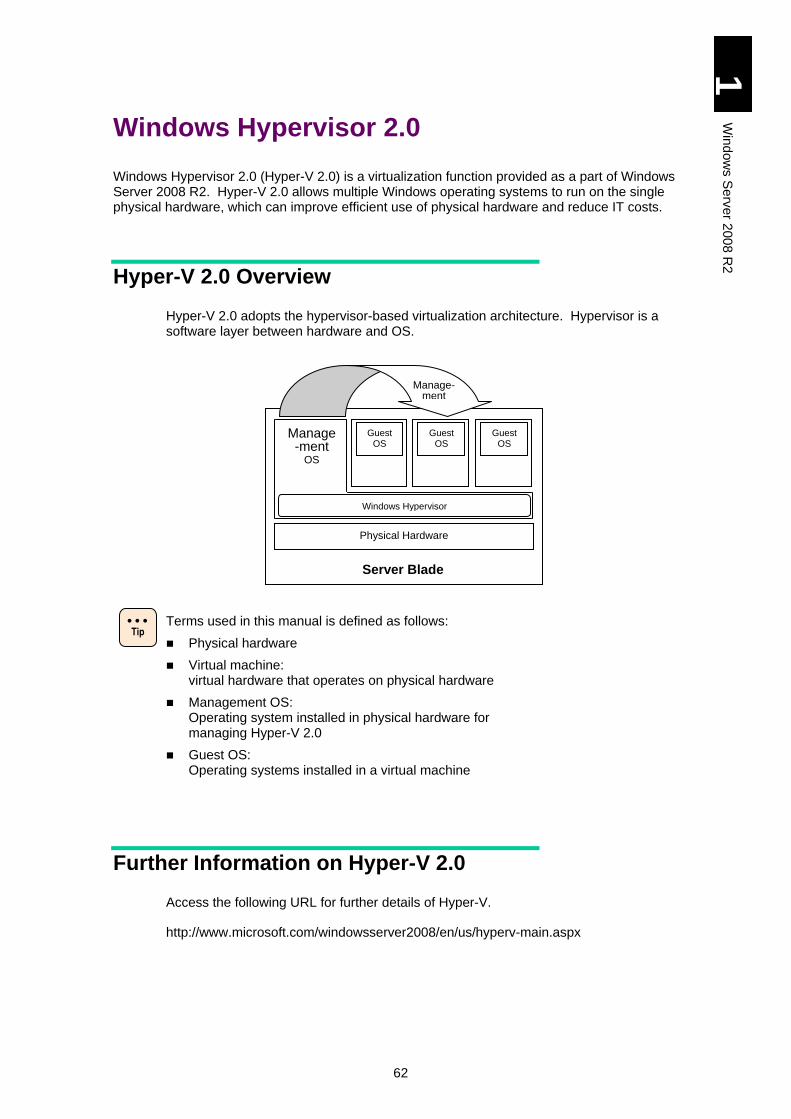
62
1
Win
dow
s S
erv
er 2
00
8 R
2
Windows Hypervisor 2.0
Windows Hypervisor 2.0 (Hyper-V 2.0) is a virtualization function provided as a part of Windows Server 2008 R2. Hyper-V 2.0 allows multiple Windows operating systems to run on the single physical hardware, which can improve efficient use of physical hardware and reduce IT costs.
Hyper-V 2.0 Overview
Hyper-V 2.0 adopts the hypervisor-based virtualization architecture. Hypervisor is a software layer between hardware and OS.
Terms used in this manual is defined as follows:
Physical hardware
Virtual machine: virtual hardware that operates on physical hardware
Management OS: Operating system installed in physical hardware for managing Hyper-V 2.0
Guest OS: Operating systems installed in a virtual machine
Further Information on Hyper-V 2.0
Access the following URL for further details of Hyper-V.
http://www.microsoft.com/windowsserver2008/en/us/hyperv-main.aspx
Physical Hardware
Windows Hypervisor
Manage-ment
OS
Guest OS
Guest OS
Guest OS
Server Blade
Manage- ment
Tip
63
1
Win
dow
s S
erv
er 2
00
8 R
2
System Configuration for Hyper-V 2.0
This section describes system configuration to use Hyper-V 2.0.
Server Blade for Hyper-V 2.0
Server blades that support Windows Server 2008 R2.
Software Configuration
Following software requirements should be satisfied to configure Hyper-V 2.0.
[Requirements for Software]
Windows Server 2008 R2 Standard/Enterprise/Datacenter for the management OS
Windows Server 2008 R2 SP1 Standard/Enterprise/Datacenter for the management OS
64
1
Win
dow
s S
erv
er 2
00
8 R
2
Physical Hardware Configuration
In addition to the system requirements for Windows Server 2008 R2, the following hardware requirements should be satisfied to use Hyper-V 2.0.
Refer to the following URL for the system requirements for
Windows Server 2008 R2.
http://www.microsoft.com/windowsserver2008/en/us/system-
requirements.aspx
[Requirements for Hardware]
Data Execute Prevention (DEP) DEP settings of the server blade are all enabled by default. Use it as it is.
Intel 64 (x64-based processor) All CPUs mounted in the server blade support Intel x64 features. Use it as it is.
Intel Virtualization Technology (Intel VT) Intel VT settings of the server blade are all enabled by default . Use it as it is.
It is recommended that the server blade should use the physical hardware that satisfies the requirements shown below or more for configuration. Refer to Virtual Machine Configuration as well
CPU core: In addition to the total number of CPUs to be assigned to each guest OS running simultaneously, at least one CPU for the management OS is required.
Memory: In addition to the total capacity of the memory, which is recommended by Microsoft to each OS running simultaneously, at least another 2 GB for the management OS is required.
Partitions: Separate partitions are required for the management OS and the virtual hard disk file (.vhd) of a virtual machine.
Recommendations above are just general standards and do
not guarantee that the system will work well at any condition.
They may be insufficient depending on an application to run on
the guest OS. Give the system testrun and check if it works
properly beforehand.
Recommendations above are just general standards. When
using the system for a specific purpose such as a test
environment, it may not necessarily satisfy the recommended
requirements. Examine the configuration depending on your
purpose.
65
1
Win
dow
s S
erv
er 2
00
8 R
2
Virtual Machine Configuration
Hitachi confirmed that the following guest OSs ran properly on the server blade.
Windows 2000 Server with Service Pack 4
Windows 2000 Advanced Server with Service Pack 4
Windows Server 2003, Standard Edition with Service Pack 2 (including R2)
Windows Server 2003, Enterprise Edition with Service Pack 2 (including R2)
Windows Server 2003, x64 Standard Edition with Service Pack 2 (including R2)
Windows Server 2003, x64 Enterprise Edition with Service Pack 2 (including R2)
Windows Server 2008 Standard 32-bit
Windows Server 2008 Enterprise 32-bit
Windows Server 2008 Datacenter 32-bit
Windows Server 2008 Standard 64-bit
Windows Server 2008 Enterprise 64-bit
Windows Server 2008 Datacenter 64-bit
Windows Server 2008 Standard 32-bit with Service Pack 2
Windows Server 2008 Enterprise 32-bit with Service Pack 2
Windows Server 2008 Datacenter 32-bit with Service Pack 2
Windows Server 2008 Standard 64-bit with Service Pack 2
Windows Server 2008 Enterprise 64-bit with Service Pack 2
Windows Server 2008 Datacenter 64-bit with Service Pack 2
Windows Server 2008 R2 Standard
Windows Server 2008 R2 Enterprise
Windows Server 2008 R2 Datacenter
Windows Server 2008 R2 Standard with Service Pack 1
Windows Server 2008 R2 Enterprise with Service Pack 1
Windows Server 2008 R2 Datacenter with Service Pack 1
Windows XP Professional x86 Edition with Service Pack 3
Windows Vista Business x86 Edition with Service Pack 2
Windows Vista Enterprise x86 Edition with Service Pack 2
Windows Vista Ultimate x86 Edition with Service Pack 2
Windows 7 Professional x86 Edition
Windows 7 Enterprise x86 Edition
Windows 7 Ultimate x86 Edition
Windows 7 Professional x64 Edition
Windows 7 Enterprise x64 Edition
Windows 7 Ultimate x64 Edition
Windows 7 Professional x86 Edition with Service Pack 1
Windows 7 Enterprise x86 Edition with Service Pack 1
Windows 7 Ultimate x86 Edition with Service Pack 1
Windows 7 Professional x64 Edition with Service Pack 1
Windows 7 Enterprise x64 Edition with Service Pack 1
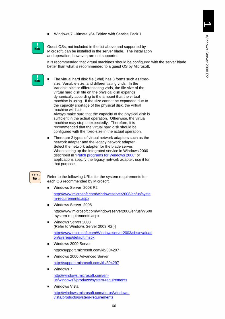
66
1
Win
dow
s S
erv
er 2
00
8 R
2
Windows 7 Ultimate x64 Edition with Service Pack 1
Guest OSs, not included in the list above and supported by
Microsoft, can be installed in the server blade. The installation
and operation, however, are not supported.
It is recommended that virtual machines should be configured with the server blade better than what is recommended to a guest OS by Microsoft.
The virtual hard disk file (.vhd) has 3 forms such as fixed-size, Variable-size, and differentiating vhds. In the Variable-size or differentiating vhds, the file size of the virtual hard disk file on the physical disk expands dynamically according to the amount that the virtual machine is using. If the size cannot be expanded due to the capacity shortage of the physical disk, the virtual machine will halt. Always make sure that the capacity of the physical disk is sufficient in the actual operation. Otherwise, the virtual machine may stop unexpectedly. Therefore, it is recommended that the virtual hard disk should be configured with the fixed-size in the actual operation.
There are 2 types of virtual network adapters such as the network adapter and the legacy network adapter. Select the network adapter for the blade server. When setting up the integrated service in Windows 2000 described in “Patch programs for Windows 2000” or applications specify the legacy network adapter, use it for that purpose.
Refer to the following URLs for the system requirements for
each OS recommended by Microsoft.
Windows Server 2008 R2
http://www.microsoft.com/windowsserver2008/en/us/syste
m-requirements.aspx
Windows Server 2008
http://www.microsoft.com/windowsserver2008/en/us/WS08
-system-requirements.aspx
Windows Server 2003 (Refer to Windows Server 2003 R2.)]
http://www.microsoft.com/Windowsserver2003/sbs/evaluati
on/sysreqs/default.mspx
Windows 2000 Server
http://support.microsoft.com/kb/304297
Windows 2000 Advanced Server
http://support.microsoft.com/kb/304297
Windows 7
http://windows.microsoft.com/en-
us/windows7/products/system-requirements
Windows Vista
http://windows.microsoft.com/en-us/windows-
vista/products/system-requirements

67
1
Win
dow
s S
erv
er 2
00
8 R
2
Windows XP
http://support.microsoft.com/kb/314865
The maximum number of processors that can be assigned
depends on a guest OS.
One (1) processor at a maximum can be assigned to
Windows Server 2000;
two (2) at a maximum to Windows Server 2003 R2,
Windows Server 2003, Windows Vista, and Windows XP
SP3;
four (4) at a maximum to Windows Server 2008 R2,
Windows Server 2008, and Windows 7.
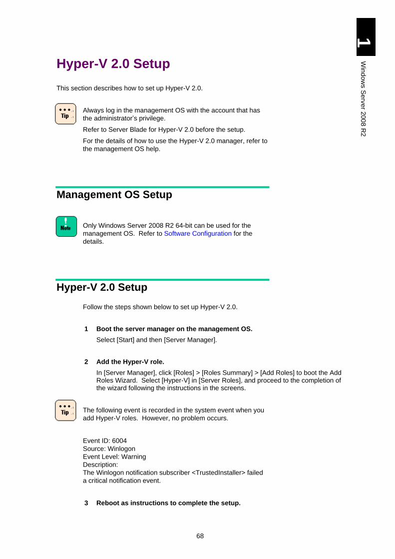
68
1
Win
dow
s S
erv
er 2
00
8 R
2
Hyper-V 2.0 Setup
This section describes how to set up Hyper-V 2.0.
Always log in the management OS with the account that has
the administrator’s privilege.
Refer to Server Blade for Hyper-V 2.0 before the setup.
For the details of how to use the Hyper-V 2.0 manager, refer to
the management OS help.
Management OS Setup
Only Windows Server 2008 R2 64-bit can be used for the
management OS. Refer to Software Configuration for the
details.
Hyper-V 2.0 Setup
Follow the steps shown below to set up Hyper-V 2.0.
1 Boot the server manager on the management OS.
Select [Start] and then [Server Manager].
2 Add the Hyper-V role.
In [Server Manager], click [Roles] > [Roles Summary] > [Add Roles] to boot the Add Roles Wizard. Select [Hyper-V] in [Server Roles], and proceed to the completion of the wizard following the instructions in the screens.
The following event is recorded in the system event when you
add Hyper-V roles. However, no problem occurs.
Event ID: 6004
Source: Winlogon
Event Level: Warning
Description:
The Winlogon notification subscriber <TrustedInstaller> failed
a critical notification event.
3 Reboot as instructions to complete the setup.
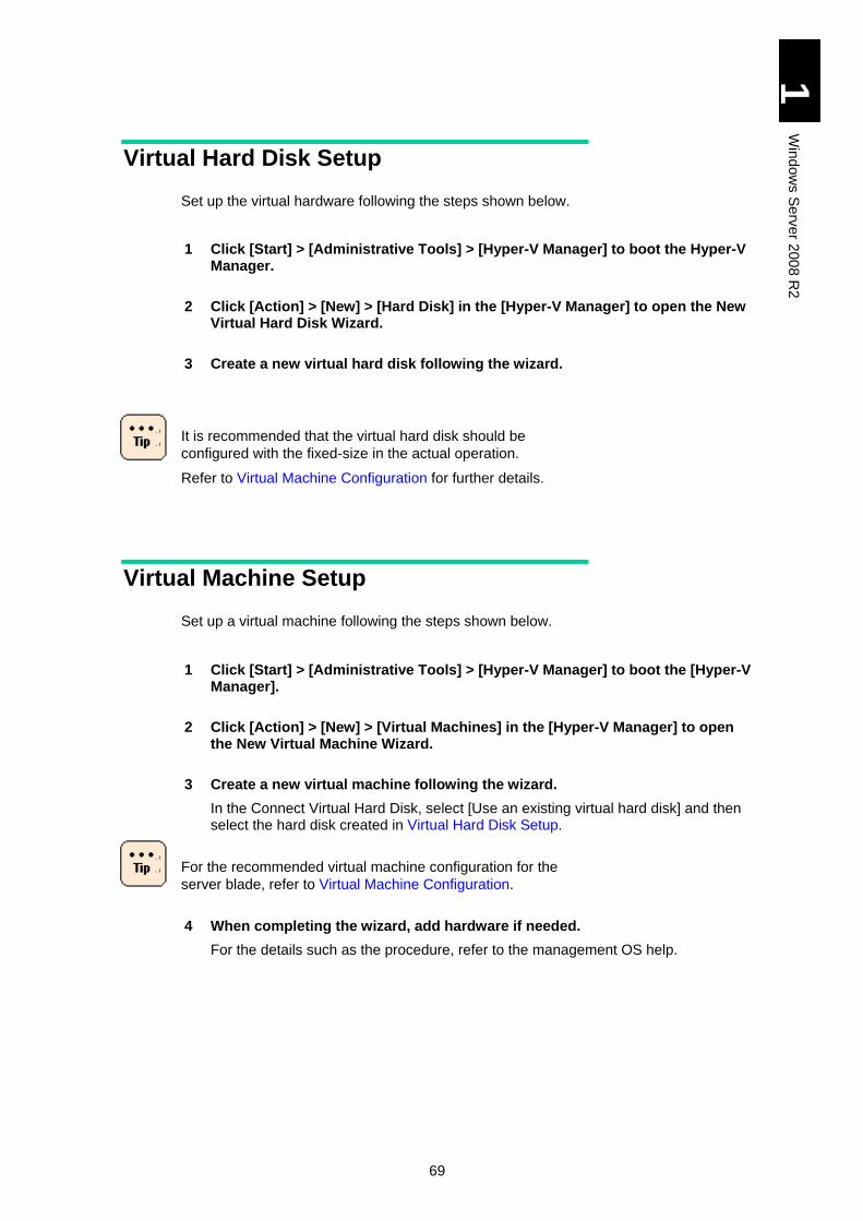
69
1
Win
dow
s S
erv
er 2
00
8 R
2
Virtual Hard Disk Setup
Set up the virtual hardware following the steps shown below.
1 Click [Start] > [Administrative Tools] > [Hyper-V Manager] to boot the Hyper-V Manager.
2 Click [Action] > [New] > [Hard Disk] in the [Hyper-V Manager] to open the New Virtual Hard Disk Wizard.
3 Create a new virtual hard disk following the wizard.
It is recommended that the virtual hard disk should be
configured with the fixed-size in the actual operation.
Refer to Virtual Machine Configuration for further details.
Virtual Machine Setup
Set up a virtual machine following the steps shown below.
1 Click [Start] > [Administrative Tools] > [Hyper-V Manager] to boot the [Hyper-V Manager].
2 Click [Action] > [New] > [Virtual Machines] in the [Hyper-V Manager] to open the New Virtual Machine Wizard.
3 Create a new virtual machine following the wizard.
In the Connect Virtual Hard Disk, select [Use an existing virtual hard disk] and then select the hard disk created in Virtual Hard Disk Setup.
For the recommended virtual machine configuration for the
server blade, refer to Virtual Machine Configuration.
4 When completing the wizard, add hardware if needed.
For the details such as the procedure, refer to the management OS help.
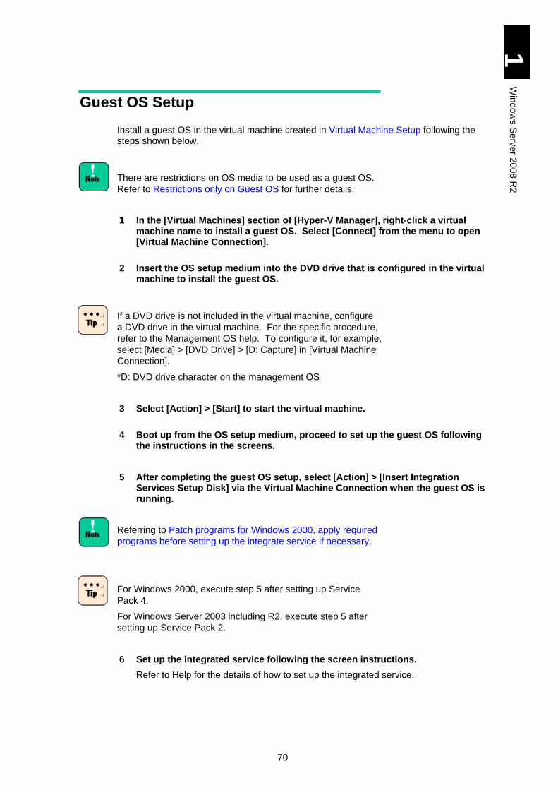
70
1
Win
dow
s S
erv
er 2
00
8 R
2
Guest OS Setup
Install a guest OS in the virtual machine created in Virtual Machine Setup following the steps shown below.
There are restrictions on OS media to be used as a guest OS.
Refer to Restrictions only on Guest OS for further details.
1 In the [Virtual Machines] section of [Hyper-V Manager], right-click a virtual machine name to install a guest OS. Select [Connect] from the menu to open [Virtual Machine Connection].
2 Insert the OS setup medium into the DVD drive that is configured in the virtual machine to install the guest OS.
If a DVD drive is not included in the virtual machine, configure
a DVD drive in the virtual machine. For the specific procedure,
refer to the Management OS help. To configure it, for example,
select [Media] > [DVD Drive] > [D: Capture] in [Virtual Machine
Connection].
*D: DVD drive character on the management OS
3 Select [Action] > [Start] to start the virtual machine.
4 Boot up from the OS setup medium, proceed to set up the guest OS following the instructions in the screens.
5 After completing the guest OS setup, select [Action] > [Insert Integration Services Setup Disk] via the Virtual Machine Connection when the guest OS is running.
Referring to Patch programs for Windows 2000, apply required
programs before setting up the integrate service if necessary.
For Windows 2000, execute step 5 after setting up Service
Pack 4.
For Windows Server 2003 including R2, execute step 5 after
setting up Service Pack 2.
6 Set up the integrated service following the screen instructions.
Refer to Help for the details of how to set up the integrated service.
71
1
Win
dow
s S
erv
er 2
00
8 R
2
Restrictions on Hyper-V 2.0
This section describes restrictions when using Hyper-V 2.0 on the server blade.
General Restrictions
Maintenance
As advancing the integration using the virtual environment, multiple tasks and environments run on a single machine. Therefore, it is important to plan the machine operation including time to spare for maintenance work. Maintenance tasks include applying security patches, updating application and drivers, and installing service packs. Make a plan for the system in advance taking account of time required for maintenance including the guest OS, and use it accordingly.
Server Core
Installation of Windows Server 2008 R2/Windows Server 2008 Server Core is not supported.
Application
Some application or middleware may have notice when using Hyper-V 2.0. Refer to the application distributor from which you have bought it for the details.
Cluster
When configuring a cluster using Hyper-V 2.0, it is recommended that you should configure WindowS Failover Cluster (WSFC) between management OSs. Refer to the management OS Help for how to configure a cluster between management OSs.
Cluster configuration between a guest OS and a physical machine is not supported. Cluster configuration between guest OSs requires a storage device via iSCSI. When guest OSs include Windows 2000 Server/Windows Server 2003, cluster configuration between guest OSs is not supported.
Cluster failover is executed when connection between the management OS and a shared disk fails due to FC cable break, for example. Cluster failover service itself may fail down, however, when the guest OS adds so much access loads to the shared disk that the quorum fails at the failover.
Live Migration
When a series of Live Migrations are used for a short period, it may fail. Use a series of Live Migration at the intervals of a few minutes.
Intel PROSet
When you install Intel(R) PROSet in the management OS to use, refer to Appendix II to this SOFTWARE GUIDE.
Do not install Intel(R) PROSet in any guest OS.
72
1
Win
dow
s S
erv
er 2
00
8 R
2
Event related to Physical Hardware
Monitor events related to the physical hardware on the management OS, not on the guest OS.
OS Reboot and Shutdown
It is recommended to shut down all guest OSs explicitly before rebooting and shutting down the management OS. Especially when multiple guest OSs are running, shutting down the management OS at the same time puts high load on CPU. This can cause trouble such as too much time to take or improper shutdown.
Dynamic Memory
When SP1 or later is installed on the management OS, Dynamic Memory is available. We confirm that the following OSs have operated on the server blades.
- Windows Server 2003, Standard Edition with Service Pack 2 (including R2)
- Windows Server 2003, Enterprise Edition with Service Pack 2 (including R2)
- Windows Server 2003, x64 Standard Edition with Service Pack 2 (including R2)
- Windows Server 2003, x64 Enterprise Edition with Service Pack 2 (including R2)
- Windows Server 2008 Standard 32-bit with Service Pack 2
- Windows Server 2008 Enterprise 32-bit with Service Pack 2
- Windows Server 2008 Datacenter 32-bit with Service Pack 2
- Windows Server 2008 Standard 64-bit with Service Pack 2
- Windows Server 2008 Enterprise 64-bit with Service Pack 2
- Windows Server 2008 Datacenter 64-bit with Service Pack 2
- Windows Server 2008 R2 Standard with Service Pack 1
- Windows Server 2008 R2 Enterprise with Service Pack 1
- Windows Server 2008 R2 Datacenter with Service Pack 1
- Windows Vista Enterprise x86 Edition with Service Pack 2
- Windows Vista Ultimate x86 Edition with Service Pack 2
- Windows 7 Enterprise x86 Edition with Service Pack 1
- Windows 7 Ultimate x86 Edition with Service Pack 1
- Windows 7 Enterprise x64 Edition with Service Pack 1
- Windows 7 Ultimate x64 Edition with Service Pack 1
When using Windows Server 2008 Standard 32-bit with Service Pack 2/Windows Server 2008 Standard 64-bit with Service Pack 2 as a guest OS, apply the following Windows Update before enabling Dynamic Memory.
http://support.microsoft.com/kb/2230887
RemoteFX
RemoteFX is not supported.
Other restrictions
Search in the following URL “Microsoft Help and Support” using “Hyper-V” as a keyword.
http://support.microsoft.com/
73
1
Win
dow
s S
erv
er 2
00
8 R
2
Restrictions only on Management OS
Software on the management OS
It is recommended that task application (middleware) such as a database or application server should not be installed on the management OS with Hyper-V enabled.
Role
It is recommended that any role but Hyper-V in Windows Server 2008 R2 should be disabled on the management OS with Hyper-V enabled.
Restrictions only on Guest OS
Saving VM
When selecting [Action] > [Save] in the management screen of the virtual machine, the virtual machine status is saved and the virtual machine halts. To restart the virtual machine from the halting point, select [Action] > [Start]. This operation, however, is different from the guest OS shutdown and reboot. Applications communicating with the outside may register an error.
Notes for Active Directory on the guest OS
Microsoft Help and Support provides “Considerations when hosting Active Directory domain controller in virtual hosting environments” in the following URL. Access the following URL and read it in advance.
http://support.microsoft.com/kb/888794/en-us
Network Load Balancing (NLB) configuration on the guest OS
Configuring NLB cluster on the guest OS is not supported. We recommend that tasks that require NLB should be done on the physical machine.0
OS installation media
When using Windows Server 2003 32-bit with Service Pack2 as a guest OS, use the OS medium to which Service Pack 1 or 2 has been applied. Otherwise, the guest OS may show the “STOP” error and halt during installation.
Snapshot
It is recommended that the snapshot should not be used in the actual environment. If using the snapshot, overhead may occur in performance, or consistency may be destroyed in the system where multiple servers combine.
It is also recommended that snapshot should not be used in the guest OS where Active Directory is configured. If using the snapshot, Inconsistency in database may occur.
Virtual Hard Disk File (.vhd)
When multiple virtual hard disk files (.vhd) are on a single physical hard disk, IO bottleneck may occur depending on a processing on the guest OS. This may affect the entire OS processing.
When using multiple guest OSs in the actual environment, execute careful testruns in advance. You might as well deploy virtual hard disk files (.vhd) on a separate physical disk if necessary.
74
1
Win
dow
s S
erv
er 2
00
8 R
2
Virtual SCSI controller
A guest OS cannot be installed in a virtual hard disk connected to a virtual SCSI controller. With Windows 2000 Server as a guest OS, the SCSI controller connected to a virtual machine is not available. Connect all virtual hard disks to the virtual IDE controller with Windows 2000 Server as a guest OS.
Patch programs for Windows 2000
When using Windows 2000 with service pack 4, in which the integrated service has been setup, and applying the following patch programs to the guest OS, 0xCE is displayed and the guest OS may halt.
KB891861
http://support.microsoft.com/kb/891861/
KB905590
http://support.microsoft.com/kb/905590/
KB922582
http://support.microsoft.com/kb/922582/
Apply these programs before setting up the integrated service if necessary.
Since programs KB891861/KB922582 are prioritized in Windows update programs, perform Windows Update before the integrated service. When programs KB891861/KB922582 have been applied, there is no problem if you perform the integrated service and then Windows Update.
Use the legacy network adapter as a virtual network adapter on a virtual machine before setting up the integrated service. After setting up the integrated service, delete the legacy network adapter from the virtual machine and use a network adapter.
If trouble occurs, the guest OS may have to be set up again.
Sound playback with a guest OS
When playing back sounds with a guest OS, you cannot play them on Hyper-V manager. If you need to play a sound, connect to the guest OS using an application such as a remote desktop client from a PC with a sound device to play the sound.
When using a remote connecting application which cannot play
a sound if some connecting destinations have no physical
sound device, you cannot replay a sound even though using
remote connection. See your application manual for details.
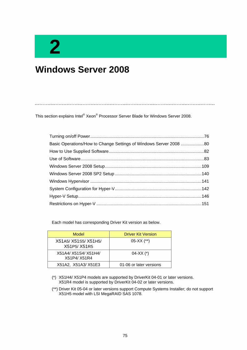
75
2 Windows Server 2008
This section explains Intel® Xeon
® Processor Server Blade for Windows Server 2008.
Turning on/off Power ............................................................................................. 76
Basic Operations/How to Change Settings of Windows Server 2008 ................... 80
How to Use Supplied Software .............................................................................. 82
Use of Software ..................................................................................................... 83
Windows Server 2008 Setup ............................................................................... 109
Windows Server 2008 SP2 Setup ....................................................................... 140
Windows Hypervisor ........................................................................................... 141
System Configuration for Hyper-V ....................................................................... 142
Hyper-V Setup ..................................................................................................... 146
Restrictions on Hyper-V ...................................................................................... 151
Each model has corresponding Driver Kit version as below.
(*) X51H4/ X51P4 models are supported by DriverKit 04-01 or later versions. X51R4 model is supported by DriverKit 04-02 or later versions.
(**) Driver Kit 05-04 or later versions support Compute Systems Installer; do not support X51H5 model with LSI MegaRAID SAS 1078.
Model Driver Kit Version
X51A5/ X51S5/ X51H5/ X51P5/ X51R5
05-XX (**)
X51A4/ X51S4/ X51H4/ X51P4/ X51R4
04-XX (*)
X51A2, X51A3/ X51E3 01-06 or later versions

76
2
Win
dow
s S
erv
er 2
00
8
Turning on/off Power
This section explains how to turn on the system and start the OS, how to turn off the system by the OS shutdown, and how to forcibly terminate the applications and system.
As for Intel® Xeon® Processor Server Blade, no devices such as the display, the keyboard or the mouse etc. are connected.
A basic operation is done by way of the network by the remote-console application.
After starting Windows, it is also possible to operate it by a remote desktop connection.
Refer to "Remote-console application user’s guide” stored in “Remote Console Application CD” attached with server chassis for the details of connection method to the remote-console and the remote-console application.
Refer to "Windows Server 2008 Setup", when you purchase the Server Blade and set up Windows,
Prepare for the connection to the server blade by the remote-console.
Refer to 'Remote-console application user's guide' for details of the remote-console connection.
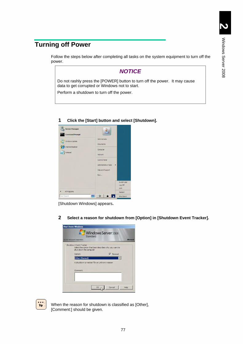
77
2
Win
dow
s S
erv
er 2
00
8
Turning off Power
Follow the steps below after completing all tasks on the system equipment to turn off the power.
NOTICE
Do not rashly press the [POWER] button to turn off the power. It may cause data to get corrupted or Windows not to start.
Perform a shutdown to turn off the power.
1 Click the [Start] button and select [Shutdown].
[Shutdown Windows] appears.
2 Select a reason for shutdown from [Option] in [Shutdown Event Tracker].
When the reason for shutdown is classified as [Other],
[Comment:] should be given.
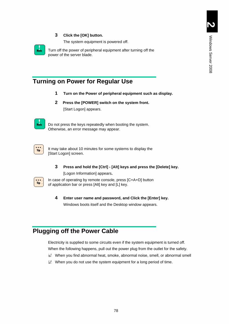
78
2
Win
dow
s S
erv
er 2
00
8
3 Click the [OK] button.
The system equipment is powered off.
Turn off the power of peripheral equipment after turning off the
power of the server blade.
Turning on Power for Regular Use
1 Turn on the Power of peripheral equipment such as display.
2 Press the [POWER] switch on the system front.
[Start Logon] appears.
Do not press the keys repeatedly when booting the system.
Otherwise, an error message may appear.
It may take about 10 minutes for some systems to display the
[Start Logon] screen.
3 Press and hold the [Ctrl] - [Alt] keys and press the [Delete] key.
[Logon Information] appears.
In case of operating by remote console, press [C+A+D] button
of application bar or press [Alt] key and [L] key.
4 Enter user name and password, and Click the [Enter] key.
Windows boots itself and the Desktop window appears.
Plugging off the Power Cable
Electricity is supplied to some circuits even if the system equipment is turned off.
When the following happens, pull out the power plug from the outlet for the safety.
When you find abnormal heat, smoke, abnormal noise, smell, or abnormal smell
When you do not use the system equipment for a long period of time.
79
2
Win
dow
s S
erv
er 2
00
8
Terminating Application/System Forcibly
When the system equipment function fails during its processing applications, terminating the applications forcibly or rebooting the system equipment forcibly may be able to resume normal operation.
Forcibly Terminate Application
Right-click the task bar and click [Task Manager] of the shortcut menu. Click the [Application] tab, select the application you want to terminate, and click the [End Task] button.
OS or application may not operate correctly, or data may not be secured after the forcible termination. In that case, reset the OS or application, or restore data from the backup.
Forcibly Reboot the System Equipment
When Windows functions abnormally, keep pressing the [POWER] switch for four seconds or more to turn off the power.
OS or application may not operate correctly, or data may not be secured after the reset. In that case, reset the OS or application, or restore data from the backup.
Do not press the [POWER] switch again until the Windows
reboot is completed except emergency. If you do, Windows
may not boot.
When resetting, be sure to boot and terminate Windows
properly, and then reboot it. Otherwise, Windows may not
operate correctly.
80
2
Win
dow
s S
erv
er 2
00
8
Basic Operations/How to Change Settings of Windows Server 2008
This section explains basic operations and how to change settings of Windows Server 2008.
How to Use Help
Help is available from Windows, in which how to use is described.
Start [Help and Support].
1 Click the [Start] button and then select [Help and Support].
[Windows Help and Support Center] boots itself.
A pop up message “Do you need to get the latest help
contents when searching Help?” may be displayed at the
first boot. If selecting “yes”, the latest contents are
obtained from Windows Online Help when connecting to
the Internet. Select “yes” if necessary.
If the pop up message is not displayed after the first setup
or at the first boot, you can change the setting by selecting
[Option] and then [Settings].
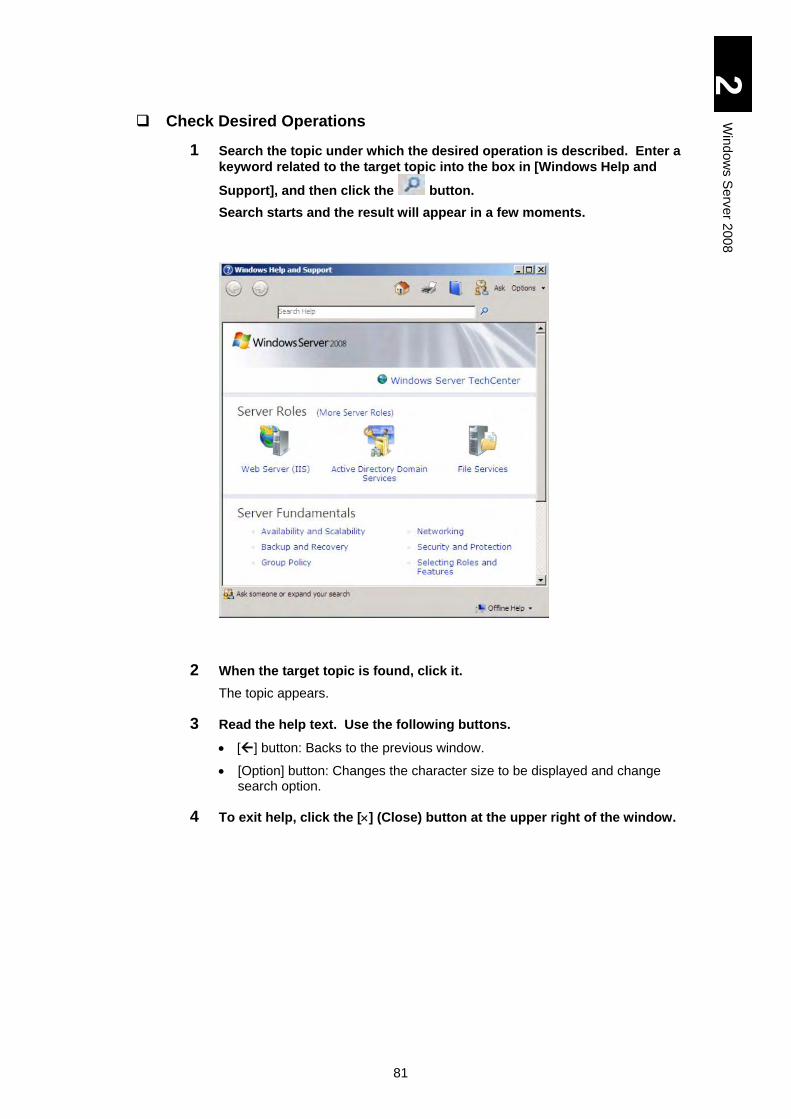
81
2
Win
dow
s S
erv
er 2
00
8
Check Desired Operations
1 Search the topic under which the desired operation is described. Enter a
keyword related to the target topic into the box in [Windows Help and
Support], and then click the button.
Search starts and the result will appear in a few moments.
2 When the target topic is found, click it.
The topic appears.
3 Read the help text. Use the following buttons.
[] button: Backs to the previous window.
[Option] button: Changes the character size to be displayed and change search option.
4 To exit help, click the [] (Close) button at the upper right of the window.
82
2
Win
dow
s S
erv
er 2
00
8
How to Use Supplied Software
This section explains the software included in this system.
MegaRAID Storage Manager
This software is necessary to manage the disk array devices. Be sure to install it when the HDD is installed in the server blade. Otherwise, a double-failure might be caused because of non-detection of the hard disk failure, and the failure analysis become difficult. Refer to the file 'MegaRAID Storage Manager manual' in the CD-ROM for details of the usage. d:\MANUAL\ MSManager.pdf (for X51A2/ X51A3/ X51E3/ X51A4/ X51/H4 models)
d:\MANUAL\MSManager2.pdf (for X51R4/ X51A5/ X51H5/ X51R5 models) [Driver Kit version 05-04 or later]
d:\X51x5\MANUAL\MSManager2.pdf
Intel® PROSet
Intel PROSet is a utility to provide expansion functions such as Dual LAN Redundancy.
Refer to “Windows 2008 LAN Expanded Function Manual” for the details.
When settings for Intel PROSet are changed, network
connection may be temporarily disconnected. Thus, when you
change PROSet settings, use connection via remote console
not via remote desktop.
83
2
Win
dow
s S
erv
er 2
00
8
Use of Software
This section explains the restrictions on the use of software.
Restrictions on Use of Windows Server 2008
Server Core
Do not install Server Core, which is not supported.
Hyper-V
Windows Server® 2008 Standard and Windows Server® 2008 Enterprise contain Hypervisor-based virtualization technology, Hyper-V Bata version. The official edition of this technology will be released soon, which can be downloaded from Windows Update.
Windows Server Shutdown
If you shut down Windows while the service registered to start at the boot is still activated, it may not be shut down normally. Be sure to allow a time interval of at least one minute after booting Windows.
Restore the Computer
Step 4 in Setup procedure (click here.) may not be displayed in some OS installation media. When that happens, “Repair your computer” on the step 4 screen is not displayed, so that Windows Recovery Environment (hereinafter, referred to as Windows RE) cannot be started.
http://support.microsoft.com/kb/951495
Start Windows RE as follows, if necessary.
1. In the window of “Select OS to install”, press and hold the [Shift] key and press the [F10] key.
A command prompt is displayed.
2. Enter the following command in the command prompt to execute “recenv.exe”.
> cd /d %SystemDrive%\source\recovery
> RecEnv.exe
3. Windows RE will start.
84
2
Win
dow
s S
erv
er 2
00
8
Fault Tolerant
Backup regularly. Span volume, Stripe volume, RAID-5 volume and Mirror volume are not supported.
Backup
Windows Server Backup does not support backing up to tape media. When backing up data to a tape device, purchase the backup software.
Backing up to DVD media is also not supported.
Screen Display
After switching the screen display to change a task, the previous display may remain depending on the timing. In such a case, redraw the point in question to display properly.
Depending on the status of use, the message box may be hidden behind other windows.
To change the display color, terminate the application. Otherwise, it can cause strange display of the application. In such a case, redraw by switching the screen for proper display.
When changing refresh rates, confirm that your monitor can display a screen properly.
A screen may remain displayed after stopping the play with some applications that playing animated files. When this happens, change screens such as maximize another window.
Power Saving Function
Do not select [System Standby], [Hybrid Sleep] and [Hibernate]. These three are not supported.
Among power supply options, you can only change the time-out period before the display shutdown.
If you fail to observe two restrictions above, the monitor may not operate properly.
Setting Recovery Operation at System Shutdown
It is recommended that the [Automatically restart] checkbox should be unchecked.
The procedure is as follows:
1. Select [Start] - [Management Tool], and open [Server Manager].
2. Select [Change System Property], and open [System Property].
3. Select the [Details Setting] tab, and then click the [Set] button in [Start and Recovery]. [Start and Recovery] will open.
4. Remove the check mark from [Automatically restart], and click the [OK] button.
85
2
Win
dow
s S
erv
er 2
00
8
Getting Complete Memory Dump in Physical Memory Exceeding 2 GB
When Windows is set on the system equipment installed with 2 GB or larger memory, [Complete Memory Dump] cannot be selected from [Write Debug Information] in [Start and Recovery]. Perform the following procedure when getting [Complete Memory Dump] in an environment where 2 GB or larger Physical Memory is used. Actually, [Complete Memory Dump] is not included in the [Write Debut Information] list. Refer to the following URL for the details, where Windows Server 2003 should be translated to Windows Server 2008.
http://support.microsoft.com/kb/274598/en-us
1 Insert the "Driver Kit" CD-ROM into the CD/DVD drive.
2 Select [Run] from the [Start] menu, enter following file name and click
[OK].
d:\Utility\Dump\PMDE.BAT
[With Driver Kit version 05-04 or later]
X51A5 model: d:\X51x5\Win2008\Tools\Dump\PMDE.BAT
3 Press any key when the following message appears.
"Change the setting to get Complete Memory Dump.
Press any key to continue the operation.
Press the [Ctrl] + [C] keys for stopping."
4 Set [Virtual memory] size. Refer to the following.
Setting "Virtual Memory" Size
When starting [Startup and Recovery] after Step 2 and clicking the [OK] button, the dump format will be changed to the one selected in [Write Debug Information]. If you have clicked the [OK] button, repeat Step 2.
86
2
Win
dow
s S
erv
er 2
00
8
Setting "Virtual Memory" Size
When setting Virtual Memory to get the complete memory dump, set the virtual memory file to a size larger than the capacity of the physical memory. If you try to set the file size of the virtual memory smaller than the physical memory, a warning message "If the paging file is disabled or the virtual memory's initial page size: is smaller than xxx MB, system error can occur and useful information to identify the problem cannot be saved. Do you like to continue?" appears. If you select this xxx MB, the complete memory dump may not be obtained correctly. Set the file size larger than [xxx +400] MB.
When setting Virtual Memory to get the kernel memory dump, set enough size for the virtual memory. Otherwise, the kernel memory dump may not be properly collected. Refer to the following URL for the detail.
http://support.microsoft.com/kb/949052/en-us
1 Select [Start] – [AdministrativeTool] – [Server Manager], and the [Server Manager] will open.
2 Select [Change System Property], and [System Property] will open.
3 Select the [Advanced] tab, and click the [Settings] button in [Performance]. [Performance Option] will open.
4 From the same [Advanced] tab, click the [Settings] button in [Virtual Memory]. [Virtual Memory] will open.
5 Remove the check mark from [Manage automatically all the drive paging file sizes].
6 Select [Custom Size], and enter the value [xxx+400] MB or over to [Initial] and [Maximum] size.
[Maximum] size must be larger than [Initial] size.
7 Reboot the system equipment.
PAE: Physical Address Extension
PAE in Windows Server 2008 32-bit is supported. Refer to the following URL for PAE.
http://www.microsoft.com/us
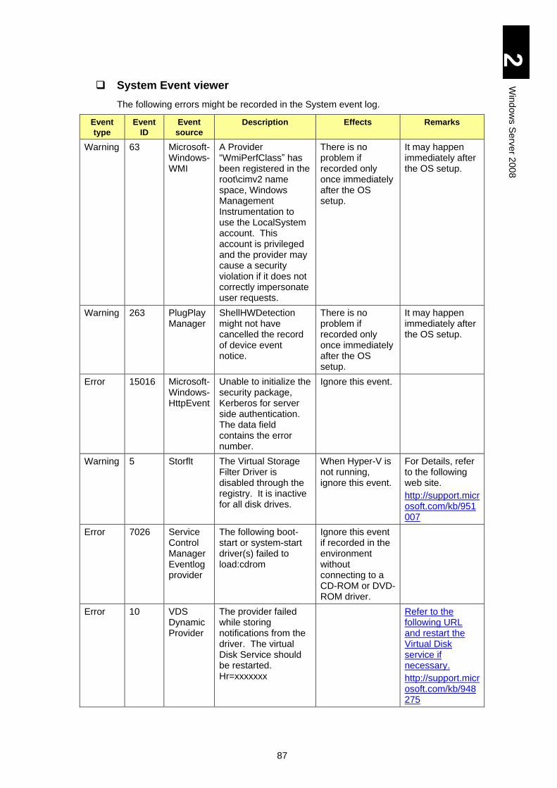
87
2
Win
dow
s S
erv
er 2
00
8
System Event viewer
The following errors might be recorded in the System event log.
Event
type
Event
ID
Event
source
Description Effects Remarks
Warning 63 Microsoft-Windows-WMI
A Provider “WmiPerfClass” has been registered in the root\cimv2 name space, Windows Management Instrumentation to use the LocalSystem account. This account is privileged and the provider may cause a security violation if it does not correctly impersonate user requests.
There is no problem if recorded only once immediately after the OS setup.
It may happen immediately after the OS setup.
Warning 263 PlugPlayManager
ShellHWDetection might not have cancelled the record of device event notice.
There is no problem if recorded only once immediately after the OS setup.
It may happen immediately after the OS setup.
Error 15016 Microsoft-Windows-HttpEvent
Unable to initialize the security package, Kerberos for server side authentication. The data field contains the error number.
Ignore this event.
Warning 5 Storflt The Virtual Storage Filter Driver is disabled through the registry. It is inactive for all disk drives.
When Hyper-V is not running, ignore this event.
For Details, refer to the following web site.
http://support.microsoft.com/kb/951007
Error 7026 Service Control Manager Eventlog provider
The following boot-start or system-start driver(s) failed to load:cdrom
Ignore this event if recorded in the environment without connecting to a CD-ROM or DVD-ROM driver.
Error 10 VDS Dynamic Provider
The provider failed while storing notifications from the driver. The virtual Disk Service should be restarted. Hr=xxxxxxx
Refer to the following URL and restart the Virtual Disk service if necessary.
http://support.microsoft.com/kb/948275
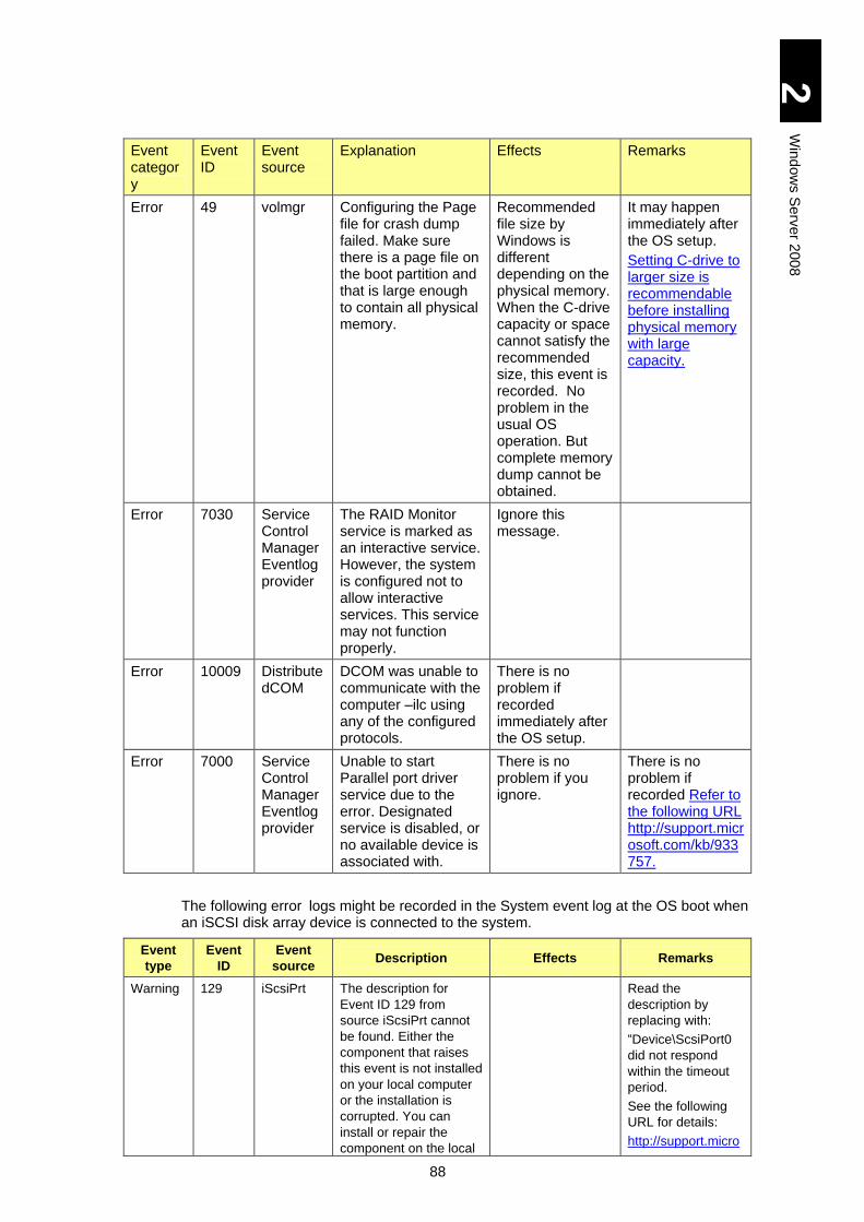
88
2
Win
dow
s S
erv
er 2
00
8
Event category
Event ID
Event source
Explanation Effects Remarks
Error 49 volmgr Configuring the Page file for crash dump failed. Make sure there is a page file on the boot partition and that is large enough to contain all physical memory.
Recommended file size by Windows is different depending on the physical memory. When the C-drive capacity or space cannot satisfy the recommended size, this event is recorded. No problem in the usual OS operation. But complete memory dump cannot be obtained.
It may happen immediately after the OS setup.
Setting C-drive to larger size is recommendable before installing physical memory with large capacity.
Error 7030 Service Control Manager Eventlog provider
The RAID Monitor service is marked as an interactive service. However, the system is configured not to allow interactive services. This service may not function properly.
Ignore this message.
Error 10009 DistributedCOM
DCOM was unable to communicate with the computer –ilc using any of the configured protocols.
There is no problem if recorded immediately after the OS setup.
Error 7000 Service Control Manager Eventlog provider
Unable to start Parallel port driver service due to the error. Designated service is disabled, or no available device is associated with.
There is no problem if you ignore.
There is no problem if recorded Refer to the following URL http://support.microsoft.com/kb/933757.
The following error logs might be recorded in the System event log at the OS boot when an iSCSI disk array device is connected to the system.
Event
type
Event
ID
Event
source Description Effects Remarks
Warning 129 iScsiPrt The description for
Event ID 129 from
source iScsiPrt cannot
be found. Either the
component that raises
this event is not installed
on your local computer
or the installation is
corrupted. You can
install or repair the
component on the local
Read the
description by
replacing with:
“Device\ScsiPort0
did not respond
within the timeout
period.
See the following
URL for details:
http://support.micro
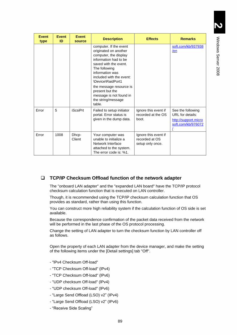
89
2
Win
dow
s S
erv
er 2
00
8
Event
type
Event
ID
Event
source Description Effects Remarks
computer. If the event
originated on another
computer, the display
information had to be
saved with the event.
The following
information was
included with the event:
\Device\RaidPort1
the message resource is
present but the
message is not found in
the string/message
table.
soft.com/kb/937938
/en
Error 5 iScsiPrt Failed to setup initiator
portal. Error status is
given in the dump data.
Ignore this event if
recorded at the OS
boot.
See the following
URL for details:
http://support.micro
soft.com/kb/976072
/
Error 1008 Dhcp-
Client
Your computer was
unable to initialize a
Network Interface
attached to the system.
The error code is: %1.
Ignore this event if
recorded at OS
setup only once.
TCP/IP Checksum Offload function of the network adapter
The "onboard LAN adapter" and the "expanded LAN board" have the TCP/IP protocol checksum calculation function that is executed on LAN controller.
Though, it is recommended using the TCP/IP checksum calculation function that OS provides as standard, rather than using this function.
You can construct more high reliability system if the calculation function of OS side is set available.
Because the correspondence confirmation of the packet data received from the network will be performed in the last phase of the OS protocol processing.
Change the setting of LAN adapter to turn the checksum function by LAN controller off as follows.
Open the property of each LAN adapter from the device manager, and make the setting of the following items under the [Detail settings] tab "Off".
- "lPv4 Checksum Off-load"
- "TCP Checksum Off-load" (lPv4)
- "TCP Checksum Off-load" (lPv6)
- "UDP checksum Off-load" (lPv4)
- "UDP checksum Off-load" (lPv6)
- “Large Send Offload (LSO) v2” (IPv4)
- “Large Send Offload (LSO) v2” (IPv6)
- “Receive Side Scaling”
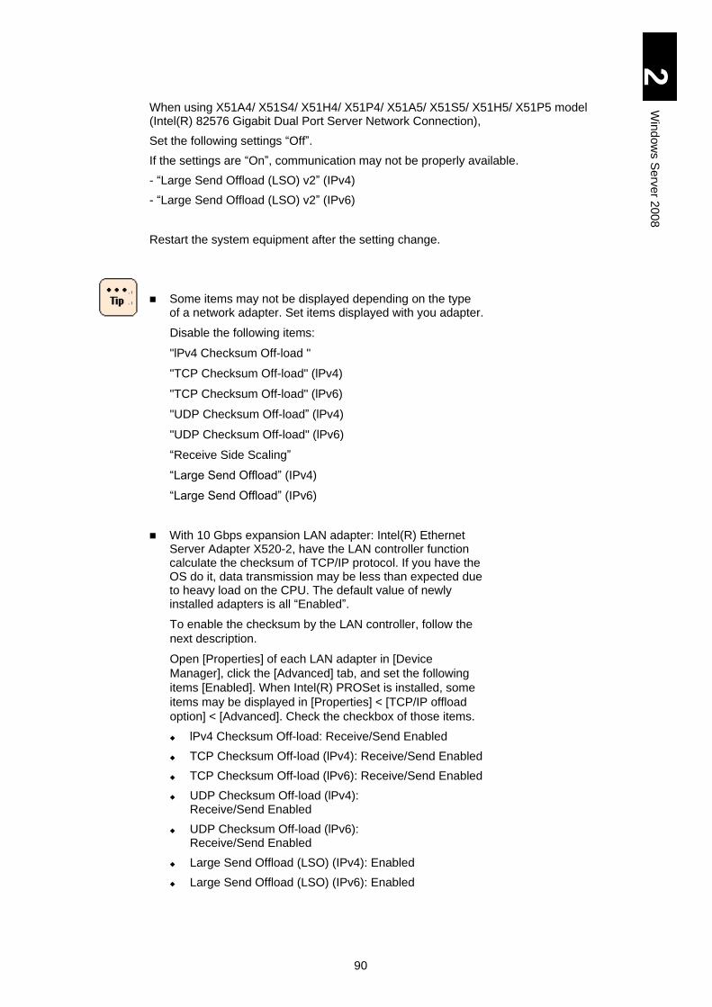
90
2
Win
dow
s S
erv
er 2
00
8
When using X51A4/ X51S4/ X51H4/ X51P4/ X51A5/ X51S5/ X51H5/ X51P5 model (Intel(R) 82576 Gigabit Dual Port Server Network Connection),
Set the following settings “Off”.
If the settings are “On”, communication may not be properly available.
- “Large Send Offload (LSO) v2” (IPv4)
- “Large Send Offload (LSO) v2” (IPv6)
Restart the system equipment after the setting change.
Some items may not be displayed depending on the type of a network adapter. Set items displayed with you adapter.
Disable the following items:
"lPv4 Checksum Off-load "
"TCP Checksum Off-load" (lPv4)
"TCP Checksum Off-load" (lPv6)
"UDP Checksum Off-load” (lPv4)
"UDP Checksum Off-load" (lPv6)
“Receive Side Scaling”
“Large Send Offload” (IPv4)
“Large Send Offload” (IPv6)
With 10 Gbps expansion LAN adapter: Intel(R) Ethernet Server Adapter X520-2, have the LAN controller function calculate the checksum of TCP/IP protocol. If you have the OS do it, data transmission may be less than expected due to heavy load on the CPU. The default value of newly installed adapters is all “Enabled”.
To enable the checksum by the LAN controller, follow the
next description.
Open [Properties] of each LAN adapter in [Device
Manager], click the [Advanced] tab, and set the following
items [Enabled]. When Intel(R) PROSet is installed, some
items may be displayed in [Properties] < [TCP/IP offload
option] < [Advanced]. Check the checkbox of those items.
lPv4 Checksum Off-load: Receive/Send Enabled
TCP Checksum Off-load (lPv4): Receive/Send Enabled
TCP Checksum Off-load (lPv6): Receive/Send Enabled
UDP Checksum Off-load (lPv4): Receive/Send Enabled
UDP Checksum Off-load (lPv6): Receive/Send Enabled
Large Send Offload (LSO) (IPv4): Enabled
Large Send Offload (LSO) (IPv6): Enabled
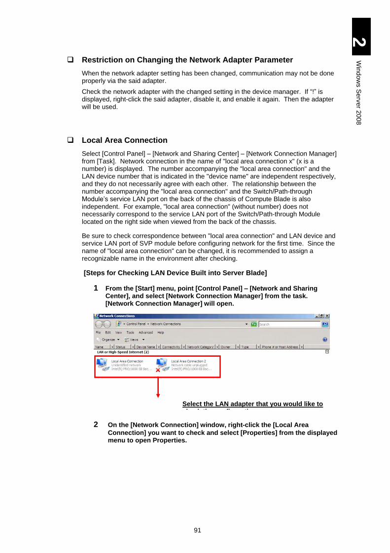
91
2
Win
dow
s S
erv
er 2
00
8
Restriction on Changing the Network Adapter Parameter
When the network adapter setting has been changed, communication may not be done properly via the said adapter.
Check the network adapter with the changed setting in the device manager. If “!” is displayed, right-click the said adapter, disable it, and enable it again. Then the adapter will be used.
Local Area Connection
Select [Control Panel] – [Network and Sharing Center] – [Network Connection Manager] from [Task]. Network connection in the name of "local area connection x" (x is a number) is displayed. The number accompanying the "local area connection" and the LAN device number that is indicated in the "device name" are independent respectively, and they do not necessarily agree with each other. The relationship between the number accompanying the "local area connection" and the Switch/Path-through Module’s service LAN port on the back of the chassis of Compute Blade is also independent. For example, "local area connection" (without number) does not necessarily correspond to the service LAN port of the Switch/Path-through Module located on the right side when viewed from the back of the chassis.
Be sure to check correspondence between "local area connection" and LAN device and service LAN port of SVP module before configuring network for the first time. Since the name of "local area connection" can be changed, it is recommended to assign a recognizable name in the environment after checking.
[Steps for Checking LAN Device Built into Server Blade]
1 From the [Start] menu, point [Control Panel] – [Network and Sharing Center], and select [Network Connection Manager] from the task. [Network Connection Manager] will open.
2 On the [Network Connection] window, right-click the [Local Area
Connection] you want to check and select [Properties] from the displayed menu to open Properties.
Select the LAN adapter that you would like to check the configuration
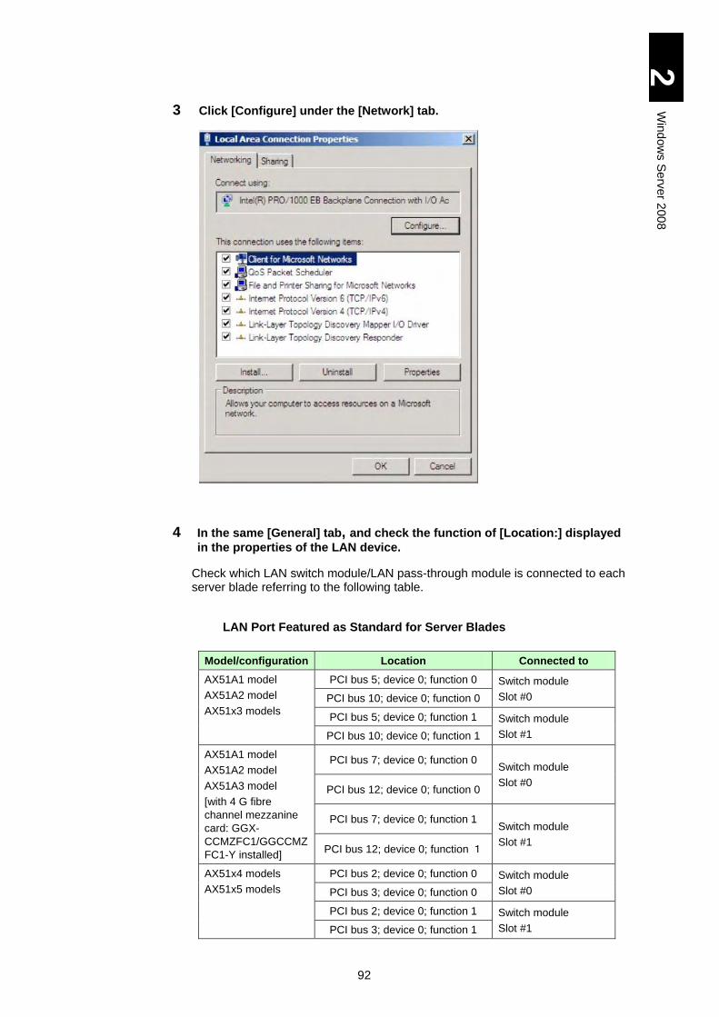
92
2
Win
dow
s S
erv
er 2
00
8
3 Click [Configure] under the [Network] tab.
4 In the same [General] tab, and check the function of [Location:] displayed
in the properties of the LAN device.
Check which LAN switch module/LAN pass-through module is connected to each server blade referring to the following table.
LAN Port Featured as Standard for Server Blades
Model/configuration Location Connected to
AX51A1 model
AX51A2 model
AX51x3 models
PCI bus 5; device 0; function 0 Switch module
Slot #0 PCI bus 10; device 0; function 0
PCI bus 5; device 0; function 1 Switch module
Slot #1 PCI bus 10; device 0; function 1
AX51A1 model
AX51A2 model
AX51A3 model
[with 4 G fibre
channel mezzanine
card: GGX-
CCMZFC1/GGCCMZ
FC1-Y installed]
PCI bus 7; device 0; function 0 Switch module
Slot #0 PCI bus 12; device 0; function 0
PCI bus 7; device 0; function 1 Switch module
Slot #1 PCI bus 12; device 0; function 1
AX51x4 models
AX51x5 models
PCI bus 2; device 0; function 0 Switch module
Slot #0 PCI bus 3; device 0; function 0
PCI bus 2; device 0; function 1 Switch module
Slot #1 PCI bus 3; device 0; function 1
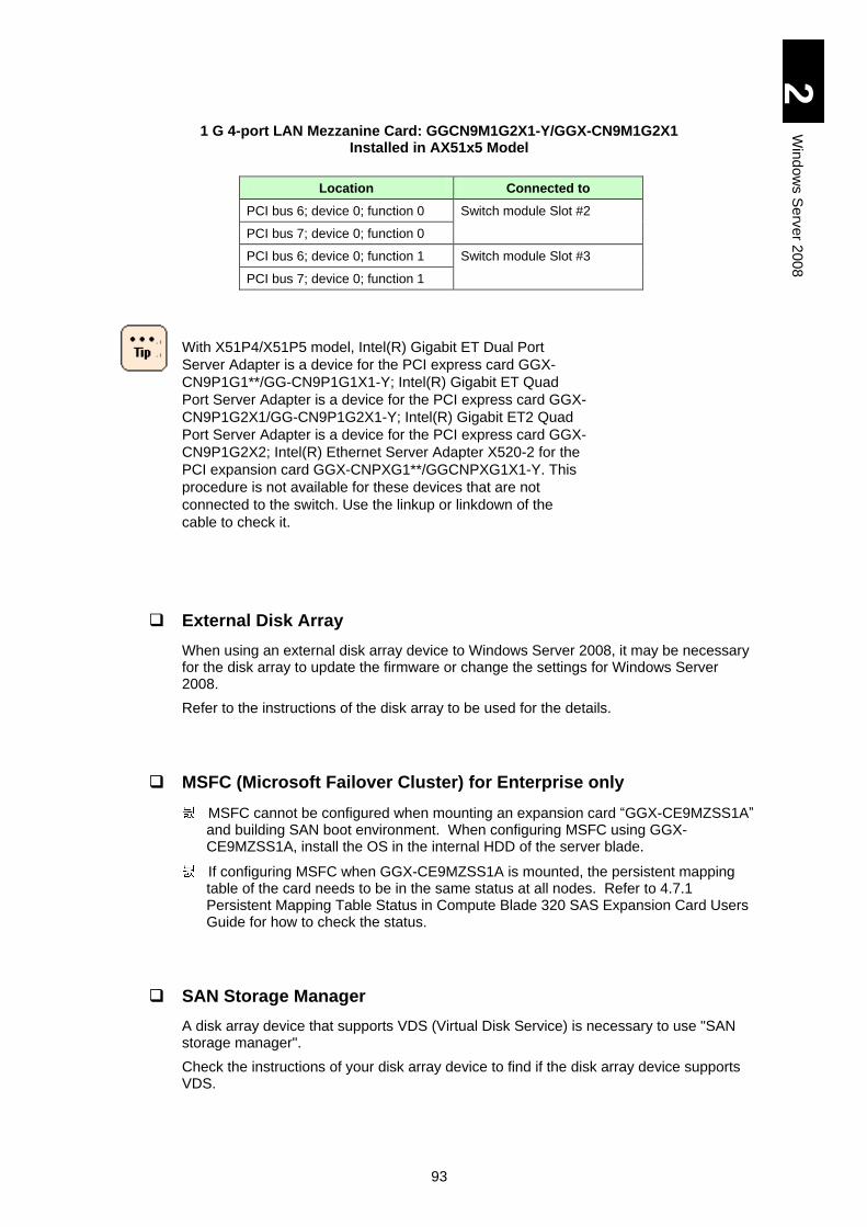
93
2
Win
dow
s S
erv
er 2
00
8
1 G 4-port LAN Mezzanine Card: GGCN9M1G2X1-Y/GGX-CN9M1G2X1 Installed in AX51x5 Model
Location Connected to
PCI bus 6; device 0; function 0 Switch module Slot #2
PCI bus 7; device 0; function 0
PCI bus 6; device 0; function 1 Switch module Slot #3
PCI bus 7; device 0; function 1
With X51P4/X51P5 model, Intel(R) Gigabit ET Dual Port
Server Adapter is a device for the PCI express card GGX-
CN9P1G1**/GG-CN9P1G1X1-Y; Intel(R) Gigabit ET Quad
Port Server Adapter is a device for the PCI express card GGX-
CN9P1G2X1/GG-CN9P1G2X1-Y; Intel(R) Gigabit ET2 Quad
Port Server Adapter is a device for the PCI express card GGX-
CN9P1G2X2; Intel(R) Ethernet Server Adapter X520-2 for the
PCI expansion card GGX-CNPXG1**/GGCNPXG1X1-Y. This
procedure is not available for these devices that are not
connected to the switch. Use the linkup or linkdown of the
cable to check it.
External Disk Array
When using an external disk array device to Windows Server 2008, it may be necessary for the disk array to update the firmware or change the settings for Windows Server 2008.
Refer to the instructions of the disk array to be used for the details.
MSFC (Microsoft Failover Cluster) for Enterprise only
MSFC cannot be configured when mounting an expansion card “GGX-CE9MZSS1A” and building SAN boot environment. When configuring MSFC using GGX-CE9MZSS1A, install the OS in the internal HDD of the server blade.
If configuring MSFC when GGX-CE9MZSS1A is mounted, the persistent mapping table of the card needs to be in the same status at all nodes. Refer to 4.7.1 Persistent Mapping Table Status in Compute Blade 320 SAS Expansion Card Users Guide for how to check the status.
SAN Storage Manager
A disk array device that supports VDS (Virtual Disk Service) is necessary to use "SAN storage manager".
Check the instructions of your disk array device to find if the disk array device supports VDS.
94
2
Win
dow
s S
erv
er 2
00
8
File Properties
[Details] of [File Properties] by Explorer may not display File Version, Product Information or Product Version. Not-displayed items may appear by rebooting the OS or changing solution/color bits.
Event Log on Network Adapter
\DEVICE {354C76B6-E426-4CEB-8015-BF991BA8D75F} instead of a network adapter name such as Intel® 82566DC-2 Gigabit Network Connection may be displayed in the event log explanation of the network adapter.
This occurs due to the specification, which will not affect the operation.
The network adapter name and the number in brackets (GUID) may be different depending on your environment.
Display of Network Adapter Connection
[Network Connection] or task tray status may not be quickly updated at the network adapter linkup. To find the status, select [View] in [Network Connections]. Then select [Latest Update] to update the connection.
Network Adapter Event Log at OS Boot
Error event may occur in the network adapter at the system boot. The network adapter may be linked down. Confirm that the targeted network adapter is connected in [Network Connections].
A linkup event may be recorded at the system boot in whatever status the network adapter is linked. Check the connection status of the targeted network adapter in [Network Connection].
Setup of link speed of LAN adapter
When using X51A3/ X51E3 model (Intel(R) PRO/1000 EB Backplane Connection with I/O Acceleration and Intel(R) PRO/1000 PF Dual Port Server Adapter), it is unable to change the link speed.
When using X51A4/ X51S4/ X51H4/ X51P4 model Intel(R) 82576 Gigabit Dual Port Server Network Connection), it is enable to choose one from 10Mbps/100Mbps/1.0Gbps It is set by properties of LAN devices (“Link speed and Duplex” of “Details” tab) If Intel PROSet is installed, see “Speed and Duplex” of “Link speed” tab. However, link speed of “1.0Gbps/full duplex” can not be changed even if the setting is changed.
Multipath
When a multipath (access route) is assigned to LU of an external disk array where to install the OS, change it to a single path before installing the OS. With multiple paths assigned to the LU, the installation fails. Install the OS with a single path, then install multipath software, and release the single-path routing.
When a multipath (access route) is assigned to LU of an external disk array where the OS has been installed, change it to a single-path routing before restoring the OS from
95
2
Win
dow
s S
erv
er 2
00
8
the backup files. With multiple paths assigned to the LU, the restoration may fail. Check notes on the backup software referring to the manual beforehand.
It is common to change a multipath to a single-path routing from the management utility of an external disk array. Refer to the manual of the external disk array device.
USB Memory
With a USB memory connected, do not power on the system equipment or perform reboot-up. Boot the OS and then connect the USB memory. After that, confirm that drive letters of other drives are not changed.
iSCSI
An environment with iSCSI connection has the following restrictions.
Do not include a LAN adapter used for iSCSI connection in configuration for a team or VLAN with Intel PROSet.
When an OS is installed in the external disk array device with iSCSI connection, select “Safe Mode with Networking” for booting the OS in safe mode.
96
2
Win
dow
s S
erv
er 2
00
8
Restrictions on Windows Server 2008 SP2
Read through Restrictions on Use of Windows Server 2008, and then refer to this subsection.
Refer to Microsoft Website for information on Windows Server
2008 SP2.
Event Viewer
A lot of the following event is recorded in the system event log at the OS boot after applying Windows Server 2008 SP2. There, however, is no problem.
Event ID: 4374
Event source: Microsoft-Windows-Servicing
Event Level: Warning
Description: Windows Servicing identified that package KB905866 (Update) is not applicable for this sys.
The following event is recorded in the system event log at the OS boot after applying Windows Server 2008 SP2. There, however, is no problem.
Event ID: 7026
Event source: Service Control Manager
Event Level: Error
Description: The following boot-start or system-start driver(s) failed to load: storflt
Refer to the following Website for further details.
http://support.microsoft.com/kb/971527
Microsoft Multipath I/O (MPIO)
When configuring multipath environment with “Multipath I/O” enabled, a standard function to the OS, without installing Windows Server 2008 SP2, apply the following update module: KB967752 before installing SP2. If you install Windows Server 2008 SP2 without applying the update module and uninstall it, access to the multi-path disk may not be available and the OS may not be able to boot up.
Refer to the following Website for further details.
http://support.microsoft.com/kb/967752
97
2
Win
dow
s S
erv
er 2
00
8
Device Manager
A device, which is disabled in Device manager without installing Windows Server 2008 SP2, has automatically been Enabled after installing Windows Server 2008 SP2. Check Disabled devices in Device Manager before installing Windows Server 2008 SP, and disable them again if they are Enabled after installing Windows Server 2008 SP.
Local Area Connection
Local Area Connection, which is disabled in network Connection in Control Panel without installing Windows Server 2008 SP2, has automatically been Enabled after installing Windows Server 2008 SP2. Check each Local Area Connection before installing Windows Server 2008 S2, and disable it again if it is Enabled after installing Windows Server 2008 SP2.
Network Communication Broken after Installing SP2
With A1/A2/A3/E3 model server blades, network communication has been not available at the OS boot after installing Windows Server 2008 SP2. Perform the steps below to set the network adapter after installing Windows Server 2008 SP2.
1 Click [Start] > [Server manager].
2 Select [Diagnosis] > [Device Manager].
3 Find the following network adapter.
Intel(R) PRO/1000 EB Backplane Connection with I/O Acceleration
4. Double-click the target adapter to open [Properties].
5 Click [Advanced] tab, set “Receive Side Scaling” in Properties to Disabled.
6 When multiple target adapters exist, set all adapters to Disabled.
7 When the settings are complete, reboot the OS.
98
2
Win
dow
s S
erv
er 2
00
8
Multipath I/O (MPIO) with OS in the External Disk Array via iSCSI
This subsection describes how to set the multipath I/O (MPIO) when the OS is installed in an external disk array device connected via iSCSI.
Perform setup procedures to Apply Patches before setting MPIO. If you set MPIO before applying patches required for iSCSI, STOP error may occur.
Perform the setup to step 5 with the secondary path disabled (Boot: Disable), not with enabled (Boot: SECONDARY) in iSCSI BIOS Setup Utility. If you enable the secondary path (Boot: SECONDARY) before completing step 5, STOP error may occur.
Even with MPIO enabled, if the secondary path alone is connected due to failure in the path, which is set to Primary (Boot: PRIMARY) in the iSCSI BIOS Setup Utility, memory dumps cannot be collected.
Refer to User’s Guide for further details of iSCSI BIOS Setup Utility.
How to Add Multipath I/O
The following steps show how to add MPIO.
1 Power on the server blade, boot Windows, and log on as Administrator.
2 Click [Start] > [Administrative Tools] > [Server Manager] to open. Select [Features] in [Server Manager], and click [Feature overview] > [Add features].
3 When [Select feature] screen is displayed in [Add Feature Wizard], put a checkmark in [Multipath I/O], and then click [Next]
4 [Confirm Installation Selections] screen is displayed. Check that Multipath I/O in the pane, and click [Install].
5 Soon [Installation Results] screen is displayed. Check that “Installation succeeded” is checked on the screen, and click [Close].
How to Configure Multipath I/O in iSCSI
The following steps show how to configure multipath in iSCSI.
1 Power on the server blade, boot Windows, and log on as Administrator.
2 Click [Start] > [Administrative Tools] > [MPIO] to open [MPIO Properties].
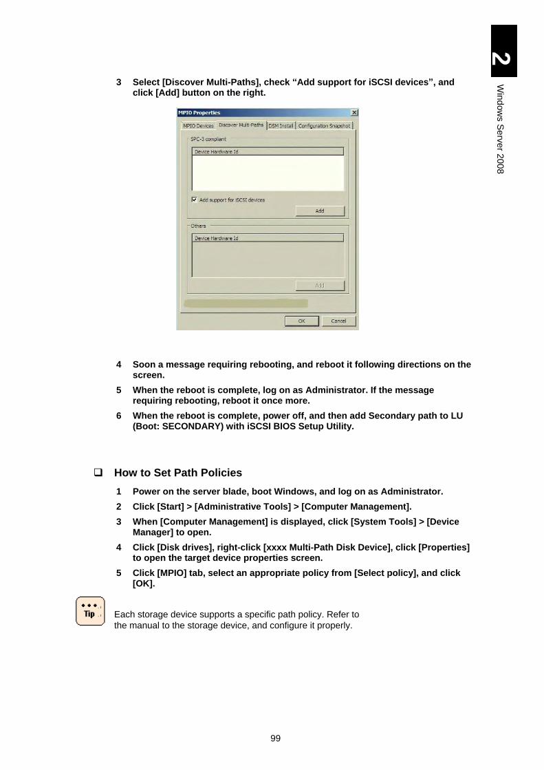
99
2
Win
dow
s S
erv
er 2
00
8
3 Select [Discover Multi-Paths], check “Add support for iSCSI devices”, and click [Add] button on the right.
4 Soon a message requiring rebooting, and reboot it following directions on the screen.
5 When the reboot is complete, log on as Administrator. If the message requiring rebooting, reboot it once more.
6 When the reboot is complete, power off, and then add Secondary path to LU (Boot: SECONDARY) with iSCSI BIOS Setup Utility.
How to Set Path Policies
1 Power on the server blade, boot Windows, and log on as Administrator.
2 Click [Start] > [Administrative Tools] > [Computer Management].
3 When [Computer Management] is displayed, click [System Tools] > [Device Manager] to open.
4 Click [Disk drives], right-click [xxxx Multi-Path Disk Device], click [Properties] to open the target device properties screen.
5 Click [MPIO] tab, select an appropriate policy from [Select policy], and click [OK].
Each storage device supports a specific path policy. Refer to
the manual to the storage device, and configure it properly.
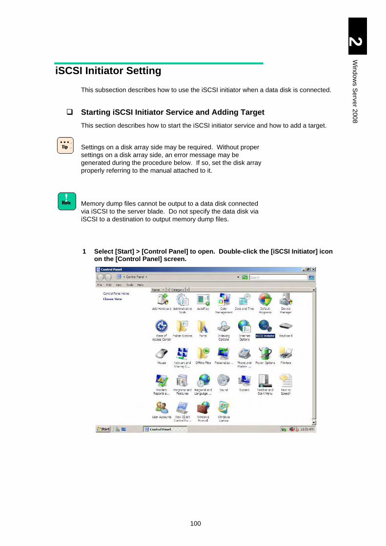
100
2
Win
dow
s S
erv
er 2
00
8
iSCSI Initiator Setting
This subsection describes how to use the iSCSI initiator when a data disk is connected.
Starting iSCSI Initiator Service and Adding Target
This section describes how to start the iSCSI initiator service and how to add a target.
Settings on a disk array side may be required. Without proper
settings on a disk array side, an error message may be
generated during the procedure below. If so, set the disk array
properly referring to the manual attached to it.
Memory dump files cannot be output to a data disk connected
via iSCSI to the server blade. Do not specify the data disk via
iSCSI to a destination to output memory dump files.
1 Select [Start] > [Control Panel] to open. Double-click the [iSCSI Initiator] icon on the [Control Panel] screen.
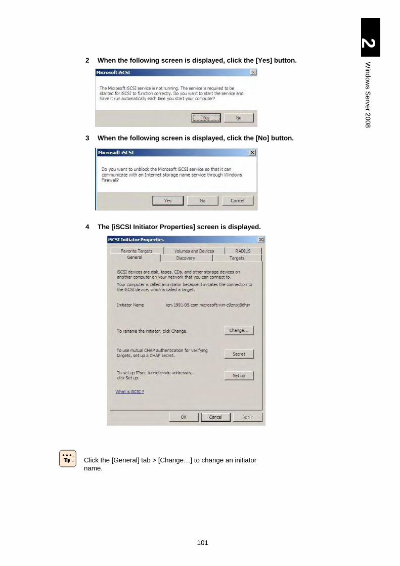
101
2
Win
dow
s S
erv
er 2
00
8
2 When the following screen is displayed, click the [Yes] button.
3 When the following screen is displayed, click the [No] button.
4 The [iSCSI Initiator Properties] screen is displayed.
Click the [General] tab > [Change…] to change an initiator
name.
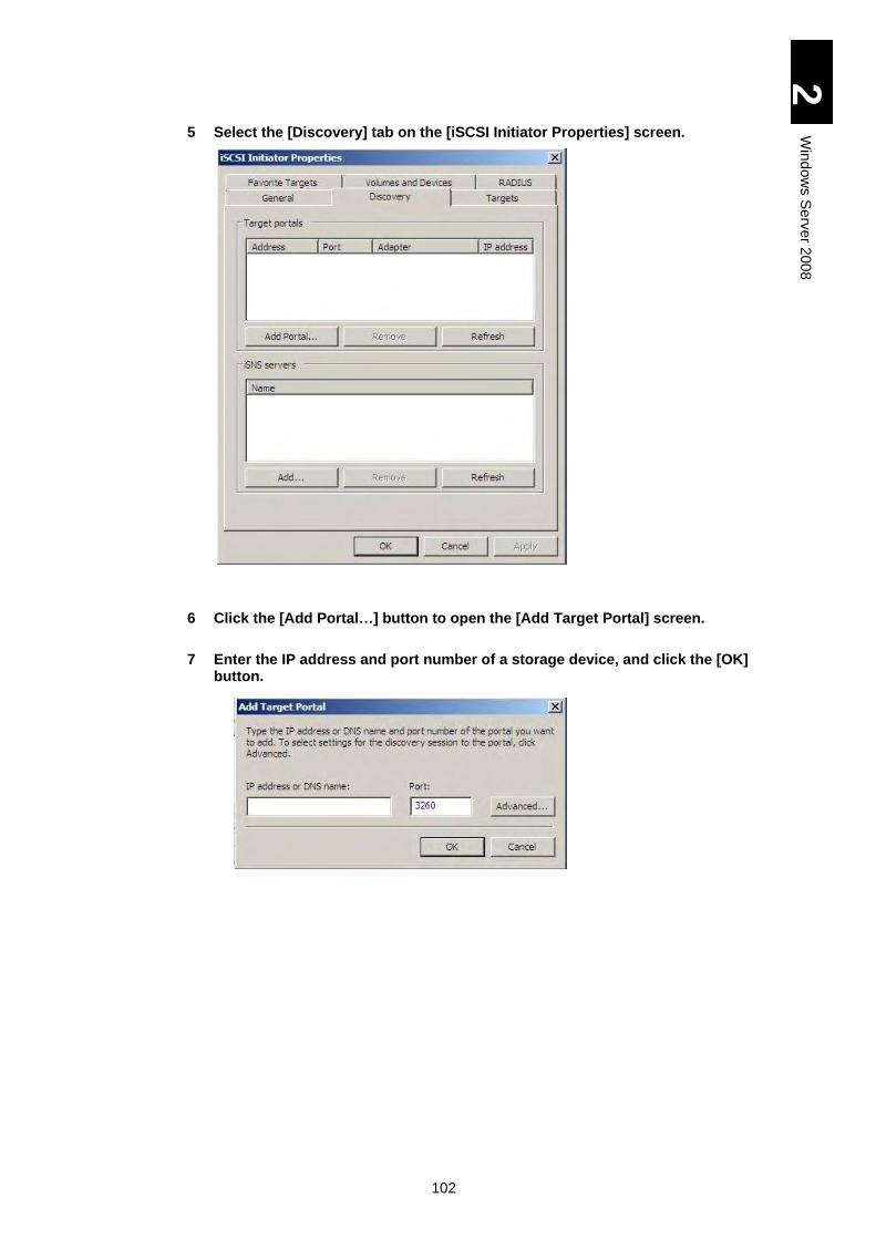
102
2
Win
dow
s S
erv
er 2
00
8
5 Select the [Discovery] tab on the [iSCSI Initiator Properties] screen.
6 Click the [Add Portal…] button to open the [Add Target Portal] screen.
7 Enter the IP address and port number of a storage device, and click the [OK] button.
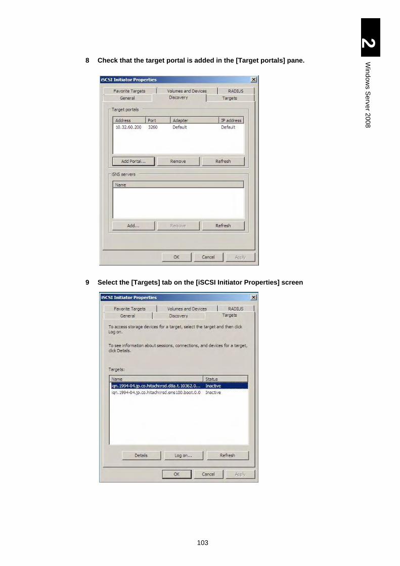
103
2
Win
dow
s S
erv
er 2
00
8
8 Check that the target portal is added in the [Target portals] pane.
9 Select the [Targets] tab on the [iSCSI Initiator Properties] screen
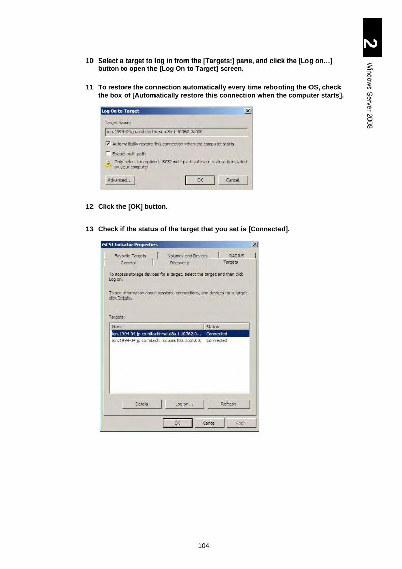
104
2
Win
dow
s S
erv
er 2
00
8
10 Select a target to log in from the [Targets:] pane, and click the [Log on…] button to open the [Log On to Target] screen.
11 To restore the connection automatically every time rebooting the OS, check the box of [Automatically restore this connection when the computer starts].
12 Click the [OK] button.
13 Check if the status of the target that you set is [Connected].
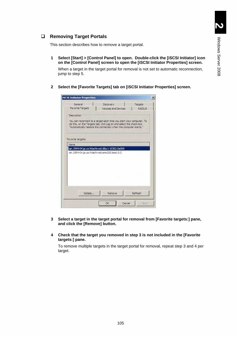
105
2
Win
dow
s S
erv
er 2
00
8
Removing Target Portals
This section describes how to remove a target portal.
1 Select [Start] > [Control Panel] to open. Double-click the [iSCSI Initiator] icon on the [Control Panel] screen to open the [iSCSI Initiator Properties] screen.
When a target in the target portal for removal is not set to automatic reconnection, jump to step 5.
2 Select the [Favorite Targets] tab on [iSCSI Initiator Properties] screen.
3 Select a target in the target portal for removal from [Favorite targets:] pane, and click the [Remove] button.
4 Check that the target you removed in step 3 is not included in the [Favorite targets:] pane.
To remove multiple targets in the target portal for removal, repeat step 3 and 4 per target.
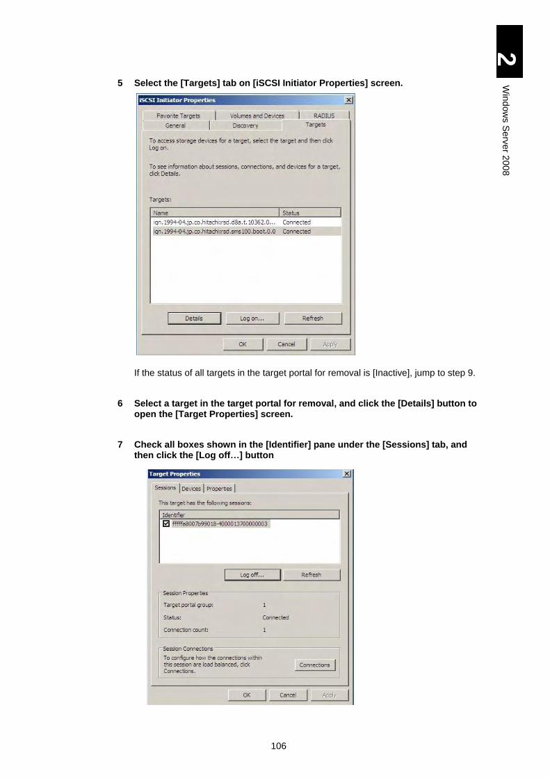
106
2
Win
dow
s S
erv
er 2
00
8
5 Select the [Targets] tab on [iSCSI Initiator Properties] screen.
If the status of all targets in the target portal for removal is [Inactive], jump to step 9.
6 Select a target in the target portal for removal, and click the [Details] button to open the [Target Properties] screen.
7 Check all boxes shown in the [Identifier] pane under the [Sessions] tab, and then click the [Log off…] button
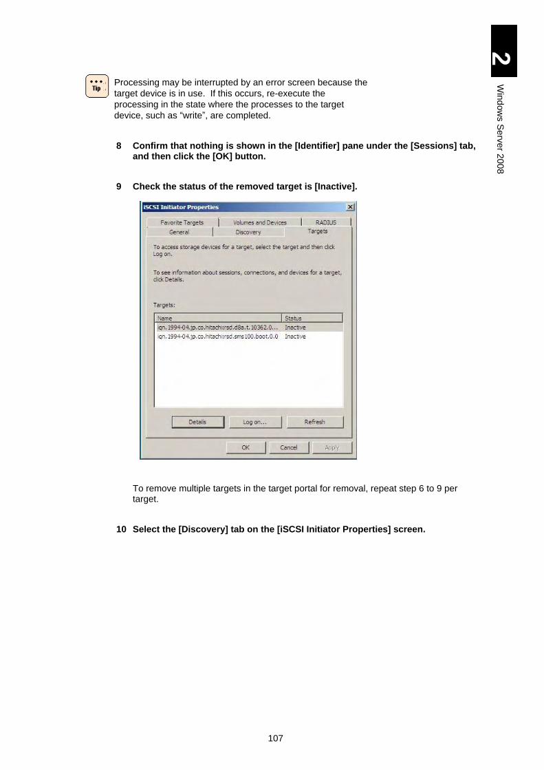
107
2
Win
dow
s S
erv
er 2
00
8
Processing may be interrupted by an error screen because the
target device is in use. If this occurs, re-execute the
processing in the state where the processes to the target
device, such as “write”, are completed.
8 Confirm that nothing is shown in the [Identifier] pane under the [Sessions] tab, and then click the [OK] button.
9 Check the status of the removed target is [Inactive].
To remove multiple targets in the target portal for removal, repeat step 6 to 9 per target.
10 Select the [Discovery] tab on the [iSCSI Initiator Properties] screen.
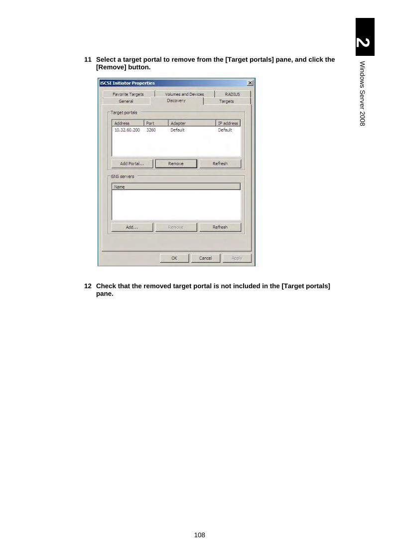
108
2
Win
dow
s S
erv
er 2
00
8
11 Select a target portal to remove from the [Target portals] pane, and click the [Remove] button.
12 Check that the removed target portal is not included in the [Target portals] pane.
109
2
Win
dow
s S
erv
er 2
00
8
Windows Server 2008 Setup
This section explains the setup for Windows Server 2008.
For the installation procedure of the driver for expanded board, refer to the manual of expanded board.
NOTICE
Re-setup causes the hard disk data to disappear. Back up data that you need in advance.
When installing Windows server 2008, driver, utility, use the
DriverKit 01-06 or a later version CD-ROM attached to the
server blade. .
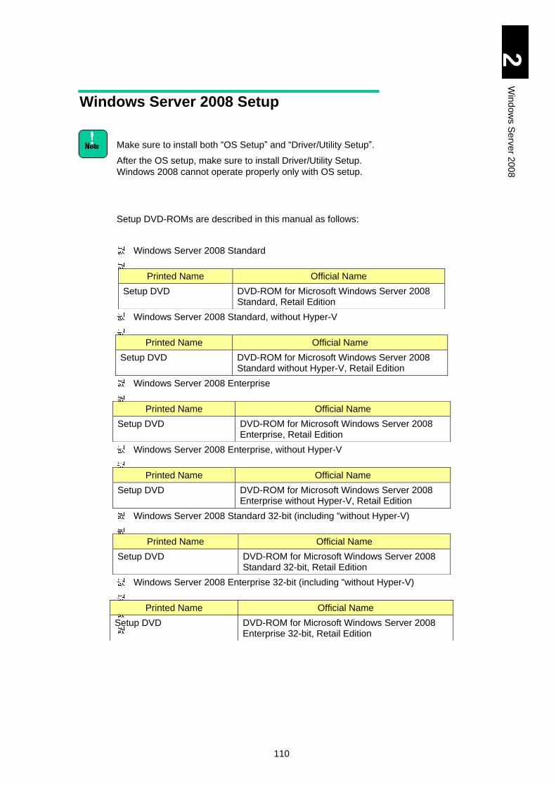
110
2
Win
dow
s S
erv
er 2
00
8
Windows Server 2008 Setup
Make sure to install both “OS Setup” and “Driver/Utility Setup”.
After the OS setup, make sure to install Driver/Utility Setup.
Windows 2008 cannot operate properly only with OS setup.
Setup DVD-ROMs are described in this manual as follows:
Windows Server 2008 Standard
Windows Server 2008 Standard, without Hyper-V
Windows Server 2008 Enterprise
Windows Server 2008 Enterprise, without Hyper-V
Windows Server 2008 Standard 32-bit (including “without Hyper-V)
Windows Server 2008 Enterprise 32-bit (including “without Hyper-V)
Printed Name Official Name
Setup DVD DVD-ROM for Microsoft Windows Server 2008 Standard, Retail Edition
Printed Name Official Name
Setup DVD DVD-ROM for Microsoft Windows Server 2008 Standard without Hyper-V, Retail Edition
Printed Name Official Name
Setup DVD DVD-ROM for Microsoft Windows Server 2008 Enterprise, Retail Edition
Printed Name Official Name
Setup DVD DVD-ROM for Microsoft Windows Server 2008 Enterprise without Hyper-V, Retail Edition
Printed Name Official Name
Setup DVD DVD-ROM for Microsoft Windows Server 2008 Standard 32-bit, Retail Edition
Printed Name Official Name
Setup DVD DVD-ROM for Microsoft Windows Server 2008 Enterprise 32-bit, Retail Edition

111
2
Win
dow
s S
erv
er 2
00
8
Setup Flow
Setup with Compute Systems Installer
Setup without Compute Systems Installer
Back up necessary files. (Use backup program.)
Set partition to the disk array. (Carry out as necessary.)
Initialize BIOS settings. (as necessary)
Before Setup
Install the OS completely.
OS Setup
Component/Utility Installation
Update the OS using Windows Update.
Set up each component and utility.
Set up other applications as necessary.
Update/Setting/Application Installation
Setup with Compute Systems Installer
Update the Registry.
Install the drivers: Chipset Driver / LAN driver / Display driver
Install MegaRAID Storage Manager as necessary.
Install.Intel(R) PROSet as necessary
112
2
Win
dow
s S
erv
er 2
00
8
Details of Windows Server 2008 Setup
This section describes how to setup Windows Server 2008.
Restrictions on Setup
At the setup, connect to the server blade using the remote console application. It is recommended that the CD-ROM/DVD-ROM drive should be connected to the USB port on the server blade front panel.
Remote FD of the remote-console application
When you use remote FD of the remote-console application, driver FD cannot be recognized on Windows setup.
Connect the USB FD drive to the USB port on the server blade front panel when you use FD. It is recommended for Windows 2008 that drivers should be read from CD-ROM not from FD.
Capacity of a logical drive for installing the OS
Set the capacity of a logical drive for installing the OS to 2 TB or less. If with more then 2 TB, the OS can recognize just up to 2 TB.
In case installing OS into the EXTERNAL DISK ARRAY DEVICE
Set 'one path' to the Fibre at the target LU before installing OS. If several paths set to the target LU, the installation fails. Generally use the management utility of the external disk array device for setting ‘one path’. Refer the external disk array device’s manual for the detail. Install multiple path software after the OS installation, and cancel the one-path setting.
Set RAID device to use LUN0 as OS. And, confirm that 'Boot Priority' of the target LU is the first priority at System Boot menu. To display System Boot Menu, press the [F2] key immediately after booting the server blade.
At reinstalling OS, Non-target LU should be hidden temporarily for safety. Confirm whether temporarily to be able to mask Non-target LU at the setting of the external RAID device, or to be able to remove them from Group.
Setting partition (drive)
The partition (drive) to which the OS is installed Install the OS to the first partition of the HDD. All programs and data in the partition will be deleted.
Setting write cache
Confirm that the write cache of a disk in which Windows 2008 is installed is in the write through mode before the setup. If it is in the write back mode, change it to the write through mode. Refer to MegaRAID Storage Manager manual for how to change the write mode.
113
2
Win
dow
s S
erv
er 2
00
8
Refer to the following folder in DriverKit CD-ROM for
MegaRAID Storage Manager manual. d: is the CD/DVD drive
name.
d:\MANUAL\MSManager.pdf (for X51A2/ X51A3/ X51E3/
X51A4/ X51H4 models)
d:\MANUAL\MSManager2.pdf (for X51R4/ X51A5/ X51H5/
X51R5 model)
[Driver Kit version 05-04 or later]
d:\X51x5\MANUAL\MSManager2.pdf
DVD drive
Windows Server 2008 setup needs a DVD-ROM drive (hereinafter referred to as DVD drive).
DVD-ROM ejection
Press the eject button of the DVD drive only when changing DVD-ROM media. Otherwise, the OS setup must be reinstalled.
With multiple disks and partitions (drives)
When multiple disks and partitions (drives) are installed in the system equipment, multiple disks are displayed as the target for installation. The number of a disk and the order of disks, however, are not fixed. When performing the setup with multiple disks viewed, determine the target disk for installation by its size not by the order or its number.
This is why we recommend that you should configure different capacity of disk arrays and hard disks installed in the system per drive.
In case that you select a wrong disk or partition as the target, existent partitions, or existent data may be removed. For further details, refer to the following Microsoft website.
http://support.microsoft.com/kb/937251
You can find disk capacity in “MegaRAID WebBIOS” or system BIOS. For details, refer to Chapter 5 “Server Blade Setup” in User’s Guide.
When installing the OS in an external disk array device connected via iSCSI
Settings such as iSCSI BIOS Setup Utility are required before Windows 2008 is installed in an external disk array device connected via iSCSI. Configure those settings referring to User’s Guide.
Set up the OS with the secondary path Disabled (Boot: Disable), not Enabled (Boot: SECONDARY) with iSCSI BIOS Setup Utility. Refer to Multipath I/O (MPIO) with OS in the External Disk Array via iSCSI to enable the secondary path (Boot: SECONDARY).
114
2
Win
dow
s S
erv
er 2
00
8
Setup Steps
NOTICE
Re-setup causes the hard disk data to disappear. Back up data that you need in advance.
When external disk array device or SCSI device is connected,
turn off the device power before starting the setup. Otherwise,
the installing destination may not be recognized correctly.
1 Turn on the system equipment, and quickly insert the Setup DVD to the
DVD drive.
2 If a message "Press any key to boot from CD or DVD" appears, press any
key without giving a pause.
When pressing the key late, the existing OS starts instead of
the CD-ROM. In that case, go back to step 1.
When pressing the key more than once, [Windows Boot
Manager] may start. In that case, select Windows Setup [EMS
Enabled] and continue the setup.
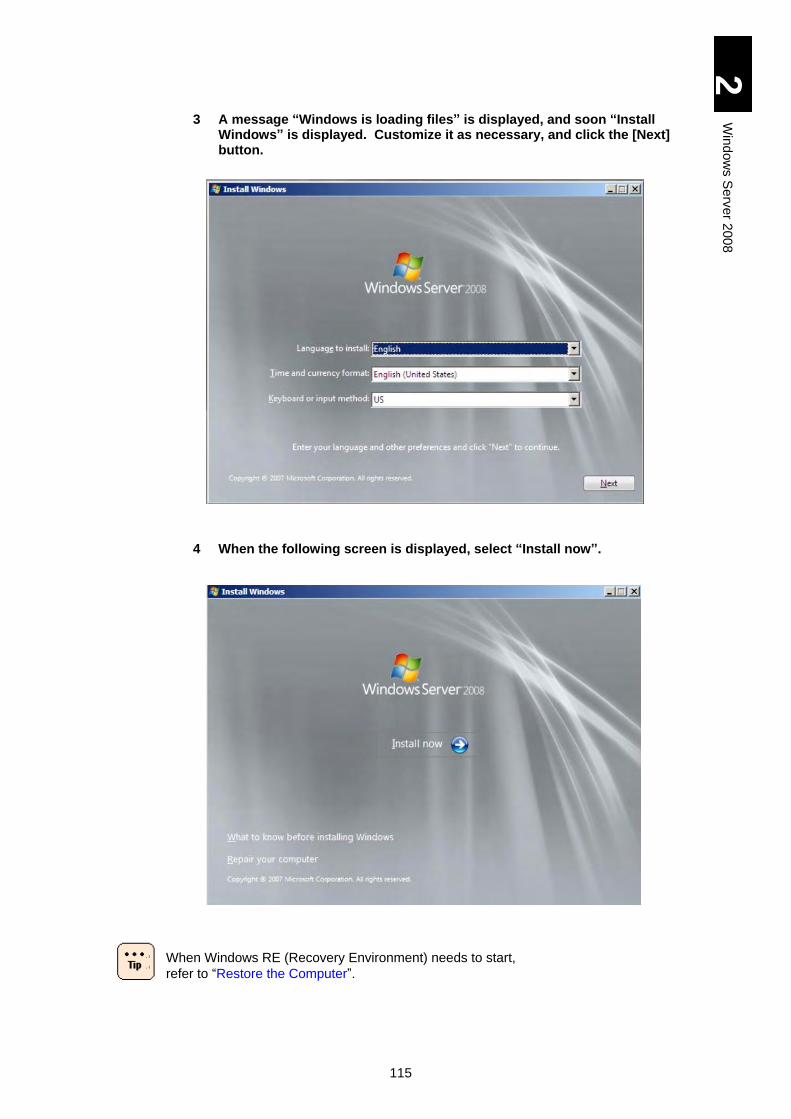
115
2
Win
dow
s S
erv
er 2
00
8
3 A message “Windows is loading files” is displayed, and soon “Install Windows” is displayed. Customize it as necessary, and click the [Next] button.
4 When the following screen is displayed, select “Install now”.
When Windows RE (Recovery Environment) needs to start,
refer to “Restore the Computer”.
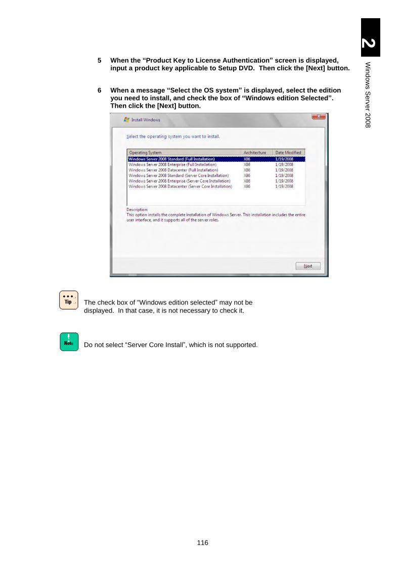
116
2
Win
dow
s S
erv
er 2
00
8
5 When the “Product Key to License Authentication” screen is displayed, input a product key applicable to Setup DVD. Then click the [Next] button.
6 When a message “Select the OS system” is displayed, select the edition you need to install, and check the box of “Windows edition Selected”. Then click the [Next] button.
The check box of “Windows edition selected” may not be
displayed. In that case, it is not necessary to check it.
Do not select “Server Core Install”, which is not supported.
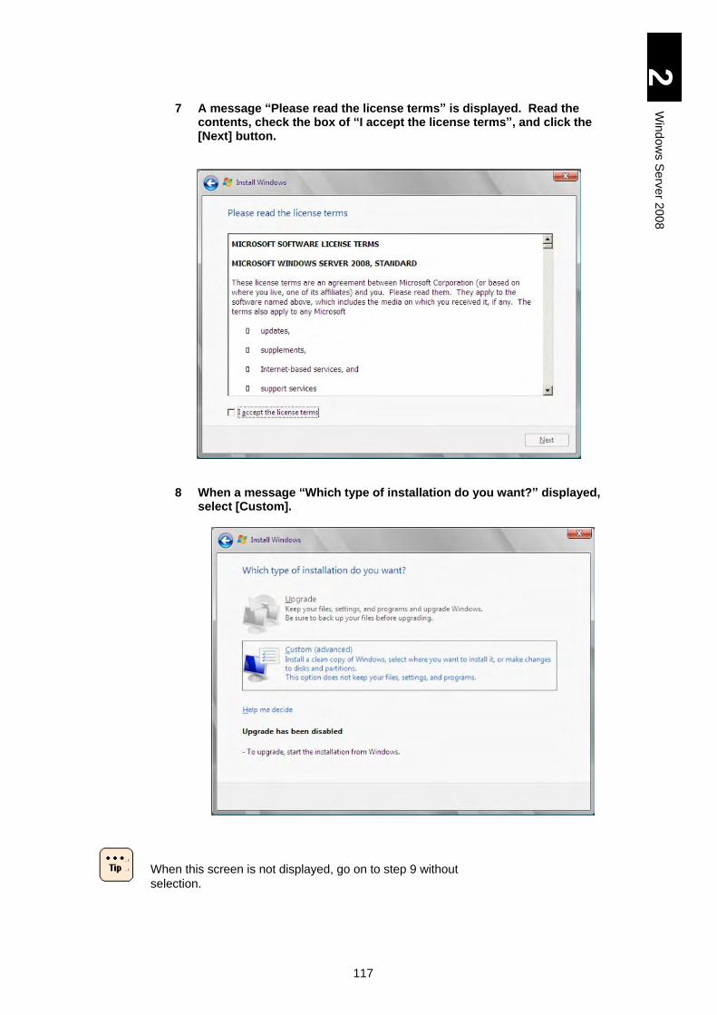
117
2
Win
dow
s S
erv
er 2
00
8
7 A message “Please read the license terms” is displayed. Read the contents, check the box of “I accept the license terms”, and click the [Next] button.
8 When a message “Which type of installation do you want?” displayed, select [Custom].
When this screen is not displayed, go on to step 9 without
selection.
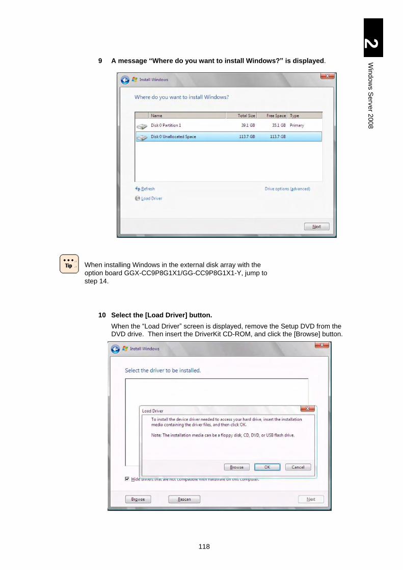
118
2
Win
dow
s S
erv
er 2
00
8
9 A message “Where do you want to install Windows?” is displayed.
When installing Windows in the external disk array with the
option board GGX-CC9P8G1X1/GG-CC9P8G1X1-Y, jump to
step 14.
10 Select the [Load Driver] button.
When the “Load Driver” screen is displayed, remove the Setup DVD from the DVD drive. Then insert the DriverKit CD-ROM, and click the [Browse] button.
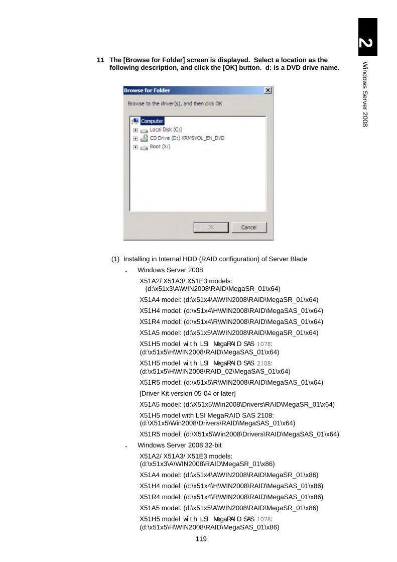
119
2
Win
dow
s S
erv
er 2
00
8
11 The [Browse for Folder] screen is displayed. Select a location as the following description, and click the [OK] button. d: is a DVD drive name.
(1) Installing in Internal HDD (RAID configuration) of Server Blade
Windows Server 2008
X51A2/ X51A3/ X51E3 models: (d:\x51x3\A\WIN2008\RAID\MegaSR_01\x64)
X51A4 model: (d:\x51x4\A\WIN2008\RAID\MegaSR_01\x64)
X51H4 model: (d:\x51x4\H\WIN2008\RAID\MegaSAS_01\x64)
X51R4 model: (d:\x51x4\R\WIN2008\RAID\MegaSAS_01\x64)
X51A5 model: (d:\x51x5\A\WIN2008\RAID\MegaSR_01\x64)
X51H5 model wi t h LSI MegaRAI D SAS 1078:
(d:\x51x5\H\WIN2008\RAID\MegaSAS_01\x64)
X51H5 model wi t h LSI MegaRAI D SAS 2108: (d:\x51x5\H\WIN2008\RAID_02\MegaSAS_01\x64)
X51R5 model: (d:\x51x5\R\WIN2008\RAID\MegaSAS_01\x64)
[Driver Kit version 05-04 or later]
X51A5 model: (d:\X51x5\Win2008\Drivers\RAID\MegaSR_01\x64)
X51H5 model with LSI MegaRAID SAS 2108: (d:\X51x5\Win2008\Drivers\RAID\MegaSAS_01\x64)
X51R5 model: (d:\X51x5\Win2008\Drivers\RAID\MegaSAS_01\x64)
Windows Server 2008 32-bit
X51A2/ X51A3/ X51E3 models: (d:\x51x3\A\WIN2008\RAID\MegaSR_01\x86)
X51A4 model: (d:\x51x4\A\WIN2008\RAID\MegaSR_01\x86)
X51H4 model: (d:\x51x4\H\WIN2008\RAID\MegaSAS_01\x86)
X51R4 model: (d:\x51x4\R\WIN2008\RAID\MegaSAS_01\x86)
X51A5 model: (d:\x51x5\A\WIN2008\RAID\MegaSR_01\x86)
X51H5 model wi t h LSI MegaRAI D SAS 1078:
(d:\x51x5\H\WIN2008\RAID\MegaSAS_01\x86)
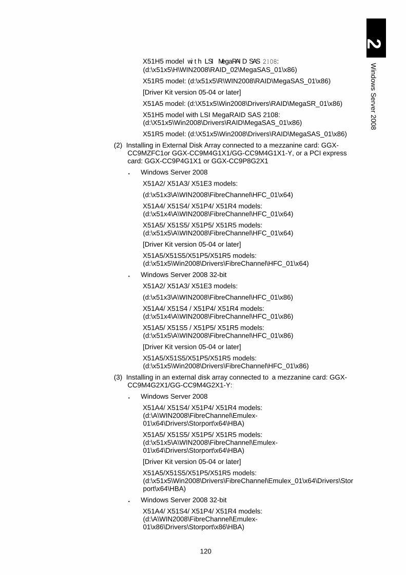
120
2
Win
dow
s S
erv
er 2
00
8
X51H5 model wi t h LSI MegaRAI D SAS 2108: (d:\x51x5\H\WIN2008\RAID_02\MegaSAS_01\x86)
X51R5 model: (d:\x51x5\R\WIN2008\RAID\MegaSAS_01\x86)
[Driver Kit version 05-04 or later]
X51A5 model: (d:\X51x5\Win2008\Drivers\RAID\MegaSR_01\x86)
X51H5 model with LSI MegaRAID SAS 2108: (d:\X51x5\Win2008\Drivers\RAID\MegaSAS_01\x86)
X51R5 model: (d:\X51x5\Win2008\Drivers\RAID\MegaSAS_01\x86)
(2) Installing in External Disk Array connected to a mezzanine card: GGX-CC9MZFC1or GGX-CC9M4G1X1/GG-CC9M4G1X1-Y, or a PCI express card: GGX-CC9P4G1X1 or GGX-CC9P8G2X1
Windows Server 2008
X51A2/ X51A3/ X51E3 models:
(d:\x51x3\A\WIN2008\FibreChannel\HFC_01\x64)
X51A4/ X51S4/ X51P4/ X51R4 models: (d:\x51x4\A\WIN2008\FibreChannel\HFC_01\x64)
X51A5/ X51S5/ X51P5/ X51R5 models: (d:\x51x5\A\WIN2008\FibreChannel\HFC_01\x64)
[Driver Kit version 05-04 or later]
X51A5/X51S5/X51P5/X51R5 models: (d:\x51x5\Win2008\Drivers\FibreChannel\HFC_01\x64)
Windows Server 2008 32-bit
X51A2/ X51A3/ X51E3 models:
(d:\x51x3\A\WIN2008\FibreChannel\HFC_01\x86)
X51A4/ X51S4 / X51P4/ X51R4 models: (d:\x51x4\A\WIN2008\FibreChannel\HFC_01\x86)
X51A5/ X51S5 / X51P5/ X51R5 models: (d:\x51x5\A\WIN2008\FibreChannel\HFC_01\x86)
[Driver Kit version 05-04 or later]
X51A5/X51S5/X51P5/X51R5 models: (d:\x51x5\Win2008\Drivers\FibreChannel\HFC_01\x86)
(3) Installing in an external disk array connected to a mezzanine card: GGX-CC9M4G2X1/GG-CC9M4G2X1-Y:
Windows Server 2008
X51A4/ X51S4/ X51P4/ X51R4 models: (d:\A\WIN2008\FibreChannel\Emulex-01\x64\Drivers\Storport\x64\HBA)
X51A5/ X51S5/ X51P5/ X51R5 models: (d:\x51x5\A\WIN2008\FibreChannel\Emulex-01\x64\Drivers\Storport\x64\HBA)
[Driver Kit version 05-04 or later]
X51A5/X51S5/X51P5/X51R5 models: (d:\x51x5\Win2008\Drivers\FibreChannel\Emulex_01\x64\Drivers\Storport\x64\HBA)
Windows Server 2008 32-bit
X51A4/ X51S4/ X51P4/ X51R4 models: (d:\A\WIN2008\FibreChannel\Emulex-01\x86\Drivers\Storport\x86\HBA)
121
2
Win
dow
s S
erv
er 2
00
8
X51A5/ X51S5/ X51P5/ X51R5 models: (d:\x51x5\A\WIN2008\FibreChannel\Emulex-01\x86\Drivers\Storport\x86\HBA)
[Driver Kit version 05-04 or later]
X51A5/X51S5/X51P5/X51R5 models: (d:\x51x5\Win2008\Drivers\FibreChannel\Emulex_01\x86\Drivers\Storport\x86\HBA)
(4) Installing in SSD in P5 model server blade:
Windows Server 2008
X51P5 model: (d:\x51x5\H\WIN2008\SAS\LSI_SAS_01\x64)
[Driver Kit version 05-04 or later]
X51P5 model: (d:\x51x5\Win2008\Drivers\SAS\LSI_SAS_01\x64)
Windows Server 2008 32-bit
X51P5 model: (d:\x51x5\H\WIN2008\SAS\LSI_SAS_01\x86)
[Driver Kit version 05-04 or later]
X51P5 model: (d:\x51x5\Win2008\Drivers\SAS\LSI_SAS_01\x86)
(5) Installing in an external disk array device via iSCSI with A5/S5/P5/R5
Windows Server 2008
X51A5/X51S5/X51P5/X51R5 models: (d:\x51x5\A\WIN2008\LAN\ INTEL_01\x64)
[Driver Kit version 05-04 or later]
X51A5/X51S5/X51P5/X51R5 models: (d:\x51x5\Win2008\Drivers\LAN\INTEL_01\x64)
Windows Server 2008 32-bit
X51A5/X51S5/X51P5/X51R5 models: (d:\x51x5\A\WIN2008\LAN\ INTEL_01\x86)
[Driver Kit version 05-04 or later]
X51A5/X51S5/X51P5/X51R5 models: (d:\x51x5\Win2008\Drivers\LAN\INTEL_01\x86)
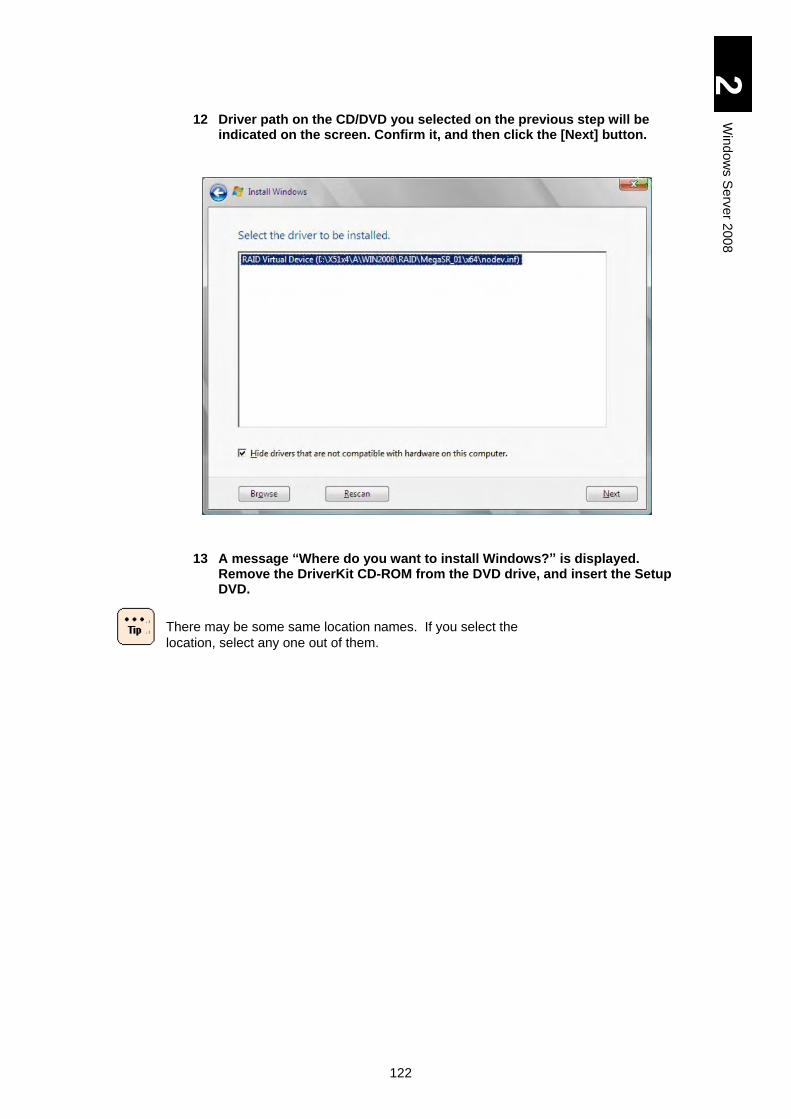
122
2
Win
dow
s S
erv
er 2
00
8
12 Driver path on the CD/DVD you selected on the previous step will be indicated on the screen. Confirm it, and then click the [Next] button.
13 A message “Where do you want to install Windows?” is displayed. Remove the DriverKit CD-ROM from the DVD drive, and insert the Setup DVD.
There may be some same location names. If you select the
location, select any one out of them.
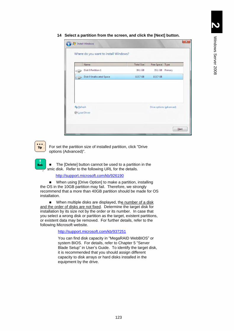
123
2
Win
dow
s S
erv
er 2
00
8
14 Select a partition from the screen, and click the [Next] button.
For set the partition size of installed partition, click “Drive
options (Advanced)“.
The [Delete] button cannot be used to a partition in the dynamic disk. Refer to the following URL for the details.
http://support.microsoft.com/kb/926190
When using [Drive Option] to make a partition, installing the OS in the 10GB partition may fail. Therefore, we strongly recommend that a more than 40GB partition should be made for OS installation.
When multiple disks are displayed, the number of a disk and the order of disks are not fixed. Determine the target disk for installation by its size not by the order or its number. In case that you select a wrong disk or partition as the target, existent partitions, or existent data may be removed. For further details, refer to the following Microsoft website.
http://support.microsoft.com/kb/937251
You can find disk capacity in “MegaRAID WebBIOS” or
system BIOS. For details, refer to Chapter 5 “Server
Blade Setup” in User’s Guide. To identify the target disk,
it is recommended that you should assign different
capacity to disk arrays or hard disks installed in the
equipment by the drive.
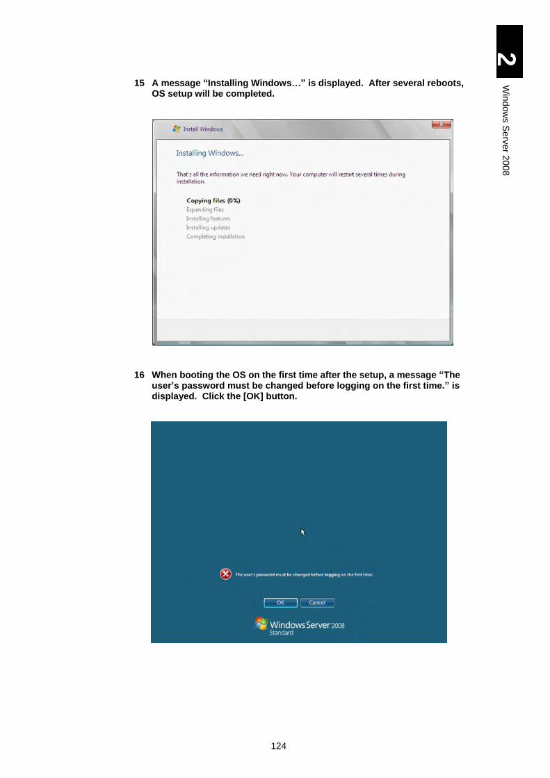
124
2
Win
dow
s S
erv
er 2
00
8
15 A message “Installing Windows…” is displayed. After several reboots, OS setup will be completed.
16 When booting the OS on the first time after the setup, a message “The user’s password must be changed before logging on the first time.” is displayed. Click the [OK] button.
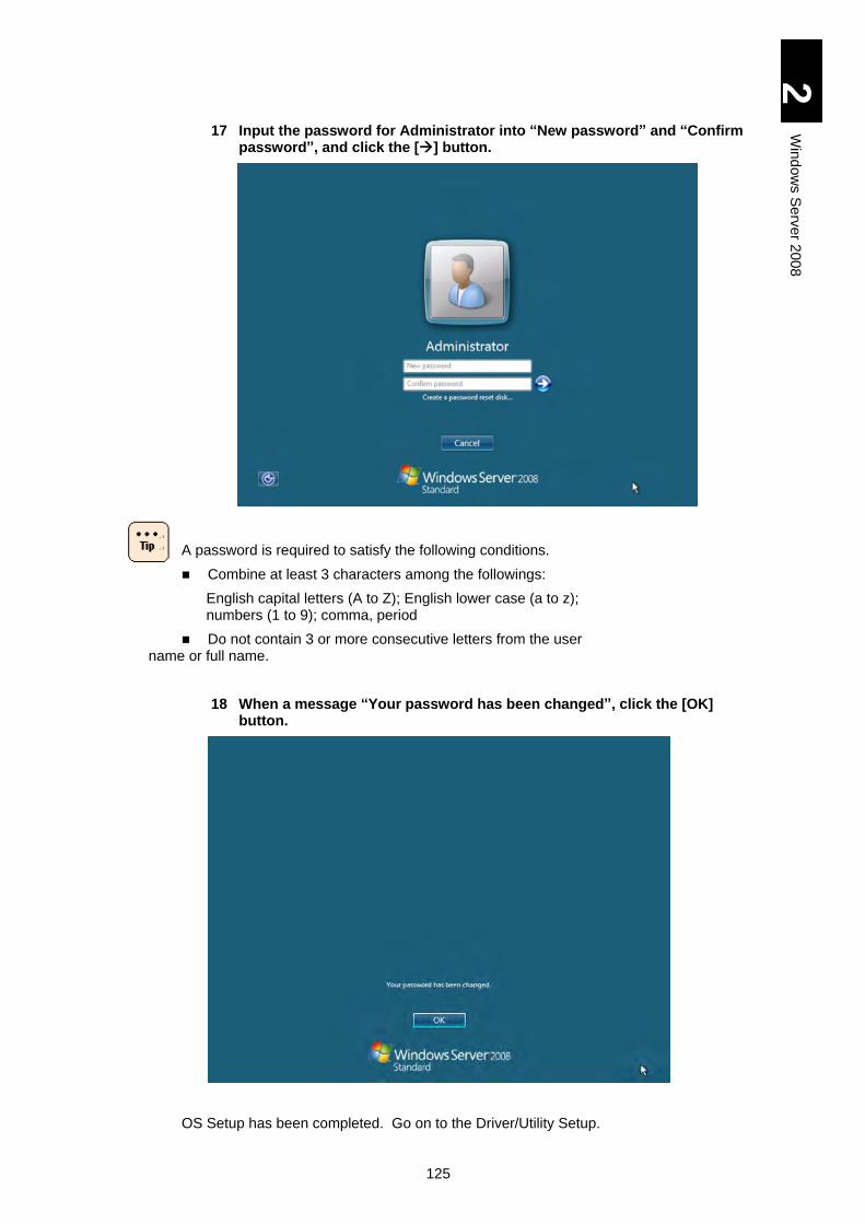
125
2
Win
dow
s S
erv
er 2
00
8
17 Input the password for Administrator into “New password” and “Confirm password”, and click the [] button.
A password is required to satisfy the following conditions.
Combine at least 3 characters among the followings:
English capital letters (A to Z); English lower case (a to z); numbers (1 to 9); comma, period
Do not contain 3 or more consecutive letters from the user name or full name.
18 When a message “Your password has been changed”, click the [OK] button.
OS Setup has been completed. Go on to the Driver/Utility Setup.
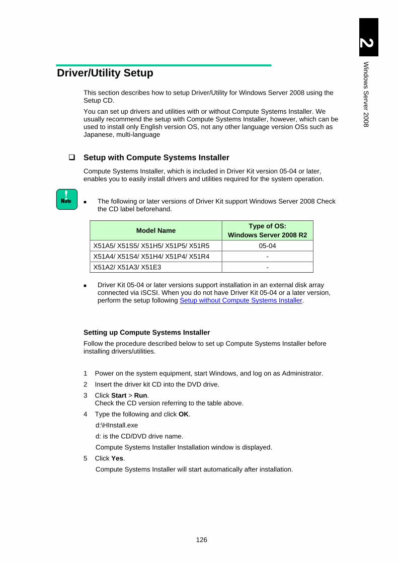
126
2
Win
dow
s S
erv
er 2
00
8
Driver/Utility Setup
This section describes how to setup Driver/Utility for Windows Server 2008 using the Setup CD.
You can set up drivers and utilities with or without Compute Systems Installer. We usually recommend the setup with Compute Systems Installer, however, which can be used to install only English version OS, not any other language version OSs such as Japanese, multi-language
Setup with Compute Systems Installer
Compute Systems Installer, which is included in Driver Kit version 05-04 or later, enables you to easily install drivers and utilities required for the system operation.
The following or later versions of Driver Kit support Windows Server 2008 Check the CD label beforehand.
Driver Kit 05-04 or later versions support installation in an external disk array connected via iSCSI. When you do not have Driver Kit 05-04 or a later version, perform the setup following Setup without Compute Systems Installer.
Setting up Compute Systems Installer
Follow the procedure described below to set up Compute Systems Installer before installing drivers/utilities.
1 Power on the system equipment, start Windows, and log on as Administrator.
2 Insert the driver kit CD into the DVD drive.
3 Click Start > Run. Check the CD version referring to the table above.
4 Type the following and click OK.
d:\HInstall.exe
d: is the CD/DVD drive name.
Compute Systems Installer Installation window is displayed.
5 Click Yes.
Compute Systems Installer will start automatically after installation.
Model Name Type of OS:
Windows Server 2008 R2
X51A5/ X51S5/ X51H5/ X51P5/ X51R5 05-04
X51A4/ X51S4/ X51H4/ X51P4/ X51R4 -
X51A2/ X51A3/ X51E3 -
127
2
Win
dow
s S
erv
er 2
00
8
Setting up Drivers/Utilities
Set up drivers and utilities with Compute Systems Installer.
When you have installed Compute Systems Installer in Setting up Compute Systems Installer, Compute Systems Installer will start automatically. If so, jump to step 3.
When you start Compute Systems Installer with the Found
New Hardware dialog box open, the installer may not proceed.
If so, click Cancel in the dialog box to remove it.
1 Click Start > Run.
2 Type the following and click OK.
c:\Hitachi/S-INST\SysInst2-exe
c: is the system drive name.
The Compute Systems Installer Installation window is displayed.
3 Click OK.
A window will be displayed, where you can select which component to install.
4 When installing all components, click default installation. When selecting components to install, click Custom installation, select components following the directions in the window, and click Next.
We usually recommend the Default installation.
5 Click Next.
Preparation for installation will start.
Then, follow the instructions on the windows to proceed. You may have to change CDs during installation.
A setup completion window will be displayed at the end. When reboot is required, go on to step 6; when reboot is not required, jump to step 9.
You may be asked to type something at setting up utilities. See
the manual of each utility for the details about setup
procedures. See How to Use Supplied Software for the
location of each manual.
6 Check Reboot Now. and remove the CD from the drive.
7 Click OK.
The server blade will be rebooted.
8 Log on as Administrator after reboot.
Compute Systems Installer automatically reboots to continue processing. Repeat step 5 to step 8 as necessary.
9 Click Done. If you want to remove Compute Systems Installer, jump to “Removing Compute Systems Installer” without clicking Done.
Compute Systems Installer will be finished.
128
2
Win
dow
s S
erv
er 2
00
8
Removing Compute Systems Installer
When drivers and utilities have been set up, remove Compute Systems Installer. Reboot is required for removing Compute Systems Installer.
1 In the finish window for Compute Systems Installer, check Never launch the program on startup and then check Uninstall this program.
Compute Systems Installer Deletion window is displayed.
2 Click Yes.
3 Click Done.
Compute Systems Installer will be removed.
Checking Driver Updates
With some adapters or devices, their drivers may not be installed with the Compute Systems Installer. The latest drivers can be available in attached CDs or can be downloaded from Web sites. Apply the latest drivers referring to the manual of your adapters.
When applying the new driver, Compute Systems Installer may
not recognize the driver installation status correctly. If you
update the driver manually, remove Compute Systems Installer
in advance.
Applying Patches
Apply Windows update patches such as the security patch as necessary. Some server blades and adapters may have prerequisite patches. Visit each Web site or contact your reseller for patches recommended to apply.
129
2
Win
dow
s S
erv
er 2
00
8
Setup without Compute Systems Installer
When setting up driver/utility without Compute Systems Installer, make sure to install the following drivers, utilities, and register update respectively.
Registry Update
Start iSCSI Initiator service (Only with OS installed in an external disk array device connected via iSCSI)
Driver
Setting name for RAID virtual device (if necessary)
Chipset driver
LAN driver
Display driver
Front-panel SAS Port Driver
Utility
MegaRAID Storage Manager
Intel® PROSet
ServerConductor
Driver for mezzanine cards/Utility
Change Dump settings (Only with OS installed in an external disk array device connected via iSCSI)
Update Information Check
Check information on driver update
Apply patch files
After having installed drivers/utilities above, install an
expansion board driver. Refer to the expansion board manual
for the installation procedure. Then Update the registry after
having installed the expansion board driver.
130
2
Win
dow
s S
erv
er 2
00
8
Registry Update
Insert the “Driver kit” CD-ROM into the CD/DVD drive, and execute the following steps.
* d: represents the drive name of CD/DVD.
1 Click the [Start] button, and select [Run…].
2 Input the following, and click the [OK] button.
d:\UTILITY\TIMEOUT VALUE\TimeOutValue.bat
[Driver Kit version 05-04 or later]
d:\X51x5\Win2008\Tools\TimeOutValue\TimeOutValue.bat
Set the registry to obtain dump when NMI is issued.
1 Click the [Start] button, and select [Run…].
2 Input the following, and click the [OK] button.
d:\UTILITY\DUMP\NMID.bat
[Driver Kit version 05-04 or later]
d:\X51x5\Win2008\Tools\NMIDump\NMID.bat
Set the PCI driver.
1 Click the [Start] button, and select [Run…].
2 Input the following, and click the [OK] button.
d:\UTILITY\PCI\WIN2008\avoidD3.bat
[Driver Kit version 05-04 or later]
d:\X51x5\Win2008\Tools\avoidD3\avoidD3.bat
Change the LAN driver settings.
1 Click the [Start] button, and select [Run…].
2 Input the following, and click the [OK] button.
X51A3/ X51E3 models: d:\OPTION\TOOLS\LANREG\WIN2008\SNPDSW08_E.bat
X51A4/ X51S4/ X51H4/ X51P4/ X51R4/ X51A5/ X51S5/ X51H5/ X51P5/ X51R5 models: d:\UTILITY\SNPDS\WIN2008\SNPDSW08_E.bat
[Driver Kit version 05-04 or later]
X51A5/X51S5/X51H5/X51P5/X51R5 models: d:\X51x5\Win2008\Tools\SNPDS\SNPDSW08.bat
To enable these items, reboot the OS after applying batches.
131
2
Win
dow
s S
erv
er 2
00
8
Start iSCSI Initiator service (Only with OS installed in an external disk array device connected via iSCSI)
Follow the steps below to start the iSCSI initiator service.
1 Power on the server blade, boot Windows, log on as Administrator.
2 Click [Start] > [Administrative Tools] > [iSCSI Initiator].
3 When the [Microsoft iSCSI] dialog box is displayed, click [Yes].
4 When [iSCSI Initiator Properties] is displayed, click [OK].
Setting Name for RAID Virtual Device
When the OS has been installed in the internal HDD of the server blade (SATA RAID configuration), apply “inf” file following steps shown below to set a name to the RAID virtual device.
1 Power on the system equipment to boot Windows, and log on as Administrator.
2 Insert the DriverKit CD-ROM, into the DVD drive.
3 Click the [Start] button and then select [Server Manager]. [Server Manager] will appear.
4 Select [Diagnostics] and then [Device Manager].
5 Open the [System Device] tree.
6 Select the following name, right-click it, and select [Update Driver Software].
Windows Server 2008 (X51H4/ X51R4/ X51H5/ X51R5 model): LSI RAID Virtual Device
Windows Server 2008 32-bit: RAID Virtual Device (X51A3/ X51E3/ X51A4 model)
LSI RAID Virtual Device (X51H4/ X51R4 model)
[Driver Software Update Wizard] will appear.
7 Select [Browse my computer for driver software].
8 Select [Let me pick from a list of device drivers on my computer].
9 Click the [Have Disk] button. Type the following into the [Copy manufacturer’s files from:] field, and then click the [OK] button.
Windows Server 2008 (X51H4/ X51R4 model)
X51H4 model: d:\X51x4\H\WIN2008\RAID\MegaSAS_01\x64
X51R4 model: d:\X51x4\R\WIN2008\RAID\MegaSAS_01\x64
X51H5 model with LSI MegaRAID SAS 1078: d:\X51x5\H\WIN2008\RAID\MegaSAS_01\x64
X51H5 model with LSI MegaRAID SAS 2108: d:\X51x5\H\WIN2008\RAID_02\MegaSAS_01\x64
X51R5 model: d:\X51x5\R\WIN2008\RAID\MegaSAS_01\x64
[Driver Kit version 05-04 or later]
X51H5 model with LSI MegaRAID SAS 2108: d:\X51x5\Win2008\Drivers\RAID\MegaSAS_01\x64
X51R5 model: d:\X51x5\Win2008\Drivers\RAID\MegaSAS_01\x64
132
2
Win
dow
s S
erv
er 2
00
8
Windows Server 2008 32-bit:
X51A3/ X51E3 model: d:\x51x3\A\WIN2008\RAID\MegaSR_01\x86
X51A4 model: d:\x51x4\A\WIN2008\RAID\MegaSR_01\x86
X51H4 model: d:\x51x4\H\WIN2008\RAID\MegaSAS_01\x86
X51R4 model: d:\X51x4\R\WIN2008\RAID\MegaSAS_01\x86
X51A5 model: d:\x51x5\A\WIN2008\RAID\MegaSR_01\x86
X51H5 model wi t h LSI MegaRAI D SAS 1078:
d:\x51x5\H\WIN2008\RAID\MegaSAS_01\x86
X51H5 model wi t h LSI MegaRAI D SAS 2108:
d:\x51x5\H\WIN2008_02\RAID\MegaSAS_01\x86
X51R5 model: d:\X51x5\R\WIN2008\RAID\MegaSAS_01\x86
[Driver Kit version 05-04 or later]
X51A5 model: d:\X51x5\Win2008\Drivers\RAID\MegaSR_01\x86
X51H5 model with LSI MegaRAID SAS 2108: d:\X51x5\Win2008\Drivers\RAID\MegaSAS_01\x86
X51R5 model: d:\X51x5\Win2008\Drivers\RAID\MegaSAS_01\x86
10 When the screen returns to [Driver Software Update Wizard], click the [Next] button.
11 Confirm “Windows has successfully updated your driver software.” is displayed, and then click the [Close] button.
Chipset Driver
Install the chipset driver following the steps below:
1 Power on the system equipment, boot Windows, and log on with Administrator.
2 Insert the DriverKit into the DVD drive.
3 Click the [Start] button and then select [Run…].
4 Input the following, and click the [OK] button.
X51A2/ X51A3/ X51E3 models: d:\x51x3\A\WIN2008\CHIPSET\INTEL_01\infinst_autol.exe
X51A4/ X51S4/ X51H4/ X51P4/ X51R4 models: d:\x51x4\A\WIN2008\CHIPSET\INTEL_01\infinst_autol.exe
X51A5/ X51S5/ X51H5/ X51P5/ X51R5 models: d:\x51x5\A\WIN2008\CHIPSET\INTEL_01\infinst_autol.exe (d: is the DVD drive name.)
[Driver Kit version 05-04 or later]
X51A5/X51S5/X51H5/X51P5/X51R5 models: d:\X51x5\WIN2008\Drivers\Chipset\INTEL_01\infinst_autol.exe
The Setup screen is displayed.
5 Click the [Next] button.
“License Agreement Terms“ is displayed.
6 Read the license agreement, and then click the [Yes] button if you agree.
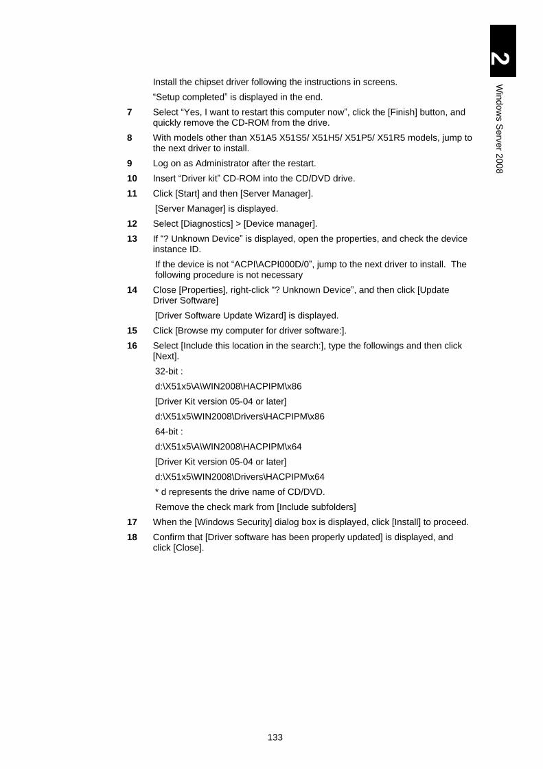
133
2
Win
dow
s S
erv
er 2
00
8
Install the chipset driver following the instructions in screens.
“Setup completed” is displayed in the end.
7 Select “Yes, I want to restart this computer now”, click the [Finish] button, and quickly remove the CD-ROM from the drive.
8 With models other than X51A5 X51S5/ X51H5/ X51P5/ X51R5 models, jump to the next driver to install.
9 Log on as Administrator after the restart.
10 Insert “Driver kit” CD-ROM into the CD/DVD drive.
11 Click [Start] and then [Server Manager].
[Server Manager] is displayed.
12 Select [Diagnostics] > [Device manager].
13 If “? Unknown Device” is displayed, open the properties, and check the device instance ID.
If the device is not “ACPI\ACPI000D/0”, jump to the next driver to install. The following procedure is not necessary
14 Close [Properties], right-click “? Unknown Device”, and then click [Update Driver Software]
[Driver Software Update Wizard] is displayed.
15 Click [Browse my computer for driver software:].
16 Select [Include this location in the search:], type the followings and then click [Next].
32-bit :
d:\X51x5\A\WIN2008\HACPIPM\x86
[Driver Kit version 05-04 or later]
d:\X51x5\WIN2008\Drivers\HACPIPM\x86
64-bit :
d:\X51x5\A\WIN2008\HACPIPM\x64
[Driver Kit version 05-04 or later]
d:\X51x5\WIN2008\Drivers\HACPIPM\x64
* d represents the drive name of CD/DVD.
Remove the check mark from [Include subfolders]
17 When the [Windows Security] dialog box is displayed, click [Install] to proceed.
18 Confirm that [Driver software has been properly updated] is displayed, and click [Close].
134
2
Win
dow
s S
erv
er 2
00
8
LAN Driver
Install LAN driver in the following procedure. For the driver for expanded board, see the manual of the expanded board.
1 Turn on the power of system equipment, boot Windows, and log on as "Administrator".
2 Insert the Driver kit CD-ROM into the CD/DVD drive.
3 Click the [Start] button and select [Server Manager].
[Server Manager] appears.
4 Select [Diagnostics] and then [Device Manager].
[Device Manager] appears.
5 Right-click the Ethernet controller under the Other Devices tree the driver of which has not been updated, and click [Update Driver].
[Update Wizard] appears.
6 Select [Browse my computer for driver software].
7 Select [Search for driver software in this location:] and input the followings. Then click the [Next] button.
When 10Gbps LAN is installed:
A 10Gbps LAN PCI express card requires a different driver
from that for other LAN devices.
If you attempt to install a driver, a message, “Windows was
unable to install your Ethernet Controller.” may be displayed,
which shows that the driver is incorrect. When the message is
displayed, install the right driver for the device.
Windows Server 2008:
(1) Driver for CN9PXG1X1: 10 Gbps 2-port LAN PCI express card
d:\x51x5\P\WIN2008\LAN\INTELXG_01\x64
[Driver Kit version 05-04 or later]
d:\X51x5\WIN2008\Drivers\LAN\INTELXG_01\x64
d: is the DVD drive name.
(2) Driver for LAN devices other than (1) CN9PXG1X1
A2/A3/E3 models: d:\x51x3\A\WIN2008\LAN\INTEL_01\x64
X51A4/ X51S4/ X51H4/ X51P4/ X51R4 models: d:\x51x4\A\WIN2008\LAN\INTEL_01\x64
X51A5/ X51S5/ X51H5/ X51P5/ X51R5 models: d:\x51x5\A\WIN2008\LAN\INTEL_01\x64
[Driver Kit version 05-04 or later]
X51A5/X51S5/X51H5/X51P5/X51R5 models: d:\X51x5\WIN2008\Drivers\LAN\INTEL_01\x64
Windows Server 2008 32-bit
(1) Driver for CN9PXG1X1: 10 Gbps 2-port LAN PCI express card
d:\x51x5\P\WIN2008\LAN\INTELXG_01\x86
[Driver Kit version 05-04 or later]
d:\X51x5\WIN2008\Drivers\LAN\INTELXG_01\x86
135
2
Win
dow
s S
erv
er 2
00
8
d: is the DVD driver name.
(2) Driver for LAN devices other than (1) CN9PXG1X1
X51A3/ X51E3 models: d:\x51x3\A\WIN2008\LAN\INTEL_01\x86
X51A4/ X51S4/ X51H4/ X51P4/ X51R4 models: d:\x51x4\A\WIN2008\LAN\INTEL_01\x86
X51A5/ X51S5/ X51H5/ X51P5/ X51R5 models: d:\x51x5\A\WIN2008\LAN\INTEL_01\x86
[Driver Kit version 05-04 or later]
X51A5/X51S5/X51H5/X51P5/X51R5 models: d:\X51x5\WIN2008\Drivers\LAN\INTEL_01\x86
d: is the DVD drive name.
Remove the check mark from [Include subfolders].
8 Confirm that “Driver software updated correctly.” is displayed, and then click the [Close] button.
9 In case of X51A4/ X51S4/ X51H4/ X51P4/ X51R4/ X51A5/ X51S5/ X51H5/ X51P5/ X51R5 model, go to Step 11.
10 Right-click the network adapter whose LAN driver has been updated, and select [Delete].
When [Confirm the device uninstall] is displayed, click the [OK] button.
Delete only LAN drivers whose network adapters have
been updated. Otherwise, the LAN driver may not be
applied correctly and not operate properly.
Do not check the box of [Delete this device driver software].
If you do, the LAN driver may not be applied correctly and
not operate properly.
11 If there remain network adapters whose LAN drivers have not been updated, repeat above Steps 5 to 9 for each network adapters.
12 When having updated and deleted LAN drivers for all network adapters, select any device in the device manager, and right-click the device and select [Scan for hardware change].
All network adapters are automatically detected and the LAN driver is applied
It may take several minutes. Do not execute any other operations while updating the device manager display.
A message “The driver has not been installed properly.” in the task tray when the LAN driver has been applied automatically. In that case, reboot the system equipment following the LAN driver installation procedure. Open properties of each network adapter from the device manager, and confirm that the LAN driver is applied properly.
13 In case of X51A4/ X51S4/ X51H4/ X51P4/ X51R4/ X51A5/ X51S5/ X51H5/ X51P5/ X51R5 model, go to Step 17.
14 Right-click [Basic System Device], and select [Driver Software Update].
136
2
Win
dow
s S
erv
er 2
00
8
[Driver Software Update] is displayed.
15 Select [Search the driver software in PC].
16 Input the followings into [Search the driver software in the location:]. Click the [Next] button.
Windows Server 2008:
X51A3/ X51E3 models: d:\x51x3\A\WIN2008\LAN\INTEL_01\x64
Windows Server 2008 32-bit
X51A3/ X51E3 models: d:\x51x3\A\WIN2008\LAN\INTEL_01\x86
d: is the CD/DVD driver name.
Remove the check mark from [Search the subfolder].
17 Confirm that a message “Driver Software has been updated correctly.” is displayed, and click the [Close] button.
18 Change the LAN driver settings.
Click [Start] > [Run...], and apply the following batch file.
d:¥Win2008¥Tools¥SNPDS¥SNPDSW08.bat
d: is the CD/DVD driver name.
When this batch is applied, some settings are restored to
the default values as the following URL shows.
http://support.microsoft.com/kb/967224
When you apply the batch on the way of installing
Windows Server 2008 as the procedure in this manual, no
problem occurs. If you apply the batch after completing
installation, values changed after the installation are
restored to the default ones. See URL shown above in this
Note for details.
19 Remove the CD-ROM from the drive, and reboot the system equipment.
A message “This hardware cannot be started.” may be
displayed at the driver setup. In this case, reboot the
system equipment, and it will operate properly. Confirm
using the device manager that the device is running
correctly.
Error event logs can be logged at the time of system boot.
That can be caused by link down of the network adapter.
See “Network connection” and confirm that the proper
network adapter is connected. If Intel PROSet is installed,
right-click the proper network adapter from device manager,
and click “Properties”, and see “Link status” of “Link speed”
tab or of “Link” tab.
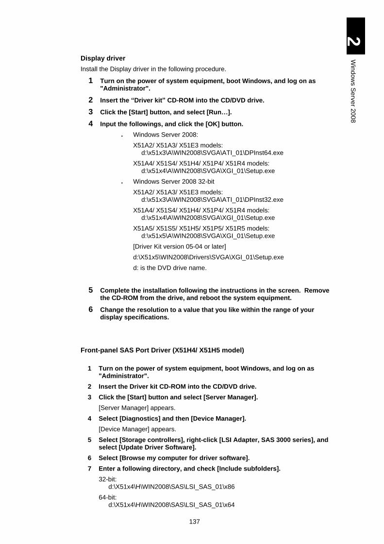
137
2
Win
dow
s S
erv
er 2
00
8
Display driver
Install the Display driver in the following procedure.
1 Turn on the power of system equipment, boot Windows, and log on as "Administrator".
2 Insert the “Driver kit” CD-ROM into the CD/DVD drive.
3 Click the [Start] button, and select [Run…].
4 Input the followings, and click the [OK] button.
Windows Server 2008:
X51A2/ X51A3/ X51E3 models: d:\x51x3\A\WIN2008\SVGA\ATI_01\DPInst64.exe
X51A4/ X51S4/ X51H4/ X51P4/ X51R4 models: d:\x51x4\A\WIN2008\SVGA\XGI_01\Setup.exe
Windows Server 2008 32-bit
X51A2/ X51A3/ X51E3 models: d:\x51x3\A\WIN2008\SVGA\ATI_01\DPInst32.exe
X51A4/ X51S4/ X51H4/ X51P4/ X51R4 models: d:\x51x4\A\WIN2008\SVGA\XGI_01\Setup.exe
X51A5/ X51S5/ X51H5/ X51P5/ X51R5 models: d:\x51x5\A\WIN2008\SVGA\XGI_01\Setup.exe
[Driver Kit version 05-04 or later]
d:\X51x5\WIN2008\Drivers\SVGA\XGI_01\Setup.exe
d: is the DVD drive name.
5 Complete the installation following the instructions in the screen. Remove the CD-ROM from the drive, and reboot the system equipment.
6 Change the resolution to a value that you like within the range of your display specifications.
Front-panel SAS Port Driver (X51H4/ X51H5 model)
1 Turn on the power of system equipment, boot Windows, and log on as
"Administrator".
2 Insert the Driver kit CD-ROM into the CD/DVD drive.
3 Click the [Start] button and select [Server Manager].
[Server Manager] appears.
4 Select [Diagnostics] and then [Device Manager].
[Device Manager] appears.
5 Select [Storage controllers], right-click [LSI Adapter, SAS 3000 series], and select [Update Driver Software].
6 Select [Browse my computer for driver software].
7 Enter a following directory, and check [Include subfolders].
32-bit: d:\X51x4\H\WIN2008\SAS\LSI_SAS_01\x86
64-bit: d:\X51x4\H\WIN2008\SAS\LSI_SAS_01\x64
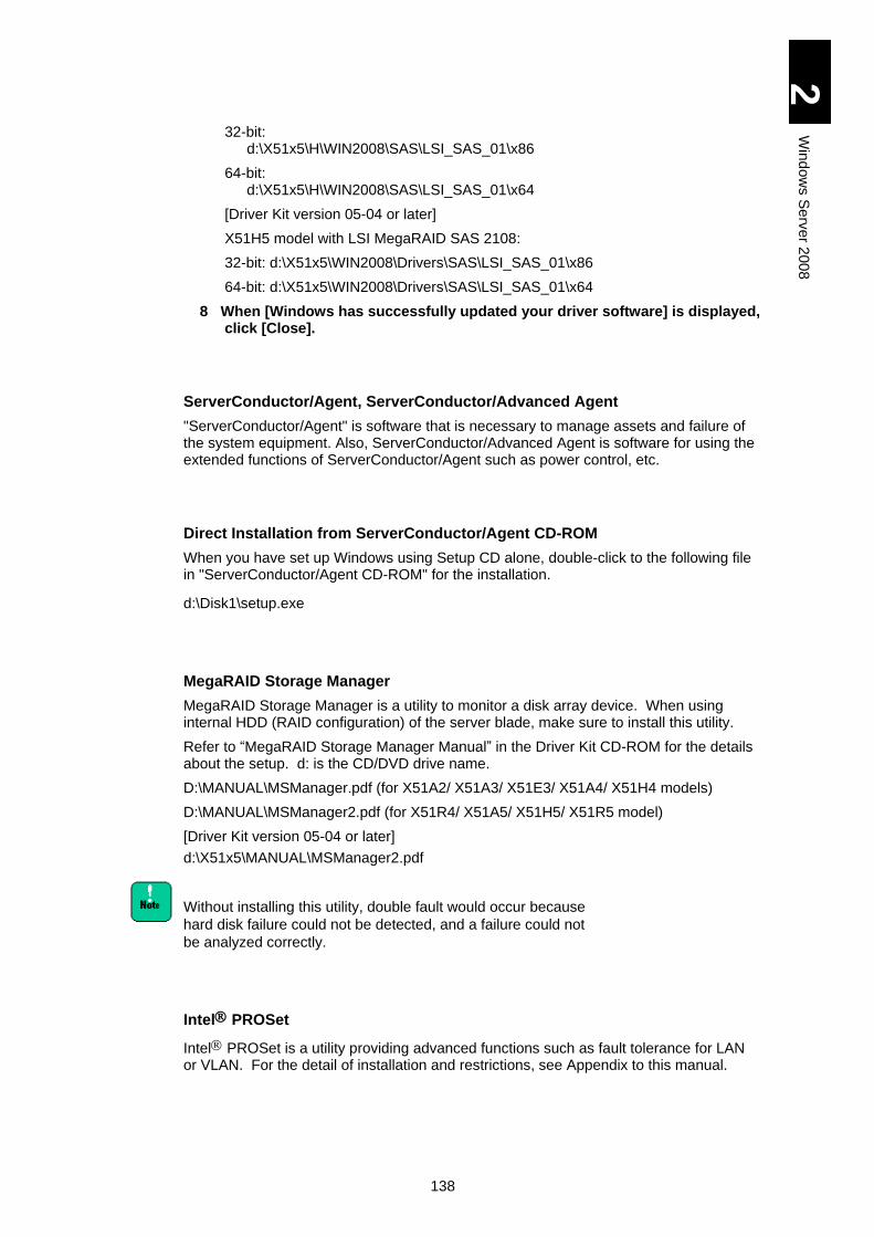
138
2
Win
dow
s S
erv
er 2
00
8
32-bit: d:\X51x5\H\WIN2008\SAS\LSI_SAS_01\x86
64-bit: d:\X51x5\H\WIN2008\SAS\LSI_SAS_01\x64
[Driver Kit version 05-04 or later]
X51H5 model with LSI MegaRAID SAS 2108:
32-bit: d:\X51x5\WIN2008\Drivers\SAS\LSI_SAS_01\x86
64-bit: d:\X51x5\WIN2008\Drivers\SAS\LSI_SAS_01\x64
8 When [Windows has successfully updated your driver software] is displayed, click [Close].
ServerConductor/Agent, ServerConductor/Advanced Agent
"ServerConductor/Agent" is software that is necessary to manage assets and failure of the system equipment. Also, ServerConductor/Advanced Agent is software for using the extended functions of ServerConductor/Agent such as power control, etc.
Direct Installation from ServerConductor/Agent CD-ROM
When you have set up Windows using Setup CD alone, double-click to the following file in "ServerConductor/Agent CD-ROM" for the installation.
d:\Disk1\setup.exe
MegaRAID Storage Manager
MegaRAID Storage Manager is a utility to monitor a disk array device. When using internal HDD (RAID configuration) of the server blade, make sure to install this utility.
Refer to “MegaRAID Storage Manager Manual” in the Driver Kit CD-ROM for the details about the setup. d: is the CD/DVD drive name.
D:\MANUAL\MSManager.pdf (for X51A2/ X51A3/ X51E3/ X51A4/ X51H4 models)
D:\MANUAL\MSManager2.pdf (for X51R4/ X51A5/ X51H5/ X51R5 model)
[Driver Kit version 05-04 or later]
d:\X51x5\MANUAL\MSManager2.pdf
Without installing this utility, double fault would occur because
hard disk failure could not be detected, and a failure could not
be analyzed correctly.
Intel PROSet
Intel PROSet is a utility providing advanced functions such as fault tolerance for LAN or VLAN. For the detail of installation and restrictions, see Appendix to this manual.
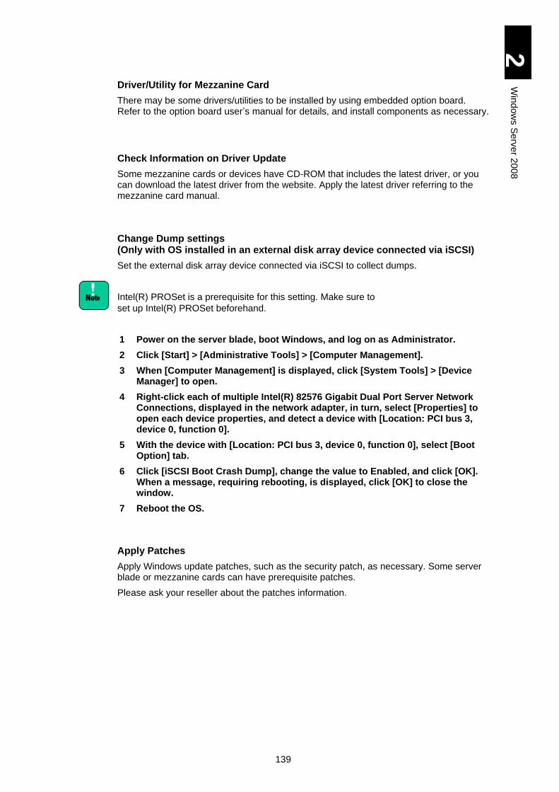
139
2
Win
dow
s S
erv
er 2
00
8
Driver/Utility for Mezzanine Card
There may be some drivers/utilities to be installed by using embedded option board. Refer to the option board user’s manual for details, and install components as necessary.
Check Information on Driver Update
Some mezzanine cards or devices have CD-ROM that includes the latest driver, or you can download the latest driver from the website. Apply the latest driver referring to the mezzanine card manual.
Change Dump settings (Only with OS installed in an external disk array device connected via iSCSI)
Set the external disk array device connected via iSCSI to collect dumps.
Intel(R) PROSet is a prerequisite for this setting. Make sure to
set up Intel(R) PROSet beforehand.
1 Power on the server blade, boot Windows, and log on as Administrator.
2 Click [Start] > [Administrative Tools] > [Computer Management].
3 When [Computer Management] is displayed, click [System Tools] > [Device Manager] to open.
4 Right-click each of multiple Intel(R) 82576 Gigabit Dual Port Server Network Connections, displayed in the network adapter, in turn, select [Properties] to open each device properties, and detect a device with [Location: PCI bus 3, device 0, function 0].
5 With the device with [Location: PCI bus 3, device 0, function 0], select [Boot Option] tab.
6 Click [iSCSI Boot Crash Dump], change the value to Enabled, and click [OK]. When a message, requiring rebooting, is displayed, click [OK] to close the window.
7 Reboot the OS.
Apply Patches
Apply Windows update patches, such as the security patch, as necessary. Some server blade or mezzanine cards can have prerequisite patches.
Please ask your reseller about the patches information.
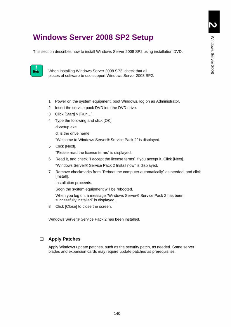
140
2
Win
dow
s S
erv
er 2
00
8
Windows Server 2008 SP2 Setup
This section describes how to install Windows Server 2008 SP2 using installation DVD.
When installing Windows Server 2008 SP2, check that all
pieces of software to use support Windows Server 2008 SP2.
1 Power on the system equipment, boot Windows, log on as Administrator.
2 Insert the service pack DVD into the DVD drive.
3 Click [Start] > [Run…].
4 Type the following and click [OK].
d:\setup.exe
d: is the drive name.
“Welcome to Windows Server® Service Pack 2” is displayed.
5 Click [Next].
“Please read the license terms” is displayed.
6 Read it, and check “I accept the license terms” if you accept it. Click [Next].
“Windows Server® Service Pack 2 Install now” is displayed.
7 Remove checkmarks from “Reboot the computer automatically” as needed, and click [Install].
Installation proceeds.
Soon the system equipment will be rebooted.
When you log on, a message “Windows Server® Service Pack 2 has been successfully installed” is displayed.
8 Click [Close] to close the screen.
Windows Server® Service Pack 2 has been installed.
Apply Patches
Apply Windows update patches, such as the security patch, as needed. Some server blades and expansion cards may require update patches as prerequisites.
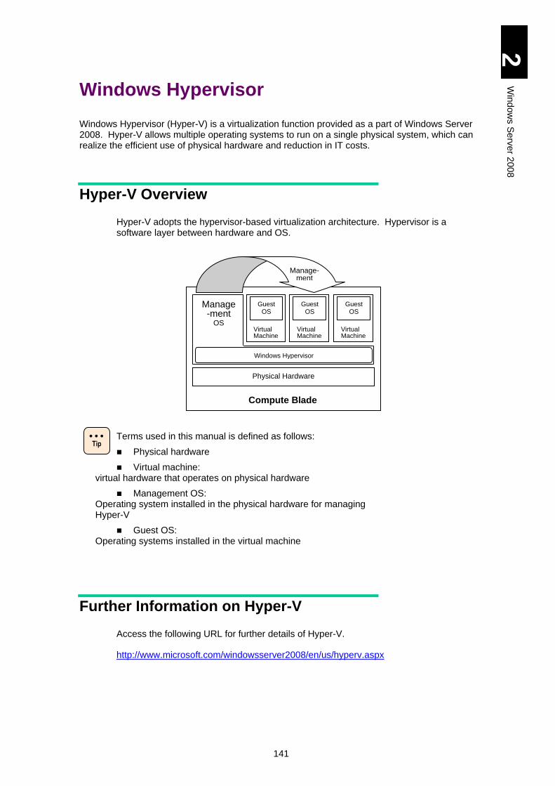
141
2
Win
dow
s S
erv
er 2
00
8
Windows Hypervisor
Windows Hypervisor (Hyper-V) is a virtualization function provided as a part of Windows Server 2008. Hyper-V allows multiple operating systems to run on a single physical system, which can realize the efficient use of physical hardware and reduction in IT costs.
Hyper-V Overview
Hyper-V adopts the hypervisor-based virtualization architecture. Hypervisor is a software layer between hardware and OS.
Terms used in this manual is defined as follows:
Physical hardware
Virtual machine: virtual hardware that operates on physical hardware
Management OS: Operating system installed in the physical hardware for managing Hyper-V
Guest OS: Operating systems installed in the virtual machine
Further Information on Hyper-V
Access the following URL for further details of Hyper-V.
http://www.microsoft.com/windowsserver2008/en/us/hyperv.aspx
Physical Hardware
Windows Hypervisor
Manage-ment
OS
Virtual Machine
Guest OS
Virtual Machine
Guest OS
Virtual Machine
Guest OS
Compute Blade
Manage- ment
Tip
142
2
Win
dow
s S
erv
er 2
00
8
System Configuration for Hyper-V
This section describes system configuration to use Hyper-V.
System Equipment for Hyper-V
Server blades should support Windows Server 2008 x64.
Software Configuration
Following software requirements should be satisfied to configure Hyper-V.
[Requirements for Software]
Windows Server 2008 Standard/Enterprise x64 edition for the management OS If the edition is “Without Hyper-V”, the hyper-V function is not provided.
RTM (Release To Manufacturing) update for Hyper-V Since a beta version of Hyper-V can be included with Windows Server 2008, in such case, obtain and apply “Hyper-V Update for Windows Server 2008 x64” to the beta version. There is also “Hyper-V Update for Windows Server 2008 x32” because the management tool is included in Windows Server 2008 x32. Hyper-V, however, can run only on Windows Server 2008 x64. Access the following URL for the RTM update for Hyper-V. http://www.microsoft.com/downloads/details.aspx?FamilyId=6F69D661-5B91-4E5E-A6C0-210E629E1C42&displaylang=en
143
2
Win
dow
s S
erv
er 2
00
8
Physical Hardware Configuration
In addition to the system requirements for Windows Server 2008, the following hardware requirements should be satisfied to use Hyper-V.
Refer to the following URL for the system requirements for
Windows Server 2008.
http://msdn.microsoft.com/en-us/windowsserver/cc196364.aspx
[Requirements for Hardware]
Data Execute Prevention (DEP) DEP settings are all enabled by default in the Compute Blade system equipment. Use it as it is.
Intel 64 (x64-based processor) All CPUs mounted in the Compute Blade system equipment support Intel x64 features. Use it as it is.
Intel Virtualization Technology (Intel VT) Intel VT settings are all enabled by default in the Compute Blade system equipment. Use it as it is.
It is recommended that the system equipment should use the physical hardware that satisfies the requirements shown below or more for configuration. Refer to Virtual Machine Configuration as well
CPU core: In addition to the total number of CPUs to be assigned to each guest OS running simultaneously, at least one CPU for the management OS is required.
Memory: In addition to the total capacity of the memory, which is recommended by Microsoft to each OS running simultaneously, at least another 2 GB for the management OS is required.
Partitions: Separate partitions are required for the management OS and the virtual hard disk file of a virtual machine.
Recommendations above are just general standards and do
not guarantee that the system will work well at any condition.
They may be insufficient depending on an application to run on
the guest OS. Give the system testrun and check if it will work
properly beforehand.
Recommendations above are just general standards. When
using the system for a specific purpose such as a test
environment, it may not necessarily satisfy the recommended
requirements. Examine the configuration depending on your
purpose.
144
2
Win
dow
s S
erv
er 2
00
8
Virtual Machine Configuration
Hitachi confirmed that the following guest OSs ran properly.
Windows Server 2003, Standard Edition with Service Pack 2 (including R2)
Windows Server 2003, Enterprise Edition with Service Pack 2 (including R2)
Windows Server 2003, x64 Standard Edition with Service Pack 2 (including R2)
Windows Server 2003, x64 Enterprise Edition with Service Pack 2 (including R2)
Windows Server 2008 Standard 32-bit
Windows Server 2008 Enterprise 32-bit
Windows Server 2008 Standard 64-bit
Windows Server 2008 Enterprise 64-bit
Guest OSes, not included in the list above and supported by
Microsoft, can be installed in the Compute Blade system
equipment. The installation and operation, however, are not
supported. The system may not operate properly.
It is recommended that virtual machines should be configured
with the system requirements better than what is
recommended to a guest OS by Microsoft.
Recommendations above are just general standards and do
not guarantee that the system will work well at any condition.
They may be insufficient depending on an application to run on
the guest OS. Give the system testrun and check if it will work
properly beforehand.
There are 2 ways to configure a virtual hard drive (virtual hard
disk). One is using a virtual hard disk file (.vhd), and the other
is connecting a physical hard disk via the virtual SCSI
controller. Connection to the physical hard disk, however, is
not supported. Use the virtual hard disk file (.vhd) for the
Compute Blade system equipment.
The virtual hard disk file (.vhd) has 3 forms such as fixed-size,
Variable-size, and differencing vhds. In the Variable-size or
differencing vhds, the file size of the virtual hard disk file on the
physical disk expands dynamically according to the amount
that the virtual machine is using. If the size cannot be
expanded due to the capacity shortage of the physical disk, the
virtual machine will halt.
Always make sure that the capacity of the physical disk is
sufficient in the actual operation. Otherwise, the virtual
machine may stop unexpectedly. Therefore, it is
recommended that the virtual hard disk should be configured
with the fixed-size in the actual operation.

145
2
Win
dow
s S
erv
er 2
00
8
There are 2 types of virtual network adapters such as the
network adapter and the legacy network adapter.
Select the network adapter for the Compute Blade system
equipment. If a certain application specifies a legacy network
adapter, use the adapter only for that purpose..
Refer to the following URLs for the system requirements for
each OS recommended by Microsoft.
[Windows Server 2008]
http://technet.microsoft.com/en-us/windowsserver/2008/bb414778.aspx
[Windows Server 2003
(Refer to Windows Server 2003 R2.)]
http://www.microsoft.com/Windowsserver2003/sbs/evaluation/sysreqs/default.mspx
The maximum number of processors assigned depends on a
guest OS. Two (2) processors at a maximum can be assigned
to Windows Server 2003 R2 or Windows Server 2003; four (4)
at a maximum to Windows Server 2008. Refer to the following
URL for the details.
http://www.microsoft.com/windowsserver2008/en/us/hyperv.aspx
146
2
Win
dow
s S
erv
er 2
00
8
Hyper-V Setup
This section describes how to set up Hyper-V.
Always log in the management OS with the account that has
the manager’s privilege.
Refer to “System Configuration for Hyper-V” before the setup.
For the details of how to use the Hyper-V manager, refer to the
management OS help.
Management OS Setup
Refer to the “Software Guide” attached to the Compute Blade system equipment for how to set up the management OS.
Only Windows Server 2008 64-bit can be used for the
management OS. Refer to “Software Configuration” for the
details.
Hyper-V Setup
Follow the steps shown below to set up Hyper-V.
Refer to the procedures provided in the following URL by
Microsoft before the setup.
http://technet.microsoft.com/en-us/library/cc732470.aspx
1 Download the update program “Windows6.0-KB950050-x86.msu”, and execute it on the management OS. Then start the setup following instructions on the screen. When the setup is completed, reboot the management OS.
Refer to “Software Configuration” for how to download the update program.
Hyper-V can run only on Windows Server 2008 x64. There is,
however, Hyper-V Update for Windows Server 2008 x32.
Refer to “Software Configuration” for the details.
147
2
Win
dow
s S
erv
er 2
00
8
The following event is registered a couple of times during the update program set up. Event ID: 4374 Source: Microsoft-Windows-Servicing Event Level: Warning Description: PackageKB950050(Update) could not be applied to your system. If the following system event is registered when the OS is rebooted after the setup, however, the update program has been properly setup without a problem. Event ID: 19 Source: Microsoft-Windows-WindowsUpdateClient Event Level: Information Description: Installation Successful: Windows successfully installed the following update: Windows update program KB950050.
2 Boot the server manager on the management OS.
Select [Start] and then [Server Manager].
3 Add the Hyper-V role.
In [Server Manager], click [Roles]->[Roles Summary]->[Add Roles] to boot the Add Roles Wizard. Select [Hyper-V] in [Server Roles], and proceed to the completion of the wizard following the instructions in the screens.
The following events are recorded in the system event when
adding the Hyper-V role. However, no problem occurs.
Event ID: 4376
Source: Servicing
Event Level: Warning
Description:
Servicing has required reboot to complete the operation of
setting package KB950050(Update) into the permanent state.
Event ID: 4376
Source: Servicing
Event Level: Warning
Description:
Servicing has required reboot to complete the operation of
setting package [package name] into the installed state.
Event ID: 1
Source: VMSMP
Event Level: Warning
Description:
Failed to open handle to switch list configuration store key due
to error C0000034. Persistent Virtual Switches and Ports are
not restored.
148
2
Win
dow
s S
erv
er 2
00
8
The following events are registered in the application event
when adding the Hyper-V role. However, no problem occurs.
Event ID: 6004
Source: Winlogon
Event Level: Warning
Description:
The Winlogon notification subscriber <TrustedInstaller> failed
a critical notification event.
4 Reboot as instructions to complete the setup.
Virtual Hard Disk Setup
Set up the virtual hardware following the steps shown below.
1 Click [Start]->[Administrative Tools]->[Hyper-V Manager] to boot the Hyper-V Manager.
2 Click [Action]->[New]->[Hard Disk] in the [Hyper-V Manager] to open the New Virtual Hard Disk Wizard.
3 Create a new virtual hard disk following the wizard.
It is recommended that the virtual hard disk should be
configured with the fixed-size in the actual operation.
Refer to “Virtual Machine Configuration” for further details.
Virtual Machine Setup
Set up the virtual machine following the steps shown below.
Refer to the procedures provided in the following URL by
Microsoft before the setup.
http://technet.microsoft.com/en-us/library/cc732470.aspx
149
2
Win
dow
s S
erv
er 2
00
8
1 Click [Start]->[Administrative Tools]->[Hyper-V Manager] to boot the [Hyper-V Manager].
2 Click [Action]->[New]->[Virtual Machines] in the [Hyper-V Manager] to open the New Virtual Machine Wizard.
3 Create a new virtual machine following the wizard.
In the Connect Virtual Hard Disk, select [Use an existing virtual hard disk] and then select the hard disk created in “Virtual Hard Disk Setup”.
For the recommended virtual machine configuration for the
Compute Blade system equipment, refer to “Virtual Machine
Configuration”.
4 When completing the wizard, add hardware if needed.
For the details such as the procedure, refer to the management OS help.
Guest OS Setup
Install the guest OS in the virtual machine created in “Virtual Machine Setup” following the steps shown below.
There are restrictions on OS media to be used as a guest OS.
Refer to “Restrictions only on Guest OS” for further details.
1 In the [Virtual Machines] section of [Hyper-V Manager], right-click a virtual machine name to install a guest OS. Select [Connect] from the menu to open [Virtual Machine Connection].
2 Insert the OS setup medium into the DVD drive that is configured in the virtual machine to install the guest OS.
If a DVD drive is not included in the virtual machine, configure
a DVD drive in the virtual machine. For the specific procedure,
refer to the Management OS help. To configure it, for example,
select [Media]->[DVD Drive]->[D: Capture] in [Virtual Machine
Connection].
*D: DVD drive character on the management OS
3 Select [Action]->[Start] to start the virtual machine.
4 Boot up from the OS setup medium, proceed to set up the guest OS following the instructions in the screens.
150
2
Win
dow
s S
erv
er 2
00
8
When the guest OS boots up before the integrated service
setup, the following events may be registered in the system
event. Since it is no problem, set up the integrated service as
the procedures.
Event ID: 26
Source: VMSMP
Event Level: Error
Description:
NIC driver [Any virtual machine name] cannot load because it
is incompatible with the server virtualization stack. Server
version 2.0; Client version 1 (virtual machine…)
When the guest OS boots up before the integrated service
setup, the following event may be registered in the Hyper-V-
Worker event. Since it is no problem, set up the integrated
service as the procedures.
Event ID: 23012
Source: Hyper-V-Worker
Event Level: Error
Description:
Device [any virtual machine name] “Microsoft Synthetic
Mouse” cannot load because it is incompatible with the virtual
stack. Server version 2.0; Client version 1 (virtual machine…)
5 After completing the guest OS setup, select [Action]->[Insert Integration Services Setup Disk] via the Virtual Machine Connection when the guest OS is running.
For Windows Server 2003 including R2, execute step 5 after
completing the Service Pack 2 setup.
6 Set up the integrated service following the screen instructions.
Refer to Help for the details of how to set up the integrated service.
151
2
Win
dow
s S
erv
er 2
00
8
Restrictions on Hyper-V
This section describes restrictions when using Hyper-V on the Compute Blade system equipment.
General Restrictions
Maintenance
As advancing the integration using the virtual environment, multiple tasks and environments run on a single machine. Therefore, it is important to plan the machine operation including time to spare for maintenance work. Maintenance tasks include applying security patches, updating application and drivers, and installing service packs. Make a plan for the system in advance taking account of time required for maintenance including the guest OS, and use it accordingly.
Server Core
Installation of Windows Server 2008 Server Core is not supported.
Application
Some application or middleware may have notice when using Hyper-V. Refer to the application distributor from which you have bought it for the details.
Cluster
When configuring a cluster using Hyper-V, configure WindowS Failover Cluster (WSFC) between management OSe. Refer to the management OS Help for how to configure a cluster between management OSs. In the failover cluster, failover is executed per LUN. Therefore, if multiple virtual machines are deployed to a single LUN, they always transfer by the LUN and cannot transfer by the virtual machine.
Cluster configuration between guest OSs or a guest OS and a physical machine is not supported.
Microsoft provides a tool for failover cluster. Send a request from the following URL if necessary, and you can obtain the tool. http://support.microsoft.com/kb/951308/en-us
In the cluster configuration with the management OS, do not select [No Majority: Disk Only]. It is recommended that the management OS should adopt the operation with dual connections to shared disks against path failure. Cluster failover is executed when connection between the management OS and a shared disk fails due to FC cable break, for example. Cluster failover service itself may become down, however, when the guest OS adds so much access loads to the shared disk that the quorum fails at the failover.
Hyper-V Management Tool Microsoft provides the Hyper-V management tool that can be available for a client. But the OS must be Windows Vista Service Pack1 or later versions. Therefore, Windows XP cannot be used.
http://support.microsoft.com/kb/952627/en-us
152
2
Win
dow
s S
erv
er 2
00
8
Event related to Physical Hardware Monitor events related to the physical hardware on the management OS, not on the guest OS.
OS Reboot and Shutdown It is recommended to shut down all guest OSs explicitly before rebooting and shutting down the management OS. Especially when multiple guest OSs are running, shutting down the management OS at the same time puts high load on CPU. This can cause trouble such as too much time to take or improper shutdown.
Intel® PROSet When installing Intel® PROSet on the management OS, see “Appendix I: Advanced Function for LAN Windows Server 2008” included in this software guide. Do not install Intel® PROSet on a guest OS.
Other restrictions Search in the following URL “Microsoft Help and Support” using “Hyper-V” as a keyword.
http://support.microsoft.com/
Restrictions independent of Hyper-V Refer to the software guide attached to the Compute Blade system equipment for restrictions independent of Hyper-V.
Restrictions only on Management OS
Software on the management OS
It is recommended that task application (middleware) such as a database or application server should not be installed on the management OS with Hyper-V enabled.
Role
It is recommended that any role but Hyper-V in Windows Server 2008 should be disabled on the management OS with Hyper-V enabled.
Gigabit FibreChannel adapter card
When using Hyper-V via HITACHI Gigabit FibreChannel adapter on the Compute Blade system equipment, use the driver version 4.1.4.390 or later.
Restrictions only on Guest OS
Saving VM
When selecting [Action]->[Save] in the management screen of the virtual machine, the virtual machine status is saved and the virtual machine halts. To restart the virtual machine from the halting point, select [Action]->[Start]. This operation, however, is different from the guest OS shutdown and reboot. Applications communicating with the outside may register an error.

153
2
Win
dow
s S
erv
er 2
00
8
Notes for Active Directory on the guest OS
Microsoft Help and Support provides “Considerations when hosting Active Directory domain controller in virtual hosting environments” in the following URL. Access the following URL and read it in advance.
http://support.microsoft.com/kb/888794/en-us
Network Load Balancing (NLB) configuration on the guest OS
Configuring NLB cluster on the guest OS is not supported. We recommend that tasks that require NLB should be done on the physical machine.
OS installation media
When using Windows Server 2003 x32 Service Pack2 as a guest OS, use the OS medium to which Service Pack 1 or 2 has been applied. Otherwise, the guest OS may show the “STOP” error and halt during installation.
Snapshot
It is recommended that the snapshot should not be used in the actual environment. If using the snapshot, overhead may occur in performance, or consistency may be destroyed in the system where multiple servers combine.
It is recommended that snapshot should not be used in the guest OS where Active Directory is configured. If using the snapshot, Inconsistency in database may occur.
Virtual Hard Disk File (.vhd)
When multiple virtual hard disk files (.vhd) are on a single physical hard disk, IO bottleneck may occur depending on a processing on the guest OS. This may affect the entire OS processing.
When using multiple guest OSs in the actual environment, execute careful testruns in advance. You might as well deploy virtual hard disk files (.vhd) on a separate physical disk if necessary.
iSCSI
Using iSCSI on a guest OS is not supported.

154
2
Win
dow
s S
erv
er 2
00
8
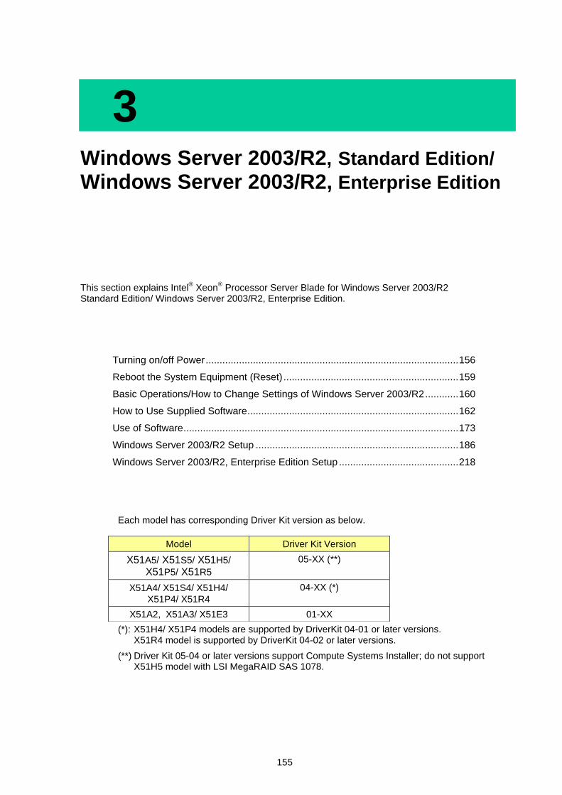
155
3 Windows Server 2003/R2, Standard Edition/ Windows Server 2003/R2, Enterprise Edition
This section explains Intel® Xeon
® Processor Server Blade for Windows Server 2003/R2
Standard Edition/ Windows Server 2003/R2, Enterprise Edition.
Turning on/off Power ........................................................................................... 156
Reboot the System Equipment (Reset) ............................................................... 159
Basic Operations/How to Change Settings of Windows Server 2003/R2 ............ 160
How to Use Supplied Software ............................................................................ 162
Use of Software ................................................................................................... 173
Windows Server 2003/R2 Setup ......................................................................... 186
Windows Server 2003/R2, Enterprise Edition Setup ........................................... 218
Each model has corresponding Driver Kit version as below.
(*): X51H4/ X51P4 models are supported by DriverKit 04-01 or later versions. X51R4 model is supported by DriverKit 04-02 or later versions.
(**) Driver Kit 05-04 or later versions support Compute Systems Installer; do not support X51H5 model with LSI MegaRAID SAS 1078.
Model Driver Kit Version
X51A5/ X51S5/ X51H5/ X51P5/ X51R5
05-XX (**)
X51A4/ X51S4/ X51H4/
X51P4/ X51R4
04-XX (*)
X51A2, X51A3/ X51E3 01-XX

156
3
Win
do
ws S
erv
er 2
00
3/R
2, S
tan
da
rd E
ditio
n/ W
ind
ow
s S
erv
er 2
003
/R2
, En
terp
rise
Ed
ition
Turning on/off Power
This section explains how to operate when you turn it on/off for regular use.
As for Server blade, no devices such as the display, the keyboard or the mouse etc. are connected. A basic operation is done by way of the network by the remote-console application. After starting Windows, it is also possible to operate it by a remote desktop connection. Refer to "Remote-console application user's guide" for the details of connection method to the remote-console and the remote-console application. Refer to "Windows Server 2003/R2 Setup", when you purchase Server Blade and set up Windows, Prepare for the connection to the server blade by the remote-console. Refer to 'Remote-console application user's guide' for details of the remote-console connection.
Turning off Power
Follow the steps below after completing all tasks on the system equipment to turn off the power.
NOTICE
Do not rashly press the [POWER] button to turn off the power. It may cause data to get corrupted or Windows not to start.
Perform a shutdown to turn off the power.
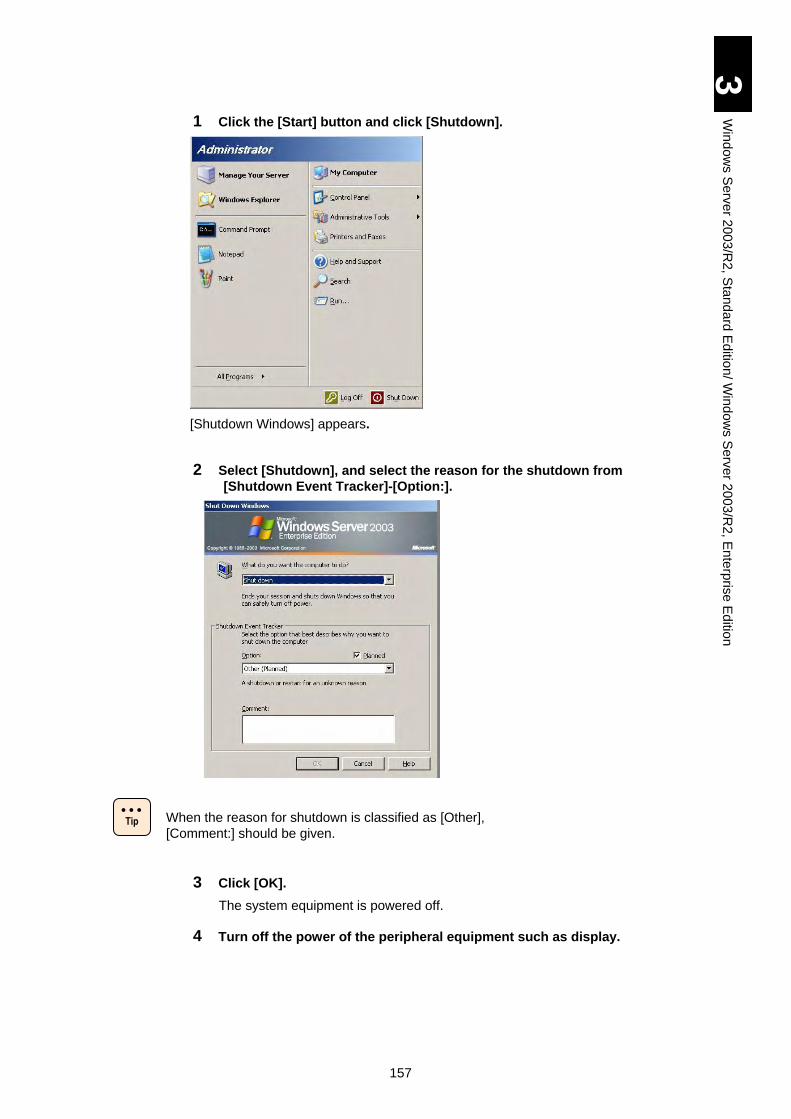
157
3
Win
do
ws S
erv
er 2
00
3/R
2, S
tan
da
rd E
ditio
n/ W
ind
ow
s S
erv
er 2
003
/R2
, En
terp
rise
Ed
ition
1 Click the [Start] button and click [Shutdown].
[Shutdown Windows] appears.
2 Select [Shutdown], and select the reason for the shutdown from
[Shutdown Event Tracker]-[Option:].
When the reason for shutdown is classified as [Other],
[Comment:] should be given.
3 Click [OK].
The system equipment is powered off.
4 Turn off the power of the peripheral equipment such as display.
Tip
158
3
Win
do
ws S
erv
er 2
00
3/R
2, S
tan
da
rd E
ditio
n/ W
ind
ow
s S
erv
er 2
003
/R2
, En
terp
rise
Ed
ition
Turning on Power for Regular Use
1 Turning on the Power of peripheral equipment such as display.
2 Press the [POWER] switch on the front of the system.
[Start Logon] appears.
Do not press the keys repeatedly when booting the system.
Otherwise, an error message may appear.
Some type of monitors may take time before display appears.
3 Use the [Ctrl] - [Alt] - [Delete] key combination.
[Logon Information] appears.
4 Enter user name and password, and press the [Enter] key.
Windows boots itself and the Desktop window appears.
! Note
159
3
Win
do
ws S
erv
er 2
00
3/R
2, S
tan
da
rd E
ditio
n/ W
ind
ow
s S
erv
er 2
003
/R2
, En
terp
rise
Ed
ition
Reboot the System Equipment (Reset)
When the system equipment function fails during its processing applications, terminating the applications forcefully or rebooting the system equipment forcefully may be able to resume normal operation.
Forcibly Terminate Application
Right-click the task bar and click [Task Manager] of the shortcut menu. Click the [Application] tab, select the application you want to terminate, and click [End Task].
Forcibly Reboot the System Equipment
When Windows functions abnormally, keep pressing the [POWER] switch for four seconds or more to turn off the power. However, the system equipment may not be of use unless the HDD is reformatted.
Do not press the [POWER] switch again until the Windows
reboot is completed except emergency. When resetting, be
sure to reboot Windows after once booting and properly
terminating it.
! Note
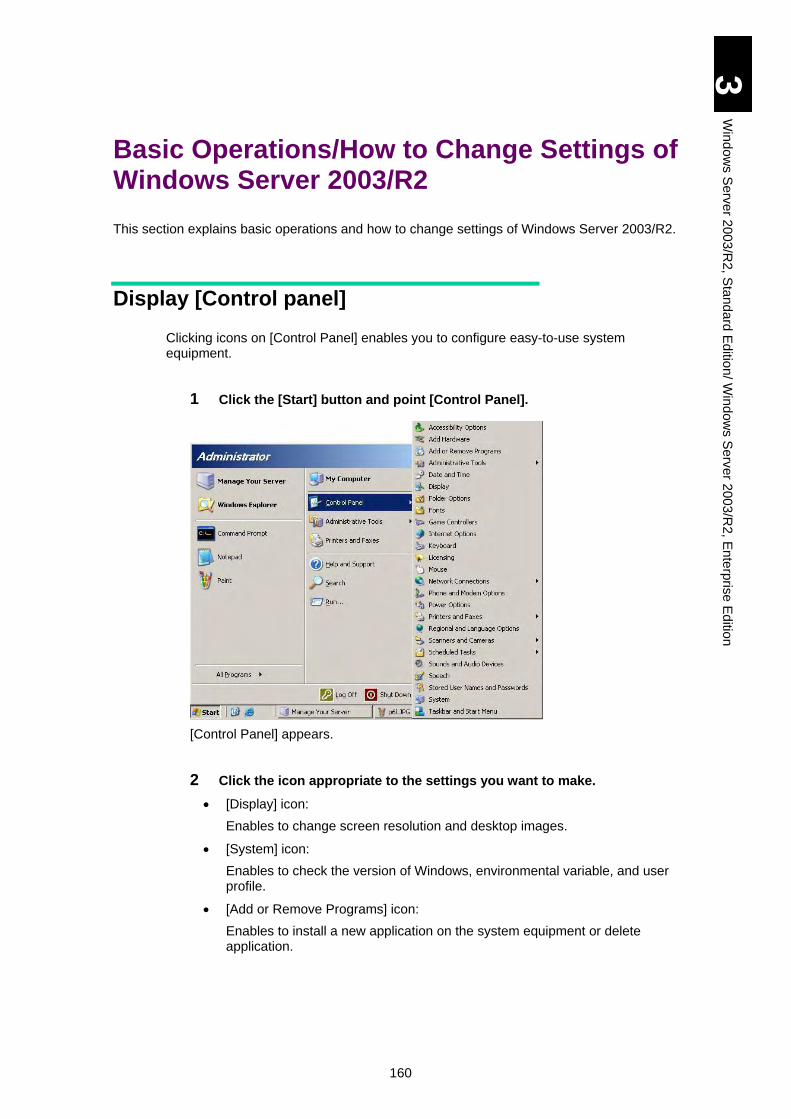
160
3
Win
do
ws S
erv
er 2
00
3/R
2, S
tan
da
rd E
ditio
n/ W
ind
ow
s S
erv
er 2
003
/R2
, En
terp
rise
Ed
ition
Basic Operations/How to Change Settings of Windows Server 2003/R2
This section explains basic operations and how to change settings of Windows Server 2003/R2.
Display [Control panel]
Clicking icons on [Control Panel] enables you to configure easy-to-use system equipment.
1 Click the [Start] button and point [Control Panel].
[Control Panel] appears.
2 Click the icon appropriate to the settings you want to make.
[Display] icon:
Enables to change screen resolution and desktop images.
[System] icon:
Enables to check the version of Windows, environmental variable, and user profile.
[Add or Remove Programs] icon:
Enables to install a new application on the system equipment or delete application.
161
3
Win
do
ws S
erv
er 2
00
3/R
2, S
tan
da
rd E
ditio
n/ W
ind
ow
s S
erv
er 2
003
/R2
, En
terp
rise
Ed
ition
How to Use Help
Help is available from Windows, in which how to use is described.
Start [Help and Support].
1 Click the [Start] button and then click [Help and Support].
[Help and Support Center] boots itself.
Check Desired Operations
1 Search the topic under which the desired operation is described. Enter a
keyword related to the target topic into [Search] in the upper left corner of
[Help and Support Center], and then click the [] button.
Search starts and the result will appear in a few moments.
2 When the target topic is found, click it.
The topic appears.
3 Read the help text.
[Back] button: Backs to the previous window.
[Option] button: Changes the character size to be displayed and change search option.
4 To exit help, click [] (Close) button at the upper right of the window.
How to Use [Display properties]
Refer to "Remote-console application user's guide" for the resolution that can be set when using the remote-console.
162
3
Win
do
ws S
erv
er 2
00
3/R
2, S
tan
da
rd E
ditio
n/ W
ind
ow
s S
erv
er 2
003
/R2
, En
terp
rise
Ed
ition
How to Use Supplied Software
This section explains the software included with this system.
MegaRAID Storage Manager
This software is necessary to manage the disk array devices. Be sure to install it when the HDD is installed in the server blade. Otherwise, a double-failure might be caused because of non-detection of the hard disk failure, and the failure analysis become difficult. Refer to the file 'MegaRAID Storage Manager manual' in the CD-ROM for details of the usage. D:\MANUAL\MSManager.pdf (for X51A2/ X51A3/ X51E3/ X51A4/ X51H4 models)
D:\MANUAL\MSManager2.pdf (for X51R4/ X51A5/ X51H5/ X51R5model)
[Driver Kit version 05-04 or later]
d:\X51x5\MANUAL\MSManager2.pdf
Intel PROSet
Intel PROSet is a LAN device configuration program. This system equipment supports
the following extensions that can be configured with Intel PROSet.
AFT (Adapter Fault Tolerance)
SFT (Switch Fault Tolerance)
ALB (Adaptive Load Balancing)
Tag VLAN (IEEE802.1q VLAN)
When settings for Intel PROSet are changed, network
connection may be temporarily disconnected. Thus, when you
change PROSet settings, use connection via remote console
not via remote desktop.
163
3
Win
do
ws S
erv
er 2
00
3/R
2, S
tan
da
rd E
ditio
n/ W
ind
ow
s S
erv
er 2
003
/R2
, En
terp
rise
Ed
ition
Four built-in LAN devices exist in the server blade. It is necessary to confirm which LAN device is connected with which LAN switch module when 1Gigabit LAN switch module is installed.
Refer to following contents as confirmation method on Windows.
"Intel Xeon Processor Server Blade Windows Server 2003/R2" - "Use of Software" - "Restrictions 2003 on Use of Windows Server R2" - "Local Area Connection".
Some applications limit the use of LAN extensions. Check with the application manual when constructing the system equipment.
Only "TCP/IP" protocol is supported. Do not use protocol other
than "TCP/IP" for LAN using extensions.
Do not use these extensions for LAN for internal cluster
communication of a cluster server.
Install Intel PROSet
1 Turn on the power of the system equipment, boot Windows, and log on as
"Administrator".
2 Insert "Driver Kit" CD-ROM into the CD/DVD drive.
3 Click [Start] – [Run].
[Run] appears.
4 Click [OK] with specifying the following files.
32-bit:
d:\OPTION\TOOLS\WIN2003\INTELLAN\APPS\PROSETDX\Win32\DxSetup.EXE
[With Driver Kit version 05-04 or later]
d: \X51x5\Win2003R2\Utility\PROSetDX\x86\APPS\PROSETDX\Win32\ DxSetup.E
XE
64-bit:
d:\OPTION\TOOLS\WIN2003x64\INTELLAN\APPS\PROSETDX\Winx64\DxSetup.EXE
[With Driver Kit version 05-04 or later]
d: \X51x5\Win2003R2\Utility\PROSetDX\x64\APPS\PROSETDX\Winx64\ DxSetup.
EXE
*d: represents the drive name of CD/DVD. The setup program boots itself and setup starts.
5 Click [Next].
[License Agreement] appears.
6 Ensure the coverage of license agreement and check [I accept the terms
in the license agreement] and click [Next].
! Note
Tip

164
3
Win
do
ws S
erv
er 2
00
3/R
2, S
tan
da
rd E
ditio
n/ W
ind
ow
s S
erv
er 2
003
/R2
, En
terp
rise
Ed
ition
[Setup Type] appears.
7 Check [Complete], and click [Next] button.
"Ready to Install the Program" is displayed.
8 Click [Install].
Installation starts and "InstallShield Wizard Completed" appears.
9 Click [Finish].
165
3
Win
do
ws S
erv
er 2
00
3/R
2, S
tan
da
rd E
ditio
n/ W
ind
ow
s S
erv
er 2
003
/R2
, En
terp
rise
Ed
ition
Overview of AFT Function
The AFT function is provided by offering redundant links from the system to the network. To provide this redundant configuration, two LAN devices will be used. The primary device for normal connection is teamed up with the secondary device for backup connection for coordinated operation.
The installed device driver regularly monitors the connection status of network during operation. If a problem such as accidental uncoupling of the network cable from the adapter for normal connection, all traffic (including MAC address and IP address) is inherited by the link for backup via this AFT function. As the link is switched without interrupting network processing, users can operate the system without regard to the change of the link.
Preconditions:
(1) Two LAN devices installed in the system as standard or added can be used for the AFT team.
(2) Two LAN devices used for AFT are connected to a dam hub or switching hub.
(3) Spanning Tree Protocol (STP) is disabled in the connected hub.
As it takes a few seconds to switch a link, network connection
may be temporarily disconnected depending on the application
you are using.
Frames for checking (broadcast frame: proprietary
specification of Intel PROSet) are sent or received between
two LAN devices during operation of AFT. In an environment
where frames for checking are not normally sent or received
due to specifications of switching hub, switching of LAN
devices for normal connection may occur, causing interference
with normal operation of AFT.
! Note
166
3
Win
do
ws S
erv
er 2
00
3/R
2, S
tan
da
rd E
ditio
n/ W
ind
ow
s S
erv
er 2
003
/R2
, En
terp
rise
Ed
ition
Overview of SFT Function
SFT provides virtually the same functions as those of AFT. However, the network connection configuration is different.
Two LAN devices, connected to the same hub on AFT, are connected to two switching hubs on the same network on SFT. This provides redundancy for switching hub.
Preconditions:
(1) Two LAN devices installed in the system as standard or added can be used for the SFT team.
(2) Two LAN devices used for SFT are connected to two switching hubs.
(3) Spanning tree protocol (STP) is effective in the two connected switching hubs.
There is no problem even if STP to the port of switching hub
with which LAN device is connected is invalidly set.
In : of X51A1, X51A2, X51A3/ X51E3 model at the occurrence
of a problem with connection, which does not involve link down
in the LAN device for normal connection, switching to the LAN
device for backup connection does not take place.
A failure of one switching hub disables communication.
Therefore, do not connect the client directly to two switching
hubs used in a SFT configuration.
In : of X51A4/ X51S4/ X51H4/ X51P4 model, frame for
confirmation (broadcast frame of Intel specific frame) is sent
and received between two LAN controllers while SFT works. In
the system which frame for confirmation can not be sent or
received due to the specification of some kinds of switching
HUB, the status of secondary LAN device can be indicated as
“Disabled” or SFT can not work normally by problem such as
switching of LAN for the regular use. When it always happens,
use the tool for disabling SFT Probe. The tool is included in the
following directory of Driver Kit. When you use DriverKit 04-05
or later versions, however, you do not need to use this tool.
D:\UTILITY\SFTPDIS\SFTPDIS.bat
After executing the tool, be sure to execute system reboot.
Overview of ALB Function
The ALB function enables two LAN devices to team up (a single IP address is allocated) and secures the bandwidth of network data transmission. Because of the fault-tolerance feature, the ALB function also provides redundancy. During operation, the LAN driver manages two LAN devices (in the same team), periodically analyzes traffic volume of transmission data, and distributes traffic load to devices. This can be implemented by sending and receiving operations via one LAN device that acts as primary line and by sending operation of transmission data distributed to the remaining LAN device at the same time. When a problem occurs in the primary line, the remaining LAN device will take over the operation.
! Note
Tip
167
3
Win
do
ws S
erv
er 2
00
3/R
2, S
tan
da
rd E
ditio
n/ W
ind
ow
s S
erv
er 2
003
/R2
, En
terp
rise
Ed
ition
Preconditions:
(1) Two LAN devices installed in the system as standard or added can be used for the team ALB.
(2) Two LAN devices used for ALB are connected to one switching hub.
(3) Spanning tree protocol (STP) is invalid in the connected hub.
Since incoming data is processed by one LAN device, the
bandwidth when receiving is unchanged.
Some : s may not be able to lead to the performance
improvement because of the overhead of the load-balancing
processing, which depends on the operational environment.
(CPU load or the communication contents etc.)
As it takes a few seconds to switch a link, network connection
may be temporarily disconnected depending on the application
you are using.
Frames for checking (broadcast frame: proprietary
specification of Intel PROSet) are sent or received between
two LAN devices during operation of load balancing. In an
environment where frames for checking are not normally sent
or received due to specifications of switching hub, switching of
LAN devices for primary line may occur, causing interference
with normal operation of load balancing.
Overview of Tag-based VLAN
A VLAN is capable of dividing each group that is physically connected via network into groups that can communicate logically. This means that the range within in reach of packet is intentionally restricted to allow communications only in a group, resulting in restriction of all communications between groups, including broadcast packet.
The IEEE802.1q Tag-based VLAN is a function to identify VLAN group using the number specified for a tag in a packet. By expanding the range of this function that has been conventionally used for the switching hub to the LAN device, more secured network system can be constructed.
Preconditions:
(1) A LAN device is connected to IEEE802.1q VLAN-ready switching hub.
(2) A maximum of 10 VLAN groups can be configured on the system.
How to Set up AFT/SFT/ALB Team
1 Select [Control Panel]-[System], and click [Device Manager]
under [Hardware]tab.
2 Click [+] button on [Network adapters].
LAN devices are displayed.
3 Right-click at LAN device that you want to set the team, and click [Properties] from the menu.
4 Select [Teaming] tab, check [Team with other adapters] of [Teaming options], and click [New Team] button.
! Note
168
3
Win
do
ws S
erv
er 2
00
3/R
2, S
tan
da
rd E
ditio
n/ W
ind
ow
s S
erv
er 2
003
/R2
, En
terp
rise
Ed
ition
5 Set the team name, and click [Next] button.
6 Select two LAN devices that compose the team, and click [Next].
7 Select [Adapter Fault Tolerance] if AFT, select [Switch Fault Tolerance] if SFT, select [Adaptive Load Balancing] if ALB, and click [Next].
When the selected number of LAN devices that compose the
team is three or more, [Switch Fault Tolerance] is not
displayed.
8 Click [Finish].
It might take time till set completion.
9 Select [Settings] tab, click [Modify Team].
10 Select [Adapters] tab, then the LAN device that you set as primary adapter (for usual connection, main line), and click [Set Primary].
11 Click [OK].
In case of AFT/SFT, go to procedure 13.
12 Select [Advanced] tab, then [Receive Load Balancing] on [Settings], and set the [Value] to [Disabled].
When adaptive load balancing function is set disabled, the
message that IP addresses are overlapping can be displayed.
And the following error log can be recorded.
Event Type: Error
Event Source: Tcpip
Event ID: 4199
Explanation: Overlapping of IP address and MAC address is detected. The network operation of the system can be disabled.
There is no problem for the operation if that happened only when adaptive load balancing function is set disabled.
13 Select [Advanced] tab, then [Activation Delay] on [Settings], and set the [Value] to [3].
For SFT, there is no problem if [Activation Delay] is 60
seconds as its default.
14 Click [OK] when it returns to property of LAN device.
15 Click [OK].
16 Check that the [Team] created in [Network Connections] on [Control Panel] is added.
The team created in [Network Connections] on [Control Panel]
may be doubly displayed immediately after setup. Updating
the display after a while will resume the normal display.
! Note
! Note
Tip
Tip
169
3
Win
do
ws S
erv
er 2
00
3/R
2, S
tan
da
rd E
ditio
n/ W
ind
ow
s S
erv
er 2
003
/R2
, En
terp
rise
Ed
ition
17 Reboot the system equipment.
Set TCP/IP if necessary.
The error event log concerning LAN driver might be generated at the setting team. There is a possibility that LAN adapter link is down. Right-click LAN adapter that you had set [Team] on [Device Manager], click [Properties] from the menu, and check the [Link Status] in [Link] tab (this tab name might be [Link] by the Intel® PROSet version.).
The error event log concerning LAN driver might be generated on the LAN adapter that team has been set when usual system start. There is a possibility that LAN adapter link is down. Right-click LAN adapter that you had set [Team] on [Device Manager], click [Properties] from the menu, and check the [Link Status] in [Link] tab (this tab name might be [Link] by the Intel® PROSet version.).
How to Delete AFT/SFT/ALB Team
1 Select [Control panel]-[System], and click [Device Manager] on
[Hardware]tab-[Device Manager].
2 Click [+] button on [Network Adapter].
LAN devices are displayed.
3 Right-click the AFT/SFT/ALB team that you want to delete, and click [Properties] from the menu.
4 Select [Settings] tab, and click [Remove Team] button.
5 Click [Yes], when the message "Are you sure you want to remove this team?" is displayed.
6 Reboot the system equipment.
The error event log concerning LAN driver might be generated
when deleting team.
There is a possibility that LAN adapter link is down.
Right-click the LAN adapter that you had set as a team on
[Device Manager], click [Properties] from the menu, and
confirm that the status is normal by the [Link Status] in [Link
Speed] tab (this tab name might be [Link] by the Intel®
PROSet version.).
! Note
! Note
Tip
170
3
Win
do
ws S
erv
er 2
00
3/R
2, S
tan
da
rd E
ditio
n/ W
ind
ow
s S
erv
er 2
003
/R2
, En
terp
rise
Ed
ition
How to Set up Tag-based VLAN
1 Select [Control panel]-[System], and click [Device Manager] on
[Hardware]tab-[Device Manager].
2 Click [+] button on [Network Adapter].
LAN devices are displayed.
3 Right-click the LAN device that you create VLAN, and click [Properties] from the menu.
The device property is displayed.
4 Select [VLANS] tab, and click [New] button.
5 Input [VLAN ID] and [VLAN Name], and click [OK].
Input the [VLAN ID] value which is same as the value set on connected switching HUB.
6 Repeat the procedure 4 - 5, for each VLANs you set.
7 Click [OK] when it returns to property of LAN device.
8 Confirm the VLAN created on [Network Connections] on [Control Panel] has been added.
The team created in [Network Connections] on [Control Panel]
may be doubly displayed immediately after setup. Updating
the display after a while will resume the normal display.
9 Reboot the system equipment.
Set TCP/IP if necessary.
The error event log concerning LAN driver might be
generated at the setting Tag-based VLAN. There is a possibility that LAN adapter link is down. Right-click LAN adapter that you had set [Team] on [Device Manager], click [Properties] from the menu, and check the [Link Status] in [Link Speed] tab (this tab name might be [Link] by the Intel® PROSet version.).
The error event log concerning LAN driver might be generated on the LAN adapter that Tag-based VLAN has been set when usual system starts. There is a possibility that LAN adapter link is down. Right-click LAN adapter that you had set [Team] on [Device Manager], click [Properties] from the menu, and check the [Link Status] in [Link Speed] tab (this tab name might be [Link] by the Intel® PROSet version.).
! Note
! Note
Tip
171
3
Win
do
ws S
erv
er 2
00
3/R
2, S
tan
da
rd E
ditio
n/ W
ind
ow
s S
erv
er 2
003
/R2
, En
terp
rise
Ed
ition
When the VLAN function is set and used for team
(AFT/ALB/SFT), the display shows that the corresponding
team (AFT/ALB/SFT) is not connected to LAN cable even if it
is connected.
There is no problem in the communication.
Confirm that the VLAN, which was created in the
corresponding team and the physical devices, which compose
the team, are working normally.
How to Delete Tag-based VLAN
1 Select [Control panel]-[System], and click [Device Manager] on
[Hardware]tab-[Device Manager].
2 Click [+] button on [Network Adapter].
LAN devices are displayed.
3 Right-click the LAN device of VLAN that you want to delete, and click [Properties] from the menu.
4 Select [Settings] tab, and click [Remove VLAN] button.
5 Click [Yes], when the message "Do you want to remove the last VLAN?" is displayed.
When the VLAN that you try to delete is the last one, the
following message is displayed.
"QoS packet tag becomes invalid on the adapter.
Do you really delete the last VLAN from this adapter?
Then click [OK].
6 Reboot the system equipment.
The error event log concerning LAN driver might be generated
at the deleting Tag-based VLAN.
There is a possibility that LAN adapter link is down.
Right-click LAN adapter that you had set [Team] on [Device
Manager], click [Properties] from the menu, and check the
[Link Status] in [Link Speed] tab (this tab name might be [Link]
by the Intel® PROSet version.).
Tip
! Note
Tip
172
3
Win
do
ws S
erv
er 2
00
3/R
2, S
tan
da
rd E
ditio
n/ W
ind
ow
s S
erv
er 2
003
/R2
, En
terp
rise
Ed
ition
Notes
The switching time of the redundancy composition
Though Intel® PROSet is aimed at the reliability improving by provided redundancy of LAN adapter, it may take a few seconds or a few minutes to recovering the communication when switching the communication link according to the system environment (network composition, applications etc.).
Inheritance of operation between adapters
When the cable connected to the primary adapter is disconnected, the operation will be taken over by the secondary adapter; however, the inheritance takes some time. Inserting and extracting the cable twice or more within 30 seconds could cause malfunction. To replace the cable while maintaining the network connection with fault tolerance for some reasons, allow the time intervals of 30 seconds or more between cable insertion and extraction. In such a case, check that network connection has been normally taken over in the Event Viewer beforehand.
Maximum number of VLANs
A maximum of 10 VLANs can be created on one system. Some network configuration may become unstable when creating VLANs more than the maximum number.
Refer to "Local area connection" for the correspondence of LAN device name displayed
by the device manager and an actual LAN device.
About the LAN device diagnostic function
In the environment in which Intel PROSet is installed, if you click the [Diagnostics] of the [Link Speed] tab (this tab name might be [Link] by the Intel® PROSet
version.).on the property of onboard network adapter "Intel PRO/1000 EB Backplane Connection with I/O Acceleration"(X51A1/ X51A2/ X51A3/ X51E3 model) or Intel®82576 Gigabit Dual Port Server Network Connection (X51A4/ X51S4/ X51H4/ X51P4/ X51A5/ X51S5/ X51H5/ X51P5 model) , and you turn on the check box of " Test cable connections and the frequency response" in the [Cable] tab and execute [Run Test], the result of "Cable OfflineTest" becomes "Cable Offline Test Failed". But there is no problem to use.
In the environment in which Intel PROSet is installed, when you click the [Diagnostics] under the [Link Speed] tab (this tab name might be [Link] by the Intel®
PROSet version.) on the property of the Onboard Network Adapter [Intel PRO/1000 EB Backplane Connection with I/O Acceleration] and execute [Run Test] under the [Hardware] tab, the result of "Loop Back Test" may fail. But there is no problem on use.
About the power management (X51A1/ X51A2/ X51A3/ X51E3 model)
Although there are two onboard network adapters "IntelR PRO/1000 PF Dual Port Server Adapter", the following items are not displayed in the property of one of adapters:
-“Make PME on” in [Details] tab is not displayed, when Intel® PROSet is not installed.
-[Power Management] tab screen is not displayed when Intel® PROSet is installed.
Temporary network disconnection when creating Team/VALN
All Team/VLAN of the system equipment may disconnect temporarily. Operate it after confirming that all Team/VLAN can connect.
173
3
Win
do
ws S
erv
er 2
00
3/R
2, S
tan
da
rd E
ditio
n/ W
ind
ow
s S
erv
er 2
003
/R2
, En
terp
rise
Ed
ition
Use of Software
This section explains the restrictions on the use of software.
Restrictions on Use of Windows Server 2003/R2
Windows Server 2003 Shutdown
If you shut down Windows while the service registered to start at the boot is still activated, it may not be shut down normally. Be sure to allow a time interval of at least one minute after booting Windows.
Disk Managements
When creating FAT16 partition (it will be displayed as FAT in [Manages disks]), note that the maximum capacity is 4,094 MB.
For dynamic volume, start [Help and Support] from the [Start] menu –and open the following windows to refer: [Disks and Data] – [Managing Disks and Volumes] – [Disk Management] – [How To] – [Manage Dynamic Volumes].
If a new hard disk is added or a hard disk is physically formatted, the [Upgrade Disk and Signature Wizard] dialog box appears when [Disk Management] is started. Follow instructions in the dialog box and write a disk signature.
Fault Tolerant
To set up mirror configuration on the HDD installed in the server blade, use the onboard RAID function rather than the Windows fault-tolerant function.
Backup
Tape cannot be used concurrently by backup of [System Tool] and backup function of other applications such as SQL Server.
The volume of bytes of the processed file output to the log at the time of backup differs from that of at the time of restore. However, it presents no problem if a message indicating that backup and restore processes have been completed successfully is displayed.
Do not use backup device with a changer for the backup tool that comes standard on the OS. To use the LTO changer, etc., use a commercially available backup application.
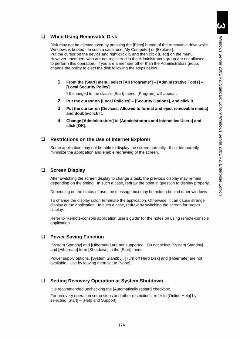
174
3
Win
do
ws S
erv
er 2
00
3/R
2, S
tan
da
rd E
ditio
n/ W
ind
ow
s S
erv
er 2
003
/R2
, En
terp
rise
Ed
ition
When Using Removable Disk
Disk may not be ejected even by pressing the [Eject] button of the removable drive while Windows is booted. In such a case, use [My Computer] or [Explorer]. Put the cursor on the device and right-click it, and then click [Eject] on the menu. However, members who are not registered in the Administrators group are not allowed to perform this operation. If you are a member other than the Administrators group, change the policy to eject the disk following the steps below.
1 From the [Start] menu, select [All Programs*] – [Administrative Tools] –
[Local Security Policy].
* If changed to the classic [Start] menu, [Program] will appear.
2 Put the cursor on [Local Policies] – [Security Options], and click it.
3 Put the cursor on [Devices: Allowed to format and eject removable media]
and double-click it.
4 Change [Administrators] to [Administrators and Interactive Users] and
click [OK].
Restrictions on the Use of Internet Explorer
Some application may not be able to display the screen normally. If so, temporarily minimize the application and enable redrawing of the screen.
Screen Display
After switching the screen display to change a task, the previous display may remain depending on the timing. In such a case, redraw the point in question to display properly.
Depending on the status of use, the message box may be hidden behind other windows.
To change the display color, terminate the application. Otherwise, it can cause strange display of the application. In such a case, redraw by switching the screen for proper display.
Refer to 'Remote-console application user's guide' for the notes on using remote-console application.
Power Saving Function
[System Standby] and [Hibernate] are not supported. Do not select [System Standby] and [Hibernate] form [Shutdown] in the [Start] menu.
Power supply options, [System Standby], [Turn off Hard Disk] and [Hibernate] are not available. Use by leaving them set to [None].
Setting Recovery Operation at System Shutdown
It is recommended unchecking the [Automatically restart] checkbox.
For recovery operation setup steps and other restrictions, refer to [Online Help] by selecting [Start] – [Help and Support].
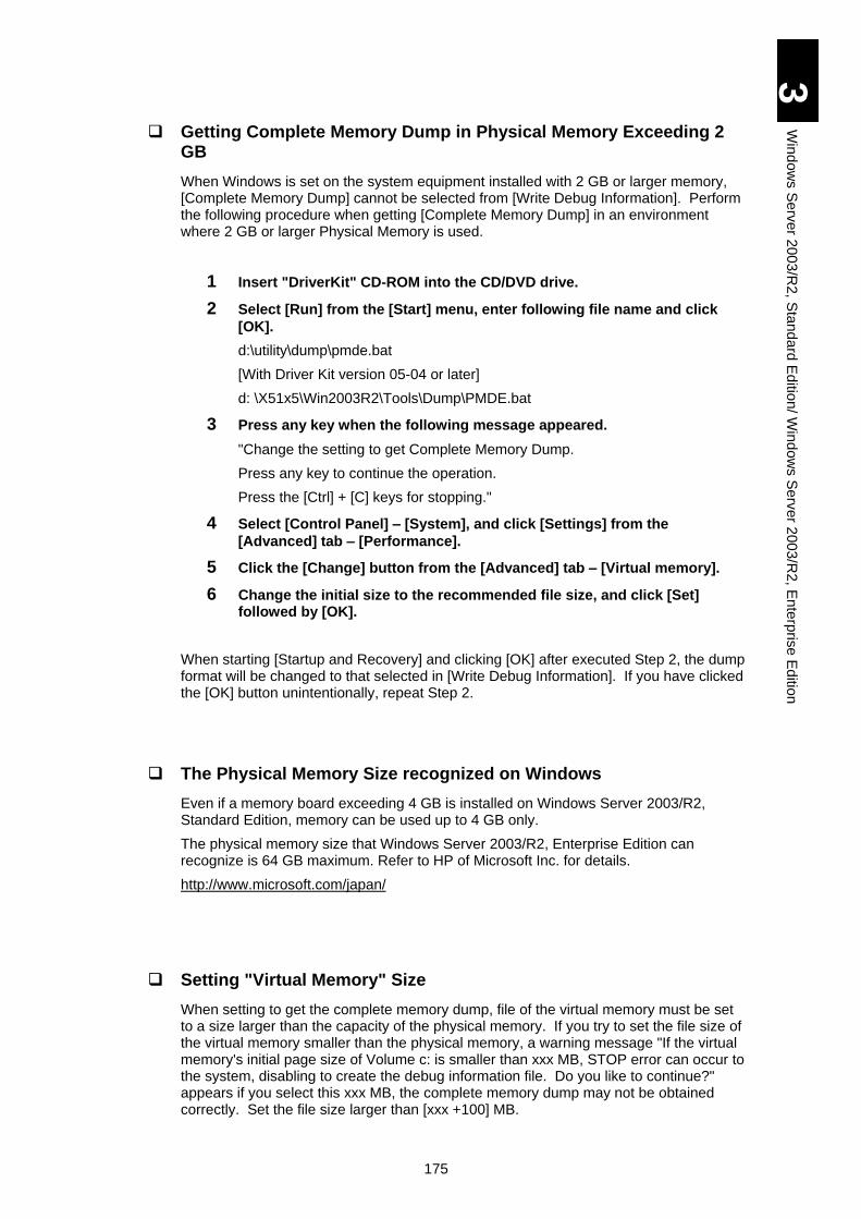
175
3
Win
do
ws S
erv
er 2
00
3/R
2, S
tan
da
rd E
ditio
n/ W
ind
ow
s S
erv
er 2
003
/R2
, En
terp
rise
Ed
ition
Getting Complete Memory Dump in Physical Memory Exceeding 2 GB
When Windows is set on the system equipment installed with 2 GB or larger memory, [Complete Memory Dump] cannot be selected from [Write Debug Information]. Perform the following procedure when getting [Complete Memory Dump] in an environment where 2 GB or larger Physical Memory is used.
1 Insert "DriverKit" CD-ROM into the CD/DVD drive.
2 Select [Run] from the [Start] menu, enter following file name and click
[OK].
d:\utility\dump\pmde.bat
[With Driver Kit version 05-04 or later]
d: \X51x5\Win2003R2\Tools\Dump\PMDE.bat
3 Press any key when the following message appeared.
"Change the setting to get Complete Memory Dump.
Press any key to continue the operation.
Press the [Ctrl] + [C] keys for stopping."
4 Select [Control Panel] – [System], and click [Settings] from the
[Advanced] tab – [Performance].
5 Click the [Change] button from the [Advanced] tab – [Virtual memory].
6 Change the initial size to the recommended file size, and click [Set] followed by [OK].
When starting [Startup and Recovery] and clicking [OK] after executed Step 2, the dump format will be changed to that selected in [Write Debug Information]. If you have clicked the [OK] button unintentionally, repeat Step 2.
The Physical Memory Size recognized on Windows
Even if a memory board exceeding 4 GB is installed on Windows Server 2003/R2, Standard Edition, memory can be used up to 4 GB only.
The physical memory size that Windows Server 2003/R2, Enterprise Edition can recognize is 64 GB maximum. Refer to HP of Microsoft Inc. for details.
http://www.microsoft.com/japan/
Setting "Virtual Memory" Size
When setting to get the complete memory dump, file of the virtual memory must be set to a size larger than the capacity of the physical memory. If you try to set the file size of the virtual memory smaller than the physical memory, a warning message "If the virtual memory's initial page size of Volume c: is smaller than xxx MB, STOP error can occur to the system, disabling to create the debug information file. Do you like to continue?" appears if you select this xxx MB, the complete memory dump may not be obtained correctly. Set the file size larger than [xxx +100] MB.
176
3
Win
do
ws S
erv
er 2
00
3/R
2, S
tan
da
rd E
ditio
n/ W
ind
ow
s S
erv
er 2
003
/R2
, En
terp
rise
Ed
ition
Device Manager
The message"?SVPMASS" might be displayed on the device manager in some : s. It is the device for the remote FD function on remote-console application. Refer to "Remote-console application user's guide" for the usage of remote FD.
The "Uncertain Device" might be displayed on the device manager. It is the device for the remote CD/DVD function on remote-console application. Refer to "Remote-console application user's guide" for directions of remote CD/ DVD.
Event Log of Network Adapter at Boot
A linkup event may be recorded at the boot regardless of actual linkup status of the network adapter.
Check the connection status of the targeted network adapter in [Network Connections].
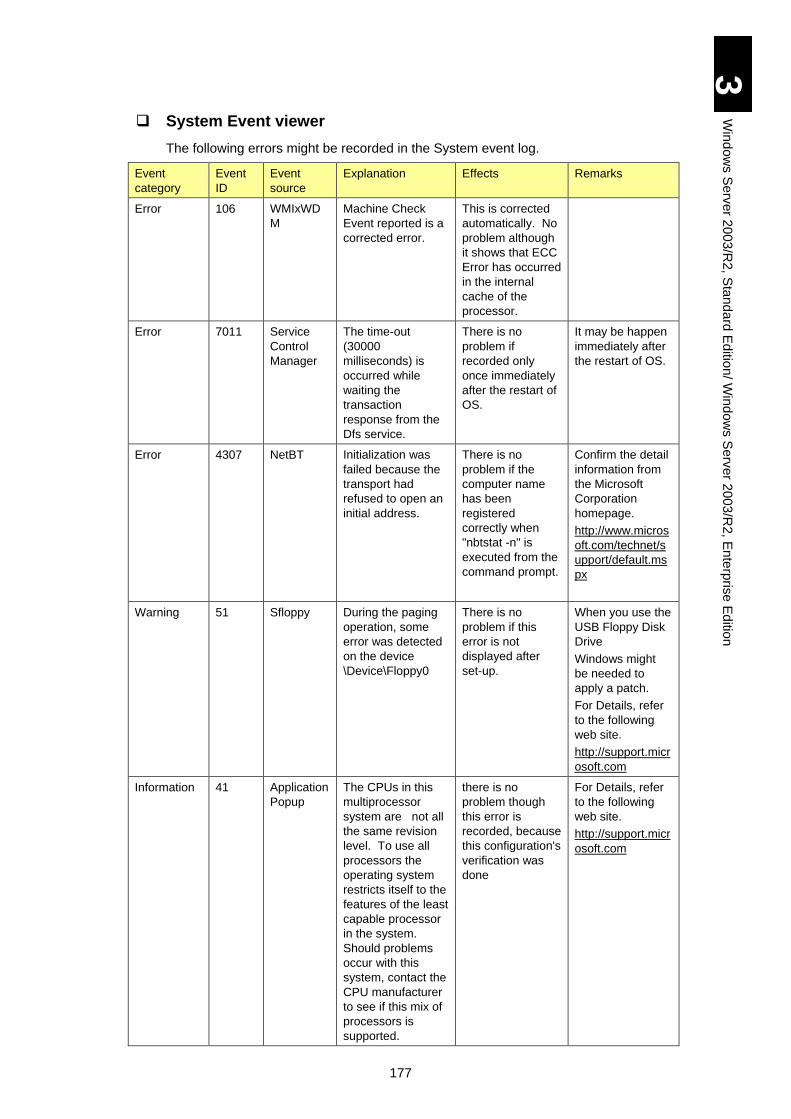
177
3
Win
do
ws S
erv
er 2
00
3/R
2, S
tan
da
rd E
ditio
n/ W
ind
ow
s S
erv
er 2
003
/R2
, En
terp
rise
Ed
ition
System Event viewer
The following errors might be recorded in the System event log.
Event
category
Event
ID
Event
source
Explanation Effects Remarks
Error 106 WMIxWD
M
Machine Check
Event reported is a
corrected error.
This is corrected
automatically. No
problem although
it shows that ECC
Error has occurred
in the internal
cache of the
processor.
Error 7011 Service
Control
Manager
The time-out
(30000
milliseconds) is
occurred while
waiting the
transaction
response from the
Dfs service.
There is no
problem if
recorded only
once immediately
after the restart of
OS.
It may be happen
immediately after
the restart of OS.
Error 4307 NetBT Initialization was
failed because the
transport had
refused to open an
initial address.
There is no
problem if the
computer name
has been
registered
correctly when
"nbtstat -n" is
executed from the
command prompt.
Confirm the detail
information from
the Microsoft
Corporation
homepage.
http://www.micros
oft.com/technet/s
upport/default.ms
px
Warning 51 Sfloppy During the paging
operation, some
error was detected
on the device
\Device\Floppy0
There is no
problem if this
error is not
displayed after
set-up.
When you use the
USB Floppy Disk
Drive
Windows might
be needed to
apply a patch.
For Details, refer
to the following
web site.
http://support.micr
osoft.com
Information 41 Application
Popup
The CPUs in this
multiprocessor
system are not all
the same revision
level. To use all
processors the
operating system
restricts itself to the
features of the least
capable processor
in the system.
Should problems
occur with this
system, contact the
CPU manufacturer
to see if this mix of
processors is
supported.
there is no
problem though
this error is
recorded, because
this configuration's
verification was
done
For Details, refer
to the following
web site.
http://support.micr
osoft.com
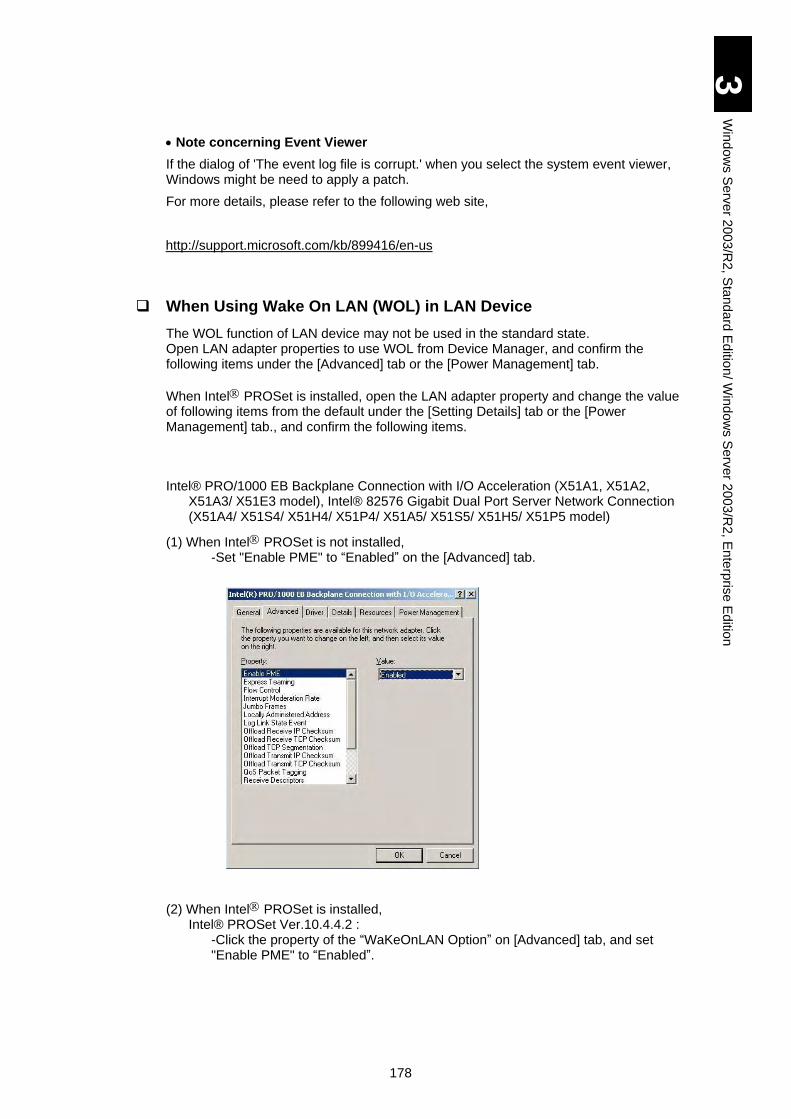
178
3
Win
do
ws S
erv
er 2
00
3/R
2, S
tan
da
rd E
ditio
n/ W
ind
ow
s S
erv
er 2
003
/R2
, En
terp
rise
Ed
ition
Note concerning Event Viewer
If the dialog of 'The event log file is corrupt.' when you select the system event viewer, Windows might be need to apply a patch.
For more details, please refer to the following web site,
http://support.microsoft.com/kb/899416/en-us
When Using Wake On LAN (WOL) in LAN Device
The WOL function of LAN device may not be used in the standard state. Open LAN adapter properties to use WOL from Device Manager, and confirm the following items under the [Advanced] tab or the [Power Management] tab.
When Intel PROSet is installed, open the LAN adapter property and change the value of following items from the default under the [Setting Details] tab or the [Power Management] tab., and confirm the following items.
Intel® PRO/1000 EB Backplane Connection with I/O Acceleration (X51A1, X51A2,
X51A3/ X51E3 model), Intel® 82576 Gigabit Dual Port Server Network Connection (X51A4/ X51S4/ X51H4/ X51P4/ X51A5/ X51S5/ X51H5/ X51P5 model)
(1) When Intel PROSet is not installed, -Set "Enable PME" to “Enabled” on the [Advanced] tab.
(2) When Intel PROSet is installed, Intel® PROSet Ver.10.4.4.2 :
-Click the property of the “WaKeOnLAN Option” on [Advanced] tab, and set "Enable PME" to “Enabled”.
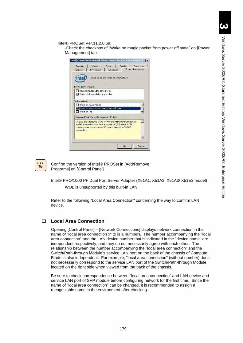
179
3
Win
do
ws S
erv
er 2
00
3/R
2, S
tan
da
rd E
ditio
n/ W
ind
ow
s S
erv
er 2
003
/R2
, En
terp
rise
Ed
ition
Intel® PROSet Ver.11.2.0.69: -Check the checkbox of “Wake on magic packet from power off state” on [Power Management] tab.
Confirm the version of Intel® PROSet in [Add/Remove
Programs] on [Control Panel]
Intel® PRO/1000 PF Dual Port Server Adapter (X51A1, X51A2, X51A3/ X51E3 model)
WOL is unsupported by this built-in LAN
Refer to the following "Local Area Connection" concerning the way to confirm LAN device.
Local Area Connection
Opening [Control Panel] – [Network Connections] displays network connection in the name of "local area connection x" (x is a number). The number accompanying the "local area connection" and the LAN device number that is indicated in the "device name" are independent respectively, and they do not necessarily agree with each other. The relationship between the number accompanying the "local area connection" and the Switch/Path-through Module’s service LAN port on the back of the chassis of Compute Blade is also independent. For example, "local area connection" (without number) does not necessarily correspond to the service LAN port of the Switch/Path-through Module located on the right side when viewed from the back of the chassis.
Be sure to check correspondence between "local area connection" and LAN device and service LAN port of SVP module before configuring network for the first time. Since the name of "local area connection" can be changed, it is recommended to assign a recognizable name in the environment after checking.
Tip
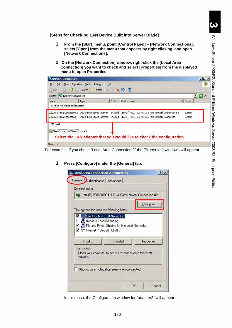
180
3
Win
do
ws S
erv
er 2
00
3/R
2, S
tan
da
rd E
ditio
n/ W
ind
ow
s S
erv
er 2
003
/R2
, En
terp
rise
Ed
ition
[Steps for Checking LAN Device Built into Server Blade]
1 From the [Start] menu, point [Control Panel] – [Network Connections],
select [Open] from the menu that appears by right clicking, and open [Network Connections].
2 On the [Network Connection] window, right-click the [Local Area
Connection] you want to check and select [Properties] from the displayed menu to open Properties.
For example, if you chose “Local Area Connection 2” the [Properties] windows will appear.
3 Press [Configure] under the [General] tab.
In this case, the Configuration window for “adapter2 “will appear.
Select the LAN adapter that you would like to check the configuration
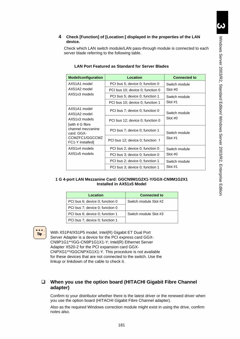
181
3
Win
do
ws S
erv
er 2
00
3/R
2, S
tan
da
rd E
ditio
n/ W
ind
ow
s S
erv
er 2
003
/R2
, En
terp
rise
Ed
ition
4 Check [Function] of [Location:] displayed in the properties of the LAN
device.
Check which LAN switch module/LAN pass-through module is connected to each server blade referring to the following table.
LAN Port Featured as Standard for Server Blades
Model/configuration Location Connected to
AX51A1 model
AX51A2 model
AX51x3 models
PCI bus 5; device 0; function 0 Switch module
Slot #0 PCI bus 10; device 0; function 0
PCI bus 5; device 0; function 1 Switch module
Slot #1 PCI bus 10; device 0; function 1
AX51A1 model
AX51A2 model
AX51x3 models
[with 4 G fibre
channel mezzanine
card: GGX-
CCMZFC1/GGCCMZ
FC1-Y installed]
PCI bus 7; device 0; function 0 Switch module
Slot #0 PCI bus 12; device 0; function 0
PCI bus 7; device 0; function 1 Switch module
Slot #1 PCI bus 12; device 0; function 1
AX51x4 models
AX51x5 models
PCI bus 2; device 0; function 0 Switch module
Slot #0 PCI bus 3; device 0; function 0
PCI bus 2; device 0; function 1 Switch module
Slot #1 PCI bus 3; device 0; function 1
1 G 4-port LAN Mezzanine Card: GGCN9M1G2X1-Y/GGX-CN9M1G2X1 Installed in AX51x5 Model
Location Connected to
PCI bus 6; device 0; function 0 Switch module Slot #2
PCI bus 7; device 0; function 0
PCI bus 6; device 0; function 1 Switch module Slot #3
PCI bus 7; device 0; function 1
With X51P4/X51P5 model, Intel(R) Gigabit ET Dual Port
Server Adapter is a device for the PCI express card GGX-
CN9P1G1**/GG-CN9P1G1X1-Y; Intel(R) Ethernet Server
Adapter X520-2 for the PCI expansion card GGX-
CNPXG1**/GGCNPXG1X1-Y. This procedure is not available
for these devices that are not connected to the switch. Use the
linkup or linkdown of the cable to check it.
When you use the option board (HITACHI Gigabit Fibre Channel adapter)
Confirm to your distributor whether there is the latest driver or the renewed driver when you use the option board (HITACHI Gigabit Fibre Channel adapter).
Also as the required Windows correction module might exist in using the drive, confirm notes also.
182
3
Win
do
ws S
erv
er 2
00
3/R
2, S
tan
da
rd E
ditio
n/ W
ind
ow
s S
erv
er 2
003
/R2
, En
terp
rise
Ed
ition
When you use MSCS (cluster) (Only Enterprise Edition)
When the option board (HITACHI Gigabit Fibre Channel adapter) is installed, and MSCS (cluster service) is used, it is necessary to make MSCS mode enable with the parameter setting tool.
Refer to "Chapter 10. Setting of the GIGABIT FIBRE CHANNEL Adapter" on the option board manual "Hitachi Gigabit Fibre Channel adapter user's guide", and set "MSCS mode" to enable by using the parameter setting tool (hfcutil.exe).
This setting is unnecessary in the system that “Hitachi Dynamic Link Manager” is installed in.
When MSCS is used, the use of a standard firewall function is not recommended, though the firewall function was installed as a standard in Service Pack 1 and Windows Server 2003/R2.
Confirm that the "Windows Firewall/Internet Connection Sharing (ICS)" service has been stopped and that "Startup Kind" is "Invalid" or "Manual" on [Management tool] - [Service], when MSCS is assembled and you do not need the firewall function.
"Windows Firewall/Internet Connection Sharing (ICS)" service
doesn't stop even if you set "Invalid" to firewall from [Control
Panel] - [Windows firewall].
Be sure to stop serving from [Management Tool] - [Service]
when you stop the firewall.
When Fiber channel Mezzanine card (GGX-CC9MZFC1 or GGX-CC9M4G1X1/GG-CC9M4G1X1-Y) is mounted and the SAN boot environment is constructed, it is necessary to make the duplicate boot-path by the path duplicate software.
The cluster configuration wizard become an error when you make boot-path double and execute cluster configuration wizard, because LU that includes OS and LU for Coram and the common data will exist on the same path.
It is necessary to change in the registry to compose the cluster.
Concerning the change of the registry, retrieve KB886569 on the web site of the following Microsoft Company.
http://support.microsoft.com
KB886569: How to add a registry value to a Windows Server 2003-based computer that you start from a SAN so that the startup disk, the pagefile disks, and the cluster disks are all on the same SAN fabric.
Note that the registry is different according to whether the service pack is installed.
When Fiber channel Mezzanine card (GGX-CC9MZFC1 or CC9M4G1X1/GG-CC9M4G1X1-Y) is mounted and the SAN boot environment is constructed, MSCS configuration cannot be established. Install OS into built-in HDD of server blade, when MSCS is built by GGX-CE9MZSS1A.
! Note
183
3
Win
do
ws S
erv
er 2
00
3/R
2, S
tan
da
rd E
ditio
n/ W
ind
ow
s S
erv
er 2
003
/R2
, En
terp
rise
Ed
ition
Restriction on SAN Storage Manager
A VDS-capable disk array device is required to use SAN storage manager. Refer to the manual provided with your disk array device for whether or not the device supports VDS.
About Scalable Networking Pack (KB912222)
The corresponding hardware is needed to receive the favor of a part of function, though "Scalable Networking Pack" (KB912222) is being offered by the Microsoft Corporation.
The installation of Scalable Networking Pack under the SP1 environment is unsupported though the correspondence hardware is mounted in the X51A1, X51A2 and X51A3/X51E3 model.
Refer to following web page for
Concerning the details of Scalable Networking Pack, retrieve KB912222 on the web site of the Microsoft Company.
http://support.microsoft.com
SP1 is not supported for / X51A5/ X51S5/ X51H5/ X51P5 model.
TCP/IP Checksum Offload function of the network adapter
The "onboard LAN adapter" and the "extended LAN board" have the TCP/IP protocol checksum calculation function that is executed on LAN controller.
Though, it is recommended using the TCP/IP checksum calculation function that OS provides as standard, rather than using this function.
You can construct more high reliability system if the calculation function of OS side is set available.
Because the correspondence confirmation of the packet data received from the network will be performed in the last phase of the OS protocol processing.
Change the setting of LAN adapter to turn the checksum function by LAN controller off as follows.
When you use LAN advanced function of Intel PROSet
(AFT/ALB/SFT/tag VLAN), delete LAN advanced function once,
change the setting, and configure LAN advanced function
again after the setting change.
Restart the system device after the setting change.
- "lPv4 Checksum Off-load"
- "TCP Checksum Off-load" (lPv4)
- "UDP Checksum Off-load (lPv4)
- "Receive IP Checksum Off-load"
- "Receive TCP Checksum Off-load"
- "Send IP Checksum Off-load"
- "Send TCP Checksum Off-load"
- "TCP segmentation Off-load"
- “Receive Side Scaling”
! Note
184
3
Win
do
ws S
erv
er 2
00
3/R
2, S
tan
da
rd E
ditio
n/ W
ind
ow
s S
erv
er 2
003
/R2
, En
terp
rise
Ed
ition
Open the property of each LAN adapter in [Device manager], and set the following items under the [Detail settings] tab to “Disabled”. When Intel(R) PROSet is installed, some items may be displayed in [Properties] < [TCP/IP Offload Option] < [Advanced]. Check the checkbox of those items
Some items may not be displayed depending on the type of a network adapter. Set items displayed with you adapter.
Disable the following items:
"lPv4 Checksum Off-load "
"TCP Checksum Off-load" (lPv4)
"UDP Checksum Off-load” (lPv4)
"Off-load TCP segmentation"
“Receive Side Scaling”
With 10 Gbps expansion LAN adapter: Intel(R) Ethernet Server Adapter X520-2, have the LAN controller function calculate the checksum of TCP/IP protocol. If you have the OS do it, data transmission may be less than expected due to heavy load on the CPU. The default value of newly installed adapters is all “Enabled”.
To enable the checksum by the LAN controller, follow the
next description.
Open [Properties] of each LAN adapter in [Device
Manager], click the [Advanced] tab, and set the following
items [Enabled]. When Intel(R) PROSet is installed, some
items may be displayed in [Properties] < [TCP/IP Offload
option] < [Advanced]. Check the checkbox of those items.
lPv4 Checksum Off-load: Receive/Send Enabled
TCP segmentation Off-load: Enabled
TCP Checksum Off-load (lPv4): Receive/Send Enabled
UDP Checksum Off-load (lPv4): Receive/Send Enabled
Event Log of Network Adapter at Boot
A linkup event may be recorded at the boot regardless of actual linkup status of the network adapter.
Check the connection status of the target network adapter in [Network Connections].
Display of Network Adapter Connection
[Network Connection] or task tray status may not be quickly updated at the network adapter linkup. To find the status, select [View] in [Network Connections]. Then select [Latest Update] to update the connection.
185
3
Win
do
ws S
erv
er 2
00
3/R
2, S
tan
da
rd E
ditio
n/ W
ind
ow
s S
erv
er 2
003
/R2
, En
terp
rise
Ed
ition
Link Rate Setting for LAN Adapter
When you use A1/A2/A3/E3 model with Intel (R) PRO/1000 EB Backplane Connection with I/O Acceleration and Intel (R) PRO/1000 PF Dual Port Server Adapter, the link rate cannot be changed.
When using A4/S4/H4/P4/R4 model with Intel® 82576 Gigabit Dual Port Server Network Connection, LAN driver Ver.10.3.49.0, and Intel(R) PROSet Ver. 13.2.8.0, you can select one from 10Mbps, 100Mbps, and 1.0Gbps. Select a LAN device > [Properties] > [[Advanced] tab > [Link rate and Duplex], or [Link Rate] tab > [Rate and Duplex] if Intel (R) PROSet is installed, and select one from the three.
If the setting is changed, the rink rate is unchangeable and remains as “1.0Gps/full duplex”. Use the provided “Auto negotiation” as it is.
Event Log on Network Adapter
\DEVICE {354C76B6-E426-4CEB-8015-BF991BA8D75F} instead of a network adapter name such as Intel® 82566DC-2 Gigabit Network Connection may be displayed in the event log explanation of the network adapter.
This occurs due to the specification, which will not affect the operation.
The network adapter name and the number in brackets (GUID) may be different depending on your environment.
Multipath
When a multipath (access route) is assigned to LU of an external disk array where to install the OS, change it to a single path before installing the OS. With multiple paths assigned to the LU, the installation fails. Install the OS with a single path, then install multipath software, and release the single-path routing.
When a multipath (access route) is assigned to LU of an external disk array where the OS has been installed, change it to a single-path routing before restoring the OS from the backup files. With multiple paths assigned to the LU, the restoration may fail. Check notes on the backup software referring to the manual beforehand.
It is common to change a multipath to a single-path routing from the management utility of an external disk array. Refer to the manual of the external disk array device.
Functions Requiring Floppy Disk Drive
The following functions require a floppy disk drive. Then you cannot use them without a USB floppy disk drive.
Automatic System Recovery (ASR)
Windows Recovery Console
OS setup with the Setup CD
Other functions that need a floppy disk drive
USB Memory
With a USB memory connected, do not power on the system equipment or perform reboot-up. Boot the OS and then connect the USB memory. After that, confirm that drive letters of other drives are not changed..
186
3
Win
do
ws S
erv
er 2
00
3/R
2, S
tan
da
rd E
ditio
n/ W
ind
ow
s S
erv
er 2
003
/R2
, En
terp
rise
Ed
ition
Windows Server 2003/R2 Setup
This section explains the steps to redo setting up to the state after completion of initial setting of Windows Server 2003/R2 model. To set up Windows 2003/R2 for server blade without OS, follow the same steps.
For the installation procedure of the driver for expanded board, refer to the manual of expanded board.
NOTICE
Re-setup causes the hard disk data to disappear. Back up data that you need in advance.
For re-setup, see "Restrictions to Setup".
The description below shows Windows setup to the HDD
module.
There are the notes that include the built environment
construction also when you construct the boot environment
from the external disk array device connected via Fibre
Channel.
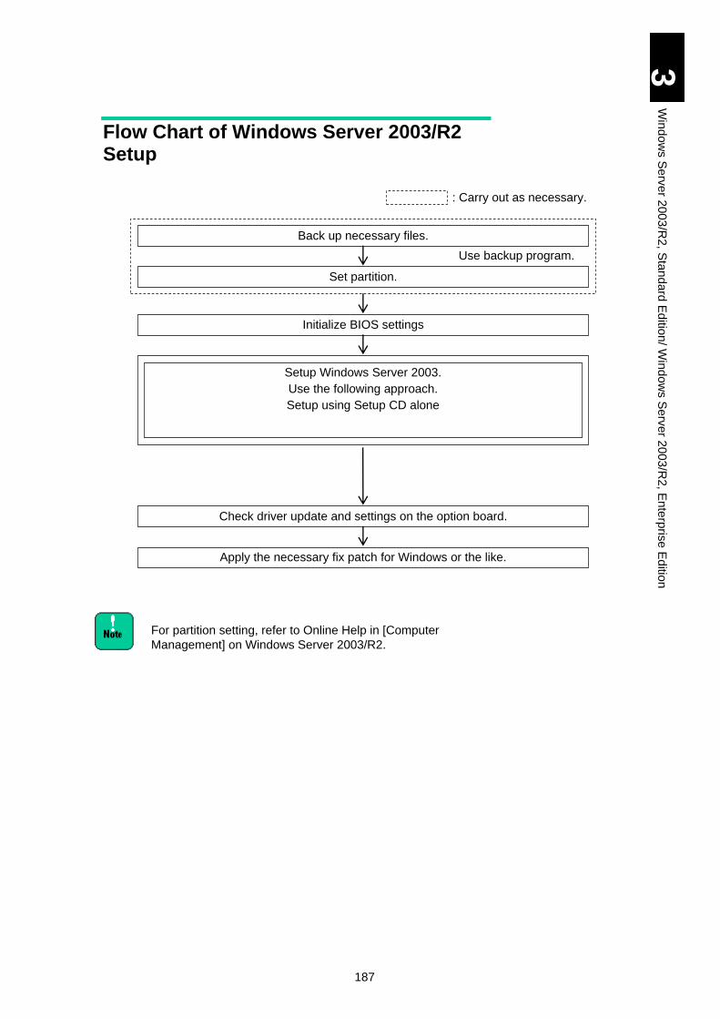
187
3
Win
do
ws S
erv
er 2
00
3/R
2, S
tan
da
rd E
ditio
n/ W
ind
ow
s S
erv
er 2
003
/R2
, En
terp
rise
Ed
ition
Flow Chart of Windows Server 2003/R2 Setup
For partition setting, refer to Online Help in [Computer
Management] on Windows Server 2003/R2.
Back up necessary files.
: Carry out as necessary.
Set partition.
Initialize BIOS settings
Setup Windows Server 2003.
Use the following approach.
Setup using Setup CD alone
Check driver update and settings on the option board.
Apply the necessary fix patch for Windows or the like.
Use backup program.
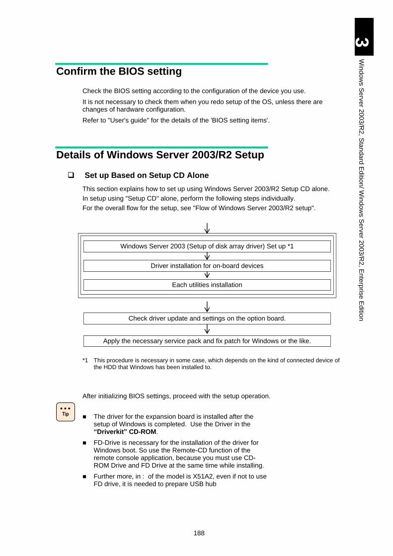
188
3
Win
do
ws S
erv
er 2
00
3/R
2, S
tan
da
rd E
ditio
n/ W
ind
ow
s S
erv
er 2
003
/R2
, En
terp
rise
Ed
ition
Confirm the BIOS setting
Check the BIOS setting according to the configuration of the device you use.
It is not necessary to check them when you redo setup of the OS, unless there are changes of hardware configuration.
Refer to "User's guide" for the details of the 'BIOS setting items'.
Details of Windows Server 2003/R2 Setup
Set up Based on Setup CD Alone
This section explains how to set up using Windows Server 2003/R2 Setup CD alone.
In setup using "Setup CD" alone, perform the following steps individually.
For the overall flow for the setup, see "Flow of Windows Server 2003/R2 setup".
*1 This procedure is necessary in some case, which depends on the kind of connected device of the HDD that Windows has been installed to.
After initializing BIOS settings, proceed with the setup operation.
The driver for the expansion board is installed after the setup of Windows is completed. Use the Driver in the “Driverkit” CD-ROM.
FD-Drive is necessary for the installation of the driver for Windows boot. So use the Remote-CD function of the remote console application, because you must use CD-ROM Drive and FD Drive at the same time while installing.
Further more, in : of the model is X51A2, even if not to use FD drive, it is needed to prepare USB hub
Check driver update and settings on the option board.
Apply the necessary service pack and fix patch for Windows or the like.
Windows Server 2003 (Setup of disk array driver) Set up *1
Driver installation for on-board devices
Each utilities installation
Tip
189
3
Win
do
ws S
erv
er 2
00
3/R
2, S
tan
da
rd E
ditio
n/ W
ind
ow
s S
erv
er 2
003
/R2
, En
terp
rise
Ed
ition
Restrictions to Setup
Setting partition (drive)
The partition (drive) to which the OS is installed Install the OS to the first partition of the HDD.
Symptoms being reported when Windows Server 2003 setup
Concerning the installation using OS media of Windows Server 2003, the following symptoms are reported by the Microsoft Corporation.
For details, retrieve KB (number) on the following web sites.
http://support.microsoft.com/
KB827052 Universal serial bus (USB) input devices may not work when unsigned drivers are being installed during Windows Setup
⇒The mouse or keyboard connected to USB may not be operational while
setting it up. There is no problem if the setup ends.
About remote FD of the remote-console application
When you use remote FD of the remote-console application, driver FD cannot be recognized on Windows setup.
Connect the USB FD drive with the USB port in front of the server blade when you use FD.
Installing OS into the EXTERNAL DISK ARRAY DEVICE
Set 'one path' to the Fibre at the target LU before installing OS. If several paths set to the target LU, the installation fails. Generally use the management utility of the external disk array device for setting ‘one path’. Refer the external disk array device’s manual for the detail.
Set RAID device to use LUN0 as OS. And, confirm that 'Boot Priority' of the target LU is the first priority at System Boot menu. To display System Boot Menu, push F2 key immediately after booting the server blade.
At reinstalling OS, Non-target LU should be hidden temporarily for safety. Confirm whether temporarily to be able to mask Non-target LU at the setting of the external RAID device, or to be able to remove them from Group.
OS media with X51x5/X51x4 model
The first media of Windows Server 2003 is not available for setting up Windows Server 2003 on X51A5/X51A4 model. Make sure to use the OS media with SP1 or the one with SP2. Windows Server 2003 R2 media is equivalent to the one with SP1 applied.
Capacity of a logical drive for installing the OS
Set the capacity of a logical drive for installing the OS to 2 TB or less. If with more then 2 TB, the OS can recognize just up to 2 TB.
190
3
Win
do
ws S
erv
er 2
00
3/R
2, S
tan
da
rd E
ditio
n/ W
ind
ow
s S
erv
er 2
003
/R2
, En
terp
rise
Ed
ition
Setup Steps
NOTICE
Re-setup causes the hard disk data to disappear. Back up data that you need in advance.
When external disk array device which is not target for
installation is connected, turn off the device power before
starting the setup.
1 Create Driver FD on the other working pc before starting installation.
It is not required in case you install into a non-RAID configuration HDD in the server blade. Prepare one brand new and formatted FD (See "Note") used as boot Driver FD before installing Windows Server 2003.
Creating boot Driver FD, it must be done on Windows base PC by using the batch file in the "DriverKit"CD-ROM.
Refer the following directory information for each Model.
If the brand new and formatted FD is not used for creating boot
Driver FD, loading may fail with the following error message.
"File XXXX.sys caused an unexpected error (YYYYY) at line
ZZZZ ........"
(1) When installing to the HDD(RAID configuration) in server blade;
Model X51A1:
32-bit: \X51x1\A\WIN2003\RAID\MKFD.BAT
64-bit: \X51x1\A\WIN2003x64\RAID\MKFD.BAT
Model X51A2:
32-bit: \X51x2\A\WIN2003\RAID\MKFD.BAT
64-bit: \X51x2\A\WIN2003x64\RAID\MKFD.BAT
Model X51A3/X51E3:
32-bit: \X51x3\A\WIN2003\RAID\MKFD.BAT
64-bit: \X51x3\A\WIN2003x64\RAID\MKFD.BAT
Model X51A4
32-bit: \X51x4\A\WIN2003\RAID\MKFD.BAT
64-bit: \X51x4\A\WIN2003x64\RAID\MKFD.BAT
Model X51H4
32-bit: \X51x4\H\WIN2003\RAID\MKFD.BAT
64-bit: \X51x4\H\WIN2003x64\RAID\MKFD.BAT
Model X51R4
32-bit: \X51x4\R\WIN2003\RAID\MKFD.BAT
!
Note
! Note
191
3
Win
do
ws S
erv
er 2
00
3/R
2, S
tan
da
rd E
ditio
n/ W
ind
ow
s S
erv
er 2
003
/R2
, En
terp
rise
Ed
ition
64-bit: \X51x4\R\WIN2003x64\RAID\MKFD.BAT
Model X51A5
32-bit: \X51x5\A\WIN2003\RAID\MKFD.BAT
64-bit: \X51x5\A\WIN2003x64\RAID\MKFD.BAT
Model X51H5 wi t h LSI MegaRAI D SAS 1078
32-bit: \X51x5\H\WIN2003\RAID\MKFD.BAT
64-bit: \X51x5\H\WIN2003x64\RAID\MKFD.BAT
Model X51H5 wi t h LSI MegaRAI D SAS 2108
32-bit: \X51x5\H\WIN2003\RAID_02\MKFD.BAT
64-bit: \X51x5\H\WIN2003x64\RAID_02\MKFD.BAT
Model X51R5
32-bit: \X51x5\R\WIN2003\RAID\MKFD.BAT
64-bit: \X51x5\R\WIN2003x64\RAID\MKFD.BAT
[With Driver Kit version 05-04 or later]
Model X51A5
32-bit: \X51x5\Win2003R2\Drivers\RAID\MegaSR_01\x86\MKFD.BAT
64-bit: \X51x5\Win2003R2\Drivers\RAID\MegaSR_01\x64\MKFD.BAT
Model X51H5 wi t h LSI MegaRAI D SAS 2108
32-bit: \X51x5\Win2003R2\Drivers\RAID\MegaSAS_01\x86\MKFD.BAT
64-bit: \X51x5\Win2003R2\Drivers\RAID\MegaSAS_01\x64\MKFD.BAT
Model X51R5
32-bit: \X51x5\Win2003R2\Drivers\RAID\MegaSAS_01\x86\MKFD.BAT
64-bit: \X51x5\Win2003R2\Drivers\RAID\MegaSAS_01\x64\MKFD.BAT
(2) For installation in the external disk array devices connected to a mezzanine card: GGX-CC9MZFC1, GGX-CC9M4G1X1/GG-CC9M4G1X1-Y, or GGX-CC9P4G1X, or a PCI express card: GGX-CC9P8G2X1, see the folder under the following folder corresponding to each board model name.
32-bit:
\OPTION\WIN2003\.
64-bit:
\OPTION\WIN2003x64\.
[With Driver Kit version 05-04 or later]
X51A5/ X51S5/ X51P5/ X51R5 models:
32-bit: \X51x5\Win2003R2\Drivers\FibreChannel\HFC_01\x86\MKFD.BAT
64-bit: \X51x5\Win2003R2\Drivers\FibreChannel\HFC_01\x64\MKFD.BAT
(3) For installation in the external disk array devices connected to a mezzanine card: GGX-CC9M4G2X1/GG-CC9M4G2X1-Y, or a PCI express card: GGX-CC9P8G1X1/GG-CC9P8G1X1-Y, see the folder under the following folder corresponding to each board model name.
32-bit:
\OPTION\WIN2003\.
64-bit:
\OPTION\WIN2003x64\.
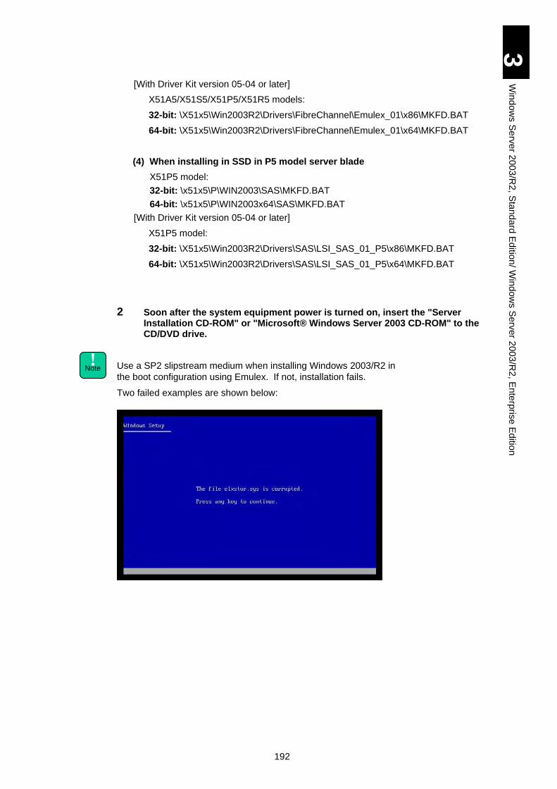
192
3
Win
do
ws S
erv
er 2
00
3/R
2, S
tan
da
rd E
ditio
n/ W
ind
ow
s S
erv
er 2
003
/R2
, En
terp
rise
Ed
ition
[With Driver Kit version 05-04 or later]
X51A5/X51S5/X51P5/X51R5 models:
32-bit: \X51x5\Win2003R2\Drivers\FibreChannel\Emulex_01\x86\MKFD.BAT
64-bit: \X51x5\Win2003R2\Drivers\FibreChannel\Emulex_01\x64\MKFD.BAT
(4) When installing in SSD in P5 model server blade
X51P5 model:
32-bit: \x51x5\P\WIN2003\SAS\MKFD.BAT
64-bit: \x51x5\P\WIN2003x64\SAS\MKFD.BAT
[With Driver Kit version 05-04 or later]
X51P5 model:
32-bit: \X51x5\Win2003R2\Drivers\SAS\LSI_SAS_01_P5\x86\MKFD.BAT
64-bit: \X51x5\Win2003R2\Drivers\SAS\LSI_SAS_01_P5\x64\MKFD.BAT
2 Soon after the system equipment power is turned on, insert the "Server Installation CD-ROM" or "Microsoft® Windows Server 2003 CD-ROM" to the CD/DVD drive.
Use a SP2 slipstream medium when installing Windows 2003/R2 in
the boot configuration using Emulex. If not, installation fails.
Two failed examples are shown below:
! Note
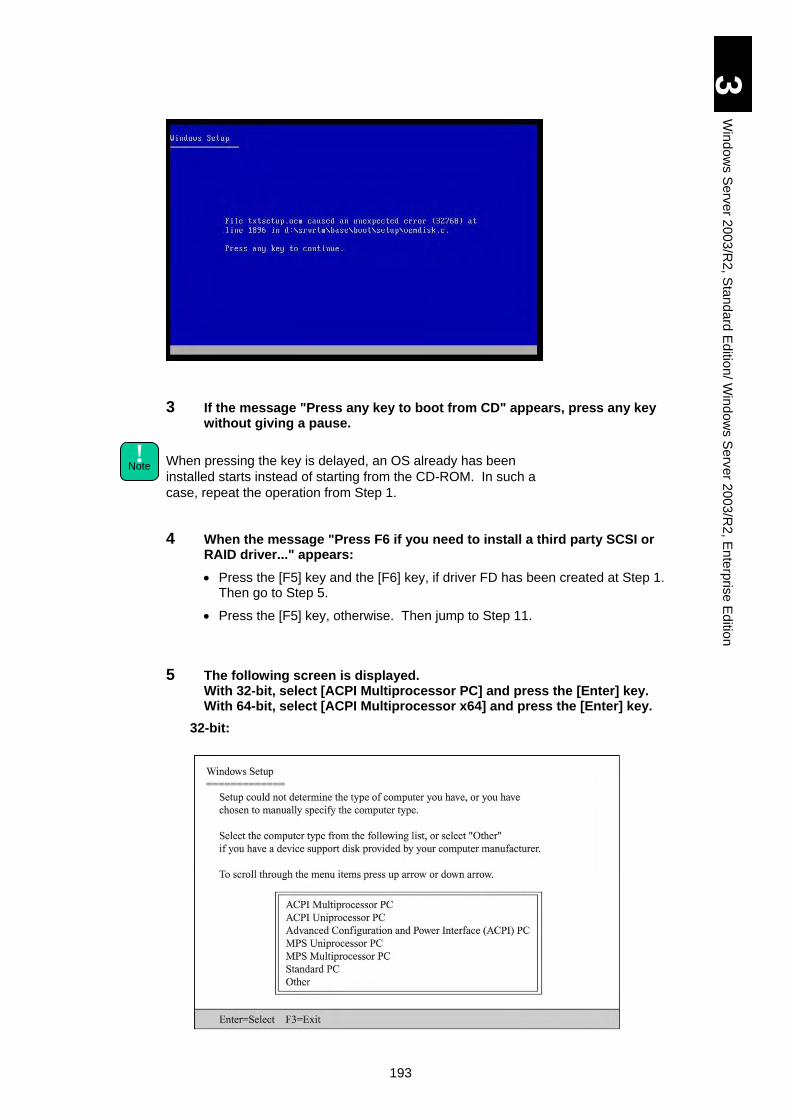
193
3
Win
do
ws S
erv
er 2
00
3/R
2, S
tan
da
rd E
ditio
n/ W
ind
ow
s S
erv
er 2
003
/R2
, En
terp
rise
Ed
ition
3 If the message "Press any key to boot from CD" appears, press any key without giving a pause.
When pressing the key is delayed, an OS already has been
installed starts instead of starting from the CD-ROM. In such a
case, repeat the operation from Step 1.
4 When the message "Press F6 if you need to install a third party SCSI or RAID driver..." appears:
Press the [F5] key and the [F6] key, if driver FD has been created at Step 1. Then go to Step 5.
Press the [F5] key, otherwise. Then jump to Step 11.
5 The following screen is displayed. With 32-bit, select [ACPI Multiprocessor PC] and press the [Enter] key. With 64-bit, select [ACPI Multiprocessor x64] and press the [Enter] key.
32-bit:
! Note
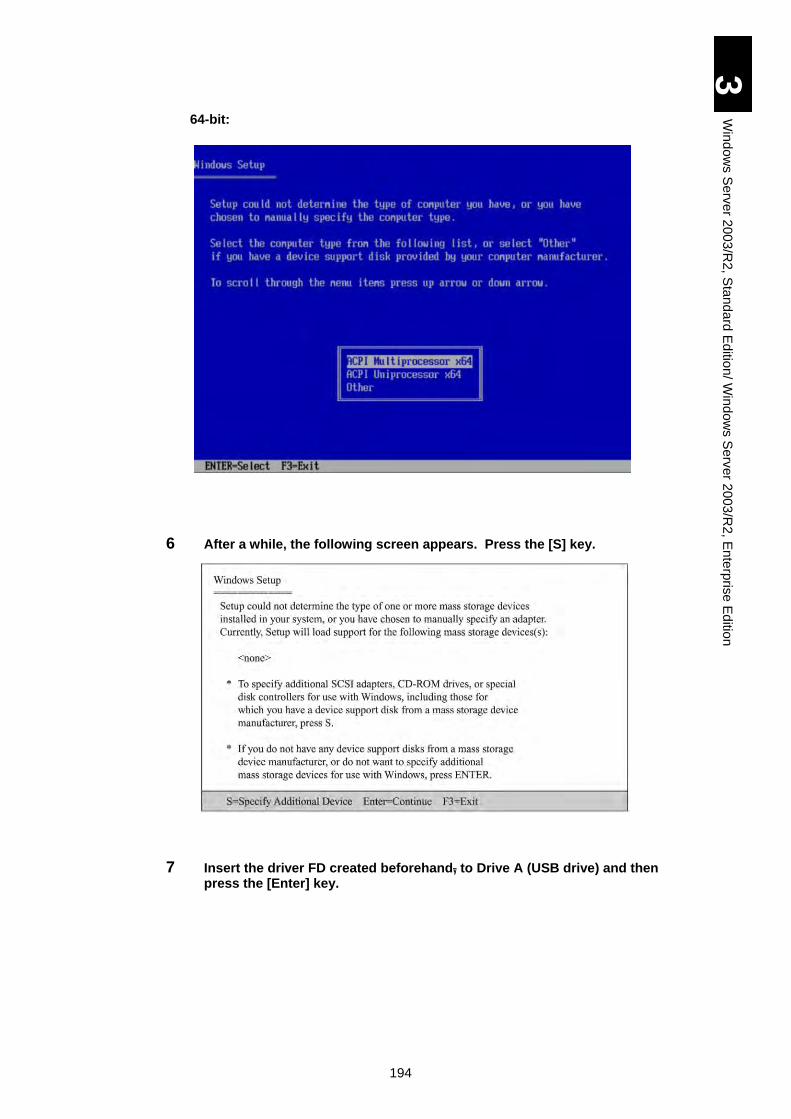
194
3
Win
do
ws S
erv
er 2
00
3/R
2, S
tan
da
rd E
ditio
n/ W
ind
ow
s S
erv
er 2
003
/R2
, En
terp
rise
Ed
ition
64-bit:
6 After a while, the following screen appears. Press the [S] key.
7 Insert the driver FD created beforehand, to Drive A (USB drive) and then press the [Enter] key.
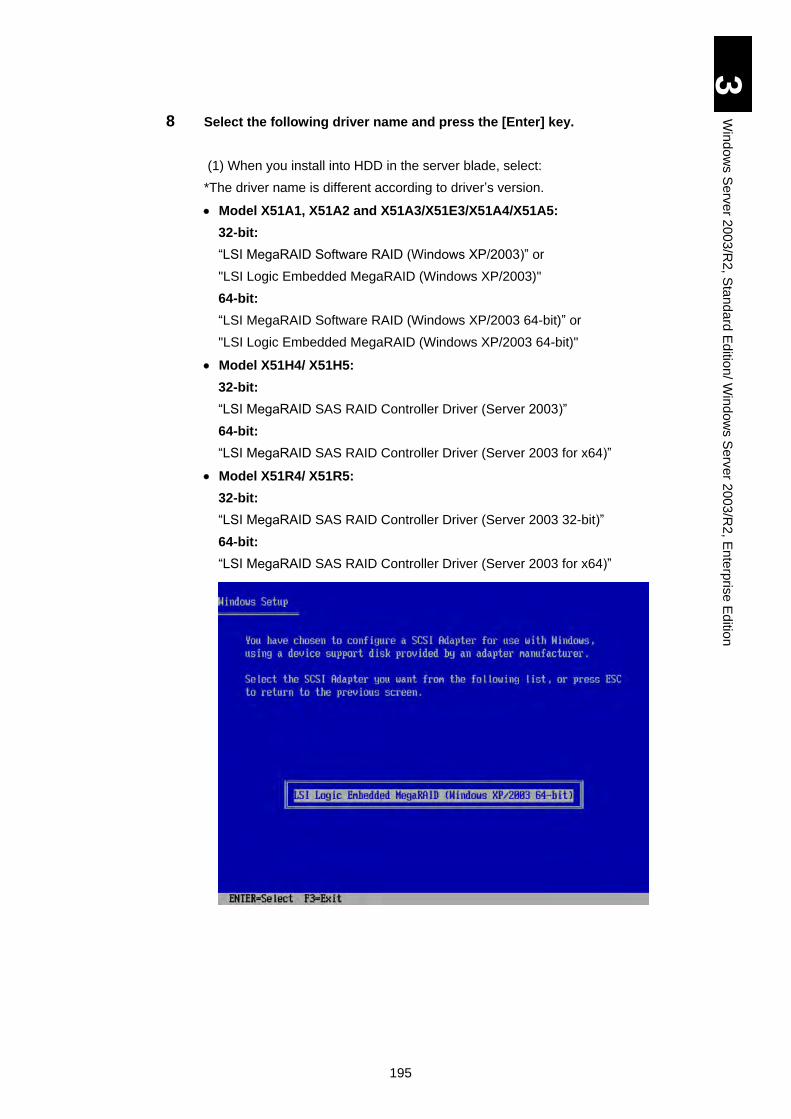
195
3
Win
do
ws S
erv
er 2
00
3/R
2, S
tan
da
rd E
ditio
n/ W
ind
ow
s S
erv
er 2
003
/R2
, En
terp
rise
Ed
ition
8 Select the following driver name and press the [Enter] key.
(1) When you install into HDD in the server blade, select:
*The driver name is different according to driver’s version.
Model X51A1, X51A2 and X51A3/X51E3/X51A4/X51A5:
32-bit:
“LSI MegaRAID Software RAID (Windows XP/2003)” or
"LSI Logic Embedded MegaRAID (Windows XP/2003)"
64-bit:
“LSI MegaRAID Software RAID (Windows XP/2003 64-bit)” or
"LSI Logic Embedded MegaRAID (Windows XP/2003 64-bit)"
Model X51H4/ X51H5:
32-bit:
“LSI MegaRAID SAS RAID Controller Driver (Server 2003)”
64-bit:
“LSI MegaRAID SAS RAID Controller Driver (Server 2003 for x64)”
Model X51R4/ X51R5:
32-bit:
“LSI MegaRAID SAS RAID Controller Driver (Server 2003 32-bit)”
64-bit:
“LSI MegaRAID SAS RAID Controller Driver (Server 2003 for x64)”
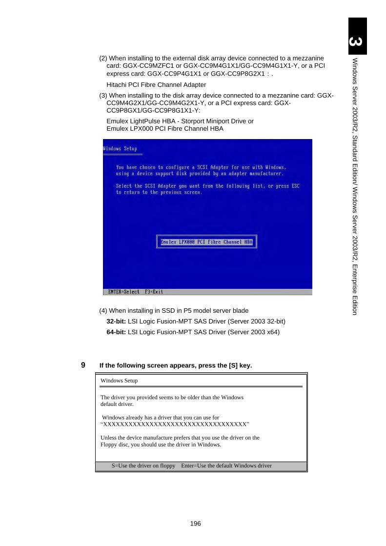
196
3
Win
do
ws S
erv
er 2
00
3/R
2, S
tan
da
rd E
ditio
n/ W
ind
ow
s S
erv
er 2
003
/R2
, En
terp
rise
Ed
ition
(2) When installing to the external disk array device connected to a mezzanine card: GGX-CC9MZFC1 or GGX-CC9M4G1X1/GG-CC9M4G1X1-Y, or a PCI
express card: GGX-CC9P4G1X1 or GGX-CC9P8G2X1:.
Hitachi PCI Fibre Channel Adapter
(3) When installing to the disk array device connected to a mezzanine card: GGX-CC9M4G2X1/GG-CC9M4G2X1-Y, or a PCI express card: GGX-CC9P8GX1/GG-CC9P8G1X1-Y:
Emulex LightPulse HBA - Storport Miniport Drive or Emulex LPX000 PCI Fibre Channel HBA
(4) When installing in SSD in P5 model server blade
32-bit: LSI Logic Fusion-MPT SAS Driver (Server 2003 32-bit)
64-bit: LSI Logic Fusion-MPT SAS Driver (Server 2003 x64)
9 If the following screen appears, press the [S] key.
Windows Setup
The driver you provided seems to be older than the Windows
default driver.
Windows already has a driver that you can use for
“XXXXXXXXXXXXXXXXXXXXXXXXXXXXXXXXXX”
Unless the device manufacture prefers that you use the driver on the
Floppy disc, you should use the driver in Windows.
S=Use the driver on floppy Enter=Use the default Windows driver
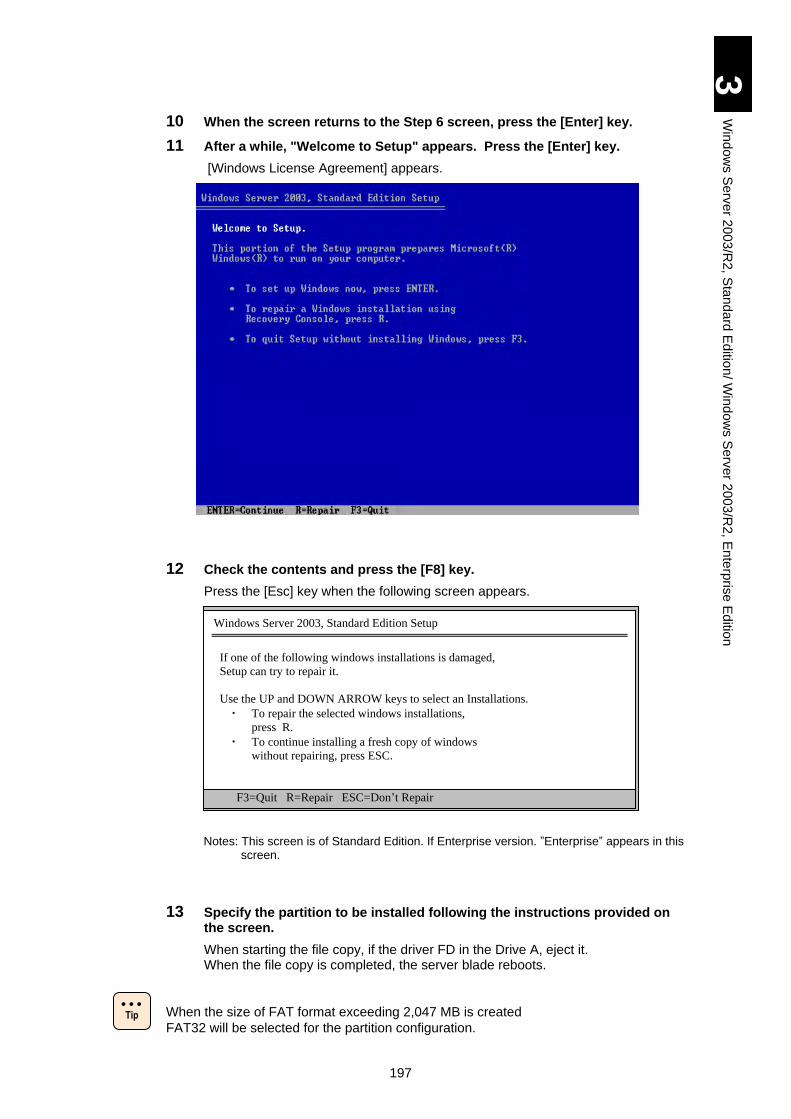
197
3
Win
do
ws S
erv
er 2
00
3/R
2, S
tan
da
rd E
ditio
n/ W
ind
ow
s S
erv
er 2
003
/R2
, En
terp
rise
Ed
ition
10 When the screen returns to the Step 6 screen, press the [Enter] key.
11 After a while, "Welcome to Setup" appears. Press the [Enter] key.
[Windows License Agreement] appears.
12 Check the contents and press the [F8] key.
Press the [Esc] key when the following screen appears.
Notes: This screen is of Standard Edition. If Enterprise version. ”Enterprise” appears in this screen.
13 Specify the partition to be installed following the instructions provided on the screen.
When starting the file copy, if the driver FD in the Drive A, eject it. When the file copy is completed, the server blade reboots.
When the size of FAT format exceeding 2,047 MB is created
FAT32 will be selected for the partition configuration.
Windows Server 2003, Standard Edition Setup
If one of the following windows installations is damaged,
Setup can try to repair it.
Use the UP and DOWN ARROW keys to select an Installations.
・ To repair the selected windows installations,
press R.
・ To continue installing a fresh copy of windows
without repairing, press ESC.
F3=Quit R=Repair ESC=Don’t Repair
Tip
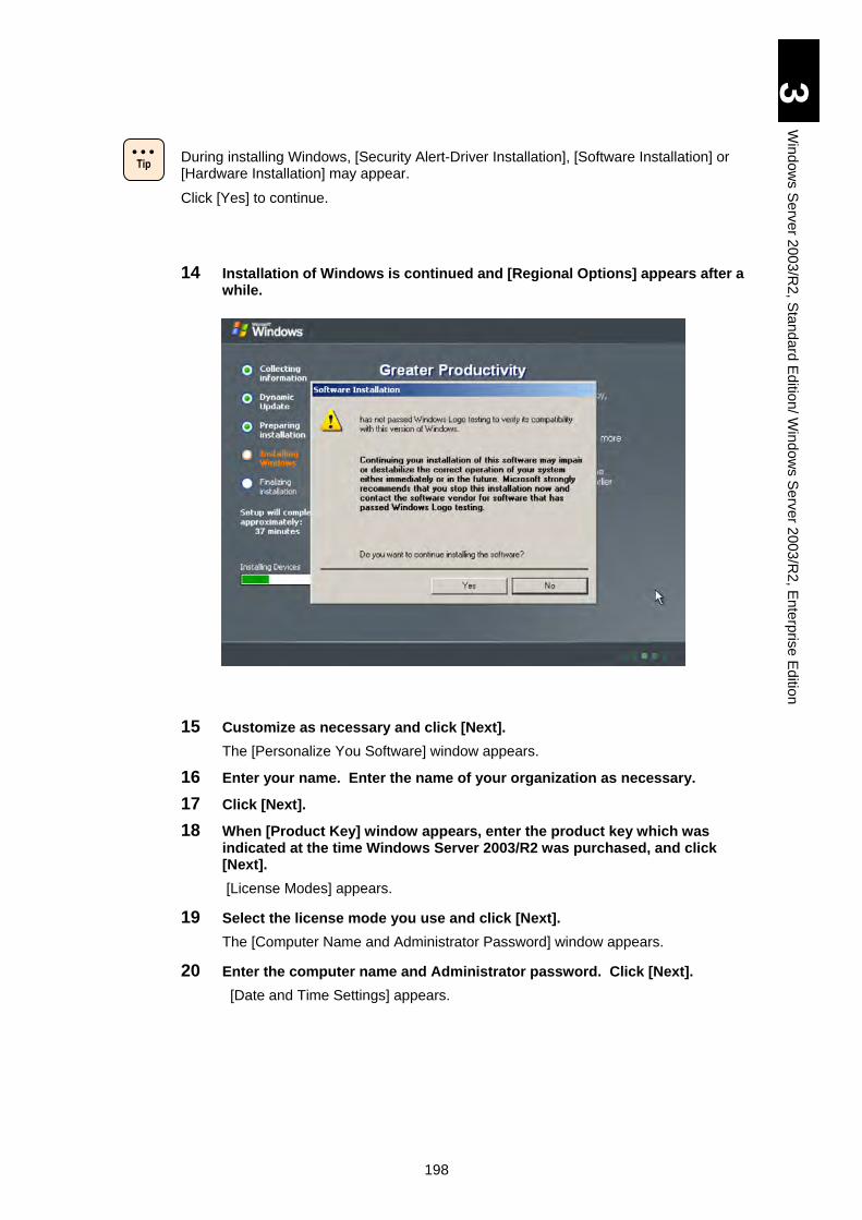
198
3
Win
do
ws S
erv
er 2
00
3/R
2, S
tan
da
rd E
ditio
n/ W
ind
ow
s S
erv
er 2
003
/R2
, En
terp
rise
Ed
ition
During installing Windows, [Security Alert-Driver Installation], [Software Installation] or [Hardware Installation] may appear.
Click [Yes] to continue.
14 Installation of Windows is continued and [Regional Options] appears after a while.
15 Customize as necessary and click [Next].
The [Personalize You Software] window appears.
16 Enter your name. Enter the name of your organization as necessary.
17 Click [Next].
18 When [Product Key] window appears, enter the product key which was indicated at the time Windows Server 2003/R2 was purchased, and click [Next].
[License Modes] appears.
19 Select the license mode you use and click [Next].
The [Computer Name and Administrator Password] window appears.
20 Enter the computer name and Administrator password. Click [Next].
[Date and Time Settings] appears.
Tip
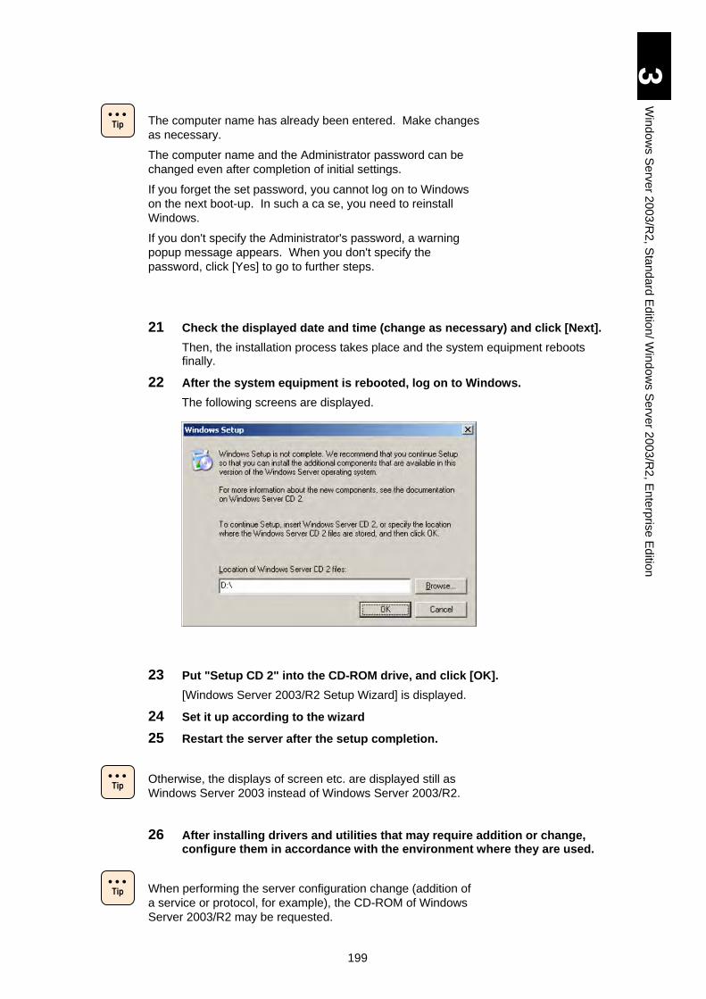
199
3
Win
do
ws S
erv
er 2
00
3/R
2, S
tan
da
rd E
ditio
n/ W
ind
ow
s S
erv
er 2
003
/R2
, En
terp
rise
Ed
ition
The computer name has already been entered. Make changes
as necessary.
The computer name and the Administrator password can be
changed even after completion of initial settings.
If you forget the set password, you cannot log on to Windows
on the next boot-up. In such a ca se, you need to reinstall
Windows.
If you don't specify the Administrator's password, a warning
popup message appears. When you don't specify the
password, click [Yes] to go to further steps.
21 Check the displayed date and time (change as necessary) and click [Next].
Then, the installation process takes place and the system equipment reboots finally.
22 After the system equipment is rebooted, log on to Windows.
The following screens are displayed.
23 Put "Setup CD 2" into the CD-ROM drive, and click [OK].
[Windows Server 2003/R2 Setup Wizard] is displayed.
24 Set it up according to the wizard
25 Restart the server after the setup completion.
Otherwise, the displays of screen etc. are displayed still as
Windows Server 2003 instead of Windows Server 2003/R2.
26 After installing drivers and utilities that may require addition or change, configure them in accordance with the environment where they are used.
When performing the server configuration change (addition of
a service or protocol, for example), the CD-ROM of Windows
Server 2003/R2 may be requested.
Tip
Tip
Tip
200
3
Win
do
ws S
erv
er 2
00
3/R
2, S
tan
da
rd E
ditio
n/ W
ind
ow
s S
erv
er 2
003
/R2
, En
terp
rise
Ed
ition
Registry Update (1)
Put the “Driver kit” CD-ROM into the CD/DVD drive, and execute the following batches.
(* d: represents the drive name of CD/DVD.)
1 Make the dump-button of the Blade effective.
d:\utility\dump\NMID.bat
[With Driver Kit version 05-04 or later]
d:\X51x5\Win2003R2\Tools\NMIDump\NMID.bat
2 Set the PCI driver.
d:\utility\pci\WIN2003\avoidD3.bat
[With Driver Kit version 05-04 or later]
d:\X51x5\Win2003R2\Tools\avoidD3\avoidD3.bat
When using Driver Kit version 05-06 or later, you need not
perform the following Step 3. Skip step 3 and reboot the OS.
3 Set the LAN driver. (X51A5 X51S5/ X51H5/ X51P5/ X51R5 models)
d:\utility\ndismask\NDISMask_E.bat
[With Driver Kit version 05-04 or later]
d:\X51x5\Win2003R2\Tools\NDISMask\NDISMask_E.bat
Reboot the OS to save the new settings after applying patches.
NDISMask.bat is only for Windows Server 2003. Do not
execute it on other Windows versions.
Chip Set Driver
When you have set up Windows using Setup CD, install chip set driver in the following procedure.
With X51A4/ X51S4/ X51H4/ X51P4/ X51R4/X51A5 X51S5/ X51H5/ X51P5/ X51R5 model, make sure to install “Service pack 2 (SP2)” before Chip Set Driver.
If you install Chip Set Driver before “Service pack 2 (SP2)” with X51A4/ X51S4/ X51H4/ X51P4/ X51R4/X51A5 X51S5/ X51H5/ X51P5/ X51R5 model, the keyboard or mouse may not work after the reboot. If so, you need to set up Windows again.
When you have installed the OS in HVM environment, refer to “Restrictions on Setup” in Chapter 5 before applying the chipset driver. A restriction on FC mezzanine cards assigned to LPARs is described in that section.
Tip
201
3
Win
do
ws S
erv
er 2
00
3/R
2, S
tan
da
rd E
ditio
n/ W
ind
ow
s S
erv
er 2
003
/R2
, En
terp
rise
Ed
ition
1 Turn on the power of system equipment, boot Windows, and log on as "Administrator".
2 Insert “Driver kit” CD-ROM into the CD/DVD drive.
3 Click the [Start] button, and select [Run…].
4 Enter the followings and click [OK].
d:\X51x1\A\WIN2003\CHIPSET\infinst_autol.exe (X51A1 model) d:\X51x2\A\WIN2003\CHIPSET\infinst_autol.exe (X51A2 model) d:\X51x3\A\WIN2003\CHIPSET\infinst_autol.exe (X51A3/ X51E3 model) d:\X51x4\A\WIN2003\CHIPSET\infinst_autol.exe (X51A4/ X51S4/ X51H4/ X51P4/ X51R4 model) d:\X51x5\A\WIN2003\CHIPSET\infinst_autol.exe (X51A5 X51S5/ X51H5/ X51P5/ X51R5 model) [With Driver Kit version 05-04 or later]
d:\X51x5\Win2003R2\Drivers\Chipset\INTEL_01\infinst_autol.exe (X51A5/X51S5/X51H5/X51P5/X51R5 models) * d: represents the drive name of CD/DVD.
[Setup] appears.
5 Click [Next].
[License Agreement] appears.
6 Read the contents of [License Agreement] and click [Yes].
Continue your setup according to the screen instructions.
Finally, [InstallShield(R) wizard has been finished] appears.
7 Eject the CD-ROM from the drive, select [No, I will restart this computer later] and click [Finish].
8 With models other than X51A5 X51S5/ X51H5/ X51P5/ X51R5 models, jump to step 22.
9 Click the [Start] button and then [Restart] to restart Windows.
10 Log on as Administrator after the restart.
11 Insert “Driver kit” CD-ROM into the CD/DVD drive.
12 Select [Start] > [Control Panel] > [System] to display [System Properties].
13 Click the [Device manager] button under the [Hardware] tab to display [Device Manager].
14 If “? Unknown Device” is displayed, open the properties, and check the device instance ID under the [Details] tab.
If the device is not “ACPI\ACPI000D/0”, jump to the next driver to install. The following procedure is not necessary.
15 Close [Properties], right-click “? Unknown Device”, and then click [Update Driver] to display [Hardware Update Wizard].
16 If you are asked as "Can Windows connect to Windows Update to search for software?", select [No, not this time.], and click [Next].
17 Select [Install from a list or specific location] and click [Next].
18 Select [Include this location in the search:], type the following and then click [Next].
202
3
Win
do
ws S
erv
er 2
00
3/R
2, S
tan
da
rd E
ditio
n/ W
ind
ow
s S
erv
er 2
003
/R2
, En
terp
rise
Ed
ition
32-bit:
d:\X51x5\A\WIN2003\HACPIPM [With Driver Kit version 05-04 or later] \X51x5\Win2003R2\Drivers\HACPIPM\x86
64-bit:
d:\X51x5\A\WIN2003x64\HACPIPM [With Driver Kit version 05-04 or later] \X51x5\Win2003R2\Drivers\HACPIPM\x64
* d: represents the drive name of CD/DVD.
File Copy starts. When it is completed, "Completing the Hardware Update Wizard" appears.
19 If the [Security Warning-Install Driver] dialog box is displayed, click [Yes] to proceed.
20 The file copy starts. When it finishes, [Hardware Update Wizard completed] is displayed.
21 Click the [Finish] button to return to [Device Manager].
22 Click the [Start] button, select [Shutdown], and shut down Windows.
LAN Driver
When you have set up Windows using Setup CD alone, install LAN driver in the following procedure. For the driver for expanded board, see the manual of the expanded board.
Make sure to install “Chip Set Driver” before LAN Driver. If not,
the OS has stopped working according to a report.
1 Turn on the power of system equipment, boot Windows, and log on as "Administrator".
2 Insert “Driverkit” CD-ROM into the CD/DVD drive.
3 Select [Start] – [Control Panel] – [System].
[System Properties] appears.
4 Click [Device Manager] under the [Hardware] tab.
[Device Manager] appears
5 Right-click the network adapter whose driver has not been updated and click [Update Driver].
[Hardware Update Wizard] appears.
6 If you are asked as "Can Windows connect to Windows Update to search for software?", select [No, not this time.], and click [Next].
7 Select [Install from a list or specific location] and click [Next].
8 Select [Include this location in the search:] enter the followings and then click [Next].
! Note
203
3
Win
do
ws S
erv
er 2
00
3/R
2, S
tan
da
rd E
ditio
n/ W
ind
ow
s S
erv
er 2
003
/R2
, En
terp
rise
Ed
ition
When 10Gbps LAN is installed:
A 10Gbps LAN PCI express card requires a different driver
from that for other LAN devices.
If you attempt to install a driver, a message, “Windows was
unable to install your Ethernet Controller.” may be displayed,
which shows that the driver is incorrect. When the message is
displayed, install the right driver for the device.
32-bit:
d:\X51x1\A\WIN2003\LAN (X51A1 model) d:\X51x2\A\WIN2003\LAN (X51A2 model) d:\X51x3\A\WIN2003\LAN (X51A3/ X51E3 model) d:\X51x4\A\WIN2003\LAN (X51A4/ X51S4/ X51H4/ X51P4/ X51R4 model) d:\X51x5\A\WIN2003\LAN (X51A5/ X51S5/ X51H5/ X51P5/ X51R5 model) d:\X51x5\P\WIN2003\LAN\CN9PXG1X1 (CN9PXG1X1: 10Gbps 2-port LAN PCI express card)
[With Driver Kit version 05-04 or later] d:\X51x5\Win2003R2\Drivers\LAN\INTELXG_01\x86 (CN9PXG1X1: 10Gbps 2-port LAN PCI express card)
d:\X51x5\Win2003R2\Drivers\LAN\INTEL_01\x86 (X51A5/X51S5/X51H5/X51P5/X51R5 model)
64-bit:
d:\X51x1\A\WIN2003x64\LAN (X51A1 model) d:\X51x2\A\WIN2003x64\LAN (X51A2 model) d:\X51x3\A\WIN2003x64\LAN (X51A3/ X51E3 model) d:\X51x4\A\WIN2003x64\LAN (X51A4/S X514/ X51H4/ X51P4/ X51R4 model)
d:\X51x5\A\WIN2003x64\LAN (X51A5/ X51S4/ X51H5/ X51P5/ X51R5 model)
d:\X51x5\P\WIN2003x64\LAN\CN9PXG1X1 (CN9PXG1X1: 10Gbps 2-port LAN PCI express card)
[With Driver Kit version 05-04 or later] d:\X51x5\Win2003R2\Drivers\LAN\INTELXG_01\x64 (CN9PXG1X1: 10Gbps 2-port LAN PCI express card)
d:\X51x5\Win2003R2\Drivers\LAN\INTEL_01\x64 (X51A5/X51S5/X51H5/X51P5/X51R5 models)
* d: represents the drive name of CD/DVD.
File Copy starts. When it is completed, "Completing the Hardware Update Wizard" appears.
"Hardware Installation" screen may appear while installing the driver. If it, click the [Continue] button to advance the installation.
When SP2 is installed in the system, make sure to execute the SNP Blocker tool referring the SP2.
9 Click [Finish].
[Device Manager] reappears.
10 If there remain network adapters whose LAN driver has not been updated, repeat above Steps 6 to 9 for each network adapters.
11 With X51A4/ X51S4/ X51H4/ X51P4/ X51R4 X51A5/ X51S5/ X51H5/ X51P5/ X51R5 model, go to Step 14.
204
3
Win
do
ws S
erv
er 2
00
3/R
2, S
tan
da
rd E
ditio
n/ W
ind
ow
s S
erv
er 2
003
/R2
, En
terp
rise
Ed
ition
12 Right-click [Other Devices] – [Basic System Device], and click [Update Driver].
[Hardware Update Wizard] appears.
13 Perform above Steps 6~9 same as above.
14 Restart the system device.
The message, "This hardware can't be started" may appear when setting-up driver. If so, reboot the system equipment to restore the normal operation. Confirm that the device is operated normally on [Device Manager].
The error event log might be generated every time that the system boots. There is a possibility that LAN adapter link is down. Confirm the link condition of the network adapter on [Network Connection]. When Intel® PROSet is installed, you can confirm this status in [Link Speed] tab (this tab name might be [Link] by the Intel® PROSet version.) on [property] of the network adapter. To open the [property] screen, right click the network adapter on [Device Manager] and select [property] from the menu.
The line speed of the onboard LAN device cannot be changed
Neither the property on the network nor the network status
of the task tray might be updated at once, by the link-up. To
confirm the current status, select [Display] - [Update to latest
information] on the Network Property, and update the
network status.
Display driver
When you have set up Windows using Setup CD alone, install Display driver in the following procedure.
The driver cannot be installed while using "/3GB Switch".
Install the driver after starting Windows without using "/3GB
Switch ".
1 Turn on the power of system equipment, boot Windows, and log on as "Administrator".
2 Insert “Driver kit” CD-ROM into the CD/DVD drive.
3 Select [Start] – [Control Panel] – [System].
[System Properties] appears.
4 Click [Device Manager] under the [Hardware] tab.
[Device Manager] appears.
! Note
! Note
Tip
Tip
205
3
Win
do
ws S
erv
er 2
00
3/R
2, S
tan
da
rd E
ditio
n/ W
ind
ow
s S
erv
er 2
003
/R2
, En
terp
rise
Ed
ition
5 Right-click [Standard VGA Graphics Adapter] of [Display adapters] and click [Update Driver].
[Hardware Update Wizard] appears.
6 If you are asked as "Can Windows connect to Windows Update to search for software?", select [No, not this time.], and click [Next].
7 Select [Install from a list or specific location] and click [Next].
8 Select [Include this location in the search:], enter the followings and then click [Next].
32-bit:
d:\X51x1\A\WIN2003\SVGA (X51A1 model)
d:\X51x2\A\WIN2003\SVGA (X51A2 model)
d:\X51x3\A\WIN2003\SVGA (X51A3/ X51E3 model)
d:\X51x4\A\WIN2003\SVGA (X51A4/ X51S4/ X51H4/ X51P4/ X51R4 model)
d:\X51x5\A\WIN2003\SVGA (X51A5/ X51S5/ X51H5/ X51P5/ X51R5 model)
[Driver Kit version 05-04 or later]
d: \X51x5\Win2003R2\Drivers\SVGA\XGI_01\x86 (X51A5/X51S5/X51H5/X51P5/X51R5 models)
64-bit:
d:\X51x1\A\WIN2003x64\SVGA (X51A1 model)
d:\X51x2\A\WIN2003x64\SVGA (X51A2 model)
d:\X51x3\A\WIN2003x64\SVGA (X51A3/ X51E3 model)
d:\X51x4\A\WIN2003x64\SVGA (X51A4/ X51S4/ X51H4/ X51P4/ X51R4 model)
d:\X51x5\A\WIN2003x64\SVGA (X51A5/ X51S5/ X51H5/ X51P5/ X51R5 model)
[Driver Kit version 05-04 or later]
d: \X51x5\Win2003R2\Drivers\SVGA\XGI_01\x64 (X51A5/X51S5/X51H5/X51P5/X51R5 models)
* d: represents the drive name of CD/DVD.
File copy starts. When it is completed, "Completing the Hardware Update Wizard" appears.
9 Click [Finish].
When [Do you want to restart your computer now?] is displayed, click [Yes].
Front-panel SAS Port Driver (X51H4/ X51H5 model)
1 Turn on the power of system equipment, boot Windows, and log on as "Administrator".
2 Insert “Driver kit” CD-ROM into the CD/DVD drive.
3 Select [Start] – [Control Panel] – [System].
[System Properties] appears.
4 Click [Device Manager] under [System Tools].
[Device Manager] appears.
5 Select [Other devices], right-click [SCSI Controller], and then click [Update Driver].
6 If you are asked as "Can Windows connect to Windows Update to search for software?", select [No, not this time.], and click [Next].
206
3
Win
do
ws S
erv
er 2
00
3/R
2, S
tan
da
rd E
ditio
n/ W
ind
ow
s S
erv
er 2
003
/R2
, En
terp
rise
Ed
ition
7 Select [Install from a list or specific location (Advanced)] and click [Next].
8 Enter a following directory, and check [Include this location in the search].
32-bit: d:\X51x4\H\WIN2003\SAS (X51H4 model)
64-bit: d:\X51x4\H\WIN2003x64\SAS (X51H4 model)
32-bit: d:\X51x5\H\WIN2003\SAS (X51H5 model)
64-bit: d:\X51x5\H\WIN2003x64\SAS (X51H5 model)
[Driver Kit version 05-04 or later]
X51H5 model with LSI MegaRAID SAS 2108:
32-bit: d:\X51x5\Win2003R2\Drivers\SAS\LSI_SAS_01\x86
64-bit: d:\X51x5\Win2003R2\Drivers\SAS\LSI_SAS_01\x64
* d: represents the drive name of CD/DVD.
9 When [Completing the Hardware Update Wizard] is displayed, click [Finish].
ServerConductor/Agent, ServerConductor/Advanced Agent
"ServerConductor/Agent" is software that is necessary to manage assets and failure of the system equipment. Also, ServerConductor/Advanced Agent is software for using the extended functions of ServerConductor/Agent such as power control, etc.
Preconditions
Apply SP1 when you use the Windows Server 2003 X51A1 model.
SP1 can be downloaded from the Web site of the Microsoft Company.
See the method of applying "Service Pack 1 (SP1)".
Install "ServerConductor/Agent" using the following methods.
Direct Installation from ServerConductor/Agent CD-ROM
When you have set up Windows using Setup CD alone, double-click to the following file in "ServerConductor/Agent CD-ROM" for the installation.
d:\Disk1\setup.exe
MegaRAID Storage Manager
"MegaRAID Storage Manager" is the software that is necessary to manage the disk array device.
Install it when you use HDD in the server blade on the RAID configuration.
Otherwise, the hard disk trouble cannot be detected and it may cause a double trouble and interfere to the analysis at the failure.
For details of the installation, refer to the following file 'MegaRAID Storage Manager manual' in the CD-ROM.
D:\MANUAL\MSManager.pdf (for X51A2/ X51A3/ X51E3/ X51A4/ X51H4 models)
D:\MANUAL\MSManager2.pdf (for X51R4/ X51A5/ X51H5/ X51R5 model)
[Driver Kit version 05-04 or later]
d:\X51x5\MANUAL\MSManager2.pdf
207
3
Win
do
ws S
erv
er 2
00
3/R
2, S
tan
da
rd E
ditio
n/ W
ind
ow
s S
erv
er 2
003
/R2
, En
terp
rise
Ed
ition
Intel PROSet
Intel PROSet is a setup program for LAN devices. For the detail of installation, see "Install Intel PROSet".
When settings for Intel PROSet are changed, network
connection may be temporarily disconnected. Thus, when you
change PROSet settings, use connection via remote console
not via remote desktop.
Update and Configure Option Board Drivers
Some drivers may not be in the “Driver kit” CD-ROM, depending on option boards and devices you purchased. A CD including the latest driver may be supplied or the latest driver may be able to be downloaded from the Internet. Use the latest driver by consulting the option board user's manual.
Update 8 G Fibre Channel Mezzanine Card: GGX-CC9M4G2X1/GG-CC9M4G2X1-Y
When any of 8 GB fibre channel expansion cards is installed, a
mezzanine card: GGX-CC9M4G2X1/GG-CC9M4G2X1-Y or a
PCI express card: GGX-CC9P8G1X1/GG-CC9P8G1X1-Y,
make sure to update its driver. If note, unexpected problems
may occur. See the user’s manual for the optional card for how
to update the driver.
Apply Service Pack 2 and recommended update patches
before updating drivers. If you try to update drivers before
applying Service Pack 2 and recommended update patches,
updating drivers may fail.
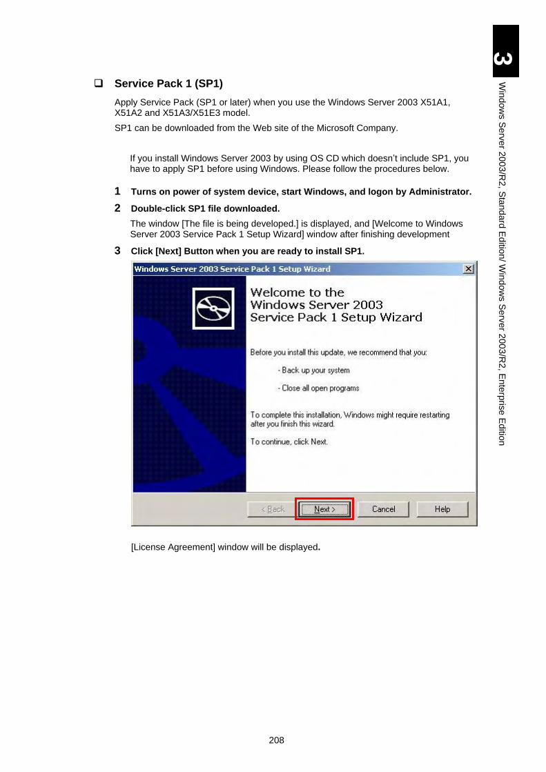
208
3
Win
do
ws S
erv
er 2
00
3/R
2, S
tan
da
rd E
ditio
n/ W
ind
ow
s S
erv
er 2
003
/R2
, En
terp
rise
Ed
ition
Service Pack 1 (SP1)
Apply Service Pack (SP1 or later) when you use the Windows Server 2003 X51A1, X51A2 and X51A3/X51E3 model.
SP1 can be downloaded from the Web site of the Microsoft Company.
If you install Windows Server 2003 by using OS CD which doesn’t include SP1, you have to apply SP1 before using Windows. Please follow the procedures below.
1 Turns on power of system device, start Windows, and logon by Administrator.
2 Double-click SP1 file downloaded.
The window [The file is being developed.] is displayed, and [Welcome to Windows Server 2003 Service Pack 1 Setup Wizard] window after finishing development
3 Click [Next] Button when you are ready to install SP1.
[License Agreement] window will be displayed.
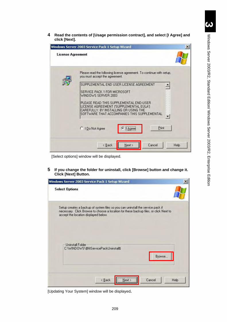
209
3
Win
do
ws S
erv
er 2
00
3/R
2, S
tan
da
rd E
ditio
n/ W
ind
ow
s S
erv
er 2
003
/R2
, En
terp
rise
Ed
ition
4 Read the contents of [Usage permission contract], and select [I Agree] and click [Next].
[Select options] window will be displayed.
5 If you change the folder for uninstall, click [Browse] button and change it. Click [Next] Button.
[Updating Your System] window will be displayed.
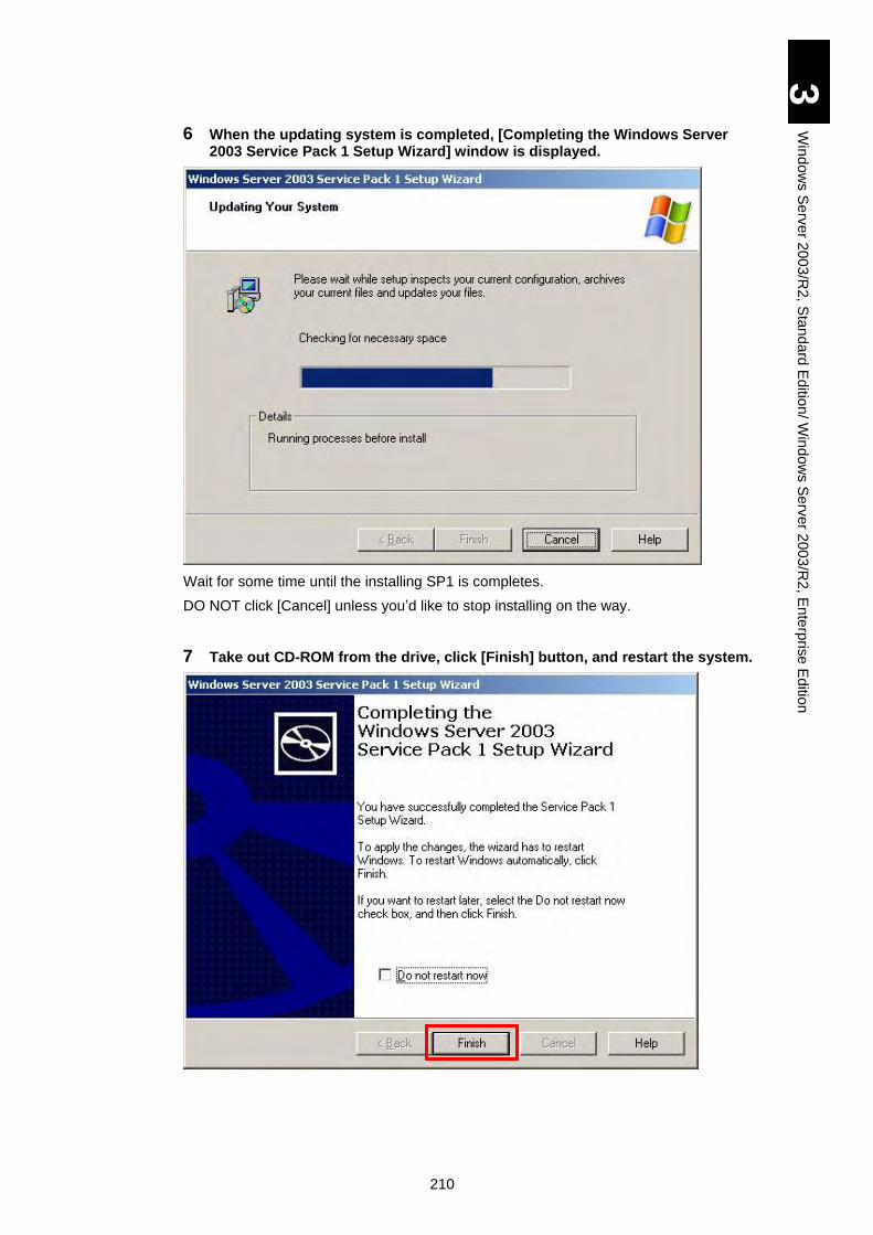
210
3
Win
do
ws S
erv
er 2
00
3/R
2, S
tan
da
rd E
ditio
n/ W
ind
ow
s S
erv
er 2
003
/R2
, En
terp
rise
Ed
ition
6 When the updating system is completed, [Completing the Windows Server 2003 Service Pack 1 Setup Wizard] window is displayed.
Wait for some time until the installing SP1 is completes.
DO NOT click [Cancel] unless you’d like to stop installing on the way.
7 Take out CD-ROM from the drive, click [Finish] button, and restart the system.
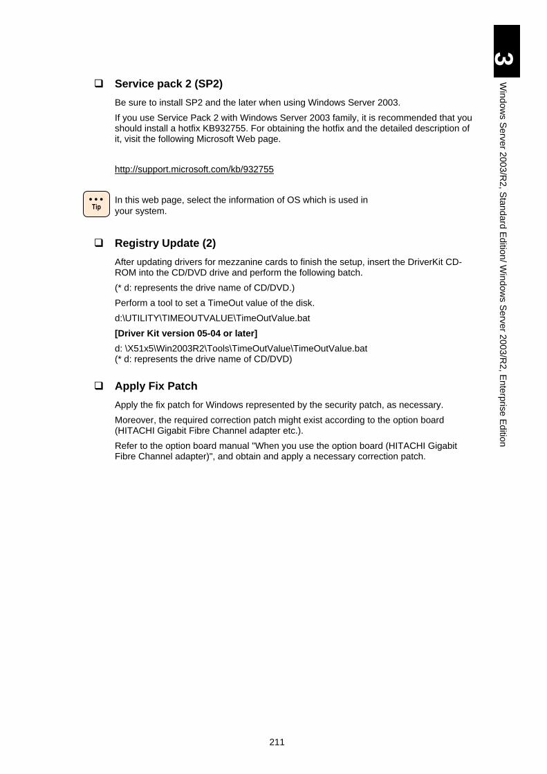
211
3
Win
do
ws S
erv
er 2
00
3/R
2, S
tan
da
rd E
ditio
n/ W
ind
ow
s S
erv
er 2
003
/R2
, En
terp
rise
Ed
ition
Service pack 2 (SP2)
Be sure to install SP2 and the later when using Windows Server 2003.
If you use Service Pack 2 with Windows Server 2003 family, it is recommended that you should install a hotfix KB932755. For obtaining the hotfix and the detailed description of it, visit the following Microsoft Web page.
http://support.microsoft.com/kb/932755
In this web page, select the information of OS which is used in
your system.
Registry Update (2)
After updating drivers for mezzanine cards to finish the setup, insert the DriverKit CD-ROM into the CD/DVD drive and perform the following batch.
(* d: represents the drive name of CD/DVD.)
Perform a tool to set a TimeOut value of the disk.
d:\UTILITY\TIMEOUTVALUE\TimeOutValue.bat
[Driver Kit version 05-04 or later]
d: \X51x5\Win2003R2\Tools\TimeOutValue\TimeOutValue.bat (* d: represents the drive name of CD/DVD)
Apply Fix Patch
Apply the fix patch for Windows represented by the security patch, as necessary.
Moreover, the required correction patch might exist according to the option board (HITACHI Gigabit Fibre Channel adapter etc.).
Refer to the option board manual "When you use the option board (HITACHI Gigabit Fibre Channel adapter)", and obtain and apply a necessary correction patch.
Tip
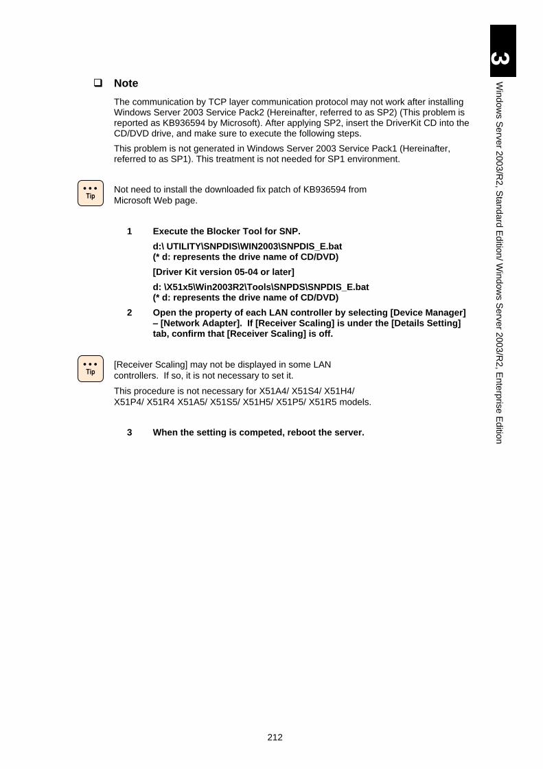
212
3
Win
do
ws S
erv
er 2
00
3/R
2, S
tan
da
rd E
ditio
n/ W
ind
ow
s S
erv
er 2
003
/R2
, En
terp
rise
Ed
ition
Note
The communication by TCP layer communication protocol may not work after installing Windows Server 2003 Service Pack2 (Hereinafter, referred to as SP2) (This problem is reported as KB936594 by Microsoft). After applying SP2, insert the DriverKit CD into the CD/DVD drive, and make sure to execute the following steps.
This problem is not generated in Windows Server 2003 Service Pack1 (Hereinafter, referred to as SP1). This treatment is not needed for SP1 environment.
Not need to install the downloaded fix patch of KB936594 from
Microsoft Web page.
1 Execute the Blocker Tool for SNP.
d:\ UTILITY\SNPDIS\WIN2003\SNPDIS_E.bat (* d: represents the drive name of CD/DVD)
[Driver Kit version 05-04 or later]
d: \X51x5\Win2003R2\Tools\SNPDS\SNPDIS_E.bat (* d: represents the drive name of CD/DVD)
2 Open the property of each LAN controller by selecting [Device Manager] – [Network Adapter]. If [Receiver Scaling] is under the [Details Setting] tab, confirm that [Receiver Scaling] is off.
[Receiver Scaling] may not be displayed in some LAN
controllers. If so, it is not necessary to set it.
This procedure is not necessary for X51A4/ X51S4/ X51H4/
X51P4/ X51R4 X51A5/ X51S5/ X51H5/ X51P5/ X51R5 models.
3 When the setting is competed, reboot the server.
Tip
Tip
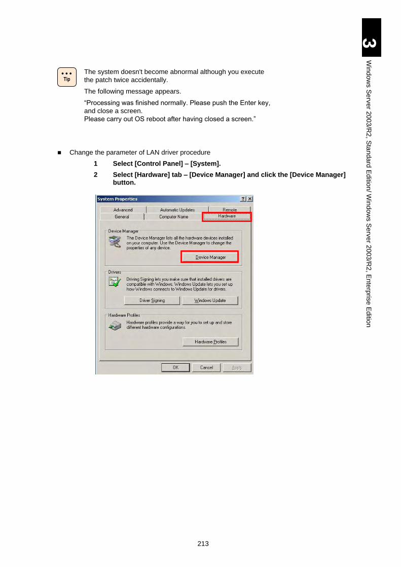
213
3
Win
do
ws S
erv
er 2
00
3/R
2, S
tan
da
rd E
ditio
n/ W
ind
ow
s S
erv
er 2
003
/R2
, En
terp
rise
Ed
ition
The system doesn't become abnormal although you execute
the patch twice accidentally.
The following message appears.
“Processing was finished normally. Please push the Enter key,
and close a screen.
Please carry out OS reboot after having closed a screen.”
Change the parameter of LAN driver procedure
1 Select [Control Panel] – [System].
2 Select [Hardware] tab – [Device Manager] and click the [Device Manager] button.
Tip
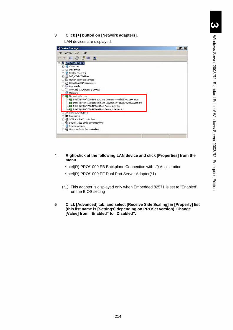
214
3
Win
do
ws S
erv
er 2
00
3/R
2, S
tan
da
rd E
ditio
n/ W
ind
ow
s S
erv
er 2
003
/R2
, En
terp
rise
Ed
ition
3 Click [+] button on [Network adapters].
LAN devices are displayed.
4 Right-click at the following LAN device and click [Properties] from the menu.
・Intel(R) PRO/1000 EB Backplane Connection with I/0 Acceleration
・Intel(R) PRO/1000 PF Dual Port Server Adapter(*1)
(*1): This adapter is displayed only when Embedded 82571 is set to "Enabled" on the BIOS setting
5 Click [Advanced] tab, and select [Receive Side Scaling] in [Property] list (this list name is [Settings] depending on PROSet version). Change [Value] from “Enabled” to “Disabled”.
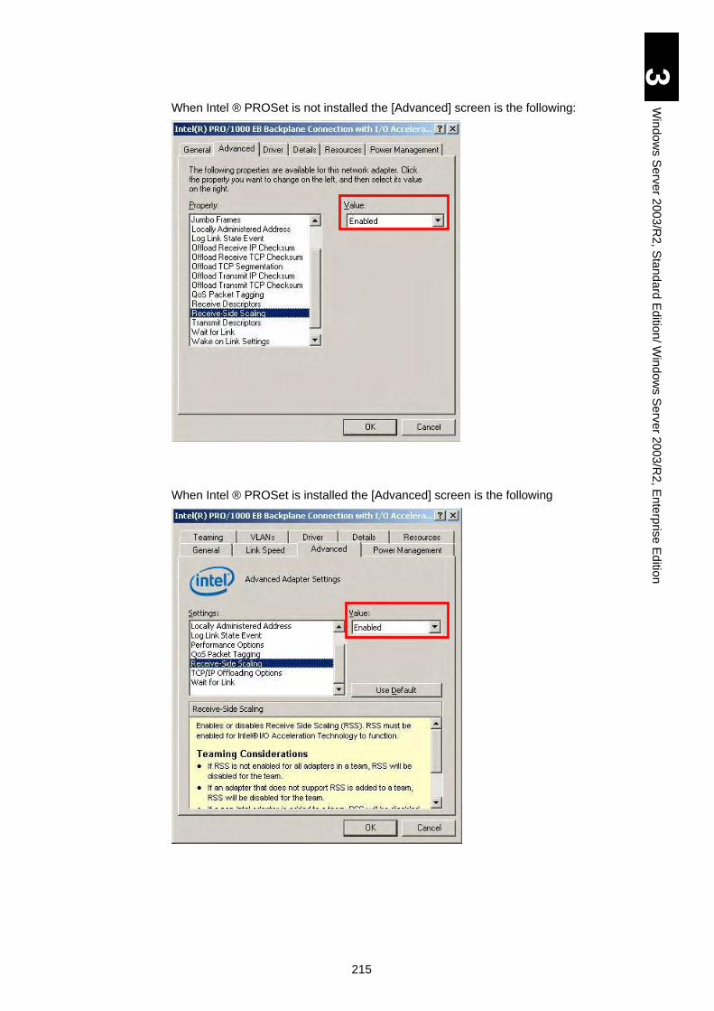
215
3
Win
do
ws S
erv
er 2
00
3/R
2, S
tan
da
rd E
ditio
n/ W
ind
ow
s S
erv
er 2
003
/R2
, En
terp
rise
Ed
ition
When Intel ® PROSet is not installed the [Advanced] screen is the following:
When Intel ® PROSet is installed the [Advanced] screen is the following
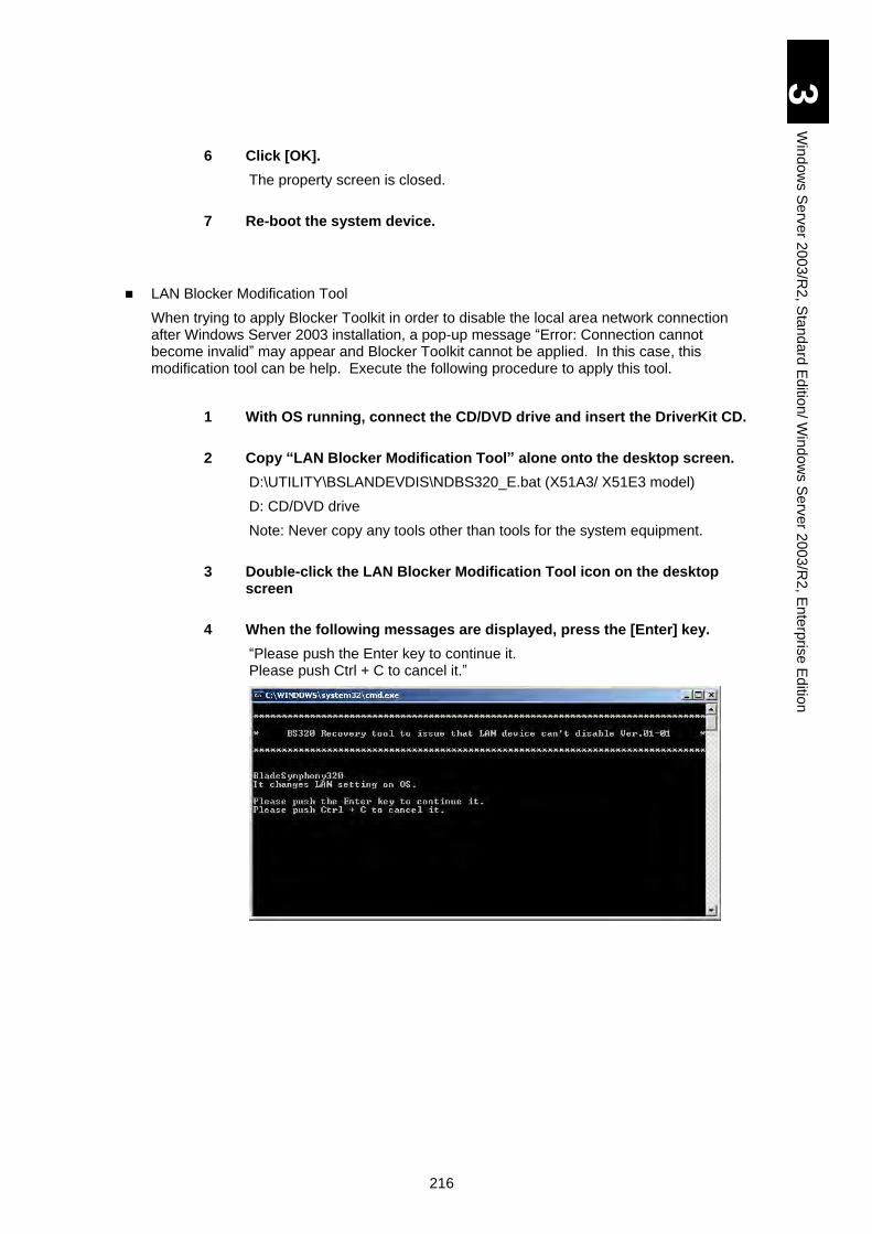
216
3
Win
do
ws S
erv
er 2
00
3/R
2, S
tan
da
rd E
ditio
n/ W
ind
ow
s S
erv
er 2
003
/R2
, En
terp
rise
Ed
ition
6 Click [OK].
The property screen is closed.
7 Re-boot the system device.
LAN Blocker Modification Tool
When trying to apply Blocker Toolkit in order to disable the local area network connection after Windows Server 2003 installation, a pop-up message “Error: Connection cannot become invalid” may appear and Blocker Toolkit cannot be applied. In this case, this modification tool can be help. Execute the following procedure to apply this tool.
1 With OS running, connect the CD/DVD drive and insert the DriverKit CD.
2 Copy “LAN Blocker Modification Tool” alone onto the desktop screen.
D:\UTILITY\BSLANDEVDIS\NDBS320_E.bat (X51A3/ X51E3 model)
D: CD/DVD drive
Note: Never copy any tools other than tools for the system equipment.
3 Double-click the LAN Blocker Modification Tool icon on the desktop screen
4 When the following messages are displayed, press the [Enter] key.
“Please push the Enter key to continue it. Please push Ctrl + C to cancel it.”
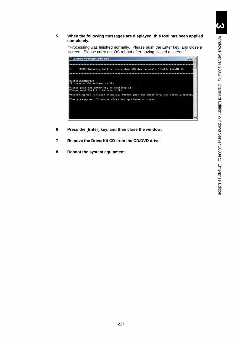
217
3
Win
do
ws S
erv
er 2
00
3/R
2, S
tan
da
rd E
ditio
n/ W
ind
ow
s S
erv
er 2
003
/R2
, En
terp
rise
Ed
ition
5 When the following messages are displayed, this tool has been applied completely.
“Processing was finished normally. Please push the Enter key, and close a screen. Please carry out OS reboot after having closed a screen.”
6 Press the [Enter] key, and then close the window.
7 Remove the DriverKit CD from the CD/DVD drive.
8 Reboot the system equipment.
218
3
Win
do
ws S
erv
er 2
00
3/R
2, S
tan
da
rd E
ditio
n/ W
ind
ow
s S
erv
er 2
003
/R2
, En
terp
rise
Ed
ition
Windows Server 2003/R2, Enterprise Edition Setup
This section explains how to set up Windows Server 2003/R2, Enterprise Edition.
Detail of Setup
A basic method for setting up Windows Server 2003/R2, Enterprise Edition is the same as that of Windows Server 2003/R2, Standard Edition. For more information, see “Set up Windows Server 2003/R2"
219
4 Red Hat Enterprise Linux Version 4 Update 3 / Version 4.5 / Version 4.7 / Version 5.1 / Version 5.3 / Version 5.4 / Version 5.6
This chapter explains the installation procedure of Intel Xeon Processor Server Blade Red Hat Enterprise Linux 4 Update 3 / 4.5 / 4.7 and 5.1 / 5.3 / 5.4 / 5.6 for Compute Blade.
Be sure to check the model and the version of the installation media before installing.
Please note that this chapter may be updated without notice.
When you have the driver kit version 05-06 or later and install
RHEL 5.6 or later, or RHEL 6.1 or later, use the Red Hat
Enterprise Linux driver CD for installation. See Chapter 5:
Red Hat Enterprise Linux Version 5.6 / Version 6.1 with the
Driver CD, newly added to the SOFTWARE GUIDE for how
to install RHEL 5.6 and RHEL 6.1.
Red Hat Enterprise Linux Version 4 Update 3 / Version 4.5
Version 4.7 Procedure ........................................................................................ 221
How to Create Driver Disk .................................................................................. 223
How to Install Linux ............................................................................................. 224
How to update the e1000 driver (Intel(R) PRO/1000 Network Driver)................ 244
Red Hat Enterprise Linux Version 5.1/Version 5.3/Version 5.4/Version 5.6
Procedure ............................................................................................................ 247
How to Create Driver Disk .................................................................................. 249
How to Install Linux ............................................................................................. 252
How to Update the Network Driver ...................................................................... 282
How to update the e1000/e1000e driver (Intel(R) PRO/1000 Network Driver) .. 282
How to update the igb driver (Intel(R) Gigabit Ethernet Network Driver)............ 286
How to update the ixgbe driver
(Intel(R) 10 Gigabit PCI Express Network Driver ................................................ 290
! Note
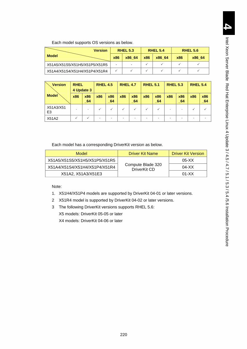
220
4
Inte
l Xe
on
Se
rver B
lad
e R
ed
Ha
t En
terp
rise L
inux 4
Up
da
te 3
/ 4.5
/ 4.7
/ 5.1
/ 5.3
/ 5.4
/5.6
Insta
llatio
n P
roced
ure
Each model supports OS versions as below.
Version
Model
RHEL 5.3 RHEL 5.4 RHEL 5.6
x86 x86_64 x86 x86_64 x86 x86_64
X51A5/X51S5/X51H5/X51P5/X51R5 - -
X51A4/X51S4/X51H4/X51P4/X51R4
Version
Model
RHEL
4 Update 3
RHEL 4.5 RHEL 4.7 RHEL 5.1 RHEL 5.3 RHEL 5.4
x86 x86
_64
x86 x86
_64
x86 x86
_64
x86 x86
_64
x86 x86
_64
x86 x86
_64
X51A3/X51
E3 - - - -
X51A2 - - - - - - - - - -
Each model has a corresponding DriverKit version as below.
Note:
1. X51H4/X51P4 models are supported by DriverKit 04-01 or later versions.
2 X51R4 model is supported by DriverKit 04-02 or later versions.
3 The following DriverKit versions supports RHEL 5.6:
X5 models: DriverKit 05-05 or later
X4 models: DriverKit 04-06 or later
Model Driver Kit Name Driver Kit Version
X51A5/X51S5/X51H5/X51P5/X51R5 Compute Blade 320
DriverKit CD
05-XX
X51A4/X51S4/X51H4/X51P4/X51R4 04-XX
X51A2, X51A3/X51E3 01-XX
221
4
Inte
l Xe
on
Se
rver B
lad
e R
ed
Ha
t En
terp
rise L
inux 4
Up
da
te 3
/ 4.5
/ 4.7
/ 5.1
/ 5.3
/ 5.4
/5.6
Insta
llatio
n P
roced
ure
Red Hat Enterprise Linux Version 4 Update 3 / Version 4.5 / Version 4.7 Procedure
Note
When installing Red Hat Enterprise Linux 4 Update 3 / 4.5/ 4.7, it is necessary to create a driver disk for the installation. Start the installation after creating a driver disk according to the procedure described in this chapter. Check the target of Linux installation and perform the installation for Linux according to the proper method.
CD/DVD drive and FD drive are necessary for installation. Without any FD drive, USB memory is required.
There are two ways for the installation, one is the local connection using USB and another is the remote connection using remote CD/DVD/FD function of remote KVM.
See the table below.
No. Connection Notes
1 CD/DVD Local Prepare CD/DVD drive using USB connection. If you
use FD drive using USB connection, USB hub is
necessary as well.
2 Remote Installation may take much longer compared with that
of local connection.
This is not recommended.
3 FD Local Prepare FD drive using USB connection. If you use
CD/DVD drive using USB connection, USB hub is
necessary as well. This is not recommended because
of necessity of making FD driver.
4 Remote There is no particular note. This is recommended.
It can be used without making FD driver.
NOTICE
Trouble caused by using media other than Red Hat Enterprise Linux 4 Update 3/4.5/4.7 is not guaranteed.
If the correspondent LSI Logic Software RAID driver is not installed, the hard disk can not be recognized or the data can be lost.
Installation causes data in the HDD to disappear. Back up the important data in advance.
This installation procedure is one example. To set up
advanced settings, go to the following site for reference.
http://www.redhat.com/docs/manuals/enterprise/
222
4
Inte
l Xe
on
Se
rver B
lad
e R
ed
Ha
t En
terp
rise L
inux 4
Up
da
te 3
/ 4.5
/ 4.7
/ 5.1
/ 5.3
/ 5.4
/5.6
Insta
llatio
n P
roced
ure
If you use Hitachi FC adapter: When you install the FC
adapter driver for Linux, please use the CD named "Gigabit
Fibre Channel Adapter Drivers for Windows/Linux/VMware"
which is attached to the product. As for the installation
procedure, please refer to "Hitachi Gigabit Fibre Channel
Adapter User's Guide" which is contained in the attached CD.
[Hitachi FC adapter]
GGX-CC9M4G1X1EX/GGX-CC9M4G1X1/GG-CC9M4G1X1-
Y, GGX-CC9P4G1X1EX
When you have installed RHEL 5.4 x64, proceed to Installing
RHEL 5.4.3/5.6.1 Kernel after installing the FC adapter with
the manual described above.
! Note
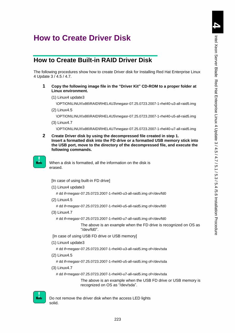
223
4
Inte
l Xe
on
Se
rver B
lad
e R
ed
Ha
t En
terp
rise L
inux 4
Up
da
te 3
/ 4.5
/ 4.7
/ 5.1
/ 5.3
/ 5.4
/5.6
Insta
llatio
n P
roced
ure
How to Create Driver Disk
How to Create Built-in RAID Driver Disk
The following procedures show how to create Driver disk for Installing Red Hat Enterprise Linux 4 Update 3 / 4.5 / 4.7.
1 Copy the following image file in the “Driver Kit” CD-ROM to a proper folder at Linux environment.
(1) Linux4 update3
\OPTION\LINUX\x86\RAID\RHEL4U3\megasr-07.25.0723.2007-1-rhel40-u3-all-raid5.img
(2) Linux4.5
\OPTION\LINUX\x86\RAID\RHEL4U5\megasr-07.25.0723.2007-1-rhel40-u5-all-raid5.img
(3) Linux4.7
\OPTION\LINUX\x86\RAID\RHEL4U7\megasr-07.25.0723.2007-1-rhel40-u7-all-raid5.img
2 Create Driver disk by using the decompressed file created in step 1. Insert a formatted disk into the FD drive or a formatted USB memory stick into the USB port, move to the directory of the decompressed file, and execute the following commands.
When a disk is formatted, all the information on the disk is
erased.
[In case of using built-in FD drive]
(1) Linux4 update3
# dd if=megasr-07.25.0723.2007-1-rhel40-u3-all-raid5.img of=/dev/fd0
(2) Linux4.5
# dd if=megasr-07.25.0723.2007-1-rhel40-u5-all-raid5.img of=/dev/fd0
(3) Linux4.7
# dd if=megasr-07.25.0723.2007-1-rhel40-u7-all-raid5.img of=/dev/fd0
The above is an example when the FD drive is recognized on OS as “/dev/fd0”.
[In case of using USB FD drive or USB memory]
(1) Linux4 update3
# dd if=megasr-07.25.0723.2007-1-rhel40-u3-all-raid5.img of=/dev/sda
(2) Linux4.5
# dd if=megasr-07.25.0723.2007-1-rhel40-u5-all-raid5.img of=/dev/sda
(3) Linux4.7
# dd if=megasr-07.25.0723.2007-1-rhel40-u7-all-raid5.img of=/dev/sda
The above is an example when the USB FD drive or USB memory is recognized on OS as “/dev/sda”.
Do not remove the driver disk when the access LED lights
solid.
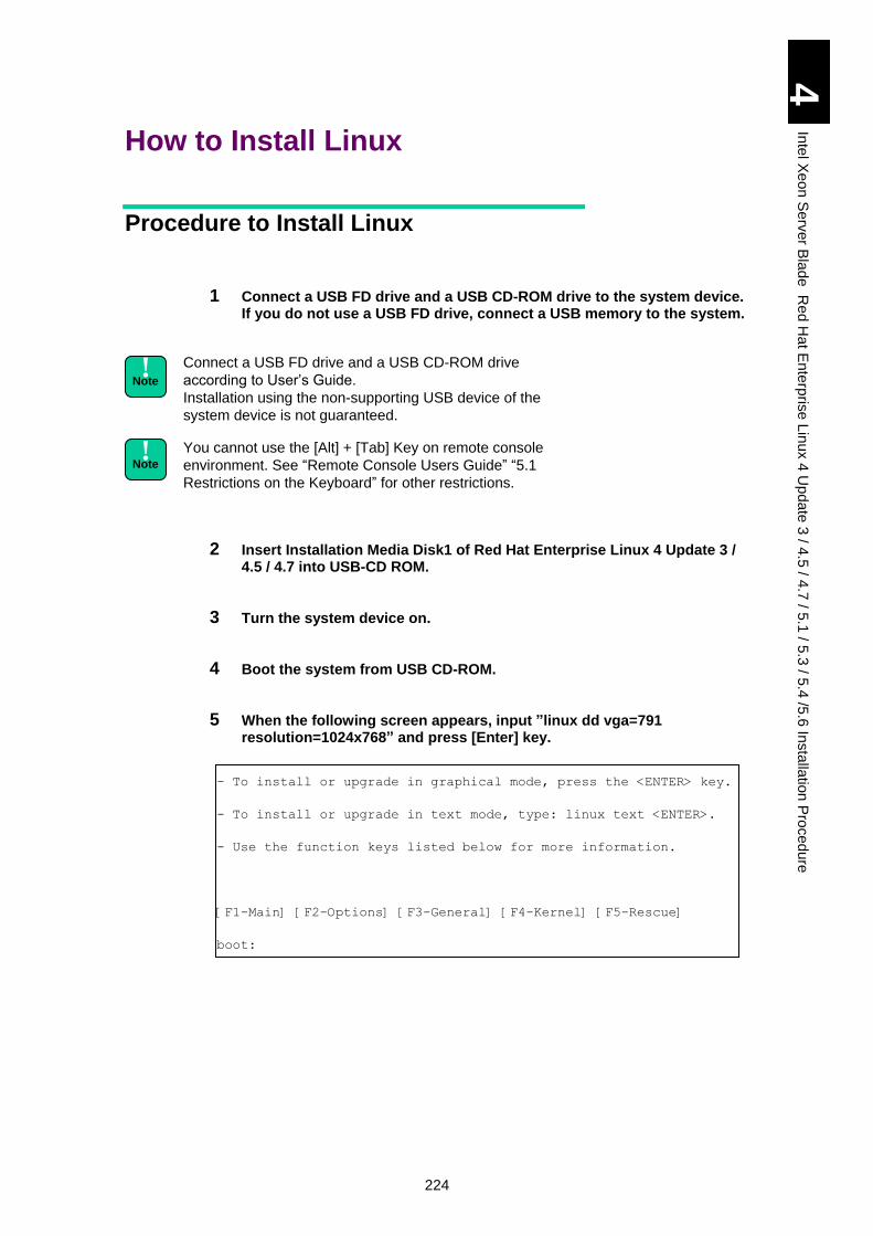
224
4
Inte
l Xe
on
Se
rver B
lad
e R
ed
Ha
t En
terp
rise L
inux 4
Up
da
te 3
/ 4.5
/ 4.7
/ 5.1
/ 5.3
/ 5.4
/5.6
Insta
llatio
n P
roced
ure
How to Install Linux
Procedure to Install Linux
1 Connect a USB FD drive and a USB CD-ROM drive to the system device. If you do not use a USB FD drive, connect a USB memory to the system.
Connect a USB FD drive and a USB CD-ROM drive
according to User’s Guide.
Installation using the non-supporting USB device of the
system device is not guaranteed.
You cannot use the [Alt] + [Tab] Key on remote console
environment. See “Remote Console Users Guide” “5.1
Restrictions on the Keyboard” for other restrictions.
2 Insert Installation Media Disk1 of Red Hat Enterprise Linux 4 Update 3 / 4.5 / 4.7 into USB-CD ROM.
3 Turn the system device on.
4 Boot the system from USB CD-ROM.
5 When the following screen appears, input ”linux dd vga=791 resolution=1024x768” and press [Enter] key.
- To install or upgrade in graphical mode, press the <ENTER> key.
- To install or upgrade in text mode, type: linux text <ENTER>.
- Use the function keys listed below for more information.
[F1-Main] [F2-Options] [F3-General] [F4-Kernel] [F5-Rescue]
boot:
! Note
! Note
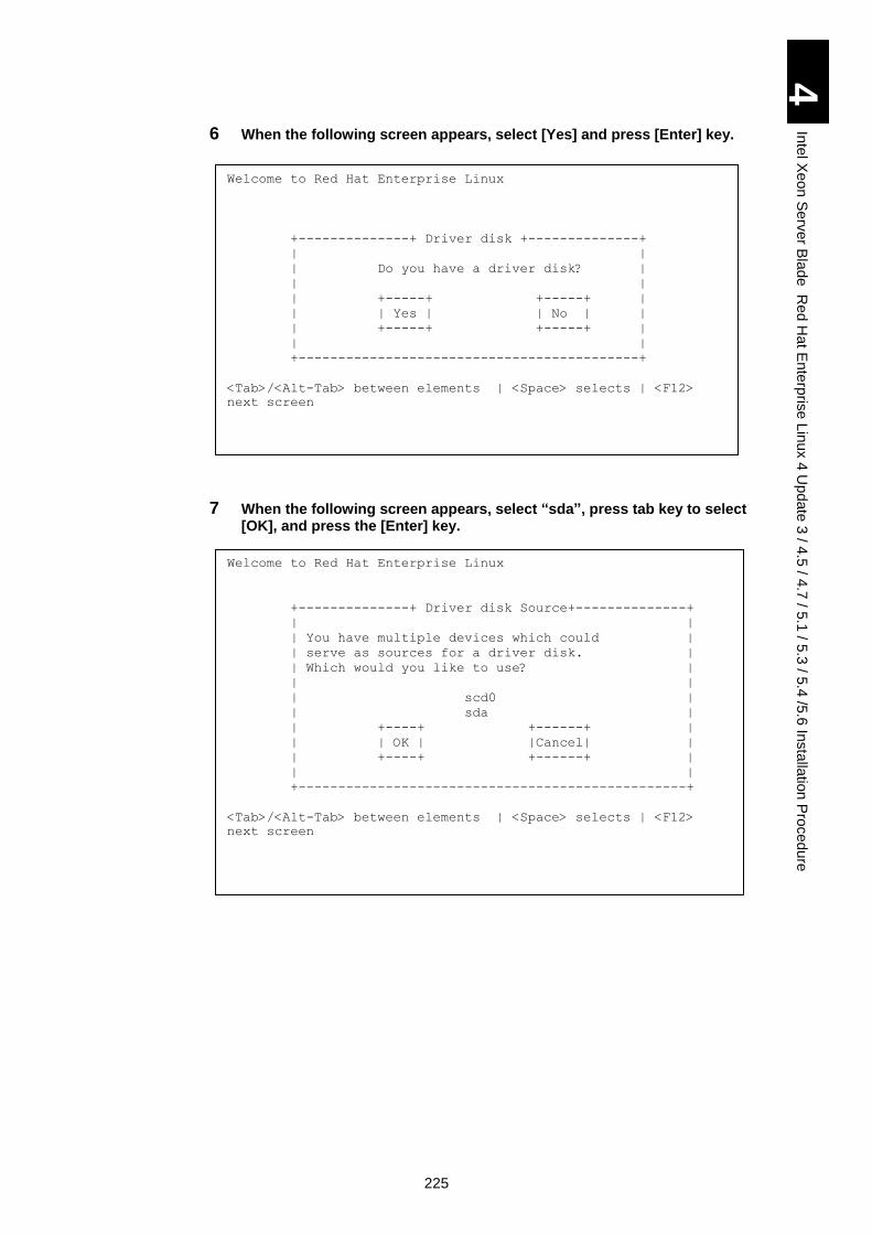
225
4
Inte
l Xe
on
Se
rver B
lad
e R
ed
Ha
t En
terp
rise L
inux 4
Up
da
te 3
/ 4.5
/ 4.7
/ 5.1
/ 5.3
/ 5.4
/5.6
Insta
llatio
n P
roced
ure
6 When the following screen appears, select [Yes] and press [Enter] key.
7 When the following screen appears, select “sda”, press tab key to select [OK], and press the [Enter] key.
Welcome to Red Hat Enterprise Linux
+--------------+ Driver disk +--------------+
| |
| Do you have a driver disk? |
| |
| +-----+ +-----+ |
| | Yes | | No | |
| +-----+ +-----+ |
| |
+-------------------------------------------+
<Tab>/<Alt-Tab> between elements | <Space> selects | <F12>
next screen
Welcome to Red Hat Enterprise Linux
+--------------+ Driver disk Source+--------------+
| |
| You have multiple devices which could |
| serve as sources for a driver disk. |
| Which would you like to use? |
| |
| scd0 |
| sda |
| +----+ +------+ |
| | OK | |Cancel| |
| +----+ +------+ |
| |
+-------------------------------------------------+
<Tab>/<Alt-Tab> between elements | <Space> selects | <F12>
next screen
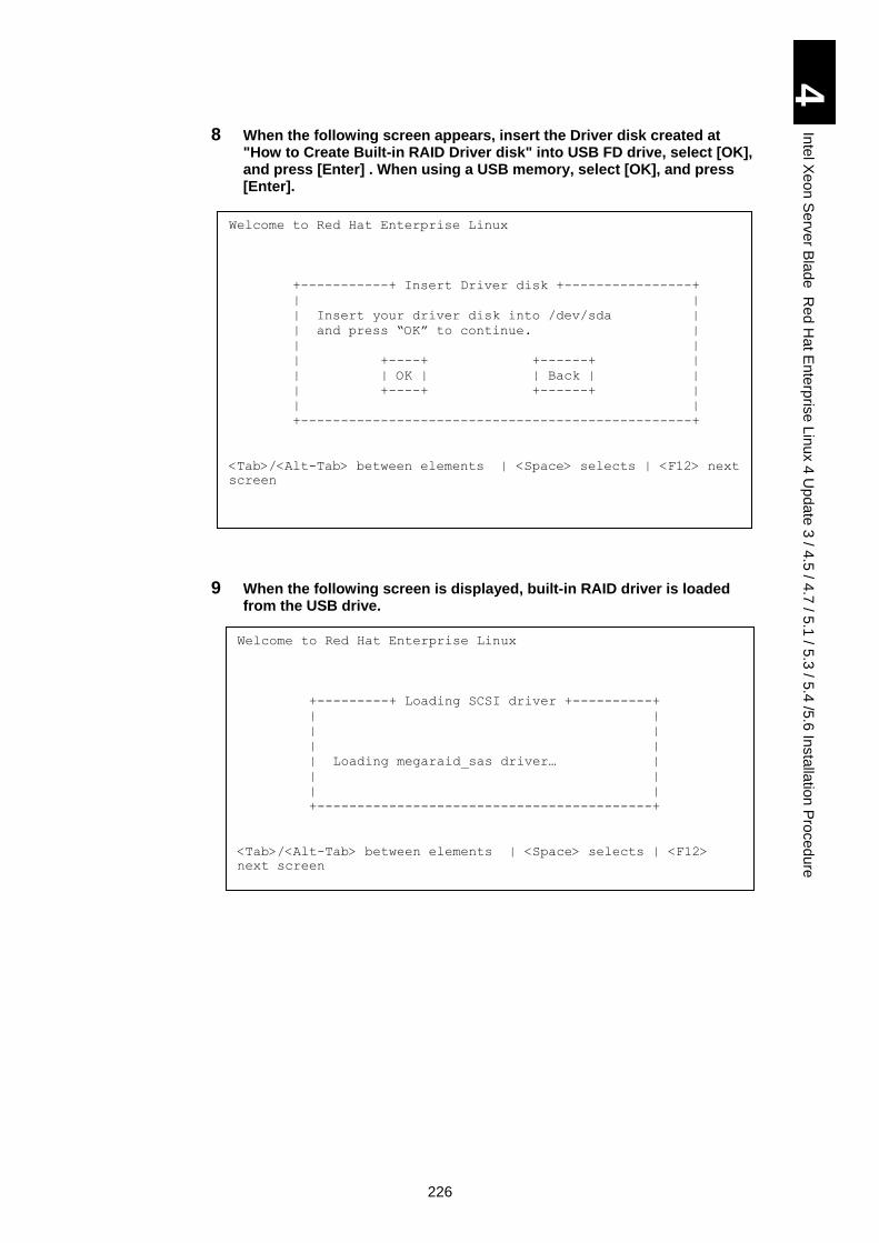
226
4
Inte
l Xe
on
Se
rver B
lad
e R
ed
Ha
t En
terp
rise L
inux 4
Up
da
te 3
/ 4.5
/ 4.7
/ 5.1
/ 5.3
/ 5.4
/5.6
Insta
llatio
n P
roced
ure
8 When the following screen appears, insert the Driver disk created at "How to Create Built-in RAID Driver disk" into USB FD drive, select [OK], and press [Enter] . When using a USB memory, select [OK], and press [Enter].
9 When the following screen is displayed, built-in RAID driver is loaded from the USB drive.
Welcome to Red Hat Enterprise Linux
+-----------+ Insert Driver disk +----------------+
| |
| Insert your driver disk into /dev/sda |
| and press “OK” to continue. |
| |
| +----+ +------+ |
| | OK | | Back | |
| +----+ +------+ |
| |
+-------------------------------------------------+
<Tab>/<Alt-Tab> between elements | <Space> selects | <F12> next
screen
Welcome to Red Hat Enterprise Linux
+---------+ Loading SCSI driver +----------+
| |
| |
| |
| Loading megaraid_sas driver… |
| |
| |
+------------------------------------------+
<Tab>/<Alt-Tab> between elements | <Space> selects | <F12>
next screen
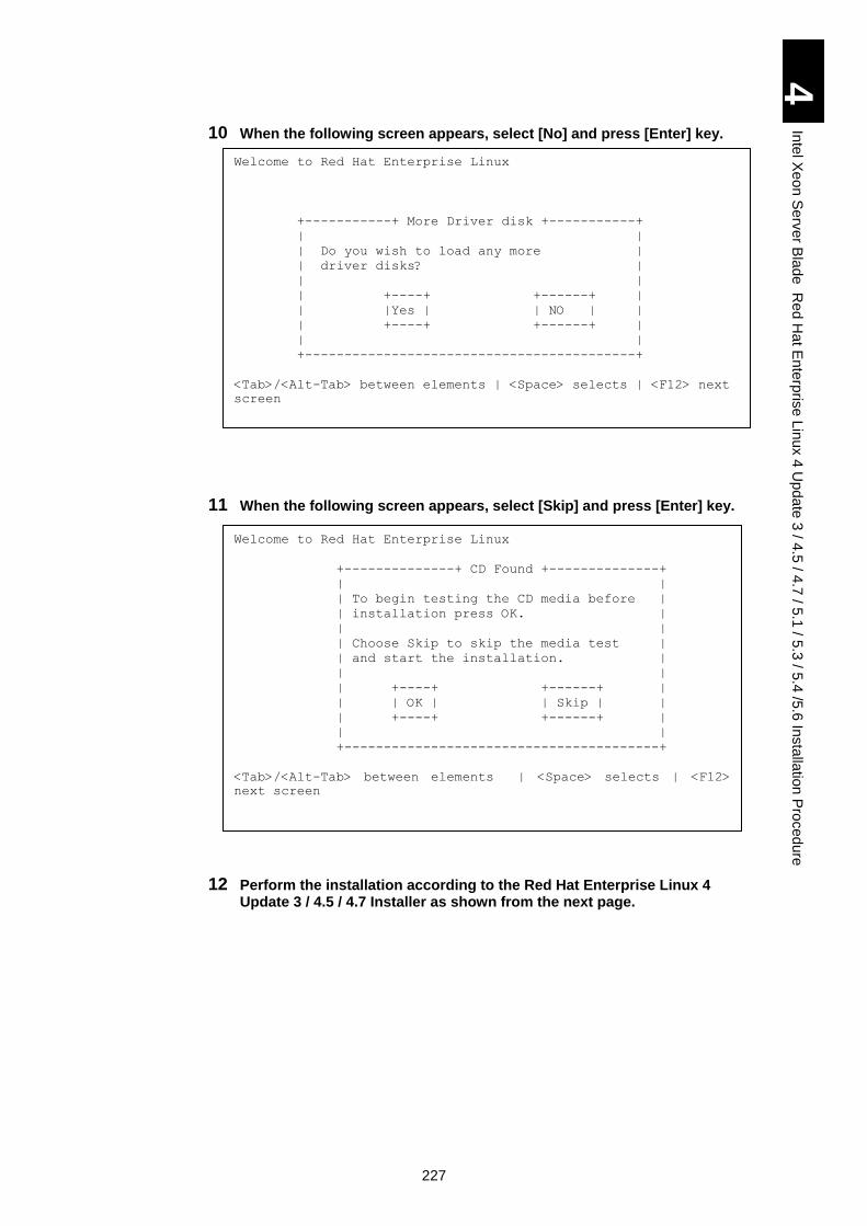
227
4
Inte
l Xe
on
Se
rver B
lad
e R
ed
Ha
t En
terp
rise L
inux 4
Up
da
te 3
/ 4.5
/ 4.7
/ 5.1
/ 5.3
/ 5.4
/5.6
Insta
llatio
n P
roced
ure
10 When the following screen appears, select [No] and press [Enter] key.
11 When the following screen appears, select [Skip] and press [Enter] key.
12 Perform the installation according to the Red Hat Enterprise Linux 4 Update 3 / 4.5 / 4.7 Installer as shown from the next page.
Welcome to Red Hat Enterprise Linux
+--------------+ CD Found +--------------+
| |
| To begin testing the CD media before |
| installation press OK. |
| |
| Choose Skip to skip the media test |
| and start the installation. |
| |
| +----+ +------+ |
| | OK | | Skip | |
| +----+ +------+ |
| |
+----------------------------------------+
<Tab>/<Alt-Tab> between elements | <Space> selects | <F12>
next screen
Welcome to Red Hat Enterprise Linux
+-----------+ More Driver disk +-----------+
| |
| Do you wish to load any more |
| driver disks? |
| |
| +----+ +------+ |
| |Yes | | NO | |
| +----+ +------+ |
| |
+------------------------------------------+
<Tab>/<Alt-Tab> between elements | <Space> selects | <F12> next
screen
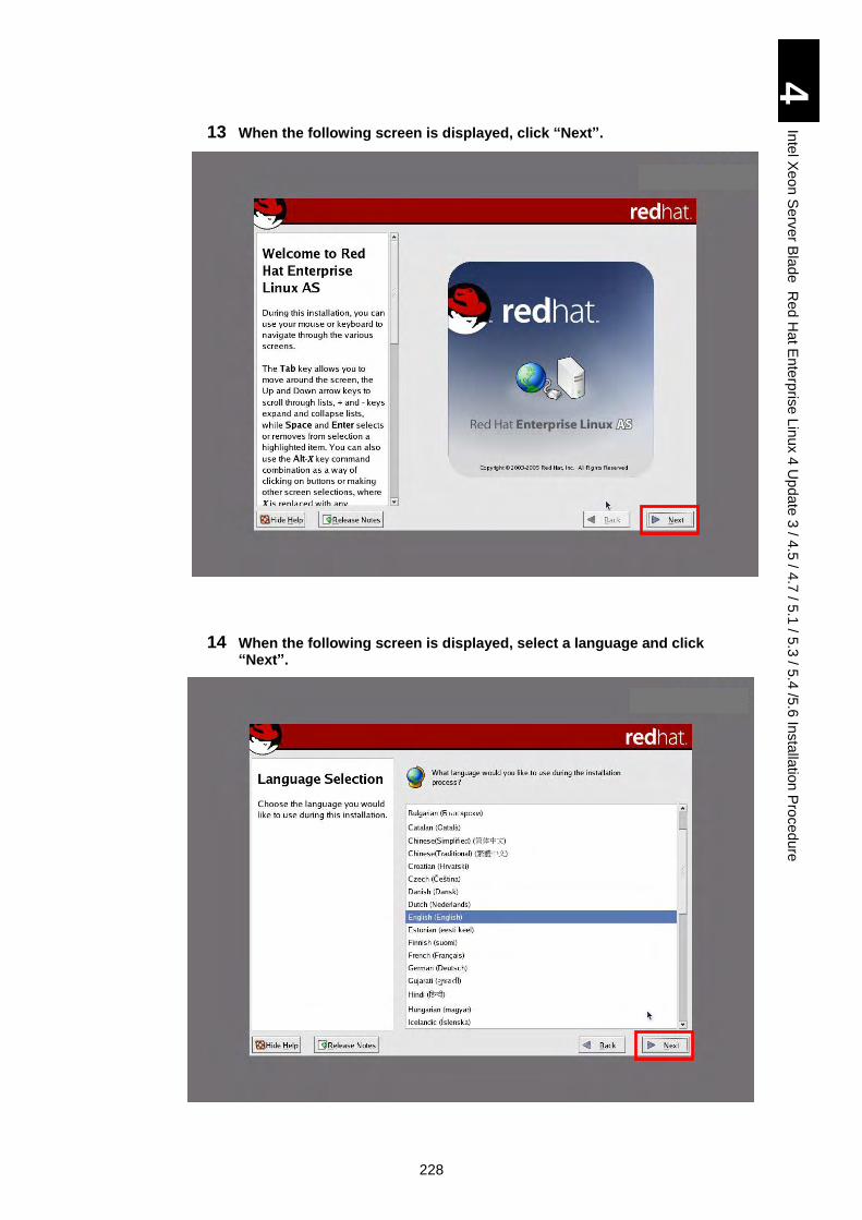
228
4
Inte
l Xe
on
Se
rver B
lad
e R
ed
Ha
t En
terp
rise L
inux 4
Up
da
te 3
/ 4.5
/ 4.7
/ 5.1
/ 5.3
/ 5.4
/5.6
Insta
llatio
n P
roced
ure
13 When the following screen is displayed, click “Next”.
14 When the following screen is displayed, select a language and click “Next”.
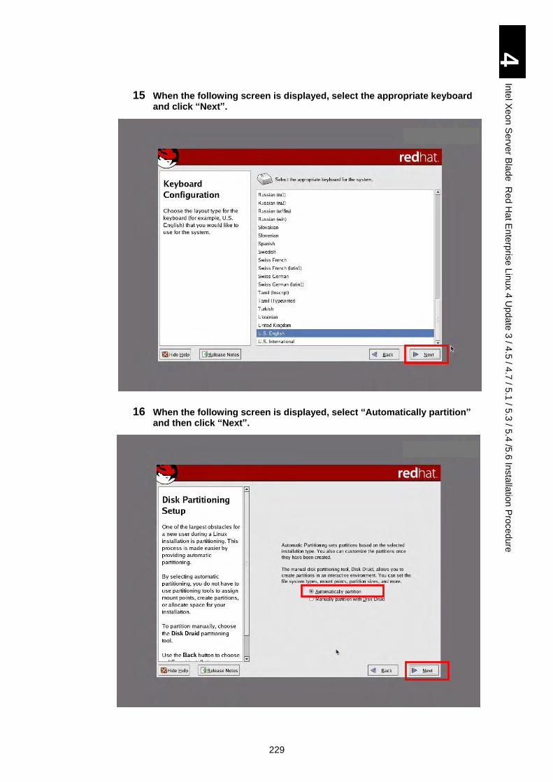
229
4
Inte
l Xe
on
Se
rver B
lad
e R
ed
Ha
t En
terp
rise L
inux 4
Up
da
te 3
/ 4.5
/ 4.7
/ 5.1
/ 5.3
/ 5.4
/5.6
Insta
llatio
n P
roced
ure
15 When the following screen is displayed, select the appropriate keyboard and click “Next”.
16 When the following screen is displayed, select “Automatically partition” and then click “Next”.
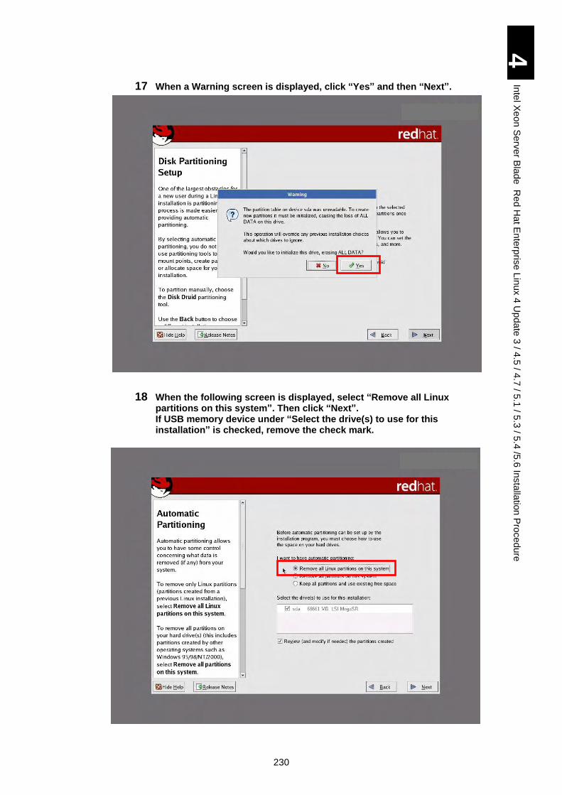
230
4
Inte
l Xe
on
Se
rver B
lad
e R
ed
Ha
t En
terp
rise L
inux 4
Up
da
te 3
/ 4.5
/ 4.7
/ 5.1
/ 5.3
/ 5.4
/5.6
Insta
llatio
n P
roced
ure
17 When a Warning screen is displayed, click “Yes” and then “Next”.
18 When the following screen is displayed, select “Remove all Linux partitions on this system”. Then click “Next”. If USB memory device under “Select the drive(s) to use for this installation” is checked, remove the check mark.
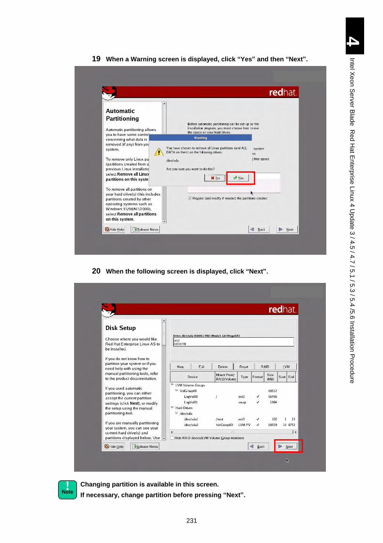
231
4
Inte
l Xe
on
Se
rver B
lad
e R
ed
Ha
t En
terp
rise L
inux 4
Up
da
te 3
/ 4.5
/ 4.7
/ 5.1
/ 5.3
/ 5.4
/5.6
Insta
llatio
n P
roced
ure
19 When a Warning screen is displayed, click “Yes” and then “Next”.
20 When the following screen is displayed, click “Next”.
Changing partition is available in this screen.
If necessary, change partition before pressing “Next”.
! Note
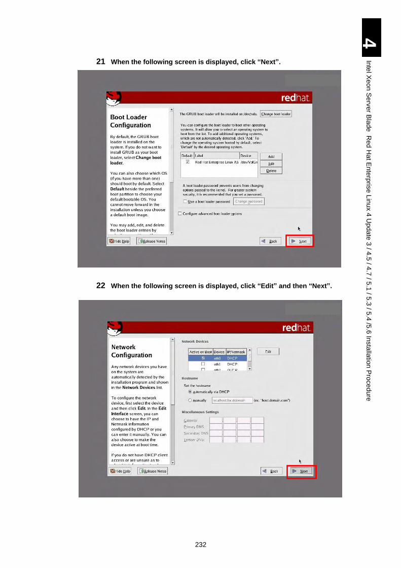
232
4
Inte
l Xe
on
Se
rver B
lad
e R
ed
Ha
t En
terp
rise L
inux 4
Up
da
te 3
/ 4.5
/ 4.7
/ 5.1
/ 5.3
/ 5.4
/5.6
Insta
llatio
n P
roced
ure
21 When the following screen is displayed, click “Next”.
22 When the following screen is displayed, click “Edit” and then “Next”.
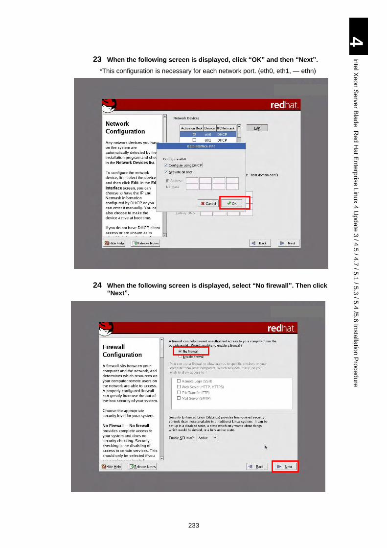
233
4
Inte
l Xe
on
Se
rver B
lad
e R
ed
Ha
t En
terp
rise L
inux 4
Up
da
te 3
/ 4.5
/ 4.7
/ 5.1
/ 5.3
/ 5.4
/5.6
Insta
llatio
n P
roced
ure
23 When the following screen is displayed, click “OK” and then “Next”.
*This configuration is necessary for each network port. (eth0, eth1, ― ethn)
24 When the following screen is displayed, select “No firewall”. Then click “Next”.
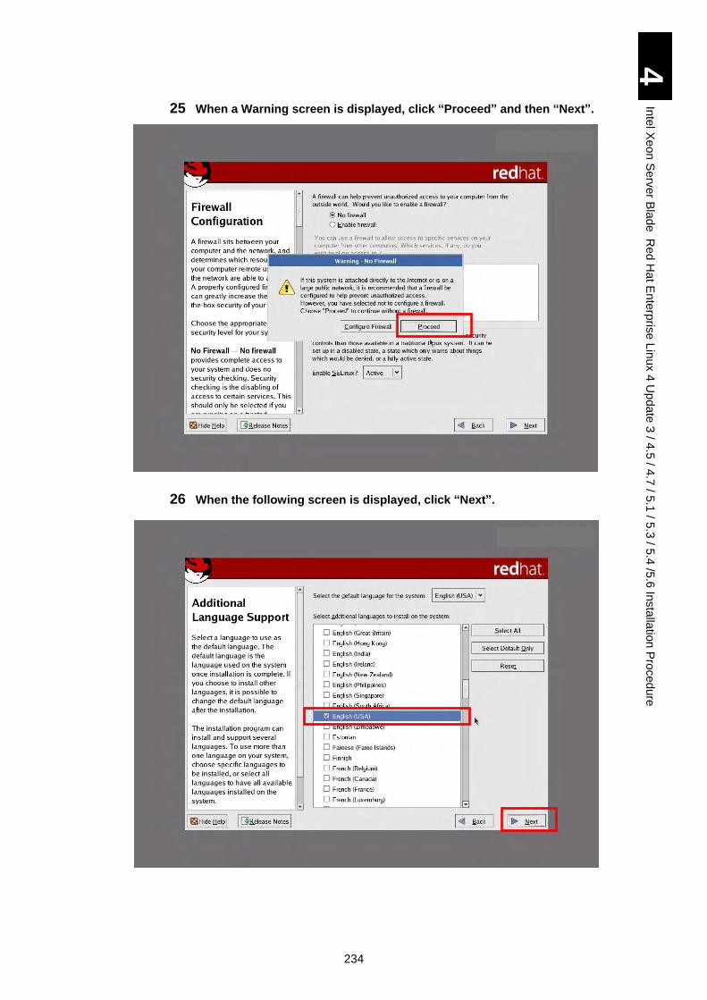
234
4
Inte
l Xe
on
Se
rver B
lad
e R
ed
Ha
t En
terp
rise L
inux 4
Up
da
te 3
/ 4.5
/ 4.7
/ 5.1
/ 5.3
/ 5.4
/5.6
Insta
llatio
n P
roced
ure
25 When a Warning screen is displayed, click “Proceed” and then “Next”.
26 When the following screen is displayed, click “Next”.
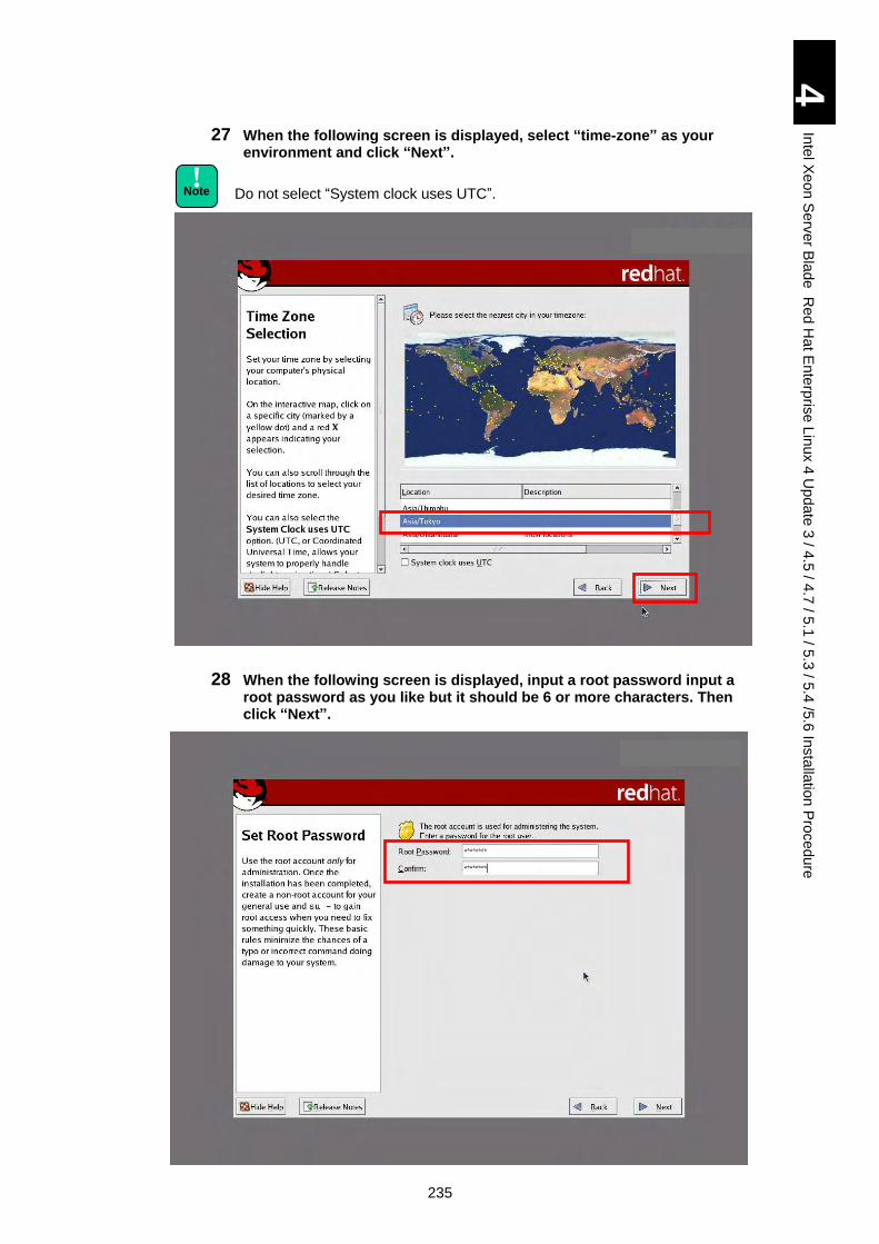
235
4
Inte
l Xe
on
Se
rver B
lad
e R
ed
Ha
t En
terp
rise L
inux 4
Up
da
te 3
/ 4.5
/ 4.7
/ 5.1
/ 5.3
/ 5.4
/5.6
Insta
llatio
n P
roced
ure
27 When the following screen is displayed, select “time-zone” as your environment and click “Next”.
Do not select “System clock uses UTC”.
28 When the following screen is displayed, input a root password input a root password as you like but it should be 6 or more characters. Then click “Next”.
! Note
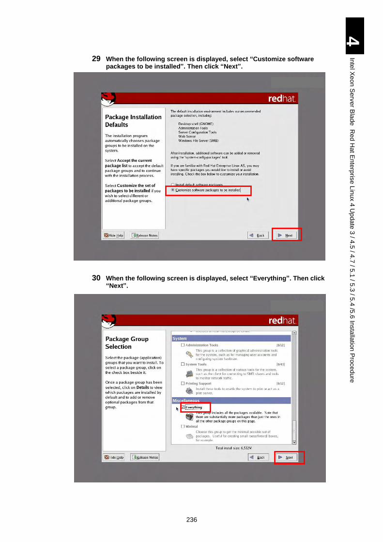
236
4
Inte
l Xe
on
Se
rver B
lad
e R
ed
Ha
t En
terp
rise L
inux 4
Up
da
te 3
/ 4.5
/ 4.7
/ 5.1
/ 5.3
/ 5.4
/5.6
Insta
llatio
n P
roced
ure
29 When the following screen is displayed, select “Customize software packages to be installed”. Then click “Next”.
30 When the following screen is displayed, select “Everything”. Then click “Next”.
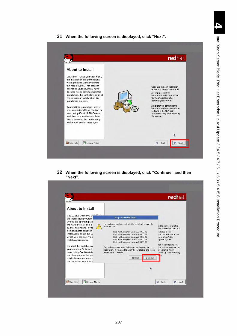
237
4
Inte
l Xe
on
Se
rver B
lad
e R
ed
Ha
t En
terp
rise L
inux 4
Up
da
te 3
/ 4.5
/ 4.7
/ 5.1
/ 5.3
/ 5.4
/5.6
Insta
llatio
n P
roced
ure
31 When the following screen is displayed, click “Next”.
32 When the following screen is displayed, click “Continue” and then “Next”.
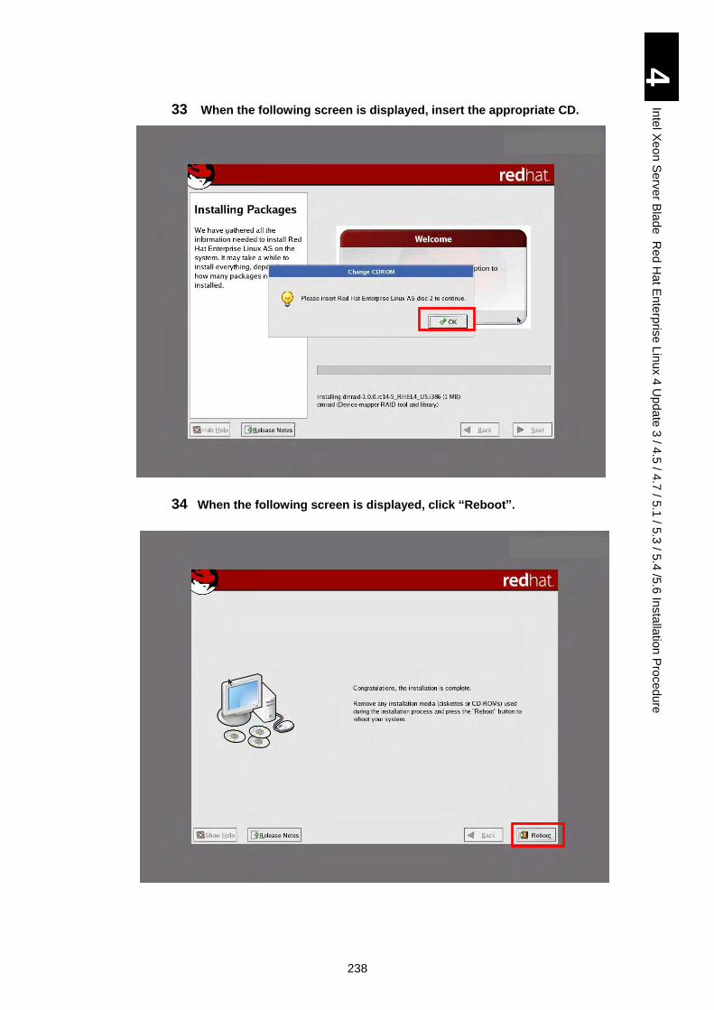
238
4
Inte
l Xe
on
Se
rver B
lad
e R
ed
Ha
t En
terp
rise L
inux 4
Up
da
te 3
/ 4.5
/ 4.7
/ 5.1
/ 5.3
/ 5.4
/5.6
Insta
llatio
n P
roced
ure
33 When the following screen is displayed, insert the appropriate CD.
34 When the following screen is displayed, click “Reboot”.
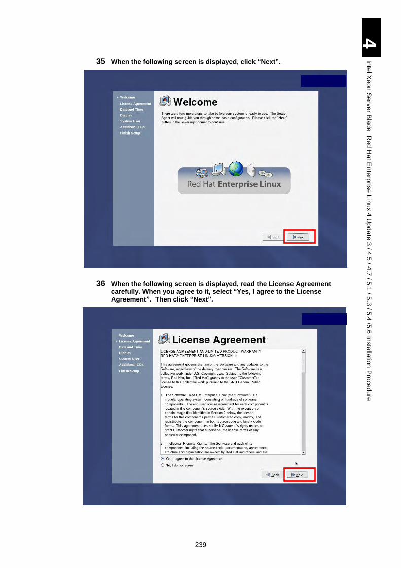
239
4
Inte
l Xe
on
Se
rver B
lad
e R
ed
Ha
t En
terp
rise L
inux 4
Up
da
te 3
/ 4.5
/ 4.7
/ 5.1
/ 5.3
/ 5.4
/5.6
Insta
llatio
n P
roced
ure
35 When the following screen is displayed, click “Next”.
36 When the following screen is displayed, read the License Agreement carefully. When you agree to it, select “Yes, I agree to the License Agreement”. Then click “Next”.
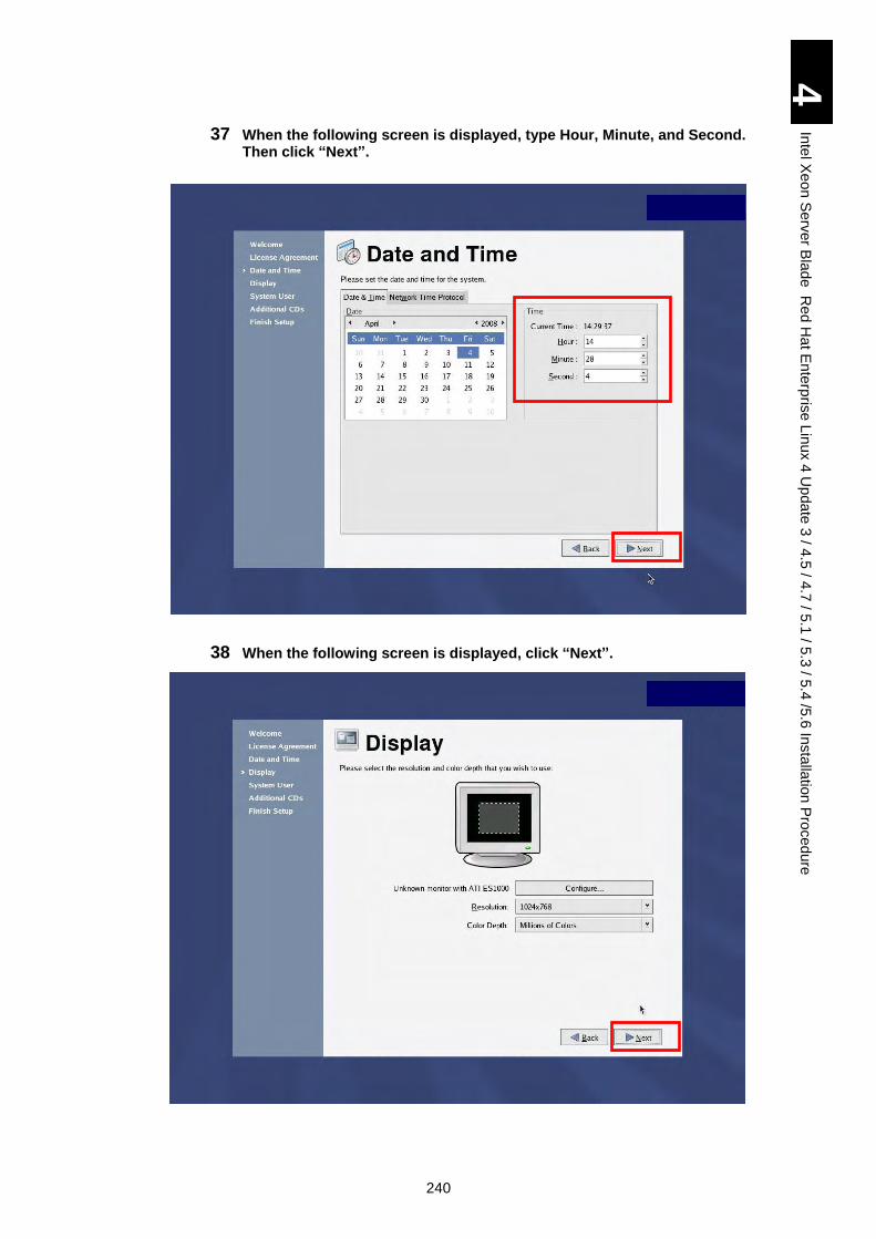
240
4
Inte
l Xe
on
Se
rver B
lad
e R
ed
Ha
t En
terp
rise L
inux 4
Up
da
te 3
/ 4.5
/ 4.7
/ 5.1
/ 5.3
/ 5.4
/5.6
Insta
llatio
n P
roced
ure
37 When the following screen is displayed, type Hour, Minute, and Second. Then click “Next”.
38 When the following screen is displayed, click “Next”.
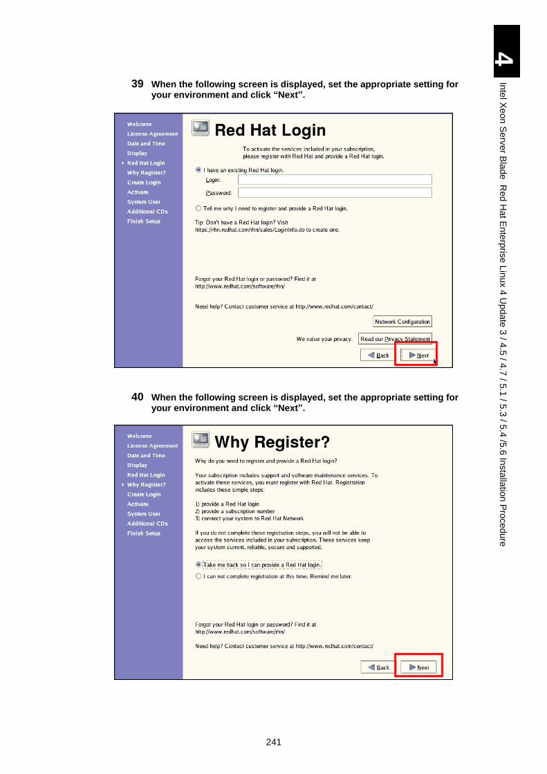
241
4
Inte
l Xe
on
Se
rver B
lad
e R
ed
Ha
t En
terp
rise L
inux 4
Up
da
te 3
/ 4.5
/ 4.7
/ 5.1
/ 5.3
/ 5.4
/5.6
Insta
llatio
n P
roced
ure
39 When the following screen is displayed, set the appropriate setting for your environment and click “Next”.
40 When the following screen is displayed, set the appropriate setting for your environment and click “Next”.
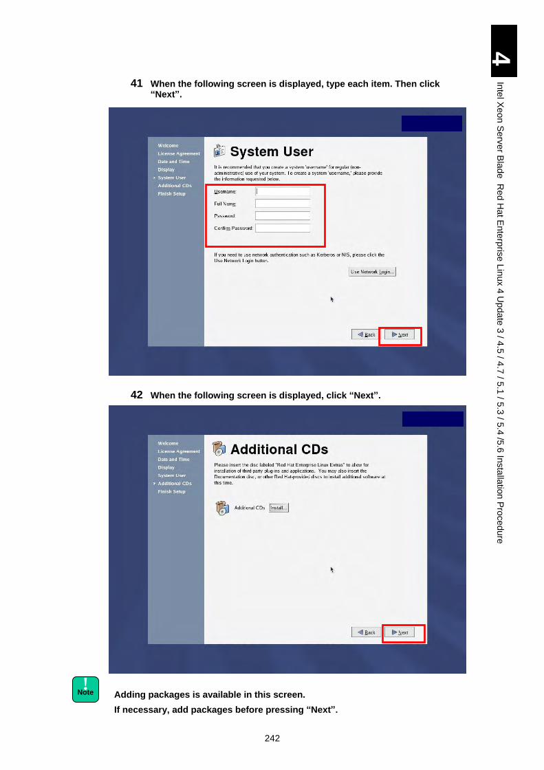
242
4
Inte
l Xe
on
Se
rver B
lad
e R
ed
Ha
t En
terp
rise L
inux 4
Up
da
te 3
/ 4.5
/ 4.7
/ 5.1
/ 5.3
/ 5.4
/5.6
Insta
llatio
n P
roced
ure
41 When the following screen is displayed, type each item. Then click “Next”.
42 When the following screen is displayed, click “Next”.
Adding packages is available in this screen.
If necessary, add packages before pressing “Next”.
! Note
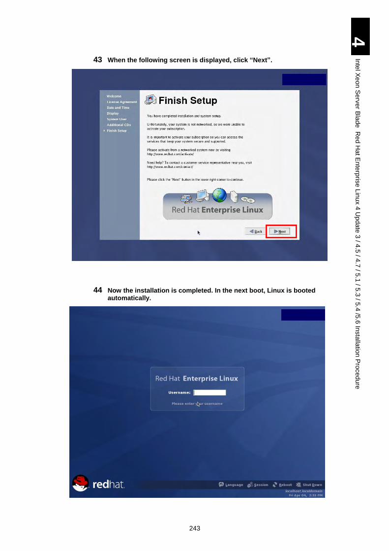
243
4
Inte
l Xe
on
Se
rver B
lad
e R
ed
Ha
t En
terp
rise L
inux 4
Up
da
te 3
/ 4.5
/ 4.7
/ 5.1
/ 5.3
/ 5.4
/5.6
Insta
llatio
n P
roced
ure
43 When the following screen is displayed, click “Next”.
44 Now the installation is completed. In the next boot, Linux is booted automatically.
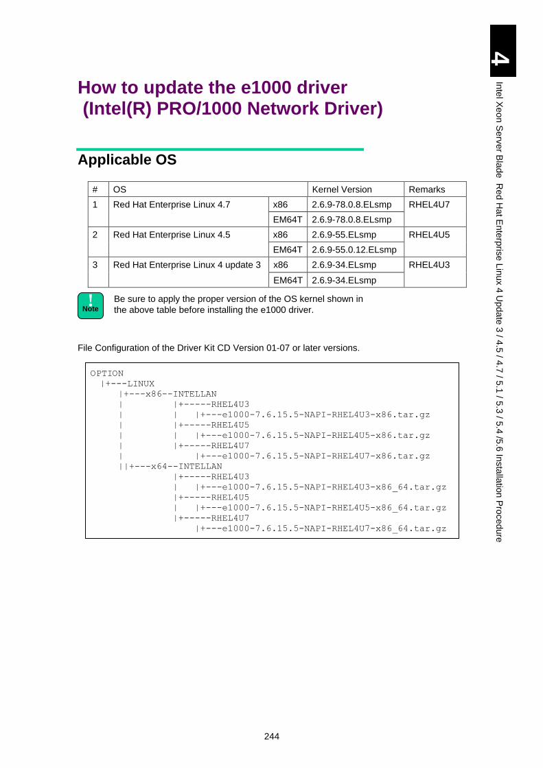
244
4
Inte
l Xe
on
Se
rver B
lad
e R
ed
Ha
t En
terp
rise L
inux 4
Up
da
te 3
/ 4.5
/ 4.7
/ 5.1
/ 5.3
/ 5.4
/5.6
Insta
llatio
n P
roced
ure
How to update the e1000 driver (Intel(R) PRO/1000 Network Driver)
Applicable OS
# OS Kernel Version Remarks
1 Red Hat Enterprise Linux 4.7 x86 2.6.9-78.0.8.ELsmp RHEL4U7
EM64T 2.6.9-78.0.8.ELsmp
2 Red Hat Enterprise Linux 4.5 x86 2.6.9-55.ELsmp RHEL4U5
EM64T 2.6.9-55.0.12.ELsmp
3 Red Hat Enterprise Linux 4 update 3 x86 2.6.9-34.ELsmp RHEL4U3
EM64T 2.6.9-34.ELsmp
Be sure to apply the proper version of the OS kernel shown in
the above table before installing the e1000 driver.
File Configuration of the Driver Kit CD Version 01-07 or later versions.
OPTION
|+---LINUX
|+---x86--INTELLAN
| |+-----RHEL4U3
| | |+---e1000-7.6.15.5-NAPI-RHEL4U3-x86.tar.gz
| |+-----RHEL4U5
| | |+---e1000-7.6.15.5-NAPI-RHEL4U5-x86.tar.gz
| |+-----RHEL4U7
| |+---e1000-7.6.15.5-NAPI-RHEL4U7-x86.tar.gz
||+---x64--INTELLAN
|+-----RHEL4U3
| |+---e1000-7.6.15.5-NAPI-RHEL4U3-x86_64.tar.gz
|+-----RHEL4U5
| |+---e1000-7.6.15.5-NAPI-RHEL4U5-x86_64.tar.gz
|+-----RHEL4U7
|+---e1000-7.6.15.5-NAPI-RHEL4U7-x86_64.tar.gz
! Note
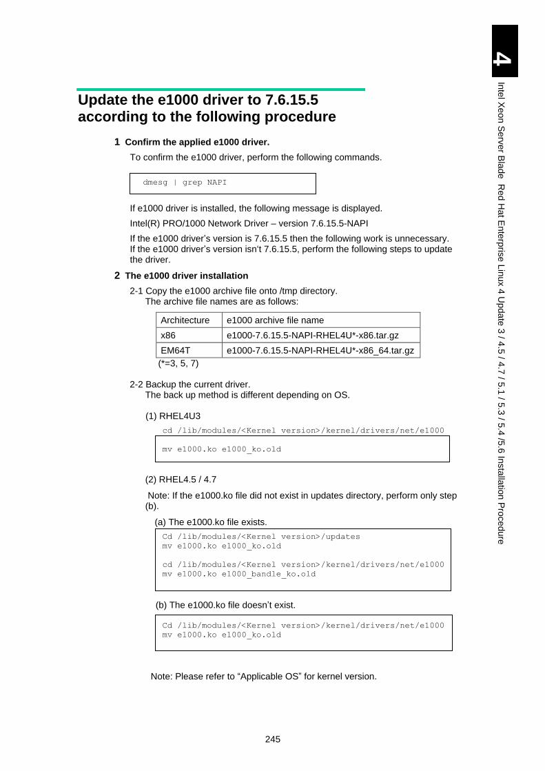
245
4
Inte
l Xe
on
Se
rver B
lad
e R
ed
Ha
t En
terp
rise L
inux 4
Up
da
te 3
/ 4.5
/ 4.7
/ 5.1
/ 5.3
/ 5.4
/5.6
Insta
llatio
n P
roced
ure
Update the e1000 driver to 7.6.15.5 according to the following procedure
1 Confirm the applied e1000 driver.
To confirm the e1000 driver, perform the following commands.
dmesg | grep NAPI
If e1000 driver is installed, the following message is displayed.
Intel(R) PRO/1000 Network Driver – version 7.6.15.5-NAPI
If the e1000 driver’s version is 7.6.15.5 then the following work is unnecessary. If the e1000 driver’s version isn‘t 7.6.15.5, perform the following steps to update the driver.
2 The e1000 driver installation
2-1 Copy the e1000 archive file onto /tmp directory. The archive file names are as follows:
Architecture e1000 archive file name
x86 e1000-7.6.15.5-NAPI-RHEL4U*-x86.tar.gz
EM64T e1000-7.6.15.5-NAPI-RHEL4U*-x86_64.tar.gz
(*=3, 5, 7)
2-2 Backup the current driver. The back up method is different depending on OS. (1) RHEL4U3
cd /lib/modules/<Kernel version>/kernel/drivers/net/e1000
mv e1000.ko e1000_ko.old
(2) RHEL4.5 / 4.7
Note: If the e1000.ko file did not exist in updates directory, perform only step (b).
(a) The e1000.ko file exists.
Cd /lib/modules/<Kernel version>/updates
mv e1000.ko e1000_ko.old
cd /lib/modules/<Kernel version>/kernel/drivers/net/e1000
mv e1000.ko e1000_bandle_ko.old
(b) The e1000.ko file doesn’t exist.
Cd /lib/modules/<Kernel version>/kernel/drivers/net/e1000
mv e1000.ko e1000_ko.old
Note: Please refer to “Applicable OS” for kernel version.
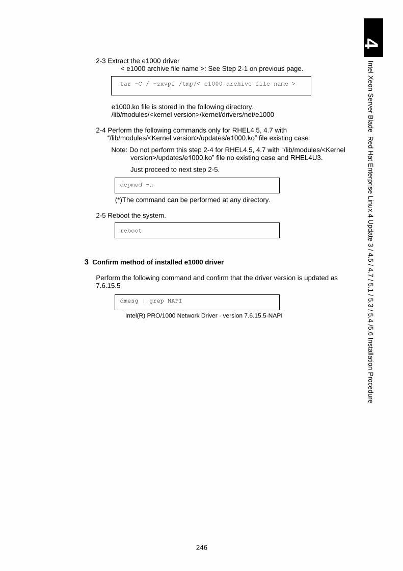
246
4
Inte
l Xe
on
Se
rver B
lad
e R
ed
Ha
t En
terp
rise L
inux 4
Up
da
te 3
/ 4.5
/ 4.7
/ 5.1
/ 5.3
/ 5.4
/5.6
Insta
llatio
n P
roced
ure
2-3 Extract the e1000 driver < e1000 archive file name >: See Step 2-1 on previous page.
tar -C / -zxvpf /tmp/< e1000 archive file name >
e1000.ko file is stored in the following directory.
/lib/modules/<kernel version>/kernel/drivers/net/e1000
2-4 Perform the following commands only for RHEL4.5, 4.7 with “/lib/modules/<Kernel version>/updates/e1000.ko” file existing case
Note: Do not perform this step 2-4 for RHEL4.5, 4.7 with “/lib/modules/<Kernel version>/updates/e1000.ko” file no existing case and RHEL4U3.
Just proceed to next step 2-5.
depmod -a
(*)The command can be performed at any directory.
2-5 Reboot the system.
reboot
3 Confirm method of installed e1000 driver
Perform the following command and confirm that the driver version is updated as 7.6.15.5
dmesg | grep NAPI
Intel(R) PRO/1000 Network Driver - version 7.6.15.5-NAPI
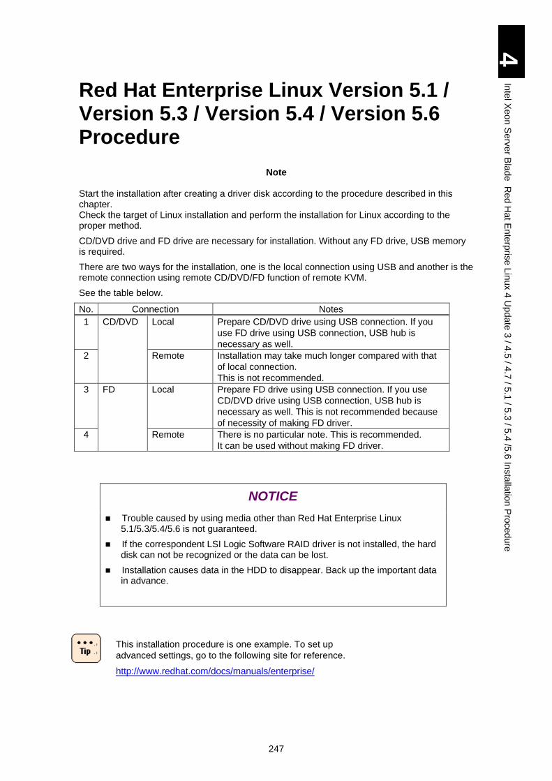
247
4
Inte
l Xe
on
Se
rver B
lad
e R
ed
Ha
t En
terp
rise L
inux 4
Up
da
te 3
/ 4.5
/ 4.7
/ 5.1
/ 5.3
/ 5.4
/5.6
Insta
llatio
n P
roced
ure
Red Hat Enterprise Linux Version 5.1 / Version 5.3 / Version 5.4 / Version 5.6 Procedure
Note
Start the installation after creating a driver disk according to the procedure described in this chapter. Check the target of Linux installation and perform the installation for Linux according to the proper method.
CD/DVD drive and FD drive are necessary for installation. Without any FD drive, USB memory is required.
There are two ways for the installation, one is the local connection using USB and another is the remote connection using remote CD/DVD/FD function of remote KVM.
See the table below.
No. Connection Notes
1 CD/DVD Local Prepare CD/DVD drive using USB connection. If you
use FD drive using USB connection, USB hub is
necessary as well.
2 Remote Installation may take much longer compared with that
of local connection.
This is not recommended.
3 FD Local Prepare FD drive using USB connection. If you use
CD/DVD drive using USB connection, USB hub is
necessary as well. This is not recommended because
of necessity of making FD driver.
4 Remote There is no particular note. This is recommended.
It can be used without making FD driver.
NOTICE
Trouble caused by using media other than Red Hat Enterprise Linux 5.1/5.3/5.4/5.6 is not guaranteed.
If the correspondent LSI Logic Software RAID driver is not installed, the hard disk can not be recognized or the data can be lost.
Installation causes data in the HDD to disappear. Back up the important data in advance.
This installation procedure is one example. To set up
advanced settings, go to the following site for reference.
http://www.redhat.com/docs/manuals/enterprise/
248
4
Inte
l Xe
on
Se
rver B
lad
e R
ed
Ha
t En
terp
rise L
inux 4
Up
da
te 3
/ 4.5
/ 4.7
/ 5.1
/ 5.3
/ 5.4
/5.6
Insta
llatio
n P
roced
ure
If you use Hitachi FC adapter: When you install the FC
adapter driver for Linux, please use the CD named "Gigabit
Fibre Channel Adapter Drivers for Windows/Linux/VMware"
which is attached to the product. As for the installation
procedure, please refer to "Hitachi Gigabit Fibre Channel
Board User's Guide" which is contained in the attached CD.
When installing RHEL 5.4 x64:
When having completely installed RHEL 5.4 x64 following the
procedure, then jump to Step 68 in “How to Install Linux”.
[Hitachi FC adapter]
GGX-CC9M4G1X1EX/GGX-CC9M4G1X1/GG-CC9M4G1X1-
Y, GGX-CC9P4G1X1EX, GGX-CC9P8G2X1EX
When using the FC adapter by Emulex, proceed to the next.
[Emulex FC adapter]
GGX-CC9M4G2X1/GG-CC9M4G2X1-Y
GGX-CC9P8G1X1/GG-CC9P8G1X1-Y
! Note
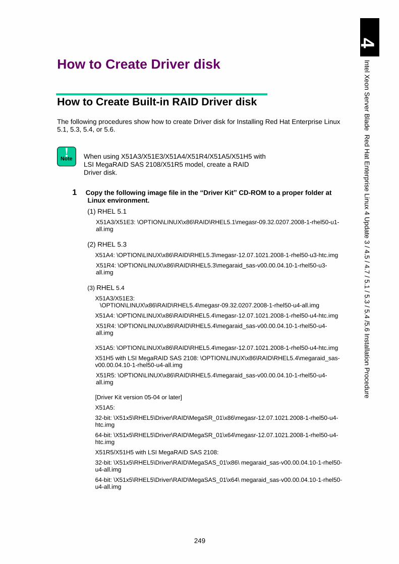
249
4
Inte
l Xe
on
Se
rver B
lad
e R
ed
Ha
t En
terp
rise L
inux 4
Up
da
te 3
/ 4.5
/ 4.7
/ 5.1
/ 5.3
/ 5.4
/5.6
Insta
llatio
n P
roced
ure
How to Create Driver disk
How to Create Built-in RAID Driver disk
The following procedures show how to create Driver disk for Installing Red Hat Enterprise Linux 5.1, 5.3, 5.4, or 5.6.
When using X51A3/X51E3/X51A4/X51R4/X51A5/X51H5 with
LSI MegaRAID SAS 2108/X51R5 model, create a RAID
Driver disk.
1 Copy the following image file in the “Driver Kit” CD-ROM to a proper folder at Linux environment.
(1) RHEL 5.1
X51A3/X51E3: \OPTION\LINUX\x86\RAID\RHEL5.1\megasr-09.32.0207.2008-1-rhel50-u1-all.img
(2) RHEL 5.3
X51A4: \OPTION\LINUX\x86\RAID\RHEL5.3\megasr-12.07.1021.2008-1-rhel50-u3-htc.img
X51R4: \OPTION\LINUX\x86\RAID\RHEL5.3\megaraid_sas-v00.00.04.10-1-rhel50-u3-all.img
(3) RHEL 5.4
X51A3/X51E3: \OPTION\LINUX\x86\RAID\RHEL5.4\megasr-09.32.0207.2008-1-rhel50-u4-all.img
X51A4: \OPTION\LINUX\x86\RAID\RHEL5.4\megasr-12.07.1021.2008-1-rhel50-u4-htc.img
X51R4: \OPTION\LINUX\x86\RAID\RHEL5.4\megaraid_sas-v00.00.04.10-1-rhel50-u4-all.img
X51A5: \OPTION\LINUX\x86\RAID\RHEL5.4\megasr-12.07.1021.2008-1-rhel50-u4-htc.img
X51H5 with LSI MegaRAID SAS 2108: \OPTION\LINUX\x86\RAID\RHEL5.4\megaraid_sas-v00.00.04.10-1-rhel50-u4-all.img
X51R5: \OPTION\LINUX\x86\RAID\RHEL5.4\megaraid_sas-v00.00.04.10-1-rhel50-u4-all.img
[Driver Kit version 05-04 or later]
X51A5:
32-bit: \X51x5\RHEL5\Driver\RAID\MegaSR_01\x86\megasr-12.07.1021.2008-1-rhel50-u4-htc.img
64-bit: \X51x5\RHEL5\Driver\RAID\MegaSR_01\x64\megasr-12.07.1021.2008-1-rhel50-u4-htc.img
X51R5/X51H5 with LSI MegaRAID SAS 2108:
32-bit: \X51x5\RHEL5\Driver\RAID\MegaSAS_01\x86\ megaraid_sas-v00.00.04.10-1-rhel50-u4-all.img
64-bit: \X51x5\RHEL5\Driver\RAID\MegaSAS_01\x64\ megaraid_sas-v00.00.04.10-1-rhel50-u4-all.img
! Note
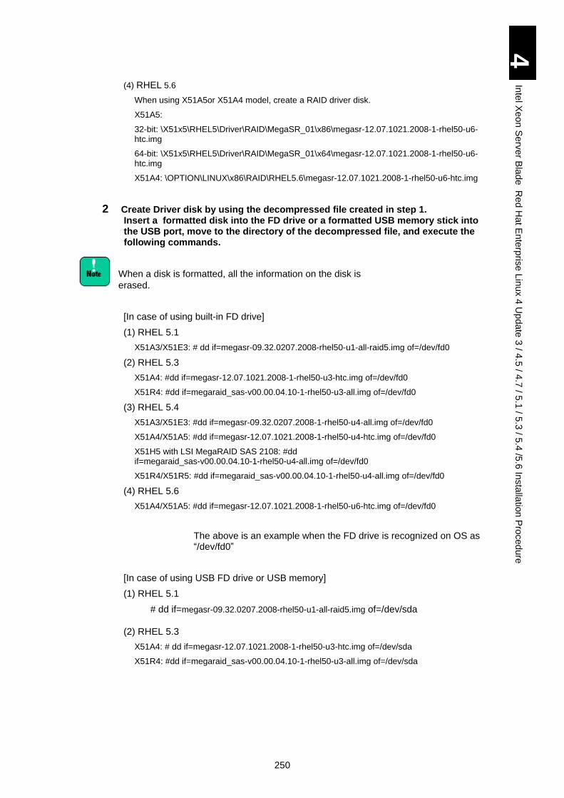
250
4
Inte
l Xe
on
Se
rver B
lad
e R
ed
Ha
t En
terp
rise L
inux 4
Up
da
te 3
/ 4.5
/ 4.7
/ 5.1
/ 5.3
/ 5.4
/5.6
Insta
llatio
n P
roced
ure
(4) RHEL 5.6
When using X51A5or X51A4 model, create a RAID driver disk.
X51A5:
32-bit: \X51x5\RHEL5\Driver\RAID\MegaSR_01\x86\megasr-12.07.1021.2008-1-rhel50-u6-htc.img
64-bit: \X51x5\RHEL5\Driver\RAID\MegaSR_01\x64\megasr-12.07.1021.2008-1-rhel50-u6-htc.img
X51A4: \OPTION\LINUX\x86\RAID\RHEL5.6\megasr-12.07.1021.2008-1-rhel50-u6-htc.img
2 Create Driver disk by using the decompressed file created in step 1. Insert a formatted disk into the FD drive or a formatted USB memory stick into the USB port, move to the directory of the decompressed file, and execute the following commands.
When a disk is formatted, all the information on the disk is
erased.
[In case of using built-in FD drive]
(1) RHEL 5.1
X51A3/X51E3: # dd if=megasr-09.32.0207.2008-rhel50-u1-all-raid5.img of=/dev/fd0
(2) RHEL 5.3
X51A4: #dd if=megasr-12.07.1021.2008-1-rhel50-u3-htc.img of=/dev/fd0
X51R4: #dd if=megaraid_sas-v00.00.04.10-1-rhel50-u3-all.img of=/dev/fd0
(3) RHEL 5.4
X51A3/X51E3: #dd if=megasr-09.32.0207.2008-1-rhel50-u4-all.img of=/dev/fd0
X51A4/X51A5: #dd if=megasr-12.07.1021.2008-1-rhel50-u4-htc.img of=/dev/fd0
X51H5 with LSI MegaRAID SAS 2108: #dd if=megaraid_sas-v00.00.04.10-1-rhel50-u4-all.img of=/dev/fd0
X51R4/X51R5: #dd if=megaraid_sas-v00.00.04.10-1-rhel50-u4-all.img of=/dev/fd0
(4) RHEL 5.6
X51A4/X51A5: #dd if=megasr-12.07.1021.2008-1-rhel50-u6-htc.img of=/dev/fd0
The above is an example when the FD drive is recognized on OS as “/dev/fd0”
[In case of using USB FD drive or USB memory]
(1) RHEL 5.1
# dd if=megasr-09.32.0207.2008-rhel50-u1-all-raid5.img of=/dev/sda
(2) RHEL 5.3
X51A4: # dd if=megasr-12.07.1021.2008-1-rhel50-u3-htc.img of=/dev/sda
X51R4: #dd if=megaraid_sas-v00.00.04.10-1-rhel50-u3-all.img of=/dev/sda
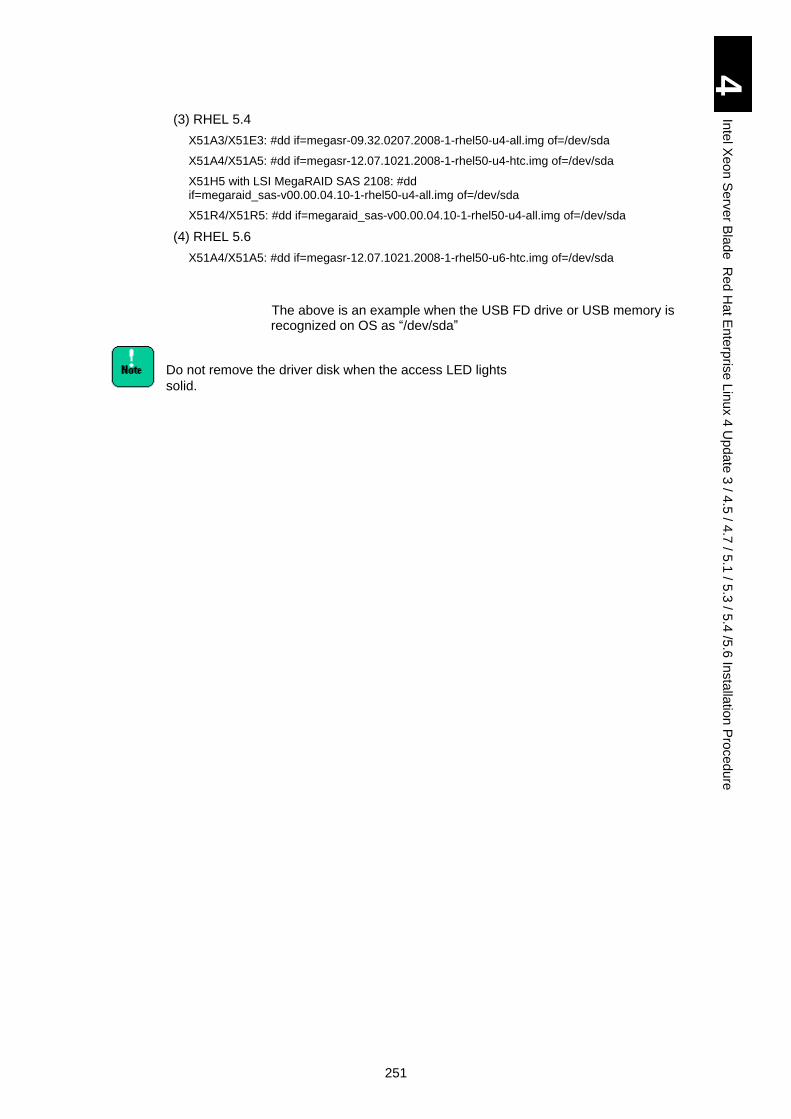
251
4
Inte
l Xe
on
Se
rver B
lad
e R
ed
Ha
t En
terp
rise L
inux 4
Up
da
te 3
/ 4.5
/ 4.7
/ 5.1
/ 5.3
/ 5.4
/5.6
Insta
llatio
n P
roced
ure
(3) RHEL 5.4
X51A3/X51E3: #dd if=megasr-09.32.0207.2008-1-rhel50-u4-all.img of=/dev/sda
X51A4/X51A5: #dd if=megasr-12.07.1021.2008-1-rhel50-u4-htc.img of=/dev/sda
X51H5 with LSI MegaRAID SAS 2108: #dd if=megaraid_sas-v00.00.04.10-1-rhel50-u4-all.img of=/dev/sda
X51R4/X51R5: #dd if=megaraid_sas-v00.00.04.10-1-rhel50-u4-all.img of=/dev/sda
(4) RHEL 5.6
X51A4/X51A5: #dd if=megasr-12.07.1021.2008-1-rhel50-u6-htc.img of=/dev/sda
The above is an example when the USB FD drive or USB memory is recognized on OS as “/dev/sda”
Do not remove the driver disk when the access LED lights
solid.
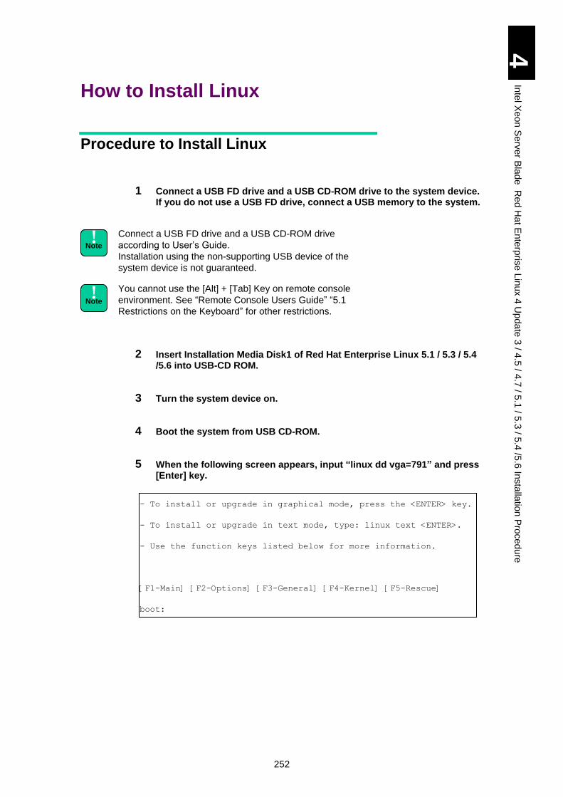
252
4
Inte
l Xe
on
Se
rver B
lad
e R
ed
Ha
t En
terp
rise L
inux 4
Up
da
te 3
/ 4.5
/ 4.7
/ 5.1
/ 5.3
/ 5.4
/5.6
Insta
llatio
n P
roced
ure
How to Install Linux
Procedure to Install Linux
1 Connect a USB FD drive and a USB CD-ROM drive to the system device. If you do not use a USB FD drive, connect a USB memory to the system.
Connect a USB FD drive and a USB CD-ROM drive
according to User’s Guide.
Installation using the non-supporting USB device of the
system device is not guaranteed.
You cannot use the [Alt] + [Tab] Key on remote console
environment. See “Remote Console Users Guide” “5.1
Restrictions on the Keyboard” for other restrictions.
2 Insert Installation Media Disk1 of Red Hat Enterprise Linux 5.1 / 5.3 / 5.4 /5.6 into USB-CD ROM.
3 Turn the system device on.
4 Boot the system from USB CD-ROM.
5 When the following screen appears, input “linux dd vga=791” and press [Enter] key.
- To install or upgrade in graphical mode, press the <ENTER> key.
- To install or upgrade in text mode, type: linux text <ENTER>.
- Use the function keys listed below for more information.
[F1-Main] [F2-Options] [F3-General] [F4-Kernel] [F5-Rescue]
boot:
! Note
! Note
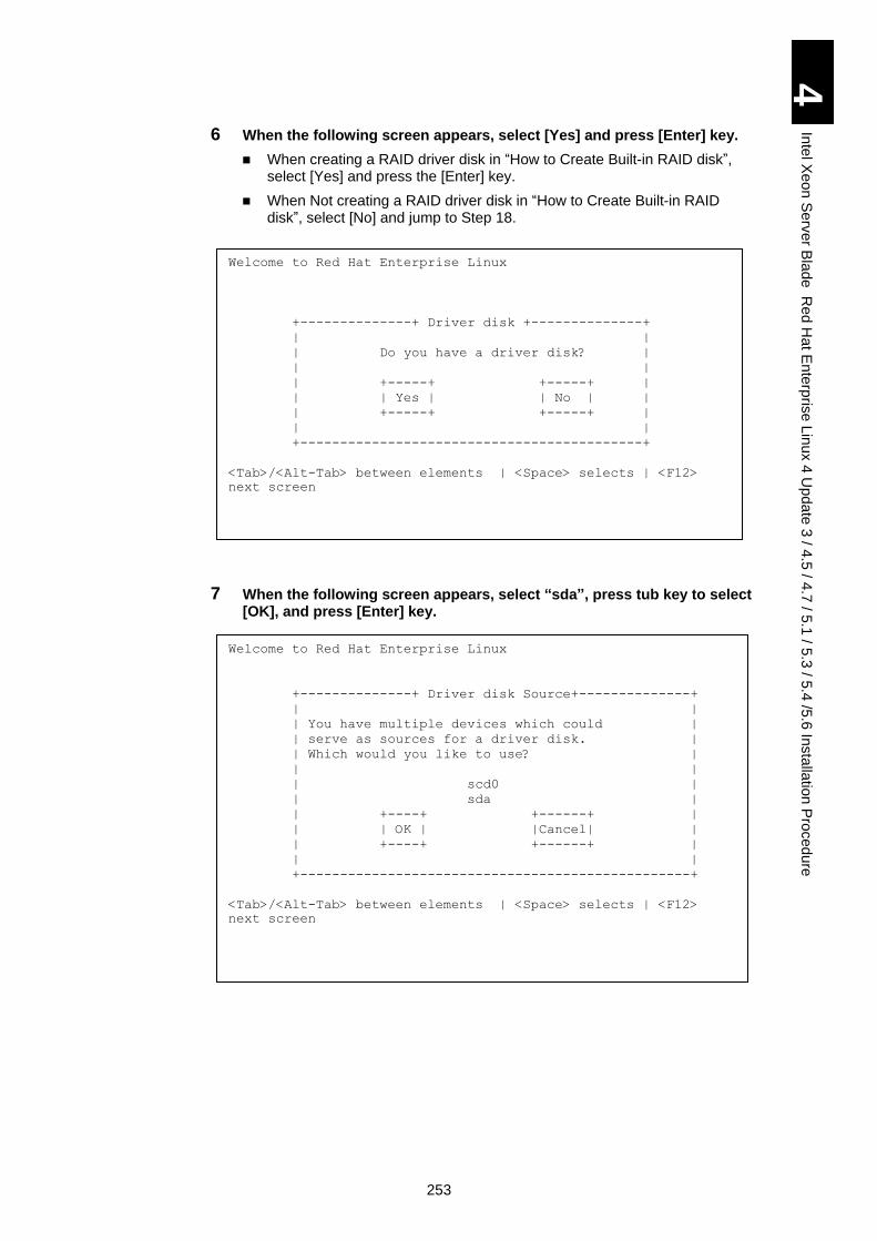
253
4
Inte
l Xe
on
Se
rver B
lad
e R
ed
Ha
t En
terp
rise L
inux 4
Up
da
te 3
/ 4.5
/ 4.7
/ 5.1
/ 5.3
/ 5.4
/5.6
Insta
llatio
n P
roced
ure
6 When the following screen appears, select [Yes] and press [Enter] key.
When creating a RAID driver disk in “How to Create Built-in RAID disk”, select [Yes] and press the [Enter] key.
When Not creating a RAID driver disk in “How to Create Built-in RAID disk”, select [No] and jump to Step 18.
7 When the following screen appears, select “sda”, press tub key to select [OK], and press [Enter] key.
Welcome to Red Hat Enterprise Linux
+--------------+ Driver disk +--------------+
| |
| Do you have a driver disk? |
| |
| +-----+ +-----+ |
| | Yes | | No | |
| +-----+ +-----+ |
| |
+-------------------------------------------+
<Tab>/<Alt-Tab> between elements | <Space> selects | <F12>
next screen
Welcome to Red Hat Enterprise Linux
+--------------+ Driver disk Source+--------------+
| |
| You have multiple devices which could |
| serve as sources for a driver disk. |
| Which would you like to use? |
| |
| scd0 |
| sda |
| +----+ +------+ |
| | OK | |Cancel| |
| +----+ +------+ |
| |
+-------------------------------------------------+
<Tab>/<Alt-Tab> between elements | <Space> selects | <F12>
next screen
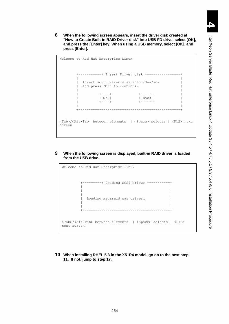
254
4
Inte
l Xe
on
Se
rver B
lad
e R
ed
Ha
t En
terp
rise L
inux 4
Up
da
te 3
/ 4.5
/ 4.7
/ 5.1
/ 5.3
/ 5.4
/5.6
Insta
llatio
n P
roced
ure
8 When the following screen appears, insert the driver disk created at "How to Create Built-in RAID Driver disk" into USB FD drive, select [OK], and press the [Enter] key. When using a USB memory, select [OK], and press [Enter].
9 When the following screen is displayed, built-in RAID driver is loaded from the USB drive.
10 When installing RHEL 5.3 in the X51R4 model, go on to the next step 11. If not, jump to step 17.
Welcome to Red Hat Enterprise Linux
+-----------+ Insert Driver disk +----------------+
| |
| Insert your driver disk into /dev/sda |
| and press “OK” to continue. |
| |
| +----+ +------+ |
| | OK | | Back | |
| +----+ +------+ |
| |
+-------------------------------------------------+
<Tab>/<Alt-Tab> between elements | <Space> selects | <F12> next
screen
Welcome to Red Hat Enterprise Linux
+---------+ Loading SCSI driver +----------+
| |
| |
| |
| Loading megaraid_sas driver… |
| |
| |
+------------------------------------------+
<Tab>/<Alt-Tab> between elements | <Space> selects | <F12>
next screen
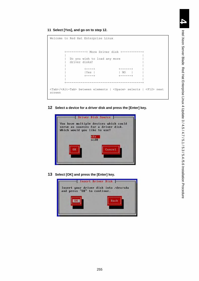
255
4
Inte
l Xe
on
Se
rver B
lad
e R
ed
Ha
t En
terp
rise L
inux 4
Up
da
te 3
/ 4.5
/ 4.7
/ 5.1
/ 5.3
/ 5.4
/5.6
Insta
llatio
n P
roced
ure
11 Select [Yes], and go on to step 12.
12 Select a device for a driver disk and press the [Enter] key.
13 Select [OK] and press the [Enter] key.
Welcome to Red Hat Enterprise Linux
+-----------+ More Driver disk +-----------+
| |
| Do you wish to load any more |
| driver disks? |
| |
| +----+ +------+ |
| |Yes | | NO | |
| +----+ +------+ |
| |
+------------------------------------------+
<Tab>/<Alt-Tab> between elements | <Space> selects | <F12> next
screen
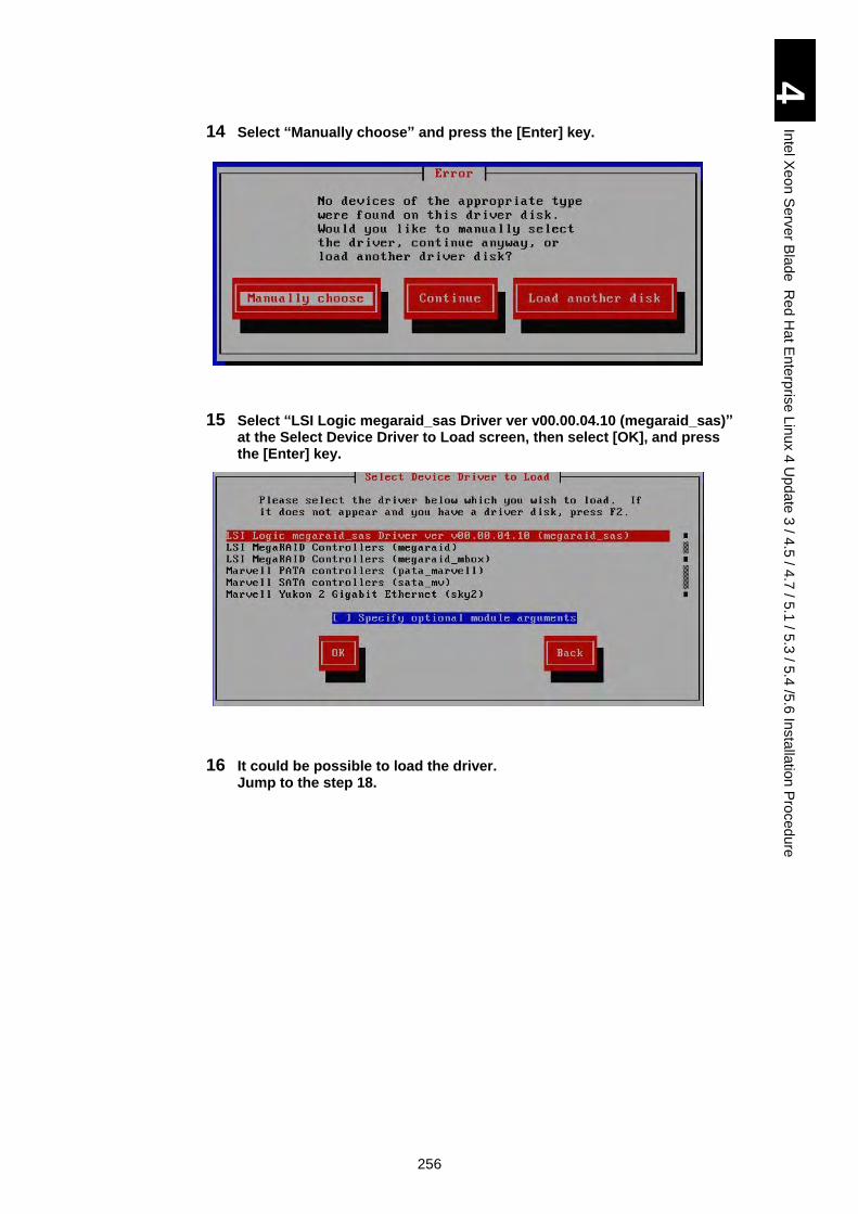
256
4
Inte
l Xe
on
Se
rver B
lad
e R
ed
Ha
t En
terp
rise L
inux 4
Up
da
te 3
/ 4.5
/ 4.7
/ 5.1
/ 5.3
/ 5.4
/5.6
Insta
llatio
n P
roced
ure
14 Select “Manually choose” and press the [Enter] key.
15 Select “LSI Logic megaraid_sas Driver ver v00.00.04.10 (megaraid_sas)” at the Select Device Driver to Load screen, then select [OK], and press the [Enter] key.
16 It could be possible to load the driver. Jump to the step 18.
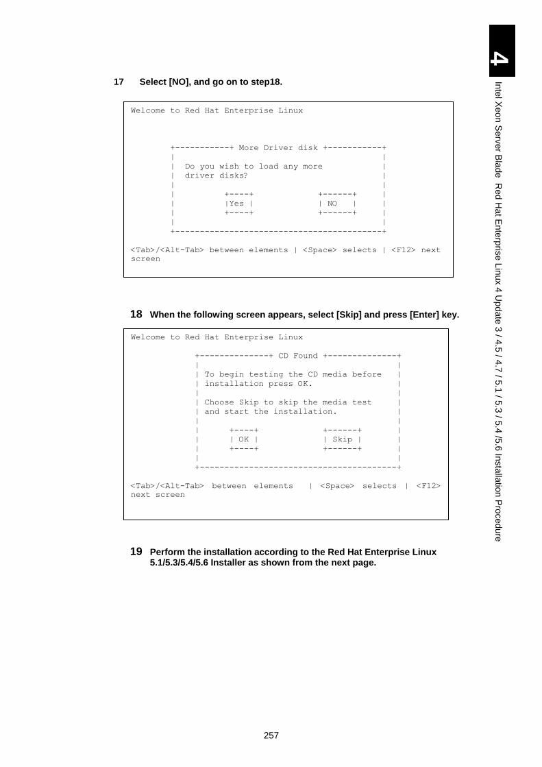
257
4
Inte
l Xe
on
Se
rver B
lad
e R
ed
Ha
t En
terp
rise L
inux 4
Up
da
te 3
/ 4.5
/ 4.7
/ 5.1
/ 5.3
/ 5.4
/5.6
Insta
llatio
n P
roced
ure
17 Select [NO], and go on to step18.
18 When the following screen appears, select [Skip] and press [Enter] key.
19 Perform the installation according to the Red Hat Enterprise Linux 5.1/5.3/5.4/5.6 Installer as shown from the next page.
Welcome to Red Hat Enterprise Linux
+--------------+ CD Found +--------------+
| |
| To begin testing the CD media before |
| installation press OK. |
| |
| Choose Skip to skip the media test |
| and start the installation. |
| |
| +----+ +------+ |
| | OK | | Skip | |
| +----+ +------+ |
| |
+----------------------------------------+
<Tab>/<Alt-Tab> between elements | <Space> selects | <F12>
next screen
Welcome to Red Hat Enterprise Linux
+-----------+ More Driver disk +-----------+
| |
| Do you wish to load any more |
| driver disks? |
| |
| +----+ +------+ |
| |Yes | | NO | |
| +----+ +------+ |
| |
+------------------------------------------+
<Tab>/<Alt-Tab> between elements | <Space> selects | <F12> next
screen
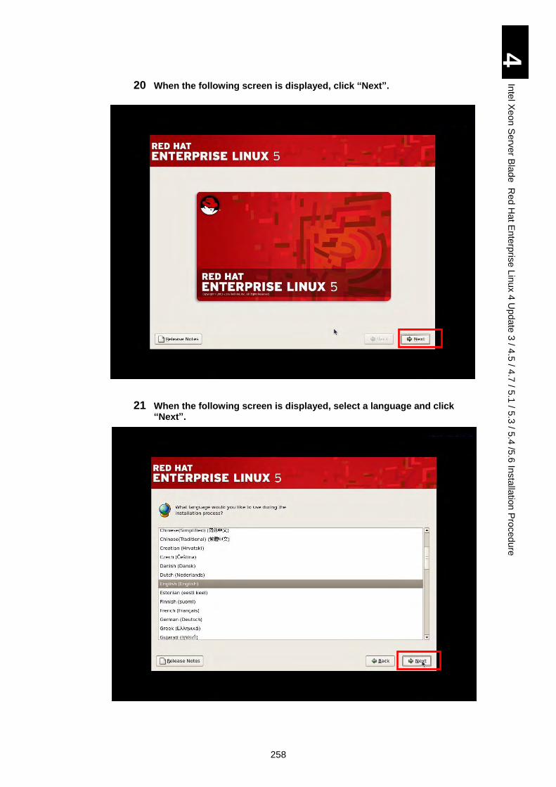
258
4
Inte
l Xe
on
Se
rver B
lad
e R
ed
Ha
t En
terp
rise L
inux 4
Up
da
te 3
/ 4.5
/ 4.7
/ 5.1
/ 5.3
/ 5.4
/5.6
Insta
llatio
n P
roced
ure
20 When the following screen is displayed, click “Next”.
21 When the following screen is displayed, select a language and click “Next”.
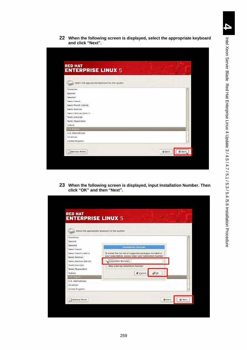
259
4
Inte
l Xe
on
Se
rver B
lad
e R
ed
Ha
t En
terp
rise L
inux 4
Up
da
te 3
/ 4.5
/ 4.7
/ 5.1
/ 5.3
/ 5.4
/5.6
Insta
llatio
n P
roced
ure
22 When the following screen is displayed, select the appropriate keyboard and click “Next”.
23 When the following screen is displayed, input Installation Number. Then click “OK” and then “Next”.
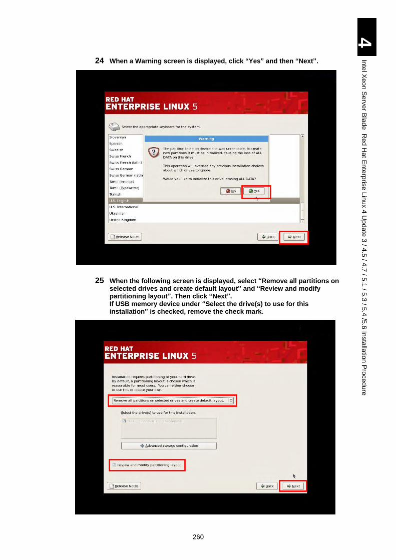
260
4
Inte
l Xe
on
Se
rver B
lad
e R
ed
Ha
t En
terp
rise L
inux 4
Up
da
te 3
/ 4.5
/ 4.7
/ 5.1
/ 5.3
/ 5.4
/5.6
Insta
llatio
n P
roced
ure
24 When a Warning screen is displayed, click “Yes” and then “Next”.
25 When the following screen is displayed, select “Remove all partitions on selected drives and create default layout” and “Review and modify partitioning layout”. Then click “Next”. If USB memory device under “Select the drive(s) to use for this installation” is checked, remove the check mark.
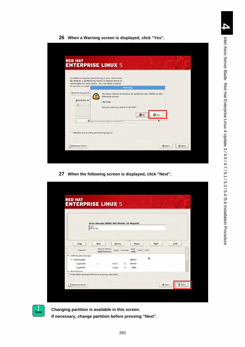
261
4
Inte
l Xe
on
Se
rver B
lad
e R
ed
Ha
t En
terp
rise L
inux 4
Up
da
te 3
/ 4.5
/ 4.7
/ 5.1
/ 5.3
/ 5.4
/5.6
Insta
llatio
n P
roced
ure
26 When a Warning screen is displayed, click “Yes”.
27 When the following screen is displayed, click “Next”.
Changing partition is available in this screen.
If necessary, change partition before pressing “Next”.
! Note
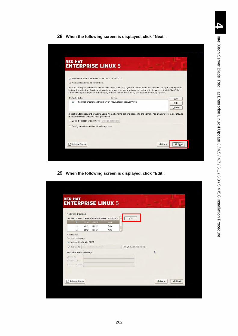
262
4
Inte
l Xe
on
Se
rver B
lad
e R
ed
Ha
t En
terp
rise L
inux 4
Up
da
te 3
/ 4.5
/ 4.7
/ 5.1
/ 5.3
/ 5.4
/5.6
Insta
llatio
n P
roced
ure
28 When the following screen is displayed, click “Next”.
29 When the following screen is displayed, click “Edit”.
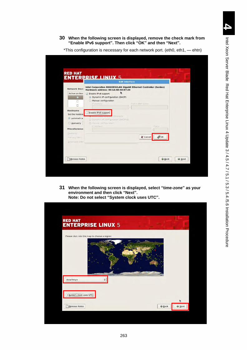
263
4
Inte
l Xe
on
Se
rver B
lad
e R
ed
Ha
t En
terp
rise L
inux 4
Up
da
te 3
/ 4.5
/ 4.7
/ 5.1
/ 5.3
/ 5.4
/5.6
Insta
llatio
n P
roced
ure
30 When the following screen is displayed, remove the check mark from “Enable IPv6 support”. Then click “OK” and then “Next”.
*This configuration is necessary for each network port. (eth0, eth1, ― ehtn)
31 When the following screen is displayed, select “time-zone” as your environment and then click “Next”. Note: Do not select “System clock uses UTC”.
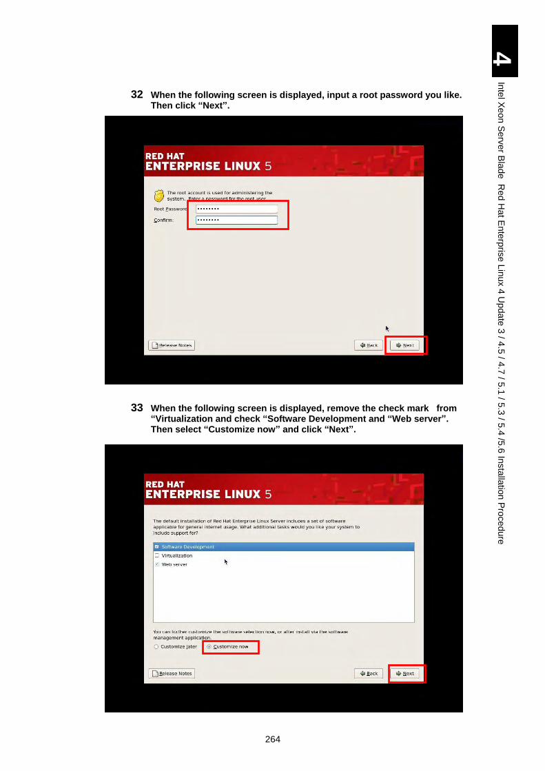
264
4
Inte
l Xe
on
Se
rver B
lad
e R
ed
Ha
t En
terp
rise L
inux 4
Up
da
te 3
/ 4.5
/ 4.7
/ 5.1
/ 5.3
/ 5.4
/5.6
Insta
llatio
n P
roced
ure
32 When the following screen is displayed, input a root password you like. Then click “Next”.
33 When the following screen is displayed, remove the check mark from “Virtualization and check “Software Development and “Web server”. Then select “Customize now” and click “Next”.
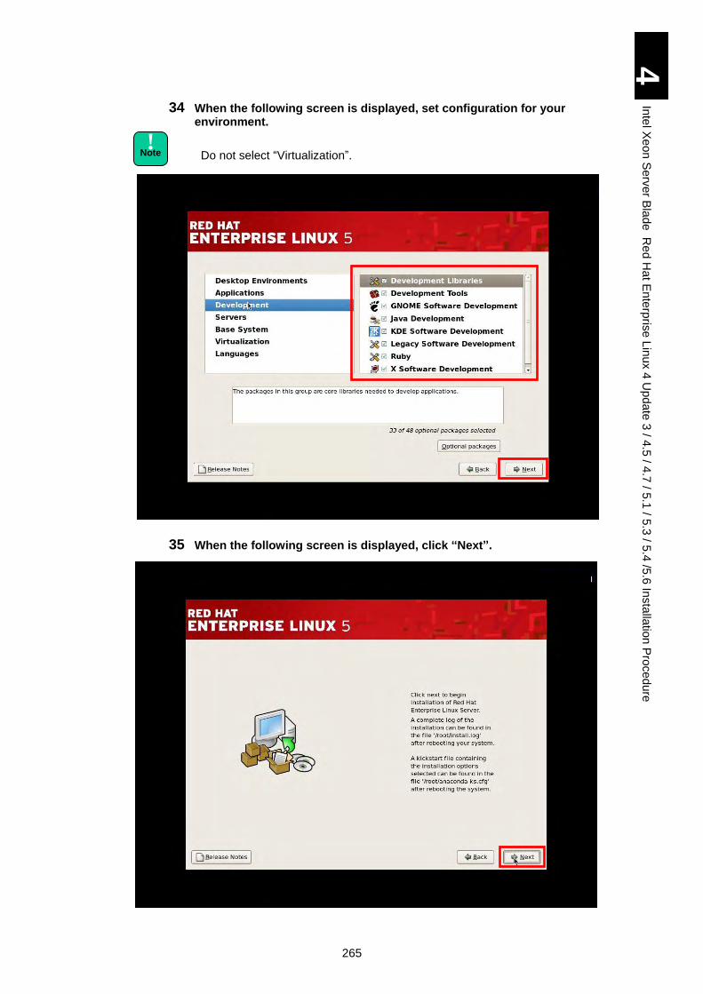
265
4
Inte
l Xe
on
Se
rver B
lad
e R
ed
Ha
t En
terp
rise L
inux 4
Up
da
te 3
/ 4.5
/ 4.7
/ 5.1
/ 5.3
/ 5.4
/5.6
Insta
llatio
n P
roced
ure
34 When the following screen is displayed, set configuration for your environment.
Do not select “Virtualization”.
35 When the following screen is displayed, click “Next”.
! Note
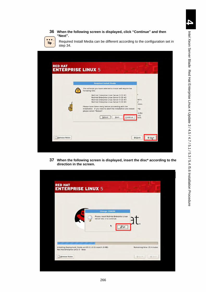
266
4
Inte
l Xe
on
Se
rver B
lad
e R
ed
Ha
t En
terp
rise L
inux 4
Up
da
te 3
/ 4.5
/ 4.7
/ 5.1
/ 5.3
/ 5.4
/5.6
Insta
llatio
n P
roced
ure
36 When the following screen is displayed, click “Continue” and then “Next”.
Required Install Media can be different according to the configuration set in step 34.
37 When the following screen is displayed, insert the disc* according to the direction in the screen.
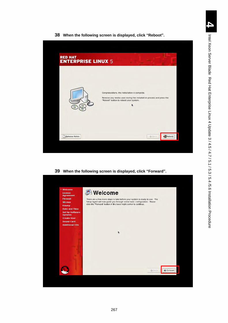
267
4
Inte
l Xe
on
Se
rver B
lad
e R
ed
Ha
t En
terp
rise L
inux 4
Up
da
te 3
/ 4.5
/ 4.7
/ 5.1
/ 5.3
/ 5.4
/5.6
Insta
llatio
n P
roced
ure
38 When the following screen is displayed, click “Reboot”.
39 When the following screen is displayed, click “Forward”.
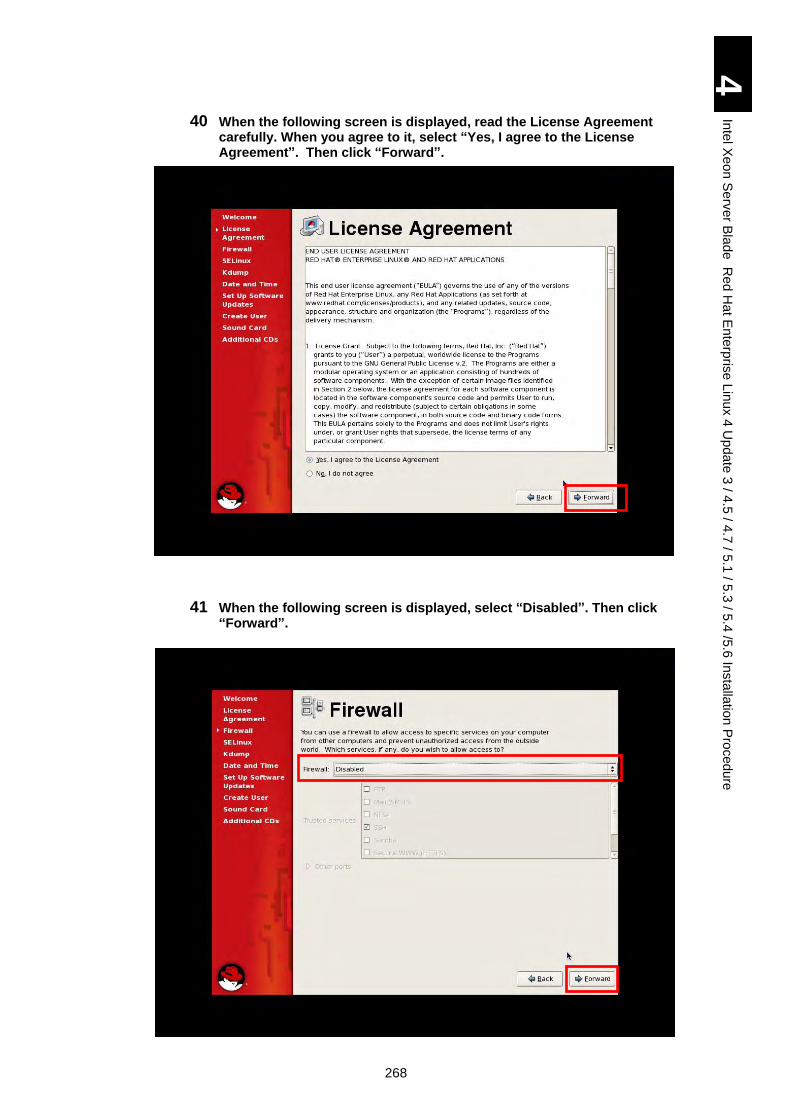
268
4
Inte
l Xe
on
Se
rver B
lad
e R
ed
Ha
t En
terp
rise L
inux 4
Up
da
te 3
/ 4.5
/ 4.7
/ 5.1
/ 5.3
/ 5.4
/5.6
Insta
llatio
n P
roced
ure
40 When the following screen is displayed, read the License Agreement carefully. When you agree to it, select “Yes, I agree to the License Agreement”. Then click “Forward”.
41 When the following screen is displayed, select “Disabled”. Then click “Forward”.
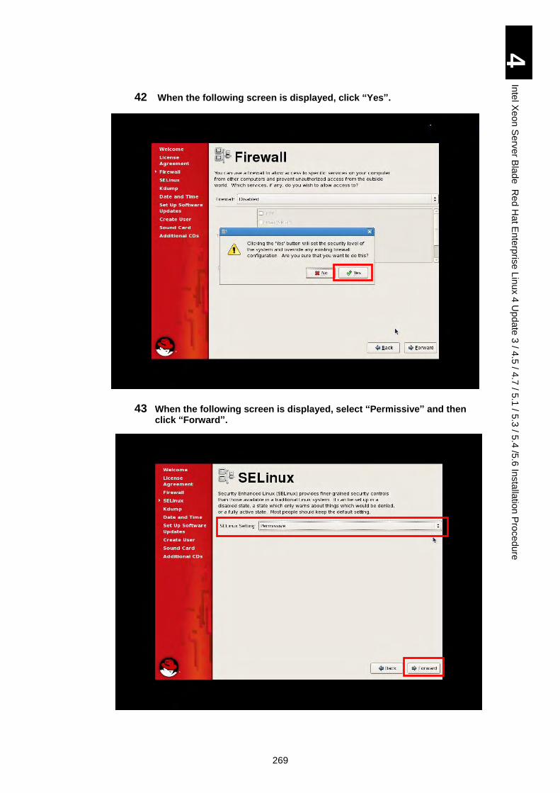
269
4
Inte
l Xe
on
Se
rver B
lad
e R
ed
Ha
t En
terp
rise L
inux 4
Up
da
te 3
/ 4.5
/ 4.7
/ 5.1
/ 5.3
/ 5.4
/5.6
Insta
llatio
n P
roced
ure
42 When the following screen is displayed, click “Yes”.
43 When the following screen is displayed, select “Permissive” and then click “Forward”.
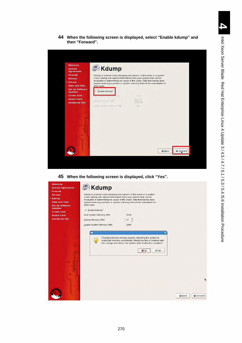
270
4
Inte
l Xe
on
Se
rver B
lad
e R
ed
Ha
t En
terp
rise L
inux 4
Up
da
te 3
/ 4.5
/ 4.7
/ 5.1
/ 5.3
/ 5.4
/5.6
Insta
llatio
n P
roced
ure
44 When the following screen is displayed, select “Enable kdump” and then “Forward”.
45 When the following screen is displayed, click “Yes”.
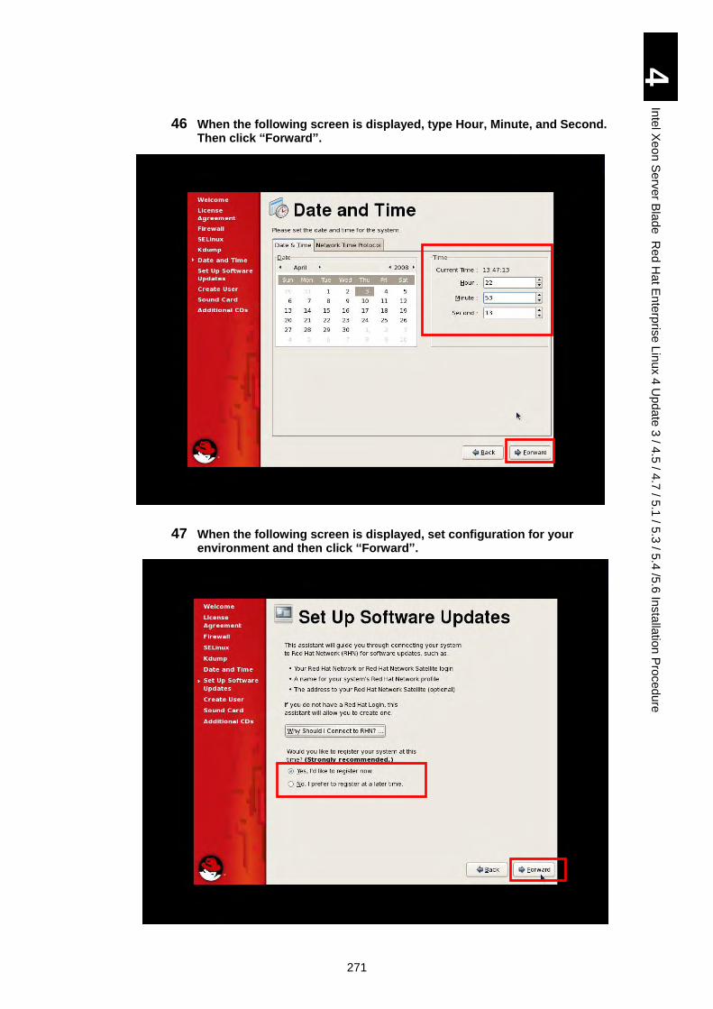
271
4
Inte
l Xe
on
Se
rver B
lad
e R
ed
Ha
t En
terp
rise L
inux 4
Up
da
te 3
/ 4.5
/ 4.7
/ 5.1
/ 5.3
/ 5.4
/5.6
Insta
llatio
n P
roced
ure
46 When the following screen is displayed, type Hour, Minute, and Second. Then click “Forward”.
47 When the following screen is displayed, set configuration for your environment and then click “Forward”.
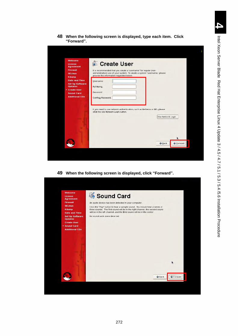
272
4
Inte
l Xe
on
Se
rver B
lad
e R
ed
Ha
t En
terp
rise L
inux 4
Up
da
te 3
/ 4.5
/ 4.7
/ 5.1
/ 5.3
/ 5.4
/5.6
Insta
llatio
n P
roced
ure
48 When the following screen is displayed, type each item. Click “Forward”.
49 When the following screen is displayed, click “Forward”.
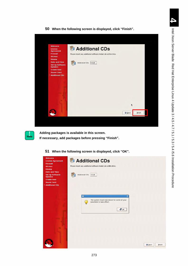
273
4
Inte
l Xe
on
Se
rver B
lad
e R
ed
Ha
t En
terp
rise L
inux 4
Up
da
te 3
/ 4.5
/ 4.7
/ 5.1
/ 5.3
/ 5.4
/5.6
Insta
llatio
n P
roced
ure
50 When the following screen is displayed, click “Finish”.
Adding packages is available in this screen.
If necessary, add packages before pressing “Finish”.
51 When the following screen is displayed, click “OK”.
! Note
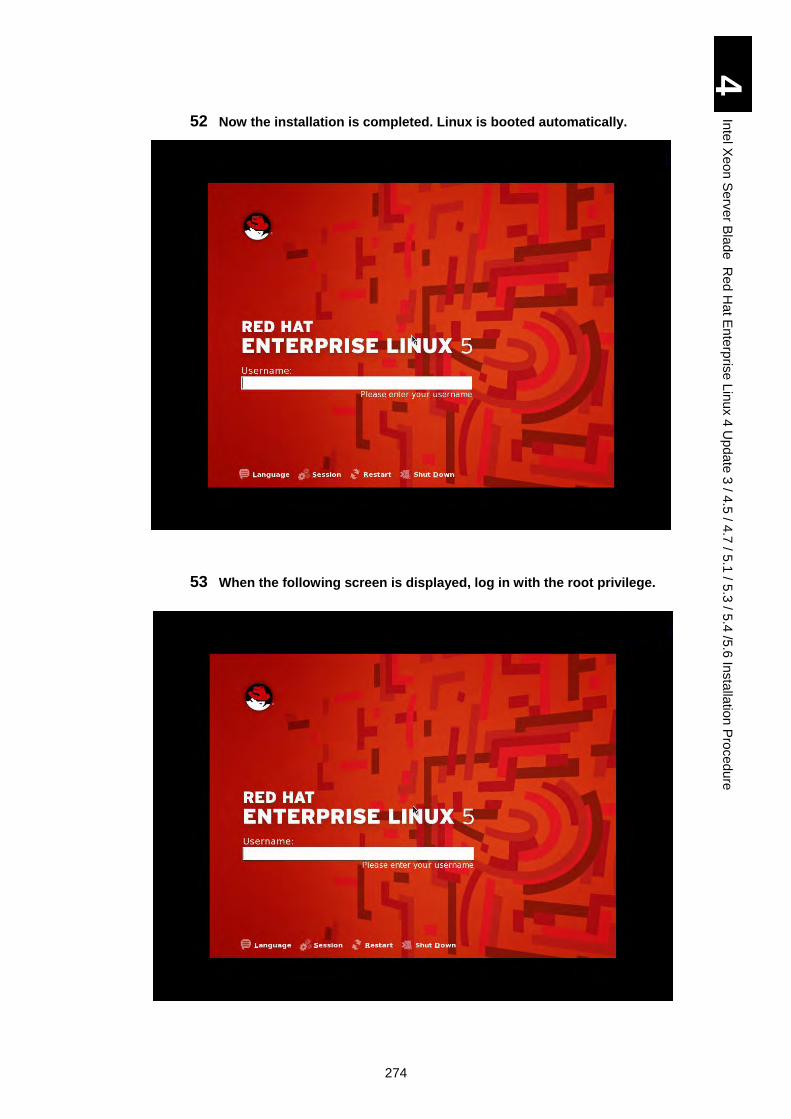
274
4
Inte
l Xe
on
Se
rver B
lad
e R
ed
Ha
t En
terp
rise L
inux 4
Up
da
te 3
/ 4.5
/ 4.7
/ 5.1
/ 5.3
/ 5.4
/5.6
Insta
llatio
n P
roced
ure
52 Now the installation is completed. Linux is booted automatically.
53 When the following screen is displayed, log in with the root privilege.
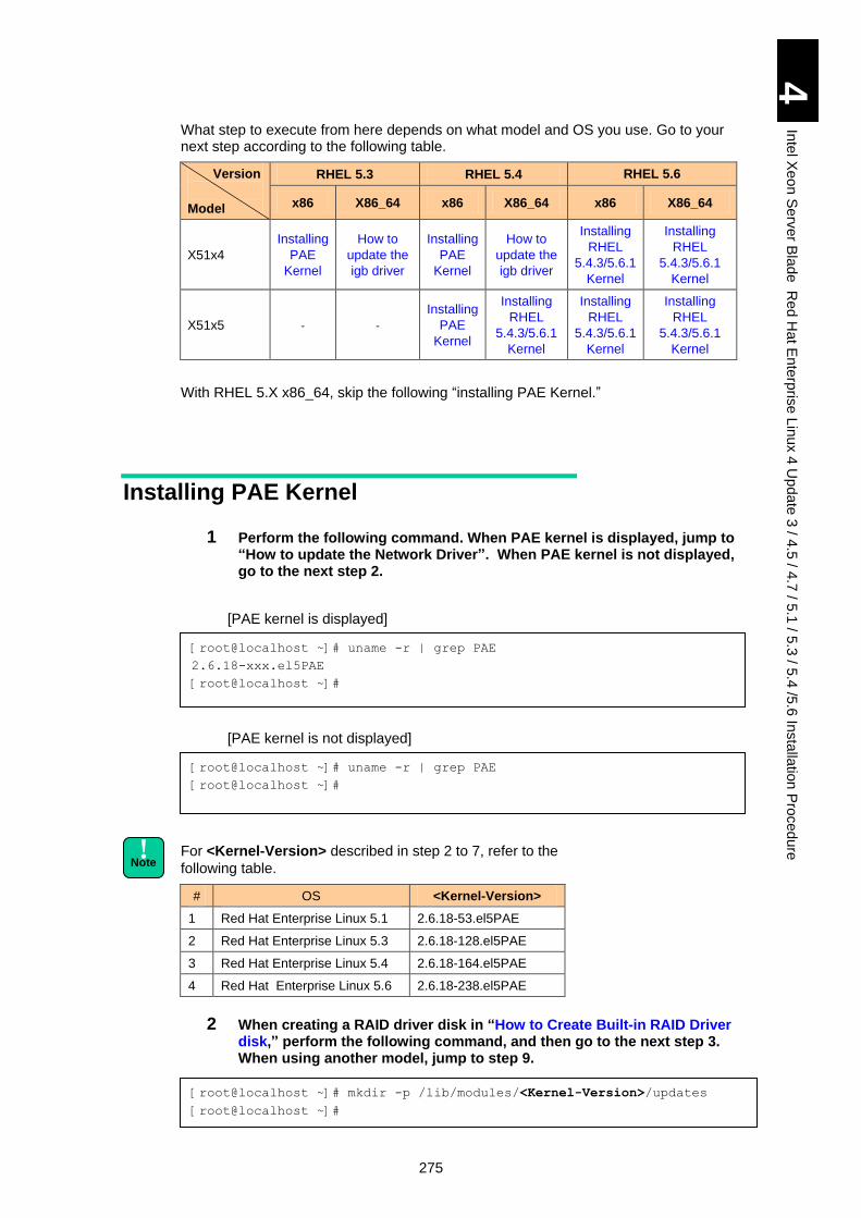
275
4
Inte
l Xe
on
Se
rver B
lad
e R
ed
Ha
t En
terp
rise L
inux 4
Up
da
te 3
/ 4.5
/ 4.7
/ 5.1
/ 5.3
/ 5.4
/5.6
Insta
llatio
n P
roced
ure
What step to execute from here depends on what model and OS you use. Go to your next step according to the following table.
Version
Model
RHEL 5.3 RHEL 5.4 RHEL 5.6
x86 X86_64 x86 X86_64 x86 X86_64
X51x4
Installing
PAE
Kernel
How to
update the
igb driver
Installing
PAE
Kernel
How to
update the
igb driver
Installing
RHEL
5.4.3/5.6.1
Kernel
Installing
RHEL
5.4.3/5.6.1
Kernel
X51x5 - -
Installing
PAE
Kernel
Installing
RHEL
5.4.3/5.6.1
Kernel
Installing
RHEL
5.4.3/5.6.1
Kernel
Installing
RHEL
5.4.3/5.6.1
Kernel
With RHEL 5.X x86_64, skip the following “installing PAE Kernel.”
Installing PAE Kernel
1 Perform the following command. When PAE kernel is displayed, jump to “How to update the Network Driver”. When PAE kernel is not displayed, go to the next step 2.
[PAE kernel is displayed]
[PAE kernel is not displayed]
For <Kernel-Version> described in step 2 to 7, refer to the
following table.
# OS <Kernel-Version>
1 Red Hat Enterprise Linux 5.1 2.6.18-53.el5PAE
2 Red Hat Enterprise Linux 5.3 2.6.18-128.el5PAE
3 Red Hat Enterprise Linux 5.4 2.6.18-164.el5PAE
4 Red Hat Enterprise Linux 5.6 2.6.18-238.el5PAE
2 When creating a RAID driver disk in “How to Create Built-in RAID Driver disk,” perform the following command, and then go to the next step 3. When using another model, jump to step 9.
[root@localhost ~]# uname -r | grep PAE
2.6.18-xxx.el5PAE
[root@localhost ~]#
[root@localhost ~]# mkdir -p /lib/modules/<Kernel-Version>/updates
[root@localhost ~]#
! Note
[root@localhost ~]# uname -r | grep PAE
[root@localhost ~]#
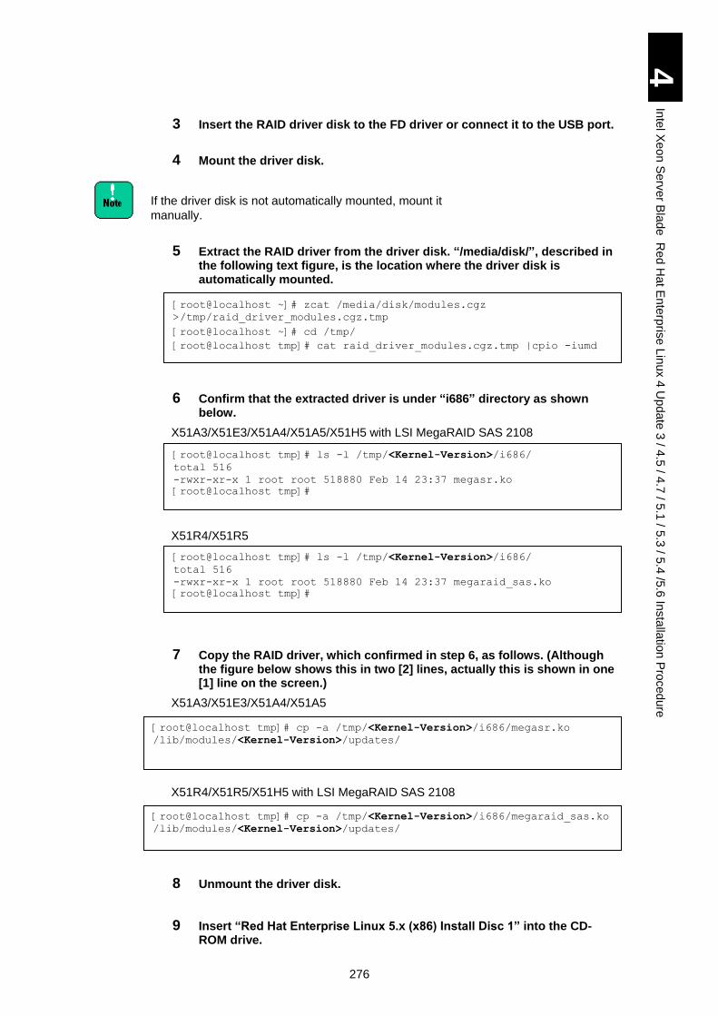
276
4
Inte
l Xe
on
Se
rver B
lad
e R
ed
Ha
t En
terp
rise L
inux 4
Up
da
te 3
/ 4.5
/ 4.7
/ 5.1
/ 5.3
/ 5.4
/5.6
Insta
llatio
n P
roced
ure
3 Insert the RAID driver disk to the FD driver or connect it to the USB port.
4 Mount the driver disk.
If the driver disk is not automatically mounted, mount it
manually.
5 Extract the RAID driver from the driver disk. “/media/disk/”, described in the following text figure, is the location where the driver disk is automatically mounted.
6 Confirm that the extracted driver is under “i686” directory as shown below.
X51A3/X51E3/X51A4/X51A5/X51H5 with LSI MegaRAID SAS 2108
X51R4/X51R5
7 Copy the RAID driver, which confirmed in step 6, as follows. (Although the figure below shows this in two [2] lines, actually this is shown in one [1] line on the screen.)
X51A3/X51E3/X51A4/X51A5
X51R4/X51R5/X51H5 with LSI MegaRAID SAS 2108
8 Unmount the driver disk.
9 Insert “Red Hat Enterprise Linux 5.x (x86) Install Disc 1” into the CD-ROM drive.
[root@localhost ~]# zcat /media/disk/modules.cgz
>/tmp/raid_driver_modules.cgz.tmp
[root@localhost ~]# cd /tmp/
[root@localhost tmp]# cat raid_driver_modules.cgz.tmp |cpio -iumd
[root@localhost tmp]# ls -l /tmp/<Kernel-Version>/i686/
total 516
-rwxr-xr-x 1 root root 518880 Feb 14 23:37 megasr.ko
[root@localhost tmp]#
[root@localhost tmp]# ls -l /tmp/<Kernel-Version>/i686/
total 516
-rwxr-xr-x 1 root root 518880 Feb 14 23:37 megaraid_sas.ko
[root@localhost tmp]#
[root@localhost tmp]# cp -a /tmp/<Kernel-Version>/i686/megasr.ko
/lib/modules/<Kernel-Version>/updates/
[root@localhost tmp]# cp -a /tmp/<Kernel-Version>/i686/megaraid_sas.ko
/lib/modules/<Kernel-Version>/updates/
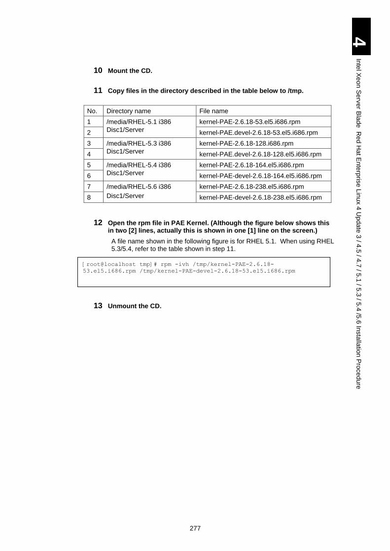
277
4
Inte
l Xe
on
Se
rver B
lad
e R
ed
Ha
t En
terp
rise L
inux 4
Up
da
te 3
/ 4.5
/ 4.7
/ 5.1
/ 5.3
/ 5.4
/5.6
Insta
llatio
n P
roced
ure
10 Mount the CD.
11 Copy files in the directory described in the table below to /tmp.
No. Directory name File name
1 /media/RHEL-5.1 i386
Disc1/Server
kernel-PAE-2.6.18-53.el5.i686.rpm
2 kernel-PAE.devel-2.6.18-53.el5.i686.rpm
3 /media/RHEL-5.3 i386
Disc1/Server
kernel-PAE-2.6.18-128.i686.rpm
4 kernel-PAE.devel-2.6.18-128.el5.i686.rpm
5 /media/RHEL-5.4 i386
Disc1/Server
kernel-PAE-2.6.18-164.el5.i686.rpm
6 kernel-PAE-devel-2.6.18-164.el5.i686.rpm
7 /media/RHEL-5.6 i386
Disc1/Server
kernel-PAE-2.6.18-238.el5.i686.rpm
8 kernel-PAE-devel-2.6.18-238.el5.i686.rpm
12 Open the rpm file in PAE Kernel. (Although the figure below shows this in two [2] lines, actually this is shown in one [1] line on the screen.)
A file name shown in the following figure is for RHEL 5.1. When using RHEL 5.3/5.4, refer to the table shown in step 11.
13 Unmount the CD.
[root@localhost tmp]# rpm -ivh /tmp/kernel-PAE-2.6.18-
53.el5.i686.rpm /tmp/kernel-PAE-devel-2.6.18-53.el5.i686.rpm
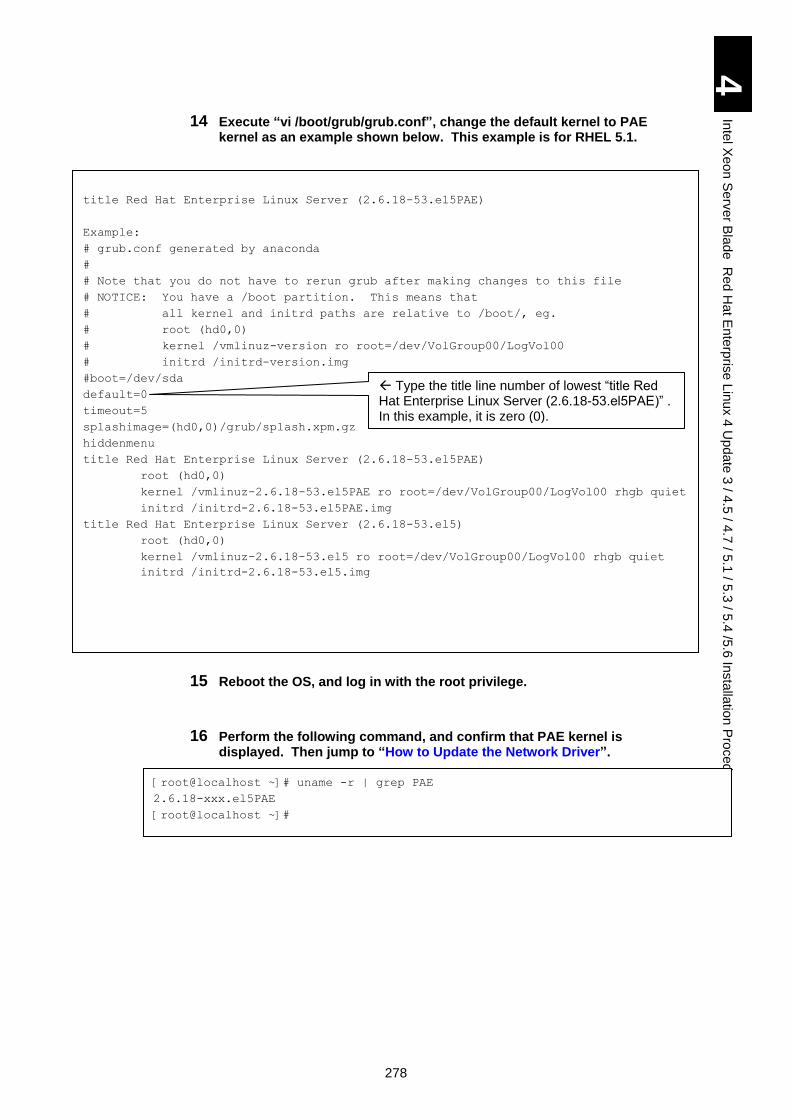
278
4
Inte
l Xe
on
Se
rver B
lad
e R
ed
Ha
t En
terp
rise L
inux 4
Up
da
te 3
/ 4.5
/ 4.7
/ 5.1
/ 5.3
/ 5.4
/5.6
Insta
llatio
n P
roced
ure
14 Execute “vi /boot/grub/grub.conf”, change the default kernel to PAE kernel as an example shown below. This example is for RHEL 5.1.
15 Reboot the OS, and log in with the root privilege.
16 Perform the following command, and confirm that PAE kernel is displayed. Then jump to “How to Update the Network Driver”.
title Red Hat Enterprise Linux Server (2.6.18-53.el5PAE)
Example:
# grub.conf generated by anaconda
#
# Note that you do not have to rerun grub after making changes to this file
# NOTICE: You have a /boot partition. This means that
# all kernel and initrd paths are relative to /boot/, eg.
# root (hd0,0)
# kernel /vmlinuz-version ro root=/dev/VolGroup00/LogVol00
# initrd /initrd-version.img
#boot=/dev/sda
default=0
timeout=5
splashimage=(hd0,0)/grub/splash.xpm.gz
hiddenmenu
title Red Hat Enterprise Linux Server (2.6.18-53.el5PAE)
root (hd0,0)
kernel /vmlinuz-2.6.18-53.el5PAE ro root=/dev/VolGroup00/LogVol00 rhgb quiet
initrd /initrd-2.6.18-53.el5PAE.img
title Red Hat Enterprise Linux Server (2.6.18-53.el5)
root (hd0,0)
kernel /vmlinuz-2.6.18-53.el5 ro root=/dev/VolGroup00/LogVol00 rhgb quiet
initrd /initrd-2.6.18-53.el5.img
[root@localhost ~]# uname -r | grep PAE
2.6.18-xxx.el5PAE
[root@localhost ~]#
Type the title line number of lowest “title Red Hat Enterprise Linux Server (2.6.18-53.el5PAE)” . In this example, it is zero (0).
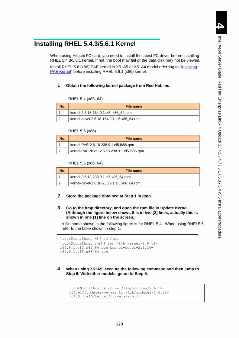
279
4
Inte
l Xe
on
Se
rver B
lad
e R
ed
Ha
t En
terp
rise L
inux 4
Up
da
te 3
/ 4.5
/ 4.7
/ 5.1
/ 5.3
/ 5.4
/5.6
Insta
llatio
n P
roced
ure
Installing RHEL 5.4.3/5.6.1 Kernel
When using Hitachi FC card, you need to install the latest FC driver before installing RHEL 5.4.3/5.6.1 kernel. If not, the boot may fail or the data disk may not be viewed.
Install RHEL 5.6 (x86) PAE kernel in X51A5 or X51A4 model referring to “Installing PAE Kernel” before installing RHEL 5.6.1 (x86) kernel.
1 Obtain the following kernel package from Red Hat, Inc.
RHEL 5.4 (x86_64)
No. File name
1 kernel-2.6.18-164.9.1.el5. x86_64.rpm
2 kernel-devel-2.6.18-164.9.1.el5.x86_64.rpm
RHEL 5.6 (x86)
No. File name
1 kernel-PAE-2.6.18-238.9.1.el5.i686.rpm
2 kernel-PAE-devel-2.6.18-238.9.1.el5.i686.rpm
RHEL 5.6 (x86_64)
No. File name
1 kernel-2.6.18-238.9.1.el5.x86_64.rpm
2 kernel-devel-2.6.18-238.9.1.el5.x86_64.rpm
2 Store the package obtained at Step 1 in /tmp.
3 Go to the /tmp directory, and open the rpm file in Update Kernel. (Although the figure below shows this in two [2] lines, actually this is shown in one [1] line on the screen.)
A file name shown in the following figure is for RHEL 5.4. When using RHEL5.6, refer to the table shown in step 1.
4 When using X51A5, execute the following command and then jump to Step 6. With other models, go on to Step 5.
[root@localhost ~]# cd /tmp
[root@localhost tmp]# rpm -ivh kernel-2.6.18-
164.9.1.el5.x86_64.rpm kernel-devel-2.6.18-
164.9.1.el5.x86_64.rpm
[root@localhost]# cp -a /lib/modules/2.6.18-
164.el5/updates/megasr.ko /lib/modules/2.6.18-
164.9.1.el5/kernel/drivers/scsi/.
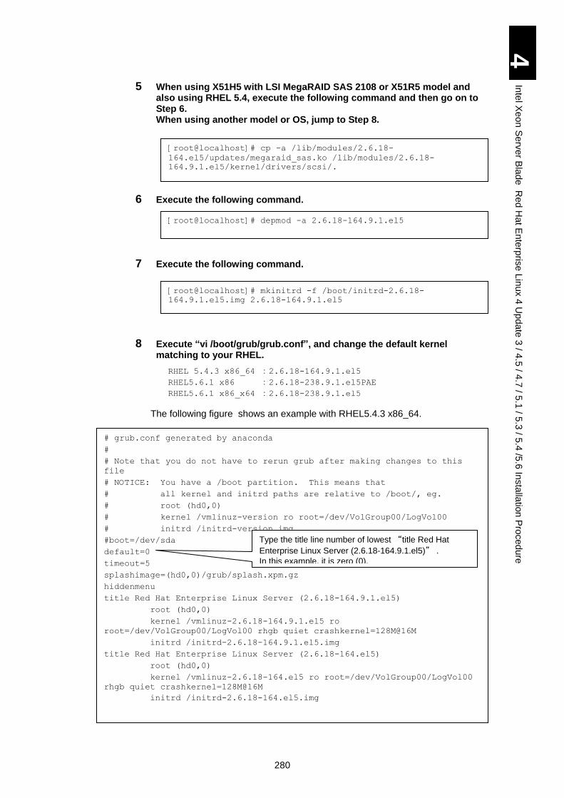
280
4
Inte
l Xe
on
Se
rver B
lad
e R
ed
Ha
t En
terp
rise L
inux 4
Up
da
te 3
/ 4.5
/ 4.7
/ 5.1
/ 5.3
/ 5.4
/5.6
Insta
llatio
n P
roced
ure
5 When using X51H5 with LSI MegaRAID SAS 2108 or X51R5 model and also using RHEL 5.4, execute the following command and then go on to Step 6. When using another model or OS, jump to Step 8.
6 Execute the following command.
7 Execute the following command.
8 Execute “vi /boot/grub/grub.conf”, and change the default kernel matching to your RHEL.
RHEL 5.4.3 x86_64 :2.6.18-164.9.1.el5
RHEL5.6.1 x86 :2.6.18-238.9.1.el5PAE
RHEL5.6.1 x86_x64 :2.6.18-238.9.1.el5
The following figure shows an example with RHEL5.4.3 x86_64.
[root@localhost]# cp -a /lib/modules/2.6.18-
164.el5/updates/megaraid_sas.ko /lib/modules/2.6.18-
164.9.1.el5/kernel/drivers/scsi/.
[root@localhost]# depmod -a 2.6.18-164.9.1.el5
[root@localhost]# mkinitrd -f /boot/initrd-2.6.18-
164.9.1.el5.img 2.6.18-164.9.1.el5
# grub.conf generated by anaconda
#
# Note that you do not have to rerun grub after making changes to this
file
# NOTICE: You have a /boot partition. This means that
# all kernel and initrd paths are relative to /boot/, eg.
# root (hd0,0)
# kernel /vmlinuz-version ro root=/dev/VolGroup00/LogVol00
# initrd /initrd-version.img
#boot=/dev/sda
default=0
timeout=5
splashimage=(hd0,0)/grub/splash.xpm.gz
hiddenmenu
title Red Hat Enterprise Linux Server (2.6.18-164.9.1.el5)
root (hd0,0)
kernel /vmlinuz-2.6.18-164.9.1.el5 ro
root=/dev/VolGroup00/LogVol00 rhgb quiet crashkernel=128M@16M
initrd /initrd-2.6.18-164.9.1.el5.img
title Red Hat Enterprise Linux Server (2.6.18-164.el5)
root (hd0,0)
kernel /vmlinuz-2.6.18-164.el5 ro root=/dev/VolGroup00/LogVol00
rhgb quiet crashkernel=128M@16M
initrd /initrd-2.6.18-164.el5.img
Type the title line number of lowest “title Red Hat
Enterprise Linux Server (2.6.18-164.9.1.el5)” .
In this example, it is zero (0).
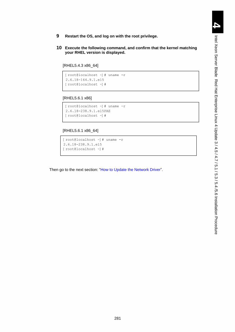
281
4
Inte
l Xe
on
Se
rver B
lad
e R
ed
Ha
t En
terp
rise L
inux 4
Up
da
te 3
/ 4.5
/ 4.7
/ 5.1
/ 5.3
/ 5.4
/5.6
Insta
llatio
n P
roced
ure
9 Restart the OS, and log on with the root privilege.
10 Execute the following command, and confirm that the kernel matching your RHEL version is displayed.
[RHEL5.4.3 x86_64]
[RHEL5.6.1 x86]
[RHEL5.6.1 x86_64]
Then go to the next section: “How to Update the Network Driver”.
[root@localhost ~]# uname -r
2.6.18-164.9.1.el5
[root@localhost ~]#
[root@localhost ~]# uname -r
2.6.18-238.9.1.el5PAE
[root@localhost ~]#
[root@localhost ~]# uname -r
2.6.18-238.9.1.el5
[root@localhost ~]#
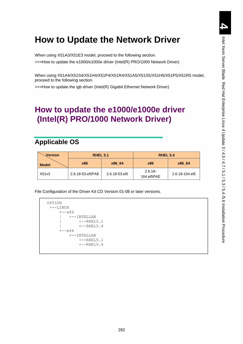
282
4
Inte
l Xe
on
Se
rver B
lad
e R
ed
Ha
t En
terp
rise L
inux 4
Up
da
te 3
/ 4.5
/ 4.7
/ 5.1
/ 5.3
/ 5.4
/5.6
Insta
llatio
n P
roced
ure
How to Update the Network Driver
When using X51A3/X51E3 model, proceed to the following section.
>>>How to update the e1000/e1000e driver (Intel(R) PRO/1000 Network Driver)
When using X51A4/X51S4/X51H4/X51P4/X51R4/X51A5/X51S5/X51H5/X51P5/X51R5 model, proceed to the following section.
>>>How to update the igb driver (Intel(R) Gigabit Ethernet Network Driver)
How to update the e1000/e1000e driver (Intel(R) PRO/1000 Network Driver)
Applicable OS
Version
Model
RHEL 5.1 RHEL 5.4
x86 x86_64 x86 x86_64
X51x3 2.6.18-53.el5PAE 2.6.18-53.el5 2.6.18-
164.el5PAE 2.6.18-164.el5
File Configuration of the Driver Kit CD Version 01-08 or later versions.
OPTION
+--LINUX
+--x86
| +--INTELLAN
| +--RHEL5.1
| +--RHEL5.4
+--x64
+--INTELLAN
+--RHEL5.1
+--RHEL5.4
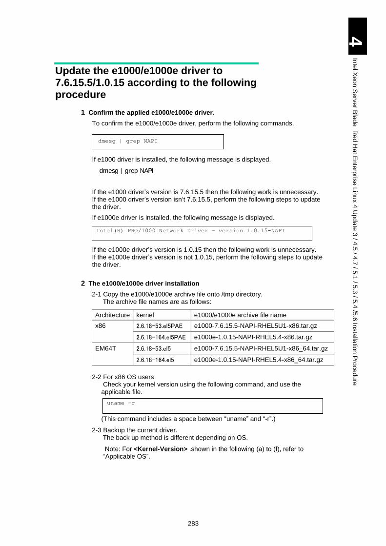
283
4
Inte
l Xe
on
Se
rver B
lad
e R
ed
Ha
t En
terp
rise L
inux 4
Up
da
te 3
/ 4.5
/ 4.7
/ 5.1
/ 5.3
/ 5.4
/5.6
Insta
llatio
n P
roced
ure
Update the e1000/e1000e driver to 7.6.15.5/1.0.15 according to the following procedure
1 Confirm the applied e1000/e1000e driver.
To confirm the e1000/e1000e driver, perform the following commands.
dmesg | grep NAPI
If e1000 driver is installed, the following message is displayed.
dmesg | grep NAPI
If the e1000 driver’s version is 7.6.15.5 then the following work is unnecessary. If the e1000 driver’s version isn‘t 7.6.15.5, perform the following steps to update the driver.
If e1000e driver is installed, the following message is displayed.
If the e1000e driver’s version is 1.0.15 then the following work is unnecessary. If the e1000e driver’s version is not 1.0.15, perform the following steps to update the driver.
2 The e1000/e1000e driver installation
2-1 Copy the e1000/e1000e archive file onto /tmp directory. The archive file names are as follows:
Architecture kernel e1000/e1000e archive file name
x86 2.6.18-53.el5PAE e1000-7.6.15.5-NAPI-RHEL5U1-x86.tar.gz
2.6.18-164.el5PAE e1000e-1.0.15-NAPI-RHEL5.4-x86.tar.gz
EM64T 2.6.18-53.el5 e1000-7.6.15.5-NAPI-RHEL5U1-x86_64.tar.gz
2.6.18-164.el5 e1000e-1.0.15-NAPI-RHEL5.4-x86_64.tar.gz
2-2 For x86 OS users
Check your kernel version using the following command, and use the applicable file. (This command includes a space between “uname” and “-r”.)
2-3 Backup the current driver. The back up method is different depending on OS. Note: For <Kernel-Version> .shown in the following (a) to (f), refer to “Applicable OS”.
Intel(R) PRO/1000 Network Driver – version 1.0.15-NAPI
uname –r
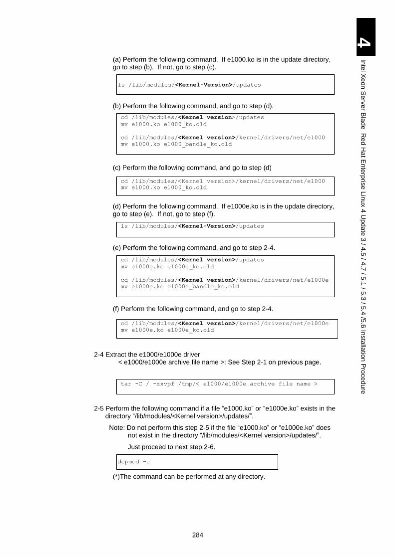
284
4
Inte
l Xe
on
Se
rver B
lad
e R
ed
Ha
t En
terp
rise L
inux 4
Up
da
te 3
/ 4.5
/ 4.7
/ 5.1
/ 5.3
/ 5.4
/5.6
Insta
llatio
n P
roced
ure
(a) Perform the following command. If e1000.ko is in the update directory, go to step (b). If not, go to step (c).
ls /lib/modules/<Kernel-Version>/updates
(b) Perform the following command, and go to step (d).
(c) Perform the following command, and go to step (d)
(d) Perform the following command. If e1000e.ko is in the update directory, go to step (e). If not, go to step (f).
(e) Perform the following command, and go to step 2-4. (f) Perform the following command, and go to step 2-4.
2-4 Extract the e1000/e1000e driver < e1000/e1000e archive file name >: See Step 2-1 on previous page.
2-5 Perform the following command if a file “e1000.ko” or “e1000e.ko” exists in the directory “/lib/modules/<Kernel version>/updates/”.
Note: Do not perform this step 2-5 if the file “e1000.ko” or “e1000e.ko” does not exist in the directory “/lib/modules/<Kernel version>/updates/”.
Just proceed to next step 2-6.
depmod -a
(*)The command can be performed at any directory.
cd /lib/modules/<Kernel version>/updates
mv e1000.ko e1000_ko.old
cd /lib/modules/<Kernel version>/kernel/drivers/net/e1000
mv e1000.ko e1000_bandle_ko.old
cd /lib/modules/<Kernel version>/kernel/drivers/net/e1000
mv e1000.ko e1000_ko.old
ls /lib/modules/<Kernel-Version>/updates
cd /lib/modules/<Kernel version>/updates
mv e1000e.ko e1000e_ko.old
cd /lib/modules/<Kernel version>/kernel/drivers/net/e1000e
mv e1000e.ko e1000e_bandle_ko.old
cd /lib/modules/<Kernel version>/kernel/drivers/net/e1000e
mv e1000e.ko e1000e_ko.old
tar -C / -zxvpf /tmp/< e1000/e1000e archive file name >
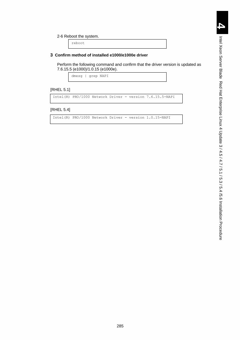
285
4
Inte
l Xe
on
Se
rver B
lad
e R
ed
Ha
t En
terp
rise L
inux 4
Up
da
te 3
/ 4.5
/ 4.7
/ 5.1
/ 5.3
/ 5.4
/5.6
Insta
llatio
n P
roced
ure
2-6 Reboot the system.
reboot
3 Confirm method of installed e1000/e1000e driver
Perform the following command and confirm that the driver version is updated as 7.6.15.5 (e1000)/1.0.15 (e1000e).
dmesg | grep NAPI
[RHEL 5.1]
[RHEL 5.4]
Intel(R) PRO/1000 Network Driver - version 7.6.15.5-NAPI
Intel(R) PRO/1000 Network Driver - version 1.0.15-NAPI
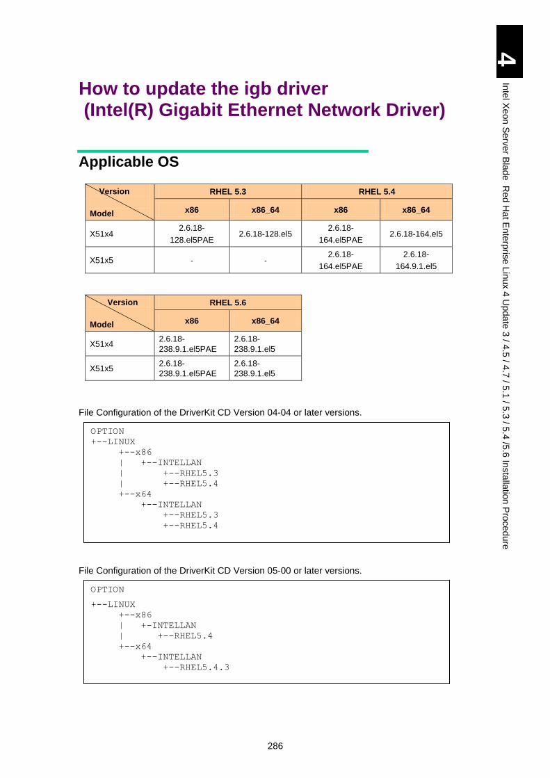
286
4
Inte
l Xe
on
Se
rver B
lad
e R
ed
Ha
t En
terp
rise L
inux 4
Up
da
te 3
/ 4.5
/ 4.7
/ 5.1
/ 5.3
/ 5.4
/5.6
Insta
llatio
n P
roced
ure
How to update the igb driver (Intel(R) Gigabit Ethernet Network Driver)
Applicable OS
Version
Model
RHEL 5.3 RHEL 5.4
x86 x86_64 x86 x86_64
X51x4 2.6.18-
128.el5PAE 2.6.18-128.el5
2.6.18-
164.el5PAE 2.6.18-164.el5
X51x5 - - 2.6.18-
164.el5PAE
2.6.18-
164.9.1.el5
Version
Model
RHEL 5.6
x86 x86_64
X51x4 2.6.18-
238.9.1.el5PAE
2.6.18-
238.9.1.el5
X51x5 2.6.18-
238.9.1.el5PAE
2.6.18-
238.9.1.el5
File Configuration of the DriverKit CD Version 04-04 or later versions.
File Configuration of the DriverKit CD Version 05-00 or later versions.
OPTION
+--LINUX
+--x86
| +--INTELLAN
| +--RHEL5.3
| +--RHEL5.4
+--x64
+--INTELLAN
+--RHEL5.3
+--RHEL5.4
OPTION
+--LINUX
+--x86
| +-INTELLAN
| +--RHEL5.4
+--x64
+--INTELLAN
+--RHEL5.4.3
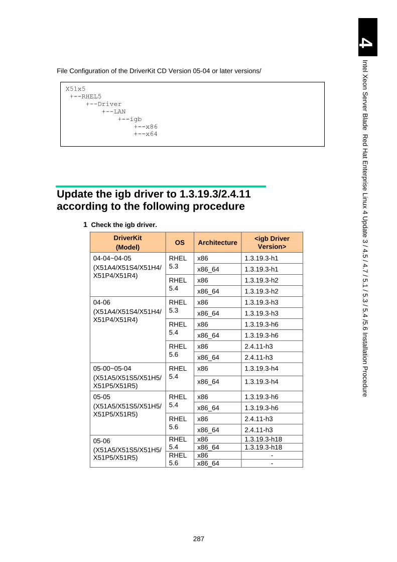
287
4
Inte
l Xe
on
Se
rver B
lad
e R
ed
Ha
t En
terp
rise L
inux 4
Up
da
te 3
/ 4.5
/ 4.7
/ 5.1
/ 5.3
/ 5.4
/5.6
Insta
llatio
n P
roced
ure
File Configuration of the DriverKit CD Version 05-04 or later versions/
Update the igb driver to 1.3.19.3/2.4.11 according to the following procedure
1 Check the igb driver.
DriverKit
(Model) OS Architecture
<igb Driver
Version>
04-04~04-05
(X51A4/X51S4/X51H4/
X51P4/X51R4)
RHEL
5.3
x86 1.3.19.3-h1
x86_64 1.3.19.3-h1
RHEL
5.4
x86 1.3.19.3-h2
x86_64 1.3.19.3-h2
04-06
(X51A4/X51S4/X51H4/
X51P4/X51R4)
RHEL
5.3
x86 1.3.19.3-h3
x86_64 1.3.19.3-h3
RHEL
5.4
x86 1.3.19.3-h6
x86_64 1.3.19.3-h6
RHEL
5.6
x86 2.4.11-h3
x86_64 2.4.11-h3
05-00~05-04
(X51A5/X51S5/X51H5/
X51P5/X51R5)
RHEL
5.4
x86 1.3.19.3-h4
x86_64 1.3.19.3-h4
05-05
(X51A5/X51S5/X51H5/
X51P5/X51R5)
RHEL
5.4
x86 1.3.19.3-h6
x86_64 1.3.19.3-h6
RHEL
5.6
x86 2.4.11-h3
x86_64 2.4.11-h3
05-06
(X51A5/X51S5/X51H5/X51P5/X51R5)
RHEL 5.4
x86 1.3.19.3-h18
x86_64 1.3.19.3-h18
RHEL 5.6
x86 -
x86_64 -
X51x5
+--RHEL5
+--Driver
+--LAN
+--igb
+--x86
+--x64
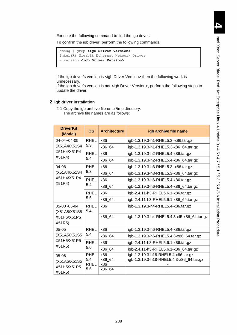
288
4
Inte
l Xe
on
Se
rver B
lad
e R
ed
Ha
t En
terp
rise L
inux 4
Up
da
te 3
/ 4.5
/ 4.7
/ 5.1
/ 5.3
/ 5.4
/5.6
Insta
llatio
n P
roced
ure
Execute the following command to find the igb driver.
To confirm the igb driver, perform the following commands.
If the igb driver’s version is <igb Driver Version> then the following work is unnecessary. If the igb driver’s version is not <igb Driver Version>, perform the following steps to update the driver.
2 igb driver installation
2-1 Copy the igb archive file onto /tmp directory. The archive file names are as follows:
DriverKit
(Model) OS Architecture igb archive file name
04-04~04-05
(X51A4/X51S4
X51H4/X51P4
X51R4)
RHEL
5.3
x86 igb-1.3.19.3-h1-RHEL5.3 -x86.tar.gz
x86_64 igb-1.3.19.3-h1-RHEL5.3-x86_64.tar.gz
RHEL
5.4
x86 igb-1.3.19.3-h2-RHEL5.4-x86.tar.gz
x86_64 igb-1.3.19.3-h2-RHEL5.4-x86_64.tar.gz
04-06
(X51A4/X51S4
X51H4/X51P4
X51R4)
RHEL
5.3
x86 igb-1.3.19.3-h3-RHEL5.3 -x86.tar.gz
x86_64 igb-1.3.19.3-h3-RHEL5.3-x86_64.tar.gz
RHEL
5.4
x86 igb-1.3.19.3-h6-RHEL5.4-x86.tar.gz
x86_64 igb-1.3.19.3-h6-RHEL5.4-x86_64.tar.gz
RHEL
5.6
x86 igb-2.4.11-h3-RHEL5.6.1-x86.tar.gz
x86_64 igb-2.4.11-h3-RHEL5.6.1-x86_64.tar.gz
05-00~05-04
(X51A5/X51S5
X51H5/X51P5
X51R5)
RHEL
5.4
x86 igb-1.3.19.3-h4-RHEL5.4-x86.tar.gz
x86_64 igb-1.3.19.3-h4-RHEL5.4.3-el5-x86_64.tar.gz
05-05
(X51A5/X51S5
X51H5/X51P5
X51R5)
RHEL
5.4
x86 igb-1.3.19.3-h6-RHEL5.4-x86.tar.gz
x86_64 igb-1.3.19.3-h6-RHEL5.4.3-x86_64.tar.gz
RHEL
5.6
x86 igb-2.4.11-h3-RHEL5.6.1-x86.tar.gz
x86_64 igb-2.4.11-h3-RHEL5.6.1-x86_64.tar.gz
05-06
(X51A5/X51S5
X51H5/X51P5
X51R5)
RHEL 5.4
x86 igb-1.3.19.3-h18-RHEL5.4-x86.tar.gz
x86_64 igb-1.3.19.3-h18-RHEL5.4.3-x86_64.tar.gz
RHEL 5.6
x86 -
x86_64 -
dmesg | grep <igb Driver Version>
Intel(R) Gigabit Ethernet Network Driver
– version <igb Driver Version>
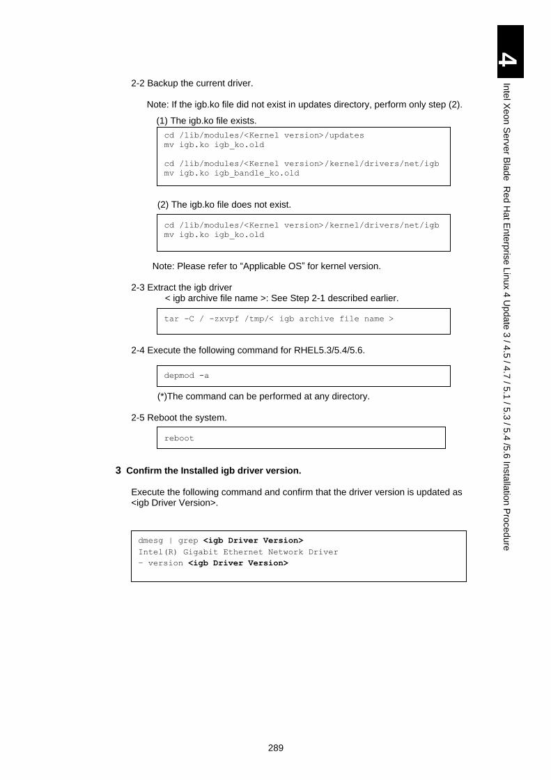
289
4
Inte
l Xe
on
Se
rver B
lad
e R
ed
Ha
t En
terp
rise L
inux 4
Up
da
te 3
/ 4.5
/ 4.7
/ 5.1
/ 5.3
/ 5.4
/5.6
Insta
llatio
n P
roced
ure
2-2 Backup the current driver.
Note: If the igb.ko file did not exist in updates directory, perform only step (2).
(1) The igb.ko file exists.
cd /lib/modules/<Kernel version>/updates
mv igb.ko igb_ko.old
cd /lib/modules/<Kernel version>/kernel/drivers/net/igb
mv igb.ko igb_bandle_ko.old
(2) The igb.ko file does not exist.
cd /lib/modules/<Kernel version>/kernel/drivers/net/igb
mv igb.ko igb_ko.old
Note: Please refer to “Applicable OS” for kernel version.
2-3 Extract the igb driver < igb archive file name >: See Step 2-1 described earlier.
tar -C / -zxvpf /tmp/< igb archive file name >
2-4 Execute the following command for RHEL5.3/5.4/5.6.
depmod -a
(*)The command can be performed at any directory.
2-5 Reboot the system.
reboot
3 Confirm the Installed igb driver version.
Execute the following command and confirm that the driver version is updated as <igb Driver Version>.
dmesg | grep <igb Driver Version>
Intel(R) Gigabit Ethernet Network Driver
– version <igb Driver Version>
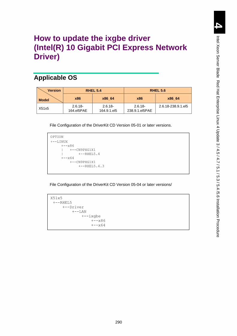
290
4
Inte
l Xe
on
Se
rver B
lad
e R
ed
Ha
t En
terp
rise L
inux 4
Up
da
te 3
/ 4.5
/ 4.7
/ 5.1
/ 5.3
/ 5.4
/5.6
Insta
llatio
n P
roced
ure
How to update the ixgbe driver (Intel(R) 10 Gigabit PCI Express Network Driver)
Applicable OS
Version
Model
RHEL 5.4 RHEL 5.6
x86 x86_64 x86 x86_64
X51x5 2.6.18-
164.el5PAE
2.6.18-
164.9.1.el5
2.6.18-
238.9.1.el5PAE
2.6.18-238.9.1.el5
File Configuration of the DriverKit CD Version 05-01 or later versions.
File Configuration of the DriverKit CD Version 05-04 or later versions/
OPTION
+--LINUX
+--x86
| +--CN9PXG1X1
| +--RHEL5.4
+--x64
+--CN9PXG1X1
+--RHEL5.4.3
X51x5
+--RHEL5
+--Driver
+--LAN
+--ixgbe
+--x86
+--x64
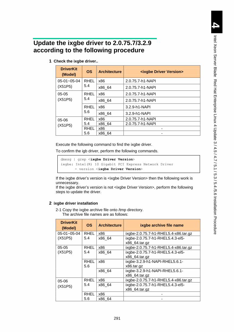
291
4
Inte
l Xe
on
Se
rver B
lad
e R
ed
Ha
t En
terp
rise L
inux 4
Up
da
te 3
/ 4.5
/ 4.7
/ 5.1
/ 5.3
/ 5.4
/5.6
Insta
llatio
n P
roced
ure
Update the ixgbe driver to 2.0.75.7/3.2.9 according to the following procedure
1 Check the ixgbe driver..
DriverKit
(Model) OS Architecture <ixgbe Driver Version>
05-01~05-04
(X51P5)
RHEL
5.4
x86 2.0.75.7-h1-NAPI
x86_64 2.0.75.7-h1-NAPI
05-05
(X51P5)
RHEL
5.4
x86 2.0.75.7-h1-NAPI
x86_64 2.0.75.7-h1-NAPI
RHEL
5.6
x86 3.2.9-h1-NAPI
x86_64 3.2.9-h1-NAPI
05-06
(X51P5)
RHEL 5.4
x86 2.0.75.7-h1-NAPI
x86_64 2.0.75.7-h1-NAPI
RHEL 5.6
x86 -
x86_64 -
Execute the following command to find the ixgbe driver.
To confirm the igb driver, perform the following commands.
If the ixgbe driver’s version is <ixgbe Driver Version> then the following work is unnecessary. If the ixgbe driver’s version is not <ixgbe Driver Version>, perform the following steps to update the driver.
2 ixgbe driver installation
2-1 Copy the ixgbe archive file onto /tmp directory. The archive file names are as follows:
DriverKit
(Model) OS Architecture ixgbe archive file name
05-01~05-04 (X51P5)
RHEL 5.4
x86 ixgbe-2.0.75.7-h1-RHEL5.4-x86.tar.gz
x86_64 ixgbe-2.0.75.7-h1-RHEL5.4.3-el5-x86_64.tar.gz
05-05 (X51P5)
RHEL 5.4
x86 ixgbe-2.0.75.7-h1-RHEL5.4-x86.tar.gz
x86_64 ixgbe-2.0.75.7-h1-RHEL5.4.3-el5-x86_64.tar.gz
RHEL 5.6
x86 ixgbe-3.2.9-h1-NAPI-RHEL5.6.1-x86.tar.gz
x86_64 ixgbe-3.2.9-h1-NAPI-RHEL5.6.1-x86_64.tar.gz
05-06
(X51P5)
RHEL 5.4
x86 ixgbe-2.0.75.7-h1-RHEL5.4-x86.tar.gz
x86_64 ixgbe-2.0.75.7-h1-RHEL5.4.3-el5-x86_64.tar.gz
RHEL 5.6
x86 -
x86_64 -
dmesg | grep <ixgbe Driver Version>
ixgbe: Intel(R) 10 Gigabit PCI Express Network Driver
- version <ixgbe Driver Version>
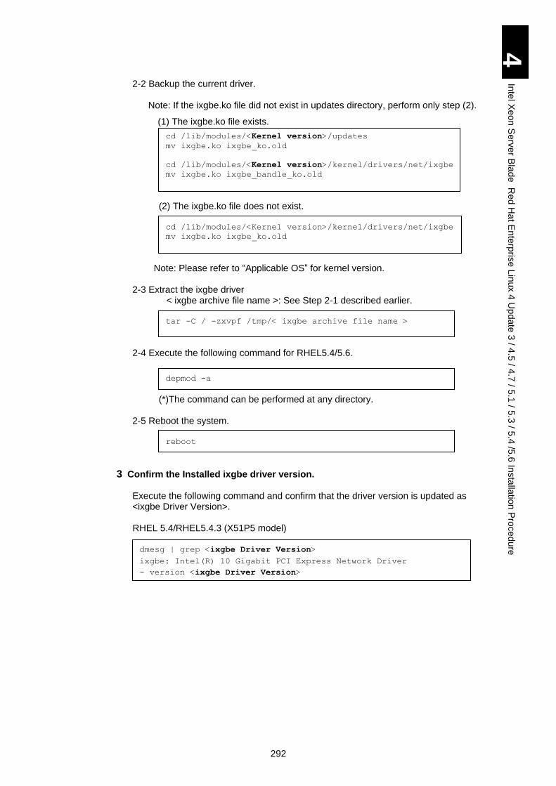
292
4
Inte
l Xe
on
Se
rver B
lad
e R
ed
Ha
t En
terp
rise L
inux 4
Up
da
te 3
/ 4.5
/ 4.7
/ 5.1
/ 5.3
/ 5.4
/5.6
Insta
llatio
n P
roced
ure
2-2 Backup the current driver.
Note: If the ixgbe.ko file did not exist in updates directory, perform only step (2).
(1) The ixgbe.ko file exists.
cd /lib/modules/<Kernel version>/updates
mv ixgbe.ko ixgbe_ko.old
cd /lib/modules/<Kernel version>/kernel/drivers/net/ixgbe
mv ixgbe.ko ixgbe_bandle_ko.old
(2) The ixgbe.ko file does not exist.
cd /lib/modules/<Kernel version>/kernel/drivers/net/ixgbe
mv ixgbe.ko ixgbe_ko.old
Note: Please refer to “Applicable OS” for kernel version.
2-3 Extract the ixgbe driver < ixgbe archive file name >: See Step 2-1 described earlier.
tar -C / -zxvpf /tmp/< ixgbe archive file name >
2-4 Execute the following command for RHEL5.4/5.6.
depmod -a
(*)The command can be performed at any directory.
2-5 Reboot the system.
reboot
3 Confirm the Installed ixgbe driver version.
Execute the following command and confirm that the driver version is updated as <ixgbe Driver Version>.
RHEL 5.4/RHEL5.4.3 (X51P5 model)
dmesg | grep <ixgbe Driver Version>
ixgbe: Intel(R) 10 Gigabit PCI Express Network Driver
- version <ixgbe Driver Version>
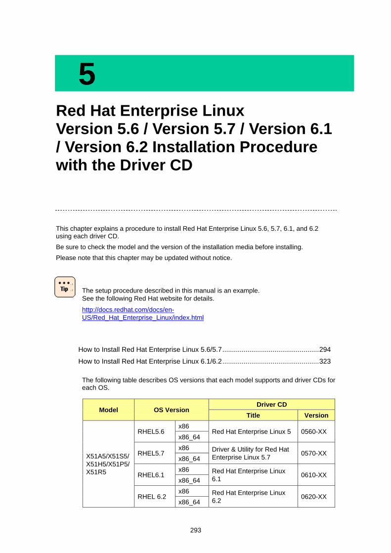
293
5 Red Hat Enterprise Linux Version 5.6 / Version 5.7 / Version 6.1 / Version 6.2 Installation Procedure with the Driver CD
This chapter explains a procedure to install Red Hat Enterprise Linux 5.6, 5.7, 6.1, and 6.2 using each driver CD.
Be sure to check the model and the version of the installation media before installing.
Please note that this chapter may be updated without notice.
The setup procedure described in this manual is an example.
See the following Red Hat website for details.
http://docs.redhat.com/docs/en-
US/Red_Hat_Enterprise_Linux/index.html
How to Install Red Hat Enterprise Linux 5.6/5.7 .................................................. 294
How to Install Red Hat Enterprise Linux 6.1/6.2 .................................................. 323
The following table describes OS versions that each model supports and driver CDs for each OS.
Model OS Version Driver CD
Title Version
X51A5/X51S5/
X51H5/X51P5/
X51R5
RHEL5.6 x86
Red Hat Enterprise Linux 5 0560-XX x86_64
RHEL5.7 x86 Driver & Utility for Red Hat
Enterprise Linux 5.7 0570-XX
x86_64
RHEL6.1 x86 Red Hat Enterprise Linux
6.1 0610-XX
x86_64
RHEL 6.2 x86 Red Hat Enterprise Linux
6.2 0620-XX
x86_64
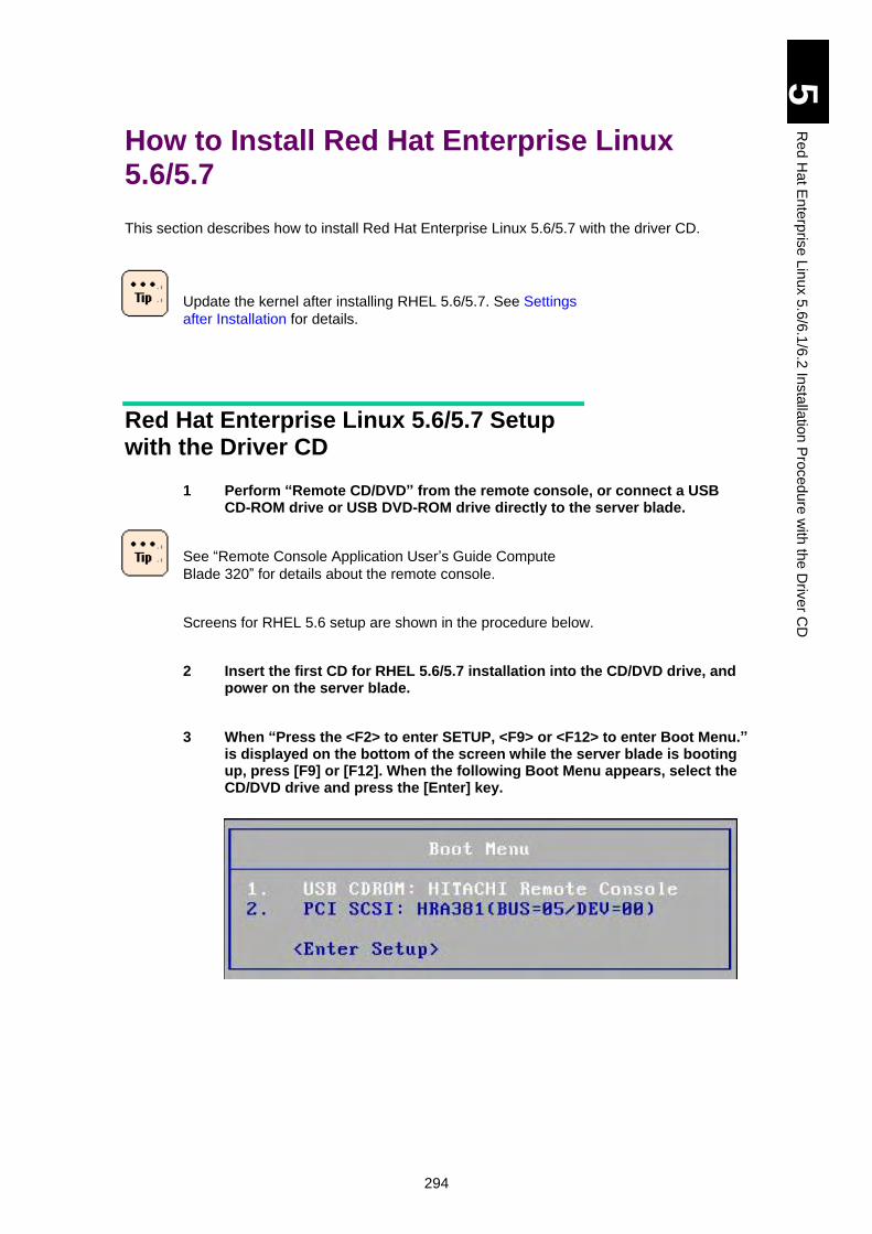
294
5
Re
d H
at E
nte
rpris
e L
inux 5
.6/6
.1/6
.2 In
sta
llatio
n P
roced
ure
with
the
Driv
er C
D
How to Install Red Hat Enterprise Linux 5.6/5.7
This section describes how to install Red Hat Enterprise Linux 5.6/5.7 with the driver CD.
Update the kernel after installing RHEL 5.6/5.7. See Settings
after Installation for details.
Red Hat Enterprise Linux 5.6/5.7 Setup with the Driver CD
1 Perform “Remote CD/DVD” from the remote console, or connect a USB CD-ROM drive or USB DVD-ROM drive directly to the server blade.
See “Remote Console Application User’s Guide Compute
Blade 320” for details about the remote console.
Screens for RHEL 5.6 setup are shown in the procedure below.
2 Insert the first CD for RHEL 5.6/5.7 installation into the CD/DVD drive, and power on the server blade.
3 When “Press the <F2> to enter SETUP, <F9> or <F12> to enter Boot Menu.” is displayed on the bottom of the screen while the server blade is booting up, press [F9] or [F12]. When the following Boot Menu appears, select the CD/DVD drive and press the [Enter] key.
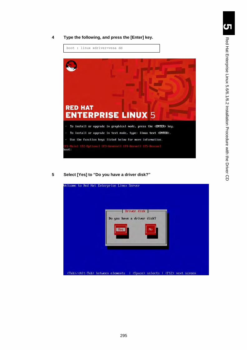
295
5
Re
d H
at E
nte
rpris
e L
inux 5
.6/6
.1/6
.2 In
sta
llatio
n P
roced
ure
with
the
Driv
er C
D
4 Type the following, and press the [Enter] key.
5 Select [Yes] to “Do you have a driver disk?”
boot : linux xdriver=vesa dd
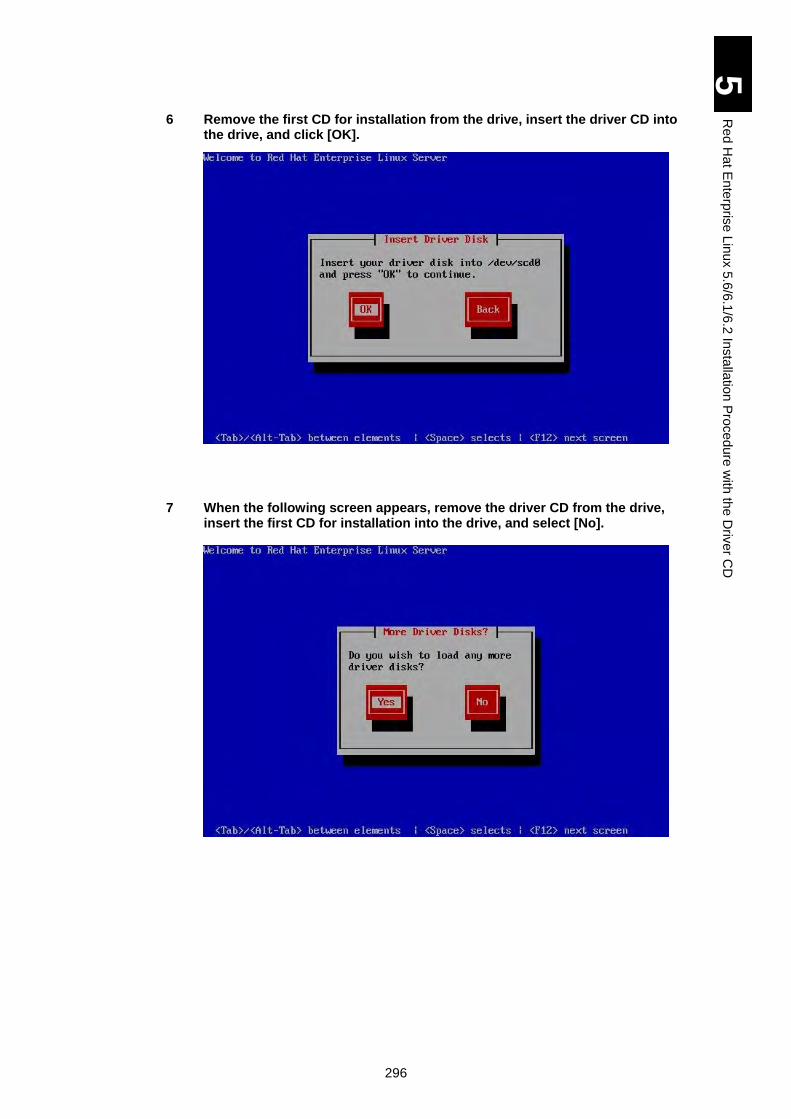
296
5
Re
d H
at E
nte
rpris
e L
inux 5
.6/6
.1/6
.2 In
sta
llatio
n P
roced
ure
with
the
Driv
er C
D
6 Remove the first CD for installation from the drive, insert the driver CD into the drive, and click [OK].
7 When the following screen appears, remove the driver CD from the drive, insert the first CD for installation into the drive, and select [No].
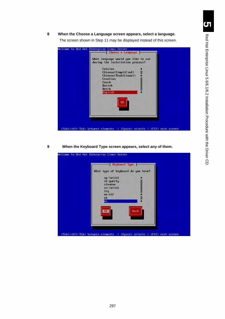
297
5
Re
d H
at E
nte
rpris
e L
inux 5
.6/6
.1/6
.2 In
sta
llatio
n P
roced
ure
with
the
Driv
er C
D
8 When the Choose a Language screen appears, select a language.
The screen shown in Step 11 may be displayed instead of this screen.
9 When the Keyboard Type screen appears, select any of them.
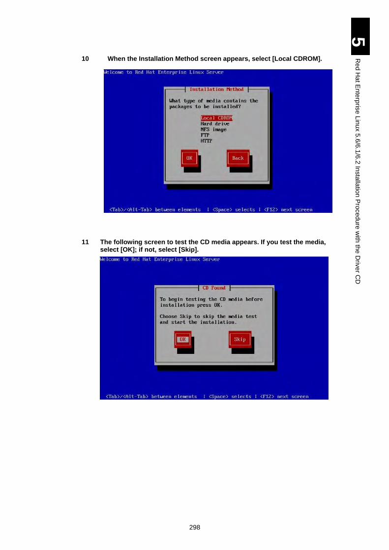
298
5
Re
d H
at E
nte
rpris
e L
inux 5
.6/6
.1/6
.2 In
sta
llatio
n P
roced
ure
with
the
Driv
er C
D
10 When the Installation Method screen appears, select [Local CDROM].
11 The following screen to test the CD media appears. If you test the media, select [OK]; if not, select [Skip].
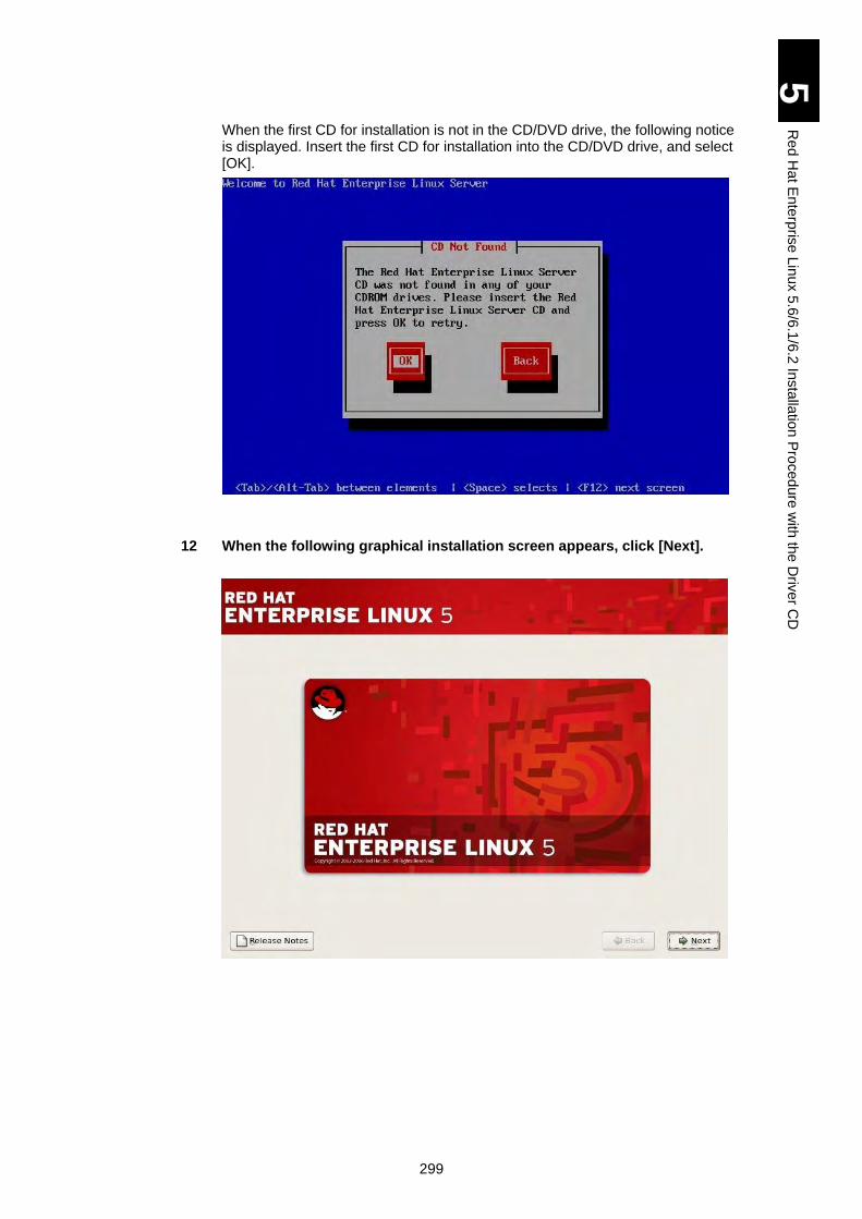
299
5
Re
d H
at E
nte
rpris
e L
inux 5
.6/6
.1/6
.2 In
sta
llatio
n P
roced
ure
with
the
Driv
er C
D
When the first CD for installation is not in the CD/DVD drive, the following notice is displayed. Insert the first CD for installation into the CD/DVD drive, and select [OK].
12 When the following graphical installation screen appears, click [Next].
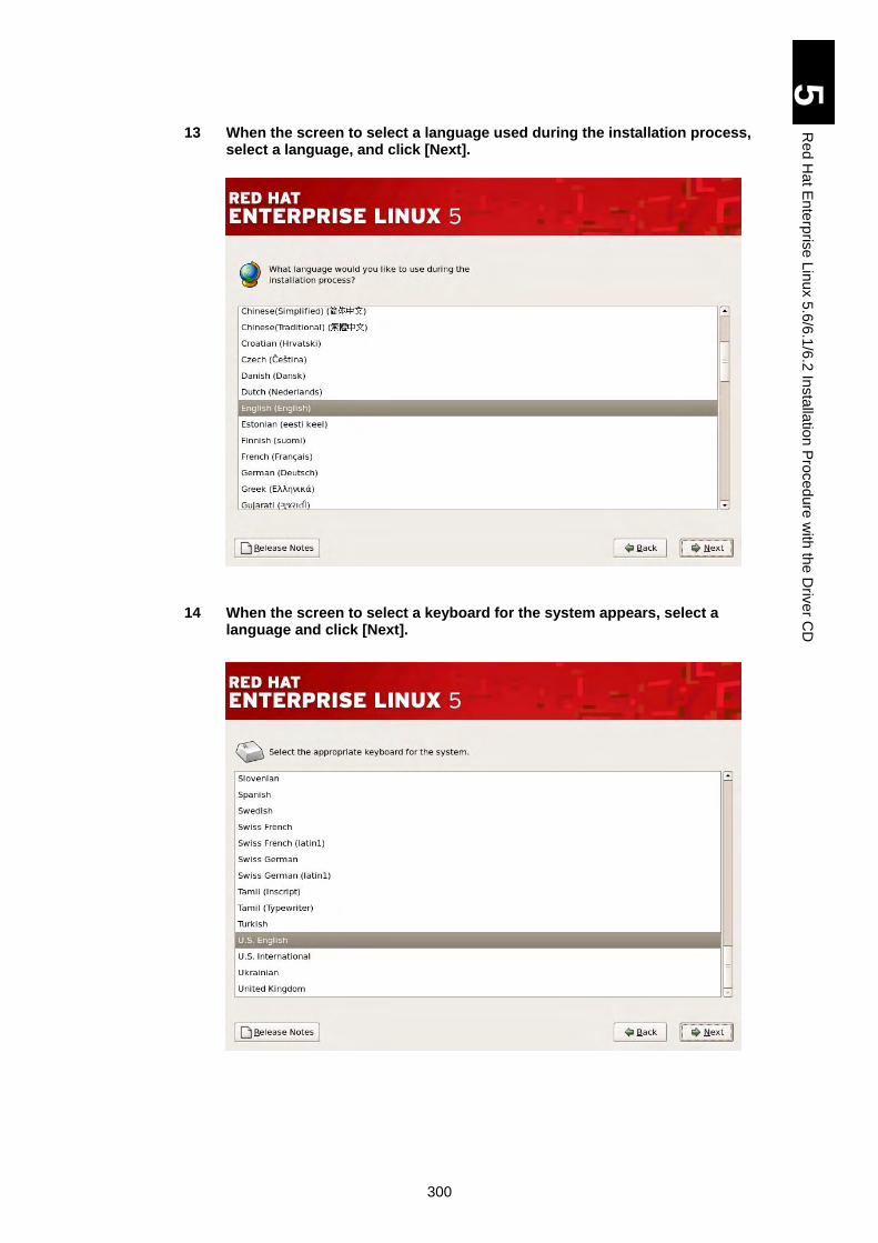
300
5
Re
d H
at E
nte
rpris
e L
inux 5
.6/6
.1/6
.2 In
sta
llatio
n P
roced
ure
with
the
Driv
er C
D
13 When the screen to select a language used during the installation process, select a language, and click [Next].
14 When the screen to select a keyboard for the system appears, select a language and click [Next].
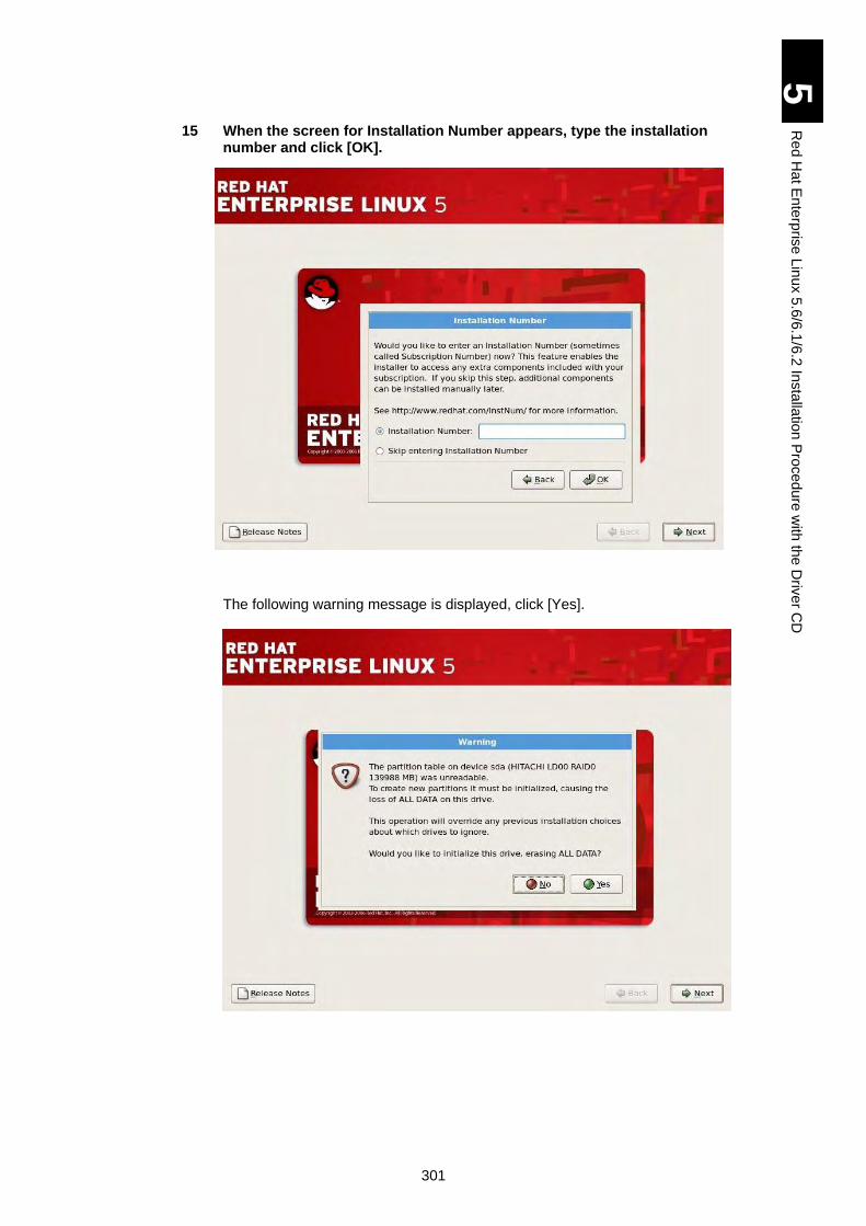
301
5
Re
d H
at E
nte
rpris
e L
inux 5
.6/6
.1/6
.2 In
sta
llatio
n P
roced
ure
with
the
Driv
er C
D
15 When the screen for Installation Number appears, type the installation number and click [OK].
The following warning message is displayed, click [Yes].
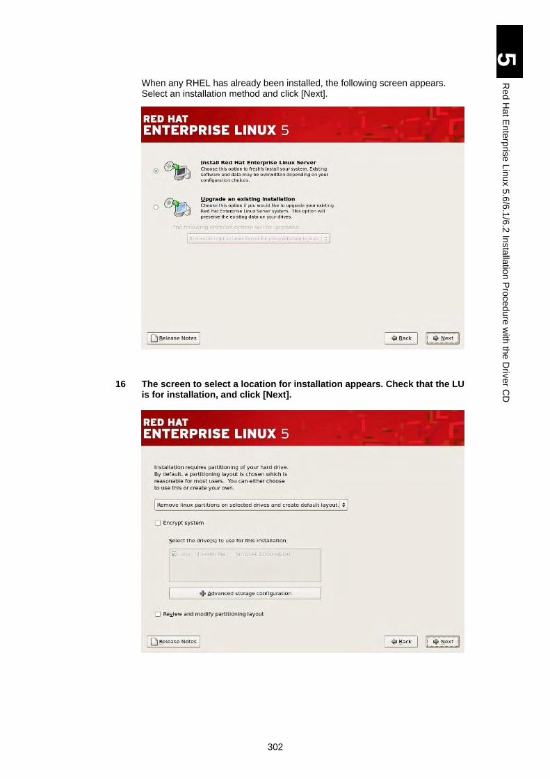
302
5
Re
d H
at E
nte
rpris
e L
inux 5
.6/6
.1/6
.2 In
sta
llatio
n P
roced
ure
with
the
Driv
er C
D
When any RHEL has already been installed, the following screen appears. Select an installation method and click [Next].
16 The screen to select a location for installation appears. Check that the LU is for installation, and click [Next].
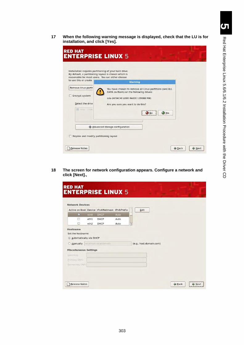
303
5
Re
d H
at E
nte
rpris
e L
inux 5
.6/6
.1/6
.2 In
sta
llatio
n P
roced
ure
with
the
Driv
er C
D
17 When the following warning message is displayed, check that the LU is for installation, and click [Yes].
18 The screen for network configuration appears. Configure a network and click [Next].,
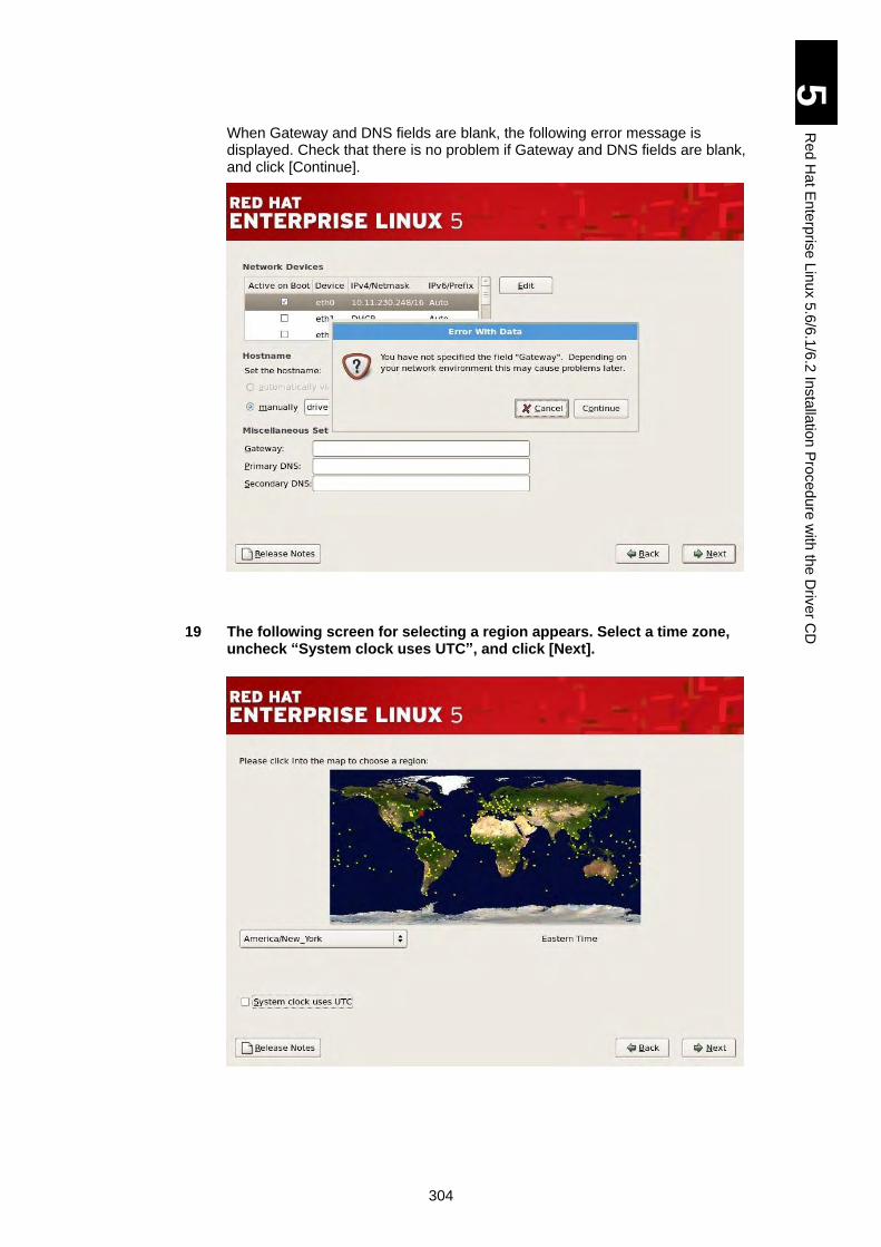
304
5
Re
d H
at E
nte
rpris
e L
inux 5
.6/6
.1/6
.2 In
sta
llatio
n P
roced
ure
with
the
Driv
er C
D
When Gateway and DNS fields are blank, the following error message is displayed. Check that there is no problem if Gateway and DNS fields are blank, and click [Continue].
19 The following screen for selecting a region appears. Select a time zone, uncheck “System clock uses UTC”, and click [Next].
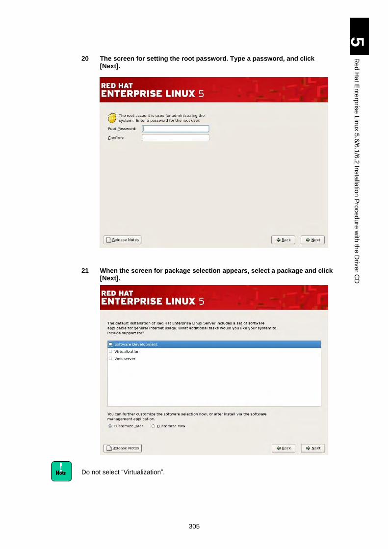
305
5
Re
d H
at E
nte
rpris
e L
inux 5
.6/6
.1/6
.2 In
sta
llatio
n P
roced
ure
with
the
Driv
er C
D
20 The screen for setting the root password. Type a password, and click [Next].
21 When the screen for package selection appears, select a package and click [Next].
Do not select “Virtualization”.
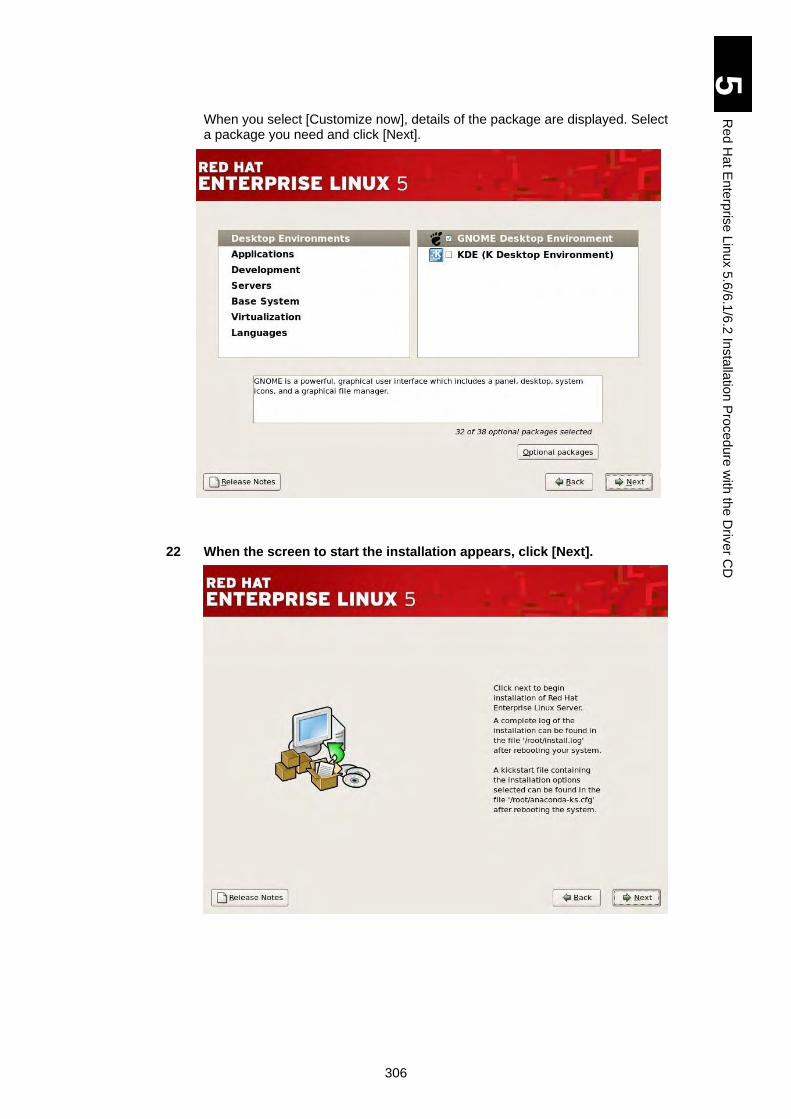
306
5
Re
d H
at E
nte
rpris
e L
inux 5
.6/6
.1/6
.2 In
sta
llatio
n P
roced
ure
with
the
Driv
er C
D
When you select [Customize now], details of the package are displayed. Select a package you need and click [Next].
22 When the screen to start the installation appears, click [Next].
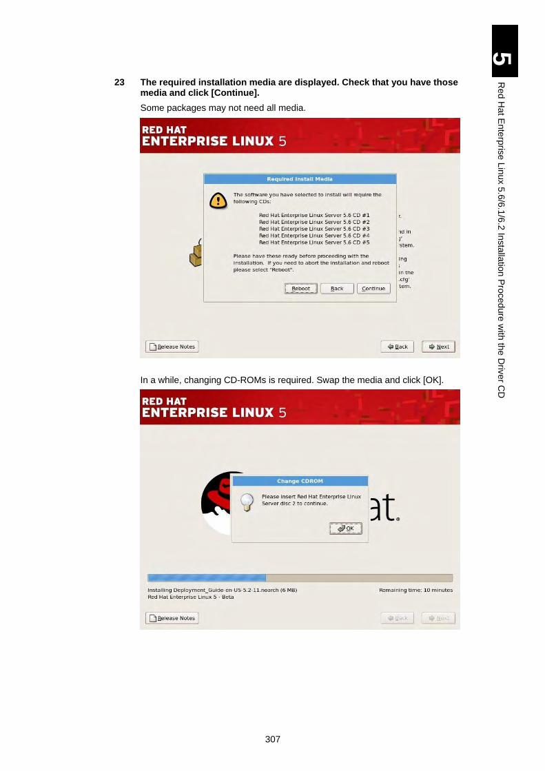
307
5
Re
d H
at E
nte
rpris
e L
inux 5
.6/6
.1/6
.2 In
sta
llatio
n P
roced
ure
with
the
Driv
er C
D
23 The required installation media are displayed. Check that you have those media and click [Continue].
Some packages may not need all media.
In a while, changing CD-ROMs is required. Swap the media and click [OK].
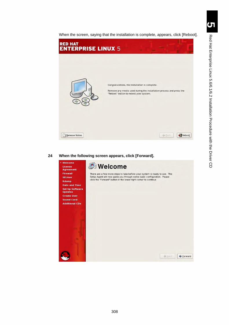
308
5
Re
d H
at E
nte
rpris
e L
inux 5
.6/6
.1/6
.2 In
sta
llatio
n P
roced
ure
with
the
Driv
er C
D
When the screen, saying that the installation is complete, appears, click [Reboot].
24 When the following screen appears, click [Forward].
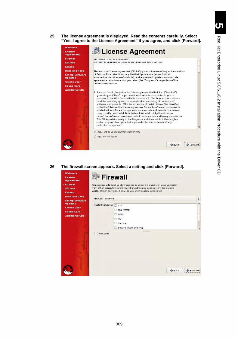
309
5
Re
d H
at E
nte
rpris
e L
inux 5
.6/6
.1/6
.2 In
sta
llatio
n P
roced
ure
with
the
Driv
er C
D
25 The license agreement is displayed. Read the contents carefully. Select “Yes, I agree to the License Agreement” if you agree, and click [Forward].
26 The firewall screen appears. Select a setting and click [Forward].
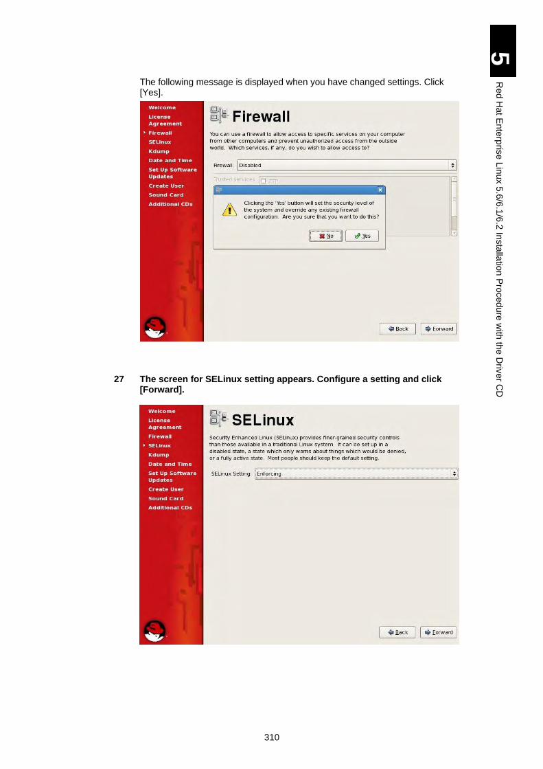
310
5
Re
d H
at E
nte
rpris
e L
inux 5
.6/6
.1/6
.2 In
sta
llatio
n P
roced
ure
with
the
Driv
er C
D
The following message is displayed when you have changed settings. Click [Yes].
27 The screen for SELinux setting appears. Configure a setting and click [Forward].
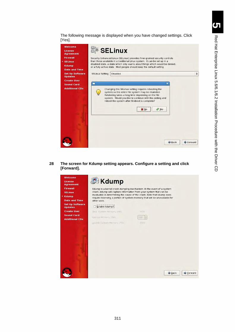
311
5
Re
d H
at E
nte
rpris
e L
inux 5
.6/6
.1/6
.2 In
sta
llatio
n P
roced
ure
with
the
Driv
er C
D
The following message is displayed when you have changed settings. Click [Yes].
28 The screen for Kdump setting appears. Configure a setting and click [Forward].
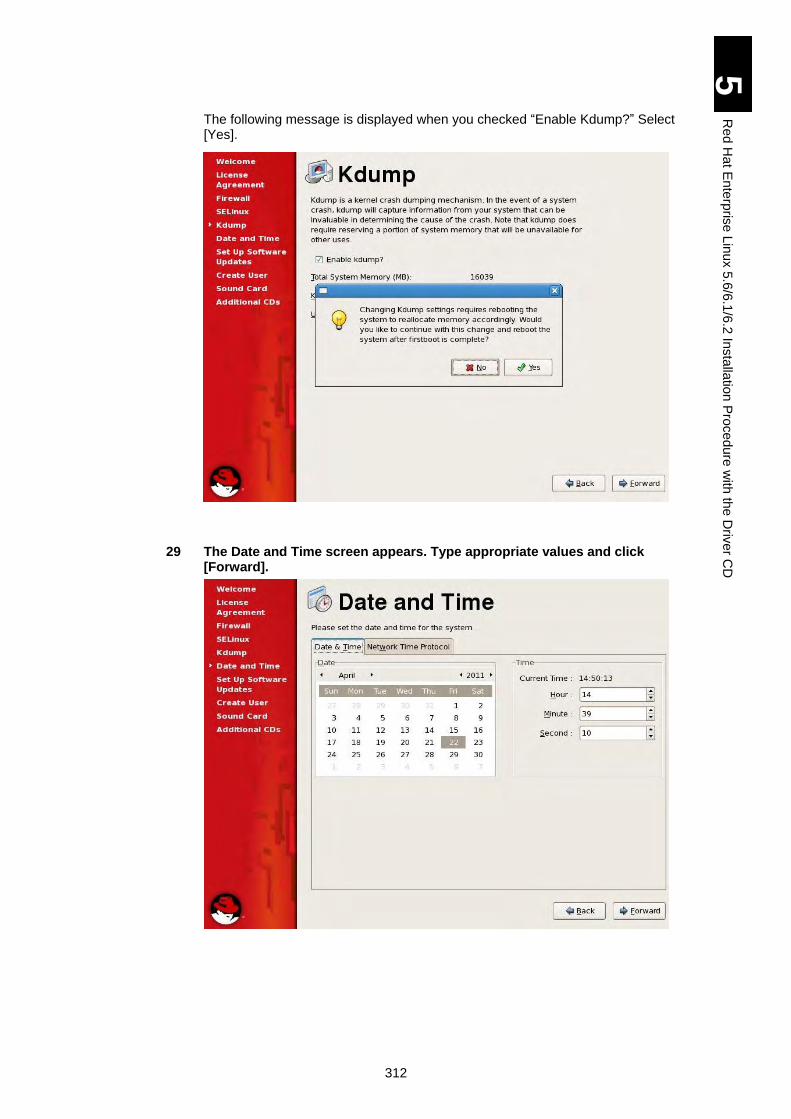
312
5
Re
d H
at E
nte
rpris
e L
inux 5
.6/6
.1/6
.2 In
sta
llatio
n P
roced
ure
with
the
Driv
er C
D
The following message is displayed when you checked “Enable Kdump?” Select [Yes].
29 The Date and Time screen appears. Type appropriate values and click [Forward].
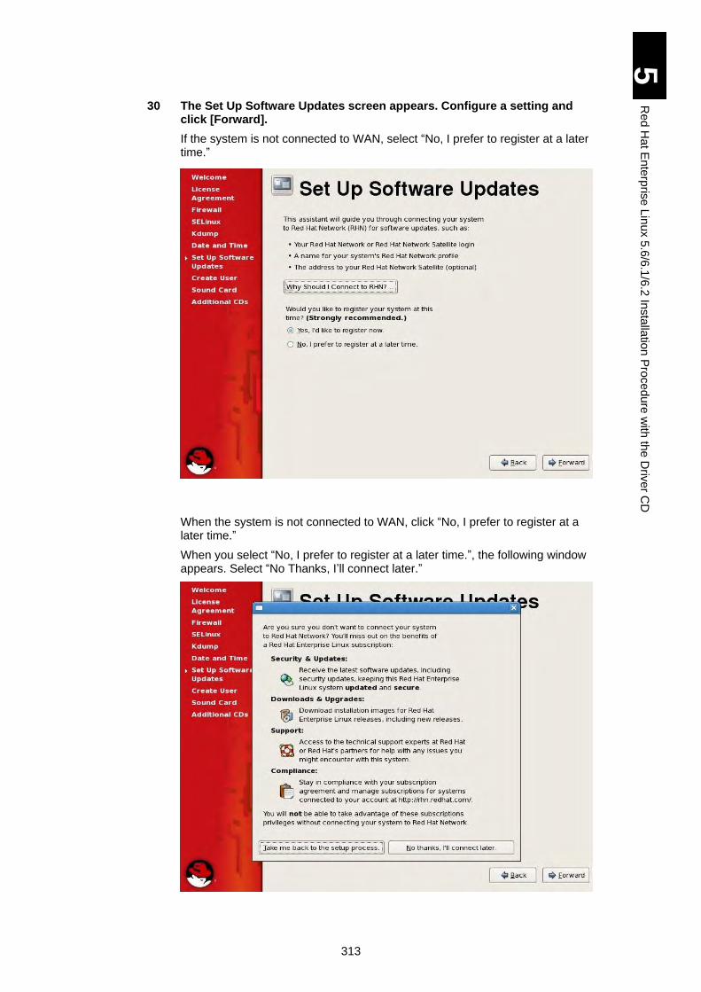
313
5
Re
d H
at E
nte
rpris
e L
inux 5
.6/6
.1/6
.2 In
sta
llatio
n P
roced
ure
with
the
Driv
er C
D
30 The Set Up Software Updates screen appears. Configure a setting and click [Forward].
If the system is not connected to WAN, select “No, I prefer to register at a later time.”
When the system is not connected to WAN, click “No, I prefer to register at a later time.”
When you select “No, I prefer to register at a later time.”, the following window appears. Select “No Thanks, I’ll connect later.”
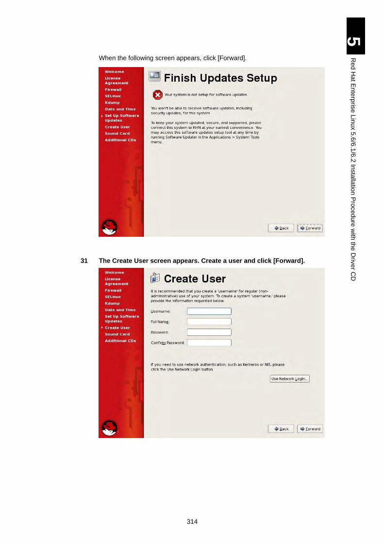
314
5
Re
d H
at E
nte
rpris
e L
inux 5
.6/6
.1/6
.2 In
sta
llatio
n P
roced
ure
with
the
Driv
er C
D
When the following screen appears, click [Forward].
31 The Create User screen appears. Create a user and click [Forward].
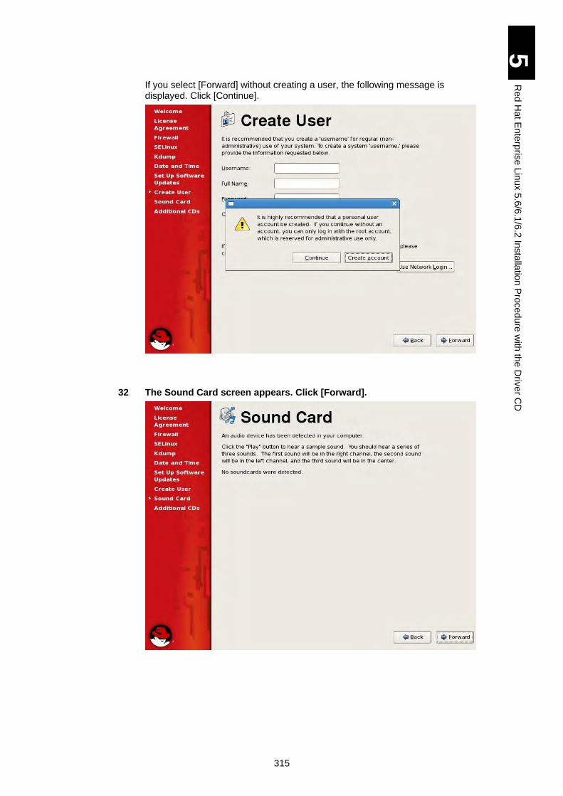
315
5
Re
d H
at E
nte
rpris
e L
inux 5
.6/6
.1/6
.2 In
sta
llatio
n P
roced
ure
with
the
Driv
er C
D
If you select [Forward] without creating a user, the following message is displayed. Click [Continue].
32 The Sound Card screen appears. Click [Forward].
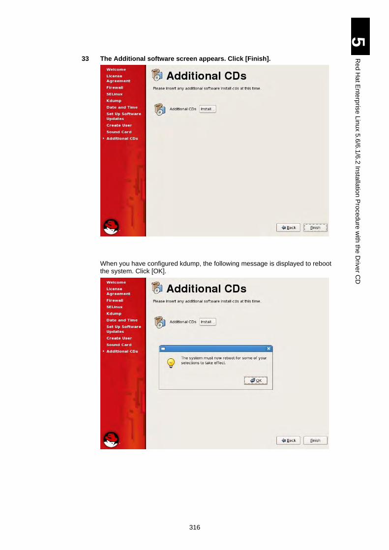
316
5
Re
d H
at E
nte
rpris
e L
inux 5
.6/6
.1/6
.2 In
sta
llatio
n P
roced
ure
with
the
Driv
er C
D
33 The Additional software screen appears. Click [Finish].
When you have configured kdump, the following message is displayed to reboot the system. Click [OK].
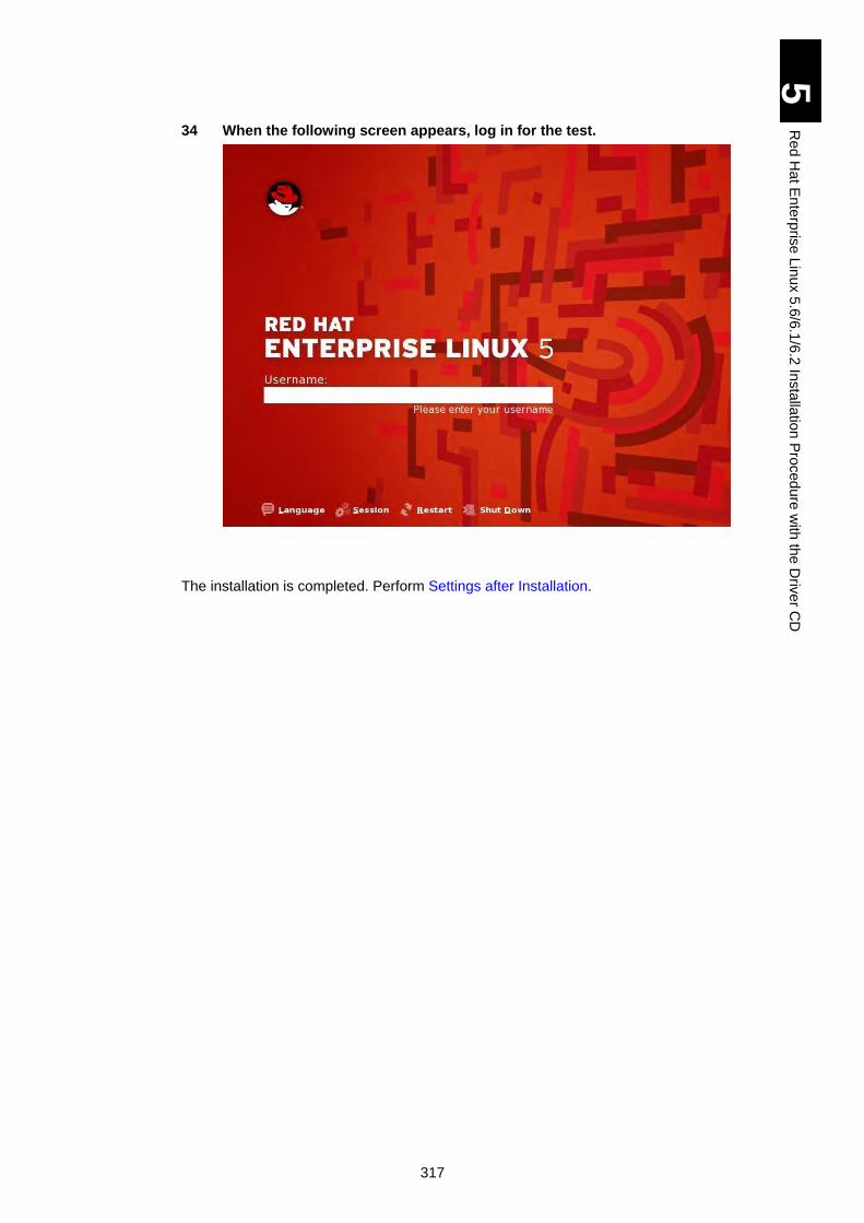
317
5
Re
d H
at E
nte
rpris
e L
inux 5
.6/6
.1/6
.2 In
sta
llatio
n P
roced
ure
with
the
Driv
er C
D
34 When the following screen appears, log in for the test.
The installation is completed. Perform Settings after Installation.
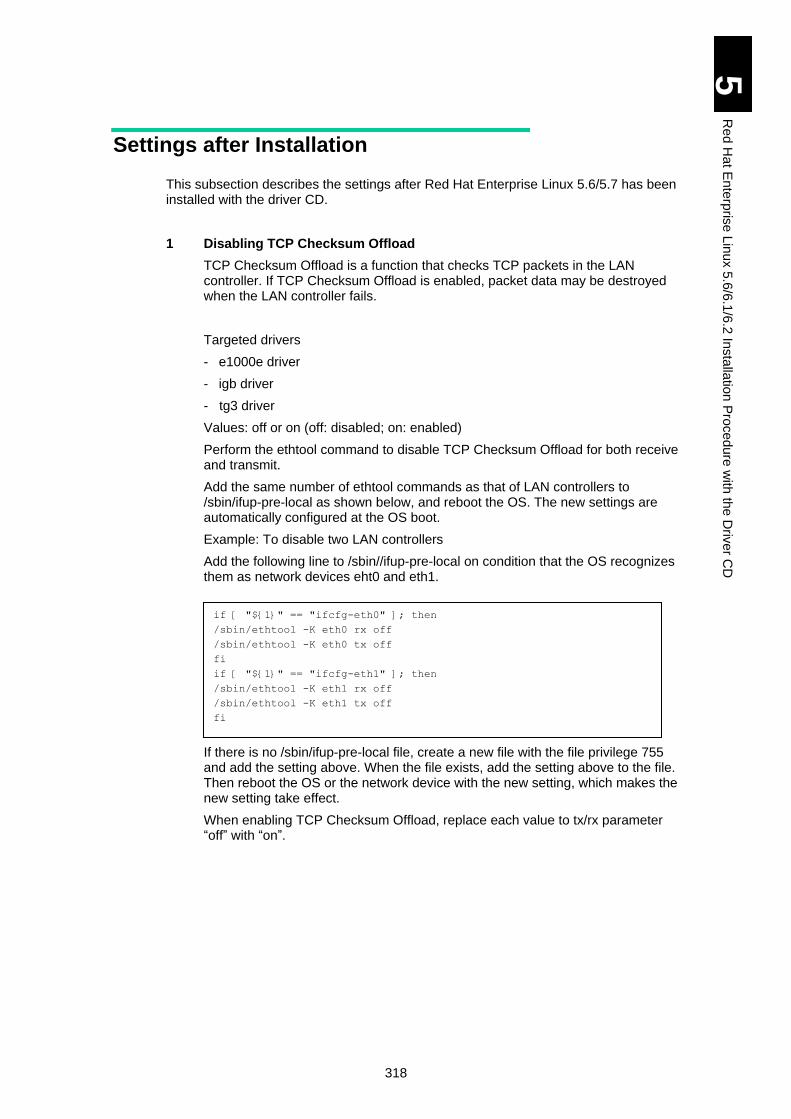
318
5
Re
d H
at E
nte
rpris
e L
inux 5
.6/6
.1/6
.2 In
sta
llatio
n P
roced
ure
with
the
Driv
er C
D
Settings after Installation
This subsection describes the settings after Red Hat Enterprise Linux 5.6/5.7 has been installed with the driver CD.
1 Disabling TCP Checksum Offload
TCP Checksum Offload is a function that checks TCP packets in the LAN controller. If TCP Checksum Offload is enabled, packet data may be destroyed when the LAN controller fails.
Targeted drivers
- e1000e driver
- igb driver
- tg3 driver
Values: off or on (off: disabled; on: enabled)
Perform the ethtool command to disable TCP Checksum Offload for both receive and transmit.
Add the same number of ethtool commands as that of LAN controllers to /sbin/ifup-pre-local as shown below, and reboot the OS. The new settings are automatically configured at the OS boot.
Example: To disable two LAN controllers
Add the following line to /sbin//ifup-pre-local on condition that the OS recognizes them as network devices eht0 and eth1.
If there is no /sbin/ifup-pre-local file, create a new file with the file privilege 755 and add the setting above. When the file exists, add the setting above to the file. Then reboot the OS or the network device with the new setting, which makes the new setting take effect.
When enabling TCP Checksum Offload, replace each value to tx/rx parameter “off” with “on”.
if [ "${1}" == "ifcfg-eth0" ]; then
/sbin/ethtool -K eth0 rx off
/sbin/ethtool -K eth0 tx off
fi
if [ "${1}" == "ifcfg-eth1" ]; then
/sbin/ethtool -K eth1 rx off
/sbin/ethtool -K eth1 tx off
fi
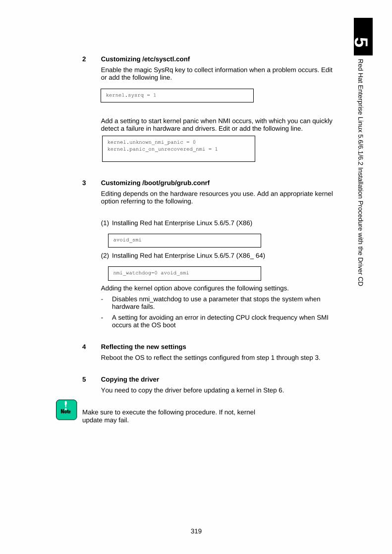
319
5
Re
d H
at E
nte
rpris
e L
inux 5
.6/6
.1/6
.2 In
sta
llatio
n P
roced
ure
with
the
Driv
er C
D
2 Customizing /etc/sysctl.conf
Enable the magic SysRq key to collect information when a problem occurs. Edit or add the following line.
Add a setting to start kernel panic when NMI occurs, with which you can quickly detect a failure in hardware and drivers. Edit or add the following line.
3 Customizing /boot/grub/grub.conrf
Editing depends on the hardware resources you use. Add an appropriate kernel option referring to the following.
(1) Installing Red hat Enterprise Linux 5.6/5.7 (X86)
(2) Installing Red hat Enterprise Linux 5.6/5.7 (X86_ 64)
Adding the kernel option above configures the following settings.
- Disables nmi_watchdog to use a parameter that stops the system when hardware fails.
- A setting for avoiding an error in detecting CPU clock frequency when SMI occurs at the OS boot
4 Reflecting the new settings
Reboot the OS to reflect the settings configured from step 1 through step 3.
5 Copying the driver
You need to copy the driver before updating a kernel in Step 6.
Make sure to execute the following procedure. If not, kernel
update may fail.
kernel.sysrq = 1
kernel.unknown_nmi_panic = 0
kernel.panic_on_unrecovered_nmi = 1
nmi_watchdog=0 avoid_smi
avoid_smi
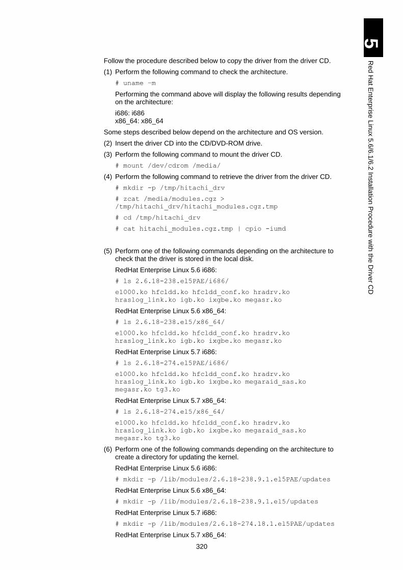
320
5
Re
d H
at E
nte
rpris
e L
inux 5
.6/6
.1/6
.2 In
sta
llatio
n P
roced
ure
with
the
Driv
er C
D
Follow the procedure described below to copy the driver from the driver CD.
(1) Perform the following command to check the architecture.
# uname –m
Performing the command above will display the following results depending on the architecture:
i686: i686 x86_64: x86_64
Some steps described below depend on the architecture and OS version.
(2) Insert the driver CD into the CD/DVD-ROM drive.
(3) Perform the following command to mount the driver CD.
# mount /dev/cdrom /media/
(4) Perform the following command to retrieve the driver from the driver CD.
# mkdir -p /tmp/hitachi_drv
# zcat /media/modules.cgz >
/tmp/hitachi_drv/hitachi_modules.cgz.tmp
# cd /tmp/hitachi_drv
# cat hitachi_modules.cgz.tmp | cpio -iumd
(5) Perform one of the following commands depending on the architecture to check that the driver is stored in the local disk.
RedHat Enterprise Linux 5.6 i686:
# ls 2.6.18-238.el5PAE/i686/
e1000.ko hfcldd.ko hfcldd_conf.ko hradrv.ko
hraslog_link.ko igb.ko ixgbe.ko megasr.ko
RedHat Enterprise Linux 5.6 x86_64:
# ls 2.6.18-238.el5/x86_64/
e1000.ko hfcldd.ko hfcldd_conf.ko hradrv.ko
hraslog_link.ko igb.ko ixgbe.ko megasr.ko
RedHat Enterprise Linux 5.7 i686:
# ls 2.6.18-274.el5PAE/i686/
e1000.ko hfcldd.ko hfcldd_conf.ko hradrv.ko
hraslog_link.ko igb.ko ixgbe.ko megaraid_sas.ko
megasr.ko tg3.ko
RedHat Enterprise Linux 5.7 x86_64:
# ls 2.6.18-274.el5/x86_64/
e1000.ko hfcldd.ko hfcldd_conf.ko hradrv.ko
hraslog_link.ko igb.ko ixgbe.ko megaraid_sas.ko
megasr.ko tg3.ko
(6) Perform one of the following commands depending on the architecture to create a directory for updating the kernel.
RedHat Enterprise Linux 5.6 i686:
# mkdir –p /lib/modules/2.6.18-238.9.1.el5PAE/updates
RedHat Enterprise Linux 5.6 x86_64:
# mkdir –p /lib/modules/2.6.18-238.9.1.el5/updates
RedHat Enterprise Linux 5.7 i686:
# mkdir –p /lib/modules/2.6.18-274.18.1.el5PAE/updates
RedHat Enterprise Linux 5.7 x86_64:
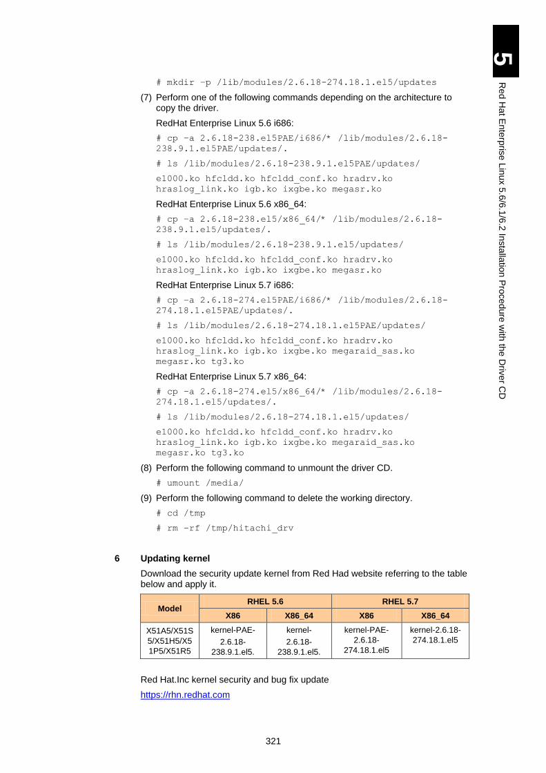
321
5
Re
d H
at E
nte
rpris
e L
inux 5
.6/6
.1/6
.2 In
sta
llatio
n P
roced
ure
with
the
Driv
er C
D
# mkdir –p /lib/modules/2.6.18-274.18.1.el5/updates
(7) Perform one of the following commands depending on the architecture to copy the driver.
RedHat Enterprise Linux 5.6 i686:
# cp –a 2.6.18-238.el5PAE/i686/* /lib/modules/2.6.18-
238.9.1.el5PAE/updates/.
# ls /lib/modules/2.6.18-238.9.1.el5PAE/updates/
e1000.ko hfcldd.ko hfcldd_conf.ko hradrv.ko
hraslog_link.ko igb.ko ixgbe.ko megasr.ko
RedHat Enterprise Linux 5.6 x86_64:
# cp –a 2.6.18-238.el5/x86_64/* /lib/modules/2.6.18-
238.9.1.el5/updates/.
# ls /lib/modules/2.6.18-238.9.1.el5/updates/
e1000.ko hfcldd.ko hfcldd_conf.ko hradrv.ko
hraslog_link.ko igb.ko ixgbe.ko megasr.ko
RedHat Enterprise Linux 5.7 i686:
# cp –a 2.6.18-274.el5PAE/i686/* /lib/modules/2.6.18-
274.18.1.el5PAE/updates/.
# ls /lib/modules/2.6.18-274.18.1.el5PAE/updates/
e1000.ko hfcldd.ko hfcldd_conf.ko hradrv.ko
hraslog_link.ko igb.ko ixgbe.ko megaraid_sas.ko
megasr.ko tg3.ko
RedHat Enterprise Linux 5.7 x86_64:
# cp –a 2.6.18-274.el5/x86_64/* /lib/modules/2.6.18-
274.18.1.el5/updates/.
# ls /lib/modules/2.6.18-274.18.1.el5/updates/
e1000.ko hfcldd.ko hfcldd_conf.ko hradrv.ko
hraslog_link.ko igb.ko ixgbe.ko megaraid_sas.ko
megasr.ko tg3.ko
(8) Perform the following command to unmount the driver CD.
# umount /media/
(9) Perform the following command to delete the working directory.
# cd /tmp
# rm –rf /tmp/hitachi_drv
6 Updating kernel
Download the security update kernel from Red Had website referring to the table below and apply it.
Model RHEL 5.6 RHEL 5.7
X86 X86_64 X86 X86_64
X51A5/X51S
5/X51H5/X5
1P5/X51R5
kernel-PAE-
2.6.18-
238.9.1.el5.
kernel-
2.6.18-
238.9.1.el5.
kernel-PAE-
2.6.18-
274.18.1.el5
kernel-2.6.18-
274.18.1.el5
Red Hat.Inc kernel security and bug fix update
https://rhn.redhat.com
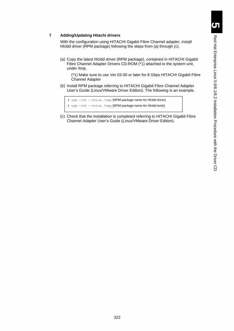
322
5
Re
d H
at E
nte
rpris
e L
inux 5
.6/6
.1/6
.2 In
sta
llatio
n P
roced
ure
with
the
Driv
er C
D
7 Adding/Updating Hitachi drivers
With the configuration using HITACHI Gigabit Fibre Channel adapter, install hfcldd driver (RPM package) following the steps from (a) through (c).
(a) Copy the latest hfcldd driver (RPM package), contained in HITACHI Gigabit Fibre Channel Adapter Drivers CD-ROM (*1) attached to the system unit, under /tmp.
(*1) Make sure to use Ver.03-00 or later for 8 Gbps HITACHI Gigabit Fibre Channel Adapter
(b) Install RPM package referring to HITACHI Gigabit Fibre Channel Adapter User’s Guide (Linux/VMware Driver Edition). The following is an example.
(c) Check that the installation is completed referring to HITACHI Gigabit Fibre Channel Adapter User’s Guide (Linux/VMware Driver Edition).
# rpm -ivh --force /tmp/[RPM package name for hfcldd driver]
# rpm -ivh --force /tmp/[RPM package name for hfcldd-tools]
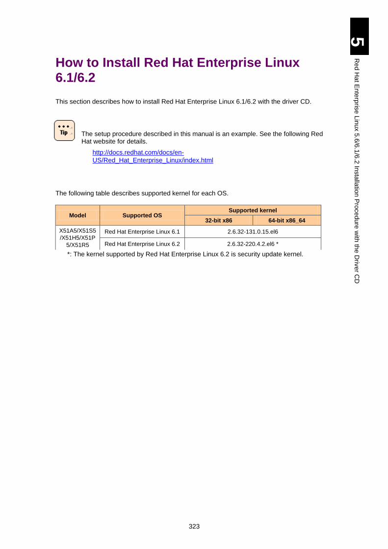
323
5
Re
d H
at E
nte
rpris
e L
inux 5
.6/6
.1/6
.2 In
sta
llatio
n P
roced
ure
with
the
Driv
er C
D
How to Install Red Hat Enterprise Linux 6.1/6.2
This section describes how to install Red Hat Enterprise Linux 6.1/6.2 with the driver CD.
The setup procedure described in this manual is an example. See the following Red Hat website for details.
http://docs.redhat.com/docs/en-
US/Red_Hat_Enterprise_Linux/index.html
The following table describes supported kernel for each OS.
*: The kernel supported by Red Hat Enterprise Linux 6.2 is security update kernel.
Model Supported OS Supported kernel
32-bit x86 64-bit x86_64
X51A5/X51S5
/X51H5/X51P
5/X51R5
Red Hat Enterprise Linux 6.1 2.6.32-131.0.15.el6
Red Hat Enterprise Linux 6.2 2.6.32-220.4.2.el6 *
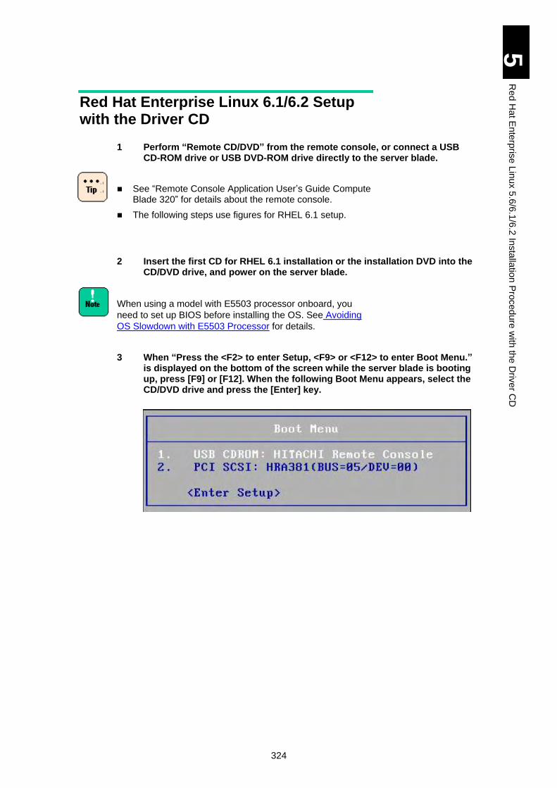
324
5
Re
d H
at E
nte
rpris
e L
inux 5
.6/6
.1/6
.2 In
sta
llatio
n P
roced
ure
with
the
Driv
er C
D
Red Hat Enterprise Linux 6.1/6.2 Setup with the Driver CD
1 Perform “Remote CD/DVD” from the remote console, or connect a USB CD-ROM drive or USB DVD-ROM drive directly to the server blade.
See “Remote Console Application User’s Guide Compute Blade 320” for details about the remote console.
The following steps use figures for RHEL 6.1 setup.
2 Insert the first CD for RHEL 6.1 installation or the installation DVD into the CD/DVD drive, and power on the server blade.
When using a model with E5503 processor onboard, you
need to set up BIOS before installing the OS. See Avoiding
OS Slowdown with E5503 Processor for details.
3 When “Press the <F2> to enter Setup, <F9> or <F12> to enter Boot Menu.” is displayed on the bottom of the screen while the server blade is booting up, press [F9] or [F12]. When the following Boot Menu appears, select the CD/DVD drive and press the [Enter] key.

325
5
Re
d H
at E
nte
rpris
e L
inux 5
.6/6
.1/6
.2 In
sta
llatio
n P
roced
ure
with
the
Driv
er C
D
4 Select “Install system with basic video driver”, and press the [Tab] key.
Press the [Tab] key to display options, and type “dd”.
When using Red Hat Enterprise Linux 6.2, make sure to add
“pcie_aspm=off dd”.
Example: >vmlinuz initrd=initrd. img xdriver=vesa
nomodeset pcie_aspm=off dd
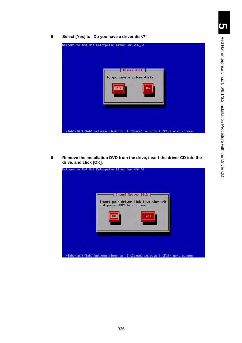
326
5
Re
d H
at E
nte
rpris
e L
inux 5
.6/6
.1/6
.2 In
sta
llatio
n P
roced
ure
with
the
Driv
er C
D
5 Select [Yes] to “Do you have a driver disk?”
6 Remove the installation DVD from the drive, insert the driver CD into the drive, and click [OK].
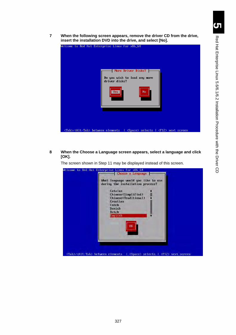
327
5
Re
d H
at E
nte
rpris
e L
inux 5
.6/6
.1/6
.2 In
sta
llatio
n P
roced
ure
with
the
Driv
er C
D
7 When the following screen appears, remove the driver CD from the drive, insert the installation DVD into the drive, and select [No].
8 When the Choose a Language screen appears, select a language and click [OK].
The screen shown in Step 11 may be displayed instead of this screen.
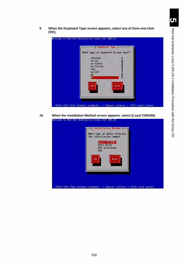
328
5
Re
d H
at E
nte
rpris
e L
inux 5
.6/6
.1/6
.2 In
sta
llatio
n P
roced
ure
with
the
Driv
er C
D
9 When the Keyboard Type screen appears, select any of them and click [OK].
10 When the installation Method screen appears, select [Local CDROM].
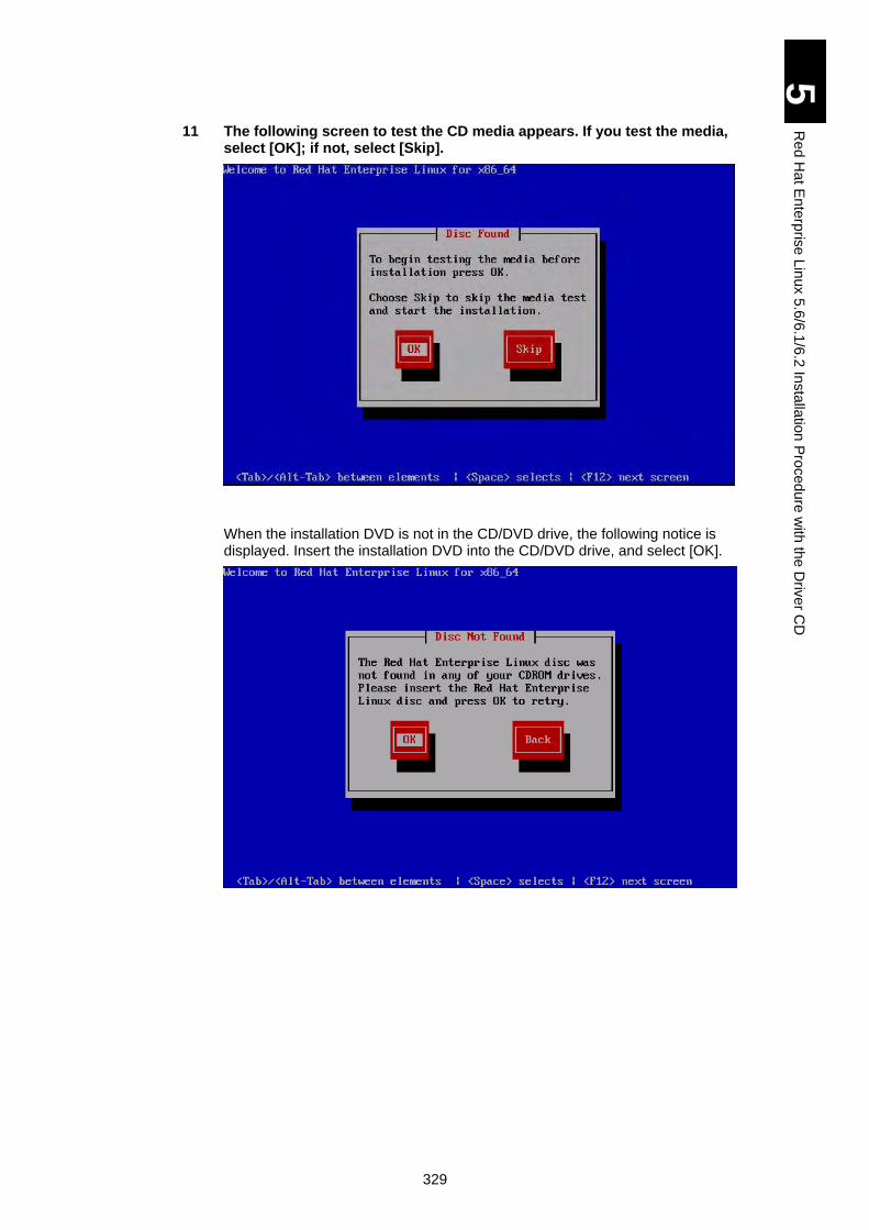
329
5
Re
d H
at E
nte
rpris
e L
inux 5
.6/6
.1/6
.2 In
sta
llatio
n P
roced
ure
with
the
Driv
er C
D
11 The following screen to test the CD media appears. If you test the media, select [OK]; if not, select [Skip].
When the installation DVD is not in the CD/DVD drive, the following notice is displayed. Insert the installation DVD into the CD/DVD drive, and select [OK].
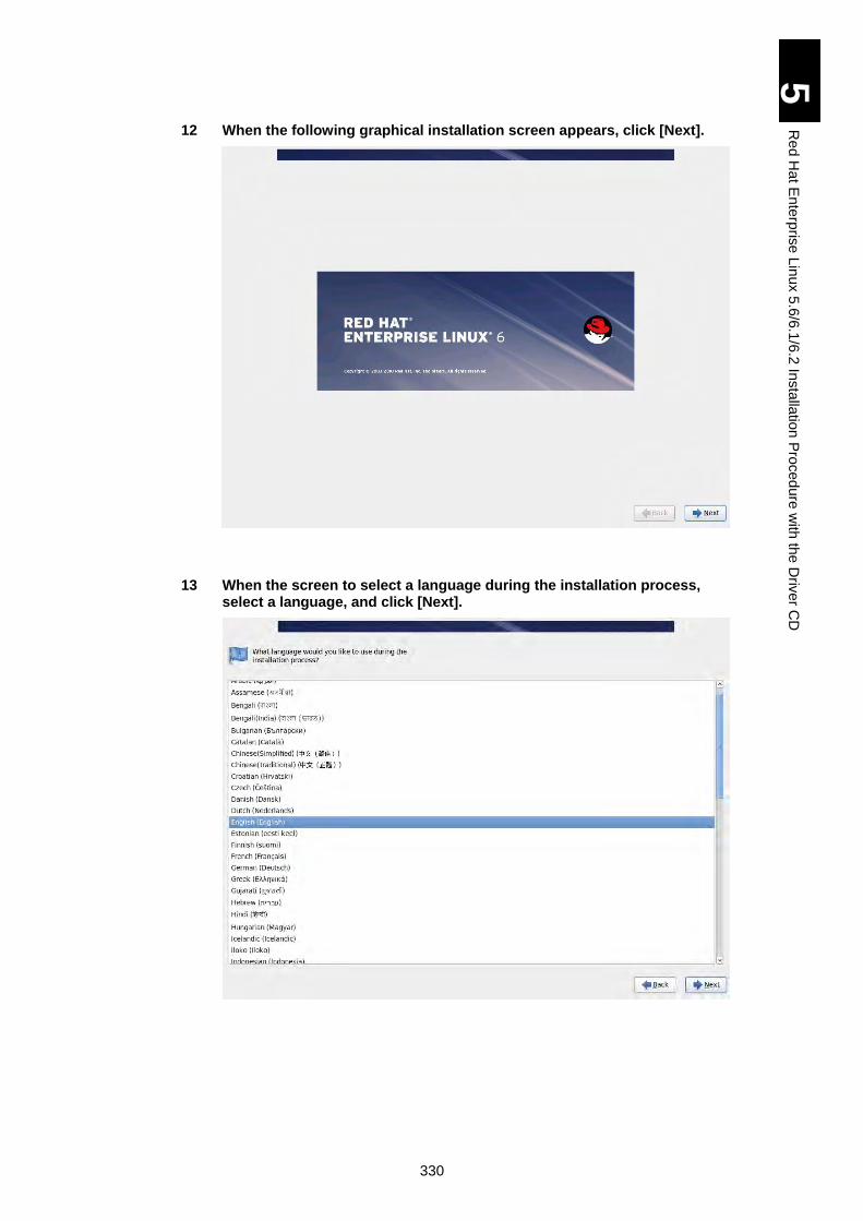
330
5
Re
d H
at E
nte
rpris
e L
inux 5
.6/6
.1/6
.2 In
sta
llatio
n P
roced
ure
with
the
Driv
er C
D
12 When the following graphical installation screen appears, click [Next].
13 When the screen to select a language during the installation process, select a language, and click [Next].
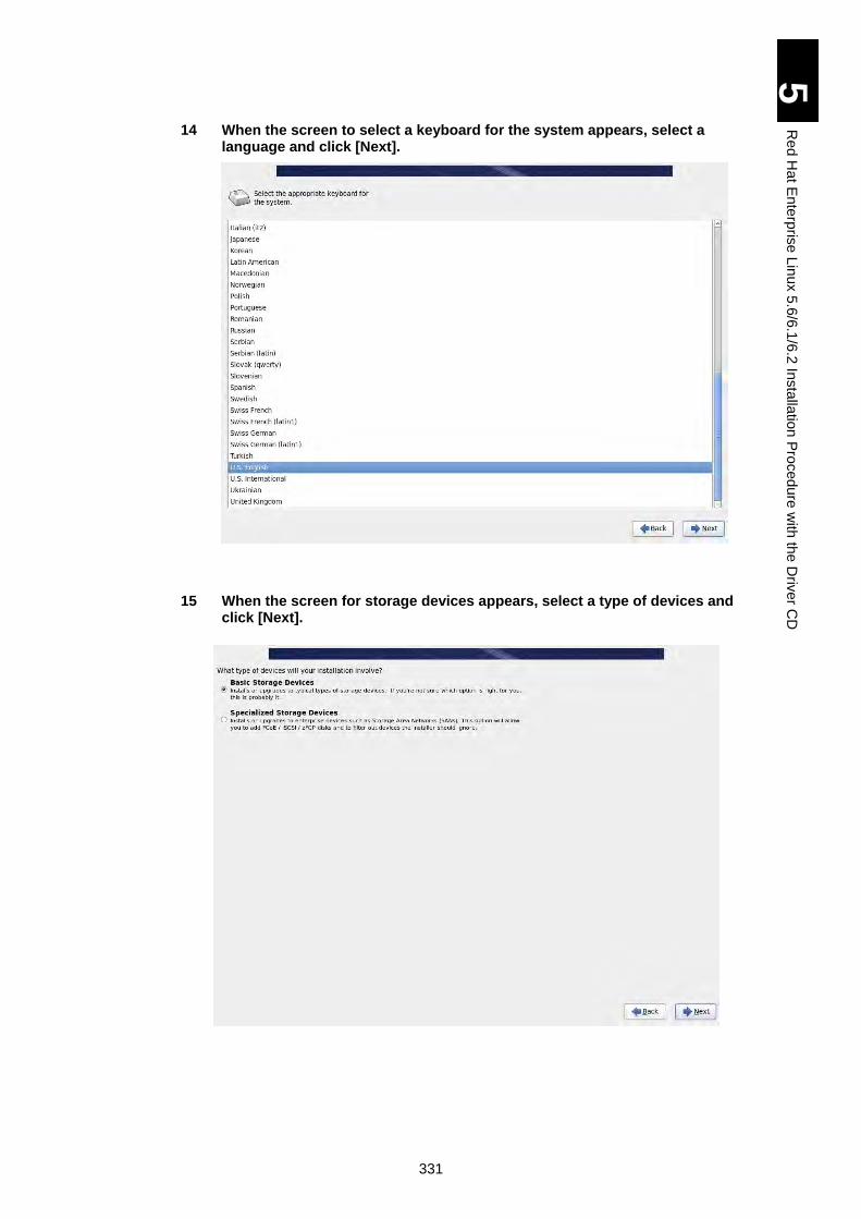
331
5
Re
d H
at E
nte
rpris
e L
inux 5
.6/6
.1/6
.2 In
sta
llatio
n P
roced
ure
with
the
Driv
er C
D
14 When the screen to select a keyboard for the system appears, select a language and click [Next].
15 When the screen for storage devices appears, select a type of devices and click [Next].
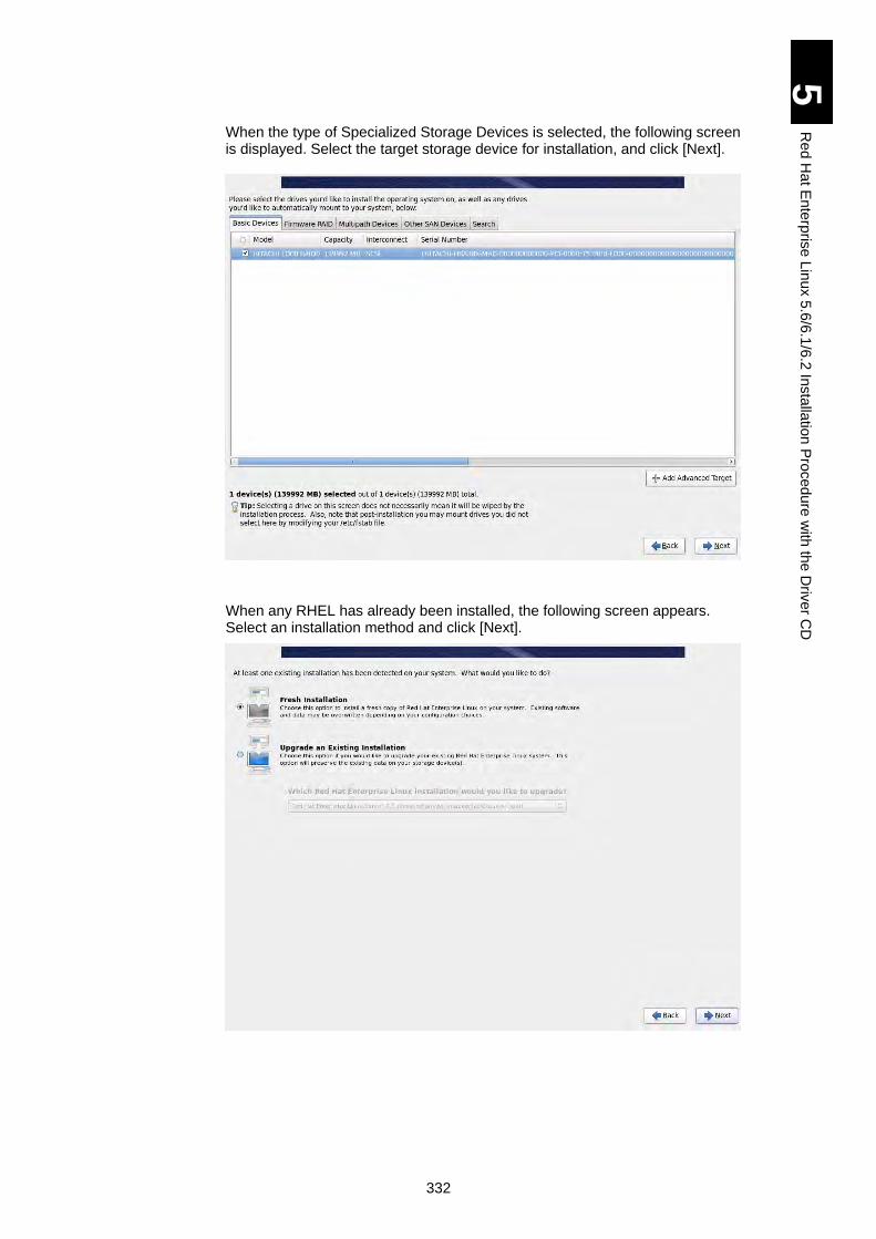
332
5
Re
d H
at E
nte
rpris
e L
inux 5
.6/6
.1/6
.2 In
sta
llatio
n P
roced
ure
with
the
Driv
er C
D
When the type of Specialized Storage Devices is selected, the following screen is displayed. Select the target storage device for installation, and click [Next].
When any RHEL has already been installed, the following screen appears. Select an installation method and click [Next].
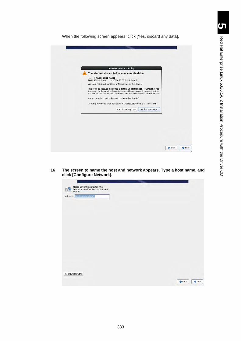
333
5
Re
d H
at E
nte
rpris
e L
inux 5
.6/6
.1/6
.2 In
sta
llatio
n P
roced
ure
with
the
Driv
er C
D
When the following screen appears, click [Yes, discard any data].
16 The screen to name the host and network appears. Type a host name, and click [Configure Network].
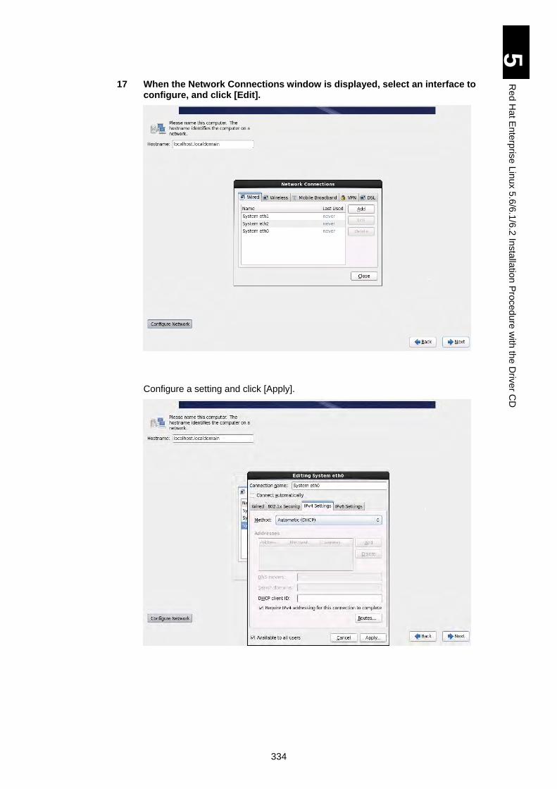
334
5
Re
d H
at E
nte
rpris
e L
inux 5
.6/6
.1/6
.2 In
sta
llatio
n P
roced
ure
with
the
Driv
er C
D
17 When the Network Connections window is displayed, select an interface to configure, and click [Edit].
Configure a setting and click [Apply].
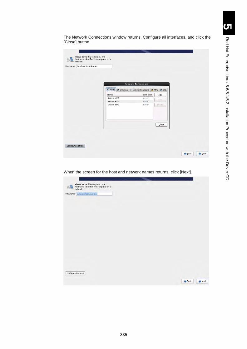
335
5
Re
d H
at E
nte
rpris
e L
inux 5
.6/6
.1/6
.2 In
sta
llatio
n P
roced
ure
with
the
Driv
er C
D
The Network Connections window returns. Configure all interfaces, and click the [Close] button.
When the screen for the host and network names returns, click [Next].
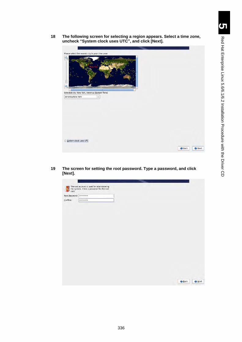
336
5
Re
d H
at E
nte
rpris
e L
inux 5
.6/6
.1/6
.2 In
sta
llatio
n P
roced
ure
with
the
Driv
er C
D
18 The following screen for selecting a region appears. Select a time zone, uncheck “System clock uses UTC”, and click [Next].
19 The screen for setting the root password. Type a password, and click [Next].
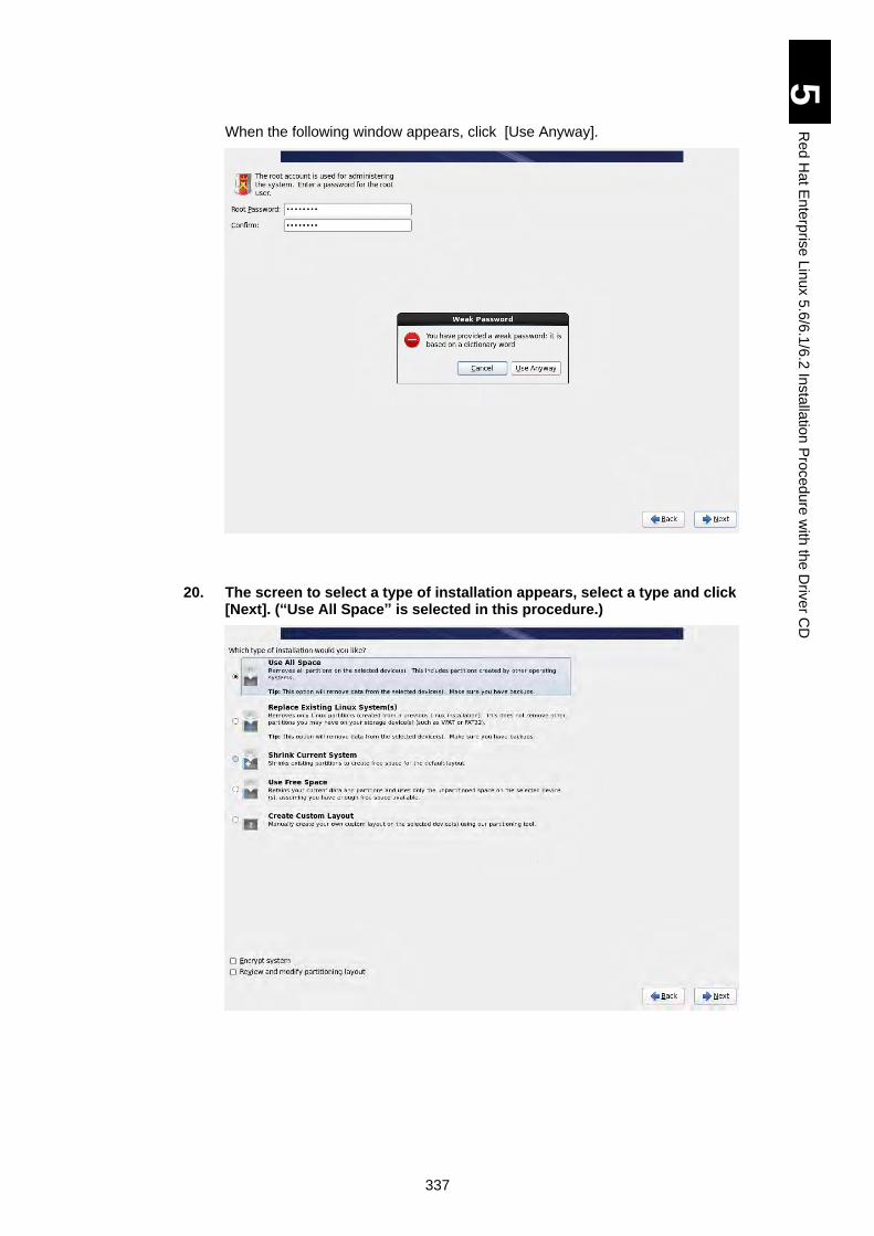
337
5
Re
d H
at E
nte
rpris
e L
inux 5
.6/6
.1/6
.2 In
sta
llatio
n P
roced
ure
with
the
Driv
er C
D
When the following window appears, click [Use Anyway].
20. The screen to select a type of installation appears, select a type and click [Next]. (“Use All Space” is selected in this procedure.)
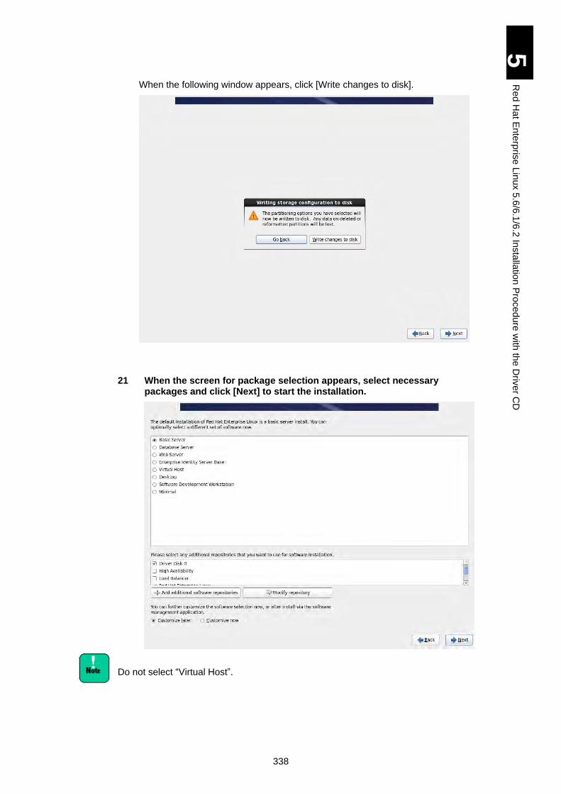
338
5
Re
d H
at E
nte
rpris
e L
inux 5
.6/6
.1/6
.2 In
sta
llatio
n P
roced
ure
with
the
Driv
er C
D
When the following window appears, click [Write changes to disk].
21 When the screen for package selection appears, select necessary packages and click [Next] to start the installation.
Do not select “Virtual Host”.
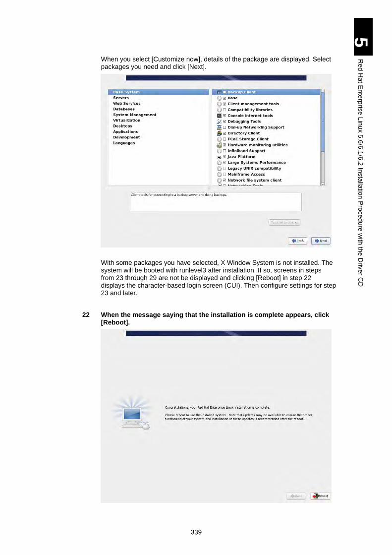
339
5
Re
d H
at E
nte
rpris
e L
inux 5
.6/6
.1/6
.2 In
sta
llatio
n P
roced
ure
with
the
Driv
er C
D
When you select [Customize now], details of the package are displayed. Select packages you need and click [Next].
With some packages you have selected, X Window System is not installed. The system will be booted with runlevel3 after installation. If so, screens in steps from 23 through 29 are not be displayed and clicking [Reboot] in step 22 displays the character-based login screen (CUI). Then configure settings for step 23 and later.
22 When the message saying that the installation is complete appears, click [Reboot].
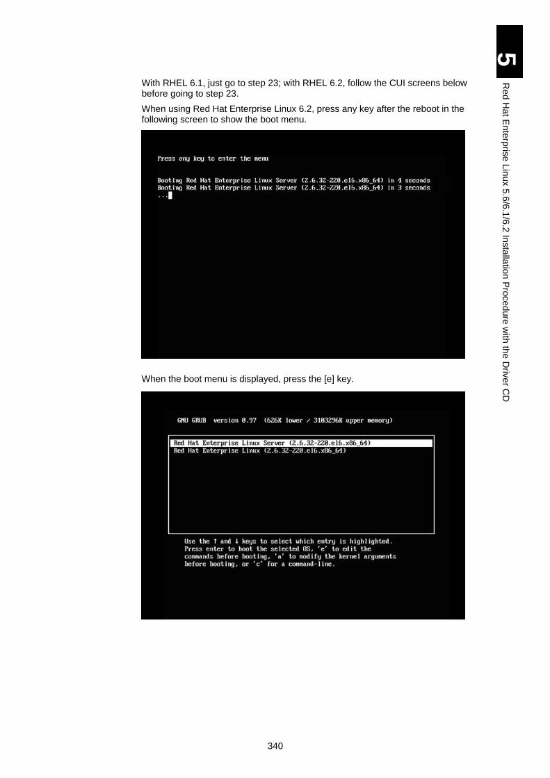
340
5
Re
d H
at E
nte
rpris
e L
inux 5
.6/6
.1/6
.2 In
sta
llatio
n P
roced
ure
with
the
Driv
er C
D
With RHEL 6.1, just go to step 23; with RHEL 6.2, follow the CUI screens below before going to step 23.
When using Red Hat Enterprise Linux 6.2, press any key after the reboot in the following screen to show the boot menu.
When the boot menu is displayed, press the [e] key.
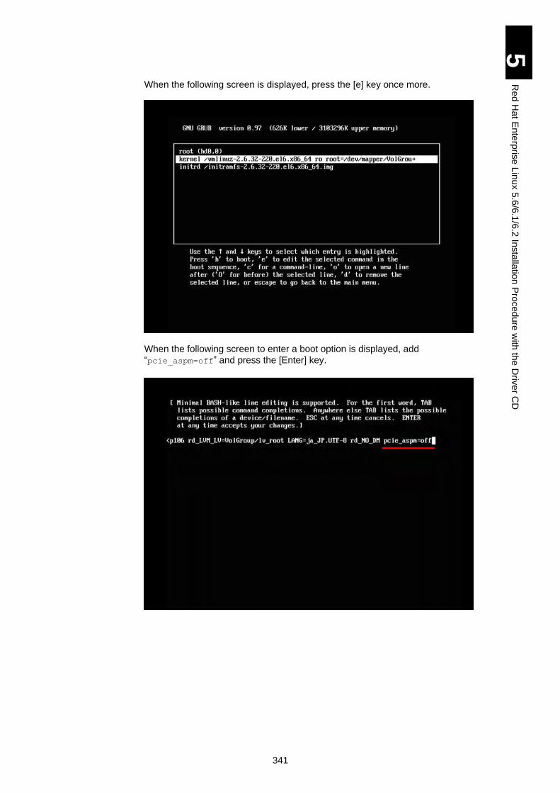
341
5
Re
d H
at E
nte
rpris
e L
inux 5
.6/6
.1/6
.2 In
sta
llatio
n P
roced
ure
with
the
Driv
er C
D
When the following screen is displayed, press the [e] key once more.
When the following screen to enter a boot option is displayed, add
“pcie_aspm=off” and press the [Enter] key.
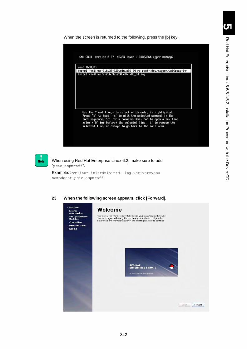
342
5
Re
d H
at E
nte
rpris
e L
inux 5
.6/6
.1/6
.2 In
sta
llatio
n P
roced
ure
with
the
Driv
er C
D
When the screen is returned to the following, press the [b] key.
When using Red Hat Enterprise Linux 6.2, make sure to add
“pcie_aspm=off”.
Example: >vmlinuz initrd=initrd. img xdriver=vesa
nomodeset pcie_aspm=off
23 When the following screen appears, click [Forward].
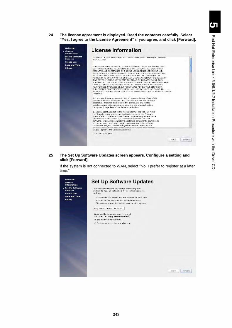
343
5
Re
d H
at E
nte
rpris
e L
inux 5
.6/6
.1/6
.2 In
sta
llatio
n P
roced
ure
with
the
Driv
er C
D
24 The license agreement is displayed. Read the contents carefully. Select “Yes, I agree to the License Agreement” if you agree, and click [Forward].
25 The Set Up Software Updates screen appears. Configure a setting and click [Forward].
If the system is not connected to WAN, select “No, I prefer to register at a later time.”
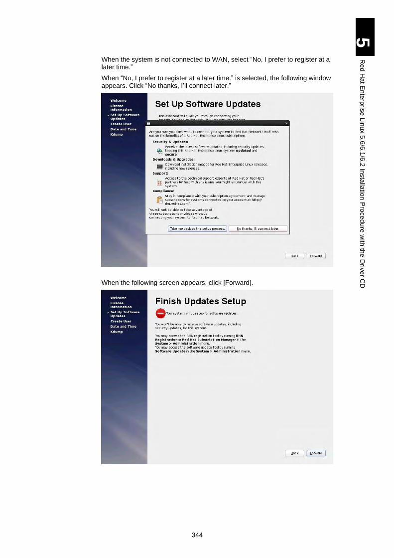
344
5
Re
d H
at E
nte
rpris
e L
inux 5
.6/6
.1/6
.2 In
sta
llatio
n P
roced
ure
with
the
Driv
er C
D
When the system is not connected to WAN, select “No, I prefer to register at a later time.”
When “No, I prefer to register at a later time.” is selected, the following window appears. Click “No thanks, I’ll connect later.”
When the following screen appears, click [Forward].
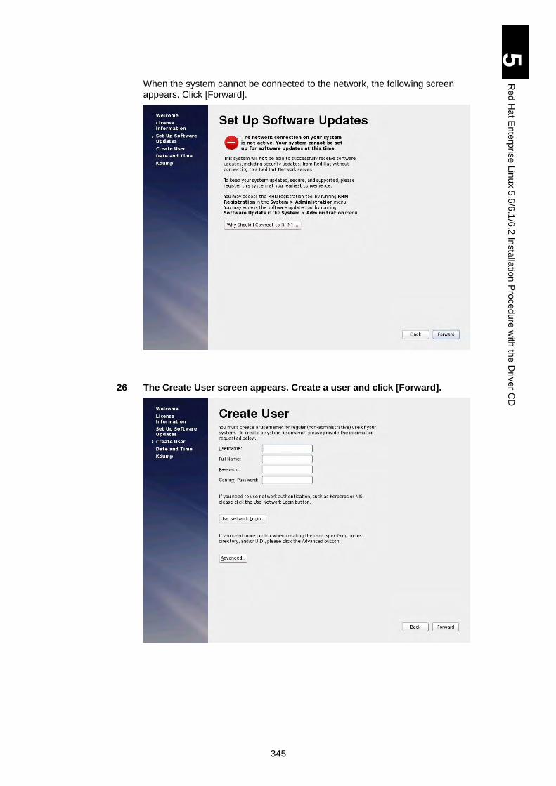
345
5
Re
d H
at E
nte
rpris
e L
inux 5
.6/6
.1/6
.2 In
sta
llatio
n P
roced
ure
with
the
Driv
er C
D
When the system cannot be connected to the network, the following screen appears. Click [Forward].
26 The Create User screen appears. Create a user and click [Forward].
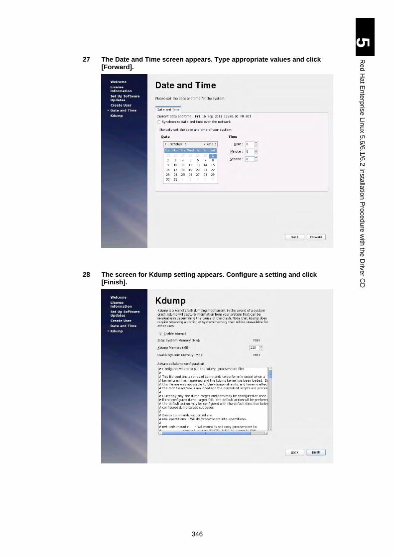
346
5
Re
d H
at E
nte
rpris
e L
inux 5
.6/6
.1/6
.2 In
sta
llatio
n P
roced
ure
with
the
Driv
er C
D
27 The Date and Time screen appears. Type appropriate values and click [Forward].
28 The screen for Kdump setting appears. Configure a setting and click [Finish].
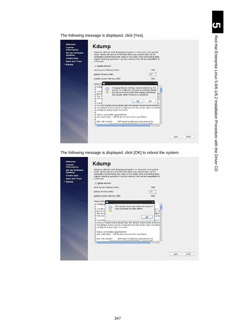
347
5
Re
d H
at E
nte
rpris
e L
inux 5
.6/6
.1/6
.2 In
sta
llatio
n P
roced
ure
with
the
Driv
er C
D
The following message is displayed, click [Yes].
The following message is displayed, click [OK] to reboot the system.
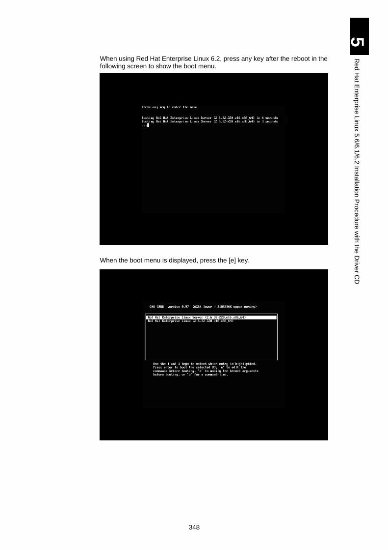
348
5
Re
d H
at E
nte
rpris
e L
inux 5
.6/6
.1/6
.2 In
sta
llatio
n P
roced
ure
with
the
Driv
er C
D
When using Red Hat Enterprise Linux 6.2, press any key after the reboot in the following screen to show the boot menu.
When the boot menu is displayed, press the [e] key.
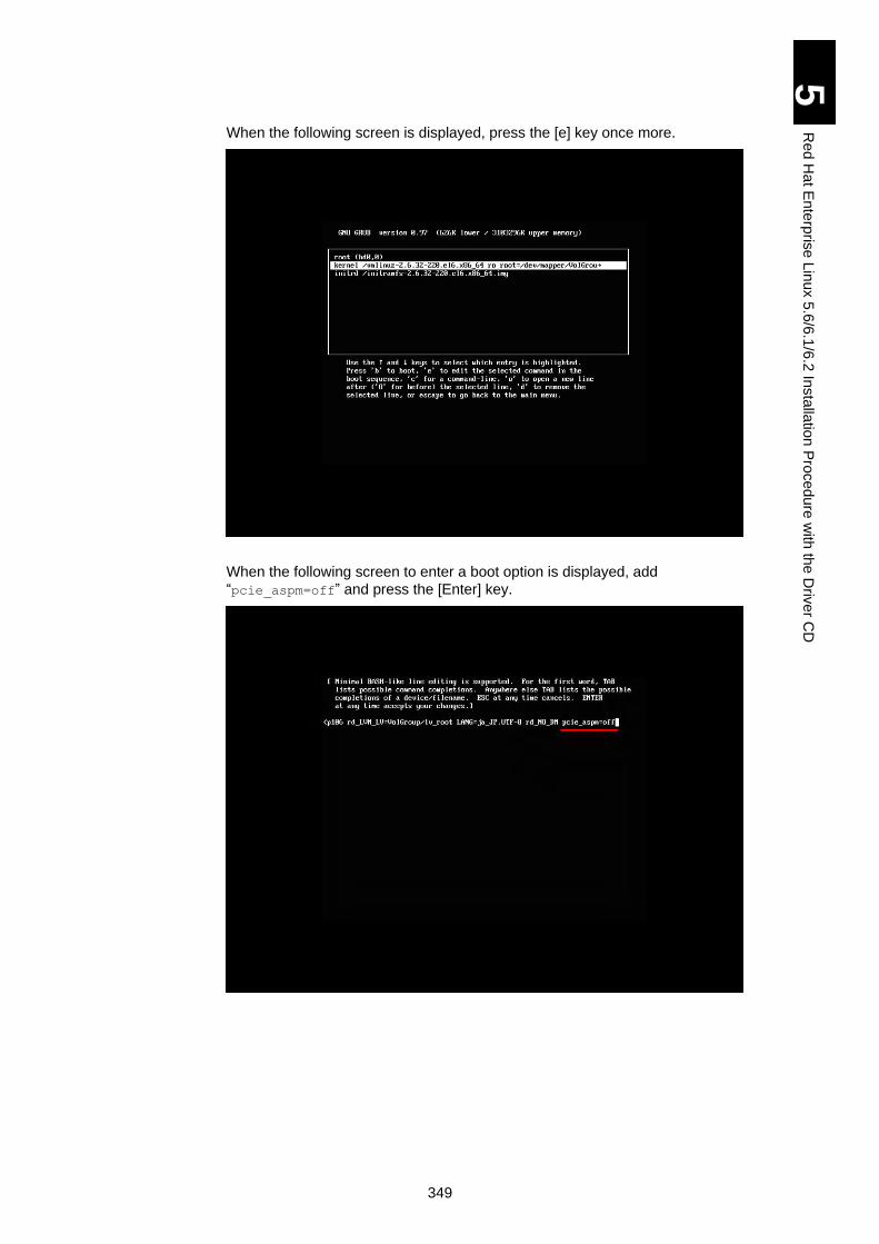
349
5
Re
d H
at E
nte
rpris
e L
inux 5
.6/6
.1/6
.2 In
sta
llatio
n P
roced
ure
with
the
Driv
er C
D
When the following screen is displayed, press the [e] key once more.
When the following screen to enter a boot option is displayed, add
“pcie_aspm=off” and press the [Enter] key.
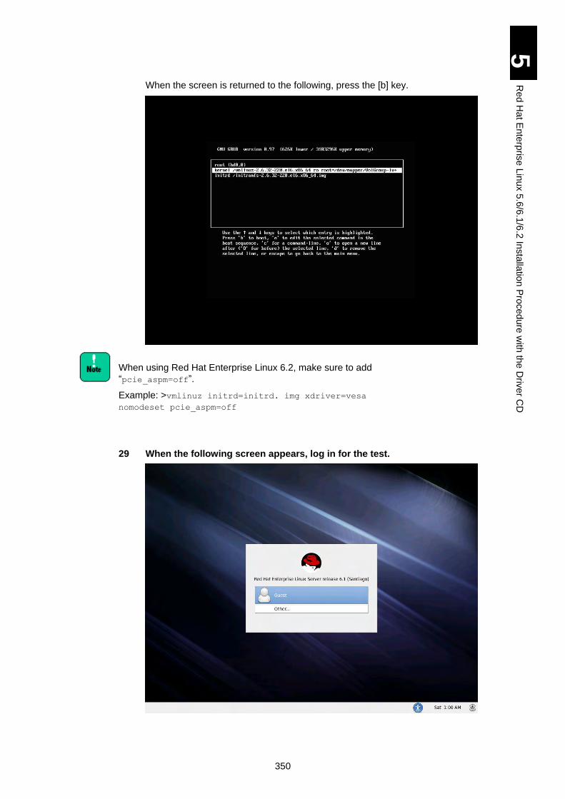
350
5
Re
d H
at E
nte
rpris
e L
inux 5
.6/6
.1/6
.2 In
sta
llatio
n P
roced
ure
with
the
Driv
er C
D
When the screen is returned to the following, press the [b] key.
When using Red Hat Enterprise Linux 6.2, make sure to add
“pcie_aspm=off”.
Example: >vmlinuz initrd=initrd. img xdriver=vesa
nomodeset pcie_aspm=off
29 When the following screen appears, log in for the test.

351
5
Re
d H
at E
nte
rpris
e L
inux 5
.6/6
.1/6
.2 In
sta
llatio
n P
roced
ure
with
the
Driv
er C
D
When using a model with E5503 processor onboard, you
need to set up the OS after installing the OS. See Avoiding
OS Slowdown with E5503 Processor for details.
The installation is completed. Perform Settings after Installation.
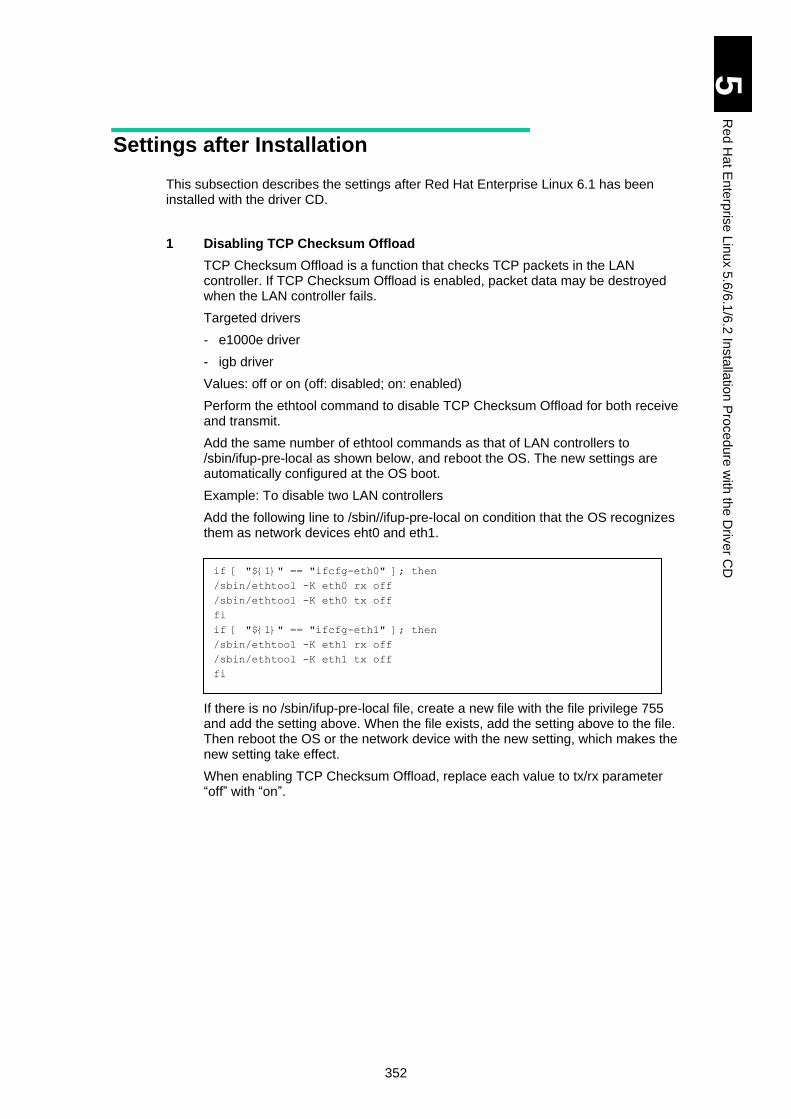
352
5
Re
d H
at E
nte
rpris
e L
inux 5
.6/6
.1/6
.2 In
sta
llatio
n P
roced
ure
with
the
Driv
er C
D
Settings after Installation
This subsection describes the settings after Red Hat Enterprise Linux 6.1 has been installed with the driver CD.
1 Disabling TCP Checksum Offload
TCP Checksum Offload is a function that checks TCP packets in the LAN controller. If TCP Checksum Offload is enabled, packet data may be destroyed when the LAN controller fails.
Targeted drivers
- e1000e driver
- igb driver
Values: off or on (off: disabled; on: enabled)
Perform the ethtool command to disable TCP Checksum Offload for both receive and transmit.
Add the same number of ethtool commands as that of LAN controllers to /sbin/ifup-pre-local as shown below, and reboot the OS. The new settings are automatically configured at the OS boot.
Example: To disable two LAN controllers
Add the following line to /sbin//ifup-pre-local on condition that the OS recognizes them as network devices eht0 and eth1.
If there is no /sbin/ifup-pre-local file, create a new file with the file privilege 755 and add the setting above. When the file exists, add the setting above to the file. Then reboot the OS or the network device with the new setting, which makes the new setting take effect.
When enabling TCP Checksum Offload, replace each value to tx/rx parameter “off” with “on”.
if [ "${1}" == "ifcfg-eth0" ]; then
/sbin/ethtool -K eth0 rx off
/sbin/ethtool -K eth0 tx off
fi
if [ "${1}" == "ifcfg-eth1" ]; then
/sbin/ethtool -K eth1 rx off
/sbin/ethtool -K eth1 tx off
fi

353
5
Re
d H
at E
nte
rpris
e L
inux 5
.6/6
.1/6
.2 In
sta
llatio
n P
roced
ure
with
the
Driv
er C
D
2 Customizing /etc/sysctl.conf
Enable the magic SysRq key to collect information when a problem occurs. Edit or add the following line.
Add a setting to start kernel panic when NMI occurs, with which you can quickly detect a failure in hardware and drivers. Edit or add the following line.
3 Customizing /boot/grub/grub.conrf
Add the following kernel option.
[Red hat Enterprise Linux 6.1 (32-bit x86, 64-bit x86_64)]
[Red Hat Enterprise Linux 6.2 (32-bit x86, 64-bit x86_64)]
Adding the kernel option above configures the following settings.
- Disables nmi_watchdog to use a parameter that stops the system when hardware fails.
- A setting for avoiding Aero from working
- A setting for avoiding ASPM from working
4 Reflecting the new settings
Reboot the OS to reflect the settings configured from step 1 through step 3.
5 Adding/Updating Hitachi drivers
Installing RHEL 6.1 using the driver CD will add or update some drivers.
If with the following condition, install the driver to load tools required for operation.
Connected to the Hitachi disk array system with the hfcldd driver
Reinstall the driver contained in the driver CD-ROM attached to the HITACHI Gigabit Fibre Channel Adapter.
kernel.sysrq = 1
kernel.unknown_nmi_panic = 0
kernel.panic_on_unrecovered_nmi = 1
kernel.panic_on_io_nmi = 1
nmi_watchdog=0 pci=noaer
nmi_watchdog=0 pci=noaer pcie_aspm=off
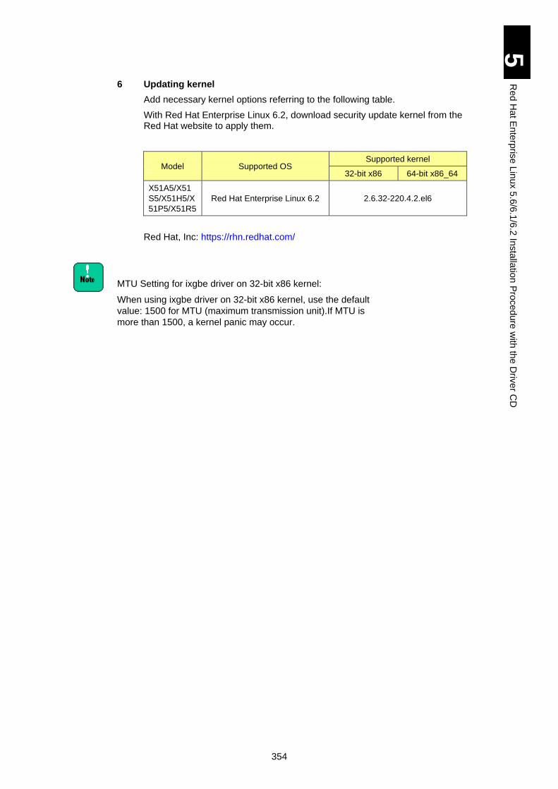
354
5
Re
d H
at E
nte
rpris
e L
inux 5
.6/6
.1/6
.2 In
sta
llatio
n P
roced
ure
with
the
Driv
er C
D
6 Updating kernel
Add necessary kernel options referring to the following table.
With Red Hat Enterprise Linux 6.2, download security update kernel from the Red Hat website to apply them.
Model Supported OS Supported kernel
32-bit x86 64-bit x86_64
X51A5/X51
S5/X51H5/X
51P5/X51R5
Red Hat Enterprise Linux 6.2 2.6.32-220.4.2.el6
Red Hat, Inc: https://rhn.redhat.com/
MTU Setting for ixgbe driver on 32-bit x86 kernel:
When using ixgbe driver on 32-bit x86 kernel, use the default
value: 1500 for MTU (maximum transmission unit).If MTU is
more than 1500, a kernel panic may occur.
355
5
Re
d H
at E
nte
rpris
e L
inux 5
.6/6
.1/6
.2 In
sta
llatio
n P
roced
ure
with
the
Driv
er C
D
Avoiding OS Slowdown with E5503 Processor
This section describes procedures for change in configuration required when you use Red Hat Enterprise Linux 6.1 (32 bit x86, x86_64) on a model with E5503 processor.
Affected models and OSs
Affected model: x5 models with Xeon E5503 processor
Affected OS: Red Hat Enterprise Linux 6.1 (32 bit: x86, 64 bit: x86_64)
Problem
When Red Hat Enterprise Linux 6.1 is used on an affected model, the OS slows down.
Solutions
OS slowdown can be avoided by two configurations of BIOS and OS.
Make sure to change BIOS configuration before installing the OS.
Make sure to change OS configuration after installing the OS.
When a standby server blade has E5503 processor onboard with N+M cold standby, make sure to change BIOS and OS settings for the standby server blade.
(A) Disabling USB2.0 by BIOS configuration
[Starting BIOS setup menu]
1. Power on the server blade.
2. When “press >F2> to enter SETUP, <F9> or <F12> to enter Boot Menu.” is displayed on the bottom of the screen during the server blade startup, press the [F2] key.
[Check processors onboard]
1. Select [Advanced Processor Options] from the Main menu.
2. Check the processor information displayed in [Advanced Processor Options]. When the following contents are displayed, E5503 processor is installed. Then go to the next step to change BIOS configuration.
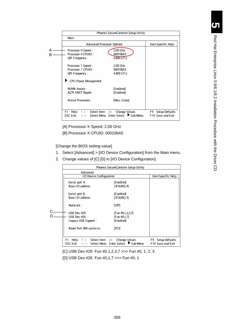
356
5
Re
d H
at E
nte
rpris
e L
inux 5
.6/6
.1/6
.2 In
sta
llatio
n P
roced
ure
with
the
Driv
er C
D
[A] Processor X Speed: 2.00 GHz
[B] Processor X CPUID: 000106A5
[Change the BIOS setting value]
1. Select [Advanced] > [I/O Device Configuration] from the Main menu.
2. Change values of [C] [D] in [I/O Device Configuration].
[C] USB Dev #29 Fun #0,1,2,3,7 >>> Fun #0, 1, 2, 3
[D] USB Dev #26 Fun #0,1,7 >>> Fun #0, 1
Phoenix SecureCore(tm) Setup Utility
Main
Advanced Processor Options Item Specific Help
Processor 0 Speed : 2.00 GHz
Processor 0 CPUID : 000106A5
QPI Frequency : 4.800 GT/s
Processor 1 Speed : 2.00 GHz
Processor 1 CPUID : 000106A5
QPI Frequency : 4.800 GT/s
CPU Power Management
NUMA Aware : [Enabled]
ACPI SRAT Report [Enabled]
Active Processors [Max. Cores]
F1 Help ↑ ↓ Select Item -/+ Change Values F9 Setup Defaults
ESC Exit ←→ Select Menu Enter Select Sub-Menu F10 Save and Exit
A B
Phoenix SecureCore(tm) Setup Utility
Advanced I/O Device Configuration Item Specific Help
Serial port A: [Enabled]
Base I/O address [3F8/IRQ 4]
Serial port B: [Enabled]
Base I/O address [2F8/IRQ 3]
NumLock : [Off]
USB Dev #29 [Fun #0,1,2,3,7]
USB Dev #26 [Fun #0,1,7]
Legacy USB Support : [Enabled]
Route Port 80h cycles to [PCI]
F1 Help ↑ ↓ Select Item -/+ Change Values F9 Setup Defaults
ESC Exit ←→ Select Menu Enter Select Sub-Menu F10 Save and Exit
C D
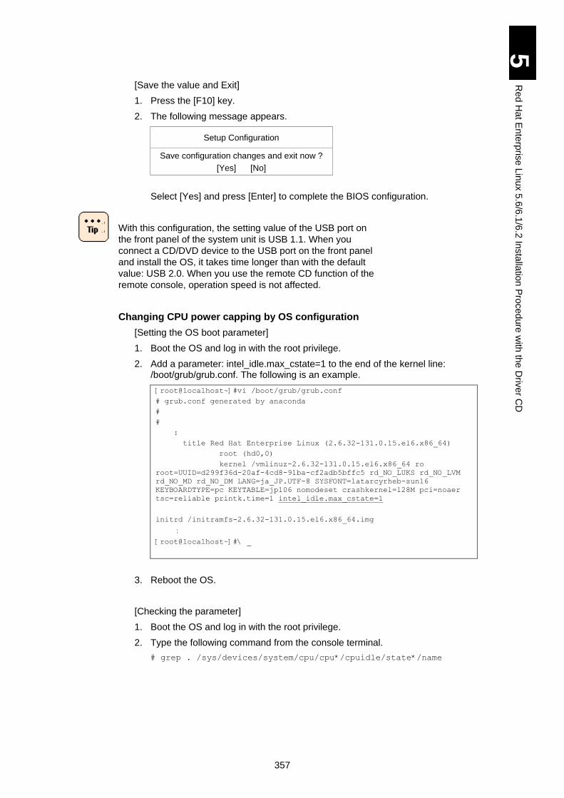
357
5
Re
d H
at E
nte
rpris
e L
inux 5
.6/6
.1/6
.2 In
sta
llatio
n P
roced
ure
with
the
Driv
er C
D
[Save the value and Exit]
1. Press the [F10] key.
2. The following message appears.
Setup Configuration
Save configuration changes and exit now ?
[Yes] [No]
Select [Yes] and press [Enter] to complete the BIOS configuration.
With this configuration, the setting value of the USB port on
the front panel of the system unit is USB 1.1. When you
connect a CD/DVD device to the USB port on the front panel
and install the OS, it takes time longer than with the default
value: USB 2.0. When you use the remote CD function of the
remote console, operation speed is not affected.
Changing CPU power capping by OS configuration
[Setting the OS boot parameter]
1. Boot the OS and log in with the root privilege.
2. Add a parameter: intel_idle.max_cstate=1 to the end of the kernel line: /boot/grub/grub.conf. The following is an example.
[root@localhost~]#vi /boot/grub/grub.conf
# grub.conf generated by anaconda
#
#
:
title Red Hat Enterprise Linux (2.6.32-131.0.15.el6.x86_64)
root (hd0,0)
kernel /vmlinuz-2.6.32-131.0.15.el6.x86_64 ro
root=UUID=d299f36d-20af-4cd8-91ba-cf2adb5bffc5 rd_NO_LUKS rd_NO_LVM
rd_NO_MD rd_NO_DM LANG=ja_JP.UTF-8 SYSFONT=latarcyrheb-sun16
KEYBOARDTYPE=pc KEYTABLE=jp106 nomodeset crashkernel=128M pci=noaer
tsc=reliable printk.time=1 intel_idle.max_cstate=1
initrd /initramfs-2.6.32-131.0.15.el6.x86_64.img
:
[root@localhost~]#\ _
3. Reboot the OS.
[Checking the parameter]
1. Boot the OS and log in with the root privilege.
2. Type the following command from the console terminal.
# grep . /sys/devices/system/cpu/cpu*/cpuidle/state*/name
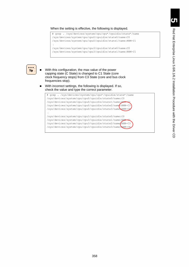
358
5
Re
d H
at E
nte
rpris
e L
inux 5
.6/6
.1/6
.2 In
sta
llatio
n P
roced
ure
with
the
Driv
er C
D
When the setting is effective, the following is displayed.
# grep . /sys/devices/system/cpu/cpu*/cpuidle/state*/name
/sys/devices/system/cpu/cpu0/cpuidle/state0/name:C0
/sys/devices/system/cpu/cpu0/cpuidle/state1/name:NHM-C1
:
/sys/devices/system/cpu/cpu3/cpuidle/state0/name:C0
/sys/devices/system/cpu/cpu3/cpuidle/state1/name:NHM-C1
With this configuration, the max value of the power capping state (C State) is changed to C1 State (core clock frequency stops) from C3 State (core and bus clock frequencies stop).
With incorrect settings, the following is displayed. If so, check the value and type the correct parameter.
# grep . /sys/devices/system/cpu/cpu*/cpuidle/state*/name
/sys/devices/system/cpu/cpu0/cpuidle/state0/name:C0
/sys/devices/system/cpu/cpu0/cpuidle/state1/name:NHM-C1
/sys/devices/system/cpu/cpu0/cpuidle/state2/name:NHM-C3
/sys/devices/system/cpu/cpu0/cpuidle/state3/name:NHM-C6
:
/sys/devices/system/cpu/cpu3/cpuidle/state0/name:C0
/sys/devices/system/cpu/cpu3/cpuidle/state1/name:NHM-C1
/sys/devices/system/cpu/cpu3/cpuidle/state2/name:NHM-C3
/sys/devices/system/cpu/cpu3/cpuidle/state3/name:NHM-C6
359
6 Windows Server 2008/R2 (Xeon) with HVM (Hitachi Virtualization Manager)
This chapter explains the use of Windows Server 2008/R2 (Xeon) in HVM (Hitachi Virtualization Manager) environment. HVM stands for Hitachi Virtualization Manager.
Use of Windows Server 2008/R2 with HVM ........................................................ 360
Restrictions on Windows ..................................................................................... 362
Windows Server 2008/R2 Setup ......................................................................... 366
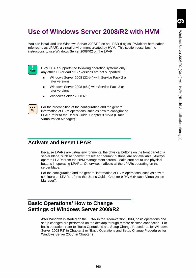
360
6
Win
do
ws S
erv
er 2
00
8/R
2 (X
eo
n) w
ith H
VM
(Hita
ch
i Virtu
aliz
atio
n M
an
age
r)
Use of Windows Server 2008/R2 with HVM
You can install and use Windows Server 2008/R2 on an LPAR (Logical PARtition: hereinafter referred to as LPAR), a virtual environment created by HVM. This section describes the instructions to use Windows Server 2008/R2 on the LPAR.
HVM LPAR supports the following operation systems only:
any other OS or earlier SP versions are not supported:
Windows Server 2008 (32-bit) with Service Pack 2 or later versions
Windows Server 2008 (x64) with Service Pack 2 or later versions
Windows Server 2008 R2
For the precondition of the configuration and the general
information of HVM operations, such as how to configure an
LPAR, refer to the User’s Guide, Chapter 9 “HVM (Hitachi
Virtualization Manager)”.
Activate and Reset LPAR
Because LPARs are virtual environments, the physical buttons on the front panel of a server blade, such as “power”, “reset” and “dump” buttons, are not available. Always operate LPARs from the HVM management screen. Make sure not to use physical buttons in operating LPARs. Otherwise, it affects all the LPARs operating on the server blade.
For the configuration and the general information of HVM operations, such as how to configure an LPAR, refer to the User’s Guide, Chapter 9 “HVM (Hitachi Virtualization Manager)”.
Basic Operations/ How to Change Settings of Windows Server 2008/R2
After Windows is started on the LPAR in the Xeon-version HVM, basic operations and setup changes are performed on the desktop through remote desktop connection. For basic operation, refer to "Basic Operations and Setup Change Procedures for Windows Server 2008 R2” in Chapter 1 or "Basic Operations and Setup Change Procedures for Windows Server 2008” in Chapter 2.
Tip
! Note
361
6
Win
do
ws S
erv
er 2
00
8/R
2 (X
eo
n) w
ith H
VM
(Hita
ch
i Virtu
aliz
atio
n M
an
age
r)
How to Use Supplied Software
You can use Intel(R) PROSet even in the LPAR environment. For descriptions and setup procedures, refer to the followings:
-“How to Use Supplied Software”
in Chapter 1: Windows Server 2008 R2
in Chapter 2: Windows Server 2008
362
6
Win
do
ws S
erv
er 2
00
8/R
2 (X
eo
n) w
ith H
VM
(Hita
ch
i Virtu
aliz
atio
n M
an
age
r)
Restrictions on Windows
This section describes restrictions when using Windows Server 2008/R2.
Restrictions on Windows Server 2008/R2
Refer to Use of Windows Server 2008 R2 in Chapter 1: Windows Server 2008 R2 or Use of Windows Server 2008 in Chapter 2: Windows Server 2008 in advance. Restrictions in the LPAR environment are described below. If both have the same kind of restrictions in the LPAR environment, prioritize the contents described below.
Hyper-V
Hyper-V is not available in the LPAR environment.
Network-related Precautions
When ALB is used, it is recommended that the team should be composed of physical NICs.
With teaming, a virtual NIC and physical NIC cannot be included in the same team.
You can distinguish between virtual NICs and physical NICs (dedicated network adapters assigned to LPAR) by using the following procedures.
Use the PCI bus number of the device:
1 Select [Control Panel] > [System], and click [Device Manager] shown on the left.
2 Click the [+] button in the [Network Adapter]. LAN devices are displayed.
3 Right-click a LAN device, and click [Properties] from the menu.
4 Check the location in the [General] tab.
An adapter with the PCI bus of 127 is a virtual NIC. A virtual NIC number in LPAR is the same value as subtracted one (1) from the device value.
Any other PCI bus than 127 is a physical NIC.
Use the MAC address
1 View the MAC address used for a virtual NIC in the HVM VNIC Assignment screen.
Write down the MAC address of the target virtual NIC.
2 Boot Windows, and then enter the following command in the command prompt.
ipconfg/all ( stands for a space.)
When information on all LAN adapters is displayed, search the target virtual NIC using the MAC address as a key.
When composing a team from the virtual NIC and shared NIC, set the following items in the [Advanced] tab, [Properties] of the adapter consisting of teams.
Activation delay: 60 (the recommended value)
Probe: invalid
If the virtual NIC and shared NIC form an AFT, SFT, or ALB team, a lot of team switch events may be registered in the event viewer. It is recommended that the Probe consisting of teams should be disabled. Link-down is the only trigger to
363
6
Win
do
ws S
erv
er 2
00
8/R
2 (X
eo
n) w
ith H
VM
(Hita
ch
i Virtu
aliz
atio
n M
an
age
r)
switch teams. Refer to “Advanced Function for LAN: Windows Server 2003/R2; Windows Server 2008” or “Advanced Function for LAN: Windows Server 2008 R2”, Appendix I and II to this manual for how to disable Probes.
For the Intel(R) PROSet functionality, such as AFT, SFT, and ALB, and working conditions, refer to the following document and/or files in “DriverKit”.
“Advanced Function for LAN: Windows Server 2003/R2; Windows Server 2008” or “Advanced Function for LAN: Windows Server 2008 R2”, as Appendix I and II to this manual.
Windows Server 2008:
d: OPTION\TOOLS\Win2008\PROSetDX\APPS\PROSETDX
Windows Server 2008 R2
d: OPTION\TOOLS\Win2008R2\PROSetDX\APPS\PROSETDX
Identifying the Virtual and Shared NIC Adapter If you use the shared NIC adapter in an environment with Intel® PROSet installed, you cannot identify the adapter by using the "Identify Adapter" function on the "Link" tab for the properties of the extended network adapter "Intel® PRO/1000 MF Dual Port Network Connection".
When using Jumbo Frame in the virtual NIC and shared NIC, set the size to “4088” or smaller out of values that can be set in the Intel LAN driver. Communication is not available with values more than 4088.
TCP/IP Checksum Offload function of the network adapter
The "onboard LAN adapter" and the "expanded LAN board" have the TCP/IP protocol checksum calculation function that is executed on LAN controller.
It is recommended, however, that the TCP/IP checksum calculation function provided by OS as standard should be used rather than this function.
You can construct more highly reliable system if the calculation function of OS side is set available.
Because the consistency check of the packet data received from the network will be performed in the last phase of the OS protocol processing.
Change the setting of LAN adapter to turn the checksum function by the LAN controller off as described in the Note below.
When you configure a cluster, it is recommended that a physical NIC should be assigned for heartbeat.
364
6
Win
do
ws S
erv
er 2
00
8/R
2 (X
eo
n) w
ith H
VM
(Hita
ch
i Virtu
aliz
atio
n M
an
age
r)
When using the advanced functions for LAN of Intel(R)
PROSet, such as AFT, ALB, SFT, or Tag VLAN, delete the
advanced functions before the setting. Re-configure the
advanced functions for LAN after the setting.
From [Device Manager], open [Properties] for each LAN
adapter, and set each item “off”. Then reboot the system.
- "Off-load of lpv4 checksum"
- "Off-load of TCP checksum" (lpv4)
- "Off-load of TCP checksum" (lpv6)
- "Off-load of UDP checksum" (lpv4)
- "Off-load of UDP checksum" (lpv6)
- “Scaling on the Receive side”
Restart the system equipment after the setting change.
When using a virtual NIC or shared NIC adapter, set the
following items “off” or “Send Enabled”. Otherwise,
communication may not be available with default values.
- "Off-load of lpv4 checksum"
- "Off-load of TCP checksum (lpv4)"
- "Off-load of UDP checksum (lpv4)"
- “Large Send Off-load (LSO) v2 (IPv4)”
Some items may not be displayed depending on the type of a
network adapter. Set items displayed with you adapter.
Tip
! Note
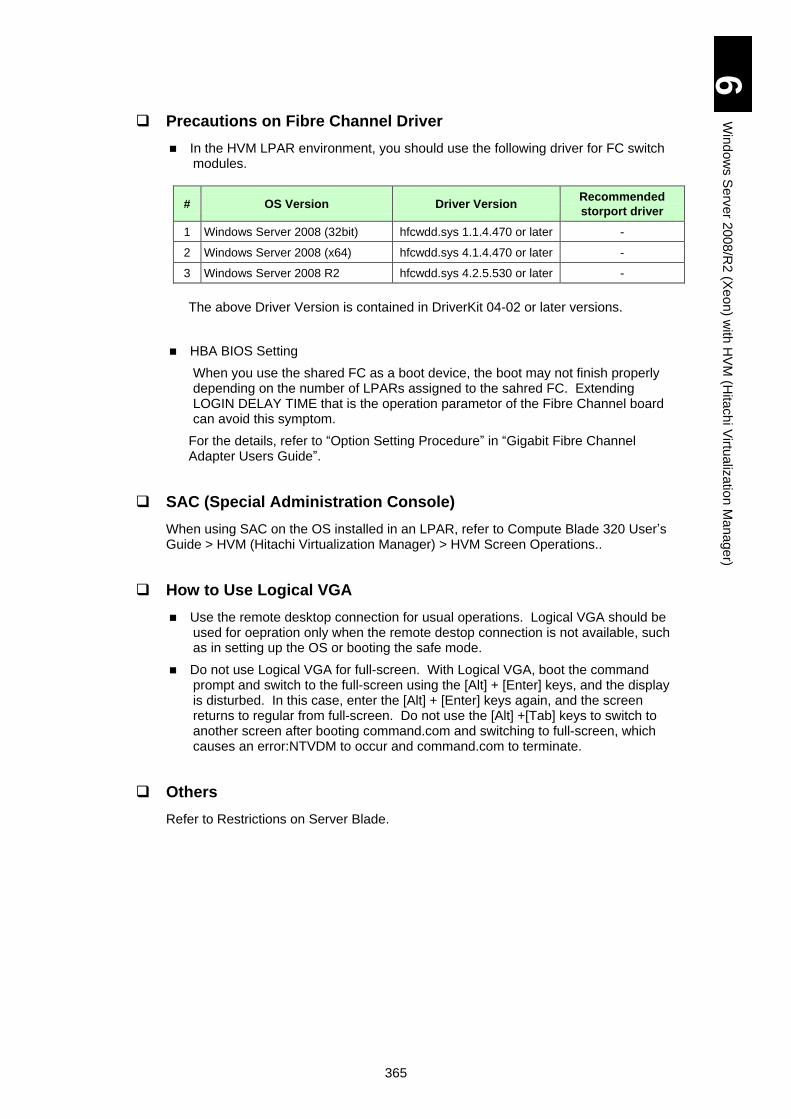
365
6
Win
do
ws S
erv
er 2
00
8/R
2 (X
eo
n) w
ith H
VM
(Hita
ch
i Virtu
aliz
atio
n M
an
age
r)
Precautions on Fibre Channel Driver
In the HVM LPAR environment, you should use the following driver for FC switch modules.
# OS Version Driver Version Recommended
storport driver
1 Windows Server 2008 (32bit) hfcwdd.sys 1.1.4.470 or later -
2 Windows Server 2008 (x64) hfcwdd.sys 4.1.4.470 or later -
3 Windows Server 2008 R2 hfcwdd.sys 4.2.5.530 or later -
The above Driver Version is contained in DriverKit 04-02 or later versions.
HBA BIOS Setting
When you use the shared FC as a boot device, the boot may not finish properly depending on the number of LPARs assigned to the sahred FC. Extending LOGIN DELAY TIME that is the operation parametor of the Fibre Channel board can avoid this symptom.
For the details, refer to “Option Setting Procedure” in “Gigabit Fibre Channel Adapter Users Guide”.
SAC (Special Administration Console)
When using SAC on the OS installed in an LPAR, refer to Compute Blade 320 User’s Guide > HVM (Hitachi Virtualization Manager) > HVM Screen Operations..
How to Use Logical VGA
Use the remote desktop connection for usual operations. Logical VGA should be used for oepration only when the remote destop connection is not available, such as in setting up the OS or booting the safe mode.
Do not use Logical VGA for full-screen. With Logical VGA, boot the command prompt and switch to the full-screen using the [Alt] + [Enter] keys, and the display is disturbed. In this case, enter the [Alt] + [Enter] keys again, and the screen returns to regular from full-screen. Do not use the [Alt] +[Tab] keys to switch to another screen after booting command.com and switching to full-screen, which causes an error:NTVDM to occur and command.com to terminate.
Others
Refer to Restrictions on Server Blade.
366
6
Win
do
ws S
erv
er 2
00
8/R
2 (X
eo
n) w
ith H
VM
(Hita
ch
i Virtu
aliz
atio
n M
an
age
r)
Windows Server 2008/R2 Setup
This section explains the setup for Windows Server 2008/R2.
For the installation procedure of the driver for mezzanine cards, refer to the manual of mezzanine cards.
When installing Windows, driver, or utility, use the DriverKit
04-02 or later version CD-ROM. Ask your reseller for the
latest version. Do not use other versions for Windows Server
2008/R2 setup.
Some recommended patch modules or the latest drivers may
be required for Windows Server 2008/R2. Check Microsoft
website to obtain required modules and drivers in advance.
How to Setup
This section describes how to setup Windows Server 2008/R2 on HVM LPAR. Basically, follow “Windows Server 2008 R2 Setup” in Chapter 1 or “Windows Server 2008 Setup” in Chapter 2. Instructions and restrictions on HVM LPAR environment are described below. Read this chapter to the end once, and then proceed to “Windows Server 2008 R2 Setup” or “Windows Server 2008 Setup”.
OS Setup
This section describes instructions and restrictions on setting up Windows Server 2008/R2 in HVM LPAR environment. Basically, follow instructions and restrictions on the server blade. If some of them overlap, prioritize the description below.
NOTICE
Re-setup causes the hard disk data to disappear. Back up data that you need in advance.
Tip
! Note
367
6
Win
do
ws S
erv
er 2
00
8/R
2 (X
eo
n) w
ith H
VM
(Hita
ch
i Virtu
aliz
atio
n M
an
age
r)
Setup Procedure
Setup procedure is equivalent to the description in “Windows Server 2008 R2”, Chapter 1 or “Windows Server 2008”, Chapter 2. Prerequisites before the setup are as follows:
Assign a USB device to an LPAR for OS setup.
Operate the setup through the logical VGA screen. Refer to “HVM (Hitachi Virtualization Manager)” in Compute Blade 320 User’s Guide for how to assign a USB device, and how to view or operate the Logical VGA screen.
Set to boot the OS from the DVD-ROM drive connected via USB on the logical EFI of LPAR. Refer to “HVM (Hitachi Virtualization Manager)” in Compute Blade 320 Users Guide.
Set the FC switch module before the OS setup. When setting on the LPAR, operate the logical EFI Shell of LPAR.
Refer to “HVM (Hitachi Virtualization Manager)” in Compute Blade 320 Users Guide for how to enter the logical EFI Shell.
Refer to “EFI Driver” in “HITACHI Gigabit Fibre Channel Adapter Users Guide” for the details of the adapter setting.
For actual setup procedures, refer to “Details of Windows Server 2008 R2 Setup” in Chapter 1 or “Details of Windows Server 2008 Setup” in Chapter 2.
Restrictions on Setup
Boot Device
Only FC mezzanine cards are available as a boot device. Read the installing procedure referring to instructions on FC mezzanine cards.
Remote KVM
When setting up Windows, use the remote KVM through the logical VGA screen of LPAR.
Configure an LPAR to setup Windows before the setup referring to “HVM (Hitachi Virtualization Manager)” in Compute Blade 320 User’s Guide. The recommended LPAR configuration for Windows Server 2008/R2 is as follows
Adjust resources to assign to the LPAR for the purpose or environment.
Processor: Two or more
Memory: 2.0GB or larger
Disk: 40 GB or larger for a partition to set up OS
Disk: At least one virtual NIC for the remote desktop connection
The virtual NIC may not be recognized as a network device at the first OS boot after the setup. Reboot the OS, and it will be recognized correctly.
When a USB port, different from the port used when the boot option is registered, is used, the USB DVD-ROM drive may not be recognized. In that case, re-register the boot option.
LPARs in HVM are virtual environments. When you are asked to type a product key at OS setup, use the key for a virtual environment.

368
6
Win
do
ws S
erv
er 2
00
8/R
2 (X
eo
n) w
ith H
VM
(Hita
ch
i Virtu
aliz
atio
n M
an
age
r)
Driver/Utility Setup
This section describes instructions and restrictions on setting up drivers and utilities for Windows Server 2008/R2 in HVM LPAR environment. Basically, follow instructions and restrictions on the server blade. If some of them overlap, prioritize the description below.
Setup Procedure
Refer to “Driver/Utility Setup” in Chapter 1 or 2 for the specific setup procedures as P4 model.
Restrictions on Setup
Display driver
Refer to “Display Driver” in Chapter 1 or 2 for the specific procedure.
It is not necessary to install the display driver in the LPAR environment.
LAN driver (Only for Windows Server 2008 R2)
Drivers for the virtual NIC and shared NIC are stored in the separate folders. When installing “LAN Driver” referring to the procedure in Chapter 1, install the driver using the following folder.
d: Win2008R2\LAN\INTEL_02\x64
d: is a CD/DVD drive name.
369
7 Windows Server 2003/R2 (Xeon) with HVM (Hitachi Virtualization Manager)
This chapter explains the use of Windows Server 2003 (Xeon) in HVM (Hitachi Virtualization Manager) environment. HVM is used for Hitachi Virtualization Manager.
Use of Windows Server 2003/R2 with HVM ........................................................ 370
Restrictions on Windows ..................................................................................... 372
Windows Server 2003/R2 Setup ......................................................................... 376
370
7
Win
do
ws S
erv
er 2
00
3/R
2 (X
eo
n) w
ith H
VM
(Hita
ch
i Virtu
aliz
atio
n M
an
age
r)
Use of Windows Server 2003/R2 with HVM
You can install and use Windows Server 2003/R2 on an LPAR (Logical PARtition: hereinafter referred to as LPAR), a virtual environment created by HVM. This section describes the instructions to use Windows Server 2003/R2 on the LPAR.
The LPAR in HVM supports only the following Windows
versions with SP among Windows 2003/R2.
- Windows Server 2003/R2 (32-bit)
with Service Pack 2 or a later version
- Windows Server 2003/R2 x64 Editions
with Service Pack 2 or a later version
Other Windows Server 2003/R2 and the earlier version
Service Pack are not supported.
For the precondition of the configuration and the general
information of HVM operations, such as how to configure
an LPAR, refer to the User’s Guide, Chapter 9 “HVM
(Hitachi Virtualization Manager)”.
In addition to above, other settings are required. Refer to
the User’s Guide, Chapter 9 “HVM (Hitachi Virtualization
Manager)” for details.
Activate and Reset LPAR
Because LPARs are virtual environments, the physical buttons on the front panel of a server blade, such as “power”, “reset” and “dump” buttons, are not available. Always operate LPARs from the HVM management screen. Make sure not to use physical buttons in operating LPARs. Otherwise, it affects all the LPARs operating on the server blade.
For the configuration and the general information of HVM operations, such as how to configure an LPAR, refer to the User’s Guide, Chapter 9 “HVM (Hitachi Virtualization Manager)”.
Tip
! Note
371
7
Win
do
ws S
erv
er 2
00
3/R
2 (X
eo
n) w
ith H
VM
(Hita
ch
i Virtu
aliz
atio
n M
an
age
r)
Basic Operations/ How to Change Settings of Windows Server 2003/R2
After Windows is started on the LPAR, basic operations and setup changes are performed on the desktop through remote desktop connection. For basic operation, refer to "Basic Operations/ How to Change Settings of Windows Server 2003/R2 ”.
When executing the remote desktop connection of Windows Server 2003, start the application “Remote Desktop Connection” on Windows of the operation terminal. Start the application using the following command line with/console option or admin option without fail, not from the short cut in the start menu.
mstsc.exe/console (or mstsc.exe/admin)
If starting the application “Remote Desktop Connection” using other method such as the icon in the start menu,
not the command ‘mstsc.exe/console’ or
mstsc.exe/admin, a certain function of Windows may not be available. Make sure to execute a command,
‘mstsc.exe/console’ or mstsc.exe/admin, to start “Remote Desktop Connection”.
A command to use is different depending on a “Remote Desktop Connection (mstsc.exe)” version. /console: earlier versions than v61. /admin: v6.1 or later versions
How to Use Supplied Software
You can use Intel(R) PROSet even in the LPAR environment. For descriptions and setup procedures, refer to the followings:
“Windows Server 2003/R2” > “How to Use Supplied Software”
Tip
372
7
Win
do
ws S
erv
er 2
00
3/R
2 (X
eo
n) w
ith H
VM
(Hita
ch
i Virtu
aliz
atio
n M
an
age
r)
Restrictions on Windows
This section describes restrictions when using Windows Server 2003/R2.
Restrictions on Windows Server 2003/R2
Refer to Use of Windows Server 2003/R2 in Chapter 3: Windows Server 2003/R2 in advance. Instructions and restrictions in the LPAR environment are described below. If both have the same kind of restrictions in the LPAR environment, prioritize the contents described below.
Use of Software
Prerequisites and restrictions on using Windows Server 2003 in the LPAR environment are for the system equivalent to other models.
Refer to ‘User of Software’ in Chapter 3 “Windows Server 2003/R2” beforehand.
Refer to the User’s Guide, Chapter 9 “HVM (Hitachi Virtualization Manager)” for configurations and instructions on HVM.
Additional instructions in the LPAR environment are described below.
SAC (Special Administration Console)
When using SAC on the OS installed in an LPAR, refer to Compute Blade 320 User’s Guide > HVM (Hitachi Virtualization Manager) > HVM Screen Operations.
Network-related Precautions
When ALB is used, it is recommended that the team should be composed of physical NICs.
With teaming, a virtual NIC and physical NIC cannot be included in the same team.
You can distinguish between virtual NICs and physical NICs (dedicated network adapters assigned to LPAR) by using the following procedures.
Use the PCI bus number of the device:
1 Select [Control Panel] > [System], and click [Hardware] tab > [Device Manager] in [Device Manager:
2 Click the [+] button in the [Network Adapter]. LAN devices are displayed.
3 Right-click a LAN device, and click [Properties] from the menu.
4 Check the location in the [General] tab.
An adapter with the PCI bus of 127 is a virtual NIC. A virtual NIC number in LPAR is the same value as subtracted one (1) from the device value.
Any other PCI bus than 127 is a physical NIC.
Use the MAC address
1 View the MAC address used for a virtual NIC in the HVM VNIC Assignment screen.
Write down the MAC address of the target virtual NIC.
373
7
Win
do
ws S
erv
er 2
00
3/R
2 (X
eo
n) w
ith H
VM
(Hita
ch
i Virtu
aliz
atio
n M
an
age
r)
2 Boot Windows, and then enter the following command in the command prompt.
ipconfg/all ( stands for a space.)
When information on all LAN adapters is displayed, search the target virtual NIC using the MAC address as a key.
When composing a team from the virtual NIC and shared NIC, set the following items in the [Advanced] tab, [Properties] of the adapter consisting of teams.
Activation delay: 60 (the recommended value)
Probe: invalid
If the virtual NIC and shared NIC form an AFT, SFT, or ALB team, a lot of team switch events may be registered in the event viewer. It is recommended that the Probe consisting of teams should be disabled. Link-down is the only trigger to switch teams. Refer to “Advanced Function for LAN: Windows Server 2008; Windows Server 2003/R2”, Appendix I to this manual for how to disable Probe.
When the internal LAN device of the server blade is used for teaming, SFT configuration is recommendable: AFT/ALB are not available as Xeon server blade.
For the Intel(R) PROSet functionality, such as AFT, SFT, and ALB, and working conditions, refer to the following document and/or files in “DriverKit”.
“Advanced Function for LAN: Windows Server 2008; Windows Server 2003/R2” as Appendix I to this manual.
Windows Server 2003/R2:
d: OPTION\TOOLS\\Win2003\INTELLAN\APPS\PROSETDX
d: OPTION\TOOLS\\Win2003x64\INTELLAN\APPS\PROSETDX
Identifying the Virtual and Shared NIC Adapter If you use the shared NIC adapter in an environment with Intel(R) PROSet installed, you cannot identify the adapter by using the "Identify Adapter" function on the "Link" tab for the properties of the extended network adapter "Intel(R) PRO/1000 MF Dual Port Network Connection".
When using Jumbo Frame in the virtual NIC and shared NIC, set the size to “4088” or smaller out of values that can be set in the Intel LAN driver. Communication is not available with values more than 4088.
TCP/IP Checksum Offload function of the network adapter
The "onboard LAN adapter" and the "expansion LAN board" have the TCP/IP protocol checksum calculation function that is executed on LAN controller.
It is recommended, however, that the TCP/IP checksum calculation function provided by OS as standard should be used rather than this function.
You can construct more highly reliable system if the calculation function of OS side is set available.
Because the consistency check of the packet data received from the network will be performed in the last phase of the OS protocol processing.
Change the setting of LAN adapter to turn the checksum function by the LAN controller off as described in the Note below.
When you configure a cluster, it is recommended that a physical NIC should be assigned for heartbeat.
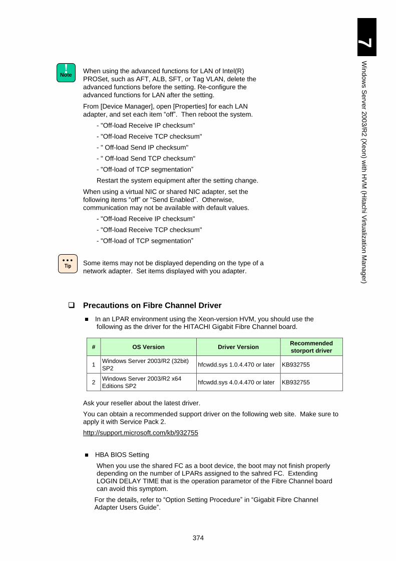
374
7
Win
do
ws S
erv
er 2
00
3/R
2 (X
eo
n) w
ith H
VM
(Hita
ch
i Virtu
aliz
atio
n M
an
age
r)
When using the advanced functions for LAN of Intel(R)
PROSet, such as AFT, ALB, SFT, or Tag VLAN, delete the
advanced functions before the setting. Re-configure the
advanced functions for LAN after the setting.
From [Device Manager], open [Properties] for each LAN
adapter, and set each item “off”. Then reboot the system.
- "Off-load Receive IP checksum"
- "Off-load Receive TCP checksum"
- " Off-load Send IP checksum"
- " Off-load Send TCP checksum"
- "Off-load of TCP segmentation”
Restart the system equipment after the setting change.
When using a virtual NIC or shared NIC adapter, set the
following items “off” or “Send Enabled”. Otherwise,
communication may not be available with default values.
- "Off-load Receive IP checksum"
- "Off-load Receive TCP checksum"
- "Off-load of TCP segmentation”
Some items may not be displayed depending on the type of a
network adapter. Set items displayed with you adapter.
Precautions on Fibre Channel Driver
In an LPAR environment using the Xeon-version HVM, you should use the following as the driver for the HITACHI Gigabit Fibre Channel board.
# OS Version Driver Version Recommended
storport driver
1 Windows Server 2003/R2 (32bit)
SP2 hfcwdd.sys 1.0.4.470 or later KB932755
2 Windows Server 2003/R2 x64
Editions SP2 hfcwdd.sys 4.0.4.470 or later KB932755
Ask your reseller about the latest driver.
You can obtain a recommended support driver on the following web site. Make sure to apply it with Service Pack 2.
http://support.microsoft.com/kb/932755
HBA BIOS Setting
When you use the shared FC as a boot device, the boot may not finish properly depending on the number of LPARs assigned to the sahred FC. Extending LOGIN DELAY TIME that is the operation parametor of the Fibre Channel board can avoid this symptom.
For the details, refer to “Option Setting Procedure” in “Gigabit Fibre Channel Adapter Users Guide”.
Tip
! Note
375
7
Win
do
ws S
erv
er 2
00
3/R
2 (X
eo
n) w
ith H
VM
(Hita
ch
i Virtu
aliz
atio
n M
an
age
r)
How to Use Logical VGA
Use the remote desktop connection for usual operations. Logical VGA should be used for oepration only when the remote destop connection is not available, such as OS setup or booting the safe mode.
Do not use Logica VGA for full-screen. With Logical VGA, boot the command prompt and switch to the full-screen using the [Alt] + [Enter] keys, and the display is disturbed. In this case, enter the [Alt] + [Enter] keys again, and the screen returns to regular from full-screen. Do not use the [Alt] +[Tab] keys to switch to another screen after booting command.com and switching to full-screen, which causes an error:NTVDM to occur and command.com to terminate
Others
Refer to Restrictions on Server Blade.
376
7
Win
do
ws S
erv
er 2
00
3/R
2 (X
eo
n) w
ith H
VM
(Hita
ch
i Virtu
aliz
atio
n M
an
age
r)
Windows Server 2003/R2 Setup
This section explains the setup for Windows Server 2003/R2.
For the installation procedure of the driver for mezzanine cards, refer to the manual of mezzanine cards.
Windows Server 2003 may have the recommended patches
or the latest drivers to apply.
How to Setup
This section describes how to setup Windows Server 2003/R2 on HVM LPAR. Basically, follow “Windows Server 2003/R2 Setup” in Chapter 3. Instructions and restrictions on HVM LPAR environment are described below. Read this chapter to the end once, and then proceed to “Windows Server 2003/R2 Setup”
NOTICE
Re-setup causes the hard disk data to disappear. Back up data that you need in advance.
Tip
377
7
Win
do
ws S
erv
er 2
00
3/R
2 (X
eo
n) w
ith H
VM
(Hita
ch
i Virtu
aliz
atio
n M
an
age
r)
Windows Server 2003/R2 Setup
This section describes instructions and restrictions on setting up Windows Server 2003/R2 in HVM LPAR environment. Basically, follow instructions and restrictions on the server blade. If some of them overlap, prioritize the description below.
Setup Procedure
Setup procedure is equivalent to the description in “Windows Server 2003/R2”, Chapter 3. Prerequisites before the setup are as follows:
Assign a USB device to an LPAR for OS setup.
Operate the setup through the logical VGA screen. Refer to “HVM (Hitachi Virtualization Manager)” in Compute Blade 320 User’s Guide for how to assign a USB device, and how to view or operate the Logical VGA screen.
Connect a USB FD drive to the USB port on the front panel of the server blade. The remote FD drive of the remote console application is not recognized during setting up Windows, which is not available for setup. Use the remote CD/DVD ROM drive of the remote console application.
Set to boot the OS from the DVD-ROM drive connected via USB on the logical EFI of LPAR. Refer to “HVM (Hitachi Virtualization Manager)” in Compute Blade 320 Users Guide.
Set the HITACHI Gigabit Fibre Channel adapter before the OS setup. When setting on the LPAR, operate the logical EFI Shell of LPAR.
Refer to “HVM (Hitachi Virtualization Manager)” in Compute Blade 320 User’s Guide for how to enter the logical EFI Shell.
Refer to “EFI Driver” in “HITACHI Gigabit Fibre Channel Adapter Users Guide” for the details of the adapter setting.
For actual setup procedures, refer to “Details of Windows Server 2003/R2 Setup” in Chapter 3.
Restrictions on Setup
FC mezzanine card
Only FC mezzanine cards are available as a boot device. Read the installing procedure referring to instructions on FC mezzanine cards.
At setup, assign a single FC mezzanine card to an LPAR for boot. If another FC mezzanine card exists, the LPAR can be rebooted during chipset driver installation. This can cause the driver not to be installed properly. If you need to use multiple FC mezzanine cards on an LPAR, apply the chip set driver before adding the other FC mezzanine cards to the LPAR.
Remote KVM
When setting up Windows, use the remote KVM through the logical VGA screen of LPAR.
Connect a physical USB FD drive and remote CD/DVD-ROM drive to the front panel of the server blade, and assign the USB device to the LPAR using the USB shared function.
Configure an LPAR to setup Windows before the setup referring to “HVM (Hitachi Virtualization Manager)” in Compute Blade 320 User’s Guide. The recommended LPAR configuration for Windows Server 2003/R2 is as follows
Adjust resources to assign to the LPAR for the purpose or environment.

378
7
Win
do
ws S
erv
er 2
00
3/R
2 (X
eo
n) w
ith H
VM
(Hita
ch
i Virtu
aliz
atio
n M
an
age
r)
Processor: Two or more
Memory: 768 MB or larger
Disk: 10GB or larger for the partition on which the OS is set up.
Network: At least one virtual NIC for the remote desktop connection
The LPAR on HVM supports only the following Windows versions with SP among Windows 2003/R2: Windows Server 2003/R2 with Service Pack 2 or a later version. Other Windows Server 2003/R2 and the earlier version Service Pack are not supported.
Make sure to use OS media with SP1 or SP2 for setting up Windows Server 2003 (32-bit). Windows Server 2003 first edition is not available. Windows Server 2003 R2 media are equivalent to Windows Server 2003 with SP1. Make sure to apply SP2 after setting up the OS.
The virtual NIC may not be recognized as a network device at the first OS boot after the setup. Reboot the OS, and it will be recognized correctly.
The USB DVD-ROM drive may not be recognized if you use a different USB port from the USB port used when registering the boot option. In that case, re-register the boot option.
Display driver
Skip the procedure of Display Driver in Chapter 3. Installing a display driver is not necessary in the LPAR environment.
After the OS setup, set the resolution and the number of colors: click [Control Panel] to open [Screen], and set those items in the [Setting] tab. With 16-color (4-bit) mode, part of the window may not be displayed properly.

379
8 Red Hat Enterprise Linux Version 5.3 / Version 5.4 /Version 5.6 with HVM (Hitachi Virtualization Manager)
This chapter explains the use of Red Hat Enterprise Linux Version 5.3/5.4/5.6 (Xeon) in HVM (Hitachi Virtualization Manager) environment. HVM stands for Hitachi Virtualization Manager.
Please note that this chapter may be updated without notice.
How to Install Red Hat Enterprise Linux 5.3/5.4/5.6 ............................................ 380

380
8
Re
d H
at E
nte
rpris
e L
inux V
ers
ion
5.3
/ Ve
rsio
n 5
.4 / V
ers
ion
5.6
with
HV
M (H
itach
i Virtu
aliz
atio
n M
an
ag
er)
How to Install Red Hat Enterprise Linux 5.3/5.4/5.6
Prerequisites to install
Prerequisites before the install are as follows:
Assign a USB device to an LPAR for OS install.
Operate the install through the logical VGA screen. Refer to “HVM (Hitachi Virtualization Manager)” in Compute Blade 2000 Users Guide for how to assign a USB device, and how to view or operate the Logical VGA screen.
Set to boot the OS from the DVD-ROM drive connected via USB on the logical EFI of LPAR. Refer to “HVM (Hitachi Virtualization Manager)” in Compute Blade 2000 Users Guide.
Set the HITACHI Gigabit Fibre Channel adapter before the OS install. When setting on the LPAR, operate the logical EFI Shell of LPAR.
Refer to “HVM (Hitachi Virtualization Manager)” in Compute Blade 2000 Users Guide for how to enter the logical EFI Shell.
Refer to “EFI Driver” in “HITACHI Gigabit Fibre Channel Adapter Users Guide” for the details of the adapter setting.
The hfcldd driver media is necessary for OS installation. Refer to “HITACHI Gigabit Fibre Channel Adapter Users Guide” > “Appendix A” for how to create the hfcldd driver media.
Check your system hardware configuration before installing
the OS. When you configure the hardware including the LSI
MegaRAID SAS and Hitachi Gigabit Fibre Channel Adapter
and use the fibre channel adapter as a boot device, set the
following in the BIOS Setup menu before OS installation:
[Advanced] > [Launch Storage OpROM]: Select “Disabled”.
NOTICE
Re-setup causes the hard disk data to disappear. Back up data that you need in advance.

381
8
Re
d H
at E
nte
rpris
e L
inux V
ers
ion
5.3
/ Ve
rsio
n 5
.4 / V
ers
ion
5.6
with
HV
M (H
itach
i Virtu
aliz
atio
n M
an
ag
er)
Procedure to Install
1 Connect a USB CD-ROM or USB DVD-ROM drive to the system device.
Connect a USB CD-ROM drive or a USB DVD-ROM drive
according to User’s Guide.
Installation using a USB drive not supported by the system
device is not guaranteed.
The remote CD/DVD function of the remote console is not
available.
2 Insert Installation Media Disk1 of Red Hat Enterprise Linux 5.3/5.4/5.6 into the USB-CD ROM or USB-DVD ROM.
3 Activate an LPAR, and connect to the LPAR via remote console.
4 Boot the system from the USB CD-ROM or USB-DVD ROM.
5 When the following screen appears, input “linux dd” at boot: prompt and then press the [Enter] key.
! Note
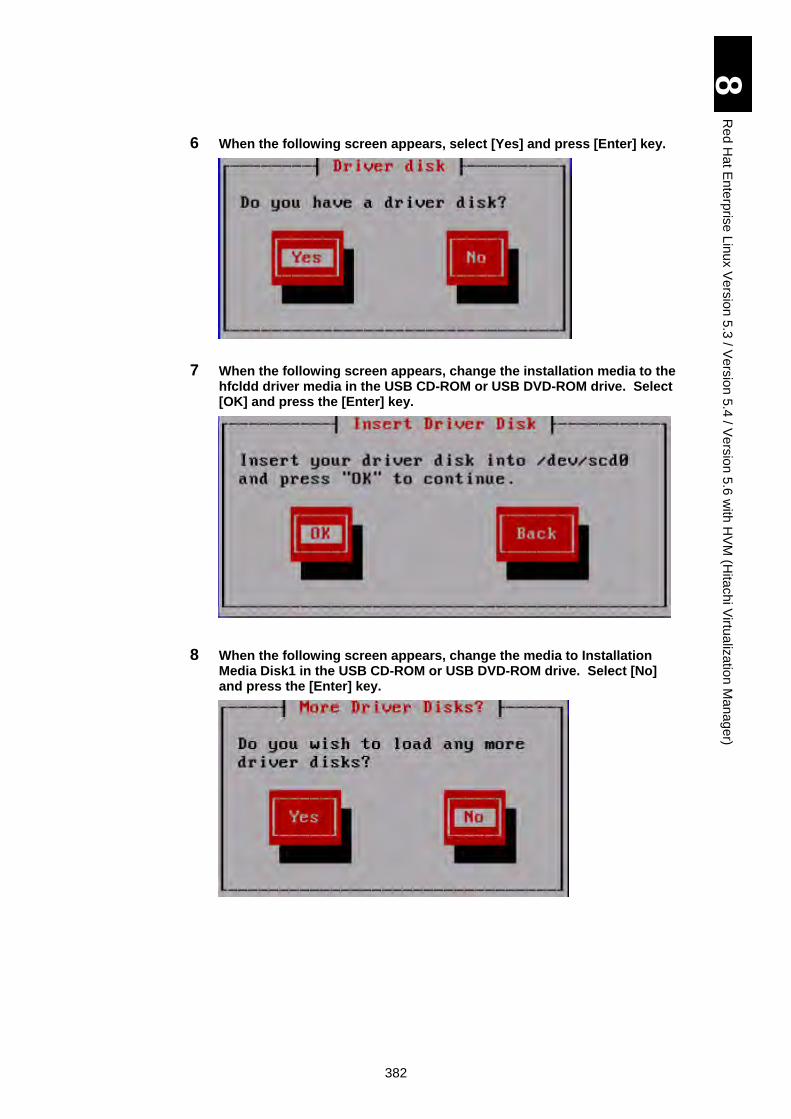
382
8
Re
d H
at E
nte
rpris
e L
inux V
ers
ion
5.3
/ Ve
rsio
n 5
.4 / V
ers
ion
5.6
with
HV
M (H
itach
i Virtu
aliz
atio
n M
an
ag
er)
6 When the following screen appears, select [Yes] and press [Enter] key.
7 When the following screen appears, change the installation media to the hfcldd driver media in the USB CD-ROM or USB DVD-ROM drive. Select [OK] and press the [Enter] key.
8 When the following screen appears, change the media to Installation Media Disk1 in the USB CD-ROM or USB DVD-ROM drive. Select [No] and press the [Enter] key.
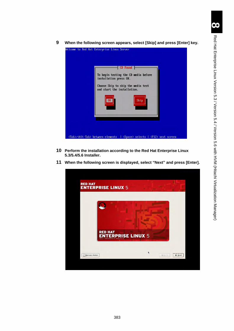
383
8
Re
d H
at E
nte
rpris
e L
inux V
ers
ion
5.3
/ Ve
rsio
n 5
.4 / V
ers
ion
5.6
with
HV
M (H
itach
i Virtu
aliz
atio
n M
an
ag
er)
9 When the following screen appears, select [Skip] and press [Enter] key.
10 Perform the installation according to the Red Hat Enterprise Linux 5.3/5.4/5.6 Installer.
11 When the following screen is displayed, select “Next” and press [Enter].
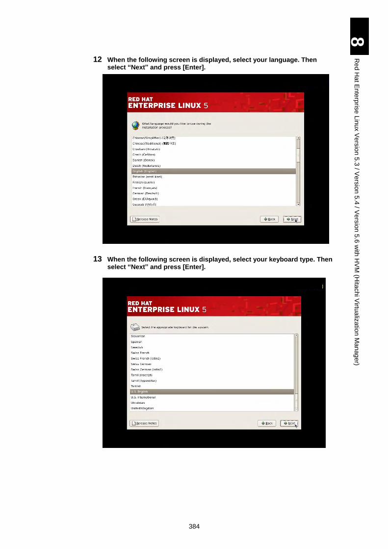
384
8
Re
d H
at E
nte
rpris
e L
inux V
ers
ion
5.3
/ Ve
rsio
n 5
.4 / V
ers
ion
5.6
with
HV
M (H
itach
i Virtu
aliz
atio
n M
an
ag
er)
12 When the following screen is displayed, select your language. Then select “Next” and press [Enter].
13 When the following screen is displayed, select your keyboard type. Then select “Next” and press [Enter].
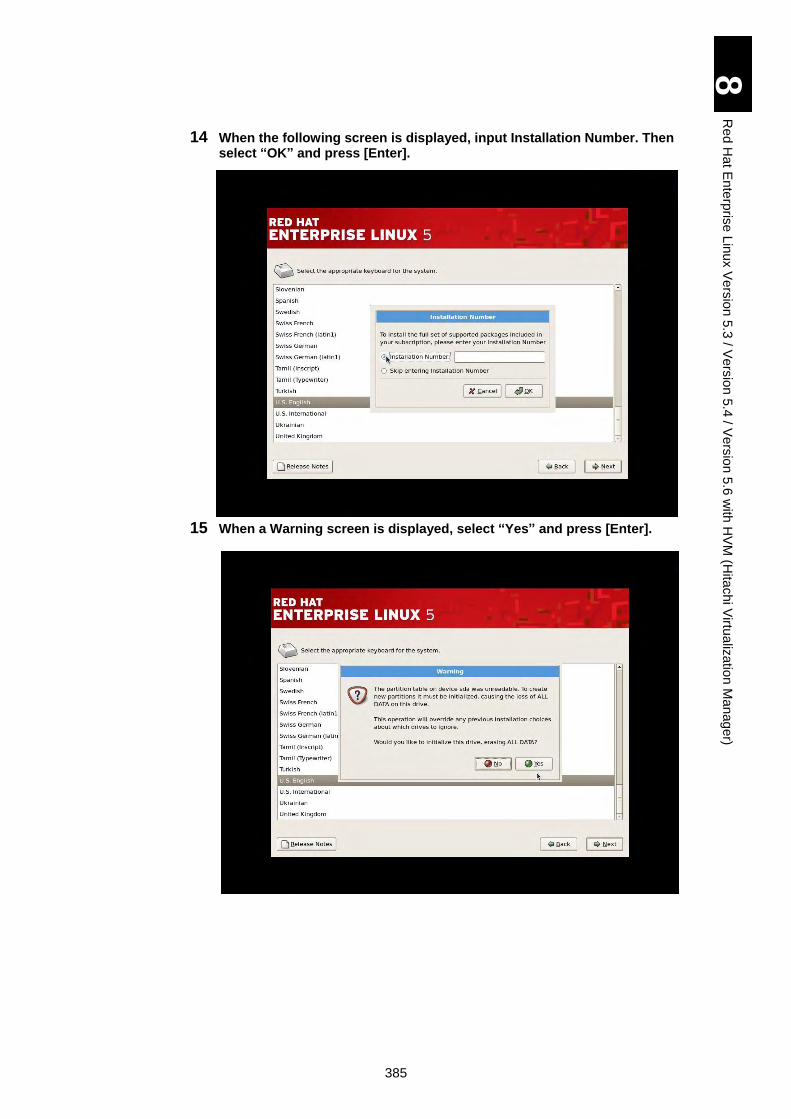
385
8
Re
d H
at E
nte
rpris
e L
inux V
ers
ion
5.3
/ Ve
rsio
n 5
.4 / V
ers
ion
5.6
with
HV
M (H
itach
i Virtu
aliz
atio
n M
an
ag
er)
14 When the following screen is displayed, input Installation Number. Then select “OK” and press [Enter].
15 When a Warning screen is displayed, select “Yes” and press [Enter].

386
8
Re
d H
at E
nte
rpris
e L
inux V
ers
ion
5.3
/ Ve
rsio
n 5
.4 / V
ers
ion
5.6
with
HV
M (H
itach
i Virtu
aliz
atio
n M
an
ag
er)
16 When the following screen is displayed, select “Remove all partitions on selected drives and create default layout” and “Review and modify partitioning layout”. Then select “Next” and press [Enter].
17 When a Warning screen is displayed, select “Yes” and press [Enter].
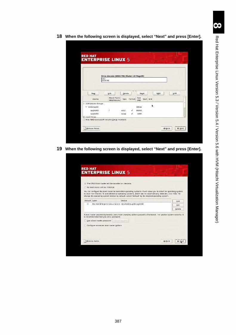
387
8
Re
d H
at E
nte
rpris
e L
inux V
ers
ion
5.3
/ Ve
rsio
n 5
.4 / V
ers
ion
5.6
with
HV
M (H
itach
i Virtu
aliz
atio
n M
an
ag
er)
18 When the following screen is displayed, select “Next” and press [Enter].
19 When the following screen is displayed, select “Next” and press [Enter].

388
8
Re
d H
at E
nte
rpris
e L
inux V
ers
ion
5.3
/ Ve
rsio
n 5
.4 / V
ers
ion
5.6
with
HV
M (H
itach
i Virtu
aliz
atio
n M
an
ag
er)
20 When the following screen is displayed, select “Edit” and press [Enter].
21 When the following screen is displayed, remove the check mark from “Enable IPv6 support”. Then select “OK” and press [Enter]. *This configuration is necessary for each network port. (eth0, eth1, -- ethn)
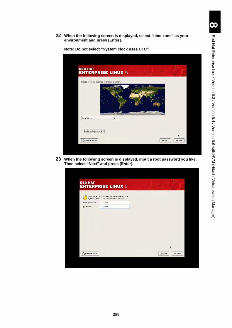
389
8
Re
d H
at E
nte
rpris
e L
inux V
ers
ion
5.3
/ Ve
rsio
n 5
.4 / V
ers
ion
5.6
with
HV
M (H
itach
i Virtu
aliz
atio
n M
an
ag
er)
22 When the following screen is displayed, select “time-zone” as your environment and press [Enter]. Note: Do not select “System clock uses UTC”
23 When the following screen is displayed, input a root password you like. Then select “Next” and press [Enter].
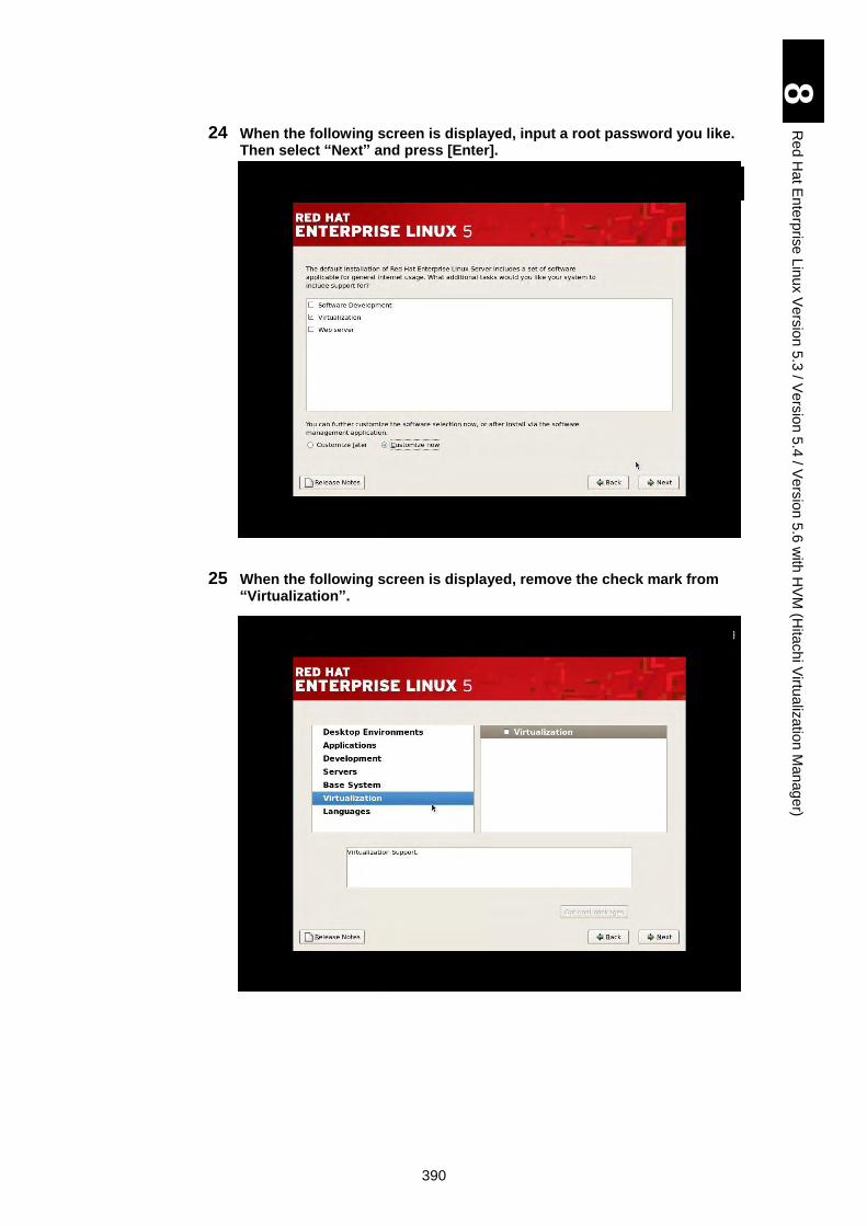
390
8
Re
d H
at E
nte
rpris
e L
inux V
ers
ion
5.3
/ Ve
rsio
n 5
.4 / V
ers
ion
5.6
with
HV
M (H
itach
i Virtu
aliz
atio
n M
an
ag
er)
24 When the following screen is displayed, input a root password you like. Then select “Next” and press [Enter].
25 When the following screen is displayed, remove the check mark from “Virtualization”.
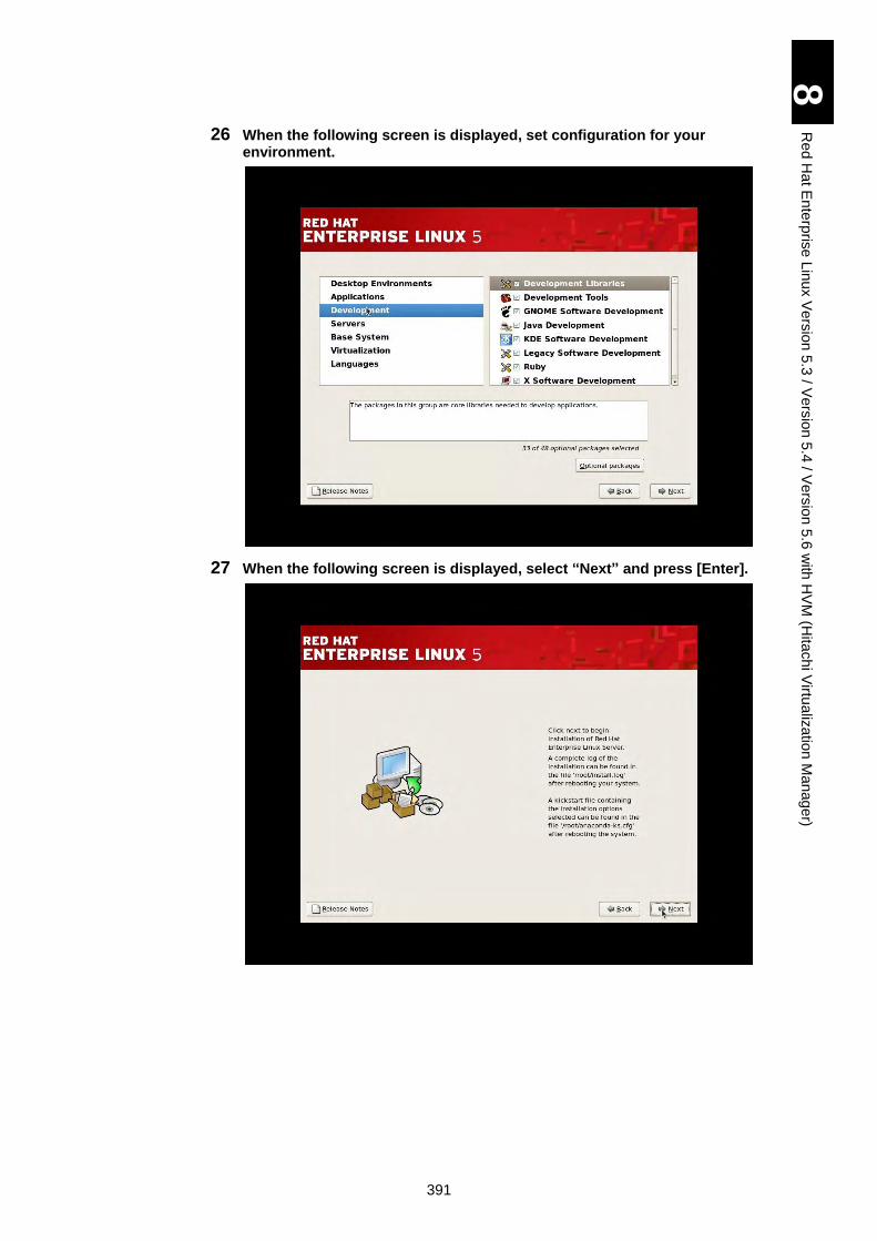
391
8
Re
d H
at E
nte
rpris
e L
inux V
ers
ion
5.3
/ Ve
rsio
n 5
.4 / V
ers
ion
5.6
with
HV
M (H
itach
i Virtu
aliz
atio
n M
an
ag
er)
26 When the following screen is displayed, set configuration for your environment.
27 When the following screen is displayed, select “Next” and press [Enter].
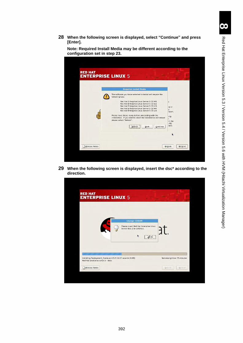
392
8
Re
d H
at E
nte
rpris
e L
inux V
ers
ion
5.3
/ Ve
rsio
n 5
.4 / V
ers
ion
5.6
with
HV
M (H
itach
i Virtu
aliz
atio
n M
an
ag
er)
28 When the following screen is displayed, select “Continue” and press [Enter].
Note: Required Install Media may be different according to the configuration set in step 23.
29 When the following screen is displayed, insert the dsc* according to the direction.
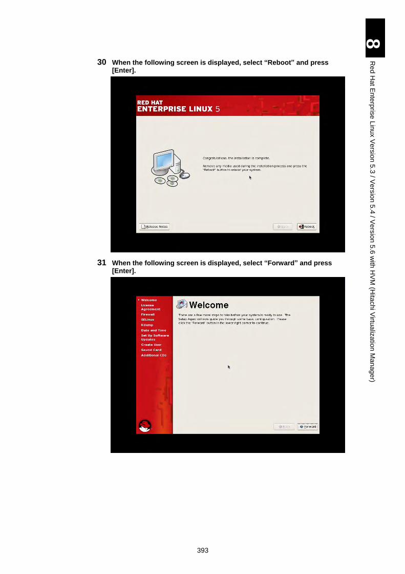
393
8
Re
d H
at E
nte
rpris
e L
inux V
ers
ion
5.3
/ Ve
rsio
n 5
.4 / V
ers
ion
5.6
with
HV
M (H
itach
i Virtu
aliz
atio
n M
an
ag
er)
30 When the following screen is displayed, select “Reboot” and press [Enter].
31 When the following screen is displayed, select “Forward” and press [Enter].
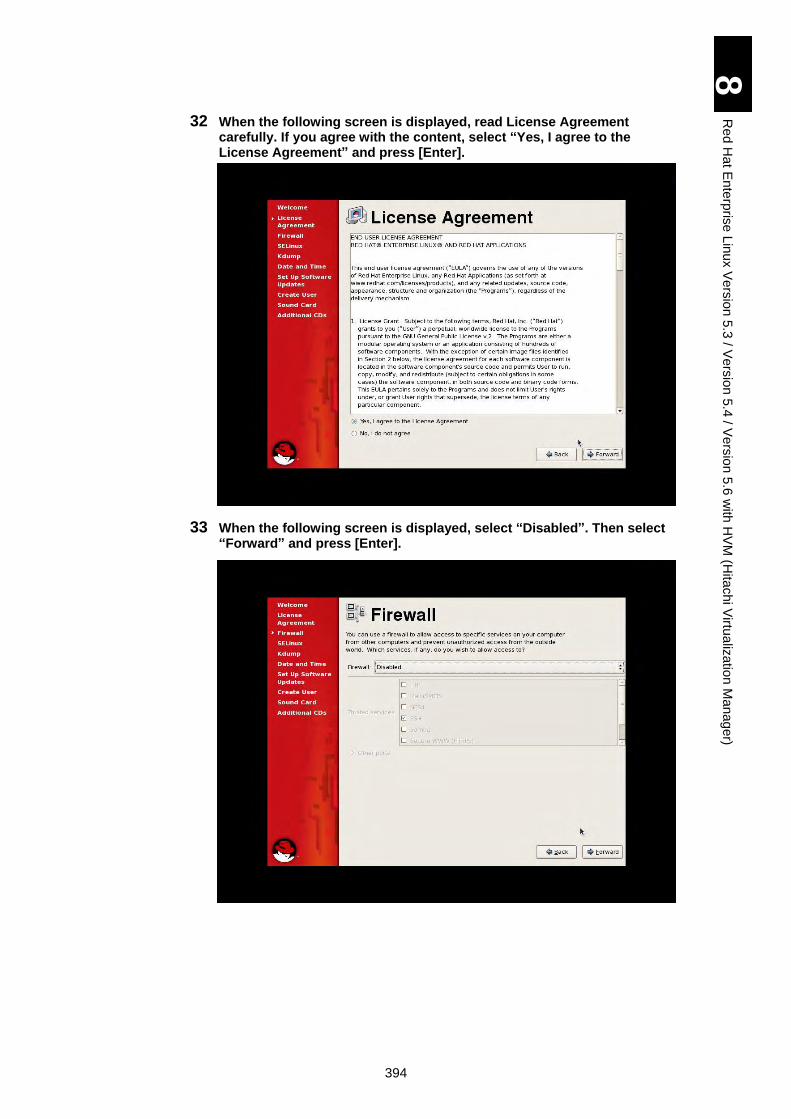
394
8
Re
d H
at E
nte
rpris
e L
inux V
ers
ion
5.3
/ Ve
rsio
n 5
.4 / V
ers
ion
5.6
with
HV
M (H
itach
i Virtu
aliz
atio
n M
an
ag
er)
32 When the following screen is displayed, read License Agreement carefully. If you agree with the content, select “Yes, I agree to the License Agreement” and press [Enter].
33 When the following screen is displayed, select “Disabled”. Then select “Forward” and press [Enter].
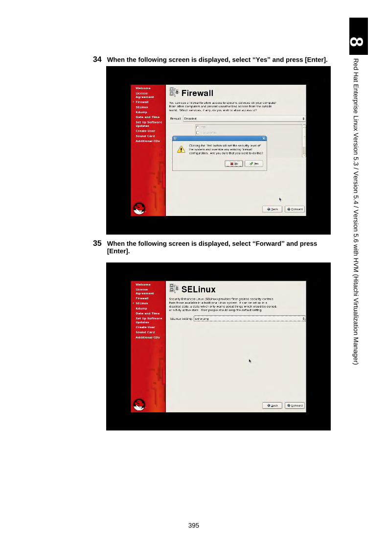
395
8
Re
d H
at E
nte
rpris
e L
inux V
ers
ion
5.3
/ Ve
rsio
n 5
.4 / V
ers
ion
5.6
with
HV
M (H
itach
i Virtu
aliz
atio
n M
an
ag
er)
34 When the following screen is displayed, select “Yes” and press [Enter].
35 When the following screen is displayed, select “Forward” and press [Enter].
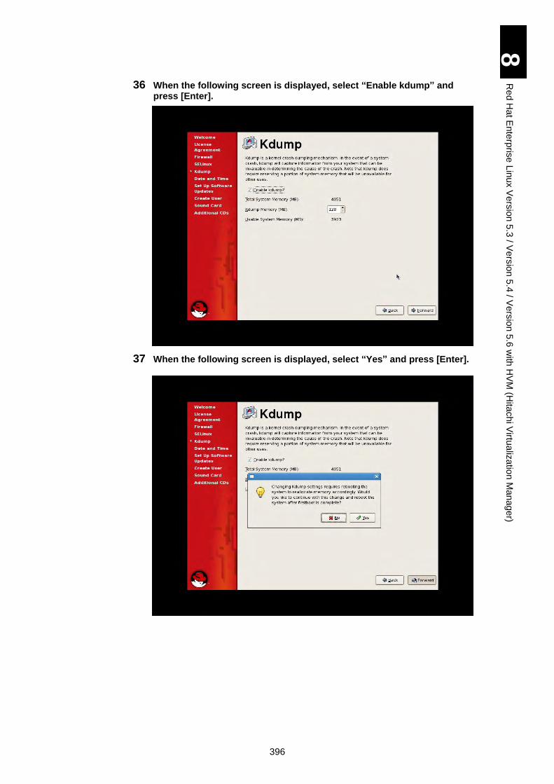
396
8
Re
d H
at E
nte
rpris
e L
inux V
ers
ion
5.3
/ Ve
rsio
n 5
.4 / V
ers
ion
5.6
with
HV
M (H
itach
i Virtu
aliz
atio
n M
an
ag
er)
36 When the following screen is displayed, select “Enable kdump” and press [Enter].
37 When the following screen is displayed, select “Yes” and press [Enter].
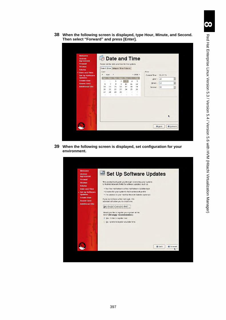
397
8
Re
d H
at E
nte
rpris
e L
inux V
ers
ion
5.3
/ Ve
rsio
n 5
.4 / V
ers
ion
5.6
with
HV
M (H
itach
i Virtu
aliz
atio
n M
an
ag
er)
38 When the following screen is displayed, type Hour, Minute, and Second. Then select “Forward” and press [Enter].
39 When the following screen is displayed, set configuration for your environment.
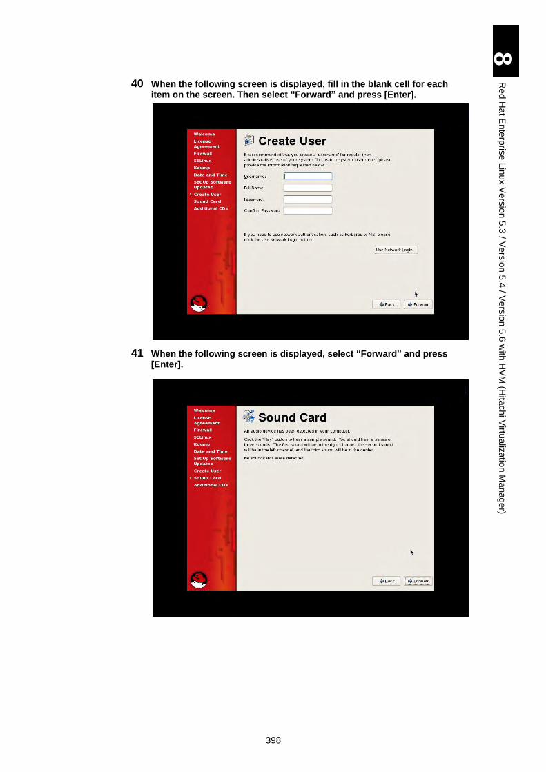
398
8
Re
d H
at E
nte
rpris
e L
inux V
ers
ion
5.3
/ Ve
rsio
n 5
.4 / V
ers
ion
5.6
with
HV
M (H
itach
i Virtu
aliz
atio
n M
an
ag
er)
40 When the following screen is displayed, fill in the blank cell for each item on the screen. Then select “Forward” and press [Enter].
41 When the following screen is displayed, select “Forward” and press [Enter].
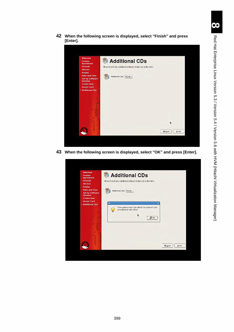
399
8
Re
d H
at E
nte
rpris
e L
inux V
ers
ion
5.3
/ Ve
rsio
n 5
.4 / V
ers
ion
5.6
with
HV
M (H
itach
i Virtu
aliz
atio
n M
an
ag
er)
42 When the following screen is displayed, select “Finish” and press [Enter].
43 When the following screen is displayed, select “OK” and press [Enter].
400
8
Re
d H
at E
nte
rpris
e L
inux V
ers
ion
5.3
/ Ve
rsio
n 5
.4 / V
ers
ion
5.6
with
HV
M (H
itach
i Virtu
aliz
atio
n M
an
ag
er)
44 Now the installation is completed. In the next boot, Linux is booted automatically.
401
9 Red Hat Enterprise Linux Version 5.6 / Version 6.1 with HVM (Hitachi Virtualization Manager) using the Driver CD
This chapter explains the use of Red Hat Enterprise Linux Version 5.6/6.1 (Xeon) in HVM (Hitachi Virtualization Manager) environment with using the driver CD. HVM stands for Hitachi Virtualization Manager.
Please note that this chapter may be updated without notice.
Red Hat Enterprise Linux 5.6 .............................................................................. 402
Red Hat Enterprise Linux 6.1 .............................................................................. 413
402
9
Re
d H
at E
nte
rpris
e L
inux V
ers
ion
5.6
/ Ve
rsio
n 6
.1 w
ith H
VM
(Hita
ch
i Virtu
aliz
atio
n M
an
ag
er) u
sin
g th
e D
rive
r CD
Red Hat Enterprise Linux 5.6
Red Hat Enterprise Linux 5.6 can be installed on a virtual environment provided by HVM, which is called LPAR.
Prerequisites for Setup
This subsection describes restrictions and notes when you use Red Hat Enterprise Linux 5.6 on the LPAR.
The procedure described later uses Red Hat Enterprise Linux 5.6 installation CD and Hitachi driver CD.
If you use a recovery CD provided by Linux support service, see the user’s guide given by that support service.
Make sure to use media for Red Hat Enterprise Linux 5.6 for the setup. Never use any media other than that.
Make sure also to use the driver specified for Red Hat Enterprise Linux 5.6 for the setup. Never use any driver other than that. If you use a driver not corresponding to the version, the OS will not work properly.
HVM LPAR supports the following OSs.
Red Hat Enterprise Linux 5.6 (X86)
Red Hat Enterprise Linux 5.6 (X86_64)
The following kernel versions are supported.
X86: 2.6.18-238.9.1.el5PAE or later
X86_64: 2.6.18-238.9.1.el5 or later
Contact your reseller about the latest recommended driver version for Red Hat Enterprise Linux 5.6 and download it.
403
9
Re
d H
at E
nte
rpris
e L
inux V
ers
ion
5.6
/ Ve
rsio
n 6
.1 w
ith H
VM
(Hita
ch
i Virtu
aliz
atio
n M
an
ag
er) u
sin
g th
e D
rive
r CD
Notes and Restrictions on RHEL 5.6 with HVM
This subsection describes notes and restrictions on using Red hat Enterprise Linux 5.6 with an LPAR.
Basic Operations and Setting Change
Basic operations and setting change can be performed using SSH, terminal software, or remote console after Red Hat Enterprise Linux 5.6 is booted on the HVM LPAR.
Booting and resetting LPARs
Since the LPAR is a virtual environment, physical buttons including the power button and reset button on the front panel of a sever blade and the dump command from a management module are not available for LPAR operation. Make sure to operate an LPAR from the HVM management screen. If you use a physical button, all LPARs running on the server blade may be affected, which may destroy the OS. Never use physical buttons when any LPAR is booted.
Some items may not be displayed depending on the type of
network adapter. Configure settings for the items displayed
with the adapter you use.
Notes on the network
hbonding/bonding cannot bond virtual NICs and physical NICs. Some items may not be displayed depending on the type of network adapter. Configure settings for the items displayed with the adapter you use.
Notes on the fibre channel driver
Use a gigabit fibre channel adapter in the HVM LPAR environment.
Setting the HBA BIOS
When a shared fibre channel is used as a boot device, the boot may not be properly completed depending on the number of LPARs assigned to the shared fibre channel. This problem may be avoided by extending LOGIN DELAY TIME, which is an operation parameter for a gigabit fibre channel adapter. See “Option setting procedure” in Gigabit Fibre Channel Adapter User’s Guide.
Using the remote console
Use the remote console only for setting up the OS. Use terminal software for usual operations.
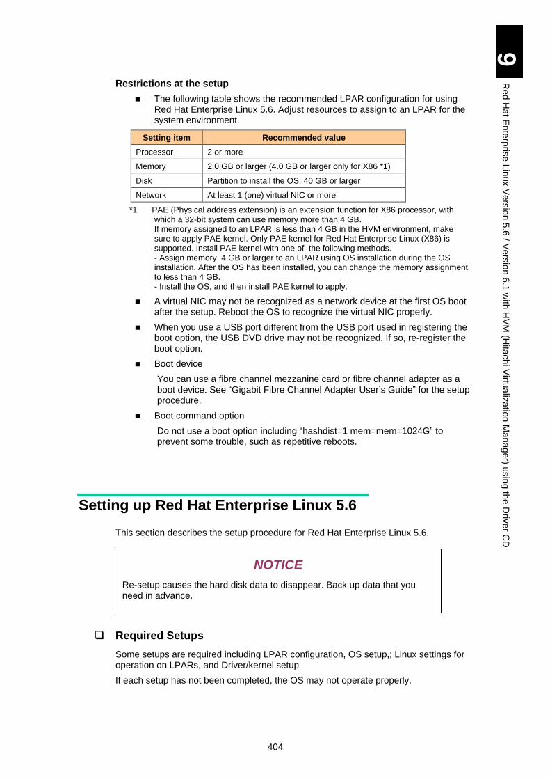
404
9
Re
d H
at E
nte
rpris
e L
inux V
ers
ion
5.6
/ Ve
rsio
n 6
.1 w
ith H
VM
(Hita
ch
i Virtu
aliz
atio
n M
an
ag
er) u
sin
g th
e D
rive
r CD
Restrictions at the setup
The following table shows the recommended LPAR configuration for using Red Hat Enterprise Linux 5.6. Adjust resources to assign to an LPAR for the system environment.
Setting item Recommended value
Processor 2 or more
Memory 2.0 GB or larger (4.0 GB or larger only for X86 *1)
Disk Partition to install the OS: 40 GB or larger
Network At least 1 (one) virtual NIC or more
*1 PAE (Physical address extension) is an extension function for X86 processor, with which a 32-bit system can use memory more than 4 GB. If memory assigned to an LPAR is less than 4 GB in the HVM environment, make sure to apply PAE kernel. Only PAE kernel for Red Hat Enterprise Linux (X86) is supported. Install PAE kernel with one of the following methods. - Assign memory 4 GB or larger to an LPAR using OS installation during the OS installation. After the OS has been installed, you can change the memory assignment to less than 4 GB. - Install the OS, and then install PAE kernel to apply.
A virtual NIC may not be recognized as a network device at the first OS boot after the setup. Reboot the OS to recognize the virtual NIC properly.
When you use a USB port different from the USB port used in registering the boot option, the USB DVD drive may not be recognized. If so, re-register the boot option.
Boot device
You can use a fibre channel mezzanine card or fibre channel adapter as a boot device. See “Gigabit Fibre Channel Adapter User’s Guide” for the setup procedure.
Boot command option
Do not use a boot option including “hashdist=1 mem=mem=1024G” to prevent some trouble, such as repetitive reboots.
Setting up Red Hat Enterprise Linux 5.6
This section describes the setup procedure for Red Hat Enterprise Linux 5.6.
Required Setups
Some setups are required including LPAR configuration, OS setup,; Linux settings for operation on LPARs, and Driver/kernel setup
If each setup has not been completed, the OS may not operate properly.
NOTICE
Re-setup causes the hard disk data to disappear. Back up data that you need in advance.
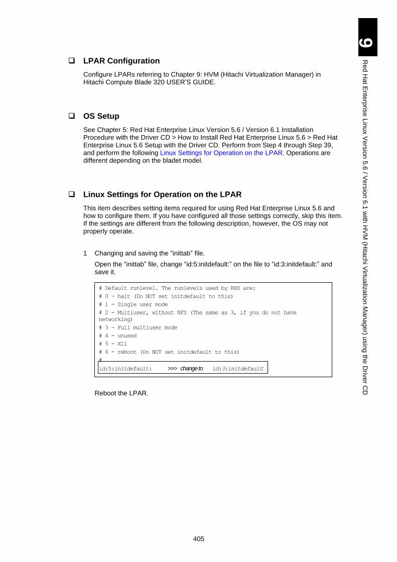
405
9
Re
d H
at E
nte
rpris
e L
inux V
ers
ion
5.6
/ Ve
rsio
n 6
.1 w
ith H
VM
(Hita
ch
i Virtu
aliz
atio
n M
an
ag
er) u
sin
g th
e D
rive
r CD
LPAR Configuration
Configure LPARs referring to Chapter 9: HVM (Hitachi Virtualization Manager) in Hitachi Compute Blade 320 USER’S GUIDE.
OS Setup
See Chapter 5: Red Hat Enterprise Linux Version 5.6 / Version 6.1 Installation Procedure with the Driver CD > How to Install Red Hat Enterprise Linux 5.6 > Red Hat Enterprise Linux 5.6 Setup with the Driver CD. Perform from Step 4 through Step 39, and perform the following Linux Settings for Operation on the LPAR. Operations are different depending on the bladet model.
Linux Settings for Operation on the LPAR
This item describes setting items required for using Red Hat Enterprise Linux 5.6 and how to configure them. If you have configured all those settings correctly, skip this item. If the settings are different from the following description, however, the OS may not properly operate.
1 Changing and saving the “inittab” file.
Open the “inittab” file, change “id:5:initdefault:” on the file to “id:3:initdefault:” and save it.
Reboot the LPAR.
# Default runlevel. The runlevels used by RHS are:
# 0 - halt (Do NOT set initdefault to this)
# 1 - Single user mode
# 2 - Multiuser, without NFS (The same as 3, if you do not have
networking)
# 3 - Full multiuser mode
# 4 - unused
# 5 - X11
# 6 - reboot (Do NOT set initdefault to this)
#
id:5:initdefault: >>> change to id:3:initdefault:
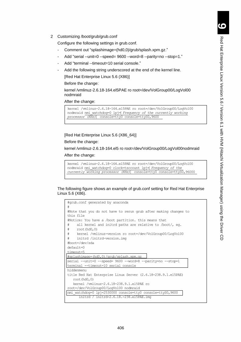
406
9
Re
d H
at E
nte
rpris
e L
inux V
ers
ion
5.6
/ Ve
rsio
n 6
.1 w
ith H
VM
(Hita
ch
i Virtu
aliz
atio
n M
an
ag
er) u
sin
g th
e D
rive
r CD
2 Customizing /boot/grub/grub.conf
Configure the following settings in grub.conf.
- Comment out “splashimage=(hd0,0)/grub/splash.xpm.gz.”
- Add “serial --unit=0 --speed= 9600 --word=8 --parity=no --stop=1.”
- Add “terminal --timeout=10 serial console.”
- Add the following string underscored at the end of the kernel line.
[Red Hat Enterprise Linux 5.6 (X86)]
Before the change:
kernel /vmlinuz-2.6.18-164.el5PAE ro root=/dev/VolGroup00/LogVol00 nodmraid
After the change:
[Red Hat Enterprise Linux 5.6 (X86_64)]
[Red Hat Enterprise Linux 5.6 (X86_64)]
Before the change:
kernel /vmlinuz-2.6.18-164.el5 ro root=/dev/VolGroup00/LogVol00nodmraid
After the change:
The following figure shows an example of grub.conf setting for Red Hat Enterprise Linux 5.6 (X86).
#grub.conf generated by anaconda
#
#Note that you do not have to rerun grub after making changes to
this file
#Notice: You have a /boot partition. this means that
# all kernel and initrd paths are relative to /boot/, eg.
# root(hd0,0)
# kernel /vmlinuz-version ro root=/dev/VolGroup00/LogVol00
# initrd /initrd-version.img
#boot=/dev/sda
default=0
timeout=5
#splashimage=(hd0,0)/grub/splash.xpm.gz
serial --unit=0 --speed= 9600 --word=8 --parity=no --stop=1
terminal --timeout=10 serial console
hiddenmenu
title Red Hat Enterprise Linux Server (2.6.18-238.9.1.el5PAE)
root(hd0,0)
kernel /vmlinuz-2.6.18-238.9.1.el5PAE ro
root=/dev/VolGroup00/LogVol00 nodmraid
nmi_watchdog=0 lpj=2530000 console=tty0 console=ttyS0,9600
initrd / initrd-2.6.18.-238.el5PAE.img
kernel /vmlinuz-2.6.18-164.el5PAE ro root=/dev/VolGroup00/LogVol00
nodmraid nmi_watchdog=0 clock=tsccount lpj=[Frequency of the
currently working processor (KHz)] console=tty0 console=ttyS0,96000
kernel /vmlinuz-2.6.18-164.el5PAE ro root=/dev/VolGroup00/LogVol00
nodmraid nmi_watchdog=0 lpj=[Frequency of the currently working
processor (KHz)] console=tty0 console=ttyS0,9600
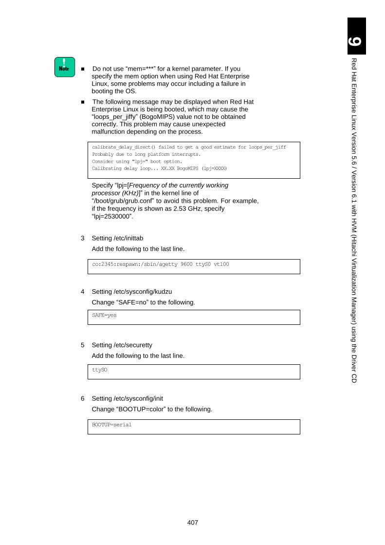
407
9
Re
d H
at E
nte
rpris
e L
inux V
ers
ion
5.6
/ Ve
rsio
n 6
.1 w
ith H
VM
(Hita
ch
i Virtu
aliz
atio
n M
an
ag
er) u
sin
g th
e D
rive
r CD
Do not use “mem=***” for a kernel parameter. If you specify the mem option when using Red Hat Enterprise Linux, some problems may occur including a failure in booting the OS.
The following message may be displayed when Red Hat Enterprise Linux is being booted, which may cause the “loops_per_jiffy” (BogoMIPS) value not to be obtained correctly. This problem may cause unexpected malfunction depending on the process.
Specify “lpj=[Frequency of the currently working
processor (KHz)]” in the kernel line of
“/boot/grub/grub.conf” to avoid this problem. For example,
if the frequency is shown as 2.53 GHz, specify
“lpj=2530000”.
3 Setting /etc/inittab
Add the following to the last line.
4 Setting /etc/sysconfig/kudzu
Change “SAFE=no” to the following.
5 Setting /etc/securetty
Add the following to the last line.
6 Setting /etc/sysconfig/init
Change “BOOTUP=color” to the following.
calibrate_delay_direct() failed to get a good estimate for loops_per_jiff
Probably due to long platform interrupts.
Consider using "lpj=" boot option.
Calibrating delay loop... XX.XX BogoMIPS (lpj=XXXX)
co:2345:respawn:/sbin/agetty 9600 ttyS0 vt100
SAFE=yes
ttySO
BOOTUP=serial
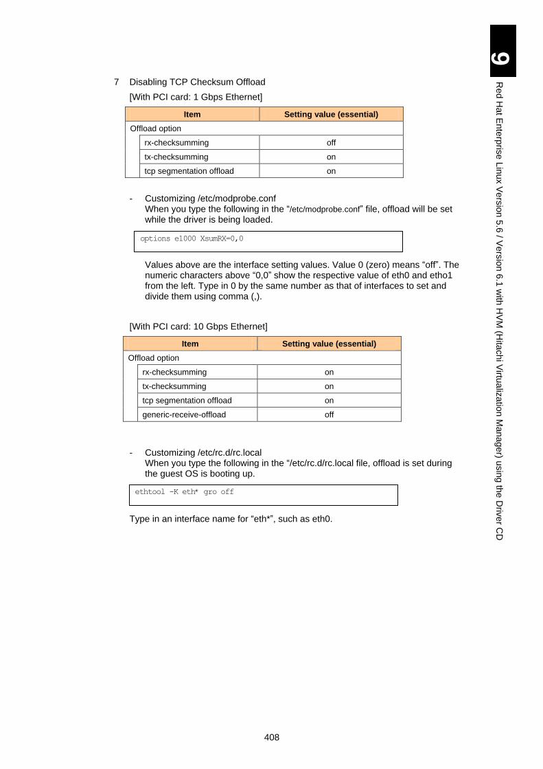
408
9
Re
d H
at E
nte
rpris
e L
inux V
ers
ion
5.6
/ Ve
rsio
n 6
.1 w
ith H
VM
(Hita
ch
i Virtu
aliz
atio
n M
an
ag
er) u
sin
g th
e D
rive
r CD
7 Disabling TCP Checksum Offload
[With PCI card: 1 Gbps Ethernet]
Item Setting value (essential)
Offload option
rx-checksumming off
tx-checksumming on
tcp segmentation offload on
- Customizing /etc/modprobe.conf When you type the following in the “/etc/modprobe.conf” file, offload will be set while the driver is being loaded.
Values above are the interface setting values. Value 0 (zero) means “off”. The numeric characters above “0,0” show the respective value of eth0 and etho1 from the left. Type in 0 by the same number as that of interfaces to set and divide them using comma (,).
[With PCI card: 10 Gbps Ethernet]
Item Setting value (essential)
Offload option
rx-checksumming on
tx-checksumming on
tcp segmentation offload on
generic-receive-offload off
- Customizing /etc/rc.d/rc.local When you type the following in the “/etc/rc.d/rc.local file, offload is set during the guest OS is booting up.
Type in an interface name for “eth*”, such as eth0.
options e1000 XsumRX=0,0
ethtool -K eth* gro off
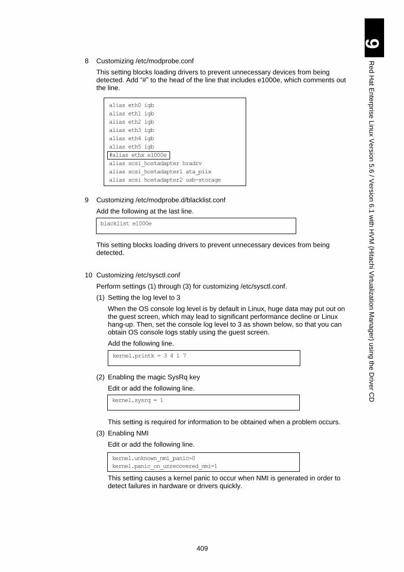
409
9
Re
d H
at E
nte
rpris
e L
inux V
ers
ion
5.6
/ Ve
rsio
n 6
.1 w
ith H
VM
(Hita
ch
i Virtu
aliz
atio
n M
an
ag
er) u
sin
g th
e D
rive
r CD
8 Customizing /etc/modprobe.conf
This setting blocks loading drivers to prevent unnecessary devices from being detected. Add “#” to the head of the line that includes e1000e, which comments out the line.
9 Customizing /etc/modprobe.d/blacklist.conf
Add the following at the last line.
This setting blocks loading drivers to prevent unnecessary devices from being detected.
10 Customizing /etc/sysctl.conf
Perform settings (1) through (3) for customizing /etc/sysctl.conf.
(1) Setting the log level to 3
When the OS console log level is by default in Linux, huge data may put out on the guest screen, which may lead to significant performance decline or Linux hang-up. Then, set the console log level to 3 as shown below, so that you can obtain OS console logs stably using the guest screen.
Add the following line.
(2) Enabling the magic SysRq key
Edit or add the following line.
This setting is required for information to be obtained when a problem occurs.
(3) Enabling NMI
Edit or add the following line.
This setting causes a kernel panic to occur when NMI is generated in order to detect failures in hardware or drivers quickly.
alias eth0 igb
alias eth1 igb
alias eth2 igb
alias eth3 igb
alias eth4 igb
alias eth5 igb
#alias ethx e1000e
alias scsi_hostadapter hradrv
alias scsi_hostadapter1 ata_piix
alias scsi_hostadapter2 usb-storage
blacklist e1000e
kernel.printk = 3 4 1 7
kernel.sysrq = 1
kernel.unknown_nmi_panic=0
kernel.panic_on_unrecovered_nmi=1
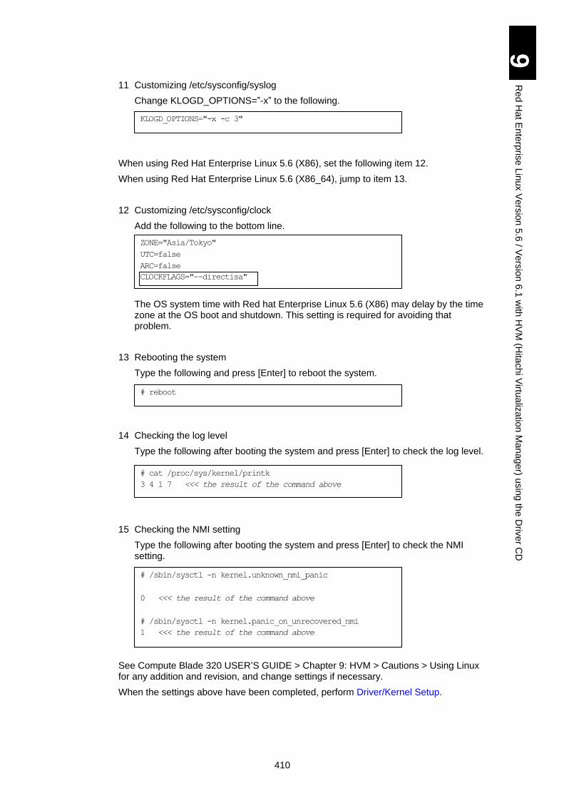
410
9
Re
d H
at E
nte
rpris
e L
inux V
ers
ion
5.6
/ Ve
rsio
n 6
.1 w
ith H
VM
(Hita
ch
i Virtu
aliz
atio
n M
an
ag
er) u
sin
g th
e D
rive
r CD
11 Customizing /etc/sysconfig/syslog
Change KLOGD_OPTIONS=”-x” to the following.
When using Red Hat Enterprise Linux 5.6 (X86), set the following item 12.
When using Red Hat Enterprise Linux 5.6 (X86_64), jump to item 13.
12 Customizing /etc/sysconfig/clock
Add the following to the bottom line.
The OS system time with Red hat Enterprise Linux 5.6 (X86) may delay by the time zone at the OS boot and shutdown. This setting is required for avoiding that problem.
13 Rebooting the system
Type the following and press [Enter] to reboot the system.
14 Checking the log level
Type the following after booting the system and press [Enter] to check the log level.
15 Checking the NMI setting
Type the following after booting the system and press [Enter] to check the NMI setting.
See Compute Blade 320 USER’S GUIDE > Chapter 9: HVM > Cautions > Using Linux for any addition and revision, and change settings if necessary.
When the settings above have been completed, perform Driver/Kernel Setup.
KLOGD_OPTIONS="-x -c 3"
ZONE="Asia/Tokyo"
UTC=false
ARC=false
CLOCKFLAGS="--directisa"
# reboot
# cat /proc/sys/kernel/printk
3 4 1 7 <<< the result of the command above
# /sbin/sysctl -n kernel.unknown_nmi_panic
0 <<< the result of the command above
# /sbin/sysctl -n kernel.panic_on_unrecovered_nmi
1 <<< the result of the command above
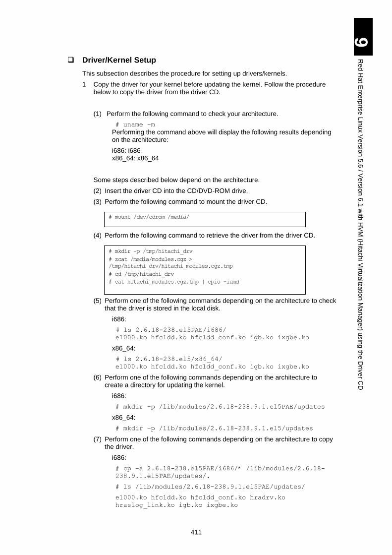
411
9
Re
d H
at E
nte
rpris
e L
inux V
ers
ion
5.6
/ Ve
rsio
n 6
.1 w
ith H
VM
(Hita
ch
i Virtu
aliz
atio
n M
an
ag
er) u
sin
g th
e D
rive
r CD
Driver/Kernel Setup
This subsection describes the procedure for setting up drivers/kernels.
1 Copy the driver for your kernel before updating the kernel. Follow the procedure below to copy the driver from the driver CD.
(1) Perform the following command to check your architecture.
# uname –m
Performing the command above will display the following results depending on the architecture:
i686: i686 x86_64: x86_64
Some steps described below depend on the architecture.
(2) Insert the driver CD into the CD/DVD-ROM drive.
(3) Perform the following command to mount the driver CD.
(4) Perform the following command to retrieve the driver from the driver CD.
(5) Perform one of the following commands depending on the architecture to check that the driver is stored in the local disk.
i686:
# ls 2.6.18-238.el5PAE/i686/
e1000.ko hfcldd.ko hfcldd_conf.ko igb.ko ixgbe.ko
x86_64:
# ls 2.6.18-238.el5/x86_64/
e1000.ko hfcldd.ko hfcldd_conf.ko igb.ko ixgbe.ko
(6) Perform one of the following commands depending on the architecture to create a directory for updating the kernel.
i686:
# mkdir –p /lib/modules/2.6.18-238.9.1.el5PAE/updates
x86_64:
# mkdir –p /lib/modules/2.6.18-238.9.1.el5/updates
(7) Perform one of the following commands depending on the architecture to copy the driver.
i686:
# cp –a 2.6.18-238.el5PAE/i686/* /lib/modules/2.6.18-
238.9.1.el5PAE/updates/.
# ls /lib/modules/2.6.18-238.9.1.el5PAE/updates/
e1000.ko hfcldd.ko hfcldd_conf.ko hradrv.ko
hraslog_link.ko igb.ko ixgbe.ko
# mount /dev/cdrom /media/
# mkdir -p /tmp/hitachi_drv
# zcat /media/modules.cgz >
/tmp/hitachi_drv/hitachi_modules.cgz.tmp
# cd /tmp/hitachi_drv
# cat hitachi_modules.cgz.tmp | cpio -iumd
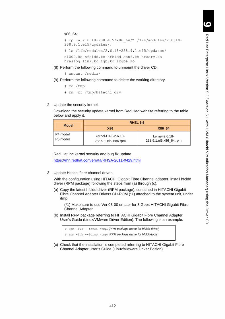
412
9
Re
d H
at E
nte
rpris
e L
inux V
ers
ion
5.6
/ Ve
rsio
n 6
.1 w
ith H
VM
(Hita
ch
i Virtu
aliz
atio
n M
an
ag
er) u
sin
g th
e D
rive
r CD
x86_64:
# cp –a 2.6.18-238.el5/x86_64/* /lib/modules/2.6.18-
238.9.1.el5/updates/.
# ls /lib/modules/2.6.18-238.9.1.el5/updates/
e1000.ko hfcldd.ko hfcldd_conf.ko hradrv.ko
hraslog_link.ko igb.ko ixgbe.ko
(8) Perform the following command to unmount the driver CD.
# umount /media/
(9) Perform the following command to delete the working directory.
# cd /tmp
# rm –rf /tmp/hitachi_drv
2 Update the security kernel.
Download the security update kernel from Red Had website referring to the table below and apply it.
Model RHEL 5.6
X86 X86_64
P4 model
P5 model kernel-PAE-2.6.18-
238.9.1.el5.i686.rpm
kernel-2.6.18-
238.9.1.el5.x86_64.rpm
Red Hat.Inc kernel security and bug fix update
https://rhn.redhat.com/errata/RHSA-2011-0429.html
3 Update Hitachi fibre channel driver.
With the configuration using HITACHI Gigabit Fibre Channel adapter, install hfcldd driver (RPM package) following the steps from (a) through (c).
(a) Copy the latest hfcldd driver (RPM package), contained in HITACHI Gigabit Fibre Channel Adapter Drivers CD-ROM (*1) attached to the system unit, under /tmp.
(*1) Make sure to use Ver.03-00 or later for 8 Gbps HITACHI Gigabit Fibre Channel Adapter
(b) Install RPM package referring to HITACHI Gigabit Fibre Channel Adapter User’s Guide (Linux/VMware Driver Edition). The following is an example.
(c) Check that the installation is completed referring to HITACHI Gigabit Fibre Channel Adapter User’s Guide (Linux/VMware Driver Edition).
# rpm -ivh --force /tmp/[RPM package name for hfcldd driver]
# rpm -ivh --force /tmp/[RPM package name for hfcldd-tools]
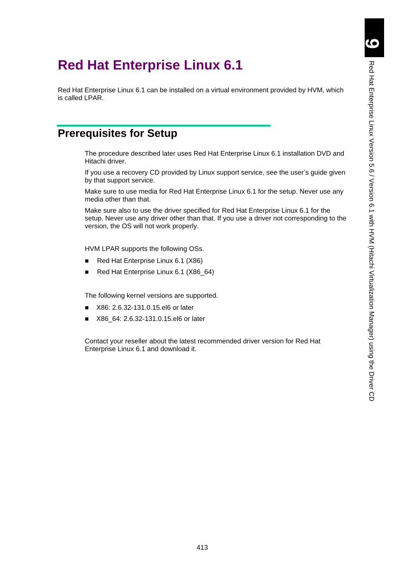
413
9
Re
d H
at E
nte
rpris
e L
inux V
ers
ion
5.6
/ Ve
rsio
n 6
.1 w
ith H
VM
(Hita
ch
i Virtu
aliz
atio
n M
an
ag
er) u
sin
g th
e D
rive
r CD
Red Hat Enterprise Linux 6.1
Red Hat Enterprise Linux 6.1 can be installed on a virtual environment provided by HVM, which is called LPAR.
Prerequisites for Setup
The procedure described later uses Red Hat Enterprise Linux 6.1 installation DVD and Hitachi driver.
If you use a recovery CD provided by Linux support service, see the user’s guide given by that support service.
Make sure to use media for Red Hat Enterprise Linux 6.1 for the setup. Never use any media other than that.
Make sure also to use the driver specified for Red Hat Enterprise Linux 6.1 for the setup. Never use any driver other than that. If you use a driver not corresponding to the version, the OS will not work properly.
HVM LPAR supports the following OSs.
Red Hat Enterprise Linux 6.1 (X86)
Red Hat Enterprise Linux 6.1 (X86_64)
The following kernel versions are supported.
X86: 2.6.32-131.0.15.el6 or later
X86_64: 2.6.32-131.0.15.el6 or later
Contact your reseller about the latest recommended driver version for Red Hat Enterprise Linux 6.1 and download it.
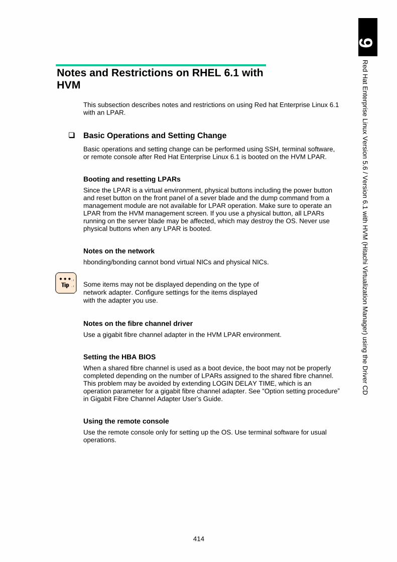
414
9
Re
d H
at E
nte
rpris
e L
inux V
ers
ion
5.6
/ Ve
rsio
n 6
.1 w
ith H
VM
(Hita
ch
i Virtu
aliz
atio
n M
an
ag
er) u
sin
g th
e D
rive
r CD
Notes and Restrictions on RHEL 6.1 with HVM
This subsection describes notes and restrictions on using Red hat Enterprise Linux 6.1 with an LPAR.
Basic Operations and Setting Change
Basic operations and setting change can be performed using SSH, terminal software, or remote console after Red Hat Enterprise Linux 6.1 is booted on the HVM LPAR.
Booting and resetting LPARs
Since the LPAR is a virtual environment, physical buttons including the power button and reset button on the front panel of a sever blade and the dump command from a management module are not available for LPAR operation. Make sure to operate an LPAR from the HVM management screen. If you use a physical button, all LPARs running on the server blade may be affected, which may destroy the OS. Never use physical buttons when any LPAR is booted.
Notes on the network
hbonding/bonding cannot bond virtual NICs and physical NICs.
Some items may not be displayed depending on the type of
network adapter. Configure settings for the items displayed
with the adapter you use.
Notes on the fibre channel driver
Use a gigabit fibre channel adapter in the HVM LPAR environment.
Setting the HBA BIOS
When a shared fibre channel is used as a boot device, the boot may not be properly completed depending on the number of LPARs assigned to the shared fibre channel. This problem may be avoided by extending LOGIN DELAY TIME, which is an operation parameter for a gigabit fibre channel adapter. See “Option setting procedure” in Gigabit Fibre Channel Adapter User’s Guide.
Using the remote console
Use the remote console only for setting up the OS. Use terminal software for usual operations.
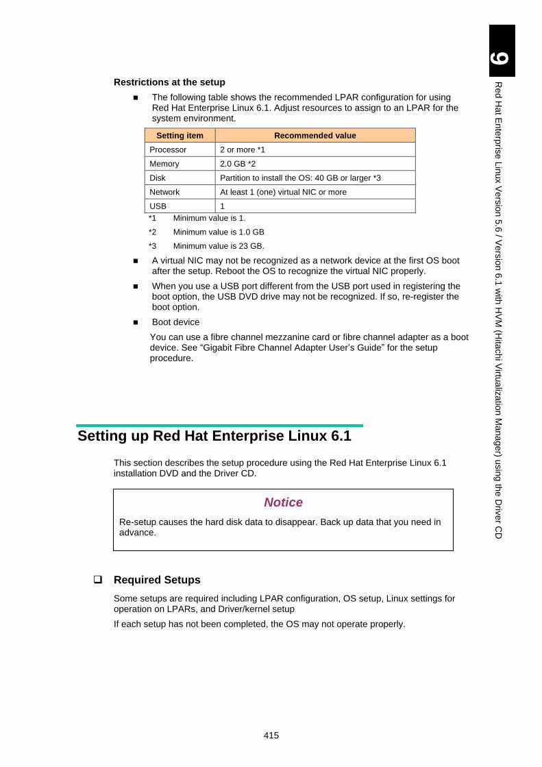
415
9
Re
d H
at E
nte
rpris
e L
inux V
ers
ion
5.6
/ Ve
rsio
n 6
.1 w
ith H
VM
(Hita
ch
i Virtu
aliz
atio
n M
an
ag
er) u
sin
g th
e D
rive
r CD
Restrictions at the setup
The following table shows the recommended LPAR configuration for using Red Hat Enterprise Linux 6.1. Adjust resources to assign to an LPAR for the system environment.
Setting item Recommended value
Processor 2 or more *1
Memory 2.0 GB *2
Disk Partition to install the OS: 40 GB or larger *3
Network At least 1 (one) virtual NIC or more
USB 1
*1 Minimum value is 1.
*2 Minimum value is 1.0 GB
*3 Minimum value is 23 GB.
A virtual NIC may not be recognized as a network device at the first OS boot after the setup. Reboot the OS to recognize the virtual NIC properly.
When you use a USB port different from the USB port used in registering the boot option, the USB DVD drive may not be recognized. If so, re-register the boot option.
Boot device
You can use a fibre channel mezzanine card or fibre channel adapter as a boot device. See “Gigabit Fibre Channel Adapter User’s Guide” for the setup procedure.
Setting up Red Hat Enterprise Linux 6.1
This section describes the setup procedure using the Red Hat Enterprise Linux 6.1 installation DVD and the Driver CD.
Required Setups
Some setups are required including LPAR configuration, OS setup, Linux settings for operation on LPARs, and Driver/kernel setup
If each setup has not been completed, the OS may not operate properly.
Notice
Re-setup causes the hard disk data to disappear. Back up data that you need in advance.
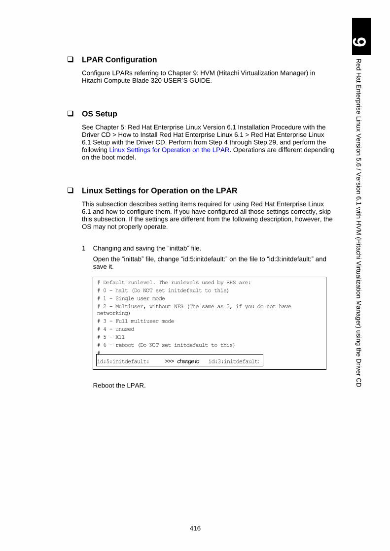
416
9
Re
d H
at E
nte
rpris
e L
inux V
ers
ion
5.6
/ Ve
rsio
n 6
.1 w
ith H
VM
(Hita
ch
i Virtu
aliz
atio
n M
an
ag
er) u
sin
g th
e D
rive
r CD
LPAR Configuration
Configure LPARs referring to Chapter 9: HVM (Hitachi Virtualization Manager) in Hitachi Compute Blade 320 USER’S GUIDE.
OS Setup
See Chapter 5: Red Hat Enterprise Linux Version 6.1 Installation Procedure with the Driver CD > How to Install Red Hat Enterprise Linux 6.1 > Red Hat Enterprise Linux 6.1 Setup with the Driver CD. Perform from Step 4 through Step 29, and perform the following Linux Settings for Operation on the LPAR. Operations are different depending on the boot model.
Linux Settings for Operation on the LPAR
This subsection describes setting items required for using Red Hat Enterprise Linux 6.1 and how to configure them. If you have configured all those settings correctly, skip this subsection. If the settings are different from the following description, however, the OS may not properly operate.
1 Changing and saving the “inittab” file.
Open the “inittab” file, change “id:5:initdefault:” on the file to “id:3:initdefault:” and save it.
Reboot the LPAR.
# Default runlevel. The runlevels used by RHS are:
# 0 - halt (Do NOT set initdefault to this)
# 1 - Single user mode
# 2 - Multiuser, without NFS (The same as 3, if you do not have
networking)
# 3 - Full multiuser mode
# 4 - unused
# 5 - X11
# 6 - reboot (Do NOT set initdefault to this)
#
id:5:initdefault: >>> change to id:3:initdefault:
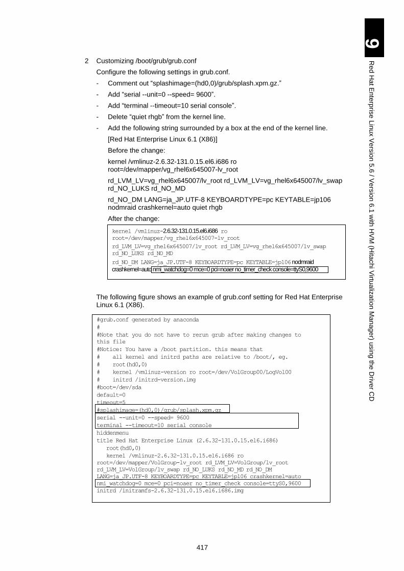
417
9
Re
d H
at E
nte
rpris
e L
inux V
ers
ion
5.6
/ Ve
rsio
n 6
.1 w
ith H
VM
(Hita
ch
i Virtu
aliz
atio
n M
an
ag
er) u
sin
g th
e D
rive
r CD
2 Customizing /boot/grub/grub.conf
Configure the following settings in grub.conf.
- Comment out “splashimage=(hd0,0)/grub/splash.xpm.gz.”
- Add “serial --unit=0 --speed= 9600”.
- Add “terminal --timeout=10 serial console”.
- Delete “quiet rhgb” from the kernel line.
- Add the following string surrounded by a box at the end of the kernel line.
[Red Hat Enterprise Linux 6.1 (X86)]
Before the change:
kernel /vmlinuz-2.6.32-131.0.15.el6.i686 ro root=/dev/mapper/vg_rhel6x645007-lv_root
rd_LVM_LV=vg_rhel6x645007/lv_root rd_LVM_LV=vg_rhel6x645007/lv_swap rd_NO_LUKS rd_NO_MD
rd_NO_DM LANG=ja_JP.UTF-8 KEYBOARDTYPE=pc KEYTABLE=jp106 nodmraid crashkernel=auto quiet rhgb
After the change:
The following figure shows an example of grub.conf setting for Red Hat Enterprise Linux 6.1 (X86).
#grub.conf generated by anaconda
#
#Note that you do not have to rerun grub after making changes to
this file
#Notice: You have a /boot partition. this means that
# all kernel and initrd paths are relative to /boot/, eg.
# root(hd0,0)
# kernel /vmlinuz-version ro root=/dev/VolGroup00/LogVol00
# initrd /initrd-version.img
#boot=/dev/sda
default=0
timeout=5
#splashimage=(hd0,0)/grub/splash.xpm.gz
serial --unit=0 --speed= 9600
terminal --timeout=10 serial console
hiddenmenu
title Red Hat Enterprise Linux (2.6.32-131.0.15.el6.i686)
root(hd0,0)
kernel /vmlinuz-2.6.32-131.0.15.el6.i686 ro
root=/dev/mapper/VolGroup-lv_root rd_LVM_LV=VolGroup/lv_root
rd_LVM_LV=VolGroup/lv_swap rd_NO_LUKS rd_NO_MD rd_NO_DM LANG=ja_JP.UTF-8 KEYBOARDTYPE=pc KEYTABLE=jp106 crashkernel=auto
nmi_watchdog=0 mce=0 pci=noaer no_timer_check console=ttyS0,9600
initrd /initramfs-2.6.32-131.0.15.el6.i686.img
kernel /vmlinuz-2.6.32-131.0.15.el6.i686 ro root=/dev/mapper/vg_rhel6x645007-lv_root
rd_LVM_LV=vg_rhel6x645007/lv_root rd_LVM_LV=vg_rhel6x645007/lv_swap
rd_NO_LUKS rd_NO_MD
rd_NO_DM LANG=ja_JP.UTF-8 KEYBOARDTYPE=pc KEYTABLE=jp106 nodmraid
crashkernel=auto nmi_watchdog=0 mce=0 pci=noaer no_timer_check console=ttyS0,9600
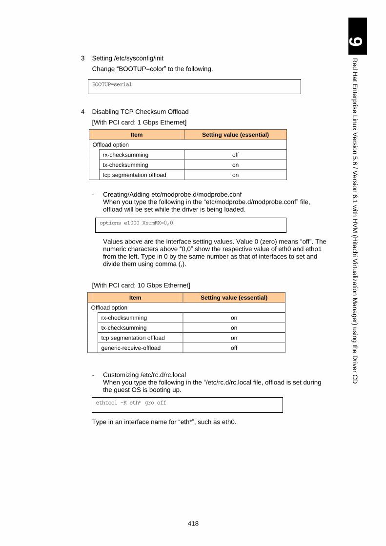
418
9
Re
d H
at E
nte
rpris
e L
inux V
ers
ion
5.6
/ Ve
rsio
n 6
.1 w
ith H
VM
(Hita
ch
i Virtu
aliz
atio
n M
an
ag
er) u
sin
g th
e D
rive
r CD
3 Setting /etc/sysconfig/init
Change “BOOTUP=color” to the following.
4 Disabling TCP Checksum Offload
[With PCI card: 1 Gbps Ethernet]
Item Setting value (essential)
Offload option
rx-checksumming off
tx-checksumming on
tcp segmentation offload on
- Creating/Adding etc/modprobe.d/modprobe.conf When you type the following in the “etc/modprobe.d/modprobe.conf” file, offload will be set while the driver is being loaded.
Values above are the interface setting values. Value 0 (zero) means “off”. The numeric characters above “0,0” show the respective value of eth0 and etho1 from the left. Type in 0 by the same number as that of interfaces to set and divide them using comma (,).
[With PCI card: 10 Gbps Ethernet]
Item Setting value (essential)
Offload option
rx-checksumming on
tx-checksumming on
tcp segmentation offload on
generic-receive-offload off
- Customizing /etc/rc.d/rc.local When you type the following in the “/etc/rc.d/rc.local file, offload is set during the guest OS is booting up.
Type in an interface name for “eth*”, such as eth0.
BOOTUP=serial
options e1000 XsumRX=0,0
ethtool -K eth* gro off
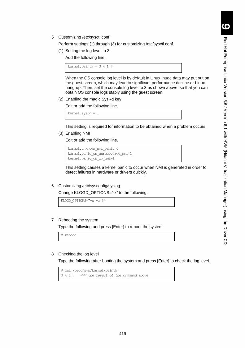
419
9
Re
d H
at E
nte
rpris
e L
inux V
ers
ion
5.6
/ Ve
rsio
n 6
.1 w
ith H
VM
(Hita
ch
i Virtu
aliz
atio
n M
an
ag
er) u
sin
g th
e D
rive
r CD
5 Customizing /etc/sysctl.conf
Perform settings (1) through (3) for customizing /etc/sysctl.conf.
(1) Setting the log level to 3
Add the following line.
When the OS console log level is by default in Linux, huge data may put out on the guest screen, which may lead to significant performance decline or Linux hang-up. Then, set the console log level to 3 as shown above, so that you can obtain OS console logs stably using the guest screen.
(2) Enabling the magic SysRq key
Edit or add the following line.
This setting is required for information to be obtained when a problem occurs.
(3) Enabling NMI
Edit or add the following line.
This setting causes a kernel panic to occur when NMI is generated in order to detect failures in hardware or drivers quickly.
6 Customizing /etc/sysconfig/syslog
Change KLOGD_OPTIONS=”-x” to the following.
7 Rebooting the system
Type the following and press [Enter] to reboot the system.
8 Checking the log level
Type the following after booting the system and press [Enter] to check the log level.
kernel.printk = 3 4 1 7
kernel.sysrq = 1
kernel.unknown_nmi_panic=0
kernel.panic_on_unrecovered_nmi=1
kernel.panic_on_io_nmi=1
# reboot
# cat /proc/sys/kernel/printk
3 4 1 7 <<< the result of the command above
KLOGD_OPTIONS="-x -c 3"
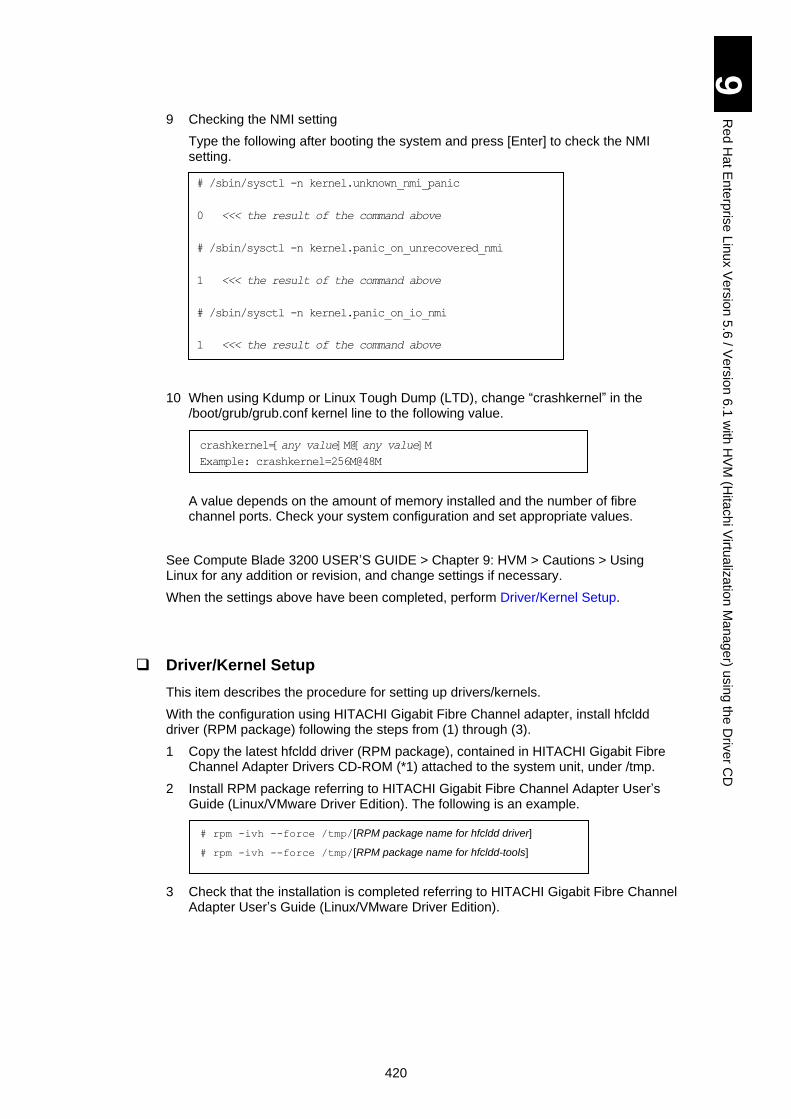
420
9
Re
d H
at E
nte
rpris
e L
inux V
ers
ion
5.6
/ Ve
rsio
n 6
.1 w
ith H
VM
(Hita
ch
i Virtu
aliz
atio
n M
an
ag
er) u
sin
g th
e D
rive
r CD
9 Checking the NMI setting
Type the following after booting the system and press [Enter] to check the NMI setting.
10 When using Kdump or Linux Tough Dump (LTD), change “crashkernel” in the /boot/grub/grub.conf kernel line to the following value.
A value depends on the amount of memory installed and the number of fibre channel ports. Check your system configuration and set appropriate values.
See Compute Blade 3200 USER’S GUIDE > Chapter 9: HVM > Cautions > Using Linux for any addition or revision, and change settings if necessary.
When the settings above have been completed, perform Driver/Kernel Setup.
Driver/Kernel Setup
This item describes the procedure for setting up drivers/kernels.
With the configuration using HITACHI Gigabit Fibre Channel adapter, install hfcldd driver (RPM package) following the steps from (1) through (3).
1 Copy the latest hfcldd driver (RPM package), contained in HITACHI Gigabit Fibre Channel Adapter Drivers CD-ROM (*1) attached to the system unit, under /tmp.
2 Install RPM package referring to HITACHI Gigabit Fibre Channel Adapter User’s Guide (Linux/VMware Driver Edition). The following is an example.
3 Check that the installation is completed referring to HITACHI Gigabit Fibre Channel Adapter User’s Guide (Linux/VMware Driver Edition).
# /sbin/sysctl -n kernel.unknown_nmi_panic
0 <<< the result of the command above
# /sbin/sysctl -n kernel.panic_on_unrecovered_nmi
1 <<< the result of the command above
# /sbin/sysctl -n kernel.panic_on_io_nmi
1 <<< the result of the command above
# rpm -ivh --force /tmp/[RPM package name for hfcldd driver]
# rpm -ivh --force /tmp/[RPM package name for hfcldd-tools]
crashkernel=[any value]M@[any value]M
Example: crashkernel=256M@48M
1
Appendix-I Advanced Function for LAN Windows Server 2008
This appendix explains advanced functions for LAN in Windows Server 2008.
Installing Intel(R) PROSet ....................................................................................... 2
Setting of LAN Advanced Functions ........................................................................ 4
2
Ap
pe
nd
ix-I
Ad
va
nced
Fun
ctio
ns fo
r LA
N
How to Set Advanced LAN Functions in Windows Server 2008
This section explains how to set the advanced function for LAN in the Windows Server 2008 32-bit or 64-bit environment.
It is necessary for the LAN driver for Windows Server 2008 32-bit/64-bit to have been properly installed as a prerequisite. Refer to a manual or software guide of each LAN device for how to install the driver.
When Hyper-V environment is used with Windows Server 2008
64-bit, advanced LAN functions are not supported.
Make sure to install Intel(R) PROSet when using advanced functions for LAN in Windows 2008 32-bit/64-bit environment. Follow the procedure for installing Intel(R) PROSet described below
Execute the setup program in the following directory in the CD-ROM “DriverKit” supporting
Windows Server 2008. (When the CD-ROM or DVD ROM drive is Drive D:)
OS Location of Tool for LAN Redundancy
Windows Server 2008
32-bit
D:\OPTION\TOOLS\WIN2008\INTELLAN\APPS\PROSETDX\Vista32\dxs
etup.exe
or
D:\X51x5\Win2008\Utility\PROSetDX\APPS\PROSETDX\Win32\
Dxsetup.exe
Windows Server 2008
64-bit
D:\OPTION\TOOLS\WIN2008\INTELLAN\APPS\PROSETDX\Vistax64\dx
setup.exe
or
D:\X51x5\Win2008\Utility\PROSetDX\APPS\PROSETDX\Winx64\
Dxsetup.exe
Installing Intel(R) PROSet)
1. When the following screen appears, click the [Next] button.
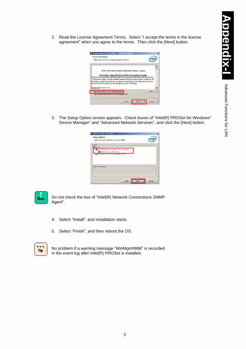
3
Ap
pe
nd
ix-I
Ad
va
nced
Fun
ctio
ns fo
r LA
N
2. Read the License Agreement Terms. Select “I accept the terms in the license agreement” when you agree to the terms. Then click the [Next] button.
3. The Setup Option screen appears. Check boxes of “Intel(R) PROSet for Windows*
Device Manager” and “Advanced Network Services”, and click the [Next] button.
Do not check the box of “Intel(R) Network Connections SNMP Agent”.
4. Select “Install”, and installation starts.
5. Select “Finish”, and then reboot the OS.
No problem if a warning message “WinMgmtWMI” is recorded in the event log after Intel(R) PROSet is installed.
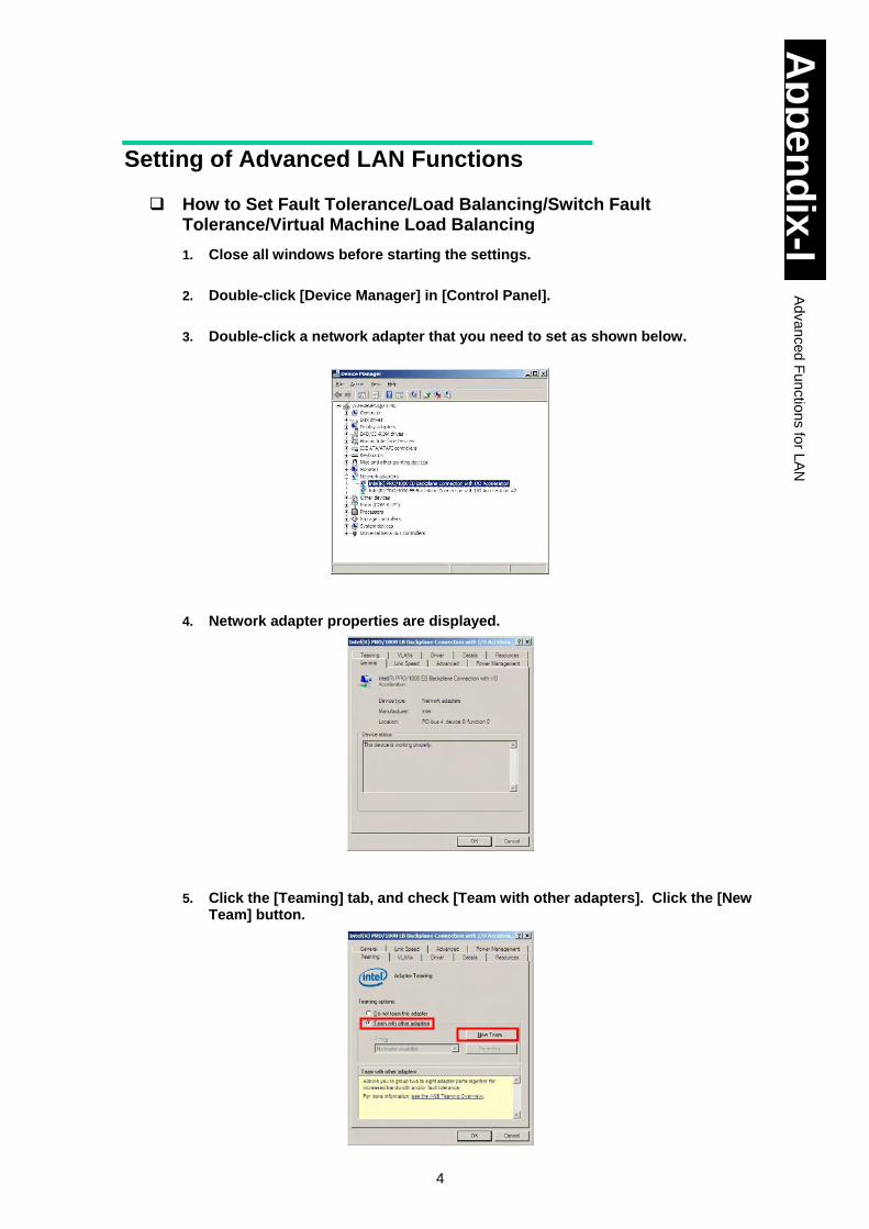
4
Ap
pe
nd
ix-I
Ad
va
nced
Fun
ctio
ns fo
r LA
N
Setting of Advanced LAN Functions
How to Set Fault Tolerance/Load Balancing/Switch Fault Tolerance/Virtual Machine Load Balancing
1. Close all windows before starting the settings.
2. Double-click [Device Manager] in [Control Panel].
3. Double-click a network adapter that you need to set as shown below.
4. Network adapter properties are displayed.
5. Click the [Teaming] tab, and check [Team with other adapters]. Click the [New
Team] button.
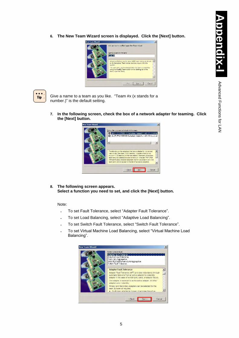
5
Ap
pe
nd
ix-I
Ad
va
nced
Fun
ctio
ns fo
r LA
N
6. The New Team Wizard screen is displayed. Click the [Next] button.
Give a name to a team as you like. “Team #x (x stands for a number.)” is the default setting.
7. In the following screen, check the box of a network adapter for teaming. Click the [Next] button.
8. The following screen appears.
Select a function you need to set, and click the [Next] button.
Note:
To set Fault Tolerance, select “Adapter Fault Tolerance”.
To set Load Balancing, select “Adaptive Load Balancing”.
To set Switch Fault Tolerance, select “Switch Fault Tolerance”.
To set Virtual Machine Load Balancing, select “Virtual Machine Load Balancing”.

6
Ap
pe
nd
ix-I
Ad
va
nced
Fun
ctio
ns fo
r LA
N
Load Balancing and Virtual Machine Load Balancing include
Fault Tolerance. Load Balancing, however, requires that the
team should consist of LAN devices with the same speed.
Virtual Machine Load Balancing is displayed in the pane only
when Hyper-V is installed.
When composing a team of Fault Tolerance or Switch Fault Tolerance, select two LAN devices.
For Load Balancing and Virtual Machine Load Balancing, up to two LAN devices can compose a team in this server blade.
Load Balancing contains Fault Tolerance on condition that
Load Balancing is set to a team consisting of LAN devices with
the same speed.
When composing a team of Fault Tolerance or Switch Fault Tolerance, select two LAN devices.
For Load Balancing, up to two LAN devices can make a team in this system equipment.
It may take a bit longer until the setting is completed.
When three or more LAN devices are selected to team up, Switch Fault Tolerance is not displayed.
Intel(R) PROSet is used to improve reliability for communication by giving redundancy to LAN devices. In some environments (network structure or application), however, it may take from a dozen seconds to a couple of minutes to restore communication at switching links.
Since incoming data are processed by a single LAN device, the bandwidth does not change at receiving data. ALB/VMLB is a function used to improve the actual throughput with the load balancing function. In some operation environments such as CPU loading or contents of communication, however, it may not improve performance due to overhead on the load balance processing.
LAN devices used in this server blade support only three functions: Adapter Fault Tolerance, Adaptive Load Balancing, and Switch Fault Tolerance. Therefore, do not select other functions except those three.
Tip
Tip
Tip
Tip
Tip
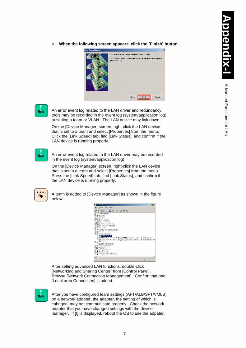
7
Ap
pe
nd
ix-I
Ad
va
nced
Fun
ctio
ns fo
r LA
N
9. When the following screen appears, click the [Finish] button.
An error event log related to the LAN driver and redundancy tools may be recorded in the event log (system/application log) at setting a team or VLAN. The LAN device may link down.
On the [Device Manager] screen, right-click the LAN device that is set to a team and select [Properties] from the menu. Click the [Link Speed] tab, find [Link Status], and confirm if the LAN device is running properly.
An error event log related to the LAN driver may be recorded in the event log (system/application log).
On the [Device Manager] screen, right-click the LAN device that is set to a team and select [Properties] from the menu. Press the [Link Speed] tab, find [Link Status], and confirm if the LAN device is running properly.
A team is added to [Device Manager] as shown in the figure below.
After setting advanced LAN functions, double-click [Networking and Sharing Center] from [Control Panel]. Browse [Network Connection Management]. Confirm that one [Local area Connection] is added.
After you have configured team settings (AFT/ALB/SFT/VMLB) on a network adapter, the adapter, the setting of which is cahnged, may not communicate properly. Check the network adapter that you have changed settings with the device manager. If [!] is displayed, reboot the OS to use the adpater.
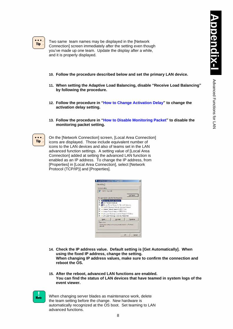
8
Ap
pe
nd
ix-I
Ad
va
nced
Fun
ctio
ns fo
r LA
N
Two same team names may be displayed in the [Network Connection] screen immediately after the setting even though you’ve made up one team. Update the display after a while, and it is properly displayed.
10. Follow the procedure described below and set the primary LAN device.
11. When setting the Adaptive Load Balancing, disable “Receive Load Balancing” by following the procedure.
12. Follow the procedure in “How to Change Activation Delay” to change the activation delay setting.
13. Follow the procedure in “How to Disable Monitoring Packet” to disable the monitoring packet setting.
On the [Network Connection] screen, [Local Area Connection] icons are displayed. Those include equivalent number of icons to the LAN devices and also of teams set in the LAN advanced function settings. A setting value of [Local Area Connection] added at setting the advanced LAN function is enabled as an IP address. To change the IP address, from [Properties] in [Local Area Connection], select [Network Protocol (TCP/IP)] and [Properties].
14. Check the IP address value. Default setting is [Get Automatically]. When using the fixed IP address, change the setting. When changing IP address values, make sure to confirm the connection and reboot the OS.
15. After the reboot, advanced LAN functions are enabled. You can find the status of LAN devices that have teamed in system logs of the event viewer.
When changing server blades as maintenance work, delete the team setting before the change. New hardware is automatically recognized at the OS boot. Set teaming to LAN advanced functions.
9
Ap
pe
nd
ix-I
Ad
va
nced
Fun
ctio
ns fo
r LA
N
When a team consists of different LAN devices, setting values of those LAN devices that join the team may be changed to the optimum ones.
Using the virtual machine load balancing (VMLB) with Hyper-V
Follow the steps described below, and open the properties of [Local Area Connection xx] that is newly created after a VMLB is created. Remove check marks from all protocol icons ( ), and assign them to the virtual network in the Hyper-V environment.
1. Double-click [Network and Sharing Center] in [Control Panel]. Refer to [Network Connection Manager].
2. In the [Network Connection] screen, right-click on [Local Area Connection xx] that is newly added by setting the VMLB. Select [Properties] from the dropdown menu.
3. Remove check marks from all protocol icons displayed in the [This connection uses the following items.] field.
4. Click the [OK] button.
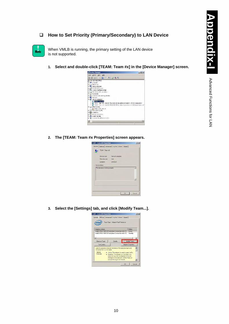
10
Ap
pe
nd
ix-I
Ad
va
nced
Fun
ctio
ns fo
r LA
N
How to Set Priority (Primary/Secondary) to LAN Device
When VMLB is running, the primary setting of the LAN device
is not supported.
1. Select and double-click [TEAM: Team #x] in the [Device Manager] screen.
2. The [TEAM: Team #x Properties] screen appears.
3. Select the [Settings] tab, and click [Modify Team...].
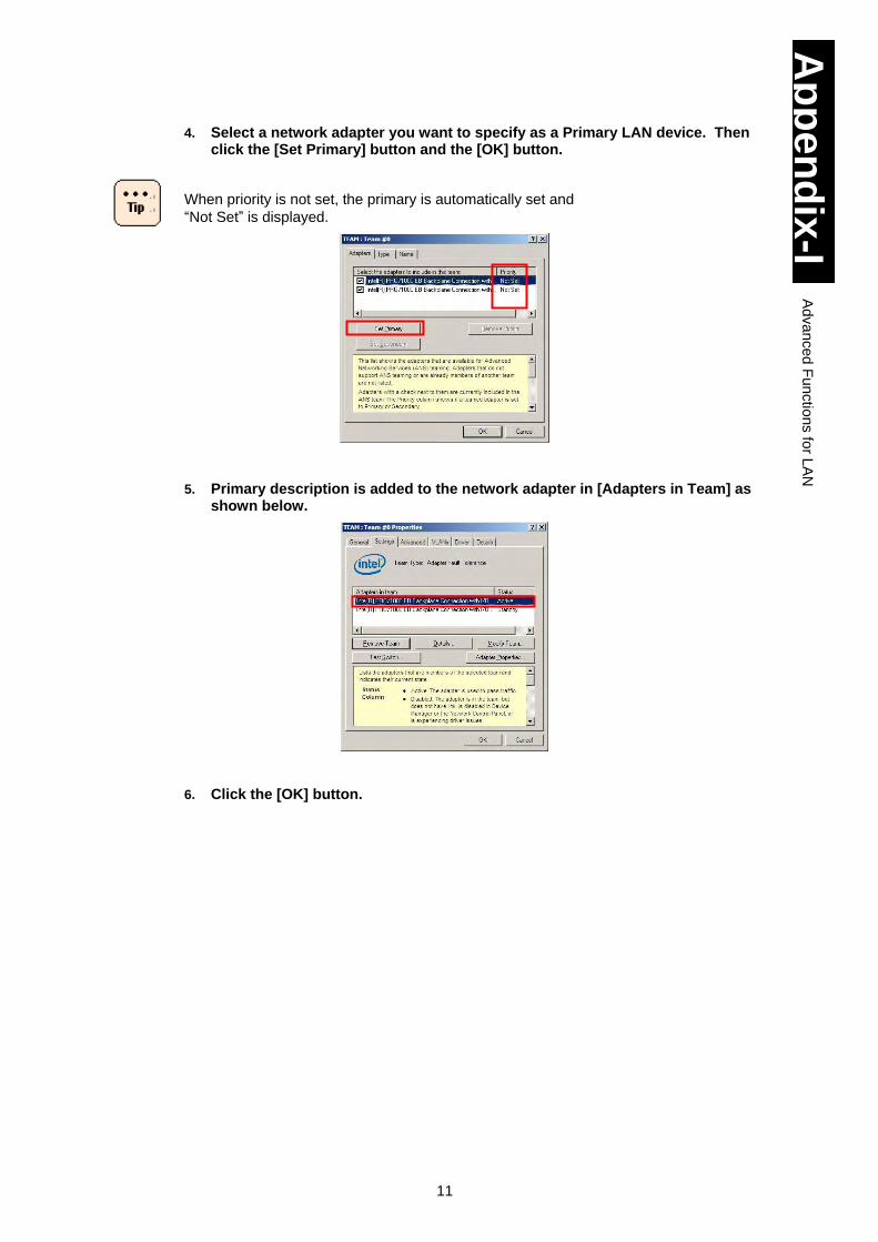
11
Ap
pe
nd
ix-I
Ad
va
nced
Fun
ctio
ns fo
r LA
N
4. Select a network adapter you want to specify as a Primary LAN device. Then click the [Set Primary] button and the [OK] button.
When priority is not set, the primary is automatically set and
“Not Set” is displayed.
5. Primary description is added to the network adapter in [Adapters in Team] as
shown below.
6. Click the [OK] button.
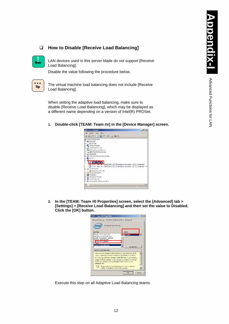
12
Ap
pe
nd
ix-I
Ad
va
nced
Fun
ctio
ns fo
r LA
N
How to Disable [Receive Load Balancing]
LAN devices used in this server blade do not support [Receive
Load Balancing].
Disable the value following the procedure below.
The virtual machine load balancing does not include [Receive
Load Balancing].
When setting the adaptive load balancing, make sure to
disable [Receive Load Balancing], which may be displayed as
a different name depending on a version of Intel(R) PROSet.
1. Double-click [TEAM: Team #x] in the [Device Manager] screen.
2. In the [TEAM: Team #0 Properties] screen, select the [Advanced] tab >
[Settings] > [Receive Load Balancing] and then set the value to Disabled. Click the [OK] button.
Execute this step on all Adaptive Load Balancing teams.
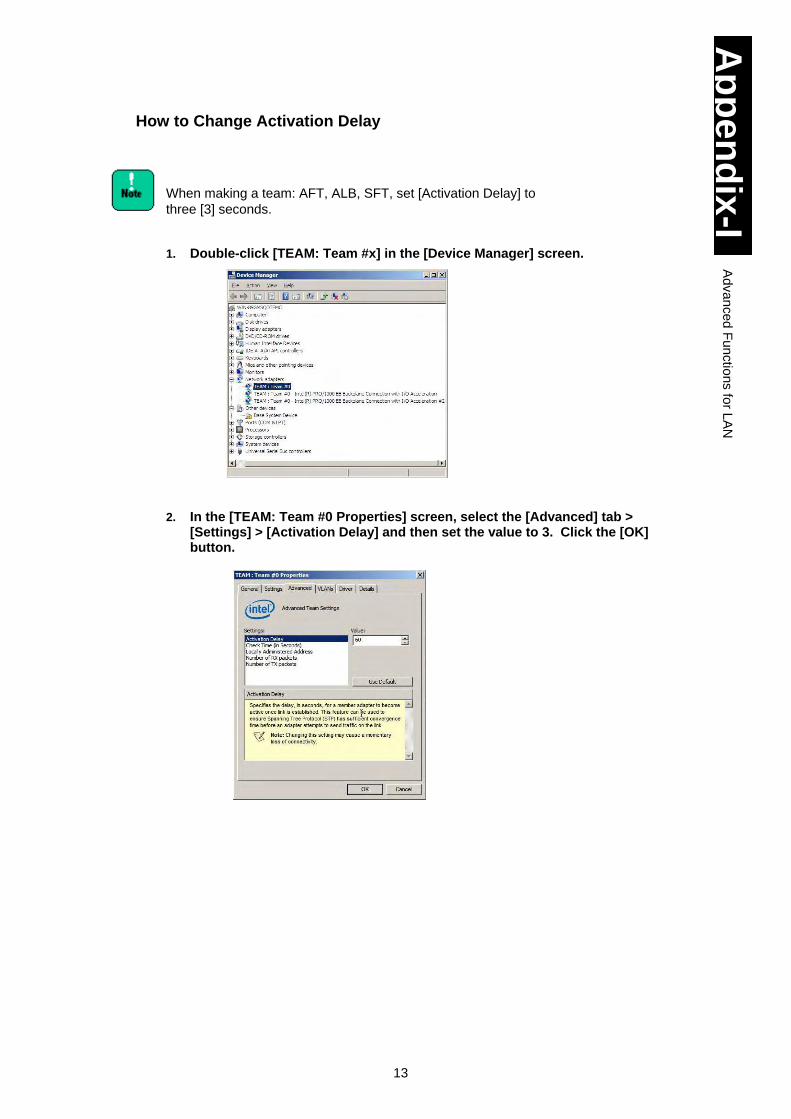
13
Ap
pe
nd
ix-I
Ad
va
nced
Fun
ctio
ns fo
r LA
N
How to Change Activation Delay
When making a team: AFT, ALB, SFT, set [Activation Delay] to
three [3] seconds.
1. Double-click [TEAM: Team #x] in the [Device Manager] screen.
2. In the [TEAM: Team #0 Properties] screen, select the [Advanced] tab > [Settings] > [Activation Delay] and then set the value to 3. Click the [OK] button.
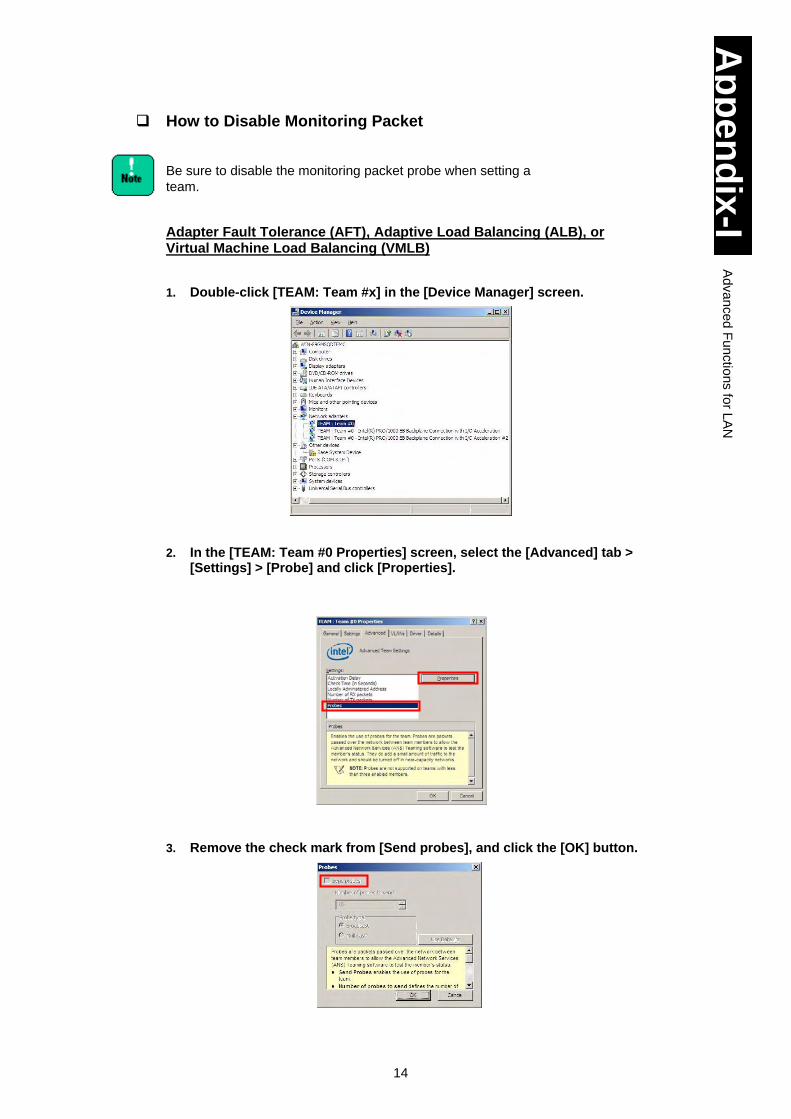
14
Ap
pe
nd
ix-I
Ad
va
nced
Fun
ctio
ns fo
r LA
N
How to Disable Monitoring Packet
Be sure to disable the monitoring packet probe when setting a
team.
Adapter Fault Tolerance (AFT), Adaptive Load Balancing (ALB), or Virtual Machine Load Balancing (VMLB)
1. Double-click [TEAM: Team #x] in the [Device Manager] screen.
2. In the [TEAM: Team #0 Properties] screen, select the [Advanced] tab > [Settings] > [Probe] and click [Properties].
3. Remove the check mark from [Send probes], and click the [OK] button.
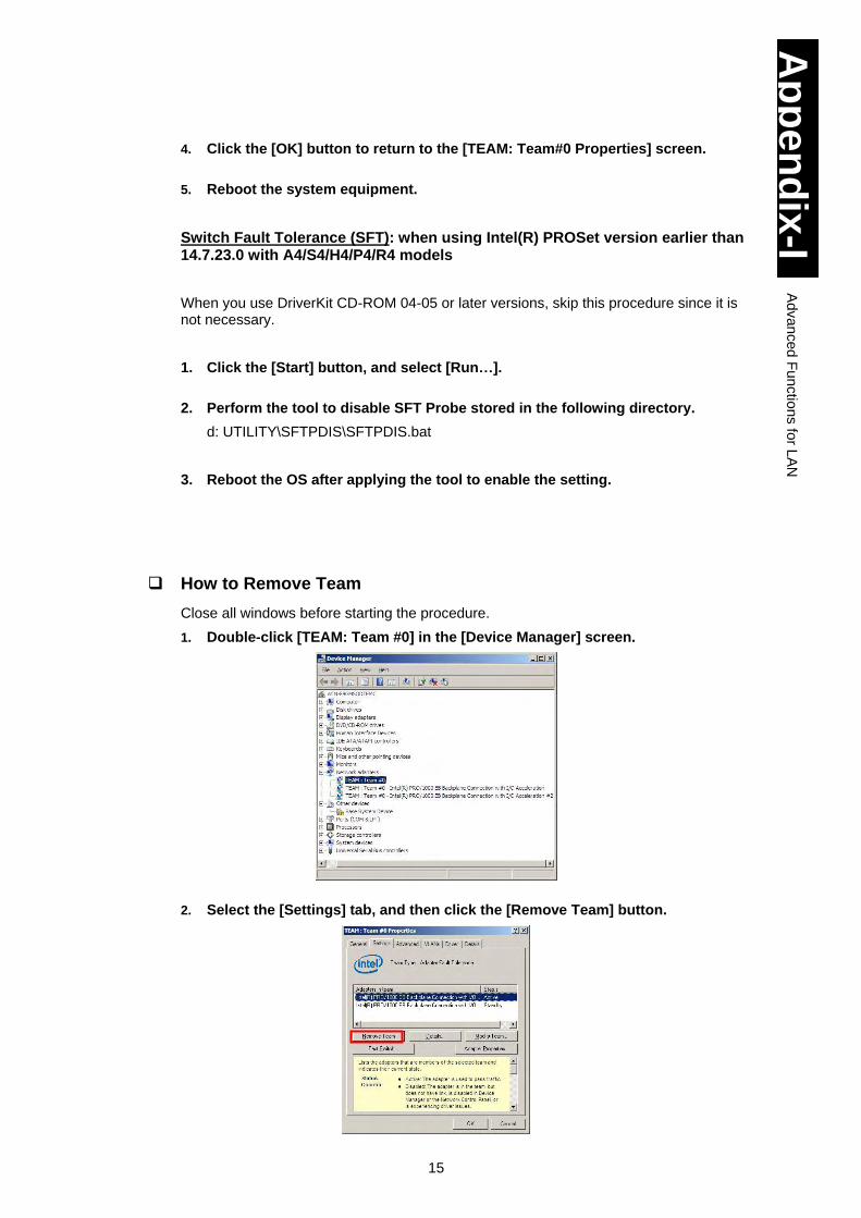
15
Ap
pe
nd
ix-I
Ad
va
nced
Fun
ctio
ns fo
r LA
N
4. Click the [OK] button to return to the [TEAM: Team#0 Properties] screen.
5. Reboot the system equipment.
Switch Fault Tolerance (SFT): when using Intel(R) PROSet version earlier than 14.7.23.0 with A4/S4/H4/P4/R4 models
When you use DriverKit CD-ROM 04-05 or later versions, skip this procedure since it is not necessary.
1. Click the [Start] button, and select [Run…].
2. Perform the tool to disable SFT Probe stored in the following directory.
d: UTILITY\SFTPDIS\SFTPDIS.bat
3. Reboot the OS after applying the tool to enable the setting.
How to Remove Team
Close all windows before starting the procedure.
1. Double-click [TEAM: Team #0] in the [Device Manager] screen.
2. Select the [Settings] tab, and then click the [Remove Team] button.
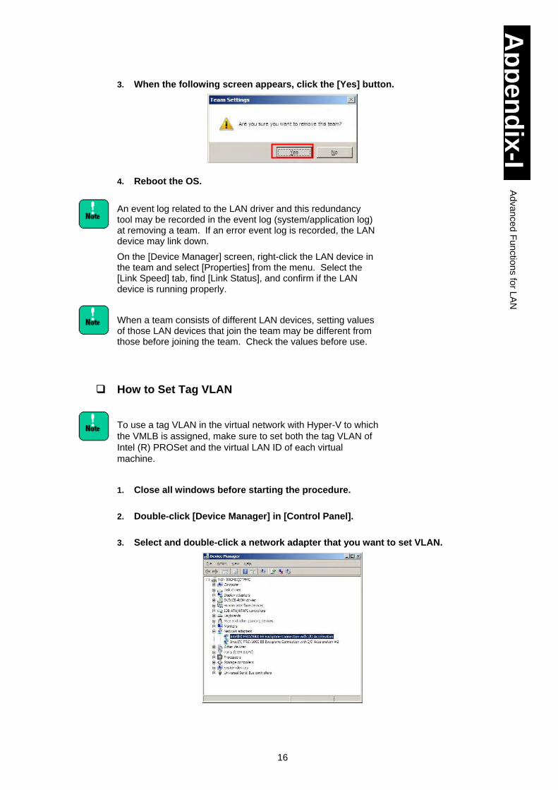
16
Ap
pe
nd
ix-I
Ad
va
nced
Fun
ctio
ns fo
r LA
N
3. When the following screen appears, click the [Yes] button.
4. Reboot the OS.
An event log related to the LAN driver and this redundancy tool may be recorded in the event log (system/application log) at removing a team. If an error event log is recorded, the LAN device may link down.
On the [Device Manager] screen, right-click the LAN device in the team and select [Properties] from the menu. Select the [Link Speed] tab, find [Link Status], and confirm if the LAN device is running properly.
When a team consists of different LAN devices, setting values of those LAN devices that join the team may be different from those before joining the team. Check the values before use.
How to Set Tag VLAN
To use a tag VLAN in the virtual network with Hyper-V to which
the VMLB is assigned, make sure to set both the tag VLAN of
Intel (R) PROSet and the virtual LAN ID of each virtual
machine.
1. Close all windows before starting the procedure.
2. Double-click [Device Manager] in [Control Panel].
3. Select and double-click a network adapter that you want to set VLAN.
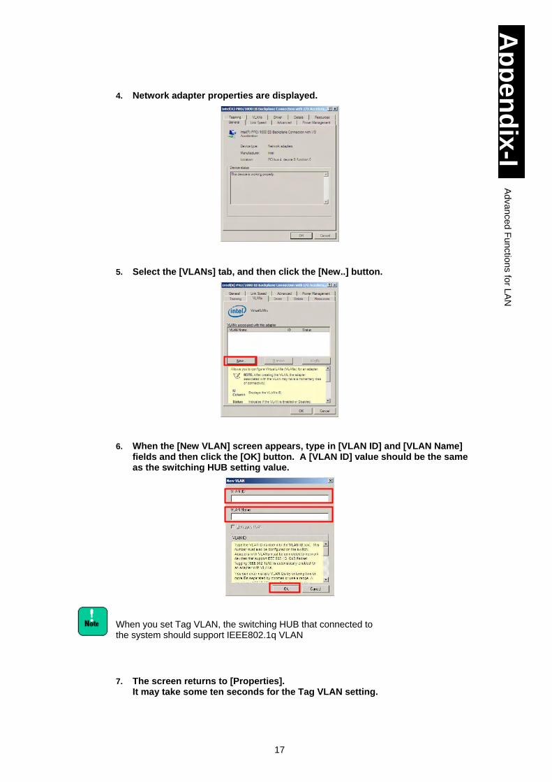
17
Ap
pe
nd
ix-I
Ad
va
nced
Fun
ctio
ns fo
r LA
N
4. Network adapter properties are displayed.
5. Select the [VLANs] tab, and then click the [New..] button.
6. When the [New VLAN] screen appears, type in [VLAN ID] and [VLAN Name]
fields and then click the [OK] button. A [VLAN ID] value should be the same as the switching HUB setting value.
When you set Tag VLAN, the switching HUB that connected to the system should support IEEE802.1q VLAN
7. The screen returns to [Properties]. It may take some ten seconds for the Tag VLAN setting.
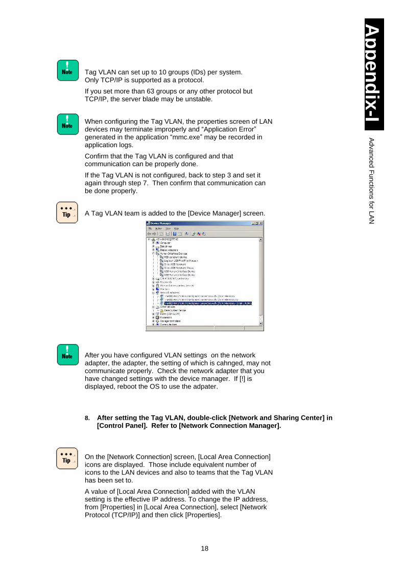
18
Ap
pe
nd
ix-I
Ad
va
nced
Fun
ctio
ns fo
r LA
N
Tag VLAN can set up to 10 groups (IDs) per system. Only TCP/IP is supported as a protocol.
If you set more than 63 groups or any other protocol but TCP/IP, the server blade may be unstable.
When configuring the Tag VLAN, the properties screen of LAN devices may terminate improperly and “Application Error” generated in the application “mmc.exe” may be recorded in application logs.
Confirm that the Tag VLAN is configured and that communication can be properly done.
If the Tag VLAN is not configured, back to step 3 and set it again through step 7. Then confirm that communication can be done properly.
A Tag VLAN team is added to the [Device Manager] screen.
After you have configured VLAN settings on the network adapter, the adapter, the setting of which is cahnged, may not communicate properly. Check the network adapter that you have changed settings with the device manager. If [!] is displayed, reboot the OS to use the adpater.
8. After setting the Tag VLAN, double-click [Network and Sharing Center] in
[Control Panel]. Refer to [Network Connection Manager].
On the [Network Connection] screen, [Local Area Connection] icons are displayed. Those include equivalent number of icons to the LAN devices and also to teams that the Tag VLAN has been set to.
A value of [Local Area Connection] added with the VLAN setting is the effective IP address. To change the IP address, from [Properties] in [Local Area Connection], select [Network Protocol (TCP/IP)] and then click [Properties].
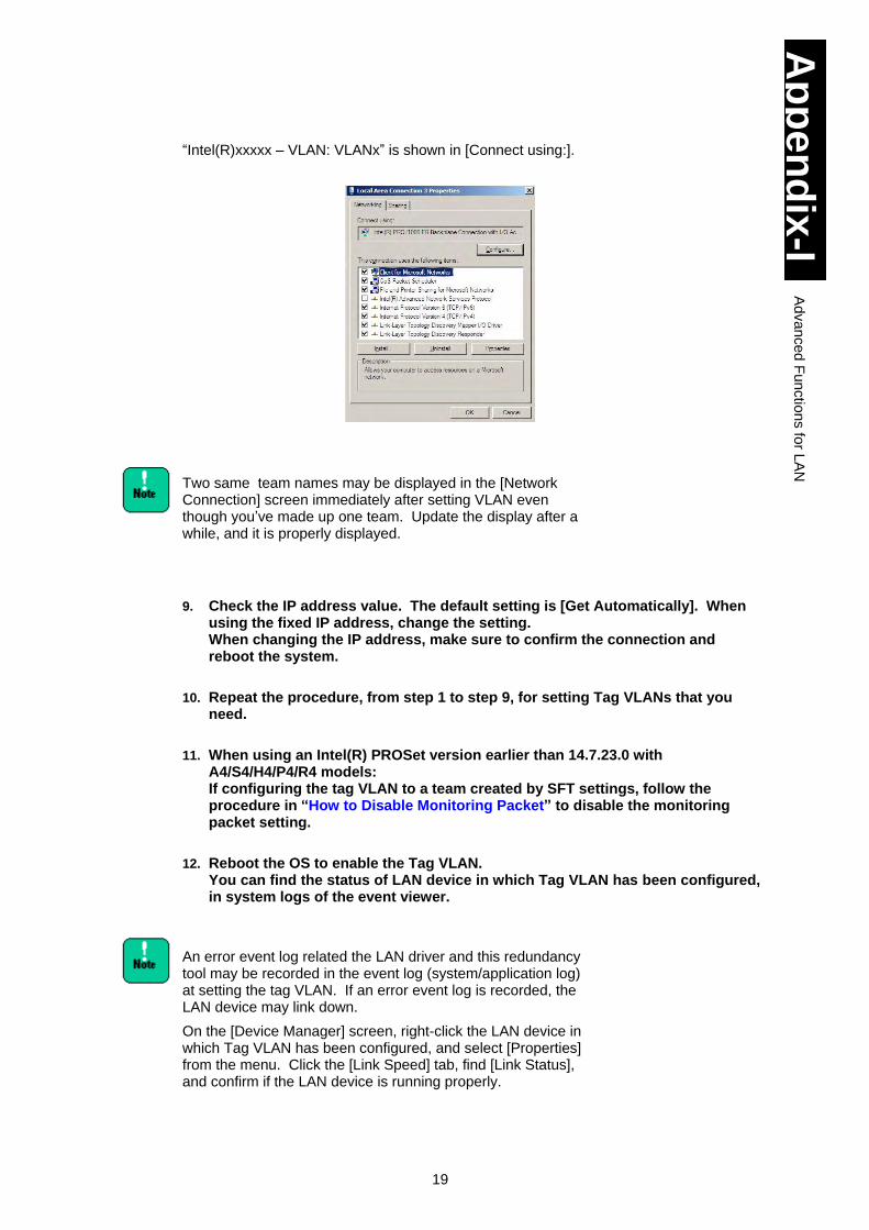
19
Ap
pe
nd
ix-I
Ad
va
nced
Fun
ctio
ns fo
r LA
N
“Intel(R)xxxxx – VLAN: VLANx” is shown in [Connect using:].
Two same team names may be displayed in the [Network Connection] screen immediately after setting VLAN even though you’ve made up one team. Update the display after a while, and it is properly displayed.
9. Check the IP address value. The default setting is [Get Automatically]. When using the fixed IP address, change the setting. When changing the IP address, make sure to confirm the connection and reboot the system.
10. Repeat the procedure, from step 1 to step 9, for setting Tag VLANs that you need.
11. When using an Intel(R) PROSet version earlier than 14.7.23.0 with A4/S4/H4/P4/R4 models: If configuring the tag VLAN to a team created by SFT settings, follow the procedure in “How to Disable Monitoring Packet” to disable the monitoring packet setting.
12. Reboot the OS to enable the Tag VLAN. You can find the status of LAN device in which Tag VLAN has been configured, in system logs of the event viewer.
An error event log related the LAN driver and this redundancy tool may be recorded in the event log (system/application log) at setting the tag VLAN. If an error event log is recorded, the LAN device may link down.
On the [Device Manager] screen, right-click the LAN device in which Tag VLAN has been configured, and select [Properties] from the menu. Click the [Link Speed] tab, find [Link Status], and confirm if the LAN device is running properly.
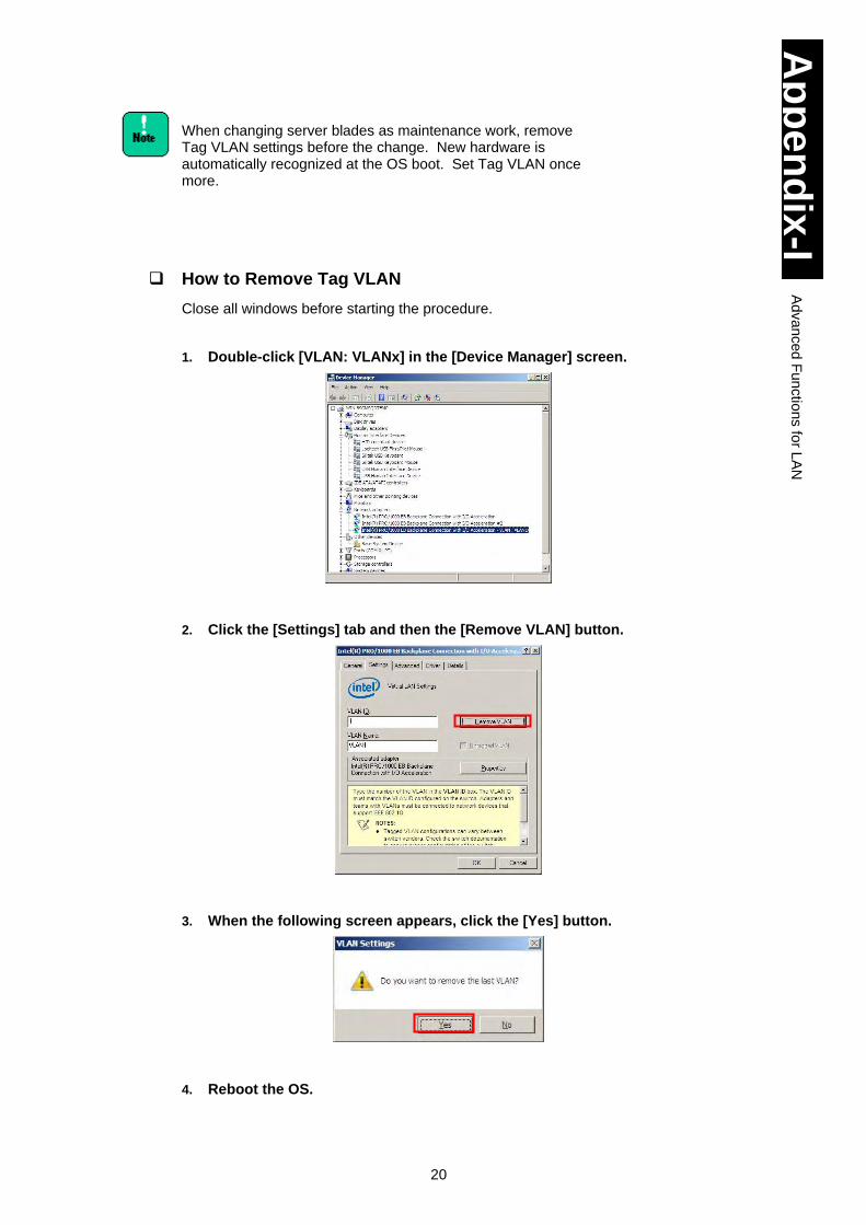
20
Ap
pe
nd
ix-I
Ad
va
nced
Fun
ctio
ns fo
r LA
N
When changing server blades as maintenance work, remove Tag VLAN settings before the change. New hardware is automatically recognized at the OS boot. Set Tag VLAN once more.
How to Remove Tag VLAN
Close all windows before starting the procedure.
1. Double-click [VLAN: VLANx] in the [Device Manager] screen.
2. Click the [Settings] tab and then the [Remove VLAN] button.
3. When the following screen appears, click the [Yes] button.
4. Reboot the OS.
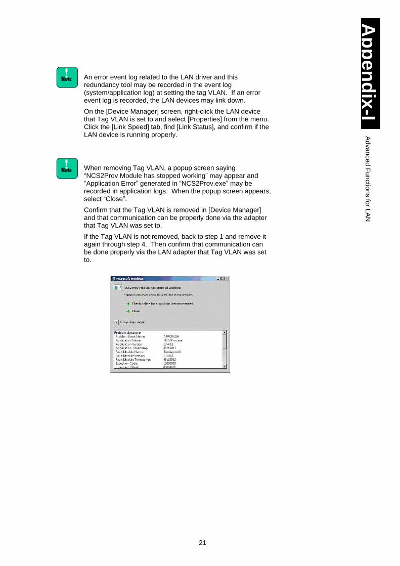
21
Ap
pe
nd
ix-I
Ad
va
nced
Fun
ctio
ns fo
r LA
N
An error event log related to the LAN driver and this redundancy tool may be recorded in the event log (system/application log) at setting the tag VLAN. If an error event log is recorded, the LAN devices may link down.
On the [Device Manager] screen, right-click the LAN device that Tag VLAN is set to and select [Properties] from the menu. Click the [Link Speed] tab, find [Link Status], and confirm if the LAN device is running properly.
When removing Tag VLAN, a popup screen saying “NCS2Prov Module has stopped working” may appear and “Application Error” generated in “NCS2Prov.exe” may be recorded in application logs. When the popup screen appears, select “Close”.
Confirm that the Tag VLAN is removed in [Device Manager] and that communication can be properly done via the adapter that Tag VLAN was set to.
If the Tag VLAN is not removed, back to step 1 and remove it again through step 4. Then confirm that communication can be done properly via the LAN adapter that Tag VLAN was set to.
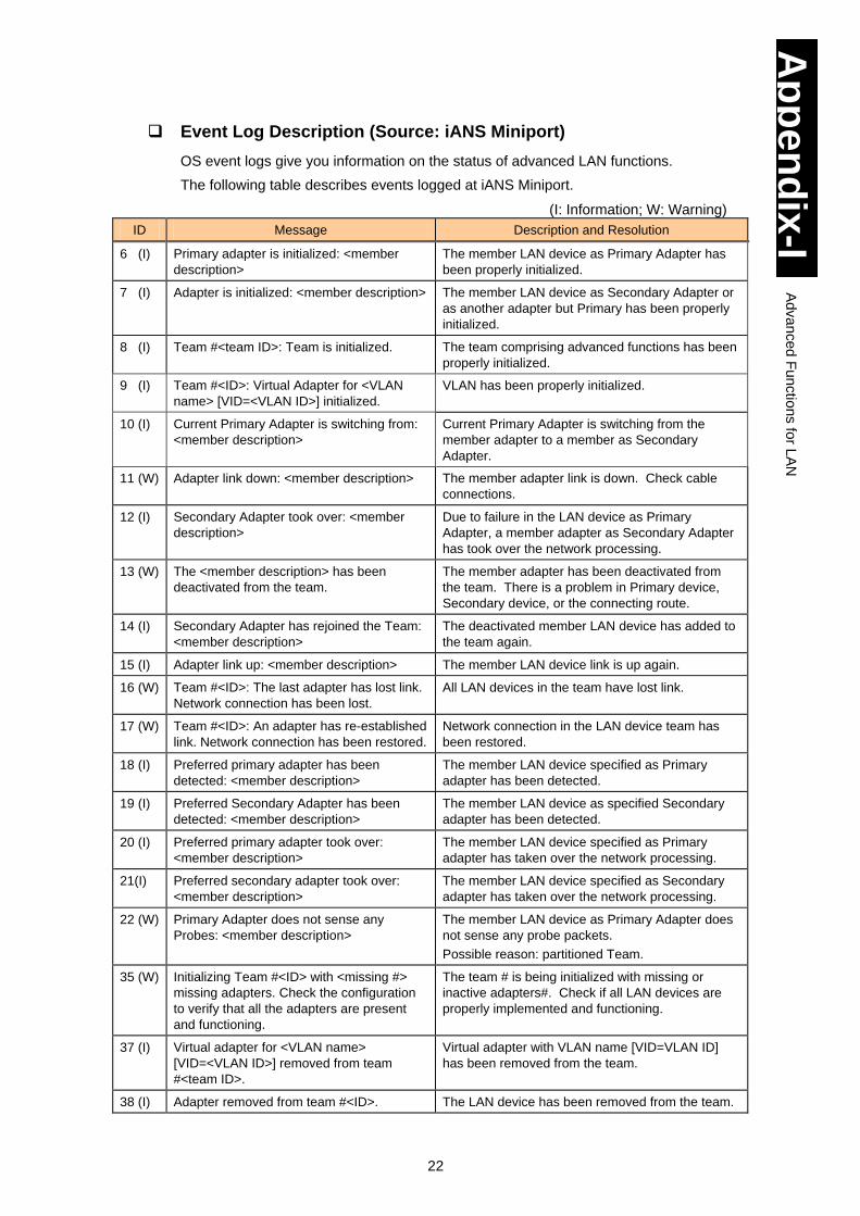
22
Ap
pe
nd
ix-I
Ad
va
nced
Fun
ctio
ns fo
r LA
N
Event Log Description (Source: iANS Miniport)
OS event logs give you information on the status of advanced LAN functions.
The following table describes events logged at iANS Miniport.
(I: Information; W: Warning)
ID Message Description and Resolution
6 (I) Primary adapter is initialized: <member
description>
The member LAN device as Primary Adapter has
been properly initialized.
7 (I) Adapter is initialized: <member description> The member LAN device as Secondary Adapter or
as another adapter but Primary has been properly
initialized.
8 (I) Team #<team ID>: Team is initialized. The team comprising advanced functions has been
properly initialized.
9 (I) Team #<ID>: Virtual Adapter for <VLAN
name> [VID=<VLAN ID>] initialized.
VLAN has been properly initialized.
10 (I) Current Primary Adapter is switching from:
<member description>
Current Primary Adapter is switching from the
member adapter to a member as Secondary
Adapter.
11 (W) Adapter link down: <member description> The member adapter link is down. Check cable
connections.
12 (I) Secondary Adapter took over: <member
description>
Due to failure in the LAN device as Primary
Adapter, a member adapter as Secondary Adapter
has took over the network processing.
13 (W) The <member description> has been
deactivated from the team.
The member adapter has been deactivated from
the team. There is a problem in Primary device,
Secondary device, or the connecting route.
14 (I) Secondary Adapter has rejoined the Team:
<member description>
The deactivated member LAN device has added to
the team again.
15 (I) Adapter link up: <member description> The member LAN device link is up again.
16 (W) Team #<ID>: The last adapter has lost link.
Network connection has been lost.
All LAN devices in the team have lost link.
17 (W) Team #<ID>: An adapter has re-established
link. Network connection has been restored.
Network connection in the LAN device team has
been restored.
18 (I) Preferred primary adapter has been
detected: <member description>
The member LAN device specified as Primary
adapter has been detected.
19 (I) Preferred Secondary Adapter has been
detected: <member description>
The member LAN device as specified Secondary
adapter has been detected.
20 (I) Preferred primary adapter took over:
<member description>
The member LAN device specified as Primary
adapter has taken over the network processing.
21(I) Preferred secondary adapter took over:
<member description>
The member LAN device specified as Secondary
adapter has taken over the network processing.
22 (W) Primary Adapter does not sense any
Probes: <member description>
The member LAN device as Primary Adapter does
not sense any probe packets.
Possible reason: partitioned Team.
35 (W) Initializing Team #<ID> with <missing #>
missing adapters. Check the configuration
to verify that all the adapters are present
and functioning.
The team # is being initialized with missing or
inactive adapters#. Check if all LAN devices are
properly implemented and functioning.
37 (I) Virtual adapter for <VLAN name>
[VID=<VLAN ID>] removed from team
#<team ID>.
Virtual adapter with VLAN name [VID=VLAN ID]
has been removed from the team.
38 (I) Adapter removed from team #<ID>. The LAN device has been removed from the team.
23
Ap
pe
nd
ix-I
Ad
va
nced
Fun
ctio
ns fo
r LA
N
Example of Operating Advanced Function
[Prerequisites]
A fault tolerance team is comprised of LAN Device A (Intel(R) PRO/1000 A Network Connection) and LAN Device B (Intel(R) PRO/1000 B Network Connection). Do not set preference values such as primary and secondary to both devices, and LAN Device A is automatically set to the Primary. (Refer to “How to set Primary LAN Device” for setting preference.)
[Operation]
Suppose LAN Device A link is down when the network function is running. Fault tolerance function makes LAN Device B take over the process. Even if LAN Device A restores the linkup after a while, LAN Device B keeps processing.
[OS Event Log to be recorded: System Log] (Source: iANS Miniport)
1. When a server blade Boots
Event ID 7: Information Adapter is initialized: Intel(R) PRO/1000 A Network Connection
Event ID 7: Information Adapter is initialized: Intel(R) PRO/1000 B Network Connection
Event ID 15: Information Adapter link up: Intel(R) PRO/1000 A Network Connection
Event ID 15: Information Adapter link up: Intel(R) PRO/1000 B Network Connection
Event ID 8: Information Team #<team ID>: Team is initialized.
Immediately after a server blade boots in setting Fault Tolerance, “Event ID 11: Adapter link down: <member description>” may be generated. Since no hardware failure occurs, use it as it is.
2. When Link Connection is down
Event ID 11: Warning Adapter link down: <member description>: Intel(R) PRO/1000 A Network Connection
Event ID 10: Information Current Primary Adapter is switching from: <member description>: Intel(R) PRO/1000 A Network Connection
Event ID 12: Information Secondary Adapter took over: <member description>: Intel(R) PRO/1000 B Network Connection
3. When Link Connection is restored
Event ID 15: Information Adapter link up: Intel(R) PRO/1000 A Network Connection
Event ID 14: Information Secondary Adapter has rejoined the Team: <member description>: Intel(R) PRO/1000 A Network Connection
Without setting preference, LAN Device A remains Secondary even if restored.
24
Ap
pe
nd
ix-I
Ad
va
nced
Fun
ctio
ns fo
r LA
N
When integrating advanced functions mentioned above with
Microsoft NLB/WLBS, use these functions in the multicast
mode, not in the unicast mode.
Do not configure the teaming among advanced functions for
LAN, in the LAN for inter-cluster communication in the cluster
server.
Diagnostic function in LAN devices
When Intel(R) PROSet is installed, do not perform the
diagnostic test by clicking [Diagnostics] under the [Link Speed]
tab in the LAN device [Properties].
If you performed the diagnostic test, linkdown could not be
detected. If you have performed the diagnostic test, be sure to
reboot the OS.
Be sure to disable monitoring packets when setting a team.
Refer to “How to Disable Monitoring Packet” for details.
If monitoring packets are not disabled at AFT/ALB setting, or if
a heavy load is added in the current network environment
when you configure the SFT setting, using a version of Intel(R)
PROSet earlier than 14.7.23.0 with A4/S4/H4/P4/R4 model,
the LAN device for primary connection may be switched to
another, which may lead to improper operation.
1
Appendix-II Advanced Function for LAN Windows Server 2008 R2
This appendix explains advanced functions for LAN in Windows Server 2008 R2.
Installing Intel (R) PROSet ...................................................................................... 2
Setting of LAN Advanced Functions ........................................................................ 4
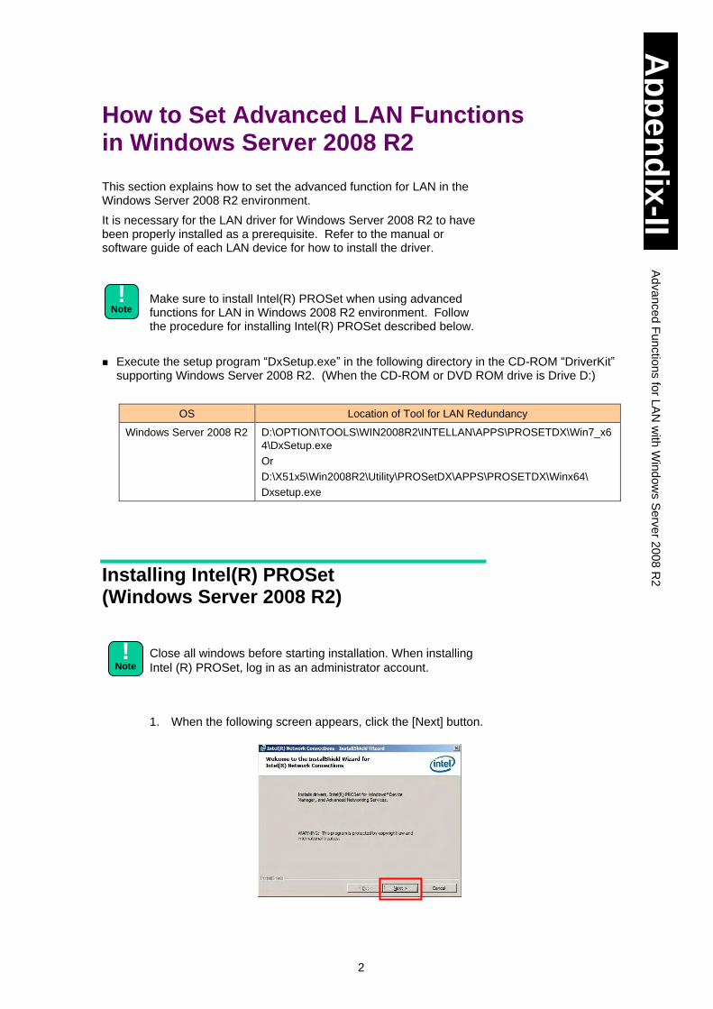
2
Ap
pe
nd
ix-II
Ad
va
nce
d F
un
ctio
ns fo
r LA
N w
ith W
ind
ow
s S
erv
er 2
00
8 R
2
How to Set Advanced LAN Functions in Windows Server 2008 R2
This section explains how to set the advanced function for LAN in the Windows Server 2008 R2 environment.
It is necessary for the LAN driver for Windows Server 2008 R2 to have been properly installed as a prerequisite. Refer to the manual or software guide of each LAN device for how to install the driver.
Make sure to install Intel(R) PROSet when using advanced functions for LAN in Windows 2008 R2 environment. Follow the procedure for installing Intel(R) PROSet described below.
Execute the setup program “DxSetup.exe” in the following directory in the CD-ROM “DriverKit”
supporting Windows Server 2008 R2. (When the CD-ROM or DVD ROM drive is Drive D:)
OS Location of Tool for LAN Redundancy
Windows Server 2008 R2 D:\OPTION\TOOLS\WIN2008R2\INTELLAN\APPS\PROSETDX\Win7_x6
4\DxSetup.exe
Or
D:\X51x5\Win2008R2\Utility\PROSetDX\APPS\PROSETDX\Winx64\
Dxsetup.exe
Installing Intel(R) PROSet (Windows Server 2008 R2)
Close all windows before starting installation. When installing
Intel (R) PROSet, log in as an administrator account.
1. When the following screen appears, click the [Next] button.
!
Note
!
Note
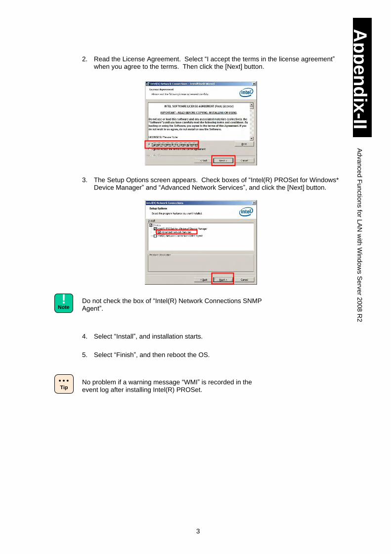
3
Ap
pe
nd
ix-II
Ad
va
nce
d F
un
ctio
ns fo
r LA
N w
ith W
ind
ow
s S
erv
er 2
00
8 R
2
2. Read the License Agreement. Select “I accept the terms in the license agreement” when you agree to the terms. Then click the [Next] button.
3. The Setup Options screen appears. Check boxes of “Intel(R) PROSet for Windows*
Device Manager” and “Advanced Network Services”, and click the [Next] button.
Do not check the box of “Intel(R) Network Connections SNMP Agent”.
4. Select “Install”, and installation starts.
5. Select “Finish”, and then reboot the OS.
No problem if a warning message “WMI” is recorded in the event log after installing Intel(R) PROSet.
!
Note
Tip
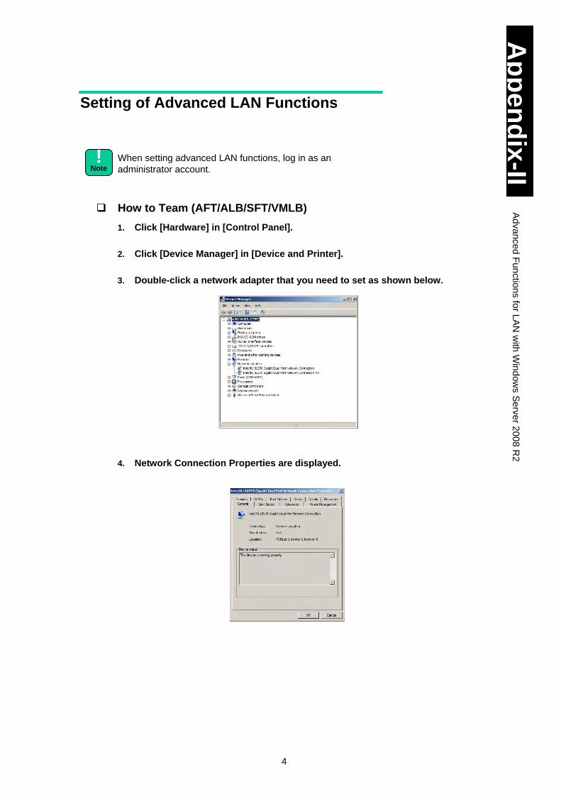
4
Ap
pe
nd
ix-II
Ad
va
nce
d F
un
ctio
ns fo
r LA
N w
ith W
ind
ow
s S
erv
er 2
00
8 R
2
Setting of Advanced LAN Functions
When setting advanced LAN functions, log in as an
administrator account.
How to Team (AFT/ALB/SFT/VMLB)
1. Click [Hardware] in [Control Panel].
2. Click [Device Manager] in [Device and Printer].
3. Double-click a network adapter that you need to set as shown below.
4. Network Connection Properties are displayed.
!
Note
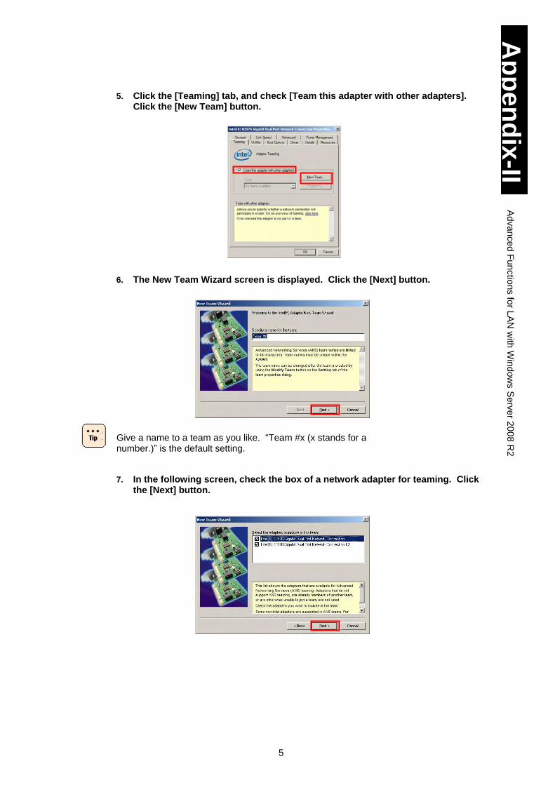
5
Ap
pe
nd
ix-II
Ad
va
nce
d F
un
ctio
ns fo
r LA
N w
ith W
ind
ow
s S
erv
er 2
00
8 R
2
5. Click the [Teaming] tab, and check [Team this adapter with other adapters].
Click the [New Team] button.
6. The New Team Wizard screen is displayed. Click the [Next] button.
Give a name to a team as you like. “Team #x (x stands for a number.)” is the default setting.
7. In the following screen, check the box of a network adapter for teaming. Click the [Next] button.
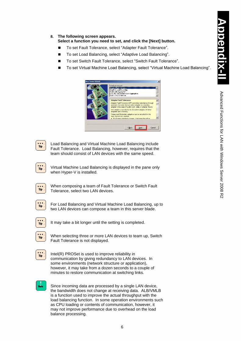
6
Ap
pe
nd
ix-II
Ad
va
nce
d F
un
ctio
ns fo
r LA
N w
ith W
ind
ow
s S
erv
er 2
00
8 R
2
8. The following screen appears. Select a function you need to set, and click the [Next] button.
To set Fault Tolerance, select “Adapter Fault Tolerance”.
To set Load Balancing, select “Adaptive Load Balancing”.
To set Switch Fault Tolerance, select “Switch Fault Tolerance”.
To set Virtual Machine Load Balancing, select “Virtual Machine Load Balancing”.
Load Balancing and Virtual Machine Load Balancing include
Fault Tolerance. Load Balancing, however, requires that the
team should consist of LAN devices with the same speed.
Virtual Machine Load Balancing is displayed in the pane only
when Hyper-V is installed.
When composing a team of Fault Tolerance or Switch Fault
Tolerance, select two LAN devices.
For Load Balancing and Virtual Machine Load Balancing, up to two LAN devices can compose a team in this server blade.
It may take a bit longer until the setting is completed.
When selecting three or more LAN devices to team up, Switch Fault Tolerance is not displayed.
Intel(R) PROSet is used to improve reliability in communication by giving redundancy to LAN devices. In some environments (network structure or application), however, it may take from a dozen seconds to a couple of minutes to restore communication at switching links.
Since incoming data are processed by a single LAN device, the bandwidth does not change at receiving data. ALB/VMLB is a function used to improve the actual throughput with the load balancing function. In some operation environments such as CPU loading or contents of communication, however, it may not improve performance due to overhead on the load balance processing.
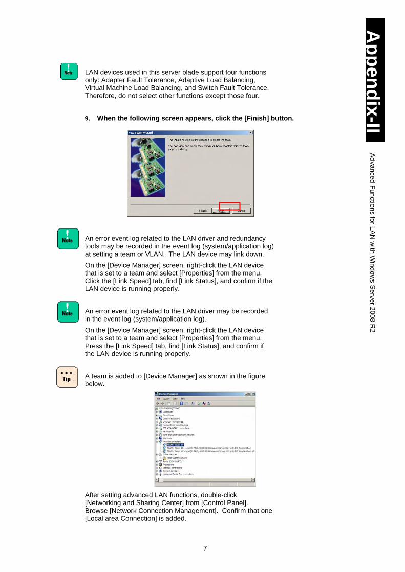
7
Ap
pe
nd
ix-II
Ad
va
nce
d F
un
ctio
ns fo
r LA
N w
ith W
ind
ow
s S
erv
er 2
00
8 R
2
LAN devices used in this server blade support four functions only: Adapter Fault Tolerance, Adaptive Load Balancing, Virtual Machine Load Balancing, and Switch Fault Tolerance. Therefore, do not select other functions except those four.
9. When the following screen appears, click the [Finish] button.
An error event log related to the LAN driver and redundancy tools may be recorded in the event log (system/application log) at setting a team or VLAN. The LAN device may link down.
On the [Device Manager] screen, right-click the LAN device that is set to a team and select [Properties] from the menu. Click the [Link Speed] tab, find [Link Status], and confirm if the LAN device is running properly.
An error event log related to the LAN driver may be recorded in the event log (system/application log).
On the [Device Manager] screen, right-click the LAN device that is set to a team and select [Properties] from the menu. Press the [Link Speed] tab, find [Link Status], and confirm if the LAN device is running properly.
A team is added to [Device Manager] as shown in the figure below.
After setting advanced LAN functions, double-click [Networking and Sharing Center] from [Control Panel]. Browse [Network Connection Management]. Confirm that one [Local area Connection] is added.
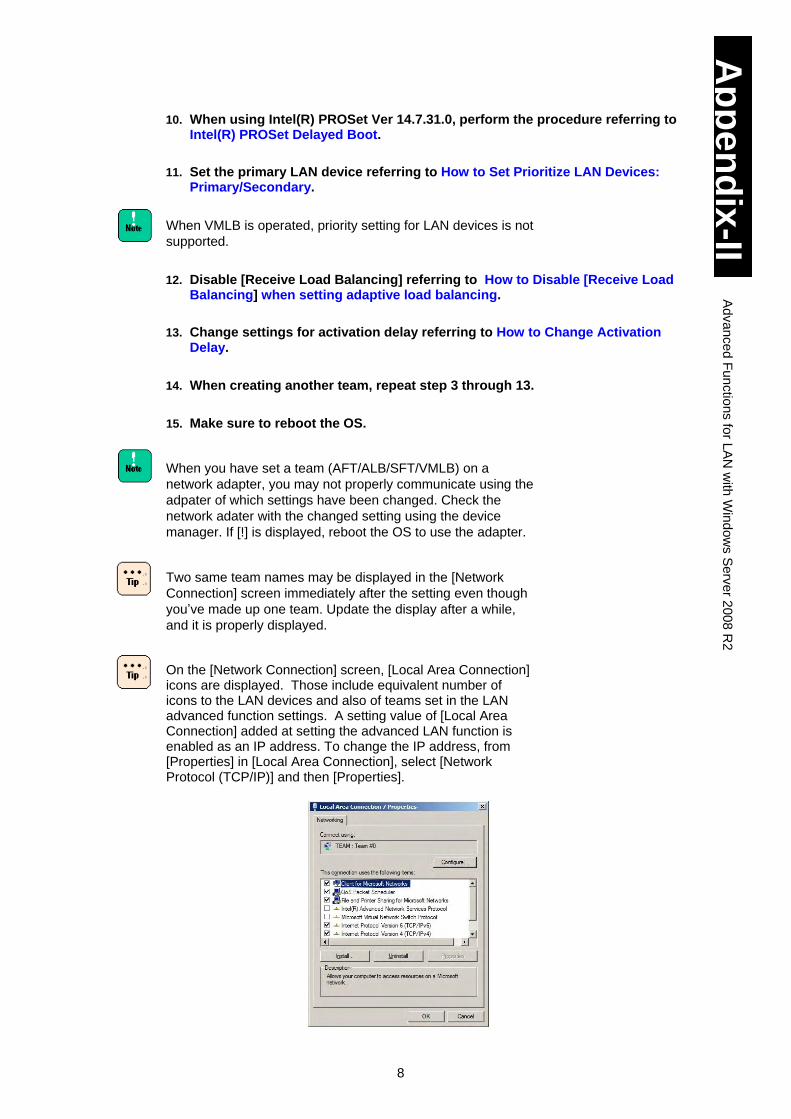
8
Ap
pe
nd
ix-II
Ad
va
nce
d F
un
ctio
ns fo
r LA
N w
ith W
ind
ow
s S
erv
er 2
00
8 R
2
10. When using Intel(R) PROSet Ver 14.7.31.0, perform the procedure referring to Intel(R) PROSet Delayed Boot.
11. Set the primary LAN device referring to How to Set Prioritize LAN Devices: Primary/Secondary.
When VMLB is operated, priority setting for LAN devices is not
supported.
12. Disable [Receive Load Balancing] referring to How to Disable [Receive Load
Balancing] when setting adaptive load balancing.
13. Change settings for activation delay referring to How to Change Activation Delay.
14. When creating another team, repeat step 3 through 13.
15. Make sure to reboot the OS.
When you have set a team (AFT/ALB/SFT/VMLB) on a
network adapter, you may not properly communicate using the
adpater of which settings have been changed. Check the
network adater with the changed setting using the device
manager. If [!] is displayed, reboot the OS to use the adapter.
Two same team names may be displayed in the [Network
Connection] screen immediately after the setting even though
you’ve made up one team. Update the display after a while,
and it is properly displayed.
On the [Network Connection] screen, [Local Area Connection] icons are displayed. Those include equivalent number of icons to the LAN devices and also of teams set in the LAN advanced function settings. A setting value of [Local Area Connection] added at setting the advanced LAN function is enabled as an IP address. To change the IP address, from [Properties] in [Local Area Connection], select [Network Protocol (TCP/IP)] and then [Properties].
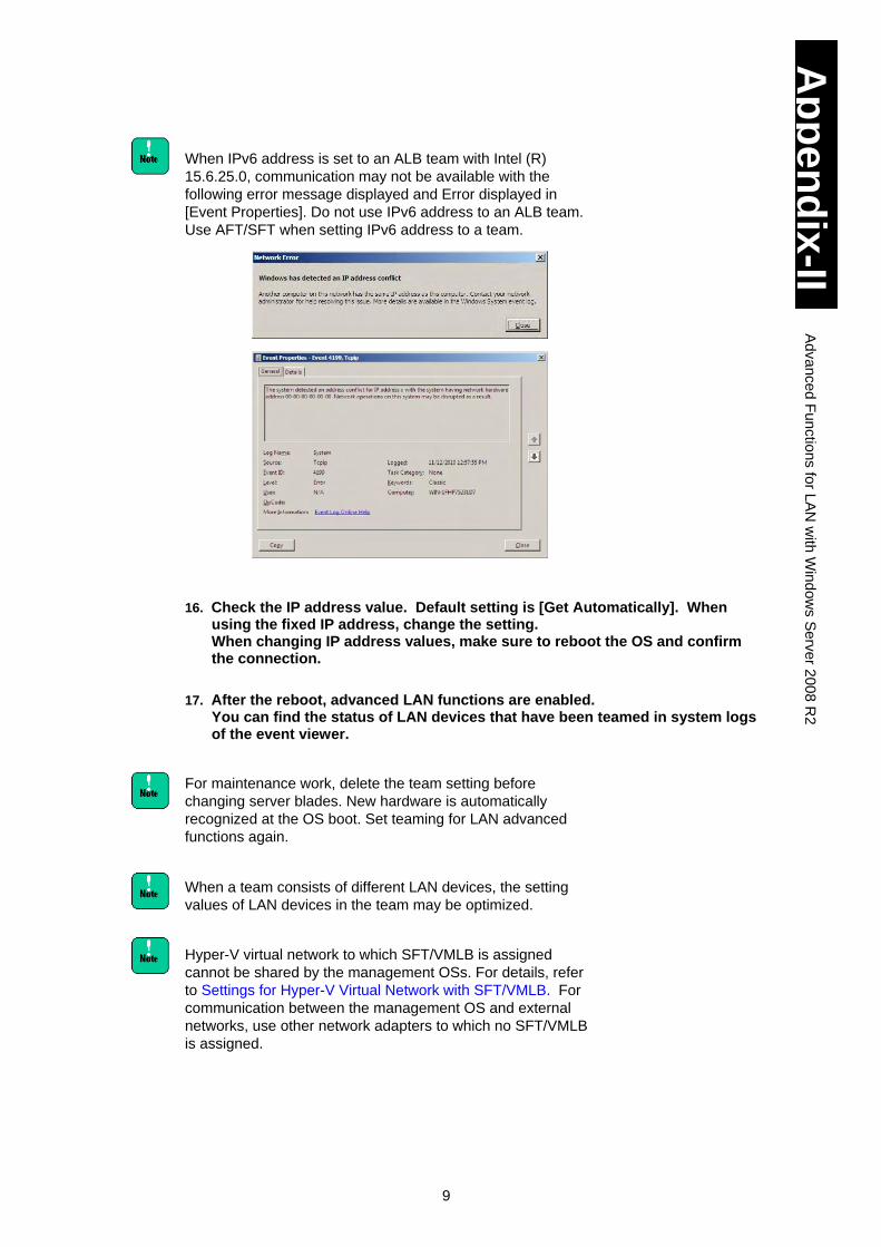
9
Ap
pe
nd
ix-II
Ad
va
nce
d F
un
ctio
ns fo
r LA
N w
ith W
ind
ow
s S
erv
er 2
00
8 R
2
When IPv6 address is set to an ALB team with Intel (R)
15.6.25.0, communication may not be available with the
following error message displayed and Error displayed in
[Event Properties]. Do not use IPv6 address to an ALB team.
Use AFT/SFT when setting IPv6 address to a team.
16. Check the IP address value. Default setting is [Get Automatically]. When using the fixed IP address, change the setting. When changing IP address values, make sure to reboot the OS and confirm the connection.
17. After the reboot, advanced LAN functions are enabled. You can find the status of LAN devices that have been teamed in system logs of the event viewer.
For maintenance work, delete the team setting before
changing server blades. New hardware is automatically
recognized at the OS boot. Set teaming for LAN advanced
functions again.
When a team consists of different LAN devices, the setting
values of LAN devices in the team may be optimized.
Hyper-V virtual network to which SFT/VMLB is assigned
cannot be shared by the management OSs. For details, refer
to Settings for Hyper-V Virtual Network with SFT/VMLB. For
communication between the management OS and external
networks, use other network adapters to which no SFT/VMLB
is assigned.
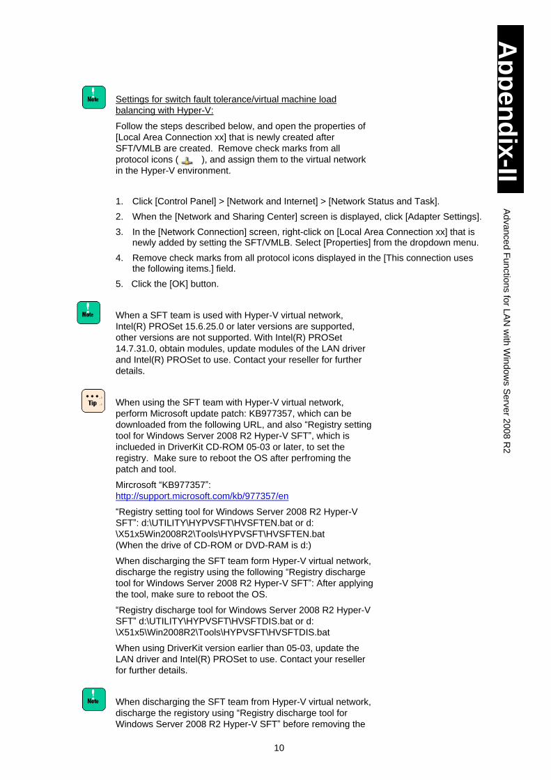
10
Ap
pe
nd
ix-II
Ad
va
nce
d F
un
ctio
ns fo
r LA
N w
ith W
ind
ow
s S
erv
er 2
00
8 R
2
Settings for switch fault tolerance/virtual machine load
balancing with Hyper-V:
Follow the steps described below, and open the properties of
[Local Area Connection xx] that is newly created after
SFT/VMLB are created. Remove check marks from all
protocol icons ( ), and assign them to the virtual network
in the Hyper-V environment.
1. Click [Control Panel] > [Network and Internet] > [Network Status and Task].
2. When the [Network and Sharing Center] screen is displayed, click [Adapter Settings].
3. In the [Network Connection] screen, right-click on [Local Area Connection xx] that is newly added by setting the SFT/VMLB. Select [Properties] from the dropdown menu.
4. Remove check marks from all protocol icons displayed in the [This connection uses the following items.] field.
5. Click the [OK] button.
When a SFT team is used with Hyper-V virtual network,
Intel(R) PROSet 15.6.25.0 or later versions are supported,
other versions are not supported. With Intel(R) PROSet
14.7.31.0, obtain modules, update modules of the LAN driver
and Intel(R) PROSet to use. Contact your reseller for further
details.
When using the SFT team with Hyper-V virtual network,
perform Microsoft update patch: KB977357, which can be
downloaded from the following URL, and also “Registry setting
tool for Windows Server 2008 R2 Hyper-V SFT”, which is
inclueded in DriverKit CD-ROM 05-03 or later, to set the
registry. Make sure to reboot the OS after perfroming the
patch and tool.
Mircrosoft “KB977357”:
http://support.microsoft.com/kb/977357/en
“Registry setting tool for Windows Server 2008 R2 Hyper-V
SFT”: d:\UTILITY\HYPVSFT\HVSFTEN.bat or d:
\X51x5Win2008R2\Tools\HYPVSFT\HVSFTEN.bat
(When the drive of CD-ROM or DVD-RAM is d:)
When discharging the SFT team form Hyper-V virtual network,
discharge the registry using the following “Registry discharge
tool for Windows Server 2008 R2 Hyper-V SFT”: After applying
the tool, make sure to reboot the OS.
“Registry discharge tool for Windows Server 2008 R2 Hyper-V
SFT” d:\UTILITY\HYPVSFT\HVSFTDIS.bat or d:
\X51x5\Win2008R2\Tools\HYPVSFT\HVSFTDIS.bat
When using DriverKit version earlier than 05-03, update the
LAN driver and Intel(R) PROSet to use. Contact your reseller
for further details.
When discharging the SFT team from Hyper-V virtual network,
discharge the registory using “Registry discharge tool for
Windows Server 2008 R2 Hyper-V SFT” before removing the
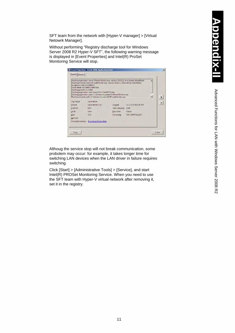
11
Ap
pe
nd
ix-II
Ad
va
nce
d F
un
ctio
ns fo
r LA
N w
ith W
ind
ow
s S
erv
er 2
00
8 R
2
SFT team from the network with [Hyper-V manager] > [Virtual
Netowrk Manager].
Without performing “Registry discharge tool for Windows
Server 2008 R2 Hyper-V SFT”, the following warning message
is displayed in [Event Properties] and Intel(R) ProSet
Monitoring Service will stop.
Althoug the service stop will not break communication, some
probolem may occur: for example, it takes longer time for
switching LAN devices when the LAN driver in failure requires
switching.
Click [Start] > [Administrative Tools] > [Service], and start
Intel(R) PROSet Monitoring Service. When you need to use
the SFT team with Hyper-V virtual network after removing it,
set it in the registry.
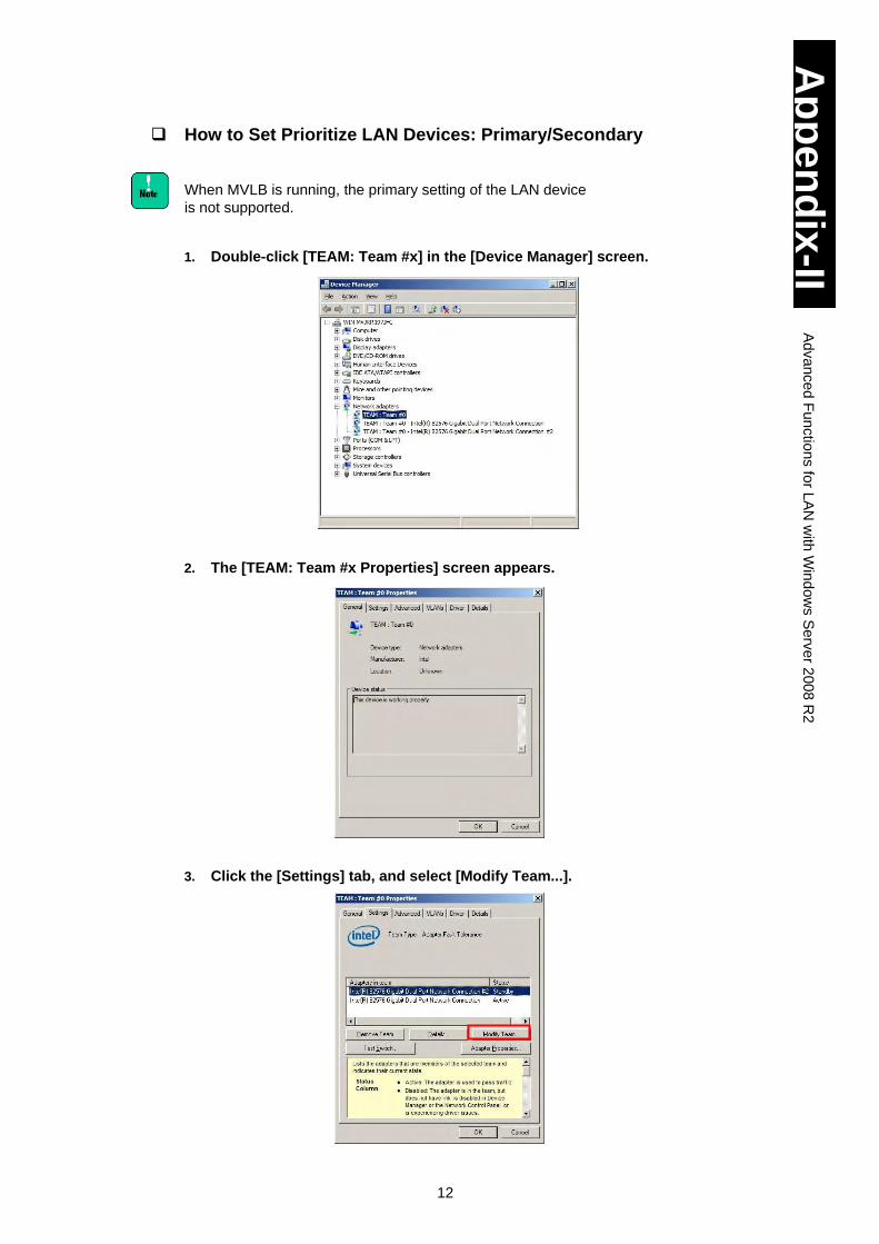
12
Ap
pe
nd
ix-II
Ad
va
nce
d F
un
ctio
ns fo
r LA
N w
ith W
ind
ow
s S
erv
er 2
00
8 R
2
How to Set Prioritize LAN Devices: Primary/Secondary
When MVLB is running, the primary setting of the LAN device
is not supported.
1. Double-click [TEAM: Team #x] in the [Device Manager] screen.
2. The [TEAM: Team #x Properties] screen appears.
3. Click the [Settings] tab, and select [Modify Team...].
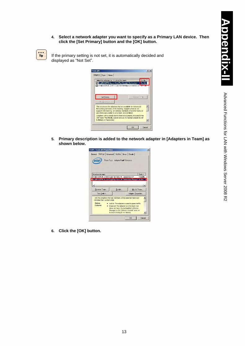
13
Ap
pe
nd
ix-II
Ad
va
nce
d F
un
ctio
ns fo
r LA
N w
ith W
ind
ow
s S
erv
er 2
00
8 R
2
4. Select a network adapter you want to specify as a Primary LAN device. Then click the [Set Primary] button and the [OK] button.
If the primary setting is not set, it is automatically decided and
displayed as “Not Set”.
5. Primary description is added to the network adapter in [Adapters in Team] as
shown below.
6. Click the [OK] button.
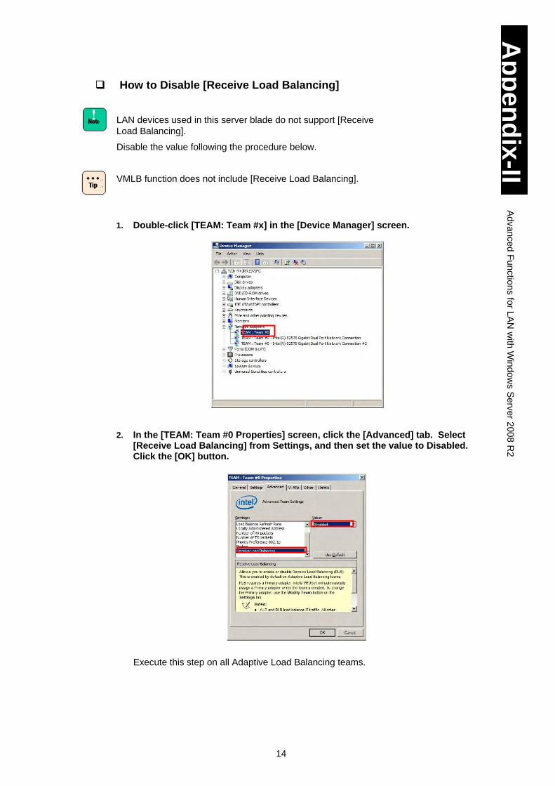
14
Ap
pe
nd
ix-II
Ad
va
nce
d F
un
ctio
ns fo
r LA
N w
ith W
ind
ow
s S
erv
er 2
00
8 R
2
How to Disable [Receive Load Balancing]
LAN devices used in this server blade do not support [Receive
Load Balancing].
Disable the value following the procedure below.
VMLB function does not include [Receive Load Balancing].
1. Double-click [TEAM: Team #x] in the [Device Manager] screen.
2. In the [TEAM: Team #0 Properties] screen, click the [Advanced] tab. Select
[Receive Load Balancing] from Settings, and then set the value to Disabled. Click the [OK] button.
Execute this step on all Adaptive Load Balancing teams.
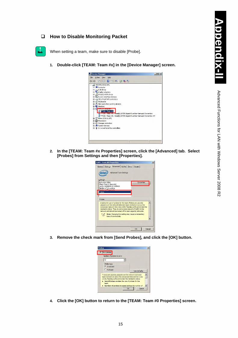
15
Ap
pe
nd
ix-II
Ad
va
nce
d F
un
ctio
ns fo
r LA
N w
ith W
ind
ow
s S
erv
er 2
00
8 R
2
How to Disable Monitoring Packet
When setting a team, make sure to disable [Probe].
1. Double-click [TEAM: Team #x] in the [Device Manager] screen.
2. In the [TEAM: Team #x Properties] screen, click the [Advanced] tab. Select [Probes] from Settings and then [Properties].
3. Remove the check mark from [Send Probes], and click the [OK] button.
4. Click the [OK] button to return to the [TEAM: Team #0 Properties] screen.
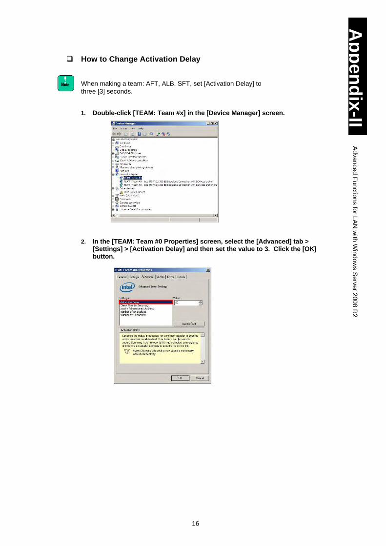
16
Ap
pe
nd
ix-II
Ad
va
nce
d F
un
ctio
ns fo
r LA
N w
ith W
ind
ow
s S
erv
er 2
00
8 R
2
How to Change Activation Delay
When making a team: AFT, ALB, SFT, set [Activation Delay] to
three [3] seconds.
1. Double-click [TEAM: Team #x] in the [Device Manager] screen.
2. In the [TEAM: Team #0 Properties] screen, select the [Advanced] tab > [Settings] > [Activation Delay] and then set the value to 3. Click the [OK] button.
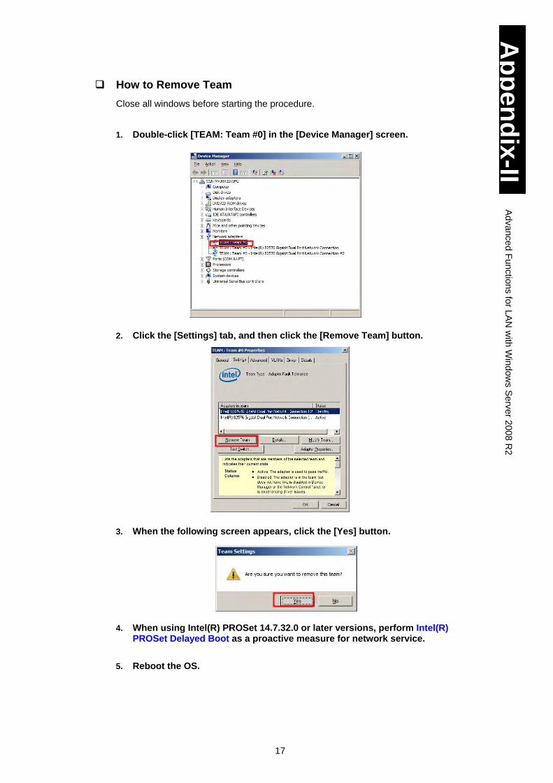
17
Ap
pe
nd
ix-II
Ad
va
nce
d F
un
ctio
ns fo
r LA
N w
ith W
ind
ow
s S
erv
er 2
00
8 R
2
How to Remove Team
Close all windows before starting the procedure.
1. Double-click [TEAM: Team #0] in the [Device Manager] screen.
2. Click the [Settings] tab, and then click the [Remove Team] button.
3. When the following screen appears, click the [Yes] button.
4. When using Intel(R) PROSet 14.7.32.0 or later versions, perform Intel(R) PROSet Delayed Boot as a proactive measure for network service.
5. Reboot the OS.
18
Ap
pe
nd
ix-II
Ad
va
nce
d F
un
ctio
ns fo
r LA
N w
ith W
ind
ow
s S
erv
er 2
00
8 R
2
An event log related to the LAN driver and this redundancy
tools may be generated in the system and application logs
when removing a team. The LAN device may link down.
On the [Device Manager] screen, right-click the LAN device in
the team and select [Properties] from the menu. Click the [Link
Speed] tab, find [Link Status], and confirm if the LAN device is
running properly.
When a team consists of different LAN devices, the setting
values of the LAN device may be different from the values
before the team is comprised. Check the values before the
use.
When a team is set as a network device to use in another
application, make sure to remove the team from the application
settings.
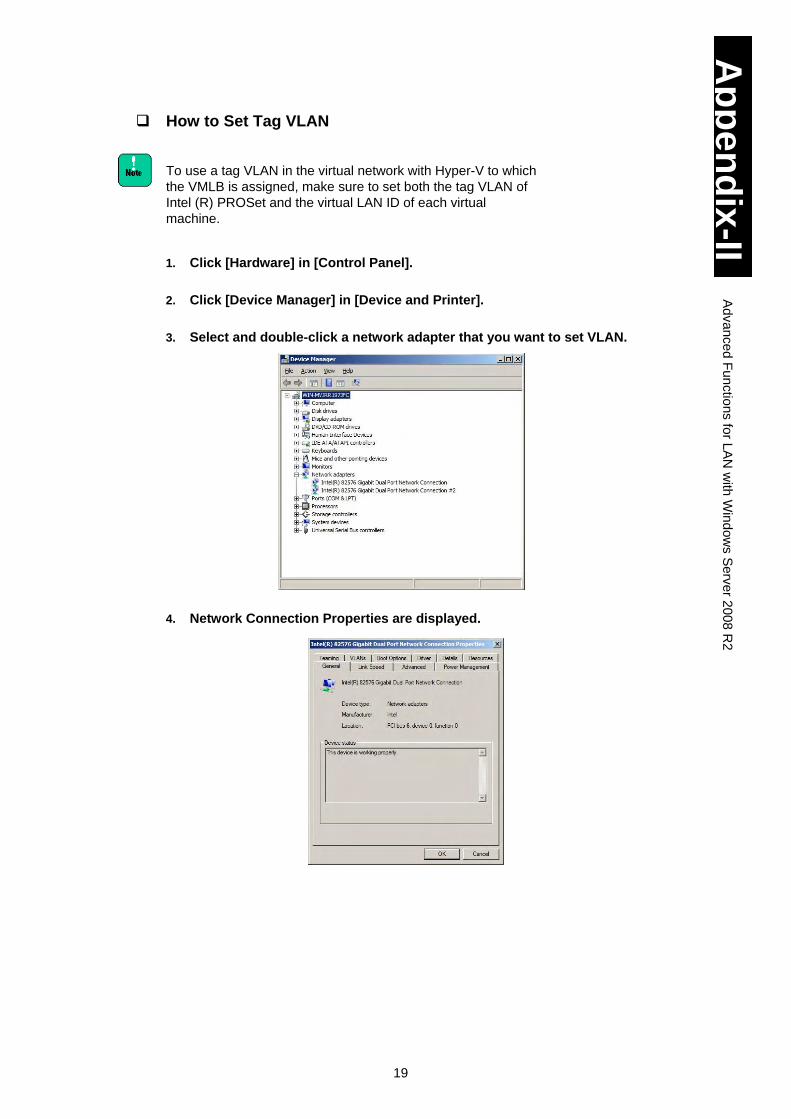
19
Ap
pe
nd
ix-II
Ad
va
nce
d F
un
ctio
ns fo
r LA
N w
ith W
ind
ow
s S
erv
er 2
00
8 R
2
How to Set Tag VLAN
To use a tag VLAN in the virtual network with Hyper-V to which
the VMLB is assigned, make sure to set both the tag VLAN of
Intel (R) PROSet and the virtual LAN ID of each virtual
machine.
1. Click [Hardware] in [Control Panel].
2. Click [Device Manager] in [Device and Printer].
3. Select and double-click a network adapter that you want to set VLAN.
4. Network Connection Properties are displayed.
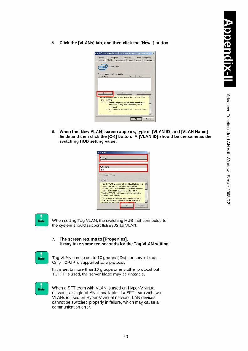
20
Ap
pe
nd
ix-II
Ad
va
nce
d F
un
ctio
ns fo
r LA
N w
ith W
ind
ow
s S
erv
er 2
00
8 R
2
5. Click the [VLANs] tab, and then click the [New..] button.
6. When the [New VLAN] screen appears, type in [VLAN ID] and [VLAN Name]
fields and then click the [OK] button. A [VLAN ID] should be the same as the switching HUB setting value.
When setting Tag VLAN, the switching HUB that connected to the system should support IEEE802.1q VLAN.
7. The screen returns to [Properties]. It may take some ten seconds for the Tag VLAN setting.
Tag VLAN can be set to 10 groups (IDs) per server blade. Only TCP/IP is supported as a protocol.
If it is set to more than 10 groups or any other protocol but TCP/IP is used, the server blade may be unstable.
When a SFT team with VLAN is used on Hyper-V virtual network, a single VLAN is available. If a SFT team with two VLANs is used on Hyper-V virtual network, LAN devices cannot be switched properly in failure, which may cause a communication error.
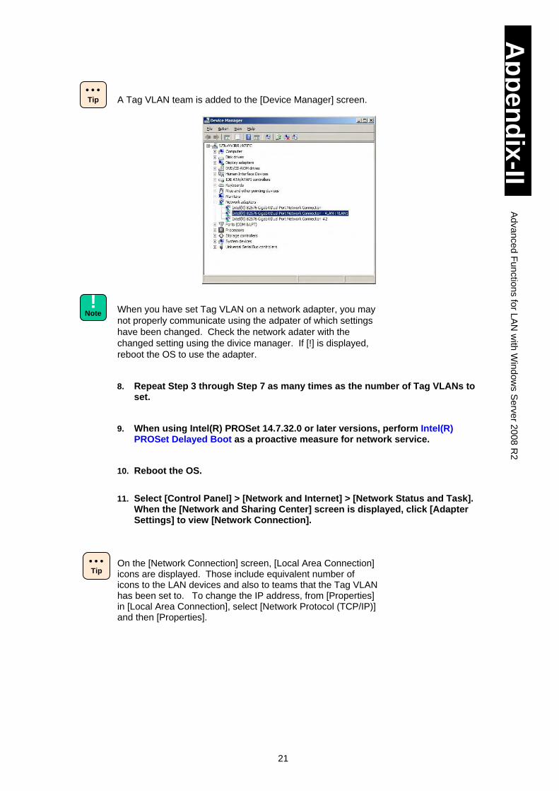
21
Ap
pe
nd
ix-II
Ad
va
nce
d F
un
ctio
ns fo
r LA
N w
ith W
ind
ow
s S
erv
er 2
00
8 R
2
A Tag VLAN team is added to the [Device Manager] screen.
When you have set Tag VLAN on a network adapter, you may
not properly communicate using the adpater of which settings
have been changed. Check the network adater with the
changed setting using the divice manager. If [!] is displayed,
reboot the OS to use the adapter.
8. Repeat Step 3 through Step 7 as many times as the number of Tag VLANs to set.
9. When using Intel(R) PROSet 14.7.32.0 or later versions, perform Intel(R) PROSet Delayed Boot as a proactive measure for network service.
10. Reboot the OS.
11. Select [Control Panel] > [Network and Internet] > [Network Status and Task].
When the [Network and Sharing Center] screen is displayed, click [Adapter Settings] to view [Network Connection].
On the [Network Connection] screen, [Local Area Connection] icons are displayed. Those include equivalent number of icons to the LAN devices and also to teams that the Tag VLAN has been set to. To change the IP address, from [Properties] in [Local Area Connection], select [Network Protocol (TCP/IP)] and then [Properties].
Tip
Tip
!
Note
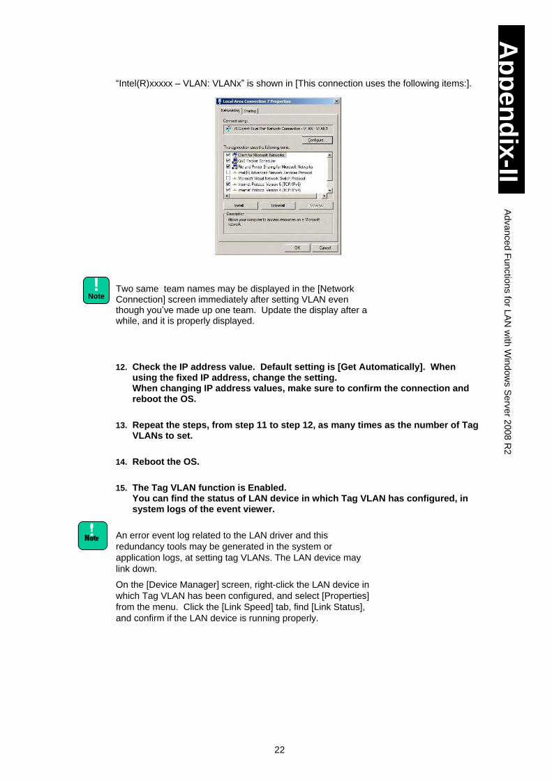
22
Ap
pe
nd
ix-II
Ad
va
nce
d F
un
ctio
ns fo
r LA
N w
ith W
ind
ow
s S
erv
er 2
00
8 R
2
“Intel(R)xxxxx – VLAN: VLANx” is shown in [This connection uses the following items:].
Two same team names may be displayed in the [Network Connection] screen immediately after setting VLAN even though you’ve made up one team. Update the display after a while, and it is properly displayed.
12. Check the IP address value. Default setting is [Get Automatically]. When using the fixed IP address, change the setting. When changing IP address values, make sure to confirm the connection and reboot the OS.
13. Repeat the steps, from step 11 to step 12, as many times as the number of Tag VLANs to set.
14. Reboot the OS.
15. The Tag VLAN function is Enabled. You can find the status of LAN device in which Tag VLAN has configured, in system logs of the event viewer.
An error event log related to the LAN driver and this
redundancy tools may be generated in the system or
application logs, at setting tag VLANs. The LAN device may
link down.
On the [Device Manager] screen, right-click the LAN device in
which Tag VLAN has been configured, and select [Properties]
from the menu. Click the [Link Speed] tab, find [Link Status],
and confirm if the LAN device is running properly.
!
Note
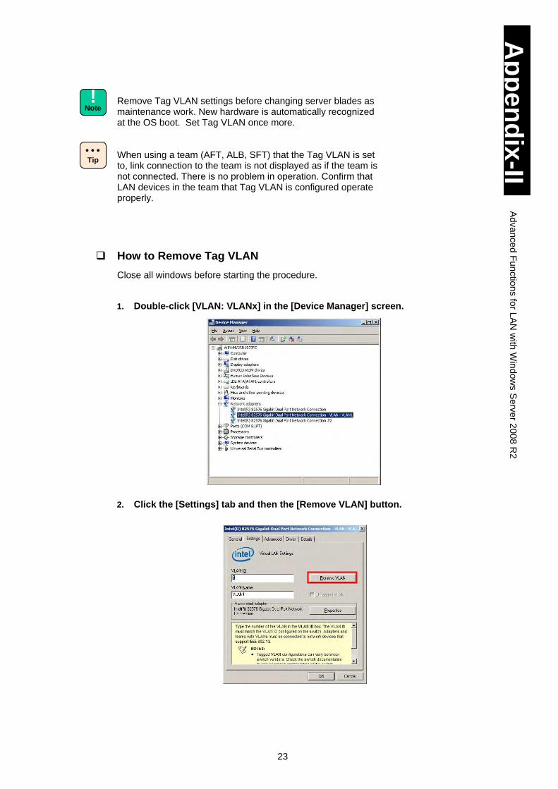
23
Ap
pe
nd
ix-II
Ad
va
nce
d F
un
ctio
ns fo
r LA
N w
ith W
ind
ow
s S
erv
er 2
00
8 R
2
Remove Tag VLAN settings before changing server blades as maintenance work. New hardware is automatically recognized at the OS boot. Set Tag VLAN once more.
When using a team (AFT, ALB, SFT) that the Tag VLAN is set to, link connection to the team is not displayed as if the team is not connected. There is no problem in operation. Confirm that LAN devices in the team that Tag VLAN is configured operate properly.
How to Remove Tag VLAN
Close all windows before starting the procedure.
1. Double-click [VLAN: VLANx] in the [Device Manager] screen.
2. Click the [Settings] tab and then the [Remove VLAN] button.
Tip
!
Note
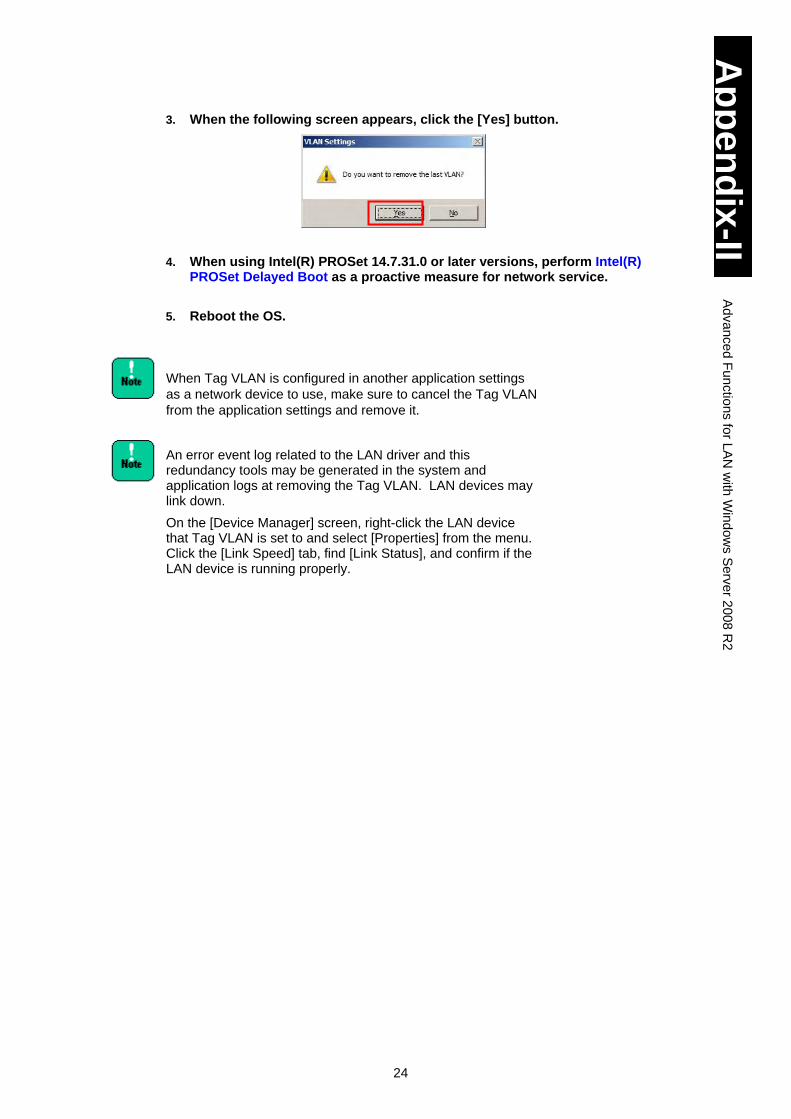
24
Ap
pe
nd
ix-II
Ad
va
nce
d F
un
ctio
ns fo
r LA
N w
ith W
ind
ow
s S
erv
er 2
00
8 R
2
3. When the following screen appears, click the [Yes] button.
4. When using Intel(R) PROSet 14.7.31.0 or later versions, perform Intel(R) PROSet Delayed Boot as a proactive measure for network service.
5. Reboot the OS.
When Tag VLAN is configured in another application settings
as a network device to use, make sure to cancel the Tag VLAN
from the application settings and remove it.
An error event log related to the LAN driver and this redundancy tools may be generated in the system and application logs at removing the Tag VLAN. LAN devices may link down.
On the [Device Manager] screen, right-click the LAN device that Tag VLAN is set to and select [Properties] from the menu. Click the [Link Speed] tab, find [Link Status], and confirm if the LAN device is running properly.
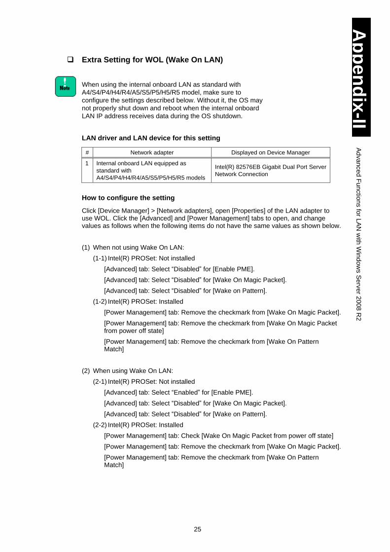
25
Ap
pe
nd
ix-II
Ad
va
nce
d F
un
ctio
ns fo
r LA
N w
ith W
ind
ow
s S
erv
er 2
00
8 R
2
Extra Setting for WOL (Wake On LAN)
When using the internal onboard LAN as standard with
A4/S4/P4/H4/R4/A5/S5/P5/H5/R5 model, make sure to
configure the settings described below. Without it, the OS may
not properly shut down and reboot when the internal onboard
LAN IP address receives data during the OS shutdown.
LAN driver and LAN device for this setting
# Network adapter Displayed on Device Manager
1 Internal onboard LAN equipped as
standard with
A4/S4/P4/H4/R4/A5/S5/P5/H5/R5 models
Intel(R) 82576EB Gigabit Dual Port Server
Network Connection
How to configure the setting
Click [Device Manager] > [Network adapters], open [Properties] of the LAN adapter to use WOL. Click the [Advanced] and [Power Management] tabs to open, and change values as follows when the following items do not have the same values as shown below.
(1) When not using Wake On LAN:
(1-1) Intel(R) PROSet: Not installed
[Advanced] tab: Select “Disabled” for [Enable PME].
[Advanced] tab: Select “Disabled” for [Wake On Magic Packet].
[Advanced] tab: Select “Disabled” for [Wake on Pattern].
(1-2) Intel(R) PROSet: Installed
[Power Management] tab: Remove the checkmark from [Wake On Magic Packet].
[Power Management] tab: Remove the checkmark from [Wake On Magic Packet from power off state]
[Power Management] tab: Remove the checkmark from [Wake On Pattern Match]
(2) When using Wake On LAN:
(2-1) Intel(R) PROSet: Not installed
[Advanced] tab: Select “Enabled” for [Enable PME].
[Advanced] tab: Select “Disabled” for [Wake On Magic Packet].
[Advanced] tab: Select “Disabled” for [Wake on Pattern].
(2-2) Intel(R) PROSet: Installed
[Power Management] tab: Check [Wake On Magic Packet from power off state]
[Power Management] tab: Remove the checkmark from [Wake On Magic Packet].
[Power Management] tab: Remove the checkmark from [Wake On Pattern Match]
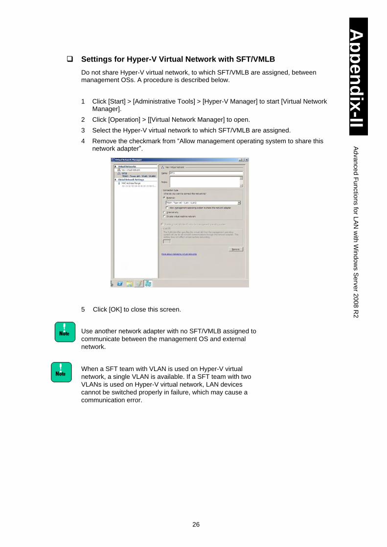
26
Ap
pe
nd
ix-II
Ad
va
nce
d F
un
ctio
ns fo
r LA
N w
ith W
ind
ow
s S
erv
er 2
00
8 R
2
Settings for Hyper-V Virtual Network with SFT/VMLB
Do not share Hyper-V virtual network, to which SFT/VMLB are assigned, between management OSs. A procedure is described below.
1 Click [Start] > [Administrative Tools] > [Hyper-V Manager] to start [Virtual Network Manager].
2 Click [Operation] > [[Virtual Network Manager] to open.
3 Select the Hyper-V virtual network to which SFT/VMLB are assigned.
4 Remove the checkmark from “Allow management operating system to share this network adapter”.
5 Click [OK] to close this screen.
Use another network adapter with no SFT/VMLB assigned to
communicate between the management OS and external
network.
When a SFT team with VLAN is used on Hyper-V virtual
network, a single VLAN is available. If a SFT team with two
VLANs is used on Hyper-V virtual network, LAN devices
cannot be switched properly in failure, which may cause a
communication error.
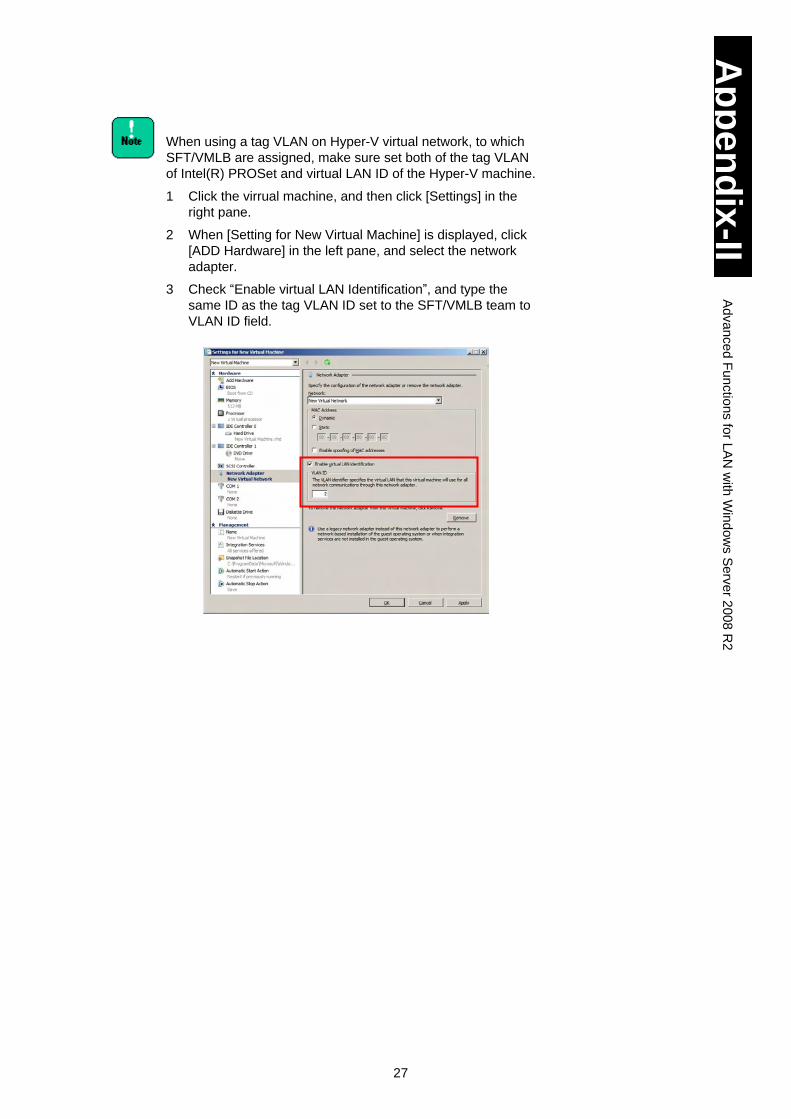
27
Ap
pe
nd
ix-II
Ad
va
nce
d F
un
ctio
ns fo
r LA
N w
ith W
ind
ow
s S
erv
er 2
00
8 R
2
When using a tag VLAN on Hyper-V virtual network, to which
SFT/VMLB are assigned, make sure set both of the tag VLAN
of Intel(R) PROSet and virtual LAN ID of the Hyper-V machine.
1 Click the virrual machine, and then click [Settings] in the
right pane.
2 When [Setting for New Virtual Machine] is displayed, click
[ADD Hardware] in the left pane, and select the network
adapter.
3 Check “Enable virtual LAN Identification”, and type the
same ID as the tag VLAN ID set to the SFT/VMLB team to
VLAN ID field.
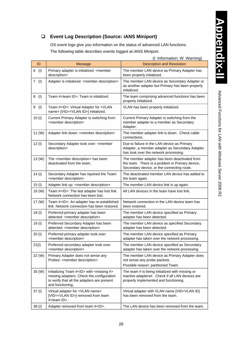
28
Ap
pe
nd
ix-II
Ad
va
nce
d F
un
ctio
ns fo
r LA
N w
ith W
ind
ow
s S
erv
er 2
00
8 R
2
Event Log Description (Source: iANS Miniport)
OS event logs give you information on the status of advanced LAN functions.
The following table describes events logged at iANS Miniport.
(I: Information; W: Warning)
ID Message Description and Resolution
6 (I) Primary adapter is initialized: <member
description>
The member LAN device as Primary Adapter has
been properly initialized.
7 (I) Adapter is initialized: <member description> The member LAN device as Secondary Adapter or
as another adapter but Primary has been properly
initialized.
8 (I) Team #<team ID>: Team is initialized. The team comprising advanced functions has been
properly initialized.
9 (I) Team #<ID>: Virtual Adapter for <VLAN
name> [VID=<VLAN ID>] initialized.
VLAN has been properly initialized.
10 (I) Current Primary Adapter is switching from:
<member description>
Current Primary Adapter is switching from the
member adapter to a member as Secondary
Adapter.
11 (W) Adapter link down: <member description> The member adapter link is down. Check cable
connections.
12 (I) Secondary Adapter took over: <member
description>
Due to failure in the LAN device as Primary
Adapter, a member adapter as Secondary Adapter
has took over the network processing.
13 (W) The <member description> has been
deactivated from the team.
The member adapter has been deactivated from
the team. There is a problem in Primary device,
Secondary device, or the connecting route.
14 (I) Secondary Adapter has rejoined the Team:
<member description>
The deactivated member LAN device has added to
the team again.
15 (I) Adapter link up: <member description> The member LAN device link is up again.
16 (W) Team #<ID>: The last adapter has lost link.
Network connection has been lost.
All LAN devices in the team have lost link.
17 (W) Team #<ID>: An adapter has re-established
link. Network connection has been restored.
Network connection in the LAN device team has
been restored.
18 (I) Preferred primary adapter has been
detected: <member description>
The member LAN device specified as Primary
adapter has been detected.
19 (I) Preferred Secondary Adapter has been
detected: <member description>
The member LAN device as specified Secondary
adapter has been detected.
20 (I) Preferred primary adapter took over:
<member description>
The member LAN device specified as Primary
adapter has taken over the network processing.
21(I) Preferred secondary adapter took over:
<member description>
The member LAN device specified as Secondary
adapter has taken over the network processing.
22 (W) Primary Adapter does not sense any
Probes: <member description>
The member LAN device as Primary Adapter does
not sense any probe packets.
Possible reason: partitioned Team.
35 (W) Initializing Team #<ID> with <missing #>
missing adapters. Check the configuration
to verify that all the adapters are present
and functioning.
The team # is being initialized with missing or
inactive adapters#. Check if all LAN devices are
properly implemented and functioning.
37 (I) Virtual adapter for <VLAN name>
[VID=<VLAN ID>] removed from team
#<team ID>.
Virtual adapter with VLAN name [VID=VLAN ID]
has been removed from the team.
38 (I) Adapter removed from team #<ID>. The LAN device has been removed from the team.
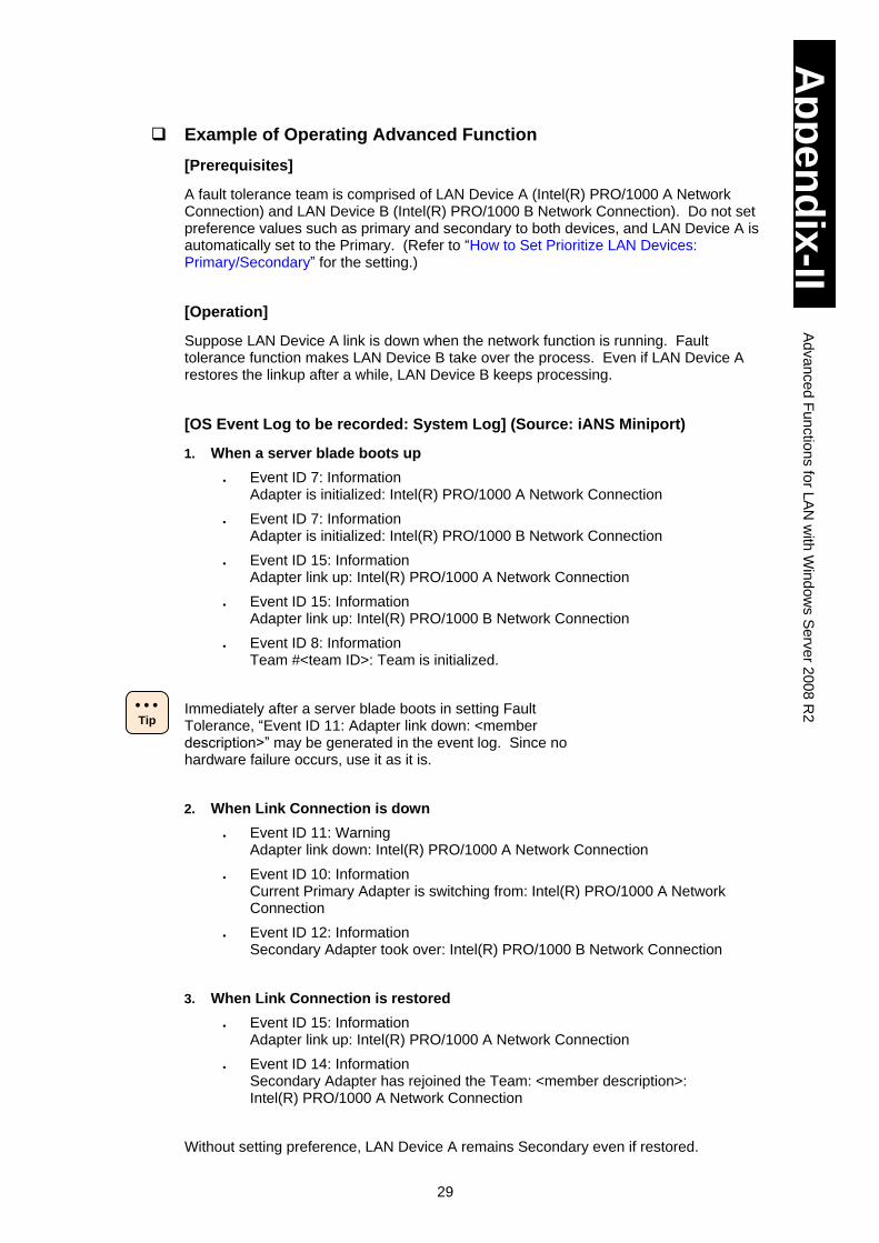
29
Ap
pe
nd
ix-II
Ad
va
nce
d F
un
ctio
ns fo
r LA
N w
ith W
ind
ow
s S
erv
er 2
00
8 R
2
Example of Operating Advanced Function
[Prerequisites]
A fault tolerance team is comprised of LAN Device A (Intel(R) PRO/1000 A Network Connection) and LAN Device B (Intel(R) PRO/1000 B Network Connection). Do not set preference values such as primary and secondary to both devices, and LAN Device A is automatically set to the Primary. (Refer to “How to Set Prioritize LAN Devices: Primary/Secondary” for the setting.)
[Operation]
Suppose LAN Device A link is down when the network function is running. Fault tolerance function makes LAN Device B take over the process. Even if LAN Device A restores the linkup after a while, LAN Device B keeps processing.
[OS Event Log to be recorded: System Log] (Source: iANS Miniport)
1. When a server blade boots up
Event ID 7: Information Adapter is initialized: Intel(R) PRO/1000 A Network Connection
Event ID 7: Information Adapter is initialized: Intel(R) PRO/1000 B Network Connection
Event ID 15: Information Adapter link up: Intel(R) PRO/1000 A Network Connection
Event ID 15: Information Adapter link up: Intel(R) PRO/1000 B Network Connection
Event ID 8: Information Team #<team ID>: Team is initialized.
Immediately after a server blade boots in setting Fault Tolerance, “Event ID 11: Adapter link down: <member description>” may be generated in the event log. Since no hardware failure occurs, use it as it is.
2. When Link Connection is down
Event ID 11: Warning Adapter link down: Intel(R) PRO/1000 A Network Connection
Event ID 10: Information Current Primary Adapter is switching from: Intel(R) PRO/1000 A Network Connection
Event ID 12: Information Secondary Adapter took over: Intel(R) PRO/1000 B Network Connection
3. When Link Connection is restored
Event ID 15: Information Adapter link up: Intel(R) PRO/1000 A Network Connection
Event ID 14: Information Secondary Adapter has rejoined the Team: <member description>: Intel(R) PRO/1000 A Network Connection
Without setting preference, LAN Device A remains Secondary even if restored.
Tip
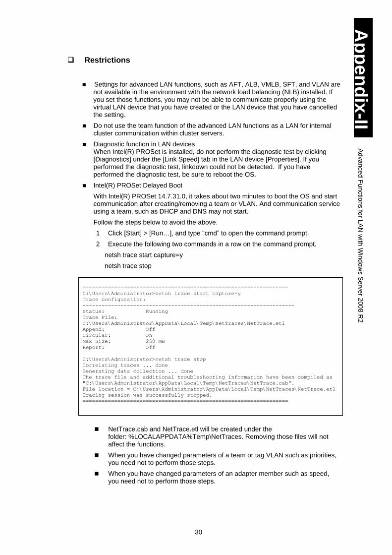
30
Ap
pe
nd
ix-II
Ad
va
nce
d F
un
ctio
ns fo
r LA
N w
ith W
ind
ow
s S
erv
er 2
00
8 R
2
Restrictions
Settings for advanced LAN functions, such as AFT, ALB, VMLB, SFT, and VLAN are not available in the environment with the network load balancing (NLB) installed. If you set those functions, you may not be able to communicate properly using the virtual LAN device that you have created or the LAN device that you have cancelled the setting.
Do not use the team function of the advanced LAN functions as a LAN for internal cluster communication within cluster servers.
Diagnostic function in LAN devices When Intel(R) PROSet is installed, do not perform the diagnostic test by clicking [Diagnostics] under the [Link Speed] tab in the LAN device [Properties]. If you performed the diagnostic test, linkdown could not be detected. If you have performed the diagnostic test, be sure to reboot the OS.
Intel(R) PROSet Delayed Boot
With Intel(R) PROSet 14.7.31.0, it takes about two minutes to boot the OS and start communication after creating/removing a team or VLAN. And communication service using a team, such as DHCP and DNS may not start.
Follow the steps below to avoid the above.
1 Click [Start] > [Run…], and type “cmd” to open the command prompt.
2 Execute the following two commands in a row on the command prompt.
netsh trace start capture=y
netsh trace stop
NetTrace.cab and NetTrace.etl will be created under the folder: %LOCALAPPDATA%Temp\NetTraces. Removing those files will not affect the functions.
When you have changed parameters of a team or tag VLAN such as priorities, you need not to perform those steps.
When you have changed parameters of an adapter member such as speed, you need not to perform those steps.
=================================================================
C:\Users\Administrator>netsh trace start capture=y
Trace configuration:
-------------------------------------------------------------------
Status: Running
Trace File:
C:\Users\Administrator\AppData\Local\Temp\NetTraces\NetTrace.etl
Append: Off
Circular: On
Max Size: 250 MB
Report: Off
C:\Users\Administrator>netsh trace stop
Correlating traces ... done
Generating data collection ... done
The trace file and additional troubleshooting information have been compiled as
"C:\Users\Administrator\AppData\Local\Temp\NetTraces\NetTrace.cab".
File location = C:\Users\Administrator\AppData\Local\Temp\NetTraces\NetTrace.etl
Tracing session was successfully stopped.
=================================================================

Hitachi Compute Blade 320 Software Guide

MK-99BDS320002-07
Hitachi Data Systems
Corporate Headquarters 2845 Lafayette Street
Santa Clara, California 95050-2639 U.S.A. www.hds.com
Regional Contact Information
Americas
+1 408 970 1000
Europe, Middle East, and Africa
+44 (0) 1753 618000 [email protected]
Asia Pacific
+852 3189 7900 [email protected]