highly concurrent shared storage
TRANSCRIPT
1 of 25
Highly concurrent shared storage
Khalil Amiri 1, Garth Gibson1, and Richard Golding2
1Carnegie Mellon University, Pittsburgh, PA2Hewlett-Packard Laboratories, Palo Alto, CA
{khalil.amiri,garth.gibson}@cs.cmu.edu,[email protected]
Abstract. Shared storage arrays enable thousands of storage devices to be shared and directlyaccessed by end hosts over switched system-area networks, promising databases and filesystems highlyscalable, reliable storage. In such systems, hosts perform access tasks (read and write) and manage-ment tasks (migration and reconstruction of data on failed devices.) Each task translates into multiplephases of low-level device I/Os, so that concurrent host tasks can span multiple shared devices andaccess overlapping ranges potentially leading to inconsistencies for redundancy codes and for dataread by end hosts. Highly scalable concurrency control and recovery protocols are required to coordi-nate on-line storage management and access tasks. While expressing storage-level tasks as ACID trans-actions ensures proper concurrency control and recovery, such an approach imposes high performanceoverhead, results in replication of work and does not exploit the available knowledge about storagelevel tasks. In this paper, we identify the tasks that storage controllers must perform, propose anapproach which allows these tasks to be composed from basic operations, we call base storage transac-tions (BSTs) such that correctness requires only the serializability of the BSTs and not of the parenttasks. Furthermore, we show that atomicity is almost always not required from BSTs. Instead, recoverycan be often specialized to the semantics of each task. Having established serializability for BSTs as thecore concurrency control requirement, we propose distributed protocols that exploit technology trendsand BST properties to hide latency in the common case. We show that these protocols outscale tradi-tional centralized alternatives and are only few percent slower than the ideal zero-overhead protocol.
1. Motivation
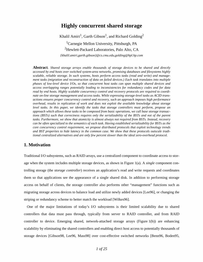
Traditional I/O subsystems, such as RAID arrays, use a centralized component to coordinate access to stor-
age when the system includes multiple storage devices, as shown in Figure 1(a). Asingle component con-
trolling storage (thestorage controller) receives an application’s read and write requests and coordinates
them so that applications see the appearance of a single shared disk. In addition to performing storage
access on behalf of clients, the storage controller also performs other “management” functions such as
migrating storage across devices to balance load and utilize newly added devices [Lee96], or changing the
striping or redundancy scheme to better match the workload [Wilkes96].
One of the major limitations of today’s I/O subsystems is their limited scalability due to shared
controllers that data must pass through, typically from server to RAID controller, and from RAID
controller to device. Emerging shared, network-attached storage arrays (Figure 1(b)) are enhancing
scalability by eliminating the shared controllers and enabling direct host access to potentially thousands of
storage devices [Gibson98, Lee96, Mass98] over cost-effective switched networks [Benn96, Boden95,
2 of 25
Horst95]. In these systems, each host acts as the storage controller on behalf of the applications running on
it, achieving scalable storage access bandwidths [Gibson98].
Unfortunately, the shared storage arrays shown in Figure 1(b) lack a central point to affect coordination.
Because data is striped across several devices and often stored redundantly, a single logical I/O operation
initiated by an application may involve sending requests to several devices. Unless proper concurrency
control provisions are taken, these I/Os can be interleaved so that hosts see inconsistent data or corrupt the
redundancy codes. These consistencies can occur even if the application processes running on the hosts are
participating in an application-level concurrency control protocol. This is because storage systems
transparently impose relationships among the data they store.
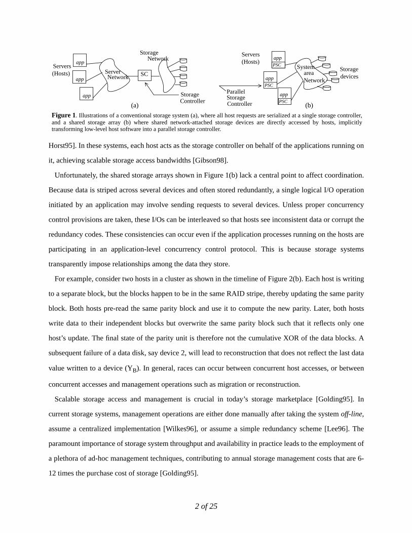
For example, consider two hosts in a cluster as shown in the timeline of Figure 2(b). Each host is writing
to a separate block, but the blocks happen to be in the same RAID stripe, thereby updating the same parity
block. Both hosts pre-read the same parity block and use it to compute the new parity. Later, both hosts
write data to their independent blocks but overwrite the same parity block such that it reflects only one
host’s update. The final state of the parity unit is therefore not the cumulative XOR of the data blocks. A
subsequent failure of a data disk, say device 2, will lead to reconstruction that does not reflect the last data
value written to a device (YB). In general, races can occur between concurrent host accesses, or between
concurrent accesses and management operations such as migration or reconstruction.
Scalable storage access and management is crucial in today’s storage marketplace [Golding95]. In
current storage systems, management operations are either done manually after taking the systemoff-line,
assume a centralized implementation [Wilkes96], or assume a simple redundancy scheme [Lee96]. The
paramount importance of storage system throughput and availability in practice leads to the employment of
a plethora of ad-hoc management techniques, contributing to annual storage management costs that are 6-
12 times the purchase cost of storage [Golding95].
Parallel
Servers
areaNetwork
(Hosts)Storagedevices
Servers(Hosts) Server
Network
StorageController
StorageNetwork
SystemSC
(a) (b)
PSC
StorageController
app
PSC
app
PSC
appapp
app
app
Figure 1. Illustrations of a conventional storage system (a), where all host requests are serialized at a single storage controller,and a shared storage array (b) where shared network-attached storage devices are directly accessed by hosts, implicitlytransforming low-level host software into a parallel storage controller.
3 of 25
In this paper, we address the challenges of building a scalable distributed storage management system
that enables high concurrency between access and management tasks while ensuring correctness. In
particular, we characterize the tasks that storage controllers perform and break down these tasks into sets
of basic two-phased operations, which we callbasic storage transactions (or BSTs), and show that overall
correctness requires ensuring only the serializability of the component BSTs and not of the parent tasks.
We present distributed concurrency control protocols that exploit technology trends toward more device
functionality and BST properties to provide serializability for BSTs with high scalability, coming within
few percent of the performance of the ideal zero-overhead protocol (a protocol which performs no
concurrency control work and provides no correctness guarantees). We further show that only a limited
form of atomicity, and not “all or nothing” atomicity, is required from BSTs. We present recovery
protocols that exploit knowledge about operation semantics to achieve this level of atomicity at very low
overhead.
The rest of the paper is organized as follows. Section 2 describes in more detail the kind of tasks that are
carried out at the storage layer (by the storage controllers). In Section 3, we show how these tasks can be
composed out of a few BSTs. We further show that the serializability of the BSTs ensures correctness for
the parent tasks. In Section 4, we present distributed concurrency control protocols specialized to BSTs.
We compare their performance to centralized variants and to the zero-overhead protocol. We discuss
recovery protocols for BSTs in Section 5 and conclude the paper in Section 6.
Device 1 Device 2
X0TA: hostwrite (XA) TB: hostwrite (YB)Yo
Device 3 (parity)
P0=Xo+Y0
Host A
devread(data): Y0
devread(parity): P0
devwrite(data): YBdevwrite(parity):
devread(data): X0devread(parity): P0
devwrite(data): XAdevwrite(parity):(XA+Y0)
Host B
(X0+YB)XA YB P=Xo+YB
Figure 2. A sketch of a RAID 5 small write (a). Data and parity are read in a first phase, and used together with new data tocompute the new parity. A timeline showing two concurrent small writes with no concurrency control provisions (b). Initially,the data units on device 1 and device 2 contain X0 and Y0, respectively, and the parity unit is their XOR (X0+Y0). Although hostA is updating device 1 and host B is updating device 2, they both need to update the parity, both read the same version of theparity, but Host A writes parity last overwriting B’s parity write, leaving parity inconsistent. Even if the hosts are involved in anapplication-level concurrency control protocol, they can not be aware of the storage level association introduced by RAID level5 parity. Further, they can not anticipate races with storage management tasks performed by the storage controllers.
(a) (b)
PDDD
12 12
New data
4 of 25
2. Distributed storage management
Storage controllers perform access (read and write) tasks as well as storage management tasks. Storage
management tasks include migrating storage to balance load or utilize new devices [Lee96], adapting stor-
age representation to access pattern [Wilkes96], backup, and the reconstruction of data on failed devices.
Because data availability is of paramount importance to a growing number of organizations, access tasks
must be performed in parallel with management tasks. Furthermore, the overhead of controlling the con-
currency of these tasks must be minimal to maximize application I/O throughput. Most storage subsystems
use RAID for fault-tolerance. We review RAID basics before describing our system model in more detail.
2.1. RAID background
Large collections of storage commonly employ redundant codes that are transparent to applications so that
simple and common device failures can be tolerated without invoking expensive (tape-based) higher level
failure and disaster recovery mechanisms. For example, in RAID level 5, a parity-based redundancy code
is computed across a group of data blocks and stored on a separate parity device. This allows the system to
tolerate any single self-identifying device failure by recovering data from the failed device using the other
data blocks in the group and the redundant code [Patt88]. The block of parity that protects a set of data
units is called a parity unit. A set of data units and their corresponding parity unit is called a parity stripe.
We focus for the rest of this paper on RAID level 5 as our case study and evaluation architecture.
2.2. System description
Figure 1(b) shows the kind of system that concerns us. A shared storage system is composed of multiple
disks and hosts, connected by a scalable network fabric. The devices store uniquely named blocks and act
independently of each other. Each host acts as a storage controller for its applications. The controller func-
tion can be implemented in software as operating system device drivers or could be delegated to a network
card.
Hosts perform exactly four operations, divided intoaccess tasks andmanagement tasks. The access tasks
are reads and writes(hostread andhostwrite operations). The management tasks are reconstruction and
storage/representation migration (reconstruct andmigrate operations respectively). A high-level task is
mapped onto one or more low-level I/O requests to (contiguous) physical blocks on a single device
(devreadanddevwrite). Depending on the striping and redundancy policy, and whether a storage device
5 of 25
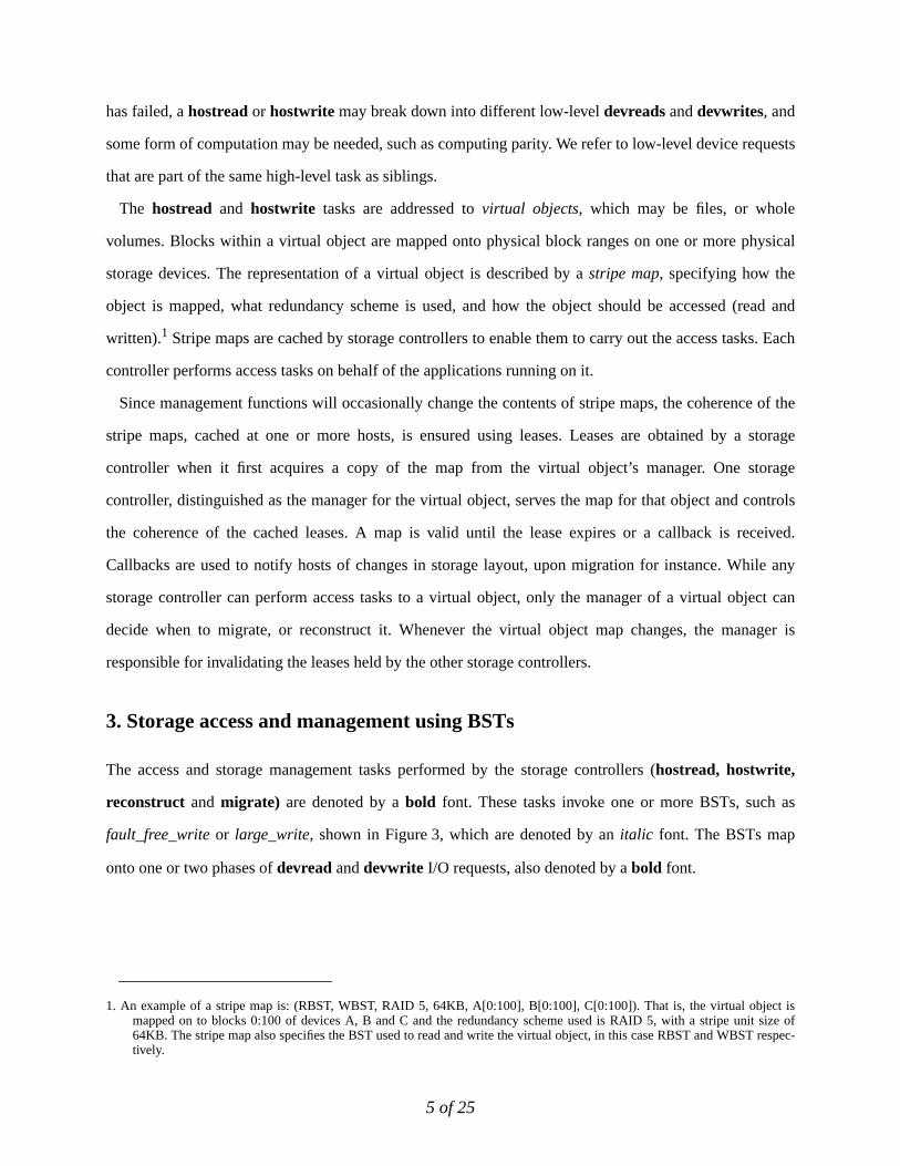
has failed, ahostreador hostwrite may break down into different low-leveldevreads anddevwrites, and
some form of computation may be needed, such as computing parity. We refer to low-level device requests
that are part of the same high-level task as siblings.
The hostread and hostwrite tasks are addressed tovirtual objects, which may be files, or whole
volumes. Blocks within a virtual object are mapped onto physical block ranges on one or more physical
storage devices. The representation of a virtual object is described by astripe map, specifying how the
object is mapped, what redundancy scheme is used, and how the object should be accessed (read and
written).1 Stripe maps are cached by storage controllers to enable them to carry out the access tasks. Each
controller performs access tasks on behalf of the applications running on it.
Since management functions will occasionally change the contents of stripe maps, the coherence of the
stripe maps, cached at one or more hosts, is ensured using leases. Leases are obtained by a storage
controller when it first acquires a copy of the map from the virtual object’s manager. One storage
controller, distinguished as the manager for the virtual object, serves the map for that object and controls
the coherence of the cached leases. A map is valid until the lease expires or a callback is received.
Callbacks are used to notify hosts of changes in storage layout, upon migration for instance. While any
storage controller can perform access tasks to a virtual object, only the manager of a virtual object can
decide when to migrate, or reconstruct it. Whenever the virtual object map changes, the manager is
responsible for invalidating the leases held by the other storage controllers.
3. Storage access and management using BSTs
The access and storage management tasks performed by the storage controllers (hostread, hostwrite,
reconstruct and migrate) are denoted by abold font. These tasks invoke one or more BSTs, such as
fault_free_writeor large_write, shown in Figure 3, which are denoted by anitalic font. The BSTs map
onto one or two phases ofdevreadanddevwrite I/O requests, also denoted by abold font.
1. An example of a stripe map is: (RBST, WBST, RAID 5, 64KB, A[0:100], B[0:100], C[0:100]). That is, the virtual object ismapped on to blocks 0:100 of devices A, B and C and the redundancy scheme used is RAID 5, with a stripe unit size of64KB. The stripe map also specifies the BST used to read and write the virtual object, in this case RBST and WBST respec-tively.
6 of 25
3.1. Desired properties for BSTs
As already motivated, concurrency must be controlled to preserve data consistency when shared devices
are accessed by multiple hosts. One solution is to express every access or management task as a transaction
[Gray75, Eswa76], which traditionally provides the ACID (Atomicity, Consistency, Isolation and Durabil-
ity) properties [Haerder83, Gray93]. Standard transaction implementation techniques, such as locking and
logging, can be used to ensure isolation and atomicity of these tasks.
This approach is highly undesirable, however, because it requires unnecessary performance and space
overhead. First, there are only four specific tasks to be supported, not general transactions, and the system
designer has full a priori knowledge of their semantics. This allows for optimizations specific to the
operations. For example, there is no need to do logging and ensure atomicity when migrating blocks from
their original location to a new location. In this case, data is available at the original location if the “write”
to the new location does not complete (due to a failure).
Second, high-level applications such as databases and file systems already provide mechanisms for high-
level atomicity [Gray93, Mohan92] in the face of three kinds of failures: transaction failures (user abort),
system failures (loss of volatile memory contents), and media (storage device) failures. This atomicity is at
the granularity of a database transaction or file system update, which typically spans many storage tasks.
PDDD
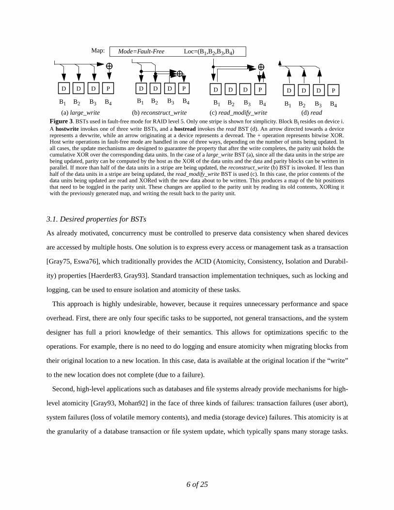
(a) large_write (d) read
B1 B2 B3 B4
Mode=Fault-Free
PDDD
B1 B2 B3 B4
PDDD
B1 B2 B3 B4
(c) read_modify_write
Loc=(B1,B2,B3,B4)
Figure 3. BSTs used in fault-free mode for RAID level 5. Only one stripe is shown for simplicity. Block Bi resides on device i.A hostwrite invokes one of three write BSTs, and ahostread invokes theread BST (d). An arrow directed towards a devicerepresents a devwrite, while an arrow originating at a device represents a devread. The + operation represents bitwise XOR.Host write operations in fault-free mode are handled in one of three ways, depending on the number of units being updated. Inall cases, the update mechanisms are designed to guarantee the property that after the write completes, the parity unit holds thecumulative XOR over the corresponding data units. In the case of a large_write BST (a), since all the data units in the stripe arebeing updated, parity can be computed by the host as the XOR of the data units and the data and parity blocks can be written inparallel. If more than half of the data units in a stripe are being updated, thereconstruct_write (b) BST is invoked. If less thanhalf of the data units in a stripe are being updated, theread_modify_write BST is used (c). In this case, the prior contents of thedata units being updated are read and XORed with the new data about to be written. This produces a map of the bit positionsthat need to be toggled in the parity unit. These changes are applied to the parity unit by reading its old contents, XORing itwith the previously generated map, and writing the result back to the parity unit.
PDDD
(b) reconstruct_write
B1 B2 B3 B4
Map:
7 of 25
These high-level mechanisms are built to require only the limited atomicity semantics provided by today’s
disk drives, which only provide atomicity at the granularity of a single-sector write.
While applying ACID transactions for storage access and management tasks is too expensive and results
in replication of work, doing nothing is not acceptable either. We argue that for BSTs, we need and should
provide only durability, isolation, and a limited form atomicity. These notions have a specific meaning for
storage-level transactions:
• Isolation. We desire the execution of BSTs to be serializable, i.e. equivalent to a serial execution where a single
BST is active at a time. We show later that providing this guarantee simplifies higher levels and ensures that the
consistency of the redundancy codes is preserved.
• Data-parity update atomicity. As argued above, we do not desire “all or nothing” atomicity for a multi-block
write to a virtual object. However, we desire that redundancy codes be consistent (and replicas be in synch). This
property must be ensured in the event of host and power failures, because on restart after a failure, higher level
applications resubmithostwrites, which in turn invoke one of the write BSTs. The write BSTs, however, assume
the redundancy codes are correct at the start of the BST. Note that this property does not require the full application
hostwrite to be processed. However, whatever “portion” of the data write is processed at the time of the failure, its
effect must also be visible in the redundant code (mirror copy or parity block).
• Durability. Data written by BSTs that completed persists, never switching back to older data.
3.2. Storage management based on BSTs
“Virtual objects” are potentially large, so that reconstruction or migration tasks can take considerable time.
Thus, allowinghostread andhostwrite accesses to proceed concurrently is crucial to storage system avail-
ability. This is difficult to do, however, because management tasks change the physical mapping of a vir-
tual object when migrating blocks or reconstructing them on a new device. This is further complicated by
the fact that a large number of hosts may be actively writing to the object.
Our approach is to treat the object as being in one of four modes: FAULT-FREE, DEGRADED,
RECONSTRUCTION or MIGRATION. FAULT-FREE and DEGRADED modes areaccess modes (where only
access tasks are allowed) and RECONSTRUCTION and MIGRATION modes aremanagement modes (where
both management and access tasks are allowed). To enable high concurrency between access and
management tasks in a management mode, we require BSTs invoked by access tasks to be aware of the
new and old physical mappings. Thereconstruct task can only be performed in the RECONSTRUCTION
mode. Themigrate task can only be performed in the MIGRATION mode.
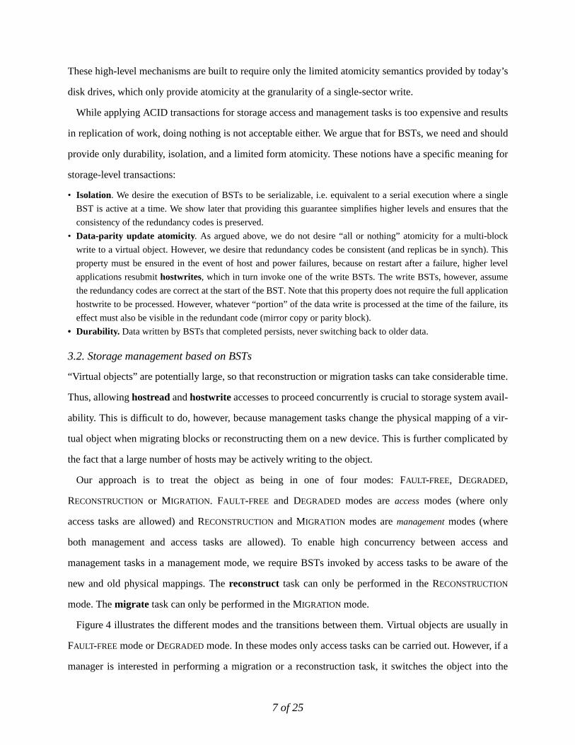
Figure 4 illustrates the different modes and the transitions between them. Virtual objects are usually in
FAULT-FREE mode or DEGRADED mode. In these modes only access tasks can be carried out. However, if a
manager is interested in performing a migration or a reconstruction task, it switches the object into the
8 of 25
proper mode (MIGRATION or RECONSTRUCTION) by allocating fresh unused space on one or more storage
devices to which data will be migrated or reconstructed. Once the management task completes, the object
transitions back into an access mode. We discuss the BSTs used under each mode in more detail next.
3.2.1. FAULT-FREE MODE
In fault-free mode,hostread tasks are carried out by invoking thefault_free_read BST. Hostwrite tasks
can be performed by invoking one of the BSTs in Figure 3:large_write, reconstruct_write,
read_modify_write depending on how much data in the stripe is being updated. No management tasks are
performed under this mode. When operating in fault-free mode, it is clear by inspection that the application
of a single BST leaves the parity consistent. Thus a serializable execution of several BSTs should also pre-
serve parity consistency.
3.2.2. DEGRADED MODE
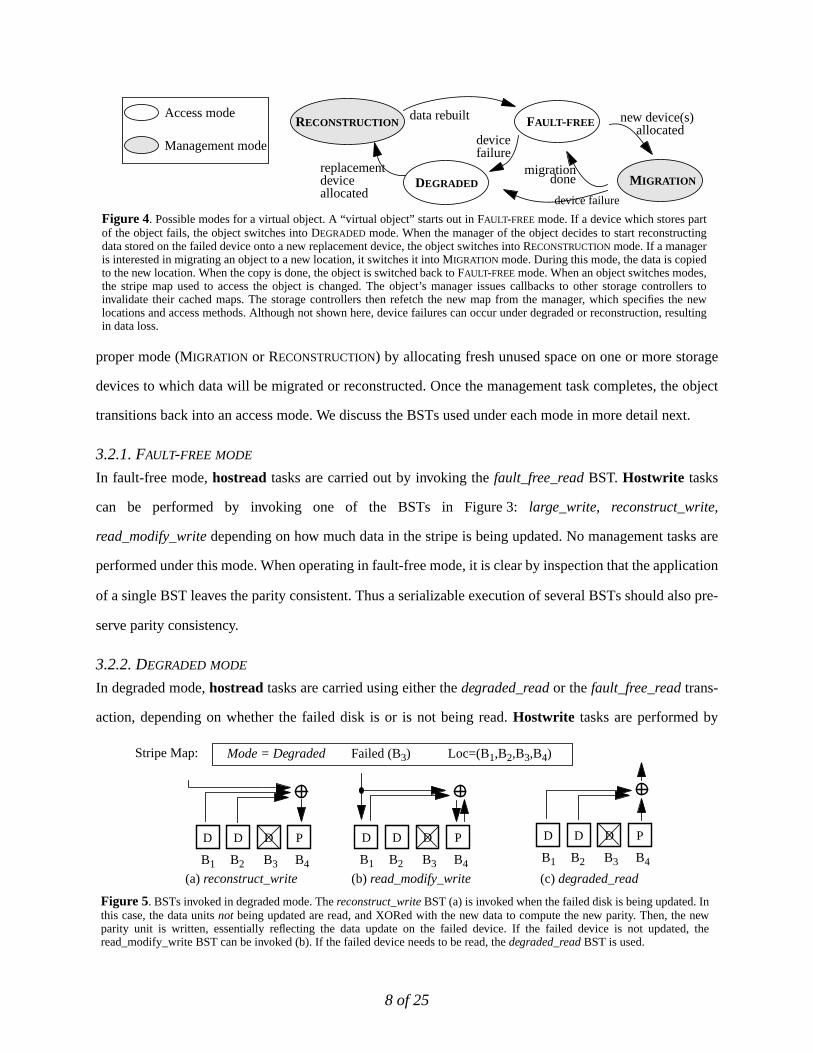
In degraded mode,hostread tasks are carried using either thedegraded_read or thefault_free_read trans-
action, depending on whether the failed disk is or is not being read.Hostwrite tasks are performed by
Figure 4. Possible modes for a virtual object. A “virtual object” starts out in FAULT-FREE mode. If a device which stores partof the object fails, the object switches into DEGRADED mode. When the manager of the object decides to start reconstructingdata stored on the failed device onto a new replacement device, the object switches into RECONSTRUCTION mode. If a manageris interested in migrating an object to a new location, it switches it into MIGRATION mode. During this mode, the data is copiedto the new location. When the copy is done, the object is switched back to FAULT-FREE mode. When an object switches modes,the stripe map used to access the object is changed. The object’s manager issues callbacks to other storage controllers toinvalidate their cached maps. The storage controllers then refetch the new map from the manager, which specifies the newlocations and access methods. Although not shown here, device failures can occur under degraded or reconstruction, resultingin data loss.
FAULT-FREE
MIGRATIONDEGRADED
RECONSTRUCTION
devicefailure
replacementdeviceallocated
data rebuilt new device(s)allocated
migrationdone
Access mode
Management mode
device failure
(a) reconstruct_write (c) degraded_read
PDDD
B1 B2 B3 B4
PDDD
B1 B2 B3 B4
(b) read_modify_write
PDDD
B1 B2 B3 B4
Mode = Degraded Failed (B3) Loc=(B1,B2,B3,B4)
Figure 5. BSTs invoked in degraded mode. Thereconstruct_write BST (a) is invoked when the failed disk is being updated. Inthis case, the data unitsnot being updated are read, and XORed with the new data to compute the new parity. Then, the newparity unit is written, essentially reflecting the data update on the failed device. If the failed device is not updated, theread_modify_write BST can be invoked (b). If the failed device needs to be read, thedegraded_read BST is used.
Stripe Map:
9 of 25
invoking one of the degraded mode BSTs:degraded_write or read_modify_write depending on whether
the failed disk is being written or not. Figure 5 depicts examples degraded mode BSTs. No management
tasks are allowed under this mode. In degraded mode, it is clear that applying the BSTs one at a time
results in consistent updates and reads. Hence, ensuring the serializability of the transactions is sufficient to
ensure correctness.
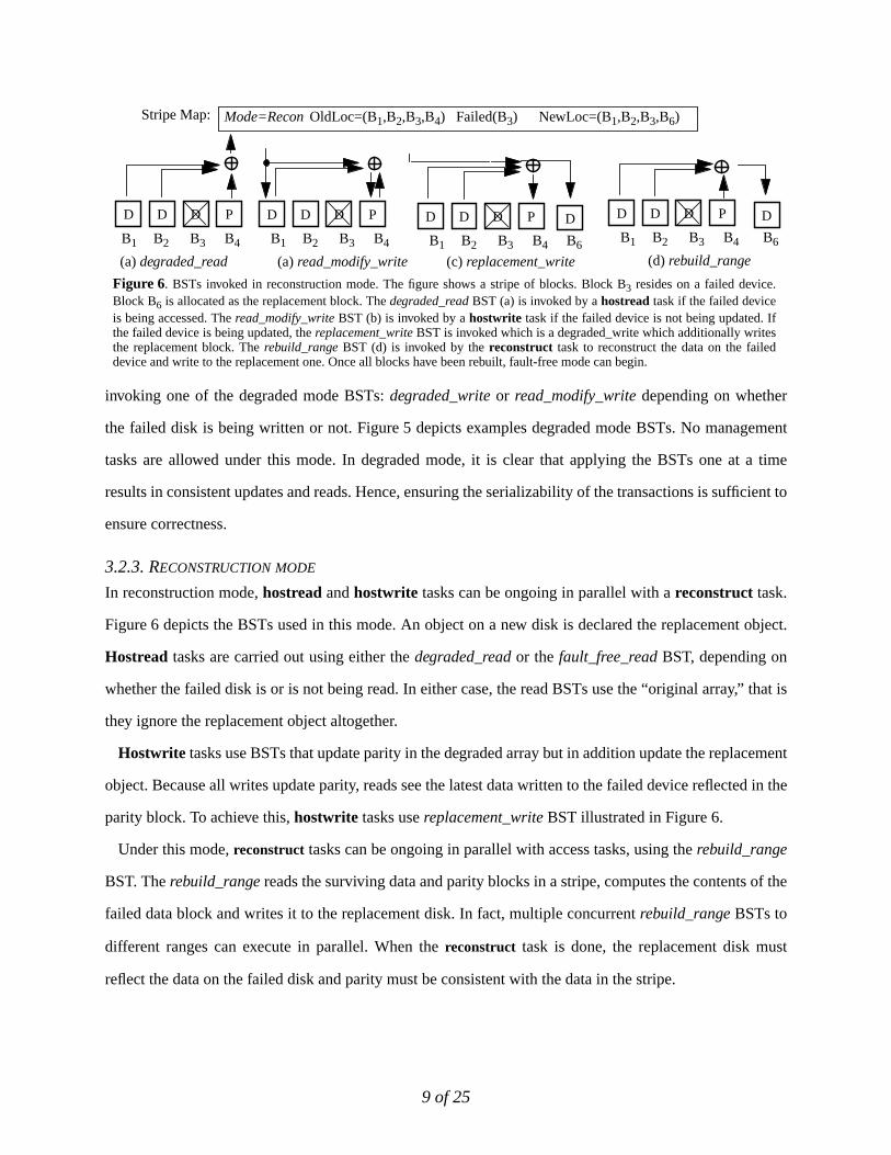
3.2.3. RECONSTRUCTION MODE
In reconstruction mode,hostread andhostwrite tasks can be ongoing in parallel with areconstruct task.
Figure 6 depicts the BSTs used in this mode. An object on a new disk is declared the replacement object.
Hostread tasks are carried out using either thedegraded_read or thefault_free_read BST, depending on
whether the failed disk is or is not being read. In either case, the read BSTs use the “original array,” that is
they ignore the replacement object altogether.
Hostwrite tasks use BSTs that update parity in the degraded array but in addition update the replacement
object. Because all writes update parity, reads see the latest data written to the failed device reflected in the
parity block. To achieve this,hostwrite tasks usereplacement_write BST illustrated in Figure 6.
Under this mode,reconstruct tasks can be ongoing in parallel with access tasks, using therebuild_range
BST. The rebuild_rangereads the surviving data and parity blocks in a stripe, computes the contents of the
failed data block and writes it to the replacement disk. In fact, multiple concurrentrebuild_range BSTs to
different ranges can execute in parallel. When thereconstruct task is done, the replacement disk must
reflect the data on the failed disk and parity must be consistent with the data in the stripe.
(c) replacement_write
OldLoc=(B1,B2,B3,B4) Failed(B3)
PDDD
(a) read_modify_write
PDDD
B1 B2 B3 B4
PDDD D
NewLoc=(B1,B2,B3,B6)
(d) rebuild_range
D
Mode=Recon
Figure 6. BSTs invoked in reconstruction mode. The figure shows a stripe of blocks. Block B3 resides on a failed device.Block B6 is allocated as the replacement block. Thedegraded_readBST (a) is invoked by ahostread task if the failed deviceis being accessed. Theread_modify_write BST (b) is invoked by ahostwrite task if the failed device is not being updated. Ifthe failed device is being updated, thereplacement_writeBST is invoked which is a degraded_write which additionally writesthe replacement block. The rebuild_rangeBST (d) is invoked by thereconstruct task to reconstruct the data on the faileddevice and write to the replacement one. Once all blocks have been rebuilt, fault-free mode can begin.
B1 B2 B3 B4 B1 B2 B3 B4 B6B6
(a)degraded_read
PDDD
B1 B2 B3 B4
Stripe Map:
10 of 25
In reconstruction mode, it may not be straightforward to see that the serializability of the
read_modify_write, replacement_writeandrebuild_range BSTs is sufficient to ensure consistent data and
correct reconstruction. We present an intuition behind the proof here.
First, consider the “old location” of the virtual object. That is the disks in the degraded array (B1 through
B4 in Figure 6), ignoring the replacement disk. It is easy to see that a serial application ofdegraded_read,
read_modify_write BSTs (writes that do not update the failed device), andreplacement_write BST would
result in consistent parity and correct reads. Note thatreplacement_write is simply adegraded_write that
in addition writes to the replacement device (B6). Thus after a replacement_write, data is reflected in the
parity of the degraded array as well as on the replacement device. The rebuild_range BST does not update
the degraded array and therefore does interfere with the old stripe. Arebuild_range BST reads the blocks
in the degraded array and writes the data to the replacement disk. Ifrebuild_range are serialized with
ongoing writes, it will at most unnecessarily recompute and rewrite (B6) data block value, and the
replacement disk is always in synch with the degraded array.
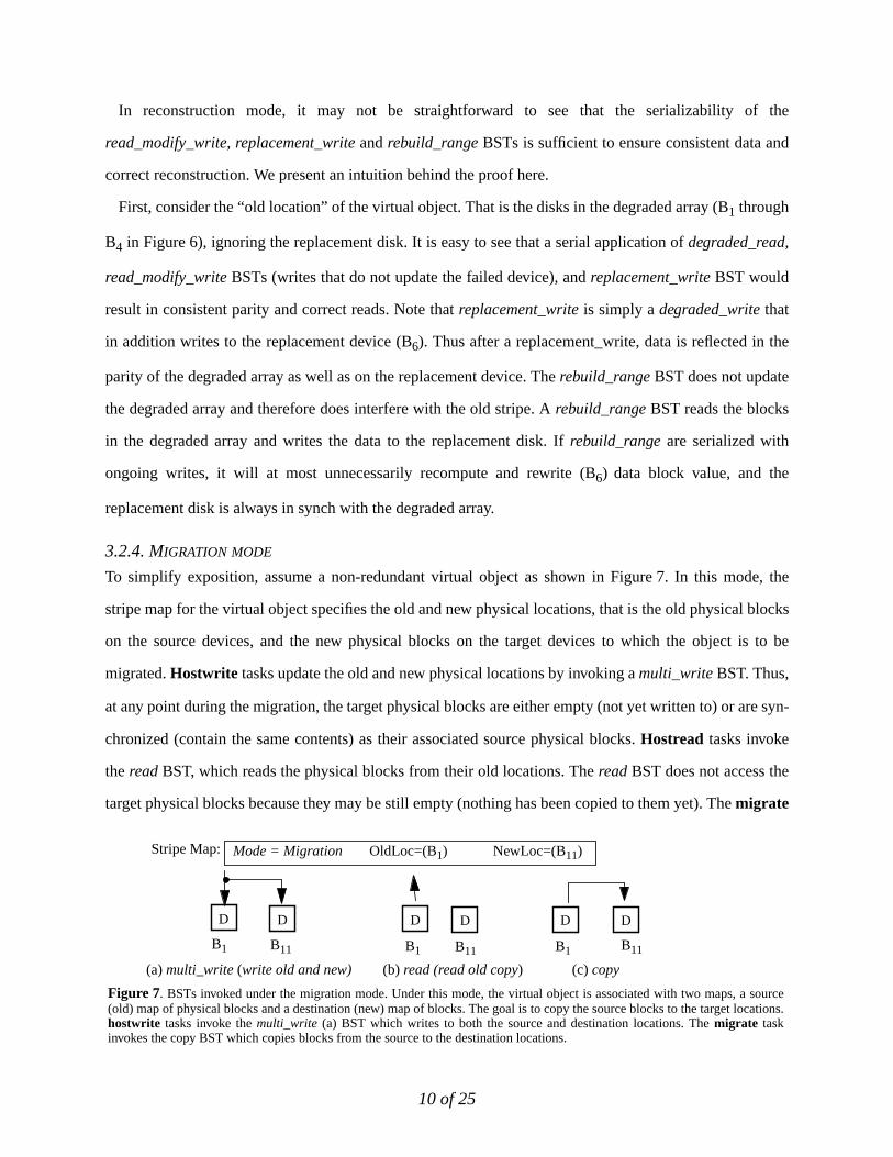
3.2.4. MIGRATION MODE
To simplify exposition, assume a non-redundant virtual object as shown in Figure 7. In this mode, the
stripe map for the virtual object specifies the old and new physical locations, that is the old physical blocks
on the source devices, and the new physical blocks on the target devices to which the object is to be
migrated.Hostwrite tasks update the old and new physical locations by invoking amulti_write BST. Thus,
at any point during the migration, the target physical blocks are either empty (not yet written to) or are syn-
chronized (contain the same contents) as their associated source physical blocks.Hostread tasks invoke
theread BST, which reads the physical blocks from their old locations. ThereadBST does not access the
target physical blocks because they may be still empty (nothing has been copied to them yet). Themigrate
(a)multi_write (write old and new) (b) read (read old copy)
D
B1
D
B1
Mode = Migration OldLoc=(B1) NewLoc=(B11)
D
B1
D
B11
(c) copy
D
B11
D
B11
Figure 7. BSTs invoked under the migration mode. Under this mode, the virtual object is associated with two maps, a source(old) map of physical blocks and a destination (new) map of blocks. The goal is to copy the source blocks to the target locations.hostwrite tasks invoke themulti_write (a) BST which writes to both the source and destination locations. Themigrate taskinvokes the copy BST which copies blocks from the source to the destination locations.
Stripe Map:
11 of 25
task can be ongoing in parallel using thecopy BST. This can be easily generalized to a redundant scheme,
by having each write perform the same BST on the source and target blocks (mirroring the entire BST).
4. Concurrency control for base storage transactions
Our goal in the rest of this paper is to arrive at protocols ensuring the serializability of BSTs and ensuring
their satisfactory recovery after failures. Our approach is to introduce low overhead transparent protocols
between host-based storage controllers exploiting simple device support to avoid changing applications
written for single controller storage systems (Figure 1a).
Given that the connectivity of system-area networks enables thousands of storage devices and hosts to be
clustered in one shared array, we desire our protocols to scale to such large sizes. Furthermore, protocols
must be free from deadlocks. Finally, new functions required from storage device should be simple and
clear, given that devices are manufactured by several independent vendors, and complex systems
implemented by diverse organizations are likely to be fragile. We present concurrency control protocols in
this section, and recovery protocols in Section 5.
We present two centralized protocols traditionally employed in practice,server locking and callback
locking, and our optimized distributed protocols, namelydevice-served locking and timestamp ordering. We
show how the optimized protocols benefit from specialization to BST properties and technology trends. We
evaluate performance relative to the ideal performance of azero-overhead protocol, which performs no
concurrency control.
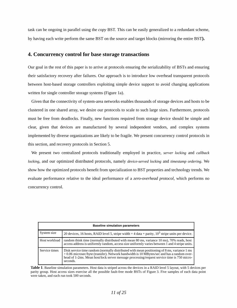
Baseline simulation parameters
System size 20 devices, 16 hosts, RAID level 5, stripe width = 4 data + parity, 103 stripe units per device.
Host workload random think time (normally distributed with mean 80 ms, variance 10 ms), 70% reads, hostaccess address is uniformly random, access size uniformly varies between 1 and 4 stripe units.
Service times Disk service time random (normally distributed with mean positioning of 8 ms, variance 1 ms+ 0.06 microsec/byte (transfer). Network bandwidth is 10 MBytes/sec and has a random over-head of 1-2ms. Mean host/lock server message processing/request service time is 750 micro-seconds.
Table 1. Baseline simulation parameters. Host data is striped across the devices in a RAID level 5 layout, with 5 devices perparity group. Host access sizes exercise all the possible fault-free mode BSTs of Figure 3. Five samples of each data pointwere taken, and each run took 500 seconds.
12 of 25
4.1. Evaluation environment
We implemented our protocols in full detail in simulation, using the Pantheon simulator system
[Wilkes96]. We simulate a cluster system consisting of hosts and disks connected by a network. Table 1
shows the baseline parameters of the experiments. Although the protocols were simulated in detail, the ser-
vice times for hosts, controllers, links and storage devices were derived from simple distributions based on
observed behavior of Pentium-class servers communicating with 1997 SCSI disks [Seag97] over a fast
switched local area network (like FibreChannel). Host clocks were allowed to drift within a practical few
milliseconds of real-time [Mills88]. We compared the performance of the protocols under a variety of syn-
thetically generated workloads and environmental conditions. The baseline workload represents the kind
of sharing that is characteristic of OLTP workloads and cluster applications (databases and file servers),
where load is dynamically balanced across the hosts or servers in the cluster resulting in limited locality
and mostly random accesses. This baseline system applies a moderate to high load on its storage devices
yielding about 50% sustained utilization. We report the performance of the protocols in FAULT-FREEmode
since they are representative of their general performance.
4.2. Centralized locking protocols
Three approaches have been traditionally used to achieve serializability: locking, optimistic, and times-
tamp ordering. Locking is the most widely used in practice. The particular locking variant that is widely
used in practice is two-phase locking.
Two-phase locking background. Locks on shared data items are used to enforce a serial order on execu-
tion. Locking is the preferred solution when resources are limited and the overhead of lock acquisition and
release is low. Significant concurrency can be achieved withtwo-phase locking[Gray75], a programming
discipline where locks may be acquired one at a time, but no lock can be released until it is certain that no
more locks will be needed. Two-phase locking, however, is susceptible to deadlocks, and to processors
holding locks long enough to reduce concurrency. A deadlock prevention or detection and resolution
scheme must be employed in conjunction with two-phase locking. In storage systems, the most common
locking implementations areserver locking andcallback locking.
Server locking. Under this scheme, a centralized lock server provides locking on low-level storage block
ranges. A BST executing at a host acquires an exclusive (in case of adevwrite) or a shared (in case of a
devread) lock on a set of target ranges by sending alock messageto the lock server. The host may then
13 of 25
issue thedevreads or devwrites low-level I/O requests to the devices. When all I/O requests in the BST
complete, the host sends anunlock message to the lock server. As there is only one lock and one unlock
message per BST, the protocol is trivially two-phase and therefore serializable. Because all locks are
acquired in a single message, latency is minimized and deadlocks are avoided. The lock server queues a
host’s lock request if there is an outstanding lock on a block in the requested range. Once all the conflicting
locks have been released, a response is returned to the host. However, server locking introduces a potential
bottleneck at the server and delays issuing the requests low-level I/O requests for at least one round trip of
messaging to the lock server.
Callback locking. This is a popular variant of server locking which delays the unlock message, effectively
caching the lock at the host, in the hope that the host will generate another access to the same block(s) in
the near future and be able to avoid sending a lock message to the server [Howa88, Lamb91, Carey94]. If a
host requests a lock from the lock server that conflicts with a lock cached by another host, the server con-
tacts the host holding the conflicting lock (this is thecallback message), asking it to relinquish the cached
lock so the server can grant a lock to the new owner. One common optimization to callback locking is to
have locks automatically expire after a lease period so that callback messaging is reduced. Our implemen-
tation uses a lease period of four seconds.
Centralized locking performance. Figure 8 highlights the scalability limitation of server locking protocols.
It plots the host-end latency of the protocols against (a) total offered throughput (by varying the number of
150500 1000
1350
total throughput (ops/sec)
00
20
40
60
80
89.29la
tenc
y (m
sec)
server lockingcallback locklingzero-overhead protocol
220 40 60 80
100
contention (%disk accessed)
00
10
20
30
40
50
52.03
late
ncy
(mse
c)
server lockingcallback locklingzero-overhead protocol
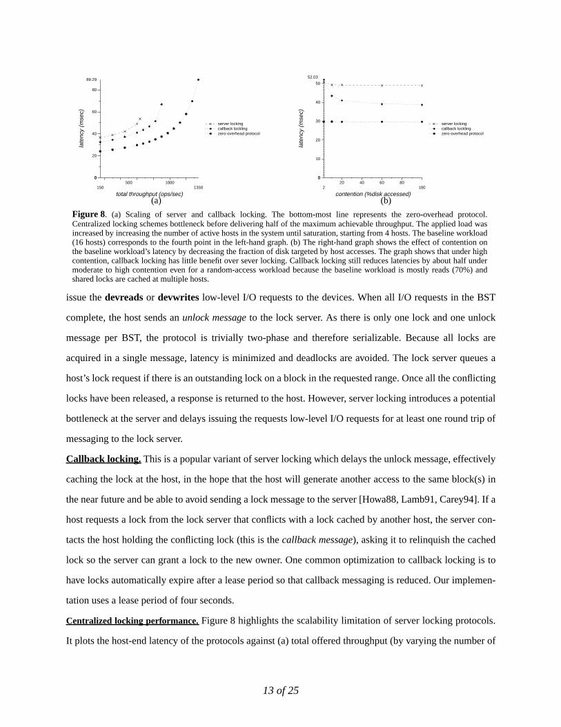
Figure 8. (a) Scaling of server and callback locking. The bottom-most line represents the zero-overhead protocol.Centralized locking schemes bottleneck before delivering half of the maximum achievable throughput. The applied load wasincreased by increasing the number of active hosts in the system until saturation, starting from 4 hosts. The baseline workload(16 hosts) corresponds to the fourth point in the left-hand graph. (b) The right-hand graph shows the effect of contention onthe baseline workload’s latency by decreasing the fraction of disk targeted by host accesses. The graph shows that under highcontention, callback locking has little benefit over sever locking. Callback locking still reduces latencies by about half undermoderate to high contention even for a random-access workload because the baseline workload is mostly reads (70%) andshared locks are cached at multiple hosts.
(a) (b)
14 of 25
hosts) and against (b) contention (by varying the % of disk addressed). The protocols bottleneck substan-
tially before delivering the full throughput of the I/O system that is attainable with a zero-overhead proto-
col (which performs no concurrency control work and provides no consistency guarantees). This occurs
because the server’s CPU is bottlenecked handling network messaging and processing lock and unlock
requests (750usec per message send or receive). Callback locking reduces lock server load and lock acqui-
sition latencies when locks are commonly reused by the same host multiple times before a different host
requests a conflicting lock. At one extreme, a host requests locks on its private data and never again inter-
acts with the lock server until the lease expires. At the other extreme, each lock is used once by a host, and
then is called back by a conflicting use. This will induce the same number of messages as simple server
locking. Lock acquisition latency can be even worse if a read lock is shared by a large number hosts since
all of them need to be called back.
Figure 9 and Figure 8 show that at the baseline workload, callback locking reduces latency relative to
simple locking by 20% but is still 33% larger than the zero-overhead protocol. This benefit is not from
locality—the workload contains little of it—but from the dominance of read traffic, which allows
concurrent cached read locks at all hosts until the next write. While more benefits would be possible if the
workload had more locality, the false sharing between independent accesses that share a parity block limits
the potential benefits of locality.
4.3. Parallel lock servers
The scalability bottleneck of centralized locking protocols can be avoided by distributing the locking work
across multiple parallel lock servers.1
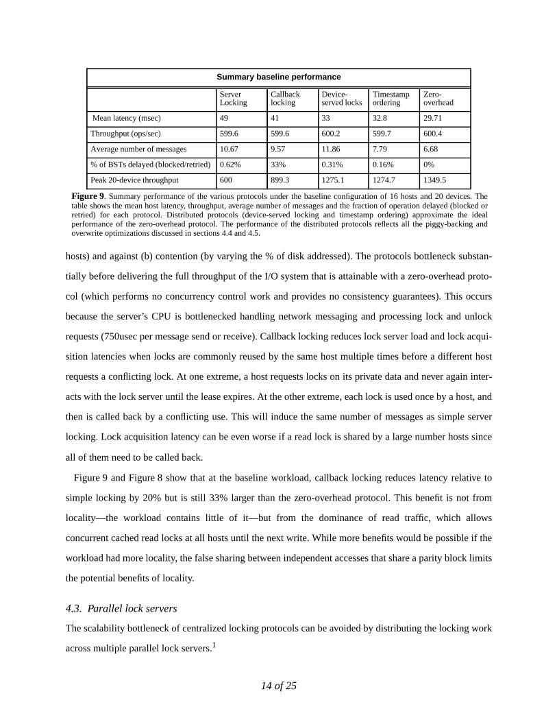
Summary baseline performance
ServerLocking
Callbacklocking
Device-served locks
Timestampordering
Zero-overhead
Mean latency (msec) 49 41 33 32.8 29.71
Throughput (ops/sec) 599.6 599.6 600.2 599.7 600.4
Average number of messages 10.67 9.57 11.86 7.79 6.68
% of BSTs delayed (blocked/retried) 0.62% 33% 0.31% 0.16% 0%
Peak 20-device throughput 600 899.3 1275.1 1274.7 1349.5
Figure 9. Summary performance of the various protocols under the baseline configuration of 16 hosts and 20 devices. Thetable shows the mean host latency, throughput, average number of messages and the fraction of operation delayed (blocked orretried) for each protocol. Distributed protocols (device-served locking and timestamp ordering) approximate the idealperformance of the zero-overhead protocol. The performance of the distributed protocols reflects all the piggy-backing andoverwrite optimizations discussed in sections 4.4 and 4.5.
15 of 25
Locks can be partitioned across multiple lock servers according to some static or dynamic scheme, and
hosts directly send parallel lock requests to the appropriate servers. However, deadlocks can arise when a
host attempts to acquire locks managed by multiple independent servers. This can be avoided if locks are
acquired one at a time in a specific order, but this implies that lock requests are sent to the lock servers in
sequence—the next request is sent only after the previous reply is received—and not in parallel, increasing
latency and lock hold time substantially. Alternatively, deadlocks can be detected via request time-outs. If
a lock request can not be serviced at a lock server within a given time, a negative response is returned to the
host. A timed out host BST then releases all acquired locks, and retries acquiring locks from the beginning.
While parallel lock servers do not have the single lock server bottleneck problem, this benefit comes at
the cost of more messaging and usually longer pre-I/O latency. This induces longer lock hold times,
increasing the window in time of potential conflict compared to an unloaded single lock server and
resulting in higher probabilities of conflict. We present a specialized implementation of this scheme in the
following section.
4.4. Device-served locking
Given the requirement of some number of parallel lock servers and the opportunity of increasing storage
device intelligence, we investigated embedding lock servers in the devices. Device-served locking will
reduce the cost of a scalable serializable storage array by eliminating the need for dedicated lock server
hardware, and decrease latency and the total number of messages by exploiting the two-phase nature of
BSTs to piggy-back lock messaging on I/O requests.
In device-served locks, each device serves locks for the blocks stored on it. This enhances scalability by
balancing lock load over all the devices. As a parallel lock server scheme, simple device-served locking
1. Faster lock servers can be built using low-latency networks, hardware-specialized transport protocols and symmetric multipro-cessor machines. However, this simply increases the maximum attainable throughput but does not eliminate the scalabilitylimitation.
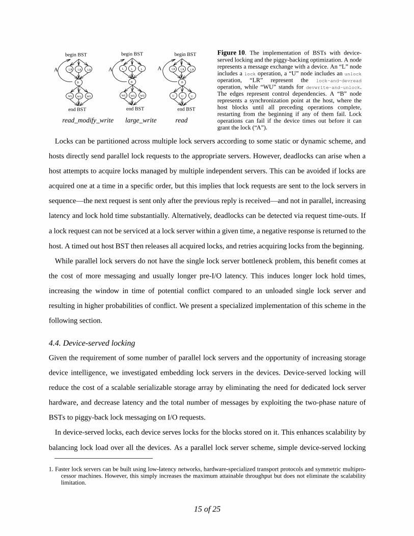
Figure 10. The implementation of BSTs with device-served locking and the piggy-backing optimization. A noderepresents a message exchange with a device. An “L” nodeincludes alock operation, a “U” node includes anunlock
operation, “LR” represent the lock-and-devread
operation, while “WU” stands fordevwrite-and-unlock .The edges represent control dependencies. A “B” noderepresents a synchronization point at the host, where thehost blocks until all preceding operations complete,restarting from the beginning if any of them fail. Lockoperations can fail if the device times out before it cangrant the lock (“A”).
begin BST begin BST
read_modify_write read
begin BST
large_write
LR LR LR
WU WU WU
L L L
WU WU WU
LR LR LR
U U U
end BSTend BSTend BST
BB B
A A A
16 of 25
increases the amount of messaging and pre-I/O latency. For example, in single-phase writes, a lock phase
must be added preceding the writes, since we can not bundle the lock and write requests together without
non-serializability. However, the lock/unlock messaging can be eliminated by piggy-backing these
messages on I/O requests as shown in Figure 10.
For single-phase reads, lock acquisition can be piggy-backed on the reads, reducing pre-I/O latency, but
a separate unlock phase is required. Fortunately, the second phase latency can be hidden from the
application since the data has been received. For two-phase writes, locks can be acquired during the first
I/O phase (by piggy-backing the lock requests on thedevread requests) and released during the second I/O
phase (by piggy-backing the unlock messages onto thedevwrite requests) totally hiding the latency and
messaging cost of locking.
We require that a host not issue anydevwrites until all locks have been acquired in order to keep
recovery simple, although it may issuedevreads. Restarting a BST in the lock acquisition phase therefore
does not require undoing writes (since no data has been written yet).
This device-supported parallel locking is almost sufficient to eliminate the need for leased callback locks
because two-phase writes have no latency overhead associated with locking and the overhead of unlocking
for single phase reads is not observable. Only single phase writes would benefit from lock caching. Given
the increase in complexity and durable device state that comes with callback locking we see pragmatic
value in avoiding callbacks in device-served locking.
Device-served locking is more effective than the centralized locking schemes, as shown in the summary
table of Figure 9. With the baseline workload, it achieves latencies only 10% larger than minimal, and a
peak throughput equal to 94% of maximum.
Despite its scalability, device-served locking has two disadvantages: it uses more messages than
centralized locking protocols, as shown in the summary table of Figure 9, and it has performance
vulnerabilities under high contention due to its susceptibility to deadlocks. Moreover, configuring the
17 of 25
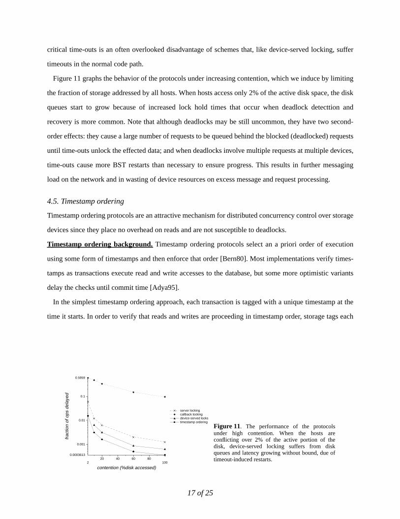
critical time-outs is an often overlooked disadvantage of schemes that, like device-served locking, suffer
timeouts in the normal code path.
Figure 11 graphs the behavior of the protocols under increasing contention, which we induce by limiting
the fraction of storage addressed by all hosts. When hosts access only 2% of the active disk space, the disk
queues start to grow because of increased lock hold times that occur when deadlock detecttion and
recovery is more common. Note that although deadlocks may be still uncommon, they have two second-
order effects: they cause a large number of requests to be queued behind the blocked (deadlocked) requests
until time-outs unlock the effected data; and when deadlocks involve multiple requests at multiple devices,
time-outs cause more BST restarts than necessary to ensure progress. This results in further messaging
load on the network and in wasting of device resources on excess message and request processing.
4.5. Timestamp ordering
Timestamp ordering protocols are an attractive mechanism for distributed concurrency control over storage
devices since they place no overhead on reads and are not susceptible to deadlocks.
Timestamp ordering background. Timestamp ordering protocols select an a priori order of execution
using some form of timestamps and then enforce that order [Bern80]. Most implementations verify times-
tamps as transactions execute read and write accesses to the database, but some more optimistic variants
delay the checks until commit time [Adya95].
In the simplest timestamp ordering approach, each transaction is tagged with a unique timestamp at the
time it starts. In order to verify that reads and writes are proceeding in timestamp order, storage tags each
Figure 11. The performance of the protocolsunder high contention. When the hosts areconflicting over 2% of the active portion of thedisk, device-served locking suffers from diskqueues and latency growing without bound, due oftimeout-induced restarts.
220 40 60 80
100
contention (%disk accessed)
0.0003613
0.001
0.01
0.1
0.5959
frac
tion
of o
ps d
elay
ed
server lockingcallback lockingdevice-served lockstimestamp ordering
18 of 25
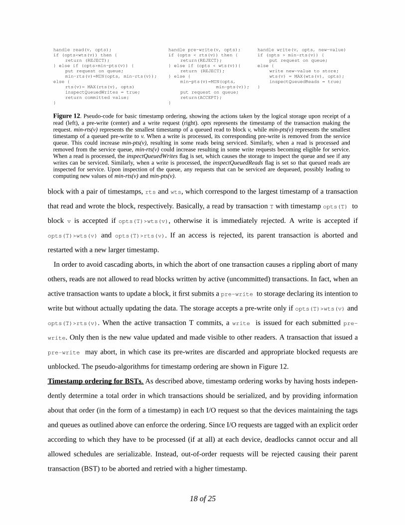
block with a pair of timestamps,rts andwts , which correspond to the largest timestamp of a transaction
that read and wrote the block, respectively. Basically, a read by transactionT with timestampopts(T) to
block v is accepted ifopts(T)>wts(v) , otherwise it is immediately rejected. A write is accepted if
opts(T)>wts(v) and opts(T)>rts(v) . If an access is rejected, its parent transaction is aborted and
restarted with a new larger timestamp.
In order to avoid cascading aborts, in which the abort of one transaction causes a rippling abort of many
others, reads are not allowed to read blocks written by active (uncommitted) transactions. In fact, when an
active transaction wants to update a block, it first submits apre-write to storage declaring its intention to
write but without actually updating the data. The storage accepts a pre-write only ifopts(T)>wts(v) and
opts(T)>rts(v) . When the active transaction T commits, awrite is issued for each submittedpre-
write . Only then is the new value updated and made visible to other readers. A transaction that issued a
pre-write may abort, in which case its pre-writes are discarded and appropriate blocked requests are
unblocked. The pseudo-algorithms for timestamp ordering are shown in Figure 12.
Timestamp ordering for BSTs. As described above, timestamp ordering works by having hosts indepen-
dently determine a total order in which transactions should be serialized, and by providing information
about that order (in the form of a timestamp) in each I/O request so that the devices maintaining the tags
and queues as outlined above can enforce the ordering. Since I/O requests are tagged with an explicit order
according to which they have to be processed (if at all) at each device, deadlocks cannot occur and all
allowed schedules are serializable. Instead, out-of-order requests will be rejected causing their parent
transaction (BST) to be aborted and retried with a higher timestamp.
handle read(v, opts);if (opts<wts(v)) then {
return (REJECT);} else if (opts>min-pts(v)) {
put request on queue;min-rts(v)=MIN(opts, min-rts(v));
else {rts(v)= MAX(rts(v), opts)inspectQueuedWrites = true;return committed value;
}
handle pre-write(v, opts);if (opts < rts(v)) then {
return(REJECT);} else if (opts < wts(v)){
return (REJECT);} else {
min-pts(v)=MIN(opts,min-pts(v));
put request on queue;return(ACCEPT);
}
Figure 12. Pseudo-code for basic timestamp ordering, showing the actions taken by the logical storage upon receipt of aread (left), a pre-write (center) and a write request (right).opts represents the timestamp of the transaction making therequest.min-rts(v) represents the smallest timestamp of a queued read to blockv, while min-pts(v) represents the smallesttimestamp of a queued pre-write tov. When a write is processed, its corresponding pre-write is removed from the servicequeue. This could increasemin-pts(v), resulting in some reads being serviced. Similarly, when a read is processed andremoved from the service queue,min-rts(v) could increase resulting in some write requests becoming eligible for service.When a read is processed, theinspectQueuedWrites flag is set, which causes the storage to inspect the queue and see if anywrites can be serviced. Similarly, when a write is processed, theinspectQueuedReadsflag is set so that queued reads areinspected for service. Upon inspection of the queue, any requests that can be serviced are dequeued, possibly leading tocomputing new values ofmin-rts(v)and min-pts(v).
handle write(v, opts, new-value)if (opts > min-rts(v)) {
put request on queue;else {
write new-value to store;wts(v) = MAX(wts(v), opts);inspectQueuedReads = true;
}
19 of 25
As in the general case, since each device is performing a local check, a write request may pass the check
in some devices, but the BST may abort due to failed checks in other devices. Because of the simple
structure of BSTs, splitting the write protocol into a pre-write phase followed by a write phase ensures that
the host has all device decisions before issuing any write, allowing it to avoid complex and expensive undo
of disk writes. The cluster of hosts share a loosely-synchronized clock. New timestamps are generated at a
host by sampling the local clock, then appending the host’s unique identifier to the least significant bits of
the clock value.
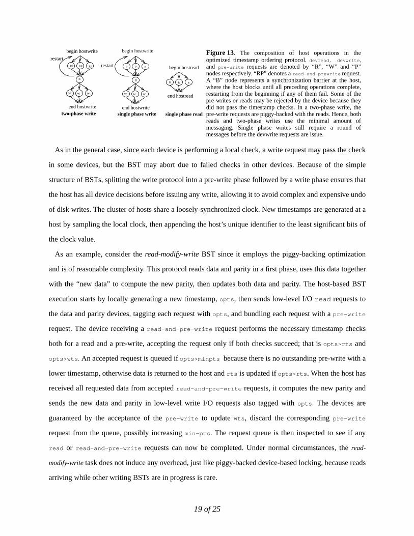
As an example, consider theread-modify-write BST since it employs the piggy-backing optimization
and is of reasonable complexity. This protocol reads data and parity in a first phase, uses this data together
with the “new data” to compute the new parity, then updates both data and parity. The host-based BST
execution starts by locally generating a new timestamp,opts , then sends low-level I/Oread requests to
the data and parity devices, tagging each request withopts , and bundling each request with apre-write
request. The device receiving aread-and-pre-write request performs the necessary timestamp checks
both for a read and a pre-write, accepting the request only if both checks succeed; that isopts>rts and
opts>wts . An accepted request is queued ifopts>minpts because there is no outstanding pre-write with a
lower timestamp, otherwise data is returned to the host andrts is updated ifopts>rts . When the host has
received all requested data from acceptedread-and-pre-write requests, it computes the new parity and
sends the new data and parity in low-level write I/O requests also tagged withopts . The devices are
guaranteed by the acceptance of thepre-write to updatewts , discard the correspondingpre-write
request from the queue, possibly increasingmin-pts . The request queue is then inspected to see if any
read or read-and-pre-write requests can now be completed. Under normal circumstances, theread-
modify-write task does not induce any overhead, just like piggy-backed device-based locking, because reads
arriving while other writing BSTs are in progress is rare.
begin hostwrite
begin hostread
two-phase write single phase read
begin hostwrite
single phase write
RP RP RP
W W W
P P P
W W W
R R R
end hostread
end hostwriteend hostwrite
Figure 13. The composition of host operations in theoptimized timestamp ordering protocol.devread, devwrite ,
and pre-write requests are denoted by “R”, “W” and “P”nodes respectively. “RP” denotes aread-and-prewrite request.A “B” node represents a synchronization barrier at the host,where the host blocks until all preceding operations complete,restarting from the beginning if any of them fail. Some of thepre-writes or reads may be rejected by the device because theydid not pass the timestamp checks. In a two-phase write, thepre-write requests are piggy-backed with the reads. Hence, bothreads and two-phase writes use the minimal amount ofmessaging. Single phase writes still require a round ofmessages before the devwrite requests are issue.
B B
restartrestart
20 of 25
We discuss optimizations to the basic timestamp ordering protocol next, which lend them to efficient
implementation. These optimizations were implemented in our simulation, and the results reflect their
effects.
Minimizing b uffering overhead. The protocol as presented can induce high buffering overhead at the
storage device when there is high overwrite and concurrent read activity to overlapping ranges. If the stor-
age device has accepted multiple pre-writes to a block, and their corresponding writes are received out of
order, the writes have to be buffered and applied in order to satisfy any intermediate reads. Our approach is
to apply writes as soon as they arrive because modern disk drives have limited memory. As a result, some
unnecessary reads may be rejected. Although unlikely, readers can theoretically starve in our protocol if
there is a very persistent stream of writes. The advantage of immediate write processing is that storage
devices can exploit their ability to stream data at high data rates to the disk surface.
Avoiding timestamp accesses. Our protocol requires that the pair of timestamps,rts andwts, associated
with each disk block be durable: read before any disk operation and written after every disk operation. A
naive implementation might store these timestamps on disk, nearby the associated data. However, this
would result in one extra disk access after reading a block (to update the block’srts ), and one extra disk
access before writing a block (to read the block’s previouswts ). Doubling the number of disk accesses is
not consistent with our high-performance goal. Because all clocks are loosely synchronized and message
delivery latency should be bounded, a device need not accept a request timestamped with a value much
smaller than its current time. Hence, per-block timestamp information older thanT seconds, for some value
to T, can be discarded and a value of “current time minusT” used instead. Moreover, if a device is reinitiat-
149.9500 1000
1350
total throughput (ops/sec)
00
20
40
60
80
89.29
late
ncy
(mse
c)
server lockingcallback locklingdevice-served lockstimestamp orderingzero-overhead protocol
1020 40 60 80
90
read fraction (%)
00
5
10
15
15.62
mes
sage
s pe
r op
erat
ion
server lockingcallback locklingdevice-served lockstimestamp orderingzero-overhead protocol
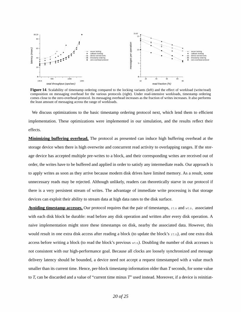
Figure 14. Scalability of timestamp ordering compared to the locking variants (left) and the effect of workload (write/read)composition on messaging overhead for the various protocols (right). Under read-intensive workloads, timestamp orderingcomes close to the zero-overhead protocol. Its messaging overhead increases as the fraction of writes increases. It also performsthe least amount of messaging across the range of workloads.
21 of 25
ing after a “crash” or power cycle, it can simply wait timeT after its clock is synchronized before accepting
requests, or record its initial synchronized time and reject all requests with earlier timestamps. Therefore,
timestamps only need volatile storage, and only enough to record a few seconds of activity. The use of
loosely synchronized clocks for concurrency control and for efficient timestamp management has been
suggested in the Thor client-server object-oriented database management system [Adya95].
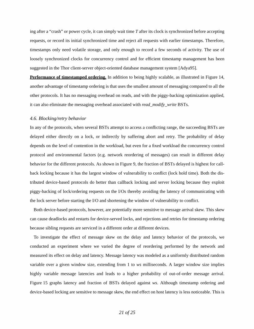
Performance of timestamped ordering. In addition to being highly scalable, as illustrated in Figure 14,
another advantage of timestamp ordering is that uses the smallest amount of messaging compared to all the
other protocols. It has no messaging overhead on reads, and with the piggy-backing optimization applied,
it can also eliminate the messaging overhead associated withread_modify_write BSTs.
4.6. Blocking/retry behavior
In any of the protocols, when several BSTs attempt to access a conflicting range, the succeeding BSTs are
delayed either directly on a lock, or indirectly by suffering abort and retry. The probability of delay
depends on the level of contention in the workload, but even for a fixed workload the concurrency control
protocol and environmental factors (e.g. network reordering of messages) can result in different delay
behavior for the different protocols. As shown in Figure 9, the fraction of BSTs delayed is highest for call-
back locking because it has the largest window of vulnerability to conflict (lock hold time). Both the dis-
tributed device-based protocols do better than callback locking and server locking because they exploit
piggy-backing of lock/ordering requests on the I/Os thereby avoiding the latency of communicating with
the lock server before starting the I/O and shortening the window of vulnerability to conflict.
Both device-based protocols, however, are potentially more sensitive to message arrival skew. This skew
can cause deadlocks and restarts for device-served locks, and rejections and retries for timestamp ordering
because sibling requests are serviced in a different order at different devices.
To investigate the effect of message skew on the delay and latency behavior of the protocols, we
conducted an experiment where we varied the degree of reordering performed by the network and
measured its effect on delay and latency. Message latency was modeled as a uniformly distributed random
variable over a given window size, extending from 1 tows milliseconds. A larger window size implies
highly variable message latencies and leads to a higher probability of out-of-order message arrival.
Figure 15 graphs latency and fraction of BSTs delayed againstws. Although timestamp ordering and
device-based locking are sensitive to message skew, the end effect on host latency is less noticeable. This is
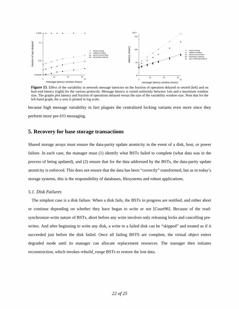
22 of 25
because high message variability in fact plagues the centralized locking variants even more since they
perform more pre-I/O messaging.
5. Recovery for base storage transactions
Shared storage arrays must ensure the data-parity update atomicity in the event of a disk, host, or power
failure. In each case, the manager must (1) identify what BSTs failed to complete (what data was in the
process of being updated), and (2) ensure that for the data addressed by the BSTs, the data-parity update
atomicity is enforced. This does not ensure that the data has been “correctly” transformed, but as in today’s
storage systems, this is the responsibility of databases, filesystems and robust applications.
5.1. Disk Failures
The simplest case is a disk failure. When a disk fails, the BSTs in progress are notified, and either abort
or continue depending on whether they have began to write or not [Court96]. Because of the read-
synchronize-write nature of BSTs, abort before any write involves only releasing locks and cancelling pre-
writes. And after beginning to write any disk, a write to a failed disk can be “skipped” and treated as if it
succeeded just before the disk failed. Once all failing BSTS are complete, the virtual object enters
degraded mode until its manager can allocate replacement resources. The manager then initiates
reconstruction, which invokesrebuild_range BSTs to restore the lost data.
210 20 30
32
message latency window (msec)
0.001606
0.01
0.1
0.3396fr
actio
n of
ops
del
ayed
server lockingcallback locklingdevice-served lockstimestamp ordering
210 20 30
32
message latency window (msec)
00
50
100
150
160.9
late
ncy
(mse
c)
server lockingcallback locklingdevice-served lockstimestamp orderingzero-overhead protocol
Figure 15. Effect of the variability in network message latencies on the fraction of operation delayed or retried (left) and onhost-end latency (right) for the various protocols. Message latency is varied uniformly between 1ms and a maximum windowsize. The graphs plot latency and fraction of operations delayed versus the size of the variability window size. Note that for theleft-hand graph, the y-axis is plotted in log scale.
23 of 25
5.2. Host and power failures
For host and power failures, however, a more complex approach is needed because knowing which BSTS
are incomplete can be much harder and only a small fraction of the object’s range is likely to be in need of
recovery.
One approach avoids identifying the failed BSTs altogether and instead declares all data suspect after a
failure. This is, of course, prohibitively expensive. The traditional technique for detecting that a transaction
started and did not complete is to use write-ahead logging. For BSTs, we do not want additional delay
induced by write-ahead logging so we piggy-back these log messages on BSTS actions that “commit” to
doing work. The write-ahead log record is quite compact since it contains only a description of the BST,
the type of the BST and the target range that it addresses, and not the before- or after-image of the blocks.
For server and callback locking, it is already required that locks granted by a server persist through
failures so BST write-ahead logging can be piggy-backed on lock acquisitions and lock releases. Lock
servers achieve durable recording of these logs with NVRAM for power fail and primary/secondary
replication for machine failure.
For device-served locks and timestamp ordering, the operations can piggy-back write ahead logs onto
device locks and pre-writes. Again, NVRAM is needed for coping with power failure because synchronous
disk writes on each lock or pre-write are too expensive. For disk failure, however, we can use the simple
host-based recovery described above.
Upon identifying that a BST accessing a virtual object has failed, the manager for that object enters that
object into a RECOVERYmode to ensure data-parity update atomicity:
Fault-fr ee mode. Under fault-free mode, once the suspect ranges are identified, data-parity update atomic-
ity can be effectively upheld by recomputing the parity block from the stripe of data blocks. Under this
mode, all devices are operational, so therebuild_rangeBST can be used to recompute the parity block.
Degraded and reconstruction modes.Under these modes, one of the data disks has failed and is not
accessible. Thus, the only way to ensure that data and parity blocks in a stripe are updated atomically is to
use logging. Consequently, the BSTs invoked by ahostwrite task under these modes must be atomic. The
before- or after-image of the blocks that are to be updated by a BST must be logged, so that atomicity is
enforced. In case of a write BST, the “after-image” of the blocks is available at the storage controller
before the beginning of the write phase. Atomicity can be ensured by sending the after-image of the blocks
24 of 25
to the manager of the virtual object before the write phase begins. The manager writes the blocks to a log
on stable storage and can enforce atomicity by reinstating the blocks from the log in case of an untimely
failure. Therebuild_rangeBST invoked by thereconstruct task does not need to be atomic and recovery
can be performed by simply reissuing the BST, becauserebuild_range writes only to the replacement
object and does not update the degraded array.
Migration mode. In migration mode, a BST is invoked either by an access task or by amigrate task. For
BSTs that are invoked byhostwrite tasks, recovery can be carried out as described in fault-free mode
above. In the case of acopy BST that is invoked by a migrate task, recovery can simply be enacted by re-
issuing the copy BST.
6. Conclusions
Shared storage arrays enable thousands of storage devices to be shared and directly accessed by end hosts
over switched system-area networks. In such systems, concurrent host tasks can lead to inconsistencies for
redundancy codes and for data read by end hosts. In this paper, we propose a novel approach to construct-
ing a scalable distributed storage management system that enables high concurrency between access and
management tasks while ensuring correctness. Our approach breaks down the storage access and manage-
ment tasks performed by storage controllers into two-phased operations (BSTs) such that correctness
requires ensuring only the serializability of the component BSTs and not of the parent tasks. We present
distributed protocols that exploit technology trends and BST properties to provide serializability for BSTs
with high scalability, coming within few percent of the performance of the ideal zero-overhead protocol.
The protocols distribute concurrency control work to the endpoints (hosts where accesses originate and
devices where stored data resides), avoiding bottlenecks. We further show that atomicity is not required for
most BSTs, and present recovery protocols for BSTs that exploit knowledge about operation semantics to
reduce recovery overhead substantially.
References[Adya95] A. Adya, R. Gruber, B. Liskov and U. Maheshwari, “Efficient optimistic concurrency control using loosely syn-
chronized clocks”,Proceeding of the SIGMOD International Conference on Management of Data, May 1995.[Benn96] A. Benner, “Fibre Channel: Gigabit Communications and I/O for Computer Networks”, McGraw Hill, New
York, 1996.[Bern80] P. Bernstein and N. Goodman, “Timestamp based algorithms for concurrency control in distributed database sys-
tems”,Proceedings of the 6th International Conference on Very Large Databases, October 1980.[Bhide91] A. Bhide, E. Elnozahy, and S. Morgan, “A Highly Available Network File Server”,Proceedings of the 1991
USENIX Winter Conference, pp. 199-206.
25 of 25
[Boden95] N. Boden et al., “Myrinet: A Gigabit-per-Second Local Area Network”,IEEE Micro, Feb. 1995.[Carey94] M. Carey, M. Franklin, and M. Zaharioudakis, “Fine-grained sharing in a page server OODBMS,”Proceedings
of the 1994 ACM SIGMOD, Minneapolis, MN, May 1994.[Court96] W. V. Courtright II, G. Gibson, M. Holland, and J. Zelenka, “A Structured Approach to Redundant Disk Array
Implementation,”Proceedings of the 1996 IPDS, Sept. 4-6, 1996.[Eswa76] K. Eswaran, J. Gray, R. Lorie and L. Traiger, “The notions of consistency and predicate locks in a database sys-
tems.”Communications of the ACM, Vol. 19, No. 11, November 1976, pp. 624-633.[Gibson98] G. Gibson et al, “Cost-effective high-bandwidth storage architecture”Proceedings of ACM ASPLOS, October
1998.[Golding95] R. Golding, E. Shriver, T. Sullivan and J. Wilkes, “Attribute-managed storage,” Workshop on modeling and
specification of I/O, San Antonio, Texas, October 1995.[Gray75] J. Gray, R. Lorie, G. Putzulo, and I. Traiger, “Granularity of locks and degrees of consistency in a shared data-
base”, IBM Research Report, RJ1654, September 1975.[Gray93] J. Gray and A. Reuter. Transaction Processing: Concepts and techniques. Morgan Kaufmann, San Mateo, CA,
1993.[Haerd83] T. Haerder and A. Reuter, “Principles of Transaction-oriented Database Recovery”,ACM Computing Surveys,
Vol. 15, No. 4, pp. 287-317.[Holl94] M. Holland, G. Gibson, and D. Sieworek, “Architectures and Algorithms for On-Line Failure Recovery in
Redundant Disk Arrays,”Journal of Distributed and Parallel Databases, Vol. 2, No. 3, pp. 295-335, July 1994.[Horst95] R. Horst, “TNet: A Reliable System Area Network”,IEEE Micro, Feb. 1995.[Howa88] J. Howard, M. Kazar, S. Menees, D. Nichols, M. Satyanarayanan, R. Sidebotham, and M. West, “Scale and Per-
formance in a Distributed File System,”ACM Transactions on Computer Systems, Vol. 6, No. 1, pp. 51-81, Feb-ruary 1988.
[Kung81] H. T. Kung and J. T. Robinson, “On optimistic methods for concurrency control”,ACM Transactions on Data-base Systems, vol. 6, no. 2, June 1981.
[Lamb91] C. Lamb, G. Landis, J. Orenstein, and D. Weinreb, “The ObjectStore Database System,”CACM, Vol. 34, No. 10,October 1991.
[Lee96] E. Lee and C. Thekkath, “Petal: Distributed Virtual Disks”,Proceedings of the seventh ASPLOS,October 1996.[Mass98] P. Massiglia, “Changing storage subsystems,” Computer Technology Review, Jan 1999.[Mills88] D. L. Mills, “Network time protocol: specification and implementation,” DARPA-internet report RFC 1059,
DARPA, July 1988.[Mohan92] C. Mohan, D. Haderle, B. Lindsay, H. Pirahesh, and P. Schwarz, “ARIES: A Transaction Recovery Method Sup-
porting Fine-Granularity Locking and Partial Rollbacks Using Write-Ahead Logging”,ACM Transactions onDatabase Systems, Vol. 17, No. 1, pp. 94-162, 1992.
[Papa79] C. Papadimitriou, “Serializability of concurrent updates,” Journal of the ACM, Vol. 26, No. 4, October 1979, pp.631-653.
[Patt88] D. Patterson, G. Gibson, and R. Katz, “A Case for Redundant Arrays of Inexpensive Disks”,Proc. of ACM SIG-MOD, June 1988.
[Seag97] Seagate Technology, “Cheetah: Industry-Leading Performance for the Most Demanding Applications”,http://seagate.com, 1997.
[Wilkes96] J. Wilkes, R. Golding, C. Staelin, and T. Sullivan, “The HP AutoRAID hierarchical storage system”,ACM Trans-actions on Computer Systems, vol. 14, no. 1, February 1996, pp.108-136.