&high pressure pipeline products services
TRANSCRIPT
Hig
h P
res
su
re P
ipe
line
Pro
du
cts
& S
erv
ice
s
A global leader in the optimization of pressurized pipeline systems, TDW provides a comprehensive
portfolio of patented pipeline maintenance and repair solutions, developed over decades of field
application by an accomplished staff of engineers and available through an extensive global network
of highly trained technicians.
Drilling and Tapping Machines
STOPPLE® Train Plugging System
Plugging equipment, including the LOCK-O-RING® Plus completion plug
Fittings, including the STOPPLE® Plus fitting
SANDWICH® Valves
Rehabilitation Products
Cathodic Protection Equipment
Hot Tapping & Plugging Services
Turnkey Project Management
&High PressurePipeline Products Services

Hig
h P
res
su
re P
ipe
line
Pro
du
cts
& S
erv
ice
s
A global leader in the optimization of pressurized pipeline systems, TDW provides a comprehensive
portfolio of patented pipeline maintenance and repair solutions, developed over decades of �eld
application by an accomplished staff of engineers and available through an extensive global network
of highly trained technicians.
Drilling and Tapping Machines
STOPPLE® Train Plugging System
Plugging equipment, including the LOCK-O-RING® Plus completion plug
Fittings, including the STOPPLE® Plus �tting
SANDWICH® Valves
Rehabilitation Products
Cathodic Protection Equipment
Hot Tapping & Plugging Services
Turnkey Project Management
&High PressurePipeline Products Services
Date: September 2018Supersedes: January 2018
Notice
Product Warranty
Terms and Conditions
Drilling and Tapping Equipment
T-101 Drilling Machine 1/2" through 4" 2000.001
904 Drilling Machine 1/2" through 4" 2000.003
360 Tapping Machine 2" through 6" 1000.004
660 Tapping Machine 3" through 16" 1000.005
760 Tapping Machine 3" through 16" 1000.006
860 Tapping Machine 3" through 20" 1000.008
936 Tapping Machine 12" through 36" 1000.009
1200 Tapping Machine 12" through 36" 1000.001
2400 Tapping Machine 30" through 60" 1000.002
Air Motors 1010.002
Fall Protection Equipment 1010.003
Plugging Service & Equipment
STOPPLE®
Applications STPPL
STOPPLE® Plugging Machines 4" through 48" 1030.001
SANDWICH ® Valves
SANDWICH® Valves 4" and larger 1020.001
Rehabilitation Products
RES-Q™ Composite Wrap for Pipelines 2" through 60" 5300.003
RES-Q™ Composite Wrap for Process Piping 2" through 60" 5300.004
Steel Repair Sleeves 2" through 48" 7300.002
Contents
High Pressure Piping Systems
Contents Continued High Pressure Piping Systems
ff 3/99
1100.001
1100.004
1100.005
1100.006
1100.007
1100.008
1120.001
1110.001
1110.004
1110.005
1110.006
1110.002
5200.001
2100.001
2100.019
2100.020
1160.001
5210.001
5210.002
4" through 36"
4" through 22"
4" through 12" & 16" 4"
through 8"
4" through 8"
4" through 36"
2" through 24"
4" through 36"
2" through 30"
4" through 8"
4" through 8"
4" through 8"
2" through 24"
2" through 14"
2" and 3"
2-Inch
4" through 24"
2" x 4" through 36" x 44"
2" through 48"
2" x 6" through 36" x 42"
5210.003
tp 11/01
tp-pg 11/01
Fittings
Flange and Fitting Application Data Form
PROSERIES Fittings - 600 Class
STOPPLE® Fittings
STOPPLE® Fittings - ASME B31.3
STOPPLE® Fittings - ASME B31.4
STOPPLE® Fittings - ASME B31.8
STOPPLE® Plus Fittings
STOPPLE® Fittings - Multi-Certified
LOCK-O-RING® Flanges and Plugs
TDW Tapping Fittings
TDW Tapping Fittings -ASME B31.3
TDW Tapping Fittings -ASME B31.4
TDW Tapping Fittings -ASME B31.8
No. 3 Branch Connection Fittings
WEDGE-LOCK® Pipe Plug
THREAD-O-RING™ Fitting
THREAD-O-RING™ Flanged Fitting
Spherical 3-WAY™ Tee with LOCK-O-RING® Flange
Water Applications Tapping & Plugging Fittings
Cathodic Protection Equipment
U-SealsTM
and Z-SealsTM
M-2 Plastic THINSULATOR®
Insulator and 3-Way Cradles
Data Forms
Hot Tapping Service Application Data Form
Hot Tapping & Plugging Service Application Data
Form Planning: HT&P Field Requirements/Clearances
ff 1/00
2100.023
Date: March 1999Supersedes: n/a
Any operation involving work on pipe containing liquids or gases under pressure is potentially hazardous. It is necessary that correct procedures be followed in the use of this equipment to maintain a safe working environment.
No person should use this equipment who is not fully trained in the procedures stated in its manual and who is not fully aware of the potential hazards connected with work on pipe containing liquids or gases under pressure.
The equipment purchaser is responsible for the manner in which the equipment is used and the training and competence of the operators.
Should any difficulty arise at any time in the use of equipment, please contact TDW immediately. In the U.S., Toll Free: 1-888-TDWmSon (839-6766), Phone: (918) 447-5100, Fax: (918) 446-6327, Email: [email protected]
© Copyright 1999. All rights reserved T.D. Williamson, Inc. ® Registered trademark of T.D. Williamson, Inc. TM Trademark of T. D. Williamson, Inc. Data subject to change without notice. Printed in USA.
ISO Certified 9001 and 9002
Notice
Date: June 2000Supersedes: September 1999
1. Products manufactured by T. D. Williamson, Inc., are warranted free from defects in material and workmanship for a period of three (3) years from the date of shipment from the factory. Elastomer products are warranted for one (1) year under proper storage tobe free from defects in material and workmanship. The foregoing warranty does not apply to any items not manufactured byT. D. Williamson, including but not limited, to, electronic devices, switch components, pumps, o-rings, purchase cylinders,etc. These third party parts will revert back to suppliers warranty. TDW assumes no liability under this or any other warrantyfor components not manufactured by TDW. This Warranty applies only to products shipped after June 30, 2000.
2. If TDW accepts any claim made under this Warranty, TDW’s liability, if any, shall be limited to, at TDW’s sole option, repair orreplacement of the failed part or product, or a refund of the purchase price, less an allowance for services rendered for the productprior to the Warranty claim. TDW disclaims any and all responsibility for special, consequential or incidental damages arisingout of or related to the sale, use, or inability to use any products covered by this Warranty.
3. Buyer agrees not to return goods for any reason except with the prior written consent of TDW, which consent, if given, shall specifythe terms, conditions and charges upon which any returns may be made. Materials returned to TDW for Warranty work must havea Return Material Authorization (RMA) number, and such number must be noted on the package at the time of shipment. Claimsunder this Warranty must be made in writing within ten (10) days of any failure and sent by registered mail to: P. O. Box 3409,Tulsa, Oklahoma 74101. Any failed products or parts must be held for inspection by TDW or, at TDW’s option, returned to TDW’sfactory. Customer shall prepay shipping charges, and shall pay all duties and taxes, as applicable, for products or parts returned toTDW for warranty service.
4. This Warranty shall not apply to any product or component which has been repaired or altered by anyone other than TDW, orhas become damaged due to misuse, negligence or casualty, or has been operated or maintained contrary to TDW’s printedinstructions and warnings.
5. The sole purpose of the exclusive remedy contained in the limited Warranty shall be to provide repair or replacement of failedproducts, or to refund the purchase price of the failed product as explained above in paragraph 2. This exclusive remedy shall notbe deemed to have failed of its essential purpose so long as TDW agrees to repair or replace the failed product or to refund thepurchase price as explained above.
6. All rights, duties, and obligations arising under this limited Warranty shall be governed by the laws of the State of Oklahoma,U.S.A., regardless of conflict of laws provisions. In the event Buyer initiates litigation under this Warranty, Buyer hereby agreesthat jurisdiction for such litigation shall be brought only in the District Court for the County of Tulsa, Oklahoma.
7. TDW reserves the right to make any changes in or improvements on its products without incurring any liability or obligation toupdate or change previously sold product and/or the accessories thereto.
8. THIS WARRANTY IS IN LIEU OF ALL OTHER WARRANTIES EXPRESS OR IMPLIED, INCLUDING THE WARRANTIES OFMERCHANTABILITY AND FITNESS FOR PARTICULAR PURPOSE, WHICH ARE EXPRESSLY DISCLAIMED. TDW NEITHERASSUMES NOR AUTHORIZES ANY OTHER PERSON TO MODIFY THESE TERMS AND CONDITIONS, WARRANT SPECIFICAPPLICATIONS, OR ASSUME FOR TDW ANY OTHER LIABILITY IN CONNECTION WITH THE SALE OF ANY TDW PRODUCTOTHER THAN AS PROVIDED IN THIS WARRANTY.
Product Warranty
Date: September 1999
1. Minimum Order: $50.00 (U.S.). Any combination of products or services is allowed to satisfy minimum on a single shipment to a single destination.
2. Orders: All orders are subject to acceptance by T. D. Williamson, Inc.
3. Return of Materials: Goods may be returned to T. D. Williamson, Inc., only after approval and receipt by customer of definite shipping instructions and our written Return Materials Authorization. Returned goods are subject to restocking or reconditioning charges. Customer fabricated items or those requiring special material or special size will not be accepted for return.
4. Prices: Prices are subject to change without notice.
5. Taxes: Any tax based on or measured by the charges made for, or the cash receipts from the sale of products or services shall be added to the stated price.
6. Delivery: Our responsibility ceases upon delivery to any common carrier; and we do not, unless previously instructed, insure shipments beyond the point of delivery to said carrier. We make every effort to ship all material within the time indicated by us, but do not guarantee to do so, and all such indications are subject to delays occasioned by causes beyond our control. We assume no responsibility for delays in delivery or defaults resulting from strikes, work stoppages, fire, floods, accidents, inability to obtain materials, fuels or transportations, governmental decree, or any other causes which are unavoidable.
7. Claims: Claims for shortages or defective products must be made within 10 days after receipt of shipment. Loss or damage to materials in transit is the responsibility of the carrier.
8. Cancellations and Changes: Orders once placed and accepted can be canceled or changed only with our consent and upon terms that will save us from loss.
9. Cost of Collection and Attorney Fees: Buyer shall be responsible for all our costs and expenses, including attorney fees, incurred by us in collecting the purchase price for goods or services sold beyond its due date inclusive of delinquency charge.
10. Terms of Payment and Delinquency Charge: Our terms of payment are as shown on our quotation or invoice. All accounts are payable in United States funds, free of exchange rate variation or collection charges. A delinquency charge will be added on any amount not paid within the stated terms of payment and thereafter on all accounts in arrears until paid.
11. Delays in Performance: T. D. Williamson, Inc., shall not be liable for any delay in performance hereunder due to unforeseen circumstances or due to causes beyond its control including, but not limited to, acts of nature, acts of government, labor disputes, delays in transportation, and delays in delivery or inability to deliver by T. D. Williamson, Inc.’s suppliers.
12. Order of Precedence: (a) These Terms and Conditions and any attachments take precedence over customer’s additional or different terms and conditions, to which notice of objection is hereby given. Acceptance by customer is limited to these Terms and Conditions. Neither T. D. Williamson, Inc.’s commence of performance nor delivery shall be deemed or construed as acceptance of customer’s additional or differ-ent terms and conditions. (b) Customer’s purchase of T. D. Williamson, Inc., products hereunder represents acceptance of these Terms and Conditions and any attachments, which together constitute the entire understanding between the parties and supersede any previous communications, representations, or agreements by either party whether verbal or written. No change or modification of the Terms and Conditions herein shall be valid or binding on either party unless in writing and signed by an authorized representative of each party.
13. Governing Law: Any dispute regarding the interpretation or validity hereof shall be governed by the laws of the State of Oklahoma. The par-ties hereby agree that any dispute relating to the products or services sold hereunder shall be subject to the jurisdiction of the courts within the State of Oklahoma.
14. Miscellaneous: (a) Except as may be prohibited by the U.S. Bankruptcy Laws, in the event of any insolvency or inability to pay debts as they become due by a party hereto, or voluntary or involuntary bankruptcy proceeding by or against a party hereto, or appointment of a receiver or assetnee for the benefit of creditors, the other party may elect to cancel any unfulfilled obligations hereunder. (b) Any required notices shall be given in writing at the address of each party set forth herein, or to such other addresses either party may substitute by written notice to the other. (c) Neither party may assign nor transfer any of the rights, duties, or obligations herein, without the prior written consent of the other, and any purported attempt to do so shall be null and void. (d) TDW’s failure to exercise any of its rights hereunder shall not constitute or be deemed a waiver or forfeiture of such rights. (e) Stenographic and clerical errors are subject to correction.
Terms and Conditions

Bleeder Valve
Hole Saw (or drill)
Threaded Valve Adapter
Valve
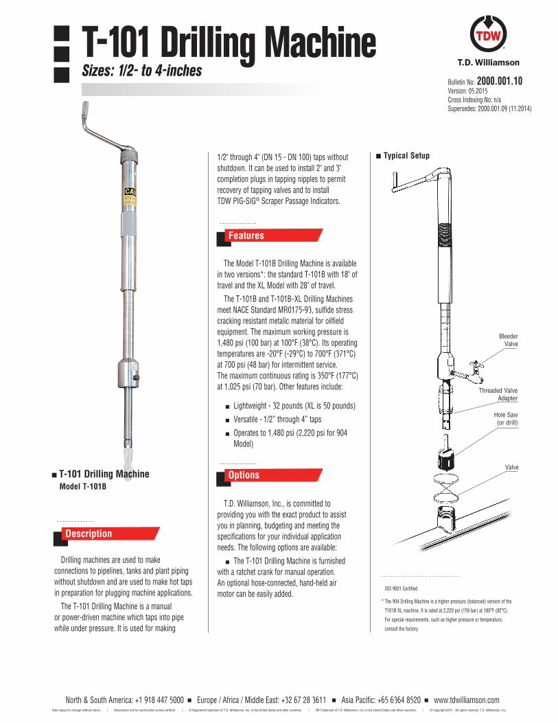
T-101 Drilling MachineSizes: 1/2- to 4-inches
North & South America: +1 918 447 5000 Europe / Africa / Middle East: +32 67 28 3611 Asia Pacific: +65 6364 8520 www.tdwilliamson.comData subject to change without notice. / Dimensions not for construction unless certified. / ® Registered trademark of T.D. Williamson, Inc. in the United States and other countries. / TM Trademark of T.D. Williamson, Inc. in the United States and other countries. / © Copyright 2015 All rights reserved. T.D. Williamson, Inc.
Bulletin No: 2000.001.10Version: 05.2015Cross Indexing No: n/aSupersedes: 2000.001.09 (11.2014)
1/2" through 4" (DN 15 - DN 100) taps without shutdown. It can be used to install 2" and 3" completion plugs in tapping nipples to permit recovery of tapping valves and to install TDW PIG-SIG® Scraper Passage Indicators.
The Model T-101B Drilling Machine is available in two versions*: the standard T-101B with 18" of travel and the XL Model with 28" of travel.
The T-101B and T-101B-XL Drilling Machines meet NACE Standard MR0175-93, sulfide stress cracking resistant metalic material for oilfield equipment. The maximum working pressure is 1,480 psi (100 bar) at 100°F (38°C). Its operating temperatures are -20°F (-29°C) to 700°F (371°C) at 700 psi (48 bar) for intermittent service. The maximum continuous rating is 350°F (177°C) at 1,025 psi (70 bar). Other features include:
Lightweight - 32 pounds (XL is 50 pounds)
Versatile - 1/2” through 4” taps
Operates to 1,480 psi (2,220 psi for 904 Model)
ISO 9001 Certified
* The 904 Drilling Machine is a higher pressure (balanced) version of the
T101B XL machine. It is rated at 2,220 psi (150 bar) at 180°F (82°C).
For special requirements, such as higher pressure or temperature,
consult the factory.
Drilling machines are used to make connections to pipelines, tanks and plant piping without shutdown and are used to make hot taps in preparation for plugging machine applications.
The T-101 Drilling Machine is a manual or power-driven machine which taps into pipe while under pressure. It is used for making
Description
Typical Setup
Features
T.D. Williamson, Inc., is committed to providing you with the exact product to assist you in planning, budgeting and meeting the specifications for your individual application needs. The following options are available:
The T-101 Drilling Machine is furnished with a ratchet crank for manual operation. An optional hose-connected, hand-held air motor can be easily added.
Options T-101 Drilling Machine Model T-101B
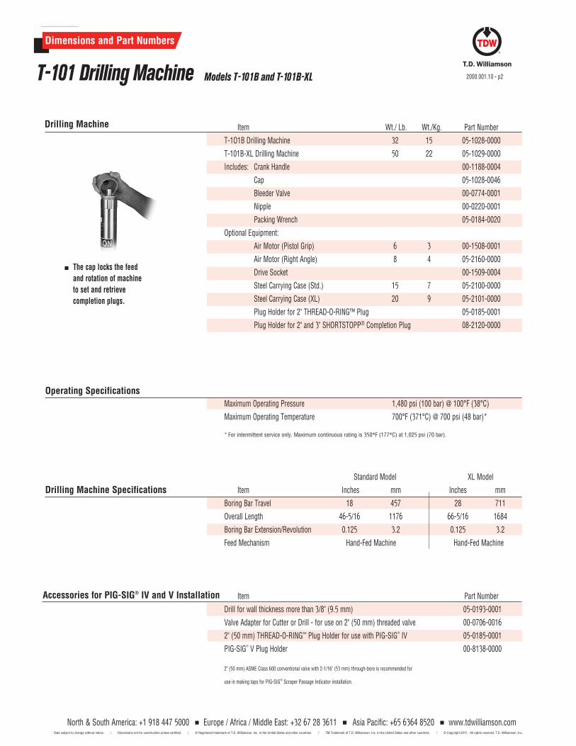
Item Wt./ Lb. Wt./Kg. Part Number
T-1O1B Drilling Machine 32 15 05-1028-0000
T-101B-XL Drilling Machine 50 22 05-1029-0000
Includes: Crank Handle 00-1188-0004
Cap 05-1028-0046
Bleeder Valve 00-0774-0001
Nipple 00-0220-0001
Packing Wrench 05-0184-0020
Optional Equipment:
Air Motor (Pistol Grip) 6 3 00-1508-0001
Air Motor (Right Angle) 8 4 05-2160-0000
Drive Socket 00-1509-0004
Steel Carrying Case (Std.) 15 7 05-2100-0000
Steel Carrying Case (XL) 20 9 05-2101-0000
Plug Holder for 2" THREAD-O-RING™ Plug 05-0185-0001
Plug Holder for 2" and 3" SHORTSTOPP® Completion Plug 08-2120-0000
Drilling Machine
Standard Model XL Model
Item Inches mm Inches mm
Boring Bar Travel 18 457 28 711
Overall Length 46-5/16 1176 66-5/16 1684
Boring Bar Extension/Revolution 0.125 3.2 0.125 3.2
Feed Mechanism Hand-Fed Machine Hand-Fed Machine
Drilling Machine Specifications
Item Part Number
Drill for wall thickness more than 3/8" (9.5 mm) 05-0193-0001
Valve Adapter for Cutter or Drill - for use on 2" (50 mm) threaded valve 00-0706-0016
2" (50 mm) THREAD-O-RING™ Plug Holder for use with PIG-SIG® IV 05-0185-0001
PIG-SIG® V Plug Holder 00-8138-0000
2" (50 mm) ASME CIass 600 conventional valve with 2-1/16" (53 mm) through-bore is recommended for
use in making taps for PIG-SIG® Scraper Passage Indicator installation.
Accessories for PIG-SIG® IV and V Installation
The cap locks the feed and rotation of machine to set and retrieve completion plugs.
Maximum Operating Pressure 1,480 psi (100 bar) @ 100°F (38°C)
Maximum Operating Temperature 700°F (371°C) @ 700 psi (48 bar)*
* For intermittent service only. Maximum continuous rating is 350°F (177°C) at 1,025 psi (70 bar).
Operating Specifications
Models T-101B and T-101B-XLT-101 Drilling Machine
Dimensions and Part Numbers
2000.001.10 - p2
North & South America: +1 918 447 5000 Europe / Africa / Middle East: +32 67 28 3611 Asia Pacific: +65 6364 8520 www.tdwilliamson.comData subject to change without notice. / Dimensions not for construction unless certified. / ® Registered trademark of T.D. Williamson, Inc. in the United States and other countries. / TM Trademark of T.D. Williamson, Inc. in the United States and other countries. / © Copyright 2015 All rights reserved. T.D. Williamson, Inc.
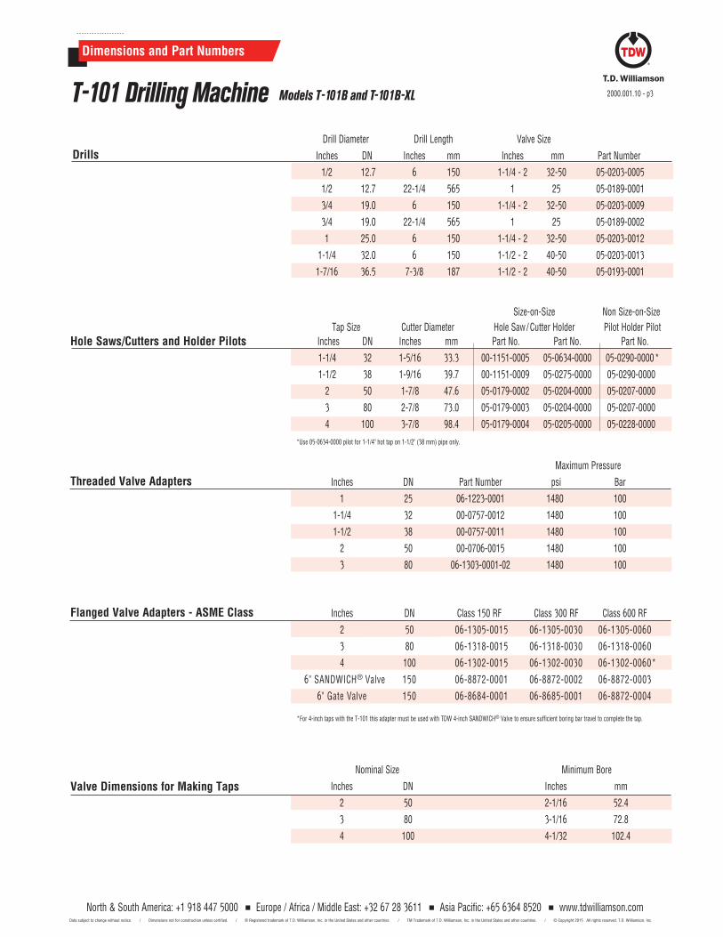
Drill Diameter Drill Length Valve Size
Inches DN Inches mm Inches mm Part Number
1/2 12.7 6 150 1-1/4 - 2 32-50 05-0203-0005
1/2 12.7 22-1/4 565 1 25 05-0189-0001
3/4 19.0 6 150 1-1/4 - 2 32-50 05-0203-0009
3/4 19.0 22-1/4 565 1 25 05-0189-0002
1 25.0 6 150 1-1/4 - 2 32-50 05-0203-0012
1-1/4 32.0 6 150 1-1/2 - 2 40-50 05-0203-0013
1-7/16 36.5 7-3/8 187 1-1/2 - 2 40-50 05-0193-0001
Maximum Pressure
Inches DN Part Number psi Bar
1 25 06-1223-0001 1480 100
1-1/4 32 00-0757-0012 1480 100
1-1/2 38 00-0757-0011 1480 100
2 50 00-0706-0015 1480 100
3 80 06-1303-0001-02 1480 100
Threaded Valve Adapters
Flanged Valve Adapters - ASME Class Inches DN Class 150 RF Class 300 RF Class 600 RF
2 50 06-1305-0015 06-1305-0030 06-1305-0060
3 80 06-1318-0015 06-1318-0030 06-1318-0060
4 100 06-1302-0015 06-1302-0030 06-1302-0060 *
6" SANDWICH® Valve 150 06-8872-0001 06-8872-0002 06-8872-0003
6" Gate Valve 150 06-8684-0001 06-8685-0001 06-8872-0004
*For 4-inch taps with the T-101 this adapter must be used with TDW 4-inch SANDWICH® Valve to ensure sufficient boring bar travel to complete the tap.
Drills
Valve Dimensions for Making Taps Nominal Size Minimum Bore
Inches DN Inches mm
2 50 2-1/16 52.4
3 80 3-1/16 72.8
4 100 4-1/32 102.4
Hole Saws/Cutters and Holder Pilots
Size-on-Size Non Size-on-Size
Tap Size Cutter Diameter Hole Saw/ Cutter Holder Pilot Holder Pilot Inches DN Inches mm Part No. Part No. Part No.
1-1/4 32 1-5/16 33.3 00-1151-0005 05-0634-0000 05-0290-0000 *
1-1/2 38 1-9/16 39.7 00-1151-0009 05-0275-0000 05-0290-0000
2 50 1-7/8 47.6 05-0179-0002 05-0204-0000 05-0207-0000
3 80 2-7/8 73.0 05-0179-0003 05-0204-0000 05-0207-0000
4 100 3-7/8 98.4 05-0179-0004 05-0205-0000 05-0228-0000
*Use 05-0634-0000 pilot for 1-1/4" hot tap on 1-1/2" (38 mm) pipe only.
Dimensions and Part Numbers
2000.001.10 - p3T-101 Drilling Machine
North & South America: +1 918 447 5000 Europe / Africa / Middle East: +32 67 28 3611 Asia Pacific: +65 6364 8520 www.tdwilliamson.comData subject to change without notice. / Dimensions not for construction unless certified. / ® Registered trademark of T.D. Williamson, Inc. in the United States and other countries. / TM Trademark of T.D. Williamson, Inc. in the United States and other countries. / © Copyright 2015 All rights reserved. T.D. Williamson, Inc.
Models T-101B and T-101B-XL

2000.001.10 - p4
North & South America: +1 918 447 5000 Europe / Africa / Middle East: +32 67 28 3611 Asia Pacific: +65 6364 8520 www.tdwilliamson.comData subject to change without notice. / Dimensions not for construction unless certified. / ® Registered trademark of T.D. Williamson, Inc. in the United States and other countries. / TM Trademark of T.D. Williamson, Inc. in the United States and other countries. / © Copyright 2015 All rights reserved. T.D. Williamson, Inc.
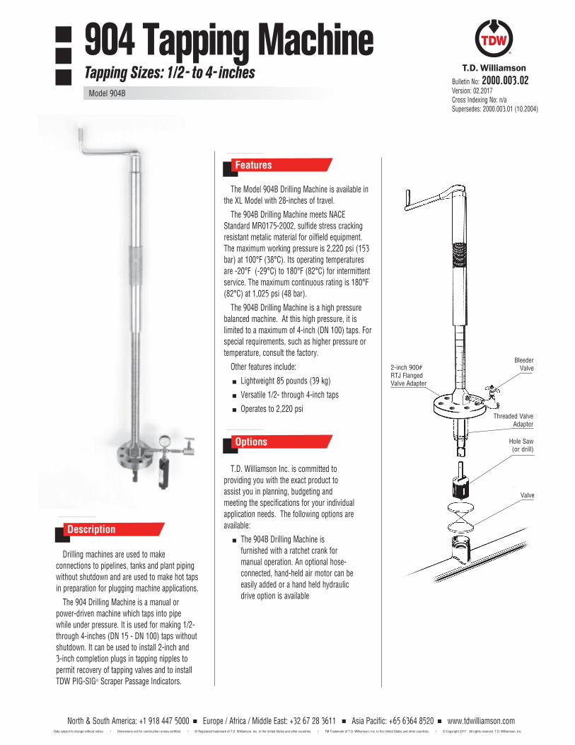
Features
The Model 904B Drilling Machine is available in the XL Model with 28-inches of travel.
The 904B Drilling Machine meets NACE Standard MR0175-2002, sulfide stress cracking resistant metalic material for oilfield equipment. The maximum working pressure is 2,220 psi (153 bar) at 100°F (38°C). Its operating temperatures are -20°F (-29°C) to 180°F (82°C) for intermittent service. The maximum continuous rating is 180°F (82°C) at 1,025 psi (48 bar).
The 904B Drilling Machine is a high pressure balanced machine. At this high pressure, it is limited to a maximum of 4-inch (DN 100) taps. For special requirements, such as higher pressure or temperature, consult the factory.
Other features include:
Lightweight 85 pounds (39 kg)
Versatile 1/2- through 4-inch taps
Operates to 2,220 psi
T.D. Williamson Inc. is committed to providing you with the exact product to assist you in planning, budgeting and meeting the specifications for your individual application needs. The following options are available:
The 904B Drilling Machine is furnished with a ratchet crank for manual operation. An optional hose- connected, hand-held air motor can be easily added or a hand held hydraulic drive option is available
Drilling machines are used to make connections to pipelines, tanks and plant piping without shutdown and are used to make hot taps in preparation for plugging machine applications.
The 904 Drilling Machine is a manual or power-driven machine which taps into pipe while under pressure. It is used for making 1/2- through 4-inches (DN 15 - DN 100) taps without shutdown. It can be used to install 2-inch and 3-inch completion plugs in tapping nipples to permit recovery of tapping valves and to install TDW PIG-SIG® Scraper Passage Indicators.
Bleeder Valve
Hole Saw (or drill)
Threaded Valve Adapter
Description
Valve
Options
Bulletin No: 2000.003.02Version: 02.2017Cross Indexing No: n/aSupersedes: 2000.003.01 (10.2004)
2-inch 900# RTJ Flanged Valve Adapter
904 Tapping MachineTapping Sizes: 1/2- to 4- inches
Model 904B
North & South America: +1 918 447 5000 Europe / Africa / Middle East: +32 67 28 3611 Asia Pacific: +65 6364 8520 www.tdwilliamson.comData subject to change without notice. / Dimensions not for construction unless certified. / ® Registered trademark of T.D. Williamson, Inc. in the United States and other countries. / TM Trademark of T.D. Williamson, Inc. in the United States and other countries. / © Copyright 2017 All rights reserved. T.D. Williamson, Inc.
Dimensions and Part Numbers
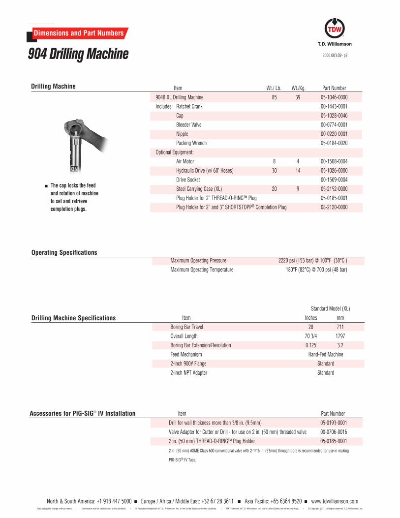
Item Wt./ Lb. Wt./Kg. Part Number
904B XL Drilling Machine 85 39 05-1046-0000
Includes: Ratchet Crank 00-1443-0001
Cap 05-1028-0046
Bleeder Valve 00-0774-0001
Nipple 00-0220-0001
Packing Wrench 05-0184-0020
Optional Equipment:
Air Motor 8 4 00-1508-0004
Hydraulic Drive (w/ 60’ Hoses) 30 14 05-1026-0000
Drive Socket 00-1509-0004
Steel Carrying Case (XL) 20 9 05-2152-0000
Plug Holder for 2” THREAD-O-RING™ Plug 05-0185-0001
Plug Holder for 2” and 3” SHORTSTOPP® Completion Plug 08-2120-0000
Drilling Machine
Standard Model (XL)
Item Inches mm
Boring Bar Travel 28 711
Overall Length 70 3/4 1797
Boring Bar Extension/Revolution 0.125 3.2
Feed Mechanism Hand-Fed Machine
2-inch 900# Flange Standard
2-inch NPT Adapter Standard
Drilling Machine Specifications
Item Part Number
Drill for wall thickness more than 3/8 in. (9.5mm) 05-0193-0001
Valve Adapter for Cutter or Drill - for use on 2 in. (50 mm) threaded valve 00-0706-0016
2 in. (50 mm) THREAD-O-RING™ Plug Holder 05-0185-0001
2 in. (50 mm) ASME CIass 600 conventional valve with 2-1/16 in. (53mm) through-bore is recommended for use in making
PIG-SIG® IV Taps.
Accessories for PIG-SIG® IV Installation
The cap locks the feed and rotation of machine to set and retrieve completion plugs.
Maximum Operating Pressure 2220 psi (153 bar) @ 100°F (38°C )
Maximum Operating Temperature 180°F (82°C) @ 700 psi (48 bar)
Operating Specifications
904 Drilling Machine 2000.003.02- p2
North & South America: +1 918 447 5000 Europe / Africa / Middle East: +32 67 28 3611 Asia Pacific: +65 6364 8520 www.tdwilliamson.comData subject to change without notice. / Dimensions not for construction unless certified. / ® Registered trademark of T.D. Williamson, Inc. in the United States and other countries. / TM Trademark of T.D. Williamson, Inc. in the United States and other countries. / © Copyright 2017 All rights reserved. T.D. Williamson, Inc.
Dimensions and Part Numbers
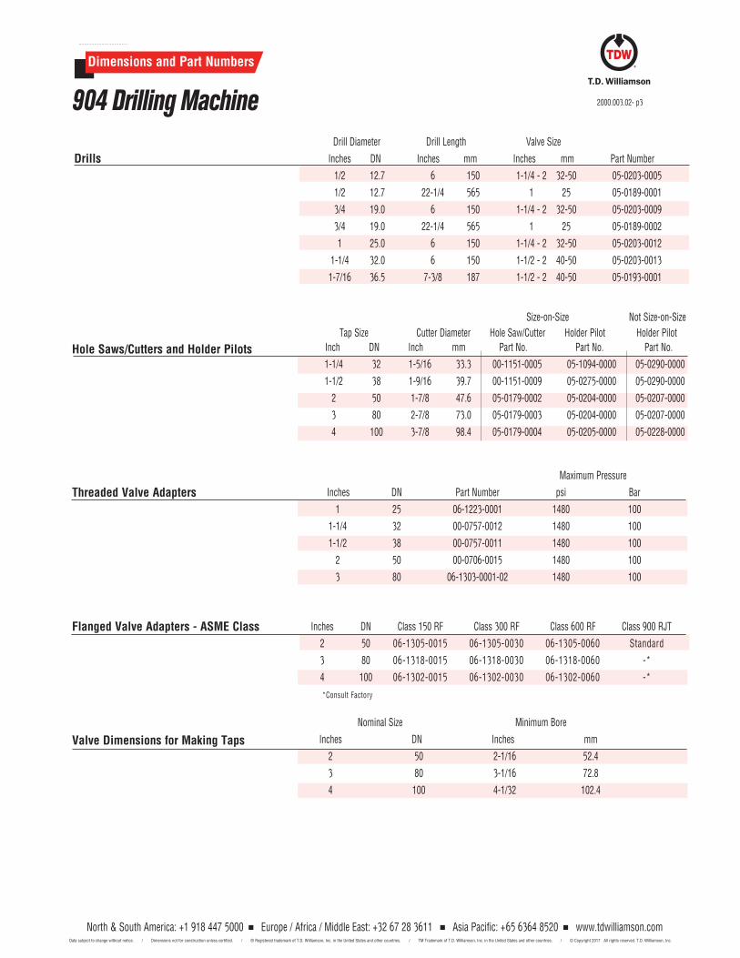
Drill Diameter Drill Length Valve Size
Inches DN Inches mm Inches mm Part Number
1/2 12.7 6 150 1-1/4 - 2 32-50 05-0203-0005
1/2 12.7 22-1/4 565 1 25 05-0189-0001
3/4 19.0 6 150 1-1/4 - 2 32-50 05-0203-0009
3/4 19.0 22-1/4 565 1 25 05-0189-0002
1 25.0 6 150 1-1/4 - 2 32-50 05-0203-0012
1-1/4 32.0 6 150 1-1/2 - 2 40-50 05-0203-0013
1-7/16 36.5 7-3/8 187 1-1/2 - 2 40-50 05-0193-0001
Maximum Pressure
Inches DN Part Number psi Bar
1 25 06-1223-0001 1480 100
1-1/4 32 00-0757-0012 1480 100
1-1/2 38 00-0757-0011 1480 100
2 50 00-0706-0015 1480 100
3 80 06-1303-0001-02 1480 100
Threaded Valve Adapters
Flanged Valve Adapters - ASME Class Inches DN Class 150 RF Class 300 RF Class 600 RF Class 900 RJT
2 50 06-1305-0015 06-1305-0030 06-1305-0060 Standard
3 80 06-1318-0015 06-1318-0030 06-1318-0060 -*
4 100 06-1302-0015 06-1302-0030 06-1302-0060 -*
*Consult Factory
Drills
Valve Dimensions for Making Taps
Nominal Size Minimum Bore
Inches DN Inches mm
2 50 2-1/16 52.4
3 80 3-1/16 72.8
4 100 4-1/32 102.4
904 Drilling Machine
Hole Saws/Cutters and Holder Pilots
Size-on-Size Not Size-on-Size Tap Size Cutter Diameter Hole Saw/Cutter Holder Pilot Holder Pilot Inch DN Inch mm Part No. Part No. Part No.
1-1/4 32 1-5/16 33.3 00-1151-0005 05-1094-0000 05-0290-0000
1-1/2 38 1-9/16 39.7 00-1151-0009 05-0275-0000 05-0290-0000
2 50 1-7/8 47.6 05-0179-0002 05-0204-0000 05-0207-0000
3 80 2-7/8 73.0 05-0179-0003 05-0204-0000 05-0207-0000
4 100 3-7/8 98.4 05-0179-0004 05-0205-0000 05-0228-0000
2000.003.02- p3
North & South America: +1 918 447 5000 Europe / Africa / Middle East: +32 67 28 3611 Asia Pacific: +65 6364 8520 www.tdwilliamson.comData subject to change without notice. / Dimensions not for construction unless certified. / ® Registered trademark of T.D. Williamson, Inc. in the United States and other countries. / TM Trademark of T.D. Williamson, Inc. in the United States and other countries. / © Copyright 2017 All rights reserved. T.D. Williamson, Inc.

2000.003.02- p4
North & South America: +1 918 447 5000 Europe / Africa / Middle East: +32 67 28 3611 Asia Pacific: +65 6364 8520 www.tdwilliamson.comData subject to change without notice. / Dimensions not for construction unless certified. / ® Registered trademark of T.D. Williamson, Inc. in the United States and other countries. / TM Trademark of T.D. Williamson, Inc. in the United States and other countries. / © Copyright 2017 All rights reserved. T.D. Williamson, Inc.
Bulletin No: 1000.004.08Version: 06.2018Cross Indexing No: n/aSupersedes: 1000.004.07 (12.2017)
360 Tapping MachineSizes: 2- to 6-inch
Model 360B
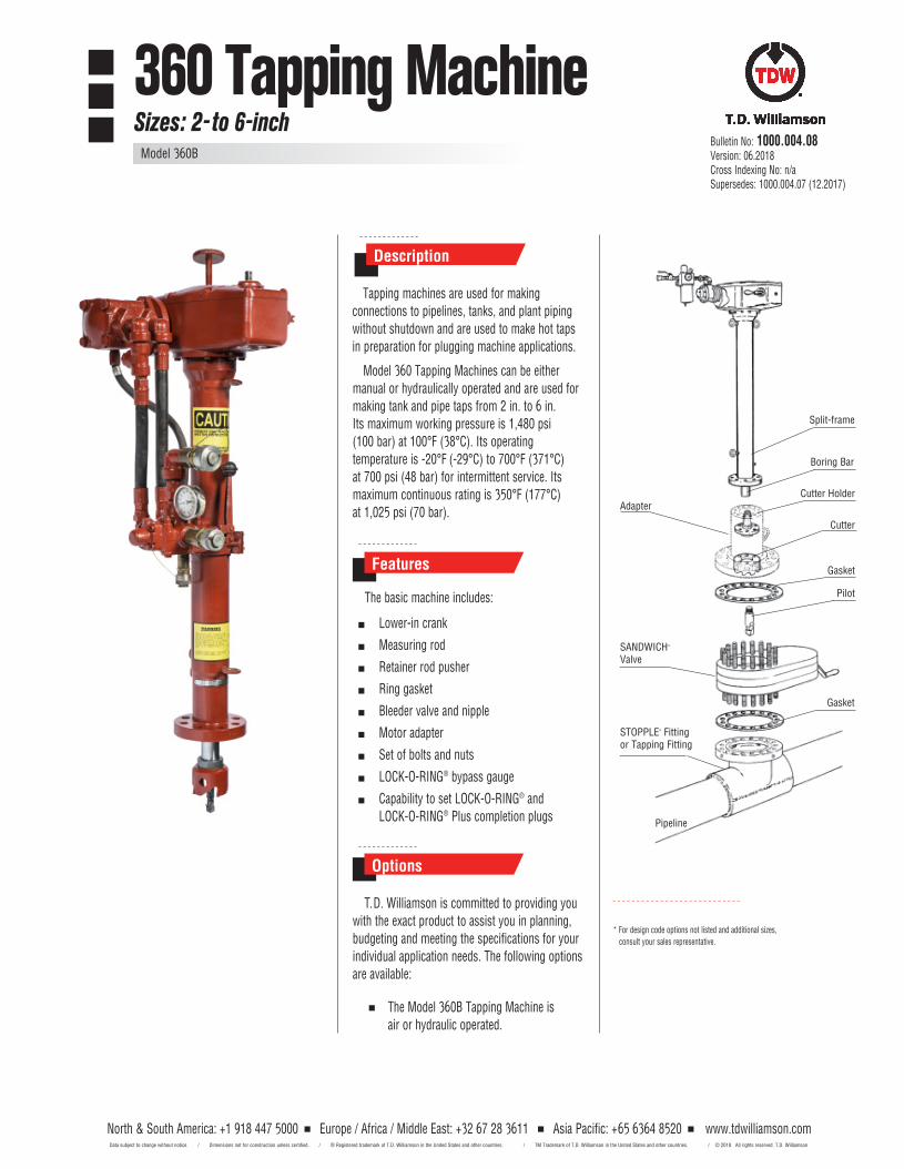
Boring Bar
AdapterCutter Holder
Cutter
Gasket
SANDWICH® Valve
Gasket
Pipeline
STOPPLE® Fitting or Tapping Fitting
Split-frame
Pilot
Features
Options
The basic machine includes:
Tapping machines are used for making connections to pipelines, tanks, and plant piping without shutdown and are used to make hot taps in preparation for plugging machine applications.
Description
T.D. Williamson is committed to providing youwith the exact product to assist you in planning, budgeting and meeting the specifications for your individual application needs. The following options are available:
The Model 360B Tapping Machine is air or hydraulic operated.
Model 360 Tapping Machines can be either manual or hydraulically operated and are used for making tank and pipe taps from 2 in. to 6 in. Its maximum working pressure is 1,480 psi (100 bar) at 100°F (38°C). Its operating temperature is -20°F (-29°C) to 700°F (371°C) at 700 psi (48 bar) for intermittent service. Its maximum continuous rating is 350°F (177°C) at 1,025 psi (70 bar).
* For design code options not listed and additional sizes, consult your sales representative.
North & South America: +1 918 447 5000 Europe / Africa / Middle East: +32 67 28 3611 Asia Pacific: +65 6364 8520 Data subject to change without notice. / Dimensions not for construction unless certified. / ® Registered trademark of T.D. Williamson in the United States and other countries. / TM Trademark of T.D. Williamson in the United States and other countries. /
www.tdwilliamson.com© 2018 All rights reserved. T.D. Williamson
Lower-in crank
Measuring rod
Retainer rod pusher
Ring gasket
Bleeder valve and nipple
Motor adapter
Set of bolts and nuts
LOCK-O-RING® bypass gauge
Capability to set LOCK-O-RING® and LOCK-O-RING® Plus completion plugs
Dimensions and Part Numbers
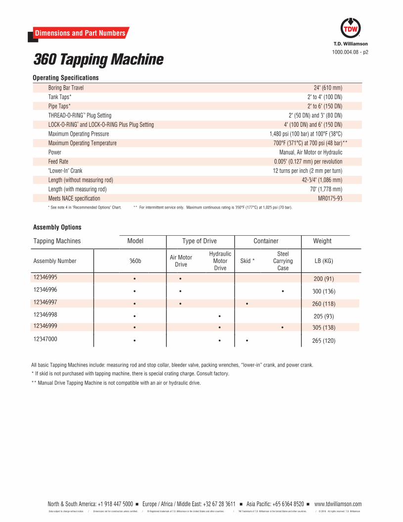
Boring Bar Travel 24" (610 mm)
Tank Taps* 2" to 4" (100 DN)
Pipe Taps* 2" to 6" (150 DN)
THREAD-O-RINGTM Plug Setting 2" (50 DN) and 3" (80 DN)
LOCK-O-RING®
and LOCK-O-RING Plus Plug Setting 4" (100 DN) and 6" (150 DN)
Maximum Operating Pressure 1,480 psi (100 bar) at 100°F (38°C)
Maximum Operating Temperature 700°F (371°C) at 700 psi (48 bar) **
Power Manual, Air Motor or Hydraulic
Feed Rate 0.005" (0.127 mm) per revolution
"Lower-In" Crank 12 turns per inch (2 mm per turn)
Length (without measuring rod) 42-3/4" (1,086 mm)
Length (with measuring rod) 70" (1,778 mm)
Meets NACE specification MR0175-93* See note 4 in "Recommended Options" Chart. ** For intermittent service only. Maximum continuous rating is 350°F (177°C) at 1,025 psi (70 bar).
Operating Specifications
360 Tapping Machine1000.004.08 - p2
Assembly Options
North & South America: +1 918 447 5000 Europe / Africa / Middle East: +32 67 28 3611 Asia Pacific: +65 6364 8520 Data subject to change without notice. / Dimensions not for construction unless certified. / ® Registered trademark of T.D. Williamson in the United States and other countries. / TM Trademark of T.D. Williamson in the United States and other countries. /
www.tdwilliamson.com© 2018 All rights reserved. T.D. Williamson
North & South America: +1 918 447 5000 Europe / Africa / Middle East: +32 67 28 3611 Asia Pacific: +65 6364 8520 www.tdwilliamson.comData subject to change without notice. / Dimensions not for construction unless certified. / ® Registered trademark of T.D. Williamson, Inc. in the United States and other countries. / TM Trademark of T.D. Williamson, Inc. in the United States and other countries. / © Copyright 2017 All rights reserved. T.D. Williamson, Inc.
Tapping Machines Type of Drive Container Weight
Assembly Number 360bAir Motor
Drive
Hydraulic Motor Drive
Skid *Steel
Carrying Case
LB (KG)
12346995 • • 200 (91)
12346996 • • • 300 (136)
12346997 • • • 260 (118)
12346998 • • 205 (93)
12346999 • • • 305 (138)
12347000 • • • 265 (120)
All basic Tapping Machines include: measuring rod and stop collar, bleeder valve, packing wrenches, “lower-in” crank, and power crank.
* If skid is not purchased with tapping machine, there is special crating charge. Consult factory.
** Manual Drive Tapping Machine is not compatible with an air or hydraulic drive.
Model
North & South America: +1 918 447 5000 Europe / Africa / Middle East: +32 67 28 3611 Asia Pacific: +65 6364 8520 www.tdwilliamson.comData subject to change without notice. / Dimensions not for construction unless certified. / ® Registered trademark of T.D. Williamson, Inc. in the United States and other countries. / TM Trademark of T.D. Williamson, Inc. in the United States and other countries. / © Copyright 2017 All rights reserved. T.D. Williamson, Inc.
Size Cutter Holder Plug Holders
Inches DN Lb. Kg. Part Number Lb. Kg. Part Number
2 50 -- -- -- 1/2 0.2 05-0061-0001
3 80 2 9 05-0053-0003 1-1/4 0.6 05-0073-0001
4 100 2 9 05-0053-0003 -- -- --
6 150 6-1/2 3 05-0053-0002* -- -- --
* Cutter holder extension (P/N 05-0071-0000) required for 6 in. (150 DN) ASME Class 600 taps
Dimensions and Part Numbers
Cutter Holders & Plug Holders
360 Tapping Machine
Adapters
Nominal Tap Size ASME Class 150 RF Flange ASME Class 300 RF Flange ASME Class 600 RF Flange 600# SANDWICH® & Ball Valves
Inches DN Part Number Lb. Kg. Part Number Lb. Kg. Part Number Lb. Kg. Part Number Lb. Kg.
1 25 06-0027-0001 18 8 06-0028-0001 17 8 06-0030-0001 20 9 -- -- --
1-1/4 32 06-0027-0002 19 9 06-0028-0002 20 9 06-0030-0002 22 10 -- -- --
1-1/2 40 06-0027-0003 19 9 06-0028-0003 22 10 06-0030-0003 23 10 -- -- --
2 50 06-0027-0004 16 7 06-0028-0004 18 8 06-0030-0004 20 9 -- -- --
3 80 06-0027-0005 21 10 06-0028-0005 24 11 06-0030-0005 27 12 -- -- --
4 100 06-6098-0004* 32 15 06-6099-0004 42 19 06-6101-0004** 35 16 06-6097-0004-01*** 53 24
6 150 06-6098-0006* 45 20 06-6099-0006 62 28 06-6101-0006** 100 45 06-6097-0006-01*** 110 50* Will also work on SHORTCUTT® Valves ** See special adapters for SANDWICH® & Ball valves. *** Compatible with LOCK-O-RING® and LOCK-O-RING® Plus Plugs
1000.004.08 - p3
North & South America: +1 918 447 5000 Europe / Africa / Middle East: +32 67 28 3611 Asia Pacific: +65 6364 8520 Data subject to change without notice. / Dimensions not for construction unless certified. / ® Registered trademark of T.D. Williamson in the United States and other countries. / TM Trademark of T.D. Williamson in the United States and other countries. /
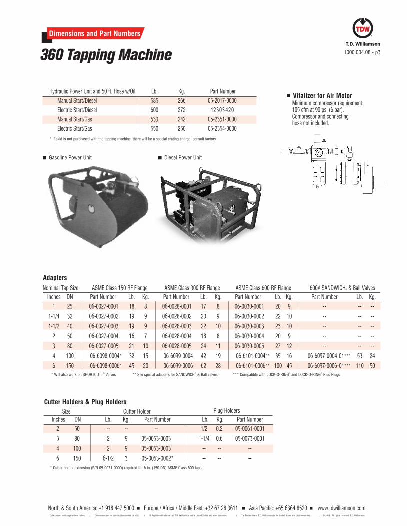
Vitalizer for Air MotorMinimum compressor requirement: 105 cfm at 90 psi (6 bar). Compressor and connecting
hose not included.
Hydraulic Power Unit and 50 ft. Hose w/Oil Lb. Kg. Part Number
Manual Start/Diesel 585 266 05-2017-0000
Electric Start/Diesel 600 272 12303 420
Manual Start/Gas 533 242 05-2351-0000
Electric Start/Gas 550 250 05-2354-0000
* If skid is not purchased with the tapping machine, there will be a special crating charge; consult factory
Gasoline Power Unit Diesel Power Unit
www.tdwilliamson.com© 2018 All rights reserved. T.D. Williamson
North & South America: +1 918 447 5000 Europe / Africa / Middle East: +32 67 28 3611 Asia Pacific: +65 6364 8520 Data subject to change without notice. / Dimensions not for construction unless certified. / ® Registered trademark of T.D. Williamson in the United States and other countries. / TM Trademark of T.D. Williamson in the United States and other countries. /
Dimensions and Part Numbers
360 Tapping Machine
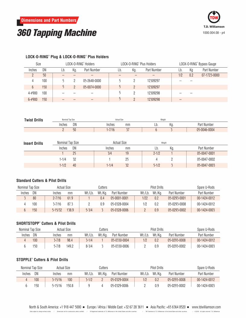
STOPPLE® Cutters & Pilot Drills
Nominal Tap Size Actual Size Cutters Pilot Drills Spare U-Rods
Inches DN Inches mm Wt./Lb. Wt./Kg. Part Number Wt./Lb. Wt./Kg. Part Number Part Number
4 100 3-15/16 100 3-1/2 2 05-0329-0004 1/2 0.2 05-0293-0008 00-1424-0012
6 150 5-15/16 150.8 9 4 05-0329-0006 2 0.9 05-0293-0002 00-1424-0003
1000.004.08 - p4
Nominal Tap Size Actual Size Cutters Pilot Drills Spare U-Rods
Inches DN Inches mm Wt./Lb. Wt./Kg. Part Number Wt./Lb. Wt./Kg. Part Number Part Number
3 80 2-7/16 61.9 1 0.4 05-0001-0001 1/22 0.2 05-0293-0001 00-1424-0012
4 100 3-7/16 87.3 2 0.9 05-0328-0004 1/2 0.2 05-0293-0008 00-1424-0012
6 150 5-15/32 138.9 5-3/4 3 05-0328-0006 2 0.9 05-0293-0002 00-1424-0003
SHORTSTOPP® Cutters & Pilot Drills
Standard Cutters & Pilot Drills
Nominal Tap Size Actual Size Cutters Pilot Drills Spare U-Rods
Inches DN Inches mm Wt./Lb. Wt./Kg. Part Number Wt./Lb. Wt./Kg. Part Number Part Number
4 100 3-7/8 98.4 3-1/4 1 05-0330-0004 1/2 0.2 05-0293-0008 00-1424-0012
6 150 5-7/8 149.2 8-3/4 3 05-0330-0006 2 0.9 05-0293-0002 00-1424-0003
North & South America: +1 918 447 5000 Europe / Africa / Middle East: +32 67 28 3611 Asia Pacific: +65 6364 8520 www.tdwilliamson.comData subject to change without notice. / Dimensions not for construction unless certified. / ® Registered trademark of T.D. Williamson, Inc. in the United States and other countries. / TM Trademark of T.D. Williamson, Inc. in the United States and other countries. / © Copyright 2017 All rights reserved. T.D. Williamson, Inc.
Nominal Tap Size Actual Size Weight
Inches DN Inches mm Lb. Kg. Part Number
2 50 1-7/16 37 6 3 05-0046-0004
Twist Drills
LOCK-O-RING® Plug & LOCK-O-RING® Plus Holders
Nominal Tap Size Actual Size Weight
Inches DN Inches mm Lb. Kg. Part Number
1 25 3/4 19 2-1/2 1 05-0047-0001
1-1/4 32 1 25 4 2 05-0047-0002
1-1/2 40 1-1/4 32 5-1/2 3 05-0047-0003
Insert Drills
Size LOCK-O-RING®
Holders LOCK-O-RING® Plus Holders LOCK-O-RING®
Bypass Gauge
Inches DN Lb. Kg. Part Number Lb. Kg. Part Number Lb. Kg Part Number
2 50 -- -- -- -- -- -- 1/2 0.2 07-1723-0000
4 100 5 2 05-2648-0000 5 2 12309297 -- --
6 150 5 2 05-0074-0000 5 2 12309297
4-#900 100 -- -- -- 5 2 12309298 -- --
6-#900 150 -- -- -- 5 2 12309298 --
www.tdwilliamson.com© 2018 All rights reserved. T.D. Williamson
North & South America: +1 918 447 5000 Europe / Africa / Middle East: +32 67 28 3611 Asia Pacific: +65 6364 8520 www.tdwilliamson.comData subject to change without notice. / Dimensions not for construction unless certified. / ® Registered trademark of T.D. Williamson, Inc. in the United States and other countries. / TM Trademark of T.D. Williamson, Inc. in the United States and other countries. / © Copyright 2017 All rights reserved. T.D. Williamson, Inc.
Dimensions and Part Numbers
360 Tapping Machine
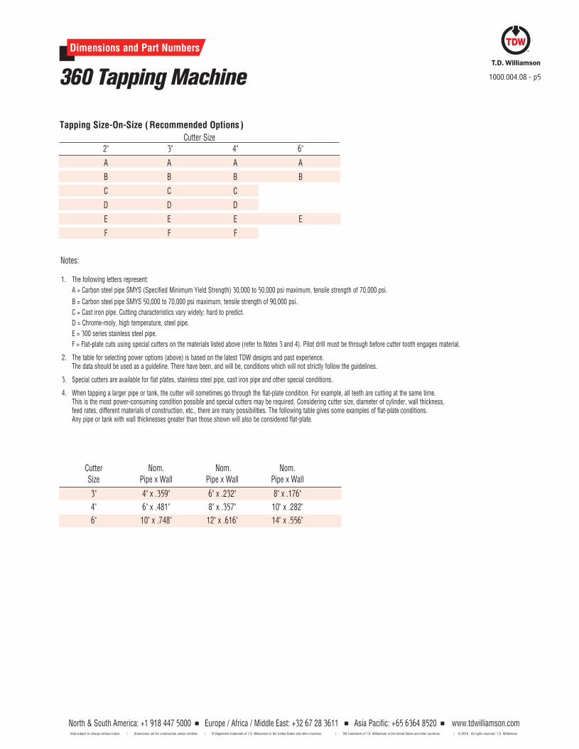
Tapping Size-On-Size ( Recommended Options )Cutter Size
2" 3" 4" 6"
A A A A
B B B B
C C C
D D D
E E E E
F F F
1000.004.08 - p5
Notes:
Cutter Nom. Nom. Nom. Size Pipe x Wall Pipe x Wall Pipe x Wall
3" 4" x .359" 6" x .232" 8" x .176"
4" 6" x .481" 8" x .357" 10" x .282"
6" 10" x .748" 12" x .616" 14" x .556"
1. The following letters represent:
A = Carbon steel pipe SMYS (Specified Minimum Yield Strength) 30,000 to 50,000 psi maximum, tensile strength of 70,000 psi.
B = Carbon steel pipe SMYS 50,000 to 70,000 psi maximum, tensile strength of 90,000 psi.
C = Cast iron pipe. Cutting characteristics vary widely; hard to predict.
D = Chrome-moly, high temperature, steel pipe.
E = 300 series stainless steel pipe.
F = Flat-plate cuts using special cutters on the materials listed above (refer to Notes 3 and 4). Pilot drill must be through before cutter tooth engages material.
2. The table for selecting power options (above) is based on the latest TDW designs and past experience. The data should be used as a guideline. There have been, and will be, conditions which will not strictly follow the guidelines.
3. Special cutters are available for flat plates, stainless steel pipe, cast iron pipe and other special conditions.
4. When tapping a larger pipe or tank, the cutter will sometimes go through the flat-plate condition. For example, all teeth are cutting at the same time. This is the most power-consuming condition possible and special cutters may be required. Considering cutter size, diameter of cylinder, wall thickness, feed rates, different materials of construction, etc., there are many possibilities. The following table gives some examples of flat-plate conditions. Any pipe or tank with wall thicknesses greater than those shown will also be considered flat-plate.
North & South America: +1 918 447 5000 Europe / Africa / Middle East: +32 67 28 3611 Asia Pacific: +65 6364 8520 Data subject to change without notice. / Dimensions not for construction unless certified. / ® Registered trademark of T.D. Williamson in the United States and other countries. / TM Trademark of T.D. Williamson in the United States and other countries. /
www.tdwilliamson.com© 2018 All rights reserved. T.D. Williamson
Dimensions and Part Numbers
360 Tapping Machine 1000.004.08 - p6
North & South America: +1 918 447 5000 Europe / Africa / Middle East: +32 67 28 3611 Asia Pacific: +65 6364 8520 Data subject to change without notice. / Dimensions not for construction unless certified. / ® Registered trademark of T.D. Williamson in the United States and other countries. / TM Trademark of T.D. Williamson in the United States and other countries. /
www.tdwilliamson.com© 2018 All rights reserved. T.D. Williamson
North & South America: +1 918 447 5000 Europe / Africa / Middle East: +32 67 28 3611 Asia Pacific: +65 6364 8520 www.tdwilliamson.comData subject to change without notice. / Dimensions not for construction unless certified. / ® Registered trademark of T.D. Williamson, Inc. in the United States and other countries. / TM Trademark of T.D. Williamson, Inc. in the United States and other countries. / © Copyright 2017 All rights reserved. T.D. Williamson, Inc.
* For design code options not listed and additional sizes, consult your sales representative.
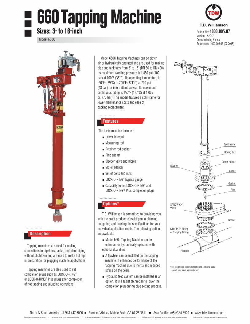
Tapping machines are used for making connections to pipelines, tanks, and plant piping without shutdown and are used to make hot taps in preparation for plugging machine applications.
Tapping machines are also used to set completion plugs such as LOCK-O-RING® or LOCK-O-RING® Plus plugs after completion of hot tapping and plugging operations.
Model 660C Tapping Machines can be either air or hydraulically operated and are used for making pipe and tank taps from 3" to 16" (DN 80 to DN 400). Its maximum working pressure is 1,480 psi (102 bar) at 100°F (38°C). Its operating temperature is -20°F (-29°C) to 700°F (371°C) at 700 psi(48 bar) for intermittent service. Its maximumcontinuous rating is 350°F (177°C) at 1,025psi (70 bar). This model features a split-frame forlower maintenance costs and ease ofpacking replacement.
The basic machine includes:
Lower-in crank
Measuring rod
Retainer rod pusher
Ring gasket
Bleeder valve and nipple
Motor adapter
Set of bolts and nuts
LOCK-O-RING® bypass gauge
Capability to set LOCK-O-RING® and LOCK-O-RING® Plus completion plugs
T.D. Williamson is committed to providing youwith the exact product to assist you in planning, budgeting and meeting the specifications for your individual application needs. The following options are available:
Model 660c Tapping Machine can be either air or hydraulically operated with
optional dual drive.
A flywheel can be installed on the tapping machine. It enhances performance of the tapping machine due to inertia and reduced stress on the gears.
Hydraulic feed system can be installed as an option. It will assist technician to lower the completion plug during plug setting process.
Description
Features
Options*
Boring Bar
AdapterCutter Holder
Cutter
Gasket
SANDWICH®
Valve
Gasket
Pipeline
STOPPLE® Fitting or Tapping Fitting
Split-frame
Pilot
Bulletin No: 1000.005.07Version:12.2017Cross Indexing No: n/aSupersedes: 1000.005.06 (07.2015)
660 Tapping MachineSizes: 3- to 16-inch
Model 660C
North & South America: +1 918 447 5000 Europe / Africa / Middle East: +32 67 28 3611 Asia Pacific: +65 6364 8520 www.tdwilliamson.comData subject to change without notice. / Dimensions not for construction unless certified. / ® Registered trademark of T.D. Williamson, Inc. in the United States and other countries. / TM Trademark of T.D. Williamson, Inc. in the United States and other countries. / © Copyright 2017 All rights reserved. T.D. Williamson, Inc.
Dimensions and Part Numbers
660 Tapping Machine Model 660C1000.005.08 - p2
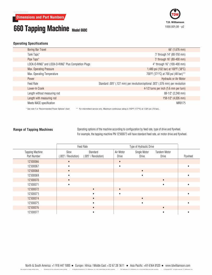
Operating Specifications
Boring Bar Travel 66" (1,676 mm)
Tank Taps* 3" through 14" (80-350 mm)
Pipe Taps* 3" through 16" (80-400 mm)
LOCK-O-RING® and LOCK-O-RING® Plus Completion Plugs 4” through 16” (100-400 mm)
Max. Operating Pressure 1,480 psi (102 bar) at 100°F (38°C)
Max. Operating Temperature 700°F (371°C) at 700 psi (48 bar)**
Power Hydraulic or Air Motor
Feed Rate Standard .005" (.127 mm) per revolution/optional .003" (.076 mm) per revolution
Lower-In Crank 4-1/2 turns per inch (5.6 mm per turn)
Length without measuring rod 88-1/2" (2,248 mm)
Length with measuring rod 158-1/2" (4,026 mm)
Meets NACE specification MR0175
* See note 5 in "Recommended Power Options" chart ** For intermittent service only. Maximum continuous rating is 350°F (177°C) at 1,025 psi (70 bar).
Range of Tapping Machines
Tapping Machine Slow Standard Air Motor Single Motor Tandem Motor Part Number (.003" / Revolution) (.005" / Revolution) Drive Drive Drive Flywheel
Feed Rate Type of Hydraulic Drive
Operating options of the machine according to configuration by feed rate, type of drive and flywheel.
For example, the tapping machine PN 12300073 will have standard feed rate, air motor drive and flywheel.
12300066 • •
12300067 • • •
12300068 • •
12300069 • • •
12300070 • •
12300071 • • •
12300072 • •
12300073 • • •
12300074 • •
12300075 • • •
12300076 • •
12300077 • • •
North & South America: +1 918 447 5000 Europe / Africa / Middle East: +32 67 28 3611 Asia Pacific: +65 6364 8520 www.tdwilliamson.comData subject to change without notice. / Dimensions not for construction unless certified. / ® Registered trademark of T.D. Williamson, Inc. in the United States and other countries. / TM Trademark of T.D. Williamson, Inc. in the United States and other countries. / © Copyright 2017 All rights reserved. T.D. Williamson, Inc.
Dimensions and Part Numbers
660 Tapping Machine Model 660C1000.005.08 - p3
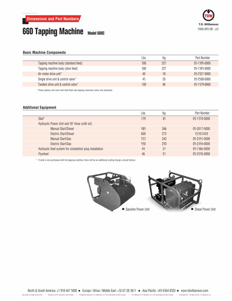
Basic Machine Components
Tapping machine body (standard feed) 500 227 05- 1395- 0000
Tapping machine body (slow feed) 500 227 05-1393-0000
Air motor drive unit* 40 18 05-2327-0000
Single drive unit & control valve* 45 20 05-2508-0000
Tandem drive unit & control valve* 100 46 05-1379-0000
* These options will work with both feed rate tapping machines (slow and standard).
Lbs. Kg. Part Number
Skid* 179 81 05-1370-0000
Hydraulic Power Unit and 50’ Hose (with oil)
Manual Start/Diesel 585 266 05- 2017-0000
Electric Start/Diesel 600 272 12303 420
Manual Start/Gas 533 242 05- 2351-0000
Electric Start/Gas 550 250 05-2354- 0000
Hydraulic feed system for completion plug installation 45 21 05-1366- 0000
Flywheel 46 21 05- 2376- 0000
* If skid is not purchased with the tapping machine, there will be an additional crating charge; consult factory.
Lbs. Kg. Part Number
Additional Equipment
Gasoline Power Unit Diesel Power Unit
North & South America: +1 918 447 5000 Europe / Africa / Middle East: +32 67 28 3611 Asia Pacific: +65 6364 8520 www.tdwilliamson.comData subject to change without notice. / Dimensions not for construction unless certified. / ® Registered trademark of T.D. Williamson, Inc. in the United States and other countries. / TM Trademark of T.D. Williamson, Inc. in the United States and other countries. / © Copyright 2017 All rights reserved. T.D. Williamson, Inc.
4-16 100-400 600 3.5 1.6 05-0075-0000
1000.005.08 - p4
Dimensions and Part Numbers
660 Tapping Machine Model 660C
Inches mm Lbs. Kg. Part Number
3 & 4 80 & 100 2.5 1 05-0054-0001
6-12 150-300 8 4 05-0054-0002
14-16 350-400 7 3 05-0054-0003
Cutter Holders
600 4.5 2 12308409
4-6 100-150
900 4.5 2 12308306
8-16 200-400 600 11 5 12309011
LOCK-O-RING® Plus Plugs
Completion Plug Holders
LOCK-O-RING® Plugs
Inches mm ASME Class Lbs. Kg. Part Number
ASME Class 150 RF Flange ASME Class 300 RF Flange ASME Class 600 RF Flange
Standard Adapters for Gate Valves
3 80 54 24 06-6102-0003 55 25 06-6103-0003 57 26 06-6105-0003
4 100 57 26 06-6102-0004 * 65 29 06-6103-0004 80 36 06-5091-0004
6 150 70 32 06-5088-0006 * 95 43 06-6103-0006 146 66 06-5091-0006
8 200 85 39 06-6102-0008 * 100 45 06-6103-0008 150 68 06-6105-0008
10 250 115 42 06-6102-0010 * 155 70 06-6103-0010 200 91 06-6105-0010
12 300 170 77 06-6102-0012 * 215 98 06-6103-0012 315 143 06-6105-0012
14 350 191 87 06-6102-0014 227 103 06-6103-0014 359 163 06-6105-0014
16** 400 300 136 06-6102-0016 350 160 06-6103-0016 460 210 06-6105-0016
* Will work on SHORTCUTT® Valves, Bulletin 2010.000.00 ** For tandem drive hydraulic model.
Inches mm Lbs. Kg. Part Number Lbs. Kg. Part Number Lbs. Kg. Part Number
ASME Class 150 RF Flange ASME Class 300 RF Flange ASME Class 600 RF Flange
Inches mm Lbs. Kg. Part Number Lbs. Kg. Part Number Lbs. Kg. Part Number
Adapters for SANDWICH®
Valves & Ball Valves (Compatible to set LOCK- O- RING® and LOCK- O- RING® Plus Completion Plugs )
4 100 65 29 26-3205-0415 7 34 26-3205-0430 85 39 26-3205-0460
6 150 80 36 26-3205- 0615 100 45 26-3205-0630 130 59 26- 3205-0660
8 200 100 45 26-3205-0815 125 57 26-3205-0830 170 77 26-3205-0860
10 250 170 77 26- 3205-1015 210 5 26-3205- 1030 285 129 26-3205-1060
12 300 250 113 26-3205-1215 300 136 26- 3205- 1230 375 170 26- 3205- 1260
14 350 285 129 26-3205-1415 350 159 26-3205-1430 425 193 26-3205-1460
16 400 400 181 26-3205-1615 490 222 26-3205-1630 610 277 26-3205-1666
North & South America: +1 918 447 5000 Europe / Africa / Middle East: +32 67 28 3611 Asia Pacific: +65 6364 8520 www.tdwilliamson.comData subject to change without notice. / Dimensions not for construction unless certified. / ® Registered trademark of T.D. Williamson, Inc. in the United States and other countries. / TM Trademark of T.D. Williamson, Inc. in the United States and other countries. / © Copyright 2017 All rights reserved. T.D. Williamson, Inc.
1000.005.08 - p5
Dimensions and Part Numbers
660 Tapping Machine Model 660C
Inches mm Inches mm Wt./Lbs. Wt./Kg. Part Number Wt./Lbs. Wt./Kg. Part Number Part Number
Nominal Tap Size Actual T–ap Size Cutters Pilot Drills Spare U-Rods
4 100 3-15/16 100 3-1/2 2 05-0329-0004 1/2 0.2 05-0293-0008 00-1424-0012
6 150 5-15/16 150.8 9 4 05-0329-0006 2 0.9 05-0293-0002 00-1424-0003
8 200 7-7/8 200 16 7 05-0329-0008 2 0.9 05-0293-0003 00-1424-0003
10 250 9-7/8 250.8 27 12 05-0329-0010 2 0.9 05-0293-0004 00-1424-0003
12 300 11-13/16 300.1 40-1/2 18 05-0388-0012 2-1/2 1 05-0293-0005 00-1424-0008
14 350 13-1/16 331.8 49 22 05-0388-0014 5-1/2 2.5 05-0293-0006 00-1424-0008
16 400 15-1/16 382.6 64 29 05-0388-0016 6 2.7 05-0293-0007 00-1424-0008
STOPPLE®
Cutters & Pilot Drills
Inches mm Inches mm Wt./Lbs. Wt./Kg. Part Number Wt./Lbs. Wt./Kg. Part Number Part Number
Nominal Tap Size Actual Tap Size Cutters Pilot Drills Spare U-RodsSHORTSTOPP
®
Cutters & Pilot Drills
4 100 3-7/8 98.4 3-1/4 1 05-0330-0004 1/2 0.2 05-0293-0008 00-1424-0012
6 150 5-7/8 149.2 8-3/4 3 05-0330-0006 2 0.9 05-0293-0002 00-1424-0003
8 200 7-3/4 196.9 20 9 05-0330-0008 2 0.9 05-0293-0003 00-1424-0003
10 250 9-3/4 247.7 23 10 05-0330-0010 2 0.9 05-0293-0004 00-1424-0003
12 300 11-3/4 298.5 40 18 05-0330-0012 2-1/2 1.0 05-0293-0005 00-1424-0003
3 80 2-7/16 67 1 0.5 05-0001-0001 1/2 0.2 05-0293-0001 00-1424-0012
4 100 3-7/16 87.3 2 0.9 05-0328-0004 1/2 0.2 05-0293-0008 00-1424-0012
6 150 5-15/32 138.9 5-3/4 3 05-0328-0006 2 0.9 05-0293-0002 00-1424-0003
8 200 7-5/16 185.8 14-1/2 7 05-0328-0008 2 0.9 05-0293-0003 00-1424-0003
10 250 9-1/2 241.3 22-1/2 10 05-0328-0010 2 0.9 05-0293-0004 00-1424-0003
12 300 11-1/2 292.1 36 16 05-0389-0012 2-1/2 1.0 05-0293-0005 00-1424-0008
14 350 12-3/4 323.9 42 19 05-0389-0014 5-1/2 2.5 05-0293-0006 00-1424-0008
16 400 14-11/16 373.1 61 28 05-0389-0016 6 2.7 05-0293-0007 00-1424-0008
Standard Cutters & Pilot Drills
Inches mm Inches mm Wt./Lbs. Wt./Kg. Part Number Wt./Lbs. Wt./Kg. Part Number Part Number
Nominal Tap Size Actual Tap Size Cutters Pilot Drills Spare U-Rods
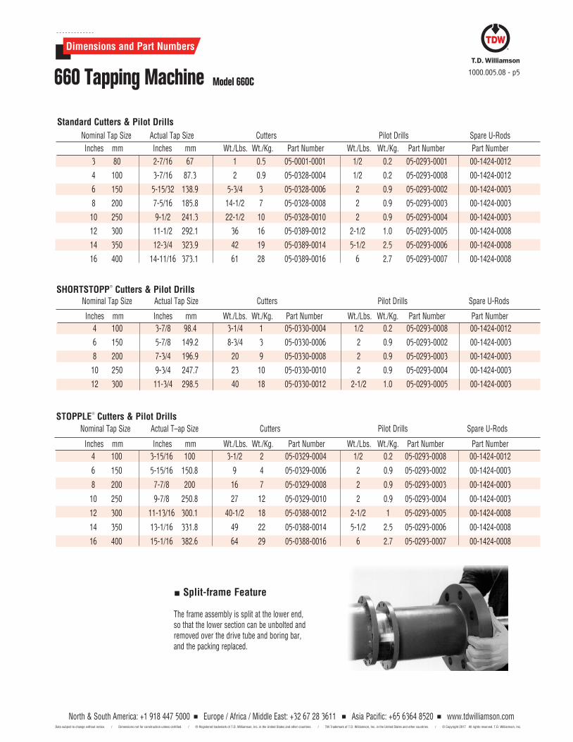
Split-frame Feature
The frame assembly is split at the lower end, so that the lower section can be unbolted and removed over the drive tube and boring bar, and the packing replaced.
North & South America: +1 918 447 5000 Europe / Africa / Middle East: +32 67 28 3611 Asia Pacific: +65 6364 8520 www.tdwilliamson.comData subject to change without notice. / Dimensions not for construction unless certified. / ® Registered trademark of T.D. Williamson, Inc. in the United States and other countries. / TM Trademark of T.D. Williamson, Inc. in the United States and other countries. / © Copyright 2017 All rights reserved. T.D. Williamson, Inc.
Dimensions and Part Numbers
660 Tapping Machine Model 660C1000.005.08 - p6
Cutter Nom. Nom. Nom. Size Pipe x Wall Pipe x Wall Pipe x Wall
3" 4" x .359" 6" x .232" 8" x .176"
4" 6" x .481" 8" x .357" 10" x .282"
6" 10" x .748" 12" x .616" 14" x .556"
8" 18" x .776" 20" x .692" 24" x .571"
Cutter Nom. Nom. Nom. Size Pipe x Wall Pipe x Wall Pipe x Wall
10" 24" x .980" 30" x .772" 48" x .475"
12" 36" x .943" 48" x .699" 60" x .556"
14" 48" x .862" 60" x .685" 72" x .569"
16" 56" x .980" 60" x .913" 72" x .757"
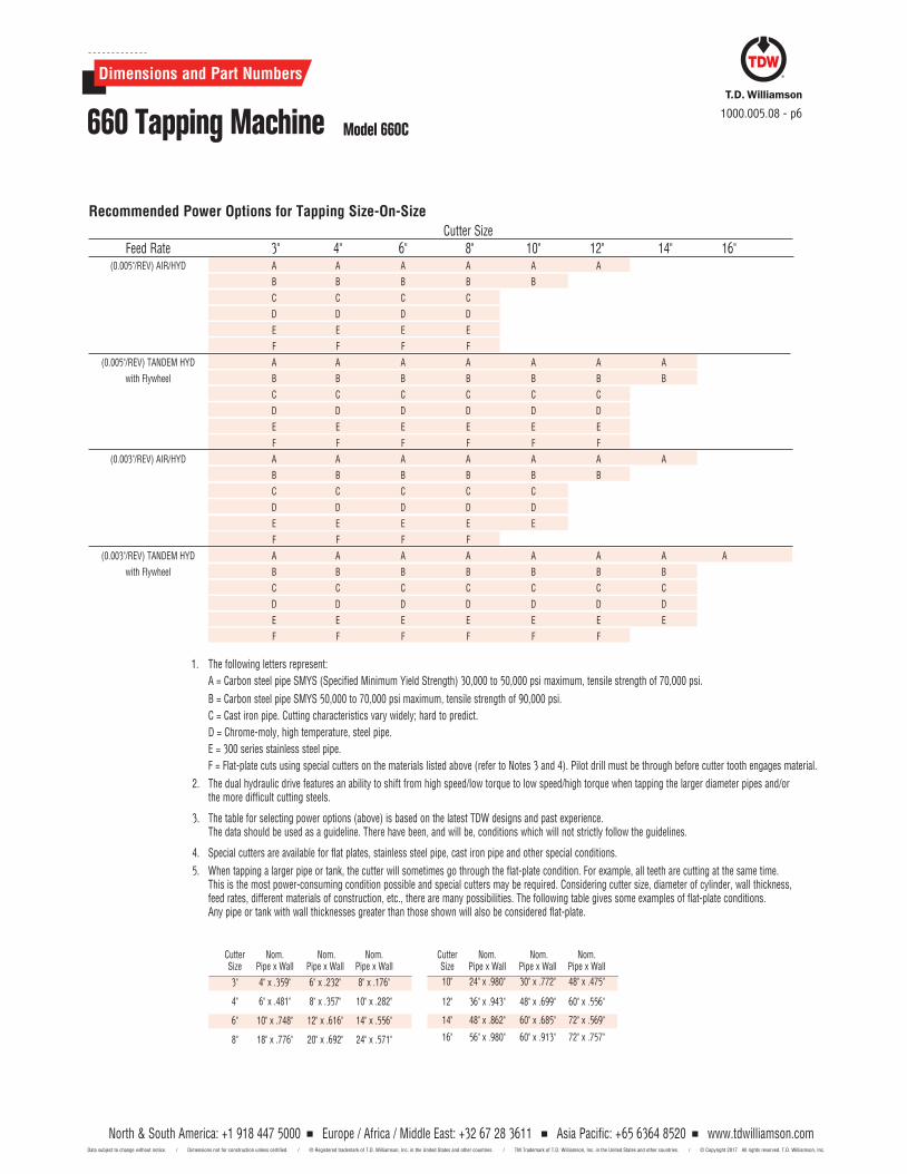
Recommended Power Options for Tapping Size-On-Size Cutter Size Feed Rate 3" 4" 6" 8" 10" 12" 14" 16" (0.005"/REV) AIR/HYD A A A A A A
B B B B B
C C C C
D D D D
E E E E
F F F F
(0.005"/REV) TANDEM HYD A A A A A A A
with Flywheel B B B B B B B
C C C C C C
D D D D D D
E E E E E E
F F F F F F
(0.003"/REV) AIR/HYD A A A A A A A
B B B B B B
C C C C C
D D D D D
E E E E E
F F F F
(0.003"/REV) TANDEM HYD A A A A A A A A
with Flywheel B B B B B B B
C C C C C C C
D D D D D D D
E E E E E E E
F F F F F F
1. The following letters represent:
A = Carbon steel pipe SMYS (Specified Minimum Yield Strength) 30,000 to 50,000 psi maximum, tensile strength of 70,000 psi.
B = Carbon steel pipe SMYS 50,000 to 70,000 psi maximum, tensile strength of 90,000 psi.
C = Cast iron pipe. Cutting characteristics vary widely; hard to predict.
D = Chrome-moly, high temperature, steel pipe.
E = 300 series stainless steel pipe.
F = Flat-plate cuts using special cutters on the materials listed above (refer to Notes 3 and 4). Pilot drill must be through before cutter tooth engages material.
2. The dual hydraulic drive features an ability to shift from high speed/low torque to low speed/high torque when tapping the larger diameter pipes and/or the more difficult cutting steels.
3. The table for selecting power options (above) is based on the latest TDW designs and past experience. The data should be used as a guideline. There have been, and will be, conditions which will not strictly follow the guidelines.
4. Special cutters are available for flat plates, stainless steel pipe, cast iron pipe and other special conditions.
5. When tapping a larger pipe or tank, the cutter will sometimes go through the flat-plate condition. For example, all teeth are cutting at the same time. This is the most power-consuming condition possible and special cutters may be required. Considering cutter size, diameter of cylinder, wall thickness, feed rates, different materials of construction, etc., there are many possibilities. The following table gives some examples of flat-plate conditions. Any pipe or tank with wall thicknesses greater than those shown will also be considered flat-plate.
North & South America: +1 918 447 5000 Europe / Africa / Middle East: +32 67 28 3611 Asia Pacific: +65 6364 8520 Data subject to change without notice. / Dimensions not for construction unless certified. / ® Registered trademark of T.D. Williamson, Inc. in the United States and other countries. / TM Trademark of T.D. Williamson, Inc. in the United States and other countries. /
www.tdwilliamson.com© Copyright 2017 All rights reserved. T.D. Williamson, Inc.
* For design code options not listed and additional sizes, consult your sales representative.
Patented in the United States and in foreign countries.
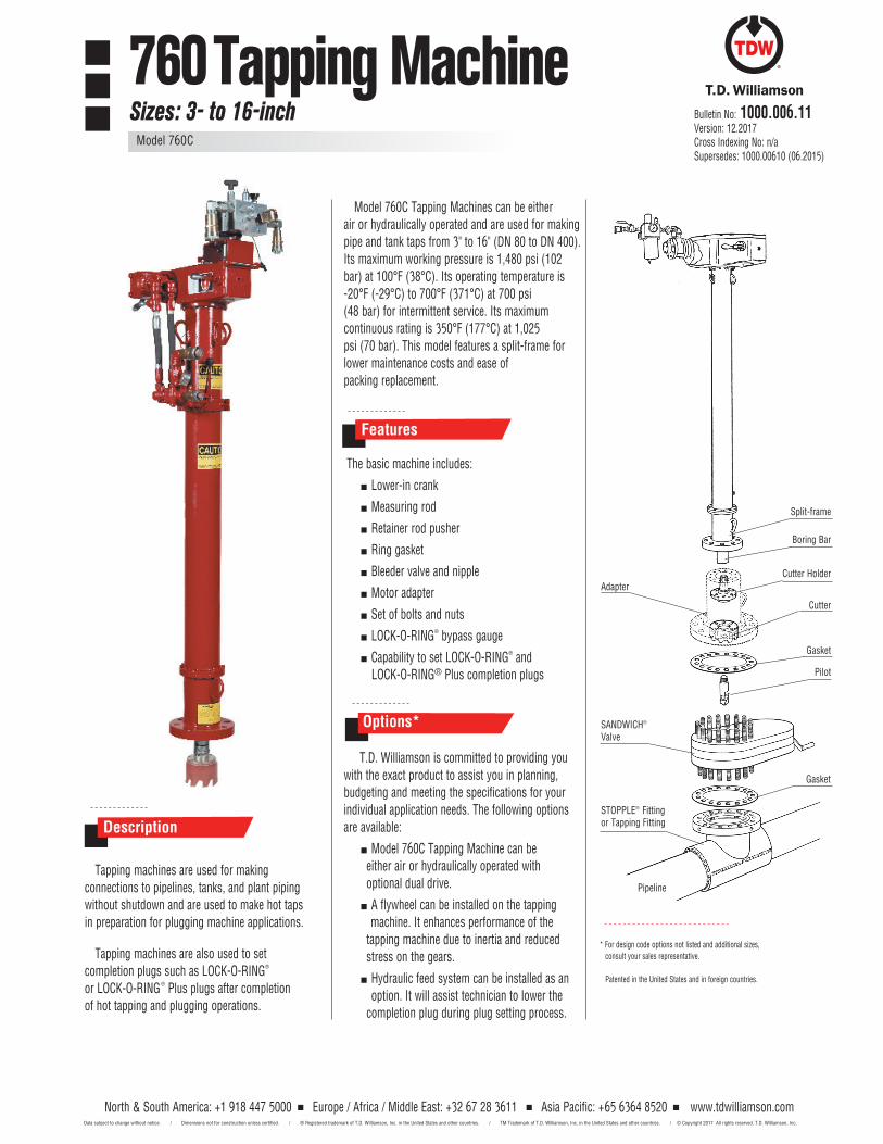
Tapping machines are used for making connections to pipelines, tanks, and plant piping without shutdown and are used to make hot taps in preparation for plugging machine applications.
Tapping machines are also used to set completion plugs such as LOCK-O-RING® or LOCK-O-RING® Plus plugs after completion of hot tapping and plugging operations.
Model 760C Tapping Machines can be either air or hydraulically operated and are used for making pipe and tank taps from 3" to 16" (DN 80 to DN 400). Its maximum working pressure is 1,480 psi (102 bar) at 100°F (38°C). Its operating temperature is -20°F (-29°C) to 700°F (371°C) at 700 psi(48 bar) for intermittent service. Its maximumcontinuous rating is 350°F (177°C) at 1,025psi (70 bar). This model features a split-frame forlower maintenance costs and ease ofpacking replacement.
The basic machine includes:
Lower-in crank
Measuring rod
Retainer rod pusher
Ring gasket
Bleeder valve and nipple
Motor adapter
Set of bolts and nuts
LOCK-O-RING® bypass gauge
Capability to set LOCK-O-RING® and LOCK-O-RING® Plus completion plugs
T.D. Williamson is committed to providing youwith the exact product to assist you in planning, budgeting and meeting the specifications for your individual application needs. The following options are available:
Model 760C Tapping Machine can be either air or hydraulically operated with optional dual drive.
A flywheel can be installed on the tapping machine. It enhances performance of the tapping machine due to inertia and reduced stress on the gears.
Hydraulic feed system can be installed as an option. It will assist technician to lower the completion plug during plug setting process.
Description
Features
Options*
Boring Bar
AdapterCutter Holder
Cutter
Gasket
SANDWICH®
Valve
Gasket
Pipeline
STOPPLE® Fitting or Tapping Fitting
Split-frame
Pilot
Bulletin No: 1000.006.11Version: 12.2017Cross Indexing No: n/aSupersedes: 1000.00610 (06.2015)
760 Tapping MachineSizes: 3- to 16-inch
Model 760C
North & South America: +1 918 447 5000 Europe / Africa / Middle East: +32 67 28 3611 Asia Pacific: +65 6364 8520 Data subject to change without notice. / Dimensions not for construction unless certified. / ® Registered trademark of T.D. Williamson, Inc. in the United States and other countries. / TM Trademark of T.D. Williamson, Inc. in the United States and other countries. /
www.tdwilliamson.com© Copyright 2017 All rights reserved. T.D. Williamson, Inc.
Dimensions and Part Numbers
1000.006.11 - p2760 Tapping Machine Model 760C
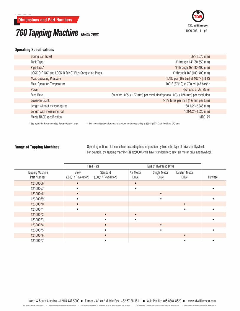
Operating Specifications
Boring Bar Travel 66" (1,676 mm)
Tank Taps* 3" through 14" (80-350 mm)
Pipe Taps* 3" through 16" (80-400 mm)
LOCK-O-RING® and LOCK-O-RING® Plus Completion Plugs 4” through 16” (100-400 mm)
Max. Operating Pressure 1,480 psi (102 bar) at 100°F (38°C)
Max. Operating Temperature 700°F (371°C) at 700 psi (48 bar)**
Power Hydraulic or Air Motor
Feed Rate Standard .005" (.127 mm) per revolution/optional .003" (.076 mm) per revolution
Lower-In Crank 4-1/2 turns per inch (5.6 mm per turn)
Length without measuring rod 88-1/2" (2,248 mm)
Length with measuring rod 158-1/2" (4,026 mm)
Meets NACE specification MR0175
* See note 5 in "Recommended Power Options" chart ** For intermittent service only. Maximum continuous rating is 350°F (177°C) at 1,025 psi (70 bar).
Range of Tapping Machines
Tapping Machine Slow Standard Air Motor Single Motor Tandem Motor Part Number (.003" / Revolution) (.005" / Revolution) Drive Drive Drive Flywheel
Feed Rate Type of Hydraulic Drive
Operating options of the machine according to configuration by feed rate, type of drive and flywheel.
For example, the tapping machine PN 12300073 will have standard feed rate, air motor drive and flywheel.
12300066 • •
12300067 • • •
12300068 • •
12300069 • • •
12300070 • •
12300071 • • •
12300072 • •
12300073 • • •
12300074 • •
12300075 • • •
12300076 • •
12300077 • • •

North & South America: +1 918 447 5000 Europe / Africa / Middle East: +32 67 28 3611 Asia Pacific: +65 6364 8520 Data subject to change without notice. / Dimensions not for construction unless certified. / ® Registered trademark of T.D. Williamson, Inc. in the United States and other countries. / TM Trademark of T.D. Williamson, Inc. in the United States and other countries. /
www.tdwilliamson.com© Copyright 2017 All rights reserved. T.D. Williamson, Inc.
Dimensions and Part Numbers
760 Tapping Machine Model 760C1000.006.11 - p3
Basic Machine Components
Tapping machine body (standard feed) 500 227 05- 1395- 0000
Tapping machine body (slow feed) 500 227 05-1393-0000
Air motor drive unit* 40 18 05-2327-0000
Single drive unit & control valve* 45 20 05-2508-0000
Tandem drive unit & control valve* 100 46 05-1379-0000
* These options will work with both feed rate tapping machines (slow and standard).
Lb. Kg. Part Number
Skid* 179 81 05-1387-0000
Hydraulic Power Unit and 50’ Hose (with oil)
Manual Start/Diesel 585 266 05- 2017-0000
Electric Start/Diesel 600 272 12303 420
Manual Start/Gas 533 242 05- 2351-0000
Electric Start/Gas 550 250 05-2354- 0000
Hydraulic feed system for completion plug installation 45 21 05-1366- 0000
Flywheel 46 21 05- 2376- 0000
* If skid is not purchased with the tapping machine, there will be an additional crating charge; consult factory.
Lb. Kg. Part Number
Additional Equipment
Gasoline Power Unit Diesel Power Unit
North & South America: +1 918 447 5000 Europe / Africa / Middle East: +32 67 28 3611 Asia Pacific: +65 6364 8520 Data subject to change without notice. / Dimensions not for construction unless certified. / ® Registered trademark of T.D. Williamson, Inc. in the United States and other countries. / TM Trademark of T.D. Williamson, Inc. in the United States and other countries. /
www.tdwilliamson.com© Copyright 2017 All rights reserved. T.D. Williamson, Inc.
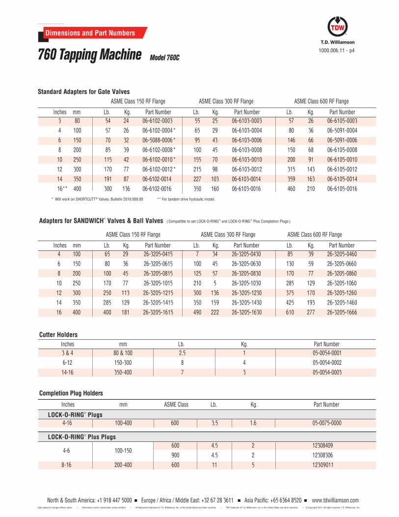
4-16 100-400 600 3.5 1.6 05-0075-0000
1000.006.11 - p4
Dimensions and Part Numbers
760 Tapping Machine Model 760C
Inches mm Lb. Kg. Part Number
3 & 4 80 & 100 2.5 1 05-0054-0001
6-12 150-300 8 4 05-0054-0002
14-16 350-400 7 3 05-0054-0003
Cutter Holders
600 4.5 2 123084094-6 100-150
900 4.5 2 12308306
8-16 200-400 600 11 5 12309011
LOCK-O-RING® Plus Plugs
Completion Plug Holders
LOCK-O-RING® Plugs
Inches mm ASME Class Lb. Kg. Part Number
ASME Class 150 RF Flange ASME Class 300 RF Flange ASME Class 600 RF Flange
Standard Adapters for Gate Valves
3 80 54 24 06-6102-0003 55 25 06-6103-0003 57 26 06-6105-0003
4 100 57 26 06-6102-0004* 65 29 06-6103-0004 80 36 06-5091-0004
6 150 70 32 06-5088-0006* 95 43 06-6103-0006 146 66 06-5091-0006
8 200 85 39 06-6102-0008 * 100 45 06-6103-0008 150 68 06-6105-0008
10 250 115 42 06-6102-0010* 155 70 06-6103-0010 200 91 06-6105-0010
12 300 170 77 06-6102-0012 * 215 98 06-6103-0012 315 143 06-6105-0012
14 350 191 87 06-6102-0014 227 103 06-6103-0014 359 163 06-6105-0014
16** 400 300 136 06-6102-0016 350 160 06-6103-0016 460 210 06-6105-0016
* Will work on SHORTCUTT® Valves, Bulletin 2010.000.00 ** For tandem drive hydraulic model.
Inches mm Lb. Kg. Part Number Lb. Kg. Part Number Lb. Kg. Part Number
ASME Class 150 RF Flange ASME Class 300 RF Flange ASME Class 600 RF Flange
Inches mm Lb. Kg. Part Number Lb. Kg. Part Number Lb. Kg. Part Number
Adapters for SANDWICH®
Valves & Ball Valves (Compatible to set LOCK- O- RING® and LOCK- O- RING® Plus Completion Plugs )
4 100 65 29 26-3205-0415 7 34 26-3205-0430 85 39 26-3205-0460
6 150 80 36 26-3205- 0615 100 45 26-3205-0630 130 59 26- 3205-0660
8 200 100 45 26-3205-0815 125 57 26-3205-0830 170 77 26-3205-0860
10 250 170 77 26- 3205-1015 210 5 26-3205- 1030 285 129 26-3205-1060
12 300 250 113 26-3205-1215 300 136 26- 3205- 1230 375 170 26- 3205- 1260
14 350 285 129 26-3205-1415 350 159 26-3205-1430 425 193 26-3205-1460
16 400 400 181 26-3205-1615 490 222 26-3205-1630 610 277 26-3205-1666
North & South America: +1 918 447 5000 Europe / Africa / Middle East: +32 67 28 3611 Asia Pacific: +65 6364 8520 Data subject to change without notice. / Dimensions not for construction unless certified. / ® Registered trademark of T.D. Williamson, Inc. in the United States and other countries. / TM Trademark of T.D. Williamson, Inc. in the United States and other countries. /
www.tdwilliamson.com© Copyright 2017 All rights reserved. T.D. Williamson, Inc.
1000.006.11 - p5
Dimensions and Part Numbers
760 Tapping Machine Model 760C
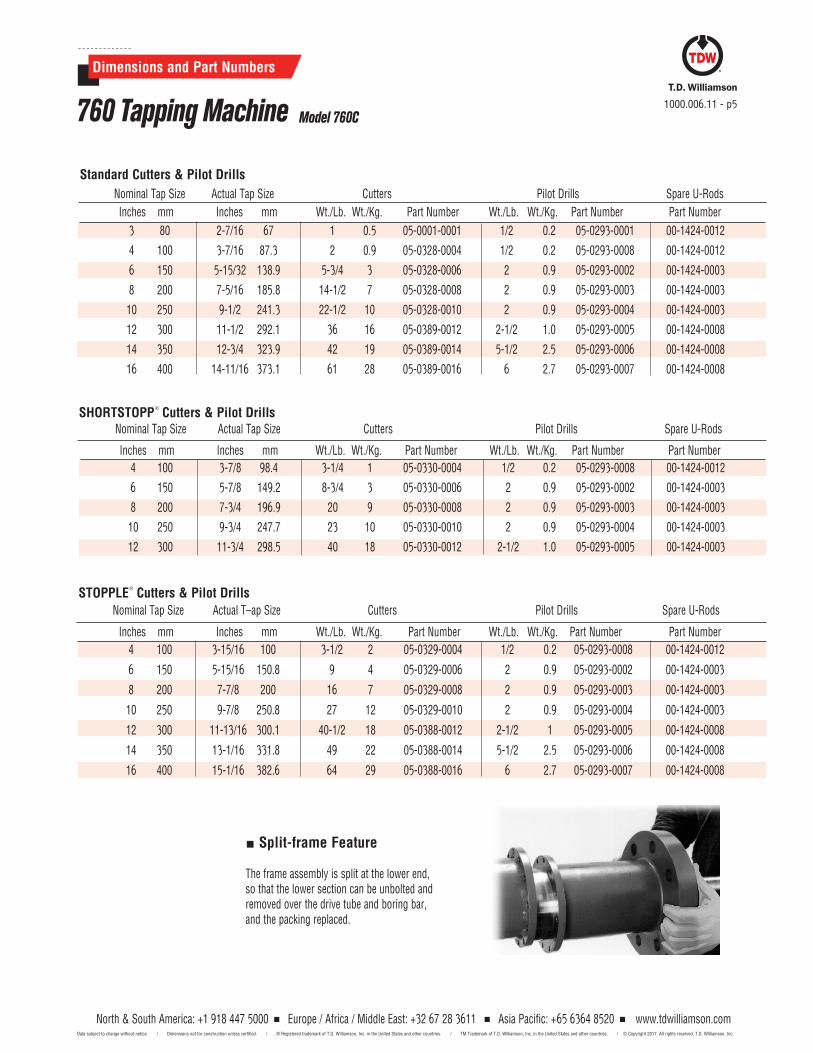
Inches mm Inches mm Wt./Lb. Wt./Kg. Part Number Wt./Lb. Wt./Kg. Part Number Part Number
Nominal Tap Size Actual T–ap Size Cutters Pilot Drills Spare U-Rods
4 100 3-15/16 100 3-1/2 2 05-0329-0004 1/2 0.2 05-0293-0008 00-1424-0012
6 150 5-15/16 150.8 9 4 05-0329-0006 2 0.9 05-0293-0002 00-1424-0003
8 200 7-7/8 200 16 7 05-0329-0008 2 0.9 05-0293-0003 00-1424-0003
10 250 9-7/8 250.8 27 12 05-0329-0010 2 0.9 05-0293-0004 00-1424-0003
12 300 11-13/16 300.1 40-1/2 18 05-0388-0012 2-1/2 1 05-0293-0005 00-1424-0008
14 350 13-1/16 331.8 49 22 05-0388-0014 5-1/2 2.5 05-0293-0006 00-1424-0008
16 400 15-1/16 382.6 64 29 05-0388-0016 6 2.7 05-0293-0007 00-1424-0008
STOPPLE®
Cutters & Pilot Drills
Inches mm Inches mm Wt./Lb. Wt./Kg. Part Number Wt./Lb. Wt./Kg. Part Number Part Number
Nominal Tap Size Actual Tap Size Cutters Pilot Drills Spare U-RodsSHORTSTOPP
®
Cutters & Pilot Drills
4 100 3-7/8 98.4 3-1/4 1 05-0330-0004 1/2 0.2 05-0293-0008 00-1424-0012
6 150 5-7/8 149.2 8-3/4 3 05-0330-0006 2 0.9 05-0293-0002 00-1424-0003
8 200 7-3/4 196.9 20 9 05-0330-0008 2 0.9 05-0293-0003 00-1424-0003
10 250 9-3/4 247.7 23 10 05-0330-0010 2 0.9 05-0293-0004 00-1424-0003
12 300 11-3/4 298.5 40 18 05-0330-0012 2-1/2 1.0 05-0293-0005 00-1424-0003
3 80 2-7/16 67 1 0.5 05-0001-0001 1/2 0.2 05-0293-0001 00-1424-0012
4 100 3-7/16 87.3 2 0.9 05-0328-0004 1/2 0.2 05-0293-0008 00-1424-0012
6 150 5-15/32 138.9 5-3/4 3 05-0328-0006 2 0.9 05-0293-0002 00-1424-0003
8 200 7-5/16 185.8 14-1/2 7 05-0328-0008 2 0.9 05-0293-0003 00-1424-0003
10 250 9-1/2 241.3 22-1/2 10 05-0328-0010 2 0.9 05-0293-0004 00-1424-0003
12 300 11-1/2 292.1 36 16 05-0389-0012 2-1/2 1.0 05-0293-0005 00-1424-0008
14 350 12-3/4 323.9 42 19 05-0389-0014 5-1/2 2.5 05-0293-0006 00-1424-0008
16 400 14-11/16 373.1 61 28 05-0389-0016 6 2.7 05-0293-0007 00-1424-0008
Standard Cutters & Pilot Drills
Inches mm Inches mm Wt./Lb. Wt./Kg. Part Number Wt./Lb. Wt./Kg. Part Number Part Number
Nominal Tap Size Actual Tap Size Cutters Pilot Drills Spare U-Rods
Split-frame Feature
The frame assembly is split at the lower end, so that the lower section can be unbolted and removed over the drive tube and boring bar, and the packing replaced.
North & South America: +1 918 447 5000 Europe / Africa / Middle East: +32 67 28 3611 Asia Pacific: +65 6364 8520 Data subject to change without notice. / Dimensions not for construction unless certified. / ® Registered trademark of T.D. Williamson, Inc. in the United States and other countries. / TM Trademark of T.D. Williamson, Inc. in the United States and other countries. /
www.tdwilliamson.com© Copyright 2017 All rights reserved. T.D. Williamson, Inc.
Dimensions and Part Numbers
760 Tapping Machine Model 760C1000.006.11 - p6
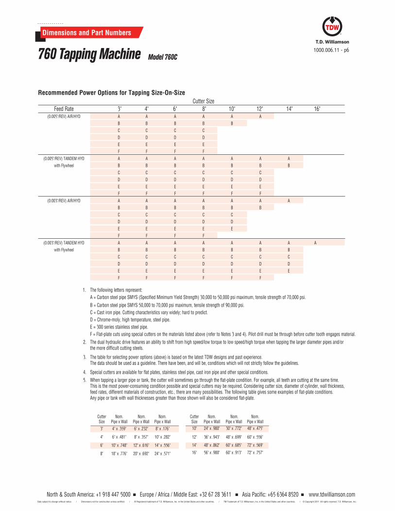
Cutter Nom. Nom. Nom. Size Pipe x Wall Pipe x Wall Pipe x Wall
3" 4" x .359" 6" x .232" 8" x .176"
4" 6" x .481" 8" x .357" 10" x .282"
6" 10" x .748" 12" x .616" 14" x .556"
8" 18" x .776" 20" x .692" 24" x .571"
Cutter Nom. Nom. Nom. Size Pipe x Wall Pipe x Wall Pipe x Wall
10" 24" x .980" 30" x .772" 48" x .475"
12" 36" x .943" 48" x .699" 60" x .556"
14" 48" x .862" 60" x .685" 72" x .569"
16" 56" x .980" 60" x .913" 72" x .757"
Recommended Power Options for Tapping Size-On-SizeCutter Size
Feed Rate 3" 4" 6" 8" 10" 12" 14" 16" (0.005"/REV) AIR/HYD A A A A A A
B B B B B
C C C C
D D D D
E E E E
F F F F
(0.005"/REV) TANDEM HYD A A A A A A A
with Flywheel B B B B B B B
C C C C C C
D D D D D D
E E E E E E
F F F F F F
(0.003"/REV) AIR/HYD A A A A A A A
B B B B B B
C C C C C
D D D D D
E E E E E
F F F F
(0.003"/REV) TANDEM HYD A A A A A A A A
with Flywheel B B B B B B B
C C C C C C C
D D D D D D D
E E E E E E E
F F F F F F
1. The following letters represent:
A = Carbon steel pipe SMYS (Specified Minimum Yield Strength) 30,000 to 50,000 psi maximum, tensile strength of 70,000 psi.
B = Carbon steel pipe SMYS 50,000 to 70,000 psi maximum, tensile strength of 90,000 psi.
C = Cast iron pipe. Cutting characteristics vary widely; hard to predict.
D = Chrome-moly, high temperature, steel pipe.
E = 300 series stainless steel pipe.
F = Flat-plate cuts using special cutters on the materials listed above (refer to Notes 3 and 4). Pilot drill must be through before cutter tooth engages material.
2. The dual hydraulic drive features an ability to shift from high speed/low torque to low speed/high torque when tapping the larger diameter pipes and/or the more difficult cutting steels.
3. The table for selecting power options (above) is based on the latest TDW designs and past experience. The data should be used as a guideline. There have been, and will be, conditions which will not strictly follow the guidelines.
4. Special cutters are available for flat plates, stainless steel pipe, cast iron pipe and other special conditions.
5. When tapping a larger pipe or tank, the cutter will sometimes go through the flat-plate condition. For example, all teeth are cutting at the same time. This is the most power-consuming condition possible and special cutters may be required. Considering cutter size, diameter of cylinder, wall thickness, feed rates, different materials of construction, etc., there are many possibilities. The following table gives some examples of flat-plate conditions. Any pipe or tank with wall thicknesses greater than those shown will also be considered flat-plate.
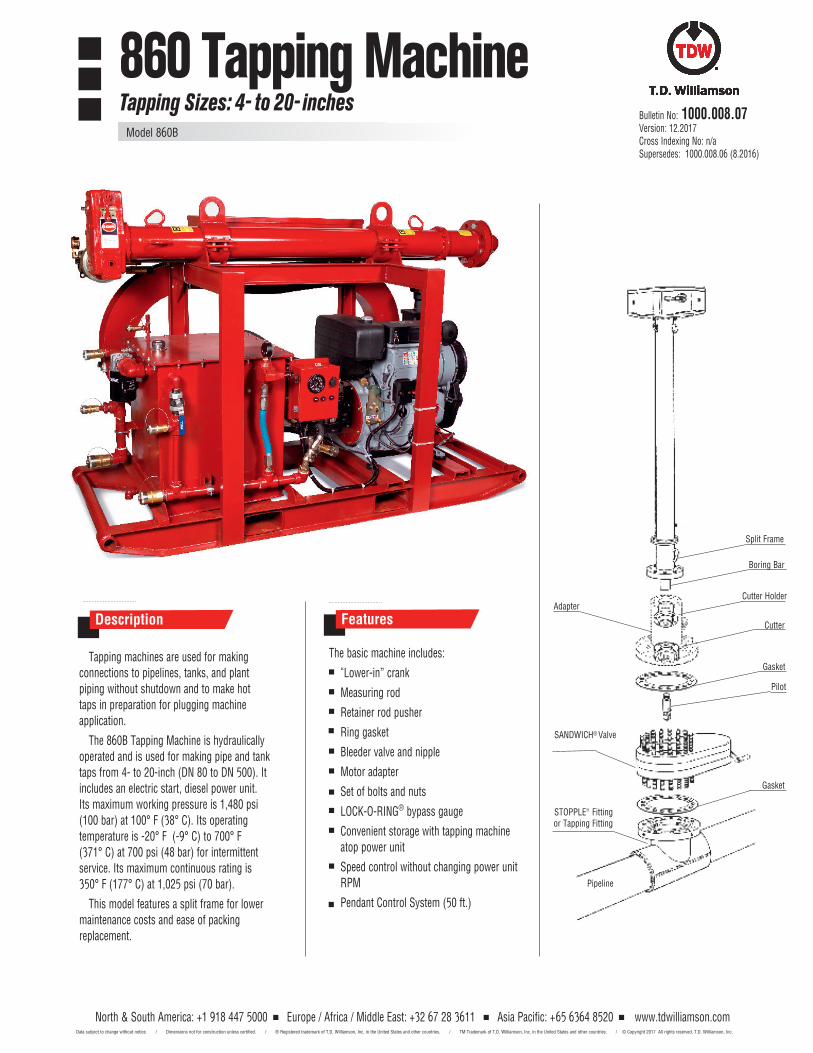
Description
Tapping machines are used for making connections to pipelines, tanks, and plant piping without shutdown and to make hot taps in preparation for plugging machine application.
The 860B Tapping Machine is hydraulically operated and is used for making pipe and tank taps from 4- to 20-inch (DN 80 to DN 500). It includes an electric start, diesel power unit. Its maximum working pressure is 1,480 psi (100 bar) at 100° F (38° C). Its operating temperature is -20° F (-9° C) to 700° F (371° C) at 700 psi (48 bar) for intermittent service. Its maximum continuous rating is 350° F (177° C) at 1,025 psi (70 bar).
This model features a split frame for lower maintenance costs and ease of packing replacement.
Adapter
SANDWICH® Valve
Pipeline
STOPPLE® Fitting or Tapping Fitting
Boring Bar
Cutter Holder
Cutter
Gasket
Gasket
Split Frame
Pilot
Bulletin No: 1000.008.07Version: 12.2017Cross Indexing No: n/aSupersedes: 1000.008.06 (8.2016)
The basic machine includes:
“Lower-in” crank
Measuring rod
Retainer rod pusher
Ring gasket
Bleeder valve and nipple
Motor adapter
Set of bolts and nuts
LOCK-O-RING® bypass gauge
Convenient storage with tapping machine atop power unit
Speed control without changing power unit RPM
Pendant Control System (50 ft.)
Features
860 Tapping MachineTapping Sizes: 4- to 20- inches
Model 860B
North & South America: +1 918 447 5000 Europe / Africa / Middle East: +32 67 28 3611 Asia Pacific: +65 6364 8520 Data subject to change without notice. / Dimensions not for construction unless certified. / ® Registered trademark of T.D. Williamson, Inc. in the United States and other countries. / TM Trademark of T.D. Williamson, Inc. in the United States and other countries. /
www.tdwilliamson.com© Copyright 2017 All rights reserved. T.D. Williamson, Inc.
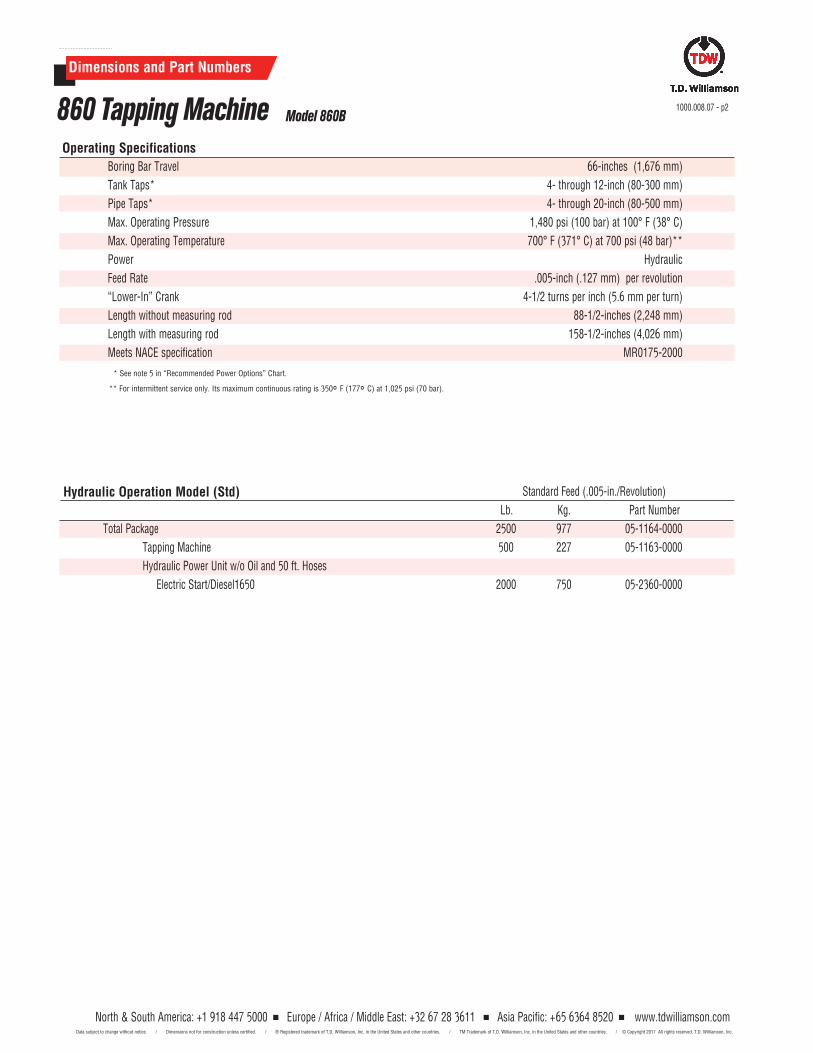
Dimensions and Part Numbers
Hydraulic Operation Model (Std)
Boring Bar Travel 66-inches (1,676 mm)
Tank Taps* 4- through 12-inch (80-300 mm)
Pipe Taps* 4- through 20-inch (80-500 mm)
Max. Operating Pressure 1,480 psi (100 bar) at 100° F (38° C)
Max. Operating Temperature 700° F (371° C) at 700 psi (48 bar)**
Power Hydraulic
Feed Rate .005-inch (.127 mm) per revolution
“Lower-In” Crank 4-1/2 turns per inch (5.6 mm per turn)
Length without measuring rod 88-1/2-inches (2,248 mm)
Length with measuring rod 158-1/2-inches (4,026 mm)
Meets NACE specification MR0175-2000
* See note 5 in “Recommended Power Options” Chart.
** For intermittent service only. Its maximum continuous rating is 350° F (177° C) at 1,025 psi (70 bar).
Standard Feed (.005-in./Revolution)
Lb. Kg. Part Number
Total Package 2500 977 05-1164-0000
Tapping Machine 500 227 05-1163-0000
Hydraulic Power Unit w/o Oil and 50 ft. Hoses
Electric Start/Diesel1650 2000 750 05-2360-0000
Operating Specifications
1000.008.07 - p2860 Tapping Machine Model 860B
North & South America: +1 918 447 5000 Europe / Africa / Middle East: +32 67 28 3611 Asia Pacific: +65 6364 8520 Data subject to change without notice. / Dimensions not for construction unless certified. / ® Registered trademark of T.D. Williamson, Inc. in the United States and other countries. / TM Trademark of T.D. Williamson, Inc. in the United States and other countries. /
www.tdwilliamson.com© Copyright 2017 All rights reserved. T.D. Williamson, Inc.
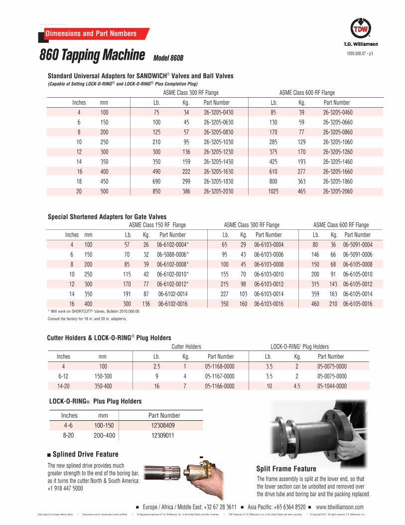
Dimensions and Part Numbers
Special Shortened Adapters for Gate ValvesASME Class 150 RF Flange ASME Class 300 RF Flange ASME Class 600 RF Flange
Inches mm Lb. Kg. Part Number Lb. Kg. Part Number Lb. Kg. Part Number
4 100 57 26 06-6102-0004* 65 29 06-6103-0004 80 36 06-5091-0004
6 150 70 32 06-5088-0006* 95 43 06-6103-0006 146 66 06-5091-0006
8 200 85 39 06-6102-0008* 100 45 06-6103-0008 150 68 06-6105-0008
10 250 115 42 06-6102-0010* 155 70 06-6103-0010 200 91 06-6105-0010
12 300 170 77 06-6102-0012* 215 98 06-6103-0012 315 143 06-6105-0012
14 350 191 87 06-6102-0014 227 103 06-6103-0014 359 163 06-6105-0014
16 400 300 136 06-6102-0016 350 160 06-6103-0016 460 210 06-6105-0016* Will work on SHORTCUTT® Valves, Bulletin 2010.000.00
Consult the factory for 18 in. and 20 in. adapterrs.
Standard Universal Adapters for SANDWICH® Valves and Ball Valves (Capable of Setting LOCK-O-RING® and LOCK-O-RING® Plus Completion Plug)
ASME Class 300 RF Flange ASME Class 600 RF Flange
Inches mm Lb. Kg. Part Number Lb. Kg. Part Number
4 100 75 34 26-3205-0430 85 39 26-3205-0460
6 150 100 45 26-3205-0630 130 59 26-3205-0660
8 200 125 57 26-3205-0830 170 77 26-3205-0860
10 250 210 95 26-3205-1030 285 129 26-3205-1060
12 300 300 136 26-3205-1230 375 170 26-3205-1260
14 350 350 159 26-3205-1430 425 193 26-3205-1460
16 400 490 222 26-3205-1630 610 277 26-3205-1660
18 450 690 299 26-3205-1830 800 363 26-3205-1860
20 500 850 386 26-3205-2030 1025 465 26-3205-2060
Cutter Holders LOCK-O-RING® Plug Holders
Inches mm Lb. Kg. Part Number Lb. Kg. Part Number
4 100 2.5 1 05-1168-0000 3.5 2 05-0075-0000
6-12 150-300 9 4 05-1167-0000 3.5 2 05-0075-0000
14-20 350-400 16 7 05-1166-0000 10 4.5 05-1044-0000
Cutter Holders & LOCK-O-RING® Plug Holders
Split Frame FeatureThe frame assembly is split at the lower end, so that the lower section can be unbolted and removed over the drive tube and boring bar and the packing replaced.
1000.008.07 - p3860 Tapping Machine Model 860B
Splined Drive Feature
The new splined drive provides much greater strength to the end of the boring bar, as it turns the cutter.North & South America: +1 918 447 5000
Europe / Africa / Middle East: +32 67 28 3611 Asia Pacific: +65 6364 8520 Data subject to change without notice. / Dimensions not for construction unless certified. / ® Registered trademark of T.D. Williamson, Inc. in the United States and other countries. / TM Trademark of T.D. Williamson, Inc. in the United States and other countries. /
www.tdwilliamson.com© Copyright 2017 All rights reserved. T.D. Williamson, Inc.
LOCK-O-RING® Plus Plug Holders
Inches mm Part Number
100-150 123084094-6
8-20 200-400 12309011
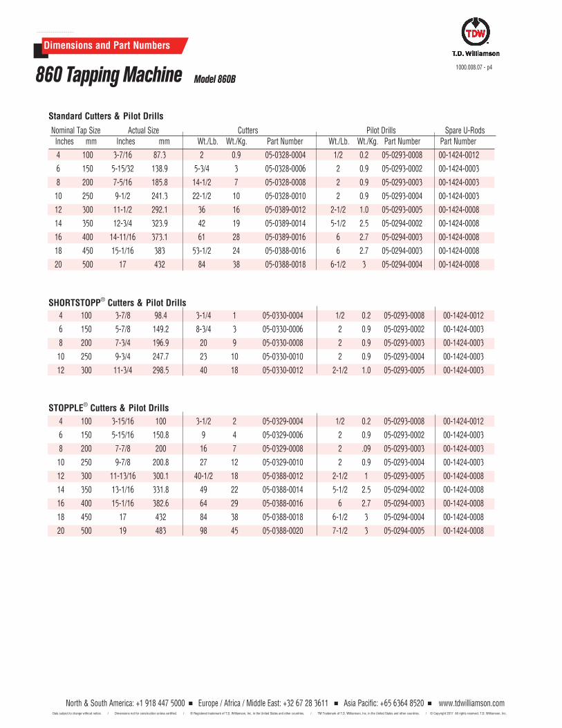
Dimensions and Part Numbers
Nominal Tap Size Actual Size Cutters Pilot Drills Spare U-RodsInches mm Inches mm Wt./Lb. Wt./Kg. Part Number Wt./Lb. Wt./Kg. Part Number Part Number
4 100 3-7/16 87.3 2 0.9 05-0328-0004 1/2 0.2 05-0293-0008 00-1424-0012
6 150 5-15/32 138.9 5-3/4 3 05-0328-0006 2 0.9 05-0293-0002 00-1424-0003
8 200 7-5/16 185.8 14-1/2 7 05-0328-0008 2 0.9 05-0293-0003 00-1424-0003
10 250 9-1/2 241.3 22-1/2 10 05-0328-0010 2 0.9 05-0293-0004 00-1424-0003
12 300 11-1/2 292.1 36 16 05-0389-0012 2-1/2 1.0 05-0293-0005 00-1424-0008
14 350 12-3/4 323.9 42 19 05-0389-0014 5-1/2 2.5 05-0294-0002 00-1424-0008
16 400 14-11/16 373.1 61 28 05-0389-0016 6 2.7 05-0294-0003 00-1424-0008
18 450 15-1/16 383 53-1/2 24 05-0388-0016 6 2.7 05-0294-0003 00-1424-0008
20 500 17 432 84 38 05-0388-0018 6-1/2 3 05-0294-0004 00-1424-0008
4 100 3-7/8 98.4 3-1/4 1 05-0330-0004 1/2 0.2 05-0293-0008 00-1424-0012
6 150 5-7/8 149.2 8-3/4 3 05-0330-0006 2 0.9 05-0293-0002 00-1424-0003
8 200 7-3/4 196.9 20 9 05-0330-0008 2 0.9 05-0293-0003 00-1424-0003
10 250 9-3/4 247.7 23 10 05-0330-0010 2 0.9 05-0293-0004 00-1424-0003
12 300 11-3/4 298.5 40 18 05-0330-0012 2-1/2 1.0 05-0293-0005 00-1424-0003
4 100 3-15/16 100 3-1/2 2 05-0329-0004 1/2 0.2 05-0293-0008 00-1424-0012
6 150 5-15/16 150.8 9 4 05-0329-0006 2 0.9 05-0293-0002 00-1424-0003
8 200 7-7/8 200 16 7 05-0329-0008 2 .09 05-0293-0003 00-1424-0003
10 250 9-7/8 200.8 27 12 05-0329-0010 2 0.9 05-0293-0004 00-1424-0003
12 300 11-13/16 300.1 40-1/2 18 05-0388-0012 2-1/2 1 05-0293-0005 00-1424-0008
14 350 13-1/16 331.8 49 22 05-0388-0014 5-1/2 2.5 05-0294-0002 00-1424-0008
16 400 15-1/16 382.6 64 29 05-0388-0016 6 2.7 05-0294-0003 00-1424-0008
18 450 17 432 84 38 05-0388-0018 6-1/2 3 05-0294-0004 00-1424-0008
20 500 19 483 98 45 05-0388-0020 7-1/2 3 05-0294-0005 00-1424-0008
STOPPLE® Cutters & Pilot Drills
SHORTSTOPP® Cutters & Pilot Drills
Standard Cutters & Pilot Drills
1000.008.07 - p4860 Tapping Machine Model 860B
North & South America: +1 918 447 5000 Europe / Africa / Middle East: +32 67 28 3611 Asia Pacific: +65 6364 8520 Data subject to change without notice. / Dimensions not for construction unless certified. / ® Registered trademark of T.D. Williamson, Inc. in the United States and other countries. / TM Trademark of T.D. Williamson, Inc. in the United States and other countries. /
www.tdwilliamson.com© Copyright 2017 All rights reserved. T.D. Williamson, Inc.
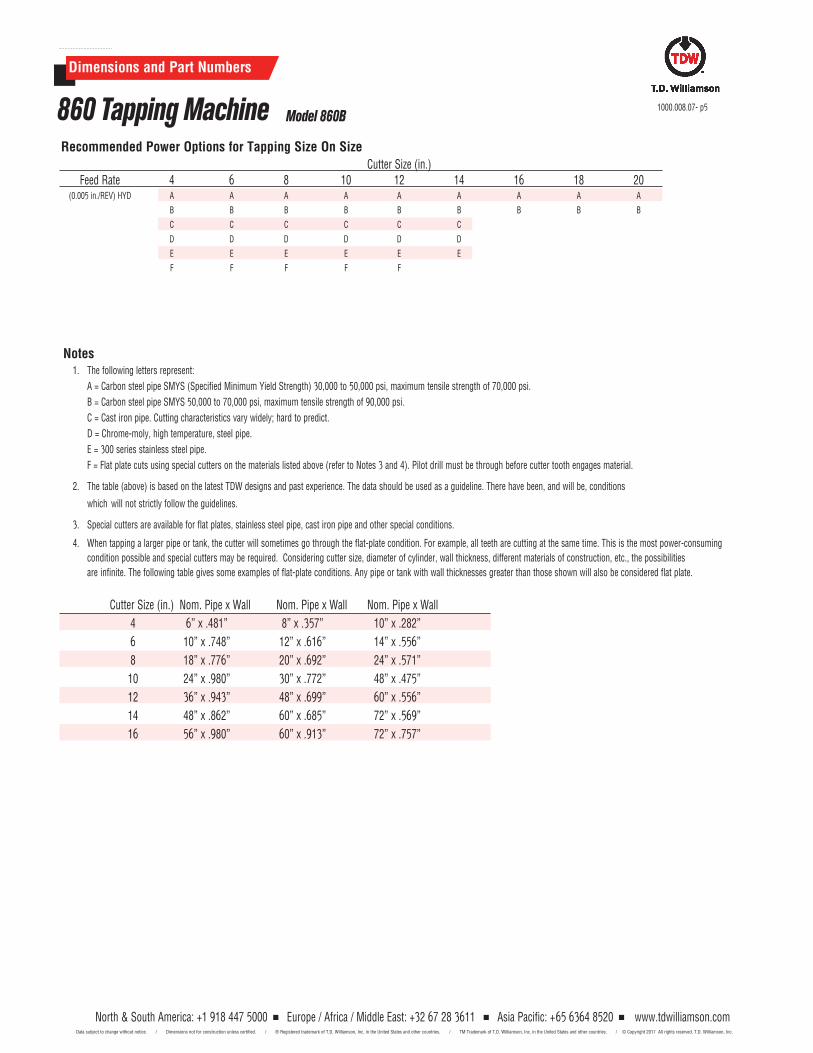
Dimensions and Part Numbers
Notes1. The following letters represent:
A = Carbon steel pipe SMYS (Specified Minimum Yield Strength) 30,000 to 50,000 psi, maximum tensile strength of 70,000 psi.
B = Carbon steel pipe SMYS 50,000 to 70,000 psi, maximum tensile strength of 90,000 psi.
C = Cast iron pipe. Cutting characteristics vary widely; hard to predict.
D = Chrome-moly, high temperature, steel pipe.
E = 300 series stainless steel pipe.
F = Flat plate cuts using special cutters on the materials listed above (refer to Notes 3 and 4). Pilot drill must be through before cutter tooth engages material.
2. The table (above) is based on the latest TDW designs and past experience. The data should be used as a guideline. There have been, and will be, conditions
which will not strictly follow the guidelines.
3. Special cutters are available for flat plates, stainless steel pipe, cast iron pipe and other special conditions.
4. When tapping a larger pipe or tank, the cutter will sometimes go through the flat-plate condition. For example, all teeth are cutting at the same time. This is the most power-consuming
condition possible and special cutters may be required. Considering cutter size, diameter of cylinder, wall thickness, different materials of construction, etc., the possibilities
are infinite. The following table gives some examples of flat-plate conditions. Any pipe or tank with wall thicknesses greater than those shown will also be considered flat plate.
Cutter Size (in.) Nom. Pipe x Wall Nom. Pipe x Wall Nom. Pipe x Wall
4 6” x .481” 8” x .357” 10” x .282”
6 10” x .748” 12” x .616” 14” x .556”
8 18” x .776” 20” x .692” 24” x .571”
10 24” x .980” 30” x .772” 48” x .475”
12 36” x .943” 48” x .699” 60” x .556”
14 48” x .862” 60” x .685” 72” x .569”
16 56” x .980” 60” x .913” 72” x .757”
1000.008.07- p5860 Tapping Machine Model 860B
Recommended Power Options for Tapping Size On SizeCutter Size (in.)
Feed Rate 4 6 8 10 12 14 16 18 20 (0.005 in./REV) HYD A A A A A A A A A
B B B B B B B B B
C C C C C C
D D D D D D
E E E E E E
F F F F F
North & South America: +1 918 447 5000 Europe / Africa / Middle East: +32 67 28 3611 Asia Pacific: +65 6364 8520 Data subject to change without notice. / Dimensions not for construction unless certified. / ® Registered trademark of T.D. Williamson, Inc. in the United States and other countries. / TM Trademark of T.D. Williamson, Inc. in the United States and other countries. /
www.tdwilliamson.com© Copyright 2017 All rights reserved. T.D. Williamson, Inc.

1000.008.07 - p6
North & South America: +1 918 447 5000 Europe / Africa / Middle East: +32 67 28 3611 Asia Pacific: +65 6364 8520 Data subject to change without notice. / Dimensions not for construction unless certified. / ® Registered trademark of T.D. Williamson, Inc. in the United States and other countries. / TM Trademark of T.D. Williamson, Inc. in the United States and other countries. /
www.tdwilliamson.com© Copyright 2017 All rights reserved. T.D. Williamson, Inc.
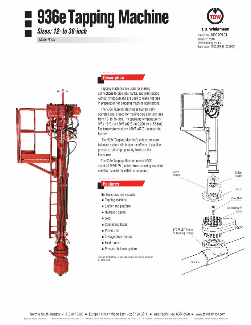
North & South America: +1 918 447 5000 Europe / Africa / Middle East: +32 67 28 3611 Asia Pacific: +65 6364 8520 www.tdwilliamson.comData subject to change without notice. / Dimensions not for construction unless certified. / ® Registered trademark of T.D. Williamson, Inc. in the United States and other countries. / TM Trademark of T.D. Williamson, Inc. in the United States and other countries. / © Copyright 2015 All rights reserved. T.D. Williamson, Inc.
Description
Features
Tapping machines are used for making connections to pipelines, tanks, and plant piping without shutdown and are used to make hot taps in preparation for plugging machine applications.
The 936e Tapping Machine is hydraulically operated and is used for making pipe and tank taps from 12- to 36-inch. Its operating temperature is 0°F (-18°C) to 180°F (82°C) at 2,220 psi (153 bar). For temperatures above 180°F (82°C), consult the factory.
The 936e Tapping Machine’s unique pressure balanced system eliminates the effects of pipeline pressure, reducing operating loads on the feedscrew.
The 936e Tapping Machine meets NACE standard MR0175 (sulfide stress cracking resistant metallic material for oilfield equipment). Valve
Adapter
STOPPLE® Fitting
or Tapping Fitting
SANDWICH® Valve
Pilot Drill
Cutter
CutterHolder
Pipeline
Bulletin No: 1000.009.04 Version:01/2018Cross Indexing No: n/a Supersedes: 1000.009.03 (09.2015)
The basic machine includes:
Tapping machine
Ladder and platform
Hydraulic piping
Skid
Connecting hoses
Power unit
2-Stage drive motors
Feed motor
Pressure-balance system
Consult the factory for special cutters and pilots required for tank taps.
936e Tapping MachineSizes: 12- to 36-inch
Model 936E
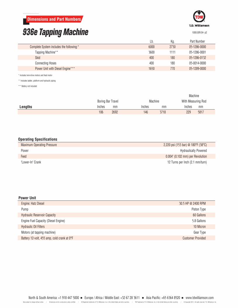
North & South America: +1 918 447 5000 Europe / Africa / Middle East: +32 67 28 3611 Asia Pacific: +65 6364 8520 www.tdwilliamson.comData subject to change without notice. / Dimensions not for construction unless certified. / ® Registered trademark of T.D. Williamson, Inc. in the United States and other countries. / TM Trademark of T.D. Williamson, Inc. in the United States and other countries. / © Copyright 2015 All rights reserved. T.D. Williamson, Inc.
Lb. Kg. Part Number
Complete System includes the following:* 6000 2730 05-1286-0000
Tapping Machine** 3600 1111 05-1286-0001
Skid 400 180 05-1286-0132
Connecting Hoses 400 180 05-0014-0000
Power Unit with Diesel Engine*** 1650 770 05-1289-0000
* Includes twin-drive motors and feed motor
** Includes ladder, platform and hydraulic piping
*** Battery not included
Machine
Boring Bar Travel Machine With Measuring Rod
Inches mm Inches mm Inches mm
106 2692 146 3718 229 5817
Operating Specifications
Maximum Operating Pressure 2,220 psi (153 bar) @ 180°F (38°C)
Power Hydraulically Powered
Feed 0.004" (0.102 mm) per Revolution
"Lower-In" Crank 12 Turns per Inch (2.1 mm/turn)
Power Unit
Engine: Hatz Diesel 30.5 HP @ 2400 RPM
Pump Piston Type
Hydraulic Reservoir Capacity 60 Gallons
Engine Fuel Capacity (Diesel Engine) 5.8 Gallons
Hydraulic Oil Filters 10 Micron
Motors (at tapping machine) Gear Type
Battery 12-volt, 455 amp, cold crank at 0°F Customer Provided
Lengths
1000.009.04- p2
Dimensions and Part Numbers
936e Tapping Machine
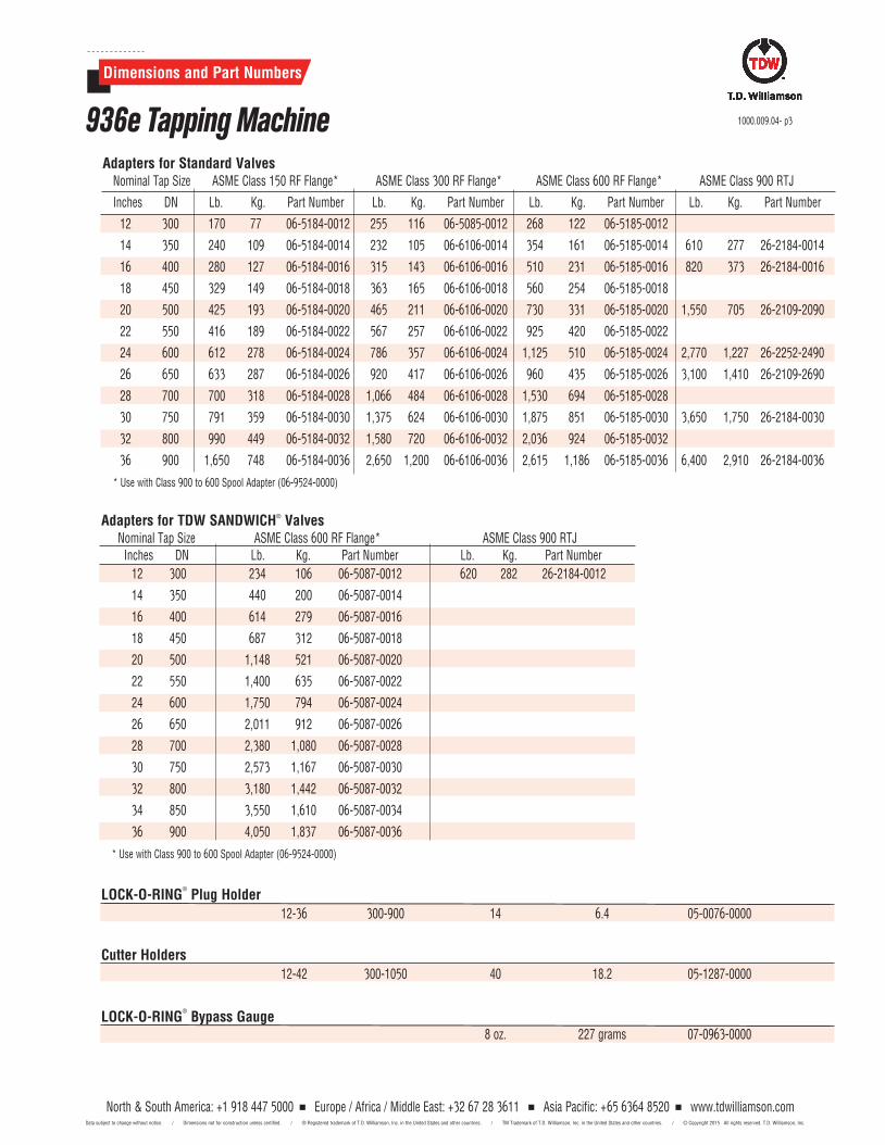
North & South America: +1 918 447 5000 Europe / Africa / Middle East: +32 67 28 3611 Asia Pacific: +65 6364 8520 www.tdwilliamson.comData subject to change without notice. / Dimensions not for construction unless certified. / ® Registered trademark of T.D. Williamson, Inc. in the United States and other countries. / TM Trademark of T.D. Williamson, Inc. in the United States and other countries. / © Copyright 2015 All rights reserved. T.D. Williamson, Inc.
North & South America: +1 918 447 5000 Europe / Africa / Middle East: +32 67 28 3611 Asia Pacific: +65 6364 8520 www.tdwilliamson.comData subject to change without notice. / Dimensions not for construction unless certified. / ® Registered trademark of T.D. Williamson, Inc. in the United States and other countries. / TM Trademark of T.D. Williamson, Inc. in the United States and other countries. / © Copyright 2015 All rights reserved. T.D. Williamson, Inc.
Adapters for TDW SANDWICH® Valves Nominal Tap Size ASME Class 600 RF Flange* ASME Class 900 RTJ Inches DN Lb. Kg. Part Number Lb. Kg. Part Number
12 300 234 106 06-5087-0012 620 282 26-2184-0012
14 350 440 200 06-5087-0014
16 400 614 279 06-5087-0016
18 450 687 312 06-5087-0018
20 500 1,148 521 06-5087-0020
22 550 1,400 635 06-5087-0022
24 600 1,750 794 06-5087-0024
26 650 2,011 912 06-5087-0026
28 700 2,380 1,080 06-5087-0028
30 750 2,573 1,167 06-5087-0030
32 800 3,180 1,442 06-5087-0032
34 850 3,550 1,610 06-5087-0034
36 900 4,050 1,837 06-5087-0036
* Use with Class 900 to 600 Spool Adapter (06-9524-0000)
LOCK-O-RING®
Plug Holder 12-36 300-900 14 6.4 05-0076-0000
Cutter Holders 12-42 300-1050 40 18.2 05-1287-0000
LOCK-O-RING® Bypass Gauge
8 oz. 227 grams 07-0963-0000
Adapters for Standard ValvesNominal Tap Size ASME Class 150 RF Flange* ASME Class 300 RF Flange* ASME Class 600 RF Flange* ASME Class 900 RTJ
Inches DN Lb. Kg. Part Number Lb. Kg. Part Number Lb. Kg. Part Number Lb. Kg. Part Number
12 300 170 77 06-5184-0012 255 116 06-5085-0012 268 122 06-5185-0012
14 350 240 109 06-5184-0014 232 105 06-6106-0014 354 161 06-5185-0014 610 277 26-2184-0014
16 400 280 127 06-5184-0016 315 143 06-6106-0016 510 231 06-5185-0016 820 373 26-2184-0016
18 450 329 149 06-5184-0018 363 165 06-6106-0018 560 254 06-5185-0018
20 500 425 193 06-5184-0020 465 211 06-6106-0020 730 331 06-5185-0020 1,550 705 26-2109-2090
22 550 416 189 06-5184-0022 567 257 06-6106-0022 925 420 06-5185-0022
24 600 612 278 06-5184-0024 786 357 06-6106-0024 1,125 510 06-5185-0024 2,770 1,227 26-2252-2490
26 650 633 287 06-5184-0026 920 417 06-6106-0026 960 435 06-5185-0026 3,100 1,410 26-2109-2690
28 700 700 318 06-5184-0028 1,066 484 06-6106-0028 1,530 694 06-5185-0028
30 750 791 359 06-5184-0030 1,375 624 06-6106-0030 1,875 851 06-5185-0030 3,650 1,750 26-2184-0030
32 800 990 449 06-5184-0032 1,580 720 06-6106-0032 2,036 924 06-5185-0032
36 900 1,650 748 06-5184-0036 2,650 1,200 06-6106-0036 2,615 1,186 06-5185-0036 6,400 2,910 26-2184-0036
* Use with Class 900 to 600 Spool Adapter (06-9524-0000)
1000.009.04- p3
Dimensions and Part Numbers
936e Tapping Machine
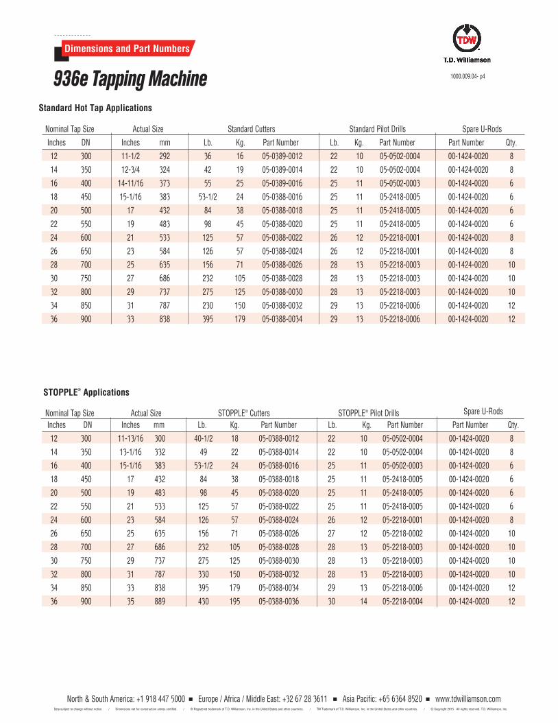
North & South America: +1 918 447 5000 Europe / Africa / Middle East: +32 67 28 3611 Asia Pacific: +65 6364 8520 www.tdwilliamson.comData subject to change without notice. / Dimensions not for construction unless certified. / ® Registered trademark of T.D. Williamson, Inc. in the United States and other countries. / TM Trademark of T.D. Williamson, Inc. in the United States and other countries. / © Copyright 2015 All rights reserved. T.D. Williamson, Inc.
Standard Hot Tap Applications Nominal Tap Size Actual Size Standard Cutters Standard Pilot Drills Spare U-Rods
Inches DN Inches mm Lb. Kg. Part Number Lb. Kg. Part Number Part Number Qty.
12 300 11-1/2 292 36 16 05-0389-0012 22 10 05-0502-0004 00-1424-0020 8
14 350 12-3/4 324 42 19 05-0389-0014 22 10 05-0502-0004 00-1424-0020 8
16 400 14-11/16 373 55 25 05-0389-0016 25 11 05-0502-0003 00-1424-0020 6
18 450 15-1/16 383 53-1/2 24 05-0388-0016 25 11 05-2418-0005 00-1424-0020 6
20 500 17 432 84 38 05-0388-0018 25 11 05-2418-0005 00-1424-0020 6
22 550 19 483 98 45 05-0388-0020 25 11 05-2418-0005 00-1424-0020 6
24 600 21 533 125 57 05-0388-0022 26 12 05-2218-0001 00-1424-0020 8
26 650 23 584 126 57 05-0388-0024 26 12 05-2218-0001 00-1424-0020 8
28 700 25 635 156 71 05-0388-0026 28 13 05-2218-0003 00-1424-0020 10
30 750 27 686 232 105 05-0388-0028 28 13 05-2218-0003 00-1424-0020 10
32 800 29 737 275 125 05-0388-0030 28 13 05-2218-0003 00-1424-0020 10
34 850 31 787 230 150 05-0388-0032 29 13 05-2218-0006 00-1424-0020 12
36 900 33 838 395 179 05-0388-0034 29 13 05-2218-0006 00-1424-0020 12
Nominal Tap Size Actual Size STOPPLE® Cutters STOPPLE® Pilot Drills Spare U-Rods
Inches DN Inches mm Lb. Kg. Part Number Lb. Kg. Part Number Part Number Qty.
12 300 11-13/16 300 40-1/2 18 05-0388-0012 22 10 05-0502-0004 00-1424-0020 8
14 350 13-1/16 332 49 22 05-0388-0014 22 10 05-0502-0004 00-1424-0020 8
16 400 15-1/16 383 53-1/2 24 05-0388-0016 25 11 05-0502-0003 00-1424-0020 6
18 450 17 432 84 38 05-0388-0018 25 11 05-2418-0005 00-1424-0020 6
20 500 19 483 98 45 05-0388-0020 25 11 05-2418-0005 00-1424-0020 6
22 550 21 533 125 57 05-0388-0022 25 11 05-2418-0005 00-1424-0020 6
24 600 23 584 126 57 05-0388-0024 26 12 05-2218-0001 00-1424-0020 8
26 650 25 635 156 71 05-0388-0026 27 12 05-2218-0002 00-1424-0020 10
28 700 27 686 232 105 05-0388-0028 28 13 05-2218-0003 00-1424-0020 10
30 750 29 737 275 125 05-0388-0030 28 13 05-2218-0003 00-1424-0020 10
32 800 31 787 330 150 05-0388-0032 28 13 05-2218-0003 00-1424-0020 10
34 850 33 838 395 179 05-0388-0034 29 13 05-2218-0006 00-1424-0020 12
36 900 35 889 430 195 05-0388-0036 30 14 05-2218-0004 00-1424-0020 12
STOPPLE® Applications
1000.009.04- p4
Dimensions and Part Numbers
936e Tapping Machine
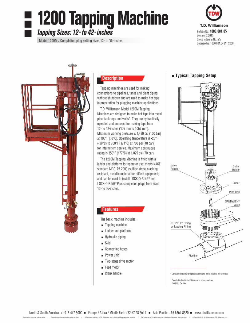
North & South America: +1 918 447 5000 Europe / Africa / Middle East: +32 67 28 3611 Asia Pacific: +65 6364 8520 www.tdwilliamson.comData subject to change without notice. / Dimensions not for construction unless certified. / ® Registered trademark of T.D. Williamson, Inc. in the United States and other countries. / TM Trademark of T.D. Williamson, Inc. in the United States and other countries. / © Copyright 2015 All rights reserved. T.D. Williamson, Inc.
Tapping machines are used for making connections to pipelines, tanks and plant piping without shutdown and are used to make hot taps in preparation for plugging machine applications.
T.D. Williamson Model 1200M Tapping Machines are designed to make hot taps into metal pipe, tank tops and walls*. They are hydraulically operated and are used for making taps from 12- to 42-inches (305 mm to 1067 mm). Maximum working pressure is 1,480 psi (100 bar) at 100°F (38°C). Operating temperature is -20°F (-29°C) to 700°F (371°C) at 700 psi (48 bar) for intermittent service. Maximum continuous rating is 350°F (177°C) at 1,025 psi (70 bar).
The 1200M Tapping Machine is fitted with a ladder and platform for operator use; meets NACE standard MR0175-2009 (sulfide stress cracking- resistant, metallic material for oilfield equipment; and can be used to install LOCK-O-RING® and LOCK-O-RING® Plus completion plugs from sizes 12- to 36-inches.
Description
Features
The basic machine includes: Tapping machine
Ladder and platform
Hydraulic piping
Skid
Connecting hoses
Power unit
Two-stage drive motor
Feed motor
Crank handle
Typical Tapping Setup
ValveAdapter
Cutter
SANDWICH® Valve
CutterHolder
Pilot Drill
STOPPLE® Fitting or Tapping Fitting
Pipeline
* Consult the factory for special cutters and pilots required for tank taps.
Patented in the United States and in other countries. ISO 9001 Certified
Bulletin No: 1000.001.05Version: 7.2015Cross Indexing No: n/aSupersedes: 1000.001.04 (11.2008)
1200 Tapping MachineTapping Sizes: 12- to 42- inches
Model 1200M / Completion plug setting sizes 12- to 36-inches
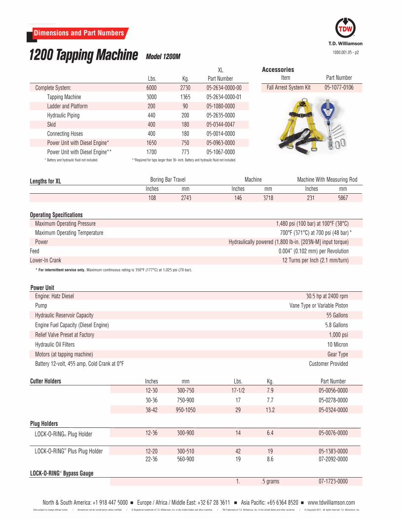
North & South America: +1 918 447 5000 Europe / Africa / Middle East: +32 67 28 3611 Asia Pacific: +65 6364 8520 www.tdwilliamson.comData subject to change without notice. / Dimensions not for construction unless certified. / ® Registered trademark of T.D. Williamson, Inc. in the United States and other countries. / TM Trademark of T.D. Williamson, Inc. in the United States and other countries. / © Copyright 2015 All rights reserved. T.D. Williamson, Inc.
North & South America: +1 918 447 5000 Europe / Africa / Middle East: +32 67 28 3611 Asia Pacific: +65 6364 8520 www.tdwilliamson.comData subject to change without notice. / Dimensions not for construction unless certified. / ® Registered trademark of T.D. Williamson, Inc. in the United States and other countries. / TM Trademark of T.D. Williamson, Inc. in the United States and other countries. / © Copyright 2015 All rights reserved. T.D. Williamson, Inc.
Dimensions and Part Numbers
XL Lbs. Kg. Part Number Complete System: 6000 2730 05-2634-0000-00 Tapping Machine 3000 1365 05-2634-0000-01 Ladder and Platform 200 90 05-1080-0000 Hydraulic Piping 440 200 05-2635-0000 Skid 400 180 05-0344-0047 Connecting Hoses 400 180 05-0014-0000 Power Unit with Diesel Engine* 1650 750 05-0963-0000 Power Unit with Diesel Engine** 1700 773 05-1067-0000 * Battery and hydraulic fluid not included. ** Required for taps larger than 36- inch. Battery and hydraulic fluid not included.
Boring Bar Travel Machine Machine With Measuring Rod Inches mm Inches mm Inches mm 108 2743 146 3718 231 5867
Operating Specifications Maximum Operating Pressure 1,480 psi (100 bar) at 100°F (38°C)
Maximum Operating Temperature 700°F (371°C) at 700 psi (48 bar) * Power Hydraulically powered (1,800 lb-in. [203N-M] input torque) Feed 0.004” (0.102 mm) per Revolution Lower-In Crank 12 Turns per Inch (2.1 mm/turn)
Power Unit
Engine: Hatz Diesel 30.5 hp at 2400 rpmPump Vane Type or Variable Piston
Hydraulic Reservoir Capacity 55 Gallons
Engine Fuel Capacity (Diesel Engine) 5.8 Gallons
Relief Valve Preset at Factory 1,000 psi
Hydraulic Oil Filters 10 Micron
Motors (at tapping machine) Gear TypeBattery 12-volt, 455 amp, Cold Crank at 0°F Customer Provided
Lengths for XL
* For intermittent service only. Maximum continuous rating is 350°F (177°C) at 1,025 psi (70 bar).
Cutter Holders Inches mm Lbs. Kg. Part Number 12-30 300-750 17-1/2 7.9 05-0056-0000
30-36 750-900 17 7.7 05-0278-0000
38-42 950-1050 29 13.2 05-0324-0000 Plug Holders LOCK-O-RING® Plug Holder 12-36 300-900 14 6.4 05-0076-0000
LOCK-O-RING® Plus Plug Holder 12-20 300-510 42 19 05-1383-0000 22-36 560-900 19 8.6 07-2092-0000
LOCK-O-RING® Bypass Gauge 1. .5 grams 07-1723-0000
Accessories Item Part Number
Fall Arrest System Kit 05-1077-0106
1200 Tapping Machine Model 1200M1000.001.05 - p2
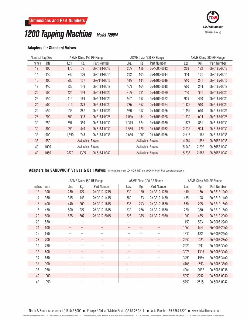
North & South America: +1 918 447 5000 Europe / Africa / Middle East: +32 67 28 3611 Asia Pacific: +65 6364 8520 www.tdwilliamson.comData subject to change without notice. / Dimensions not for construction unless certified. / ® Registered trademark of T.D. Williamson, Inc. in the United States and other countries. / TM Trademark of T.D. Williamson, Inc. in the United States and other countries. / © Copyright 2015 All rights reserved. T.D. Williamson, Inc.
Dimensions and Part Numbers
Nominal Tap Size ASME Class 150 RF Flange ASME Class 300 RF Flange ASME Class 600 RF Flange Inches DN Lbs. Kg. Part Number Lbs. Kg Part Number Lbs. Kg. Part Number
12 300 170 77 06-5184-0012 255 116 06-5085-0012 268 122 06-5185-0012
14 350 240 109 06-5184-0014 232 105 06-6106-0014 354 161 06-5185-0014
16 400 280 127 06-9333-0016 315 143 06-6106-0016 510 231 06-5185-0016
18 450 329 149 06-5184-0018 363 165 06-6106-0018 560 254 06-5185-0018
20 500 425 193 06-5184-0020 465 211 06-6106-0020 730 331 06-5185-0020
22 550 416 189 06-5184-0022 567 257 06-6106-0022 925 420 06-5185-0022
24 600 612 278 06-5184-0024 786 357 06-6106-0024 1,125 510 06-5185-0024
26 650 633 287 06-5184-0026 920 417 06-6106-0026 1,455 660 06-5185-0026
28 700 700 318 06-5184-0028 1,066 484 06-6106-0028 1,530 694 06-5185-0028
30 750 791 359 06-5184-0030 1,375 624 06-6106-0030 1,875 851 06-5185-0030
32 800 990 449 06-5184-0032 1,580 720 06-6106-0032 2,036 924 06-5185-0032
36 900 1,650 748 06-5184-0036 2,650 1200 06-6106-0036 2,615 1,186 06-5185-0036
38 950 Available on Request Available on Request 4,064 1,856 06-5087-0038
40 1000 Available on Request Available on Request 5,042 2,292 06-5087-0040
42 1050 2870 1305 06-5184-0042 Available on Request 5,736 2,067 06-5087-0042
Adapters for Standard Valves
1200 Tapping Machine Model 1200M1000.001.05 - p3
Adapters for SANDWICH® Valves & Ball Valves (Compatible to set LOCK- O- RING®
and LOCK-O-RING®
Plus completion plugs )
ASME Class 150 RF Flange ASME Class 300 RF Flange ASME Class 600 RF Flange Inches mm Lbs. Kg. Part Number Lbs. Kg. Part Number Lbs. Kg. Part Number 12 300 280 127 26-3212-1215 330 150 26-3212-1230 410 186 26-3212-1260
14 350 315 143 26-3212-1415 380 173 26-3212-1430 435 198 26-3212-1460
16 400 440 200 26-3212-1615 535 243 26-3212-1630 650 295 26-3212-1660
18 450 500 227 26-3212-1815 630 286 26-3212-1830 770 350 26-3212-1860
20 500 675 307 26-3212-2015 825 375 26-3212-2030 1000 455 26-3212-2060
22 550 -- -- -- -- -- -- 1150 523 26-3003-2260 24 600 -- -- -- -- -- -- 1460 664 26-3003-2460
26 650 -- -- -- -- -- -- 1830 832 26-3003-2660
28 700 -- -- -- -- -- -- 2250 1023 26-3003-2860
30 750 -- -- -- -- -- -- 2620 1191 26-3003-3060
32 800 -- -- -- -- -- -- 3075 1395 26-3003-3260
34 850 -- -- -- -- -- -- 3490 1586 26-3003-3460
36 900 -- -- -- -- -- -- 4165 1893 26-3003-3660
38 950 -- -- -- -- -- -- 4064 2032 06-5087-0038
40 1000 -- -- -- -- -- -- 5050 2292 06-5087-0040
42 1050 -- -- -- -- -- -- 5750 2615 06-5087-0042
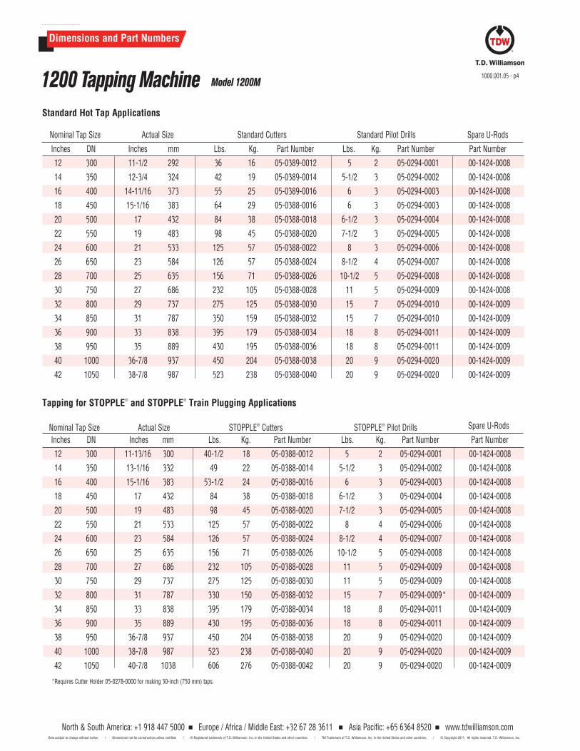
North & South America: +1 918 447 5000 Europe / Africa / Middle East: +32 67 28 3611 Asia Pacific: +65 6364 8520 www.tdwilliamson.comData subject to change without notice. / Dimensions not for construction unless certified. / ® Registered trademark of T.D. Williamson, Inc. in the United States and other countries. / TM Trademark of T.D. Williamson, Inc. in the United States and other countries. / © Copyright 2015 All rights reserved. T.D. Williamson, Inc.
North & South America: +1 918 447 5000 Europe / Africa / Middle East: +32 67 28 3611 Asia Pacific: +65 6364 8520 www.tdwilliamson.comData subject to change without notice. / Dimensions not for construction unless certified. / ® Registered trademark of T.D. Williamson, Inc. in the United States and other countries. / TM Trademark of T.D. Williamson, Inc. in the United States and other countries. / © Copyright 2015 All rights reserved. T.D. Williamson, Inc.
Standard Hot Tap Applications Nominal Tap Size Actual Size Standard Cutters Standard Pilot Drills Spare U-Rods
Inches DN Inches mm Lbs. Kg. Part Number Lbs. Kg. Part Number Part Number
12 300 11-1/2 292 36 16 05-0389-0012 5 2 05-0294-0001 00-1424-0008
14 350 12-3/4 324 42 19 05-0389-0014 5-1/2 3 05-0294-0002 00-1424-0008
16 400 14-11/16 373 55 25 05-0389-0016 6 3 05-0294-0003 00-1424-0008
18 450 15-1/16 383 64 29 05-0388-0016 6 3 05-0294-0003 00-1424-0008
20 500 17 432 84 38 05-0388-0018 6-1/2 3 05-0294-0004 00-1424-0008
22 550 19 483 98 45 05-0388-0020 7-1/2 3 05-0294-0005 00-1424-0008
24 600 21 533 125 57 05-0388-0022 8 3 05-0294-0006 00-1424-0008
26 650 23 584 126 57 05-0388-0024 8-1/2 4 05-0294-0007 00-1424-0008
28 700 25 635 156 71 05-0388-0026 10-1/2 5 05-0294-0008 00-1424-0008
30 750 27 686 232 105 05-0388-0028 11 5 05-0294-0009 00-1424-0008
32 800 29 737 275 125 05-0388-0030 15 7 05-0294-0010 00-1424-0009
34 850 31 787 350 159 05-0388-0032 15 7 05-0294-0010 00-1424-0009
36 900 33 838 395 179 05-0388-0034 18 8 05-0294-0011 00-1424-0009
38 950 35 889 430 195 05-0388-0036 18 8 05-0294-0011 00-1424-0009
40 1000 36-7/8 937 450 204 05-0388-0038 20 9 05-0294-0020 00-1424-0009
42 1050 38-7/8 987 523 238 05-0388-0040 20 9 05-0294-0020 00-1424-0009
Tapping for STOPPLE® and STOPPLE® Train Plugging Applications Nominal Tap Size Actual Size STOPPLE® Cutters STOPPLE® Pilot Drills Spare U-Rods
Inches DN Inches mm Lbs. Kg. Part Number Lbs. Kg. Part Number Part Number
12 300 11-13/16 300 40-1/2 18 05-0388-0012 5 2 05-0294-0001 00-1424-0008
14 350 13-1/16 332 49 22 05-0388-0014 5-1/2 3 05-0294-0002 00-1424-0008
16 400 15-1/16 383 53-1/2 24 05-0388-0016 6 3 05-0294-0003 00-1424-0008
18 450 17 432 84 38 05-0388-0018 6-1/2 3 05-0294-0004 00-1424-0008
20 500 19 483 98 45 05-0388-0020 7-1/2 3 05-0294-0005 00-1424-0008
22 550 21 533 125 57 05-0388-0022 8 4 05-0294-0006 00-1424-0008
24 600 23 584 126 57 05-0388-0024 8-1/2 4 05-0294-0007 00-1424-0008
26 650 25 635 156 71 05-0388-0026 10-1/2 5 05-0294-0008 00-1424-0008
28 700 27 686 232 105 05-0388-0028 11 5 05-0294-0009 00-1424-0008
30 750 29 737 275 125 05-0388-0030 11 5 05-0294-0009 00-1424-0008
32 800 31 787 330 150 05-0388-0032 15 7 05-0294-0009 * 00-1424-0009
34 850 33 838 395 179 05-0388-0034 18 8 05-0294-0011 00-1424-0009
36 900 35 889 430 195 05-0388-0036 18 8 05-0294-0011 00-1424-0009
38 950 36-7/8 937 450 204 05-0388-0038 20 9 05-0294-0020 00-1424-0009
40 1000 38-7/8 987 523 238 05-0388-0040 20 9 05-0294-0020 00-1424-0009
42 1050 40-7/8 1038 606 276 05-0388-0042 20 9 05-0294-0020 00-1424-0009
*Requires Cutter Holder 05-0278-0000 for making 30-inch (750 mm) taps.
Dimensions and Part Numbers
1200 Tapping Machine Model 1200M1000.001.05 - p4
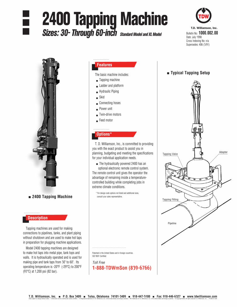
The basic machine includes:
Tapping machine
Ladder and platform
Hydraulic Piping
Skid
Connecting hoses
Power unit
Twin-drive motors
Feed motor
T. D. Williamson, Inc., is committed to providing you with the exact product to assist you in planning, budgeting and meeting the specifications for your individual application needs.
The hydraulically powered 2400 has an optional electronic remote control system.
The remote control unit gives the operator the advantage of remaining inside a temperature-controlled building while completing jobs in extreme climate conditions.
* For design code options not listed and additional sizes, consult your sales representative.
Features
Description
Options*
Typical Tapping Setup
2400 Tapping MachineTapping Fitting
Pipeline
AdapterTapping Valve
Tapping machines are used for making connections to pipelines, tanks, and plant piping without shutdown and are used to make hot taps in preparation for plugging machine applications.
Model 2400 tapping machines are designed
to make hot taps into metal pipe, tank tops and walls. It is hydraulically operated and is used for making pipe and tank taps from 30" to 60". Its operating temperature is -20°F (-29°C) to 200°F (93°C) at 1,200 psi (82 bar).
Toll Free
1-888-TDWmSon (839-6766)
Patented in the United States and in foreign countries.ISO 9001 Certified
Bulletin No: 1000.002.00Date: July 1998Cross Indexing No: n/aSupersedes: 406 (3/91)
T.D. Williamson, Inc. P.O. Box 3409 Tulsa, Oklahoma 74101-3409 918-447-5100 Fax: 918-446-6327 www.tdwilliamson.comData subject to change without notice. / Dimensions not for construction unless certified. / ® Registered trademark of T.D. Williamson, Inc. in the United States and foreign countries / TM Trademark of T.D. Williamson, Inc. in the United States and foreign countries / © Copyright 2006. All rights reserved T.D. Williamson, Inc. / Printed in USA
2400 Tapping MachineSizes: 30- Through 60-inch Standard Model and XL Model
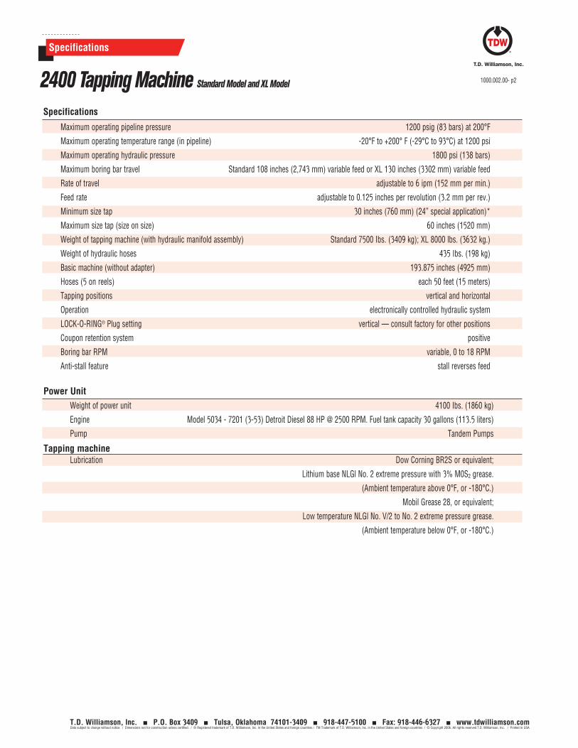
Specifications
Specifications
2400 Tapping Machine Standard Model and XL Model 1000.002.00- p2
T.D. Williamson, Inc. P.O. Box 3409 Tulsa, Oklahoma 74101-3409 918-447-5100 Fax: 918-446-6327 www.tdwilliamson.comData subject to change without notice. / Dimensions not for construction unless certified. / ® Registered trademark of T.D. Williamson, Inc. in the United States and foreign countries / TM Trademark of T.D. Williamson, Inc. in the United States and foreign countries / © Copyright 2006. All rights reserved T.D. Williamson, Inc. / Printed in USA
Maximum operating pipeline pressure 1200 psig (83 bars) at 200°F
Maximum operating temperature range (in pipeline) -20°F to +200° F (-29°C to 93°C) at 1200 psi
Maximum operating hydraulic pressure 1800 psi (138 bars)
Maximum boring bar travel Standard 108 inches (2,743 mm) variable feed or XL 130 inches (3302 mm) variable feed
Rate of travel adjustable to 6 ipm (152 mm per min.)
Feed rate adjustable to 0.125 inches per revolution (3.2 mm per rev.)
Minimum size tap 30 inches (760 mm) (24” special application)*
Maximum size tap (size on size) 60 inches (1520 mm)
Weight of tapping machine (with hydraulic manifold assembly) Standard 7500 Ibs. (3409 kg); XL 8000 lbs. (3632 kg.)
Weight of hydraulic hoses 435 Ibs. (198 kg)
Basic machine (without adapter) 193.875 inches (4925 mm)
Hoses (5 on reels) each 50 feet (15 meters)
Tapping positions vertical and horizontal
Operation electronically controlled hydraulic system
LOCK-O-RING® Plug setting vertical — consult factory for other positions
Coupon retention system positive
Boring bar RPM variable, 0 to 18 RPM
Anti-stall feature stall reverses feed
Power Unit
Weight of power unit 4100 Ibs. (1860 kg)
Engine Model 5034 - 7201 (3-53) Detroit Diesel 88 HP @ 2500 RPM. Fuel tank capacity 30 gallons (113.5 liters)
Pump Tandem Pumps
Tapping machine Lubrication Dow Corning BR2S or equivalent;
Lithium base NLGl No. 2 extreme pressure with 3% M0S2 grease.
(Ambient temperature above 0°F, or -180°C.)
Mobil Grease 28, or equivalent;
Low temperature NLGl No. V/2 to No. 2 extreme pressure grease.
(Ambient temperature below 0°F, or -180°C.)
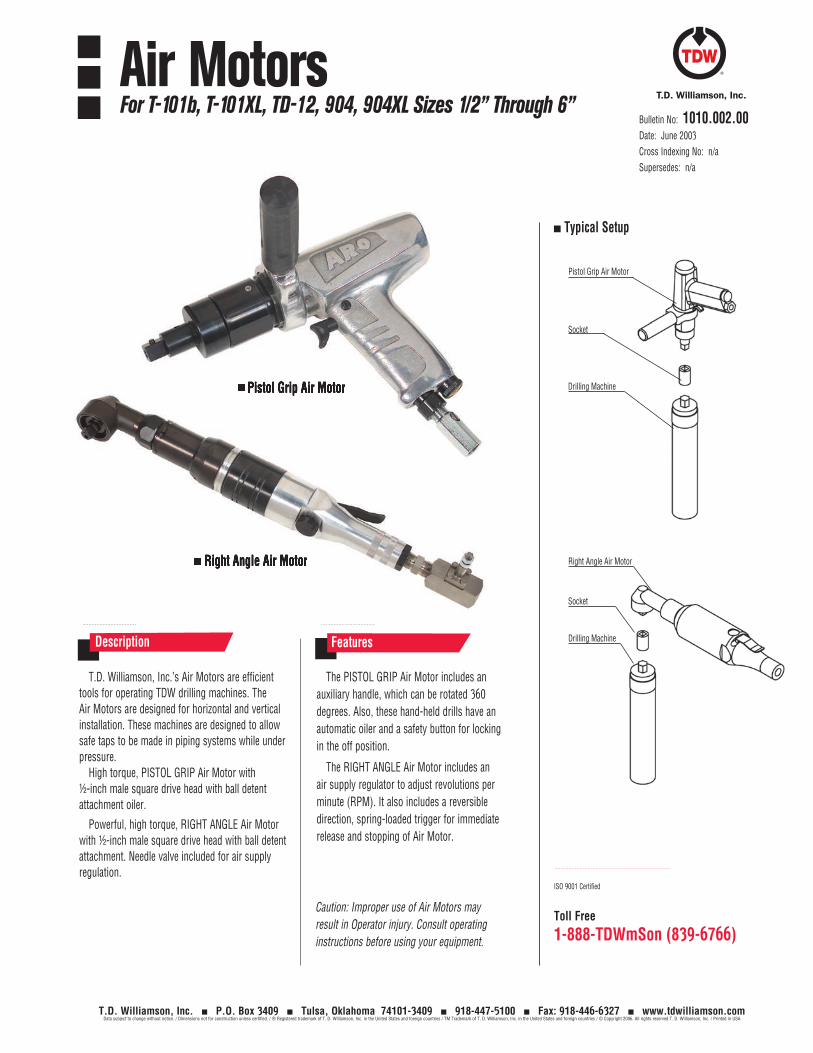
T.D. Williamson, Inc. P.O. Box 3409 Tulsa, Oklahoma 74101-3409 918-447-5100 Fax: 918-446-6327 www.tdwilliamson.comData subject to change without notice. / Dimensions not for construction unless certified. / ® Registered trademark of T. D. Williamson, Inc. in the United States and foreign countries / TM Trademark of T. D. Williamson, Inc. in the United States and foreign countries / © Copyright 2006. All rights reserved T. D. Williamson, Inc. / Printed in USA
Toll Free
1-888-TDWmSon (839-6766)
Air MotorsFor T-101b, T-101XL, TD-12, 904, 904XL Sizes 1/2” Through 6”
T.D. Williamson, Inc.’s Air Motors are efficient tools for operating TDW drilling machines. The Air Motors are designed for horizontal and vertical installation. These machines are designed to allow safe taps to be made in piping systems while under pressure.
High torque, PISTOL GRIP Air Motor with ½-inch male square drive head with ball detent attachment oiler.
Powerful, high torque, RIGHT ANGLE Air Motor with ½-inch male square drive head with ball detent attachment. Needle valve included for air supply regulation.
The PISTOL GRIP Air Motor includes an auxiliary handle, which can be rotated 360 degrees. Also, these hand-held drills have an automatic oiler and a safety button for locking in the off position.
The RIGHT ANGLE Air Motor includes an air supply regulator to adjust revolutions per minute (RPM). It also includes a reversible direction, spring-loaded trigger for immediate release and stopping of Air Motor.
Description Features
Typical Setup
ISO 9001 Certified
Bulletin No: 1010.002.00Date: June 2003Cross Indexing No: n/aSupersedes: n/a
Socket
Pistol Grip Air Motor
Drilling Machine Pistol Grip Air Motor
Right Angle Air Motor Right Angle Air Motor
Socket
Drilling Machine
Caution: Improper use of Air Motors may result in Operator injury. Consult operating instructions before using your equipment.
Right Angle Air Motor
Pistol Grip Air Motor
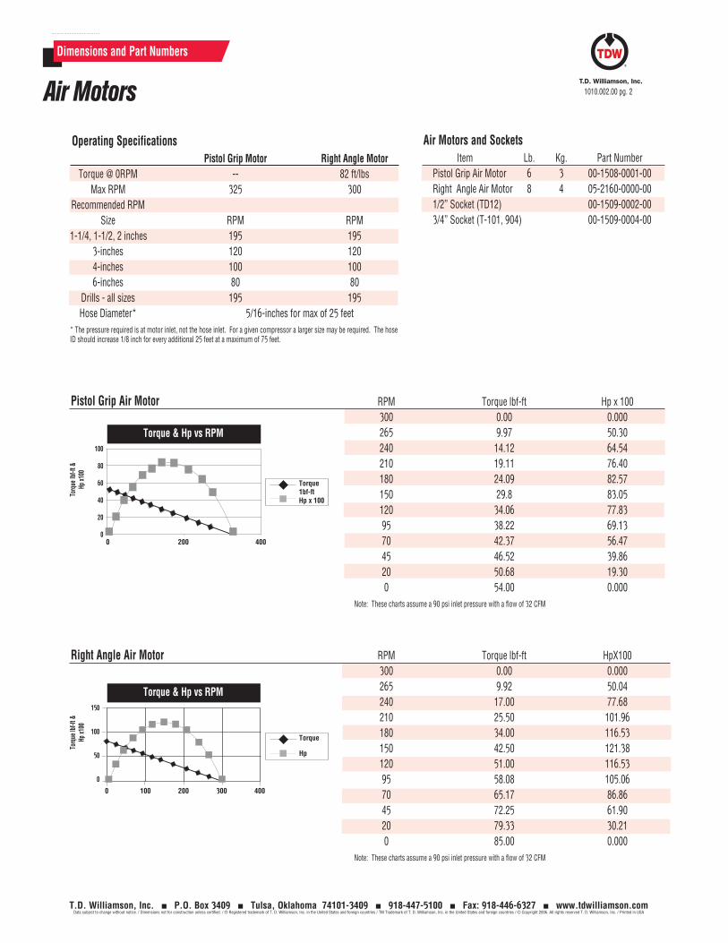
T.D. Williamson, Inc. P.O. Box 3409 Tulsa, Oklahoma 74101-3409 918-447-5100 Fax: 918-446-6327 www.tdwilliamson.comData subject to change without notice. / Dimensions not for construction unless certified. / ® Registered trademark of T. D. Williamson, Inc. in the United States and foreign countries / TM Trademark of T. D. Williamson, Inc. in the United States and foreign countries / © Copyright 2006. All rights reserved T. D. Williamson, Inc. / Printed in USA
Dimensions and Part Numbers
Air Motors 1010.002.00 pg. 2
Air Motors and Sockets Item Lb. Kg. Part Number Pistol Grip Air Motor 6 3 00-1508-0001-00 Right Angle Air Motor 8 4 05-2160-0000-00 1/2” Socket (TD12) 00-1509-0002-00 3/4” Socket (T-101, 904) 00-1509-0004-00
Torque
Hp
RPM Torque lbf-ft HpX100 300 0.00 0.000 265 9.92 50.04 240 17.00 77.68 210 25.50 101.96 180 34.00 116.53 150 42.50 121.38 120 51.00 116.53 95 58.08 105.06 70 65.17 86.86 45 72.25 61.90 20 79.33 30.21 0 85.00 0.000Note: These charts assume a 90 psi inlet pressure with a flow of 32 CFM
Right Angle Air Motor
Operating Specifications Pistol Grip Motor Right Angle Motor Torque @ 0RPM -- 82 ft/lbs Max RPM 325 300 Recommended RPM Size RPM RPM 1-1/4, 1-1/2, 2 inches 195 195 3-inches 120 120 4-inches 100 100 6-inches 80 80 Drills - all sizes 195 195 Hose Diameter* 5/16-inches for max of 25 feet* The pressure required is at motor inlet, not the hose inlet. For a given compressor a larger size may be required. The hose ID should increase 1/8 inch for every additional 25 feet at a maximum of 75 feet.
Torq
ue lb
f-ft &
Hp
x100
150
100
50
0
0 100 200 300 400
Torque 1bf-ftHp x 100
RPM Torque lbf-ft Hp x 100 300 0.00 0.000 265 9.97 50.30 240 14.12 64.54 210 19.11 76.40 180 24.09 82.57 150 29.8 83.05 120 34.06 77.83 95 38.22 69.13 70 42.37 56.47 45 46.52 39.86 20 50.68 19.30 0 54.00 0.000Note: These charts assume a 90 psi inlet pressure with a flow of 32 CFM
Pistol Grip Air Motor
Torq
ue lb
f-ft &
Hp
x100
100
80
60
40
20
00 200 400
Torque & Hp vs RPM
Torque & Hp vs RPM
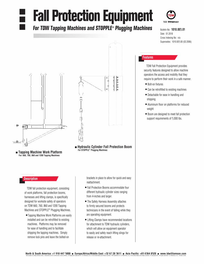
Bulletin No: 1010.003.01Date: 01.2018
Cross Indexing No: n/a
Supersedes: 1010.003.00 (02.2006)
North & South America: +1 918 447 5000 Europe/Africa/Middle East: +32 67 28 3611 Asia Pacific: +65 6364 8520 www.tdwilliamson.comData subject to change without notice. / Dimensions not for construction unless certified. / ® Registered trademark of T. D. Williamson, Inc. in the United States and foreign countries / TM Trademark of T. D. Williamson, Inc. in the United States and foreign countries / © Copyright 2017. All rights reserved T. D. Williamson, Inc. / Printed in USA
Description
TDW Fall Protection Equipment provides
security features designed to allow machine
operators the access and mobility that they
require to perform their work in a safe manner.
Bolt-on fixtures
Can be retrofitted to existing machines
Detachable for ease in handling and
shipping
Aluminum floor on platforms for reduced
weight
Boom are designed to meet fall protection
support requirements of 5,000 lbs.
Features
Tapping Machine Work Platform For: 660, 760, 860 and 1200 Tapping Machines
Hydraulic Cylinder Fall Protection Boom For STOPPLE® Plugging Machines
TDW fall protection equipment, consisting
of work platforms, fall protection booms,
harnesses and lifting clamps, is specifically
designed for worksite safety of operators
on TDW 660, 760, 860 and 1200 Tapping
Machines and STOPPLE® Plugging Machines.
Tapping Machine Work Platforms are easily
installed and can be retrofitted to existing
machines. Platforms may be removed
for ease of handling and to facilitate
shipping the tapping machines. Simply
remove lock pins and leave the bolted-on
brackets in place to allow for quick and easy
reattachment.
Fall Protection Booms accommodate four
different hydraulic cylinder sizes ranging
from 4-inches and larger.
The Safety Harness Assembly attaches
to firmly secured booms and protects
technicians in the event of falling while they
are operating equipment.
Lifting Clamps have recommended locations
for attachment to TDW hydraulic cylinders,
which will allow an equipment operator
to easily and safely reach lifting slings for
release or re-attachment.
Fall Protection EquipmentFor TDW Tapping Machines and STOPPLE® Plugging Machines
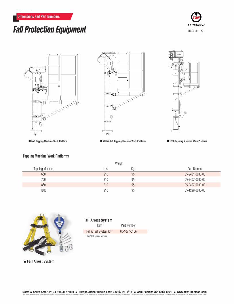
North & South America: +1 918 447 5000 Europe/Africa/Middle East: +32 67 28 3611 Asia Pacific: +65 6364 8520 www.tdwilliamson.comData subject to change without notice. / Dimensions not for construction unless certified. / ® Registered trademark of T. D. Williamson, Inc. in the United States and foreign countries / TM Trademark of T. D. Williamson, Inc. in the United States and foreign countries / © Copyright 2006. All rights reserved T. D. Williamson, Inc. / Printed in USA
Dimensions and Part Numbers
Tapping Machine Work Platforms
Weight
Tapping Machine Lbs. Kg. Part Number
660 210 95 05-2401-0000-00
760 210 95 05-2407-0000-00
860 210 95 05-2407-0000-00
1200 210 95 05-1229-0000-00
1010.003.01 - p2Fall Protection Equipment
660 Tapping Machine Work Platform 760 & 860 Tapping Machine Work Platform 1200 Tapping Machine Work Platform
Fall Arrest SystemItem Part Number
Fall Arrest System Kit* 05-1077-0106*For 1200 Tapping Machine
Fall Arrest System
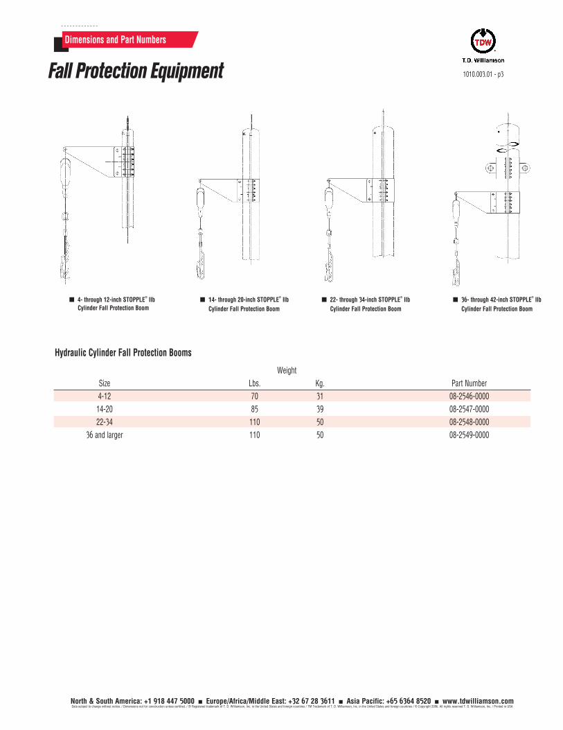
North & South America: +1 918 447 5000 Europe/Africa/Middle East: +32 67 28 3611 Asia Pacific: +65 6364 8520 www.tdwilliamson.comData subject to change without notice. / Dimensions not for construction unless certified. / ® Registered trademark of T. D. Williamson, Inc. in the United States and foreign countries / TM Trademark of T. D. Williamson, Inc. in the United States and foreign countries / © Copyright 2006. All rights reserved T. D. Williamson, Inc. / Printed in USA
Dimensions and Part Numbers
1010.003.01 - p3Fall Protection Equipment
4- through 12-inch STOPPLE® IIb
Cylinder Fall Protection Boom14- through 20-inch STOPPLE
® IIb
Cylinder Fall Protection Boom
22- through 34-inch STOPPLE® IIb
Cylinder Fall Protection Boom
36- through 42-inch STOPPLE® IIb
Cylinder Fall Protection Boom
Hydraulic Cylinder Fall Protection Booms
Weight
Size Lbs. Kg. Part Number
4-12 70 31 08-2546-0000
14-20 85 39 08-2547-0000
22-34 110 50 08-2548-0000
36 and larger 110 50 08-2549-0000

North & South America: +1 918 447 5000 Europe/Africa/Middle East: +32 67 28 3611 Asia Pacific: +65 6364 8520 www.tdwilliamson.comData subject to change without notice. / Dimensions not for construction unless certified. / ® Registered trademark of T. D. Williamson, Inc. in the United States and foreign countries / TM Trademark of T. D. Williamson, Inc. in the United States and foreign countries / © Copyright 2006. All rights reserved T. D. Williamson, Inc. / Printed in USA
1010.003.01 - p4
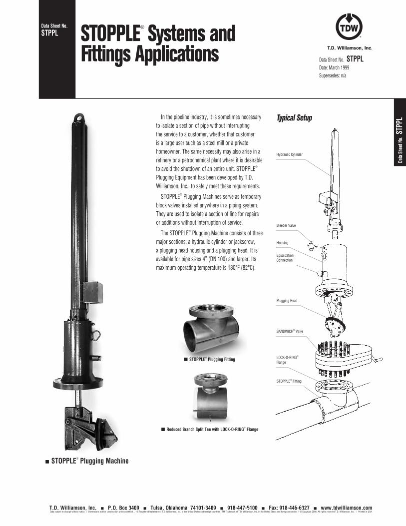
Data
She
et N
o. S
TPPL
Data Sheet No. STPPL
Data Sheet No. STPPLDate: March 1999Supersedes: n/a
STOPPLE® Systems and Fittings Applications
STOPPLE® Plugging Fitting
Reduced Branch Split Tee with LOCK-O-RING® Flange
In the pipeline industry, it is sometimes necessary to isolate a section of pipe without interrupting the service to a customer, whether that customer is a large user such as a steel mill or a private homeowner. The same necessity may also arise in a refinery or a petrochemical plant where it is desirable to avoid the shutdown of an entire unit. STOPPLE® Plugging Equipment has been developed by T.D. Williamson, Inc., to safely meet these requirements.
STOPPLE® Plugging Machines serve as temporary block valves installed anywhere in a piping system. They are used to isolate a section of line for repairs or additions without interruption of service.
The STOPPLE® Plugging Machine consists of three major sections: a hydraulic cylinder or jackscrew, a plugging head housing and a plugging head. It is available for pipe sizes 4” (DN 100) and larger. Its maximum operating temperature is 180°F (82°C).
Typical Setup
Hydraulic Cylinder
Bleeder Valve
Housing
Plugging Head
SANDWICH® Valve
LOCK-O-RING® Flange
STOPPLE® Fitting
Equalization Connection
STOPPLE® Plugging Machine
T.D. Williamson, Inc. P.O. Box 3409 Tulsa, Oklahoma 74101-3409 918-447-5100 Fax: 918-446-6327 www.tdwilliamson.comData subject to change without notice. / Dimensions not for construction unless certified. / ® Registered trademark of T.D. Williamson, Inc. in the United States and foreign countries / TM Trademark of T.D. Williamson, Inc. in the United States and foreign countries / © Copyright 2006. All rights reserved T.D. Williamson, Inc. / Printed in USA
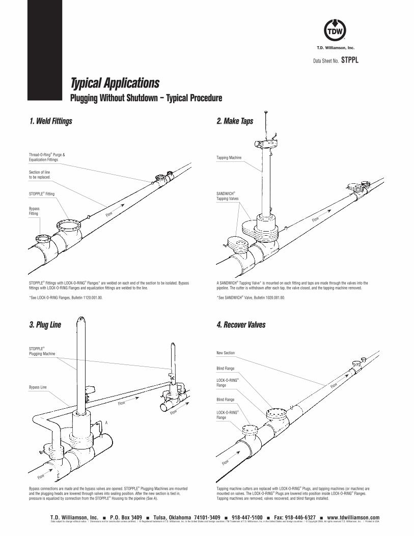
Data Sheet No. STPPL
Typical ApplicationsPlugging Without Shutdown – Typical Procedure
1. Weld Fittings 2. Make Taps
A SANDWICH® Tapping Valve* is mounted on each fitting and taps are made through the valves into the pipeline. The cutter is withdrawn after each tap, the valve closed, and the tapping machine removed.
*See SANDWICH® Valve, Bulletin 1020.001.00.
STOPPLE® Fittings with LOCK-O-RING® Flanges* are welded on each end of the section to be isolated. Bypass fittings with LOCK-O-RING Flanges and equalization fittings are welded to the line.
*See LOCK-O-RING Flanges, Bulletin 1120.001.00.
3. Plug Line 4. Recover Valves
Tapping machine cutters are replaced with LOCK-O-RING® Plugs, and tapping machines (or machine) are mounted on valves. The LOCK-O-RING® Plugs are lowered into position inside LOCK-O-RING® Flanges. Tapping machines are removed, valves recovered, and blind flanges installed.
Bypass connections are made and the bypass valves are opened. STOPPLE® Plugging Machines are mounted and the plugging heads are lowered through valves into sealing position. After the new section is tied in, pressure is equalized by connection from the STOPPLE® Housing to the pipeline (See A).
Thread-O-Ring® Purge & Equalization Fittings
STOPPLE® Plugging Machine
Bypass Line
A
Tapping Machine
New Section
Blind Flange
LOCK-O-RING® Flange
LOCK-O-RING® Flange
Blind Flange
SANDWICH® Tapping Valves
Section of line to be replaced.
STOPPLE® Fitting
Bypass Fitting
Flow
Flow
Flow
Flow
Flow
FlowFlow
T.D. Williamson, Inc. P.O. Box 3409 Tulsa, Oklahoma 74101-3409 918-447-5100 Fax: 918-446-6327 www.tdwilliamson.comData subject to change without notice. / Dimensions not for construction unless certified. / ® Registered trademark of T.D. Williamson, Inc. in the United States and foreign countries / TM Trademark of T.D. Williamson, Inc. in the United States and foreign countries / © Copyright 2006. All rights reserved T.D. Williamson, Inc. / Printed in USA
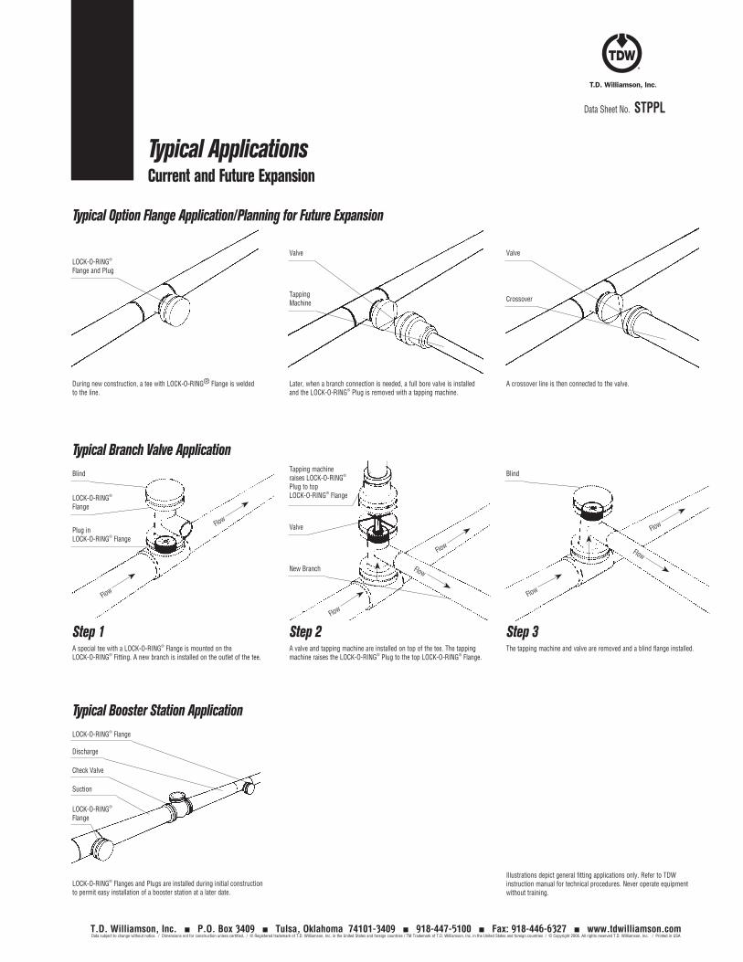
Blind
Flow
Flow
Flow
Valve
New Branch
Tapping machine raises LOCK-O-RING® Plug to top LOCK-O-RING® Flange
Flow
Flow
Flow
Data Sheet No. STPPL
Typical ApplicationsCurrent and Future Expansion
Step 1 Step 2 Step 3A special tee with a LOCK-O-RING® Flange is mounted on the LOCK-O-RING® Fitting. A new branch is installed on the outlet of the tee.
A valve and tapping machine are installed on top of the tee. The tapping machine raises the LOCK-O-RING® Plug to the top LOCK-O-RING® Flange.
The tapping machine and valve are removed and a blind flange installed.
Illustrations depict general fitting applications only. Refer to TDW instruction manual for technical procedures. Never operate equipment without training.
Typical Option Flange Application/Planning for Future Expansion
During new construction, a tee with LOCK-O-RING® Flange is welded to the line.
Later, when a branch connection is needed, a full bore valve is installed and the LOCK-O-RING® Plug is removed with a tapping machine.
A crossover line is then connected to the valve.
LOCK-O-RING® Flange and Plug
Valve Valve
Crossover
Tapping Machine
Blind
LOCK-O-RING® Flange
Plug in LOCK-O-RING® Flange
Typical Branch Valve Application
Flow
Flow
LOCK-O-RING® Flange Discharge Check Valve Suction
LOCK-O-RING® Flange
Typical Booster Station Application
LOCK-O-RING® Flanges and Plugs are installed during initial construction to permit easy installation of a booster station at a later date.
T.D. Williamson, Inc. P.O. Box 3409 Tulsa, Oklahoma 74101-3409 918-447-5100 Fax: 918-446-6327 www.tdwilliamson.comData subject to change without notice. / Dimensions not for construction unless certified. / ® Registered trademark of T.D. Williamson, Inc. in the United States and foreign countries / TM Trademark of T.D. Williamson, Inc. in the United States and foreign countries / © Copyright 2006. All rights reserved T.D. Williamson, Inc. / Printed in USA
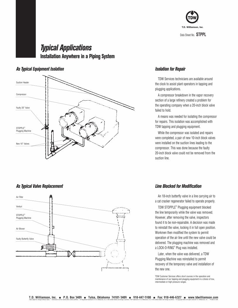
Data Sheet No. STPPL
Typical ApplicationsInstallation Anywhere in a Piping System
Isolation for Repair
TDW Services technicians are available around the clock to assist plant operators in tapping and plugging applications.
A compressor breakdown in the vapor recovery section of a large refinery created a problem for the operating company when a 20-inch block valve failed to hold.
A means was needed for isolating the compressor for repairs. This isolation was accomplished with TDW tapping and plugging equipment.
While the compressor was isolated and repairs were completed, a pair of new 10-inch block valves were installed on the suction lines leading to the compressor. This was done because the faulty 20-inch block valve could not be removed from the suction line.
Line Blocked for Modification
An 18-inch butterfly valve in a line carrying air to a cat cracker regenerator failed to operate properly.
TDW STOPPLE® Plugging equipment blocked the line temporarily while the valve was removed. However, after removing the valve, inspectors found it to be non-repairable. A decision was made to reinstall the valve, locking it in full open position. Workmen then modified the system to permit operation of the air line until the new valve could be delivered. The plugging machine was removed and a LOCK-O-RING® Plug was installed.
Later, when the valve was delivered, a TDW Plugging Machine was reinstalled to permit recovery of the temporary valve and installation of the new one.
TDW Customer Services offers short courses in the operation and maintenance of our tapping and plugging equipment in a choice of low, intermediate or high pressure ranges.
Suction Header
Compressor
Faulty 20” Valve
STOPPLE® Plugging Machine
New 10” Valves
Air Filter
Venturi
STOPPLE® Plugging Machine
Air Blower
Faulty Butterfly Valve
As Typical Equipment Isolation
As Typical Valve Replacement
T.D. Williamson, Inc. P.O. Box 3409 Tulsa, Oklahoma 74101-3409 918-447-5100 Fax: 918-446-6327 www.tdwilliamson.comData subject to change without notice. / Dimensions not for construction unless certified. / ® Registered trademark of T.D. Williamson, Inc. in the United States and foreign countries / TM Trademark of T.D. Williamson, Inc. in the United States and foreign countries / © Copyright 2006. All rights reserved T.D. Williamson, Inc. / Printed in USA
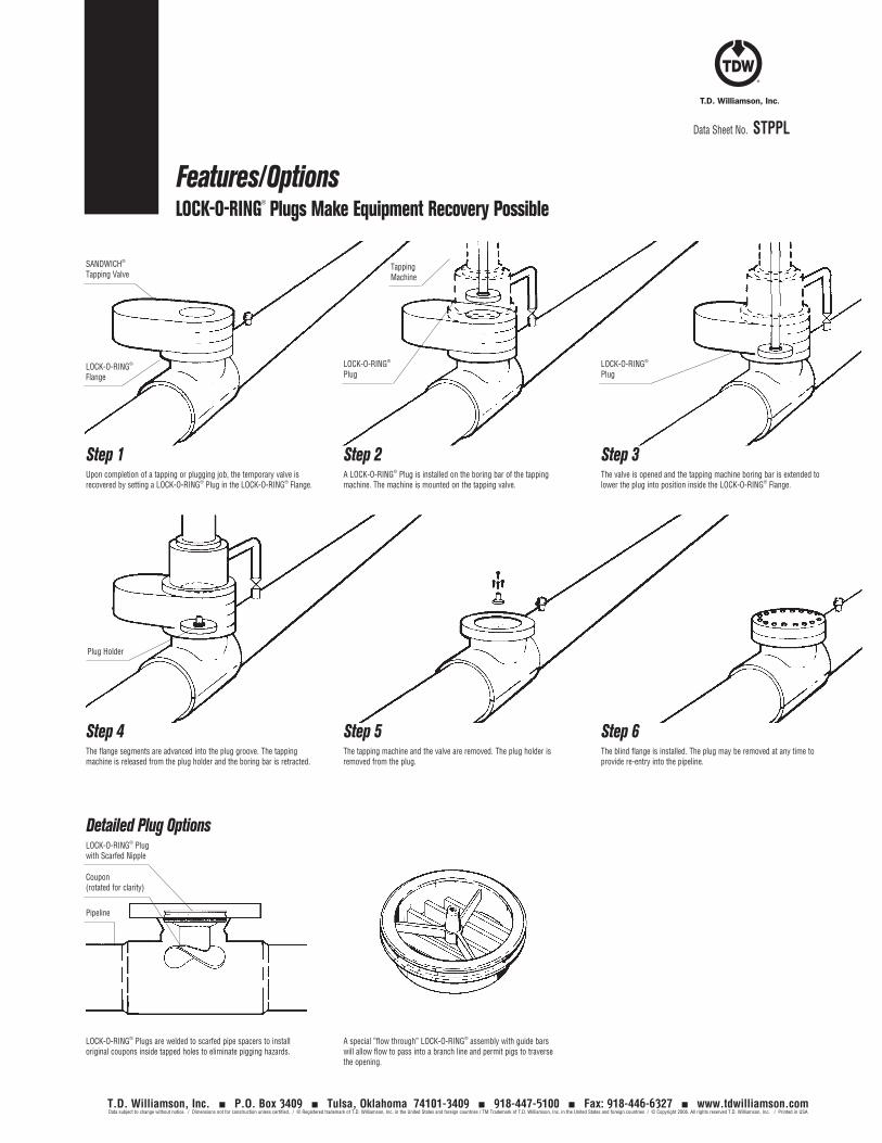
Data Sheet No. STPPL
Features/OptionsLOCK-O-RING® Plugs Make Equipment Recovery Possible
Step 1 Step 2 Step 3
SANDWICH® Tapping Valve
LOCK-O-RING® Flange
Upon completion of a tapping or plugging job, the temporary valve is recovered by setting a LOCK-O-RING® Plug in the LOCK-O-RING® Flange.
A LOCK-O-RING® Plug is installed on the boring bar of the tapping machine. The machine is mounted on the tapping valve.
The valve is opened and the tapping machine boring bar is extended to lower the plug into position inside the LOCK-O-RING® Flange.
LOCK-O-RING® Plug
LOCK-O-RING® Plug
Tapping Machine
Step 4 Step 5 Step 6The flange segments are advanced into the plug groove. The tapping machine is released from the plug holder and the boring bar is retracted.
The tapping machine and the valve are removed. The plug holder is removed from the plug.
The blind flange is installed. The plug may be removed at any time to provide re-entry into the pipeline.
Plug Holder
LOCK-O-RING® Plug with Scarfed Nipple
Pipeline
Coupon (rotated for clarity)
Detailed Plug Options
LOCK-O-RING® Plugs are welded to scarfed pipe spacers to install original coupons inside tapped holes to eliminate pigging hazards.
A special ”flow through” LOCK-O-RING® assembly with guide bars will allow flow to pass into a branch line and permit pigs to traverse the opening.
T.D. Williamson, Inc. P.O. Box 3409 Tulsa, Oklahoma 74101-3409 918-447-5100 Fax: 918-446-6327 www.tdwilliamson.comData subject to change without notice. / Dimensions not for construction unless certified. / ® Registered trademark of T.D. Williamson, Inc. in the United States and foreign countries / TM Trademark of T.D. Williamson, Inc. in the United States and foreign countries / © Copyright 2006. All rights reserved T.D. Williamson, Inc. / Printed in USA
Data Sheet No. STPPL
Data
She
et N
o. S
TPPL
T.D. Williamson, Inc. P.O. Box 3409 Tulsa, Oklahoma 74101-3409 918-447-5100 Fax: 918-446-6327 www.tdwilliamson.comData subject to change without notice. / Dimensions not for construction unless certified. / ® Registered trademark of T.D. Williamson, Inc. in the United States and foreign countries / TM Trademark of T.D. Williamson, Inc. in the United States and foreign countries / © Copyright 2006. All rights reserved T.D. Williamson, Inc. / Printed in USA
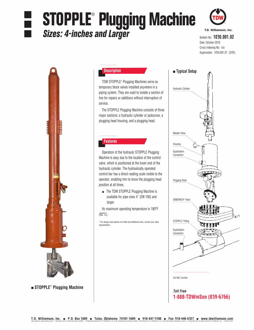
Toll Free
1-888-TDWmSon (839-6766)
TDW STOPPLE® Plugging Machines serve as temporary block valves installed anywhere in a piping system. They are used to isolate a section of line for repairs or additions without interruption of service.
The STOPPLE Plugging Machine consists of three major sections: a hydraulic cylinder or jackscrew, a plugging head housing, and a plugging head.
Description
Operation of the hydraulic STOPPLE Plugging Machine is easy due to the location of the control valve, which is positioned at the lower end of the hydraulic cylinder. The hydraulically operated control bar has a direct reading scale visible to the operator, enabling him to know the plugging head position at all times.
The TDW STOPPLE Plugging Machine is available for pipe sizes 4” (DN 100) and larger.
Its maximum operating temperature is 180°F (82°C).
* For design code options not listed and additional sizes, consult your sales representative.
Features
ISO 9001 Certified
STOPPLE® Plugging Machine
Typical Setup
Hydraulic Cylinder
Bleeder Valve
Housing
Plugging Head
SANDWICH® Valve
STOPPLE® Fitting
Equalization Connection
Equalization Connection
Bulletin No: 1030.001.02Date: October 2010Cross Indexing No: n/aSupersedes: 1030.001.01 (2/05)
STOPPLE® Plugging MachineSizes: 4-inches and Larger
T.D. Williamson, Inc. P.O. Box 3409 Tulsa, Oklahoma 74101-3409 918-447-5100 Fax: 918-446-6327 www.tdwilliamson.comData subject to change without notice. / Dimensions not for construction unless certified. / ® Registered trademark of T.D. Williamson, Inc. in the United States and foreign countries / TM Trademark of T.D. Williamson, Inc. in the United States and foreign countries / © Copyright 2010. All rights reserved T.D. Williamson, Inc. / Printed in USA
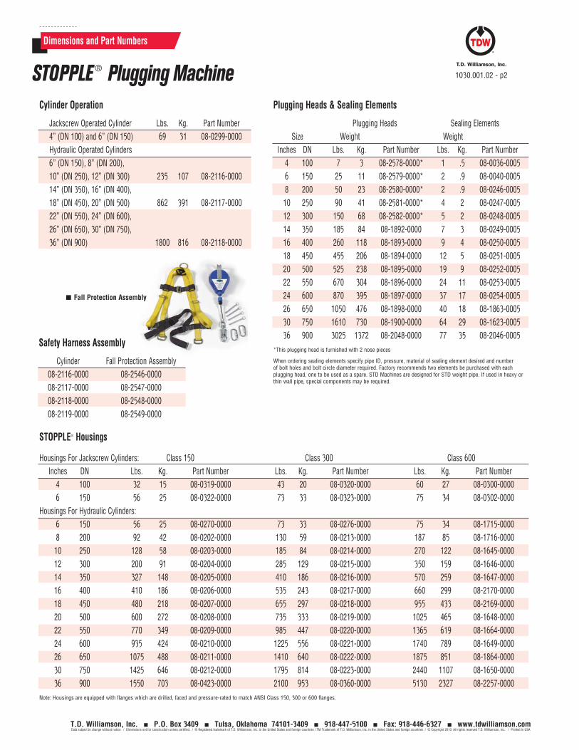
Dimensions and Part Numbers
STOPPLE® Housings
Housings For Jackscrew Cylinders: Class 150 Class 300 Class 600 Inches DN Lbs. Kg. Part Number Lbs. Kg. Part Number Lbs. Kg. Part Number 4 100 32 15 08-0319-0000 43 20 08-0320-0000 60 27 08-0300-0000 6 150 56 25 08-0322-0000 73 33 08-0323-0000 75 34 08-0302-0000Housings For Hydraulic Cylinders: 6 150 56 25 08-0270-0000 73 33 08-0276-0000 75 34 08-1715-0000 8 200 92 42 08-0202-0000 130 59 08-0213-0000 187 85 08-1716-0000 10 250 128 58 08-0203-0000 185 84 08-0214-0000 270 122 08-1645-0000 12 300 200 91 08-0204-0000 285 129 08-0215-0000 350 159 08-1646-0000 14 350 327 148 08-0205-0000 410 186 08-0216-0000 570 259 08-1647-0000 16 400 410 186 08-0206-0000 535 243 08-0217-0000 660 299 08-2170-0000 18 450 480 218 08-0207-0000 655 297 08-0218-0000 955 433 08-2169-0000 20 500 600 272 08-0208-0000 735 333 08-0219-0000 1025 465 08-1648-0000 22 550 770 349 08-0209-0000 985 447 08-0220-0000 1365 619 08-1664-0000 24 600 935 424 08-0210-0000 1225 556 08-0221-0000 1740 789 08-1649-0000 26 650 1075 488 08-0211-0000 1410 640 08-0222-0000 1875 851 08-1864-0000 30 750 1425 646 08-0212-0000 1795 814 08-0223-0000 2440 1107 08-1650-0000 36 900 1550 703 08-0423-0000 2100 953 08-0360-0000 5130 2327 08-2257-0000 Note: Housings are equipped with flanges which are drilled, faced and pressure-rated to match ANSI Class 150, 300 or 600 flanges.
Plugging Heads & Sealing Elements
Plugging Heads Sealing Elements Size Weight Weight Inches DN Lbs. Kg. Part Number Lbs. Kg. Part Number 4 100 7 3 08-2578-0000* 1 .5 08-0036-0005 6 150 25 11 08-2579-0000* 2 .9 08-0040-0005 8 200 50 23 08-2580-0000* 2 .9 08-0246-0005 10 250 90 41 08-2581-0000* 4 2 08-0247-0005 12 300 150 68 08-2582-0000* 5 2 08-0248-0005 14 350 185 84 08-1892-0000 7 3 08-0249-0005 16 400 260 118 08-1893-0000 9 4 08-0250-0005 18 450 455 206 08-1894-0000 12 5 08-0251-0005 20 500 525 238 08-1895-0000 19 9 08-0252-0005 22 550 670 304 08-1896-0000 24 11 08-0253-0005 24 600 870 395 08-1897-0000 37 17 08-0254-0005 26 650 1050 476 08-1898-0000 40 18 08-1863-0005 30 750 1610 730 08-1900-0000 64 29 08-1623-0005 36 900 3025 1372 08-2048-0000 77 35 08-2046-0005 *This plugging head is furnished with 2 nose pieces
When ordering sealing elements specify pipe ID, pressure, material of sealing element desired and number of bolt holes and bolt circle diameter required. Factory recommends two elements be purchased with each plugging head, one to be used as a spare. STD Machines are designed for STD weight pipe. If used in heavy or thin wall pipe, special components may be required.
Cylinder Operation
Jackscrew Operated Cylinder Lbs. Kg. Part Number 4” (DN 100) and 6” (DN 150) 69 31 08-0299-0000 Hydraulic Operated Cylinders 6” (DN 150), 8” (DN 200), 10” (DN 250), 12” (DN 300) 235 107 08-2116-0000 14” (DN 350), 16” (DN 400), 18” (DN 450), 20” (DN 500) 862 391 08-2117-0000 22” (DN 550), 24” (DN 600), 26” (DN 650), 30” (DN 750), 36” (DN 900) 1800 816 08-2118-0000
1030.001.02 - p2STOPPLE ® Plugging Machine
Safety Harness Assembly
Cylinder Fall Protection Assembly 08-2116-0000 08-2546-0000 08-2117-0000 08-2547-0000 08-2118-0000 08-2548-0000 08-2119-0000 08-2549-0000
Fall Protection Assembly
T.D. Williamson, Inc. P.O. Box 3409 Tulsa, Oklahoma 74101-3409 918-447-5100 Fax: 918-446-6327 www.tdwilliamson.comData subject to change without notice. / Dimensions not for construction unless certified. / ® Registered trademark of T.D. Williamson, Inc. in the United States and foreign countries / TM Trademark of T.D. Williamson, Inc. in the United States and foreign countries / © Copyright 2010. All rights reserved T.D. Williamson, Inc. / Printed in USA
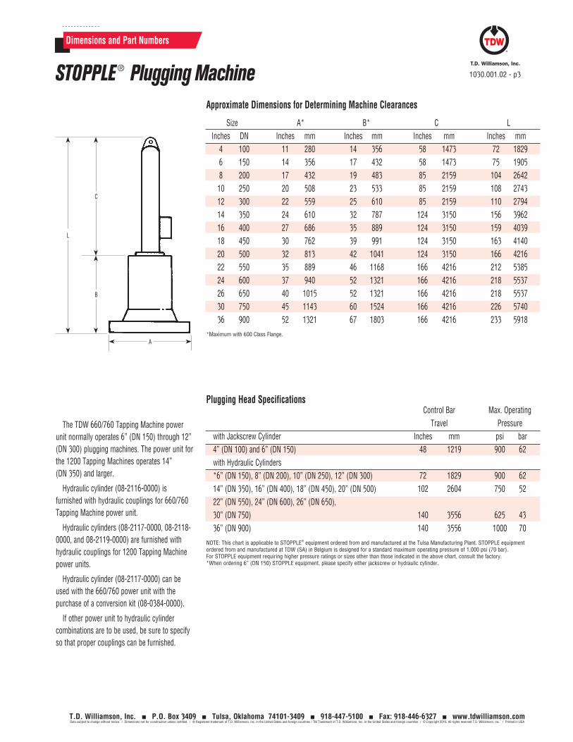
Dimensions and Part Numbers
Approximate Dimensions for Determining Machine Clearances
Size A* B* C L Inches DN Inches mm Inches mm Inches mm Inches mm 4 100 11 280 14 356 58 1473 72 1829 6 150 14 356 17 432 58 1473 75 1905 8 200 17 432 19 483 85 2159 104 2642 10 250 20 508 23 533 85 2159 108 2743 12 300 22 559 25 610 85 2159 110 2794 14 350 24 610 32 787 124 3150 156 3962 16 400 27 686 35 889 124 3150 159 4039 18 450 30 762 39 991 124 3150 163 4140 20 500 32 813 42 1041 124 3150 166 4216 22 550 35 889 46 1168 166 4216 212 5385 24 600 37 940 52 1321 166 4216 218 5537 26 650 40 1015 52 1321 166 4216 218 5537 30 750 45 1143 60 1524 166 4216 226 5740 36 900 52 1321 67 1803 166 4216 233 5918*Maximum with 600 Class Flange.
Plugging Head Specifications
The TDW 660/760 Tapping Machine power unit normally operates 6” (DN 150) through 12” (DN 300) plugging machines. The power unit for the 1200 Tapping Machines operates 14” (DN 350) and larger.
Hydraulic cylinder (08-2116-0000) is furnished with hydraulic couplings for 660/760 Tapping Machine power unit.
Hydraulic cylinders (08-2117-0000, 08-2118-0000, and 08-2119-0000) are furnished with hydraulic couplings for 1200 Tapping Machine power units.
Hydraulic cylinder (08-2117-0000) can be used with the 660/760 power unit with the purchase of a conversion kit (08-0384-0000).
If other power unit to hydraulic cylinder combinations are to be used, be sure to specify so that proper couplings can be furnished.
Control Bar Max. OperatingTravel Pressure
with Jackscrew Cylinder Inches mm psi bar 4” (DN 100) and 6” (DN 150) 48 1219 900 62 with Hydraulic Cylinders *6” (DN 150), 8” (DN 200), 10” (DN 250), 12” (DN 300) 72 1829 900 62 14” (DN 350), 16” (DN 400), 18” (DN 450), 20” (DN 500) 102 2604 750 52 22” (DN 550), 24” (DN 600), 26” (DN 650), 30” (DN 750) 140 3556 625 43 36” (DN 900) 140 3556 1000 70NOTE: This chart is applicable to STOPPLE® equipment ordered from and manufactured at the Tulsa Manufacturing Plant. STOPPLE equipment ordered from and manufactured at TDW (SA) in Belgium is designed for a standard maximum operating pressure of 1,000 psi (70 bar). For STOPPLE equipment requiring higher pressure ratings or sizes other than those indicated in the above chart, consult the factory. *When ordering 6” (DN 150) STOPPLE equipment, please specify either jackscrew or hydraulic cylinder.
A
B
C
L
1030.001.02 - p3STOPPLE ® Plugging Machine
T.D. Williamson, Inc. P.O. Box 3409 Tulsa, Oklahoma 74101-3409 918-447-5100 Fax: 918-446-6327 www.tdwilliamson.comData subject to change without notice. / Dimensions not for construction unless certified. / ® Registered trademark of T.D. Williamson, Inc. in the United States and foreign countries / TM Trademark of T.D. Williamson, Inc. in the United States and foreign countries / © Copyright 2010. All rights reserved T.D. Williamson, Inc. / Printed in USA
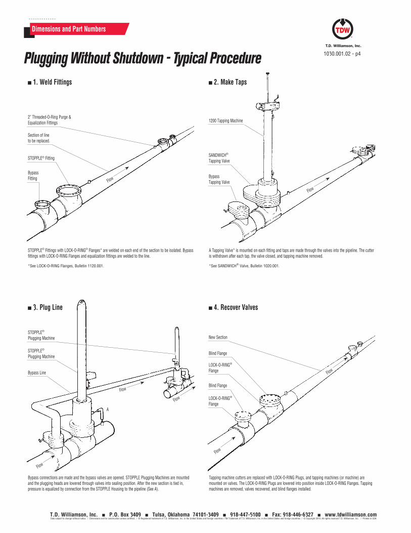
Dimensions and Part Numbers
1. Weld Fittings 2. Make Taps
A Tapping Valve* is mounted on each fitting and taps are made through the valves into the pipeline. The cutter is withdrawn after each tap, the valve closed, and tapping machine removed.
*See SANDWICH® Valve, Bulletin 1020.001.
STOPPLE® Fittings with LOCK-O-RING® Flanges* are welded on each end of the section to be isolated. Bypass fittings with LOCK-O-RING Flanges and equalization fittings are welded to the line.
*See LOCK-O-RING Flanges, Bulletin 1120.001.
3. Plug Line 4. Recover Valves
Tapping machine cutters are replaced with LOCK-O-RING Plugs, and tapping machines (or machine) are mounted on valves. The LOCK-O-RING Plugs are lowered into position inside LOCK-O-RING Flanges. Tapping machines are removed, valves recovered, and blind flanges installed.
Bypass connections are made and the bypass valves are opened. STOPPLE Plugging Machines are mounted and the plugging heads are lowered through valves into sealing position. After the new section is tied in, pressure is equalized by connection from the STOPPLE Housing to the pipeline (See A).
2” Threaded-O-Ring Purge & Equalization Fittings
STOPPLE® Plugging Machine
STOPPLE® Plugging Machine
Bypass Line
A
1200 Tapping Machine
New Section
Blind Flange
LOCK-O-RING® Flange
LOCK-O-RING® Flange
Blind Flange
SANDWICH® Tapping Valve
Bypass Tapping Valve
Section of line to be replaced.
STOPPLE® Fitting
Bypass Fitting
Flow
Flow
Flow
Flow
Flow
Flow
Flow
1030.001.02 - p4Plugging Without Shutdown - Typical Procedure
T.D. Williamson, Inc. P.O. Box 3409 Tulsa, Oklahoma 74101-3409 918-447-5100 Fax: 918-446-6327 www.tdwilliamson.comData subject to change without notice. / Dimensions not for construction unless certified. / ® Registered trademark of T.D. Williamson, Inc. in the United States and foreign countries / TM Trademark of T.D. Williamson, Inc. in the United States and foreign countries / © Copyright 2010. All rights reserved T.D. Williamson, Inc. / Printed in USA
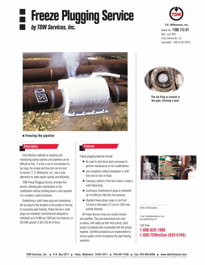
TDW Services, Inc. P.O. Box 2217 Tulsa, Oklahoma 74101-2217 918-447-5100 Fax: 918-446-0398 www.tdwilliamson.comData subject to change without notice. / Dimensions not for construction unless certified. / ® Registered trademark of T. D. Williamson, Inc. in the United States and foreign countries / TM Trademark of T. D. Williamson, Inc. in the United States and foreign countries / © Copyright 2005. All rights reserved T. D. Williamson, Inc. / Printed in USA
Toll Free
1-800-828-19881-888-TDWmSon (839-6766)
Cost-effective methods of repairing and maintaining piping systems and pipelines can be difficult to find. If a line is out of commission for too long, the money and time lost can be hard to recover. T. D. Williamson, Inc., has a wise alternative to make repairs quickly and efficiently.
TDW Freeze Plugging Service, provides this service, allowing pipe maintenance or line modification without shutting down a vital segment of a company's plant processes.
Establishing a solid freeze plug and maintaining the ice plug for the duration of the project is the key to successful pipe freezing. Freeze Service's solid plugs are constantly monitored and designed to withstand up to 8,000 psi (560 bar) line pressure, or 225,000 pounds (1,001,250 N) of force.
Freeze plugging features include:
No need to shut down plant processes to perform maintenance or line modifications.
Job completion without draindown or refill time and no loss of fluids.
Freezing a portion of the line's fluid to create a solid freeze plug.
Continuous monitoring of plugs to withstand up to 8,000 psi (560 bar) line pressure.
Standard freeze plugs range in size from 1/2 inch to 48-inches (13 mm to 1220 mm) outside diameter.
All Freeze Service crews are nuclear trained and qualified. They are experienced and work as teams, with safety as their first priority. Each project is analyzed and coordinated with the project engineer. Certified procedures are implemented to ensure quality control throughout the pipe freezing operation..
Features
Bulletin No: 1300.712.01Date: June 2005Cross Indexing No: n/aSupersedes: 1300.712.00 (10/01)
Freeze Plugging Serviceby TDW Services, Inc.
The Ice Plug is created in the pipe, forming a seal.
OSHA & SNSI Qualified
E-mail: [email protected]
Description
Freezing the pipeline
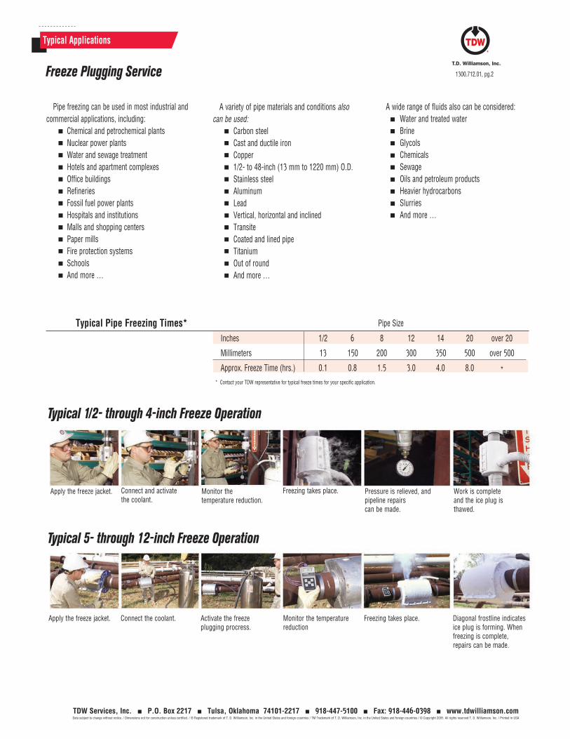
Typical Applications
1300.712.01, pg.2
TDW Services, Inc. P.O. Box 2217 Tulsa, Oklahoma 74101-2217 918-447-5100 Fax: 918-446-0398 www.tdwilliamson.comData subject to change without notice. / Dimensions not for construction unless certified. / ® Registered trademark of T. D. Williamson, Inc. in the United States and foreign countries / TM Trademark of T. D. Williamson, Inc. in the United States and foreign countries / © Copyright 2005. All rights reserved T. D. Williamson, Inc. / Printed in USA
Inches 1/2 6 8 12 14 20 over 20
Millimeters 13 150 200 300 350 500 over 500
Approx. Freeze Time (hrs.) 0.1 0.8 1.5 3.0 4.0 8.0 *
Typical Pipe Freezing Times* Pipe Size
Apply the freeze jacket. Connect the coolant. Activate the freeze plugging procress.
Freezing takes place. Diagonal frostline indicates ice plug is forming. When freezing is complete, repairs can be made.
Monitor the temperature reduction
* Contact your TDW representative for typical freeze times for your specific application.
Apply the freeze jacket. Connect and activate the coolant.
Monitor the temperature reduction.
Pressure is relieved, and pipeline repairs can be made.
Work is complete and the ice plug is thawed.
Freezing takes place.
Typical 1/2- through 4-inch Freeze Operation
Typical 5- through 12-inch Freeze Operation
Pipe freezing can be used in most industrial and commercial applications, including:
Chemical and petrochemical plantsNuclear power plantsWater and sewage treatmentHotels and apartment complexesOffice buildingsRefineriesFossil fuel power plantsHospitals and institutionsMalls and shopping centersPaper millsFire protection systemsSchoolsAnd more …
A variety of pipe materials and conditions also can be used:
Carbon steelCast and ductile ironCopper1/2- to 48-inch (13 mm to 1220 mm) O.D.Stainless steelAluminumLeadVertical, horizontal and inclinedTransiteCoated and lined pipeTitaniumOut of roundAnd more …
A wide range of fluids also can be considered:Water and treated waterBrineGlycolsChemicalsSewageOils and petroleum productsHeavier hydrocarbonsSlurriesAnd more …
Freeze Plugging Service
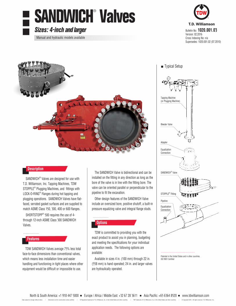
North & South America: +1 918 447 5000 Europe / Africa / Middle East: +32 67 28 3611 Asia Pacific: +65 6364 8520 www.tdwilliamson.comData subject to change without notice. / Dimensions not for construction unless certified. / ® Registered trademark of T.D. Williamson, Inc. in the United States and other countries. / TM Trademark of T.D. Williamson, Inc. in the United States and other countries. / © Copyright 2016 All rights reserved. T.D. Williamson, Inc.
SANDWICH® Valves are designed for use with
T.D. Williamson, Inc. Tapping Machines, TDW
STOPPLE® Plugging Machines, and fittings with
LOCK-O-RING® Flanges during hot tapping and
plugging operations. SANDWICH Valves have flat-
faced, serrated gasket surfaces and are supplied to
match ASME Class 150, 300, 400 or 600 flanges.
SHORTSTOPP® 500 requires the use of 4-
through 12-inch ASME Class 300 SANDWICH
Valves.
DescriptionThe SANDWICH Valve is bidirectional and can be
installed on the fitting in any direction as long as the
bore of the valve is in line with the fitting bore. The
valve can be oriented parallel or perpendicular to the
pipeline to fit the excavation.
Other design features of the SANDWICH Valve
include an oversized bore, positive shutoff, a built-in
pressure equalizing valve and integral flange studs.
TDW is committed to providing you with the
exact product to assist you in planning, budgeting
and meeting the specifications for your individual
application needs. The following options are
available:
Available in sizes 4 in. (100 mm) through 22 in.
(558 mm) is hand operated; 24 in. and larger valves
are hydraulically operated.
Options
TDW SANDWICH Valves average 75% less total
face-to-face dimensions than conventional valves,
which means less installation time and easier
handling and functioning in tight places where other
equipment would be difficult or impossible to use.
Features
Patented in the United States and in other countries.ISO 9001 Certified
Typical Setup
Tapping Machine (or Plugging Machine)
Bleeder Valve
Adapter
Equalization Connection
SANDWICH® Valve
STOPPLE® Fitting
Pipeline
Equalization Connection
SANDWICH® ValvesSizes: 4-inch and larger
Manual and hydraulic models available
Bulletin No: 1020.001.03Version: 02.2016Cross Indexing No: n/aSupersedes: 1020.001.02 (07.2010)
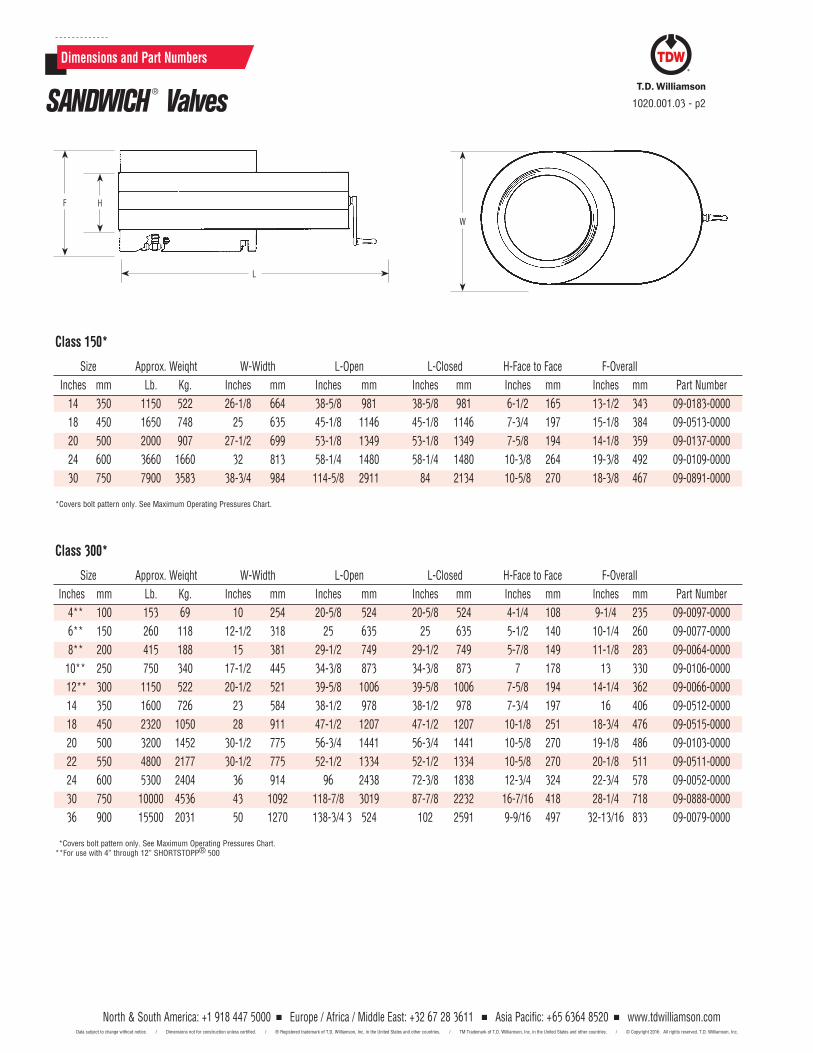
North & South America: +1 918 447 5000 Europe / Africa / Middle East: +32 67 28 3611 Asia Pacific: +65 6364 8520 www.tdwilliamson.comData subject to change without notice. / Dimensions not for construction unless certified. / ® Registered trademark of T.D. Williamson, Inc. in the United States and other countries. / TM Trademark of T.D. Williamson, Inc. in the United States and other countries. / © Copyright 2016 All rights reserved. T.D. Williamson, Inc.
Dimensions and Part Numbers
Class 150*
Size Approx. Weiqht W-Width L-Open L-Closed H-Face to Face F-Overall
Inches mm Lb. Kg. Inches mm Inches mm Inches mm Inches mm Inches mm Part Number
14 350 1150 522 26-1/8 664 38-5/8 981 38-5/8 981 6-1/2 165 13-1/2 343 09-0183-0000
18 450 1650 748 25 635 45-1/8 1146 45-1/8 1146 7-3/4 197 15-1/8 384 09-0513-0000
20 500 2000 907 27-1/2 699 53-1/8 1349 53-1/8 1349 7-5/8 194 14-1/8 359 09-0137-0000
24 600 3660 1660 32 813 58-1/4 1480 58-1/4 1480 10-3/8 264 19-3/8 492 09-0109-0000
30 750 7900 3583 38-3/4 984 114-5/8 2911 84 2134 10-5/8 270 18-3/8 467 09-0891-0000
*Covers bolt pattern only. See Maximum Operating Pressures Chart.
Class 300*
Size Approx. Weiqht W-Width L-Open L-Closed H-Face to Face F-Overall
Inches mm Lb. Kg. Inches mm Inches mm Inches mm Inches mm Inches mm Part Number
4** 100 153 69 10 254 20-5/8 524 20-5/8 524 4-1/4 108 9-1/4 235 09-0097-0000
6** 150 260 118 12-1/2 318 25 635 25 635 5-1/2 140 10-1/4 260 09-0077-0000
8** 200 415 188 15 381 29-1/2 749 29-1/2 749 5-7/8 149 11-1/8 283 09-0064-0000
10** 250 750 340 17-1/2 445 34-3/8 873 34-3/8 873 7 178 13 330 09-0106-0000
12** 300 1150 522 20-1/2 521 39-5/8 1006 39-5/8 1006 7-5/8 194 14-1/4 362 09-0066-0000
14 350 1600 726 23 584 38-1/2 978 38-1/2 978 7-3/4 197 16 406 09-0512-0000
18 450 2320 1050 28 911 47-1/2 1207 47-1/2 1207 10-1/8 251 18-3/4 476 09-0515-0000
20 500 3200 1452 30-1/2 775 56-3/4 1441 56-3/4 1441 10-5/8 270 19-1/8 486 09-0103-0000
22 550 4800 2177 30-1/2 775 52-1/2 1334 52-1/2 1334 10-5/8 270 20-1/8 511 09-0511-0000
24 600 5300 2404 36 914 96 2438 72-3/8 1838 12-3/4 324 22-3/4 578 09-0052-0000
30 750 10000 4536 43 1092 118-7/8 3019 87-7/8 2232 16-7/16 418 28-1/4 718 09-0888-0000
36 900 15500 2031 50 1270 138-3/4 3 524 102 2591 9-9/16 497 32-13/16 833 09-0079-0000
*Covers bolt pattern only. See Maximum Operating Pressures Chart. **For use with 4” through 12” SHORTSTOPP® 500
F
L
H
W
SANDWICH ® Valves 1020.001.03 - p2
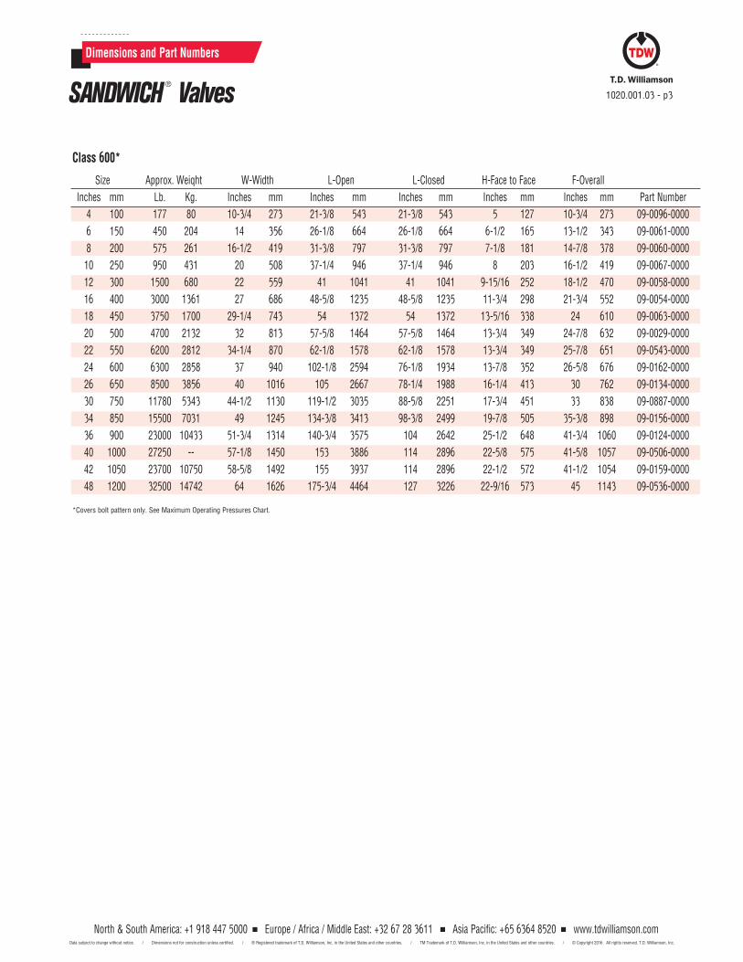
North & South America: +1 918 447 5000 Europe / Africa / Middle East: +32 67 28 3611 Asia Pacific: +65 6364 8520 www.tdwilliamson.comData subject to change without notice. / Dimensions not for construction unless certified. / ® Registered trademark of T.D. Williamson, Inc. in the United States and other countries. / TM Trademark of T.D. Williamson, Inc. in the United States and other countries. / © Copyright 2016 All rights reserved. T.D. Williamson, Inc.
North & South America: +1 918 447 5000 Europe / Africa / Middle East: +32 67 28 3611 Asia Pacific: +65 6364 8520 www.tdwilliamson.comData subject to change without notice. / Dimensions not for construction unless certified. / ® Registered trademark of T.D. Williamson, Inc. in the United States and other countries. / TM Trademark of T.D. Williamson, Inc. in the United States and other countries. / © Copyright 2016 All rights reserved. T.D. Williamson, Inc.
Dimensions and Part Numbers
Class 600*
Size Approx. Weiqht W-Width L-Open L-Closed H-Face to Face F-Overall
Inches mm Lb. Kg. Inches mm Inches mm Inches mm Inches mm Inches mm Part Number
4 100 177 80 10-3/4 273 21-3/8 543 21-3/8 543 5 127 10-3/4 273 09-0096-0000
6 150 450 204 14 356 26-1/8 664 26-1/8 664 6-1/2 165 13-1/2 343 09-0061-0000
8 200 575 261 16-1/2 419 31-3/8 797 31-3/8 797 7-1/8 181 14-7/8 378 09-0060-0000
10 250 950 431 20 508 37-1/4 946 37-1/4 946 8 203 16-1/2 419 09-0067-0000
12 300 1500 680 22 559 41 1041 41 1041 9-15/16 252 18-1/2 470 09-0058-0000
16 400 3000 1361 27 686 48-5/8 1235 48-5/8 1235 11-3/4 298 21-3/4 552 09-0054-0000
18 450 3750 1700 29-1/4 743 54 1372 54 1372 13-5/16 338 24 610 09-0063-0000
20 500 4700 2132 32 813 57-5/8 1464 57-5/8 1464 13-3/4 349 24-7/8 632 09-0029-0000
22 550 6200 2812 34-1/4 870 62-1/8 1578 62-1/8 1578 13-3/4 349 25-7/8 651 09-0543-0000
24 600 6300 2858 37 940 102-1/8 2594 76-1/8 1934 13-7/8 352 26-5/8 676 09-0162-0000
26 650 8500 3856 40 1016 105 2667 78-1/4 1988 16-1/4 413 30 762 09-0134-0000
30 750 11780 5343 44-1/2 1130 119-1/2 3035 88-5/8 2251 17-3/4 451 33 838 09-0887-0000
34 850 15500 7031 49 1245 134-3/8 3413 98-3/8 2499 19-7/8 505 35-3/8 898 09-0156-0000
36 900 23000 10433 51-3/4 1314 140-3/4 3575 104 2642 25-1/2 648 41-3/4 1060 09-0124-0000
40 1000 27250 -- 57-1/8 1450 153 3886 114 2896 22-5/8 575 41-5/8 1057 09-0506-0000
42 1050 23700 10750 58-5/8 1492 155 3937 114 2896 22-1/2 572 41-1/2 1054 09-0159-0000
48 1200 32500 14742 64 1626 175-3/4 4464 127 3226 22-9/16 573 45 1143 09-0536-0000
*Covers bolt pattern only. See Maximum Operating Pressures Chart.
SANDWICH ® Valves 1020.001.03 - p3
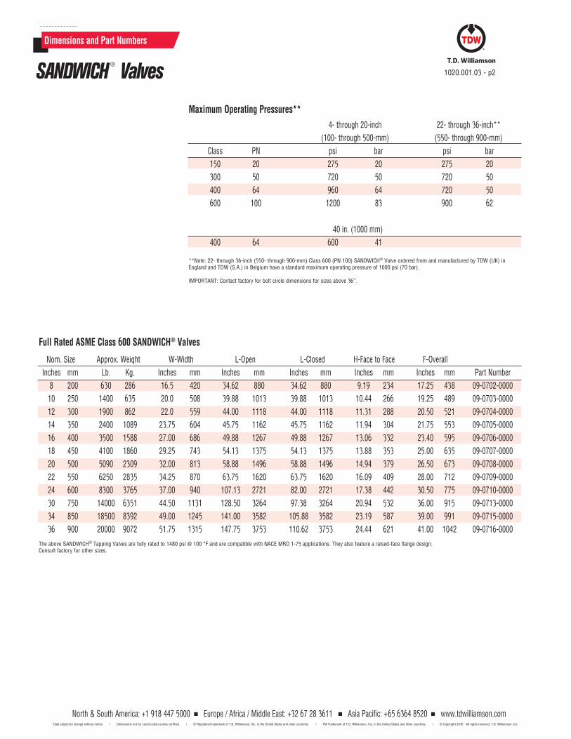
North & South America: +1 918 447 5000 Europe / Africa / Middle East: +32 67 28 3611 Asia Pacific: +65 6364 8520 www.tdwilliamson.comData subject to change without notice. / Dimensions not for construction unless certified. / ® Registered trademark of T.D. Williamson, Inc. in the United States and other countries. / TM Trademark of T.D. Williamson, Inc. in the United States and other countries. / © Copyright 2016 All rights reserved. T.D. Williamson, Inc.
Maximum Operating Pressures**
Dimensions and Part Numbers
4- through 20-inch 22- through 36-inch**
(100- through 500-mm) (550- through 900-mm)
Class PN psi bar psi bar
150 20 275 20 275 20
300 50 720 50 720 50
400 64 960 64 720 50
600 100 1200 83 900 62
40 in. (1000 mm)
400 64 600 41
**Note: 22- through 36-inch (550- through 900-mm) Class 600 (PN 100) SANDWICH® Valve ordered from and manufactured by TDW (UK) in England and TDW (S.A.) in Belgium have a standard maximum operating pressure of 1000 psi (70 bar).
IMPORTANT: Contact factory for bolt circle dimensions for sizes above 36”.
Full Rated ASME Class 600 SANDWICH® Valves
Nom. Size Approx. Weiqht W-Width L-Open L-Closed H-Face to Face F-Overall
Inches mm Lb. Kg. Inches mm Inches mm Inches mm Inches mm Inches mm Part Number
8 200 630 286 16.5 420 34.62 880 34.62 880 9.19 234 17.25 438 09-0702-0000
10 250 1400 635 20.0 508 39.88 1013 39.88 1013 10.44 266 19.25 489 09-0703-0000
12 300 1900 862 22.0 559 44.00 1118 44.00 1118 11.31 288 20.50 521 09-0704-0000
14 350 2400 1089 23.75 604 45.75 1162 45.75 1162 11.94 304 21.75 553 09-0705-0000
16 400 3500 1588 27.00 686 49.88 1267 49.88 1267 13.06 332 23.40 595 09-0706-0000
18 450 4100 1860 29.25 743 54.13 1375 54.13 1375 13.88 353 25.00 635 09-0707-0000
20 500 5090 2309 32.00 813 58.88 1496 58.88 1496 14.94 379 26.50 673 09-0708-0000
22 550 6250 2835 34.25 870 63.75 1620 63.75 1620 16.09 409 28.00 712 09-0709-0000
24 600 8300 3765 37.00 940 107.13 2721 82.00 2721 17.38 442 30.50 775 09-0710-0000
30 750 14000 6351 44.50 1131 128.50 3264 97.38 3264 20.94 532 36.00 915 09-0713-0000
34 850 18500 8392 49.00 1245 141.00 3582 105.88 3582 23.19 587 39.00 991 09-0715-0000
36 900 20000 9072 51.75 1315 147.75 3753 110.62 3753 24.44 621 41.00 1042 09-0716-0000
The above SANDWICH® Tapping Valves are fully rated to 1480 psi @ 100 °F and are compatible with NACE MRO 1-75 applications. They also feature a raised-face flange design. Consult factory for other sizes.
SANDWICH ® Valves 1020.001.03 - p2
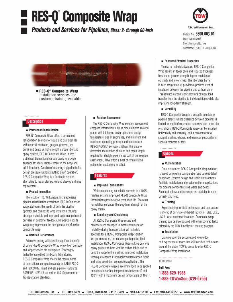
Toll Free
1-888-829-19881-888-TDWmSon (839-6766)
ISO 9001 Certified
Bulletin No: 5300.003.01Date: March 2008Cross Indexing No: n/aSupersedes: 5300.003.00 (02/08)
RES-Q®
Composite WrapProducts and Services for Pipelines, Sizes: 2- through 60-inch
Options
Improved Formulations
While maintaining no volatile solvents in a 100% reactive system, improved RES-Q Composite Wrap formulations provide a two-year shelf life. The resin formulation enhances the long-term strength of the epoxy matrix.
Simplicity and Consistency
All RES-Q Composite Wrap resins and hardeners are packaged in metal containers for reliability during transportation. All materials specified for a RES-Q Composite Wrap solution are pre-measured, pre-cut and packaged for field installation. RES-Q Composite Wrap utilizes only one epoxy product to both wet the carbon fabric and to bond the wrap to the pipeline. Improved installation techniques ensure a thoroughly wetted carbon fabric and more consistent composite application. The RES-Q Composite wrap is recommended to be applied on substrate surface temperatures between 40 and 120º F with a maximum design temperature of 165º F.
Customization
Each customized RES-Q Composite Wrap solution is based on pipeline configuration and current defect conditions. System design and fabric width options facilitate installation and provide uniform applications for pipeline components like welds and bends. Standard, elbow and tee wraps are available to meet virtually any need.
Training
Expert training for field technicians and contractors is offered at our state-of-the-art facility in Tulsa, Okla., U.S.A., or at customer locations. Composite wrap training can be incorporated with other covered tasks offered by the TDW LineMaster™ training program.
Installation
Drawing upon the accumulated knowledge and experience of more than 200 certified technicians around the globe, TDW is proud to offer RES-Q Composite Wrap installation.
Enhanced Physical Properties
Thanks to material advances, RES-Q Composite Wrap results in fewer plies and reduced thickness because of greater strength, higher modulus of elasticity and lower creep. The fiberglass barrier in each restoration kit provides a positive layer of insulation between the pipeline and carbon fabric. This stitched carbon fabric provides efficient load transfer from the pipeline to individual fibers while also improving long-term strength.
Versatility
RES-Q Composite Wrap is a versatile solution to pipeline defects where clearance between pipelines is limited or width of excavation is narrow due to job site restrictions. RES-Q Composite Wrap can be installed horizontally and vertically, and it can conform to straight pipeline, elbows, and even complex systems such as reducers or tees.
T.D. Williamson, Inc. P.O. Box 3409 Tulsa, Oklahoma 74101-3409 918-447-5100 Fax: 918-446-6327 www.tdwilliamson.comData subject to change without notice. / Dimensions not for construction unless certified. / ® Registered trademark of T.D. Williamson, Inc. in the United States and foreign countries / TM Trademark of T.D. Williamson, Inc. in the United States and foreign countries / © Copyright 2008. All rights reserved T.D. Williamson, Inc. / Printed in USA
Permanent Rehabilitation
RES-Q® Composite Wrap offers a permanent rehabilitation solution for liquid and gas pipelines with external corrosion, gouges, grooves, arc burns and dents. A high-strength carbon fiber and epoxy system, RES-Q Composite Wrap utilizes a stitched, bidirectional carbon fabric to provide superior structural reinforcement in the hoop and axial directions. Capable of restoring a pipeline to its design pressure without shutting down operation, RES-Q Composite Wrap is a flexible in-service alternative to repair clamps, welded sleeves and pipe replacement.
Product Innovation
The result of T.D. Williamson, Inc.’s extensive pipeline rehabilitation experience, RES-Q Composite Wrap addresses the needs of both the pipeline operator and composite wrap installer. Featuring stronger materials and improved performance based on years of customer feedback, RES-Q Composite Wrap truly represents the next generation of carbon composite wrap.
Certified Performance
Extensive testing validates the significant benefits of using RES-Q Composite Wrap where high pressure and longer service are anticipated. Thoroughly tested by accredited third-party laboratories, RES-Q Composite Wrap meets the requirements of international composite standards ASME PCC-2 and ISO 24817, liquid and gas pipeline standards ASME B31.4/B31.8, as well as U.S. Department of Transportation standards.
Description
Features
Solution Assessment
The RES-Q Composite Wrap solution assessment compiles information such as pipe diameter, material grade, wall thickness, design pressure, design temperature, size of anomalies, and minimum and maximum operating pressure and temperature. RES-Q ProCalc™ software analyzes this data to determine the number of wraps and repair length required for straight pipeline. As part of the solution assessment, TDW offers a host of rehabilitation options for customers to select.
RES-Q® Composite Wrap Installation services and customer training available
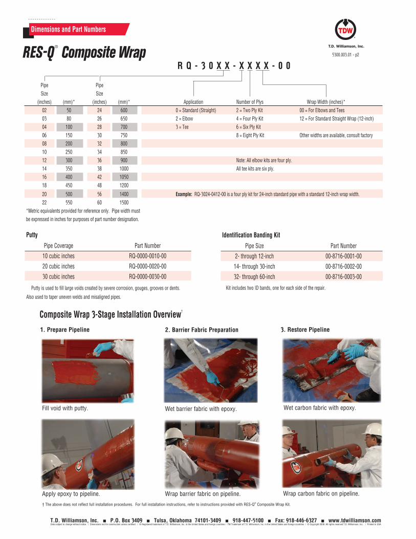
Dimensions and Part Numbers
RES-Q®
Composite Wrap 5300.003.01 - p2
Pipe Pipe Size Size (inches) (mm)* (inches) (mm)* Application Number of Plys Wrap Width (inches)* 02 50 24 600 0 = Standard (Straight) 2 = Two Ply Kit 00 = For Elbows and Tees 03 80 26 650 2 = Elbow 4 = Four Ply Kit 12 = For Standard Straight Wrap (12-inch) 04 100 28 700 3 = Tee 6 = Six Ply Kit 06 150 30 750 8 = Eight Ply Kit Other widths are available, consult factory 08 200 32 800 10 250 34 850 12 300 36 900 Note: All elbow kits are four ply. 14 350 38 1000 All tee kits are six ply. 16 400 42 1050 18 450 48 1200
20 500 56 1400 Example: RQ-3024-0412-00 is a four ply kit for 24-inch standard pipe with a standard 12-inch wrap width. 22 550 60 1500*Metric equivalents provided for reference only. Pipe width must be expressed in inches for purposes of part number designation.
Composite Wrap 3-Stage Installation Overview†
Pipe Coverage Part Number
10 cubic inches RQ-0000-0010-00
20 cubic inches RQ-0000-0020-00
30 cubic inches RQ-0000-0030-00
Putty
Putty is used to fill large voids created by severe corrosion, gouges, grooves or dents.
Also used to taper uneven welds and misaligned pipes.
T.D. Williamson, Inc. P.O. Box 3409 Tulsa, Oklahoma 74101-3409 918-447-5100 Fax: 918-446-6327 www.tdwilliamson.comData subject to change without notice. / Dimensions not for construction unless certified. / ® Registered trademark of T.D. Williamson, Inc. in the United States and foreign countries / TM Trademark of T.D. Williamson, Inc. in the United States and foreign countries / © Copyright 2008. All rights reserved T.D. Williamson, Inc. / Printed in USA
R Q - 3 0 X X - X X X X - 0 0
Pipe Size Part Number
2- through 12-inch 00-8716-0001-00
14- through 30-inch 00-8716-0002-00
32- through 60-inch 00-8716-0003-00
Kit includes two ID bands, one for each side of the repair.
Identification Banding Kit
1. Prepare Pipeline
Fill void with putty.
Apply epoxy to pipeline.
† The above does not reflect full installation procedures. For full installation instructions, refer to instructions provided with RES-Q® Composite Wrap Kit.
Wet barrier fabric with epoxy.
Wrap barrier fabric on pipeline.
Wet carbon fabric with epoxy.
Wrap carbon fabric on pipeline.
2. Barrier Fabric Preparation 3. Restore Pipeline
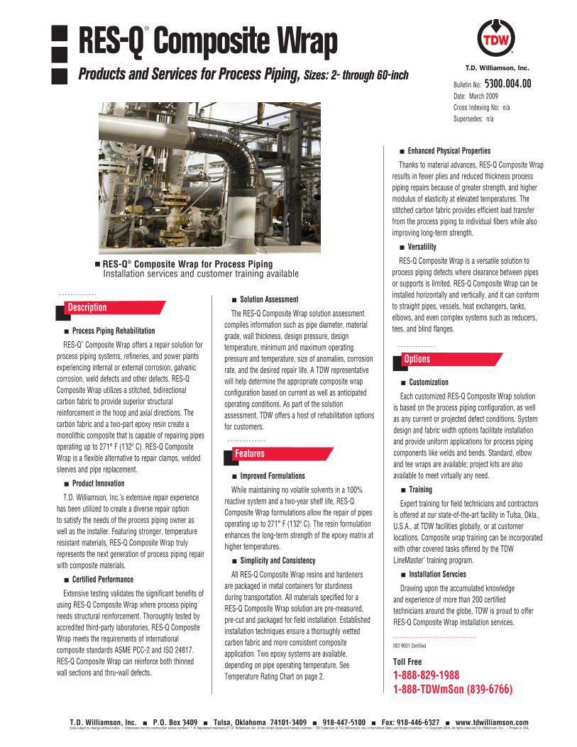
Toll Free
1-888-829-19881-888-TDWmSon (839-6766)
ISO 9001 Certified
Bulletin No: 5300.004.00Date: March 2009Cross Indexing No: n/aSupersedes: n/a
RES-Q®
Composite Wrap Products and Services for Process Piping, Sizes: 2- through 60-inch
Options
Improved Formulations
While maintaining no volatile solvents in a 100% reactive system and a two-year shelf life, RES-Q Composite Wrap formulations allow the repair of pipes operating up to 271° F (132º C). The resin formulation enhances the long-term strength of the epoxy matrix at higher temperatures.
Simplicity and Consistency
All RES-Q Composite Wrap resins and hardeners are packaged in metal containers for sturdiness during transportation. All materials specified for a RES-Q Composite Wrap solution are pre-measured, pre-cut and packaged for field installation. Established installation techniques ensure a thoroughly wetted carbon fabric and more consistent composite application. Two epoxy systems are available, depending on pipe operating temperature. See Temperature Rating Chart on page 2.
Customization
Each customized RES-Q Composite Wrap solution is based on the process piping configuration, as well as any current or projected defect conditions. System design and fabric width options facilitate installation and provide uniform applications for process piping components like welds and bends. Standard, elbow and tee wraps are available; project kits are also available to meet virtually any need.
Training
Expert training for field technicians and contractors is offered at our state-of-the-art facility in Tulsa, Okla., U.S.A., at TDW facilities globally, or at customer locations. Composite wrap training can be incorporated with other covered tasks offered by the TDW LineMaster™ training program.
Installation Servcies
Drawing upon the accumulated knowledge and experience of more than 200 certified technicians around the globe, TDW is proud to offer RES-Q Composite Wrap installation services.
Enhanced Physical Properties
Thanks to material advances, RES-Q Composite Wrap results in fewer plies and reduced thickness process piping repairs because of greater strength, and higher modulus of elasticity at elevated temperatures. The stitched carbon fabric provides efficient load transfer from the process piping to individual fibers while also improving long-term strength.
Versatility
RES-Q Composite Wrap is a versatile solution to process piping defects where clearance between pipes or supports is limited. RES-Q Composite Wrap can be installed horizontally and vertically, and it can conform to straight pipes, vessels, heat exchangers, tanks, elbows, and even complex systems such as reducers, tees, and blind flanges.
T.D. Williamson, Inc. P.O. Box 3409 Tulsa, Oklahoma 74101-3409 918-447-5100 Fax: 918-446-6327 www.tdwilliamson.comData subject to change without notice. / Dimensions not for construction unless certified. / ® Registered trademark of T.D. Williamson, Inc. in the United States and foreign countries / TM Trademark of T.D. Williamson, Inc. in the United States and foreign countries / © Copyright 2009. All rights reserved T.D. Williamson, Inc. / Printed in USA
Process Piping Rehabilitation
RES-Q® Composite Wrap offers a repair solution for process piping systems, refineries, and power plants experiencing internal or external corrosion, galvanic corrosion, weld defects and other defects. RES-Q Composite Wrap utilizes a stitched, bidirectional carbon fabric to provide superior structural reinforcement in the hoop and axial directions. The carbon fabric and a two-part epoxy resin create a monolithic composite that is capable of repairing pipes operating up to 271° F (132º C). RES-Q Composite Wrap is a flexible alternative to repair clamps, welded sleeves and pipe replacement.
Product Innovation
T.D. Williamson, Inc.’s extensive repair experience has been utilized to create a diverse repair option to satisfy the needs of the process piping owner as well as the installer. Featuring stronger, temperature resistant materials, RES-Q Composite Wrap truly represents the next generation of process piping repair with composite materials.
Certified Performance
Extensive testing validates the significant benefits of using RES-Q Composite Wrap where process piping needs structural reinforcement. Thoroughly tested by accredited third-party laboratories, RES-Q Composite Wrap meets the requirements of international composite standards ASME PCC-2 and ISO 24817. RES-Q Composite Wrap can reinforce both thinned wall sections and thru-wall defects.
Description
Features
Solution Assessment
The RES-Q Composite Wrap solution assessment compiles information such as pipe diameter, material grade, wall thickness, design pressure, design temperature, minimum and maximum operating pressure and temperature, size of anomalies, corrosion rate, and the desired repair life. A TDW representative will help determine the appropriate composite wrap configuration based on current as well as anticipated operating conditions. As part of the solution assessment, TDW offers a host of rehabilitation options for customers.
RES-Q® Composite Wrap for Process Piping Installation services and customer training available
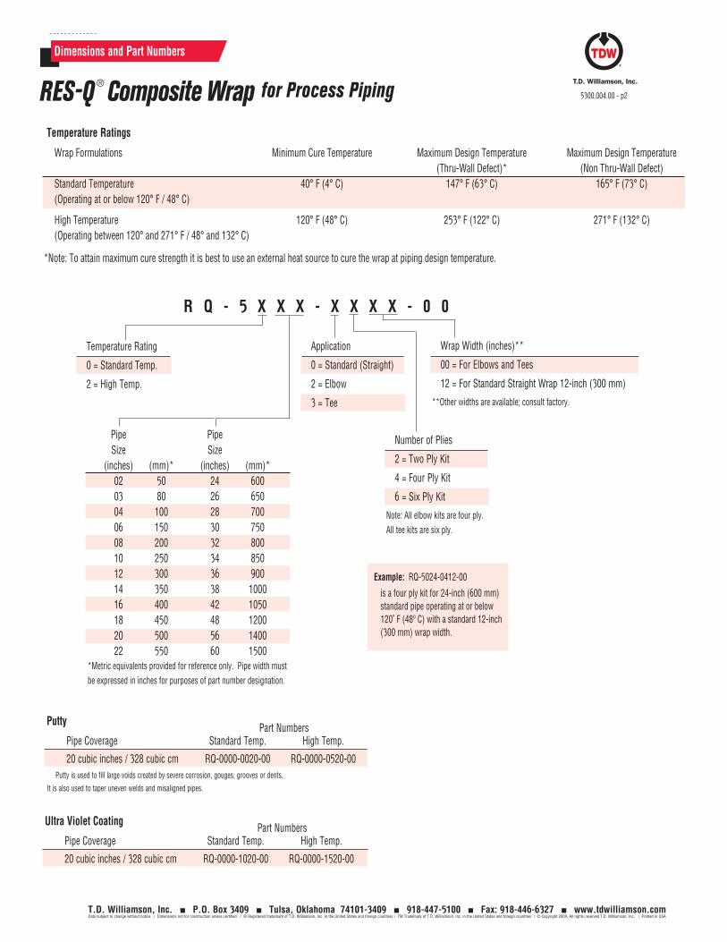
Dimensions and Part Numbers
RES-Q ® Composite Wrap for Process Piping 5300.004.00 - p2
T.D. Williamson, Inc. P.O. Box 3409 Tulsa, Oklahoma 74101-3409 918-447-5100 Fax: 918-446-6327 www.tdwilliamson.comData subject to change without notice. / Dimensions not for construction unless certified. / ® Registered trademark of T.D. Williamson, Inc. in the United States and foreign countries / TM Trademark of T.D. Williamson, Inc. in the United States and foreign countries / © Copyright 2009. All rights reserved T.D. Williamson, Inc. / Printed in USA
Part Numbers Pipe Coverage Standard Temp. High Temp.
20 cubic inches / 328 cubic cm RQ-0000-1020-00 RQ-0000-1520-00
Ultra Violet Coating
Part Numbers Pipe Coverage Standard Temp. High Temp.
20 cubic inches / 328 cubic cm RQ-0000-0020-00 RQ-0000-0520-00
Putty
Putty is used to fill large voids created by severe corrosion, gouges, grooves or dents.
It is also used to taper uneven welds and misaligned pipes.
*Metric equivalents provided for reference only. Pipe width must be expressed in inches for purposes of part number designation.
R Q - 5 X X X - X X X X - 0 0
Pipe Pipe Size Size (inches) (mm)* (inches) (mm)* 02 50 24 600 03 80 26 650 04 100 28 700 06 150 30 750 08 200 32 800 10 250 34 850 12 300 36 900 14 350 38 1000 16 400 42 1050 18 450 48 1200 20 500 56 1400 22 550 60 1500
Wrap Width (inches)**
00 = For Elbows and Tees
12 = For Standard Straight Wrap 12-inch (300 mm)
**Other widths are available; consult factory.
Temperature Rating
0 = Standard Temp.
2 = High Temp.
Application
0 = Standard (Straight)
2 = Elbow
3 = Tee
Number of Plies
2 = Two Ply Kit
4 = Four Ply Kit
6 = Six Ply Kit
Note: All elbow kits are four ply. All tee kits are six ply.
is a four ply kit for 24-inch (600 mm) standard pipe operating at or below 120˚ F (48º C) with a standard 12-inch (300 mm) wrap width.
Example: RQ-5024-0412-00
Temperature Ratings
Wrap Formulations Minimum Cure Temperature Maximum Design Temperature Maximum Design Temperature (Thru-Wall Defect)* (Non Thru-Wall Defect) Standard Temperature 40° F (4° C) 147° F (63° C) 165° F (73° C) (Operating at or below 120° F / 48° C)
High Temperature 120° F (48° C) 253° F (122° C) 271° F (132° C) (Operating between 120° and 271° F / 48° and 132° C)
*Note: To attain maximum cure strength it is best to use an external heat source to cure the wrap at piping design temperature.
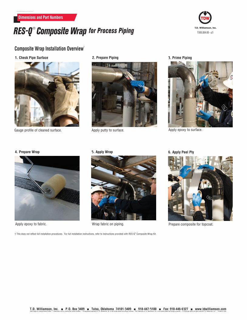
Dimensions and Part Numbers
RES-Q ® Composite Wrap for Process Piping 5300.004.00 - p3
Composite Wrap Installation Overview†
T.D. Williamson, Inc. P.O. Box 3409 Tulsa, Oklahoma 74101-3409 918-447-5100 Fax: 918-446-6327 www.tdwilliamson.comData subject to change without notice. / Dimensions not for construction unless certified. / ® Registered trademark of T.D. Williamson, Inc. in the United States and foreign countries / TM Trademark of T.D. Williamson, Inc. in the United States and foreign countries / © Copyright 2009. All rights reserved T.D. Williamson, Inc. / Printed in USA
1. Check Pipe Surface
Gauge profile of cleaned surface.
2. Prepare Piping
Apply putty to surface.
† This does not reflect full installation procedures. For full installation instructions, refer to instructions provided with RES-Q® Composite Wrap Kit.
Apply epoxy to surface.
3. Prime Piping
Wrap fabric on piping.
5. Apply Wrap
Apply epoxy to fabric.
4. Prepare Wrap
Prepare composite for topcoat.
6. Apply Peel Ply

5300.004.00 - p4
T.D. Williamson, Inc. P.O. Box 3409 Tulsa, Oklahoma 74101-3409 918-447-5100 Fax: 918-446-6327 www.tdwilliamson.comData subject to change without notice. / Dimensions not for construction unless certified. / ® Registered trademark of T.D. Williamson, Inc. in the United States and foreign countries / TM Trademark of T.D. Williamson, Inc. in the United States and foreign countries / © Copyright 2009. All rights reserved T.D. Williamson, Inc. / Printed in USA
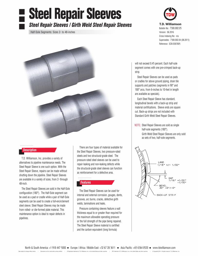
T.D. Williamson, Inc. provides a variety of
alternatives to pipeline maintenance needs. The
Steel Repair Sleeve is one such option. With the
Steel Repair Sleeve, repairs can be made without
shutting down the pipeline. Steel Repair Sleeves
are available in a variety of sizes, from 2- through
48-inch.
The Steel Repair Sleeves are sold in the Half-Sole
configuration (180°). The Half-Sole segment can
be used as a pad or cradle while a pair of Half-Sole
segments can be used to create a full-encirclement
steel sleeve. Steel Repair Sleeves may be made
from rolled- or die-formed plate material. This
maintenance option is ideal to repair defects in
pipelines.
There are four types of material available for
the Steel Repair Sleeves, two pressure-rated
steels and two structural-grade steel. The
pressure-rated steel sleeves can be used to
repair leaking and non-leaking defects while
the structural-grade steel sleeves can function
as reinforcement for a defective area.
Description
Features
Bulletin No: 7300.002.05Version: 06.2016
Cross Indexing No: n/a
Supersedes: 7300.002.04 (08.2013)
Reference: ECN E007805
will not exceed 0.45 percent. Each half-sole
segment comes with one pre-crimped back-up
strip.
Steel Repair Sleeves can be used as pads
or cradles for above ground piping, drain tile
supports and patches (segments in 90° and
180° arcs, from 6-inches to 10-feet in length
are available as specials).
Each Steel Repair Sleeve has standard,
longitudinal bevels with a back-up strip and
material certifications. Sleeve ends are square
cut. Back-up strips are not included with
Standard Girth Weld Steel Repair Sleeves.
The Steel Repair Sleeves can be used for
internal and external corrosion, gouges, dents,
grooves, arc burns, cracks, defective girth
welds, laminations and leaks.
Pressure containing sleeves feature a wall
thickness equal to or greater than required for
the maximum allowable operating pressure
or the full strength of the pipe being repaired.
The Steel Repair Sleeve material is certified
and the carbon equivalent (long formula)
NOTE: Steel Repair Sleeves are sold as single
half-sole segments (180°).
Girth Weld Steel Repair Sleeves are only sold as sets of two, half-sole segments.
Steel Repair SleevesSteel Repair Sleeves / Girth Weld Steel Repair Sleeves
Half-Sole Segments: Sizes 2- to 48-inches
North & South America: +1 918 447 5000 Europe / Africa / Middle East: +32 67 28 3611 Asia Pacific: +65 6364 8520 www.tdwilliamson.comData subject to change without notice. / Dimensions not for construction unless certified. / ® Registered trademark of T.D. Williamson, Inc. in the United States and other countries. / TM Trademark of T.D. Williamson, Inc. in the United States and other countries. / © Copyright 2016 All rights reserved. T.D. Williamson, Inc.
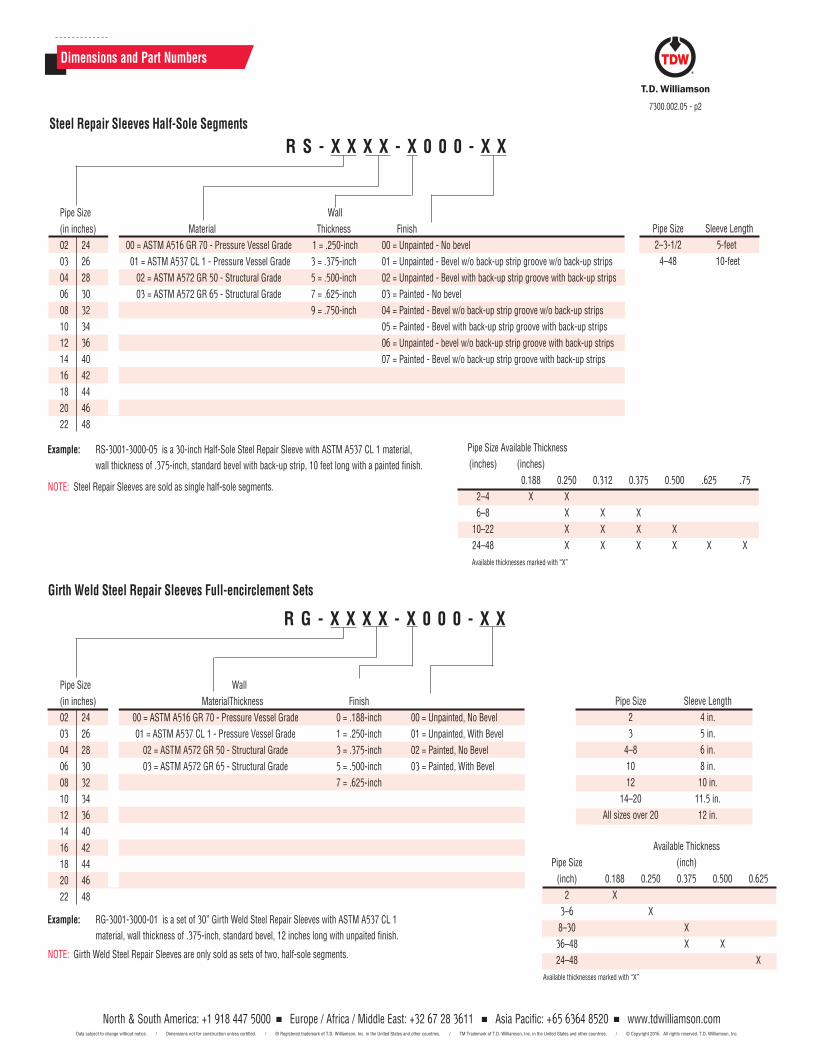
R G - X X X X - X 0 0 0 - X X
Pipe Size Wall
(in inches) Material Thickness Finish
02 24 00 = ASTM A516 GR 70 - Pressure Vessel Grade 0 = .188-inch 00 = Unpainted, No Bevel
03 26 01 = ASTM A537 CL 1 - Pressure Vessel Grade 1 = .250-inch 01 = Unpainted, With Bevel
04 28 02 = ASTM A572 GR 50 - Structural Grade 3 = .375-inch 02 = Painted, No Bevel
06 30 03 = ASTM A572 GR 65 - Structural Grade 5 = .500-inch 03 = Painted, With Bevel
08 32 7 = .625-inch
10 34
12 36
14 40
16 42
18 44
20 46
22 48
Dimensions and Part Numbers
7300.002.05 - p2
Steel Repair Sleeves Half-Sole Segments
Girth Weld Steel Repair Sleeves Full-encirclement Sets
Example: RS-3001-3000-05 is a 30-inch Half-Sole Steel Repair Sleeve with ASTM A537 CL 1 material,
wallthicknessof.375-inch,standardbevelwithback-upstrip,10feetlongwithapaintedfinish.
R S - X X X X - X 0 0 0 - X X
Pipe Size Wall
(in inches) Material Thickness Finish
02 24 00 = ASTM A516 GR 70 - Pressure Vessel Grade 1 = .250-inch 00 = Unpainted - No bevel
03 26 01 = ASTM A537 CL 1 - Pressure Vessel Grade 3 = .375-inch 01 = Unpainted - Bevel w/o back-up strip groove w/o back-up strips
04 28 02 = ASTM A572 GR 50 - Structural Grade 5 = .500-inch 02 = Unpainted - Bevel with back-up strip groove with back-up strips
06 30 03 = ASTM A572 GR 65 - Structural Grade 7 = .625-inch 03 = Painted - No bevel
08 32 9 = .750-inch 04 = Painted - Bevel w/o back-up strip groove w/o back-up strips
10 34 05 = Painted - Bevel with back-up strip groove with back-up strips
12 36 06 = Unpainted - bevel w/o back-up strip groove with back-up strips
14 40 07 = Painted - Bevel w/o back-up strip groove with back-up strips
16 42
18 44
20 46
22 48
Example: RG-3001-3000-01 is a set of 30” Girth Weld Steel Repair Sleeves with ASTM A537 CL 1
material,wallthicknessof.375-inch,standardbevel,12incheslongwithunpaitedfinish.
Pipe Size Sleeve Length
2–3-1/2 5-feet
4–48 10-feet
Pipe Size Sleeve Length
2 4 in.
3 5 in.
4–8 6 in.
10 8 in.
12 10 in.
14–20 11.5 in.
All sizes over 20 12 in.
NOTE: Girth Weld Steel Repair Sleeves are only sold as sets of two, half-sole segments.
NOTE: Steel Repair Sleeves are sold as single half-sole segments.
Pipe Size Available Thickness
(inches) (inches)
0.188 0.250 0.312 0.375 0.500 .625 .75
2–4 X X
6–8 X X X
10–22 X X X X
24–48 X X X X X X
Available thicknesses marked with “X”
Available Thickness
Pipe Size (inch)
(inch) 0.188 0.250 0.375 0.500 0.625
2 X
3–6 X
8–30 X
36–48 X X
24–48 X
Available thicknesses marked with “X”
North & South America: +1 918 447 5000 Europe / Africa / Middle East: +32 67 28 3611 Asia Pacific: +65 6364 8520 www.tdwilliamson.comData subject to change without notice. / Dimensions not for construction unless certified. / ® Registered trademark of T.D. Williamson, Inc. in the United States and other countries. / TM Trademark of T.D. Williamson, Inc. in the United States and other countries. / © Copyright 2016 All rights reserved. T.D. Williamson, Inc.
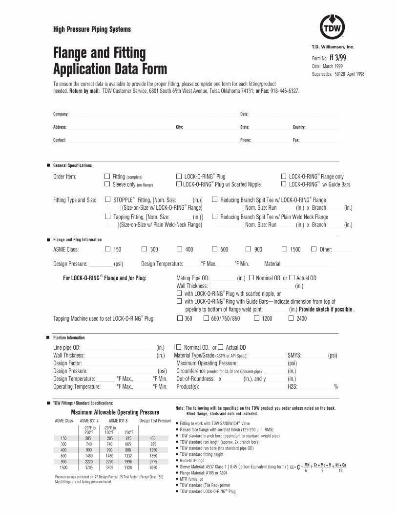
General Specifications
Order Item: Fitting (complete) LOCK-O-RING® Plug LOCK-O-RING® Flange only Sleeve only (no flange) LOCK-O-RING® Plug w/ Scarfed Nipple LOCK-O-RING® w/ Guide Bars
Fitting Type and Size: STOPPLE® Fitting, [Nom. Size: (in.)] Reducing Branch Split Tee w/ LOCK-O-RING® Flange Tapping Fitting, [Nom. Size: (in.)] Reducing Branch Split Tee w/ Plain Weld Neck Flange
Flange and Plug Information ASME Class: 150 300 400 600 900 1500 Other:
Design Pressure: (psi) Design Temperature: °F Max. °F Min. Material:
For LOCK-O-RING® Flange and /or Plug: Mating Pipe OD: (in.) Nominal OD, or Actual OD Wall Thickness: (in.) with LOCK-O-RING® Plug with scarfed nipple, or with LOCK-O-RING® Ring with Guide Bars—indicate dimension from top of pipeline to bottom of flange weld joint: (in.) Provide sketch if possible .Tapping Machine used to set LOCK-O-RING® Plug: 360 660 / 760/ 860 1200 2400 Pipeline Information Line pipe OD: (in.) Nominal OD, or Actual ODWall Thickness: (in.) Material Type/Grade (ASTM or API Spec.): SMYS: (psi)Design Factor: Maximum Operating Pressure: (psi) Design Pressure: (psi) Circumference (needed for CI, DI and Concrete pipe): (in.)Design Temperature: °F Max., °F Min. Out-of-Roundness: x (in.), and y (in.)Operating Temperature: °F Max., °F Min. Product(s): H2S: %
[ (Size-on-Size w/ LOCK-O-RING® Flange)
[ (Size-on-Size w/ Plain Weld-Neck Flange)
Fitting to work with TDW SANDWICH® Valve Raised face flange with serrated finish (125-250 µ in. RMS) TDW standard branch bore (equivalent to standard weight pipe) TDW standard run length (approx. 2x branch bore) TDW standard run bore (fits standard pipe OD) TDW standard fitting height Buna-N O-rings Sleeve Material: A537 Class 1 [ 0.45 Carbon Equivalent (long form) ]: Flange Material: A105 or A694 MTR furnished TDW standard (Tile Red) primer TDW standard LOCK-O-RING® Plug
High Pressure Piping Systems
Flange and Fitting
Application Data Form
Company: Date:
Address: City: State: Country:
Contact: Phone: Fax:
To ensure the correct data is available to provide the proper fitting, please complete one form for each fitting/product needed. Return by mail: TDW Customer Service, 6801 South 65th West Avenue, Tulsa Oklahoma 74131; or Fax: 918-446-6327.
Form No: ff 3/99Date: March 1999Supersedes: 50128 April 1998
[ Nom. Size: Run (in.) x Branch (in.)
Pressure ratings are based on .72 Design Factor/1.25 Test Factor, (Except Class 150).Most fittings are not factory pressure tested.
6 5 15CE= C + MN + Cr + Mo + V + Ni + Cu
[
Note: The following will be specified on the TDW product you order unless noted on the back. Blind flange, studs and nuts not included.
[ Nom. Size: Run (in.) x Branch (in.)
Maximum Allowable Operating PressureASME Class ASME B31.4 ASME B31.8 Design Test Pressure -20°F to -20°F to 250°F 100°F 250°F 150 285 285 245 450 300 740 740 665 925 400 990 990 888 1250 600 1480 1480 1332 1850 900 2220 2220 1998 2775 1500 3705 3705 3328 4650
TDW Fittings / Standard Specifications:
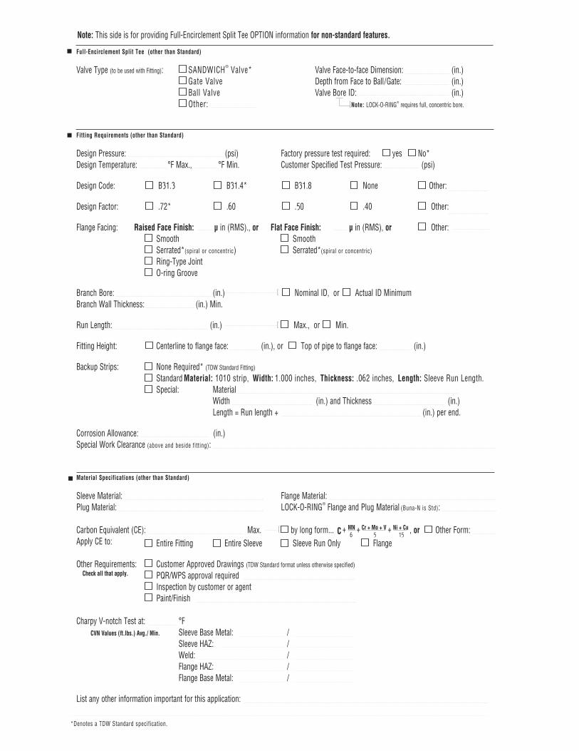
6 5 15 C + MN + Cr + Mo + V + Ni + Cu
[
Note: This side is for providing Full-Encirclement Split Tee OPTION information for non-standard features.
*Denotes a TDW Standard specification.
[
[
Full-Encirclement Split Tee (other than Standard) Valve Type (to be used with Fitting): SANDWICH® Valve* Valve Face-to-face Dimension: (in.) Gate Valve Depth from Face to Ball/Gate: (in.) Ball Valve Valve Bore ID: (in.) Other: [Note: LOCK-O-RING® requires full, concentric bore.
Fitting Requirements (other than Standard) Design Pressure: (psi) Factory pressure test required: yes No*Design Temperature: °F Max., °F Min. Customer Specified Test Pressure: (psi)
Design Code: B31.3 B31.4* B31.8 None Other:
Design Factor: .72* .60 .50 .40 Other:
Flange Facing: Raised Face Finish: µ in (RMS)., or Flat Face Finish: µ in (RMS), or Other: Smooth Smooth Serrated*(spiral or concentric) Serrated*(spiral or concentric)
Ring-Type Joint O-ring Groove
Branch Bore: (in.) Nominal ID, or Actual ID Minimum Branch Wall Thickness: (in.) Min.
Run Length: (in.) Max., or Min. Fitting Height: Centerline to flange face: (in.), or Top of pipe to flange face: (in.)
Backup Strips: None Required* (TDW Standard Fitting)
Standard Material: 1010 strip, Width: 1.000 inches, Thickness: .062 inches, Length: Sleeve Run Length. Special: Material Width (in.) and Thickness (in.) Length = Run length + (in.) per end.
Corrosion Allowance: (in.)Special Work Clearance (above and beside fitting):
Material Specifications (other than Standard)
Sleeve Material: Flange Material: Plug Material: LOCK-O-RING® Flange and Plug Material (Buna-N is Std):
Carbon Equivalent (CE): Max. by long form... , or Other Form:Apply CE to: Entire Fitting Entire Sleeve Sleeve Run Only Flange
Other Requirements: Customer Approved Drawings (TDW Standard format unless otherwise specified)
Check all that apply. PQR/WPS approval required Inspection by customer or agent Paint/Finish Charpy V-notch Test at: °F CVN Values (ft.lbs.) Avg./ Min. Sleeve Base Metal: / Sleeve HAZ: / Weld: / Flange HAZ: / Flange Base Metal: /
List any other information important for this application:
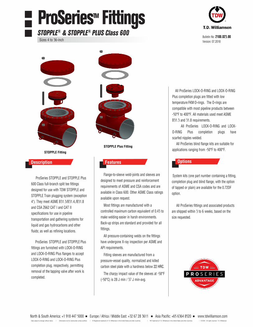
North & South America: +1 918 447 5000 Europe / Africa / Middle East: +32 67 28 3611 Asia Pacific: +65 6364 8520 Data subject to change without notice. / Dimensions not for construction unless certified. / ® Registered trademark of T.D. Williamson in the United States and other countries. / TM Trademark of T.D. Williamson in the United States and other countries. /
www.tdwilliamson.com © 2018 All rights reserved. T.D. Williamson
Flange-to-sleeve weld-joints and sleeves are
designed to meet pressure and reinforcement
requirements of ASME and CSA codes and are
available in Class 600. Other ASME Class ratings
available upon request.
Most fittings are manufactured with a
controlled maximum carbon equivalent of 0.43 to
make welding easier in harsh environments.
Back-up strips are standard and provided for all
fittings.
All pressure-containing welds on the fittings
have undergone X-ray inspection per ASME and
API requirements.
Fitting sleeves are manufactured from a
pressure-vessel quality, normalized and killed
carbon steel plate with a hardness below 22 HRC.
The charpy impact value of the sleeves at -58°F
(-50°C) is 28 J min / 37 J min-avg.
Features
ProSeries STOPPLE and STOPPLE Plus
600 Class full-branch split tee fittings
designed for use with TDW STOPPLE and
STOPPLE Train plugging system (exception
4"). They meet ASME B31.3/B31.4,/B31.8
and CSA Z662 CAT I and CAT II
specifications for use in pipeline
transportation and gathering systems for
liquid and gas hydrocarbons and other
fluids; as well as refining locations.
ProSeries STOPPLE and STOPPLE Plus
fittings are furnished with LOCK-O-RING
and LOCK-O-RING Plus flanges to accept
LOCK-O-RING and LOCK-O-RING Plus
completion plug, respectively, permitting
removal of the tapping valve after work is
completed.
Bulletin No: 2100.023.00Version: 07.2018
ProSeriesTM FittingsSTOPPLE® & STOPPLE® PLUS Class 600
Sizes 4 to 36-inch
All ProSeries LOCK-O-RING and LOCK-O-RING
Plus completion plugs are fitted with low
temperature FKM O-rings. The O-rings are
compatible with most pipeline products between
-50°F to 400°F. All materials used meet ASME
B31.3 and 31.8 requirements.
All ProSeries LOCK-O-RING and LOCK-
O-RING Plus completion plugs have
scarfed nipples welded.
All ProSeries blind flange kits are suitable for
applications ranging from -50°F to 400°F.
System kits (one part number containing a fitting,
completion plug and blind flange, with the option
of tapped or plain) are available for the 0.72DF
option.
All ProSeries fittings and associated products
are shipped within 3 to 6 weeks, based on the
size requested.
Options
STOPPLE Plus Fitting
STOPPLE Fitting
Description Description
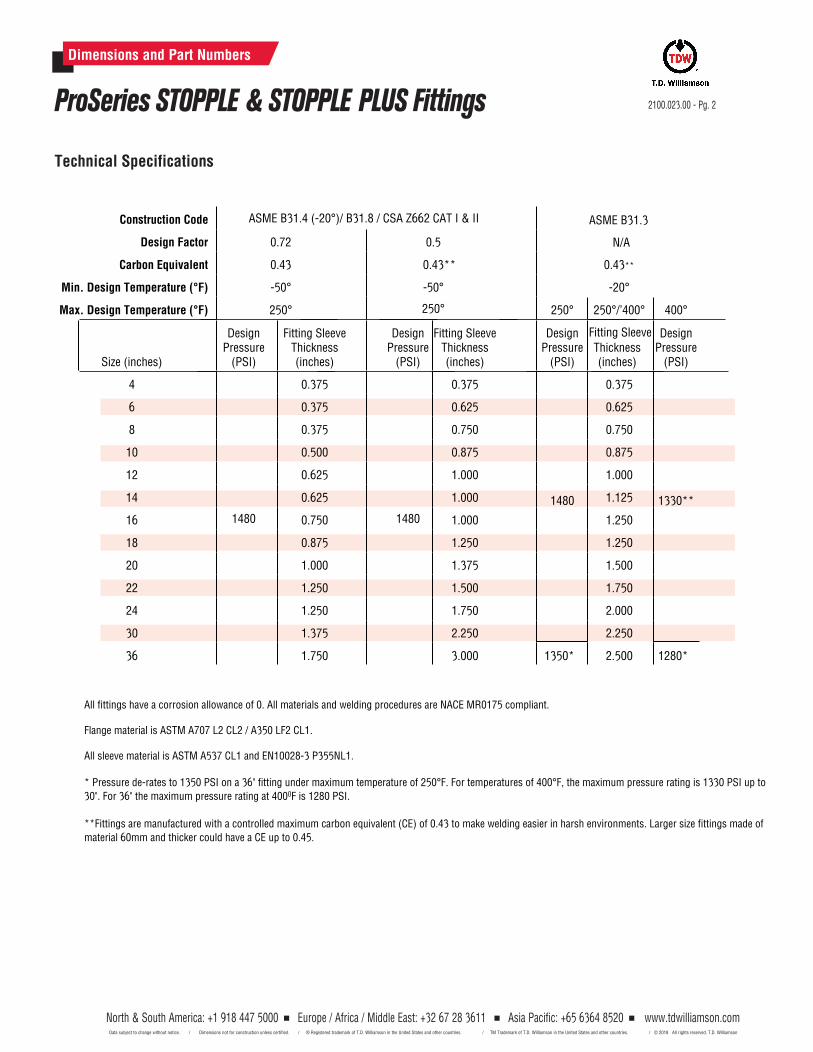
North & South America: +1 918 447 5000 Europe / Africa / Middle East: +32 67 28 3611 Asia Pacific: +65 6364 8520 www.tdwilliamson.comData subject to change without notice. / Dimensions not for construction unless certified. / ® Registered trademark of T.D. Williamson, Inc. in the United States and other countries. / TM Trademark of T.D. Williamson, Inc. in the United States and other countries. / © Copyright 2014 All rights reserved. T.D. Williamson, Inc.
ASME B31.4 (-20°)/ B31.8 / CSA Z662 CAT I & II
0.72 0.5
0.43 0.43**
-50° -50°
ASME B31.3
N/A
0.43**
-20°
250° 250° 250° 250°/’400° 400°
Size (inches)
Design Pressure
(PSI)
Fitting Sleeve Thickness (inches)
Design Pressure
(PSI)
Fitting Sleeve Thickness (inches)
Design Pressure
(PSI)
Design Pressure
(PSI)
4 0.375 0.375 0.375
8 0.375 0.750 0.750
12 0.625 1.000 1.000
2100.023.00 - Pg. 2
Dimensions and Part Numbers
ProSeries STOPPLE & STOPPLE PLUS Fittings
Technical Specifications
Construction Code
Design Factor
Carbon Equivalent
Min. Design Temperature (°F)
Max. Design Temperature (°F)
0.3756 0.625 0.625
All fittings have a corrosion allowance of 0. All materials and welding procedures are NACE MR0175 compliant.
Flange material is ASTM A707 L2 CL2 / A350 LF2 CL1.
All sleeve material is ASTM A537 CL1 and EN10028-3 P355NL1.
* Pressure de-rates to 1350 PSI on a 36" fitting under maximum temperature of 250°F. For temperatures of 400°F, the maximum pressure rating is 1330 PSI up to30". For 36" the maximum pressure rating at 4000F is 1280 PSI.
**Fittings are manufactured with a controlled maximum carbon equivalent (CE) of 0.43 to make welding easier in harsh environments. Larger size fittings made of material 60mm and thicker could have a CE up to 0.45.
10 0.500 0.875 0.875
1480 1480
1480 1330**14 0.625 1.000 1.125
16 0.750 1.000 1.250
18 0.875 1.250 1.250
20 1.000 1.375 1.500
22 1.250 1.500 1.750
24 1.250 1.750 2.000
30 1.375 2.250 2.250
36 1.750 3.000 1350* 2.500 1280*
North & South America: +1 918 447 5000 Europe / Africa / Middle East: +32 67 28 3611 Asia Pacific: +65 6364 8520 Data subject to change without notice. / Dimensions not for construction unless certified. / ® Registered trademark of T.D. Williamson in the United States and other countries. / TM Trademark of T.D. Williamson in the United States and other countries. /
www.tdwilliamson.com © 2018 All rights reserved. T.D. Williamson
Thickness (inches)
Fitting Sleeve
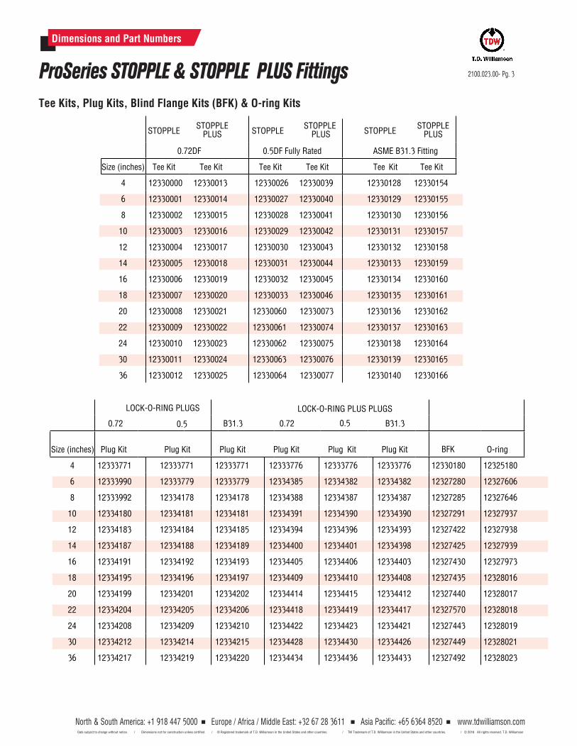
North & South America: +1 918 447 5000 Europe / Africa / Middle East: +32 67 28 3611 Asia Pacific: +65 6364 8520 www.tdwilliamson.comData subject to change without notice. / Dimensions not for construction unless certified. / ® Registered trademark of T.D. Williamson, Inc. in the United States and other countries. / TM Trademark of T.D. Williamson, Inc. in the United States and other countries. / © Copyright 2014 All rights reserved. T.D. Williamson, Inc.
Code B31.4 / B31.8 / CSA Z662 CAT I & II B31.3
Design Factor 0.72 0.5 0.5 N/A
Carbon Equivalent 0.43 0.43 0.43 0.43
Min. Design Temperature (°F) -50° -50° -50° -20°
Max. Design Temperature (°F) 250° 250° 250° 250° 250°/’400° 400°
Size (inches)
Design Pressure
(PSI)
Fitting Sleeve Thickness (inches)
Design Pressure
(PSI)
Fitting Sleeve Thickness (inches)
Design Pressure
(PSI)
Fitting Sleeve Thickness (inches)
Design Pressure
(PSI)
Fitting Sleeve
Thickness
Design Pressure
(PSI)
4
1480
0.375
1480
0.375
1480
0.375
1480
0.375
1330**
6 0.375 0.625 0.625 0.625
8 0.375 0.750 0.750 0.750
10 0.500 0.875 0.875 0.875
12 0.625 1.000 1.000 1.000
14 0.625 1.000 1.000 1.125
16 0.750 1.000 1.000 1.250
18 0.875
1.250
1.250 1.250
20 1.000 1430* 1.375 1.500
22 1.250 1220* 1.500 1.750
24 1.250 1110* 1.750 2.000
30 1.375 1375* 2.250 2.250
36 1.750 720* 3.000 1350** 2.500 1280**
Dimensions and Part Numbers
2100.023.00- Pg. 3ProSeries STOPPLE & STOPPLE PLUS Fittings
STOPPLESTOPPLE
PLUS
0.72DF 0.5DF Fully Rated ASME B31.3 Fitting
Size (inches) Tee Kit Tee Kit Tee Kit Tee Kit Tee Kit Tee Kit
4 12330000 12330013 12330128 12330154
8 12330002 12330015 12330130 12330156
0.72 0.5 B31.3 0.72
LOCK-O-RING PLUS PLUGS
0.5 B31.3
Size (inches) Plug Kit Plug Kit Plug Kit Plug Kit Plug Kit Plug Kit BFK O-ring
4 12333771 12333771 12333771 12333776 12333776 12333776 12330180 12325180
Tee Kits, Plug Kits, Blind Flange Kits (BFK) & O-ring Kits
STOPPLESTOPPLE
PLUS STOPPLESTOPPLE
PLUS
6 12330001 12330014 12330129 12330155
6 12333990 12333779 12333779 12334385 12334382 12334382 12327280 12327606
8 12333992 12334178 12334178 12334388 12334387 12334387 12327285 12327646
10 12330003 12330016 12330131 12330157
12 12330004 12330017 12330132 12330158
14 12330005 12330018 12330133 12330159
16 12330006 12330019 12330134 12330160
18 12330007 12330020 12330135 12330161
20 12330008 12330021 12330060 12330073 12330136 12330162
22 12330009 12330022 12330061 12330074 12330137 12330163
24 12330010 12330023 12330062 12330075 12330138 12330164
30 12330011 12330024 12330063 12330076 12330139 12330165
36 12330012 12330025 12330064 12330077 12330140 12330166
10 12334180 12334181 12334181 12334391 12334390 12334390 12327291 12327937
12 12334183 12334184 12334185 12334394 12334396 12334393 12327422 12327938
14 12334187 12334188 12334189 12334400 12334401 12334398 12327425 12327939
16 12334191 12334192 12334193 12334405 12334406 12334403 12327430 12327973
18 12334195 12334196 12334197 12334409 12334410 12334408 12327435 12328016
20 12334199 12334201 12334202 12334414 12334415 12334412 12327440 12328017
22 12334204 12334205 12334206 12334418 12334419 12334417 12327570 12328018
24 12334208 12334209 12334210 12334422 12334423 12334421 12327443 12328019
30 12334212 12334214 12334215 12334428 12334430 12334426 12327449 12328021
36 12334217 12334219 12334220 12334434 12334436 12334433 12327492 12328023
North & South America: +1 918 447 5000 Europe / Africa / Middle East: +32 67 28 3611 Asia Pacific: +65 6364 8520 Data subject to change without notice. / Dimensions not for construction unless certified. / ® Registered trademark of T.D. Williamson in the United States and other countries. / TM Trademark of T.D. Williamson in the United States and other countries. /
www.tdwilliamson.com © 2018 All rights reserved. T.D. Williamson
12330026 12330039
12330028 12330041
12330027 12330040
12330029 12330042
12330030 12330043
12330031 12330044
12330032 12330045
12330033 12330046
LOCK-O-RING PLUGS
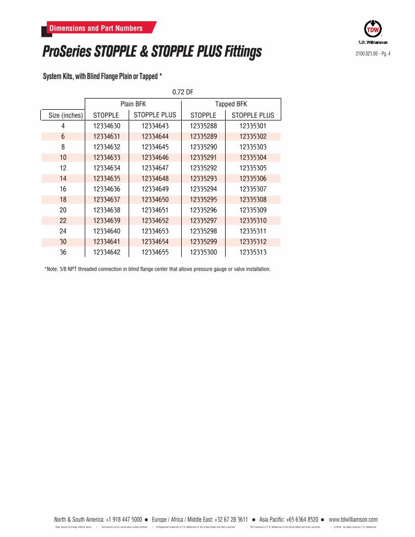
2100.023.00 - Pg. 4
Dimensions and Part Numbers
ProSeries STOPPLE & STOPPLE PLUS FittingsSystem Kits, with Blind Flange Plain or Tapped *
Plain BFK Tapped BFK
Size (inches) STOPPLE STOPPLE PLUS STOPPLE STOPPLE PLUS
4 12334630 12334643 12335288 12335301
8 12334632 12334645 12335290 12335303
10 12334633 12334646 12335291 12335304
12 12334634 12334647 12335292 12335305
14 12334635 12334648 12335293 12335306
16 12334636 12334649 12335294 12335307
18 12334637 12334650 12335295 12335308
20 12334638 12334651 12335296 12335309
22 12334639 12334652 12335297 12335310
24 12334640 12334653 12335298 12335311
30 12334641 12334654 12335299 12335312
36 12334642 12334655 12335300 12335313
6 12334631 12334644 12335289 12335302
0.72 DF
North & South America: +1 918 447 5000 Europe / Africa / Middle East: +32 67 28 3611 Asia Pacific: +65 6364 8520 Data subject to change without notice. / Dimensions not for construction unless certified. / ® Registered trademark of T.D. Williamson in the United States and other countries. / TM Trademark of T.D. Williamson in the United States and other countries. /
www.tdwilliamson.com © 2018 All rights reserved. T.D. Williamson
*Note: 3/8 NPT threaded connection in blind flange center that allows pressure gauge or valve installation.
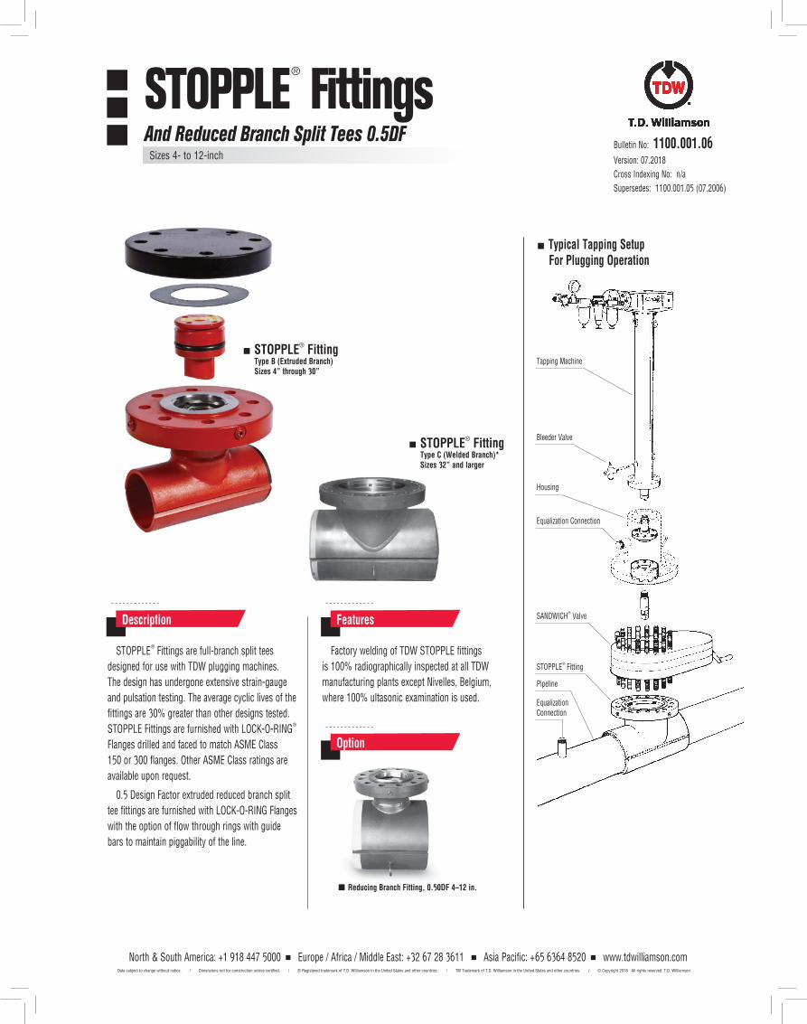
STOPPLE® Fittings are full-branch split tees
designed for use with TDW plugging machines.
The design has undergone extensive strain-gauge
and pulsation testing. The average cyclic lives of the
fittings are 30% greater than other designs tested.
STOPPLE Fittings are furnished with LOCK-O-RING®
Flanges drilled and faced to match ASME Class
150 or 300 flanges. Other ASME Class ratings are
available upon request.
0.5 Design Factor extruded reduced branch split
tee fittings are furnished with LOCK-O-RING Flanges
with the option of flow through rings with guide
bars to maintain piggability of the line.
Factory welding of TDW STOPPLE fittings
is 100% radiographically inspected at all TDW
manufacturing plants except Nivelles, Belgium,
where 100% ultasonic examination is used.
Description Features
Option
STOPPLE® Fitting Type C (Welded Branch)* Sizes 32” and larger
Reducing Branch Fitting, 0.50DF 4–12 in.
Tapping Machine
Typical Tapping Setup For Plugging Operation
Bleeder Valve
SANDWICH® Valve
STOPPLE® Fitting
Pipeline
Equalization Connection
Equalization Connection
Housing
Bulletin No: 1100.001.06 Version: 07.2018
Cross Indexing No: n/a
Supersedes: 1100.001.05 (07.2006)
STOPPLE® Fitting Type B (Extruded Branch) Sizes 4” through 30”
STOPPLE® FittingsAnd Reduced Branch Split Tees 0.5DF
Sizes 4- to 12-inch
North & South America: +1 918 447 5000 Europe / Africa / Middle East: +32 67 28 3611 Asia Pacific: +65 6364 8520 www.tdwilliamson.comData subject to change without notice. / Dimensions not for construction unless certified. / ® Registered trademark of T.D. Williamson in the United States and other countries. / TM Trademark of T.D. Williamson in the United States and other countries. / © Copyright 2018 All rights reserved. T.D. Williamson
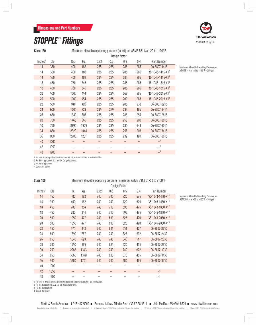
Dimensions and Part Numbers
1100.001.06 Pg. 2
Class 150 Maximum allowable operating pressure (in psi) per ASME B31.8 at -20 to +100º F
Design factor
Inches1 DN lbs. kg. 0.72 0.6 0.5 0.4 Part Number
14 350 400 182 285 285 285 285 06-8807-1415
14 350 400 182 285 285 285 285 36-1043-1415-X12
14 350 400 182 285 285 285 285 36-1045-1415-X13
18 450 760 345 285 285 285 285 36-1043-1815-X12
18 450 760 345 285 285 285 285 36-1045-1815-X13
20 500 1000 454 285 285 262 285 36-1043-2015-X12
20 500 1000 454 285 285 262 285 36-1045-2015-X13
22 550 940 426 285 285 285 238 06-8807-2215
24 600 1605 728 285 279 233 186 06-8807-2415
26 650 1340 608 285 285 285 259 06-8807-2615
28 700 1465 665 285 285 250 200 06-8807-2815
30 750 2895 1303 285 285 285 248 06-8807-3015
34 850 2320 1044 285 285 258 206 06-8807-3415
36 900 2780 1251 285 285 239 191 06-8807-3615
40 1000 -- -- -- -- -- -- --4
42 1050 -- -- -- -- -- -- --4
48 1200 -- -- -- -- -- -- --4
1. For sizes 4- through 12-inch and 16-inch sizes, see bulletins 1100.005.01 and 1100.006.01.2. For B31.4 applications. 0.72 and 0.6 Design Factor only.3. For B31.8 applications4. Consult the factory.
Maximum Allowable Operatiing Pressure per ASME B31.4 at -20 to +180º F = 285 psi
STOPPLE ® Fittings
Class 300 Maximum allowable operating pressure (in psi) per ASME B31.8 at -20 to +100º F
Design Factor
Inches1 DN lb. kg. 0.72 0.6 0.5 0.4 Part Number
14 350 400 182 740 740 720 575 36-1043-1430-X12
14 350 400 182 740 740 720 575 36-1045-1430-X13
18 450 780 354 740 710 595 475 36-1043-1830-X12
18 450 780 354 740 710 595 475 36-1045-1830-X13
20 500 1050 477 740 630 525 420 36-1043-2030-X12
20 500 1050 477 740 630 525 420 36-1045-2030-X13
22 550 975 442 740 641 534 427 06-8807-2230
24 600 1690 767 740 740 627 502 06-8807-2430
26 650 1540 699 740 740 646 517 06-8807-2630
28 700 1950 885 740 625 520 415 06-8807-2830
30 750 2985 1343 740 740 740 672 06-8807-3030
34 850 3065 1379 740 685 570 455 06-8807-3430
36 900 3780 1701 740 700 580 465 06-8807-3630
40 1000 -- -- -- -- -- -- --4
42 1050 -- -- -- -- -- -- --4
48 1200 -- -- -- -- -- -- --4
1. For sizes 4- through 12-inch and 16-inch sizes, see bulletins 1100.005.01 and 1100.006.01.2. For B31.4 applications. 0.72 and 0.6 Design Factor only.3. For B31.8 applications4. Consult the factory.
Maximum Allowable Operatiing Pressure per ASME B31.4 at -20 to +180º F = 740 psi
North & South America: +1 918 447 5000 Europe / Africa / Middle East: +32 67 28 3611 Asia Pacific: +65 6364 8520 www.tdwilliamson.comData subject to change without notice. / Dimensions not for construction unless certified. / ® Registered trademark of T.D. Williamson in the United States and other countries. / TM Trademark of T.D. Williamson in the United States and other countries. / © Copyright 2018 All rights reserved. T.D. Williamson
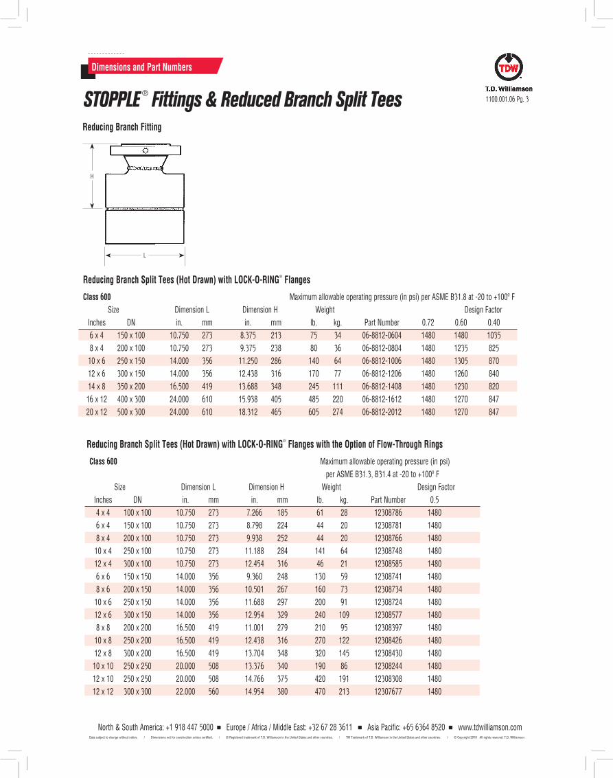
Dimensions and Part Numbers
Reducing Branch Split Tees (Hot Drawn) with LOCK-O-RING®
Flanges
Class 600 Maximum allowable operating pressure (in psi) per ASME B31.8 at -20 to +100º F
Size Dimension L Dimension H Weight Design Factor
Inches DN in. mm in. mm lb. kg. Part Number 0.72 0.60 0.40
6 x 4 150 x 100 10.750 273 8.375 213 75 34 06-8812-0604 1480 1480 1035
8 x 4 200 x 100 10.750 273 9.375 238 80 36 06-8812-0804 1480 1235 825
10 x 6 250 x 150 14.000 356 11.250 286 140 64 06-8812-1006 1480 1305 870
12 x 6 300 x 150 14.000 356 12.438 316 170 77 06-8812-1206 1480 1260 840
14 x 8 350 x 200 16.500 419 13.688 348 245 111 06-8812-1408 1480 1230 820
16 x 12 400 x 300 24.000 610 15.938 405 485 220 06-8812-1612 1480 1270 847
20 x 12 500 x 300 24.000 610 18.312 465 605 274 06-8812-2012 1480 1270 847
Reducing Branch Fitting
L
H
1100.001.06 Pg. 3
Reducing Branch Split Tees (Hot Drawn) with LOCK-O-RING®
Flanges with the Option of Flow-Through Rings
Class 600 Maximum allowable operating pressure (in psi)
per ASME B31.3, B31.4 at -20 to +100º F
Size Dimension L Dimension H Weight Design Factor
Inches DN in. mm in. mm lb. kg. Part Number 0.5
4 x 4 100 x 100 10.750 273 7.266 185 61 28 12308786 1480
6 x 4 150 x 100 10.750 273 8.798 224 44 20 12308781 1480
8 x 4 200 x 100 10.750 273 9.938 252 44 20 12308766 1480
10 x 4 250 x 100 10.750 273 11.188 284 141 64 12308748 1480
12 x 4 300 x 100 10.750 273 12.454 316 46 21 12308585 1480
6 x 6 150 x 150 14.000 356 9.360 248 130 59 12308741 1480
8 x 6 200 x 150 14.000 356 10.501 267 160 73 12308734 1480
10 x 6 250 x 150 14.000 356 11.688 297 200 91 12308724 1480
12 x 6 300 x 150 14.000 356 12.954 329 240 109 12308577 1480
8 x 8 200 x 200 16.500 419 11.001 279 210 95 12308397 1480
10 x 8 250 x 200 16.500 419 12.438 316 270 122 12308426 1480
12 x 8 300 x 200 16.500 419 13.704 348 320 145 12308430 1480
10 x 10 250 x 250 20.000 508 13.376 340 190 86 12308244 1480
12 x 10 250 x 250 20.000 508 14.766 375 420 191 12308308 1480
12 x 12 300 x 300 22.000 560 14.954 380 470 213 12307677 1480
STOPPLE ® Fittings & Reduced Branch Split Tees
North & South America: +1 918 447 5000 Europe / Africa / Middle East: +32 67 28 3611 Asia Pacific: +65 6364 8520 www.tdwilliamson.comData subject to change without notice. / Dimensions not for construction unless certified. / ® Registered trademark of T.D. Williamson in the United States and other countries. / TM Trademark of T.D. Williamson in the United States and other countries. / © Copyright 2018 All rights reserved. T.D. Williamson
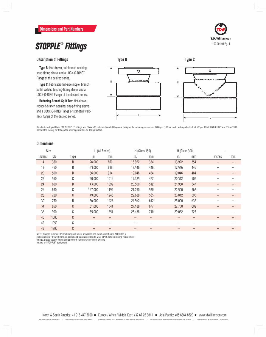
Dimensions and Part Numbers
1100.001.06 Pg. 4
Dimensions
NOTE: Flanges in sizes 10” (250 mm) and below are drilled and faced according to ANSI B16.5. Flanges above 10” (250 mm) are drilled and faced according to MSS-SP44. When ordering replacement fittings, please specify fitting equipped with flanges which will fit existing hot tap or STOPPLE® equipment.
Type B: Hot-drawn, full-branch opening,
snug-fitting sleeve and a LOCK-O-RING®
Flange of the desired series.
Type C: Fabricated full-size nipple, branch
outlet welded to snug-fitting sleeve and a
LOCK-O-RING Flange of the desired series.
Reducing-Branch Split Tee: Hot-drawn,
reduced-branch opening, snug-fitting sleeve
and a LOCK-O-RING Flange or standard weld-
neck flange of the desired series.
Standard cataloged Class 600 STOPPLE® fittings and Class 600 reduced-branch fittings are designed for working pressure of 1480 psi (102 bar) with a design factor F of .72 per ASME B31.8-1995 and B31.4-1992. Consult the factory for fittings for other applications or design factors.
Description of Fittings
L
H
Type B
L
H
Type C
Size L (All Series) H (Class 150) H (Class 300) --
Inches DN Type in. mm in. mm in. mm inches mm
14 350 B 26.000 660 13.922 354 13.922 354 -- --
18 450 B 33.000 838 17.546 446 17.546 446 -- --
20 500 B 36.000 914 19.046 484 19.046 484 -- --
22 550 C 40.000 1016 19.125 477 20.312 507 -- --
24 600 B 43.000 1092 20.500 512 21.938 547 -- --
26 650 C 1 47.000 1194 21.250 530 22.500 562 -- --
28 700 C 49.000 1245 22.688 565 23.812 595 -- --
30 750 B 56.000 1423 24.562 612 25.000 632 -- --
34 850 C 61.000 1541 27.188 677 27.750 692 -- --
36 900 C 65.000 1651 28.438 710 29.062 725 -- --
40 1000 C -- -- -- -- -- -- -- --
42 1050 C -- -- -- -- -- -- -- --
48 1200 C -- -- -- -- -- -- -- --
STOPPLE ® Fittings
North & South America: +1 918 447 5000 Europe / Africa / Middle East: +32 67 28 3611 Asia Pacific: +65 6364 8520 www.tdwilliamson.comData subject to change without notice. / Dimensions not for construction unless certified. / ® Registered trademark of T.D. Williamson in the United States and other countries. / TM Trademark of T.D. Williamson in the United States and other countries. / © Copyright 2018 All rights reserved. T.D. Williamson
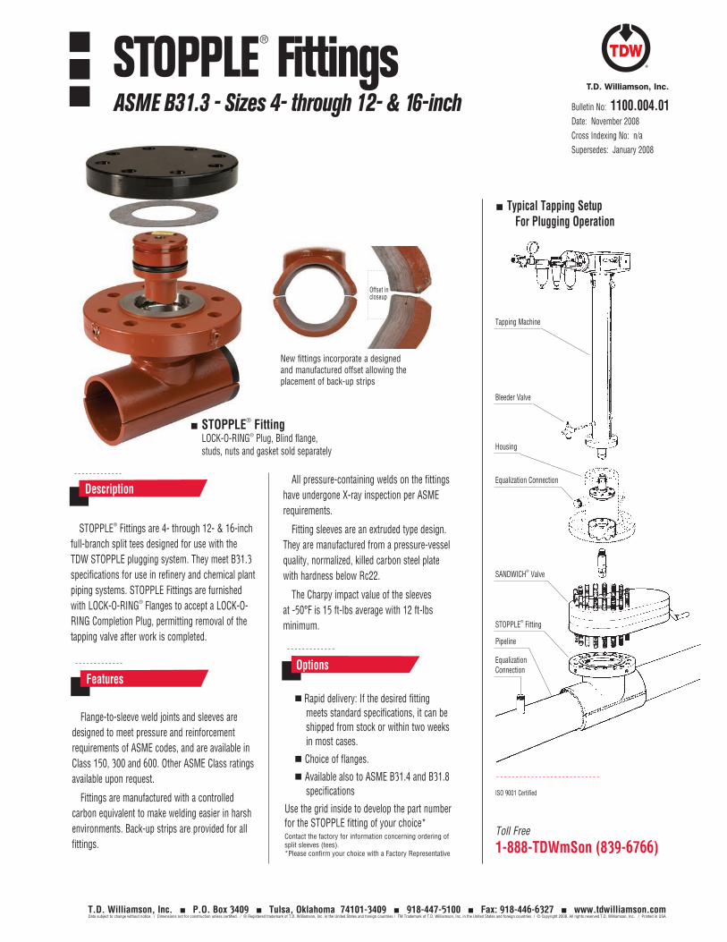
Toll Free
1-888-TDWmSon (839-6766)
ISO 9001 Certified
Tapping Machine
Typical Tapping Setup For Plugging Operation
Bleeder Valve
SANDWICH® Valve
STOPPLE® Fitting
Pipeline
Equalization Connection
Equalization Connection
Housing
Bulletin No: 1100.004.01Date: November 2008Cross Indexing No: n/aSupersedes: January 2008
STOPPLE® FittingsASME B31.3 - Sizes 4- through 12- & 16-inch
T.D. Williamson, Inc. P.O. Box 3409 Tulsa, Oklahoma 74101-3409 918-447-5100 Fax: 918-446-6327 www.tdwilliamson.comData subject to change without notice. / Dimensions not for construction unless certified. / ® Registered trademark of T.D. Williamson, Inc. in the United States and foreign countries / TM Trademark of T.D. Williamson, Inc. in the United States and foreign countries / © Copyright 2008. All rights reserved T.D. Williamson, Inc. / Printed in USA
STOPPLE® Fittings are 4- through 12- & 16-inch full-branch split tees designed for use with the TDW STOPPLE plugging system. They meet B31.3 specifications for use in refinery and chemical plant piping systems. STOPPLE Fittings are furnished with LOCK-O-RING® Flanges to accept a LOCK-O-RING Completion Plug, permitting removal of the tapping valve after work is completed.
Description
STOPPLE® FittingLOCK-O-RING® Plug, Blind flange, studs, nuts and gasket sold separately
All pressure-containing welds on the fittings have undergone X-ray inspection per ASME requirements.
Fitting sleeves are an extruded type design. They are manufactured from a pressure-vessel quality, normalized, killed carbon steel plate with hardness below Rc22.
The Charpy impact value of the sleeves at -50°F is 15 ft-lbs average with 12 ft-lbs minimum.
Flange-to-sleeve weld joints and sleeves are designed to meet pressure and reinforcement requirements of ASME codes, and are available in Class 150, 300 and 600. Other ASME Class ratings available upon request.
Fittings are manufactured with a controlled carbon equivalent to make welding easier in harsh environments. Back-up strips are provided for all fittings.
Features Rapid delivery: If the desired fitting
meets standard specifications, it can be shipped from stock or within two weeks in most cases.
Choice of flanges.
Available also to ASME B31.4 and B31.8 specifications
Use the grid inside to develop the part number for the STOPPLE fitting of your choice*Contact the factory for information concerning ordering of split sleeves (tees). *Please confirm your choice with a Factory Representative
Options
New fittings incorporate a designed and manufactured offset allowing the placement of back-up strips
Offset in closeup
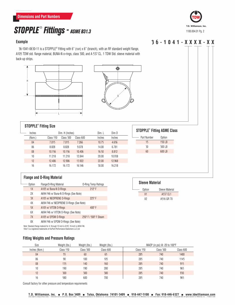
Dimensions and Part Numbers
1100.004.01 Pg. 2
T.D. Williamson, Inc. P.O. Box 3409 Tulsa, Oklahoma 74101-3409 918-447-5100 Fax: 918-446-6327 www.tdwilliamson.comData subject to change without notice. / Dimensions not for construction unless certified. / ® Registered trademark of T.D. Williamson, Inc. in the United States and foreign countries / TM Trademark of T.D. Williamson, Inc. in the United States and foreign countries / © Copyright 2008. All rights reserved T.D. Williamson, Inc. / Printed in USA
3 6 - 1 0 4 1 - X X X X - X XExample
36-1041-0630-11 is a STOPPLE® Fitting with 6” (run) x 6” (branch), with an RF standard weight flange, A105 TDW std. flange material, BUNA-N o-rings, class 300, and A 537 CL. 1 TDW Std. sleeve material with back-up strips.
Fitting Weights and Pressure Ratings
Size Weight (lbs.) Weight (lbs.) Weight (lbs.) MAOP (in psi) @ -20 to 100°F Inches (Nom.) Class 150 Class 300 Class 600 Class 150 Class 300 Class 600 04 55 60 65 285 740 1480 06 90 100 105 285 740 1145 08 135 140 160 285 740 915 10 190 190 280 285 740 965 12 300 300 380 285 740 930 16 580 600 700 285 740 965
Consult factory for other pressure and temperature requirements
Flange and O-Ring Material
Option Flange/O-Ring Material O-Ring Temp Ratings 1X A105 w/ Buna-N O-Rings 212º F 2X A694 F46 w/ Buna-N O-Rings (See Note) 3X A105 w/ NEOPRENE O-Rings 225º F 4X A694 F46 w/ NEOPRENE O-Rings (See Note) 5X A105 w/ VITON O-Rings 400º F 6X A694 F46 w/ VITON O-Rings (See Note) 7X A105 w/ EPDM O-Rings 250º F / 500º F Steam 8X A694 F46 w/ EPDM O-Rings (See Note)
Sleeve Material
Option Sleeve Material X1 A537 CL1 X2 A516 GR 70
STOPPLE® Fitting ASME Class
Part Number Option 15 150 LB 30 300 LB 60 600 LB
STOPPLE® Fitting Size
Inches Dim. H (Inches) Dim. L Dim D (Nom.) Class 150 Class 300 Class 600 Inches Inches 04 7.015 7.015 7.266 10.75 4.656 06 8.828 8.828 9.078 14.00 6.781 08 10.156 10.156 10.406 16.50 8.812 10 11.218 11.218 12.844 20.00 10.938 12 12.406 12.906 13.922 22.00 12.968 16 16.172 16.172 16.546 30.00 16.218
L
H
D
STOPPLE ® Fittings - ASME B31.3
Note: Standard flange material for 4- through 12-inch is A105, 16-inch is A694 F46.Viton® is a registered trademarks of DuPont Performance Elastomers LLC Ltd
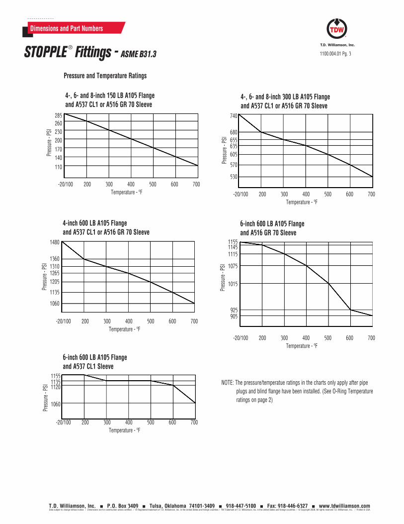
Dimensions and Part Numbers
1100.004.01 Pg. 3
T.D. Williamson, Inc. P.O. Box 3409 Tulsa, Oklahoma 74101-3409 918-447-5100 Fax: 918-446-6327 www.tdwilliamson.comData subject to change without notice. / Dimensions not for construction unless certified. / ® Registered trademark of T.D. Williamson, Inc. in the United States and foreign countries / TM Trademark of T.D. Williamson, Inc. in the United States and foreign countries / © Copyright 2008. All rights reserved T.D. Williamson, Inc. / Printed in USA
STOPPLE ® Fittings - ASME B31.3
-20/100 200 300 400 500 600 700Temperature - ºF
Pres
sure
- PS
I
285260230200170140
110
4-, 6- and 8-inch 150 LB A105 Flange and A537 CL1 or A516 GR 70 Sleeve
Pressure and Temperature Ratings
-20/100 200 300 400 500 600 700Temperature - ºF
Pres
sure
- PS
I
1480
1360131012651205
1135
1060
4-inch 600 LB A105 Flange and A537 CL1 or A516 GR 70 Sleeve
-20/100 200 300 400 500 600 700Temperature - ºF
Pres
sure
- PS
I
115511351120
1060
6-inch 600 LB A105 Flange and A537 CL1 Sleeve
-20/100 200 300 400 500 600 700Temperature - ºF
Pres
sure
- PS
I
115511451115
1075
1015
925905
6-inch 600 LB A105 Flange and A516 GR 70 Sleeve
-20/100 200 300 400 500 600 700Temperature - ºF
Pres
sure
- PS
I
740
680655635605
570
530
4-, 6- and 8-inch 300 LB A105 Flange and A537 CL1 or A516 GR 70 Sleeve
NOTE: The pressure/temperatue ratings in the charts only apply after pipe plugs and blind flange have been installed. (See O-Ring Temperature ratings on page 2)
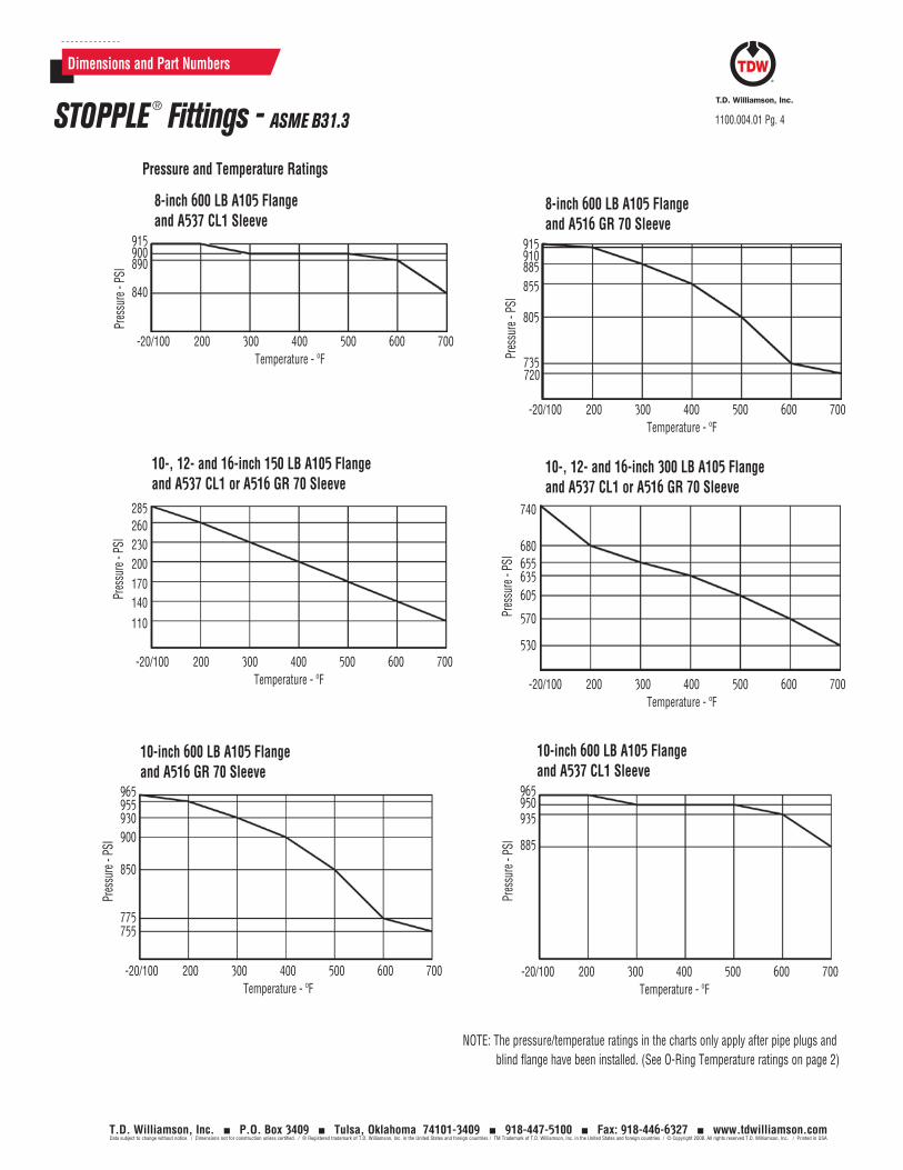
-20/100 200 300 400 500 600 700Temperature - ºF
Pres
sure
- PS
I
285260230200170140
110
10-, 12- and 16-inch 150 LB A105 Flange and A537 CL1 or A516 GR 70 Sleeve
-20/100 200 300 400 500 600 700Temperature - ºF
Pres
sure
- PS
I740
680655635605
570
530
10-, 12- and 16-inch 300 LB A105 Flange and A537 CL1 or A516 GR 70 Sleeve
1100.004.01 Pg. 4
T.D. Williamson, Inc. P.O. Box 3409 Tulsa, Oklahoma 74101-3409 918-447-5100 Fax: 918-446-6327 www.tdwilliamson.comData subject to change without notice. / Dimensions not for construction unless certified. / ® Registered trademark of T.D. Williamson, Inc. in the United States and foreign countries / TM Trademark of T.D. Williamson, Inc. in the United States and foreign countries / © Copyright 2008. All rights reserved T.D. Williamson, Inc. / Printed in USA
Dimensions and Part Numbers
STOPPLE ® Fittings - ASME B31.3
Pressure and Temperature Ratings
NOTE: The pressure/temperatue ratings in the charts only apply after pipe plugs and blind flange have been installed. (See O-Ring Temperature ratings on page 2)
-20/100 200 300 400 500 600 700Temperature - ºF
Pres
sure
- PS
I
915900890
840
8-inch 600 LB A105 Flange and A537 CL1 Sleeve
-20/100 200 300 400 500 600 700Temperature - ºF
Pres
sure
- PS
I
915910885855
805
735720
8-inch 600 LB A105 Flange and A516 GR 70 Sleeve
-20/100 200 300 400 500 600 700Temperature - ºF
Pres
sure
- PS
I
965955930900
850
775755
10-inch 600 LB A105 Flange and A516 GR 70 Sleeve
-20/100 200 300 400 500 600 700Temperature - ºF
Pres
sure
- PS
I
965950935
885
10-inch 600 LB A105 Flange and A537 CL1 Sleeve
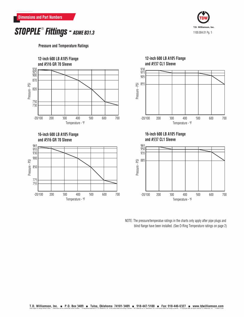
-20/100 200 300 400 500 600 700Temperature - ºF
Pres
sure
- PS
I
930925900870
820
750730
12-inch 600 LB A105 Flange and A516 GR 70 Sleeve
-20/100 200 300 400 500 600 700Temperature - ºF
Pres
sure
- PS
I
930915905
855
12-inch 600 LB A105 Flange and A537 CL1 Sleeve
1100.004.01 Pg. 5
T.D. Williamson, Inc. P.O. Box 3409 Tulsa, Oklahoma 74101-3409 918-447-5100 Fax: 918-446-6327 www.tdwilliamson.comData subject to change without notice. / Dimensions not for construction unless certified. / ® Registered trademark of T.D. Williamson, Inc. in the United States and foreign countries / TM Trademark of T.D. Williamson, Inc. in the United States and foreign countries / © Copyright 2008. All rights reserved T.D. Williamson, Inc. / Printed in USA
Dimensions and Part Numbers
STOPPLE ® Fittings - ASME B31.3
Pressure and Temperature Ratings
NOTE: The pressure/temperatue ratings in the charts only apply after pipe plugs and blind flange have been installed. (See O-Ring Temperature ratings on page 2)
16-inch 600 LB A105 Flange and A537 CL1 Sleeve
-20/100 200 300 400 500 600 700Temperature - ºF
Pres
sure
- PS
I
965950935
885
16-inch 600 LB A105 Flange and A516 GR 70 Sleeve
-20/100 200 300 400 500 600 700Temperature - ºF
Pres
sure
- PS
I
965955930900
850
775755

1100.004.01 Pg. 6
T.D. Williamson, Inc. P.O. Box 3409 Tulsa, Oklahoma 74101-3409 918-447-5100 Fax: 918-446-6327 www.tdwilliamson.comData subject to change without notice. / Dimensions not for construction unless certified. / ® Registered trademark of T.D. Williamson, Inc. in the United States and foreign countries / TM Trademark of T.D. Williamson, Inc. in the United States and foreign countries / © Copyright 2008. All rights reserved T.D. Williamson, Inc. / Printed in USA
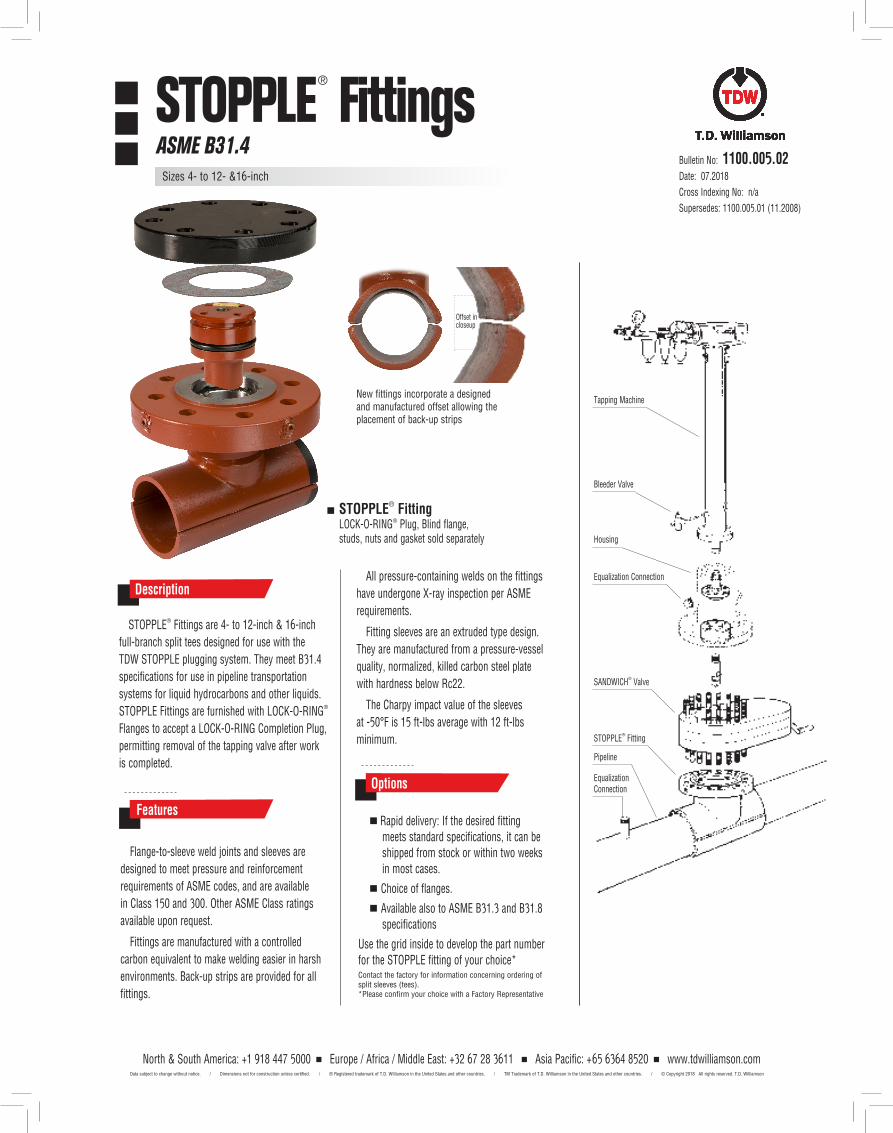
Tapping Machine
Bleeder Valve
SANDWICH® Valve
STOPPLE® Fitting
Pipeline
Equalization Connection
Equalization Connection
Housing
Bulletin No: 1100.005.02Date: 07.2018
Cross Indexing No: n/a
Supersedes: 1100.005.01 (11.2008)
STOPPLE® Fittings are 4- to 12-inch & 16-inch
full-branch split tees designed for use with the
TDW STOPPLE plugging system. They meet B31.4
specifications for use in pipeline transportation
systems for liquid hydrocarbons and other liquids.
STOPPLE Fittings are furnished with LOCK-O-RING®
Flanges to accept a LOCK-O-RING Completion Plug,
permitting removal of the tapping valve after work
is completed.
DescriptionAll pressure-containing welds on the fittings
have undergone X-ray inspection per ASME
requirements.
Fitting sleeves are an extruded type design.
They are manufactured from a pressure-vessel
quality, normalized, killed carbon steel plate
with hardness below Rc22.
The Charpy impact value of the sleeves
at -50°F is 15 ft-lbs average with 12 ft-lbs
minimum.
Flange-to-sleeve weld joints and sleeves are
designed to meet pressure and reinforcement
requirements of ASME codes, and are available
in Class 150 and 300. Other ASME Class ratings
available upon request.
Fittings are manufactured with a controlled
carbon equivalent to make welding easier in harsh
environments. Back-up strips are provided for all
fittings.
Features Rapid delivery: If the desired fitting
meets standard specifications, it can be shipped from stock or within two weeks in most cases.
Choice of flanges.
Available also to ASME B31.3 and B31.8 specifications
Use the grid inside to develop the part number for the STOPPLE fitting of your choice*Contact the factory for information concerning ordering of split sleeves (tees). *Please confirm your choice with a Factory Representative
Options
STOPPLE® FittingLOCK-O-RING® Plug, Blind flange, studs, nuts and gasket sold separately
New fittings incorporate a designed and manufactured offset allowing the placement of back-up strips
Offset in closeup
® FittingsSTOPPLEASME B31.4
Sizes 4- to 12- &16-inch
North & South America: +1 918 447 5000 Europe / Africa / Middle East: +32 67 28 3611 Asia Pacific: +65 6364 8520 www.tdwilliamson.comData subject to change without notice. / Dimensions not for construction unless certified. / ® Registered trademark of T.D. Williamson in the United States and other countries. / TM Trademark of T.D. Williamson in the United States and other countries. / © Copyright 2018 All rights reserved. T.D. Williamson
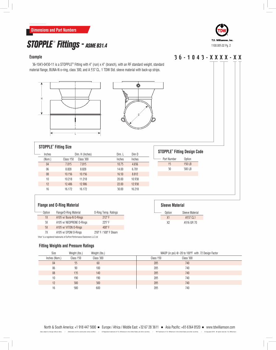
Dimensions and Part Numbers
1100.005.02 Pg. 2STOPPLE ® Fittings - ASME B31.4
3 6 - 1 0 4 3 - X X X X - X XExample
36-1043-0430-11 is a STOPPLE® Fitting with 4” (run) x 4” (branch), with an RF standard weight, standard
material flange, BUNA-N o-ring, class 300, and A 537 CL. 1 TDW Std. sleeve material with back-up strips.
Fitting Weights and Pressure Ratings
Size Weight (lbs.) Weight (lbs.) MAOP (in psi) @ -20 to 100°F with .72 Design Factor
Inches (Nom.) Class 150 Class 300 Class 150 Class 300
04 55 60 285 740
06 90 100 285 740
08 135 140 285 740
10 190 190 285 740
12 300 300 285 740
16 580 600 285 740
Sleeve Material
Option Sleeve Material
X1 A537 CL1
X2 A516 GR 70
STOPPLE®
Fitting Design Code
Part Number Option
15 150 LB
30 300 LB
STOPPLE®
Fitting Size
Inches Dim. H (Inches) Dim. L Dim D
(Nom.) Class 150 Class 300 Inches Inches
04 7.015 7.015 10.75 4.656
06 8.828 8.828 14.00 6.781
08 10.156 10.156 16.50 8.812
10 10.218 11.218 20.00 10.938
12 12.406 12.906 22.00 12.938
16 16.172 16.172 30.00 16.218
L
H
D
Flange and O-Ring Material
Option Flange/O-Ring Material O-Ring Temp. Ratings
1X A105 w/ Buna-N O-Rings 212º F
3X A105 w/ NEOPRENE O-Rings 225º F
5X A105 w/ VITON O-Rings 400º F
7X A105 w/ EPDM O-Rings 250º F / 500º F SteamViton® is a registered trademarks of DuPont Performance Elastomers LLC Ltd
North & South America: +1 918 447 5000 Europe / Africa / Middle East: +32 67 28 3611 Asia Pacific: +65 6364 8520 www.tdwilliamson.comData subject to change without notice. / Dimensions not for construction unless certified. / ® Registered trademark of T.D. Williamson in the United States and other countries. / TM Trademark of T.D. Williamson in the United States and other countries. / © Copyright 2018 All rights reserved. T.D. Williamson
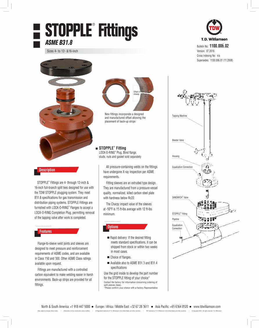
Tapping Machine
Bleeder Valve
SANDWICH® Valve
STOPPLE® Fitting
Pipeline
Equalization Connection
Equalization Connection
Housing
Bulletin No: 1100.006.02Version: 07.2018
Cross Indexing No: n/a
Supersedes: 1100.006.01 (11.2008)
STOPPLE® Fittings are 4- through 12-inch &
16-inch full-branch split tees designed for use with
the TDW STOPPLE plugging system. They meet
B31.8 specifications for gas transmission and
distribution piping systems. STOPPLE Fittings are
furnished with LOCK-O-RING® Flanges to accept a
LOCK-O-RING Completion Plug, permitting removal
of the tapping valve after work is completed.
DescriptionAll pressure-containing welds on the fittings
have undergone X-ray inspection per ASME
requirements.
Fitting sleeves are an extruded type design.
They are manufactured from a pressure-vessel
quality, normalized, killed carbon steel plate
with hardness below Rc22.
The Charpy impact value of the sleeves
at -50°F is 15 ft-lbs average with 12 ft-lbs
minimum.
Flange-to-sleeve weld joints and sleeves are
designed to meet pressure and reinforcement
requirements of ASME codes, and are available
in Class 150 and 300. Other ASME Class ratings
available upon request.
Fittings are manufactured with a controlled
carbon equivalent to make welding easier in harsh
environments. Back-up strips are provided for all
fittings.
Features
Rapid delivery: If the desired fitting meets standard specifications, it can be shipped from stock or within two weeks in most cases.
Choice of flanges.
Available also to ASME B31.3 and B31.4 specifications
Use the grid inside to develop the part number for the STOPPLE fitting of your choice*Contact the factory for information concerning ordering of split sleeves (tees). *Please confirm your choice with a Factory Representative
Options
STOPPLE® FittingLOCK-O-RING® Plug, Blind flange, studs, nuts and gasket sold separately
New fittings incorporate a designed and manufactured offset allowing the placement of back-up strips
Offset in closeup
® Fittings STOPPLEASME B31.8
Sizes 4- to 12- &16-inch
North & South America: +1 918 447 5000 Europe / Africa / Middle East: +32 67 28 3611 Asia Pacific: +65 6364 8520 www.tdwilliamson.comData subject to change without notice. / Dimensions not for construction unless certified. / ® Registered trademark of T.D. Williamson in the United States and other countries. / TM Trademark of T.D. Williamson in the United States and other countries. / © Copyright 2018 All rights reserved. T.D. Williamson
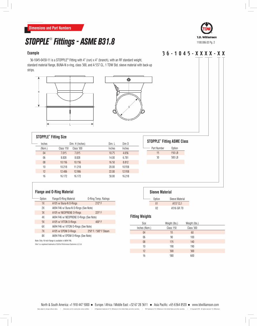
3 6 - 1 0 4 5 - X X X X - X XExample
36-1045-0430-11 is a STOPPLE® Fitting with 4” (run) x 4” (branch), with an RF standard weight,
standard material flange, BUNA-N o-ring, class 300, and A 537 CL. 1 TDW Std. sleeve material with back-up
strips.
Dimensions and Part Numbers
1100.006.02 Pg. 2STOPPLE ® Fittings - ASME B31.8
Sleeve Material
Option Sleeve Material
X1 A537 CL1
X2 A516 GR 70
STOPPLE®
Fitting ASME Class
Part Number Option
15 150 LB
30 300 LB
STOPPLE®
Fitting Size
Inches Dim. H (Inches) Dim. L Dim D
(Nom.) Class 150 Class 300 Inches Inches
04 7.015 7.015 10.75 4.656
06 8.828 8.828 14.00 6.781
08 10.156 10.156 16.50 8.812
10 10.218 11.218 20.00 10.938
12 12.406 12.906 22.00 12.938
16 16.172 16.172 30.00 16.218
L
H
D
Fitting Weights
Size Weight (lbs.) Weight (lbs.)
Inches (Nom.) Class 150 Class 300
04 55 60
06 90 100
08 135 140
10 190 190
12 300 300
16 580 600
Flange and O-Ring Material
Option Flange/O-Ring Material O-Ring Temp. Ratings
1X A105 w/ Buna-N O-Rings 212º F
2X A694 F46 w/ Buna-N O-Rings (See Note)
3X A105 w/ NEOPRENE O-Rings 225º F
4X A694 F46 w/ NEOPRENE O-Rings (See Note)
5X A105 w/ VITON O-Rings 400º F
6X A694 F46 w/ VITON O-Rings (See Note)
7X A105 w/ EPDM O-Rings 250º F / 500º F Steam
8X A694 F46 w/ EPDM O-Rings (See Note)
Note: Only 16-inch flange is available in A694 F46.
Viton® is a registered trademarks of DuPont Performance Elastomers LLC Ltd
North & South America: +1 918 447 5000 Europe / Africa / Middle East: +32 67 28 3611 Asia Pacific: +65 6364 8520 www.tdwilliamson.comData subject to change without notice. / Dimensions not for construction unless certified. / ® Registered trademark of T.D. Williamson in the United States and other countries. / TM Trademark of T.D. Williamson in the United States and other countries. / © Copyright 2018 All rights reserved. T.D. Williamson
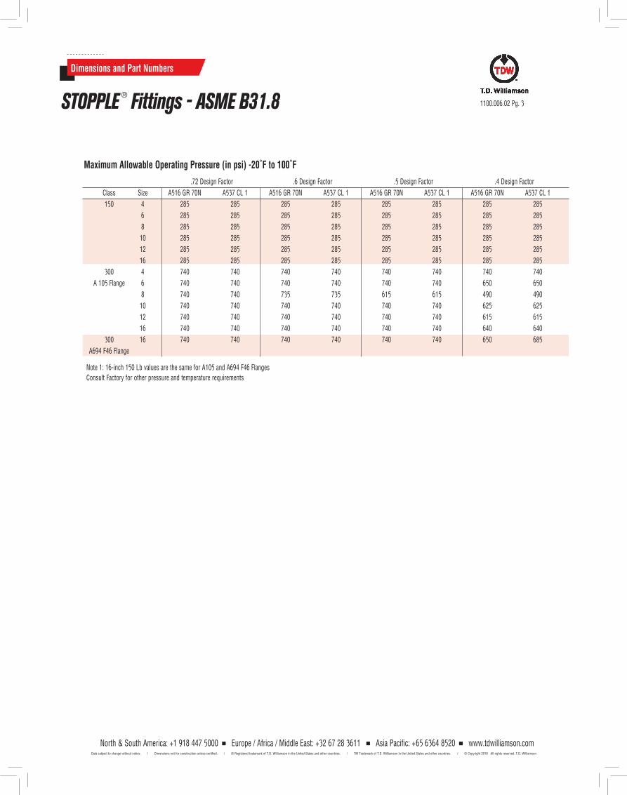
Maximum Allowable Operating Pressure (in psi) -20˚F to 100˚F
.72 Design Factor .6 Design Factor .5 Design Factor .4 Design Factor
Class Size A516 GR 70N A537 CL 1 A516 GR 70N A537 CL 1 A516 GR 70N A537 CL 1 A516 GR 70N A537 CL 1
150 4 285 285 285 285 285 285 285 285
6 285 285 285 285 285 285 285 285
8 285 285 285 285 285 285 285 285
10 285 285 285 285 285 285 285 285
12 285 285 285 285 285 285 285 285
16 285 285 285 285 285 285 285 285
300 4 740 740 740 740 740 740 740 740
A 105 Flange 6 740 740 740 740 740 740 650 650
8 740 740 735 735 615 615 490 490
10 740 740 740 740 740 740 625 625
12 740 740 740 740 740 740 615 615
16 740 740 740 740 740 740 640 640
300 16 740 740 740 740 740 740 650 685
A694 F46 Flange
Note 1: 16-inch 150 Lb values are the same for A105 and A694 F46 FlangesConsult Factory for other pressure and temperature requirements
Dimensions and Part Numbers
1100.006.02 Pg. 3STOPPLE ® Fittings - ASME B31.8
North & South America: +1 918 447 5000 Europe / Africa / Middle East: +32 67 28 3611 Asia Pacific: +65 6364 8520 www.tdwilliamson.comData subject to change without notice. / Dimensions not for construction unless certified. / ® Registered trademark of T.D. Williamson in the United States and other countries. / TM Trademark of T.D. Williamson in the United States and other countries. / © Copyright 2018 All rights reserved. T.D. Williamson

1100.006.02 Pg. 4
North & South America: +1 918 447 5000 Europe / Africa / Middle East: +32 67 28 3611 Asia Pacific: +65 6364 8520 www.tdwilliamson.comData subject to change without notice. / Dimensions not for construction unless certified. / ® Registered trademark of T.D. Williamson in the United States and other countries. / TM Trademark of T.D. Williamson in the United States and other countries. / © Copyright 2018 All rights reserved. T.D. Williamson
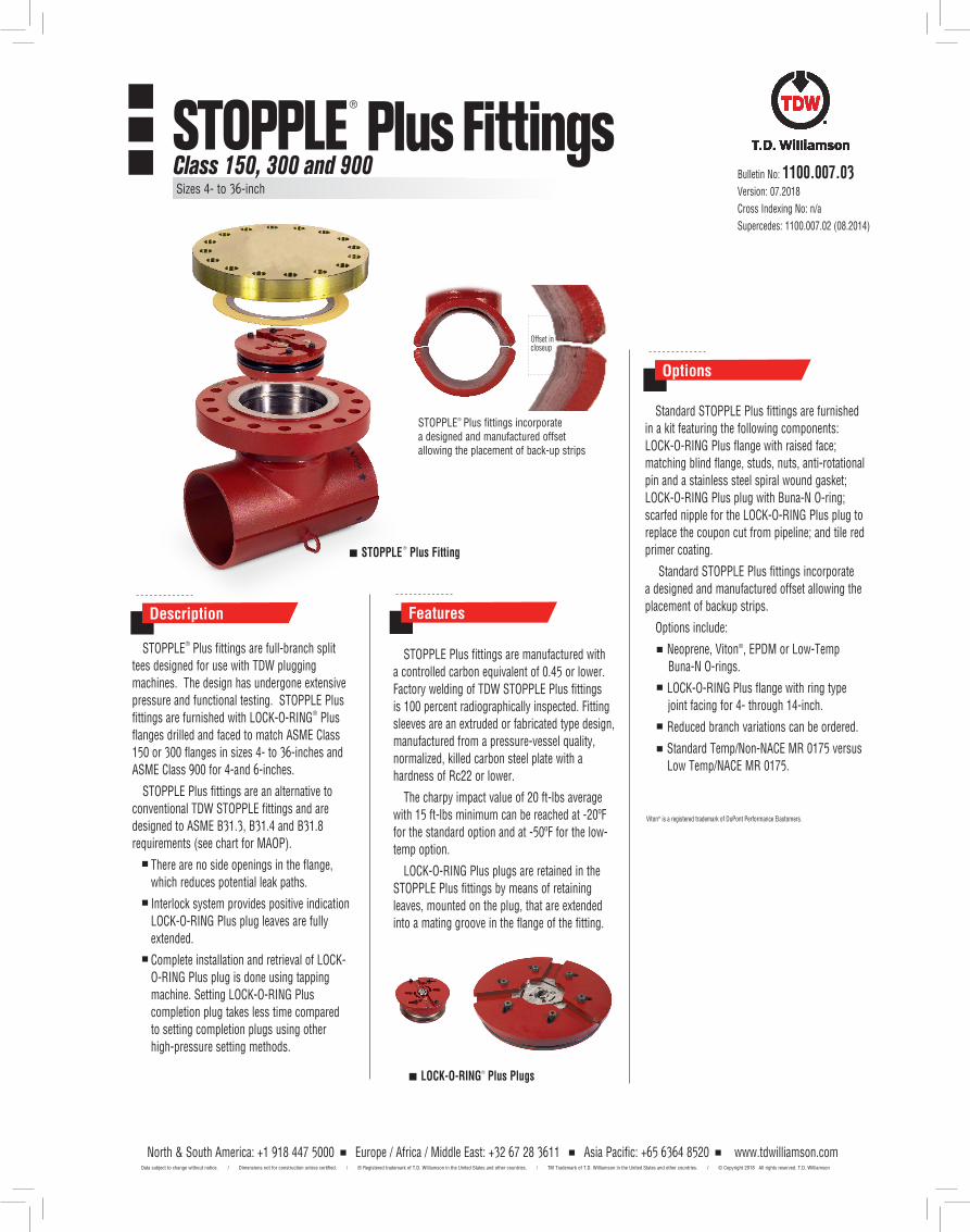
North & South America: +1 918 447 5000 Europe / Africa / Middle East: +32 67 28 3611 Asia Pacific: +65 6364 8520 www.tdwilliamson.com
STOPPLE Plus fittings are manufactured with a controlled carbon equivalent of 0.45 or lower. Factory welding of TDW STOPPLE Plus fittings is 100 percent radiographically inspected. Fitting sleeves are an extruded or fabricated type design, manufactured from a pressure-vessel quality, normalized, killed carbon steel plate with a hardness of Rc22 or lower.
The charpy impact value of 20 ft-lbs average with 15 ft-lbs minimum can be reached at -20ºF for the standard option and at -50ºF for the low- temp option.
LOCK-O-RING Plus plugs are retained in the STOPPLE Plus fittings by means of retaining leaves, mounted on the plug, that are extended into a mating groove in the flange of the fitting.
Features
STOPPLE® Plus fittings are full-branch split tees designed for use with TDW plugging machines. The design has undergone extensive pressure and functional testing. STOPPLE Plus fittings are furnished with LOCK-O-RING® Plus flanges drilled and faced to match ASME Class 150 or 300 flanges in sizes 4- to 36-inches and ASME Class 900 for 4-and 6-inches.
STOPPLE Plus fittings are an alternative to conventional TDW STOPPLE fittings and are designed to ASME B31.3, B31.4 and B31.8 requirements (see chart for MAOP).
There are no side openings in the flange, which reduces potential leak paths.
Interlock system provides positive indication LOCK-O-RING Plus plug leaves are fully extended.
Complete installation and retrieval of LOCK-O-RING Plus plug is done using tapping machine. Setting LOCK-O-RING Plus completion plug takes less time compared to setting completion plugs using other high-pressure setting methods.
Description
STOPPLE®
Plus Fitting
Options
Bulletin No: 1100.007.03Version: 07.2018
Cross Indexing No: n/a
Supercedes: 1100.007.02 (08.2014)
Standard STOPPLE Plus fittings are furnished in a kit featuring the following components: LOCK-O-RING Plus flange with raised face; matching blind flange, studs, nuts, anti-rotational pin and a stainless steel spiral wound gasket; LOCK-O-RING Plus plug with Buna-N O-ring; scarfed nipple for the LOCK-O-RING Plus plug to replace the coupon cut from pipeline; and tile red primer coating.
Standard STOPPLE Plus fittings incorporate a designed and manufactured offset allowing the placement of backup strips.
Options include:
Neoprene, Viton®, EPDM or Low-Temp Buna-N O-rings.
LOCK-O-RING Plus flange with ring type joint facing for 4- through 14-inch.
Reduced branch variations can be ordered.
Standard Temp/Non-NACE MR 0175 versus Low Temp/NACE MR 0175.
LOCK-O-RING® Plus Plugs
®
Plus Fittings
STOPPLE® Plus fittings incorporate a designed and manufactured offset allowing the placement of back-up strips
Offset in closeup
Viton® is a registered trademark of DuPont Performance Elastomers.
Sizes 4- to 36-inch
STOPPLE
Data subject to change without notice. / Dimensions not for construction unless certified. / ® Registered trademark of T.D. Williamson in the United States and other countries. / TM Trademark of T.D. Williamson in the United States and other countries. / © Copyright 2018 All rights reserved. T.D. Williamson
Class 150, 300 and 900
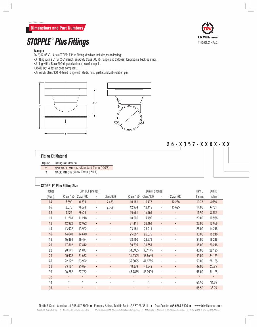
North & South America: +1 918 447 5000 Europe / Africa / Middle East: +32 67 28 3611 Asia Pacific: +65 6364 8520 www.tdwilliamson.comData subject to change without notice. / Dimensions not for construction unless certified. / ® Registered trademark of T.D. Williamson, Inc. in the United States and other countries. / TM Trademark of T.D. Williamson, Inc. in the United States and other countries. / © Copyright 2014 All rights reserved. T.D. Williamson, Inc.
1100.007.03 - Pg. 2
Dimensions and Part Numbers
STOPPLE ® Plus Fittings
Fitting Kit Material
Option Fitting Kit Material
2 Non-NACE MR 0175/Standard Temp (-20ºF)
3 NACE MR 0175/Low Temp (-50ºF)
Example26-2357-0630-14 is a STOPPLE Plus Fitting kit which includes the following:• A fitting with a 6" run X 6" branch, an ASME Class 300 RF flange, and 2 (loose) longitudinal back-up strips.• A plug with a Buna-N O-ring and a (loose) scarfed nipple.• ASME B31.4 design code compliant.• An ASME class 300 RF blind flange with studs, nuts, gasket and anti-rotation pin.
2 6 - X 3 5 7 - X X X X - X X
Inches Dim CLF (inches) Dim H (inches) Dim L Dim D
(Nom) Class 150 Class 300 - Class 900 Class 150 Class 300 - Class 900 Inches Inches
04 6.390 6.390 - 7.453 10.161 10.473 - 12.286 10.75 4.656
06 8.078 8.078 - 9.359 12.974 13.412 - 15.695 14.00 6.781
08 9.625 9.625 - - 15.661 16.161 - - 16.50 8.812
10 11.218 11.218 - - 18.505 19.192 - - 20.00 10.938
12 12.922 12.922 - - 21.411 22.161 - - 22.00 12.968
14 13.922 13.922 - - 23.161 23.911 - - 26.00 14.218
16 14.640 14.640 - - 25.067 25.879 - - 30.00 16.218
18 16.484 16.484 - - 28.160 28.973 - - 33.00 18.218
20 17.812 17.812 - - 30.739 31.551 - - 36.00 20.218
22 20.141 21.047 - 34.3955 36.1145 - - 40.00 22.125
24 20.922 21.672 - - 36.2395 38.8645 - - 43.00 24.125
26 22.172 23.922 - - 39.3025 41.6765 - - 50.00 26.125
28 23.187 25.094 - - 40.879 43.849 - - 49.00 28.25
30 26.282 27.782 - - 45.7875 48.0995 - - 56.00 31.125
32 * * * - * * - - * *
34 * * - - * * - - 61.50 34.25
36 * * - - * * - - 65.50 36.25
STOPPLE®
Plus Fitting Size
North & South America: +1 918 447 5000 Europe / Africa / Middle East: +32 67 28 3611 Asia Pacific: +65 6364 8520 www.tdwilliamson.comData subject to change without notice. / Dimensions not for construction unless certified. / ® Registered trademark of T.D. Williamson in the United States and other countries. / TM Trademark of T.D. Williamson in the United States and other countries. / © Copyright 2018 All rights reserved. T.D. Williamson
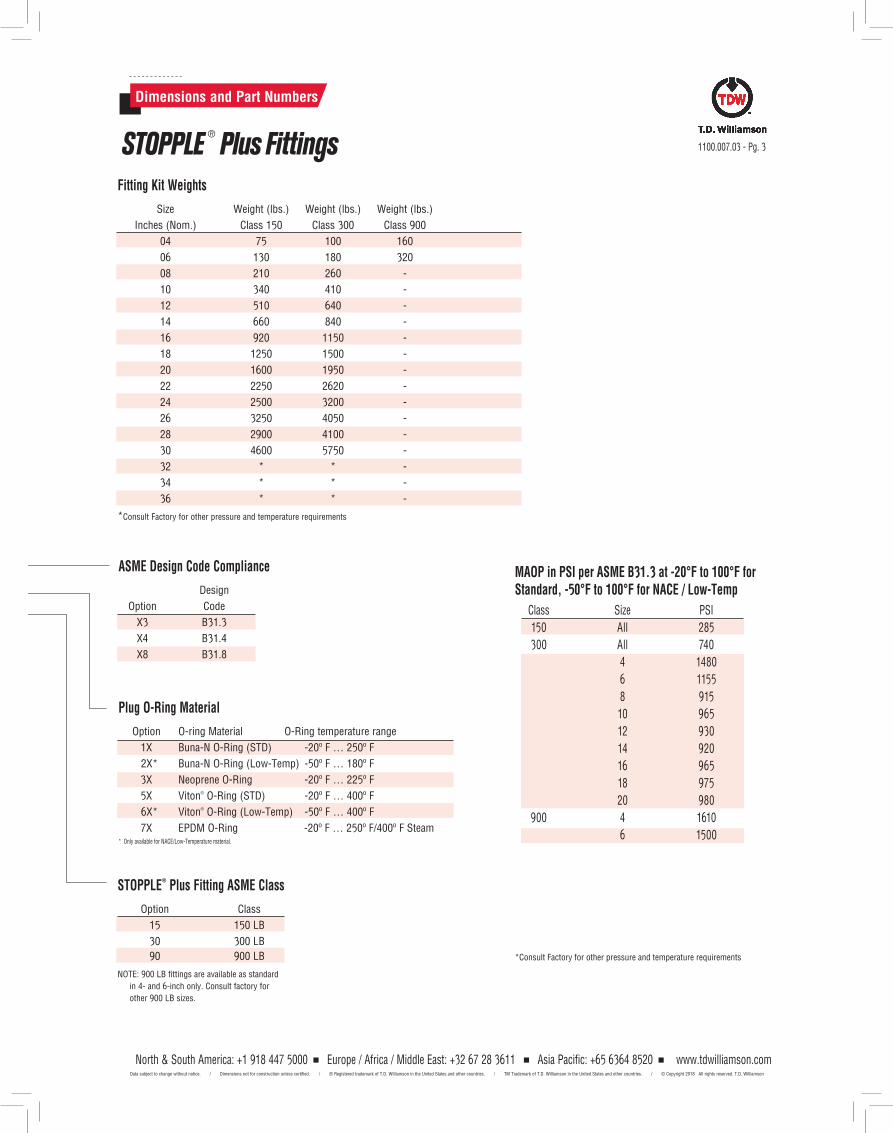
North & South America: +1 918 447 5000 Europe / Africa / Middle East: +32 67 28 3611 Asia Pacific: +65 6364 8520 www.tdwilliamson.comData subject to change without notice. / Dimensions not for construction unless certified. / ® Registered trademark of T.D. Williamson, Inc. in the United States and other countries. / TM Trademark of T.D. Williamson, Inc. in the United States and other countries. / © Copyright 2014 All rights reserved. T.D. Williamson, Inc.
Dimensions and Part Numbers
STOPPLE ® Plus Fittings
ASME Design Code Compliance
Design
Option Code
X3 B31.3
X4 B31.4
X8 B31.8
STOPPLE®
Plus Fitting ASME Class
Option Class
15 150 LB
30 300 LB
90 900 LB
NOTE: 900 LB fittings are available as standard
in 4- and 6-inch only. Consult factory for
other 900 LB sizes.
1100.007.03 - Pg. 3
Plug O-Ring Material
Option O-ring Material O-Ring temperature range
1X Buna-N O-Ring (STD) -20º F … 250º F
2X* Buna-N O-Ring (Low-Temp) -50º F … 180º F
3X Neoprene O-Ring -20º F … 225º F
5X Viton® O-Ring (STD) -20º F … 400º F
6X* Viton® O-Ring (Low-Temp) -50º F … 400º F
7X EPDM O-Ring -20º F … 250º F/400º F Steam* Only available for NACE/Low-Temperature material.
Fitting Kit Weights
Size Weight (lbs.) Weight (lbs.) Weight (lbs.)
Inches (Nom.) Class 150 Class 300 Class 900
04 75 100 160
06 130 180 320
08 210 260 -
10 340 410 -
12 510 640 -
14 660 840 -
16 920 1150 -
18 1250 1500 -
20 1600 1950 -
22 2250 2620 -
24 2500 3200 -
26 3250 4050 -
28 2900 4100 -
30 4600 5750 -
32 * * -
34 * * -
36 * * -
*Consult Factory for other pressure and temperature requirements
MAOP in PSI per ASME B31.3 at -20°F to 100°F for Standard, -50°F to 100°F for NACE / Low-Temp
Class Size PSI
150 All 285
300 All 740
4 1480
6 1155
8 915
10 965
12 930
14 920
16 965
18 975
20 980
900 4 1610
6 1500
*Consult Factory for other pressure and temperature requirements
North & South America: +1 918 447 5000 Europe / Africa / Middle East: +32 67 28 3611 Asia Pacific: +65 6364 8520 www.tdwilliamson.comData subject to change without notice. / Dimensions not for construction unless certified. / ® Registered trademark of T.D. Williamson in the United States and other countries. / TM Trademark of T.D. Williamson in the United States and other countries. / © Copyright 2018 All rights reserved. T.D. Williamson
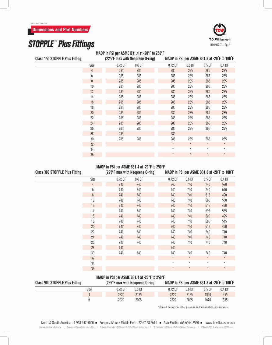
Size 0.72 DF 0.6 DF 0.72 DF 0.6 DF 0.5 DF 0.4 DF
4 740 740 740 740 740 590
6 740 740 740 740 740 610
8 740 740 740 740 615 490
10 740 740 740 740 665 530
12 740 740 740 740 615 490
14 740 740 740 740 695 555
16 740 740 740 740 620 495
18 740 740 740 740 685 545
20 740 740 740 740 615 490
22 740 740 740 740 740 740
24 740 740 740 740 740 740
26 740 740 740 740 740 740
28 740 740
30 740 740 740 740 740 740
32 * * * *
34 * * * *
36 * * * *
MAOP in PSI per ASME B31.4 at -20°F to 250°F (225°F max with Neoprene O-ring)
MAOP in PSI per ASME B31.4 at -20°F to 250°F (225°F max with Neoprene O-ring)
MAOP in PSI per ASME B31.8 at -20˚F to 100˚F
MAOP in PSI per ASME B31.8 at -20˚F to 100˚F
Class 150 STOPPLE Plus Fitting
Class 300 STOPPLE Plus Fitting
Size 0.72 DF 0.6 DF 0.72 DF 0.6 DF 0.5 DF 0.4 DF
4 285 285 285 285 285 285
6 285 285 285 285 285 285
8 285 285 285 285 285 285
10 285 285 285 285 285 285
12 285 285 285 285 285 285
14 285 285 285 285 285 285
16 285 285 285 285 285 285
18 285 285 285 285 285 285
20 285 285 285 285 285 285
22 285 285 285 285 285 285
24 285 285 285 285 285 285
26 285 285 285 285 285 285
28 285 285
30 285 285 285 285 285 285
32 * * * *
34 * * * *
36 * * * *
1100.007.03 - Pg. 4
Dimensions and Part Numbers
STOPPLE ® Plus Fittings
MAOP in PSI per ASME B31.4 at -20°F to 250°F (225°F max with Neoprene O-ring) MAOP in PSI per ASME B31.8 at -20˚F to 100˚FClass 900 STOPPLE Plus Fitting
*Consult Factory for other pressure and temperature requirements
Size 0.72 DF 0.6 DF 0.72 DF 0.6 DF 0.5 DF 0.4 DF
4 2220 2185 2220 2185 1820 1455
6 2220 2005 2220 2005 1670 1335
North & South America: +1 918 447 5000 Europe / Africa / Middle East: +32 67 28 3611 Asia Pacific: +65 6364 8520 www.tdwilliamson.comData subject to change without notice. / Dimensions not for construction unless certified. / ® Registered trademark of T.D. Williamson in the United States and other countries. / TM Trademark of T.D. Williamson in the United States and other countries. / © Copyright 2018 All rights reserved. T.D. Williamson
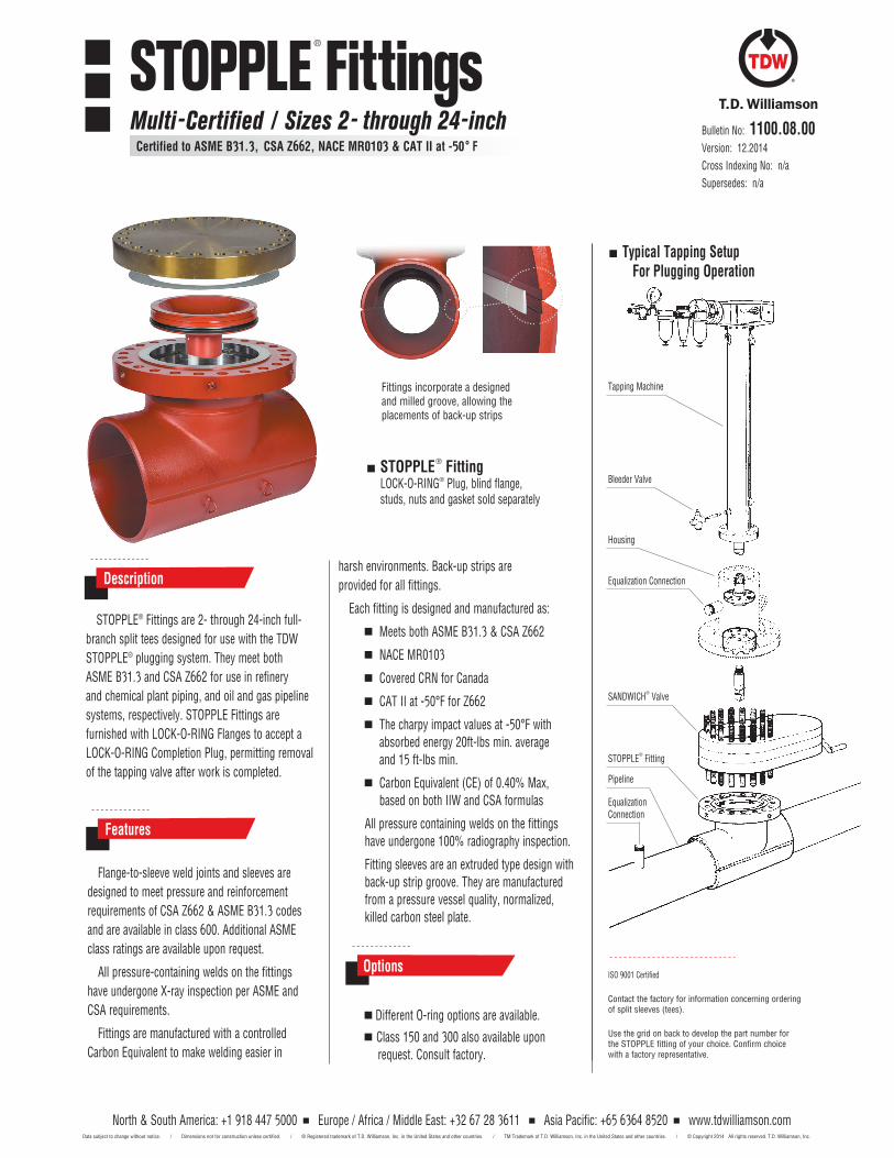
ISO 9001 Certified Contact the factory for information concerning ordering of split sleeves (tees). Use the grid on back to develop the part number for the STOPPLE fitting of your choice. Confirm choice with a factory representative.
Tapping Machine
Typical Tapping Setup For Plugging Operation
Bleeder Valve
SANDWICH® Valve
STOPPLE® Fitting
Pipeline
Equalization Connection
Equalization Connection
Housing
Bulletin No: 1100.08.00Version: 12.2014Cross Indexing No: n/aSupersedes: n/a
STOPPLE® Fittings are 2- through 24-inch full-branch split tees designed for use with the TDW STOPPLE® plugging system. They meet both ASME B31.3 and CSA Z662 for use in refinery and chemical plant piping, and oil and gas pipeline systems, respectively. STOPPLE Fittings are furnished with LOCK-O-RING Flanges to accept a LOCK-O-RING Completion Plug, permitting removal of the tapping valve after work is completed.
Descriptionharsh environments. Back-up strips are provided for all fittings.
Each fitting is designed and manufactured as:
Meets both ASME B31.3 & CSA Z662
NACE MR0103
Covered CRN for Canada
CAT II at -50°F for Z662
The charpy impact values at -50°F with absorbed energy 20ft-lbs min. average and 15 ft-lbs min.
Carbon Equivalent (CE) of 0.40% Max, based on both IIW and CSA formulas
All pressure containing welds on the fittings have undergone 100% radiography inspection.
Fitting sleeves are an extruded type design with back-up strip groove. They are manufactured from a pressure vessel quality, normalized, killed carbon steel plate.
Flange-to-sleeve weld joints and sleeves are designed to meet pressure and reinforcement requirements of CSA Z662 & ASME B31.3 codes and are available in class 600. Additional ASME class ratings are available upon request.
All pressure-containing welds on the fittings have undergone X-ray inspection per ASME and CSA requirements.
Fittings are manufactured with a controlled Carbon Equivalent to make welding easier in
Features
Different O-ring options are available.
Class 150 and 300 also available upon request. Consult factory.
Options
STOPPLE® FittingLOCK-O-RING® Plug, blind flange, studs, nuts and gasket sold separately
Fittings incorporate a designed and milled groove, allowing the placements of back-up strips
STOPPLE® Fittings
Multi-Certified / Sizes 2- through 24-inch Certified to ASME B31.3, CSA Z662, NACE MR0103 & CAT II at -50° F
North & South America: +1 918 447 5000 Europe / Africa / Middle East: +32 67 28 3611 Asia Pacific: +65 6364 8520 www.tdwilliamson.comData subject to change without notice. / Dimensions not for construction unless certified. / ® Registered trademark of T.D. Williamson, Inc. in the United States and other countries. / TM Trademark of T.D. Williamson, Inc. in the United States and other countries. / © Copyright 2014 All rights reserved. T.D. Williamson, Inc.
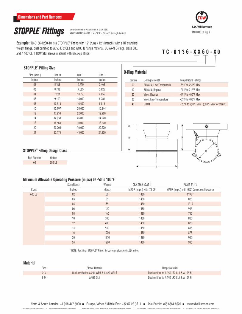
T C - 0 1 3 6 - X X 6 0 - X 0
Example: TC-0136-1260-10 is a STOPPLE® Fitting with 12" (run) x 12" (branch), with a RF standard weight flange, dual certified to A350 LF2 CL1 and A105 N flange material, BUNA-N O-rings, class 600, and A 537 CL 1 TDW Std. sleeve material with back-up strips.
1100.008.00 Pg. 2
North & South America: +1 918 447 5000 Europe / Africa / Middle East: +32 67 28 3611 Asia Pacific: +65 6364 8520 www.tdwilliamson.comData subject to change without notice. / Dimensions not for construction unless certified. / ® Registered trademark of T.D. Williamson, Inc. in the United States and other countries. / TM Trademark of T.D. Williamson, Inc. in the United States and other countries. / © Copyright 2014 All rights reserved. T.D. Williamson, Inc.
O-Ring Material
Option O-Ring Material Temperature Ratings 00 BUNA-N, Low Temperature -65°F to 250°F Max 10 BUNA-N, Regular -20°F to 212°F Max 20 Viton, Regular -15°F to 400°F Max 30 Viton, Low Temperature -55°F to 400°F Max 40 EPDM - 20°F to 250°F Max (500°F Max for steam)
STOPPLE® Fitting Size
Size (Nom.) Dim. H Dim. L Dim D Inches Inches Inches Inches 02 8.368 5.750 2.469 03 8.718 7.625 3.625 04 7.281 10.750 4.656 06 9.109 14.000 6.781 08 10.813 16.500 8.813 10 12.797 20.000 10.844 12 13.953 22.000 12.968 14 14.938 26.000 14.220 16 16.563 30.000 16.220 20 20.204 36.000 20.220 24 22.375 43.000 24.220
Material Size Sleeve Material Flange Material 2-3 Dual certified to A 234 WPB & A 420 WPL6 Dual certified to A 350 LF2 CL1 & A 105 N 4-24 A 537 CL1 Dual certified to A 350 LF2 CL1 & A 105 N
Dimensions and Part Numbers
STOPPLE ® Fittings Multi-Certified to ASME B31.3, CSA Z662, NACE MR0103 & CAT II at -50°F – Sizes 2- through 24-inch
L
H H
D
* NOTE: For 2-inch STOPPLE® Fitting, the corrosion allowance is .034 inches.
STOPPLE® Fitting Design Class
Part Number Option 60 600 LB
Maximum Allowable Operating Pressure (in psi) @ -50 to 100°F Size (Nom.) Weight CSA Z662 f/CAT II ASME B31.3 Class Inches (Lbs.) MAOP (in psi) with .72 DF MAOP (in psi) with .062" Corrosion Allowance 600 LB 02 60 1480 1195 * 03 65 1480 825
04 65 1480 1315 06 120 1480 945 08 160 1480 750 10 300 1480 825 12 400 1480 820 14 540 1480 815 16 1000 1480 875 20 1230 1480 905 24 1900 1480 935
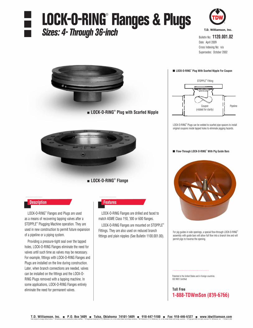
Toll Free
1-888-TDWmSon (839-6766)
LOCK-O-RING® Flanges and Plugs are used as a means of recovering tapping valves after a STOPPLE® Plugging Machine operation. They are used in new construction to permit future expansion of a pipeline or a piping system.
Providing a pressure-tight seal over the tapped holes, LOCK-O-RING Flanges eliminate the need for valves until such time as valves may be necessary. For example, fittings with LOCK-O-RING Flanges and Plugs are installed on the line during construction. Later, when branch connections are needed, valves can be installed on the fittings and the LOCK-O-RING Plugs removed with a tapping machine. In some applications, LOCK-O-RING Flanges entirely eliminate the need for permanent valves.
LOCK-O-RING Flanges are drilled and faced to match ASME Class 150, 300 or 600 flanges.
LOCK-O-RING Flanges are mounted on STOPPLE® Fittings. They are also used on reduced branch fittings and plain nipples (See Bulletin 1100.001.00).
For pig guides in side openings, a special flow-through LOCK-O-RING® assembly with guide bars will allow full flow into a branch line and will permit pigs to traverse the opening.
Description Features
LOCK-O-RING® Plug with Scarfed Nipple
LOCK-O-RING® Flange
Patented in the United States and in foreign countries.ISO 9001 Certified
LOCK-O-RING® Plugs can be welded to scarfed pipe spacers to install original coupons inside tapped holes to eliminate pigging hazards.
STOPPLE® Fitting
PipelineCoupon (rotated for clarity)
LOCK-O-RING® Plug With Scarfed Nipple For Coupon
Flow-Through LOCK-O-RING® With Pig Guide Bars
Bulletin No: 1120.001.02Date: April 2009Cross Indexing No: n/aSupersedes: October 2002
LOCK-O-RING® Flanges & PlugsSizes: 4- Through 36-inch
T.D. Williamson, Inc. P.O. Box 3409 Tulsa, Oklahoma 74101-3409 918-447-5100 Fax: 918-446-6327 www.tdwilliamson.comData subject to change without notice. / Dimensions not for construction unless certified. / ® Registered trademark of T.D. Williamson, Inc. in the United States and foreign countries / TM Trademark of T.D. Williamson, Inc. in the United States and foreign countries / © Copyright 2009. All rights reserved T.D. Williamson, Inc. / Printed in USA
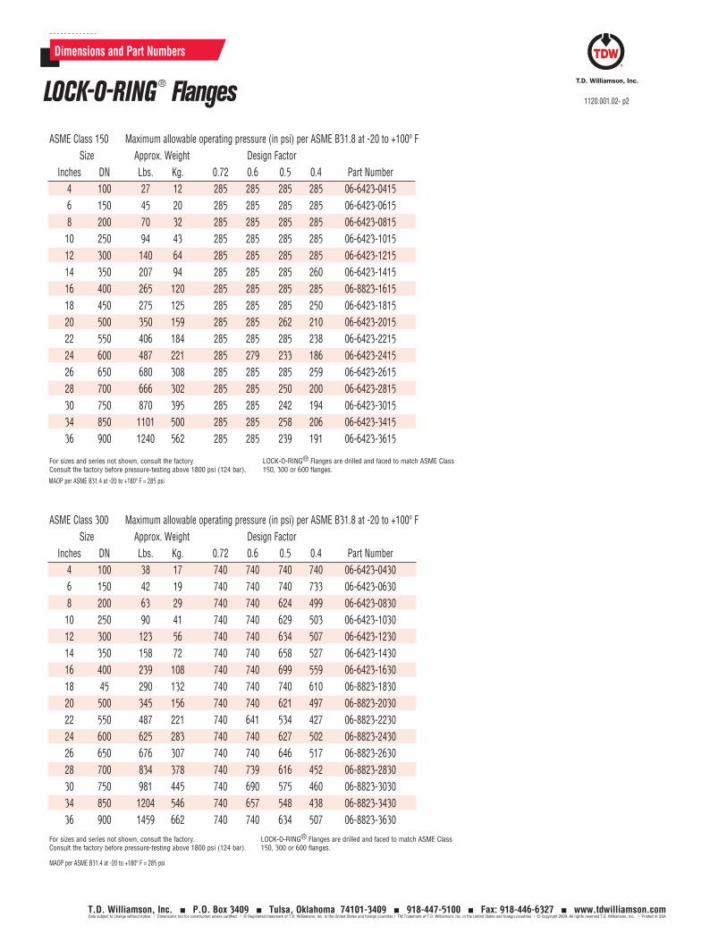
Dimensions and Part Numbers
ASME Class 150 Maximum allowable operating pressure (in psi) per ASME B31.8 at -20 to +100º F Size Approx. Weight Design Factor Inches DN Lbs. Kg. 0.72 0.6 0.5 0.4 Part Number 4 100 27 12 285 285 285 285 06-6423-0415 6 150 45 20 285 285 285 285 06-6423-0615 8 200 70 32 285 285 285 285 06-6423-0815 10 250 94 43 285 285 285 285 06-6423-1015 12 300 140 64 285 285 285 285 06-6423-1215 14 350 207 94 285 285 285 260 06-6423-1415 16 400 265 120 285 285 285 285 06-8823-1615 18 450 275 125 285 285 285 250 06-6423-1815 20 500 350 159 285 285 262 210 06-6423-2015 22 550 406 184 285 285 285 238 06-6423-2215 24 600 487 221 285 279 233 186 06-6423-2415 26 650 680 308 285 285 285 259 06-6423-2615 28 700 666 302 285 285 250 200 06-6423-2815 30 750 870 395 285 285 242 194 06-6423-3015 34 850 1101 500 285 285 258 206 06-6423-3415 36 900 1240 562 285 285 239 191 06-6423-3615
For sizes and series not shown, consult the factory. Consult the factory before pressure-testing above 1800 psi (124 bar).
LOCK-O-RING® Flanges are drilled and faced to match ASME Class 150, 300 or 600 flanges.
ASME Class 300 Maximum allowable operating pressure (in psi) per ASME B31.8 at -20 to +100º F Size Approx. Weight Design Factor Inches DN Lbs. Kg. 0.72 0.6 0.5 0.4 Part Number 4 100 38 17 740 740 740 740 06-6423-0430 6 150 42 19 740 740 740 733 06-6423-0630 8 200 63 29 740 740 624 499 06-6423-0830 10 250 90 41 740 740 629 503 06-6423-1030 12 300 123 56 740 740 634 507 06-6423-1230 14 350 158 72 740 740 658 527 06-6423-1430 16 400 239 108 740 740 699 559 06-6423-1630 18 45 290 132 740 740 740 610 06-8823-1830 20 500 345 156 740 740 621 497 06-8823-2030 22 550 487 221 740 641 534 427 06-8823-2230 24 600 625 283 740 740 627 502 06-8823-2430 26 650 676 307 740 740 646 517 06-8823-2630 28 700 834 378 740 739 616 452 06-8823-2830 30 750 981 445 740 690 575 460 06-8823-3030 34 850 1204 546 740 657 548 438 06-8823-3430 36 900 1459 662 740 740 634 507 06-8823-3630
For sizes and series not shown, consult the factory. Consult the factory before pressure-testing above 1800 psi (124 bar).
LOCK-O-RING® Flanges are drilled and faced to match ASME Class 150, 300 or 600 flanges.
MAOP per ASME B31.4 at -20 to +180º F = 285 psi
MAOP per ASME B31.4 at -20 to +180º F = 285 psi
LOCK-O-RING ® Flanges 1120.001.02- p2
T.D. Williamson, Inc. P.O. Box 3409 Tulsa, Oklahoma 74101-3409 918-447-5100 Fax: 918-446-6327 www.tdwilliamson.comData subject to change without notice. / Dimensions not for construction unless certified. / ® Registered trademark of T.D. Williamson, Inc. in the United States and foreign countries / TM Trademark of T.D. Williamson, Inc. in the United States and foreign countries / © Copyright 2009. All rights reserved T.D. Williamson, Inc. / Printed in USA
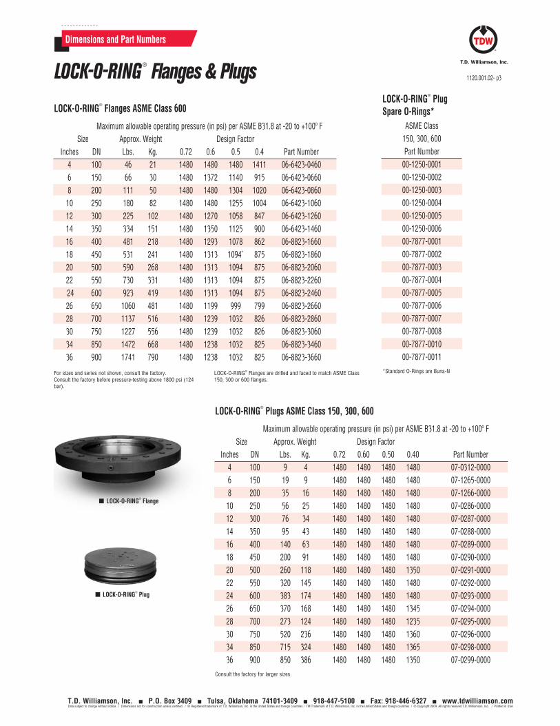
Dimensions and Part Numbers
LOCK-O-RING® Flanges ASME Class 600
Maximum allowable operating pressure (in psi) per ASME B31.8 at -20 to +100º F Size Approx. Weight Design Factor Inches DN Lbs. Kg. 0.72 0.6 0.5 0.4 Part Number 4 100 46 21 1480 1480 1480 1411 06-6423-0460 6 150 66 30 1480 1372 1140 915 06-6423-0660 8 200 111 50 1480 1480 1304 1020 06-6423-0860 10 250 180 82 1480 1480 1255 1004 06-6423-1060 12 300 225 102 1480 1270 1058 847 06-6423-1260 14 350 334 151 1480 1350 1125 900 06-6423-1460 16 400 481 218 1480 1293 1078 862 06-8823-1660 18 450 531 241 1480 1313 1094` 875 06-8823-1860 20 500 590 268 1480 1313 1094 875 06-8823-2060 22 550 730 331 1480 1313 1094 875 06-8823-2260 24 600 923 419 1480 1313 1094 875 06-8823-2460 26 650 1060 481 1480 1199 999 799 06-8823-2660 28 700 1137 516 1480 1239 1032 826 06-8823-2860 30 750 1227 556 1480 1239 1032 826 06-8823-3060 34 850 1472 668 1480 1238 1032 825 06-8823-3460 36 900 1741 790 1480 1238 1032 825 06-8823-3660
For sizes and series not shown, consult the factory. Consult the factory before pressure-testing above 1800 psi (124 bar).
LOCK-O-RING® Flanges are drilled and faced to match ASME Class 150, 300 or 600 flanges.
LOCK-O-RING® Plugs ASME Class 150, 300, 600
LOCK-O-RING® Plug Spare O-Rings*
ASME Class 150, 300, 600 Part Number
00-1250-000100-1250-000200-1250-000300-1250-000400-1250-000500-1250-000600-7877-000100-7877-000200-7877-000300-7877-000400-7877-000500-7877-000600-7877-000700-7877-000800-7877-001000-7877-0011
*Standard O-Rings are Buna-N
LOCK-O-RING® Flange
LOCK-O-RING® Plug
Maximum allowable operating pressure (in psi) per ASME B31.8 at -20 to +100º F Size Approx. Weight Design Factor Inches DN Lbs. Kg. 0.72 0.60 0.50 0.40 Part Number 4 100 9 4 1480 1480 1480 1480 07-0312-0000 6 150 19 9 1480 1480 1480 1480 07-1265-0000 8 200 35 16 1480 1480 1480 1480 07-1266-0000 10 250 56 25 1480 1480 1480 1480 07-0286-0000 12 300 76 34 1480 1480 1480 1480 07-0287-0000 14 350 95 43 1480 1480 1480 1480 07-0288-0000 16 400 140 63 1480 1480 1480 1480 07-0289-0000 18 450 200 91 1480 1480 1480 1480 07-0290-0000 20 500 260 118 1480 1480 1480 1350 07-0291-0000 22 550 320 145 1480 1480 1480 1480 07-0292-0000 24 600 383 174 1480 1480 1480 1480 07-0293-0000 26 650 370 168 1480 1480 1480 1345 07-0294-0000 28 700 273 124 1480 1480 1480 1235 07-0295-0000 30 750 520 236 1480 1480 1480 1360 07-0296-0000 34 850 715 324 1480 1480 1480 1365 07-0298-0000 36 900 850 386 1480 1480 1480 1350 07-0299-0000Consult the factory for larger sizes.
LOCK-O-RING ® Flanges & Plugs 1120.001.02- p3
T.D. Williamson, Inc. P.O. Box 3409 Tulsa, Oklahoma 74101-3409 918-447-5100 Fax: 918-446-6327 www.tdwilliamson.comData subject to change without notice. / Dimensions not for construction unless certified. / ® Registered trademark of T.D. Williamson, Inc. in the United States and foreign countries / TM Trademark of T.D. Williamson, Inc. in the United States and foreign countries / © Copyright 2009. All rights reserved T.D. Williamson, Inc. / Printed in USA
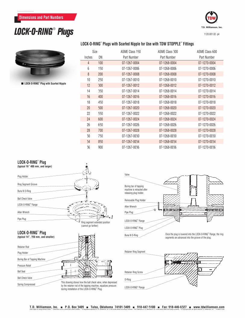
Removable Plug Holder
Boring bar of tapping machine is retracted after releasing plug holder.
Valve
Once the plug is lowered into the LOCK-O-RING® Flange, the ring segments are advanced into the groove of the plug.
LOCK-O-RING® Plugs with Scarfed Nipple for Use with TDW STOPPLE® Fittings
Size ASME Class 150 ASME Class 300 ASME Class 600 Inches DN Part Number Part Number Part Number 4 100 07-1267-0004 07-1268-0004 07-1270-0004 6 150 07-1267-0006 07-1268-0006 07-1270-0006 8 200 07-1267-0008 07-1268-0008 07-1270-0008 10 250 07-1267-0010 07-1268-0010 07-1270-0010 12 300 07-1267-0012 07-1268-0012 07-1270-0012 14 350 07-1267-0014 07-1268-0014 07-1270-0014 16 400 07-1267-0016 07-1268-0016 07-1270-0016 18 450 07-1267-0018 07-1268-0018 07-1270-0018 20 500 07-1267-0020 07-1268-0020 07-1270-0020 22 550 07-1267-0022 07-1268-0022 07-1270-0022 24 600 07-1267-0024 07-1268-0024 07-1270-0024 26 650 07-1267-0026 07-1268-0026 07-1270-0026 28 700 07-1267-0028 07-1268-0028 07-1270-0028 30 750 07-1267-0030 07-1268-0030 07-1270-0030 34 850 07-1267-0034 07-1268-0034 07-1270-0034 36 900 07-1267-0036 07-1268-0036 07-1270-0036
LOCK-O-RING® Plug with Scarfed Nipple
Plug Holder
LOCK-O-RING® Plug (typical 16” 400 mm, and larger)
LOCK-O-RING® Plug (typical 14”, 350 mm, and smaller)
Ring Segment Groove
Buna N O-Ring
Ball Check Valve
LOCK-O-RING® Flange
Allen Wrench
Pipe Plug
Retainer Rod
Plug Holder
Boring Bar of Tapping Machine
Pressure Relief
Ball Seat
Ball Check Valve
Spring Compressed
LOCK-O-RING® Flange
LOCK-O-RING® Plug
Buna N O-Ring
Retainer Ring Segment
Retainer Ring Screw
LOCK-O-RING® Flange
O-Ring
Allen Wrench
Pipe Plug
This drawing shows how the ball check valve, when depressed by the retainer rod of the tapping machine, equalizes pressure during installation of the LOCK-O-RING® Plug.
Ring segment extended position (cannot go farther)
Dimensions and Part Numbers
LOCK-O-RING® Plugs 1120.001.02- p4
T.D. Williamson, Inc. P.O. Box 3409 Tulsa, Oklahoma 74101-3409 918-447-5100 Fax: 918-446-6327 www.tdwilliamson.comData subject to change without notice. / Dimensions not for construction unless certified. / ® Registered trademark of T.D. Williamson, Inc. in the United States and foreign countries / TM Trademark of T.D. Williamson, Inc. in the United States and foreign countries / © Copyright 2009. All rights reserved T.D. Williamson, Inc. / Printed in USA
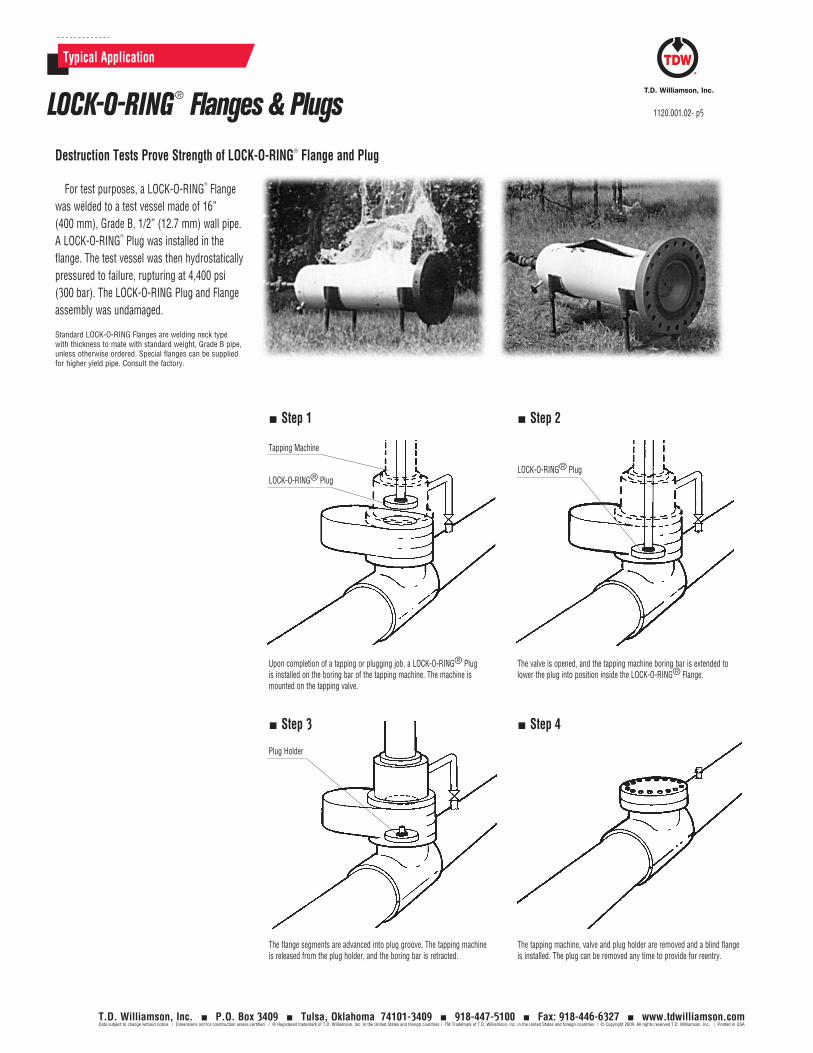
Typical Application
Destruction Tests Prove Strength of LOCK-O-RING® Flange and Plug
For test purposes, a LOCK-O-RING®
Flange was welded to a test vessel made of 16” (400 mm), Grade B, 1/2” (12.7 mm) wall pipe. A LOCK-O-RING
®
Plug was installed in the flange. The test vessel was then hydrostatically pressured to failure, rupturing at 4,400 psi (300 bar). The LOCK-O-RING Plug and Flange assembly was undamaged.
Standard LOCK-O-RING Flanges are welding neck type with thickness to mate with standard weight, Grade B pipe, unless otherwise ordered. Special flanges can be supplied for higher yield pipe. Consult the factory.
Upon completion of a tapping or plugging job, a LOCK-O-RING® Plug is installed on the boring bar of the tapping machine. The machine is mounted on the tapping valve.
The flange segments are advanced into plug groove. The tapping machine is released from the plug holder, and the boring bar is retracted.
The valve is opened, and the tapping machine boring bar is extended to lower the plug into position inside the LOCK-O-RING® Flange.
The tapping machine, valve and plug holder are removed and a blind flange is installed. The plug can be removed any time to provide for reentry.
Tapping Machine
LOCK-O-RING® PlugLOCK-O-RING® Plug
Plug Holder
Step 1 Step 2
Step 3 Step 4
LOCK-O-RING® Flanges & Plugs 1120.001.02- p5
T.D. Williamson, Inc. P.O. Box 3409 Tulsa, Oklahoma 74101-3409 918-447-5100 Fax: 918-446-6327 www.tdwilliamson.comData subject to change without notice. / Dimensions not for construction unless certified. / ® Registered trademark of T.D. Williamson, Inc. in the United States and foreign countries / TM Trademark of T.D. Williamson, Inc. in the United States and foreign countries / © Copyright 2009. All rights reserved T.D. Williamson, Inc. / Printed in USA

1120.001.02- p6
T.D. Williamson, Inc. P.O. Box 3409 Tulsa, Oklahoma 74101-3409 918-447-5100 Fax: 918-446-6327 www.tdwilliamson.comData subject to change without notice. / Dimensions not for construction unless certified. / ® Registered trademark of T.D. Williamson, Inc. in the United States and foreign countries / TM Trademark of T.D. Williamson, Inc. in the United States and foreign countries / © Copyright 2009. All rights reserved T.D. Williamson, Inc. / Printed in USA
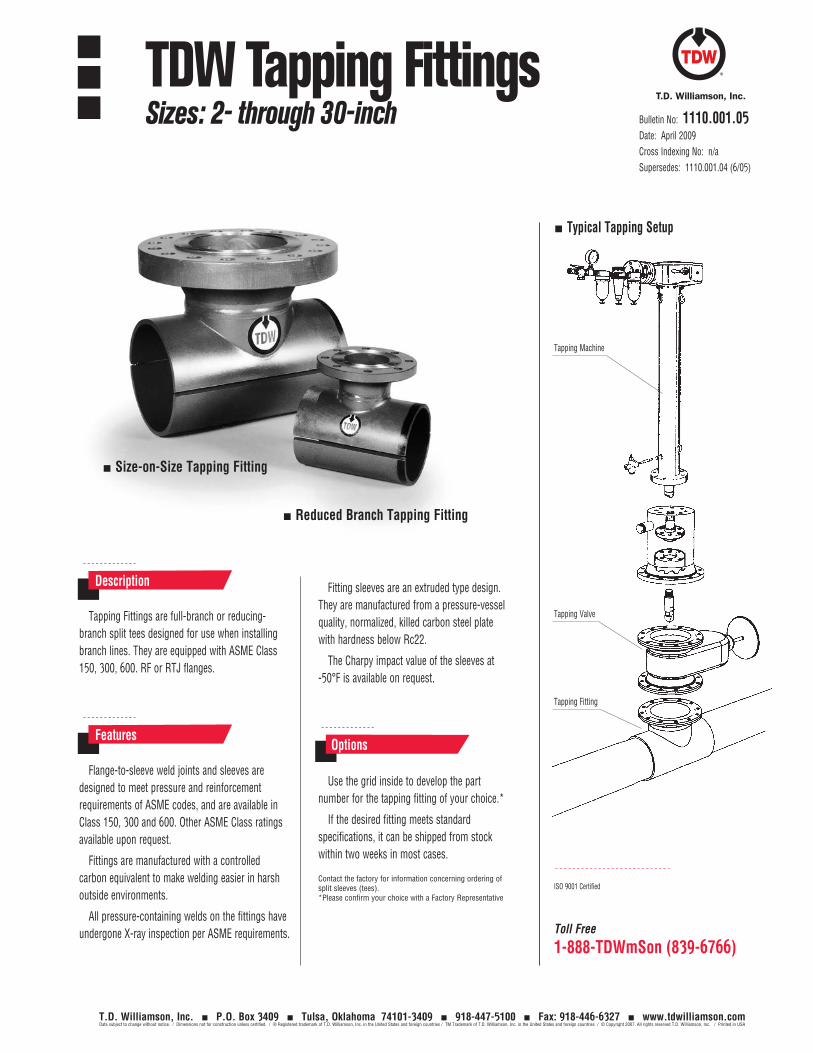
Toll Free
1-888-TDWmSon (839-6766)
ISO 9001 Certified
Tapping Fittings are full-branch or reducing-branch split tees designed for use when installing branch lines. They are equipped with ASME Class 150, 300, 600. RF or RTJ flanges.
Fitting sleeves are an extruded type design. They are manufactured from a pressure-vessel quality, normalized, killed carbon steel plate with hardness below Rc22.
The Charpy impact value of the sleeves at -50°F is available on request.
Description
Flange-to-sleeve weld joints and sleeves are designed to meet pressure and reinforcement requirements of ASME codes, and are available in Class 150, 300 and 600. Other ASME Class ratings available upon request.
Fittings are manufactured with a controlled carbon equivalent to make welding easier in harsh outside environments.
All pressure-containing welds on the fittings have undergone X-ray inspection per ASME requirements.
Features
Use the grid inside to develop the part number for the tapping fitting of your choice.*
If the desired fitting meets standard specifications, it can be shipped from stock within two weeks in most cases.
Contact the factory for information concerning ordering of split sleeves (tees). *Please confirm your choice with a Factory Representative
Options
Tapping Machine
Typical Tapping Setup
Tapping Valve
Tapping Fitting
Bulletin No: 1110.001.05Date: April 2009Cross Indexing No: n/aSupersedes: 1110.001.04 (6/05)
Size-on-Size Tapping Fitting
Reduced Branch Tapping Fitting
TDW Tapping FittingsSizes: 2- through 30-inch
T.D. Williamson, Inc. P.O. Box 3409 Tulsa, Oklahoma 74101-3409 918-447-5100 Fax: 918-446-6327 www.tdwilliamson.comData subject to change without notice. / Dimensions not for construction unless certified. / ® Registered trademark of T.D. Williamson, Inc. in the United States and foreign countries / TM Trademark of T.D. Williamson, Inc. in the United States and foreign countries / © Copyright 2007. All rights reserved T.D. Williamson, Inc. / Printed in USA
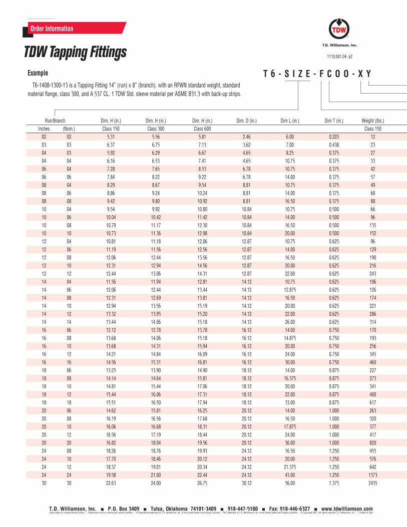
Order Information
T 6 - S I Z E - F C O O - X YExample
T6-1408-1300-13 is a Tapping Fitting 14” (run) x 8” (branch), with an RFWN standard weight, standard material flange, class 300, and A 537 CL. 1 TDW Std. sleeve material per ASME B31.3 with back-up strips.
Run/Branch Dim. H (in.) Dim. H (in.) Dim. H (in.) Dim. D (in.) Dim L (in.) Dim T (in.) Weight (lbs.) Weight (lbs.) Weight (lbs.) MAOP @ 100°F Class 600 Inches (Nom.) Class 150 Class 300 Class 600 Class 150 Class 300 Class 600 B31.3 XY Options 03-33 02 02 5.31 5.56 5.81 2.46 6.00 0.203 12 14 17 1480 03 03 6.37 6.75 7.13 3.62 7.00 0.438 23 21 30 1480 04 03 5.92 6.29 6.67 4.65 8.25 0.375 27 25 34 1480 04 04 6.16 6.53 7.41 4.65 10.75 0.375 33 38 58 1480 06 04 7.28 7.65 8.53 6.78 10.75 0.375 42 47 66 1220 06 06 7.84 8.22 9.22 6.78 14.00 0.375 57 73 109 1200 08 04 8.29 8.67 9.54 8.81 10.75 0.375 49 54 73 1010 08 06 8.86 9.24 10.24 8.81 14.00 0.375 68 84 120 955 08 08 9.42 9.80 10.92 8.81 16.50 0.375 88 118 159 950 10 04 9.54 9.92 10.80 10.84 10.75 0.500 66 71 90 1110 10 06 10.04 10.42 11.42 10.84 14.00 0.500 96 112 148 1030 10 08 10.79 11.17 12.30 10.84 16.50 0.500 135 165 208 1020 10 10 10.73 11.36 12.98 10.84 20.00 0.500 152 190 276 995 12 04 10.81 11.18 12.06 12.87 10.75 0.625 96 101 120 1210 12 06 11.19 11.56 12.56 12.87 14.00 0.625 129 145 181 1110 12 08 12.06 12.44 13.56 12.87 16.50 0.625 190 220 263 1090 12 10 12.31 12.94 14.56 12.87 20.00 0.625 216 254 345 1040 12 12 12.44 13.06 14.31 12.87 22.00 0.625 243 297 383 955 14 04 11.56 11.94 12.81 14.12 10.75 0.625 106 111 130 1115 14 06 12.06 12.44 13.44 14.12 12.875 0.625 126 142 178 1045 14 08 12.31 12.69 13.81 14.12 16.50 0.625 174 204 247 980 14 10 12.94 13.56 15.19 14.12 20.00 0.625 221 259 350 975 14 12 13.32 13.95 15.20 14.12 22.00 0.625 286 340 424 890 14 14 13.44 14.06 15.18 14.12 26.00 0.625 314 393 537 935 16 06 12.12 12.78 13.78 16.12 14.00 0.750 170 186 222 1140 16 08 13.68 14.06 15.18 16.12 14.875 0.750 193 223 266 990 16 10 13.68 14.31 15.94 16.12 20.00 0.750 256 294 385 1025 16 12 14.21 14.84 16.09 16.12 24.00 0.750 345 399 505 1005 16 16 14.56 15.31 16.81 16.12 30.00 0.750 460 569 778 990 18 06 13.25 13.90 14.90 18.12 14.00 0.875 227 243 279 1190 18 08 14.14 14.64 15.81 18.12 16.375 0.875 273 303 346 1130 18 10 14.81 15.44 17.06 18.12 20.00 0.875 341 379 470 1060 18 12 15.44 16.06 17.31 18.12 22.00 0.875 400 453 537 945 18 18 15.51 16.50 17.94 18.12 33.00 0.875 617 770 1001 990 20 06 14.62 15.81 16.25 20.12 14.00 1.000 263 279 315 1260 20 08 16.19 16.56 17.68 20.12 16.50 1.000 320 350 393 1140 20 10 16.06 16.68 18.31 20.12 17.875 1.000 377 415 506 970 20 12 16.56 17.19 18.44 20.12 24.00 1.000 417 471 587 965 20 20 16.82 18.04 19.56 20.12 36.00 1.000 820 1011 1314 1000 24 08 18.26 18.76 19.93 24.12 16.50 1.250 455 485 528 1245 24 10 17.70 18.46 20.12 24.12 20.00 1.250 576 614 525 1160 24 12 18.37 19.01 20.34 24.12 21.375 1.250 642 696 780 980 24 24 19.58 21.00 22.44 24.12 43.00 1.250 1373 1658 2077 1015 30 30 22.63 24.00 26.75 30.12 56.00 1.375 2435 2893 3235 945
TDW Tapping Fittings 1110.001.04- p2
T.D. Williamson, Inc. P.O. Box 3409 Tulsa, Oklahoma 74101-3409 918-447-5100 Fax: 918-446-6327 www.tdwilliamson.comData subject to change without notice. / Dimensions not for construction unless certified. / ® Registered trademark of T.D. Williamson, Inc. in the United States and foreign countries / TM Trademark of T.D. Williamson, Inc. in the United States and foreign countries / © Copyright 2007. All rights reserved T.D. Williamson, Inc. / Printed in USA
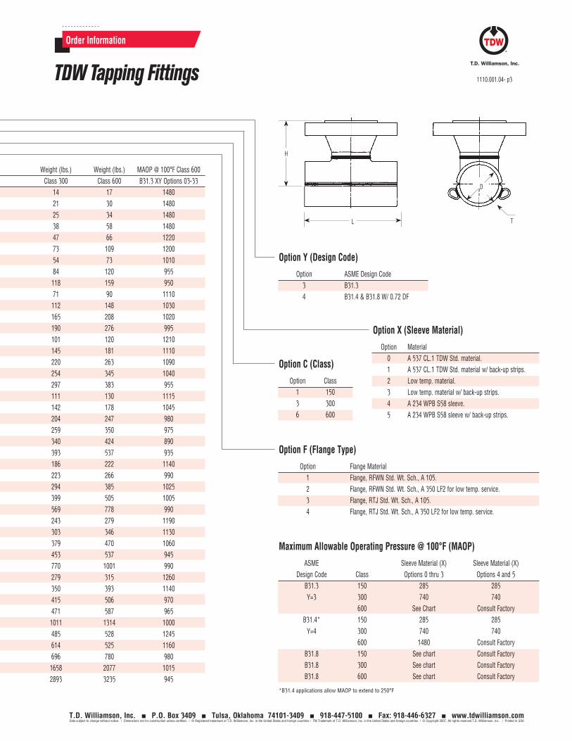
Order Information
Option X (Sleeve Material)
Option Material 0 A 537 CL.1 TDW Std. material. 1 A 537 CL.1 TDW Std. material w/ back-up strips. 2 Low temp. material. 3 Low temp. material w/ back-up strips. 4 A 234 WPB S58 sleeve. 5 A 234 WPB S58 sleeve w/ back-up strips.
Option Y (Design Code)
Option ASME Design Code3 B31.34 B31.4 & B31.8 W/ 0.72 DF
Option C (Class)
Option Class1 1503 3006 600
Option F (Flange Type)
Option Flange Material1 Flange, RFWN Std. Wt. Sch., A 105.2 Flange, RFWN Std. Wt. Sch., A 350 LF2 for low temp. service.3 Flange, RTJ Std. Wt. Sch., A 105.4 Flange, RTJ Std. Wt. Sch., A 350 LF2 for low temp. service.
Maximum Allowable Operating Pressure @ 100°F (MAOP)
ASME Sleeve Material (X) Sleeve Material (X) Design Code Class Options 0 thru 3 Options 4 and 5
B31.3 150 285 285Y=3 300 740 740
600 See Chart Consult FactoryB31.4* 150 285 285
Y=4 300 740 740 600 1480 Consult Factory
B31.8 150 See chart Consult FactoryB31.8 300 See chart Consult FactoryB31.8 600 See chart Consult Factory
*B31.4 applications allow MAOP to extend to 250°F
H
L
D
T
Run/Branch Dim. H (in.) Dim. H (in.) Dim. H (in.) Dim. D (in.) Dim L (in.) Dim T (in.) Weight (lbs.) Weight (lbs.) Weight (lbs.) MAOP @ 100°F Class 600 Inches (Nom.) Class 150 Class 300 Class 600 Class 150 Class 300 Class 600 B31.3 XY Options 03-33 02 02 5.31 5.56 5.81 2.46 6.00 0.203 12 14 17 1480 03 03 6.37 6.75 7.13 3.62 7.00 0.438 23 21 30 1480 04 03 5.92 6.29 6.67 4.65 8.25 0.375 27 25 34 1480 04 04 6.16 6.53 7.41 4.65 10.75 0.375 33 38 58 1480 06 04 7.28 7.65 8.53 6.78 10.75 0.375 42 47 66 1220 06 06 7.84 8.22 9.22 6.78 14.00 0.375 57 73 109 1200 08 04 8.29 8.67 9.54 8.81 10.75 0.375 49 54 73 1010 08 06 8.86 9.24 10.24 8.81 14.00 0.375 68 84 120 955 08 08 9.42 9.80 10.92 8.81 16.50 0.375 88 118 159 950 10 04 9.54 9.92 10.80 10.84 10.75 0.500 66 71 90 1110 10 06 10.04 10.42 11.42 10.84 14.00 0.500 96 112 148 1030 10 08 10.79 11.17 12.30 10.84 16.50 0.500 135 165 208 1020 10 10 10.73 11.36 12.98 10.84 20.00 0.500 152 190 276 995 12 04 10.81 11.18 12.06 12.87 10.75 0.625 96 101 120 1210 12 06 11.19 11.56 12.56 12.87 14.00 0.625 129 145 181 1110 12 08 12.06 12.44 13.56 12.87 16.50 0.625 190 220 263 1090 12 10 12.31 12.94 14.56 12.87 20.00 0.625 216 254 345 1040 12 12 12.44 13.06 14.31 12.87 22.00 0.625 243 297 383 955 14 04 11.56 11.94 12.81 14.12 10.75 0.625 106 111 130 1115 14 06 12.06 12.44 13.44 14.12 12.875 0.625 126 142 178 1045 14 08 12.31 12.69 13.81 14.12 16.50 0.625 174 204 247 980 14 10 12.94 13.56 15.19 14.12 20.00 0.625 221 259 350 975 14 12 13.32 13.95 15.20 14.12 22.00 0.625 286 340 424 890 14 14 13.44 14.06 15.18 14.12 26.00 0.625 314 393 537 935 16 06 12.12 12.78 13.78 16.12 14.00 0.750 170 186 222 1140 16 08 13.68 14.06 15.18 16.12 14.875 0.750 193 223 266 990 16 10 13.68 14.31 15.94 16.12 20.00 0.750 256 294 385 1025 16 12 14.21 14.84 16.09 16.12 24.00 0.750 345 399 505 1005 16 16 14.56 15.31 16.81 16.12 30.00 0.750 460 569 778 990 18 06 13.25 13.90 14.90 18.12 14.00 0.875 227 243 279 1190 18 08 14.14 14.64 15.81 18.12 16.375 0.875 273 303 346 1130 18 10 14.81 15.44 17.06 18.12 20.00 0.875 341 379 470 1060 18 12 15.44 16.06 17.31 18.12 22.00 0.875 400 453 537 945 18 18 15.51 16.50 17.94 18.12 33.00 0.875 617 770 1001 990 20 06 14.62 15.81 16.25 20.12 14.00 1.000 263 279 315 1260 20 08 16.19 16.56 17.68 20.12 16.50 1.000 320 350 393 1140 20 10 16.06 16.68 18.31 20.12 17.875 1.000 377 415 506 970 20 12 16.56 17.19 18.44 20.12 24.00 1.000 417 471 587 965 20 20 16.82 18.04 19.56 20.12 36.00 1.000 820 1011 1314 1000 24 08 18.26 18.76 19.93 24.12 16.50 1.250 455 485 528 1245 24 10 17.70 18.46 20.12 24.12 20.00 1.250 576 614 525 1160 24 12 18.37 19.01 20.34 24.12 21.375 1.250 642 696 780 980 24 24 19.58 21.00 22.44 24.12 43.00 1.250 1373 1658 2077 1015 30 30 22.63 24.00 26.75 30.12 56.00 1.375 2435 2893 3235 945
TDW Tapping Fittings 1110.001.04- p3
T.D. Williamson, Inc. P.O. Box 3409 Tulsa, Oklahoma 74101-3409 918-447-5100 Fax: 918-446-6327 www.tdwilliamson.comData subject to change without notice. / Dimensions not for construction unless certified. / ® Registered trademark of T.D. Williamson, Inc. in the United States and foreign countries / TM Trademark of T.D. Williamson, Inc. in the United States and foreign countries / © Copyright 2007. All rights reserved T.D. Williamson, Inc. / Printed in USA
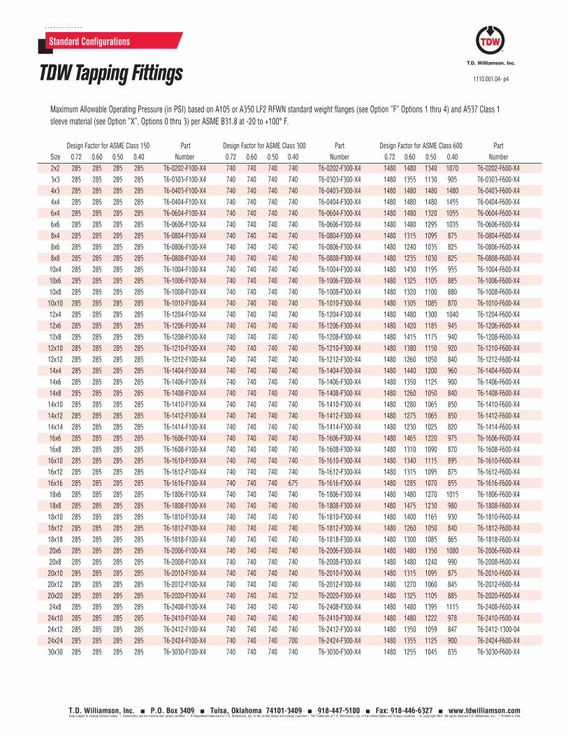
Design Factor for ASME Class 150 Part Design Factor for ASME Class 300 Part Design Factor for ASME Class 600 Part Size 0.72 0.60 0.50 0.40 Number 0.72 0.60 0.50 0.40 Number 0.72 0.60 0.50 0.40 Number 2x2 285 285 285 285 T6-0202-F100-X4 740 740 740 740 T6-0202-F300-X4 1480 1480 1340 1070 T6-0202-F600-X4 3x3 285 285 285 285 T6-0303-F100-X4 740 740 740 740 T6-0303-F300-X4 1480 1355 1130 905 T6-0303-F600-X4 4x3 285 285 285 285 T6-0403-F100-X4 740 740 740 740 T6-0403-F300-X4 1480 1480 1480 1480 T6-0403-F600-X4 4x4 285 285 285 285 T6-0404-F100-X4 740 740 740 740 T6-0404-F300-X4 1480 1480 1480 1455 T6-0404-F600-X4 6x4 285 285 285 285 T6-0604-F100-X4 740 740 740 740 T6-0604-F300-X4 1480 1480 1320 1055 T6-0604-F600-X4 6x6 285 285 285 285 T6-0606-F100-X4 740 740 740 740 T6-0606-F300-X4 1480 1480 1295 1035 T6-0606-F600-X4 8x4 285 285 285 285 T6-0804-F100-X4 740 740 740 740 T6-0804-F300-X4 1480 1315 1095 875 T6-0804-F600-X4 8x6 285 285 285 285 T6-0806-F100-X4 740 740 740 740 T6-0806-F300-X4 1480 1240 1035 825 T6-0806-F600-X4 8x8 285 285 285 285 T6-0808-F100-X4 740 740 740 740 T6-0808-F300-X4 1480 1235 1030 825 T6-0808-F600-X4 10x4 285 285 285 285 T6-1004-F100-X4 740 740 740 740 T6-1004-F300-X4 1480 1430 1195 955 T6-1004-F600-X4 10x6 285 285 285 285 T6-1006-F100-X4 740 740 740 740 T6-1006-F300-X4 1480 1325 1105 885 T6-1006-F600-X4 10x8 285 285 285 285 T6-1008-F100-X4 740 740 740 740 T6-1008-F300-X4 1480 1320 1100 880 T6-1008-F600-X4 10x10 285 285 285 285 T6-1010-F100-X4 740 740 740 740 T6-1010-F300-X4 1480 1305 1085 870 T6-1010-F600-X4 12x4 285 285 285 285 T6-1204-F100-X4 740 740 740 740 T6-1204-F300-X4 1480 1480 1300 1040 T6-1204-F600-X4 12x6 285 285 285 285 T6-1206-F100-X4 740 740 740 740 T6-1206-F300-X4 1480 1420 1185 945 T6-1206-F600-X4 12x8 285 285 285 285 T6-1208-F100-X4 740 740 740 740 T6-1208-F300-X4 1480 1415 1175 940 T6-1208-F600-X4 12x10 285 285 285 285 T6-1210-F100-X4 740 740 740 740 T6-1210-F300-X4 1480 1380 1150 920 T6-1210-F600-X4 12x12 285 285 285 285 T6-1212-F100-X4 740 740 740 740 T6-1212-F300-X4 1480 1260 1050 840 T6-1212-F600-X4 14x4 285 285 285 285 T6-1404-F100-X4 740 740 740 740 T6-1404-F300-X4 1480 1440 1200 960 T6-1404-F600-X4 14x6 285 285 285 285 T6-1406-F100-X4 740 740 740 740 T6-1406-F300-X4 1480 1350 1125 900 T6-1406-F600-X4 14x8 285 285 285 285 T6-1408-F100-X4 740 740 740 740 T6-1408-F300-X4 1480 1260 1050 840 T6-1408-F600-X4 14x10 285 285 285 285 T6-1410-F100-X4 740 740 740 740 T6-1410-F300-X4 1480 1280 1065 850 T6-1410-F600-X4 14x12 285 285 285 285 T6-1412-F100-X4 740 740 740 740 T6-1412-F300-X4 1480 1275 1065 850 T6-1412-F600-X4 14x14 285 285 285 285 T6-1414-F100-X4 740 740 740 740 T6-1414-F300-X4 1480 1230 1025 820 T6-1414-F600-X4 16x6 285 285 285 285 T6-1606-F100-X4 740 740 740 740 T6-1606-F300-X4 1480 1465 1220 975 T6-1606-F600-X4 16x8 285 285 285 285 T6-1608-F100-X4 740 740 740 740 T6-1608-F300-X4 1480 1310 1090 870 T6-1608-F600-X4 16x10 285 285 285 285 T6-1610-F100-X4 740 740 740 740 T6-1610-F300-X4 1480 1340 1115 895 T6-1610-F600-X4 16x12 285 285 285 285 T6-1612-F100-X4 740 740 740 740 T6-1612-F300-X4 1480 1315 1095 875 T6-1612-F600-X4 16x16 285 285 285 285 T6-1616-F100-X4 740 740 740 675 T6-1616-F300-X4 1480 1285 1070 855 T6-1616-F600-X4 18x6 285 285 285 285 T6-1806-F100-X4 740 740 740 740 T6-1806-F300-X4 1480 1480 1270 1015 T6-1806-F600-X4 18x8 285 285 285 285 T6-1808-F100-X4 740 740 740 740 T6-1808-F300-X4 1480 1475 1230 980 T6-1808-F600-X4 18x10 285 285 285 285 T6-1810-F100-X4 740 740 740 740 T6-1810-F300-X4 1480 1400 1165 930 T6-1810-F600-X4 18x12 285 285 285 285 T6-1812-F100-X4 740 740 740 740 T6-1812-F300-X4 1480 1260 1050 840 T6-1812-F600-X4 18x18 285 285 285 285 T6-1818-F100-X4 740 740 740 740 T6-1818-F300-X4 1480 1300 1085 865 T6-1818-F600-X4 20x6 285 285 285 285 T6-2006-F100-X4 740 740 740 740 T6-2006-F300-X4 1480 1480 1350 1080 T6-2006-F600-X4 20x8 285 285 285 285 T6-2008-F100-X4 740 740 740 740 T6-2008-F300-X4 1480 1480 1240 990 T6-2008-F600-X4 20x10 285 285 285 285 T6-2010-F100-X4 740 740 740 740 T6-2010-F300-X4 1480 1315 1095 875 T6-2010-F600-X4 20x12 285 285 285 285 T6-2012-F100-X4 740 740 740 740 T6-2012-F300-X4 1480 1270 1060 845 T6-2012-F600-X4 20x20 285 285 285 285 T6-2020-F100-X4 740 740 740 732 T6-2020-F300-X4 1480 1325 1105 885 T6-2020-F600-X4 24x8 285 285 285 285 T6-2408-F100-X4 740 740 740 740 T6-2408-F300-X4 1480 1480 1395 1115 T6-2408-F600-X4 24x10 285 285 285 285 T6-2410-F100-X4 740 740 740 740 T6-2410-F300-X4 1480 1480 1222 978 T6-2410-F600-X4 24x12 285 285 285 285 T6-2412-F100-X4 740 740 740 740 T6-2412-F300-X4 1480 1350 1059 847 T6-2412-1300-04 24x24 285 285 285 285 T6-2424-F100-X4 740 740 740 700 T6-2424-F300-X4 1480 1355 1125 900 T6-2424-F600-X4 30x30 285 285 285 285 T6-3030-F100-X4 740 740 740 740 T6-3030-F300-X4 1480 1255 1045 835 T6-3030-F600-X4
Standard Configurations
Maximum Allowable Operating Pressure (in PSI) based on A105 or A350 LF2 RFWN standard weight flanges (see Option ”F” Options 1 thru 4) and A537 Class 1 sleeve material (see Option ”X”, Options 0 thru 3) per ASME B31.8 at -20 to +100° F.
TDW Tapping Fittings 1110.001.04- p4
T.D. Williamson, Inc. P.O. Box 3409 Tulsa, Oklahoma 74101-3409 918-447-5100 Fax: 918-446-6327 www.tdwilliamson.comData subject to change without notice. / Dimensions not for construction unless certified. / ® Registered trademark of T.D. Williamson, Inc. in the United States and foreign countries / TM Trademark of T.D. Williamson, Inc. in the United States and foreign countries / © Copyright 2007. All rights reserved T.D. Williamson, Inc. / Printed in USA

Toll Free
1-888-TDWmSon (839-6766)
ISO 9001 Certified
Tapping fittings are full-branch split tees designed for use when connecting branch lines. They are offered in sizes 4- through 12- and 16-inch and meet B31.3 specifications for use in refinery and chemical plant piping systems. Fittings are equipped with RF or RTJ flanges.
are manufactured from a pressure-vessel quality, normalized, killed carbon steel plate with hardness below Rc22.
The Charpy impact value of the sleeves at -50°F is 15 ft-lbs average with 12 ft-lbs minimum.
Description
Flange-to-sleeve weld joints and sleeves are designed to meet pressure and reinforcement requirements of ASME codes, and are available in Class 150, 300 and 600. Other ASME Class ratings available upon request.
Fittings are manufactured with a controlled carbon equivalent to make welding easier in harsh environments. Back-up strips are provided for all fittings.
All pressure-containing welds on the fittings have undergone X-ray inspection per ASME requirements.
Fitting sleeves are an extruded type design. They
Features Rapid delivery: If the desired fitting meets standard specifications, it can be shipped from stock within two weeks in most cases.
Choice of flanges.
Available also to ASME B31.4 and B31.8 specifications.
For B31.1, consult factory.
Use the grid inside to develop the part number for the tapping fitting of your choice*Contact the factory for information concerning ordering of split sleeves (tees). *Please confirm your choice with a Factory Representative
Options
Tapping Machine
Typical Tapping Setup
Tapping Valve
Tapping Fitting
Bulletin No: 1110.004.01Date: November 2008Cross Indexing No: n/aSupersedes: January 2008
TDW Tapping FittingsASME B31.3 - Sizes: 4- through 12- and 16-inch
T.D. Williamson, Inc. P.O. Box 3409 Tulsa, Oklahoma 74101-3409 918-447-5100 Fax: 918-446-6327 www.tdwilliamson.comData subject to change without notice. / Dimensions not for construction unless certified. / ® Registered trademark of T.D. Williamson, Inc. in the United States and foreign countries / TM Trademark of T.D. Williamson, Inc. in the United States and foreign countries / © Copyright 2008. All rights reserved T.D. Williamson, Inc. / Printed in USA
Tapping Fitting Blind flange, studs, nuts and gasket sold separately
New fittings incorporate a designed and manufactured offset allowing the placement of back-up strips
Offset in closeup
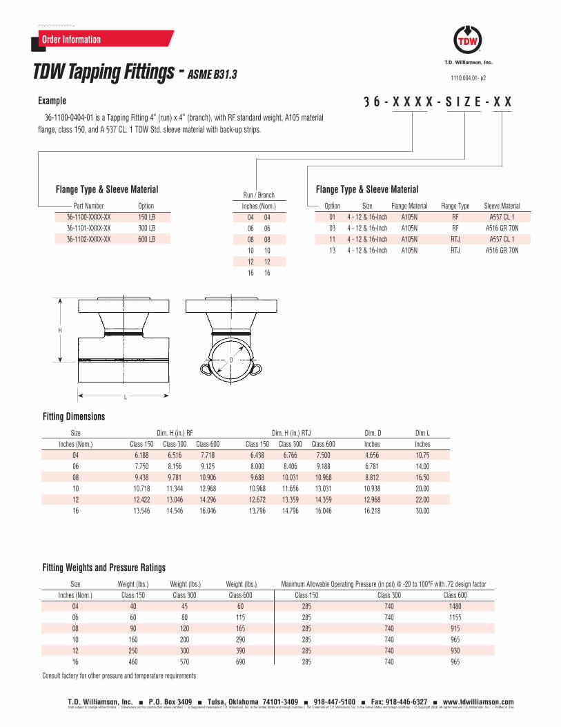
3 6 - X X X X - S I Z E - X XExample
36-1100-0404-01 is a Tapping Fitting 4” (run) x 4” (branch), with RF standard weight, A105 material flange, class 150, and A 537 CL. 1 TDW Std. sleeve material with back-up strips.
Order Information
TDW Tapping Fittings - ASME B31.3 1110.004.01- p2
T.D. Williamson, Inc. P.O. Box 3409 Tulsa, Oklahoma 74101-3409 918-447-5100 Fax: 918-446-6327 www.tdwilliamson.comData subject to change without notice. / Dimensions not for construction unless certified. / ® Registered trademark of T.D. Williamson, Inc. in the United States and foreign countries / TM Trademark of T.D. Williamson, Inc. in the United States and foreign countries / © Copyright 2008. All rights reserved T.D. Williamson, Inc. / Printed in USA
Fitting Weights and Pressure Ratings
Size Weight (lbs.) Weight (lbs.) Weight (lbs.) Maximum Allowable Operating Pressure (in psi) @ -20 to 100°F with .72 design factor Inches (Nom.) Class 150 Class 300 Class 600 Class 150 Class 300 Class 600 04 40 45 60 285 740 1480 06 60 80 115 285 740 1155 08 90 120 165 285 740 915 10 160 200 290 285 740 965 12 250 300 390 285 740 930 16 460 570 690 285 740 965
Consult factory for other pressure and temperature requirements
H
L
D
Flange Type & Sleeve Material
Part Number Option 36-1100-XXXX-XX 150 LB 36-1101-XXXX-XX 300 LB 36-1102-XXXX-XX 600 LB
Flange Type & Sleeve Material
Option Size Flange Material Flange Type Sleeve Material 01 4 - 12 & 16-Inch A105N RF A537 CL 1 03 4 - 12 & 16-Inch A105N RF A516 GR 70N 11 4 - 12 & 16-Inch A105N RTJ A537 CL 1 13 4 - 12 & 16-Inch A105N RTJ A516 GR 70N
Fitting Dimensions
Size Dim. H (in.) RF Dim. H (in.) RTJ Dim. D Dim L Inches (Nom.) Class 150 Class 300 Class 600 Class 150 Class 300 Class 600 Inches Inches 04 6.188 6.516 7.718 6.438 6.766 7.500 4.656 10.75 06 7.750 8.156 9.125 8.000 8.406 9.188 6.781 14.00 08 9.438 9.781 10.906 9.688 10.031 10.968 8.812 16.50 10 10.718 11.344 12.968 10.968 11.656 13.031 10.938 20.00 12 12.422 13.046 14.296 12.672 13.359 14.359 12.968 22.00 16 13.546 14.546 16.046 13.796 14.796 16.046 16.218 30.00
Run / Branch Inches (Nom.) 04 04 06 06 08 08 10 10 12 12 16 16
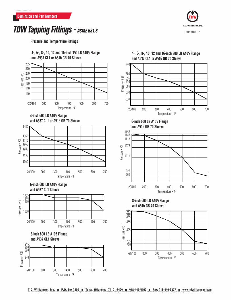
-20/100 200 300 400 500 600 700Temperature - ºF
Pres
sure
- PS
I
285260230200170140
110
4-, 6-, 8-, 10, 12 and 16-inch 150 LB A105 Flange and A537 CL1 or A516 GR 70 Sleeve
-20/100 200 300 400 500 600 700Temperature - ºF
Pres
sure
- PS
I
1480
1360131012651205
1135
1060
4-inch 600 LB A105 Flange and A537 CL1 or A516 GR 70 Sleeve
-20/100 200 300 400 500 600 700Temperature - ºF
Pres
sure
- PS
I
115511351120
1060
6-inch 600 LB A105 Flange and A537 CL1 Sleeve
-20/100 200 300 400 500 600 700Temperature - ºF
Pres
sure
- PS
I
915900890
840
8-inch 600 LB A105 Flange and A537 CL1 Sleeve
-20/100 200 300 400 500 600 700Temperature - ºF
Pres
sure
- PS
I
915910885855
805
735720
8-inch 600 LB A105 Flange and A516 GR 70 Sleeve
-20/100 200 300 400 500 600 700Temperature - ºF
Pres
sure
- PS
I
115511451115
1075
1015
925905
6-inch 600 LB A105 Flange and A516 GR 70 Sleeve
-20/100 200 300 400 500 600 700Temperature - ºF
Pres
sure
- PS
I
740
680655635605
570
530
4-, 6-, 8-, 10, 12 and 16-inch 300 LB A105 Flange and A537 CL1 or A516 GR 70 Sleeve
Pressure and Temperature Ratings
Deminsion and Part Numbers
TDW Tapping Fittings - ASME B31.3 1110.004.01- p3
T.D. Williamson, Inc. P.O. Box 3409 Tulsa, Oklahoma 74101-3409 918-447-5100 Fax: 918-446-6327 www.tdwilliamson.comData subject to change without notice. / Dimensions not for construction unless certified. / ® Registered trademark of T.D. Williamson, Inc. in the United States and foreign countries / TM Trademark of T.D. Williamson, Inc. in the United States and foreign countries / © Copyright 2008. All rights reserved T.D. Williamson, Inc. / Printed in USA
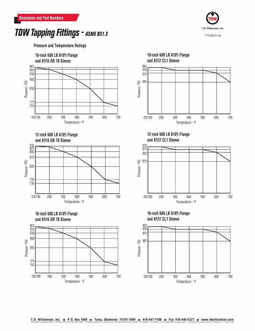
1110.004.01- p4
T.D. Williamson, Inc. P.O. Box 3409 Tulsa, Oklahoma 74101-3409 918-447-5100 Fax: 918-446-6327 www.tdwilliamson.comData subject to change without notice. / Dimensions not for construction unless certified. / ® Registered trademark of T.D. Williamson, Inc. in the United States and foreign countries / TM Trademark of T.D. Williamson, Inc. in the United States and foreign countries / © Copyright 2008. All rights reserved T.D. Williamson, Inc. / Printed in USA
Pressure and Temperature Ratings
Deminsion and Part Numbers
TDW Tapping Fittings - ASME B31.3
-20/100 200 300 400 500 600 700Temperature - ºF
Pres
sure
- PS
I
965955930900
850
775755
10-inch 600 LB A105 Flange and A516 GR 70 Sleeve
-20/100 200 300 400 500 600 700Temperature - ºF
Pres
sure
- PS
I
965950935
885
10-inch 600 LB A105 Flange and A537 CL1 Sleeve
-20/100 200 300 400 500 600 700Temperature - ºF
Pres
sure
- PS
I
930925900870
820
750730
12-inch 600 LB A105 Flange and A516 GR 70 Sleeve
-20/100 200 300 400 500 600 700Temperature - ºF
Pres
sure
- PS
I
930915905
855
12-inch 600 LB A105 Flange and A537 CL1 Sleeve
16-inch 600 LB A105 Flange and A537 CL1 Sleeve
-20/100 200 300 400 500 600 700Temperature - ºF
Pres
sure
- PS
I
965950935
885
16-inch 600 LB A105 Flange and A516 GR 70 Sleeve
-20/100 200 300 400 500 600 700Temperature - ºF
Pres
sure
- PS
I
965955930900
850
775755
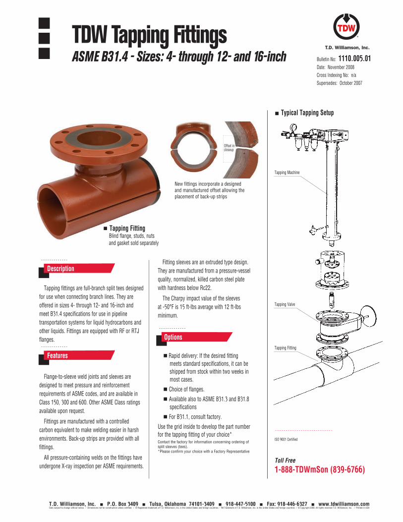
Toll Free
1-888-TDWmSon (839-6766)
ISO 9001 Certified
Tapping Machine
Typical Tapping Setup
Tapping Valve
Tapping Fitting
Bulletin No: 1110.005.01Date: November 2008Cross Indexing No: n/aSupersedes: October 2007
TDW Tapping FittingsASME B31.4 - Sizes: 4- through 12- and 16-inch
T.D. Williamson, Inc. P.O. Box 3409 Tulsa, Oklahoma 74101-3409 918-447-5100 Fax: 918-446-6327 www.tdwilliamson.comData subject to change without notice. / Dimensions not for construction unless certified. / ® Registered trademark of T.D. Williamson, Inc. in the United States and foreign countries / TM Trademark of T.D. Williamson, Inc. in the United States and foreign countries / © Copyright 2008. All rights reserved T.D. Williamson, Inc. / Printed in USA
Tapping fittings are full-branch split tees designed for use when connecting branch lines. They are offered in sizes 4- through 12- and 16-inch and meet B31.4 specifications for use in pipeline transportation systems for liquid hydrocarbons and other liquids. Fittings are equipped with RF or RTJ flanges.
Fitting sleeves are an extruded type design. They are manufactured from a pressure-vessel quality, normalized, killed carbon steel plate with hardness below Rc22.
The Charpy impact value of the sleeves at -50°F is 15 ft-lbs average with 12 ft-lbs minimum.
Description
Flange-to-sleeve weld joints and sleeves are designed to meet pressure and reinforcement requirements of ASME codes, and are available in Class 150, 300 and 600. Other ASME Class ratings available upon request.
Fittings are manufactured with a controlled carbon equivalent to make welding easier in harsh environments. Back-up strips are provided with all fittings.
All pressure-containing welds on the fittings have undergone X-ray inspection per ASME requirements.
Features Rapid delivery: If the desired fitting meets standard specifications, it can be shipped from stock within two weeks in most cases.
Choice of flanges.
Available also to ASME B31.3 and B31.8 specifications
For B31.1, consult factory.
Use the grid inside to develop the part number for the tapping fitting of your choice*Contact the factory for information concerning ordering of split sleeves (tees). *Please confirm your choice with a Factory Representative
Options
Tapping Fitting Blind flange, studs, nuts and gasket sold separately
New fittings incorporate a designed and manufactured offset allowing the placement of back-up strips
Offset in closeup
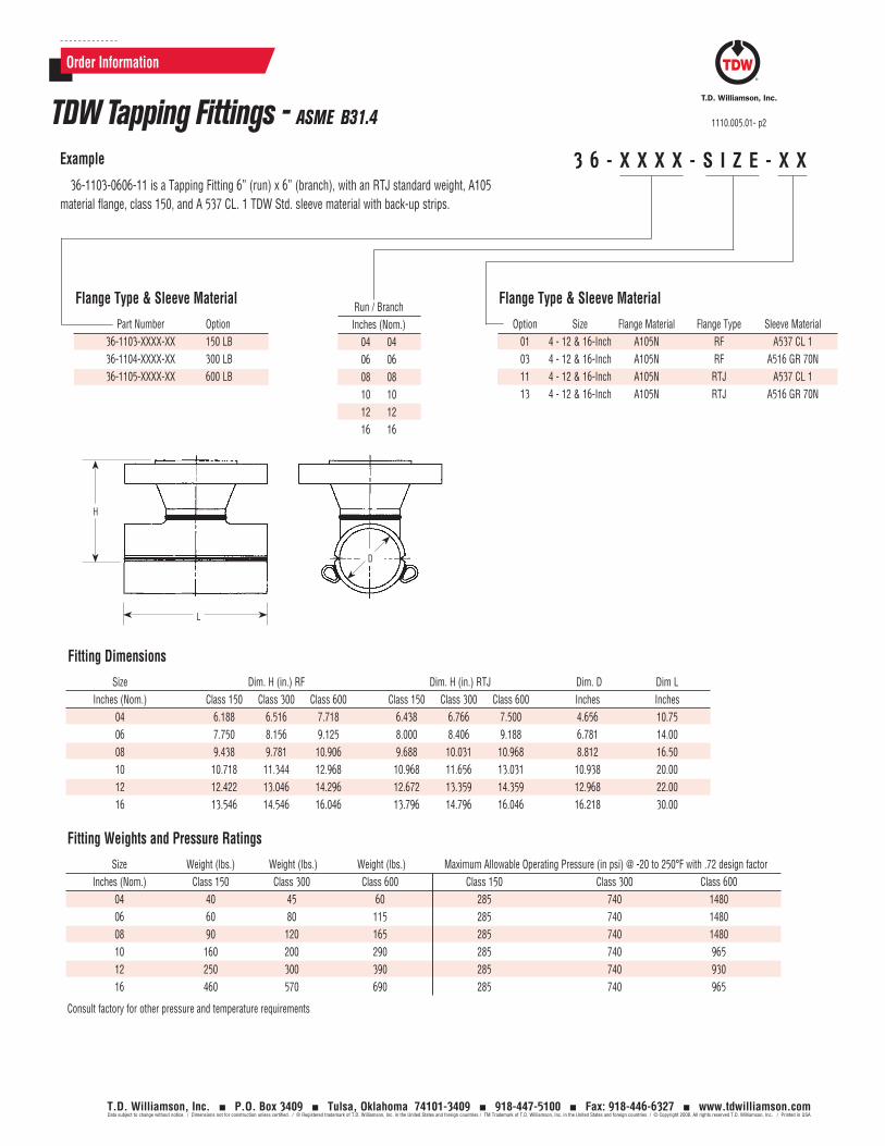
Order Information
3 6 - X X X X - S I Z E - X XExample
36-1103-0606-11 is a Tapping Fitting 6” (run) x 6” (branch), with an RTJ standard weight, A105 material flange, class 150, and A 537 CL. 1 TDW Std. sleeve material with back-up strips.
TDW Tapping Fittings - ASME B31.4 1110.005.01- p2
T.D. Williamson, Inc. P.O. Box 3409 Tulsa, Oklahoma 74101-3409 918-447-5100 Fax: 918-446-6327 www.tdwilliamson.comData subject to change without notice. / Dimensions not for construction unless certified. / ® Registered trademark of T.D. Williamson, Inc. in the United States and foreign countries / TM Trademark of T.D. Williamson, Inc. in the United States and foreign countries / © Copyright 2008. All rights reserved T.D. Williamson, Inc. / Printed in USA
Fitting Weights and Pressure Ratings
Size Weight (lbs.) Weight (lbs.) Weight (lbs.) Maximum Allowable Operating Pressure (in psi) @ -20 to 250°F with .72 design factor Inches (Nom.) Class 150 Class 300 Class 600 Class 150 Class 300 Class 600 04 40 45 60 285 740 1480 06 60 80 115 285 740 1480 08 90 120 165 285 740 1480 10 160 200 290 285 740 965 12 250 300 390 285 740 930 16 460 570 690 285 740 965
Consult factory for other pressure and temperature requirements
H
L
D
Flange Type & Sleeve Material
Part Number Option 36-1103-XXXX-XX 150 LB 36-1104-XXXX-XX 300 LB 36-1105-XXXX-XX 600 LB
Flange Type & Sleeve Material
Option Size Flange Material Flange Type Sleeve Material 01 4 - 12 & 16-Inch A105N RF A537 CL 1 03 4 - 12 & 16-Inch A105N RF A516 GR 70N 11 4 - 12 & 16-Inch A105N RTJ A537 CL 1 13 4 - 12 & 16-Inch A105N RTJ A516 GR 70N
Fitting Dimensions
Size Dim. H (in.) RF Dim. H (in.) RTJ Dim. D Dim L Inches (Nom.) Class 150 Class 300 Class 600 Class 150 Class 300 Class 600 Inches Inches 04 6.188 6.516 7.718 6.438 6.766 7.500 4.656 10.75 06 7.750 8.156 9.125 8.000 8.406 9.188 6.781 14.00 08 9.438 9.781 10.906 9.688 10.031 10.968 8.812 16.50 10 10.718 11.344 12.968 10.968 11.656 13.031 10.938 20.00 12 12.422 13.046 14.296 12.672 13.359 14.359 12.968 22.00 16 13.546 14.546 16.046 13.796 14.796 16.046 16.218 30.00
Run / Branch Inches (Nom.) 04 04 06 06 08 08 10 10 12 12 16 16
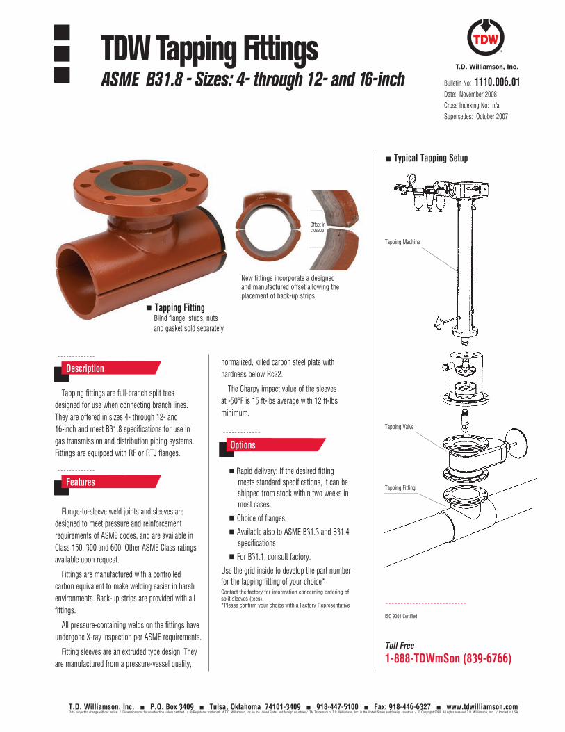
Toll Free
1-888-TDWmSon (839-6766)
ISO 9001 Certified
Tapping Machine
Typical Tapping Setup
Tapping Valve
Tapping Fitting
Bulletin No: 1110.006.01Date: November 2008Cross Indexing No: n/aSupersedes: October 2007
TDW Tapping FittingsASME B31.8 - Sizes: 4- through 12- and 16-inch
T.D. Williamson, Inc. P.O. Box 3409 Tulsa, Oklahoma 74101-3409 918-447-5100 Fax: 918-446-6327 www.tdwilliamson.comData subject to change without notice. / Dimensions not for construction unless certified. / ® Registered trademark of T.D. Williamson, Inc. in the United States and foreign countries / TM Trademark of T.D. Williamson, Inc. in the United States and foreign countries / © Copyright 2008. All rights reserved T.D. Williamson, Inc. / Printed in USA
Tapping fittings are full-branch split tees designed for use when connecting branch lines. They are offered in sizes 4- through 12- and 16-inch and meet B31.8 specifications for use in gas transmission and distribution piping systems. Fittings are equipped with RF or RTJ flanges.
normalized, killed carbon steel plate with hardness below Rc22.
The Charpy impact value of the sleeves at -50°F is 15 ft-lbs average with 12 ft-lbs minimum.
Description
Flange-to-sleeve weld joints and sleeves are designed to meet pressure and reinforcement requirements of ASME codes, and are available in Class 150, 300 and 600. Other ASME Class ratings available upon request.
Fittings are manufactured with a controlled carbon equivalent to make welding easier in harsh environments. Back-up strips are provided with all fittings.
All pressure-containing welds on the fittings have undergone X-ray inspection per ASME requirements.
Fitting sleeves are an extruded type design. They are manufactured from a pressure-vessel quality,
Features Rapid delivery: If the desired fitting
meets standard specifications, it can be shipped from stock within two weeks in most cases.
Choice of flanges.
Available also to ASME B31.3 and B31.4 specifications
For B31.1, consult factory.
Use the grid inside to develop the part number for the tapping fitting of your choice*Contact the factory for information concerning ordering of split sleeves (tees). *Please confirm your choice with a Factory Representative
Options
Tapping Fitting Blind flange, studs, nuts and gasket sold separately
New fittings incorporate a designed and manufactured offset allowing the placement of back-up strips
Offset in closeup
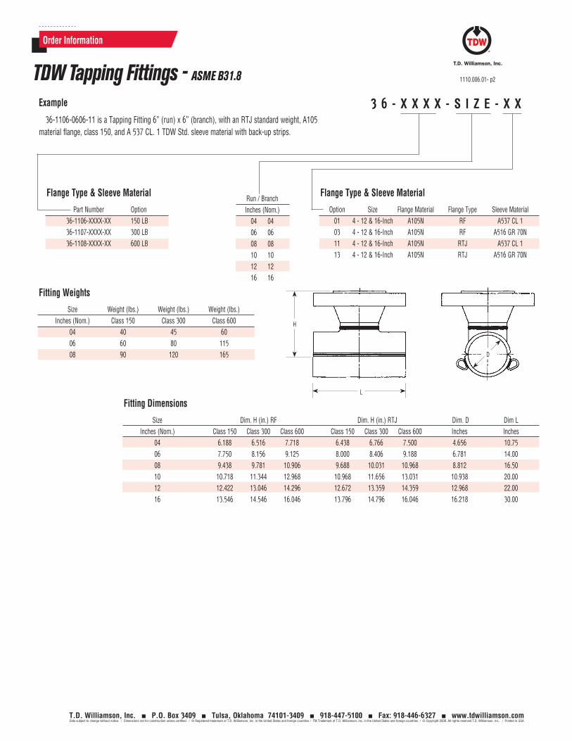
Order Information
3 6 - X X X X - S I Z E - X XExample
36-1106-0606-11 is a Tapping Fitting 6” (run) x 6” (branch), with an RTJ standard weight, A105 material flange, class 150, and A 537 CL. 1 TDW Std. sleeve material with back-up strips.
TDW Tapping Fittings - ASME B31.8 1110.006.01- p2
T.D. Williamson, Inc. P.O. Box 3409 Tulsa, Oklahoma 74101-3409 918-447-5100 Fax: 918-446-6327 www.tdwilliamson.comData subject to change without notice. / Dimensions not for construction unless certified. / ® Registered trademark of T.D. Williamson, Inc. in the United States and foreign countries / TM Trademark of T.D. Williamson, Inc. in the United States and foreign countries / © Copyright 2008. All rights reserved T.D. Williamson, Inc. / Printed in USA
H
L
D
Flange Type & Sleeve Material
Part Number Option 36-1106-XXXX-XX 150 LB 36-1107-XXXX-XX 300 LB 36-1108-XXXX-XX 600 LB
Flange Type & Sleeve Material
Option Size Flange Material Flange Type Sleeve Material 01 4 - 12 & 16-Inch A105N RF A537 CL 1 03 4 - 12 & 16-Inch A105N RF A516 GR 70N 11 4 - 12 & 16-Inch A105N RTJ A537 CL 1 13 4 - 12 & 16-Inch A105N RTJ A516 GR 70N
Fitting Weights
Size Weight (lbs.) Weight (lbs.) Weight (lbs.) Inches (Nom.) Class 150 Class 300 Class 600 04 40 45 60 06 60 80 115 08 90 120 165
Fitting Dimensions
Size Dim. H (in.) RF Dim. H (in.) RTJ Dim. D Dim L Inches (Nom.) Class 150 Class 300 Class 600 Class 150 Class 300 Class 600 Inches Inches 04 6.188 6.516 7.718 6.438 6.766 7.500 4.656 10.75 06 7.750 8.156 9.125 8.000 8.406 9.188 6.781 14.00 08 9.438 9.781 10.906 9.688 10.031 10.968 8.812 16.50 10 10.718 11.344 12.968 10.968 11.656 13.031 10.938 20.00 12 12.422 13.046 14.296 12.672 13.359 14.359 12.968 22.00 16 13.546 14.546 16.046 13.796 14.796 16.046 16.218 30.00
Run / Branch Inches (Nom.) 04 04 06 06 08 08 10 10 12 12 16 16
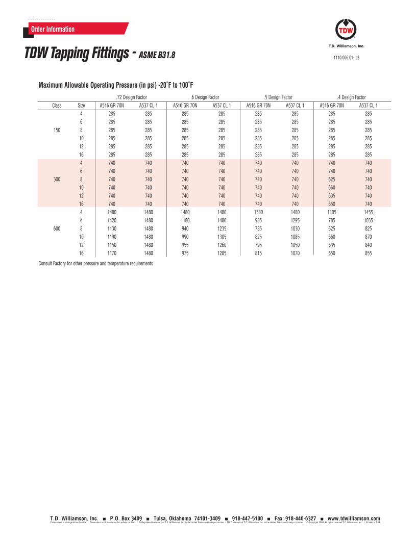
Order Information
TDW Tapping Fittings - ASME B31.8 1110.006.01- p3
T.D. Williamson, Inc. P.O. Box 3409 Tulsa, Oklahoma 74101-3409 918-447-5100 Fax: 918-446-6327 www.tdwilliamson.comData subject to change without notice. / Dimensions not for construction unless certified. / ® Registered trademark of T.D. Williamson, Inc. in the United States and foreign countries / TM Trademark of T.D. Williamson, Inc. in the United States and foreign countries / © Copyright 2008. All rights reserved T.D. Williamson, Inc. / Printed in USA
Maximum Allowable Operating Pressure (in psi) -20˚F to 100˚F
.72 Design Factor .6 Design Factor .5 Design Factor .4 Design Factor Class Size A516 GR 70N A537 CL 1 A516 GR 70N A537 CL 1 A516 GR 70N A537 CL 1 A516 GR 70N A537 CL 1 4 285 285 285 285 285 285 285 285 6 285 285 285 285 285 285 285 285 150 8 285 285 285 285 285 285 285 285 10 285 285 285 285 285 285 285 285 12 285 285 285 285 285 285 285 285 16 285 285 285 285 285 285 285 285 4 740 740 740 740 740 740 740 740 6 740 740 740 740 740 740 740 740 300 8 740 740 740 740 740 740 625 740 10 740 740 740 740 740 740 660 740 12 740 740 740 740 740 740 635 740 16 740 740 740 740 740 740 650 740 4 1480 1480 1480 1480 1380 1480 1105 1455 6 1420 1480 1180 1480 985 1295 785 1035 600 8 1130 1480 940 1235 785 1030 625 825 10 1190 1480 990 1305 825 1085 660 870 12 1150 1480 955 1260 795 1050 635 840 16 1170 1480 975 1285 815 1070 650 855
Consult Factory for other pressure and temperature requirements

1110.006.01- p4
T.D. Williamson, Inc. P.O. Box 3409 Tulsa, Oklahoma 74101-3409 918-447-5100 Fax: 918-446-6327 www.tdwilliamson.comData subject to change without notice. / Dimensions not for construction unless certified. / ® Registered trademark of T.D. Williamson, Inc. in the United States and foreign countries / TM Trademark of T.D. Williamson, Inc. in the United States and foreign countries / © Copyright 2008. All rights reserved T.D. Williamson, Inc. / Printed in USA
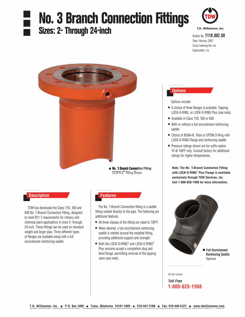
The No. 3 Branch Connection fitting is a saddle fitting welded directly to the pipe. The following are additional features.
All three classes of the fitting are rated to 700°F.
When desired, a full encirclement reinforcing saddle is welded around the installed fitting, providing additional support and strength.
Both the LOCK-O-RING® and LOCK-O-RING® Plus versions accept a completion plug and blind flange, permitting removal of the tapping valve (see note).
Features
Toll Free
1-800-828-1988
ISO 9001 Certified
TDW has developed the Class 150, 300 and 600 No. 3 Branch Connection Fitting, designed to meet B31.3 requirements for refinery and chemical plant applications in sizes 2- through 24-inch. These fittings can be used on standard weight and larger pipe. Three different types of flanges are available along with a full encirclement reinforcing saddle.
Description
No. 3 Branch Connection Fitting STOPPLE® Fitting Shown
Options
Bulletin No: 1110.002.00Date: February 2007Cross Indexing No: n/aSupercedes: n/a
Options include:
A choice of three flanges is available: Tapping, LOCK-0-RING, or LOCK-O-RING Plus (see note).
Available in Class 150, 300 or 600
With or without a full encirclement reinforcing saddle
Choice of BUNA-N, Viton or EPDM O-Ring with LOCK-O-RING Flange and reinforcing saddle.
Pressure ratings shown are for suffix option 10 @ 100ºF only. Consult factory for additional ratings for higher temperatures.
Full Encirclement Reinforcing Saddle Optional
Note: The No. 3 Branch Connection Fitting with LOCK-O-RING® Plus Flange is available exclusively through TDW Services, Inc. Call 1-800-828-1988 for more information.
No. 3 Branch Connection FittingsSizes: 2- Through 24-inch
T.D. Williamson, Inc. P.O. Box 3409 Tulsa, Oklahoma 74101-3409 918-447-5100 Fax: 918-446-6327 www.tdwilliamson.comData subject to change without notice. / Dimensions not for construction unless certified. / ® Registered trademark of T.D. Williamson, Inc. in the United States and foreign countries / TM Trademark of T.D. Williamson, Inc. in the United States and foreign countries / © Copyright 2007. All rights reserved T.D. Williamson, Inc. / Printed in USA
No. 3 Branch Connection FittingSTOPPLE® Fitting Shown
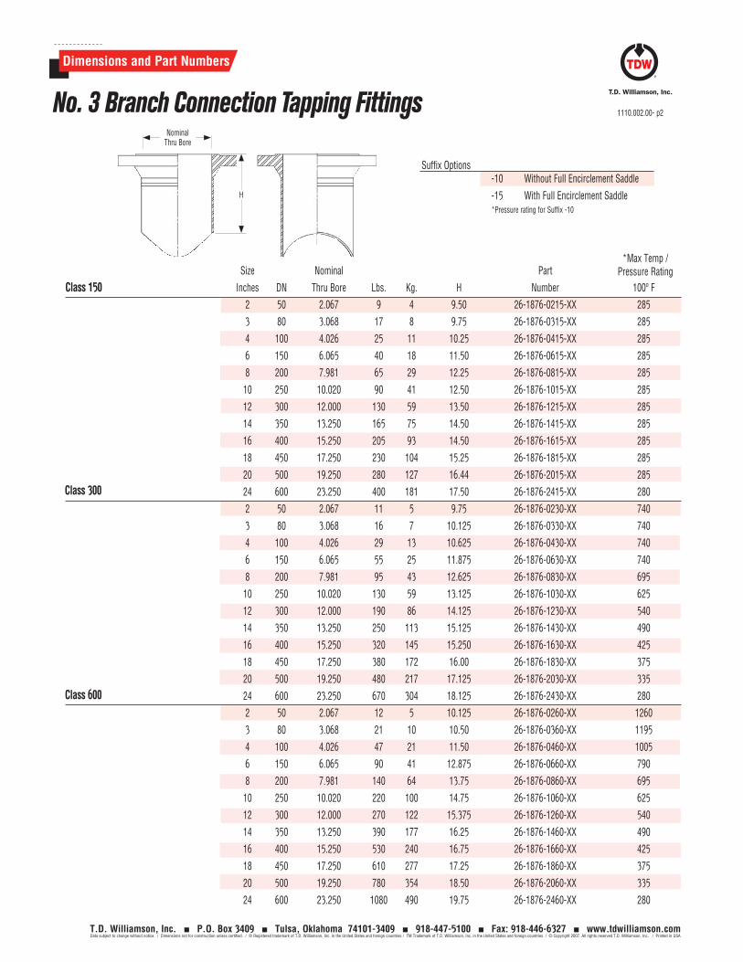
Class 600
Class 300
Dimensions and Part Numbers
1110.002.00- p2
T.D. Williamson, Inc. P.O. Box 3409 Tulsa, Oklahoma 74101-3409 918-447-5100 Fax: 918-446-6327 www.tdwilliamson.comData subject to change without notice. / Dimensions not for construction unless certified. / ® Registered trademark of T.D. Williamson, Inc. in the United States and foreign countries / TM Trademark of T.D. Williamson, Inc. in the United States and foreign countries / © Copyright 2007. All rights reserved T.D. Williamson, Inc. / Printed in USA
Size Nominal Part
Inches DN Thru Bore Lbs. Kg. H Number 100º F
2 50 2.067 9 4 9.50 26-1876-0215-XX 285
3 80 3.068 17 8 9.75 26-1876-0315-XX 285
4 100 4.026 25 11 10.25 26-1876-0415-XX 285
6 150 6.065 40 18 11.50 26-1876-0615-XX 285
8 200 7.981 65 29 12.25 26-1876-0815-XX 285
10 250 10.020 90 41 12.50 26-1876-1015-XX 285
12 300 12.000 130 59 13.50 26-1876-1215-XX 285
14 350 13.250 165 75 14.50 26-1876-1415-XX 285
16 400 15.250 205 93 14.50 26-1876-1615-XX 285
18 450 17.250 230 104 15.25 26-1876-1815-XX 285
20 500 19.250 280 127 16.44 26-1876-2015-XX 285
24 600 23.250 400 181 17.50 26-1876-2415-XX 280
2 50 2.067 11 5 9.75 26-1876-0230-XX 740
3 80 3.068 16 7 10.125 26-1876-0330-XX 740
4 100 4.026 29 13 10.625 26-1876-0430-XX 740
6 150 6.065 55 25 11.875 26-1876-0630-XX 740
8 200 7.981 95 43 12.625 26-1876-0830-XX 695
10 250 10.020 130 59 13.125 26-1876-1030-XX 625
12 300 12.000 190 86 14.125 26-1876-1230-XX 540
14 350 13.250 250 113 15.125 26-1876-1430-XX 490
16 400 15.250 320 145 15.250 26-1876-1630-XX 425
18 450 17.250 380 172 16.00 26-1876-1830-XX 375
20 500 19.250 480 217 17.125 26-1876-2030-XX 335
24 600 23.250 670 304 18.125 26-1876-2430-XX 280
2 50 2.067 12 5 10.125 26-1876-0260-XX 1260
3 80 3.068 21 10 10.50 26-1876-0360-XX 1195
4 100 4.026 47 21 11.50 26-1876-0460-XX 1005
6 150 6.065 90 41 12.875 26-1876-0660-XX 790
8 200 7.981 140 64 13.75 26-1876-0860-XX 695
10 250 10.020 220 100 14.75 26-1876-1060-XX 625
12 300 12.000 270 122 15.375 26-1876-1260-XX 540
14 350 13.250 390 177 16.25 26-1876-1460-XX 490
16 400 15.250 530 240 16.75 26-1876-1660-XX 425
18 450 17.250 610 277 17.25 26-1876-1860-XX 375
20 500 19.250 780 354 18.50 26-1876-2060-XX 335
24 600 23.250 1080 490 19.75 26-1876-2460-XX 280
Class 150
*Max Temp / Pressure Rating
No. 3 Branch Connection Tapping FittingsNominal
Thru Bore
H
-10 Without Full Encirclement Saddle
-15 With Full Encirclement Saddle*Pressure rating for Suffix -10
Suffix Options
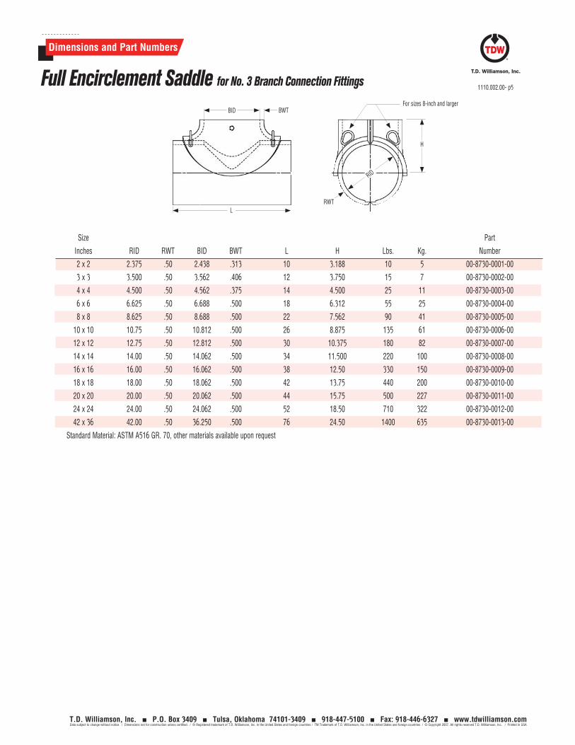
Dimensions and Part Numbers
1110.002.00- p5
T.D. Williamson, Inc. P.O. Box 3409 Tulsa, Oklahoma 74101-3409 918-447-5100 Fax: 918-446-6327 www.tdwilliamson.comData subject to change without notice. / Dimensions not for construction unless certified. / ® Registered trademark of T.D. Williamson, Inc. in the United States and foreign countries / TM Trademark of T.D. Williamson, Inc. in the United States and foreign countries / © Copyright 2007. All rights reserved T.D. Williamson, Inc. / Printed in USA
Full Encirclement Saddle for No. 3 Branch Connection Fittings
BID
H
BWT
LRWT
Size Part
Inches RID RWT BID BWT L H Lbs. Kg. Number
2 x 2 2.375 .50 2.438 .313 10 3.188 10 5 00-8730-0001-00
3 x 3 3.500 .50 3.562 .406 12 3.750 15 7 00-8730-0002-00
4 x 4 4.500 .50 4.562 .375 14 4.500 25 11 00-8730-0003-00
6 x 6 6.625 .50 6.688 .500 18 6.312 55 25 00-8730-0004-00
8 x 8 8.625 .50 8.688 .500 22 7.562 90 41 00-8730-0005-00
10 x 10 10.75 .50 10.812 .500 26 8.875 135 61 00-8730-0006-00
12 x 12 12.75 .50 12.812 .500 30 10.375 180 82 00-8730-0007-00
14 x 14 14.00 .50 14.062 .500 34 11.500 220 100 00-8730-0008-00
16 x 16 16.00 .50 16.062 .500 38 12.50 330 150 00-8730-0009-00
18 x 18 18.00 .50 18.062 .500 42 13.75 440 200 00-8730-0010-00
20 x 20 20.00 .50 20.062 .500 44 15.75 500 227 00-8730-0011-00
24 x 24 24.00 .50 24.062 .500 52 18.50 710 322 00-8730-0012-00
42 x 36 42.00 .50 36.250 .500 76 24.50 1400 635 00-8730-0013-00
Standard Material: ASTM A516 GR. 70, other materials available upon request
RID
For sizes 8-inch and larger
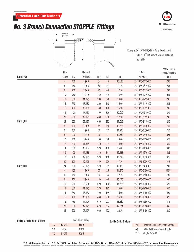
Dimensions and Part Numbers
1110.002.00- p3
T.D. Williamson, Inc. P.O. Box 3409 Tulsa, Oklahoma 74101-3409 918-447-5100 Fax: 918-446-6327 www.tdwilliamson.comData subject to change without notice. / Dimensions not for construction unless certified. / ® Registered trademark of T.D. Williamson, Inc. in the United States and foreign countries / TM Trademark of T.D. Williamson, Inc. in the United States and foreign countries / © Copyright 2007. All rights reserved T.D. Williamson, Inc. / Printed in USA
No. 3 Branch Connection STOPPLE ® Fittings
Size Nominal Part
Inches DN Thru Bore Lbs. Kg. H Number 100º F
4 100 3.969 34 15 10.688 26-1875-0415-XX 285
6 150 5.968 60 27 11.75 26-1875-0615-XX 285
8 200 7.940 95 43 12.50 26-1875-0815-XX 285
10 250 9.940 130 59 13.00 26-1875-1015-XX 285
12 300 11.875 190 59 14.00 26-1875-1215-XX 285
14 350 13.187 260 118 15.00 26-1875-1415-XX 285
16 400 15.188 330 150 16.50 26-1875-1615-XX 285
18 450 17.125 350 159 16.656 26-1875-1815-XX 285
20 500 19.125 440 200 17.50 26-1875-2015-XX 285
24 600 23.125 600 272 17.062 26-1875-2415-XX 280
4 100 3.969 45 20 10.625 26-1875-0430-XX 740
6 150 5.968 60 27 11.938 26-1875-0630-XX 740
8 200 7.940 90 41 12.562 26-1875-0830-XX 695
10 250 9.940 130 59 13.00 26-1875-1030-XX 625
12 300 11.875 170 77 14.00 26-1875-1230-XX 540
14 350 13.187 220 100 15.00 26-1875-1430-XX 490
16 400 15.188 310 141 16.188 26-1875-1630-XX 425
18 450 17.125 370 168 16.312 26-1875-1830-XX 375
20 500 19.125 440 200 17.25 26-1875-2030-XX 335
24 600 23.125 570 259 19.188 26-1875-2430-XX 280
4 100 3.969 55 25 11.375 26-1875-0460-XX 1005
6 150 5.968 80 36 12.75 26-1875-0660-XX 790
8 200 7.940 140 64 13.625 26-1875-0860-XX 695
10 250 9.940 220 100 14.625 26-1875-1060-XX 625
12 300 11.875 270 122 15.00 26-1875-1260-XX 540
14 350 13.187 320 145 16.00 26-1875-1460-XX 490
16 400 15.188 440 200 16.50 26-1875-1660-XX 425
18 450 17.125 610 277 16.562 26-1875-1860-XX 375
20 500 19.125 670 304 19.031 26-1875-2060-XX 335
24 600 23.125 930 422 20.25 26-1875-2460-XX 280
Class 150
Class 300
Class 600
*Max Temp / Pressure Rating
NominalThru Bore
H
Max Temp Rating
-1X Buna-N 180ºF
-2X Viton 400ºF
-3X EPDM 300ºF
O-ring Material Suffix Options -X0 Without Full Encirclement Saddle
-X5 With Full Encirclement Saddle*Pressure rating for Suffix -10
Saddle Suffix Options
Example: 26-1875-0415-20 is for a 4-inch 150lb
STOPPLE® Fitting with Viton O-ring and
no saddle.
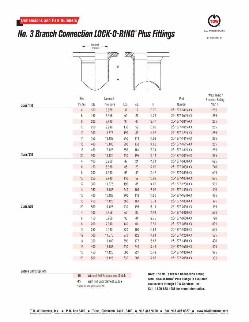
Dimensions and Part Numbers
1110.002.00- p4
T.D. Williamson, Inc. P.O. Box 3409 Tulsa, Oklahoma 74101-3409 918-447-5100 Fax: 918-446-6327 www.tdwilliamson.comData subject to change without notice. / Dimensions not for construction unless certified. / ® Registered trademark of T.D. Williamson, Inc. in the United States and foreign countries / TM Trademark of T.D. Williamson, Inc. in the United States and foreign countries / © Copyright 2007. All rights reserved T.D. Williamson, Inc. / Printed in USA
No. 3 Branch Connection LOCK-O-RING ® Plus Fittings
Class 600
Class 300
Size Nominal Part
Inches DN Thru Bore Lbs. Kg. H Number 100º F
4 100 3.968 37 17 10.72 26-1877-0415-XX 285
6 150 5.968 60 27 11.75 26-1877-0615-XX 285
8 200 7.940 95 43 12.47 26-1877-0815-XX 285
10 250 9.940 130 59 13.02 26-1877-1015-XX 285
12 300 11.875 190 86 14.02 26-1877-1215-XX 285
14 350 13.188 250 113 15.02 26-1877-1415-XX 285
16 400 15.188 290 132 14.60 26-1877-1615-XX 285
18 450 17.125 355 161 15.31 26-1877-1815-XX 285
20 500 19.125 430 195 16.14 26-1877-2015-XX 285
4 100 3.968 47 21 11.21 26-1877-0430-XX 625
6 150 5.968 65 29 12.00 26-1877-0630-XX 740
8 200 7.940 95 43 12.47 26-1877-0830-XX 695
10 250 9.940 130 59 13.02 26-1877-1030-XX 625
12 300 11.875 190 86 14.02 26-1877-1230-XX 505
14 350 13.188 240 109 15.02 26-1877-1430-XX 490
16 400 15.188 290 132 15.60 26-1877-1630-XX 425
18 450 17.125 360 163 15.31 26-1877-1830-XX 375
20 500 19.125 430 195 16.14 26-1877-2030-XX 335
4 100 3.968 60 27 11.91 26-1877-0460-XX 625
6 150 5.968 90 41 12.75 26-1877-0660-XX 790
8 200 7.940 140 64 13.59 26-1877-0860-XX 695
10 250 9.940 220 100 14.64 26-1877-1060-XX 625
12 300 11.875 270 122 14.81 26-1877-1260-XX 505
14 350 13.188 390 177 15.66 26-1877-1460-XX 490
16 400 15.188 530 240 17.44 26-1877-1660-XX 425
18 450 17.125 500 227 16.49 26-1877-1860-XX 375
20 500 19.125 630 286 17.66 26-1877-2060-XX 335
Class 150
*Max Temp / Pressure Rating
NominalThru Bore
H
-10 Without Full Encirclement Saddle
-15 With Full Encirclement Saddle*Pressure rating for Suffix -10
Saddle Suffix Options Note: The No. 3 Branch Connection Fitting with LOCK-O-RING® Plus Flange is available exclusively through TDW Services, Inc. Call 1-800-828-1988 for more information.

1110.002.00- p6
T.D. Williamson, Inc. P.O. Box 3409 Tulsa, Oklahoma 74101-3409 918-447-5100 Fax: 918-446-6327 www.tdwilliamson.comData subject to change without notice. / Dimensions not for construction unless certified. / ® Registered trademark of T.D. Williamson, Inc. in the United States and foreign countries / TM Trademark of T.D. Williamson, Inc. in the United States and foreign countries / © Copyright 2007. All rights reserved T.D. Williamson, Inc. / Printed in USA
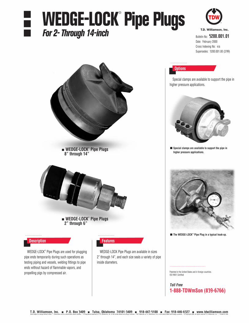
Toll Free
1-888-TDWmSon (839-6766)
WEDGE-LOCK® Pipe Plugs are used for plugging pipe ends temporarily during such operations as testing piping and vessels, welding fittings to pipe ends without hazard of flammable vapors, and propelling pigs by compressed air.
WEDGE-LOCK Pipe Plugs are available in sizes 2” through 14”, and each size seals a variety of pipe inside diameters.
Description Features
Special clamps are available to support the pipe in higher pressure applications.
Options
WEDGE-LOCK® Pipe Plugs8” through 14”
WEDGE-LOCK® Pipe Plugs2” through 6”
Patented in the United States and in foreign countries.ISO 9001 Certified
Special clamps are available to support the pipe in higher pressure applications.
The WEDGE-LOCK® Pipe Plug in a typical hook-up.
Bulletin No: 5200.001.01Date: February 2000Cross Indexing No: n/aSupersedes: 5200.001.00 (2/99)
WEDGE-LOCK®
Pipe PlugsFor 2- Through 14-inch
T.D. Williamson, Inc. P.O. Box 3409 Tulsa, Oklahoma 74101-3409 918-447-5100 Fax: 918-446-6327 www.tdwilliamson.comData subject to change without notice. / Dimensions not for construction unless certified. / ® Registered trademark of T.D. Williamson, Inc. in the United States and foreign countries / TM Trademark of T.D. Williamson, Inc. in the United States and foreign countries / © Copyright 2006. All rights reserved T.D. Williamson, Inc. / Printed in USA
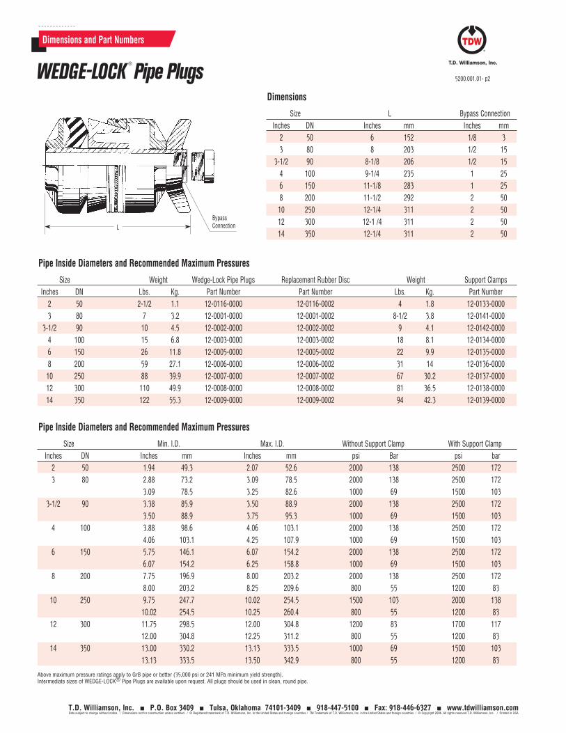
Dimensions and Part Numbers
Dimensions
Pipe Inside Diameters and Recommended Maximum Pressures
Pipe Inside Diameters and Recommended Maximum Pressures
LBypass Connection
Size L Bypass Connection Inches DN Inches mm Inches mm 2 50 6 152 1/8 3 3 80 8 203 1/2 15 3-1/2 90 8-1/8 206 1/2 15 4 100 9-1/4 235 1 25 6 150 11-1/8 283 1 25 8 200 11-1/2 292 2 50 10 250 12-1/4 311 2 50 12 300 12-1 /4 311 2 50 14 350 12-1/4 311 2 50
Size Weight Wedge-Lock Pipe Plugs Replacement Rubber Disc Weight Support Clamps Inches DN Lbs. Kg. Part Number Part Number Lbs. Kg. Part Number 2 50 2-1/2 1.1 12-0116-0000 12-0116-0002 4 1.8 12-0133-0000 3 80 7 3.2 12-0001-0000 12-0001-0002 8-1/2 3.8 12-0141-0000 3-1/2 90 10 4.5 12-0002-0000 12-0002-0002 9 4.1 12-0142-0000 4 100 15 6.8 12-0003-0000 12-0003-0002 18 8.1 12-0134-0000 6 150 26 11.8 12-0005-0000 12-0005-0002 22 9.9 12-0135-0000 8 200 59 27.1 12-0006-0000 12-0006-0002 31 14 12-0136-0000 10 250 88 39.9 12-0007-0000 12-0007-0002 67 30.2 12-0137-0000 12 300 110 49.9 12-0008-0000 12-0008-0002 81 36.5 12-0138-0000 14 350 122 55.3 12-0009-0000 12-0009-0002 94 42.3 12-0139-0000
Size Min. I.D. Max. I.D. Without Support Clamp With Support Clamp Inches DN Inches mm Inches mm psi Bar psi bar 2 50 1.94 49.3 2.07 52.6 2000 138 2500 172 3 80 2.88 73.2 3.09 78.5 2000 138 2500 172 3.09 78.5 3.25 82.6 1000 69 1500 103 3-1/2 90 3.38 85.9 3.50 88.9 2000 138 2500 172 3.50 88.9 3.75 95.3 1000 69 1500 103 4 100 3.88 98.6 4.06 103.1 2000 138 2500 172 4.06 103.1 4.25 107.9 1000 69 1500 103 6 150 5.75 146.1 6.07 154.2 2000 138 2500 172 6.07 154.2 6.25 158.8 1000 69 1500 103 8 200 7.75 196.9 8.00 203.2 2000 138 2500 172 8.00 203.2 8.25 209.6 800 55 1200 83 10 250 9.75 247.7 10.02 254.5 1500 103 2000 138 10.02 254.5 10.25 260.4 800 55 1200 83 12 300 11.75 298.5 12.00 304.8 1200 83 1700 117 12.00 304.8 12.25 311.2 800 55 1200 83 14 350 13.00 330.2 13.13 333.5 1000 69 1500 103 13.13 333.5 13.50 342.9 800 55 1200 83
Above maximum pressure ratings apply to GrB pipe or better (35,000 psi or 241 MPa minimum yield strength). Intermediate sizes of WEDGE-LOCK® Pipe Plugs are available upon request. All plugs should be used in clean, round pipe.
WEDGE-LOCK®
Pipe Plugs 5200.001.01- p2
T.D. Williamson, Inc. P.O. Box 3409 Tulsa, Oklahoma 74101-3409 918-447-5100 Fax: 918-446-6327 www.tdwilliamson.comData subject to change without notice. / Dimensions not for construction unless certified. / ® Registered trademark of T.D. Williamson, Inc. in the United States and foreign countries / TM Trademark of T.D. Williamson, Inc. in the United States and foreign countries / © Copyright 2006. All rights reserved T.D. Williamson, Inc. / Printed in USA
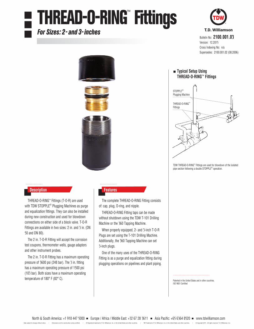
Bulletin No: 2100.001.03Version: 12.2015
Cross Indexing No: n/a
Supersedes: 2100.001.02 (08.2006)
THREAD-O-RING™ Fittings (T-O-R) are used
with TDW STOPPLE® Plugging Machines as purge
and equalization fittings. They can also be installed
during new construction and used for blowdown
connections on either side of a block valve. T-O-R
Fittings are available in two sizes: 2 in. and 3 in. (DN
50 and DN 80).
The 2 in. T-O-R Fitting will accept the corrosion
test coupons, thermometer wells, gauge adapters
and other instrument probes.
The 2 in. T-O-R Fitting has a maximum operating
pressure of 3600 psi (248 bar). The 3 in. fitting
has a maximum operating pressure of 1500 psi
(103 bar). Both sizes have a maximum operating
temperature of 180° F (82° C).
The complete THREAD-O-RING Fitting consists
of: cap, plug, O-ring, and nipple.
THREAD-O-RING Fitting taps can be made
without shutdown using the TDW T-101 Drilling
Machine or the 360 Tapping Machine.
When properly equipped, 2- and 3-inch T-O-R
Plugs are set using the T-101 Drilling Machine.
Additionally, the 360 Tapping Machine can set
3-inch plugs.
One of the many uses of the THREAD-O-RING
Fitting is as a purge and equalization fitting during
plugging operations on pipelines and plant piping.
Description Features
Patented in the United States and in other countries.ISO 9001 Certified
Typical Setup Using THREAD-O-RING™ Fittings
STOPPLE® Plugging Machine
THREAD-O-RING™ Fittings
TDW THREAD-O-RING™ Fittings are used for blowdown of the isolated pipe section following a double STOPPLE® operation.
North & South America: +1 918 447 5000 Europe / Africa / Middle East: +32 67 28 3611 Asia Pacific: +65 6364 8520 www.tdwilliamson.comData subject to change without notice. / Dimensions not for construction unless certified. / ® Registered trademark of T.D. Williamson, Inc. in the United States and other countries. / TM Trademark of T.D. Williamson, Inc. in the United States and other countries. / © Copyright 2015 All rights reserved. T.D. Williamson, Inc.
THREAD-O-RING™ FittingsFor Sizes: 2- and 3- inches
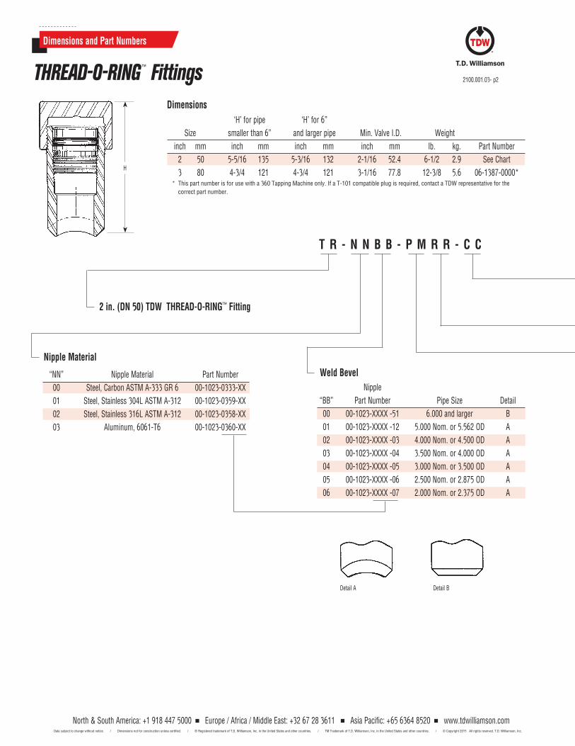
2 in. (DN 50) TDW THREAD-O-RING™ Fitting
‘H’ for pipe ‘H’ for 6”
Size smaller than 6” and larger pipe Min. Valve I.D. Weight
inch mm inch mm inch mm inch mm lb. kg. Part Number
2 50 5-5/16 135 5-3/16 132 2-1/16 52.4 6-1/2 2.9 See Chart
3 80 4-3/4 121 4-3/4 121 3-1/16 77.8 12-3/8 5.6 06-1387-0000*
Dimensions
Nipple Material
“NN” Nipple Material Part Number
00 Steel, Carbon ASTM A-333 GR 6 00-1023-0333-XX
01 Steel, Stainless 304L ASTM A-312 00-1023-0359-XX
02 Steel, Stainless 316L ASTM A-312 00-1023-0358-XX
03 Aluminum, 6061-T6 00-1023-0360-XX
H
T R - N N B B - P M R R - C C
Dimensions and Part Numbers
THREAD-O-RING™ Fittings 2100.001.03- p2
Weld Bevel
Nipple
“BB” Part Number Pipe Size Detail
00 00-1023-XXXX -51 6.000 and larger B
01 00-1023-XXXX -12 5.000 Nom. or 5.562 OD A
02 00-1023-XXXX -03 4.000 Nom. or 4.500 OD A
03 00-1023-XXXX -04 3.500 Nom. or 4.000 OD A
04 00-1023-XXXX -05 3.000 Nom. or 3.500 OD A
05 00-1023-XXXX -06 2.500 Nom. or 2.875 OD A
06 00-1023-XXXX -07 2.000 Nom. or 2.375 OD A
Detail A Detail B
North & South America: +1 918 447 5000 Europe / Africa / Middle East: +32 67 28 3611 Asia Pacific: +65 6364 8520 www.tdwilliamson.comData subject to change without notice. / Dimensions not for construction unless certified. / ® Registered trademark of T.D. Williamson, Inc. in the United States and other countries. / TM Trademark of T.D. Williamson, Inc. in the United States and other countries. / © Copyright 2015 All rights reserved. T.D. Williamson, Inc.
* This part number is for use with a 360 Tapping Machine only. If a T-101 compatible plug is required, contact a TDW representative for the
correct part number.
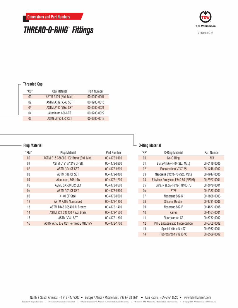
Plug Material
“PM” Plug Material Part Number
00 ASTM B16 C36000 H02 Brass (Std. Mat.) 00-4172-0100
01 ASTM C1213/1215 CF Stl. 00-4172-0200
02 ASTM 304 CF SST 00-4172-0600
03 ASTM 316 CF SST 00-4172-0400
04 Aluminum, 6061-T6 00-4172-1200
05 ASME SA350 LF2 CL1 00-4172-0500
06 ASTM 303 CF SST 00-4172-0300
08 4140 CF Steel 00-4172-0800
12 ASTM A105 Normalized 00-4172-1300
13 ASTM B148 C95400 Al Bronze 00-4172-1400
14 ASTM B21 C46400 Naval Brass 00-4172-1500
15 ASTM 304L SST 00-4172-1600
16 ASTM A350 LF2 CL1 Per NACE MR0175 00-4172-1700
O-Ring Material
“RR” O-Ring Material Part Number
00 No O-Ring N/A
01 Buna-N N674-70 (Std. Mat.) 00-0118-0006
02 Fluorocarbon V747-75 00-1248-0002
03 Neoprene C1276-70 (Std. Mat.) 00-1947-0006
04 Ethylene Propylene E540-80 (EPDM) 00-2977-0001
05 Buna-N (Low-Temp.) N103-70 00-3079-0001
06 PTFE 00-1327-0001
07 Neoprene 882-K 00-1808-0003
08 Silicone Rubber 00-3781-0006
09 Neoprene 882-P 00-4677-0006
10 Kalrez 00-4353-0001
11 Fluorocarbon GF 00-6732-0002
12 PTFE Encapsulated Fluorocarbon 00-6762-0002
13 Special Nitrile N-497 00-6932-0001
14 Fluorocarbon V1238-95 00-8509-0002
Threaded Cap
“CC” Cap Material Part Number
00 ASTM A105 (Std. Mat.) 00-0200-0001
02 ASTM A312 304L SST 00-0200-0015
03 ASTM A312 316L SST 00-0200-0021
04 Aluminum 6061-T6 00-0200-0022
06 ASME A350 LF2 CL1 00-0200-0019
2100.001.03- p3
Dimensions and Part Numbers
THREAD-O-RING™ Fittings
North & South America: +1 918 447 5000 Europe / Africa / Middle East: +32 67 28 3611 Asia Pacific: +65 6364 8520 www.tdwilliamson.comData subject to change without notice. / Dimensions not for construction unless certified. / ® Registered trademark of T.D. Williamson, Inc. in the United States and other countries. / TM Trademark of T.D. Williamson, Inc. in the United States and other countries. / © Copyright 2015 All rights reserved. T.D. Williamson, Inc.

2100.001.03- p4
North & South America: +1 918 447 5000 Europe / Africa / Middle East: +32 67 28 3611 Asia Pacific: +65 6364 8520 www.tdwilliamson.comData subject to change without notice. / Dimensions not for construction unless certified. / ® Registered trademark of T.D. Williamson, Inc. in the United States and other countries. / TM Trademark of T.D. Williamson, Inc. in the United States and other countries. / © Copyright 2015 All rights reserved. T.D. Williamson, Inc.
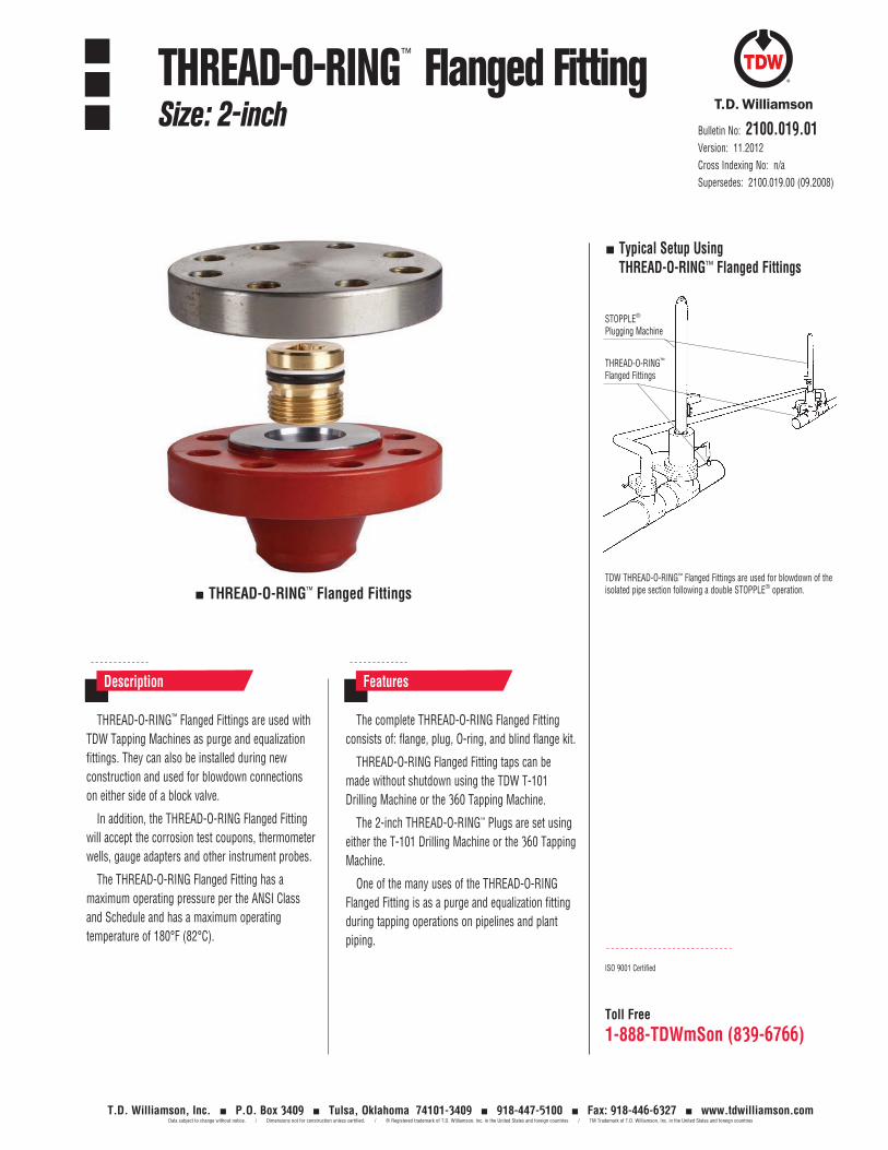
Toll Free
1-888-TDWmSon (839-6766)
Bulletin No: 2100.019.01Version: 11.2012Cross Indexing No: n/aSupersedes: 2100.019.00 (09.2008)
THREAD-O-RING™ Flanged Fittings are used with TDW Tapping Machines as purge and equalization fittings. They can also be installed during new construction and used for blowdown connections on either side of a block valve.
In addition, the THREAD-O-RING Flanged Fitting will accept the corrosion test coupons, thermometer wells, gauge adapters and other instrument probes.
The THREAD-O-RING Flanged Fitting has a maximum operating pressure per the ANSI Class and Schedule and has a maximum operating temperature of 180°F (82°C).
The complete THREAD-O-RING Flanged Fitting consists of: flange, plug, O-ring, and blind flange kit.
THREAD-O-RING Flanged Fitting taps can be made without shutdown using the TDW T-101 Drilling Machine or the 360 Tapping Machine.
The 2-inch THREAD-O-RING™ Plugs are set using either the T-101 Drilling Machine or the 360 Tapping Machine.
One of the many uses of the THREAD-O-RING Flanged Fitting is as a purge and equalization fitting during tapping operations on pipelines and plant piping.
Description Features
THREAD-O-RING™ Flanged Fittings
ISO 9001 Certified
Typical Setup Using THREAD-O-RING™ Flanged Fittings
STOPPLE® Plugging Machine
THREAD-O-RING™ Flanged Fittings
TDW THREAD-O-RING™ Flanged Fittings are used for blowdown of the isolated pipe section following a double STOPPLE® operation.
THREAD-O-RING™ Flanged FittingSize: 2-inch
T.D. Williamson, Inc. P.O. Box 3409 Tulsa, Oklahoma 74101-3409 918-447-5100 Fax: 918-446-6327 www.tdwilliamson.comData subject to change without notice. / Dimensions not for construction unless certified. / ® Registered trademark of T.D. Williamson, Inc. in the United States and foreign countries / TM Trademark of T.D. Williamson, Inc. in the United States and foreign countries
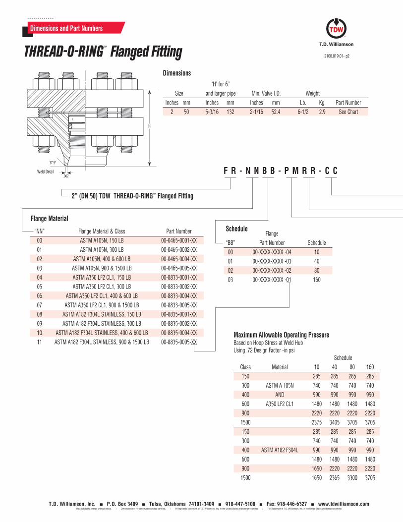
2” (DN 50) TDW THREAD-O-RING™ Flanged Fitting
‘H’ for 6” Size and larger pipe Min. Valve I.D. Weight Inches mm Inches mm Inches mm Lb. Kg. Part Number 2 50 5-3/16 132 2-1/16 52.4 6-1/2 2.9 See Chart
Dimensions
Flange Material
“NN” Flange Material & Class Part Number 00 ASTM A105N, 150 LB 00-0465-0001-XX 01 ASTM A105N, 300 LB 00-0465-0002-XX 02 ASTM A105N, 400 & 600 LB 00-0465-0004-XX 03 ASTM A105N, 900 & 1500 LB 00-0465-0005-XX 04 ASTM A350 LF2 CL1, 150 LB 00-8833-0001-XX 05 ASTM A350 LF2 CL1, 300 LB 00-8833-0002-XX 06 ASTM A350 LF2 CL1, 400 & 600 LB 00-8833-0004-XX 07 ASTM A350 LF2 CL1, 900 & 1500 LB 00-8833-0005-XX 08 ASTM A182 F304L STAINLESS, 150 LB 00-8835-0001-XX 09 ASTM A182 F304L STAINLESS, 300 LB 00-8835-0002-XX 10 ASTM A182 F304L STAINLESS, 400 & 600 LB 00-8835-0004-XX 11 ASTM A182 F304L STAINLESS, 900 & 1500 LB 00-8835-0005-XX
H
F R - N N B B - P M R R - C C
Dimensions and Part Numbers
THREAD-O-RING™ Flanged Fitting 2100.019.01- p2
T.D. Williamson, Inc. P.O. Box 3409 Tulsa, Oklahoma 74101-3409 918-447-5100 Fax: 918-446-6327 www.tdwilliamson.comData subject to change without notice. / Dimensions not for construction unless certified. / ® Registered trademark of T.D. Williamson, Inc. in the United States and foreign countries / TM Trademark of T.D. Williamson, Inc. in the United States and foreign countries
Schedule Flange “BB” Part Number Schedule 00 00-XXXX-XXXX -04 10 01 00-XXXX-XXXX -03 40 02 00-XXXX-XXXX -02 80 03 00-XXXX-XXXX -01 160
Weld Detail
37.5º
.062
Maximum Allowable Operating Pressure Based on Hoop Stress at Weld HubUsing .72 Design Factor -in psi Schedule Class Material 10 40 80 160 150 285 285 285 285 300 ASTM A 105N 740 740 740 740 400 AND 990 990 990 990 600 A350 LF2 CL1 1480 1480 1480 1480 900 2220 2220 2220 2220 1500 2375 3405 3705 3705 150 285 285 285 285 300 740 740 740 740 400 ASTM A182 F304L 990 990 990 990 600 1480 1480 1480 1480 900 1650 2220 2220 2220 1500 1650 2365 3300 3705
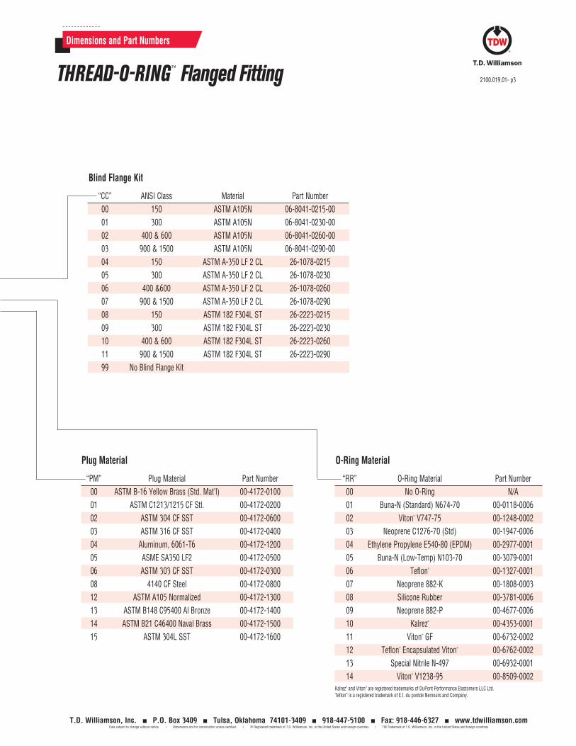
Plug Material
“PM” Plug Material Part Number 00 ASTM B-16 Yellow Brass (Std. Mat’l) 00-4172-0100 01 ASTM C1213/1215 CF Stl. 00-4172-0200 02 ASTM 304 CF SST 00-4172-0600 03 ASTM 316 CF SST 00-4172-0400 04 Aluminum, 6061-T6 00-4172-1200 05 ASME SA350 LF2 00-4172-0500 06 ASTM 303 CF SST 00-4172-0300 08 4140 CF Steel 00-4172-0800 12 ASTM A105 Normalized 00-4172-1300 13 ASTM B148 C95400 Al Bronze 00-4172-1400 14 ASTM B21 C46400 Naval Brass 00-4172-1500 15 ASTM 304L SST 00-4172-1600
O-Ring Material
“RR” O-Ring Material Part Number 00 No O-Ring N/A 01 Buna-N (Standard) N674-70 00-0118-0006 02 Viton® V747-75 00-1248-0002 03 Neoprene C1276-70 (Std) 00-1947-0006 04 Ethylene Propylene E540-80 (EPDM) 00-2977-0001 05 Buna-N (Low-Temp) N103-70 00-3079-0001 06 Teflon® 00-1327-0001 07 Neoprene 882-K 00-1808-0003 08 Silicone Rubber 00-3781-0006 09 Neoprene 882-P 00-4677-0006 10 Kalrez® 00-4353-0001 11 Viton® GF 00-6732-0002 12 Teflon® Encapsulated Viton® 00-6762-0002 13 Special Nitrile N-497 00-6932-0001 14 Viton® V1238-95 00-8509-0002
Blind Flange Kit
“CC” ANSI Class Material Part Number 00 150 ASTM A105N 06-8041-0215-00 01 300 ASTM A105N 06-8041-0230-00 02 400 & 600 ASTM A105N 06-8041-0260-00 03 900 & 1500 ASTM A105N 06-8041-0290-00 04 150 ASTM A-350 LF 2 CL 26-1078-0215 05 300 ASTM A-350 LF 2 CL 26-1078-0230 06 400 &600 ASTM A-350 LF 2 CL 26-1078-0260 07 900 & 1500 ASTM A-350 LF 2 CL 26-1078-0290 08 150 ASTM 182 F304L ST 26-2223-0215 09 300 ASTM 182 F304L ST 26-2223-0230 10 400 & 600 ASTM 182 F304L ST 26-2223-0260 11 900 & 1500 ASTM 182 F304L ST 26-2223-0290 99 No Blind Flange Kit
2100.019.01- p3
Dimensions and Part Numbers
THREAD-O-RING™ Flanged Fitting
T.D. Williamson, Inc. P.O. Box 3409 Tulsa, Oklahoma 74101-3409 918-447-5100 Fax: 918-446-6327 www.tdwilliamson.comData subject to change without notice. / Dimensions not for construction unless certified. / ® Registered trademark of T.D. Williamson, Inc. in the United States and foreign countries / TM Trademark of T.D. Williamson, Inc. in the United States and foreign countries
Kalrez® and Viton® are registered trademarks of DuPont Performance Elastomers LLC Ltd.Teflon® is a registered trademark of E.I. du pontde Nemours and Company.

2100.019.01- p4
T.D. Williamson, Inc. P.O. Box 3409 Tulsa, Oklahoma 74101-3409 918-447-5100 Fax: 918-446-6327 www.tdwilliamson.comData subject to change without notice. / Dimensions not for construction unless certified. / ® Registered trademark of T.D. Williamson, Inc. in the United States and foreign countries / TM Trademark of T.D. Williamson, Inc. in the United States and foreign countries
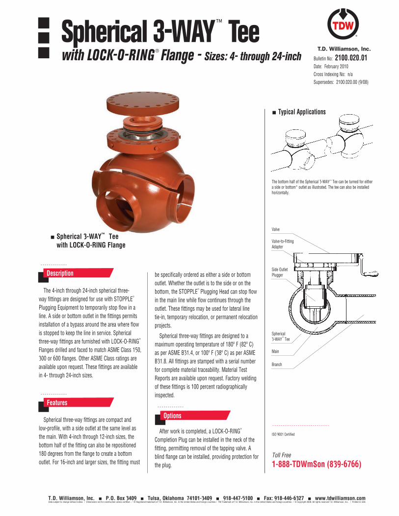
Spherical 3-WAY™ Tee with LOCK-O-RING Flange
Toll Free
1-888-TDWmSon (839-6766)
The 4-inch through 24-inch spherical three-way fittings are designed for use with STOPPLE
®
Plugging Equipment to temporarily stop flow in a line. A side or bottom outlet in the fittings permits installation of a bypass around the area where flow is stopped to keep the line in service. Spherical three-way fittings are furnished with LOCK-O-RING
®
Flanges drilled and faced to match ASME Class 150, 300 or 600 flanges. Other ASME Class ratings are available upon request. These fittings are available in 4- through 24-inch sizes.
Spherical three-way fittings are compact and low-profile, with a side outlet at the same level as the main. With 4-inch through 12-inch sizes, the bottom half of the fitting can also be repositioned 180 degrees from the flange to create a bottom outlet. For 16-inch and larger sizes, the fitting must
Description
Features
Options
ISO 9001 Certified
Typical Applications
The bottom half of the Spherical 3-WAY ™ Tee can be turned for either a side or bottom* outlet as illustrated. The tee can also be installed horizontally.
Valve
Valve-to-Fitting Adapter
Spherical 3-WAY™ Tee
Main
Side Outlet Plugger
Branch
Bulletin No: 2100.020.01Date: February 2010Cross Indexing No: n/aSupersedes: 2100.020.00 (9/08)
Spherical 3-WAY™ Teewith LOCK-O-RING ® Flange - Sizes: 4- through 24-inch
T.D. Williamson, Inc. P.O. Box 3409 Tulsa, Oklahoma 74101-3409 918-447-5100 Fax: 918-446-6327 www.tdwilliamson.comData subject to change without notice. / Dimensions not for construction unless certified. / ® Registered trademark of T.D. Williamson, Inc. in the United States and foreign countries / TM Trademark of T.D. Williamson, Inc. in the United States and foreign countries / © Copyright 2008. All rights reserved T.D. Williamson, Inc. / Printed in USA
be specifically ordered as either a side or bottom outlet. Whether the outlet is to the side or on the bottom, the STOPPLE
®
Plugging Head can stop flow in the main line while flow continues through the outlet. These fittings may be used for lateral line tie-in, temporary relocation, or permanent relocation projects.
Spherical three-way fittings are designed to a maximum operating temperature of 180º F (82º C) as per ASME B31.4, or 100º F (38º C) as per ASME B31.8. All fittings are stamped with a serial number for complete material traceability. Material Test Reports are available upon request. Factory welding of these fittings is 100 percent radiographically inspected.
After work is completed, a LOCK-O-RING®
Completion Plug can be installed in the neck of the fitting, permitting removal of the tapping valve. A blind flange can be installed, providing protection for the plug.
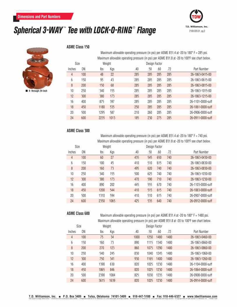
Dimensions and Part Numbers
4- through 24-inch
ASME Class 150
ASME Class 300
Maximum allowable operating pressure (in psi) per ASME B31.4 at -20 to 180° F = 285 psi. Maximum allowable operating pressure (in psi) per ASME B31.8 at -20 to 100ºF see chart below. Size Weight Design Factor Inches DN lbs Kgs .40 .50 .60 .72 Part Number 4 100 48 22 285 285 285 285 26-1863-0415-00 6 150 95 43 285 285 285 285 26-1863-0615-00 8 200 150 68 285 285 285 285 26-1863-0815-00 10 250 340 155 285 285 285 285 26-1863-1015-00 12 300 380 173 285 285 285 285 26-1863-1215-00 16 400 875 397 285 285 285 285 26-1101-0000-suff 18 450 1180 535 250 285 285 285 26-1061-0000-suff 20 500 1295 587 210 260 285 285 26-0906-0000-suff 24 600 2235 1013 185 230 275 285 26-0911-0000-suff
Maximum allowable operating pressure (in psi) per ASME B31.4 at -20 to 180° F = 740 psi. Maximum allowable operating pressure (in psi) per ASME B31.8 at -20 to 100ºF see chart below. Size Weight Design Factor Inches DN lbs Kgs .40 .50 .60 .72 Part Number 4 100 60 27 435 545 650 740 26-1863-0430-00 6 150 100 45 410 510 615 740 26-1863-0630-00 8 200 160 73 495 620 740 740 26-1863-0830-00 10 250 340 155 500 625 740 740 26-1863-1030-00 12 300 380 173 470 590 710 740 26-1863-1230-00 16 400 890 202 445 555 670 740 26-1103-0000-suff 18 450 1200 544 410 515 615 740 26-1063-0000-suff 20 500 1310 594 410 510 615 740 26-0907-0000-suff 24 600 2350 1065 425 535 640 740 26-0912-0000-suff
2100.020.01, pg.2Spherical 3-WAY ™ Tee with LOCK-O-RING ® Flange
T.D. Williamson, Inc. P.O. Box 3409 Tulsa, Oklahoma 74101-3409 918-447-5100 Fax: 918-446-6327 www.tdwilliamson.comData subject to change without notice. / Dimensions not for construction unless certified. / ® Registered trademark of T.D. Williamson, Inc. in the United States and foreign countries / TM Trademark of T.D. Williamson, Inc. in the United States and foreign countries / © Copyright 2008. All rights reserved T.D. Williamson, Inc. / Printed in USA
ASME Class 600 Maximum allowable operating pressure (in psi) per ASME B31.4 at -20 to 180° F = 1480 psi. Maximum allowable operating pressure (in psi) per ASME B31.8 at -20 to 100ºF see chart below. Size Weight Design Factor Inches DN lbs Kgs .40 .50 .60 .72 Part Number 4 100 75 34 1000 1250 1480 1480 26-1863-0460-00 6 150 160 73 890 1115 1340 1480 26-1863-0660-00 8 200 270 123 860 1075 1290 1480 26-1863-0860-00 10 250 540 245 830 1040 1245 1480 26-1863-1060-00 12 300 750 341 930 1165 1400 1480 26-1863-1260-00 16 400 1390 630 820 1025 1230 1480 26-1104-0000-suff 18 450 1865 846 820 1025 1230 1480 26-1064-0000-suff 20 500 2390 1084 825 1030 1235 1480 26-0908-0000-suff 24 600 3615 1639 820 1025 1230 1480 26-0914-0000-suff
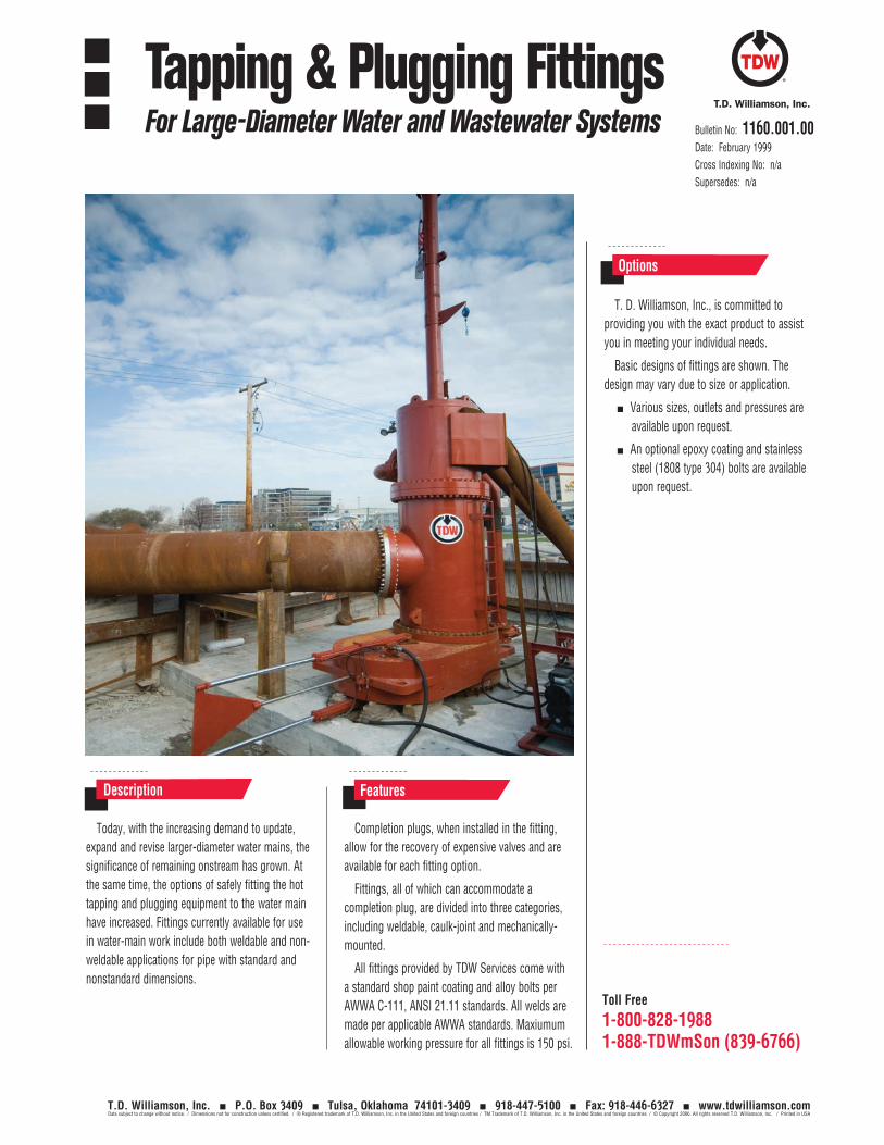
T. D. Williamson, Inc., is committed to providing you with the exact product to assist you in meeting your individual needs.
Basic designs of fittings are shown. The design may vary due to size or application.
Various sizes, outlets and pressures are available upon request.
An optional epoxy coating and stainless steel (1808 type 304) bolts are available upon request.
Options
Today, with the increasing demand to update, expand and revise larger-diameter water mains, the significance of remaining onstream has grown. At the same time, the options of safely fitting the hot tapping and plugging equipment to the water main have increased. Fittings currently available for use in water-main work include both weldable and non-weldable applications for pipe with standard and nonstandard dimensions.
Completion plugs, when installed in the fitting, allow for the recovery of expensive valves and are available for each fitting option.
Fittings, all of which can accommodate a completion plug, are divided into three categories, including weldable, caulk-joint and mechanically-mounted.
All fittings provided by TDW Services come with a standard shop paint coating and alloy bolts per AWWA C-111, ANSI 21.11 standards. All welds are made per applicable AWWA standards. Maxiumum allowable working pressure for all fittings is 150 psi.
Description Features
Toll Free
1-800-828-19881-888-TDWmSon (839-6766)
Bulletin No: 1160.001.00Date: February 1999Cross Indexing No: n/aSupersedes: n/a
Tapping & Plugging FittingsFor Large-Diameter Water and Wastewater Systems
T.D. Williamson, Inc. P.O. Box 3409 Tulsa, Oklahoma 74101-3409 918-447-5100 Fax: 918-446-6327 www.tdwilliamson.comData subject to change without notice. / Dimensions not for construction unless certified. / ® Registered trademark of T.D. Williamson, Inc. in the United States and foreign countries / TM Trademark of T.D. Williamson, Inc. in the United States and foreign countries / © Copyright 2006. All rights reserved T.D. Williamson, Inc. / Printed in USA
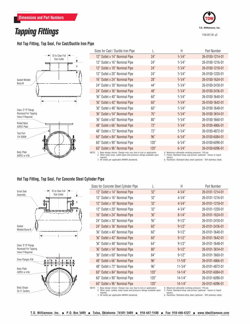
Dimensions and Part Numbers
Sizes for Cast / Ductile Iron Pipe L H Part Number12” Outlet x 14” Nominal Pipe 24” 5-3/4” 26-0100-1214-0112” Outlet x 16” Nominal Pipe 24” 5-3/4” 26-0100-1216-0112” Outlet x 18” Nominal Pipe 24” 5-3/4” 26-0100-1218-0112” Outlet x 20” Nominal Pipe 24” 5-3/4” 26-0100-1220-0116” Outlet x 24” Nominal Pipe 28” 5-3/4” 26-0100-1624-0124” Outlet x 30” Nominal Pipe 44” 5-3/4” 26-0100-2430-0124” Outlet x 36” Nominal Pipe 48” 5-3/4” 26-0100-2436-0136” Outlet x 40” Nominal Pipe 60” 5-3/4” 26-0100-3640-0136” Outlet x 42” Nominal Pipe 60” 5-3/4” 26-0100-3642-0136” Outlet x 48” Nominal Pipe 60” 5-3/4” 26-0100-3648-0136” Outlet x 54” Nominal Pipe 76” 5-3/4” 26-0100-3654-0136” Outlet x 60” Nominal Pipe 80” 5-3/4” 26-0100-3660-0148” Outlet x 66” Nominal Pipe 72” 5-3/4” 26-0100-4866-0148” Outlet x 72” Nominal Pipe 72” 5-3/4” 26-0100-4872-0160” Outlet x 84” Nominal Pipe 96” 6-3/4” 26-0100-6084-0160” Outlet x 90” Nominal Pipe 120” 6-3/4” 26-0100-6090-0160” Outlet x 96” Nominal Pipe 120” 6-3/4” 26-0100-6096-01
NOTE: 1. Base design shown. Design may vary due to size or application.2. Other body sizes, outlet types and pressure ratings available upon
request.3. All welds per applicable AWWA standards.
4. Maximum allowable working pressure: 150 psi.5. Finish: Standard-shop coat primer (optional - fusion or liquid
epoxy).6. Hardware: Standard-alloy steel (optional - 304 stainless steel).
ID to Clear Full Size Cutter
H
L
Gasket Molded Buna-N
Class ‘D’ FF Flange Recessed For Tapping Valve If Required
Rolled NeckA285C Plate
Test Port3/4-3000#
Body PlateA285C or A36
Hot Tap Fitting, Top Seal, For Cast/Ductile Iron Pipe
Sizes for Concrete Steel Cylinder Pipe L H Part Number12” Outlet x 14” Nominal Pipe 32” 4-3/4” 26-0101-1214-0112” Outlet x 16” Nominal Pipe 32” 4-3/4” 26-0101-1216-0112” Outlet x 18” Nominal Pipe 32” 4-3/4” 26-0101-1218-0112” Outlet x 20” Nominal Pipe 32” 4-3/4” 26-0101-1220-0116” Outlet x 24” Nominal Pipe 36” 8-1/4” 26-0101-1624-0124” Outlet x 30” Nominal Pipe 56” 9-1/2” 26-0101-2430-0124” Outlet x 36” Nominal Pipe 60” 9-1/2” 26-0101-2436-0136” Outlet x 40” Nominal Pipe 60” 9-1/2” 26-0101-3640-0136” Outlet x 42” Nominal Pipe 60” 9-1/2” 26-0101-3642-0136” Outlet x 48” Nominal Pipe 64” 9-1/2” 26-0101-3648-0136” Outlet x 54” Nominal Pipe 80” 9-1/2” 26-0101-3654-0136” Outlet x 60” Nominal Pipe 84” 9-1/2” 26-0101-3660-0148” Outlet x 66” Nominal Pipe 96” 11-5/8” 26-0101-4866-0148” Outlet x 72” Nominal Pipe 96” 11-3/4” 26-0101-4872-0160” Outlet x 84” Nominal Pipe 120” 14-1/4” 26-0101-6084-0160” Outlet x 90” Nominal Pipe 120” 14-1/4” 26-0101-6090-0160” Outlet x 96” Nominal Pipe 120” 14-1/4” 26-0101-6096-01
NOTE: 1. Base design shown. Design may vary due to size or application.2. Other sizes, outlets, body styles and pressure ratings available upon
request.3. All welds per applicable AWWA standards.
4. Maximum allowable working pressure: 150 psi.5. Finish: Standard-shop coat primer (optional - fusion or liquid
epoxy).6. Hardware: Standard-alloy steel (optional - 304 stainless steel).
Hot Tap Fitting, Top Seal, For Concrete Steel Cylinder Pipe
ID to Clear Full Size Cutter
H
L
Gasket Molded Buna-N
Grout Seal Assembly
Class ‘D’ FF Flange Recessed For Tapping Valve If Required
Draw Flanges A36
Body PlateA285C or A36
Body StrapsOn 4” Centers
1160.001.00- p2
T.D. Williamson, Inc. P.O. Box 3409 Tulsa, Oklahoma 74101-3409 918-447-5100 Fax: 918-446-6327 www.tdwilliamson.comData subject to change without notice. / Dimensions not for construction unless certified. / ® Registered trademark of T.D. Williamson, Inc. in the United States and foreign countries / TM Trademark of T.D. Williamson, Inc. in the United States and foreign countries / © Copyright 2006. All rights reserved T.D. Williamson, Inc. / Printed in USA
Tapping Fittings
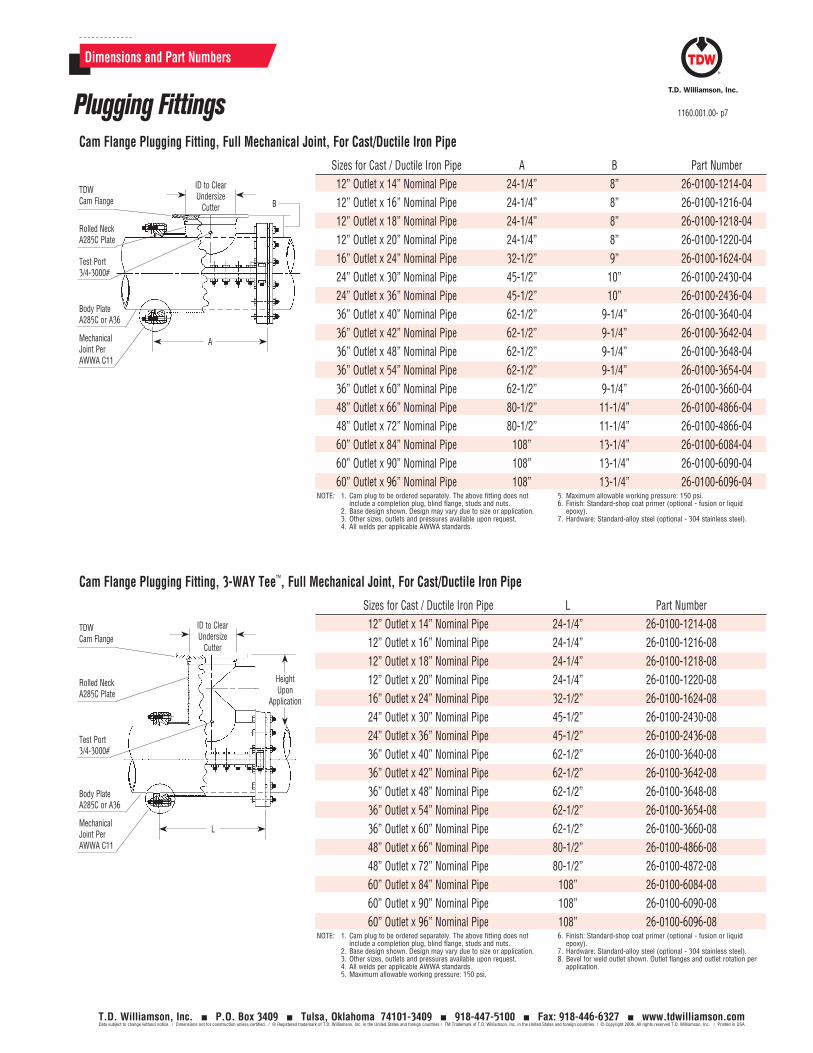
Sizes for Cast / Ductile Iron Pipe L Part Number12” Outlet x 14” Nominal Pipe 24-1/4” 26-0100-1214-0812” Outlet x 16” Nominal Pipe 24-1/4” 26-0100-1216-0812” Outlet x 18” Nominal Pipe 24-1/4” 26-0100-1218-0812” Outlet x 20” Nominal Pipe 24-1/4” 26-0100-1220-0816” Outlet x 24” Nominal Pipe 32-1/2” 26-0100-1624-0824” Outlet x 30” Nominal Pipe 45-1/2” 26-0100-2430-0824” Outlet x 36” Nominal Pipe 45-1/2” 26-0100-2436-0836” Outlet x 40” Nominal Pipe 62-1/2” 26-0100-3640-0836” Outlet x 42” Nominal Pipe 62-1/2” 26-0100-3642-0836” Outlet x 48” Nominal Pipe 62-1/2” 26-0100-3648-0836” Outlet x 54” Nominal Pipe 62-1/2” 26-0100-3654-0836” Outlet x 60” Nominal Pipe 62-1/2” 26-0100-3660-0848” Outlet x 66” Nominal Pipe 80-1/2” 26-0100-4866-0848” Outlet x 72” Nominal Pipe 80-1/2” 26-0100-4872-0860” Outlet x 84” Nominal Pipe 108” 26-0100-6084-0860” Outlet x 90” Nominal Pipe 108” 26-0100-6090-0860” Outlet x 96” Nominal Pipe 108” 26-0100-6096-08
NOTE: 1. Cam plug to be ordered separately. The above fitting does not include a completion plug, blind flange, studs and nuts.
2. Base design shown. Design may vary due to size or application.3. Other sizes, outlets and pressures available upon request.4. All welds per applicable AWWA standards.5. Maximum allowable working pressure: 150 psi.
6. Finish: Standard-shop coat primer (optional - fusion or liquid epoxy).
7. Hardware: Standard-alloy steel (optional - 304 stainless steel).8. Bevel for weld outlet shown. Outlet flanges and outlet rotation per
application.
Cam Flange Plugging Fitting, 3-WAY Tee™, Full Mechanical Joint, For Cast/Ductile Iron Pipe
MechanicalJoint PerAWWA C11
ID to Clear Undersize
Cutter
L
Body Plate A285C or A36
TDW Cam Flange
HeightUpon
Application
Rolled NeckA285C Plate
Test Port3/4-3000#
Dimensions and Part Numbers
Sizes for Cast / Ductile Iron Pipe A B Part Number12” Outlet x 14” Nominal Pipe 24-1/4” 8” 26-0100-1214-0412” Outlet x 16” Nominal Pipe 24-1/4” 8” 26-0100-1216-0412” Outlet x 18” Nominal Pipe 24-1/4” 8” 26-0100-1218-0412” Outlet x 20” Nominal Pipe 24-1/4” 8” 26-0100-1220-0416” Outlet x 24” Nominal Pipe 32-1/2” 9” 26-0100-1624-0424” Outlet x 30” Nominal Pipe 45-1/2” 10” 26-0100-2430-0424” Outlet x 36” Nominal Pipe 45-1/2” 10” 26-0100-2436-0436” Outlet x 40” Nominal Pipe 62-1/2” 9-1/4” 26-0100-3640-0436” Outlet x 42” Nominal Pipe 62-1/2” 9-1/4” 26-0100-3642-0436” Outlet x 48” Nominal Pipe 62-1/2” 9-1/4” 26-0100-3648-0436” Outlet x 54” Nominal Pipe 62-1/2” 9-1/4” 26-0100-3654-0436” Outlet x 60” Nominal Pipe 62-1/2” 9-1/4” 26-0100-3660-0448” Outlet x 66” Nominal Pipe 80-1/2” 11-1/4” 26-0100-4866-0448” Outlet x 72” Nominal Pipe 80-1/2” 11-1/4” 26-0100-4866-0460” Outlet x 84” Nominal Pipe 108” 13-1/4” 26-0100-6084-0460” Outlet x 90” Nominal Pipe 108” 13-1/4” 26-0100-6090-0460” Outlet x 96” Nominal Pipe 108” 13-1/4” 26-0100-6096-04
NOTE: 1. Cam plug to be ordered separately. The above fitting does not include a completion plug, blind flange, studs and nuts.
2. Base design shown. Design may vary due to size or application.3. Other sizes, outlets and pressures available upon request.4. All welds per applicable AWWA standards.
5. Maximum allowable working pressure: 150 psi.6. Finish: Standard-shop coat primer (optional - fusion or liquid
epoxy).7. Hardware: Standard-alloy steel (optional - 304 stainless steel).
Cam Flange Plugging Fitting, Full Mechanical Joint, For Cast/Ductile Iron Pipe
ID to Clear Undersize
Cutter
AMechanicalJoint PerAWWA C11
Body Plate A285C or A36
TDW Cam Flange
B
Rolled NeckA285C Plate
Test Port3/4-3000#
Plugging Fittings 1160.001.00- p7
T.D. Williamson, Inc. P.O. Box 3409 Tulsa, Oklahoma 74101-3409 918-447-5100 Fax: 918-446-6327 www.tdwilliamson.comData subject to change without notice. / Dimensions not for construction unless certified. / ® Registered trademark of T.D. Williamson, Inc. in the United States and foreign countries / TM Trademark of T.D. Williamson, Inc. in the United States and foreign countries / © Copyright 2006. All rights reserved T.D. Williamson, Inc. / Printed in USA
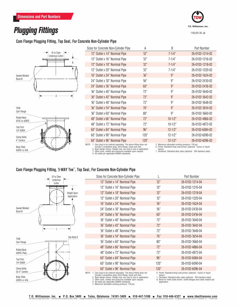
Dimensions and Part Numbers
Sizes for Concrete Non-Cylinder Pipe A B Part Number12” Outlet x 14” Nominal Pipe 32” 7-1/4” 26-0102-1214-0212” Outlet x 16” Nominal Pipe 32” 7-1/4” 26-0102-1216-0212” Outlet x 18” Nominal Pipe 32” 7-1/4” 26-0102-1218-0212” Outlet x 20” Nominal Pipe 32” 7-1/4” 26-0102-1220-0216” Outlet x 24” Nominal Pipe 36” 9” 26-0102-1624-0224” Outlet x 30” Nominal Pipe 56” 9” 26-0102-2430-0224” Outlet x 36” Nominal Pipe 60” 9” 26-0102-2436-0236” Outlet x 40” Nominal Pipe 72” 9” 26-0102-3640-0236” Outlet x 42” Nominal Pipe 72” 9” 26-0102-3642-0236” Outlet x 48” Nominal Pipe 72” 9” 26-0102-3648-0236” Outlet x 54” Nominal Pipe 76” 9” 26-0102-3654-0236” Outlet x 60” Nominal Pipe 80” 9” 26-0102-3660-0248” Outlet x 66” Nominal Pipe 72” 10-1/2” 26-0102-4866-0248” Outlet x 72” Nominal Pipe 72” 10-1/2” 26-0102-4872-0260” Outlet x 84” Nominal Pipe 96” 12-1/2” 26-0102-6084-0260” Outlet x 90” Nominal Pipe 120” 12-1/2” 26-0102-6090-0260” Outlet x 96” Nominal Pipe 120” 12-1/2” 26-0102-6096-02
NOTE: 1. Cam plug to be ordered separately. The above fitting does not include a completion plug, blind flange, studs and nuts.
2. Base design shown. Design may vary due to size or application.3. Other sizes, outlets and pressures available upon request.4. All welds per applicable AWWA standards.
5. Maximum allowable working pressure: 150 psi.6. Finish: Standard-shop coat primer (optional - fusion or liquid
epoxy).7. Hardware: Standard-alloy steel (optional - 304 stainless steel).
Cam Flange Plugging Fitting, Top Seal, For Concrete Non-Cylinder Pipe
ID to Clear Undersize Cutter
B
A
Gasket Molded Buna-N
TDW Cam Flange
Rolled NeckA53C or A285C
Test Port3/4-3000#
Body PlateA285C or A36
Clamp Bolts4” Centers
Sizes for Concrete Non-Cylinder Pipe L Part Number12” Outlet x 14” Nominal Pipe 32” 26-0102-1214-0412” Outlet x 16” Nominal Pipe 32” 26-0102-1216-0412” Outlet x 18” Nominal Pipe 32” 26-0102-1218-0412” Outlet x 20” Nominal Pipe 32” 26-0102-1220-0416” Outlet x 24” Nominal Pipe 36” 26-0102-1624-0424” Outlet x 30” Nominal Pipe 56” 26-0102-2430-0424” Outlet x 36” Nominal Pipe 60” 26-0102-2436-0436” Outlet x 40” Nominal Pipe 72” 26-0102-3640-0436” Outlet x 42” Nominal Pipe 72” 26-0102-3642-0436” Outlet x 48” Nominal Pipe 72” 26-0102-3648-0436” Outlet x 54” Nominal Pipe 76” 26-0102-3654-0436” Outlet x 60” Nominal Pipe 80” 26-0102-3660-0448” Outlet x 66” Nominal Pipe 72” 26-0102-4866-0448” Outlet x 72” Nominal Pipe 72” 26-0102-4872-0460” Outlet x 84” Nominal Pipe 96” 26-0102-6084-0460” Outlet x 90” Nominal Pipe 120” 26-0102-6090-0460” Outlet x 96” Nominal Pipe 120” 26-0102-6096-04
NOTE: 1. Cam plug to be ordered separately. The above fitting does not include a completion plug, blind flange, studs and nuts.
2. Base design shown. Design may vary due to size or application.3. Other sizes, outlets and pressures available upon request.4. All welds per applicable AWWA standards.5. Maximum allowable working pressure: 150 psi.
6. Finish: Standard-shop coat primer (optional - fusion or liquid epoxy).
7. Hardware: Standard-alloy steel (optional - 304 stainless steel).8. Bevel for weld outlet shown. Outlet flanges and outlet rotation per
application.
Cam Flange Plugging Fitting, 3-WAY Tee™, Top Seal, For Concrete Non-Cylinder Pipe
ID to Clear Undersize
Cutter
Height Upon Application
L
TDW Cam Flange
Rolled NeckA285C Plate
See Note 8
Test Port3/4-3000#
Body PlateA285C or A36
Gasket Molded Buna-N
Clamp BoltsOn 4” Centers
Plugging Fittings 1160.001.00- p6
T.D. Williamson, Inc. P.O. Box 3409 Tulsa, Oklahoma 74101-3409 918-447-5100 Fax: 918-446-6327 www.tdwilliamson.comData subject to change without notice. / Dimensions not for construction unless certified. / ® Registered trademark of T.D. Williamson, Inc. in the United States and foreign countries / TM Trademark of T.D. Williamson, Inc. in the United States and foreign countries / © Copyright 2006. All rights reserved T.D. Williamson, Inc. / Printed in USA
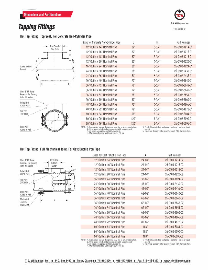
Sizes for Concrete Non-Cylinder Pipe L H Part Number12” Outlet x 14” Nominal Pipe 32” 5-3/4” 26-0102-1214-0112” Outlet x 16” Nominal Pipe 32” 5-3/4” 26-0102-1216-0112” Outlet x 18” Nominal Pipe 32” 5-3/4” 26-0102-1218-0112” Outlet x 20” Nominal Pipe 32” 5-3/4” 26-0102-1220-0116” Outlet x 24” Nominal Pipe 36” 5-3/4” 26-0102-1624-0124” Outlet x 30” Nominal Pipe 56” 5-3/4” 26-0102-2430-0124” Outlet x 36” Nominal Pipe 60” 5-3/4” 26-0102-2436-0136” Outlet x 40” Nominal Pipe 72” 5-3/4” 26-0102-3640-0136” Outlet x 42” Nominal Pipe 72” 5-3/4” 26-0102-3642-0136” Outlet x 48” Nominal Pipe 72” 5-3/4” 26-0102-3648-0136” Outlet x 54” Nominal Pipe 76” 5-3/4” 26-0102-3654-0136” Outlet x 60” Nominal Pipe 80” 5-3/4” 26-0102-3660-0148” Outlet x 66” Nominal Pipe 72” 5-3/4” 26-0102-4866-0148” Outlet x 72” Nominal Pipe 72” 5-3/4” 26-0102-4872-0160” Outlet x 84” Nominal Pipe 96” 6-3/4” 26-0102-6084-0160” Outlet x 90” Nominal Pipe 120” 6-3/4” 26-0102-6090-0160” Outlet x 96” Nominal Pipe 120” 6-3/4” 26-0102-6096-01
NOTE: 1. Base design shown. Design may vary due to size or application.2. Other sizes, outlets and pressures available upon request.3. All welds per applicable AWWA standards.4. Maximum allowable working pressure: 150 psi.
5. Finish: Standard-shop coat primer (optional - fusion or liquid epoxy).
6. Hardware: Standard-alloy steel (optional - 304 stainless steel).
Hot Tap Fitting, Top Seal, For Concrete Non-Cylinder Pipe
ID to Clear Full Size Cutter
H
L
Gasket Molded Buna-N
Class ‘D’ FF Flange Recessed For Tapping Valve If Required
Rolled NeckA285C Plate
Test Port3/4-3000#
Body PlateA285C or A36
Dimensions and Part Numbers
Sizes for Cast / Ductile Iron Pipe A Part Number12” Outlet x 14” Nominal Pipe 24-1/4” 26-0100-1214-0212” Outlet x 16” Nominal Pipe 24-1/4” 26-0100-1216-0212” Outlet x 18” Nominal Pipe 24-1/4” 26-0100-1218-0212” Outlet x 20” Nominal Pipe 24-1/4” 26-0100-1220-0216” Outlet x 24” Nominal Pipe 32-1/2” 26-0100-1624-0224” Outlet x 30” Nominal Pipe 45-1/2” 26-0100-2430-0224” Outlet x 36” Nominal Pipe 45-1/2” 26-0100-2436-0236” Outlet x 40” Nominal Pipe 62-1/2” 26-0100-3640-0236” Outlet x 42” Nominal Pipe 62-1/2” 26-0100-3642-0236” Outlet x 48” Nominal Pipe 62-1/2” 26-0100-3648-0236” Outlet x 54” Nominal Pipe 62-1/2” 26-0100-3654-0236” Outlet x 60” Nominal Pipe 62-1/2” 26-0100-3660-0248” Outlet x 66” Nominal Pipe 80-1/2” 26-0100-4866-0248” Outlet x 72” Nominal Pipe 80-1/2” 26-0100-4872-0260” Outlet x 84” Nominal Pipe 108” 26-0100-6084-0260” Outlet x 90” Nominal Pipe 108” 26-0100-6090-0260” Outlet x 96” Nominal Pipe 108” 26-0100-6096-02
NOTE: 1. Base design shown. Design may vary due to size or application.2. Other sizes, outlets and pressures available upon request.3. All welds per applicable AWWA standards.4. Maximum allowable working pressure: 150 psi.
5. Finish: Standard-shop coat primer (optional - fusion or liquid epoxy).
6. Hardware: Standard-alloy steel (optional - 304 stainless steel).
Hot Tap Fitting, Full Mechanical Joint, For Cast/Ductile Iron Pipe
ID to Clear Full Size Cutter
AMechanicalJoint PerAWWA C11
Body Plate A285C or A36
Class ‘D’ FF Flange Recessed For Tapping Valve If Required
6-1/2”Rolled NeckA285C Plate
Test Port3/4-3000#
Tapping Fittings 1160.001.00- p3
T.D. Williamson, Inc. P.O. Box 3409 Tulsa, Oklahoma 74101-3409 918-447-5100 Fax: 918-446-6327 www.tdwilliamson.comData subject to change without notice. / Dimensions not for construction unless certified. / ® Registered trademark of T.D. Williamson, Inc. in the United States and foreign countries / TM Trademark of T.D. Williamson, Inc. in the United States and foreign countries / © Copyright 2006. All rights reserved T.D. Williamson, Inc. / Printed in USA
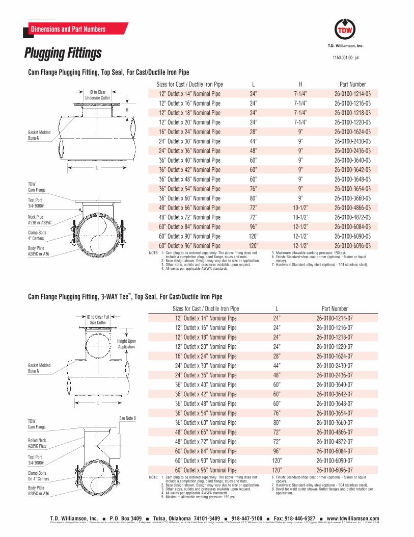
Dimensions and Part Numbers
Sizes for Cast / Ductile Iron Pipe L H Part Number12” Outlet x 14” Nominal Pipe 24” 7-1/4” 26-0100-1214-0312” Outlet x 16” Nominal Pipe 24” 7-1/4” 26-0100-1216-0312” Outlet x 18” Nominal Pipe 24” 7-1/4” 26-0100-1218-0312” Outlet x 20” Nominal Pipe 24” 7-1/4” 26-0100-1220-0316” Outlet x 24” Nominal Pipe 28” 9” 26-0100-1624-0324” Outlet x 30” Nominal Pipe 44” 9” 26-0100-2430-0324” Outlet x 36” Nominal Pipe 48” 9” 26-0100-2436-0336” Outlet x 40” Nominal Pipe 60” 9” 26-0100-3640-0336” Outlet x 42” Nominal Pipe 60” 9” 26-0100-3642-0336” Outlet x 48” Nominal Pipe 60” 9” 26-0100-3648-0336” Outlet x 54” Nominal Pipe 76” 9” 26-0100-3654-0336” Outlet x 60” Nominal Pipe 80” 9” 26-0100-3660-0348” Outlet x 66” Nominal Pipe 72” 10-1/2” 26-0100-4866-0348” Outlet x 72” Nominal Pipe 72” 10-1/2” 26-0100-4872-0360” Outlet x 84” Nominal Pipe 96” 12-1/2” 26-0100-6084-0360” Outlet x 90” Nominal Pipe 120” 12-1/2” 26-0100-6090-0360” Outlet x 96” Nominal Pipe 120” 12-1/2” 26-0100-6096-03
NOTE: 1. Cam plug to be ordered separately. The above fitting does not include a completion plug, blind flange, studs and nuts.
2. Base design shown. Design may vary due to size or application.3. Other sizes, outlets and pressures available upon request.4. All welds per applicable AWWA standards.
5. Maximum allowable working pressure: 150 psi.6. Finish: Standard-shop coat primer (optional - fusion or liquid
epoxy).7. Hardware: Standard-alloy steel (optional - 304 stainless steel).
ID to Clear Undersize Cutter
H
L
TDW Cam Flange
Test Port3/4-3000#
Neck PipeA53B or A285C
Body PlateA285C or A36
Gasket Molded Buna-N
Clamp Bolts4” Centers
Cam Flange Plugging Fitting, Top Seal, For Cast/Ductile Iron Pipe
ID to Clear Full Size Cutter
Height Upon Application
L
TDW Cam Flange
Rolled NeckA285C Plate
See Note 8
Test Port3/4-3000#
Body PlateA285C or A36
Gasket Molded Buna-N
Clamp BoltsOn 4” Centers
Sizes for Cast / Ductile Iron Pipe L Part Number 12” Outlet x 14” Nominal Pipe 24” 26-0100-1214-07 12” Outlet x 16” Nominal Pipe 24” 26-0100-1216-07 12” Outlet x 18” Nominal Pipe 24” 26-0100-1218-07 12” Outlet x 20” Nominal Pipe 24” 26-0100-1220-07 16” Outlet x 24” Nominal Pipe 28” 26-0100-1624-07 24” Outlet x 30” Nominal Pipe 44” 26-0100-2430-07 24” Outlet x 36” Nominal Pipe 48” 26-0100-2436-07 36” Outlet x 40” Nominal Pipe 60” 26-0100-3640-07 36” Outlet x 42” Nominal Pipe 60” 26-0100-3642-07 36” Outlet x 48” Nominal Pipe 60” 26-0100-3648-07 36” Outlet x 54” Nominal Pipe 76” 26-0100-3654-07 36” Outlet x 60” Nominal Pipe 80” 26-0100-3660-07 48” Outlet x 66” Nominal Pipe 72” 26-0100-4866-07 48” Outlet x 72” Nominal Pipe 72” 26-0100-4872-07 60” Outlet x 84” Nominal Pipe 96” 26-0100-6084-07 60” Outlet x 90” Nominal Pipe 120” 26-0100-6090-07 60” Outlet x 96” Nominal Pipe 120” 26-0100-6096-07NOTE: 1. Cam plug to be ordered separately. The above fitting does not
include a completion plug, blind flange, studs and nuts.2. Base design shown. Design may vary due to size or application.3. Other sizes, outlets and pressures available upon request.4. All welds per applicable AWWA standards.5. Maximum allowable working pressure: 150 psi.
6. Finish: Standard-shop coat primer (optional - fusion or liquid epoxy).
7. Hardware: Standard-alloy steel (optional - 304 stainless steel).8. Bevel for weld outlet shown. Outlet flanges and outlet rotation per
application.
Cam Flange Plugging Fitting, 3-WAY Tee™, Top Seal, For Cast/Ductile Iron Pipe
Plugging Fittings 1160.001.00- p4
T.D. Williamson, Inc. P.O. Box 3409 Tulsa, Oklahoma 74101-3409 918-447-5100 Fax: 918-446-6327 www.tdwilliamson.comData subject to change without notice. / Dimensions not for construction unless certified. / ® Registered trademark of T.D. Williamson, Inc. in the United States and foreign countries / TM Trademark of T.D. Williamson, Inc. in the United States and foreign countries / © Copyright 2006. All rights reserved T.D. Williamson, Inc. / Printed in USA
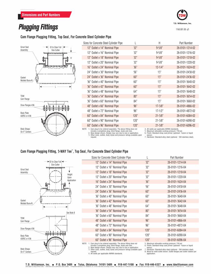
Sizes for Concrete Steel Cylinder Pipe L H Part Number12” Outlet x 14” Nominal Pipe 32” 9-5/8” 26-0101-1214-0212” Outlet x 16” Nominal Pipe 32” 9-5/8” 26-0101-1216-0212” Outlet x 18” Nominal Pipe 32” 9-5/8” 26-0101-1218-0212” Outlet x 20” Nominal Pipe 32” 9-5/8” 26-0101-1220-0216” Outlet x 24” Nominal Pipe 36” 12-1/4” 26-0101-1624-0224” Outlet x 30” Nominal Pipe 56” 13” 26-0101-2430-0224” Outlet x 36” Nominal Pipe 60” 13” 26-0101-2436-0236” Outlet x 40” Nominal Pipe 60” 13” 26-0101-3640-0236” Outlet x 42” Nominal Pipe 60” 13” 26-0101-3642-0236” Outlet x 48” Nominal Pipe 64” 13” 26-0101-3648-0236” Outlet x 54” Nominal Pipe 80” 13” 26-0101-3654-0236” Outlet x 60” Nominal Pipe 84” 13” 26-0101-3660-0248” Outlet x 66” Nominal Pipe 96” 17-3/8” 26-0101-4866-0248” Outlet x 72” Nominal Pipe 96” 17-1/2” 26-0101-4872-0260” Outlet x 84” Nominal Pipe 120” 21-3/8” 26-0101-6084-0260” Outlet x 90” Nominal Pipe 120” 21-3/8” 26-0101-6090-0260” Outlet x 96” Nominal Pipe 120” 21-3/8” 26-0101-6096-02
NOTE: 1. Cam plug to be ordered separately. The above fitting does not include a completion plug, blind flange, studs and nuts.
2. Base design shown. Design may vary due to size or application.3. Other sizes, outlets, body styles and pressure ratings available upon
request.
4. All welds per applicable AWWA standards.5. Maximum allowable working pressure: 150 psi.6. Finish: Standard-shop coat primer (optional - fusion or liquid
epoxy).7. Hardware: Standard-alloy steel (optional - 304 stainless steel).
Cam Flange Plugging Fitting, Top Seal, For Concrete Steel Cylinder Pipe
ID to Clear Full Size Cutter
H
L
Gasket Molded Buna-N
Grout Seal Assembly
TDW Cam Flange
Draw Flanges A36
Body PlateA285C or A36
Body StrapsOn 4” Centers
Dimensions and Part Numbers
Sizes for Concrete Steel Cylinder Pipe L Part Number12” Outlet x 14” Nominal Pipe 32” 26-0101-1214-0412” Outlet x 16” Nominal Pipe 32” 26-0101-1216-0412” Outlet x 18” Nominal Pipe 32” 26-0101-1218-0412” Outlet x 20” Nominal Pipe 32” 26-0101-1220-0416” Outlet x 24” Nominal Pipe 36” 26-0101-1624-0424” Outlet x 30” Nominal Pipe 56” 26-0101-2430-0424” Outlet x 36” Nominal Pipe 60” 26-0101-2436-0436” Outlet x 40” Nominal Pipe 60” 26-0101-3640-0436” Outlet x 42” Nominal Pipe 60” 26-0101-3642-0436” Outlet x 48” Nominal Pipe 64” 26-0101-3648-0436” Outlet x 54” Nominal Pipe 80” 26-0101-3654-0436” Outlet x 60” Nominal Pipe 84” 26-0101-3660-0448” Outlet x 66” Nominal Pipe 96” 26-0101-4866-0448” Outlet x 72” Nominal Pipe 96” 26-0101-4872-0460” Outlet x 84” Nominal Pipe 120” 26-0101-6084-0460” Outlet x 90” Nominal Pipe 120” 26-0101-6090-0460” Outlet x 96” Nominal Pipe 120” 26-0101-6096-04
NOTE: 1. Cam plug to be ordered separately. The above fitting does not include a completion plug, blind flange, studs and nuts.
2. Base design shown. Design may vary due to size or application.3. Other sizes, outlets, body styles and pressure ratings available upon
request.4. All welds per applicable AWWA standards.
5. Maximum allowable working pressure: 150 psi.6. Finish: Standard-shop coat primer (optional - fusion or liquid
epoxy).7. Hardware: Standard-alloy steel (optional - 304 stainless steel).8. Bevel for weld outlet shown. Outlet flanges and outlet rotation per
application.
Cam Flange Plugging Fitting, 3-WAY Tee™, Top Seal, For Concrete Steel Cylinder Pipe
ID to Clear Full Size Cutter
HeightUpon Application
L
Gasket Molded Buna-N
Grout Seal Assembly
TDW Cam Flange
Draw Flanges A36
Body PlateA285C or A36
Body StrapsOn 4” Centers
See Note 8
Plugging Fittings 1160.001.00- p5
T.D. Williamson, Inc. P.O. Box 3409 Tulsa, Oklahoma 74101-3409 918-447-5100 Fax: 918-446-6327 www.tdwilliamson.comData subject to change without notice. / Dimensions not for construction unless certified. / ® Registered trademark of T.D. Williamson, Inc. in the United States and foreign countries / TM Trademark of T.D. Williamson, Inc. in the United States and foreign countries / © Copyright 2006. All rights reserved T.D. Williamson, Inc. / Printed in USA
TDW’s History with the Water and Wastewater Industry
In the early 1950s, TDW performed the first successful modification to a live operating water system.
TDW offers folding plugging equipment and specialized fittings.
TDW performed the first concrete plugging application.
TDW provides sixty offices around the world. TDW holds ISO 9001 & 9002 certifications. TDW performs a successful application on a
96” diameter pipe in 1995. TDW has over a dozen registered engineers
on staff.
T.D. Williamson, Inc.
1160.001.00- p8
T.D. Williamson, Inc. P.O. Box 3409 Tulsa, Oklahoma 74101-3409 918-447-5100 Fax: 918-446-6327 www.tdwilliamson.comData subject to change without notice. / Dimensions not for construction unless certified. / ® Registered trademark of T.D. Williamson, Inc. in the United States and foreign countries / TM Trademark of T.D. Williamson, Inc. in the United States and foreign countries / © Copyright 2006. All rights reserved T.D. Williamson, Inc. / Printed in USA
The Recognized World Leader in Hot Tapping & Pipe Plugging Technologies
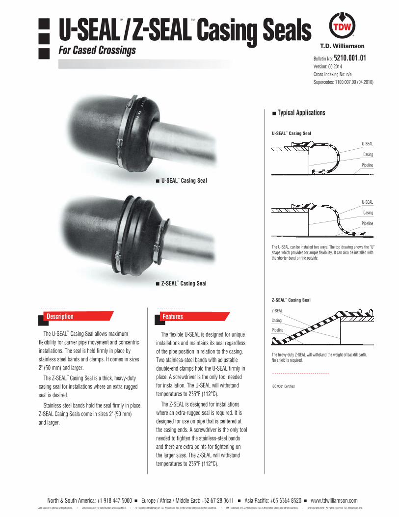
The U-SEAL™ Casing Seal allows maximum flexibility for carrier pipe movement and concentric installations. The seal is held firmly in place by stainless steel bands and clamps. It comes in sizes 2" (50 mm) and larger.
The Z-SEAL™ Casing Seal is a thick, heavy-duty casing seal for installations where an extra rugged seal is desired.
Stainless steel bands hold the seal firmly in place. Z-SEAL Casing Seals come in sizes 2" (50 mm) and larger.
The flexible U-SEAL is designed for unique installations and maintains its seal regardless of the pipe position in relation to the casing. Two stainless-steel bands with adjustable double-end clamps hold the U-SEAL firmly in place. A screwdriver is the only tool needed for installation. The U-SEAL will withstand temperatures to 235°F (112°C).
The Z-SEAL is designed for installations where an extra-rugged seal is required. It is designed for use on pipe that is centered at the casing ends. A screwdriver is the only tool needed to tighten the stainless-steel bands and there are extra points for tightening on the larger sizes. The Z-SEAL will withstand temperatures to 235°F (112°C).
Description Features
The U-SEAL can be installed two ways. The top drawing shows the “U” shape which provides for ample flexibility. It can also be installed with the shorter band on the outside.
The heavy-duty Z-SEAL will withstand the weight of backfill earth. No shield is required.
Typical Applications
U-SEAL™ Casing Seal
Z-SEAL™ Casing Seal
U-SEAL™ Casing Seal
Z-SEAL™ Casing Seal
Casing
U-SEAL
ISO 9001 Certified
Pipeline
Casing
U-SEAL
Z-SEAL
Casing
Pipeline
Pipeline
North & South America: +1 918 447 5000 Europe / Africa / Middle East: +32 67 28 3611 Asia Pacific: +65 6364 8520 www.tdwilliamson.comData subject to change without notice. / Dimensions not for construction unless certified. / ® Registered trademark of T.D. Williamson, Inc. in the United States and other countries. / TM Trademark of T.D. Williamson, Inc. in the United States and other countries. / © Copyright 2014 All rights reserved. T.D. Williamson, Inc.
Bulletin No: 5210.001.01Version: 06.2014Cross Indexing No: n/aSupercedes: 1100.007.00 (04.2010)
U-SEAL™/Z-SEAL™ Casing SealsFor Cased Crossings
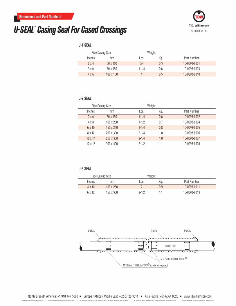
U-1 SEAL
Pipe Casing Size Weight Inches mm Lbs. Kg. Part Number 2 x 4 50 x 100 3/4 0.3 10-0093-0001 3 x 6 80 x 150 1-1/4 0.6 10-0093-0003 4 x 6 100 x 150 1 0.5 10-0093-0010
U-3 SEAL
Pipe Casing Size Weight Inches mm Lbs. Kg. Part Number 4 x 10 100 x 250 2 0.9 10-0093-0011 6 x 12 150 x 300 2-1/2 1.1 10-0093-0013
U-2 SEAL
Pipe Casing Size Weight Inches mm Lbs. Kg. Part Number 2 x 6 50 x 150 1-1/4 0.6 10-0093-0002 4 x 8 100 x 200 1-1/2 0.7 10-0093-0004 6 x 10 150 x 250 1-3/4 0.8 10-0093-0005 8 x 12 200 x 300 2-1/4 1.0 10-0093-0006 10 x 14 250 x 350 2-1/4 1.0 10-0093-0007 12 x 16 300 x 400 2-1/2 1.1 10-0093-0008
Carrier Pipe
Casing
M-2 Plastic THINSULATORS®
M-2 Plastic THINSULATORS® (cradle not required)
U-SEAL U-SEAL
North & South America: +1 918 447 5000 Europe / Africa / Middle East: +32 67 28 3611 Asia Pacific: +65 6364 8520 www.tdwilliamson.comData subject to change without notice. / Dimensions not for construction unless certified. / ® Registered trademark of T.D. Williamson, Inc. in the United States and other countries. / TM Trademark of T.D. Williamson, Inc. in the United States and other countries. / © Copyright 2014 All rights reserved. T.D. Williamson, Inc.
5210.001.01- p2
Dimensions and Part Numbers
U-SEAL™ Casing Seal For Cased Crossings
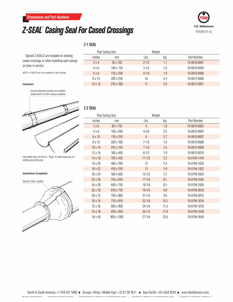
Spliced Z-SEALS are installed on existing cased crossings or when installing split casings on lines in service.
NOTE: U-SEALS are not available in split design.
Z-1 SEAL
Pipe Casing Size Weight Inches mm Lbs. Kg. Part Number
2 x 4 50 x 100 2-1/2 1.1 10-0010-0001 4 x 6 100 x 150 3-1/2 1.6 10-0010-0004 6 x 8 150 x 200 4-1/4 1.9 10-0010-0006 8 x 10 200 x 250 10 4.5 10-0012-0006 10 x 12 250 x 300 11 5.0 10-0012-0007
Z-2 SEAL
Pipe Casing Size Weight Inches mm Lbs. Kg. Part Number
3 x 6 80 x 150 4 1.8 10-0010-0003 4 x 8 100 x 200 4-3/4 2.2 10-0010-0005 6 x 10 150 x 250 6 2.7 10-0010-0007 8 x 12 200 x 300 7-1/2 3.4 10-0010-0008 10 x 14 250 x 350 7-1/2 3.4 10-0010-0009 12 x 16 300 x 400 8-1/2 3.9 10-0010-0010 14 x 18 350 x 450 11-1/2 5.2 10-0194-1418 16 x 20 400 x 500 12 5.4 10-0194-1620 18 x 22 450 x 550 13 5.9 10-0194-1822 20 x 24 500 x 600 12-1/2 5.7 10-0194-2024 22 x 26 550 x 650 17-3/4 8.1 10-0194-2226 24 x 28 600 x 700 18-3/4 8.5 10-0194-2428 26 x 30 650 x 750 19-3/4 9.0 10-0194-2630 28 x 32 700 x 800 21-1/4 9.6 10-0194-2832 30 x 34 750 x 850 22-3/4 10.3 10-0194-3034 32 x 36 800 x 900 24-3/4 11.2 10-0194-3236 34 x 38 850 x 950 26-1/4 11.9 10-0194-3438 36 x 40 900 x 1000 27-3/4 12.6 10-0194-3640
End and alternate insulators are installed upside down to center casing on pipeline.
Interrupted torch-cut forms a “hinge” to make lineup easy for welding around the pipe.
Spliced Z-SEAL installed
Insulators
Installation Completed
North & South America: +1 918 447 5000 Europe / Africa / Middle East: +32 67 28 3611 Asia Pacific: +65 6364 8520 www.tdwilliamson.comData subject to change without notice. / Dimensions not for construction unless certified. / ® Registered trademark of T.D. Williamson, Inc. in the United States and other countries. / TM Trademark of T.D. Williamson, Inc. in the United States and other countries. / © Copyright 2014 All rights reserved. T.D. Williamson, Inc.
5210.001.01- p3
Dimensions and Part Numbers
Z-SEAL™ Casing Seal For Cased Crossings
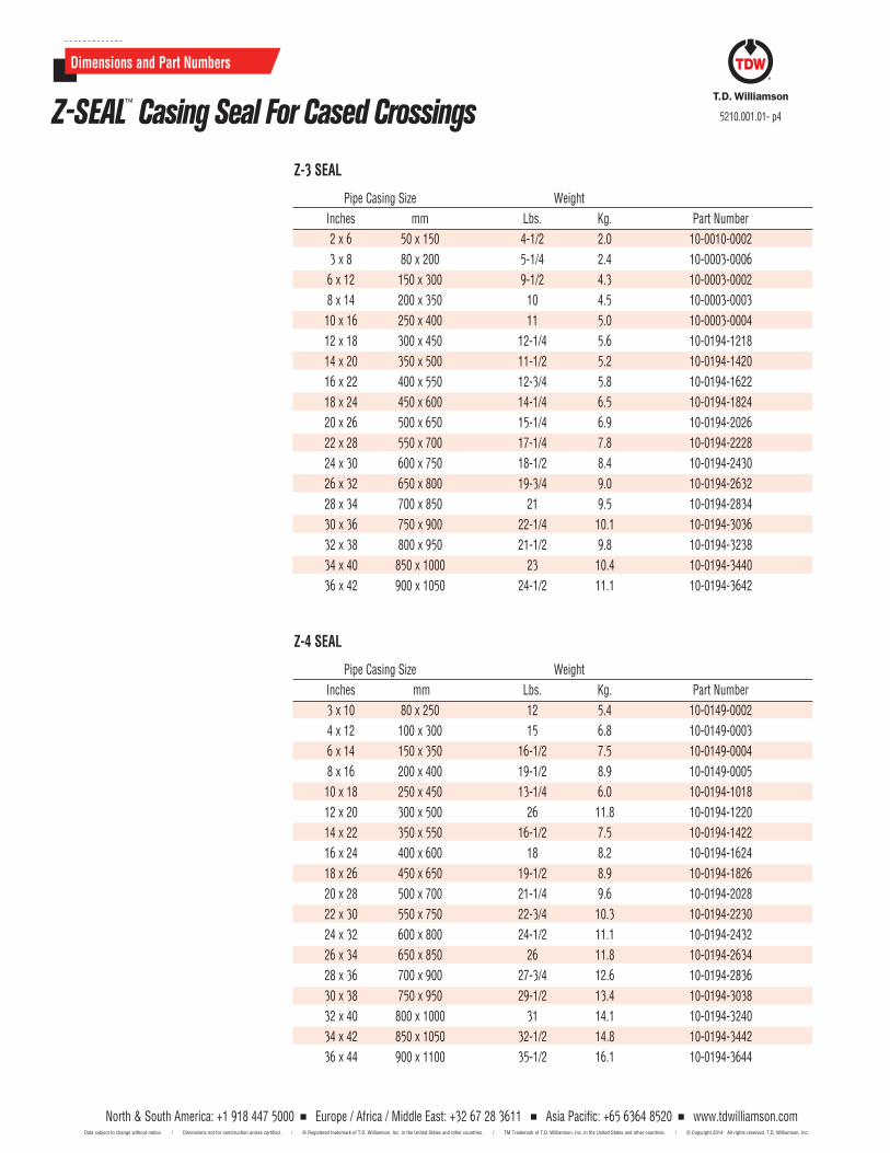
Z-3 SEAL
Pipe Casing Size Weight Inches mm Lbs. Kg. Part Number2 x 6 50 x 150 4-1/2 2.0 10-0010-0002
3 x 8 80 x 200 5-1/4 2.4 10-0003-0006 6 x 12 150 x 300 9-1/2 4.3 10-0003-0002 8 x 14 200 x 350 10 4.5 10-0003-0003 10 x 16 250 x 400 11 5.0 10-0003-0004 12 x 18 300 x 450 12-1/4 5.6 10-0194-1218 14 x 20 350 x 500 11-1/2 5.2 10-0194-1420 16 x 22 400 x 550 12-3/4 5.8 10-0194-1622 18 x 24 450 x 600 14-1/4 6.5 10-0194-1824 20 x 26 500 x 650 15-1/4 6.9 10-0194-2026 22 x 28 550 x 700 17-1/4 7.8 10-0194-2228 24 x 30 600 x 750 18-1/2 8.4 10-0194-2430 26 x 32 650 x 800 19-3/4 9.0 10-0194-2632 28 x 34 700 x 850 21 9.5 10-0194-2834 30 x 36 750 x 900 22-1/4 10.1 10-0194-3036 32 x 38 800 x 950 21-1/2 9.8 10-0194-3238 34 x 40 850 x 1000 23 10.4 10-0194-3440 36 x 42 900 x 1050 24-1/2 11.1 10-0194-3642
Z-4 SEAL
Pipe Casing Size Weight Inches mm Lbs. Kg. Part Number
3 x 10 80 x 250 12 5.4 10-0149-0002 4 x 12 100 x 300 15 6.8 10-0149-0003 6 x 14 150 x 350 16-1/2 7.5 10-0149-0004 8 x 16 200 x 400 19-1/2 8.9 10-0149-0005 10 x 18 250 x 450 13-1/4 6.0 10-0194-1018 12 x 20 300 x 500 26 11.8 10-0194-1220 14 x 22 350 x 550 16-1/2 7.5 10-0194-1422 16 x 24 400 x 600 18 8.2 10-0194-1624 18 x 26 450 x 650 19-1/2 8.9 10-0194-1826 20 x 28 500 x 700 21-1/4 9.6 10-0194-2028 22 x 30 550 x 750 22-3/4 10.3 10-0194-2230 24 x 32 600 x 800 24-1/2 11.1 10-0194-2432 26 x 34 650 x 850 26 11.8 10-0194-2634 28 x 36 700 x 900 27-3/4 12.6 10-0194-2836 30 x 38 750 x 950 29-1/2 13.4 10-0194-3038 32 x 40 800 x 1000 31 14.1 10-0194-3240 34 x 42 850 x 1050 32-1/2 14.8 10-0194-3442 36 x 44 900 x 1100 35-1/2 16.1 10-0194-3644
North & South America: +1 918 447 5000 Europe / Africa / Middle East: +32 67 28 3611 Asia Pacific: +65 6364 8520 www.tdwilliamson.comData subject to change without notice. / Dimensions not for construction unless certified. / ® Registered trademark of T.D. Williamson, Inc. in the United States and other countries. / TM Trademark of T.D. Williamson, Inc. in the United States and other countries. / © Copyright 2014 All rights reserved. T.D. Williamson, Inc.
5210.001.01- p4
Dimensions and Part Numbers
Z-SEAL™ Casing Seal For Cased Crossings
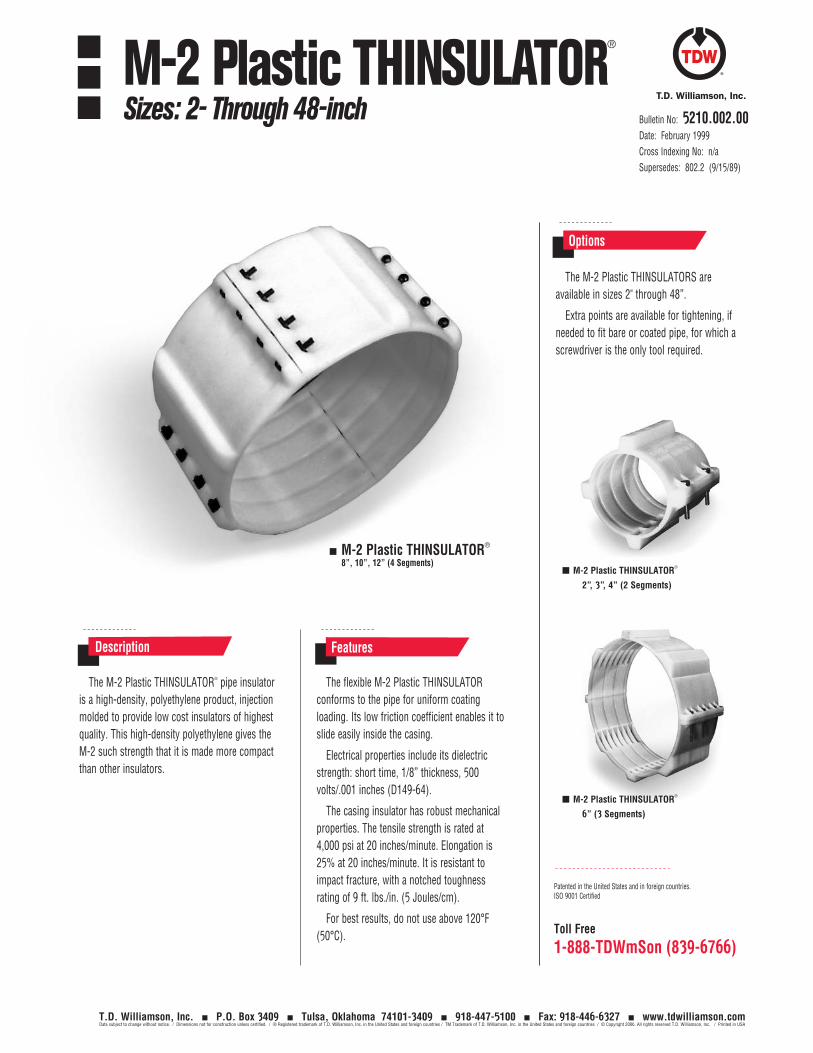
Toll Free
1-888-TDWmSon (839-6766)
The M-2 Plastic THINSULATOR® pipe insulator is a high-density, polyethylene product, injection molded to provide low cost insulators of highest quality. This high-density polyethylene gives the M-2 such strength that it is made more compact than other insulators.
The flexible M-2 Plastic THINSULATOR conforms to the pipe for uniform coating loading. Its low friction coefficient enables it to slide easily inside the casing.
Electrical properties include its dielectric strength: short time, 1/8” thickness, 500 volts/.001 inches (D149-64).
The casing insulator has robust mechanical properties. The tensile strength is rated at 4,000 psi at 20 inches/minute. Elongation is 25% at 20 inches/minute. It is resistant to impact fracture, with a notched toughness rating of 9 ft. lbs./in. (5 Joules/cm).
For best results, do not use above 120°F (50°C).
Description Features
M-2 Plastic THINSULATOR® 8”, 10”, 12” (4 Segments)
M-2 Plastic THINSULATOR®
6” (3 Segments)
The M-2 Plastic THINSULATORS are available in sizes 2" through 48”.
Extra points are available for tightening, if needed to fit bare or coated pipe, for which a screwdriver is the only tool required.
Options
Patented in the United States and in foreign countries.ISO 9001 Certified
M-2 Plastic THINSULATOR®
2”, 3”, 4” (2 Segments)
Bulletin No: 5210.002.00Date: February 1999Cross Indexing No: n/aSupersedes: 802.2 (9/15/89)
M-2 Plastic THINSULATOR®
Sizes: 2- Through 48-inch
T.D. Williamson, Inc. P.O. Box 3409 Tulsa, Oklahoma 74101-3409 918-447-5100 Fax: 918-446-6327 www.tdwilliamson.comData subject to change without notice. / Dimensions not for construction unless certified. / ® Registered trademark of T.D. Williamson, Inc. in the United States and foreign countries / TM Trademark of T.D. Williamson, Inc. in the United States and foreign countries / © Copyright 2006. All rights reserved T.D. Williamson, Inc. / Printed in USA
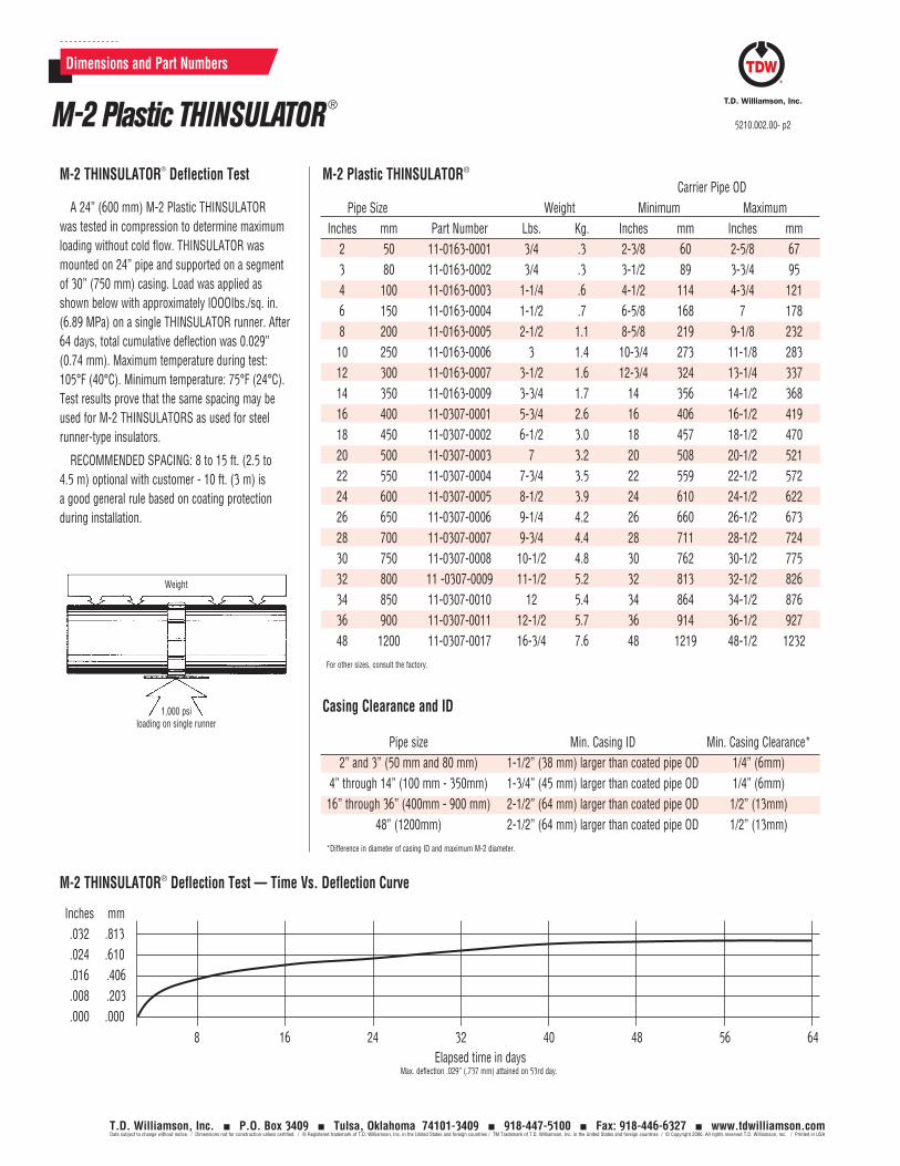
Casing Clearance and ID
Pipe size Min. Casing ID Min. Casing Clearance* 2” and 3” (50 mm and 80 mm) 1-1/2” (38 mm) larger than coated pipe OD 1/4” (6mm) 4” through 14” (100 mm - 350mm) 1-3/4” (45 mm) larger than coated pipe OD 1/4” (6mm) 16” through 36” (400mm - 900 mm) 2-1/2” (64 mm) larger than coated pipe OD 1/2” (13mm) 48” (1200mm) 2-1/2” (64 mm) larger than coated pipe OD 1/2” (13mm)
*Difference in diameter of casing ID and maximum M-2 diameter.
Carrier Pipe OD Pipe Size Weight Minimum Maximum Inches mm Part Number Lbs. Kg. Inches mm Inches mm 2 50 11-0163-0001 3/4 .3 2-3/8 60 2-5/8 67 3 80 11-0163-0002 3/4 .3 3-1/2 89 3-3/4 95 4 100 11-0163-0003 1-1/4 .6 4-1/2 114 4-3/4 121 6 150 11-0163-0004 1-1/2 .7 6-5/8 168 7 178 8 200 11-0163-0005 2-1/2 1.1 8-5/8 219 9-1/8 232 10 250 11-0163-0006 3 1.4 10-3/4 273 11-1/8 283 12 300 11-0163-0007 3-1/2 1.6 12-3/4 324 13-1/4 337 14 350 11-0163-0009 3-3/4 1.7 14 356 14-1/2 368 16 400 11-0307-0001 5-3/4 2.6 16 406 16-1/2 419 18 450 11-0307-0002 6-1/2 3.0 18 457 18-1/2 470 20 500 11-0307-0003 7 3.2 20 508 20-1/2 521 22 550 11-0307-0004 7-3/4 3.5 22 559 22-1/2 572 24 600 11-0307-0005 8-1/2 3.9 24 610 24-1/2 622 26 650 11-0307-0006 9-1/4 4.2 26 660 26-1/2 673 28 700 11-0307-0007 9-3/4 4.4 28 711 28-1/2 724 30 750 11-0307-0008 10-1/2 4.8 30 762 30-1/2 775 32 800 11 -0307-0009 11-1/2 5.2 32 813 32-1/2 826 34 850 11-0307-0010 12 5.4 34 864 34-1/2 876 36 900 11-0307-0011 12-1/2 5.7 36 914 36-1/2 927 48 1200 11-0307-0017 16-3/4 7.6 48 1219 48-1/2 1232
For other sizes, consult the factory.
Dimensions and Part Numbers
A 24” (600 mm) M-2 Plastic THINSULATOR was tested in compression to determine maximum loading without cold flow. THINSULATOR was mounted on 24” pipe and supported on a segment of 30” (750 mm) casing. Load was applied as shown below with approximately lOOOIbs./sq. in. (6.89 MPa) on a single THINSULATOR runner. After 64 days, total cumulative deflection was 0.029” (0.74 mm). Maximum temperature during test: 105°F (40°C). Minimum temperature: 75°F (24°C).Test results prove that the same spacing may be used for M-2 THINSULATORS as used for steel runner-type insulators.
RECOMMENDED SPACING: 8 to 15 ft. (2.5 to 4.5 m) optional with customer - 10 ft. (3 m) is a good general rule based on coating protection during installation.
M-2 THINSULATOR® Deflection Test
Weight
1,000 psiloading on single runner
Inches mm .032 .813 .024 .610 .016 .406 .008 .203 .000 .000
8 16 24 32 40 48 56 64 Elapsed time in days
Max. deflection .029” (.737 mm) attained on 53rd day.
M-2 THINSULATOR® Deflection Test — Time Vs. Deflection Curve
M-2 Plastic THINSULATOR®
M-2 Plastic THINSULATOR ®
5210.002.00- p2
T.D. Williamson, Inc. P.O. Box 3409 Tulsa, Oklahoma 74101-3409 918-447-5100 Fax: 918-446-6327 www.tdwilliamson.comData subject to change without notice. / Dimensions not for construction unless certified. / ® Registered trademark of T.D. Williamson, Inc. in the United States and foreign countries / TM Trademark of T.D. Williamson, Inc. in the United States and foreign countries / © Copyright 2006. All rights reserved T.D. Williamson, Inc. / Printed in USA
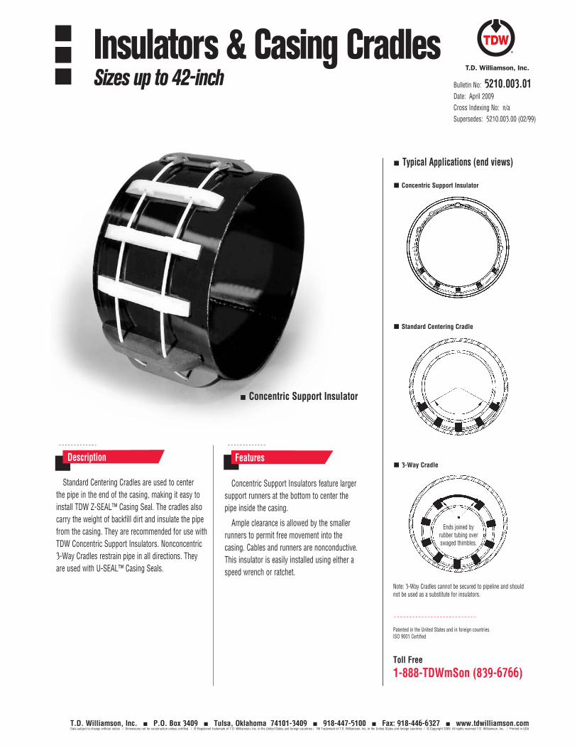
Toll Free
1-888-TDWmSon (839-6766)
Standard Centering Cradles are used to center the pipe in the end of the casing, making it easy to install TDW Z-SEAL™ Casing Seal. The cradles also carry the weight of backfill dirt and insulate the pipe from the casing. They are recommended for use with TDW Concentric Support Insulators. Nonconcentric 3-Way Cradles restrain pipe in all directions. They are used with U-SEAL™ Casing Seals.
Concentric Support Insulators feature larger support runners at the bottom to center the pipe inside the casing.
Ample clearance is allowed by the smaller runners to permit free movement into the casing. Cables and runners are nonconductive. This insulator is easily installed using either a speed wrench or ratchet.
Description Features
Concentric Support Insulator
Typical Applications (end views)
Concentric Support Insulator
Standard Centering Cradle
3-Way Cradle
Note: 3-Way Cradles cannot be secured to pipeline and should not be used as a substitute for insulators.
Ends joined by rubber tubing over swaged thimbles.
Patented in the United States and in foreign countries.ISO 9001 Certified
Bulletin No: 5210.003.01Date: April 2009Cross Indexing No: n/aSupersedes: 5210.003.00 (02/99)
Insulators & Casing CradlesSizes up to 42-inch
T.D. Williamson, Inc. P.O. Box 3409 Tulsa, Oklahoma 74101-3409 918-447-5100 Fax: 918-446-6327 www.tdwilliamson.comData subject to change without notice. / Dimensions not for construction unless certified. / ® Registered trademark of T.D. Williamson, Inc. in the United States and foreign countries / TM Trademark of T.D. Williamson, Inc. in the United States and foreign countries / © Copyright 2009. All rights reserved T.D. Williamson, Inc. / Printed in USA
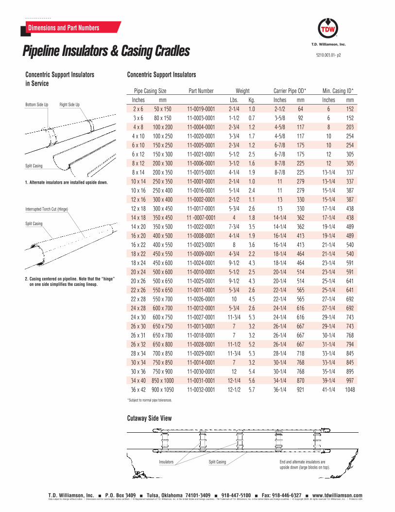
Dimensions and Part Numbers
Concentric Support InsulatorsConcentric Support Insulators in Service
Pipe Casing Size Part Number Weight Carrier Pipe OD* Min. Casing ID* Inches mm Lbs. Kg. Inches mm Inches mm 2 x 6 50 x 150 11-0019-0001 2-1/4 1.0 2-1/2 64 6 152 3 x 6 80 x 150 11-0003-0001 1-1/2 0.7 3-5/8 92 6 152 4 x 8 100 x 200 11-0004-0001 2-3/4 1.2 4-5/8 117 8 203 4 x 10 100 x 250 11-0020-0001 3-3/4 1.7 4-5/8 117 10 254 6 x 10 150 x 250 11-0005-0001 2-3/4 1.2 6-7/8 175 10 254 6 x 12 150 x 300 11-0021-0001 5-1/2 2.5 6-7/8 175 12 305 8 x 12 200 x 300 11-0006-0001 3-1/2 1.6 8-7/8 225 12 305 8 x 14 200 x 350 11-0015-0001 4-1/4 1.9 8-7/8 225 13-1/4 337 10 x 14 250 x 350 11-0001-0001 2-1/4 1.0 11 279 13-1/4 337 10 x 16 250 x 400 11-0016-0001 5-1/4 2.4 11 279 15-1/4 387 12 x 16 300 x 400 11-0002-0001 2-1/2 1.1 13 330 15-1/4 387 12 x 18 300 x 450 11-0017-0001 5-3/4 2.6 13 330 17-1/4 438 14 x 18 350 x 450 11 -0007-0001 4 1.8 14-1/4 362 17-1/4 438 14 x 20 350 x 500 11-0022-0001 7-3/4 3.5 14-1/4 362 19-1/4 489 16 x 20 400 x 500 11-0008-0001 4-1/4 1.9 16-1/4 413 19-1/4 489 16 x 22 400 x 550 11-0023-0001 8 3.6 16-1/4 413 21-1/4 540 18 x 22 450 x 550 11-0009-0001 4-3/4 2.2 18-1/4 464 21-1/4 540 18 x 24 450 x 600 11-0024-0001 9-1/2 4.3 18-1/4 464 23-1/4 591 20 x 24 500 x 600 11-0010-0001 5-1/2 2.5 20-1/4 514 23-1/4 591 20 x 26 500 x 650 11-0025-0001 9-1/2 4.3 20-1/4 514 25-1/4 641 22 x 26 550 x 650 11-0011-0001 5-3/4 2.6 22-1/4 565 25-1/4 641 22 x 28 550 x 700 11-0026-0001 10 4.5 22-1/4 565 27-1/4 692 24 x 28 600 x 700 11-0012-0001 5-3/4 2.6 24-1/4 616 27-1/4 692 24 x 30 600 x 750 11-0027-0001 11-3/4 5.3 24-1/4 616 29-1/4 743 26 x 30 650 x 750 11-0013-0001 7 3.2 26-1/4 667 29-1/4 743 26 x 31 650 x 780 11-0018-0001 7 3.2 26-1/4 667 30-1/4 768 26 x 32 650 x 800 11-0028-0001 11-1/2 5.2 26-1/4 667 31-1/4 794 28 x 34 700 x 850 11-0029-0001 11-3/4 5.3 28-1/4 718 33-1/4 845 30 x 34 750 x 850 11-0014-0001 7 3.2 30-1/4 768 33-1/4 845 30 x 36 750 x 900 11-0030-0001 12 5.4 30-1/4 768 35-1/4 895 34 x 40 850 x 1000 11-0031-0001 12-1/4 5.6 34-1/4 870 39-1/4 997 36 x 42 900 x 1050 11-0032-0001 12-1/2 5.7 36-1/4 921 41-1/4 1048
*Subject to normal pipe tolerances.
2. Casing centered on pipeline. Note that the “hinge” on one side simplifies the casing lineup.
1. Alternate insulators are installed upside down.
Bottom Side Up Right Side Up
Split Casing
Split Casing
Interrupted Torch Cut (Hinge)
Insulators Split Casing End and alternate insulators are upside down (large blocks on top).
Cutaway Side View
Pipeline Insulators & Casing Cradles 5210.003.01- p2
T.D. Williamson, Inc. P.O. Box 3409 Tulsa, Oklahoma 74101-3409 918-447-5100 Fax: 918-446-6327 www.tdwilliamson.comData subject to change without notice. / Dimensions not for construction unless certified. / ® Registered trademark of T.D. Williamson, Inc. in the United States and foreign countries / TM Trademark of T.D. Williamson, Inc. in the United States and foreign countries / © Copyright 2009. All rights reserved T.D. Williamson, Inc. / Printed in USA
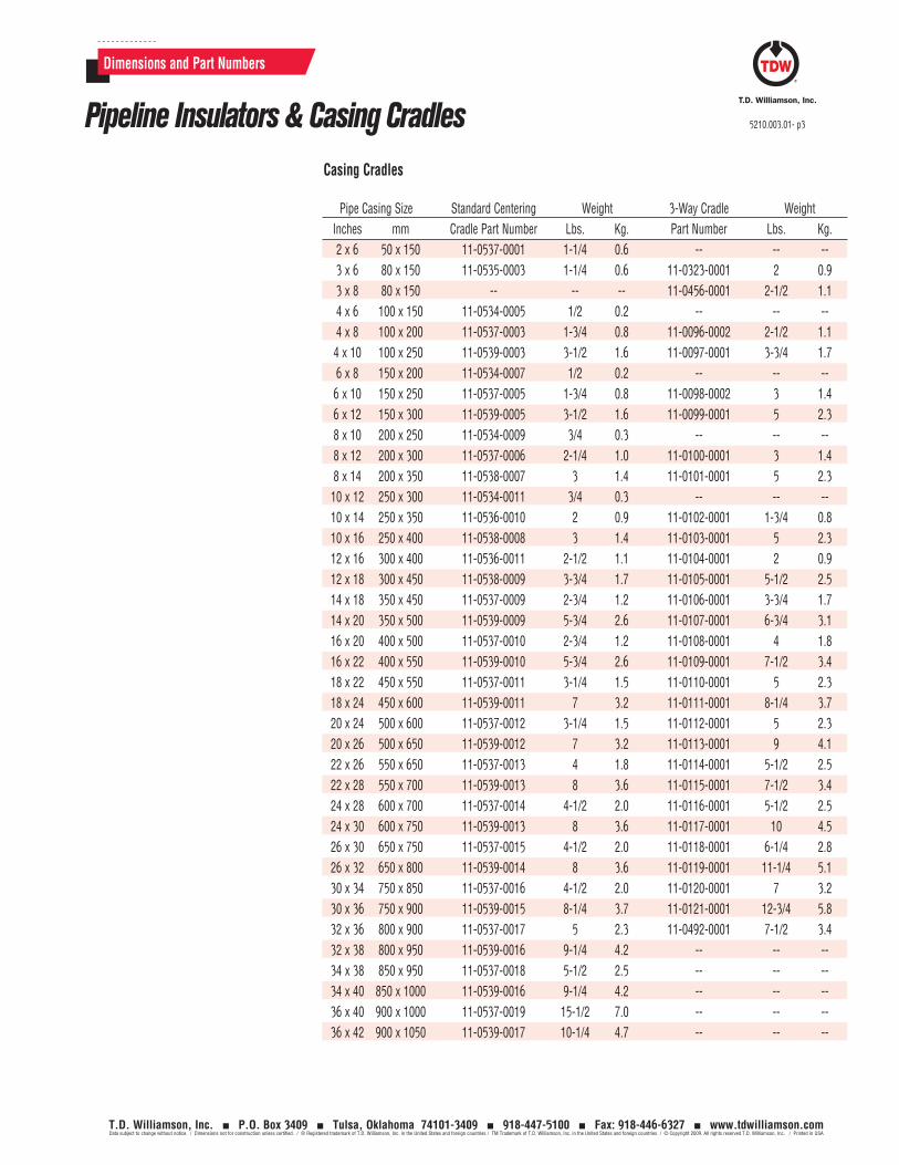
Dimensions and Part Numbers
Casing Cradles
Pipe Casing Size Standard Centering Weight 3-Way Cradle Weight Inches mm Cradle Part Number Lbs. Kg. Part Number Lbs. Kg. 2 x 6 50 x 150 11-0537-0001 1-1/4 0.6 -- -- -- 3 x 6 80 x 150 11-0535-0003 1-1/4 0.6 11-0323-0001 2 0.9 3 x 8 80 x 150 -- -- -- 11-0456-0001 2-1/2 1.1 4 x 6 100 x 150 11-0534-0005 1/2 0.2 -- -- -- 4 x 8 100 x 200 11-0537-0003 1-3/4 0.8 11-0096-0002 2-1/2 1.1 4 x 10 100 x 250 11-0539-0003 3-1/2 1.6 11-0097-0001 3-3/4 1.7 6 x 8 150 x 200 11-0534-0007 1/2 0.2 -- -- -- 6 x 10 150 x 250 11-0537-0005 1-3/4 0.8 11-0098-0002 3 1.4 6 x 12 150 x 300 11-0539-0005 3-1/2 1.6 11-0099-0001 5 2.3 8 x 10 200 x 250 11-0534-0009 3/4 0.3 -- -- -- 8 x 12 200 x 300 11-0537-0006 2-1/4 1.0 11-0100-0001 3 1.4 8 x 14 200 x 350 11-0538-0007 3 1.4 11-0101-0001 5 2.3 10 x 12 250 x 300 11-0534-0011 3/4 0.3 -- -- -- 10 x 14 250 x 350 11-0536-0010 2 0.9 11-0102-0001 1-3/4 0.8 10 x 16 250 x 400 11-0538-0008 3 1.4 11-0103-0001 5 2.3 12 x 16 300 x 400 11-0536-0011 2-1/2 1.1 11-0104-0001 2 0.9 12 x 18 300 x 450 11-0538-0009 3-3/4 1.7 11-0105-0001 5-1/2 2.5 14 x 18 350 x 450 11-0537-0009 2-3/4 1.2 11-0106-0001 3-3/4 1.7 14 x 20 350 x 500 11-0539-0009 5-3/4 2.6 11-0107-0001 6-3/4 3.1 16 x 20 400 x 500 11-0537-0010 2-3/4 1.2 11-0108-0001 4 1.8 16 x 22 400 x 550 11-0539-0010 5-3/4 2.6 11-0109-0001 7-1/2 3.4 18 x 22 450 x 550 11-0537-0011 3-1/4 1.5 11-0110-0001 5 2.3 18 x 24 450 x 600 11-0539-0011 7 3.2 11-0111-0001 8-1/4 3.7 20 x 24 500 x 600 11-0537-0012 3-1/4 1.5 11-0112-0001 5 2.3 20 x 26 500 x 650 11-0539-0012 7 3.2 11-0113-0001 9 4.1 22 x 26 550 x 650 11-0537-0013 4 1.8 11-0114-0001 5-1/2 2.5 22 x 28 550 x 700 11-0539-0013 8 3.6 11-0115-0001 7-1/2 3.4 24 x 28 600 x 700 11-0537-0014 4-1/2 2.0 11-0116-0001 5-1/2 2.5 24 x 30 600 x 750 11-0539-0013 8 3.6 11-0117-0001 10 4.5 26 x 30 650 x 750 11-0537-0015 4-1/2 2.0 11-0118-0001 6-1/4 2.8 26 x 32 650 x 800 11-0539-0014 8 3.6 11-0119-0001 11-1/4 5.1 30 x 34 750 x 850 11-0537-0016 4-1/2 2.0 11-0120-0001 7 3.2 30 x 36 750 x 900 11-0539-0015 8-1/4 3.7 11-0121-0001 12-3/4 5.8 32 x 36 800 x 900 11-0537-0017 5 2.3 11-0492-0001 7-1/2 3.4 32 x 38 800 x 950 11-0539-0016 9-1/4 4.2 -- -- -- 34 x 38 850 x 950 11-0537-0018 5-1/2 2.5 -- -- -- 34 x 40 850 x 1000 11-0539-0016 9-1/4 4.2 -- -- -- 36 x 40 900 x 1000 11-0537-0019 15-1/2 7.0 -- -- -- 36 x 42 900 x 1050 11-0539-0017 10-1/4 4.7 -- -- --
Pipeline Insulators & Casing Cradles 5210.003.01- p3
T.D. Williamson, Inc. P.O. Box 3409 Tulsa, Oklahoma 74101-3409 918-447-5100 Fax: 918-446-6327 www.tdwilliamson.comData subject to change without notice. / Dimensions not for construction unless certified. / ® Registered trademark of T.D. Williamson, Inc. in the United States and foreign countries / TM Trademark of T.D. Williamson, Inc. in the United States and foreign countries / © Copyright 2009. All rights reserved T.D. Williamson, Inc. / Printed in USA

5210.003.01- p4
T.D. Williamson, Inc. P.O. Box 3409 Tulsa, Oklahoma 74101-3409 918-447-5100 Fax: 918-446-6327 www.tdwilliamson.comData subject to change without notice. / Dimensions not for construction unless certified. / ® Registered trademark of T.D. Williamson, Inc. in the United States and foreign countries / TM Trademark of T.D. Williamson, Inc. in the United States and foreign countries / © Copyright 2009. All rights reserved T.D. Williamson, Inc. / Printed in USA
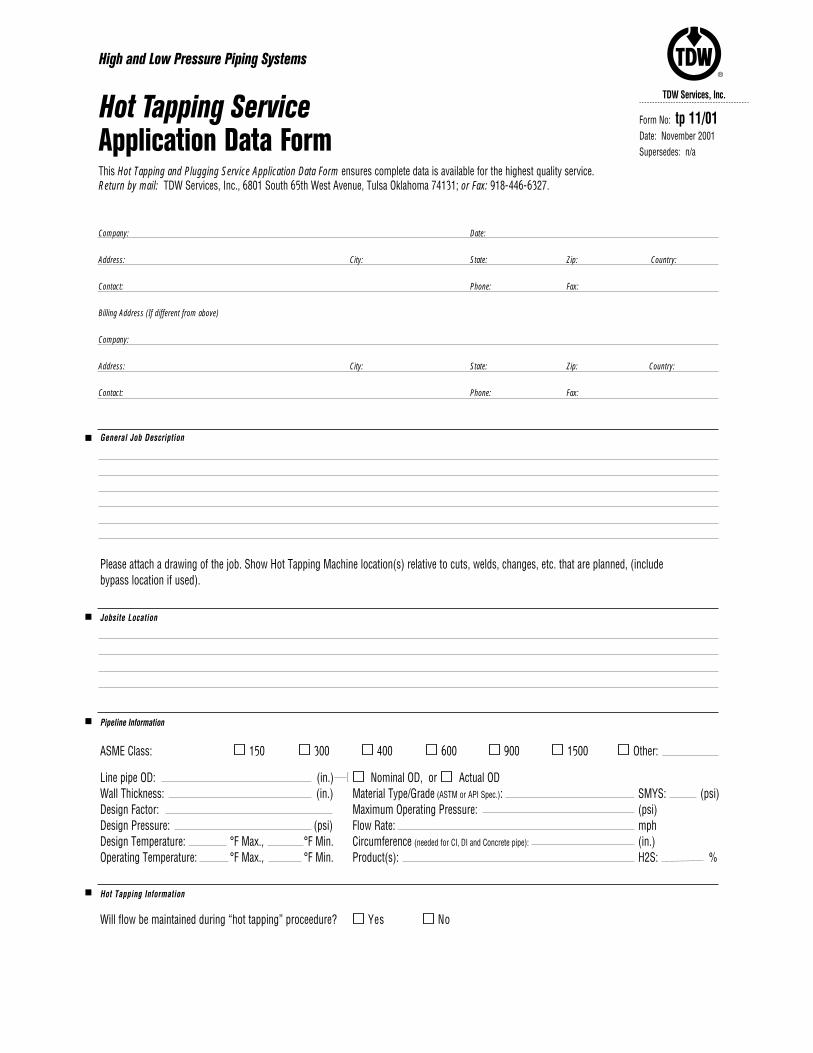
TDW Services, Inc.
®
Company: Date:
Address: City: State: Zip: Country:
Contact: Phone: Fax:
Billing Address (If different from above)
Company:
Address: City: State: Zip: Country:
Contact: Phone: Fax:
High and Low Pressure Piping Systems
Hot Tapping ServiceApplication Data FormThis Hot Tapping and Plugging Service Application Data Form ensures complete data is available for the highest quality service. Return by mail: TDW Services, Inc., 6801 South 65th West Avenue, Tulsa Oklahoma 74131; or Fax: 918-446-6327.
Form No: tp 11/01Date: November 2001Supersedes: n/a
General Job Description
Please attach a drawing of the job. Show Hot Tapping Machine location(s) relative to cuts, welds, changes, etc. that are planned, (include bypass location if used).
Jobsite Location
Pipeline Information
ASME Class: 150 300 400 600 900 1500 Other:
Line pipe OD: (in.) Nominal OD, or Actual ODWall Thickness: (in.) Material Type/Grade (ASTM or API Spec.): SMYS: (psi)Design Factor: Maximum Operating Pressure: (psi) Design Pressure: (psi) Flow Rate: mph Design Temperature: °F Max., °F Min. Circumference (needed for CI, DI and Concrete pipe): (in.)Operating Temperature: °F Max., °F Min. Product(s): H2S: %
Hot Tapping Information
Will flow be maintained during “hot tapping” proceedure? Yes No
[
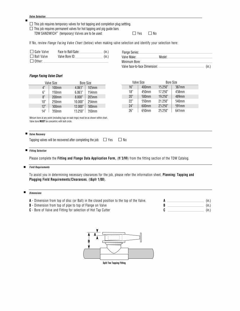
Valve Selection
This job requires temporary valves for hot tapping and completion plug settting.This job requires permanent valves for hot tapping and pig guide barsTDW SANDWICH® (temporary) Valves are to be used: Yes No
If No, review Flange Facing Valve Chart (below) when making valve selection and identify your selection here:
Flange Series:Valve Make: Model:Minimum Bore:Valve face-to-face Dimension: (in.)
Flange Facing Valve Chart
Valve Size Bore Size4” 100mm 4.063” 103mm6” 150mm 6.063” 154mm8” 200mm 8.000” 203mm
10” 250mm 10.000” 254mm12” 300mm 12.000” 300mm14” 350mm 13.250” 350mm
Valve Recovery
Tapping valves will be recovered after completing the job: Yes No
Fitting Selection
Please complete the Fitting and Flange Data Application Form, (ff 3/99) from the fitting section of the TDW Catalog.
Field Requirements
To assist you in determining necessary clearances for the job, please refer the information sheet, Planning: Tapping and Plugging Field Requirements/Clearances, (t&pfr 1/00).
Dimensions
A - Dimension from top of disc (or Ball) in the closed position to the top of the Valve. A (in.)B - Dimension from top of pipe to top of Flange on Valve B (in.)C - Bore of Valve and Fitting for selection of Hot Tap Cutter C (in.)
Minium bore at any point (including lugs on seat rings) must be as shown within chart.Valve bore MUST be concentric with bolt circle.
Gate Valve Face to Ball/Gate: (in.)Ball Valve Valve Bore ID: (in.)Other:
Split Tee Tapping Fitting
A
B
Valve Size Bore Size16” 400mm 15.250” 387mm18” 450mm 17.250” 438mm20” 500mm 19.250” 489mm22” 550mm 21.250” 540mm24” 600mm 23.250” 591mm26” 650mm 25.250” 641mm
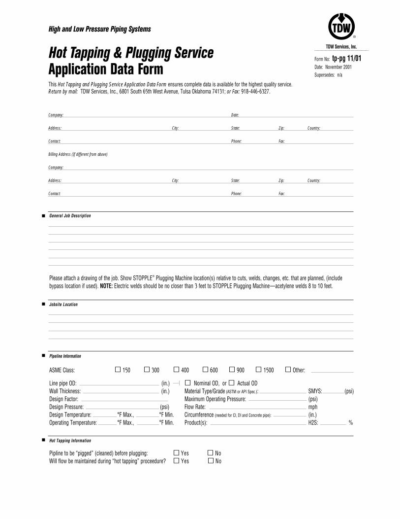
General Job Description
Please attach a drawing of the job. Show STOPPLE® Plugging Machine location(s) relative to cuts, welds, changes, etc. that are planned, (include bypass location if used). NOTE: Electric welds should be no closer than 3 feet to STOPPLE Plugging Machine—acetylene welds 8 to 10 feet.
Jobsite Location
Pipeline Information
ASME Class: 150 300 400 600 900 1500 Other:
Line pipe OD: (in.) Nominal OD, or Actual ODWall Thickness: (in.) Material Type/Grade (ASTM or API Spec.): SMYS: (psi)Design Factor: Maximum Operating Pressure: (psi) Design Pressure: (psi) Flow Rate: mph Design Temperature: °F Max., °F Min. Circumference (needed for CI, DI and Concrete pipe): (in.)Operating Temperature: °F Max., °F Min. Product(s): H2S: %
Hot Tapping Information
Pipline to be “pigged” (cleaned) before plugging: Yes NoWill flow be maintained during “hot tapping” proceedure? Yes No
TDW Services, Inc.
®
Company: Date:
Address: City: State: Zip: Country:
Contact: Phone: Fax:
Billing Address (If different from above)
Company:
Address: City: State: Zip: Country:
Contact: Phone: Fax:
High and Low Pressure Piping Systems
Hot Tapping & Plugging ServiceApplication Data FormThis Hot Tapping and Plugging Service Application Data Form ensures complete data is available for the highest quality service. Return by mail: TDW Services, Inc., 6801 South 65th West Avenue, Tulsa Oklahoma 74131; or Fax: 918-446-6327.
Form No: tp-pg 11/01Date: November 2001Supersedes: n/a
[
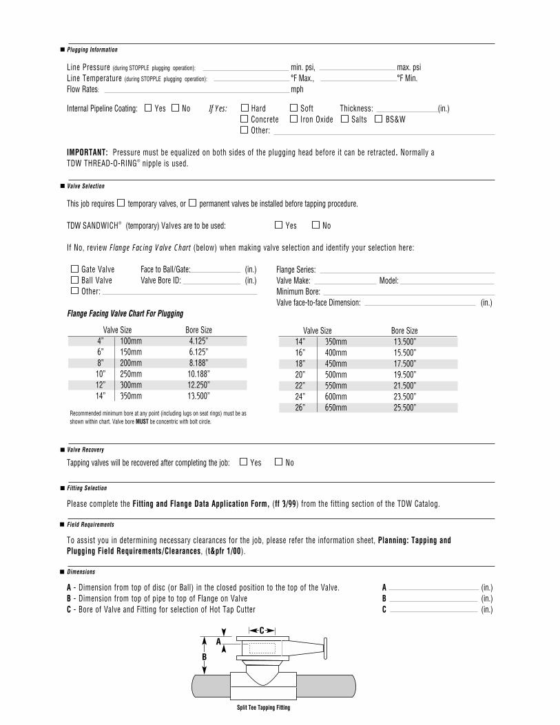
Split Tee Tapping Fitting
CA
B
Valve Size Bore Size14” 350mm 13.500”16” 400mm 15.500”18” 450mm 17.500”20” 500mm 19.500”22” 550mm 21.500”24” 600mm 23.500”26” 650mm 25.500”
Gate Valve Face to Ball/Gate: (in.)Ball Valve Valve Bore ID: (in.)Other:
Recommended minimum bore at any point (including lugs on seat rings) must be asshown within chart. Valve bore MUST be concentric with bolt circle.
Plugging Information
Line Pressure (during STOPPLE plugging operation): min. psi, max. psiLine Temperature (during STOPPLE plugging operation): °F Max., °F Min.Flow Rates: mph
Internal Pipeline Coating: Yes No If Yes: Hard Soft Thickness: (in.)Concrete Iron Oxide Salts BS&W Other:
IMPORTANT: Pressure must be equalized on both sides of the plugging head before it can be retracted. Normally a TDW THREAD-O-RING® nipple is used.
Valve Selection
This job requires temporary valves, or permanent valves be installed before tapping procedure.
TDW SANDWICH® (temporary) Valves are to be used: Yes No
If No, review Flange Facing Valve Chart (below) when making valve selection and identify your selection here:
Flange Series:Valve Make: Model:Minimum Bore:Valve face-to-face Dimension: (in.)
Flange Facing Valve Chart For Plugging
Valve Size Bore Size4” 100mm 4.125”6” 150mm 6.125”8” 200mm 8.188”
10” 250mm 10.188”12” 300mm 12.250”14” 350mm 13.500”
Valve Recovery
Tapping valves will be recovered after completing the job: Yes No
Fitting Selection
Please complete the Fitting and Flange Data Application Form, (ff 3/99) from the fitting section of the TDW Catalog.
Field Requirements
To assist you in determining necessary clearances for the job, please refer the information sheet, Planning: Tapping and Plugging Field Requirements/Clearances, (t&pfr 1/00).
Dimensions
A - Dimension from top of disc (or Ball) in the closed position to the top of the Valve. A (in.)B - Dimension from top of pipe to top of Flange on Valve B (in.)C - Bore of Valve and Fitting for selection of Hot Tap Cutter C (in.)
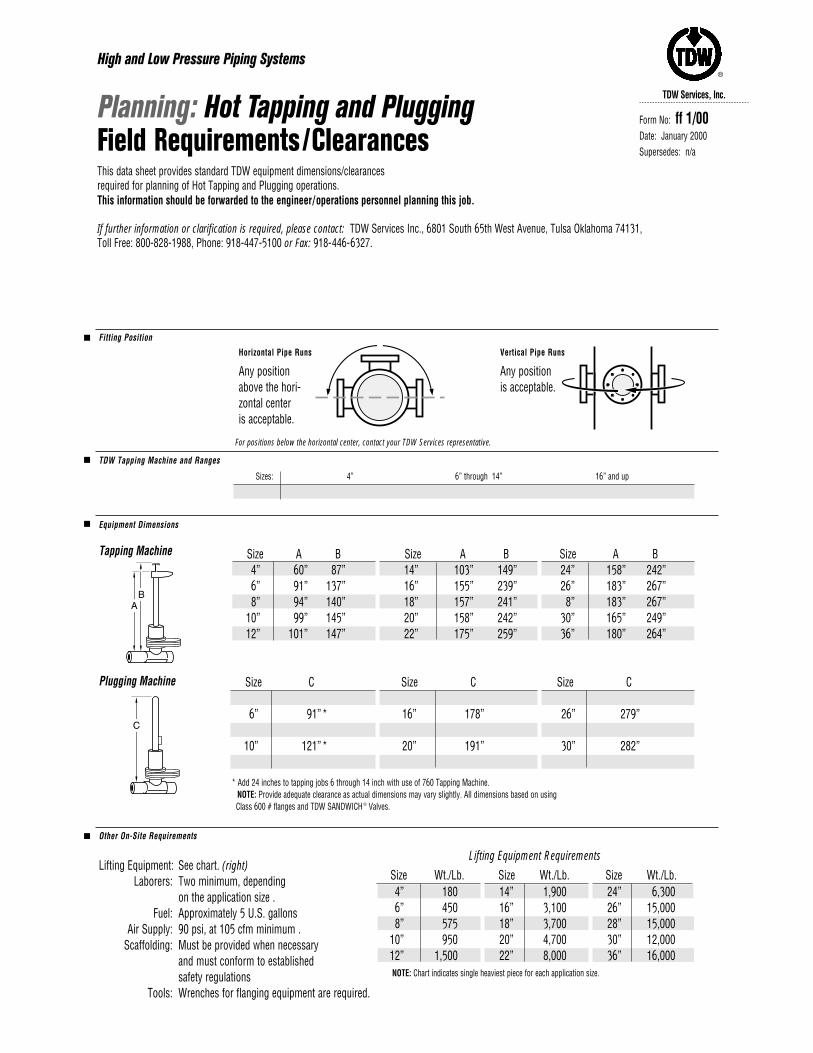
Fitting Position
TDW Tapping Machine and Ranges
Sizes: 4” 6” through 14” 16” and up
Machine: 360 Tapping Machine 660 Tapping Machine 1200 Tapping Machine
Equipment Dimensions
Tapping Machine
Plugging Machine
Other On-Site Requirements
Lifting Equipment: See chart. (right)Laborers: Two minimum, depending
on the application size .Fuel: Approximately 5 U.S. gallons
Air Supply: 90 psi, at 105 cfm minimum .Scaffolding: Must be provided when necessary
and must conform to established safety regulations
Tools: Wrenches for flanging equipment are required.
Size C Size C Size C4” 85” 14” 172” * 24” 238”6” 91”* 16” 178” 26” 279”8” 116”* 18” 184” 28” 279”
10” 121”* 20” 191” 30” 282”12” 127”* 22” 255” 36” 280”
Size Wt./Lb. Size Wt./Lb. Size Wt./Lb.4” 180 14” 1,900 24” 6,3006” 450 16” 3,100 26” 15,0008” 575 18” 3,700 28” 15,000
10” 950 20” 4,700 30” 12,00012” 1,500 22” 8,000 36” 16,000
Lifting Equipment Requirements
TDW Services, Inc.
®
High and Low Pressure Piping Systems
Planning: Hot Tapping and Plugging Field Requirements/ClearancesThis data sheet provides standard TDW equipment dimensions/clearances required for planning of Hot Tapping and Plugging operations. This information should be forwarded to the engineer/operations personnel planning this job.
If further information or clarification is required, please contact: TDW Services Inc., 6801 South 65th West Avenue, Tulsa Oklahoma 74131, Toll Free: 800-828-1988, Phone: 918-447-5100 or Fax: 918-446-6327.
Form No: ff 1/00Date: January 2000Supersedes: n/a
* Add 24 inches to tapping jobs 6 through 14 inch with use of 760 Tapping Machine.NOTE: Provide adequate clearance as actual dimensions may vary slightly. All dimensions based on using Class 600 # flanges and TDW SANDWICH ® Valves.
NOTE: Chart indicates single heaviest piece for each application size.
For positions below the horizontal center, contact your TDW Services representative.
Horizontal Pipe Runs
Any position above the hori-zontal center is acceptable.
Vertical Pipe Runs
Any position is acceptable.
Size A B Size A B Size A B4” 60” 87” 14” 103” 149” 24” 158” 242”6” 91” 137” 16” 155” 239” 26” 183” 267”8” 94” 140” 18” 157” 241” 8” 183” 267”
10” 99” 145” 20” 158” 242” 30” 165” 249”12” 101” 147” 22” 175” 259” 36” 180” 264”

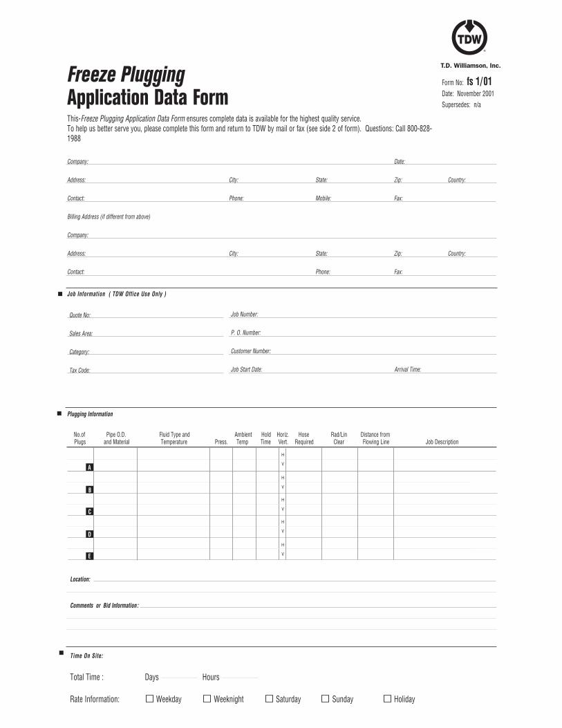
Company: Date:
Address: City: State: Zip: Country:
Contact: Phone: Mobile: Fax:
Billing Address (if different from above)
Company:
Address: City: State: Zip: Country:
Contact: Phone: Fax:
Freeze Plugging
Application Data FormThis-Freeze Plugging Application Data Form ensures complete data is available for the highest quality service. To help us better serve you, please complete this form and return to TDW by mail or fax (see side 2 of form). Questions: Call 800-828-1988
Form No: fs 1/01Date: November 2001Supersedes: n/a
Job Information ( TDW Office Use Only )
Plugging Information
No.of Pipe O.D. Fluid Type and Ambient Hold Horiz. Hose Rad/Lin Distance fromPlugs and Material Temperature Press. Temp Time Vert. Required Clear Flowing Line Job Description
Location:
Comments or Bid Information:
Time On Site:
Total Time : Days Hours
Rate Information: Weekday Weeknight Saturday Sunday Holiday
Quote No:
Sales Area:
Category:
Tax Code:
Job Number:
P. O. Number:
Customer Number:
Job Start Date: Arrival Time:
H
V
H
V
H
V
H
V
H
V
A
B
C
D
E
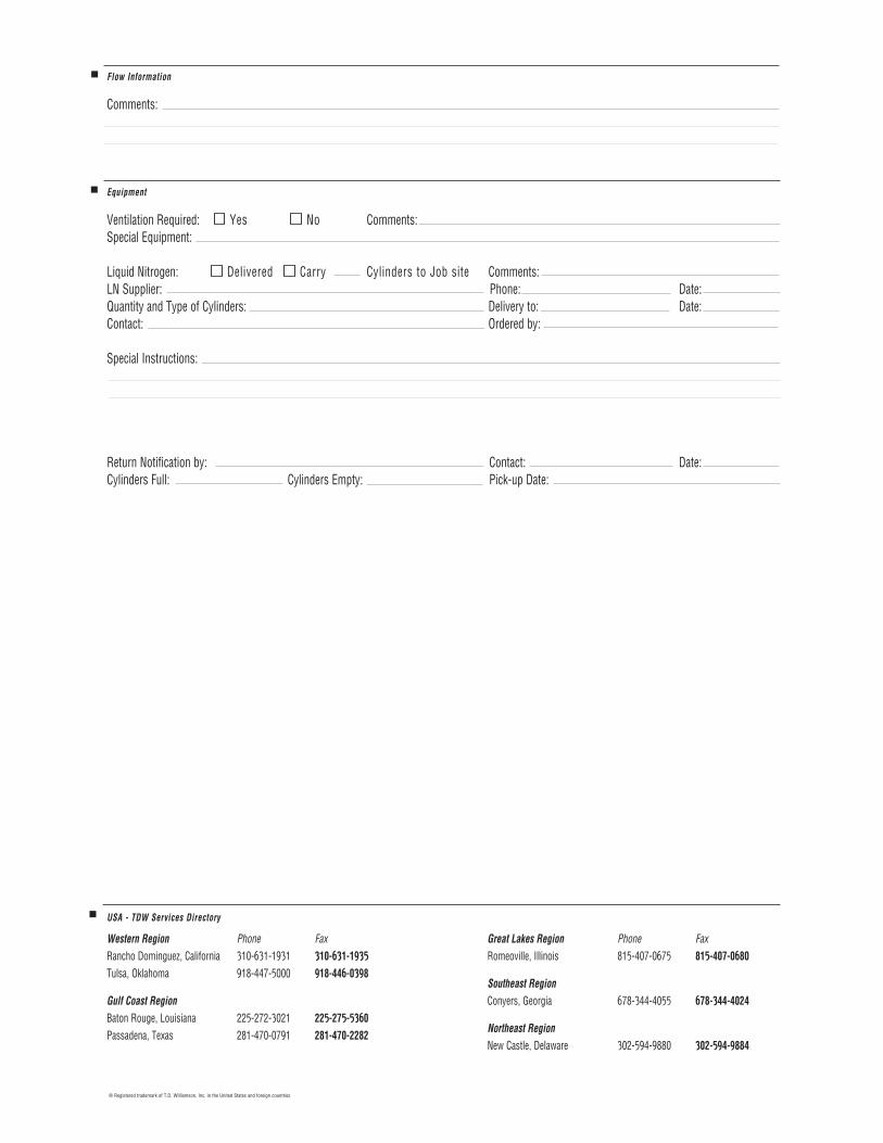
Flow Information Comments:
Equipment Ventilation Required: Yes No Comments: Special Equipment:
Liquid Nitrogen: Delivered Carry Cylinders to Job site Comments: LN Supplier: Phone: Date:Quantity and Type of Cylinders: Delivery to: Date:Contact: Ordered by:
Special Instructions:
Return Notification by: Contact: Date:Cylinders Full: Cylinders Empty: Pick-up Date:
USA - TDW Services Directory
Western Region Phone Fax Rancho Dominguez, California 310-631-1931 310-631-1935Tulsa, Oklahoma 918-447-5000 918-446-0398
Gulf Coast Region Baton Rouge, Louisiana 225-272-3021 225-275-5360Passadena, Texas 281-470-0791 281-470-2282
Great Lakes Region Phone Fax Romeoville, Illinois 815-407-0675 815-407-0680
Southeast Region Conyers, Georgia 678-344-4055 678-344-4024
Northeast Region New Castle, Delaware 302-594-9880 302-594-9884
® Registered trademark of T.D. Williamson, Inc. in the United States and foreign countries
® Registered Trademarks of T.D. Williamson, Inc. in the U.S. and foreign countries