hardware - rndr. Šárka vavrečková, ph.d
TRANSCRIPT
Sarka Vavreckova
Hardwareand Communication
Technologies
Institute of Computer ScienceFaculty of Filosophy and Science in OpavaSilesian University in Opava
OpavaApril 30, 2015
Annotation: This study material is assigned to the students of the subject Hard-ware a komunikacnı technologie (Hardware and Communication Technologies).We assume at least basic knowledge in hardware, computer networks and op-erating systems, optimaly lectures of the subject Technical equipment of per-sonal computers.
Hardware and Communication Technologies
RNDr. Sarka Vavreckova, Ph.D.
Available on: http://elearning.fpf.slu.cz/
Institute of Computer ScienceFaculty of Filosophy and Science in OpavaSilesian University in OpavaBezrucovo nam. 13, Opava
Typesetted with LATEX
Tato inovace predmetu Hardware a komunikacnı technologie je spolufinancovana Evrop-skym socialnım fondem a Statnım rozpoctem CR, projekt cıslo CZ.1.07/2.2.00/28.0014,“Interdisciplinarnı vzdelavanı v ICT s jazykovou kompetencı”.
Contents
1 Hardware basics 11.1 Common hardware components . . . . . . . . . . . . . . . . . . . . . . . . . . 1
1.1.1 Chassis . . . . . . . . . . . . . . . . . . . . . . . . . . . . . . . . . . . . 11.1.2 Mainboard . . . . . . . . . . . . . . . . . . . . . . . . . . . . . . . . . . . 11.1.3 Processor . . . . . . . . . . . . . . . . . . . . . . . . . . . . . . . . . . . 41.1.4 Memory modules . . . . . . . . . . . . . . . . . . . . . . . . . . . . . . . 6
1.2 Basic tools . . . . . . . . . . . . . . . . . . . . . . . . . . . . . . . . . . . . . . 81.2.1 Common screws and screwdrivers . . . . . . . . . . . . . . . . . . . . . 81.2.2 Tools to prevent electrostatic discharge . . . . . . . . . . . . . . . . . . 131.2.3 Other tools . . . . . . . . . . . . . . . . . . . . . . . . . . . . . . . . . . 14
1.3 Software for hardware detection in operating systems . . . . . . . . . . . . . 141.3.1 Hardware commands in Windows . . . . . . . . . . . . . . . . . . . . . 151.3.2 Hardware commands in Linux . . . . . . . . . . . . . . . . . . . . . . . 191.3.3 fdisk in Linux . . . . . . . . . . . . . . . . . . . . . . . . . . . . . . . . 22
1.4 Third party software . . . . . . . . . . . . . . . . . . . . . . . . . . . . . . . . . 231.4.1 HWInfo . . . . . . . . . . . . . . . . . . . . . . . . . . . . . . . . . . . . . 231.4.2 System Spec . . . . . . . . . . . . . . . . . . . . . . . . . . . . . . . . . 251.4.3 PC Wizard . . . . . . . . . . . . . . . . . . . . . . . . . . . . . . . . . . . 261.4.4 Other software to discover hardware . . . . . . . . . . . . . . . . . . . 27
2 Playing with hardware and reparations 292.1 Processor . . . . . . . . . . . . . . . . . . . . . . . . . . . . . . . . . . . . . . . 29
2.1.1 Recognizing Intel processors . . . . . . . . . . . . . . . . . . . . . . . . 292.1.2 Recognizing AMD processors . . . . . . . . . . . . . . . . . . . . . . . . 362.1.3 Processor installation . . . . . . . . . . . . . . . . . . . . . . . . . . . . 412.1.4 Testing and monitoring . . . . . . . . . . . . . . . . . . . . . . . . . . . 422.1.5 Benchmark results . . . . . . . . . . . . . . . . . . . . . . . . . . . . . . 442.1.6 Overclocking and underclocking . . . . . . . . . . . . . . . . . . . . . . 46
2.2 Memory . . . . . . . . . . . . . . . . . . . . . . . . . . . . . . . . . . . . . . . . 482.2.1 Properties . . . . . . . . . . . . . . . . . . . . . . . . . . . . . . . . . . . 482.2.2 Installation . . . . . . . . . . . . . . . . . . . . . . . . . . . . . . . . . . 502.2.3 Speed and latency . . . . . . . . . . . . . . . . . . . . . . . . . . . . . . 512.2.4 Memory information . . . . . . . . . . . . . . . . . . . . . . . . . . . . . 53
iii
iv
2.2.5 Overclocking . . . . . . . . . . . . . . . . . . . . . . . . . . . . . . . . . 542.2.6 Testing . . . . . . . . . . . . . . . . . . . . . . . . . . . . . . . . . . . . . 57
2.3 Magnetic memory media . . . . . . . . . . . . . . . . . . . . . . . . . . . . . . 602.3.1 Revision . . . . . . . . . . . . . . . . . . . . . . . . . . . . . . . . . . . . 602.3.2 S.M.A.R.T. . . . . . . . . . . . . . . . . . . . . . . . . . . . . . . . . . . . 612.3.3 Errors testing . . . . . . . . . . . . . . . . . . . . . . . . . . . . . . . . . 64
2.4 Power supply unit (PSU) . . . . . . . . . . . . . . . . . . . . . . . . . . . . . . 652.5 Monitoring . . . . . . . . . . . . . . . . . . . . . . . . . . . . . . . . . . . . . . 69
2.5.1 HWMonitor . . . . . . . . . . . . . . . . . . . . . . . . . . . . . . . . . . 692.6 Benchmarks . . . . . . . . . . . . . . . . . . . . . . . . . . . . . . . . . . . . . 70
3 Network 723.1 Communication overview . . . . . . . . . . . . . . . . . . . . . . . . . . . . . . 72
3.1.1 Protocol stacks . . . . . . . . . . . . . . . . . . . . . . . . . . . . . . . . 723.1.2 Encapsulation . . . . . . . . . . . . . . . . . . . . . . . . . . . . . . . . 75
3.2 Network equipment . . . . . . . . . . . . . . . . . . . . . . . . . . . . . . . . . 753.2.1 Active network equipment . . . . . . . . . . . . . . . . . . . . . . . . . 753.2.2 Passive network equipment . . . . . . . . . . . . . . . . . . . . . . . . . 763.2.3 RJ-45 connectors – crimping . . . . . . . . . . . . . . . . . . . . . . . . 78
3.3 Network commands in Windows . . . . . . . . . . . . . . . . . . . . . . . . . . 803.3.1 Files related to network . . . . . . . . . . . . . . . . . . . . . . . . . . . 803.3.2 Basic working with IP and MAC address . . . . . . . . . . . . . . . . . 803.3.3 Testing and statistics . . . . . . . . . . . . . . . . . . . . . . . . . . . . 823.3.4 Other commands . . . . . . . . . . . . . . . . . . . . . . . . . . . . . . . 85
3.4 Network commands in Linux . . . . . . . . . . . . . . . . . . . . . . . . . . . . 853.4.1 Files related to network . . . . . . . . . . . . . . . . . . . . . . . . . . . 853.4.2 Older address commands . . . . . . . . . . . . . . . . . . . . . . . . . . 873.4.3 iproute2 and command ip . . . . . . . . . . . . . . . . . . . . . . . . 893.4.4 Network interface and addresses . . . . . . . . . . . . . . . . . . . . . 893.4.5 Routing and filtering . . . . . . . . . . . . . . . . . . . . . . . . . . . . . 913.4.6 Neighbourhood . . . . . . . . . . . . . . . . . . . . . . . . . . . . . . . . 95
3.5 Network diagnosis . . . . . . . . . . . . . . . . . . . . . . . . . . . . . . . . . . 963.5.1 Wi-fi channels . . . . . . . . . . . . . . . . . . . . . . . . . . . . . . . . 963.5.2 Wireshark . . . . . . . . . . . . . . . . . . . . . . . . . . . . . . . . . . . 1003.5.3 Where to place it? . . . . . . . . . . . . . . . . . . . . . . . . . . . . . . 104
4 Servers 1074.1 Windows Server . . . . . . . . . . . . . . . . . . . . . . . . . . . . . . . . . . . 107
4.1.1 Editions . . . . . . . . . . . . . . . . . . . . . . . . . . . . . . . . . . . . 1074.1.2 Roles . . . . . . . . . . . . . . . . . . . . . . . . . . . . . . . . . . . . . . 1084.1.3 Installation . . . . . . . . . . . . . . . . . . . . . . . . . . . . . . . . . . 110
4.2 Linux Server . . . . . . . . . . . . . . . . . . . . . . . . . . . . . . . . . . . . . 1114.2.1 Distributions . . . . . . . . . . . . . . . . . . . . . . . . . . . . . . . . . 1124.2.2 Installation . . . . . . . . . . . . . . . . . . . . . . . . . . . . . . . . . . 113
Chapter 1Hardware basics
1.1 Common hardware components
We suppose certain knowledge of hardware over the subject “Technical equipment ofpersonal computers”, but we revise some components and their functionality.
1.1.1 Chassis
Chassis (or case) is mainly constructed from steel, aluminium, plastic or some othermaterials. We choose chassis according to the following criteria:
• form factor (size) – our mainboard has to fit the chassis (neither bigger nor smaller),all screws have to match,
• number of 5.25” and 3.5” positions (for HDDs, optical drives, card readers),
• material – too thick chassis vibrates whilest fans rotate,
• inner space – air needs to circulate,
• number and arrangement of USB plug seats or other important plugs,
• other criteria (e.g. design).
1.1.2 Mainboard
Motherboard (or mainboard) is the most important part of every computer (includingnotebooks, HTPCs,1 etc.). We pay attention to
• form factor (ATX, BTX, micro-ATX, mini-ITX, etc.),
• type of processor socket (LGA 1155, LGA 2011, AM3, FM1, . . . ),
• chipset (Intel H61, Z68, AMD A55, . . . ),
• BIOS producer, BIOS possibilities (including overclocking),
1HTPC (Home Theatre PC) is small silent well-designed PC in living rooms, used for videos, photos, TVsignal streaming, . . .
1
CHAPTER 1 HARDWARE BASICS 2
• integrated peripherals (yes/no/what/quality),
• number and type of memory slots,
• supported version of USB and SATA interface,
• number of PCIe slots and others (as the case some/what graphic and sound inter-faces), etc.
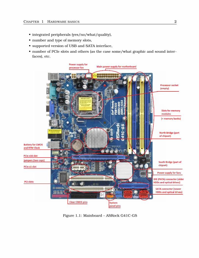
Figure 1.1: Mainboard – ASRock G41C-GS
CHAPTER 1 HARDWARE BASICS 3
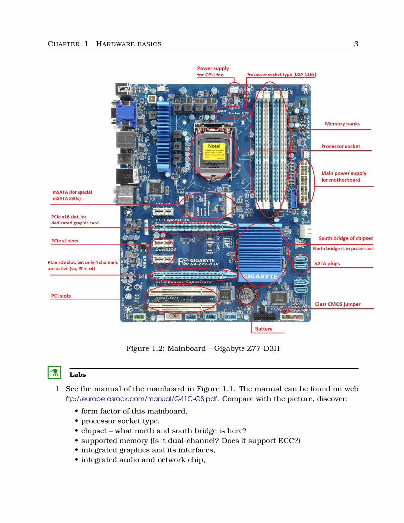
Figure 1.2: Mainboard – Gigabyte Z77-D3H
C Labs
1. See the manual of the mainboard in Figure 1.1. The manual can be found on webftp://europe.asrock.com/manual/G41C-GS.pdf. Compare with the picture, discover:
• form factor of this mainboard,• processor socket type,• chipset – what north and south bridge is here?• supported memory (Is it dual-channel? Does it support ECC?)• integrated graphics and its interfaces,• integrated audio and network chip,
CHAPTER 1 HARDWARE BASICS 4
• all leaded interfaces/plugs (graphics – VGA, DVI, . . . ?),• BIOS and its properties,• version of USB and SATA.
Take a look at instalation process images (processor, memory modules, hard disks)and BIOS Setup. What are the possibilities of memory and processor overclocking?Examine ACPI configuration, Storage configuration (including PIO/DMA mode fordisks) and HW Health monitoring.
2. Get similar information about the mainboard Gigabyte Z77-D3H (Figure 1.2). Findits manual (ask Google). Compare these two mainboards, notice the difference inprocessor sockets and chipset structure.
3. Well, we have some training mainboards, so we will have a look at them.
4. Choose some web store with hardware and find a mainboard according to thesecriteria:
• form factor micro-ATX,• processor socket LGA 1155,• chipset Intel H61,• SATA III interface (6 Gb/s),• USB 3.0 support,• 2 or more memory banks.
C
1.1.3 Processor
Processor is a heart of a computer. There are a few producers of processors:
• Intel – the most popular processors especially for desktops, notebooks, netbooks,HTPCs
• AMD – the second one popular producer of processors
• VIA – produces chipsets, CPUs, memory modules, audio chips and other chips, weknow VIA Nano for netbooks
• ARM processors are produced by more manufacturers – nVidia (Tegra), Marvell,Texas Instruments, Transmeta, . . . , with RISC instruction sets
• IBM – PowerPC in old Apple Macs, and other producers
Hardware architectures:
• x86 – 32bit architecture of older Intel and AMD processors
• x64 (the same as amd64 or x86-64) – 64bit architecture of newer Intel and AMDprocessors
• ARM
• ia-64 – Intel processors for servers (Itanium)
• Sun SPARC, MIPS, . . . – other server architectures
CHAPTER 1 HARDWARE BASICS 5
Each processor needs concrete type of socket. When buying processor, we would knowwhat socket is necessary.
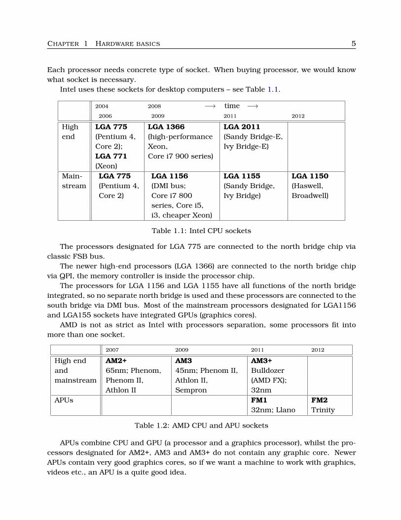
Intel uses these sockets for desktop computers – see Table 1.1.
2004 2008 −→ time −→2006 2009 2011 2012
High LGA 775 LGA 1366 LGA 2011end (Pentium 4, (high-performance (Sandy Bridge-E,
Core 2); Xeon, Ivy Bridge-E)LGA 771 Core i7 900 series)(Xeon)
Main- LGA 775 LGA 1156 LGA 1155 LGA 1150stream (Pentium 4, (DMI bus; (Sandy Bridge, (Haswell,
Core 2) Core i7 800 Ivy Bridge) Broadwell)series, Core i5,i3, cheaper Xeon)
Table 1.1: Intel CPU sockets
The processors designated for LGA 775 are connected to the north bridge chip viaclassic FSB bus.
The newer high-end processors (LGA 1366) are connected to the north bridge chipvia QPI, the memory controller is inside the processor chip.
The processors for LGA 1156 and LGA 1155 have all functions of the north bridgeintegrated, so no separate north bridge is used and these processors are connected to thesouth bridge via DMI bus. Most of the mainstream processors designated for LGA1156and LGA155 sockets have integrated GPUs (graphics cores).
AMD is not as strict as Intel with processors separation, some processors fit intomore than one socket.
2007 2009 2011 2012
High end AM2+ AM3 AM3+and 65nm; Phenom, 45nm; Phenom II, Bulldozermainstream Phenom II, Athlon II, (AMD FX);
Athlon II Sempron 32nmAPUs FM1 FM2
32nm; Llano Trinity
Table 1.2: AMD CPU and APU sockets
APUs combine CPU and GPU (a processor and a graphics processor), whilst the pro-cessors designated for AM2+, AM3 and AM3+ do not contain any graphic core. NewerAPUs contain very good graphics cores, so if we want a machine to work with graphics,videos etc., an APU is a quite good idea.
CHAPTER 1 HARDWARE BASICS 6
� More information:
• http://ark.intel.com/• http://products.amd.com/• http://www.10stripe.com/featured/cpu/index.php• http://www.cpu-world.com/Sockets/index.html
�
Each processor meets some of the properties well-known from the subject “Technicalequipment of personal computers” – hyperscalar and superscalar architectures, out-of-order execution, branch prediction, low or high TDP, Turbo boost or Turbo core, etc. Wecan explore these properties on the webs of processor producers (they are mentionedabove).
C Labs
1. Find images of the particular sockets and processors and compare.
2. Browse some computer web store and find some interesting processors to plug intothe socket LGA 1155, LGA 1366, AM3+ and FM1.
C
1.1.4 Memory modules
Nowadays, there are nearly exclusively DIMM (Dual In-line Memory Module) modulesin desktop computers, only rarely (in very old computers) we can find SIMM (Single. . . )modules. All types of memory chips on SIMM and DIMM modules are dynamic memories,they need periodic refresh of their content.
There are these types of memory chips on DIMM modules:
• SDR (the older ones from 90’s) – work synchroniously with the system timer, onetick = one operation;
• DDR – 184pin DIMM for desktops or smaller 200pin SO-DIMM for notebooks; dataare transferred on both the rising and falling edges of the clock signal (two timesa clock), so the transfer rate is doubled (or this module is able to work at the halffrequence with the same transfer rate),
• DDR2 (around 2008) – 240pin DIMM or 200pin SO-DIMM; the bus between thememory cells and the buffer is twice wider, so double amount of data per clock ismoved,
• DDR3 – 240pin DIMM or 204pin SO-DIMM; lower voltage and doubled bus clock,
• DDR4 – comming soon.
Nowadays, DIMM moduls with DDR3 are the most used.
CHAPTER 1 HARDWARE BASICS 7
� Remark:
DIMM modules with different memory chips are not compatible, we have to know whattype of memory slots (so called memory banks) are on our mainboard.
�
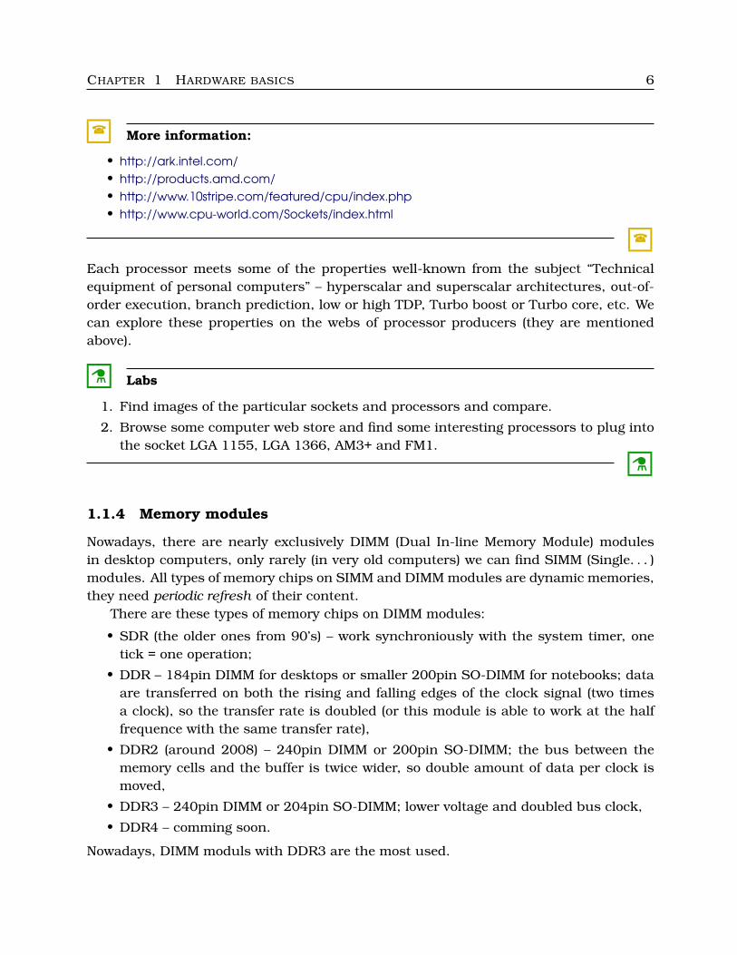
The memory modules are labeled by their transfer rate or by their frequency, see Ta-ble 1.3.
Chips JEDEC labeling Labeling by chips Examples
DDR PCxxxx DDRyyy PC1600 =DDR200PC2700 =DDR266PC3200 =DDR400
DDR2 PC2-xxxx DDR2-yyy PC2-4200 =DDR2-533or DDR2-yyyy PC2-6400 =DDR2-800
PC2-8500 =DDR2-1066DDR3 PC3-xxxx DDR3-yyy PC3-6400 =DDR3-800
or PC3-xxxxx or DDR3-yyyy PC3-8500 =DDR3-1066PC3-10600=DDR3-1333
where xxxx is transfer rate (MB/s)and yyy is doubled frequency (bus clock, MHz)
Table 1.3: DIMM labeling
Very important indicator of quality and usability is latency (marked tCL). Lower la-tencies mean better response of memory chips. We will concern with latencies later, nowwe would know that newer types od DIMMs generaly have higher latencies than oldertypes. Typical values of tCL:
• DDR: 2–3
• DDR2: 3–6
• DDR3: 6–11
Lower is better. As we can see, latencies grow with higher frequencies.Communication with memory modules is controlled by a memory controller. This
component is integrated either in the north bridge or in the processor. The memorycontroller may be able to communicate parallely with two, three or four memory modulesat the same time, so we call it dual-channel, triple-channel or quad-channel memorycontroller.
But if we want to utilize this property, we must put the modules into the correctbanks. This information can be found in the documentation of the mainboard, usuallywe ought to put them into the banks with the same color; see the figures with mainboardsabove.
CHAPTER 1 HARDWARE BASICS 8
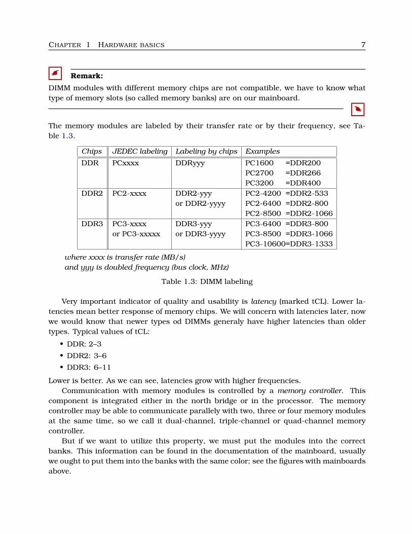
Figure 1.3: Memory modules
� More information:
• http://www.bit-tech.net/hardware/memory/2007/11/15/the secrets of pc memory part 1/4• http://www.xbitlabs.com/articles/memory/display/ddr2-ddr.html• http://computer.howstuffworks.com/ram.htm
�
C Labs
Learn to recognize different types of DIMM modules, try to insert them into memorybanks with locking and to take them out.
C
1.2 Basic tools
1.2.1 Common screws and screwdrivers
We need to have some tools to open the given PC, to install and repair components. Firstwe deal with screws (fasteners) and screwdrivers.
CHAPTER 1 HARDWARE BASICS 9
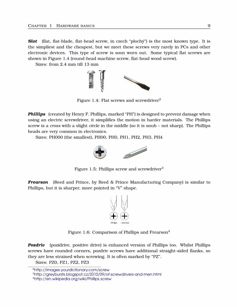
Slot (flat, flat-blade, flat-head screw, in czech “plochy”) is the most known type. It isthe simpliest and the cheapest, but we meet these screws very rarely in PCs and otherelectronic devices. This type of screw is soon worn out. Some typical flat screws areshown in Figure 1.4 (round-head machine screw, flat-head wood screw).
Sizes: from 2.4 mm till 13 mm
Figure 1.4: Flat screws and screwdriver2
Phillips (created by Henry F. Phillips, marked “PH”) is designed to prevent damage whenusing an electric screwdriver, it simplifies the motion in harder materials. The Phillipsscrew is a cross with a slight circle in the middle (so it is snub – not sharp). The Phillipsheads are very common in electronics.
Sizes: PH000 (the smallest), PH00, PH0, PH1, PH2, PH3, PH4
Figure 1.5: Phillips screw and screwdriver3
Frearson (Reed and Prince, by Reed & Prince Manufacturing Company) is similar toPhillips, but it is sharper, more pointed in “V” shape.
Figure 1.6: Comparison of Phillips and Frearson4
Pozdriv (pozidrive, positive drive) is enhanced version of Phillips too. Whilst Phillipsscrews have rounded corners, pozdriv screws have additional straight-sided flanks, sothey are less strained when screwing. It is often marked by “PZ”.
Sizes: PZ0, PZ1, PZ2, PZ32http://images.yourdictionary.com/screw3http://greybursts.blogspot.cz/2010/09/of-screwdrivers-and-men.html4http://en.wikipedia.org/wiki/Phillips screw
CHAPTER 1 HARDWARE BASICS 10
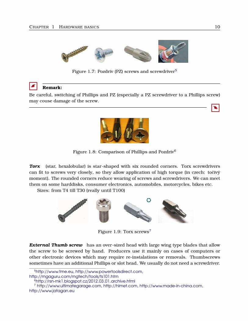
Figure 1.7: Pozdriv (PZ) screws and screwdriver5
� Remark:
Be careful, switching of Phillips and PZ (especially a PZ screwdriver to a Phillips screw)may couse damage of the screw.
�
Figure 1.8: Comparison of Phillips and Pozdriv6
Torx (star, hexalobular) is star-shaped with six rounded corners. Torx screwdriverscan fit to screws very closely, so they allow application of high torque (in czech: tocivymoment). The rounded corners reduce wearing of screws and screwdrivers. We can meetthem on some harddisks, consumer electronics, automobiles, motorcycles, bikes etc.
Sizes: from T4 till T30 (really until T100)
Figure 1.9: Torx screws7
External Thumb screw has an over-sized head with large wing type blades that allowthe screw to be screwed by hand. Producers use it mainly on cases of computers orother electronic devices which may require re-instalations or removals. Thumbscrewssometimes have an additional Phillips or slot head. We usually do not need a screwdriver.
5http://www.tme.eu, http://www.powertoolsdirect.com,http://mgaguru.com/mgtech/tools/ts101.htm
6http://rsn-mk1.blogspot.cz/2012 03 01 archive.html7 http://www.ultimategarage.com, http://hlmet.com, http://www.made-in-china.com,
http://www.jatagan.eu
CHAPTER 1 HARDWARE BASICS 11
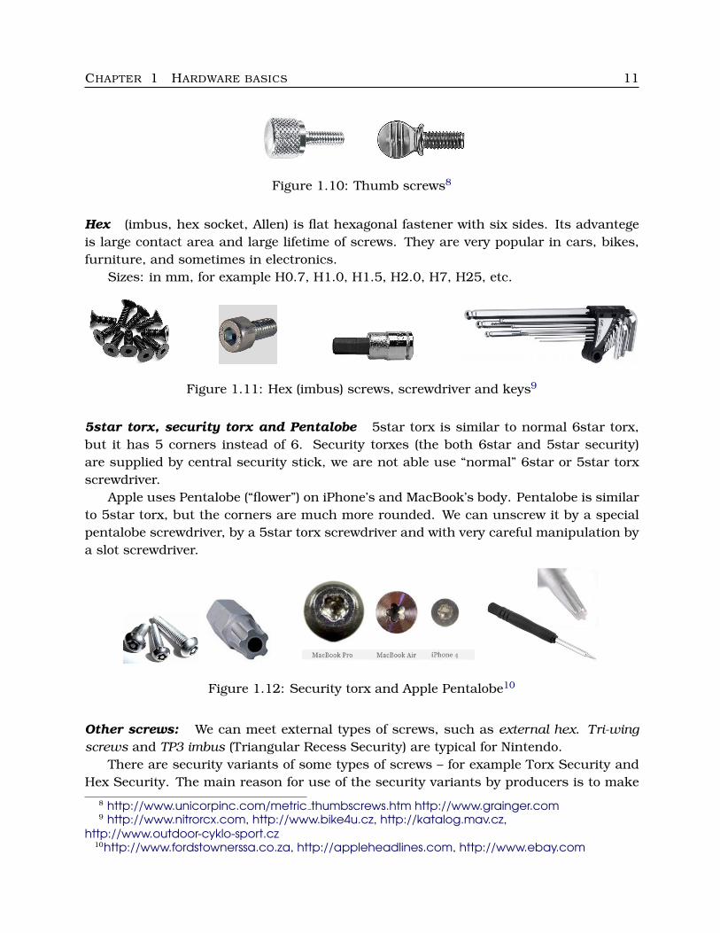
Figure 1.10: Thumb screws8
Hex (imbus, hex socket, Allen) is flat hexagonal fastener with six sides. Its advantegeis large contact area and large lifetime of screws. They are very popular in cars, bikes,furniture, and sometimes in electronics.
Sizes: in mm, for example H0.7, H1.0, H1.5, H2.0, H7, H25, etc.
Figure 1.11: Hex (imbus) screws, screwdriver and keys9
5star torx, security torx and Pentalobe 5star torx is similar to normal 6star torx,but it has 5 corners instead of 6. Security torxes (the both 6star and 5star security)are supplied by central security stick, we are not able use “normal” 6star or 5star torxscrewdriver.
Apple uses Pentalobe (“flower”) on iPhone’s and MacBook’s body. Pentalobe is similarto 5star torx, but the corners are much more rounded. We can unscrew it by a specialpentalobe screwdriver, by a 5star torx screwdriver and with very careful manipulation bya slot screwdriver.
Figure 1.12: Security torx and Apple Pentalobe10
Other screws: We can meet external types of screws, such as external hex. Tri-wingscrews and TP3 imbus (Triangular Recess Security) are typical for Nintendo.
There are security variants of some types of screws – for example Torx Security andHex Security. The main reason for use of the security variants by producers is to make
8 http://www.unicorpinc.com/metric thumbscrews.htm http://www.grainger.com9 http://www.nitrorcx.com, http://www.bike4u.cz, http://katalog.mav.cz,
http://www.outdoor-cyklo-sport.cz10http://www.fordstownerssa.co.za, http://appleheadlines.com, http://www.ebay.com
CHAPTER 1 HARDWARE BASICS 12
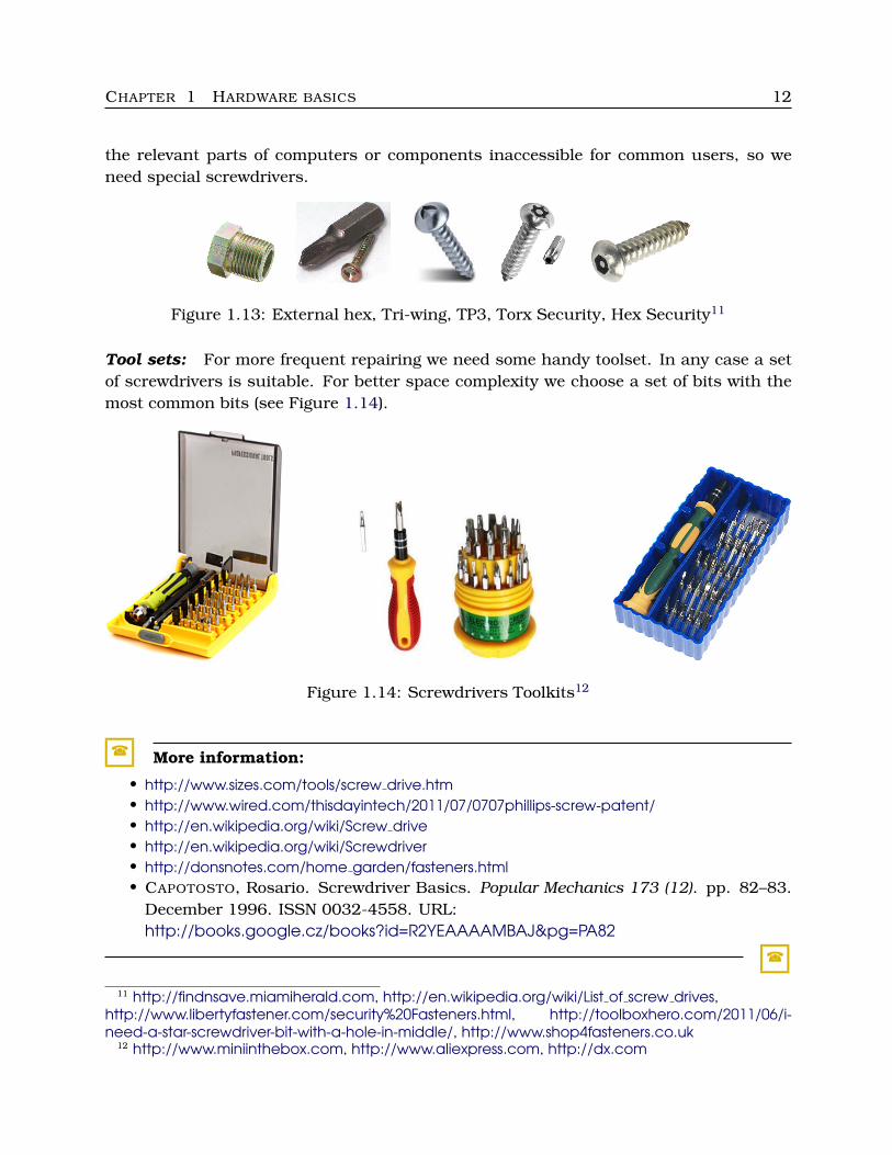
the relevant parts of computers or components inaccessible for common users, so weneed special screwdrivers.
Figure 1.13: External hex, Tri-wing, TP3, Torx Security, Hex Security11
Tool sets: For more frequent repairing we need some handy toolset. In any case a setof screwdrivers is suitable. For better space complexity we choose a set of bits with themost common bits (see Figure 1.14).
Figure 1.14: Screwdrivers Toolkits12
� More information:
• http://www.sizes.com/tools/screw drive.htm• http://www.wired.com/thisdayintech/2011/07/0707phillips-screw-patent/• http://en.wikipedia.org/wiki/Screw drive• http://en.wikipedia.org/wiki/Screwdriver• http://donsnotes.com/home garden/fasteners.html• CAPOTOSTO, Rosario. Screwdriver Basics. Popular Mechanics 173 (12). pp. 82–83.
December 1996. ISSN 0032-4558. URL:http://books.google.cz/books?id=R2YEAAAAMBAJ&pg=PA82
�
11 http://findnsave.miamiherald.com, http://en.wikipedia.org/wiki/List of screw drives,http://www.libertyfastener.com/security%20Fasteners.html, http://toolboxhero.com/2011/06/i-need-a-star-screwdriver-bit-with-a-hole-in-middle/, http://www.shop4fasteners.co.uk
12 http://www.miniinthebox.com, http://www.aliexpress.com, http://dx.com
CHAPTER 1 HARDWARE BASICS 13
1.2.2 Tools to prevent electrostatic discharge
When two objects with different voltage touch with each other, dangerous eletrostaticdischarge (ESD) occurs. It also concerns the human body, computer components, chips.People are able to survive it remaining healthy, but not always electronic components– ESD is called a “silent killer”. The situation is worse in dry air, using classic (non-antistatic) carpets, etc.
What to do to prevent ESD when opening a case (chassis) and we do not have anyantistatic tools:
• wash your hands in flow of cold water,
• touch the chassis of PC before handling any component (the PC must be switchedoff, but still plugged into the electrical outlet).
Well, but we would have to touch the chassis all the time or at least very often.
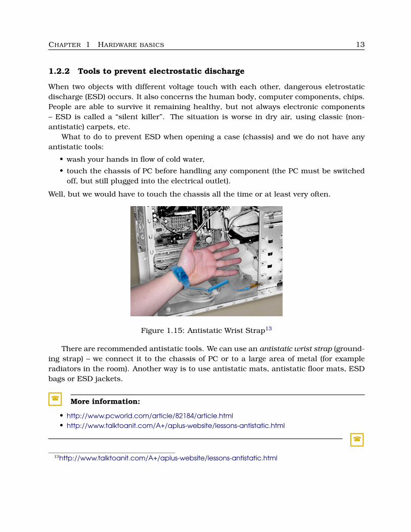
Figure 1.15: Antistatic Wrist Strap13
There are recommended antistatic tools. We can use an antistatic wrist strap (ground-ing strap) – we connect it to the chassis of PC or to a large area of metal (for exampleradiators in the room). Another way is to use antistatic mats, antistatic floor mats, ESDbags or ESD jackets.
� More information:
• http://www.pcworld.com/article/82184/article.html• http://www.talktoanit.com/A+/aplus-website/lessons-antistatic.html
�
13http://www.talktoanit.com/A+/aplus-website/lessons-antistatic.html
CHAPTER 1 HARDWARE BASICS 14
1.2.3 Other tools
We also can use the following tools:
• Pliers are sometimes useful (for example to unscrew to tight screws or to pick someobjects through too narrow hole).
• Tweezers to pick some objects through too narrow hole or to set them there.
• Penlight to see well in dark cases.
• Clamps to tighten long cables.
• Network tools – Network Cable Crimp for RJ-45, some testers (RJ-45 cable tester,wi-fi analyzer, etc.).
• Air blower or compressed air or vacuum cleaner to blow off dust.
• Isopropyl alcohol to clean water-sensitive parts of various components.
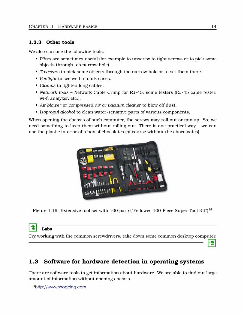
When opening the chassis of such computer, the screws may roll out or mix up. So, weneed something to keep them without rolling out. There is one practical way – we canuse the plastic interior of a box of chocolates (of course without the chocoloates).
Figure 1.16: Extensive tool set with 100 parts(“Fellowes 100-Piece Super Tool Kit”)14
C Labs
Try working with the common screwdrivers, take down some common desktop computer.
C
1.3 Software for hardware detection in operating systems
There are software tools to get information about hardware. We are able to find out largeamount of information without opening chassis.
14http://www.shopping.com
CHAPTER 1 HARDWARE BASICS 15
1.3.1 Hardware commands in Windows
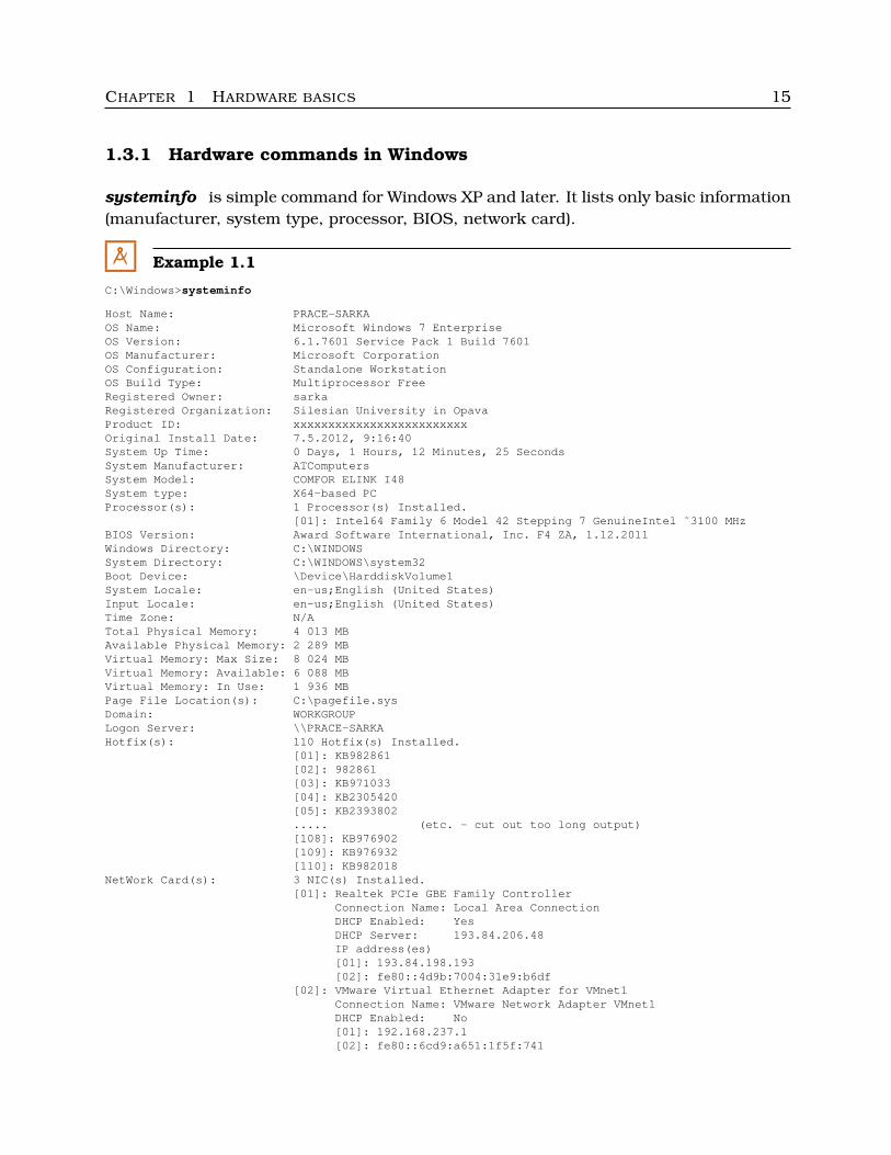
systeminfo is simple command for Windows XP and later. It lists only basic information(manufacturer, system type, processor, BIOS, network card).
M Example 1.1
C:\Windows>systeminfo
Host Name: PRACE-SARKAOS Name: Microsoft Windows 7 EnterpriseOS Version: 6.1.7601 Service Pack 1 Build 7601OS Manufacturer: Microsoft CorporationOS Configuration: Standalone WorkstationOS Build Type: Multiprocessor FreeRegistered Owner: sarkaRegistered Organization: Silesian University in OpavaProduct ID: xxxxxxxxxxxxxxxxxxxxxxxxxOriginal Install Date: 7.5.2012, 9:16:40System Up Time: 0 Days, 1 Hours, 12 Minutes, 25 SecondsSystem Manufacturer: ATComputersSystem Model: COMFOR ELINK I48System type: X64-based PCProcessor(s): 1 Processor(s) Installed.
[01]: Intel64 Family 6 Model 42 Stepping 7 GenuineIntel ˜3100 MHzBIOS Version: Award Software International, Inc. F4 ZA, 1.12.2011Windows Directory: C:\WINDOWSSystem Directory: C:\WINDOWS\system32Boot Device: \Device\HarddiskVolume1System Locale: en-us;English (United States)Input Locale: en-us;English (United States)Time Zone: N/ATotal Physical Memory: 4 013 MBAvailable Physical Memory: 2 289 MBVirtual Memory: Max Size: 8 024 MBVirtual Memory: Available: 6 088 MBVirtual Memory: In Use: 1 936 MBPage File Location(s): C:\pagefile.sysDomain: WORKGROUPLogon Server: \\PRACE-SARKAHotfix(s): 110 Hotfix(s) Installed.
[01]: KB982861[02]: 982861[03]: KB971033[04]: KB2305420[05]: KB2393802..... (etc. - cut out too long output)[108]: KB976902[109]: KB976932[110]: KB982018
NetWork Card(s): 3 NIC(s) Installed.[01]: Realtek PCIe GBE Family Controller
Connection Name: Local Area ConnectionDHCP Enabled: YesDHCP Server: 193.84.206.48IP address(es)[01]: 193.84.198.193[02]: fe80::4d9b:7004:31e9:b6df
[02]: VMware Virtual Ethernet Adapter for VMnet1Connection Name: VMware Network Adapter VMnet1DHCP Enabled: No[01]: 192.168.237.1[02]: fe80::6cd9:a651:1f5f:741
CHAPTER 1 HARDWARE BASICS 16
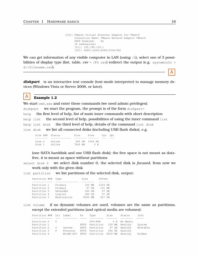
[03]: VMware Virtual Ethernet Adapter for VMnet8Connection Name: VMware Network Adapter VMnet8DHCP Enabled: NoIP address(es)[01]: 192.168.126.1[02]: fe80::a562:bf86:535d:982
We can get information of any visible computer in LAN (using /S), select one of 3 possi-bilities of display type (list, table, csv – /FO csv) redirect the output (e.g. systeminfo >
d:\filename.csv).
M
diskpart is an interactive text console (text-mode interpreter) to manage memory de-vices (Windows Vista or Server 2008, or later).
M Example 1.2
We start cmd.exe and enter these commands (we need admin privileges):diskpart we start the program, the prompt is of the form diskpart>
help the first level of help, list of main inner commands with short descriptionhelp list the second level of help, possibilities of using the inner command list
help list disk the third level of help, details of the command list disk
list disk we list all connected disks (including USB flash disks), e.g.
Disk ### Status Size Free Dyn Gpt-------- ------------- -------- ------- --- ---Disk 0 Online 465 GB 1024 KBDisk 1 Online 7640 MB 0 B
(one SATA harddisk and one USB flash disk); the free space is not meant as data-free, it is meant as space without partitions
select disk 0 we select disk number 0, the selected disk is focused, from now wework only with the given disk
list partition we list partitions of the selected disk, output:
Partition ### Type Size Offset------------- --------------- -------- -------Partition 1 Primary 100 MB 1024 KBPartition 2 Primary 97 GB 101 MBPartition 0 Extended 360 GB 97 GBPartition 4 Logical 360 GB 97 GBPartition 3 Restoration 8000 MB 457 GB
list volume if no dynamic volumes are used, volumes are the same as partitions,except the extended partitions (and optical media are volumes):
Partition ### Ltr Label Fs Type Size Status Info------------- --- --------- ---- --------- ------- -------- -----Partition 0 D DVD-ROM 0 B No MediaPartition 1 NTFS Partition 100 MB Healthy SystemPartition 2 C System NTFS Partition 97 GB Healthy BootablePartition 3 P Personal NTFS Partition 360 GB HealthyPartition 4 WinRE-ATC NTFS Partition 8000 MB Healthy Hidden
CHAPTER 1 HARDWARE BASICS 17
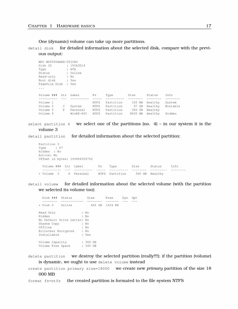
One (dynamic) volume can take up more partitions.
detail disk for detailed information about the selected disk, compare with the previ-ous output:
WDC WD5000AAKX-001CA0Disk ID : 15CA3D14Type : ATAStatus : OnlineRead-only : NoBoot disk : YesPagefile Disk : Yes...
Volume ### Ltr Label Fs Type Size Status Info---------- --- ---------- ----- ---------- -------- -------- --------Volume 1 NTFS Partition 100 MB Healthy SystemVolume 2 C System NTFS Partition 97 GB Healthy BootableVolume 3 P Personal NTFS Partition 360 GB HealthyVolume 4 WinRE-ATC NTFS Partition 8000 MB Healthy Hidden
select partition 4 we select one of the partitions (no. 4) – in our system it is thevolume 3
detail partition for detailed information about the selected partition:
Partition 3Type : 07Hidden : NoActive: NoOffset in bytes: 104964554752
Volume ### Ltr Label Fs Type Size Status Info---------- --- ---------- ----- ---------- -------- --------- --------
* Volume 3 P Personal NTFS Partition 360 GB Healthy
detail volume for detailed information about the selected volume (with the partitionwe selected its volume too):
Disk ### Status Size Free Dyn Gpt-------- ------------ -------- ------- --- ---
* Disk 0 Online 465 GB 1024 KB
Read Only : NoHidden : NoNo Default Drive Letter: NoShadow Copy : NoOffline : NoBitLocker Encrypted : NoInstallable : Yes
Volume Capacity : 360 GBVolume Free Space : 340 GB
delete partition we destroy the selected partition (really!!!); if the partition (volume)is dynamic, we ought to use delete volume instead
create partition primary size=18000 we create new primary partition of the size 18000 MB
format fs=ntfs the created partition is formated to the file system NTFS
CHAPTER 1 HARDWARE BASICS 18
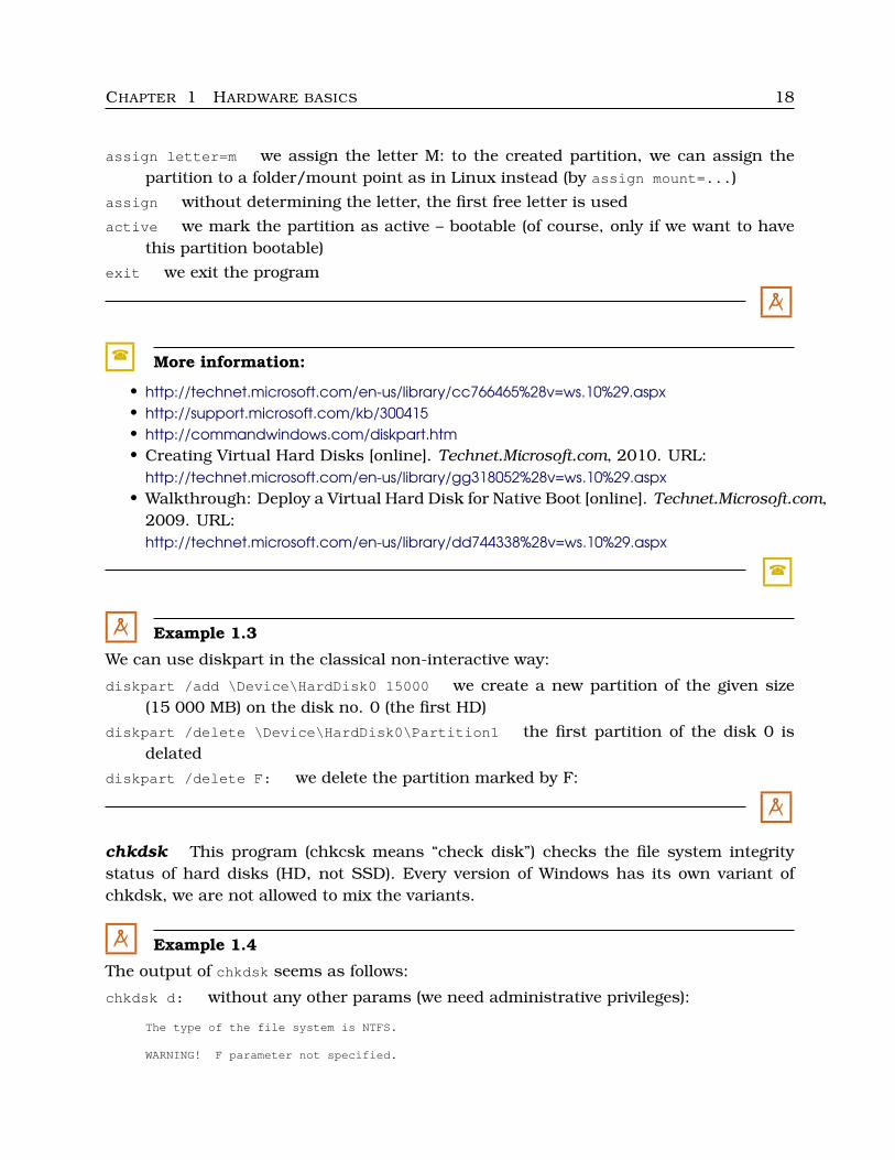
assign letter=m we assign the letter M: to the created partition, we can assign thepartition to a folder/mount point as in Linux instead (by assign mount=...)
assign without determining the letter, the first free letter is used
active we mark the partition as active – bootable (of course, only if we want to havethis partition bootable)
exit we exit the program
M
� More information:
• http://technet.microsoft.com/en-us/library/cc766465%28v=ws.10%29.aspx• http://support.microsoft.com/kb/300415• http://commandwindows.com/diskpart.htm• Creating Virtual Hard Disks [online]. Technet.Microsoft.com, 2010. URL:
http://technet.microsoft.com/en-us/library/gg318052%28v=ws.10%29.aspx• Walkthrough: Deploy a Virtual Hard Disk for Native Boot [online]. Technet.Microsoft.com,
2009. URL:http://technet.microsoft.com/en-us/library/dd744338%28v=ws.10%29.aspx
�
M Example 1.3
We can use diskpart in the classical non-interactive way:
diskpart /add \Device\HardDisk0 15000 we create a new partition of the given size(15 000 MB) on the disk no. 0 (the first HD)
diskpart /delete \Device\HardDisk0\Partition1 the first partition of the disk 0 isdelated
diskpart /delete F: we delete the partition marked by F:
M
chkdsk This program (chkcsk means “check disk”) checks the file system integritystatus of hard disks (HD, not SSD). Every version of Windows has its own variant ofchkdsk, we are not allowed to mix the variants.
M Example 1.4
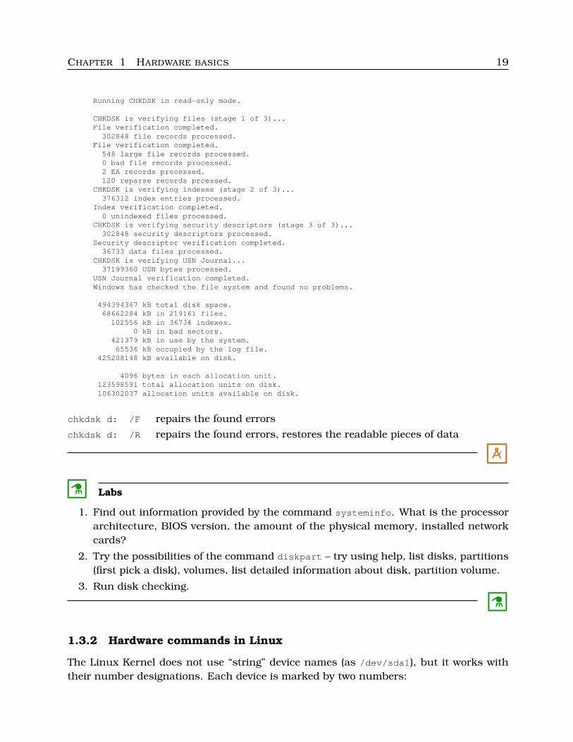
The output of chkdsk seems as follows:
chkdsk d: without any other params (we need administrative privileges):
The type of the file system is NTFS.
WARNING! F parameter not specified.
CHAPTER 1 HARDWARE BASICS 19
Running CHKDSK in read-only mode.
CHKDSK is verifying files (stage 1 of 3)...File verification completed.
302848 file records processed.File verification completed.
548 large file records processed.0 bad file records processed.2 EA records processed.120 reparse records prcessed.
CHKDSK is verifying indexes (stage 2 of 3)...376312 index entries processed.
Index verification completed.0 unindexed files processed.
CHKDSK is verifying security descriptors (stage 3 of 3)...302848 security descriptors processed.
Security descriptor verification completed.36733 data files processed.
CHKDSK is verifying USN Journal...37199360 USN bytes processed.
USN Journal verification completed.Windows has checked the file system and found no problems.
494394367 kB total disk space.68662284 kB in 219161 files.
102556 kB in 36734 indexes.0 kB in bad sectors.
421379 kB in use by the system.65536 kB occupied by the log file.
425208148 kB available on disk.
4096 bytes in each allocation unit.123598591 total allocation units on disk.106302037 allocation units available on disk.
chkdsk d: /F repairs the found errors
chkdsk d: /R repairs the found errors, restores the readable pieces of data
M
C Labs
1. Find out information provided by the command systeminfo. What is the processorarchitecture, BIOS version, the amount of the physical memory, installed networkcards?
2. Try the possibilities of the command diskpart – try using help, list disks, partitions(first pick a disk), volumes, list detailed information about disk, partition volume.
3. Run disk checking.
C
1.3.2 Hardware commands in Linux
The Linux Kernel does not use “string” device names (as /dev/sda1), but it works withtheir number designations. Each device is marked by two numbers:
CHAPTER 1 HARDWARE BASICS 20
• Major number is unique for the given type of device (disks, monitors, network cards,etc.) – the device class.
• Minor number is unique for every instance of the given type.
For example: if we get connected two network cards, their major numbers are the sameand their minor numbers are different.
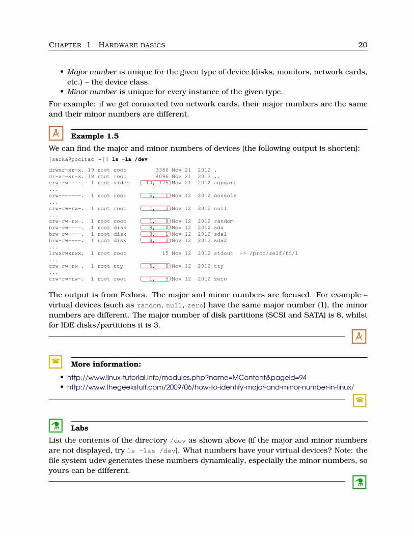
M Example 1.5
We can find the major and minor numbers of devices (the following output is shorten):[sarka@pocitac ˜]$ ls -la /dev
drwxr-xr-x. 19 root root 3380 Nov 21 2012 .dr-xr-xr-x. 18 root root 4096 Nov 21 2012 ..�� ��crw-rw----. 1 root video 10, 175 Nov 21 2012 agpgart... �� ��crw-------. 1 root root 5, 1 Nov 12 2012 console... �� ��crw-rw-rw-. 1 root root 1, 3 Nov 12 2012 null... �� ��crw-rw-rw-. 1 root root 1, 8 Nov 12 2012 random�� ��brw-rw----. 1 root disk 8, 0 Nov 12 2012 sda�� ��brw-rw----. 1 root disk 8, 1 Nov 12 2012 sda1�� ��brw-rw----. 1 root disk 8, 2 Nov 12 2012 sda2...lrwxrwxrwx. 1 root root 15 Nov 12 2012 stdout -> /proc/self/fd/1... �� ��crw-rw-rw-. 1 root tty 5, 0 Nov 12 2012 tty... �� ��crw-rw-rw-. 1 root root 1, 5 Nov 12 2012 zero
The output is from Fedora. The major and minor numbers are focused. For example –virtual devices (such as random, null, zero) have the same major number (1), the minornumbers are different. The major number of disk partitions (SCSI and SATA) is 8, whilstfor IDE disks/partitions it is 3.
M
� More information:
• http://www.linux-tutorial.info/modules.php?name=MContent&pageid=94• http://www.thegeekstuff.com/2009/06/how-to-identify-major-and-minor-number-in-linux/
�
C Labs
List the contents of the directory /dev as shown above (if the major and minor numbersare not displayed, try ls -las /dev). What numbers have your virtual devices? Note: thefile system udev generates these numbers dynamically, especially the minor numbers, soyours can be different.
C
CHAPTER 1 HARDWARE BASICS 21
The following commands relate to disks and memory:
df (disk free) writes out free space on disks, mounting points etc.
df -Th shows filesystems on partitions toodf -ah gives information about mounted filesystems including the virtual ones
sync synchronization of partitions and caches
fsck (files checking) checking and repairing the filesystems, there are more variants:
fsck.ext3 /dev/sda9 for the filesystem ext3, we check the partition /dev/sda9 (itis necessary to disconnect it in advance)
raiserfsck /dev/sda3 for the filesystem RaiserFSfsck.ntfs /dev/sda2 for NTFSfsck.vfat /dev/sda5 for FAT16 and FAT32, etc.
mkfs.ext3 /dev/sda4 creating the filesystem ext3 on /dev/sda4, similarly for otherfilesystems
mount lists mounted devices, with parameters we can mount partitions
mount /mnt/winD mounts the partition with the mouning point /mnt/winDmount -o r /mnt/winD with the indication “read-only”mount -t vfat /dev/sdb2 /mnt/flash we mount the given USB flash disk with
the filesystem FAT32, special file /dev/sdb2 and mounting point /mnt/flashumount /mnt/winD the given partition is unmounted
free writes out complete memory information
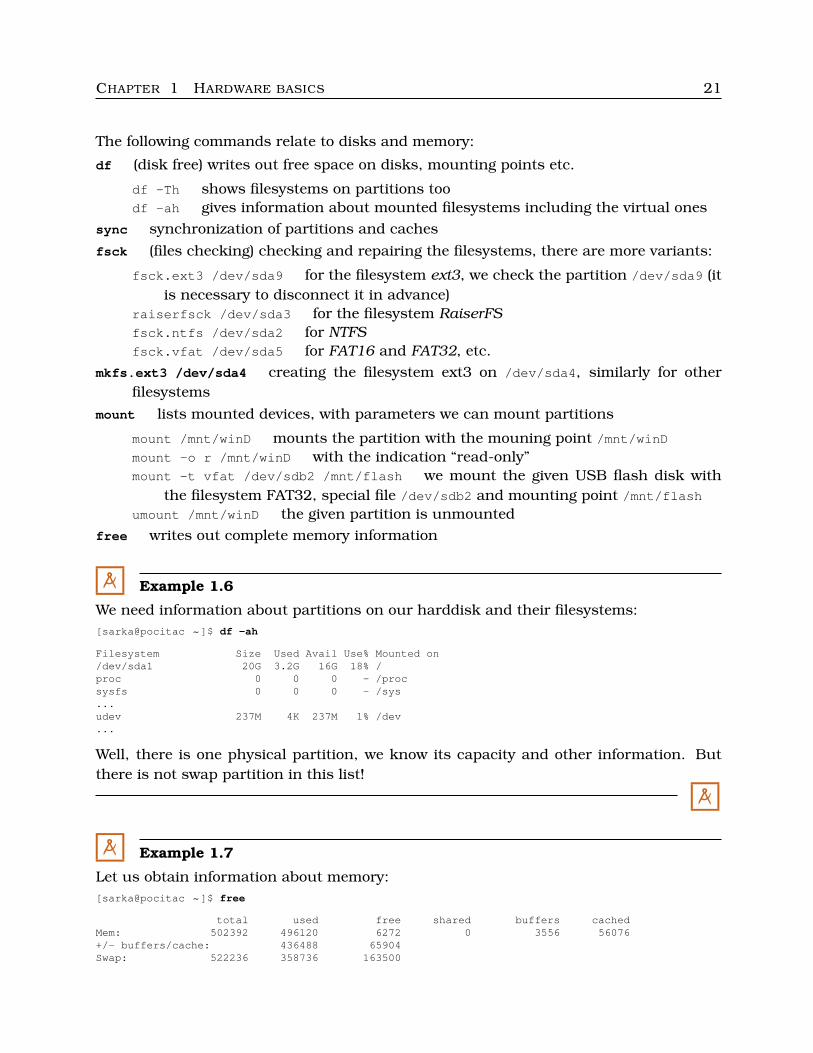
M Example 1.6
We need information about partitions on our harddisk and their filesystems:[sarka@pocitac ˜]$ df -ah
Filesystem Size Used Avail Use% Mounted on/dev/sda1 20G 3.2G 16G 18% /proc 0 0 0 - /procsysfs 0 0 0 - /sys...udev 237M 4K 237M 1% /dev...
Well, there is one physical partition, we know its capacity and other information. Butthere is not swap partition in this list!
M
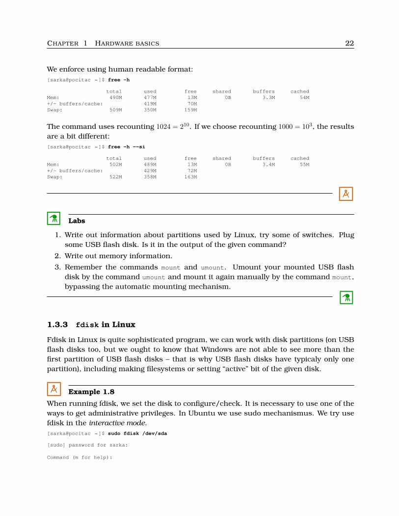
M Example 1.7
Let us obtain information about memory:[sarka@pocitac ˜]$ free
total used free shared buffers cachedMem: 502392 496120 6272 0 3556 56076+/- buffers/cache: 436488 65904Swap: 522236 358736 163500
CHAPTER 1 HARDWARE BASICS 22
We enforce using human readable format:[sarka@pocitac ˜]$ free -h
total used free shared buffers cachedMem: 490M 477M 13M 0B 3.3M 54M+/- buffers/cache: 419M 70MSwap: 509M 350M 159M
The command uses recounting 1024 = 210. If we choose recounting 1000 = 103, the resultsare a bit different:[sarka@pocitac ˜]$ free -h --si
total used free shared buffers cachedMem: 502M 489M 13M 0B 3.4M 55M+/- buffers/cache: 429M 72MSwap: 522M 358M 163M
M
C Labs
1. Write out information about partitions used by Linux, try some of switches. Plugsome USB flash disk. Is it in the output of the given command?
2. Write out memory information.
3. Remember the commands mount and umount. Umount your mounted USB flashdisk by the command umount and mount it again manually by the command mount,bypassing the automatic mounting mechanism.
C
1.3.3 fdisk in Linux
Fdisk in Linux is quite sophisticated program, we can work with disk partitions (on USBflash disks too, but we ought to know that Windows are not able to see more than thefirst partition of USB flash disks – that is why USB flash disks have typicaly only onepartition), including making filesystems or setting “active” bit of the given disk.
M Example 1.8
When running fdisk, we set the disk to configure/check. It is necessary to use one of theways to get administrative privileges. In Ubuntu we use sudo mechanismus. We try usefdisk in the interactive mode.[sarka@pocitac ˜]$ sudo fdisk /dev/sda
[sudo] password for sarka:
Command (m for help):
CHAPTER 1 HARDWARE BASICS 23
The prompt has changed (after typing the password). We can show help by the key “m”,or write any other inner command (each is represented by one of letters). So we chose“p”, it means listing the MBR table of the disk (see help of the program).Command (m for help): p
Disk /dev/sda: 21.5 GB, 21474836480 bytes255 heads, 63 sectors/track, 2 610 cylinders, total 41 943 040 sectorsUnits = sectors of 1 * 512 bytesSector size (logical/physical): 512 bytes / 512 bytesI/O size (minimal/optimal): 512 bytes / 512 bytesDisk identifier: 0x000f0004
Device Boot Begin End Blocks Id System/dev/sda1 * 2048 40894463 20446208 83 Linux/dev/sda2 40896510 41940991 522241 5 Extended/dev/sda5 40896512 41940991 522240 82 Linux swap/Solaris
This output is complete, there are three partitions on this disk (really two – /dev/sda1
is primary, /dev/sda2 is extended, and the third one, /dev/sda5 is only logical partitioninside the extended one). Pay attention to the long numbers in the columns Begin, Endand Blocks of the rows /dev/sda2 and /dev/sda5. They are very similar. Why?
We finish by touching the key “q” and Enter.
M
� Remark:
By the command fdisk -l we show information about all disks. We need administrativeprivileges too.
�
C Labs
1. Try fdisk without passing to the interactive mode as outlined in Remark above –find out information about all disks in your computer. You can run it inside a virtualcomputer or from LiveDVD, if you do not have any standard installed Linux.
2. Run fdisk in the interactive mode (for some of your disks).
C
1.4 Third party software
1.4.1 HWInfo
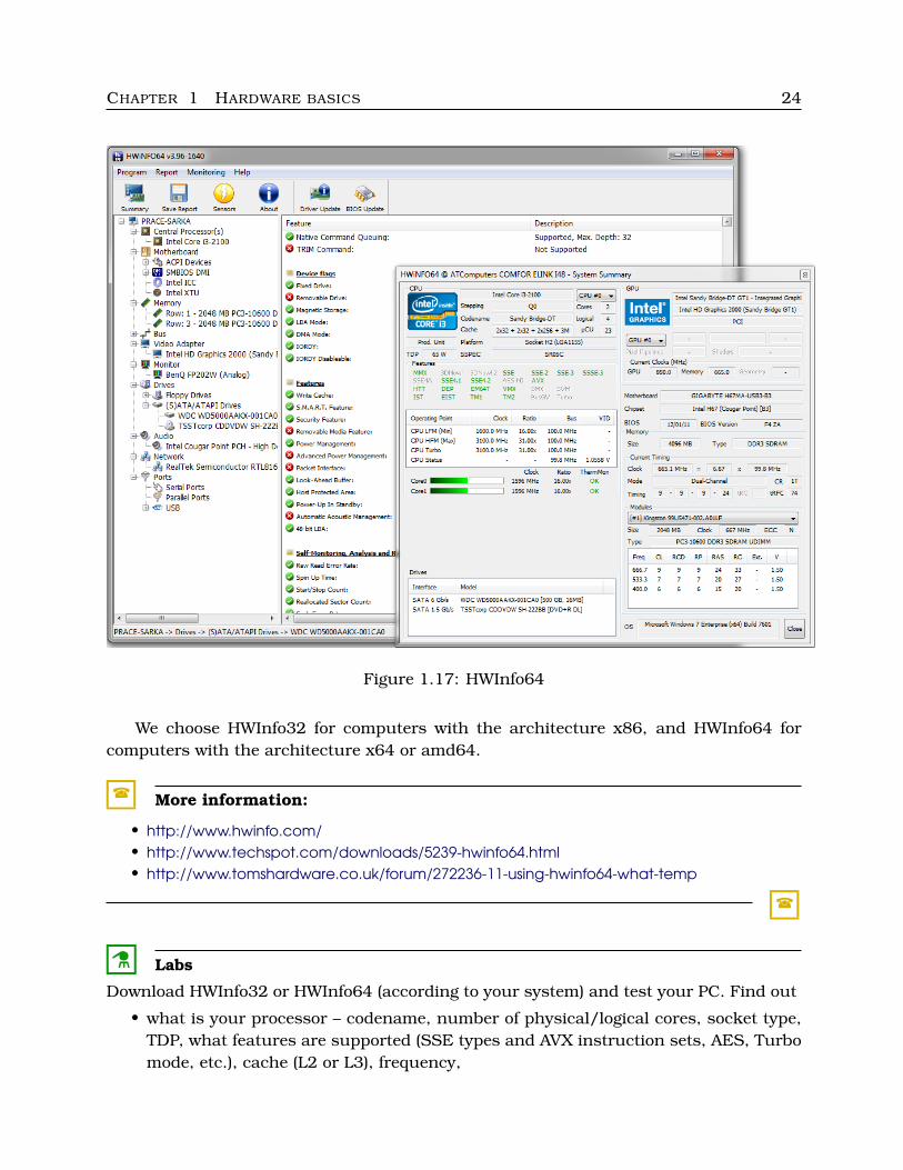
HWInfo32 and HWInfo64 are the most popular tools to find out information abouthardware (processors, chipsets, graphics etc.). This (czech) product is freeware
and there are extensions to this software.
CHAPTER 1 HARDWARE BASICS 24
Figure 1.17: HWInfo64
We choose HWInfo32 for computers with the architecture x86, and HWInfo64 forcomputers with the architecture x64 or amd64.
� More information:
• http://www.hwinfo.com/• http://www.techspot.com/downloads/5239-hwinfo64.html• http://www.tomshardware.co.uk/forum/272236-11-using-hwinfo64-what-temp
�
C Labs
Download HWInfo32 or HWInfo64 (according to your system) and test your PC. Find out
• what is your processor – codename, number of physical/logical cores, socket type,TDP, what features are supported (SSE types and AVX instruction sets, AES, Turbomode, etc.), cache (L2 or L3), frequency,
CHAPTER 1 HARDWARE BASICS 25
• mainboard – model, chipset, bios,
• memory – type, size, mode (single- or dual-channel), timing, number of modulesand their properties (including serial number, voltage, timing), speed,
• what is your graphics – GPU/video chipset, processor clock and video memory clock,
• monitor – name, manufacturer, date of manufacture, vertical and horizontal size,frequences, supported video modes,
• HDD – drive controller/interface (SATA II, SATA III, what speed), capacity, geometryproperties (number of cylinders, heads – surfaces – platters, cache buffer size), DMAmode, NCQ, support of S.M.A.R.T., Power Mangement, etc.,
• optical drive – model, controller/interface, DMA mode support, possibilities of read-ing/writing (CD-R/RW, DVD+/-R/RW, etc.)
• audio and network card properties.
Check S.M.A.R.T. values of your hard disk. Is everything O.K.?
C
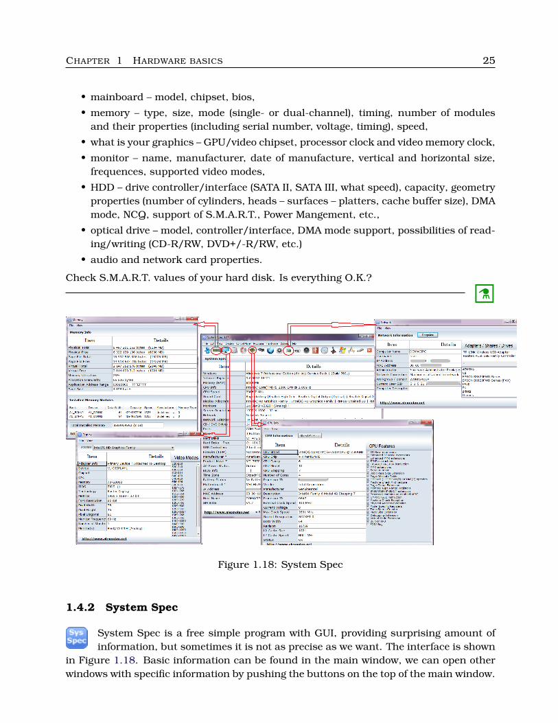
Figure 1.18: System Spec
1.4.2 System Spec
System Spec is a free simple program with GUI, providing surprising amount ofinformation, but sometimes it is not as precise as we want. The interface is shown
in Figure 1.18. Basic information can be found in the main window, we can open otherwindows with specific information by pushing the buttons on the top of the main window.
CHAPTER 1 HARDWARE BASICS 26
� More information:
• http://www.alexnolan.net/software/sysspec.htm
�
C Labs
Try System Spec, find out information about your mainboard, processor and memorymodules.
Compare this software with HWInfo – run the both applications on the same computerand compare the achieved results.
C
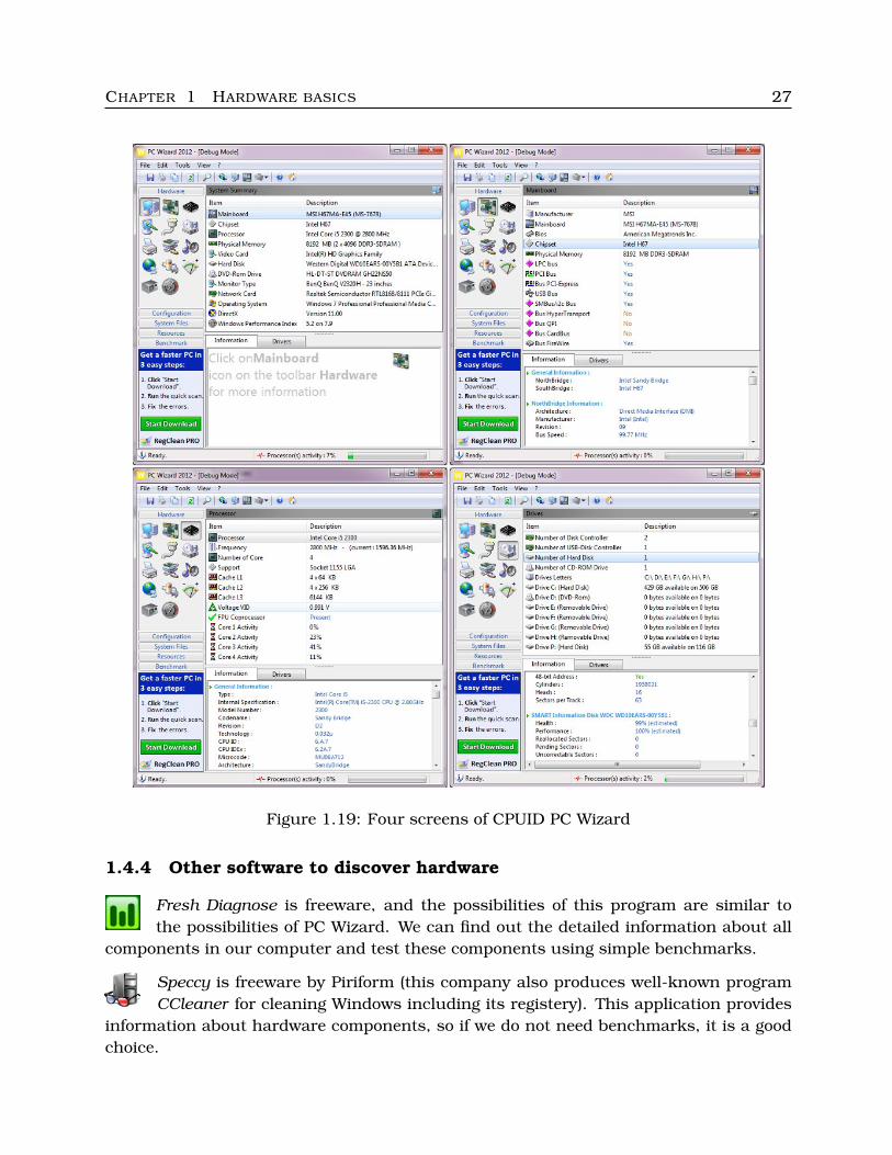
1.4.3 PC Wizard
The next interesting program to obtain hardware information is PC Wizard. It isfreeware by CPUID. The provided information is very wide and precise, we can find
out the detailed values of parameters of all components in the given computer (hardware),operating system, DirectX, and there are simple benchmarks there. Two-tier icon menuis on the left side, see Figure 1.19. There is a portable version of this software too.
� More information:
• http://www.cpuid.com/softwares/pc-wizard.html
�
� Remark:
Be careful while installing. All the mentioned applications are great and it is freeware,but they often try to install some other software or toolbars during their installation, socarefully read all texts in windows during installation.
�
C Labs
Test PC Wizard and dicsover all possibilities of this software. Try to compare with HWInfoand System Spec.
C
CHAPTER 1 HARDWARE BASICS 27
Figure 1.19: Four screens of CPUID PC Wizard
1.4.4 Other software to discover hardware
Fresh Diagnose is freeware, and the possibilities of this program are similar tothe possibilities of PC Wizard. We can find out the detailed information about all
components in our computer and test these components using simple benchmarks.
Speccy is freeware by Piriform (this company also produces well-known programCCleaner for cleaning Windows including its registery). This application provides
information about hardware components, so if we do not need benchmarks, it is a goodchoice.
CHAPTER 1 HARDWARE BASICS 28
� More information:
• http://www.freshdevices.com/freshdiag.html• http://www.piriform.com/speccy
�
C Labs
1. Try or at least take a look at the described software.
2. Find out the licence information for all the above mentioned programs – is it possibleto use it for commercial purposes?
C
Chapter 2Playing with hardware and reparations
2.1 Processor
We should be able to recognize common types of processors by their codename and toconsider their properties. Let us take a look at the most popular processors by Intel andAMD.
2.1.1 Recognizing Intel processors
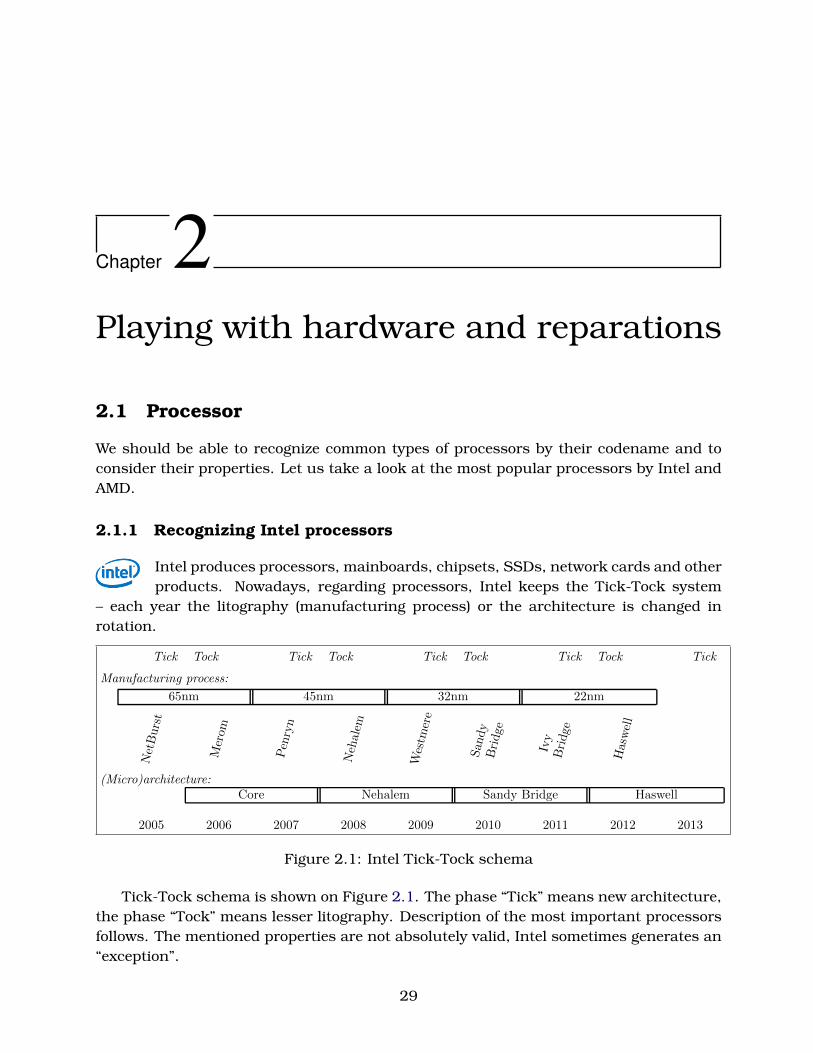
Intel produces processors, mainboards, chipsets, SSDs, network cards and otherproducts. Nowadays, regarding processors, Intel keeps the Tick-Tock system
– each year the litography (manufacturing process) or the architecture is changed inrotation.
Tick Tock Tick Tock Tick Tock Tick Tock Tick
Manufacturing process:
65nm 45nm 32nm 22nm
NetBurst
Merom
Penryn
Nehalem
Westm
ere
San
dy
Bridge
Ivy
Bridge
Haswell
(Micro)architecture:Core Nehalem Sandy Bridge Haswell
2005 2006 2007 2008 2009 2010 2011 2012 2013
Figure 2.1: Intel Tick-Tock schema
Tick-Tock schema is shown on Figure 2.1. The phase “Tick” means new architecture,the phase “Tock” means lesser litography. Description of the most important processorsfollows. The mentioned properties are not absolutely valid, Intel sometimes generates an“exception”.
29
CHAPTER 2 PLAYING WITH HARDWARE AND REPARATIONS 30
3rd Generation Core i: 22nm litography, microarchitecture Ivy Bridge (architectureSandy Bridge), Turbo Boost 2.0, 64bit main instruction set, AVX and AES instructions,Dual-channel memory controller, mainly 4 physical cores (not all processors)
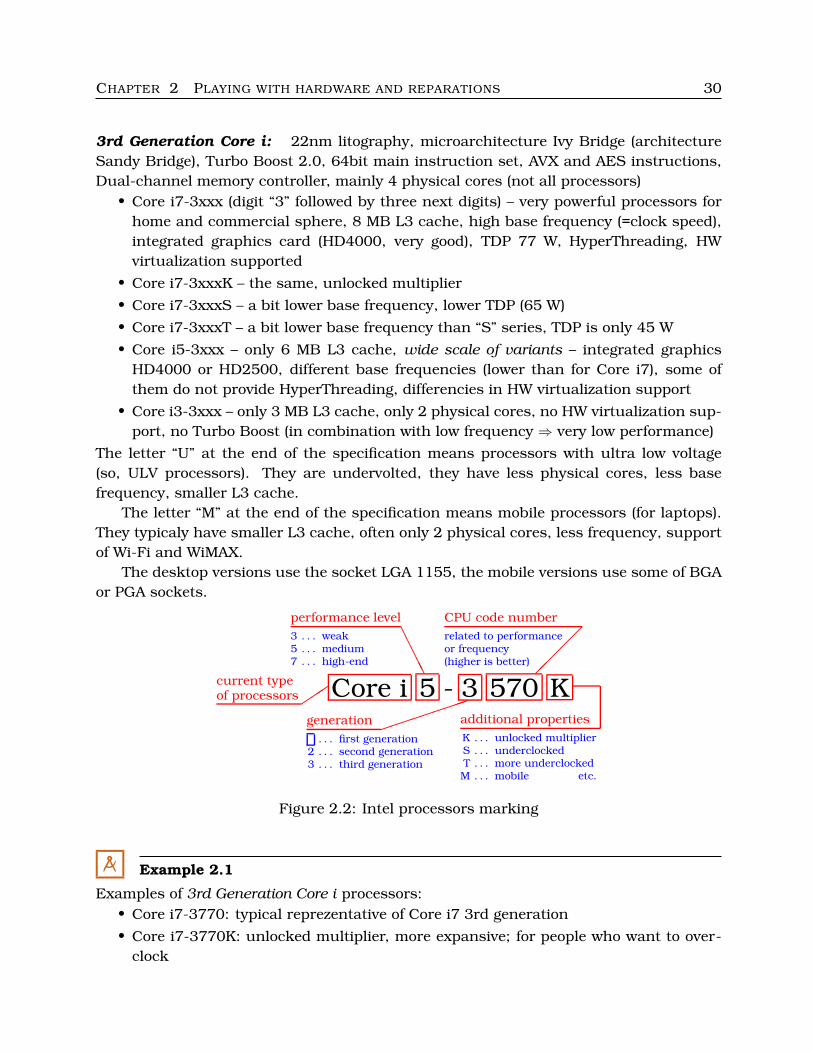
• Core i7-3xxx (digit “3” followed by three next digits) – very powerful processors forhome and commercial sphere, 8 MB L3 cache, high base frequency (=clock speed),integrated graphics card (HD4000, very good), TDP 77 W, HyperThreading, HWvirtualization supported
• Core i7-3xxxK – the same, unlocked multiplier
• Core i7-3xxxS – a bit lower base frequency, lower TDP (65 W)
• Core i7-3xxxT – a bit lower base frequency than “S” series, TDP is only 45 W
• Core i5-3xxx – only 6 MB L3 cache, wide scale of variants – integrated graphicsHD4000 or HD2500, different base frequencies (lower than for Core i7), some ofthem do not provide HyperThreading, differencies in HW virtualization support
• Core i3-3xxx – only 3 MB L3 cache, only 2 physical cores, no HW virtualization sup-port, no Turbo Boost (in combination with low frequency ⇒ very low performance)
The letter “U” at the end of the specification means processors with ultra low voltage(so, ULV processors). They are undervolted, they have less physical cores, less basefrequency, smaller L3 cache.
The letter “M” at the end of the specification means mobile processors (for laptops).They typicaly have smaller L3 cache, often only 2 physical cores, less frequency, supportof Wi-Fi and WiMAX.
The desktop versions use the socket LGA 1155, the mobile versions use some of BGAor PGA sockets.
Core i 5 - 3 570 Kcurrent typeof processors �
��
performance level
AAAAA
generation ���������
CPU code number
��
���
additional properties
3 . . . weak5 . . . medium7 . . . high-end
. . . first generation2 . . . second generation3 . . . third generation
related to performanceor frequency(higher is better)
K . . . unlocked multiplierS . . . underclockedT . . . more underclockedM . . . mobile etc.
Figure 2.2: Intel processors marking
M Example 2.1
Examples of 3rd Generation Core i processors:• Core i7-3770: typical reprezentative of Core i7 3rd generation
• Core i7-3770K: unlocked multiplier, more expansive; for people who want to over-clock
CHAPTER 2 PLAYING WITH HARDWARE AND REPARATIONS 31
• Core i7-3770S: underclocked (lower frequency), lesser TDP
• Core i5-3570: HW virtualization, no HyperThreading, HD2500 graphics
• Core i5-3470T: HW virtualization, graphics HD2500, Hyperthreading, but only 2physical cores! – more similar to Core i3 than to Core i5
• Core i5-3570K: no HW virtualization, no HyperThreading, HD4000 graphics
• Core i3-3240: only 2 physical cores, HyperThreading (so 4 logical cores), HD2500graphics – machines for Word+Excel :-)
• Core i7-3517U: TDP is 17 W. Why? Only 2 physical cores, HyperThreading, ultra lowbase frequency, HD4000 graphics, only 4 MB L3 cache; this processor is intendedfor cheaper mobile devices
• Core i7-3615QM: for mobile devices too, but 6 MB cache, 4 physical cores, Hyper-Threading, Turbo Boost, TDP 45 W; more useful
• Core i5-3660M: for mobile devices, 3 MB cache, 2 physical cores, HyperThreading,Turbo Boost, TDP 35 W, HD4000 graphics
• Core i3-3120M: 3 MB cache, 2 physical cores, HyperThreading, but no Turbo Boost,TDP 35 W, HD4000 graphics
M
� Remark:
Core i5 Ivy Bridge is acceptable for overwhelming majority of users. Core i7 are tooexpansive, Core i3 are too slow. Of course, we should choose well, equipment of Core i5is very diverse. Notice differencies among i7, i5 and i3, and between desktop and mobileprocessors.
�
3rd Generation Core i Extreme Edition: only mobile processors yet. 4 physical cores,HyperThreading, 8 MB cache, base frequency and TDP medium (mobile) or high (desk-top), Turbo Boost, HW virtualization, Wi-Fi, WiMAX, the mobile versions have integratedgraphics HD4000.
Example: Core i7-3940XM
2nd Generation Core i: 32nm litography, (micro)architecture Sandy Bridge, IntelHD3000 or HD2000 integrated graphics, other properties similar to Ivy Bridge (Core i3rd Generation), maximum memory size is lesser – usually 8 or 26 GB
• Core i7-2xxx
• Core i5-2xxx
• Core i3-2xxx
The desktop versions use the same socket as the 3rd generation, LGA 1155.
CHAPTER 2 PLAYING WITH HARDWARE AND REPARATIONS 32
M Example 2.2
Examples of 2nd Generation Core i processors:
• Core i7-2600: TDP 95 W, 4 physical cores, HyperThreading, Turbo Boost 2.0, 8 MBL3 cache, HW virtualization, HD2000 graphics
• Core i5-2550K: TDP 95 W, 4 physical cores, but no HyperThreading, Turbo Boost2.0, 6 MB L3 cache, no HW virtualization, no integrated graphics, unlocked multi-plier
• Core i5-2400: TDP 95 W, 4 physical cores, no HyperThreading, Turbo Boost 2.0, 6MB L3 cache, HW virtualization, HD2000 graphics
• Core i3-2130: TDP 65 W, 2 physical cores, HyperThreading, no Turbo Boost, 3 MBL3 cache, no virtualization, HD2000 graphics
• Core i5-2510E: for mobile devices, TDP 35 W, 2 physical cores, HyperThreading,Turbo Boost 2.0, 3 MB L3 cache, HW virtualization, HD3000 graphics, Wi-fi, WiMAX
• Core i3-2370M: for mobile devices too, TDP 35 W, 2 physical cores, HyperThreading,no Turbo Boost, 3 MB L3 cache, no virtualization, HD3000 graphics, Wi-fi, WiMAX
M
2nd Generation Core i Extreme Edition: 32nm litography (Sandy Bridge), TurboBoost 2.0, HW virtualization, high frequency. These processors are assigned to desktopsor laptops:
• the desktop variant has no integrated graphics, the used socket is LGA 2011, TDPis 130 or 150 W, 15 L3 cache, 6 physical cores and Hyperthreading, max memoryup to 64 GB, Quad-channel memory controller
• the laptop variant has integrated graphics chip HD3000, TDP is 55 W, 8 MB L3cache, 4 physical cores and HyperThreading, max memory up to 32 GB, Dual-channel memory controller
M Example 2.3
Examples of 2nd Generation Core i Extreme Edition processors:
• Core i7-3970X: extremely powerful processor with very high energy consumption(so, very high TDP – 150 W), very expensive
• Core i7-2960XM: less cores, lower frequency, lower TDP, less L3 cache ⇒ slowerthan Core i7-3970X, but by way of contrast to other mobile processors, perfor-mance of this model is very good; it is a bit more expensive than the desktop modelmentioned above
M
CHAPTER 2 PLAYING WITH HARDWARE AND REPARATIONS 33
1st Generation Core i (formaly “previous generation”): Nehalem architecture, there aretwo microarchitectures – Nehalem (42nm litography) and Westmere (32nm litography).SSE 4.2 multimedia instruction set (no AVX instructions)
• Core i7-9xx (we call it 900 series) – QPI bus between the given processor and theNorth Bridge, LGA 1366 socket, Turbo Boost 1.0, LGA 1366 socket, HyperThread-ing, Triple-channel memory controller, 24 GB maximal memory size
– with the cores Gulftown: 32nm litography, 12 MB L3 cache, 6 physical cores,TDP 130 W
– with the cores Bloomfield: 45nm litography, 8 MB L3 cache, 4 physical cores,TDP 130 W(well – worse litography + the same TDP = less physical cores; more cores withworse litography would mean worse TDP)
• Core i7-8xx (800 series) – DMI bus between the given processor and the SouthBridge (it means that all functions of the North Bridge are integrated to the pro-cessor), LGA 1156 socket, Turbo Boost 1.0, LGA 1366 socket, HyperThreading,Dual-channel memory controller, 16 GB maximal memory size
– with the cores Lynnfield: 45nm litography, 8 MB L3 cache, 4 physical cores,TDP 95 W
• Core i5-xxx – DMI bus, LGA 1156 socket, Turbo Boost 1.0, 16 GB maximal memorysize
– with the cores Clarkdale: 32nm litography, 4 MB L3 cache, 2 physical cores,HyperThreading, TDP 73 W, integrated Intel HD graphics
– with the cores Lynnfield (the same as i7 800 series): 45nm litography, 8 MB L3cache, 4 physical cores, no HyperThreading, TDP 95 W, without graphics core
• Core i3-xxx – DMI bus, LGA 1156 socket, no Turbo Boost (it is bad)
– with the cores Clarkdale: 32nm litography, 4 MB L3 cache, 2 physical cores,HyperThreading, TDP 73 W, integrated Intel HD graphics
32nm processors of the first generation have the integrated graphics core; but this coreis made by 45nm litography, although it is inside the same package. 45nm processorshave no integrated graphics.
The models intended to mobile devices (laptops) have less L3 cache, lower base fre-quency, lower TDP and often less physical cores.
M Example 2.4
Examples of 2nd Generation Core i processors:
• Core i7-980: 32nm litography (cores Gulftown), QPI bus, LGA 1366, 6 physical coreswith HyperThreading, Triple-channel memory controller, very expansive in 2011
• Core i7-920: 45nm litography (cores Bloomfield), QPI bus, LGA 1366, 4 physicalcores with HyperThreading, Triple-channel memory controller
CHAPTER 2 PLAYING WITH HARDWARE AND REPARATIONS 34
• Core i7-880: 45nm litography (cores Lynnfield), DMI bus, LGA 1156, 4 physicalcores with HyperThreading, 8 MB cache
• Core i5-670: 32nm litography (cores Clarkdale), DMI bus, LGA 1156, 2 physicalcores with HyperThreading, 4 MB cache
• Core i5-760: 45nm litography (cores Lynnfield), DMI bus, LGA 1156, 4 physicalcores, but without HyperThreading, 8 MB cache
• Core i3-560: 32nm litography (cores Clarkdale), DMI, LGA 1156, 2 physical coreswith HyperThreading, 4 MB cache
Newer (smaller) litography is better, more physical cores are better than less physicalcores without HyperThreading. So:
• cores Clarkdale and Gulftown: 32nm litography,
• cores Lynnfield and Bloomfield: 45nm litography
QPI bus means LGA 1366 socket, DMI bus means LGA 1156 socket.
M
Core 2 processors: for older mainboards with the socket LGA 775 (some of the high-performance models are for LGA 771), classical FSB bus between the socket LGA 775and the North Bridge chip (so the memory controller is in the North Bridge), 45nm or65nm litography, no graphics core integrated, no HyperThreading, no Turbo Boost
M Example 2.5
Examples of Core 2 processors with 45nm litography:
• Core 2 Duo E8400: 2 cores, 6 MB L2 cache (no L3 cache), TDP 65 W (all Core 2 Duohave 65W TDP), LGA 775
• Core 2 Quad Q9450: 4 cores, 12 MB L2 cache, TDP 95 W, LGA 775
• Core 2 Extreme QX9775: 4 cores, 12 MB L2 cache, TDP 150 W, higher clock speed(frequency), LGA 771
M
We can find some cheaper processors made by 32nm litography process:
• Pentium Desktop: some of them are produced with 32nm litography with the in-tegrated graphics, without advanced technologies such as Turbo Boost or Hyper-Threading, they respond to the worst/cheapest Core i3 models, DMI bus, LGA 1155
• Celeron: some of them 32nm litography with the integrated graphics, 2 cores with-out HyperThreading, no Turbo Boost, DMI bus, LGA 1155
• Atom: integrated graphics (very cheap), 1 or 2 cores, HyperThreading, no TurboBoost, no Out-of-order, very low TDP, only 4 GB maximal memory size!
CHAPTER 2 PLAYING WITH HARDWARE AND REPARATIONS 35
M Example 2.6
Some of the cheapest “non-Core i” processors:• Pentium G870: 32nm litography, 2 cores, no HyperThreading, integrated HD Graph-
ics, no Turbo Boost, 3 MB L2 cache, TDP 65 W; very cheap, we know why• Celeron G555: 32nm litography, 2 cores, no HyperThreading, integrated HD Graph-
ics, no Turbo Boost, 2 MB L2 cache, TDP 65 W; shorter memory bandwidth andslower graphics than Pentium G870; cheaper than Pentium G870, worse
• Atom D2550: 32nm litography, 2 cores with HyperThreading, integrated HD Graph-ics, no Turbo Boost, 1 MB L2 cache, TDP 10 W, very low frequency, only 1 memorychannel, only 4 GB max. memory supported, very slow graphics
Do not buy these processors!
M
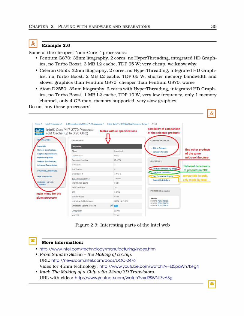
Figure 2.3: Interesting parts of the Intel web
� More information:• http://www.intel.com/technology/manufacturing/index.htm• From Sand to Silicon – the Making of a Chip.
URL: http://newsroom.intel.com/docs/DOC-2476Video for 45nm technology: http://www.youtube.com/watch?v=Q5paWn7bFg4
• Intel: The Making of a Chip with 22nm/3D Transistors.URL with video: http://www.youtube.com/watch?v=d9SWNLZvA8g
�
CHAPTER 2 PLAYING WITH HARDWARE AND REPARATIONS 36
C Labs
1. Explore http://ark.intel.com/ and find out some newer interesting processors. Try thecomparing function with at least 3 different processors.
2. What is the meaning of the property “AES New instructions”? Find it on the webpage of some newer processor. This property is only for 32nm or newer processors.
3. Similarly find the property “Intel Wireless Display” (Wi-Di). This property is relatedto a integrated graphics.
4. And what about “Intel Anti-Theft”?C
2.1.2 Recognizing AMD processors
AMD produces processors, graphic cards, memory modules and mainboards.No official Tick-Tock scheme is not kept by AMD, but some production scheme
exists. The development is separated into two main branches – classic processors andAPUs. APU is a combination of a weak processor and of a (quite) good graphic chip. Weneed not any dedicated graphic card, it is integrated into the processor box. AMD doesnot implement hyperthreading, so we do not distinguish physical and logical cores.
Nowadays there are several variants of AMD processors.
AMD FX: FX processors are high-end products with 4, 6 or 8 cores. They are producedwith 32nm litography process, working on high frequencies, 8 MB L3 cache, TDP is about100 W. These processors belong to the AM3+ socket. Some of them are marked as “BlackEdition” – their multiplier is unlocked.
FX processors are without graphic core, so we need a dedicated graphic card.Nowadays there are three generations of FX. The first and second one are built on
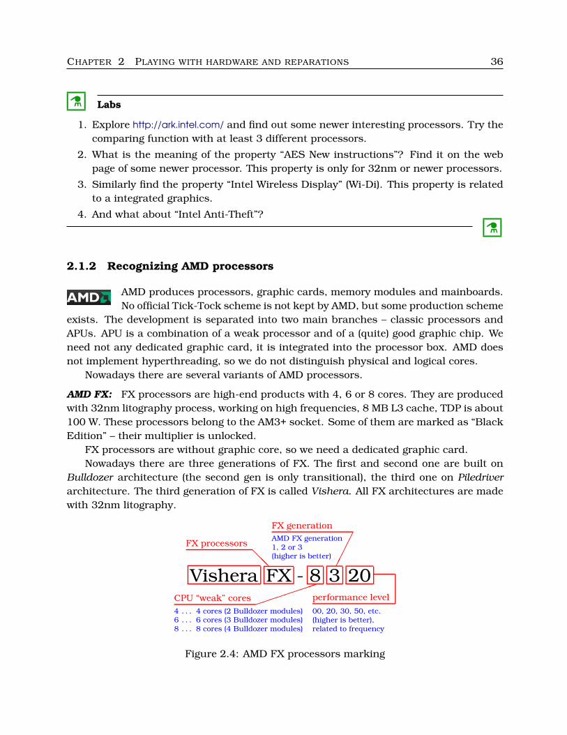
Bulldozer architecture (the second gen is only transitional), the third one on Piledriverarchitecture. The third generation of FX is called Vishera. All FX architectures are madewith 32nm litography.
Vishera FX - 8 3 20
FX processors
@@@
CPU “weak” cores ���������
FX generation
���
��
performance level
4 . . . 4 cores (2 Bulldozer modules)6 . . . 6 cores (3 Bulldozer modules)8 . . . 8 cores (4 Bulldozer modules)
AMD FX generation1, 2 or 3(higher is better)
00, 20, 30, 50, etc.(higher is better),related to frequency
Figure 2.4: AMD FX processors marking
CHAPTER 2 PLAYING WITH HARDWARE AND REPARATIONS 37
Although AMD FX are very powerful, it is not possible to compare them with Intelprocessors working on the similar frequencies. In fact, the FX cores are too simple andtoo many parts are shared. The processors are created from “Bulldozer modules”. OneBulldozer module has two simple cores, each core has its own ALU (so one module hastwo ALUs), but on the other hand only one FPU, one shared decoding unit and one branchprediction unit. In view of this fact, the performance of AMD FX with 8 cores is similarto (a bit better than) Intel Core i7 with 4 physical and 8 logical cores (hyperthreading) onthe same frequency.
M Example 2.7
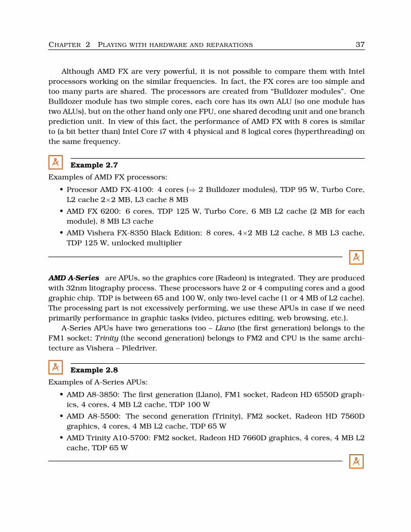
Examples of AMD FX processors:
• Procesor AMD FX-4100: 4 cores (⇒ 2 Bulldozer modules), TDP 95 W, Turbo Core,L2 cache 2×2 MB, L3 cache 8 MB
• AMD FX 6200: 6 cores, TDP 125 W, Turbo Core, 6 MB L2 cache (2 MB for eachmodule), 8 MB L3 cache
• AMD Vishera FX-8350 Black Edition: 8 cores, 4×2 MB L2 cache, 8 MB L3 cache,TDP 125 W, unlocked multiplier
M
AMD A-Series are APUs, so the graphics core (Radeon) is integrated. They are producedwith 32nm litography process. These processors have 2 or 4 computing cores and a goodgraphic chip. TDP is between 65 and 100 W, only two-level cache (1 or 4 MB of L2 cache).The processing part is not excessively performing, we use these APUs in case if we needprimarily performance in graphic tasks (video, pictures editing, web browsing, etc.).
A-Series APUs have two generations too – Llano (the first generation) belongs to theFM1 socket; Trinity (the second generation) belongs to FM2 and CPU is the same archi-tecture as Vishera – Piledriver.
M Example 2.8
Examples of A-Series APUs:
• AMD A8-3850: The first generation (Llano), FM1 socket, Radeon HD 6550D graph-ics, 4 cores, 4 MB L2 cache, TDP 100 W
• AMD A8-5500: The second generation (Trinity), FM2 socket, Radeon HD 7560Dgraphics, 4 cores, 4 MB L2 cache, TDP 65 W
• AMD Trinity A10-5700: FM2 socket, Radeon HD 7660D graphics, 4 cores, 4 MB L2cache, TDP 65 W
M
CHAPTER 2 PLAYING WITH HARDWARE AND REPARATIONS 38
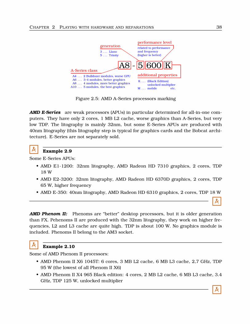
A8 - 5 600 KA-Series class ������
generationQQQQQQ
performance level
��
��
additional propertiesA4 . . . 2 Bulldozer modules, worse GPU
A6 . . . 3–4 modules, better graphicsA8 . . . 4 modules, more better graphics
A10 . . . 5 modules, the best graphics
3 . . . Llano5 . . . Trinity
related to performanceand frequency
(higher is better)
K . . . (Black Edition)unlocked multiplier
M . . . mobile etc.
Figure 2.5: AMD A-Series processors marking
AMD E-Series are weak processors (APUs) in particular determined for all-in-one com-puters. They have only 2 cores, 1 MB L2 cache, worse graphics than A-Series, but verylow TDP. The litography is mainly 32nm, but some E-Series APUs are produced with40nm litography (this litography step is typical for graphics cards and the Bobcat archi-tecture). E-Series are not separately sold.
M Example 2.9
Some E-Series APUs:
• AMD E1-1200: 32nm litography, AMD Radeon HD 7310 graphics, 2 cores, TDP18 W
• AMD E2-3200: 32nm litography, AMD Radeon HD 6370D graphics, 2 cores, TDP65 W, higher frequency
• AMD E-350: 40nm litography, AMD Radeon HD 6310 graphics, 2 cores, TDP 18 W
M
AMD Phenom II: Phenoms are “better” desktop processors, but it is older generationthan FX. Pehenoms II are produced with the 32nm litography, they work on higher fre-quencies, L2 and L3 cache are quite high. TDP is about 100 W. No graphics module isincluded. Phenoms II belong to the AM3 socket.
M Example 2.10
Some of AMD Phenom II processors:
• AMD Phenom II X6 1045T: 6 cores, 3 MB L2 cache, 6 MB L3 cache, 2,7 GHz, TDP95 W (the lowest of all Phenom II X6)
• AMD Phenom II X4 965 Black edition: 4 cores, 2 MB L2 cache, 6 MB L3 cache, 3.4GHz, TDP 125 W, unlocked multiplier
M
CHAPTER 2 PLAYING WITH HARDWARE AND REPARATIONS 39
AMD Athlon II: produced with 45nm (AM3 socket) or 32nm (FM1 or FM2 socket) litog-raphy process. Athlon II Trinity (the newest generation) belongs to FM2 socket. Athlon IIhas only two levels of cache memory, usually from 1.5 till 4 MB L2 cache. TDP is between45 and 100 W. No graphics module is included.
M Example 2.11
Some of AMD Athlon II processors:• AMD Athlon II X3 450: 3 cores, 45nm litography, 3.2 GHz, 1.5 MB L2 cache (3×512
KiB), AM3 socket, TDP 95 W
• AMD Athlon II X4 651: 4 cores, 32nm litography, 3 GHz, 4 MB L2 cache, FM1socket, TDP 100 W
• AMD Trinity Athlon II X4 740: 4 cores, 32nm litography, 3.2 GHz, 4 MB L2 cache,FM2 socket, TDP 65 W
M
AMD Sempron is the cheapest type of AMD processors (parallel for Intel Celeron) withlow frequencies and small-sized L2 cache (1 MB only). Semprons do not have any graph-ics module. They are produced with the 45nm litography. They belong to the AM3 socket.
M Example 2.12
One AMD Sempron processor:• AMD Sempron 145: AM3 socket, 1 MB L2 cache, 2.8GHz, TDP 45 W
M
AMD Fusion is not a concrete type of processor, it is similarly a concept combining CPUand GPU (well, it is APU). AMD counts various processors among AMD Fusion products– Bobcat/Brazos and Zacate (40nm, see E-Series), Llano (32nm), Trinity (32nm) andothers.
� More information:
• AMD CPU Manufacturing. URL with video: http://www.youtube.com/watch?v=qLGAoGhoOhU• ANGELINI, Ch.: AMD FX-8350 Review: Does Piledriver Fix Bulldozer’s Flaws? Tom’s
Hardware, October 23, 2012. URL: http://www.tomshardware.com/reviews/fx-8350-vishera-review,3328.html
• ANGELINI, Ch.: AMD’s Trinity APU Efficiency: Undervolted And Overclocked. Tom’sHardware, October 2, 2012. http://www.tomshardware.com/reviews/a10-5800k-trinity-efficiency,3315.html
• WOLIGROSKI, D.: AMD A10-4600M Review: Mobile Trinity Gets Tested. Tom’s Hard-ware, May 15, 2012. URL: http://www.tomshardware.com/reviews/a10-4600m-trinity-piledriver,3202.html
CHAPTER 2 PLAYING WITH HARDWARE AND REPARATIONS 40
• TOLMAN, H. AMD A10-5800K Trinity Desktop Processor. Benchmark Reviews, Oc-tober 2, 2012. URL:http://benchmarkreviews.com/index.php?option=com content&task=view&id=860&Itemid=63
• MASIERO, M. – ROOS, A.: CPU Charts 2012: 86 Processors From AMD And Intel,Tested. Tom’s Hardware, December 24, 2012. URL:http://www.tomshardware.com/reviews/cpu-performance-comparison,3370.html
• AnandTech CPU Benchmarks. URL: http://www.anandtech.com/bench/CPU/2
�
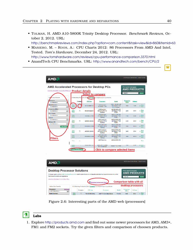
Figure 2.6: Interesting parts of the AMD web (processors]
C Labs
1. Explore http://products.amd.com and find out some newer processors for AM3, AM3+,FM1 and FM2 sockets. Try the given filters and comparison of choosen products.
CHAPTER 2 PLAYING WITH HARDWARE AND REPARATIONS 41
2. Compare some properties of various graphics modules for desktop APUs (find it onhttp://www.amd.com/uk/products/, on the left: APUs, Desktop, Product Specs). Notethe properties “Radeon Cores on Die”, “GPU Clock Speed” and “DDR3 Speed” (well,also “Radeon Brand”). Note the differences between A-Series and E-Series.
C
2.1.3 Processor installation
Processor installation is similar to various platforms. The procedure is the following:
1. Prepare the given mainboard – take it out of a computer etc., according to thepresent situation.
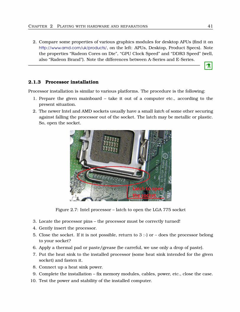
2. The newer Intel and AMD sockets usually have a small latch of some other securingagainst falling the processor out of the socket. The latch may be metallic or plastic.So, open the socket.
Figure 2.7: Intel processor – latch to open the LGA 775 socket
3. Locate the processor pins – the processor must be correctly turned!
4. Gently insert the processor.
5. Close the socket. If it is not possible, return to 3 :-) or – does the processor belongto your socket?
6. Apply a thermal pad or paste/grease (be carreful, we use only a drop of paste).
7. Put the heat sink to the installed processor (some heat sink intended for the givensocket) and fasten it.
8. Connect up a heat sink power.
9. Complete the installation – fix memory modules, cables, power, etc., close the case.
10. Test the power and stability of the installed computer.
CHAPTER 2 PLAYING WITH HARDWARE AND REPARATIONS 42
There are some tiny differencies when installing various processors. Concrete techniquesare described on the below mentioned webs:
� More information:
• How to install a LGA1156 or LGA1155 processor into the socket. Intel.com, Septem-ber 18, 2012. URL: http://www.intel.com/support/processors/sb/CS-032258.htm
• AMD Processor Installation Videos. AMD.com. URL: http://support.amd.com/us/System-Building-and-Compatibility/Pages/ProcessorInstallationVideos.aspx
• SCHMID, P.: LGA 775 Processor Installation. Tom’s Hardware, June 19, 2004. URL:http://www.tomshardware.com/reviews/intel-stakes-vision-pc-future-775-launch,830-6.html
• Intel CPU installation (LGA 775), video by Intel. July 2006. URL:http://www.youtube.com/watch?v=b6NbPMQgwPM
• LGA 775 install video (ASRock mainboard). August 2006. URL:http://www.youtube.com/watch?v=8emxPAZZ53w
• AMD processor installation. July 2008. URL: http://www.youtube.com/watch?v=iss6QSGzVNc• KYRNIN, M.: Installing a CPU and Heatsink (AMD), 8 pages. About.com. URL:
http://compreviews.about.com/od/tutorials/ss/DIYCPU.htm• How to Install a New Processor (Intel, AMD, VIA). Video included. URL:
http://www.wikihow.com/Install-a-New-Processor
�
2.1.4 Testing and monitoring
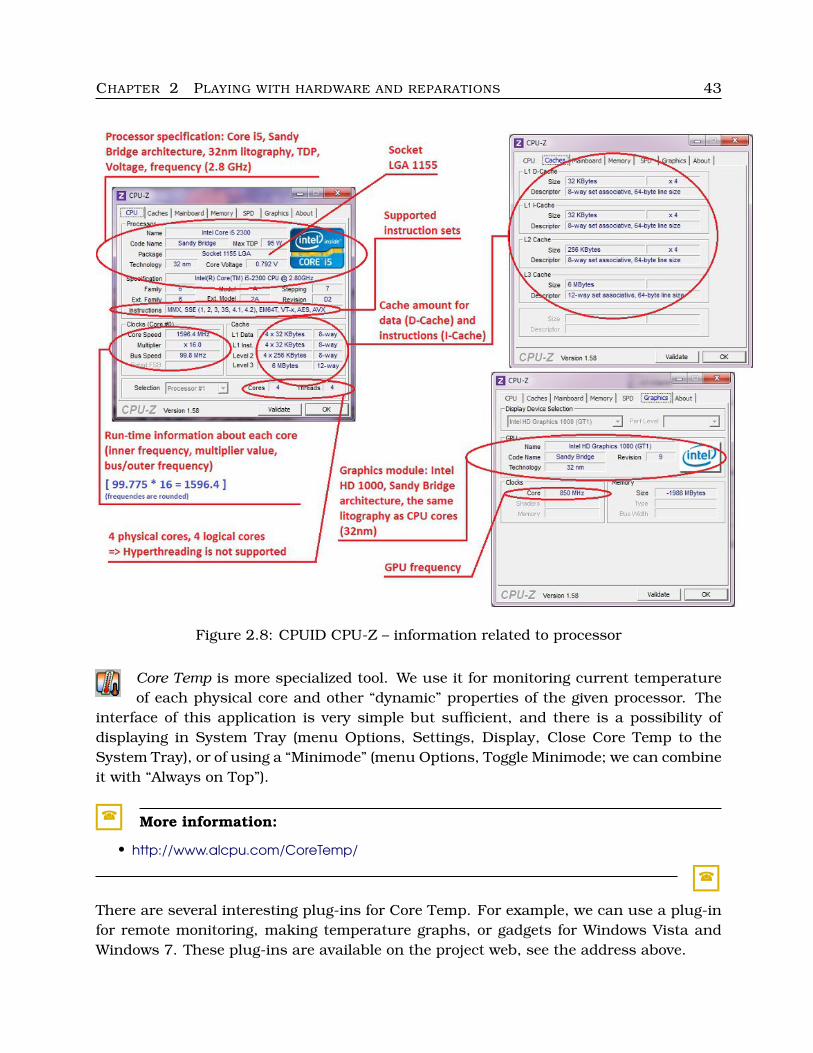
CPU-Z is one of the most popular tools to get information about processor includ-ing some run-time information. There are the most important information – type
of processor, socket, litography, maximal value for TDP, maximal frequency, current fre-quencies, cache sizes, integrated GPU information, etc.
� More information:
• http://www.cpuid.com/softwares/cpu-z.html
�
The interface of CPU-Z is very simple with several tabs, as we can see on Figure 2.8. Thereare three tabs relative to processor – the first one (CPU), the second one with processorcache information and the tab GPU (if our processor includes a graphics module).
C Labs
1. Download CPU-Z and try it on at least one computer.
2. Find out the list of supported processors.C
CHAPTER 2 PLAYING WITH HARDWARE AND REPARATIONS 43
Figure 2.8: CPUID CPU-Z – information related to processor
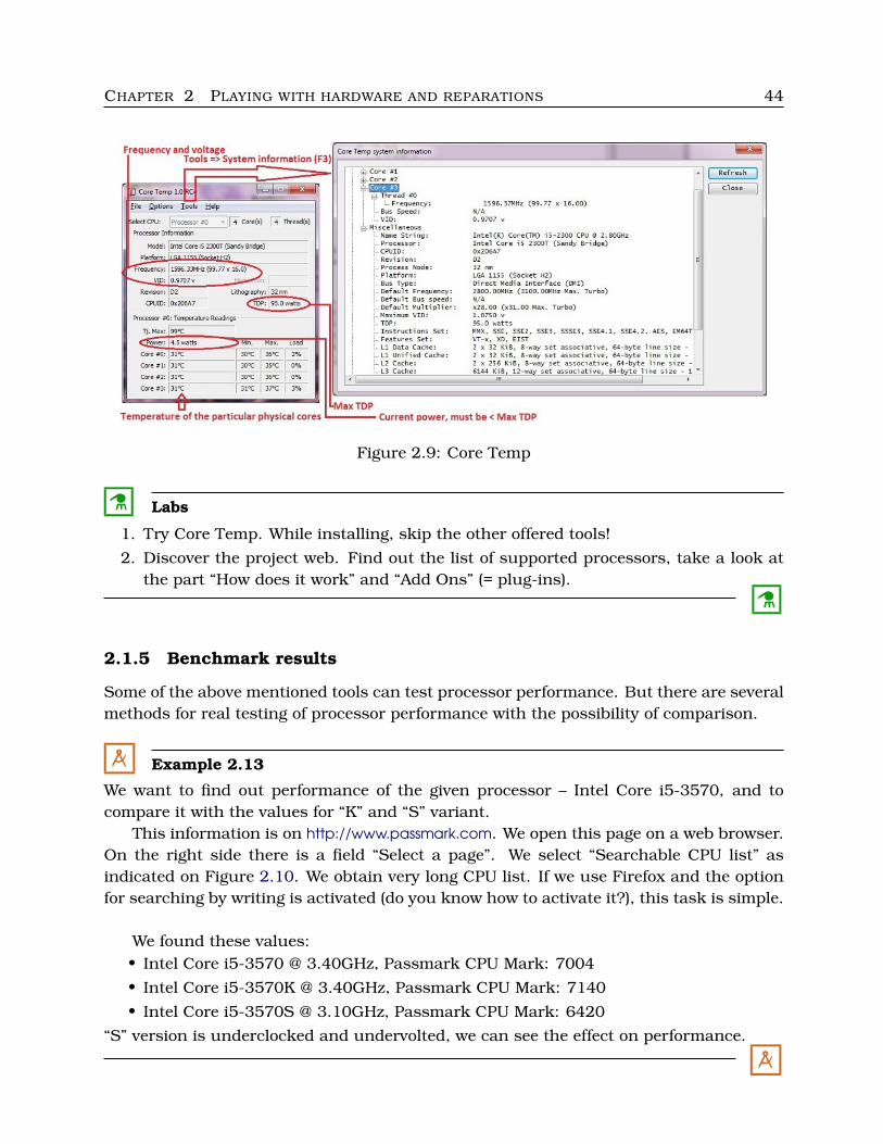
Core Temp is more specialized tool. We use it for monitoring current temperatureof each physical core and other “dynamic” properties of the given processor. The
interface of this application is very simple but sufficient, and there is a possibility ofdisplaying in System Tray (menu Options, Settings, Display, Close Core Temp to theSystem Tray), or of using a “Minimode” (menu Options, Toggle Minimode; we can combineit with “Always on Top”).
� More information:
• http://www.alcpu.com/CoreTemp/
�
There are several interesting plug-ins for Core Temp. For example, we can use a plug-infor remote monitoring, making temperature graphs, or gadgets for Windows Vista andWindows 7. These plug-ins are available on the project web, see the address above.
CHAPTER 2 PLAYING WITH HARDWARE AND REPARATIONS 44
Figure 2.9: Core Temp
C Labs
1. Try Core Temp. While installing, skip the other offered tools!
2. Discover the project web. Find out the list of supported processors, take a look atthe part “How does it work” and “Add Ons” (= plug-ins).
C
2.1.5 Benchmark results
Some of the above mentioned tools can test processor performance. But there are severalmethods for real testing of processor performance with the possibility of comparison.
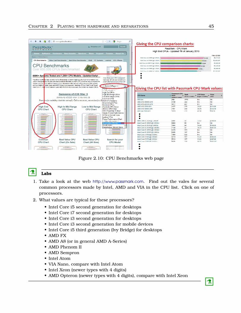
M Example 2.13
We want to find out performance of the given processor – Intel Core i5-3570, and tocompare it with the values for “K” and “S” variant.
This information is on http://www.passmark.com. We open this page on a web browser.On the right side there is a field “Select a page”. We select “Searchable CPU list” asindicated on Figure 2.10. We obtain very long CPU list. If we use Firefox and the optionfor searching by writing is activated (do you know how to activate it?), this task is simple.
We found these values:• Intel Core i5-3570 @ 3.40GHz, Passmark CPU Mark: 7004
• Intel Core i5-3570K @ 3.40GHz, Passmark CPU Mark: 7140
• Intel Core i5-3570S @ 3.10GHz, Passmark CPU Mark: 6420
“S” version is underclocked and undervolted, we can see the effect on performance.
M
CHAPTER 2 PLAYING WITH HARDWARE AND REPARATIONS 45
Figure 2.10: CPU Benchmarks web page
C Labs
1. Take a look at the web http://www.passmark.com. Find out the vales for severalcommon processors made by Intel, AMD and VIA in the CPU list. Click on one ofprocessors.
2. What values are typical for these processors?
• Intel Core i5 second generation for desktops• Intel Core i7 second generation for desktops• Intel Core i3 second generation for desktops• Intel Core i3 second generation for mobile devices• Intel Core i5 third generation (Ivy Bridge) for desktops• AMD FX• AMD A8 (or in general AMD A-Series)• AMD Phenom II• AMD Sempron• Intel Atom• VIA Nano, compare with Intel Atom• Intel Xeon (newer types with 4 digits)• AMD Opteron (newer types with 4 digits), compare with Intel Xeon
C
CHAPTER 2 PLAYING WITH HARDWARE AND REPARATIONS 46
� Remark:
The measured values are only approximate – the quoted value is affected by the overallPC configuration. We usually suppose the difference up to 5 %.
�
2.1.6 Overclocking and underclocking
We overclock the processor if we want to fasten it. But we have to keep in our mind thatthe given processor will be hotter and “hungry” (energy consumption rises). Contrarily,we underclock to lower energy consumption and heating.
Overclocking and underclocking is possible by one of these ways:
1. We change FSB/HT/QPI (bus) frequency.
2. We increase or decrease multiplier – for processors with the unlocked multiplier:
• Intel: “K-Series” edition,• AMD: “Black Edition”.
3. We change voltage of processor cores.
Sometimes other additional changes are necessary, for example memory overclocking orunderclocking; in case that CPU and memory are not suitably synchronized, delays andinstabilities of the given system appear.
� Remark:
It is necessary to overclock very slowly, in short steps, and we have to test system stabil-ity after each step. The excessively overclocked processor overheats, is unstable (somerandom computation errors emerge) and its lifetime shortens. Each overclocked systemneeds very good cooling and an adequately dimensioned power supply unit.
�
Overclocking and underclocking is usually done in BIOS Setup, but some producers(such as Asustek with the products Asus) make available applications to overclock fromthe installed operating system. Some general tools (third-party) exist, for example Crys-talCPUID or RightMark CPU Clock Utility.
How to overclock/underclock (in BIOS Setup):
1. Find out whole information about our processor (frequencies, multiplier).
2. Pass out into BIOS Setup (or UEFI) and find out the section with CPU oveclock-ing/underclocking.
3. If Turbo Boost (Intel) or Turbo Core (AMD) is set, unset it.
4. Change a bit the chosen parameter (e.g. we increase frequency by 10 or 20 MHz).
5. Put the processor to the test. We can use Prime95 (Windows, MacOS X) or MPrime(Linux, FreeBSD) in “Torture” mode during a few hours (6 hours are recommended).
6. If everything is OK, we are able to come back to step 4.
CHAPTER 2 PLAYING WITH HARDWARE AND REPARATIONS 47
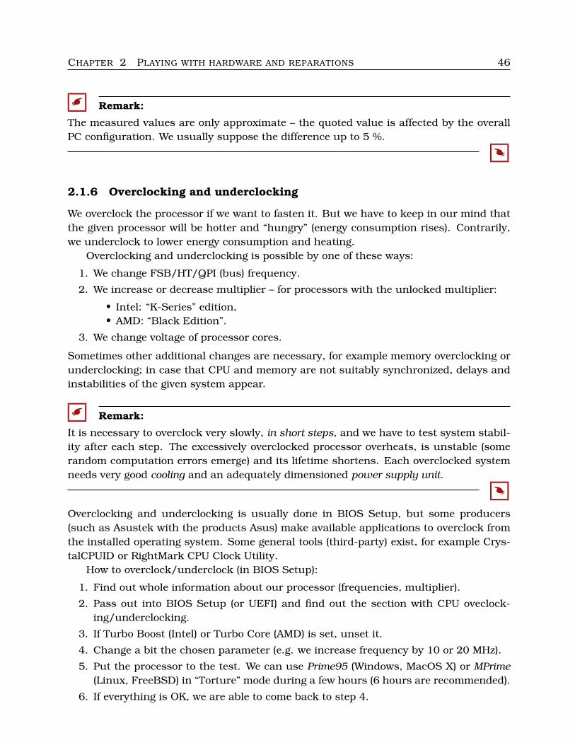
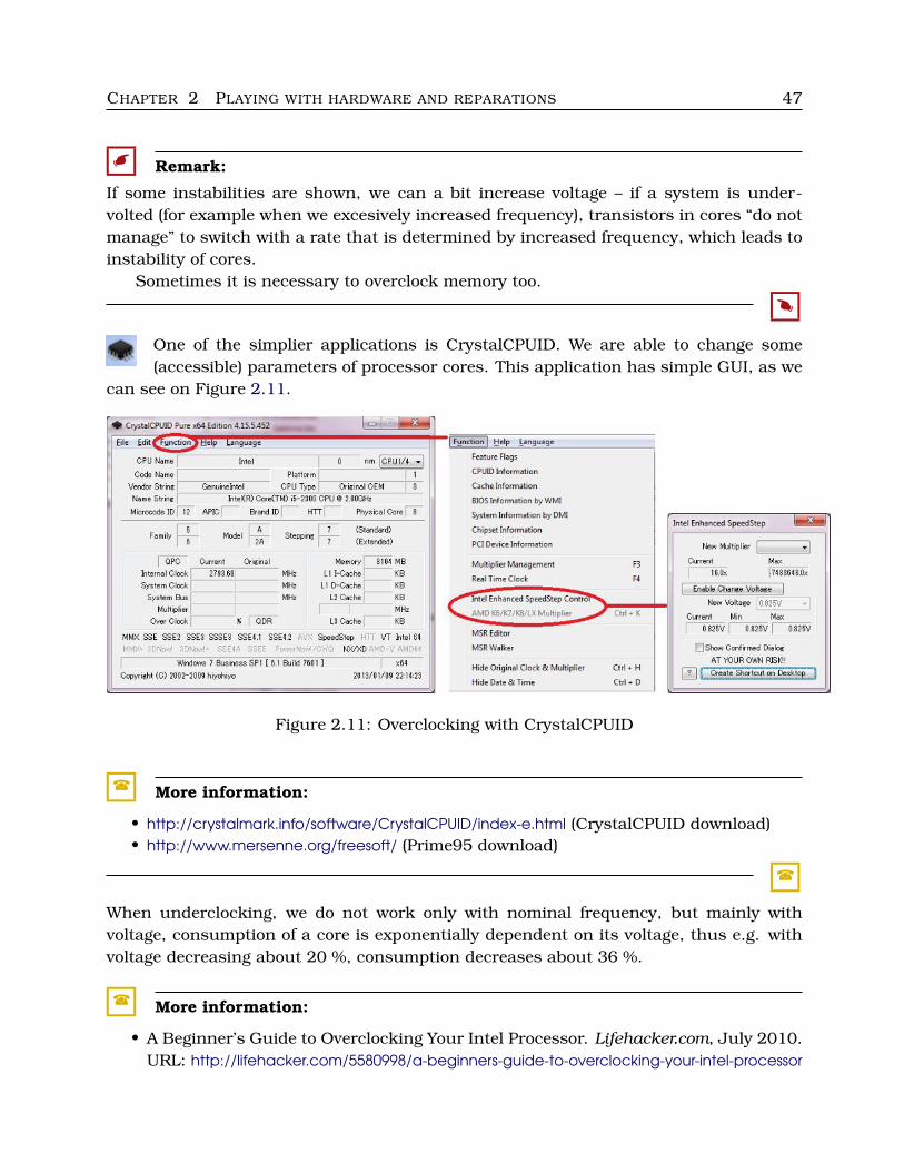
� Remark:
If some instabilities are shown, we can a bit increase voltage – if a system is under-volted (for example when we excesively increased frequency), transistors in cores “do notmanage” to switch with a rate that is determined by increased frequency, which leads toinstability of cores.
Sometimes it is necessary to overclock memory too.
�
One of the simplier applications is CrystalCPUID. We are able to change some(accessible) parameters of processor cores. This application has simple GUI, as we
can see on Figure 2.11.
Figure 2.11: Overclocking with CrystalCPUID
� More information:
• http://crystalmark.info/software/CrystalCPUID/index-e.html (CrystalCPUID download)• http://www.mersenne.org/freesoft/ (Prime95 download)
�
When underclocking, we do not work only with nominal frequency, but mainly withvoltage, consumption of a core is exponentially dependent on its voltage, thus e.g. withvoltage decreasing about 20 %, consumption decreases about 36 %.
� More information:
• A Beginner’s Guide to Overclocking Your Intel Processor. Lifehacker.com, July 2010.URL: http://lifehacker.com/5580998/a-beginners-guide-to-overclocking-your-intel-processor
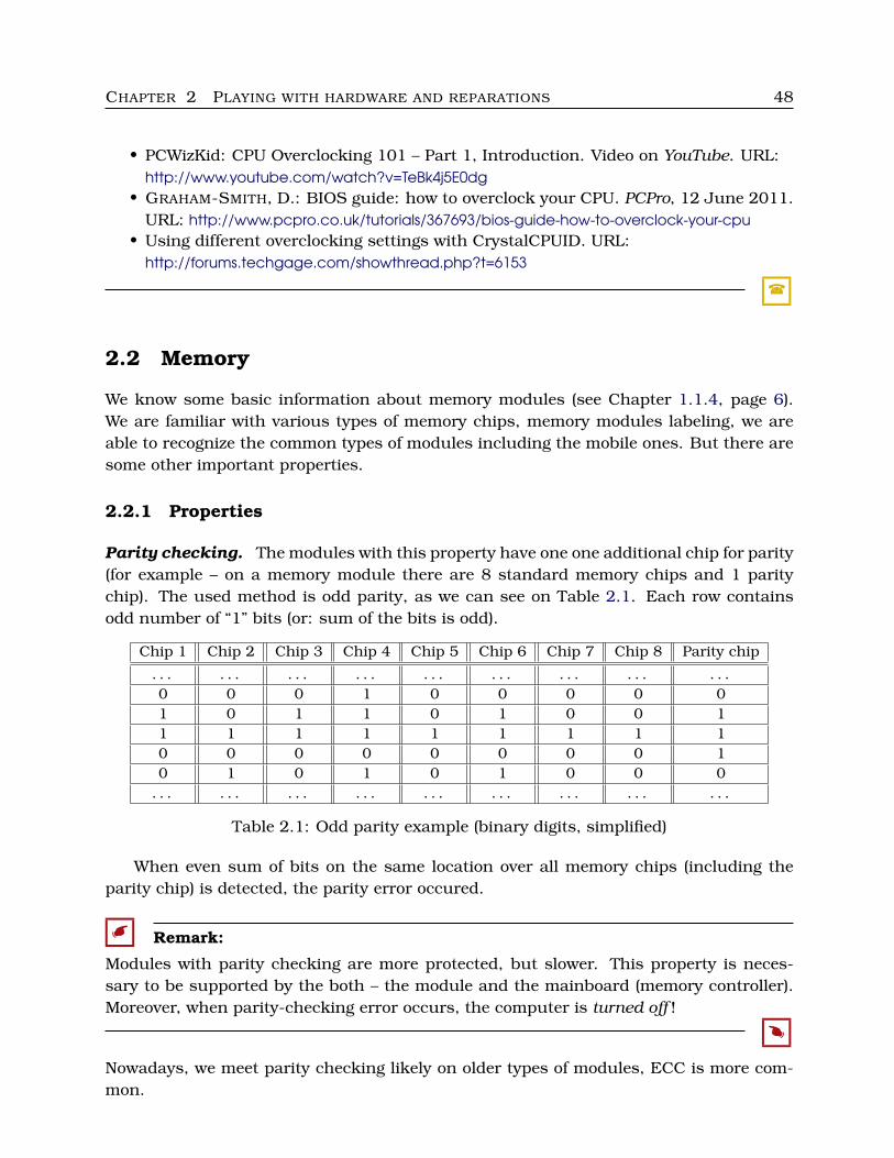
CHAPTER 2 PLAYING WITH HARDWARE AND REPARATIONS 48
• PCWizKid: CPU Overclocking 101 – Part 1, Introduction. Video on YouTube. URL:http://www.youtube.com/watch?v=TeBk4j5E0dg
• GRAHAM-SMITH, D.: BIOS guide: how to overclock your CPU. PCPro, 12 June 2011.URL: http://www.pcpro.co.uk/tutorials/367693/bios-guide-how-to-overclock-your-cpu
• Using different overclocking settings with CrystalCPUID. URL:http://forums.techgage.com/showthread.php?t=6153
�
2.2 Memory
We know some basic information about memory modules (see Chapter 1.1.4, page 6).We are familiar with various types of memory chips, memory modules labeling, we areable to recognize the common types of modules including the mobile ones. But there aresome other important properties.
2.2.1 Properties
Parity checking. The modules with this property have one one additional chip for parity(for example – on a memory module there are 8 standard memory chips and 1 paritychip). The used method is odd parity, as we can see on Table 2.1. Each row containsodd number of “1” bits (or: sum of the bits is odd).
Chip 1 Chip 2 Chip 3 Chip 4 Chip 5 Chip 6 Chip 7 Chip 8 Parity chip
. . . . . . . . . . . . . . . . . . . . . . . . . . .0 0 0 1 0 0 0 0 01 0 1 1 0 1 0 0 11 1 1 1 1 1 1 1 10 0 0 0 0 0 0 0 10 1 0 1 0 1 0 0 0
. . . . . . . . . . . . . . . . . . . . . . . . . . .
Table 2.1: Odd parity example (binary digits, simplified)
When even sum of bits on the same location over all memory chips (including theparity chip) is detected, the parity error occured.
� Remark:
Modules with parity checking are more protected, but slower. This property is neces-sary to be supported by the both – the module and the mainboard (memory controller).Moreover, when parity-checking error occurs, the computer is turned off !
�
Nowadays, we meet parity checking likely on older types of modules, ECC is more com-mon.
CHAPTER 2 PLAYING WITH HARDWARE AND REPARATIONS 49
Error checking. The modules with the property ECC (Error-Correcting Code) useparity bits too. The module includes only 8 (or 4 or 16) “big” memory chips and one ortwo smaller parity chips. Eeach group of 8 bits in memory chips receives 1-bit additionalinformation (odd parity) in the parity chip.
The single-bit errors on data can be detected. When parity error becomes, it is cor-rected, our PC (or server) keeps working, it is not turned off.
The modules, that are not ECC, are marked as “non-ECC”.
� Remark:
ECC modules are determined for server mainboards. They are a bit slower, but safer. Thisproperty must be supported by the module and by the mainboard (and by the memorycontroller) too.
If our mainboard does not support ECC, we must use non-ECC modules!
�
There are some subsequent techniques for more expansive server memory modules:Multiple-bit error correction, Chipkill, Memory scrubbing, Intel Single Device Data Cor-rection (SDDC).
Registered. The memory modules marked as “Registered” contain one additional chip,the register chip. This chip acts as a buffer, which slightly slows down memory access, itis something as caches. The communication stream is more stable, no data is lost whenthe traffic is too fast. It is useful when we have bigger amount of high-capacity moduleson a mainboard and we require stable and scalable memory.
Registered modules are sometimes marked as “Buffered”. The modules, that arenot registered, can be marked by “not-buffered” (or there is no information about thisproperty).
A lot of server memory modules meet the both these properties – they are ECC andRegistered too. We also meet with “Registered with Parity” modules, but it is the same(ECC and Registered).
� Remark:
This property is also typical for server mainboards and modules (the mainboard mustsupport “Registered” modules), so we do not buy these modules for desktop mainboards.
�
C Labs
Find out ECC and Registered memory modules in some web store. Note the way of theirmarking, their common capacity and their price.
C
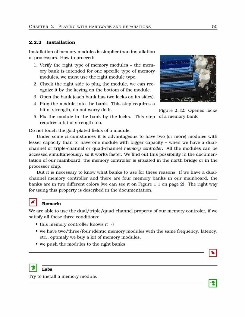
CHAPTER 2 PLAYING WITH HARDWARE AND REPARATIONS 50
2.2.2 Installation
Figure 2.12: Opened locksof a memory bank
Installation of memory modules is simplier than installationof processors. How to proceed:
1. Verify the right type of memory modules – the mem-ory bank is intended for one specific type of memorymodules, we must use the right module type.
2. Check the right side to plug the module, we can rec-ognize it by the keying on the bottom of the module.
3. Open the bank (each bank has two locks on its sides).
4. Plug the module into the bank. This step requires abit of strength, do not worry do it.
5. Fix the module in the bank by the locks. This steprequires a bit of strength too.
Do not touch the gold-plated fields of a module.Under some circumstances it is advantageous to have two (or more) modules with
lesser capacity than to have one module with bigger capacity – when we have a dual-channel or triple-channel or quad-channel memory controller. All the modules can beaccessed simultaneously, so it works faster. We find out this possibility in the documen-tation of our mainboard, the memory controller is situated in the north bridge or in theprocessor chip.
But it is necessary to know what banks to use for these reasons. If we have a dual-channel memory controller and there are four memory banks in our mainboard, thebanks are in two different colors (we can see it on Figure 1.1 on page 2). The right wayfor using this property is described in the documentation.
� Remark:
We are able to use the dual/triple/quad-channel property of our memory controler, if wesatisfy all these three conditions:
• this memory controller knows it :-)
• we have two/three/four identic memory modules with the same frequency, latency,etc., optimaly we buy a kit of memory modules,
• we push the modules to the right banks.
�
C Labs
Try to install a memory module.
C
CHAPTER 2 PLAYING WITH HARDWARE AND REPARATIONS 51
2.2.3 Speed and latency
Capacity of our memory is important, but its speed (throughput) and latency is importanttoo.
We need to know how a memory module works. There exists a logical gride of memorycells (we put one bit into one cell). Thus the memory cell is on one row and one column.
Suppose that an operating system wants to read data from memory. This “multiope-ration” is decomposed by a memory controller into such partial operations (commands)and each operation takes some time:
1. RRD (Row Active to Row Active Delay): find the proper memory bank; if it is differentfrom the last used, activate the new bank containing the searched row.
2. RAS (Row Address Strobe): find the row.
3. RCD (RAS to CAS Delay): the row is found, prepare for looking for the column.
4. CAS (Column Address Strobe): find the column.
5. reading or writing . . .
6. RP (Row Precharge): renew the contents of the read cells (remember – this type ofmemory is destructive while reading!).
There are some other operations related to memory refreshing (remember – this type ofmemory is dynamic, it is necessary to refresh periodicly the cells content!).
• RFC (Row Refresh Cycle): deactivate a memory module (memory modules must bedeactivated during their refreshing).
• RF (Refresh): refresh (rewrite the cells by reading without modification).
The memory controller does it to prevent discharging capacitors, the interval is a fewmiliseconds.
Latency is the time measure representing delay between the moment of issuing theread/write command and its fulfiling.
The typical spent time for reading or writing is:tRAS (how long we find the row)
+ tRCD (how long we cross from row finding to column finding)
+ tCL (CAS Latency; how long we find the column)
+ tRP (how long we renew the cells)
+ . . .
� Remark:
The subsequent read memory cell is very likely to be found on the same row as theprevious read cell. It implies that the operations RRD, RAS and RCD are not frequentlyused; the most common operation is CAS.
Well, the time parameter tCL is the most important for memory latency. We often meetwith equating the terms tCL and memory latency. It is clear that “less is better”.
�
CHAPTER 2 PLAYING WITH HARDWARE AND REPARATIONS 52
M Example 2.14
Each memory module is labeled either only with its tCL or with a bit longer sequence ofnumbers. If the whole string is present, it may look like one of these three sequences:
tCL–tRCD–tRP–tRAS / CM RATE3 – 3 – 2 – 6 / 1T8 – 7 – 6 – 19 / 2T5 – 5 – 5 – 16 / 2T
The values tCL, tRCD, tRP and tRAS are clear.The “managing” value CM RATE (Command Rate) is a time interval between forming
some of the above mentioned commands with determining the target memory chip, andits receiving by such chip. It is usually 1 or 2.
Nowadays, only tCL is often given. If no this information can be found, we can expectworse value.
M
Typical values of tCL are:• between 2 and 3 for DDR,
• between 3 and 6 for DDR2,
• between 5 and 10 for DDR3.As we can see, faster types of modules work with worse latency.
How much is tCL important when buying new modules? We would consider thesecriteria (in the quoted order):
1. type and capacity of modules,
2. frequency – higher is better, but first of all memory frequency and processor fre-quency would be synchronized (one would be a multiple of the remaining one),
3. latency – important mainly if our processor has low L2 cache.
M Example 2.15
Some of memory modules specifications:• Crucial CT2KIT25664BA1339A 4GB DDR3 SDRAM Memory Module
4GB Kit 2X2GB PC3-10600 1333MHZ DDR3 240-Pin DIMM Unbuffered CL9 1.5V
means DDR3 modules (classic DIMM for desktops with 240 pins), kit of 2 pieces(each 2 GB), total capacity 4 GB, frequency 1333 MHz, transfer rate 10 600 MB/s(PC3-10600), latency is 9 (CL9), unbuffered and non-ECC
• Kingston ValueRAM 2GB DDR2 SDRAM Memory Module
2GB 2 x 1GB - 667MHz DDR2-667/PC2-5300 - Non-ECC - DDR2 SDRAM - 240-pin
means one DDR2 desktop module, capacity 2 GB, frequency 667 MHz, transfer rate5300 MB/s, latency is not given (but we can find somewhere else – CL5), unbufferedand non-ECC
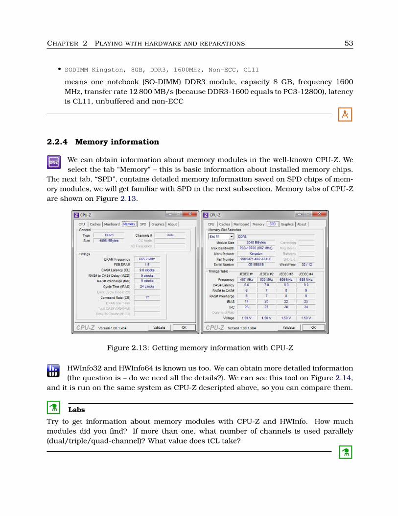
CHAPTER 2 PLAYING WITH HARDWARE AND REPARATIONS 53
• SODIMM Kingston, 8GB, DDR3, 1600MHz, Non-ECC, CL11
means one notebook (SO-DIMM) DDR3 module, capacity 8 GB, frequency 1600MHz, transfer rate 12 800 MB/s (because DDR3-1600 equals to PC3-12800), latencyis CL11, unbuffered and non-ECC
M
2.2.4 Memory information
We can obtain information about memory modules in the well-known CPU-Z. Weselect the tab “Memory” – this is basic information about installed memory chips.
The next tab, “SPD”, contains detailed memory information saved on SPD chips of mem-ory modules, we will get familiar with SPD in the next subsection. Memory tabs of CPU-Zare shown on Figure 2.13.
Figure 2.13: Getting memory information with CPU-Z
HWInfo32 and HWInfo64 is known us too. We can obtain more detailed information(the question is – do we need all the details?). We can see this tool on Figure 2.14,
and it is run on the same system as CPU-Z descripted above, so you can compare them.
C Labs
Try to get information about memory modules with CPU-Z and HWInfo. How muchmodules did you find? If more than one, what number of channels is used parallely(dual/triple/quad-channel)? What value does tCL take?
C
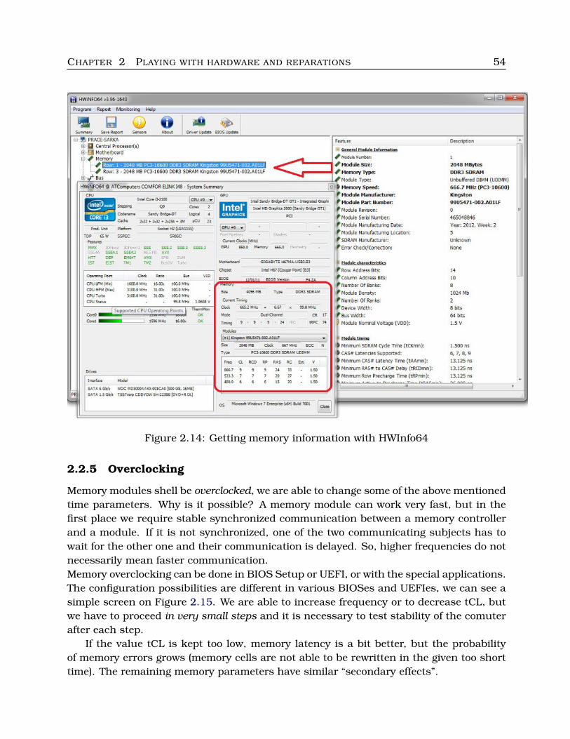
CHAPTER 2 PLAYING WITH HARDWARE AND REPARATIONS 54
Figure 2.14: Getting memory information with HWInfo64
2.2.5 Overclocking
Memory modules shell be overclocked, we are able to change some of the above mentionedtime parameters. Why is it possible? A memory module can work very fast, but in thefirst place we require stable synchronized communication between a memory controllerand a module. If it is not synchronized, one of the two communicating subjects has towait for the other one and their communication is delayed. So, higher frequencies do notnecessarily mean faster communication.Memory overclocking can be done in BIOS Setup or UEFI, or with the special applications.The configuration possibilities are different in various BIOSes and UEFIes, we can see asimple screen on Figure 2.15. We are able to increase frequency or to decrease tCL, butwe have to proceed in very small steps and it is necessary to test stability of the comuterafter each step.
If the value tCL is kept too low, memory latency is a bit better, but the probabilityof memory errors grows (memory cells are not able to be rewritten in the given too shorttime). The remaining memory parameters have similar “secondary effects”.
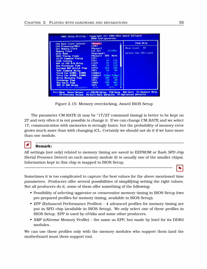
CHAPTER 2 PLAYING WITH HARDWARE AND REPARATIONS 55
Figure 2.15: Memory overclocking, Award BIOS Setup
The parameter CM RATE (it may be “1T/2T command timing) is better to be kept on2T and very often it is not possible to change it. If we can change CM RATE and we select1T, communication with memories is strongly faster, but the probability of memory errorgrows much more than with changing tCL. Certainly we should not do it if we have morethan one module.
� Remark:
All settings (not only) related to memory timing are saved in EEPROM or flash SPD chip(Serial Presence Detect) on each memory module (it is usually one of the smaller chips).Information kept in this chip is mapped to BIOS Setup.
�
Sometimes it is too complicated to capture the best values for the above mentioned timeparameters. Producers offer several possibilities of simplifying setting the right values.Not all producers do it, some of them offer something of the following:
• Possibility of selecting aggresive or conservative memory timing in BIOS Setup (twopre-prepared profiles for memory timing, available in BIOS Setup).
• EPP (Enhanced Performance Profiles) – 4 advanced profiles for memory timing areput in SPD chip (available in BIOS Setup). We only select one of these profiles inBIOS Setup. EPP is used by nVidia and some other producers.
• XMP (eXtreme Memory Profile) – the same as EPP, but made by Intel for its DDR3modules.
We can use these profiles only with the memory modules who support them (and themotherboard must them support too).
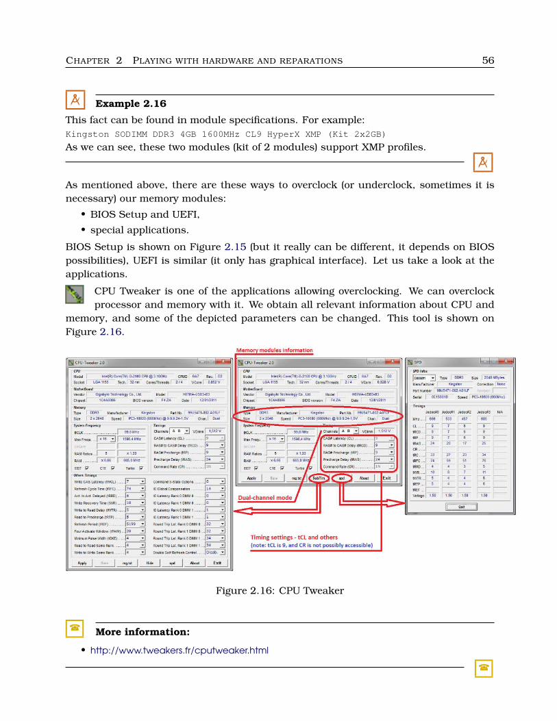
CHAPTER 2 PLAYING WITH HARDWARE AND REPARATIONS 56
M Example 2.16
This fact can be found in module specifications. For example:Kingston SODIMM DDR3 4GB 1600MHz CL9 HyperX XMP (Kit 2x2GB)
As we can see, these two modules (kit of 2 modules) support XMP profiles.
M
As mentioned above, there are these ways to overclock (or underclock, sometimes it isnecessary) our memory modules:
• BIOS Setup and UEFI,
• special applications.
BIOS Setup is shown on Figure 2.15 (but it really can be different, it depends on BIOSpossibilities), UEFI is similar (it only has graphical interface). Let us take a look at theapplications.
CPU Tweaker is one of the applications allowing overclocking. We can overclockprocessor and memory with it. We obtain all relevant information about CPU and
memory, and some of the depicted parameters can be changed. This tool is shown onFigure 2.16.
Figure 2.16: CPU Tweaker
� More information:
• http://www.tweakers.fr/cputweaker.html
�
CHAPTER 2 PLAYING WITH HARDWARE AND REPARATIONS 57
Most people makes memory overclocking in BIOS Setup, it is not any problem. Weonly have to find the proper section in BIOS Setup (or UEFI), whitch is likely labeled“Performance”, “Advanced configuration” or similarly. So, how to overclock memory:
1. find the proper section in BIOS Setup, check the concrete possibilities,
2. try to change tCL (or another parameter) in very small step,
3. test stability of your system – use MemTest (see below),
4. if everything is OK, you can finish or return to step 2, if some errors occur, put thechanged value back and test again.
� More information:
• IWANIUK, P.: How to overclock your RAM. Tutorial Make the most of your mem-ory with our RAM tweaking tips. PCFormat Issue 256, October 2nd, 2011. URL:http://www.techradar.com/news/computing-components/upgrades/how-to-overclock-your-ram-1030286
• TORRES, G.: Understanding RAM Timings. Hardware Secrets, May 17, 2011. URL:http://www.hardwaresecrets.com/article/Understanding-RAM-Timings/26
• Intel and Overclocking DDR3 memory. Intel.com. URL: http://www.intel.com/content/www/us/en/gaming/gaming-computers/intel-extreme-memory-profile-xmp.html
• LENG, R.J.: The Secrets of PC Memory: Part 1 Bit-Tech.net, 15th November 2007.URL: http://www.bit-tech.net/hardware/memory/2007/11/15/the secrets of pc memory part 1/4
• Woomack: Memory Overclocking Guide for Intel Ivy Bridge platform. Overclock-ers.com, July 31, 2012. URL: http://www.overclockers.com/memory-overclocking-guide-ivy-bridge
• Memory (RAM) Overclocking Guide – DDR3. Master’s Lair, July 2011. URL:http://www.masterslair.com/memory-ram-overclocking-guide-ddr3/
• YAM, M.: A Tour Of The Kingston Memory Factory In Taiwan. Tom’s hardware,August 5, 2010. URL: http://www.tomshardware.co.uk/picturestory/7-dram-flash-nand-ssd-usb.html
�
2.2.6 Testing
We use memory testing in these cases:
1. something is wrong, from time to time some mistake occurs, there are some in-stabilities in applications running, BSD (Blue Screen of Death – do you know it?)etc.,
2. we bought new memory modules,
3. we overclock memory,
4. we can give benchmark results, we test performance (see Section 2.6, page 70).
We focus on the first three cases (memory functionality, not performance).
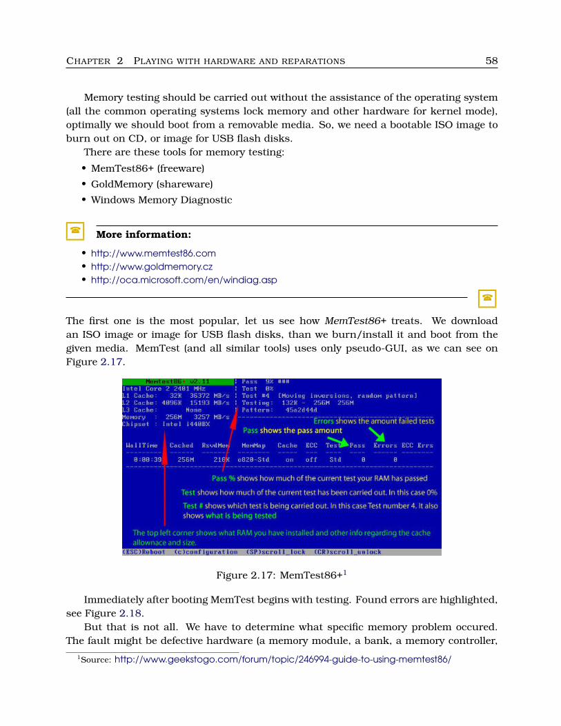
CHAPTER 2 PLAYING WITH HARDWARE AND REPARATIONS 58
Memory testing should be carried out without the assistance of the operating system(all the common operating systems lock memory and other hardware for kernel mode),optimally we should boot from a removable media. So, we need a bootable ISO image toburn out on CD, or image for USB flash disks.
There are these tools for memory testing:
• MemTest86+ (freeware)
• GoldMemory (shareware)
• Windows Memory Diagnostic
� More information:
• http://www.memtest86.com• http://www.goldmemory.cz• http://oca.microsoft.com/en/windiag.asp
�
The first one is the most popular, let us see how MemTest86+ treats. We downloadan ISO image or image for USB flash disks, than we burn/install it and boot from thegiven media. MemTest (and all similar tools) uses only pseudo-GUI, as we can see onFigure 2.17.
Figure 2.17: MemTest86+1
Immediately after booting MemTest begins with testing. Found errors are highlighted,see Figure 2.18.
But that is not all. We have to determine what specific memory problem occured.The fault might be defective hardware (a memory module, a bank, a memory controller,
1Source: http://www.geekstogo.com/forum/topic/246994-guide-to-using-memtest86/
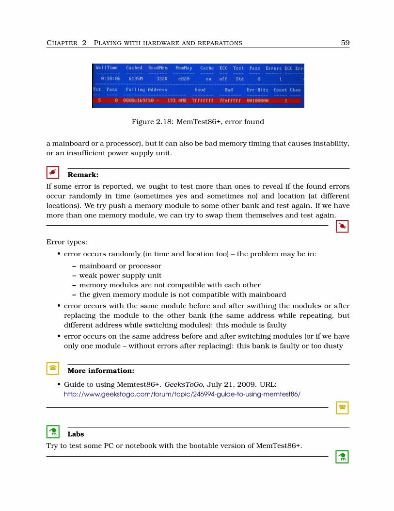
CHAPTER 2 PLAYING WITH HARDWARE AND REPARATIONS 59
Figure 2.18: MemTest86+, error found
a mainboard or a processor), but it can also be bad memory timing that causes instability,or an insufficient power supply unit.
� Remark:
If some error is reported, we ought to test more than ones to reveal if the found errorsoccur randomly in time (sometimes yes and sometimes no) and location (at differentlocations). We try push a memory module to some other bank and test again. If we havemore than one memory module, we can try to swap them themselves and test again.
�
Error types:
• error occurs randomly (in time and location too) – the problem may be in:
– mainboard or processor– weak power supply unit– memory modules are not compatible with each other– the given memory module is not compatible with mainboard
• error occurs with the same module before and after swithing the modules or afterreplacing the module to the other bank (the same address while repeating, butdifferent address while switching modules): this module is faulty
• error occurs on the same address before and after switching modules (or if we haveonly one module – without errors after replacing): this bank is faulty or too dusty
� More information:
• Guide to using Memtest86+. GeeksToGo, July 21, 2009. URL:http://www.geekstogo.com/forum/topic/246994-guide-to-using-memtest86/
�
C Labs
Try to test some PC or notebook with the bootable version of MemTest86+.
C
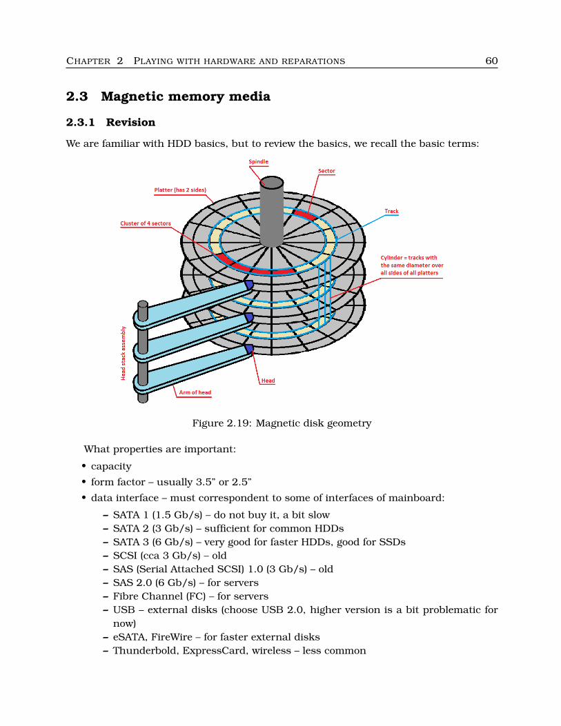
CHAPTER 2 PLAYING WITH HARDWARE AND REPARATIONS 60
2.3 Magnetic memory media
2.3.1 Revision
We are familiar with HDD basics, but to review the basics, we recall the basic terms:
Figure 2.19: Magnetic disk geometry
What properties are important:
• capacity
• form factor – usually 3.5” or 2.5”
• data interface – must correspondent to some of interfaces of mainboard:
– SATA 1 (1.5 Gb/s) – do not buy it, a bit slow– SATA 2 (3 Gb/s) – sufficient for common HDDs– SATA 3 (6 Gb/s) – very good for faster HDDs, good for SSDs– SCSI (cca 3 Gb/s) – old– SAS (Serial Attached SCSI) 1.0 (3 Gb/s) – old– SAS 2.0 (6 Gb/s) – for servers– Fibre Channel (FC) – for servers– USB – external disks (choose USB 2.0, higher version is a bit problematic for
now)– eSATA, FireWire – for faster external disks– Thunderbold, ExpressCard, wireless – less common
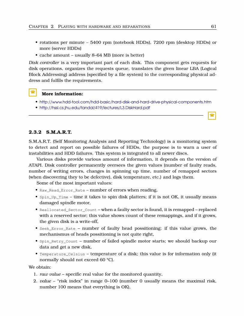
CHAPTER 2 PLAYING WITH HARDWARE AND REPARATIONS 61
• rotations per minute – 5400 rpm (notebook HDDs), 7200 rpm (desktop HDDs) ormore (server HDDs)
• cache amount – usually 8–64 MB (more is better)
Disk controller is a very important part of each disk. This component gets requests fordisk operations, organizes the requests queue, translates the given linear LBA (LogicalBlock Addressing) address (specified by a file system) to the corresponding physical ad-dress and fulfils the requirements.
� More information:
• http://www.hdd-tool.com/hdd-basic/hard-disk-and-hard-drive-physical-components.htm• http://hssl.cs.jhu.edu/randal/419/lectures/L3.DiskHard.pdf
�
2.3.2 S.M.A.R.T.
S.M.A.R.T. (Self Monitoring Analysis and Reporting Technology) is a monitoring systemto detect and report on possible failures of HDDs, the purpose is to warn a user ofinstabilities and HDD failures. This system is integrated to all newer discs.
Various disks provide various amount of information, it depends on the version ofATAPI. Disk controller permanently oversees the given values (number of faulty reads,number of writing errors, changes in spinning up time, number of remapped sectors(when discovering they to be defective), disk temperature, etc.) and logs them.
Some of the most important values:
• Raw_Read_Error_Rate – number of errors when reading,
• Spin_Up_Time – time it takes to spin disk platters; if it is not OK, it usually meansdamaged spindle motor,
• Reallocated_Sector_Count – when a faulty sector is found, it is remapped – replacedwith a reserved sector; this value shows count of these remappings, and if it grows,the given disk is a write-off,
• Seek_Error_Rate – number of faulty head possitioning; if this value grows, themechanismus of heads possitioning is not quite right,
• Spin_Retry_Count – number of failed spindle motor starts; we should backup ourdata and get a new disk,
• Temperature_Celsius – temperature of a disk; this value is for information only (itnormally should not exceed 60 °C).
We obtain:
1. raw value – specific real value for the monitored quantity,
2. value – “risk index” in range 0–100 (number 0 usually means the maximal risk,number 100 means that everything is OK),
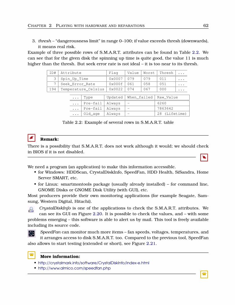
CHAPTER 2 PLAYING WITH HARDWARE AND REPARATIONS 62
3. thresh – “dangerousness limit” in range 0–100; if value exceeds thresh (downwards),it means real risk.
Example of three possible rows of S.M.A.R.T. attributes can be found in Table 2.2. Wecan see that for the given disk the spinning up time is quite good, the value 11 is muchhigher than the thresh. But seek error rate is not ideal – it is too near to its thresh.
ID# Attribute Flag Value Worst Thresh ...
3 Spin_Up_Time 0x0007 079 079 011 ...
7 Seek_Error_Rate 0x000f 061 058 051 ...
194 Temperature_Celsius 0x0022 074 067 000 ...
... Type Updated When_failed Raw_Value
... Pre-fail Always - 6260
... Pre-fail Always - 7863642
... Old_age Always - 28 (Lifetime)
Table 2.2: Example of several rows in S.M.A.R.T. table
� Remark:
There is a possibility that S.M.A.R.T. does not work although it would; we should checkin BIOS if it is not disabled.
�
We need a program (an application) to make this information accessible.• for Windows: HDDScan, CrystalDiskInfo, SpeedFan, HDD Health, SiSandra, Home
Server SMART, etc.• for Linux: smartmontools package (usually already installed) – for command line,
GNOME Disks or GNOME Disk Utility (with GUI), etc.Most producers provide their own monitoring applications (for example Seagate, Sam-sung, Western Digital, Hitachi).
CrystalDiskInfo is one of the applications to check the S.M.A.R.T. attributes. Wecan see its GUI on Figure 2.20. It is possible to check the values, and – with some
problems emerging – this software is able to alert us by mail. This tool is freely availableincluding its source code.
SpeedFan can monitor much more items – fan speeds, voltages, temperatures, andit arranges access to disk S.M.A.R.T. too. Compared to the previous tool, SpeedFan
also allows to start testing (extended or short), see Figure 2.21.
� More information:• http://crystalmark.info/software/CrystalDiskInfo/index-e.html• http://www.almico.com/speedfan.php
�
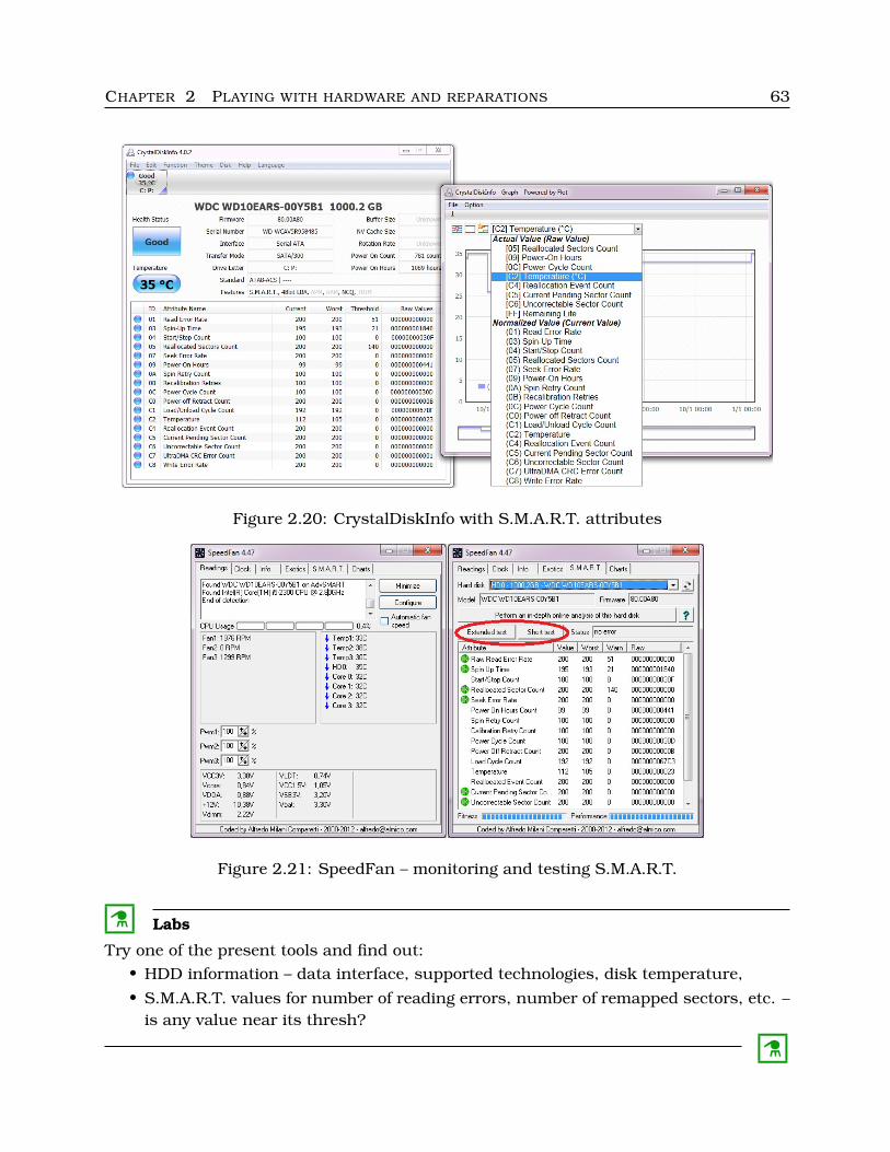
CHAPTER 2 PLAYING WITH HARDWARE AND REPARATIONS 63
Figure 2.20: CrystalDiskInfo with S.M.A.R.T. attributes
Figure 2.21: SpeedFan – monitoring and testing S.M.A.R.T.
C Labs
Try one of the present tools and find out:• HDD information – data interface, supported technologies, disk temperature,
• S.M.A.R.T. values for number of reading errors, number of remapped sectors, etc. –is any value near its thresh?
C
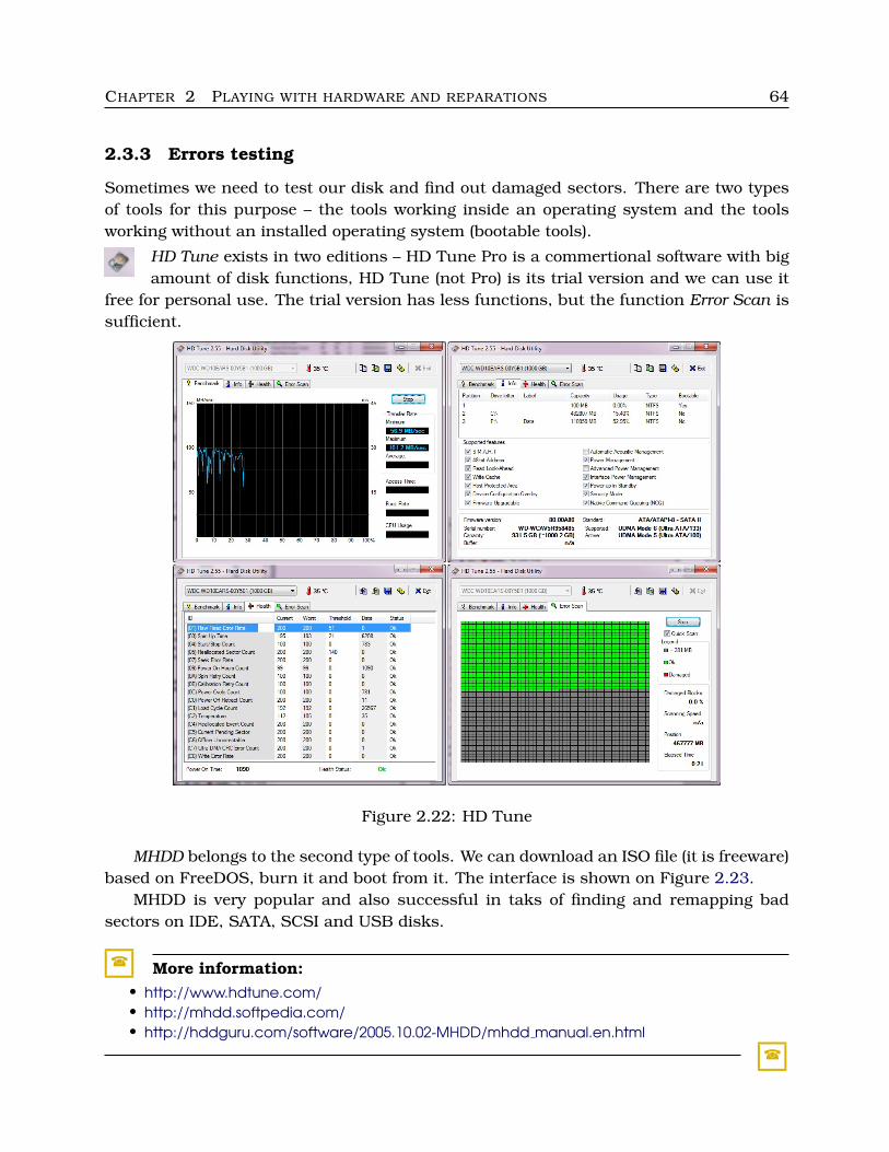
CHAPTER 2 PLAYING WITH HARDWARE AND REPARATIONS 64
2.3.3 Errors testing
Sometimes we need to test our disk and find out damaged sectors. There are two typesof tools for this purpose – the tools working inside an operating system and the toolsworking without an installed operating system (bootable tools).
HD Tune exists in two editions – HD Tune Pro is a commertional software with bigamount of disk functions, HD Tune (not Pro) is its trial version and we can use it
free for personal use. The trial version has less functions, but the function Error Scan issufficient.
Figure 2.22: HD Tune
MHDD belongs to the second type of tools. We can download an ISO file (it is freeware)based on FreeDOS, burn it and boot from it. The interface is shown on Figure 2.23.
MHDD is very popular and also successful in taks of finding and remapping badsectors on IDE, SATA, SCSI and USB disks.
� More information:• http://www.hdtune.com/• http://mhdd.softpedia.com/• http://hddguru.com/software/2005.10.02-MHDD/mhdd manual.en.html
�
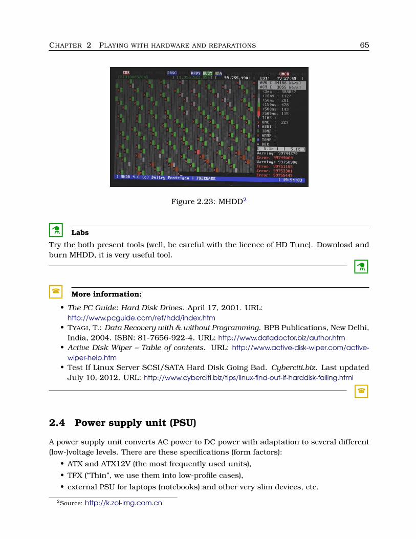
CHAPTER 2 PLAYING WITH HARDWARE AND REPARATIONS 65
Figure 2.23: MHDD2
C Labs
Try the both present tools (well, be careful with the licence of HD Tune). Download andburn MHDD, it is very useful tool.
C
� More information:
• The PC Guide: Hard Disk Drives. April 17, 2001. URL:http://www.pcguide.com/ref/hdd/index.htm
• TYAGI, T.: Data Recovery with & without Programming. BPB Publications, New Delhi,India, 2004. ISBN: 81-7656-922-4. URL: http://www.datadoctor.biz/author.htm
• Active Disk Wiper – Table of contents. URL: http://www.active-disk-wiper.com/active-wiper-help.htm
• Test If Linux Server SCSI/SATA Hard Disk Going Bad. Cyberciti.biz. Last updatedJuly 10, 2012. URL: http://www.cyberciti.biz/tips/linux-find-out-if-harddisk-failing.html
�
2.4 Power supply unit (PSU)
A power supply unit converts AC power to DC power with adaptation to several different(low-)voltage levels. There are these specifications (form factors):
• ATX and ATX12V (the most frequently used units),
• TFX (“Thin”, we use them into low-profile cases),
• external PSU for laptops (notebooks) and other very slim devices, etc.
2Source: http://k.zol-img.com.cn
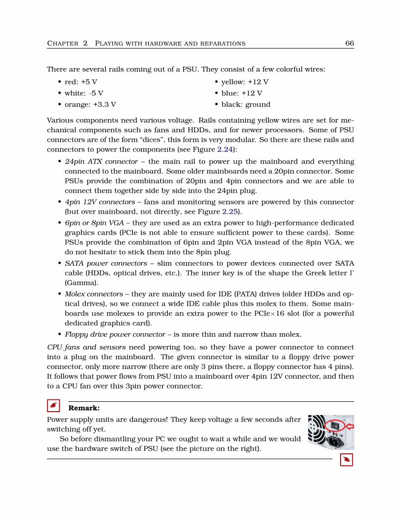
CHAPTER 2 PLAYING WITH HARDWARE AND REPARATIONS 66
There are several rails coming out of a PSU. They consist of a few colorful wires:
• red: +5 V
• white: -5 V
• orange: +3.3 V
• yellow: +12 V
• blue: +12 V
• black: ground
Various components need various voltage. Rails containing yellow wires are set for me-chanical components such as fans and HDDs, and for newer processors. Some of PSUconnectors are of the form “dices”, this form is very modular. So there are these rails andconnectors to power the components (see Figure 2.24):
• 24pin ATX connector – the main rail to power up the mainboard and everythingconnected to the mainboard. Some older mainboards need a 20pin connector. SomePSUs provide the combination of 20pin and 4pin connectors and we are able toconnect them together side by side into the 24pin plug.
• 4pin 12V connectors – fans and monitoring sensors are powered by this connector(but over mainboard, not directly, see Figure 2.25).
• 6pin or 8pin VGA – they are used as an extra power to high-performance dedicatedgraphics cards (PCIe is not able to ensure sufficient power to these cards). SomePSUs provide the combination of 6pin and 2pin VGA instead of the 8pin VGA, wedo not hesitate to stick them into the 8pin plug.
• SATA power connectors – slim connectors to power devices connected over SATAcable (HDDs, optical drives, etc.). The inner key is of the shape the Greek letter Γ
(Gamma).
• Molex connectors – they are mainly used for IDE (PATA) drives (older HDDs and op-tical drives), so we connect a wide IDE cable plus this molex to them. Some main-boards use molexes to provide an extra power to the PCIe×16 slot (for a powerfuldedicated graphics card).
• Floppy drive power connector – is more thin and narrow than molex.
CPU fans and sensors need powering too, so they have a power connector to connectinto a plug on the mainboard. The given connector is similar to a floppy drive powerconnector, only more narrow (there are only 3 pins there, a floppy connector has 4 pins).It follows that power flows from PSU into a mainboard over 4pin 12V connector, and thento a CPU fan over this 3pin power connector.
� Remark:
Power supply units are dangerous! They keep voltage a few seconds afterswitching off yet.
So before dismantling your PC we ought to wait a while and we woulduse the hardware switch of PSU (see the picture on the right).
�
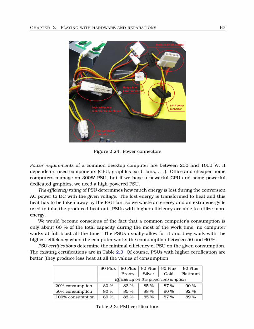
CHAPTER 2 PLAYING WITH HARDWARE AND REPARATIONS 67
Figure 2.24: Power connectors
Power requirements of a common desktop computer are between 250 and 1000 W. Itdepends on used components (CPU, graphics card, fans, . . . ). Office and cheaper homecomputers manage on 300W PSU, but if we have a powerful CPU and some powerfuldedicated graphics, we need a high-powered PSU.
The efficiency rating of PSU determines how much energy is lost during the conversionAC power to DC with the given voltage. The lost energy is transformed to heat and thisheat has to be taken away by the PSU fan, so we waste an energy and an extra energy isused to take the produced heat out. PSUs with higher efficiency are able to utilize moreenergy.
We would become conscious of the fact that a common computer’s consumption isonly about 60 % of the total capacity during the most of the work time, no computerworks at full blast all the time. The PSUs usually allow for it and they work with thehighest efficiency when the computer works the consumption between 50 and 60 %.
PSU certifications determine the minimal efficiency of PSU on the given consumption.The existing certifications are in Table 2.3. Of course, PSUs with higher certification arebetter (they produce less heat at all the values of consumption.
80 Plus 80 Plus 80 Plus 80 Plus 80 PlusBronze Silver Gold Platinum
Efficiency on the given consumption
20% consumption 80 % 82 % 85 % 87 % 90 %50% consumption 80 % 85 % 88 % 90 % 92 %100% consumption 80 % 82 % 85 % 87 % 89 %
Table 2.3: PSU certifications
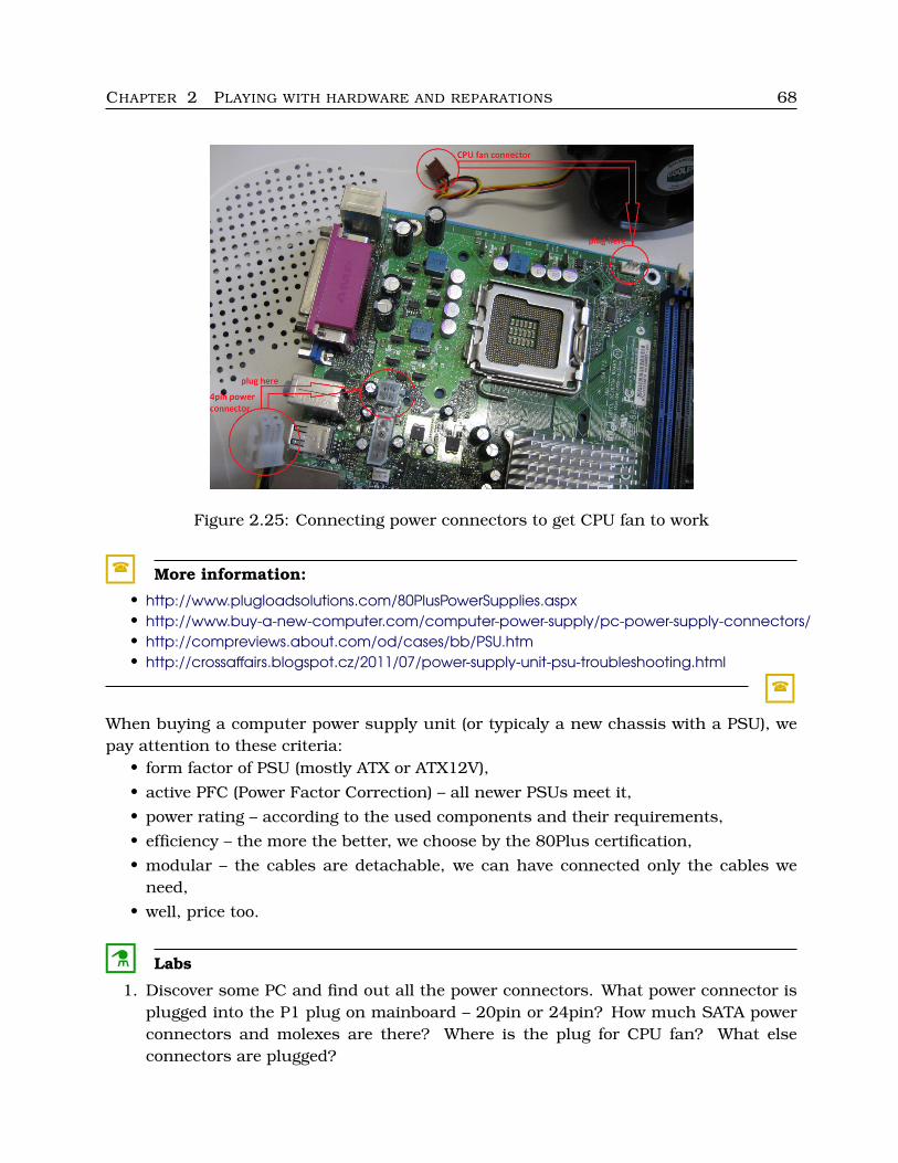
CHAPTER 2 PLAYING WITH HARDWARE AND REPARATIONS 68
Figure 2.25: Connecting power connectors to get CPU fan to work
� More information:
• http://www.plugloadsolutions.com/80PlusPowerSupplies.aspx• http://www.buy-a-new-computer.com/computer-power-supply/pc-power-supply-connectors/• http://compreviews.about.com/od/cases/bb/PSU.htm• http://crossaffairs.blogspot.cz/2011/07/power-supply-unit-psu-troubleshooting.html
�
When buying a computer power supply unit (or typicaly a new chassis with a PSU), wepay attention to these criteria:
• form factor of PSU (mostly ATX or ATX12V),
• active PFC (Power Factor Correction) – all newer PSUs meet it,
• power rating – according to the used components and their requirements,
• efficiency – the more the better, we choose by the 80Plus certification,
• modular – the cables are detachable, we can have connected only the cables weneed,
• well, price too.
C Labs
1. Discover some PC and find out all the power connectors. What power connector isplugged into the P1 plug on mainboard – 20pin or 24pin? How much SATA powerconnectors and molexes are there? Where is the plug for CPU fan? What elseconnectors are plugged?
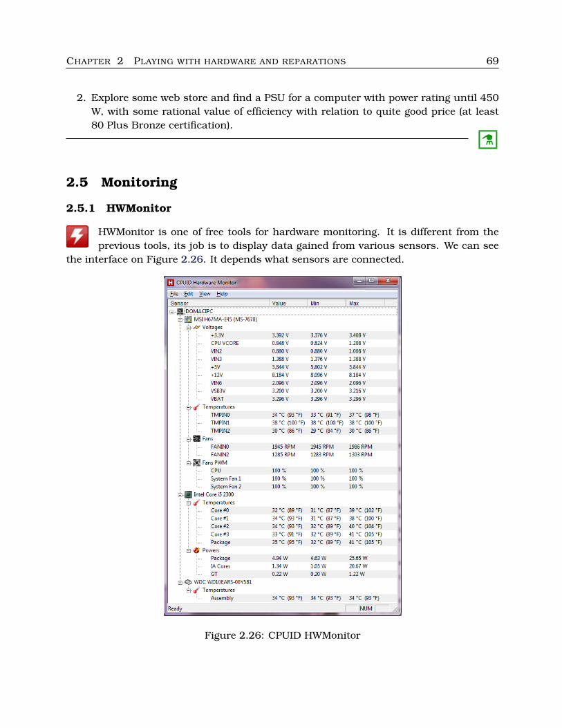
CHAPTER 2 PLAYING WITH HARDWARE AND REPARATIONS 69
2. Explore some web store and find a PSU for a computer with power rating until 450W, with some rational value of efficiency with relation to quite good price (at least80 Plus Bronze certification).
C
2.5 Monitoring
2.5.1 HWMonitor
HWMonitor is one of free tools for hardware monitoring. It is different from theprevious tools, its job is to display data gained from various sensors. We can see
the interface on Figure 2.26. It depends what sensors are connected.
Figure 2.26: CPUID HWMonitor

CHAPTER 2 PLAYING WITH HARDWARE AND REPARATIONS 70
2.6 Benchmarks
SiSoftware Sandra is one of the most popular benchmarking tools. We get infor-mation about hardware including our memory modules, and we have the use of
several interesting tools and benchmarks. This software is commercial, but we can trylite version free.
Figure 2.27: SiSoftware Sandra – memory information
There are more benchmark applications – CPUMark, Futuremark 3DMark, PCMarkVantage, PCMark 7, GPU-Z, etc. Some of them are freely available, see addresses listedbelow.
CHAPTER 2 PLAYING WITH HARDWARE AND REPARATIONS 71
� More information:
• http://www.sisoftware.net/• http://www.memorybenchmark.net/ram.php?ram=Kingston+99U5471-002.A01LF+2GB• http://www.overclockzone.com/download/• http://www.futuremark.com/support/guides• http://www.techradar.com/news/software/applications/best-overclocking-software-15-top-apps-
721381• http://www.techpowerup.com/downloads/• http://www.techpowerup.com/gpuz/• Wawro, A.: Overclock Your CPU, GPU, and RAM. PCWorld, May 23, 2011. URL:
http://www.pcworld.com/article/228488/overclock your cpu gpu and ram.html
�
Chapter 3Network
We review several terms and concepts of computer networks, but we assume that readershave a basic understanding of this subject.
3.1 Communication overview
When a person wants to tell something to another person, they both have to under-stand the same communication language, their communication consists of words of thislanguage, maintaining the given syntactic and semantic structure.
When a computer wants to tell something to another computer (or some other de-vice), they both have to understand the same communication language too – we call thislanguage a protocol.
� Remark:
A communications protocol describes digital unit formats and rules for their processingand transmission between computing systems.
�
3.1.1 Protocol stacks
Each protocol serves for some given partial purpose (procols can not be too complicated),so protocols have to cooperate with other protocols – a protocol can provide services toanother protocol. But no protocol can cooperate with any other one.
So, all the known protocols are separated to several levels and it was determined thateach protocol provides services to higher layer protocols and uses the services of lowerlayer protocols.
It was necessary to standardize all communication elements – besides the mentionedprotocols, all communicating elements need their own addresses.
72
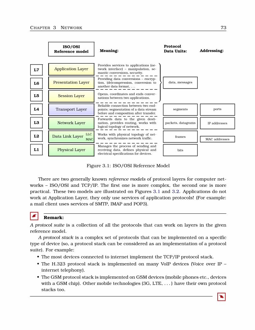
CHAPTER 3 NETWORK 73
ISO/OSIReference model
ProtocolData Units: Addressing:Meaning:
Application Layer
Presentation Layer
Session Layer
Transport Layer
Network Layer
Data Link LayerMAC
LLC
Physical Layer
L7
L6
L5
L4
L3
L2
L1
data, messages
segments
packets, datagrams
frames
bits
ports
IP addresses
MAC addresses
Provides services to applications (ne-twork interface) – manipulation, se-mantic conversions, security.
Providing data conversions – encryp-tion, (de)compression, conversion toanother data format, . . .
Opens, coordinates and ends conver-sations between two applications.
Reliable connection between two end-points; segmentation of a data streambefore and composition after transfer.
Forwards data to the given desti-nation, provides routing, works withlogical topology of network.
Works with physical topology of net-work, synchronizes network traffic.
Manages the process of sending andreceiving data, defines physical andelectrical specifications for devices.
Figure 3.1: ISO/OSI Reference Model
There are two generally known reference models of protocol layers for computer net-works – ISO/OSI and TCP/IP. The first one is more complex, the second one is morepractical. These two models are illustrated on Figures 3.1 and 3.2. Applications do notwork at Application Layer, they only use services of application protocols! (For example:a mail client uses services of SMTP, IMAP and POP3).
� Remark:
A protocol suite is a collection of all the protocols that can work on layers in the givenreference model.
A protocol stack is a complex set of protocols that can be implemented on a specifictype of device (so, a protocol stack can be considered as an implementation of a protocolsuite). For example:
• The most devices connected to internet implement the TCP/IP protocol stack.
• The H.323 protocol stack is implemented on many VoIP devices (Voice over IP –internet telephony).
• The GSM protocol stack is implemented on GSM devices (mobile phones etc., deviceswith a GSM chip). Other mobile technologies (3G, LTE, . . . ) have their own protocolstacks too.
�
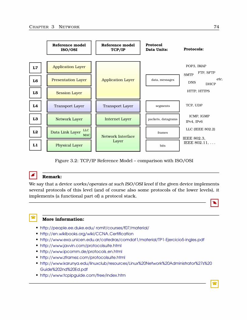
CHAPTER 3 NETWORK 74
Reference model
ISO/OSI
Reference model
TCP/IP
Protocol
Data Units: Protocols:
Application Layer
Presentation Layer
Session Layer
Transport Layer
Network Layer
Data Link LayerMAC
LLC
Physical Layer
L7
L6
L5
L4
L3
L2
L1
Application Layer
Transport Layer
Internet Layer
Network InterfaceLayer
data, messages
segments
packets, datagrams
frames
bits
HTTP, HTTPS
FTP, SFTP
DHCPDNS
POP3, IMAP
SMTP
etc.
TCP, UDP
IPv4, IPv6
ICMP, IGMP
LLC (IEEE 802.2)
IEEE 802.3,IEEE 802.11, . . .
Figure 3.2: TCP/IP Reference Model – comparison with ISO/OSI
� Remark:
We say that a device works/operates at such ISO/OSI level if the given device implementsseveral protocols of this level (and of course also some protocols of the lower levels), itimplements (a functional part of) a protocol stack.
�
� More information:
• http://people.ee.duke.edu/ romit/courses/f07/material/• http://en.wikibooks.org/wiki/CCNA Certification• http://www.exa.unicen.edu.ar/catedras/comdat1/material/TP1-Ejercicio5-ingles.pdf• http://www.javvin.com/protocolsuite.html• http://www.ipcomm.de/protocols en.html• http://www.zframez.com/protocolsuite.html• http://www.karunya.edu/linuxclub/resources/Linux%20Network%20Administrator%27s%20
Guide%202nd%20Ed.pdf• http://www.tcpipguide.com/free/index.htm
�
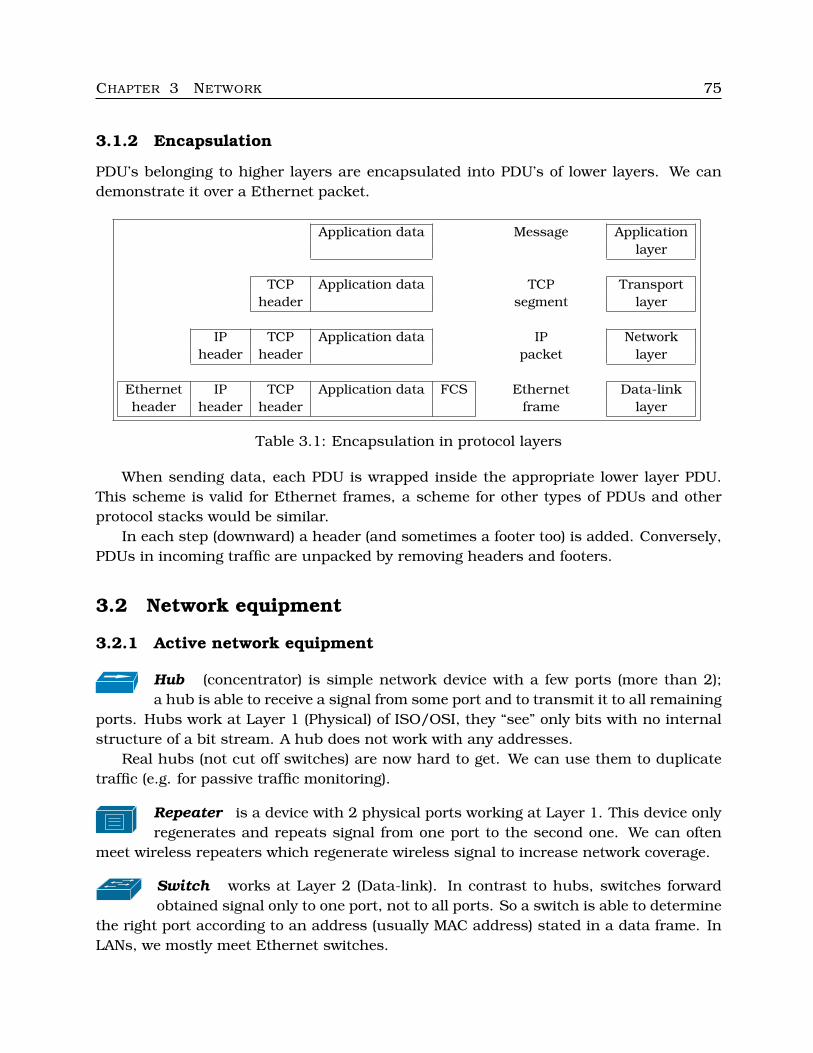
CHAPTER 3 NETWORK 75
3.1.2 Encapsulation
PDU’s belonging to higher layers are encapsulated into PDU’s of lower layers. We candemonstrate it over a Ethernet packet.
Application data Message Applicationlayer
TCP Application data TCP Transportheader segment layer
IP TCP Application data IP Networkheader header packet layer
Ethernet IP TCP Application data FCS Ethernet Data-linkheader header header frame layer
Table 3.1: Encapsulation in protocol layers
When sending data, each PDU is wrapped inside the appropriate lower layer PDU.This scheme is valid for Ethernet frames, a scheme for other types of PDUs and otherprotocol stacks would be similar.
In each step (downward) a header (and sometimes a footer too) is added. Conversely,PDUs in incoming traffic are unpacked by removing headers and footers.
3.2 Network equipment
3.2.1 Active network equipment
Hub (concentrator) is simple network device with a few ports (more than 2);a hub is able to receive a signal from some port and to transmit it to all remaining
ports. Hubs work at Layer 1 (Physical) of ISO/OSI, they “see” only bits with no internalstructure of a bit stream. A hub does not work with any addresses.
Real hubs (not cut off switches) are now hard to get. We can use them to duplicatetraffic (e.g. for passive traffic monitoring).
Repeater is a device with 2 physical ports working at Layer 1. This device onlyregenerates and repeats signal from one port to the second one. We can often
meet wireless repeaters which regenerate wireless signal to increase network coverage.
Switch works at Layer 2 (Data-link). In contrast to hubs, switches forwardobtained signal only to one port, not to all ports. So a switch is able to determine
the right port according to an address (usually MAC address) stated in a data frame. InLANs, we mostly meet Ethernet switches.
CHAPTER 3 NETWORK 76
A switch determines among ports by a special table with L2 addresses – this tableis called MAC table or CAM table. Each row of this table contains an MAC address, anoutcomming physical port (interface address) and some additional information accordingto specific properties of such device.
Some switches include L3 funcionality too (or – multilayer switch).
Bridge mainly operates at Layer 2 too. Bridges typicaly connect two networksegments, they work similarly to switches (but they have only two ports – each
for one network segment).
Wireless bridge connects a wireless network to another LAN. It can be WDS(Wireless Distribution System).
Router works at Layer 3 (Network Layer). Routers forward by logical addresses(mainly IP addresses), these addresses are kept in a routing table. More than one
way may lead into one destination L3 address (in contrast to MAC addresses at LANs), arouter has to choose one of the existing ways – the best one with the least cost.
Nowadays, routers work with subnets, not with particular computers. So, they havesubnet IP addresses in their routing tables.
Brouter (Bridge Router) is a device combining bridge and router functionality (it op-erates at Layers 2 and 3).
Gateway works on Layers 4–7. Geteways operate as interfaces connecting two networkswith different protocol stacks.
NIC (Network Interface Card) allows the computer or other complex device to accessa network medium (wired – e.g. Ethernet, or wireless – e.g. Wi-fi).
C Labs
Find out Cisco network icons on Internet. We will need them for networks modelling.They are accessible in several formats – EPS and some picture formats.
C
3.2.2 Passive network equipment
Signal in computer networks can be transmitted through
• copper cables (wired, the most common) – UTP (unshielded) or STP (shielded)
• optical cables (wired too, but LED or laser light is used instead of electrons)
• air (wireless – there are radio, infrared and other wireless networks)
• coaxial cables – TV signal distribution (TV antennas), connecting external antennato a wirelless router, . . . (with different impendances!)
• etc.
CHAPTER 3 NETWORK 77
Various cables constitute the most important passive network equipment.At Ethernet networks we often use UTP – unshielded twisted pair cables with RJ-45
connectors.
� Remark:
Important related standards:
• ISO/IEC 11801 – telecommunication cabling systems for structured cabling, weoften use the categories 5, 5e and 6 for Ethernet,
• ANSI/TIA/EIA-568-B – besides other elements, this standard defines the way ofplugging T568A better known as RJ-45.
�
� More information:
• Guide to ISO/IEC 11801. February 2008. URL: http://www.lanster.com/pub/files/file/okablowanie normy/Guide ISO 11801 2nd Amendment1.pdf
• What’s the Difference Between T568A and T568B? CableOrganizer.com LearningCenter. URL: http://www.cableorganizer.com/articles/difference-between-T568A-and-T568B.html
�
There are more different types of Ethernet cables (categories). The most common UTPcables are:
• Cat 3 – for telephone wiring only,
• Cat 5 – for Ethernet, frequencies of up to 100 MHz (10Base-T, Fast Ethernet 100Base-TX, and sometimes Gigabit Ethernet 1000Base-T), maximal length is 100 m,
• Cat 5e – similar to Cat 5, but crosstalk specifications are better, we use Cat 5e forGigabit Ethernet,
• Cat 6 – for Gigabit Ethernet and 10GBase-T (10Gb Ethernet), frequencies of up to250 MHz, more strict specifications for crosstalk and noise,
• Cat 6a (not 6e!) – frequencies of up to 500 MHz, improved specifications of aliencrosstalk; the maximal length is 100 m for Gigabit Ethernet and 55 m for 10GbEthernet,
• Cat 7, the newest one.
C Labs
Take a look (quickly) at the information sources stated above. Examine some Ethernetcable and find out its type.
C
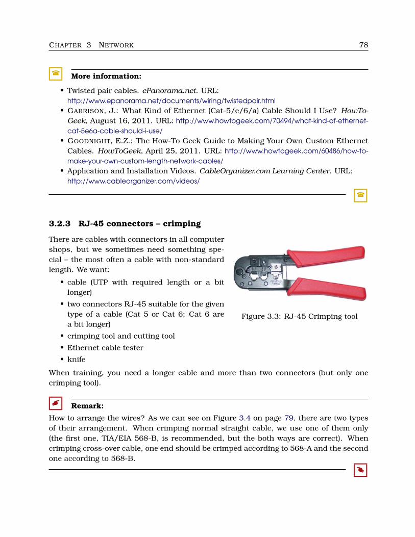
CHAPTER 3 NETWORK 78
� More information:
• Twisted pair cables. ePanorama.net. URL:http://www.epanorama.net/documents/wiring/twistedpair.html
• GARRISON, J.: What Kind of Ethernet (Cat-5/e/6/a) Cable Should I Use? HowTo-Geek, August 16, 2011. URL: http://www.howtogeek.com/70494/what-kind-of-ethernet-cat-5e6a-cable-should-i-use/
• GOODNIGHT, E.Z.: The How-To Geek Guide to Making Your Own Custom EthernetCables. HowToGeek, April 25, 2011. URL: http://www.howtogeek.com/60486/how-to-make-your-own-custom-length-network-cables/
• Application and Installation Videos. CableOrganizer.com Learning Center. URL:http://www.cableorganizer.com/videos/
�
3.2.3 RJ-45 connectors – crimping
Figure 3.3: RJ-45 Crimping tool
There are cables with connectors in all computershops, but we sometimes need something spe-cial – the most often a cable with non-standardlength. We want:
• cable (UTP with required length or a bitlonger)
• two connectors RJ-45 suitable for the giventype of a cable (Cat 5 or Cat 6; Cat 6 area bit longer)
• crimping tool and cutting tool
• Ethernet cable tester
• knife
When training, you need a longer cable and more than two connectors (but only onecrimping tool).
� Remark:
How to arrange the wires? As we can see on Figure 3.4 on page 79, there are two typesof their arrangement. When crimping normal straight cable, we use one of them only(the first one, TIA/EIA 568-B, is recommended, but the both ways are correct). Whencrimping cross-over cable, one end should be crimped according to 568-A and the secondone according to 568-B.
�
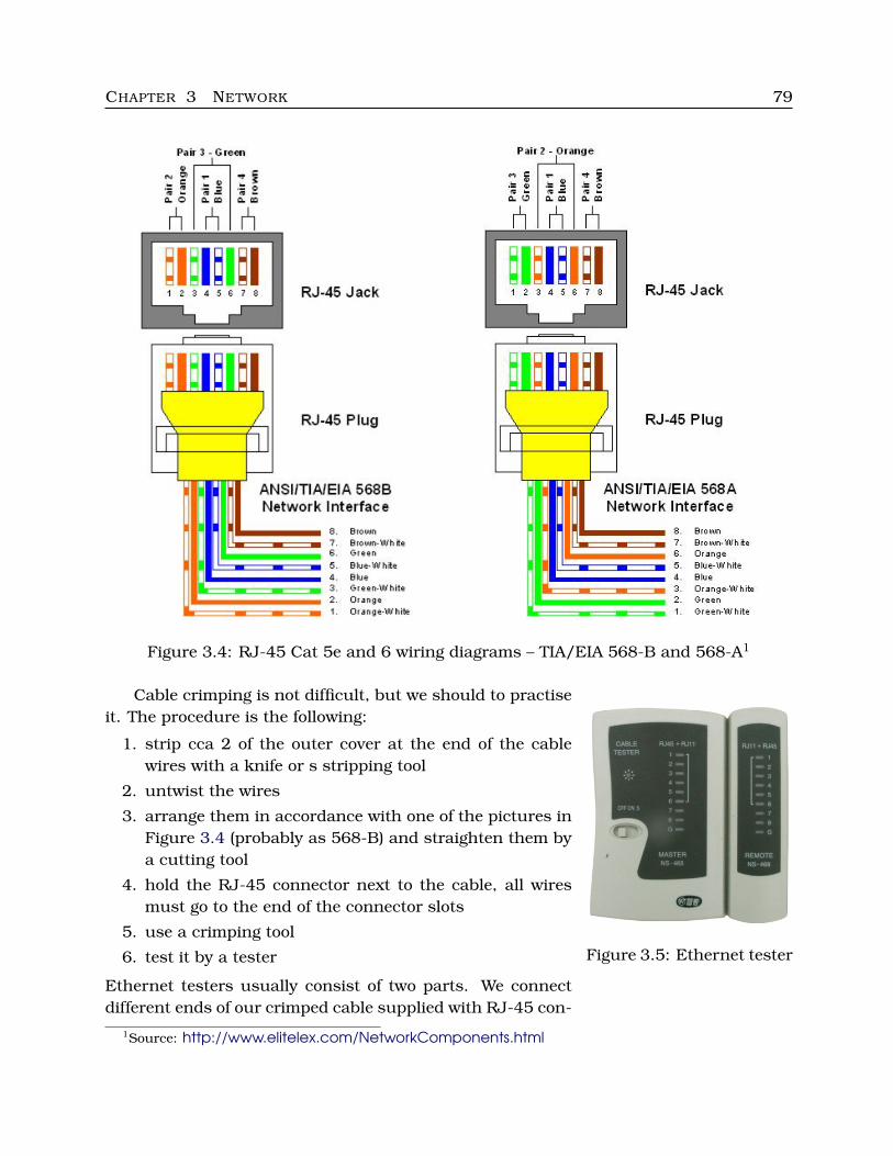
CHAPTER 3 NETWORK 79
Figure 3.4: RJ-45 Cat 5e and 6 wiring diagrams – TIA/EIA 568-B and 568-A1
Figure 3.5: Ethernet tester
Cable crimping is not difficult, but we should to practiseit. The procedure is the following:
1. strip cca 2 of the outer cover at the end of the cablewires with a knife or s stripping tool
2. untwist the wires
3. arrange them in accordance with one of the pictures inFigure 3.4 (probably as 568-B) and straighten them bya cutting tool
4. hold the RJ-45 connector next to the cable, all wiresmust go to the end of the connector slots
5. use a crimping tool
6. test it by a tester
Ethernet testers usually consist of two parts. We connectdifferent ends of our crimped cable supplied with RJ-45 con-
1Source: http://www.elitelex.com/NetworkComponents.html
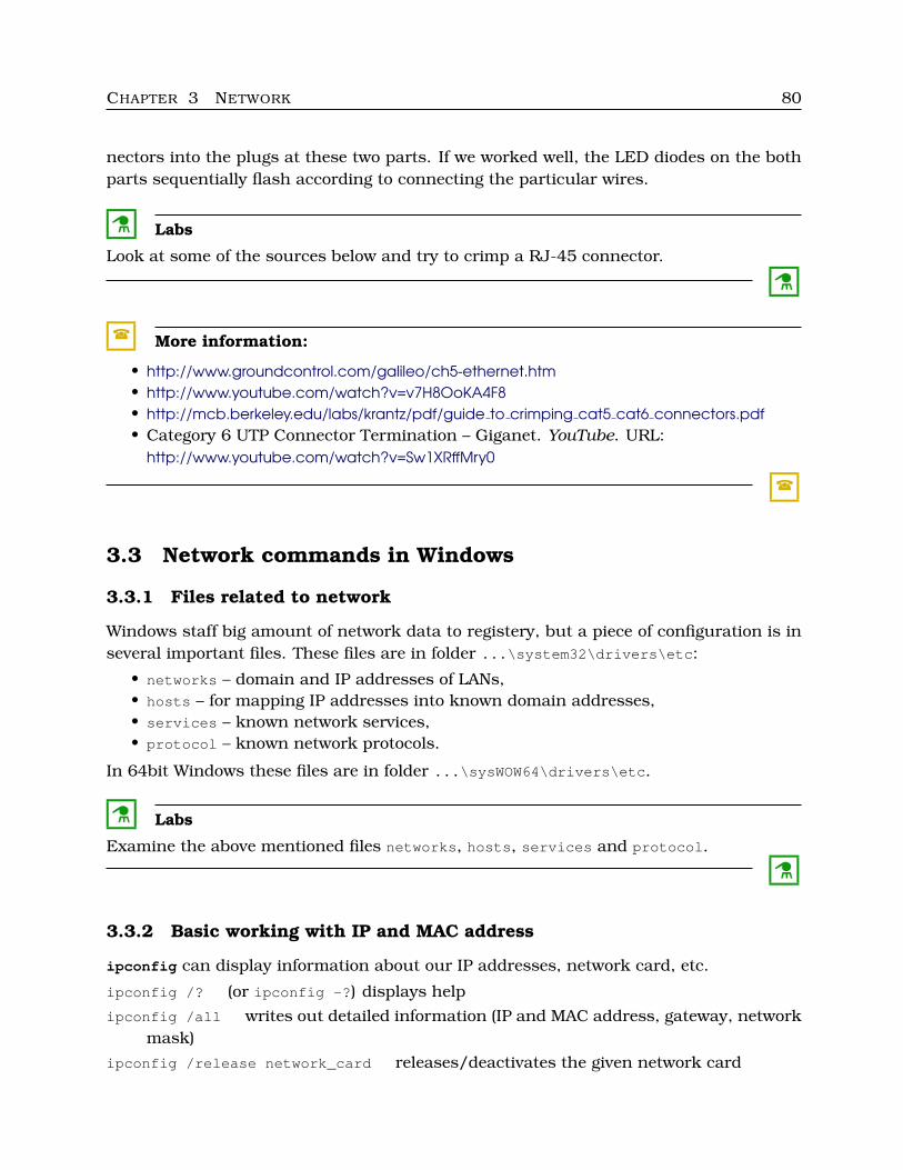
CHAPTER 3 NETWORK 80
nectors into the plugs at these two parts. If we worked well, the LED diodes on the bothparts sequentially flash according to connecting the particular wires.
C Labs
Look at some of the sources below and try to crimp a RJ-45 connector.
C
� More information:
• http://www.groundcontrol.com/galileo/ch5-ethernet.htm• http://www.youtube.com/watch?v=v7H8OoKA4F8• http://mcb.berkeley.edu/labs/krantz/pdf/guide to crimping cat5 cat6 connectors.pdf• Category 6 UTP Connector Termination – Giganet. YouTube. URL:
http://www.youtube.com/watch?v=Sw1XRffMry0
�
3.3 Network commands in Windows
3.3.1 Files related to network
Windows staff big amount of network data to registery, but a piece of configuration is inseveral important files. These files are in folder ...\system32\drivers\etc:
• networks – domain and IP addresses of LANs,• hosts – for mapping IP addresses into known domain addresses,• services – known network services,• protocol – known network protocols.
In 64bit Windows these files are in folder ...\sysWOW64\drivers\etc.
C Labs
Examine the above mentioned files networks, hosts, services and protocol.
C
3.3.2 Basic working with IP and MAC address
ipconfig can display information about our IP addresses, network card, etc.
ipconfig /? (or ipconfig -?) displays help
ipconfig /all writes out detailed information (IP and MAC address, gateway, networkmask)
ipconfig /release network_card releases/deactivates the given network card
CHAPTER 3 NETWORK 81
ipconfig /release releases/deactivates all network cards
ipconfig /renew network_card renews IP address for the given card
ipconfig /displaydns displays all used DNS records including their TTL
ipconfig /flushdns empties DNS cache
M Example 3.1
If we are unable to establish a network connection or our network connection is notworking properly (for example, when our network card by mistake received an IP addressthat is already assigned to another device, or DNS servers were not properly obtained),new IP address obtaining may help. We apply the following commands:
ipconfig /flushdns cleans DNS cache
ipconfig /release
ipconfig /renew
ipconfig /all checks if everything is all right
This procedure is useful only if we have dynamic IP addresses.
M
ARP is a protocol for mapping IP addresses into physical (MAC) addresses. MACaddresses are discovered by sending ARP packets with queries. Each network card keepsits own buffer with the established pairs of IP and MAC addresses (ARP tables). We workwith this mapping using the command arp.
arp -a displays ARP table
arp -a -n 10.0.128.10 displays ARP table of the network card with the given IP ad-dress
arp -s 123.123.123.123 00-12-34-56-78-9A adds new (static) entry to our ARP table
arp -d 123.123.123.123 removes the given entry
arp -d * removes all entries
The next useful command is nslookup. We use it to map domain addresses into IPaddresses.
nslookup www.google.com displays IP addresses and aliases for the given domain ad-dress
nslookup 77.76.75.3 reverse mapping
nslookup switching to the interaction mode, we exit it by the command exit
The whole help for this command is only in the interaction mode (by the inner command? or help).
If we send data to an IP address, the packets usually (not always) pass through agateway to the Internet or another network. Therefore, each node including common
CHAPTER 3 NETWORK 82
computers knows the gateway address and other routing information (i.e. which way tosend data to a certain (sub)networks), it keeps its own routing table. Records can beinserted into this table manually (static records) or dynamically (performed by routingprotocols).
The command route allows to work with this table.
route displays help
route print displays our routing table, in the newest versions it displays two tables –separately for IPv4 and IPv6
route print 193.* displays only those destinations which correspond to the given ex-pression (we can use “*” and “?” too)
route add 193.84.197.0 mask 255.255.255.128 193.84.195.8 metric 4 adds new sta-tic record with the given destination, mask, gateway and metric
route -p add 193.84.197.0 mask 255.255.255.128 193.84.195.8 metric 4 the sameas the previous example, but this record remains in the table after restart of com-puter
route change 193.84.197.0 mask 255.255.255.128 193.84.195.9 metric 3 if 2 wechange one record
route del 193.84.197.0 erases the record
C Labs
1. Obtain your IP address, mask, gateway address, DNS server address.
2. Do you have static or dynamic IP address? If you have a dynamic address, deacti-vate your network card and then activate it (renew your IP address).
3. Display your ARP table.
4. Find out IP address of the web microsoft.com.
5. Find out your DNS server (its IP address).
6. Display your routing table.
C
3.3.3 Testing and statistics
The command ping allows to test whether a device with the given domain or IP addressis accessible. This command send ICMP packets with ICMP Echo Request message.
ping www.google.com finds out if the given server is accessible
ping -n 2 www.google.com we assigned number of testing ICMP packets sent to thegiven server
ping -t www.google.com number of testing packets is unlimited, these packets aresent till pressing Ctrl+C
CHAPTER 3 NETWORK 83
M Example 3.2
We can use the command ping for testing of functionality of our network card too:ping loopback orping 127.0.0.1
M
M Example 3.3
If our network connection seems to be right, but in fact it does not work, we should verifyDNS translation functionality:
ping www.google.com probably produces an error message
ping 74.125.79.104 the same, but we use one of the IP addresses of such server in-stead of its domain address (so, we communicate without DNS mechanism)
If the second command is successfull, we probably use an address of non-functional DNSserver. We should get an address of a correct DNS server (e.g. at our connection provider)or we can use an address of a public DNS server.
There are several public DNS servers – e.g. Google provides these servers with ad-dresses 8.8.8.8 and 8.8.4.4.
M
We use tracert when we want to find the path of our sent packets (addresses of routersthrough the path). Windows tracert uses ICMP packets sent inside IP datagrams with agradually increasing value of TTL.
tracert -? help (yes, it is correct, UNIX syntax of switches, as for nearly all networkcommands)
tracert www.google.com what is the route to the given server?
We can assign IP addresses too.
The program pathping gives similar results (the whole path to the given server –router addresses), and in addition pathping calculates the statistic information similarto ping.It works on the principle of ICMP Echo Request and ICMP Echo Reply messages,just as ping.
pathping -? writes out help
pathping www.google.com router addresses and the related statistic information
The fist stage (listing router addresses) may be faster than by tracert, but the secondstage (statistics) is very slow – it may take more than 100 seconds. If it costs too longtime, we can press Ctrl+C .
netstat is very powerful tool to get statistic information related to the TCP/IP proto-cols. This program is in effect the same as the identically named command in UNIX-like
CHAPTER 3 NETWORK 84
systems. The command keeps the same UNIX syntax, and it even enables to group one-letter type switches after one dash. The set of switches supported in different Windowsversions is not the same!
netstat writes out basic statistics (only TCP connections, and without those applica-tions which listen)
netstat -a writes out whole statistics
netstat -a -o whole statistics, and one additional column – PID of the working pro-cess for each entry
netstat -ao the same (switches are grouped)
netstat -ano writes IP addresses instead of domain addresses; it is faster, and it worksalso if we have malfunctioning DNS servers
netstat -ab > seznam.log all processes (names and PID) communicating on network,the output is directed into the given file
netstat -e basic statistics for Ethernet (number of sent and received packets, numberof errors, etc. – TCP/IP protocols
netstat -es detailed statistics for all TCP/IP protocols
netstat -sp tcp detailed statistics for the protocol TCP (we can use the parameterstcp, udp or ip)
netstat 2 works repeatedly every 2 seconds, we finish it by pressing Ctrl+C (we cancombine it with other switches)
netstat -r displays our routing table, such as route print
M Example 3.4
The command netstat -osp tcp writes out detailed statistics for the TCP protocol, anddisplays the column with PID of a communicating process (switch -o). First, the statisticinformation is displayed. The table with process entries follows:
C:\Windows>netstat -osp tcp
Proto Local Address Foreign Address State PIDTCP 10.0.0.139:49206 111.221.74.19:33033 ESTABLISHED 3736TCP 10.0.0.139:49210 db3msgr6011410:https ESTABLISHED 3736...
The processes with established connection may be e.g. Skype, a mail client, web browser,antivirus software. We can find out the process name corresponding to our PID by TaskManager (press Ctrl+Shift+Esc , show the column with PID), or Process Explorer (to down-load on http://www.sysinternals.com) of by the command tasklist. In this case:
C:\Windows>tasklist
Image Name PID Session Name Session# Mem Usage========================================================================...Skype.exe 3736 Console 1 78 024 kB...
M
CHAPTER 3 NETWORK 85
C Labs
1. Try ping on your DNS server IP address, and then on IP addresses of Google publicDNS servers. Compare time results.
2. Note difference (including the time stamps) in the outputs of these commands:tracert www.google.com
pathping www.google.com
3. Find out PID of all processes which are communicating through network (or listen-ing).
4. Write out statistics related to TCP/IP protocols.
5. Write out detailed statistics for the IP protocol.
6. Try both the commands used in the last example of this section.
C
3.3.4 Other commands
Other useful commands (we know some of them from Operating systems):
net resources sharing in LAN, NTP server setting, users and groups management, etc.
wmic WMI Console, we know this command
netsh very unpopular command with its own inner subcommands, we know it too
ftp FTP client
ipseccmd IPSec protocol configuration, this command is available on servers
openfiles management of files open remotely through LAN on our or foreign computer(there are some variants of net for these reasons, see net file)
There are several commands installed on Windows Server which are not accessible ondesktop editions – commands to manage Active Directory (e.g. ntdsutil or netdom), tomanage DNS server (e.g. dnsutil), etc.
� More information:
• http://technet.microsoft.com/en-us/library/cc772390%28WS.10%29.aspx• http://www.microsoft.com/resources/documentation/windows/xp/all/proddocs/en-us
/ntcmds.mspx?mfr=true.• http://commandwindows.com/
�
3.4 Network commands in Linux
3.4.1 Files related to network
The most “network” files can be found in the directory /etc/sysconfig/network and itssubdirectories, alternatively /etc/sysconfig/network-scripts or for some distributions
CHAPTER 3 NETWORK 86
the directory /etc/rc.d/rc.inet1 (Slackware), /etc/conf.d/net (Gentoo) or /etc/network(Debian).
M Example 3.5
Suppose that our network configuration is in /etc/sysconfig/network-scripts. In thisdirectory, there would be placed the file ifcfg-eth0 with the configuration of the firstnetwork interface card – IP address, mask, way of obtaining IP address (if we get IPaddress dynamically, this address is not stated in this file), etc. If we have more networkcards, every network interface has such file in this directory.
M
M Example 3.6
Other interesting file is /etc/resolv.conf – we set DNS server addresses here. An entryrelated to a DNS server (we can have more similar entries) is of the formnameserver address, for examplenameserver 193.84.192.10
The given DNS server will be used immediately after saving this file.
M
M Example 3.7
Suppose that we want to create a router from a computer. With Linux, it is not hard.We just need to have a device with more than one network interface, and we have tocarry out a few settings. One of them is permitting of forwarding. We do it in the file/etc/sysctl.conf:
• find the row net.ipv4.ip_forward=0 (or net/ipv4/ip_forward=0)
• change it to net.ipv4.ip_forward=1 (or with slashes)
• restart the system or make the daemon sysctl to reread its configuration files:sysctl -p
Permitting of forwarding does not suffice. We have to set the address of this devide asgateway on all computers in the given LAN, and then we configure firewall and othersecurity mechanismes.
Note that we do not need to restart whole the system, although we made essentialchanges in system settings.
M
There is large amount of useful files in the directory /etc, for example /etc/networks,/etc/hosts, /etc/ethers.
Dynamic network settings can be found in subdirectories and files in /proc, for ex-ample /proc/net/arp.
CHAPTER 3 NETWORK 87
M Example 3.8
Some of the files in /proc allow writing in text mode (without file locking), such asecho 1 > /proc/sys/net/ipv4/ip_forward
switches on forwarding (well, we ought to have more than one network interface). If thevalue 0 is in this file, forwarding is off, the value 1 means working forwarding. However,this setting is valid only to reboot (of course, we are in /proc), so we have to save thiscommand into a suitable configuration file, for example /etc/rc.d/rc.local, accordingto our distribution.
M
C Labs
Examine the above mentioned files including the network parts of /proc.
C
3.4.2 Older address commands
First we look at the commands used to work with addresses used in UNIX-like systems fordecades. In the newer distributions, instead of the below mentioned commands ifconfig,route and arp, we often use new command ip.
ifconfig allows to configure network interfaces of kernel.
ifconfig displays information about all network interfaces
ifconfig eth0 displays information about the network interface eth0
ifconfig eth0 down “throws down” the network interface eth0 (deactivates this inter-face); we use it, if we want to assign a new IP address
ifconfig eth0 up activates eth0
ifconfig eth0 down hw ether 00:00:00:00:00:02 deactivates eth0 and sets new MACaddress
ifconfig eth0 172.19.124.104 netmask 255.255.255.0 up sets IP address and sub-net mask for eth0 and activates it
ifconfig eth0 promisc sets promiscuous mode for eth0
ifconfig eth0 -promisc switches off promiscuous mode
There are another switches (determination of multicast and broadcast addresses, assign-ing hardware resources (I/O memory, IRQ, etc.), setting metrics, and others.
M Example 3.9
The output of the command ifconfig on device with one network interface:sarka@notebook:˜$ ifconfig
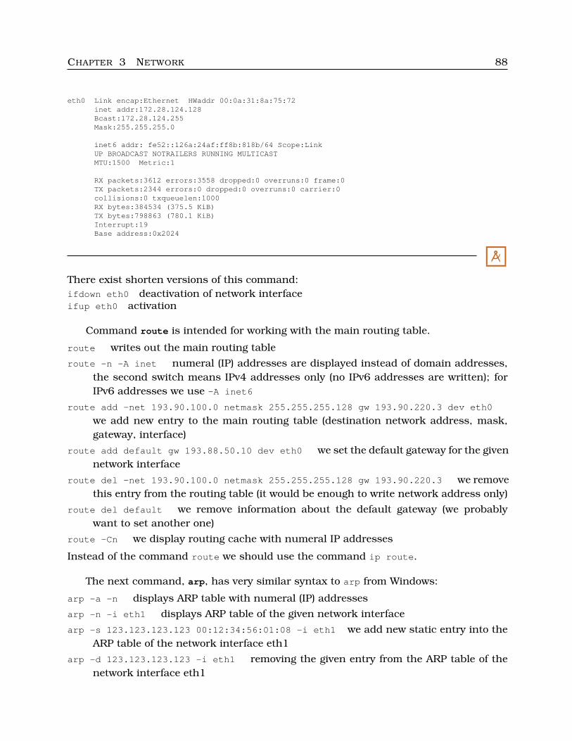
CHAPTER 3 NETWORK 88
eth0 Link encap:Ethernet HWaddr 00:0a:31:8a:75:72inet addr:172.28.124.128Bcast:172.28.124.255Mask:255.255.255.0
inet6 addr: fe52::126a:24af:ff8b:818b/64 Scope:LinkUP BROADCAST NOTRAILERS RUNNING MULTICASTMTU:1500 Metric:1
RX packets:3612 errors:3558 dropped:0 overruns:0 frame:0TX packets:2344 errors:0 dropped:0 overruns:0 carrier:0collisions:0 txqueuelen:1000RX bytes:384534 (375.5 KiB)TX bytes:798863 (780.1 KiB)Interrupt:19Base address:0x2024
M
There exist shorten versions of this command:ifdown eth0 deactivation of network interfaceifup eth0 activation
Command route is intended for working with the main routing table.
route writes out the main routing table
route -n -A inet numeral (IP) addresses are displayed instead of domain addresses,the second switch means IPv4 addresses only (no IPv6 addresses are written); forIPv6 addresses we use -A inet6
route add -net 193.90.100.0 netmask 255.255.255.128 gw 193.90.220.3 dev eth0
we add new entry to the main routing table (destination network address, mask,gateway, interface)
route add default gw 193.88.50.10 dev eth0 we set the default gateway for the givennetwork interface
route del -net 193.90.100.0 netmask 255.255.255.128 gw 193.90.220.3 we removethis entry from the routing table (it would be enough to write network address only)
route del default we remove information about the default gateway (we probablywant to set another one)
route -Cn we display routing cache with numeral IP addresses
Instead of the command route we should use the command ip route.
The next command, arp, has very similar syntax to arp from Windows:
arp -a -n displays ARP table with numeral (IP) addresses
arp -n -i eth1 displays ARP table of the given network interface
arp -s 123.123.123.123 00:12:34:56:01:08 -i eth1 we add new static entry into theARP table of the network interface eth1
arp -d 123.123.123.123 -i eth1 removing the given entry from the ARP table of thenetwork interface eth1
CHAPTER 3 NETWORK 89
C Labs
If possible, try the above mentioned commands.
C
3.4.3 iproute2 and command ip
Command ip (the part of the package iproute2) is very complex and besides others it isconsidered as successor of the above shortly described commands ifconfig, route a arp.Its configuration files can be found in /etc/iproute2. The following subsections mainlyshow usage of the command ip.
� More information:
• man ip
• http://linux-ip.net/gl/ip-cref/• http://linux-ip.net/html/index.html• http://www.policyrouting.org/iproute2-toc.html• http://lartc.org/howto/index.html• http://www.faqs.org/docs/Linux-mini/Remote-Bridging.html• http://www.linuxhomenetworking.com/wiki/index.php/Quick HOWTO : Ch03 : Linux Networking
�
3.4.4 Network interface and addresses
The first purpose of this command is setting network interfaces and IP addresses.
ip link ... we work on L2 (data-link) layer (and a bit L1 too) – MAC addresses andnetwork interface
ip link show displays the connection status, the network interface status of allinterfaces (it is possible to use list or ls instead of show, or we can shorten itinto sh
ip -s link show eth0 only for the interface eth0; the parameter -s means moredetailed output
ip link set dev eth0 up activates the eth0 interfaceip link set dev eth0 down deactivates the eth0 interfaceip link set dev eth0 mtu 1500 changes the MTU value to 1500 octets (MTU
means Maximum Transmission Unit, it is the maximal IP datagram lengthwhich is allowed to be transmitted through this device)
ip link set dev eth0 address 02:00:00:00:11:22 we change MAC address ofthe network interface eth0
ip addr ... now we work on L3 (network) layer – IP addresses (instead of addr we canwrite address or a)
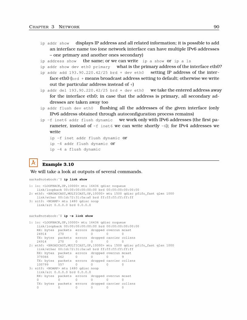
CHAPTER 3 NETWORK 90
ip addr show displays IP address and all related information; it is possible to addan interface name too (one network interface can have multiple IPv6 addresses– one primary and another ones secondary)
ip address show the same; or we can write ip a show or ip a ls
ip addr show dev eth0 primary what is the primary address of the interface eth0?ip addr add 193.90.220.42/25 brd + dev eth0 setting IP address of the inter-
face eth0 (brd + means broadcast address setting to default; otherwise we writeout the particular address instead of +)
ip addr del 193.90.220.42/25 brd + dev eth0 we take the entered address awayfor the interface eth0; in case that the address is primary, all secondary ad-dresses are taken away too
ip addr flush dev eth0 flushing all the addresses of the given interface (onlyIPv6 address obtained through autoconfiguration process remains)
ip -f inet6 addr flush dynamic we work only with IPv6 addresses (the first pa-rameter, instead of -f inet6 we can write shortly -6); for IPv4 addresses wewriteip -f inet addr flush dynamic orip -4 addr flush dynamic orip -4 a flush dynamic
M Example 3.10
We will take a look at outputs of several commands.
sarka@notebook:˜$ ip link show
1: lo: <LOOPBACK,UP,10000> mtu 16436 qdisc noqueuelink/loopback 00:00:00:00:00:00 brd 00:00:00:00:00:00
2: eth0: <BROADCAST,MULTICAST,UP,10000> mtu 1500 qdisc pfifo_fast qlen 1000link/ether 00:1d:72:31:0a:a0 brd ff:ff:ff:ff:ff:ff
3: sit0: <NOARP> mtu 1480 qdisc nooplink/sit 0.0.0.0 brd 0.0.0.0
sarka@notebook:˜$ ip -s link show
1: lo: <LOOPBACK,UP,10000> mtu 16436 qdisc noqueuelink/loopback 00:00:00:00:00:00 brd 00:00:00:00:00:00RX: bytes packets errors dropped overrun mcast24914 270 0 0 0 0TX: bytes packets errors dropped carrier collsns24914 270 0 0 0 0
2: eth0: <BROADCAST,MULTICAST,UP,10000> mtu 1500 qdisc pfifo_fast qlen 1000link/ether 00:1d:72:31:0a:a0 brd ff:ff:ff:ff:ff:ffRX: bytes packets errors dropped overrun mcast379366 562 0 0 0 9TX: bytes packets errors dropped carrier collsns100799 557 0 0 0 0
3: sit0: <NOARP> mtu 1480 qdisc nooplink/sit 0.0.0.0 brd 0.0.0.0RX: bytes packets errors dropped overrun mcast0 0 0 0 0 0TX: bytes packets errors dropped carrier collsns0 0 0 0 0 0
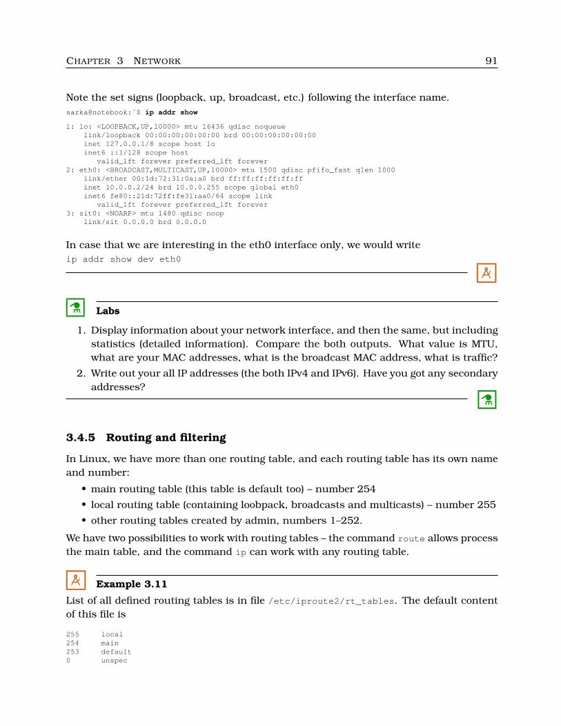
CHAPTER 3 NETWORK 91
Note the set signs (loopback, up, broadcast, etc.) following the interface name.sarka@notebook:˜$ ip addr show
1: lo: <LOOPBACK,UP,10000> mtu 16436 qdisc noqueuelink/loopback 00:00:00:00:00:00 brd 00:00:00:00:00:00inet 127.0.0.1/8 scope host loinet6 ::1/128 scope host
valid_lft forever preferred_lft forever2: eth0: <BROADCAST,MULTICAST,UP,10000> mtu 1500 qdisc pfifo_fast qlen 1000
link/ether 00:1d:72:31:0a:a0 brd ff:ff:ff:ff:ff:ffinet 10.0.0.2/24 brd 10.0.0.255 scope global eth0inet6 fe80::21d:72ff:fe31:aa0/64 scope link
valid_lft forever preferred_lft forever3: sit0: <NOARP> mtu 1480 qdisc noop
link/sit 0.0.0.0 brd 0.0.0.0
In case that we are interesting in the eth0 interface only, we would writeip addr show dev eth0
M
C Labs
1. Display information about your network interface, and then the same, but includingstatistics (detailed information). Compare the both outputs. What value is MTU,what are your MAC addresses, what is the broadcast MAC address, what is traffic?
2. Write out your all IP addresses (the both IPv4 and IPv6). Have you got any secondaryaddresses?
C
3.4.5 Routing and filtering
In Linux, we have more than one routing table, and each routing table has its own nameand number:
• main routing table (this table is default too) – number 254
• local routing table (containing loobpack, broadcasts and multicasts) – number 255
• other routing tables created by admin, numbers 1–252.
We have two possibilities to work with routing tables – the command route allows processthe main table, and the command ip can work with any routing table.
M Example 3.11
List of all defined routing tables is in file /etc/iproute2/rt_tables. The default contentof this file is
255 local254 main253 default0 unspec
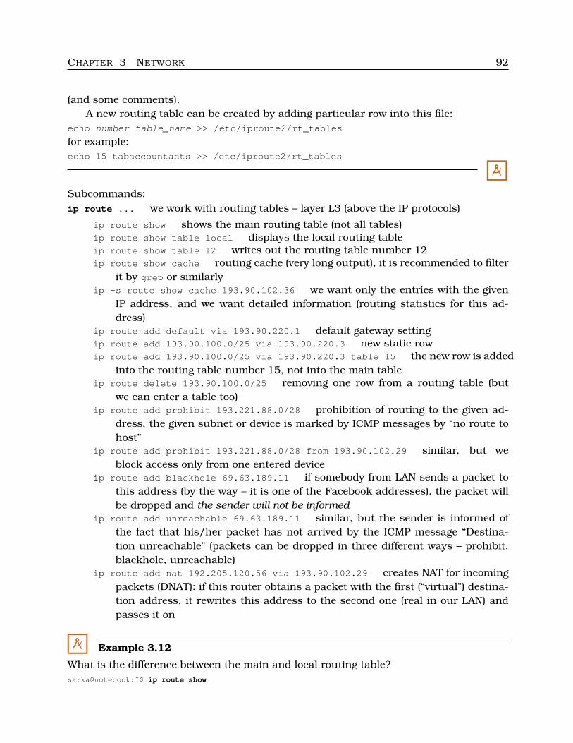
CHAPTER 3 NETWORK 92
(and some comments).A new routing table can be created by adding particular row into this file:
echo number table_name >> /etc/iproute2/rt_tables
for example:echo 15 tabaccountants >> /etc/iproute2/rt_tables
M
Subcommands:ip route ... we work with routing tables – layer L3 (above the IP protocols)
ip route show shows the main routing table (not all tables)ip route show table local displays the local routing tableip route show table 12 writes out the routing table number 12ip route show cache routing cache (very long output), it is recommended to filter
it by grep or similarlyip -s route show cache 193.90.102.36 we want only the entries with the given
IP address, and we want detailed information (routing statistics for this ad-dress)
ip route add default via 193.90.220.1 default gateway settingip route add 193.90.100.0/25 via 193.90.220.3 new static rowip route add 193.90.100.0/25 via 193.90.220.3 table 15 the new row is added
into the routing table number 15, not into the main tableip route delete 193.90.100.0/25 removing one row from a routing table (but
we can enter a table too)ip route add prohibit 193.221.88.0/28 prohibition of routing to the given ad-
dress, the given subnet or device is marked by ICMP messages by “no route tohost”
ip route add prohibit 193.221.88.0/28 from 193.90.102.29 similar, but weblock access only from one entered device
ip route add blackhole 69.63.189.11 if somebody from LAN sends a packet tothis address (by the way – it is one of the Facebook addresses), the packet willbe dropped and the sender will not be informed
ip route add unreachable 69.63.189.11 similar, but the sender is informed ofthe fact that his/her packet has not arrived by the ICMP message “Destina-tion unreachable” (packets can be dropped in three different ways – prohibit,blackhole, unreachable)
ip route add nat 192.205.120.56 via 193.90.102.29 creates NAT for incomingpackets (DNAT): if this router obtains a packet with the first (“virtual”) destina-tion address, it rewrites this address to the second one (real in our LAN) andpasses it on
M Example 3.12
What is the difference between the main and local routing table?sarka@notebook:˜$ ip route show
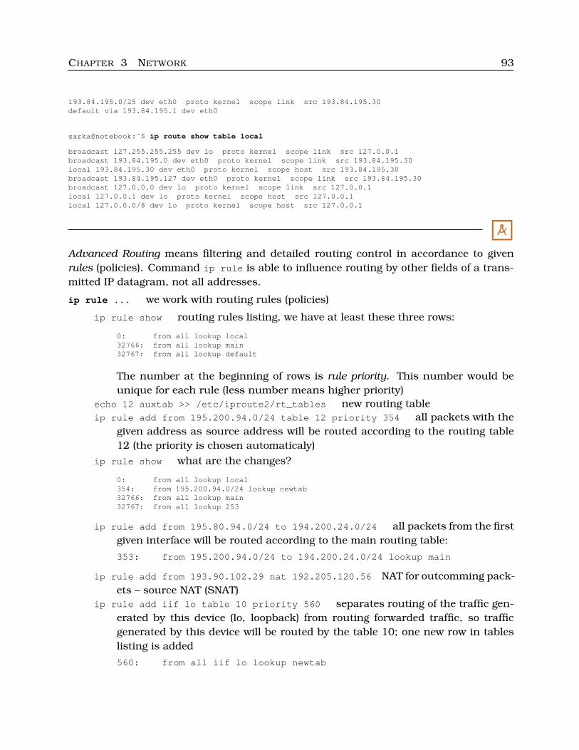
CHAPTER 3 NETWORK 93
193.84.195.0/25 dev eth0 proto kernel scope link src 193.84.195.30default via 193.84.195.1 dev eth0
sarka@notebook:˜$ ip route show table local
broadcast 127.255.255.255 dev lo proto kernel scope link src 127.0.0.1broadcast 193.84.195.0 dev eth0 proto kernel scope link src 193.84.195.30local 193.84.195.30 dev eth0 proto kernel scope host src 193.84.195.30broadcast 193.84.195.127 dev eth0 proto kernel scope link src 193.84.195.30broadcast 127.0.0.0 dev lo proto kernel scope link src 127.0.0.1local 127.0.0.1 dev lo proto kernel scope host src 127.0.0.1local 127.0.0.0/8 dev lo proto kernel scope host src 127.0.0.1
M
Advanced Routing means filtering and detailed routing control in accordance to givenrules (policies). Command ip rule is able to influence routing by other fields of a trans-mitted IP datagram, not all addresses.
ip rule ... we work with routing rules (policies)
ip rule show routing rules listing, we have at least these three rows:
0: from all lookup local32766: from all lookup main32767: from all lookup default
The number at the beginning of rows is rule priority. This number would beunique for each rule (less number means higher priority)
echo 12 auxtab >> /etc/iproute2/rt_tables new routing tableip rule add from 195.200.94.0/24 table 12 priority 354 all packets with the
given address as source address will be routed according to the routing table12 (the priority is chosen automaticaly)
ip rule show what are the changes?
0: from all lookup local354: from 195.200.94.0/24 lookup newtab32766: from all lookup main32767: from all lookup 253
ip rule add from 195.80.94.0/24 to 194.200.24.0/24 all packets from the firstgiven interface will be routed according to the main routing table:
353: from 195.200.94.0/24 to 194.200.24.0/24 lookup main
ip rule add from 193.90.102.29 nat 192.205.120.56 NAT for outcomming pack-ets – source NAT (SNAT)
ip rule add iif lo table 10 priority 560 separates routing of the traffic gen-erated by this device (lo, loopback) from routing forwarded traffic, so trafficgenerated by this device will be routed by the table 10; one new row in tableslisting is added
560: from all iif lo lookup newtab
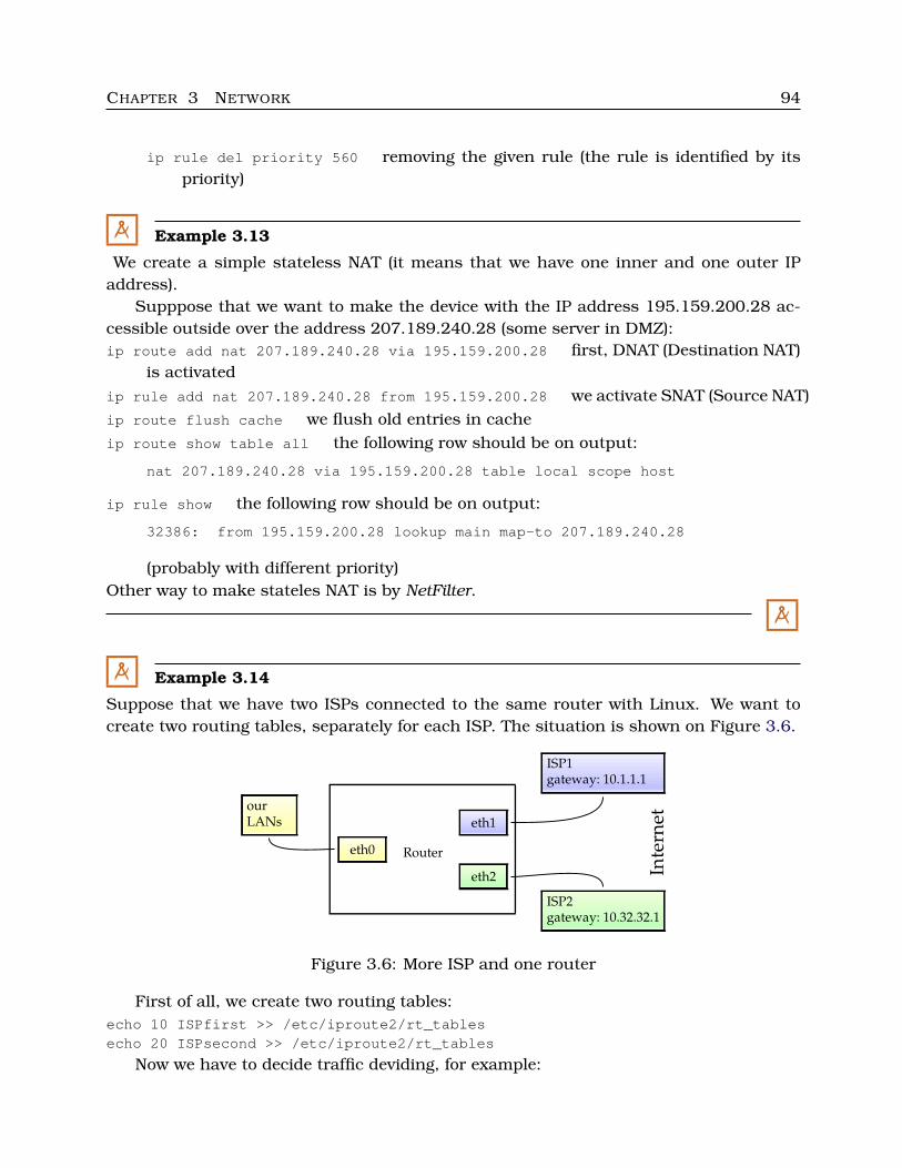
CHAPTER 3 NETWORK 94
ip rule del priority 560 removing the given rule (the rule is identified by itspriority)
M Example 3.13
We create a simple stateless NAT (it means that we have one inner and one outer IPaddress).
Supppose that we want to make the device with the IP address 195.159.200.28 ac-cessible outside over the address 207.189.240.28 (some server in DMZ):ip route add nat 207.189.240.28 via 195.159.200.28 first, DNAT (Destination NAT)
is activatedip rule add nat 207.189.240.28 from 195.159.200.28 we activate SNAT (Source NAT)ip route flush cache we flush old entries in cacheip route show table all the following row should be on output:
nat 207.189.240.28 via 195.159.200.28 table local scope host
ip rule show the following row should be on output:
32386: from 195.159.200.28 lookup main map-to 207.189.240.28
(probably with different priority)Other way to make stateles NAT is by NetFilter.
M
M Example 3.14
Suppose that we have two ISPs connected to the same router with Linux. We want tocreate two routing tables, separately for each ISP. The situation is shown on Figure 3.6.
ISP1gateway: 10.1.1.1
ourLANs eth1
eth0 Router
Inte
rnet
eth2
ISP2gateway: 10.32.32.1
Figure 3.6: More ISP and one router
First of all, we create two routing tables:echo 10 ISPfirst >> /etc/iproute2/rt_tablesecho 20 ISPsecond >> /etc/iproute2/rt_tables
Now we have to decide traffic deviding, for example:
CHAPTER 3 NETWORK 95
ip route add default via 10.32.32.1 dev eth2 default gateway for everything notlisted in other tables
ip route add default via 10.1.1.1 dev eth1 table 10 new entry into the table 10(default gateway for everything routed by this table)
ip route add default via 10.32.32.1 dev eth2 table 20 similarly for the second ta-ble
ip rule add from 10.192.0.0/24 table 10 all packets incoming from the given LAN,is routed in accordance with the table 10
ip rule add from 10.192.128.0/24 table 20 all packets incoming from the given LAN,is routed in accordance with the table 20
M
C Labs
1. Find out and display the file /etc/iproute2/rt_tables). What privileques are set tothis file?
• ls -la /etc/iproute2/rt_tables basic permissions• getfacl /etc/iproute2/rt_tables lists POSIX ACLs• lsattr /etc/iproute2/rt_tables file attributes• getfattr /etc/iproute2/rt_tables extended attributes
2. Write out the main routing table and compare it with the output of the commandroute. Display your local routing table too. Find out default gateway address. Howwould you change this gateway address?
3. Display all the defined rules for advanced routing.
C
3.4.6 Neighbourhood
IPv4 protocols uses ARP protocol for network discovering, IPv6 uses NDP (NeighbourDiscovery Protocol) – NDis mechanism (Network Discovery).
The particular network nodes can be in some of the following states (we call it NUD,Neighbour Unreachability Detection):
• none – state “non-filled”• noarp – neighbour is valid and accessible, it does not have to be verified by ARP
queries, expiration date is determined• permanent – similar to noarp, but without any expiration date (unlimited validation
time)• reachable – valid and accessible, with expiration date, and after this date it is re-
discovered by ARP queries (typical for dynamicaly discovered neighbours)• incomplete – neighbour is just discovered
CHAPTER 3 NETWORK 96
• stale – valid, but its accessibility is permanently discovered (this entry changes itsstate to delay after each using)
• delay – it is necessary to verify this entry• probe – the neighbour have not answered in time, kernel has to send ARP query• failed – ARP query has failed, this entry is not valid
The most common states are reachable, stale or permanent.Prıkazy:
ip neighbour ... we work with connections between L2 and L3 addresses of the samenetwork (with neighbours), we can shorten the word neighbour to neighbor, neighor n
ip neigh show displays current status of ARP or NDP cache (tables)ip neigh show dev eth0 list of neighbours connected to the interface eth0ip neigh show to 193.168.200/24 neighbours from the given subnetip -s neigh show to 10.0.0.1 detailed information about the given neighbour
(number of users of this entry, and number of seconds passed since using/con-firmation/update
ip neigh show nud permanent all neighbours with the state je “permanent”ip neigh add 193.168.200.1 lladdr 00:0a:1b:2c:3d:4e dev eth2 nud permanent
adding new static entry to the ARP table (IP and MAC address, interface, state),nud value becomes one of the possibilities noarp, reachable, permanent or stale
ip neigh del 193.168.200.1 dev eth2 removing the given entry
C Labs
1. Display your ARP/NDP cache. Try displaying with statistics (detailed information.
2. Add a “virtual” neighbour to your ARP cache – with MAC address 03:00:01:a5:b6:c7,IP address is 10.0.0.12, and it is connected to eth0, state permanent. Display allneighbours. Display all members with the state permanent. Remove the new entry.
3. Complete the whole interface activation procedure:
• deactivate the interface• set new IP address• set gateway• set DNS server address• activate the interface
C
3.5 Network diagnosis
3.5.1 Wi-fi channels
As we know, too much Wi-fi access points (APs) mean errors in packets transmission,necessity of their retransmission, so, slower traffic.
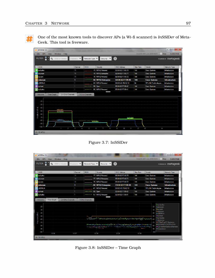
CHAPTER 3 NETWORK 97
One of the most known tools to discover APs (a Wi-fi scanner) is InSSIDer of Meta-Geek. This tool is freeware.
Figure 3.7: InSSIDer
Figure 3.8: InSSIDer – Time Graph
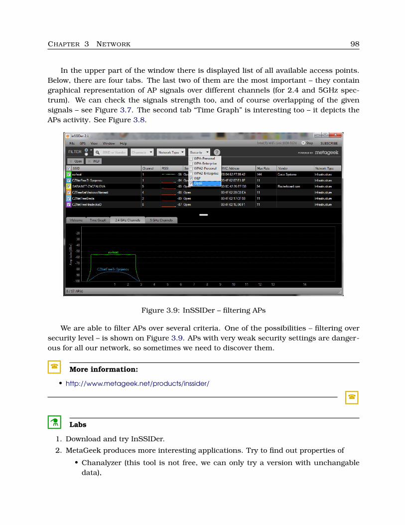
CHAPTER 3 NETWORK 98
In the upper part of the window there is displayed list of all available access points.Below, there are four tabs. The last two of them are the most important – they containgraphical representation of AP signals over different channels (for 2.4 and 5GHz spec-trum). We can check the signals strength too, and of course overlapping of the givensignals – see Figure 3.7. The second tab “Time Graph” is interesting too – it depicts theAPs activity. See Figure 3.8.
Figure 3.9: InSSIDer – filtering APs
We are able to filter APs over several criteria. One of the possibilities – filtering oversecurity level – is shown on Figure 3.9. APs with very weak security settings are danger-ous for all our network, so sometimes we need to discover them.
� More information:
• http://www.metageek.net/products/inssider/
�
C Labs
1. Download and try InSSIDer.
2. MetaGeek produces more interesting applications. Try to find out properties of
• Chanalyzer (this tool is not free, we can only try a version with unchangabledata),
CHAPTER 3 NETWORK 99
• Wi-Spy (commertial),• Eye P.A. (downloadable fully functional version for 15 days),• AirPcap (commertial), etc.
Some of the products require special hardware.C
Sometimes we need to map Wi-fi signal coverage. There are several tools which can helpus with Wi-fi planning, for example Ekahau Site Survey (commercial), Ekahau HeatMap-per (freeware after registration), MetaGeek VisiWave (free trial for 30 days), Meraki WiFiMapper (freeware), Aerohive Wi-Fi Planning Tool (freeware after registration).
� More information:
• http://www.ekahau.com/products/heatmapper/overview.html• http://www.metageek.net/products/visiwave/• http://www.meraki.com/products/wireless/wifi-mapper• http://www.aerohive.com/planner• http://www.youtube.com/watch?feature=player embedded&v=EaeMof51txg (video)
�
C Labs
Choose and try some of the Wi-fi tools listed above.
C
We sometimes need to map (depict) our network. Well, we can use a piece of paper and apencil, but there are several applications for these purposes. Most of them are proprietary(commercial), but some of them are free. The ones with manual handling allow to createa network map by manually placing icons and connections, the automated ones generatethe maps by traversing the network and discovering the active devices.
One of the interesting very simple tools is Diagramly (free, web application) – see theicons “Clipart/Networking” and “Clipart/Telecomunication”. The other one, Creately, ismore sophisticated, but commercial (it is possible try it free). Cade is one of the freemapping tools.
� More information:
• https://www.draw.io/ (Diagramly)• http://creately.com/ (Creately)• http://www.weresc.com/home.php (Cade)• http://en.wikipedia.org/wiki/Comparison of network diagram software• http://www.idsia.ch/andrea/sim/simnet.html
�
CHAPTER 3 NETWORK 100
C Labs
Take a look at several mapping tools, choose two of them and try to create a simplenetwork.
C
3.5.2 Wireshark
Wireshark is the most common used packet sniffer. It is free software availableunder GPL, and free for download. If we use Windows, this program works over
WinPCap – packet capture library for Windows. WinPCap is API for Windows that allowsto capture network data, using filters and setting network card to the promiscuous mode.Wireshark (because of WinPCap) supports great amount of various protocols and is veryeasy to use.
� More information:
• http://www.wireshark.org/
�
For Windows and MacOS X – we download the installation package from the web men-tioned above and install it as usual. For Linux – installation packages are very probablyavailable over your package manager, so click, click and click, or for example in Debian-based Linuxes writeapt-get install wireshark (with root privileges – use su or sudo).
First of all, we need to choose the network interface to track. The procedure is hintedon Figure 3.10 (menu Capture ï Interfaces). We ought to switch our network card tothe promiscuous mode (in order to capture all packets, not only those intended to us) inOptions, see Figure 3.11. Then we click to Start. The entire procedure is the following:
1. choose the network interface, set it to the promiscuous mode,
2. start capturing,
3. wait a minute (not too long),
4. stop capturing – menu Capture ï Stop, or the corresponding icon.
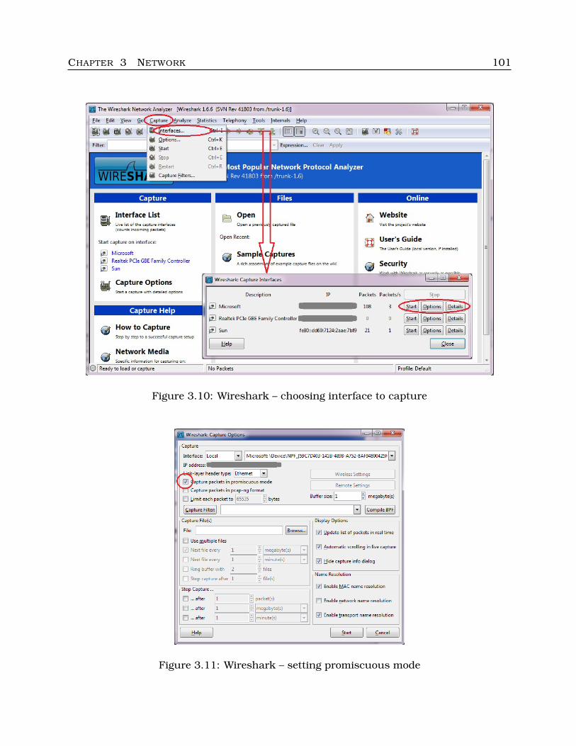
CHAPTER 3 NETWORK 101
Figure 3.10: Wireshark – choosing interface to capture
Figure 3.11: Wireshark – setting promiscuous mode
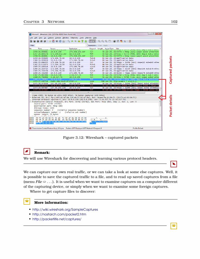
CHAPTER 3 NETWORK 102
Figure 3.12: Wireshark – captured packets
� Remark:
We will use Wireshark for discovering and learning various protocol headers.
�
We can capture our own real traffic, or we can take a look at some else captures. Well, itis possible to save the captured traffic to a file, and to read up saved captures from a file(menu File ï . . . ). It is useful when we want to examine captures on a computer differentof the capturing device, or simply when we want to examine some foreign captures.
Where to get capture files to discover:
� More information:
• http://wiki.wireshark.org/SampleCaptures• http://nostarch.com/packet2.htm• http://packetlife.net/captures/
�
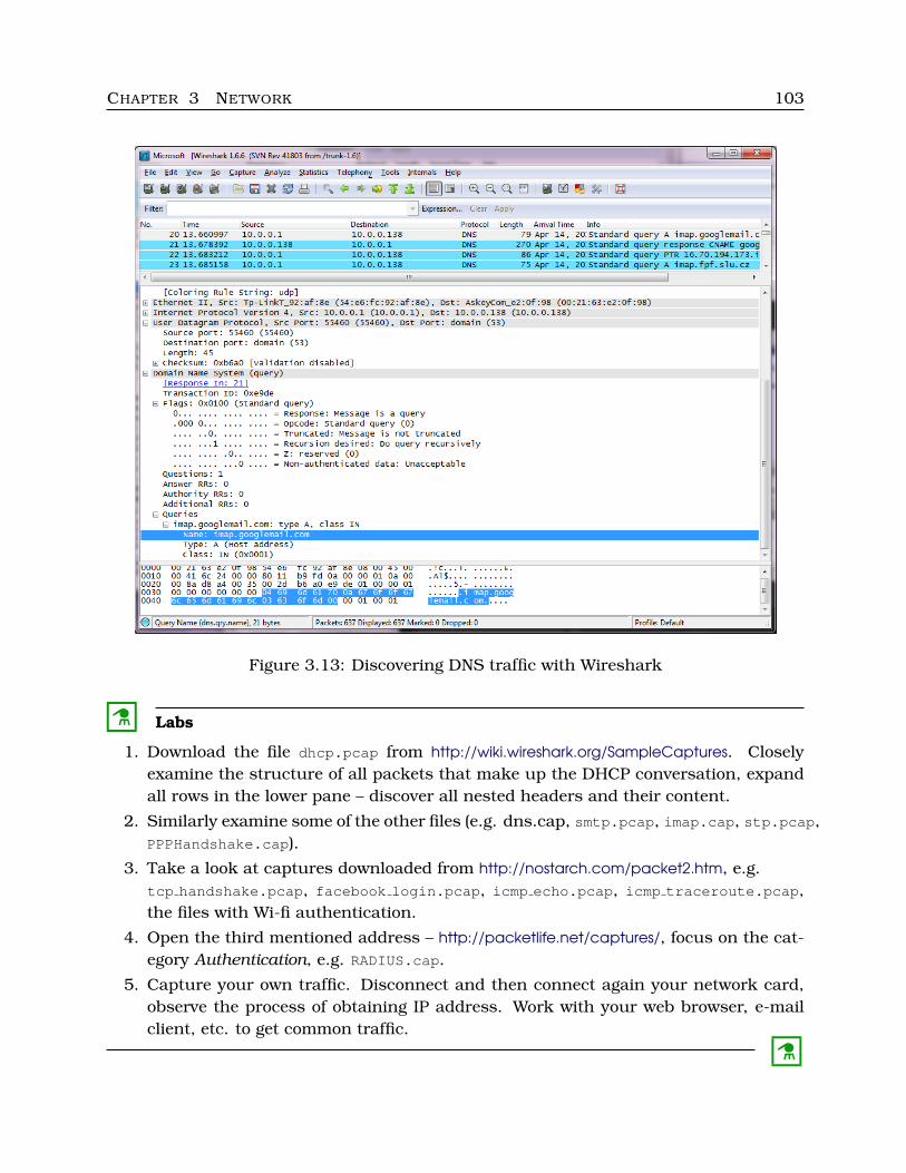
CHAPTER 3 NETWORK 103
Figure 3.13: Discovering DNS traffic with Wireshark
C Labs
1. Download the file dhcp.pcap from http://wiki.wireshark.org/SampleCaptures. Closelyexamine the structure of all packets that make up the DHCP conversation, expandall rows in the lower pane – discover all nested headers and their content.
2. Similarly examine some of the other files (e.g. dns.cap, smtp.pcap, imap.cap, stp.pcap,PPPHandshake.cap).
3. Take a look at captures downloaded from http://nostarch.com/packet2.htm, e.g.tcp handshake.pcap, facebook login.pcap, icmp echo.pcap, icmp traceroute.pcap,the files with Wi-fi authentication.
4. Open the third mentioned address – http://packetlife.net/captures/, focus on the cat-egory Authentication, e.g. RADIUS.cap.
5. Capture your own traffic. Disconnect and then connect again your network card,observe the process of obtaining IP address. Work with your web browser, e-mailclient, etc. to get common traffic.
C
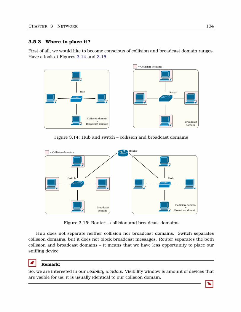
CHAPTER 3 NETWORK 104
3.5.3 Where to place it?
First of all, we would like to become conscious of collision and broadcast domain ranges.Have a look at Figures 3.14 and 3.15.
Hub
Collision domain
=
Broadcast domain
Switch
Broadcast
domain
= Collision domains
Figure 3.14: Hub and switch – collision and broadcast domains
Switch
Broadcast
domain
= Collision domainsRouter
Hub
Collision domain
=
Broadcast domain
Figure 3.15: Router – collision and broadcast domains
Hub does not separate neither collision nor broadcast domains. Switch separatescollision domains, but it does not block broadcast messages. Router separates the bothcollision and broadcast domains – it means that we have less opportunity to place oursniffing device.
� Remark:
So, we are interested in our visibility window. Visibility window is amount of devices thatare visible for us; it is usually identical to our collision domain.
�
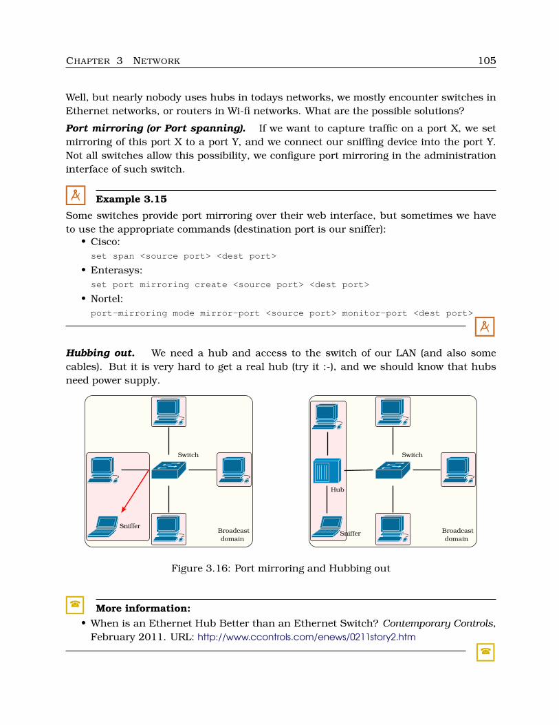
CHAPTER 3 NETWORK 105
Well, but nearly nobody uses hubs in todays networks, we mostly encounter switches inEthernet networks, or routers in Wi-fi networks. What are the possible solutions?
Port mirroring (or Port spanning). If we want to capture traffic on a port X, we setmirroring of this port X to a port Y, and we connect our sniffing device into the port Y.Not all switches allow this possibility, we configure port mirroring in the administrationinterface of such switch.
M Example 3.15
Some switches provide port mirroring over their web interface, but sometimes we haveto use the appropriate commands (destination port is our sniffer):
• Cisco:set span <source port> <dest port>
• Enterasys:set port mirroring create <source port> <dest port>
• Nortel:port-mirroring mode mirror-port <source port> monitor-port <dest port>
M
Hubbing out. We need a hub and access to the switch of our LAN (and also somecables). But it is very hard to get a real hub (try it :-), and we should know that hubsneed power supply.
Switch
Broadcast
domain
Sniffer
Switch
Broadcast
domainSniffer
Hub
Figure 3.16: Port mirroring and Hubbing out
� More information:• When is an Ethernet Hub Better than an Ethernet Switch? Contemporary Controls,
February 2011. URL: http://www.ccontrols.com/enews/0211story2.htm
�
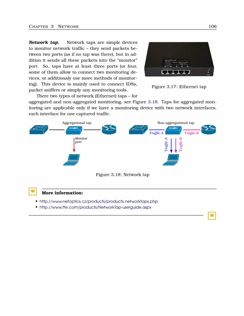
CHAPTER 3 NETWORK 106
Figure 3.17: Ethernet tap
Network tap. Network taps are simple devicesto monitor network traffic – they send packets be-tween two ports (as if no tap was there), but in ad-dition it sends all these packets into the “monitor”port. So, taps have at least three ports (or four,some of them allow to connect two monitoring de-vices, or additionaly use more methods of monitor-ing). This device is mainly used to connect IDSs,packet sniffers or simply any monitoring tools.
There two types of network (Ethernet) taps – foraggregated and non-aggregated monitoring, see Figure 3.18. Taps for aggregated mon-itoring are applicable only if we have a monitoring device with two network interfaces,each interface for one captured traffic.
Aggregational tap
Monitorport
Non-aggregational tap
Traffic A
Tra
ffic
A
Traffic B
Tra
ffic
B
Figure 3.18: Network tap
� More information:
• http://www.netoptics.cz/products/products networktaps.php• http://www.fte.com/products/NetworkTap-userguide.aspx
�
Chapter 4Servers
4.1 Windows Server
4.1.1 Editions
Windows Server in all versions contain the same kernel as Windows NT systems fordesktops. Similarly as on desktops, server versions occur in more editions too, but thenewest version is “less cut” than the previous versions.
Windows Server 2008 (kernel as Windows Vista) was accessible in these editions:
• Standard
• Enterprise
• Datacenter
• Foundation – for smaller companies, OEM only
• Web Server, Storage Server
• Server for Itanium-based Systems
Other editions are Small Business Server, Essential Business Server and HPC Server(Compute Cluster).
Windows Server 2008 R2 provide similar editions, their kernel is the same as inWindows 7.
Windows Server 2012 (or Windows Server 8) have the same kernel as Windows 8, andthere are a bit less editions:
• Standard
• Datacenter
• Foundation
• Essentials
There are more differencies among these editions – number of supported processors orwhole hardware architectures, maximum RAM, parallely connected users, server roles,etc.
107
CHAPTER 4 SERVERS 108
� More information:
• http://www.microsoft.com/en-us/server-cloud/windows-server/buy.aspx (follow “Get Licenc-ing Details”)
• http://chakkaradeep.wordpress.com/2008/02/06/windows-server-2008-edition-feature-differences/• http://technet.microsoft.com/en-us/library/dd459191.aspx• http://technet.microsoft.com/en-us/library/dd349801%28v=ws.10%29.aspx• http://en.wikipedia.org/wiki/Comparison of Microsoft Windows versions
�
C Labs
Find out possibilities of such editions, their comparison. What editions have or have notthese properties:
• support of 64 processor chips
• user limit 25 users
• DHCP role and DNS role
• Server Core mode
• Hyper-V (hypervisor)
• IIS (web server role)
C
4.1.2 Roles
A role is a primary duty (service) provided by the given Windows Server installation. Someof the main roles are:
• File Services – storage network management, file replication, quotas, NFS, etc.
• DHCP Server
• DNS Server
• Print Services – print server
• Application Server – deployment and managing of applications (mainly .NET apps) –only inside intranet
• Terminal Services – enables users to access applications remotely from anywhere bythe RDP protocol (RDP is encapsulated in HTTPS packets)
• Web Server – running IIS (Internet Information Services)
• Active Directory Domain Services (previously AD) – storing and managing informationabout users, computers etc., providing security access to this information
• Active Directory Lightweight Directory Services – compatibility of Microsoft AD withnon-Microsoft directory services
CHAPTER 4 SERVERS 109
• other AD roles (AD Certificate Services, AD Rights Management Services, AD Feder-ation Services)
• Hyper-V – creating and managing virtual machines and their resources
• Network Policy and Access Services – managing secure access to network for users(VPN server, RADIUS server, proxy, remote access profiles, etc.
• Windows Deployment Services (WDS) – we know it (remember Operating systems),managing WIM files with Windows images, deploying them
• etc.
Server Core is an installation option which means installation without “needless” partsof Windows Server (GUI, Internet Explorer, etc.). But some applications with windowsare accessible in Windows Core too, such as Registery editor (regedt32.exe), Notepad(notepad.exe), Task manager (taskmgr.exe), System information (msinfo32.exe), Win-dows installer (msiexec.exe), Microsoft support diagnostic tool (msdt.exe) and of courseCmd (cmd.exe).
No .NET applications can run on Server Core (so we are not able to use e.g. Pow-erShell – Win Server 2008). Some of roles are not available too (e.g. Terminal Servicesand Application Server), some roles are limited (e.g. Web Server role does not supportASP.NET).
Well, but is any reason to deploy Server Core? Yes, security.
� More information:
• http://www.microsoft.com/en-us/server-cloud/windows-server/overview.aspx• http://www.windowsitpro.com/article/john-savills-windows-faqs/q-what-are-the-server-roles-in-
windows-server-2008–99274• http://technet.microsoft.com/en-us/library/dd184075.aspx (What is Server Core)
�
C Labs
Follow the link http://secunia.com/advisories/product/10/?task=advisories (Secunia Advisoriesfor Internet Explorer 5.5). Are there any unpatched or only partially patched problems?Is there any vulnerability which can lead to allow system acces for remote users, securitybypass, expose important or sensitive information, execute a script code remotely, doCSS (Cross-Site-Scripting) attack?
As you can see, this is only one application in GUI. Other applications contain somevulnerabilities too. So, there is a point in using Server Core.
C
CHAPTER 4 SERVERS 110
4.1.3 Installation
Windows Server installation itself is not hard. The first stage is similar to a desktopinstallation. We just set ProductID, select a disk partition to install on, enter passwords,etc. It takes more time than installing desktop versions. After booting we set up allneedful properties.
� More information:
• http://www.petri.co.il/how-to-install-windows-server-2008-step-by-step.htm• http://www.petri.co.il/installing-windows-server-2012-rc.htm• http://www.youtube.com/watch?v=YG7RCayLgfM (Windows Server 2012 Datacenter in-
stallation; video)• Lowe, S.: Ten first steps with Windows Server 2012. TechRepublic, September 18,
2012. URL: http://www.techrepublic.com/blog/networking/ten-first-steps-with-windows-server-2012/6006
�
Then, we activate and configure all server roles which we need. We usually use some ofMSC consoles. Starting from 2008 version, we can use a new complex console namedServer Manager. This console allows to install or remove server roles, various features,add role services.
One more thing – Windows Server is not allowed in Czech, only in English.
� More information:
• http://technet.microsoft.com/en-us/library/cc732131%28v=ws.10%29.aspx (Server Manager)• http://www.zdnet.com/windows-server-2012-rtm-review-7000004213/• http://www.youtube.com/watch?v=pfozG7aY WQ (Installing and Configuring a DHCP
Server – Windows Server 2008 R2; video)• http://blogs.technet.com/b/teamdhcp/archive/2012/08/31/installing-and-configuring-dhcp-
role-on-windows-server-2012.aspx• http://technet.microsoft.com/en-us/library/hh831669.aspx• http://www.windowsnetworking.com/articles-tutorials/windows-server-2008/configure-Windows-
Server-2008-advanced-firewall-MMC-snap-in.html• http://www.windowsitpro.com/article/server-systems/control-windows-server-2008-roles-and
-features-98303
�
C Labs
We will install Windows Server and try to install and set some roles.
C
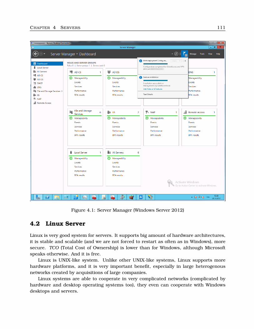
CHAPTER 4 SERVERS 111
Figure 4.1: Server Manager (Windows Server 2012)
4.2 Linux Server
Linux is very good system for servers. It supports big amount of hardware architectures,it is stable and scalable (and we are not forced to restart as often as in Windows), moresecure. TCO (Total Cost of Ownership) is lower than for Windows, although Microsoftspeaks otherwise. And it is free.
Linux is UNIX-like system. Unlike other UNIX-like systems, Linux supports morehardware platforms, and it is very important benefit, especially in large heterogenousnetworks created by acquisitions of large companies.
Linux systems are able to cooperate in very complicated networks (complicated byhardware and desktop operating systems too), they even can cooperate with Windowsdesktops and servers.
CHAPTER 4 SERVERS 112
� More information:• http://www.pcworld.com/article/204423/why linux beats windows for servers.html• http://smashingtips.com/6-reasons-why-linux-servers-are-more-secure
�
We know how to manage Linux on desktop (remember Operating systems), now welook at how to manage Linux on servers.
4.2.1 Distributions
First of all, we need to choose one of the large amount of Linux distributions. Tech-nically speaking, it does not matter – what distribution we choose, almost every Linuxdistribution can be installed as a server. But some of the distributions are more suitableand require less work when changing configuration and additionally install some typicalserver tools.
The second important criterion is support. Not every distribution producer providestechnical support. Some commercial Linuxes have their community (freely available)branch, so we can try this community system and than go over to the commercial system.This procedure is quite regular and it is the main reason why the commercial companiessupport their community branches.
The best Linux distributions to install as server:• Debian – very stable distribution for large amount of hardware architectures, with-
out official support; great if we have good Linux experts or we do not want to investfor now,
• Red Hat Enterprise Linux – distribution with good official support (commercial), itscommunity (freely available) branch is Fedora,
• SUSE Linux Enterprise Server (by Novell) – commercial Linux too, its communitycolleague is OpenSUSE,
• Gentoo – community distribution with large amount of supported hardware archi-tectures,
• etc.
� Remark:
Red Hat uses its packaging system RPM, and most of commercial Linux providers tookover this system (including SUSE). So, RPM is the most commonly used, but sometimeswe can meet one unpleasant thing – dependency hell between packages.
Debian uses its packaging system DEB, as all its descendants (such as Ubuntu,Knoppix, Damn Small Linux, etc.). DEB solves dependencies among packages betterthan RPM.
The both packaging systems provide automated upgrade/patching.
�
CHAPTER 4 SERVERS 113
� More information:
• http://www.debian.org/• http://www.redhat.com/products/enterprise-linux/server/• https://www.suse.com/• http://www.gentoo.org/
�
Hardware architectures marking:
• i386: old 32bit Intel architecture
• amd64 (or sometimes x64): the most common hardware architecture for Intel andAMD processors (amd64 is for Intel 64bit processors too!)
• IA-64: Intel Itanium (server processors architecture, not for desktop)
• MIPS, SPARC: server processors
• ARM: mostly mobile architectures
C Labs
Find out typical hardware architectures in some web computer store. If you have somevirtualization software (VMWare Workstation/Player, VirtualBox, etc.), check to see whathardware architecture is simulated by it.
C
4.2.2 Installation
Linux installation is as simple as Windows installation (but it depends on the distribu-tion), but one of very important steps is disk partitioning.
The root partition contains all directories without their own partition. So, we have toreserve partitions for all “problematic” directories used by common users (/home, /var,/tmp). The directory /var/log with system and application logs would have its own par-tition too, because it can grow rapidly and decrease free space in /var. Some directoriesrequire special settings (sharing, or e.g. read-only), primarily /usr is often installed asread-only (we only remount it for writing while installing new software).
� More information:
• Unix/Linux Disk Partitioning Guide. URL: http://content.hccfl.edu/pollock/aunix1/partitioning.htm
• http://www.linkedin.com/groups/What-is-best-disk-partition-49301.S.127067390
�
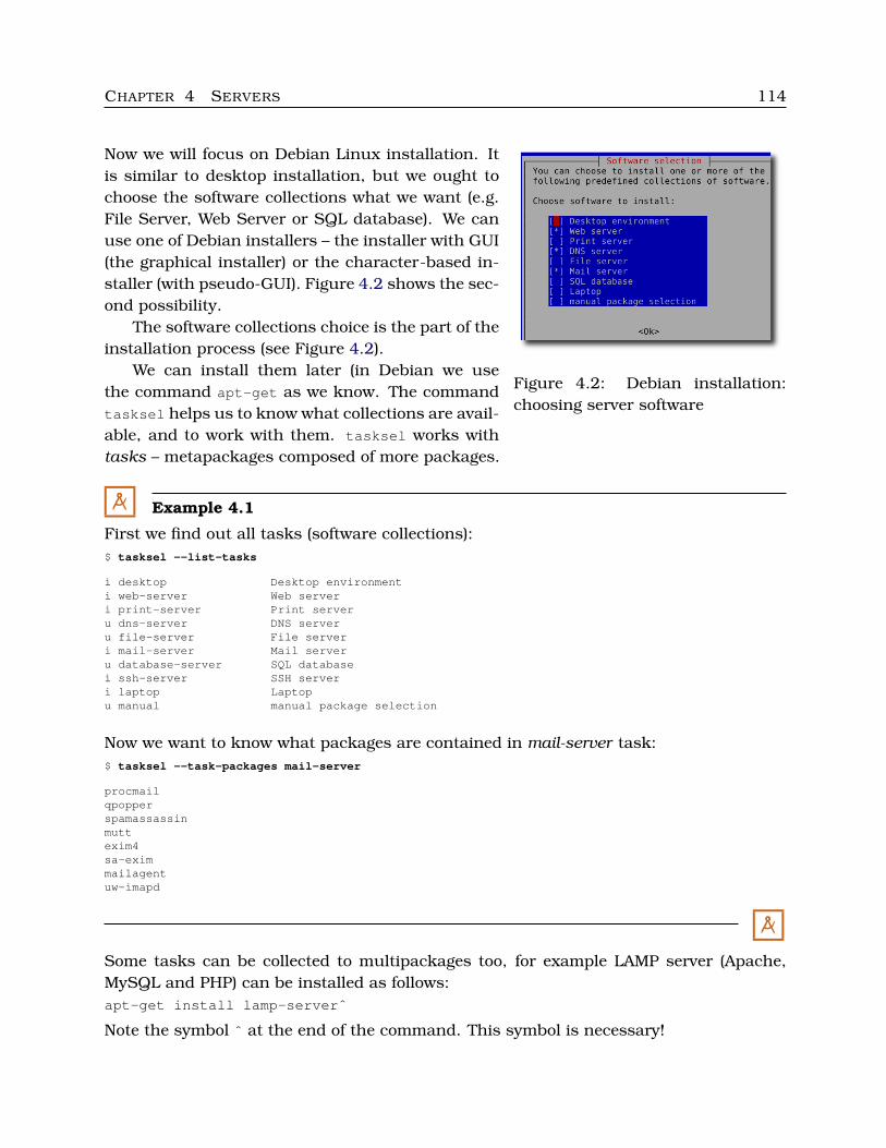
CHAPTER 4 SERVERS 114
Figure 4.2: Debian installation:choosing server software
Now we will focus on Debian Linux installation. Itis similar to desktop installation, but we ought tochoose the software collections what we want (e.g.File Server, Web Server or SQL database). We canuse one of Debian installers – the installer with GUI(the graphical installer) or the character-based in-staller (with pseudo-GUI). Figure 4.2 shows the sec-ond possibility.
The software collections choice is the part of theinstallation process (see Figure 4.2).
We can install them later (in Debian we usethe command apt-get as we know. The commandtasksel helps us to know what collections are avail-able, and to work with them. tasksel works withtasks – metapackages composed of more packages.
M Example 4.1
First we find out all tasks (software collections):$ tasksel --list-tasks
i desktop Desktop environmenti web-server Web serveri print-server Print serveru dns-server DNS serveru file-server File serveri mail-server Mail serveru database-server SQL databasei ssh-server SSH serveri laptop Laptopu manual manual package selection
Now we want to know what packages are contained in mail-server task:$ tasksel --task-packages mail-server
procmailqpopperspamassassinmuttexim4sa-eximmailagentuw-imapd
M
Some tasks can be collected to multipackages too, for example LAMP server (Apache,MySQL and PHP) can be installed as follows:apt-get install lamp-serverˆ
Note the symbol ˆ at the end of the command. This symbol is necessary!
CHAPTER 4 SERVERS 115
� Remark:
While installing LAMP, we have to configure it to the secure state. See one of the belowmentioned sources.
�
� More information:
• http://www.debian.org/releases/stable/amd64/index.html.en• http://www.youtube.com/watch?v=sJuJbqxxhos• http://wiki.debian.org/LaMp (LAMP configuration)• http://www.lifelinux.com/how-to-setup-a-lamp-server-on-centos-6-0/• http://stevenbenner.com/2010/06/setting-up-an-ubuntu-lamp-server-part-1-initial-setup/• http://wiki.debian.org/SecurityManagement
�
C Labs
1. Find out packages contained in the task web-server.
2. Try to install Debian server into a virtual server (choose some of the offered servercollections).
C