hardware manual - acs880-37 drives
TRANSCRIPT

ABB industrial drives
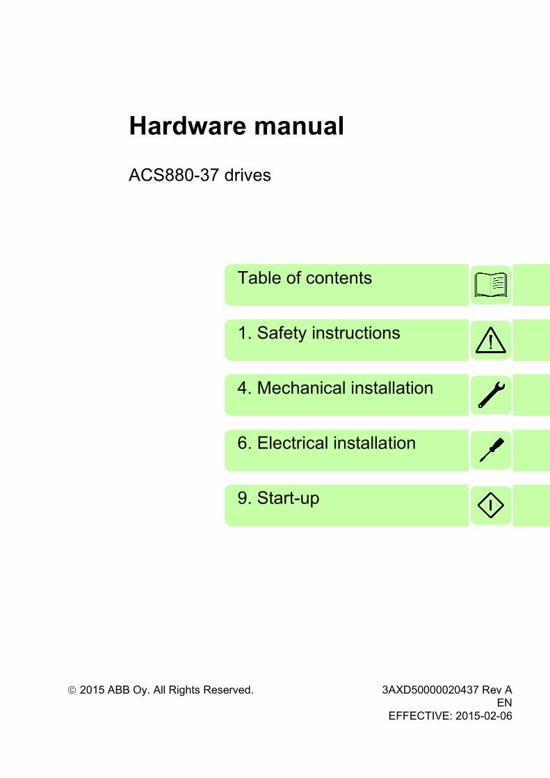
Hardware manualACS880-37 drives

List of related manuals
You can find manuals and other product documents in PDF format on the Internet. See section Document library on the Internet on the inside of the back cover. For manuals not available in the Document library, contact your local ABB representative.
Drive hardware manuals and guides Code (English)
ACS880-37 drives hardware manual 3AXD50000020437
ACS-AP-X assistant control panels user’s manual 3AUA0000085685
Drive firmware manuals and guides
ACS880 primary control program firmware manual 3AUA0000085967
Quick start-up guide for ACS880 drives with primary control program
3AUA0000098062
ACS880 IGBT supply control program firmware manual 3AUA0000131562
Option manuals and guides
Drive composer start-up and maintenance PC tool user’s manual
3AUA0000094606
FSO-12 safety functions module user’s manual 3AXD50000015612
User’s manual for Prevention of unexpected start-up (+Q950) for ACS880-07/17/37 drives
3AUA0000145922
User’s manual for Emergency stop, stop category 0 (+Q951) for ACS880-07/17/37 drives
3AUA0000119895
User’s manual for Emergency stop, stop category 1 (+Q952) for ACS880-07/17/37 drives
3AUA0000119896
User’s manual for Prevention of unexpected start-up (+Q957) for ACS880-07/17/37 drives
3AUA0000119910
User’s manual for Emergency stop, stop category 0 (+Q963) for ACS880-07/17/37 drives
3AUA0000119908
User’s manual for Emergency stop, stop category 1 (+Q964) for ACS880-07/17/37 drives
3AUA0000119909
User’s manual for Emergency stop, configurable stop category 0 or 1 (+Q978) for ACS880-07/17/37 drives
3AUA0000145920
User’s manual for Emergency stop, configurable stop category 0 or 1 (+Q979) for ACS880-07/17/37 drives
3AUA0000145921
Manuals and quick guides for I/O extension modules, fieldbus adapters, etc.
ACS880-37 manuals


Hardware manual
ACS880-37 drives
3AXD50000020437 Rev AEN
EFFECTIVE: 2015-02-06
2015 ABB Oy. All Rights Reserved.
1. Safety instructions
4. Mechanical installation
Table of contents
6. Electrical installation
9. Start-up


7
Table of contents
1. Safety instructions
Contents of this chapter . . . . . . . . . . . . . . . . . . . . . . . . . . . . . . . . . . . . . . . . . . . . . . . . . 17Use of warnings and notes . . . . . . . . . . . . . . . . . . . . . . . . . . . . . . . . . . . . . . . . . . . . . . . 17General safety in installation, start-up and maintenance . . . . . . . . . . . . . . . . . . . . . . . . 18Electrical safety in installation, start-up and maintenance . . . . . . . . . . . . . . . . . . . . . . . 21
Precautions before electrical work . . . . . . . . . . . . . . . . . . . . . . . . . . . . . . . . . . . . . . . 21Additional instructions and notes . . . . . . . . . . . . . . . . . . . . . . . . . . . . . . . . . . . . . . . . 22Grounding . . . . . . . . . . . . . . . . . . . . . . . . . . . . . . . . . . . . . . . . . . . . . . . . . . . . . . . . . . 23
Additional instructions for permanent magnet motor drives . . . . . . . . . . . . . . . . . . . . . . 24Safety in installation, start-up and maintenance . . . . . . . . . . . . . . . . . . . . . . . . . . . . . 24
2. Introduction to the manual
Contents of this chapter . . . . . . . . . . . . . . . . . . . . . . . . . . . . . . . . . . . . . . . . . . . . . . . . . 25Target audience . . . . . . . . . . . . . . . . . . . . . . . . . . . . . . . . . . . . . . . . . . . . . . . . . . . . . . . 25Contents of the manual . . . . . . . . . . . . . . . . . . . . . . . . . . . . . . . . . . . . . . . . . . . . . . . . . . 25Related documents . . . . . . . . . . . . . . . . . . . . . . . . . . . . . . . . . . . . . . . . . . . . . . . . . . . . . 26Categorization by frame size and option code . . . . . . . . . . . . . . . . . . . . . . . . . . . . . . . . 26Quick installation, commissioning and operation flowchart . . . . . . . . . . . . . . . . . . . . . . . 27Terms and abbreviations . . . . . . . . . . . . . . . . . . . . . . . . . . . . . . . . . . . . . . . . . . . . . . . . . 28
Safety data (SIL, PL) . . . . . . . . . . . . . . . . . . . . . . . . . . . . . . . . . . . . . . . . . . . . . . . . . 29
3. Operation principle and hardware description
Contents of this chapter . . . . . . . . . . . . . . . . . . . . . . . . . . . . . . . . . . . . . . . . . . . . . . . . . 31Operation principle . . . . . . . . . . . . . . . . . . . . . . . . . . . . . . . . . . . . . . . . . . . . . . . . . . . . . 31
Supply unit . . . . . . . . . . . . . . . . . . . . . . . . . . . . . . . . . . . . . . . . . . . . . . . . . . . . . . . . . 31AC voltage and current waveforms . . . . . . . . . . . . . . . . . . . . . . . . . . . . . . . . . . . . 32Charging . . . . . . . . . . . . . . . . . . . . . . . . . . . . . . . . . . . . . . . . . . . . . . . . . . . . . . . . 32
Inverter unit . . . . . . . . . . . . . . . . . . . . . . . . . . . . . . . . . . . . . . . . . . . . . . . . . . . . . . . . . 32Overview circuit diagram of the drive . . . . . . . . . . . . . . . . . . . . . . . . . . . . . . . . . . . . . 33
Cabinet line-up and layout examples . . . . . . . . . . . . . . . . . . . . . . . . . . . . . . . . . . . . . . . 34Frame 1×R8i + 1×R8i . . . . . . . . . . . . . . . . . . . . . . . . . . . . . . . . . . . . . . . . . . . . . . . . . 34Frame 2×R8i + 2×R8i . . . . . . . . . . . . . . . . . . . . . . . . . . . . . . . . . . . . . . . . . . . . . . . . . 36Frame 3×R8i + 3×R8i (with main breaker) . . . . . . . . . . . . . . . . . . . . . . . . . . . . . . . . . 38Auxiliary control cubicle (ACU) layout . . . . . . . . . . . . . . . . . . . . . . . . . . . . . . . . . . . . 40
Overview of power and control connections . . . . . . . . . . . . . . . . . . . . . . . . . . . . . . . . . . 42Door switches and lights . . . . . . . . . . . . . . . . . . . . . . . . . . . . . . . . . . . . . . . . . . . . . . . . . 44
Main disconnecting device [Q1.1] . . . . . . . . . . . . . . . . . . . . . . . . . . . . . . . . . . . . . 45Auxiliary voltage switch [Q21] . . . . . . . . . . . . . . . . . . . . . . . . . . . . . . . . . . . . . . . . 45Grounding (earthing) switch [Q9.x], optional . . . . . . . . . . . . . . . . . . . . . . . . . . . . . 45Other devices on the door . . . . . . . . . . . . . . . . . . . . . . . . . . . . . . . . . . . . . . . . . . . 45
Control panel . . . . . . . . . . . . . . . . . . . . . . . . . . . . . . . . . . . . . . . . . . . . . . . . . . . . . . . 46Control by PC tools . . . . . . . . . . . . . . . . . . . . . . . . . . . . . . . . . . . . . . . . . . . . . . . . 46
Descriptions of cabinet options . . . . . . . . . . . . . . . . . . . . . . . . . . . . . . . . . . . . . . . . . . . . 47Degree of protection . . . . . . . . . . . . . . . . . . . . . . . . . . . . . . . . . . . . . . . . . . . . . . . . . . 47
Definitions . . . . . . . . . . . . . . . . . . . . . . . . . . . . . . . . . . . . . . . . . . . . . . . . . . . . . . . 47IP22 (standard) . . . . . . . . . . . . . . . . . . . . . . . . . . . . . . . . . . . . . . . . . . . . . . . . . . . 47
8
IP42 (option +B054) . . . . . . . . . . . . . . . . . . . . . . . . . . . . . . . . . . . . . . . . . . . . . . . 47IP54 (option +B055) . . . . . . . . . . . . . . . . . . . . . . . . . . . . . . . . . . . . . . . . . . . . . . . 47Channeled air outlet (option +C130) . . . . . . . . . . . . . . . . . . . . . . . . . . . . . . . . . . 47
Marine construction (option +C121) . . . . . . . . . . . . . . . . . . . . . . . . . . . . . . . . . . . . . 48UL listed (option +C129) . . . . . . . . . . . . . . . . . . . . . . . . . . . . . . . . . . . . . . . . . . . . . . 48CSA approved (option +C134) . . . . . . . . . . . . . . . . . . . . . . . . . . . . . . . . . . . . . . . . . 48Seismic design (option +C180) . . . . . . . . . . . . . . . . . . . . . . . . . . . . . . . . . . . . . . . . . 48Resistor braking (options +D150 and +D151) . . . . . . . . . . . . . . . . . . . . . . . . . . . . . . 48EMC filters (option + E202) . . . . . . . . . . . . . . . . . . . . . . . . . . . . . . . . . . . . . . . . . . . . 48Cabinet heater with external supply (option +G300) . . . . . . . . . . . . . . . . . . . . . . . . . 49Terminals for external interruptible control voltage (option +G307) . . . . . . . . . . . . . 49Output for motor space heater (option +G313) . . . . . . . . . . . . . . . . . . . . . . . . . . . . . 49Additional wire markings (options +G340 and +G342) . . . . . . . . . . . . . . . . . . . . . . . 50Cable conduit entry (option +H358) . . . . . . . . . . . . . . . . . . . . . . . . . . . . . . . . . . . . . 50Common motor terminal cubicle (option +H359) . . . . . . . . . . . . . . . . . . . . . . . . . . . 50Common output terminal (option +H366) . . . . . . . . . . . . . . . . . . . . . . . . . . . . . . . . . 50Additional terminal block X504 (option +L504) . . . . . . . . . . . . . . . . . . . . . . . . . . . . . 51Thermistor relays (options +L505, +2L505) . . . . . . . . . . . . . . . . . . . . . . . . . . . . . . . 51Pt100 relays (options +2L506, +3L506, +5L506, +8L506) . . . . . . . . . . . . . . . . . . . . 52
What the option contains . . . . . . . . . . . . . . . . . . . . . . . . . . . . . . . . . . . . . . . . . . . 52Description . . . . . . . . . . . . . . . . . . . . . . . . . . . . . . . . . . . . . . . . . . . . . . . . . . . . . . 52
Type designation label . . . . . . . . . . . . . . . . . . . . . . . . . . . . . . . . . . . . . . . . . . . . . . . . . . 53Type designation key . . . . . . . . . . . . . . . . . . . . . . . . . . . . . . . . . . . . . . . . . . . . . . . . . . . 53
4. Mechanical installation
Contents of this chapter . . . . . . . . . . . . . . . . . . . . . . . . . . . . . . . . . . . . . . . . . . . . . . . . . 57Examining the installation site . . . . . . . . . . . . . . . . . . . . . . . . . . . . . . . . . . . . . . . . . . . . 57Necessary tools . . . . . . . . . . . . . . . . . . . . . . . . . . . . . . . . . . . . . . . . . . . . . . . . . . . . . . . 58Checking the delivery . . . . . . . . . . . . . . . . . . . . . . . . . . . . . . . . . . . . . . . . . . . . . . . . . . 58Moving and unpacking the drive . . . . . . . . . . . . . . . . . . . . . . . . . . . . . . . . . . . . . . . . . . 59
Moving the drive in its packaging . . . . . . . . . . . . . . . . . . . . . . . . . . . . . . . . . . . . . . . 59Lifting the crate with a forklift . . . . . . . . . . . . . . . . . . . . . . . . . . . . . . . . . . . . . . . . 59Lifting the crate with a crane . . . . . . . . . . . . . . . . . . . . . . . . . . . . . . . . . . . . . . . . . 60Moving the crate with a forklift . . . . . . . . . . . . . . . . . . . . . . . . . . . . . . . . . . . . . . . 61
Removing the transport package . . . . . . . . . . . . . . . . . . . . . . . . . . . . . . . . . . . . . . . 62Moving the unpacked drive cabinet . . . . . . . . . . . . . . . . . . . . . . . . . . . . . . . . . . . . . . 62
Lifting the cabinet with a crane . . . . . . . . . . . . . . . . . . . . . . . . . . . . . . . . . . . . . . . 62Moving the cabinet on rollers . . . . . . . . . . . . . . . . . . . . . . . . . . . . . . . . . . . . . . . . 63Moving the cabinet on its back . . . . . . . . . . . . . . . . . . . . . . . . . . . . . . . . . . . . . . . 63Final placement of the cabinet . . . . . . . . . . . . . . . . . . . . . . . . . . . . . . . . . . . . . . . 64
Fastening the cabinet to the floor and wall or roof (non-marine units) . . . . . . . . . . . . . . 65General rules . . . . . . . . . . . . . . . . . . . . . . . . . . . . . . . . . . . . . . . . . . . . . . . . . . . . . . . 65Fastening methods . . . . . . . . . . . . . . . . . . . . . . . . . . . . . . . . . . . . . . . . . . . . . . . . . . 66Alternative 1 – Clamping . . . . . . . . . . . . . . . . . . . . . . . . . . . . . . . . . . . . . . . . . . . . . . 66Alternative 2 – Using the holes inside the cabinet . . . . . . . . . . . . . . . . . . . . . . . . . . 66
Fastening the cabinet to the floor and roof/wall (marine units) . . . . . . . . . . . . . . . . . . . 67Miscellaneous . . . . . . . . . . . . . . . . . . . . . . . . . . . . . . . . . . . . . . . . . . . . . . . . . . . . . . . . 68
Cable duct in the floor below the cabinet . . . . . . . . . . . . . . . . . . . . . . . . . . . . . . . . . 68Air inlet through the bottom (option +C128) . . . . . . . . . . . . . . . . . . . . . . . . . . . . . . . 68Air outlet duct on the cabinet roof (option +C130) . . . . . . . . . . . . . . . . . . . . . . . . . . 68
Calculating the required static pressure difference . . . . . . . . . . . . . . . . . . . . . . . 69Arc welding . . . . . . . . . . . . . . . . . . . . . . . . . . . . . . . . . . . . . . . . . . . . . . . . . . . . . . . . 69

9
5. Guidelines for planning the electrical installation
Contents of this chapter . . . . . . . . . . . . . . . . . . . . . . . . . . . . . . . . . . . . . . . . . . . . . . . . . 71Limitation of liability . . . . . . . . . . . . . . . . . . . . . . . . . . . . . . . . . . . . . . . . . . . . . . . . . . . . . 71Selecting the supply disconnecting device . . . . . . . . . . . . . . . . . . . . . . . . . . . . . . . . . . . 71Selecting the main contactor . . . . . . . . . . . . . . . . . . . . . . . . . . . . . . . . . . . . . . . . . . . . . . 71Examining the compatibility of the motor and drive . . . . . . . . . . . . . . . . . . . . . . . . . . . . . 72
Protecting the motor insulation and bearings . . . . . . . . . . . . . . . . . . . . . . . . . . . . . . . 72Requirements table . . . . . . . . . . . . . . . . . . . . . . . . . . . . . . . . . . . . . . . . . . . . . . . . . . 73
Additional requirements for explosion-safe (EX) motors . . . . . . . . . . . . . . . . . . . . 74Additional requirements for ABB motors of types other than M2_, M3_, M4_, HX_ and AM_ . . . . . . . . . . . . . . . . . . . . . . . . . . . . . . . . . . . . . . . . . . . . . . . . . . . . . . . . . . . . 75Additional requirements for braking applications . . . . . . . . . . . . . . . . . . . . . . . . . . 75Additional requirements for ABB high-output and IP23 motors . . . . . . . . . . . . . . . 75Additional requirements for non-ABB high-output and IP23 motors . . . . . . . . . . . 75Additional data for calculating the rise time and the peak line-to-line voltage . . . . 76
Selecting the power cables . . . . . . . . . . . . . . . . . . . . . . . . . . . . . . . . . . . . . . . . . . . . . . . 76General rules . . . . . . . . . . . . . . . . . . . . . . . . . . . . . . . . . . . . . . . . . . . . . . . . . . . . . . . 76Typical cable sizes . . . . . . . . . . . . . . . . . . . . . . . . . . . . . . . . . . . . . . . . . . . . . . . . . . . 78
Input (supply) cable sizes . . . . . . . . . . . . . . . . . . . . . . . . . . . . . . . . . . . . . . . . . . . 78Output (motor) cable sizes . . . . . . . . . . . . . . . . . . . . . . . . . . . . . . . . . . . . . . . . . . . 79
Alternative power cable types . . . . . . . . . . . . . . . . . . . . . . . . . . . . . . . . . . . . . . . . . . . 80Recommended power cable types . . . . . . . . . . . . . . . . . . . . . . . . . . . . . . . . . . . . . 80Power cable types for limited use . . . . . . . . . . . . . . . . . . . . . . . . . . . . . . . . . . . . . 80Not allowed power cable types . . . . . . . . . . . . . . . . . . . . . . . . . . . . . . . . . . . . . . . 80
Motor cable shield . . . . . . . . . . . . . . . . . . . . . . . . . . . . . . . . . . . . . . . . . . . . . . . . . . . 80Additional US requirements . . . . . . . . . . . . . . . . . . . . . . . . . . . . . . . . . . . . . . . . . . . . 81
Conduit . . . . . . . . . . . . . . . . . . . . . . . . . . . . . . . . . . . . . . . . . . . . . . . . . . . . . . . . . . 81Armored cable / shielded power cable . . . . . . . . . . . . . . . . . . . . . . . . . . . . . . . . . . 81
Planning the braking system . . . . . . . . . . . . . . . . . . . . . . . . . . . . . . . . . . . . . . . . . . . . . . 81Selecting the control cables . . . . . . . . . . . . . . . . . . . . . . . . . . . . . . . . . . . . . . . . . . . . . . 81
Shielding . . . . . . . . . . . . . . . . . . . . . . . . . . . . . . . . . . . . . . . . . . . . . . . . . . . . . . . . . . . 81Signals in separate cables . . . . . . . . . . . . . . . . . . . . . . . . . . . . . . . . . . . . . . . . . . . . . 82Signals allowed to be run in the same cable . . . . . . . . . . . . . . . . . . . . . . . . . . . . . . . 82Relay cable type . . . . . . . . . . . . . . . . . . . . . . . . . . . . . . . . . . . . . . . . . . . . . . . . . . . . . 82Control panel cable length and type . . . . . . . . . . . . . . . . . . . . . . . . . . . . . . . . . . . . . . 82
Routing the cables . . . . . . . . . . . . . . . . . . . . . . . . . . . . . . . . . . . . . . . . . . . . . . . . . . . . . 82Separate control cable ducts . . . . . . . . . . . . . . . . . . . . . . . . . . . . . . . . . . . . . . . . . . . 83Continuous motor cable shield or enclosure for equipment on the motor cable . . . . . 83
Implementing thermal overload and short-circuit protection . . . . . . . . . . . . . . . . . . . . . . 84Protecting the drive and input power cable in short-circuits . . . . . . . . . . . . . . . . . . . . 84Protecting the motor and motor cable in short-circuits . . . . . . . . . . . . . . . . . . . . . . . . 84Protecting the drive and the power cables against thermal overload . . . . . . . . . . . . . 84Protecting the motor against thermal overload . . . . . . . . . . . . . . . . . . . . . . . . . . . . . . 84
Protecting the drive against ground faults . . . . . . . . . . . . . . . . . . . . . . . . . . . . . . . . . . . . 84Residual current device compatibility . . . . . . . . . . . . . . . . . . . . . . . . . . . . . . . . . . . . . 85
Implementing the emergency stop function . . . . . . . . . . . . . . . . . . . . . . . . . . . . . . . . . . 85Implementing the Safe torque off function . . . . . . . . . . . . . . . . . . . . . . . . . . . . . . . . . . . 85Implementing the Prevention of unexpected start-up function . . . . . . . . . . . . . . . . . . . . 85Implementing the functions provided by the FSO-xx safety functions module (option +Q972 or +Q973) . . . . . . . . . . . . . . . . . . . . . . . . . . . . . . . . . . . . . . . . . . . . . . . . . . . . . . . . . . . . 86
Declaration of Conformity . . . . . . . . . . . . . . . . . . . . . . . . . . . . . . . . . . . . . . . . . . . . . . 86Implementing the Power-loss ride-through function . . . . . . . . . . . . . . . . . . . . . . . . . . . . 86Supplying power for the auxiliary circuits . . . . . . . . . . . . . . . . . . . . . . . . . . . . . . . . . . . . 86

10
Using power factor compensation capacitors with the drive . . . . . . . . . . . . . . . . . . . . . 87Implementing a safety switch between the drive and the motor . . . . . . . . . . . . . . . . . . 87Protecting the contacts of relay outputs . . . . . . . . . . . . . . . . . . . . . . . . . . . . . . . . . . . . . 87Connecting a motor temperature sensor to the drive I/O . . . . . . . . . . . . . . . . . . . . . . . . 88
6. Electrical installation
Contents of this chapter . . . . . . . . . . . . . . . . . . . . . . . . . . . . . . . . . . . . . . . . . . . . . . . . . 89Warnings . . . . . . . . . . . . . . . . . . . . . . . . . . . . . . . . . . . . . . . . . . . . . . . . . . . . . . . . . . . . 89Checking the insulation of the assembly . . . . . . . . . . . . . . . . . . . . . . . . . . . . . . . . . . . . 89
Drive . . . . . . . . . . . . . . . . . . . . . . . . . . . . . . . . . . . . . . . . . . . . . . . . . . . . . . . . . . . . . 89Input cable . . . . . . . . . . . . . . . . . . . . . . . . . . . . . . . . . . . . . . . . . . . . . . . . . . . . . . . . . 89Motor and motor cable . . . . . . . . . . . . . . . . . . . . . . . . . . . . . . . . . . . . . . . . . . . . . . . 90Custom brake resistor assembly . . . . . . . . . . . . . . . . . . . . . . . . . . . . . . . . . . . . . . . . 90
Checking the compatibility with IT (ungrounded) systems . . . . . . . . . . . . . . . . . . . . . . . 90Attaching the device stickers to the cabinet door . . . . . . . . . . . . . . . . . . . . . . . . . . . . . 90Checking the settings of transformers T21, T101 and T111 . . . . . . . . . . . . . . . . . . . . . 90
T21 and T101 tap settings (400…500 V units) . . . . . . . . . . . . . . . . . . . . . . . . . . . . . 91T21 and T101 tap settings (690 V units) . . . . . . . . . . . . . . . . . . . . . . . . . . . . . . . . . . 91T111 tap settings . . . . . . . . . . . . . . . . . . . . . . . . . . . . . . . . . . . . . . . . . . . . . . . . . . . . 92
Connecting the control cables . . . . . . . . . . . . . . . . . . . . . . . . . . . . . . . . . . . . . . . . . . . . 93Control cable connection procedure . . . . . . . . . . . . . . . . . . . . . . . . . . . . . . . . . . . . . 93
Grounding the outer shields of the control cables at the cabinet lead-through . . 93Routing the control cables inside the cabinet . . . . . . . . . . . . . . . . . . . . . . . . . . . . 95Connecting to the inverter control unit [A41] . . . . . . . . . . . . . . . . . . . . . . . . . . . . 95Connecting an auxiliary voltage supply (UPS, option +G307) . . . . . . . . . . . . . . . 97Connecting emergency stop push buttons (options +Q951, +Q952, +Q963, +Q964, +Q978, +Q979) . . . . . . . . . . . . . . . . . . . . . . . . . . . . . . . . . . . . . . . . . . . . . . . . . . . 97Wiring the starter for auxiliary motor fan (options +M602…+M610) . . . . . . . . . . . 97Wiring the thermistor relay(s) (options +L505 and +2L505) . . . . . . . . . . . . . . . . . 98Wiring the Pt100 relays (options +2L506, +3L506, +5L506 and +8L506) . . . . . . 99Powering the heating and lighting equipment (options +G300, +G301 and +G313) . 100Wiring ground fault monitoring for IT ungrounded systems (option +Q954) . . . . 101
Connecting the motor cables (units without common motor terminal cubicle) . . . . . . . 102Output busbars . . . . . . . . . . . . . . . . . . . . . . . . . . . . . . . . . . . . . . . . . . . . . . . . . . . . 102Connection diagram (without option +H366) . . . . . . . . . . . . . . . . . . . . . . . . . . . . . . 102Connection diagram (with option +H366) . . . . . . . . . . . . . . . . . . . . . . . . . . . . . . . . 103Procedure . . . . . . . . . . . . . . . . . . . . . . . . . . . . . . . . . . . . . . . . . . . . . . . . . . . . . . . . 104
Removing and reinstalling the fan carriage of an inverter module . . . . . . . . . . . 104Removing the inverter module . . . . . . . . . . . . . . . . . . . . . . . . . . . . . . . . . . . . . . 106Connecting the motor cables . . . . . . . . . . . . . . . . . . . . . . . . . . . . . . . . . . . . . . . 110Re-inserting the fan carriage of an inverter module . . . . . . . . . . . . . . . . . . . . . . 112Re-inserting the inverter module into the cubicle . . . . . . . . . . . . . . . . . . . . . . . . 112
Connecting the motor cables (units with common motor terminal cubicle) . . . . . . . . . 113Output busbars . . . . . . . . . . . . . . . . . . . . . . . . . . . . . . . . . . . . . . . . . . . . . . . . . . . . 113Connection diagram . . . . . . . . . . . . . . . . . . . . . . . . . . . . . . . . . . . . . . . . . . . . . . . . 113Procedure . . . . . . . . . . . . . . . . . . . . . . . . . . . . . . . . . . . . . . . . . . . . . . . . . . . . . . . . 113
Connecting an external brake resistor assembly . . . . . . . . . . . . . . . . . . . . . . . . . . . . . 114Connecting the input power cables . . . . . . . . . . . . . . . . . . . . . . . . . . . . . . . . . . . . . . . 115
Connection diagram . . . . . . . . . . . . . . . . . . . . . . . . . . . . . . . . . . . . . . . . . . . . . . . . 115Layout of the input cable connection terminals and lead-throughs . . . . . . . . . . . . . 115Connection procedure . . . . . . . . . . . . . . . . . . . . . . . . . . . . . . . . . . . . . . . . . . . . . . . 115
Connecting a PC . . . . . . . . . . . . . . . . . . . . . . . . . . . . . . . . . . . . . . . . . . . . . . . . . . . . . 118

11
Panel bus (Control of several units from one control panel) . . . . . . . . . . . . . . . . . . . . . 119Installing option modules . . . . . . . . . . . . . . . . . . . . . . . . . . . . . . . . . . . . . . . . . . . . . . . . 120
Mechanical installation of I/O extension, fieldbus adapter and pulse encoder interface modules . . . . . . . . . . . . . . . . . . . . . . . . . . . . . . . . . . . . . . . . . . . . . . . . . . . . . . . . . . 120Mechanical installation of an FSO-xx safety functions module . . . . . . . . . . . . . . . . 121Wiring of option modules . . . . . . . . . . . . . . . . . . . . . . . . . . . . . . . . . . . . . . . . . . . . . 122
7. Control units of the drive
What this chapter contains . . . . . . . . . . . . . . . . . . . . . . . . . . . . . . . . . . . . . . . . . . . . . . 123General . . . . . . . . . . . . . . . . . . . . . . . . . . . . . . . . . . . . . . . . . . . . . . . . . . . . . . . . . . . . . 123
Control unit layout and connections . . . . . . . . . . . . . . . . . . . . . . . . . . . . . . . . . . . . . 124Default I/O diagram of the inverter control unit [A41] . . . . . . . . . . . . . . . . . . . . . . . . 127External power supply for the control unit (XPOW) . . . . . . . . . . . . . . . . . . . . . . . . . 128DI6 as a PTC sensor input . . . . . . . . . . . . . . . . . . . . . . . . . . . . . . . . . . . . . . . . . . . . 128AI1 or AI2 as a Pt100 or KTY84 sensor input . . . . . . . . . . . . . . . . . . . . . . . . . . . . . . 129DIIL input . . . . . . . . . . . . . . . . . . . . . . . . . . . . . . . . . . . . . . . . . . . . . . . . . . . . . . . . . 129Drive-to-drive link . . . . . . . . . . . . . . . . . . . . . . . . . . . . . . . . . . . . . . . . . . . . . . . . . . . 129Safe torque off . . . . . . . . . . . . . . . . . . . . . . . . . . . . . . . . . . . . . . . . . . . . . . . . . . . . . 130Safety functions (X12) . . . . . . . . . . . . . . . . . . . . . . . . . . . . . . . . . . . . . . . . . . . . . . . 130SDHC memory card slot . . . . . . . . . . . . . . . . . . . . . . . . . . . . . . . . . . . . . . . . . . . . . . 130
Control unit connector data . . . . . . . . . . . . . . . . . . . . . . . . . . . . . . . . . . . . . . . . . . . . . . 131
8. Installation checklist
Contents of this chapter . . . . . . . . . . . . . . . . . . . . . . . . . . . . . . . . . . . . . . . . . . . . . . . . 135Warnings . . . . . . . . . . . . . . . . . . . . . . . . . . . . . . . . . . . . . . . . . . . . . . . . . . . . . . . . . . . . 135Checklist . . . . . . . . . . . . . . . . . . . . . . . . . . . . . . . . . . . . . . . . . . . . . . . . . . . . . . . . . . . . 135
9. Start-up
Contents of this chapter . . . . . . . . . . . . . . . . . . . . . . . . . . . . . . . . . . . . . . . . . . . . . . . . 137Start-up procedure . . . . . . . . . . . . . . . . . . . . . . . . . . . . . . . . . . . . . . . . . . . . . . . . . . . . 137
Checks/Settings with no voltage connected . . . . . . . . . . . . . . . . . . . . . . . . . . . . 138Powering up the auxiliary circuit of the drive . . . . . . . . . . . . . . . . . . . . . . . . . . . . 138Setting up the supply unit parameters . . . . . . . . . . . . . . . . . . . . . . . . . . . . . . . . . 139Setting up the inverter unit parameters, and performing the first start . . . . . . . . . 139Powering up the main circuit of the drive . . . . . . . . . . . . . . . . . . . . . . . . . . . . . . . 139On-load checks . . . . . . . . . . . . . . . . . . . . . . . . . . . . . . . . . . . . . . . . . . . . . . . . . . 139
10. Fault tracing
Contents of this chapter . . . . . . . . . . . . . . . . . . . . . . . . . . . . . . . . . . . . . . . . . . . . . . . . 141LEDs . . . . . . . . . . . . . . . . . . . . . . . . . . . . . . . . . . . . . . . . . . . . . . . . . . . . . . . . . . . . . . . 141Warning and fault messages . . . . . . . . . . . . . . . . . . . . . . . . . . . . . . . . . . . . . . . . . . . . . 141
11. Maintenance
Contents of this chapter . . . . . . . . . . . . . . . . . . . . . . . . . . . . . . . . . . . . . . . . . . . . . . . . 143Maintenance intervals . . . . . . . . . . . . . . . . . . . . . . . . . . . . . . . . . . . . . . . . . . . . . . . . . . 143Cabinet . . . . . . . . . . . . . . . . . . . . . . . . . . . . . . . . . . . . . . . . . . . . . . . . . . . . . . . . . . . . . 145
Cleaning the interior of the cabinet . . . . . . . . . . . . . . . . . . . . . . . . . . . . . . . . . . . . . . 145Cleaning the door air inlets (IP22 and IP42) . . . . . . . . . . . . . . . . . . . . . . . . . . . . . . . 145Cleaning the door air inlets (IP54) . . . . . . . . . . . . . . . . . . . . . . . . . . . . . . . . . . . . . . 146
12
Cleaning the outlet (roof) filters (IP54) . . . . . . . . . . . . . . . . . . . . . . . . . . . . . . . . . . 146Replacing the outlet (roof) filters (IP54) . . . . . . . . . . . . . . . . . . . . . . . . . . . . . . . . . 146
Heatsink . . . . . . . . . . . . . . . . . . . . . . . . . . . . . . . . . . . . . . . . . . . . . . . . . . . . . . . . . . . . 147Power connections and quick connectors . . . . . . . . . . . . . . . . . . . . . . . . . . . . . . . . . . 148
Retightening the power connections . . . . . . . . . . . . . . . . . . . . . . . . . . . . . . . . . . . . 148Fans . . . . . . . . . . . . . . . . . . . . . . . . . . . . . . . . . . . . . . . . . . . . . . . . . . . . . . . . . . . . . . . 149
Replacing the cooling fan in the auxiliary control cubicle . . . . . . . . . . . . . . . . . . . . 149Replacing the fan(s) in the incoming cubicle . . . . . . . . . . . . . . . . . . . . . . . . . . . . . . 150Replacing a roof fan (IP54) . . . . . . . . . . . . . . . . . . . . . . . . . . . . . . . . . . . . . . . . . . . 151Replacing a supply or inverter module cooling fan (speed-controlled version) . . . . 152Replacing a supply or inverter module cooling fan, direct-on-line version (option +C188) 153Replacing the circuit board compartment fan (frame R8i) . . . . . . . . . . . . . . . . . . . . 155Replacing the fan of the LCL filter (BLCL-1x-x) . . . . . . . . . . . . . . . . . . . . . . . . . . . 157Replacing the fan of the LCL filter (BLCL-2x-x) . . . . . . . . . . . . . . . . . . . . . . . . . . . 158
Supply and inverter modules . . . . . . . . . . . . . . . . . . . . . . . . . . . . . . . . . . . . . . . . . . . . 159Cleaning . . . . . . . . . . . . . . . . . . . . . . . . . . . . . . . . . . . . . . . . . . . . . . . . . . . . . . . . . 159Replacing a supply or inverter module . . . . . . . . . . . . . . . . . . . . . . . . . . . . . . . . . . 159
LCL filter . . . . . . . . . . . . . . . . . . . . . . . . . . . . . . . . . . . . . . . . . . . . . . . . . . . . . . . . . . . 160Replacing the LCL filter . . . . . . . . . . . . . . . . . . . . . . . . . . . . . . . . . . . . . . . . . . . . . . 160
Capacitors . . . . . . . . . . . . . . . . . . . . . . . . . . . . . . . . . . . . . . . . . . . . . . . . . . . . . . . . . . 164Reforming the capacitors . . . . . . . . . . . . . . . . . . . . . . . . . . . . . . . . . . . . . . . . . . . . 164
Fuses . . . . . . . . . . . . . . . . . . . . . . . . . . . . . . . . . . . . . . . . . . . . . . . . . . . . . . . . . . . . . . 165Replacing the AC fuses in the incoming cubicle . . . . . . . . . . . . . . . . . . . . . . . . . . . 165Replacing the AC fuses in the LCL filter module or supply module cubicle (frame 3×R8i + 3×R8i and up) . . . . . . . . . . . . . . . . . . . . . . . . . . . . . . . . . . . . . . . . . . . . . . 165Replacing the DC fuses in the supply module cubicle (frame 2×R8i + 2×R8i and up) . . 166Replacing the DC fuses in the inverter module cubicle (frame 2×R8i + 2×R8i and up) . 168
Control panel . . . . . . . . . . . . . . . . . . . . . . . . . . . . . . . . . . . . . . . . . . . . . . . . . . . . . . . . 169Replacing the battery . . . . . . . . . . . . . . . . . . . . . . . . . . . . . . . . . . . . . . . . . . . . . . . 169Cleaning . . . . . . . . . . . . . . . . . . . . . . . . . . . . . . . . . . . . . . . . . . . . . . . . . . . . . . . . . 169
Memory unit . . . . . . . . . . . . . . . . . . . . . . . . . . . . . . . . . . . . . . . . . . . . . . . . . . . . . . . . . 170
12. Technical data
Contents of this chapter . . . . . . . . . . . . . . . . . . . . . . . . . . . . . . . . . . . . . . . . . . . . . . . . 171Ratings . . . . . . . . . . . . . . . . . . . . . . . . . . . . . . . . . . . . . . . . . . . . . . . . . . . . . . . . . . . . . 171
Definitions . . . . . . . . . . . . . . . . . . . . . . . . . . . . . . . . . . . . . . . . . . . . . . . . . . . . . . . . 172Derating . . . . . . . . . . . . . . . . . . . . . . . . . . . . . . . . . . . . . . . . . . . . . . . . . . . . . . . . . . 173
Ambient temperature derating . . . . . . . . . . . . . . . . . . . . . . . . . . . . . . . . . . . . . . 173Altitude derating . . . . . . . . . . . . . . . . . . . . . . . . . . . . . . . . . . . . . . . . . . . . . . . . . 173Switching frequency derating . . . . . . . . . . . . . . . . . . . . . . . . . . . . . . . . . . . . . . . 173Output frequency derating . . . . . . . . . . . . . . . . . . . . . . . . . . . . . . . . . . . . . . . . . 173
Frame sizes and power module types . . . . . . . . . . . . . . . . . . . . . . . . . . . . . . . . . . . . . 174Fuses . . . . . . . . . . . . . . . . . . . . . . . . . . . . . . . . . . . . . . . . . . . . . . . . . . . . . . . . . . . . . . 175
AC fuses . . . . . . . . . . . . . . . . . . . . . . . . . . . . . . . . . . . . . . . . . . . . . . . . . . . . . . . . . 175DC fuses . . . . . . . . . . . . . . . . . . . . . . . . . . . . . . . . . . . . . . . . . . . . . . . . . . . . . . . . . 176Fuses on CVAR varistor board . . . . . . . . . . . . . . . . . . . . . . . . . . . . . . . . . . . . . . . . 177
Dimensions and weights . . . . . . . . . . . . . . . . . . . . . . . . . . . . . . . . . . . . . . . . . . . . . . . 177Free space requirements . . . . . . . . . . . . . . . . . . . . . . . . . . . . . . . . . . . . . . . . . . . . . . . 177Cooling data, noise . . . . . . . . . . . . . . . . . . . . . . . . . . . . . . . . . . . . . . . . . . . . . . . . . . . 178Sine output filter data . . . . . . . . . . . . . . . . . . . . . . . . . . . . . . . . . . . . . . . . . . . . . . . . . . 179

13
Terminal and lead-through data for the power cables . . . . . . . . . . . . . . . . . . . . . . . . . . 179Terminal data for the supply and inverter control units . . . . . . . . . . . . . . . . . . . . . . . . . 179Electrical power network specification . . . . . . . . . . . . . . . . . . . . . . . . . . . . . . . . . . . . . 180Motor connection data . . . . . . . . . . . . . . . . . . . . . . . . . . . . . . . . . . . . . . . . . . . . . . . . . . 180Control unit connection data . . . . . . . . . . . . . . . . . . . . . . . . . . . . . . . . . . . . . . . . . . . . . 181Efficiency . . . . . . . . . . . . . . . . . . . . . . . . . . . . . . . . . . . . . . . . . . . . . . . . . . . . . . . . . . . . 181Protection classes . . . . . . . . . . . . . . . . . . . . . . . . . . . . . . . . . . . . . . . . . . . . . . . . . . . . . 181Ambient conditions . . . . . . . . . . . . . . . . . . . . . . . . . . . . . . . . . . . . . . . . . . . . . . . . . . . . 181Materials . . . . . . . . . . . . . . . . . . . . . . . . . . . . . . . . . . . . . . . . . . . . . . . . . . . . . . . . . . . . 182Applicable standards . . . . . . . . . . . . . . . . . . . . . . . . . . . . . . . . . . . . . . . . . . . . . . . . . . . 183CE marking . . . . . . . . . . . . . . . . . . . . . . . . . . . . . . . . . . . . . . . . . . . . . . . . . . . . . . . . . . 184
Compliance with the European Low Voltage Directive . . . . . . . . . . . . . . . . . . . . . . . 184Compliance with the European EMC Directive . . . . . . . . . . . . . . . . . . . . . . . . . . . . . 184Compliance with the European Machinery Directive . . . . . . . . . . . . . . . . . . . . . . . . 184
Declaration of Conformity . . . . . . . . . . . . . . . . . . . . . . . . . . . . . . . . . . . . . . . . . . 185Compliance with EN 61800-3:2004 . . . . . . . . . . . . . . . . . . . . . . . . . . . . . . . . . . . . . . . . 187
Definitions . . . . . . . . . . . . . . . . . . . . . . . . . . . . . . . . . . . . . . . . . . . . . . . . . . . . . . . . . 187Category C2 . . . . . . . . . . . . . . . . . . . . . . . . . . . . . . . . . . . . . . . . . . . . . . . . . . . . . . . 187Category C3 . . . . . . . . . . . . . . . . . . . . . . . . . . . . . . . . . . . . . . . . . . . . . . . . . . . . . . . 187Category C4 . . . . . . . . . . . . . . . . . . . . . . . . . . . . . . . . . . . . . . . . . . . . . . . . . . . . . . . 188
UL marking . . . . . . . . . . . . . . . . . . . . . . . . . . . . . . . . . . . . . . . . . . . . . . . . . . . . . . . . . . 188UL checklist . . . . . . . . . . . . . . . . . . . . . . . . . . . . . . . . . . . . . . . . . . . . . . . . . . . . . . . 188
CSA marking . . . . . . . . . . . . . . . . . . . . . . . . . . . . . . . . . . . . . . . . . . . . . . . . . . . . . . . . . 189 “C-tick” marking . . . . . . . . . . . . . . . . . . . . . . . . . . . . . . . . . . . . . . . . . . . . . . . . . . . . . . 189EAC (Eurasian Conformity) marking . . . . . . . . . . . . . . . . . . . . . . . . . . . . . . . . . . . . . . . 189Tightening torques . . . . . . . . . . . . . . . . . . . . . . . . . . . . . . . . . . . . . . . . . . . . . . . . . . . . 189
Electrical connections . . . . . . . . . . . . . . . . . . . . . . . . . . . . . . . . . . . . . . . . . . . . . . . . 189Mechanical connections . . . . . . . . . . . . . . . . . . . . . . . . . . . . . . . . . . . . . . . . . . . . . . 189Insulation supports . . . . . . . . . . . . . . . . . . . . . . . . . . . . . . . . . . . . . . . . . . . . . . . . . . 190Cable lugs . . . . . . . . . . . . . . . . . . . . . . . . . . . . . . . . . . . . . . . . . . . . . . . . . . . . . . . . . 190
Disclaimers . . . . . . . . . . . . . . . . . . . . . . . . . . . . . . . . . . . . . . . . . . . . . . . . . . . . . . . . . . 190Generic disclaimer . . . . . . . . . . . . . . . . . . . . . . . . . . . . . . . . . . . . . . . . . . . . . . . . . . 190Cyber security disclaimer . . . . . . . . . . . . . . . . . . . . . . . . . . . . . . . . . . . . . . . . . . . . . 190
13. Dimensions
What this chapter contains . . . . . . . . . . . . . . . . . . . . . . . . . . . . . . . . . . . . . . . . . . . . . . 191Cabinet line-up dimensions . . . . . . . . . . . . . . . . . . . . . . . . . . . . . . . . . . . . . . . . . . . . . . 192
Dimension tables . . . . . . . . . . . . . . . . . . . . . . . . . . . . . . . . . . . . . . . . . . . . . . . . . . . 1921×R8i + 1×R8i . . . . . . . . . . . . . . . . . . . . . . . . . . . . . . . . . . . . . . . . . . . . . . . . . . . . . 192ACS880-37-1110A-3, -1010A-5, -1110A-5, -0660A-7, -0770A-7, -0950A-7, -1130A-7 . 1933×R8i + 3×R8i . . . . . . . . . . . . . . . . . . . . . . . . . . . . . . . . . . . . . . . . . . . . . . . . . . . . . 194ACS880-37-1210A-3, -1430A-3, -1700A-3, -1530A-5 . . . . . . . . . . . . . . . . . . . . . . . 1944×R8i + 4×R8i . . . . . . . . . . . . . . . . . . . . . . . . . . . . . . . . . . . . . . . . . . . . . . . . . . . . . 1956×R8i + 5×R8i . . . . . . . . . . . . . . . . . . . . . . . . . . . . . . . . . . . . . . . . . . . . . . . . . . . . . 1956×R8i + 6×R8i . . . . . . . . . . . . . . . . . . . . . . . . . . . . . . . . . . . . . . . . . . . . . . . . . . . . . 195Dimension drawing examples . . . . . . . . . . . . . . . . . . . . . . . . . . . . . . . . . . . . . . . . . . 196
Frame 1×R8i + 1×R8i . . . . . . . . . . . . . . . . . . . . . . . . . . . . . . . . . . . . . . . . . . . . . 196Frame 1×R8i + 1×R8i, top cable entry/exit (+H351+H353) . . . . . . . . . . . . . . . . . 197Frame 1×R8i + 1×R8i with brake choppers and resistors (+D150+D151) . . . . . . 198Frame 1×R8i + 1×R8i with sine output filter (+E206) . . . . . . . . . . . . . . . . . . . . . . 199Frame 2×R8i + 2×R8i (eg. ACS880-37-1110A-3), IP22 . . . . . . . . . . . . . . . . . . . 200Frame 2×R8i + 2×R8i (eg. ACS880-37-1210A-3), IP54 . . . . . . . . . . . . . . . . . . . 201

14
Frame 2×R8i + 2×R8i with main breaker (+F255) and common motor terminal cubicle (+H359), 1/2 . . . . . . . . . . . . . . . . . . . . . . . . . . . . . . . . . . . . . . . . . . . . . . . . . . . . 202Frame 2×R8i + 2×R8i with main breaker (+F255) and common motor terminal cubicle (+H359), 2/2 . . . . . . . . . . . . . . . . . . . . . . . . . . . . . . . . . . . . . . . . . . . . . . . . . . . . 203Frame 2×R8i + 2×R8i with main breaker (+F255) and top entry/top exit (+H351+H353), 1/2 . . . . . . . . . . . . . . . . . . . . . . . . . . . . . . . . . . . . . . . . . . . . . . . 204Frame 2×R8i + 2×R8i with main breaker (+F255) and top entry/top exit (+H351+H353), 2/2 . . . . . . . . . . . . . . . . . . . . . . . . . . . . . . . . . . . . . . . . . . . . . . . 205Frame 3×R8i + 3×R8i, 1/2 . . . . . . . . . . . . . . . . . . . . . . . . . . . . . . . . . . . . . . . . . 206Frame 3×R8i + 3×R8i, 2/2 . . . . . . . . . . . . . . . . . . . . . . . . . . . . . . . . . . . . . . . . . 207Frame 3×R8i + 3×R8i with common motor terminal cubicle (+H359), 1/2 . . . . . 208Frame 3×R8i + 3×R8i with common motor terminal cubicle (+H359), 2/2 . . . . . 209
Location and size of input terminals . . . . . . . . . . . . . . . . . . . . . . . . . . . . . . . . . . . . . . 210Frame 1×R8i + 1×R8i, bottom cable entry . . . . . . . . . . . . . . . . . . . . . . . . . . . . . . . 210Frame 1×R8i + 1×R8i, top cable entry . . . . . . . . . . . . . . . . . . . . . . . . . . . . . . . . . . 210Frame 2×R8i + 2×R8i with main switch/disconnector (400 mm), bottom cable entry . . . 211Frame 2×R8i + 2×R8i with main switch/disconnector (400 mm), top cable entry . . 211Frame 2×R8i + 2×R8i with main switch/disconnector (600 mm), bottom cable entry . . . 212Frame 2×R8i + 2×R8i with main switch/disconnector (600 mm), top cable entry . . 212Units with main breaker (600 mm), bottom cable entry . . . . . . . . . . . . . . . . . . . . . . 213Units with main breaker (600 mm), top cable entry . . . . . . . . . . . . . . . . . . . . . . . . . 213
Location and size of output terminals (units without common motor terminal cubicle) 214Frame 1×R8i + 1×R8i (without sine output filter) . . . . . . . . . . . . . . . . . . . . . . . . . . 214Inverter module cubicle with two R8i modules, bottom cable exit . . . . . . . . . . . . . . 214Inverter module cubicle with two R8i modules, top cable exit . . . . . . . . . . . . . . . . . 215Inverter module cubicle with three R8i modules, bottom cable exit . . . . . . . . . . . . 215Inverter module cubicle with three R8i modules, top cable exit . . . . . . . . . . . . . . . 216Sine filter (+E206) cubicle, 1000 mm, bottom cable exit . . . . . . . . . . . . . . . . . . . . . 216Sine filter (+E206) cubicle, 1000 mm, top cable exit . . . . . . . . . . . . . . . . . . . . . . . . 217
Location and size of output terminals (units with common motor terminal cubicle) . . . 218Cubicle width 300 mm, bottom cable exit . . . . . . . . . . . . . . . . . . . . . . . . . . . . . . . . 218Cubicle width 300 mm (double-busbar version), bottom cable exit . . . . . . . . . . . . . 219Cubicle width 300 mm, top cable exit . . . . . . . . . . . . . . . . . . . . . . . . . . . . . . . . . . . 219Cubicle width 300 mm (double-busbar version), top cable exit . . . . . . . . . . . . . . . . 220Cubicle width 400 mm, bottom cable exit . . . . . . . . . . . . . . . . . . . . . . . . . . . . . . . . 220Cubicle width 400 mm, top cable exit . . . . . . . . . . . . . . . . . . . . . . . . . . . . . . . . . . . 221Cubicle width 600 mm, bottom cable exit . . . . . . . . . . . . . . . . . . . . . . . . . . . . . . . . 221Cubicle width 600 mm, top cable exit . . . . . . . . . . . . . . . . . . . . . . . . . . . . . . . . . . . 222
14. The Safe torque off function
What this chapter contains . . . . . . . . . . . . . . . . . . . . . . . . . . . . . . . . . . . . . . . . . . . . . 223Description . . . . . . . . . . . . . . . . . . . . . . . . . . . . . . . . . . . . . . . . . . . . . . . . . . . . . . . . . . 223
Compliance with the European Machinery Directive . . . . . . . . . . . . . . . . . . . . . . . . 224Wiring . . . . . . . . . . . . . . . . . . . . . . . . . . . . . . . . . . . . . . . . . . . . . . . . . . . . . . . . . . . . . . 224
Activation switch . . . . . . . . . . . . . . . . . . . . . . . . . . . . . . . . . . . . . . . . . . . . . . . . . . . 224Cable types and lengths . . . . . . . . . . . . . . . . . . . . . . . . . . . . . . . . . . . . . . . . . . . . . 225Grounding of protective shields . . . . . . . . . . . . . . . . . . . . . . . . . . . . . . . . . . . . . . . . 225Frame n×R8i inverter unit (internal power supply) . . . . . . . . . . . . . . . . . . . . . . . . . 226Multiple inverter units (internal power supply) . . . . . . . . . . . . . . . . . . . . . . . . . . . . . 227Multiple inverter units (external power supply) . . . . . . . . . . . . . . . . . . . . . . . . . . . . 228
Operation principle . . . . . . . . . . . . . . . . . . . . . . . . . . . . . . . . . . . . . . . . . . . . . . . . . . . . 229

15
Start-up including acceptance test . . . . . . . . . . . . . . . . . . . . . . . . . . . . . . . . . . . . . . . . 229Competence . . . . . . . . . . . . . . . . . . . . . . . . . . . . . . . . . . . . . . . . . . . . . . . . . . . . . . . 229Acceptance test reports . . . . . . . . . . . . . . . . . . . . . . . . . . . . . . . . . . . . . . . . . . . . . . 229Acceptance test procedure . . . . . . . . . . . . . . . . . . . . . . . . . . . . . . . . . . . . . . . . . . . . 229
Use . . . . . . . . . . . . . . . . . . . . . . . . . . . . . . . . . . . . . . . . . . . . . . . . . . . . . . . . . . . . . . . . 230Maintenance . . . . . . . . . . . . . . . . . . . . . . . . . . . . . . . . . . . . . . . . . . . . . . . . . . . . . . . . . 231
Competence . . . . . . . . . . . . . . . . . . . . . . . . . . . . . . . . . . . . . . . . . . . . . . . . . . . . . . . 232Fault tracing . . . . . . . . . . . . . . . . . . . . . . . . . . . . . . . . . . . . . . . . . . . . . . . . . . . . . . . . . 232Safety data . . . . . . . . . . . . . . . . . . . . . . . . . . . . . . . . . . . . . . . . . . . . . . . . . . . . . . . . . . 232
Abbreviations . . . . . . . . . . . . . . . . . . . . . . . . . . . . . . . . . . . . . . . . . . . . . . . . . . . . . . 233Declaration of conformity . . . . . . . . . . . . . . . . . . . . . . . . . . . . . . . . . . . . . . . . . . . . . 233
15. Resistor braking
Contents of this chapter . . . . . . . . . . . . . . . . . . . . . . . . . . . . . . . . . . . . . . . . . . . . . . . . 235Operating principle . . . . . . . . . . . . . . . . . . . . . . . . . . . . . . . . . . . . . . . . . . . . . . . . . . . . 235Factory-installed brake choppers and resistors . . . . . . . . . . . . . . . . . . . . . . . . . . . . . . 236Technical data . . . . . . . . . . . . . . . . . . . . . . . . . . . . . . . . . . . . . . . . . . . . . . . . . . . . . . . . 237
Ratings of chopper/resistor combinations . . . . . . . . . . . . . . . . . . . . . . . . . . . . . . . . 237SAFUR resistors . . . . . . . . . . . . . . . . . . . . . . . . . . . . . . . . . . . . . . . . . . . . . . . . . . . . 237Terminals and cable lead-through data of factory-installed chopper/resistor cubicles . . 237
Planning the braking system . . . . . . . . . . . . . . . . . . . . . . . . . . . . . . . . . . . . . . . . . . . . . 238Verifying the capacity of the braking equipment . . . . . . . . . . . . . . . . . . . . . . . . . . . . 238
Custom resistors . . . . . . . . . . . . . . . . . . . . . . . . . . . . . . . . . . . . . . . . . . . . . . . . . 238Calculating the maximum braking power (Pbr) . . . . . . . . . . . . . . . . . . . . . . . . . . 239
Selecting and routing the cables of a custom resistor . . . . . . . . . . . . . . . . . . . . . . . 240Minimizing electromagnetic interference . . . . . . . . . . . . . . . . . . . . . . . . . . . . . . . 240Maximum cable length . . . . . . . . . . . . . . . . . . . . . . . . . . . . . . . . . . . . . . . . . . . . . 240EMC compliance of the complete installation . . . . . . . . . . . . . . . . . . . . . . . . . . . 240Placing custom brake resistors . . . . . . . . . . . . . . . . . . . . . . . . . . . . . . . . . . . . . . 240
Protecting the system against thermal overload . . . . . . . . . . . . . . . . . . . . . . . . . . . . 240Thermal protection of the resistors . . . . . . . . . . . . . . . . . . . . . . . . . . . . . . . . . . . 241
Protecting the resistor cable against short-circuits . . . . . . . . . . . . . . . . . . . . . . . . . . 241Mechanical installation of custom brake resistors . . . . . . . . . . . . . . . . . . . . . . . . . . . . . 241Electrical installation of custom brake resistors . . . . . . . . . . . . . . . . . . . . . . . . . . . . . . 241
Connection diagram . . . . . . . . . . . . . . . . . . . . . . . . . . . . . . . . . . . . . . . . . . . . . . . . . 241Connection procedure . . . . . . . . . . . . . . . . . . . . . . . . . . . . . . . . . . . . . . . . . . . . . . . 242
Start-up . . . . . . . . . . . . . . . . . . . . . . . . . . . . . . . . . . . . . . . . . . . . . . . . . . . . . . . . . . . . . 242
Further information
Product and service inquiries . . . . . . . . . . . . . . . . . . . . . . . . . . . . . . . . . . . . . . . . . . . . 243Product training . . . . . . . . . . . . . . . . . . . . . . . . . . . . . . . . . . . . . . . . . . . . . . . . . . . . . . . 243Providing feedback on ABB Drives manuals . . . . . . . . . . . . . . . . . . . . . . . . . . . . . . . . . 243Document library on the Internet . . . . . . . . . . . . . . . . . . . . . . . . . . . . . . . . . . . . . . . . . . 243

16
Safety instructions 17
1
Safety instructions
Contents of this chapterThis chapter contains the safety instructions which you must obey when you install and operate the drive and do maintenance on the drive. If you ignore the safety instructions, injury, death or damage can occur.
Use of warnings and notesWarnings tell you about conditions which can cause injury or death, or damage to the equipment. They also tell you how to prevent the danger. Notes draw attention to a particular condition or fact, or give information on a subject.
The manual uses these warning symbols:
Electricity warning tells about hazards from electricity which can cause injury or death, or damage to the equipment.
General warning tells about conditions, other than those caused by electricity, which can cause injury or death, or damage to the equipment.
Electrostatic sensitive devices warning tells you about the risk of electrostatic discharge which can cause damage to the equipment.
18 Safety instructions
General safety in installation, start-up and maintenanceThese instructions are for all personnel that install the drive and do maintenance work on it.
WARNING! Obey these instructions. If you ignore them, injury or death, or damage to the equipment can occur.
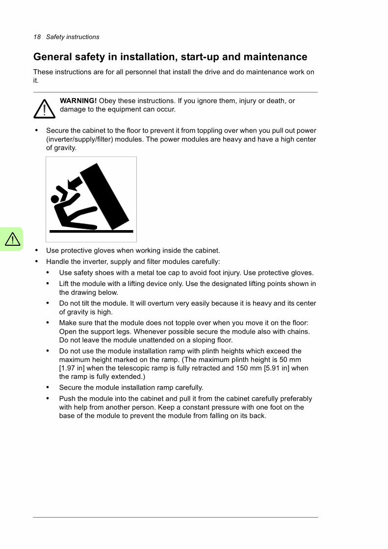
• Secure the cabinet to the floor to prevent it from toppling over when you pull out power (inverter/supply/filter) modules. The power modules are heavy and have a high center of gravity.
• Use protective gloves when working inside the cabinet.
• Handle the inverter, supply and filter modules carefully:
• Use safety shoes with a metal toe cap to avoid foot injury. Use protective gloves.
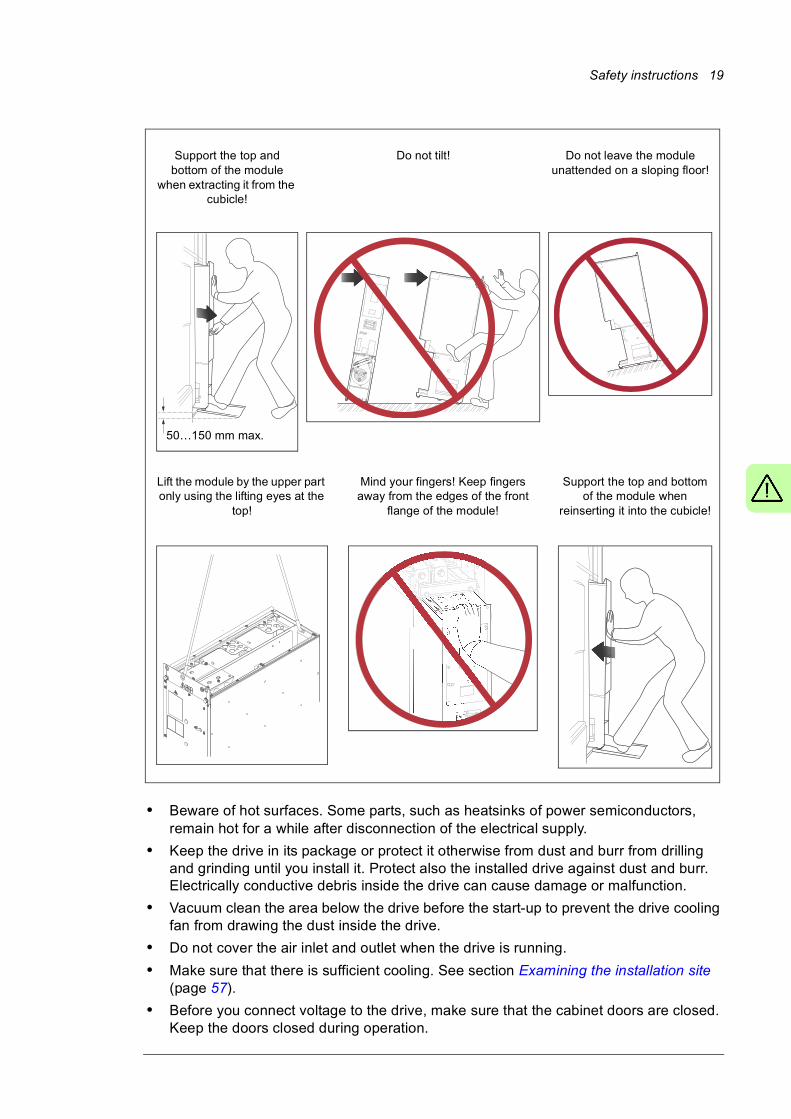
• Lift the module with a lifting device only. Use the designated lifting points shown in the drawing below.
• Do not tilt the module. It will overturn very easily because it is heavy and its center of gravity is high.
• Make sure that the module does not topple over when you move it on the floor: Open the support legs. Whenever possible secure the module also with chains. Do not leave the module unattended on a sloping floor.
• Do not use the module installation ramp with plinth heights which exceed the maximum height marked on the ramp. (The maximum plinth height is 50 mm [1.97 in] when the telescopic ramp is fully retracted and 150 mm [5.91 in] when the ramp is fully extended.)
• Secure the module installation ramp carefully.
• Push the module into the cabinet and pull it from the cabinet carefully preferably with help from another person. Keep a constant pressure with one foot on the base of the module to prevent the module from falling on its back.
Safety instructions 19
• Beware of hot surfaces. Some parts, such as heatsinks of power semiconductors, remain hot for a while after disconnection of the electrical supply.
• Keep the drive in its package or protect it otherwise from dust and burr from drilling and grinding until you install it. Protect also the installed drive against dust and burr. Electrically conductive debris inside the drive can cause damage or malfunction.
• Vacuum clean the area below the drive before the start-up to prevent the drive cooling fan from drawing the dust inside the drive.
• Do not cover the air inlet and outlet when the drive is running.
• Make sure that there is sufficient cooling. See section Examining the installation site (page 57).
• Before you connect voltage to the drive, make sure that the cabinet doors are closed. Keep the doors closed during operation.
50…150 mm max.
Support the top and bottom of the module
when extracting it from the cubicle!
Do not tilt!
Lift the module by the upper part only using the lifting eyes at the
top!
Mind your fingers! Keep fingers away from the edges of the front
flange of the module!
Support the top and bottom of the module when
reinserting it into the cubicle!
Do not leave the module unattended on a sloping floor!

20 Safety instructions
• Before you adjust the drive operation limits, make sure that the motor and all driven equipment can operate throughout the set operation limits.
• Before you activate the automatic fault reset or automatic restart functions of the drive control program, make sure that no dangerous situations can occur. These functions reset the drive automatically and continue operation after a fault or supply break.
• The maximum number of drive power-ups is five in ten minutes. Too frequent power-ups can damage the charging circuit of the DC capacitors.
• Make sure that any safety circuits (for example, emergency stop and Safe torque off) are validated at start-up. See chapter The Safe torque off function (page 223). For other safety functions, see their separate instructions.
Note: • If you select an external source for the start command and it is on, the drive will start
immediately after fault reset unless you configure the drive for pulse start. See the firmware manual.
• When the control location is not set to Local, the stop key on the control panel will not stop the drive.
• Only authorized persons are allowed to repair a malfunctioning drive.
Safety instructions 21
Electrical safety in installation, start-up and maintenance
Precautions before electrical work
These warnings are for all personnel who do work on the drive, motor cable or motor.
WARNING! Obey these instructions. If you ignore them, injury or death, or damage to the equipment can occur. If you are not a qualified electrician, do not do installation or maintenance work. Go through these steps before you begin any
installation or maintenance work.
1. Clearly identify the work location.
2. Disconnect all possible voltage sources. • Open the main switch-disconnector [Q1.1] or breaker [Q1] of the drive.
• Open the disconnector of the supply transformer as the main switch-disconnector or breaker of the drive does not remove the voltage from the input busbars of the drive.
• Make sure that reconnection is not possible. Lock the disconnectors to open position and attach a warning notice to them.
• Disconnect any external power sources from the control circuits before you do work on the control cables.
• After you disconnect the drive, always wait for 5 minutes to let the intermediate circuit capacitors discharge before you continue.
3. Protect any other energized parts in the work location against contact.
4. Take special precautions when close to bare conductors.
5. Measure that the installation is de-energized. • Use a multimeter with an impedance of at least 1 Mohm.
• Make sure that the voltage between the drive input power terminals (L1, L2, L3) and the grounding (PE) busbar is close to 0 V.
• Make sure that the voltage between the drive DC busbars (+ and -) and the grounding (PE) busbar is close to 0 V.
6. Install temporary grounding as required by the local regulations. Close the grounding switch (option +F259, Q9) if present.
7. Ask the person in control of the electrical installation work for a permit to work.
22 Safety instructions
Additional instructions and notes
WARNING! Obey these instructions. If you ignore them, injury or death, or damage to the equipment can occur.
• If you are not a qualified electrician, do not do electrical installation or maintenance work.
• Do not install a drive with EMC filter option +E202 on an ungrounded power system or a high resistance-grounded (over 30 ohms) power system.
• Do not connect the drive to a voltage higher than what is specified on the type designation label. If you do, the brake chopper starts to operate which causes the overheating of the brake resistor (if present). Overvoltage can also cause the motor to rush to its maximum speed.
• We do not recommend that you secure the cabinet by arc welding. If you have to, obey the instructions on page 69.
• Do not do insulation or voltage withstand tests on the drive or its modules.
Note:• The motor cable terminals of the drive are at a dangerous voltage when the input
power is on, regardless of whether the motor is running or not.
• The DC bus, brake chopper and brake resistors (if any) are at a dangerous voltage.
• External wiring can supply dangerous voltages to the relay outputs of the control units of the drive.
• The Safe torque off function does not remove the voltage from the main and auxiliary circuits. The function is not effective against deliberate sabotage or misuse.
WARNING! Use a grounding wrist band when you handle the printed circuit boards. Do not touch the boards unnecessarily. The boards contain components sensitive to electrostatic discharge.
WARNING! Obey these instructions. If you ignore them, equipment malfunction and damage to the fiber optic cables can occur.
• Handle fiber optic cables with care.
• When you unplug the cables, always hold the connector, not the cable itself.
• Do not touch the ends of the fibers with bare hands as the ends are extremely sensitive to dirt.
• Do not bend the fiber optic cables too tightly. The minimum allowed bend radius is 35 mm (1.4”).

Safety instructions 23
Grounding
These instructions are for all personnel who are responsible for the grounding of the drive.
WARNING! Obey these instructions. If you ignore them, injury or death, or equipment malfunction can occur, and electromagnetic interference can increase.
• If you are not a qualified electrician, do not do grounding work.
• Always ground the drive, the motor and adjoining equipment. This is necessary for the personnel safety. Proper grounding also reduces electromagnetic emission and interference.
• Make sure that the conductivity of the grounding conductors is sufficient. See section Selecting the power cables (page 76). Obey the local regulations.
• Connect the power cable shields to protective earth (PE) of the drive to make sure of personnel safety.
• Make a 360° grounding of the power and control cable shields at the cable entries to suppress electromagnetic disturbances.
• In a multiple-drive installation, connect each drive separately to the protective earth (PE) busbar of the switch board or the transformer.
Note:• You can use power cable shields as grounding conductors only when their conductivity
is sufficient.
• As the normal touch current of the drive is higher than 3.5 mA AC or 10 mA DC, you must use a fixed protective earth connection. See standard EN 61800-5-1, 4.3.5.5.2.
24 Safety instructions
Additional instructions for permanent magnet motor drives
Safety in installation, start-up and maintenance
These are additional warnings concerning permanent magnet motor drives. The other safety instructions in this chapter are also valid.
WARNING! Obey these instructions. If you ignore them, injury or death and damage to the equipment can occur.
• Do not do work on the drive when the permanent magnet motor is rotating. A rotating permanent magnet motor energizes the drive including its input power terminals.
Before installation, start-up and maintenance work on the drive:• Stop the motor.
• Disconnect the motor from the drive with a safety switch or by other means.
• If you cannot disconnect the motor, make sure that the motor cannot rotate during work. Make sure that no other system, like hydraulic crawling drives, can rotate the motor directly or through any mechanical connection like felt, nip, rope, etc.
• Measure that the installation is de-energized.
• Use a multimeter with an impedance of at least 1 Mohm.
• Make sure that the voltage between the drive output terminals (U2, V2, W2) and the grounding (PE) busbar is close to 0 V.
• Make sure that the voltage between the drive input power terminals (1L1, 1L2, 1L3) and the grounding (PE) busbar is close to 0 V.
• Make sure that the voltage between the plus and minus busbars of the drive DC link and the grounding (PE) busbar is close to 0 V.
• Install temporary grounding to the drive output terminals (U2, V2, W2). Connect the output terminals together as well as to the PE.
• Make sure that the operator cannot run the motor over the rated speed. Motor overspeed causes overvoltage which can damage the capacitors in the intermediate circuit of the drive.

Introduction to the manual 25
2
Introduction to the manual
Contents of this chapterThis chapter describes the manual. It contains a flowchart of steps in checking the delivery, installing and starting up the drive. The flowchart refers to chapters/sections in this manual and to other manuals.
Target audienceThis manual is intended for people who plan the installation, install, start up, use and service the drive. Read the manual before working on the drive. You are expected to know the fundamentals of electricity, wiring, electrical components and electrical schematic symbols.
The manual is written for readers worldwide. Both SI and imperial units are shown.
Contents of the manualThis manual contains the instructions and information for the basic drive configuration. The chapters of the manual are briefly described below.
Safety instructions gives safety instructions for the installation, start-up, operation and maintenance of the drive.
Introduction to the manual gives and introduction to this manual.
Operation principle and hardware description describes the operation principle and construction of the drive.
Mechanical installation describes how to install the drive mechanically.
Guidelines for planning the electrical installation contains instructions for the motor and cable selection, protections and cable routing.

26 Introduction to the manual
Electrical installation gives instructions on wiring the drive.
Control units of the drive contains the default I/O connection diagrams, descriptions of the terminals and technical data for the control units of both the supply and inverter units.
Installation checklist contains a list for checking the mechanical and electrical installation of the drive.
Start-up describes the start-up procedure of the drive.
Fault tracing describes the fault tracing possibilities of the drive.
Maintenance contains preventive maintenance instructions.
Technical data contains the technical specifications of the drive, eg. the ratings, sizes and technical requirements, provisions for fulfilling the requirements for CE and other markings.
Dimensions contains example dimension drawings of the drive.
The Safe torque off function describes the Safe torque off function of the drive and gives instructions on its implementation.
Resistor braking describes selection, protection, wiring and start-up of optional brake choppers and resistors. The chapter also contains technical data.
Related documentsSee List of related manuals on the inside of the front cover.
Categorization by frame size and option codeSome instructions, technical data and dimension drawings which concern only certain frame sizes are marked with the symbol of the frame size. The frame size indicates the number of power modules that form the supply and inverter units respectively. For example, the marking “2×R8i + 2×R8i” refers to a drive that has a supply unit consisting of two frame R8i IGBT supply modules and an inverter unit consisting of two frame R8i inverter modules. The frame size is marked on the type designation label (see page 53).
The instructions, technical data and dimension drawings which only concern certain optional selections are marked with option codes (such as +E205). The options included in the drive can be identified from the option codes visible on the type designation label (see page 53). The option selections are listed in section Type designation key (page 53).
Introduction to the manual 27
Quick installation, commissioning and operation flowchart
Task See
Plan the electrical installation and acquire the accessories needed (cables, fuses, etc.).
Check the ratings, required cooling air flow, input power connection, compatibility of the motor, motor connection, and other technical data.
Guidelines for planning the electrical installation (page 71)
Technical data (page 171)
Check the installation site. Ambient conditions (page 181)
Unpack and check the drive (only intact units may be started up).
Make sure that all necessary optional modules and equipment are present and correct.
Mount the drive.
Mechanical installation (page 57)
If the drive has been non-operational for more than one year, the DC link capacitors need to be reformed (page 164)
Route the cables. Routing the cables (page 82)
Check the insulation of the supply cable, the motor and the motor cable.
Checking the insulation of the assembly (page 89)
If the drive is about to be connected to an IT (ungrounded) system, check that the drive is not equipped with EMC filter +E202.
Checking the compatibility with IT (ungrounded) systems (page 90)
Connect the power cables.
Connect the control cables.
Electrical installation (page 89),
Check the installation. Installation checklist (page 135)
Start the drive up. Start-up (page 137)
Operate the drive: start, stop, speed control etc. ACS880 quick start-up guide, firmware manual
28 Introduction to the manual
Terms and abbreviationsTerm/
Abbreviation
Explanation
BCU Drive control unit. The drive contains two BCU control units. One controls the supply unit, the other controls the inverter unit.
As standard, the external I/O control signals are connected to the control unit, or optional I/O extensions mounted on it.
Drive Frequency converter for controlling AC motors. The drive consists of the supply unit (aka line-side converter) and the inverter unit (aka motor-side converter) connected together by the DC link.
In this manual, the term refers to the ACS880-37 as a whole.
EMC Electromagnetic compatibility
EMI Electromagnetic interference
EMT Electrical metallic tubing
FAIO-01 Optional analog I/O extension module
FCAN-01 Optional FCAN-01 CANopen adapter module
FCNA-01 Optional ControlNet™ adapter module
FDCO-01 Optional DDCS communication module with two pairs of 10 Mbit/s DDCS channels
FDNA-01 Optional DeviceNet™ adapter module
FECA-01 Optional EtherCAT adapter module
FEN-01 Optional TTL incremental encoder interface module
FEN-11 Optional TTL absolute encoder interface module
FEN-21 Optional resolver interface module
FEN-31 Optional HTL incremental encoder interface module
FENA-11 Optional Ethernet adapter module for EtherNet/IP™, Modbus TCP and PROFINET IO protocols
FENA-21 Optional Ethernet adapter module for EtherNet/IP™, Modbus TCP and PROFINET IO protocols, 2-port
FEPL-01 Optional Ethernet POWERLINK adapter module
FIO-01 Optional digital I/O extension module
FIO-11 Optional analog I/O extension module
FLON-01 Optional LonWorks® adapter module
FPBA-01 Optional PROFIBUS DP adapter module
Frame (size) Relates to the construction type of the component in question. For example, several drive types with different power ratings may have the same basic construction, and a frame size is used in reference to all those drive types.
The frame size marking of the drive indicates the quantity and frame size of the supply modules, plus the quantity and frame size of the inverter modules, eg. “2×R8i + 2×R8i”.
To determine the frame size of a drive type, see the rating tables in chapter Technical data.
FSO-12 Optional functional safety module
IGBT Insulated gate bipolar transistor; a voltage-controlled semiconductor type widely used in drives due to their easy controllability and high switching frequency.
Inverter unit The part of the drive that converts DC to AC for the motor. Consists of one or more inverter modules and their auxiliary components.
The inverter unit is also capable of feeding energy from a decelerating motor into the DC link.
I/O Input/Output
Power module Supply module or inverter module. See also Frame (size).
RFI Radio-frequency interference
SAR Safe acceleration range

Introduction to the manual 29
Safety data (SIL, PL)
SBC Safe brake control
SLS Safely-limited speed without encoder
SS1 Safe stop 1
SSE Safe stop emergency
SSM Safe speed monitor without encoder
STO Safe torque off. See chapter The Safe torque off function (page 223).
Supply unit The part of the drive that converts AC to DC for the motor. Consists of one or more supply modules and their auxiliary components such as the LCL filter.
Abbr. Reference Description
Cat. EN ISO 13849-1 Classification of the safety-related parts of a control system in respect of their resistance to faults and their subsequent behavior in the fault condition, and which is achieved by the structural arrangement of the parts, fault detection and/or by their reliability. The categories are: B, 1, 2, 3 and 4.
CCF EN ISO 13849-1 Common cause failure (%)
DC EN ISO 13849-1 Diagnostic coverage
FIT IEC 61508 Failure in time: 1E-9 hours
HFT IEC 61508 Hardware fault tolerance
MTTFd EN ISO 13849-1 Mean time to dangerous failure: (The total number of life units) / (the number of dangerous, undetected failures) during a particular measurement interval under stated conditions
PFD IEC 61508 Probability of failure on demand
PFHD IEC 61508 Probability of dangerous failures per hour
PL EN ISO 13849-1 Performance level. Levels a…e correspond to SIL
SC IEC 61508 Systematic capability
SFF IEC 61508 Safe failure fraction (%)
SIL IEC 61508 Safety integrity level (1…3)
SILCL IEC/EN 62061 Maximum SIL (level 1…3) that can be claimed for a safety function or subsystem
SS1 IEC/EN 61800-5-2 Safe stop 1
STO IEC/EN 61800-5-2 Safe torque off
T1 IEC 61508 Proof test interval. See also section Maintenance (page 231).
Term/
Abbreviation
Explanation

30 Introduction to the manual
Operation principle and hardware description 31
3
Operation principle and hardware description
Contents of this chapter
This chapter briefly describes the operation principle and construction of the drive.
Operation principle
The ACS880-37 is a low-harmonic, air-cooled, cabinet-installed drive for controlling asynchronous AC induction motors, permanent magnet synchronous motors, AC induction servomotors and ABB synchronous reluctance (SynRM) motors.
The drive consists of several cubicles that contain the supply and motor terminals, 1 to 6 IGBT supply module(s) forming the supply unit (line-side converter), 1 to 6 inverter modules forming the inverter unit (motor-side converter), and optional equipment. The actual arrangement of the cubicles varies from type to type and the selected options. Some optional equipment require additional cubicles. See chapter Dimensions for examples of cabinet line-ups.
Supply unit
The supply unit rectifies three-phase AC current to direct current for the intermediate DC link of the drive.
32 Operation principle and hardware description
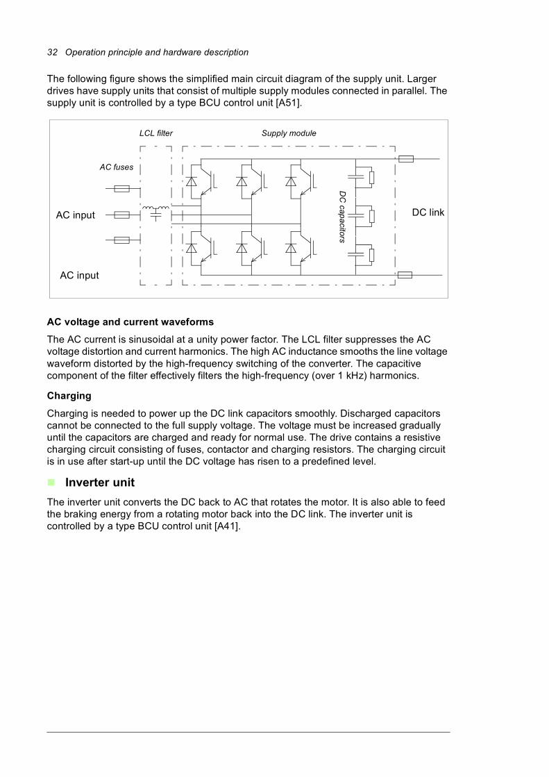
The following figure shows the simplified main circuit diagram of the supply unit. Larger drives have supply units that consist of multiple supply modules connected in parallel. The supply unit is controlled by a type BCU control unit [A51].
AC voltage and current waveforms
The AC current is sinusoidal at a unity power factor. The LCL filter suppresses the AC voltage distortion and current harmonics. The high AC inductance smooths the line voltage waveform distorted by the high-frequency switching of the converter. The capacitive component of the filter effectively filters the high-frequency (over 1 kHz) harmonics.
Charging
Charging is needed to power up the DC link capacitors smoothly. Discharged capacitors cannot be connected to the full supply voltage. The voltage must be increased gradually until the capacitors are charged and ready for normal use. The drive contains a resistive charging circuit consisting of fuses, contactor and charging resistors. The charging circuit is in use after start-up until the DC voltage has risen to a predefined level.
Inverter unit
The inverter unit converts the DC back to AC that rotates the motor. It is also able to feed the braking energy from a rotating motor back into the DC link. The inverter unit is controlled by a type BCU control unit [A41].
AC fuses
LCL filter Supply module
DC
capa
citorsDC link
AC input
AC input
Operation principle and hardware description 33
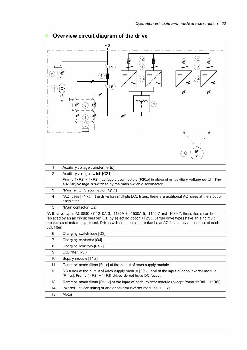
Overview circuit diagram of the drive
1 Auxiliary voltage transformer(s)
2 Auxiliary voltage switch [Q21].
Frame 1×R8i + 1×R8i has fuse disconnectors [F20.x] in place of an auxiliary voltage switch. The auxiliary voltage is switched by the main switch/disconnector.
3 *Main switch/disconnector [Q1.1]
4 *AC fuses [F1.x]. If the drive has multiple LCL filters, there are additional AC fuses at the input of each filter.
5 *Main contactor [Q2]
*With drive types ACS880-37-1210A-3, -1430A-3, -1530A-5, -1450-7 and -1680-7, these items can be replaced by an air circuit breaker [Q1] by selecting option +F255. Larger drive types have an air circuit breaker as standard equipment. Drives with an air circuit breaker have AC fuses only at the input of each LCL filter.
6 Charging switch fuse [Q3]
7 Charging contactor [Q4]
8 Charging resistors [R4.x]
9 LCL filter [R3.x]
10 Supply module [T1.x]
11 Common mode filters [R1.x] at the output of each supply module
12 DC fuses at the output of each supply module [F2.x], and at the input of each inverter module [F11.x]. Frame 1×R8i + 1×R8i drives do not have DC fuses.
13 Common mode filters [R11.x] at the input of each inverter module (except frame 1×R8i + 1×R8i)
14 Inverter unit consisting of one or several inverter modules [T11.x]
15 Motor
M3~
~ 3
3
4
5
9
102
1
14
11
15
6
7
8
13
1212
34 Operation principle and hardware description
Cabinet line-up and layout examples
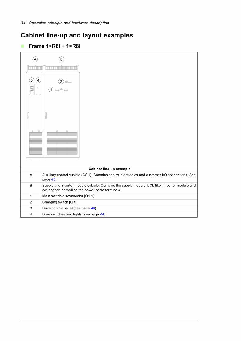
Frame 1×R8i + 1×R8i
Cabinet line-up example
A Auxiliary control cubicle (ACU). Contains control electronics and customer I/O connections. See page 40.
B Supply and inverter module cubicle. Contains the supply module, LCL filter, inverter module and switchgear, as well as the power cable terminals.
1 Main switch-disconnector [Q1.1].
2 Charging switch [Q3]
3 Drive control panel (see page 46)
4 Door switches and lights (see page 44)
A B
1
23 4
Operation principle and hardware description 35
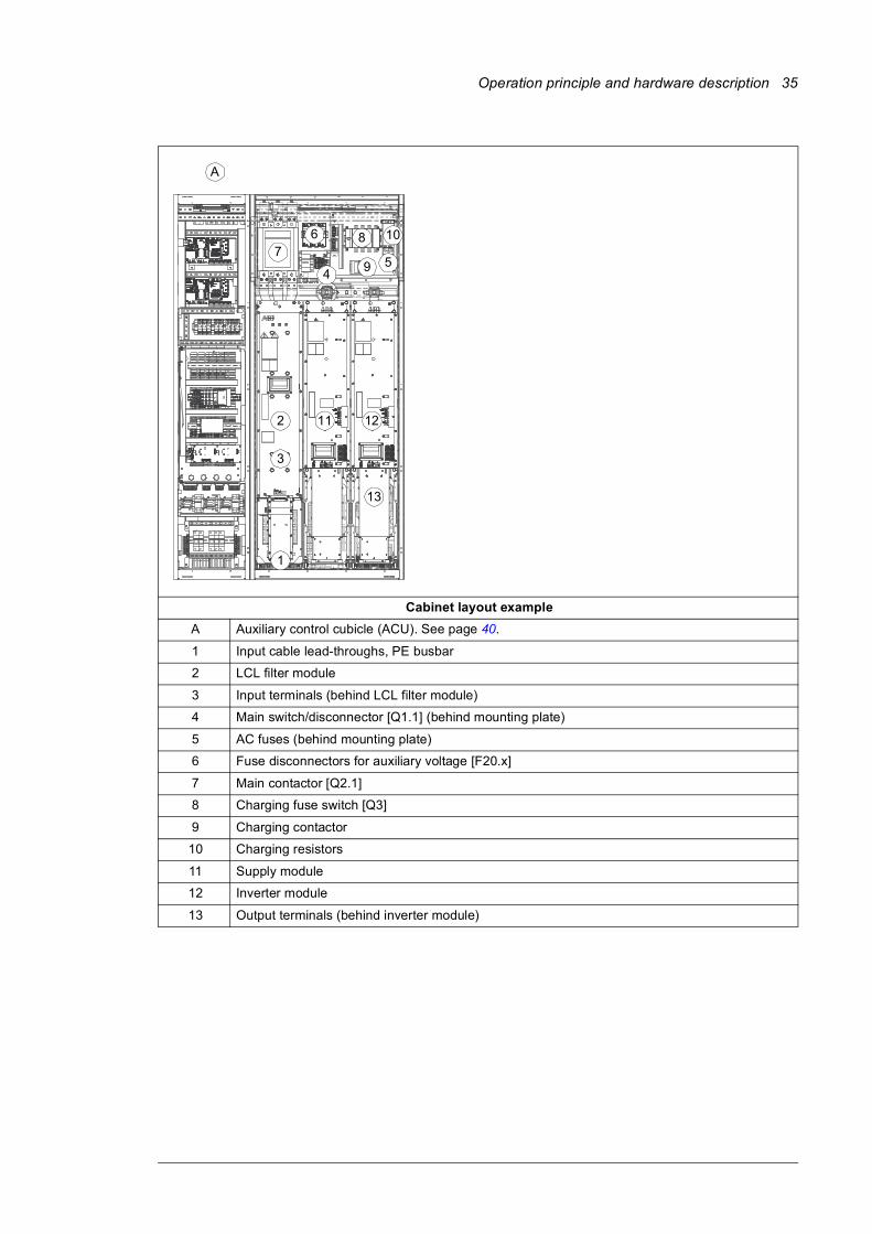
Cabinet layout example
A Auxiliary control cubicle (ACU). See page 40.
1 Input cable lead-throughs, PE busbar
2 LCL filter module
3 Input terminals (behind LCL filter module)
4 Main switch/disconnector [Q1.1] (behind mounting plate)
5 AC fuses (behind mounting plate)
6 Fuse disconnectors for auxiliary voltage [F20.x]
7 Main contactor [Q2.1]
8 Charging fuse switch [Q3]
9 Charging contactor
10 Charging resistors
11 Supply module
12 Inverter module
13 Output terminals (behind inverter module)
6
A
2 11 12
78 10
94
1
3
5
13
36 Operation principle and hardware description
Frame 2×R8i + 2×R8i
Cabinet line-up example
A Auxiliary control cubicle (ACU). Contains control electronics and customer I/O connections. See page 40.
B Incoming cubicle. Contains the input terminals, switchgear and charging equipment.
C Supply module cubicle. Contains two R8i supply modules together with an LCL filter module.
D Inverter module cubicle. Contains two R8i inverter modules. As standard, the motor cables are run from each inverter module to the motor unless the drive is equipped with option +H359 (common motor terminal cubicle), +H366 (common output terminals) or +E206 (sine filters).
1 Main switch-disconnector [Q1.1]
2 Grounding/earthing switch [Q9.1] (option +F259)
3 Drive control panel (see page 46)
4 Door switches and lights (see page 44)
5 Auxiliary voltage switch [Q21]
6 Charging switch [Q3]
A B C D
1
5
3 4
2
6
Operation principle and hardware description 37
Cabinet layout example
A Auxiliary control cubicle (ACU). See page 40.
1 Input cable lead-throughs, PE busbar
2 Input terminals
3 Main switch-disconnector [Q1.1]
4 Grounding/earthing switch [Q9.1] (option +F259)
5 AC fuses
6 Charging resistors and contactor
7 Main contactor (behind charging equipment)
8 Auxiliary voltage switch [Q21]
9 Charging switch [Q3]
10 Incoming cubicle cooling fan
11 DC fuses (at the output of each supply module and at the input of each inverter module)
12 LCL filter module
13 Supply modules
14 Inverter modules. The output terminals are located behind each module. Each module must be individually connected to the motor using separate cables unless the drive is equipped with option +H359 (common motor terminal cubicle), +H366 (common output terminals) or +E206 (sine filters).
1
2
4
3
5
A
6
8 9
7
10
13
11 11 11
13
12
14 14
11
38 Operation principle and hardware description
Frame 3×R8i + 3×R8i (with main breaker)
Cabinet line-up example
A Auxiliary control cubicle (ACU). Contains control electronics and customer I/O connections. See page 40.
B Incoming cubicle. Contains the input terminals, switchgear and charging equipment.
C Supply module cubicle (1). Contains two LCL filter modules.
D Supply module cubicle (2). Contains three R8i supply modules.
E Inverter module cubicle. Contains three R8i inverter modules. As standard, the motor cables are run from each inverter module to the motor unless the drive is equipped with option +H359 (common motor terminal cubicle), +H366 (common output terminals) or +E206 (sine filters).
1 Main circuit breaker [Q1]
2 Grounding/earthing switch [Q9.1] (option +F259)
3 Drive control panel (see page 46)
4 Door switches and lights (see page 44)
5 Auxiliary voltage switch [Q21]
6 Charging switch [Q3]
A B C D E
1
5
3 4
2
6
Operation principle and hardware description 39
Cabinet layout example
A Auxiliary control cubicle (ACU). See page 40.
1 Input cable lead-throughs, PE busbar
2 Input terminals
3 Charging resistors
4 Incoming cubicle cooling fans (behind the charging resistor mounting plate)
5 Main breaker [Q1]
6 Charging switch [Q3]
7 Auxiliary voltage switch [Q21]
8 Grounding/earthing switch [Q9.1] (option +F259)
9 Charging contactor (behind auxiliary equipment)
10 AC fuses
11 LCL filter modules
12 Supply modules
13 DC fuses (at the output of each supply module and at the input of each inverter module)
14 Inverter modules. The output terminals are located behind each module. Each module must be individually connected to the motor using separate cables unless the drive is equipped with option +H359 (common motor terminal cubicle), +H366 (common output terminals) or +E206 (sine filters).
A
7
3
5
2
6
1
8 9
10
1211
13 13
144
40 Operation principle and hardware description
Auxiliary control cubicle (ACU) layout
A layout example of the auxiliary control cubicle (ACU) is shown below.
1 Fuse-disconnectors F101. On the primary of transformer T101 (item 27).
19 Lead-through for control cables
2 Fuse-disconnectors F27 for motor cooling fan outputs (options +M602…610)
20 Terminal block X68 for FSO-xx safety functions module (option +Q973)
3 Supply control unit [A51]. See chapter Control units of the drive (page 123)
21 I/O terminal block (option +L504). The I/O of the inverter control unit is wired to this block.
4 Inverter control unit [A41]. Three optional I/O extension, encoder interface, or fieldbus adapter modules can be installed on the unit. Additional modules are installed on item 13. See chapter Control units of the drive (page 123)
22 Grounding/clamping point for control cables
5 Auxiliary voltage circuit breaker F112. On the secondary of transformer T111 (item 29). Mounted on the right-hand inside wall.
23 24 V DC power supply and buffer module
Swing-out frame closed,detachable mounting plates in place
Swing-out frame open,without detachable mounting plates
3
2
4 5
1
8
9
10
11
12
13
14 15 16
17 18
19
20 2122
23
24
25
25
26
27
28
30
3132
33
29
34
9
6
35
7
Operation principle and hardware description 41
6 Switch F90 for ground fault monitoring (item 12) 24 Motor fan starters and contactors (options +M602…610)
7 FSO-xx safety functions module (option +Q973 and other options requiring FSO-xx)
25 Terminal blocks X601 for motor fan connections (options +M602…610)
8 Temperature monitoring relays (options +L505 and +L506). The terminals [X506] are located on the back of the detachable mounting plate.
26 24 V DC power supply for cabinet lighting (option +G301)
9 Swing-out frame 27 Transformer T101 (at the back of the cubicle, not visible). Supplies IP54, brake chopper and brake resistor cabinet cooling fans (options +B055, +D150 and +D151).
10 Mounting rail for additional equipment 28 Transformer T21 (at the back of the cubicle, not visible). Supplies the control circuitry and the cooling fans in both the incoming unit (ICU) and the auxiliary control unit (ACU). Also supplies the cooling fan of type BLCL-1x-x LCL filter modules.
11 Safety relays (emergency stop, safe torque off) 29 Transformer T111. Supplies direct-on-line cooling fans of supply, LCL filter (BLCL-2x-x) and inverter modules (option +C188).
12 Ground fault monitoring equipment for ungrounded systems (option +Q954)
30 Auxiliary voltage circuit breakers F22 and F102. On the secondary of transformers T21 (item 28) and T101 (item 27) respectively.
13 FEA-03 extension adapter (option +L515). See item 4.
31 Input voltage setting for auxiliary voltage transformer T101 (item 27)
14 Switch and circuit breaker for externally-supplied motor space heater (option +G313). The terminals [X313] are located on the back of the detachable mounting plate.
32 Input voltage setting for auxiliary voltage transformer T21 (item 28)
15 Switch and circuit breaker for externally-supplied control voltage (option +G307), eg. UPS. The terminals [X307] are located on the back of the detachable mounting plate.
33 Input voltage setting for auxiliary voltage transformer T111 (item 29)
16 Switch and circuit breaker for externally-supplied cabinet lighting and heating (options +G300 and +G301). The terminals [X300] are located on the back of the detachable mounting plate.
34 Terminal blocks
• X250: indication of main switch-disconnector and contactor status
• X951: connection of external emergency stop button
• X954: ground fault alarm indication• X957: for connection of Prevention of
unexpected start-up switch.
Mounted on the left-hand inside wall.
17 Fuse-disconnectors F21. On the primary of transformer T21 (item 28). Mounted on a detachable plate.
35 Cubicle heater element (option +G300). Mounted on the right-hand inside wall.
18 Fuse-disconnectors F111. On the primary of transformer T111 (item 29). Mounted on a detachable plate.
42 Operation principle and hardware description
Overview of power and control connections
The diagram shows the power connections and control interfaces of the drive.
1
2
3
4
Option modules can be inserted into slots 1, 2, 3 and 4 as follows:
Additional modules can be installed on an optional FEA-03 extension adapter connected to the RDCO module on slot 4.
5 Memory unit (see page 170)
6 Connection for FSO-xx safety functions module
7 See section Control panel (page 46)
8 Terminal blocks on the inverter control unit. See page 95, and Control units of the drive (page 123). These terminals are optionally wired to terminal block X504 in the auxiliary control cabinet of the drive.
L1
L2
L3
PE
U2
V2
W2
M 3 ~
L1
L2
L3
PE
Fxx
Slots 1, 2 and 3
17
.........
..........
.
.......... ..........
.....
.....
6
.
.
.
. . .10
..........
.....
....
.
4
2 3
Slot 45
X205
X12
X13
8
Inverter control unit [A41]
Supply control unit [A51]
V1T/R…9
11 13
12
14
ACS880-37
Fxxx
Module type Slots
Analog and digital I/O extension modules 1, 2, 3
Feedback interface modules 1, 2, 3
Fieldbus communication modules 1, 2, 3
RDCO-xx DDCS communication option module (standard equipment). As standard, a fiber optic link connects the supply and inverter control units.
4
See section Type designation key, page 53

Operation principle and hardware description 43
9 Fiber optic link to each inverter module. Similarly, each supply module is connected to the supply control unit by fiber optic cables.
10 Terminal blocks for customer connections installed in the drive cabinet. For the locations, see Auxiliary control cubicle (ACU) layout (page 40). Wiring details are given starting on page 97.
11 Supply unit (consisting of one or more supply modules and LCL filters)
12 DC link
13 Inverter unit (consisting of one or more inverter modules)
14 Optional brake chopper (+D150) and resistors (+D151)
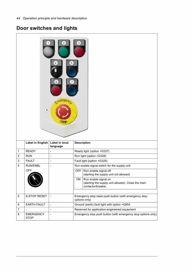
44 Operation principle and hardware description
Door switches and lights
Label in English Label in local language
Description
1 READY - Ready light (option +G327)
2 RUN - Run light (option +G328)
3 FAULT - Fault light (option +G329)
4 RUN/ENBL - Run enable signal switch for the supply unit
5 E-STOP RESET - Emergency stop reset push button (with emergency stop options only)
6 EARTH FAULT - Ground (earth) fault light with option +Q954
7 - - Reserved for application-engineered equipment
8 EMERGENCY STOP
- Emergency stop push button (with emergency stop options only)
1 2 3
4 5
6 7
8
OFF OFF Run enable signal off(starting the supply unit not allowed)
ON Run enable signal on(starting the supply unit allowed). Close the main contactor/breaker.
Operation principle and hardware description 45
Main disconnecting device [Q1.1]
Depending on the configuration of the drive, the main disconnecting device of the drive is either a switch-disconnector or a main circuit breaker. Units with a switch-disconnector also have a main contactor.
The main disconnecting device switches the main supply to the drive on and off. To disconnect the main supply, turn the switch-disconnector to the 0 (OFF) position, or rack out the main breaker (whichever device is installed).
WARNING! The main disconnecting device does not isolate the input power terminals, AC voltage meters, or the *auxiliary voltage circuit from the power line. To isolate the auxiliary voltage circuit, open the auxiliary voltage switch (Q21). To
isolate the input power terminals and AC voltage meters, open the main breaker of the supply transformer.
*With frame 1×R8i + 1×R8i units, the main switch-disconnector [Q1.1] also switches the auxiliary voltage on and off.
To close the main disconnecting device, auxiliary voltage must be switched on, and the grounding switch (if present) must be open.
Auxiliary voltage switch [Q21]
The auxiliary voltage switch controls the supply to the auxiliary voltage transformers. The transformer feeds the control circuits inside the drive such as cooling fans, relays and measuring equipment. The switch is fitted with fuses.
Note: Frame 1×R8i + 1×R8i units are not fitted with an auxiliary voltage switch. The auxiliary voltage is switched on and off by the main disconnecting device [Q1], and protected by fuse disconnectors F20.1…F20.3.
Grounding (earthing) switch [Q9.x], optional
The grounding switch [Q9.1] (option +F259) connects the main AC power bus to the PE busbar.
To close the grounding switch, auxiliary voltage must be switched on, and the main disconnecting device must be open.
WARNING! The grounding switch does not ground the input power terminals of the drive or the auxiliary (control) voltage circuits.
Other devices on the door
• Voltmeter (option +G334); comes with a phase selector switch. Note: The voltage is measured on the supply side of the main switch or breaker.
• AC current meter (option +G335) on one phase.

46 Operation principle and hardware description
Control panel
The ACS-AP-I is the user interface of the drive. It provides the essential controls such as Start/Stop/Direction/Reset/Reference, and the parameter settings for the inverter control program.
One control panel can be used to control several drives through a panel link; see section Panel bus (Control of several units from one control panel) (page 119).
The control panel can be removed by pulling it forward from the top edge and reinstalled in reverse order. For the use of the control panel, see ACS-AP assistant control panel user’s manual (3AUA0000085685 [English]) and the firmware manual.
Control by PC tools
There is a USB connector on the front of the panel that can be used to connect a PC to the drive. When a PC is connected to the control panel, the control panel keypad is disabled.

Operation principle and hardware description 47
Descriptions of cabinet options
Degree of protection
Definitions
According to IEC/EN 60529, the degree of protection is indicated by an IP code where the first numeral means protection against ingress of solid foreign objects, and the second numeral protection against ingress of water. The IP codes of the standard cabinet and options covered in this manual are defined below.
* meaning for protection of persons: against access to hazardous parts with finger
IP22 (standard)
The degree of protection of the standard drive cabinet is IP22 (UL type 1). The air outlets at the top of the cabinet are covered with a brass grating. The air inlet gratings are covered with plastic gratings. With doors open, the degree of protection of the standard cabinet and all cabinet options is IP20. The live parts inside the cabinet are protected against contact with clear plastic shrouds or metallic gratings.
IP42 (option +B054)
This option provides the degree of protection of IP42 (UL type 1 Filtered). The air inlet gratings are covered with a metallic mesh between the inner metallic grating and the outer plastic grating.
IP54 (option +B055)
This option provides the degree of protection of IP54 (UL type 12). It provides the cabinet air inlets with filter housings containing folded board air filter mats between the inner metallic grating and the outer plastic grating. An additional fan on the cabinet roof is included.
Channeled air outlet (option +C130)
This option provides a collar for fitting an air outlet duct. The collar is located on the cabinet roof. The option provides the cabinet air inlets with filter housings containing folded board air filter mats between the inner metallic grating and the outer plastic grating.
See also Air outlet duct on the cabinet roof (option +C130) on page 68.
IP code The equipment is protected …
First numeral Second numeral
IP22 against ingress of solid foreign objects > 12.5 mm diameter *
against dripping (15° tilting) water
IP42 against ingress of solid foreign objects > 1 mm against dripping (15° tilting) water
IP54 dust-protected against splashing water

48 Operation principle and hardware description
Marine construction (option +C121)
The option includes the following accessories and features:• reinforced mechanics
• grab railings
• door flush bolt which allows the door to open 90 degrees and prevents it from slamming close
• self-extinctive materials
• flat bars at base of the cabinet for fastening
• fastening braces at the top of the cabinet.
Required options: Appropriate additional wire marking option (see page 50) according to the requirements of the classification society
Related options: halogen-free materials and wiring (+G330)
UL listed (option +C129)
The option includes factory inspection of the cabinet according to UL 508C and the following accessories and features:• US type main switch and fuses
• top entry and exit of cables
• US cable conduit entry (plain plate without ready-made holes)
• all components UL Listed/Recognized
• maximum supply voltage 600 V.
Related options: +H358 (cable conduit entry)
CSA approved (option +C134)
The option includes the following accessories and features:• US/CSA type main switch fuse
• bottom entry and exit of cables
• US cable conduit entry (plain plate without ready-made holes)
• all components UL/CSA listed/recognized
• maximum supply voltage 600 V.
Seismic design (option +C180)
The option includes the following accessories and features:• reinforced plinth
• flat bars at base of the cabinet for fastening.
Resistor braking (options +D150 and +D151)
See chapter Resistor braking on page 235.
EMC filters (option + E202)
See section Type designation key on page 53 and sections Compliance with the European EMC Directive on page 184 and Compliance with EN 61800-3:2004 on page 187.
More information: Technical Guide No. 3 – EMC Compliant Installation and Configuration for a Power Drive System (3AFE61348280 [English])

Operation principle and hardware description 49
Cabinet heater with external supply (option +G300)
The option contains: • heating elements in the cubicles and supply/inverter modules
• load switch for providing electrical isolation during service
• miniature circuit breaker for overcurrent protection
• terminal block for external power supply.
The heater prevents humidity condensation inside the cabinet when the drive is not running. The power output of the semiconductor-type heating elements depends on the environmental temperature. The customer must switch the heating off when it is not needed by cutting the supply voltage off.
The customer must supply the heater from an external 110…240 V AC power source.
See also • Powering the heating and lighting equipment (options +G300, +G301 and +G313)
• circuit diagrams delivered with drive for the actual wiring.
Terminals for external interruptible control voltage (option +G307)
The option provides terminals for connecting external interruptible control voltage to the control unit and control devices when the drive is not running.
See also• Supplying power for the auxiliary circuits on page 86
• Connecting an auxiliary voltage supply (UPS, option +G307) on page 97
• circuit diagrams delivered with drive for the actual wiring.
Output for motor space heater (option +G313)
The option contains:• load switch for providing electrical isolation during service
• miniature circuit breaker for overcurrent protection
• terminal block for external supply and heating element(s) connection
The heater is off when the drive is running. The customer controls the heating elements in the motor windings on and off with the external supply. The power and voltage of the motor heater depend on the motor.
See also• Supplying power for the auxiliary circuits on page 86
• Powering the heating and lighting equipment (options +G300, +G301 and +G313) on page 100
• circuit diagrams delivered with drive for the actual wiring.
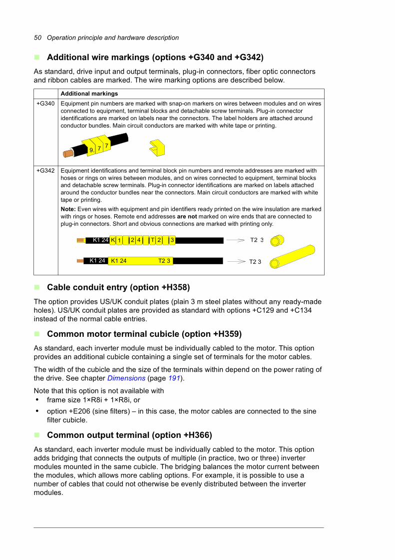
50 Operation principle and hardware description
Additional wire markings (options +G340 and +G342)
As standard, drive input and output terminals, plug-in connectors, fiber optic connectors and ribbon cables are marked. The wire marking options are described below.
Cable conduit entry (option +H358)
The option provides US/UK conduit plates (plain 3 m steel plates without any ready-made holes). US/UK conduit plates are provided as standard with options +C129 and +C134 instead of the normal cable entries.
Common motor terminal cubicle (option +H359)
As standard, each inverter module must be individually cabled to the motor. This option provides an additional cubicle containing a single set of terminals for the motor cables.
The width of the cubicle and the size of the terminals within depend on the power rating of the drive. See chapter Dimensions (page 191).
Note that this option is not available with• frame size 1×R8i + 1×R8i, or
• option +E206 (sine filters) – in this case, the motor cables are connected to the sine filter cubicle.
Common output terminal (option +H366)
As standard, each inverter module must be individually cabled to the motor. This option adds bridging that connects the outputs of multiple (in practice, two or three) inverter modules mounted in the same cubicle. The bridging balances the motor current between the modules, which allows more cabling options. For example, it is possible to use a number of cables that could not otherwise be evenly distributed between the inverter modules.
Additional markings
+G340 Equipment pin numbers are marked with snap-on markers on wires between modules and on wires connected to equipment, terminal blocks and detachable screw terminals. Plug-in connector identifications are marked on labels near the connectors. The label holders are attached around conductor bundles. Main circuit conductors are marked with white tape or printing.
+G342 Equipment identifications and terminal block pin numbers and remote addresses are marked with hoses or rings on wires between modules, and on wires connected to equipment, terminal blocks and detachable screw terminals. Plug-in connector identifications are marked on labels attached around the conductor bundles near the connectors. Main circuit conductors are marked with white tape or printing.
Note: Even wires with equipment and pin identifiers ready printed on the wire insulation are marked with rings or hoses. Remote end addresses are not marked on wire ends that are connected to plug-in connectors. Short and obvious connections are marked with printing only.
9. 7 7
2 41KK1 24 T2 332T
K1 24 K1 24 T2 3 T2 3

Operation principle and hardware description 51
WARNING! The bridging can carry the nominal output of one inverter module. In case of three parallel modules, ensure that the load capacity of the bridging is not exceeded. For example, if the cabling connects to the output busbars at one
module only, use the module in the middle.
Note: The +H366 option only interconnects the outputs of inverter modules within the same cubicle, not modules installed in different cubicles. Therefore, when the drive has more than three inverter modules, make sure that the load is distributed evenly between the modules:
• In case of two inverter cubicles of two modules, connect the same number of cables to each cubicle.
• In case of one inverter cubicle with three modules and another with two, each cubicle requires a number of cables proportional to the number of modules within. For example, connect three out of five (or six out of ten, etc.) cables to the cubicle with three modules, the remaining two out of five (four out of ten) cables to the cubicle with two modules.
Additional terminal block X504 (option +L504)
The standard terminal blocks of the drive control unit are wired to the additional terminal block at the factory for customer control wiring. The terminals are spring loaded.
Cables accepted by the terminals:
• solid wire 0.08 to 4 mm2
• stranded wire with ferrule 0.14 to 2.5 mm2
• stranded wire without ferrule 0.08 to 2.5 mm2 (28 to 12 AWG).
Stripping length: 10 mm.
Note: The optional modules inserted in the slots of the control unit (or optional FEA-03 extension adapter) are not wired to the additional terminal block. The customer must connect the optional module control wires directly to the modules.
Thermistor relays (options +L505, +2L505)
The thermistor relay is used for the overtemperature supervision of motors equipped with PTC thermistors. When the motor temperature rises to the thermistor wake-up level, the thermistor resistance increases sharply. The relay detects the change and indicates motor overtemperature through its auxiliary contacts.
Option +L505 provides a thermistor relay and an auxiliary relay and connection terminals for one measuring circuit (one PTC thermistor) and for one normally open contact. The relay can be reset locally or from a remote reset switch wired to the relay.
Option +2L505 provides two thermistor relays and auxiliary relays and connection terminals for two measuring circuit (one PTC thermistor in each) and for two normally open contacts. The relays can be reset locally or from a remote reset switch wired to the relay.

52 Operation principle and hardware description
The customer connects PTC sensors to the thermistor relay, and the terminals of the auxiliary relay of the normally open contact, for example, to• main breaker control circuit of the drive for opening the breaker in case of motor
overtemperature or
• appropriate digital input of the drive for tripping the drive and generating a fault message in case of motor overtemperature or
• customer control circuit.
See also• firmware manual for parameter settings
• Wiring the thermistor relay(s) (options +L505 and +2L505) on page 98
• circuit diagrams delivered with the drive for the actual wiring.
Pt100 relays (options +2L506, +3L506, +5L506, +8L506)
What the option contains
The standard Pt100 relay option includes two (+2L506), three (+3L506), five (+5L506) or eight (+8L506) Pt100 temperature monitoring relays and an auxiliary relay wired to a terminal block. Other numbers of Pt100 relays must be ordered as application engineered.
Description
A Pt100 relay is used for overtemperature supervision of motors equipped with Pt100 sensors. For example, three sensors measure the temperature of the motor windings and two sensors the temperature of the bearings. The sensor resistance increases linearly as the temperature rises. The relay releases at an adjustable wake-up level and indicates motor overtemperature through its change-over contact.
The relay provides connection terminals for one Pt100 temperature sensor and terminals of one normally open and one normally closed contact.
The customer connects Pt100 sensors to the Pt100 relays (one sensor per relay) and the auxiliary relays of the normally open contacts of the Pt100 relays, for example, to• main breaker control circuit of the drive for opening the breaker in case of motor
overtemperature or
• appropriate digital input of the drive for tripping the drive and generating a fault message in case of motor overtemperature or
• customer control circuit.
See also• firmware manual for parameter settings
• Wiring the Pt100 relays (options +2L506, +3L506, +5L506 and +8L506) on page 99
• Pt100 relay alarm and trip limit setting instructions on page 138
• circuit diagrams delivered with the drive for the actual wiring.
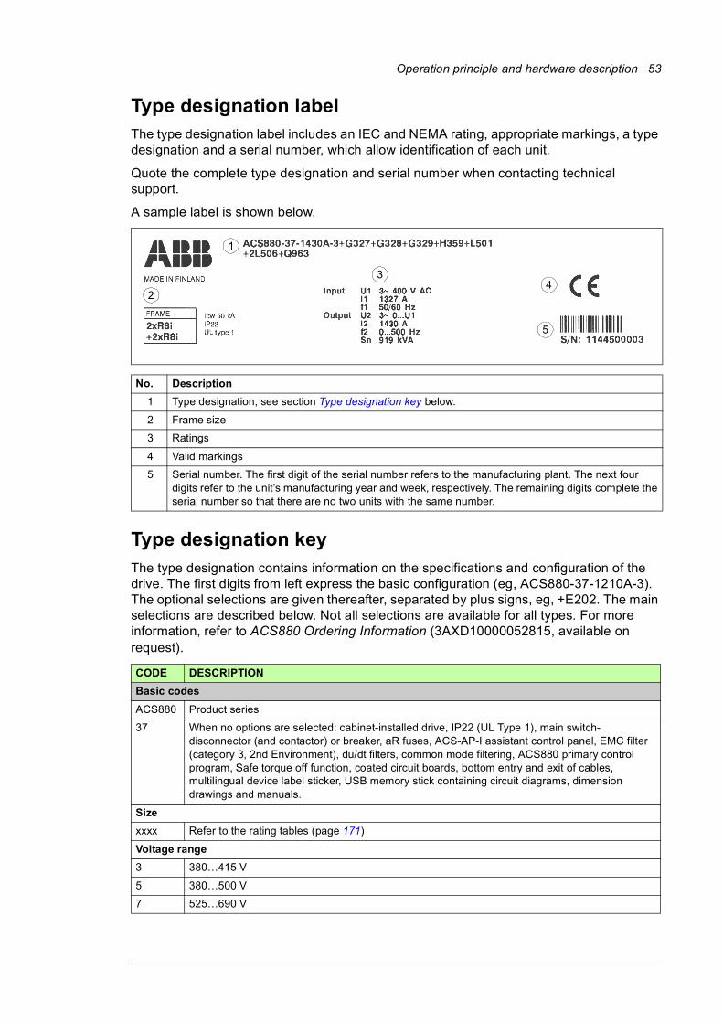
Operation principle and hardware description 53
Type designation labelThe type designation label includes an IEC and NEMA rating, appropriate markings, a type designation and a serial number, which allow identification of each unit.
Quote the complete type designation and serial number when contacting technical support.
A sample label is shown below.
Type designation keyThe type designation contains information on the specifications and configuration of the drive. The first digits from left express the basic configuration (eg, ACS880-37-1210A-3). The optional selections are given thereafter, separated by plus signs, eg, +E202. The main selections are described below. Not all selections are available for all types. For more information, refer to ACS880 Ordering Information (3AXD10000052815, available on request).
No. Description
1 Type designation, see section Type designation key below.
2 Frame size
3 Ratings
4 Valid markings
5 Serial number. The first digit of the serial number refers to the manufacturing plant. The next four digits refer to the unit’s manufacturing year and week, respectively. The remaining digits complete the serial number so that there are no two units with the same number.
CODE DESCRIPTION
Basic codes
ACS880 Product series
37 When no options are selected: cabinet-installed drive, IP22 (UL Type 1), main switch-disconnector (and contactor) or breaker, aR fuses, ACS-AP-I assistant control panel, EMC filter (category 3, 2nd Environment), du/dt filters, common mode filtering, ACS880 primary control program, Safe torque off function, coated circuit boards, bottom entry and exit of cables, multilingual device label sticker, USB memory stick containing circuit diagrams, dimension drawings and manuals.
Size
xxxx Refer to the rating tables (page 171)
Voltage range
3 380…415 V
5 380…500 V
7 525…690 V
1
34
5
2

54 Operation principle and hardware description
Option codes (plus codes)
Degree of protection
B054 IP42 (UL Type 1 Filtered)
B055 IP54 (UL Type 12)
Construction
C121 Marine construction (reinforced mechanics and fastening, handrails, self-extinctive materials)
C129 UL Listed (US type main switch fuse, top entry and exit of cables, cable conduit entries, all components UL Listed or Recognized, max. supply voltage 600 V)
C134 CSA Approved (US/CSA type main switch fuse, bottom entry and exit of cables, cable conduit entries, all components UL/CSA Listed or Recognized, max. supply voltage 600 V)
C128 Air inlet through bottom of cabinet
C130 Channeled air outlet
C164 Plinth height 100 mm
C179 Plinth height 200 mm
C180 Seismic design
C188 Direct-on-line cooling fans of supply/inverter modules
Resistor braking
D150 Brake choppers
D151 Brake resistors
Filters
E202 EMC filter for first environment TN (grounded) system, category C2
E206 Sine output filter
Line options
F255 Main (air circuit) breaker (instead of line contactor)
F259 Grounding (earthing) switch
Cabinet equipment
G300 Cabinet and module heating elements (external supply)
G301 Cabinet lighting
G307 Terminals for connecting external control voltage (230 V AC or 115 V AC, eg. UPS)
G313 Output for motor heater (external supply)
G317 Supply connection by busbars
G327 Ready light, white
G328 Run light, green
G329 Fault light, red
G330 Halogen-free wiring and materials
G334 V-meter with selector switch
G335 A-meter in one phase
G340See section Additional wire markings (options +G340 and +G342) on page 50.
G342
Cabling
H350 Bottom entry
H351 Top entry
H352 Bottom exit
H353 Top exit
H358 Cable conduit entry (US/UK)
H359 Common motor terminal cubicle
CODE DESCRIPTION

Operation principle and hardware description 55
H366 Common output terminals (for inverter modules mounted in the same cubicle)
Fieldbus adapters
K451 FDNA-01 DeviceNet™ adapter module
K452 FLON-01 LonWorks® adapter module
K454 FPBA-01 PROFIBUS DP adapter module
K457 FCAN-01 CANopen adapter module
K458 FSCA-01 RS-485 adapter module
K462 FCNA-01 ControlNet™ adapter module
K469 FECA EtherCat adapter module
K470 FEPL EtherPOWERLINK adapter module
K473 FENA-11 Ethernet adapter module for EtherNet/IP™, Modbus TCP and PROFINET IO protocols
K475 FENA-21 Ethernet adapter module for EtherNet/IP™, Modbus TCP and PROFINET IO protocols, 2-port
I/O extensions and feedback interfaces
L500 FIO-11 analog I/O extension module
L501 FIO-01 digital I/O extension module
L502 FEN-31 HTL incremental encoder interface module
L503 FDCO-01 optical DDCS communication adapter module
L504 Additional I/O terminal block
L505 Thermistor relay (1 or 2 pcs)
L506 Pt100 relay (2, 3, 5 or 8 pcs)
L508 FDCO-02 optical DDCS communication adapter module
L513 ATEX-certified thermal protection with PTC sensors (1 or 2 pcs)
L514 ATEX-certified thermal protection with Pt100 relays (3, 5 or 8 pcs)
L515 FEA-03 I/O extension adapter module
L516 FEN-21 resolver interface module
L517 FEN-01 TTL incremental encoder interface module
L518 FEN-11 TTL absolute encoder interface module
L525 FAIO-01 analog I/O extension module
L526 FDIO-01 digital I/O extension module
Starter for auxiliary motor fan
M602 Trip limit setting range: 2.5 … 4 A
M603 Trip limit setting range: 4 … 6.3 A
M604 Trip limit setting range: 6.3 … 10 A
M605 Trip limit setting range: 10…16 A
M606 Trip limit setting range: 16…20 A
M610 Trip limit setting range: 20…25 A
Control program
N7502 Control program for synchronous reluctance motors (SynRM)
N8010 Application programming
Specialties
P902 Customized
P904 Extended warranty
P912 Seaworthy packaging
P913 Special color
P929 Container packaging
CODE DESCRIPTION

56 Operation principle and hardware description
Safety functions
Q950 Prevention of unexpected start-up with FSO-xx safety functions module, by activating the Safe torque off function
Q951 Emergency stop (category 0) with safety relays, by opening the main breaker/contactor
Q952 Emergency stop (category 1) with safety relays, by opening the main breaker/contactor
Q954 Ground fault monitoring for IT (ungrounded) systems
Q957 Prevention of unexpected start-up with safety relays, by activating the Safe torque off function
Q963 Emergency stop (category 0) with safety relays, by activating the Safe torque off function
Q964 Emergency stop (category 1) with safety relays, by activating the Safe torque off function
Q965 Safely-limited speed with FSO-21 and encoder
Q971 ATEX-certified safe disconnection function
Q972 FSO-21 safety functions module
Q973 FSO-12 safety functions module
Q978 Emergency stop (configurable for category 0 or 1) with FSO-xx safety functions module, by opening the main breaker/contactor
Q979 Emergency stop (configurable for category 0 or 1) with FSO-xx safety functions module, by activating the Safe torque off function
Full set of printed manuals in the selected languageNote: The delivery may include manuals in English if the requested language is not available.
R700 English
R701 German
R702 Italian
R703 Dutch
R704 Danish
R705 Swedish
R706 Finnish
R707 French
R708 Spanish
R709 Portuguese
R711 Russian
CODE DESCRIPTION
Mechanical installation 57
4
Mechanical installation
Contents of this chapterThis chapter describes the mechanical installation procedure of the drive.
Examining the installation siteExamine the installation site:• The installation site is sufficiently ventilated or cooled to transfer away the drive
losses. 1)
• The ambient conditions of the drive meet the specifications. 1)
• The wall behind the unit is of non-flammable material.
• There is enough free space above the drive to enable cooling air flow, service and maintenance.
• The floor that the unit is installed on is of non-flammable material, as smooth as possible, and strong enough to support the weight of the unit. Check the floor flatness with a spirit level. The maximum allowed deviation from the surface level is 5 mm in every 3 meters. Level the installation site, if necessary, as the cabinet is not equipped with adjustable feet.
1) The heat losses and ambient conditions are specified in chapter Technical data.
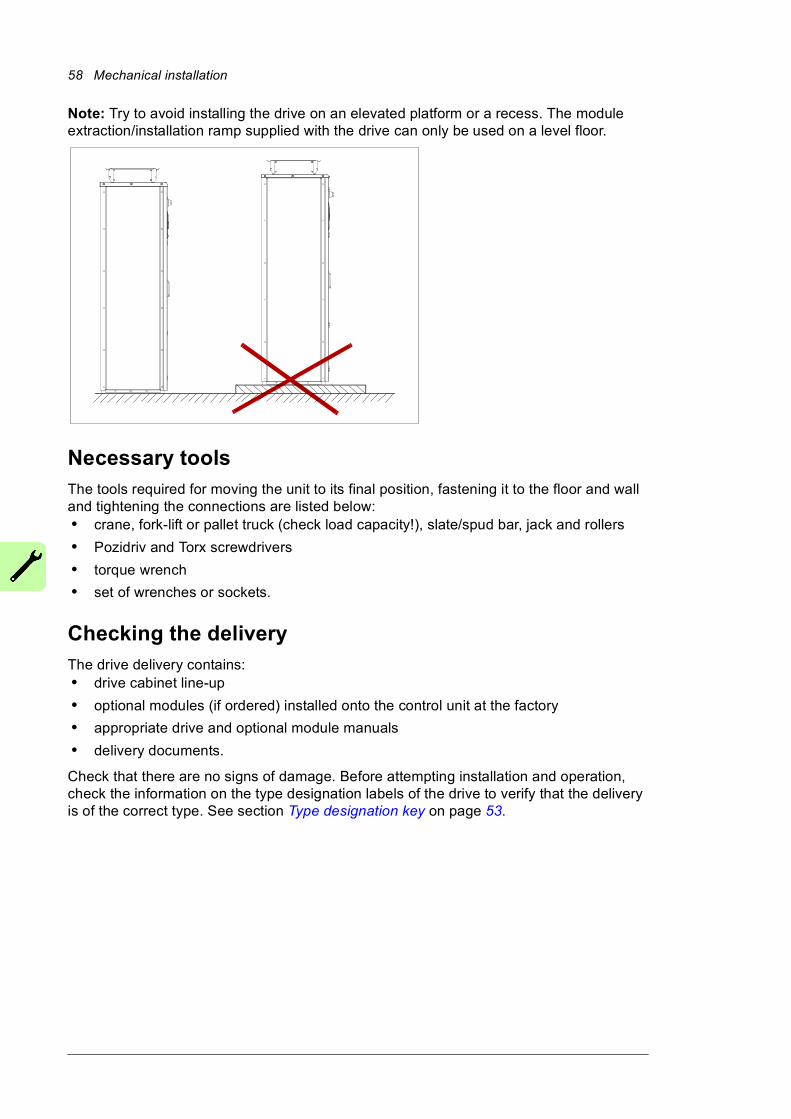
58 Mechanical installation
Note: Try to avoid installing the drive on an elevated platform or a recess. The module extraction/installation ramp supplied with the drive can only be used on a level floor.
Necessary toolsThe tools required for moving the unit to its final position, fastening it to the floor and wall and tightening the connections are listed below:• crane, fork-lift or pallet truck (check load capacity!), slate/spud bar, jack and rollers
• Pozidriv and Torx screwdrivers
• torque wrench
• set of wrenches or sockets.
Checking the deliveryThe drive delivery contains:• drive cabinet line-up
• optional modules (if ordered) installed onto the control unit at the factory
• appropriate drive and optional module manuals
• delivery documents.
Check that there are no signs of damage. Before attempting installation and operation, check the information on the type designation labels of the drive to verify that the delivery is of the correct type. See section Type designation key on page 53.
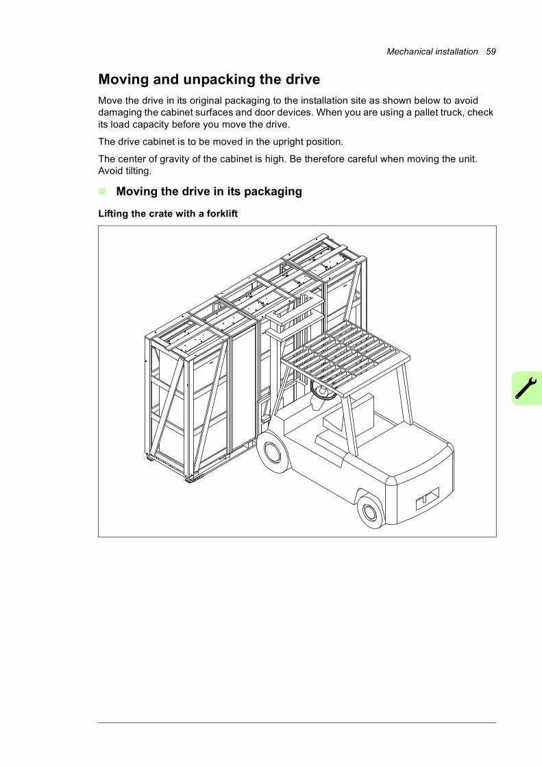
Mechanical installation 59
Moving and unpacking the driveMove the drive in its original packaging to the installation site as shown below to avoid damaging the cabinet surfaces and door devices. When you are using a pallet truck, check its load capacity before you move the drive.
The drive cabinet is to be moved in the upright position.
The center of gravity of the cabinet is high. Be therefore careful when moving the unit. Avoid tilting.
Moving the drive in its packaging
Lifting the crate with a forklift
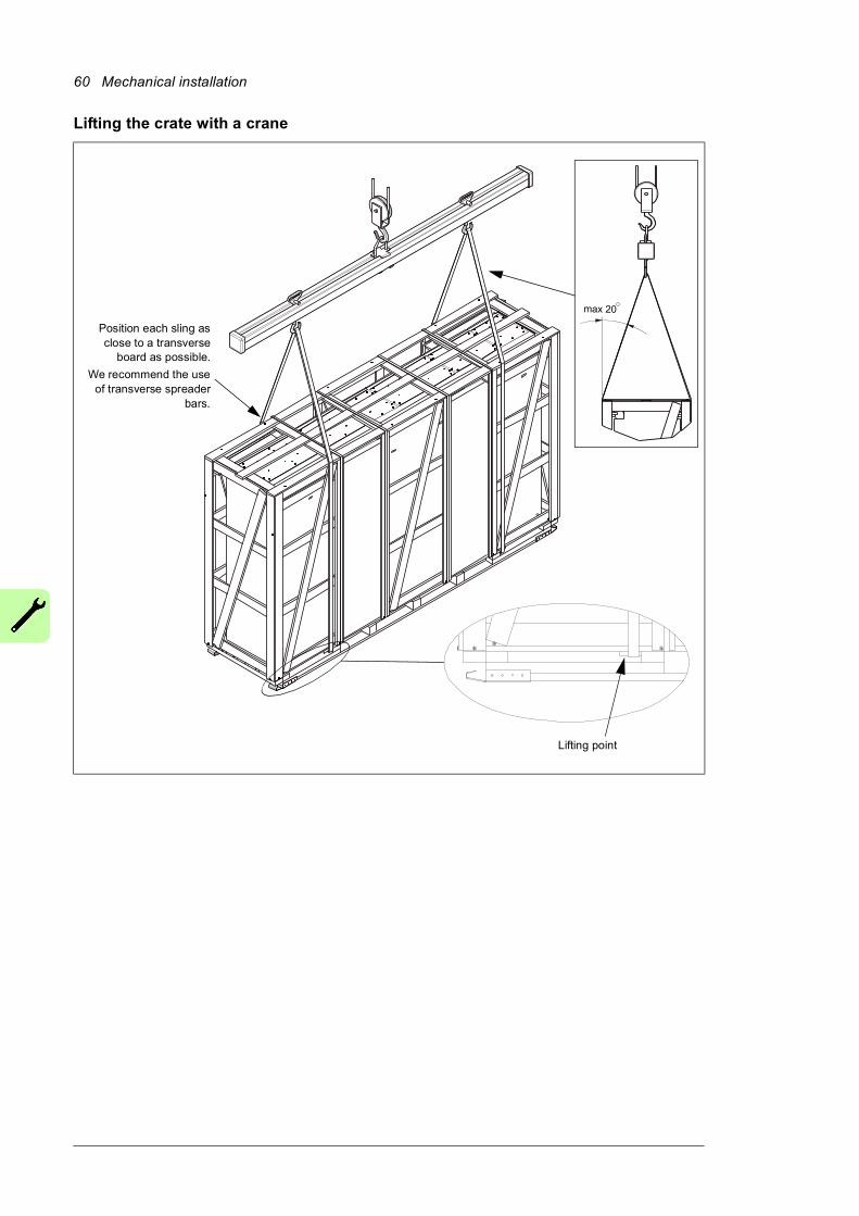
60 Mechanical installation
Lifting the crate with a crane
max 20
Position each sling asclose to a transverse
board as possible.
We recommend the useof transverse spreader
bars.
Lifting point
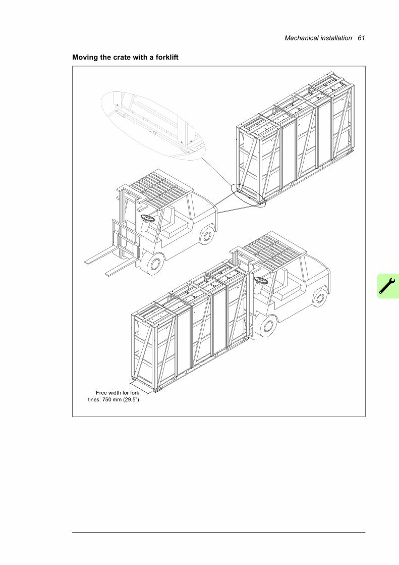
Mechanical installation 61
Moving the crate with a forklift
Free width for forktines: 750 mm (29.5”)

62 Mechanical installation
Removing the transport package
Remove the transport package as follows:
1. Undo the screws that attach the wooden parts of the transport crate together.
2. Remove the wooden parts.
3. Remove the clamps with which the drive cabinet is mounted onto the transport pallet by undoing the fastening screws.
4. Remove the plastic wrapping.
Moving the unpacked drive cabinet
Lifting the cabinet with a crane
Lift the drive cabinet using its lifting eyes. The lifting eyes can be removed after the cabinet is in its final position, but their mounting holes must be blocked to retain the degree of protection.
Note: The minimum allowed height of the lifting slings with IP54 units is 2 meters (6’7”).
IP54
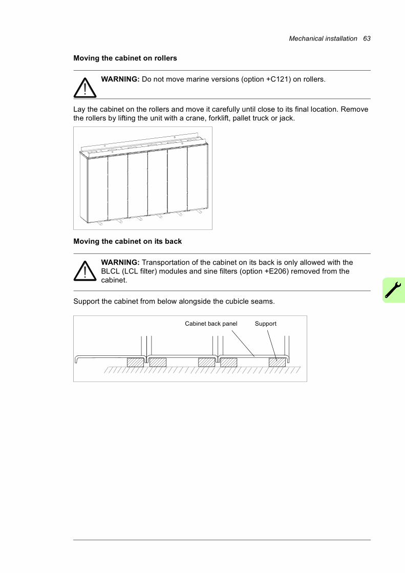
Mechanical installation 63
Moving the cabinet on rollers
WARNING: Do not move marine versions (option +C121) on rollers.
Lay the cabinet on the rollers and move it carefully until close to its final location. Remove the rollers by lifting the unit with a crane, forklift, pallet truck or jack.
Moving the cabinet on its back
WARNING: Transportation of the cabinet on its back is only allowed with the BLCL (LCL filter) modules and sine filters (option +E206) removed from the cabinet.
Support the cabinet from below alongside the cubicle seams.
Cabinet back panel Support
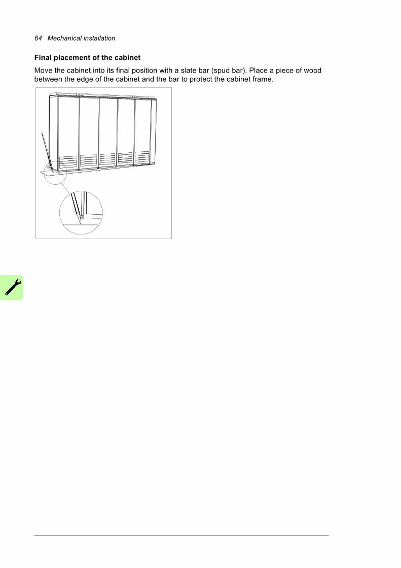
64 Mechanical installation
Final placement of the cabinet
Move the cabinet into its final position with a slate bar (spud bar). Place a piece of wood between the edge of the cabinet and the bar to protect the cabinet frame.
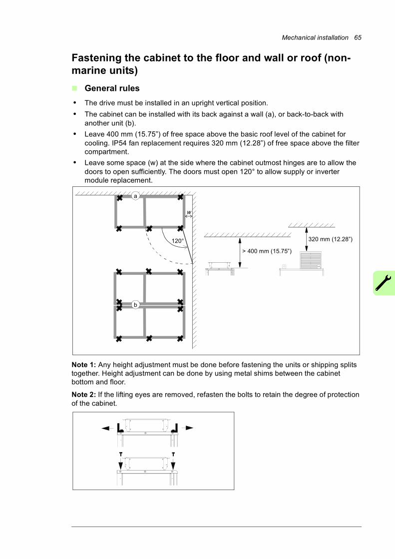
Mechanical installation 65
Fastening the cabinet to the floor and wall or roof (non-marine units)
General rules
• The drive must be installed in an upright vertical position.
• The cabinet can be installed with its back against a wall (a), or back-to-back with another unit (b).
• Leave 400 mm (15.75”) of free space above the basic roof level of the cabinet for cooling. IP54 fan replacement requires 320 mm (12.28”) of free space above the filter compartment.
• Leave some space (w) at the side where the cabinet outmost hinges are to allow the doors to open sufficiently. The doors must open 120° to allow supply or inverter module replacement.
Note 1: Any height adjustment must be done before fastening the units or shipping splits together. Height adjustment can be done by using metal shims between the cabinet bottom and floor.
Note 2: If the lifting eyes are removed, refasten the bolts to retain the degree of protection of the cabinet.
a
b
120°
w
> 400 mm (15.75”)
320 mm (12.28”)
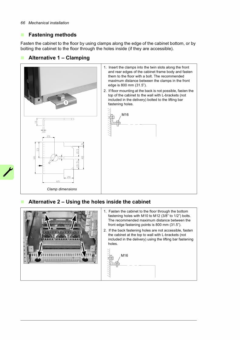
66 Mechanical installation
Fastening methods
Fasten the cabinet to the floor by using clamps along the edge of the cabinet bottom, or by bolting the cabinet to the floor through the holes inside (if they are accessible).
Alternative 1 – Clamping
Alternative 2 – Using the holes inside the cabinet
1. Insert the clamps into the twin slots along the front and rear edges of the cabinet frame body and fasten them to the floor with a bolt. The recommended maximum distance between the clamps in the front edge is 800 mm (31.5”).
2. If floor mounting at the back is not possible, fasten the top of the cabinet to the wall with L-brackets (not included in the delivery) bolted to the lifting bar fastening holes.
1. Fasten the cabinet to the floor through the bottom fastening holes with M10 to M12 (3/8” to 1/2”) bolts. The recommended maximum distance between the front edge fastening points is 800 mm (31.5”).
2. If the back fastening holes are not accessible, fasten the cabinet at the top to wall with L-brackets (not included in the delivery) using the lifting bar fastening holes.
1
Clamp dimensions
M16
M16

Mechanical installation 67
Fastening the cabinet to the floor and roof/wall (marine units)Follow the general rules given in section General rules on page 65.
See the dimension drawing delivered with the drive for the locations of the fastening holes in the flat bars below the cabinet and for fastening points at the top of the cabinet. Top fastening brackets are included in the delivery.
Fasten the cabinet to the floor and roof (wall) as follows:
1. Bolt the unit to the floor through the holes in each flat bar at the base of the cabinet using M10 or M12 screws.
2. If there is not enough room behind the cabinet for installation, clamp the rear ends of the flat bars.
3. Remove the lifting lugs and bolt the fastening brackets into the lifting lug holes. Fasten the top of the cabinet to the rear wall and/or roof with brackets.
M16
2. Clamping the cabinet to the floor at the back
a Clamp
b Back panel of cabinet
c Flat bars at base of cabinet
3. Fastening the cabinet at the top
d Fastening bracket
a b
c
2 3d
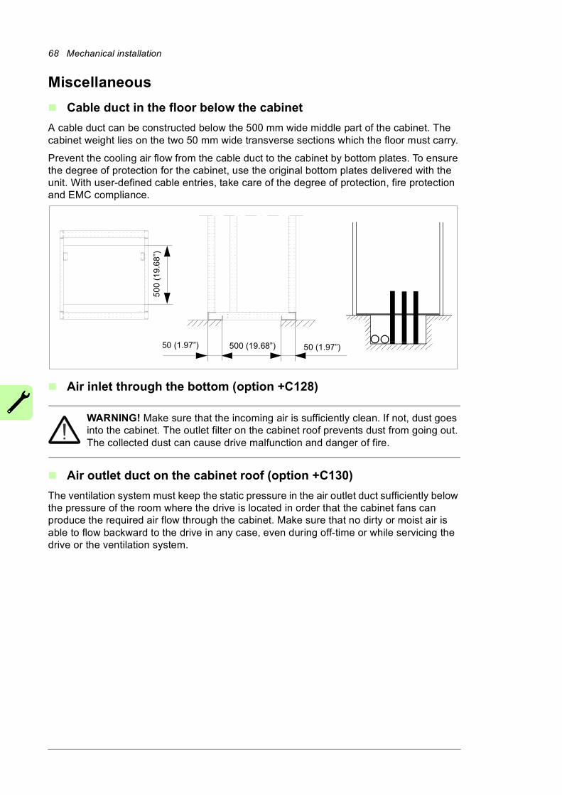
68 Mechanical installation
Miscellaneous
Cable duct in the floor below the cabinet
A cable duct can be constructed below the 500 mm wide middle part of the cabinet. The cabinet weight lies on the two 50 mm wide transverse sections which the floor must carry.
Prevent the cooling air flow from the cable duct to the cabinet by bottom plates. To ensure the degree of protection for the cabinet, use the original bottom plates delivered with the unit. With user-defined cable entries, take care of the degree of protection, fire protection and EMC compliance.
Air inlet through the bottom (option +C128)
WARNING! Make sure that the incoming air is sufficiently clean. If not, dust goes into the cabinet. The outlet filter on the cabinet roof prevents dust from going out. The collected dust can cause drive malfunction and danger of fire.
Air outlet duct on the cabinet roof (option +C130)
The ventilation system must keep the static pressure in the air outlet duct sufficiently below the pressure of the room where the drive is located in order that the cabinet fans can produce the required air flow through the cabinet. Make sure that no dirty or moist air is able to flow backward to the drive in any case, even during off-time or while servicing the drive or the ventilation system.
500 (19.68”) 50 (1.97”)
50
0 (1
9.6
8”)
50 (1.97”)
Mechanical installation 69
Calculating the required static pressure difference
The required static pressure difference between the exit air duct and the drive installation room can be calculated as follows:
where
Example
The cabinet has 3 exit openings of 315 mm diameter. The rated air flow of the cabinet is
4650 m3/h =1.3 m3/s.
Ac = 3 • 0.3152 • / 4 = 0.234 m2
vm = q / Ac = 1.3 / 0.234 = 5.5 m/s
pd = 0.5 • • vm2 = 0.5 • 1.1 • 5.52= 17 Pa
The required pressure in the exit air duct is then, 1.5…2 • 17 Pa = 26…34 Pa, below the pressure in the room.
For more information: Contact ABB.
Arc welding
Fastening the cabinet by arc welding is not recommended. However, if arc welding is the only mounting option, connect the return conductor of the welding equipment to the cabinet frame at the bottom within 0.5 meters (1’6”) of the welding point.
Note: The thickness of the zinc coating of the cabinet frame is 100 to 200 micrometers (4 to 8 mil).
WARNING! Make sure that the return wire is connected correctly. Welding current must not return via any component or cabling of the drive. If the welding return wire is connected improperly, the welding circuit can damage electronic circuits in
the cabinet.
WARNING! Do not inhale the welding fumes.
pd Dynamic pressure
Air density (kg/m3)
vm Average air velocity in the exit duct(s) (m/s)
q Rated air flow of the drive (m3/s)
Ac Cross-sectional area of the exit duct(s) (m2)
ps = (1.5…2) • pd��
pd = 0.5 • � • vm2
vm = q / Ac
�
�
�

70 Mechanical installation
Guidelines for planning the electrical installation 71
5
Guidelines for planning the electrical installation
Contents of this chapterThis chapter contains instructions for planning the electrical installation of the drive. Some instructions are mandatory to follow in every installation, others provide useful information that only concerns certain applications.
Limitation of liabilityThe installation must always be designed and made according to applicable local laws and regulations. ABB does not assume any liability whatsoever for any installation which breaches the local laws and/or other regulations. Furthermore, if the recommendations given by ABB are not followed, the drive may experience problems that the warranty does not cover.
Selecting the supply disconnecting deviceThe drive is equipped with a main disconnecting device. Depending on the size of the drive, the disconnecting device is a switch-disconnector or an air circuit breaker. The disconnecting device can be locked to the open position for installation and maintenance work.
Selecting the main contactorDepending on type, the drive is equipped with either a main contactor or an air circuit breaker. See Overview circuit diagram of the drive (page 33).

72 Guidelines for planning the electrical installation
Examining the compatibility of the motor and driveUse an asynchronous AC induction motor, permanent magnet synchronous motor or AC induction servomotor with the drive. Several induction motors can be connected to the drive at a time.
Select the motor size and drive type from to the rating tables in chapter Technical data on basis of the AC line voltage and motor load. Use the DriveSize PC tool if you need to tune the selection more in detail.
Make sure that the motor withstands the maximum peak voltage in the motor terminals. See the Requirements table on page 73. For basics of protecting the motor insulation and bearings in drive systems, refer to section Protecting the motor insulation and bearings below.
Note:• Consult the motor manufacturer before using a motor whose nominal voltage differs
from the AC line voltage connected to the drive input.
• The voltage peaks at the motor terminals are relative to the supply voltage of the drive, not the drive output voltage.
• If the motor and drive are not of the same size, consider the following operation limits of the drive control program:
• motor nominal voltage range 1/6 ... 2 · UN
• motor nominal current range 1/6 ... 2 · IN of the drive in DTC control and 0 ... 2 · IN in scalar control. The control mode is selected by a drive parameter.
Protecting the motor insulation and bearings
The drive employs modern IGBT inverter technology. Regardless of frequency, the drive output comprises pulses of approximately the drive DC bus voltage with a very short rise time. The pulse voltage can almost double at the motor terminals, depending on the attenuation and reflection properties of the motor cable and the terminals. This can cause additional stress on the motor and motor cable insulation.
Modern variable speed drives with their fast rising voltage pulses and high switching frequencies can generate current pulses that flow through the motor bearings. This can gradually erode the bearing races and rolling elements.
Optional du/dt filters protect motor insulation system and reduce bearing currents. Optional common mode filters mainly reduce bearing currents. Insulated N-end (non-drive end) bearings protect the motor bearings.

Guidelines for planning the electrical installation 73
Requirements table
The following table shows how to select the motor insulation system and when an optional drive du/dt and common mode filters and insulated N-end (non-drive end) motor bearings are required. Ignoring the requirements or improper installation may shorten motor life or damage the motor bearings and voids the warranty.
Motor type
Nominal AC supply voltage
Requirement for
Motor insulation
system
ABB du/dt and common mode filters, insulated N-end motor bearings
PN < 100 kW and frame
size < IEC 315
100 kW < PN < 350 kWor
IEC 315 < frame size < IEC 400
PN > 350 kWor
frame size > IEC 400
PN < 134 hp and frame
size < NEMA 500
134 hp < PN < 469 hpor
NEMA 500 < frame size < NEMA 580
PN > 469 hpor
frame size > NEMA 580
ABB motors
Random-wound M2_, M3_ and M4_
UN < 500 V Standard - + N + N + CMF
500 V < UN < 600 V Standard + du/dt + N + du/dt + N + du/dt + CMF
or
Reinforced - + N + N + CMF
600 V < UN < 690 V(cable length < 150 m)
Reinforced + du/dt + N + du/dt + N + du/dt + CMF
600 V < UN < 690 V(cable length > 150 m)
Reinforced - + N + N + CMF
Form-wound HX_ and AM_
380 V < UN < 690 V Standard n.a. + N + CMF PN < 500 kW:+N + CMF
PN > 500 kW+N + du/dt + CMF
Old* form-wound HX_ and modular
380 V < UN < 690 V Check with the motor manufacturer.
+ N + du/dt with voltages over 500 V + CMF
Random-wound HX_ and AM_ **
0 V < UN < 500 V Enamelled wire with fiber glass taping
+ N + CMF
500 V < UN < 690 V + N + du/dt + CMF
HDP Consult the motor manufacturer.
* manufactured before 1.1.1998
** For motors manufactured before 1.1.1998, check for additional instructions with the motor manufacturer.
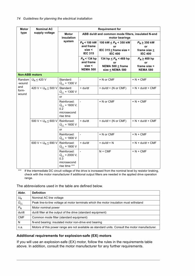
74 Guidelines for planning the electrical installation
The abbreviations used in the table are defined below.
Additional requirements for explosion-safe (EX) motors
If you will use an explosion-safe (EX) motor, follow the rules in the requirements table above. In addition, consult the motor manufacturer for any further requirements.
Non-ABB motors
Random-wound and form-wound
UN < 420 V Standard: ÛLL = 1300 V
- + N or CMF + N + CMF
420 V < UN < 500 V Standard: ÛLL = 1300 V
+ du/dt + du/dt + (N or CMF) + N + du/dt + CMF
or
Reinforced: ÛLL = 1600 V, 0.2 microsecond rise time
- + N or CMF + N + CMF
500 V < UN < 600 V Reinforced: ÛLL = 1600 V
+ du/dt + du/dt + (N or CMF) + N + du/dt + CMF
or
Reinforced: ÛLL = 1800 V
- + N or CMF + N + CMF
600 V < UN < 690 V Reinforced: ÛLL = 1800 V
+ du/dt + du/dt + N + N + du/dt + CMF
Reinforced: ÛLL = 2000 V, 0.3 microsecond rise time ***
- N + CMF + N + CMF
*** If the intermediate DC circuit voltage of the drive is increased from the nominal level by resistor braking, check with the motor manufacturer if additional output filters are needed in the applied drive operation range.
Abbr. Definition
UN Nominal AC line voltage
ÛLL Peak line-to-line voltage at motor terminals which the motor insulation must withstand
PN Motor nominal power
du/dt du/dt filter at the output of the drive (standard equipment)
CMF Common mode filter (standard equipment)
N N-end bearing: insulated motor non-drive end bearing
n.a. Motors of this power range are not available as standard units. Consult the motor manufacturer.
Motor type
Nominal AC supply voltage
Requirement for
Motor insulation
system
ABB du/dt and common mode filters, insulated N-end motor bearings
PN < 100 kW and frame
size < IEC 315
100 kW < PN < 350 kWor
IEC 315 < frame size < IEC 400
PN > 350 kWor
frame size > IEC 400
PN < 134 hp and frame
size < NEMA 500
134 hp < PN < 469 hpor
NEMA 500 < frame size < NEMA 580
PN > 469 hpor
frame size > NEMA 580
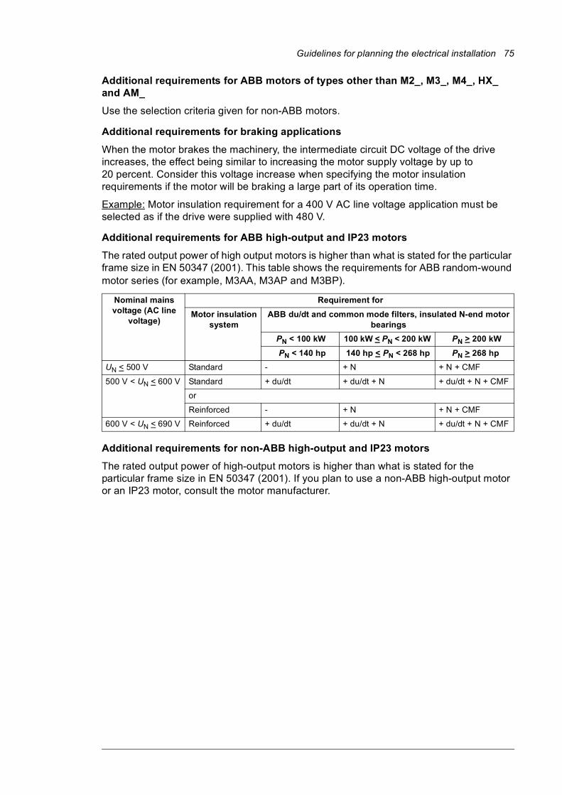
Guidelines for planning the electrical installation 75
Additional requirements for ABB motors of types other than M2_, M3_, M4_, HX_ and AM_
Use the selection criteria given for non-ABB motors.
Additional requirements for braking applications
When the motor brakes the machinery, the intermediate circuit DC voltage of the drive increases, the effect being similar to increasing the motor supply voltage by up to 20 percent. Consider this voltage increase when specifying the motor insulation requirements if the motor will be braking a large part of its operation time.
Example: Motor insulation requirement for a 400 V AC line voltage application must be selected as if the drive were supplied with 480 V.
Additional requirements for ABB high-output and IP23 motors
The rated output power of high output motors is higher than what is stated for the particular frame size in EN 50347 (2001). This table shows the requirements for ABB random-wound motor series (for example, M3AA, M3AP and M3BP).
Additional requirements for non-ABB high-output and IP23 motors
The rated output power of high-output motors is higher than what is stated for the particular frame size in EN 50347 (2001). If you plan to use a non-ABB high-output motor or an IP23 motor, consult the motor manufacturer.
Nominal mains voltage (AC line
voltage)
Requirement for
Motor insulation system
ABB du/dt and common mode filters, insulated N-end motor bearings
PN < 100 kW 100 kW < PN < 200 kW PN > 200 kW
PN < 140 hp 140 hp < PN < 268 hp PN > 268 hp
UN < 500 V Standard - + N + N + CMF
500 V < UN < 600 V Standard + du/dt + du/dt + N + du/dt + N + CMF
or
Reinforced - + N + N + CMF
600 V < UN < 690 V Reinforced + du/dt + du/dt + N + du/dt + N + CMF
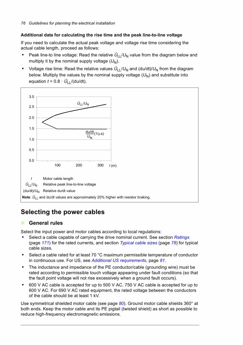
76 Guidelines for planning the electrical installation
Additional data for calculating the rise time and the peak line-to-line voltage
If you need to calculate the actual peak voltage and voltage rise time considering the actual cable length, proceed as follows:
• Peak line-to line voltage: Read the relative ÛLL/UN value from the diagram below and multiply it by the nominal supply voltage (UN).
• Voltage rise time: Read the relative values ÛLL/UN and (du/dt)/UN from the diagram
below. Multiply the values by the nominal supply voltage (UN) and substitute into
equation t = 0.8 · ÛLL/(du/dt).
Selecting the power cables
General rules
Select the input power and motor cables according to local regulations:• Select a cable capable of carrying the drive nominal current. See section Ratings
(page 171) for the rated currents, and section Typical cable sizes (page 78) for typical cable sizes.
• Select a cable rated for at least 70 °C maximum permissible temperature of conductor in continuous use. For US, see Additional US requirements, page 81.
• The inductance and impedance of the PE conductor/cable (grounding wire) must be rated according to permissible touch voltage appearing under fault conditions (so that the fault point voltage will not rise excessively when a ground fault occurs).
• 600 V AC cable is accepted for up to 500 V AC. 750 V AC cable is accepted for up to 600 V AC. For 690 V AC rated equipment, the rated voltage between the conductors of the cable should be at least 1 kV.
Use symmetrical shielded motor cable (see page 80). Ground motor cable shields 360° at both ends. Keep the motor cable and its PE pigtail (twisted shield) as short as possible to reduce high-frequency electromagnetic emissions.
I Motor cable length
ÛLL/UN Relative peak line-to-line voltage
(du/dt)/UN Relative du/dt value
Note: ÛLL and du/dt values are approximately 20% higher with resistor braking.
100 200 3000.0
0.5
1.0
1.5
2.0
2.5
3.0
l (m)
du/dtUN
-------------(1/s)
ÛLL/UN
Guidelines for planning the electrical installation 77
Note: When continuous metal conduit is employed, shielded cable is not required. The conduit must have bonding at both ends.
A four-conductor system is allowed for input cabling, but shielded symmetrical cable is recommended.
Compared to a four-conductor system, the use of symmetrical shielded cable reduces electromagnetic emission of the whole drive system as well as the stress on motor insulation, bearing currents and wear.
The protective conductor must always have an adequate conductivity. The table below shows the minimum cross-sectional area related to the phase conductor size according to IEC 61439-1 when the phase conductor and the protective conductor are made of the same metal.
Cross-sectional area of the phase conductors
S (mm2)
Minimum cross-sectional area of the corresponding protective conductor
Sp (mm2)
S < 16 S
16 < S < 35 16
35 < S < 400 S/2
400 < S < 800 200
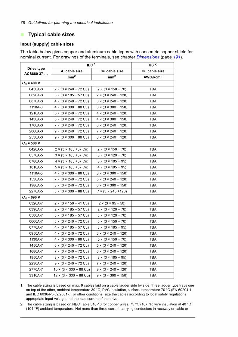
78 Guidelines for planning the electrical installation
Typical cable sizes
Input (supply) cable sizes
The table below gives copper and aluminum cable types with concentric copper shield for nominal current. For drawings of the terminals, see chapter Dimensions (page 191).
1. The cable sizing is based on max. 9 cables laid on a cable ladder side by side, three ladder type trays one on top of the other, ambient temperature 30 °C, PVC insulation, surface temperature 70 °C (EN 60204-1 and IEC 60364-5-52/2001). For other conditions, size the cables according to local safety regulations, appropriate input voltage and the load current of the drive.
2. The cable sizing is based on NEC Table 310-16 for copper wires, 75 °C (167 °F) wire insulation at 40 °C (104 °F) ambient temperature. Not more than three current-carrying conductors in raceway or cable or
Drive type
ACS880-37-…
IEC 1) US 2)
Al cable size Cu cable size Cu cable size
mm2 mm2 AWG/kcmil
UN = 400 V
0450A-3 2 × (3 × 240 + 72 Cu) 2 × (3 × 150 + 70) TBA
0620A-3 3 × (3 × 185 + 57 Cu) 2 × (3 × 240 + 120) TBA
0870A-3 4 × (3 × 240 + 72 Cu) 3 × (3 × 240 + 120) TBA
1110A-3 4 × (3 × 300 + 88 Cu) 3 × (3 × 300 + 150) TBA
1210A-3 5 × (3 × 240 + 72 Cu) 4 × (3 × 240 + 120) TBA
1430A-3 6 × (3 × 240 + 72 Cu) 4 × (3 × 300 + 150) TBA
1700A-3 7 × (3 × 240 + 72 Cu) 6 × (3 × 240 + 120) TBA
2060A-3 9 × (3 × 240 + 72 Cu) 7 × (3 × 240 + 120) TBA
2530A-3 9 × (3 × 300 + 88 Cu) 8 × (3 × 240 + 120) TBA
UN = 500 V
0420A-5 2 × (3 × 185 +57 Cu) 2 × (3 × 150 + 70) TBA
0570A-5 3 × (3 × 185 +57 Cu) 3 × (3 × 120 + 70) TBA
0780A-5 4 × (3 × 185 +57 Cu) 3 × (3 × 185 + 95) TBA
1010A-5 5 × (3 × 185 +57 Cu) 4 × (3 × 185 + 95) TBA
1110A-5 4 × (3 × 300 + 88 Cu) 3 × (3 × 300 + 150) TBA
1530A-5 7 × (3 × 240 + 72 Cu) 5 × (3 × 240 + 120) TBA
1980A-5 8 × (3 × 240 + 72 Cu) 6 × (3 × 300 + 150) TBA
2270A-5 8 × (3 × 300 + 88 Cu) 7 × (3 × 240 +120) TBA
UN = 690 V
0320A-7 2 × (3 × 150 + 41 Cu) 2 × (3 × 95 + 50) TBA
0390A-7 2 × (3 × 185 + 57 Cu) 2 × (3 × 120 + 70) TBA
0580A-7 3 × (3 × 185 + 57 Cu) 3 × (3 × 120 + 70) TBA
0660A-7 3 × (3 × 240 + 72 Cu) 3 × (3 × 150 + 70) TBA
0770A-7 4 × (3 × 185 + 57 Cu) 3 × (3 × 185 + 95) TBA
0950A-7 4 × (3 × 240 + 72 Cu) 3 × (3 × 240 + 120) TBA
1130A-7 4 × (3 × 300 + 88 Cu) 5 × (3 × 150 + 70) TBA
1450A-7 6 × (3 × 240 + 72 Cu) 5 × (3 × 240 + 120) TBA
1680A-7 7 × (3 × 240 + 72 Cu) 6 × (3 × 240 + 120) TBA
1950A-7 8 × (3 × 240 + 72 Cu) 8 × (3 × 185 + 95) TBA
2230A-7 9 × (3 × 240 + 72 Cu) 7 × (3 × 240 + 120) TBA
2770A-7 10 × (3 × 300 + 88 Cu) 9 × (3 × 240 + 120) TBA
3310A-7 12 × (3 × 300 + 88 Cu) 9 × (3 × 300 + 150) TBA
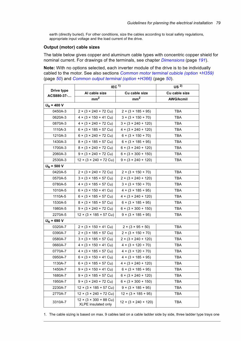
Guidelines for planning the electrical installation 79
earth (directly buried). For other conditions, size the cables according to local safety regulations, appropriate input voltage and the load current of the drive.
Output (motor) cable sizes
The table below gives copper and aluminum cable types with concentric copper shield for nominal current. For drawings of the terminals, see chapter Dimensions (page 191).
Note: With no options selected, each inverter module of the drive is to be individually cabled to the motor. See also sections Common motor terminal cubicle (option +H359) (page 50) and Common output terminal (option +H366) (page 50).
1. The cable sizing is based on max. 9 cables laid on a cable ladder side by side, three ladder type trays one
Drive type
ACS880-37-…
IEC 1) US 2)
Al cable size Cu cable size Cu cable size
mm2 mm2 AWG/kcmil
UN = 400 V
0450A-3 2 × (3 × 240 + 72 Cu) 2 × (3 × 185 + 95) TBA
0620A-3 4 × (3 × 150 + 41 Cu) 3 × (3 × 150 + 70) TBA
0870A-3 4 × (3 × 240 + 72 Cu) 3 × (3 × 240 + 120) TBA
1110A-3 6 × (3 × 185 + 57 Cu) 4 × (3 × 240 + 120) TBA
1210A-3 6 × (3 × 240 + 72 Cu) 6 × (3 × 150 + 70) TBA
1430A-3 8 × (3 × 185 + 57 Cu) 6 × (3 × 185 + 95) TBA
1700A-3 8 × (3 × 240 + 72 Cu) 6 × (3 × 240 + 120) TBA
2060A-3 9 × (3 × 240 + 72 Cu) 6 × (3 × 300 + 150) TBA
2530A-3 12 × (3 × 240 + 72 Cu) 9 × (3 × 240 + 120) TBA
UN = 500 V
0420A-5 2 × (3 × 240 + 72 Cu) 2 × (3 × 150 + 70) TBA
0570A-5 3 × (3 × 185 + 57 Cu) 2 × (3 × 240 + 120) TBA
0780A-5 4 × (3 × 185 + 57 Cu) 3 × (3 × 150 + 70) TBA
1010A-5 6 × (3 × 150 + 41 Cu) 4 × (3 × 185 + 95) TBA
1110A-5 6 × (3 × 185 + 57 Cu) 4 × (3 × 240 + 120) TBA
1530A-5 8 × (3 × 185 + 57 Cu) 6 × (3 × 185 + 95) TBA
1980A-5 9 × (3 × 240 + 72 Cu) 6 × (3 × 300 + 150) TBA
2270A-5 12 × (3 × 185 + 57 Cu) 9 × (3 × 185 + 95) TBA
UN = 690 V
0320A-7 2 × (3 × 150 + 41 Cu) 2 × (3 × 95 + 50) TBA
0390A-7 2 × (3 × 185 + 57 Cu) 2 × (3 × 150 + 70) TBA
0580A-7 3 × (3 × 185 + 57 Cu) 2 × (3 × 240 + 120) TBA
0660A-7 4 × (3 × 150 + 41 Cu) 4 × (3 × 120 + 70) TBA
0770A-7 4 × (3 × 185 + 57 Cu) 4 × (3 × 120 + 70) TBA
0950A-7 6 × (3 × 150 + 41 Cu) 4 × (3 × 185 + 95) TBA
1130A-7 6 × (3 × 185 + 57 Cu) 4 × (3 × 240 + 120) TBA
1450A-7 9 × (3 × 150 + 41 Cu) 6 × (3 × 185 + 95) TBA
1680A-7 9 × (3 × 185 + 57 Cu) 6 × (3 × 240 + 120) TBA
1950A-7 9 × (3 × 240 + 72 Cu) 6 × (3 × 300 + 150) TBA
2230A-7 12 × (3 × 185 + 57 Cu) 9 × (3 × 185 + 95) TBA
2770A-7 12 × (3 × 240 + 72 Cu) 12 × (3 × 185 + 95) TBA
3310A-712 × (3 × 300 + 88 Cu)
XLPE insulated only12 × (3 × 240 + 120) TBA
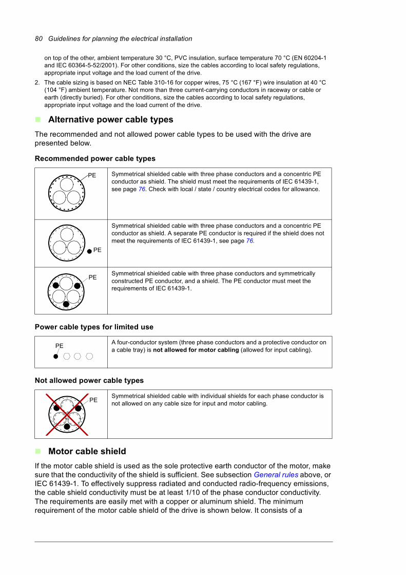
80 Guidelines for planning the electrical installation
on top of the other, ambient temperature 30 °C, PVC insulation, surface temperature 70 °C (EN 60204-1 and IEC 60364-5-52/2001). For other conditions, size the cables according to local safety regulations, appropriate input voltage and the load current of the drive.
2. The cable sizing is based on NEC Table 310-16 for copper wires, 75 °C (167 °F) wire insulation at 40 °C (104 °F) ambient temperature. Not more than three current-carrying conductors in raceway or cable or earth (directly buried). For other conditions, size the cables according to local safety regulations, appropriate input voltage and the load current of the drive.
Alternative power cable types
The recommended and not allowed power cable types to be used with the drive are presented below.
Recommended power cable types
Power cable types for limited use
Not allowed power cable types
Motor cable shield
If the motor cable shield is used as the sole protective earth conductor of the motor, make sure that the conductivity of the shield is sufficient. See subsection General rules above, or IEC 61439-1. To effectively suppress radiated and conducted radio-frequency emissions, the cable shield conductivity must be at least 1/10 of the phase conductor conductivity. The requirements are easily met with a copper or aluminum shield. The minimum requirement of the motor cable shield of the drive is shown below. It consists of a
Symmetrical shielded cable with three phase conductors and a concentric PE conductor as shield. The shield must meet the requirements of IEC 61439-1, see page 76. Check with local / state / country electrical codes for allowance.
Symmetrical shielded cable with three phase conductors and a concentric PE conductor as shield. A separate PE conductor is required if the shield does not meet the requirements of IEC 61439-1, see page 76.
Symmetrical shielded cable with three phase conductors and symmetrically constructed PE conductor, and a shield. The PE conductor must meet the requirements of IEC 61439-1.
A four-conductor system (three phase conductors and a protective conductor on a cable tray) is not allowed for motor cabling (allowed for input cabling).
Symmetrical shielded cable with individual shields for each phase conductor is not allowed on any cable size for input and motor cabling.
PE
PE
PE
PE
PE
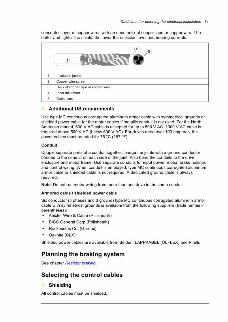
Guidelines for planning the electrical installation 81
concentric layer of copper wires with an open helix of copper tape or copper wire. The better and tighter the shield, the lower the emission level and bearing currents.
Additional US requirements
Use type MC continuous corrugated aluminum armor cable with symmetrical grounds or shielded power cable for the motor cables if metallic conduit is not used. For the North American market, 600 V AC cable is accepted for up to 500 V AC. 1000 V AC cable is required above 500 V AC (below 600 V AC). For drives rated over 100 amperes, the power cables must be rated for 75 °C (167 °F).
Conduit
Couple separate parts of a conduit together: bridge the joints with a ground conductor bonded to the conduit on each side of the joint. Also bond the conduits to the drive enclosure and motor frame. Use separate conduits for input power, motor, brake resistor, and control wiring. When conduit is employed, type MC continuous corrugated aluminum armor cable or shielded cable is not required. A dedicated ground cable is always required.
Note: Do not run motor wiring from more than one drive in the same conduit.
Armored cable / shielded power cable
Six conductor (3 phases and 3 ground) type MC continuous corrugated aluminum armor cable with symmetrical grounds is available from the following suppliers (trade names in parentheses): • Anixter Wire & Cable (Philsheath)
• BICC General Corp (Philsheath)
• Rockbestos Co. (Gardex)
• Oaknite (CLX).
Shielded power cables are available from Belden, LAPPKABEL (ÖLFLEX) and Pirelli.
Planning the braking systemSee chapter Resistor braking.
Selecting the control cables
Shielding
All control cables must be shielded.
1 Insulation jacket
2 Copper wire screen
3 Helix of copper tape or copper wire
4 Inner insulation
5 Cable core
1 23
45

82 Guidelines for planning the electrical installation
Use a double-shielded twisted pair cable for analog signals. This type of cable is recommended for the pulse encoder signals also. Employ one individually shielded pair for each signal. Do not use common return for different analog signals.
A double-shielded cable (figure a below) is the best alternative for low-voltage digital signals but single-shielded (b) twisted pair cable is also acceptable.
Signals in separate cables
Run analog and digital signals in separate, shielded cables. Never mix 24 V DC and 115/230 V AC signals in the same cable.
Signals allowed to be run in the same cable
Relay-controlled signals, providing their voltage does not exceed 48 V, can be run in the same cables as digital input signals. The relay-controlled signals should be run as twisted pairs.
Relay cable type
The cable type with braided metallic screen (for example ÖLFLEX by LAPPKABEL, Germany) has been tested and approved by ABB.
Control panel cable length and type
In remote use, the cable connecting the control panel to the drive must not be longer than three meters (10 ft). Cable type: shielded CAT 5e or better Ethernet patch cable with RJ-45 ends.
Routing the cablesRoute the motor cable away from other cable routes. Motor cables of several drives can be run in parallel installed next to each other. The motor cable, input power cable and control cables should be installed on separate trays. Avoid long parallel runs of motor cables with other cables in order to decrease electromagnetic interference caused by the rapid changes in the drive output voltage.
Where control cables must cross power cables, make sure they are arranged at an angle as near to 90 degrees as possible. Do not run extra cables through the drive.
The cable trays must have good electrical bonding to each other and to the grounding electrodes. Aluminum tray systems can be used to improve local equalizing of potential.
a b
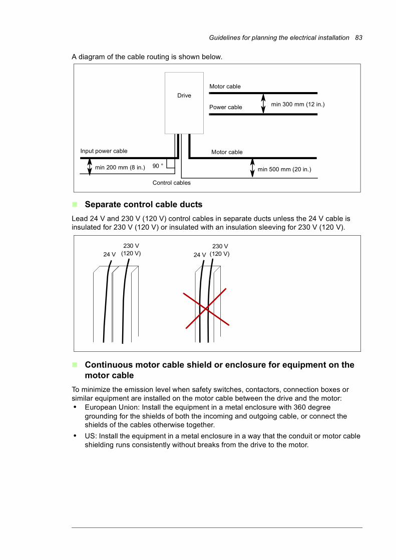
Guidelines for planning the electrical installation 83
A diagram of the cable routing is shown below.
Separate control cable ducts
Lead 24 V and 230 V (120 V) control cables in separate ducts unless the 24 V cable is insulated for 230 V (120 V) or insulated with an insulation sleeving for 230 V (120 V).
Continuous motor cable shield or enclosure for equipment on the motor cable
To minimize the emission level when safety switches, contactors, connection boxes or similar equipment are installed on the motor cable between the drive and the motor:• European Union: Install the equipment in a metal enclosure with 360 degree
grounding for the shields of both the incoming and outgoing cable, or connect the shields of the cables otherwise together.
• US: Install the equipment in a metal enclosure in a way that the conduit or motor cable shielding runs consistently without breaks from the drive to the motor.
90 °min 500 mm (20 in.) min 200 mm (8 in.)
min 300 mm (12 in.)
Drive
Motor cable
Power cable
Motor cableInput power cable
Control cables
24 V 24 V
230 V(120 V)
230 V(120 V)
84 Guidelines for planning the electrical installation
Implementing thermal overload and short-circuit protection
Protecting the drive and input power cable in short-circuits
The drive is equipped with internal AC fuses as standard. Protect the input cable with fuses or a suitable circuit breaker. Size the input cable fuses according to the instructions given in chapter Technical data. The fuses will protect the input cable in short-circuit situations, restrict drive damage and prevent damage to adjoining equipment in case of a short-circuit inside the drive.
Protecting the motor and motor cable in short-circuits
The drive protects the motor cable and motor in a short-circuit situation when the motor cable is sized according to the nominal current of the drive. No additional protection devices are needed.
Protecting the drive and the power cables against thermal overload
The drive protects itself and the input and motor cables against thermal overload when the cables are sized according to the nominal current of the drive. No additional thermal protection devices are needed.
WARNING! If the drive is connected to multiple motors, use a separate circuit breaker or fuses for protecting each motor cable and motor against overload. The drive overload protection is tuned for the total motor load. It may not trip due to an
overload in one motor circuit only.
Protecting the motor against thermal overload
According to regulations, the motor must be protected against thermal overload and the current must be switched off when overload is detected. The drive includes a motor thermal protection function that protects the motor and switches off the current when necessary. Depending on a drive parameter value, the function either monitors a calculated temperature value (based on a motor thermal model) or an actual temperature indication given by motor temperature sensors. The user can tune the thermal model further by feeding in additional motor and load data.
The most common temperature sensors are:• motor sizes IEC180…225: thermal switch, eg. Klixon
• motor sizes IEC200…250 and larger: PTC or Pt100.
See the firmware manual for more information on the motor thermal protection, and the connection and use of the temperature sensors.
Protecting the drive against ground faultsThe drive is equipped with an internal ground fault protective function to protect the unit against ground faults in the motor and motor cable in TN (grounded) networks. This is not a personnel safety or a fire protection feature. The ground fault protective function can be disabled with a parameter, refer to the firmware manual.
An optional ground fault monitoring device (+Q954) is available for IT (ungrounded) systems. The option includes a ground fault indicator on the drive cabinet door.
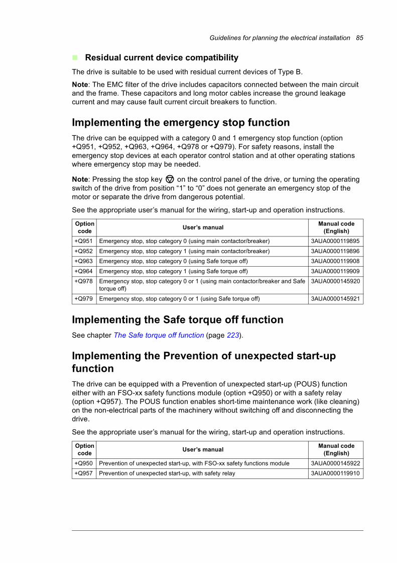
Guidelines for planning the electrical installation 85
Residual current device compatibility
The drive is suitable to be used with residual current devices of Type B.
Note: The EMC filter of the drive includes capacitors connected between the main circuit and the frame. These capacitors and long motor cables increase the ground leakage current and may cause fault current circuit breakers to function.
Implementing the emergency stop functionThe drive can be equipped with a category 0 and 1 emergency stop function (option +Q951, +Q952, +Q963, +Q964, +Q978 or +Q979). For safety reasons, install the emergency stop devices at each operator control station and at other operating stations where emergency stop may be needed.
Note: Pressing the stop key on the control panel of the drive, or turning the operating switch of the drive from position “1” to “0” does not generate an emergency stop of the motor or separate the drive from dangerous potential.
See the appropriate user’s manual for the wiring, start-up and operation instructions.
Implementing the Safe torque off functionSee chapter The Safe torque off function (page 223).
Implementing the Prevention of unexpected start-up functionThe drive can be equipped with a Prevention of unexpected start-up (POUS) function either with an FSO-xx safety functions module (option +Q950) or with a safety relay (option +Q957). The POUS function enables short-time maintenance work (like cleaning) on the non-electrical parts of the machinery without switching off and disconnecting the drive.
See the appropriate user’s manual for the wiring, start-up and operation instructions.
Option code
User’s manualManual code
(English)
+Q951 Emergency stop, stop category 0 (using main contactor/breaker) 3AUA0000119895
+Q952 Emergency stop, stop category 1 (using main contactor/breaker) 3AUA0000119896
+Q963 Emergency stop, stop category 0 (using Safe torque off) 3AUA0000119908
+Q964 Emergency stop, stop category 1 (using Safe torque off) 3AUA0000119909
+Q978 Emergency stop, stop category 0 or 1 (using main contactor/breaker and Safe torque off)
3AUA0000145920
+Q979 Emergency stop, stop category 0 or 1 (using Safe torque off) 3AUA0000145921
Option code
User’s manualManual code
(English)
+Q950 Prevention of unexpected start-up, with FSO-xx safety functions module 3AUA0000145922
+Q957 Prevention of unexpected start-up, with safety relay 3AUA0000119910
86 Guidelines for planning the electrical installation
Implementing the functions provided by the FSO-xx safety functions module (option +Q972 or +Q973)The drive can be equipped with an FSO-xx safety functions module (option +Q972 or +Q973) which enables the implementation of functions such as Safe brake control (SBC), Safe stop 1 (SS1), Safe stop emergency (SSE), Safely limited speed (SLS) and Safe maximum speed (SMS).
The settings of the FSO-xx are at default when delivered from the factory. The connectors of the module are pre-wired to terminal block X68. The wiring of the external safety circuit and configuration of the FSO-xx module are the responsibility of the machine builder.
The FSO-xx reserves the standard Safe torque off (STO) connection of the inverter control unit. STO can still be utilized by other safety circuits through the FSO-xx.
For wiring instructions, safety data and more information on the functions provided by the FSO-xx, refer to its manual.
Declaration of Conformity
See page 185.
Implementing the Power-loss ride-through functionImplement the power-loss ride-through function as follows:
Check that the power-loss ride-through function of the inverter unit is enabled with parameter 30.31 Undervoltage control in the ACS880 primary control program.
WARNING! Make sure that the flying restart of the motor will not cause any danger. If you are in doubt, do not implement the Power-loss ride-through function.
The main contactor of the drive opens in a power-loss situation. When the power returns, the contactor closes. However, if the power-loss situation lasts so long that the drive trips on undervoltage, it must be reset and started again to continue operation. If the power-loss situation lasts so long that the buffer module (see page 40) runs out, the main contactor remains open and the drive operates only after reset and a new start.
With external uninterruptible control voltage (option +G307), the main contactor remains closed in power-loss situations. If the power-loss situation lasts so long that the drive trips on undervoltage, it must be reset and started again to continue operation.
Supplying power for the auxiliary circuitsThe drive is equipped with an auxiliary control voltage transformer which supplies control voltage, for example, for the control devices and cabinet fan(s).
The following options are to be supplied from external power sources:• +G300/+G301: Cabinet heaters and/or lighting (230 or 115 V AC; external fuse: 16 A)
• +G307: Connection for an external uninterruptible power supply (230 or 115 V AC; external fuse: 16 A) to the control unit and control devices when the drive is not running
• +G313: Power supply connection (230 V AC; external fuse 16 A) for a motor space heater output.
Guidelines for planning the electrical installation 87
Using power factor compensation capacitors with the drivePower factor compensation is not needed with AC drives. However, if a drive is to be connected in a system with compensation capacitors installed, note the following restrictions.
WARNING! Do not connect power factor compensation capacitors or harmonic filters to the motor cables (between the drive and the motor). They are not meant to be used with AC drives and can cause permanent damage to the drive or
themselves.
If there are power factor compensation capacitors in parallel with the three phase input of the drive:
1. Do not connect a high-power capacitor to the power line while the drive is connected. The connection will cause voltage transients that may trip or even damage the drive.
2. If capacitor load is increased/decreased step by step when the AC drive is connected to the power line, make sure that the connection steps are low enough not to cause voltage transients that would trip the drive.
3. Check that the power factor compensation unit is suitable for use in systems with AC drives, ie, harmonic generating loads. In such systems, the compensation unit should typically be equipped with a blocking reactor or harmonic filter.
Implementing a safety switch between the drive and the motorWe recommend to install a safety switch between the permanent magnet synchronous motor and the drive output. The switch is needed to isolate the motor during any maintenance work on the drive.
Protecting the contacts of relay outputsInductive loads (relays, contactors, motors) cause voltage transients when switched off.
The relay contacts on the drive control unit are protected with varistors (250 V) against overvoltage peaks. In spite of this, it is highly recommended that inductive loads are equipped with noise attenuating circuits (varistors, RC filters [AC] or diodes [DC]) in order to minimize the EMC emission at switch-off. If not suppressed, the disturbances may connect capacitively or inductively to other conductors in the control cable and form a risk of malfunction in other parts of the system.
Install the protective component as close to the inductive load as possible. Do not install protective components at the relay outputs.
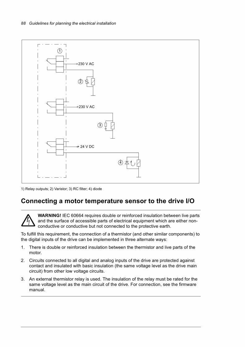
88 Guidelines for planning the electrical installation
1) Relay outputs; 2) Varistor; 3) RC filter; 4) diode
Connecting a motor temperature sensor to the drive I/O
WARNING! IEC 60664 requires double or reinforced insulation between live parts and the surface of accessible parts of electrical equipment which are either non-conductive or conductive but not connected to the protective earth.
To fulfill this requirement, the connection of a thermistor (and other similar components) to the digital inputs of the drive can be implemented in three alternate ways:
1. There is double or reinforced insulation between the thermistor and live parts of the motor.
2. Circuits connected to all digital and analog inputs of the drive are protected against contact and insulated with basic insulation (the same voltage level as the drive main circuit) from other low voltage circuits.
3. An external thermistor relay is used. The insulation of the relay must be rated for the same voltage level as the main circuit of the drive. For connection, see the firmware manual.
1
2
3
230 V AC
+ 24 V DC
4
230 V AC
Electrical installation 89
6
Electrical installation
Contents of this chapterThis chapter gives instructions on the wiring the drive.
Warnings
WARNING! Only qualified electricians are allowed to carry out the work described in this chapter. Follow the Safety instructions on the first pages of this manual. Ignoring the safety instructions can cause injury or death.
Checking the insulation of the assembly
Drive
Do not make any voltage tolerance or insulation resistance tests on any part of the drive as testing can damage the drive. Every drive has been tested for insulation between the main circuit and the chassis at the factory. Also, there are voltage-limiting circuits inside the drive which cut down the testing voltage automatically.
Input cable
Check the insulation of the input cable according to local regulations before connecting it to the drive.

90 Electrical installation
Motor and motor cable
1. Check that the motor cable is disconnected from the drive output terminals U2, V2 and W2.
2. Measure the insulation resistance between each phase conductor and the Protective Earth conductor using a measuring voltage of 1000 V DC. The insulation resistance of an ABB motor must exceed 100 Mohm (reference value at 25 °C or 77 °F). For the insulation resistance of other motors, consult the manufacturer’s instructions. Note: Moisture inside the motor casing will reduce the insulation resistance. If moisture is suspected, dry the motor and repeat the measurement.
Custom brake resistor assembly
See section Connection procedure (page 242).
Checking the compatibility with IT (ungrounded) systemsEMC filter +E202 is not suitable for use in an IT (ungrounded) system. If the drive is equipped with filter +E202, disconnect the filter before connecting the drive to the supply network. For instructions on how to do this, contact your local ABB representative.
WARNING! If a drive with EMC filter +E202 is installed on an IT system (an ungrounded power system or a high resistance-grounded [over 30 ohm] power system), the system will be connected to earth potential through the EMC filter
capacitors of the drive. This may cause danger, or damage the unit.
Attaching the device stickers to the cabinet doorA multilingual device label sticker is delivered with the drive. Attach the stickers in the local language on the English texts; see section Door switches and lights (page 44).
Checking the settings of transformers T21, T101 and T111Check the tap settings of all auxiliary voltage transformers. Transformer T21 is standard equipment; T101 and T111 are present if required by the selected options.
The voltage settings of transformers T21 and T101 are made at terminal blocks T21_X1/X2 and T101_X1/X2 respectively. The settings of transformer T111 are made on the transformer itself. The locations of the transformers and the terminal blocks are shown in section Auxiliary control cubicle (ACU) layout (page 40).
ohm
M3~
U1
V1
W1PE
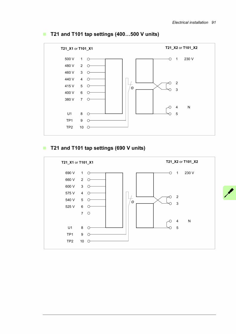
Electrical installation 91
T21 and T101 tap settings (400…500 V units)
T21 and T101 tap settings (690 V units)
500 V 1
480 V 2
460 V 3
440 V 4
415 V 5
400 V 6
380 V 7
U1 8
TP1 9
TP2 10
T21_X1 or T101_X1 T21_X2 or T101_X2
1 230 V
2
3
4 N
5
Θ
690 V 1
660 V 2
600 V 3
575 V 4
540 V 5
525 V 6
7
U1 8
TP1 9
TP2 10
T21_X1 or T101_X1 T21_X2 or T101_X2
1 230 V
2
3
4 N
5
Θ
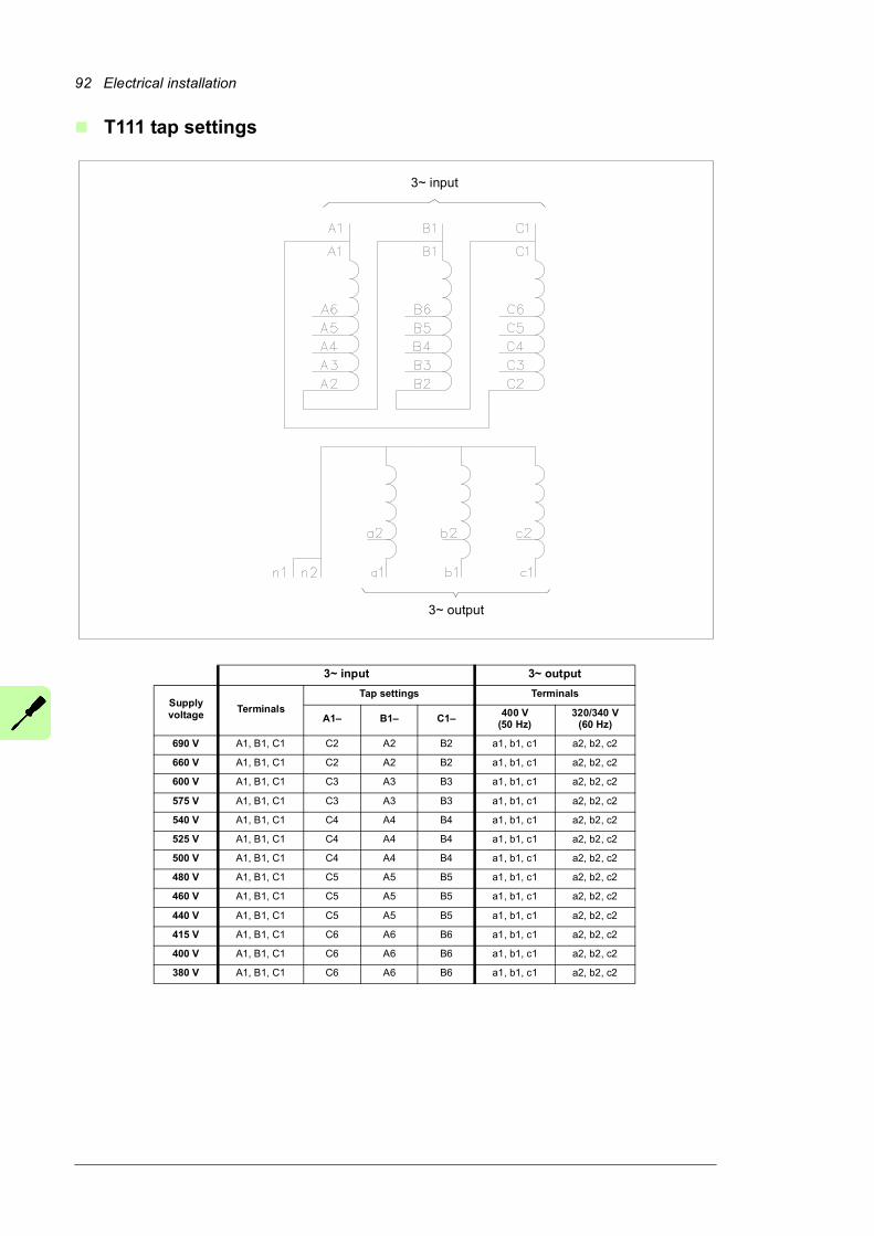
92 Electrical installation
T111 tap settings
3~ input
3~ input 3~ output
Supply voltage
Terminals
Tap settings Terminals
A1– B1– C1– 400 V(50 Hz)
320/340 V(60 Hz)
690 V A1, B1, C1 C2 A2 B2 a1, b1, c1 a2, b2, c2
660 V A1, B1, C1 C2 A2 B2 a1, b1, c1 a2, b2, c2
600 V A1, B1, C1 C3 A3 B3 a1, b1, c1 a2, b2, c2
575 V A1, B1, C1 C3 A3 B3 a1, b1, c1 a2, b2, c2
540 V A1, B1, C1 C4 A4 B4 a1, b1, c1 a2, b2, c2
525 V A1, B1, C1 C4 A4 B4 a1, b1, c1 a2, b2, c2
500 V A1, B1, C1 C4 A4 B4 a1, b1, c1 a2, b2, c2
480 V A1, B1, C1 C5 A5 B5 a1, b1, c1 a2, b2, c2
460 V A1, B1, C1 C5 A5 B5 a1, b1, c1 a2, b2, c2
440 V A1, B1, C1 C5 A5 B5 a1, b1, c1 a2, b2, c2
415 V A1, B1, C1 C6 A6 B6 a1, b1, c1 a2, b2, c2
400 V A1, B1, C1 C6 A6 B6 a1, b1, c1 a2, b2, c2
380 V A1, B1, C1 C6 A6 B6 a1, b1, c1 a2, b2, c2
3~ output
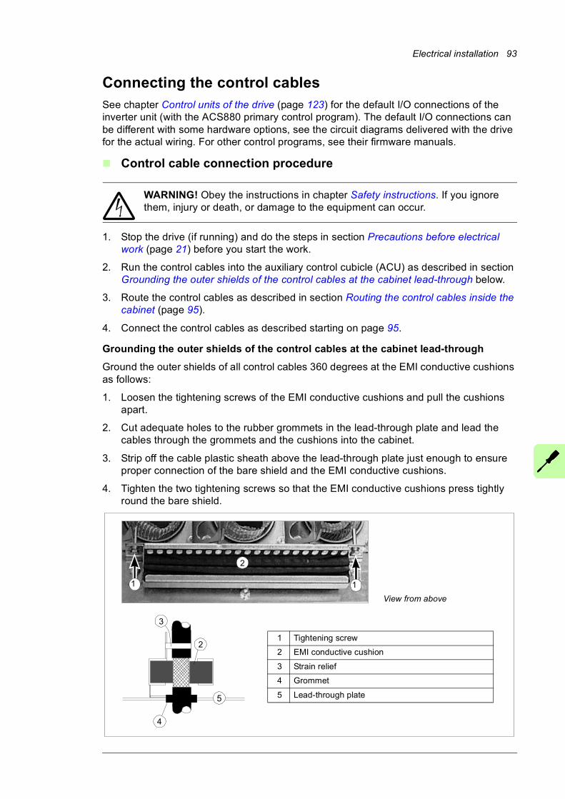
Electrical installation 93
Connecting the control cablesSee chapter Control units of the drive (page 123) for the default I/O connections of the inverter unit (with the ACS880 primary control program). The default I/O connections can be different with some hardware options, see the circuit diagrams delivered with the drive for the actual wiring. For other control programs, see their firmware manuals.
Control cable connection procedure
WARNING! Obey the instructions in chapter Safety instructions. If you ignore them, injury or death, or damage to the equipment can occur.
1. Stop the drive (if running) and do the steps in section Precautions before electrical work (page 21) before you start the work.
2. Run the control cables into the auxiliary control cubicle (ACU) as described in section Grounding the outer shields of the control cables at the cabinet lead-through below.
3. Route the control cables as described in section Routing the control cables inside the cabinet (page 95).
4. Connect the control cables as described starting on page 95.
Grounding the outer shields of the control cables at the cabinet lead-through
Ground the outer shields of all control cables 360 degrees at the EMI conductive cushions as follows:
1. Loosen the tightening screws of the EMI conductive cushions and pull the cushions apart.
2. Cut adequate holes to the rubber grommets in the lead-through plate and lead the cables through the grommets and the cushions into the cabinet.
3. Strip off the cable plastic sheath above the lead-through plate just enough to ensure proper connection of the bare shield and the EMI conductive cushions.
4. Tighten the two tightening screws so that the EMI conductive cushions press tightly round the bare shield.
View from above
1 Tightening screw
2 EMI conductive cushion
3 Strain relief
4 Grommet
5 Lead-through plate
2
3
4
5
1
2
1
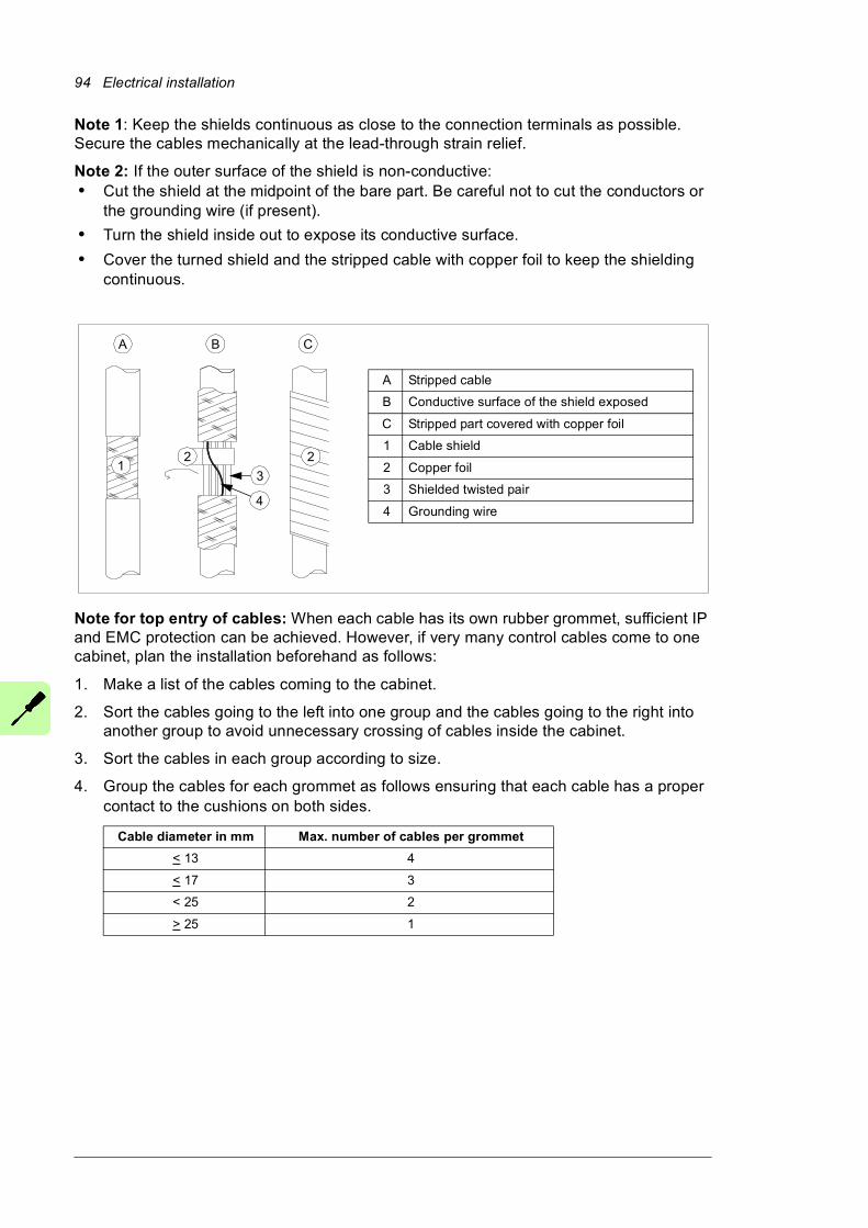
94 Electrical installation
Note 1: Keep the shields continuous as close to the connection terminals as possible. Secure the cables mechanically at the lead-through strain relief.
Note 2: If the outer surface of the shield is non-conductive:• Cut the shield at the midpoint of the bare part. Be careful not to cut the conductors or
the grounding wire (if present).
• Turn the shield inside out to expose its conductive surface.
• Cover the turned shield and the stripped cable with copper foil to keep the shielding continuous.
Note for top entry of cables: When each cable has its own rubber grommet, sufficient IP and EMC protection can be achieved. However, if very many control cables come to one cabinet, plan the installation beforehand as follows:
1. Make a list of the cables coming to the cabinet.
2. Sort the cables going to the left into one group and the cables going to the right into another group to avoid unnecessary crossing of cables inside the cabinet.
3. Sort the cables in each group according to size.
4. Group the cables for each grommet as follows ensuring that each cable has a proper contact to the cushions on both sides.
Cable diameter in mm Max. number of cables per grommet
< 13 4
< 17 3
< 25 2
> 25 1
A Stripped cable
B Conductive surface of the shield exposed
C Stripped part covered with copper foil
1 Cable shield
2 Copper foil
3 Shielded twisted pair
4 Grounding wire
1
A B C
2 2
3
4

Electrical installation 95
5. Arrange the bunches according to size from thickest to the thinnest between the EMI conductive cushions.
6. If more than one cable go through a grommet, seal the grommet by applying Loctite 5221 (catalogue number 25551) inside the grommet.
Routing the control cables inside the cabinet
Use the existing trunking in the cabinet wherever possible. Use sleeving if cables are laid against sharp edges. When running cables to or from the swing-out frame, leave enough slack at the hinge to allow the frame to open fully.
Connecting to the inverter control unit [A41]
Connect the conductors to the appropriate terminals (see page 123) of the control unit or terminal block X504 (option +L504).
Connect the inner twisted pair shields and all separate grounding wires to the grounding clamps below the control unit.
The drawing below represents a drive with additional I/O terminal block (option +L504). Without the block, the grounding is made the same way.
Notes:• Do not ground the outer shield of the cable here since it is grounded at the lead-
through.
• Keep any signal wire pairs twisted as close to the terminals as possible. Twisting the wire with its return wire reduces disturbances caused by inductive coupling.
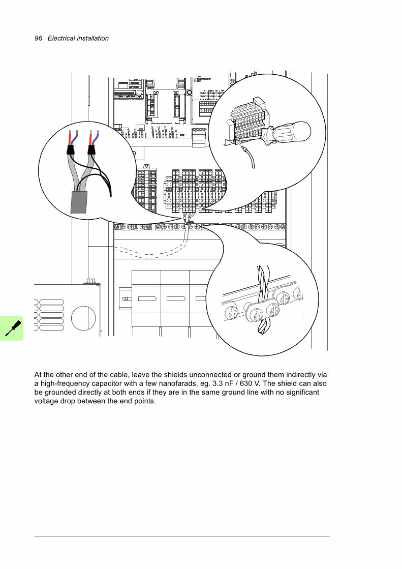
96 Electrical installation
At the other end of the cable, leave the shields unconnected or ground them indirectly via a high-frequency capacitor with a few nanofarads, eg. 3.3 nF / 630 V. The shield can also be grounded directly at both ends if they are in the same ground line with no significant voltage drop between the end points.
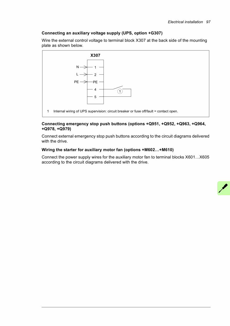
Electrical installation 97
Connecting an auxiliary voltage supply (UPS, option +G307)
Wire the external control voltage to terminal block X307 at the back side of the mounting plate as shown below.
Connecting emergency stop push buttons (options +Q951, +Q952, +Q963, +Q964, +Q978, +Q979)
Connect external emergency stop push buttons according to the circuit diagrams delivered with the drive.
Wiring the starter for auxiliary motor fan (options +M602…+M610)
Connect the power supply wires for the auxiliary motor fan to terminal blocks X601…X605 according to the circuit diagrams delivered with the drive.
1
2
PE
4
5
N
L
X307
PE
1
1 Internal wiring of UPS supervision: circuit breaker or fuse off/fault = contact open.
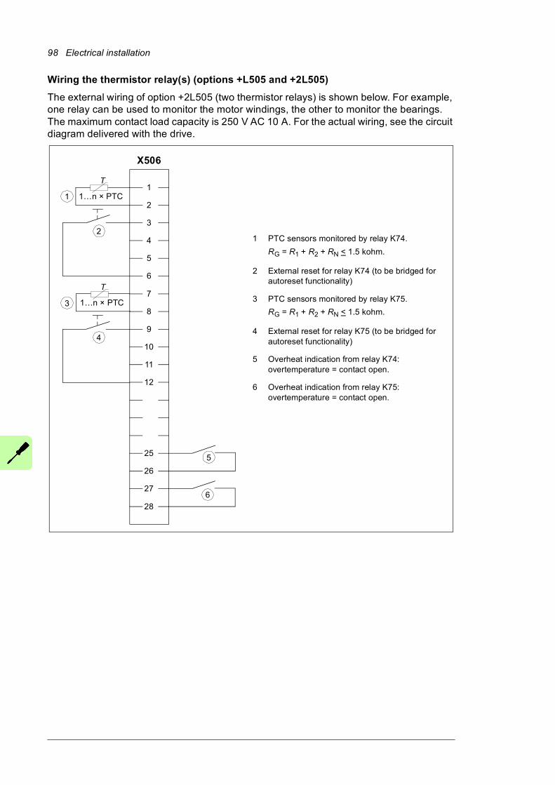
98 Electrical installation
Wiring the thermistor relay(s) (options +L505 and +2L505)
The external wiring of option +2L505 (two thermistor relays) is shown below. For example, one relay can be used to monitor the motor windings, the other to monitor the bearings. The maximum contact load capacity is 250 V AC 10 A. For the actual wiring, see the circuit diagram delivered with the drive.
1
2
3
4
5
6
7
8
9
10
11
12
25
26
27
28
X506
T
T
1…n × PTC
6
5
1…n × PTC
1 PTC sensors monitored by relay K74.
RG = R1 + R2 + RN < 1.5 kohm.
2 External reset for relay K74 (to be bridged for autoreset functionality)
3 PTC sensors monitored by relay K75.
RG = R1 + R2 + RN < 1.5 kohm.
4 External reset for relay K75 (to be bridged for autoreset functionality)
5 Overheat indication from relay K74: overtemperature = contact open.
6 Overheat indication from relay K75: overtemperature = contact open.
2
3
1
4
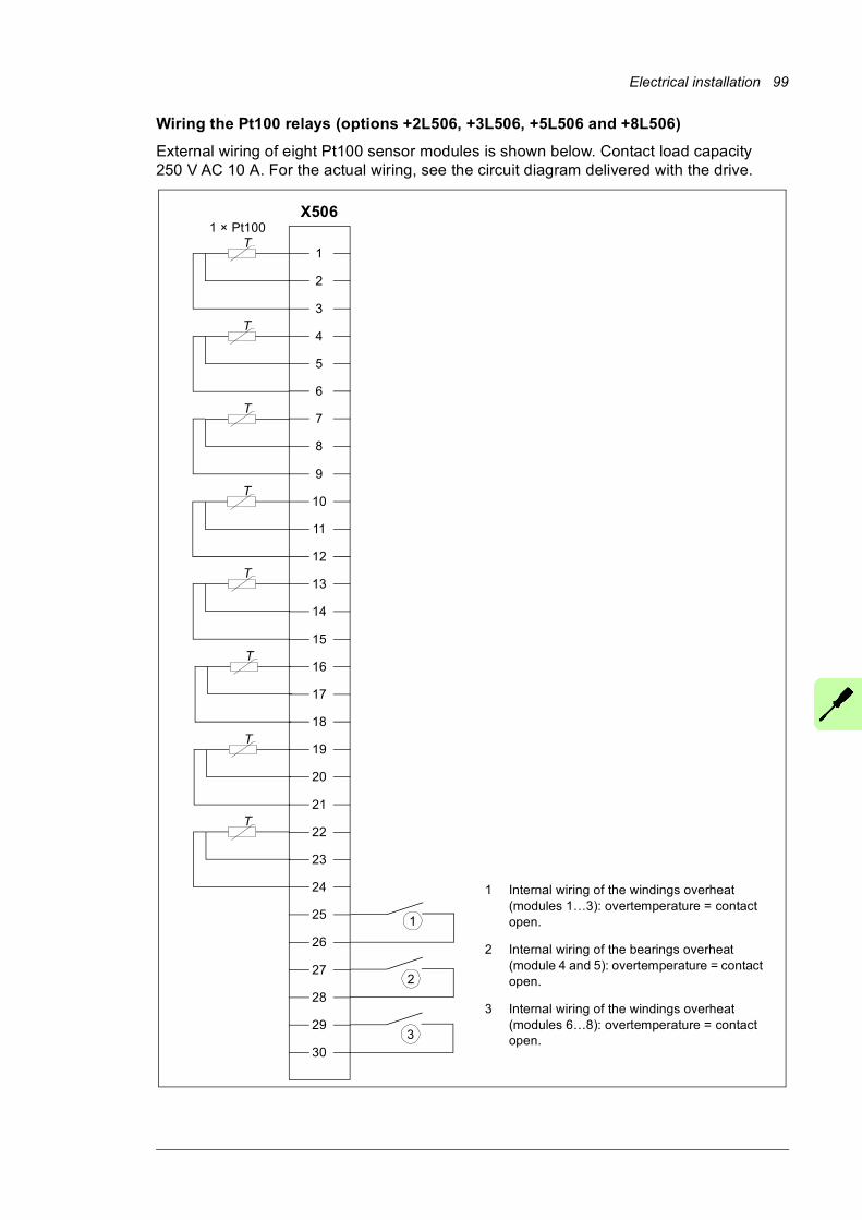
Electrical installation 99
Wiring the Pt100 relays (options +2L506, +3L506, +5L506 and +8L506)
External wiring of eight Pt100 sensor modules is shown below. Contact load capacity 250 V AC 10 A. For the actual wiring, see the circuit diagram delivered with the drive.
1
2
3
4
5
6
7
8
9
10
11
12
13
14
15
16
17
18
19
20
21
22
23
24
25
26
27
28
29
30
X506
T1 × Pt100
2
1
T
T
T
T
T
T
T
3
1 Internal wiring of the windings overheat (modules 1…3): overtemperature = contact open.
2 Internal wiring of the bearings overheat (module 4 and 5): overtemperature = contact open.
3 Internal wiring of the windings overheat (modules 6…8): overtemperature = contact open.
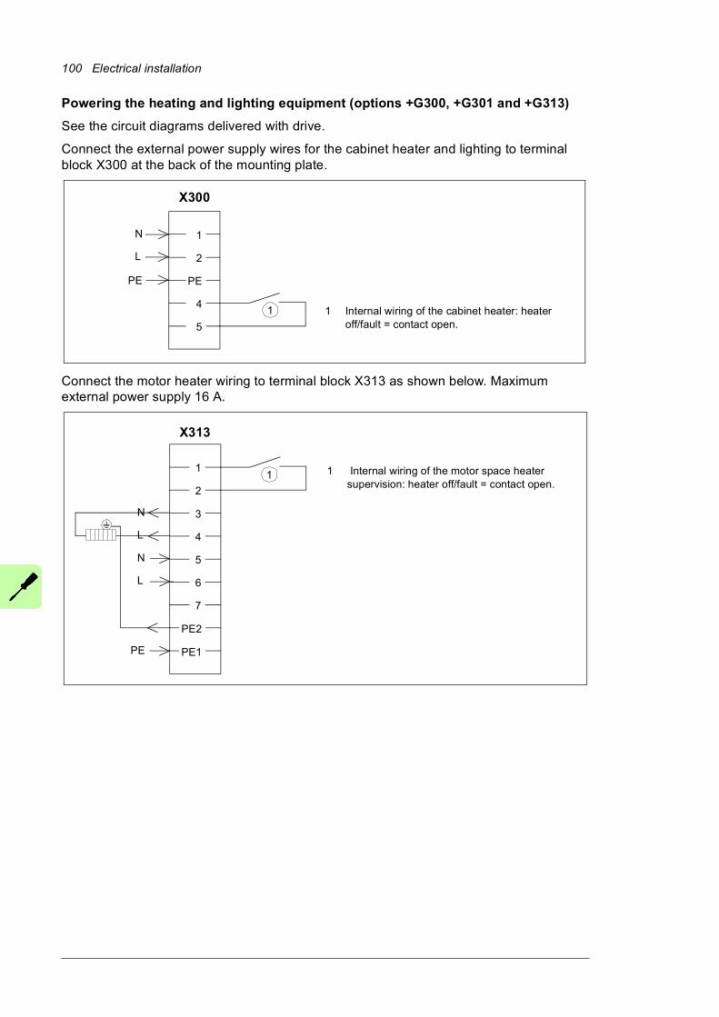
100 Electrical installation
Powering the heating and lighting equipment (options +G300, +G301 and +G313)
See the circuit diagrams delivered with drive.
Connect the external power supply wires for the cabinet heater and lighting to terminal block X300 at the back of the mounting plate.
Connect the motor heater wiring to terminal block X313 as shown below. Maximum external power supply 16 A.
1
2
PE
4
5
N
L
X300
PE
1 Internal wiring of the cabinet heater: heater off/fault = contact open.
1
1
2
3
4
5
6
7
PE2
PE1
N
L
N
L
X313
PE
1 Internal wiring of the motor space heater supervision: heater off/fault = contact open.
1
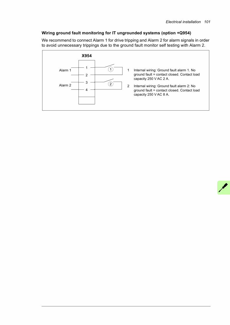
Electrical installation 101
Wiring ground fault monitoring for IT ungrounded systems (option +Q954)
We recommend to connect Alarm 1 for drive tripping and Alarm 2 for alarm signals in order to avoid unnecessary trippings due to the ground fault monitor self testing with Alarm 2.
1
2
3
4
X954
Alarm 1
Alarm 2
1 Internal wiring: Ground fault alarm 1. No ground fault = contact closed. Contact load capacity 250 V AC 2 A.
2 Internal wiring: Ground fault alarm 2: No ground fault = contact closed. Contact load capacity 250 V AC 8 A.
1
2
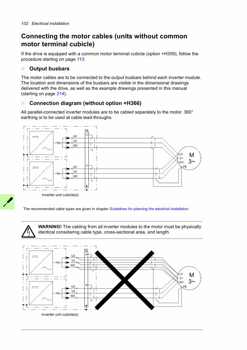
102 Electrical installation
Connecting the motor cables (units without common motor terminal cubicle)If the drive is equipped with a common motor terminal cubicle (option +H359), follow the procedure starting on page 113.
Output busbars
The motor cables are to be connected to the output busbars behind each inverter module. The location and dimensions of the busbars are visible in the dimensional drawings delivered with the drive, as well as the example drawings presented in this manual (starting on page 214).
Connection diagram (without option +H366)
All parallel-connected inverter modules are to be cabled separately to the motor. 360° earthing is to be used at cable lead-throughs.
WARNING! The cabling from all inverter modules to the motor must be physically identical considering cable type, cross-sectional area, and length.
U2
V2
W2
PE
U2
V2
W2
M3~
U1
W1
V1
PE
Inverter unit cubicle(s)
The recommended cable types are given in chapter Guidelines for planning the electrical installation.
Inverter unit cubicle(s)
PE
U2
V2
W2
U2
V2
W2
M3~
U1
W1
V1
PE
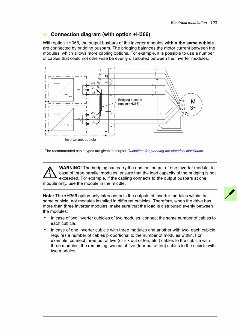
Electrical installation 103
Connection diagram (with option +H366)
With option +H366, the output busbars of the inverter modules within the same cubicle are connected by bridging busbars. The bridging balances the motor current between the modules, which allows more cabling options. For example, it is possible to use a number of cables that could not otherwise be evenly distributed between the inverter modules.
WARNING! The bridging can carry the nominal output of one inverter module. In case of three parallel modules, ensure that the load capacity of the bridging is not exceeded. For example, if the cabling connects to the output busbars at one
module only, use the module in the middle.
Note: The +H366 option only interconnects the outputs of inverter modules within the same cubicle, not modules installed in different cubicles. Therefore, when the drive has more than three inverter modules, make sure that the load is distributed evenly between the modules:
• In case of two inverter cubicles of two modules, connect the same number of cables to each cubicle.
• In case of one inverter cubicle with three modules and another with two, each cubicle requires a number of cables proportional to the number of modules within. For example, connect three out of five (or six out of ten, etc.) cables to the cubicle with three modules, the remaining two out of five (four out of ten) cables to the cubicle with two modules.
Inverter unit cubicle
The recommended cable types are given in chapter Guidelines for planning the electrical installation.
PE
U2
V2
W2
U2
V2
W2
M3~U1
W1
V1
PE
Bridging busbars (option +H366)
104 Electrical installation
Procedure
The procedure involves removing the fan carriage of each inverter module, making the connections, and reinserting the fan carriage.
To allow more room for making the connections, the inverter module can be removed completely instead of just the fan carriage. To do this, follow the procedure under Removing the inverter module (page 106).
Removing and reinstalling the fan carriage of an inverter module
Refer to the drawings below.
WARNING! Obey the instructions in chapter Safety instructions. If you ignore them, injury or death, or damage to the equipment can occur.
1. Do the steps in section Precautions before electrical work (page 21) before you start the work.
2. Open the inverter module cubicle door.
3. Remove the screws holding the front cover plate. Lift the cover plate somewhat to release it.
4. Disconnect the wiring at the top of the fan carriage.
5. Remove the two screws at the bottom of the fan carriage.
WARNING! Before you proceed, make sure the two screws holding the top of the inverter module are in place.
6. Remove the two screws at the top of the fan carriage.
7. Pull the fan carriage out.
8. Repeat the procedure for other fan carriages in the same cubicle.
Proceed to Connecting the motor cables (page 110).
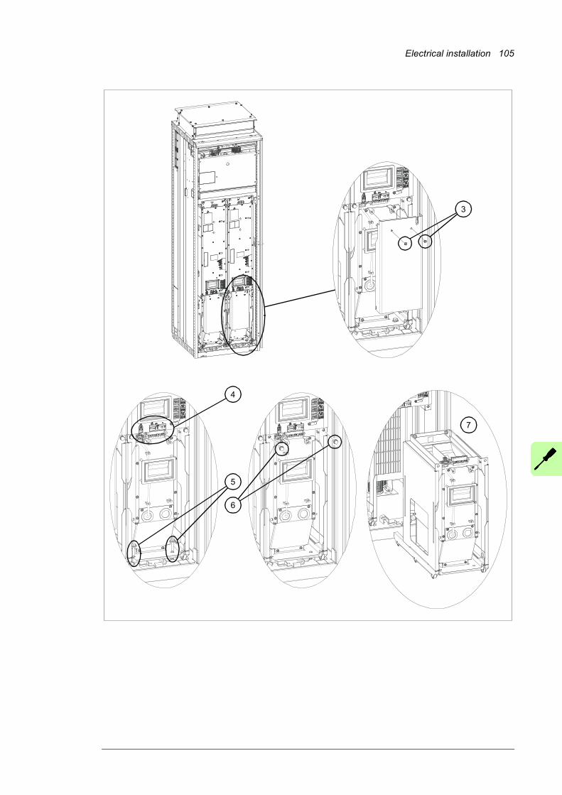
Electrical installation 105
4
5
3
6
7
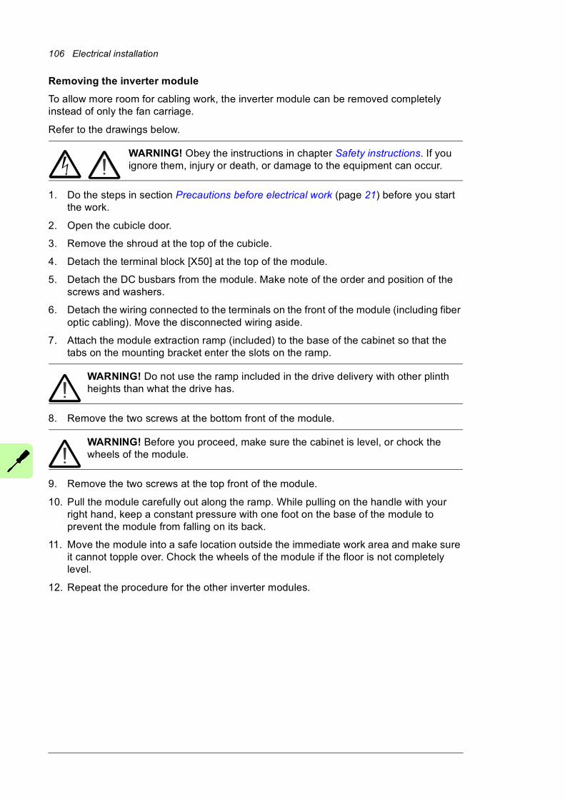
106 Electrical installation
Removing the inverter module
To allow more room for cabling work, the inverter module can be removed completely instead of only the fan carriage.
Refer to the drawings below.
WARNING! Obey the instructions in chapter Safety instructions. If you ignore them, injury or death, or damage to the equipment can occur.
1. Do the steps in section Precautions before electrical work (page 21) before you start the work.
2. Open the cubicle door.
3. Remove the shroud at the top of the cubicle.
4. Detach the terminal block [X50] at the top of the module.
5. Detach the DC busbars from the module. Make note of the order and position of the screws and washers.
6. Detach the wiring connected to the terminals on the front of the module (including fiber optic cabling). Move the disconnected wiring aside.
7. Attach the module extraction ramp (included) to the base of the cabinet so that the tabs on the mounting bracket enter the slots on the ramp.
WARNING! Do not use the ramp included in the drive delivery with other plinth heights than what the drive has.
8. Remove the two screws at the bottom front of the module.
WARNING! Before you proceed, make sure the cabinet is level, or chock the wheels of the module.
9. Remove the two screws at the top front of the module.
10. Pull the module carefully out along the ramp. While pulling on the handle with your right hand, keep a constant pressure with one foot on the base of the module to prevent the module from falling on its back.
11. Move the module into a safe location outside the immediate work area and make sure it cannot topple over. Chock the wheels of the module if the floor is not completely level.
12. Repeat the procedure for the other inverter modules.
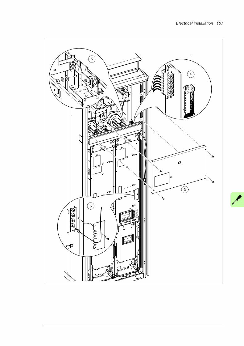
Electrical installation 107
5
6
4
3
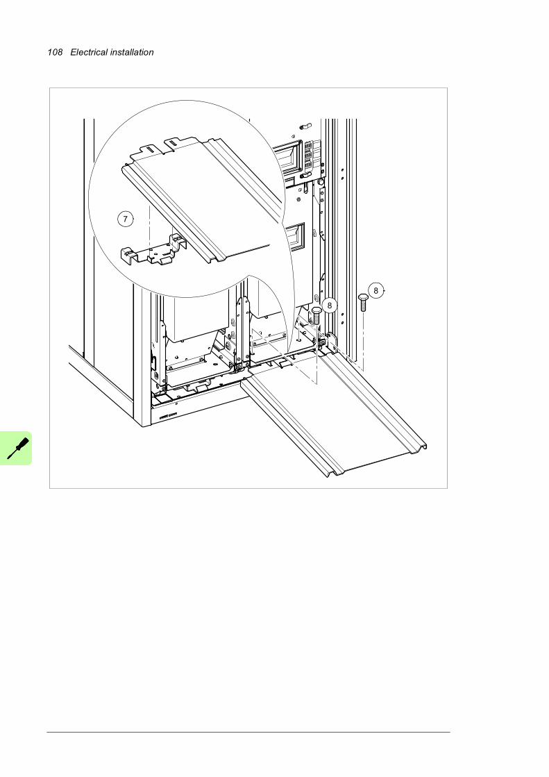
108 Electrical installation
7
8
8
Electrical installation 109
9
10
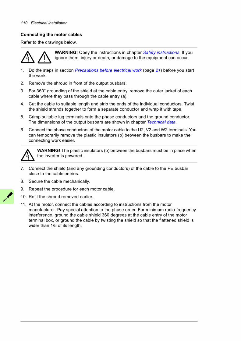
110 Electrical installation
Connecting the motor cables
Refer to the drawings below.
WARNING! Obey the instructions in chapter Safety instructions. If you ignore them, injury or death, or damage to the equipment can occur.
1. Do the steps in section Precautions before electrical work (page 21) before you start the work.
2. Remove the shroud in front of the output busbars.
3. For 360° grounding of the shield at the cable entry, remove the outer jacket of each cable where they pass through the cable entry (a).
4. Cut the cable to suitable length and strip the ends of the individual conductors. Twist the shield strands together to form a separate conductor and wrap it with tape.
5. Crimp suitable lug terminals onto the phase conductors and the ground conductor. The dimensions of the output busbars are shown in chapter Technical data.
6. Connect the phase conductors of the motor cable to the U2, V2 and W2 terminals. You can temporarily remove the plastic insulators (b) between the busbars to make the connecting work easier.
WARNING! The plastic insulators (b) between the busbars must be in place when the inverter is powered.
7. Connect the shield (and any grounding conductors) of the cable to the PE busbar close to the cable entries.
8. Secure the cable mechanically.
9. Repeat the procedure for each motor cable.
10. Refit the shroud removed earlier.
11. At the motor, connect the cables according to instructions from the motor manufacturer. Pay special attention to the phase order. For minimum radio-frequency interference, ground the cable shield 360 degrees at the cable entry of the motor terminal box, or ground the cable by twisting the shield so that the flattened shield is wider than 1/5 of its length.
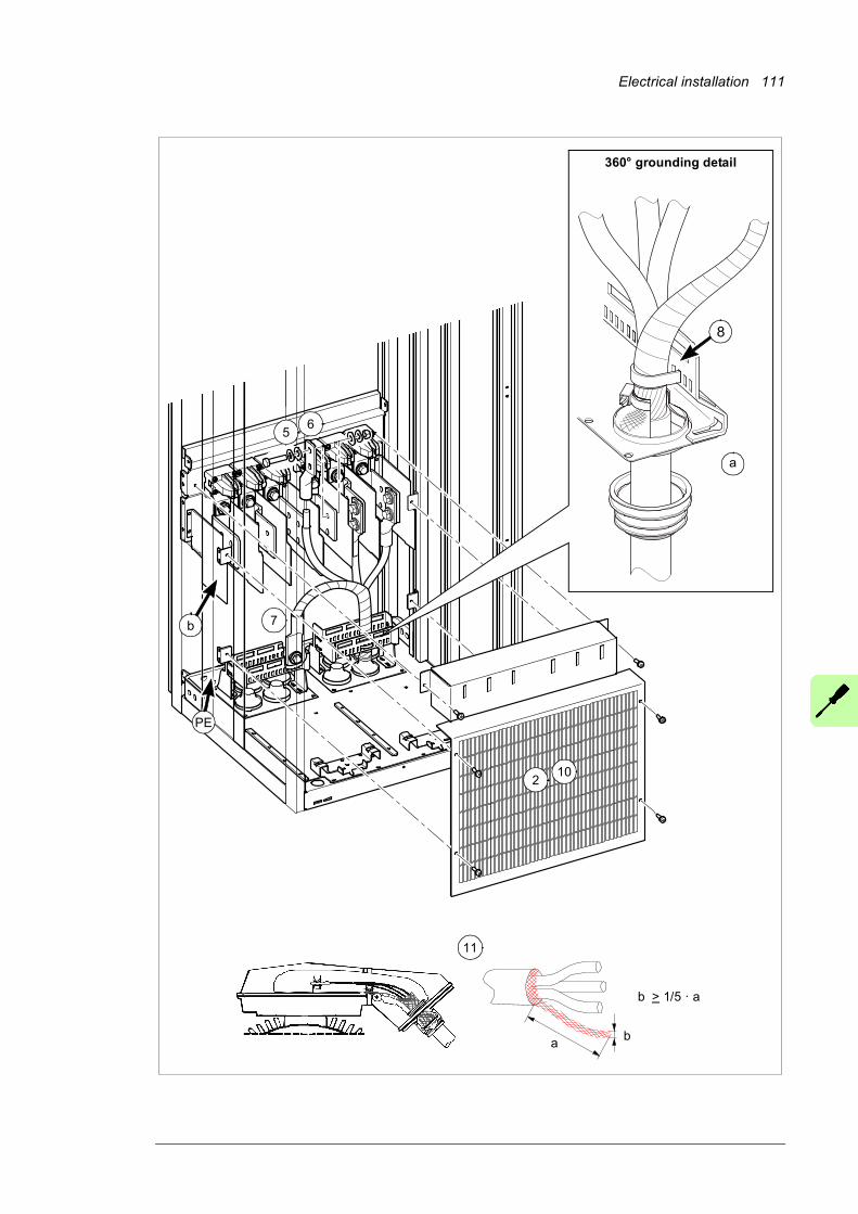
Electrical installation 111
2
360° grounding detail
ab
b > 1/5 · a
11
b
a
PE
10
7
56
8

112 Electrical installation
Re-inserting the fan carriage of an inverter module
(If the inverter module was removed completely instead of only the fan carriage, proceed to section Re-inserting the inverter module into the cubicle below.)
The re-installation of the fan carriage is the removal procedure in reverse. See section Removing and reinstalling the fan carriage of an inverter module (page 104).
Re-inserting the inverter module into the cubicle
WARNING! Obey the instructions in chapter Safety instructions. If you ignore them, injury or death, or damage to the equipment can occur.
1. Make sure there are no tools, debris or any other foreign objects in the cubicle.
2. If not already in place, attach the module extraction ramp (included) to the base of the cabinet so that the tabs on the mounting bracket enter the slots on the ramp.
3. Push the module up the ramp and back into the cubicle.• Keep your fingers away from the edge of the module front plate to avoid
pinching.
• Keep a constant pressure with one foot on the base of the module to prevent the module from falling on its back.
4. Secure the top front of the module with two screws.
5. Secure the bottom front of the module with two screws.
6. Remove the ramp.
7. Attach the DC busbars to the module.
8. Reconnect terminal block [X50] at the top of the module.
9. Reconnect the wiring and fiber optic cables to the terminals on the front of the module.
10. Repeat the procedure for the other inverter modules.
11. Reinstall the shroud near the top of the cubicle.
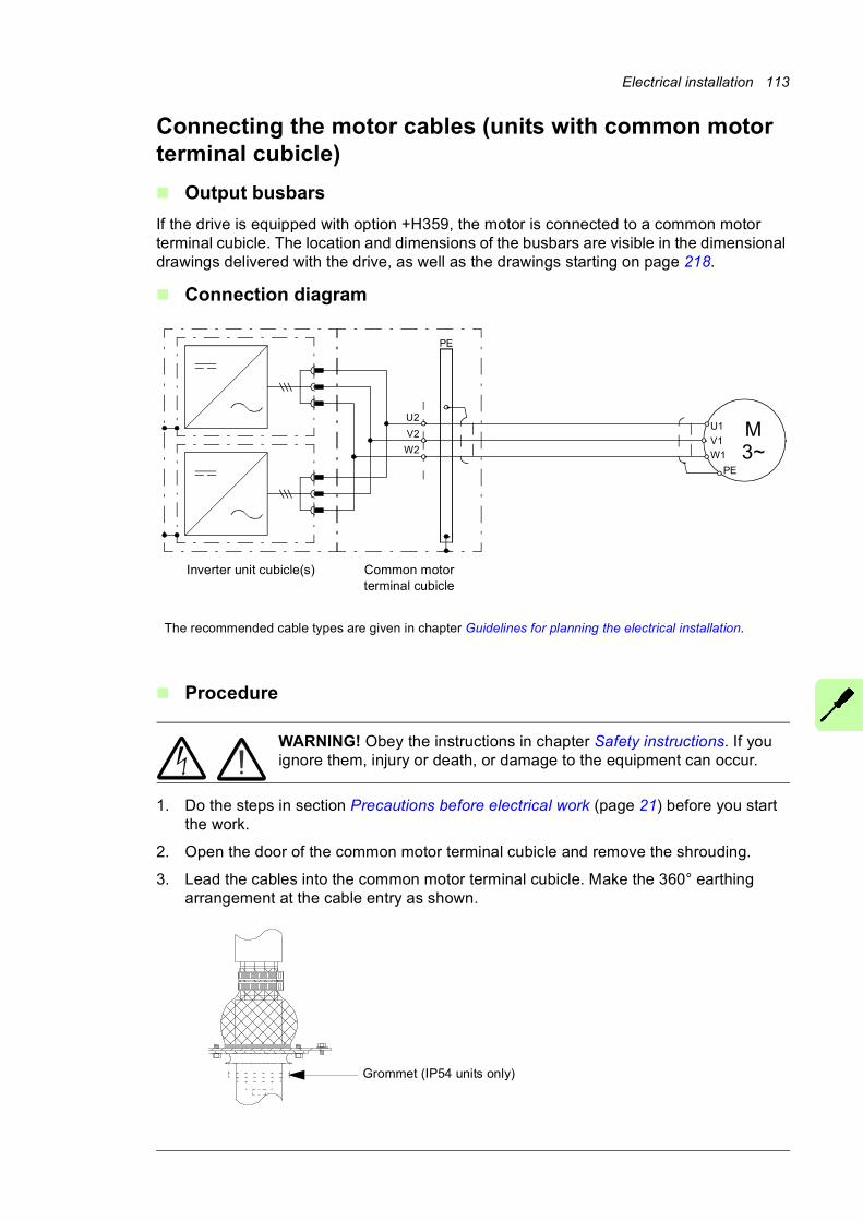
Electrical installation 113
Connecting the motor cables (units with common motor terminal cubicle)
Output busbars
If the drive is equipped with option +H359, the motor is connected to a common motor terminal cubicle. The location and dimensions of the busbars are visible in the dimensional drawings delivered with the drive, as well as the drawings starting on page 218.
Connection diagram
Procedure
WARNING! Obey the instructions in chapter Safety instructions. If you ignore them, injury or death, or damage to the equipment can occur.
1. Do the steps in section Precautions before electrical work (page 21) before you start the work.
2. Open the door of the common motor terminal cubicle and remove the shrouding.
3. Lead the cables into the common motor terminal cubicle. Make the 360° earthing arrangement at the cable entry as shown.
U2
V2
W2
PE
The recommended cable types are given in chapter Guidelines for planning the electrical installation.
M3~
U1
W1
V1
PE
Inverter unit cubicle(s) Common motor terminal cubicle
Grommet (IP54 units only)
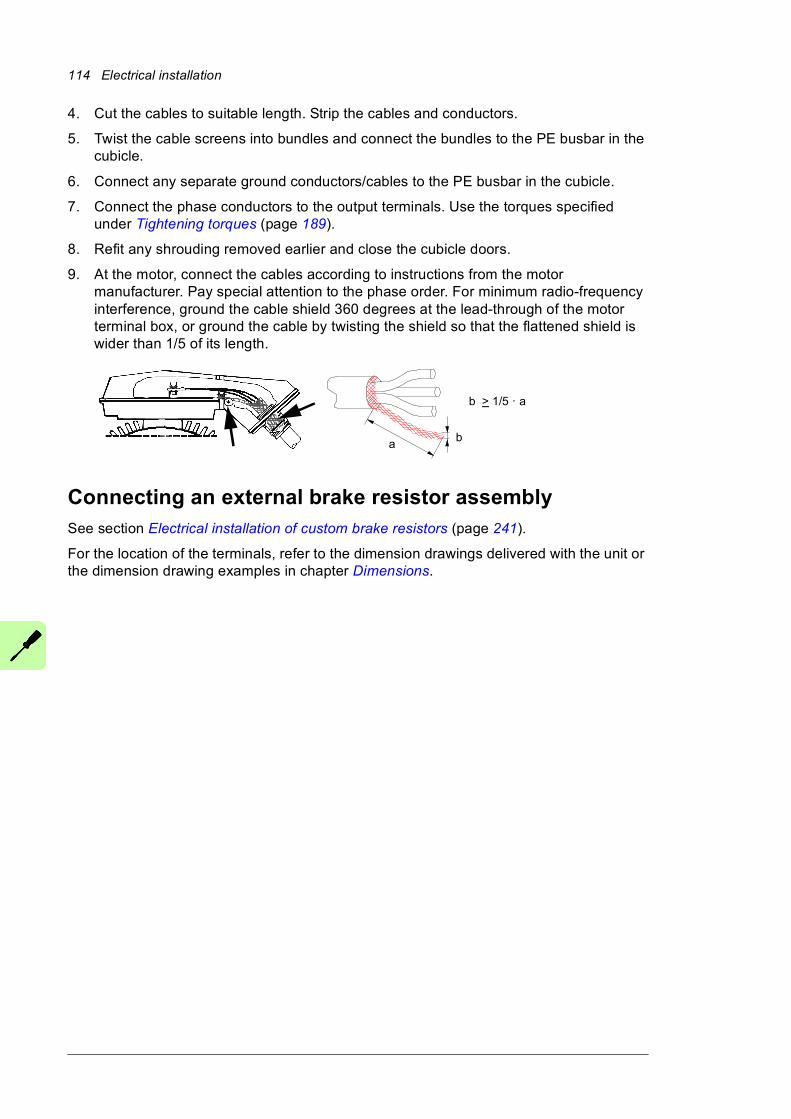
114 Electrical installation
4. Cut the cables to suitable length. Strip the cables and conductors.
5. Twist the cable screens into bundles and connect the bundles to the PE busbar in the cubicle.
6. Connect any separate ground conductors/cables to the PE busbar in the cubicle.
7. Connect the phase conductors to the output terminals. Use the torques specified under Tightening torques (page 189).
8. Refit any shrouding removed earlier and close the cubicle doors.
9. At the motor, connect the cables according to instructions from the motor manufacturer. Pay special attention to the phase order. For minimum radio-frequency interference, ground the cable shield 360 degrees at the lead-through of the motor terminal box, or ground the cable by twisting the shield so that the flattened shield is wider than 1/5 of its length.
Connecting an external brake resistor assemblySee section Electrical installation of custom brake resistors (page 241).
For the location of the terminals, refer to the dimension drawings delivered with the unit or the dimension drawing examples in chapter Dimensions.
ab
b > 1/5 · a
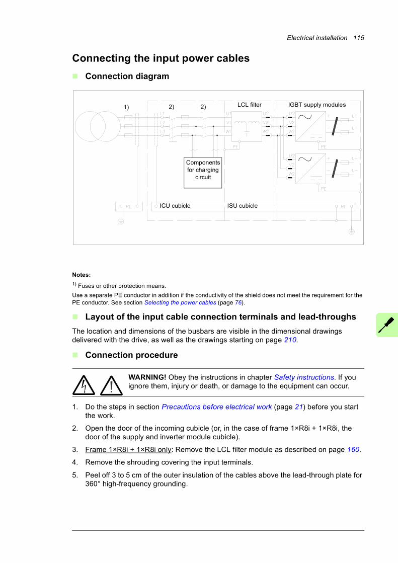
Electrical installation 115
Connecting the input power cables
Connection diagram
Notes:
1) Fuses or other protection means.
Use a separate PE conductor in addition if the conductivity of the shield does not meet the requirement for the PE conductor. See section Selecting the power cables (page 76).
Layout of the input cable connection terminals and lead-throughs
The location and dimensions of the busbars are visible in the dimensional drawings delivered with the drive, as well as the drawings starting on page 210.
Connection procedure
WARNING! Obey the instructions in chapter Safety instructions. If you ignore them, injury or death, or damage to the equipment can occur.
1. Do the steps in section Precautions before electrical work (page 21) before you start the work.
2. Open the door of the incoming cubicle (or, in the case of frame 1×R8i + 1×R8i, the door of the supply and inverter module cubicle).
3. Frame 1×R8i + 1×R8i only: Remove the LCL filter module as described on page 160.
4. Remove the shrouding covering the input terminals.
5. Peel off 3 to 5 cm of the outer insulation of the cables above the lead-through plate for 360° high-frequency grounding.
Components for charging
circuit
LCL filter IGBT supply modules
ICU cubicle ISU cubicle
1) 2) 2)
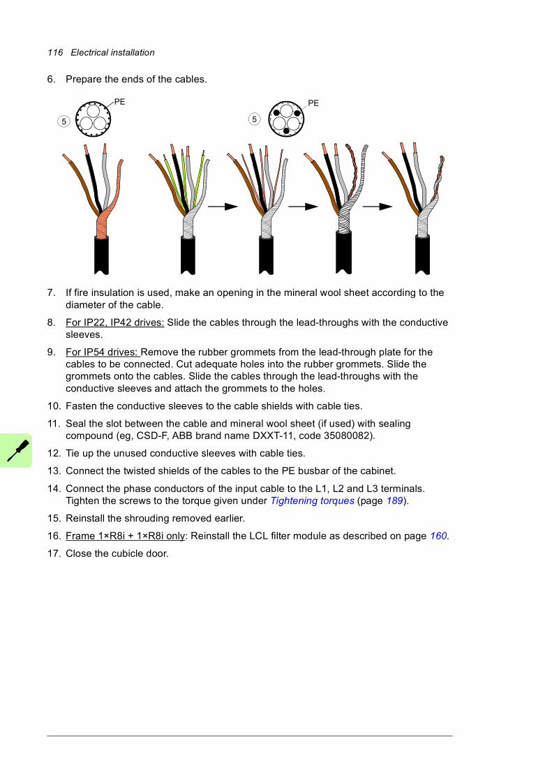
116 Electrical installation
6. Prepare the ends of the cables.
7. If fire insulation is used, make an opening in the mineral wool sheet according to the diameter of the cable.
8. For IP22, IP42 drives: Slide the cables through the lead-throughs with the conductive sleeves.
9. For IP54 drives: Remove the rubber grommets from the lead-through plate for the cables to be connected. Cut adequate holes into the rubber grommets. Slide the grommets onto the cables. Slide the cables through the lead-throughs with the conductive sleeves and attach the grommets to the holes.
10. Fasten the conductive sleeves to the cable shields with cable ties.
11. Seal the slot between the cable and mineral wool sheet (if used) with sealing compound (eg, CSD-F, ABB brand name DXXT-11, code 35080082).
12. Tie up the unused conductive sleeves with cable ties.
13. Connect the twisted shields of the cables to the PE busbar of the cabinet.
14. Connect the phase conductors of the input cable to the L1, L2 and L3 terminals. Tighten the screws to the torque given under Tightening torques (page 189).
15. Reinstall the shrouding removed earlier.
16. Frame 1×R8i + 1×R8i only: Reinstall the LCL filter module as described on page 160.
17. Close the cubicle door.
PEPE
5 5
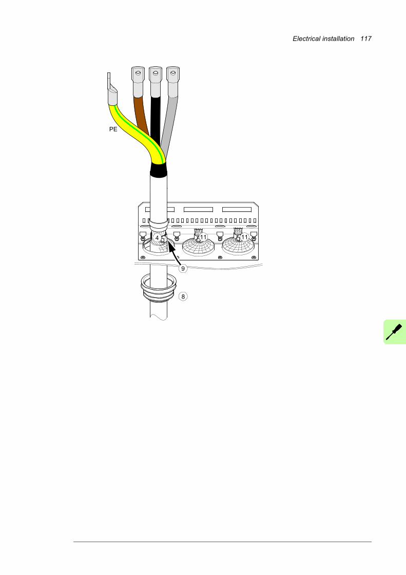
Electrical installation 117
PE
11
8
4
9
11
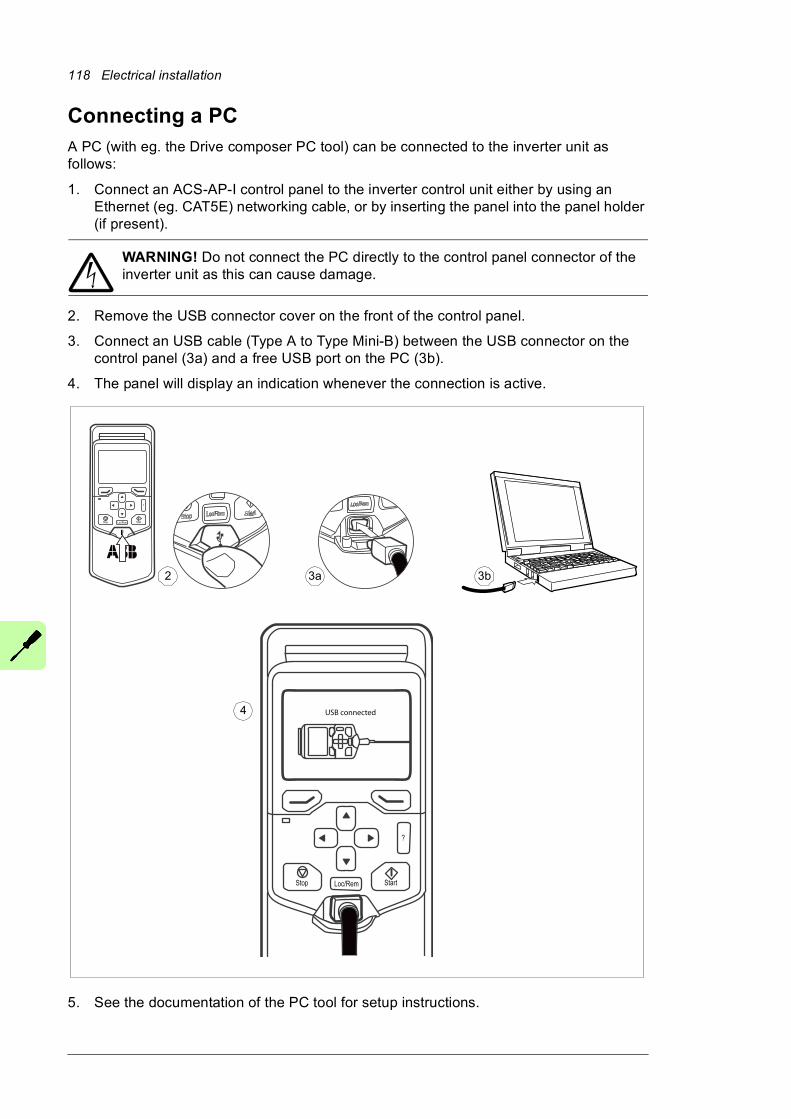
118 Electrical installation
Connecting a PCA PC (with eg. the Drive composer PC tool) can be connected to the inverter unit as follows:
1. Connect an ACS-AP-I control panel to the inverter control unit either by using an Ethernet (eg. CAT5E) networking cable, or by inserting the panel into the panel holder (if present).
WARNING! Do not connect the PC directly to the control panel connector of the inverter unit as this can cause damage.
2. Remove the USB connector cover on the front of the control panel.
3. Connect an USB cable (Type A to Type Mini-B) between the USB connector on the control panel (3a) and a free USB port on the PC (3b).
4. The panel will display an indication whenever the connection is active.
5. See the documentation of the PC tool for setup instructions.
?
StartStop Loc/Rem
?
StartStop Loc/Rem
USB connected
3a 3b2
4
Electrical installation 119
Panel bus (Control of several units from one control panel)One control panel (or PC) can be used to control several supply or inverter units by constructing a panel bus. A control panel mounting platform or an FDPI-02 module is required. For further information, see FDPI-02 diagnostics and panel interface user’s manual (3AUA0000113618 [English]).
Note: The drive has an internal panel bus connecting both the supply control unit [A51] and the inverter control unit [A41] to the panel. Unless other units are to be connected to the panel bus, go to step 4.
1. Connect the panel to one inverter unit using an Ethernet (eg. CAT5E) cable.• Use Menu – Settings – Edit texts – Drive to give a descriptive name to the unit
• Use parameter 49.01 to assign the unit with a unique node ID number
• Set other parameters in group 49 if necessary
• Use parameter 49.06 to validate any changes.
Repeat the above for each unit.
2. With the panel connected to one inverter unit, link the inverter units together using Ethernet cables. (Each panel platform has two connectors.)
3. In the last unit, switch bus termination on. With a panel platform, move the terminating switch into the outer position. (With an FDPI-02 module, move termination switch S2 into the TERMINATED position.) Termination should be off on all other units.
4. On the control panel, switch on the panel bus functionality (Options – Select drive – Panel bus). The unit to be controlled can now be selected from the list under Options – Select drive.
5. If a PC is connected to the control panel, the units on the panel bus are automatically displayed in the Drive composer tool.
1
1 32

120 Electrical installation
Installing option modules
Mechanical installation of I/O extension, fieldbus adapter and pulse encoder interface modules
See page 42 for the available slots for each module. Install the option modules as follows:
WARNING! Obey the instructions in chapter Safety instructions. If you ignore them, injury or death, or damage to the equipment can occur.
1. Stop the drive and do the steps in section Precautions before electrical work (page 21) before you start the work.
2. Open the door of the auxiliary control cubicle (ACU).
3. Remove the shrouding at the top of the cubicle.
4. Locate the inverter control unit [A41].
5. Insert the module carefully into its position on the control unit.
6. Fasten the mounting screw. Note: The screw tightens the connections and grounds the module. It is essential for fulfilling the EMC requirements and for proper operation of the module.
Electrical installation 121
Mechanical installation of an FSO-xx safety functions module
1. Fasten the FSO-xx safety functions module onto slot 3 of the inverter control unit [A41] with four screws.
2. Tighten the FSO-xx electronics grounding screw.
3. Connect the FSO-xx data cable between FSO-xx connector X110 and to BCU-x2 connector X12.
1
3
2

122 Electrical installation
Wiring of option modules
See the appropriate option module manual for specific installation and wiring instructions.
Control units of the drive 123
7
Control units of the drive
What this chapter containsThis chapter
• describes the connections of the control units used in the drive,
• contains the specifications of the inputs and outputs of the control units.
GeneralThe ACS880 drive utilizes BCU-x2 control units. The BCU-x2 consists of a BCON-12 control board (and a BIOC-01 I/O connector board and power supply board) built in a metal housing.
The supply and inverter units of the ACS880-37 are each controlled by a dedicated BCU-x2 control unit. The designation of the supply control unit is A51; the inverter control unit is A41. Both are located in the ACU cubicle (see the drawings in chapter Operation principle and hardware description), and connect to the power modules (ie. supply and inverter modules respectively) by fiber optic cables.
In this manual, the name “BCU-x2” represents the control unit types BCU-02 and BCU-12. These have a different number of power module connections (2 and 7 respectively) but are otherwise similar.
124 Control units of the drive
Control unit layout and connections
Description
I/O I/O terminals (see following diagram)
SLOT 1 I/O extension, encoder interface or fieldbus adapter module connection. (This is the sole location for an FDPI-02 diagnostics and panel interface.)
SLOT 2 I/O extension, encoder interface or fieldbus adapter module connection
SLOT 3 I/O extension, encoder interface, fieldbus adapter or FSO-xx safety functions module connection
SLOT 4 RDCO-0x DDCS communication option module connection
X205 Memory unit connection
BATTERY Holder for real-time clock battery (CR 2032)
AI1 Mode selector for analog input AI1 (I = current, U = voltage)
AI2 Mode selector for analog input AI2 (I = current, U = voltage)
D2D TERM Termination switch for drive-to-drive link (D2D)
DICOM = DIOGND
Ground selection. Determines whether DICOM is separated from DIOGND (ie. the common reference for the digital inputs floats).
7-segment displayMulticharacter indications are displayed as repeated sequences of characters
(“U” is indicated briefly before “o”.)Control program startup in progress
(Flashing) Firmware cannot be started. Memory unit missing or corrupted
Firmware download from PC to control unit in progress
At power-up, the display may show short indications of eg. “1”, “2”, “b” or “U”. These are normal indications immediately after power-up. If the display ends up showing any other value than those described, it indicates a hardware failure.
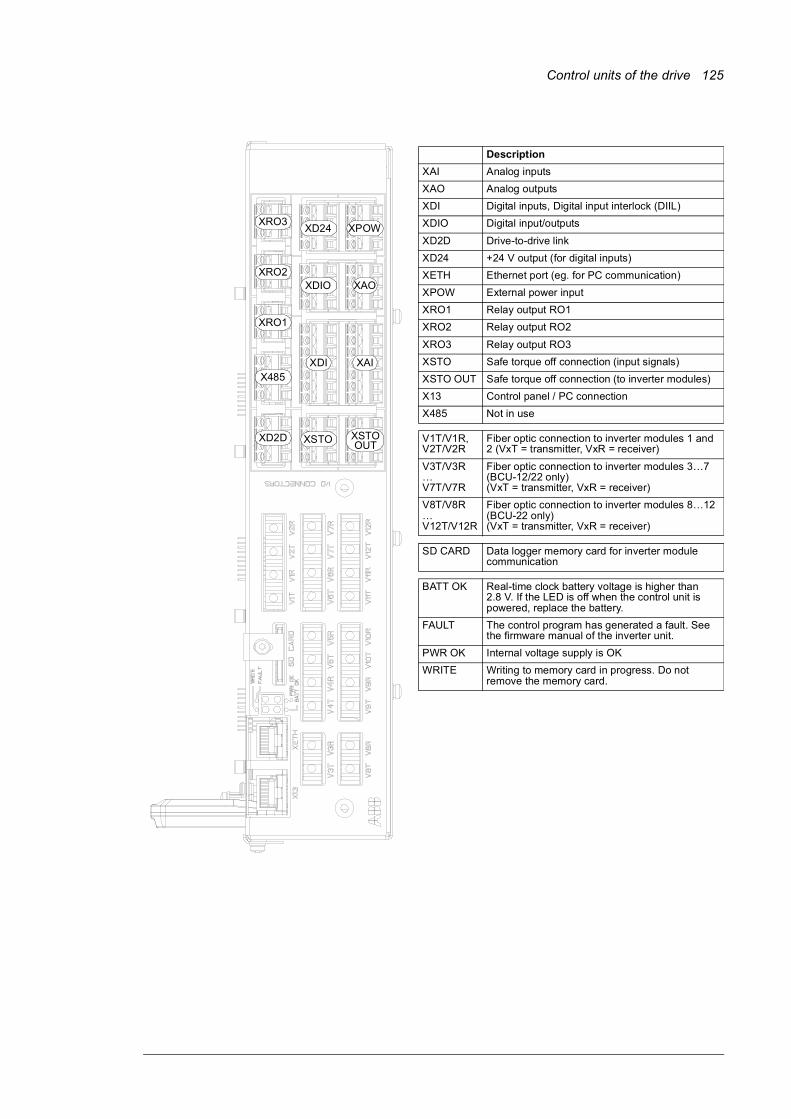
Control units of the drive 125
Description
XAI Analog inputs
XAO Analog outputs
XDI Digital inputs, Digital input interlock (DIIL)
XDIO Digital input/outputs
XD2D Drive-to-drive link
XD24 +24 V output (for digital inputs)
XETH Ethernet port (eg. for PC communication)
XPOW External power input
XRO1 Relay output RO1
XRO2 Relay output RO2
XRO3 Relay output RO3
XSTO Safe torque off connection (input signals)
XSTO OUT Safe torque off connection (to inverter modules)
X13 Control panel / PC connection
X485 Not in use
V1T/V1R, V2T/V2R
Fiber optic connection to inverter modules 1 and 2 (VxT = transmitter, VxR = receiver)
V3T/V3R…V7T/V7R
Fiber optic connection to inverter modules 3…7 (BCU-12/22 only)(VxT = transmitter, VxR = receiver)
V8T/V8R…V12T/V12R
Fiber optic connection to inverter modules 8…12 (BCU-22 only)(VxT = transmitter, VxR = receiver)
SD CARD Data logger memory card for inverter module communication
BATT OK Real-time clock battery voltage is higher than 2.8 V. If the LED is off when the control unit is powered, replace the battery.
FAULT The control program has generated a fault. See the firmware manual of the inverter unit.
PWR OK Internal voltage supply is OK
WRITE Writing to memory card in progress. Do not remove the memory card.
XDI
XSTO
X485
XD2D
XRO1
XRO2
XRO3
XDIO
XD24
XSTOOUT
XAI
XAO
XPOW
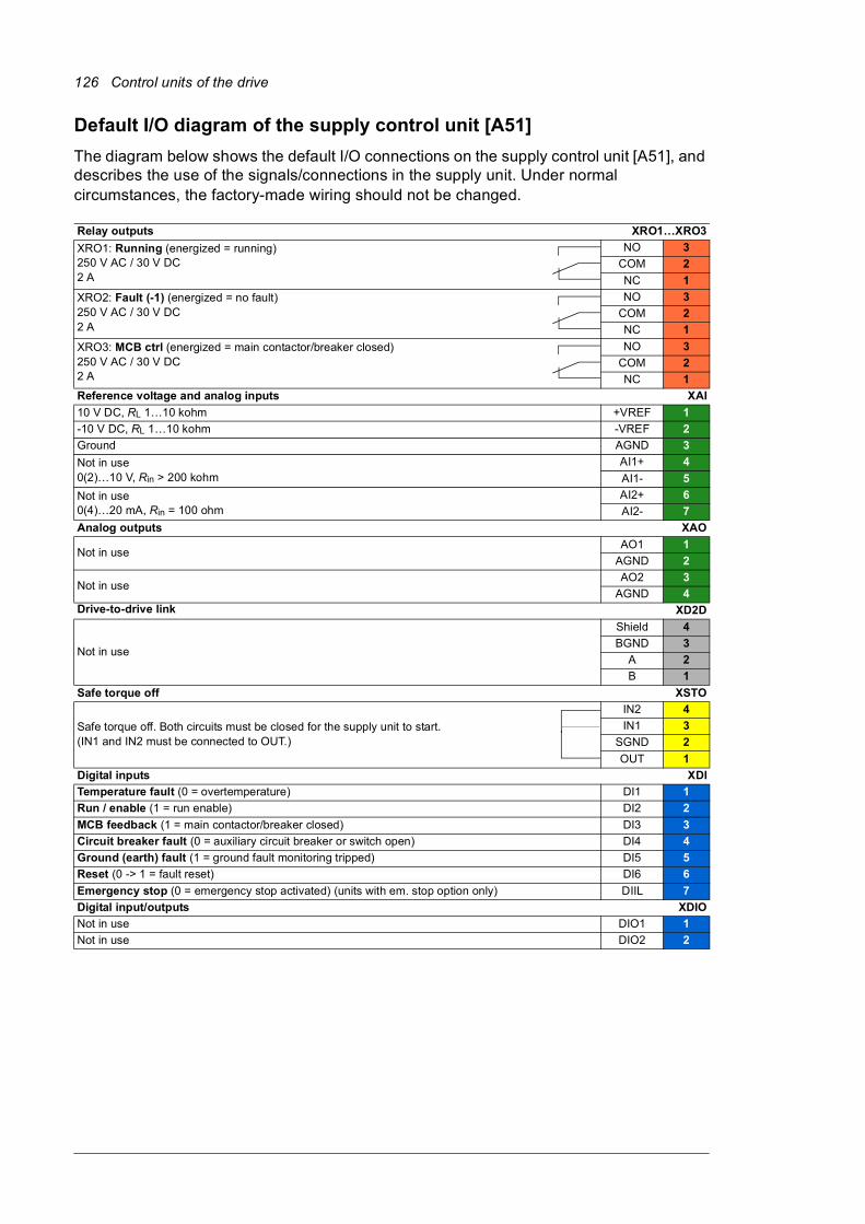
126 Control units of the drive
Default I/O diagram of the supply control unit [A51]
The diagram below shows the default I/O connections on the supply control unit [A51], and describes the use of the signals/connections in the supply unit. Under normal circumstances, the factory-made wiring should not be changed.
Relay outputs XRO1…XRO3
XRO1: Running (energized = running)250 V AC / 30 V DC2 A
NO 3
COM 2
NC 1
XRO2: Fault (-1) (energized = no fault)250 V AC / 30 V DC2 A
NO 3
COM 2
NC 1
XRO3: MCB ctrl (energized = main contactor/breaker closed)250 V AC / 30 V DC2 A
NO 3
COM 2
NC 1
Reference voltage and analog inputs XAI
10 V DC, RL 1…10 kohm +VREF 1
-10 V DC, RL 1…10 kohm -VREF 2
Ground AGND 3
Not in use0(2)…10 V, Rin > 200 kohm
AI1+ 4
AI1- 5
Not in use0(4)…20 mA, Rin = 100 ohm
AI2+ 6
AI2- 7
Analog outputs XAO
Not in useAO1 1
AGND 2
Not in useAO2 3
AGND 4Drive-to-drive link XD2D
Not in use
Shield 4
BGND 3
A 2
B 1
Safe torque off XSTO
Safe torque off. Both circuits must be closed for the supply unit to start.(IN1 and IN2 must be connected to OUT.)
IN2 4
IN1 3
SGND 2
OUT 1
Digital inputs XDI
Temperature fault (0 = overtemperature) DI1 1
Run / enable (1 = run enable) DI2 2
MCB feedback (1 = main contactor/breaker closed) DI3 3
Circuit breaker fault (0 = auxiliary circuit breaker or switch open) DI4 4
Ground (earth) fault (1 = ground fault monitoring tripped) DI5 5
Reset (0 -> 1 = fault reset) DI6 6
Emergency stop (0 = emergency stop activated) (units with em. stop option only) DIIL 7
Digital input/outputs XDIO
Not in use DIO1 1
Not in use DIO2 2
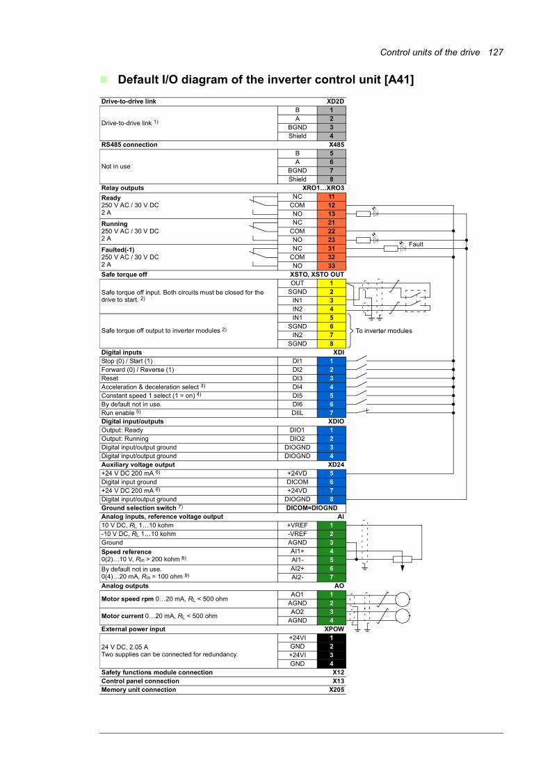
Control units of the drive 127
Default I/O diagram of the inverter control unit [A41]
Drive-to-drive link XD2D
Drive-to-drive link 1)
B 1A 2
BGND 3Shield 4
RS485 connection X485
Not in use
B 5A 6
BGND 7Shield 8
Relay outputs XRO1…XRO3
Ready250 V AC / 30 V DC2 A
NC 11COM 12NO 13
Running250 V AC / 30 V DC2 A
NC 21COM 22NO 23
Faulted(-1)250 V AC / 30 V DC2 A
NC 31COM 32NO 33
Safe torque off XSTO, XSTO OUT
Safe torque off input. Both circuits must be closed for the drive to start. 2)
OUT 1SGND 2
IN1 3IN2 4
Safe torque off output to inverter modules 2)
IN1 5SGND 6
IN2 7SGND 8
Digital inputs XDIStop (0) / Start (1) DI1 1Forward (0) / Reverse (1) DI2 2Reset DI3 3Acceleration & deceleration select 3) DI4 4Constant speed 1 select (1 = on) 4) DI5 5By default not in use. DI6 6Run enable 5) DIIL 7Digital input/outputs XDIOOutput: Ready DIO1 1Output: Running DIO2 2Digital input/output ground DIOGND 3Digital input/output ground DIOGND 4Auxiliary voltage output XD24+24 V DC 200 mA 6) +24VD 5Digital input ground DICOM 6+24 V DC 200 mA 6) +24VD 7Digital input/output ground DIOGND 8Ground selection switch 7) DICOM=DIOGNDAnalog inputs, reference voltage output AI10 V DC, RL 1…10 kohm +VREF 1-10 V DC, RL 1…10 kohm -VREF 2Ground AGND 3
Speed reference0(2)…10 V, Rin > 200 kohm 8)
AI1+ 4AI1- 5
By default not in use.0(4)…20 mA, Rin = 100 ohm 9)
AI2+ 6AI2- 7
Analog outputs AO
Motor speed rpm 0…20 mA, RL < 500 ohmAO1 1
AGND 2
Motor current 0…20 mA, RL < 500 ohmAO2 3
AGND 4External power input XPOW
24 V DC, 2.05 ATwo supplies can be connected for redundancy.
+24VI 1GND 2+24VI 3GND 4
Safety functions module connection X12Control panel connection X13Memory unit connection X205
Fault
To inverter modules

128 Control units of the drive
Notes:
The wire size accepted by all screw terminals (for both stranded and solid wire) is
0.5 … 2.5 mm2 (24…12 AWG). The torque is 0.5 N·m (5 lbf·in).
1) See section Drive-to-drive link (page 129).
2) See chapter The Safe torque off function (page 223).
3) 0 = Acceleration/deceleration ramps defined by parameters 23.12/23.13 in use. 1 = Acceleration/deceleration ramps defined by parameters 23.14/23.15 in use.
4) Constant speed 1 is defined by parameter 22.26.
5) See section DIIL input (page 129).
6) Total load capacity of these outputs is 4.8 W (200 mA at 24 V) minus the power taken by DIO1 and DIO2.
7) Determines whether DICOM is separated from DIOGND (ie. common reference for digital inputs floats; in practice, selects whether the digital inputs are used in current sinking or sourcing mode). See also Ground isolation diagram on page 133.DICOM = DIOGND ON: DICOM connected to DIOGND. OFF: DICOM and DIOGND separate.
8) Current [0(4)…20 mA, Rin = 100 ohm] or voltage [0(2)…10 V, Rin > 200 kohm] input selected by switch AI1. Change of setting requires reboot of control unit.
9) Current [0(4)…20 mA, Rin = 100 ohm] or voltage [0(2)…10 V, Rin > 200 kohm] input selected by switch AI2. Change of setting requires reboot of control unit.
External power supply for the control unit (XPOW)
The BCU-x2 is powered from a 24 V DC, 2 A supply through terminal block XPOW. A second supply can be connected to the same terminal block for redundancy.
DI6 as a PTC sensor input
PTC sensors can be connected to this input for motor temperature measurement as follows. The sum of the sensor resistances must not exceed the threshold resistance of the digital input at normal motor operating temperature. Do not connect both ends of the cable shield directly to ground. If a capacitor cannot be used at one end, leave that end of the shield unconnected. See the firmware manual for parameter settings.
Note: PTC sensors can alternatively be connected to FEN-xx encoder interface module.
WARNING! As the inputs pictured above are not insulated according to IEC 60664, the connection of the motor temperature sensor requires double or reinforced insulation between motor live parts and the sensor. If the assembly
does not fulfill the requirement, the I/O board terminals must be protected against contact
T3.3 nF> 630 V AC
PTC
DI6
+24VD
TT“0” > 4 kohm “1” < 1.5 kohmImax = 5 mA
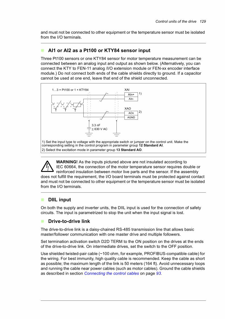
Control units of the drive 129
and must not be connected to other equipment or the temperature sensor must be isolated from the I/O terminals.
AI1 or AI2 as a Pt100 or KTY84 sensor input
Three Pt100 sensors or one KTY84 sensor for motor temperature measurement can be connected between an analog input and output as shown below. (Alternatively, you can connect the KTY to FEN-11 analog /I/O extension module or FEN-xx encoder interface module.) Do not connect both ends of the cable shields directly to ground. If a capacitor cannot be used at one end, leave that end of the shield unconnected.
WARNING! As the inputs pictured above are not insulated according to IEC 60664, the connection of the motor temperature sensor requires double or reinforced insulation between motor live parts and the sensor. If the assembly
does not fulfill the requirement, the I/O board terminals must be protected against contact and must not be connected to other equipment or the temperature sensor must be isolated from the I/O terminals.
DIIL input
On both the supply and inverter units, the DIIL input is used for the connection of safety circuits. The input is parametrized to stop the unit when the input signal is lost.
Drive-to-drive link
The drive-to-drive link is a daisy-chained RS-485 transmission line that allows basic master/follower communication with one master drive and multiple followers.
Set termination activation switch D2D TERM to the ON position on the drives at the ends of the drive-to-drive link. On intermediate drives, set the switch to the OFF position.
Use shielded twisted-pair cable (~100 ohm, for example, PROFIBUS-compatible cable) for the wiring. For best immunity, high quality cable is recommended. Keep the cable as short as possible; the maximum length of the link is 50 meters (164 ft). Avoid unnecessary loops and running the cable near power cables (such as motor cables). Ground the cable shields as described in section Connecting the control cables on page 93.
1) Set the input type to voltage with the appropriate switch or jumper on the control unit. Make the corresponding setting in the control program in parameter group 12 Standard AI.2) Select the excitation mode in parameter group 13 Standard AO.
1…3 × Pt100 or 1 × KTY84
3.3 nF > 630 V AC
XAI
XAO
AIn+AIn-
AOn
AGND
1)
2)TTT
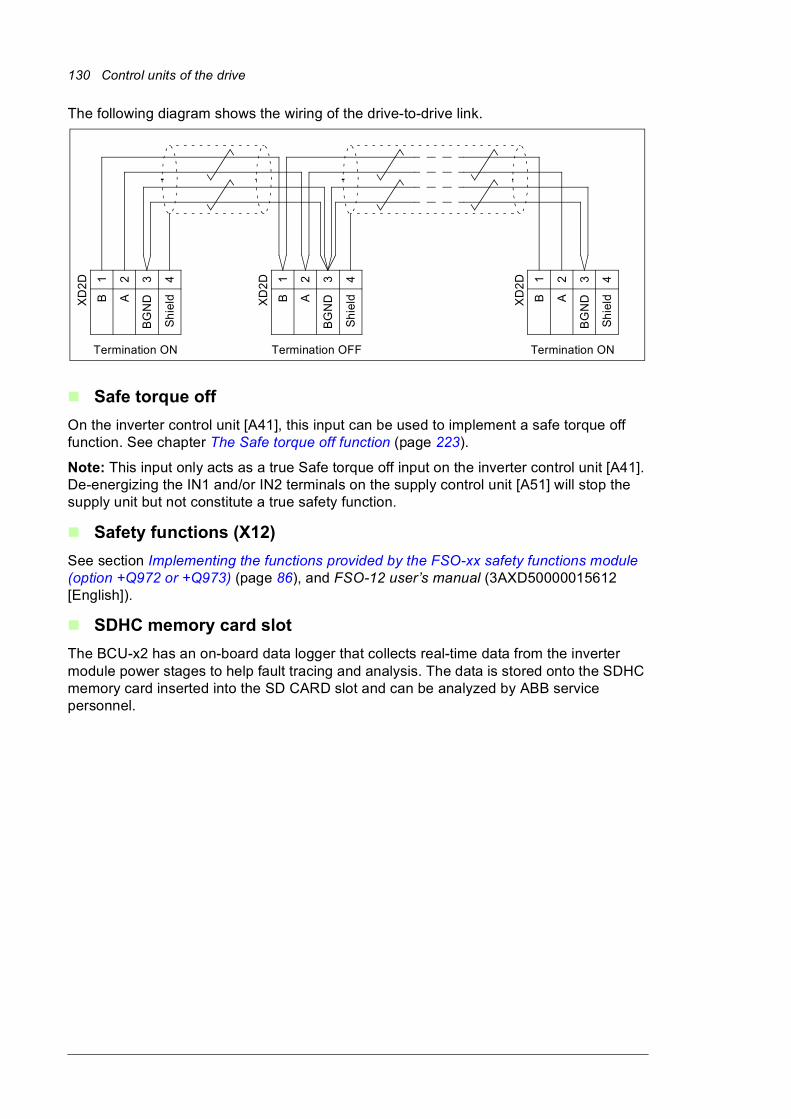
130 Control units of the drive
The following diagram shows the wiring of the drive-to-drive link.
Safe torque off
On the inverter control unit [A41], this input can be used to implement a safe torque off function. See chapter The Safe torque off function (page 223).
Note: This input only acts as a true Safe torque off input on the inverter control unit [A41]. De-energizing the IN1 and/or IN2 terminals on the supply control unit [A51] will stop the supply unit but not constitute a true safety function.
Safety functions (X12)
See section Implementing the functions provided by the FSO-xx safety functions module (option +Q972 or +Q973) (page 86), and FSO-12 user’s manual (3AXD50000015612 [English]).
SDHC memory card slot
The BCU-x2 has an on-board data logger that collects real-time data from the inverter module power stages to help fault tracing and analysis. The data is stored onto the SDHC memory card inserted into the SD CARD slot and can be analyzed by ABB service personnel.
1 2 3 4
B A
BG
ND
Sh
ieldXD
2D
Termination OFF
1 2 3 4
B A
BG
ND
Sh
ieldXD
2D 1 2 3 4
B A
BG
ND
Sh
ieldXD
2D
Termination ONTermination ON

Control units of the drive 131
Control unit connector data
Power supply(XPOW)
Connector pitch 5 mm, wire size 2.5 mm2
24 V (±10%) DC, 2 AExternal power input. Two supplies can be connected for redundancy.
Relay outputs RO1…RO3 (XRO1…XRO3)
Connector pitch 5 mm, wire size 2.5 mm2
250 V AC / 30 V DC, 2 AProtected by varistors
+24 V output(XD24:2 and XD24:4)
Connector pitch 5 mm, wire size 2.5 mm2
Total load capacity of these outputs is 4.8 W (200 mA / 24 V) minus the power taken by DIO1 and DIO2.
Digital inputs DI1…DI6(XDI:1…XDI:6)
Connector pitch 5 mm, wire size 2.5 mm2
24 V logic levels: “0” < 5 V, “1” > 15 VRin: 2.0 kohmInput type: NPN/PNP (DI1…DI5), NPN (DI6)Hardware filtering: 0.04 ms, digital filtering up to 8 msDI6 (XDI:6) can alternatively be used as an input for a PTC sensor.“0” > 4 kohm, “1” < 1.5 kohmImax: 15 mA (DI1…DI5), 5 mA (DI6)
Start interlock input DIIL(XD24:1)
Connector pitch 5 mm, wire size 2.5 mm2
24 V logic levels: “0” < 5 V, “1” > 15 VRin: 2.0 kohmInput type: NPN/PNPHardware filtering: 0.04 ms, digital filtering up to 8 ms
Digital inputs/outputs DIO1 and DIO2 (XDIO:1 and XDIO:2)Input/output mode selection by parameters.DIO1 can be configured as a frequency input (0…16 kHz with hardware filtering of 4 microseconds) for 24 V level square wave signal (sinusoidal or other wave form cannot be used). DIO2 can be configured as a 24 V level square wave frequency output. See the firmware manual, parameter group 11.
Connector pitch 5 mm, wire size 2.5 mm2
As inputs:24 V logic levels: “0” < 5 V, “1” > 15 VRin: 2.0 kohmFiltering: 1 msAs outputs:Total output current from +24VD is limited to 200 mA
Reference voltage for analog inputs +VREF and -VREF(XAI:1 and XAI:2)
Connector pitch 5 mm, wire size 2.5 mm2
10 V ±1% and –10 V ±1%, Rload 1…10 kohm
Analog inputs AI1 and AI2 (XAI:4 … XAI:7).Current/voltage input mode selection by switches.
Connector pitch 5 mm, wire size 2.5 mm2
Current input: –20…20 mA, Rin = 100 ohmVoltage input: –10…10 V, Rin > 200 kohmDifferential inputs, common mode range ±30 VSampling interval per channel: 0.25 msHardware filtering: 0.25 ms, adjustable digital filtering up to 8 msResolution: 11 bit + sign bitInaccuracy: 1% of full scale range
RL
DIOx
DIOGND
+24VD

132 Control units of the drive
Analog outputs AO1 and AO2(XAO)
Connector pitch 5 mm, wire size 2.5 mm2
0…20 mA, Rload < 500 ohmFrequency range: 0…500 HzResolution: 11 bit + sign bitInaccuracy: 2% of full scale range
Drive-to-drive link(XD2D)
Connector pitch 5 mm, wire size 2.5 mm2
Physical layer: RS-485Termination by switch
RS-485 connection(X485)
Connector pitch 5 mm, wire size 2.5 mm2
Physical layer: RS-485
Safe torque off connection(XSTO)
Connector pitch 5 mm, wire size 2.5 mm2
Input voltage range: -3…30 V DCLogic levels: “0” < 5 V, “1” > 17 VFor the unit to start, both connections must be “1”Current consumption: 50 mA (+24 V DC, continuous) per STO channel per inverter moduleEMC (immunity) according to IEC 61326-3-1
Safe torque off output(XSTO OUT)
Connector pitch 5 mm, wire size 2.5 mm2
To STO connector of inverter module. See chapter The Safe torque off function (page 223).
Control panel connection(X13)
Connector: RJ-45Cable length < 3 m
Ethernet connection(XETH)
Connector: RJ-45
SDHC memory card slot(SD CARD)
Memory card type: SDHCMaximum memory size: 4 GB
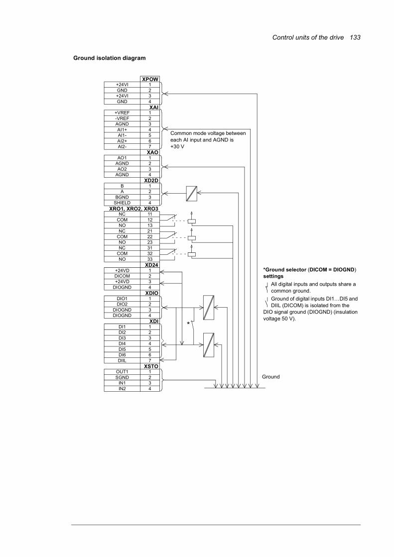
Control units of the drive 133
Ground isolation diagram
XPOW+24VI 1GND 2+24VI 3GND 4
XAI+VREF 1-VREF 2AGND 3AI1+ 4AI1- 5AI2+ 6AI2- 7
XAOAO1 1
AGND 2AO2 3
AGND 4XD2D
B 1A 2
BGND 3SHIELD 4
XRO1, XRO2, XRO3NC 11
COM 12NO 13NC 21
COM 22NO 23NC 31
COM 32NO 33
XD24+24VD 1DICOM 2+24VD 3
DIOGND 4XDIO
DIO1 1DIO2 2
DIOGND 3DIOGND 4
XDIDI1 1DI2 2DI3 3DI4 4DI5 5DI6 6DIIL 7
XSTOOUT1 1SGND 2
IN1 3IN2 4
*
Ground
Common mode voltage between each AI input and AGND is +30 V
*Ground selector (DICOM = DIOGND) settings
All digital inputs and outputs share a common ground.
Ground of digital inputs DI1…DI5 and DIIL (DICOM) is isolated from the
DIO signal ground (DIOGND) (insulation voltage 50 V).

134 Control units of the drive

Installation checklist 135
8
Installation checklist
Contents of this chapterThis chapter contains an installation checklist which you must complete before you start up the drive.
Warnings
WARNING! Obey the instructions in chapter Safety instructions. If you ignore them, injury or death, or damage to the equipment can occur.
ChecklistDo the steps in section Precautions before electrical work (page 21) before you start the work. Go through the checklist together with another person..
Check that …
The ambient operating conditions meet the specifications given in chapter Technical data.
The drive cabinet has been fixed to floor, and if necessary due to vibration etc, also from top to the wall or roof.
The cooling air will flow freely in and out of the drive cabinet,
If the drive will be connected to an IT (ungrounded) or a corner grounded TN network: The optional EMC filter (+E202) of the drive (if any) has been disconnected. See page 90.
If the drive has been stored over one year: The electrolytic DC capacitors in the DC link of the drive have been reformed. See Converter module capacitor reforming instructions (3BFE64059629 [English]).

136 Installation checklist
There is an adequately sized protective earth (ground) conductor between the drive and the switchboard, and the conductor has been connected to appropriate terminal. Proper grounding has also been measured according to the regulations.
There is an adequately sized protective earth (ground) conductor between the motor and the drive, and the conductor has been connected to appropriate terminal. Proper grounding has also been measured according to the regulations.
Only for drives with option +D150: There is an adequately sized protective earth (ground) conductor between the user-installed brake resistor and the drive, and the conductor has been connected to appropriate terminal. Proper grounding has also been measured according to the regulations.
The supply voltage matches the nominal input voltage of the drive. Check the type designation label.
The voltage setting of the auxiliary voltage transformers T21 (standard), T101 (option-specific) and T111 (option-specific) is correct. See page 90.
The input power cable has been connected to the appropriate terminals, the phase order is correct, and the terminals have been tightened. (Pull on the conductors to check.)
The motor cable has been connected to the appropriate terminals, the phase order is right, and the terminals have been tightened. (Pull the conductors to check.)
The motor cable (and brake resistor cable, if present) has been routed away from other cables.
No power factor compensation capacitors have been connected to the motor cable.
If a drive bypass connection will be used: The direct-on-line contactor of the motor and the drive output contactor are either mechanically or electrically interlocked, ie, cannot be closed simultaneously.
The external brake resistor (if present) has been connected to the appropriate terminals, and the terminals have been tightened. (Pull on the conductors to check.)
The brake resistor cable has been routed away from other cables.
The control cables have been connected to the appropriate terminals, and the terminals have been tightened. (Pull the conductors to check.)
There are no tools, foreign objects or dust from drilling inside the drive.
All shrouds and cover of the motor connection box are in place. Cabinet doors have been closed.
The motor and the driven equipment are ready for start.
Check that …
Start-up 137
9
Start-up
Contents of this chapterThis chapter contains the start-up procedure of the drive.
Start-up procedureThe tasks which are needed in certain cases only are marked with underlining, and option codes are given in brackets. Default device designations (if any) are given in brackets after the name, for example “main switch-disconnector [Q1]”. The same device designations are typically also used in the circuit diagrams.
These instructions cannot and do not cover all possible start-up tasks of a customized drive. Always refer to the delivery-specific circuit diagrams when proceeding with the start-up.
WARNING! Only qualified electricians are allowed to do the work described in this chapter.
Note: For certain options (such as functional safety options +Q950, +Q951, +Q952, +Q957, +Q963, +Q964, +Q978, +Q979), additional start-up instructions are given in their separate manuals. See the listing of manuals inside the front cover.
138 Start-up
Action
Safety
WARNING! Obey the safety instructions during the start-up procedure. See chapter Safety instructions on page 17.
Checks/Settings with no voltage connected
Ensure that the disconnector of the supply transformer is locked to the off (0) position, ie. no voltage is, and cannot be connected to the drive inadvertently.
Check that the main switch-disconnector [Q1.1] is switched off, or main breaker [Q1] racked out.
Check that the grounding switch [Q9.1] (option +F259) is switched on.
Check the mechanical and electrical installation of the drive. See Installation checklist (page 135).
Check the settings of breakers/switches in the auxiliary circuits. See the circuit diagrams delivered with the drive.
Check the tap settings of transformers T21, T101 (if present) and T111 (if present). See Checking the settings of transformers T21, T101 and T111 (page 90).
Disconnect any unfinished or uninspected auxiliary voltage (115/230 V AC) cables that lead from the terminal blocks to the outside of the equipment.
Check that both channels of the Safe torque off circuit connected to the STO inputs of both the supply control unit [A51] and the inverter control unit [A41] are closed. Refer to the wiring diagrams delivered with the drive.
If the Safe torque off functionality is used, check that the STO OUT output on the inverter control unit [A41] is chained to the STO inputs of all inverter modules.
If the Safe torque off functionality is not used, check that the STO input on all inverter modules is correctly wired to +24 V and ground.
Drives with ground fault monitoring for IT (ungrounded) systems (option +Q954): Adjust the settings of the ground fault monitor to suit the installation. See the circuit diagrams of the delivery and IRDH275B Ground Fault Monitor Operating Manual by Bender (code: TGH1386en).
Drives with Pt100 relays (option +(n)L506):
• Check the connections against the circuit diagrams of the delivery.
• Set the alarm and trip levels of the Pt100 relays.
Set the alarm and trip levels of the Pt100 relay as low as possible based on the operating temperature and test results of the machine. The trip level can be set, for example, 10 °C higher than what the temperature of the machine is at maximal load in the maximum environmental temperature.
We recommend to set the operating temperatures of the relay, typically for example, as follows:
• 120…140 °C when only tripping is in use
• alarm 120…140 °C and trip 130…150 °C when both alarm and tripping are used.
Powering up the auxiliary circuit of the drive
Make sure that it is safe to connect voltage. Ensure that
• nobody is working on the drive or circuits that have been wired from outside into the drive cabinet
• the cover of the motor terminal box is in place.
Drives with a voltmeter (option +G334): Make sure that the circuit breaker of the measuring circuit [F5.1] is closed.
Close the circuit breakers and/or fuse disconnectors supplying the auxiliary voltage circuits.
Close the cabinet doors.
Close the main breaker of the supply transformer.
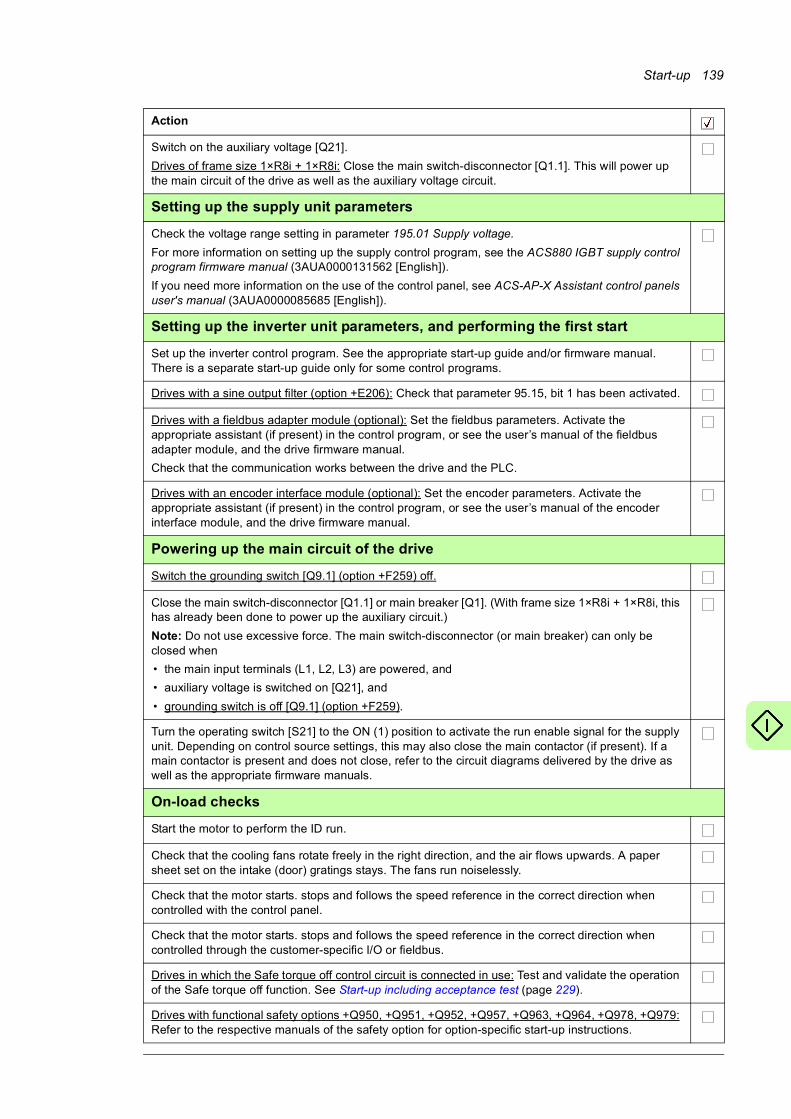
Start-up 139
Switch on the auxiliary voltage [Q21].
Drives of frame size 1×R8i + 1×R8i: Close the main switch-disconnector [Q1.1]. This will power up the main circuit of the drive as well as the auxiliary voltage circuit.
Setting up the supply unit parameters
Check the voltage range setting in parameter 195.01 Supply voltage.
For more information on setting up the supply control program, see the ACS880 IGBT supply control program firmware manual (3AUA0000131562 [English]).
If you need more information on the use of the control panel, see ACS-AP-X Assistant control panels user's manual (3AUA0000085685 [English]).
Setting up the inverter unit parameters, and performing the first start
Set up the inverter control program. See the appropriate start-up guide and/or firmware manual. There is a separate start-up guide only for some control programs.
Drives with a sine output filter (option +E206): Check that parameter 95.15, bit 1 has been activated.
Drives with a fieldbus adapter module (optional): Set the fieldbus parameters. Activate the appropriate assistant (if present) in the control program, or see the user’s manual of the fieldbus adapter module, and the drive firmware manual.
Check that the communication works between the drive and the PLC.
Drives with an encoder interface module (optional): Set the encoder parameters. Activate the appropriate assistant (if present) in the control program, or see the user’s manual of the encoder interface module, and the drive firmware manual.
Powering up the main circuit of the drive
Switch the grounding switch [Q9.1] (option +F259) off.
Close the main switch-disconnector [Q1.1] or main breaker [Q1]. (With frame size 1×R8i + 1×R8i, this has already been done to power up the auxiliary circuit.)
Note: Do not use excessive force. The main switch-disconnector (or main breaker) can only be closed when
• the main input terminals (L1, L2, L3) are powered, and
• auxiliary voltage is switched on [Q21], and
• grounding switch is off [Q9.1] (option +F259).
Turn the operating switch [S21] to the ON (1) position to activate the run enable signal for the supply unit. Depending on control source settings, this may also close the main contactor (if present). If a main contactor is present and does not close, refer to the circuit diagrams delivered by the drive as well as the appropriate firmware manuals.
On-load checks
Start the motor to perform the ID run.
Check that the cooling fans rotate freely in the right direction, and the air flows upwards. A paper sheet set on the intake (door) gratings stays. The fans run noiselessly.
Check that the motor starts. stops and follows the speed reference in the correct direction when controlled with the control panel.
Check that the motor starts. stops and follows the speed reference in the correct direction when controlled through the customer-specific I/O or fieldbus.
Drives in which the Safe torque off control circuit is connected in use: Test and validate the operation of the Safe torque off function. See Start-up including acceptance test (page 229).
Drives with functional safety options +Q950, +Q951, +Q952, +Q957, +Q963, +Q964, +Q978, +Q979: Refer to the respective manuals of the safety option for option-specific start-up instructions.
Action

140 Start-up
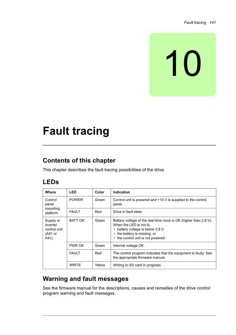
Fault tracing 141
10
Fault tracing
Contents of this chapterThis chapter describes the fault tracing possibilities of the drive.
LEDs
Warning and fault messagesSee the firmware manual for the descriptions, causes and remedies of the drive control program warning and fault messages.
Where LED Color Indication
Control panel mounting platform
POWER Green Control unit is powered and +15 V is supplied to the control panel.
FAULT Red Drive in fault state.
Supply or inverter control unit (A51 or A41)
BATT OK Green Battery voltage of the real-time clock is OK (higher than 2.8 V). When the LED is not lit,• battery voltage is below 2.8 V,• the battery is missing, or• the control unit is not powered.
PWR OK Green Internal voltage OK
FAULT Red The control program indicates that the equipment is faulty. See the appropriate firmware manual.
WRITE Yellow Writing to SD card in progress.

142 Fault tracing
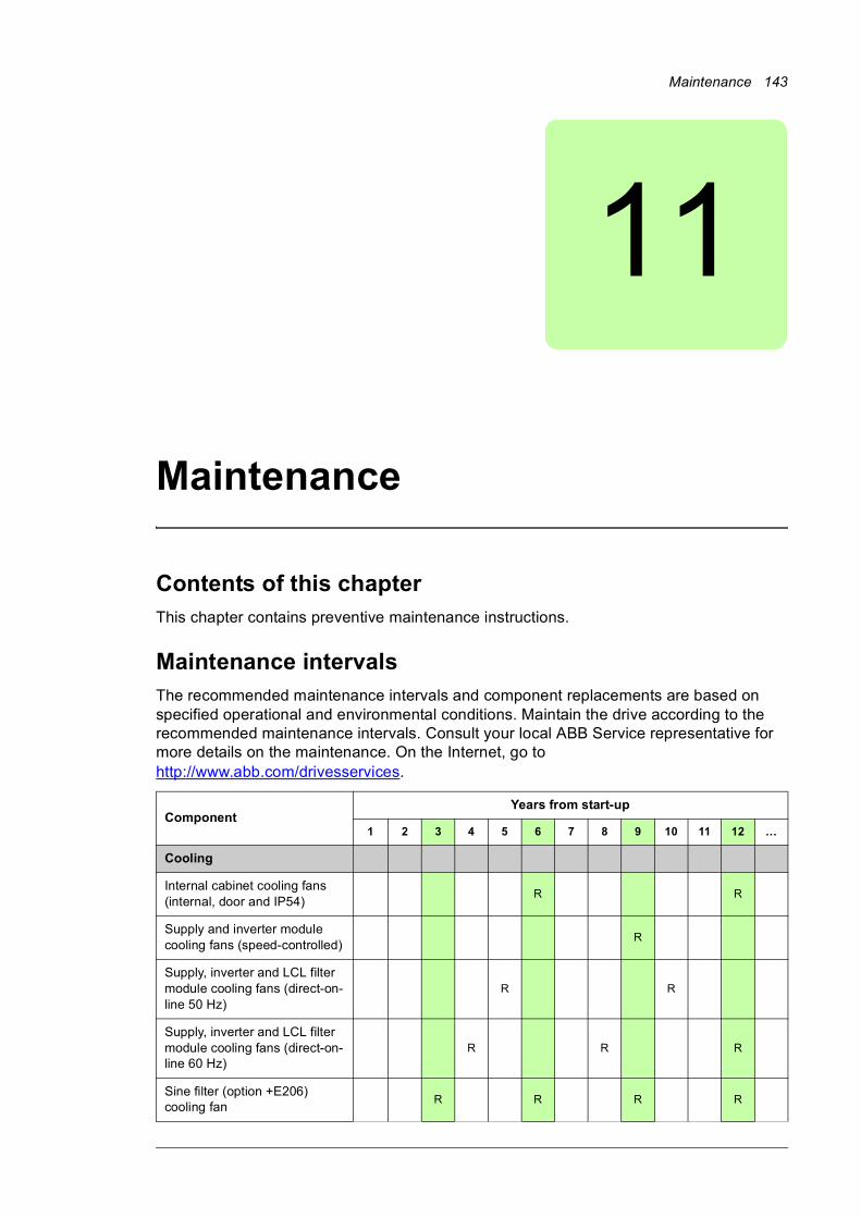
Maintenance 143
11
Maintenance
Contents of this chapterThis chapter contains preventive maintenance instructions.
Maintenance intervalsThe recommended maintenance intervals and component replacements are based on specified operational and environmental conditions. Maintain the drive according to the recommended maintenance intervals. Consult your local ABB Service representative for more details on the maintenance. On the Internet, go to http://www.abb.com/drivesservices.
ComponentYears from start-up
1 2 3 4 5 6 7 8 9 10 11 12 …
Cooling
Internal cabinet cooling fans (internal, door and IP54)
R R
Supply and inverter module cooling fans (speed-controlled)
R
Supply, inverter and LCL filter module cooling fans (direct-on-line 50 Hz)
R R
Supply, inverter and LCL filter module cooling fans (direct-on-line 60 Hz)
R R R
Sine filter (option +E206) cooling fan
R R R R
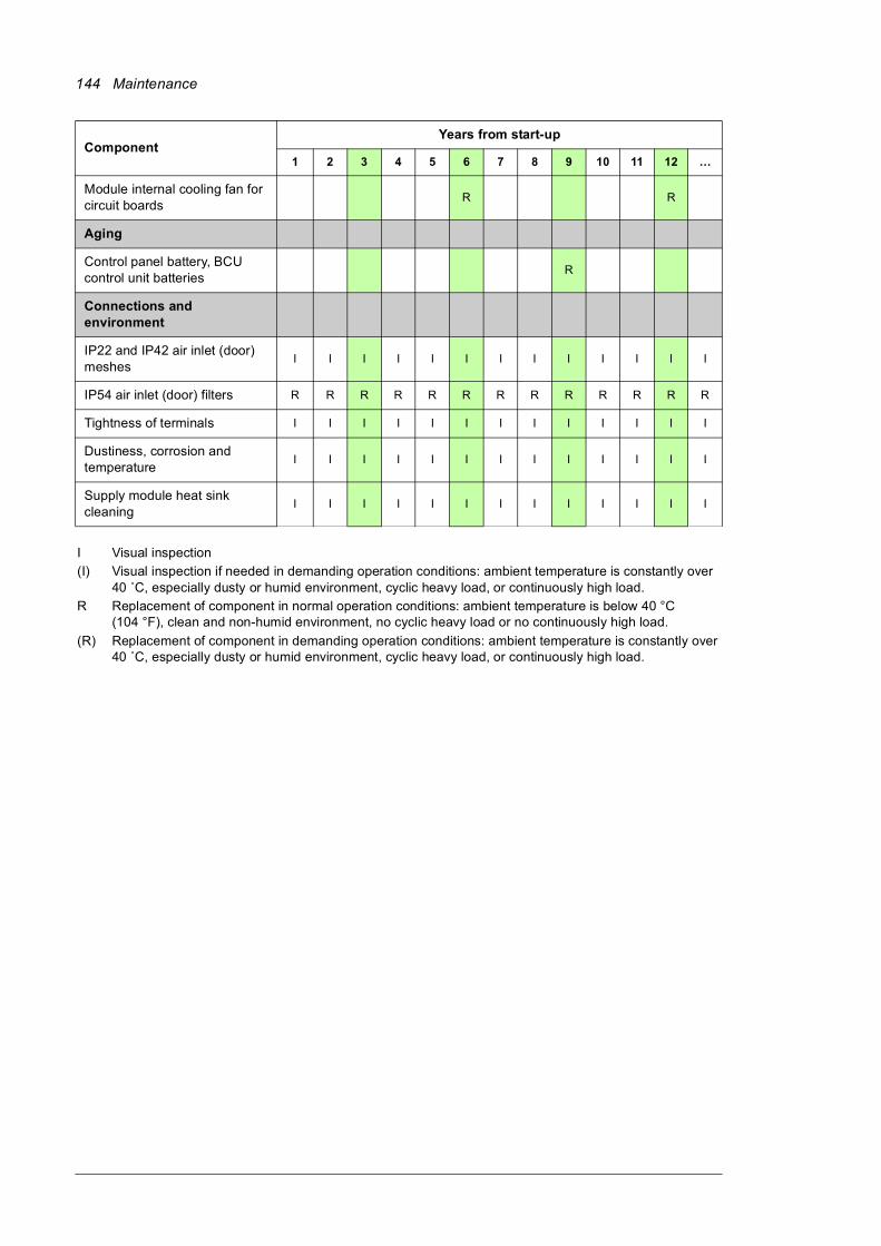
144 Maintenance
Module internal cooling fan for circuit boards
R R
Aging
Control panel battery, BCU control unit batteries
R
Connections and environment
IP22 and IP42 air inlet (door) meshes
I I I I I I I I I I I I I
IP54 air inlet (door) filters R R R R R R R R R R R R R
Tightness of terminals I I I I I I I I I I I I I
Dustiness, corrosion and temperature
I I I I I I I I I I I I I
Supply module heat sink cleaning
I I I I I I I I I I I I I
I Visual inspection
(I) Visual inspection if needed in demanding operation conditions: ambient temperature is constantly over 40 ˚C, especially dusty or humid environment, cyclic heavy load, or continuously high load.
R Replacement of component in normal operation conditions: ambient temperature is below 40 °C (104 °F), clean and non-humid environment, no cyclic heavy load or no continuously high load.
(R) Replacement of component in demanding operation conditions: ambient temperature is constantly over 40 ˚C, especially dusty or humid environment, cyclic heavy load, or continuously high load.
ComponentYears from start-up
1 2 3 4 5 6 7 8 9 10 11 12 …

Maintenance 145
Cabinet
Cleaning the interior of the cabinet
WARNING! Obey the instructions in chapter Safety instructions. If you ignore them, injury or death, or damage to the equipment can occur.
WARNING! Use a vacuum cleaner with an antistatic hose and nozzle, and wear a grounding wristband. Otherwise an electrostatic charge might build up and damage the circuit boards.
1. Stop the drive and do the steps in section Precautions before electrical work (page 21) before you start the work.
2. Open the cabinet doors.
3. Clean the interior of the cabinet. Use a vacuum cleaner and a soft brush.
4. Clean the air inlets of the fans and air outlets of the module (top).
5. Clean the air inlet gratings on the doors (see section Cleaning the door air inlets (IP22 and IP42) on page 145).
6. Close the doors.
Cleaning the door air inlets (IP22 and IP42)
1. Remove the fasteners at the top of the grating.
2. Lift the grating and pull it away from the door.
3. Clean the stainless steel mesh and grating. If necessary, remove the mesh by turning the clips gently.
4. Install the mesh and grating in reverse order.
1
2
3 5
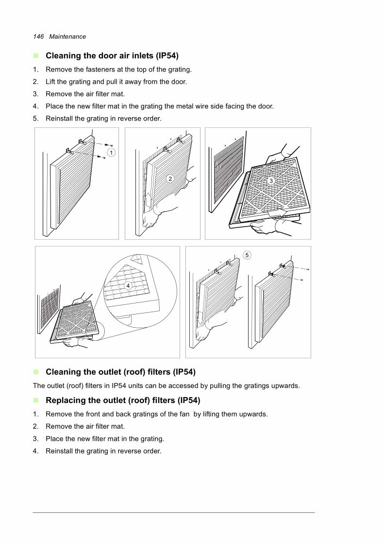
146 Maintenance
Cleaning the door air inlets (IP54)
1. Remove the fasteners at the top of the grating.
2. Lift the grating and pull it away from the door.
3. Remove the air filter mat.
4. Place the new filter mat in the grating the metal wire side facing the door.
5. Reinstall the grating in reverse order.
Cleaning the outlet (roof) filters (IP54)
The outlet (roof) filters in IP54 units can be accessed by pulling the gratings upwards.
Replacing the outlet (roof) filters (IP54)
1. Remove the front and back gratings of the fan by lifting them upwards.
2. Remove the air filter mat.
3. Place the new filter mat in the grating.
4. Reinstall the grating in reverse order.
1
2
3
3
4
5
Maintenance 147
HeatsinkThe drive module heatsink fins pick up dust from the cooling air. The drive runs into overtemperature warnings and faults if the heatsink is not clean. When necessary, clean the heatsink as follows.
WARNING! Obey the instructions in chapter Safety instructions. If you ignore them, injury or death, or damage to the equipment can occur.
WARNING! Use a vacuum cleaner with antistatic hose and nozzle. Using a normal vacuum cleaner creates static discharges which can damage circuit boards.
1. Stop the drive and do the steps in section Precautions before electrical work (page 21) before you start the work.
2. Remove the drive module from the cabinet.
3. Remove the module cooling fan(s). See section Fans below.
4. Blow dry clean compressed air (not humid) from bottom to top and simultaneously use a vacuum cleaner at the air outlet to trap the dust. Note: If there is a risk of dust entering adjoining equipment, perform the cleaning in another room
5. Refit the cooling fan.

148 Maintenance
Power connections and quick connectors
Retightening the power connections
WARNING! Obey the instructions in chapter Safety instructions. If you ignore them, injury or death, or damage to the equipment can occur.
1. Stop the drive (if running) and do the steps in section Precautions before electrical work (page 21) before you start the work.
2. Check the tightness of the cable connections. Use the tightening torques given in chapter Technical data.
Maintenance 149
FansThe lifespan of the cooling fans of the drive depends on the running time, ambient temperature and dust concentration. See the firmware manual for the actual signal which indicates the running time of the cooling fan. Reset the running time signal after a fan replacement.
Replacement fans are available from ABB. Do not use other than ABB specified spare parts.
Replacing the cooling fan in the auxiliary control cubicle
WARNING! Obey the instructions in chapter Safety instructions. If you ignore them, injury or death, or damage to the equipment can occur.
1. Stop the drive and do the steps in section Precautions before electrical work (page 21) before you start the work.
2. Remove the shrouding from in front of the fan.
3. Unplug the power supply cable of the fan.
4. Remove the fastening screws of the fan.
5. Install the new fan in reverse order.
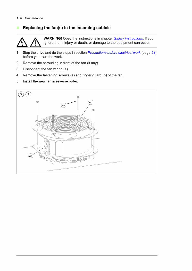
150 Maintenance
Replacing the fan(s) in the incoming cubicle
WARNING! Obey the instructions in chapter Safety instructions. If you ignore them, injury or death, or damage to the equipment can occur.
1. Stop the drive and do the steps in section Precautions before electrical work (page 21) before you start the work.
2. Remove the shrouding in front of the fan (if any).
3. Disconnect the fan wiring (a)
4. Remove the fastening screws (a) and finger guard (b) of the fan.
5. Install the new fan in reverse order.
4a
3 4
3a
4b
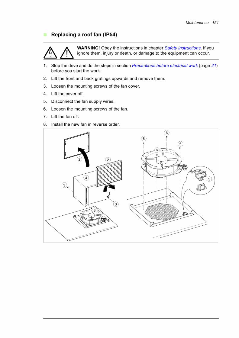
Maintenance 151
Replacing a roof fan (IP54)
WARNING! Obey the instructions in chapter Safety instructions. If you ignore them, injury or death, or damage to the equipment can occur.
1. Stop the drive and do the steps in section Precautions before electrical work (page 21) before you start the work.
2. Lift the front and back gratings upwards and remove them.
3. Loosen the mounting screws of the fan cover.
4. Lift the cover off.
5. Disconnect the fan supply wires.
6. Loosen the mounting screws of the fan.
7. Lift the fan off.
8. Install the new fan in reverse order.
2
3
4
2
3
3
5
6
6
6
6
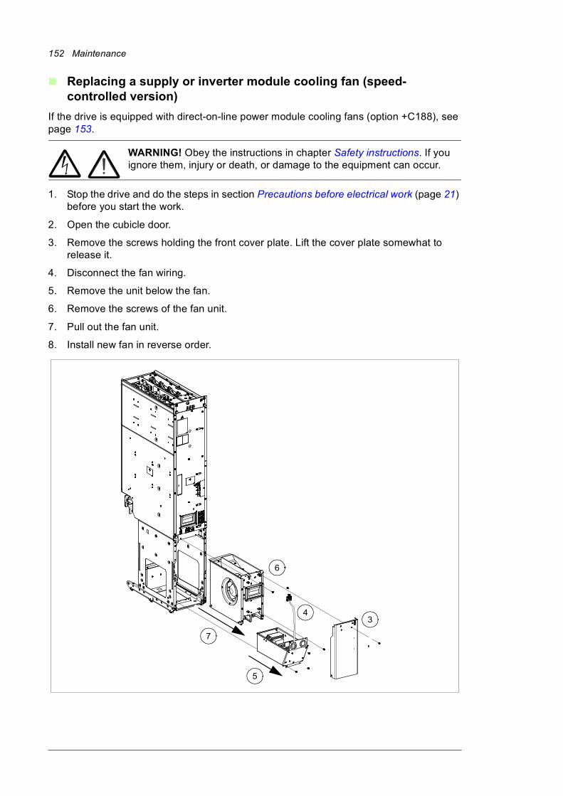
152 Maintenance
Replacing a supply or inverter module cooling fan (speed-controlled version)
If the drive is equipped with direct-on-line power module cooling fans (option +C188), see page 153.
WARNING! Obey the instructions in chapter Safety instructions. If you ignore them, injury or death, or damage to the equipment can occur.
1. Stop the drive and do the steps in section Precautions before electrical work (page 21) before you start the work.
2. Open the cubicle door.
3. Remove the screws holding the front cover plate. Lift the cover plate somewhat to release it.
4. Disconnect the fan wiring.
5. Remove the unit below the fan.
6. Remove the screws of the fan unit.
7. Pull out the fan unit.
8. Install new fan in reverse order.
7
34
5
6
Maintenance 153
Replacing a supply or inverter module cooling fan, direct-on-line version (option +C188)
WARNING! Obey the instructions in chapter Safety instructions. If you ignore them, injury or death, or damage to the equipment can occur.
1. Stop the drive (if running) and do the steps in section Precautions before electrical work (page 21) before you start the work.
2. Open the door.
3. Remove the shroud in front of the fan.
4. Remove the cover panel.
5. Remove the bracket.
6. Unplug the wiring of the fan assembly.
7. Undo the screws of the fan assembly.
8. Pull out the fan assembly.
9. Unplug fan wire from the fan assembly.
10. Undo the screws of the fan.
11. Install a new fan in reverse order.

154 Maintenance
4
5
6
7
8
6
10
10
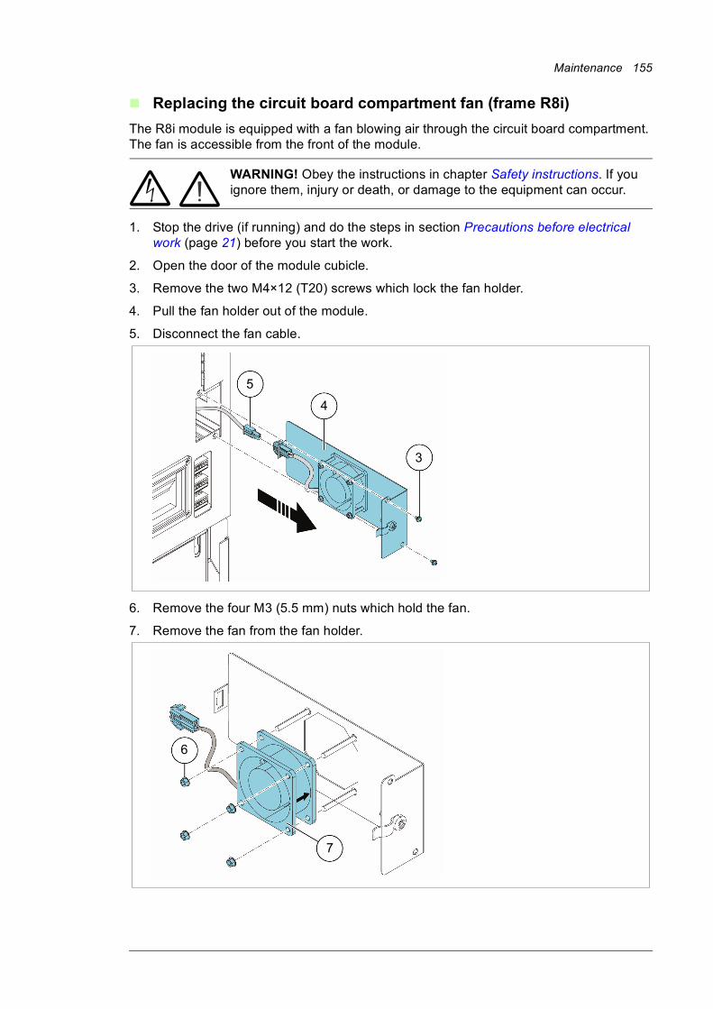
Maintenance 155
Replacing the circuit board compartment fan (frame R8i)
The R8i module is equipped with a fan blowing air through the circuit board compartment. The fan is accessible from the front of the module.
WARNING! Obey the instructions in chapter Safety instructions. If you ignore them, injury or death, or damage to the equipment can occur.
1. Stop the drive (if running) and do the steps in section Precautions before electrical work (page 21) before you start the work.
2. Open the door of the module cubicle.
3. Remove the two M4×12 (T20) screws which lock the fan holder.
4. Pull the fan holder out of the module.
5. Disconnect the fan cable.
6. Remove the four M3 (5.5 mm) nuts which hold the fan.
7. Remove the fan from the fan holder.
3
4
5
6
7
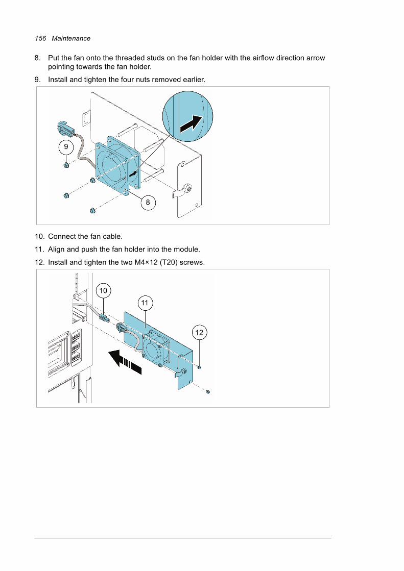
156 Maintenance
8. Put the fan onto the threaded studs on the fan holder with the airflow direction arrow pointing towards the fan holder.
9. Install and tighten the four nuts removed earlier.
10. Connect the fan cable.
11. Align and push the fan holder into the module.
12. Install and tighten the two M4×12 (T20) screws.
9
8
10
11
12
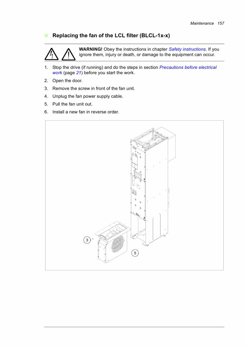
Maintenance 157
Replacing the fan of the LCL filter (BLCL-1x-x)
WARNING! Obey the instructions in chapter Safety instructions. If you ignore them, injury or death, or damage to the equipment can occur.
1. Stop the drive (if running) and do the steps in section Precautions before electrical work (page 21) before you start the work.
2. Open the door.
3. Remove the screw in front of the fan unit.
4. Unplug the fan power supply cable.
5. Pull the fan unit out.
6. Install a new fan in reverse order.
3
5
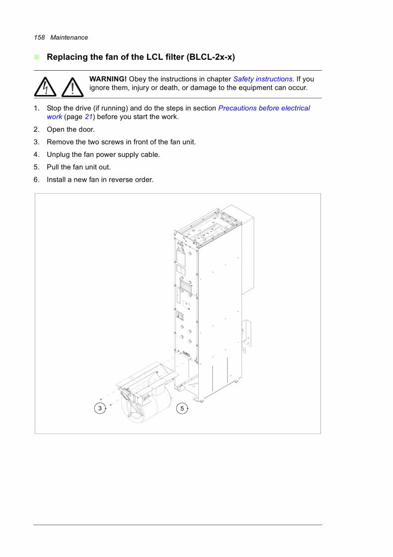
158 Maintenance
Replacing the fan of the LCL filter (BLCL-2x-x)
WARNING! Obey the instructions in chapter Safety instructions. If you ignore them, injury or death, or damage to the equipment can occur.
1. Stop the drive (if running) and do the steps in section Precautions before electrical work (page 21) before you start the work.
2. Open the door.
3. Remove the two screws in front of the fan unit.
4. Unplug the fan power supply cable.
5. Pull the fan unit out.
6. Install a new fan in reverse order.
3 5
Maintenance 159
Supply and inverter modules
Cleaning
The module heatsink fins pick up dust from the cooling air. The module runs into overtemperature warnings and faults if the heatsink is not clean. In a “normal” environment (neither especially dusty nor clean), the heatsink should be checked annually, in a dusty environment more often.
WARNING! Obey the instructions in chapter Safety instructions. If you ignore them, injury or death, or damage to the equipment can occur.
1. Stop the drive (if running) and do the steps in section Precautions before electrical work (page 21) before you start the work.
2. Remove the cooling fan of the supply module as described under Fans elsewhere in this chapter.
3. Blow clean, dry and oilfree compressed air through the module from bottom to top, simultaneously using a vacuum cleaner at the air outlet to trap the dust. Note: Prevent the dust from entering adjoining equipment.
4. Refit the cooling fan.
Replacing a supply or inverter module
WARNING! Make sure the replacement module has exactly the same type code as the old module.
Follow the module extraction and insertion procedures under Connecting the motor cables (units without common motor terminal cubicle) (page 102).
160 Maintenance
LCL filter
Replacing the LCL filter
WARNING! Ignoring the following instructions can cause physical injury, or damage to the equipment:
• Use extreme caution when maneuvering modules that run on wheels. The modules are heavy and have a high center of gravity. They topple over easily if handled carelessly.
• When removing a module on wheels, pull the module carefully out of the cubicle along the ramp. While pulling on the handle, keep a constant pressure with one foot on the base of the module to prevent the module from falling on its back.
• When reinserting the module, keep your fingers away from the edge of the module front plate to avoid pinching them between the module and the cubicle. Also, keep a constant pressure with one foot on the base of the module to prevent the module from falling on its back.
• Do not tilt the module. Do not leave the module unattended on a sloping floor.
• Do not use the module installation ramp with plinth heights which exceed the maximum height marked on the ramp. (The maximum plinth height is 50 mm [1.97 in] when the telescopic ramp is fully retracted and 150 mm [5.91 in] when the ramp is fully extended.)
WARNING! Obey the instructions in chapter Safety instructions. If you ignore them, injury or death, or damage to the equipment can occur.
1. Stop the drive (if running) and do the steps in section Precautions before electrical work (page 21) before you start the work.
2. Open the cubicle door.
3. Undo the four screws of the shroud in the upper part of the cubicle. Remove the shroud.
4. Unplug the signal connector cable on top of the module.
5. Remove the screws in the busbars on top of the LCL filter module. Be careful not to drop the screws inside the module!
6. Remove the fan of the LCL filter module. Unplug the signal connector cable and remove the screws in front of the fan.
7. Remove the fastening screws in the busbar behind the module.
8. Remove the two screws that fasten the bottom of the module to the base of the cabinet.
9. Install the module pull-put ramp: lift the module pull-out ramp against the cabinet base so that the hooks of the base go into the ramp’s holes.
10. Remove the two fastening screws that fasten the top of the module to the cabinet frame.

Maintenance 161
11. Pull the module carefully out of the cabinet along the ramp. While pulling on the handle, keep a constant pressure with one foot on the base of the module to prevent the module from falling on its back.
12. Replace the module: install the module in reverse order. Mind you fingers. Keep a constant pressure with one foot on the base of the module to prevent the module from falling on its back. Note: Be careful not to break the fastening screws: tighten the fastening screws of the module to 22 N·m (16.2 lbf.ft) and fastening bolts of the DC output busbars to 70 N·m (51.6 lbf.ft).• Plug the module signal wire set to the module signal connector.
• Fasten the shrouds.
13. Remove the module pull-out ramp and close the cabinet doors.
162 Maintenance
5
6
3
4
7
Maintenance 163
6
8
7
11
10
9

164 Maintenance
CapacitorsThe DC circuit of the power modules of the drive contain several electrolytic capacitors. Their lifespan depends on the operating time of the drive, loading and ambient temperature. Capacitor life can be prolonged by lowering the ambient temperature.
Capacitor failure is usually followed by damage to the unit and an input cable fuse failure, or a fault trip. Contact ABB if capacitor failure is suspected. Replacements are available from ABB. Do not use other than ABB-specified spare parts.
Reforming the capacitors
The capacitors must be reformed if the drive has been stored for a year or more. See page 53 for information on finding out the manufacturing date. For information on reforming the capacitors, see Converter module capacitor reforming instructions (3BFE64059629 [English]).

Maintenance 165
Fuses
Replacing the AC fuses in the incoming cubicle
Units without a main breaker have AC fuses in the incoming cubicle (or, in the case of frame 1×R8i + 1×R8i, in the combined supply and inverter module cubicle).
WARNING! Obey the instructions in chapter Safety instructions. If you ignore them, injury or death, or damage to the equipment can occur.
1. Do the steps in section Precautions before electrical work (page 21) before you start the work.
2. Open the cubicle door.
3. Remove the shrouding from in front of the fuses.
4. Slacken the nuts of the headless screws of the fuses so that you can slide out the fuse blocks. Make note of the order of the washers on the screws.
5. Remove the screws, nuts and washers from the old fuses and attach them to the new fuses. Make sure to keep the washers in the original order.
6. Insert the new fuses into their slots in the cubicle. Pre-tighten the nuts first by hand or by applying a torque of no more than 5 N·m (3.7 lbf•ft).
7. Tighten the nuts to torque as follows:• Cooper-Bussmann fuses: 50 N•m (37 lbf•ft)• Mersen (Ferraz Shawmut) fuses: 46 N•m (34 lbf•ft)• Other: Refer to the fuse manufacturer’s instructions.
8. Reinstall the shroud and close the door.
Replacing the AC fuses in the LCL filter module or supply module cubicle (frame 3×R8i + 3×R8i and up)
Frames 3×R8i + 3×R8i and up have AC fuses located above each LCL filter module. To replace, use the procedure Replacing the DC fuses in the supply module cubicle (frame 2×R8i + 2×R8i and up) below.
166 Maintenance
Replacing the DC fuses in the supply module cubicle (frame 2×R8i + 2×R8i and up)
There are DC fuses at the output of each supply module (labeled 4b in the drawing below). Note that there are also DC fuses at the input of each inverter module; see page 168.
This procedure can also be used to replace the AC fuses located above the LCL filter modules (4a).
WARNING! Obey the instructions in chapter Safety instructions. If you ignore them, injury or death, or damage to the equipment can occur.
1. Do the steps in section Precautions before electrical work (page 21) before you start the work.
2. Open the door of the supply module cubicle.
3. Remove the shrouding from in front of the fuses.
4. Slacken the nuts of the headless screws of the fuses so that you can slide out the fuse blocks. Make note of the order of the washers on the screws.
5. Remove the screws, nuts and washers from the old fuses and attach them to the new fuses. Make sure to keep the washers in the original order.
6. Insert the new fuses into their slots in the cubicle. Pre-tighten the nuts first by hand or by applying a torque of no more than 5 N·m (3.7 lbf•ft).
7. Tighten the nuts to torque as follows:• Cooper-Bussmann fuses: 50 N•m (37 lbf•ft)• Mersen (Ferraz-Shawmut): 46 N•m (34 lbf•ft)• Other: Refer to the fuse manufacturer’s instructions.
8. Reinstall the shroud and close the door.
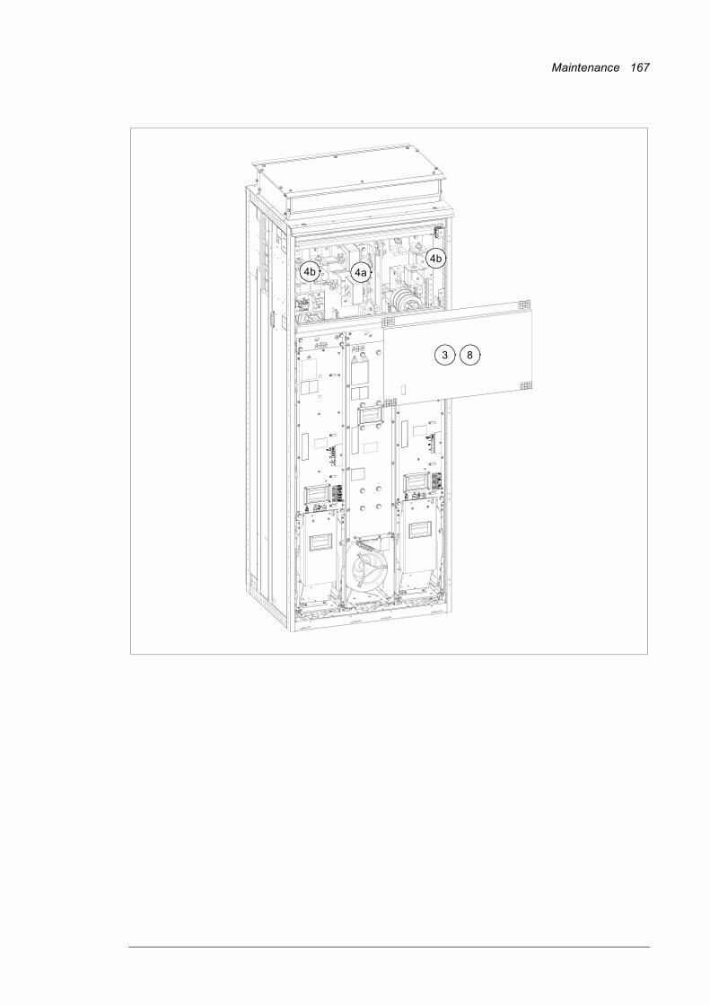
Maintenance 167
3
4b 4a4b
8
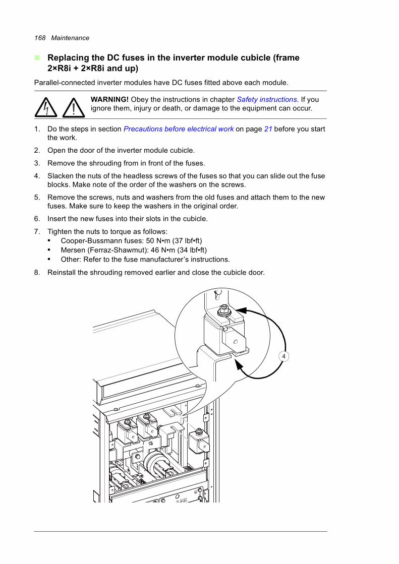
168 Maintenance
Replacing the DC fuses in the inverter module cubicle (frame 2×R8i + 2×R8i and up)
Parallel-connected inverter modules have DC fuses fitted above each module.
WARNING! Obey the instructions in chapter Safety instructions. If you ignore them, injury or death, or damage to the equipment can occur.
1. Do the steps in section Precautions before electrical work on page 21 before you start the work.
2. Open the door of the inverter module cubicle.
3. Remove the shrouding from in front of the fuses.
4. Slacken the nuts of the headless screws of the fuses so that you can slide out the fuse blocks. Make note of the order of the washers on the screws.
5. Remove the screws, nuts and washers from the old fuses and attach them to the new fuses. Make sure to keep the washers in the original order.
6. Insert the new fuses into their slots in the cubicle.
7. Tighten the nuts to torque as follows:• Cooper-Bussmann fuses: 50 N•m (37 lbf•ft)• Mersen (Ferraz-Shawmut): 46 N•m (34 lbf•ft)• Other: Refer to the fuse manufacturer’s instructions.
8. Reinstall the shrouding removed earlier and close the cubicle door.
4

Maintenance 169
Control panel
Replacing the battery
1. Turn the lid on the back of the panel counter-clockwise until the lid opens.
2. Replace the battery with a new CR2032 battery.
3. Put the lid back and tighten it by turning it clockwise.
4. Dispose of the old battery according to local disposal rules or applicable laws.
Cleaning
See ACS-AP-x assistant control panels user’s manual [3AUA0000085685 (English)].
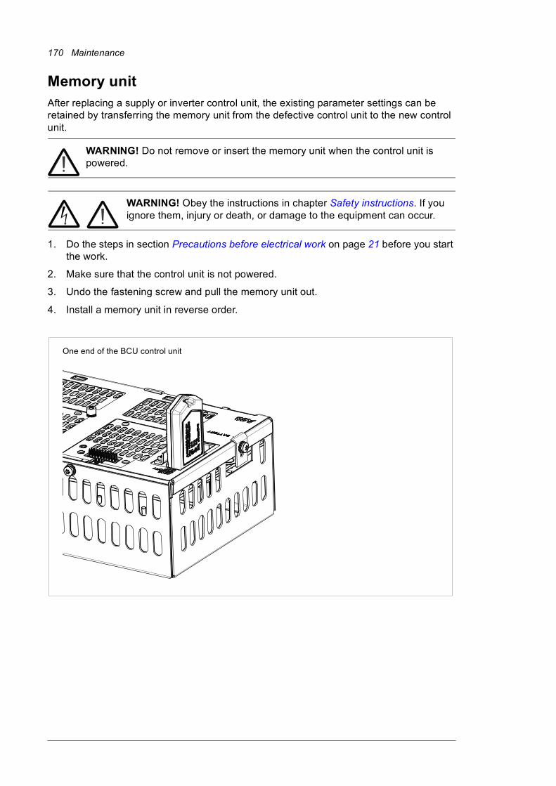
170 Maintenance
Memory unitAfter replacing a supply or inverter control unit, the existing parameter settings can be retained by transferring the memory unit from the defective control unit to the new control unit.
WARNING! Do not remove or insert the memory unit when the control unit is powered.
WARNING! Obey the instructions in chapter Safety instructions. If you ignore them, injury or death, or damage to the equipment can occur.
1. Do the steps in section Precautions before electrical work on page 21 before you start the work.
2. Make sure that the control unit is not powered.
3. Undo the fastening screw and pull the memory unit out.
4. Install a memory unit in reverse order.
One end of the BCU control unit
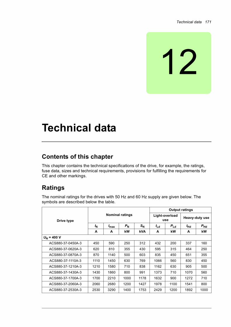
Technical data 171
12
Technical data
Contents of this chapterThis chapter contains the technical specifications of the drive, for example, the ratings, fuse data, sizes and technical requirements, provisions for fulfilling the requirements for CE and other markings.
RatingsThe nominal ratings for the drives with 50 Hz and 60 Hz supply are given below. The symbols are described below the table.
Drive type
Nominal ratings
Output ratings
Light-overload use
Heavy-duty use
IN Imax PN SN ILd PLd IHd PHd
A A kW kVA A kW A kW
UN = 400 V
ACS880-37-0450A-3 450 590 250 312 432 200 337 160
ACS880-37-0620A-3 620 810 355 430 595 315 464 250
ACS880-37-0870A-3 870 1140 500 603 835 450 651 355
ACS880-37-1110A-3 1110 1450 630 769 1066 560 830 450
ACS880-37-1210A-3 1210 1580 710 838 1162 630 905 500
ACS880-37-1430A-3 1430 1860 800 991 1373 710 1070 560
ACS880-37-1700A-3 1700 2210 1000 1178 1632 900 1272 710
ACS880-37-2060A-3 2060 2680 1200 1427 1978 1100 1541 800
ACS880-37-2530A-3 2530 3290 1400 1753 2429 1200 1892 1000

172 Technical data
Definitions
UN = 500 V
ACS880-37-0420A-5 420 550 250 364 403 250 314 200
ACS880-37-0570A-5 570 750 400 494 547 355 426 250
ACS880-37-0780A-5 780 1020 560 675.5 749 500 583 400
ACS880-37-1010A-5 1010 1320 710 875 970 630 755 500
ACS880-37-1110A-5 1110 1450 800 961 1066 710 830 560
ACS880-37-1530A-5 1530 1990 1100 1325 1469 1000 1144 800
ACS880-37-1980A-5 1980 2580 1400 1715 1901 1300 1481 1000
ACS880-37-2270A-5 2270 2960 1600 1966 2179 1500 1698 1200
UN = 690 V
ACS880-37-0320A-7 320 480 315 382 307 250 239 200
ACS880-37-0390A-7 390 590 355 466 374 355 292 250
ACS880-37-0580A-7 580 870 560 693 557 500 434 400
ACS880-37-0660A-7 660 990 630 789 634 560 494 450
ACS880-37-0770A-7 770 1160 710 920 739 710 576 560
ACS880-37-0950A-7 950 1430 900 1135 912 800 711 710
ACS880-37-1130A-7 1130 1700 1100 1350 1085 1000 845 800
ACS880-37-1450A-7 1450 2180 1400 1733 1392 1300 1085 1000
ACS880-37-1680A-7 1680 2520 1600 2008 1613 1500 1257 1200
ACS880-37-1950A-7 1950 2930 1900 2330 1872 1800 1459 1400
ACS880-37-2230A-7 2230 3350 2200 2665 2141 2000 1668 1600
ACS880-37-2770A-7 2770 4160 2700 3310 2659 2600 2072 2000
ACS880-37-3310A-7 3310 4970 3200 3956 3178 3000 2476 2400
UN Supply voltage range. See also section Electrical power network specification (page 180).
IN Nominal output current (available continuously with no over-loading)
Imax Maximum output current. Available for 10 seconds at start, then as long as allowed by drive temperature.
PN Typical motor power in no-overload use
SN Apparent power in no-overload use
ILd Continuous rms output current allowing 10% overload for 1 minute every 5 minutes.
PLd Typical motor power in light-overload use
IHd Continuous rms output current allowing 50% overload for 1 minute every 5 minutes.
PHd Typical motor power in heavy-duty use
Note 1: The ratings apply at an ambient temperature of 40 °C (104 °F).
Note 2: To achieve the rated motor power given in the table, the rated current of the drive must be higher than or equal to the rated motor current.
The DriveSize dimensioning tool available from ABB is recommended for selecting the drive, motor and gear combination.
Drive type
Nominal ratings
Output ratings
Light-overload use
Heavy-duty use
IN Imax PN SN ILd PLd IHd PHd
A A kW kVA A kW A kW
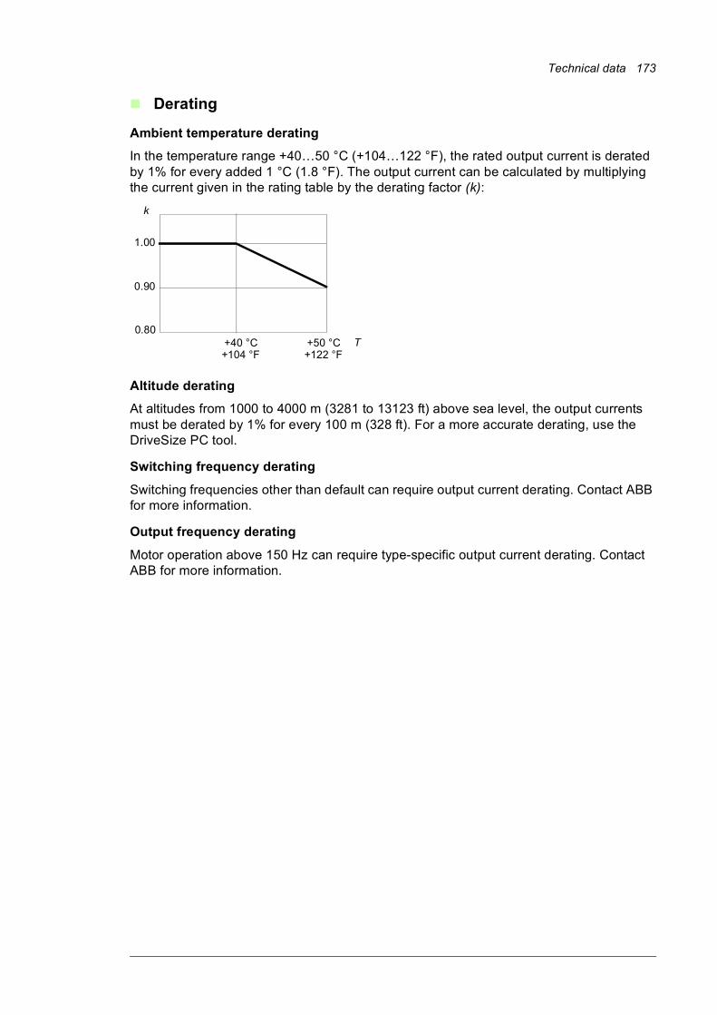
Technical data 173
Derating
Ambient temperature derating
In the temperature range +40…50 °C (+104…122 °F), the rated output current is derated by 1% for every added 1 °C (1.8 °F). The output current can be calculated by multiplying the current given in the rating table by the derating factor (k):
Altitude derating
At altitudes from 1000 to 4000 m (3281 to 13123 ft) above sea level, the output currents must be derated by 1% for every 100 m (328 ft). For a more accurate derating, use the DriveSize PC tool.
Switching frequency derating
Switching frequencies other than default can require output current derating. Contact ABB for more information.
Output frequency derating
Motor operation above 150 Hz can require type-specific output current derating. Contact ABB for more information.
T
1.00
0.90
+40 °C+104 °F
+50 °C+122 °F
k
0.80
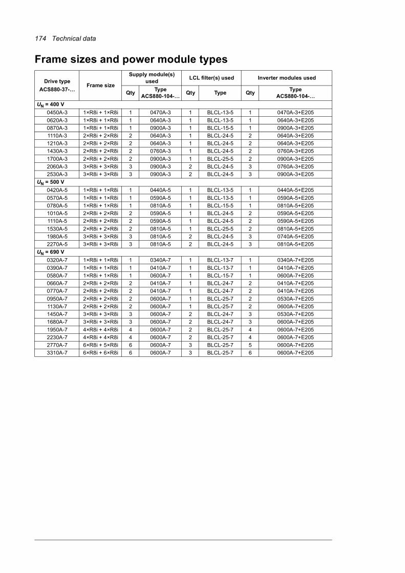
174 Technical data
Frame sizes and power module types
Drive type
ACS880-37-…Frame size
Supply module(s) used
LCL filter(s) used Inverter modules used
QtyType
ACS880-104-…Qty Type Qty
TypeACS880-104-…
UN = 400 V
0450A-3 1×R8i + 1×R8i 1 0470A-3 1 BLCL-13-5 1 0470A-3+E205
0620A-3 1×R8i + 1×R8i 1 0640A-3 1 BLCL-13-5 1 0640A-3+E205
0870A-3 1×R8i + 1×R8i 1 0900A-3 1 BLCL-15-5 1 0900A-3+E205
1110A-3 2×R8i + 2×R8i 2 0640A-3 1 BLCL-24-5 2 0640A-3+E205
1210A-3 2×R8i + 2×R8i 2 0640A-3 1 BLCL-24-5 2 0640A-3+E205
1430A-3 2×R8i + 2×R8i 2 0760A-3 1 BLCL-24-5 2 0760A-3+E205
1700A-3 2×R8i + 2×R8i 2 0900A-3 1 BLCL-25-5 2 0900A-3+E205
2060A-3 3×R8i + 3×R8i 3 0900A-3 2 BLCL-24-5 3 0760A-3+E205
2530A-3 3×R8i + 3×R8i 3 0900A-3 2 BLCL-24-5 3 0900A-3+E205
UN = 500 V
0420A-5 1×R8i + 1×R8i 1 0440A-5 1 BLCL-13-5 1 0440A-5+E205
0570A-5 1×R8i + 1×R8i 1 0590A-5 1 BLCL-13-5 1 0590A-5+E205
0780A-5 1×R8i + 1×R8i 1 0810A-5 1 BLCL-15-5 1 0810A-5+E205
1010A-5 2×R8i + 2×R8i 2 0590A-5 1 BLCL-24-5 2 0590A-5+E205
1110A-5 2×R8i + 2×R8i 2 0590A-5 1 BLCL-24-5 2 0590A-5+E205
1530A-5 2×R8i + 2×R8i 2 0810A-5 1 BLCL-25-5 2 0810A-5+E205
1980A-5 3×R8i + 3×R8i 3 0810A-5 2 BLCL-24-5 3 0740A-5+E205
2270A-5 3×R8i + 3×R8i 3 0810A-5 2 BLCL-24-5 3 0810A-5+E205
UN = 690 V
0320A-7 1×R8i + 1×R8i 1 0340A-7 1 BLCL-13-7 1 0340A-7+E205
0390A-7 1×R8i + 1×R8i 1 0410A-7 1 BLCL-13-7 1 0410A-7+E205
0580A-7 1×R8i + 1×R8i 1 0600A-7 1 BLCL-15-7 1 0600A-7+E205
0660A-7 2×R8i + 2×R8i 2 0410A-7 1 BLCL-24-7 2 0410A-7+E205
0770A-7 2×R8i + 2×R8i 2 0410A-7 1 BLCL-24-7 2 0410A-7+E205
0950A-7 2×R8i + 2×R8i 2 0600A-7 1 BLCL-25-7 2 0530A-7+E205
1130A-7 2×R8i + 2×R8i 2 0600A-7 1 BLCL-25-7 2 0600A-7+E205
1450A-7 3×R8i + 3×R8i 3 0600A-7 2 BLCL-24-7 3 0530A-7+E205
1680A-7 3×R8i + 3×R8i 3 0600A-7 2 BLCL-24-7 3 0600A-7+E205
1950A-7 4×R8i + 4×R8i 4 0600A-7 2 BLCL-25-7 4 0600A-7+E205
2230A-7 4×R8i + 4×R8i 4 0600A-7 2 BLCL-25-7 4 0600A-7+E205
2770A-7 6×R8i + 5×R8i 6 0600A-7 3 BLCL-25-7 5 0600A-7+E205
3310A-7 6×R8i + 6×R8i 6 0600A-7 3 BLCL-25-7 6 0600A-7+E205
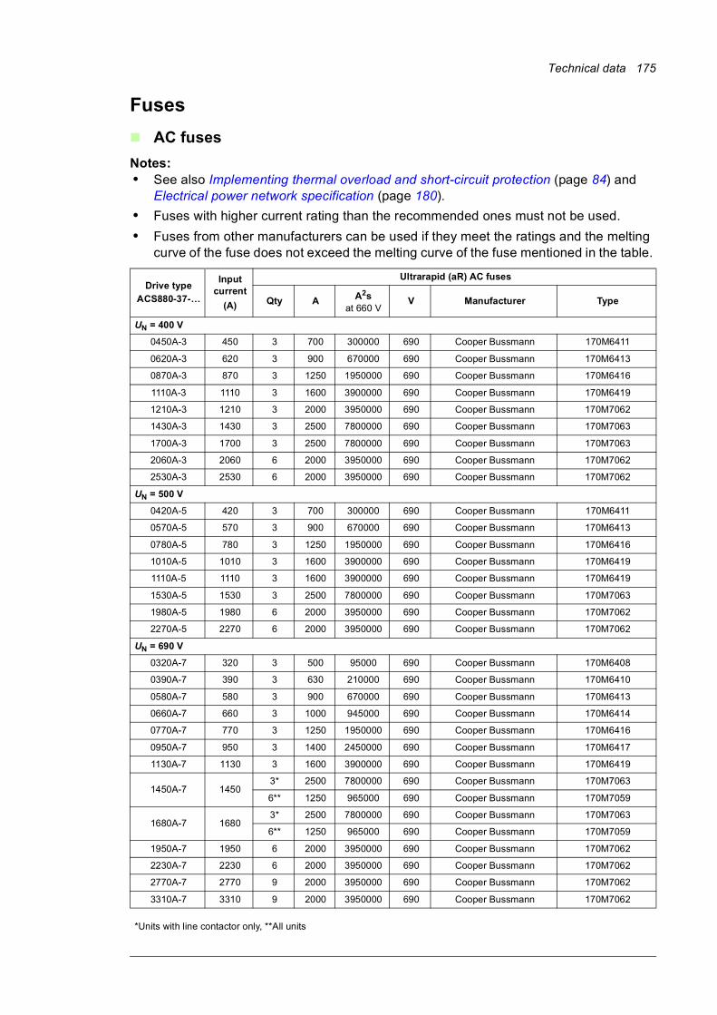
Technical data 175
Fuses
AC fuses
Notes:• See also Implementing thermal overload and short-circuit protection (page 84) and
Electrical power network specification (page 180).
• Fuses with higher current rating than the recommended ones must not be used.
• Fuses from other manufacturers can be used if they meet the ratings and the melting curve of the fuse does not exceed the melting curve of the fuse mentioned in the table.
Drive typeACS880-37-…
Input current
(A)
Ultrarapid (aR) AC fuses
Qty A A2sat 660 V
V Manufacturer Type
UN = 400 V
0450A-3 450 3 700 300000 690 Cooper Bussmann 170M6411
0620A-3 620 3 900 670000 690 Cooper Bussmann 170M6413
0870A-3 870 3 1250 1950000 690 Cooper Bussmann 170M6416
1110A-3 1110 3 1600 3900000 690 Cooper Bussmann 170M6419
1210A-3 1210 3 2000 3950000 690 Cooper Bussmann 170M7062
1430A-3 1430 3 2500 7800000 690 Cooper Bussmann 170M7063
1700A-3 1700 3 2500 7800000 690 Cooper Bussmann 170M7063
2060A-3 2060 6 2000 3950000 690 Cooper Bussmann 170M7062
2530A-3 2530 6 2000 3950000 690 Cooper Bussmann 170M7062
UN = 500 V
0420A-5 420 3 700 300000 690 Cooper Bussmann 170M6411
0570A-5 570 3 900 670000 690 Cooper Bussmann 170M6413
0780A-5 780 3 1250 1950000 690 Cooper Bussmann 170M6416
1010A-5 1010 3 1600 3900000 690 Cooper Bussmann 170M6419
1110A-5 1110 3 1600 3900000 690 Cooper Bussmann 170M6419
1530A-5 1530 3 2500 7800000 690 Cooper Bussmann 170M7063
1980A-5 1980 6 2000 3950000 690 Cooper Bussmann 170M7062
2270A-5 2270 6 2000 3950000 690 Cooper Bussmann 170M7062
UN = 690 V
0320A-7 320 3 500 95000 690 Cooper Bussmann 170M6408
0390A-7 390 3 630 210000 690 Cooper Bussmann 170M6410
0580A-7 580 3 900 670000 690 Cooper Bussmann 170M6413
0660A-7 660 3 1000 945000 690 Cooper Bussmann 170M6414
0770A-7 770 3 1250 1950000 690 Cooper Bussmann 170M6416
0950A-7 950 3 1400 2450000 690 Cooper Bussmann 170M6417
1130A-7 1130 3 1600 3900000 690 Cooper Bussmann 170M6419
1450A-7 14503* 2500 7800000 690 Cooper Bussmann 170M7063
6** 1250 965000 690 Cooper Bussmann 170M7059
1680A-7 16803* 2500 7800000 690 Cooper Bussmann 170M7063
6** 1250 965000 690 Cooper Bussmann 170M7059
1950A-7 1950 6 2000 3950000 690 Cooper Bussmann 170M7062
2230A-7 2230 6 2000 3950000 690 Cooper Bussmann 170M7062
2770A-7 2770 9 2000 3950000 690 Cooper Bussmann 170M7062
3310A-7 3310 9 2000 3950000 690 Cooper Bussmann 170M7062
*Units with line contactor only, **All units
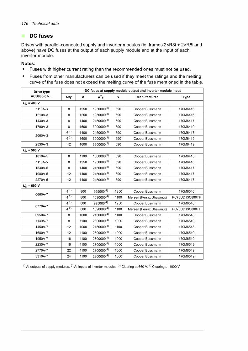
176 Technical data
DC fuses
Drives with parallel-connected supply and inverter modules (ie. frames 2×R8i + 2×R8i and above) have DC fuses at the output of each supply module and at the input of each inverter module.
Notes:• Fuses with higher current rating than the recommended ones must not be used.
• Fuses from other manufacturers can be used if they meet the ratings and the melting curve of the fuse does not exceed the melting curve of the fuse mentioned in the table.
Drive typeACS880-37-…
DC fuses at supply module output and inverter module input
Qty A A2s V Manufacturer Type
UN = 400 V
1110A-3 8 1250 1950000 3) 690 Cooper Bussmann 170M6416
1210A-3 8 1250 1950000 3) 690 Cooper Bussmann 170M6416
1430A-3 8 1400 2450000 3) 690 Cooper Bussmann 170M6417
1700A-3 8 1600 3900000 3) 690 Cooper Bussmann 170M6419
2060A-36 1) 1400 2450000 3) 690 Cooper Bussmann 170M6417
6 2) 1600 3900000 3) 690 Cooper Bussmann 170M6419
2530A-3 12 1600 3900000 3) 690 Cooper Bussmann 170M6419
UN = 500 V
1010A-5 8 1100 1300000 3) 690 Cooper Bussmann 170M6415
1110A-5 8 1250 1950000 3) 690 Cooper Bussmann 170M6416
1530A-5 8 1400 2450000 3) 690 Cooper Bussmann 170M6417
1980A-5 12 1400 2450000 3) 690 Cooper Bussmann 170M6417
2270A-5 12 1400 2450000 3) 690 Cooper Bussmann 170M6417
UN = 690 V
0660A-74 1) 800 995000 4) 1250 Cooper Bussmann 170M6546
4 2) 800 1090000 4) 1100 Mersen (Ferraz Shawmut) PC73UD13C800TF
0770A-74 1) 800 995000 4) 1250 Cooper Bussmann 170M6546
4 2) 800 1090000 4) 1100 Mersen (Ferraz Shawmut) PC73UD13C800TF
0950A-7 8 1000 2150000 4) 1100 Cooper Bussmann 170M6548
1130A-7 8 1100 2800000 4) 1000 Cooper Bussmann 170M6549
1450A-7 12 1000 2150000 4) 1100 Cooper Bussmann 170M6548
1680A-7 12 1100 2800000 4) 1000 Cooper Bussmann 170M6549
1950A-7 16 1100 2800000 4) 1000 Cooper Bussmann 170M6549
2230A-7 16 1100 2800000 4) 1000 Cooper Bussmann 170M6549
2770A-7 22 1100 2800000 4) 1000 Cooper Bussmann 170M6549
3310A-7 24 1100 2800000 4) 1000 Cooper Bussmann 170M6549
1) At outputs of supply modules, 2) At inputs of inverter modules, 3) Clearing at 660 V, 4) Clearing at 1000 V
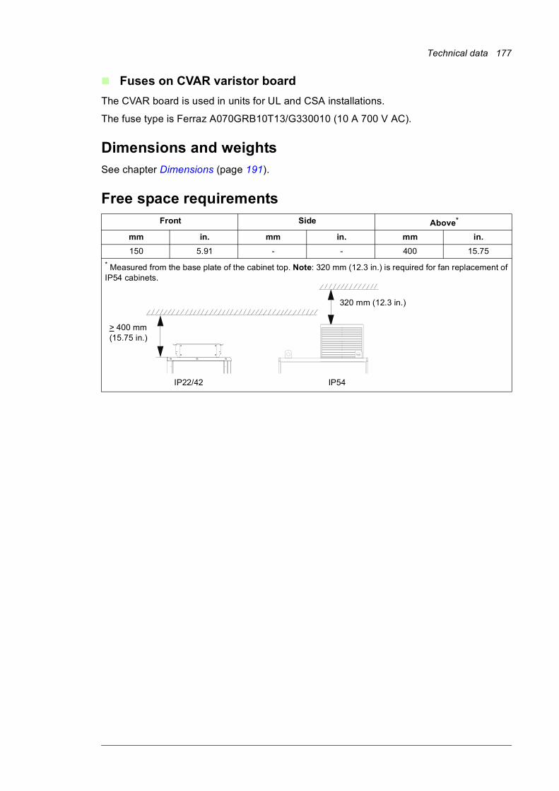
Technical data 177
Fuses on CVAR varistor board
The CVAR board is used in units for UL and CSA installations.
The fuse type is Ferraz A070GRB10T13/G330010 (10 A 700 V AC).
Dimensions and weightsSee chapter Dimensions (page 191).
Free space requirementsFront Side Above*
mm in. mm in. mm in.
150 5.91 - - 400 15.75
* Measured from the base plate of the cabinet top. Note: 320 mm (12.3 in.) is required for fan replacement of IP54 cabinets.
320 mm (12.3 in.)
> 400 mm (15.75 in.)
IP22/42 IP54

178 Technical data
Cooling data, noise
Drive typeAir flow Heat dissipation Noise
m3/h ft3/min kW dB(A)
UN = 400 V
ACS880-37-0450A-3 2860 1680 14 75
ACS880-37-0620A-3 2860 1680 18 75
ACS880-37-0870A-3 2860 1680 27 75
ACS880-37-1110A-3 5720 3370 31 77
ACS880-37-1210A-3 5720 3370 34 77
ACS880-37-1430A-3 5720 3370 38 77
ACS880-37-1700A-3 5720 3370 51 77
ACS880-37-2060A-3 8580 5050 61 78
ACS880-37-2530A-3 8580 5050 76 78
UN = 500 V
ACS880-37-0420A-5 2860 1680 13 75
ACS880-37-0570A-5 2860 1680 17 75
ACS880-37-0780A-5 2860 1680 25 75
ACS880-37-1010A-5 5720 3370 31 77
ACS880-37-1110A-5 5720 3370 32 77
ACS880-37-1530A-5 5720 3370 46 77
ACS880-37-1980A-5 8580 5050 59 78
ACS880-37-2270A-5 8580 5050 69 78
UN = 690 V
ACS880-37-0320A-7 2860 1680 16 75
ACS880-37-0390A-7 2860 1680 19 75
ACS880-37-0580A-7 2860 1680 26 75
ACS880-37-0660A-7 5720 3370 30 77
ACS880-37-0770A-7 5720 3370 34 77
ACS880-37-0950A-7 5720 3370 40 77
ACS880-37-1130A-7 5720 3370 48 77
ACS880-37-1450A-7 8580 5050 63 78
ACS880-37-1680A-7 8580 5050 74 78
ACS880-37-1950A-7 11440 6730 84 79
ACS880-37-2230A-7 11440 6730 95 79
ACS880-37-2770A-7 14300 8420 119 79
ACS880-37-3310A-7 17160 10100 142 79
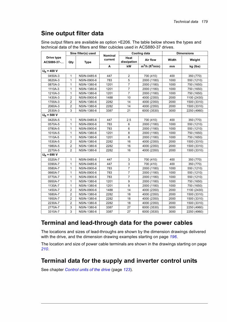
Technical data 179
Sine output filter dataSine output filters are available as option +E206. The table below shows the types and technical data of the filters and filter cubicles used in ACS880-37 drives.
Terminal and lead-through data for the power cablesThe locations and sizes of lead-throughs are shown by the dimension drawings delivered with the drive, and the dimension drawing examples starting on page 196.
The location and size of power cable terminals are shown in the drawings starting on page 210.
Terminal data for the supply and inverter control unitsSee chapter Control units of the drive (page 123).
Drive type
ACS880-37-…
Sine filter(s) usedNominal current
Cooling data Dimensions
Qty TypeHeat
dissipationAir flow Width Weight
A kW m3/h (ft3/min) mm kg (lbs)
UN = 400 V
0450A-3 1 NSIN-0485-6 447 2 700 (410) 400 350 (770)
0620A-3 1 NSIN-0900-6 783 5 2000 (1180) 1000 550 (1210)
0870A-3 1 NSIN-1380-6 1201 7 2000 (1180) 1000 750 (1650)
1110A-3 1 NSIN-1380-6 1201 7 2000 (1180) 1000 750 (1650)
1210A-3 1 NSIN-1380-6 1201 7 2000 (1180) 1000 750 (1650)
1430A-3 2 NSIN-0900-6 1488 10 4000 (2350) 2000 1100 (2430)
1700A-3 2 NSIN-1380-6 2282 14 4000 (2350) 2000 1500 (3310)
2060A-3 2 NSIN-1380-6 2282 14 4000 (2350) 2000 1500 (3310)
2530A-3 3 NSIN-1380-6 3387 21 6000 (3530) 3000 2250 (4960)
UN = 500 V
0420A-5 1 NSIN-0485-6 447 2.5 700 (410) 400 350 (770)
0570A-5 1 NSIN-0900-6 783 6 2000 (1180) 1000 550 (1210)
0780A-5 1 NSIN-0900-6 783 6 2000 (1180) 1000 550 (1210)
1010A-5 1 NSIN-1380-6 1201 8 2000 (1180) 1000 750 (1650)
1110A-5 1 NSIN-1380-6 1201 8 2000 (1180) 1000 750 (1650)
1530A-5 2 NSIN-1380-6 2282 16 4000 (2350) 2000 1500 (3310)
1980A-5 2 NSIN-1380-6 2282 16 4000 (2350) 2000 1500 (3310)
2270A-5 2 NSIN-1380-6 2282 16 4000 (2350) 2000 1500 (3310)
UN = 690 V
0320A-7 1 NSIN-0485-6 447 3 700 (410) 400 350 (770)
0390A-7 1 NSIN-0485-6 447 3 700 (410) 400 350 (770)
0580A-7 1 NSIN-0900-6 783 7 2000 (1180) 1000 550 (1210)
0660A-7 1 NSIN-0900-6 783 7 2000 (1180) 1000 550 (1210)
0770A-7 1 NSIN-0900-6 783 7 2000 (1180) 1000 550 (1210)
0950A-7 1 NSIN-1380-6 1201 9 2000 (1180) 1000 750 (1650)
1130A-7 1 NSIN-1380-6 1201 9 2000 (1180) 1000 750 (1650)
1450A-7 2 NSIN-0900-6 1488 14 4000 (2350) 2000 1100 (2430)
1680A-7 2 NSIN-1380-6 2282 18 4000 (2350) 2000 1500 (3310)
1950A-7 2 NSIN-1380-6 2282 18 4000 (2350) 2000 1500 (3310)
2230A-7 2 NSIN-1380-6 2282 18 4000 (2350) 2000 1500 (3310)
2770A-7 3 NSIN-1380-6 3387 27 6000 (3530) 3000 2250 (4960)
3310A-7 3 NSIN-1380-6 3387 27 6000 (3530) 3000 2250 (4960)
180 Technical data
Electrical power network specificationVoltage (U1) ACS880-37-xxxx-3 (UN = 400 V): 380/400/415 V AC 3-phase ± 10%
ACS880-37-xxxx-5 (UN = 500 V): 380/400/415/440/460/480/500 V AC 3-phase ±
10%
ACS880-37-xxxx-7 (UN = 690 V): 525…690 V AC (525…600 V AC in corner-
grounded TN systems) 3-phase ± 10%
Frequency 50/60 Hz, Variation ± 5% of nominal frequency
Imbalance Max. ± 3% of nominal phase-to-phase voltage
Short-circuit withstand strength (IEC 61439-1)
IEC/EN 61439-1:2009
Frame 1×R8i + 1×R8i:
Maximum allowable prospective shortcircuit current Icc is 65 kA. In this case, the
input cable must be equipped with fuses as follows:
• maximum 1250 A gG*
*) Type gG according to IEC 60269
Maximum allowed operating time is <0.1 s for fuses mentioned above.
Rated peak withstand current Ipk = 105 kA
Rated short-time withstand current Icw = 50 kA/1 s
Frame 2×R8i + 2×R8i and above:
Rated peak withstand current Ipk = 105 kA
Rated short-time withstand current:
Icw = 50 kA/1 s for units without air circuit breaker
Icw = 65 kA/1 s for units with air circuit breaker
Overvoltage category OVCIII
Power factor cosphi1 = 1, cosphi (total) = 0.99
Harmonic distortion Harmonics are below the limits defined in IEEE519.
Rsc THD Voltage [%] THD Current [%]
20 3 2.5*
100 0.8 2.5*
THD = Total Harmonic Distortion (THD). The voltage THD depends on the short-circuit ratio (Rsc). The spectrum of the distortion also contains interharmonics.
Rsc = Isc/INIsc= short-circuit current at point of common coupling (PCC)
IN= IGBT supply unit nominal current
*Other loads may influence the THD value.
Motor connection dataMotor types Asynchronous AC induction motors, permanent magnet synchronous motors,
AC induction servomotors, ABB synchronous reluctance (SynRM) motors
Voltage (U2) 0 to U1, 3-phase symmetrical, Umax at the field weakening point
50
2
2
N
n
I
I In nth harmonic component
IN nominal current
Technical data 181
Frequency 0…±500 Hz (0…±120 Hz with sine output filters [option +E206])
• For higher operational output frequencies, please contact your local ABB representative.
• Operation above 150 Hz may require type-specific derating. For more information, contact your local ABB representative.
Current See section Ratings.
Switching frequency 2 kHz (typical)
Maximum recommended motor cable length
500 m (1640 ft).
Note: With motor cables longer than 150 m (492 ft) the EMC Directive requirements may not be fulfilled.
Control unit connection dataSee chapter Control units of the drive (page 123).
Efficiency97.2 … 98.0% at nominal power level depending on drive type
Protection classesDegrees of protection (IEC/EN 60529)
IP22 (standard), IP42 (option +B054), IP54 (option +B055)
Enclosure types (UL50) UL Type 1 (standard), UL Type 1 Filtered (option +B054), UL Type 12 (option +B055). For indoor use only.
Overvoltage category (IEC 60664-1)
III
Protective class (IEC/EN 61800-5-1)
I
Ambient conditionsEnvironmental limits for the drive system are given below. The drive is to be used in a heated, indoor, controlled environment.
Operationinstalled for stationary use
Storagein the protective package
Transportationin the protective package
Installation site altitude 0 to 4000 m (13123 ft) above sea level.
Output derated above 1000 m (3281 ft). See section Derating.
- -
Air temperature 0 … +40 °C (+32 … +104 °F). No condensation allowed.Output derated in the range +40 … +50 °C (+104 … +122 °F). See section Derating.
-40 to +70 °C(-40 to +158 °F)
-40 to +70 °C(-40 to +158 °F)
Relative humidity Max. 95% Max. 95% Max. 95%
No condensation allowed. Maximum allowed relative humidity is 60% in the presence of corrosive gases.
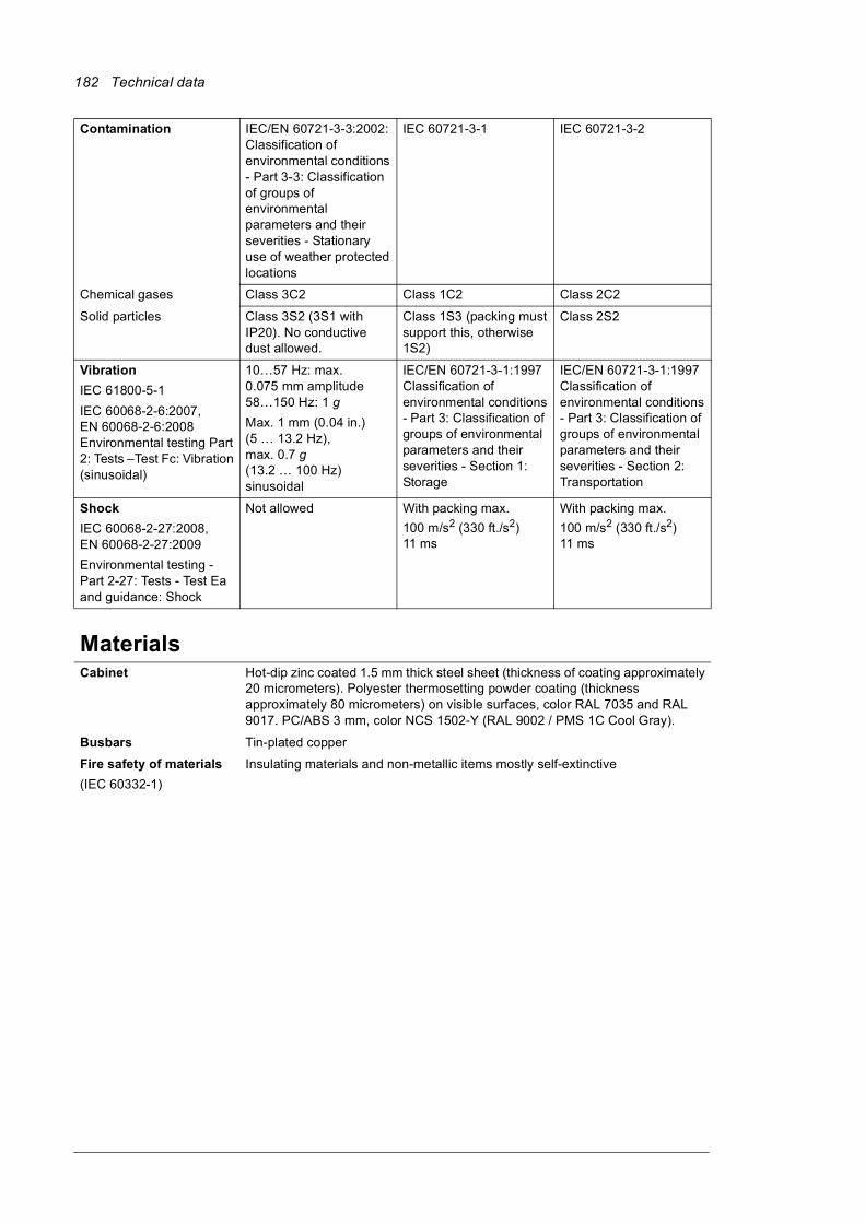
182 Technical data
Contamination IEC/EN 60721-3-3:2002: Classification of environmental conditions - Part 3-3: Classification of groups of environmental parameters and their severities - Stationary use of weather protected locations
IEC 60721-3-1 IEC 60721-3-2
Chemical gases Class 3C2 Class 1C2 Class 2C2
Solid particles Class 3S2 (3S1 with IP20). No conductive dust allowed.
Class 1S3 (packing must support this, otherwise 1S2)
Class 2S2
Vibration
IEC 61800-5-1
IEC 60068-2-6:2007, EN 60068-2-6:2008 Environmental testing Part 2: Tests –Test Fc: Vibration (sinusoidal)
10…57 Hz: max. 0.075 mm amplitude58…150 Hz: 1 g
Max. 1 mm (0.04 in.) (5 … 13.2 Hz),max. 0.7 g (13.2 … 100 Hz) sinusoidal
IEC/EN 60721-3-1:1997 Classification of environmental conditions - Part 3: Classification of groups of environmental parameters and their severities - Section 1: Storage
IEC/EN 60721-3-1:1997 Classification of environmental conditions - Part 3: Classification of groups of environmental parameters and their severities - Section 2: Transportation
Shock
IEC 60068-2-27:2008, EN 60068-2-27:2009
Environmental testing - Part 2-27: Tests - Test Ea and guidance: Shock
Not allowed With packing max.
100 m/s2 (330 ft./s2) 11 ms
With packing max.
100 m/s2 (330 ft./s2) 11 ms
MaterialsCabinet Hot-dip zinc coated 1.5 mm thick steel sheet (thickness of coating approximately
20 micrometers). Polyester thermosetting powder coating (thickness approximately 80 micrometers) on visible surfaces, color RAL 7035 and RAL 9017. PC/ABS 3 mm, color NCS 1502-Y (RAL 9002 / PMS 1C Cool Gray).
Busbars Tin-plated copper
Fire safety of materials
(IEC 60332-1)
Insulating materials and non-metallic items mostly self-extinctive

Technical data 183
Package Standard package:
• timber, polyethylene sheet (thickness 0.2 mm), stretch film (thickness 0.023 mm), PP tape, PET strap, sheet metal (steel)
• for land and air transport when planned storage time is less than 2 months or when storage can be arranged in clean and dry conditions less than 6 months
• can be used when products will not be exposed to corrosive atmosphere during transport or storage
Container package:
• timber, VCI sheet film (PE, thickness 0.15 mm), VCI stretch film (PE, thickness 0.04 mm), VCI emitter bags, PP tape, PET strap, sheet metal (steel)
• for sea transport in containers
• recommended for land and air transport when storage time prior to installation exceeds 6 months or storage is arranged in partially weather-protected conditions
Seaworthy package:
• timber, plywood, VCI sheet film (PE, thickness 0.15 mm), VCI stretch film (PE, thickness 0.04 mm), VCI emitter bags, PP tape, PET strap, sheet metal (steel)
• for sea transport with or without containerization
• for long storage periods in environments where roofed and humidity-controlled storage cannot be arranged
Cabinets are fastened to the pallet with screws and braced from the top end to the package walls to prevents swaying inside the package. Package elements are attached together with screws. For handling the packages, see section Moving and unpacking the drive on page 59.
Disposal The main parts of the drive can be recycled to preserve natural resources and energy. Product parts and materials should be dismantled and separated.
Generally all metals, such as steel, aluminum, copper and its alloys, and precious metals can be recycled as material. Plastics, rubber, cardboard and other packaging material can be used in energy recovery. Printed circuit boards and DC capacitors (C1-1 to C1-x) need selective treatment according to IEC 62635 guidelines. To aid recycling, plastic parts are marked with an approppriate identification code.
Contact your local ABB distributor for further information on environmental aspects and recycling instructions for professional recyclers. End of life treatment must follow international and local regulations.
Applicable standardsThe drive complies with the standards below. The compliance with the European Low Voltage Directive is verified according to standard EN 61800-5-1.
EN 61800-5-1:2007 Adjustable speed electrical power drive systems. Part 5-1: Safety requirements – electrical, thermal and energy
EN 60204-1:2006 +A1 2009
Safety of machinery. Electrical equipment of machines. Part 1: General requirements. Provisions for compliance: The final assembler of the machine is responsible for installing emergency-stop device.
IEC/EN 60529:1991 + A1 2000
Degrees of protection provided by enclosures (IP code)
EN 61800-3:2004 Adjustable speed electrical power drive systems. Part 3: EMC requirements and specific test methods
UL 501:2007 Enclosures for Electrical Equipment, Non-Environmental Considerations
UL 508C:2002 UL Standard for Safety, Power Conversion Equipment, third edition
UL 508A: 2001 UL Standard for Industrial Control Panels, first edition
CSA C22.2 No. 14-10 Industrial control equipment

184 Technical data
CE markingA CE mark is attached to the drive to verify that the drive complies with the provisions of the European Low Voltage and EMC Directives. The CE marking also verifies that the drive, in regard to its safety functions (such as Safe torque off), conforms with the Machinery Directive as a safety component.
Compliance with the European Low Voltage Directive
The compliance with the European Low Voltage Directive has been verified according to standard EN 61800-5-1.
Compliance with the European EMC Directive
The EMC Directive defines the requirements for immunity and emissions of electrical equipment used within the European Union. The EMC product standard (EN 61800-3:2004) covers requirements stated for drives. See section Compliance with EN 61800-3:2004 below.
Compliance with the European Machinery Directive
The drive is an electronic product which is covered by the European Low Voltage Directive. However, the drive includes the Safe torque off function and can be equipped with other safety functions for machinery which, as safety components, are in the scope of the Machinery Directive. These functions of the drive comply with European harmonized standards such as EN 61800-5-2. The related declarations of conformity are shown below.

Technical data 185
Declaration of Conformity
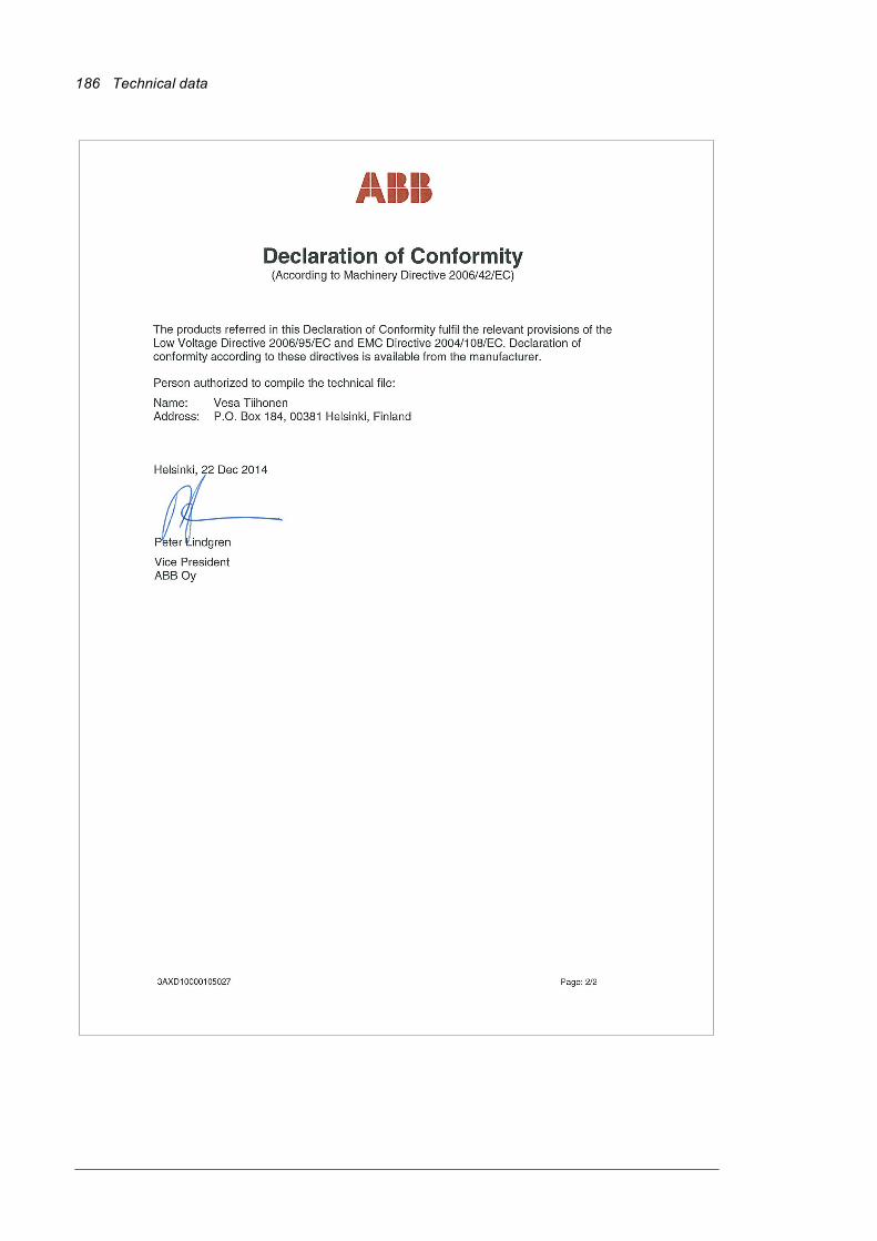
186 Technical data
Technical data 187
Compliance with EN 61800-3:2004
Definitions
EMC stands for Electromagnetic Compatibility. It is the ability of electrical/electronic equipment to operate without problems within an electromagnetic environment. Likewise, the equipment must not disturb or interfere with any other product or system within its locality.
First environment includes establishments connected to a low-voltage network which supplies buildings used for domestic purposes.
Second environment includes establishments connected to a network not supplying domestic premises.
Drive of category C2: drive of rated voltage less than 1000 V and intended to be installed and started up only by a professional when used in the first environment. Note: A professional is a person or organization having necessary skills in installing and/or starting up power drive systems, including their EMC aspects.
Drive of category C3: drive of rated voltage less than 1000 V and intended for use in the second environment and not intended for use in the first environment.
Drive of category C4: drive of rated voltage equal to or above 1000 V, or rated current equal to or above 400 A, or intended for use in complex systems in the second environment.
Category C2
The drive complies with the standard with the following provisions:
1. The drive is equipped with EMC filter (option +E202).
2. The motor and control cables are selected as specified in the hardware manual.
3. The drive is installed according to the instructions given in the hardware manual.
4. Maximum motor cable length is 100 meters (328 ft).
WARNING! The drive may cause radio interference if used in a residential or domestic environment. The user is required to take measures to prevent interference, in addition to the requirements for CE compliance listed above, if necessary.
Note: Do not install a drive equipped with EMC filter +E202 on IT (ungrounded) systems. The supply network becomes connected to ground potential through the EMC filter capacitors which may cause danger or damage the unit.
Category C3
The drive complies with the standard with the following provisions:
1. The motor and control cables are selected as specified in the hardware manual.
2. The drive is installed according to the instructions given in the hardware manual.
3. Maximum motor cable length is 100 meters (328 ft).
WARNING! A drive of category C3 is not intended to be used on a low-voltage public network which supplies domestic premises. Radio frequency interference is expected if the drive is used on such a network.
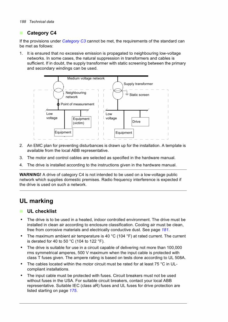
188 Technical data
Category C4
If the provisions under Category C3 cannot be met, the requirements of the standard can be met as follows:
1. It is ensured that no excessive emission is propagated to neighbouring low-voltage networks. In some cases, the natural suppression in transformers and cables is sufficient. If in doubt, the supply transformer with static screening between the primary and secondary windings can be used.
2. An EMC plan for preventing disturbances is drawn up for the installation. A template is available from the local ABB representative.
3. The motor and control cables are selected as specified in the hardware manual.
4. The drive is installed according to the instructions given in the hardware manual.
WARNING! A drive of category C4 is not intended to be used on a low-voltage public network which supplies domestic premises. Radio frequency interference is expected if the drive is used on such a network.
UL marking
UL checklist
• The drive is to be used in a heated, indoor controlled environment. The drive must be installed in clean air according to enclosure classification. Cooling air must be clean, free from corrosive materials and electrically conductive dust. See page 181.
• The maximum ambient air temperature is 40 °C (104 °F) at rated current. The current is derated for 40 to 50 °C (104 to 122 °F).
• The drive is suitable for use in a circuit capable of delivering not more than 100,000 rms symmetrical amperes, 500 V maximum when the input cable is protected with class T fuses given. The ampere rating is based on tests done according to UL 508A.
• The cables located within the motor circuit must be rated for at least 75 °C in UL-compliant installations.
• The input cable must be protected with fuses. Circuit breakers must not be used without fuses in the USA. For suitable circuit breakers, contact your local ABB representative. Suitable IEC (class aR) fuses and UL fuses for drive protection are listed starting on page 175.
Low voltage
Equipment
Low voltage
Equipment
Equipment(victim)
Supply transformer
Medium voltage network
Static screen
Point of measurement
Drive
Neighbouring network
Technical data 189
• For installation in the United States, branch circuit protection must be provided in accordance with the National Electrical Code (NEC) and any applicable local codes. To fulfill this requirement, use the UL classified fuses.
• For installation in Canada, branch circuit protection must be provided in accordance with the Canadian Electrical Code and any applicable provincial codes. To fulfill this requirement, use the UL classified fuses.
• The drive provides overload protection in accordance with the National Electrical Code (NEC).
CSA markingCSA marking is pending for the drive. The approval is valid with rated voltages.
“C-tick” marking
C-tick marking is pending for the drive.
“C-tick” marking is required in Australia and New Zealand. A “C-tick” mark is attached to each drive in order to verify compliance with the relevant standard (IEC 61800-3:2004, Adjustable speed electrical power drive systems – Part 3: EMC product standard including specific test methods), mandated by the Trans-Tasman Electromagnetic Compatibility Scheme.
For fulfilling the requirements of the standard, see section Compliance with EN 61800-3:2004.
EAC (Eurasian Conformity) markingEAC marking is pending for the drive at the time of printing.
Tightening torquesUnless a tightening torque is specified in the text, the following torques can be used.
Electrical connections
Mechanical connections
Size Torque
N·m
Note
M3 0.5 Strength class 4.6...8.8
M4 1 Strength class 4.6...8.8
M5 4 Strength class 8.8
M6 9 Strength class 8.8
M8 22 Strength class 8.8
M10 42 Strength class 8.8
M12 70 Strength class 8.8
M16 120 Strength class 8.8
Size Max. torque
N·m
Note
M5 6 Strength class 8.8
190 Technical data
Insulation supports
Cable lugs
Disclaimers
Generic disclaimer
The manufacturer shall have no obligation with respect to any product which (i) has been improperly repaired or altered; (ii) has been subjected to misuse, negligence or accident; (iii) has been used in a manner contrary to the manufacturer’s instructions; or (iv) has failed as a result of ordinary wear and tear.
Cyber security disclaimer
This product is designed to be connected to and to communicate information and data via a network interface. It is Customer's sole responsibility to provide and continuously ensure a secure connection between the product and Customer network or any other network (as the case may be). Customer shall establish and maintain any appropriate measures (such as but not limited to the installation of firewalls, application of authentication measures, encryption of data, installation of anti-virus programs, etc) to protect the product, the network, its system and the interface against any kind of security breaches, unauthorized access, interference, intrusion, leakage and/or theft of data or information. ABB and its affiliates are not liable for damages and/or losses related to such security breaches, any unauthorized access, interference, intrusion, leakage and/or theft of data or information.
M6 10 Strength class 8.8
M8 24 Strength class 8.8
Size Max. torque
N·m
Note
M6 5 Strength class 8.8
M8 9 Strength class 8.8
M10 18 Strength class 8.8
M12 31 Strength class 8.8
Size Max. torque
N·m
Note
M8 15 Strength class 8.8
M10 32 Strength class 8.8
M12 50 Strength class 8.8
Size Max. torque
N·m
Note
Dimensions 191
13
Dimensions
What this chapter containsThis chapter contains the following dimension data:
• Composition of cabinet line-ups in tabular form for each frame size with options (page 192)
• Dimension drawing examples of selected line-ups (page 196)
• Location and size of input terminals (page 210)
• Location and size of output terminals for drives without common motor terminal cubicle (page 214)
• Location and size of output terminals for drives with common motor terminal cubicle (+H359) (page 218).
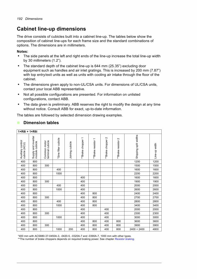
192 Dimensions
Cabinet line-up dimensionsThe drive consists of cubicles built into a cabinet line-up. The tables below show the composition of cabinet line-ups for each frame size and the standard combinations of options. The dimensions are in millimeters.
Notes:• The side panels at the left and right ends of the line-up increase the total line-up width
by 30 millimeters (1.2”).
• The standard depth of the cabinet line-up is 644 mm (25.35”) excluding door equipment such as handles and air inlet gratings. This is increased by 200 mm (7.87”) with top entry/exit units as well as units with cooling air intake through the floor of the cabinet.
• The dimensions given apply to non-UL/CSA units. For dimensions of UL/CSA units, contact your local ABB representative.
• Not all possible configurations are presented. For information on unlisted configurations, contact ABB.
• The data given is preliminary. ABB reserves the right to modify the design at any time without notice. Consult ABB for exact, up-to-date information.
The tables are followed by selected dimension drawing examples.
Dimension tables
1×R8i + 1×R8i
Au
xilia
ry c
ont
rol
cub
icle
(A
CU
)
Su
ppl
y a
nd in
vert
erm
odu
le c
ubi
cle
Co
mm
on
mo
tor
term
inal
cub
icle
*Sin
e fi
lter
cubi
cle
Join
ing
cub
icle
**B
rake
ch
oppe
r 1
**B
rake
res
isto
r 1
**B
rake
ch
oppe
r 2
**B
rake
res
isto
r 2
Sh
ippi
ng s
plit
wid
ths
Lin
e-u
p w
idth
400 800 1200 1200
400 800 300 1500 1500
400 800 400 1600 1600
400 800 1000 2200 2200
400 800 400 1600 1600
400 800 300 400 1900 1900
400 800 400 400 2000 2000
400 800 1000 400 2600 2600
400 800 400 800 2400 2400
400 800 300 400 800 2700 2700
400 800 400 400 800 2800 2800
400 800 1000 400 800 3400 3400
400 800 400 400 2000 2000
400 800 300 400 400 2300 2300
400 800 1000 400 400 3000 3000
400 800 400 800 400 800 3600 3600
400 800 300 400 800 400 800 3900 3900
400 800 1000 200 400 800 400 800 2400 + 2400 4800
*400 mm with ACS880-37-0450A-3, -0420-5, -0320A-7 and -0390A-7, 1000 mm with other types.**The number of brake choppers depends on required braking power. See chapter Resistor braking.
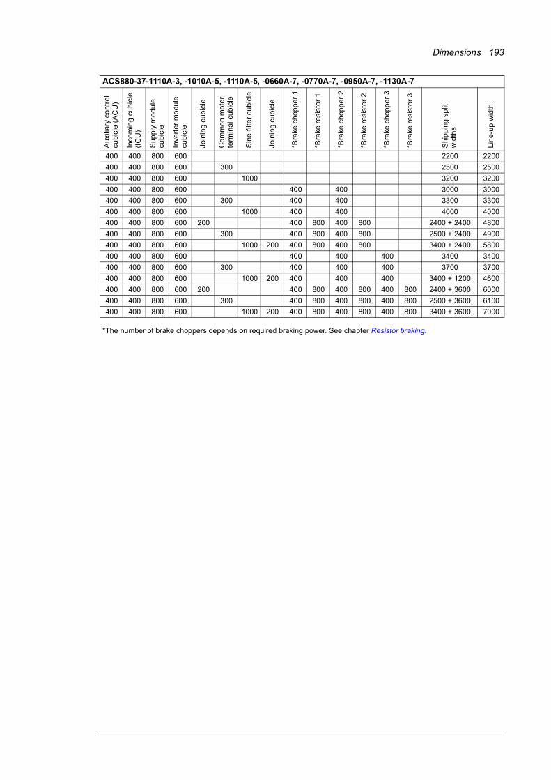
Dimensions 193
ACS880-37-1110A-3, -1010A-5, -1110A-5, -0660A-7, -0770A-7, -0950A-7, -1130A-7
Aux
iliar
y co
ntro
l cu
bicl
e (
AC
U)
Inco
min
g cu
bicl
e (I
CU
)
Sup
ply
mo
dule
cu
bicl
e
Inve
rter
mo
dule
cu
bicl
e
Join
ing
cub
icle
Co
mm
on
mo
tor
term
inal
cub
icle
Sin
e f
ilter
cu
bicl
e
Join
ing
cub
icle
*Bra
ke c
hop
per
1
*Bra
ke r
esis
tor
1
*Bra
ke c
hop
per
2
*Bra
ke r
esis
tor
2
*Bra
ke c
hop
per
3
*Bra
ke r
esis
tor
3
Shi
pp
ing
spl
it w
idth
s
Lin
e-u
p w
idth
400 400 800 600 2200 2200
400 400 800 600 300 2500 2500
400 400 800 600 1000 3200 3200
400 400 800 600 400 400 3000 3000
400 400 800 600 300 400 400 3300 3300
400 400 800 600 1000 400 400 4000 4000
400 400 800 600 200 400 800 400 800 2400 + 2400 4800
400 400 800 600 300 400 800 400 800 2500 + 2400 4900
400 400 800 600 1000 200 400 800 400 800 3400 + 2400 5800
400 400 800 600 400 400 400 3400 3400
400 400 800 600 300 400 400 400 3700 3700
400 400 800 600 1000 200 400 400 400 3400 + 1200 4600
400 400 800 600 200 400 800 400 800 400 800 2400 + 3600 6000
400 400 800 600 300 400 800 400 800 400 800 2500 + 3600 6100
400 400 800 600 1000 200 400 800 400 800 400 800 3400 + 3600 7000
*The number of brake choppers depends on required braking power. See chapter Resistor braking.
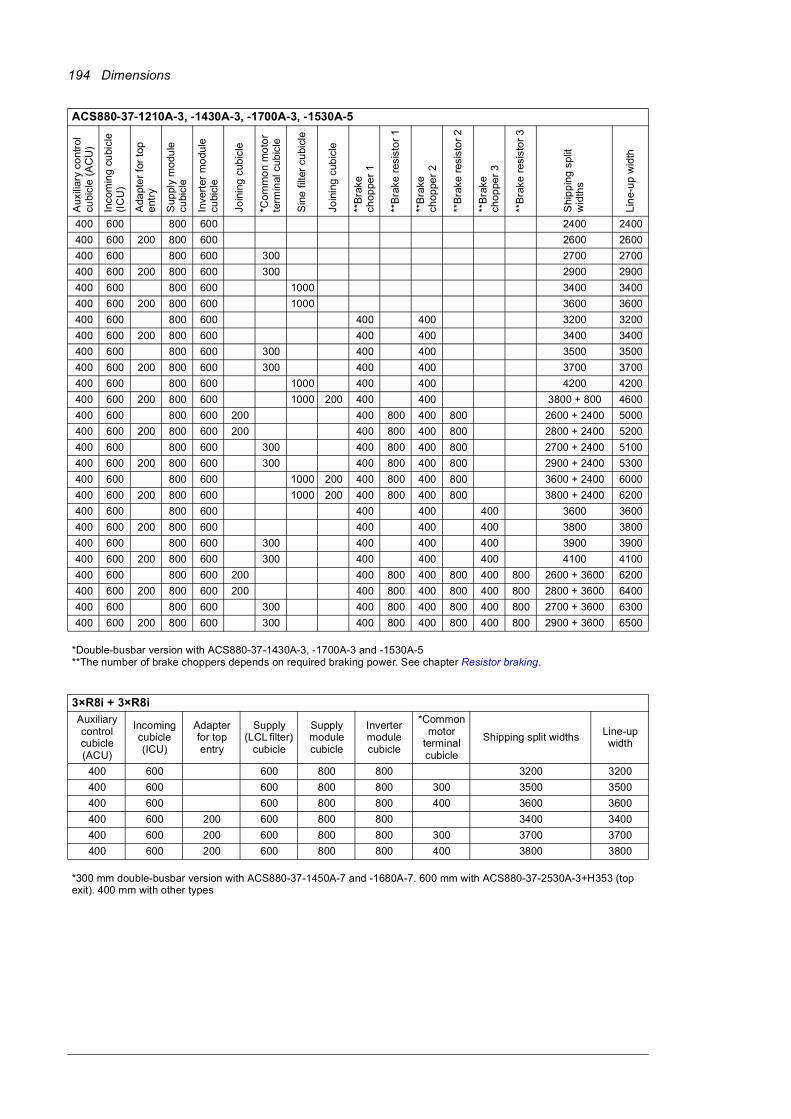
194 Dimensions
ACS880-37-1210A-3, -1430A-3, -1700A-3, -1530A-5
Aux
iliar
y co
ntro
l cu
bicl
e (
AC
U)
Inco
min
g cu
bicl
e (I
CU
)
Ada
pte
r fo
r to
p
ent
ry
Sup
ply
mo
dule
cu
bicl
e
Inve
rter
mo
dule
cu
bicl
e
Join
ing
cub
icle
*Co
mm
on
mo
tor
term
inal
cub
icle
Sin
e f
ilter
cu
bicl
e
Join
ing
cub
icle
**B
rake
ch
oppe
r1
**B
rake
res
isto
r 1
**B
rake
ch
oppe
r2
**B
rake
res
isto
r 2
**B
rake
ch
oppe
r3
**B
rake
res
isto
r 3
Shi
pp
ing
spl
it w
idth
s
Lin
e-u
p w
idth
400 600 800 600 2400 2400
400 600 200 800 600 2600 2600
400 600 800 600 300 2700 2700
400 600 200 800 600 300 2900 2900
400 600 800 600 1000 3400 3400
400 600 200 800 600 1000 3600 3600
400 600 800 600 400 400 3200 3200
400 600 200 800 600 400 400 3400 3400
400 600 800 600 300 400 400 3500 3500
400 600 200 800 600 300 400 400 3700 3700
400 600 800 600 1000 400 400 4200 4200
400 600 200 800 600 1000 200 400 400 3800 + 800 4600
400 600 800 600 200 400 800 400 800 2600 + 2400 5000
400 600 200 800 600 200 400 800 400 800 2800 + 2400 5200
400 600 800 600 300 400 800 400 800 2700 + 2400 5100
400 600 200 800 600 300 400 800 400 800 2900 + 2400 5300
400 600 800 600 1000 200 400 800 400 800 3600 + 2400 6000
400 600 200 800 600 1000 200 400 800 400 800 3800 + 2400 6200
400 600 800 600 400 400 400 3600 3600
400 600 200 800 600 400 400 400 3800 3800
400 600 800 600 300 400 400 400 3900 3900
400 600 200 800 600 300 400 400 400 4100 4100
400 600 800 600 200 400 800 400 800 400 800 2600 + 3600 6200
400 600 200 800 600 200 400 800 400 800 400 800 2800 + 3600 6400
400 600 800 600 300 400 800 400 800 400 800 2700 + 3600 6300
400 600 200 800 600 300 400 800 400 800 400 800 2900 + 3600 6500
*Double-busbar version with ACS880-37-1430A-3, -1700A-3 and -1530A-5**The number of brake choppers depends on required braking power. See chapter Resistor braking.
3×R8i + 3×R8iAuxiliary controlcubicle (ACU)
Incoming cubicle (ICU)
Adapter for top entry
Supply (LCL filter)
cubicle
Supply module cubicle
Inverter module cubicle
*Common motor
terminal cubicle
Shipping split widths Line-up width
400 600 600 800 800 3200 3200
400 600 600 800 800 300 3500 3500
400 600 600 800 800 400 3600 3600
400 600 200 600 800 800 3400 3400
400 600 200 600 800 800 300 3700 3700
400 600 200 600 800 800 400 3800 3800
*300 mm double-busbar version with ACS880-37-1450A-7 and -1680A-7. 600 mm with ACS880-37-2530A-3+H353 (top exit). 400 mm with other types
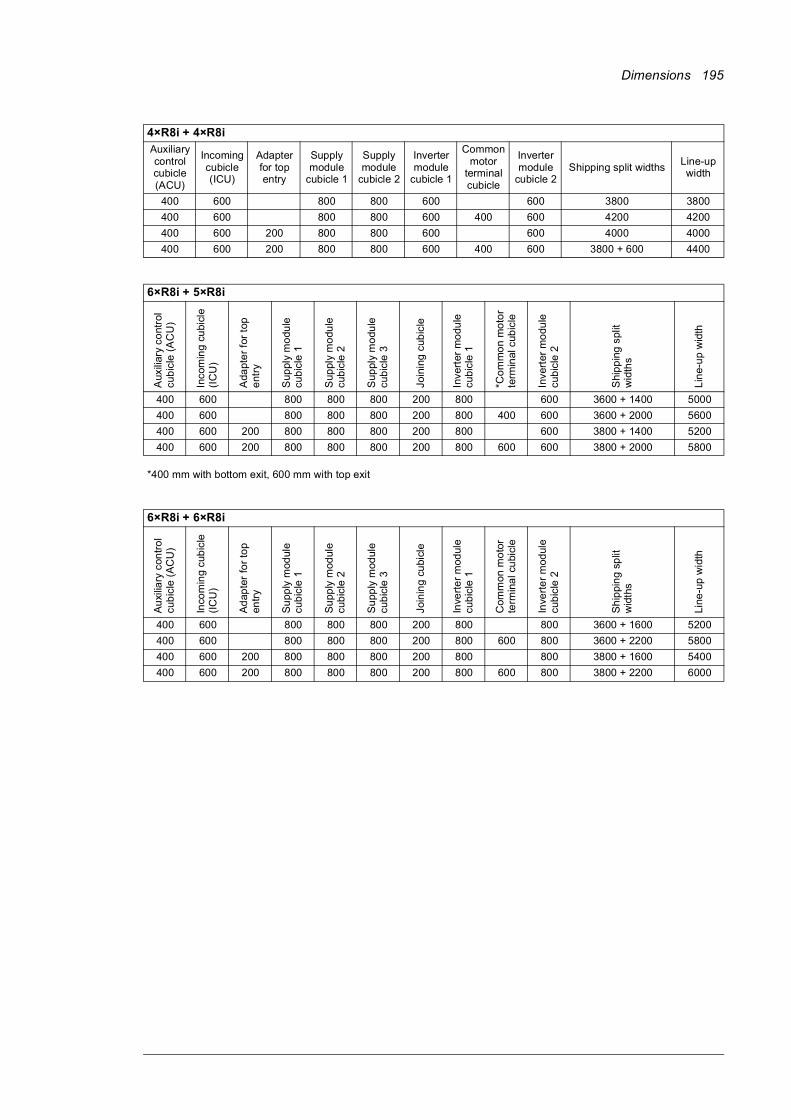
Dimensions 195
4×R8i + 4×R8iAuxiliary controlcubicle (ACU)
Incoming cubicle (ICU)
Adapter for top entry
Supply module
cubicle 1
Supply module
cubicle 2
Inverter module
cubicle 1
Common motor
terminal cubicle
Inverter module
cubicle 2Shipping split widths
Line-up width
400 600 800 800 600 600 3800 3800
400 600 800 800 600 400 600 4200 4200
400 600 200 800 800 600 600 4000 4000
400 600 200 800 800 600 400 600 3800 + 600 4400
6×R8i + 5×R8i
Aux
iliar
y co
ntro
l cu
bic
le (
AC
U)
Inco
min
g cu
bicl
e (I
CU
)
Ada
pte
r fo
r to
p
ent
ry
Sup
ply
mo
dule
cu
bic
le 1
Sup
ply
mo
dule
cu
bic
le 2
Sup
ply
mo
dule
cu
bic
le 3
Join
ing
cub
icle
Inve
rter
mo
dule
cu
bic
le 1
*Co
mm
on
mo
tor
term
inal
cub
icle
Inve
rter
mo
dule
cu
bic
le 2
Shi
pp
ing
spl
it w
idth
s
Lin
e-u
p w
idth
400 600 800 800 800 200 800 600 3600 + 1400 5000
400 600 800 800 800 200 800 400 600 3600 + 2000 5600
400 600 200 800 800 800 200 800 600 3800 + 1400 5200
400 600 200 800 800 800 200 800 600 600 3800 + 2000 5800
*400 mm with bottom exit, 600 mm with top exit
6×R8i + 6×R8i
Au
xilia
ry c
ontr
ol
cub
icle
(A
CU
)
Inco
min
g cu
bic
le
(IC
U)
Ad
apte
r fo
r to
p en
try
Su
pply
mod
ule
cub
icle
1
Su
pply
mod
ule
cub
icle
2
Su
pply
mod
ule
cub
icle
3
Join
ing
cubi
cle
Inve
rte
r m
odul
e cu
bic
le 1
Com
mon
mo
tor
term
ina
l cu
bicl
e
Inve
rte
r m
odul
e cu
bic
le 2
Sh
ippi
ng
sp
lit
wid
ths
Line
-up
wid
th
400 600 800 800 800 200 800 800 3600 + 1600 5200
400 600 800 800 800 200 800 600 800 3600 + 2200 5800
400 600 200 800 800 800 200 800 800 3800 + 1600 5400
400 600 200 800 800 800 200 800 600 800 3800 + 2200 6000
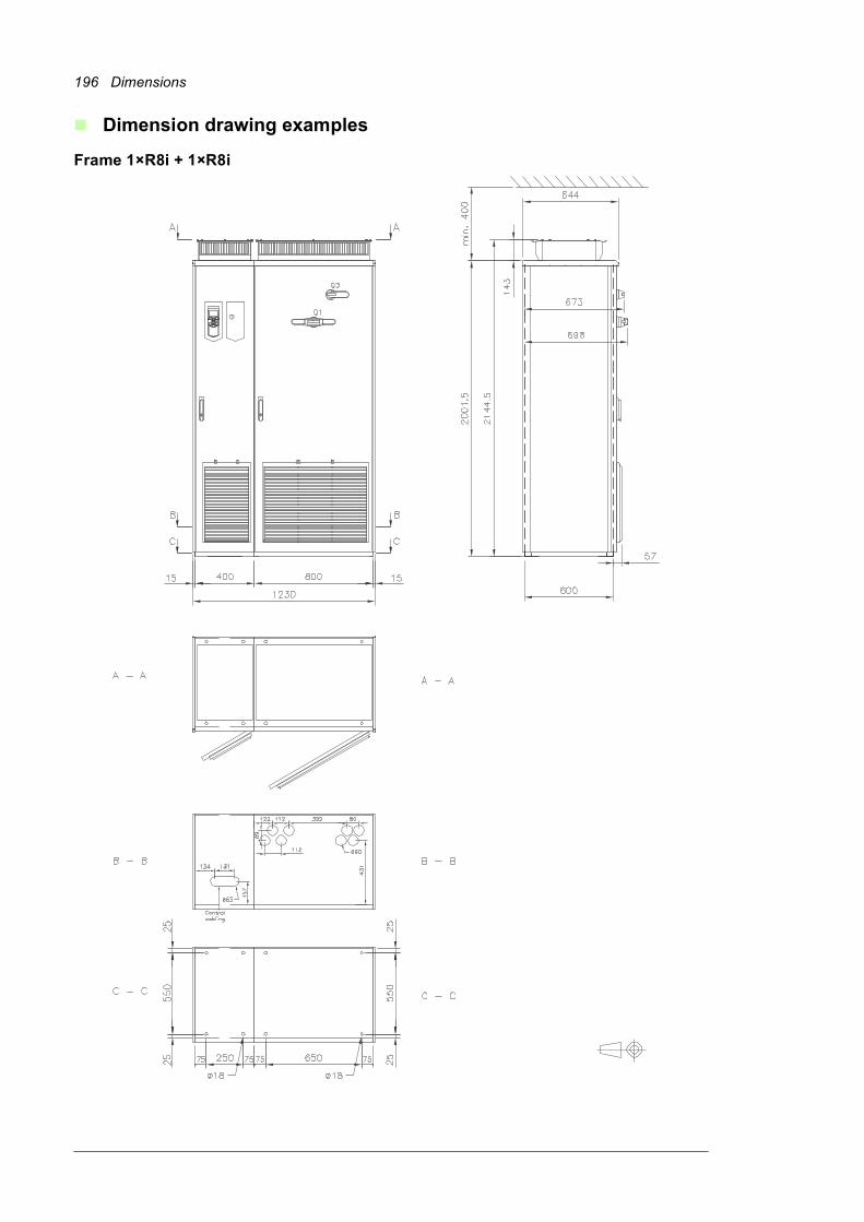
196 Dimensions
Dimension drawing examples
Frame 1×R8i + 1×R8i
Dimensions 197
Frame 1×R8i + 1×R8i, top cable entry/exit (+H351+H353)

198 Dimensions
Frame 1×R8i + 1×R8i with brake choppers and resistors (+D150+D151)
Dimensions 199
Frame 1×R8i + 1×R8i with sine output filter (+E206)
200 Dimensions
Frame 2×R8i + 2×R8i (eg. ACS880-37-1110A-3), IP22

Dimensions 201
Frame 2×R8i + 2×R8i (eg. ACS880-37-1210A-3), IP54
202 Dimensions
Frame 2×R8i + 2×R8i with main breaker (+F255) and common motor terminal cubicle (+H359), 1/2
Dimensions 203
Frame 2×R8i + 2×R8i with main breaker (+F255) and common motor terminal cubicle (+H359), 2/2
204 Dimensions
Frame 2×R8i + 2×R8i with main breaker (+F255) and top entry/top exit (+H351+H353), 1/2

Dimensions 205
Frame 2×R8i + 2×R8i with main breaker (+F255) and top entry/top exit (+H351+H353), 2/2
206 Dimensions
Frame 3×R8i + 3×R8i, 1/2
Dimensions 207
Frame 3×R8i + 3×R8i, 2/2
208 Dimensions
Frame 3×R8i + 3×R8i with common motor terminal cubicle (+H359), 1/2
Dimensions 209
Frame 3×R8i + 3×R8i with common motor terminal cubicle (+H359), 2/2
210 Dimensions
Location and size of input terminals
Frame 1×R8i + 1×R8i, bottom cable entry
Frame 1×R8i + 1×R8i, top cable entry

Dimensions 211
Frame 2×R8i + 2×R8i with main switch/disconnector (400 mm), bottom cable entry
Frame 2×R8i + 2×R8i with main switch/disconnector (400 mm), top cable entry
212 Dimensions
Frame 2×R8i + 2×R8i with main switch/disconnector (600 mm), bottom cable entry
Frame 2×R8i + 2×R8i with main switch/disconnector (600 mm), top cable entry
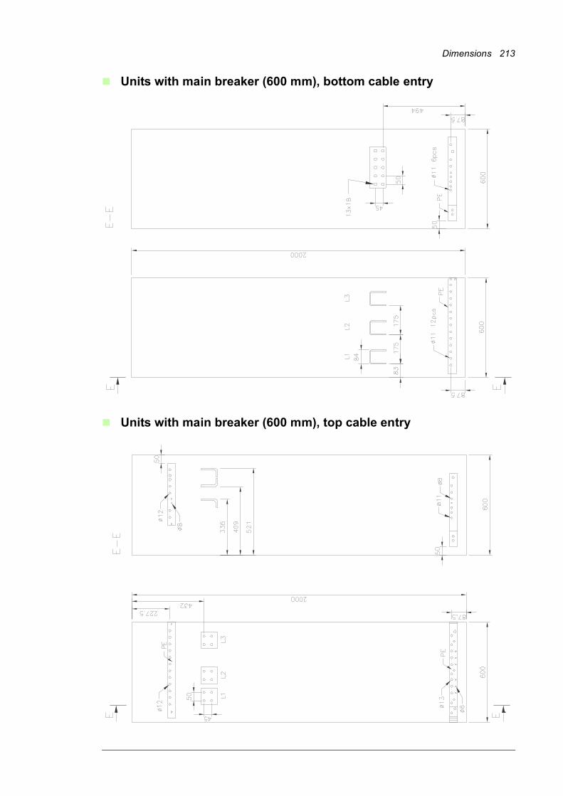
Dimensions 213
Units with main breaker (600 mm), bottom cable entry
Units with main breaker (600 mm), top cable entry
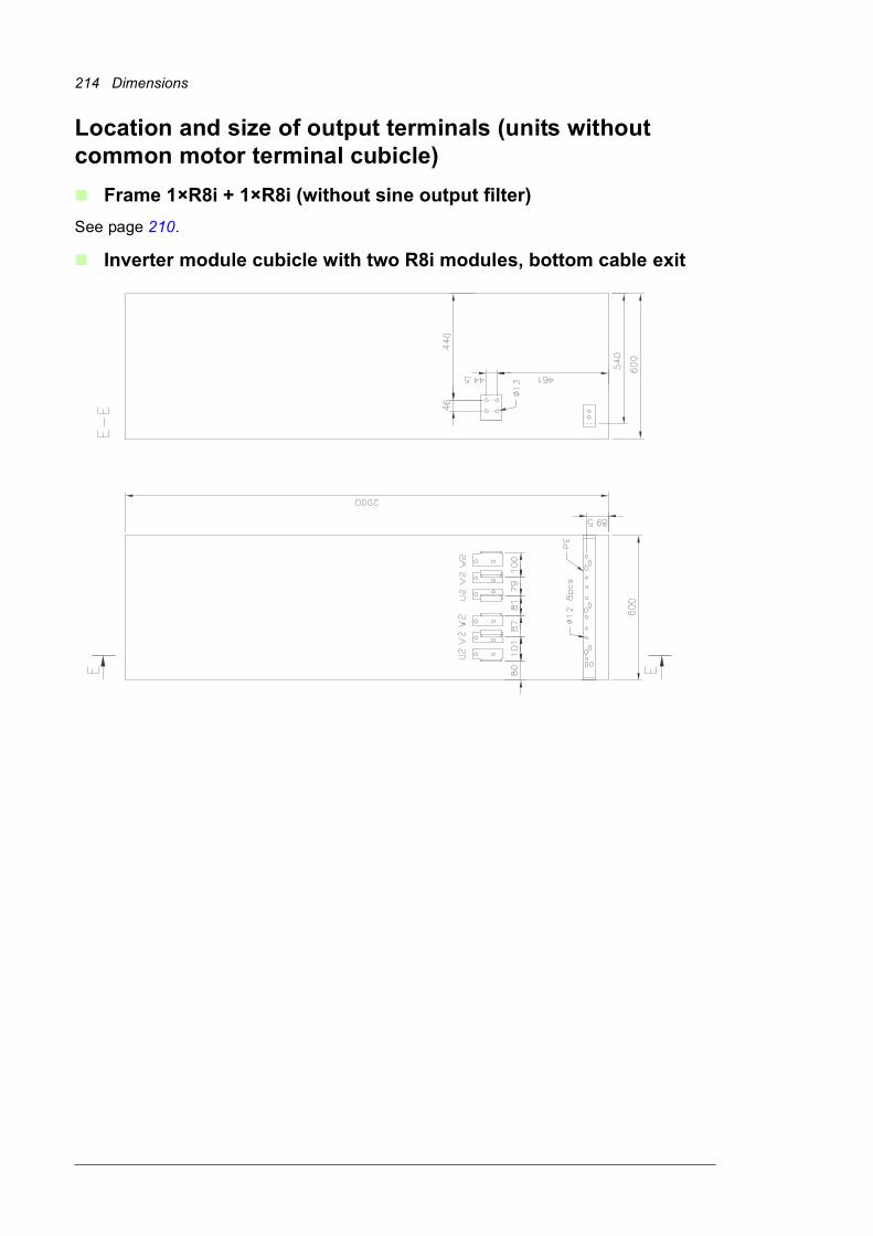
214 Dimensions
Location and size of output terminals (units without common motor terminal cubicle)
Frame 1×R8i + 1×R8i (without sine output filter)
See page 210.
Inverter module cubicle with two R8i modules, bottom cable exit
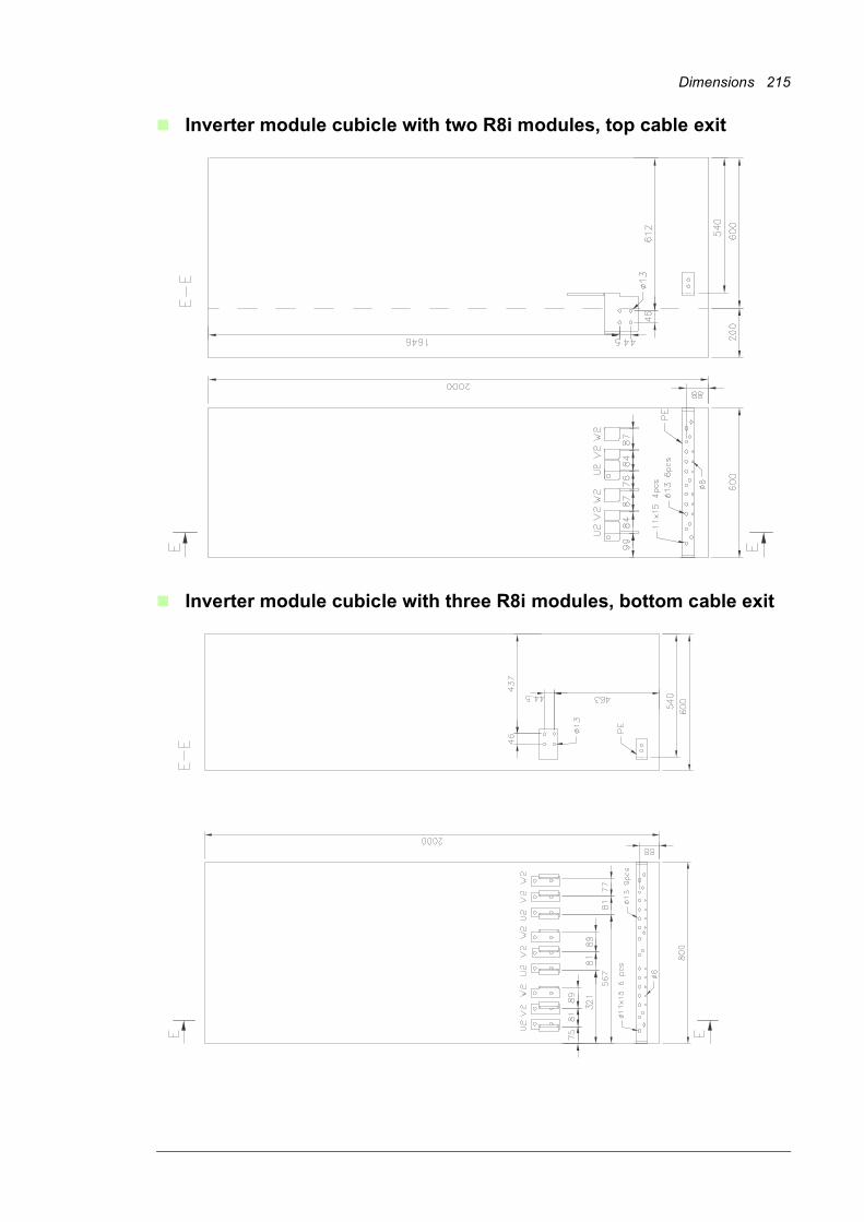
Dimensions 215
Inverter module cubicle with two R8i modules, top cable exit
Inverter module cubicle with three R8i modules, bottom cable exit
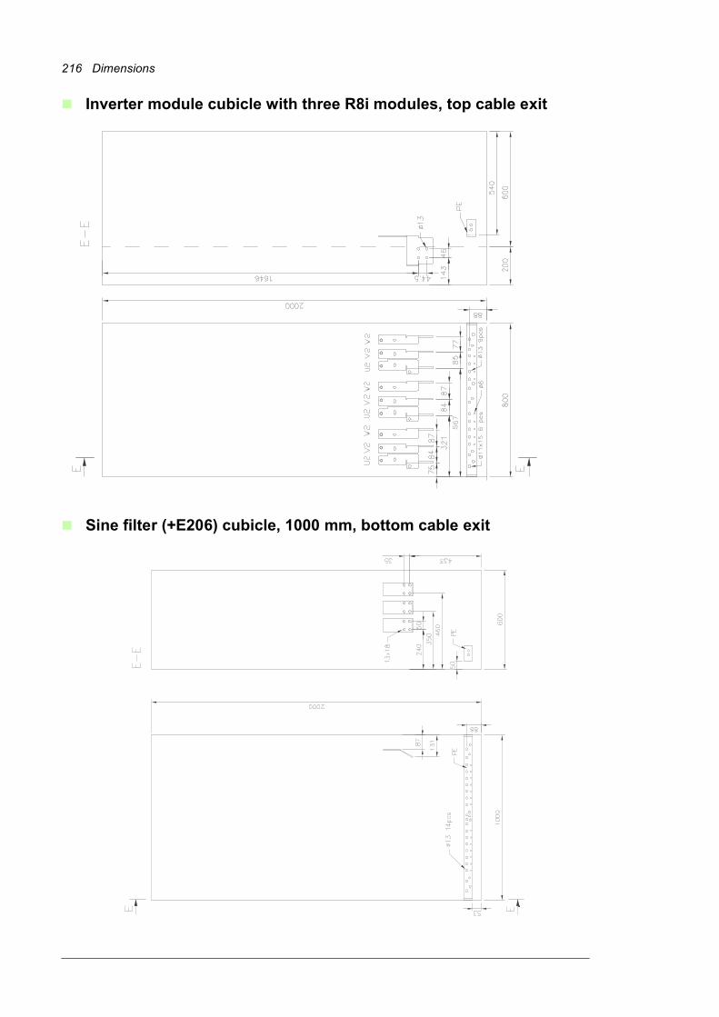
216 Dimensions
Inverter module cubicle with three R8i modules, top cable exit
Sine filter (+E206) cubicle, 1000 mm, bottom cable exit
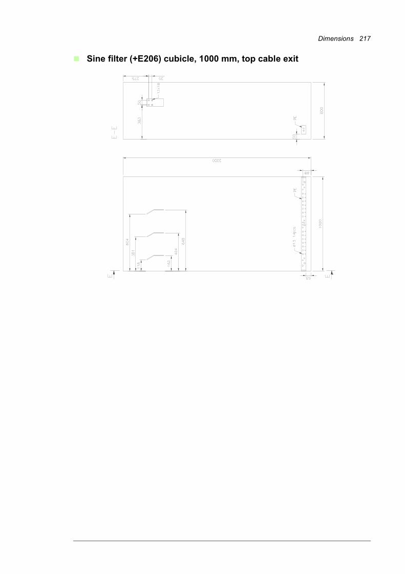
Dimensions 217
Sine filter (+E206) cubicle, 1000 mm, top cable exit
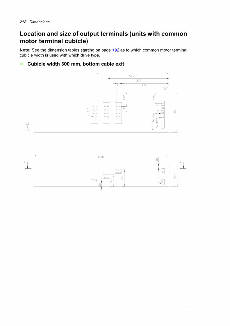
218 Dimensions
Location and size of output terminals (units with common motor terminal cubicle)Note: See the dimension tables starting on page 192 as to which common motor terminal cubicle width is used with which drive type.
Cubicle width 300 mm, bottom cable exit

Dimensions 219
Cubicle width 300 mm (double-busbar version), bottom cable exit
Cubicle width 300 mm, top cable exit
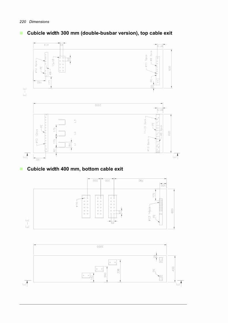
220 Dimensions
Cubicle width 300 mm (double-busbar version), top cable exit
Cubicle width 400 mm, bottom cable exit
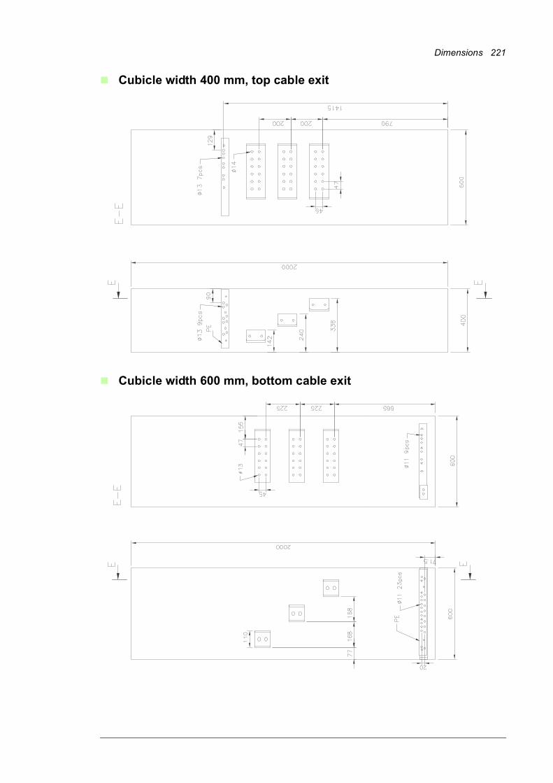
Dimensions 221
Cubicle width 400 mm, top cable exit
Cubicle width 600 mm, bottom cable exit
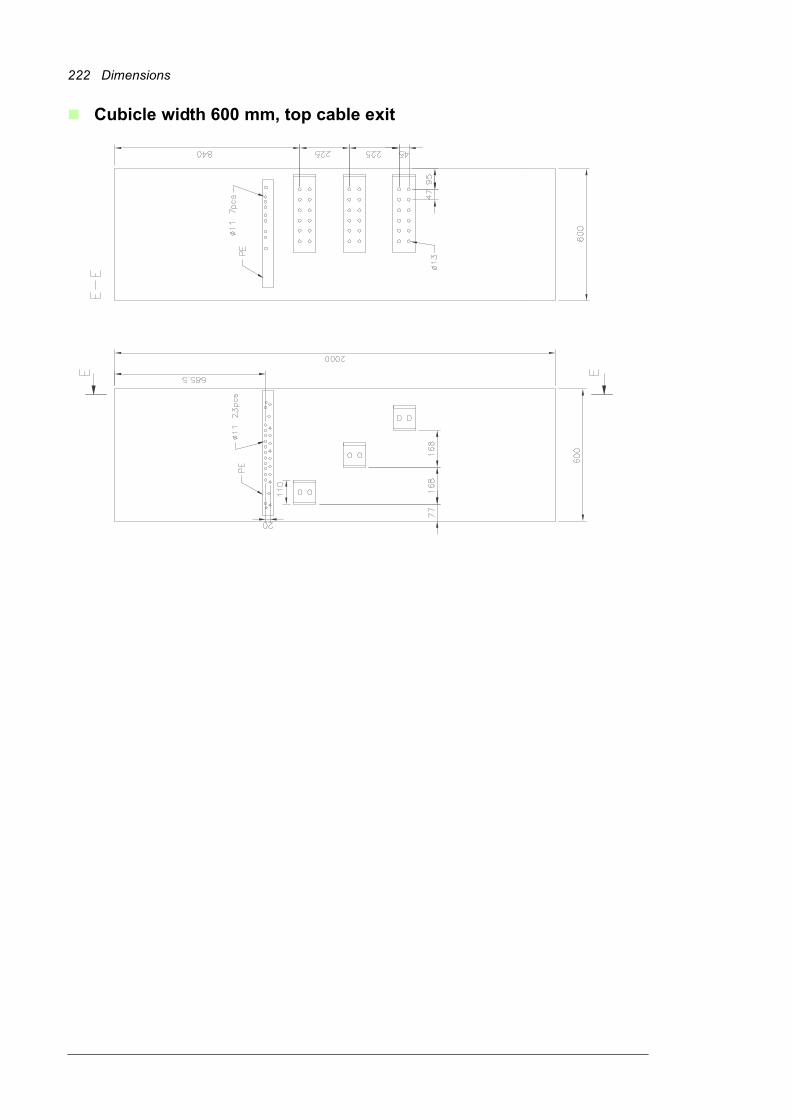
222 Dimensions
Cubicle width 600 mm, top cable exit
The Safe torque off function 223
14
The Safe torque off function
What this chapter containsThis chapter describes the Safe torque off (STO) function of the inverter (ie. the inverter unit of the drive) and gives instructions for its use.
DescriptionThe Safe torque off function can be used, for example, to construct safety or supervision circuits that stop the inverter in case of danger (such as an emergency stop circuit). Another possible application is a prevention of unexpected start-up switch that enables short-time maintenance operations like cleaning or work on non-electrical parts of the machinery without switching off the power supply to the inverter.
When activated, the Safe torque off function disables the control voltage of the power semiconductors of the inverter output stage (A, see diagram below), thus preventing the inverter from generating the torque required to rotate the motor. If the motor is running when Safe torque off is activated, it coasts to a stop.
The Safe torque off function has a redundant architecture, that is, both channels must be used in the safety function implementation. The safety data given in this manual is calculated for redundant use, and does not apply if both channels are not used.
The Safe torque off function of the inverter complies with these standards:
Standard Name
EN 60204-1:2006 + AC:2010 Safety of machinery – Electrical equipment of machines – Part 1: General requirements
IEC 61326-3-1:2008 Electrical equipment for measurement, control and laboratory use – EMC requirements – Part 3-1: Immunity requirements for safety-related systems and for equipment intended to perform safety-related functions (functional safety) – General industrial applications
224 The Safe torque off function
The function also corresponds to Prevention of unexpected start-up as specified by EN 1037:1995 + A1:2008 and Uncontrolled stop (stop category 0) as specified in EN 60204-1:2006 + AC:2010.
Compliance with the European Machinery Directive
See page 184.
WiringThe following diagrams present examples of Safe torque off wiring for• a frame n×R8i inverter unit (page 226)• multiple inverter units (page 227)• multiple inverter units when an external 24 V DC power supply is used (page 228).
For information on the specifications of the STO input, see chapter Control units of the drive (page 123).
Activation switch
In the wiring diagrams below, the activation switch has the designation [K]. This represents a component such as a manually operated switch, an emergency stop push button switch, or the contacts of a safety relay or safety PLC.
• In case a manually operated activation switch is used, the switch must be of a type that can be locked out to the open position.
• The contacts of the switch or relay must open/close within 200 ms of each other.
• An FSO-xx safety functions module can also be used. For more information, see the FSO-xx module documentation.
IEC 61508-1:2010 Functional safety of electrical/electronic/programmable electronic safety-related systems – Part 1: General requirements
IEC 61508-2:2010 Functional safety of electrical/electronic/programmable electronic safety-related systems – Part 2: Requirements for electrical/electronic/programmable electronic safety-related systems
IEC 61511:2003 Functional safety – Safety instrumented systems for the process industry sector
IEC/EN 61800-5-2:2007 Adjustable speed electrical power drive systems – Part 5-2: Safety requirements – Functional
IEC/EN 62061:2005 + AC:2010
Safety of machinery – Functional safety of safety-related electrical, electronic and programmable electronic control systems
EN ISO 13849-1:2008 + AC:2009
Safety of machinery – Safety-related parts of control systems – Part 1: General principles for design
EN ISO 13849-2:2012 Safety of machinery – Safety-related parts of control systems – Part 2: Validation
Standard Name

The Safe torque off function 225
Cable types and lengths
• Double-shielded twisted-pair cable is recommended.
• Maximum cable lengths:
• 30 m (100 ft) between activation switch [K] and inverter control unit• 60 m (200 ft) between multiple inverter units• 60 m (200 ft) between external power supply and first inverter unit• With frame n×R8i inverter units: 30 m (100 ft) between BCU control unit and last
inverter module in the chain.
Note: The voltage at the INx terminals of each inverter control unit (or frame R8i inverter module) must be at least 17 V DC to be interpreted as “1”.
Grounding of protective shields
• Ground the shield in the cabling between the activation switch and the control unit at the control unit.
• Ground the shield in the cabling between two control units at one control unit only.
• For frame R8i and multiples: Do not ground the shield in the cabling between BCU and R8i module, or between R8i modules.
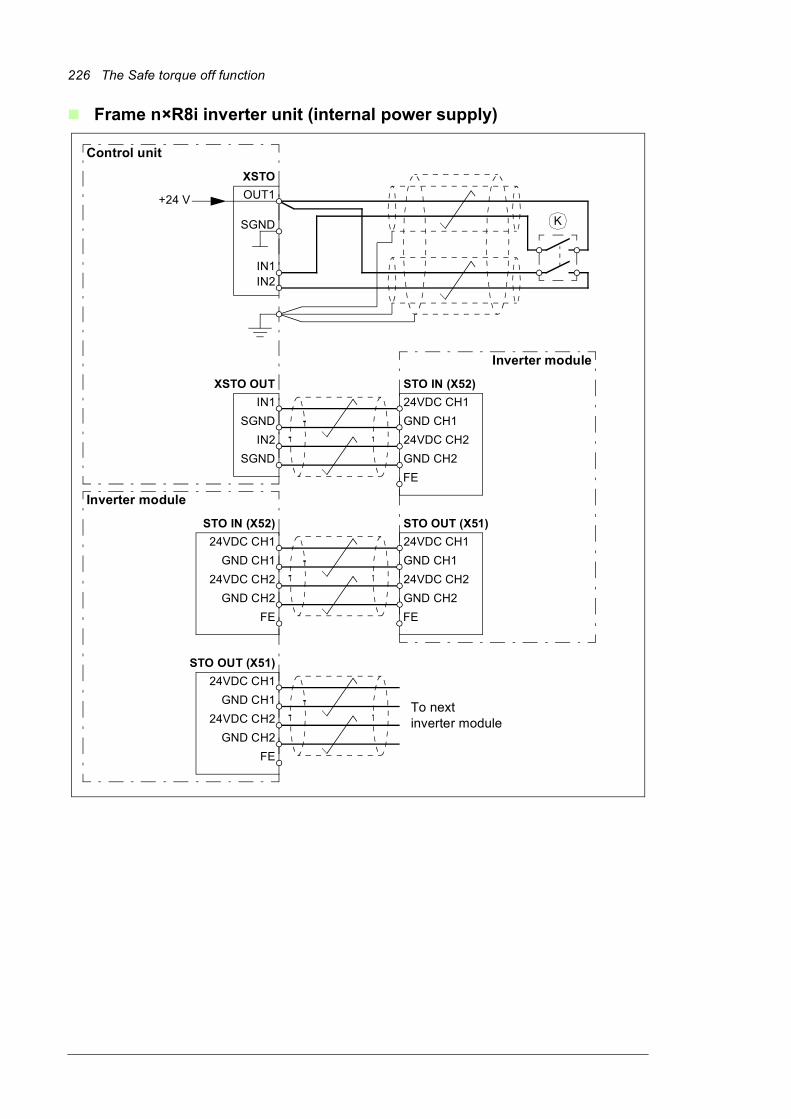
226 The Safe torque off function
Frame n×R8i inverter unit (internal power supply)
+24 V OUT1
SGND
IN1IN2
XSTO
K
IN1
SGND
XSTO OUT
IN2
SGND
24VDC CH1
GND CH1
STO IN (X52)
24VDC CH2
FE
To nextinverter module
GND CH2
24VDC CH1
GND CH1
STO OUT (X51)
24VDC CH2
FE
GND CH2
24VDC CH1
GND CH1
STO IN (X52)
24VDC CH2
FE
GND CH2
24VDC CH1
GND CH1
STO OUT (X51)
24VDC CH2
FE
GND CH2
Inverter module
Inverter module
Control unit

The Safe torque off function 227
Multiple inverter units (internal power supply)
+24 V OUT1
SGND
IN1IN2
Inverter unit
OUT1
SGND
IN1IN2
OUT1
SGND
IN1IN2
Inverter unit
Inverter unit
K
XSTOControl unit
XSTOControl unit
XSTOControl unit
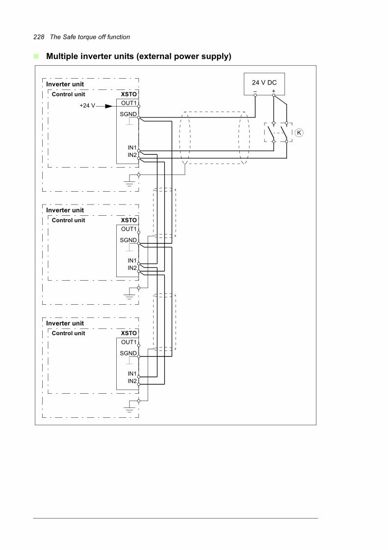
228 The Safe torque off function
Multiple inverter units (external power supply)
OUT1
SGND
IN1IN2
OUT1
SGND
IN1IN2
OUT1
SGND
IN1IN2
Inverter unit
+24 V
Inverter unit
Control unit
Inverter unit
24 V DC– +
K
XSTOControl unit
XSTO
Control unit XSTO
The Safe torque off function 229
Operation principle1. The Safe torque off activates (the activation switch is opened, or safety relay contacts
open).
2. The STO inputs on the inverter control unit [A41] de-energize.
3. The control unit cuts off the control voltage from the inverter IGBTs.
4. The control program generates an indication as defined by parameter 31.22 (refer to the firmware manual of the inverter).
5. Motor coasts to a stop (if running). The inverter cannot restart while the activation switch or safety relay contacts are open. After the contacts close, a new start command is required to start the drive.
Start-up including acceptance testTo ensure the safe operation of a safety function, validation is required. The final assembler of the machine must validate the function by performing an acceptance test. The acceptance test must be performed• at initial start-up of the safety function
• after any changes related to the safety function (circuit boards, wiring, components, settings, etc.)
• after any maintenance work related to the safety function.
Competence
The acceptance test of the safety function must be carried out by a competent person with adequate expertise and knowledge of the safety function as well as functional safety, as required by IEC 61508-1 clause 6. The test procedures and report must be documented and signed by this person.
Acceptance test reports
Signed acceptance test reports must be stored in the logbook of the machine. The report shall include documentation of start-up activities and test results, references to failure reports and resolution of failures. Any new acceptance tests performed due to changes or maintenance shall be logged into the logbook.
Acceptance test procedure
After wiring the Safe torque off function, validate its operation as follows.
Note: If the drive is equipped with safety option +Q950, +Q951, +Q952, +Q957, +Q963, +Q964, +Q978 or +Q979, do the procedure shown in the documentation of the option. If the drive is equipped with safety option +Q972 or Q973, do the procedure shown in the FSO module documentation.
Note: With frame sizes 2×R8i + 2×R8i and up, all inverter modules must be powered and connected to the STO circuit during the acceptance test.
Action
WARNING! Follow the safety instructions given in chapter Safety instructions (page 17). Ignoring the instructions can cause physical injury or death, or damage to the equipment.
Ensure that the drive can be run and stopped freely during start-up.
230 The Safe torque off function
Use1. Open the activation switch, or activate the safety functionality that is wired to the STO
connection.
2. STO inputs on the inverter control unit [A41] de-energize, and the inverter control unit cuts off the control voltage from the inverter IGBTs.
3. The control program generates an indication as defined by parameter 31.22 (refer to the firmware manual of the inverter).
4. The motor coasts to a stop (if running). The inverter will not restart while the activation switch or safety relay contacts are open.
5. Deactivate the STO by closing the activation switch, or reseting the safety functionality that is wired to the STO connection.
6. Reset any faults before restarting.
WARNING! The Safe torque off function does not disconnect the voltage of the main and auxiliary circuits from the drive. Therefore maintenance work on electrical parts of the drive or the motor can only be carried out after isolating the
drive from the main supply.
Stop the inverter (if running), switch the input power off and isolate the drive from the power line by a disconnector.
Check the Safe torque off circuit connections against the wiring diagram.
Close the disconnector and switch the power on.
Test the operation of the STO function when the motor is stopped.
• Give a stop command to the inverter (if running) and wait until the motor shaft is at a standstill.
Ensure that the inverter operates as follows:
• Open the STO circuit. The inverter generates an indication if one is defined for ‘stopped’ state in parameter 31.22 (see the firmware manual).
• Give a start command to verify that the STO function blocks the inverter’s operation. The motor should not start.
• Close the STO circuit.
• Reset any active faults. Restart the inverter and check that the motor runs normally.
Test the operation of the STO function when the motor is running.
• Start the inverter and ensure the motor is running.
• Open the STO circuit. The motor should stop. The inverter generates an indication if one is defined for ‘running’ state in parameter 31.22 (see the firmware manual).
• Reset any active faults and try to start the inverter.
• Ensure that the motor stays at a standstill and the inverter operates as described above in testing the operation when the motor is stopped.
• Close the STO circuit.
• Reset any active faults. Restart the inverter and check that the motor runs normally.
Document and sign the acceptance test report which verifies that the safety function is safe and accepted for operation.
Action
The Safe torque off function 231
WARNING! The Safe torque off functionality is only achieved through the XSTO connector of the inverter control unit [A41]. True Safe torque off functionality is not achieved through the XSTO connectors of other control units such as the supply
control unit [A51].
The Safe torque off function is supported by any ACS880 inverter unit firmware. It is not supported by supply or brake firmware.
WARNING! (With permanent magnet or synchronous reluctance [SynRM] motors only) In case of a multiple IGBT power semiconductor failure, the inverter system can produce an alignment torque which maximally rotates the motor shaft by
180/p (with permanent magnet motors) or 180/2p (with synchronous reluctance [SynRM] motors) degrees regardless of the activation of the Safe torque off function. p denotes the number of pole pairs.
Notes:• If a running inverter is stopped by using the Safe torque off function, the inverter will
cut off the motor supply voltage and the motor will coast to a stop. If this causes danger or is not otherwise acceptable, stop the inverter and machinery using the appropriate stop mode before activating the Safe torque off function.
• The Safe torque off function overrides all other functions of the inverter unit.
• The Safe torque off function is ineffective against deliberate sabotage or misuse.
• The Safe torque off function has been designed to reduce the recognized hazardous conditions. In spite of this, it is not always possible to eliminate all potential hazards. The assembler of the machine must inform the final user about the residual risks.
MaintenanceAfter the operation of the circuit is validated at start-up, the STO function shall be maintained by periodic proof testing. In high demand mode of operation, the maximum proof test interval is 20 years. In low demand mode of operation, the maximum proof test interval is 2 years. The test procedure is given in section Acceptance test procedure (page 229).
Note: See also the Recommendation of Use CNB/M/11.050 (published by the European co-ordination of Notified Bodies) concerning dual-channel safety-related systems with electromechanical outputs:• When the safety integrity requirement for the safety function is SIL 3 or PL e (cat. 3 or
4), the proof test for the function must be performed at least every month.
• When the safety integrity requirement for the safety function is SIL 2 (HFT = 1) or PL d (cat. 3), the proof test for the function must be performed at least every 12 months.
The STO function of the inverter does not contain any electromechanical components.
In addition to proof testing, it is a good practice to check the operation of the function when other maintenance procedures are carried out on the machinery.
Include the Safe torque off operation test described above in the routine maintenance program of the machinery that the inverter runs.
If any wiring or component change is needed after start up, or the parameters are restored, follow the test given in section Acceptance test procedure (page 229).
Use only ABB approved spare parts.
Record all maintenance and proof test activities in the machine logbook.

232 The Safe torque off function
Competence
The maintenance and proof test activities of the safety function must be carried out by a competent person with adequate expertise and knowledge of the safety function as well as functional safety, as required by IEC 61508-1 clause 6.
Fault tracingThe indications given during the normal operation of the Safe torque off function are selected by inverter control program parameter 31.22.
The diagnostics of the Safe torque off function cross-compare the status of the two STO channels. In case the channels are not in the same state, a fault reaction function is performed and the inverter trips on an “STO hardware failure” fault. An attempt to use the STO in a non-redundant manner, for example activating only one channel, will trigger the same reaction.
See the firmware manual of the inverter control program for the indications generated by the inverter, and for details on directing fault and warning indications to an output on the control unit for external diagnostics.
Any failures of the Safe torque off function must be reported to ABB.
Safety dataThe safety data for the Safe torque off function is given below.
Note: The safety data is calculated for redundant use, and does not apply if both STO channels are not used.
• The following temperature profile is used in safety value calculations:
• 670 on/off cycles per year with T = 71.66 °C• 1340 on/off cycles per year with T = 61.66 °C• 30 on/off cycles per year with T = 10.0 °C• 32 °C board temperature at 2.0% of time• 60 °C board temperature at 1.5% of time• 85 °C board temperature at 2.3% of time.
• The STO is a type B safety component as defined in IEC 61508-2.
• Relevant failure modes:• The STO trips spuriously (safe failure)• The STO does not activate when requestedA fault exclusion on the failure mode “short circuit on printed circuit board” has been made (EN 13849-2, table D.5). The analysis is based on an assumption that one failure occurs at one time. No accumulated failures have been analyzed.
• STO reaction time (shortest detectable break): 1 ms
Frame sizeSIL/
SILCLSC PL
SFFPFHD
(T1 = 20 a) PFD(T1 = 2 a)
MTTFd DCCat. HFT CCF
Lifetime
(%) (1/h) (a) (%) (a)
R8i 3 3 e >99 4.74E-11 4.23E-07 27325 >90 3 1 80 20
2×R8i 3 3 e >99 5.57E-11 4.98E-07 19607 >90 3 1 80 20
3×R8i 3 3 e >99 6.39E-11 5.74E-07 15295 >90 3 1 80 20
4×R8i 3 3 e >99 7.22E-11 6.49E-07 12540 >90 3 1 80 20
5×R8i 3 3 e >99 8.05E-11 7.24E-07 10626 >90 3 1 80 20
6×R8i 3 3 e >99 8.87E-11 7.99E-07 9220 >90 3 1 80 20
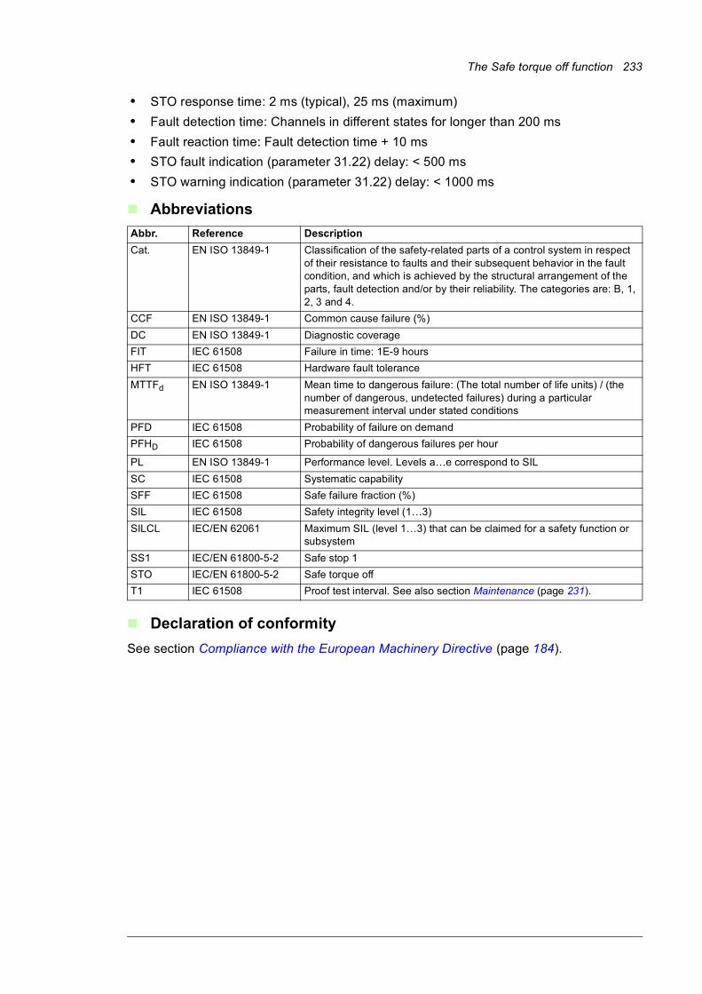
The Safe torque off function 233
• STO response time: 2 ms (typical), 25 ms (maximum)
• Fault detection time: Channels in different states for longer than 200 ms
• Fault reaction time: Fault detection time + 10 ms
• STO fault indication (parameter 31.22) delay: < 500 ms
• STO warning indication (parameter 31.22) delay: < 1000 ms
Abbreviations
Declaration of conformity
See section Compliance with the European Machinery Directive (page 184).
Abbr. Reference Description
Cat. EN ISO 13849-1 Classification of the safety-related parts of a control system in respect of their resistance to faults and their subsequent behavior in the fault condition, and which is achieved by the structural arrangement of the parts, fault detection and/or by their reliability. The categories are: B, 1, 2, 3 and 4.
CCF EN ISO 13849-1 Common cause failure (%)
DC EN ISO 13849-1 Diagnostic coverage
FIT IEC 61508 Failure in time: 1E-9 hours
HFT IEC 61508 Hardware fault tolerance
MTTFd EN ISO 13849-1 Mean time to dangerous failure: (The total number of life units) / (the number of dangerous, undetected failures) during a particular measurement interval under stated conditions
PFD IEC 61508 Probability of failure on demand
PFHD IEC 61508 Probability of dangerous failures per hour
PL EN ISO 13849-1 Performance level. Levels a…e correspond to SIL
SC IEC 61508 Systematic capability
SFF IEC 61508 Safe failure fraction (%)
SIL IEC 61508 Safety integrity level (1…3)
SILCL IEC/EN 62061 Maximum SIL (level 1…3) that can be claimed for a safety function or subsystem
SS1 IEC/EN 61800-5-2 Safe stop 1
STO IEC/EN 61800-5-2 Safe torque off
T1 IEC 61508 Proof test interval. See also section Maintenance (page 231).

234 The Safe torque off function
Resistor braking 235
15
Resistor braking
Contents of this chapterThis chapter tells how to select, protect and wire brake choppers and resistors. The chapter also contains the related technical data.
Operating principleThe brake chopper handles the energy generated by a decelerating motor. The chopper connects the brake resistor to the intermediate DC circuit whenever the voltage in the circuit exceeds the limit defined by the control program. Energy consumption by the resistor losses lowers the voltage until the resistor can be disconnected.
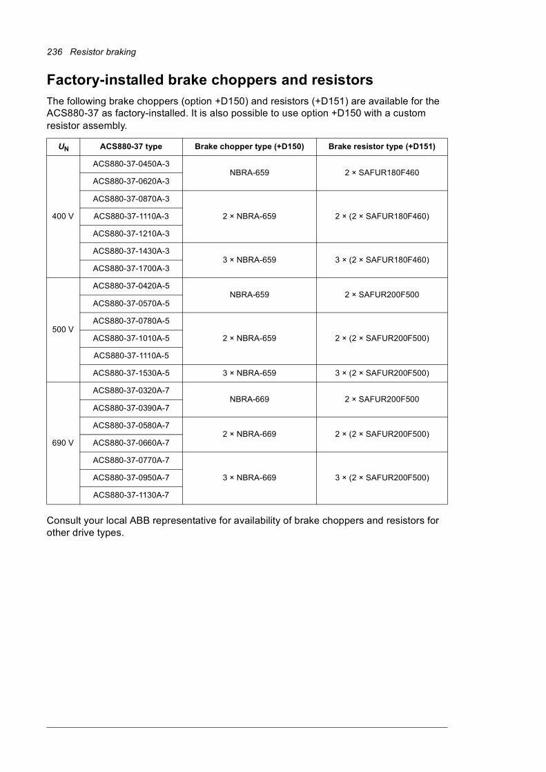
236 Resistor braking
Factory-installed brake choppers and resistorsThe following brake choppers (option +D150) and resistors (+D151) are available for the ACS880-37 as factory-installed. It is also possible to use option +D150 with a custom resistor assembly.
Consult your local ABB representative for availability of brake choppers and resistors for other drive types.
UN ACS880-37 type Brake chopper type (+D150) Brake resistor type (+D151)
400 V
ACS880-37-0450A-3NBRA-659 2 × SAFUR180F460
ACS880-37-0620A-3
ACS880-37-0870A-3
2 × NBRA-659 2 × (2 × SAFUR180F460)ACS880-37-1110A-3
ACS880-37-1210A-3
ACS880-37-1430A-33 × NBRA-659 3 × (2 × SAFUR180F460)
ACS880-37-1700A-3
500 V
ACS880-37-0420A-5NBRA-659 2 × SAFUR200F500
ACS880-37-0570A-5
ACS880-37-0780A-5
2 × NBRA-659 2 × (2 × SAFUR200F500)ACS880-37-1010A-5
ACS880-37-1110A-5
ACS880-37-1530A-5 3 × NBRA-659 3 × (2 × SAFUR200F500)
690 V
ACS880-37-0320A-7NBRA-669 2 × SAFUR200F500
ACS880-37-0390A-7
ACS880-37-0580A-72 × NBRA-669 2 × (2 × SAFUR200F500)
ACS880-37-0660A-7
ACS880-37-0770A-7
3 × NBRA-669 3 × (2 × SAFUR200F500)ACS880-37-0950A-7
ACS880-37-1130A-7
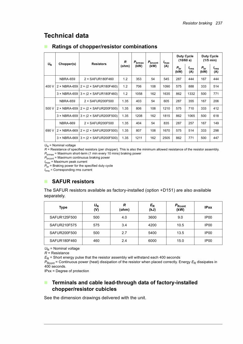
Resistor braking 237
Technical data
Ratings of chopper/resistor combinations
SAFUR resistors
The SAFUR resistors available as factory-installed (option +D151) are also available separately.
Terminals and cable lead-through data of factory-installed chopper/resistor cubicles
See the dimension drawings delivered with the unit.
UN Chopper(s) ResistorsR
(ohm)Pbrmax(kW)
Pbrcont(kW)
Imax(A)
Duty Cycle(10/60 s)
Duty Cycle(1/5 min)
Pbr(kW)
Irms(A)
Pbr(kW)
Irms(A)
400 V
NBRA-659 2 × SAFUR180F460 1.2 353 54 545 287 444 167 444
2 × NBRA-659 2 × (2 × SAFUR180F460) 1.2 706 108 1090 575 888 333 514
3 × NBRA-659 3 × (2 × SAFUR180F460) 1.2 1058 162 1635 862 1332 500 771
500 V
NBRA-659 2 × SAFUR200F500 1.35 403 54 605 287 355 167 206
2 × NBRA-659 2 × (2 × SAFUR200F500) 1.35 806 108 1210 575 710 333 412
3 × NBRA-659 3 × (2 × SAFUR200F500) 1.35 1208 162 1815 862 1065 500 618
690 V
NBRA-669 2 × SAFUR200F500 1.35 404 54 835 287 257 167 149
2 × NBRA-669 2 × (2 × SAFUR200F500) 1.35 807 108 1670 575 514 333 298
3 × NBRA-669 3 × (2 × SAFUR200F500) 1.35 1211 162 2505 862 771 500 447
UN = Nominal voltageR = Resistance of specified resistors (per chopper). This is also the minimum allowed resistance of the resistor assembly.Pbrmax = Maximum short-term (1 min every 10 mins) braking powerPbrcont = Maximum continuous braking powerImax = Maximum peak currentPbr = Braking power for the specified duty cycleIrms = Corresponding rms current
TypeUN(V)
R(ohm)
ER(kJ)
PRcont(kW)
IPxx
SAFUR125F500 500 4.0 3600 9.0 IP00
SAFUR210F575 575 3.4 4200 10.5 IP00
SAFUR200F500 500 2.7 5400 13.5 IP00
SAFUR180F460 460 2.4 6000 15.0 IP00
UN = Nominal voltageR = ResistanceER = Short energy pulse that the resistor assembly will withstand each 400 secondsPRcont = Continuous power (heat) dissipation of the resistor when placed correctly. Energy ER dissipates in 400 seconds.IPxx = Degree of protection
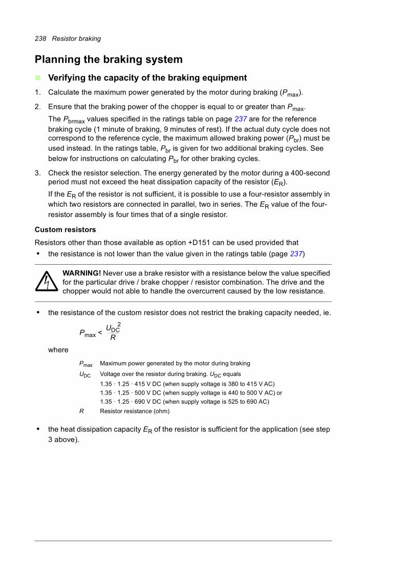
238 Resistor braking
Planning the braking system
Verifying the capacity of the braking equipment
1. Calculate the maximum power generated by the motor during braking (Pmax).
2. Ensure that the braking power of the chopper is equal to or greater than Pmax.
The Pbrmax values specified in the ratings table on page 237 are for the reference
braking cycle (1 minute of braking, 9 minutes of rest). If the actual duty cycle does not correspond to the reference cycle, the maximum allowed braking power (Pbr) must be used instead. In the ratings table, Pbr is given for two additional braking cycles. See
below for instructions on calculating Pbr for other braking cycles.
3. Check the resistor selection. The energy generated by the motor during a 400-second period must not exceed the heat dissipation capacity of the resistor (ER).
If the ER of the resistor is not sufficient, it is possible to use a four-resistor assembly in which two resistors are connected in parallel, two in series. The ER value of the four-
resistor assembly is four times that of a single resistor.
Custom resistors
Resistors other than those available as option +D151 can be used provided that
• the resistance is not lower than the value given in the ratings table (page 237)
WARNING! Never use a brake resistor with a resistance below the value specified for the particular drive / brake chopper / resistor combination. The drive and the chopper would not able to handle the overcurrent caused by the low resistance.
• the resistance of the custom resistor does not restrict the braking capacity needed, ie.
where
• the heat dissipation capacity ER of the resistor is sufficient for the application (see step
3 above).
Pmax Maximum power generated by the motor during braking
UDC Voltage over the resistor during braking. UDC equals
1.35 · 1.25 · 415 V DC (when supply voltage is 380 to 415 V AC)
1.35 · 1.25 · 500 V DC (when supply voltage is 440 to 500 V AC) or
1.35 · 1.25 · 690 V DC (when supply voltage is 525 to 690 AC)
R Resistor resistance (ohm)
Pmax <UDC
R
2
Resistor braking 239
Calculating the maximum braking power (Pbr)
• Braking energy transferred during any ten minute period must be less than or equal to the energy transferred during the reference braking cycle.
• The braking power must not exceed the rated maximum value Pbrmax.
Example 1
The duration of a braking cycle is 30 minutes. The braking time is 15 minutes.
Result: If the braking time exceeds 10 minutes, the braking is considered continuous. The allowed continuous braking power is 10% of maximum braking power (Pbrmax).
Example 2
The duration of a braking cycle (T) is three minutes. The braking time (tbr) is 40 seconds.
Result: The maximum allowed braking power for the cycle is 37% of the rated value given for the reference cycle.
1. n × Pbr × tbr < Pbrmax × 60 s
2. Pbr < Pbrmax
n = Number of braking pulses during a 10-minute period
Pbr = Maximum allowed braking power (kW)
tbr = Braking time (s)
Pbrmax = Maximum braking power for a reference cycle (kW)
Pbr < Pbrmax x 60 s
4 x 40 s = 0.375 x Pbrmax1.
2. Pbr < Pbrmax OK
t600 sT tbr
Pbrmax
Pbr
240 Resistor braking
Selecting and routing the cables of a custom resistor
Use the same cable type for the resistor cabling as for the drive input cabling to ensure that the input fuses also protect the resistor cable. Alternatively, a two conductor shielded cable with the same cross-sectional area can be used.
Minimizing electromagnetic interference
Follow these rules in order to minimize electromagnetic interference caused by the rapid current changes in the resistor cables:• Shield the braking power line completely, either by using shielded cable or a metallic
enclosure. Unshielded single-core cable can only be used if it is routed inside a cabinet that efficiently suppresses the radiated emissions.
• Install the cables away from other cable routes.
• Avoid long parallel runs with other cables. The minimum parallel cabling separation distance should be 0.3 meters (1 ft).
• Cross any other cables at right angles.
• Keep the cable as short as possible in order to minimize the radiated emissions and stress on chopper IGBTs. The longer the cable the higher the radiated emissions, inductive load and voltage peaks over the IGBT semiconductors of the brake chopper.
Maximum cable length
The maximum length of the resistor cable(s) is 50 m (164 ft).
EMC compliance of the complete installation
Note: ABB has not verified that the EMC requirements are fulfilled with custom brake resistors and cabling. The EMC compliance of the complete installation must be considered by the customer.
Placing custom brake resistors
Install the resistors outside the drive in a place where they are able to cool effectively.
Arrange the cooling of the resistor in a way that• no danger of overheating is caused to the resistor or nearby materials, and
• the temperature of the room the resistor is located in does not exceed the allowed maximum.
Supply the resistor with cooling air/water according to the resistor manufacturer’s instructions.
WARNING! The materials near the brake resistor must be non-flammable. The surface temperature of the resistor is high. The temperature of the air flowing from the resistor is hundreds of degrees Celsius. If the exhaust vents are connected to
a ventilation system, ensure that the materials withstand high temperatures. Protect the resistor against contact.
Protecting the system against thermal overload
The brake chopper protects itself and the resistor cables against thermal overload when the cables are dimensioned according to the nominal current of the drive. By default, a brake chopper fault is wired to stop the supply unit of the drive.
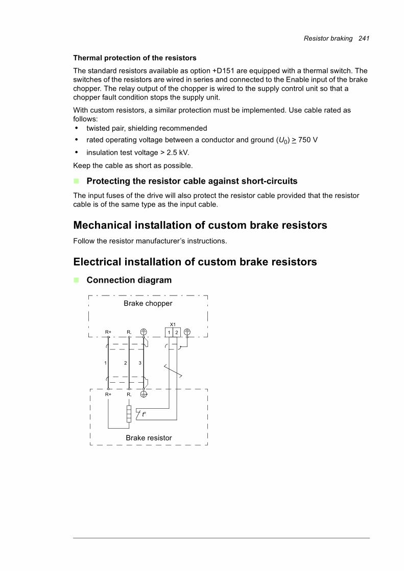
Resistor braking 241
Thermal protection of the resistors
The standard resistors available as option +D151 are equipped with a thermal switch. The switches of the resistors are wired in series and connected to the Enable input of the brake chopper. The relay output of the chopper is wired to the supply control unit so that a chopper fault condition stops the supply unit.
With custom resistors, a similar protection must be implemented. Use cable rated as follows:• twisted pair, shielding recommended
• rated operating voltage between a conductor and ground (U0) > 750 V
• insulation test voltage > 2.5 kV.
Keep the cable as short as possible.
Protecting the resistor cable against short-circuits
The input fuses of the drive will also protect the resistor cable provided that the resistor cable is of the same type as the input cable.
Mechanical installation of custom brake resistorsFollow the resistor manufacturer’s instructions.
Electrical installation of custom brake resistors
Connection diagram
R+ R‚
R+ R‚
1 2 3
t°
Brake chopper
Brake resistor
1 2
X1
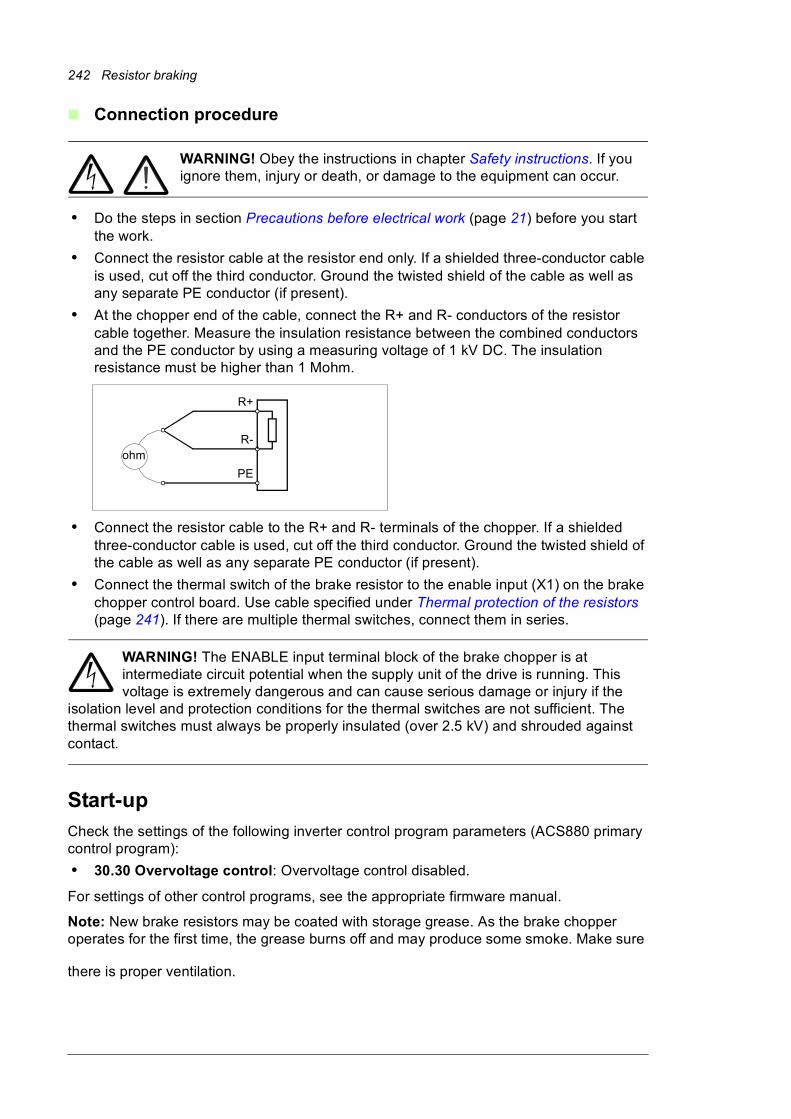
242 Resistor braking
Connection procedure
WARNING! Obey the instructions in chapter Safety instructions. If you ignore them, injury or death, or damage to the equipment can occur.
• Do the steps in section Precautions before electrical work (page 21) before you start the work.
• Connect the resistor cable at the resistor end only. If a shielded three-conductor cable is used, cut off the third conductor. Ground the twisted shield of the cable as well as any separate PE conductor (if present).
• At the chopper end of the cable, connect the R+ and R- conductors of the resistor cable together. Measure the insulation resistance between the combined conductors and the PE conductor by using a measuring voltage of 1 kV DC. The insulation resistance must be higher than 1 Mohm.
• Connect the resistor cable to the R+ and R- terminals of the chopper. If a shielded three-conductor cable is used, cut off the third conductor. Ground the twisted shield of the cable as well as any separate PE conductor (if present).
• Connect the thermal switch of the brake resistor to the enable input (X1) on the brake chopper control board. Use cable specified under Thermal protection of the resistors (page 241). If there are multiple thermal switches, connect them in series.
WARNING! The ENABLE input terminal block of the brake chopper is at intermediate circuit potential when the supply unit of the drive is running. This voltage is extremely dangerous and can cause serious damage or injury if the
isolation level and protection conditions for the thermal switches are not sufficient. The thermal switches must always be properly insulated (over 2.5 kV) and shrouded against contact.
Start-upCheck the settings of the following inverter control program parameters (ACS880 primary control program):
• 30.30 Overvoltage control: Overvoltage control disabled.
For settings of other control programs, see the appropriate firmware manual.
Note: New brake resistors may be coated with storage grease. As the brake chopper operates for the first time, the grease burns off and may produce some smoke. Make sure
there is proper ventilation.
ohmR-
R+
PE

Further information
Product and service inquiries
Address any inquiries about the product to your local ABB representative, quoting the type designation and serial number of the unit in question. A listing of ABB sales, support and service contacts can be found by navigating to www.abb.com/searchchannels.
Product training
For information on ABB product training, navigate to www.abb.com/drives and select Training courses.
Providing feedback on ABB Drives manuals
Your comments on our manuals are welcome. Go to www.abb.com/drives and select Document Library – Manuals feedback form (LV AC drives).
Document library on the Internet
You can find manuals and other product documents in PDF format on the Internet at www.abb.com/drives/documents.

www.abb.com/driveswww.abb.com/drivespartners
3AXD50000020437 Rev A (EN) 2015-02-06
Contact us