gv-cms series - amazon s3
TRANSCRIPT

CSV183-A
User’s Manual V18.3
GV-CMS Series
© 2021 GeoVision, Inc. All rights reserved.
Under the copyright laws, this manual may not be copied, in whole or in part,
without the written consent of GeoVision.
Every effort has been made to ensure that the information in this manual is
accurate. GeoVision, Inc. makes no expressed or implied warranty of any
kind and assumes no responsibility for errors or omissions. No liability is
assumed for incidental or consequential damages arising from the use of
the information or products contained herein. Features and specifications
are subject to change without notice.
GeoVision, Inc.
9F, No. 246, Sec. 1, Neihu Rd.,
Neihu District, Taipei, Taiwan
Tel: +886-2-8797-8377
Fax: +886-2-8797-8335
http://www.geovision.com.tw
Trademarks used in this manual: GeoVision, the GeoVision logo and GV
series products are trademarks of GeoVision, Inc.
October 2021
Scan the following QR codes for product warranty and technical
support policy:
[Warranty] [Technical Support Policy]
i
Contents
Naming and Definition ............................................................... vii
GPU Decoding Specifications .................................................. viii
Chapter 1 Center V2 ..................................................................... 1 1.1 Minimum System Requirements ............................................ 2 1.2 Installation ............................................................................... 4 1.3 The Center V2 Window ........................................................... 6 1.4 Subscriber Account .............................................................. 12
1.4.1 Creating a Subscriber .............................................................. 13 1.4.2 Subscriber Settings .................................................................. 15 1.4.3 Attachment Mode Settings ...................................................... 17 1.4.4 Channel Heading ..................................................................... 21
1.5 Connecting to Center V2 ...................................................... 22 1.5.1 Setting Normal Mode ............................................................... 24 1.5.2 Setting Panic Button ................................................................ 34 1.5.3 Detecting Input Status ............................................................. 35
1.6 Live View ............................................................................... 36 1.7 Recording .............................................................................. 38 1.8 Playback ................................................................................ 39
1.8.1 Attachment Playback ............................................................... 39 1.8.2 Remote Playback ..................................................................... 43
1.9 Two-Way Audio ..................................................................... 47 1.10 Advanced Monitoring and Management ............................ 49
1.10.1 Showing I/O Status ................................................................ 49 1.10.2 Camera/Audio Control Window ............................................. 51 1.10.3 Camera Monitor ..................................................................... 54 1.10.4 Viewing Subscriber Information ............................................. 56 1.10.5 Disabling Subscription ........................................................... 56
1.11 Subscriber Schedule .......................................................... 57 1.11.1 Setting a Schedule ................................................................. 57 1.11.2 Scheduling Alert Notification .................................................. 59
ii
1.12 Alarm Report ....................................................................... 60 1.12.1 Creating an Alarm Report ...................................................... 60 1.12.2 Editing Alarm Report Categories ........................................... 62 1.12.3 Printing Alarm Reports........................................................... 63
1.13 Event List ............................................................................ 64 1.13.1 Marking the Events with Colorful Flags ................................. 64 1.13.2 Using the Event Tabs ............................................................ 66 1.13.3 Setting Alert Levels of Event Messages ................................ 69
1.14 Event Log Browser ............................................................. 71 1.14.1 Opening the Event Log .......................................................... 73 1.14.2 Filtering the Event Log ........................................................... 74 1.14.3 Backing up the Event Log ...................................................... 76 1.14.4 Setting the Event Log ............................................................ 78 1.14.5 Printing the Event Log ........................................................... 79
1.15 System Configuration ......................................................... 80 1.15.1 General Settings .................................................................... 80 1.15.2 Layout Settings ...................................................................... 83 1.15.3 Network Settings .................................................................... 84 1.15.4 Recording Settings ................................................................ 86 1.15.5 Dispatch Server Settings ....................................................... 89
1.16 Notification Settings ........................................................... 90 1.17 Output Alerts ....................................................................... 92
1.17.1 Configuring a Local GV-I/O Box ............................................ 92 1.17.2 Configuring a Virtual GV-I/O Box .......................................... 93 1.17.3 Triggering Outputs by Event .................................................. 94 1.17.4 Triggering Outputs Manually ................................................. 95
1.18 SMS Alerts ........................................................................... 96 1.18.1 Setting SMS Server ............................................................... 96 1.18.2 Connecting to SMS Server .................................................... 99 1.18.3 Sending SMS ....................................................................... 100 1.18.4 Inserting Device Information ................................................ 101
1.19 E-Mail Alerts .......................................................................103 1.19.1 Setting Mailbox .................................................................... 103 1.19.2 Sending E-Mail .................................................................... 105 1.19.3 Inserting Device Information ................................................ 106
iii
1.20 E-Map Alerts .......................................................................107 1.20.1 The Remote E-Map Window ............................................... 107 1.20.2 Configuring the Remote E-Map ........................................... 109
1.21 Event Chart ........................................................................111 1.21.1 Accessing the Event Chart .................................................. 111 1.21.2 Event Chart .......................................................................... 114
1.22 Failover Server ...................................................................115 1.23 Assigning a Subscriber to Another Center V2 .................117 1.24 Channel Display on Another Monitor ...............................118
Chapter 2 Dispatch Server ...................................................... 118 2.1 Minimum System Requirements .........................................119 2.2 Installation ............................................................................121 2.3 The Dispatch Sever Window ...............................................123 2.4 Subscriber Account .............................................................125 2.5 Service Startup ....................................................................128 2.6 Connecting Center V2 to Dispatch Server .........................130 2.7 Connecting to Dispatch Server ...........................................131 2.8 Connecting GV-IP Device to Dispatch Server ....................132 2.9 Setting a Primary Center V2 Server ....................................136 2.10 Event Query .......................................................................136 2.11 Event List ...........................................................................137 2.12 Subscription Schedule ......................................................140 2.13 Live View ............................................................................141 2.14 Log Browser .......................................................................142
2.14.1 Dispatch Log Browser.......................................................... 142 2.14.2 Event Log Browser .............................................................. 143
2.15 System Configuration ........................................................144 2.16 SMS Alerts ..........................................................................147 2.17 E-Mail Alerts .......................................................................148 2.18 Event Chart ........................................................................149 2.19 Failover Server ...................................................................151
iv
Chapter 3 Vital Sign Monitor ................................................... 152 3.1 Minimum System Requirements .........................................153 3.2 Installation ............................................................................155 3.3 The Vital Sign Monitor Window ...........................................156 3.4 Subscriber Account .............................................................160 3.5 Service Startup ....................................................................162 3.6 Connection to Vital Sign Monitor ........................................163
3.6.1 Advanced Settings for Subscription ...................................... 165 3.6.2 Detecting Input Status ........................................................... 173
3.7 Subscriber Monitoring .........................................................174 3.7.1 Viewing Subscriber Status ..................................................... 174 3.7.2 Viewing Storage Information ................................................. 176 3.7.3 Disabling Subscription ........................................................... 177
3.8 Subscriber Schedule ...........................................................178 3.9 Alarm Report ........................................................................179 3.10 Remote Playback ...............................................................180 3.11 Event List ...........................................................................181
3.11.1 Adding Event Tabs .............................................................. 181 3.11.2 Setting up the Customized Event Tab ................................. 182 3.11.3 Setting Alert Level of Event Messages ................................ 183
3.12 Event Log Browser ............................................................184 3.13 System Configuration ........................................................185
3.13.1 System Settings ................................................................... 185 3.13.2 Password Settings ............................................................... 187 3.13.3 Event Log Settings ............................................................... 188 3.13.4 Notification Settings ............................................................. 189 3.13.5 Alerts Interval Settings ......................................................... 190
3.14 Output Alerts ......................................................................191 3.14.1 Configuring a Local GV-I/O Box .......................................... 191 3.14.2 Configuring a Virtual GV-I/O Box ........................................ 191 3.14.3 Triggering Outputs by Event ................................................ 191 3.14.4 Triggering Outputs Manually ............................................... 192
3.15 SMS Alerts ..........................................................................193 3.15.1 Setting SMS Server ............................................................. 193 3.15.2 Sending SMS ....................................................................... 193 3.15.3 Inserting Device Information ................................................ 194
v
3.16 E-Mail Alerts .......................................................................195 3.16.1 Setting Mailbox .................................................................... 195 3.16.2 Sending E-Mail .................................................................... 195 3.16.3 Inserting Device Information ................................................ 196
3.17 Temperature Alarm ............................................................197 3.18 Event Chart ........................................................................199 3.19 Failover Server ...................................................................200
Appendix ................................................................................... 203
A. Dongle Description ...............................................................204 Dongle options for Center V2 ............................................................ 204 Dongle options for Dispatch Server .................................................. 204 Dongle options for Vital Sign Monitor ................................................ 205
B. Upgrading the Black Dongle ................................................206 C. Fast Backup and Restoration ...............................................208
Installing the FBR Program ............................................................... 208 Backing Up and Restoring Settings .................................................. 209
D. Watermark Proof ...................................................................211 E. PTZ Control Using GV-Joystick V2 ......................................212 F. Image Size on Center V2 .......................................................213 G. UPnP Settings .......................................................................214 H. Supported IP Device Brands and Protocols ........................216 I. MultiLang Tool for Translated Text........................................217 J. Specifications ........................................................................221
Center V2........................................................................................... 221 Dispatch Server ................................................................................. 222 Comparison of Vital Sign Monitor and Center V2 Pro ...................... 223
vi
Preface GeoVision Center Monitoring Station series includes Center V2, Dispatch Server, Vital Sign Monitor, Control Center and GIS. The manual introduces Center V2, Dispatch Server and Vital Sign Monitor. For Control Center and GIS, please refer to GV-Control Center User’s Manual and GV-GIS User’s Manual.
vii
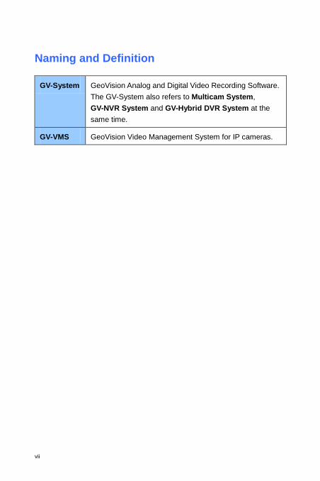
Naming and Definition
GV-System GeoVision Analog and Digital Video Recording Software. The GV-System also refers to Multicam System, GV-NVR System and GV-Hybrid DVR System at the same time.
GV-VMS GeoVision Video Management System for IP cameras.

viii
GPU Decoding Specifications GPU (Graphics Processing Unit) decoding can lower the CPU loading and increase the total frame rate supported by a GV-CMS. GPU decoding can be performed on on-board GPU, external GPU, or both, under the following specifications. For H.264 Video Compression On-board GPU: GPU decoding is only supported when using the following Intel chipsets: 2nd ~ 8th Generation Intel Core i3 / i5 / i7 Desktop Processors 9th ~ 11th Generation Intel Core i3 / i5 / i7 / i9 Desktop Processors For H.265 Video Compression On-board GPU: GPU decoding is only supported when using the following Intel chipsets: 6th ~ 8th Generation Intel Core i3 / i5 / i7 Desktop Processors 9th ~ 11th Generation Intel Core i3 / i5 / i7 / i9 Desktop Processors External GPU: GPU decoding is only supported when using NVIDIA graphics cards with compute capability 3.0 or above and memory 2 GB or above. To look up the commute capability of the NVIDIA graphics cards, refer to: https://developer.nvidia.com/cuda-gpus Note: 1. One external NVIDIA graphic card can be supported to perform GPU
decoding at free of charge. 2. GeForce GTX1060 is not supported. On-board GPU + external GPU: To have both the on-board GPU and external GPU perform GPU decoding, the GPUs must follow their respective specifications listed above.
ix
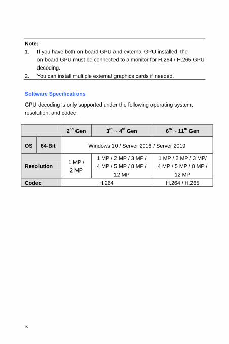
Note: 1. If you have both on-board GPU and external GPU installed, the
on-board GPU must be connected to a monitor for H.264 / H.265 GPU decoding.
2. You can install multiple external graphics cards if needed. Software Specifications
GPU decoding is only supported under the following operating system, resolution, and codec.
2nd Gen 3rd ~ 4th Gen 6th ~ 11th Gen
OS 64-Bit Windows 10 / Server 2016 / Server 2019
Resolution 1 MP / 2 MP
1 MP / 2 MP / 3 MP / 4 MP / 5 MP / 8 MP /
12 MP
1 MP / 2 MP / 3 MP/ 4 MP / 5 MP / 8 MP /
12 MP Codec H.264 H.264 / H.265
1
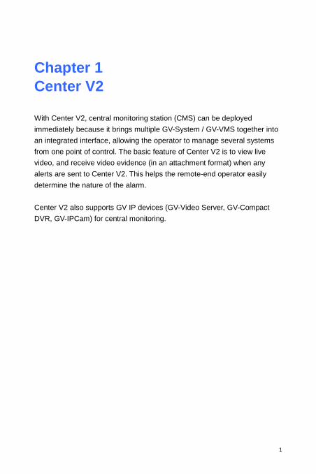
Chapter 1 Center V2 With Center V2, central monitoring station (CMS) can be deployed immediately because it brings multiple GV-System / GV-VMS together into an integrated interface, allowing the operator to manage several systems from one point of control. The basic feature of Center V2 is to view live video, and receive video evidence (in an attachment format) when any alerts are sent to Center V2. This helps the remote-end operator easily determine the nature of the alarm. Center V2 also supports GV IP devices (GV-Video Server, GV-Compact DVR, GV-IPCam) for central monitoring.
2
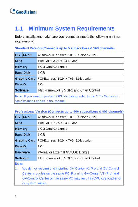
1.1 Minimum System Requirements Before installation, make sure your computer meets the following minimum requirements.
Standard Version (Connects up to 5 subscribers & 160 channels)
Professional Version (Connects up to 500 subscribers & 800 channels) OS 64-bit Windows 10 / Server 2016 / Server 2019
CPU Intel Core i7 2600, 3.4 GHz
Memory 8 GB Dual Channels
Hard Disk 1 GB
Graphic Card PCI-Express, 1024 x 768, 32-bit color
DirectX 9.0c
Hardware Internal or External GV-USB Dongle
Software .Net Framework 3.5 SP1 and Chart Control Note: 1. We do not recommend installing GV-Center V2 Pro and GV-Control
Center modules on the same PC. Running GV-Center V2 (Pro) and GV-Control Center on the same PC may result in CPU overload error or system failure.
OS 64-bit Windows 10 / Server 2016 / Server 2019
CPU Intel Core i3 2130, 3.4 GHz
Memory 4 GB Dual Channels
Hard Disk 1 GB
Graphic Card PCI-Express, 1024 x 768, 32-bit color
DirectX 9.0c
Software .Net Framework 3.5 SP1 and Chart Control
Note: If you want to perform GPU decoding, refer to the GPU Decoding Specifications earlier in the manual.
Center V2
3
1
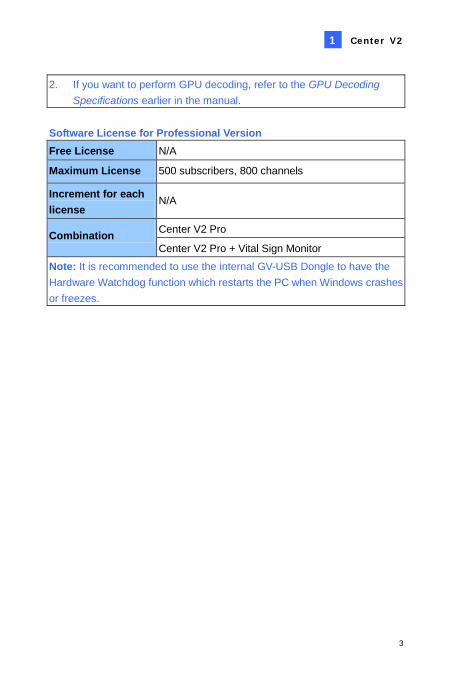
2. If you want to perform GPU decoding, refer to the GPU Decoding Specifications earlier in the manual.
Software License for Professional Version Free License N/A
Maximum License 500 subscribers, 800 channels
Increment for each license
N/A
Combination Center V2 Pro
Center V2 Pro + Vital Sign Monitor Note: It is recommended to use the internal GV-USB Dongle to have the Hardware Watchdog function which restarts the PC when Windows crashes or freezes.
4
1.2 Installation Install from Software DVD
1. Insert the Software DVD to your computer. It runs automatically and a window appears.
2. Select Install GeoVision Primary Applications.
3. Click GV-Center V2 and follow the on-screen instructions.
4. To install .Net Framework 3.5 SP1, select Download Microsoft .NET Framework 3.5.
5. To install Microsoft Chart Controls, select Download Microsoft Chart Controls [for .Net Framework 3.5].
6. To install the professional version, it is required to:
A. Connect the GV-USB Dongle to the computer.
B. Install the driver for the GV-USB Dongle. From the Software DVD, select Install or Remove GeoVision GV-Series Driver and select Install GeoVision USB Device Driver.
Download from GeoVision Website
1. Go to http://www.geovision.com.tw/download/product/GV-Center%20V2
Center V2
5
1
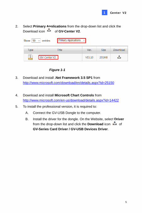
2. Select Primary Applications from the drop-down list and click the Download icon of GV-Center V2.
Figure 1-1
3. Download and install .Net Framework 3.5 SP1 from http://www.microsoft.com/download/en/details.aspx?id=25150
4. Download and install Microsoft Chart Controls from http://www.microsoft.com/en-us/download/details.aspx?id=14422
5. To install the professional version, it is required to:
A. Connect the GV-USB Dongle to the computer.
B. Install the driver for the dongle. On the Website, select Driver from the drop-down list and click the Download icon of GV-Series Card Driver / GV-USB Devices Driver.
6
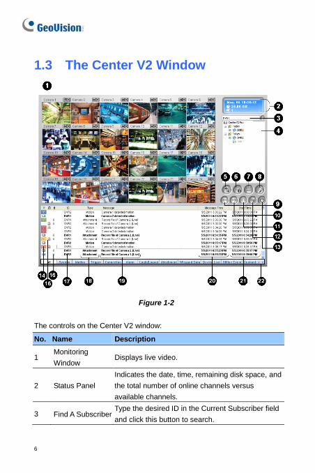
1.3 The Center V2 Window
Figure 1-2
The controls on the Center V2 window:
No. Name Description
1 Monitoring Window
Displays live video.
2 Status Panel Indicates the date, time, remaining disk space, and the total number of online channels versus available channels.
3 Find A Subscriber Type the desired ID in the Current Subscriber field and click this button to search.
Center V2
7
1
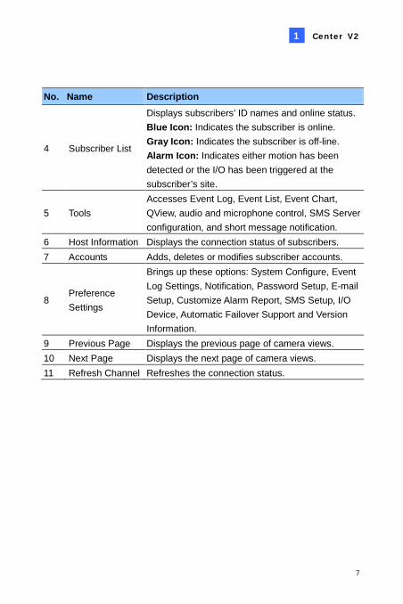
No. Name Description
4 Subscriber List
Displays subscribers’ ID names and online status. Blue Icon: Indicates the subscriber is online. Gray Icon: Indicates the subscriber is off-line. Alarm Icon: Indicates either motion has been detected or the I/O has been triggered at the subscriber’s site.
5 Tools Accesses Event Log, Event List, Event Chart, QView, audio and microphone control, SMS Server configuration, and short message notification.
6 Host Information Displays the connection status of subscribers. 7 Accounts Adds, deletes or modifies subscriber accounts.
8 Preference Settings
Brings up these options: System Configure, Event Log Settings, Notification, Password Setup, E-mail Setup, Customize Alarm Report, SMS Setup, I/O Device, Automatic Failover Support and Version Information.
9 Previous Page Displays the previous page of camera views. 10 Next Page Displays the next page of camera views. 11 Refresh Channel Refreshes the connection status.
8
No. Name Description
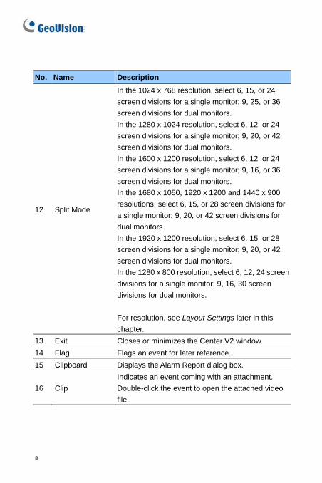
12 Split Mode
In the 1024 x 768 resolution, select 6, 15, or 24 screen divisions for a single monitor; 9, 25, or 36 screen divisions for dual monitors. In the 1280 x 1024 resolution, select 6, 12, or 24 screen divisions for a single monitor; 9, 20, or 42 screen divisions for dual monitors. In the 1600 x 1200 resolution, select 6, 12, or 24 screen divisions for a single monitor; 9, 16, or 36 screen divisions for dual monitors. In the 1680 x 1050, 1920 x 1200 and 1440 x 900 resolutions, select 6, 15, or 28 screen divisions for a single monitor; 9, 20, or 42 screen divisions for dual monitors. In the 1920 x 1200 resolution, select 6, 15, or 28 screen divisions for a single monitor; 9, 20, or 42 screen divisions for dual monitors. In the 1280 x 800 resolution, select 6, 12, 24 screen divisions for a single monitor; 9, 16, 30 screen divisions for dual monitors. For resolution, see Layout Settings later in this chapter.
13 Exit Closes or minimizes the Center V2 window. 14 Flag Flags an event for later reference. 15 Clipboard Displays the Alarm Report dialog box.
16 Clip Indicates an event coming with an attachment. Double-click the event to open the attached video file.
Center V2
9
1
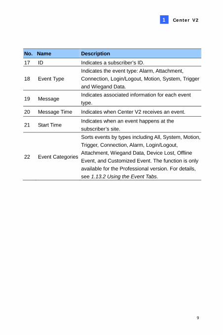
No. Name Description 17 ID Indicates a subscriber’s ID.
18 Event Type Indicates the event type: Alarm, Attachment, Connection, Login/Logout, Motion, System, Trigger and Wiegand Data.
19 Message Indicates associated information for each event type.
20 Message Time Indicates when Center V2 receives an event.
21 Start Time Indicates when an event happens at the subscriber’s site.
22 Event Categories
Sorts events by types including All, System, Motion, Trigger, Connection, Alarm, Login/Logout, Attachment, Wiegand Data, Device Lost, Offline Event, and Customized Event. The function is only available for the Professional version. For details, see 1.13.2 Using the Event Tabs.
10
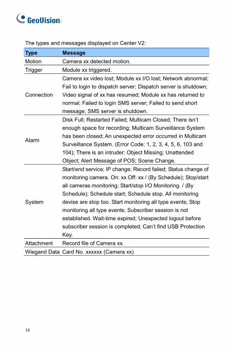
The types and messages displayed on Center V2:
Type Message
Motion Camera xx detected motion.
Trigger Module xx triggered.
Connection
Camera xx video lost; Module xx I/O lost; Network abnormal;
Fail to login to dispatch server; Dispatch server is shutdown;
Video signal of xx has resumed; Module xx has returned to
normal; Failed to login SMS server; Failed to send short
message; SMS server is shutdown.
Alarm
Disk Full; Restarted Failed; Multicam Closed; There isn’t
enough space for recording; Multicam Surveillance System
has been closed; An unexpected error occurred in Multicam
Surveillance System. (Error Code: 1, 2, 3, 4, 5, 6, 103 and
104); There is an intruder; Object Missing; Unattended
Object; Alert Message of POS; Scene Change.
System
Start/end service; IP change; Record failed; Status change of
monitoring camera. On: xx Off: xx / (By Schedule); Stop/start
all cameras monitoring; Start/stop I/O Monitoring. / (By
Schedule); Schedule start; Schedule stop. All monitoring
devise are stop too. Start monitoring all type events; Stop
monitoring all type events; Subscriber session is not
established. Wait-time expired; Unexpected logout before
subscriber session is completed; Can’t find USB Protection
Key.
Attachment Record file of Camera xx.
Wiegand Data Card No. xxxxxx (Camera xx)
Center V2
11
1
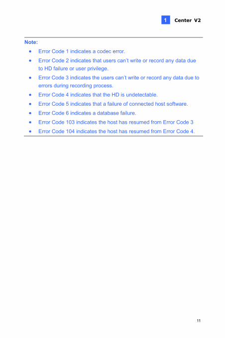
Note:
Error Code 1 indicates a codec error.
Error Code 2 indicates that users can’t write or record any data due
to HD failure or user privilege.
Error Code 3 indicates the users can’t write or record any data due to errors during recording process.
Error Code 4 indicates that the HD is undetectable.
Error Code 5 indicates that a failure of connected host software.
Error Code 6 indicates a database failure.
Error Code 103 indicates the host has resumed from Error Code 3
Error Code 104 indicates the host has resumed from Error Code 4.
12
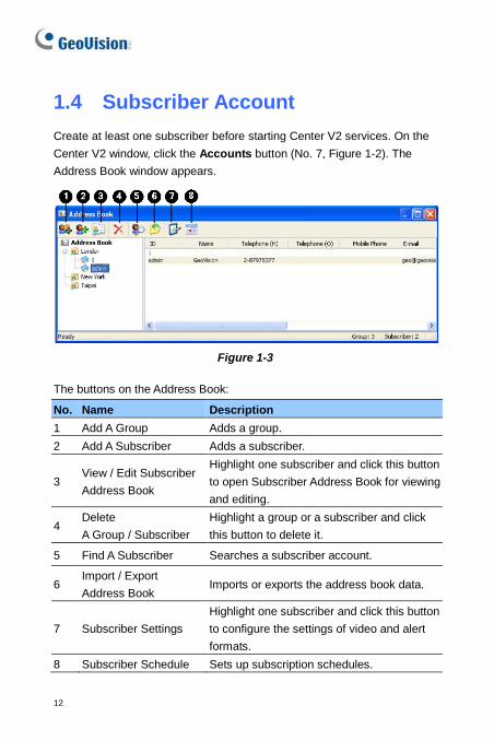
1.4 Subscriber Account Create at least one subscriber before starting Center V2 services. On the Center V2 window, click the Accounts button (No. 7, Figure 1-2). The Address Book window appears.
Figure 1-3 The buttons on the Address Book:
No. Name Description 1 Add A Group Adds a group. 2 Add A Subscriber Adds a subscriber.
3 View / Edit Subscriber Address Book
Highlight one subscriber and click this button to open Subscriber Address Book for viewing and editing.
4 Delete A Group / Subscriber
Highlight a group or a subscriber and click this button to delete it.
5 Find A Subscriber Searches a subscriber account.
6 Import / Export Address Book
Imports or exports the address book data.
7 Subscriber Settings Highlight one subscriber and click this button to configure the settings of video and alert formats.
8 Subscriber Schedule Sets up subscription schedules.
Center V2
13
1
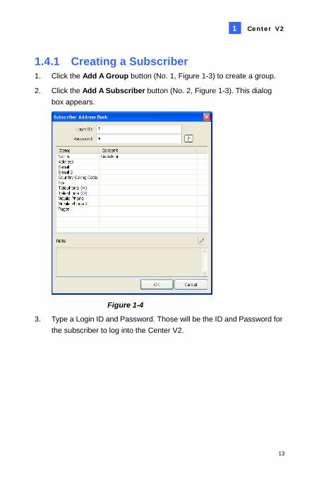
1.4.1 Creating a Subscriber 1. Click the Add A Group button (No. 1, Figure 1-3) to create a group.
2. Click the Add A Subscriber button (No. 2, Figure 1-3). This dialog box appears.
Figure 1-4
3. Type a Login ID and Password. Those will be the ID and Password for the subscriber to log into the Center V2.
14
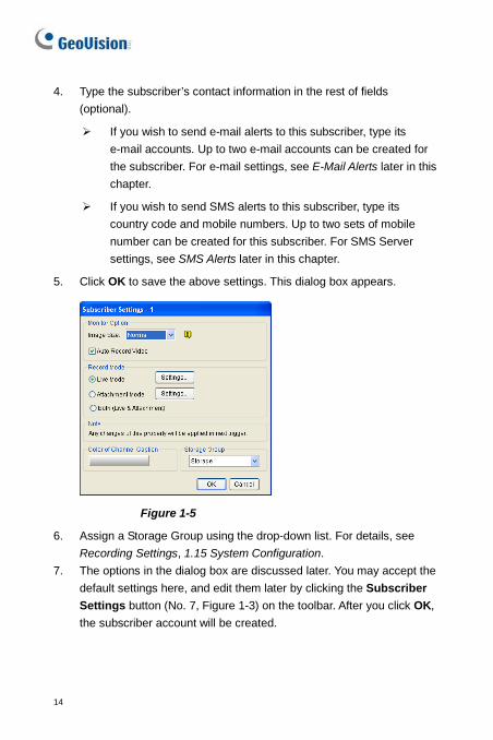
4. Type the subscriber’s contact information in the rest of fields (optional).
If you wish to send e-mail alerts to this subscriber, type its e-mail accounts. Up to two e-mail accounts can be created for the subscriber. For e-mail settings, see E-Mail Alerts later in this chapter.
If you wish to send SMS alerts to this subscriber, type its country code and mobile numbers. Up to two sets of mobile number can be created for this subscriber. For SMS Server settings, see SMS Alerts later in this chapter.
5. Click OK to save the above settings. This dialog box appears.
Figure 1-5
6. Assign a Storage Group using the drop-down list. For details, see Recording Settings, 1.15 System Configuration.
7. The options in the dialog box are discussed later. You may accept the default settings here, and edit them later by clicking the Subscriber Settings button (No. 7, Figure 1-3) on the toolbar. After you click OK, the subscriber account will be created.
Center V2
15
1
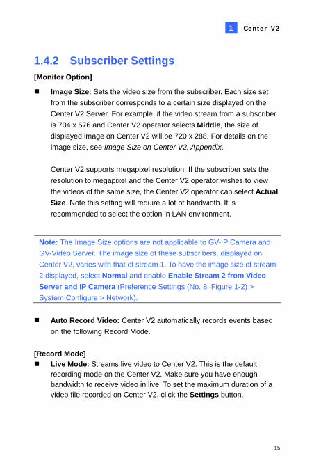
1.4.2 Subscriber Settings [Monitor Option]
Image Size: Sets the video size from the subscriber. Each size set from the subscriber corresponds to a certain size displayed on the Center V2 Server. For example, if the video stream from a subscriber is 704 x 576 and Center V2 operator selects Middle, the size of displayed image on Center V2 will be 720 x 288. For details on the image size, see Image Size on Center V2, Appendix. Center V2 supports megapixel resolution. If the subscriber sets the resolution to megapixel and the Center V2 operator wishes to view the videos of the same size, the Center V2 operator can select Actual Size. Note this setting will require a lot of bandwidth. It is recommended to select the option in LAN environment.
Note: The Image Size options are not applicable to GV-IP Camera and GV-Video Server. The image size of these subscribers, displayed on Center V2, varies with that of stream 1. To have the image size of stream 2 displayed, select Normal and enable Enable Stream 2 from Video Server and IP Camera (Preference Settings (No. 8, Figure 1-2) > System Configure > Network).
Auto Record Video: Center V2 automatically records events based
on the following Record Mode. [Record Mode] Live Mode: Streams live video to Center V2. This is the default
recording mode on the Center V2. Make sure you have enough bandwidth to receive video in live. To set the maximum duration of a video file recorded on Center V2, click the Settings button.
16
Attachment Mode: A defined time of event will be recorded before sending to Center V2. The attachment will be sent out immediately once your subscriber is connected to Center V2. The Attachment Mode also provides several options associated with the attachment. Click the Settings button to bring up the Record Settings – Attachment Mode dialog box. See Attachment Mode Settings later for further setup.
Both (Live & Attachment): Sends both live video and attachment files.
[Color of Channel Caption] Changes the color of channel headings. For further setup, see Channel Heading later in this chapter.
Center V2
17
1
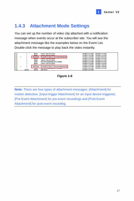
1.4.3 Attachment Mode Settings You can set up the number of video clip attached with a notification message when events occur at the subscriber site. You will see the attachment message like the examples below on the Event List. Double-click the message to play back the video instantly.
Figure 1-6
Note: There are four types of attachment messages: [Attachment] for motion detection, [Input-trigger Attachment] for an input device triggered, [Pre-Event Attachment] for pre-event recordings and [Post-Event Attachment] for post-event recording.
18
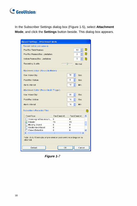
In the Subscriber Settings dialog box (Figure 1-5), select Attachment Mode, and click the Settings button beside. This dialog box appears.
Figure 1-7
Center V2
19
1
[Record Options (per camera)] Pre-Rec Total Frames: Determines the total pre-recorded frames in a
video attachment. Pre-Rec Frames/sec Limitation: Determines the frame rate in the
pre-recorded period.
Note: Dividing the Pre-Rec Total Frames by Pre-Rec Frames/Sec Limitation, you will get the total time of the video attachment.
Motion Frames/sec Limitation: Determines the frame rate of the
video to be sent as an attachment. Recording Quality: Use the slider bar to adjust the video quality in 3
levels. [Attachment option (Record by Motion)] Defines the duration of the video attachment delivered upon motion. Max video Clip: Determines the duration of the video attachment. Pos-Rec Motion: Determines how many seconds of video to be sent
after motion stops. Alerts interval: Determines the interval between notification
messages attached with video clips. [Attachment option (Record by I/O trigger)] Defines the duration of the video attachment delivered upon I/O trigger. The three options are the same as those in [Attachment option (Record by Motion)] above. [Subscriber’s Recorded Files] Receives up to 15 minutes of pre-event and post-event recordings respectively for the selected event from this subscriber. These video attachments provide the Center V2 administrator information of what happened before and after the event . Note this function is only applicable to these event types: Motion, I/O Trigger, Video Signal Resumption, Intruder, Crowd Detection, Unattended Object, Scene Change, Missing Object, Advanced Unattended Object, Advanced Scene Change and Advanced Missing Object.
20
Select the desired event type, click the Pre-Event Attachment and/or Post-Event Attachment column, and select the number of clip files to be attached with a notification message. For example, if the subscriber is set to record for 1 minute per clip, and the pre-event attachment is set to 15 (as illustrated in Figure 1-7), you will receive 15 notifications with attachments when the selected event occurs. However, if the subscriber is set to record for 5 minutes per clip, you will receive 3 notifications with attachments.
Note: For the subscriber to provide pre-event and post-event recordings of an event, it has to be recording in the round-the-clock mode.
Center V2
21
1
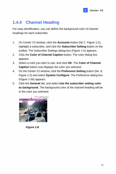
1.4.4 Channel Heading For easy identification, you can define the background color of channel headings for each subscriber.
1. On Center V2 window, click the Accounts button (No.7, Figure 1-2),
highlight a subscriber, and click the Subscriber Setting button on the toolbar. The Subscriber Settings dialog box (Figure 1-5) appears.
2. Click the Color of Channel Caption button. The color dialog box appears.
3. Select a color you wish to use, and click OK. The Color of Channel Caption button now displays the color you selected.
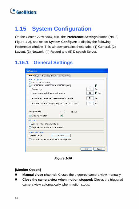
4. On the Center V2 window, click the Preference Setting button (No. 8, Figure 1-2) and select System Configure. The Preference dialog box (Figure 1-56) appears.
5. Click the General tab, and select Use the subscriber setting color as background. The background color of the channel heading will be in the color you selected.
Figure 1-8
22
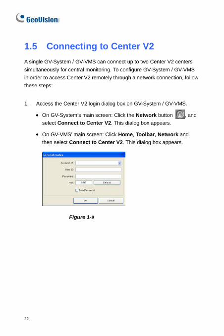
1.5 Connecting to Center V2 A single GV-System / GV-VMS can connect up to two Center V2 centers simultaneously for central monitoring. To configure GV-System / GV-VMS in order to access Center V2 remotely through a network connection, follow these steps:
1. Access the Center V2 login dialog box on GV-System / GV-VMS.
• On GV-System’s main screen: Click the Network button , and select Connect to Center V2. This dialog box appears.
• On GV-VMS’ main screen: Click Home, Toolbar, Network and then select Connect to Center V2. This dialog box appears.
Figure 1-9
Center V2
23
1
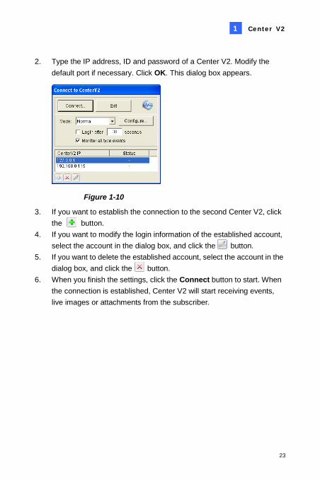
2. Type the IP address, ID and password of a Center V2. Modify the default port if necessary. Click OK. This dialog box appears.
Figure 1-10
3. If you want to establish the connection to the second Center V2, click the button.
4. If you want to modify the login information of the established account, select the account in the dialog box, and click the button.
5. If you want to delete the established account, select the account in the dialog box, and click the button.
6. When you finish the settings, click the Connect button to start. When the connection is established, Center V2 will start receiving events, live images or attachments from the subscriber.
24
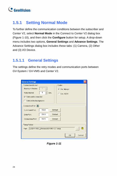
1.5.1 Setting Normal Mode To further define the communication conditions between the subscriber and Center V2, select Normal Mode in the Connect to Center V2 dialog box (Figure 1-10), and then click the Configure button for setup. A drop-down menu includes two options, General Settings and Advance Settings. The Advance Settings dialog box includes these tabs: (1) Camera, (2) Other and (3) I/O Device.
1.5.1.1 General Settings The settings define the retry modes and communication ports between GV-System / GV-VMS and Center V2.
Figure 1-11
Center V2
25
1
[Connection Broken]
Maximum Retries: Sets the number of retries if connection is not immediately available.
Retry Interval: Sets the interval between retries.
Retry until connected: Keeps GV-System / GV-VMS on trying until connected to Center V2.
Retry in the background: Hides the retries in the background. [Codec] Selects Geo Mpeg 4 (default) or Geo H264 as the compression method for video sent to Center V2. [Connective Port] Displays ports used for communication. It is recommended to keep the default settings, unless otherwise necessary. To automatically configure these ports on your router by UPnP technology, click the Arrow button. For details on UPnP settings, see UPnP Settings, Appendix. [Temp Folder] Attachments are temporarily stored in this folder while waiting to be sent to Center V2. In case the connection is broken, attachments meant to be sent to Center V2 could be found here. Once the connection is back to normal, events saved in the Temp Folder will be sent out immediately.
26
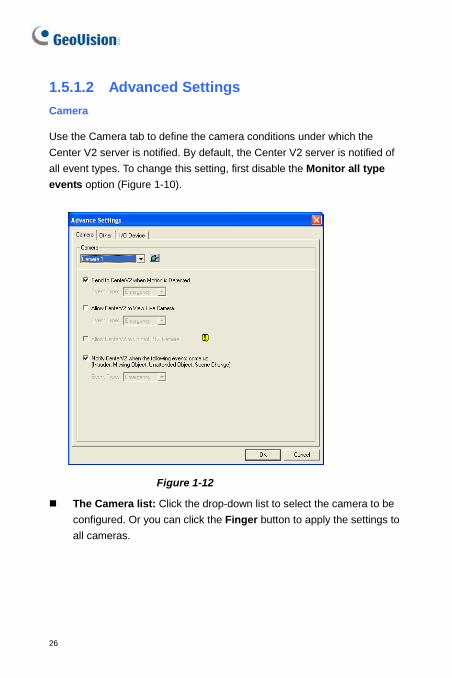
1.5.1.2 Advanced Settings Camera
Use the Camera tab to define the camera conditions under which the Center V2 server is notified. By default, the Center V2 server is notified of all event types. To change this setting, first disable the Monitor all type events option (Figure 1-10).
Figure 1-12
The Camera list: Click the drop-down list to select the camera to be configured. Or you can click the Finger button to apply the settings to all cameras.
Center V2
27
1
Send to Center V2 when Motion is Detected: Sends notifications (video and text messages) to Center V2 when motion is detected. Event Type: To always notify Center V2 of motion event, select Emergency. To only notify Center V2 of motion event when an assigned input is triggered or within the established schedule, select Normal.
Allow Center V2 to View Live Camera: Gives Center V2 the privilege to view your cameras at any time.
Allow Center V2 to Control PTZ Camera: Gives Center V2 the privilege to control your PTZ cameras. Remember to properly set up camera mapping first. See Mapping PTZ Cameras, Chapter 1, GV-DVR User’s Manual on the Software DVD.
Notify Center V2 when the following events come up: Notifies Center V2 when any of these alert events occur: Intruder, Missing Object, Unattended Object, Scene Change, Crowd Detection, Advanced Missing Object, Advanced Unattended Object and Advanced Scene Change.
Event Type: To always notify Center V2 of these alert events, select Emergency. If the subscriber wants Center V2 to get notified of these alert events only when an assigned input is triggered or within the established schedule, select Normal.
Note: To assign an input or set up a schedule for sending trigger notifications, see Security Service, [I/O Device] and Monitoring Schedule respectively.
28
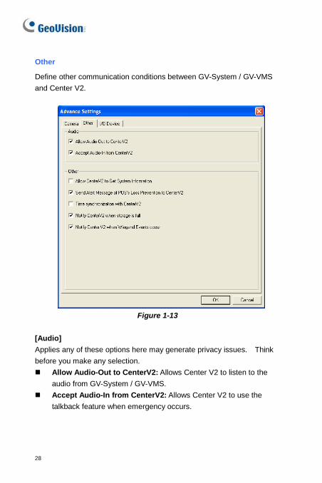
Other
Define other communication conditions between GV-System / GV-VMS and Center V2.
Figure 1-13
[Audio] Applies any of these options here may generate privacy issues. Think before you make any selection. Allow Audio-Out to CenterV2: Allows Center V2 to listen to the
audio from GV-System / GV-VMS. Accept Audio-In from CenterV2: Allows Center V2 to use the
talkback feature when emergency occurs.
Center V2
29
1
[Other] Allow Center V2 to Get System Information: Allows Center V2 to
get system information on your GV-System / GV-VMS. Send Alert Message of POS’s Loss Prevention to Center V2:
Notifies Center V2 about the events of POS Loss Prevention. Note this option is only supported by GV-System
Time synchronization with Center V2: Enables the time increment/decrement of minutes and seconds at the subscriber site to match the time at the Center V2.
Notify Center V2 when the storage space was full: Notifies the Center V2 when the subscriber’s storage space is insufficient.
Notify Center V2 when Wiegand Event occurs: This option is designed for the access control application with GV-Wiegand Capture. When the GV-System / GV-VMS receives the card number from GV-Wiegand Capture, the number can also be sent to the Center V2. Note this option is only supported by GV-System
Note: When Time synchronization with Center V2 is selected, the function of time synchronization will be activated as soon as the Center V2 is started up, and it will be re-activated every 12 hours.
I/O Device
The settings define which I/O condition to notify Center V2. To configure these settings, first disable the Monitor all type events option in Figure 1-10. Note this tab is only accessible when one or more I/O device is installed to GV-System / GV-VMS.
30
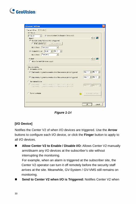
Figure 1-14
[I/O Device]
Notifies the Center V2 of when I/O devices are triggered. Use the Arrow buttons to configure each I/O device, or click the Finger button to apply to all I/O devices.
Allow Center V2 to Enable / Disable I/O: Allows Center V2 manually arm/disarm any I/O devices at the subscriber’s site without interrupting the monitoring. For example, when an alarm is triggered at the subscriber site, the Center V2 operator can turn it off remotely before the security staff arrives at the site. Meanwhile, GV-System / GV-VMS still remains on monitoring.
Send to Center V2 when I/O is Triggered: Notifies Center V2 when
Center V2
31
1
any selected input is triggered.
With Camera(s): Sends the camera video to Center V2 when the selected input is triggered. Click the Set Camera(s) button to assign cameras for the application.
Event Type: If the subscriber wants Center V2 always to get notified of the input trigger, select Emergency. If the subscriber wants Center V2 to get notified of the input trigger only when an assigned input is triggered, select Normal. Right Arrow button: Sets the delay time to notify Center V2 of input trigger. This feature is only available when the Normal type is chosen.
Exit Delay: While the system is activated, this feature provides an interval of time for the subscriber to exit the premises. During this time, the specified input (e.g. an exit/entry door) is inactive. Once the exit delay expires, the input will be fully armed.
Entry Delay: While the system is activated, this feature provides an interval of time for the subscriber to entry the premises. During this time, the specified input (e.g. an exit/entry door) is inactive so that the subscriber can disarm the system. If the subscriber fails to do, once the entry delay expires, Center V2 will get notified of the input trigger.
Output Module: Enables the assigned output module when the selected input module is triggered. For the example of Figure 1-14, when the I/O Device (Module 1, Input 4) is triggered, the Output (Module 1, Pin 3) will be activated simultaneously. Right Arrow button: Sets the delay time to trigger the assigned output module. Event Type: If the subscriber wants Center V2 always to get notified of the output trigger, select Emergency. If the subscriber wants Center V2 to get notified of the output trigger only when an assigned input is triggered, select Normal.
32
Note: 1. To set an input trigger for the notification of Normal events, see
[Security Service] below. 2. The delay settings in Send to Center V2 when I/O is triggered
and Output Module allow you to enter your premises and disable input/output module before it is activated. To disable prior I/O settings, the subscriber may exit the connection to Center V2 or use the Stop monitoring normal events when selected pin is triggered feature in Figure 1-14.
Allow Center V2 to Force Output: Allows Center V2 to manually force output devices of the subscriber to be triggered.
[Security Service] Defines the input type or the schedule. Proceed to configure input and schedule settings.
Momentary Mode: Pushbutton switches that are normally open and stay closed only as long as the button is pressed. Momentary switches allow turn-on or turn-off from multiple locations. For example, certain premises have a designated entry/exit door. When the staff enters the entry door, the system starts monitoring. When the staff leaves from the exit door, the system stops monitoring.
Maintained Mode: Push-on/push off button switches that stay open until thrown, and then stay closed until thrown again. Maintained switches are convenient for only one switch location. For example, in the business hour when the door is opened, the system stops monitoring; in the non-business hour when the door is closed, the system starts monitoring.
Center V2
33
1
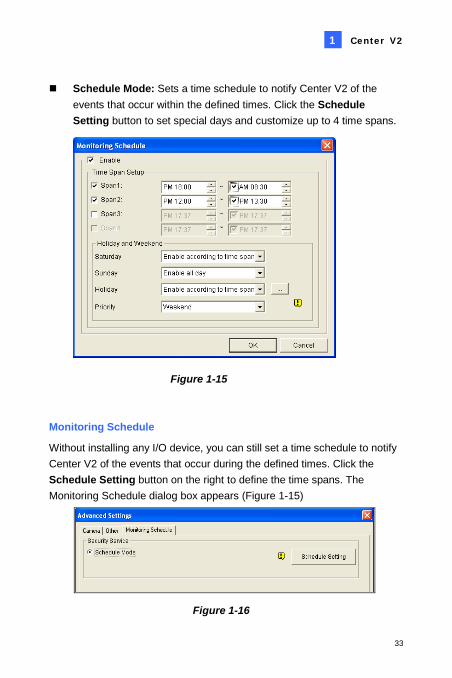
Schedule Mode: Sets a time schedule to notify Center V2 of the events that occur within the defined times. Click the Schedule Setting button to set special days and customize up to 4 time spans.
Figure 1-15
Monitoring Schedule
Without installing any I/O device, you can still set a time schedule to notify Center V2 of the events that occur during the defined times. Click the Schedule Setting button on the right to define the time spans. The Monitoring Schedule dialog box appears (Figure 1-15)
Figure 1-16
34
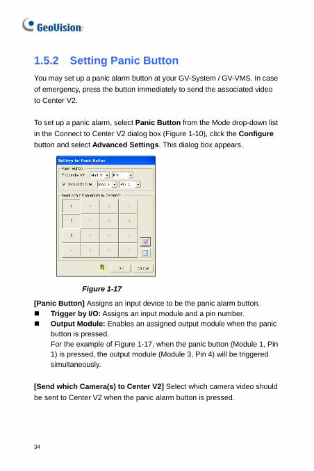
1.5.2 Setting Panic Button You may set up a panic alarm button at your GV-System / GV-VMS. In case of emergency, press the button immediately to send the associated video to Center V2. To set up a panic alarm, select Panic Button from the Mode drop-down list in the Connect to Center V2 dialog box (Figure 1-10), click the Configure button and select Advanced Settings. This dialog box appears.
Figure 1-17
[Panic Button] Assigns an input device to be the panic alarm button. Trigger by I/O: Assigns an input module and a pin number. Output Module: Enables an assigned output module when the panic
button is pressed. For the example of Figure 1-17, when the panic button (Module 1, Pin 1) is pressed, the output module (Module 3, Pin 4) will be triggered simultaneously.
[Send which Camera(s) to Center V2] Select which camera video should be sent to Center V2 when the panic alarm button is pressed.
Center V2
35
1
1.5.3 Detecting Input Status The feature is designed to monitor all inputs for a change of state whenever the subscriber starts the live monitoring through Center V2. A change from the previously defined state (N/O to N/C or N/C to N/O) will activate an alarm condition.
Click in the Connect to Center V2 dialog box (Figure 1-10). For details, see Input State Detection, Chapter 6, GV-DVR User’s Manual on the Software DVD.
36
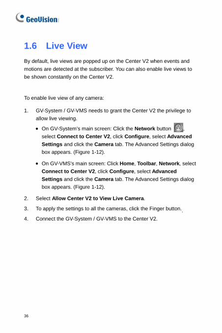
1.6 Live View By default, live views are popped up on the Center V2 when events and motions are detected at the subscriber. You can also enable live views to be shown constantly on the Center V2.
To enable live view of any camera:
1. GV-System / GV-VMS needs to grant the Center V2 the privilege to allow live viewing.
• On GV-System’s main screen: Click the Network button , select Connect to Center V2, click Configure, select Advanced Settings and click the Camera tab. The Advanced Settings dialog box appears. (Figure 1-12).
• On GV-VMS’s main screen: Click Home, Toolbar, Network, select Connect to Center V2, click Configure, select Advanced Settings and click the Camera tab. The Advanced Settings dialog box appears. (Figure 1-12).
2. Select Allow Center V2 to View Live Camera.
3. To apply the settings to all the cameras, click the Finger button..
4. Connect the GV-System / GV-VMS to the Center V2.
Center V2
37
1
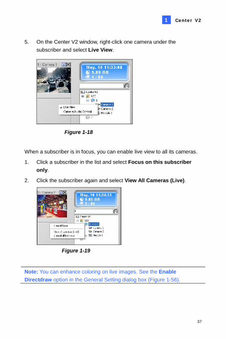
5. On the Center V2 window, right-click one camera under the subscriber and select Live View.
Figure 1-18
When a subscriber is in focus, you can enable live view to all its cameras.
1. Click a subscriber in the list and select Focus on this subscriber only.
2. Click the subscriber again and select View All Cameras (Live).
Figure 1-19
Note: You can enhance coloring on live images. See the Enable Directdraw option in the General Setting dialog box (Figure 1-56).
38
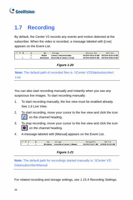
1.7 Recording By default, the Center V2 records any events and motion detected at the subscriber. When the video is recorded, a message labeled with [Live] appears on the Event List.
Figure 1-20
Note: The default path of recorded files is :\\Center V2\Data\subscriber\ Live
You can also start recording manually and instantly when you see any suspicious live images. To start recording manually:
1. To start recording manually, the live view must be enabled already. See 1.6 Live View.
2. To start recording, move your cursor to the live view and click the icon on the channel heading.
3. To stop recording, move your cursor to the live view and click the icon on the channel heading.
4. A message labeled with [Manual] appears on the Event List.
Figure 1-21
Note: The default path for recordings started manually is :\\Center V2\ Data\subscriber\Manual
For related recording and storage settings, see 1.15.4 Recording Settings.
Center V2
39
1
1.8 Playback You can play back the video events saved on the Center V2 by clicking the attachments on the Event List, or play back the video events recorded on the remote subscriber.
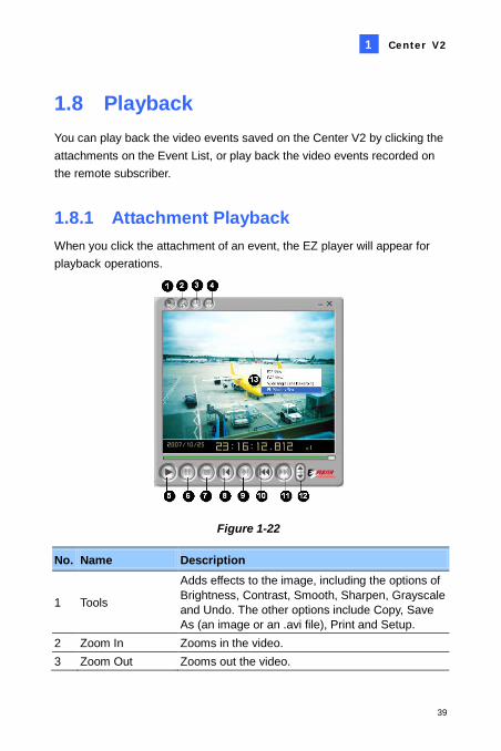
1.8.1 Attachment Playback When you click the attachment of an event, the EZ player will appear for playback operations.
Figure 1-22
No. Name Description
1 Tools
Adds effects to the image, including the options of Brightness, Contrast, Smooth, Sharpen, Grayscale and Undo. The other options include Copy, Save As (an image or an .avi file), Print and Setup.
2 Zoom In Zooms in the video. 3 Zoom Out Zooms out the video.
40
No. Name Description
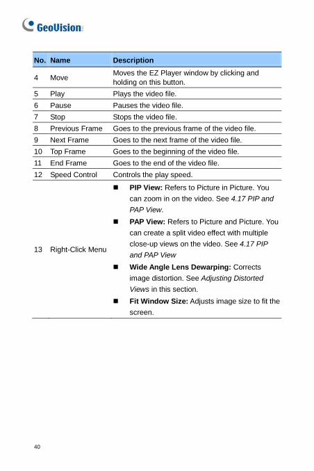
4 Move Moves the EZ Player window by clicking and holding on this button.
5 Play Plays the video file. 6 Pause Pauses the video file. 7 Stop Stops the video file. 8 Previous Frame Goes to the previous frame of the video file. 9 Next Frame Goes to the next frame of the video file. 10 Top Frame Goes to the beginning of the video file. 11 End Frame Goes to the end of the video file. 12 Speed Control Controls the play speed.
13 Right-Click Menu
PIP View: Refers to Picture in Picture. You can zoom in on the video. See 4.17 PIP and PAP View.
PAP View: Refers to Picture and Picture. You can create a split video effect with multiple close-up views on the video. See 4.17 PIP and PAP View
Wide Angle Lens Dewarping: Corrects image distortion. See Adjusting Distorted Views in this section.
Fit Window Size: Adjusts image size to fit the screen.
Center V2
41
1
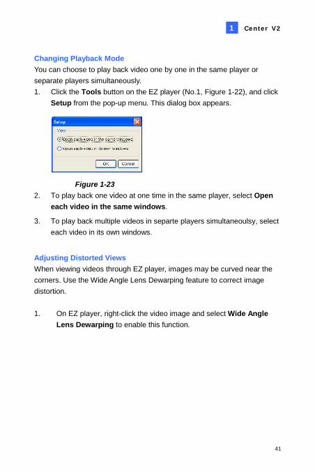
Changing Playback Mode You can choose to play back video one by one in the same player or separate players simultaneously. 1. Click the Tools button on the EZ player (No.1, Figure 1-22), and click
Setup from the pop-up menu. This dialog box appears.
Figure 1-23 2. To play back one video at one time in the same player, select Open
each video in the same windows.
3. To play back multiple videos in separte players simultaneoulsy, select each video in its own windows.
Adjusting Distorted Views When viewing videos through EZ player, images may be curved near the corners. Use the Wide Angle Lens Dewarping feature to correct image distortion. 1. On EZ player, right-click the video image and select Wide Angle
Lens Dewarping to enable this function.
42
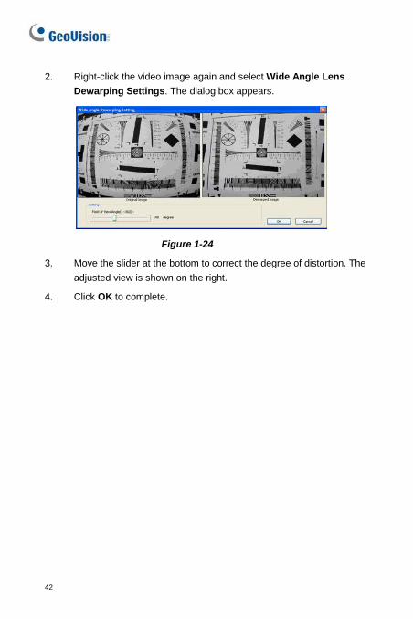
2. Right-click the video image again and select Wide Angle Lens Dewarping Settings. The dialog box appears.
Figure 1-24
3. Move the slider at the bottom to correct the degree of distortion. The adjusted view is shown on the right.
4. Click OK to complete.
Center V2
43
1
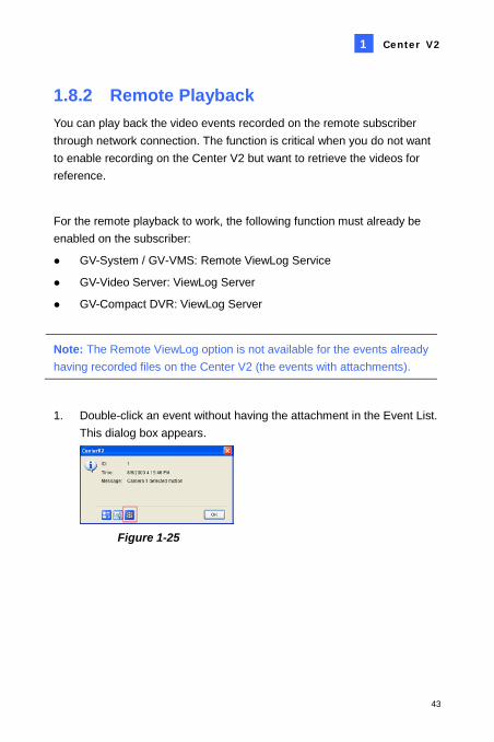
1.8.2 Remote Playback You can play back the video events recorded on the remote subscriber through network connection. The function is critical when you do not want to enable recording on the Center V2 but want to retrieve the videos for reference.
For the remote playback to work, the following function must already be enabled on the subscriber:
GV-System / GV-VMS: Remote ViewLog Service
GV-Video Server: ViewLog Server
GV-Compact DVR: ViewLog Server
Note: The Remote ViewLog option is not available for the events already having recorded files on the Center V2 (the events with attachments).
1. Double-click an event without having the attachment in the Event List. This dialog box appears.
Figure 1-25
44
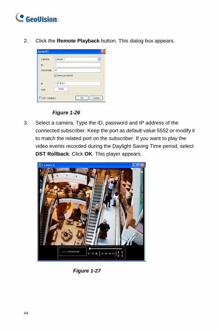
2. Click the Remote Playback button. This dialog box appears.
Figure 1-26
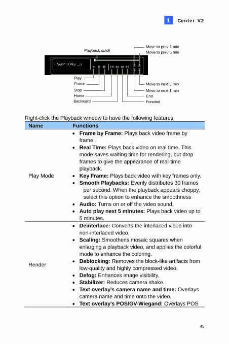
3. Select a camera. Type the ID, password and IP address of the connected subscriber. Keep the port as default value 5552 or modify it to match the related port on the subscriber. If you want to play the video events recorded during the Daylight Saving Time period, select DST Rollback. Click OK. This player appears.
Figure 1-27
Center V2
45
1
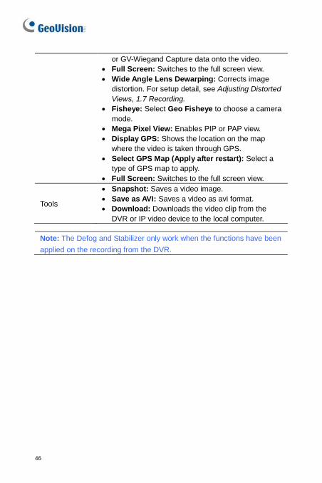
Playback scroll
PlayPauseStop
ForwardHomeBackward
End
Move to prev 5 min
Move to next 1 minMove to next 5 min
Move to prev 1 min
Right-click the Playback window to have the following features: Name Functions
Play Mode
• Frame by Frame: Plays back video frame by frame.
• Real Time: Plays back video on real time. This mode saves waiting time for rendering, but drop frames to give the appearance of real-time playback.
• Key Frame: Plays back video with key frames only. • Smooth Playbacks: Evenly distributes 30 frames
per second. When the playback appears choppy, select this option to enhance the smoothness
• Audio: Turns on or off the video sound. • Auto play next 5 minutes: Plays back video up to
5 minutes.
Render
• Deinterlace: Converts the interlaced video into non-interlaced video.
• Scaling: Smoothens mosaic squares when enlarging a playback video, and applies the colorful mode to enhance the coloring.
• Deblocking: Removes the block-like artifacts from low-quality and highly compressed video.
• Defog: Enhances image visibility. • Stabilizer: Reduces camera shake. • Text overlay’s camera name and time: Overlays
camera name and time onto the video. • Text overlay’s POS/GV-Wiegand: Overlays POS
46
or GV-Wiegand Capture data onto the video. • Full Screen: Switches to the full screen view. • Wide Angle Lens Dewarping: Corrects image
distortion. For setup detail, see Adjusting Distorted Views, 1.7 Recording.
• Fisheye: Select Geo Fisheye to choose a camera mode.
• Mega Pixel View: Enables PIP or PAP view. • Display GPS: Shows the location on the map
where the video is taken through GPS. • Select GPS Map (Apply after restart): Select a
type of GPS map to apply. • Full Screen: Switches to the full screen view.
Tools
• Snapshot: Saves a video image. • Save as AVI: Saves a video as avi format. • Download: Downloads the video clip from the
DVR or IP video device to the local computer.
Note: The Defog and Stabilizer only work when the functions have been applied on the recording from the DVR.
Center V2
47
1
1.9 Two-Way Audio The Center V2 operator can perform two-way audio with subscribers.
Note: For GV-System, this function is only supported by version 8.0 or later.
1. The GV-System / GV-VMS needs to grant Center V2 the privilege to allow two-way communications.
• On GV-System’s main screen: Click the Network button , select Connect to Center V2, click Configure, select Advanced Settings, and click the Other tab. The Advanced Settings dialog box appears (Figure 1-13).
• On GV-VMS’ main screen: Click Home, Toolbar, Network, select Connect to Center V2, click Configure, select Advanced Settings and click the Other tab. The Advanced Settings dialog box appears. (Figure 1-13).
2. Under the Audio section, select Allow Audio-Out to Center V2 and Allow Audio-In from the Center V2. Click OK.
3. Connect the GV-System / GV-VMS to the Center V2.
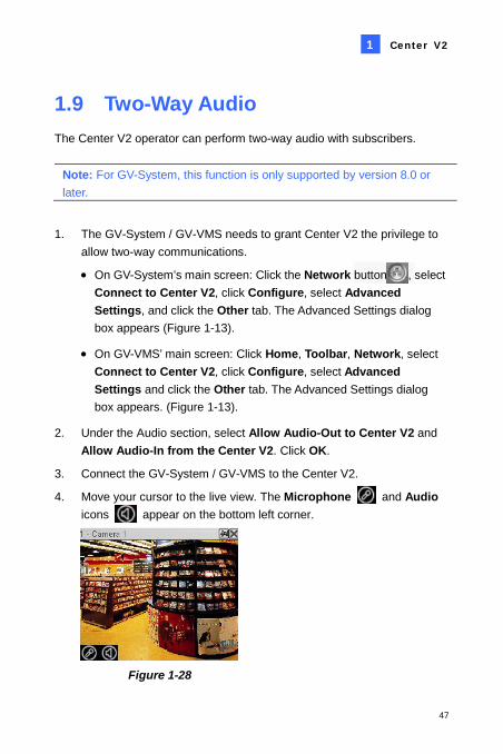
4. Move your cursor to the live view. The Microphone and Audio icons appear on the bottom left corner.
Figure 1-28
48
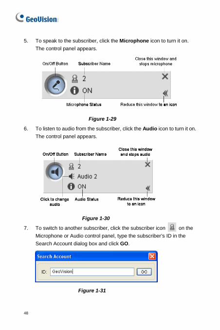
5. To speak to the subscriber, click the Microphone icon to turn it on. The control panel appears.
Figure 1-29
6. To listen to audio from the subscriber, click the Audio icon to turn it on. The control panel appears.
Figure 1-30
7. To switch to another subscriber, click the subscriber icon on the Microphone or Audio control panel, type the subscriber’s ID in the Search Account dialog box and click GO.
Figure 1-31
Center V2
49
1
1.10 Advanced Monitoring and Management
This section describes how to monitor and manage subscribers in these parts: (1) Showing and Controlling I/O Status, (2) Camera/Audio Control, (3) Simple Microphone and Audio Panels (4) Camera Monitor (5) Viewing Subscriber Information (6) Subscription Control.
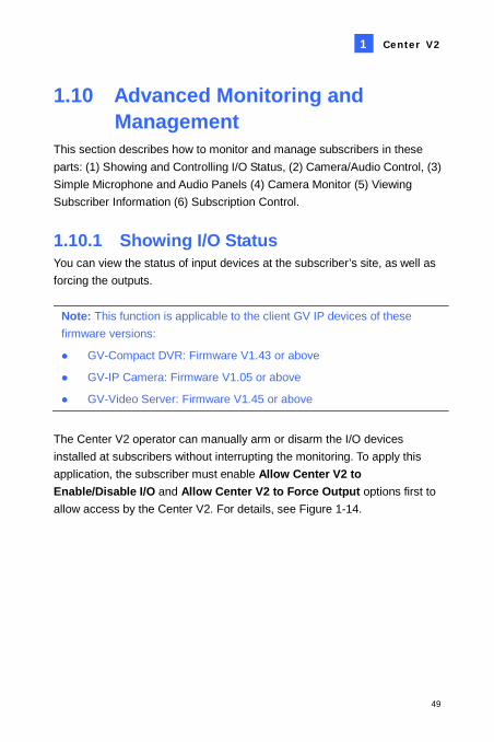
1.10.1 Showing I/O Status You can view the status of input devices at the subscriber’s site, as well as forcing the outputs.
Note: This function is applicable to the client GV IP devices of these firmware versions:
GV-Compact DVR: Firmware V1.43 or above
GV-IP Camera: Firmware V1.05 or above
GV-Video Server: Firmware V1.45 or above
The Center V2 operator can manually arm or disarm the I/O devices installed at subscribers without interrupting the monitoring. To apply this application, the subscriber must enable Allow Center V2 to Enable/Disable I/O and Allow Center V2 to Force Output options first to allow access by the Center V2. For details, see Figure 1-14.
50
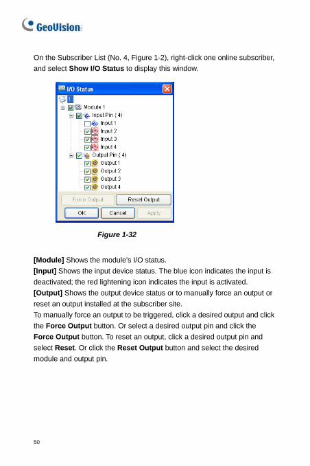
On the Subscriber List (No. 4, Figure 1-2), right-click one online subscriber, and select Show I/O Status to display this window.
Figure 1-32
[Module] Shows the module’s I/O status. [Input] Shows the input device status. The blue icon indicates the input is deactivated; the red lightening icon indicates the input is activated. [Output] Shows the output device status or to manually force an output or reset an output installed at the subscriber site. To manually force an output to be triggered, click a desired output and click the Force Output button. Or select a desired output pin and click the Force Output button. To reset an output, click a desired output pin and select Reset. Or click the Reset Output button and select the desired module and output pin.
Center V2
51
1
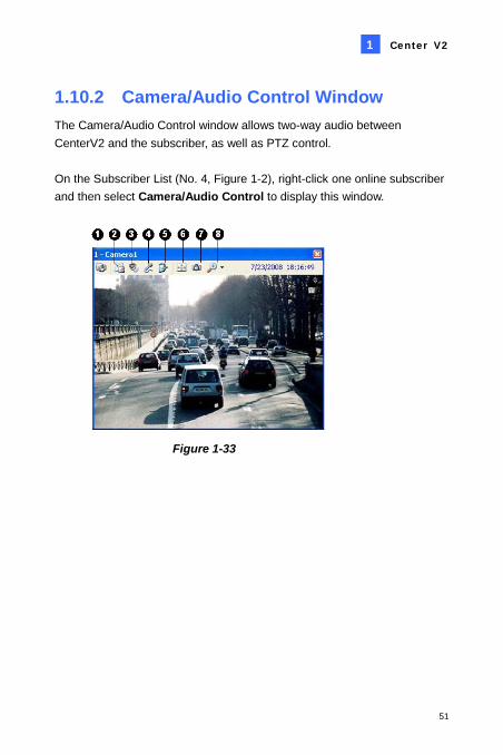
1.10.2 Camera/Audio Control Window The Camera/Audio Control window allows two-way audio between CenterV2 and the subscriber, as well as PTZ control. On the Subscriber List (No. 4, Figure 1-2), right-click one online subscriber and then select Camera/Audio Control to display this window.
Figure 1-33
52
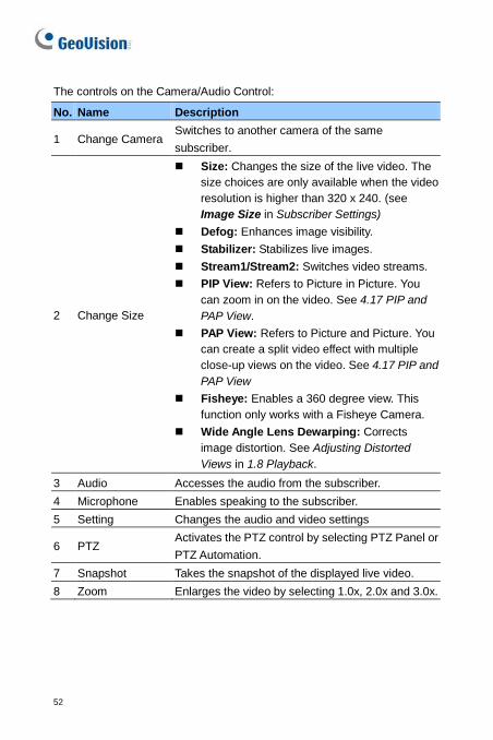
The controls on the Camera/Audio Control:
No. Name Description
1 Change Camera Switches to another camera of the same subscriber.
2 Change Size
Size: Changes the size of the live video. The size choices are only available when the video resolution is higher than 320 x 240. (see Image Size in Subscriber Settings)
Defog: Enhances image visibility. Stabilizer: Stabilizes live images. Stream1/Stream2: Switches video streams. PIP View: Refers to Picture in Picture. You
can zoom in on the video. See 4.17 PIP and PAP View.
PAP View: Refers to Picture and Picture. You can create a split video effect with multiple close-up views on the video. See 4.17 PIP and PAP View
Fisheye: Enables a 360 degree view. This function only works with a Fisheye Camera.
Wide Angle Lens Dewarping: Corrects image distortion. See Adjusting Distorted Views in 1.8 Playback.
3 Audio Accesses the audio from the subscriber. 4 Microphone Enables speaking to the subscriber. 5 Setting Changes the audio and video settings
6 PTZ Activates the PTZ control by selecting PTZ Panel or PTZ Automation.
7 Snapshot Takes the snapshot of the displayed live video. 8 Zoom Enlarges the video by selecting 1.0x, 2.0x and 3.0x.
Center V2
53
1
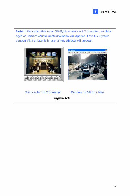
Note: If the subscriber uses GV-System version 8.2 or earlier, an older style of Camera /Audio Control Window will appear. If the GV-System version V8.3 or later is in use, a new window will appear.
Window for V8.2 or earlier Window for V8.3 or later
Figure 1-34
54
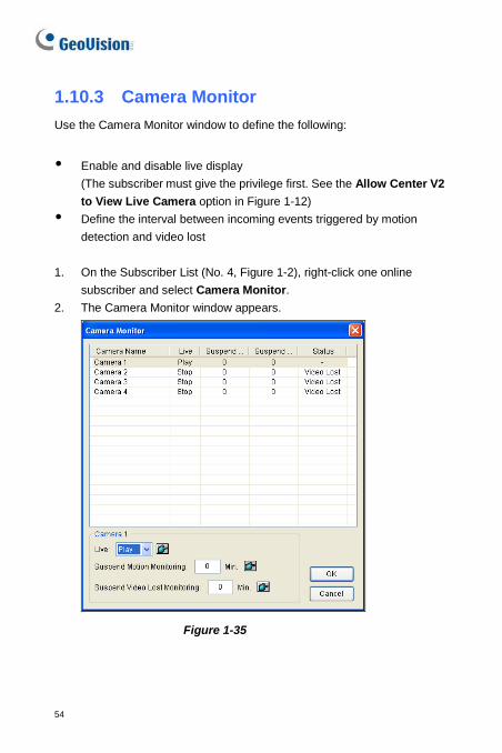
1.10.3 Camera Monitor Use the Camera Monitor window to define the following:
Enable and disable live display
(The subscriber must give the privilege first. See the Allow Center V2 to View Live Camera option in Figure 1-12)
Define the interval between incoming events triggered by motion detection and video lost
1. On the Subscriber List (No. 4, Figure 1-2), right-click one online
subscriber and select Camera Monitor. 2. The Camera Monitor window appears.
Figure 1-35
Center V2
55
1
Live drop-down list: Highlight one camera, and select Play (enable live display) or Stop (disable live video).
Suspended Motion Monitoring: Highlight one camera, and set the interval between incoming events triggered by motion detection. Alternatively, you can right-click one live camera channel on the monitoring window and select Suspend for the same setting.
Suspend Video Lost Monitoring: Highlight one camera, and set the interval between incoming events triggered by video lost.
Status column: Displays the status of video lost from cameras or disconnection.
3. Click OK to apply the settings. If the camera is enabled for live display, you will see in the upper right corner of its monitoring window; otherwise, you will see .
56
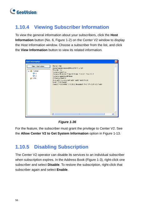
1.10.4 Viewing Subscriber Information To view the general information about your subscribers, click the Host Information button (No. 6, Figure 1-2) on the Center V2 window to display the Host Information window. Choose a subscriber from the list, and click the View Information button to view its related information.
Figure 1-36
For the feature, the subscriber must grant the privilege to Center V2. See the Allow Center V2 to Get System Information option in Figure 1-13.
1.10.5 Disabling Subscription The Center V2 operator can disable its services to an individual subscriber when subscription expires. In the Address Book (Figure 1-3), right-click one subscriber and select Disable. To restore the subscription, right-click that subscriber again and select Enable.
Center V2
57
1
1.11 Subscriber Schedule The Center V2 operator can create schedules to monitor subscription status. When subscribers do not log in Center V2 on the programmed time, the operator and subscribers will get notified. When a subscriber doesn’t log in Center V2 on time, this message will
appear on the Event List: Service hour engaged; still waiting for subscriber to log in. When a subscriber logs out suddenly during a service time, this message will appear: Unexpected subscriber logout during service times.
To activate the computer and output alarm to notify the operator while an SMS and E-mail message being sent out to a subscriber, use the Notification feature. For details, see Notification Settings later in this chapter.
1.11.1 Setting a Schedule
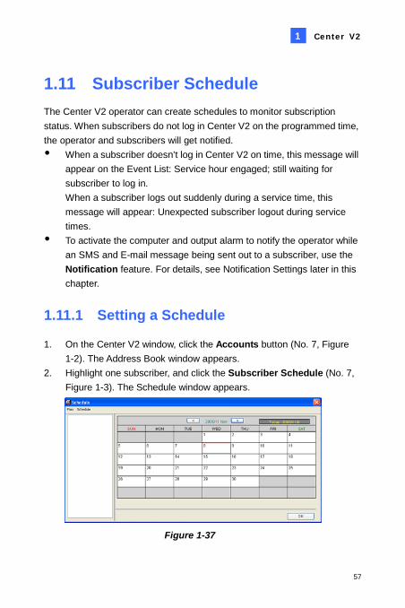
1. On the Center V2 window, click the Accounts button (No. 7, Figure 1-2). The Address Book window appears.
2. Highlight one subscriber, and click the Subscriber Schedule (No. 7, Figure 1-3). The Schedule window appears.
Figure 1-37
58
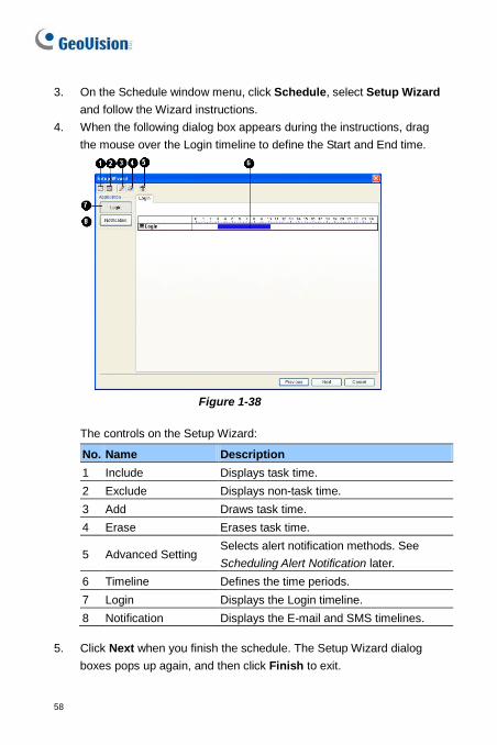
3. On the Schedule window menu, click Schedule, select Setup Wizard and follow the Wizard instructions.
4. When the following dialog box appears during the instructions, drag the mouse over the Login timeline to define the Start and End time.
Figure 1-38
The controls on the Setup Wizard:
No. Name Description 1 Include Displays task time. 2 Exclude Displays non-task time. 3 Add Draws task time. 4 Erase Erases task time.
5 Advanced Setting Selects alert notification methods. See Scheduling Alert Notification later.
6 Timeline Defines the time periods. 7 Login Displays the Login timeline. 8 Notification Displays the E-mail and SMS timelines.
5. Click Next when you finish the schedule. The Setup Wizard dialog
boxes pops up again, and then click Finish to exit.
Center V2
59
1
1.11.2 Scheduling Alert Notification E-mails and SMS messages can be sent out within the scheduled period of time. The Schedule will work with your E-Mail and SMS settings to all alert conditions. To set up alert conditions, see Notification Settings later in this chapter. Note: Once you enable the schedule function, you will not be notified when events occur outside the scheduled period of time.
1. On the Schedule window, double-click an established plan. A plan dialog box similar to Figure 1-38 appears.
2. Click the Advanced Setting button (No. 5, Figure 1-38). The Advanced Setting dialog box appears.
3. Expand the Notification folder, and select SMS or E-Mail to be scheduled.
4. On the plan dialog box, click the Notification button (No. 8, Figure 1-38), drag the mouse over SMS and / or E-mail timelines to define the Start time and End time to send out alerts.
60
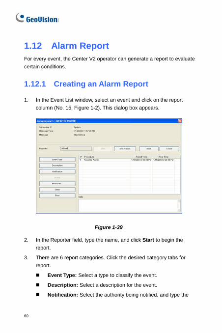
1.12 Alarm Report For every event, the Center V2 operator can generate a report to evaluate certain conditions.
1.12.1 Creating an Alarm Report
1. In the Event List window, select an event and click on the report column (No. 15, Figure 1-2). This dialog box appears.
Figure 1-39
2. In the Reporter field, type the name, and click Start to begin the report.
3. There are 6 report categories. Click the desired category tabs for report.
Event Type: Select a type to classify the event.
Description: Select a description for the event.
Notification: Select the authority being notified, and type the
Center V2
61
1
notified time.
Arrival: The button becomes available after you select a notified authority. Type the arrival time of the authority.
Measures: Select the measure taken to deal with the event.
Other: The button is available only when the e-mail and /or SMS alert are configured.
Print: Prints out the alarm report.
4. When you finish the report and will not change the contents, click the End Report. Or click Save to edit later.
62
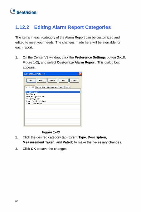
1.12.2 Editing Alarm Report Categories
The items in each category of the Alarm Report can be customized and edited to meet your needs. The changes made here will be available for each report. 1. On the Center V2 window, click the Preference Settings button (No.8,
Figure 1-2), and select Customize Alarm Report. This dialog box appears.
Figure 1-40 2. Click the desired category tab (Event Type, Description,
Measurement Taken, and Patrol) to make the necessary changes.
3. Click OK to save the changes.
Center V2
63
1
1.12.3 Printing Alarm Reports
You can print out the alarm reports along with filtered logs.
1. To filter the logs with alarm reports, click the Tools button (No.5, Figure 1-2), select View Event Log, and click the Filter button. The Filter window appears.
2. Click the Clipboard icon and select the type of alarm report from the drop-down list. For details, see Filtering the Event Log in 1.14 Event Log Browser.
3. Click OK. The search results will be displayed in the Event Log Browser window.
4. To print out the alarm reports along with the search results, click the Page Setup button (No.8, Figure 1-49), select Print Managing Alarm Report and click OK.
5. Click the Print button (No. 9, Figure 1-49). Find the alarm reports in the last part of the printouts.
Also see Printout Settings in 1.14 Event Log Browser.
64
1.13 Event List 1.13.1 Marking the Events with Colorful
Flags
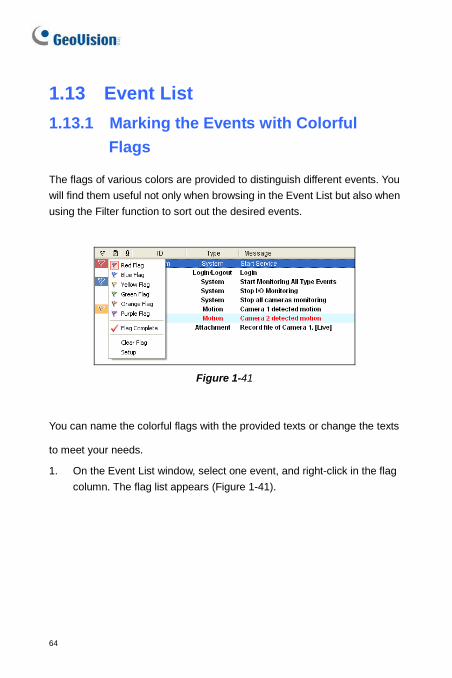
The flags of various colors are provided to distinguish different events. You will find them useful not only when browsing in the Event List but also when using the Filter function to sort out the desired events.
Figure 1-41
You can name the colorful flags with the provided texts or change the texts
to meet your needs.
1. On the Event List window, select one event, and right-click in the flag column. The flag list appears (Figure 1-41).
Center V2
65
1
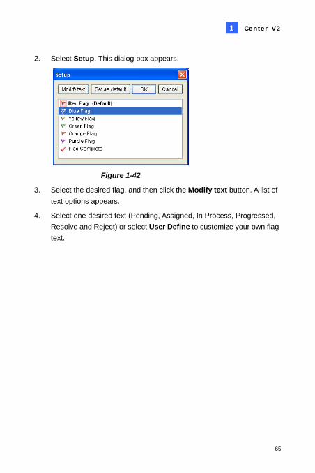
2. Select Setup. This dialog box appears.
Figure 1-42
3. Select the desired flag, and then click the Modify text button. A list of text options appears.
4. Select one desired text (Pending, Assigned, In Process, Progressed, Resolve and Reject) or select User Define to customize your own flag text.
66
1.13.2 Using the Event Tabs
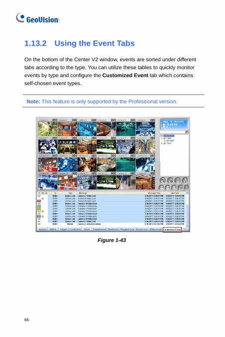
On the bottom of the Center V2 window, events are sorted under different tabs according to the type. You can utilize these tables to quickly monitor events by type and configure the Customized Event tab which contains self-chosen event types.
Note: This feature is only supported by the Professional version.
Figure 1-43
Center V2
67
1
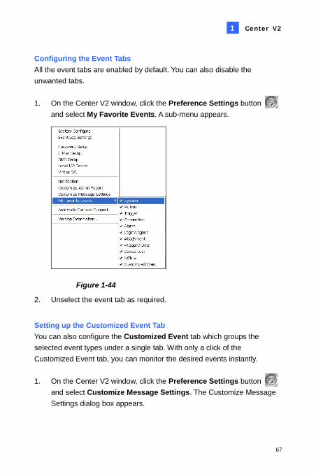
Configuring the Event Tabs All the event tabs are enabled by default. You can also disable the unwanted tabs. 1. On the Center V2 window, click the Preference Settings button
and select My Favorite Events. A sub-menu appears.
Figure 1-44
2. Unselect the event tab as required.
Setting up the Customized Event Tab You can also configure the Customized Event tab which groups the selected event types under a single tab. With only a click of the Customized Event tab, you can monitor the desired events instantly. 1. On the Center V2 window, click the Preference Settings button
and select Customize Message Settings. The Customize Message Settings dialog box appears.
68
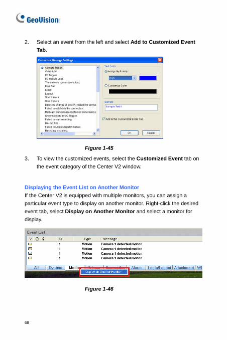
2. Select an event from the left and select Add to Customized Event Tab.
Figure 1-45
3. To view the customized events, select the Customized Event tab on the event category of the Center V2 window.
Displaying the Event List on Another Monitor If the Center V2 is equipped with multiple monitors, you can assign a particular event type to display on another monitor. Right-click the desired event tab, select Display on Another Monitor and select a monitor for display.
Figure 1-46
Center V2
69
1
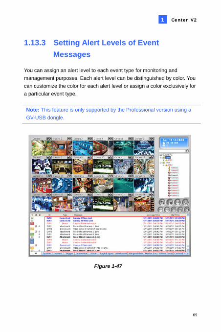
1.13.3 Setting Alert Levels of Event Messages
You can assign an alert level to each event type for monitoring and management purposes. Each alert level can be distinguished by color. You can customize the color for each alert level or assign a color exclusively for a particular event type. Note: This feature is only supported by the Professional version using a GV-USB dongle.
Figure 1-47
70
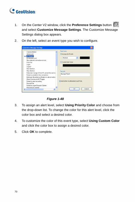
1. On the Center V2 window, click the Preference Settings button and select Customize Message Settings. The Customize Message Settings dialog box appears.
2. On the left, select an event type you wish to configure.
Figure 1-48
3. To assign an alert level, select Using Priority Color and choose from the drop-down list. To change the color for this alert level, click the color box and select a desired color.
4. To customize the color of this event type, select Using Custom Color and click the color box to assign a desired color.
5. Click OK to complete.
Center V2
71
1
1.14 Event Log Browser
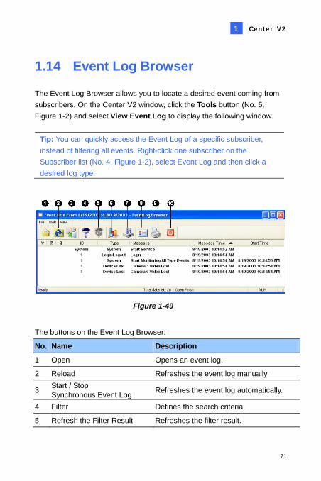
The Event Log Browser allows you to locate a desired event coming from subscribers. On the Center V2 window, click the Tools button (No. 5, Figure 1-2) and select View Event Log to display the following window.
Tip: You can quickly access the Event Log of a specific subscriber, instead of filtering all events. Right-click one subscriber on the Subscriber list (No. 4, Figure 1-2), select Event Log and then click a desired log type.
Figure 1-49
The buttons on the Event Log Browser:
No. Name Description
1 Open Opens an event log.
2 Reload Refreshes the event log manually
3 Start / Stop Synchronous Event Log Refreshes the event log automatically.
4 Filter Defines the search criteria.
5 Refresh the Filter Result Refreshes the filter result.
72
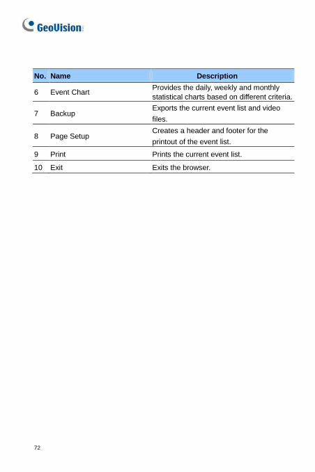
No. Name Description
6 Event Chart Provides the daily, weekly and monthly statistical charts based on different criteria.
7 Backup Exports the current event list and video files.
8 Page Setup Creates a header and footer for the printout of the event list.
9 Print Prints the current event list.
10 Exit Exits the browser.
Center V2
73
1
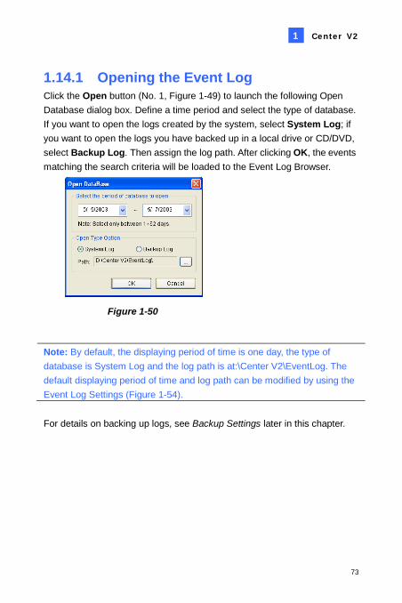
1.14.1 Opening the Event Log Click the Open button (No. 1, Figure 1-49) to launch the following Open Database dialog box. Define a time period and select the type of database. If you want to open the logs created by the system, select System Log; if you want to open the logs you have backed up in a local drive or CD/DVD, select Backup Log. Then assign the log path. After clicking OK, the events matching the search criteria will be loaded to the Event Log Browser.
Figure 1-50
Note: By default, the displaying period of time is one day, the type of database is System Log and the log path is at:\Center V2\EventLog. The default displaying period of time and log path can be modified by using the Event Log Settings (Figure 1-54). For details on backing up logs, see Backup Settings later in this chapter.
74
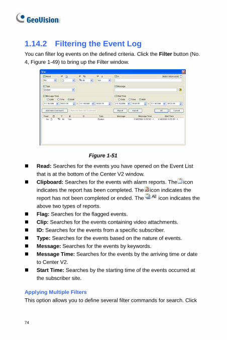
1.14.2 Filtering the Event Log You can filter log events on the defined criteria. Click the Filter button (No. 4, Figure 1-49) to bring up the Filter window.
Figure 1-51
Read: Searches for the events you have opened on the Event List that is at the bottom of the Center V2 window.
Clipboard: Searches for the events with alarm reports. The icon indicates the report has been completed. The icon indicates the report has not been completed or ended. The icon indicates the above two types of reports.
Flag: Searches for the flagged events. Clip: Searches for the events containing video attachments. ID: Searches for the events from a specific subscriber. Type: Searches for the events based on the nature of events. Message: Searches for the events by keywords. Message Time: Searches for the events by the arriving time or date
to Center V2. Start Time: Searches by the starting time of the events occurred at
the subscriber site. Applying Multiple Filters This option allows you to define several filter commands for search. Click
Center V2
75
1
the Add New Command button to add a new filter command. When you click OK, all events matching the defined commands will be listed on the Event Log Browser. Removing Filters Select the filter command you wish to remove from the filter list, and then click the Remove Selected Command button to remove it.
76
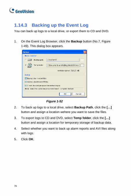
1.14.3 Backing up the Event Log You can back up logs to a local drive, or export them to CD and DVD.
1. On the Event Log Browser, click the Backup button (No.7, Figure
1-49). This dialog box appears.
Figure 1-52
2. To back up logs to a local drive, select Backup Path, click the […] button and assign a location wehere you want to save the files.
3. To export logs to CD and DVD, select Temp folder, click the […] button and assign a location for temporary storage of backup data.
4. Select whether you want to back up alarm reports and AVI files along with logs.
5. Click OK.
Center V2
77
1
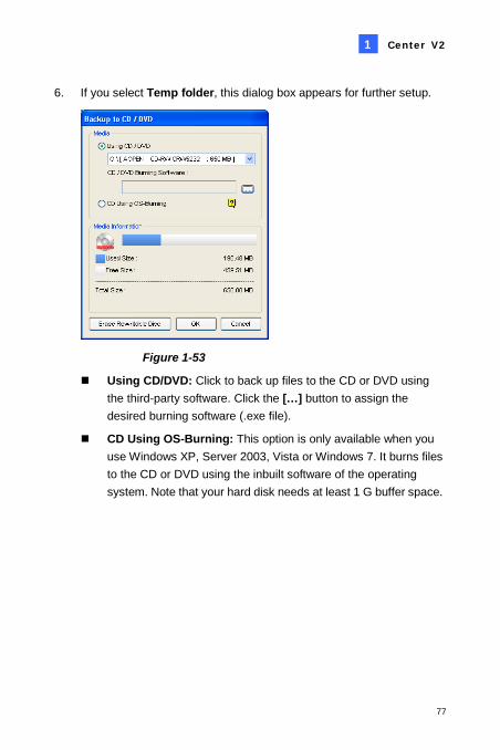
6. If you select Temp folder, this dialog box appears for further setup.
Figure 1-53
Using CD/DVD: Click to back up files to the CD or DVD using the third-party software. Click the […] button to assign the desired burning software (.exe file).
CD Using OS-Burning: This option is only available when you use Windows XP, Server 2003, Vista or Windows 7. It burns files to the CD or DVD using the inbuilt software of the operating system. Note that your hard disk needs at least 1 G buffer space.
78
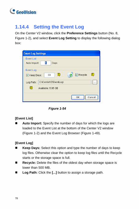
1.14.4 Setting the Event Log On the Center V2 window, click the Preference Settings button (No. 8, Figure 1-2), and select Event Log Setting to display the following dialog box:
Figure 1-54 [Event List] Auto Import: Specify the number of days for which the logs are
loaded to the Event List at the bottom of the Center V2 window (Figure 1-2) and the Event Log Browser (Figure 1-49).
[Event Log] Keep Days: Select this option and type the number of days to keep
log files. Otherwise clear the option to keep log files until the Recycle starts or the storage space is full.
Recycle: Delete the files of the oldest day when storage space is lower than 500 MB.
Log Path: Click the [...] button to assign a storage path.
Center V2
79
1
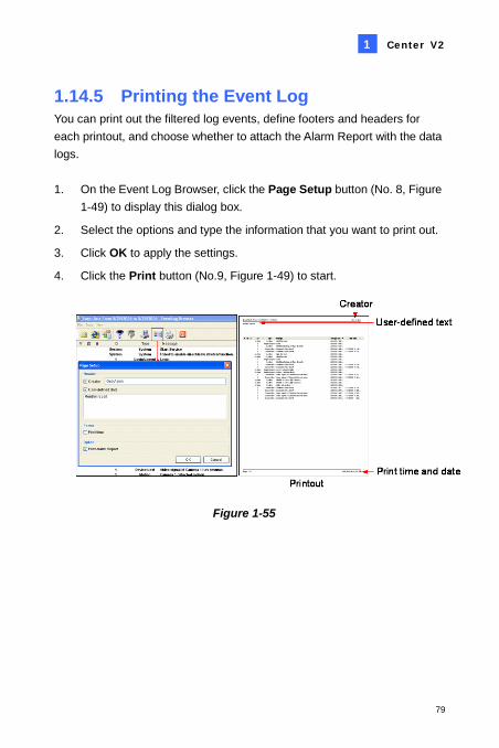
1.14.5 Printing the Event Log You can print out the filtered log events, define footers and headers for each printout, and choose whether to attach the Alarm Report with the data logs. 1. On the Event Log Browser, click the Page Setup button (No. 8, Figure
1-49) to display this dialog box.
2. Select the options and type the information that you want to print out.
3. Click OK to apply the settings.
4. Click the Print button (No.9, Figure 1-49) to start.
Figure 1-55
80
1.15 System Configuration On the Center V2 window, click the Preference Settings button (No. 8, Figure 1-2), and select System Configure to display the following Preference window. This window contains these tabs: (1) General, (2) Layout, (3) Network, (4) Record and (5) Dispatch Server.
1.15.1 General Settings
Figure 1-56
[Monitor Option] Manual close channel: Closes the triggered camera view manually. Close the camera view when motion stopped: Closes the triggered
camera view automatically when motion stops.
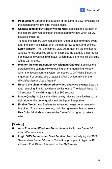
Center V2
81
1
Post Motion: Specifies the duration of the camera view remaining on the monitoring window after motion stops.
Camera send by I/O trigger will monitor: Specifies the duration of the camera view remaining on the monitoring window when an I/O device is triggered. To keep the camera view remaining on the monitoring window even after the alarm is finished, click the right-arrow button, and uncheck Latch Trigger. Then the camera view will remain on the monitoring window for the specified time. For example, the alarm is triggered for 5 minutes and you set 10 minutes, which means the total display time will be 15 minutes.
Monitor the camera sent by GV-Wiegand Capture: Specifies the duration of the camera view remaining on the monitoring window when the access control system, connected to GV-Video Server, is triggered. For details, see Chapter 8 CMS Configurations in the GV-Video Server User’s Manual.
Record the channel triggered by video analytics events: Sets the total recording time for a video analytics event. The default length is 30 seconds. The valid range is 3 to 600 seconds.
Image Quality: Adjusts the video quality. Moving the slide bar to the right side for the better quality and the bigger image size.
Enable Directdraw: Enables an enhanced image performance for live video. To enhance coloring, click the right-arrow button, select Use Colorful Mode and restart the Center V2 program to take it effect.
[Start-up] Auto Run when Windows Starts: Automatically runs Center V2
when Windows starts. Login SMS Server when Start Service: Automatically logs in SMS
Server when Center V2 starts. You will be prompted to type the IP address, Port, ID and Password of the SMS server.

82
[Channel Caption] Font and Color: Click the Settings…. button to change the font and
color of the captions. Use the subscriber setting color as background: Checks the
option to apply the caption settings. For details, see Channel Heading earlier in this chapter.
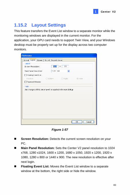
Center V2
83
1
1.15.2 Layout Settings This feature transfers the Event List window to a separate monitor while the monitoring windows are displayed in the current monitor. For the application, your GPU card needs to support Twin View, and your Windows desktop must be properly set up for the display across two computer monitors.
Figure 1-57 Screen Resolution: Detects the current screen resolution on your
PC. Main Panel Resolution: Sets the Center V2 panel resolution to 1024
x768, 1280 x1024, 1600 x 1200, 1680 x 1050, 1920 x 1200, 1920 x 1080, 1280 x 800 or 1440 x 900. The new resolution is effective after next login.
Floating Event List: Moves the Event List window to a separate window at the bottom, the right side or hide the window.
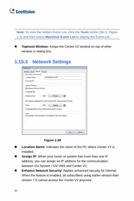
84
Note: To view the hidden Event List, click the Tools button (No.5, Figure 1-2) and then select Maximize Event List to display the Event List.
Topmost Window: Keeps the Center V2 window on top of other
window or dialog box.
1.15.3 Network Settings
Figure 1-58
Location Name: Indicates the name of the PC where Center V2 is installed.
Assign IP: When your router or system has more than one IP address, you can assign an IP address for the communication between GV-System / GV-VMS and Center V2.
Enhance Network Security: Applies enhanced security for Internet. When the feature is enabled, all subscribers using earlier version than version 7.0 cannot access the Center V2 anymore.
Center V2
85
1
Center Port: Indicates the communication port used by the Center V2. The port should match the one in Figure 1-9. To automatically configure the port on your router by UPnP technology, click the Arrow button. For details on UPnP settings, see UPnP Settings, Appendix.
Accept the Connection of GV-Compact DVR, Video Server & IP Cam: Enables the connection to GV IP devices. For connecting with GV IP devices, the default port is 5551; or you can modify it to match the Center V2 port on GV IP devices. For details, see their separate User’s Manuals.
Enable Stream 2 from Video Server and IP Camera: Applies the stream 2 of the IP devices as live view.
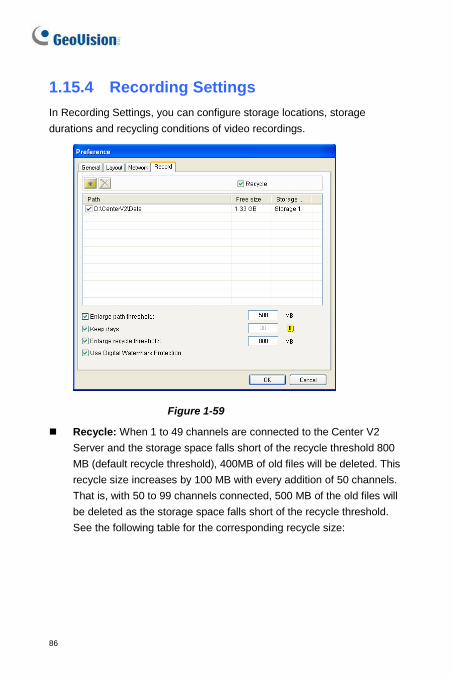
86
1.15.4 Recording Settings In Recording Settings, you can configure storage locations, storage durations and recycling conditions of video recordings.
Figure 1-59
Recycle: When 1 to 49 channels are connected to the Center V2 Server and the storage space falls short of the recycle threshold 800 MB (default recycle threshold), 400MB of old files will be deleted. This recycle size increases by 100 MB with every addition of 50 channels. That is, with 50 to 99 channels connected, 500 MB of the old files will be deleted as the storage space falls short of the recycle threshold. See the following table for the corresponding recycle size:
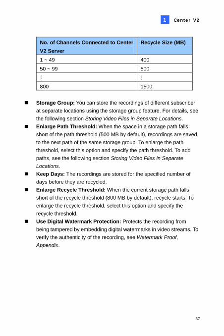
Center V2
87
1
No. of Channels Connected to Center V2 Server
Recycle Size (MB)
1 ~ 49 400 50 ~ 99 500 ︴ ︴ 800 1500
Storage Group: You can store the recordings of different subscriber
at separate locations using the storage group feature. For details, see the following section Storing Video Files in Separate Locations.
Enlarge Path Threshold: When the space in a storage path falls short of the path threshold (500 MB by default), recordings are saved to the next path of the same storage group. To enlarge the path threshold, select this option and specify the path threshold. To add paths, see the following section Storing Video Files in Separate Locations.
Keep Days: The recordings are stored for the specified number of days before they are recycled.
Enlarge Recycle Threshold: When the current storage path falls short of the recycle threshold (800 MB by default), recycle starts. To enlarge the recycle threshold, select this option and specify the recycle threshold.
Use Digital Watermark Protection: Protects the recording from being tampered by embedding digital watermarks in video streams. To verify the authenticity of the recording, see Watermark Proof, Appendix.
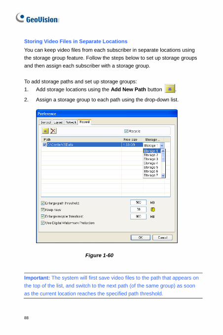
88
Storing Video Files in Separate Locations You can keep video files from each subscriber in separate locations using the storage group feature. Follow the steps below to set up storage groups and then assign each subscriber with a storage group. To add storage paths and set up storage groups: 1. Add storage locations using the Add New Path button .
2. Assign a storage group to each path using the drop-down list.
Figure 1-60
Important: The system will first save video files to the path that appears on the top of the list, and switch to the next path (of the same group) as soon as the current location reaches the specified path threshold.
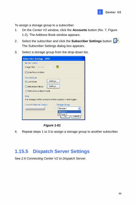
Center V2
89
1
To assign a storage group to a subscriber: 1. On the Center V2 window, click the Accounts button (No. 7, Figure
1-2). The Address Book window appears.
2. Select the subscriber and click the Subscriber Settings button . The Subscriber Settings dialog box appears.
3. Select a storage group from the drop-down list.
Figure 1-61
4. Repeat steps 1 to 3 to assign a storage group to another subscriber.
1.15.5 Dispatch Server Settings See 2.6 Connecting Center V2 to Dispatch Server.
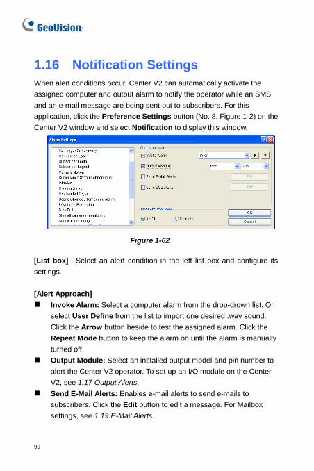
90
1.16 Notification Settings When alert conditions occur, Center V2 can automatically activate the assigned computer and output alarm to notify the operator while an SMS and an e-mail message are being sent out to subscribers. For this application, click the Preference Settings button (No. 8, Figure 1-2) on the Center V2 window and select Notification to display this window.
Figure 1-62 [List box] Select an alert condition in the left list box and configure its settings. [Alert Approach] Invoke Alarm: Select a computer alarm from the drop-drown list. Or,
select User Define from the list to import one desired .wav sound. Click the Arrow button beside to test the assigned alarm. Click the Repeat Mode button to keep the alarm on until the alarm is manually turned off.
Output Module: Select an installed output model and pin number to alert the Center V2 operator. To set up an I/O module on the Center V2, see 1.17 Output Alerts.
Send E-Mail Alerts: Enables e-mail alerts to send e-mails to subscribers. Click the Edit button to edit a message. For Mailbox settings, see 1.19 E-Mail Alerts.
Center V2
91
1
Send SMS Alerts: Enables SMS alerts to send SMS messages to subscribers. Click the Edit button to edit a message. For SMS Server settings, see 1.18 SMS Alerts.
Minimum Duration: This option is only available for Camera Motion and Connection Lost alerts. The minimum duration is the minimal time period that the event must persist for Center V2 to be notified by alarm, output, e-mail and/or SMS. Select this option and click the Edit button to type the minimum duration. The default is 3 seconds.
Note: The minimum duration function is used to minimize false motion detection alerts (such as in a outdoor scene with flying insects) or to exclude connection lost alerts from cameras that resume to network instantly after they disconnect. [Text Format of SMS] ASCII for English text, limited to 160 characters. Unicode for other languages, limited to 70 characters. Note: To automatically send E-mail and SMS alerts when alert conditions occur, ensure to set up e-mail addresses and mobile numbers for each subscriber in the Subscriber Address Book (Figure 1-4).
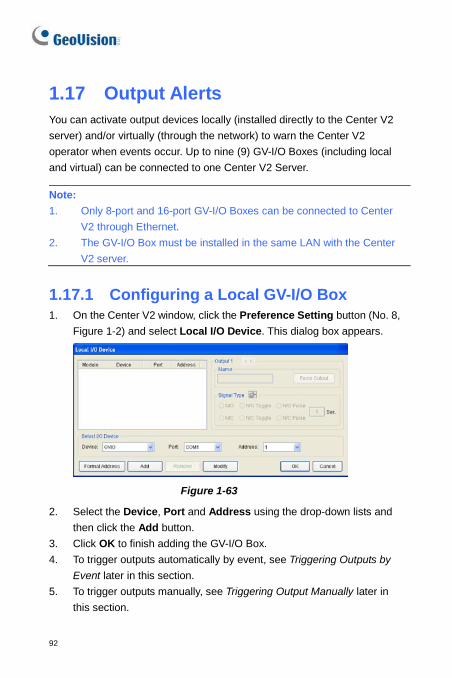
92
1.17 Output Alerts You can activate output devices locally (installed directly to the Center V2 server) and/or virtually (through the network) to warn the Center V2 operator when events occur. Up to nine (9) GV-I/O Boxes (including local and virtual) can be connected to one Center V2 Server. Note: 1. Only 8-port and 16-port GV-I/O Boxes can be connected to Center
V2 through Ethernet. 2. The GV-I/O Box must be installed in the same LAN with the Center
V2 server.
1.17.1 Configuring a Local GV-I/O Box 1. On the Center V2 window, click the Preference Setting button (No. 8,
Figure 1-2) and select Local I/O Device. This dialog box appears.
Figure 1-63
2. Select the Device, Port and Address using the drop-down lists and then click the Add button.
3. Click OK to finish adding the GV-I/O Box. 4. To trigger outputs automatically by event, see Triggering Outputs by
Event later in this section. 5. To trigger outputs manually, see Triggering Output Manually later in
this section.
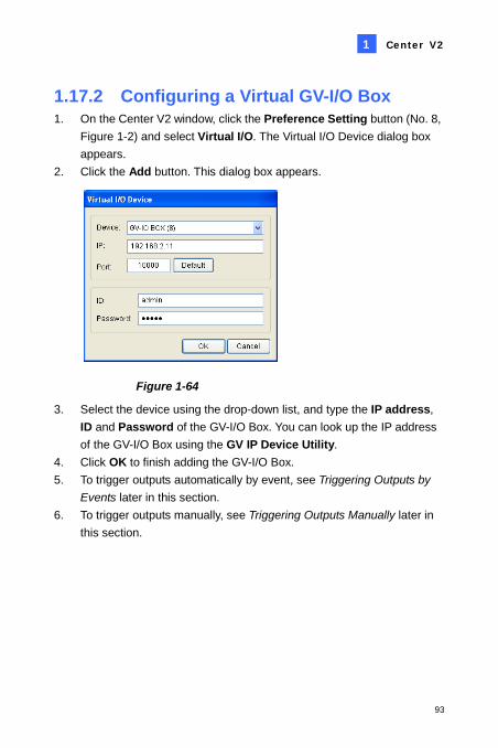
Center V2
93
1
1.17.2 Configuring a Virtual GV-I/O Box 1. On the Center V2 window, click the Preference Setting button (No. 8,
Figure 1-2) and select Virtual I/O. The Virtual I/O Device dialog box appears.
2. Click the Add button. This dialog box appears.
Figure 1-64
3. Select the device using the drop-down list, and type the IP address, ID and Password of the GV-I/O Box. You can look up the IP address of the GV-I/O Box using the GV IP Device Utility.
4. Click OK to finish adding the GV-I/O Box. 5. To trigger outputs automatically by event, see Triggering Outputs by
Events later in this section. 6. To trigger outputs manually, see Triggering Outputs Manually later in
this section.
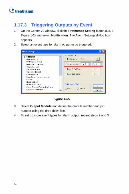
94
1.17.3 Triggering Outputs by Event 1. On the Center V2 window, click the Preference Setting button (No. 8,
Figure 1-2) and select Notification. The Alarm Settings dialog box appears.
2. Select an event type for alarm output to be triggered.
Figure 1-65
3. Select Output Module and define the module number and pin number using the drop-down lists.
4. To set up more event types for alarm output, repeat steps 2 and 3.
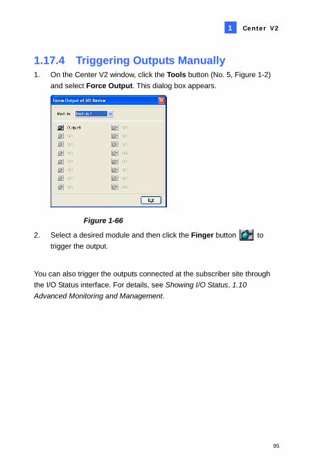
Center V2
95
1
1.17.4 Triggering Outputs Manually 1. On the Center V2 window, click the Tools button (No. 5, Figure 1-2)
and select Force Output. This dialog box appears.
Figure 1-66
2. Select a desired module and then click the Finger button to trigger the output.
You can also trigger the outputs connected at the subscriber site through the I/O Status interface. For details, see Showing I/O Status, 1.10 Advanced Monitoring and Management.
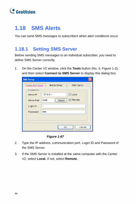
96
1.18 SMS Alerts You can send SMS messages to subscribers when alert conditions occur.
1.18.1 Setting SMS Server Before sending SMS messages to an individual subscriber, you need to define SMS Server correctly.
1. On the Center V2 window, click the Tools button (No. 5, Figure 1-2), and then select Connect to SMS Server to display this dialog box.
Figure 1-67
2. Type the IP address, communication port, Login ID and Password of the SMS Server.
3. If the SMS Server is installed at the same computer with the Center V2, select Local. If not, select Remote.
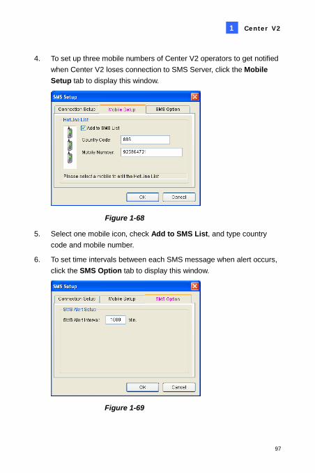
Center V2
97
1
4. To set up three mobile numbers of Center V2 operators to get notified when Center V2 loses connection to SMS Server, click the Mobile Setup tab to display this window.
Figure 1-68
5. Select one mobile icon, check Add to SMS List, and type country code and mobile number.
6. To set time intervals between each SMS message when alert occurs, click the SMS Option tab to display this window.
Figure 1-69
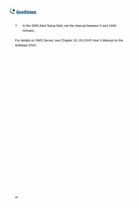
98
7. In the SMS Alert Setup field, set the interval between 0 and 1440 minutes.
For details on SMS Server, see Chapter 10, GV-DVR User’s Manual on the Software DVD.
Center V2
99
1
1.18.2 Connecting to SMS Server In the Center V2 window, click the Tools button (No.5, Figure 1-2), and then select Connect to SMS Server for connection.
100
1.18.3 Sending SMS Once the connection of SMS Server and Center V2 is established, there are several ways to send SMS messages to subscribers. See the Center V2 window for the following selections. 1. Click the Tools button (No.5, Figure 1-2) and select Send Short
Message. This sends SMS to an individual subscriber manually.
2. On the Subscriber List (No. 4, Figure 1-2), right-click one subscriber and select Send Short Message. This sends SMS to an individual subscriber manually.
3. On the Event List, double-click one Event Type, except Attachment, to call up a message window. Click the Send Short Message icon on the window. This sends SMS to an individual subscriber manually.
4. Right-click one display channel and select Send Short Message. This sends SMS to an individual subscriber manually.
5. Click the Preference Settings button (No. 8, Figure 1-2), and select Notification to display the Alarm Settings window. Check the Send SMS Alerts item. This sends SMS to subscribers automatically when set alert conditions occur. For details, see Notification Settings earlier in this chapter.
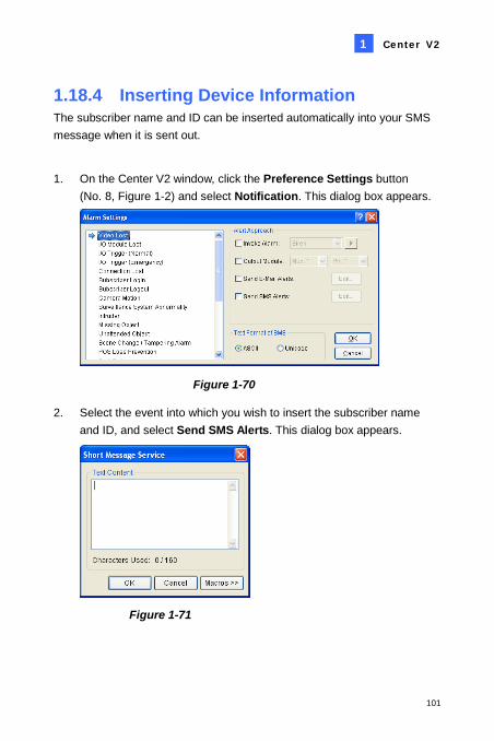
Center V2
101
1
1.18.4 Inserting Device Information The subscriber name and ID can be inserted automatically into your SMS message when it is sent out.
1. On the Center V2 window, click the Preference Settings button (No. 8, Figure 1-2) and select Notification. This dialog box appears.
Figure 1-70
2. Select the event into which you wish to insert the subscriber name and ID, and select Send SMS Alerts. This dialog box appears.
Figure 1-71
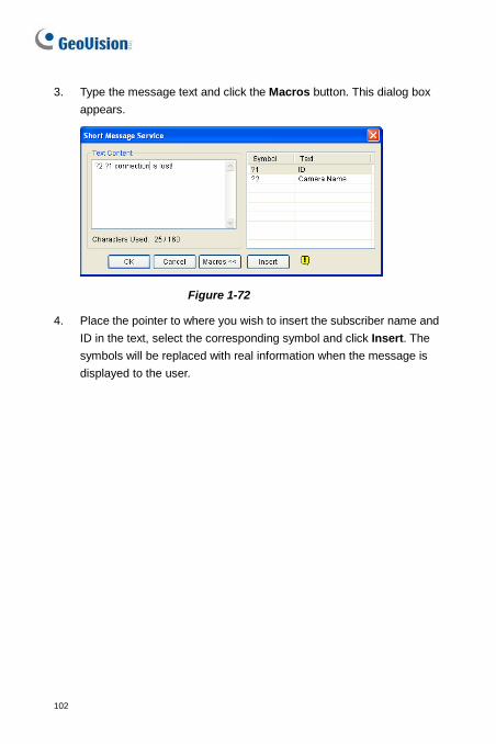
102
3. Type the message text and click the Macros button. This dialog box appears.
Figure 1-72
4. Place the pointer to where you wish to insert the subscriber name and ID in the text, select the corresponding symbol and click Insert. The symbols will be replaced with real information when the message is displayed to the user.
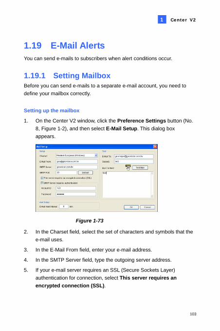
Center V2
103
1
1.19 E-Mail Alerts You can send e-mails to subscribers when alert conditions occur.
1.19.1 Setting Mailbox Before you can send e-mails to a separate e-mail account, you need to define your mailbox correctly.
Setting up the mailbox
1. On the Center V2 window, click the Preference Settings button (No. 8, Figure 1-2), and then select E-Mail Setup. This dialog box appears.
Figure 1-73
2. In the Charset field, select the set of characters and symbols that the e-mail uses.
3. In the E-Mail From field, enter your e-mail address.
4. In the SMTP Server field, type the outgoing server address.
5. If your e-mail server requires an SSL (Secure Sockets Layer) authentication for connection, select This server requires an encrypted connection (SSL).
104
6. If your e-mail service provider requires authentication for sending e-mails, select SMTP Server requires authentication, and type the account ID and password of your SMTP.
7. If you want to set time intervals between each e-mail message when alert occurs, in the Alert Setup field, set the interval between 0 and 1440 minutes.
8. Click OK.
Sending a test e-mail
After setting up your mailbox, you can use the Test section and send a message to your own e-mail account for testing. 1. Enter your own e-mail address in the E-Mail To field. 2. Enter a subject for the e-mail. 3. Type the desired message in the Mail Content field. 4. Click the Test Mail button.
Center V2
105
1
1.19.2 Sending E-Mail There are several ways to send e-mail alerts. See the Center V2 window for the following selections. 1. On the Subscriber List (No. 4, Figure 1-2), right-click one subscriber,
and then select Send E-Mail. This sends the e-mail to an individual subscriber manually.
2. Right-click one display channel, and then select Send E-Mail. This sends the e-mail to an individual subscriber manually.
3. On the Event List, double-click one Event Type, except Attachment, to call up a message window. Click the Send E-Mail icon on the window. This sends the e-mail to an individual subscriber manually.
4. Click the Preference Settings button (No. 8, Figure 1-2), and select Notification to display the Alarm Settings window. Check the Send E-Mail item. This sends e-mails to subscribers automatically when set alert conditions occur. See 1.13 Notification Settings in this chapter.

106
1.19.3 Inserting Device Information The subscriber name and ID can be inserted automatically into your email message when it is sent out. For setup details, see Inserting Device Information in 1.19 E-Mail Alerts.
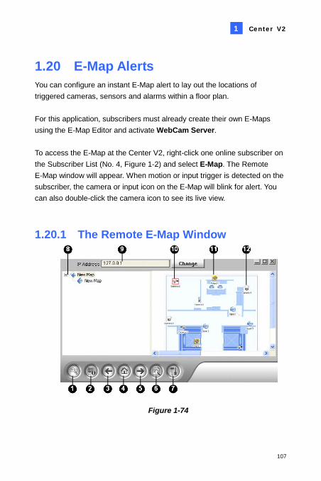
Center V2
107
1
1.20 E-Map Alerts You can configure an instant E-Map alert to lay out the locations of triggered cameras, sensors and alarms within a floor plan. For this application, subscribers must already create their own E-Maps using the E-Map Editor and activate WebCam Server. To access the E-Map at the Center V2, right-click one online subscriber on the Subscriber List (No. 4, Figure 1-2) and select E-Map. The Remote E-Map window will appear. When motion or input trigger is detected on the subscriber, the camera or input icon on the E-Map will blink for alert. You can also double-click the camera icon to see its live view.
1.20.1 The Remote E-Map Window
Figure 1-74
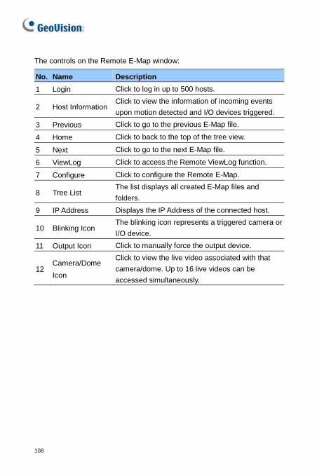
108
The controls on the Remote E-Map window:
No. Name Description 1 Login Click to log in up to 500 hosts.
2 Host Information Click to view the information of incoming events upon motion detected and I/O devices triggered.
3 Previous Click to go to the previous E-Map file.
4 Home Click to back to the top of the tree view.
5 Next Click to go to the next E-Map file.
6 ViewLog Click to access the Remote ViewLog function.
7 Configure Click to configure the Remote E-Map.
8 Tree List The list displays all created E-Map files and folders.
9 IP Address Displays the IP Address of the connected host.
10 Blinking Icon The blinking icon represents a triggered camera or I/O device.
11 Output Icon Click to manually force the output device.
12 Camera/Dome Icon
Click to view the live video associated with that camera/dome. Up to 16 live videos can be accessed simultaneously.
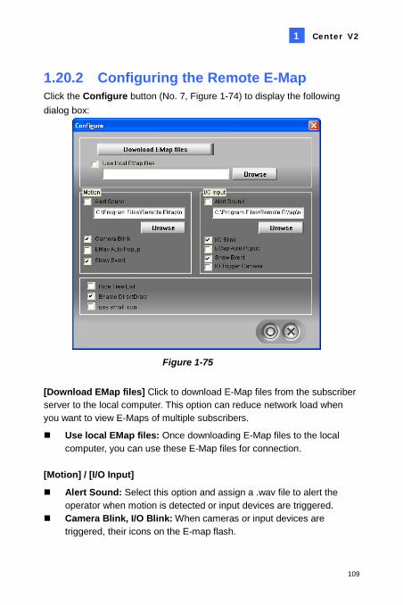
Center V2
109
1
1.20.2 Configuring the Remote E-Map Click the Configure button (No. 7, Figure 1-74) to display the following dialog box:
Figure 1-75
[Download EMap files] Click to download E-Map files from the subscriber server to the local computer. This option can reduce network load when you want to view E-Maps of multiple subscribers.
Use local EMap files: Once downloading E-Map files to the local computer, you can use these E-Map files for connection.
[Motion] / [I/O Input]
Alert Sound: Select this option and assign a .wav file to alert the operator when motion is detected or input devices are triggered.
Camera Blink, I/O Blink: When cameras or input devices are triggered, their icons on the E-map flash.
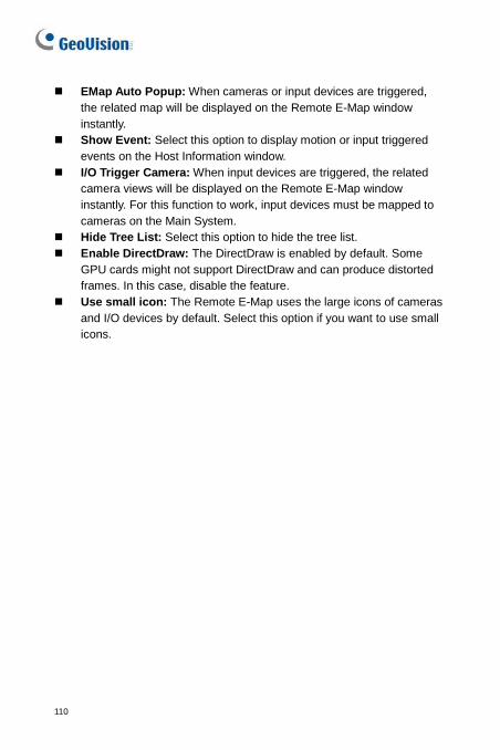
110
EMap Auto Popup: When cameras or input devices are triggered, the related map will be displayed on the Remote E-Map window instantly.
Show Event: Select this option to display motion or input triggered events on the Host Information window.
I/O Trigger Camera: When input devices are triggered, the related camera views will be displayed on the Remote E-Map window instantly. For this function to work, input devices must be mapped to cameras on the Main System.
Hide Tree List: Select this option to hide the tree list. Enable DirectDraw: The DirectDraw is enabled by default. Some
GPU cards might not support DirectDraw and can produce distorted frames. In this case, disable the feature.
Use small icon: The Remote E-Map uses the large icons of cameras and I/O devices by default. Select this option if you want to use small icons.
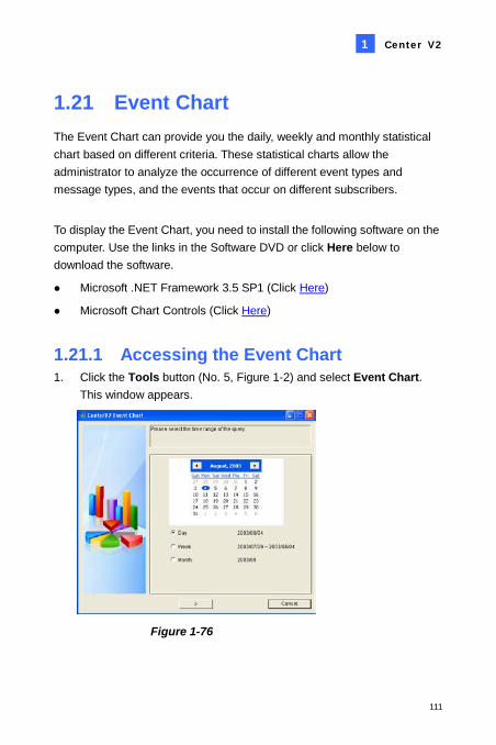
Center V2
111
1
1.21 Event Chart The Event Chart can provide you the daily, weekly and monthly statistical chart based on different criteria. These statistical charts allow the administrator to analyze the occurrence of different event types and message types, and the events that occur on different subscribers.
To display the Event Chart, you need to install the following software on the computer. Use the links in the Software DVD or click Here below to download the software.
Microsoft .NET Framework 3.5 SP1 (Click Here)
Microsoft Chart Controls (Click Here)
1.21.1 Accessing the Event Chart 1. Click the Tools button (No. 5, Figure 1-2) and select Event Chart.
This window appears.
Figure 1-76
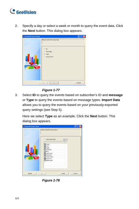
112
2. Specify a day or select a week or month to query the event data. Click the Next button. This dialog box appears.
Figure 1-77 3. Select ID to query the events based on subscriber’s ID and message
or Type to query the events based on message types. Import Data allows you to query the events based on your previously-exported query settings (see Step 5).
Here we select Type as an example. Click the Next button. This dialog box appears.
Figure 1-78
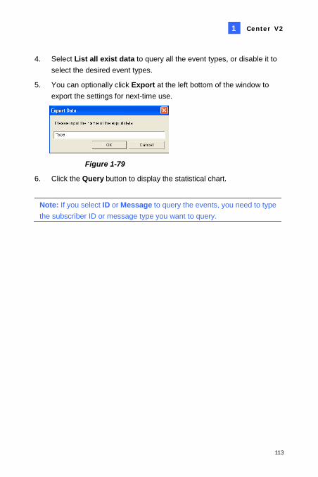
Center V2
113
1
4. Select List all exist data to query all the event types, or disable it to select the desired event types.
5. You can optionally click Export at the left bottom of the window to export the settings for next-time use.
Figure 1-79
6. Click the Query button to display the statistical chart.
Note: If you select ID or Message to query the events, you need to type the subscriber ID or message type you want to query.
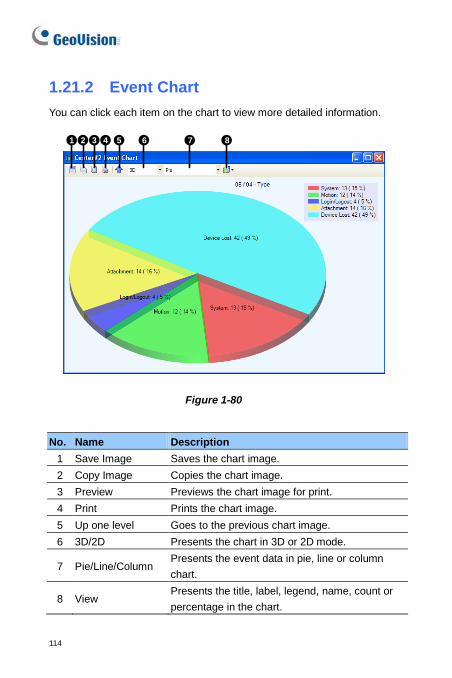
114
1.21.2 Event Chart You can click each item on the chart to view more detailed information.
1 2 3 4 5 6 7 8
Figure 1-80
No. Name Description 1 Save Image Saves the chart image. 2 Copy Image Copies the chart image. 3 Preview Previews the chart image for print. 4 Print Prints the chart image. 5 Up one level Goes to the previous chart image. 6 3D/2D Presents the chart in 3D or 2D mode.
7 Pie/Line/Column Presents the event data in pie, line or column chart.
8 View Presents the title, label, legend, name, count or percentage in the chart.
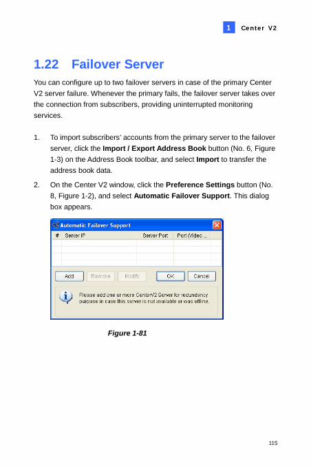
Center V2
115
1
1.22 Failover Server You can configure up to two failover servers in case of the primary Center V2 server failure. Whenever the primary fails, the failover server takes over the connection from subscribers, providing uninterrupted monitoring services. 1. To import subscribers’ accounts from the primary server to the failover
server, click the Import / Export Address Book button (No. 6, Figure 1-3) on the Address Book toolbar, and select Import to transfer the address book data.
2. On the Center V2 window, click the Preference Settings button (No. 8, Figure 1-2), and select Automatic Failover Support. This dialog box appears.
Figure 1-81
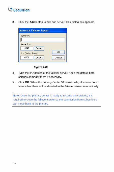
116
3. Click the Add button to add one server. This dialog box appears.
Figure 1-82
4. Type the IP Address of the failover server. Keep the default port settings or modify them if necessary.
5. Click OK. When the primary Center V2 server fails, all connections from subscribers will be diverted to the failover server automatically.
Note: Once the primary server is ready to resume the services, it is required to close the failover server so the connection from subscribers can move back to the primary.
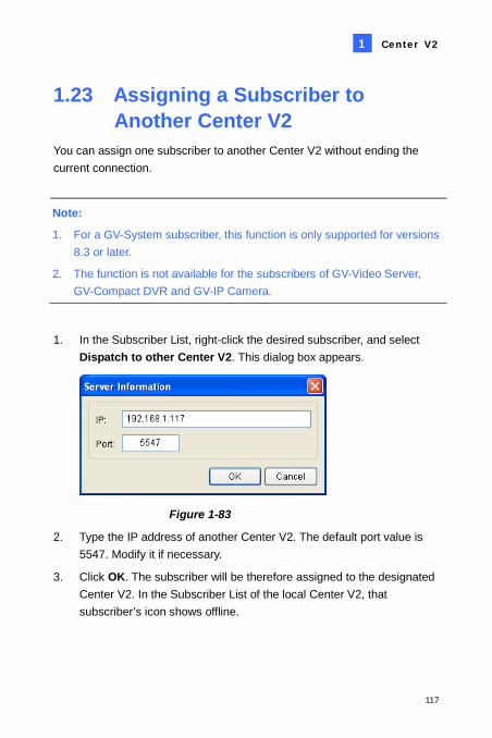
Center V2
117
1
1.23 Assigning a Subscriber to Another Center V2
You can assign one subscriber to another Center V2 without ending the current connection.
Note:
1. For a GV-System subscriber, this function is only supported for versions 8.3 or later.
2. The function is not available for the subscribers of GV-Video Server, GV-Compact DVR and GV-IP Camera.
1. In the Subscriber List, right-click the desired subscriber, and select Dispatch to other Center V2. This dialog box appears.
Figure 1-83
2. Type the IP address of another Center V2. The default port value is 5547. Modify it if necessary.
3. Click OK. The subscriber will be therefore assigned to the designated Center V2. In the Subscriber List of the local Center V2, that subscriber’s icon shows offline.
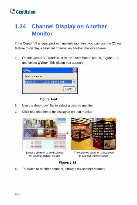
118
1.24 Channel Display on Another Monitor
If the Center V2 is equipped with multiple monitors, you can use the QView feature to display a selected channel on another monitor screen. 1. On the Center V2 window, click the Tools button (No. 5, Figure 1-2)
and select QView. This dialog box appears.
Figure 1-84
2. Use the drop-down list to select a desired monitor.
3. Click one channel to be displayed on that monitor.
Select a channel to be displayed on another monitor screen
The selected channel is displayed on another monitor screen
Figure 1-85
4. To switch to another channel, simply click another channel.
118
Chapter 2 Dispatch Server
The availability of Center V2 Servers may be threatened by network overload. Through Dispatch Server, the concern can be settled by arranging and distributing subscribers’ requests to the least busy Center V2 Servers. With Dispatch Server, a central monitor station can run several Center V2 Servers and serve a large number of subscribers with the fastest responding time. If any of Center V2 Servers needs maintenance, Dispatch Server can automatically redistribute subscribers’ requests to other Center V2 within a server farm or to servers in another location.
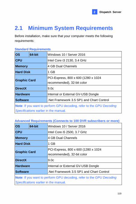
Dispatch Server
119
2
2.1 Minimum System Requirements Before installation, make sure that your computer meets the following requirements: Standard Requirements OS 64-bit Windows 10 / Server 2016
CPU Intel Core i3 2130, 3.4 GHz
Memory 4 GB Dual Channels
Hard Disk 1 GB
Graphic Card PCI-Express, 800 x 600 (1280 x 1024 recommended), 32-bit color
DirectX 9.0c
Hardware Internal or External GV-USB Dongle
Software .Net Framework 3.5 SP1 and Chart Control
Note: If you want to perform GPU decoding, refer to the GPU Decoding Specifications earlier in the manual. Advanced Requirements (Connects to 100 DVR subscribers or more) OS 64-bit Windows 10 / Server 2016
CPU Intel Core i5 2500, 3.7 GHz
Memory 4 GB Dual Channels
Hard Disk 1 GB
Graphic Card PCI-Express, 800 x 600 (1280 x 1024 recommended), 32-bit color
DirectX 9.0c
Hardware Internal or External GV-USB Dongle
Software .Net Framework 3.5 SP1 and Chart Control
Note: If you want to perform GPU decoding, refer to the GPU Decoding Specifications earlier in the manual.
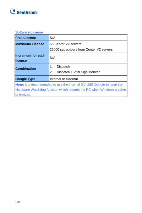
120
Software License Free License N/A
Maximum License 50 Center V2 servers 25000 subscribers from Center V2 servers
Increment for each license
N/A
Combination 1. Dispatch 2. Dispatch + Vital Sign Monitor
Dongle Type Internal or external Note: It is recommended to use the internal GV-USB Dongle to have the Hardware Watchdog function which restarts the PC when Windows crashes or freezes.
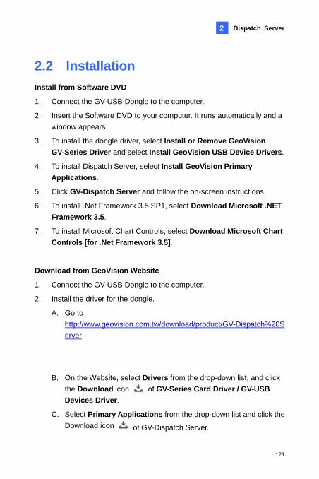
Dispatch Server
121
2
2.2 Installation Install from Software DVD
1. Connect the GV-USB Dongle to the computer.
2. Insert the Software DVD to your computer. It runs automatically and a window appears.
3. To install the dongle driver, select Install or Remove GeoVision GV-Series Driver and select Install GeoVision USB Device Drivers.
4. To install Dispatch Server, select Install GeoVision Primary Applications.
5. Click GV-Dispatch Server and follow the on-screen instructions.
6. To install .Net Framework 3.5 SP1, select Download Microsoft .NET Framework 3.5.
7. To install Microsoft Chart Controls, select Download Microsoft Chart Controls [for .Net Framework 3.5].
Download from GeoVision Website
1. Connect the GV-USB Dongle to the computer.
2. Install the driver for the dongle.
A. Go to http://www.geovision.com.tw/download/product/GV-Dispatch%20Server
B. On the Website, select Drivers from the drop-down list, and click the Download icon of GV-Series Card Driver / GV-USB Devices Driver.
C. Select Primary Applications from the drop-down list and click the Download icon of GV-Dispatch Server.
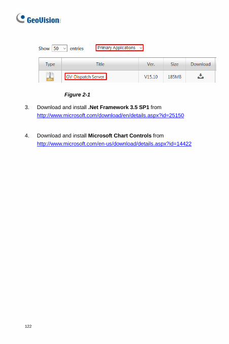
122
Figure 2-1
3. Download and install .Net Framework 3.5 SP1 from http://www.microsoft.com/download/en/details.aspx?id=25150
4. Download and install Microsoft Chart Controls from http://www.microsoft.com/en-us/download/details.aspx?id=14422
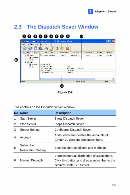
Dispatch Server
123
2
2.3 The Dispatch Sever Window 1 2 3 5 6 7 8 94 10
11
12 Figure 2-2
The controls on the Dispatch Server window:
No. Name Description
1 Start Server Starts Dispatch Sever.
2 Stop Server Stops Dispatch Sever.
3 Server Setting Configures Dispatch Sever.
4 Account Adds, edits and deletes the accounts of Center V2 Servers and subscribers.
5 Subscriber Notification Setting
Sets the alert conditions and methods
6 Manual Dispatch Enables manual distribution of subscribers. Click this button and drag a subscriber to the desired Center V2 Server.
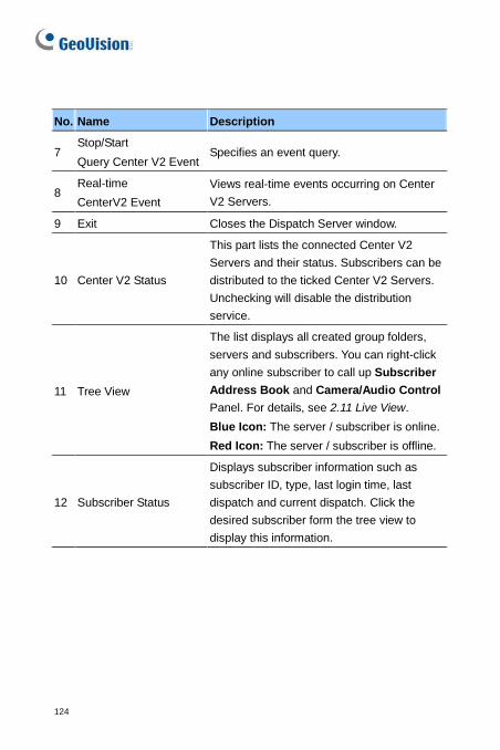
124
No. Name Description
7 Stop/Start Query Center V2 Event
Specifies an event query.
8 Real-time CenterV2 Event
Views real-time events occurring on Center V2 Servers.
9 Exit Closes the Dispatch Server window.
10 Center V2 Status
This part lists the connected Center V2 Servers and their status. Subscribers can be distributed to the ticked Center V2 Servers. Unchecking will disable the distribution service.
11 Tree View
The list displays all created group folders, servers and subscribers. You can right-click any online subscriber to call up Subscriber Address Book and Camera/Audio Control Panel. For details, see 2.11 Live View. Blue Icon: The server / subscriber is online. Red Icon: The server / subscriber is offline.
12 Subscriber Status
Displays subscriber information such as subscriber ID, type, last login time, last dispatch and current dispatch. Click the desired subscriber form the tree view to display this information.
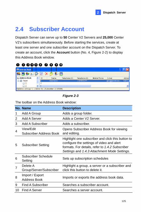
Dispatch Server
125
2
2.4 Subscriber Account Dispatch Server can serve up to 50 Center V2 Servers and 25,000 Center V2’s subscribers simultaneously. Before starting the services, create at least one server and one subscriber account on the Dispatch Server. To create an account, click the Account button (No. 4, Figure 2-2) to display this Address Book window.
Figure 2-3 The toolbar on the Address Book window:
No. Name Description 1 Add A Group Adds a group folder. 2 Add A Server Adds a Center V2 Server. 3 Add A Subscriber Adds a subscriber.
4 View/Edit Subscriber Address Book
Opens Subscriber Address Book for viewing and editing.
5 Subscriber Setting
Highlight one subscriber and click this button to configure the settings of video and alert formats. For details, refer to 1.4.2 Subscriber Settings and 1.4.3 Attachment Mode Settings.
6 Subscriber Schedule Setting Sets up subscription schedules
7 Delete A Group/Server/Subscriber
Highlight a group, a server or a subscriber and click this button to delete it.
8 Import / Export Address Book Imports or exports the address book data.
9 Find A Subscriber Searches a subscriber account. 10 Find A Server Searches a server account.
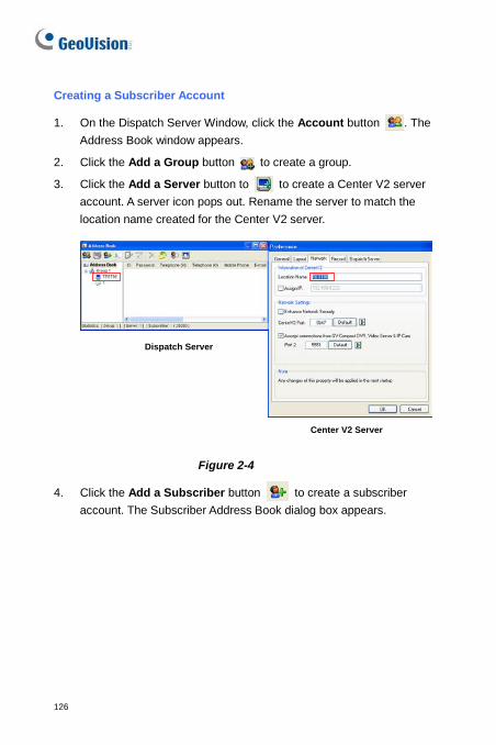
126
Creating a Subscriber Account
1. On the Dispatch Server Window, click the Account button . The Address Book window appears.
2. Click the Add a Group button to create a group.
3. Click the Add a Server button to to create a Center V2 server account. A server icon pops out. Rename the server to match the location name created for the Center V2 server.
Dispatch Server
Center V2 Server
Figure 2-4
4. Click the Add a Subscriber button to create a subscriber account. The Subscriber Address Book dialog box appears.
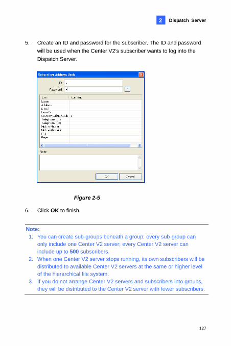
Dispatch Server
127
2
5. Create an ID and password for the subscriber. The ID and password will be used when the Center V2’s subscriber wants to log into the Dispatch Server.
Figure 2-5
6. Click OK to finish.
Note: 1. You can create sub-groups beneath a group; every sub-group can
only include one Center V2 server; every Center V2 server can include up to 500 subscribers.
2. When one Center V2 server stops running, its own subscribers will be distributed to available Center V2 servers at the same or higher level of the hierarchical file system.
3. If you do not arrange Center V2 servers and subscribers into groups, they will be distributed to the Center V2 server with fewer subscribers.
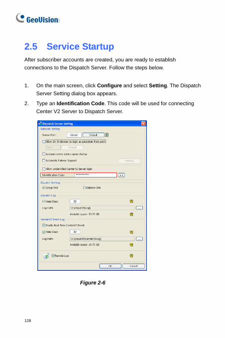
128
2.5 Service Startup After subscriber accounts are created, you are ready to establish connections to the Dispatch Server. Follow the steps below.
1. On the main screen, click Configure and select Setting. The Dispatch Server Setting dialog box appears.
2. Type an Identification Code. This code will be used for connecting Center V2 Server to Dispatch Server.
Figure 2-6

Dispatch Server
129
2
3. Connect Center V2 Server to Dispatch Server. See 2.6 Connecting Center V2 to Dispatch Server.
4. To add a GV-System / GV-VMS as a subscriber, connect the GV-System / GV-VMS to Dispatch Server. See 2.7 Connecting to Dispatch Server.
5. To add a GV-IP Device as a subscriber, connect GV-IP Devices to Dispatch Server. See 2.8 Connecting GV-IP Device to Dispatch Server.
6. Click the Start Server button (No. 1, Figure 2-2) on the main screen to start the service.
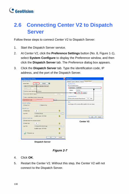
130
2.6 Connecting Center V2 to Dispatch Server
Follow these steps to connect Center V2 to Dispatch Server:
1. Start the Dispatch Server service.
2. At Center V2, click the Preference Settings button (No. 8, Figure 1-1), select System Configure to display the Preference window, and then click the Dispatch Server tab. The Preference dialog box appears.
3. Click the Dispatch Server tab. Type the identification code, IP address, and the port of the Dispatch Server.
Dispatch Server
Center V2
Figure 2-7
4. Click OK.
5. Restart the Center V2. Without this step, the Center V2 will not connect to the Dispatch Server.
Dispatch Server
131
2
2.7 Connecting to Dispatch Server Follow the steps below to configure and connect GV-System / GV-VMS to Dispatch Server:
1. Access the Center V2 login dialog box (Figure 1-9) on GV-System / GV-VMS.
On GV-System’s main screen: Click the Network button , and then select Connect to Center V2.
On GV-VMS’s main screen: Click Home, Toolbar, Network, and then select Connect to Center V2.
2. In the Center IP field, type the IP address of the Dispatch Server.
3. Type a user ID and password created in the Dispatch Server.
4. Change the port number from 5547 (Center V2 port) to 21112 (Dispatch Server port).
5. Click the OK button. The Connect to Center V2 dialog box appears.
6. Click the Connect button to enable connecting to the Dispatch Server.
Note: If you want to modify the login information of the Center V2, on the Connect to CenterV2 dialog box, click the listed Center V2 IP and then select Modify.
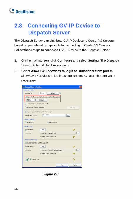
132
2.8 Connecting GV-IP Device to Dispatch Server
The Dispatch Server can distribute GV-IP Devices to Center V2 Servers based on predefined groups or balance loading of Center V2 Servers. Follow these steps to connect a GV-IP Device to the Dispatch Server:
1. On the main screen, click Configure and select Setting. The Dispatch Server Setting dialog box appears.
2. Select Allow GV IP devices to login as subscriber from port to allow GV-IP Devices to log in as subscribers. Change the port when necessary.
Figure 2-8
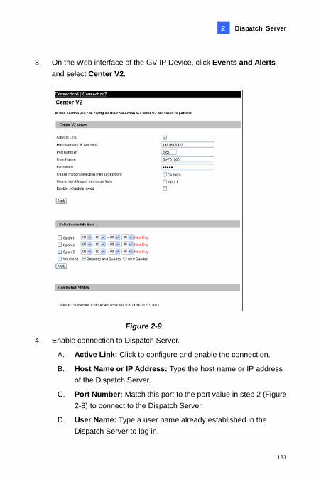
Dispatch Server
133
2
3. On the Web interface of the GV-IP Device, click Events and Alerts and select Center V2.
Figure 2-9
4. Enable connection to Dispatch Server.
A. Active Link: Click to configure and enable the connection.
B. Host Name or IP Address: Type the host name or IP address of the Dispatch Server.
C. Port Number: Match this port to the port value in step 2 (Figure 2-8) to connect to the Dispatch Server.
D. User Name: Type a user name already established in the Dispatch Server to log in.

134
E. Password: Type a valid password to log into the Dispatch Server.
F. Click Apply. The Connection Status should display “Connected” and the connection time.
5. This subscriber will be automatically distributed to an online Center V2 Server that has the least number of subscribers.
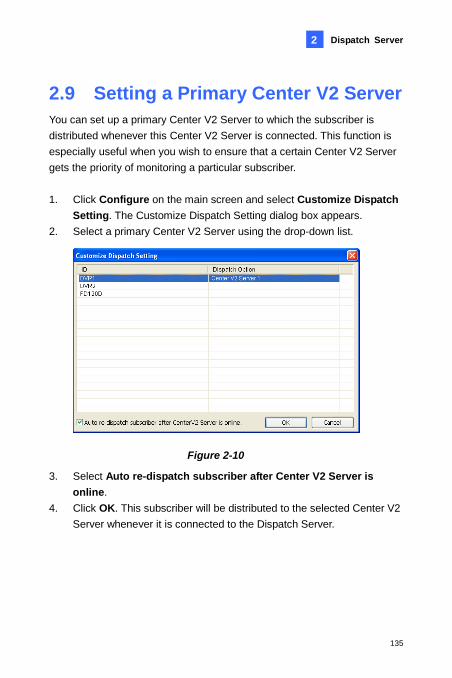
Dispatch Server
135
2
2.9 Setting a Primary Center V2 Server You can set up a primary Center V2 Server to which the subscriber is distributed whenever this Center V2 Server is connected. This function is especially useful when you wish to ensure that a certain Center V2 Server gets the priority of monitoring a particular subscriber. 1. Click Configure on the main screen and select Customize Dispatch
Setting. The Customize Dispatch Setting dialog box appears. 2. Select a primary Center V2 Server using the drop-down list.
Figure 2-10
3. Select Auto re-dispatch subscriber after Center V2 Server is online.
4. Click OK. This subscriber will be distributed to the selected Center V2 Server whenever it is connected to the Dispatch Server.
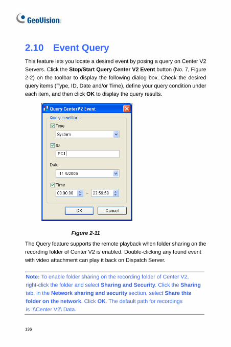
136
2.10 Event Query This feature lets you locate a desired event by posing a query on Center V2 Servers. Click the Stop/Start Query Center V2 Event button (No. 7, Figure 2-2) on the toolbar to display the following dialog box. Check the desired query items (Type, ID, Date and/or Time), define your query condition under each item, and then click OK to display the query results.
Figure 2-11
The Query feature supports the remote playback when folder sharing on the recording folder of Center V2 is enabled. Double-clicking any found event with video attachment can play it back on Dispatch Server. Note: To enable folder sharing on the recording folder of Center V2, right-click the folder and select Sharing and Security. Click the Sharing tab, in the Network sharing and security section, select Share this folder on the network. Click OK. The default path for recordings is :\\Center V2\ Data.
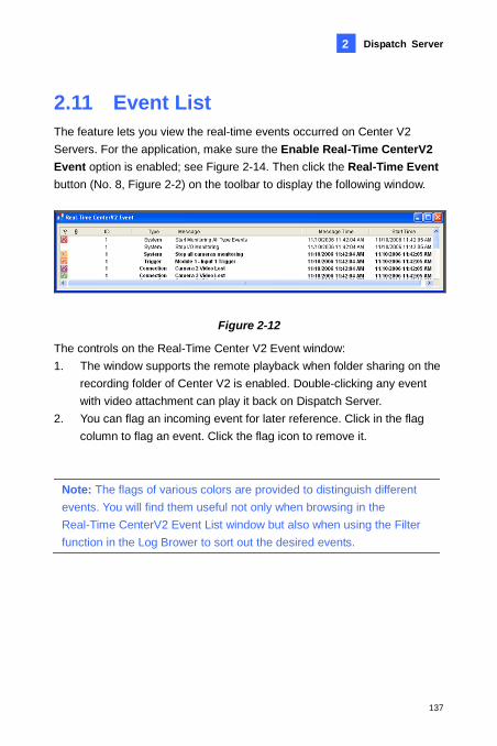
Dispatch Server
137
2
2.11 Event List The feature lets you view the real-time events occurred on Center V2 Servers. For the application, make sure the Enable Real-Time CenterV2 Event option is enabled; see Figure 2-14. Then click the Real-Time Event button (No. 8, Figure 2-2) on the toolbar to display the following window.
Figure 2-12
The controls on the Real-Time Center V2 Event window: 1. The window supports the remote playback when folder sharing on the
recording folder of Center V2 is enabled. Double-clicking any event with video attachment can play it back on Dispatch Server.
2. You can flag an incoming event for later reference. Click in the flag column to flag an event. Click the flag icon to remove it.
Note: The flags of various colors are provided to distinguish different events. You will find them useful not only when browsing in the Real-Time CenterV2 Event List window but also when using the Filter function in the Log Brower to sort out the desired events.
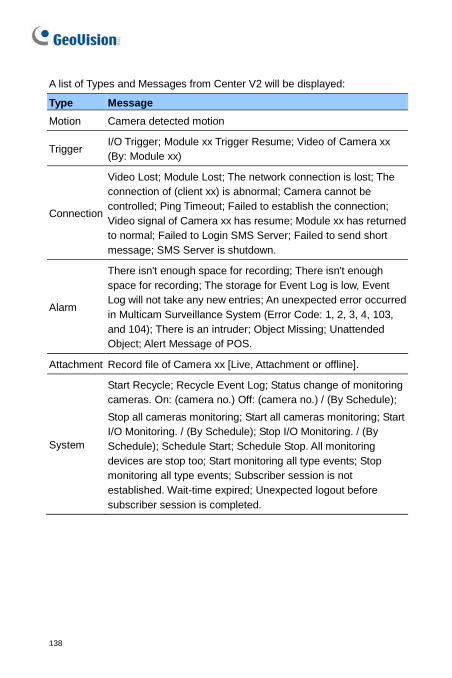
138
A list of Types and Messages from Center V2 will be displayed:
Type Message Motion Camera detected motion
Trigger I/O Trigger; Module xx Trigger Resume; Video of Camera xx (By: Module xx)
Connection
Video Lost; Module Lost; The network connection is lost; The connection of (client xx) is abnormal; Camera cannot be controlled; Ping Timeout; Failed to establish the connection; Video signal of Camera xx has resume; Module xx has returned to normal; Failed to Login SMS Server; Failed to send short message; SMS Server is shutdown.
Alarm
There isn't enough space for recording; There isn't enough space for recording; The storage for Event Log is low, Event Log will not take any new entries; An unexpected error occurred in Multicam Surveillance System (Error Code: 1, 2, 3, 4, 103, and 104); There is an intruder; Object Missing; Unattended Object; Alert Message of POS.
Attachment Record file of Camera xx [Live, Attachment or offline].
System
Start Recycle; Recycle Event Log; Status change of monitoring cameras. On: (camera no.) Off: (camera no.) / (By Schedule); Stop all cameras monitoring; Start all cameras monitoring; Start I/O Monitoring. / (By Schedule); Stop I/O Monitoring. / (By Schedule); Schedule Start; Schedule Stop. All monitoring devices are stop too; Start monitoring all type events; Stop monitoring all type events; Subscriber session is not established. Wait-time expired; Unexpected logout before subscriber session is completed.
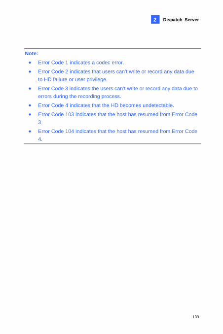
Dispatch Server
139
2
Note: • Error Code 1 indicates a codec error.
• Error Code 2 indicates that users can’t write or record any data due to HD failure or user privilege.
• Error Code 3 indicates the users can’t write or record any data due to errors during the recording process.
• Error Code 4 indicates that the HD becomes undetectable.
• Error Code 103 indicates that the host has resumed from Error Code 3
• Error Code 104 indicates that the host has resumed from Error Code 4.
140
2.12 Subscription Schedule The Dispatch Server operator can create schedules to monitor subscription status. When subscribers don’t log in Dispatch Server on the programmed time, the operator and subscribers will get notified.
To set up a schedule, see 1.11 Subscriber Schedule. When a subscriber doesn’t log in Dispatch Server on time, this
message will appear on the Event List: Service hour engaged; still waiting for subscriber to log in. When a subscriber logs out suddenly during a service time, this message will appear: Unexpected subscriber logout during service times.
To notify subscribers by SMS and E-Mail, see 2.14 SMS Alerts and
2.15 E-Mail Alerts.
Dispatch Server
141
2
2.13 Live View You can view live videos from subscribers. To access a live view, right-click any online subscriber on the tree view of the Dispatch Server window (No. 11, Figure 2-2) and select Camera/Audio Control. For details on the controls of the Live View window, see 4.6 Live View. You can enhance the coloring to have more vivid and saturated images. Click Configure on the menu bar, select DirectDraw Configuration, select Use Colorful Model, click OK and restart the Dispatch Server program for the mode to take effect. Right-click any online subscriber and select Camera/Audio Control to see the enhaced live video.
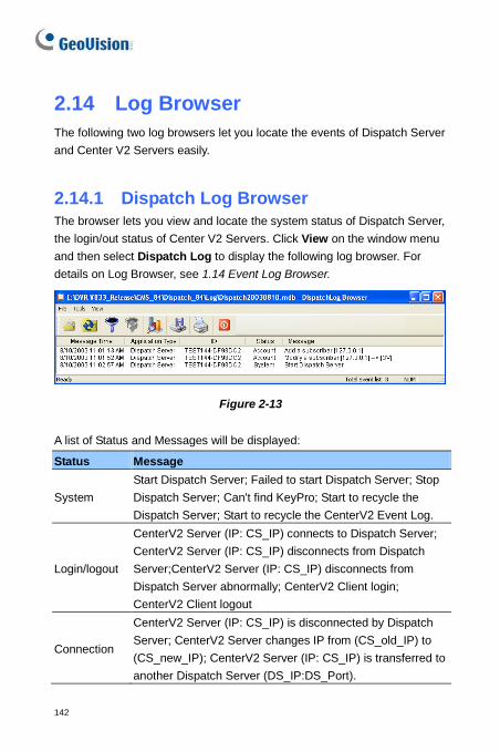
142
2.14 Log Browser The following two log browsers let you locate the events of Dispatch Server and Center V2 Servers easily.
2.14.1 Dispatch Log Browser The browser lets you view and locate the system status of Dispatch Server, the login/out status of Center V2 Servers. Click View on the window menu and then select Dispatch Log to display the following log browser. For details on Log Browser, see 1.14 Event Log Browser.
Figure 2-13
A list of Status and Messages will be displayed:
Status Message
System Start Dispatch Server; Failed to start Dispatch Server; Stop Dispatch Server; Can't find KeyPro; Start to recycle the Dispatch Server; Start to recycle the CenterV2 Event Log.
Login/logout
CenterV2 Server (IP: CS_IP) connects to Dispatch Server; CenterV2 Server (IP: CS_IP) disconnects from Dispatch Server;CenterV2 Server (IP: CS_IP) disconnects from Dispatch Server abnormally; CenterV2 Client login; CenterV2 Client logout
Connection
CenterV2 Server (IP: CS_IP) is disconnected by Dispatch Server; CenterV2 Server changes IP from (CS_old_IP) to (CS_new_IP); CenterV2 Server (IP: CS_IP) is transferred to another Dispatch Server (DS_IP:DS_Port).
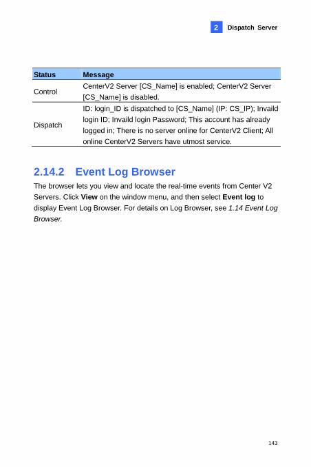
Dispatch Server
143
2
Status Message
Control CenterV2 Server [CS_Name] is enabled; CenterV2 Server [CS_Name] is disabled.
Dispatch
ID: login_ID is dispatched to [CS_Name] (IP: CS_IP); Invaild login ID; Invaild login Password; This account has already logged in; There is no server online for CenterV2 Client; All online CenterV2 Servers have utmost service.
2.14.2 Event Log Browser The browser lets you view and locate the real-time events from Center V2 Servers. Click View on the window menu, and then select Event log to display Event Log Browser. For details on Log Browser, see 1.14 Event Log Browser.
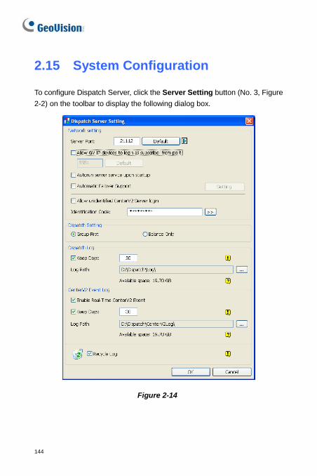
144
2.15 System Configuration
To configure Dispatch Server, click the Server Setting button (No. 3, Figure 2-2) on the toolbar to display the following dialog box.
Figure 2-14
Dispatch Server
145
2
[Network Setting] Server Port: The port should match with the Dispatch Server Port of
Center V2 (Figure 2-8). Or, keep the port setting as default. To automatically configure these ports on your router by UPnP technology, click the Arrow button. For details on UPnP settings, see UPnP Settings, Appendix.
Allow GV IP devices to login as subscriber from port: Enables the connection to the GV-Video Server, GV-IP Camera, and GV-Compact DVR. The default port is 5551, or modify it to match the Center V2 port on the GV IP devices. For details, see GV-Video Server User’s Manual, GV-IP Camera User’s Manual or GV-Compact DVR User’s Manual.
Auto run server service upon startup: Automatically starts the Dispatch service when its program starts.
Automatic Failover Support: Distributes Center V2 Servers to another Dispatch Server when the serving Dispatch Server breaks down. Enabling this item, you will be prompted to enter the IP address and port of another Dispatch Server. For details, see 2.17 Failover Server.
Allow unidentified CenterV2 Server login: Allows Center V2 to access Dispatch Server without entering the Identification Code.
Identification Code: The code protects Dispatch Server against unauthorized Internet access. Center V2 will need the code to log in Dispatch Server.
[Dispatch Setting] Group First: Keeps subscribers in the assigned groups and Center V2
Servers. Balance Only: Distributes subscribers to Center V2 Servers with
fewer subscribers. Note: An unassigned subscriber will be automatically dispatched to a Center V2 Server by balance loading.
146
[Dispatch Log] Keep Days: Select the option and specify the number of days to keep
Dispatch Logs. Otherwise clear the option to keep log until the Recycle starts or storage space is full.
Log Path: Click the button next to the item to assign a storage path. [CenterV2 Event Log] Enable Real-Time CenterV2 Event: Allows real-time event messages
coming from Center V2 Servers. Keep Days: Select the option and specify the number of days to keep
Center V2 event logs. Otherwise clear the option to keep log until the Recycle starts or storage space is full.
Log Path: Click the button next to the item to assign a storage path. [Recycle Log] Deletes the files of the oldest days when storage space is lower than 500 MB.
Dispatch Server
147
2
2.16 SMS Alerts This feature automatically sends SMS messages to subscribers when they don’t log in on the programmed time. For this, ensure to type a mobile number for each subscriber in the Subscriber Address Book (Figure 2-3). To set up SMS Server, click Configure on the window menu and select SMS Setup. For details, see 1.18 SMS Alerts. To define alert conditions to send SMS messages, click the Subscriber Notification Setting button (No. 5, Figure 2-2) on the toolbar to display the Notification Setting dialog box. For setup details, see 1.16 Notification Settings.
148
2.17 E-Mail Alerts This feature automatically sends e-mails to subscribers when they don’t log in on the programmed time. For this, ensure to type an e-mail address for each subscriber in the Subscriber Address Book (Figure 2-3). To set up mailbox, click Configure on the window menu and select E-Mail Setup. For details, see 1.19 E-Mail Alerts. To define alert conditions to send e-mails, click the Subscriber Notification Setting button (No. 5, Figure 2-2) on the toolbar to display the Notification Setting dialog box. For setup details, see 1.16 Notification Settings.
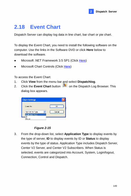
Dispatch Server
149
2
2.18 Event Chart Dispatch Server can display log data in line chart, bar chart or pie chart.
To display the Event Chart, you need to install the following software on the computer. Use the links in the Software DVD or click Here below to download the software.
Microsoft .NET Framework 3.5 SP1 (Click Here)
Microsoft Chart Controls (Click Here)
To access the Event Chart: 1. Click View from the menu bar and select Dispatchlog. 2. Click the Event Chart button on the Dispatch Log Browser. This
dialog box appears.
Figure 2-15
3. From the drop-down list, select Application Type to display events by the type of server, ID to display events by ID or Status to display events by the type of status. Application Type includes Dispatch Server, Center V2 Server, and Center V2 Subscribers. When Status is selected, events are categorized into Account, System, Login/logout, Connection, Control and Dispatch.
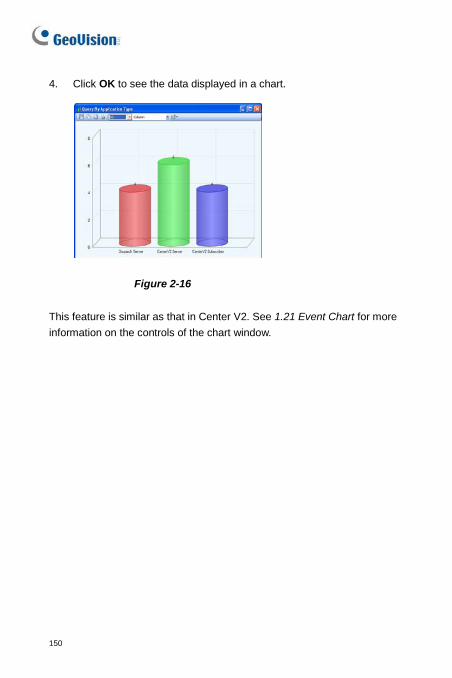
150
4. Click OK to see the data displayed in a chart.
Figure 2-16
This feature is similar as that in Center V2. See 1.21 Event Chart for more information on the controls of the chart window.
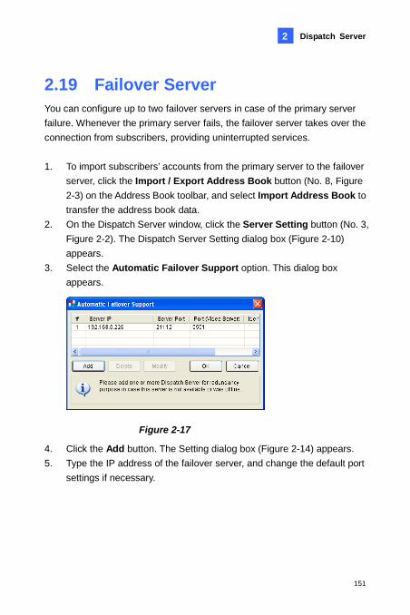
Dispatch Server
151
2
2.19 Failover Server You can configure up to two failover servers in case of the primary server failure. Whenever the primary server fails, the failover server takes over the connection from subscribers, providing uninterrupted services. 1. To import subscribers’ accounts from the primary server to the failover
server, click the Import / Export Address Book button (No. 8, Figure 2-3) on the Address Book toolbar, and select Import Address Book to transfer the address book data.
2. On the Dispatch Server window, click the Server Setting button (No. 3, Figure 2-2). The Dispatch Server Setting dialog box (Figure 2-10) appears.
3. Select the Automatic Failover Support option. This dialog box appears.
Figure 2-17
4. Click the Add button. The Setting dialog box (Figure 2-14) appears. 5. Type the IP address of the failover server, and change the default port
settings if necessary.
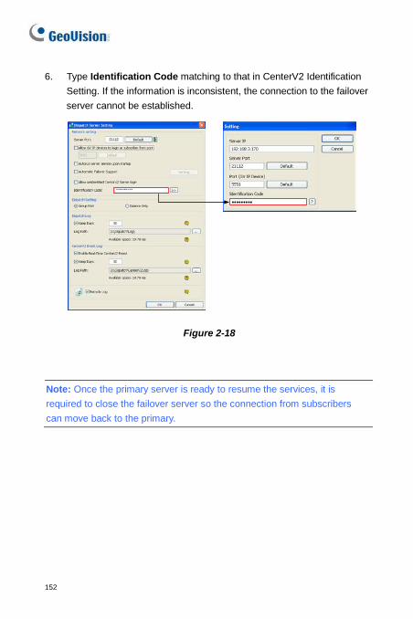
152
6. Type Identification Code matching to that in CenterV2 Identification Setting. If the information is inconsistent, the connection to the failover server cannot be established.
Figure 2-18
Note: Once the primary server is ready to resume the services, it is required to close the failover server so the connection from subscribers can move back to the primary.
152
Chapter 3 Vital Sign Monitor Vital Sign Monitor applies to the center monitoring station where multiple GV-System / GV-VMS are being monitored. When alert events occur in a GV-System / GV-VMS, Vital Sign Monitor will receive alert text messages, computer alarms and/or output alarms, while an SMS message and an E-Mail are sent out to subscribers. Vital Sign Monitor also supports GV IP devices (GV–Video Server, GV-Compact DVR, GV-IPCam) for central monitoring.
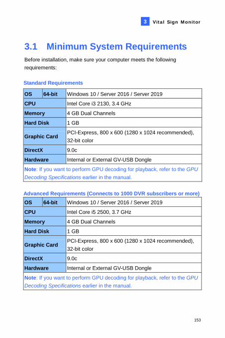
Vital Sign Monitor
153
3
3.1 Minimum System Requirements Before installation, make sure your computer meets the following requirements: Standard Requirements
Advanced Requirements (Connects to 1000 DVR subscribers or more) OS 64-bit Windows 10 / Server 2016 / Server 2019
CPU Intel Core i5 2500, 3.7 GHz
Memory 4 GB Dual Channels
Hard Disk 1 GB
Graphic Card PCI-Express, 800 x 600 (1280 x 1024 recommended), 32-bit color
DirectX 9.0c
Hardware Internal or External GV-USB Dongle
Note: If you want to perform GPU decoding for playback, refer to the GPU Decoding Specifications earlier in the manual.
OS 64-bit Windows 10 / Server 2016 / Server 2019
CPU Intel Core i3 2130, 3.4 GHz
Memory 4 GB Dual Channels
Hard Disk 1 GB
Graphic Card PCI-Express, 800 x 600 (1280 x 1024 recommended), 32-bit color
DirectX 9.0c
Hardware Internal or External GV-USB Dongle
Note: If you want to perform GPU decoding for playback, refer to the GPU Decoding Specifications earlier in the manual.
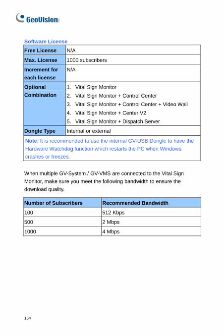
154
Software License Free License N/A
Max. License 1000 subscribers
Increment for each license
N/A
Optional Combination
1. Vital Sign Monitor 2. Vital Sign Monitor + Control Center 3. Vital Sign Monitor + Control Center + Video Wall 4. Vital Sign Monitor + Center V2 5. Vital Sign Monitor + Dispatch Server
Dongle Type Internal or external
Note: It is recommended to use the internal GV-USB Dongle to have the Hardware Watchdog function which restarts the PC when Windows crashes or freezes. When multiple GV-System / GV-VMS are connected to the Vital Sign Monitor, make sure you meet the following bandwidth to ensure the download quality.
Number of Subscribers Recommended Bandwidth
100 512 Kbps
500 2 Mbps
1000 4 Mbps
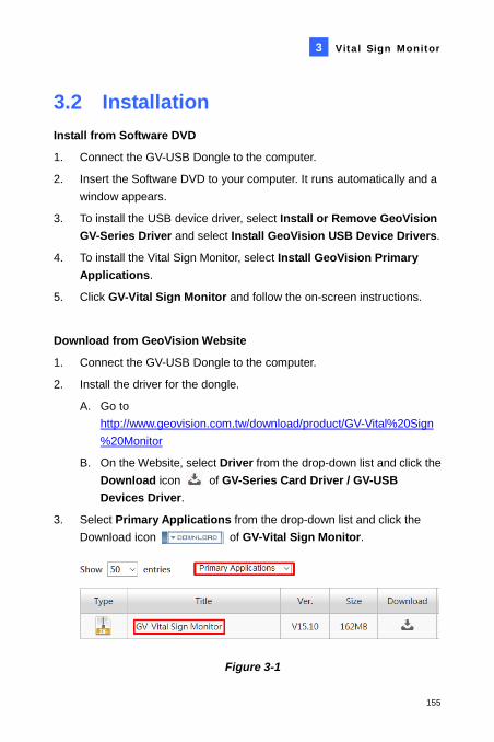
Vital Sign Monitor
155
3
3.2 Installation Install from Software DVD
1. Connect the GV-USB Dongle to the computer.
2. Insert the Software DVD to your computer. It runs automatically and a window appears.
3. To install the USB device driver, select Install or Remove GeoVision GV-Series Driver and select Install GeoVision USB Device Drivers.
4. To install the Vital Sign Monitor, select Install GeoVision Primary Applications.
5. Click GV-Vital Sign Monitor and follow the on-screen instructions.
Download from GeoVision Website
1. Connect the GV-USB Dongle to the computer.
2. Install the driver for the dongle.
A. Go to http://www.geovision.com.tw/download/product/GV-Vital%20Sign%20Monitor
B. On the Website, select Driver from the drop-down list and click the Download icon of GV-Series Card Driver / GV-USB Devices Driver.
3. Select Primary Applications from the drop-down list and click the Download icon of GV-Vital Sign Monitor.
Figure 3-1
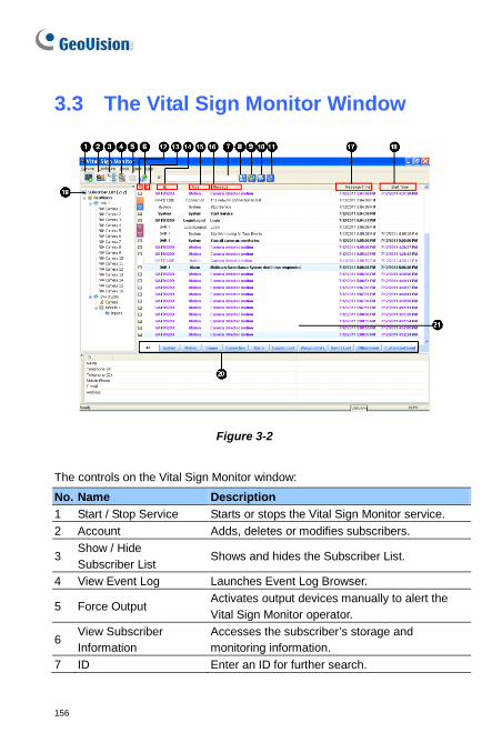
156
3.3 The Vital Sign Monitor Window
Figure 3-2
The controls on the Vital Sign Monitor window: No. Name Description 1 Start / Stop Service Starts or stops the Vital Sign Monitor service. 2 Account Adds, deletes or modifies subscribers.
3 Show / Hide Subscriber List
Shows and hides the Subscriber List.
4 View Event Log Launches Event Log Browser.
5 Force Output Activates output devices manually to alert the Vital Sign Monitor operator.
6 View Subscriber Information
Accesses the subscriber’s storage and monitoring information.
7 ID Enter an ID for further search.
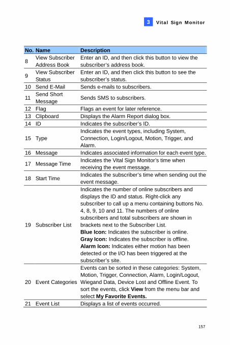
Vital Sign Monitor
157
3
No. Name Description
8 View Subscriber Address Book
Enter an ID, and then click this button to view the subscriber’s address book.
9 View Subscriber Status
Enter an ID, and then click this button to see the subscriber’s status.
10 Send E-Mail Sends e-mails to subscribers.
11 Send Short Message Sends SMS to subscribers.
12 Flag Flags an event for later reference. 13 Clipboard Displays the Alarm Report dialog box. 14 ID Indicates the subscriber’s ID.
15 Type Indicates the event types, including System, Connection, Login/Logout, Motion, Trigger, and Alarm.
16 Message Indicates associated information for each event type.
17 Message Time Indicates the Vital Sign Monitor’s time when receiving the event message.
18 Start Time Indicates the subscriber’s time when sending out the event message.
19 Subscriber List
Indicates the number of online subscribers and displays the ID and status. Right-click any subscriber to call up a menu containing buttons No. 4, 8, 9, 10 and 11. The numbers of online subscribers and total subscribers are shown in brackets next to the Subscriber List. Blue Icon: Indicates the subscriber is online. Gray Icon: Indicates the subscriber is offline. Alarm Icon: Indicates either motion has been detected or the I/O has been triggered at the subscriber’s site.
20 Event Categories
Events can be sorted in these categories: System, Motion, Trigger, Connection, Alarm, Login/Logout, Wiegand Data, Device Lost and Offline Event. To sort the events, click View from the menu bar and select My Favorite Events.
21 Event List Displays a list of events occurred.
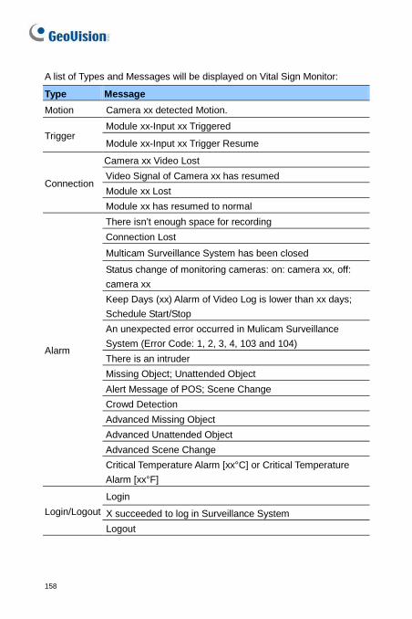
158
A list of Types and Messages will be displayed on Vital Sign Monitor:
Type Message Motion Camera xx detected Motion.
Trigger Module xx-Input xx Triggered
Module xx-Input xx Trigger Resume
Connection
Camera xx Video Lost Video Signal of Camera xx has resumed Module xx Lost Module xx has resumed to normal
Alarm
There isn’t enough space for recording Connection Lost Multicam Surveillance System has been closed Status change of monitoring cameras: on: camera xx, off: camera xx Keep Days (xx) Alarm of Video Log is lower than xx days; Schedule Start/Stop An unexpected error occurred in Mulicam Surveillance System (Error Code: 1, 2, 3, 4, 103 and 104) There is an intruder Missing Object; Unattended Object Alert Message of POS; Scene Change Crowd Detection Advanced Missing Object Advanced Unattended Object Advanced Scene Change Critical Temperature Alarm [xx°C] or Critical Temperature Alarm [xx°F]
Login/Logout Login
X succeeded to log in Surveillance System Logout
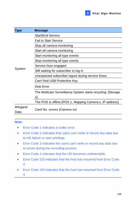
Vital Sign Monitor
159
3
Type Message
System
Start/End Service Fail to Start Service Stop all camera monitoring Start all camera monitoring Start monitoring all type events Stop monitoring all type events Service hour engaged Still waiting for subscriber to log in Unexpected subscriber logout during service times Can’t find USB Protection Key
Disk Error
The Multicam Surveillance System starts recycling. [Storage 1] The POS is offline [POS 1, Mapping Camera:x, IP address]
Wiegand Data
Card No. xxxxxx (Camera xx)
Note:
• Error Code 1 indicates a codec error.
• Error Code 2 indicates that users can’t write or record any data due to HD failure or user privilege.
• Error Code 3 indicates the users can’t write or record any data due to errors during the recording process.
• Error Code 4 indicates that the HD becomes undetectable.
• Error Code 103 indicates that the host has resumed from Error Code 3
• Error Code 104 indicates that the host has resumed from Error Code 4.
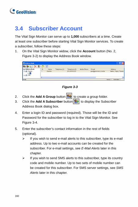
160
3.4 Subscriber Account The Vital Sign Monitor can serve up to 1,000 subscribers at a time. Create at least one subscriber before starting Vital Sign Monitor services. To create a subscriber, follow these steps: 1. On the Vital Sign Monitor widow, click the Account button (No. 2,
Figure 3-2) to display the Address Book window.
Figure 3-3
2. Click the Add A Group button to create a group folder. 3. Click the Add A Subscriber button to display the Subscriber
Address Book dialog box.
4. Enter a login ID and password (required). Those will be the ID and Password for the subscriber to log in to the Vital Sign Monitor. See Figure 3-4.
5. Enter the subscriber’s contact information in the rest of fields (optional). If you wish to send e-mail alerts to this subscriber, type its e-mail
address. Up to two e-mail accounts can be created for the subscriber. For e-mail settings, see E-Mail Alerts later in this chapter.
If you wish to send SMS alerts to this subscriber, type its country code and mobile number. Up to two sets of mobile number can be created for this subscriber. For SMS server settings, see SMS Alerts later in this chapter.

Vital Sign Monitor
161
3
6. Click OK. This adds the subscriber to the group folder created before. Returning to the Vital Sign Monitor window, you will see a message: Add a subscriber – xxx. (Subscriber xxx has been added.)
162
3.5 Service Startup After subscriber accounts are created, the Vital Sign Monitor is ready to provide services. Clicking the Start/Stop Service button (No. 1, Figure 3-2) on the Vital Sign Monitor window to receive signals from subscribers.
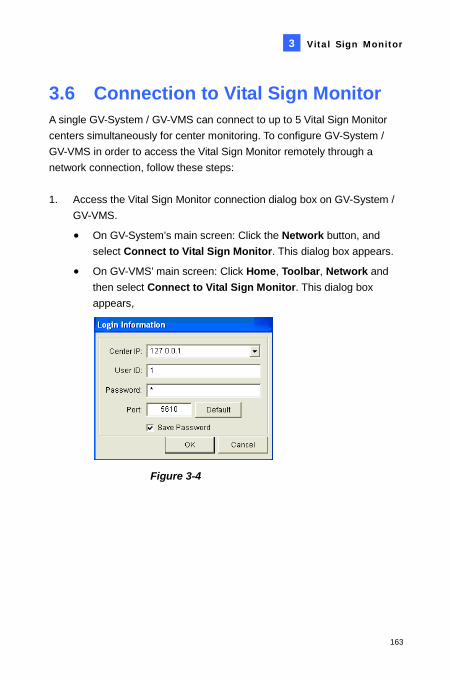
Vital Sign Monitor
163
3
3.6 Connection to Vital Sign Monitor A single GV-System / GV-VMS can connect to up to 5 Vital Sign Monitor centers simultaneously for center monitoring. To configure GV-System / GV-VMS in order to access the Vital Sign Monitor remotely through a network connection, follow these steps: 1. Access the Vital Sign Monitor connection dialog box on GV-System /
GV-VMS.
• On GV-System’s main screen: Click the Network button, and select Connect to Vital Sign Monitor. This dialog box appears.
• On GV-VMS’ main screen: Click Home, Toolbar, Network and then select Connect to Vital Sign Monitor. This dialog box appears,
Figure 3-4
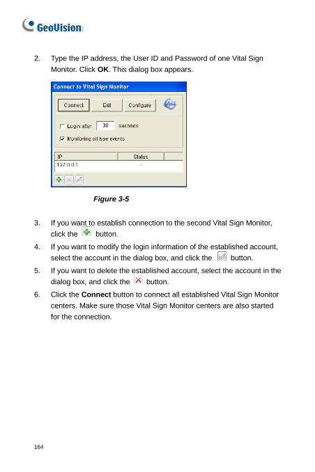
164
2. Type the IP address, the User ID and Password of one Vital Sign Monitor. Click OK. This dialog box appears.
Figure 3-5
3. If you want to establish connection to the second Vital Sign Monitor, click the button.
4. If you want to modify the login information of the established account, select the account in the dialog box, and click the button.
5. If you want to delete the established account, select the account in the dialog box, and click the button.
6. Click the Connect button to connect all established Vital Sign Monitor centers. Make sure those Vital Sign Monitor centers are also started for the connection.
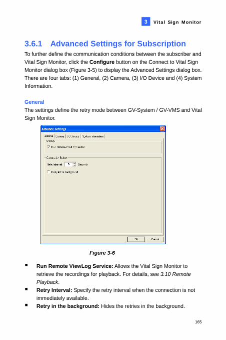
Vital Sign Monitor
165
3
3.6.1 Advanced Settings for Subscription To further define the communication conditions between the subscriber and Vital Sign Monitor, click the Configure button on the Connect to Vital Sign Monitor dialog box (Figure 3-5) to display the Advanced Settings dialog box. There are four tabs: (1) General, (2) Camera, (3) I/O Device and (4) System Information. General The settings define the retry mode between GV-System / GV-VMS and Vital Sign Monitor.
Figure 3-6
Run Remote ViewLog Service: Allows the Vital Sign Monitor to retrieve the recordings for playback. For details, see 3.10 Remote Playback.
Retry Interval: Specify the retry interval when the connection is not immediately available.
Retry in the background: Hides the retries in the background.
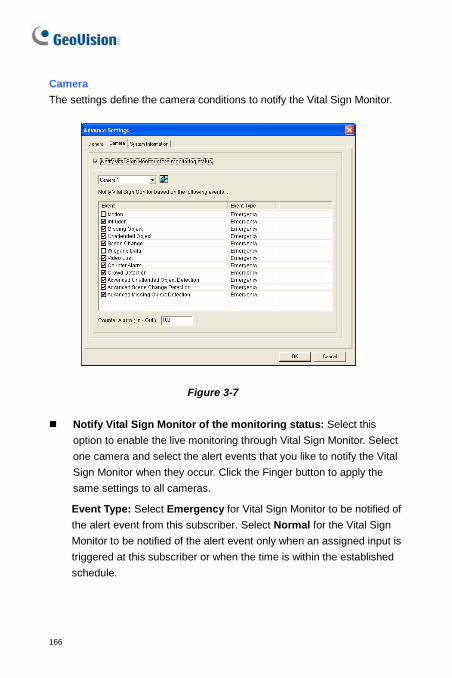
166
Camera The settings define the camera conditions to notify the Vital Sign Monitor.
Figure 3-7
Notify Vital Sign Monitor of the monitoring status: Select this option to enable the live monitoring through Vital Sign Monitor. Select one camera and select the alert events that you like to notify the Vital Sign Monitor when they occur. Click the Finger button to apply the same settings to all cameras.
Event Type: Select Emergency for Vital Sign Monitor to be notified of the alert event from this subscriber. Select Normal for the Vital Sign Monitor to be notified of the alert event only when an assigned input is triggered at this subscriber or when the time is within the established schedule.
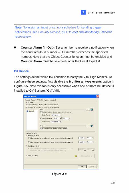
Vital Sign Monitor
167
3
Note: To assign an input or set up a schedule for sending trigger notifications, see Security Service, [I/O Device] and Monitoring Schedule respectively.
Counter Alarm (In-Out): Set a number to receive a notification when the count result (In number – Out number) exceeds the specified number. Note that the Object Counter function must be enabled and Counter Alarm must be selected under the Event Type list.
I/O Device
The settings define which I/O condition to notify the Vital Sign Monitor. To configure these settings, first disable the Monitor all type events option in Figure 3-5. Note this tab is only accessible when one or more I/O device is installed to GV-System / GV-VMS.
Figure 3-8
168
[I/O Device] Notifies the Vital Sign Monitor when I/O devices are triggered. Use the Arrow buttons to configure each I/O device, or click the Finger button to apply to all I/O devices.
Allow Vital Sign Monitor to Enable / Disable I/O: Allows the Vital Sign Monitor manually arm/disarm any I/O devices at the subscriber’s site without interrupting the monitoring. For example, when an alarm is triggered at the subscriber site, the Vital Sign Monitor operator can turn it off remotely before arriving at the site. Meanwhile, GV-System / GV-VMS still remains on monitoring.
Notify Vital Sign Monitor when I/O is Triggered: Notifies the Vital Sign Monitor when any selected input is triggered.
Event Type: If the subscriber wants the Vital Sign Monitor always to get notified of the input trigger, select Emergency. If the subscriber wants the Vital Sign Monitor to get notified of the input trigger only when an assigned input is triggered, select Normal.
Right Arrow button: Sets the delay time to notify the Vital Sign Monitor of the input trigger. This feature is only available when the Normal type is chosen. Exit Delay: While the system is activated, this feature provides
an interval of time for the subscriber to exit the premises. During this time, the specified input (e.g. an exit/entry door) is inactive. Once the exit delay expires, the input will be fully armed.
Entry Delay: While the system is activated, this feature provides an interval of time for the subscriber to entry the premises. During this time, the specified input (e.g. a exit/entry door) is inactive so that the subscriber can disarm the system. If the subscriber fails to do, once the entry delay expires, the Vital Sign Monitor will get notified of the input trigger.
Output Module: Enables the assigned output module when the selected input module is triggered. For this example of Figure 3-8, when the I/O Device (Module 1, Input 4) is triggered, the Output (Module 1, Pin 3) will be activated simultaneously.
Vital Sign Monitor
169
3
Event Type: If the subscriber wants the Vital Sign Monitor always to get notified of the output trigger, select Emergency. If the subscriber wants the Vital Sign Monitor to get notified of the output trigger only when an assigned input is triggered, select Normal. Right Arrow button: Sets the delay time to trigger the assigned output module. This feature is only available when the Normal type is chosen. The Exit Delay and Entry Delay options are similar to those described in the input trigger.
Note: To set an input trigger for the notification of Normal events, see [Security Service] below.
Allow Vital Sign Monitor to Force Output: Allows the Vital Sign
Monitor operator to manually force output devices installed at the subscriber’s site.
[Security Service] Notify the Vital Sign Monitor server of events only when an input is on or when the events occur within the defined schedule. For details, see [I/O Device], Advanced Settings in 1.5 Connection to Center V2.
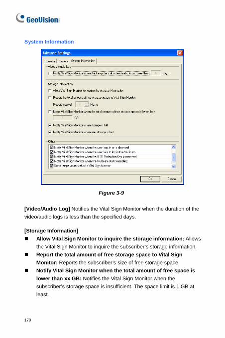
170
System Information
Figure 3-9
[Video/Audio Log] Notifies the Vital Sign Monitor when the duration of the video/audio logs is less than the specified days.
[Storage Information] Allow Vital Sign Monitor to inquire the storage information: Allows
the Vital Sign Monitor to inquire the subscriber’s storage information. Report the total amount of free storage space to Vital Sign
Monitor: Reports the subscriber’s size of free storage space. Notify Vital Sign Monitor when the total amount of free space is
lower than xx GB: Notifies the Vital Sign Monitor when the subscriber’s storage space is insufficient. The space limit is 1 GB at least.
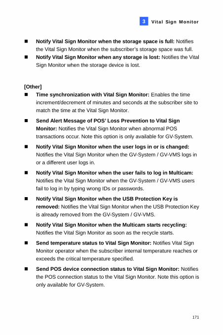
Vital Sign Monitor
171
3
Notify Vital Sign Monitor when the storage space is full: Notifies the Vital Sign Monitor when the subscriber’s storage space was full.
Notify Vital Sign Monitor when any storage is lost: Notifies the Vital Sign Monitor when the storage device is lost.
[Other] Time synchronization with Vital Sign Monitor: Enables the time
increment/decrement of minutes and seconds at the subscriber site to match the time at the Vital Sign Monitor.
Send Alert Message of POS’ Loss Prevention to Vital Sign Monitor: Notifies the Vital Sign Monitor when abnormal POS transactions occur. Note this option is only available for GV-System.
Notify Vital Sign Monitor when the user logs in or is changed: Notifies the Vital Sign Monitor when the GV-System / GV-VMS logs in or a different user logs in.
Notify Vital Sign Monitor when the user fails to log in Multicam: Notifies the Vital Sign Monitor when the GV-System / GV-VMS users fail to log in by typing wrong IDs or passwords.
Notify Vital Sign Monitor when the USB Protection Key is removed: Notifies the Vital Sign Monitor when the USB Protection Key is already removed from the GV-System / GV-VMS.
Notify Vital Sign Monitor when the Multicam starts recycling: Notifies the Vital Sign Monitor as soon as the recycle starts.
Send temperature status to Vital Sign Monitor: Notifies Vital Sign Monitor operator when the subscriber internal temperature reaches or exceeds the critical temperature specified.
Send POS device connection status to Vital Sign Monitor: Notifies the POS connection status to the Vital Sign Monitor. Note this option is only available for GV-System.
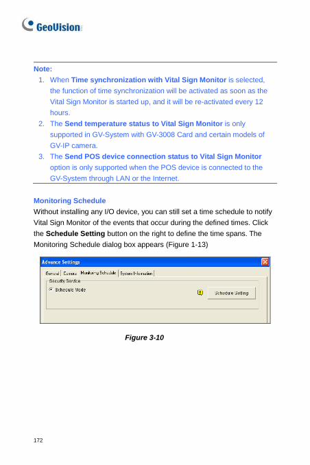
172
Note:
1. When Time synchronization with Vital Sign Monitor is selected, the function of time synchronization will be activated as soon as the Vital Sign Monitor is started up, and it will be re-activated every 12 hours.
2. The Send temperature status to Vital Sign Monitor is only supported in GV-System with GV-3008 Card and certain models of GV-IP camera.
3. The Send POS device connection status to Vital Sign Monitor option is only supported when the POS device is connected to the GV-System through LAN or the Internet.
Monitoring Schedule Without installing any I/O device, you can still set a time schedule to notify Vital Sign Monitor of the events that occur during the defined times. Click the Schedule Setting button on the right to define the time spans. The Monitoring Schedule dialog box appears (Figure 1-13)
Figure 3-10
Vital Sign Monitor
173
3
3.6.2 Detecting Input Status The feature is designed to monitor all inputs for a change of state whenever the subscriber starts the live monitoring through Vital Sign Monitor. A change from the previously defined state (N/O to N/C or N/C to N/O) will activate an alarm condition. Click on the Connect to Vital Sign Monitor dialog box (Figure 3-5). For details, see Input State Detection, Chapter 6, GV-DVR User’s Manual on the Software DVD.
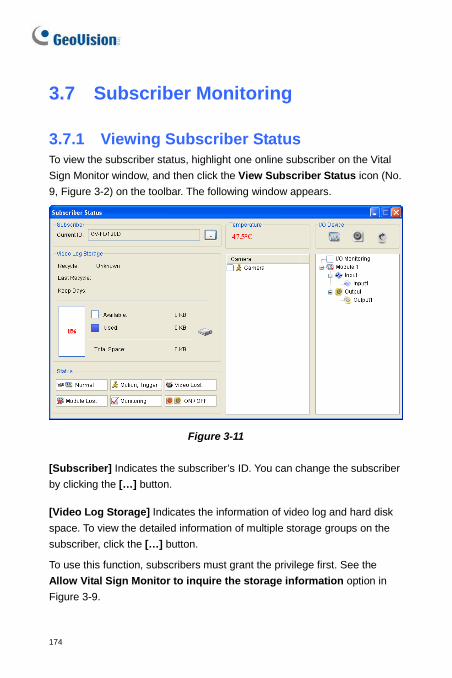
174
3.7 Subscriber Monitoring
3.7.1 Viewing Subscriber Status To view the subscriber status, highlight one online subscriber on the Vital Sign Monitor window, and then click the View Subscriber Status icon (No. 9, Figure 3-2) on the toolbar. The following window appears.
Figure 3-11
[Subscriber] Indicates the subscriber’s ID. You can change the subscriber by clicking the […] button.
[Video Log Storage] Indicates the information of video log and hard disk space. To view the detailed information of multiple storage groups on the subscriber, click the […] button.
To use this function, subscribers must grant the privilege first. See the Allow Vital Sign Monitor to inquire the storage information option in Figure 3-9.
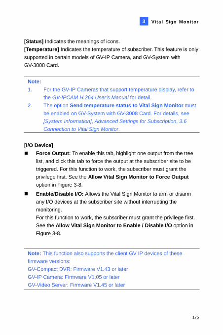
Vital Sign Monitor
175
3
[Status] Indicates the meanings of icons. [Temperature] Indicates the temperature of subscriber. This feature is only supported in certain models of GV-IP Camera, and GV-System with GV-3008 Card.
Note: 1. For the GV-IP Cameras that support temperature display, refer to
the GV-IPCAM H.264 User’s Manual for detail. 2. The option Send temperature status to Vital Sign Monitor must
be enabled on GV-System with GV-3008 Card. For details, see [System Information], Advanced Settings for Subscription, 3.6 Connection to Vital Sign Monitor.
[I/O Device] Force Output: To enable this tab, highlight one output from the tree
list, and click this tab to force the output at the subscriber site to be triggered. For this function to work, the subscriber must grant the privilege first. See the Allow Vital Sign Monitor to Force Output option in Figure 3-8.
Enable/Disable I/O: Allows the Vital Sign Monitor to arm or disarm any I/O devices at the subscriber site without interrupting the monitoring. For this function to work, the subscriber must grant the privilege first. See the Allow Vital Sign Monitor to Enable / Disable I/O option in Figure 3-8.
Note: This function also supports the client GV IP devices of these firmware versions: GV-Compact DVR: Firmware V1.43 or later GV-IP Camera: Firmware V1.05 or later GV-Video Server: Firmware V1.45 or later
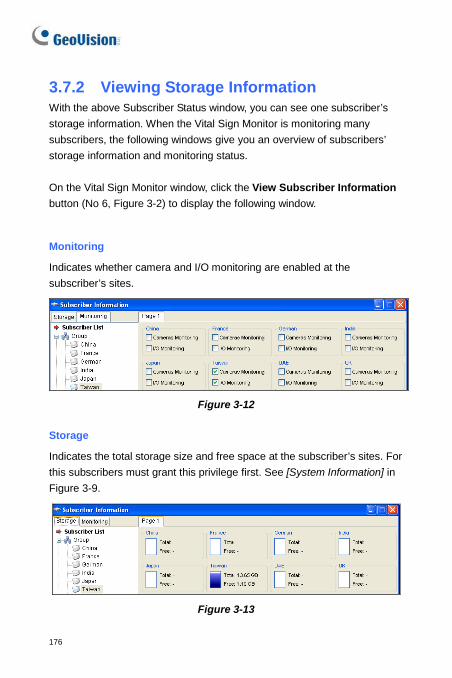
176
3.7.2 Viewing Storage Information With the above Subscriber Status window, you can see one subscriber’s storage information. When the Vital Sign Monitor is monitoring many subscribers, the following windows give you an overview of subscribers’ storage information and monitoring status. On the Vital Sign Monitor window, click the View Subscriber Information button (No 6, Figure 3-2) to display the following window.
Monitoring
Indicates whether camera and I/O monitoring are enabled at the subscriber’s sites.
Figure 3-12
Storage
Indicates the total storage size and free space at the subscriber’s sites. For this subscribers must grant this privilege first. See [System Information] in Figure 3-9.
Figure 3-13
Vital Sign Monitor
177
3
3.7.3 Disabling Subscription The Vital Sign Monitor operator can disable its services to an individual subscriber when subscription expires. On the Address Book (Figure 3-3), right-click one subscriber and select Disable. To restore the subscription, right-click again to select Enable.
178
3.8 Subscriber Schedule The Vital Sign Monitor operator can create schedules to monitor subscription status. When subscribers don’t log in the Vital Sign Monitor on the programmed time, the operator and subscribers can get notified. To set up a schedule, see 1.11 Subscriber Schedule.
When a subscriber doesn’t log in the Vital Sign Monitor on time, this message will appear on the Event List: Service hour engaged; still waiting for subscriber to log in. When a subscriber logs out suddenly during a service time, this message will appear: Unexpected subscriber logout during service times.
To activate the computer and output alarm to notify the operator while an SMS and an E-mail message being sent out to a subscriber, use the Notification feature. For details, see Notification Settings later in this chapter.
Vital Sign Monitor
179
3
3.9 Alarm Report For every event, the Vital Sign Monitor operator can generate a report to evaluate certain conditions. This function is the same as that of the Center V2. For details, see 1.12 Alarm Report.
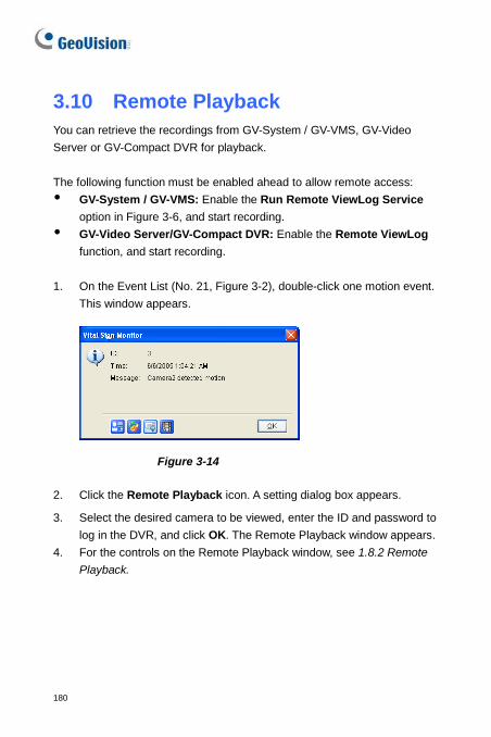
180
3.10 Remote Playback You can retrieve the recordings from GV-System / GV-VMS, GV-Video Server or GV-Compact DVR for playback. The following function must be enabled ahead to allow remote access: GV-System / GV-VMS: Enable the Run Remote ViewLog Service
option in Figure 3-6, and start recording. GV-Video Server/GV-Compact DVR: Enable the Remote ViewLog
function, and start recording. 1. On the Event List (No. 21, Figure 3-2), double-click one motion event.
This window appears.
Figure 3-14
2. Click the Remote Playback icon. A setting dialog box appears.
3. Select the desired camera to be viewed, enter the ID and password to log in the DVR, and click OK. The Remote Playback window appears.
4. For the controls on the Remote Playback window, see 1.8.2 Remote Playback.
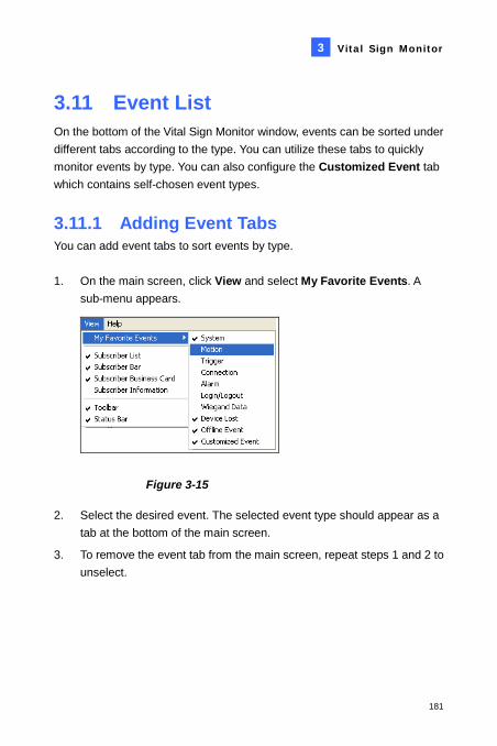
Vital Sign Monitor
181
3
3.11 Event List On the bottom of the Vital Sign Monitor window, events can be sorted under different tabs according to the type. You can utilize these tabs to quickly monitor events by type. You can also configure the Customized Event tab which contains self-chosen event types.
3.11.1 Adding Event Tabs You can add event tabs to sort events by type. 1. On the main screen, click View and select My Favorite Events. A
sub-menu appears.
Figure 3-15
2. Select the desired event. The selected event type should appear as a tab at the bottom of the main screen.
3. To remove the event tab from the main screen, repeat steps 1 and 2 to unselect.
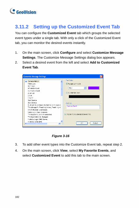
182
3.11.2 Setting up the Customized Event Tab You can configure the Customized Event tab which groups the selected event types under a single tab. With only a click of the Customized Event tab, you can monitor the desired events instantly. 1. On the main screen, click Configure and select Customize Message
Settings. The Customize Message Settings dialog box appears. 2. Select a desired event from the left and select Add to Customized
Event Tab.
Figure 3-16
3. To add other event types into the Customize Event tab, repeat step 2.
4. On the main screen, click View, select My Favorite Events, and select Customized Event to add this tab to the main screen.
Vital Sign Monitor
183
3
3.11.3 Setting Alert Level of Event Messages You can assign an alert level to each event type for monitoring and management purposes. Each alert level can be distinguished by color. You can customize the color for each alert level or assign a color exclusively for a particular event type. On the main screen, click Configure and select Customize Message Settings. The Customize Message Settings dialog box appears. For setup details, see 1.15 Setting Alert Levels of Event Messages

184
3.12 Event Log Browser To launch Event Log Browser, click Tools on the window menu and select Event Log Browser. This feature is the same as that in Center V2. For details, see 1.14 Event Log Browser.
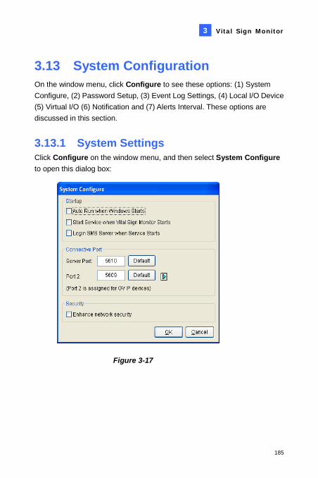
Vital Sign Monitor
185
3
3.13 System Configuration On the window menu, click Configure to see these options: (1) System Configure, (2) Password Setup, (3) Event Log Settings, (4) Local I/O Device (5) Virtual I/O (6) Notification and (7) Alerts Interval. These options are discussed in this section.
3.13.1 System Settings Click Configure on the window menu, and then select System Configure to open this dialog box:
Figure 3-17
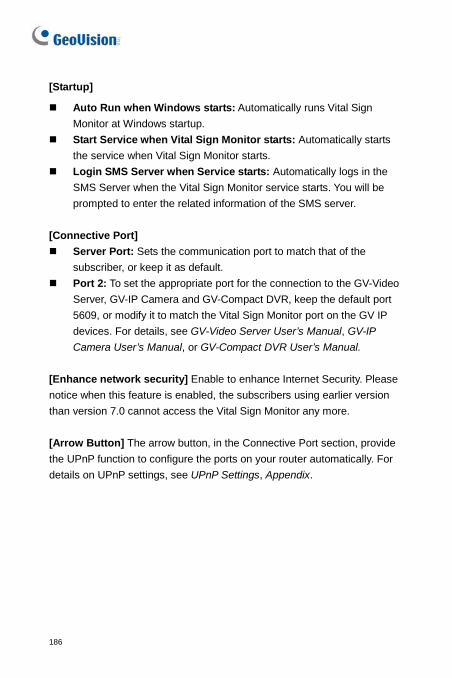
186
[Startup]
Auto Run when Windows starts: Automatically runs Vital Sign Monitor at Windows startup.
Start Service when Vital Sign Monitor starts: Automatically starts the service when Vital Sign Monitor starts.
Login SMS Server when Service starts: Automatically logs in the SMS Server when the Vital Sign Monitor service starts. You will be prompted to enter the related information of the SMS server.
[Connective Port] Server Port: Sets the communication port to match that of the
subscriber, or keep it as default. Port 2: To set the appropriate port for the connection to the GV-Video
Server, GV-IP Camera and GV-Compact DVR, keep the default port 5609, or modify it to match the Vital Sign Monitor port on the GV IP devices. For details, see GV-Video Server User’s Manual, GV-IP Camera User’s Manual, or GV-Compact DVR User’s Manual.
[Enhance network security] Enable to enhance Internet Security. Please notice when this feature is enabled, the subscribers using earlier version than version 7.0 cannot access the Vital Sign Monitor any more. [Arrow Button] The arrow button, in the Connective Port section, provide the UPnP function to configure the ports on your router automatically. For details on UPnP settings, see UPnP Settings, Appendix.
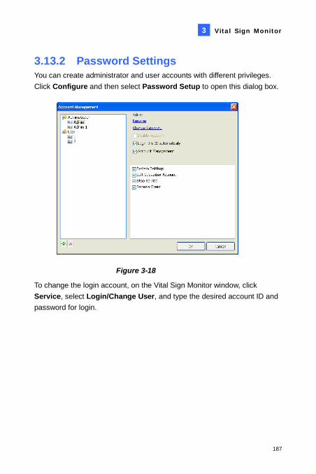
Vital Sign Monitor
187
3
3.13.2 Password Settings You can create administrator and user accounts with different privileges. Click Configure and then select Password Setup to open this dialog box.
Figure 3-18
To change the login account, on the Vital Sign Monitor window, click Service, select Login/Change User, and type the desired account ID and password for login.
188
3.13.3 Event Log Settings Click Configure on the window menu, and select Event Log Settings to display the Event Log Settings dialog box. The settings are the same as those in Center V2. For details, see Setting the Event Log in 1.14 Event Log Browser.
Also see 3.13 Event Log Browser.
Vital Sign Monitor
189
3
3.13.4 Notification Settings When alert conditions occur, the Vital Sign Monitor can automatically activate the assigned computer and output alarm to notify the operator while an SMS and an e-mail message are being sent out to subscribers.
To configure this function, click Configure on the window menu and select Notification to display the Alarm Settings window. [Alert Approach] Minimum Duration: This option is only available for Camera Motion,
Connection Lost and Video Lost alerts. The minimum duration is the minimal time period that the event must persist for Vital Sign Monitor to be notified by alarm, output, e-mail and/or SMS. Select this option and click the Edit button to type the minimum duration. The default is 3 seconds.
Note: For Video Lost alert, the minimum duration function is used to exclude video lost alerts from cameras that resume connection to GV-System / GV-VMS instantly after they disconnect.
The other settings are the same as those in Center V2. For detail, see 1.16 Notification Settings. Also see 3.15 Output Alerts, 3.16 SMS Alerts, and 3.17 E-Mail Alerts.
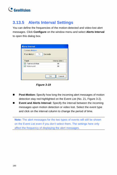
190
3.13.5 Alerts Interval Settings You can define the frequencies of the motion-detected and video-lost alert messages. Click Configure on the window menu and select Alerts Interval to open this dialog box.
Figure 3-19
Post-Motion: Specify how long the incoming alert messages of motion
detection stay red-highlighted on the Event List (No. 21, Figure 3-2). Event and Alerts Interval: Specify the interval between the incoming
messages upon motion detection or video lost. Select the event type and click on the interval column to change the period of time.
Note: The alert messages for the two types of events will still be shown on the Event List even if you don’t select them. The settings here only affect the frequency of displaying the alert messages.
Vital Sign Monitor
191
3
3.14 Output Alerts You can activate output devices installed at the Vital Sign Monitor site (local) and/or through the network (virtual) to warn the Vital Sign Monitor operator when events occur. Up to nine (9) GV-I/O Boxes (including local and virtual) can be connected to a single Vital Sign Monitor.
3.14.1 Configuring a Local GV-I/O Box On the window menu, click Configure and then select Local I/O Device. This I/O Device dialog box appears. For setup details, see Configuring a Local GV-I/O Box in 1.17 Output Alerts.
3.14.2 Configuring a Virtual GV-I/O Box On window menu, click Configure and then select Virtual I/O. The Virtual I/O Device dialog box appears. For setup details, see Configuring a Virtual GV-I/O Box in 1.17 Output Alerts.
3.14.3 Triggering Outputs by Event Click Configure on the window menu and select Notification. The Alarm Settings dialog box appears. For detail, see Triggering Outputs by Event in 1.17 Output Alerts.
Note: Only 8-port and 16-port GV-I/O Boxes can be installed through the network.
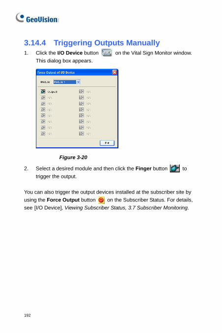
192
3.14.4 Triggering Outputs Manually 1. Click the I/O Device button on the Vital Sign Monitor window.
This dialog box appears.
Figure 3-20
2. Select a desired module and then click the Finger button to trigger the output.
You can also trigger the output devices installed at the subscriber site by using the Force Output button on the Subscriber Status. For details, see [I/O Device], Viewing Subscriber Status, 3.7 Subscriber Monitoring.
Vital Sign Monitor
193
3
3.15 SMS Alerts This feature lets you send out SMS messages to subscribers when alert conditions occur.
3.15.1 Setting SMS Server Before sending SMS messages to an individual subscriber, you need to define SMS Server correctly.
Click Configure on the window menu and select SMS Setup. For setup details, see 1.18 SMS Alerts.
3.15.2 Sending SMS Once the connection between the SMS Server and Vital Sign Monitor is established, there are several ways to send out SMS messages to subscribers. See the Vital Sign Monitor window for the following selections. 1. Click the Send Short Message button (No. 11, Figure 3-2). This sends
out SMS to an individual subscriber manually. 2. On the Event List, double-click any event type to call up a message
window, and then click the Send Short Message icon. This sends SMS to an individual subscriber manually.
3. On the Subscriber List (No. 18, Figure 3-2), right-click one subscriber and select Send Short Message. This sends SMS to an individual subscriber manually.
4. Click Configure on the window menu, and select Notification to display the Alarm Settings window. Select Send SMS Alerts. This sends SMS to subscribers automatically when alert conditions occur. See Notification Settings earlier in this chapter.

194
3.15.3 Inserting Device Information The subscriber’s ID and camera name can be automatically inserted to your SMS message when it is sent out. Click Configure on the window menu and select Notification. The Alarm Settings dialog box appears. For details, see Inserting Device Information, 1.18 SMS Alerts.
Vital Sign Monitor
195
3
3.16 E-Mail Alerts You can send e-mails to subscribers when alert conditions occur.
3.16.1 Setting Mailbox Before you can send e-mails to an e-mail account, you need to define your mailbox correctly. Click Configure on the window menu and select E-Mail Setup. For setup details, see 1.19 E-Mail Alerts.
3.16.2 Sending E-Mail There are several ways to send e-mail alerts. See the Vital Sign Monitor window for the following selections. 1. Click the E-Mail button (No. 10, Figure 3-2). This sends the e-mail to
an individual subscriber manually. 2. On the Subscriber List (No. 19, Figure 3-2), right-click one subscriber,
and then select Send E-Mail. This sends the e-mail to an individual subscriber manually.
3. On the Event List, double-click one event to call up a message window, and then click the e-mail icon. This sends the e-mail to an individual subscriber manually.
4. Click Configure on the window menu and select Notification to display the Alarm Settings window. Select Send E-Mail Alerts. This sends e-mails to subscribers automatically when alert conditions occur. See Notification Settings earlier in the chapter.
196
3.16.3 Inserting Device Information The subscriber’s ID and camera name can be automatically inserted to your e-mail message when it is sent out. Click Configure on the window menu and select Notification. The Alarm Settings dialog box appears. For details, see Inserting Device Information, 1.18 SMS Alerts.
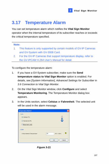
Vital Sign Monitor
197
3
3.17 Temperature Alarm You can set temperature alarm which notifies the Vital Sign Monitor operator when the internal temperature of its subscriber reaches or exceeds the critical temperature specified.
Note: 1. This feature is only supported by certain models of GV-IP Cameras
and GV-System with GV-3008 Card. 2. For the GV-IP Cameras that support temperature display, refer to
the GV-IPCAM H.264 User’s Manual for detail. To configure the temperature alarm:
1. If you have a GV-System subscriber, make sure the Send temperature status to Vital Sign Monitor option is enabled. For details, see [System Information], Advanced Settings for Subscriber in 3.6 Connection to Vital Sign Monitor.
2. On the Vital Sign Monitor window, click Configure and select Temperature Monitoring. The Temperature Monitor dialog box appears.
3. In the Units section, select Celsius or Fahrenheit. The selected unit will be used in the alarm message.
Figure 3-21
198
4. To show both units in the Subscriber Status (see Figure 3-11), select the Show both units option.
Tip: With the Show both units option is selected, select either Celsius or Fahrenheit for the unit to come before the other in the Subscriber Status.
5. In the Alarm section, specify the critical temperature.
6. Click OK. Once the temperature reaches or exceeds the critical temperature, an alarm event such as “Critical Temperature Alarm [77.5°C]”, will be shown on the Vital Sign Monitor window.
You can also invoke computer alarm and local output device, and send SMS and e-mail alerts using the Alarm Settings. For details, see 1.16 Notification Settings, 2.14 SMS Alerts and 2.15 E-Mail Alerts respectively.
Vital Sign Monitor
199
3
3.18 Event Chart The Event Chart can provide you the daily, weekly and monthly statistical chart based on different criteria. This feature is similar as that in Center V2. For details, see 1.21 Event Chart. To launch the Event Chart, click Tools on the window menu and select Event Chart.
200
3.19 Failover Server You can configure up to two failover servers in case of the primary Vital Sign Monitor server failure. Whenever the primary fails, the failover takes over the connection from subscribers, providing uninterrupted monitoring services. To access this feature, on the Vital Sign Monitor window menu (see Figure 3-2), click Service, and select Automatic Failover Support. This feature is the same as that in Center V2’s. For details on setup, see 1.22 Failover Server.
203
Appendix A. Dongle Description B. Upgrading the Black Dongle C. Fast Backup and Restoration D. Watermark Proof E. PTZ Control Using GV-Joystick V2 F. Image Size on Center V2 G. UPnP Settings H. Supported IP Device Brands and Protocols I. MultiLang Tool for Translated Text J. Specifications
204
A. Dongle Description Note the following requirements and limitations for GV-USB Dongle.
• An appropriate USB dongle of “Black” color is required for each CMS module to work.
• Using more than one Black Dongle on the same computer is possible. But remember the rule that Control Center and Center V2 cannot be run together, and Center V2 and Dispatch Server cannot be run together.
• The Black Dongle can be upgraded to include more functions.
• It is required to install drivers from the Software DVD for the Black Dongle to work.
Dongle options for Center V2 • Center V2 Pro • Center V2 + Vital Sign Monitor
Connection of GeoVision IP devices to Center V2: The Center V2 accepts any video stream from GeoVision IP video devices. There is no need to use an extra dongle. Currently Center V2 does not support the video streaming from third-party IP video devices.
Dongle options for Dispatch Server • Dispatch Server • Dispatch Server + Vital Sign Monitor
Appendix
205
Dongle options for Vital Sign Monitor • Vital Sign Monitor • Vital Sign Monitor + Control Center • Vital Sign Monitor + Control Center + Video Wall • Vital Sign Monitor + Center V2 • Vital Sign Monitor + Dispatch Server
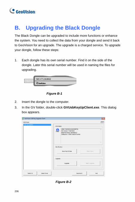
206
B. Upgrading the Black Dongle The Black Dongle can be upgraded to include more functions or enhance the system. You need to collect the data from your dongle and send it back to GeoVision for an upgrade. The upgrade is a charged service. To upgrade your dongle, follow these steps:
1. Each dongle has its own serial number. Find it on the side of the dongle. Later this serial number will be used in naming the files for upgrading.
Figure B-1 2. Insert the dongle to the computer.
3. In the GV folder, double-click GVUsbKeyUpClient.exe. This dialog box appears.
Figure B-2
Appendix
207
4. To retrieve the data from the dongle, click Select All. The information of the dongle is displayed in the information field. Note the displayed number of “HW Serial” should be the same as that on the dongle.
5. To save the data to your local computer, click Save Key ID Data. If you have more than one dongle to upgrade, click Batch Save. Different dongle data will be saved as separate files. The file will be named after the serial number on the dongle and saved as *.out. For example, if a dongle serial number is 7116442, the file is named “NVR-7116442.out”.
6. Send this data file to GeoVision at [email protected]. The GeoVision will examine the data file and send an *.in file back to you. The file name also includes the serial number of that dongle. In this example, the data file you will receive is named “NVR-7116442.in”.
7. After you receive the updated file, insert the correct dongle matching the .in file you receive, and then run GVUsbKeyUpClient.exe.
8. Click Select All to read the dongle, click Upgrade and then open the updated file to upgrade the dongle. You can also select more than one dongle in the list and click Batch Upgrade to upgrade them at the same time. Make sure these dongles match the updated files you receive.
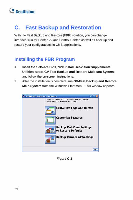
208
C. Fast Backup and Restoration With the Fast Backup and Restore (FBR) solution, you can change interface skin for Center V2 and Control Center, as well as back up and restore your configurations in CMS applications.
Installing the FBR Program 1. Insert the Software DVD, click Install GeoVision Supplemental
Utilities, select GV-Fast Backup and Restore Multicam System, and follow the on-screen instructions.
2. After the installation is complete, run GV-Fast Backup and Restore Main System from the Windows Start menu. This window appears.
Figure C-1
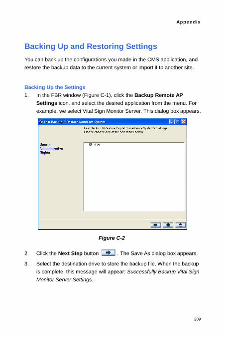
Appendix
209
Backing Up and Restoring Settings You can back up the configurations you made in the CMS application, and restore the backup data to the current system or import it to another site.
Backing Up the Settings 1. In the FBR window (Figure C-1), click the Backup Remote AP
Settings icon, and select the desired application from the menu. For example, we select Vital Sign Monitor Server. This dialog box appears.
Figure C-2 2. Click the Next Step button . The Save As dialog box appears.
3. Select the destination drive to store the backup file. When the backup is complete, this message will appear: Successfully Backup Vital Sign Monitor Server Settings.
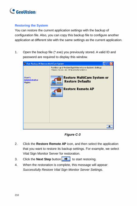
210
Restoring the System You can restore the current application settings with the backup of configuration file. Also, you can copy this backup file to configure another application at different site with the same settings as the current application.
1. Open the backup file (*.exe) you previously stored. A valid ID and
password are required to display this window.
Figure C-3 2. Click the Restore Remote AP icon, and then select the application
that you want to restore its backup settings. For example, we select Vital Sign Monitor Server for restoration.
3. Click the Next Step button to start restoring.
4. When the restoration is complete, this message will appear: Successfully Restore Vital Sign Monitor Server Settings.
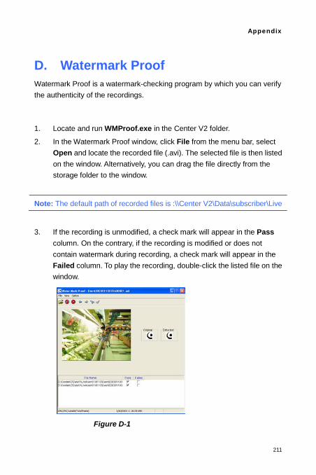
Appendix
211
D. Watermark Proof Watermark Proof is a watermark-checking program by which you can verify the authenticity of the recordings.
1. Locate and run WMProof.exe in the Center V2 folder.
2. In the Watermark Proof window, click File from the menu bar, select Open and locate the recorded file (.avi). The selected file is then listed on the window. Alternatively, you can drag the file directly from the storage folder to the window.
Note: The default path of recorded files is :\\Center V2\Data\subscriber\Live
3. If the recording is unmodified, a check mark will appear in the Pass column. On the contrary, if the recording is modified or does not contain watermark during recording, a check mark will appear in the Failed column. To play the recording, double-click the listed file on the window.
Figure D-1
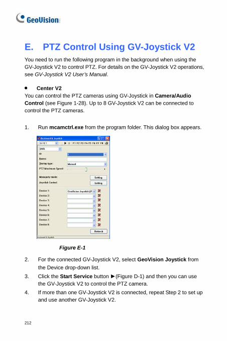
212
E. PTZ Control Using GV-Joystick V2 You need to run the following program in the background when using the GV-Joystick V2 to control PTZ. For details on the GV-Joystick V2 operations, see GV-Joystick V2 User’s Manual. • Center V2 You can control the PTZ cameras using GV-Joystick in Camera/Audio Control (see Figure 1-28). Up to 8 GV-Joystick V2 can be connected to control the PTZ cameras.
1. Run mcamctrl.exe from the program folder. This dialog box appears.
Figure E-1
2. For the connected GV-Joystick V2, select GeoVision Joystick from the Device drop-down list.
3. Click the Start Service button ►(Figure D-1) and then you can use the GV-Joystick V2 to control the PTZ camera.
4. If more than one GV-Joystick V2 is connected, repeat Step 2 to set up and use another GV-Joystick V2.
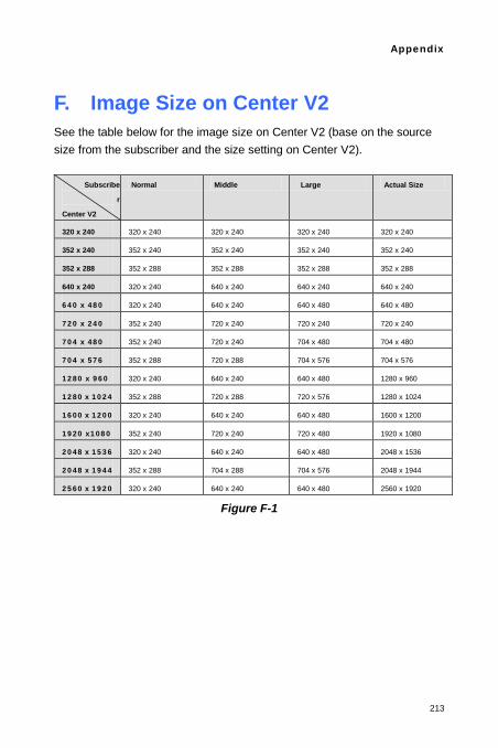
Appendix
213
F. Image Size on Center V2 See the table below for the image size on Center V2 (base on the source size from the subscriber and the size setting on Center V2).
Subscribe
r
Center V2
Normal Middle Large Actual Size
320 x 240 320 x 240 320 x 240 320 x 240 320 x 240
352 x 240 352 x 240 352 x 240 352 x 240 352 x 240
352 x 288 352 x 288 352 x 288 352 x 288 352 x 288
640 x 240 320 x 240 640 x 240 640 x 240 640 x 240
640 x 480 320 x 240 640 x 240 640 x 480 640 x 480
720 x 240 352 x 240 720 x 240 720 x 240 720 x 240
704 x 480 352 x 240 720 x 240 704 x 480 704 x 480
704 x 576 352 x 288 720 x 288 704 x 576 704 x 576
1280 x 960 320 x 240 640 x 240 640 x 480 1280 x 960
1280 x 1024 352 x 288 720 x 288 720 x 576 1280 x 1024
1600 x 1200 320 x 240 640 x 240 640 x 480 1600 x 1200
1920 x1080 352 x 240 720 x 240 720 x 480 1920 x 1080
2048 x 1536 320 x 240 640 x 240 640 x 480 2048 x 1536
2048 x 1944 352 x 288 704 x 288 704 x 576 2048 x 1944
2560 x 1920 320 x 240 640 x 240 640 x 480 2560 x 1920
Figure F-1
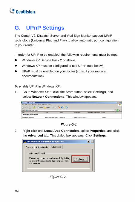
214
G. UPnP Settings The Center V2, Dispatch Server and Vital Sign Monitor support UPnP technology (Universal Plug and Play) to allow automatic port configuration to your router. In order for UPnP to be enabled, the following requirements must be met:
Windows XP Service Pack 2 or above
Windows XP must be configured to use UPnP (see below)
UPnP must be enabled on your router (consult your router’s documentation)
To enable UPnP in Windows XP:
1. Go to Windows Start, click the Start button, select Settings, and select Network Connections. This window appears.
Figure G-1
2. Right-click one Local Area Connection, select Properties, and click the Advanced tab. This dialog box appears. Click Settings.
Figure G-2
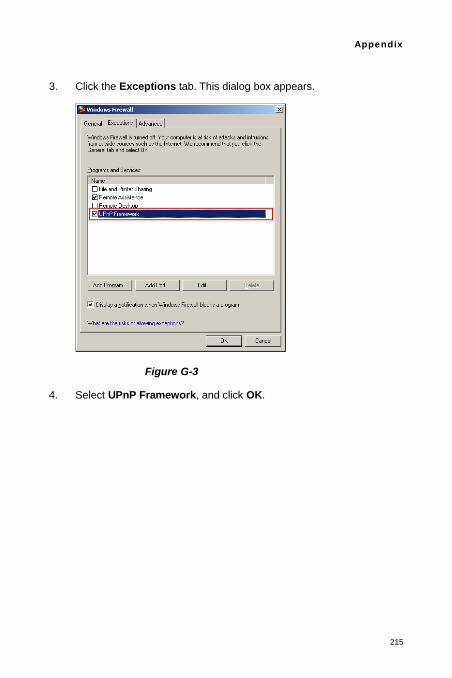
Appendix
215
3. Click the Exceptions tab. This dialog box appears.
Figure G-3
4. Select UPnP Framework, and click OK.
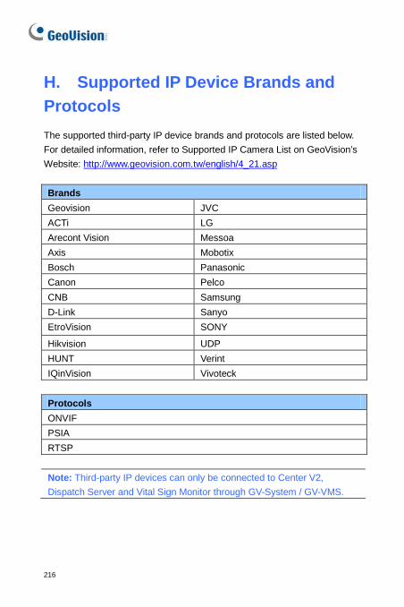
216
H. Supported IP Device Brands and Protocols The supported third-party IP device brands and protocols are listed below. For detailed information, refer to Supported IP Camera List on GeoVision’s Website: http://www.geovision.com.tw/english/4_21.asp Brands Geovision JVC ACTi LG Arecont Vision Messoa Axis Mobotix Bosch Panasonic Canon Pelco CNB Samsung D-Link Sanyo EtroVision SONY
Hikvision UDP HUNT Verint IQinVision Vivoteck
Protocols ONVIF PSIA RTSP
Note: Third-party IP devices can only be connected to Center V2, Dispatch Server and Vital Sign Monitor through GV-System / GV-VMS.
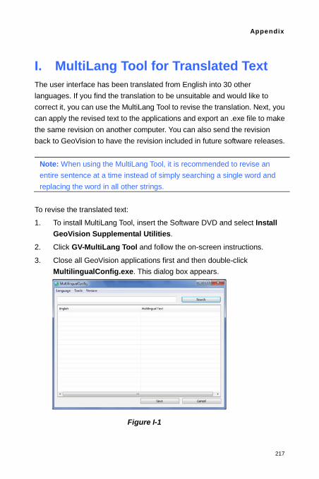
Appendix
217
I. MultiLang Tool for Translated Text The user interface has been translated from English into 30 other languages. If you find the translation to be unsuitable and would like to correct it, you can use the MultiLang Tool to revise the translation. Next, you can apply the revised text to the applications and export an .exe file to make the same revision on another computer. You can also send the revision back to GeoVision to have the revision included in future software releases.
Note: When using the MultiLang Tool, it is recommended to revise an entire sentence at a time instead of simply searching a single word and replacing the word in all other strings.
To revise the translated text:
1. To install MultiLang Tool, insert the Software DVD and select Install GeoVision Supplemental Utilities.
2. Click GV-MultiLang Tool and follow the on-screen instructions.
3. Close all GeoVision applications first and then double-click MultilingualConfig.exe. This dialog box appears.
Figure I-1
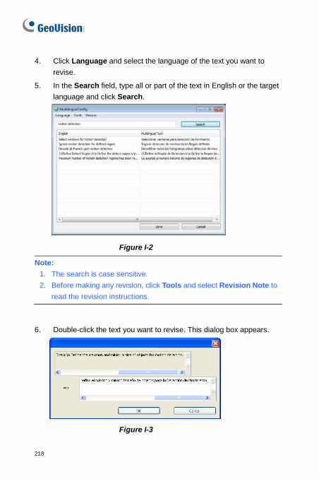
218
4. Click Language and select the language of the text you want to revise.
5. In the Search field, type all or part of the text in English or the target language and click Search.
Figure I-2
Note: 1. The search is case sensitive. 2. Before making any revision, click Tools and select Revision Note to
read the revision instructions.
6. Double-click the text you want to revise. This dialog box appears.
Figure I-3
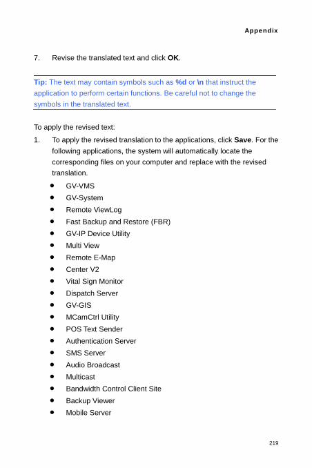
Appendix
219
7. Revise the translated text and click OK.
Tip: The text may contain symbols such as %d or \n that instruct the application to perform certain functions. Be careful not to change the symbols in the translated text. To apply the revised text:
1. To apply the revised translation to the applications, click Save. For the following applications, the system will automatically locate the corresponding files on your computer and replace with the revised translation.
• GV-VMS • GV-System • Remote ViewLog • Fast Backup and Restore (FBR) • GV-IP Device Utility • Multi View • Remote E-Map • Center V2 • Vital Sign Monitor • Dispatch Server • GV-GIS • MCamCtrl Utility • POS Text Sender • Authentication Server • SMS Server • Audio Broadcast • Multicast • Bandwidth Control Client Site • Backup Viewer • Mobile Server
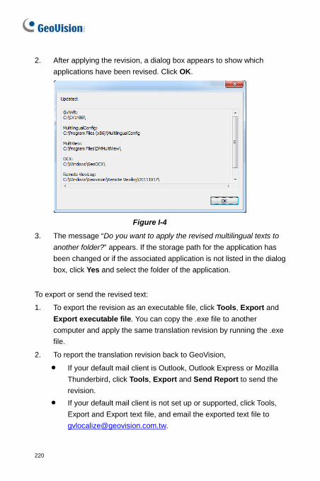
220
2. After applying the revision, a dialog box appears to show which applications have been revised. Click OK.
Figure I-4
3. The message “Do you want to apply the revised multilingual texts to another folder?” appears. If the storage path for the application has been changed or if the associated application is not listed in the dialog box, click Yes and select the folder of the application.
To export or send the revised text:
1. To export the revision as an executable file, click Tools, Export and Export executable file. You can copy the .exe file to another computer and apply the same translation revision by running the .exe file.
2. To report the translation revision back to GeoVision,
• If your default mail client is Outlook, Outlook Express or Mozilla Thunderbird, click Tools, Export and Send Report to send the revision.
• If your default mail client is not set up or supported, click Tools, Export and Export text file, and email the exported text file to [email protected].
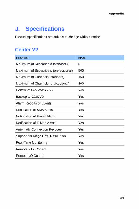
Appendix
221
J. Specifications Product specifications are subject to change without notice.
Center V2 Feature Note Maximum of Subscribers (standard) 5
Maximum of Subscribers (professional) 500
Maximum of Channels (standard) 160
Maximum of Channels (professional) 800
Control of GV-Joystick V2 Yes
Backup to CD/DVD Yes
Alarm Reports of Events Yes
Notification of SMS Alerts Yes
Notification of E-mail Alerts Yes
Notification of E-Map Alerts Yes
Automatic Connection Recovery Yes
Support for Mega Pixel Resolution Yes
Real-Time Monitoring Yes
Remote PTZ Control Yes
Remote I/O Control Yes
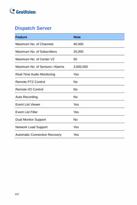
222
Dispatch Server Feature Note
Maximum No. of Channels 40,000
Maximum No. of Subscribers 25,000
Maximum No. of Center V2 50
Maximum No. of Sensors / Alarms 3,600,000
Real-Time Audio Monitoring Yes
Remote PTZ Control No
Remote I/O Control No
Auto Recording No
Event List Viewer Yes
Event List Filter Yes
Dual Monitor Support No
Network Load Support Yes
Automatic Connection Recovery Yes
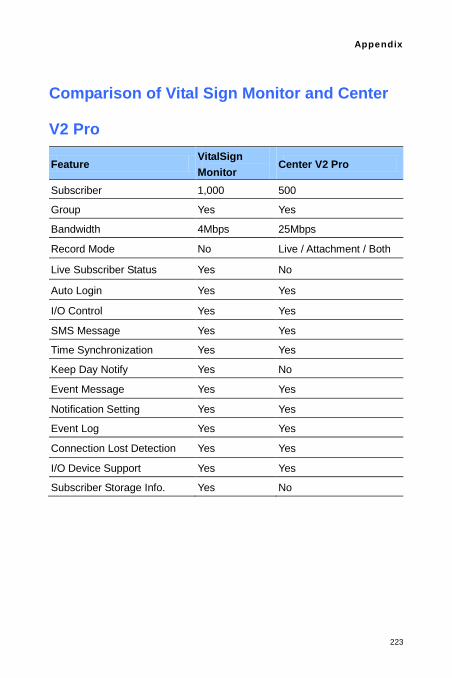
Appendix
223
Comparison of Vital Sign Monitor and Center
V2 Pro
Feature VitalSign Monitor
Center V2 Pro
Subscriber 1,000 500
Group Yes Yes
Bandwidth 4Mbps 25Mbps
Record Mode No Live / Attachment / Both
Live Subscriber Status Yes No
Auto Login Yes Yes
I/O Control Yes Yes
SMS Message Yes Yes
Time Synchronization Yes Yes
Keep Day Notify Yes No
Event Message Yes Yes
Notification Setting Yes Yes
Event Log Yes Yes
Connection Lost Detection Yes Yes
I/O Device Support Yes Yes
Subscriber Storage Info. Yes No