quick start guide - gv-ip camera h.264 - cnet content
TRANSCRIPT
Before attempting to connect or operate this product,please read these instructions carefully and save this manual for future use.
ICH264-QG-AO-EN
Quick Start GuideGV-IP Camera H.264
© 2016 GeoVision, Inc. All rights reserved. Under the copyright laws, this manual may not be copied, in whole or in part, without the written consent of GeoVision. Every effort has been made to ensure that the information in this manual is accurate. GeoVision, Inc. makes no expressed or implied warranty of any kind and assumes no responsibility for errors or omissions. No liability is assumed for incidental or consequential damages arising from the use of the information or products contained herein. Features and specifications are subject to change without notice. Note that memory card slot (local storage) is not supported for Argentina. GeoVision, Inc. 9F, No. 246, Sec. 1, Neihu Rd., Neihu District, Taipei, Taiwan Tel: +886-2-8797-8377 Fax: +886-2-8797-8335 http://www.geovision.com.tw Trademarks used in this manual: GeoVision, the GeoVision logo and GV series products are trademarks of GeoVision, Inc. Windows and Windows
XP are registered trademarks of Microsoft Corporation.
January 2016
Contents Contents ........................................................................................i Introduction ...............................................................................viii Options .....................................................................................xxii Note for Connecting to GV-System / GV-VMS ......................xxiv Note for Recording...................................................................xxv Note for GV-BX2600................................................................xxvi Note for Adjusting Focus and Zoom ....................................xxvii Note for Installing Camera Outdoor ....................................xxviii Note for Closing the Bullet Camera Cover.............................xxx Note for Bullet Camera Waterproof .......................................xxxi Note for USB Storage and WiFi Adapter ..............................xxxii
1. Box Camera ..............................................................................1
1.1 Packing List ...............................................................................1 1.2 Overview ...................................................................................2
GV-BX1200 Series / 1300 Series / 1500 Series / 2400 Series / 2500 Series / 2600 / 3400 Series / 5300 Series / 12201........2
1.3 Accessory Installation................................................................5 1.3.1 C-Mount Lenses...........................................................5 1.3.2 Infrared Illuminators (Optional) .....................................6
1.4 Connecting the Camera.............................................................7 GV-BX1200 Series / 1300 Series / 1500 Series / 2400 Series / 2500 Series / 2600 / 3400 Series / 5300 Series/ 12201.........7
2. Ultra Box Camera.....................................................................9
2.1 Packing List ...............................................................................9 2.2 Overview .................................................................................10 2.3 Installation ...............................................................................11 2.4 Connecting the Camera...........................................................13
3. Target Box Camera ................................................................14
3.1 Packing List .............................................................................14
i
3.2 Overview .................................................................................15 3.3 Installation ...............................................................................16 3.4 Connecting the Camera...........................................................18
4. IR Arctic Box Camera ............................................................19
4.1 Packing List .............................................................................19 4.2 Overview .................................................................................21 4.3 Installation ...............................................................................23 4.4 Connecting the Camera...........................................................28
5. Mini Fixed Dome & Mini Fixed Rugged Dome .....................32
5.1 Packing List .............................................................................32 5.2 Overview .................................................................................34
GV-MFD120 / 130...............................................................34 GV-MFD1501 Series / 2401 Series / 2501 Series / 3401 Series / 5301 Series.......................................................................36 GV-MDR .............................................................................38
5.3 Installation ...............................................................................41 GV-MFD Series...................................................................41 GV-MDR Series ..................................................................43
5.4 Connecting the Camera...........................................................47 5.4.1 Wire Definition............................................................47 5.4.2 Power and Network Connection .................................48 5.4.3 Vehicle Installation .....................................................49
6. Target Mini Fixed Dome.........................................................50
6.1 Packing List .............................................................................50 6.2 Overview .................................................................................51 6.3 Installation ...............................................................................52 6.4 Connecting the Camera...........................................................54
7. Target Mini Fixed Rugged Dome ..........................................55 7.1 Packing List .............................................................................55 7.2 Overview .................................................................................57 7.3 Installation ...............................................................................58 7.4 Connecting the Camera...........................................................64
ii
8. Bullet Camera (Part I).............................................................65
8.1 Packing List .............................................................................65 8.2 Overview .................................................................................66 8.3 Installation ...............................................................................67
8.3.1 Adjusting the Angles ..................................................69 8.3.2 Adjusting Lens and Inserting a Memory Card .............72 8.3.3 Inserting the Sun-Shield Cover...................................75
8.4 Connecting the Camera...........................................................76 8.4.1 Wire Definition............................................................76 8.4.2 Connecting the Power Cable......................................78
9. Bullet Camera (Part II)............................................................79
9.1 Packing List .............................................................................79 9.2 Overview .................................................................................80 9.3 Installation ...............................................................................82 9.4 Connecting the Camera...........................................................89
10. Ultra Bullet Camera..............................................................91
10.1 Packing List ...........................................................................91 10.2 Overview ...............................................................................92 10.3 Installation .............................................................................94 10.4 Connecting the Camera.........................................................98
10.4.1 Waterproofing the Cable ..........................................98 10.4.2 Wire Definition........................................................100 10.4.3 Power Connection..................................................101
11. Target Bullet Camera (Part I).............................................102 11.1 Packing List .........................................................................102 11.2 Overview .............................................................................103 11.3 Installation ...........................................................................105 11.4 Connecting the Camera.......................................................108
11.4.1 Wire Definition........................................................108 11.4.2 Power Connection..................................................109
iii
12. Target Bullet Camera (Part II)............................................110 12.1 Packing List .........................................................................110 12.2 Overview .............................................................................112 12.3 Installation ...........................................................................113 12.4 Connecting the Camera.......................................................120
12.4.1 Wire Definition........................................................120 12.4.2 Power Connection..................................................121
13. Vandal Proof IP Dome (Part I) ...........................................122
13.1 Packing List .........................................................................122 13.2 Overview .............................................................................124 13.3 Installation ...........................................................................126
13.3.1 Hard-Ceiling Mount ................................................127 13.3.2 In-Ceiling Mount .....................................................132
13.4 Connecting the Camera.......................................................135 13.4.1 Wire Definition........................................................135 13.4.2 Connecting the Power Cable..................................137
14. Vandal Proof IP Dome (Part II) ..........................................138
14.1 Packing List .........................................................................138 14.2 Overview .............................................................................141 14.3 Installation ...........................................................................143 14.4 Connecting the Camera.......................................................154
14.4.1 Connecting the Power Cable..................................154 14.4.2 Connecting the I/O Device......................................155
15. Target Vandal Proof IP Dome............................................156 15.1 Packing List .........................................................................156 15.2 Overview .............................................................................159 15.3 Installation ...........................................................................161 15.4 Connecting the Camera.......................................................170
16. Fixed IP Dome ....................................................................171
16.1 Packing List .........................................................................171 16.1.1 Packing List for Hard-Ceiling Mount .......................171
iv
16.1.2 Packing List for In-Ceiling Mount ............................172 16.2 Overview .............................................................................173 16.3 Installation ...........................................................................175
16.3.1 Hard-Ceiling Mount ................................................175 16.3.2 In-Ceiling Mount .....................................................179 16.3.3 Wall-Surface Mount................................................183
16.4 Connecting the Camera.......................................................185 17. Target Fixed IP Dome ........................................................186
17.1 Packing List .........................................................................186 17.2 Overview .............................................................................187 17.3 Installation ...........................................................................189 17.4 Connecting the Camera.......................................................191
18. Cube Camera......................................................................192
18.1 Packing List .........................................................................192 18.2 Overview .............................................................................193 18.3 Installation ...........................................................................194 18.4 Connecting the Camera.......................................................196
19. Advanced Cube Camera....................................................197
19.1 Packing List .........................................................................197 19.2 Overview .............................................................................198 19.3 Installation ...........................................................................200 19.4 Connecting the Camera.......................................................202
20. PT Camera ..........................................................................203
20.1 Packing List .........................................................................203 20.2 Overview .............................................................................205 20.3 Installation ...........................................................................207
20.3.1 Ceiling Mount .........................................................207 20.3.2 L-Shaped Wall Mount.............................................209
20.4 Connecting the Camera.......................................................212
21. Pinhole Camera..................................................................213
v
21.1 Packing List .........................................................................213 21.2 Overview .............................................................................215 21.3 Installation ...........................................................................217 21.4 Connecting the Camera.......................................................221
22. Accessing the Camera.......................................................222
22.1 System Requirement ...........................................................222 22.2 Accessing the Live View......................................................223
22.2.1 Checking the Dynamic IP Address .........................224 22.2.2 Configuring the IP Address.....................................226 22.2.3 Configuring the Wireless Connection......................228
22.3 Adjusting Image Clarity........................................................232 22.3.1 Using Focus Adjustment Cap .................................235
23. The Web Interface ..............................................................236 24. Upgrading System Firmware.............................................239 25. Restoring to Default Settings............................................241
25.1 Using the Web Interface ......................................................241 25.2 Directly on the Camera........................................................242
Box Camera......................................................................242 Ultra Box Camera and Target Box Camera.......................243 Mini Fixed Dome...............................................................244 Mini Fixed Rugged Dome..................................................245 IR Arctic Box Camera........................................................245 Target Mini Fixed Target Mini Fixed Rugged Dome ..........246 Bullet Camera ...................................................................247 Ultra Bullet Camera...........................................................248 Target Bullet Camera........................................................248 Vandal Proof IP Dome ......................................................249 Target Vandal Proof IP Dome ...........................................250 Fixed IP Dome..................................................................251 Target Fixed IP Dome.......................................................252
vi
Cube Camera ...................................................................253 Advanced Cube Camera...................................................253 PT Camera .......................................................................254 Pinhole Camera ................................................................255
vii
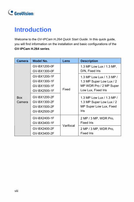
Introduction Welcome to the GV-IPCam H.264 Quick Start Guide. In this quick guide, you will find information on the installation and basic configurations of the GV-IPCam H.264 series.
Camera Model No. Lens Description
GV-BX1200-0F GV-BX1300-0F
1.3 MP Low Lux / 1.3 MP, D/N, Fixed Iris
GV-BX1200-1F GV-BX1300-1F GV-BX1500-1F GV-BX2500-1F
1.3 MP Low Lux / 1.3 MP / 1.3 MP Super Low Lux / 2 MP WDR Pro / 2 MP Super Low Lux, Fixed Iris
GV-BX1200-2F GV-BX1300-2F GV-BX1500-2F GV-BX2500-2F
Fixed
1.3 MP Low Lux / 1.3 MP / 1.3 MP Super Low Lux / 2 MP Super Low Lux, Fixed Iris
GV-BX2400-1F GV-BX3400-1F
2 MP / 3 MP, WDR Pro, Fixed Iris
Box Camera
GV-BX2400-2F GV-BX3400-2F
Varifocal 2 MP / 3 MP, WDR Pro, Fixed Iris
viii
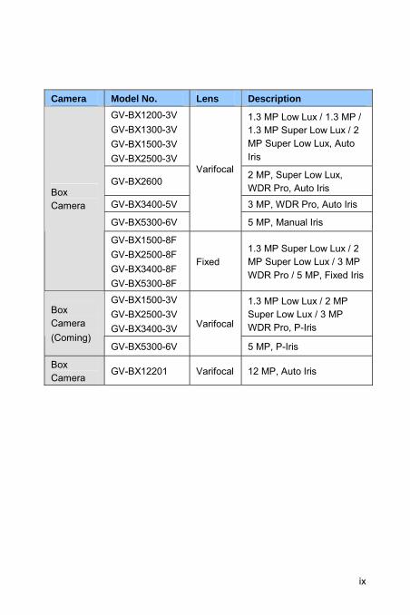
Camera Model No. Lens Description
GV-BX1200-3V GV-BX1300-3V GV-BX1500-3V GV-BX2500-3V
1.3 MP Low Lux / 1.3 MP / 1.3 MP Super Low Lux / 2 MP Super Low Lux, Auto Iris
GV-BX2600 2 MP, Super Low Lux, WDR Pro, Auto Iris
GV-BX3400-5V 3 MP, WDR Pro, Auto Iris
GV-BX5300-6V
Varifocal
5 MP, Manual Iris
Box Camera
GV-BX1500-8F GV-BX2500-8F GV-BX3400-8F GV-BX5300-8F
Fixed 1.3 MP Super Low Lux / 2 MP Super Low Lux / 3 MP WDR Pro / 5 MP, Fixed Iris
GV-BX1500-3V GV-BX2500-3V GV-BX3400-3V
1.3 MP Low Lux / 2 MP Super Low Lux / 3 MP WDR Pro, P-Iris
Box Camera (Coming)
GV-BX5300-6V
Varifocal
5 MP, P-Iris
Box Camera
GV-BX12201 Varifocal 12 MP, Auto Iris
ix
x
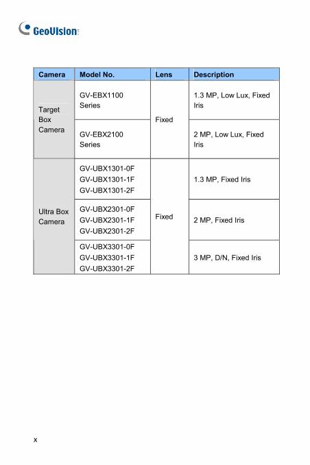
Camera Model No. Lens Description
GV-EBX1100 Series
1.3 MP, Low Lux, Fixed Iris Target
Box Camera GV-EBX2100
Series
Fixed
2 MP, Low Lux, Fixed Iris
GV-UBX1301-0F GV-UBX1301-1F GV-UBX1301-2F
1.3 MP, Fixed Iris
GV-UBX2301-0F GV-UBX2301-1F GV-UBX2301-2F
2 MP, Fixed Iris Ultra Box Camera
GV-UBX3301-0F GV-UBX3301-1F GV-UBX3301-2F
Fixed
3 MP, D/N, Fixed Iris
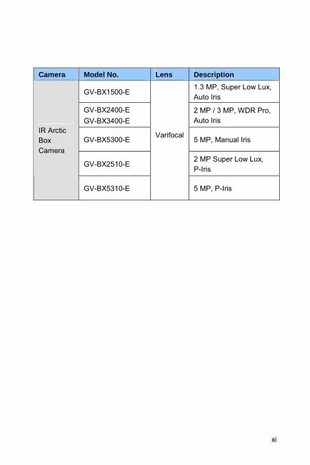
Camera Model No. Lens Description
GV-BX1500-E 1.3 MP, Super Low Lux, Auto Iris
GV-BX2400-E GV-BX3400-E
2 MP / 3 MP, WDR Pro, Auto Iris
GV-BX5300-E 5 MP, Manual Iris
GV-BX2510-E 2 MP Super Low Lux, P-Iris
IR Arctic Box Camera
GV-BX5310-E
Varifocal
5 MP, P-Iris
xi
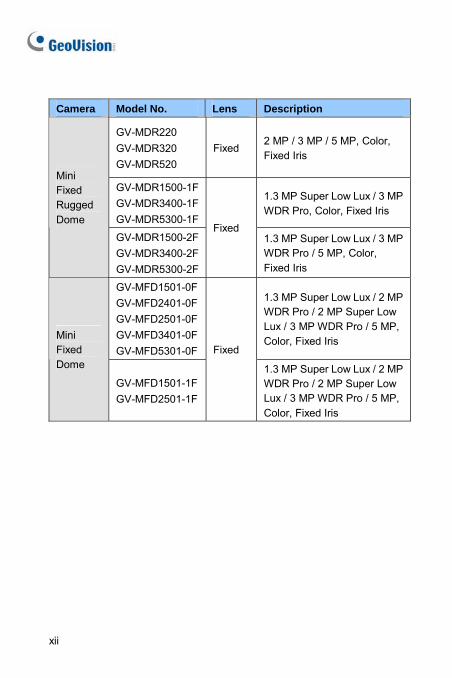
Camera Model No. Lens Description
GV-MDR220 GV-MDR320 GV-MDR520
Fixed 2 MP / 3 MP / 5 MP, Color, Fixed Iris
GV-MDR1500-1FGV-MDR3400-1FGV-MDR5300-1F
1.3 MP Super Low Lux / 3 MP WDR Pro, Color, Fixed Iris
Mini Fixed Rugged Dome
GV-MDR1500-2FGV-MDR3400-2FGV-MDR5300-2F
Fixed 1.3 MP Super Low Lux / 3 MP WDR Pro / 5 MP, Color, Fixed Iris
GV-MFD1501-0FGV-MFD2401-0FGV-MFD2501-0FGV-MFD3401-0FGV-MFD5301-0F
1.3 MP Super Low Lux / 2 MP WDR Pro / 2 MP Super Low Lux / 3 MP WDR Pro / 5 MP, Color, Fixed Iris Mini
Fixed Dome
GV-MFD1501-1FGV-MFD2501-1F
Fixed
1.3 MP Super Low Lux / 2 MP WDR Pro / 2 MP Super Low Lux / 3 MP WDR Pro / 5 MP, Color, Fixed Iris
xii
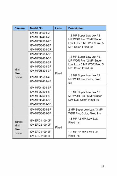
Camera Model No. Lens Description
GV-MFD1501-2FGV-MFD2401-2FGV-MFD2501-2FGV-MFD3401-2FGV-MFD5301-2F
1.3 MP Super Low Lux / 2 MP WDR Pro / 2 MP Super Low Lux / 3 MP WDR Pro / 5 MP, Color, Fixed Iris
GV-MFD1501-3FGV-MFD2401-3F GV-MFD2501-3FGV-MFD3401-3FGV-MFD5301-3F
1.3 MP Super Low Lux / 2 MP WDR Pro / 2 MP Super Low Lux / 3 MP WDR Pro / 5 MP, Color, Fixed Iris
GV-MFD1501-4FGV-MFD2401-4F
1.3 MP Super Low Lux / 2 MP WDR Pro, Color, Fixed Iris
GV-MFD1501-5FGV-MFD2401-5FGV-MFD2501-5FGV-MFD3401-5FGV-MFD5301-5F
1.3 MP Super Low Lux / 2 MP WDR Pro / 5 MP Super Low Lux, Color, Fixed Iris
Mini Fixed Dome
GV-MFD2501-6F GV-MFD3401-6F
Fixed
2 MP Super Low Lux / 3 MP WDR Pro, Color, Fixed Iris
GV-EFD1100-0FGV-EFD2100-0F
1.3 MP / 2 MP, Low Lux, Fixed Iris
Target Mini Fixed Dome GV-EFD1100-2F
GV-EFD2100-2F
Fixed 1.3 MP / 2 MP, Low Lux, Fixed Iris
xiii
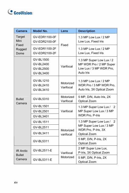
Camera Model No. Lens Description
GV-EDR1100-0FGV-EDR2100-0F
1.3 MP Low Lux / 2 MP Low Lux, Fixed Iris
Target Mini Fixed Rugged Dome
GV-EDR1100-2FGV-EDR2100-2F
Fixed 1.3 MP Low Lux / 2 MP Low Lux, Fixed Iris
GV-BL1500 GV-BL2400 GV-BL2500 GV-BL3400
Varifocal
1.3 MP Super Low Lux / 2 MP WDR Pro / 2 MP Super Low Lux / 3 MP WDR Pro, Auto Iris
GV-BL1210 GV-BL2410 GV-BL3410
Motorized Varifocal
1.3 MP Low Lux / 2 MP WDR Pro / 3 MP WDR Pro, Auto Iris, 3X Optical Zoom
GV-BL5310 Motorized Varifocal
5 MP, D/N, Auto Iris, 2X Optical Zoom
GV-BL1501
GV-BL2501
GV-BL3401
Varifocal 1.3 MP Super Low Lux / 2 MP Super Low Lux / 3 MP WDR Pro, P-Iris
GV-BL1511
GV-BL2511
GV-BL3411
1.3 MP Super Low Lux / 2 MP Super Low Lux / 3 MP WDR Pro, P-Iris, 3X Optical Zoom
Bullet Camera
GV-BL5311
Motorized varifocal
5 MP, D/N, P-Iris, 2X Optical Zoom
GV-BL2511-E 2 MP Super Low Lux, P-Iris, 3X Optical Zoom IR Arctic
Bullet Camera GV-BL5311-E
Varifocal Motorized 5 MP, D/N, P-Iris, 2X
Optical Zoom
xiv
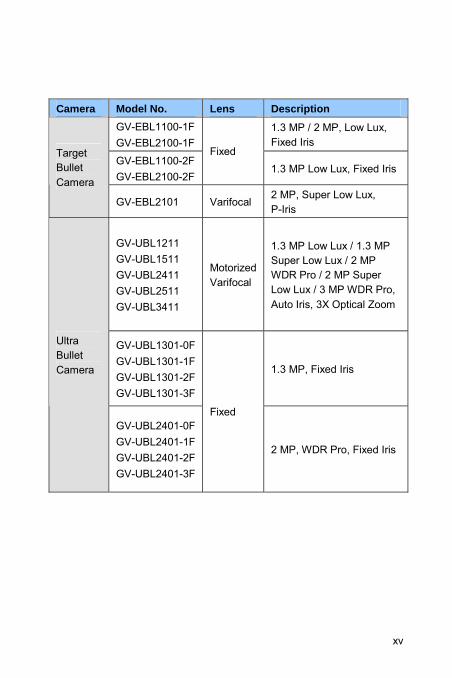
Camera Model No. Lens Description
GV-EBL1100-1FGV-EBL2100-1F
1.3 MP / 2 MP, Low Lux, Fixed Iris
GV-EBL1100-2FGV-EBL2100-2F
Fixed 1.3 MP Low Lux, Fixed Iris
Target Bullet Camera
GV-EBL2101 Varifocal 2 MP, Super Low Lux, P-Iris
GV-UBL1211 GV-UBL1511 GV-UBL2411 GV-UBL2511 GV-UBL3411
Motorized Varifocal
1.3 MP Low Lux / 1.3 MP Super Low Lux / 2 MP WDR Pro / 2 MP Super Low Lux / 3 MP WDR Pro, Auto Iris, 3X Optical Zoom
GV-UBL1301-0FGV-UBL1301-1FGV-UBL1301-2FGV-UBL1301-3F
1.3 MP, Fixed Iris
Ultra Bullet Camera
GV-UBL2401-0FGV-UBL2401-1FGV-UBL2401-2FGV-UBL2401-3F
Fixed
2 MP, WDR Pro, Fixed Iris
xv
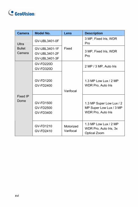
Camera Model No. Lens Description
GV-UBL3401-0F3 MP, Fixed Iris, WDR Pro Ultra
Bullet Camera
GV-UBL3401-1FGV-UBL3401-2FGV-UBL3401-3F
Fixed 3 MP, Fixed Iris, WDR Pro
GV-FD220D GV-FD320D
2 MP / 3 MP, Auto Iris
GV-FD1200 GV-FD2400
1.3 MP Low Lux / 2 MP WDR Pro, Auto Iris
GV-FD1500 GV-FD2500 GV-FD3400
Varifocal
1.3 MP Super Low Lux / 2 MP Super Low Lux / 3 MP WDR Pro, Auto Iris
Fixed IP Dome
GV-FD1210 GV-FD2410
Motorized Varifocal
1.3 MP Low Lux / 2 MP WDR Pro, Auto Iris, 3x Optical Zoom
xvi
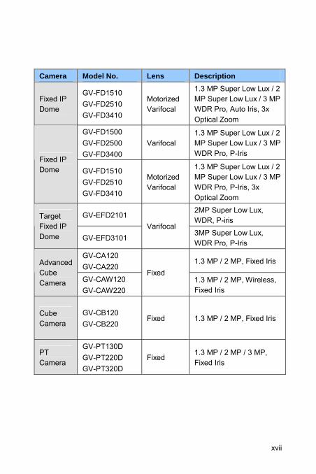
Camera Model No. Lens Description
Fixed IP Dome
GV-FD1510 GV-FD2510 GV-FD3410
Motorized Varifocal
1.3 MP Super Low Lux / 2 MP Super Low Lux / 3 MP WDR Pro, Auto Iris, 3x Optical Zoom
GV-FD1500 GV-FD2500 GV-FD3400
Varifocal 1.3 MP Super Low Lux / 2 MP Super Low Lux / 3 MP WDR Pro, P-Iris
Fixed IP Dome GV-FD1510
GV-FD2510 GV-FD3410
Motorized Varifocal
1.3 MP Super Low Lux / 2 MP Super Low Lux / 3 MP WDR Pro, P-Iris, 3x Optical Zoom
GV-EFD2101 2MP Super Low Lux, WDR, P-iris Target
Fixed IP Dome GV-EFD3101
Varifocal 3MP Super Low Lux, WDR Pro, P-Iris
GV-CA120 GV-CA220
1.3 MP / 2 MP, Fixed Iris Advanced Cube Camera GV-CAW120
GV-CAW220
Fixed 1.3 MP / 2 MP, Wireless, Fixed Iris
Cube Camera
GV-CB120 GV-CB220
Fixed 1.3 MP / 2 MP, Fixed Iris
PT Camera
GV-PT130D GV-PT220D GV-PT320D
Fixed 1.3 MP / 2 MP / 3 MP, Fixed Iris
xvii
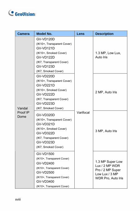
Camera Model No. Lens Description
GV-VD120D (IK10+, Transparent Cover)GV-VD121D (IK10+, Smoked Cover) GV-VD122D (IK7, Transparent Cover) GV-VD123D (IK7, Smoked Cover)
1.3 MP, Low Lux, Auto Iris
GV-VD220D (IK10+, Transparent Cover)GV-VD221D (IK10+, Smoked Cover) GV-VD222D (IK7, Transparent Cover) GV-VD223D (IK7, Smoked Cover)
2 MP, Auto Iris
GV-VD320D (IK10+, Transparent Cover)GV-VD321D (IK10+, Smoked Cover) GV-VD322D (IK7, Transparent Cover) GV-VD323D (IK7, Smoked Cover)
3 MP, Auto Iris
Vandal Proof IP Dome
GV-VD1500 (IK10+, Transparent Cover)
GV-VD2400
(IK10+, Transparent Cover)
GV-VD2500 (IK10+, Transparent Cover)
GV-VD3400 (IK10+, Transparent Cover)
Varifocal
1.3 MP Super Low Lux / 2 MP WDR Pro / 2 MP Super Low Lux / 3 MP WDR Pro, Auto Iris
xviii
Camera Model No. Lens Description
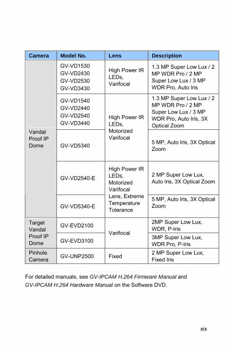
GV-VD1530 GV-VD2430 GV-VD2530 GV-VD3430
High Power IR LEDs, Varifocal
1.3 MP Super Low Lux / 2 MP WDR Pro / 2 MP Super Low Lux / 3 MP WDR Pro, Auto Iris
GV-VD1540 GV-VD2440 GV-VD2540 GV-VD3440
1.3 MP Super Low Lux / 2 MP WDR Pro / 2 MP Super Low Lux / 3 MP WDR Pro, Auto Iris, 3X Optical Zoom
GV-VD5340
High Power IR LEDs, Motorized Varifocal
5 MP, Auto Iris, 3X Optical Zoom
GV-VD2540-E 2 MP Super Low Lux, Auto Iris, 3X Optical Zoom
Vandal Proof IP Dome
GV-VD5340-E
High Power IR LEDs, Motorized Varifocal Lens, Extreme Temperature Tolerance
5 MP, Auto Iris, 3X Optical Zoom
GV-EVD2100 2MP Super Low Lux, WDR, P-Iris
Target Vandal Proof IP Dome GV-EVD3100
Varifocal 3MP Super Low Lux, WDR Pro, P-Iris
Pinhole Camera GV-UNP2500 Fixed 2 MP Super Low Lux,
Fixed Iris For detailed manuals, see GV-IPCAM H.264 Firmware Manual and GV-IPCAM H.264 Hardware Manual on the Software DVD.
xix
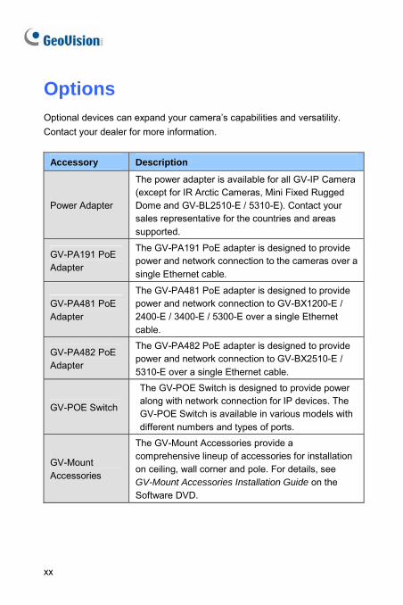
Options Optional devices can expand your camera’s capabilities and versatility. Contact your dealer for more information.
Accessory Description
Power Adapter
The power adapter is available for all GV-IP Camera (except for IR Arctic Cameras, Mini Fixed Rugged Dome and GV-BL2510-E / 5310-E). Contact your sales representative for the countries and areas supported.
GV-PA191 PoE Adapter
The GV-PA191 PoE adapter is designed to provide power and network connection to the cameras over a single Ethernet cable.
GV-PA481 PoE Adapter
The GV-PA481 PoE adapter is designed to provide power and network connection to GV-BX1200-E / 2400-E / 3400-E / 5300-E over a single Ethernet cable.
GV-PA482 PoE Adapter
The GV-PA482 PoE adapter is designed to provide power and network connection to GV-BX2510-E / 5310-E over a single Ethernet cable.
GV-POE Switch
The GV-POE Switch is designed to provide power along with network connection for IP devices. The GV-POE Switch is available in various models with different numbers and types of ports.
GV-Mount Accessories
The GV-Mount Accessories provide a comprehensive lineup of accessories for installation on ceiling, wall corner and pole. For details, see GV-Mount Accessories Installation Guide on the Software DVD.
xx
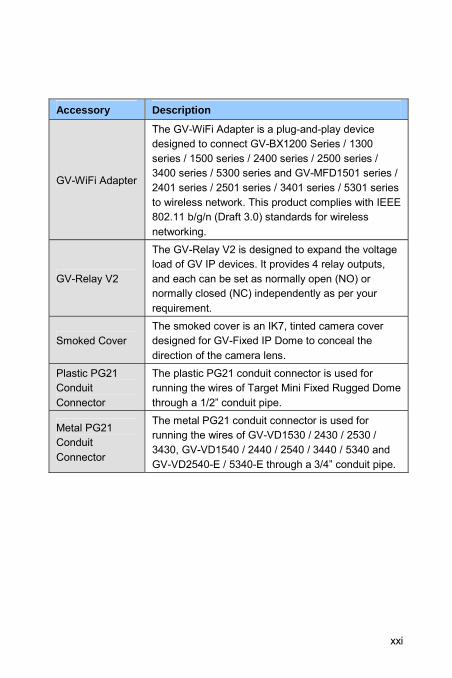
Accessory Description
GV-WiFi Adapter
The GV-WiFi Adapter is a plug-and-play device designed to connect GV-BX1200 Series / 1300 series / 1500 series / 2400 series / 2500 series / 3400 series / 5300 series and GV-MFD1501 series / 2401 series / 2501 series / 3401 series / 5301 series to wireless network. This product complies with IEEE 802.11 b/g/n (Draft 3.0) standards for wireless networking.
GV-Relay V2
The GV-Relay V2 is designed to expand the voltage load of GV IP devices. It provides 4 relay outputs, and each can be set as normally open (NO) or normally closed (NC) independently as per your requirement.
Smoked Cover The smoked cover is an IK7, tinted camera cover designed for GV-Fixed IP Dome to conceal the direction of the camera lens.
Plastic PG21 Conduit Connector
The plastic PG21 conduit connector is used for running the wires of Target Mini Fixed Rugged Dome through a 1/2” conduit pipe.
Metal PG21 Conduit Connector
The metal PG21 conduit connector is used for running the wires of GV-VD1530 / 2430 / 2530 / 3430, GV-VD1540 / 2440 / 2540 / 3440 / 5340 and GV-VD2540-E / 5340-E through a 3/4” conduit pipe.
xxi
Note for Connecting to GV-System / GV-VMS The GV-IPCAM H.264 is designed to work with GV-System / GV-VMS, a hybrid or digital video management system. Note the following when GV-IPCAM H.264 is connected to GV-System / GV-VMS:
1. By default, the images are recorded to the memory card inserted to the GV-IP Camera H.264 (except GV-IR Arctic Camera and Target Series, which are not equipped with a memory card slot).
2. Once the camera is connected to GV-System / GV-VMS, the resolution set on GV-System / GV-VMS will override the resolution set on the camera’s Web interface. You can only change the resolution settings through the Web interface when the connection to GV-System / GV-VMS is interrupted.
xxii
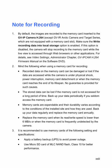
Note for Recording 1. By default, the images are recorded to the memory card inserted to the
GV-IP Camera H.264 (except GV-IR Arctic Camera and Target Series, which are not equipped with a memory card slot). Make sure the Write recording data into local storage option is enabled. If this option is disabled, the camera will stop recording to the memory card while the live view is accessed through Web browsers or other applications. For details, see Video Settings, Administrator Chapter, GV-IPCAM H.264
Firmware Manual on the Software DVD).
2. Mind the following when using a memory card for recording:
• Recorded data on the memory card can be damaged or lost if the data are accessed while the camera is under physical shock, power interruption, memory card detachment or when the memory card reaches the end of its lifespan. No guarantee is provided for such causes.
• The stored data can be lost if the memory card is not accessed for a long period of time. Back up your data periodically if you seldom access the memory card.
• Memory cards are expendable and their durability varies according to the conditions of the installed site and how they are used. Back up your data regularly and replace the memory card annually.
• Replace the memory card when its read/write speed is lower than 6 MB/s or when the memory card is frequently undetected by the camera.
3. It is recommended to use memory cards of the following setting and specifications:
• Apply a battery backup (UPS) to avoid power outage.
• Use Micro SD card of MLC NAND flash, Class 10 for better performance.
xxiii
Note for GV-BX2600 Frame Rate
Mind the following restrictions, without regard to the resolution of the camera images, when the GV-BX2600 camera is set to 60 frames per second (fps):
1 The codec MJPEG is not available in the main stream.
2 Dual streaming is not supported.
3 Video analysis functions, including motion detection, are not supported.
4 TV-out is not supported.
5 The frame rate will be dropped to 30 fps during live streaming and recording when the camera starts monitoring.
6 WDR Pro function is not supported.
7 1 or 2 fps will be dropped on the point of obtaining snapshots in JPEG format with the CGI command.
Browser
For the users of Microsoft Internet Explorer, version 11 or later is required to perform the GV-IPCAM H.264 operations through Web browser.
Recording
When GV-BX2600 uses Micro SD card or USB HDD for recording, the camera must not have more than one connection to GeoVision or third-party software.
xxiv
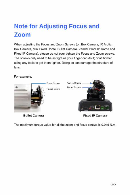
Note for Adjusting Focus and Zoom When adjusting the Focus and Zoom Screws (on Box Camera, IR Arctic Box Camera, Mini Fixed Dome, Bullet Camera, Vandal Proof IP Dome and Fixed IP Camera), please do not over tighten the Focus and Zoom screws. The screws only need to be as tight as your finger can do it; don't bother using any tools to get them tighter. Doing so can damage the structure of lens. For example,
Zoom Screw
Focus Screw
Focus Screw
Zoom Screw
Bullet Camera Fixed IP Camera
The maximum torque value for all the zoom and focus screws is 0.049 N.m
xxv
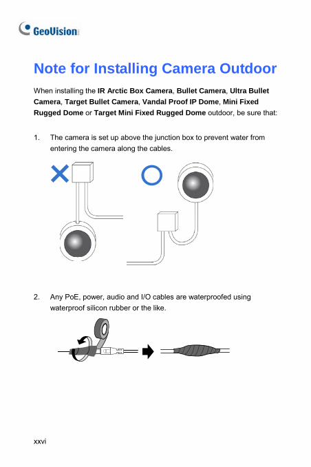
Note for Installing Camera Outdoor When installing the IR Arctic Box Camera, Bullet Camera, Ultra Bullet Camera, Target Bullet Camera, Vandal Proof IP Dome, Mini Fixed Rugged Dome or Target Mini Fixed Rugged Dome outdoor, be sure that:
1. The camera is set up above the junction box to prevent water from entering the camera along the cables.
2. Any PoE, power, audio and I/O cables are waterproofed using waterproof silicon rubber or the like.
xxvi
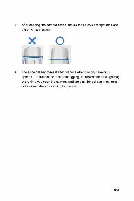
3. After opening the camera cover, ensure the screws are tightened and the cover is in place.
4. The silica gel bag loses it effectiveness when the dry camera is opened. To prevent the lens from fogging up, replace the silica gel bag every time you open the camera, and conceal the gel bag in camera within 2 minutes of exposing to open air.
xxvii
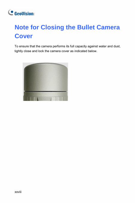
Note for Closing the Bullet Camera Cover To ensure that the camera performs its full capacity against water and dust, tightly close and lock the camera cover as indicated below.
xxviii
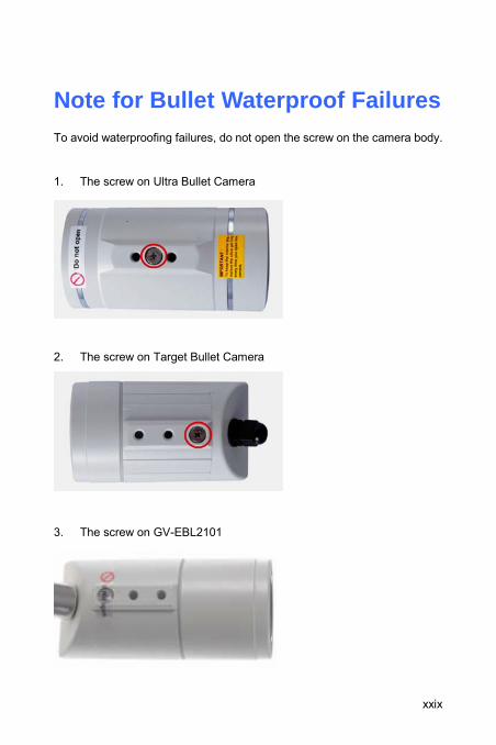
Note for Bullet Waterproof Failures To avoid waterproofing failures, do not open the screw on the camera body.
1. The screw on Ultra Bullet Camera
2. The screw on Target Bullet Camera
3. The screw on GV-EBL2101
xxix
xxx
Note for USB Storage and WiFi Adapter Mind the following limitations and requirements for using USB storage and GV-WiFi Adapter:
1. The USB hard drive must be of 2.5’’ or 3.5’’, version 2.0 or above.
2. The USB hard drive’s storage capacity must not exceed 2TB.
3. USB flash drives and USB hubs are not supported.
4. External power supply is required for the USB hard drive.
5. To connect a GV-WiFi Adapter, make sure it is connected before the camera is powered on.
Box Camera 1
1. Box Camera 1.1 Packing List • Box Camera
• Terminal Block
• Fixed Focal or Varifocal Megapixel Lens
• Six Lens Rings
• Video Out Wire
• Camera Holder
• Power Adapter
• GV-IPCAM H.264 Software DVD
• GV-NVR Software DVD
• Warranty Card
Note: The power adapter can be excluded upon request.
1
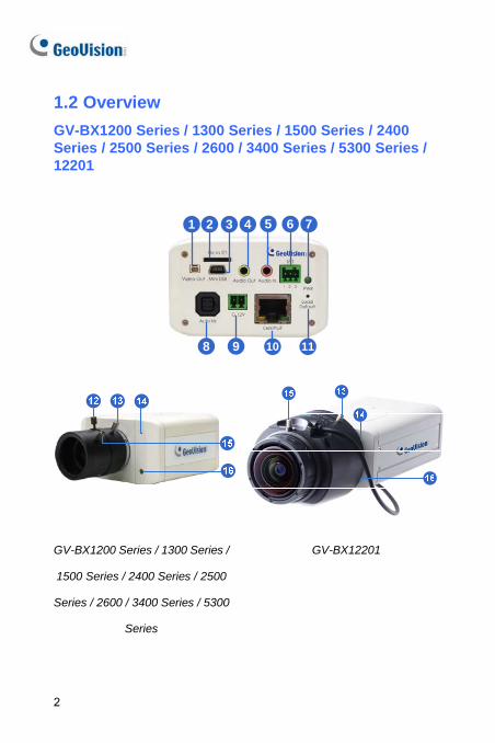
1.2 Overview GV-BX1200 Series / 1300 Series / 1500 Series / 2400 Series / 2500 Series / 2600 / 3400 Series / 5300 Series / 12201
1 2 4 5 6 7
8 9 10
3
11
GV-BX1200 Series / 1300 Series /
1500 Series / 2400 Series / 2500
Series / 2600 / 3400 Series / 5300
Series
GV-BX12201
2
Box Camera 1
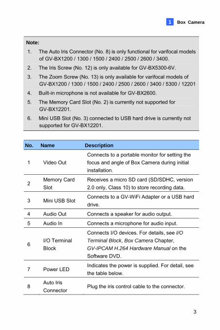
Note:
1. The Auto Iris Connector (No. 8) is only functional for varifocal models of GV-BX1200 / 1300 / 1500 / 2400 / 2500 / 2600 / 3400.
2. The Iris Screw (No. 12) is only available for GV-BX5300-6V.
3. The Zoom Screw (No. 13) is only available for varifocal models of GV-BX1200 / 1300 / 1500 / 2400 / 2500 / 2600 / 3400 / 5300 / 12201
4. Built-in microphone is not available for GV-BX2600. 5. The Memory Card Slot (No. 2) is currently not supported for
GV-BX12201. 6. Mini USB Slot (No. 3) connected to USB hard drive is currently not
supported for GV-BX12201.
No. Name Description
1 Video Out Connects to a portable monitor for setting the focus and angle of Box Camera during initial installation.
2 Memory Card Slot
Receives a micro SD card (SD/SDHC, version 2.0 only, Class 10) to store recording data.
3 Mini USB Slot Connects to a GV-WiFi Adapter or a USB hard drive.
4 Audio Out Connects a speaker for audio output.
5 Audio In Connects a microphone for audio input.
6 I/O Terminal Block
Connects I/O devices. For details, see I/O
Terminal Block, Box Camera Chapter, GV-IPCAM H.264 Hardware Manual on the Software DVD.
7 Power LED Indicates the power is supplied. For detail, see the table below.
8 Auto Iris Connector
Plug the iris control cable to the connector.
3
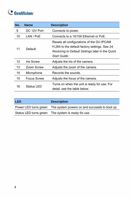
No. Name Description
9 DC 12V Port Connects to power.
10 LAN / PoE Connects to a 10/100 Ethernet or PoE.
11 Default
Resets all configurations of the GV-IPCAM H.264 to the default factory settings. See 24.
Restoring to Default Settings later in the Quick
Start Guide.
12 Iris Screw Adjusts the iris of the camera.
13 Zoom Screw Adjusts the zoom of the camera.
14 Microphone Records the sounds.
15 Focus Screw Adjusts the focus of the camera.
16 Status LED Turns on when the unit is ready for use. For detail, see the table below.
LED Description
Power LED turns green The system powers on and succeeds to boot up.
Status LED turns green The system is ready for use.
4
Box Camera 1
1.3 Accessory Installation
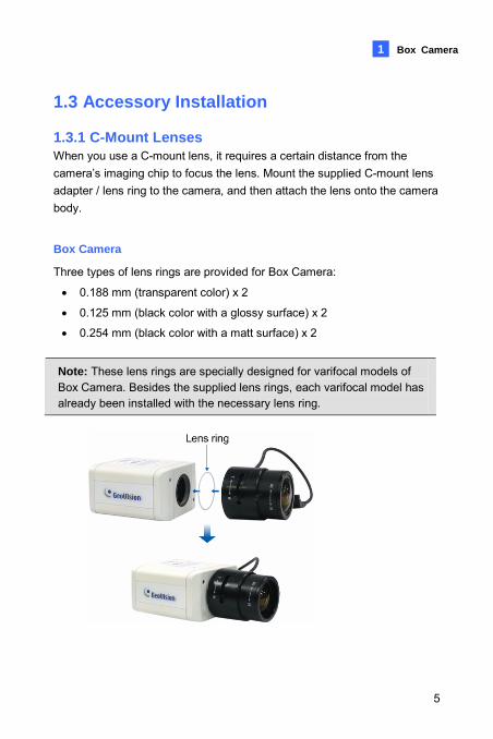
1.3.1 C-Mount Lenses When you use a C-mount lens, it requires a certain distance from the camera’s imaging chip to focus the lens. Mount the supplied C-mount lens adapter / lens ring to the camera, and then attach the lens onto the camera body.
Box Camera
Three types of lens rings are provided for Box Camera:
• 0.188 mm (transparent color) x 2
• 0.125 mm (black color with a glossy surface) x 2
• 0.254 mm (black color with a matt surface) x 2
Note: These lens rings are specially designed for varifocal models of Box Camera. Besides the supplied lens rings, each varifocal model has already been installed with the necessary lens ring.
5
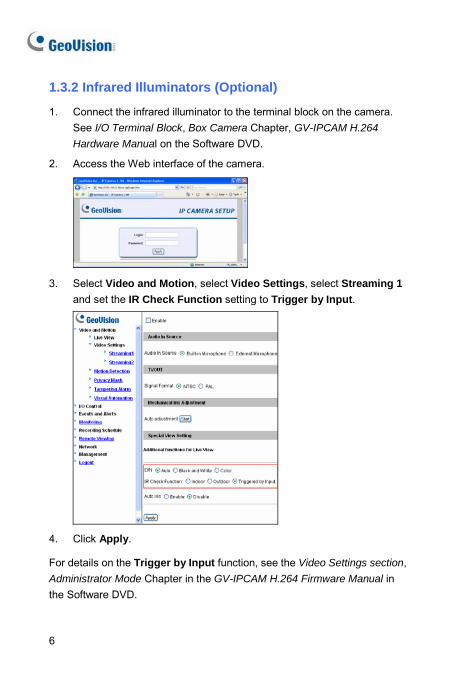
1.3.2 Infrared Illuminators (Optional)
1. Connect the infrared illuminator to the terminal block on the camera. See I/O Terminal Block, Box Camera Chapter, GV-IPCAM H.264
Hardware Manual on the Software DVD.
2. Access the Web interface of the camera.
3. Select Video and Motion, select Video Settings, select Streaming 1 and set the IR Check Function setting to Trigger by Input.
4. Click Apply.
For details on the Trigger by Input function, see the Video Settings section, Administrator Mode Chapter in the GV-IPCAM H.264 Firmware Manual in the Software DVD.
6
Box Camera 1
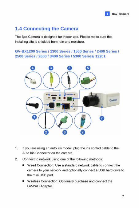
1.4 Connecting the Camera The Box Camera is designed for indoor use. Please make sure the installing site is shielded from rain and moisture. GV-BX1200 Series / 1300 Series / 1500 Series / 2400 Series / 2500 Series / 2600 / 3400 Series / 5300 Series/ 12201
1. If you are using an auto iris model, plug the iris control cable to the Auto Iris Connector on the camera.
2. Connect to network using one of the following methods:
• Wired Connection: Use a standard network cable to connect the camera to your network and optionally connect a USB hard drive to the mini USB port.
• Wireless Connection: Optionally purchase and connect the GV-WiFi Adapter.
7
8
3. Optionally connect a speaker and an external microphone.
4. Optionally connect a monitor using a Video Out wire. Enable this function by selecting your signal format at the TV Out field on the Web interface. See TV Out setting, in the Video Settings section, Administrator Mode Chapter, GV-IPCAM H.264 Firmware Manual on the Software DVD.
5. Optionally connect to input / output devices or an infrared illuminator. For details, see Infrared Illuminator and I/O Terminal Block, Box
Camera Chapter, GV-IPCAM H.264 Firmware Manual on the Software DVD.
6. Connect power using one of the following methods:
• Plug the power adapter to the power port.
• Use the Power over Ethernet (PoE) function and the power will be provided over the network cable.
7. The status LED of the camera will be on.
8. You are ready to access the live view and adjust the image clarity. See 22. Accessing the Camera in the Quick Start Guide.
Note: For details on limitations and requirements of the mini USB port, refer to Note for USB Storage and WiFi Adapter at the beginning of this quick guide.
Ultra Box Camera 2
2. Ultra Box Camera
2.1 Packing List • Ultra Box Camera
• Supporting rack
• Screw x 3
• Screw anchor x 3
• Power Adapter
• GV-IPCAM H.264 Software DVD
• GV-NVR Software DVD
• Warranty Card
Note: The power adapter can be excluded upon request.
9
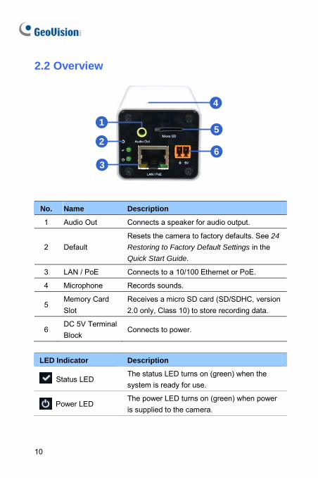
2.2 Overview
1
3
5
6
4
2
No. Name Description
1 Audio Out Connects a speaker for audio output.
2 Default Resets the camera to factory defaults. See 24
Restoring to Factory Default Settings in the Quick Start Guide.
3 LAN / PoE Connects to a 10/100 Ethernet or PoE.
4 Microphone Records sounds.
5 Memory Card Slot
Receives a micro SD card (SD/SDHC, version 2.0 only, Class 10) to store recording data.
6 DC 5V Terminal Block
Connects to power.
LED Indicator Description
Status LED The status LED turns on (green) when the system is ready for use.
Power LED The power LED turns on (green) when power is supplied to the camera.
10
Ultra Box Camera 2
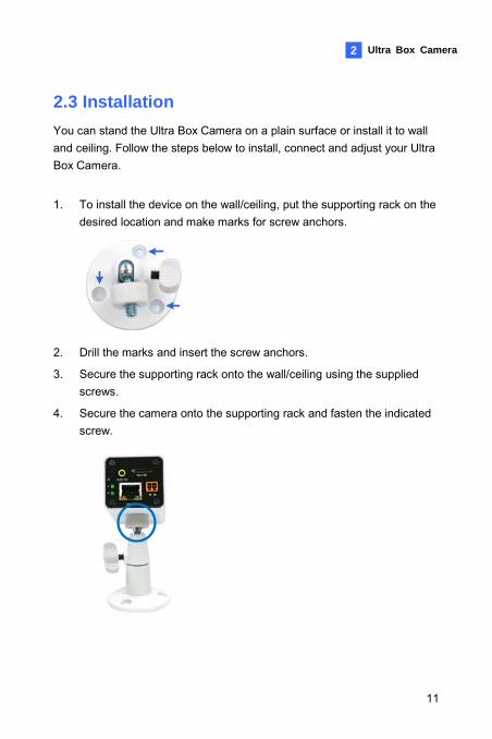
2.3 Installation You can stand the Ultra Box Camera on a plain surface or install it to wall and ceiling. Follow the steps below to install, connect and adjust your Ultra Box Camera.
1. To install the device on the wall/ceiling, put the supporting rack on the desired location and make marks for screw anchors.
2. Drill the marks and insert the screw anchors.
3. Secure the supporting rack onto the wall/ceiling using the supplied screws.
4. Secure the camera onto the supporting rack and fasten the indicated screw.
11
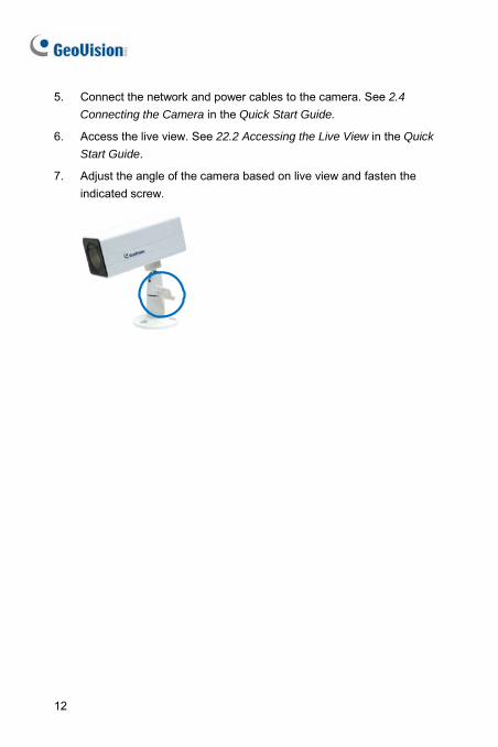
5. Connect the network and power cables to the camera. See 2.4
Connecting the Camera in the Quick Start Guide.
6. Access the live view. See 22.2 Accessing the Live View in the Quick
Start Guide.
7. Adjust the angle of the camera based on live view and fasten the indicated screw.
12
Ultra Box Camera
13
2
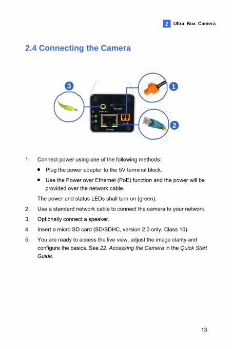
2.4 Connecting the Camera
2
3 1
1. Connect power using one of the following methods:
• Plug the power adapter to the 5V terminal block.
• Use the Power over Ethernet (PoE) function and the power will be provided over the network cable.
The power and status LEDs shall turn on (green).
2. Use a standard network cable to connect the camera to your network.
3. Optionally connect a speaker.
4. Insert a micro SD card (SD/SDHC, version 2.0 only, Class 10).
5. You are ready to access the live view, adjust the image clarity and configure the basics. See 22. Accessing the Camera in the Quick Start
Guide.
3. Target Box Camera
3.1 Packing List • Target Box Camera
• Supporting Rack
• Screw x 3
• Screw Anchor x 3
• GV-IPCAM H.264 Software DVD
• GV-NVR Software DVD
• Warranty Card
Note: Power adapter can be purchased upon request.
14
Target Box Camera 3
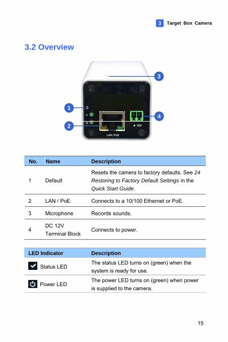
3.2 Overview
14
2
3
No. Name Description
1 Default Resets the camera to factory defaults. See 24
Restoring to Factory Default Settings in the Quick Start Guide.
2 LAN / PoE Connects to a 10/100 Ethernet or PoE.
3 Microphone Records sounds.
4 DC 12V Terminal Block
Connects to power.
LED Indicator Description
Status LED The status LED turns on (green) when the system is ready for use.
Power LED The power LED turns on (green) when power is supplied to the camera.
15
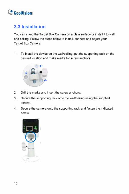
3.3 Installation You can stand the Target Box Camera on a plain surface or install it to wall and ceiling. Follow the steps below to install, connect and adjust your Target Box Camera.
1. To install the device on the wall/ceiling, put the supporting rack on the desired location and make marks for screw anchors.
2. Drill the marks and insert the screw anchors.
3. Secure the supporting rack onto the wall/ceiling using the supplied screws.
4. Secure the camera onto the supporting rack and fasten the indicated screw.
16
Target Box Camera 3
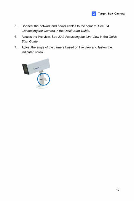
5. Connect the network and power cables to the camera. See 3.4
Connecting the Camera in the Quick Start Guide.
6. Access the live view. See 22.2 Accessing the Live View in the Quick
Start Guide.
7. Adjust the angle of the camera based on live view and fasten the indicated screw.
17
18
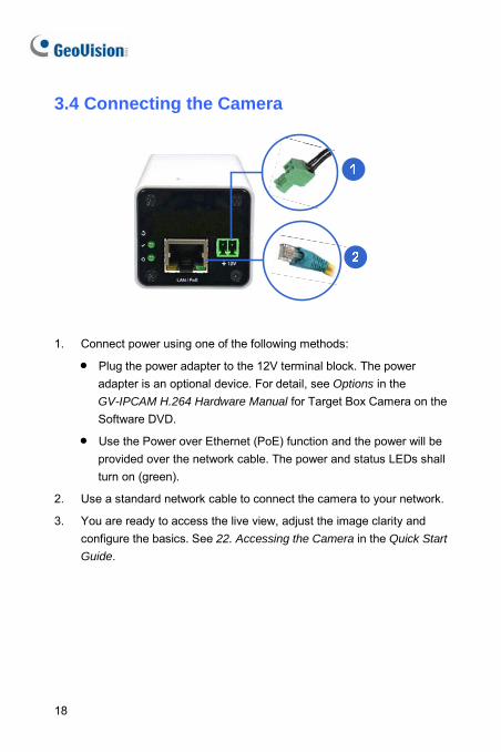
3.4 Connecting the Camera
1. Connect power using one of the following methods:
• Plug the power adapter to the 12V terminal block. The power adapter is an optional device. For detail, see Options in the GV-IPCAM H.264 Hardware Manual for Target Box Camera on the Software DVD.
• Use the Power over Ethernet (PoE) function and the power will be provided over the network cable. The power and status LEDs shall turn on (green).
2. Use a standard network cable to connect the camera to your network.
3. You are ready to access the live view, adjust the image clarity and configure the basics. See 22. Accessing the Camera in the Quick Start
Guide.
IR Arctic Box Camera 4
4. IR Arctic Box Camera 4.1 Packing List
For GV-1500-E / 2400-E / 3400-E / 5300-E • IR Arctic Box Camera
• Screw Anchor x 4
• Screw x 4
• Washer x 4
• 4 mm Torx Wrench
• 5 mm Torx Wrench
• Silica Gel Bag x 2
• Adhesive Tape x 2
• GV-IPCAM H.264 Software DVD
• GV-NVR Software DVD
• Warranty Card
Note: Optionally purchase a GV-PA481 PoE Adapter for GV-BX1500-E / 2400-E / 3400-E / 5300-E.
19
For GV-BX2510-E / 5310-E
• IR Arctic Box Camera
• Screw Anchor x 4
• Screw x 4
• Washer x 4
• 5 mm Torx Wrench
• Silica Gel Bag
• Adhesive Tape
• Power Adapter (DC 48V, 2.5A, 120 W max.)
• GV-IPCAM H.264 Software DVD
• GV-NVR Software DVD
• Warranty Card
Note: Optionally purchase a GV-PA482 PoE Adapter for GV-BX2510-E / 5310-E.
20
IR Arctic Box Camera 4
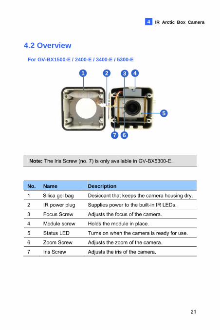
4.2 Overview For GV-BX1500-E / 2400-E / 3400-E / 5300-E
1 2 3 4
5
7 6
Note: The Iris Screw (no. 7) is only available in GV-BX5300-E.
No. Name Description
1 Silica gel bag Desiccant that keeps the camera housing dry.
2 IR power plug Supplies power to the built-in IR LEDs.
3 Focus Screw Adjusts the focus of the camera.
4 Module screw Holds the module in place.
5 Status LED Turns on when the camera is ready for use.
6 Zoom Screw Adjusts the zoom of the camera.
7 Iris Screw Adjusts the iris of the camera.
21
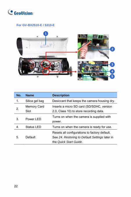
For GV-BX2510-E / 5310-E
1
2
5
3
4
No. Name Description
1. Silica gel bag Desiccant that keeps the camera housing dry.
2. Memory Card Slot
Inserts a micro SD card (SD/SDHC, version 2.0, Class 10) to store recording data.
3. Power LED Turns on when the camera is supplied with power.
4. Status LED Turns on when the camera is ready for use.
5. Default Resets all configurations to factory default. See 24. Restoring to Default Settings later in the Quick Start Guide.
22
IR Arctic Box Camera 4
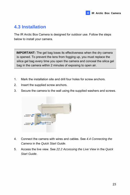
4.3 Installation The IR Arctic Box Camera is designed for outdoor use. Follow the steps below to install your camera.
IMPORTANT: The gel bag loses its effectiveness when the dry camera is opened. To prevent the lens from fogging up, you must replace the silica gel bag every time you open the camera and conceal the silica gel bag in the camera within 2 minutes of exposing to open air.
1. Mark the installation site and drill four holes for screw anchors.
2. Insert the supplied screw anchors.
3. Secure the camera to the wall using the supplied washers and screws.
4. Connect the camera with wires and cables. See 4.4 Connecting the
Camera in the Quick Start Guide.
5. Access the live view. See 22.2 Accessing the Live View in the Quick
Start Guide.
23
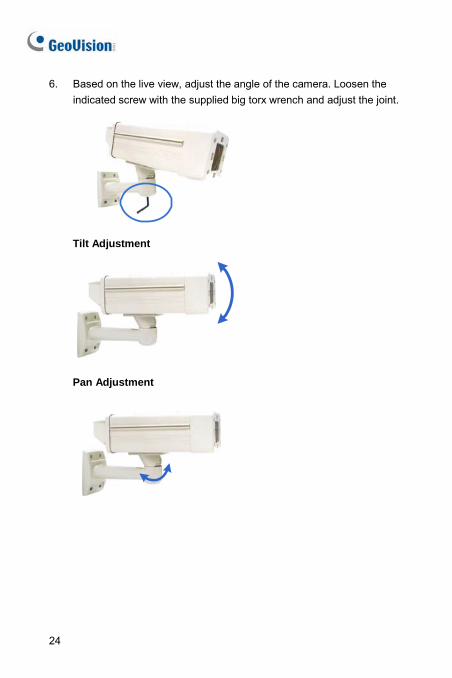
6. Based on the live view, adjust the angle of the camera. Loosen the indicated screw with the supplied big torx wrench and adjust the joint.
Tilt Adjustment
Pan Adjustment
24
IR Arctic Box Camera 4
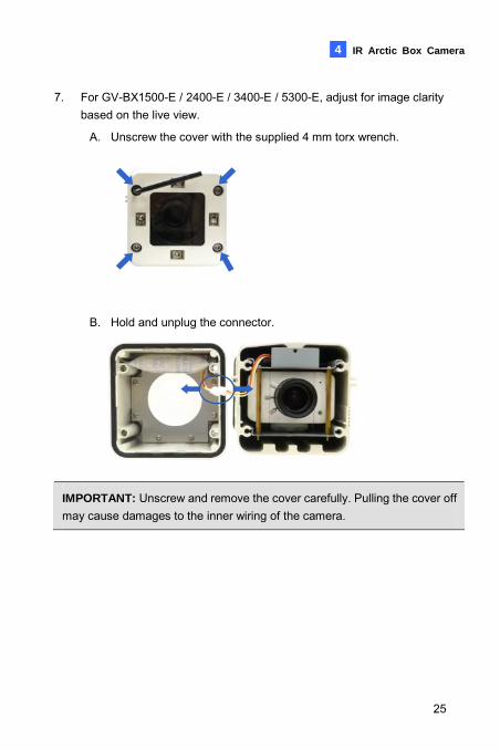
7. For GV-BX1500-E / 2400-E / 3400-E / 5300-E, adjust for image clarity based on the live view.
A. Unscrew the cover with the supplied 4 mm torx wrench.
B. Hold and unplug the connector.
IMPORTANT: Unscrew and remove the cover carefully. Pulling the cover off may cause damages to the inner wiring of the camera.
25
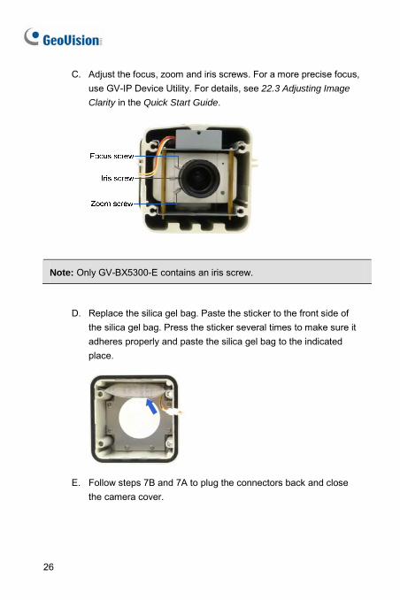
C. Adjust the focus, zoom and iris screws. For a more precise focus, use GV-IP Device Utility. For details, see 22.3 Adjusting Image
Clarity in the Quick Start Guide.
Note: Only GV-BX5300-E contains an iris screw.
D. Replace the silica gel bag. Paste the sticker to the front side of the silica gel bag. Press the sticker several times to make sure it adheres properly and paste the silica gel bag to the indicated place.
E. Follow steps 7B and 7A to plug the connectors back and close
the camera cover.
26
IR Arctic Box Camera 4
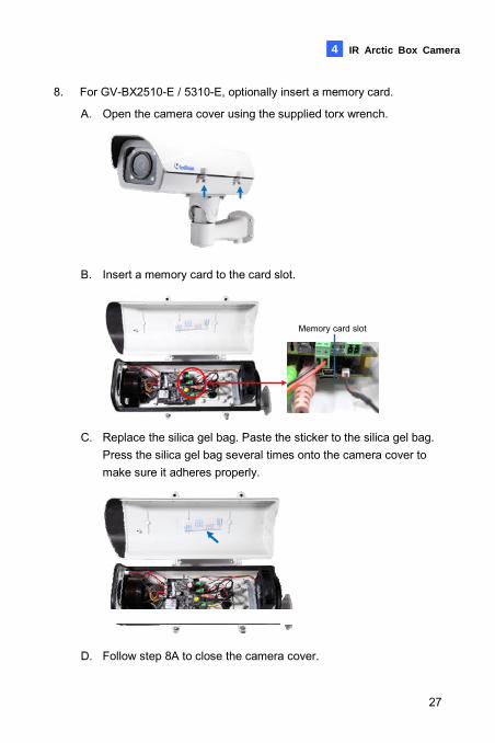
8. For GV-BX2510-E / 5310-E, optionally insert a memory card. A. Open the camera cover using the supplied torx wrench.
B. Insert a memory card to the card slot.
Memory card slot
C. Replace the silica gel bag. Paste the sticker to the silica gel bag.
Press the silica gel bag several times onto the camera cover to make sure it adheres properly.
D. Follow step 8A to close the camera cover.
27
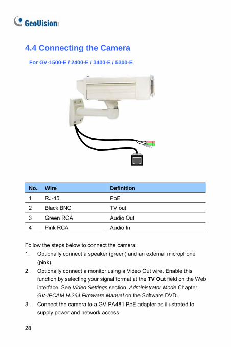
4.4 Connecting the Camera For GV-1500-E / 2400-E / 3400-E / 5300-E
No. Wire Definition
1 RJ-45 PoE
2 Black BNC t TV ou
3 Green RCA Audio Out
4 Pink RCA Audio In
ow t ow to connect t
n external microphone
eb
Foll he steps bel he camera:1. Optionally connect a speaker (green) and a
(pink). 2. Optionally connect a monitor using a Video Out wire. Enable this
function by selecting your signal format at the TV Out field on the Winterface. See Video Settings section, Administrator Mode Chapter, GV-IPCAM H.264 Firmware Manual on the Software DVD.
3. Connect the camera to a GV-PA481 PoE adapter as illustrated to supply power and network access.
28
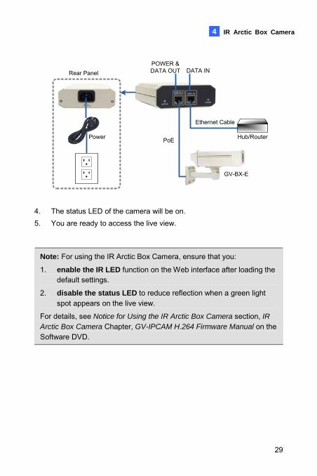
IR Arctic Box Camera 4
Ethernet Cable
PoE
GV-BX-E
Rear PanelPOWER &DATA OUT DATA IN
Power Hub/Router
4. The status LED of the camera will be on. 5. You are ready to access the live view.
Note: For using the IR Arctic Box Camera, ensure that you:
1. enable the IR LED function on the Web interface after loading the default settings.
2. disable the status LED to reduce reflection when a green light spot appears on the live view.
For details, see Notice for Using the IR Arctic Box Camera section, IR Arctic Box Camera Chapter, GV-IPCAM H.264 Firmware Manual on the Software DVD.
29
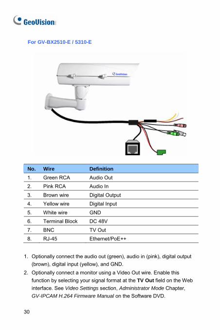
For GV-BX2510-E / 5310-E
No. Wire Definition 1. Green RCA Audio Out
2. Pink RCA Audio In
3. Brown wire Digital Output
4. Yellow wire Digital Input
5. White wire GND
6. Terminal Block DC 48V
7. BNC TV Out
8. RJ-45 Ethernet/PoE++
1. Optionally connect the audio out (green), audio in (pink), digital output
(brown), digital input (yellow), and GND. 2. Optionally connect a monitor using a Video Out wire. Enable this
function by selecting your signal format at the TV Out field on the Web interface. See Video Settings section, Administrator Mode Chapter, GV-IPCAM H.264 Firmware Manual on the Software DVD.
30
IR Arctic Box Camera
31
4
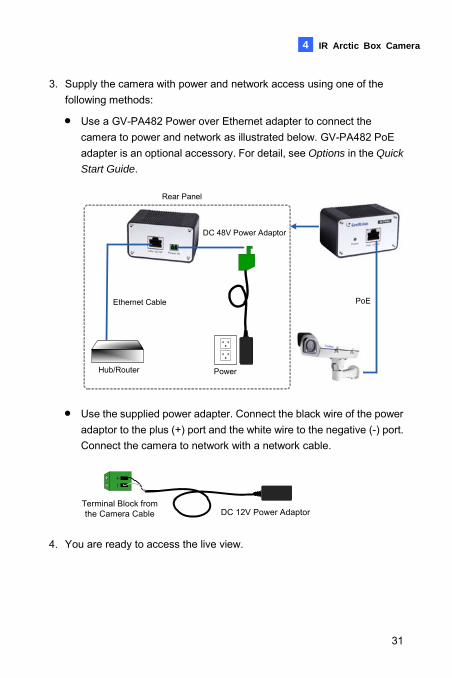
3. Supply the camera with power and network access using one of the following methods:
• Use a GV-PA482 Power over Ethernet adapter to connect the camera to power and network as illustrated below. GV-PA482 PoE adapter is an optional accessory. For detail, see Options in the Quick
Start Guide.
DC 48V Power Adaptor
PowerHub/Router
Ethernet Cable
Rear Panel
PoE
• Use the supplied power adapter. Connect the black wire of the power adaptor to the plus (+) port and the white wire to the negative (-) port. Connect the camera to network with a network cable.
DC 12V Power AdaptorTerminal Block from the Camera Cable
4. You are ready to access the live view.
5. Mini Fixed Dome & Mini Fixed Rugged Dome
5.1 Packing List
GV-MFD • Mini Fixed Dome • Torx Wrench • Self Tapping Screw x 2 • Screw Anchor x 2 • Cable stopper • 2-pin terminal block • Short-Body RJ-45 Plug (for GV-MFD1501 series / 2401 series / 2501
series / 3401 series / 5301 series) • USB / Audio Y-cable (for GV-MFD1501 series / 2401 series / 2501
series / 3401 series / 5301 series) • Power Adapter • GV-IPCAM H.264 Software DVD
• GV-NVR Software DVD
• Warranty Card
Note: The power adapter can be excluded upon request.
32
Mini Fixed & Rugged Dome
5
GV-MDR
• Mini Fixed Rugged Dome • Torx Wrench • Self Tapping Screw x 2 • Screw Anchor x 2 • Cable stopper • Cable Connector • Installation sticker • Silica gel bag x 2 • Adhesive Tape x 2 • Ferrite core for vehicle installation • GV-IPCAM H.264 Software DVD • GV-NVR Software DVD • Warranty Card
Note:
1. The power adapter can be excluded upon request.
2. When purchasing GV-MDR1500 / 3400 / 5300, choose one of the two LAN connector types (for motor vehicles or for general use). For details, see LAN Connector, 5.2 Overview in the Quick Start Guide.
33
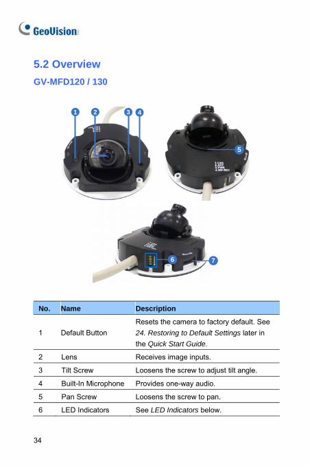
5.2 Overview GV-MFD120 / 130
1 2 3 4
5
76
No. Name Description
1 Default Button Resets the camera to factory default. See 24. Restoring to Default Settings later in the Quick Start Guide.
2 Lens Receives image inputs.
3 Tilt Screw Loosens the screw to adjust tilt angle.
4 Built-In Microphone Provides one-way audio.
5 Pan Screw Loosens the screw to pan.
6 LED Indicators See LED Indicators below.
34
Mini Fixed & Rugged Dome
5
No. Name Description
7 Memory Card Slot Receives a micro SD card (SD/SDHC, version 2.0 only, Class 10) to store recording data.
LED Indicator
LED Name Description
1. Link Turns only when the network is connected.
2. ACT Turns on when data are being transmitted.
3. PWR Turns on when power is on.
4. SW RDY (Status) Turns on when the system is ready.
35
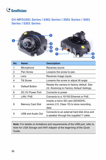
GV-MFD1501 Series / 2401 Series / 2501 Series / 3401 Series / 5301 Series
1
2
345
89
6
7
No. Name Description 1 Microphone Receives sound.
2 Pan Screw Loosens the screw to pan.
3 Lens Receives image inputs.
4 Tilt Screw Loosens the screw to adjust tilt angle.
5 Default Button Resets the camera to factory default. See 24. Restoring to Factory Default Settings.
6 DC 5V Power Port Connects to power.
7 LAN / PoE Connects to a 10/100 Ethernet or PoE.
8 Memory Card Slot Inserts a micro SD card (SD/SDHC, version 2.0, Class 10) to store recording data.
9 USB and Audio OutConnects to an external hard disk drive and a speaker through the supplied Y cable.
Note: For details on limitations and requirements of the USB port, refer to Note for USB Storage and WiFi Adapter at the beginning of the Quick Guide.
36
Mini Fixed & Rugged Dome
5
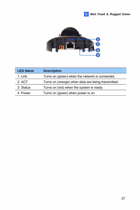
12
34
LED Name Description 1. Link Turns on (green) when the network is connected.
2. ACT Turns on (orange) when data are being transmitted.
3. Status Turns on (red) when the system is ready.
4. Power Turns on (green) when power is on.
37
GV-MDR
1
2
3
4
5
6
7
8
910
11
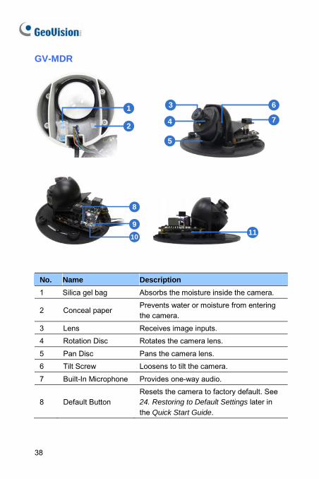
No. Name Description 1 Silica gel bag Absorbs the moisture inside the camera.
2 Conceal paper Prevents water or moisture from entering the camera.
3 Lens Receives image inputs.
4 Rotation Disc Rotates the camera lens.
5 Pan Disc Pans the camera lens.
6 Tilt Screw Loosens to tilt the camera.
7 Built-In Microphone Provides one-way audio.
8 Default Button Resets the camera to factory default. See 24. Restoring to Default Settings later in the Quick Start Guide.
38
Mini Fixed & Rugged Dome
5
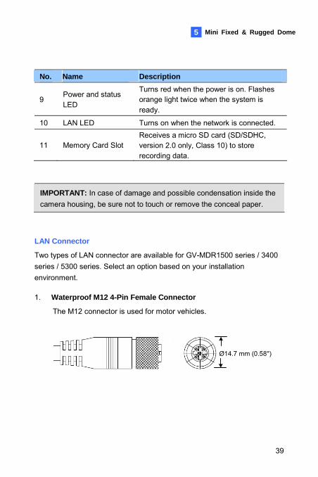
No. Name Description
9 Power and status LED
Turns red when the power is on. Flashes orange light twice when the system is ready.
10 LAN LED Turns on when the network is connected.
11 Memory Card Slot Receives a micro SD card (SD/SDHC, version 2.0 only, Class 10) to store recording data.
IMPORTANT: In case of damage and possible condensation inside the camera housing, be sure not to touch or remove the conceal paper.
LAN Connector
Two types of LAN connector are available for GV-MDR1500 series / 3400 series / 5300 series. Select an option based on your installation environment.
1. Waterproof M12 4-Pin Female Connector
The M12 connector is used for motor vehicles.
Ø14.7 mm (0.58'')
39
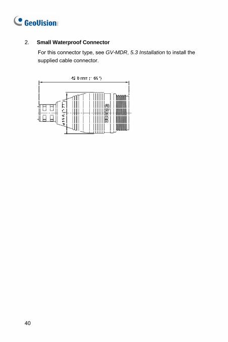
2. Small Waterproof Connector
For this connector type, see GV-MDR, 5.3 Installation to install the supplied cable connector.
40
Mini Fixed & Rugged Dome
5
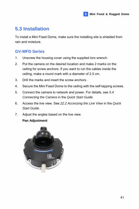
5.3 Installation To install a Mini Fixed Dome, make sure the installing site is shielded from rain and moisture. GV-MFD Series 1. Unscrew the housing cover using the supplied torx wrench.
2. Put the camera on the desired location and make 2 marks on the ceiling for screw anchors. If you want to run the cables inside the ceiling, make a round mark with a diameter of 2.5 cm.
3. Drill the marks and insert the screw anchors.
4. Secure the Mini Fixed Dome to the ceiling with the self-tapping screws.
5. Connect the camera to network and power. For details, see 5.4
Connecting the Camera in the Quick Start Guide.
6. Access the live view. See 22.2 Accessing the Live View in the Quick
Start Guide.
7. Adjust the angles based on the live view.
Pan Adjustment
41
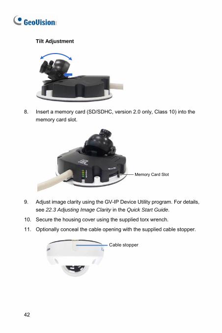
Tilt Adjustment
8. Insert a memory card (SD/SDHC, version 2.0 only, Class 10) into the memory card slot.
Memory Card Slot
9. Adjust image clarity using the GV-IP Device Utility program. For details, see 22.3 Adjusting Image Clarity in the Quick Start Guide.
10. Secure the housing cover using the supplied torx wrench.
11. Optionally conceal the cable opening with the supplied cable stopper.
Cable stopper
42
Mini Fixed & Rugged Dome
5
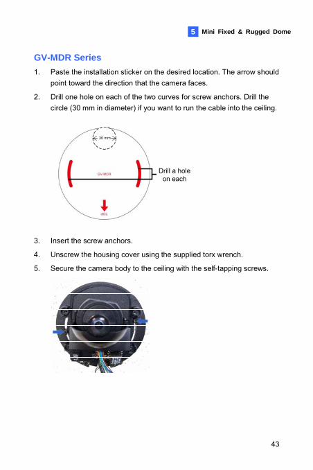
GV-MDR Series 1. Paste the installation sticker on the desired location. The arrow should
point toward the direction that the camera faces.
2. Drill one hole on each of the two curves for screw anchors. Drill the circle (30 mm in diameter) if you want to run the cable into the ceiling.
Drill a hole on each
30 mm
3. Insert the screw anchors.
4. Unscrew the housing cover using the supplied torx wrench.
5. Secure the camera body to the ceiling with the self-tapping screws.
43
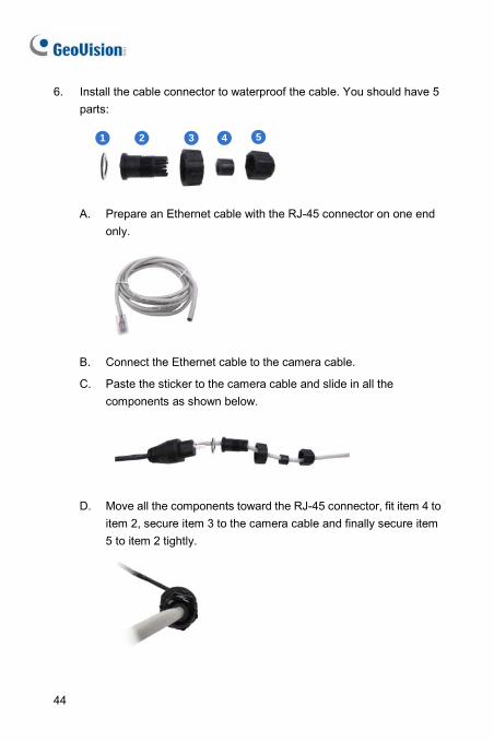
6. Install the cable connector to waterproof the cable. You should have 5 parts:
1 2 3 4 5
A. Prepare an Ethernet cable with the RJ-45 connector on one end
only.
B. Connect the Ethernet cable to the camera cable.
C. Paste the sticker to the camera cable and slide in all the components as shown below.
D. Move all the components toward the RJ-45 connector, fit item 4 to
item 2, secure item 3 to the camera cable and finally secure item 5 to item 2 tightly.
44
Mini Fixed & Rugged Dome
5
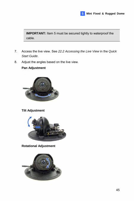
IMPORTANT: Item 5 must be secured tightly to waterproof the cable.
7. Access the live view. See 22.2 Accessing the Live View in the Quick
Start Guide.
8. Adjust the angles based on the live view.
Pan Adjustment
Tilt Adjustment
Rotational Adjustment
45
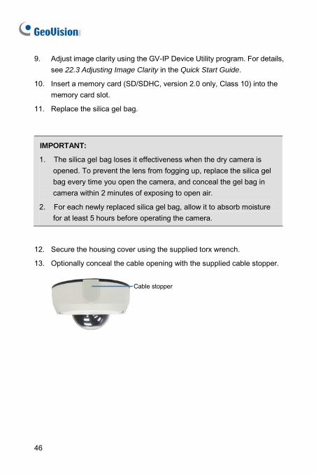
9. Adjust image clarity using the GV-IP Device Utility program. For details, see 22.3 Adjusting Image Clarity in the Quick Start Guide.
10. Insert a memory card (SD/SDHC, version 2.0 only, Class 10) into the memory card slot.
11. Replace the silica gel bag.
IMPORTANT:
1. The silica gel bag loses it effectiveness when the dry camera is opened. To prevent the lens from fogging up, replace the silica gel bag every time you open the camera, and conceal the gel bag in camera within 2 minutes of exposing to open air.
2. For each newly replaced silica gel bag, allow it to absorb moisture for at least 5 hours before operating the camera.
12. Secure the housing cover using the supplied torx wrench.
13. Optionally conceal the cable opening with the supplied cable stopper.
Cable stopper
46
Mini Fixed & Rugged Dome
5
5.4 Connecting the Camera Refer to the wire definition and illustrations below to connect the power and network.
5.4.1 Wire Definition
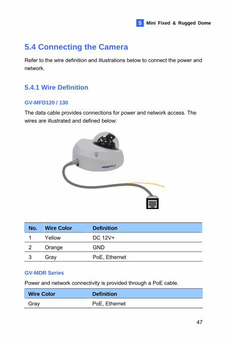
GV-MFD120 / 130
The data cable provides connections for power and network access. The wires are illustrated and defined below:
No. Wire Color Definition
1 Yellow DC 12V+
2 Orange GND
3 Gray PoE, Ethernet
GV-MDR Series
Power and network connectivity is provided through a PoE cable.
Wire Color Definition
Gray PoE, Ethernet
47
5.4.2 Power and Network Connection
Use one of the following methods to power on and connect your camera to network:
• Wired connection with PoE: Use a Power over Ethernet (PoE) adapter to connect the camera to the network, and the power will be provided at the same time.
• Wired connection with network cable (GV-MFD Series only): Connect the camera with a standard network cable and use the power adapter to supply power. See Powering On the Camera below to assemble the terminal block with power adapter.
• Wireless connection (GV-MFD1501 Series / 2401 Series / 2501 Series / 3401 Series / 5301 Series only): Connect the camera with a GV-WiFi Adapter (optional accessory) and use the power adapter to supply power.
48
Mini Fixed & Rugged Dome
49
5
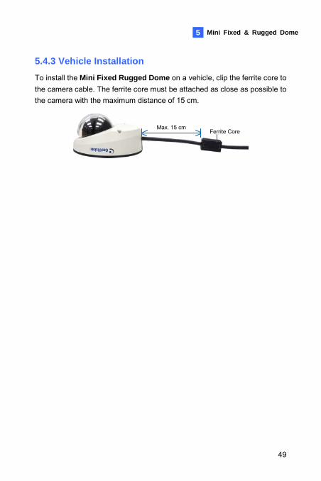
5.4.3 Vehicle Installation To install the Mini Fixed Rugged Dome on a vehicle, clip the ferrite core to the camera cable. The ferrite core must be attached as close as possible to the camera with the maximum distance of 15 cm.
Max. 15 cmFerrite Core
6. Target Mini Fixed Dome
6.1 Packing List • Target Mini Fixed Dome
• Screw x 2
• Screw Anchor x 2
• Focus Adjustment Clip or Ring
• GV-IPCAM H.264 Software DVD
• GV-NVR Software DVD
• Warranty Card
Note: The power adapter can be purchased upon request.
50
Target Mini Fixed Dome 6
6.2 Overview 1
3
2
5
d
a b
6
c
7
4
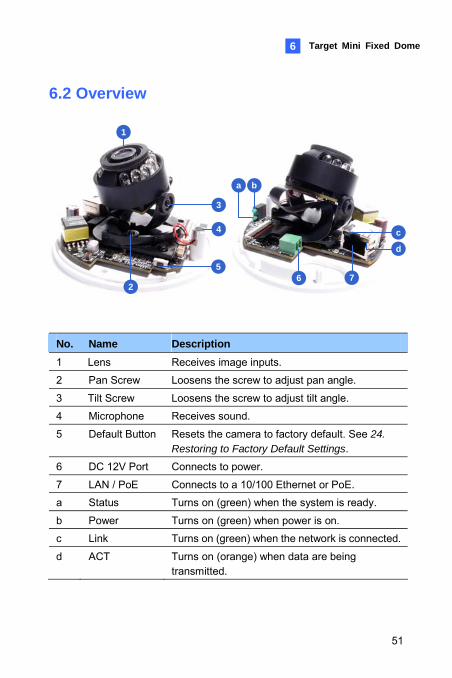
No. Name Description 1 Lens Receives image inputs.
2 Pan Screw Loosens the screw to adjust pan angle.
3 Tilt Screw Loosens the screw to adjust tilt angle.
4 Microphone Receives sound.
5 Default Button Resets the camera to factory default. See 24. Restoring to Factory Default Settings.
6 DC 12V Port Connects to power.
7 LAN / PoE Connects to a 10/100 Ethernet or PoE.
a Status Turns on (green) when the system is ready.
b Power Turns on (green) when power is on.
c Link Turns on (green) when the network is connected.
d ACT Turns on (orange) when data are being transmitted.
51
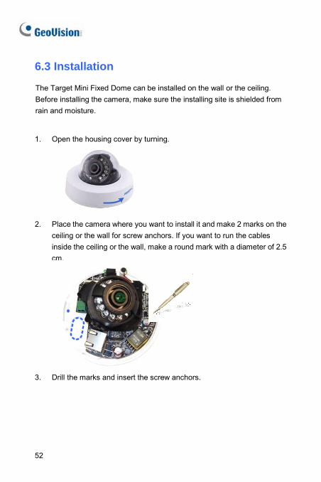
6.3 Installation
The Target Mini Fixed Dome can be installed on the wall or the ceiling. Before installing the camera, make sure the installing site is shielded from rain and moisture.
1. Open the housing cover by turning.
2. Place the camera where you want to install it and make 2 marks on the
ceiling or the wall for screw anchors. If you want to run the cables inside the ceiling or the wall, make a round mark with a diameter of 2.5 cm.
3. Drill the marks and insert the screw anchors.
52
Target Mini Fixed Dome 6
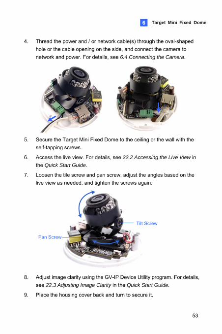
4. Thread the power and / or network cable(s) through the oval-shaped hole or the cable opening on the side, and connect the camera to network and power. For details, see 6.4 Connecting the Camera.
5. Secure the Target Mini Fixed Dome to the ceiling or the wall with the
self-tapping screws.
6. Access the live view. For details, see 22.2 Accessing the Live View in the Quick Start Guide.
7. Loosen the tile screw and pan screw, adjust the angles based on the live view as needed, and tighten the screws again.
Pan Screw
Tilt Screw
8. Adjust image clarity using the GV-IP Device Utility program. For details,
see 22.3 Adjusting Image Clarity in the Quick Start Guide.
9. Place the housing cover back and turn to secure it.
53
54
6.4 Connecting the Camera
1 2
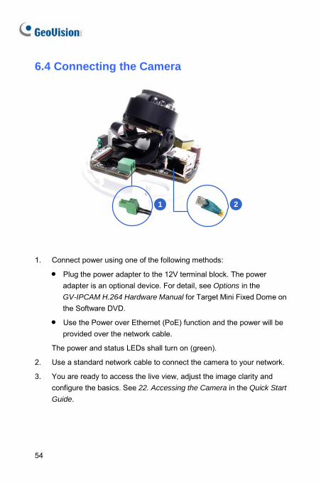
1. Connect power using one of the following methods:
• Plug the power adapter to the 12V terminal block. The power adapter is an optional device. For detail, see Options in the GV-IPCAM H.264 Hardware Manual for Target Mini Fixed Dome on the Software DVD.
• Use the Power over Ethernet (PoE) function and the power will be provided over the network cable.
The power and status LEDs shall turn on (green).
2. Use a standard network cable to connect the camera to your network.
3. You are ready to access the live view, adjust the image clarity and configure the basics. See 22. Accessing the Camera in the Quick Start
Guide.
Target Mini Fixed Rugged Dome 7
7. Target Mini Fixed Rugged Dome
7.1 Packing List • Target Mini Fixed Rugged Dome • Screw x 2 • Screw Anchor x 2 • Focus Adjustment Ring • Installation Sticker • Conduit Converter • RJ-45 Connector • Waterproof Rubber Set (for RJ45 and DC12V) • Torx Wrench • Silica Gel Bag x 2 • Adhesive Tape x 2 • Concave Hexagon Wrench • Ruler • Screw for Conduit Converter x 2 • GV-IPCAM H.264 Software DVD • GV-NVR Software DVD • Warranty Card
55
Note:
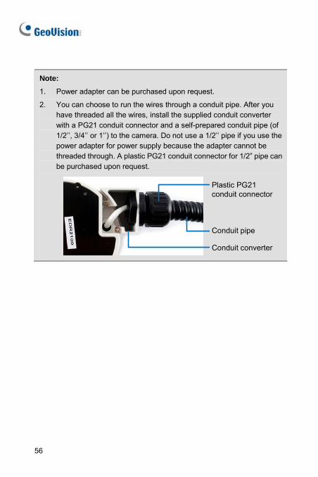
1. Power adapter can be purchased upon request.
2. You can choose to run the wires through a conduit pipe. After you have threaded all the wires, install the supplied conduit converter with a PG21 conduit connector and a self-prepared conduit pipe (of 1/2’’, 3/4’’ or 1’’) to the camera. Do not use a 1/2’’ pipe if you use the power adapter for power supply because the adapter cannot be threaded through. A plastic PG21 conduit connector for 1/2” pipe can be purchased upon request.
Conduit converter
Plastic PG21 conduit connector
Conduit pipe
56
Target Mini Fixed Rugged Dome 7
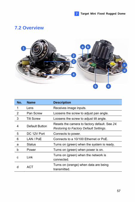
7.2 Overview
5
d
a b
6
c
1
3
2
4
No. Name Description 1 Lens Receives image inputs.
2 Pan Screw Loosens the screw to adjust pan angle.
3 Tilt Screw Loosens the screw to adjust tilt angle.
4 Default Button Resets the camera to factory default. See 24. Restoring to Factory Default Settings.
5 DC 12V Port Connects to power.
6 LAN / PoE Connects to a 10/100 Ethernet or PoE.
a Status Turns on (green) when the system is ready.
b Power Turns on (green) when power is on.
c Link Turns on (green) when the network is connected.
d ACT Turns on (orange) when data are being transmitted.
57
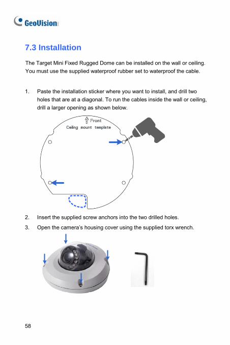
7.3 Installation
The Target Mini Fixed Rugged Dome can be installed on the wall or ceiling. You must use the supplied waterproof rubber set to waterproof the cable.
1. Paste the installation sticker where you want to install, and drill two holes that are at a diagonal. To run the cables inside the wall or ceiling, drill a larger opening as shown below.
2. Insert the supplied screw anchors into the two drilled holes.
3. Open the camera’s housing cover using the supplied torx wrench.
58
Target Mini Fixed Rugged Dome 7
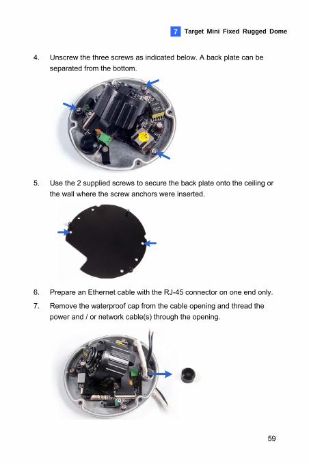
4. Unscrew the three screws as indicated below. A back plate can be separated from the bottom.
5. Use the 2 supplied screws to secure the back plate onto the ceiling or
the wall where the screw anchors were inserted.
6. Prepare an Ethernet cable with the RJ-45 connector on one end only.
7. Remove the waterproof cap from the cable opening and thread the power and / or network cable(s) through the opening.
59
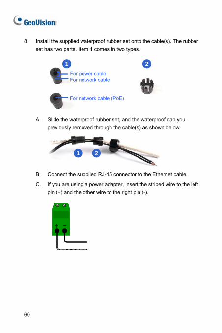
8. Install the supplied waterproof rubber set onto the cable(s). The rubber set has two parts. Item 1 comes in two types.
21
For network cable
For network cable (PoE)
For power cable
A. Slide the waterproof rubber set, and the waterproof cap you
previously removed through the cable(s) as shown below.
21
B. Connect the supplied RJ-45 connector to the Ethernet cable.
C. If you are using a power adapter, insert the striped wire to the left pin (+) and the other wire to the right pin (-).
60
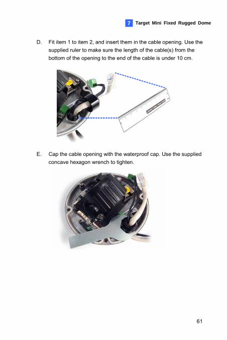
Target Mini Fixed Rugged Dome 7
D. Fit item 1 to item 2, and insert them in the cable opening. Use the supplied ruler to make sure the length of the cable(s) from the bottom of the opening to the end of the cable is under 10 cm.
E. Cap the cable opening with the waterproof cap. Use the supplied concave hexagon wrench to tighten.
61
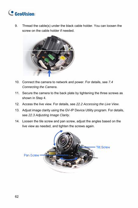
9. Thread the cable(s) under the black cable holder. You can loosen the screw on the cable holder if needed.
10. Connect the camera to network and power. For details, see 7.4
Connecting the Camera.
11. Secure the camera to the back plate by tightening the three screws as shown in Step 4.
12. Access the live view. For details, see 22.2 Accessing the Live View.
13. Adjust image clarity using the GV-IP Device Utility program. For details, see 22.3 Adjusting Image Clarity.
14. Loosen the tile screw and pan screw, adjust the angles based on the live view as needed, and tighten the screws again.
62
Target Mini Fixed Rugged Dome 7
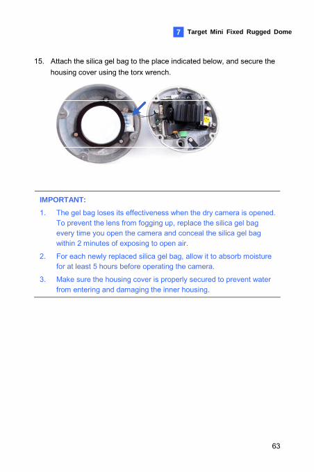
15. Attach the silica gel bag to the place indicated below, and secure the housing cover using the torx wrench.
IMPORTANT:
1. The gel bag loses its effectiveness when the dry camera is opened. To prevent the lens from fogging up, replace the silica gel bag every time you open the camera and conceal the silica gel bag within 2 minutes of exposing to open air.
2. For each newly replaced silica gel bag, allow it to absorb moisture for at least 5 hours before operating the camera.
3. Make sure the housing cover is properly secured to prevent water from entering and damaging the inner housing.
63
64
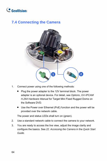
7.4 Connecting the Camera
1 2
1. Connect power using one of the following methods:
• Plug the power adapter to the 12V terminal block. The power adapter is an optional device. For detail, see Options, GV-IPCAM
H.264 Hardware Manual for Target Mini Fixed Rugged Dome on the Software DVD.
• Use the Power over Ethernet (PoE) function and the power will be provided over the network cable.
The power and status LEDs shall turn on (green).
2. Use a standard network cable to connect the camera to your network.
3. You are ready to access the live view, adjust the image clarity and configure the basics. See 22. Accessing the Camera in the Quick Start
Guide.
Bullet Camera (Part I) 8
8. Bullet Camera (Part I)
8.1 Packing List • Bullet Camera
• Self Tapping Screw x 3
• Plastic Screw Anchor x 3
• Torx Wrench x 2
• Sun-Shield Cover Kit (Sun-Shield Cover, Philips Head Screws x 2, Plastic Screw Spacer x 2 and Hexagon Screw x 2)
• Silica Gel Bag x 2
• 2-Pin Terminal Block
• Power Adapter
• GV-IPCAM H.264 Software DVD
• GV-NVR Software DVD
• Warranty Card
Note: The power adapter can be excluded upon request.
65
8.2 Overview
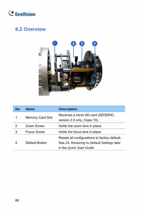
No. Name Description
1 Memory Card Slot Receives a micro SD card (SD/SDHC, version 2.0 only, Class 10).
2 Zoom Screw Holds the zoom lens in place.
3 Focus Screw Holds the focus lens in place
4 Default Button Resets all configurations to factory default. See 24. Restoring to Default Settings later in the Quick Start Guide.
66
Bullet Camera (Part I) 8
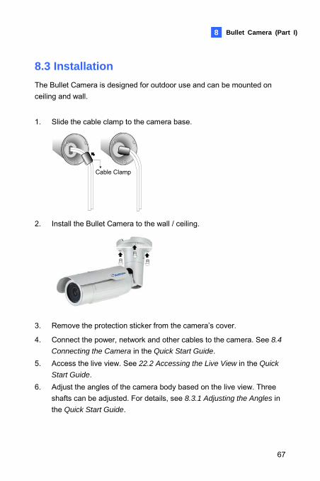
8.3 Installation The Bullet Camera is designed for outdoor use and can be mounted on ceiling and wall.
1. Slide the cable clamp to the camera base.
Cable Clamp
2. Install the Bullet Camera to the wall / ceiling.
3. Remove the protection sticker from the camera’s cover.
4. Connect the power, network and other cables to the camera. See 8.4
Connecting the Camera in the Quick Start Guide. 5. Access the live view. See 22.2 Accessing the Live View in the Quick
Start Guide. 6. Adjust the angles of the camera body based on the live view. Three
shafts can be adjusted. For details, see 8.3.1 Adjusting the Angles in the Quick Start Guide.
67
7. Loosen the camera’s cover, adjust the lens and focus, and insert a micro SD card (SD/SDHC, version 2.0 only, Class 10) into the memory card slot. See 8.3.2 Adjusting Lens and Inserting a Memory Card in the Quick Start Guide.
8. Fasten the camera’s cover. 9. Install the sun-shield cover to the Bullet Camera. For details, see 8.3.3
Installing the Sun-Shield Cover in the Quick Start Guide.
68
Bullet Camera (Part I) 8
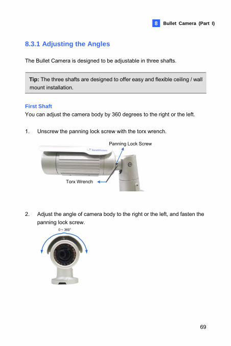
8.3.1 Adjusting the Angles The Bullet Camera is designed to be adjustable in three shafts.
Tip: The three shafts are designed to offer easy and flexible ceiling / wall mount installation.
First Shaft You can adjust the camera body by 360 degrees to the right or the left. 1. Unscrew the panning lock screw with the torx wrench.
Torx Wrench
Panning Lock Screw
2. Adjust the angle of camera body to the right or the left, and fasten the panning lock screw.
0 ~ 360°
69
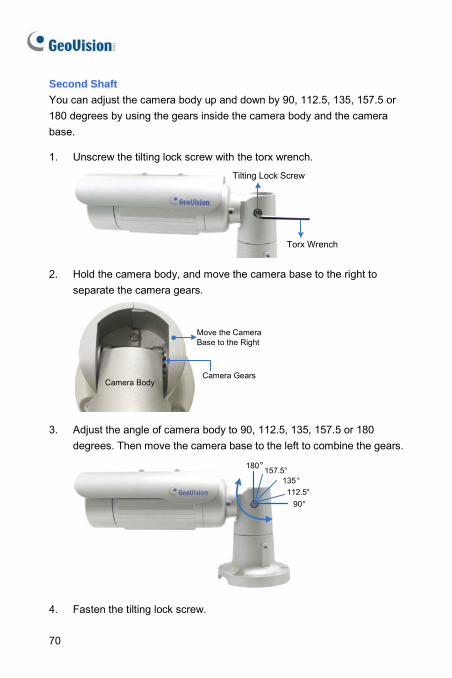
Second Shaft You can adjust the camera body up and down by 90, 112.5, 135, 157.5 or 180 degrees by using the gears inside the camera body and the camera base. 1. Unscrew the tilting lock screw with the torx wrench.
Torx Wrench
Tilting Lock Screw
2. Hold the camera body, and move the camera base to the right to
separate the camera gears.
Camera BodyCamera Gears
Move the Camera Base to the Right
3. Adjust the angle of camera body to 90, 112.5, 135, 157.5 or 180
degrees. Then move the camera base to the left to combine the gears.
90°112.5°
180°157.5°135°
4. Fasten the tilting lock screw.
70
Bullet Camera (Part I) 8
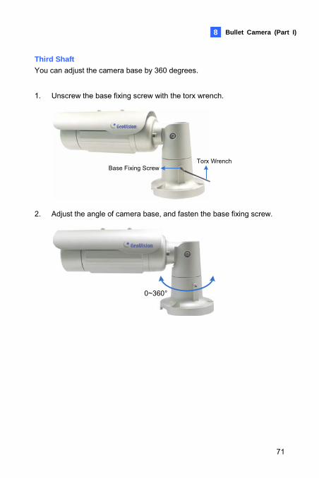
Third Shaft You can adjust the camera base by 360 degrees.
1. Unscrew the base fixing screw with the torx wrench.
Torx WrenchBase Fixing Screw
2. Adjust the angle of camera base, and fasten the base fixing screw.
0~360°
71
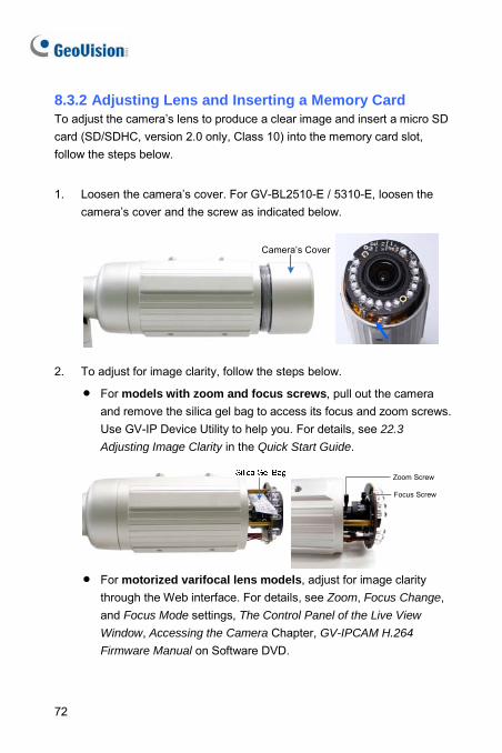
8.3.2 Adjusting Lens and Inserting a Memory Card To adjust the camera’s lens to produce a clear image and insert a micro SD card (SD/SDHC, version 2.0 only, Class 10) into the memory card slot, follow the steps below.
1. Loosen the camera’s cover. For GV-BL2510-E / 5310-E, loosen the camera’s cover and the screw as indicated below.
Camera’s Cover
2. To adjust for image clarity, follow the steps below.
• For models with zoom and focus screws, pull out the camera and remove the silica gel bag to access its focus and zoom screws. Use GV-IP Device Utility to help you. For details, see 22.3
Adjusting Image Clarity in the Quick Start Guide.
Zoom Screw
Focus Screw
• For motorized varifocal lens models, adjust for image clarity
through the Web interface. For details, see Zoom, Focus Change, and Focus Mode settings, The Control Panel of the Live View
Window, Accessing the Camera Chapter, GV-IPCAM H.264
Firmware Manual on Software DVD.
72
Bullet Camera (Part I) 8
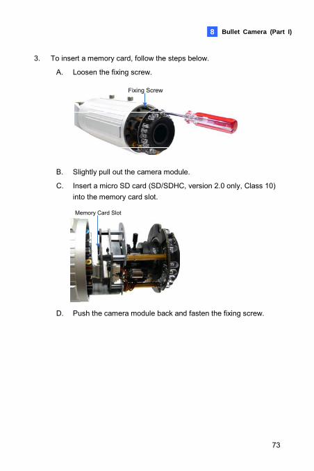
3. To insert a memory card, follow the steps below.
A. Loosen the fixing screw.
Fixing Screw
B. Slightly pull out the camera module.
C. Insert a micro SD card (SD/SDHC, version 2.0 only, Class 10) into the memory card slot.
Memory Card Slot
D. Push the camera module back and fasten the fixing screw.
73
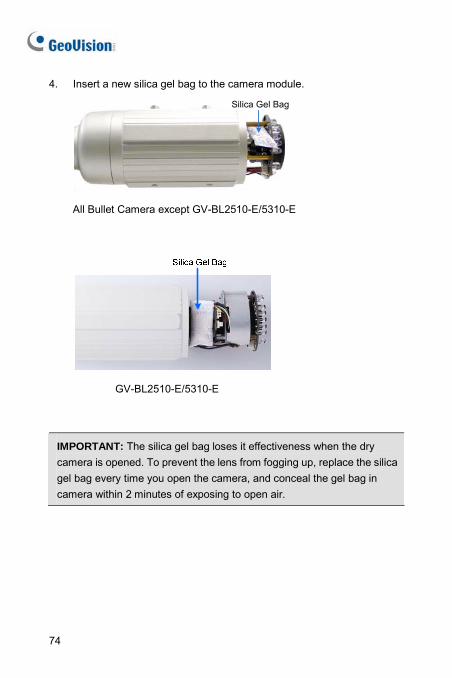
4. Insert a new silica gel bag to the camera module.
Silica Gel Bag
All Bullet Camera except GV-BL2510-E/5310-E
GV-BL2510-E/5310-E
IMPORTANT: The silica gel bag loses it effectiveness when the dry camera is opened. To prevent the lens from fogging up, replace the silica gel bag every time you open the camera, and conceal the gel bag in camera within 2 minutes of exposing to open air.
74
Bullet Camera (Part I) 8
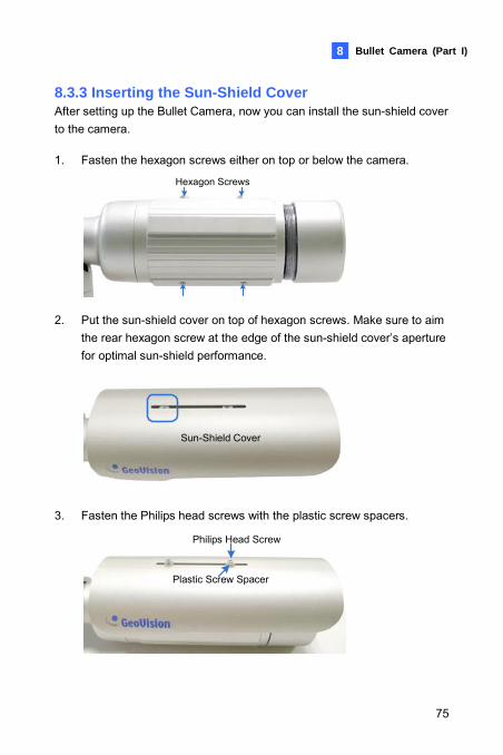
8.3.3 Inserting the Sun-Shield Cover After setting up the Bullet Camera, now you can install the sun-shield cover to the camera.
1. Fasten the hexagon screws either on top or below the camera.
Hexagon Screws
2. Put the sun-shield cover on top of hexagon screws. Make sure to aim
the rear hexagon screw at the edge of the sun-shield cover’s aperture for optimal sun-shield performance.
Sun-Shield Cover
3. Fasten the Philips head screws with the plastic screw spacers.
Philips Head Screw
Plastic Screw Spacer
75
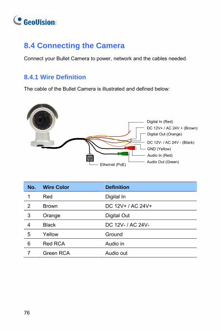
8.4 Connecting the Camera Connect your Bullet Camera to power, network and the cables needed.
8.4.1 Wire Definition
The cable of the Bullet Camera is illustrated and defined below:
Ethernet (PoE)
Digital In (Red)DC 12V+ / AC 24V + (Brown)Digital Out (Orange)
DC 12V- / AC 24V - (Black)GND (Yellow)Audio In (Red)Audio Out (Green)
No. Wire Color Definition
1 Red Digital In
2 Brown DC 12V+ / AC 24V+
3 Orange Digital Out
4 Black DC 12V- / AC 24V-
5 Yellow Ground
6 Red RCA Audio in
7 Green RCA Audio out
76
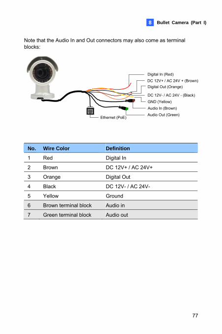
Bullet Camera (Part I) 8
Note that the Audio In and Out connectors may also come as terminal blocks:
Ethernet (PoE)
Digital In (Red)DC 12V+ / AC 24V + (Brown)Digital Out (Orange)
DC 12V- / AC 24V - (Black)GND (Yellow)Audio In (Brown)Audio Out (Green)
No. Wire Color Definition
1 Red Digital In
2 Brown DC 12V+ / AC 24V+
3 Orange Digital Out
4 Black DC 12V- / AC 24V-
5 Yellow Ground
6 Brown terminal block Audio in
7 Green terminal block Audio out
77
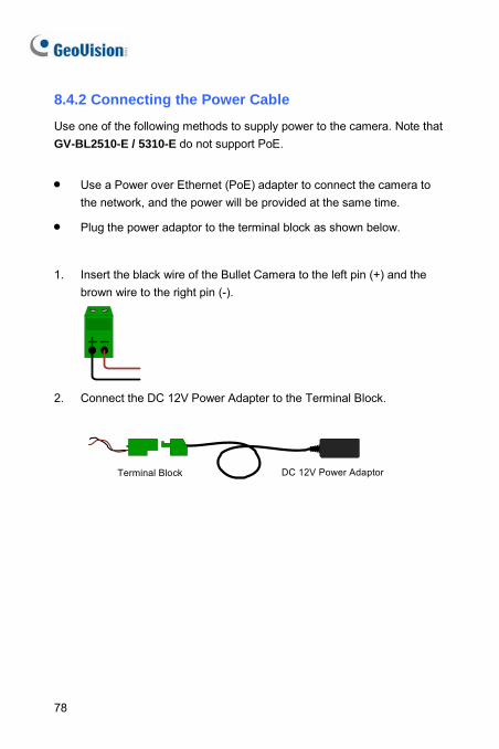
78
8.4.2 Connecting the Power Cable
Use one of the following methods to supply power to the camera. Note that GV-BL2510-E / 5310-E do not support PoE.
• Use a Power over Ethernet (PoE) adapter to connect the camera to the network, and the power will be provided at the same time.
• Plug the power adaptor to the terminal block as shown below.
1. Insert the black wire of the Bullet Camera to the left pin (+) and the
brown wire to the right pin (-).
2. Connect the DC 12V Power Adapter to the Terminal Block.
DC 12V Power AdaptorTerminal Block
Bullet Camera (Part II) 9
9. Bullet Camera (Part II)
9.1 Packing List • Bullet Camera
• Self Tapping Screw x 3
• Plastic Screw Anchor x 3
• Torx Wrench x 3
• Sun-Shield Cover Kit (Sun-Shield Cover, Philips Head Screw x 2, Plastic Screw Spacer x 2, and Hexagon Screw x 2)
• Silica Gel Bag x 2
• 2-Pin Terminal Block
• 3-Pin Terminal Block
• Power Adapter
• Installation Sticker
• Ruler
• Stand Kit (Conduit Converter, PG21 Conduit Connector, RJ-45 Connector, M3 Screw x 2, Cable Tie)
• Mounting Kit (M4 Screw x 3, Nut x 3, Plate x 3)
• GV-IPCAM H.264 Software DVD
• GV-NVR Software DVD
• Warranty Card
Note:
1. The power adapter can be excluded upon request. 2. The Mounting Kit is used for wall corner and pole installations using
GV-Mount300 / 310 / 400 / 410 (optional). For details, see GV-Mount Accessories Installation Guide on the Software DVD.
79
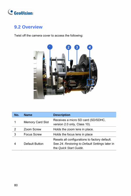
9.2 Overview
Twist off the camera cover to access the following:
No. Name Description
1 Memory Card SlotReceives a micro SD card (SD/SDHC, version 2.0 only, Class 10).
2 Zoom Screw Holds the zoom lens in place. 3 Focus Screw Holds the focus lens in place
4 Default Button Resets all configurations to factory default. See 24. Restoring to Default Settings later in the Quick Start Guide.
80
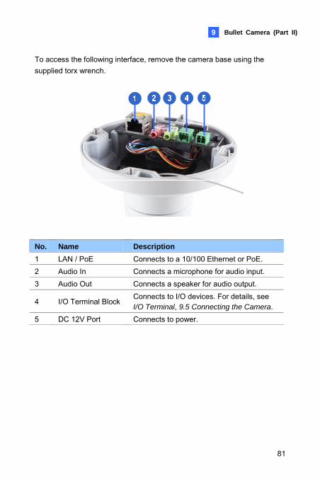
Bullet Camera (Part II) 9
To access the following interface, remove the camera base using the supplied torx wrench.
No. Name Description 1 LAN / PoE Connects to a 10/100 Ethernet or PoE. 2 Audio In Connects a microphone for audio input. 3 Audio Out Connects a speaker for audio output.
4 I/O Terminal BlockConnects to I/O devices. For details, see I/O Terminal, 9.5 Connecting the Camera.
5 DC 12V Port Connects to power.
81
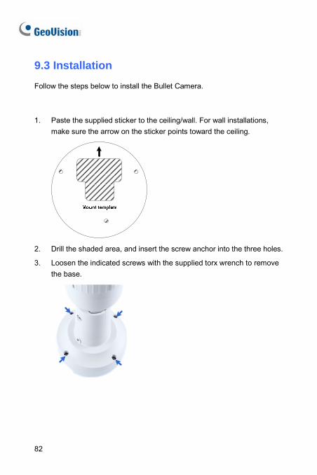
9.3 Installation
Follow the steps below to install the Bullet Camera.
1. Paste the supplied sticker to the ceiling/wall. For wall installations, make sure the arrow on the sticker points toward the ceiling.
2. Drill the shaded area, and insert the screw anchor into the three holes.
3. Loosen the indicated screws with the supplied torx wrench to remove the base.
82
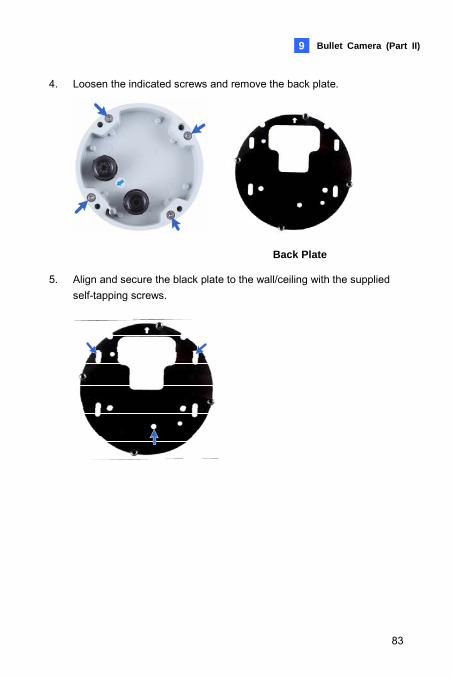
Bullet Camera (Part II) 9
4. Loosen the indicated screws and remove the back plate.
Back Plate
5. Align and secure the black plate to the wall/ceiling with the supplied self-tapping screws.
83
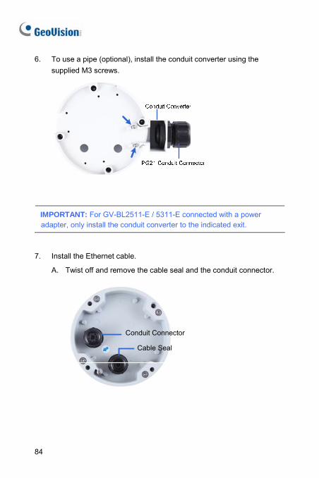
6. To use a pipe (optional), install the conduit converter using the supplied M3 screws.
IMPORTANT: For GV-BL2511-E / 5311-E connected with a power adapter, only install the conduit converter to the indicated exit.
7. Install the Ethernet cable.
A. Twist off and remove the cable seal and the conduit connector.
Cable Seal
Conduit Connector
84
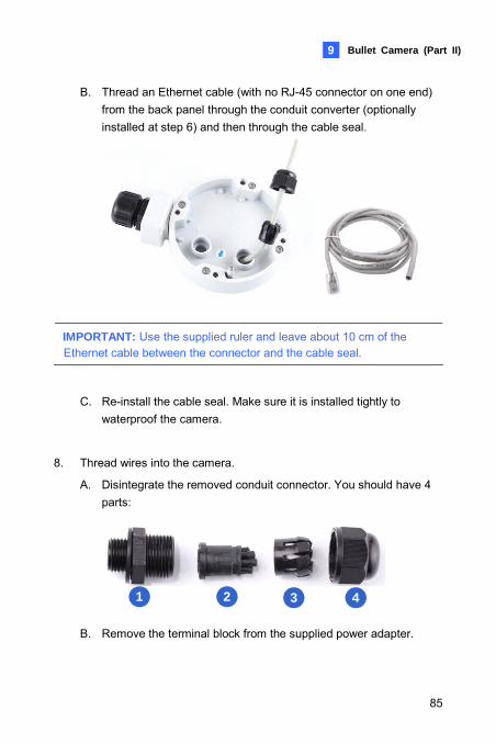
Bullet Camera (Part II) 9
B. Thread an Ethernet cable (with no RJ-45 connector on one end) from the back panel through the conduit converter (optionally installed at step 6) and then through the cable seal.
IMPORTANT: Use the supplied ruler and leave about 10 cm of the Ethernet cable between the connector and the cable seal.
C. Re-install the cable seal. Make sure it is installed tightly to waterproof the camera.
8. Thread wires into the camera.
A. Disintegrate the removed conduit connector. You should have 4 parts:
1 2 3 4 B. Remove the terminal block from the supplied power adapter.
85
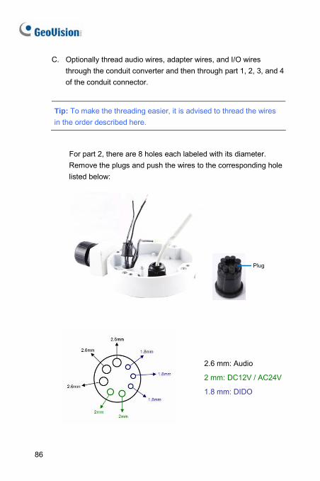
C. Optionally thread audio wires, adapter wires, and I/O wires through the conduit converter and then through part 1, 2, 3, and 4 of the conduit connector.
Tip: To make the threading easier, it is advised to thread the wires in the order described here.
For part 2, there are 8 holes each labeled with its diameter. Remove the plugs and push the wires to the corresponding hole listed below:
Plug
2.6 mm: Audio
2 mm: DC12V / AC24V
1.8 mm: DIDO
86
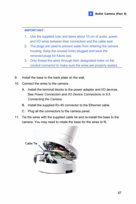
Bullet Camera (Part II) 9
IMPORTANT:
1. Use the supplied ruler and leave about 10 cm of audio, power, and I/O wires between their connectors and the cable seal.
2. The plugs are used to prevent water from entering the camera housing. Keep the unused holes plugged and save the removed plugs for future use.
3. Only thread the wires through their designated holes on the conduit connector to make sure the wires are properly sealed.
9. Install the base to the back plate on the wall.
10. Connect the wires to the camera.
A. Install the terminal blocks to the power adapter and I/O devices. See Power Connection and I/O Device Connections in 9.5
Connecting the Camera.
B. Install the supplied RJ-45 connector to the Ethernet cable.
C. Plug all the connectors to the camera panel.
11. Tie the wires with the supplied cable tie and re-install the base to the camera. You may need to rotate the base for the wires to fit.
87
12. Access the live view. For details, see 22.2 Accessing the Live View in the Quick Start Guide.
13. Adjust the angles of the camera based on the live view. Three shafts can be adjusted. See 8.3.1 Adjusting the Angles.
14. To adjust the focus and insert a micro SD card (SD/SDHC, version 2.0, Class 10), see 8.3.2 Adjusting Lens and Inserting a Memory Card.
15. Install the sun-shield cover. For details, see 8.3.3 Installing the
Sun-Shield Cover.
88
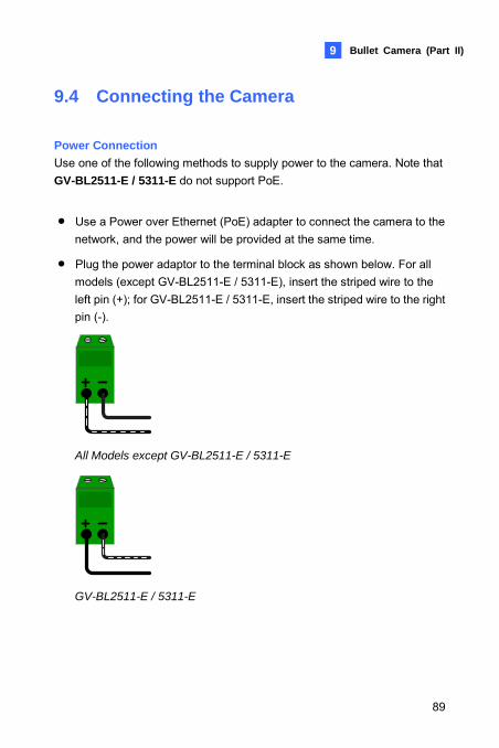
Bullet Camera (Part II) 9
9.4 Connecting the Camera
Power Connection Use one of the following methods to supply power to the camera. Note that GV-BL2511-E / 5311-E do not support PoE.
• Use a Power over Ethernet (PoE) adapter to connect the camera to the network, and the power will be provided at the same time.
• Plug the power adaptor to the terminal block as shown below. For all models (except GV-BL2511-E / 5311-E), insert the striped wire to the left pin (+); for GV-BL2511-E / 5311-E, insert the striped wire to the right pin (-).
All Models except GV-BL2511-E / 5311-E
GV-BL2511-E / 5311-E
89
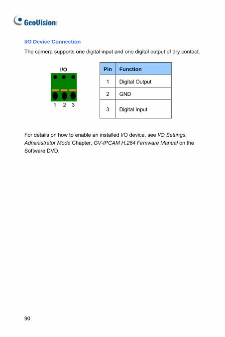
90
I/O Device Connection
The camera supports one digital input and one digital output of dry contact.
Pin Function
1 Digital Output
2 GND
I/O
1 2 3
3 Digital Input
For details on how to enable an installed I/O device, see I/O Settings, Administrator Mode Chapter, GV-IPCAM H.264 Firmware Manual on the Software DVD.
Ultra Bullet Camera 10
10. Ultra Bullet Camera
10.1 Packing List • Ultra Bullet Camera (with Waterproof or Non-Waterproof LAN
connector)
• Camera Stand
• Black Rubber
• Self Tapping Screw x 3
• Plastic Screw Anchor x 3
• Torx Wrench
• Sun-Shield Cover Kit (Sun-Shield Cover, Philips Head Screw x 2, Plastic Screw Spacer x 2 and Hexagon Screw x 2)
• Cable connector (for waterproof LAN connector only)
• Silica Gel Bag x 2
• 2-Pin Terminal Block
• Data cable
• Power Adapter
• GV-IPCAM H.264 Software DVD
• GV-NVR Software DVD
• Warranty Card
Note: The power adapter can be excluded upon request.
91
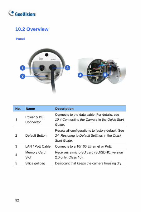
10.2 Overview
Panel
1
2
3
4 5
No. Name Description
1 Power & I/O Connector
Connects to the data cable. For details, see 10.4 Connecting the Camera in the Quick Start
Guide.
2 Default Button Resets all configurations to factory default. See 24. Restoring to Default Settings in the Quick
Start Guide.
3 LAN / PoE Cable Connects to a 10/100 Ethernet or PoE.
4 Memory Card Slot
Receives a micro SD card (SD/SDHC, version 2.0 only, Class 10).
5 Silica gel bag Desiccant that keeps the camera housing dry.
92
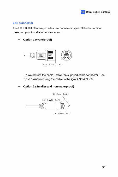
Ultra Bullet Camera 10
LAN Connector
The Ultra Bullet Camera provides two connector types. Select an option based on your installation environment.
• Option 1 (Waterproof)
To waterproof the cable, install the supplied cable connector. See 10.4.1 Waterproofing the Cable in the Quick Start Guide.
• Option 2 (Smaller and non-waterproof)
93
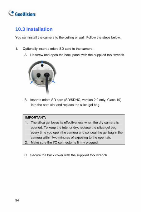
10.3 Installation You can install the camera to the ceiling or wall. Follow the steps below.
1. Optionally insert a micro SD card to the camera.
A. Unscrew and open the back panel with the supplied torx wrench.
B. Insert a micro SD card (SD/SDHC, version 2.0 only, Class 10) into the card slot and replace the silica gel bag.
IMPORTANT: 1. The silica gel loses its effectiveness when the dry camera is
opened. To keep the interior dry, replace the silica gel bag every time you open the camera and conceal the gel bag in the camera within two minutes of exposing to the open air.
2. Make sure the I/O connector is firmly plugged.
C. Secure the back cover with the supplied torx wrench.
94
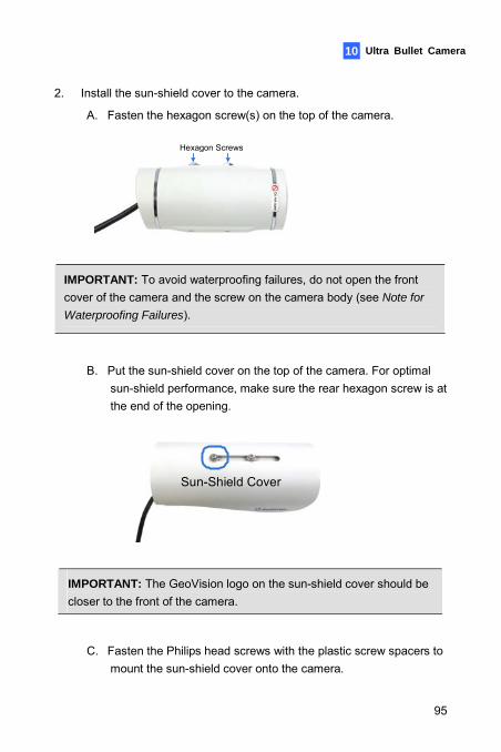
Ultra Bullet Camera 10
2. Install the sun-shield cover to the camera.
A. Fasten the hexagon screw(s) on the top of the camera.
Hexagon Screws
IMPORTANT: To avoid waterproofing failures, do not open the front cover of the camera and the screw on the camera body (see Note for
Waterproofing Failures).
B. Put the sun-shield cover on the top of the camera. For optimal sun-shield performance, make sure the rear hexagon screw is at the end of the opening.
Sun-Shield Cover
IMPORTANT: The GeoVision logo on the sun-shield cover should be closer to the front of the camera.
C. Fasten the Philips head screws with the plastic screw spacers to mount the sun-shield cover onto the camera.
95
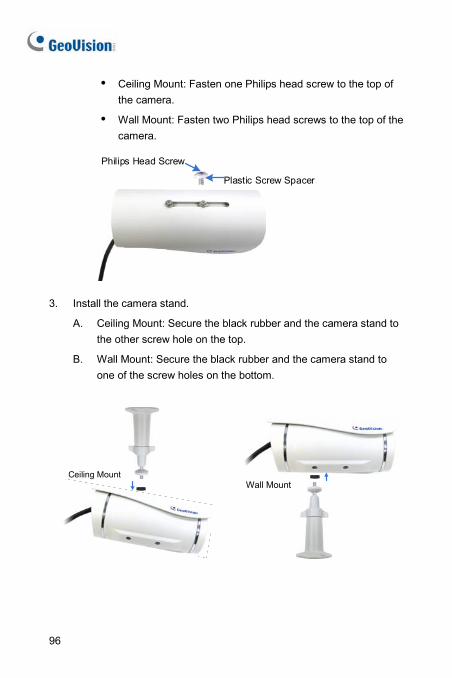
Ceiling Mount: Fasten one Philips head screw to the top of the camera.
Wall Mount: Fasten two Philips head screws to the top of the camera.
Philips Head Screw
Plastic Screw Spacer
3. Install the camera stand.
A. Ceiling Mount: Secure the black rubber and the camera stand to the other screw hole on the top.
B. Wall Mount: Secure the black rubber and the camera stand to one of the screw holes on the bottom.
Wall Mount
Ceiling Mount
96
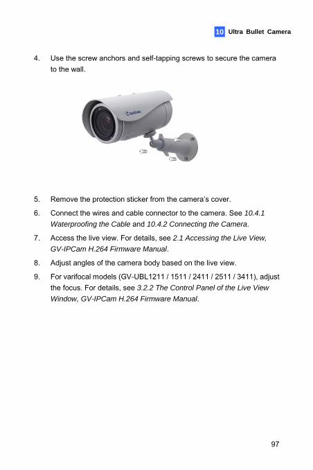
Ultra Bullet Camera 10
4. Use the screw anchors and self-tapping screws to secure the camera to the wall.
5. Remove the protection sticker from the camera’s cover.
6. Connect the wires and cable connector to the camera. See 10.4.1
Waterproofing the Cable and 10.4.2 Connecting the Camera.
7. Access the live view. For details, see 2.1 Accessing the Live View,
GV-IPCam H.264 Firmware Manual.
8. Adjust angles of the camera body based on the live view.
9. For varifocal models (GV-UBL1211 / 1511 / 2411 / 2511 / 3411), adjust the focus. For details, see 3.2.2 The Control Panel of the Live View
Window, GV-IPCam H.264 Firmware Manual.
97
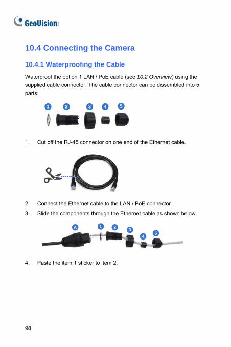
10.4 Connecting the Camera 10.4.1 Waterproofing the Cable
Waterproof the option 1 LAN / PoE cable (see 10.2 Overview) using the supplied cable connector. The cable connector can be dissembled into 5 parts:
1 2 3 4 5
1. Cut off the RJ-45 connector on one end of the Ethernet cable.
2. Connect the Ethernet cable to the LAN / PoE connector.
3. Slide the components through the Ethernet cable as shown below.
1 2 34
5A
4. Paste the item 1 sticker to item 2.
98
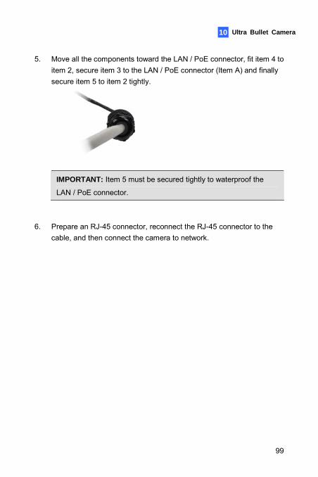
Ultra Bullet Camera 10
5. Move all the components toward the LAN / PoE connector, fit item 4 to item 2, secure item 3 to the LAN / PoE connector (Item A) and finally secure item 5 to item 2 tightly.
IMPORTANT: Item 5 must be secured tightly to waterproof the
LAN / PoE connector.
6. Prepare an RJ-45 connector, reconnect the RJ-45 connector to the
cable, and then connect the camera to network.
99
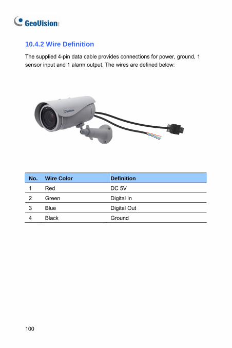
10.4.2 Wire Definition
The supplied 4-pin data cable provides connections for power, ground, 1 sensor input and 1 alarm output. The wires are defined below:
No. Wire Color Definition
1 Red DC 5V
2 Green Digital In
3 Blue Digital Out
4 Black Ground
100
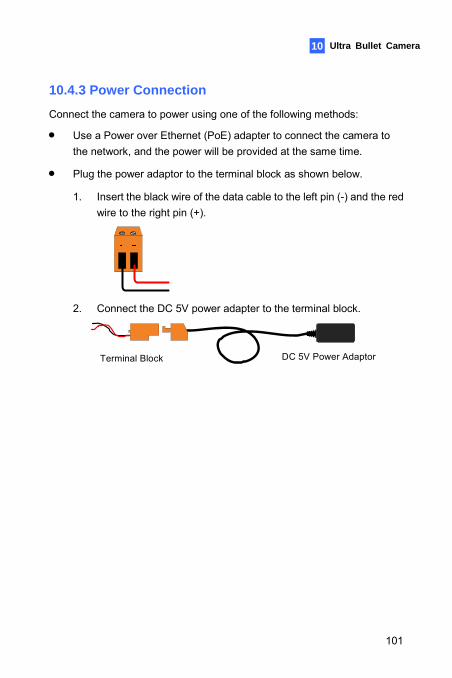
Ultra Bullet Camera
101
10
10.4.3 Power Connection
Connect the camera to power using one of the following methods:
• Use a Power over Ethernet (PoE) adapter to connect the camera to the network, and the power will be provided at the same time.
• Plug the power adaptor to the terminal block as shown below.
1. Insert the black wire of the data cable to the left pin (-) and the red wire to the right pin (+).
2. Connect the DC 5V power adapter to the terminal block.
DC 5V Power AdaptorTerminal Block
11. Target Bullet Camera (Part I)
11.1 Packing List • Target Bullet Camera
• Sun-Shield Cover
• Silica Gel Tape x 2
• Supporting Rack
• Screw for Supporting Rack x 3
• Screw Anchor x 3
• Screw for Sun-shield Cover
• Washer
• Terminal Block
• GV-IPCAM H.264 Software DVD
• GV-NVR Software DVD
• Warranty Card
Note: Power adapter can be purchased upon request.
102
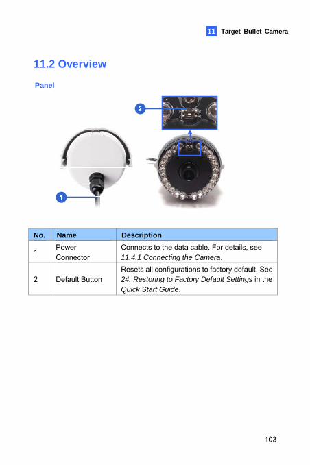
Target Bullet Camera 11 11
11.2 Overview
Panel
No. Name Description
1 Power Connector
Connects to the data cable. For details, see 11.4.1 Connecting the Camera.
2 Default Button Resets all configurations to factory default. See 24. Restoring to Factory Default Settings in the Quick Start Guide.
103
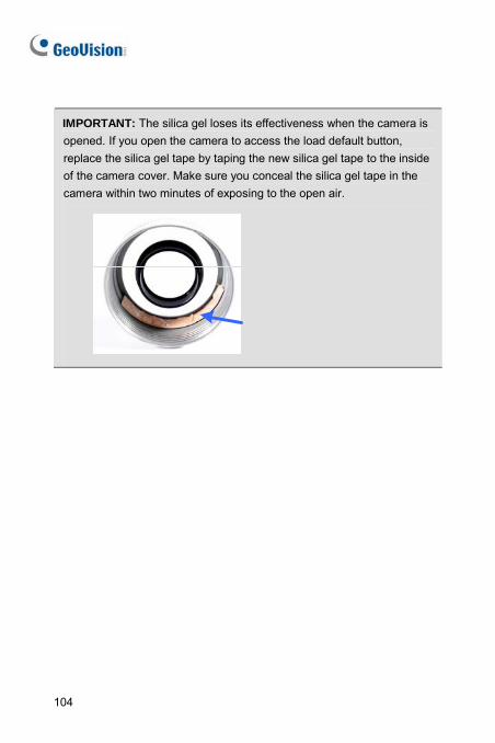
IMPORTANT: The silica gel loses its effectiveness when the camera is opened. If you open the camera to access the load default button, replace the silica gel tape by taping the new silica gel tape to the inside of the camera cover. Make sure you conceal the silica gel tape in the camera within two minutes of exposing to the open air.
104
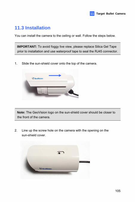
Target Bullet Camera 11 11
11.3 Installation You can install the camera to the ceiling or wall. Follow the steps below.
IMPORTANT: To avoid foggy live view, please replace Silica Gel Tape prior to installation and use waterproof tape to seal the RJ45 connector.
1. Slide the sun-shield cover onto the top of the camera.
Note: The GeoVision logo on the sun-shield cover should be closer to the front of the camera.
2. Line up the screw hole on the camera with the opening on the sun-shield cover.
105
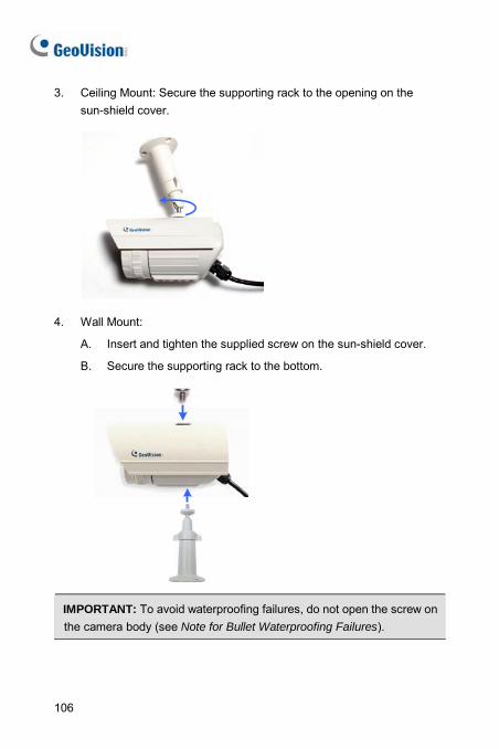
3. Ceiling Mount: Secure the supporting rack to the opening on the sun-shield cover.
4. Wall Mount:
A. Insert and tighten the supplied screw on the sun-shield cover.
B. Secure the supporting rack to the bottom.
IMPORTANT: To avoid waterproofing failures, do not open the screw on the camera body (see Note for Bullet Waterproofing Failures).
106
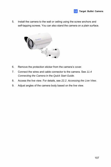
Target Bullet Camera 11 11
5. Install the camera to the wall or ceiling using the screw anchors and self-tapping screws. You can also stand the camera on a plain surface.
6. Remove the protection sticker from the camera’s cover.
7. Connect the wires and cable connector to the camera. See 11.4
Connecting the Camera in the Quick Start Guide.
8. Access the live view. For details, see 22.2. Accessing the Live View.
9. Adjust angles of the camera body based on the live view.
107
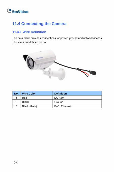
11.4 Connecting the Camera 11.4.1 Wire Definition
The data cable provides connections for power, ground and network access. The wires are defined below:
No. Wire Color Definition 1 Red DC 12V 2 Black Ground 3 Black (thick) PoE, Ethernet
108
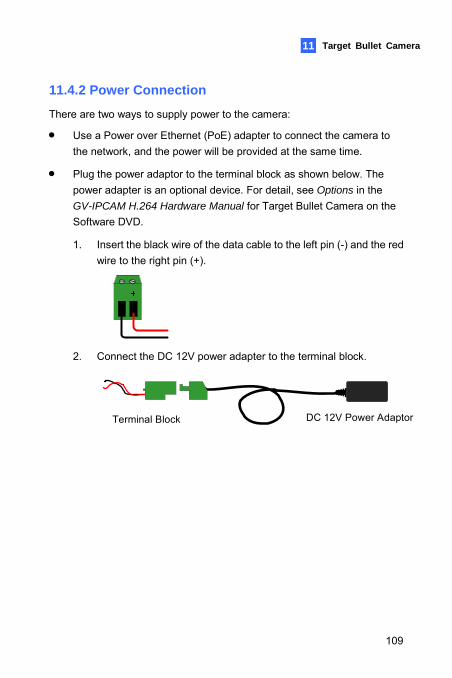
Target Bullet Camera
109
11 11
11.4.2 Power Connection
There are two ways to supply power to the camera:
• Use a Power over Ethernet (PoE) adapter to connect the camera to the network, and the power will be provided at the same time.
• Plug the power adaptor to the terminal block as shown below. The power adapter is an optional device. For detail, see Options in the GV-IPCAM H.264 Hardware Manual for Target Bullet Camera on the Software DVD.
1. Insert the black wire of the data cable to the left pin (-) and the red wire to the right pin (+).
2. Connect the DC 12V power adapter to the terminal block.
DC 12V Power AdaptorTerminal Block
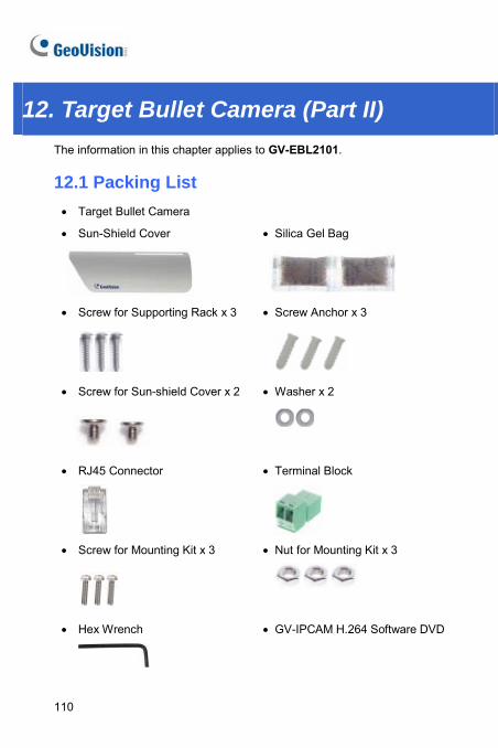
12. Target Bullet Camera (Part II) The information in this chapter applies to GV-EBL2101.
12.1 Packing List • Target Bullet Camera
• Sun-Shield Cover
• Silica Gel Bag
• Screw for Supporting Rack x 3
• Screw Anchor x 3
• Screw for Sun-shield Cover x 2
• Washer x 2
• RJ45 Connector
• Terminal Block
• Screw for Mounting Kit x 3
• Nut for Mounting Kit x 3
• Hex Wrench
• GV-IPCAM H.264 Software DVD
110
Target Bullet Camera 11 12
• GV-NVR Software DVD • Warranty Card
Note: Power adapter can be purchased upon request.
111
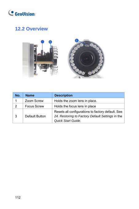
12.2 Overview
No. Name Description 1 Zoom Screw Holds the zoom lens in place. 2 Focus Screw Holds the focus lens in place
3 Default Button Resets all configurations to factory default. See 24. Restoring to Factory Default Settings in the Quick Start Guide.
112
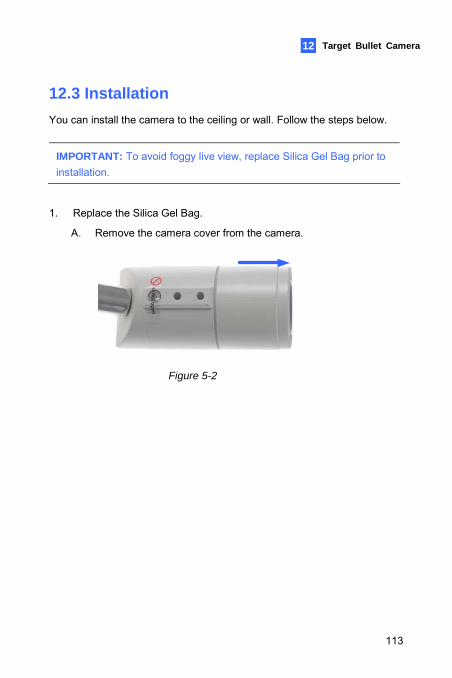
Target Bullet Camera 11 12
12.3 Installation You can install the camera to the ceiling or wall. Follow the steps below.
IMPORTANT: To avoid foggy live view, replace Silica Gel Bag prior to installation.
1. Replace the Silica Gel Bag.
A. Remove the camera cover from the camera.
Figure 5-2
113
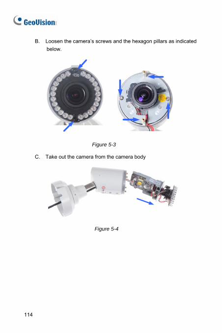
B. Loosen the camera’s screws and the hexagon pillars as indicated below.
Figure 5-3
C. Take out the camera from the camera body
Figure 5-4
114
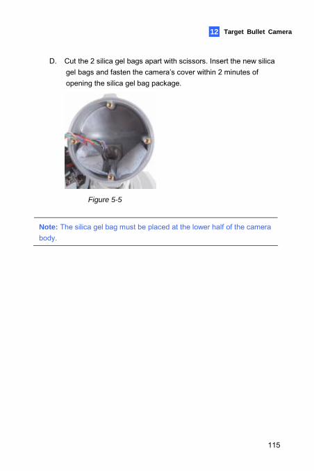
Target Bullet Camera 11 12
D. Cut the 2 silica gel bags apart with scissors. Insert the new silica gel bags and fasten the camera’s cover within 2 minutes of opening the silica gel bag package.
Figure 5-5
Note: The silica gel bag must be placed at the lower half of the camera body.
115
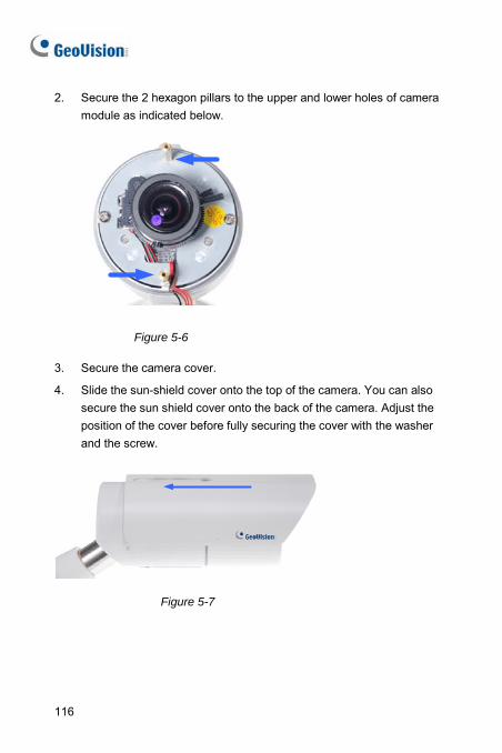
2. Secure the 2 hexagon pillars to the upper and lower holes of camera module as indicated below.
Figure 5-6
3. Secure the camera cover.
4. Slide the sun-shield cover onto the top of the camera. You can also secure the sun shield cover onto the back of the camera. Adjust the position of the cover before fully securing the cover with the washer and the screw.
Figure 5-7
116
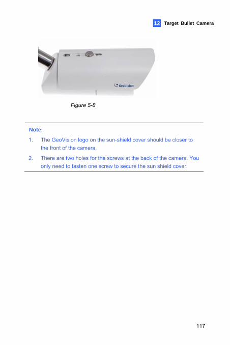
Target Bullet Camera 11 12
Figure 5-8
Note:
1. The GeoVision logo on the sun-shield cover should be closer to the front of the camera.
2. There are two holes for the screws at the back of the camera. You only need to fasten one screw to secure the sun shield cover.
117
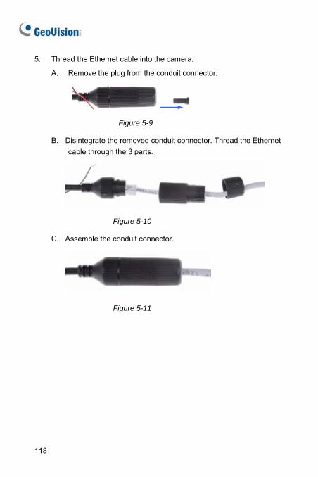
5. Thread the Ethernet cable into the camera.
A. Remove the plug from the conduit connector.
Figure 5-9
B. Disintegrate the removed conduit connector. Thread the Ethernet cable through the 3 parts.
Figure 5-10
C. Assemble the conduit connector.
Figure 5-11
118
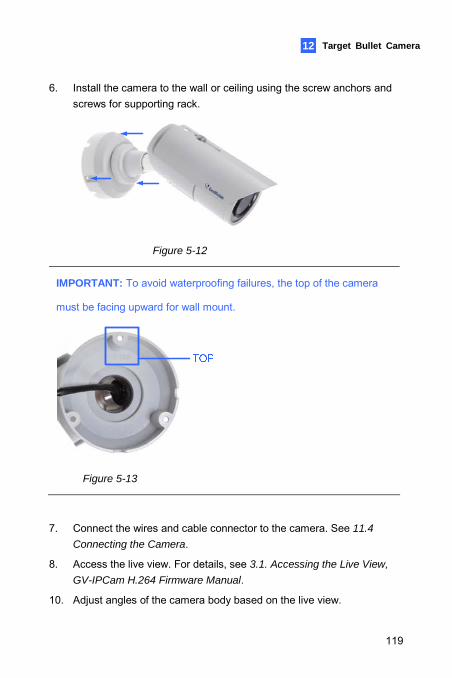
Target Bullet Camera 11 12
6. Install the camera to the wall or ceiling using the screw anchors and screws for supporting rack.
Figure 5-12
IMPORTANT: To avoid waterproofing failures, the top of the camera
must be facing upward for wall mount.
Figure 5-13
7. Connect the wires and cable connector to the camera. See 11.4
Connecting the Camera.
8. Access the live view. For details, see 3.1. Accessing the Live View,
GV-IPCam H.264 Firmware Manual.
10. Adjust angles of the camera body based on the live view.
119
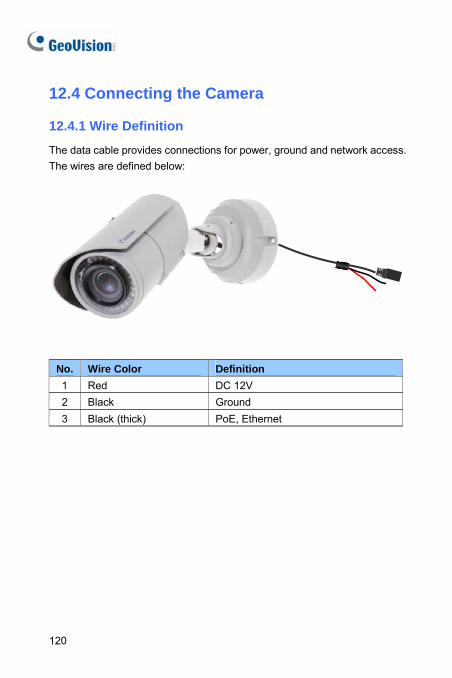
12.4 Connecting the Camera 12.4.1 Wire Definition
The data cable provides connections for power, ground and network access. The wires are defined below:
No. Wire Color Definition 1 Red DC 12V 2 Black Ground 3 Black (thick) PoE, Ethernet
120
Target Bullet Camera
121
11 12
12.4.2 Power Connection
See 11.4.2 Power Connection.
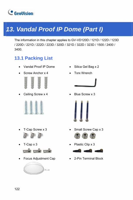
13. Vandal Proof IP Dome (Part I) The information in this chapter applies to GV-VD120D / 121D / 122D / 123D / 220D / 221D / 222D / 223D / 320D / 321D / 322D / 323D / 1500 / 2400 / 3400.
13.1 Packing List • Vandal Proof IP Dome • Silica Gel Bag x 2
• Screw Anchor x 4
• Torx Wrench
• Ceiling Screw x 4
• Blue Screw x 3
• T-Cap Screw x 3
• Small Screw Cap x 3
• T-Cap x 3
• Plastic Clip x 3
• Focus Adjustment Cap
• 2-Pin Terminal Block
122
Vandal Proof IP Dome (Part I) 13
• GV-IPCam H.264 Software
DVD • Power Adapter
• GV-NVR Software DVD • Warranty Card
Note:
1. Focus Adjustment Cap is only needed and supplied for IK10+ models.
2. The power adapter can be excluded upon request.
123
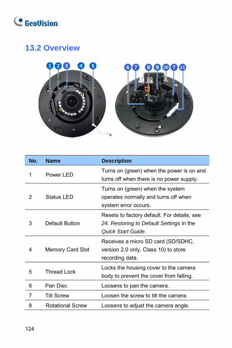
13.2 Overview
2 3 4 51 6 7 8 9 710 11
No. Name Description
1 Power LED Turns on (green) when the power is on and turns off when there is no power supply.
2 Status LED Turns on (green) when the system operates normally and turns off when system error occurs.
3 Default Button Resets to factory default. For details, see 24. Restoring to Default Settings in the Quick Start Guide.
4 Memory Card Slot Receives a micro SD card (SD/SDHC, version 2.0 only, Class 10) to store recording data.
5 Thread Lock Locks the housing cover to the camera body to prevent the cover from falling.
6 Pan Disc Loosens to pan the camera.
7 Tilt Screw Loosen the screw to tilt the camera.
8 Rotational Screw Loosens to adjust the camera angle.
124
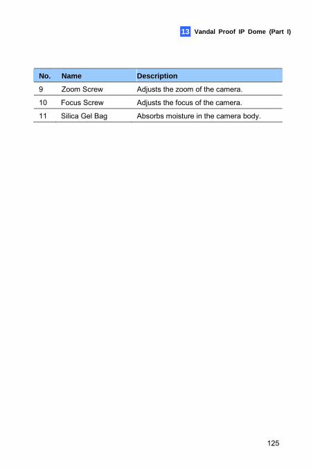
Vandal Proof IP Dome (Part I) 13
No. Name Description
9 Zoom Screw Adjusts the zoom of the camera.
10 Focus Screw Adjusts the focus of the camera.
11 Silica Gel Bag Absorbs moisture in the camera body.
125
13.3 Installation The Vandal Proof IP Dome is designed for outdoors. With the standard package, there are two ways to install the Vandal Proof IP Dome: hard-ceiling mount and in-ceiling mount.
Note: You can also install the camera:
• on a power box (of the 4" square and double gang type) using the standard package
• to ceilings, wall corners (concave or convex), and poles using optional mounting kits
For details on these installations, see GV-Mount Accessories Installation
Guide on the Software DVD.
126
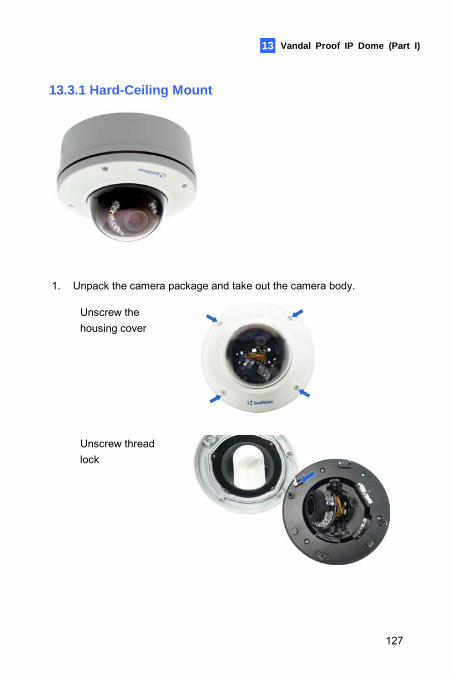
Vandal Proof IP Dome (Part I) 13
13.3.1 Hard-Ceiling Mount
1. Unpack the camera package and take out the camera body.
Unscrew the housing cover
Unscrew thread lock
127
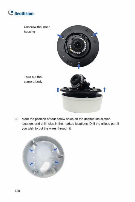
Unscrew the inner housing
Take out the camera body
2. Mark the position of four screw holes on the desired installation
location, and drill holes in the marked locations. Drill the ellipse part if you wish to put the wires through it.
128
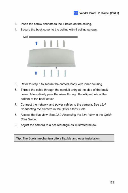
Vandal Proof IP Dome (Part I) 13
3. Insert the screw anchors to the 4 holes on the ceiling.
4. Secure the back cover to the ceiling with 4 ceiling screws.
wall
5. Refer to step 1 to secure the camera body with inner housing.
6. Thread the cable through the conduit entry at the side of the back cover. Alternatively pass the wires through the ellipse hole at the bottom of the back cover.
7. Connect the network and power cables to the camera. See 12.4
Connecting the Camera in the Quick Start Guide.
8. Access the live view. See 22.2 Accessing the Live View in the Quick
Start Guide.
9. Adjust the camera to a desired angle as illustrated below.
Tip: The 3-axis mechanism offers flexible and easy installation.
129
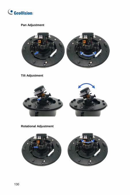
Pan Adjustment
Tilt Adjustment
Rotational Adjustment
130
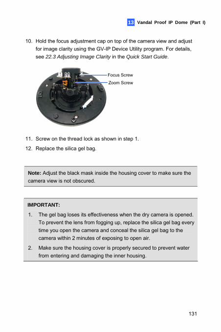
Vandal Proof IP Dome (Part I) 13
10. Hold the focus adjustment cap on top of the camera view and adjust for image clarity using the GV-IP Device Utility program. For details, see 22.3 Adjusting Image Clarity in the Quick Start Guide.
Focus Screw
Zoom Screw
11. Screw on the thread lock as shown in step 1.
12. Replace the silica gel bag.
Note: Adjust the black mask inside the housing cover to make sure the camera view is not obscured.
IMPORTANT:
1. The gel bag loses its effectiveness when the dry camera is opened. To prevent the lens from fogging up, replace the silica gel bag every time you open the camera and conceal the silica gel bag to the camera within 2 minutes of exposing to open air.
2. Make sure the housing cover is properly secured to prevent water from entering and damaging the inner housing.
131
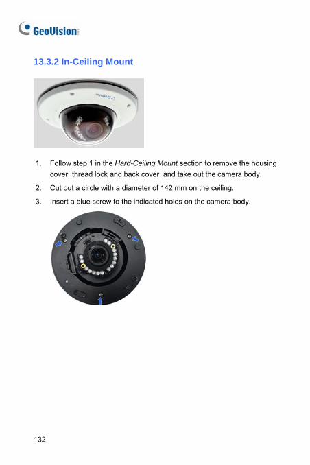
13.3.2 In-Ceiling Mount
1. Follow step 1 in the Hard-Ceiling Mount section to remove the housing
cover, thread lock and back cover, and take out the camera body.
2. Cut out a circle with a diameter of 142 mm on the ceiling.
3. Insert a blue screw to the indicated holes on the camera body.
132
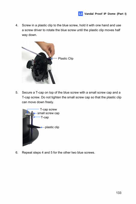
Vandal Proof IP Dome (Part I) 13
4. Screw in a plastic clip to the blue screw, hold it with one hand and use a screw driver to rotate the blue screw until the plastic clip moves half way down.
Plastic Clip
5. Secure a T-cap on top of the blue screw with a small screw cap and a T-cap screw. Do not tighten the small screw cap so that the plastic clip can move down freely.
small screw capT-cap
plastic clip
T-cap screw
6. Repeat steps 4 and 5 for the other two blue screws.
133
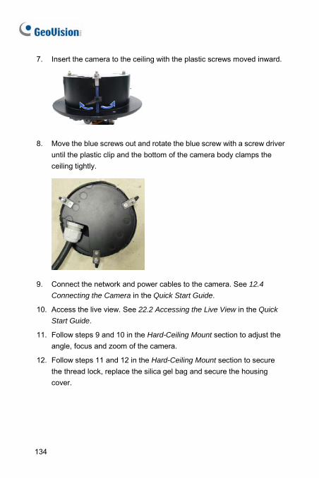
7. Insert the camera to the ceiling with the plastic screws moved inward.
8. Move the blue screws out and rotate the blue screw with a screw driver
until the plastic clip and the bottom of the camera body clamps the ceiling tightly.
9. Connect the network and power cables to the camera. See 12.4
Connecting the Camera in the Quick Start Guide.
10. Access the live view. See 22.2 Accessing the Live View in the Quick
Start Guide.
11. Follow steps 9 and 10 in the Hard-Ceiling Mount section to adjust the angle, focus and zoom of the camera.
12. Follow steps 11 and 12 in the Hard-Ceiling Mount section to secure the thread lock, replace the silica gel bag and secure the housing cover.
134
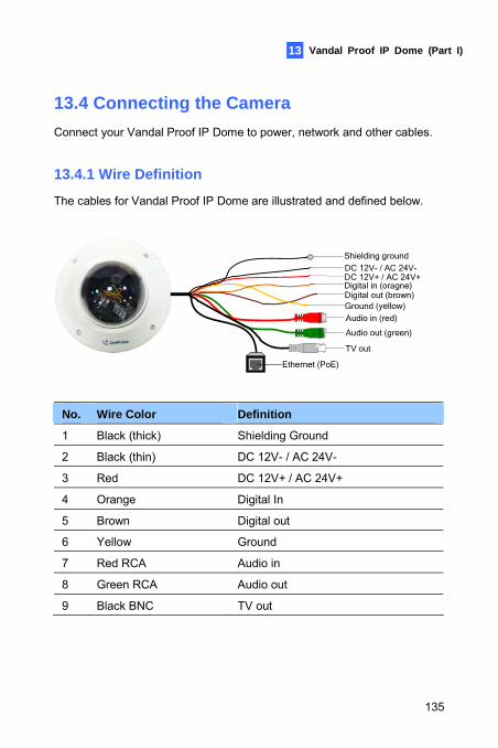
Vandal Proof IP Dome (Part I) 13
13.4 Connecting the Camera Connect your Vandal Proof IP Dome to power, network and other cables.
13.4.1 Wire Definition
The cables for Vandal Proof IP Dome are illustrated and defined below.
TV out
Audio out (green)
Audio in (red)
Digital in (oragne)
Ground (yellow)Digital out (brown)
Shielding ground
DC 12V+ / AC 24V+DC 12V- / AC 24V-
Ethernet (PoE)
No. Wire Color Definition
1 Black (thick) Shielding Ground
2 Black (thin) DC 12V- / AC 24V-
3 Red DC 12V+ / AC 24V+
4 Orange Digital In
5 Brown Digital out
6 Yellow Ground
7 Red RCA Audio in
8 Green RCA Audio out
9 Black BNC TV out
135
Note: To use the TV out function, connect the black BNC connector to a monitor and select your signal format (NTSC or PAL) at the TV Out field on the Web interface. For details, see Video Settings, Administrator Mode Chapter, GV-IPCam H.264 Firmware Manual on the Software DVD.
136
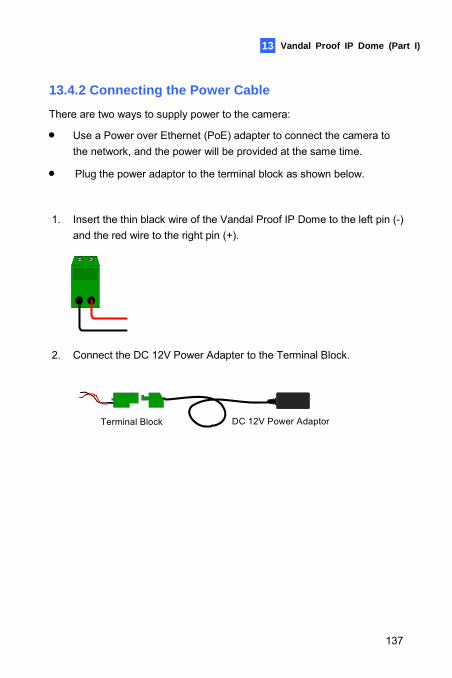
Vandal Proof IP Dome (Part I)
137
13
13.4.2 Connecting the Power Cable
There are two ways to supply power to the camera:
• Use a Power over Ethernet (PoE) adapter to connect the camera to the network, and the power will be provided at the same time.
• Plug the power adaptor to the terminal block as shown below.
1. Insert the thin black wire of the Vandal Proof IP Dome to the left pin (-) and the red wire to the right pin (+).
2. Connect the DC 12V Power Adapter to the Terminal Block.
DC 12V Power AdaptorTerminal Block
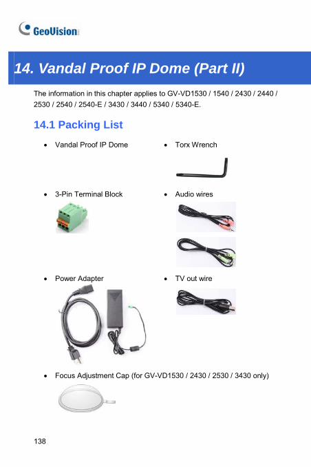
14. Vandal Proof IP Dome (Part II) The information in this chapter applies to GV-VD1530 / 1540 / 2430 / 2440 / 2530 / 2540 / 2540-E / 3430 / 3440 / 5340 / 5340-E.
14.1 Packing List • Vandal Proof IP Dome • Torx Wrench
• 3-Pin Terminal Block
• Audio wires
• Power Adapter • TV out wire
• Focus Adjustment Cap (for GV-VD1530 / 2430 / 2530 / 3430 only)
138
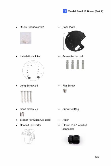
Vandal Proof IP Dome (Part II) 14
• RJ-45 Connector x 2
• Back Plate
• Installation sticker
1
1
1
Ceiling mount template
• Screw Anchor x 4
• Long Screw x 4
• Flat Screw
• Short Screw x 2
• Silica Gel Bag
• Sticker (for Silica Gel Bag) • Ruler
• Conduit Converter
• Plastic PG21 conduit connector
139
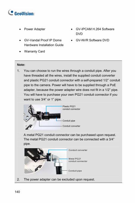
• Power Adapter • GV-IPCAM H.264 Software
DVD
• GV-Vandal Proof IP Dome Hardware Installation Guide
• GV-NVR Software DVD
• Warranty Card
Note:
1. You can choose to run the wires through a conduit pipe. After you have threaded all the wires, install the supplied conduit converter and plastic PG21 conduit connector with a self-prepared 1/2’’ conduit pipe to the camera. Power will have to be supplied through a PoE adapter, because the power adapter wire does not fit in a 1/2” pipe. You will have to purchase your own PG21 conduit connector if you want to use 3/4” or 1” pipe.
Conduit pipe
Conduit converter
Plastic PG21 conduit connector
A metal PG21 conduit connector can be purchased upon request. The metal PG21 conduit connector can be connected with a 3/4” pipe.
Conduit pipe
Conduit converter
Metal PG21 conduit connector
2. The power adapter can be excluded upon request.
140
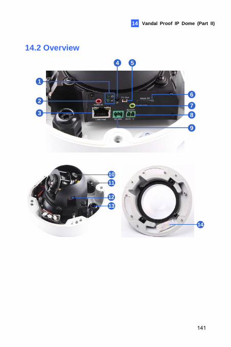
Vandal Proof IP Dome (Part II) 14
14.2 Overview
1
2
3
4 5
6
87
9
10
12
11
13
14
141
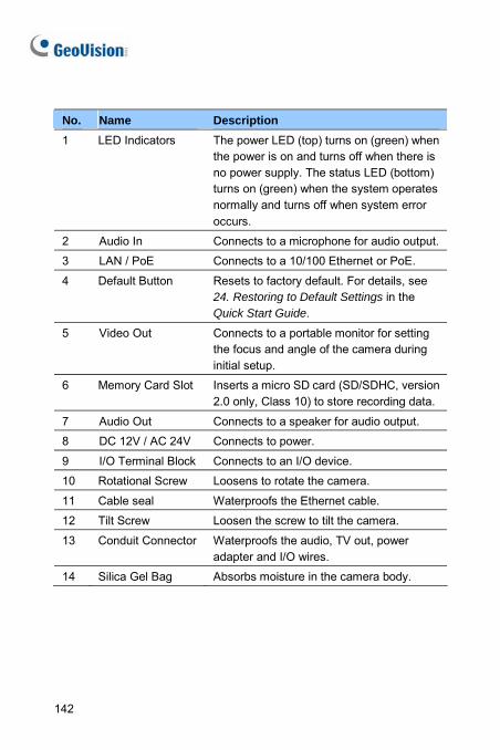
No. Name Description 1 LED Indicators The power LED (top) turns on (green) when
the power is on and turns off when there is no power supply. The status LED (bottom) turns on (green) when the system operates normally and turns off when system error occurs.
2 Audio In Connects to a microphone for audio output.
3 LAN / PoE Connects to a 10/100 Ethernet or PoE.
4 Default Button Resets to factory default. For details, see 24. Restoring to Default Settings in the Quick Start Guide.
5 Video Out Connects to a portable monitor for setting the focus and angle of the camera during initial setup.
6 Memory Card Slot Inserts a micro SD card (SD/SDHC, version 2.0 only, Class 10) to store recording data.
7 Audio Out Connects to a speaker for audio output.
8 DC 12V / AC 24V Connects to power.
9 I/O Terminal Block Connects to an I/O device.
10 Rotational Screw Loosens to rotate the camera.
11 Cable seal Waterproofs the Ethernet cable.
12 Tilt Screw Loosen the screw to tilt the camera.
13 Conduit Connector Waterproofs the audio, TV out, power adapter and I/O wires.
14 Silica Gel Bag Absorbs moisture in the camera body.
142
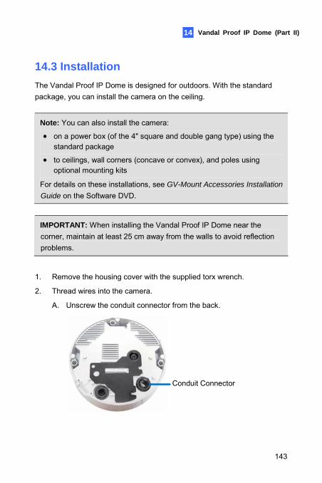
Vandal Proof IP Dome (Part II) 14
14.3 Installation The Vandal Proof IP Dome is designed for outdoors. With the standard package, you can install the camera on the ceiling.
Note: You can also install the camera:
• on a power box (of the 4" square and double gang type) using the standard package
• to ceilings, wall corners (concave or convex), and poles using optional mounting kits
For details on these installations, see GV-Mount Accessories Installation
Guide on the Software DVD.
IMPORTANT: When installing the Vandal Proof IP Dome near the corner, maintain at least 25 cm away from the walls to avoid reflection problems.
1. Remove the housing cover with the supplied torx wrench.
2. Thread wires into the camera.
A. Unscrew the conduit connector from the back.
Conduit Connector
143
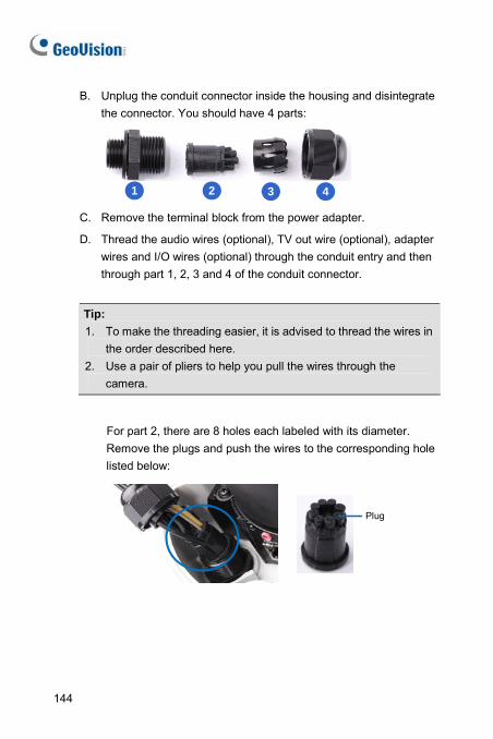
B. Unplug the conduit connector inside the housing and disintegrate the connector. You should have 4 parts:
1 2 3 4 C. Remove the terminal block from the power adapter.
D. Thread the audio wires (optional), TV out wire (optional), adapter wires and I/O wires (optional) through the conduit entry and then through part 1, 2, 3 and 4 of the conduit connector.
Tip: 1. To make the threading easier, it is advised to thread the wires in
the order described here. 2. Use a pair of pliers to help you pull the wires through the
camera.
For part 2, there are 8 holes each labeled with its diameter. Remove the plugs and push the wires to the corresponding hole listed below:
Plug
144
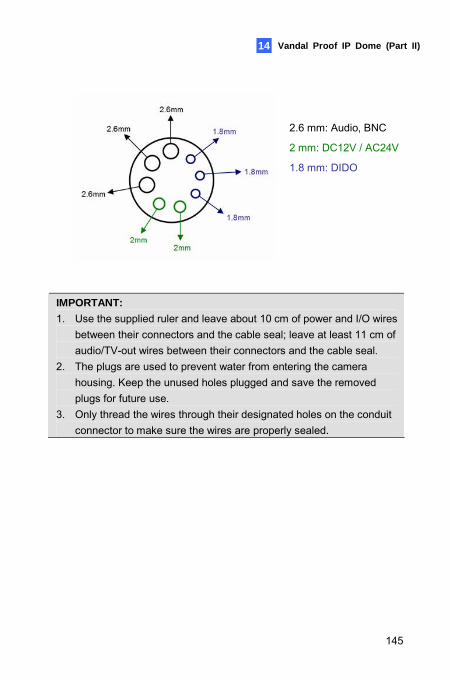
Vandal Proof IP Dome (Part II) 14
2.6 mm: Audio, BNC
2 mm: DC12V / AC24V
1.8 mm: DIDO
IMPORTANT: 1. Use the supplied ruler and leave about 10 cm of power and I/O wires
between their connectors and the cable seal; leave at least 11 cm of audio/TV-out wires between their connectors and the cable seal.
2. The plugs are used to prevent water from entering the camera housing. Keep the unused holes plugged and save the removed plugs for future use.
3. Only thread the wires through their designated holes on the conduit connector to make sure the wires are properly sealed.
145
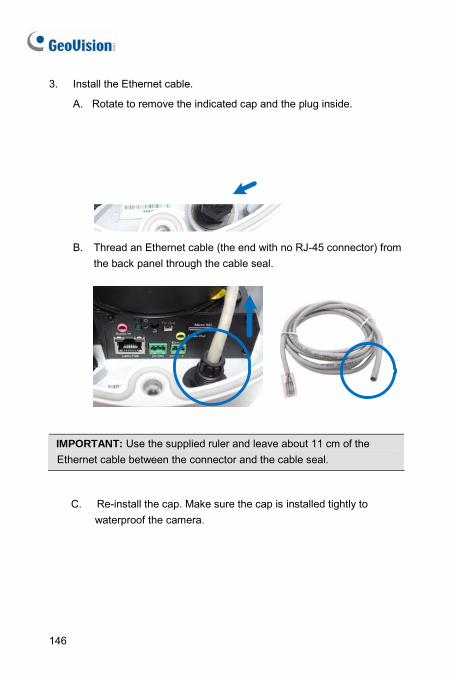
3. Install the Ethernet cable.
A. Rotate to remove the indicated cap and the plug inside.
B. Thread an Ethernet cable (the end with no RJ-45 connector) from
the back panel through the cable seal.
IMPORTANT: Use the supplied ruler and leave about 11 cm of the Ethernet cable between the connector and the cable seal.
C. Re-install the cap. Make sure the cap is installed tightly to waterproof the camera.
146
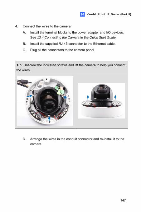
Vandal Proof IP Dome (Part II) 14
4. Connect the wires to the camera.
A. Install the terminal blocks to the power adapter and I/O devices. See 13.4 Connecting the Camera in the Quick Start Guide.
B. Install the supplied RJ-45 connector to the Ethernet cable.
C. Plug all the connectors to the camera panel.
Tip: Unscrew the indicated screws and lift the camera to help you connect the wires.
D. Arrange the wires in the conduit connector and re-install it to the camera.
147
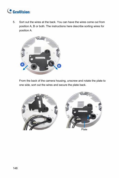
5. Sort out the wires at the back. You can have the wires come out from position A, B or both. The instructions here describe sorting wires for position A.
A B
From the back of the camera housing, unscrew and rotate the plate to one side, sort out the wires and secure the plate back.
Plate
148
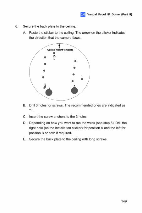
Vandal Proof IP Dome (Part II) 14
6. Secure the back plate to the ceiling.
A. Paste the sticker to the ceiling. The arrow on the sticker indicates the direction that the camera faces.
1
1
1
Ceiling mount template
AB
B. Drill 3 holes for screws. The recommended ones are indicated as
‘1’.
C. Insert the screw anchors to the 3 holes.
D. Depending on how you want to run the wires (see step 5). Drill the right hole (on the installation sticker) for position A and the left for position B or both if required.
E. Secure the back plate to the ceiling with long screws.
149
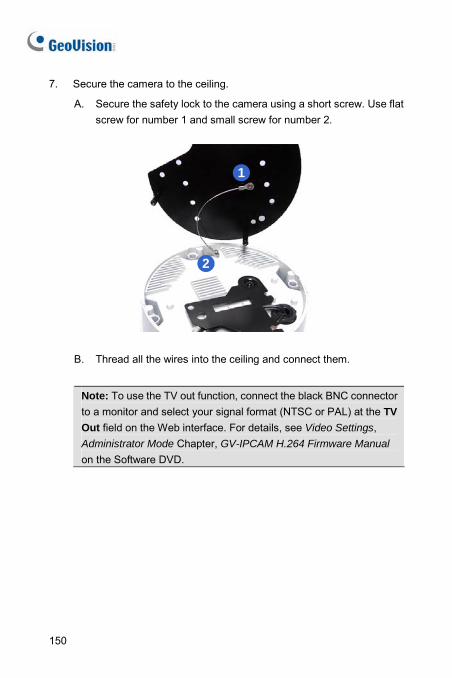
7. Secure the camera to the ceiling.
A. Secure the safety lock to the camera using a short screw. Use flat screw for number 1 and small screw for number 2.
1
2
B. Thread all the wires into the ceiling and connect them.
Note: To use the TV out function, connect the black BNC connector to a monitor and select your signal format (NTSC or PAL) at the TV Out field on the Web interface. For details, see Video Settings, Administrator Mode Chapter, GV-IPCAM H.264 Firmware Manual on the Software DVD.
150
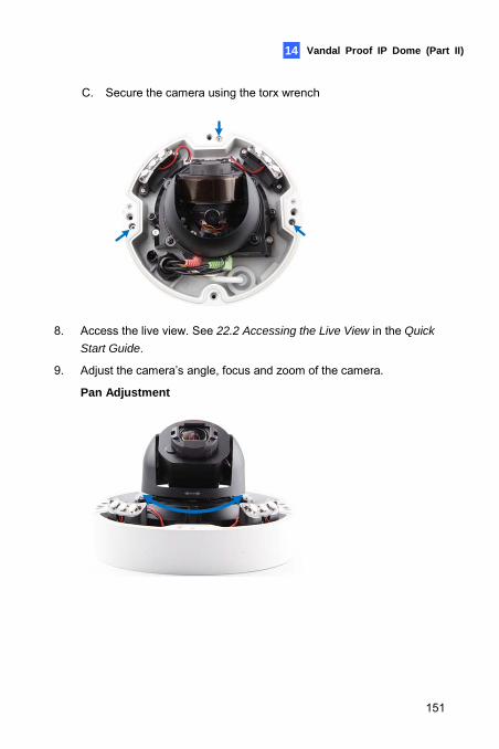
Vandal Proof IP Dome (Part II) 14
C. Secure the camera using the torx wrench
8. Access the live view. See 22.2 Accessing the Live View in the Quick
Start Guide.
9. Adjust the camera’s angle, focus and zoom of the camera.
Pan Adjustment
151
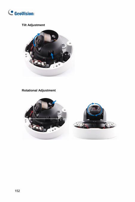
Tilt Adjustment
Rotational Adjustment
152
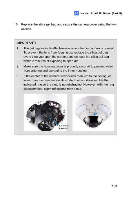
Vandal Proof IP Dome (Part II) 14
10. Replace the silica gel bag and secure the camera cover using the torx wrench.
IMPORTANT:
1. The gel bag loses its effectiveness when the dry camera is opened. To prevent the lens from fogging up, replace the silica gel bag every time you open the camera and conceal the silica gel bag within 2 minutes of exposing to open air.
2. Make sure the housing cover is properly secured to prevent water from entering and damaging the inner housing.
3. If the center of the camera view is less than 25° to the ceiling, or lower than the grey line (as illustrated below), disassemble the indicated ring so the view is not obstructed. However, with the ring disassembled, slight reflections may occur.
153
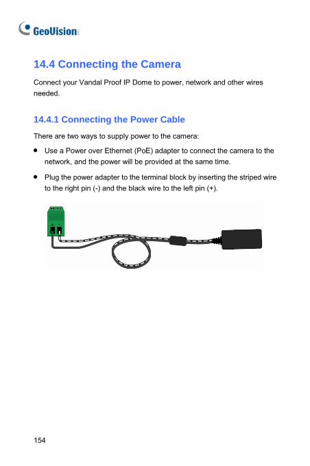
14.4 Connecting the Camera Connect your Vandal Proof IP Dome to power, network and other wires needed.
14.4.1 Connecting the Power Cable There are two ways to supply power to the camera:
• Use a Power over Ethernet (PoE) adapter to connect the camera to the network, and the power will be provided at the same time.
• Plug the power adapter to the terminal block by inserting the striped wire to the right pin (-) and the black wire to the left pin (+).
154
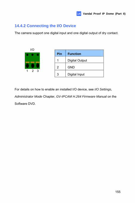
Vandal Proof IP Dome (Part II)
155
14
14.4.2 Connecting the I/O Device The camera support one digital input and one digital output of dry contact.
I/O
1 2 3
Pin Function
1 Digital Output
2 GND
3 Digital Input For details on how to enable an installed I/O device, see I/O Settings,
Administrator Mode Chapter, GV-IPCAM H.264 Firmware Manual on the
Software DVD.
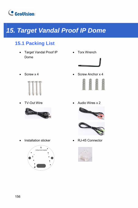
15. Target Vandal Proof IP Dome
15.1 Packing List • Target Vandal Proof IP
Dome
• Torx Wrench
• Screw x 4
• Screw Anchor x 4
• TV-Out Wire
• Audio Wires x 2
• Installation sticker
1
1
1
Ceiling mount template
1
• RJ-45 Connector
156
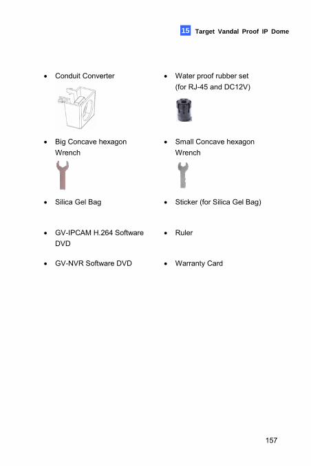
Target Vandal Proof IP Dome 15
• Conduit Converter
• Water proof rubber set (for RJ-45 and DC12V)
• Big Concave hexagon Wrench
• Small Concave hexagon Wrench
• Silica Gel Bag
• Sticker (for Silica Gel Bag)
• GV-IPCAM H.264 Software DVD
• Ruler
• GV-NVR Software DVD • Warranty Card
157
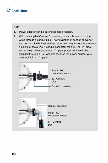
Note:
1. Power adapter can be purchased upon request.
2. With the supplied Conduit Converter, you can choose to run the wires through a conduit pipe. The installation of conduit converter and conduit pipe is illustrated as below. You may optionally purchase a plastic or metal PG21 conduit connector for a 1/2” or 3/4” pipe respectively. When you use a 1/2” pipe, power will have to be supplied through a PoE adapter because the power adapter wire does not fit in a 1/2” pipe.
Plastic PG21 conduit connector
½"Conduit pipe
Conduit converter
¾"Conduit pipe
Conduit converter
Metal PG21 conduit connector
158
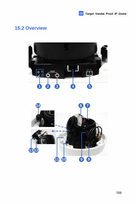
Target Vandal Proof IP Dome 15
15.2 Overview
1 2 3 4 5
6
13 12
10
7
89
14
11
159
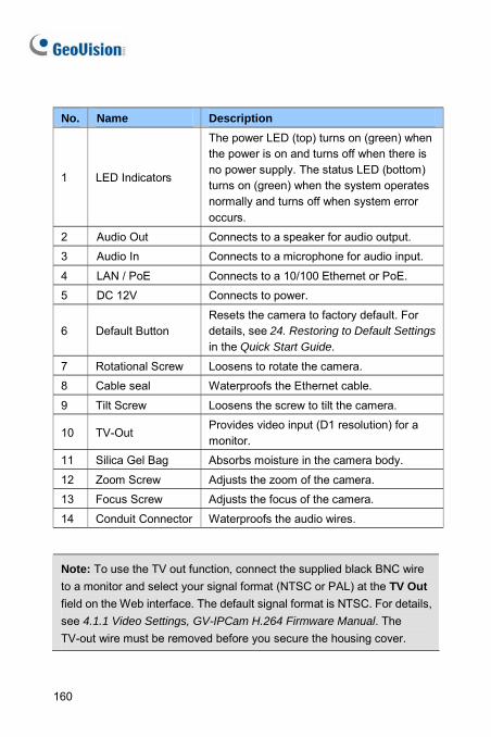
No. Name Description
1 LED Indicators
The power LED (top) turns on (green) when the power is on and turns off when there is no power supply. The status LED (bottom) turns on (green) when the system operates normally and turns off when system error occurs.
2 Audio Out Connects to a speaker for audio output.
3 Audio In Connects to a microphone for audio input.
4 LAN / PoE Connects to a 10/100 Ethernet or PoE.
5 DC 12V Connects to power.
6 Default Button Resets the camera to factory default. For details, see 24. Restoring to Default Settings in the Quick Start Guide.
7 Rotational Screw Loosens to rotate the camera.
8 Cable seal Waterproofs the Ethernet cable.
9 Tilt Screw Loosens the screw to tilt the camera.
10 TV-Out Provides video input (D1 resolution) for a monitor.
11 Silica Gel Bag Absorbs moisture in the camera body.
12 Zoom Screw Adjusts the zoom of the camera.
13 Focus Screw Adjusts the focus of the camera.
14 Conduit Connector Waterproofs the audio wires.
Note: To use the TV out function, connect the supplied black BNC wire to a monitor and select your signal format (NTSC or PAL) at the TV Out field on the Web interface. The default signal format is NTSC. For details, see 4.1.1 Video Settings, GV-IPCam H.264 Firmware Manual. The TV-out wire must be removed before you secure the housing cover.
160
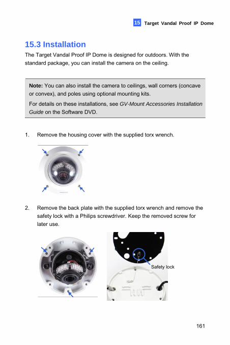
Target Vandal Proof IP Dome 15
15.3 Installation The Target Vandal Proof IP Dome is designed for outdoors. With the standard package, you can install the camera on the ceiling.
Note: You can also install the camera to ceilings, wall corners (concave or convex), and poles using optional mounting kits.
For details on these installations, see GV-Mount Accessories Installation
Guide on the Software DVD.
1. Remove the housing cover with the supplied torx wrench.
2. Remove the back plate with the supplied torx wrench and remove the safety lock with a Philips screwdriver. Keep the removed screw for later use.
Safety lock
161
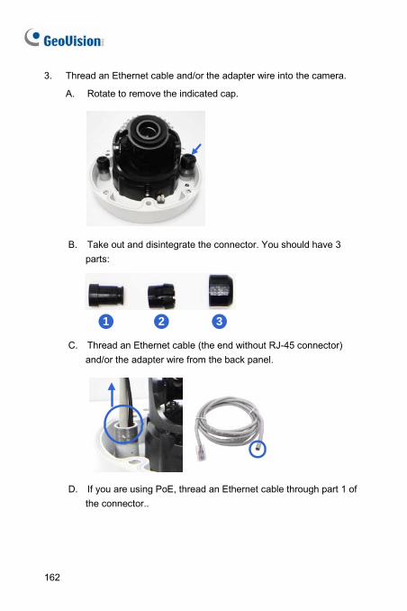
3. Thread an Ethernet cable and/or the adapter wire into the camera.
A. Rotate to remove the indicated cap.
B. Take out and disintegrate the connector. You should have 3
parts:
21 3
C. Thread an Ethernet cable (the end without RJ-45 connector) and/or the adapter wire from the back panel.
D. If you are using PoE, thread an Ethernet cable through part 1 of
the connector..
162
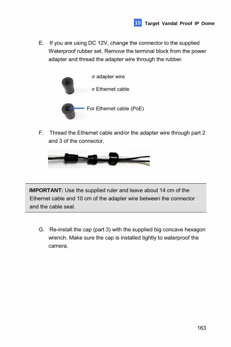
Target Vandal Proof IP Dome 15
E. If you are using DC 12V, change the connector to the supplied Waterproof rubber set. Remove the terminal block from the power adapter and thread the adapter wire through the rubber.
For adapter wire
For Ethernet cable
For Ethernet cable (PoE)
F. Thread the Ethernet cable and/or the adapter wire through part 2 and 3 of the connector.
IMPORTANT: Use the supplied ruler and leave about 14 cm of the Ethernet cable and 10 cm of the adapter wire between the connector and the cable seal.
G. Re-install the cap (part 3) with the supplied big concave hexagon wrench. Make sure the cap is installed tightly to waterproof the camera.
163
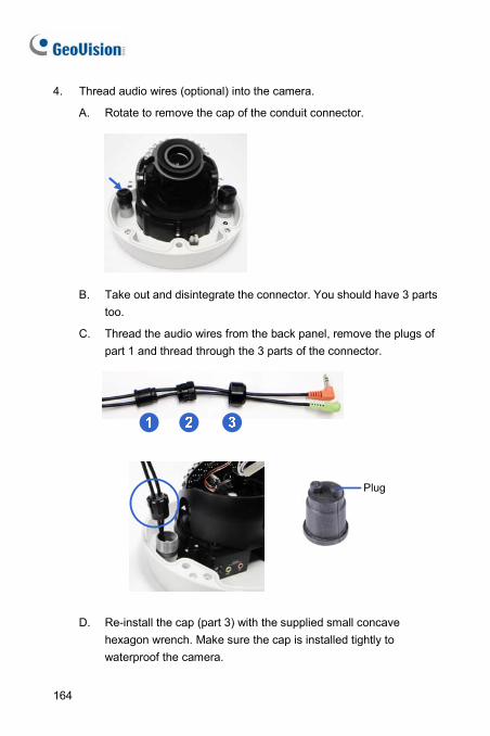
4. Thread audio wires (optional) into the camera.
A. Rotate to remove the cap of the conduit connector.
B. Take out and disintegrate the connector. You should have 3 parts too.
C. Thread the audio wires from the back panel, remove the plugs of part 1 and thread through the 3 parts of the connector.
Plug
D. Re-install the cap (part 3) with the supplied small concave hexagon wrench. Make sure the cap is installed tightly to waterproof the camera.
164
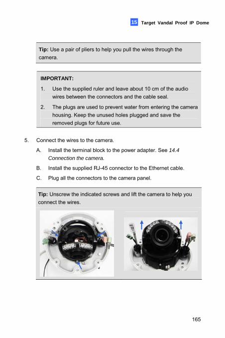
Target Vandal Proof IP Dome 15
Tip: Use a pair of pliers to help you pull the wires through the camera.
IMPORTANT:
1. Use the supplied ruler and leave about 10 cm of the audio wires between the connectors and the cable seal.
2. The plugs are used to prevent water from entering the camera housing. Keep the unused holes plugged and save the removed plugs for future use.
5. Connect the wires to the camera.
A. Install the terminal block to the power adapter. See 14.4
Connection the camera.
B. Install the supplied RJ-45 connector to the Ethernet cable.
C. Plug all the connectors to the camera panel.
Tip: Unscrew the indicated screws and lift the camera to help you connect the wires.
165
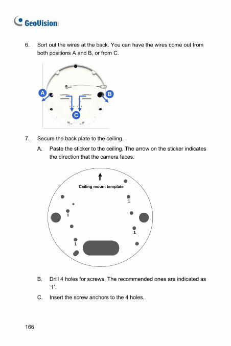
6. Sort out the wires at the back. You can have the wires come out from both positions A and B, or from C.
A B
C
7. Secure the back plate to the ceiling.
A. Paste the sticker to the ceiling. The arrow on the sticker indicates the direction that the camera faces.
1
1
1
Ceiling mount template
1
B. Drill 4 holes for screws. The recommended ones are indicated as ‘1’.
C. Insert the screw anchors to the 4 holes.
166
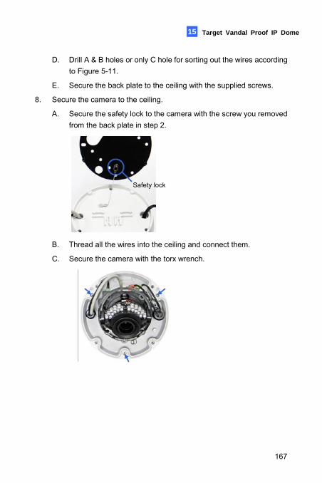
Target Vandal Proof IP Dome 15
D. Drill A & B holes or only C hole for sorting out the wires according to Figure 5-11.
E. Secure the back plate to the ceiling with the supplied screws.
8. Secure the camera to the ceiling.
A. Secure the safety lock to the camera with the screw you removed from the back plate in step 2.
Safety lock
B. Thread all the wires into the ceiling and connect them.
C. Secure the camera with the torx wrench.
167
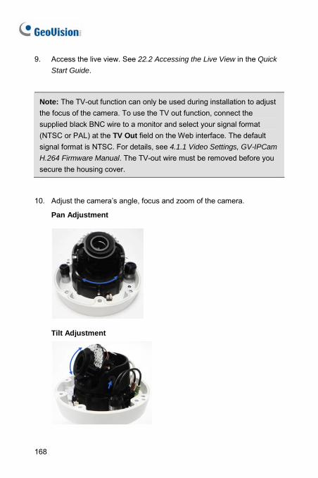
9. Access the live view. See 22.2 Accessing the Live View in the Quick
Start Guide.
Note: The TV-out function can only be used during installation to adjust the focus of the camera. To use the TV out function, connect the supplied black BNC wire to a monitor and select your signal format (NTSC or PAL) at the TV Out field on the Web interface. The default signal format is NTSC. For details, see 4.1.1 Video Settings, GV-IPCam
H.264 Firmware Manual. The TV-out wire must be removed before you secure the housing cover.
10. Adjust the camera’s angle, focus and zoom of the camera.
Pan Adjustment
Tilt Adjustment
168
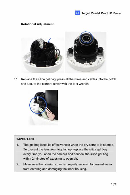
Target Vandal Proof IP Dome 15
Rotational Adjustment
11. Replace the silica gel bag, press all the wires and cables into the notch
and secure the camera cover with the torx wrench.
IMPORTANT:
1. The gel bag loses its effectiveness when the dry camera is opened. To prevent the lens from fogging up, replace the silica gel bag every time you open the camera and conceal the silica gel bag within 2 minutes of exposing to open air.
2. Make sure the housing cover is properly secured to prevent water from entering and damaging the inner housing.
169
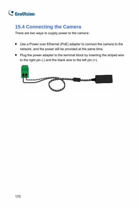
170
15.4 Connecting the Camera There are two ways to supply power to the camera:
• Use a Power over Ethernet (PoE) adapter to connect the camera to the network, and the power will be provided at the same time.
• Plug the power adapter to the terminal block by inserting the striped wire to the right pin (-) and the black wire to the left pin (+).
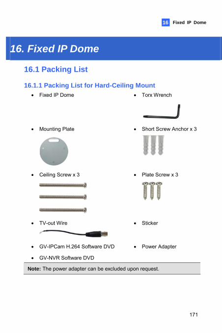
Fixed IP Dome 16
16. Fixed IP Dome
16.1 Packing List
16.1.1 Packing List for Hard-Ceiling Mount • Fixed IP Dome
• Torx Wrench
• Mounting Plate
• Short Screw Anchor x 3
• Ceiling Screw x 3
• Plate Screw x 3
• TV-out Wire
• Sticker
• GV-IPCam H.264 Software DVD • Power Adapter
• GV-NVR Software DVD
Note: The power adapter can be excluded upon request.
171
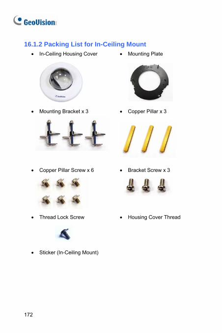
16.1.2 Packing List for In-Ceiling Mount • In-Ceiling Housing Cover
• Mounting Plate
• Mounting Bracket x 3 • Copper Pillar x 3
• Copper Pillar Screw x 6
• Bracket Screw x 3
• Thread Lock Screw
• Housing Cover Thread
• Sticker (In-Ceiling Mount)
172
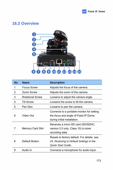
Fixed IP Dome 16
16.2 Overview
12345
6 7 8 9 10 11 12 13 14 15
No. Name Description
1 Focus Screw Adjusts the focus of the camera.
2 Zoom Screw Adjusts the zoom of the camera.
3 Rotational Screw Loosens to adjust the camera angle.
4 Tilt Screw Loosens the screw to tilt the camera.
5 Pan Disc Loosens to pan the camera.
6 Video Out Connects to a portable monitor for setting the focus and angle of Fixed IP Dome during initial installation.
7 Memory Card Slot Receives a micro SD card (SD/SDHC, version 2.0 only, Class 10) to store recording data.
8 Default Button Resets to factory default. For details, see 24. Restoring to Default Settings in the Quick Start Guide.
9 Audio In Connects a microphone for audio input.
173
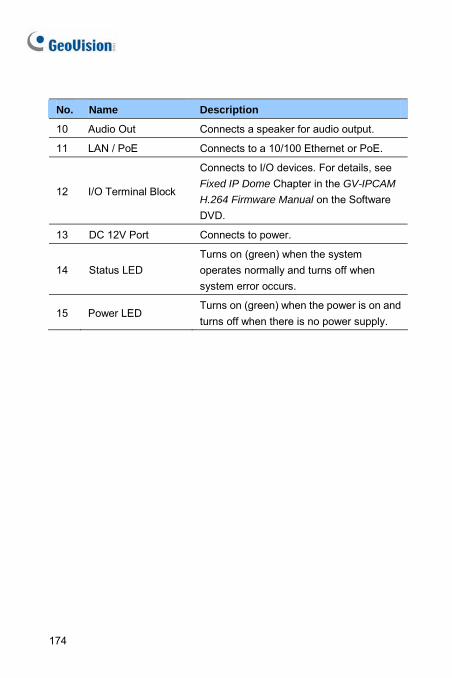
No. Name Description
10 Audio Out Connects a speaker for audio output.
11 LAN / PoE Connects to a 10/100 Ethernet or PoE.
12 I/O Terminal Block
Connects to I/O devices. For details, see Fixed IP Dome Chapter in the GV-IPCAM
H.264 Firmware Manual on the Software DVD.
13 DC 12V Port Connects to power.
14 Status LED Turns on (green) when the system operates normally and turns off when system error occurs.
15 Power LED Turns on (green) when the power is on and turns off when there is no power supply.
174
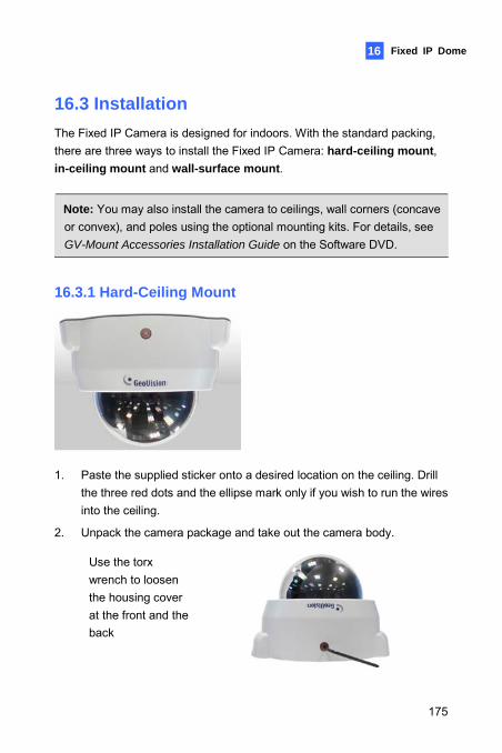
Fixed IP Dome 16
16.3 Installation The Fixed IP Camera is designed for indoors. With the standard packing, there are three ways to install the Fixed IP Camera: hard-ceiling mount, in-ceiling mount and wall-surface mount.
Note: You may also install the camera to ceilings, wall corners (concave or convex), and poles using the optional mounting kits. For details, see GV-Mount Accessories Installation Guide on the Software DVD.
16.3.1 Hard-Ceiling Mount
1. Paste the supplied sticker onto a desired location on the ceiling. Drill
the three red dots and the ellipse mark only if you wish to run the wires into the ceiling.
2. Unpack the camera package and take out the camera body.
Use the torx wrench to loosen the housing cover at the front and the back
175
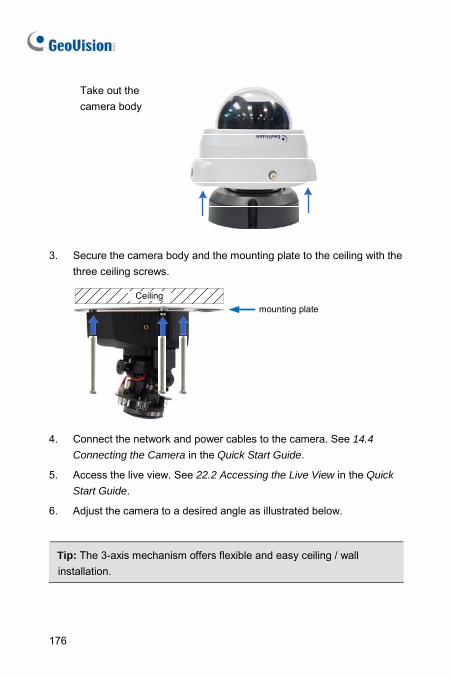
Take out the camera body
3. Secure the camera body and the mounting plate to the ceiling with the three ceiling screws.
Ceilingmounting plate
4. Connect the network and power cables to the camera. See 14.4
Connecting the Camera in the Quick Start Guide.
5. Access the live view. See 22.2 Accessing the Live View in the Quick
Start Guide.
6. Adjust the camera to a desired angle as illustrated below.
Tip: The 3-axis mechanism offers flexible and easy ceiling / wall installation.
176
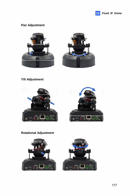
Fixed IP Dome 16
Pan Adjustment
Tilt Adjustment
Rotational Adjustment
177
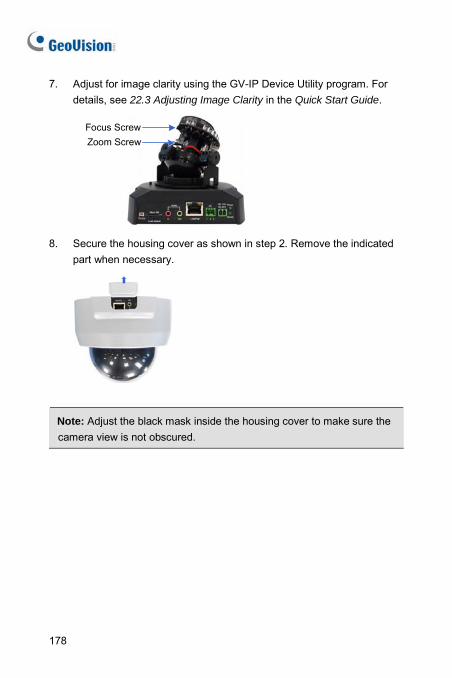
7. Adjust for image clarity using the GV-IP Device Utility program. For details, see 22.3 Adjusting Image Clarity in the Quick Start Guide.
Focus ScrewZoom Screw
8. Secure the housing cover as shown in step 2. Remove the indicated
part when necessary.
Note: Adjust the black mask inside the housing cover to make sure the camera view is not obscured.
178
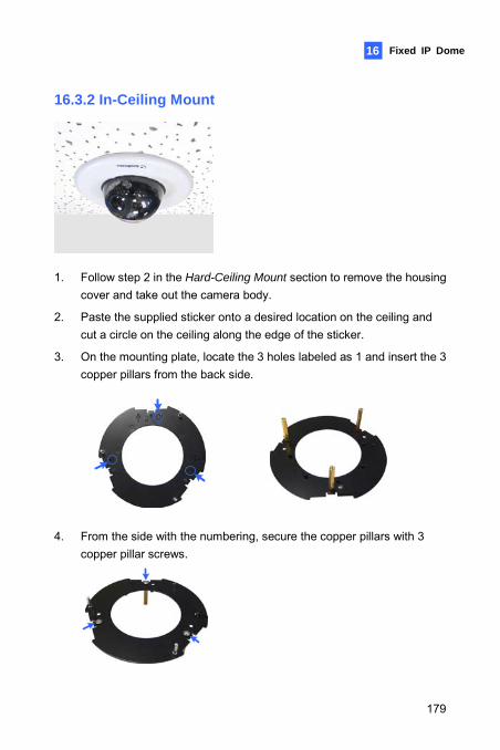
Fixed IP Dome 16
16.3.2 In-Ceiling Mount
1. Follow step 2 in the Hard-Ceiling Mount section to remove the housing
cover and take out the camera body.
2. Paste the supplied sticker onto a desired location on the ceiling and cut a circle on the ceiling along the edge of the sticker.
3. On the mounting plate, locate the 3 holes labeled as 1 and insert the 3 copper pillars from the back side.
4. From the side with the numbering, secure the copper pillars with 3 copper pillar screws.
179
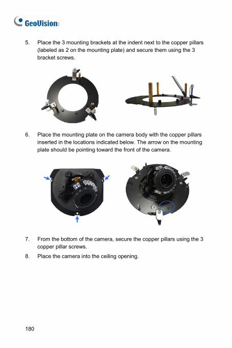
5. Place the 3 mounting brackets at the indent next to the copper pillars (labeled as 2 on the mounting plate) and secure them using the 3 bracket screws.
6. Place the mounting plate on the camera body with the copper pillars
inserted in the locations indicated below. The arrow on the mounting plate should be pointing toward the front of the camera.
7. From the bottom of the camera, secure the copper pillars using the 3 copper pillar screws.
8. Place the camera into the ceiling opening.
180
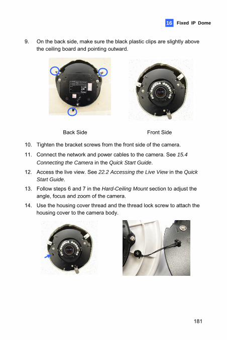
Fixed IP Dome 16
9. On the back side, make sure the black plastic clips are slightly above the ceiling board and pointing outward.
Back Side Front Side
10. Tighten the bracket screws from the front side of the camera.
11. Connect the network and power cables to the camera. See 15.4
Connecting the Camera in the Quick Start Guide.
12. Access the live view. See 22.2 Accessing the Live View in the Quick Start Guide.
13. Follow steps 6 and 7 in the Hard-Ceiling Mount section to adjust the angle, focus and zoom of the camera.
14. Use the housing cover thread and the thread lock screw to attach the housing cover to the camera body.
181
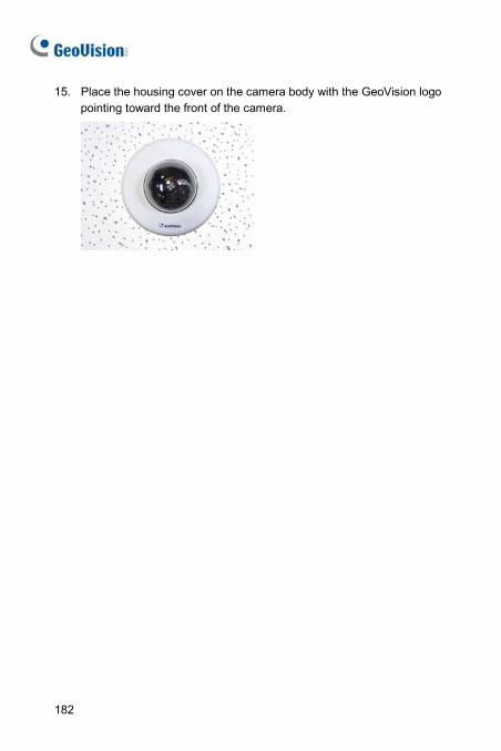
15. Place the housing cover on the camera body with the GeoVision logo pointing toward the front of the camera.
182
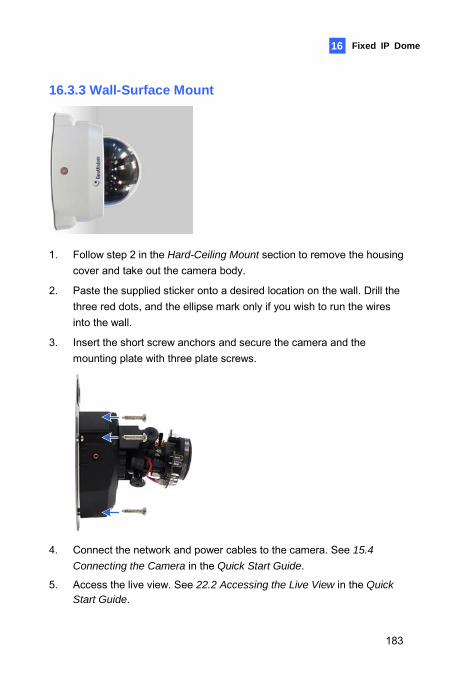
Fixed IP Dome 16
16.3.3 Wall-Surface Mount
1. Follow step 2 in the Hard-Ceiling Mount section to remove the housing
cover and take out the camera body.
2. Paste the supplied sticker onto a desired location on the wall. Drill the three red dots, and the ellipse mark only if you wish to run the wires into the wall.
3. Insert the short screw anchors and secure the camera and the mounting plate with three plate screws.
4. Connect the network and power cables to the camera. See 15.4
Connecting the Camera in the Quick Start Guide.
5. Access the live view. See 22.2 Accessing the Live View in the Quick Start Guide.
183
6. Follow steps 6 and 7 in the Hard-Ceiling Mount section to adjust the angle, focus and zoom of the camera.
7. Follow step 8 in the Hard-Ceiling Mount section to secure the housing cover.
184
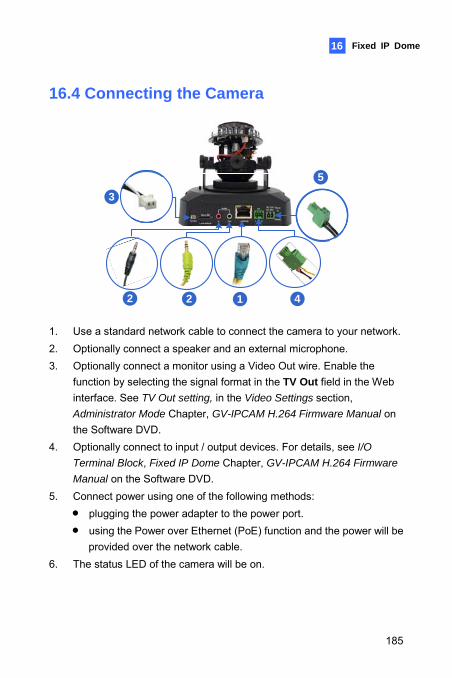
Fixed IP Dome
185
16
16.4 Connecting the Camera
33
2 2 1
5
4
1. Use a standard network cable to connect the camera to your network. 2. Optionally connect a speaker and an external microphone. 3. Optionally connect a monitor using a Video Out wire. Enable the
function by selecting the signal format in the TV Out field in the Web interface. See TV Out setting, in the Video Settings section, Administrator Mode Chapter, GV-IPCAM H.264 Firmware Manual on the Software DVD.
4. Optionally connect to input / output devices. For details, see I/O
Terminal Block, Fixed IP Dome Chapter, GV-IPCAM H.264 Firmware
Manual on the Software DVD. 5. Connect power using one of the following methods:
• plugging the power adapter to the power port. • using the Power over Ethernet (PoE) function and the power will be
provided over the network cable. 6. The status LED of the camera will be on.
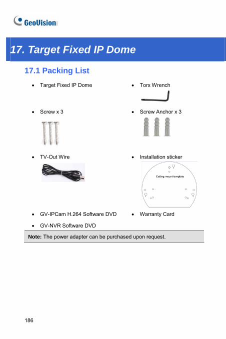
17. Target Fixed IP Dome
17.1 Packing List • Target Fixed IP Dome
• Torx Wrench
• Screw x 3
• Screw Anchor x 3
• TV-Out Wire
• Installation sticker
• GV-IPCam H.264 Software DVD • Warranty Card
• GV-NVR Software DVD
Note: The power adapter can be purchased upon request.
186
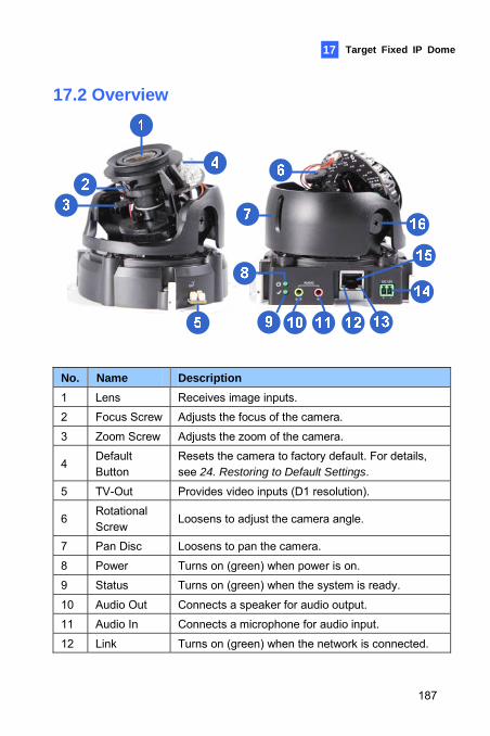
Target Fixed IP Dome 17
17.2 Overview
No. Name Description 1 Lens Receives image inputs.
2 Focus Screw Adjusts the focus of the camera.
3 Zoom Screw Adjusts the zoom of the camera.
4 Default Button
Resets the camera to factory default. For details, see 24. Restoring to Default Settings.
5 TV-Out Provides video inputs (D1 resolution).
6 Rotational Screw
Loosens to adjust the camera angle.
7 Pan Disc Loosens to pan the camera.
8 Power Turns on (green) when power is on.
9 Status Turns on (green) when the system is ready.
10 Audio Out Connects a speaker for audio output.
11 Audio In Connects a microphone for audio input.
12 Link Turns on (green) when the network is connected.
187
No. Name Description 13 ACT Turns on (orange) when data are being transmitted.
14 DC 12V Port Connects to power.
15 LAN / PoE Connects to a 10/100 Ethernet or PoE.
16 Tilt Screw Loosens the screw to adjust tilt angle.
Note: The TV-out function can only be used during installation to adjust the focus of the camera. To use the TV out function, connect the supplied black BNC wire to a monitor and select your signal format (NTSC or PAL) at the TV Out field on the Web interface. The default signal format is NTSC. For details, see 4.1.1 Video Settings, GV-IPCam
H.264 Firmware Manual. The TV-out wire must be removed before you secure the housing cover.
188
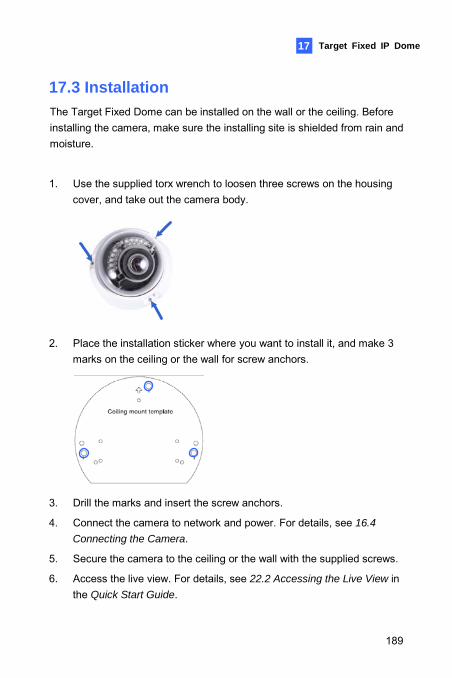
Target Fixed IP Dome 17
17.3 Installation The Target Fixed Dome can be installed on the wall or the ceiling. Before installing the camera, make sure the installing site is shielded from rain and moisture.
1. Use the supplied torx wrench to loosen three screws on the housing cover, and take out the camera body.
2. Place the installation sticker where you want to install it, and make 3
marks on the ceiling or the wall for screw anchors.
3. Drill the marks and insert the screw anchors.
4. Connect the camera to network and power. For details, see 16.4
Connecting the Camera.
5. Secure the camera to the ceiling or the wall with the supplied screws.
6. Access the live view. For details, see 22.2 Accessing the Live View in the Quick Start Guide.
189
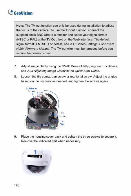
Note: The TV-out function can only be used during installation to adjust the focus of the camera. To use the TV out function, connect the supplied black BNC wire to a monitor and select your signal format (NTSC or PAL) at the TV Out field on the Web interface. The default signal format is NTSC. For details, see 4.1.1 Video Settings, GV-IPCam
H.264 Firmware Manual. The TV-out wire must be removed before you secure the housing cover.
7. Adjust image clarity using the GV-IP Device Utility program. For details, see 22.3 Adjusting Image Clarity in the Quick Start Guide.
8. Loosen the tile screw, pan screw or rotational screw. Adjust the angles based on the live view as needed, and tighten the screws again.
9. Place the housing cover back and tighten the three screws to secure it. Remove the indicated part when necessary.
190
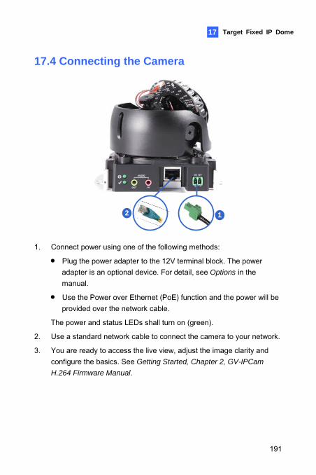
Target Fixed IP Dome
191
17
17.4 Connecting the Camera
12
1. Connect power using one of the following methods:
• Plug the power adapter to the 12V terminal block. The power adapter is an optional device. For detail, see Options in the manual.
• Use the Power over Ethernet (PoE) function and the power will be provided over the network cable.
The power and status LEDs shall turn on (green).
2. Use a standard network cable to connect the camera to your network.
3. You are ready to access the live view, adjust the image clarity and configure the basics. See Getting Started, Chapter 2, GV-IPCam
H.264 Firmware Manual.
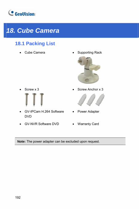
18. Cube Camera
18.1 Packing List • Cube Camera
• Supporting Rack
• Screw x 3
• Screw Anchor x 3
• GV-IPCam H.264 Software DVD
• Power Adapter
• GV-NVR Software DVD • Warranty Card
Note: The power adapter can be excluded upon request.
192
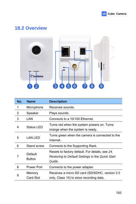
Cube Camera 18
18.2 Overview
1 2 3 4 5 6 7 8 9
No. Name Description
1 Microphone Receives sounds.
2 Speaker Plays sounds.
3 LAN Connects to a 10/100 Ethernet.
4 Status LED Turns red when the system powers on. Turns orange when the system is ready.
5 LAN LED Turns green when the camera is connected to the Internet.
6 Stand screw Connects to the Supporting Rack.
7 Default Button
Resets to factory default. For details, see 24.
Restoring to Default Settings in the Quick Start
Guide.
8 Power Port Connects to the power adapter.
9 Memory Card Slot
Receives a micro SD card (SD/SDHC, version 2.0 only, Class 10) to store recording data.
193
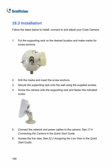
18.3 Installation Follow the steps below to install, connect to and adjust your Cube Camera.
1. Put the supporting rack on the desired location and make marks for
screw anchors.
2. Drill the marks and insert the screw anchors.
3. Secure the supporting rack onto the wall using the supplied screws.
4. Screw the camera onto the supporting rack and fasten the indicated screw.
5. Connect the network and power cables to the camera. See 17.4
Connecting the Camera in the Quick Start Guide.
6. Access the live view. See 22.2 Assigning the Live View in the Quick
Start Guide.
194
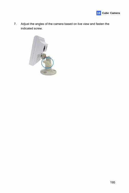
Cube Camera 18
7. Adjust the angles of the camera based on live view and fasten the indicated screw.
195
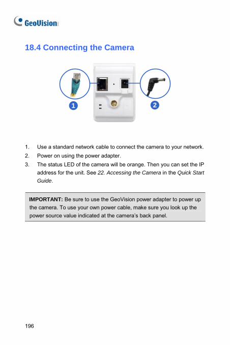
196
18.4 Connecting the Camera
1 2
1. Use a standard network cable to connect the camera to your network. 2. Power on using the power adapter. 3. The status LED of the camera will be orange. Then you can set the IP
address for the unit. See 22. Accessing the Camera in the Quick Start
Guide.
IMPORTANT: Be sure to use the GeoVision power adapter to power up the camera. To use your own power cable, make sure you look up the power source value indicated at the camera’s back panel.
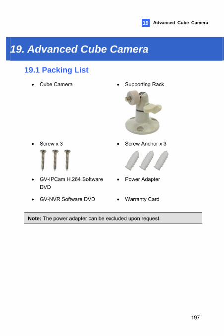
Advanced Cube Camera 19
19. Advanced Cube Camera
19.1 Packing List • Cube Camera
• Supporting Rack
• Screw x 3
• Screw Anchor x 3
• GV-IPCam H.264 Software DVD
• Power Adapter
• GV-NVR Software DVD • Warranty Card
Note: The power adapter can be excluded upon request.
197
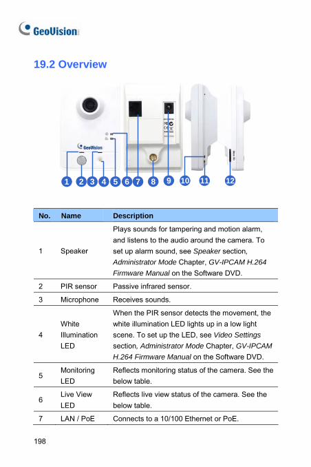
19.2 Overview
1 2 3 4 5 6 7 8 9 10 11 12
No. Name Description
1 Speaker
Plays sounds for tampering and motion alarm, and listens to the audio around the camera. To set up alarm sound, see Speaker section,
Administrator Mode Chapter, GV-IPCAM H.264
Firmware Manual on the Software DVD.
2 PIR sensor Passive infrared sensor.
3 Microphone Receives sounds.
4 White Illumination LED
When the PIR sensor detects the movement, the white illumination LED lights up in a low light scene. To set up the LED, see Video Settings section, Administrator Mode Chapter, GV-IPCAM
H.264 Firmware Manual on the Software DVD.
5 Monitoring LED
Reflects monitoring status of the camera. See the below table.
6 Live View LED
Reflects live view status of the camera. See the below table.
7 LAN / PoE Connects to a 10/100 Ethernet or PoE.
198
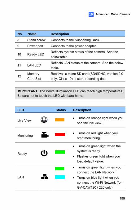
Advanced Cube Camera 19
No. Name Description
8 Stand screw Connects to the Supporting Rack.
9 Power port Connects to the power adapter.
10 Ready LED Reflects system status of the camera. See the below table.
11 LAN LED Reflects LAN status of the camera. See the below table.
12 Memory Card Slot
Receives a micro SD card (SD/SDHC, version 2.0 only, Class 10) to store recording data.
IMPORTANT: The White Illumination LED can reach high temperatures. Be sure not to touch the LED with bare hand.
LED Status Description
Live View
• Turns on orange light when you see the live view.
Monitoring
• Turns on red light when you start monitoring.
Ready
• Turns on green light when the system is ready.
• Flashes green light when you load default value.
LAN
• Turns on green light when you connect the LAN Network.
• Turns on blue light when you connect the Wi-Fi Network (for GV-CAW120 / 220 only).
199
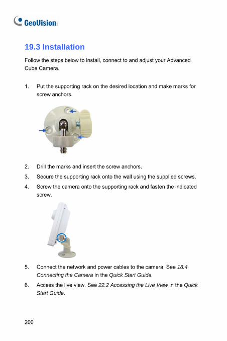
19.3 Installation Follow the steps below to install, connect to and adjust your Advanced Cube Camera.
1. Put the supporting rack on the desired location and make marks for screw anchors.
2. Drill the marks and insert the screw anchors.
3. Secure the supporting rack onto the wall using the supplied screws.
4. Screw the camera onto the supporting rack and fasten the indicated screw.
5. Connect the network and power cables to the camera. See 18.4
Connecting the Camera in the Quick Start Guide.
6. Access the live view. See 22.2 Accessing the Live View in the Quick
Start Guide.
200
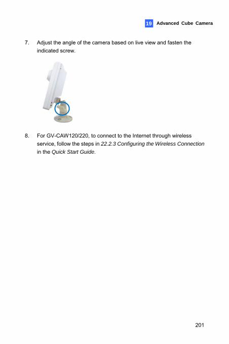
Advanced Cube Camera 19
7. Adjust the angle of the camera based on live view and fasten the indicated screw.
8. For GV-CAW120/220, to connect to the Internet through wireless
service, follow the steps in 22.2.3 Configuring the Wireless Connection
in the Quick Start Guide.
201
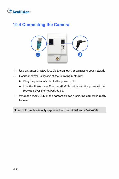
202
19.4 Connecting the Camera
1 2
1. Use a standard network cable to connect the camera to your network.
2. Connect power using one of the following methods:
• Plug the power adapter to the power port.
• Use the Power over Ethernet (PoE) function and the power will be provided over the network cable.
3. When the ready LED of the camera shines green, the camera is ready for use.
Note: PoE function is only supported for GV-CA120 and GV-CA220.
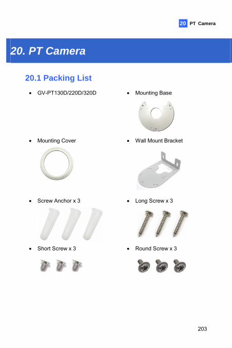
PT Camera 20
20. PT Camera 20.1 Packing List • GV-PT130D/220D/320D
• Mounting Base
• Mounting Cover
• Wall Mount Bracket
• Screw Anchor x 3
• Long Screw x 3
• Short Screw x 3
• Round Screw x 3
203
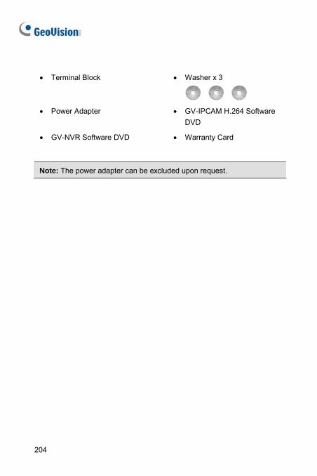
• Terminal Block • Washer x 3
• Power Adapter • GV-IPCAM H.264 Software
DVD
• GV-NVR Software DVD • Warranty Card
Note: The power adapter can be excluded upon request.
204
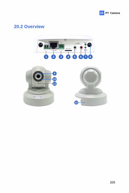
PT Camera 20
20.2 Overview
1 2 3 4 5 6 7 8
9
1011
12
205
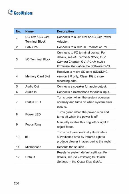
No. Name Description
1 DC 12V / AC 24V Terminal Block
Connects to a DV 12V or AC 24V Power Adapter.
2 LAN / PoE Connects to a 10/100 Ethernet or PoE.
3 I/O Terminal Block
Connects to I/O terminal device. For details, see I/O Terminal Block, PTZ
Camera Chapter, GV-IPCAM H.264
Firmware Manual on the Software DVD.
4 Memory Card Slot Receives a micro SD card (SD/SDHC, version 2.0 only, Class 10) to store recording data.
5 Audio Out Connects a speaker for audio output.
6 Audio In Connects a microphone for audio input.
7 Status LED Turns green when the system operates normally and turns off when system error occurs.
8 Power LED Turns green when the power is on and turns off when the power is off.
9 Focus Ring Manually rotates this ring left or right to adjust focus.
10 IR Turns on to automatically illuminate a surveillance area by infrared light to produce clearer images during the night.
11 Microphone Records the sounds.
12 Default Resets to system default settings. For details, see 24. Restoring to Default
Settings in the Quick Start Guide.
206
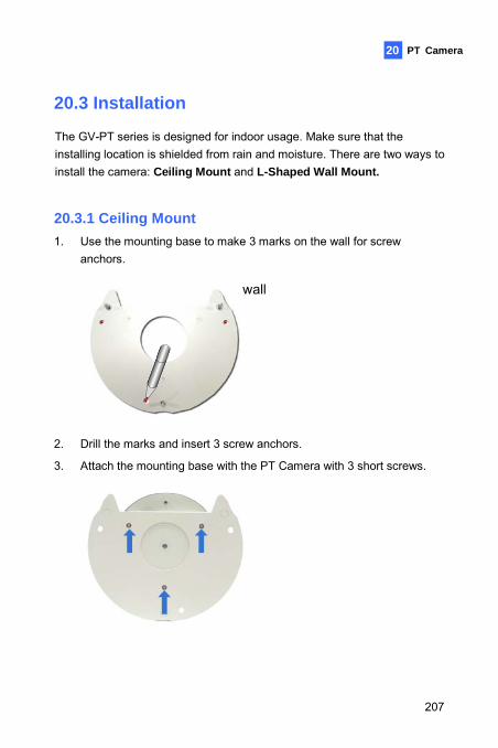
PT Camera 20
20.3 Installation
The GV-PT series is designed for indoor usage. Make sure that the installing location is shielded from rain and moisture. There are two ways to install the camera: Ceiling Mount and L-Shaped Wall Mount.
20.3.1 Ceiling Mount 1. Use the mounting base to make 3 marks on the wall for screw
anchors.
wall
2. Drill the marks and insert 3 screw anchors.
3. Attach the mounting base with the PT Camera with 3 short screws.
207
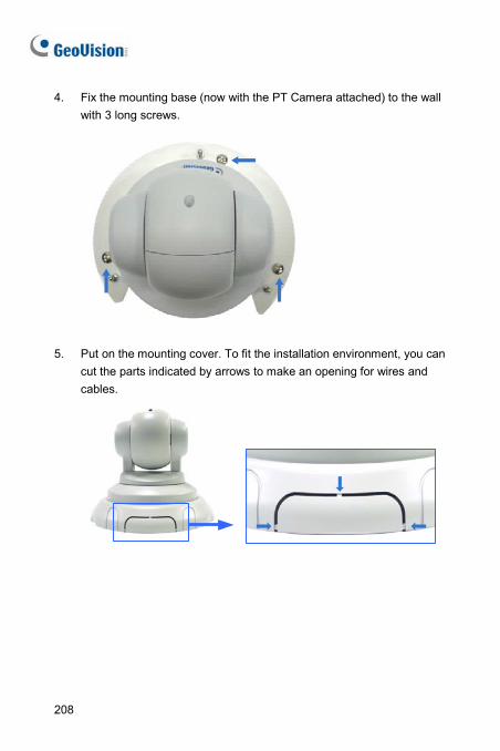
4. Fix the mounting base (now with the PT Camera attached) to the wall with 3 long screws.
5. Put on the mounting cover. To fit the installation environment, you can
cut the parts indicated by arrows to make an opening for wires and cables.
208
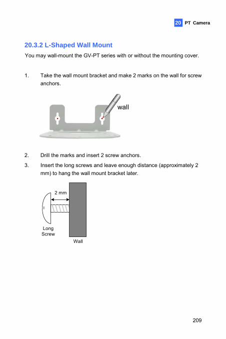
PT Camera 20
20.3.2 L-Shaped Wall Mount You may wall-mount the GV-PT series with or without the mounting cover.
1. Take the wall mount bracket and make 2 marks on the wall for screw anchors.
wall
2. Drill the marks and insert 2 screw anchors.
3. Insert the long screws and leave enough distance (approximately 2 mm) to hang the wall mount bracket later.
Wall
2 mm
Long Screw
209
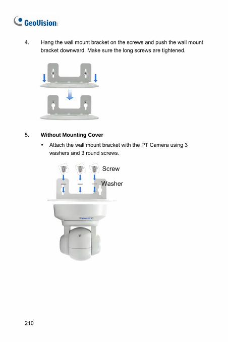
4. Hang the wall mount bracket on the screws and push the wall mount bracket downward. Make sure the long screws are tightened.
5. Without Mounting Cover
Attach the wall mount bracket with the PT Camera using 3 washers and 3 round screws.
Screw
Washer
210
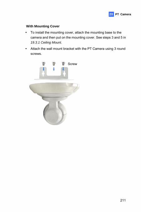
PT Camera 20
With Mounting Cover
To install the mounting cover, attach the mounting base to the camera and then put on the mounting cover. See steps 3 and 5 in 19.3.1 Ceiling Mount.
Attach the wall mount bracket with the PT Camera using 3 round screws.
Screw
211
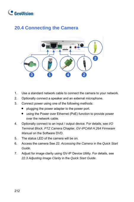
212
20.4 Connecting the Camera
13 4 2
2
1. Use a standard network cable to connect the camera to your network. 2. Optionally connect a speaker and an external microphone. 3. Connect power using one of the following methods:
• plugging the power adapter to the power port. • using the Power over Ethernet (PoE) function to provide power
over the network cable. 4. Optionally connect to an input / output device. For details, see I/O
Terminal Block, PTZ Camera Chapter, GV-IPCAM H.264 Firmware
Manual on the Software DVD. 5. The status LED of the camera will be on. 6. Access the camera See 22. Accessing the Camera in the Quick Start
Guide. 7. Adjust for image clarity using GV-IP Device Utility. For details, see
22.3 Adjusting Image Clarity in the Quick Start Guide.
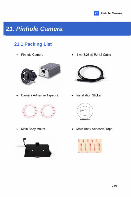
Pinhole Camera 21
21. Pinhole Camera 21.1 Packing List
• Pinhole Camera
• 1 m (3.28 ft) RJ-12 Cable
• Camera Adhesive Tape x 2
• Installation Sticker
• Main Body Mount
• Main Body Adhesive Tape
213
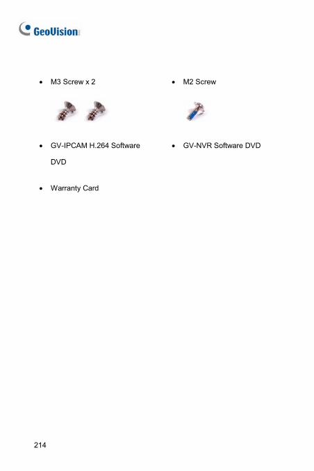
• M3 Screw x 2
• M2 Screw
• GV-IPCAM H.264 Software
DVD
• GV-NVR Software DVD
• Warranty Card
214
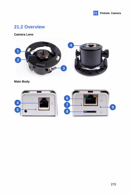
Pinhole Camera 21
21.2 Overview Camera Lens
1
2
3
4
Main Body
6
78
94
5
215
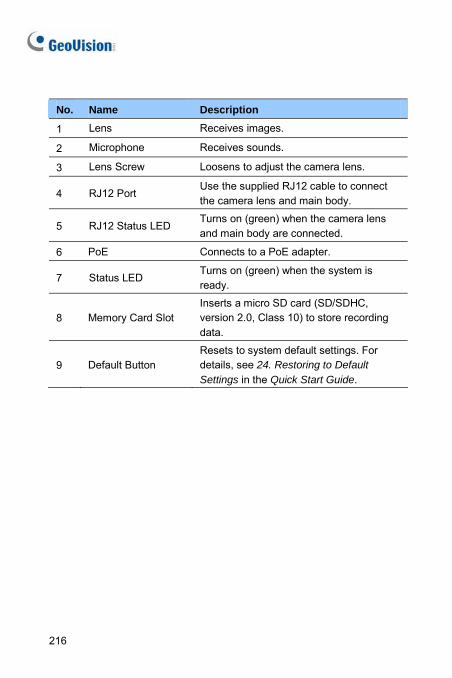
No. Name Description
1 Lens Receives images.
2 Microphone Receives sounds.
3 Lens Screw Loosens to adjust the camera lens.
4 RJ12 Port Use the supplied RJ12 cable to connect the camera lens and main body.
5 RJ12 Status LED Turns on (green) when the camera lens and main body are connected.
6 PoE Connects to a PoE adapter.
7 Status LED Turns on (green) when the system is ready.
8 Memory Card Slot Inserts a micro SD card (SD/SDHC, version 2.0, Class 10) to store recording data.
9 Default Button Resets to system default settings. For details, see 24. Restoring to Default Settings in the Quick Start Guide.
216
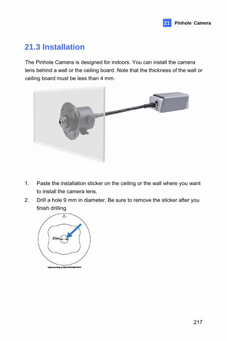
Pinhole Camera 21
21.3 Installation
The Pinhole Camera is designed for indoors. You can install the camera lens behind a wall or the ceiling board. Note that the thickness of the wall or ceiling board must be less than 4 mm.
1. Paste the installation sticker on the ceiling or the wall where you want to install the camera lens.
2. Drill a hole 9 mm in diameter. Be sure to remove the sticker after you finish drilling.
217
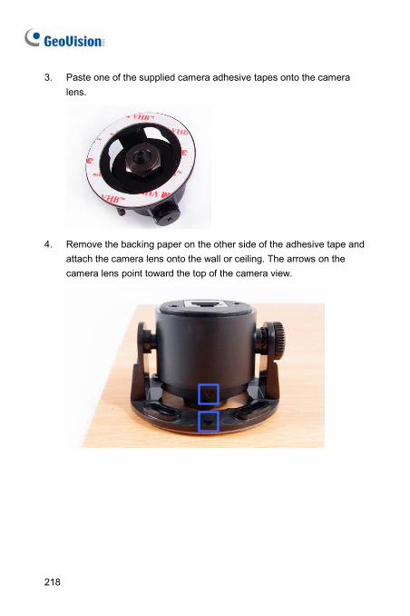
3. Paste one of the supplied camera adhesive tapes onto the camera lens.
4. Remove the backing paper on the other side of the adhesive tape and attach the camera lens onto the wall or ceiling. The arrows on the camera lens point toward the top of the camera view.
218
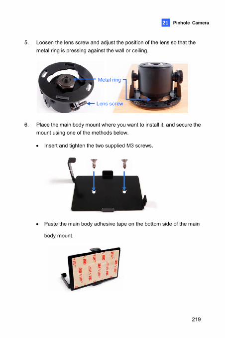
Pinhole Camera 21
5. Loosen the lens screw and adjust the position of the lens so that the metal ring is pressing against the wall or ceiling.
Metal ring
Lens screw
6. Place the main body mount where you want to install it, and secure the mount using one of the methods below.
• Insert and tighten the two supplied M3 screws.
• Paste the main body adhesive tape on the bottom side of the main
body mount.
219
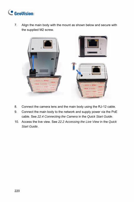
7. Align the main body with the mount as shown below and secure with the supplied M2 screw.
8. Connect the camera lens and the main body using the RJ-12 cable. 9. Connect the main body to the network and supply power via the PoE
cable. See 22.4 Connecting the Camera in the Quick Start Guide. 10. Access the live view. See 22.2 Accessing the Live View in the Quick
Start Guide.
220
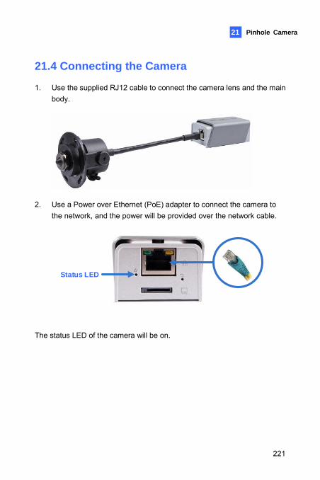
Pinhole Camera
221
21
21.4 Connecting the Camera
1. Use the supplied RJ12 cable to connect the camera lens and the main body.
2. Use a Power over Ethernet (PoE) adapter to connect the camera to
the network, and the power will be provided over the network cable.
Status LED
The status LED of the camera will be on.
22. Accessing the Camera
22.1 System Requirement To access the GV-IP Camera through the Web browser, ensure your PC connects to the network properly and meets this system requirement: • Microsoft Internet Explorer 7.x or later
Note:
1. For the users of Internet Explorer 8, additional settings are required. For details, see Appendix A in GV-IPCAM H.264
Firmware Manual on the Software DVD.
2. For GV-BX2600, Microsoft Internet Explorer 11 or later is required.
222
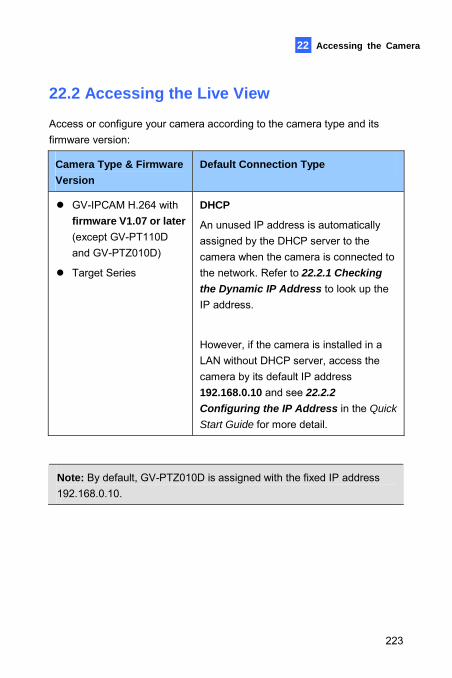
Accessing the Camera 22
22.2 Accessing the Live View
Access or configure your camera according to the camera type and its firmware version:
Camera Type & Firmware Version
Default Connection Type
GV-IPCAM H.264 with firmware V1.07 or later (except GV-PT110D and GV-PTZ010D)
Target Series
DHCP
An unused IP address is automatically assigned by the DHCP server to the camera when the camera is connected to the network. Refer to 22.2.1 Checking the Dynamic IP Address to look up the IP address.
However, if the camera is installed in a LAN without DHCP server, access the camera by its default IP address 192.168.0.10 and see 22.2.2 Configuring the IP Address in the Quick
Start Guide for more detail.
Note: By default, GV-PTZ010D is assigned with the fixed IP address 192.168.0.10.
223
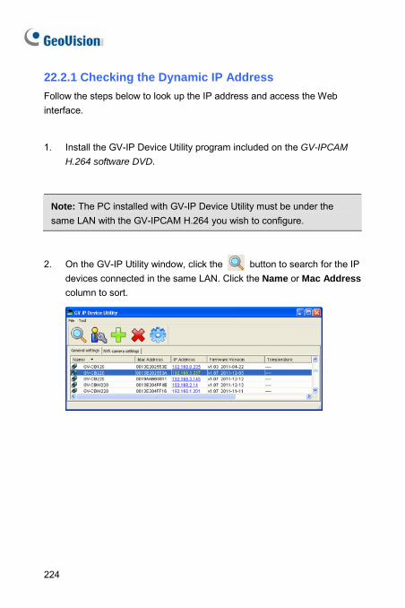
22.2.1 Checking the Dynamic IP Address Follow the steps below to look up the IP address and access the Web interface.
1. Install the GV-IP Device Utility program included on the GV-IPCAM
H.264 software DVD.
Note: The PC installed with GV-IP Device Utility must be under the same LAN with the GV-IPCAM H.264 you wish to configure.
2. On the GV-IP Utility window, click the button to search for the IP devices connected in the same LAN. Click the Name or Mac Address column to sort.
224
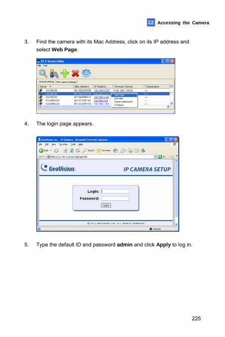
Accessing the Camera 22
3. Find the camera with its Mac Address, click on its IP address and select Web Page.
4. The login page appears.
5. Type the default ID and password admin and click Apply to log in.
225
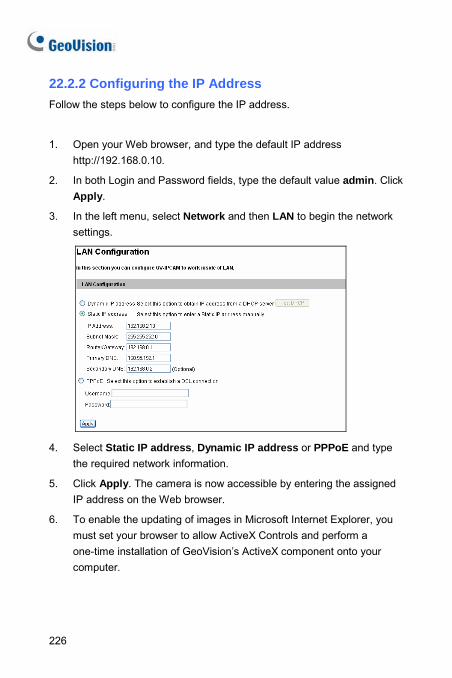
22.2.2 Configuring the IP Address Follow the steps below to configure the IP address.
1. Open your Web browser, and type the default IP address http://192.168.0.10.
2. In both Login and Password fields, type the default value admin. Click Apply.
3. In the left menu, select Network and then LAN to begin the network settings.
4. Select Static IP address, Dynamic IP address or PPPoE and type
the required network information.
5. Click Apply. The camera is now accessible by entering the assigned IP address on the Web browser.
6. To enable the updating of images in Microsoft Internet Explorer, you must set your browser to allow ActiveX Controls and perform a one-time installation of GeoVision’s ActiveX component onto your computer.
226
Accessing the Camera 22
IMPORTANT:
1. If Dynamic IP Address or PPPoE is enabled, you need to know which IP address the camera will get from DHCP server or ISP to log in. If your camera is installed in the LAN, use the GV-IP Device Utility to look up its current dynamic IP address. See 22.2.1
Checking the Dynamic IP Address in the Quick Start Guide. If your camera uses a public dynamic IP address via PPPoE, use the dynamic DNS Service to obtain a domain name that is linked to the camera’s changing IP address first. For details, see LAN
Configuration and Advanced TCP/IP sections, Administrator Mode Chapter in the GV-IPCAM H.264 Firmware Manual on the Software DVD.
2. If Dynamic IP Address or PPPoE is enabled and you cannot access the camera, you may have to reset the camera to its factory default and then perform the network settings again. To restore factory settings, see 24. Restoring to Default Settings in the Quick
Start Guide.
227
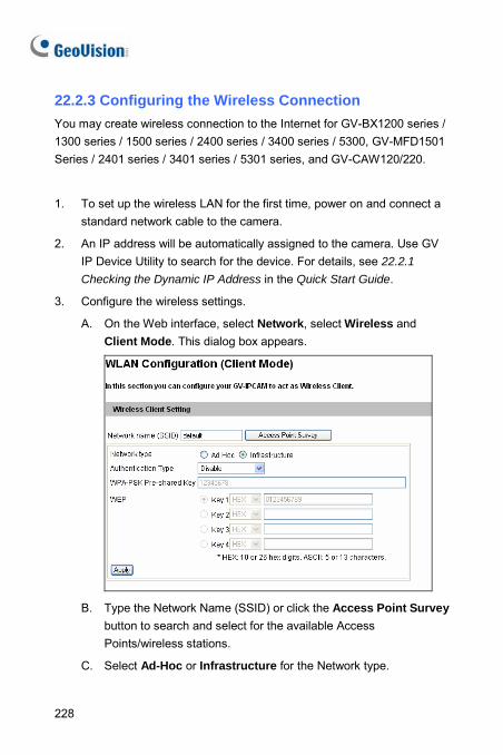
22.2.3 Configuring the Wireless Connection You may create wireless connection to the Internet for GV-BX1200 series / 1300 series / 1500 series / 2400 series / 3400 series / 5300, GV-MFD1501 Series / 2401 series / 3401 series / 5301 series, and GV-CAW120/220.
1. To set up the wireless LAN for the first time, power on and connect a standard network cable to the camera.
2. An IP address will be automatically assigned to the camera. Use GV IP Device Utility to search for the device. For details, see 22.2.1
Checking the Dynamic IP Address in the Quick Start Guide.
3. Configure the wireless settings.
A. On the Web interface, select Network, select Wireless and Client Mode. This dialog box appears.
B. Type the Network Name (SSID) or click the Access Point Survey
button to search and select for the available Access Points/wireless stations.
C. Select Ad-Hoc or Infrastructure for the Network type.
228
Accessing the Camera 22
D. Select the Authentication Type using the drop-down list. You can also obtain this information by clicking the Access Point Survey button.
E. Type the WPA-PSK Pre-shared Key or WEP depending on the encryption setting for the Access Point.
F. Click Apply to save the configuration.
Note:
1. Your encryption settings must match those used by the Access Points or wireless stations with which you want to associate.
2. When Ad Hoc is used, only WEP encryption is supported.
3. When you lose the wireless access, you can still access the unit by connecting it to a LAN and using the GV IP Device Utility to search for the device.
229
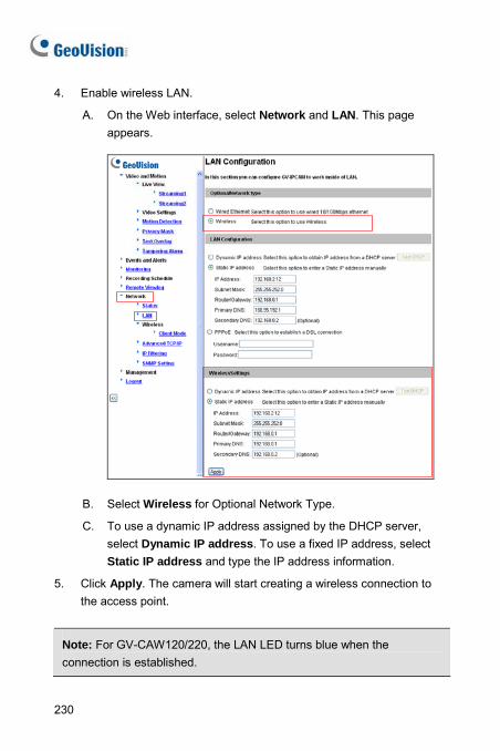
4. Enable wireless LAN.
A. On the Web interface, select Network and LAN. This page appears.
B. Select Wireless for Optional Network Type.
C. To use a dynamic IP address assigned by the DHCP server, select Dynamic IP address. To use a fixed IP address, select Static IP address and type the IP address information.
5. Click Apply. The camera will start creating a wireless connection to the access point.
Note: For GV-CAW120/220, the LAN LED turns blue when the connection is established.
230
Accessing the Camera 22
6. Unplug the Ethernet cable.
231
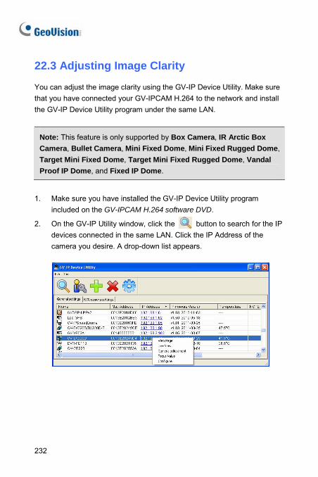
22.3 Adjusting Image Clarity
You can adjust the image clarity using the GV-IP Device Utility. Make sure that you have connected your GV-IPCAM H.264 to the network and install the GV-IP Device Utility program under the same LAN.
Note: This feature is only supported by Box Camera, IR Arctic Box Camera, Bullet Camera, Mini Fixed Dome, Mini Fixed Rugged Dome, Target Mini Fixed Dome, Target Mini Fixed Rugged Dome, Vandal Proof IP Dome, and Fixed IP Dome.
1. Make sure you have installed the GV-IP Device Utility program included on the GV-IPCAM H.264 software DVD.
2. On the GV-IP Utility window, click the button to search for the IP devices connected in the same LAN. Click the IP Address of the camera you desire. A drop-down list appears.
232
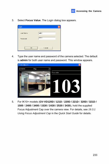
Accessing the Camera 22
3. Select Focus Value. The Login dialog box appears.
4. Type the user name and password of the camera selected. The default
is admin for both user name and password. This window appears.
5. For IK10+ models (GV-VD120D / 121D / 220D / 221D / 320D / 321D / 1500 / 2400 / 3400 / 1530 / 2430 / 2530 / 3430), hold the supplied Focus Adjustment Cap over the camera view. For details, see 19.3.1
Using Focus Adjustment Cap in the Quick Start Guide for details.
233
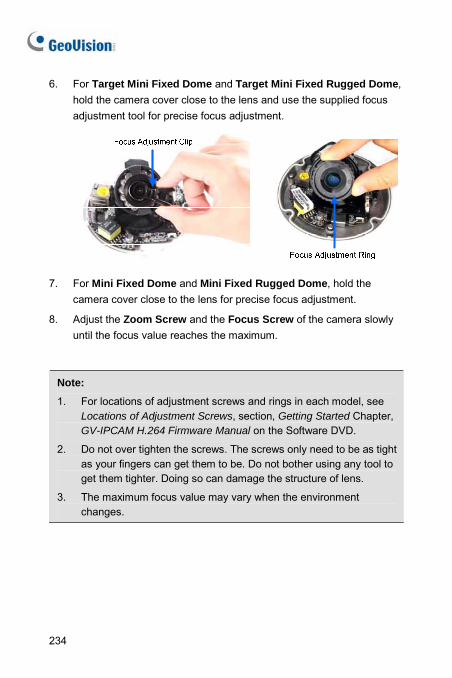
6. For Target Mini Fixed Dome and Target Mini Fixed Rugged Dome, hold the camera cover close to the lens and use the supplied focus adjustment tool for precise focus adjustment.
7. For Mini Fixed Dome and Mini Fixed Rugged Dome, hold the camera cover close to the lens for precise focus adjustment.
8. Adjust the Zoom Screw and the Focus Screw of the camera slowly until the focus value reaches the maximum.
Note:
1. For locations of adjustment screws and rings in each model, see Locations of Adjustment Screws, section, Getting Started Chapter, GV-IPCAM H.264 Firmware Manual on the Software DVD.
2. Do not over tighten the screws. The screws only need to be as tight as your fingers can get them to be. Do not bother using any tool to get them tighter. Doing so can damage the structure of lens.
3. The maximum focus value may vary when the environment changes.
234
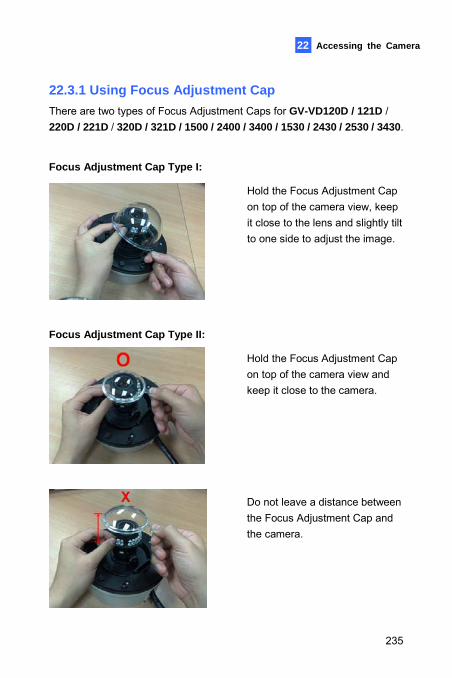
Accessing the Camera
235
22
22.3.1 Using Focus Adjustment Cap There are two types of Focus Adjustment Caps for GV-VD120D / 121D / 220D / 221D / 320D / 321D / 1500 / 2400 / 3400 / 1530 / 2430 / 2530 / 3430.
Focus Adjustment Cap Type I:
Hold the Focus Adjustment Cap on top of the camera view, keep it close to the lens and slightly tilt to one side to adjust the image.
Focus Adjustment Cap Type II:
Hold the Focus Adjustment Cap on top of the camera view and keep it close to the camera.
Do not leave a distance between the Focus Adjustment Cap and the camera.
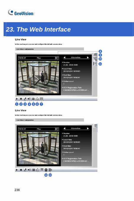
23. The Web Interface
1 2 3 4 5 6 7
8910
11
12 13
236
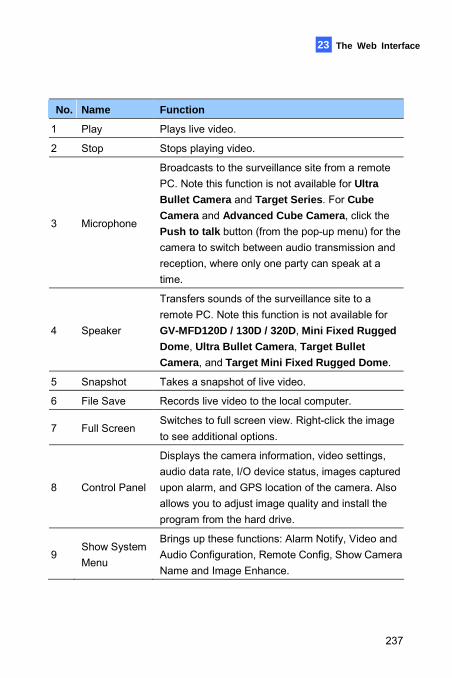
The Web Interface 23
No. Name Function
1 Play Plays live video.
2 Stop Stops playing video.
3 Microphone
Broadcasts to the surveillance site from a remote PC. Note this function is not available for Ultra Bullet Camera and Target Series. For Cube Camera and Advanced Cube Camera, click the Push to talk button (from the pop-up menu) for the camera to switch between audio transmission and reception, where only one party can speak at a time.
4 Speaker
Transfers sounds of the surveillance site to a remote PC. Note this function is not available for GV-MFD120D / 130D / 320D, Mini Fixed Rugged Dome, Ultra Bullet Camera, Target Bullet Camera, and Target Mini Fixed Rugged Dome.
5 Snapshot Takes a snapshot of live video.
6 File Save Records live video to the local computer.
7 Full Screen Switches to full screen view. Right-click the image to see additional options.
8 Control Panel
Displays the camera information, video settings, audio data rate, I/O device status, images captured upon alarm, and GPS location of the camera. Also allows you to adjust image quality and install the program from the hard drive.
9 Show System Menu
Brings up these functions: Alarm Notify, Video and Audio Configuration, Remote Config, Show Camera Name and Image Enhance.
237
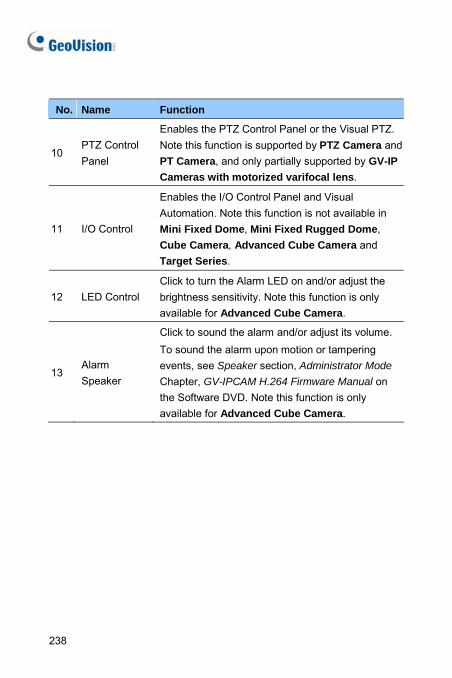
238
No. Name Function
10 PTZ Control Panel
Enables the PTZ Control Panel or the Visual PTZ. Note this function is supported by PTZ Camera and PT Camera, and only partially supported by GV-IP Cameras with motorized varifocal lens.
11 I/O Control
Enables the I/O Control Panel and Visual Automation. Note this function is not available in Mini Fixed Dome, Mini Fixed Rugged Dome, Cube Camera, Advanced Cube Camera and Target Series.
12 LED Control Click to turn the Alarm LED on and/or adjust the brightness sensitivity. Note this function is only available for Advanced Cube Camera.
13 Alarm Speaker
Click to sound the alarm and/or adjust its volume. To sound the alarm upon motion or tampering events, see Speaker section, Administrator Mode Chapter, GV-IPCAM H.264 Firmware Manual on the Software DVD. Note this function is only available for Advanced Cube Camera.
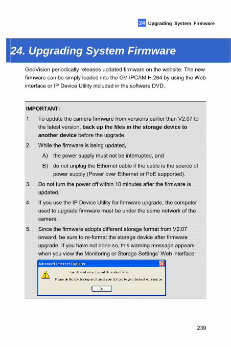
Upgrading System Firmware 24
24. Upgrading System Firmware GeoVision periodically releases updated firmware on the website. The new firmware can be simply loaded into the GV-IPCAM H.264 by using the Web interface or IP Device Utility included in the software DVD.
IMPORTANT:
1. To update the camera firmware from versions earlier than V2.07 to the latest version, back up the files in the storage device to another device before the upgrade.
2. While the firmware is being updated,
A) the power supply must not be interrupted, and
B) do not unplug the Ethernet cable if the cable is the source of power supply (Power over Ethernet or PoE supported).
3. Do not turn the power off within 10 minutes after the firmware is updated.
4. If you use the IP Device Utility for firmware upgrade, the computer used to upgrade firmware must be under the same network of the camera.
5. Since the firmware adopts different storage format from V2.07 onward, be sure to re-format the storage device after firmware upgrade. If you have not done so, this warning message appears when you view the Monitoring or Storage Settings’ Web interface:
239
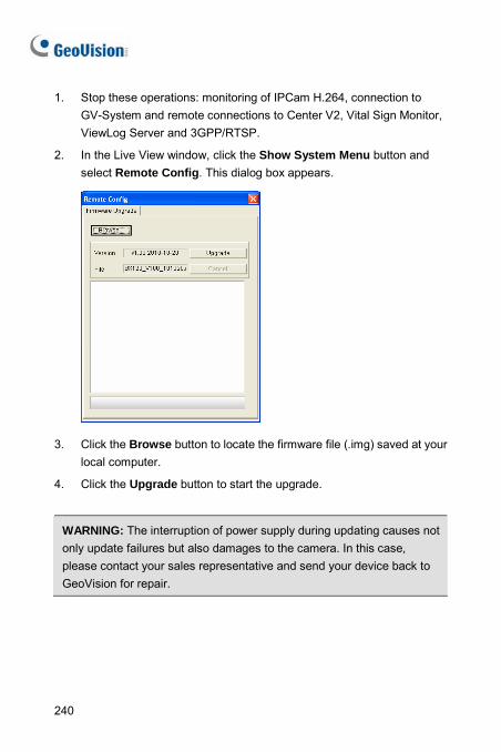
240
1. Stop these operations: monitoring of IPCam H.264, connection to GV-System and remote connections to Center V2, Vital Sign Monitor, ViewLog Server and 3GPP/RTSP.
2. In the Live View window, click the Show System Menu button and select Remote Config. This dialog box appears.
3. Click the Browse button to locate the firmware file (.img) saved at your
local computer.
4. Click the Upgrade button to start the upgrade.
WARNING: The interruption of power supply during updating causes not only update failures but also damages to the camera. In this case, please contact your sales representative and send your device back to GeoVision for repair.
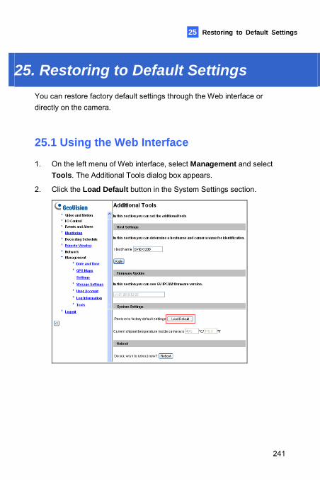
Restoring to Default Settings 25
25. Restoring to Default Settings You can restore factory default settings through the Web interface or directly on the camera.
25.1 Using the Web Interface
1. On the left menu of Web interface, select Management and select Tools. The Additional Tools dialog box appears.
2. Click the Load Default button in the System Settings section.
241
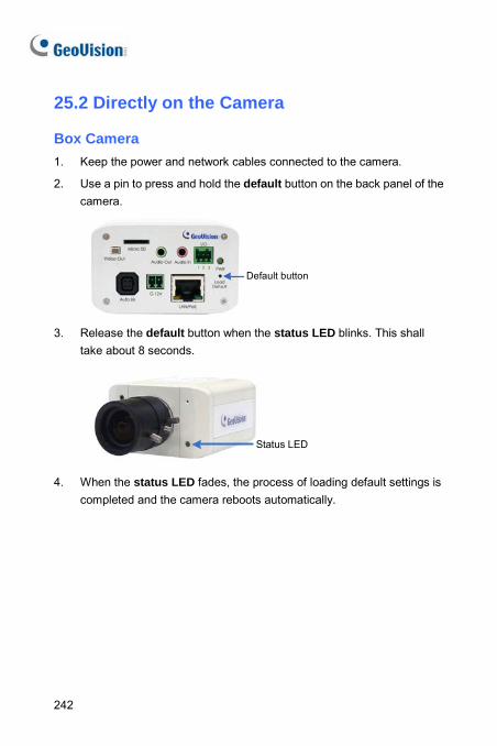
25.2 Directly on the Camera
Box Camera 1. Keep the power and network cables connected to the camera.
2. Use a pin to press and hold the default button on the back panel of the camera.
Default button
3. Release the default button when the status LED blinks. This shall
take about 8 seconds.
Status LED
4. When the status LED fades, the process of loading default settings is completed and the camera reboots automatically.
242
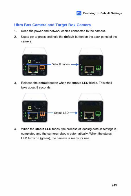
Restoring to Default Settings 25
Ultra Box Camera and Target Box Camera 1. Keep the power and network cables connected to the camera.
2. Use a pin to press and hold the default button on the back panel of the camera.
Default button
3. Release the default button when the status LED blinks. This shall
take about 8 seconds.
Status LED
4. When the status LED fades, the process of loading default settings is
completed and the camera reboots automatically. When the status LED turns on (green), the camera is ready for use.
243
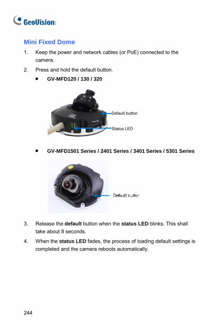
Mini Fixed Dome 1. Keep the power and network cables (or PoE) connected to the
camera.
2. Press and hold the default button.
• GV-MFD120 / 130 / 320
Default button
Status LED
• GV-MFD1501 Series / 2401 Series / 3401 Series / 5301 Series
3. Release the default button when the status LED blinks. This shall take about 8 seconds.
4. When the status LED fades, the process of loading default settings is completed and the camera reboots automatically.
244
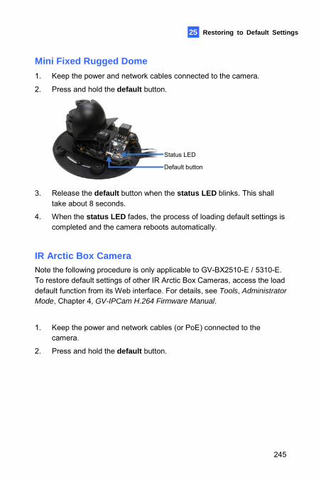
Restoring to Default Settings 25
Mini Fixed Rugged Dome 1. Keep the power and network cables connected to the camera.
2. Press and hold the default button.
Status LED
Default button
3. Release the default button when the status LED blinks. This shall take about 8 seconds.
4. When the status LED fades, the process of loading default settings is completed and the camera reboots automatically.
IR Arctic Box Camera Note the following procedure is only applicable to GV-BX2510-E / 5310-E. To restore default settings of other IR Arctic Box Cameras, access the load default function from its Web interface. For details, see Tools, Administrator Mode, Chapter 4, GV-IPCam H.264 Firmware Manual.
1. Keep the power and network cables (or PoE) connected to the camera.
2. Press and hold the default button.
245
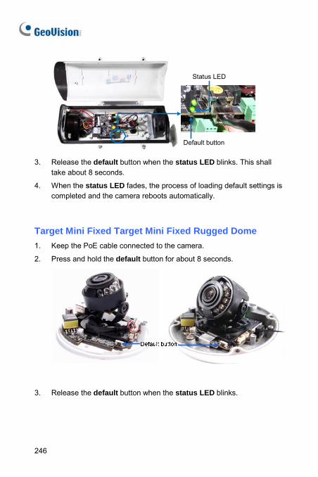
Default button
Status LED
3. Release the default button when the status LED blinks. This shall
take about 8 seconds.
4. When the status LED fades, the process of loading default settings is completed and the camera reboots automatically.
Target Mini Fixed Target Mini Fixed Rugged Dome 1. Keep the PoE cable connected to the camera.
2. Press and hold the default button for about 8 seconds.
3. Release the default button when the status LED blinks.
246
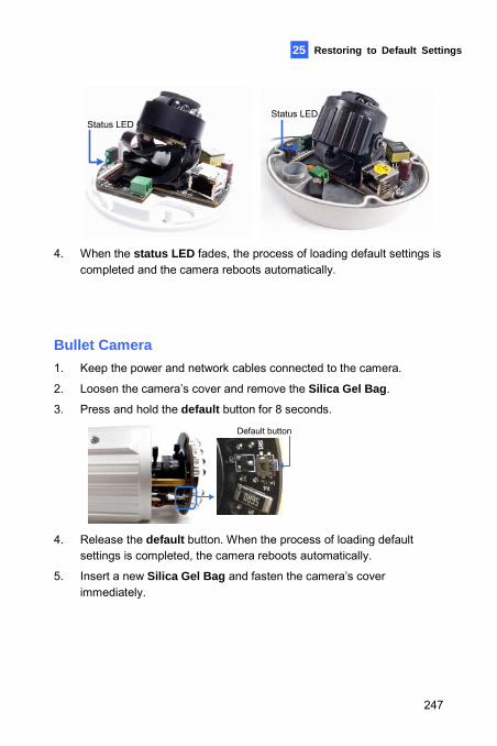
Restoring to Default Settings 25
Status LEDStatus LED
4. When the status LED fades, the process of loading default settings is completed and the camera reboots automatically.
Bullet Camera 1. Keep the power and network cables connected to the camera.
2. Loosen the camera’s cover and remove the Silica Gel Bag.
3. Press and hold the default button for 8 seconds.
Default button
4. Release the default button. When the process of loading default
settings is completed, the camera reboots automatically.
5. Insert a new Silica Gel Bag and fasten the camera’s cover immediately.
247
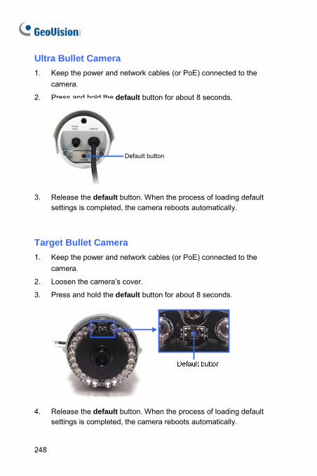
Ultra Bullet Camera 1. Keep the power and network cables (or PoE) connected to the
camera.
2. Press and hold the default button for about 8 seconds.
Default button
3. Release the default button. When the process of loading default
settings is completed, the camera reboots automatically.
Target Bullet Camera 1. Keep the power and network cables (or PoE) connected to the
camera.
2. Loosen the camera’s cover.
3. Press and hold the default button for about 8 seconds.
4. Release the default button. When the process of loading default
settings is completed, the camera reboots automatically.
248
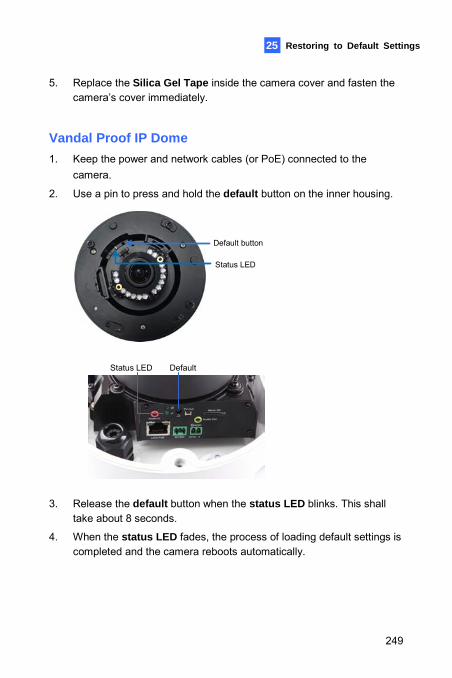
Restoring to Default Settings 25
5. Replace the Silica Gel Tape inside the camera cover and fasten the camera’s cover immediately.
Vandal Proof IP Dome 1. Keep the power and network cables (or PoE) connected to the
camera.
2. Use a pin to press and hold the default button on the inner housing.
Status LED
Default button
DefaultStatus LED
3. Release the default button when the status LED blinks. This shall
take about 8 seconds.
4. When the status LED fades, the process of loading default settings is completed and the camera reboots automatically.
249
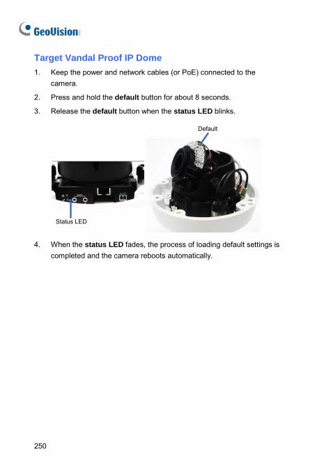
Target Vandal Proof IP Dome 1. Keep the power and network cables (or PoE) connected to the
camera.
2. Press and hold the default button for about 8 seconds.
3. Release the default button when the status LED blinks.
Status LED
Default
4. When the status LED fades, the process of loading default settings is completed and the camera reboots automatically.
250
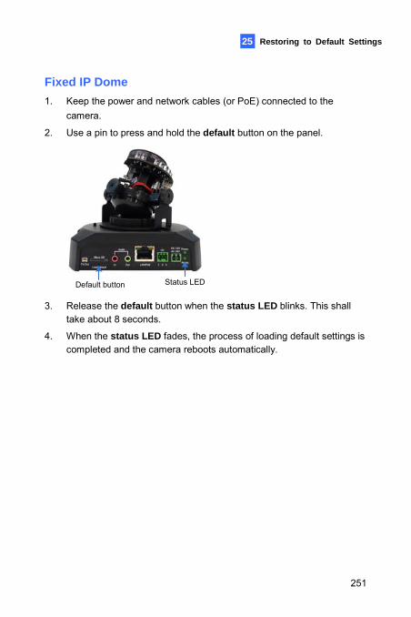
Restoring to Default Settings 25
Fixed IP Dome 1. Keep the power and network cables (or PoE) connected to the
camera.
2. Use a pin to press and hold the default button on the panel.
Default button Status LED 3. Release the default button when the status LED blinks. This shall
take about 8 seconds.
4. When the status LED fades, the process of loading default settings is completed and the camera reboots automatically.
251
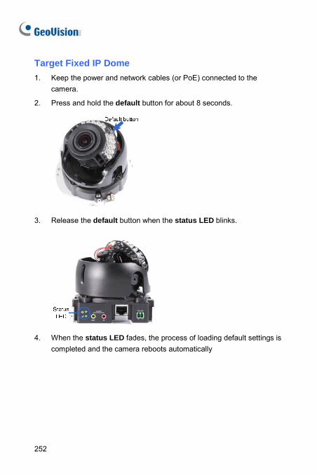
Target Fixed IP Dome 1. Keep the power and network cables (or PoE) connected to the
camera.
2. Press and hold the default button for about 8 seconds.
3. Release the default button when the status LED blinks.
4. When the status LED fades, the process of loading default settings is
completed and the camera reboots automatically
252
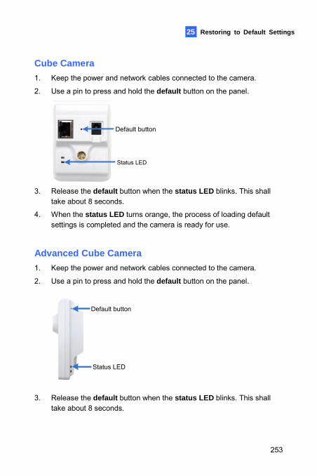
Restoring to Default Settings 25
Cube Camera 1. Keep the power and network cables connected to the camera.
2. Use a pin to press and hold the default button on the panel.
Status LED
Default button
3. Release the default button when e status LED blinks. This shall
dvanced Cube Camera ables connected to the camera.
thtake about 8 seconds.
4. When the status LED turns orange, the process of loading default settings is completed and the camera is ready for use.
A1. Keep the power and network c
2. Use a pin to press and hold the default button on the panel.
Status LED
Default button
3. Release the default butt when the status LED blinks. This shall ontake about 8 seconds.
253
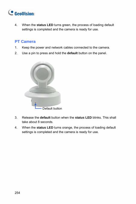
4. When the status LED turns green, the process of loading default settings is completed and the camera is ready for use.
PT Camera 1. Keep the power and network cables connected to the camera.
2. Use a pin to press and hold the default button on the panel.
Default button 3. Release the default button when the status LED blinks. This shall
take about 8 seconds.
4. When the status LED turns orange, the process of loading default settings is completed and the camera is ready for use.
254
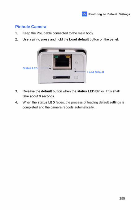
Restoring to Default Settings
255
25
Pinhole Camera 1. Keep the PoE cable connected to the main body.
2. Use a pin to press and hold the Load default button on the panel.
Load DefaultStatus LED
3. Release the default button when the status LED blinks. This shall
take about 8 seconds.
4. When the status LED fades, the process of loading default settings is completed and the camera reboots automatically.