green machining oriented to diminish density gradient for minimization of distortion in advanced...
TRANSCRIPT

This article was downloaded by: [UNESP], [Luiz Sanchez]On: 25 May 2012, At: 05:38Publisher: Taylor & FrancisInforma Ltd Registered in England and Wales Registered Number: 1072954 Registeredoffice: Mortimer House, 37-41 Mortimer Street, London W1T 3JH, UK
Machining Science and Technology: AnInternational JournalPublication details, including instructions for authors andsubscription information:http://www.tandfonline.com/loi/lmst20
GREEN MACHINING ORIENTED TODIMINISH DENSITY GRADIENT FORMINIMIZATION OF DISTORTION INADVANCED CERAMICSGill Bukvic a , Luiz Eduardo de Angelo Sanchez a , Carlos AlbertoFortulan b , A. A. Fiocchi a & Ioan Demitrius Marinescu ca Department of Mechanical Engineering, Sao Paulo State University(Unesp), Bauru, Brazilb Department of Mechanical Engineering, University of Sao Paulo(USP), Sao Carlos, Brazilc College of Engineering, MIME - University of Toledo, Toledo, Ohio,USA
Available online: 24 May 2012
To cite this article: Gill Bukvic, Luiz Eduardo de Angelo Sanchez, Carlos Alberto Fortulan, A. A.Fiocchi & Ioan Demitrius Marinescu (2012): GREEN MACHINING ORIENTED TO DIMINISH DENSITYGRADIENT FOR MINIMIZATION OF DISTORTION IN ADVANCED CERAMICS, Machining Science andTechnology: An International Journal, 16:2, 228-246
To link to this article: http://dx.doi.org/10.1080/10910344.2012.673968
PLEASE SCROLL DOWN FOR ARTICLE
Full terms and conditions of use: http://www.tandfonline.com/page/terms-and-conditions
This article may be used for research, teaching, and private study purposes. Anysubstantial or systematic reproduction, redistribution, reselling, loan, sub-licensing,systematic supply, or distribution in any form to anyone is expressly forbidden.
The publisher does not give any warranty express or implied or make any representationthat the contents will be complete or accurate or up to date. The accuracy of anyinstructions, formulae, and drug doses should be independently verified with primarysources. The publisher shall not be liable for any loss, actions, claims, proceedings,

demand, or costs or damages whatsoever or howsoever caused arising directly orindirectly in connection with or arising out of the use of this material.
Dow
nloa
ded
by [
UN
ESP
], [
Lui
z Sa
nche
z] a
t 05:
38 2
5 M
ay 2
012
GREEN MACHINING ORIENTED TO DIMINISH DENSITY GRADIENTFOR MINIMIZATION OF DISTORTION IN ADVANCED CERAMICS
Gill Bukvic1, Luiz Eduardo de Angelo Sanchez1, Carlos Alberto Fortulan2,A. A. Fiocchi1, and Ioan Demitrius Marinescu3
1Department of Mechanical Engineering, Sao Paulo State University (Unesp), Bauru, Brazil2Department of Mechanical Engineering, University of Sao Paulo (USP), Sao Carlos, Brazil3College of Engineering, MIME - University of Toledo, Toledo, Ohio, USA
& After sintering advanced ceramics, there are invariably distortions, caused in large part by theheterogeneous distribution of density gradients along the compacted piece. To correct distortions,machining is generally used to manufacture pieces within dimensional and geometric tolerances.Hence, narrow material removal limit conditions are applied, which minimize the generation ofdamage. Another alternative is machining the compacted piece before sintering, called the greenceramic stage, which allows machining without damage to mechanical strength. Since the greatestconcentration of density gradients is located in the outer-most layers of the compacted piece, thisstudy investigated the removal of different allowance values by means of green machining. The out-put variables are distortion after sintering, tool wear, cutting force, and the surface roughness of thegreen ceramics and the sintered ones. The following results have been noted: less distortion is veri-fied in the sintered piece after 1mm allowance removal; and the higher the tool wear the worse thesurface roughness of both green and sintered pieces.
Keywords ceramic, density gradient, distortion, green machining, pressing, sintering
INTRODUCTION
Although advanced ceramics have several positive properties, such ashigh resistance to wear and temperature, chemical stability and low density,these materials also have negative characteristics that limit their appli-cation, especially regarding to low fracture toughness, which is responsiblefor low resistance to impact and reduced plastic deformation (Argawal andRao, 2008).
Machining with a diamond tool is the main way to achieve the desireddimensions and the finishing of the surfaces of ceramic pieces. However,
Address correspondence to Luiz Eduardo de Angelo Sanchez, Department of Mechanical Engin-eering, Sao Paulo State University (Unesp), Bauru, Brazil. E-mail: [email protected]
Machining Science and Technology, 16:228–246Copyright # 2012 Taylor & Francis Group, LLCISSN: 1091-0344 print=1532-2483 onlineDOI: 10.1080/10910344.2012.673968
Dow
nloa
ded
by [
UN
ESP
], [
Lui
z Sa
nche
z] a
t 05:
38 2
5 M
ay 2
012
due to the high degree of brittleness, components invariably sufferdamage, such as surface and=or subsurface cracks during the materialremoval process, resulting in loss of mechanical resistance, as demonstratedby Strakna et al. (1996). Furthermore, the demand for high stiffnessmachine tools and diamond cutting tools makes the material removal pro-cess for advanced ceramics expensive. Marinescu et al. (2007) report thatamong the machining processes, grinding represents more than 80% ofall advanced ceramic machining.
Experimental results obtained by Xu and Jahanmir (1995) associatedwith the study by Swain (1979) show that in machining of sintered polycrys-talline ceramic pieces, different types of damage are verified as a conse-quence of three different material removal mechanisms: intergranularfracture and dislodgment of grains; microcracks and the formation of grainfragments through intragranular cracks; and removal of large portions ofgrains by chipping due to the propagation of transgranular cracks.
Depending on highly controlled machining conditions, Zhong (2003)and Ajjarupu et al. (2004) state that it is possible to minimize brittleremoval mechanisms that involve the formation of cracks, or even achieveductile machining in which removal mechanisms are present by plasticdeformation, as in metals. The two material removal modes, ductile or brit-tle, are associated with critical cutting depth, which, if exceeded, may resultin damages. To reduce them, Marshall et al. (1983), Malkin and Ritter(1989), Blackley and Scattergood (1991, 1994) recommend the use ofmuch lower material removal rates than those used in finishing metalpieces. Nevertheless, this procedure does not wholly guarantee that ceramicpieces will be free of microcracks.
To manage the problems involved with ceramic machining, it is possibleto utilize the compact piece machining technique in its unsintered state. Itis thus possible to produce complex shapes and details and even to leavethem with dimensions as close as possible to final measurements, project-ing the contracting force inherent to the sintering phase. According toworks by Su et al. (2008) and Ekabaram (2008), this process consumes lessenergy and makes the machining operation easier and less expensivebecause in the green state they have low mechanical strength, and as aresult, good machinability.
To calculate the costs involved in machining ceramic pieces, Wester-heide et al. (1996) point out that to produce one silicon nitride valve,44% represents machining cost, 23% powder cost and 6% shaping. Theauthor’s findings clearly indicate that green machining and power reutiliza-tion offer cost reductions in manufacturing ceramic pieces. The appli-cation of green machining to shaping pieces is achieved by sinteringceramic pieces to the final dimensions, as specified in the project, by meansof greater dimensional control of the compacted piece, discounting linear
Green Machining to Minimization of Distortion 229
Dow
nloa
ded
by [
UN
ESP
], [
Lui
z Sa
nche
z] a
t 05:
38 2
5 M
ay 2
012

shrinkage verified in the sintering phase. This green piece dimension con-trol for approaching final measurements is called near-net-shape, and it canbe done successfully through machining.
Uniaxial pressing is the most commonly used technique to producegreen compacted ceramic pieces because of its low cost and simplicity ofprocess when used in relation to pieces with small numbers of differentsections. Powder pressing causes intense friction between adjacent parti-cles, and even more intense friction between particles and the die wall.As a result, there is a heterogeneous filling of the powder in the die cavity,resulting in a compacted piece with several density gradients, as describedby Albaro (2001) and Bencoe et al. (2008). The existence of different den-sity gradients makes the sintering in each corresponding region undergodifferent intensities of volumetric contracting forces. Consequently, thedifferent contracting values lead to the deformation of the sintered piece.
Figure 1, extracted from Richerson (1992), schematically illustrates theexistence of density gradients in a green piece uniaxially pressed by singleaction method, in which it is possible to observe higher values of density inthe upper part than in the lower part. Additionally, the density difference
FIGURE 1 Density gradients in a ceramic piece using single action uniaxial pressing.
230 G. Bukvic et al.
Dow
nloa
ded
by [
UN
ESP
], [
Lui
z Sa
nche
z] a
t 05:
38 2
5 M
ay 2
012

decreases progressively as the area analyzed gets nearer the center ofthe piece. Considering this result, Westerheide et al. (1996) suggest themachining of a sufficiently large allowance to remove the portion of thegreen piece that has the largest density gradients. As an outcome of thispractice, the sintered piece would suffer less distortion.
Maier and Michaeli (1997) observed a clear relation between surfacequality and mechanical strength after sintering. Machining of sintered cer-amic pieces and the removal mechanism in green machining are very simi-lar. In both cases, machining under severe conditions creates chipping,invariably accompanied by microcracks on the piece surface; machiningunder gentle conditions is exempt from damage and unequivocal toolpoint marks are left on the surface. The authors called these two mechan-isms the chipping mode and the cutting mode, respectively.
With the tests, they found a correlation between green machined piecesurface finishing and bending strength of the sintered pieces in the two dif-ferent removal modes. The results can be summarized as follows: greenpieces have very similar mechanical strength properties, regardless of sur-face finishing. Using the unmachined sintered piece as a reference, themachined piece with the best surface finishing has greater mechanicalstrength, around 8%, yet the sintered piece with poor surface finishinghas less mechanical strength, approximately 10%.
Maier and Michaeli (1997), who machined 99.7% pure compacted alu-mina, observed an increase in cutting speed produces a slight reduction insurface roughness, and cutting strength remains nearly constant; anincrease in feed produces an increase in both surface roughness and cut-ting force, and an increase in depth of cut causes a little reduction insurface roughness but an expressive increase in cutting force.
Many problems involving green machining of ceramics are pointed outby Desfontaines et al. (2004), including low mechanical strength of thecompacted piece that may not resist machining forces and the forceapplied in affixing it to the machine. With regards to machining forces,their values tend to increase with cutting tool wear, especially if the cuttingtool is made of high speed steel (HSS), or even cemented carbide. Ng et al.(2006) stress that flank wear greater than 0.1mm can already cause surfacedamage to the piece due to excess specific cutting pressure. Another com-mon problem concerns the precaution needed when protecting themachine from powder because the material removed is dustlike and thuseasily penetrates the machine’s vital components, such as guides and bear-ings, which accelerates their wear.
The main objective of this study is to verify the effect of materialremoval of unsintered pieces on distortion generated in those same piecesafter sintering. Thus, several green compacted specimens, obtained fromsingle action uniaxial pressing, are machined under different allowance
Green Machining to Minimization of Distortion 231
Dow
nloa
ded
by [
UN
ESP
], [
Lui
z Sa
nche
z] a
t 05:
38 2
5 M
ay 2
012

removal values. As a consequence, a progressive reduction in the densitygradient located at the most outlying part of the compacted pieces and acorresponding reduction in the dimensional distortion of these sinteredpieces are sought. As a result, the time spent on machining sintered partscould be minimized, or even eliminated in cases where only green machin-ing was sufficient to generate sintered parts within acceptable limits for itsuse. Simultaneously, the wear of the cutting tool and its influence on thesurface finish of the green piece will be observed, and especially on therespective finishing of the sintered piece. This is particularly importantin situations where sintered pieces could be used without the need formachining.
MATERIAL AND METHODS
The specimens produced for the machining tests have cylindricaldimensions of approximately Ø 15� 19mm in their green state, formedby single action uniaxial pressure at 120MPa, generating a ratio betweendiameter and length of approximately 1:1.3. This ratio was chosen by thefact of highlighting the variation of densification of the specimens, thusinvariably causing distortion after sintering, according to German (1994),which becomes adequated to the study proposed in this work.
The aluminamixture with agglomerants was made in a vibratory mill withcylindrical elements in zirconia (Ø 12� 12mm). A suspension with 30% inpowder alumina volume was dispersed in a 68% volume of distilled and deio-nized water, and 1% volume of PVAl was added, and the rest, 1% volume ofammonium polyacrylate (Dispersal 130). As recommended by Leriche et al.(1988), deflocculant associated with the mechanical mixture was used toguarantee more efficient homogenization of the mixture Al2O3-ZrO2. Theceramic powder was obtained using the spray-drier technique.
Table 1 shows the ceramic composition (of alumina with 99.9% purity)used in the study: Calcined Alumina A1000-SG (Almatis, Inc., Japan) withparticles 0.4mm in equivalent average diameter, surface area of 7.7m2=gand real density (qreal) of 3.99 g=cm3.
The green specimens were machined in a universal milling machine.However, the workpiece was affixed to the vertical head and turned onthe surface of the green piece, which provided rotational movement. Thetool holder was affixed to a stiff device attached to the machine table that
TABLE 1 Chemical Composition (%) of the Specimens
Al2O3 SiO2 Fe2O3 Na2O CaO B2O3 MgO
99.9 0.03 0.02 0.07 0.02 0.001 0.04
232 G. Bukvic et al.
Dow
nloa
ded
by [
UN
ESP
], [
Lui
z Sa
nche
z] a
t 05:
38 2
5 M
ay 2
012

permitted vertical feed movement on the workpiece and horizontal move-ment that produced radial action for machining depth. A milling machineprovided higher stiffness, easy milling space around the piece with roomfor affixing the device and instruments, and slow movement of the table,which permitted very short feed rates, even shorter than in a conventionallathe.
The device affixed to the machine table was specially constructed forthe study; it had high stiffness and the capacity to affix a tool holderattached to a load cell with capacity of 20N, shown in Figure 2. The forcefrequency acquisition was of 100 points=min using LabView 6.1 software.
The cutting tool used to turn the samples was uncoated cementedcarbide, without chip breakers, Class K10 and tip radius of 0.05mm. Incompliance with ISO 3685, the end of life for the tool is achieved whenmaximum flank wear (VBmax) reaches 0.4mm.
The input parameters of the tests were conducted according to four dif-ferent turning allowance values: 0.25mm, 0.5mm, 0.75mm and 1.0mm.Each allowance was removed after several passes under 0.1mm of depthof cut, cutting speed of 66m=min and feed rate of 8mm=min. These values
FIGURE 2 Schematic experimental setup.
Green Machining to Minimization of Distortion 233
Dow
nloa
ded
by [
UN
ESP
], [
Lui
z Sa
nche
z] a
t 05:
38 2
5 M
ay 2
012

were chosen from a range of tested values. The analyzed surface imageswere obtained from a Nikon optical microscope, model SMZ800, coupledwith a digital camera. The same equipment was also used to visualize andmeasure cutting tool wear.
The input and output parameters of the tests are summarized inFigure 3.
Since the single action uniaxial compactation technique was used, bothsides of specimens have different densities, as shown in Figure 1. The lowerpart is less dense, produces more distortions and presents lower greenmechanical resistance than upper part, such as stated by Richerson(1992) and German (1994). Since the study is focused on the distortion,the lower part was elected to be machined. At the longitudinal section ofa specimen prepared by cutting and followed by polishing, it is possibleto realize different compactation levels in its right border, notably at thelower and upper parts, indicated by a coarser structure due to less densityin those regions. Figure 4 shows the longitudinal section of an unfiredspecimen used in the work.
Due to low mechanical strength of the green ceramic compact, the spe-cimens had to be carefully affixed. A steel base with a cylindrical hole wasmade, and the specimen was affixed to it using a wax-based adhesive. Thehole was approximately the size of the piece’s diameter. After being glued,the set (comprised of the base and the specimen) could be firmly affixed to
FIGURE 3 Parameters involved in the tests in summary.
234 G. Bukvic et al.
Dow
nloa
ded
by [
UN
ESP
], [
Lui
z Sa
nche
z] a
t 05:
38 2
5 M
ay 2
012

the milling machine clamp for machining. The specimen had to beunglued to reuse the steel base. Hence the glued region was heated tothe wax melting point. The specimen with the steel base is shown inFigure 5.
FIGURE 5 Specimens from left to right: before embedded in the base, embedded, machined anddetached.
FIGURE 4 Longitudinal section from one of the green specimens.
Green Machining to Minimization of Distortion 235
Dow
nloa
ded
by [
UN
ESP
], [
Lui
z Sa
nche
z] a
t 05:
38 2
5 M
ay 2
012
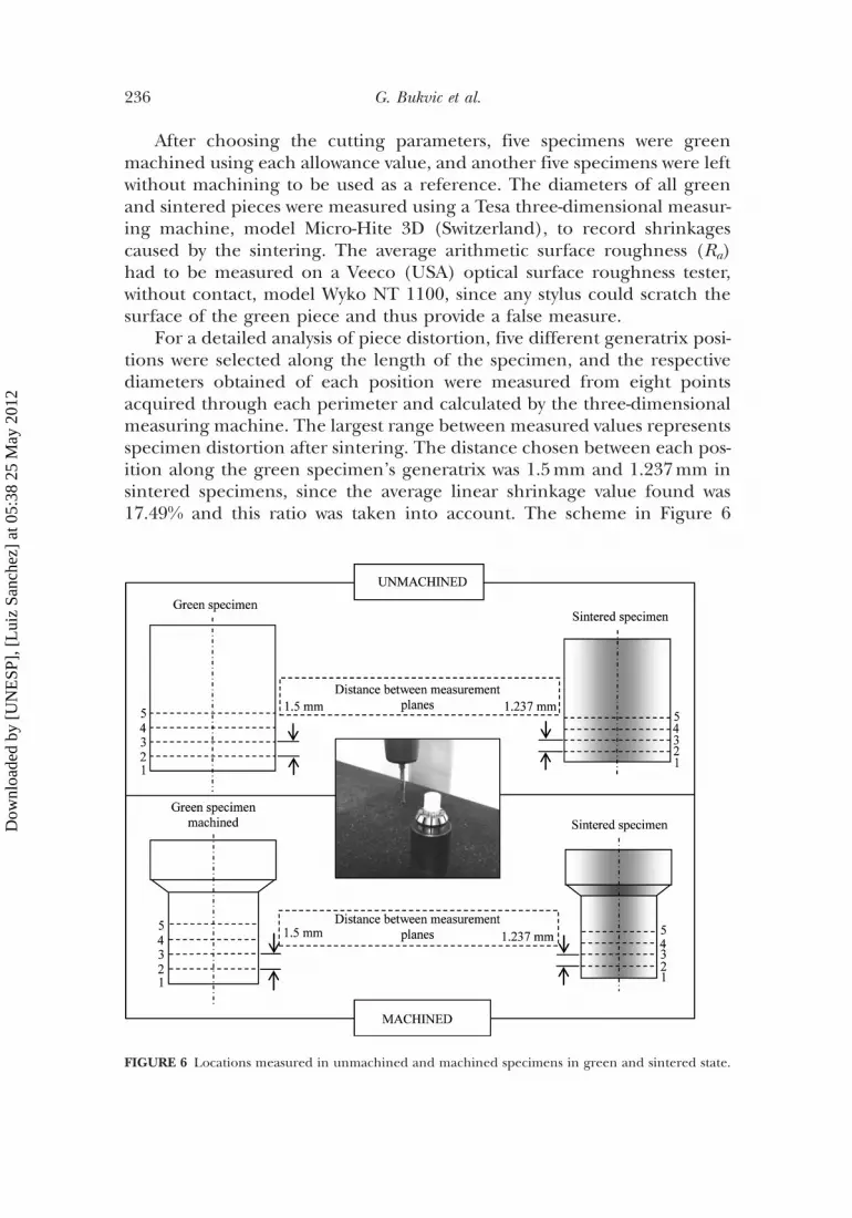
After choosing the cutting parameters, five specimens were greenmachined using each allowance value, and another five specimens were leftwithout machining to be used as a reference. The diameters of all greenand sintered pieces were measured using a Tesa three-dimensional measur-ing machine, model Micro-Hite 3D (Switzerland), to record shrinkagescaused by the sintering. The average arithmetic surface roughness (Ra)had to be measured on a Veeco (USA) optical surface roughness tester,without contact, model Wyko NT 1100, since any stylus could scratch thesurface of the green piece and thus provide a false measure.
For a detailed analysis of piece distortion, five different generatrix posi-tions were selected along the length of the specimen, and the respectivediameters obtained of each position were measured from eight pointsacquired through each perimeter and calculated by the three-dimensionalmeasuring machine. The largest range between measured values representsspecimen distortion after sintering. The distance chosen between each pos-ition along the green specimen’s generatrix was 1.5mm and 1.237mm insintered specimens, since the average linear shrinkage value found was17.49% and this ratio was taken into account. The scheme in Figure 6
FIGURE 6 Locations measured in unmachined and machined specimens in green and sintered state.
236 G. Bukvic et al.
Dow
nloa
ded
by [
UN
ESP
], [
Lui
z Sa
nche
z] a
t 05:
38 2
5 M
ay 2
012
illustrates this procedure for measuring of shrinkage of unmachined andmachined specimens.
The sintering process was conducted in a Lindberg Blue (USA)chamber-like electric furnace at a temperature of 1600�C for 2 hours.
RESULTS AND DISCUSSION
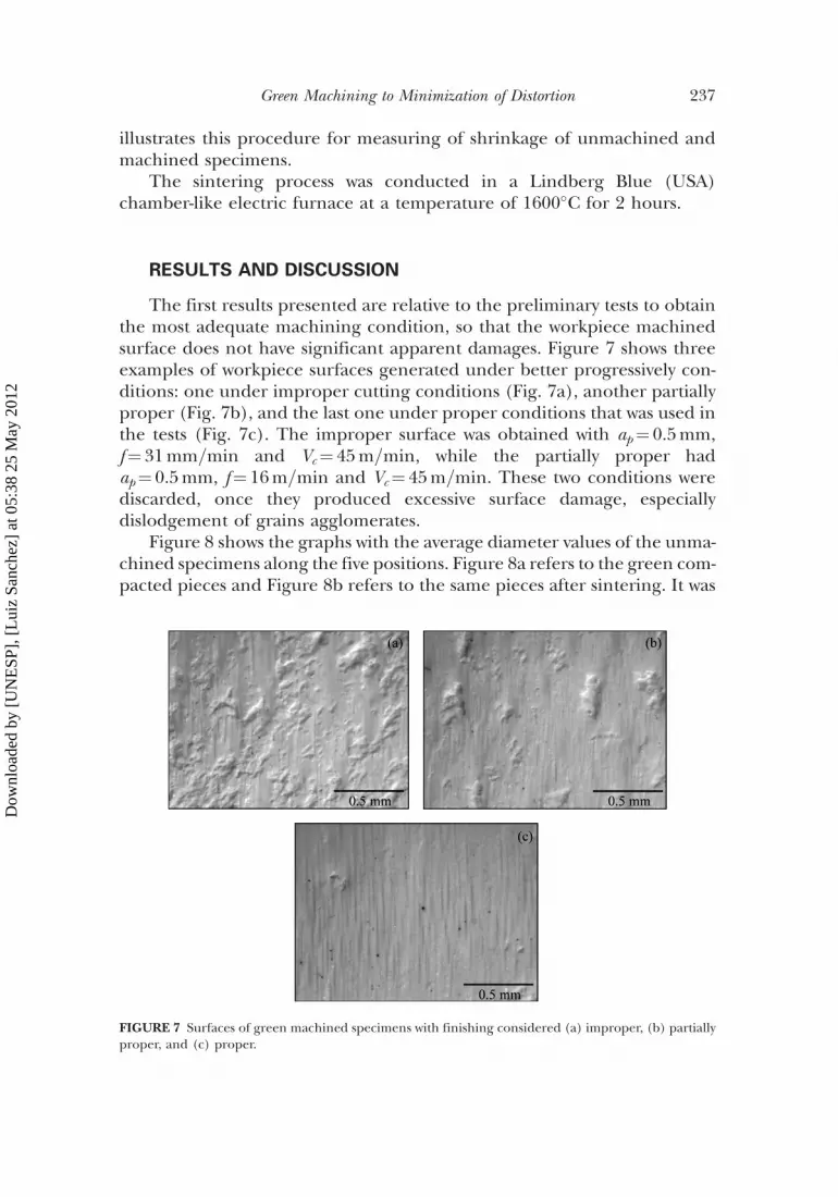
The first results presented are relative to the preliminary tests to obtainthe most adequate machining condition, so that the workpiece machinedsurface does not have significant apparent damages. Figure 7 shows threeexamples of workpiece surfaces generated under better progressively con-ditions: one under improper cutting conditions (Fig. 7a), another partiallyproper (Fig. 7b), and the last one under proper conditions that was used inthe tests (Fig. 7c). The improper surface was obtained with ap¼ 0.5mm,f¼ 31mm=min and Vc¼ 45m=min, while the partially proper hadap¼ 0.5mm, f¼ 16m=min and Vc¼ 45m=min. These two conditions werediscarded, once they produced excessive surface damage, especiallydislodgement of grains agglomerates.
Figure 8 shows the graphs with the average diameter values of the unma-chined specimens along the five positions. Figure 8a refers to the green com-pacted pieces and Figure 8b refers to the same pieces after sintering. It was
FIGURE 7 Surfaces of green machined specimens with finishing considered (a) improper, (b) partiallyproper, and (c) proper.
Green Machining to Minimization of Distortion 237
Dow
nloa
ded
by [
UN
ESP
], [
Lui
z Sa
nche
z] a
t 05:
38 2
5 M
ay 2
012

verified that the pieces suffered shrinkage in all sections, and the values var-ied according to each local measurement on the piece, as introduced in theliterature. This result is shown in the graph in Figure 8c. The most shrinkageoccurred in the diameter 1, where the lowest apparent density is located.This also proves that the method of single action uniaxial pressure is aninductor of density gradient. Concurrently, in the increasing direction ofthe sections (from 1 to 5), there are apparently higher density values thatresult in less shrinkage in the sintered specimen due to greater prior inter-action among alumina grains in the green compact.
Graphs in Figure 9 show the average linear shrinkage of greenmachined and sintered specimens in five sections, with the allowanceremovals of 0.25, 0.50, 0.75 and 1.0mm, respectively. In the machining ofspecimens, diameter number 5 is the most outlying, and number 1 is themost central, as shown in the schematic drawing in Figure 6.
In general, from graphs 8 and 9, it is possible to observe that the high-est distortion of the sintered piece occurs when it is not machined, with anaverage value of 0.075mm. Removing the allowances, the distortion valuefalls until reaching the lowest level of 0.030mm, verified in the maximumremoval of material condition of 1.0mm. This distortion is notably lessthan that found in all cases with less allowance removal. For the smallestallowance (0.25mm) there is a distortion of 0.051mm, whereas for the0.5mm and 0.75mm allowance 0.066mm and 0.071mm of distortion wereobtained, respectively.
FIGURE 8 Average diameters of (a) unmachined green and sintered (b) specimens, and (c) theirlinear shinkrage.
238 G. Bukvic et al.
Dow
nloa
ded
by [
UN
ESP
], [
Lui
z Sa
nche
z] a
t 05:
38 2
5 M
ay 2
012

FIGURE 9 Average diameters of green machined specimens with (a) 0.25, (b) 0.5, (c) 0.75, (d) 1.0mmof allowance and after their sintering.
Green Machining to Minimization of Distortion 239
Dow
nloa
ded
by [
UN
ESP
], [
Lui
z Sa
nche
z] a
t 05:
38 2
5 M
ay 2
012
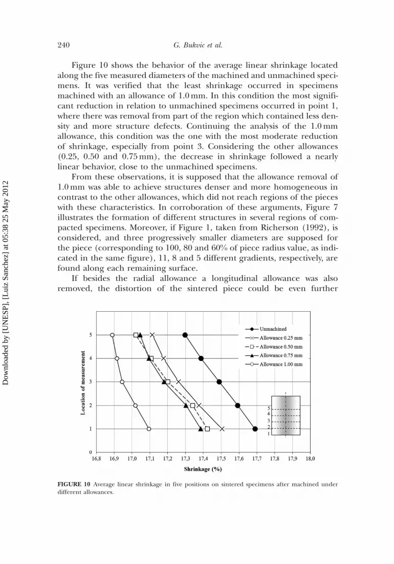
Figure 10 shows the behavior of the average linear shrinkage locatedalong the five measured diameters of the machined and unmachined speci-mens. It was verified that the least shrinkage occurred in specimensmachined with an allowance of 1.0mm. In this condition the most signifi-cant reduction in relation to unmachined specimens occurred in point 1,where there was removal from part of the region which contained less den-sity and more structure defects. Continuing the analysis of the 1.0mmallowance, this condition was the one with the most moderate reductionof shrinkage, especially from point 3. Considering the other allowances(0.25, 0.50 and 0.75mm), the decrease in shrinkage followed a nearlylinear behavior, close to the unmachined specimens.
From these observations, it is supposed that the allowance removal of1.0mm was able to achieve structures denser and more homogeneous incontrast to the other allowances, which did not reach regions of the pieceswith these characteristics. In corroboration of these arguments, Figure 7illustrates the formation of different structures in several regions of com-pacted specimens. Moreover, if Figure 1, taken from Richerson (1992), isconsidered, and three progressively smaller diameters are supposed forthe piece (corresponding to 100, 80 and 60% of piece radius value, as indi-cated in the same figure), 11, 8 and 5 different gradients, respectively, arefound along each remaining surface.
If besides the radial allowance a longitudinal allowance was alsoremoved, the distortion of the sintered piece could be even further
FIGURE 10 Average linear shrinkage in five positions on sintered specimens after machined underdifferent allowances.
240 G. Bukvic et al.
Dow
nloa
ded
by [
UN
ESP
], [
Lui
z Sa
nche
z] a
t 05:
38 2
5 M
ay 2
012

reduced. This is inferred from the graphs of the results shown thus far. If,for instance, the two worst cases of shrinkage, which belong to the two mostoutlying positions of the specimen (1 and 2), were excluded, within a hypo-thetical allowance of 3mm, the distortion calculated in graphs (b) fromFigure 9 would diminish, as suggested in Table 2. Therefore, for maximumminimizing of distortion in sintered pieces, removal around the entirepiece seems to play an important role.
Besides the approach of the distortion minimization, the green machin-ing can also be oriented to the improvement of mechanical properties ofceramic pieces. This is reached through removal of outer most layers ofthe piece where are located the largest density gradients, which invariablyconduce to cracks formation during sintering.
The graph in Figure 11 shows the average cutting force behavior on themachining of each of the test specimens using the four different allowancevalues. The cutting tool used to remove each allowance value was the same(a tool for every five specimens). In the 1.0mm allowance condition, it waspossible to use the same tool for only four specimens; during the machin-ing of the fifth specimen, there was considerable surface damage whenreaching the maximum flank wear criterion.
The cutting force in machining green alumina proves to be quite sus-ceptible to cutting tool wear. Even with a low wear rate, cutting force clearlyincreases, as can be seen, for example, in the case of 0.25mm allowanceremoval. The flank wear at the end of the fifth specimen was 0.278mmin this condition. A similar observation can be made considering onlythe machining of the first specimen. In the case of removing the allowanceof 1.0mm, four passes were performed; to remove 0.75mm, three passeswere performed; and to remove 0.5mm, two passes were performed. Toremove 0.25mm a single pass was necessary. When there were an increasingnumber of passes, tool wear increased. As result, the average cutting forceswere 1.6, 0.9, 0.8 and 0.55N, respectively.
Figure 12 presents the value of the maximum flank wear (VBmax) inrelation to the number of passes required for the total material removalof the specimens of each condition. Along the tests, it was verified through
TABLE 2 Exclusion of the Most Outlying Locations of the Green Piece
DISTORTION
ALLOWANCE 5 locationsExclusion of the 2
most outlying locations Reduction (%)
0.25 0.041 0.024 420.5 0.056 0.030 460.75 0.060 0.029 521.0 0.022 0.015 32
Green Machining to Minimization of Distortion 241
Dow
nloa
ded
by [
UN
ESP
], [
Lui
z Sa
nche
z] a
t 05:
38 2
5 M
ay 2
012

microscopic images that the cutting tool wear was caused by the abrasivenature of the alumina grains on the piece. The absence of any damageor adhesion of material to the tool can be attributed to the low temperatureand cutting force involved in the compacted machining.
It was observed that surface roughness of green machined specimensaccompanied cutting tool wear. Surface roughness values increased withthe enlargement of flank wear (VBmax), as shown in Figure 13. It was found
FIGURE 11 Cutting force for different allowances.
FIGURE 12 Tool wear versus number of passes for each allowance.
242 G. Bukvic et al.
Dow
nloa
ded
by [
UN
ESP
], [
Lui
z Sa
nche
z] a
t 05:
38 2
5 M
ay 2
012
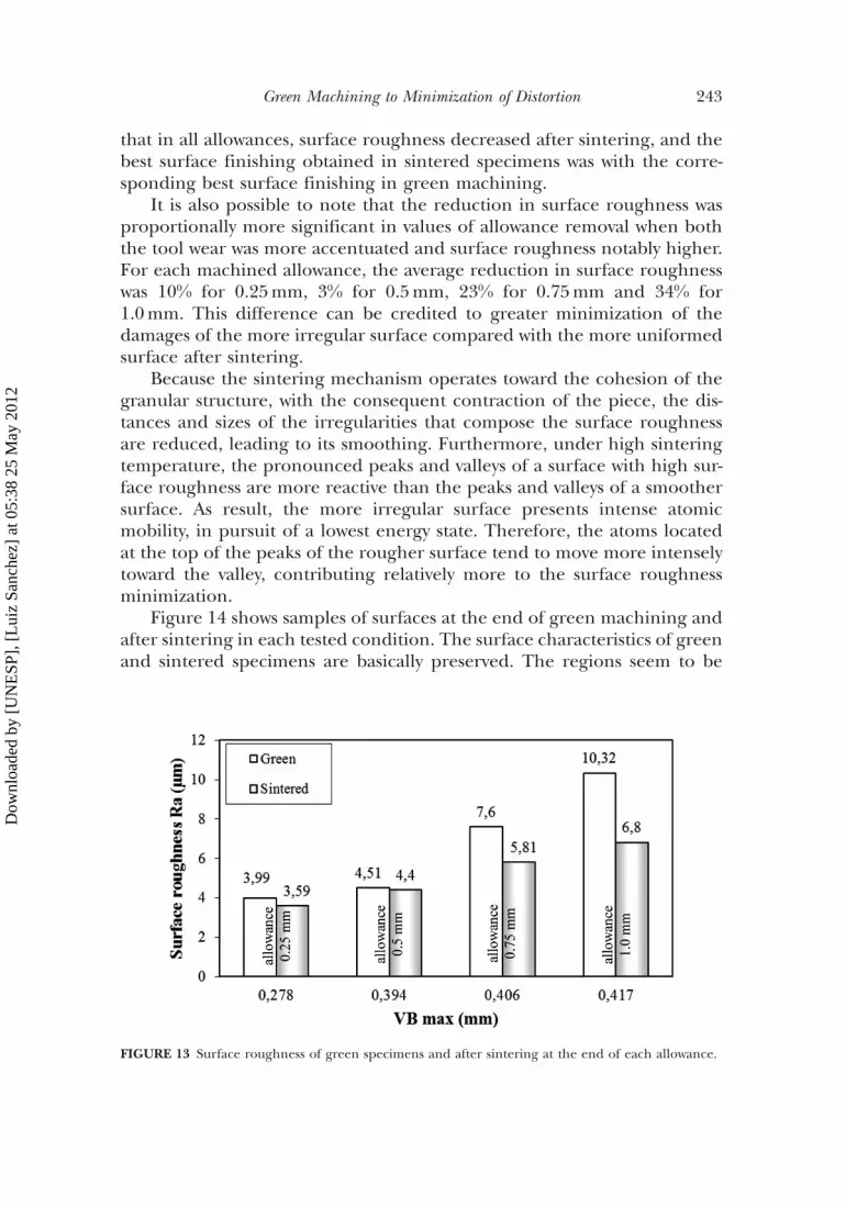
that in all allowances, surface roughness decreased after sintering, and thebest surface finishing obtained in sintered specimens was with the corre-sponding best surface finishing in green machining.
It is also possible to note that the reduction in surface roughness wasproportionally more significant in values of allowance removal when boththe tool wear was more accentuated and surface roughness notably higher.For each machined allowance, the average reduction in surface roughnesswas 10% for 0.25mm, 3% for 0.5mm, 23% for 0.75mm and 34% for1.0mm. This difference can be credited to greater minimization of thedamages of the more irregular surface compared with the more uniformedsurface after sintering.
Because the sintering mechanism operates toward the cohesion of thegranular structure, with the consequent contraction of the piece, the dis-tances and sizes of the irregularities that compose the surface roughnessare reduced, leading to its smoothing. Furthermore, under high sinteringtemperature, the pronounced peaks and valleys of a surface with high sur-face roughness are more reactive than the peaks and valleys of a smoothersurface. As result, the more irregular surface presents intense atomicmobility, in pursuit of a lowest energy state. Therefore, the atoms locatedat the top of the peaks of the rougher surface tend to move more intenselytoward the valley, contributing relatively more to the surface roughnessminimization.
Figure 14 shows samples of surfaces at the end of green machining andafter sintering in each tested condition. The surface characteristics of greenand sintered specimens are basically preserved. The regions seem to be
FIGURE 13 Surface roughness of green specimens and after sintering at the end of each allowance.
Green Machining to Minimization of Distortion 243
Dow
nloa
ded
by [
UN
ESP
], [
Lui
z Sa
nche
z] a
t 05:
38 2
5 M
ay 2
012
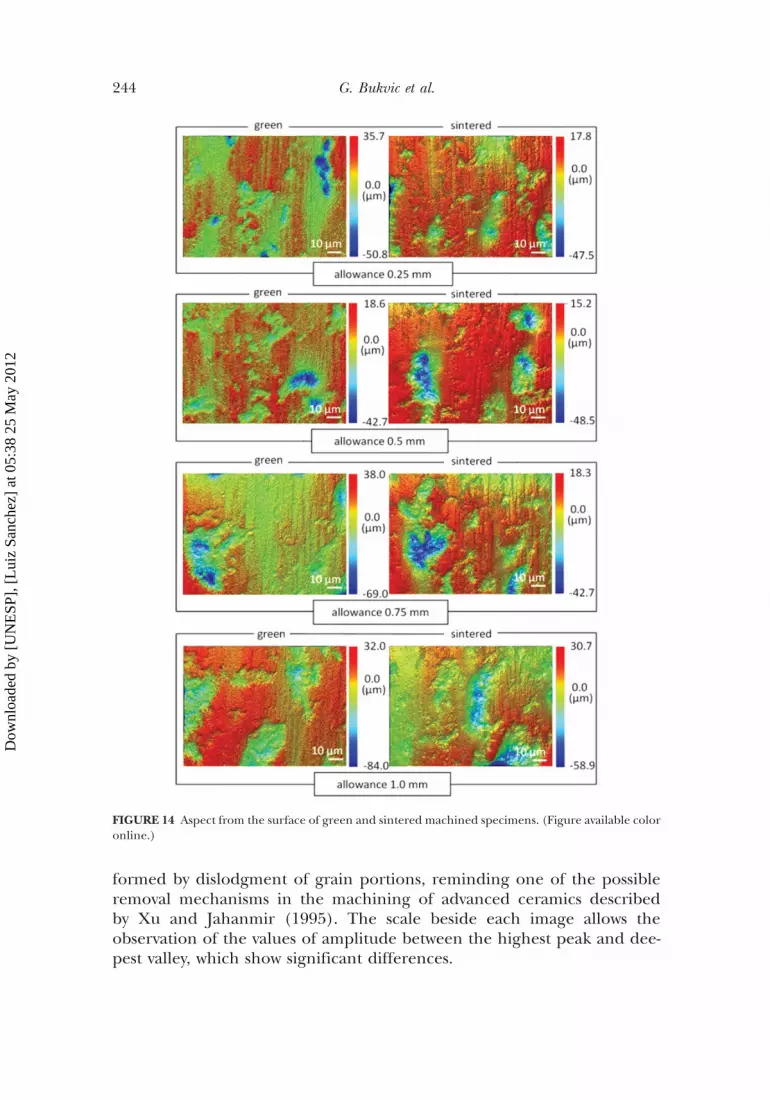
formed by dislodgment of grain portions, reminding one of the possibleremoval mechanisms in the machining of advanced ceramics describedby Xu and Jahanmir (1995). The scale beside each image allows theobservation of the values of amplitude between the highest peak and dee-pest valley, which show significant differences.
FIGURE 14 Aspect from the surface of green and sintered machined specimens. (Figure available coloronline.)
244 G. Bukvic et al.
Dow
nloa
ded
by [
UN
ESP
], [
Lui
z Sa
nche
z] a
t 05:
38 2
5 M
ay 2
012

On machined green surfaces, there is a general reduction of amplitudeafter pieces are sintered, indicating an improved surface finish, as stated inmeasurements of the surface roughness (Ra) in Figure 13. Considering thesurface of specimens shown in Figure 14, the amplitude values werereduced by 25, 43, and 23% for allowance removal of 0.25, 0.75, and1.0mm, respectively. The amplitude of the surface sample that sufferedmaterial removal of 0.5mm presented barely any reduction, agreeing withmeasured surface roughness.
CONCLUSIONS
Based on the results obtained in this study, it can be briefly concludedthat:
. The reduction in the number of density gradients reduces distortion insintered pieces. For such decrease, removal of the allowance in the greenpiece through machining is a good alternative, since outlying areas ofcompacted specimens have the biggest variations in density, whichdecrease progressively with the radius;
. With the removal of an allowance of 1.0mm, the distortion of machinedspecimens decreased significantly after sintering;
. Besides the radial allowance removal, the material machined in thelongitudinal direction of the specimen must also contribute to the mini-mization of distortion in sintered pieces;
. The surface roughness decreases after sintering. Besides, the lower thegreen piece surface roughness, the lower the sintered piece surface rough-ness. It was also observed that in percentage terms the surface roughnessdecreases more for the green piece with the worst surface roughness,although these pieces continue with a surface finishing significantly worst.
. With the substantial reduction in distortion in sintered pieces, due togreen machining, the use of pieces without the need for final machiningbecomes plausible in applications where the technical specification per-mits. In this case, the surface roughness of the green compacted assumeseven greater importance;
. Cutting tool wear has a direct influence on surface roughness of greenmachined pieces and the responsible mechanism is abrasive.
Finally, the literature about green machining usually recommends thistechnique to produce details in compacted pieces before sintering. In thiswork, green machining is directly pointed out to reduce distortion andimprove surface roughness of sintered pieces. It also suggests its use toapproaching as much as possible the dimensions intended for the sinteredpieces.
Green Machining to Minimization of Distortion 245
Dow
nloa
ded
by [
UN
ESP
], [
Lui
z Sa
nche
z] a
t 05:
38 2
5 M
ay 2
012

ACKNOWLEDGMENTS
The authors would like to thank Professor Renato G. Jacinevisius fromUniversity of Sao Paulo (USP) at Sao Carlos for the surface roughnessmeasurement without mechanical contact.
REFERENCES
Albaro, J.L.A. (2001) The pressing operation: Technical considerations and its industrial application.Part V: Pressing phase description. Industrial Ceramics, 6(3): 26–32.
Ajjarupu, S.K.; Fesperman, R.R.; Patten, J.A.; Cherukuri, H.P. (2004) Experimental and Numerical Investi-gation of Ductile Regime Machining of Silicon Nitride. Center for Precision Metrology, Department ofMechanical Engineering and Engineering Science, The University of North Carolina at Charlotte,NC 28223–0001, USA.
Argawal, S.; Rao, P.V. (2008) Experimental investigation of surface=subsurface damage formation andmaterial removal mechanisms in SiC grinding. Int. J. Mach. Tools & Manufacture, 48: 698–710.
Bencoe, D.N.; DiAntonio, C.B.; Ewsuk, K.G. (2008) Density gradient evolution in alumina powdercompacts during sintering. Sandia National Laboratories, Albuquerque, NM USA.
Blackley, W.S.; Scattergood, R.O. (1991) Ductile regime machining model for diamond turning of brit-tle materials. Precis. Eng., 13(2): 95–103.
Blackley, W.S.; Scattergood, R.O. (1994) Chip topography for ductile-regime machining of germanium.ASME J. Eng. Ind., 116: 263–266.
Desfontaines, M.; Jorand, Y.; Gonon, M.; Fantozzi, G. (2004) Characterisation of the green machinabilityof AlN powder compacts. J. Eur. Ceram. Soc., 25: 781–791.
Ekabaram, V. (2008) Optimization of Green Ceramic Grinding. Thesis, The University of Toledo, OH.German, R.M. (1994) Powder Metallurgy Science. 2nd edition, Metal Powder Industries Federation,
Princeton, New Jersey, USA.Leriche, A.; Moortgat, G.; Cambier, F.; Homerin, P.; Thevenot, F.; Orange, G.; Fantozzi, G. (1998) Prep-
aration and microstructure of zirconia toughened alumina ceramics. Advances in Ceramics, 24B:1033–1041.
Maier, H.R.; Michaeli, N. (1997) Green machining of alumina. Key Eng. Mat., 132–136: 436–439.Malkin, S.; Ritter, J.E. (1989) Grinding mechanisms and strength degradation for ceramics. ASME J.
Eng. Ind., 111: 67–174.Marinescu, I.D.; Hitchner, M.; Uhlmann, E.; Inasaki, I. (2007) Handbook of Machining with Grinding
Wheels, CRC Press, Boca Raton, FL, USA.Marshall, D.B.; Evans, A.G.; Yakub, B.T.K.; Tien, J.W.; Kino, G.S. (1983) The nature of machining dam-
age in brittle materials. Proc. Roy. Soc. London, 385: 461–475.Ng, S.H., Hull, J.B., Henshall, J.L. (2006) Machining of novel alumina=cyanoacrylate green ceramic
compacts. J. Mat. Proc. Technol., 175: 299–305.Richerson, D.W. (1992) Modern Ceramic Engineering: Properties, Processing, and use in design. 2nd Edition,
Marcel Dekker, Inc., New York, New York, USA.Strakna, T.J., Jahanmir, S., Allor, R.L., Kumar, K.V. (1996) Influence of grinding direction on fracture
strength of silicon nitride. J. Eng. Mat. Technol., 118: 335–342.Swain, M.V. (1979) Microfracture about scratches in brittle solids. Proc. Roy. Soc. London, 366: 575–597.Su, B.; Dhara, S.; Wang, L. (2008) Green ceramic machining: A top-down approach for the rapid
fabrication of complex-shaped ceramics. Int. J. Eur. Ceram. Soc., 28: 2109–2115.Westerheide, R.; Driisedau, K.A.; Hollstein, T.; Schwickert, T.; Zipse, H. (1996) Advances in characteris-
ation of machined green compacts. J. Eur. Ceram. Soc., 17: 467–472.Xu, H.H.K.; Jahanmir, S. (1995) Microfracture and material removal in scratching of alumina. J. Mater.
Sci., 30: 2235–2247.Zhong, Z.W. (2003) Ductile or partial ductile mode machining of brittle materials. Int. J. Adv. Manuf.
Technol., 21: 579–585.
246 G. Bukvic et al.
Dow
nloa
ded
by [
UN
ESP
], [
Lui
z Sa
nche
z] a
t 05:
38 2
5 M
ay 2
012