bwr fuel channel distortion - ant international
TRANSCRIPT
B W R F U E L C H A N N E L D I S T O R T I O N
© October 2011
Advanced Nuclear Technology International
Analysvägen 5, SE-435 33 Mölnlycke
Sweden
www.antinternational.com
BWR Fuel Channel Distortion
Authors
Friedrich Garzarolli Fürth, Germany
Ron Adamson Fremont, Pleasanton, CA, USA
Peter Rudling ANT International, Mölnlycke, Sweden
Alfred Strasser Sleepy Hollow, NY, USA
Reviewed by
Peter Rudling ANT International, Mölnlycke, Sweden
B W R F U E L C H A N N E L D I S T O R T I O N
Copyright © Advanced Nuclear Technology International Europe AB, ANT International, 2011.
I(III)=
Disclaimer
The information presented in this report has been compiled and analysed by
Advanced Nuclear Technology International Europe AB (ANT International®)
and its subcontractors. ANT International has exercised due diligence in this work,
but does not warrant the accuracy or completeness of the information.
ANT International does not assume any responsibility for any consequences
as a result of the use of the information for any party, except a warranty
for reasonable technical skill, which is limited to the amount paid for this assignment
by each ZIRAT/IZNA programme member.
B W R F U E L C H A N N E L D I S T O R T I O N
Copyright © Advanced Nuclear Technology International Europe AB, ANT International, 2011.
II(III)=
Contents
1 Introduction 1-1
2 Fuel channel design and manufacturing 2-1
2.1 Introduction 2-1 2.2 Different BWR FA designs 2-3 2.2.1 AREVA 2-3 2.2.2 W 2-5 2.2.3 GNF 2-7 2.3 Channel fabrication 2-9 2.3.1 Introduction 2-9 2.3.2 Channel fabrication process 2-9 2.3.2.1 Forming and welding – two-sheet method 2-9 2.3.2.2 Forming and welding – one sheet method 2-9 2.3.2.3 Thermal sizing and final assembly 2-10 2.3.3 Water cross channel fabrication 2-10 2.3.3.1 Fabricators 2-10 2.3.3.2 Process 2-10 2.3.3.2.1 Outer channel 2-10 2.3.3.2.2 Water cross 2-11 2.3.3.2.3 Channel assembly 2-11 2.3.4 Final beta-quenching 2-11
3 Fuel channel design criteria 3-1
4 Basic material behaviour 4-1
4.1 General requirements 4-1 4.2 Specific material phenomena 4-1 4.2.1 Irradiation growth 4-1 4.2.2 Creep 4-5 4.2.3 Hydrogen and hydrides 4-7 4.2.4 Strain by oxide-induced stress 4-10 4.2.5 SPPs and radiation effects 4-12 4.2.5.1 SPPs 4-12 4.2.5.2 Irradiation effects 4-13 4.2.6 Corrosion 4-18 4.2.6.1 Oxidation 4-18 4.2.6.2 Hydriding 4-22 4.2.6.3 Shadow corrosion 4-24 4.2.6.4 Zry-2 and -4 channels 4-27 4.3 Materials used 4-28 4.4 Retrospective – basics 4-31
5 Phenomena affecting channel performance 5-1
5.1 Introduction 5-1 5.2 Bulging 5-2 5.3 Channel distortion 5-3 5.4 Corrosion 5-7
B W R F U E L C H A N N E L D I S T O R T I O N
Copyright © Advanced Nuclear Technology International Europe AB, ANT International, 2011.
III(III)=
6 Channel lifetime limits 6-1
6.1 Interference with CRs 6-1 6.2 Reduced dry-out margin 6-4 6.3 Interference with in-core instruments 6-4 6.4 Increased bypass flow 6-4 6.5 Oxide spallation 6-4 6.6 Maximum hydrogen uptake 6-4
7 Channel management 7-1
8 Recent fuel channel bow data 8-1
8.1 Observations 8-1 8.1.1 Introduction 8-1 8.1.2 Parameters impacting channel bow 8-3 8.1.2.1 GNF data 8-3 8.1.2.2 AREVA data 8-6 8.1.2.3 W data 8-10 8.2 PIE programs 8-13 8.3 Hot cell PIE of GNF channels 8-13 8.3.1 PIE of AREVA channels 8-21 8.3.2 Pool examinations in the BWR-6 Cofrentes 8-26 8.4 Conclusions 8-27
9 Material modifications to counteract shadow induced bow (Including heat treatments) 9-1
9.1 Introduction 9-1 9.2 Zry-4 9-1 9.3 New Zr alloys 9-5
10 Summary and conclusions 10-1
11 Recommendations 11-1
12 References 12-1
Nomenclature
Unit conversion
B W R F U E L C H A N N E L D I S T O R T I O N
Copyright © Advanced Nuclear Technology International Europe AB, ANT International, 2011.
1-1(1-1)=
1 Introduction Boiling Water Reactor (BWR) fuel rods, as the name implies, produce steam in increasing quality as the coolant is pumped upward through the core. If the coolant temperature (driven by an increase in power or lack of coolant) were to increase above the nominal 285-295C (558 – 568K) more steam and the accompanying voids would decrease moderation and thereby decrease reactivity. Therefore the BWR has a negative temperature or power coefficient, which is a significant safety benefit. In order to maintain the most stable neutronics in the core and to add structural mechanical stability, each fuel bundle is surrounded by a thin-walled-core-length- square box, the BWR channel. A typical core is arranged with four channel-fuel bundle assemblies (each physically but not necessarily neutronically independent of one another) in a square array with one Control Blade (CB) with four wings separating the channels. Full descriptions are given in Sections 2 and 3.
This Special Topic Report (STR) addresses the properties and metallurgical behaviour of the channel which influence core performance.
In order to minimize neutron absorption BWR channels are made of zirconium alloys, almost exclusively Zircaloy (Zry)-2 and Zry-4 except for alloys currently under development (see Sections 4.3 and 9). As such, all the radiation-affected properties of zirconium alloys influence channel behaviour. These include strength, corrosion, growth, creep and microstructure stability (see Section 4).
This STR is primarily focussed on channel distortion; that is, change of shape during in-reactor service: length, bow, bulge and twist (see Sections 5.2 and 5.3). The primary negative influence of channel distortion is any of the shape changes that interfere with free motion of the CBs operating up and down (in BWRs, CBs move in from the bottom of the bundle) between the channels. Since CBs are the primary means of local reactivity control there are strict regulations governing the ability of the blades to move freely (no or minimal interference from the channel) during all anticipated operating conditions. Significant channel bowing may also decrease the dry-out and Loss of Coolant Accident (LOCA) thermal margins.
In the past ten years approximately half of the 35 BWRs in the United States have reported CB interference due to channel distortion, primarily channel bow. Channels fabricated by all vendors have been affected (see Section 2). The problem has been much less pronounced internationally, primarily related to core operating procedures (see Section 8 for details). This STR addresses a broad range of channel features which can contribute to normal and problematic performance. In particular, the so-called “shadow corrosion-induced” channel bow phenomena are analyzed (see Section 8).
Section 9 and 10 in this STR provides the conclusions and recommendations by the authors of this STR to reduce mitigate the fuel channel distortion issue.
B W R F U E L C H A N N E L D I S T O R T I O N
Copyright © Advanced Nuclear Technology International Europe AB, ANT International, 2011.
2-1(2-15)=
2 Fuel channel design and manufacturing
2.1 Introduction The channels are square cross-section boxes that extend the length of the Fuel Assemblies (FAs) and are intended to provide:
Hydraulic separation of the FA from the large, low pressure-drop space between the assemblies, in order to ensure adequate coolant flow through the assembly.
Mechanical separation of the FA from the Control Rod (CR) assembly and Instrument Tubes (ITs), to prevent potential interference with the CRs.
The channels also improve the FA design characteristics and offer some operational improvements as follows:
The assembly is stiffened structurally, particularly with regard to lateral seismic loading and their transmission to the core internals.
The assembly can transmit its decay heat during a LOCA to the channel by radiation while the channel acts as a heat sink.
The fuel sipping device can be sealed against the top of the channel making in-core, wet sipping practical.
There are two different, general types of outer channel designs and they are vendor specific:
Outer channel boxes for Global Nuclear Fuel (GNF) and AREVA1 designs,
Water cross assemblies for Westinghouse (W) – Atom SVEA designs.
The design consists of a channel box attached on one corner of the upper tie plate through a gusset on the channel with a high strength bolt for the latest GNF General Electric (GE)14 and GNF2 designs and for the AREVA ATRIUM model series and for all their predecessors. The box is supported by the FA and hydraulically sealed at the bottom of the assembly by leaf, or “finger” springs (e.g. Figure 2-7). The inner channel box in AREVA ATRIUM design serves the function for introducing unvoided water moderator into the centre of the assembly to increase reactivity and reduce enrichment requirements and in that respect is similar to the water rods of the GNF design (Figure 2-2 and Figure 2-7).
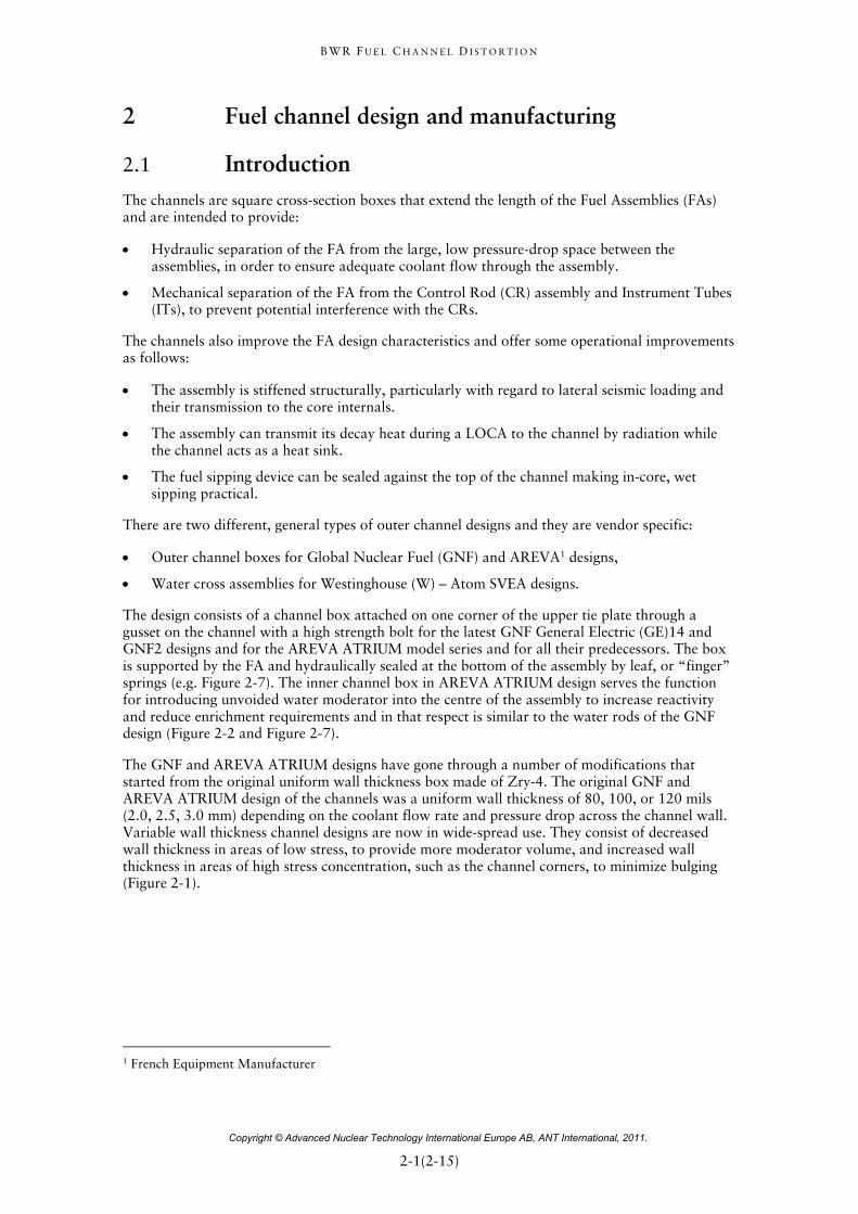
The GNF and AREVA ATRIUM designs have gone through a number of modifications that started from the original uniform wall thickness box made of Zry-4. The original GNF and AREVA ATRIUM design of the channels was a uniform wall thickness of 80, 100, or 120 mils (2.0, 2.5, 3.0 mm) depending on the coolant flow rate and pressure drop across the channel wall. Variable wall thickness channel designs are now in wide-spread use. They consist of decreased wall thickness in areas of low stress, to provide more moderator volume, and increased wall thickness in areas of high stress concentration, such as the channel corners, to minimize bulging (Figure 2-1).
1 French Equipment Manufacturer
B W R F U E L C H A N N E L D I S T O R T I O N
Copyright © Advanced Nuclear Technology International Europe AB, ANT International, 2011.
2-2(2-15)=
ANT International, 2011
Figure 2-1: Typical variable wall channel box [Strasser & Rudling, 2004].
The W design consists of a similar square box attached to the bottom nozzle, but with an internally cooled cross (“water cross”), welded to the box walls, creating four spaces for insertion of four individual fuel sub-assemblies. In this design the combination of channel and bottom nozzle form a “basket” that supports the FAs (e.g. Figure 2-5). The water cross in the W design serves a similar function by containing unvoided water moderator in its hollow interior that extends the width and length of the FA. The tips of the water cross are attached to an outer channel (Figure 2-5 and Figure 2-6).
Zry-4 has been used historically for the channel material for its reputed lower Hydrogen Pick-Up Fraction (HPUF). The BWR vendors switched to Zry-2 for improved corrosion resistance. The introduction of Zry-2 was based in part on claimed better corrosion resistance sufficient to counteract its higher Hydrogen Pick-Up (HPU) rate and result in less total hydrogen. Recent vendor recommendations, however, are to use Zry-4 to utilize its lower HPU rate to mitigate shadow corrosion related channel bowing. The decreased hydrogen may also result in lower growth rates. The issue is not resolved. New alloys with better corrosion resistance and lower growth rates are under development.
In the following the BWR designs of AREVA, W and GNF as well as the channel manufacturing process are briefly described, the interested reader is referred to Fuel Design Review Handbook and Fuel Fabrication Process Handbook.
B W R F U E L C H A N N E L D I S T O R T I O N
Copyright © Advanced Nuclear Technology International Europe AB, ANT International, 2011.
2-3(2-15)=
2.2 Different BWR FA designs
2.2.1 AREVA
All ATRIUM type FAs are characterized by a square internal water channel, which is the load bearing structure of the FA instead of using tie rods.
The ATRIUM 9 with a 9x9 rod lattice is now only supplied as reload fuel in the Japanese market. In the European and U.S. market the ATRIUM 10, having a 10x10 rod lattice, is the standard reloads fuel design. The ATRIUM 10 A or B has started operation in a German BWR in 1992 and has maintained since then its status as a reliable and economic fuel design.
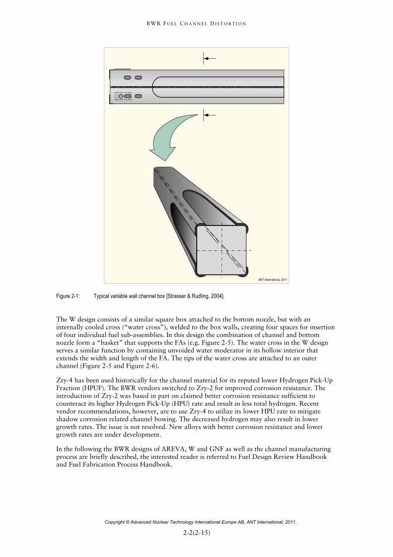
The main features of the BWR ATRIUM 10A and ATRIUM 10B FA (Figure 2-2) design are:
1) The Zry-2 Low Temperature Process (LTP), cladding material together with Fe-enhanced liner (Zr-sponge liner with 4000 wtppm Fe), or the LTP2 Zry-2 material without liner. The LTP2 material has a very fine grained material to provide improved Pellet Cladding Interaction (PCI) performance.
2) ULTRAFLOW spacer (Zry strap material with Inconel springs) and swirl vanes positioned at the centre of the flow sub-channels between the fuel rods provide water-steam separation.
3) Eight part length fuel rods.
4) Lower tie plates with FUELGUARD Debris Filter (DF).
5) Fuel channels made of Zry-2 or Zry-4.
Figure 2-2: ATRIUM 10B (the fuel outer channel is omitted in this figure), provided by the courtesy of AREVA NP.
B W R F U E L C H A N N E L D I S T O R T I O N
Copyright © Advanced Nuclear Technology International Europe AB, ANT International, 2011.
2-4(2-15)=
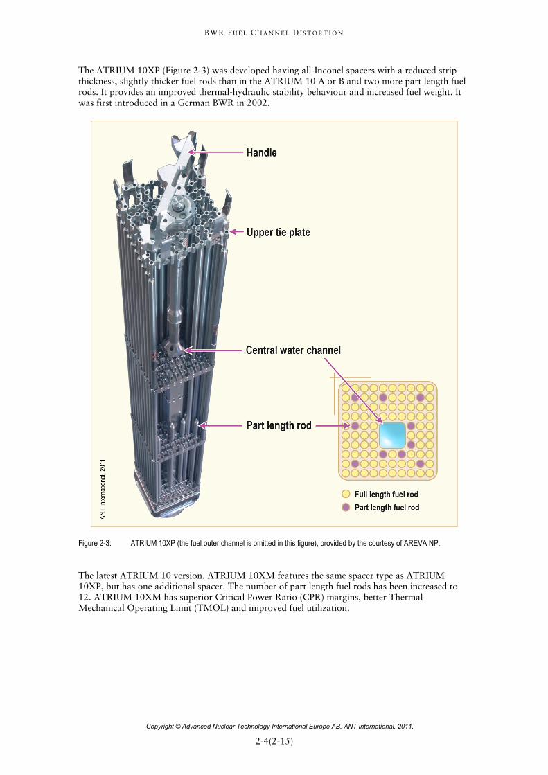
The ATRIUM 10XP (Figure 2-3) was developed having all-Inconel spacers with a reduced strip thickness, slightly thicker fuel rods than in the ATRIUM 10 A or B and two more part length fuel rods. It provides an improved thermal-hydraulic stability behaviour and increased fuel weight. It was first introduced in a German BWR in 2002.
Figure 2-3: ATRIUM 10XP (the fuel outer channel is omitted in this figure), provided by the courtesy of AREVA NP.
The latest ATRIUM 10 version, ATRIUM 10XM features the same spacer type as ATRIUM 10XP, but has one additional spacer. The number of part length fuel rods has been increased to 12. ATRIUM 10XM has superior Critical Power Ratio (CPR) margins, better Thermal Mechanical Operating Limit (TMOL) and improved fuel utilization.
B W R F U E L C H A N N E L D I S T O R T I O N
Copyright © Advanced Nuclear Technology International Europe AB, ANT International, 2011.
2-5(2-15)=
2.2.2 W
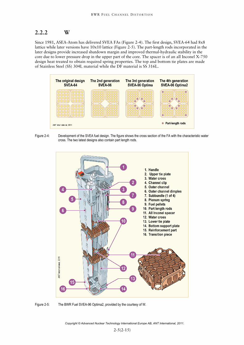
Since 1981, ASEA-Atom has delivered SVEA FAs (Figure 2-4). The first design, SVEA-64 had 8x8 lattice while later versions have 10x10 lattice (Figure 2-5). The part-length rods incorporated in the later designs provide increased shutdown margin and improved thermal-hydraulic stability in the core due to lower pressure drop in the upper part of the core. The spacer is of an all Inconel X-750 design heat treated to obtain required spring properties. The top and bottom tie plates are made of Stainless Steel (SS) 304L material while the DF material is SS 316L.
Figure 2-4: Development of the SVEA fuel design. The figure shows the cross section of the FA with the characteristic water cross. The two latest designs also contain part length rods.
Figure 2-5: The BWR Fuel SVEA-96 Optima2, provided by the courtesy of W.
B W R F U E L C H A N N E L D I S T O R T I O N
Copyright © Advanced Nuclear Technology International Europe AB, ANT International, 2011.
3-1(3-1)=
3 Fuel channel design criteria The basis for the outer channel mechanical design established by the fuel vendors may include the following criteria for normal operation.
Fuel channel distortion (bow, twist, bulging) is evaluated to ensure that:
Dry-out will not occur.
CRs can be inserted when required.
The FA can be lifted through the upper core grid.
Metal thinning due to oxide thickness growth should be limited to ensure sufficient strength to meet design requirements.
Stresses should be limited to avoid plastic deformation. The American Society of Mechanical Engineer (ASME) Code is used as the basis for these calculations. During the stress calculations, maximum oxide thickness should be assumed.
The fatigue stresses must be limited to make sure that fatigue damage due to alternating stresses due to hydraulic and mechanical loads does not occur. During the fatigue calculations, maximum oxide thickness should be assumed.
The hydrogen content should be limited to guarantee adequate ductility.
To assure safe operation following a seismic event, additional criteria are defined. Two levels of ground motion excitation, corresponding to two earthquake levels, are defined for safety-related structures, systems, and components in operating nuclear power plants. Compliance with specified criteria assure that plant safely is maintained following each event. For the first-level earthquake, the Operating Basis Earthquake (OBE), the load factors and acceptable allowable stresses ensure that the stresses in plant structures remain at least 40 percent below the yield stress of the material for the event. For the second-level earthquake, the Safe Shutdown Earthquake (SSE), whose vibratory motion is usually twice that of the OBE), the associated load factors and allowable stresses ensure that the stresses in the plant structure and assembly remain close to the yield stress of the specific materials; a small excursion in the inelastic range is allowed when the SSE load is combined with accident loads, usually those associated with a LOCA event.
The following criteria relates to an earth quake:
OBE-Allow continued safe operation of the FA following an OBE event by establishing that the FA components, such as the fuel outer channel, do not violate their dimensional requirements. This is most simply assured by requiring that the stresses in components remain below the yield stress of the unirradiated components.
SSE-Ensure safe shutdown of the reactor by maintaining the overall structural integrity of the FAs, CR insertability and a coolable geometry within the deformation limits consistent with the Emergency Core Cooling System (ECCS) and safety analysis. Requirements to assure safe shutdown are:
Fuel fragmentation does not occur due to seismic loads.
CR insertability is maintained by confirming neither no or small plastic deformation nor fracture of components such as e.g. the fuel outer channel.
Confirmation that the FA (top and bottom nozzles) maintains engagement with the reactor internals.
The Fuel Design Criteria of all FA components, including the fuel outer channels are treated in details in Fuel Design Review Handbook.
B W R F U E L C H A N N E L D I S T O R T I O N
Copyright © Advanced Nuclear Technology International Europe AB, ANT International, 2011.
4-1(4-31)
4 Basic material behaviour
4.1 General requirements BWR channels of the various designs described in Section 1 all are structural (non-heat transfer) components operating in water at about 288ºC (561K). There is a small axial temperature gradient (<2ºC, inlet to outlet (bottom to top)) due to a change in boiling phenomena as the water passes through the fuel bundle, and a very small (<1ºC) through-the-wall temperature gradient due to boiling water inside and non-boiling water outside the channel. Stress in the axial direction is small, but there is a stress in the transverse or hoop direction due to a pressure differential between inside the bundle and the by-pass flow region outside the channel. The neutron fast flux varies along the channel length depending on the coolant flow rate, on void fraction, on CB positions, on local U-235 enrichments and on gadolinia loading. (A particularly good review of this topic is provided by [Loberg, 2010]). Therefore, the channel material must accommodate corrosion-hydriding in near 288ºC (561K) water, flux-induced irradiation growth, flux-induced and thermal creep and relaxation, and hydride- or oxide-induced dimensional changes. Some specific details are given in Section 5, and basic phenomena are given here.
4.2 Specific material phenomena
4.2.1 Irradiation growth
Irradiation Growth occurs simultaneously with irradiation creep if there is an applied stress. The two processes are considered to be independent and additive, even though they compete mechanistically for the same irradiation-produced defects. Prior ZIRconium Alloy Technology (ZIRAT) reviews can be found in the ZIRAT7/IZNA52 STR, [Adamson et al, 2002/2003], the Fuel Material Technology Report, Vol. 2 [Rudling et al, 2007] and the ZIRAT14/IZNA9 STR [Adamson et al, 2009].
Irradiation growth is a change in the dimensions of a zirconium alloy reactor component even though the applied stress is nominally zero. It is approximately a constant volume process, so if there is, for example, an increase in the length of a component, the width and/or thickness must decrease to maintain constant volume. Understanding of the detailed mechanism is still evolving; however a clear correlation of growth to microstructure evolution exists, and many empirical observations have revealed key mechanistic aspects. The inherent anisotropy of the Zr crystallographic structure plays a strong role in the mechanism, as materials with isotropic crystallographic structure (like SS, copper, Inconel, etc.) do not undergo irradiation growth. It is not to be confused with irradiation swelling, which does conserve volume and does not occur in zirconium alloys under normal reactor operating conditions.
Growth has a linear dependency on fast neutron flux [Holt, 2008]. Therefore growth can be plotted against fluence (flux x time), as is commonly done, without concern for the actual value of flux.
Irradiation growth is strongly affected by fluence, Cold Work (CW), texture, irradiation temperature, and material chemistry (alloying and impurity elements). It is also thought to be influenced by hydrogen or hydride content, see Section 4.2.3.
5 Information on Zirconium Alloys
B W R F U E L C H A N N E L D I S T O R T I O N
Copyright © Advanced Nuclear Technology International Europe AB, ANT International, 2011.
4-2(4-31)
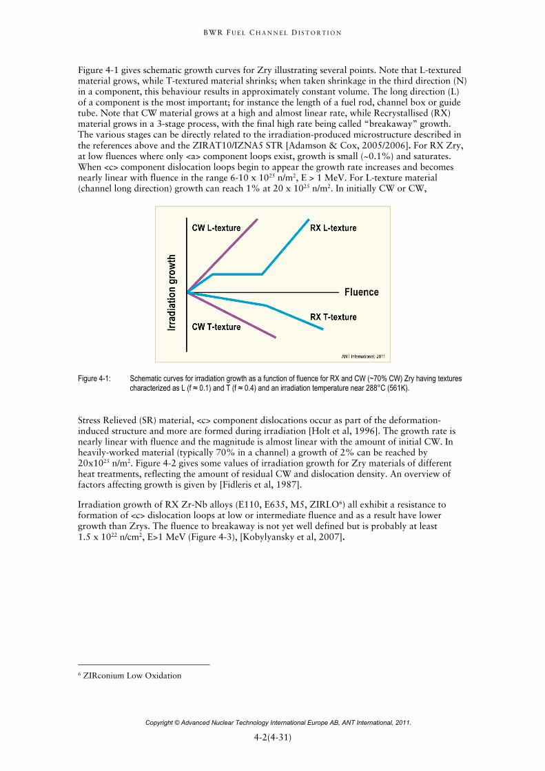
Figure 4-1 gives schematic growth curves for Zry illustrating several points. Note that L-textured material grows, while T-textured material shrinks; when taken shrinkage in the third direction (N) in a component, this behaviour results in approximately constant volume. The long direction (L) of a component is the most important; for instance the length of a fuel rod, channel box or guide tube. Note that CW material grows at a high and almost linear rate, while Recrystallised (RX) material grows in a 3-stage process, with the final high rate being called “breakaway” growth. The various stages can be directly related to the irradiation-produced microstructure described in the references above and the ZIRAT10/IZNA5 STR [Adamson & Cox, 2005/2006]. For RX Zry, at low fluences where only <a> component loops exist, growth is small (~0.1%) and saturates. When <c> component dislocation loops begin to appear the growth rate increases and becomes nearly linear with fluence in the range 6-10 x 1025 n/m2, E > 1 MeV. For L-texture material (channel long direction) growth can reach 1% at 20 x 1025 n/m2. In initially CW or CW,
Figure 4-1: Schematic curves for irradiation growth as a function of fluence for RX and CW (~70% CW) Zry having textures characterized as L (f ≈ 0.1) and T (f ≈ 0.4) and an irradiation temperature near 288°C (561K).
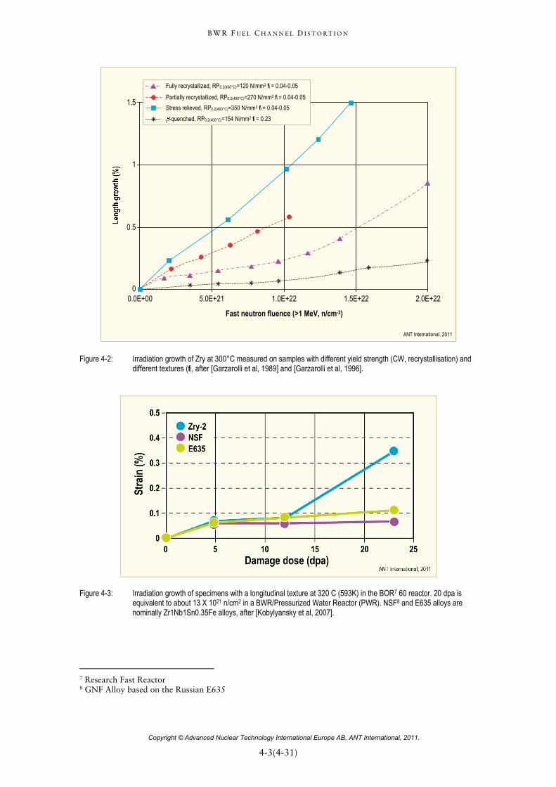
Stress Relieved (SR) material, <c> component dislocations occur as part of the deformation-induced structure and more are formed during irradiation [Holt et al, 1996]. The growth rate is nearly linear with fluence and the magnitude is almost linear with the amount of initial CW. In heavily-worked material (typically 70% in a channel) a growth of 2% can be reached by 20x1025 n/m2. Figure 4-2 gives some values of irradiation growth for Zry materials of different heat treatments, reflecting the amount of residual CW and dislocation density. An overview of factors affecting growth is given by [Fidleris et al, 1987].
Irradiation growth of RX Zr-Nb alloys (E110, E635, M5, ZIRLO6) all exhibit a resistance to formation of <c> dislocation loops at low or intermediate fluence and as a result have lower growth than Zrys. The fluence to breakaway is not yet well defined but is probably at least 1.5 x 10²² n/cm2, E>1 MeV (Figure 4-3), [Kobylyansky et al, 2007].
6 ZIRconium Low Oxidation
B W R F U E L C H A N N E L D I S T O R T I O N
Copyright © Advanced Nuclear Technology International Europe AB, ANT International, 2011.
4-3(4-31)
Fast neutron fluence (>1 MeV, n/cm-2)
0.0E+00 5.0E+21 1.0E+22 1.5E+22 2.0E+220
0.5
1
1.5
Fully recrystallized, RP0.2(400°C)=120 N/mm2 fl = 0.04-0.05
Partially recrystallized, RP0.2(400°C)=270 N/mm2 fl = 0.04-0.05
Stress relieved, RP0.2(400°C)=350 N/mm2 fl = 0.04-0.05
-quenched, RP0.2(400°C)=154 N/mm2 fl = 0.23
ANT International, 2011
Figure 4-2: Irradiation growth of Zry at 300°C measured on samples with different yield strength (CW, recrystallisation) and different textures (fl, after [Garzarolli et al, 1989] and [Garzarolli et al, 1996].
Figure 4-3: Irradiation growth of specimens with a longitudinal texture at 320 C (593K) in the BOR7 60 reactor. 20 dpa is equivalent to about 13 X 1021 n/cm2 in a BWR/Pressurized Water Reactor (PWR). NSF8 and E635 alloys are nominally Zr1Nb1Sn0.35Fe alloys, after [Kobylyansky et al, 2007].
7 Research Fast Reactor 8 GNF Alloy based on the Russian E635
B W R F U E L C H A N N E L D I S T O R T I O N
Copyright © Advanced Nuclear Technology International Europe AB, ANT International, 2011.
5-1(5-7)
5 Phenomena affecting channel performance
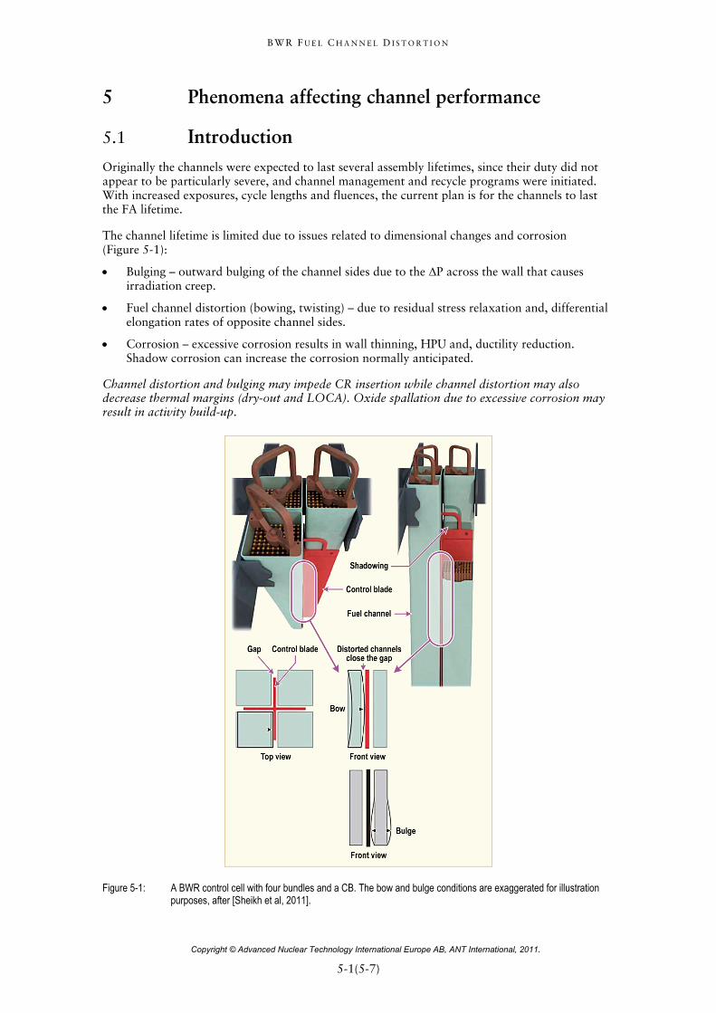
5.1 Introduction Originally the channels were expected to last several assembly lifetimes, since their duty did not appear to be particularly severe, and channel management and recycle programs were initiated. With increased exposures, cycle lengths and fluences, the current plan is for the channels to last the FA lifetime.
The channel lifetime is limited due to issues related to dimensional changes and corrosion (Figure 5-1):
Bulging – outward bulging of the channel sides due to the ΔP across the wall that causes irradiation creep.
Fuel channel distortion (bowing, twisting) – due to residual stress relaxation and, differential elongation rates of opposite channel sides.
Corrosion – excessive corrosion results in wall thinning, HPU and, ductility reduction. Shadow corrosion can increase the corrosion normally anticipated.
Channel distortion and bulging may impede CR insertion while channel distortion may also decrease thermal margins (dry-out and LOCA). Oxide spallation due to excessive corrosion may result in activity build-up.
Figure 5-1: A BWR control cell with four bundles and a CB. The bow and bulge conditions are exaggerated for illustration purposes, after [Sheikh et al, 2011].
B W R F U E L C H A N N E L D I S T O R T I O N
Copyright © Advanced Nuclear Technology International Europe AB, ANT International, 2011.
5-2(5-7)
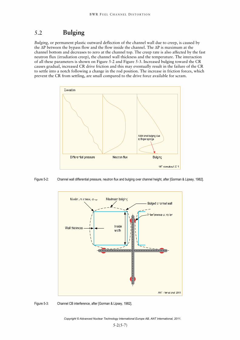
5.2 Bulging Bulging, or permanent plastic outward deflection of the channel wall due to creep, is caused by the ΔP between the bypass flow and the flow inside the channel. The ΔP is maximum at the channel bottom and decreases to zero at the channel top. The creep rate is also affected by the fast neutron flux (irradiation creep), the channel wall thickness and the temperature. The interaction of all these parameters is shown on Figure 5-2 and Figure 5-3. Increased bulging toward the CR causes gradual, increased CR drive friction and this may eventually result in the failure of the CR to settle into a notch following a change in the rod position. The increase in friction forces, which prevent the CR from settling, are small compared to the drive force available for scram.
Figure 5-2: Channel wall differential pressure, neutron flux and bulging over channel height, after [Gorman & Lipsey, 1982].
Figure 5-3: Channel CB interference, after [Gorman & Lipsey, 1982].
B W R F U E L C H A N N E L D I S T O R T I O N
Copyright © Advanced Nuclear Technology International Europe AB, ANT International, 2011.
5-3(5-7)
The bypass flow can increase if the flow area at the channel to tie plate interface increases due to bulging. The finger springs lose their effectiveness at a certain deflection level, which depends on the design.
More details may be obtained from ZIRAT10/IZNA5 STR Structural Behaviour of Fuel Components.
5.3 Channel distortion Twisting of the fuel channel may result from relaxation of residual stresses from a non-optimized channel manufacturing process; however, good fabrication methods should include stress relief annealing.
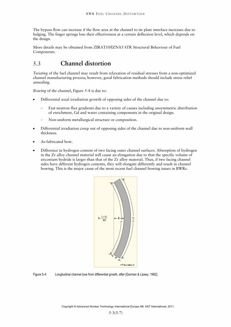
Bowing of the channel, Figure 5-4 is due to:
Differential axial irradiation growth of opposing sides of the channel due to:
Fast neutron flux gradients due to a variety of causes including unsymmetric distribution of enrichment, Gd and water containing components in the original design.
Non-uniform metallurgical structure or composition.
Differential irradiation creep out of opposing sides of the channel due to non-uniform wall thickness.
As-fabricated bow.
Difference in hydrogen content of two facing outer channel surfaces. Absorption of hydrogen in the Zr alloy channel material will cause an elongation due to that the specific volume of zirconium hydride is larger than that of the Zr alloy material. Thus, if two facing channel sides have different hydrogen contents, they will elongate differently and result in channel bowing. This is the major cause of the most recent fuel channel bowing issues in BWRs.
L LB
8W
Figure 5-4: Longitudinal channel bow from differential growth, after [Gorman & Lipsey, 1982].
B W R F U E L C H A N N E L D I S T O R T I O N
Copyright © Advanced Nuclear Technology International Europe AB, ANT International, 2011.
6-1(6-4)
6 Channel lifetime limits
6.1 Interference with CRs The main factor limiting channel life is deformation due to bulging and bow which results in interference between channel and CBs and reduction of thermal margins. The maximum allowable bulging, bow and growth values are usually deduced from geometrical considerations. Typical initial clearances between the channel and CB are between 2.4 and 3.3 mm16 depending on BWR design, channel wall thickness, and lattice type (D lattice with asymmetric clearances between blades and channels and C lattice with symmetric clearances between the channels) [Gorman & Lipsey, 1982].
There are a large number of tolerances which can affect the actual clearance. The maximum reduction of the clearance due to tolerances is between 1.5 and 2.9 mm, assuming that all tolerances act adversely at the same time [Gorman & Lipsey, 1982]. Calculating the maximum reduction of the clearance due to tolerances is clearly very conservative. A more reasonable approach is to combine the tolerances statistically, as is common in core safety analysis, which lowers the maximum reduction of clearance by about a factor of two. Furthermore, channels are usually inserted in a way that the initial bow is orientated away from the CB to get more margin towards CB-channel interaction. The above dimensions are for RT and zero differential pressure values. The clearance at operation temperature will be increased because the SS core support structure has a larger thermal expansion than the Zry channels. This results in an increase on the clearance of about 0.4 mm. On the other side the elastic bulging of the channels by the differential pressure reduces the clearance under operational conditions, especially in the lower part of the channel, by several tenths of a mm [Gorman & Lipsey, 1982]. In addition to the geometrical clearance some interference between CB and channel can be allowed. The lateral force due to interference (Fi) can be estimated by the equation:
4
1
ni nn
F Stifn I
where μ is the friction coefficient, Stifn is the channel stiffness, which depends on the elevation, and In is the interference at the 4 blades of the CR.
This force must be lower than the force that can cause problems, e.g. a disconnecting signal. For the estimation of the allowable bowing and bulging value from geometrical considerations it has to be considered that the maximum bowing occurs at the half channel length whereas the max bulging occurs at a much lower elevation.
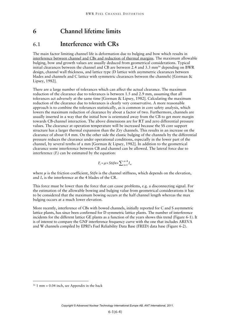
More recently, interference of CBs with bowed channels, initially reported for C and S asymmetric lattice plants, has since been confirmed for D symmetric lattice plants. The number of interference incidents for the different lattice GE plants as a function of the years shows this trend (Figure 6-1). It is of interest to compare the GNF interference frequency curve with the one that includes AREVA and W channels compiled by EPRI’s Fuel Reliability Data Base (FRED) data base (Figure 6-2).
16 1 mm = 0.04 inch, see Appendix in the back
B W R F U E L C H A N N E L D I S T O R T I O N
Copyright © Advanced Nuclear Technology International Europe AB, ANT International, 2011.
6-2(6-4)
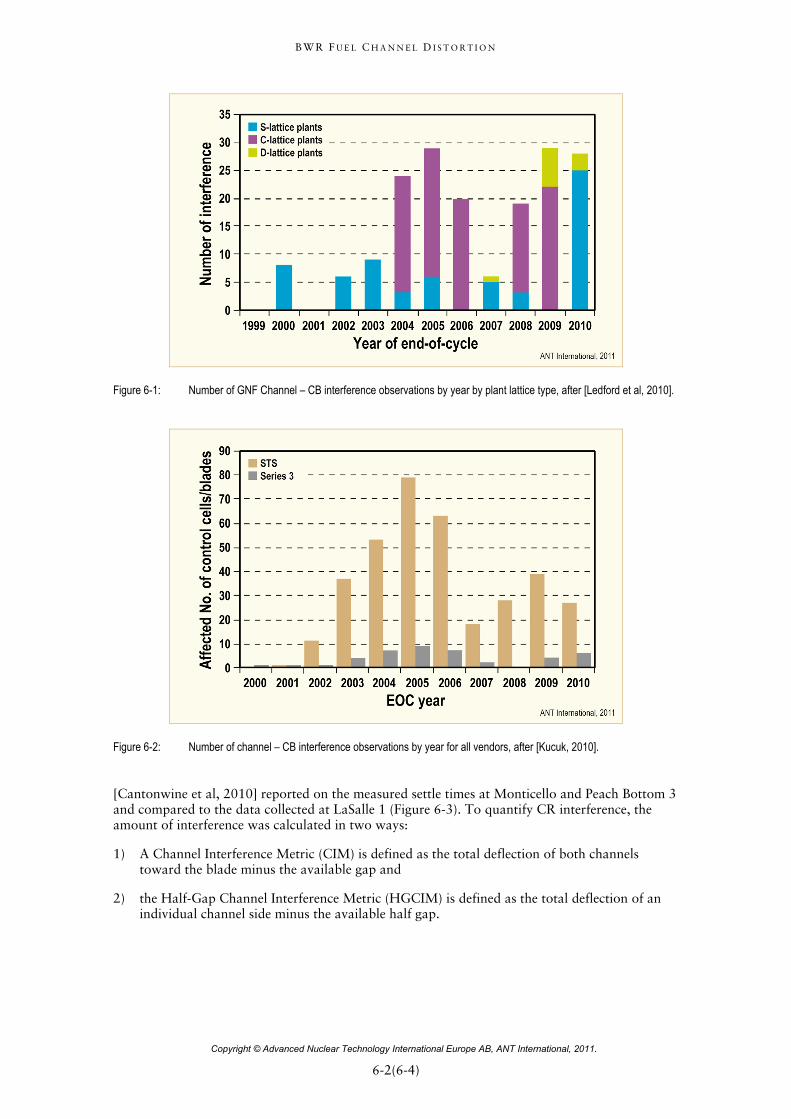
Figure 6-1: Number of GNF Channel – CB interference observations by year by plant lattice type, after [Ledford et al, 2010].
Figure 6-2: Number of channel – CB interference observations by year for all vendors, after [Kucuk, 2010].
[Cantonwine et al, 2010] reported on the measured settle times at Monticello and Peach Bottom 3 and compared to the data collected at LaSalle 1 (Figure 6-3). To quantify CR interference, the amount of interference was calculated in two ways:
1) A Channel Interference Metric (CIM) is defined as the total deflection of both channels toward the blade minus the available gap and
2) the Half-Gap Channel Interference Metric (HGCIM) is defined as the total deflection of an individual channel side minus the available half gap.
B W R F U E L C H A N N E L D I S T O R T I O N
Copyright © Advanced Nuclear Technology International Europe AB, ANT International, 2011.
6-3(6-4)
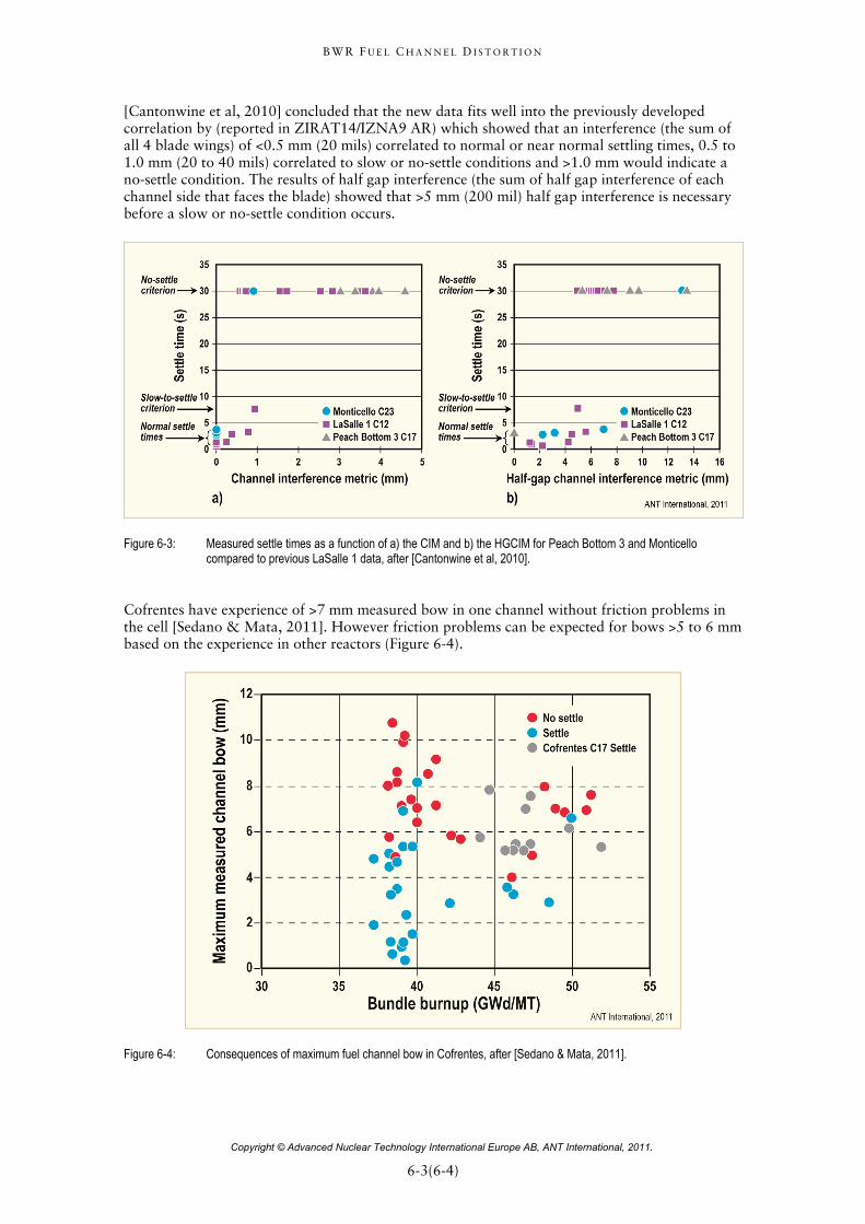
[Cantonwine et al, 2010] concluded that the new data fits well into the previously developed correlation by (reported in ZIRAT14/IZNA9 AR) which showed that an interference (the sum of all 4 blade wings) of <0.5 mm (20 mils) correlated to normal or near normal settling times, 0.5 to 1.0 mm (20 to 40 mils) correlated to slow or no-settle conditions and >1.0 mm would indicate a no-settle condition. The results of half gap interference (the sum of half gap interference of each channel side that faces the blade) showed that >5 mm (200 mil) half gap interference is necessary before a slow or no-settle condition occurs.
Figure 6-3: Measured settle times as a function of a) the CIM and b) the HGCIM for Peach Bottom 3 and Monticello compared to previous LaSalle 1 data, after [Cantonwine et al, 2010].
Cofrentes have experience of >7 mm measured bow in one channel without friction problems in the cell [Sedano & Mata, 2011]. However friction problems can be expected for bows >5 to 6 mm based on the experience in other reactors (Figure 6-4).
Figure 6-4: Consequences of maximum fuel channel bow in Cofrentes, after [Sedano & Mata, 2011].
B W R F U E L C H A N N E L D I S T O R T I O N
Copyright © Advanced Nuclear Technology International Europe AB, ANT International, 2011.
7-1(7-5)
7 Channel management The objective of channel management is to maximize the channel lifetime while ensuring that the effect of fuel channel distortion on CR interference and thermal margins are limited (i.e., to ensure that the fuel design criteria are met). To minimize any CR interference, channels are usually positioned in such a way that the channels are bowing away from the CR.
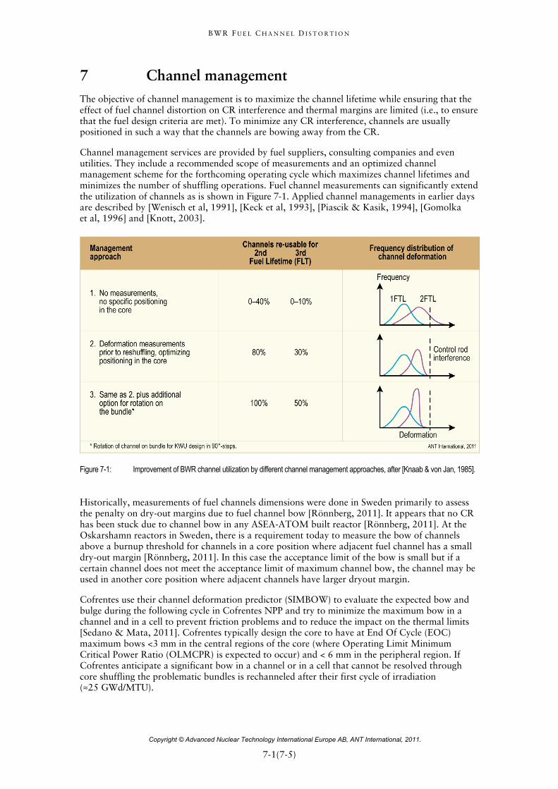
Channel management services are provided by fuel suppliers, consulting companies and even utilities. They include a recommended scope of measurements and an optimized channel management scheme for the forthcoming operating cycle which maximizes channel lifetimes and minimizes the number of shuffling operations. Fuel channel measurements can significantly extend the utilization of channels as is shown in Figure 7-1. Applied channel managements in earlier days are described by [Wenisch et al, 1991], [Keck et al, 1993], [Piascik & Kasik, 1994], [Gomolka et al, 1996] and [Knott, 2003].
Figure 7-1: Improvement of BWR channel utilization by different channel management approaches, after [Knaab & von Jan, 1985].
Historically, measurements of fuel channels dimensions were done in Sweden primarily to assess the penalty on dry-out margins due to fuel channel bow [Rönnberg, 2011]. It appears that no CR has been stuck due to channel bow in any ASEA-ATOM built reactor [Rönnberg, 2011]. At the Oskarshamn reactors in Sweden, there is a requirement today to measure the bow of channels above a burnup threshold for channels in a core position where adjacent fuel channel has a small dry-out margin [Rönnberg, 2011]. In this case the acceptance limit of the bow is small but if a certain channel does not meet the acceptance limit of maximum channel bow, the channel may be used in another core position where adjacent channels have larger dryout margin.
Cofrentes use their channel deformation predictor (SIMBOW) to evaluate the expected bow and bulge during the following cycle in Cofrentes NPP and try to minimize the maximum bow in a channel and in a cell to prevent friction problems and to reduce the impact on the thermal limits [Sedano & Mata, 2011]. Cofrentes typically design the core to have at End Of Cycle (EOC) maximum bows <3 mm in the central regions of the core (where Operating Limit Minimum Critical Power Ratio (OLMCPR) is expected to occur) and < 6 mm in the peripheral region. If Cofrentes anticipate a significant bow in a channel or in a cell that cannot be resolved through core shuffling the problematic bundles is rechanneled after their first cycle of irradiation (≈25 GWd/MTU).
B W R F U E L C H A N N E L D I S T O R T I O N
Copyright © Advanced Nuclear Technology International Europe AB, ANT International, 2011.
7-2(7-5)
Cofrentes is considered susceptible to channel distortion due to shadow corrosion phenomenon since the core operates with early control in fresh bundles (high Effective Control Blade Exposure (ECBE) parameter) [Sedano, 2011]. A conservative approach has been taken until more information (root cause…) is available. A strategy consists of the following:
Channel measurement campaigns: EOC16, EOC17 performed and EOC18 scheduled to understand the phenomenon and validate our predictor.
Cycle 17 and Cycle 18 extensive rod settle time monitoring: No slow to settle cell detected so far.
Cycle 18 and Cycle 19 loading pattern strategy following Institute of Nuclear Power Operations (INPO) SER 01-08 Rev1. Development of a channel bow predictor (SIMBOW) to help in the core design activities.
Preventive replacement of Zry-2 channels in 10 SVEA Optima-2 bundles at EOC17 and 12 GNF2 bundles at EOC18. All bundles after one cycle of irradiation.
Use of channels of new materials (Zr-4, ZIRLO) in the control cells bundles to reduce the susceptibility to shadow corrosion and minimize the channel bow.
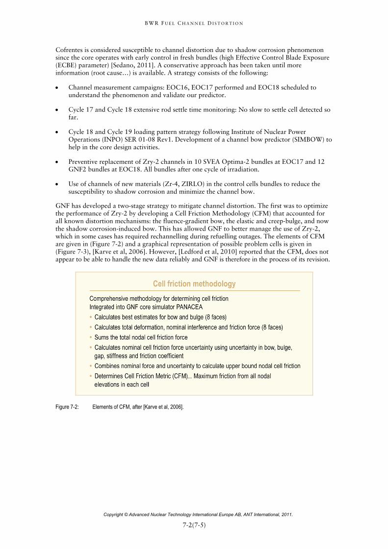
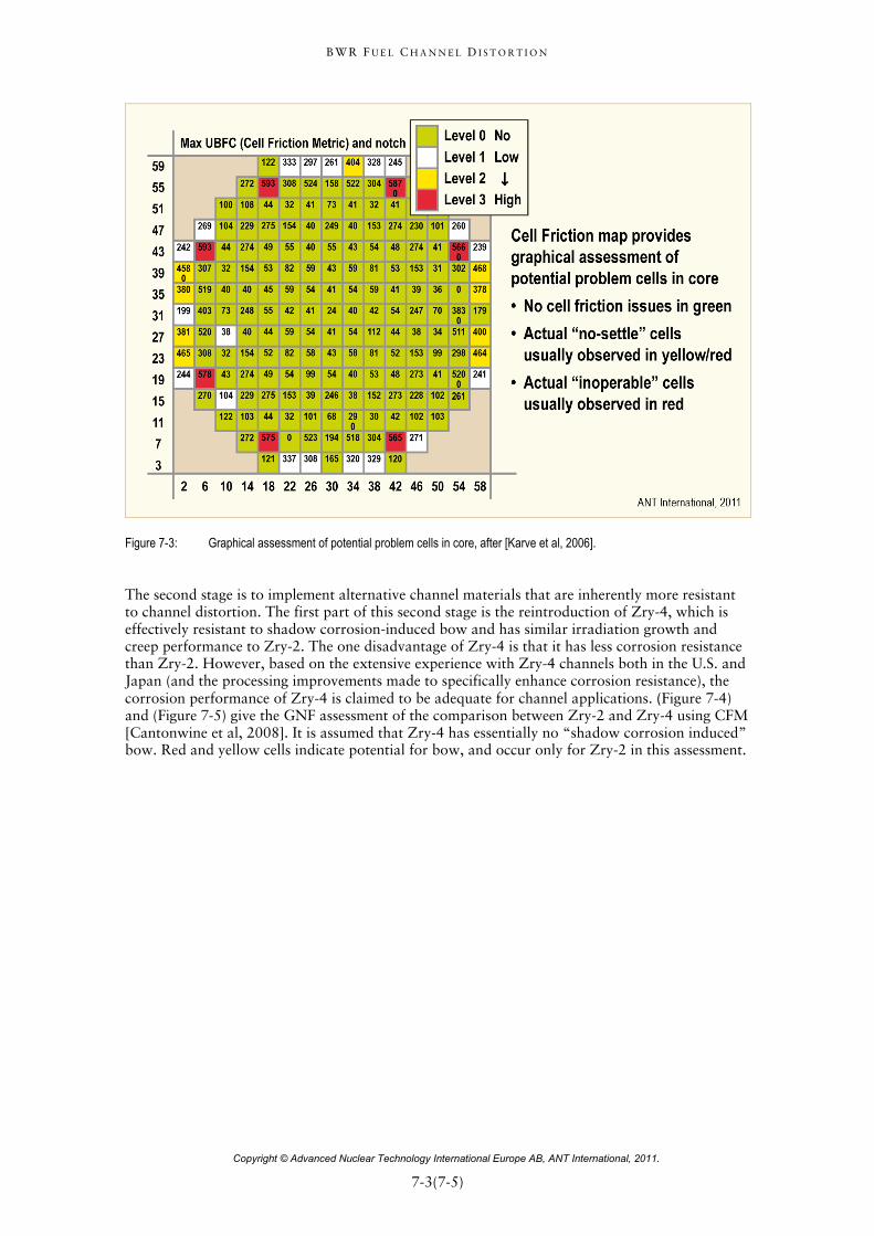
GNF has developed a two-stage strategy to mitigate channel distortion. The first was to optimize the performance of Zry-2 by developing a Cell Friction Methodology (CFM) that accounted for all known distortion mechanisms: the fluence-gradient bow, the elastic and creep-bulge, and now the shadow corrosion-induced bow. This has allowed GNF to better manage the use of Zry-2, which in some cases has required rechannelling during refuelling outages. The elements of CFM are given in (Figure 7-2) and a graphical representation of possible problem cells is given in (Figure 7-3), [Karve et al, 2006]. However, [Ledford et al, 2010] reported that the CFM, does not appear to be able to handle the new data reliably and GNF is therefore in the process of its revision.
Figure 7-2: Elements of CFM, after [Karve et al, 2006].
B W R F U E L C H A N N E L D I S T O R T I O N
Copyright © Advanced Nuclear Technology International Europe AB, ANT International, 2011.
7-3(7-5)
Figure 7-3: Graphical assessment of potential problem cells in core, after [Karve et al, 2006].
The second stage is to implement alternative channel materials that are inherently more resistant to channel distortion. The first part of this second stage is the reintroduction of Zry-4, which is effectively resistant to shadow corrosion-induced bow and has similar irradiation growth and creep performance to Zry-2. The one disadvantage of Zry-4 is that it has less corrosion resistance than Zry-2. However, based on the extensive experience with Zry-4 channels both in the U.S. and Japan (and the processing improvements made to specifically enhance corrosion resistance), the corrosion performance of Zry-4 is claimed to be adequate for channel applications. (Figure 7-4) and (Figure 7-5) give the GNF assessment of the comparison between Zry-2 and Zry-4 using CFM [Cantonwine et al, 2008]. It is assumed that Zry-4 has essentially no “shadow corrosion induced” bow. Red and yellow cells indicate potential for bow, and occur only for Zry-2 in this assessment.
B W R F U E L C H A N N E L D I S T O R T I O N
Copyright © Advanced Nuclear Technology International Europe AB, ANT International, 2011.
8-1(8-32)
8 Recent fuel channel bow data
8.1 Observations
8.1.1 Introduction
Significant CB friction was found in C and S-lattice plants with GNF thick/thin channels since the early 2000s, [Schardt et al, 2004] and [Schneider et al, 2004]. Investigations showed that the cause can be correlated to the existence of CB shadow corrosion (see Section 4.2) induced channel bow towards the CR, which manifests at high burnups. This phenomenon of shadow corrosion induced channel bowing towards the CR has not been seen before when control cell core operation with only high burnup fuel in the control cells, i.e. cells where the CR are deeply inserted into the core.
Increasing cycle length and power density have led to a new core nuclear design concept in the early 2000s. With reload batch fractions approaching 50% it has become necessary to locate a substantial amount of fresh fuel into control cell positions. The shadow corrosion induced bow progresses rather slowly and occurs only at high burnups, >30 MWd/kgU. It has been observed that the magnitude of shadow-corrosion induced bow increases to increased insertion depth and time of a CR in the early lifetime of the fuel. Analysis of this type of channel bow has clearly revealed that it does correlate to a fast fluence gradient, but is an additional bow phenomenon.
According to [Schardt et al, 2004], the mechanism for shadow corrosion induced channel bow at high burnups has a number of contributing factors:
The time of controlled operation, i.e., when a CR is inserted, on a fuel channel face,
when the controlled operation occurred in a channel’s lifetime,
proximity of the channel material to the CB,
thickness of the channel material,
total exposure of the channel and
channel material, shadow induced channel bow have been recorded only for Zry-2 but not for Zry-4 channels.
The shadow corrosion induced bow at high burnups cause the channel to bow systematically towards the CR blade.
The shadow corrosion induced bow (towards the CR) was not immediately seen since there is a time lag between the introduction of the new core design concepts and the high burnup necessary to manifest enhanced bow. Figure 8-1a shows the progression of a core design in respect to shadow corrosion induced bow for Zry-2 channels in Perry Cycle 5 to 8 (n to n+3). Initially in cycle n, there were only few fresh bundles that were controlled and none have achieved the necessary burnup to show any shadow corrosion induced bow. As the core design evolves through cycle n+1, there are substantially more fresh bundles being controlled. As the exposure of the bundles, that were controlled early in life, increases, they approach the “susceptible zone” when shadow corrosion induced bow is manifested, indicated by the pink filled boxes in the charts. Finally, a significant number of channels reach the susceptible region. The figure reveals that almost 3 cycles operation, which is almost 6 years of operation, were necessary to manifests this type of bow.
B W R F U E L C H A N N E L D I S T O R T I O N
Copyright © Advanced Nuclear Technology International Europe AB, ANT International, 2011.
8-2(8-32)
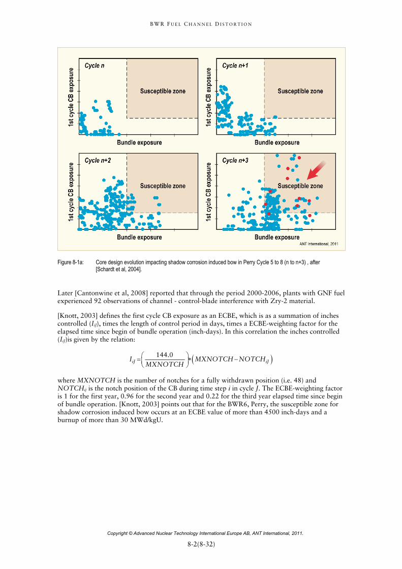
Figure 8-1a: Core design evolution impacting shadow corrosion induced bow in Perry Cycle 5 to 8 (n to n+3) , after [Schardt et al, 2004].
Later [Cantonwine et al, 2008] reported that through the period 2000-2006, plants with GNF fuel experienced 92 observations of channel - control-blade interference with Zry-2 material.
[Knott, 2003] defines the first cycle CB exposure as an ECBE, which is as a summation of inches controlled (IiJ), times the length of control period in days, times a ECBE-weighting factor for the elapsed time since begin of bundle operation (inch-days). In this correlation the inches controlled (IiJ)is given by the relation:
144.0iJ iJI MXNOTCH NOTCH
MXNOTCH
where MXNOTCH is the number of notches for a fully withdrawn position (i.e. 48) and NOTCHij is the notch position of the CB during time step i in cycle J. The ECBE-weighting factor is 1 for the first year, 0.96 for the second year and 0.22 for the third year elapsed time since begin of bundle operation. [Knott, 2003] points out that for the BWR6, Perry, the susceptible zone for shadow corrosion induced bow occurs at an ECBE value of more than 4500 inch-days and a burnup of more than 30 MWd/kgU.
B W R F U E L C H A N N E L D I S T O R T I O N
Copyright © Advanced Nuclear Technology International Europe AB, ANT International, 2011.
8-3(8-32)
8.1.2 Parameters impacting channel bow
8.1.2.1 GNF data
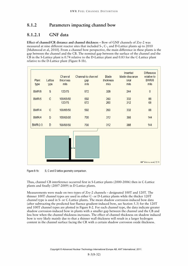
Effect of channel/CR distance and channel thickness – Bow of GNF channels of Zry-2 was measured at nine different reactor sites that included S-, C-, and D-Lattice plants up to 2010 [Mahmood et al, 2010]. From a channel bow perspective, the main difference in these plants is the gap between the channel and the CB. The nominal gap between the surface of the channel and the CB in the S-Lattice plant is 0.74 relative to the D-Lattice plant and 0.83 for the C-Lattice plant relative to the D-Lattice plant (Figure 8-1b).
Figure 8-1b: S, C and D lattice geometry comparison.
Thus, channel CB interference occurred first in S-Lattice plants (2000-2006) then in C-Lattice plants and finally (2007-2009) in D Lattice plants.
Measurements were made on two types of Zry-2 channels – designated 100T and 120T. The thinner 100T channel types are used in either C- or D-Lattice plants while the thicker 120T channel type is used in S- or C-Lattice plants. The mean shadow corrosion-induced bow data (after subtracting the predicted fast fluence gradient-induced bow, see Section 5.3) for the 120T and 100T channel types are plotted in Figure 8-2. For each channel type, the data indicate greater shadow corrosion-induced bow in plants with a smaller gap between the channel and the CB and less bow when the channel thickness increases. The effect of channel thickness on shadow induced bow is very likely mainly due to that a thinner wall thickness will result in a larger hydrogen content in the channel surface facing the CR with a certain shadow corrosion oxide thickness.
B W R F U E L C H A N N E L D I S T O R T I O N
Copyright © Advanced Nuclear Technology International Europe AB, ANT International, 2011.
9-1(9-9)
9 Material modifications to counteract shadow induced bow (Including heat treatments)
9.1 Introduction Channel CB interference has been a challenging issue over the past 10 years for BWRs with early insertion of CRs for fresh fuel, e.g. ~2-year cycles and Zry-2 channels. The primary reason for this issue was the channel distortion caused by different hydrogen contents of the facing sides of the channel (known as shadow corrosion-induced bow). A larger HPU and shadow corrosion occurs for the channel sides facing the CR. Zry-2 is particularly susceptible to this distortion mechanism because Zry-2 has a high HPUF which increases at high burnups. A three-stage strategy was developed to mitigate channel distortion.
The first was to optimize the performance of Zry-2 by developing a CFM that accounted for all known distortion mechanisms:
The fast fluence-gradient bow,
the elastic and creep bulge,
and now the shadow corrosion-induced bow.
This has required often rechannelling (i.e. replacement a bowed channel with a new straight channel) during refuelling outages. A further improvement could be reached by an optimization of the alloying chemistry as proposed by [Garzarolli et al, 2010b].
The second stage is to implement alternative channel materials that are inherently more resistant to channel distortion. The first part of this second stage is the reintroduction of Zry-4, which is effectively resistant to shadow corrosion-induced bow but has similar irradiation growth rate and creep performance as Zry-2. The one disadvantage of Zry-4 is that it has less corrosion resistant than Zry-2. However, based on the extensive experience with Zry-4 channels in Europe, U.S., and Japan (and the processing improvements made to specifically enhance corrosion resistance), the corrosion performance of Zry-4 appeared to be adequate for channel applications.
The third stage is the development of new alloys, that are not sensitive to shadow corrosion induced bow and less susceptible to fluence induced bow. Longer-term material or material-processing solutions are being evaluated in Lead Test Channel (LTC) programs at numerous plants.
9.2 Zry-4 Fully RX Zry-4 strips were originally applied by all suppliers for BWR flow channels. In the late 1980s GE (GNF) switched to Zry-2 to standardize the BWR fuel material. In 1995 ABB (W) switched also to Zry-2, because of its lower sensitivity to nodular corrosion, observed in precursors irradiated since 1988 [Dahlbäck et al, 1993]. In 1998 AREVA switched also to Zry-2 due to its better corrosion behaviour observed in lead test irradiation programs.
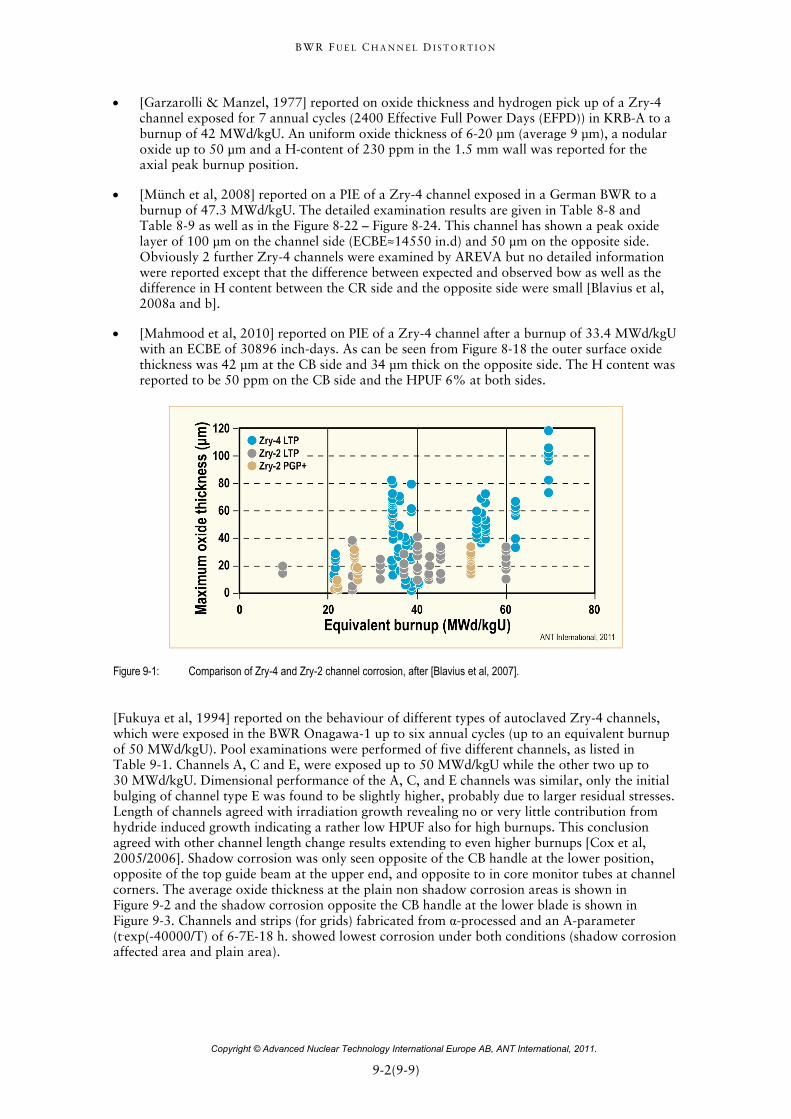
Literature information, e.g. [Dahlbäck et al, 1993] and [Blavius et al, 2007], shows that the Zry-4 channels have a significantly thicker outer surface oxide than that of Zry-2 channels at burnups in excess of about 20 MWd/kgU (e.g. Figure 9-1) and that the usual shadow corrosion thickness is at 70 to 100 μm in case of Zry-4 channels, whereas in case of Zry-2 shadow corrosion varies between 15 and 65 μm. Only some data from hot cell examinations of Zry-4 channels have been published:
B W R F U E L C H A N N E L D I S T O R T I O N
Copyright © Advanced Nuclear Technology International Europe AB, ANT International, 2011.
9-2(9-9)
[Garzarolli & Manzel, 1977] reported on oxide thickness and hydrogen pick up of a Zry-4 channel exposed for 7 annual cycles (2400 Effective Full Power Days (EFPD)) in KRB-A to a burnup of 42 MWd/kgU. An uniform oxide thickness of 6-20 μm (average 9 μm), a nodular oxide up to 50 μm and a H-content of 230 ppm in the 1.5 mm wall was reported for the axial peak burnup position.
[Münch et al, 2008] reported on a PIE of a Zry-4 channel exposed in a German BWR to a burnup of 47.3 MWd/kgU. The detailed examination results are given in Table 8-8 and Table 8-9 as well as in the Figure 8-22 – Figure 8-24. This channel has shown a peak oxide layer of 100 μm on the channel side (ECBE≈14550 in.d) and 50 μm on the opposite side. Obviously 2 further Zry-4 channels were examined by AREVA but no detailed information were reported except that the difference between expected and observed bow as well as the difference in H content between the CR side and the opposite side were small [Blavius et al, 2008a and b].
[Mahmood et al, 2010] reported on PIE of a Zry-4 channel after a burnup of 33.4 MWd/kgU with an ECBE of 30896 inch-days. As can be seen from Figure 8-18 the outer surface oxide thickness was 42 μm at the CB side and 34 μm thick on the opposite side. The H content was reported to be 50 ppm on the CB side and the HPUF 6% at both sides.
Figure 9-1: Comparison of Zry-4 and Zry-2 channel corrosion, after [Blavius et al, 2007].
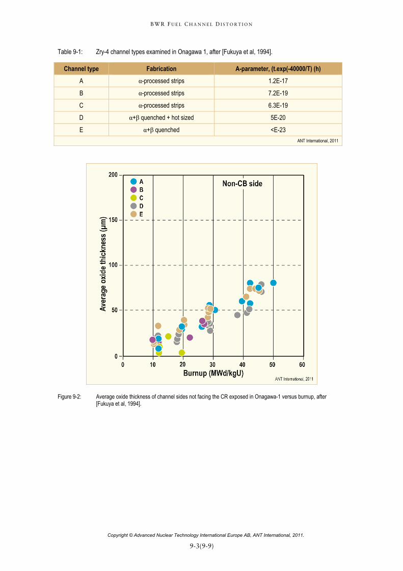
[Fukuya et al, 1994] reported on the behaviour of different types of autoclaved Zry-4 channels, which were exposed in the BWR Onagawa-1 up to six annual cycles (up to an equivalent burnup of 50 MWd/kgU). Pool examinations were performed of five different channels, as listed in Table 9-1. Channels A, C and E, were exposed up to 50 MWd/kgU while the other two up to 30 MWd/kgU. Dimensional performance of the A, C, and E channels was similar, only the initial bulging of channel type E was found to be slightly higher, probably due to larger residual stresses. Length of channels agreed with irradiation growth revealing no or very little contribution from hydride induced growth indicating a rather low HPUF also for high burnups. This conclusion agreed with other channel length change results extending to even higher burnups [Cox et al, 2005/2006]. Shadow corrosion was only seen opposite of the CB handle at the lower position, opposite of the top guide beam at the upper end, and opposite to in core monitor tubes at channel corners. The average oxide thickness at the plain non shadow corrosion areas is shown in Figure 9-2 and the shadow corrosion opposite the CB handle at the lower blade is shown in Figure 9-3. Channels and strips (for grids) fabricated from α-processed and an A-parameter (t.exp(-40000/T) of 6-7E-18 h. showed lowest corrosion under both conditions (shadow corrosion affected area and plain area).
B W R F U E L C H A N N E L D I S T O R T I O N
Copyright © Advanced Nuclear Technology International Europe AB, ANT International, 2011.
9-3(9-9)
Table 9-1: Zry-4 channel types examined in Onagawa 1, after [Fukuya et al, 1994].
Channel type Fabrication A-parameter, (t.exp(-40000/T) (h)
A α-processed strips 1.2E-17
B α-processed strips 7.2E-19
C α-processed strips 6.3E-19
D α+β quenched + hot sized 5E-20
E α+β quenched <E-23
ANT International, 2011
Figure 9-2: Average oxide thickness of channel sides not facing the CR exposed in Onagawa-1 versus burnup, after [Fukuya et al, 1994].
B W R F U E L C H A N N E L D I S T O R T I O N
Copyright © Advanced Nuclear Technology International Europe AB, ANT International, 2011.
10-1(10-4)
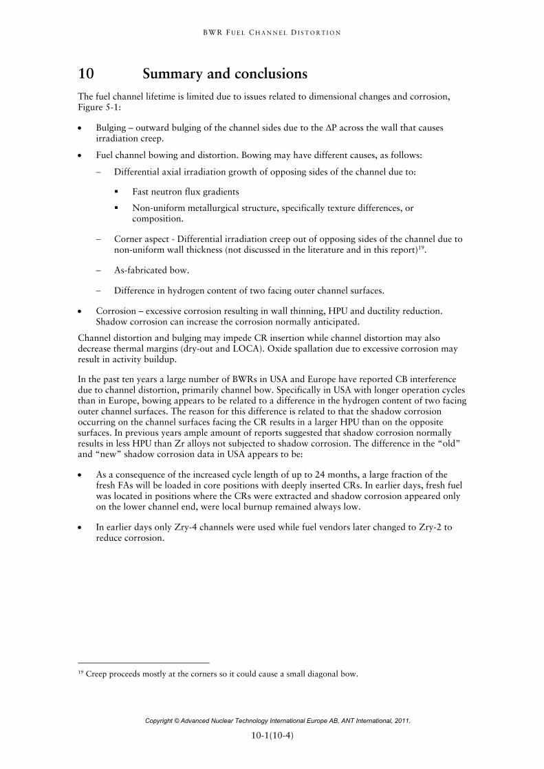
10 Summary and conclusions The fuel channel lifetime is limited due to issues related to dimensional changes and corrosion, Figure 5-1:
Bulging – outward bulging of the channel sides due to the ΔP across the wall that causes irradiation creep.
Fuel channel bowing and distortion. Bowing may have different causes, as follows:
Differential axial irradiation growth of opposing sides of the channel due to:
Fast neutron flux gradients
Non-uniform metallurgical structure, specifically texture differences, or composition.
Corner aspect - Differential irradiation creep out of opposing sides of the channel due to non-uniform wall thickness (not discussed in the literature and in this report)19.
As-fabricated bow.
Difference in hydrogen content of two facing outer channel surfaces.
Corrosion – excessive corrosion resulting in wall thinning, HPU and ductility reduction. Shadow corrosion can increase the corrosion normally anticipated.
Channel distortion and bulging may impede CR insertion while channel distortion may also decrease thermal margins (dry-out and LOCA). Oxide spallation due to excessive corrosion may result in activity buildup.
In the past ten years a large number of BWRs in USA and Europe have reported CB interference due to channel distortion, primarily channel bow. Specifically in USA with longer operation cycles than in Europe, bowing appears to be related to a difference in the hydrogen content of two facing outer channel surfaces. The reason for this difference is related to that the shadow corrosion occurring on the channel surfaces facing the CR results in a larger HPU than on the opposite surfaces. In previous years ample amount of reports suggested that shadow corrosion normally results in less HPU than Zr alloys not subjected to shadow corrosion. The difference in the “old” and “new” shadow corrosion data in USA appears to be:
As a consequence of the increased cycle length of up to 24 months, a large fraction of the fresh FAs will be loaded in core positions with deeply inserted CRs. In earlier days, fresh fuel was located in positions where the CRs were extracted and shadow corrosion appeared only on the lower channel end, were local burnup remained always low.
In earlier days only Zry-4 channels were used while fuel vendors later changed to Zry-2 to reduce corrosion.
19 Creep proceeds mostly at the corners so it could cause a small diagonal bow.
B W R F U E L C H A N N E L D I S T O R T I O N
Copyright © Advanced Nuclear Technology International Europe AB, ANT International, 2011.
10-2(10-4)
Other important observations are:
For the shadow-induced channel bow:
Only Zry-2 channels are affected while Zry-4 channels does not show shadow-induced bow.
The bow becomes significant only at higher burnups while shadow corrosion of the fuel channel surface facing the CR starts very early during irradiation.
Increased length of CR insertion and duration of its insertion increases bow later on. The timing when a CR is inserted has also a large impact on fuel channel bow. An increased length of time without any CR inserted for the fresh fuel channel before the CR is inserted, will reduce the bow.
BWRs with an elevated Cu coolant concentration (e.g. due to aluminium brass condenser tubes or feedwater heaters) seems to show less channel bow.
For bow in general:
In some cases recent AREVA channel bow data suggest that both bowing is related to both shadow corrosion and a fast flux gradient across the channel. On the other hand, GNF bowing data can be explained by only the shadow corrosion mechanism.
Recent data suggest that hydrogen in the zirconium alloy fuel channel material may accelerate the fast fluence irradiation growth rate.
The industry is handling the fuel channel bow issue by:
Developing tools that may predict the channel bow, e.g. ECBE.
Material development:
Beta-quenching the channel (or the final size strip material used to manufacture the channel) will eliminate the fast fluence-induced bow (but will not remedy the shadow corrosion induced Zry-2 channel bow).
In a first step, Zry-4 is replaced by Zry-2 to eliminate shadow-induced bow (but fluence induced bow still occurs for Zry-4). In general, Zry-4 corrosion resistance is inferior to that of Zry-2 which needs to be taken into account. Perhaps improvements of the Zry-4 manufacturing process and modification of its chemical composition can improve its corrosion resistance.
In a second step, new Zr-Nb-Fe alloys (without any nickel) are being developed.
The authors of this STR suggest the following steps leading to shadow-induced channel bow:
1) An un-autoclaved fresh channel is inserted into the core. If in a control cell configuration, shadow corrosion starts forming after a few days. In not in a controlled position, uniform oxide builds up a protective black oxide in a few months.
2) Shadow corrosion oxide thickens quickly such that after one cycle (about 19 MWd/MT) oxide thickness on the CB side is greater than away from the blade (16 microns versus 4 microns according to [Mahmood et al, 2010]). At this time Laves phase SPPs have lost much Fe, but in Zry-2 the Zintle phase SPPs are still rich in Fe and Ni. The HPUF for Zry-2 and -4 are still similar.
3) At some time, the CB is withdrawn or moved, stopping shadow corrosion. However, corrosion continues, with the distinct possibility that the corrosion rate of the original shadow oxide is greater than the non-shadow oxide on the channel face away from the blade.
B W R F U E L C H A N N E L D I S T O R T I O N
Copyright © Advanced Nuclear Technology International Europe AB, ANT International, 2011.
10-3(10-4)
4) Depending on fluence, extensive dissolution of the Laves phase SPPs occurs in both Zry-2 and -4. In Zry-2 dissolution of the Zintle phase SPPs lags behind because of their larger size. Ni has dissolved into the matrix, but its maximum level has not yet been reached. However, HPUF is Zry-2 is increasing.
5) At intermediate to high fluence oxide thickness is considerable higher on the CB side compared to non-blade side (at 40 MWd/MT, 30 microns versus 8 microns (Table 8-6). SPP dissolution is very extensive and in Zry-2 the matrix has very high levels of Fe and Ni (and Cr). Zry-4 has high levels of only Fe (and Cr). At this point according to the mechanism proposed by [Garzarolli et al, 2010b] (Section 8.4), Ni at the oxide/metal interface can remain metallic, and can act as a hydrogen window from the oxide to the metal. The HPUF thus reaches a high level in Zry-2 but not in Zry-4 because of the absence of Ni. Independent of the exact mechanism, because of the relatively high HPUF of Zry-2 and the relatively high oxide thickness on the CB side, the hydrogen values on that side become much higher than on the opposite side. This leads to bow.
6) In the case of reactor water containing significant amounts of Cu, is well-known that Cu in the coolant will make radiolysis more difficulty, probably resulting in a redox-potential within the shadow corrosion oxide that is not low enough to keep the Ni in metallic phase in the Zry-2 oxide GBs. Without metallic Ni, the HPUF will not increase.
7) We also acknowledge that hydrogen or hydrides in the Zirconium lattice may increase irradiation growth (see Section 4.2.3 for experimental results) at some level of hydrogen or fluence. It is noted that the one cycle channel (#9 from [Mahmood et al, 2010]) that had little or no bow had hydrogen levels below the solubility values at the channel temperature.
Some of the general points above are discussed more in the following.
PIE of a fuel channel from a German BWR also showed a very low shadow oxide layer build up and shadow induced bow in case of channel B although it had a very high EFDI value (293 d). As Figure 8-21 showed, in this case the CR was not inserted from beginning of irradiation but only after 132 d. The initial oxide layer, which forms during the first 130 days without an inserted CB, reduces the shadow corrosion significantly, a situation which is not considered in the today’s ECBE calculation.
Furthermore, as Figure 8-27 showed, no clear relationship between oxide gradient (difference in oxide thickness of CB and opposite CB side) and ECBE was be obtained in Cofrentes, although a slight trend of oxide gradient increase with ECBE increase was observed especially for high ECBE values. The increase of shadow corrosion was lower in Cofrentes as seen in Clinton. The detailed CR history is not known for both the Clinton and the Cofrentes case, but the very small oxide thickness of W channels in Cofrentes e.g. at high burnup (41-53 MWd/kgU) in spite of an ECBE of 15000 in.d may be an indication that these channels have not seen the CB from the early beginning but only after some time. On the other hand, [Mahmood et al, 2010] reported that also GNF channel no. 10 from plant D showed a rather high shadow oxide thickness (42-43 μm)even though it had seen a CB only after 600 days operation for about 250 days (ECBE=17795in.d, Figure 8-16). Only channel no. 11 with a much later control insertion (after 1200 days, ECBE= 712 in.d) had an oxide thickness of the CB side comparable to that of the non-control side. These results indicate that the effect of the initial non controlled time can vary significantly probably depending on water chemistry, material condition and actual proximity of the CR.
The effect of an in-BWR preoxidation on shadow corrosion is obviously not well known today.
B W R F U E L C H A N N E L D I S T O R T I O N
Copyright © Advanced Nuclear Technology International Europe AB, ANT International, 2011.
11-1(11-2)
11 Recommendations The effect of an in-BWR preoxidation on shadow corrosion is obviously not well known today. The following correlation could be considered for Zry-2 to give a more relevant parameter for the CB effect on channel bow of Zry-2 channel. The corrosion thickness of the channel side facing the CB in (μm) is described as:
Shadow-Corr Thickn = so + C1[(t - ti)n - (to-ti)n]
where t is time in days,
ti is the time to initiate shadow corrosion (~5d),
to is the time before CB insertion in days,
so is the normal uniform oxide thickness at to,
and C1 and n are constants. Possible values for C1 and n are ~5 and 0.37, respectively.
The normal uniform corrosion thickness (S) in μm can be described by a correlation assuming a rate transition after a certain time (ts):
Before rate transition S = C2*tm
and after the rate transition S = St + C3*(t-ts)
were C2, C3, and m are constants. Possible values are 0.5, 0.007, and 0.33, respectively
ts is the time up to the rate transition. A possible value is 900d and
St the oxide thickness at the transition (= C2*tsm)
For the continued increase of the shadow corrosion after the CR has been withdrawn it can be assumed that corrosion follows the same linear law as the uniform after rate transition.
The increasing oxide thickness data base from controlled channels should allow a reasonable evaluation of these constants dependant on time of CB insertion, water chemistry, etc.
To assess the potential effect of coolant chemistry (NWC, HWC and NMCA) on shadow corrosion tendency and shadow corrosion induced channel bow, a detailed analysis of periods when HWC and NMCA where applied and a comparison with the CR insertion periods is recommended. Since Cu appears to reduce shadow corrosion induced bow, it is recommended for reactors with elevated Cu coolant concentrations, to take samples from high burnup Zry-2 channels for PIE for hydrogen pick up and oxide layer thickness.
For the next years very likely Zry-4 will be applied for BWRs with long cycles where the fuel channels are experiencing early CR exposure resulting in rather large ECBE values. However, Zry-4 may experience a quite high oxide thickness at high burnup that may lead in single cases even to oxide spallations and high activities at the pressure vessel bottom, which is of importance for CR drive inspections. The corrosion of Zry-4 at high burnups is known to show strong variations. Their reasons are not well known. Water chemistry is one aspect and alloying chemistry another reason, e.g. [Garzarolli et al, 1994]. It is recommended to analyze the existing data base for correlations between oxide thickness at high burnups and the alloying chemistry especially the Cr and Si content to optimize the corrosion. Potentially, the alloy content of Zry-4 could be defined within the upper ASTM range.
B W R F U E L C H A N N E L D I S T O R T I O N
Copyright © Advanced Nuclear Technology International Europe AB, ANT International, 2011.
12-1(12-8)
12 References Adamson R. B., Irradiation Growth of Zircaloy, Zirconium in the Nuclear Industry; Third
Conference, ASTM STP 633, pp. 326, 1977.
Adamson R. B., Lutz D. R., Davies J. H., Hot Cell Observations of Shadow Corrosion Phenomena, Proceedings Fachtagung der KTG-Fachgruppe, Brennelemente und Kernbautelle, 29 Februar/1 Marz 2000, Forschungszentrum Karlsruhe, 2000.
Adamson R. B. and Rudling P., Dimensional Stability of Zirconium Alloys, ZIRAT7/IZNA2 Special Topics Report, ANT International, Mölnlycke, Sweden, ANT International, 2002/2003.
Adamson R. B., Cox B., Garzarolli F., Strasser A., Rudling P. and Wikmark G., Corrosion of Zirconium Alloys, ZIRAT7/IZNA2 Special Topics Report, ANT International, Mölnlycke, Sweden, 2002/2003.
Adamson and Cox, Impact of Irradiation on Material Performance, ZIRAT10/IZNA5 Special Topics Report, ANT International, Mölnlycke, Sweden, 2005/2006.
Adamson R., Garzarolli F., Cox B., Strasser A. and Rudling P., Corrosion Mechanisms in Zirconium Alloys, ZIRAT12/IZNA7 Special Topics Report, ANT International, Mölnlycke, Sweden, 2007/2008.
Adamson R. B, Garzarolli F. and Patterson C., In-Reactor Creep of Zirconium Alloys, ZIRAT14/IZNA9 Special Topical Report, ANT International, Mölnlycke, Sweden, 2009.
Adamson, R. B. editor, Zirconium Production and Technology, The Kroll Medal Papers 1975-2010, RPS2, ASTM International, 2010.
Adamson R. B, Garzarolli F., Patterson C., Rudling P. Strasser A. and Coleman K., ZIRAT15/IZNA10 Annual Report, ANT International, Mölnlycke, Sweden, 2010.
Andersson B., Limbäck M., Wikmark G., Hauso E., Johnsen T., Ballinger R. G. and Nystrand A-C., Test Reactor Studies of the Shadow Corrosion Phenomenon, Zirconium in the Nuclear Industry: 13th Int’l Symposium, ASTM STP 1423, Moan G. D. and Rudling P., Eds., ASTM, 2002.
Bajaj R., Kammenzind B. F., and Farkas D. M., Effects of Neutron Irradiation on the Microstructure of Alpha-Annealed Zircaloy-4, Zirconium in the Nuclear Industry: 13th International Symposium, ASTM STP 1423, G. D. Moan and P. Rudling, Eds., ASTM International, pp. 400-426, West Conshohocken, PA, 2002.
Barberis P., Rebeyrolle V., Vermoyal J. J., Chabretou V. and Vassault J. P., CASTA DIVTM: experiments and modeling of oxide induced deformation in nuclear components, 15th ASTM International Symposium: Zirconium in the Nuclear Industry, Sunriver, OR, June 2007.
Becker K. M. et. al, Analysis of the Dryout Incident in The Oskarshamn 2 Boiling Water Reactor, Paper presented at the European Two-Phase Flow Group Meeting, Paris, May 29-31, 1989.
Beier M., Münchow P., Dewes P. and Hoffmann P., Methods for examination of BWR fuel assembly structure exemplified by the implementation of Zry-2 PGP+ as material for structural components, Fachtagung der KTG-Fachgruppe, Brennelemente und Kernbauteile, Karlsruhe, 2008.
Bieli R., Ledergerber G., Zbib A., Blavius D., Münch C-J., Abnormal bow of Zircaloy-2 fuel channels without shadow corrosion influence, Jahrestagung, Germany, 2011.
B W R F U E L C H A N N E L D I S T O R T I O N
Copyright © Advanced Nuclear Technology International Europe AB, ANT International, 2011.
12-2(12-8)
Blat-Yrieix M., Ambard A., Foct F., Miguel A., Beguin S. and Cayet N., Toward a better understanding of dimensional changes in Zircaloy-4: What is the impact induced by hydrides and oxide layer?, Journal of ASTM International, Vol. 5, No. 9, Paper ID JAI101321, 2008.
Blavius D., Mueuch E-J. and Garner N. L., Dimensional Behavior of Fuel Channels – Recent Experience and Consequences, ANS/TOPFUEL, San Francisco, October, 2007.
Blavius D., Münch C-J. and Garner N., Dimensional Behavior of Fuel Channels – Update on the Operational Experiences and Evaluation Results, KTG Jahrestagung Kerntechnik, Hamburg, 2008a.
Blavius D et al., Dimensional Behavior of Fuel Channels – Update on the operational Experience and Evaluation Results, Proc. Annual Meeting on Nuclear Technology, Deutsches Atomforum, pp. 451-459, Hamburg, Germany, 2008b.
Cantonwine P. E., Karve, A. A., Lin, Y. P., Mahmood, S. T., White, D. W. and Crawford, D. C., GNF channel performance and success in mitigating channel distortion and cell friction, 2008 Water Reactor Fuel Performance, Seoul, Korea, paper 8078, October, 2008.
Cantonwine P., Crawford D., Downs M., Joe B., Bahensky T., Reimer J., del la Hoz C., Petersen K., Reitmeyer M., Morris J. and Zbib A., Channel - Control Blade Interference Management at LaSalle 1 and 2 during 2007 and 2008,. Proceedings of Top Fuel 2009, Paper 2154, Paris, France, September 6-10, 2009.
Cantonwine P., Paustian H., Hahn G., Tusar J., Reitmeyer M. and Mader E., Channel – Control Blade Interference in GE Boiling Water Reactor, D-Lattice Plants with Zircaloy-2 Channels, Proceedings of 2010 LWR Fuel Performance, Paper 079, Orlando, Florida, USA, September 26-29, 2010.
Causey A. R., Holt R. A. and MacEwen S. R., In-reactor creep of Zr2.5Nb, ASTM Spec. Techn. Publ. 824, pp. 269-, 1984.
Châtelain A., Anderson B., Ballinger R. G. and Wikmark G., Enhanced Corrosion of Zirconium Base Alloys in Proximity to Other Metals: the Shadow Effect, p.485-498, Int. Topical Meeting on LWR Fuel Performance, Park City, UT, April, 2000.
Chen J. S. F. and Adamson R. B., Observations of Shadow Phenomena on Zirconium Alloys, Proceedings of the International Topical Meeting on LWR Fuel Performance, 309-317, ANS, West Palm Beach, Florida, 1994.
Cheng B., Adamson R. B., Bell W. L. and Proebstle R. A., Corrosion performance of some Zr alloys irradiated in the Steam Generating Heavy Water Reactor, Winfrith, Proc. 1st Conference on Environmental Degradation in Nuclear Power Systems, pp. 273-296, Myrtle Beach, 1983.
Cheng B. and Adamson R. B., Mechanistic Studies of Zircaloy Nodular Corrosion, Zirconium in the Nuclear Industry: 7th Int’l Symposium, ASTM STP 393, Adamson R. B. and Van Swam L. F. P., Eds., ASTM, Philadelphia, 387-416, 1987.
Coleman C. E. and Ambler J. F. R, Solubility of Hydrogen Isotopes in Stressed Hydride – Forming Metals, Scripter Met. 17, pp. 77-82, 1983.
Cox B., Mechanisms of Zirconium Alloy Corrosion in Nuclear Reactors, Proc. Int. Symp. on Corrosion Science in the 21st, Century, Manchester, UK, July 6-10th, J. Corr. Sci. and Eng., Vol. 6, pp. 14, 2003.
Cox B., Garzarolli F., and, Rudling R., Corrosion of Zr-Nb Alloys, ZIRAT9/IZNA4 Special Topics Report, ANT International, Mölnlycke, Sweden, 2004/2005.
B W R F U E L C H A N N E L D I S T O R T I O N
Copyright © Advanced Nuclear Technology International Europe AB, ANT International, 2011.
12-3(12-8)
Cox B., Garzarolli F., Strasser A. and Rudling P., Structural Behaviour of Fuel and Fuel Channel Components, ZIRAT10/IZNA5 Special Topics Report, ANT International, Mölnlycke, Sweden, 2005/2006.
Cox B., Garzarolli F., Adamson R., Rudling P. and Strasser A., Fuel Material Technology Report, Vol. I, ANT International, Mölnlycke, Sweden, 2006.
Dag A., Hallstadius L., Enica A., and Helmersson S., Westinghouse new BWR fuel – towards the flawless target, Proceedings of 2010 LWR Fuel Performance Conference, Paper 61, Orlando, Florida, USA, 2010.
Dahlbäck M, Lundholm L., Bard T. and Jourdine P., Fuel channel material development, KTG Conference on Material Development for Fuel Elments In LWRs, Karlsruhe, Germany, 1993.
Dahlbäck M., Hallstadius L, Limbäck M., Bunel G., Moinard P., Andersson T., Askeljung P., Flygar J. and Karlsson M., The Effect of Beta Quenching in Final Dimension on the Irradiation Growth of Tubes and Channels, Proc. 14th ASTM Symposium on Zirconium in the Nuclear Industry, Stockholm, 2004.
Dahlbäck M, Limbäck M., Hallstadius L., Barberis P., Bunel G., Simonot C., Andersson T., Askeljung P., Flygar J., Lehtinen B. and Massih A. R., The effect of beta quenching in final dimension on the irradiation growth of tubes and channels, Journal of ASTM International, 2, June 2005, paper JAI12337, 2005.
Donaldson A. T., Growth in Zircaloy-4 fuel clad arising from oxidation at temperatures in the rage of 623 to 723 K, ASTM STP 1132, pp177-197, 1991.
Etoh Y. et al, Neutron Irradiation Effects on the Nodular Corrosion of Zircaloy-2, International Topical meeting on LWR Fuel Performance, Vol. 2, p. 691, ANS/ENS, Avignon, France, 1991.
Etoh Y. and Shimada S., Neutron Irradiation Effects on Intermetallic Precipitates in Zircaloy as a function of Fluence, Journal of Nuclear Materials, Vol. 200, pp. 59-69, 1993.
Fidleris V., Tucker R. P. and Adamson R. B., An overview of microstructural and experimental factors that affect the irradiation growth behaviour of zirconium alloys, Zirconium in the Nuclear Industry: 7th International Symposium, Adamson R. B. and Von Swam Eds., ASTM Spec. Techn. Publ. 939, ASTM, pp. 49-85, 1987.
Fukuya et al, BWR Fuel Channel Performance and Localized Corrosion at High Burnup, Proc. ANS LWR Fuel Performance Conference, pp. 580-586, Palm Beach, 1994.
Garzarolli, F. and Manzel R., Korrosionsbeständigkeit von Zircaloy in KWU-Leistungsreaktoren (Corrosion Resistance of Zircaloy in KWU Power Reactors), Proc. Reaktortagung, KTG, 477-480, Mannheim, 29 March - 1 April 1977.
Garzarolli F. and Stehle H., Behavior of structural materials for fuel and control elements in light water cooled power reactors, Proc IAEA International Symposium on Improvement in water reactor fuel technology and Utilization, pp. 387-407, Stockholm, 1987.
Garzarolli F., Dewes P., Maussner G. and Basso H-H., Effects of high neutron fluences on microstructure and growth of Zircaloy-4, Zirconium in the Nuclear Industry: Eighth International Symposium, ASTM STP 1023, pp. 641-657, ASTM, 1989.
Garzarolli F., Schumann R. and Steinberg E., Corrosion Optimized Zircaloy for Boiling Water Reactor (BWR) Fuel Elements, Zirconium in the Nuclear Industry, Tenth Int’l Symposium, ASTM STP 1245, A. M. Garde and E. R. Bradley, Eds., American Society for Testing and Materials, Philadelphia, 709-723, 1994.