grand gulf nuclear station - nrc integrated inspection
TRANSCRIPT
UNITED STATES NUCLEAR REGULATORY COMMISSION
REGION IV 1600 E. LAMAR BLVD.
ARLINGTON, TX 76011-4511
February 11, 2016 Kevin Mulligan Site Vice President Operations Entergy Operations, Inc. Grand Gulf Nuclear Station P.O. Box 756 Port Gibson, MS 39150
SUBJECT: GRAND GULF NUCLEAR STATION – NRC INTEGRATED INSPECTION REPORT 05000416/2015004 AND 07200050/2015001
Dear Mr. Mulligan:
On December 31, 2015, the U.S. Nuclear Regulatory Commission (NRC) completed an inspection at your Grand Gulf Nuclear Station, Unit 1. On January 7, 2016, the NRC inspectors discussed the results of this inspection with you and other members of your staff. Inspectors documented the results of this inspection in the enclosed inspection report.
NRC inspectors documented three findings of very low safety significance (Green) in this report. Three of these findings involved violations of NRC requirements. Additionally, NRC inspectors documented one Severity Level IV violation with no associated finding. Further, inspectors documented two licensee-identified violations that were determined to be of very low safety significance (Green) in this report. The NRC is treating these violations as non-cited violations consistent with Section 2.3.2.a of the NRC Enforcement Policy.
If you contest the violations or significance of these non-cited violations, you should provide a response within 30 days of the date of this inspection report, with the basis for your denial, to the U.S. Nuclear Regulatory Commission, ATTN: Document Control Desk, Washington, DC 20555-0001; with copies to the Regional Administrator, Region IV; the Director, Office of Enforcement, U.S. Nuclear Regulatory Commission, Washington, DC 20555-0001; and the NRC resident inspector at the Grand Gulf Nuclear Station. If you disagree with a cross-cutting aspect assignment in this report, you should provide a response within 30 days of the date of this inspection report, with the basis for your disagreement, to the Regional Administrator, Region IV; and the NRC resident inspector at the Grand Gulf Nuclear Station. In accordance with Title 10 of the Code of Federal Regulations (10 CFR) 2.390, “Public Inspections, Exemptions, Requests for Withholding,” a copy of this letter, its enclosure, and your response (if any) will be available electronically for public inspection in the NRC’s Public
K. Mulligan - 2 -
Document Room or from the Publicly Available Records (PARS) component of the NRC's Agencywide Documents Access and Management System (ADAMS). ADAMS is accessible from the NRC Web site at http://www.nrc.gov/reading-rm/adams.html (the Public Electronic Reading Room).
Sincerely, /RA/ Greg Warnick, Branch Chief Project Branch C Division of Reactor Projects
Docket No. 50-416; 72-050 License No. NPF-29 Enclosure: Inspection Report 05000416/2015004 and 07200050/2015001
w/ Attachments: 1. Supplemental Information
2. Request for Information – Occupational Radiation Safety Inspection 3. Detail Risk Evaluation for Division III
Diesel Generator cc w/ encl: Electronic Distribution for Grand Gulf Nuclear Station
K. Mulligan - 2 -
Document Room or from the Publicly Available Records (PARS) component of the NRC's Agencywide Documents Access and Management System (ADAMS). ADAMS is accessible from the NRC Web site at http://www.nrc.gov/reading-rm/adams.html (the Public Electronic Reading Room).
Sincerely, /RA/ Greg Warnick, Branch Chief Project Branch C Division of Reactor Projects
Docket No. 50-416; 72-050 License No. NPF-29 Enclosure: Inspection Report 05000416/2015004 and 07200050/2015001
w/ Attachments: 1. Supplemental Information 2. Request for Information – Occupational
Radiation Safety Inspection 3. Detail Risk Evaluation for Division III
Diesel Generator cc w/ encl: Electronic Distribution for Grand Gulf Nuclear Station DISTRIBUTION: See next page
ADAMS ACCESSION NUMBER: ML16043A104 SUNSI Review By: CHY
ADAMS Yes No
Non-Sensitive Sensitive
Publicly Available Non-Publicly Available
Keyword: NRC-002
OFFICE SRI:DRP/C RI:DRP/C SPE:DRP/C C:DRS/EB1 C:DRS/EB2 C:DRS/OB NAME MYoung NDay CYoung TFarnholtz GWerner VGaddy SIGNATURE /RA/E- /RA/E- /RA/ /RA/ERuesch,
for /RA/ /RA/JKirkland,
for DATE 2/11/16 2/11/16 2/9/16 2/9/16 2/10/16 2/9/16 OFFICE C:DRS/PSB1 C:DRS/PSB2 TL:DRS/IPAT C:RIV:DNMS RIV:DNMS C:DRP/C NAME MHaire HGepford THipschman RKellar ESimpson GWarnick SIGNATURE /RA/JLarsen,
for /RA/ /RA/ /RA/RBrowder,
for /RA/ /RA/
DATE 2/10/16 2/10/16 2/9/16 2/11/16 2/11/16 2/11/16 OFFICIAL RECORD COPY
Letter to Kevin Mulligan from Greg Warnick dated February 11, 2016
SUBJECT: GRAND GULF NUCLEAR STATION – NRC INSPECTION REPORT 5000416/2015004 AND 07200050/2015001
Electronic distribution by RIV: Regional Administrator ([email protected]) Deputy Regional Administrator ([email protected]) DRP Director ([email protected]) DRP Deputy Director ([email protected]) DRS Director ([email protected]) DRS Deputy Director ([email protected]) Senior Resident Inspector ([email protected]) Resident Inspector ([email protected]) Administrative Assistant (Vacant) Branch Chief, DRP/C ([email protected]) Branch Chief, DRS/EB1 ([email protected]) Branch Chief, DRS/EB2 ([email protected]) Branch Chief, DRS/OB ([email protected]) Branch Chief, DRS/PSB1 ([email protected]) Branch Chief, DRS/PSB2 ([email protected]) Branch Chief, DNMS/FCDB ([email protected]) SFSI Inspector, DNMS/FCDB ([email protected]) Senior Project Engineer, DRP/C ([email protected]) Project Engineer ([email protected]) Project Engineer ([email protected]) Public Affairs Officer ([email protected]) Project Manager ([email protected]) Project Manager ([email protected]) Team Leader, DRS/TSS ([email protected]) RITS Coordinator ([email protected]) ACES ([email protected]) Regional Counsel ([email protected]) Technical Support Assistant ([email protected]) Congressional Affairs Officer ([email protected]) RIV Congressional Affairs Officer ([email protected]) OEWEB Resource ([email protected]) OEWEB Resource ([email protected]) RIV/ETA: OEDO ([email protected]) [email protected] [email protected]
- 1 - Enclosure
U.S. NUCLEAR REGULATORY COMMISSION
REGION IV
Docket: 05000416 and 07200050
License: NPF-29
Report: 05000416/2015004 and 07200050/2015001
Licensee: Entergy Operations, Inc.
Facility: Grand Gulf Nuclear Station, Unit 1
Location: 7003 Baldhill Road Port Gibson, MS 39150
Dates: October 1 through December 31, 2015
Inspectors: M. Young, Senior Resident Inspector N. Day, Resident Inspector D. Loveless, Senior Reactor Analyst J. Buchanan, Physical Security Inspector H. Freeman, Senior Reactor Inspector N. Greene, PhD, Health Physicist G. Guerra, CHP, Emergency Preparedness Inspector M. Phalen, Senior Health Physicist G. Pick, Senior Reactor Inspector E. Simpson, ISFSI Inspector
Approved By:
Greg Warnick, Chief, Project Branch C Division of Reactor Projects
- 2 -
SUMMARY
IR 05000416/2015004, 07200050/2015001; 10/01/2015 – 12/31/2015; Grand Gulf Nuclear Station; Maintenance Effectiveness, Maintenance Risk Assessments and Emergent Work Control, Operability Determinations and Functionality Assessments, and Post-Maintenance Testing The inspection activities described in this report were performed between October 1 and December 31, 2015, by the resident inspectors at the Grand Gulf Nuclear Station and inspectors from the NRC’s Region IV office. Three findings of very low safety significance (Green) are documented in this report. Three of these findings involved violations of NRC requirements. Additionally, NRC inspectors documented one Severity Level IV violation with no associated finding. Further, inspectors documented two licensee-identified violations that were determined to be of very low safety significance (Green) in this report. The significance of inspection findings is indicated by their color (Green, White, Yellow, or Red), which is determined using Inspection Manual Chapter 0609, “Significance Determination Process.” Their cross-cutting aspects are determined using Inspection Manual Chapter 0310, “Aspects within the Cross-Cutting Areas.” Violations of NRC requirements are dispositioned in accordance with the NRC Enforcement Policy. The NRC’s program for overseeing the safe operation of commercial nuclear power reactors is described in NUREG-1649, “Reactor Oversight Process.”
Cornerstone: Mitigating Systems
• Green. The inspectors reviewed a self-revealing non-cited violation of Technical Specification 5.4.1.a, for the failure to establish adequate instructions to perform a simulated surveillance on the division I diesel generator. Specifically, the simulated surveillance run instructions verified the trip high vibration (E-23H) valve was open, but it did not close the (E-23H) valve following the run to ensure the high vibration trip was bypassed. As a result, the division I diesel generator spuriously tripped on high vibrations during the November 21, 2015, run and was rendered inoperable and unavailable. On November 22, 2015, the licensee closed the trip high vibration (E-23H) valve and successfully ran the division I diesel generator to return it to operable status. The licensee entered this issue into their corrective action program as Condition Report CR-GGN-2015-6831. The failure to establish adequate preventative maintenance instructions to perform a division I diesel generator simulated run and return the valve lineup to the required position was a performance deficiency. This performance deficiency is more than minor, and therefore a finding, because it is associated with the equipment performance attribute of the Mitigating Systems Cornerstone and adversely affected the cornerstone objective to ensure the availability, reliability, and capability of systems that respond to initiating events to prevent undesirable consequences. Specifically, following the division I diesel generator simulated run, the preventative maintenance instruction did not require the licensee to close the trip high vibration (E-23H) valve, and therefore the high vibration trip capability remained for a duration of approximately 16 hours. As a result, during the November 21, 2015 run, the diesel generator spuriously tripped on an invalid high vibration signal and was rendered inoperable and unavailable. Using Inspection Manual Chapter 0609, Appendix A, “The Significance Determination Process (SDP) for Findings At-Power,” and Inspection Manual Chapter 0609, Appendix A, Exhibit 2, “Mitigating Systems Screening Questions,” the inspectors determined that the finding is of very low safety significance (Green) because it: (1) was not a deficiency affecting the design or qualification of a mitigating structure, system,
- 3 -
or component, and did not result in a loss of functionality; (2) did not represent a loss of system and/or function; (3) did not represent an actual loss of function of at least a single train for longer than its technical specification allowed outage time, or two separate safety systems out-of-service for longer than their technical specification allowed outage time; and (4) did not represent an actual loss of function of one or more non-technical specification trains of equipment designated as high safety significant in accordance with the licensee’s maintenance rule program.
The inspectors determined that the finding has a design margin cross-cutting aspect within the human performance area because the licensee failed to ensure margins are carefully guarded and changed only through a systematic and rigorous process. Specifically, the licensee failed to fully implement their design change process such that all effected station documents and procedures were identified and revised after removing the high vibration trip for the division I and division II diesel generators [H.6]. (Section 1R12)
• Green. The inspectors identified a non-cited violation of Technical Specification Surveillance Requirement 3.0.1, for the failure to follow requirements when a surveillance was not performed within the specified frequency and declare the Limiting Condition for Operation not met or follow the provisions in Surveillance Requirement 3.0.3. Specifically, the licensee did not follow Technical Specification Surveillance Requirement 3.0.1, when they discovered that Surveillance Requirement 3.8.1.9 was not performed within its specified frequency and either declare Technical Specification Limiting Condition for Operation 3.8.1 not met, or perform the required actions to determine whether compliance with the requirement to declare the Limiting Condition for Operation not met may be delayed. The licensee failed to enter Technical Specification Surveillance Requirement 3.0.1, until September 29, 2015, after discussions with the NRC. On September 29, 2015, the licensee adequately performed the actions required in Technical Surveillance Requirement 3.0.3. The licensee entered this issue into their corrective action program as Condition Report CR-GGN-2015-5602. The failure to timely enter and perform the actions as required per Technical Specification Surveillance Requirement 3.0.1 was a performance deficiency. This performance deficiency is more than minor, and therefore a finding, because it is associated with the equipment performance attribute of the Mitigating Systems Cornerstone and adversely affected the cornerstone objective to ensure the availability, reliability, and capability of systems that respond to initiating events to prevent undesirable consequences. Specifically, the failure to perform technical specification surveillance requirements, and associated actions, did not ensure that the diesel generator could appropriately respond to initiating events. Using Inspection Manual Chapter 0609, Appendix A, “The Significance Determination Process (SDP) for Findings At-Power,” and Inspection Manual Chapter 0609, Appendix A, Exhibit 2, “Mitigating Systems Screening Questions,” the inspectors determined that the finding is of very low safety significance (Green) because it: (1) was not a deficiency affecting the design or qualification of a mitigating structure, system, or component, and did not result in a loss of functionality; (2) did not represent a loss of system and/or function; (3) did not represent an actual loss of function of at least a single train for longer than its technical specification allowed outage time, or two separate safety systems out-of-service for longer than their technical specification allowed outage time; and (4) did not represent an actual loss of function of one or more non-technical specification trains of equipment designated as high safety significant in accordance with the licensee’s maintenance rule program.
- 4 -
The inspectors determined that the finding has a conservative bias cross-cutting aspect within the human performance area because the licensee failed to use decision making-practices that emphasize prudent choices over those that are simply allowable. Specifically, operations personnel failed to enter Technical Specification Surveillance Requirement 3.0.1 because the operability determination alone justified operability without doing a detailed risk evaluation [H.14]. (Section 1R13)
• Green. The inspectors reviewed a self-revealing non-cited violation of Technical
Specification 5.4.1.a, for the failure to establish adequate maintenance instructions to perform work activities on the division III diesel generator overspeed trip limit switch. Specifically, work orders did not contain adequate instructions to check the overspeed trip switches’ alignment in accordance with vendor recommendations. As a result, the division III diesel generator was rendered inoperable and unavailable. On July 15, 2015, the licensee appropriately set the limit switch to overspeed actuating arm engagement, and returned the diesel generator to operable. The licensee entered this issue into their corrective action program as Condition Report CR-GGN-2015-3985. The failure to establish adequate work instructions to verify the overspeed switch was properly set and adjusted was a performance deficiency. This performance deficiency is more than minor, and therefore a finding, because it is associated with the equipment performance attribute of the Mitigating Systems Cornerstone and adversely affected the cornerstone objective to ensure the availability, reliability, and capability of systems that respond to initiating events to prevent undesirable consequences. Specifically, work orders to check the overspeed trip switches’ alignment did not contain adequate instructions to successfully perform the maintenance. The division III diesel generator was declared inoperable when the diesel spuriously tripped during the monthly surveillance run on July 13, 2015. The inspectors performed the initial significance determination for the division III emergency diesel generator failure. The inspectors used the NRC Inspection Manual 0609, Appendix A, Exhibit 2, “Mitigating Systems Screening Questions.” The finding required a detailed risk evaluation because it involved a performance deficiency that represented a loss of the high pressure core spray system following a postulated loss of offsite power because of the failure of the division III diesel generator. The Region IV senior reactor analyst performed a detailed risk evaluation in accordance with NRC Inspection Manual 0609, Appendix A, Section 6.0, “Detailed Risk Evaluation.” The detailed risk evaluation result is a finding of very low safety significance (Green). The calculated change in core damage frequency of 5.0 x 10⁻⁷ was dominated by an unrecovered station blackout beyond battery depletion. The analyst determined that the bounding risk of a large, early release of radiation was 9.6 x 10⁻⁸. For the details of the analysis, see Attachment 3.
Work orders were developed to address operating experience provided from the diesel generator vendor to the industry in December 2011. The inspectors determined that the cause of the deficiency occurred in 2011, and therefore, determined the finding did not have a cross-cutting aspect since it is not indicative of current licensee performance. (Section 1R19)
Cornerstone: Barrier Integrity
• SLIV. The inspectors identified a Severity Level IV, non-cited violation of 10 CFR 50.72(b)(3)(v)(C), for the licensee’s failure to make a required eight-hour report to the NRC for a condition that could have prevented fulfillment of the safety function of structures or systems that are needed to control the release of radioactive material.
- 5 -
Specifically, on October 14, 2015, the licensee failed to make the required eight-hour report following two primary containment isolation valves, 1P11F130 and 1P11F131, in the same flow path being declared inoperable. On October 15, 2015 at 9:07 pm, the licensee made a late Event Notification, EN 51473. The licensee entered this issue into their corrective action program as Condition Report CR-GGN-2015-6043. The failure to make an eight-hour report, as required by 10 CFR 50.72(b)(3)(v)(C), for a condition that could have prevented fulfillment of a safety function was a performance deficiency. This performance deficiency was screened using Inspection Manual Chapter 0612 and was determined to be a minor violation in the Reactor Oversight Process. However, due to the performance deficiency affecting the NRC’s ability to perform its regulatory oversight function, this performance deficiency was evaluated for traditional enforcement in accordance with the NRC Enforcement Policy. This performance deficiency was determined to be a Severity Level IV violation in accordance with Section 6.9.d.9 of the NRC Enforcement Policy, dated February 4, 2015. No cross-cutting aspect was assigned to this violation because no Reactor Oversight Process finding existed. (Section 1R15)
Licensee-Identified Violations Two violations of very low safety significance (Green) that were identified by the licensee have been reviewed by the inspectors. Corrective actions taken or planned by the licensee have been entered into the licensee’s corrective action program. These violations and their associated corrective action tracking numbers are listed in Section 4OA7 of this report.
- 6 -
PLANT STATUS The Grand Gulf Nuclear Station began the inspection period at 100 percent power. On October 8, 2015, the operators reduced power to approximately 85 percent to perform partial rod exercises and pattern adjustment. Upon completion, operators performed power ascension activities to reach 100 percent power on October 9, 2015. From November 12 – 23, 2015, the operators reduced power to approximately 53 percent to perform control rod sequence exchange, settle time testing, partial rod exercises and pattern adjustments. Upon completion, operators performed power ascension activities to reach 100 percent power on November 23, 2015. On December 10, 2015, the operators reduced power to approximately 81 percent to perform partial rod exercises. Upon completion, operators performed power ascension activities to reach 100 percent power on December 12, 2015. On December 18, 2015, the operators reduced power to approximately 83 percent to perform partial rod exercises. Upon completion, operators performed power ascension activities to reach 99 percent power on December 19, 2015. From December 28 – 31, 2015, the operators reduced power to approximately 59 percent to perform power suppression testing. Upon completion, operators performed power ascension activities to reach 87 percent power on December 31, 2015.
REPORT DETAILS
1. REACTOR SAFETY
Cornerstones: Initiating Events, Mitigating Systems, and Barrier Integrity 1R01 Adverse Weather Protection (71111.01)
.1 Readiness for Impending Adverse Weather Conditions
a. Inspection Scope
On November 17, 2015, the inspectors completed an inspection of the station’s readiness for impending adverse weather conditions. The inspectors reviewed plant design features, the licensee’s procedures to respond to tornadoes and high winds, and the licensee’s implementation of these procedures. The inspectors evaluated operator staffing and accessibility of controls and indications for those systems required to control the plant. These activities constituted one sample of readiness for impending adverse weather conditions, as defined in Inspection Procedure 71111.01.
b. Findings
No findings were identified.
- 7 -
.2 Readiness to Cope with External Flooding
a. Inspection Scope
On November 17, 2015, the inspectors completed an inspection of the station’s readiness to cope with external flooding. After reviewing the licensee’s flooding analysis, the inspectors chose three plant areas that were susceptible to flooding:
• diesel generator building and associated flood barrier doors • control building and associated flood barrier doors • control building and auxiliary building roofs
The inspectors reviewed plant design features and licensee procedures for coping with flooding. The inspectors walked down the selected areas to inspect the design features, including the material condition of seals, drains, and flood barriers. The inspectors evaluated whether credited operator actions could be successfully accomplished. These activities constituted one sample of readiness to cope with external flooding, as defined in Inspection Procedure 71111.01.
b. Findings
No findings were identified.
1R04 Equipment Alignment (71111.04)
.1 Partial Walkdown
a. Inspection Scope
The inspectors performed partial system walk-downs of the following risk-significant systems:
• October, 21, 2015, division II diesel generator while the division I diesel generator was in maintenance
• December 9, 2015, residual heat removal A while residual heat removal B was
inoperable for remote shutdown test
• December 10, 2015, standby service water A while division II diesel generator was inoperable
• December 10, 2015, standby service water C while division II diesel generator
was inoperable The inspectors reviewed the licensee’s procedures and system design information to determine the correct lineup for the systems. They visually verified that critical portions of the systems were correctly aligned for the existing plant configuration. These activities constituted four partial system walk-down samples, as defined in Inspection Procedure 71111.04.
- 8 -
b. Findings
No findings were identified.
1R05 Fire Protection (71111.05)
.1 Quarterly Inspection
a. Inspection Scope
The inspectors evaluated the licensee’s fire protection program for operational status and material condition. The inspectors focused their inspection on five plant areas important to safety:
• October 16, 2015, fire area 64, fire zones 1M110 and 1M112, standby service water pump house A and valve room
• October 16, 2015, fire area 65, fire zones 2M110 and 2M112, standby service water pump house B and valve room
• October 16, 2015, fire area 30, fire zone 0C214, division I switchgear area
(Unit 2)
• November 19, 2015, fire areas 20, fire zone 1A407, division II motor control center 16B41 room
• November 19, 2015, fire areas 21, fire zone 1A410, division I motor control
center 15B21 room For each area, the inspectors evaluated the fire plan against defined hazards and defense-in-depth features in the licensee’s fire protection program. The inspectors evaluated control of transient combustibles and ignition sources, fire detection and suppression systems, manual firefighting equipment and capability, passive fire protection features, and compensatory measures for degraded conditions. These activities constituted five quarterly inspection samples, as defined in Inspection Procedure 71111.05.
b. Findings
No findings were identified.
1R06 Flood Protection Measures (71111.06)
a. Inspection Scope
On December 10, 2015, the inspectors completed an inspection of the station’s ability to mitigate flooding due to internal causes. After reviewing the licensee’s flooding analysis, the inspectors chose two plant areas containing risk-significant structures, systems, and components that were susceptible to flooding:
- 9 -
• high pressure core spray pump room • residual heat removal C pump room
The inspectors reviewed plant design features and licensee procedures for coping with internal flooding. The inspectors walked down the selected areas to inspect the design features, including the material condition of seals, drains, and flood barriers. The inspectors evaluated whether operator actions credited for flood mitigation could be successfully accomplished. These activities constituted completion of two flood protection measures samples, as defined in Inspection Procedure 71111.06.
b. Findings
No findings were identified.
1R07 Heat Sink Performance (71111.07)
a. Inspection Scope
On October 20 – 21, 2015, the inspectors completed an inspection of the readiness and availability of risk-significant heat exchangers. The inspectors observed the licensee’s inspection of the division I diesel generator jacket water cooling heat exchanger and the material condition of the heat exchanger internals. Additionally, the inspectors walked down the heat exchanger to observe its performance and material condition, reviewed tube plugging data sheets and associated performance calculations, and verified that the heat exchanger was correctly categorized under the Maintenance Rule and was receiving the required maintenance. These activities constituted completion of one heat sink performance annual review sample, as defined in Inspection Procedure 71111.07.
b. Findings No findings were identified.
1R11 Licensed Operator Requalification Program and Licensed Operator Performance
(71111.11)
.1 Review of Licensed Operator Requalification
a. Inspection Scope
On November 16, 2015, the inspectors observed simulator training for an operating crew. The operating crew completed a training scenario that required operation of the plant in the MELLA+ operating region. The inspectors assessed the performance of the operators and the evaluators’ critique of their performance. The inspectors also assessed the modeling and performance of the simulator during the training activity. These activities constituted completion of one quarterly licensed operator requalification program sample, as defined in Inspection Procedure 71111.11.
- 10 -
b. Findings
No findings were identified. .2 Review of Licensed Operator Performance
a. Inspection Scope
On November 12 – 13, 2015, the inspectors observed the performance of on-shift licensed operators in the plant’s main control room. At the time of the observations, the plant was in a period of heightened activity due to a downpower to 55 percent for control rod sequence exchange, settle time testing, and monthly operability checks for control rod withdrawal blocks. The inspectors observed the operators’ performance of communications during the downpower, procedural adherence during control rod manipulation, and interaction between operators and reactor engineering. In addition, the inspectors assessed the operators’ adherence to plant procedures, including procedure EN-OP-115, “Conduct of Operations,” Revision 15, and other operations department policies. These activities constituted completion of one quarterly licensed operator performance sample, as defined in Inspection Procedure 71111.11.
b. Findings
No findings were identified. 1R12 Maintenance Effectiveness (71111.12)
a. Inspection Scope
The inspectors reviewed two instances of degraded performance or condition of safety-related structures, systems, and components (SSCs):
• December 23, 2015, standby liquid control system due to loss of continuity on the standby liquid control B squib valve
• December 30, 2015, division I diesel generator due to a high vibration trip during a surveillance test
The inspectors reviewed the extent of condition of possible common cause SSC failures and evaluated the adequacy of the licensee’s corrective actions. The inspectors reviewed the licensee’s work practices to evaluate whether these may have played a role in the degradation of the SSCs. The inspectors assessed the licensee’s characterization of the degradation in accordance with 10 CFR 50.65 (the Maintenance Rule), and verified that the licensee was appropriately tracking degraded performance and conditions in accordance with the Maintenance Rule. These activities constituted completion of two maintenance effectiveness samples, as defined in Inspection Procedure 71111.12.
- 11 -
b. Findings
Introduction. The inspectors reviewed a Green, self-revealing, non-cited violation of Technical Specification 5.4.1.a, for the failure to establish adequate instructions to perform a simulated surveillance on the division I diesel generator. Specifically, the simulated surveillance run instructions verified the trip high vibration (E-23H) valve was open, but it did not close the (E-23H) valve following the run to ensure the high vibration trip was bypassed. As a result, the division I diesel generator spuriously tripped on high vibrations during the November 21, 2015, run and was rendered inoperable and unavailable. Description. On November 21, 2015, the licensee was performing a monthly surveillance test on the division I diesel generator. This diesel generator run was also categorized as a post maintenance run to ensure that work done on the air start, lube oil, and voltage regulator systems was appropriate and correct. During this run, the diesel generator spuriously tripped on high vibrations. Engineering Change 51435 was completed August 27, 2014. The reason for the change was to bypass the vibration trip system for the division I and division II diesel generators. The purpose of the vibration trip was to provide equipment protection should high engine vibrations occur. However, industry experience indicated that the switches are unreliable in performing that function, causing spurious and unwanted trips, and subsequent system unavailability. Therefore, the licensee determined that it was acceptable to bypass and/or disable the engine vibration trips by closing and administratively locking the manual isolation valve (E-23H). This engineering change was developed and implemented via Corrective Action 11 of Condition Report CR-GGN-2013-5899 after a similar non-valid high vibration diesel generator trip occurred on the division I diesel generator. Before the division I diesel run took place, the licensee performed a simulated run, in accordance with Preventative Maintenance Instruction 07-S-23-P75-3, “Div I and Div II Diesel Generator Simulated Run”, Revision 7, to ensure that the pneumatic computer logic board was appropriately set, following maintenance on the air start, lube oil, and voltage regulator systems. This procedure was last revised on March 25, 2008. During this simulated run, the procedure required verification that the TRIP HIGH VIBRATION E-23H valve is open, but it does not require the valve to be closed after the run. As written, the procedure restored and maintained the high vibration diesel generator trip. Following the successful simulated run, on November 21, 2015, the licensee ran the division I diesel generator. Shortly after reaching full load, the diesel generator spuriously tripped on high engine vibrations and was declared inoperable and unavailable. On November 22, 2015, the licensee positioned the E-23H valve closed, successfully ran an operability test of the division I diesel generator with additional vibration monitoring, and declared it operable. Therefore, the high vibration trip vulnerability on division I diesel generator existed for approximately 16 hours. The licensee entered this into their corrective action program as Condition Report CR-GGN-2015-6831.
- 12 -
Analysis. The failure to establish adequate preventative maintenance instructions to perform a division I diesel generator simulated run and return the valve lineup to required position was a performance deficiency. This performance deficiency is more than minor, and therefore a finding, because it is associated with the equipment performance attribute of the Mitigating Systems Cornerstone and adversely affected the cornerstone objective to ensure the availability, reliability, and capability of systems that respond to initiating events to prevent undesirable consequences. Specifically, following the division I diesel generator simulated run, the preventative maintenance instruction did not require the licensee to close the trip high vibration (E-23H) valve, and therefore the high vibration trip capability remained for a duration of approximately 16 hours. As a result, during the November 21, 2015 run, the diesel generator spuriously tripped on an invalid high vibration signal and was rendered inoperable and unavailable. Using Inspection Manual Chapter 0609, Appendix A, “The Significance Determination Process (SDP) for Findings At-Power,” and Inspection Manual Chapter 0609, Appendix A, Exhibit 2, “Mitigating Systems Screening Questions,” the inspectors determined that the finding is of very low safety significance (Green) because it: (1) was not a deficiency affecting the design or qualification of a mitigating structure, system, or component, and did not result in a loss of functionality; (2) did not represent a loss of system and/or function; (3) did not represent an actual loss of function of at least a single train for longer than its technical specification allowed outage time, or two separate safety systems out-of-service for longer than their technical specification allowed outage time; and (4) did not represent an actual loss of function of one or more non-technical specification trains of equipment designated as high safety significant in accordance with the licensee’s maintenance rule program.
The inspectors determined that the finding has a design margin cross-cutting aspect within the human performance area because the licensee failed to ensure margins are carefully guarded and changed only through a systematic and rigorous process. Specifically, the licensee failed to fully implement their design change process such that all effected station documents and procedures were identified and revised after removing the high vibration trip for the division I and division II diesel generators [H.6].
Enforcement. Technical Specification 5.4.1.a, requires, in part, that written procedures shall be established, implemented, and maintained covering the applicable procedures recommended in Appendix A of Regulatory Guide 1.33, Revision 2. Section 9.a of Appendix A to Regulatory Guide 1.33, Revision 2, requires procedures for performing maintenance, such that, maintenance that can affect the performance of safety-related equipment should be properly pre-planned and performed in accordance with documented instructions appropriate to the circumstances. The licensee established Preventative Maintenance Instruction, 07-S-23-P75-3, “Div I and Div II Diesel Generator Simulated Run,” Revision 7, to meet the Regulatory Guide 1.33 requirement. Contrary to the above, on November 21, 2015, the licensee failed to establish documented instructions appropriate to the circumstances. Specifically, the licensee used Preventative Maintenance Instruction, 07-S-23-P75-3, “Div I and Div II Diesel Generator Simulated Run,” Revision 7, to perform a simulated diesel generator run but did not ensure the high vibration trip was bypassed before the instructions were concluded. As a result, during the November 21, 2015, division I diesel generator run, the diesel spuriously tripped on an invalid high vibration trip signal. On November 22, 2015, the licensee closed the trip high vibration (E-23H) valve and successfully ran the division I diesel generator to return it to operable status. Because this finding is determined to be of very low safety significance and has been entered into the licensee’s corrective action
- 13 -
program as Condition Report CR-GGN-2015-6831, this violation is being treated as a non-cited violation consistent with Section 2.3.2.a of the NRC Enforcement Policy: NCV 05000416/2015004-01, “Failure to Have Appropriate Instructions for Preventative Maintenance on the Division I Diesel Generator Simulated Run.”
1R13 Maintenance Risk Assessments and Emergent Work Control (71111.13)
a. Inspection Scope
On October 1, 2015, the inspectors reviewed a risk assessment performed by the licensee prior to changes in plant configuration and the risk management actions taken by the licensee in response to elevated risk required by Technical Specification Surveillance Requirement (SR) 3.0.3 for failure to perform SR 3.8.1.9 on division I, II, and III diesel generators. The inspectors verified that this risk assessment was performed timely and in accordance with the requirements of 10 CFR 50.65 (the Maintenance Rule) and plant procedures. The inspectors reviewed the accuracy and completeness of the licensee’s risk assessment and verified that the licensee implemented appropriate risk management actions based on the result of the assessment. Additionally, on October 1, 2015, the inspectors observed portions of one emergent work activity, secondary containment door seal replacements, after the failure of the secondary containment drawdown surveillance test that had the potential to impact barrier integrity. The inspectors verified that the licensee appropriately developed and followed a work plan for these activities. The inspectors verified that the licensee took precautions to minimize the impact of the work activities on unaffected structures, systems, and components (SSCs). These activities constituted completion of two maintenance risk assessments and emergent work control inspection samples, as defined in Inspection Procedure 71111.13.
b. Findings
Introduction. The inspectors identified a Green, non-cited violation of Technical Specification SR 3.0.1, for the failure to follow requirements when a surveillance was not performed within the specified frequency and declare the Limiting Condition for Operation (LCO) not met or follow the provisions in SR 3.0.3. Specifically, the licensee did not follow Technical Specification SR 3.0.1, when they discovered that SR 3.8.1.9 was not performed within its specified frequency and either declare Technical Specification LCO 3.8.1 not met, or perform the required actions to determine whether compliance with the requirement to declare the LCO not met may be delayed. Description. Technical Specification SR 3.8.1.9 states, “Verify each DG rejects a load greater than or equal to its associated single largest post-accident load and engine speed is maintained less than nominal plus 75 percent of the difference between nominal speed and the overspeed setpoint of 15 percent above nominal, whichever is lower.”
- 14 -
However, the technical specification surveillance requirements were not fulfilled during the testing. This was identified during the Grand Gulf 2015 Component and Design Basis Inspection and dispositioned as a Green, non-cited violation of Technical Specification 3.8.1 (NCV 050000416/2015007-06, “Failure to Perform Surveillance Requirement 3.8.1.9.”) The licensee determined that this was a missed surveillance on August 15, 2015. However, the licensee was able to provide reasonable expectation that the emergency diesel generators were capable of a largest load reject, by having successfully completed Technical Specification SR 3.8.1.10, which ensured that each diesel generator was able to reject a load greater than its respective single largest load. However, the NRC determined that Technical Specification SR 3.8.1.10 had never been performed, based on SR 3.0.1 and guidance from Inspection Manual Chapter 0326. Per Attachment 2 of NRC Inspection Manual Chapter 0326, “SR 3.0.3 may not be applied when a licensee discovers that a technical specification surveillance has never been performed. In cases where a specified safety function or a necessary and related support function required for operability has never been performed, then a reasonable expectation of operability does not exist. However, Technical Specification SR 3.0.3 would apply should the licensee determine that a technical specification surveillance had been demonstrated outside of routine surveillances, e.g., for post-maintenance testing, or for testing resulting from normal or off-normal plant operations.” Since the licensee was able to justify that Technical Specification SR 3.8.1.10 bounded Technical Specification SR 3.8.1.9, the use of the guidance in Inspection Manual Chapter 0326 for the scenario of a missed surveillance was appropriate. The licensee failed to enter SR 3.0.3 until September 29, 2015, when the inspectors asked for the SR 3.0.3 required risk assessment. At that point, the licensee adequately performed the actions required in SR 3.0.3. The licensee entered this into their corrective action program as Condition Report CR-GGN-2015-5602. Analysis. The failure to timely enter and perform the actions as required per Technical Specification SR 3.0.1 was a performance deficiency. This performance deficiency is more than minor, and therefore a finding, because it is associated with the equipment performance attribute of the Mitigating Systems Cornerstone and adversely affected the cornerstone objective to ensure the availability, reliability, and capability of systems that respond to initiating events to prevent undesirable consequences. Specifically, the failure to perform technical specification surveillance requirements, and associated actions, did not ensure that the diesel generator could appropriately respond to initiating events. Using Inspection Manual Chapter 0609, Appendix A, “The Significance Determination Process (SDP) for Findings At-Power,” and Inspection Manual Chapter 0609, Appendix A, Exhibit 2, “Mitigating Systems Screening Questions,” the inspectors determined that the finding is of very low safety significance (Green) because it: (1) was not a deficiency affecting the design or qualification of a mitigating structure, system, or component, and did not result in a loss of functionality; (2) did not represent a loss of system and/or function; (3) did not represent an actual loss of function of at least a single train for longer than its technical specification allowed outage time, or two separate safety systems out-of-service for longer than their technical specification allowed outage time; and (4) did not represent an actual loss of function of one or more non-technical
- 15 -
specification trains of equipment designated as high safety significant in accordance with the licensee’s maintenance rule program. The inspectors determined that the finding has a conservative bias cross-cutting aspect within the human performance area because the licensee failed to use decision making-practices that emphasize prudent choices over those that are simply allowable. Specifically, operations personnel failed to enter Technical Specification SR 3.0.1 because the operability determination alone justified operability without doing a detailed risk evaluation [H.14]. Enforcement. Technical Specification SR 3.0.1, states, in part, that the failure to perform a surveillance within the specified frequency shall be failure to meet the LCO except as provided in SR 3.0.3. Technical Specification SR 3.0.3 provided actions, such that, compliance with the requirement to declare the LCO not met may be delayed. Contrary to the above, on August 15, 2015, the licensee did not follow SR 3.0.1 when a surveillance was not performed within the specified frequency and declare the LCO not met or follow the provisions in SR 3.0.3. Specifically, the licensee did not follow SR 3.0.1, when they discovered that SR 3.8.1.9 was not performed within its specified frequency and either declare Technical Specification LCO 3.8.1 not met, or perform the required actions to determine whether compliance with the requirement to declare the LCO not met may be delayed. The licensee failed to enter SR 3.0.1, until September 29, 2015, after discussions with the NRC. On September 29, 2015, the licensee adequately performed the actions required in SR 3.0.3. Because this finding is determined to be of very low safety significance and has been entered into the licensee’s corrective action program as Condition Report CR-GGN-2015-5602, this violation is being treated as a non-cited violation consistent with Section 2.3.2.a of the NRC Enforcement Policy: NCV 05000416/2015004-02, “Failure to Timely Enter Technical Specification Surveillance Requirement 3.0.1.”
1R15 Operability Determinations and Functionality Assessments (71111.15)
a. Inspection Scope
The inspectors reviewed one operability determination and one functionality assessment that the licensee performed for degraded or nonconforming structures, systems, or components (SSCs):
• October 14 - 15, 2015, operability determination for primary containment isolation valves 1P11F130, 1P11F131, and 1E12F346 because the required local leak rate test was not performed at the required post extended power uprate pressure
• October 20 – 23, 2015, functionality assessment of Claiborne County emergency sirens following failures on July 28, 2015, and July 31, 2015
The inspectors reviewed the timeliness and technical adequacy of the licensee’s evaluations. Where the licensee determined the degraded SSC to be operable or functional, the inspectors verified that the licensee’s compensatory measures were appropriate to provide reasonable assurance of operability or functionality. The inspectors verified that the licensee had considered the effect of other degraded conditions on the operability or functionality of the degraded SSC.
- 16 -
These activities constituted completion of two operability and functionality review samples, as defined in Inspection Procedure 71111.15.
b. Findings
Introduction. The inspectors identified a Severity Level IV, non-cited violation of 10 CFR 50.72(b)(3)(v)(C), for the licensee’s failure to make a required eight-hour report to the NRC for a condition that could have prevented fulfillment of the safety function of structures or systems that are needed to control the release of radioactive material. Specifically, on October 14, 2015, the licensee failed to make the required eight-hour report following two primary containment isolation valves, 1P11F130 and 1P11F131, in the same flow path being declared inoperable.
Description. On October 14, 2015, at 12:20 pm, the licensee identified that there were two primary containment isolation valves, 1P11F130 and 1P11F131, in the same flow path that were not local leak rate tested using the post-extended power uprated peak containment pressure. The licensee declared both valves inoperable and closed a valve in the flow path to restore leakage to within limits in the completion time of four hours as stated in Technical Specification 3.6.1.3, Condition C. The licensee made the determination that the condition was not a reportable event. On October 15, 2015, at 8:00 am, the inspectors further questioned the licensee about the condition of the penetration. While investigating the NRC’s questions, the licensee performed a re-evaluation for reportability. Subsequently, the licensee determined that the two valves were in the same penetration and both were declared inoperable, therefore this condition was considered a potential loss of safety function of a single train system that is needed to control radiation release. On October 15, 2015, at 9:07 pm, the licensee initiated an eight-hour report, EN51473, to the NRC for a condition that could have prevented fulfillment of the safety function of structures or systems that are needed to control the release of radioactive material. This report was approximately 32 hours after the time of discovery. Analysis. The failure to make an eight-hour report, as required by 10 CFR 50.72(b)(3)(v)(C), for a condition that could have prevented fulfillment of a safety function was a performance deficiency. This performance deficiency was screened using Inspection Manual Chapter 0612 and was determined to be a minor violation in the Reactor Oversight Process. However, due to the performance deficiency affecting the NRC’s ability to perform its regulatory oversight function, this performance deficiency was evaluated for traditional enforcement in accordance with the NRC Enforcement Policy. This performance deficiency was determined to be a Severity Level IV violation in accordance with Section 6.9.d.9 of the NRC Enforcement Policy, dated February 4, 2015. No cross-cutting aspect was assigned to this violation because no Reactor Oversight Process finding existed. Enforcement. Title 10 of the Code of Federal Regulations Part 50.72(b)(3)(v)(C), requires, in part, that licensee shall notify the NRC within eight hours of the occurrence of an event or condition that at the time of discovery could have prevented fulfillment of the safety function of structures or systems that are needed to control the release of radioactive material. Contrary to the above, on October 14, 2015, the licensee failed to notify the NRC within eight hours of the occurrence of an event or condition that at the
- 17 -
time of discovery could have prevented fulfillment of the safety function of structures or systems that are needed to control the release of radioactive material. Specifically, on October 14, 2015, the licensee failed to make the required eight-hour report following two primary containment isolation valves, 1P11F130 and 1P11F131, in the same flow path being declared inoperable. On October 15, 2015, at 9:07 pm, the licensee made a late Event Notification, EN 51473. Because this violation has been entered into the licensee’s corrective action program as Condition Report CR-GGN-2015-6043, safety function was restored within a reasonable time, and the violation was not repetitive or willful, this Severity Level IV violation is being treated as a non-cited violation consistent with Section 2.3.2.a of the NRC Enforcement Policy: NCV 05000416/2015004-03, “Failure to Make a Required Eight-Hour Report for Loss of Safety Function.”
1R19 Post-Maintenance Testing (71111.19)
a. Inspection Scope
The inspectors reviewed four post-maintenance testing activities that affected risk-significant structures, systems, or components (SSCs):
• October 23, 2015, division I diesel generator following an extended maintenance outage
• November 27, 2015, high pressure core spray system following jockey pump seal replacement and leaking fitting repair
• December 22, 2015, standby service water train B, fan D following preventative
maintenance
• December 30, 2015, division I emergency switchgear and battery room ventilation heater following temperature switch replacement
The inspectors reviewed licensing- and design-basis documents for the SSCs and the maintenance and post-maintenance test procedures. The inspectors observed the performance of the post-maintenance tests to verify that the licensee performed the tests in accordance with approved procedures, satisfied the established acceptance criteria, and restored the operability of the affected SSCs. These activities constituted completion of four post-maintenance testing inspection samples, as defined in Inspection Procedure 71111.19.
b. Findings
Introduction. The inspectors reviewed a Green, self-revealing, non-cited violation (NCV) of Technical Specification 5.4.1.a, for the failure to establish adequate maintenance instructions to perform work activities on the division III diesel generator overspeed trip limit switch. Specifically, work orders did not contain adequate instructions to check the overspeed trip switches’ alignment In accordance with vendor recommendations. As a result, the division III diesel generator was rendered inoperable and unavailable.
Description. The division III diesel generator is a dual engine, single generator unit in a tandem configuration. Each of the two engines has a mechanical overspeed trip
- 18 -
mechanism and an overspeed trip switch. The switches are installed adjacent to each engine’s overspeed trip lever. In an overspeed event, the mechanical overspeed trip mechanisms actuate. This in turn actuates the respective overspeed trip switch, initiating an electrical trip, and the diesel generator is automatically secured. Actuation of either one of the engine’s trip switches can successfully initiate an overspeed trip to protect the diesel generator, in the event of a diesel generator overspeed condition. The protective function provided by the overspeed trip remains active in all modes of diesel generator operation.
During the July 13, 2015, monthly surveillance on the division III diesel generator, the diesel inadvertently tripped on overspeed logic. It was determined that the spurious overspeed trip was not caused by an actual overspeed condition. The trip was caused by the overspeed limit switch mechanically disengaging from the overspeed trip lever, which was caused by mechanical wear. Since the overspeed trip lever was no longer in contact with the limit switch, the overspeed logic was fulfilled, and the diesel generator automatically tripped.
The limit switch interfaces with the overspeed lever for both the A and B engines were inspected on December 15, 2013, per Work Orders 307601 and 307598. These work orders were created to address operating experience provided from the diesel generator vendor to the industry in December 2011 per EMD Owner’s Group Information Bulletin IB11-49. Grand Gulf Nuclear Station captured this operating experience and initiated Condition Report CR-GGN-2011-8269. The inspectors reviewed CR-GGN-2011-8269, and noted that the condition report adequately discussed and evaluated the mechanical wear issues outlined in the operating experience. However, actions taken to develop work orders and provide instructions to inspect for the problem were not adequate to appropriately check and adjust the limit switch. Analysis. The failure to establish adequate work instructions to verify the overspeed switch was properly set and adjusted was a performance deficiency. This performance deficiency is more than minor, and therefore a finding, because it is associated with the equipment performance attribute of the Mitigating Systems Cornerstone and adversely affected the cornerstone objective to ensure the availability, reliability, and capability of systems that respond to initiating events to prevent undesirable consequences. Specifically, work orders to check the overspeed trip switches’ alignment did not contain adequate instructions to successfully perform the maintenance. The division III diesel generator was declared inoperable when the diesel spuriously tripped during the monthly surveillance run on July 13, 2015. The inspectors performed the initial significance determination for the division III emergency diesel generator failure. The inspectors used the NRC Inspection Manual 0609, Appendix A, Exhibit 2, “Mitigating Systems Screening Questions.” The finding required a detailed risk evaluation because it involved a performance deficiency that represented a loss of the high pressure core spray system following a postulated loss of offsite power because of the failure of the division III diesel generator. The Region IV senior reactor analyst performed a detailed risk evaluation in accordance with NRC Inspection Manual 0609, Appendix A, Section 6.0, “Detailed Risk Evaluation.” The detailed risk evaluation result is a finding of very low safety significance (Green). The calculated change in core damage frequency of 5.0 x 10⁻⁷ was dominated by an unrecovered station blackout beyond battery depletion. The analyst determined that the bounding risk of a large, early release of radiation was 9.6 x 10⁻⁸. For the details of the analysis, see Attachment 3.
- 19 -
Work orders were developed to address operating experience provided from the diesel generator vendor to the industry in December 2011. The inspectors determined that the cause of the performance deficiency occurred in 2011, and therefore, determined the finding did not have a cross-cutting aspect since it is not indicative of current licensee performance.
Enforcement. Technical Specification 5.4.1.a, requires, in part, that written procedures shall be established, implemented, and maintained covering the applicable procedures recommended in Appendix A of Regulatory Guide 1.33, Revision 2. Section 9.a of Appendix A to Regulatory Guide 1.33, Revision 2, requires procedures for performing maintenance, such that, maintenance that can affect the performance of safety-related equipment should be properly pre-planned and performed in accordance with documented instructions appropriate to the circumstances. The licensee established Work Orders 307598 and 307601 to meet the Regulatory Guide 1.33 requirement. Contrary to the above, from August 2011 until July 13, 2015, the licensee failed to establish documented instructions appropriate to the circumstances. Specifically, Work Orders 307598 and 307601 failed to ensure operating experience from the diesel generator vendor was incorporated to successfully inspect and setup the overspeed trip mechanism for the division III diesel generator. As a result, the overspeed limit switch disengaged the overspeed lever due to normal wear during the July 13, 2015, monthly surveillance run, and the diesel generator was declared inoperable. Subsequently, the licensee appropriately set the limit switch to overspeed actuating arm engagement, and returned the diesel generator to operable status on July 15, 2015. Because this finding is determined to be of very low safety significance and has been entered into the licensee’s corrective action program as Condition Report CR-GGN-2015-3985, this violation is being treated as a non-cited violation consistent with Section 2.3.2.a of the NRC Enforcement Policy: NCV 05000416/2015004-4, “Failure to Establish Adequate Maintenance Instructions to Perform Work Activities on the Division III Diesel Generator Overspeed Trip Limit Switch.”
1R22 Surveillance Testing (71111.22)
a. Inspection Scope The inspectors observed eight risk-significant surveillance tests and reviewed test results to verify that these tests adequately demonstrated that the structures, systems, and components (SSCs) were capable of performing their safety functions: In-service tests:
• November 3, 2015, standby service water C pump 1P41-C002, and standby service water loop C return to cooling tower A valve 1P41-F011, quarterly surveillance following washer replacement
Reactor coolant system leak detection tests:
• December 23, 2015, reactor coolant system leak detection surveillance test Other surveillance tests:
- 20 -
• November 13, 2015, settle time testing for control rod 40-41 and monthly operability checks for withdrawal block
• November 13, 2015, monthly operability surveillance on control rod 28-21 for
withdrawal rod block
• November 17, 2015, low pressure coolant injection loop A discharge flow low bypass functional test
• November 17, 2015, residual heat removal pump A discharge pressure functional
test channel 2A
• December 11, 2015, division III 125-volt DC battery inter-cell connection resistance surveillance tests on December 6, 2013, and February 25, 2015
• December 23, 2015, reactor coolant dose equivalent iodine sample surveillance
test The inspectors verified that these tests met technical specification requirements, that the licensee performed the tests in accordance with their procedures, and that the results of the test satisfied appropriate acceptance criteria. The inspectors verified that the licensee restored the operability of the affected SSCs following testing. These activities constituted completion of eight surveillance testing inspection samples, as defined in Inspection Procedure 71111.22.
b. Findings
No findings were identified. Cornerstone: Emergency Preparedness
1EP6 Drill Evaluation (71114.06)
Training Evolution Observation
a. Inspection Scope
On November 16, 2015, the inspectors observed simulator-based licensed operator requalification training that included implementation of the licensee’s emergency plan. The inspectors verified that the licensee’s emergency classifications, off-site notifications, and protective action recommendations were appropriate and timely. The inspectors verified that any emergency preparedness weaknesses were appropriately identified by the evaluators and entered into the corrective action program for resolution. These activities constituted completion of one training observation sample, as defined in Inspection Procedure 71114.06.
b. Findings
No findings were identified.
- 21 -
1EP7 Exercise Evaluation – Hostile Action Event (71114.07)
a. Inspection Scope
The inspectors observed the October 21, 2015, biennial emergency plan exercise to verify the exercise acceptably tested the major elements of the emergency plan, provided opportunities for the emergency response organization to demonstrate key skills and functions, and demonstrated the licensee’s ability to coordinate with offsite emergency responders. The scenario simulated:
• A large aircraft threat to the site
• An impact of the aircraft to the site protected area
• Damage to the fire water pump house and tanks and demineralized water tank
• A loss of the circulating water and condensate systems due to debris from the aircraft impacting non-safety electrical buses
• Injured and deceased plant employees
The exercise scenario was developed to demonstrate the licensee’s capability to implement its emergency plan under conditions of uncertain physical security. During the exercise the inspectors observed activities in the control room simulator and the following emergency response facilities:
• Alternate Technical Support Center • Alternate Operations Support Center • Backup Emergency Operations Facility • Central and/or Secondary Alarm Station • Incident Command Post
The inspectors focused their evaluation of the licensee’s performance on event classification, offsite notification, recognition of offsite dose consequences, development of protective action recommendations, staffing of alternate emergency response facilities, and the coordination between the licensee and offsite agencies to ensure reactor safety under conditions of uncertain physical security. The inspectors also assessed recognition of, and response to, abnormal and emergency plant conditions, the transfer of decision-making authority and emergency function responsibilities between facilities, onsite and offsite communications, protection of plant employees and emergency workers in an uncertain physical security environment, emergency repair evaluation and capability, and the overall implementation of the emergency plan to protect public health, safety, and the environment. The inspectors reviewed the current revision of the facility emergency plan, emergency plan implementing procedures associated with operation of the licensee’s primary and alternate emergency response facilities, and procedures for the performance of associated emergency and security functions.
- 22 -
The inspectors attended the post-exercise critiques in each emergency response facility to evaluate the initial licensee self-assessment of exercise performance. The inspectors also attended a subsequent formal presentation of critique items to plant management. The specific documents reviewed during this inspection are listed in the attachment. The inspectors reviewed the scenario of previous biennial exercises and licensee drills conducted between September 2013 and October 2015 to determine whether the October 21, 2015, exercise was independent and avoided participant preconditioning in accordance with the requirements of 10 CFR Part 50, Appendix E, IV.F(2)(g). The inspectors also compared observed exercise performance with corrective action program entries and after-action reports for drills and exercises conducted between September 2013 and October 2015 to determine whether identified weaknesses had been corrected in accordance with the requirements of 10 CFR 50.47(b)(14), and 10 CFR Part 50, Appendix E, IV.F.
These activities constituted completion of one exercise evaluation sample, as defined in Inspection Procedure 71114.07.
b. Findings
No findings were identified. 1EP8 Exercise Evaluation – Scenario Review (71114.08)
a. Inspection Scope
The licensee submitted the preliminary exercise scenario for the October 21, 2015, biennial exercise to the NRC on August 14, 2015, in accordance with the requirements of 10 CFR Part 50, Appendix E, IV.F(2)(b). The inspectors performed an in-office review of the proposed scenario to determine whether it would acceptably test the major elements of the licensee’s emergency plan, and provide opportunities for the emergency response organization to demonstrate key skills and functions. These activities constituted completion of one exercise evaluation – scenario review sample, as defined in Inspection Procedure 71114.08.
b. Findings
No findings were identified.
2. RADIATION SAFETY
Cornerstones: Public Radiation Safety and Occupational Radiation Safety
2RS1 Radiological Hazard Assessment and Exposure Controls (71124.01)
a. Inspection Scope The inspectors assessed the licensee’s performance in assessing the radiological hazards in the workplace associated with licensed activities. The inspectors assessed the licensee’s implementation of appropriate radiation monitoring and exposure control measures for both individual and collective exposures. The inspectors walked down
- 23 -
various portions of the plant and performed independent radiation dose rate measurements. The inspectors interviewed the radiation protection manager, radiation protection supervisors, and radiation workers. The inspectors reviewed licensee performance in the following areas:
• The hazard assessment program, including a review of the licensee’s evaluations of changes in plant operations and radiological surveys to detect dose rates, airborne radioactivity, and surface contamination levels
• Instructions and notices to workers, including labeling or marking containers of
radioactive material, radiation work permits, actions for electronic dosimeter alarms, and changes to radiological conditions
• Programs and processes for control of sealed sources and release of potentially
contaminated material from the radiologically controlled area, including survey performance, instrument sensitivity, release criteria, procedural guidance, and sealed source accountability
• Radiological hazards control and work coverage, including the adequacy of
surveys, radiation protection job coverage and contamination controls, the use of electronic dosimeters in high noise areas, dosimetry placement, airborne radioactivity monitoring, controls for highly activated or contaminated materials (non-fuel) stored within spent fuel and other storage pools, and posting and physical controls for high radiation areas and very high radiation areas
• Radiation worker and radiation protection technician performance with respect to
radiation protection work requirements
• Audits, self-assessments, and corrective action documents related to radiological hazard assessment and exposure controls since the last inspection
These activities constituted completion of one sample of radiological hazard assessment and exposure controls, as defined in Inspection Procedure 71124.01.
b. Findings No findings were identified.
2RS2 Occupational ALARA Planning and Controls (71124.02)
a. Inspection Scope
The inspectors assessed licensee performance with respect to maintaining occupational individual and collective radiation exposures as low as is reasonably achievable (ALARA). During the inspection, the inspectors interviewed licensee personnel and reviewed licensee performance in the following areas:
• Site-specific ALARA procedures and collective exposure history, including the current 3-year rolling average, site-specific trends in collective exposures, and source-term measurements
- 24 -
• ALARA work activity evaluations/postjob reviews, exposure estimates, and
exposure mitigation requirements
• The methodology for estimating work activity exposures, the intended dose outcome, the accuracy of dose rate and man-hour estimates, and intended versus actual work activity doses and the reasons for any inconsistencies
• Records detailing the historical trends and current status of tracked plant source
terms and contingency plans for expected changes in the source term due to changes in plant fuel performance issues or changes in plant primary chemistry
• Radiation worker and radiation protection technician performance during work
activities in radiation areas, airborne radioactivity areas, or high radiation areas
• Audits, self-assessments, and corrective action documents related to ALARA planning and controls since the last inspection
These activities constituted completion of one sample of occupational ALARA planning and controls, as defined in Inspection Procedure 71124.02.
b. Findings
No findings were identified.
4. OTHER ACTIVITIES
Cornerstones: Initiating Events, Mitigating Systems, Barrier Integrity, Emergency Preparedness, Public Radiation Safety, Occupational Radiation Safety, and Security
4OA1 Performance Indicator Verification (71151)
.1 Reactor Coolant System Specific Activity (BI01)
a. Inspection Scope
The inspectors reviewed the licensee’s reactor coolant system chemistry sample analyses for the period of October 1, 2014, through September 30, 2015, to verify the accuracy and completeness of the reported data. The inspectors observed a chemistry technician obtain and analyze a reactor coolant system sample on December 23, 2015. The inspectors used definitions and guidance contained in Nuclear Energy Institute Document 99-02, “Regulatory Assessment Performance Indicator Guideline,” Revision 7, to determine the accuracy of the reported data. These activities constituted verification of the reactor coolant system specific activity performance indicator, as defined in Inspection Procedure 71151.
b. Findings
No findings were identified.
- 25 -
.2 Reactor Coolant System Total Leakage (BI02)
a. Inspection Scope
The inspectors reviewed the licensee’s records of reactor coolant system total leakage for the period of October 1, 2014, through September 30, 2015, to verify the accuracy and completeness of the reported data. The inspectors observed the performance of reactor coolant system leakage surveillance procedure on December 23, 2015. The inspectors used definitions and guidance contained in Nuclear Energy Institute Document 99-02, “Regulatory Assessment Performance Indicator Guideline,” Revision 7, to determine the accuracy of the reported data. These activities constituted verification of the reactor coolant system leakage performance indicator, as defined in Inspection Procedure 71151.
b. Findings
No findings were identified.
.3 Drill/Exercise Performance (EP01)
a. Inspection Scope
The inspectors reviewed the licensee’s evaluated exercises and selected drill and training evolutions that occurred between October 1, 2014, and September 30, 2015, to verify the accuracy of the licensee’s data for classification, notification, and protective action recommendation (PAR) opportunities. The inspectors reviewed a sample of the licensee’s completed classifications, notifications, and PARs to verify their timeliness and accuracy. The inspectors used Nuclear Energy Institute Document 99-02, “Regulatory Assessment Performance Indicator Guideline,” Revision 7, to determine the accuracy of the reported data. The specific documents reviewed are described in the attachment to this report. These activities constituted verification of the drill/exercise performance indicator, as defined in Inspection Procedure 71151.
b. Findings
No findings were identified. .4 Emergency Response Organization Drill Participation (EP02)
a. Inspection Scope
The inspectors reviewed the licensee’s records for participation in drill and training evolutions between October 1, 2014, and September 30, 2015, to verify the accuracy of the licensee’s data for drill participation opportunities. The inspectors verified that all members of the licensee’s emergency response organization (ERO) in the identified key positions had been counted in the reported performance indicator data. The inspectors reviewed the licensee’s basis for reporting the percentage of ERO members who participated in a drill. The inspectors reviewed drill attendance records and verified a
- 26 -
sample of those reported as participating. The inspectors used Nuclear Energy Institute Document 99-02, “Regulatory Assessment Performance Indicator Guideline,” Revision 7, to determine the accuracy of the reported data. The specific documents reviewed are described in the attachment to this report.
These activities constituted verification of the emergency response organization drill participation performance indicator, as defined in Inspection Procedure 71151.
b. Findings
No findings were identified. .5 Alert and Notification System Reliability (EP03)
a. Inspection Scope
The inspectors reviewed the licensee’s records of alert and notification system tests conducted between October 1, 2014, and September 30, 2015, to verify the accuracy of the licensee’s data for siren system testing opportunities. The inspectors reviewed procedural guidance on assessing alert and notification system opportunities and the results of periodic alert and notification system operability tests. The inspectors used Nuclear Energy Institute Document 99-02, “Regulatory Assessment Performance Indicator Guideline,” Revision 7, to determine the accuracy of the reported data. The specific documents reviewed are described in the attachment to this report. These activities constituted verification of the alert and notification system reliability performance indicator, as defined in Inspection Procedure 71151.
b. Findings
No findings were identified.
.6 Occupational Exposure Control Effectiveness (OR01)
a. Inspection Scope The inspectors reviewed corrective action program records documenting unplanned exposures and/or losses of radiological control over locked high radiation areas and very high radiation areas during the period of January 1, 2014, to September 30, 2015. The inspectors reviewed a sample of radiologically controlled area exit transactions showing exposures greater than 100 mrem. The inspectors used definitions and guidance contained in Nuclear Energy Institute Document 99-02, “Regulatory Assessment Performance Indicator Guideline,” Revision 7, to determine the accuracy of the reported data. These activities constituted verification of the occupational exposure control effectiveness performance indicator, as defined in Inspection Procedure 71151.
- 27 -
b. Findings No findings were identified.
.7 Radiological Effluent Technical Specifications (RETS)/Offsite Dose Calculation Manual
(ODCM) Radiological Effluent Occurrences (PR01) a. Inspection Scope
The inspectors reviewed corrective action program records for liquid or gaseous effluent releases that occurred between January 1, 2014, and September 30, 2015, and were reported to the NRC to verify the performance indicator data. The inspectors used definitions and guidance contained in Nuclear Energy Institute Document 99-02, “Regulatory Assessment Performance Indicator Guideline,” Revision 7, to determine the accuracy of the reported data. These activities constituted verification of the radiological effluent technical specifications (RETS)/offsite dose calculation manual (ODCM) radiological effluent occurrences performance indicator, as defined in Inspection Procedure 71151.
b. Findings
No findings were identified.
4OA2 Problem Identification and Resolution (71152)
.1 Routine Review
a. Inspection Scope
Throughout the inspection period, the inspectors performed daily reviews of items entered into the licensee’s corrective action program and periodically attended the licensee’s condition report screening meetings. The inspectors verified that licensee personnel were identifying problems at an appropriate threshold and entering these problems into the corrective action program for resolution. The inspectors verified that the licensee developed and implemented corrective actions commensurate with the significance of the problems identified. The inspectors also reviewed the licensee’s problem identification and resolution activities during the performance of the other inspection activities documented in this report.
b. Findings
No findings were identified.
.2 Semiannual Trend Review
a. Inspection Scope
On December 22, 2015, the inspectors completed their review of the licensee’s corrective action program, performance indicators, system health reports, backlog trending reports, and other documentation to identify trends that might indicate the
- 28 -
existence of a more significant safety issue. The inspectors verified that the licensee was taking corrective actions to address identified adverse trends. These activities constituted completion of one semiannual trend review sample, as defined in Inspection Procedure 71152.
b. Observations and Assessments
On December 21, 2015, the inspectors completed a review of an adverse trend in preventative maintenance activities that are past the original due date and into the grace period. This trend was documented in Condition Reports CR-GGN-2015-06388 and CR-GGN-2015-07276. The inspectors also reviewed several condition reports that identified late preventative maintenance activities, the licensee’s backlog trend reports and the current preventative maintenance schedule for deep grace activities.
Of the Entergy Fleet, Grand Gulf Nuclear Station currently has the highest number of preventative maintenance activities in the grace period. The licensee currently has 212 preventative maintenance activities in the grace period, and the activities span the disciplines of electrical, mechanical, and instrumentation and controls, with 128 activities being in electrical.
Of the 212 activities, 14 preventative maintenance activities are greater than 50 percent over the allotted grace period. The licensee currently has all of these preventative maintenance activities scheduled with a clear plan to complete prior to the end of the allotted grace period. If the licensee does not complete a preventative maintenance activity within the grace period, a corrective action is assigned to engineering to evaluate the impact to the equipment and ultimately decide if the equipment needs to be taken out of service prior to the next scheduled system outage.
Corrective actions associated with the adverse trend are:
• The licensee has taken action already to increase staff allocation in the electrical field so that there are more staff to accomplish the preventative maintenance tasks. Currently, the licensee has identified that there is a shortage of electrical workers and is actively working to increase staff.
• The licensee will be changing their work scheduling process to go from a 12-week schedule to a 13-week schedule. This allows for an extra week to finish any activities that could not be completed during the appropriate maintenance windows. They are also focusing on ensuring that all required preventative maintenance activities are scheduled during the system outage.
• The licensee changed their look ahead schedule from 24 hours to 72 hours. This allows the staff to understand impacts of deferring work since they will now understand and know their future work load.
• The licensee is changing the work week manager’s work schedule from Monday to Monday to a Friday to Friday week. Previously, items were being deferred and that communication was not always clear to the oncoming work week manager following the weekend. This change will ensure that the work week manager is
- 29 -
completing all assigned work tasks prior to leaving site for the weekend, resulting in fewer turnover issues.
c. Findings
No findings were identified. 4OA5 OTHER ACTIVITIES
Operation of an Independent Spent Fuel Storage Facility Installation (ISFSI) at Operating Plants (60855.1)
a. Operation of an ISFSI
Inspection Scope
A routine ISFSI inspection was conducted of the Grand Gulf Nuclear Station ISFSI on October 26-29, 2015, by a Region IV Division of Nuclear Material Safety inspector. The inspector observed loading operations and reviewed selected licensee loading, processing, and heavy load procedures associated with the licensee’s current dry fuel storage loading campaign. The inspector performed a review of the fuel assemblies selected for placement into dry fuel storage for the current ISFSI campaign to verify that the licensee was loading fuel in accordance with the Holtec Certificate of Compliance (CoC) 1014 Approved Contents. The inspector reviewed documents including: 1) the multi-purpose canister (MPC) loading maps; and 2) the fuel assembly qualification information from the approved contents consisting of the assembly decay heat (kW), cooling time (years), average U-235 enrichment (percent), and cumulative burnup (MWd/MTU).
Various loading activities were observed by the NRC inspector during the course of the routine ISFSI inspection. The licensee was in the process of loading canister #25 at the time of the inspection. There was a previously loaded HI-STORM that remained inside the fuel building during the loading operations due to weather related delays that prevented the previously loaded HI-STORM from being placed onto the ISFSI pad.
Selected welding and non-destructive examination evolutions were observed during the loading activities associated with canister #25. An automated welding process was used to perform the MPC lid to shell closure weld. The welding machine utilized a single weld head for the lid-to-shell weld. The welders operated their equipment remotely in an area of low radiological dose while monitoring the progress and performance of the machine using dual video monitors. Hydrogen monitoring was performed during the welding of the root pass. In addition, the NRC inspector observed the non-destructive liquid dye penetrant exams conducted on the first pass of the lid-to-shell weld and on the final lid closure weld after the hydrostatic pressure testing of the weld had been completed. All of the non-destructive examinations (NDE) observed by the NRC inspector passed with clear results. All noted indications (both relevant and non-relevant) were included in the documentation of the weld traveler as a permanent record by the NDE technician.
The NRC inspector observed the haul path hazard identification walk-down by the ISFSI manager and observed the vertical cask transporter lift and transport the previously
- 30 -
loaded HI-STORM 100 cask (with canister #24) out of the fuel building and along the designated haul path to the ISFSI pad.
The NRC inspector verified the radiological conditions at the ISFSI through a review of the most recent radiological survey and a walk-down of the ISFSI pad with radiation survey instrumentation. The NRC inspector accompanied a licensing representative and one radiation protection (RP) technician during the walk-down of the ISFSI pad. The ISFSI pad was clear of vegetative overgrowth and there were no unexpected combustible or flammable items present on the storage pad. The ISFSI pad contained 23 HI-STORM-100 casks which were in good physical condition. ISFSI boundary radiological measurements were taken by the RP technician with a Geiger-Mueller detector to record gamma exposure rates. The NRC inspector carried a Ludlum Model 19 sodium-iodide survey meter (NRC #033906, calibration due 3/13/2016) and recorded measurements at the ISFSI boundary. The measurements taken by the NRC inspector and RP technician confirmed the measurements recorded on the most recent ISFSI site survey. The radiological conditions in and around the ISFSI were as expected for the age and heat-load of the 23 loaded spent fuel storage casks. Annual Radiological Environmental Operating Reports were reviewed for the last two years. The reports documented the dose equivalent to any real individual located beyond the site controlled area had been well below the 10 CFR 72.104(a)(2) requirement of less than 25 mrem per year.
The NRC inspector reviewed a randomly selected month of HI-STORM 100 vent surveillance records to ensure that the Holtec CoC 1014 Technical Specifications (TS) requirements were being met for fuel stored on the ISFSI pad.
The inspector requested documentation related to maintenance, modifications, and safety evaluations performed for the fuel building cask handling crane. Documents were provided that demonstrated the fuel building cask handling crane was inspected on an annual basis in accordance with the safety standards of the American Society of Mechanical Engineers (ASME) B30.2, "Overhead and Gantry Cranes," prior to the 2015 loading campaign.
A list of Condition Reports (CRs) issued since the last NRC inspection conducted in June 2014, was provided by the licensee for the cask handling crane and the ISFSI operations. When a problem was identified the licensee would document the issue as a CR for placement in the licensee’s corrective action program. Of the list of CRs provided relating to the ISFSI and the cask handling cranes, eleven were selected by the NRC inspector for further review. The CRs were well documented and properly categorized based on the safety significance of the issue. The corrective actions taken were appropriate to the situations. Based on the level of detail of the corrective action reports, the licensee demonstrated good attention to detail in regard to the maintenance and operation of their ISFSI program and the cask handling crane. No NRC safety concerns were identified related to the CRs selected during this inspection.
The licensee’s 10 CFR 72.48 screenings and evaluations for ISFSI program changes since the last NRC routine ISFSI inspection were reviewed to determine compliance with regulatory requirements. The licensee had performed one 72.48 screen and no full 72.48 evaluations since the last NRC inspection. The licensee had not performed any 10 CFR 50.59 screenings or evaluations for the fuel building cask handling crane since
- 31 -
the last inspection. The 72.48 screening that was reviewed was determined to have been adequately evaluated by the licensee.
An on-site review of the quality assurance audit and quality assurance surveillance reports related to dry cask storage activities at the ISFSI was performed by the NRC inspector. The QA audit report resulted in several condition reports. The NRC inspector reviewed the corrective actions resulting from the condition reports to ensure that the identified deficiencies were properly categorized based on their safety significance and properly resolved. All audit identified deficiencies had been properly categorized and resolved by the licensee. The licensee had not performed any QA surveillances since the last inspection.
The inspector observed that the licensee had met the licensing requirements for the documents and activities reviewed associated with the dry cask storage activities at Grand Gulf Nuclear Station.
b. Findings
No findings of significance were identified.
4OA6 Meetings, Including Exit
Exit Meeting Summary
On September 8, 2015, the inspectors discussed the in-office review of the preliminary scenario for the 2015 biennial exercise, submitted August 14, 2015, with Mr. D. Ellis, Manager, Emergency Planning, and other members of the licensee staff. The licensee acknowledged the issues presented. The licensee confirmed that any proprietary information reviewed by the inspectors had been returned or destroyed.
On October 23, 2015, the inspectors presented the results of the onsite inspection of the biennial emergency preparedness exercise conducted October 21, 2015, to Mr. K. Mulligan, Site Vice President, and other members of the licensee staff. The licensee acknowledged the issues presented. The licensee confirmed that any proprietary information reviewed by the inspectors had been returned or destroyed. On October 29, 2015, the inspector presented the results of the ISFSI inspection to Mr. K. Mulligan, Site Vice President, and other members of the licensee staff. The licensee acknowledged the issues presented. The licensee confirmed that any proprietary information reviewed by the inspectors had been returned or destroyed. On November 19, 2015, the inspectors presented the radiation safety inspection results to Mr. V. Fallacara, General Manager of Plant Operations, and other members of the licensee staff. The licensee acknowledged the issues presented. The licensee confirmed that any proprietary information reviewed by the inspectors had been returned or destroyed. On January 7, 2015, the inspectors presented the inspection results to Mr. K. Mulligan, Site Vice President, and other members of the licensee staff, and on February 11, 2016, the inspectors presented the final inspection results to Mr. T. Coutu, Director, Regulatory and Performance Improvement. The licensee acknowledged the issues presented. The licensee confirmed that any proprietary information reviewed by the inspectors had been returned or destroyed.
- 32 -
4OA7 Licensee-Identified Violations
The following violations of very low safety significance (Green) were identified by the licensee and are violations of NRC requirements which meet the criteria of the NRC Enforcement Policy, for being dispositioned as non-cited violations.
1. Technical Specification 3.6.1.3, Surveillance Requirement 3.6.1.3.9, requires, verification of combined leakage rate of 1 gallon per minute times the total number of primary containment isolation valves through hydrostatically tested lines that penetrate the primary containment is not exceeded when these isolation valves are tested at greater than or equal to 1.1 times peak containment pressure. Contrary to the above, since June 6, 2012, the licensee failed to verify combined leakage rate of 1 gallon per minute times the total number of primary containment isolation valves through hydrostatically tested lines that penetrate the primary containment is not exceeded when these isolation valves are tested at greater than or equal to 1.1 times peak containment pressure. Specifically, the post-extended power uprate peak containment pressure analyzed increased to 14.8 psig, resulting in a new required test pressure of 16.28 psig. The licensee did not test primary containment isolation valves 1P11F130 and 1P11F131 using the new higher pressure. The licensee subsequently declared the valves inoperable and tested the two valves using the new peak containment pressure. The valves passed the surveillance test and were declared operable at 11:01 am on October 15, 2015. This finding was entered in the licensee's corrective action program as Condition Report CR-GGN-2015-05072. The finding is more than minor because it was associated with the barrier performance attribute of the Barrier Integrity Cornerstone and adversely affected the cornerstone objective to provide reasonable assurance that physical design barriers (containment) protect the public from radionuclide releases caused by accidents or events. Specifically, the licensee never performed Technical Specification Surveillance Requirement 3.6.1.3.9, and therefore did not have presumption of operability to provide the reasonable assurance that containment would protect the public from radionuclide releases caused by accidents or events. The significance of the finding was assessed using Inspection Manual Chapter 0609, Appendix A, Exhibit 3, “Barrier Integrity Screening Questions,” and it was determined to be of very low safety significance (Green).
2. Title 10 CFR 50.54(hh)(1)(iv) and (vi) require, in part, that licensees implement onsite actions necessary to enhance the capability of the facility to mitigate the consequences of an aircraft impact; and procedures for dispersal of equipment and personnel. Regulatory Guide 1.214, "Response Strategies for Potential Aircraft Threats," Section 7.1, states that to meet the dispersal requirement, licensee should include security personnel for accomplishing post-impact meditative actions in aircraft threat procedures. It further states, to include suitable locations to which those resources can be repositioned to increase survivability. Contrary to the above, on October 21, 2015, during the Grand Gulf Nuclear Station's biennial NRC evaluated exercise, the licensee failed to implement onsite actions necessary to enhance the capability of the facility to mitigate the consequences of an aircraft impact and did not have procedures for the dispersal of equipment and personnel. Specifically, during an emergency preparedness exercise observed by NRC, the licensee had not established an adequate process to use upon receiving potential aircraft threat warnings (simulated) from the NRC, to decide
- 33 -
when or if to disperse or reposition security personnel to increase survivability. This finding was entered in the licensee's corrective action program as Condition Report CR-GGN-2015-06195.
The finding is more than minor because if left uncorrected, it would have the potential to lead to a more significant security or safety concern; this failure could potentially and adversely affect survivability of security response personnel in the flight path of a potential aircraft threat as well as the capability to take appropriate actions to ensure adequate security resources when mitigating the consequences of an aircraft impact. The significance of the finding was assessed using NRC IMC 0609, Appendix E, Part I, “Baseline Security Significance Determination Process,” and it was determined to be of very low security significance (Green).
A1-1 Attachment 1
SUPPLEMENTAL INFORMATION
KEY POINTS OF CONTACT Licensee Personnel R. Benson, Superintendent, Radiation Protection C. Boschetti, Manager, Nuclear Oversight K. Boudreaux, Manager, System Engineering A. Burks, Supervisor, Radiation Protection D. Burnett, Director, Emergency Response, Corporate Operations Support R. Busick, Manager, Operations T. Coles, Engineer 1, Regulatory Assurance T. Coutu, Director, Regulatory and Performance Improvement C. Dawson II, Emergency Planner, Emergency Planning J. Dorsey, Manager, Security D. Ellis, Senior Emergency Planner/Acting Manager Emergency Planning V. Fallacara, General Manager Plant Operations E. Garrison, Acting Manager, Training M. Goodwin, Manager, Operations Support B. Grant, Manager, Production G. Hawkins, Manager, Site Projects/Maintenance Services M. Lanni, Supervisor, Radiation Protection M. Larson, Supervisor, Radiation Protection C. Lewis, Manager, Operational IT R. Meister, Senior Specialist, Regulatory Assurance R. Miller, Manager, Radiation Protection R. Millison, Coordinator, Site Vice President M. Milly, Senior Manager, Maintenance T. Moncure, Senior Technician, Radiation Protection K. Mulligan, Site Vice President J. Nadeau, Manager, Regulatory Assurance E. Riggs, Manager, ISFSI P. Salgado, Manager, Performance Improvement R. Scarbrough, NRC Interface J. Seiter, Manager, Emergency Planning P. Stokes, Supervisor, Radiation Protection R. Sumrall, Manager, Chemistry S. Sweet, Engineer, Licensing R. Vandenakker, Emergency Planner, Emergency Planning M. Vanslyke, Fleet Supervisor, Entergy Dry Cask Storage B. Wertz, Outage Manager, Production P. Williams, Director, Engineering R. Young, Auditor, Nuclear Oversight NRC Personnel C. Stott, Reactor Inspector T. Sullivan, Operations Inspector D. Loveless, Senior Reactor Analyst
A1-2
LIST OF ITEMS OPENED, CLOSED, AND DISCUSSED
Opened and Closed
05000416/2015004-01 NCV
Failure to Have Appropriate Instructions for Preventative Maintenance on the Division I Diesel Generator Simulated Run (Section 1R12)
05000416/2015004-02 NCV Failure to Timely Enter Technical Specification Surveillance Requirement 3.0.1 (Section 1R13)
05000416/2015004-03 NCV Failure to Make a Required Eight-Hour Report for Loss of Safety Function (Section 1R15)
05000416/2015004-04 NCV Failure to Establish Adequate Maintenance Instructions to Perform Work Activities on the Division III Diesel Generator Overspeed Trip Limit Switch (Section 1R19)
LIST OF DOCUMENTS REVIEWED
Section 1R01: Adverse Weather Protection Procedures
Number Title Revision
EN-FAP-EP-010 Severe Weather Response 2 and 3
05-1-02-VI-2 Hurricanes, Tornadoes 128
05-1-02-VI-1 Flooding 111 Condition Report (CR) 2015-06730
Section 1R04: Equipment Alignment Procedures
Number Title Revision
04-1-01-P75-1 Standby Diesel Generator System 102
04-1-01-E12-1 Residual Heat Removal System 145
04-1-01-P41-1 Standby Service Water System
A1-3
Section 1R05: Fire Protection Procedures
Number Title Revision
Fire Pre-Plan SSW-01 SSW Pump House and Valve Room 3
GG USFAR Grand Gulf Nuclear Station Appendix 9A Fire Hazards Analysis Report
GG USFAR 9A.5.30 Grand Gulf UFSAR
Fire Pre-Plan SSW-03 Attachment 2 of 2 Access Drawing 0
GG USFAR 9A.5.26.4 Grand Gulf USFAR: Fire Zone 0C217
GG USFAR 9A.5.30.3 GG USFAR Fire Area Analysis
Fire Pre-Plan SSW-03 Attachment 1 of 2 Access Drawing 1
Fire Pre-Plan A-32 Motor Control Center 0 Condition Reports (CRs) 1-2015-06132 1-2015-06131
Section 1R06: Flood Protection Measures Procedures
Number Title Revision
04-1-1H13-P870-10A-2 RHR C PMP RM FLOODED 134
GG UFSAR 9.3.3 Floor and Equipment Drainage Systems 0
GG USFAR 3C.3.3 Control Building 0
GG USFAR Table 3.6A-18 0
RSC 13-37/PSA-GGNS-01-IF
Internal Flooding Analysis 0
Technical Specifications B 3.4 Reactor Coolant System (RCS) 0
Technical Specifications B 3.9 Refueling Operations
GGNS-MS-02 Line Class: HBC 52 Calculations
Number Title Revision
M-195.0-48 Internal Flooding in the Auxiliary Building 0
M-195.0-41 Auxiliary Building Compartment Flooding Levels 0
A1-4
Calculations
Number Title Revision
CC-01Y13-93003
Ponding Level Calculation For Auxiliary Building Roof 0
32-9195573-001 Flood Hazard Re-evaluation – Local Intense Precipitation – Generated Flood Flow and Elevations at Grand Gulf Nuclear Station
0
CC-Q1Y23-91032
PMP Evaluation for Phase I Road and Yard Paving (2” Maximum Paving Thickness)
1
Drawings
Number Title Revision
SK-E-71 Cable Flame Test Circuit Diagram 1
M-1575 Internal Flood Areas and Boundaries Resulting From Pipe Failures, Unit 1
0
M-KA1575 Design Change Drawing, Affected Drawing: M-1575 0
M-1331L System Piping Isometric PSW Cooling Water Return From ADHRS HT EXCH AUX BLDG Unit 1
0
HL-A1331L System Piping Isometric PSW Cooling WTR Return From ADHRS HT EXCH AUX BLDG Unit 1
A
M-1331K System Piping Isometric PSW Cooling WTR Supply To ADHRS HT EXCH AUX BLDG Unit 1
0
HL-A1331K System Piping Isometric PSW Cooling WTR Supply To ADHRS HT EXCH AUX BLDG Unit 1
A
M-854 Blockouts & Penetrations Auxiliary Building EL. 93’-0”, Area 10, Unit 1
16
M-1098B Embedded & Suspended Drains Auxiliary Building Unit 1 13
M-1094E Floor & Equipment Drains System Unit 1 7
M-1098A Embedded and Suspended Drains Auxiliary Building Unit 1 4
M-1094C Floor & Equipment Drains System Unit 1 21
M-1094B Floor & Equipment Drains System 21
M-1094A Floor & Equipment Drains System Unit 1 27
M-1098H Embedded & Suspended Drains Auxiliary Building Above EL.135’-0” Unit
3
A1-5
Other Documents
Number Title Revision Date
9645-E-031.1 Bechtel Technical Specification for Instrumentation and Computer Cables
7
9645-E-029.0 Bechtel Technical Specifications for 9,000-Volt Power Cable
8
Standard Number E100.0
Technical Specification for the Environment Safety Related Parameter
7
GGNS Report: 1/TR/1ACTDG01 November 12, 2015
GGNS Report: 1/TR/1ABTWG08 November 12, 2015 Work Orders (WOs) 00348574 01 00217857 01 00217852 01 00332540 01 52540183 01
52575377 01 52557649 01 52560949 01 52537717 01 52638988 03
00336989 03 00406184 01 Section 1R07: Heat Sink Performance Procedures
Number Title Revision
07-S-24-P75-B004-1
Jacket Water Heat Exchanger Maintenance 7
GGNS-MS-37 Mechanical Standard for the Division I and II Standby Diesel Generator Maintenance
6
CEP-NDE-0862 Eddy Current Examination of Non-Ferrous Tubing in Safety Related Components Entergy Nuclear Engineering Programs
2
EN-DC-316 Heat Exchanger Performance and Condition Monitoring 7 Other Document
Number Title Date
GGNS Spring 2013 P75B004A West (Outlet) Tubesheet Final Blank Map
May 2013
Condition Report (CR) 1-2015-06166
A1-6
Work Order (WO) 52489450-01
Section 1R11: Licensed Operator Requalification Program and Licensed Operator Performance Procedures
Number Title Revision
EN-RE-215 Reactivity Maneuver Plan (BWR): RMP-GG-20-069 5
06-OP-1C11-V-0003, Attachment II
RWL Rod Block Functional Test (Below HPSP) 102
04-1-03-C11-7, Attachment I
Control Rod Settle and Insertion Test 15
03-1-01-2 Power Operations 163
GSMS-LOR-WEX04 Crew Brief
GSMS-LOR-WEX04 HPCS Initiation/ SSW C Trip/ Fuel Failure/ ATWS/ Pressure Regulator Failure
12
Other Documents
Number Title Revision
GSMS-LOR-WEX04 Crew Brief
2015 Cycle 2 Licensed Operator Requal Simulator Training Plan Simulator Differences
0
Section 1R12: Maintenance Effectiveness Procedures
Number Title Revision
06-OP-1P75-M-001
Standby Diesel Generator 11 Functional Test 137
02-S-01-2 Control and Use of Section Directives 54
07-S3-P75-3 Div I and Div II Diesel Generator Simulated Run 7
EN-DC-205 Maintenance Rule Monitoring 5
EN-DC-206 Maintenance Rule (a)(1) Process 3
EN-DC-204 Maintenance Rule Scope and Basis 3
EN-DC-203 Maintenance Rule Program 2
EN-DC-207 Maintenance Rule Periodic Assessment 3
A1-7
Other Documents
Number Title Date
GGNS Logs: Nights November 21, 2015
Maintenance Rule Database: C41 Standby Liquid Control System
System Health Report C41-Standby Liquid Control Q3-2015 Condition Reports (CRs) 2013-5899 1-2015-06873 1-2015-06838 1-2015-06831 2014-02568
2014-04090 2015-01412 2015-02276 2015-02382 2015-04374
2015-04832 2015-04841 2015-05123 2015-02276 2015-06511
2015-07265 1-2015-05123 Engineering Change (EC) 51435 Rev 0
Work Orders (WOs) 00396441 01 00430968 06
Section 1R13: Maintenance Risk Assessments and Emergent Work Control Procedure
Number Title Revision
EN-WM-104 On Line Risk Assessment 11 Other Documents
Number Title
Summary for CR-GGN-2015-05602 Initial Risk Evaluation per 02-S-01-17
Missed Surveillance Evaluation for CR-GGN-2015-5602 Section 1R15: Operability Determinations and Functionality Assessments Procedures
Number Title Revision
EN-EP-202 Equipment Important To Emergency Preparedness 1
10-S-01-39 Grand Gulf Equipment Important to Emergency Response 4
01-S-10-3 Emergency Planning Department Responsibilities 20
A1-8
Procedures
Number Title Revision
02-S-01-17 Control of Limiting Conditions for Operation 129 Other Documents
Number Title Revision Date
Claiborne County Radiological Emergency Preparedness Plan
2
NEI 99-02 6
GGNS Event Number: 51321 August 14, 2015
GG FSAR Figure 7-13 Siren Locations 61
GG FSAR Table 2-1 Public Facilities and Institutions 61
GG FSAR 7.5. Alert Notification System 51
GG FSAR 8.7 Educational Information to the Public 31
GG FSAR Emergency Plan Cross Reference 72
GG FSAR List of Procedures That Implement the Emergency Plan
31
GEXI-2012/00086
Letter from the Governor October 16, 2012
LOA No. G-3762 Letter of Agreement ween Entergy Operations Inc. and the Claiborne County Sheriff’s Department
July 1, 1993
Tensas Parish Radiological Emergency Response Plan
GEXI-2012/00088
Letter from Technological Hazards Branch November 28, 2012
EN-LI-118 ACE for Non Functional Alert and Notification System (CR-GGN-2015-4475 and CR-GGN-2015-4689)
0
American Signal Corporation REP-10 Design Review Report
January 2010
GGNS Siren Alert Notification System Design Evaluation prepared for American Signal Corporation prepared by Analysis & Computing, Inc.
March 2008
Letter Confirmation of Risk County Radiological Emergency Response Posture for the Events of August through September 3, 2015 in Support of Mississippi Emergency Management Agency Radiological Response Plan, Claiborne County Annex
September 17, 2015
A1-9
Other Documents
Number Title Revision Date
2014-00085 2014 Public Alert & Notification System Training November 25, 2015 Condition Reports (CRs) 2015-05679 PNP-2015-06052 HQN-2015-01050 2015-05227 2015-05254
1-2015-05258 1-2015-05126 1-2015-05131 1-2015-05134 1-2015-04475
2015-05972 2015-06043 2015-06047 2015-03999 Section 1R19: Post-Maintenance Testing Procedure
Number Title Revision
06-0P-1P41-M-0005
SSW Loop B Operability Check 113
Work Orders (WOs) 00419757 01 52645282 01 52645282 05 52645282 04
Section 1R22: Surveillance Testing Procedures
Number Title Revision
EN-LI-102 Corrective Action Program: CR-GGN-2015-03980 23
GG USFAR 9.2 Water Systems
GG USFAR Table 9.2-1
Standby Service Water System Passive Failure Analysis
Calculation
Number Title
13588201-M-0013-2
Table 52 EPU Operation SSW Loops A & B and HPCS SW Loop Basins A & B
Condition Report (CR) 2015-07229
Work Orders (WOs) 52647660-01 52655815-01 52647657 01
A1-10
Section 1EP6: Drill Evaluation Procedure
Number Title Revision
EN-FAP-EP-005 Emergency Preparedness Performance Indicators 4 1EP7 Exercise Evaluation – Hostile Action Based (71114.07) Procedures and Documents
Number Title Revision
Radiological Emergency Response Plan (revision by section)
01-S-10-3 Emergency Planning Department Responsibilities 020
01-S-10-5 Control of Emergency Response Equipment and Facilities 013
01-S-10-6 Emergency Response Organization 030
05-S-01-STRATEGY
Plant Operations Manual, Alternate Strategy 012
05-1-02-VI-4 Off-Normal Procedure, Security Threat 021
05-1-02-VI-5 Off-Normal Procedure, Aircraft Threat 013
10-S-01 Incident Command Post (ICP) 001
10-S-01-1 Activation of The Emergency Plan 126
10-S-01-6 Notification of Offsite Agencies and Plant On-Call Emergency Personnel
054
10-S-01-18 Personnel Search and Rescue 008
10-S-01-41 Alternate Emergency Response Facilities 002
10-S-04-7 Major Event Response Guidance 001
11-S-82-1 Security Contingency Events 031
EN-LI-114 Performance Indicator Process 006
EN-EP-310 Emergency Response Organization Notification System 004
EN-EP-610 Technical Support Center (TSC) Operations 001
EN-EP-801 Emergency Response Organization 012
A1-11
Drills and Other Documents
Number Title Date
1st Quarter 2015 Quarterly Emergency Response Facilities Inventory Report
April 16, 2015
2nd Quarter 2015 Quarterly Emergency Response Facilities Inventory Report
July 27, 2015
4th Quarter 2014 Quarterly Emergency Response Facilities Inventory Report
January 13, 2015
GIN 2014/00029 Drill and Evaluation Program Mini Drill 2014-003 Red Team
October 1, 2014
GIN 2014/00100 GGN Second Quarter 2014 Drill – Blue Team May 21, 2014
GIN 2014/00245 Drill and Evaluation Program Mini Drill 2014-003 Blue Team
November 4, 2014
GIN 2015/00065 GGN First Quarter 2015 Drill – Green Team March 31, 2015
GIN 2015/00069 Drill and Evaluation Program Mini Drill 2014-004 Red Team
April 6, 2015
GIN 2015/00112 Drill and Evaluation Program Mini Drill 2014-004 Blue Team
June 15, 2015
GIN 2015/00115 GGN Second Quarter 2015 Drill – Yellow Team June 2015
GIN 2015/00131 Report for the June 7, 2015, Emergency Declaration at GGN
July 13, 2015
GIN 2015/00140 GGN July 2015 Emergency Planning Drill – Red Team July 29, 2015 Condition Reports (CRs) 2013-06261 2013-06930 2014-00207 2014-00258 2014-00510 2014-02419
2014-03782 2014-05230 2014-05263 2014-05539 2014-06429 2014-06752
2014-08298 2015-00456 2015-00713 2015-02517 2015-02810 2015-03906
2015-04475 2015-04512 2015-04513 2015-04614 2015-04689 2015-05126
2015-05131 1EP8 Exercise Evaluation – Scenario Review (71114.08) No additional documents were reviewed.
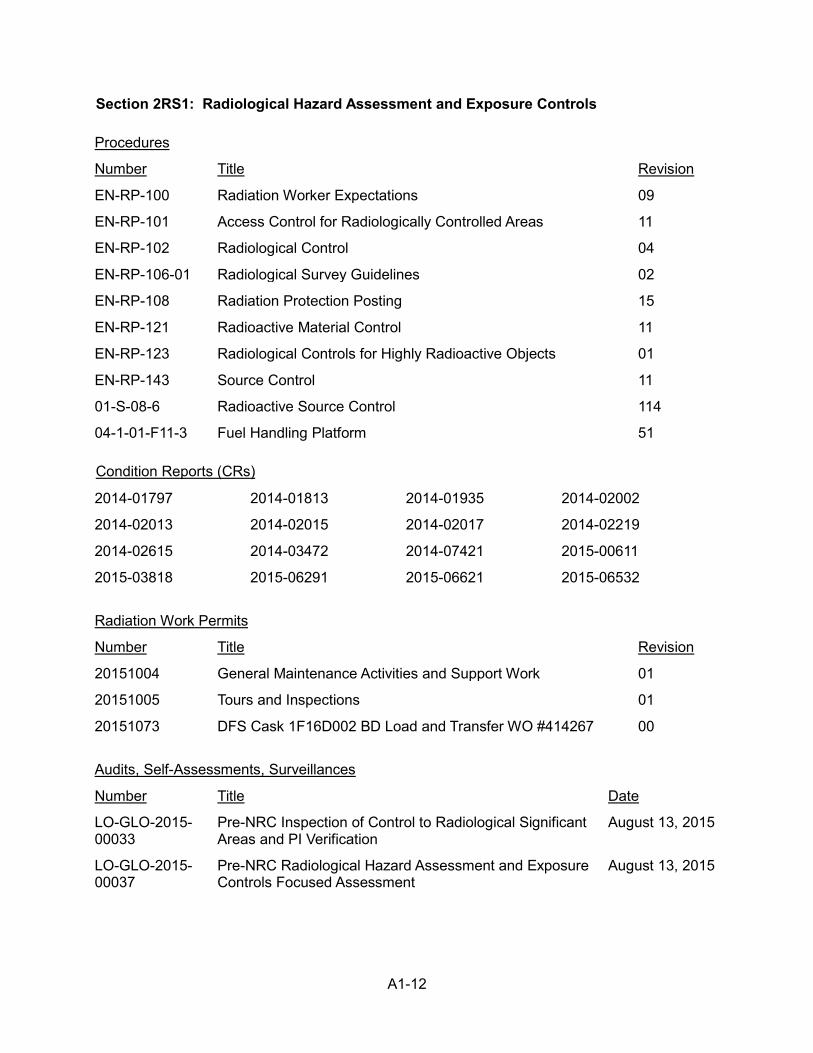
A1-12
Section 2RS1: Radiological Hazard Assessment and Exposure Controls Procedures
Number Title Revision
EN-RP-100 Radiation Worker Expectations 09
EN-RP-101 Access Control for Radiologically Controlled Areas 11
EN-RP-102 Radiological Control 04
EN-RP-106-01 Radiological Survey Guidelines 02
EN-RP-108 Radiation Protection Posting 15
EN-RP-121 Radioactive Material Control 11
EN-RP-123 Radiological Controls for Highly Radioactive Objects 01
EN-RP-143 Source Control 11
01-S-08-6 Radioactive Source Control 114
04-1-01-F11-3 Fuel Handling Platform 51 Condition Reports (CRs)
2014-01797 2014-01813 2014-01935 2014-02002
2014-02013 2014-02015 2014-02017 2014-02219
2014-02615 2014-03472 2014-07421 2015-00611
2015-03818 2015-06291 2015-06621 2015-06532 Radiation Work Permits
Number Title Revision
20151004 General Maintenance Activities and Support Work 01
20151005 Tours and Inspections 01
20151073 DFS Cask 1F16D002 BD Load and Transfer WO #414267 00 Audits, Self-Assessments, Surveillances
Number Title Date
LO-GLO-2015-00033
Pre-NRC Inspection of Control to Radiological Significant Areas and PI Verification
August 13, 2015
LO-GLO-2015-00037
Pre-NRC Radiological Hazard Assessment and Exposure Controls Focused Assessment
August 13, 2015
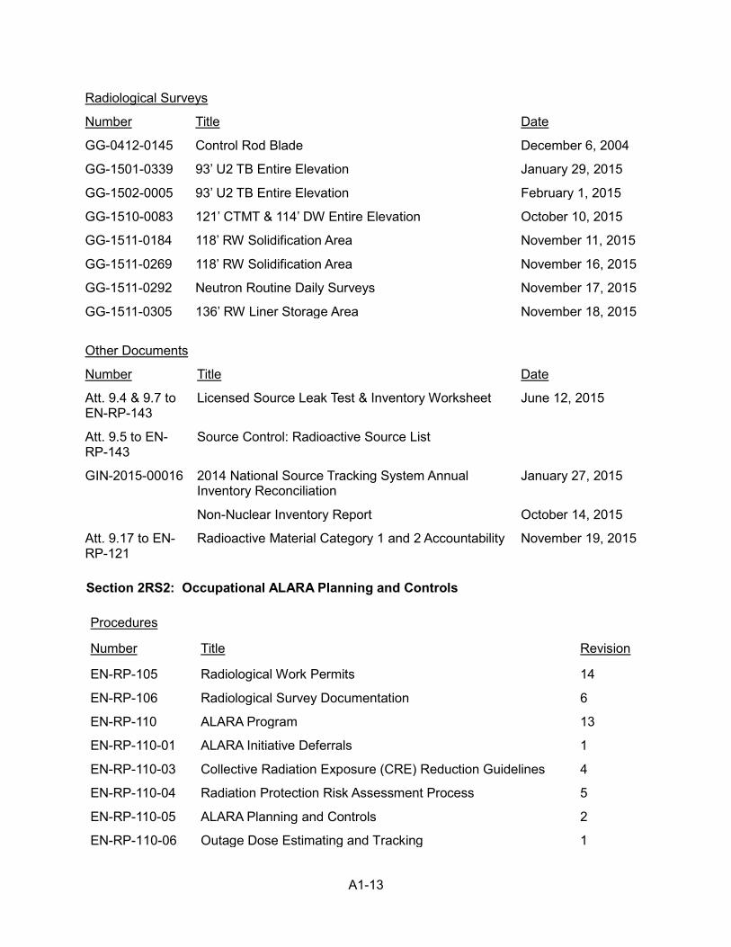
A1-13
Radiological Surveys
Number Title Date
GG-0412-0145 Control Rod Blade December 6, 2004
GG-1501-0339 93’ U2 TB Entire Elevation January 29, 2015
GG-1502-0005 93’ U2 TB Entire Elevation February 1, 2015
GG-1510-0083 121’ CTMT & 114’ DW Entire Elevation October 10, 2015
GG-1511-0184 118’ RW Solidification Area November 11, 2015
GG-1511-0269 118’ RW Solidification Area November 16, 2015
GG-1511-0292 Neutron Routine Daily Surveys November 17, 2015
GG-1511-0305 136’ RW Liner Storage Area November 18, 2015 Other Documents
Number Title Date
Att. 9.4 & 9.7 to EN-RP-143
Licensed Source Leak Test & Inventory Worksheet June 12, 2015
Att. 9.5 to EN-RP-143
Source Control: Radioactive Source List
GIN-2015-00016 2014 National Source Tracking System Annual Inventory Reconciliation
January 27, 2015
Non-Nuclear Inventory Report October 14, 2015
Att. 9.17 to EN-RP-121
Radioactive Material Category 1 and 2 Accountability November 19, 2015
Section 2RS2: Occupational ALARA Planning and Controls Procedures
Number Title Revision
EN-RP-105 Radiological Work Permits 14
EN-RP-106 Radiological Survey Documentation 6
EN-RP-110 ALARA Program 13
EN-RP-110-01 ALARA Initiative Deferrals 1
EN-RP-110-03 Collective Radiation Exposure (CRE) Reduction Guidelines 4
EN-RP-110-04 Radiation Protection Risk Assessment Process 5
EN-RP-110-05 ALARA Planning and Controls 2
EN-RP-110-06 Outage Dose Estimating and Tracking 1
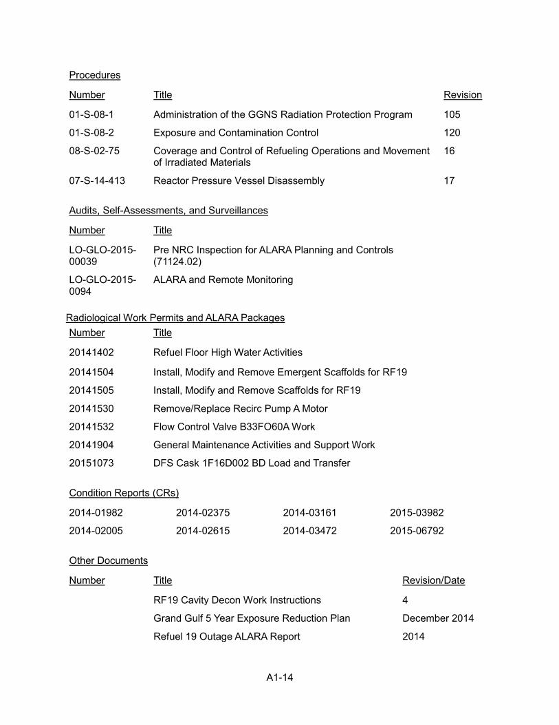
A1-14
Procedures
Number Title Revision
01-S-08-1 Administration of the GGNS Radiation Protection Program 105
01-S-08-2 Exposure and Contamination Control 120
08-S-02-75 Coverage and Control of Refueling Operations and Movement of Irradiated Materials
16
07-S-14-413 Reactor Pressure Vessel Disassembly 17 Audits, Self-Assessments, and Surveillances
Number Title
LO-GLO-2015-00039
Pre NRC Inspection for ALARA Planning and Controls (71124.02)
LO-GLO-2015-0094
ALARA and Remote Monitoring
Radiological Work Permits and ALARA Packages Number Title
20141402 Refuel Floor High Water Activities
20141504 Install, Modify and Remove Emergent Scaffolds for RF19
20141505 Install, Modify and Remove Scaffolds for RF19
20141530 Remove/Replace Recirc Pump A Motor
20141532 Flow Control Valve B33FO60A Work
20141904 General Maintenance Activities and Support Work
20151073 DFS Cask 1F16D002 BD Load and Transfer Condition Reports (CRs)
2014-01982 2014-02375 2014-03161 2015-03982
2014-02005 2014-02615 2014-03472 2015-06792 Other Documents
Number Title Revision/Date
RF19 Cavity Decon Work Instructions 4
Grand Gulf 5 Year Exposure Reduction Plan December 2014
Refuel 19 Outage ALARA Report 2014
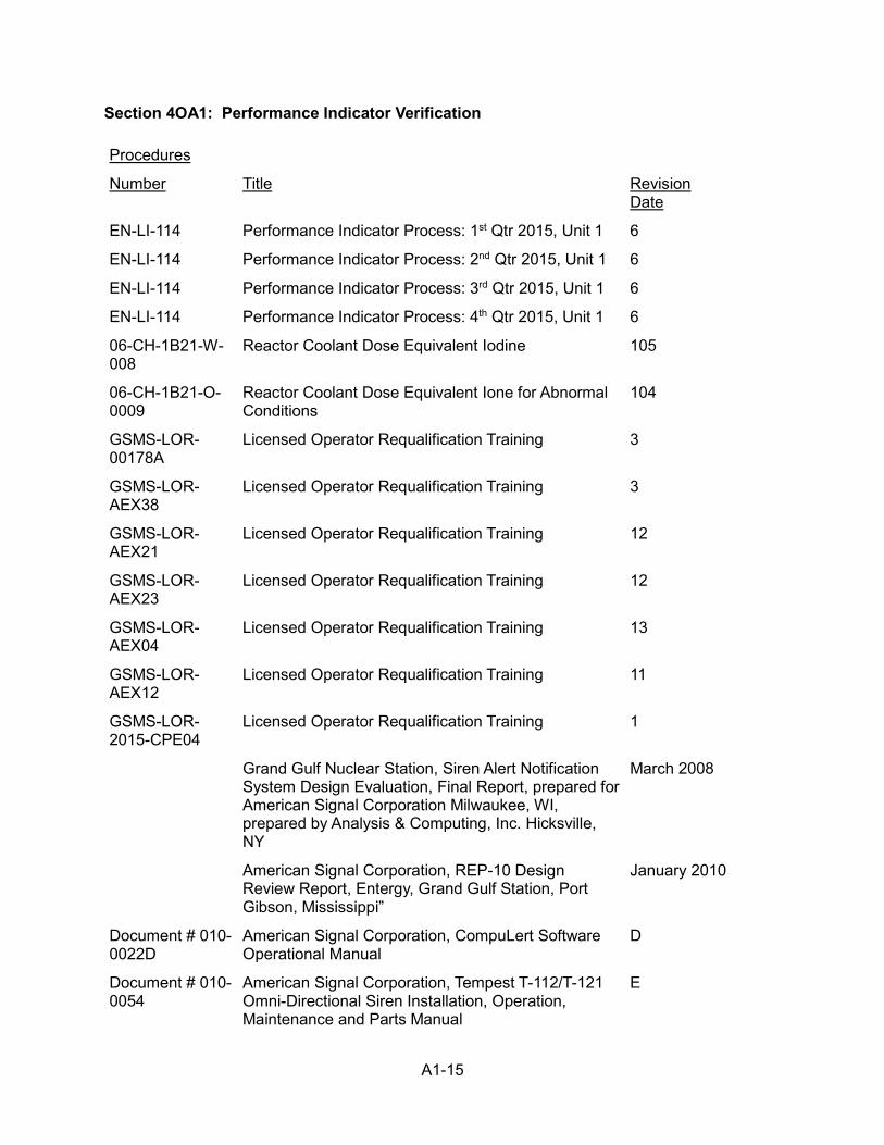
A1-15
Section 4OA1: Performance Indicator Verification Procedures
Number Title Revision Date
EN-LI-114 Performance Indicator Process: 1st Qtr 2015, Unit 1 6
EN-LI-114 Performance Indicator Process: 2nd Qtr 2015, Unit 1 6
EN-LI-114 Performance Indicator Process: 3rd Qtr 2015, Unit 1 6
EN-LI-114 Performance Indicator Process: 4th Qtr 2015, Unit 1 6
06-CH-1B21-W-008
Reactor Coolant Dose Equivalent Iodine 105
06-CH-1B21-O-0009
Reactor Coolant Dose Equivalent Ione for Abnormal Conditions
104
GSMS-LOR-00178A
Licensed Operator Requalification Training 3
GSMS-LOR-AEX38
Licensed Operator Requalification Training 3
GSMS-LOR-AEX21
Licensed Operator Requalification Training 12
GSMS-LOR-AEX23
Licensed Operator Requalification Training 12
GSMS-LOR-AEX04
Licensed Operator Requalification Training 13
GSMS-LOR-AEX12
Licensed Operator Requalification Training 11
GSMS-LOR-2015-CPE04
Licensed Operator Requalification Training 1
Grand Gulf Nuclear Station, Siren Alert Notification System Design Evaluation, Final Report, prepared for American Signal Corporation Milwaukee, WI, prepared by Analysis & Computing, Inc. Hicksville, NY
March 2008
American Signal Corporation, REP-10 Design Review Report, Entergy, Grand Gulf Station, Port Gibson, Mississippi”
January 2010
Document # 010-0022D
American Signal Corporation, CompuLert Software Operational Manual
D
Document # 010-0054
American Signal Corporation, Tempest T-112/T-121 Omni-Directional Siren Installation, Operation, Maintenance and Parts Manual
E
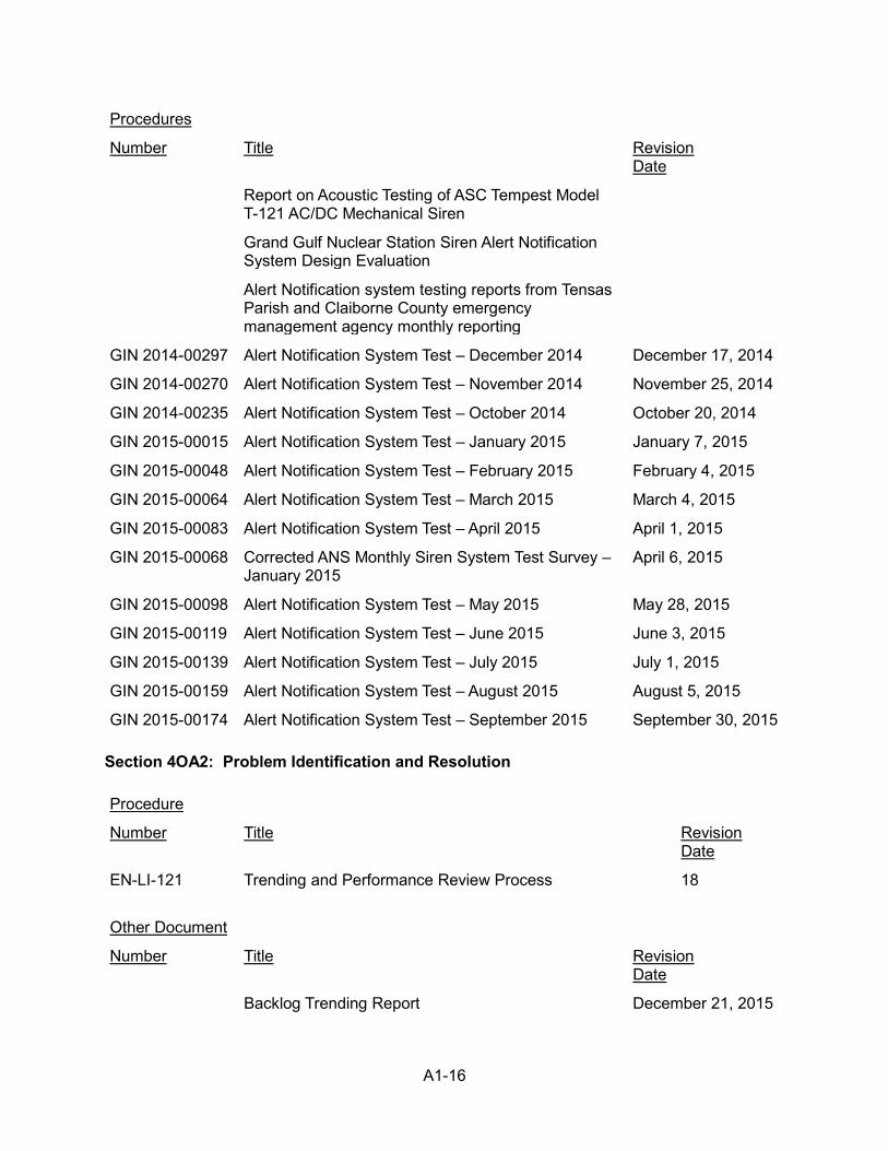
A1-16
Procedures
Number Title Revision Date
Report on Acoustic Testing of ASC Tempest Model T-121 AC/DC Mechanical Siren
Grand Gulf Nuclear Station Siren Alert Notification System Design Evaluation
Alert Notification system testing reports from Tensas Parish and Claiborne County emergency management agency monthly reporting
GIN 2014-00297 Alert Notification System Test – December 2014 December 17, 2014
GIN 2014-00270 Alert Notification System Test – November 2014 November 25, 2014
GIN 2014-00235 Alert Notification System Test – October 2014 October 20, 2014
GIN 2015-00015 Alert Notification System Test – January 2015 January 7, 2015
GIN 2015-00048 Alert Notification System Test – February 2015 February 4, 2015
GIN 2015-00064 Alert Notification System Test – March 2015 March 4, 2015
GIN 2015-00083 Alert Notification System Test – April 2015 April 1, 2015
GIN 2015-00068 Corrected ANS Monthly Siren System Test Survey – January 2015
April 6, 2015
GIN 2015-00098 Alert Notification System Test – May 2015 May 28, 2015
GIN 2015-00119 Alert Notification System Test – June 2015 June 3, 2015
GIN 2015-00139 Alert Notification System Test – July 2015 July 1, 2015
GIN 2015-00159 Alert Notification System Test – August 2015 August 5, 2015
GIN 2015-00174 Alert Notification System Test – September 2015 September 30, 2015 Section 4OA2: Problem Identification and Resolution Procedure
Number Title Revision Date
EN-LI-121 Trending and Performance Review Process 18 Other Document
Number Title Revision Date
Backlog Trending Report December 21, 2015
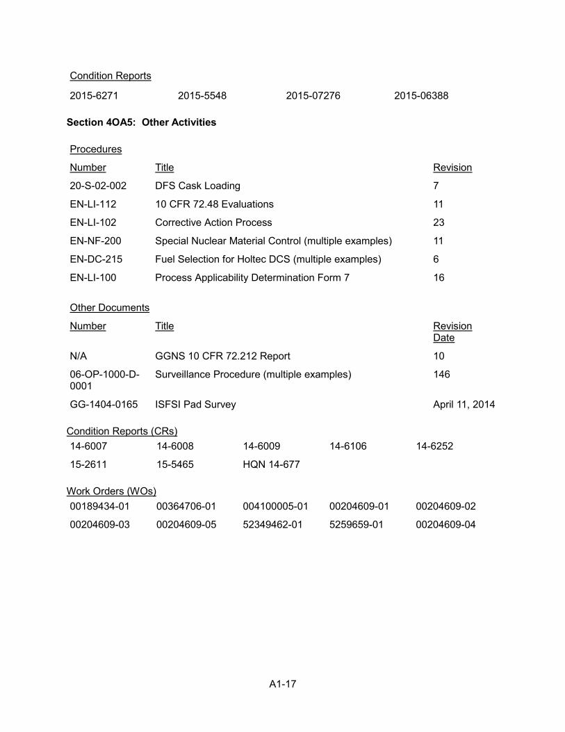
A1-17
Condition Reports
2015-6271 2015-5548 2015-07276 2015-06388 Section 4OA5: Other Activities Procedures
Number Title Revision
20-S-02-002 DFS Cask Loading 7
EN-LI-112 10 CFR 72.48 Evaluations 11
EN-LI-102 Corrective Action Process 23
EN-NF-200 Special Nuclear Material Control (multiple examples) 11
EN-DC-215 Fuel Selection for Holtec DCS (multiple examples) 6
EN-LI-100 Process Applicability Determination Form 7 16 Other Documents
Number Title Revision Date
N/A GGNS 10 CFR 72.212 Report 10
06-OP-1000-D-0001
Surveillance Procedure (multiple examples) 146
GG-1404-0165 ISFSI Pad Survey April 11, 2014 Condition Reports (CRs) 14-6007 14-6008 14-6009 14-6106 14-6252
15-2611 15-5465 HQN 14-677 Work Orders (WOs) 00189434-01 00364706-01 004100005-01 00204609-01 00204609-02
00204609-03 00204609-05 52349462-01 5259659-01 00204609-04
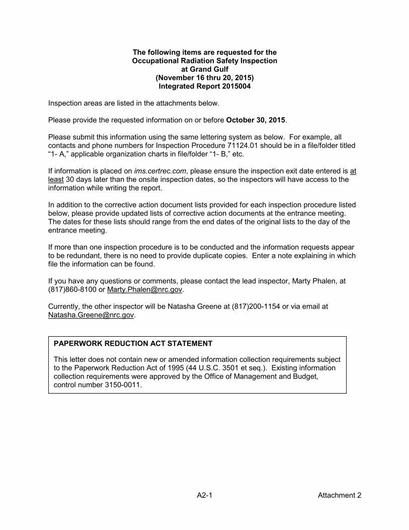
A2-1 Attachment 2
The following items are requested for the Occupational Radiation Safety Inspection
at Grand Gulf (November 16 thru 20, 2015) Integrated Report 2015004
Inspection areas are listed in the attachments below. Please provide the requested information on or before October 30, 2015. Please submit this information using the same lettering system as below. For example, all contacts and phone numbers for Inspection Procedure 71124.01 should be in a file/folder titled “1- A,” applicable organization charts in file/folder “1- B,” etc. If information is placed on ims.certrec.com, please ensure the inspection exit date entered is at least 30 days later than the onsite inspection dates, so the inspectors will have access to the information while writing the report. In addition to the corrective action document lists provided for each inspection procedure listed below, please provide updated lists of corrective action documents at the entrance meeting. The dates for these lists should range from the end dates of the original lists to the day of the entrance meeting. If more than one inspection procedure is to be conducted and the information requests appear to be redundant, there is no need to provide duplicate copies. Enter a note explaining in which file the information can be found. If you have any questions or comments, please contact the lead inspector, Marty Phalen, at (817)860-8100 or [email protected]. Currently, the other inspector will be Natasha Greene at (817)200-1154 or via email at [email protected].
PAPERWORK REDUCTION ACT STATEMENT
This letter does not contain new or amended information collection requirements subject to the Paperwork Reduction Act of 1995 (44 U.S.C. 3501 et seq.). Existing information collection requirements were approved by the Office of Management and Budget, control number 3150-0011.
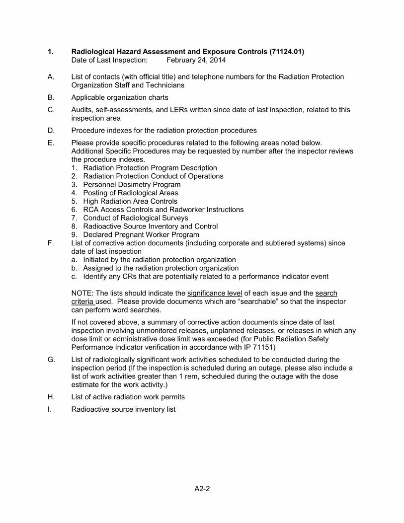
A2-2
1. Radiological Hazard Assessment and Exposure Controls (71124.01) Date of Last Inspection: February 24, 2014
A. List of contacts (with official title) and telephone numbers for the Radiation Protection
Organization Staff and Technicians
B. Applicable organization charts
C. Audits, self-assessments, and LERs written since date of last inspection, related to this inspection area
D. Procedure indexes for the radiation protection procedures
E. Please provide specific procedures related to the following areas noted below. Additional Specific Procedures may be requested by number after the inspector reviews the procedure indexes. 1. Radiation Protection Program Description 2. Radiation Protection Conduct of Operations 3. Personnel Dosimetry Program 4. Posting of Radiological Areas 5. High Radiation Area Controls 6. RCA Access Controls and Radworker Instructions 7. Conduct of Radiological Surveys 8. Radioactive Source Inventory and Control 9. Declared Pregnant Worker Program
F. List of corrective action documents (including corporate and subtiered systems) since date of last inspection a. Initiated by the radiation protection organization b. Assigned to the radiation protection organization c. Identify any CRs that are potentially related to a performance indicator event
NOTE: The lists should indicate the significance level of each issue and the search
criteria used. Please provide documents which are “searchable” so that the inspector can perform word searches.
If not covered above, a summary of corrective action documents since date of last inspection involving unmonitored releases, unplanned releases, or releases in which any dose limit or administrative dose limit was exceeded (for Public Radiation Safety Performance Indicator verification in accordance with IP 71151)
G. List of radiologically significant work activities scheduled to be conducted during the inspection period (If the inspection is scheduled during an outage, please also include a list of work activities greater than 1 rem, scheduled during the outage with the dose estimate for the work activity.)
H. List of active radiation work permits
I. Radioactive source inventory list
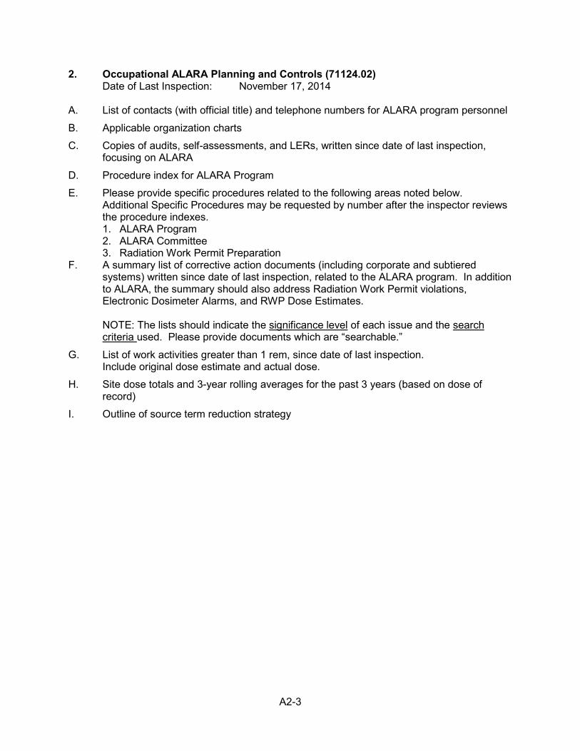
A2-3
2. Occupational ALARA Planning and Controls (71124.02) Date of Last Inspection: November 17, 2014
A. List of contacts (with official title) and telephone numbers for ALARA program personnel
B. Applicable organization charts
C. Copies of audits, self-assessments, and LERs, written since date of last inspection, focusing on ALARA
D. Procedure index for ALARA Program
E. Please provide specific procedures related to the following areas noted below. Additional Specific Procedures may be requested by number after the inspector reviews the procedure indexes. 1. ALARA Program 2. ALARA Committee 3. Radiation Work Permit Preparation
F. A summary list of corrective action documents (including corporate and subtiered systems) written since date of last inspection, related to the ALARA program. In addition to ALARA, the summary should also address Radiation Work Permit violations, Electronic Dosimeter Alarms, and RWP Dose Estimates. NOTE: The lists should indicate the significance level of each issue and the search criteria used. Please provide documents which are “searchable.”
G. List of work activities greater than 1 rem, since date of last inspection. Include original dose estimate and actual dose.
H. Site dose totals and 3-year rolling averages for the past 3 years (based on dose of record)
I. Outline of source term reduction strategy
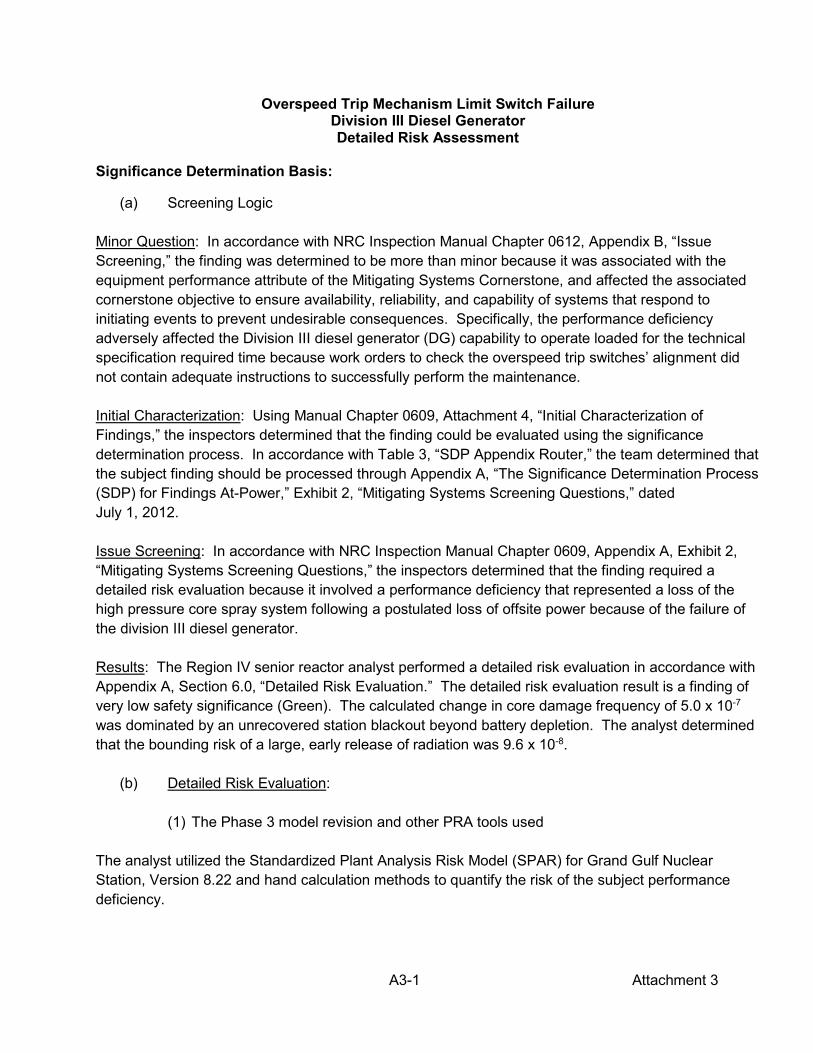
A3-1 Attachment 3
Overspeed Trip Mechanism Limit Switch Failure Division III Diesel Generator Detailed Risk Assessment
Significance Determination Basis:
(a) Screening Logic Minor Question: In accordance with NRC Inspection Manual Chapter 0612, Appendix B, “Issue Screening,” the finding was determined to be more than minor because it was associated with the equipment performance attribute of the Mitigating Systems Cornerstone, and affected the associated cornerstone objective to ensure availability, reliability, and capability of systems that respond to initiating events to prevent undesirable consequences. Specifically, the performance deficiency adversely affected the Division III diesel generator (DG) capability to operate loaded for the technical specification required time because work orders to check the overspeed trip switches’ alignment did not contain adequate instructions to successfully perform the maintenance. Initial Characterization: Using Manual Chapter 0609, Attachment 4, “Initial Characterization of Findings,” the inspectors determined that the finding could be evaluated using the significance determination process. In accordance with Table 3, “SDP Appendix Router,” the team determined that the subject finding should be processed through Appendix A, “The Significance Determination Process (SDP) for Findings At-Power,” Exhibit 2, “Mitigating Systems Screening Questions,” dated July 1, 2012. Issue Screening: In accordance with NRC Inspection Manual Chapter 0609, Appendix A, Exhibit 2, “Mitigating Systems Screening Questions,” the inspectors determined that the finding required a detailed risk evaluation because it involved a performance deficiency that represented a loss of the high pressure core spray system following a postulated loss of offsite power because of the failure of the division III diesel generator. Results: The Region IV senior reactor analyst performed a detailed risk evaluation in accordance with Appendix A, Section 6.0, “Detailed Risk Evaluation.” The detailed risk evaluation result is a finding of very low safety significance (Green). The calculated change in core damage frequency of 5.0 x 10⁻⁷ was dominated by an unrecovered station blackout beyond battery depletion. The analyst determined that the bounding risk of a large, early release of radiation was 9.6 x 10⁻⁸.
(b) Detailed Risk Evaluation:
(1) The Phase 3 model revision and other PRA tools used The analyst utilized the Standardized Plant Analysis Risk Model (SPAR) for Grand Gulf Nuclear Station, Version 8.22 and hand calculation methods to quantify the risk of the subject performance deficiency.
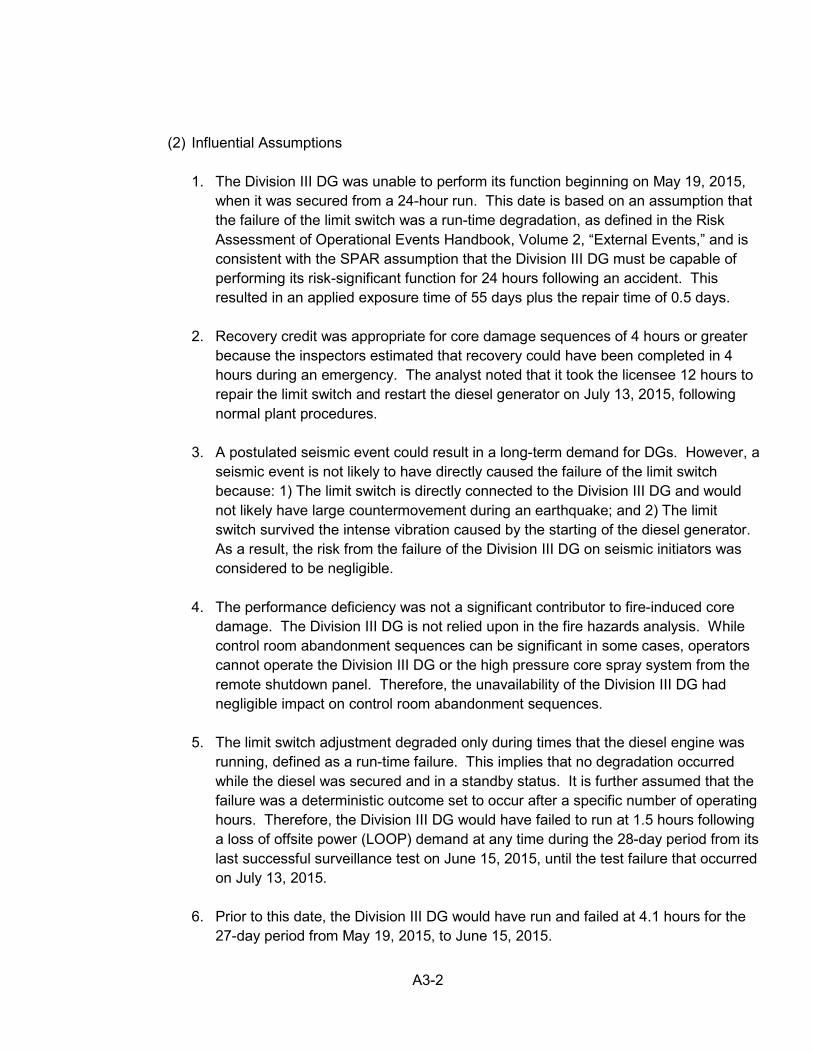
A3-2
(2) Influential Assumptions
1. The Division III DG was unable to perform its function beginning on May 19, 2015, when it was secured from a 24-hour run. This date is based on an assumption that the failure of the limit switch was a run-time degradation, as defined in the Risk Assessment of Operational Events Handbook, Volume 2, “External Events,” and is consistent with the SPAR assumption that the Division III DG must be capable of performing its risk-significant function for 24 hours following an accident. This resulted in an applied exposure time of 55 days plus the repair time of 0.5 days.
2. Recovery credit was appropriate for core damage sequences of 4 hours or greater
because the inspectors estimated that recovery could have been completed in 4 hours during an emergency. The analyst noted that it took the licensee 12 hours to repair the limit switch and restart the diesel generator on July 13, 2015, following normal plant procedures.
3. A postulated seismic event could result in a long-term demand for DGs. However, a
seismic event is not likely to have directly caused the failure of the limit switch because: 1) The limit switch is directly connected to the Division III DG and would not likely have large countermovement during an earthquake; and 2) The limit switch survived the intense vibration caused by the starting of the diesel generator. As a result, the risk from the failure of the Division III DG on seismic initiators was considered to be negligible.
4. The performance deficiency was not a significant contributor to fire-induced core
damage. The Division III DG is not relied upon in the fire hazards analysis. While control room abandonment sequences can be significant in some cases, operators cannot operate the Division III DG or the high pressure core spray system from the remote shutdown panel. Therefore, the unavailability of the Division III DG had negligible impact on control room abandonment sequences.
5. The limit switch adjustment degraded only during times that the diesel engine was
running, defined as a run-time failure. This implies that no degradation occurred while the diesel was secured and in a standby status. It is further assumed that the failure was a deterministic outcome set to occur after a specific number of operating hours. Therefore, the Division III DG would have failed to run at 1.5 hours following a loss of offsite power (LOOP) demand at any time during the 28-day period from its last successful surveillance test on June 15, 2015, until the test failure that occurred on July 13, 2015.
6. Prior to this date, the Division III DG would have run and failed at 4.1 hours for the
27-day period from May 19, 2015, to June 15, 2015.
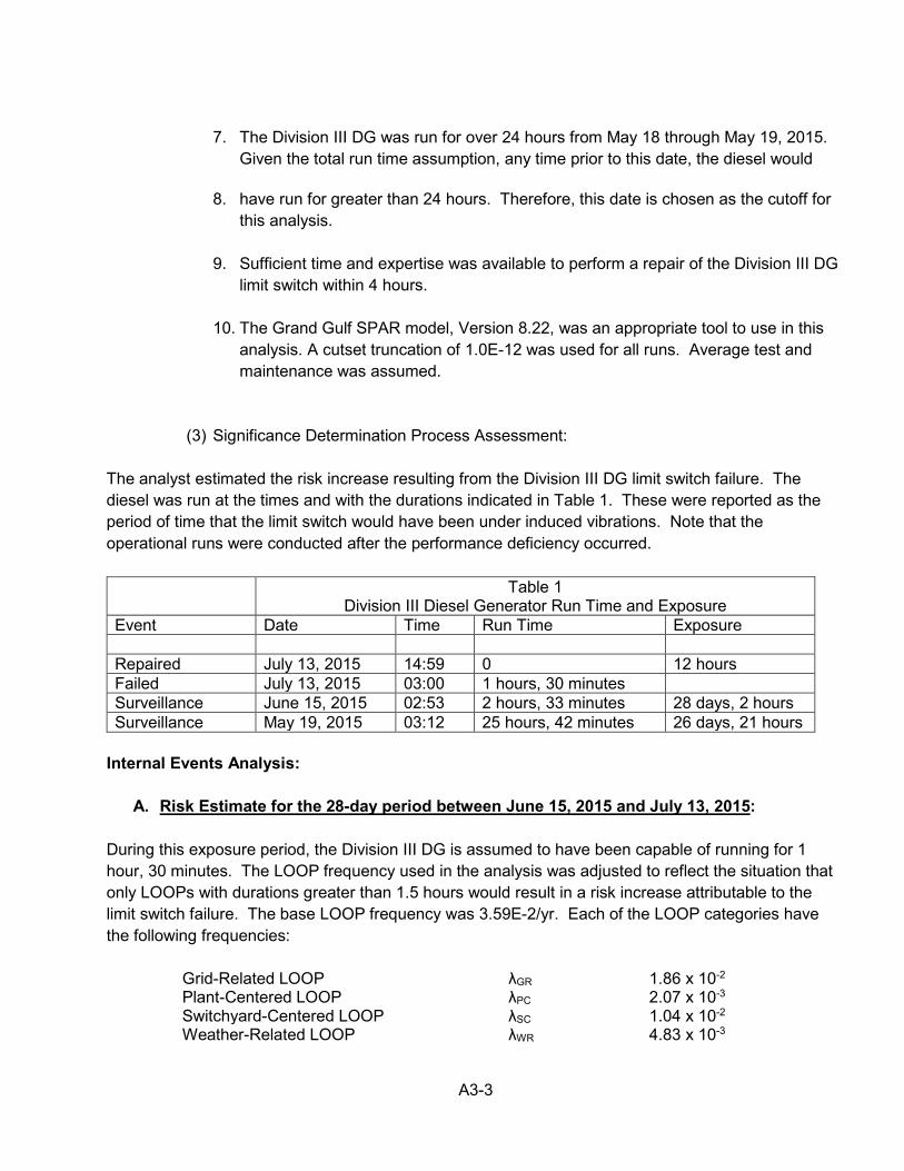
A3-3
7. The Division III DG was run for over 24 hours from May 18 through May 19, 2015.
Given the total run time assumption, any time prior to this date, the diesel would
8. have run for greater than 24 hours. Therefore, this date is chosen as the cutoff for this analysis.
9. Sufficient time and expertise was available to perform a repair of the Division III DG
limit switch within 4 hours.
10. The Grand Gulf SPAR model, Version 8.22, was an appropriate tool to use in this analysis. A cutset truncation of 1.0E-12 was used for all runs. Average test and maintenance was assumed.
(3) Significance Determination Process Assessment: The analyst estimated the risk increase resulting from the Division III DG limit switch failure. The diesel was run at the times and with the durations indicated in Table 1. These were reported as the period of time that the limit switch would have been under induced vibrations. Note that the operational runs were conducted after the performance deficiency occurred.
Table 1 Division III Diesel Generator Run Time and Exposure
Event Date Time Run Time Exposure Repaired July 13, 2015 14:59 0 12 hours Failed July 13, 2015 03:00 1 hours, 30 minutes Surveillance June 15, 2015 02:53 2 hours, 33 minutes 28 days, 2 hours Surveillance May 19, 2015 03:12 25 hours, 42 minutes 26 days, 21 hours
Internal Events Analysis:
A. Risk Estimate for the 28-day period between June 15, 2015 and July 13, 2015: During this exposure period, the Division III DG is assumed to have been capable of running for 1 hour, 30 minutes. The LOOP frequency used in the analysis was adjusted to reflect the situation that only LOOPs with durations greater than 1.5 hours would result in a risk increase attributable to the limit switch failure. The base LOOP frequency was 3.59E-2/yr. Each of the LOOP categories have the following frequencies:
Grid-Related LOOP λGR 1.86 x 10⁻² Plant-Centered LOOP λPC 2.07 x 10⁻³ Switchyard-Centered LOOP λSC 1.04 x 10⁻² Weather-Related LOOP λWR 4.83 x 10⁻³
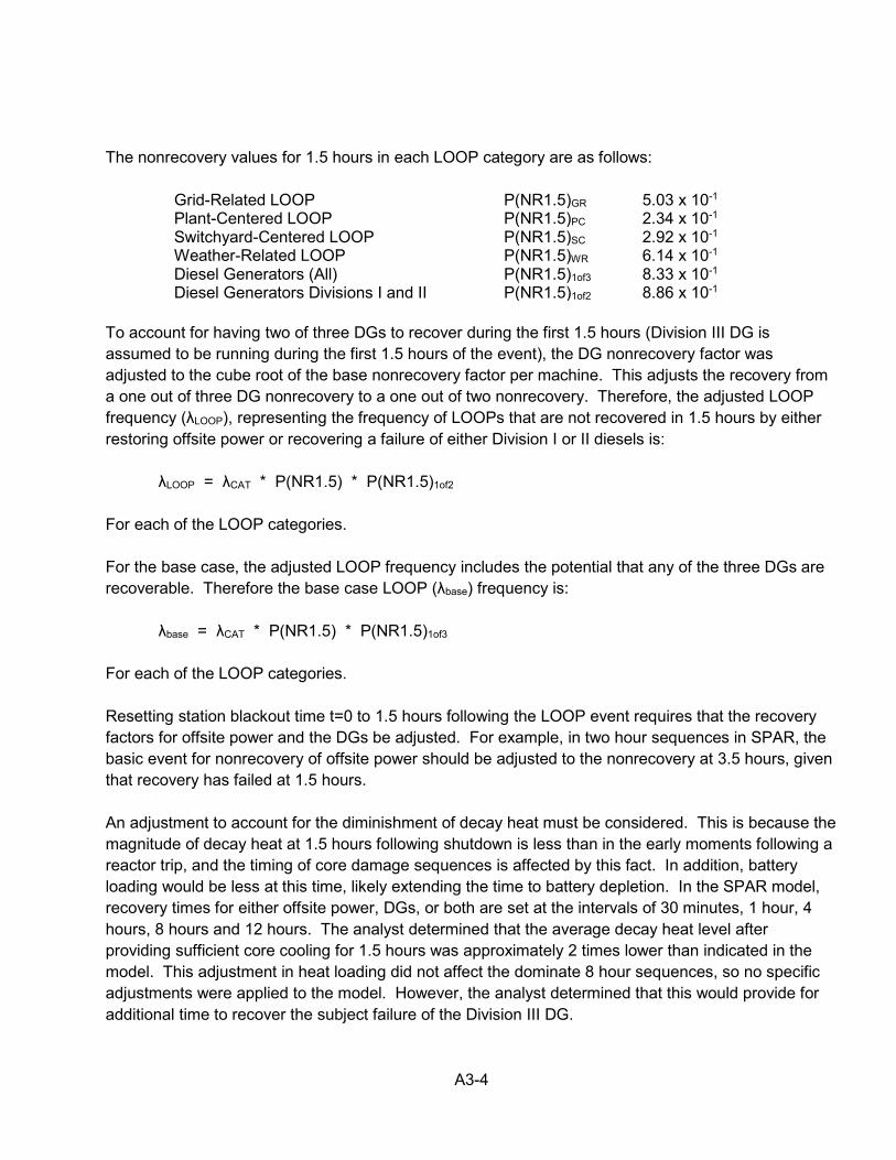
A3-4
The nonrecovery values for 1.5 hours in each LOOP category are as follows:
Grid-Related LOOP P(NR1.5)GR 5.03 x 10⁻¹ Plant-Centered LOOP P(NR1.5)PC 2.34 x 10⁻¹ Switchyard-Centered LOOP P(NR1.5)SC 2.92 x 10⁻¹ Weather-Related LOOP P(NR1.5)WR 6.14 x 10⁻¹ Diesel Generators (All) P(NR1.5)1of3 8.33 x 10⁻¹ Diesel Generators Divisions I and II P(NR1.5)1of2 8.86 x 10⁻¹
To account for having two of three DGs to recover during the first 1.5 hours (Division III DG is assumed to be running during the first 1.5 hours of the event), the DG nonrecovery factor was adjusted to the cube root of the base nonrecovery factor per machine. This adjusts the recovery from a one out of three DG nonrecovery to a one out of two nonrecovery. Therefore, the adjusted LOOP frequency (λLOOP), representing the frequency of LOOPs that are not recovered in 1.5 hours by either restoring offsite power or recovering a failure of either Division I or II diesels is: λLOOP = λCAT * P(NR1.5) * P(NR1.5)1of2 For each of the LOOP categories. For the base case, the adjusted LOOP frequency includes the potential that any of the three DGs are recoverable. Therefore the base case LOOP (λbase) frequency is: λbase = λCAT * P(NR1.5) * P(NR1.5)1of3 For each of the LOOP categories. Resetting station blackout time t=0 to 1.5 hours following the LOOP event requires that the recovery factors for offsite power and the DGs be adjusted. For example, in two hour sequences in SPAR, the basic event for nonrecovery of offsite power should be adjusted to the nonrecovery at 3.5 hours, given that recovery has failed at 1.5 hours. An adjustment to account for the diminishment of decay heat must be considered. This is because the magnitude of decay heat at 1.5 hours following shutdown is less than in the early moments following a reactor trip, and the timing of core damage sequences is affected by this fact. In addition, battery loading would be less at this time, likely extending the time to battery depletion. In the SPAR model, recovery times for either offsite power, DGs, or both are set at the intervals of 30 minutes, 1 hour, 4 hours, 8 hours and 12 hours. The analyst determined that the average decay heat level after providing sufficient core cooling for 1.5 hours was approximately 2 times lower than indicated in the model. This adjustment in heat loading did not affect the dominate 8 hour sequences, so no specific adjustments were applied to the model. However, the analyst determined that this would provide for additional time to recover the subject failure of the Division III DG.
A3-5
Table 2 presents the adjusted offsite power nonrecovery factors for the event times that are relevant in the SPAR core damage cutsets.
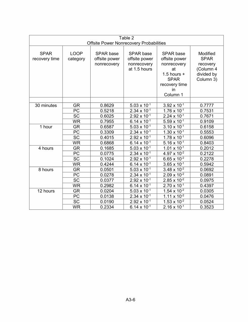
A3-6
Table 2
Offsite Power Nonrecovery Probabilities
SPAR recovery time
LOOP
category
SPAR base offsite power nonrecovery
SPAR base offsite power nonrecovery at 1.5 hours
SPAR base offsite power nonrecovery
at 1.5 hours +
SPAR recovery time
in Column 1
Modified SPAR
recovery (Column 4 divided by Column 3)
30 minutes GR 0.8629 5.03 x 10⁻¹ 3.92 x 10⁻¹ 0.7777
PC 0.5218 2.34 x 10⁻¹ 1.76 x 10⁻¹ 0.7531 SC 0.6025 2.92 x 10⁻¹ 2.24 x 10⁻¹ 0.7671 WR 0.7955 6.14 x 10⁻¹ 5.59 x 10⁻¹ 0.9109
1 hour GR 0.6587 5.03 x 10⁻¹ 3.10 x 10⁻¹ 0.6158 PC 0.3309 2.34 x 10⁻¹ 1.30 x 10⁻¹ 0.5553 SC 0.4015 2.92 x 10⁻¹ 1.78 x 10⁻¹ 0.6096 WR 0.6868 6.14 x 10⁻¹ 5.16 x 10⁻¹ 0.8403
4 hours GR 0.1685 5.03 x 10⁻¹ 1.01 x 10⁻¹ 0.2012 PC 0.0775 2.34 x 10⁻¹ 4.97 x 10⁻² 0.2122 SC 0.1024 2.92 x 10⁻¹ 6.65 x 10⁻² 0.2278 WR 0.4244 6.14 x 10⁻¹ 3.65 x 10⁻¹ 0.5942
8 hours GR 0.0501 5.03 x 10⁻¹ 3.48 x 10⁻² 0.0692 PC 0.0278 2.34 x 10⁻¹ 2.09 x 10⁻² 0.0891 SC 0.0377 2.92 x 10⁻¹ 2.85 x 10⁻² 0.0975 WR 0.2982 6.14 x 10⁻¹ 2.70 x 10⁻¹ 0.4397
12 hours GR 0.0204 5.03 x 10⁻¹ 1.54 x 10⁻² 0.0305 PC 0.0138 2.34 x 10⁻¹ 1.11 x 10⁻² 0.0476 SC 0.0190 2.92 x 10⁻¹ 1.53 x 10⁻² 0.0524 WR 0.2334 6.14 x 10⁻¹ 2.16 x 10⁻¹ 0.3523
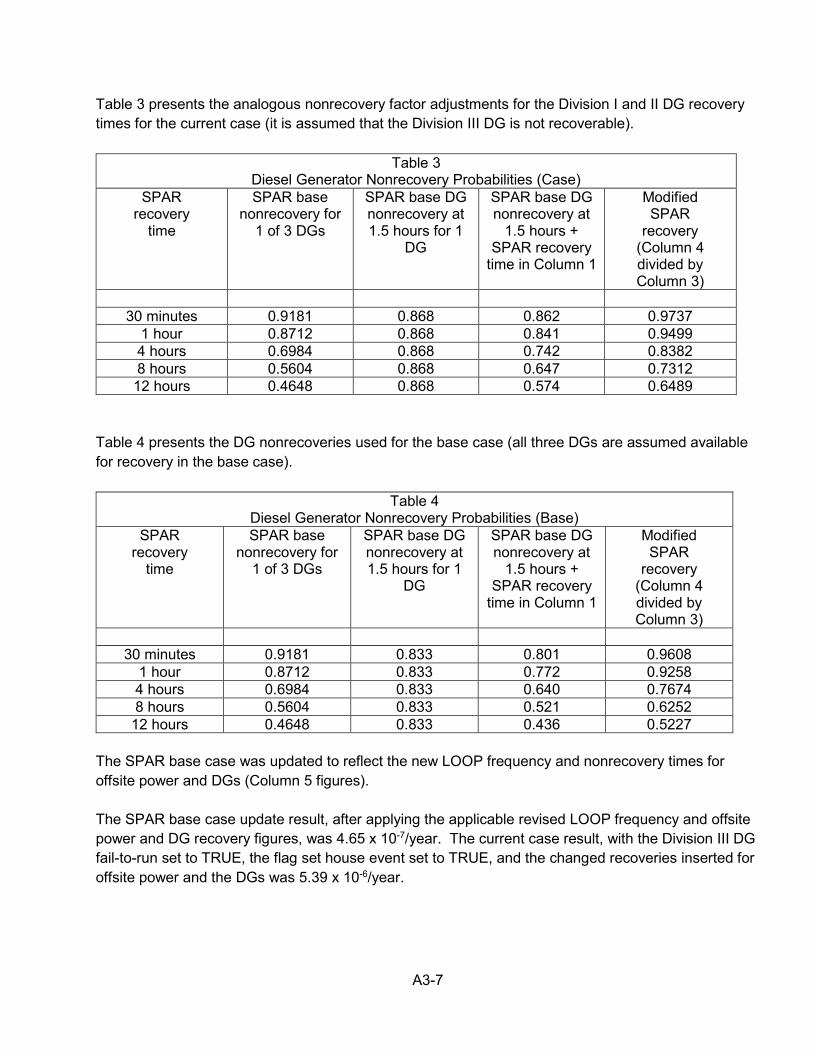
A3-7
Table 3 presents the analogous nonrecovery factor adjustments for the Division I and II DG recovery times for the current case (it is assumed that the Division III DG is not recoverable).
Table 3 Diesel Generator Nonrecovery Probabilities (Case)
SPAR recovery
time
SPAR base nonrecovery for
1 of 3 DGs
SPAR base DG nonrecovery at 1.5 hours for 1
DG
SPAR base DG nonrecovery at
1.5 hours + SPAR recovery
time in Column 1
Modified SPAR
recovery (Column 4 divided by Column 3)
30 minutes 0.9181 0.868 0.862 0.9737
1 hour 0.8712 0.868 0.841 0.9499 4 hours 0.6984 0.868 0.742 0.8382 8 hours 0.5604 0.868 0.647 0.7312 12 hours 0.4648 0.868 0.574 0.6489
Table 4 presents the DG nonrecoveries used for the base case (all three DGs are assumed available for recovery in the base case).
Table 4 Diesel Generator Nonrecovery Probabilities (Base)
SPAR recovery
time
SPAR base nonrecovery for
1 of 3 DGs
SPAR base DG nonrecovery at 1.5 hours for 1
DG
SPAR base DG nonrecovery at
1.5 hours + SPAR recovery
time in Column 1
Modified SPAR
recovery (Column 4 divided by Column 3)
30 minutes 0.9181 0.833 0.801 0.9608
1 hour 0.8712 0.833 0.772 0.9258 4 hours 0.6984 0.833 0.640 0.7674 8 hours 0.5604 0.833 0.521 0.6252
12 hours 0.4648 0.833 0.436 0.5227 The SPAR base case was updated to reflect the new LOOP frequency and nonrecovery times for offsite power and DGs (Column 5 figures). The SPAR base case update result, after applying the applicable revised LOOP frequency and offsite power and DG recovery figures, was 4.65 x 10⁻⁷/year. The current case result, with the Division III DG fail-to-run set to TRUE, the flag set house event set to TRUE, and the changed recoveries inserted for offsite power and the DGs was 5.39 x 10⁻⁶/year.
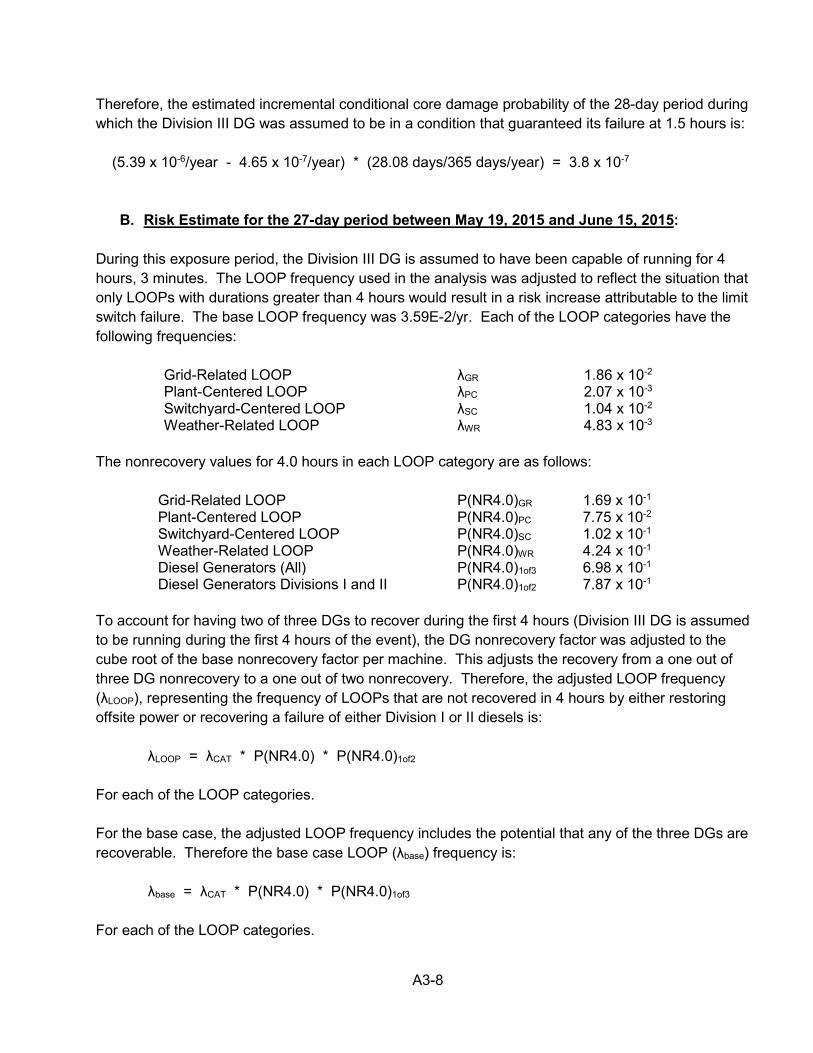
A3-8
Therefore, the estimated incremental conditional core damage probability of the 28-day period during which the Division III DG was assumed to be in a condition that guaranteed its failure at 1.5 hours is: (5.39 x 10⁻⁶/year - 4.65 x 10⁻⁷/year) * (28.08 days/365 days/year) = 3.8 x 10⁻⁷
B. Risk Estimate for the 27-day period between May 19, 2015 and June 15, 2015: During this exposure period, the Division III DG is assumed to have been capable of running for 4 hours, 3 minutes. The LOOP frequency used in the analysis was adjusted to reflect the situation that only LOOPs with durations greater than 4 hours would result in a risk increase attributable to the limit switch failure. The base LOOP frequency was 3.59E-2/yr. Each of the LOOP categories have the following frequencies:
Grid-Related LOOP λGR 1.86 x 10⁻² Plant-Centered LOOP λPC 2.07 x 10⁻³ Switchyard-Centered LOOP λSC 1.04 x 10⁻² Weather-Related LOOP λWR 4.83 x 10⁻³
The nonrecovery values for 4.0 hours in each LOOP category are as follows:
Grid-Related LOOP P(NR4.0)GR 1.69 x 10⁻¹ Plant-Centered LOOP P(NR4.0)PC 7.75 x 10⁻² Switchyard-Centered LOOP P(NR4.0)SC 1.02 x 10⁻¹ Weather-Related LOOP P(NR4.0)WR 4.24 x 10⁻¹ Diesel Generators (All) P(NR4.0)1of3 6.98 x 10⁻¹ Diesel Generators Divisions I and II P(NR4.0)1of2 7.87 x 10⁻¹
To account for having two of three DGs to recover during the first 4 hours (Division III DG is assumed to be running during the first 4 hours of the event), the DG nonrecovery factor was adjusted to the cube root of the base nonrecovery factor per machine. This adjusts the recovery from a one out of three DG nonrecovery to a one out of two nonrecovery. Therefore, the adjusted LOOP frequency (λLOOP), representing the frequency of LOOPs that are not recovered in 4 hours by either restoring offsite power or recovering a failure of either Division I or II diesels is:
λLOOP = λCAT * P(NR4.0) * P(NR4.0)1of2 For each of the LOOP categories. For the base case, the adjusted LOOP frequency includes the potential that any of the three DGs are recoverable. Therefore the base case LOOP (λbase) frequency is:
λbase = λCAT * P(NR4.0) * P(NR4.0)1of3 For each of the LOOP categories.
A3-9
Resetting station blackout time t=0 to 4 hours following the LOOP event requires that the recovery factors for offsite power and the DGs be adjusted. For example, in 2-hour sequences in SPAR, the basic event for nonrecovery of offsite power should be adjusted to the nonrecovery at 6 hours, given that recovery has failed at 4 hours. An adjustment to account for the diminishment of decay heat must be considered. This is because the magnitude of decay heat at 4 hours following shutdown is less than in the early moments following a reactor trip, and the timing of core damage sequences is affected by this fact. In addition, battery loading would be less at this time, likely extending the time to battery depletion. In the SPAR model, recovery times for either offsite power, DGs, or both are set at the intervals of 30 minutes, 1 hour, 4 hours, 8 hours and 12 hours. The analyst determined that the average decay heat level after providing sufficient core cooling for 4 hours was approximately 2-1/2 times lower than indicated in the model. This adjustment in heat loading did not affect the dominate 8 hours sequences, so no specific adjustments were applied to the model. However, the analyst determined that this would provide for additional time to recover the subject failure of the Division III DG. Table 5 presents the adjusted offsite power nonrecovery factors for the event times that are relevant in the SPAR core damage cutsets.

A3-10
Table 5
Offsite Power Nonrecovery Probabilities
SPAR recovery time
LOOP
category
SPAR base offsite power nonrecovery
SPAR base offsite power nonrecovery at 4 hours
SPAR base offsite power nonrecovery
at 4 hours +
SPAR recovery time
in Column 1
Modified SPAR
recovery (Column 4 divided by Column 3)
30 minutes GR 0.8629 1.69 x 10⁻¹ 1.41 x 10⁻¹ 0.8362
PC 0.5218 7.75 x 10⁻² 6.61 x 10⁻² 0.8524 SC 0.6025 1.02 x 10⁻¹ 8.78 x 10⁻² 0.8569 WR 0.7955 4.24 x 10⁻¹ 4.02 x 10⁻¹ 0.9472
1 hour GR 0.6587 1.69 x 10⁻¹ 1.19 x 10⁻¹ 0.7056 PC 0.3309 7.75 x 10⁻² 5.70 x 10⁻² 0.7355 SC 0.4015 1.02 x 10⁻¹ 7.61 x 10⁻² 0.7427 WR 0.6868 4.24 x 10⁻¹ 3.82 x 10⁻¹ 0.9006
4 hours GR 0.1685 1.69 x 10⁻¹ 5.01 x 10⁻² 0.2970 PC 0.0775 7.75 x 10⁻² 2.78 x 10⁻² 0.3587 SC 0.1024 1.02 x 10⁻¹ 3.77 x 10⁻² 0.3686 WR 0.4244 4.24 x 10⁻¹ 2.98 x 10⁻¹ 0.7026
8 hours GR 0.0501 1.69 x 10⁻¹ 2.04 x 10⁻² 0.1213 PC 0.0278 7.75 x 10⁻² 1.38 x 10⁻² 0.1784 SC 0.0377 1.02 x 10⁻¹ 1.90 x 10⁻² 0.1853 WR 0.2982 4.24 x 10⁻¹ 2.33 x 10⁻¹ 0.5500
12 hours GR 0.0204 1.69 x 10⁻¹ 9.94 x 10⁻³ 0.0590 PC 0.0138 7.75 x 10⁻² 8.06 x 10⁻³ 0.1039 SC 0.0190 1.02 x 10⁻¹ 1.11 x 10⁻² 0.1084 WR 0.2334 4.24 x 10⁻¹ 1.93 x 10⁻¹ 0.4538
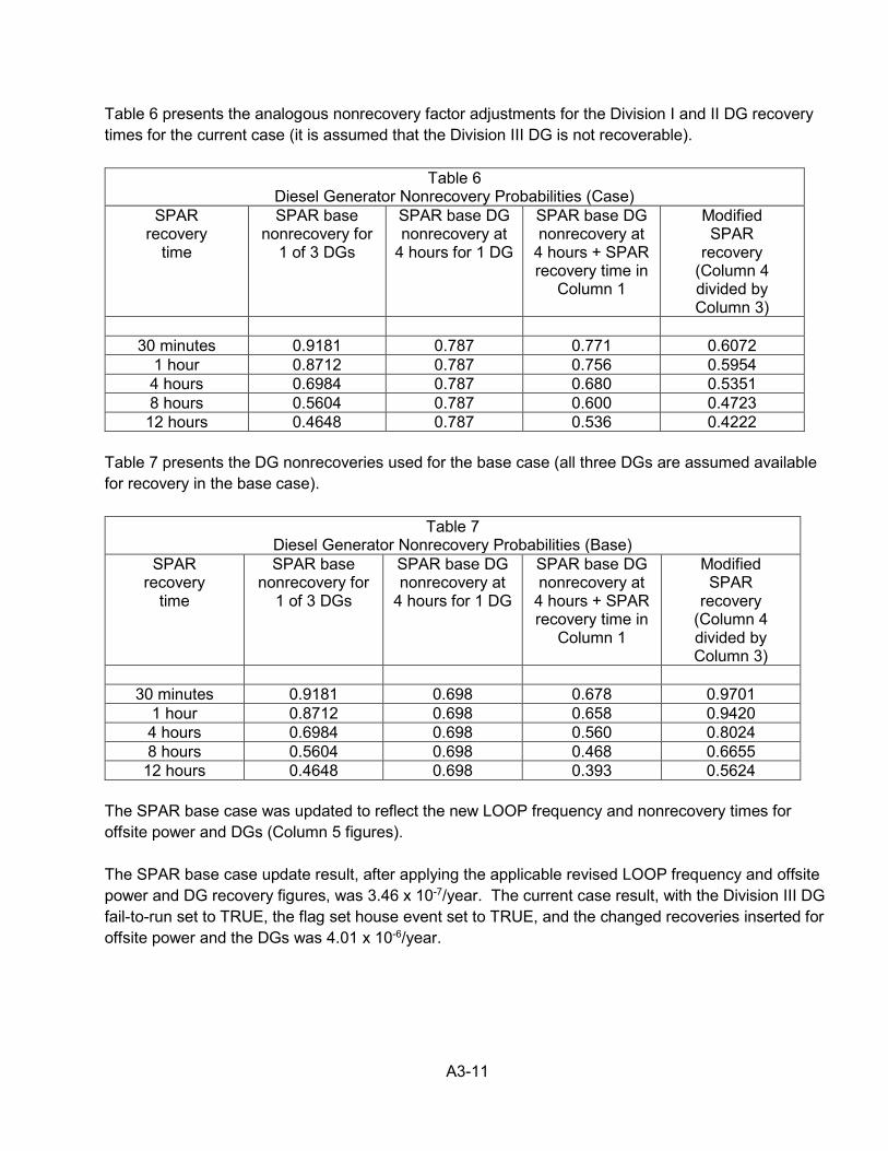
A3-11
Table 6 presents the analogous nonrecovery factor adjustments for the Division I and II DG recovery times for the current case (it is assumed that the Division III DG is not recoverable).
Table 6 Diesel Generator Nonrecovery Probabilities (Case)
SPAR recovery
time
SPAR base nonrecovery for
1 of 3 DGs
SPAR base DG nonrecovery at
4 hours for 1 DG
SPAR base DG nonrecovery at
4 hours + SPAR recovery time in
Column 1
Modified SPAR
recovery (Column 4 divided by Column 3)
30 minutes 0.9181 0.787 0.771 0.6072
1 hour 0.8712 0.787 0.756 0.5954 4 hours 0.6984 0.787 0.680 0.5351 8 hours 0.5604 0.787 0.600 0.4723 12 hours 0.4648 0.787 0.536 0.4222
Table 7 presents the DG nonrecoveries used for the base case (all three DGs are assumed available for recovery in the base case).
Table 7 Diesel Generator Nonrecovery Probabilities (Base)
SPAR recovery
time
SPAR base nonrecovery for
1 of 3 DGs
SPAR base DG nonrecovery at
4 hours for 1 DG
SPAR base DG nonrecovery at
4 hours + SPAR recovery time in
Column 1
Modified SPAR
recovery (Column 4 divided by Column 3)
30 minutes 0.9181 0.698 0.678 0.9701
1 hour 0.8712 0.698 0.658 0.9420 4 hours 0.6984 0.698 0.560 0.8024 8 hours 0.5604 0.698 0.468 0.6655
12 hours 0.4648 0.698 0.393 0.5624 The SPAR base case was updated to reflect the new LOOP frequency and nonrecovery times for offsite power and DGs (Column 5 figures). The SPAR base case update result, after applying the applicable revised LOOP frequency and offsite power and DG recovery figures, was 3.46 x 10⁻⁷/year. The current case result, with the Division III DG fail-to-run set to TRUE, the flag set house event set to TRUE, and the changed recoveries inserted for offsite power and the DGs was 4.01 x 10⁻⁶/year.
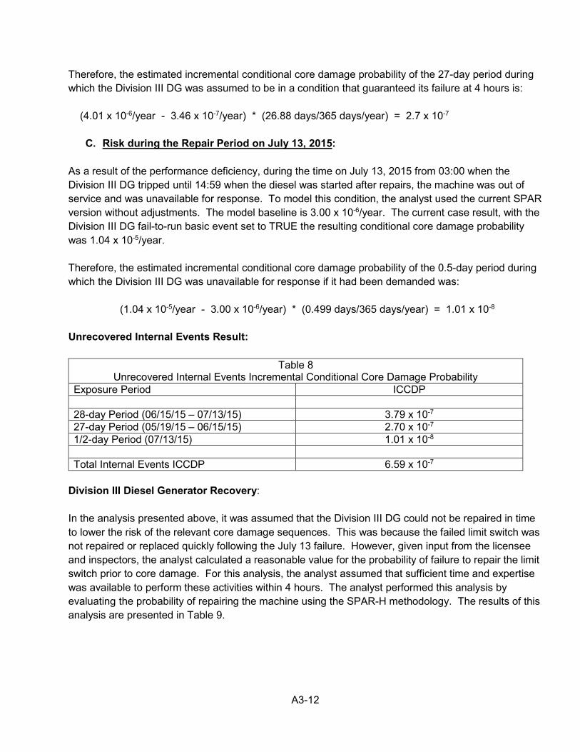
A3-12
Therefore, the estimated incremental conditional core damage probability of the 27-day period during which the Division III DG was assumed to be in a condition that guaranteed its failure at 4 hours is: (4.01 x 10⁻⁶/year - 3.46 x 10⁻⁷/year) * (26.88 days/365 days/year) = 2.7 x 10⁻⁷
C. Risk during the Repair Period on July 13, 2015: As a result of the performance deficiency, during the time on July 13, 2015 from 03:00 when the Division III DG tripped until 14:59 when the diesel was started after repairs, the machine was out of service and was unavailable for response. To model this condition, the analyst used the current SPAR version without adjustments. The model baseline is 3.00 x 10⁻⁶/year. The current case result, with the Division III DG fail-to-run basic event set to TRUE the resulting conditional core damage probability was 1.04 x 10⁻⁵/year. Therefore, the estimated incremental conditional core damage probability of the 0.5-day period during which the Division III DG was unavailable for response if it had been demanded was: (1.04 x 10⁻⁵/year - 3.00 x 10⁻⁶/year) * (0.499 days/365 days/year) = 1.01 x 10⁻⁸ Unrecovered Internal Events Result:
Table 8 Unrecovered Internal Events Incremental Conditional Core Damage Probability
Exposure Period ICCDP 28-day Period (06/15/15 – 07/13/15) 3.79 x 10⁻⁷ 27-day Period (05/19/15 – 06/15/15) 2.70 x 10⁻⁷ 1/2-day Period (07/13/15) 1.01 x 10⁻⁸ Total Internal Events ICCDP 6.59 x 10⁻⁷
Division III Diesel Generator Recovery: In the analysis presented above, it was assumed that the Division III DG could not be repaired in time to lower the risk of the relevant core damage sequences. This was because the failed limit switch was not repaired or replaced quickly following the July 13 failure. However, given input from the licensee and inspectors, the analyst calculated a reasonable value for the probability of failure to repair the limit switch prior to core damage. For this analysis, the analyst assumed that sufficient time and expertise was available to perform these activities within 4 hours. The analyst performed this analysis by evaluating the probability of repairing the machine using the SPAR-H methodology. The results of this analysis are presented in Table 9.
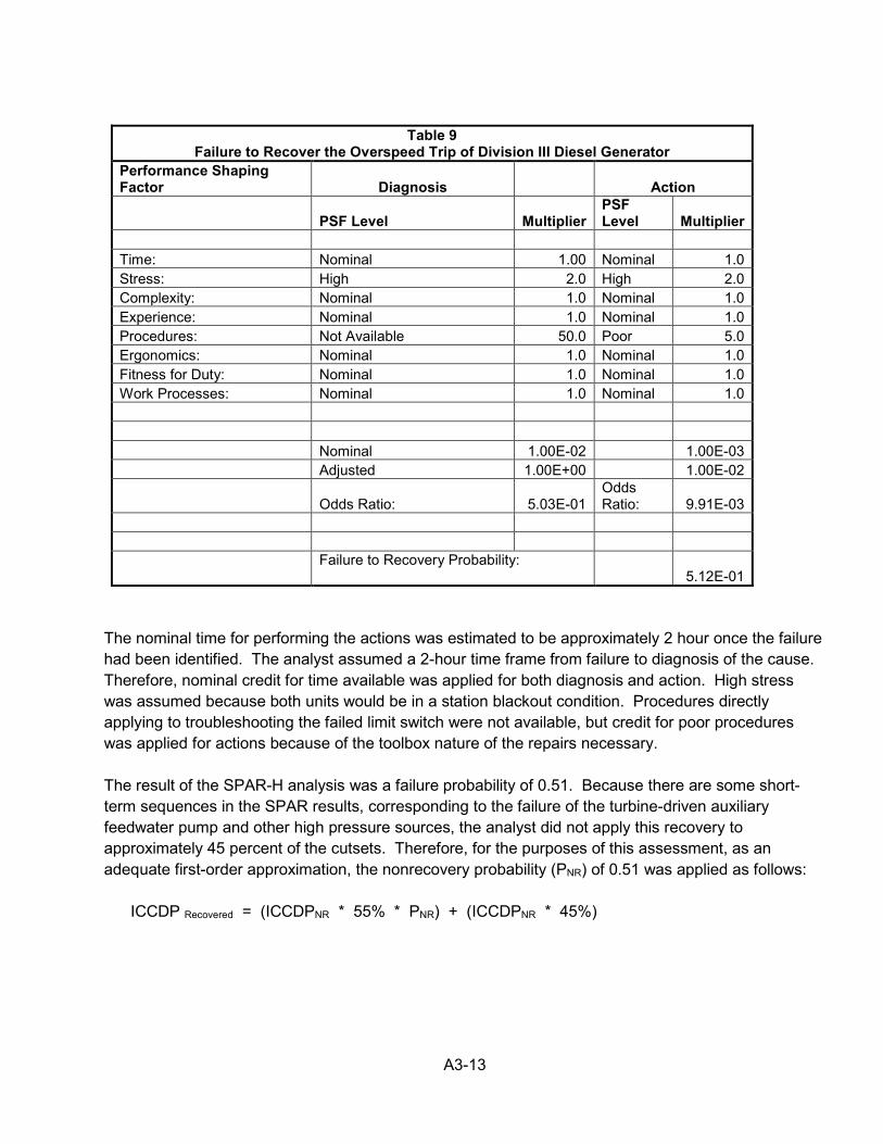
A3-13
Table 9
Failure to Recover the Overspeed Trip of Division III Diesel Generator Performance Shaping Factor Diagnosis Action
PSF Level Multiplier PSF Level Multiplier
Time: Nominal 1.00 Nominal 1.0 Stress: High 2.0 High 2.0 Complexity: Nominal 1.0 Nominal 1.0 Experience: Nominal 1.0 Nominal 1.0 Procedures: Not Available 50.0 Poor 5.0 Ergonomics: Nominal 1.0 Nominal 1.0 Fitness for Duty: Nominal 1.0 Nominal 1.0 Work Processes: Nominal 1.0 Nominal 1.0 Nominal 1.00E-02 1.00E-03 Adjusted 1.00E+00 1.00E-02
Odds Ratio: 5.03E-01 Odds Ratio: 9.91E-03
Failure to Recovery Probability: 5.12E-01
The nominal time for performing the actions was estimated to be approximately 2 hour once the failure had been identified. The analyst assumed a 2-hour time frame from failure to diagnosis of the cause. Therefore, nominal credit for time available was applied for both diagnosis and action. High stress was assumed because both units would be in a station blackout condition. Procedures directly applying to troubleshooting the failed limit switch were not available, but credit for poor procedures was applied for actions because of the toolbox nature of the repairs necessary. The result of the SPAR-H analysis was a failure probability of 0.51. Because there are some short-term sequences in the SPAR results, corresponding to the failure of the turbine-driven auxiliary feedwater pump and other high pressure sources, the analyst did not apply this recovery to approximately 45 percent of the cutsets. Therefore, for the purposes of this assessment, as an adequate first-order approximation, the nonrecovery probability (PNR) of 0.51 was applied as follows: ICCDP Recovered = (ICCDPNR * 55% * PNR) + (ICCDPNR * 45%)
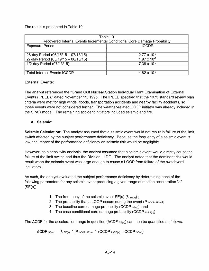
A3-14
The result is presented in Table 10:
Table 10 Recovered Internal Events Incremental Conditional Core Damage Probability
Exposure Period ICCDP 28-day Period (06/15/15 – 07/13/15) 2.77 x 10⁻⁷ 27-day Period (05/19/15 – 06/15/15) 1.97 x 10⁻⁷ 1/2-day Period (07/13/15) 7.38 x 10⁻⁹ Total Internal Events ICCDP 4.82 x 10⁻⁷
External Events: The analyst referenced the “Grand Gulf Nuclear Station Individual Plant Examination of External Events (IPEEE),” dated November 15, 1995. The IPEEE specified that the 1975 standard review plan criteria were met for high winds, floods, transportation accidents and nearby facility accidents, so those events were not considered further. The weather-related LOOP initiator was already included in the SPAR model. The remaining accident initiators included seismic and fire.
A. Seismic: Seismic Calculation: The analyst assumed that a seismic event would not result in failure of the limit switch affected by the subject performance deficiency. Because the frequency of a seismic event is low, the impact of the performance deficiency on seismic risk would be negligible. However, as a sensitivity analysis, the analyst assumed that a seismic event would directly cause the failure of the limit switch and thus the Division III DG. The analyst noted that the dominant risk would result when the seismic event was large enough to cause a LOOP from failure of the switchyard insulators. As such, the analyst evaluated the subject performance deficiency by determining each of the following parameters for any seismic event producing a given range of median acceleration "a" [SE(a)]:
1. The frequency of the seismic event SE(a) (λ SE(a)) ; 2. The probability that a LOOP occurs during the event (P LOOP-SE(a)); 3. The baseline core damage probability (CCDP SE(a)); and 4. The case conditional core damage probability (CCDP III-SE(a))
The ΔCDF for the acceleration range in question (ΔCDF SE(a)) can then be quantified as follows:
ΔCDF SE(a) = λ SE(a) * P LOOP-SE(a) * (CCDP III-SE(a) - CCDP SE(a))
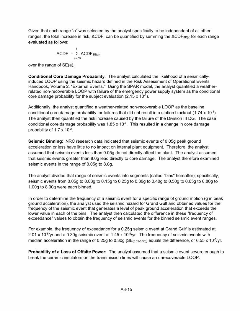
A3-15
Given that each range “a” was selected by the analyst specifically to be independent of all other ranges, the total increase in risk, ΔCDF, can be quantified by summing the ΔCDFSE(a) for each range evaluated as follows: 8
ΔCDF = Σ ΔCDFSE(a)
a=.05
over the range of SE(a). Conditional Core Damage Probability: The analyst calculated the likelihood of a seismically-induced LOOP using the seismic hazard defined in the Risk Assessment of Operational Events Handbook, Volume 2, “External Events.” Using the SPAR model, the analyst quantified a weather-related non-recoverable LOOP with failure of the emergency power supply system as the conditional core damage probability for the subject evaluation (2.15 x 10⁻¹). Additionally, the analyst quantified a weather-related non-recoverable LOOP as the baseline conditional core damage probability for failures that did not result in a station blackout (1.74 x 10⁻³). The analyst then quantified the risk increase caused by the failure of the Division III DG. The case conditional core damage probability was 1.85 x 10⁻². This resulted in a change in core damage probability of 1.7 x 10⁻². Seismic Binning: NRC research data indicated that seismic events of 0.05g peak ground acceleration or less have little to no impact on internal plant equipment. Therefore, the analyst assumed that seismic events less than 0.05g do not directly affect the plant. The analyst assumed that seismic events greater than 8.0g lead directly to core damage. The analyst therefore examined seismic events in the range of 0.05g to 8.0g. The analyst divided that range of seismic events into segments (called "bins" hereafter); specifically, seismic events from 0.05g to 0.08g to 0.15g to 0.25g to 0.30g to 0.40g to 0.50g to 0.65g to 0.80g to 1.00g to 8.00g were each binned. In order to determine the frequency of a seismic event for a specific range of ground motion (g in peak ground acceleration), the analyst used the seismic hazard for Grand Gulf and obtained values for the frequency of the seismic event that generates a level of peak ground acceleration that exceeds the lower value in each of the bins. The analyst then calculated the difference in these "frequency of exceedance" values to obtain the frequency of seismic events for the binned seismic event ranges. For example, the frequency of exceedance for a 0.25g seismic event at Grand Gulf is estimated at 2.01 x 10⁻⁵/yr and a 0.30g seismic event at 1.45 x 10⁻⁵/yr. The frequency of seismic events with median acceleration in the range of 0.25g to 0.30g [SE(0.35-0.30)] equals the difference, or 6.55 x 10⁻⁶/yr. Probability of a Loss of Offsite Power: The analyst assumed that a seismic event severe enough to break the ceramic insulators on the transmission lines will cause an unrecoverable LOOP.
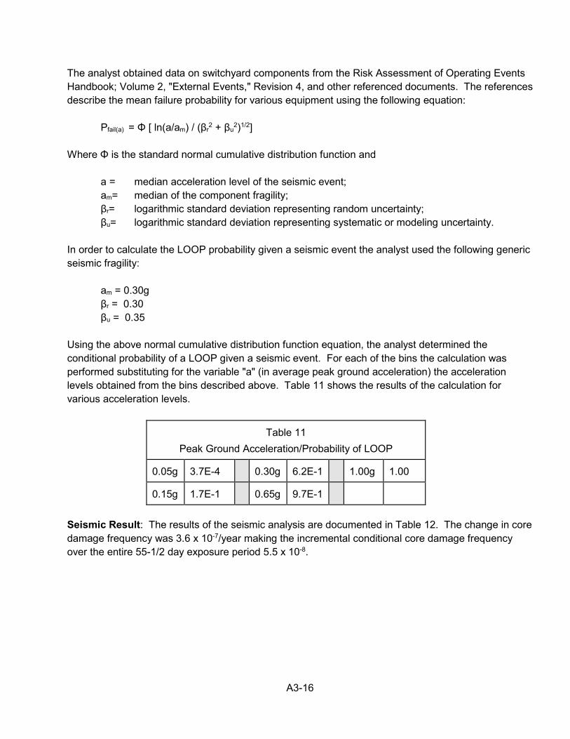
A3-16
The analyst obtained data on switchyard components from the Risk Assessment of Operating Events Handbook; Volume 2, "External Events," Revision 4, and other referenced documents. The references describe the mean failure probability for various equipment using the following equation:
Pfail(a) = Φ [ ln(a/am) / (βr2 + βu
2)1/2] Where Φ is the standard normal cumulative distribution function and
a = median acceleration level of the seismic event; am= median of the component fragility; βr= logarithmic standard deviation representing random uncertainty; βu= logarithmic standard deviation representing systematic or modeling uncertainty.
In order to calculate the LOOP probability given a seismic event the analyst used the following generic seismic fragility:
am = 0.30g βr = 0.30 βu = 0.35
Using the above normal cumulative distribution function equation, the analyst determined the conditional probability of a LOOP given a seismic event. For each of the bins the calculation was performed substituting for the variable "a" (in average peak ground acceleration) the acceleration levels obtained from the bins described above. Table 11 shows the results of the calculation for various acceleration levels.
Table 11
Peak Ground Acceleration/Probability of LOOP 0.05g
3.7E-4
0.30g
6.2E-1
1.00g
1.00
0.15g
1.7E-1
0.65g
9.7E-1
Seismic Result: The results of the seismic analysis are documented in Table 12. The change in core damage frequency was 3.6 x 10⁻⁷/year making the incremental conditional core damage frequency over the entire 55-1/2 day exposure period 5.5 x 10⁻⁸.
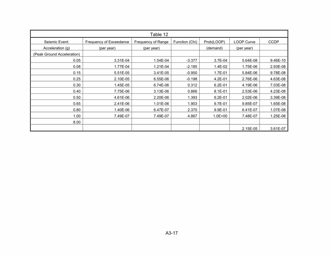
A3-17
Table 12 Seismic Event: Frequency of Exceedance Frequency of Range Function (Chi) Prob(LOOP) LOOP Curve CCDP Acceleration (g) (per year) (per year) (demand) (per year)
(Peak Ground Acceleration) 0.05 3.31E-04 1.54E-04 -3.377 3.7E-04 5.64E-08 9.46E-10 0.08 1.77E-04 1.21E-04 -2.185 1.4E-02 1.75E-06 2.93E-08 0.15 5.51E-05 3.41E-05 -0.950 1.7E-01 5.84E-06 9.78E-08 0.25 2.10E-05 6.55E-06 -0.198 4.2E-01 2.76E-06 4.63E-08 0.30 1.45E-05 6.74E-06 0.312 6.2E-01 4.19E-06 7.03E-08 0.40 7.75E-06 3.13E-06 0.866 8.1E-01 2.53E-06 4.23E-08 0.50 4.61E-06 2.20E-06 1.393 9.2E-01 2.02E-06 3.39E-08 0.65 2.41E-06 1.01E-06 1.903 9.7E-01 9.85E-07 1.65E-08 0.80 1.40E-06 6.47E-07 2.370 9.9E-01 6.41E-07 1.07E-08 1.00 7.49E-07 7.49E-07 4.867 1.0E+00 7.48E-07 1.25E-08 8.00
2.15E-05 3.61E-07
A3-18
B. Fire The risk increase from fire initiating events were reviewed and determined to have a small impact on the risk of the finding. The analyst determined that this performance deficiency was not a significant contributor to fire induced core damage because the Division III DG is not relied upon in the fire hazards analysis. While control room abandonment sequences can be significant in some cases, operators cannot operate the Division III DG or the high pressure core spray system from the remote shutdown panel. Therefore, the unavailability of the Division III DG had negligible impact on control room abandonment sequences. Large Early Release Frequency: In accordance with Manual Chapter 0609, Appendix A, the analyst reviewed the core damage sequences to determine an estimate of the change in large early release frequency caused by the finding. To address the contribution to the LERF, the analyst used NRC Inspection Manual Chapter 0609, Appendix H, “Containment Integrity Significance Determination Process.” For boiling water reactors (BWR-6 with a Mark 3 containment), because of station blackout, the failure of the Division III DG was a potential LERF contributor. The analyst identified the non-zero LERF factors for the applicable LOOP sequences. The non-zero LERF factors (0.2 in each case) were applied. As a bounding analysis, the analyst applied the 0.2 LERF factor to the total internal events incremental conditional core damage frequency (4.82 x 10⁻⁷). The bounding change in LERF was 9.6 x 10⁻⁸. Results: Because the change in core damage frequency was less than 1 x 10⁻⁶ and the change in LERF was less than 1 x 10⁻⁷, this finding was of very low safety significance (Green). The dominant core damage sequences included LOOP events leading to station blackout. Equipment that helped mitigate the risk included the reactor core isolation cooling system and the Division I and II DGs, which had a different over-speed trip design.