google file system.pdf
TRANSCRIPT
Google File System
goals• monitoring, fault tolerance, auto-recovery (thousands of low-cost
machines)
• focus on multi-GB files
• optimised for sequential reads and append writes (websites: seldom random writes & reads)
• handle appends efficiently
• co-design GFS and the applications
operations supportedclassic operations
• create, read, write, delete, open, close
new operations
• snapshot—quick&low cost ‘picture’ of a file(dir)
• record append—multiple clients appending simultaneously, no sync required
terminology
• chunk—fixed-size piece of file
• chunk server—holds chunks
• master—coordinates chunk servers
• chunk handle—ID of a chunk (64 bit, globally unique)
cluster architecture
Legend:
Data messagesControl messages
Application(file name, chunk index)
(chunk handle,chunk locations)
GFS master
File namespace
/foo/bar
Instructions to chunkserver
Chunkserver state
GFS chunkserverGFS chunkserver(chunk handle, byte range)
chunk data
chunk 2ef0
Linux file system Linux file system
GFS client
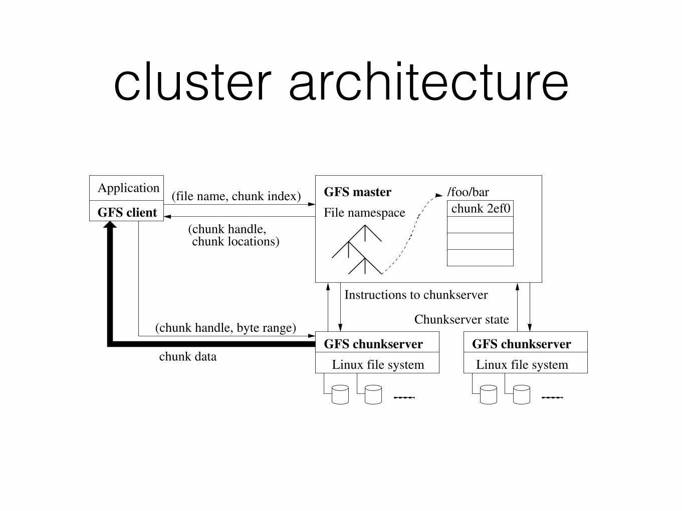
Figure 1: GFS Architecture
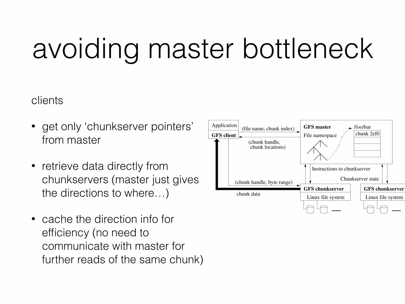
and replication decisions using global knowledge. However,we must minimize its involvement in reads and writes sothat it does not become a bottleneck. Clients never readand write file data through the master. Instead, a client asksthe master which chunkservers it should contact. It cachesthis information for a limited time and interacts with thechunkservers directly for many subsequent operations.
Let us explain the interactions for a simple read with refer-ence to Figure 1. First, using the fixed chunk size, the clienttranslates the file name and byte offset specified by the ap-plication into a chunk index within the file. Then, it sendsthe master a request containing the file name and chunkindex. The master replies with the corresponding chunkhandle and locations of the replicas. The client caches thisinformation using the file name and chunk index as the key.
The client then sends a request to one of the replicas,most likely the closest one. The request specifies the chunkhandle and a byte range within that chunk. Further readsof the same chunk require no more client-master interactionuntil the cached information expires or the file is reopened.In fact, the client typically asks for multiple chunks in thesame request and the master can also include the informa-tion for chunks immediately following those requested. Thisextra information sidesteps several future client-master in-teractions at practically no extra cost.
2.5 Chunk SizeChunk size is one of the key design parameters. We have
chosen 64 MB, which is much larger than typical file sys-tem block sizes. Each chunk replica is stored as a plainLinux file on a chunkserver and is extended only as needed.Lazy space allocation avoids wasting space due to internalfragmentation, perhaps the greatest objection against sucha large chunk size.
A large chunk size offers several important advantages.First, it reduces clients’ need to interact with the masterbecause reads and writes on the same chunk require onlyone initial request to the master for chunk location informa-tion. The reduction is especially significant for our work-loads because applications mostly read and write large filessequentially. Even for small random reads, the client cancomfortably cache all the chunk location information for amulti-TB working set. Second, since on a large chunk, aclient is more likely to perform many operations on a givenchunk, it can reduce network overhead by keeping a persis-
tent TCP connection to the chunkserver over an extendedperiod of time. Third, it reduces the size of the metadatastored on the master. This allows us to keep the metadatain memory, which in turn brings other advantages that wewill discuss in Section 2.6.1.
On the other hand, a large chunk size, even with lazy spaceallocation, has its disadvantages. A small file consists of asmall number of chunks, perhaps just one. The chunkserversstoring those chunks may become hot spots if many clientsare accessing the same file. In practice, hot spots have notbeen a major issue because our applications mostly readlarge multi-chunk files sequentially.
However, hot spots did develop when GFS was first usedby a batch-queue system: an executable was written to GFSas a single-chunk file and then started on hundreds of ma-chines at the same time. The few chunkservers storing thisexecutable were overloaded by hundreds of simultaneous re-quests. We fixed this problem by storing such executableswith a higher replication factor and by making the batch-queue system stagger application start times. A potentiallong-term solution is to allow clients to read data from otherclients in such situations.
2.6 MetadataThe master stores three major types of metadata: the file
and chunk namespaces, the mapping from files to chunks,and the locations of each chunk’s replicas. All metadata iskept in the master’s memory. The first two types (names-paces and file-to-chunk mapping) are also kept persistent bylogging mutations to an operation log stored on the mas-ter’s local disk and replicated on remote machines. Usinga log allows us to update the master state simply, reliably,and without risking inconsistencies in the event of a mastercrash. The master does not store chunk location informa-tion persistently. Instead, it asks each chunkserver about itschunks at master startup and whenever a chunkserver joinsthe cluster.
2.6.1 In-Memory Data StructuresSince metadata is stored in memory, master operations are
fast. Furthermore, it is easy and efficient for the master toperiodically scan through its entire state in the background.This periodic scanning is used to implement chunk garbagecollection, re-replication in the presence of chunkserver fail-ures, and chunk migration to balance load and disk space
the master• maintains all the metadata
• controls system-wide activities
• collects chunks of a chunk server at startup (polls) and
• generates in-memory mapping of files and chunk server pointers
• chunk lease management (replication, (re)placement)
• garbage collection of orphaned chunks
• chunk migration
• HeartBeat with chunk servers (collect state, check they’re ok)
• deals with all clients for metadata operations
avoiding master bottleneck
Legend:
Data messagesControl messages
Application(file name, chunk index)
(chunk handle,chunk locations)
GFS master
File namespace
/foo/bar
Instructions to chunkserver
Chunkserver state
GFS chunkserverGFS chunkserver(chunk handle, byte range)
chunk data
chunk 2ef0
Linux file system Linux file system
GFS client
Figure 1: GFS Architecture
and replication decisions using global knowledge. However,we must minimize its involvement in reads and writes sothat it does not become a bottleneck. Clients never readand write file data through the master. Instead, a client asksthe master which chunkservers it should contact. It cachesthis information for a limited time and interacts with thechunkservers directly for many subsequent operations.
Let us explain the interactions for a simple read with refer-ence to Figure 1. First, using the fixed chunk size, the clienttranslates the file name and byte offset specified by the ap-plication into a chunk index within the file. Then, it sendsthe master a request containing the file name and chunkindex. The master replies with the corresponding chunkhandle and locations of the replicas. The client caches thisinformation using the file name and chunk index as the key.
The client then sends a request to one of the replicas,most likely the closest one. The request specifies the chunkhandle and a byte range within that chunk. Further readsof the same chunk require no more client-master interactionuntil the cached information expires or the file is reopened.In fact, the client typically asks for multiple chunks in thesame request and the master can also include the informa-tion for chunks immediately following those requested. Thisextra information sidesteps several future client-master in-teractions at practically no extra cost.
2.5 Chunk SizeChunk size is one of the key design parameters. We have
chosen 64 MB, which is much larger than typical file sys-tem block sizes. Each chunk replica is stored as a plainLinux file on a chunkserver and is extended only as needed.Lazy space allocation avoids wasting space due to internalfragmentation, perhaps the greatest objection against sucha large chunk size.
A large chunk size offers several important advantages.First, it reduces clients’ need to interact with the masterbecause reads and writes on the same chunk require onlyone initial request to the master for chunk location informa-tion. The reduction is especially significant for our work-loads because applications mostly read and write large filessequentially. Even for small random reads, the client cancomfortably cache all the chunk location information for amulti-TB working set. Second, since on a large chunk, aclient is more likely to perform many operations on a givenchunk, it can reduce network overhead by keeping a persis-
tent TCP connection to the chunkserver over an extendedperiod of time. Third, it reduces the size of the metadatastored on the master. This allows us to keep the metadatain memory, which in turn brings other advantages that wewill discuss in Section 2.6.1.
On the other hand, a large chunk size, even with lazy spaceallocation, has its disadvantages. A small file consists of asmall number of chunks, perhaps just one. The chunkserversstoring those chunks may become hot spots if many clientsare accessing the same file. In practice, hot spots have notbeen a major issue because our applications mostly readlarge multi-chunk files sequentially.
However, hot spots did develop when GFS was first usedby a batch-queue system: an executable was written to GFSas a single-chunk file and then started on hundreds of ma-chines at the same time. The few chunkservers storing thisexecutable were overloaded by hundreds of simultaneous re-quests. We fixed this problem by storing such executableswith a higher replication factor and by making the batch-queue system stagger application start times. A potentiallong-term solution is to allow clients to read data from otherclients in such situations.
2.6 MetadataThe master stores three major types of metadata: the file
and chunk namespaces, the mapping from files to chunks,and the locations of each chunk’s replicas. All metadata iskept in the master’s memory. The first two types (names-paces and file-to-chunk mapping) are also kept persistent bylogging mutations to an operation log stored on the mas-ter’s local disk and replicated on remote machines. Usinga log allows us to update the master state simply, reliably,and without risking inconsistencies in the event of a mastercrash. The master does not store chunk location informa-tion persistently. Instead, it asks each chunkserver about itschunks at master startup and whenever a chunkserver joinsthe cluster.
2.6.1 In-Memory Data StructuresSince metadata is stored in memory, master operations are
fast. Furthermore, it is easy and efficient for the master toperiodically scan through its entire state in the background.This periodic scanning is used to implement chunk garbagecollection, re-replication in the presence of chunkserver fail-ures, and chunk migration to balance load and disk space
clients
• get only ‘chunkserver pointers’ from master
• retrieve data directly from chunkservers (master just gives the directions to where…)
• cache the direction info for efficiency (no need to communicate with master for further reads of the same chunk)
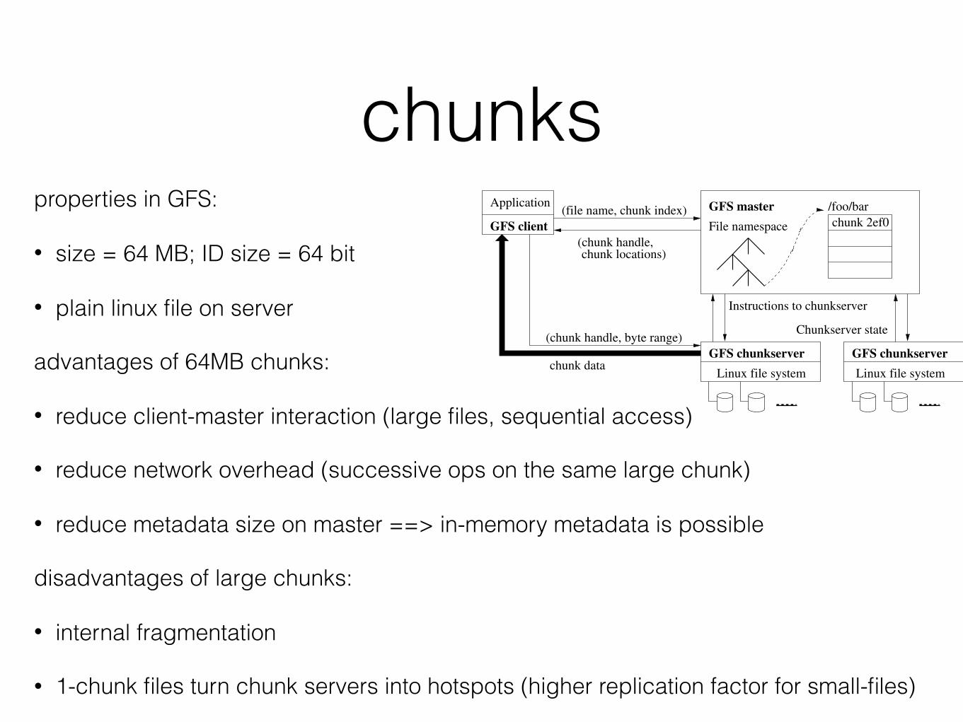
chunksproperties in GFS:
• size = 64 MB; ID size = 64 bit
• plain linux file on server
advantages of 64MB chunks:
• reduce client-master interaction (large files, sequential access)
• reduce network overhead (successive ops on the same large chunk)
• reduce metadata size on master ==> in-memory metadata is possible
disadvantages of large chunks:
• internal fragmentation
• 1-chunk files turn chunk servers into hotspots (higher replication factor for small-files)
Legend:
Data messagesControl messages
Application(file name, chunk index)
(chunk handle,chunk locations)
GFS master
File namespace
/foo/bar
Instructions to chunkserver
Chunkserver state
GFS chunkserverGFS chunkserver(chunk handle, byte range)
chunk data
chunk 2ef0
Linux file system Linux file system
GFS client
Figure 1: GFS Architecture
and replication decisions using global knowledge. However,we must minimize its involvement in reads and writes sothat it does not become a bottleneck. Clients never readand write file data through the master. Instead, a client asksthe master which chunkservers it should contact. It cachesthis information for a limited time and interacts with thechunkservers directly for many subsequent operations.
Let us explain the interactions for a simple read with refer-ence to Figure 1. First, using the fixed chunk size, the clienttranslates the file name and byte offset specified by the ap-plication into a chunk index within the file. Then, it sendsthe master a request containing the file name and chunkindex. The master replies with the corresponding chunkhandle and locations of the replicas. The client caches thisinformation using the file name and chunk index as the key.
The client then sends a request to one of the replicas,most likely the closest one. The request specifies the chunkhandle and a byte range within that chunk. Further readsof the same chunk require no more client-master interactionuntil the cached information expires or the file is reopened.In fact, the client typically asks for multiple chunks in thesame request and the master can also include the informa-tion for chunks immediately following those requested. Thisextra information sidesteps several future client-master in-teractions at practically no extra cost.
2.5 Chunk SizeChunk size is one of the key design parameters. We have
chosen 64 MB, which is much larger than typical file sys-tem block sizes. Each chunk replica is stored as a plainLinux file on a chunkserver and is extended only as needed.Lazy space allocation avoids wasting space due to internalfragmentation, perhaps the greatest objection against sucha large chunk size.
A large chunk size offers several important advantages.First, it reduces clients’ need to interact with the masterbecause reads and writes on the same chunk require onlyone initial request to the master for chunk location informa-tion. The reduction is especially significant for our work-loads because applications mostly read and write large filessequentially. Even for small random reads, the client cancomfortably cache all the chunk location information for amulti-TB working set. Second, since on a large chunk, aclient is more likely to perform many operations on a givenchunk, it can reduce network overhead by keeping a persis-
tent TCP connection to the chunkserver over an extendedperiod of time. Third, it reduces the size of the metadatastored on the master. This allows us to keep the metadatain memory, which in turn brings other advantages that wewill discuss in Section 2.6.1.
On the other hand, a large chunk size, even with lazy spaceallocation, has its disadvantages. A small file consists of asmall number of chunks, perhaps just one. The chunkserversstoring those chunks may become hot spots if many clientsare accessing the same file. In practice, hot spots have notbeen a major issue because our applications mostly readlarge multi-chunk files sequentially.
However, hot spots did develop when GFS was first usedby a batch-queue system: an executable was written to GFSas a single-chunk file and then started on hundreds of ma-chines at the same time. The few chunkservers storing thisexecutable were overloaded by hundreds of simultaneous re-quests. We fixed this problem by storing such executableswith a higher replication factor and by making the batch-queue system stagger application start times. A potentiallong-term solution is to allow clients to read data from otherclients in such situations.
2.6 MetadataThe master stores three major types of metadata: the file
and chunk namespaces, the mapping from files to chunks,and the locations of each chunk’s replicas. All metadata iskept in the master’s memory. The first two types (names-paces and file-to-chunk mapping) are also kept persistent bylogging mutations to an operation log stored on the mas-ter’s local disk and replicated on remote machines. Usinga log allows us to update the master state simply, reliably,and without risking inconsistencies in the event of a mastercrash. The master does not store chunk location informa-tion persistently. Instead, it asks each chunkserver about itschunks at master startup and whenever a chunkserver joinsthe cluster.
2.6.1 In-Memory Data StructuresSince metadata is stored in memory, master operations are
fast. Furthermore, it is easy and efficient for the master toperiodically scan through its entire state in the background.This periodic scanning is used to implement chunk garbagecollection, re-replication in the presence of chunkserver fail-ures, and chunk migration to balance load and disk space
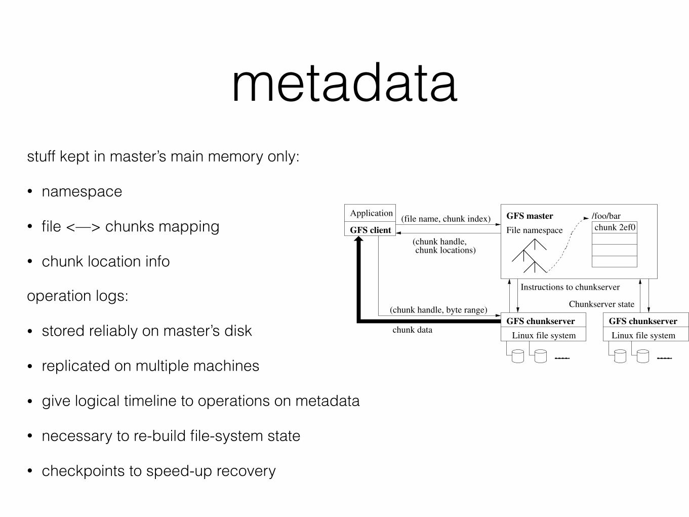
metadatastuff kept in master’s main memory only:
• namespace
• file <—> chunks mapping
• chunk location info
operation logs:
• stored reliably on master’s disk
• replicated on multiple machines
• give logical timeline to operations on metadata
• necessary to re-build file-system state
• checkpoints to speed-up recovery
Legend:
Data messagesControl messages
Application(file name, chunk index)
(chunk handle,chunk locations)
GFS master
File namespace
/foo/bar
Instructions to chunkserver
Chunkserver state
GFS chunkserverGFS chunkserver(chunk handle, byte range)
chunk data
chunk 2ef0
Linux file system Linux file system
GFS client
Figure 1: GFS Architecture
and replication decisions using global knowledge. However,we must minimize its involvement in reads and writes sothat it does not become a bottleneck. Clients never readand write file data through the master. Instead, a client asksthe master which chunkservers it should contact. It cachesthis information for a limited time and interacts with thechunkservers directly for many subsequent operations.
Let us explain the interactions for a simple read with refer-ence to Figure 1. First, using the fixed chunk size, the clienttranslates the file name and byte offset specified by the ap-plication into a chunk index within the file. Then, it sendsthe master a request containing the file name and chunkindex. The master replies with the corresponding chunkhandle and locations of the replicas. The client caches thisinformation using the file name and chunk index as the key.
The client then sends a request to one of the replicas,most likely the closest one. The request specifies the chunkhandle and a byte range within that chunk. Further readsof the same chunk require no more client-master interactionuntil the cached information expires or the file is reopened.In fact, the client typically asks for multiple chunks in thesame request and the master can also include the informa-tion for chunks immediately following those requested. Thisextra information sidesteps several future client-master in-teractions at practically no extra cost.
2.5 Chunk SizeChunk size is one of the key design parameters. We have
chosen 64 MB, which is much larger than typical file sys-tem block sizes. Each chunk replica is stored as a plainLinux file on a chunkserver and is extended only as needed.Lazy space allocation avoids wasting space due to internalfragmentation, perhaps the greatest objection against sucha large chunk size.
A large chunk size offers several important advantages.First, it reduces clients’ need to interact with the masterbecause reads and writes on the same chunk require onlyone initial request to the master for chunk location informa-tion. The reduction is especially significant for our work-loads because applications mostly read and write large filessequentially. Even for small random reads, the client cancomfortably cache all the chunk location information for amulti-TB working set. Second, since on a large chunk, aclient is more likely to perform many operations on a givenchunk, it can reduce network overhead by keeping a persis-
tent TCP connection to the chunkserver over an extendedperiod of time. Third, it reduces the size of the metadatastored on the master. This allows us to keep the metadatain memory, which in turn brings other advantages that wewill discuss in Section 2.6.1.
On the other hand, a large chunk size, even with lazy spaceallocation, has its disadvantages. A small file consists of asmall number of chunks, perhaps just one. The chunkserversstoring those chunks may become hot spots if many clientsare accessing the same file. In practice, hot spots have notbeen a major issue because our applications mostly readlarge multi-chunk files sequentially.
However, hot spots did develop when GFS was first usedby a batch-queue system: an executable was written to GFSas a single-chunk file and then started on hundreds of ma-chines at the same time. The few chunkservers storing thisexecutable were overloaded by hundreds of simultaneous re-quests. We fixed this problem by storing such executableswith a higher replication factor and by making the batch-queue system stagger application start times. A potentiallong-term solution is to allow clients to read data from otherclients in such situations.
2.6 MetadataThe master stores three major types of metadata: the file
and chunk namespaces, the mapping from files to chunks,and the locations of each chunk’s replicas. All metadata iskept in the master’s memory. The first two types (names-paces and file-to-chunk mapping) are also kept persistent bylogging mutations to an operation log stored on the mas-ter’s local disk and replicated on remote machines. Usinga log allows us to update the master state simply, reliably,and without risking inconsistencies in the event of a mastercrash. The master does not store chunk location informa-tion persistently. Instead, it asks each chunkserver about itschunks at master startup and whenever a chunkserver joinsthe cluster.
2.6.1 In-Memory Data StructuresSince metadata is stored in memory, master operations are
fast. Furthermore, it is easy and efficient for the master toperiodically scan through its entire state in the background.This periodic scanning is used to implement chunk garbagecollection, re-replication in the presence of chunkserver fail-ures, and chunk migration to balance load and disk space

reading
17
Write/Read Algorithm `Read Algorithm
18
Write/Read Algorithm `Read Algorithm
writing
14
Write/Read Algorithm `Write Algorithm
17
Write/Read Algorithm `Read Algorithm
writing
15
Write/Read Algorithm `Write Algorithm
16
Write/Read Algorithm `Write Algorithm
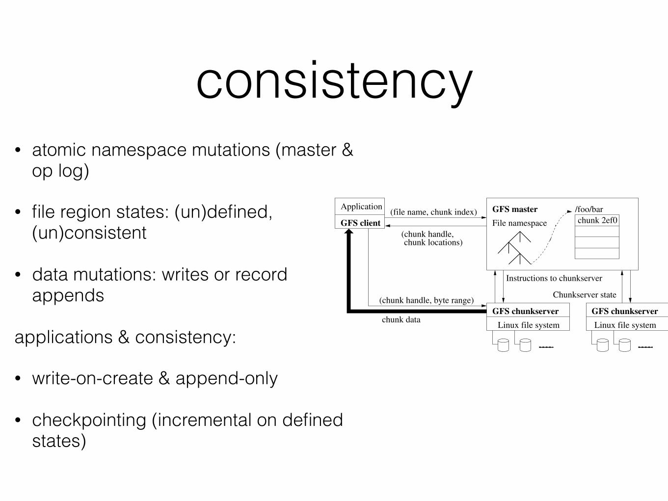
consistency• atomic namespace mutations (master &
op log)
• file region states: (un)defined, (un)consistent
• data mutations: writes or record appends
applications & consistency:
• write-on-create & append-only
• checkpointing (incremental on defined states)
Legend:
Data messagesControl messages
Application(file name, chunk index)
(chunk handle,chunk locations)
GFS master
File namespace
/foo/bar
Instructions to chunkserver
Chunkserver state
GFS chunkserverGFS chunkserver(chunk handle, byte range)
chunk data
chunk 2ef0
Linux file system Linux file system
GFS client
Figure 1: GFS Architecture
and replication decisions using global knowledge. However,we must minimize its involvement in reads and writes sothat it does not become a bottleneck. Clients never readand write file data through the master. Instead, a client asksthe master which chunkservers it should contact. It cachesthis information for a limited time and interacts with thechunkservers directly for many subsequent operations.
Let us explain the interactions for a simple read with refer-ence to Figure 1. First, using the fixed chunk size, the clienttranslates the file name and byte offset specified by the ap-plication into a chunk index within the file. Then, it sendsthe master a request containing the file name and chunkindex. The master replies with the corresponding chunkhandle and locations of the replicas. The client caches thisinformation using the file name and chunk index as the key.
The client then sends a request to one of the replicas,most likely the closest one. The request specifies the chunkhandle and a byte range within that chunk. Further readsof the same chunk require no more client-master interactionuntil the cached information expires or the file is reopened.In fact, the client typically asks for multiple chunks in thesame request and the master can also include the informa-tion for chunks immediately following those requested. Thisextra information sidesteps several future client-master in-teractions at practically no extra cost.
2.5 Chunk SizeChunk size is one of the key design parameters. We have
chosen 64 MB, which is much larger than typical file sys-tem block sizes. Each chunk replica is stored as a plainLinux file on a chunkserver and is extended only as needed.Lazy space allocation avoids wasting space due to internalfragmentation, perhaps the greatest objection against sucha large chunk size.
A large chunk size offers several important advantages.First, it reduces clients’ need to interact with the masterbecause reads and writes on the same chunk require onlyone initial request to the master for chunk location informa-tion. The reduction is especially significant for our work-loads because applications mostly read and write large filessequentially. Even for small random reads, the client cancomfortably cache all the chunk location information for amulti-TB working set. Second, since on a large chunk, aclient is more likely to perform many operations on a givenchunk, it can reduce network overhead by keeping a persis-
tent TCP connection to the chunkserver over an extendedperiod of time. Third, it reduces the size of the metadatastored on the master. This allows us to keep the metadatain memory, which in turn brings other advantages that wewill discuss in Section 2.6.1.
On the other hand, a large chunk size, even with lazy spaceallocation, has its disadvantages. A small file consists of asmall number of chunks, perhaps just one. The chunkserversstoring those chunks may become hot spots if many clientsare accessing the same file. In practice, hot spots have notbeen a major issue because our applications mostly readlarge multi-chunk files sequentially.
However, hot spots did develop when GFS was first usedby a batch-queue system: an executable was written to GFSas a single-chunk file and then started on hundreds of ma-chines at the same time. The few chunkservers storing thisexecutable were overloaded by hundreds of simultaneous re-quests. We fixed this problem by storing such executableswith a higher replication factor and by making the batch-queue system stagger application start times. A potentiallong-term solution is to allow clients to read data from otherclients in such situations.
2.6 MetadataThe master stores three major types of metadata: the file
and chunk namespaces, the mapping from files to chunks,and the locations of each chunk’s replicas. All metadata iskept in the master’s memory. The first two types (names-paces and file-to-chunk mapping) are also kept persistent bylogging mutations to an operation log stored on the mas-ter’s local disk and replicated on remote machines. Usinga log allows us to update the master state simply, reliably,and without risking inconsistencies in the event of a mastercrash. The master does not store chunk location informa-tion persistently. Instead, it asks each chunkserver about itschunks at master startup and whenever a chunkserver joinsthe cluster.
2.6.1 In-Memory Data StructuresSince metadata is stored in memory, master operations are
fast. Furthermore, it is easy and efficient for the master toperiodically scan through its entire state in the background.This periodic scanning is used to implement chunk garbagecollection, re-replication in the presence of chunkserver fail-ures, and chunk migration to balance load and disk space
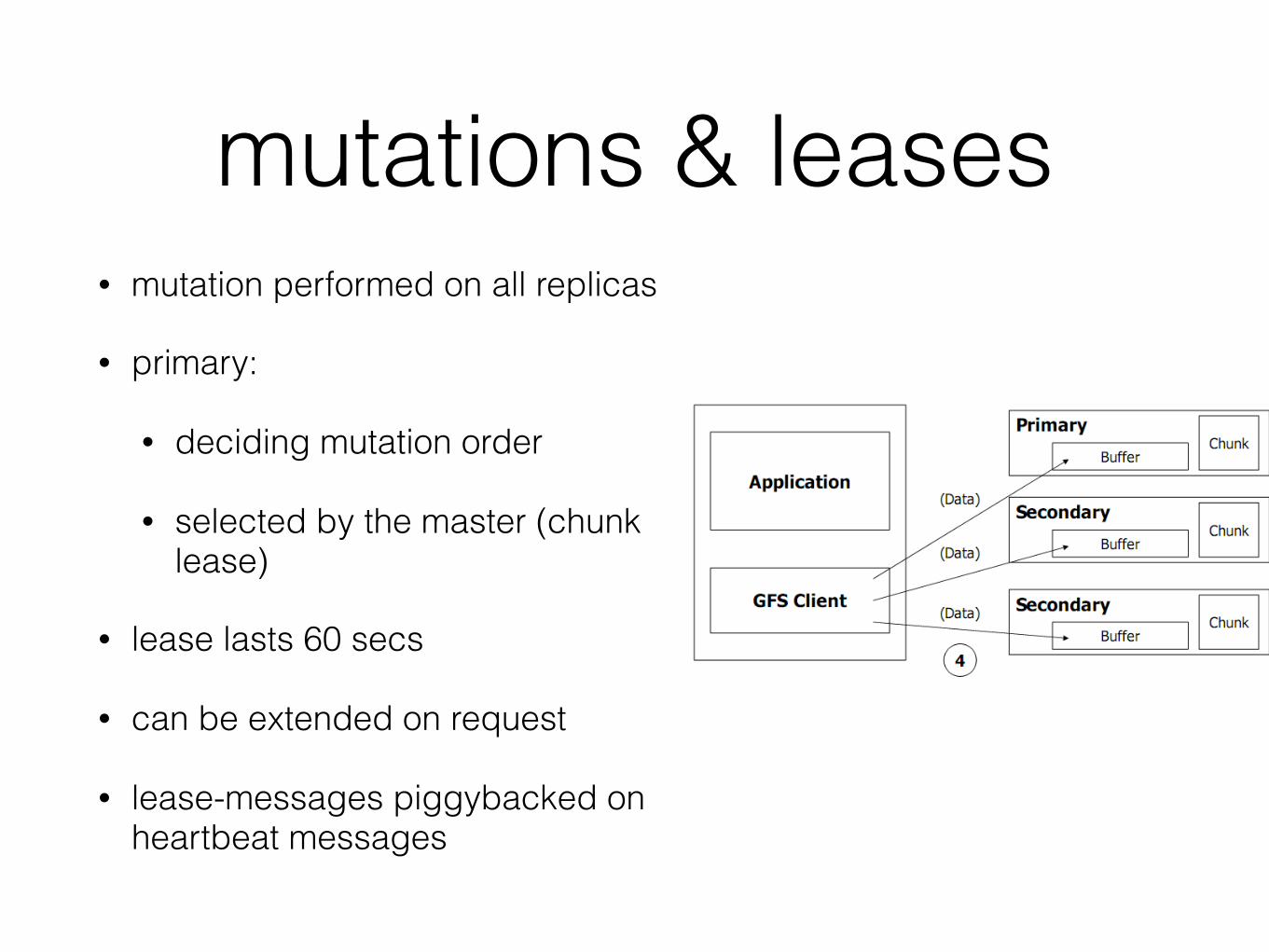
mutations & leases• mutation performed on all replicas
• primary:
• deciding mutation order
• selected by the master (chunk lease)
• lease lasts 60 secs
• can be extended on request
• lease-messages piggybacked on heartbeat messages
14
Write/Read Algorithm `Write Algorithm
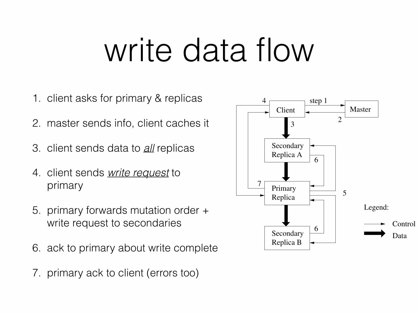
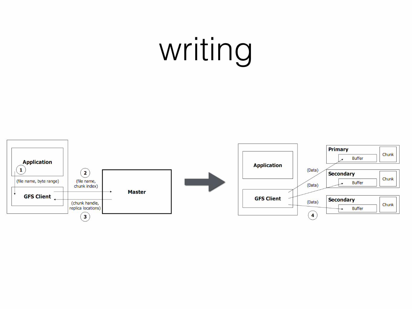
write data flow1. client asks for primary & replicas
2. master sends info, client caches it
3. client sends data to all replicas
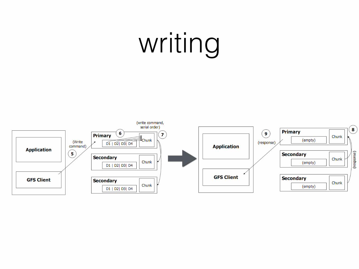
4. client sends write request to primary
5. primary forwards mutation order + write request to secondaries
6. ack to primary about write complete
7. primary ack to client (errors too)
PrimaryReplica
SecondaryReplica B
SecondaryReplica A
Master
Legend:
Control
Data
3
Client2
step 14
5
6
6
7
Figure 2: Write Control and Data Flow
becomes unreachable or replies that it no longer holdsa lease.
3. The client pushes the data to all the replicas. A clientcan do so in any order. Each chunkserver will storethe data in an internal LRU buffer cache until thedata is used or aged out. By decoupling the data flowfrom the control flow, we can improve performance byscheduling the expensive data flow based on the net-work topology regardless of which chunkserver is theprimary. Section 3.2 discusses this further.
4. Once all the replicas have acknowledged receiving thedata, the client sends a write request to the primary.The request identifies the data pushed earlier to all ofthe replicas. The primary assigns consecutive serialnumbers to all the mutations it receives, possibly frommultiple clients, which provides the necessary serial-ization. It applies the mutation to its own local statein serial number order.
5. The primary forwards the write request to all sec-ondary replicas. Each secondary replica applies mu-tations in the same serial number order assigned bythe primary.
6. The secondaries all reply to the primary indicatingthat they have completed the operation.
7. The primary replies to the client. Any errors encoun-tered at any of the replicas are reported to the client.In case of errors, the write may have succeeded at theprimary and an arbitrary subset of the secondary repli-cas. (If it had failed at the primary, it would nothave been assigned a serial number and forwarded.)The client request is considered to have failed, and themodified region is left in an inconsistent state. Ourclient code handles such errors by retrying the failedmutation. It will make a few attempts at steps (3)through (7) before falling back to a retry from the be-ginning of the write.
If a write by the application is large or straddles a chunkboundary, GFS client code breaks it down into multiplewrite operations. They all follow the control flow describedabove but may be interleaved with and overwritten by con-current operations from other clients. Therefore, the shared
file region may end up containing fragments from differentclients, although the replicas will be identical because the in-dividual operations are completed successfully in the sameorder on all replicas. This leaves the file region in consistentbut undefined state as noted in Section 2.7.
3.2 Data FlowWe decouple the flow of data from the flow of control to
use the network efficiently. While control flows from theclient to the primary and then to all secondaries, data ispushed linearly along a carefully picked chain of chunkserversin a pipelined fashion. Our goals are to fully utilize eachmachine’s network bandwidth, avoid network bottlenecksand high-latency links, and minimize the latency to pushthrough all the data.
To fully utilize each machine’s network bandwidth, thedata is pushed linearly along a chain of chunkservers ratherthan distributed in some other topology (e.g., tree). Thus,each machine’s full outbound bandwidth is used to trans-fer the data as fast as possible rather than divided amongmultiple recipients.
To avoid network bottlenecks and high-latency links (e.g.,inter-switch links are often both) as much as possible, eachmachine forwards the data to the “closest” machine in thenetwork topology that has not received it. Suppose theclient is pushing data to chunkservers S1 through S4. Itsends the data to the closest chunkserver, say S1. S1 for-wards it to the closest chunkserver S2 through S4 closest toS1, say S2. Similarly, S2 forwards it to S3 or S4, whicheveris closer to S2, and so on. Our network topology is simpleenough that “distances” can be accurately estimated fromIP addresses.
Finally, we minimize latency by pipelining the data trans-fer over TCP connections. Once a chunkserver receives somedata, it starts forwarding immediately. Pipelining is espe-cially helpful to us because we use a switched network withfull-duplex links. Sending the data immediately does notreduce the receive rate. Without network congestion, theideal elapsed time for transferring B bytes to R replicas isB/T + RL where T is the network throughput and L is la-tency to transfer bytes between two machines. Our networklinks are typically 100 Mbps (T ), and L is far below 1 ms.Therefore, 1 MB can ideally be distributed in about 80 ms.
3.3 Atomic Record AppendsGFS provides an atomic append operation called record
append. In a traditional write, the client specifies the off-set at which data is to be written. Concurrent writes tothe same region are not serializable: the region may end upcontaining data fragments from multiple clients. In a recordappend, however, the client specifies only the data. GFSappends it to the file at least once atomically (i.e., as onecontinuous sequence of bytes) at an offset of GFS’s choosingand returns that offset to the client. This is similar to writ-ing to a file opened in O APPEND mode in Unix without therace conditions when multiple writers do so concurrently.
Record append is heavily used by our distributed applica-tions in which many clients on different machines appendto the same file concurrently. Clients would need addi-tional complicated and expensive synchronization, for ex-ample through a distributed lock manager, if they do sowith traditional writes. In our workloads, such files often
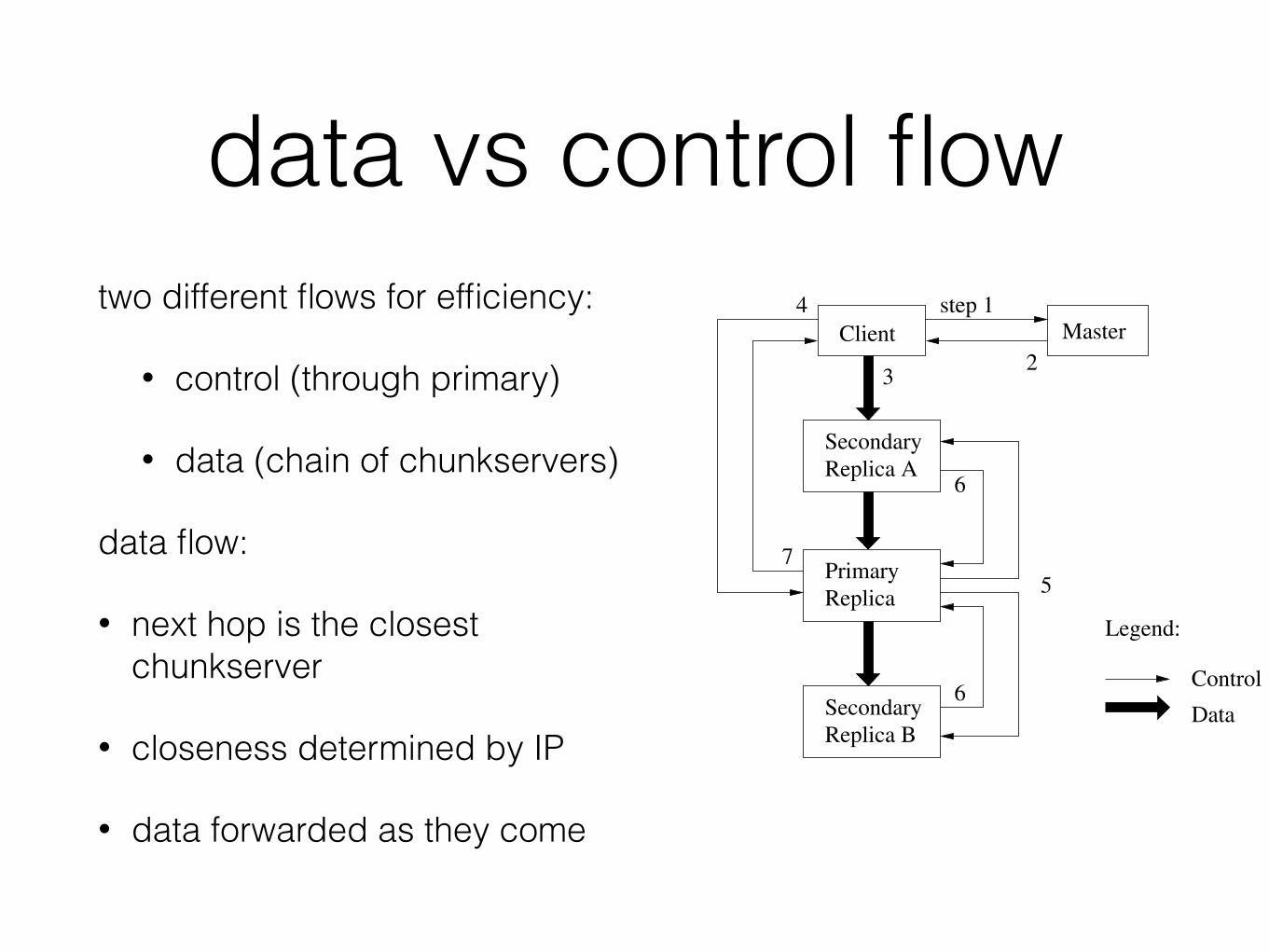
data vs control flowtwo different flows for efficiency:
• control (through primary)
• data (chain of chunkservers)
data flow:
• next hop is the closest chunkserver
• closeness determined by IP
• data forwarded as they come
PrimaryReplica
SecondaryReplica B
SecondaryReplica A
Master
Legend:
Control
Data
3
Client2
step 14
5
6
6
7
Figure 2: Write Control and Data Flow
becomes unreachable or replies that it no longer holdsa lease.
3. The client pushes the data to all the replicas. A clientcan do so in any order. Each chunkserver will storethe data in an internal LRU buffer cache until thedata is used or aged out. By decoupling the data flowfrom the control flow, we can improve performance byscheduling the expensive data flow based on the net-work topology regardless of which chunkserver is theprimary. Section 3.2 discusses this further.
4. Once all the replicas have acknowledged receiving thedata, the client sends a write request to the primary.The request identifies the data pushed earlier to all ofthe replicas. The primary assigns consecutive serialnumbers to all the mutations it receives, possibly frommultiple clients, which provides the necessary serial-ization. It applies the mutation to its own local statein serial number order.
5. The primary forwards the write request to all sec-ondary replicas. Each secondary replica applies mu-tations in the same serial number order assigned bythe primary.
6. The secondaries all reply to the primary indicatingthat they have completed the operation.
7. The primary replies to the client. Any errors encoun-tered at any of the replicas are reported to the client.In case of errors, the write may have succeeded at theprimary and an arbitrary subset of the secondary repli-cas. (If it had failed at the primary, it would nothave been assigned a serial number and forwarded.)The client request is considered to have failed, and themodified region is left in an inconsistent state. Ourclient code handles such errors by retrying the failedmutation. It will make a few attempts at steps (3)through (7) before falling back to a retry from the be-ginning of the write.
If a write by the application is large or straddles a chunkboundary, GFS client code breaks it down into multiplewrite operations. They all follow the control flow describedabove but may be interleaved with and overwritten by con-current operations from other clients. Therefore, the shared
file region may end up containing fragments from differentclients, although the replicas will be identical because the in-dividual operations are completed successfully in the sameorder on all replicas. This leaves the file region in consistentbut undefined state as noted in Section 2.7.
3.2 Data FlowWe decouple the flow of data from the flow of control to
use the network efficiently. While control flows from theclient to the primary and then to all secondaries, data ispushed linearly along a carefully picked chain of chunkserversin a pipelined fashion. Our goals are to fully utilize eachmachine’s network bandwidth, avoid network bottlenecksand high-latency links, and minimize the latency to pushthrough all the data.
To fully utilize each machine’s network bandwidth, thedata is pushed linearly along a chain of chunkservers ratherthan distributed in some other topology (e.g., tree). Thus,each machine’s full outbound bandwidth is used to trans-fer the data as fast as possible rather than divided amongmultiple recipients.
To avoid network bottlenecks and high-latency links (e.g.,inter-switch links are often both) as much as possible, eachmachine forwards the data to the “closest” machine in thenetwork topology that has not received it. Suppose theclient is pushing data to chunkservers S1 through S4. Itsends the data to the closest chunkserver, say S1. S1 for-wards it to the closest chunkserver S2 through S4 closest toS1, say S2. Similarly, S2 forwards it to S3 or S4, whicheveris closer to S2, and so on. Our network topology is simpleenough that “distances” can be accurately estimated fromIP addresses.
Finally, we minimize latency by pipelining the data trans-fer over TCP connections. Once a chunkserver receives somedata, it starts forwarding immediately. Pipelining is espe-cially helpful to us because we use a switched network withfull-duplex links. Sending the data immediately does notreduce the receive rate. Without network congestion, theideal elapsed time for transferring B bytes to R replicas isB/T + RL where T is the network throughput and L is la-tency to transfer bytes between two machines. Our networklinks are typically 100 Mbps (T ), and L is far below 1 ms.Therefore, 1 MB can ideally be distributed in about 80 ms.
3.3 Atomic Record AppendsGFS provides an atomic append operation called record
append. In a traditional write, the client specifies the off-set at which data is to be written. Concurrent writes tothe same region are not serializable: the region may end upcontaining data fragments from multiple clients. In a recordappend, however, the client specifies only the data. GFSappends it to the file at least once atomically (i.e., as onecontinuous sequence of bytes) at an offset of GFS’s choosingand returns that offset to the client. This is similar to writ-ing to a file opened in O APPEND mode in Unix without therace conditions when multiple writers do so concurrently.
Record append is heavily used by our distributed applica-tions in which many clients on different machines appendto the same file concurrently. Clients would need addi-tional complicated and expensive synchronization, for ex-ample through a distributed lock manager, if they do sowith traditional writes. In our workloads, such files often
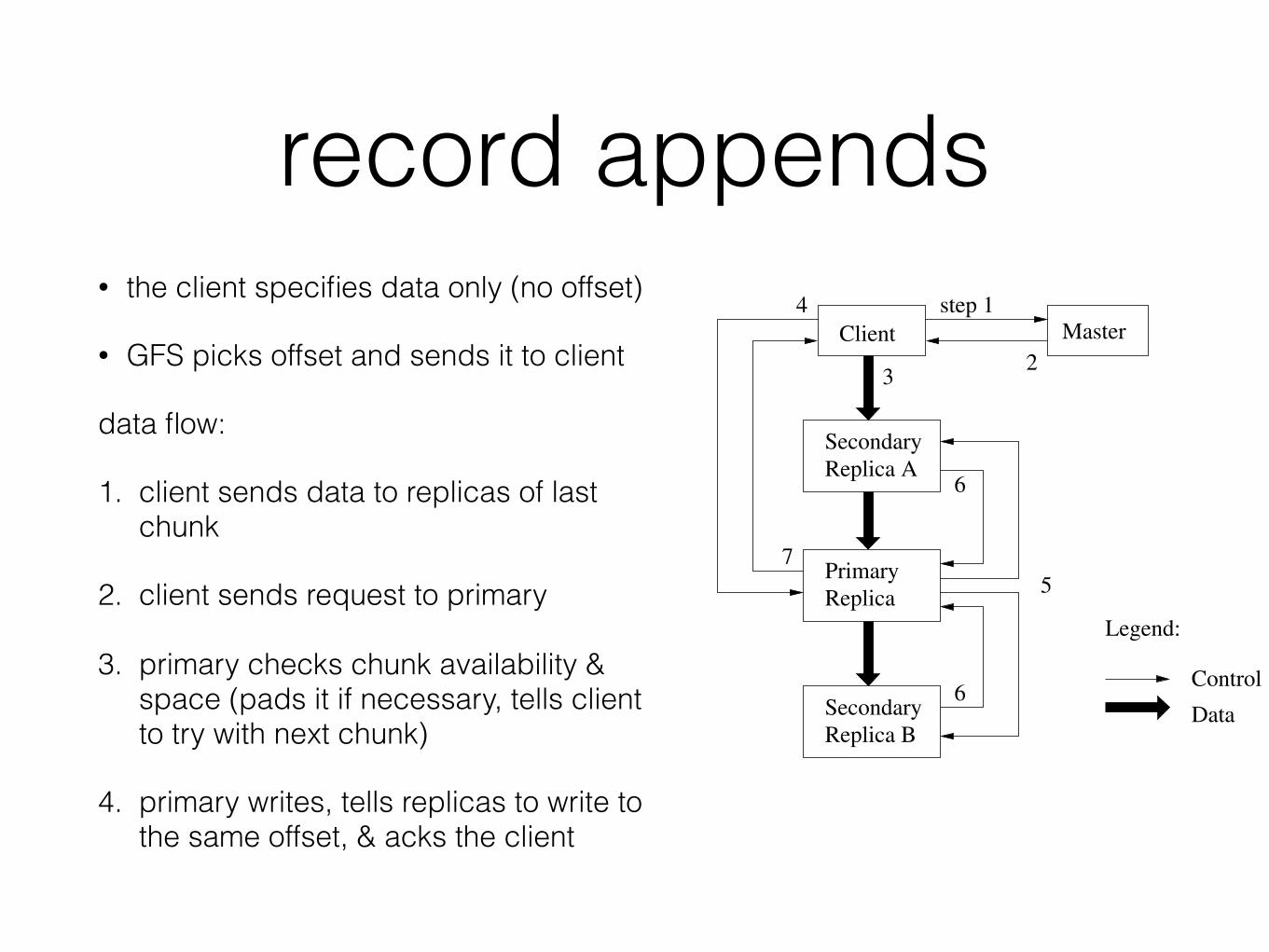
record appends• the client specifies data only (no offset)
• GFS picks offset and sends it to client
data flow:
1. client sends data to replicas of last chunk
2. client sends request to primary
3. primary checks chunk availability & space (pads it if necessary, tells client to try with next chunk)
4. primary writes, tells replicas to write to the same offset, & acks the client
PrimaryReplica
SecondaryReplica B
SecondaryReplica A
Master
Legend:
Control
Data
3
Client2
step 14
5
6
6
7
Figure 2: Write Control and Data Flow
becomes unreachable or replies that it no longer holdsa lease.
3. The client pushes the data to all the replicas. A clientcan do so in any order. Each chunkserver will storethe data in an internal LRU buffer cache until thedata is used or aged out. By decoupling the data flowfrom the control flow, we can improve performance byscheduling the expensive data flow based on the net-work topology regardless of which chunkserver is theprimary. Section 3.2 discusses this further.
4. Once all the replicas have acknowledged receiving thedata, the client sends a write request to the primary.The request identifies the data pushed earlier to all ofthe replicas. The primary assigns consecutive serialnumbers to all the mutations it receives, possibly frommultiple clients, which provides the necessary serial-ization. It applies the mutation to its own local statein serial number order.
5. The primary forwards the write request to all sec-ondary replicas. Each secondary replica applies mu-tations in the same serial number order assigned bythe primary.
6. The secondaries all reply to the primary indicatingthat they have completed the operation.
7. The primary replies to the client. Any errors encoun-tered at any of the replicas are reported to the client.In case of errors, the write may have succeeded at theprimary and an arbitrary subset of the secondary repli-cas. (If it had failed at the primary, it would nothave been assigned a serial number and forwarded.)The client request is considered to have failed, and themodified region is left in an inconsistent state. Ourclient code handles such errors by retrying the failedmutation. It will make a few attempts at steps (3)through (7) before falling back to a retry from the be-ginning of the write.
If a write by the application is large or straddles a chunkboundary, GFS client code breaks it down into multiplewrite operations. They all follow the control flow describedabove but may be interleaved with and overwritten by con-current operations from other clients. Therefore, the shared
file region may end up containing fragments from differentclients, although the replicas will be identical because the in-dividual operations are completed successfully in the sameorder on all replicas. This leaves the file region in consistentbut undefined state as noted in Section 2.7.
3.2 Data FlowWe decouple the flow of data from the flow of control to
use the network efficiently. While control flows from theclient to the primary and then to all secondaries, data ispushed linearly along a carefully picked chain of chunkserversin a pipelined fashion. Our goals are to fully utilize eachmachine’s network bandwidth, avoid network bottlenecksand high-latency links, and minimize the latency to pushthrough all the data.
To fully utilize each machine’s network bandwidth, thedata is pushed linearly along a chain of chunkservers ratherthan distributed in some other topology (e.g., tree). Thus,each machine’s full outbound bandwidth is used to trans-fer the data as fast as possible rather than divided amongmultiple recipients.
To avoid network bottlenecks and high-latency links (e.g.,inter-switch links are often both) as much as possible, eachmachine forwards the data to the “closest” machine in thenetwork topology that has not received it. Suppose theclient is pushing data to chunkservers S1 through S4. Itsends the data to the closest chunkserver, say S1. S1 for-wards it to the closest chunkserver S2 through S4 closest toS1, say S2. Similarly, S2 forwards it to S3 or S4, whicheveris closer to S2, and so on. Our network topology is simpleenough that “distances” can be accurately estimated fromIP addresses.
Finally, we minimize latency by pipelining the data trans-fer over TCP connections. Once a chunkserver receives somedata, it starts forwarding immediately. Pipelining is espe-cially helpful to us because we use a switched network withfull-duplex links. Sending the data immediately does notreduce the receive rate. Without network congestion, theideal elapsed time for transferring B bytes to R replicas isB/T + RL where T is the network throughput and L is la-tency to transfer bytes between two machines. Our networklinks are typically 100 Mbps (T ), and L is far below 1 ms.Therefore, 1 MB can ideally be distributed in about 80 ms.
3.3 Atomic Record AppendsGFS provides an atomic append operation called record
append. In a traditional write, the client specifies the off-set at which data is to be written. Concurrent writes tothe same region are not serializable: the region may end upcontaining data fragments from multiple clients. In a recordappend, however, the client specifies only the data. GFSappends it to the file at least once atomically (i.e., as onecontinuous sequence of bytes) at an offset of GFS’s choosingand returns that offset to the client. This is similar to writ-ing to a file opened in O APPEND mode in Unix without therace conditions when multiple writers do so concurrently.
Record append is heavily used by our distributed applica-tions in which many clients on different machines appendto the same file concurrently. Clients would need addi-tional complicated and expensive synchronization, for ex-ample through a distributed lock manager, if they do sowith traditional writes. In our workloads, such files often
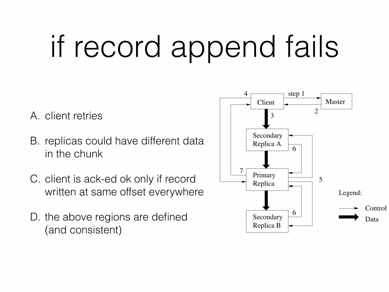
if record append fails
A. client retries
B. replicas could have different data in the chunk
C. client is ack-ed ok only if record written at same offset everywhere
D. the above regions are defined (and consistent)
PrimaryReplica
SecondaryReplica B
SecondaryReplica A
Master
Legend:
Control
Data
3
Client2
step 14
5
6
6
7
Figure 2: Write Control and Data Flow
becomes unreachable or replies that it no longer holdsa lease.
3. The client pushes the data to all the replicas. A clientcan do so in any order. Each chunkserver will storethe data in an internal LRU buffer cache until thedata is used or aged out. By decoupling the data flowfrom the control flow, we can improve performance byscheduling the expensive data flow based on the net-work topology regardless of which chunkserver is theprimary. Section 3.2 discusses this further.
4. Once all the replicas have acknowledged receiving thedata, the client sends a write request to the primary.The request identifies the data pushed earlier to all ofthe replicas. The primary assigns consecutive serialnumbers to all the mutations it receives, possibly frommultiple clients, which provides the necessary serial-ization. It applies the mutation to its own local statein serial number order.
5. The primary forwards the write request to all sec-ondary replicas. Each secondary replica applies mu-tations in the same serial number order assigned bythe primary.
6. The secondaries all reply to the primary indicatingthat they have completed the operation.
7. The primary replies to the client. Any errors encoun-tered at any of the replicas are reported to the client.In case of errors, the write may have succeeded at theprimary and an arbitrary subset of the secondary repli-cas. (If it had failed at the primary, it would nothave been assigned a serial number and forwarded.)The client request is considered to have failed, and themodified region is left in an inconsistent state. Ourclient code handles such errors by retrying the failedmutation. It will make a few attempts at steps (3)through (7) before falling back to a retry from the be-ginning of the write.
If a write by the application is large or straddles a chunkboundary, GFS client code breaks it down into multiplewrite operations. They all follow the control flow describedabove but may be interleaved with and overwritten by con-current operations from other clients. Therefore, the shared
file region may end up containing fragments from differentclients, although the replicas will be identical because the in-dividual operations are completed successfully in the sameorder on all replicas. This leaves the file region in consistentbut undefined state as noted in Section 2.7.
3.2 Data FlowWe decouple the flow of data from the flow of control to
use the network efficiently. While control flows from theclient to the primary and then to all secondaries, data ispushed linearly along a carefully picked chain of chunkserversin a pipelined fashion. Our goals are to fully utilize eachmachine’s network bandwidth, avoid network bottlenecksand high-latency links, and minimize the latency to pushthrough all the data.
To fully utilize each machine’s network bandwidth, thedata is pushed linearly along a chain of chunkservers ratherthan distributed in some other topology (e.g., tree). Thus,each machine’s full outbound bandwidth is used to trans-fer the data as fast as possible rather than divided amongmultiple recipients.
To avoid network bottlenecks and high-latency links (e.g.,inter-switch links are often both) as much as possible, eachmachine forwards the data to the “closest” machine in thenetwork topology that has not received it. Suppose theclient is pushing data to chunkservers S1 through S4. Itsends the data to the closest chunkserver, say S1. S1 for-wards it to the closest chunkserver S2 through S4 closest toS1, say S2. Similarly, S2 forwards it to S3 or S4, whicheveris closer to S2, and so on. Our network topology is simpleenough that “distances” can be accurately estimated fromIP addresses.
Finally, we minimize latency by pipelining the data trans-fer over TCP connections. Once a chunkserver receives somedata, it starts forwarding immediately. Pipelining is espe-cially helpful to us because we use a switched network withfull-duplex links. Sending the data immediately does notreduce the receive rate. Without network congestion, theideal elapsed time for transferring B bytes to R replicas isB/T + RL where T is the network throughput and L is la-tency to transfer bytes between two machines. Our networklinks are typically 100 Mbps (T ), and L is far below 1 ms.Therefore, 1 MB can ideally be distributed in about 80 ms.
3.3 Atomic Record AppendsGFS provides an atomic append operation called record
append. In a traditional write, the client specifies the off-set at which data is to be written. Concurrent writes tothe same region are not serializable: the region may end upcontaining data fragments from multiple clients. In a recordappend, however, the client specifies only the data. GFSappends it to the file at least once atomically (i.e., as onecontinuous sequence of bytes) at an offset of GFS’s choosingand returns that offset to the client. This is similar to writ-ing to a file opened in O APPEND mode in Unix without therace conditions when multiple writers do so concurrently.
Record append is heavily used by our distributed applica-tions in which many clients on different machines appendto the same file concurrently. Clients would need addi-tional complicated and expensive synchronization, for ex-ample through a distributed lock manager, if they do sowith traditional writes. In our workloads, such files often
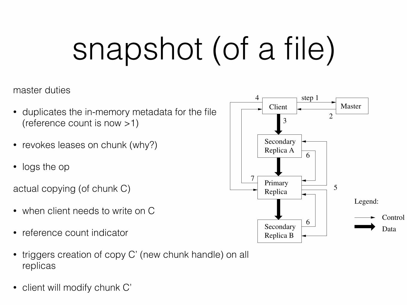
snapshot (of a file)master duties
• duplicates the in-memory metadata for the file (reference count is now >1)
• revokes leases on chunk (why?)
• logs the op
actual copying (of chunk C)
• when client needs to write on C
• reference count indicator
• triggers creation of copy C’ (new chunk handle) on all replicas
• client will modify chunk C’
PrimaryReplica
SecondaryReplica B
SecondaryReplica A
Master
Legend:
Control
Data
3
Client2
step 14
5
6
6
7
Figure 2: Write Control and Data Flow
becomes unreachable or replies that it no longer holdsa lease.
3. The client pushes the data to all the replicas. A clientcan do so in any order. Each chunkserver will storethe data in an internal LRU buffer cache until thedata is used or aged out. By decoupling the data flowfrom the control flow, we can improve performance byscheduling the expensive data flow based on the net-work topology regardless of which chunkserver is theprimary. Section 3.2 discusses this further.
4. Once all the replicas have acknowledged receiving thedata, the client sends a write request to the primary.The request identifies the data pushed earlier to all ofthe replicas. The primary assigns consecutive serialnumbers to all the mutations it receives, possibly frommultiple clients, which provides the necessary serial-ization. It applies the mutation to its own local statein serial number order.
5. The primary forwards the write request to all sec-ondary replicas. Each secondary replica applies mu-tations in the same serial number order assigned bythe primary.
6. The secondaries all reply to the primary indicatingthat they have completed the operation.
7. The primary replies to the client. Any errors encoun-tered at any of the replicas are reported to the client.In case of errors, the write may have succeeded at theprimary and an arbitrary subset of the secondary repli-cas. (If it had failed at the primary, it would nothave been assigned a serial number and forwarded.)The client request is considered to have failed, and themodified region is left in an inconsistent state. Ourclient code handles such errors by retrying the failedmutation. It will make a few attempts at steps (3)through (7) before falling back to a retry from the be-ginning of the write.
If a write by the application is large or straddles a chunkboundary, GFS client code breaks it down into multiplewrite operations. They all follow the control flow describedabove but may be interleaved with and overwritten by con-current operations from other clients. Therefore, the shared
file region may end up containing fragments from differentclients, although the replicas will be identical because the in-dividual operations are completed successfully in the sameorder on all replicas. This leaves the file region in consistentbut undefined state as noted in Section 2.7.
3.2 Data FlowWe decouple the flow of data from the flow of control to
use the network efficiently. While control flows from theclient to the primary and then to all secondaries, data ispushed linearly along a carefully picked chain of chunkserversin a pipelined fashion. Our goals are to fully utilize eachmachine’s network bandwidth, avoid network bottlenecksand high-latency links, and minimize the latency to pushthrough all the data.
To fully utilize each machine’s network bandwidth, thedata is pushed linearly along a chain of chunkservers ratherthan distributed in some other topology (e.g., tree). Thus,each machine’s full outbound bandwidth is used to trans-fer the data as fast as possible rather than divided amongmultiple recipients.
To avoid network bottlenecks and high-latency links (e.g.,inter-switch links are often both) as much as possible, eachmachine forwards the data to the “closest” machine in thenetwork topology that has not received it. Suppose theclient is pushing data to chunkservers S1 through S4. Itsends the data to the closest chunkserver, say S1. S1 for-wards it to the closest chunkserver S2 through S4 closest toS1, say S2. Similarly, S2 forwards it to S3 or S4, whicheveris closer to S2, and so on. Our network topology is simpleenough that “distances” can be accurately estimated fromIP addresses.
Finally, we minimize latency by pipelining the data trans-fer over TCP connections. Once a chunkserver receives somedata, it starts forwarding immediately. Pipelining is espe-cially helpful to us because we use a switched network withfull-duplex links. Sending the data immediately does notreduce the receive rate. Without network congestion, theideal elapsed time for transferring B bytes to R replicas isB/T + RL where T is the network throughput and L is la-tency to transfer bytes between two machines. Our networklinks are typically 100 Mbps (T ), and L is far below 1 ms.Therefore, 1 MB can ideally be distributed in about 80 ms.
3.3 Atomic Record AppendsGFS provides an atomic append operation called record
append. In a traditional write, the client specifies the off-set at which data is to be written. Concurrent writes tothe same region are not serializable: the region may end upcontaining data fragments from multiple clients. In a recordappend, however, the client specifies only the data. GFSappends it to the file at least once atomically (i.e., as onecontinuous sequence of bytes) at an offset of GFS’s choosingand returns that offset to the client. This is similar to writ-ing to a file opened in O APPEND mode in Unix without therace conditions when multiple writers do so concurrently.
Record append is heavily used by our distributed applica-tions in which many clients on different machines appendto the same file concurrently. Clients would need addi-tional complicated and expensive synchronization, for ex-ample through a distributed lock manager, if they do sowith traditional writes. In our workloads, such files often
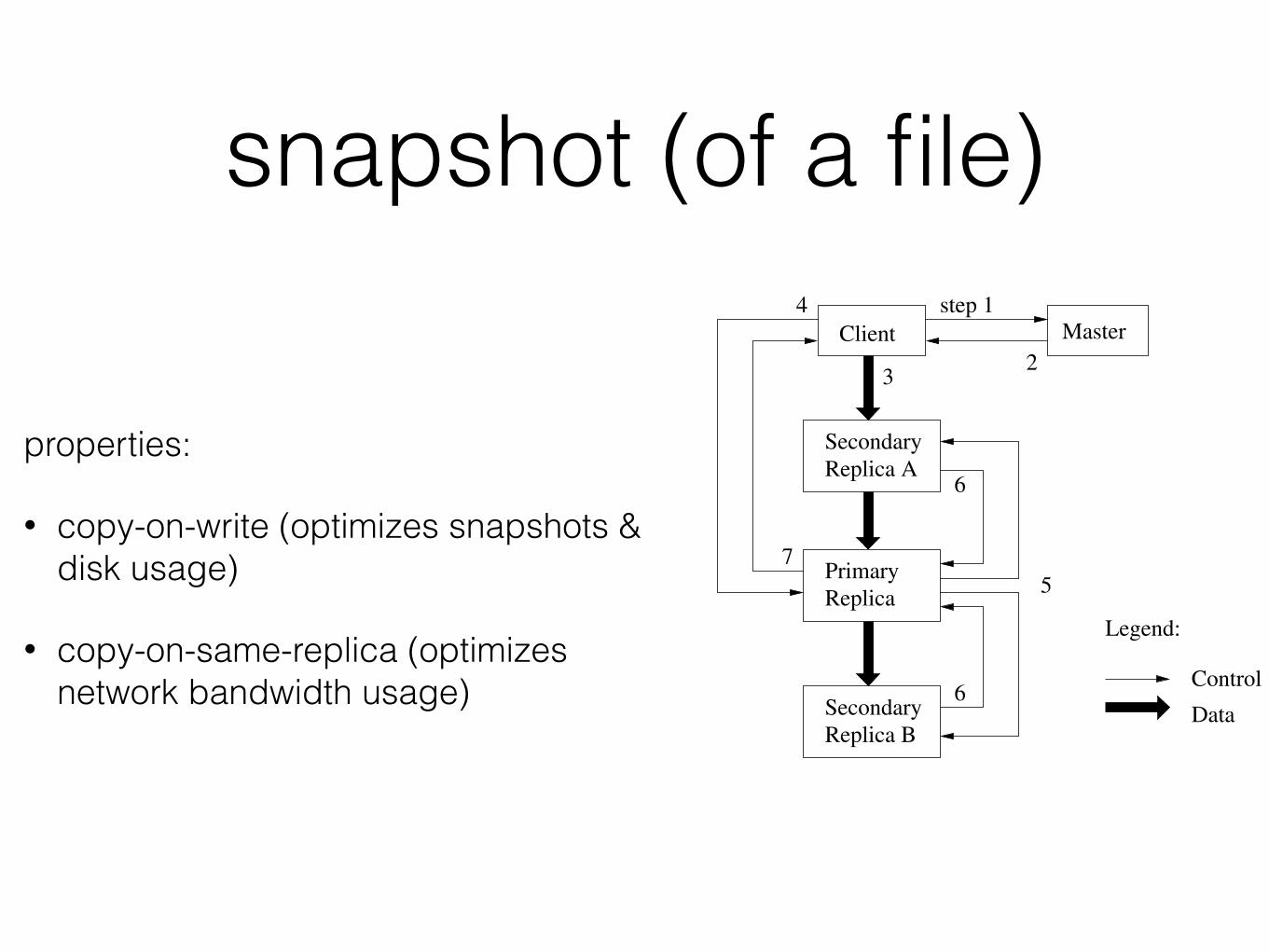
snapshot (of a file)
properties:
• copy-on-write (optimizes snapshots & disk usage)
• copy-on-same-replica (optimizes network bandwidth usage)
PrimaryReplica
SecondaryReplica B
SecondaryReplica A
Master
Legend:
Control
Data
3
Client2
step 14
5
6
6
7
Figure 2: Write Control and Data Flow
becomes unreachable or replies that it no longer holdsa lease.
3. The client pushes the data to all the replicas. A clientcan do so in any order. Each chunkserver will storethe data in an internal LRU buffer cache until thedata is used or aged out. By decoupling the data flowfrom the control flow, we can improve performance byscheduling the expensive data flow based on the net-work topology regardless of which chunkserver is theprimary. Section 3.2 discusses this further.
4. Once all the replicas have acknowledged receiving thedata, the client sends a write request to the primary.The request identifies the data pushed earlier to all ofthe replicas. The primary assigns consecutive serialnumbers to all the mutations it receives, possibly frommultiple clients, which provides the necessary serial-ization. It applies the mutation to its own local statein serial number order.
5. The primary forwards the write request to all sec-ondary replicas. Each secondary replica applies mu-tations in the same serial number order assigned bythe primary.
6. The secondaries all reply to the primary indicatingthat they have completed the operation.
7. The primary replies to the client. Any errors encoun-tered at any of the replicas are reported to the client.In case of errors, the write may have succeeded at theprimary and an arbitrary subset of the secondary repli-cas. (If it had failed at the primary, it would nothave been assigned a serial number and forwarded.)The client request is considered to have failed, and themodified region is left in an inconsistent state. Ourclient code handles such errors by retrying the failedmutation. It will make a few attempts at steps (3)through (7) before falling back to a retry from the be-ginning of the write.
If a write by the application is large or straddles a chunkboundary, GFS client code breaks it down into multiplewrite operations. They all follow the control flow describedabove but may be interleaved with and overwritten by con-current operations from other clients. Therefore, the shared
file region may end up containing fragments from differentclients, although the replicas will be identical because the in-dividual operations are completed successfully in the sameorder on all replicas. This leaves the file region in consistentbut undefined state as noted in Section 2.7.
3.2 Data FlowWe decouple the flow of data from the flow of control to
use the network efficiently. While control flows from theclient to the primary and then to all secondaries, data ispushed linearly along a carefully picked chain of chunkserversin a pipelined fashion. Our goals are to fully utilize eachmachine’s network bandwidth, avoid network bottlenecksand high-latency links, and minimize the latency to pushthrough all the data.
To fully utilize each machine’s network bandwidth, thedata is pushed linearly along a chain of chunkservers ratherthan distributed in some other topology (e.g., tree). Thus,each machine’s full outbound bandwidth is used to trans-fer the data as fast as possible rather than divided amongmultiple recipients.
To avoid network bottlenecks and high-latency links (e.g.,inter-switch links are often both) as much as possible, eachmachine forwards the data to the “closest” machine in thenetwork topology that has not received it. Suppose theclient is pushing data to chunkservers S1 through S4. Itsends the data to the closest chunkserver, say S1. S1 for-wards it to the closest chunkserver S2 through S4 closest toS1, say S2. Similarly, S2 forwards it to S3 or S4, whicheveris closer to S2, and so on. Our network topology is simpleenough that “distances” can be accurately estimated fromIP addresses.
Finally, we minimize latency by pipelining the data trans-fer over TCP connections. Once a chunkserver receives somedata, it starts forwarding immediately. Pipelining is espe-cially helpful to us because we use a switched network withfull-duplex links. Sending the data immediately does notreduce the receive rate. Without network congestion, theideal elapsed time for transferring B bytes to R replicas isB/T + RL where T is the network throughput and L is la-tency to transfer bytes between two machines. Our networklinks are typically 100 Mbps (T ), and L is far below 1 ms.Therefore, 1 MB can ideally be distributed in about 80 ms.
3.3 Atomic Record AppendsGFS provides an atomic append operation called record
append. In a traditional write, the client specifies the off-set at which data is to be written. Concurrent writes tothe same region are not serializable: the region may end upcontaining data fragments from multiple clients. In a recordappend, however, the client specifies only the data. GFSappends it to the file at least once atomically (i.e., as onecontinuous sequence of bytes) at an offset of GFS’s choosingand returns that offset to the client. This is similar to writ-ing to a file opened in O APPEND mode in Unix without therace conditions when multiple writers do so concurrently.
Record append is heavily used by our distributed applica-tions in which many clients on different machines appendto the same file concurrently. Clients would need addi-tional complicated and expensive synchronization, for ex-ample through a distributed lock manager, if they do sowith traditional writes. In our workloads, such files often
namespace & locking• master performs many operations
possibly in parallel
• namespace locks used to operate on files
• namespace tables: paths to metadata
• prefix compression (why?)
• every node read/write lock
• e.g. to deal with /d1/d2/…/dn/leaf will:
• read-lock /d1, /d1/d2, …, /d1/../dn
• read/write lock /d1/d2/…/dn/leaf
namespace & lockingproperties:
• no directories concept, only files
• read-lock on dir name is sufficient for writing file
• concurrent mutations within same dir
• read lock on dir name (prevents dir delete, snapshot, renamed)
• write lock on file name
• locks acquired in consistent total order to prevent deadlock—level in the path & lexicograph
(re)placement• distribute replicas over machines
• distribute replicas over racks
• new replicas on under-utilised chunk servers (equalize disk utilization)
• limit number of recent creations for a chunkserver
• replicate when nr of missing replicas is big (2 is better than 1)
• give priority to live files
deleting• file renamed by master (name changes including delete timestamp)
• within 3 days can go back to normal
• after 3 days metadata is actually deleted
• orphan chunks (not reachable from files) are handled later on
• heartbeat messages include list of chunk IDs
• master sends back list of orphan chunks (not pointed by files in in-memory metadata)
fault-tolerance
high availability
• 3-way replication of chunks
• op logs: master + servers restartable in few secs (fast recovery)
• shadow masters
integrity
• checksum every 64K block

Thank you!