gf40u-fi - o.s. engine
TRANSCRIPT
2021.08.01
O.S. ENGINES MFG. CO., LTD.
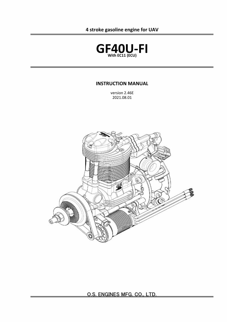
4 stroke gasoline engine for UAV
GF40U-FIWith EC11 (ECU)
INSTRUCTION MANUAL
version 2.46E
6-15 3-Chome Imagawa Higashisumiyoshi-kuOsaka 546-0003, JapanTEL.+81-6-6702-0225FAX.+81-6-6704-2722http://www.os-engines.co.jp
・Recommended propellers are 18x6-12,19x6-10,20x6-8 (DxP Inch). We recommend a propeller whoserpm is within range of 7500rpm~9000rpm at full throttle.
・Start the engine with a safety stick or an electric starter (recommendation for safety reason).
・Periodical inspection after 50, 100 hours are necessary. Follow the maintenance manual, which isseparately provided.
About the engine
1
・The engine is equipped with electronic fuel injection system to correspond to environmental changesduring a long flight.
・This is a four stroke gasoline engine, but runs on a premixed gasoline/2-stroke engine oil.
・Use high quality commercially available 2-stroke engine oil.
・Follow the oil manufacturer's recommedation concerning the mixture ratio of gasoline and oil. In caseof no recommendation by manufacturer, use a 30 : 1 gasoline-to-oil mixture.
・The engine runs counter-clockwise when viewed from the front.
*The specifications are subject to alteration for improvement without notice.*Consult us for any questions on this product and return for repair.
1
2
3
4
5
6
8 7 9
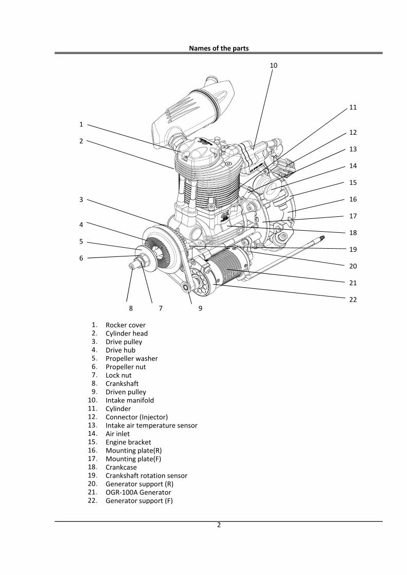
Rocker coverCylinder headDrive pulleyDrive hubPropeller washerPropeller nutLock nutCrankshaftDriven pulleyIntake manifoldCylinderConnector (Injector)Intake air temperature sensorAir inletEngine bracketMounting plate(R)Mounting plate(F)CrankcaseCrankshaft rotation sensorGenerator support (R)OGR-100A GeneratorGenerator support (F)
10
18
19
20
21
22
16
Names of the parts
22.
1.
12
11
13
14
15
17
16.17.18.19.20.21.
10.
2
2.3.4.5.6.7.8.9.
12.13.14.15.
11.
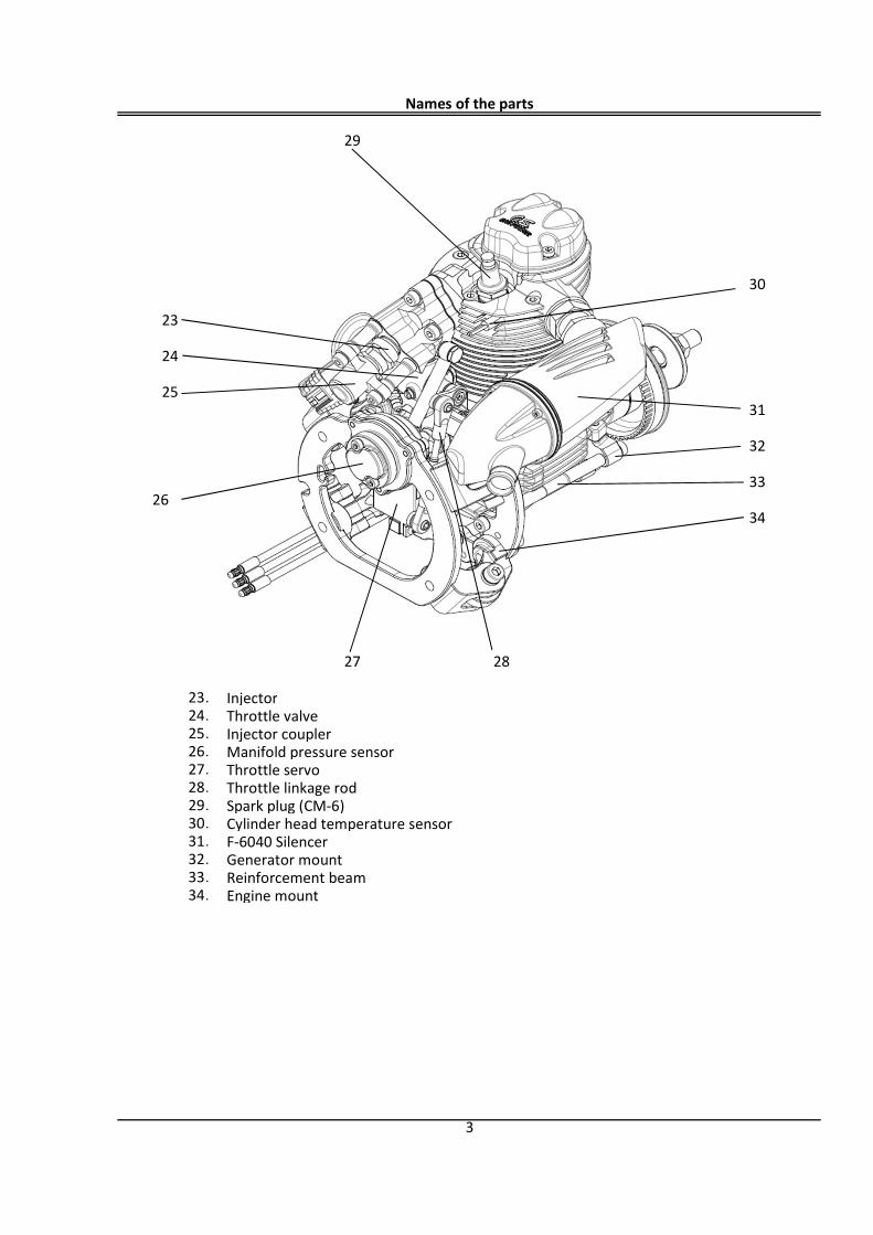
InjectorThrottle valveInjector couplerManifold pressure sensorThrottle servoThrottle linkage rodSpark plug (CM-6)Cylinder head temperature sensorF-6040 SilencerGenerator mountReinforcement beamEngine mount
32.33.
28
30
31
32
33
34
27
28.29.30.31.
29
23
24
25
26
Names of the parts
3
23.24.25.26.27.
34.
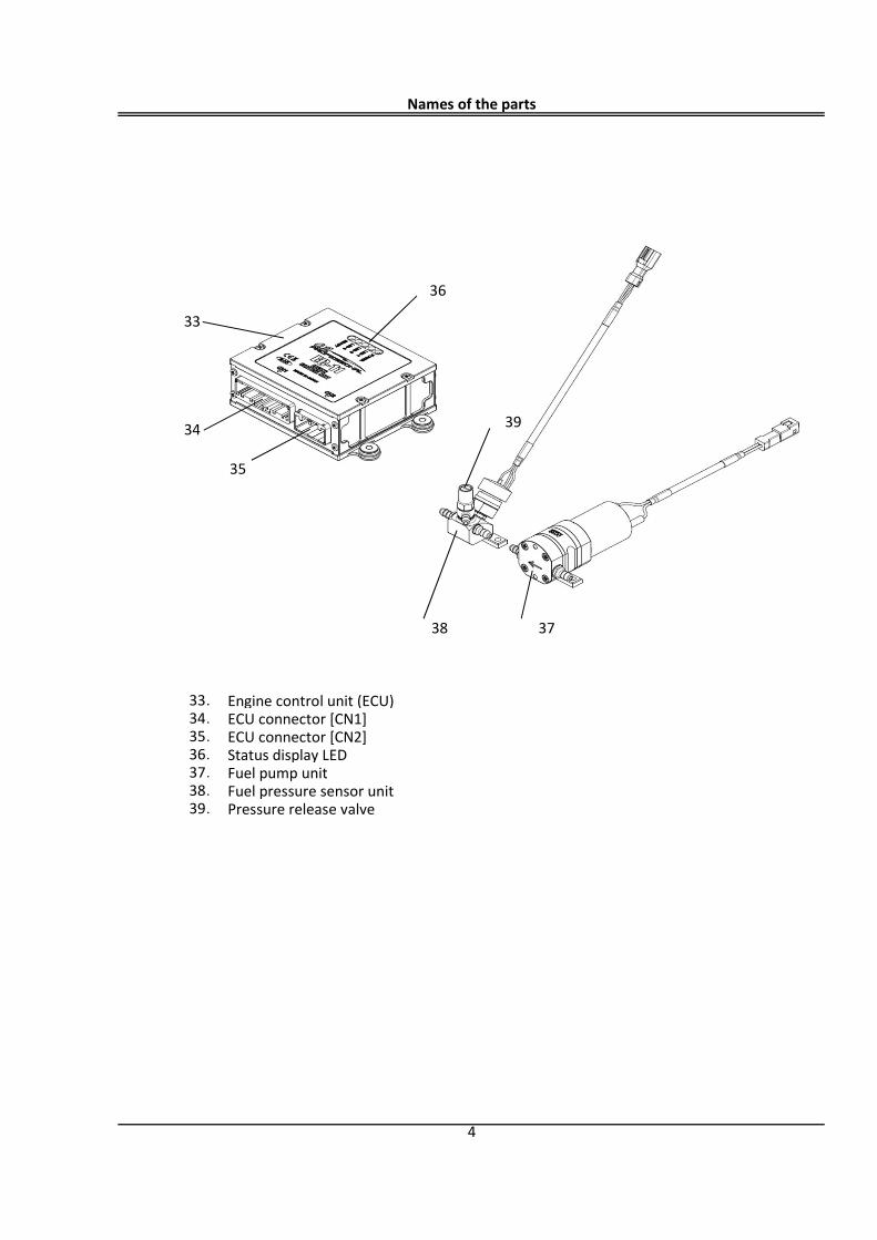
Engine control unit (ECU)ECU connector [CN1]ECU connector [CN2]Status display LEDFuel pump unitFuel pressure sensor unitPressure release valve
38.
38 37
34
33
33.34.35.36.37.
Names of the parts
4
39.
35
36
39
Accessories
5
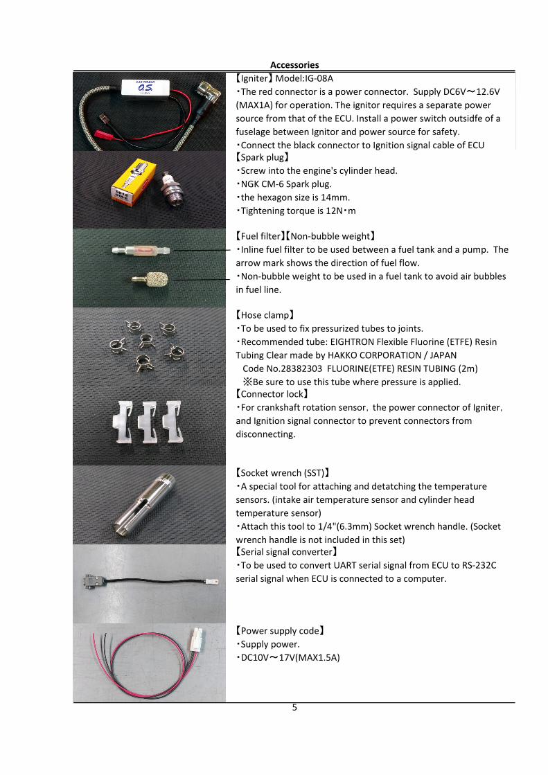
【Igniter】 Model:IG-08A・The red connector is a power connector. Supply DC6V~12.6V(MAX1A) for operation. The ignitor requires a separate powersource from that of the ECU. Install a power switch outsidfe of afuselage between Ignitor and power source for safety.・Connect the black connector to Ignition signal cable of ECU【Spark plug】・Screw into the engine's cylinder head.・NGK CM-6 Spark plug.・the hexagon size is 14mm.・Tightening torque is 12N・m
【Fuel filter】【Non-bubble weight】・Inline fuel filter to be used between a fuel tank and a pump. Thearrow mark shows the direction of fuel flow.・Non-bubble weight to be used in a fuel tank to avoid air bubblesin fuel line.
【Hose clamp】・To be used to fix pressurized tubes to joints.・Recommended tube: EIGHTRON Flexible Fluorine (ETFE) ResinTubing Clear made by HAKKO CORPORATION / JAPAN Code No.28382303 FLUORINE(ETFE) RESIN TUBING (2m) ※Be sure to use this tube where pressure is applied.【Connector lock】・For crankshaft rotation sensor,the power connector of Igniter,and Ignition signal connector to prevent connectors fromdisconnecting.
【Socket wrench (SST)】・A special tool for attaching and detatching the temperaturesensors. (intake air temperature sensor and cylinder headtemperature sensor)・Attach this tool to 1/4"(6.3mm) Socket wrench handle. (Socketwrench handle is not included in this set)【Serial signal converter】・To be used to convert UART serial signal from ECU to RS-232Cserial signal when ECU is connected to a computer.
【Power supply code】・Supply power.・DC10V~17V(MAX1.5A)
6
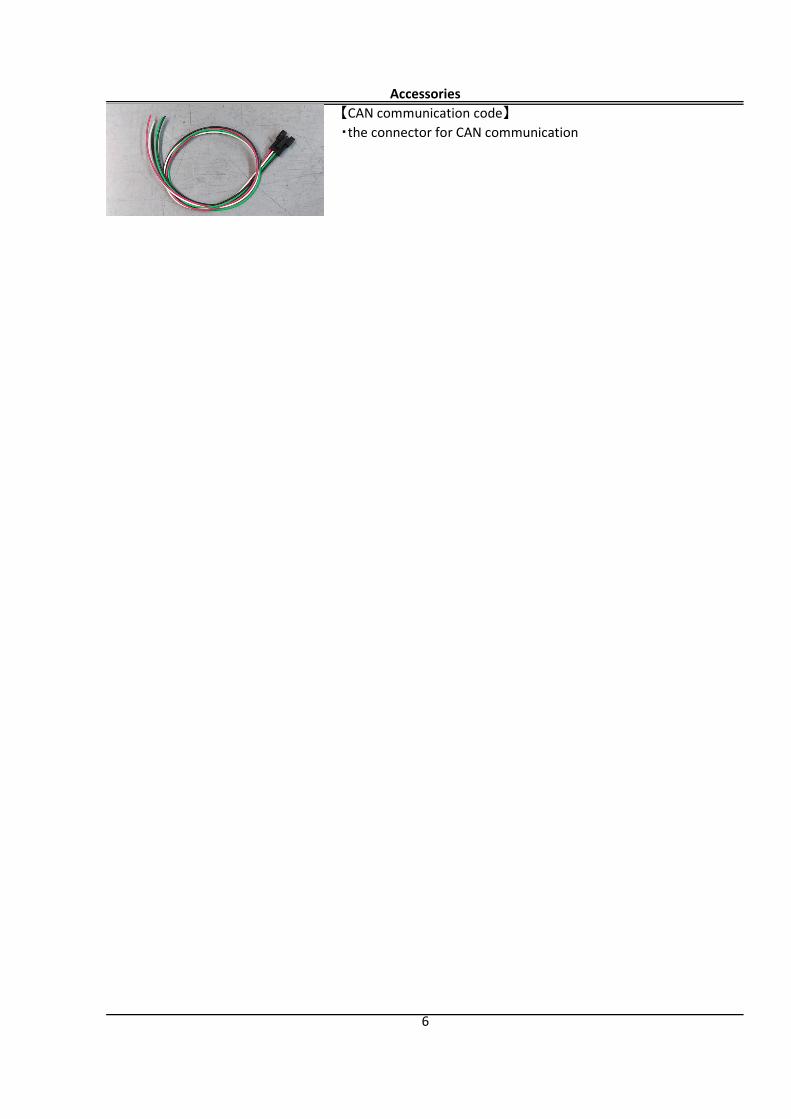
Accessories【CAN communication code】・the connector for CAN communication
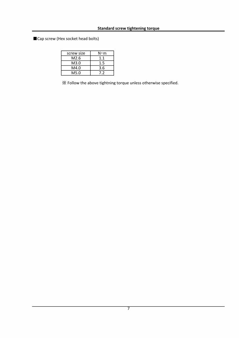
■Cap screw (Hex socket head bolts)
※ Follow the above tightning torque unless otherwise specified.
Standard screw tightening torque
7
M5.0 7.2
screw size N・mM2.6 1.1M3.0 1.5M4.0 3.6
Installation
8
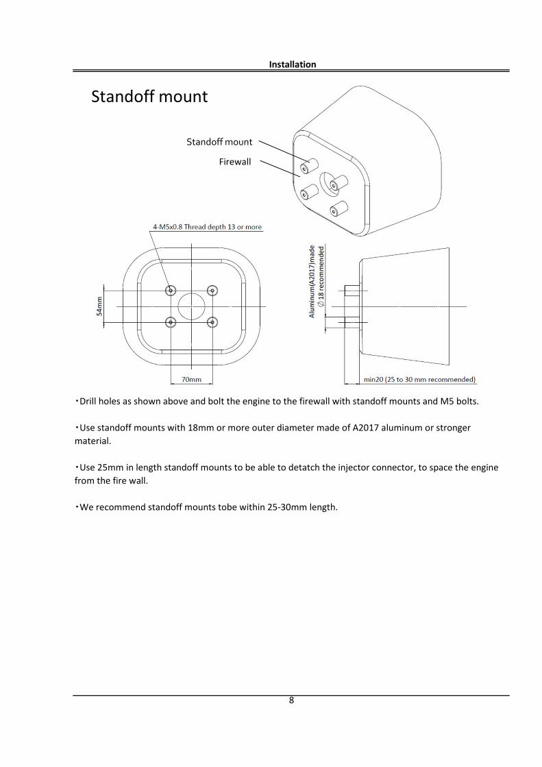
・Drill holes as shown above and bolt the engine to the firewall with standoff mounts and M5 bolts.
・Use standoff mounts with 18mm or more outer diameter made of A2017 aluminum or strongermaterial.
・Use 25mm in length standoff mounts to be able to detatch the injector connector, to space the enginefrom the fire wall.
・We recommend standoff mounts tobe within 25-30mm length.
Standoff mount
Firewall
Standoff mount
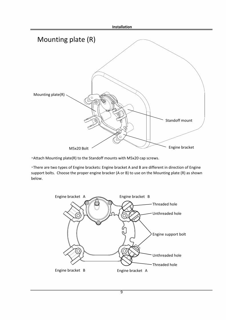
Threaded hole
Unthreaded hole
Unthreaded hole
Threaded hole
Installation
9
・Attach Mounting plate(R) to the Standoff mounts with M5x20 cap screws.
・There are two types of Engine brackets: Engine bracket A and B are different in direction of Enginesupport bolts. Choose the proper engine bracker (A or B) to use on the Mounting plate (R) as shownbelow.
Engine support bolt
Mounting plate (R)
Mounting plate(R)
Engine bracket
Standoff mount
M5x20 Bolt
Engine bracket A
Engine bracket B
Engine bracket B
Engine bracket A
Installation
10
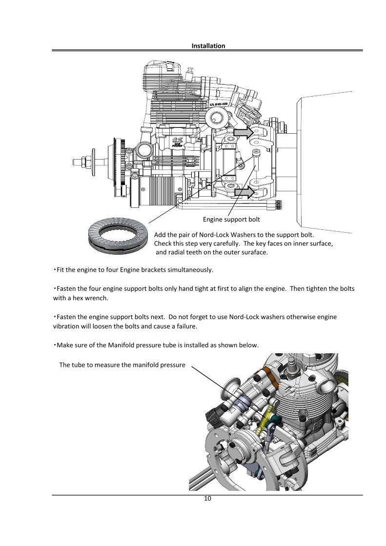
・Fit the engine to four Engine brackets simultaneously.
・Fasten the four engine support bolts only hand tight at first to align the engine. Then tighten the boltswith a hex wrench.
・Fasten the engine support bolts next. Do not forget to use Nord-Lock washers otherwise enginevibration will loosen the bolts and cause a failure.
・Make sure of the Manifold pressure tube is installed as shown below.
Engine support bolt
The tube to measure the manifold pressure
Add the pair of Nord-Lock Washers to the support bolt. Check this step very carefully. The key faces on inner surface,and radial teeth on the outer suraface.
Engine support bolt
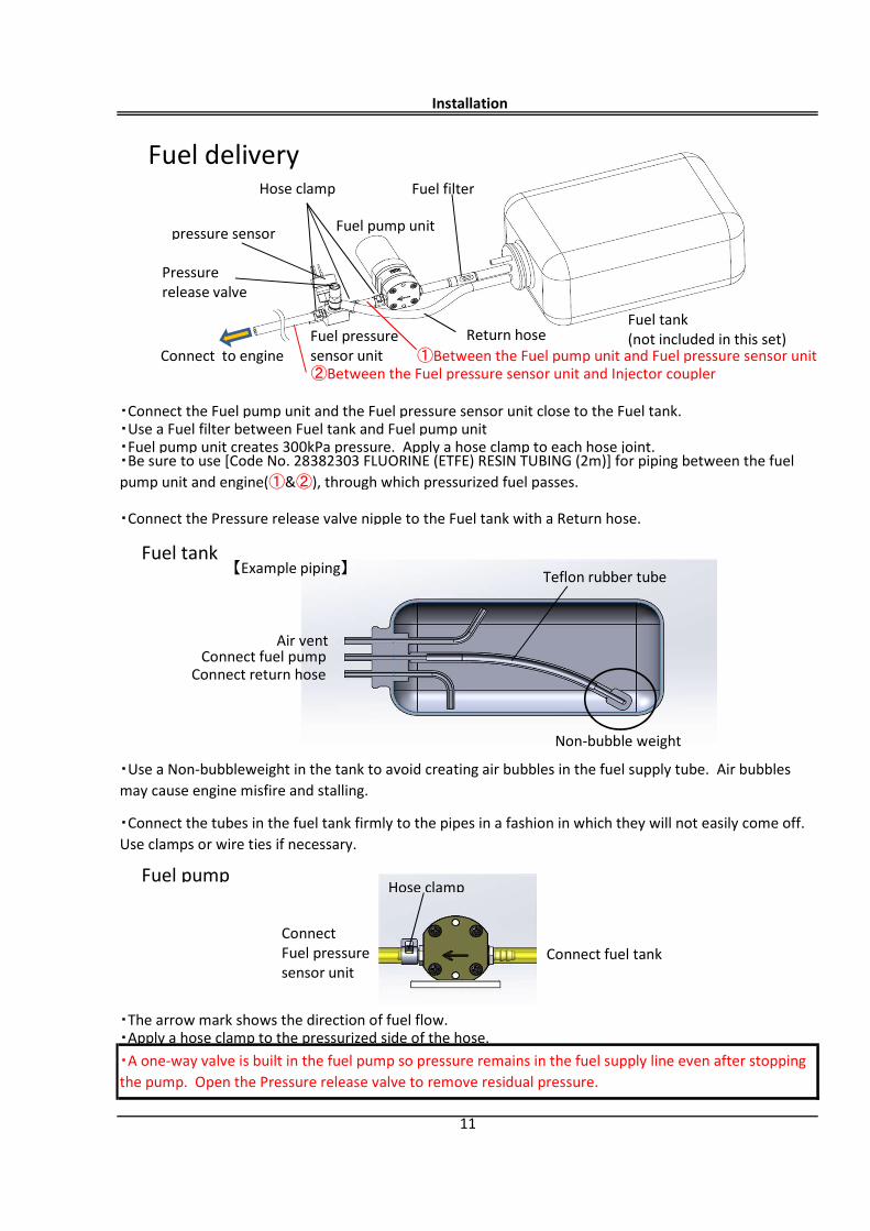
①Between the Fuel pump unit and Fuel pressure sensor unit②Between the Fuel pressure sensor unit and Injector coupler
Fuel tank
Fuel pump
・The arrow mark shows the direction of fuel flow.・Apply a hose clamp to the pressurized side of the hose.
11
・A one-way valve is built in the fuel pump so pressure remains in the fuel supply line even after stoppingthe pump. Open the Pressure release valve to remove residual pressure.
・Use a Non-bubbleweight in the tank to avoid creating air bubbles in the fuel supply tube. Air bubblesmay cause engine misfire and stalling.
・Connect the tubes in the fuel tank firmly to the pipes in a fashion in which they will not easily come off.Use clamps or wire ties if necessary.
・Be sure to use [Code No. 28382303 FLUORINE (ETFE) RESIN TUBING (2m)] for piping between the fuelpump unit and engine(①&②), through which pressurized fuel passes.
・Fuel pump unit creates 300kPa pressure. Apply a hose clamp to each hose joint.
・Connect the Pressure release valve nipple to the Fuel tank with a Return hose.
Installation
・Connect the Fuel pump unit and the Fuel pressure sensor unit close to the Fuel tank.・Use a Fuel filter between Fuel tank and Fuel pump unit
Fuel tank(not included in this set)
Fuel pump unit
Fuel pressure sensor unit
pressure sensor
Pressurerelease valve
Return hoseConnect to engine
Hose clamp Fuel filter
Fuel delivery
Connect return hoseConnect fuel pump
Air vent
【Example piping】 Teflon rubber tube
Non-bubble weight
Connect fuel tankConnect Fuel pressure sensor unit
Hose clamp
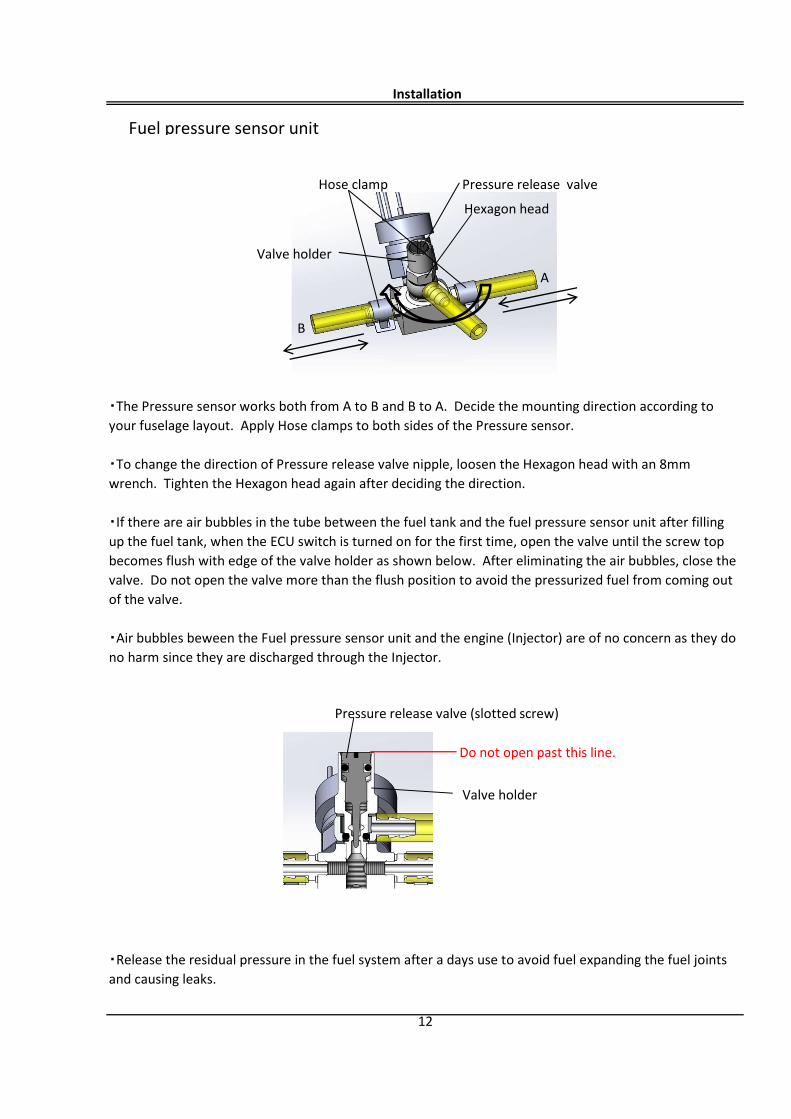
Fuel pressure sensor unit
・Release the residual pressure in the fuel system after a days use to avoid fuel expanding the fuel jointsand causing leaks.
12
Installation
・The Pressure sensor works both from A to B and B to A. Decide the mounting direction according toyour fuselage layout. Apply Hose clamps to both sides of the Pressure sensor.
・To change the direction of Pressure release valve nipple, loosen the Hexagon head with an 8mmwrench. Tighten the Hexagon head again after deciding the direction.
・If there are air bubbles in the tube between the fuel tank and the fuel pressure sensor unit after fillingup the fuel tank, when the ECU switch is turned on for the first time, open the valve until the screw topbecomes flush with edge of the valve holder as shown below. After eliminating the air bubbles, close thevalve. Do not open the valve more than the flush position to avoid the pressurized fuel from coming outof the valve.
・Air bubbles beween the Fuel pressure sensor unit and the engine (Injector) are of no concern as they dono harm since they are discharged through the Injector.
Hexagon head
A
B
Hose clamp Pressure release valve
Valve holder
Pressure release valve (slotted screw)
Do not open past this line.
Valve holder
13
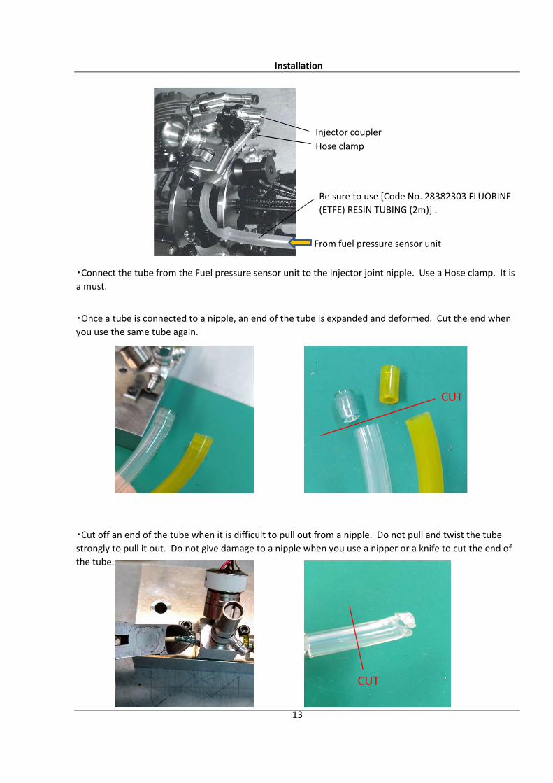
・Connect the tube from the Fuel pressure sensor unit to the Injector joint nipple. Use a Hose clamp. It isa must.
・Cut off an end of the tube when it is difficult to pull out from a nipple. Do not pull and twist the tubestrongly to pull it out. Do not give damage to a nipple when you use a nipper or a knife to cut the end ofthe tube.
Installation
Be sure to use [Code No. 28382303 FLUORINE(ETFE) RESIN TUBING (2m)] .
・Once a tube is connected to a nipple, an end of the tube is expanded and deformed. Cut the end whenyou use the same tube again.
From fuel pressure sensor unit
Hose clampInjector coupler
CUT
CUT
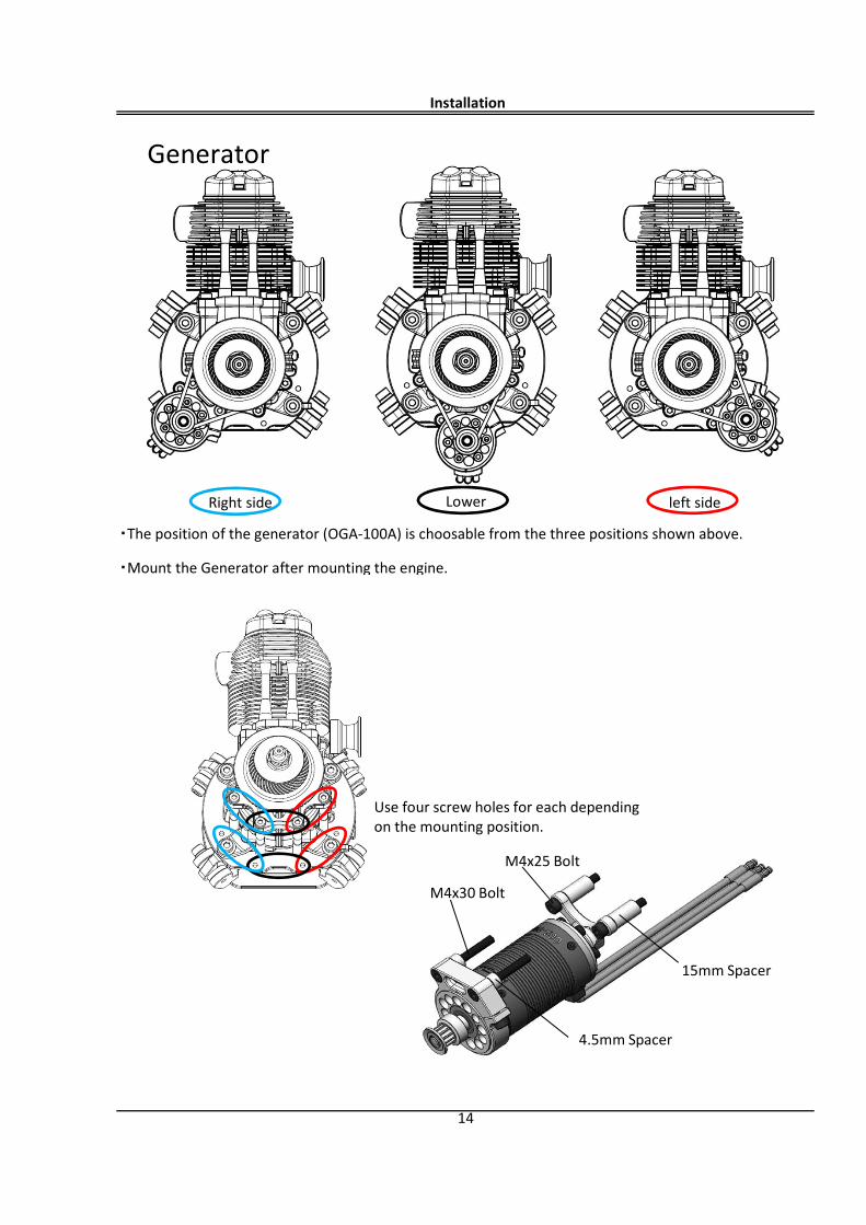
・Mount the Generator after mounting the engine.
Installation
14
・The position of the generator (OGA-100A) is choosable from the three positions shown above.
Right side left sideLower
M4x30 Bolt
M4x25 Bolt
4.5mm Spacer
15mm Spacer
Use four screw holes for each depending on the mounting position.
Generator
【Example when mounting on the left side】
【reference】
Installation
15
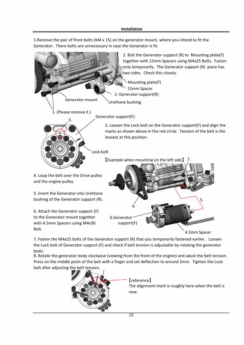
1.Remove the pair of front bolts (M4 x 15) on the generator mount, where you intend to fit theGenerator. There bolts are unnecessary in case the Generator is fit.
2. Bolt the Generator support (R) to Mounting plate(F)together with 15mm Spacers using M4x25 Bolts. Fastenonly temporarily. The Generator support (R) piece hastwo sides. Check this closely.
The alignment mark is roughly here when the belt isnew.
7. Fasten the M4x25 bolts of the Generator support (R) that you temporarily fastened earlier. Loosenthe Lock bolt of Generator support (F) and check if belt tension is adjustable by rotating the generatorbody.8. Rotate the generator body clockwise (viewing from the front of the engine) and adust the belt tension.Press on the middle point of the belt with a finger and set deflection to around 2mm. Tighten the Lockbolt after adjusting the belt tension.
3. Loosen the Lock bolt on the Generator support(F) and align themarks as shown above in the red circle. Tension of the belt is theloosest at this position.
4. Loop the belt over the Drive pulleyand the engine pulley.
5. Insert the Generator into Urethanebushing of the Generator support (R).
6. Attach the Generator support (F)to the Generator mount togetherwith 4.5mm Spacers using M4x30Bolt.
Generator mount
1. (Please remove it.)
Urethane bushing
2. Generator support(R)
Mounting plate(F)15mm Spacer
5.
7.
4.5mm Spacer
4.
6.Generatorsupport(F)
Lock bolt
3.Generator support(F)
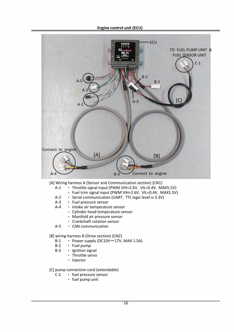
[A] Wiring harness A (Sensor and Communication section) {CN1}A-1 ・ Throttle signal input (PWM VIH=2.6V,VIL=0.4V,MAX5.5V)
・ Fuel trim signal input (PWM VIH=2.6V,VIL=0.4V,MAX5.5V)A-2 ・ Serial communication (UART,TTL logic level is 3.3V)A-3 ・ Fuel pressure sensorA-4 ・ Intake air temperature sensor
・ Cylinder head temperature sensor ・ Manifold air pressure sensor・ Crankshaft rotation sensor
A-5 ・ CAN communication
[B] wiring harness B (Drive section) {CN2}B-1 ・ Power supply (DC10V~17V, MAX 1.5A)B-2 ・ Fuel pumpB-3 ・ Ignition signal
・ Throttle servo・ Injector
[C] pump connection cord (extendable)C-1 ・ fuel pressure sensor
・ fuel pump unit
Engine control unit (ECU)
16
[B]
A-1
B-1
A-2
A-3
[A]
[C]
TO FUEL PUMP UNIT &FUEL SENSOR UNIT
Connect to engine
B-2
B-3 Connect to engineA-4
A-5
C-1
ECU
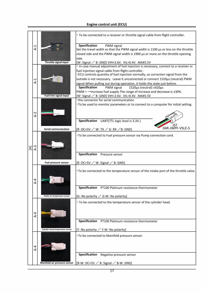
PWM signal
[W:Signal / B:GND] VIH=2.6V,VIL=0.4V,MAX5.5V
PWM signal 1520μs (neutral) ±420μsPWM + →increase fuel supply The range of increase and decrease is ±30%.[W:Signal / B:GND] VIH=2.6V,VIL=0.4V,MAX5.5V・the connector for serial communication
UART(TTL logic level is 3.3V.)
[R:DC+5V / W:TX / G:RX /B:GND]
Pressure sensor
[R:DC+5V / W:Signal / B:GND]
PT100 Platinum resistance thermometer
[G:No polarity / G-W:No polarity]
PT100 Platinum resistance thermometer
[Y:No polarity / Y-W:No polarity]
Negative pressure sensor
[R-W:DC+5V / B:Signal / B-W:GND]
Engine control unit (ECU) [A
]A-
1・ To be connected to a receiver or throttle signal cable from flight controller.
SpecificationSet the travel width so that the PWM signal width is 1100 μs or less on the throttleclosed side and the PWM signal width is 1900 μs or more on the throttle openingside.
Throttle signal input
A-1
・ In case manual adjustment of fuel injection is necessary, connect to a receiver orfuel injection signal cable from flight controller.・ECU controls quantity of fuel injection normally, so correction signal from theoutside is not necessary. Leave it unconnected or connect 1520μs (neutral) PWMsignal.When pulling out during operation, it holds the state just before.
Specification
Fuel trim signal input
A-2
・To be used to monitor parameters or to connect to a computer for initial setting.
Serial communication
A-3
・To be connected to Fuel pressure sonsor via Pump connection cord.
Specification
Specification
Fuel pressure sensor
A-4
・To be connected to the temperature sensor of the intake port of the throttle valve.
Specification
Intake air temperature sensor
A-4
・ To be connected to the temperature sensor of the cylinder head.
Specification
Cylinder head temperature sensor
Specification
Manifold air pressure sensor
17
A-4
・To be connected to Manifold pressure sensor.
JST04R-JWPF-VSLE-S
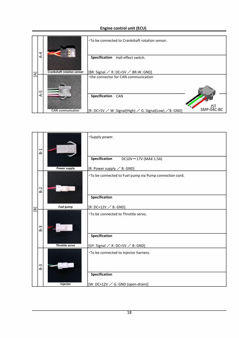
Hall-effect switch.
[BR:Signal / R:DC+5V / BR-W:GND]・the connector for CAN communication
CAN
[R:DC+5V / W:Signal(High) / G:Signal(Low) /B:GND]
DC10V~17V (MAX 1.5A)
[R:Power supply / B:GND]
[R:DC+12V / B:GND]
[GY:Signal / R:DC+5V / B:GND]
[W:DC+12V / G:GND (open-drain)]
Engine control unit (ECU) [A
]A-
4・To be connected to Crankshaft rotation sensor.
Specification
Crankshaft rotation sensor
A-5
Specification
CAN communication
[B]
B-1
Specification
Power supply
・Supply power.
B-2
・To be connected to Fuel pump via Pump connection cord.
Specification
Fuel pump
B-3
・To be connected to Throttle servo.
Specification
Throttle servo
B-3
・To be connected to Injector harness.
Injector
18
Specification
SMP-04C-BCJST
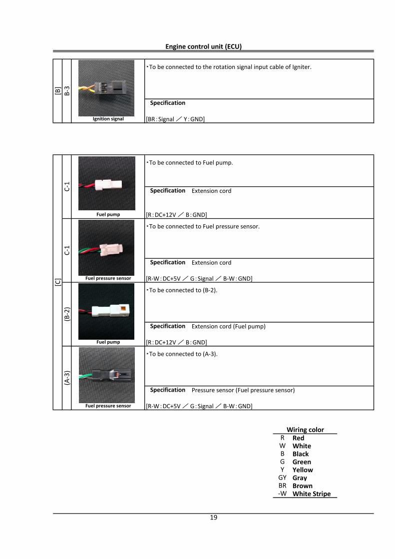
[BR:Signal / Y:GND]
Extension cord
[R:DC+12V / B:GND]
Extension cord
[R-W:DC+5V / G:Signal / B-W:GND]
Extension cord (Fuel pump)
[R:DC+12V / B:GND]
Pressure sensor (Fuel pressure sensor)
[R-W:DC+5V / G:Signal / B-W:GND]
RedWhiteBlackGreenYellowGrayBrownWhite Stripe
Engine control unit (ECU)
・To be connected to the rotation signal input cable of Igniter.
Specification
Ignition signal
[C]
C-1
[B]
B-3
・To be connected to Fuel pump.
Specification
Fuel pump
Specification
C-1
・To be connected to Fuel pressure sensor.
Fuel pressure sensor
(B-2
)
・To be connected to (B-2).
Specification
Fuel pump
(A-3
)
・To be connected to (A-3).
Specification
Fuel pressure sensor
Wiring colorR
GY
GYBR-W
19
WB
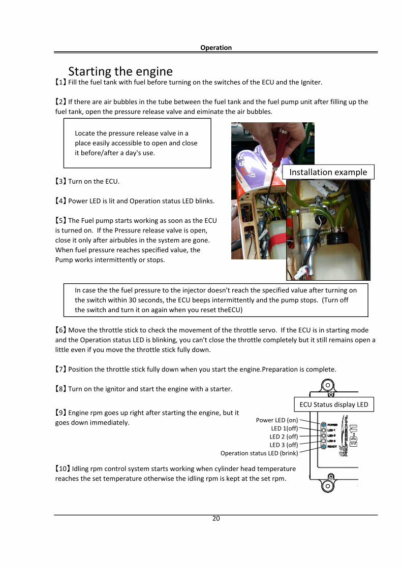
Power LED (on)LED 1(off)
LED 2 (off)LED 3 (off)
Operation status LED (brink)
Operation
20
Locate the pressure release valve in aplace easily accessible to open and closeit before/after a day's use.
【10】 Idling rpm control system starts working when cylinder head temperaturereaches the set temperature otherwise the idling rpm is kept at the set rpm.
【9】 Engine rpm goes up right after starting the engine, but itgoes down immediately.
【1】 Fill the fuel tank with fuel before turning on the switches of the ECU and the Igniter.
【2】 If there are air bubbles in the tube between the fuel tank and the fuel pump unit after filling up thefuel tank, open the pressure release valve and eiminate the air bubbles.
【3】 Turn on the ECU.
【4】 Power LED is lit and Operation status LED blinks.
【5】 The Fuel pump starts working as soon as the ECUis turned on. If the Pressure release valve is open,close it only after airbubles in the system are gone.When fuel pressure reaches specified value, thePump works intermittently or stops.
【6】 Move the throttle stick to check the movement of the throttle servo. If the ECU is in starting modeand the Operation status LED is blinking, you can't close the throttle completely but it still remains open alittle even if you move the throttle stick fully down.
【7】 Position the throttle stick fully down when you start the engine.Preparation is complete.
【8】 Turn on the ignitor and start the engine with a starter.
In case the the fuel pressure to the injector doesn't reach the specified value after turning onthe switch within 30 seconds, the ECU beeps intermittently and the pump stops. (Turn offthe switch and turn it on again when you reset theECU)
Starting the engine
Installation example
ECU Status display LED
Power LED Operation status LED
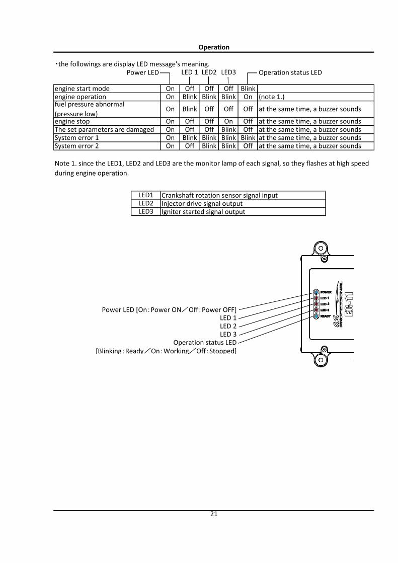
Crankshaft rotation sensor signal inputInjector drive signal outputIgniter started signal output
[Blinking:Ready/On:Working/Off:Stopped]
Note 1. since the LED1, LED2 and LED3 are the monitor lamp of each signal, so they flashes at high speedduring engine operation.
LED1LED2LED3
(note 1.)
at the same time, a buzzer sounds
at the same time, a buzzer soundsat the same time, a buzzer soundsat the same time, a buzzer soundsat the same time, a buzzer sounds
BlinkSystem error 2 On Off Blink Blink OffSystem error 1 On Blink Blink Blink
OffThe set parameters are damaged On Off Off Blink Offengine stop On Off Off On
Blink Off Off Off
engine operation On Blink Blink
21
Operation status LED
Power LED [On:Power ON/Off:Power OFF]LED 1LED 2LED 3
・the followings are display LED message's meaning.LED 1 LED2
Operation
LED3
engine start mode On Off Off Off BlinkBlink On
fuel pressure abnormal(pressure low)
On
【1】 Turn off the Ignitor switch to stop the engine.・Fuel injection cut, throttle cut, and ignition cut functions to stop the engine have not been set yet in thisprototype.
【2】 The ECU stops the fuel pump and emits Beep sound intermittently when it detects engine stop.
【3】 Turn off the ECU.
【4】 Release the residual pressure in the fuel system after a days use to avoid fuel expanding the fueljoints and causing leaks.
Operation
22
Stopping the engine
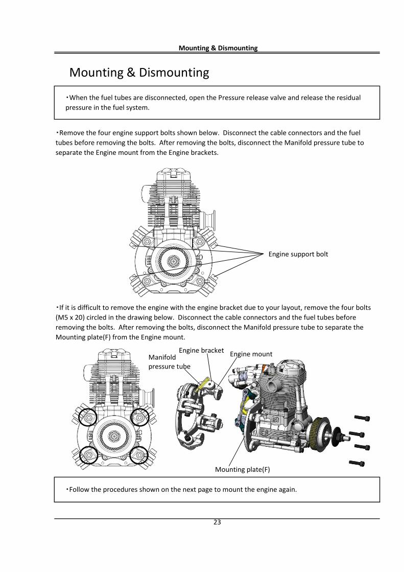
・Remove the four engine support bolts shown below. Disconnect the cable connectors and the fueltubes before removing the bolts. After removing the bolts, disconnect the Manifold pressure tube toseparate the Engine mount from the Engine brackets.
・If it is difficult to remove the engine with the engine bracket due to your layout, remove the four bolts(M5 x 20) circled in the drawing below. Disconnect the cable connectors and the fuel tubes beforeremoving the bolts. After removing the bolts, disconnect the Manifold pressure tube to separate theMounting plate(F) from the Engine mount.
Mounting & Dismounting
23
・When the fuel tubes are disconnected, open the Pressure release valve and release the residualpressure in the fuel system.
・Follow the procedures shown on the next page to mount the engine again.
Mounting & Dismounting
Engine support bolt
Engine mount
Mounting plate(F)
Manifold pressure tube
Engine bracket
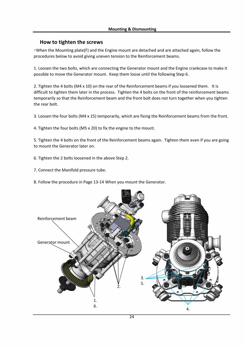
How to tighten the screws
Mounting & Dismounting
24
・When the Mounting plate(F) and the Engine mount are detached and are attached again, follow theprocedures below to avoid giving uneven tension to the Reinforcement beams.
1. Loosen the two bolts, which are connecting the Generator mount and the Engine crankcase to make itpossible to move the Generator mount. Keep them loose until the following Step 6.
2. Tighten the 4 bolts (M4 x 10) on the rear of the Reinforcement beams if you loosened them. It isdifficult to tighten them later in the process. Tighten the 4 bolts on the front of the reinforcement beamstemporarily so that the Reinforcement beam and the front bolt does not turn together when you tightenthe rear bolt.
3. Loosen the four bolts (M4 x 15) temporarily, which are fixing the Reinforcement beams from the front.
4. Tighten the four bolts (M5 x 20) to fix the engine to the mount.
5. Tighten the 4 bolts on the front of the Reinforcement beams again. Tighten them even if you are goingto mount the Generator later on.
6. Tighten the 2 bolts loosened in the above Step 2.
7. Connect the Manifold pressure tube.
8. Follow the procedure in Page 13-14 When you mount the Generator.
1.6.
Reinforcement beam
Generator mount
2.
4.
3.5.
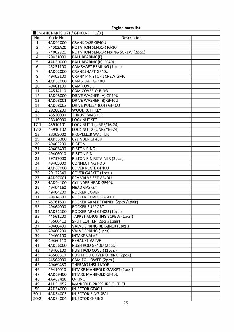
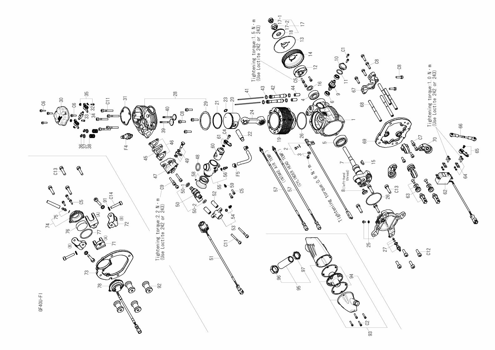
■ENGINE PARTS LIST / GF40U-FI ( 1/3 )
2550-2 4AD84004 INJECTOR O-RING50-1 4AD84003 INJECTOR RING SEAL50 4AD84000 INJECTOR GF40U49 4AD81952 MANIFOLD PRESSURE OUTLET
47 4AD69400 INTAKE MANIFOLD GF40U48 4AA07410 O-RING
46 49414010 INTAKE MANIFOLD GASKET (2pcs.)45 49469450 THERMO INSULATOR44 44564000 CAM FOLLOWER (2pcs.)43 45566310 PUSH-ROD COVER O-RING (2pcs.)
41 4AD66000 PUSH ROD GF40U (2pcs.)42 49466100 PUSH ROD COVER (1pcs.)
40 49460110 EXHAUST VALVE39 49460100 INTAKE VALVE38 49460200 VALVE SPRING (1pcs)37 49460400 VALVE SPRING RETAINER (1pcs.)
35 44561200 TAPPET ADJUSTING SCREW (1pcs.)36 45560410 SPLIT COTTER (2pcs./1pair)
34 4AD61100 ROCKER ARM GF40U (1pcs.)33 49464000 ROCKER SUPPORT32 45761600 ROCKER ARM RETAINER (2pcs./1pair)31 49414300 ROCKER COVER GASKET
29 49404160 HEAD GASKET30 49404200 ROCKER COVER
28 4AD04100 CYLINDER HEAD GF40U27 4AD07001 PCV VALVE SET GF40U26 29122540 COVER GASKET (1pcs.)25 4AD07000 COVER PLATE GF40U
23 29717000 PISTON PIN RETAINER (2pcs.)24 49405000 CONNECTING ROD
22 49406010 PISTON PIN21 49403400 PISTON RING20 49403200 PISTON19 4AD03300 CYLINDER GF40U
17-2 45910102 LOCK NUT 2 (UNF5/16-24)18 28309000 PROPELLER WASHER
17-1 45910101 LOCK NUT 1 (UNF5/16-24)17 28310000 LOCK NUT SET16 45520000 THRUST WASHER15 29208200 WOODRUFF KEY
13 4AD08001 DRIVE WASHER (B) GF40U14 4AD08002 DRIVE PULLEY (60T) GF40U
12 4AD08000 DRIVE WASHER (A) GF40U11 44514110 CAM COVER O-RING10 49401100 CAM COVER9 4AD62000 CAMSHAFT GF40U
7 4AD02000 CRANKSHAFT GF40U8 49402100 CRANK PIN STOP SCREW GF40
6 45231100 CAMSHAFT BEARING (1pcs.)5 4AD30000 BALL BEARING(R) GF40U4 29431000 BALL BEARING(F)3 74002321 ROTATION SENSOR FIXING SCREW (2pcs.)
1 4AD01000 CRANKCASE GF40U2 74002A20 ROTATION SENSOR IG-10
Engine parts list
No. Code No. Description
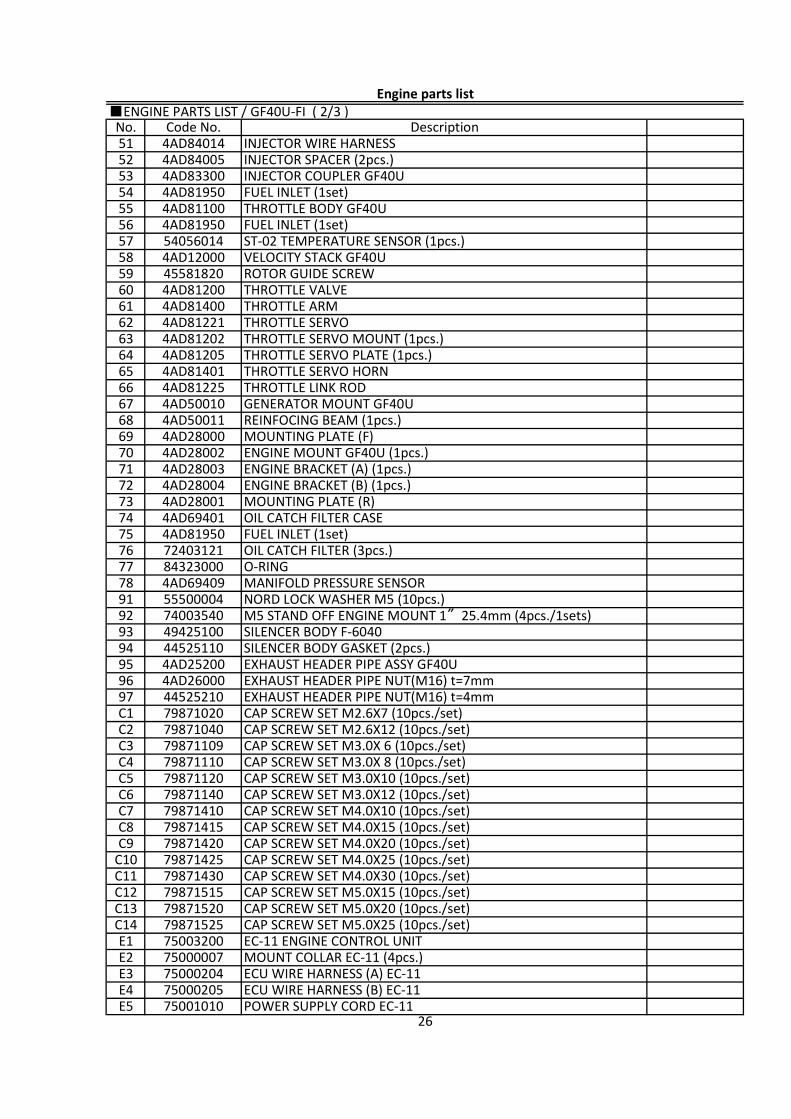
■ENGINE PARTS LIST / GF40U-FI ( 2/3 )
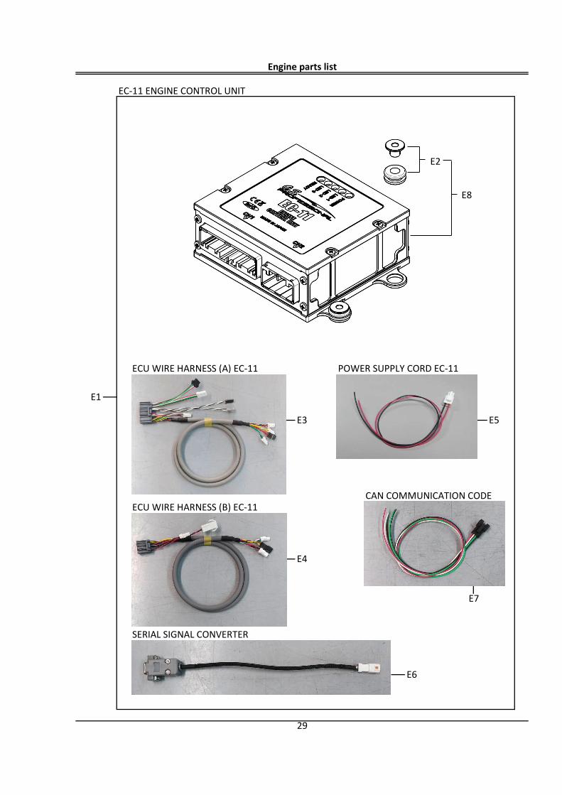
26E5 75001010 POWER SUPPLY CORD EC-11E4 75000205 ECU WIRE HARNESS (B) EC-11E3 75000204 ECU WIRE HARNESS (A) EC-11E2 75000007 MOUNT COLLAR EC-11 (4pcs.)
C14E1 75003200 EC-11 ENGINE CONTROL UNIT
79871525 CAP SCREW SET M5.0X25 (10pcs./set)C13 79871520 CAP SCREW SET M5.0X20 (10pcs./set)C12 79871515 CAP SCREW SET M5.0X15 (10pcs./set)C11 79871430 CAP SCREW SET M4.0X30 (10pcs./set)C10 79871425 CAP SCREW SET M4.0X25 (10pcs./set)
C8C9 79871420 CAP SCREW SET M4.0X20 (10pcs./set)
79871415 CAP SCREW SET M4.0X15 (10pcs./set)C7 79871410 CAP SCREW SET M4.0X10 (10pcs./set)C6 79871140 CAP SCREW SET M3.0X12 (10pcs./set)C5 79871120 CAP SCREW SET M3.0X10 (10pcs./set)C4 79871110 CAP SCREW SET M3.0X 8 (10pcs./set)
C2C3 79871109 CAP SCREW SET M3.0X 6 (10pcs./set)
79871040 CAP SCREW SET M2.6X12 (10pcs./set)C1 79871020 CAP SCREW SET M2.6X7 (10pcs./set)97 44525210 EXHAUST HEADER PIPE NUT(M16) t=4mm96 4AD26000 EXHAUST HEADER PIPE NUT(M16) t=7mm95 4AD25200 EXHAUST HEADER PIPE ASSY GF40U
9394 44525110 SILENCER BODY GASKET (2pcs.)
49425100 SILENCER BODY F-604092 74003540 M5 STAND OFF ENGINE MOUNT 1″25.4mm (4pcs./1sets)91 55500004 NORD LOCK WASHER M5 (10pcs.)78 4AD69409 MANIFOLD PRESSURE SENSOR77 84323000 O-RING
7576 72403121 OIL CATCH FILTER (3pcs.)
4AD81950 FUEL INLET (1set)74 4AD69401 OIL CATCH FILTER CASE73 4AD28001 MOUNTING PLATE (R)72 4AD28004 ENGINE BRACKET (B) (1pcs.)71 4AD28003 ENGINE BRACKET (A) (1pcs.)
6970 4AD28002 ENGINE MOUNT GF40U (1pcs.)
4AD28000 MOUNTING PLATE (F)68 4AD50011 REINFOCING BEAM (1pcs.)67 4AD50010 GENERATOR MOUNT GF40U66 4AD81225 THROTTLE LINK ROD65 4AD81401 THROTTLE SERVO HORN
6364 4AD81205 THROTTLE SERVO PLATE (1pcs.)
4AD81202 THROTTLE SERVO MOUNT (1pcs.)62 4AD81221 THROTTLE SERVO61 4AD81400 THROTTLE ARM60 4AD81200 THROTTLE VALVE59 45581820 ROTOR GUIDE SCREW
5758 4AD12000 VELOCITY STACK GF40U
54056014 ST-02 TEMPERATURE SENSOR (1pcs.)56 4AD81950 FUEL INLET (1set)55 4AD81100 THROTTLE BODY GF40U54 4AD81950 FUEL INLET (1set)53 4AD83300 INJECTOR COUPLER GF40U
5152 4AD84005 INJECTOR SPACER (2pcs.)
4AD84014 INJECTOR WIRE HARNESS
Engine parts list
No. Code No. Description
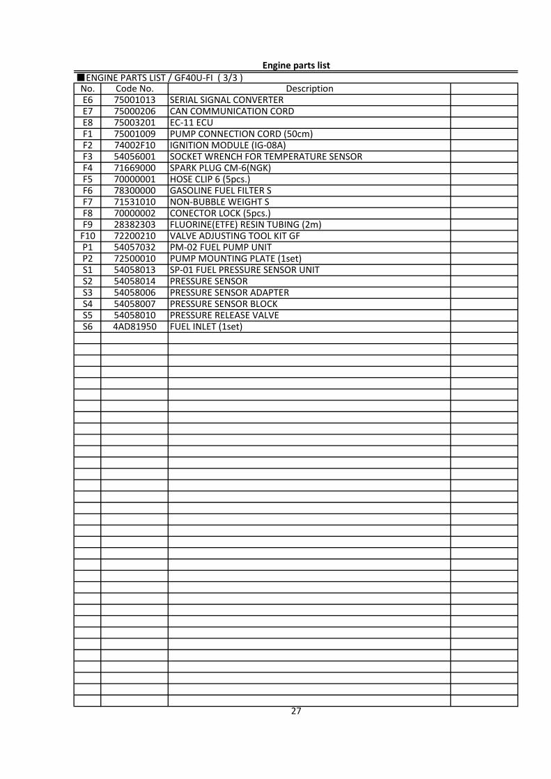
■ENGINE PARTS LIST / GF40U-FI ( 3/3 )
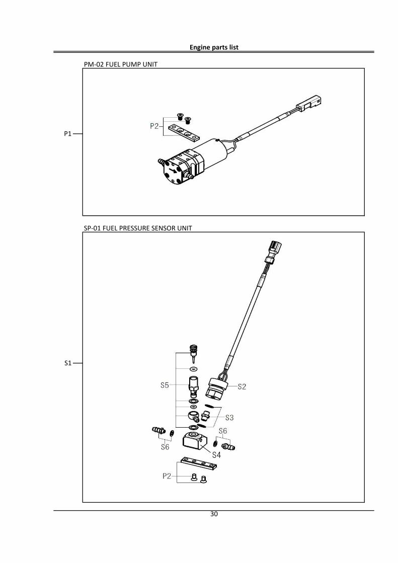
FUEL INLET (1set)4AD81950S6
S1 54058013 SP-01 FUEL PRESSURE SENSOR UNITS2 54058014 PRESSURE SENSORS3 54058006 PRESSURE SENSOR ADAPTER
F10 72200210 VALVE ADJUSTING TOOL KIT GFP1 54057032 PM-02 FUEL PUMP UNITP2 72500010 PUMP MOUNTING PLATE (1set)
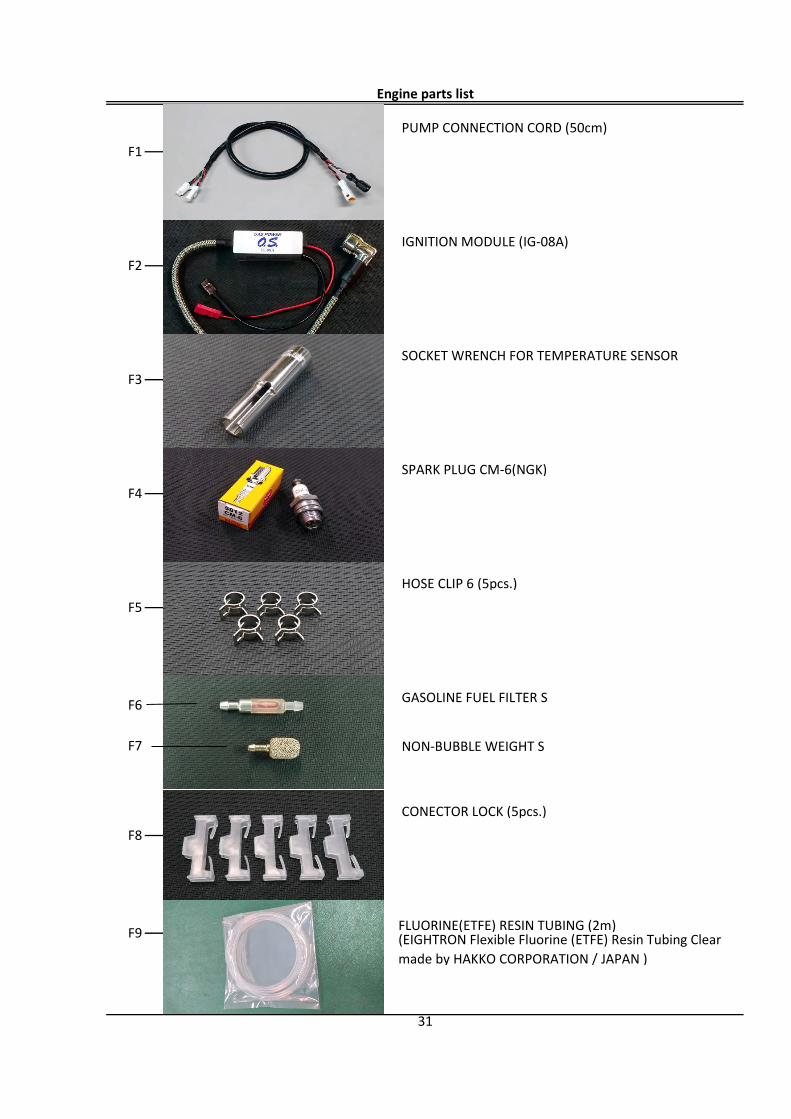
F7 71531010 NON-BUBBLE WEIGHT SF8 70000002 CONECTOR LOCK (5pcs.)F9 28382303 FLUORINE(ETFE) RESIN TUBING (2m)
F4 71669000 SPARK PLUG CM-6(NGK)F5 70000001 HOSE CLIP 6 (5pcs.)F6 78300000 GASOLINE FUEL FILTER S
F1 75001009 PUMP CONNECTION CORD (50cm)F2 74002F10 IGNITION MODULE (IG-08A)F3 54056001 SOCKET WRENCH FOR TEMPERATURE SENSOR
E6 75001013 SERIAL SIGNAL CONVERTERE7 75000206 CAN COMMUNICATION CORDE8 75003201 EC-11 ECU
27
54058010 PRESSURE RELEASE VALVES5S4 54058007 PRESSURE SENSOR BLOCK
Engine parts list
No. Code No. Description
Tightening torque:0.6 N・
m 7
17
18
13
12
14
16C5
44
43
41 42
24
20
23
21
29
28
40
C8
39
31
C11
35
32
34
33
C6
30
C6
363738
22C4
61
60
48
F5
55
56
59
C5
54
53
C11
C9
47
45
52
2
3
19
5
26
Tightening torque:1.0 N・
m
(Use Loctite 242 or 243)
Tightening torque:2.2 N・
m
thread)
25
27
C12
63
C13
62
64
65
66
70C7
69
68
67
C8
C8
C1
10
11
9
6
46
49
58
1
15
4
F4
26
50
50-1
(Use Loctite 242 or 243)
(left-hand
50-2
8
Tightening torque:1.5 N・
m(Use Loctite 242 or 243)
17-217-1
96
97
93
C2
95
94
(CYLINDER HEAD TEMP.)
57 57
91 C14
GF40U-FI
(A)
(B)(A)
(B)
9278
73
71
72
7776
75
74
C5
C13
51
(INTAKE AIR TEMP.)
EC-11 ENGINE CONTROL UNIT
E8
ECU WIRE HARNESS (A) EC-11 POWER SUPPLY CORD EC-11
CAN COMMUNICATION CODEECU WIRE HARNESS (B) EC-11
SERIAL SIGNAL CONVERTER
Engine parts list
E1
E3 E5
29
E4
E6
E7
E2
PM-02 FUEL PUMP UNIT
SP-01 FUEL PRESSURE SENSOR UNIT
Engine parts list
P1
30
S1
S4
PUMP CONNECTION CORD (50cm)
IGNITION MODULE (IG-08A)
SOCKET WRENCH FOR TEMPERATURE SENSOR
SPARK PLUG CM-6(NGK)
HOSE CLIP 6 (5pcs.)
GASOLINE FUEL FILTER S
NON-BUBBLE WEIGHT S
CONECTOR LOCK (5pcs.)
FLUORINE(ETFE) RESIN TUBING (2m)
F5
Engine parts list
F1
F2
F3
F4
31
F6
F7
F8
F9 (EIGHTRON Flexible Fluorine (ETFE) Resin Tubing Clearmade by HAKKO CORPORATION / JAPAN )
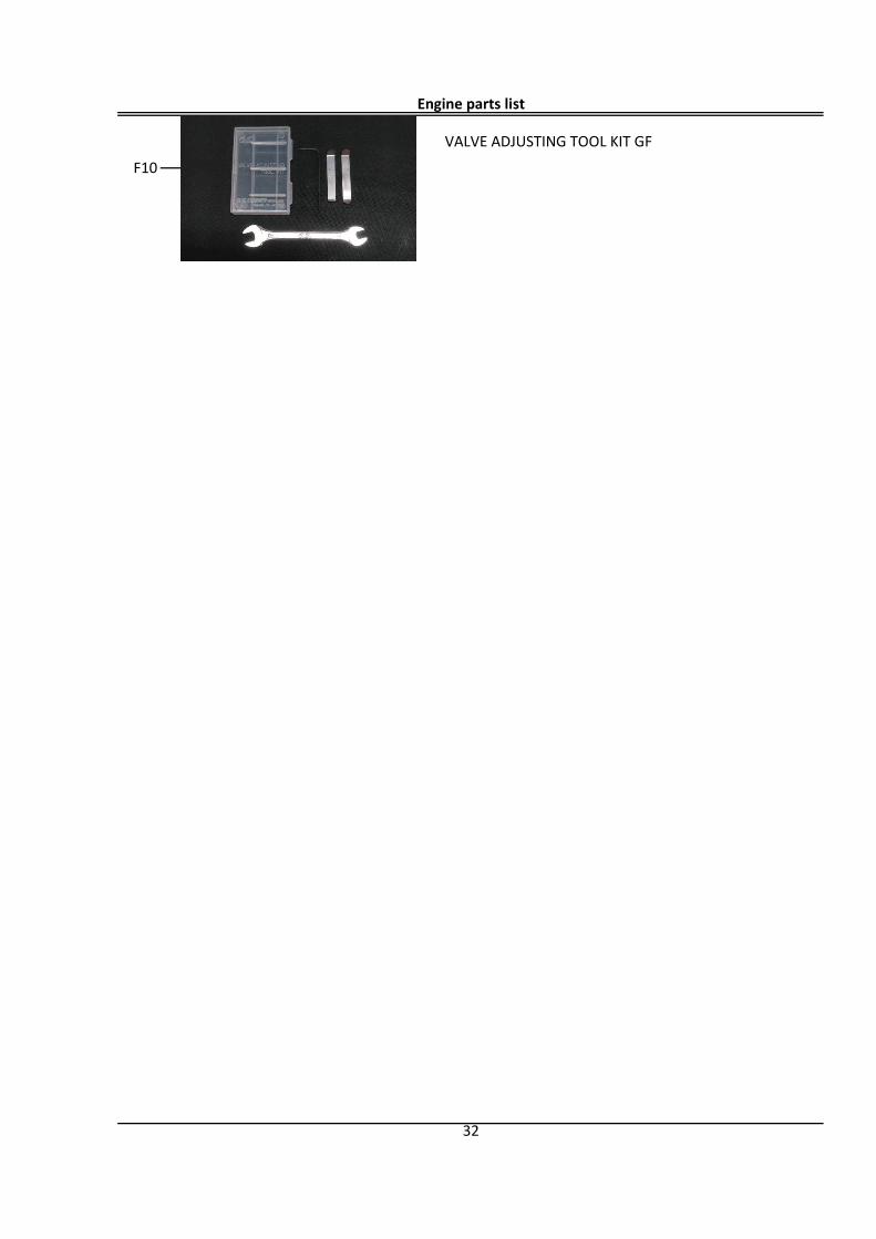
VALVE ADJUSTING TOOL KIT GF
32
Engine parts list
F10
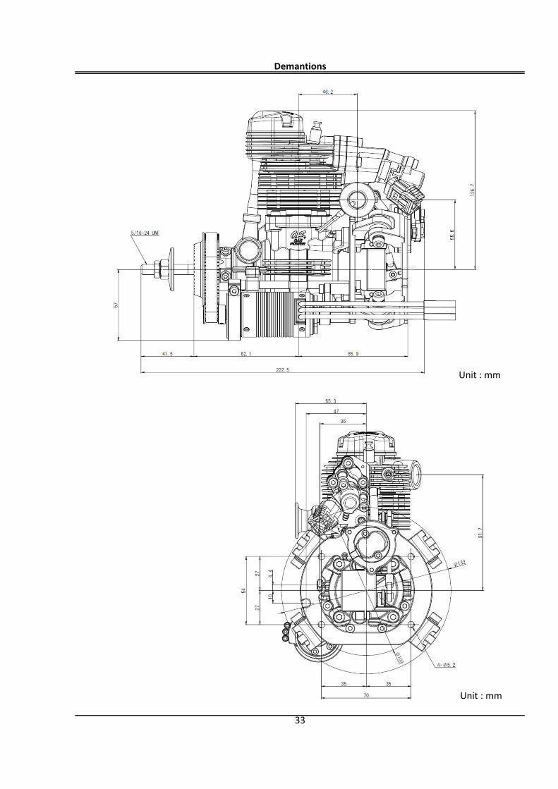
Demantions
33
Unit : mm
Unit : mm
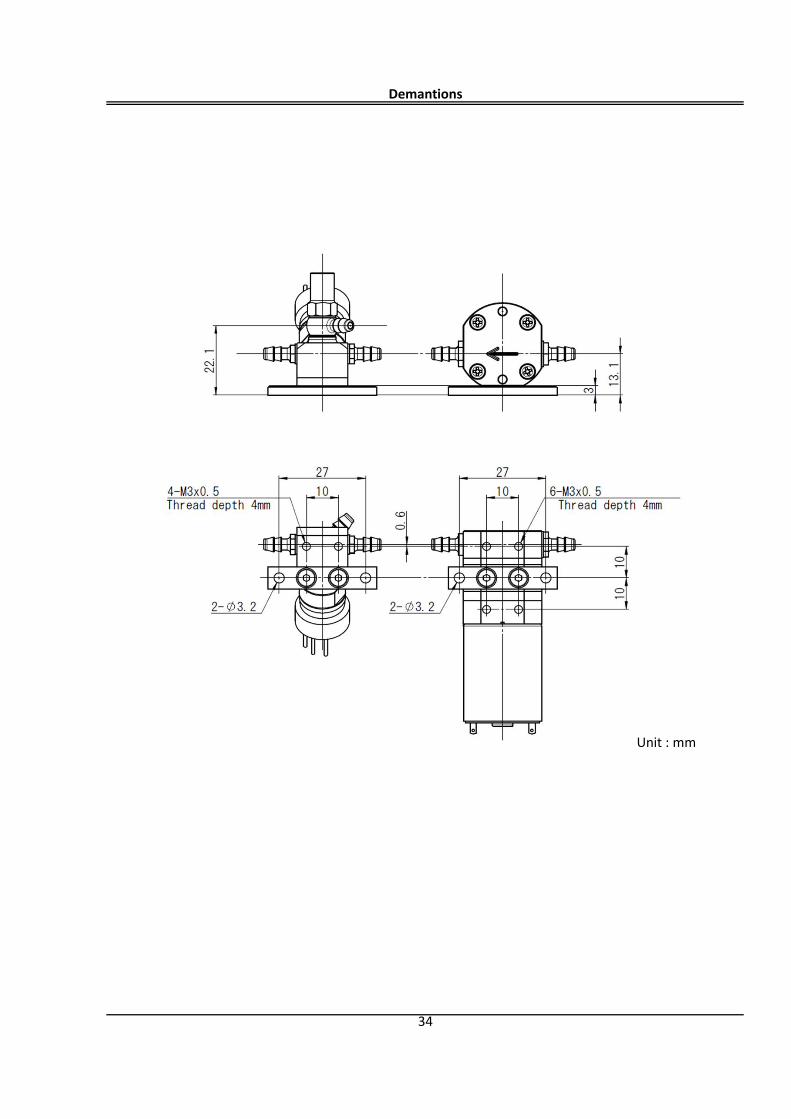
Demantions
34
Unit : mm
MEMO
35