geometric design bus turnouts
TRANSCRIPT

UNLV/TRC/RS-90/02 GUIDELINES FOR GEOMETRIC DESIGN AND LOCATION OF BUS TURNOUTS Emelinda M. Parentela Research Assistant Shashi K. Sathisan Assistant Professor of Civil Engineering Reginald R. Souleyrette II Assistant Professor of Civil Engineering Transportation Research Center University of Nevada, Las Vegas 1990 Clark County Department of Public Works

1. INTRODUCTION 1.1 Background This research team studied the effectiveness of existing bus turnouts on Las Vegas Boulevard in Spring 1990. The approach used was to compare the effects of bus operations at a roadside stop in the travel lane and at a bus turnout. Travel delays and reduction in lane capacity were the two primary measures of effectiveness used for the comparisons. The results showed that the use of bus turnouts could be an effective tool in reducing delays to other vehicles while a bus stops to serve passengers, and for improving lane capacity by minimizing queuing due to bus operations at a roadside stop in a travel lane. This follow up study addresses issues related to the development of guidelines for geometric design of bus turnouts and criteria for locating bus turnouts. 1.2 Statement of Purpose The primary objective of this study is the development of guidelines for geometric design of bus turnouts. The guidelines developed in this study could serve as a basis for the design of future turnouts. The guidelines developed in this study should reflect the local operating conditions experienced by buses. Some of the major factors that need to be included in such an effort are local characteristics such as travel speeds, posted speed limits, traffic volumes, number of travel lanes, lane widths, lane configuration, and physical dimensions of buses using these facilities. Identification of candidate sites for locating bus turnouts is the secondary objective of this study. Some of the important criteria to be used for locating bus turnouts are addressed in this study. Specifically, these some of these criteria are used in identifying candidate sites for locating bus turnouts on the section of Maryland Parkway between Flamingo Road and Sahara Avenue. This section was selected based on needs of CC DPW identified in their immediate action plans under consideration for construction of bus turnouts along Maryland Parkway.

2. METHODOLOGY The study was divided into two main areas. The first area addressed the development of guidelines for the design of bus turnouts and the second part is discusses to identifying candidate sites for locating bus turnouts on Maryland Parkway. These are further detailed in this section. 2.1 Standardization of Bus Turnout Design The development of guidelines for geometric design of bus turnouts was divided into two main tasks. The first task was to review the existing design criteria and standards. The second task was to the evaluate the adequacy of design of the existing bus turnouts on Las Vegas Boulevard. Following this, specific details of the geometric design were developed to reflect some of the local characteristics. An overview of these two tasks follows. 2.1.1 Review of Existing Design Guidelines and Literature The first step in the development of guidelines for geometric design of bus turnouts was to review the existing standards recommended or adopted by national and international agencies. This served as a starting point for the development of design guidelines for Las Vegas. A review of the literature was conducted to identify the agencies using/overseeing the use of bus turnouts. The agencies selected were either from North America or Europe. The design standards recommended by these agencies were reviewed. Salt Lake City, Utah was identified as one of the cities where bus turnouts are used. Detailed information on the engineering design plans were obtained from the City Engineer's office in Salt Lake City. This included information on the design guidelines used and the current performance of bus turnouts. Details of the literature review are presented in Section 3.1. 2.1.2 Performance Review of Existing Bus Turnouts on Las Vegas Boulevard The performance of the existing bus turnouts on Las Vegas Boulevard was reviewed using a three step process. The three steps used in the review are: 1. Review of plans and drawings, 2. Field measurement of existing turnouts, and 3. Interview of bus driver using the turnouts. Discussions of the details of each of these steps follows.

2.1.2.1 Review of Plans and Drawings Pre-construction plans of the three existing bus turnouts on Las Vegas Boulevard were reviewed. These turnouts are located near the Flamingo Hilton, The Mirage and Excalibur Hotels. Due to the non-availability of detailed drawings, some elements of the turnout geometry were determined from the Site Grading Plan prepared for each of these resorts (provided to the study team by CC DPW) and used for the installation of water lines. Details of the geometry for these turnouts are discussed in Section 3.2. 2.1.2.2 Field Measurement of Existing Bus Turnouts Actual field measurements of the dimensions of the three turnouts were made for verification. These were compared with the pre-construction drawings and if a difference were noted, the actual site measurement was used in our evaluation. This was done to ensure that the section being evaluated reflected the field condition. Details of the field measurements of the geometry of the three existing turnouts are presented in Section 3.2. 2.1.2.3 Driver Interview An interview of bus drivers interview using the turnouts was conducted to obtain a user's evaluation of the performance of the existing bus turnout. The questionnaire comprised fourteen questions which related mainly to the geometry of bus turnout such as the length of stopping area, width and angle of deceleration and acceleration tapers and its effectiveness with respect to maneuverability. The cooperation of Las Vegas Transit System who assisted in the distribution and collection of the questionnaires facilitated the interview process. Questionnaires were distributed to drivers who operated and are currently operating buses along Las Vegas Boulevard or Route 6. The questionnaire is presented in Appendix A. An analysis of the responses to the questions is presented in Section 3.3. 2.2 Location of Bus Turnouts at Maryland Parkway Between Flamingo Road and Sahara
Avenue Intersections
The following steps were followed to identify candidate sites for the possible location of bus turnouts along the specified route: development of selection criteria, reconnaissance survey and inventory of existing bus stops, traffic study, observation of passenger volumes, and identification of candidate locations. 2.2.1 Development of Selection Criteria
car was used.

A review of existing literature was made to evaluate the various criteria used by other agencies/states for the location of bus stops. This was also used to identify the agencies/states whose area had characteristics similar to those of the Las Vegas Valley. 2.2.2 Reconnaissance Survey and Inventory of Existing Bus Stops The survey was accomplished by a "walk-through" the area method aided by a route map. This was done to properly locate potential passenger generators such as commercial centers, offices, hospitals and schools. The lane configuration of the roadway and the width of sidewalks were recorded. An inventory of existing bus stops was also made. During the survey, lots adjacent to Maryland Parkway and on-street parking were also noted for possible location of bus turnouts. The construction of a turnout will not be feasible without available space. 2.2.3 Collection of Traffic Data Observations were made at a few selected locations to study the movement of vehicles during the morning and evening peak periods. The observations included the number of vehicles queued behind a bus loading or unloading passengers at a roadside stop in a through lane. Further, the most recent traffic data available at the Clark County Department of Public Work were obtained and used for this study. These included the volume of through traffic, right-turning and left-turning vehicles at selected intersections. These data are used to determine the location of potential turnouts; i.e, near-side, far-side, or mid-block. 2.2.4 Field Observation of Passenger Volume and Vehicle Queue Preliminary data on the number of buses and the queue length formed by a bus stopped at a roadside stop were collected from all existing bus stops on various days and at different times of the day. These data are used in the preliminary selection of candidate locations for bus turnouts. Random observations were conducted between the periods June 20, 1990 to July 5, 1990 following the schedule of Route 10 bus (University), since this passes all the bus stops existing on Maryland Parkway between Flamingo Road and Sahara Avenue. Data collection was facilitated by riding a bus with a glass rear window. The number of vehicles queued behind the bus, while it was stopped, was observed from the rear of the bus and recorded. A count of the number of alighting and boarding passengers was made, simultaneously. At other times, when conditions did not permit observation and the queue behind the bus from inside of a bus, a trailing
car was used.
car was used.
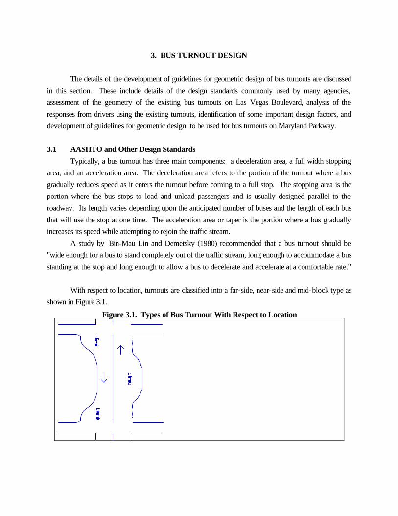
3. BUS TURNOUT DESIGN The details of the development of guidelines for geometric design of bus turnouts are discussed in this section. These include details of the design standards commonly used by many agencies, assessment of the geometry of the existing bus turnouts on Las Vegas Boulevard, analysis of the responses from drivers using the existing turnouts, identification of some important design factors, and development of guidelines for geometric design to be used for bus turnouts on Maryland Parkway. 3.1 AASHTO and Other Design Standards Typically, a bus turnout has three main components: a deceleration area, a full width stopping area, and an acceleration area. The deceleration area refers to the portion of the turnout where a bus gradually reduces speed as it enters the turnout before coming to a full stop. The stopping area is the portion where the bus stops to load and unload passengers and is usually designed parallel to the roadway. Its length varies depending upon the anticipated number of buses and the length of each bus that will use the stop at one time. The acceleration area or taper is the portion where a bus gradually increases its speed while attempting to rejoin the traffic stream. A study by Bin-Mau Lin and Demetsky (1980) recommended that a bus turnout should be "wide enough for a bus to stand completely out of the traffic stream, long enough to accommodate a bus standing at the stop and long enough to allow a bus to decelerate and accelerate at a comfortable rate." With respect to location, turnouts are classified into a far-side, near-side and mid-block type as shown in Figure 3.1.
Figure 3.1. Types of Bus Turnout With Respect to Location

A bus turnout is usually designed based on a specific standard. At present, several design standards are in use. Among the widely used ones are those recommended by the Association of American State Highways and Transportation Officials (AASHTO) and in the Federal Guidelines for Urban Street Design by the U.S. Department of Transportation, Federal Highway Administration (DOT, FHWA). These standards are summarized in Table 3.1. The dimensions of typical bus turnouts in the United States and some parts of Table 3.1. Summary of U.S. Design Standards
Agency Deceleration Taper, ft
Stopping Area, ft
Acceleration Taper, ft
Stopping Width, ft
Bus Length, ft
AASHTO 50 80 30 10 50
MTC 220 80 220 10 65
FHWA 60-80 80 40-60 10 40
Europe are summarized in Table 3.2. Table 3.3 shows existing local standards used by some European cities. (Brouwer, 1983). A deviation from the typical design, the asymmetric bay due to its non-symmetrical feature was developed in Great Britain. Richards (1976) studied the performance of this type of bay and compared it with that of the Ministry of Transportation (MOT) standard design. While the entry time between the two bays are almost the same, the results of his study favors the MOT design in terms of ease of pulling back into the traffic stream although he suggested that some modifications. These modifications are summarized as follows:

Table 3.2. Summary of Design Standards for Bus Turnout
AGENCY WIDTH TOTAL LENGTH
STOPPING LENGTH
REMARKS
AASHTO 10'
150' NS 130' FS 180' MB
add 10' to 15' length for W=12'
FEDERAL GUIDELINES (DOT,FHWA)
10' Transition L 60'-80' NS 40'-60' FS
150' to 170' NS 130' to 150' FS 180' to 220' MB
80'
Metropolitan Transportation Commission
10' (V =<30 mph) 15' (V =>30 mph)
80' add 65' to length for every bus added
SLTF@
W = 2.50m (8.2') Pull-in L = 15m (49.2') Pull-out L = 10m (32.8')
39m (127.9')
14m (45.9')
W = 2.70m (8.9') Pull-in L=16.2m (53.1') Pull-out L=10.8m (35.4')
41m (134.5')
14m (45.9')
W = 3.00m (9.8') Pull-in L = 24m (78.7') Pull-out L = 18m (59.0')
56m (183.7')
14m (45.9')
@ - Svenska Lokaltrafikforeningen (Brouwer, 1983); NS - near-side; FS - far-side; MB - midblock

Table 3.3. Dimension of Stopping Bays on the Basis of Local Standards
2.50 m wide stopping bays (v = 50 km/hr)
Gothenburg1 Hamburg Hanover London Paris St. Gallen2 SV3 Utrecht Desirable dimensions8
a b c
19m 16 15
- - -
- - -
- - -
9m 12 9
20m 14 20
13.25m 19.85 10.85
- - -
15.00m 14.004 10.00
d 50m - - - 30m 54m 43.75m - 39.00m
2.70 m wide stopping bays (v = 50 km/hr)
Gothenburg Hamburg Hanover London Paris5 St. Gallen SV3 Utrecht Desirable Dimensions8
a b c
- - -
- - -
- - -
19.5m 11.3 19.5
- - -
- - -
- - -
12m 16 8
16.20m 14.004 10.80
d - - - 50.3m - - - 36m 41.00m
3.00 m wide stopping bays (v = 50 km/hr)
Gothenburg Hamburg Hanover7 London Paris St. Gallen6 SV3 Utrecht Desirable dimensions8
a b c
22m 16 17
5m 27 5
16m 13 15
- - -
10.80m 12.00 10.80
28m 14 20
16.25m 19.85 12.65
- - -
24.00m 14.004 18.00
d 55m 37m 44m - 33.60m 62m 48.75m - 56.00m
1 According to SLTF Standards; 2 According to Swiss Standard; 3 Statens Vagverk, Sweden; 4 Dimension for 12m bus plus 2m; 5 Width =
2.89m; 6 On urban main roads; 7 Speed when pulling in to the stopping bay = 30 km/h; 8 Based on Table a = pull-in distance; b = stopping area; c = pull-out distance; d = total distance Source : P. Brouwer (UITP Revue, January 1983)

MOT Design Richards' Modified Design Width, m 3.25 (10.66') 3.50 (11.48') Total Length, m 55.0 (180.4') 55.0 (180.4') Brouwer (1983) also discussed specific values of pull-in and pull-out angles are at different speeds. These are presented in Table 3.4. As can be noted, the angles are inversely proportional to speed. Therefore, the higher the speed, the flatter are the pull-in and pull-out angles. It is interesting to note that the pull-in angle or deceleration taper is flatter than that of a pull-out angle or acceleration taper. 3.1.1 Salt Lake City Bus Turnouts Detailed drawings for bus turnouts at the Salt Lake City Main Street were obtained from their City Engineer's Office. The turnouts are mainly "midblock" turnouts and are made long enough to accommodate at least three buses at one time. A typical layout of bus turnouts used in Salt Lake City is shown in Figure 3.2.
Table 3.4. Guide Values for the Pull-in and Pull-out Angles Expressed as a Function of Speed
Figure 3.2. Typical Section of Bus Turnout at Salt Lake City Main Street

Speed
50 km/h 60 km/h 70 km/h
Pull-in angle 6 : 1 7 : 1 8 : 1
Pull-out angle 4 : 1 5 : 1 6 : 1
Source : P. Brouwer (UITP Revue, January 1983) As can be noted, the turnout consists of an entry curb and a stopping area. It is more like an exclusive bus lane, which is very effective in terms of reducing bus travel delays and improving travel time. Entry taper generally has a slope of 3:1. The stopping area varies from 190' to 210' in length, with a width of 11'6". The pavement at the turnout is constructed using reinforced concrete but a 2' wide asphalt separator is used to demarcate the turnout from the through travel lanes. The staff at the city offices in Salt Lake City reported that no serious operational problems have been encountered with the use of these turnouts. 3.2 Geometry of Existing Bus Turnouts along Las Vegas Boulevard There are three bus turnouts that presently serve the passenger buses on Vegas Boulevard. These are as follows: Turnout Intersection Type Traffic Capacity, Flamingo Hilton Flamingo Road Midblock Northbound Two The Mirage Spring Mtn. Road Farside Southbound One Excalibur Tropicana Avenue Farside Southbound Five Details of the sections, as measured in the field, are summarized in Table 3.5 and illustrated in Figure 3.3. These indicate that AASHTO conventional design standards might have served as the basis the designs, although some modifications were made, especially at the Excalibur and Mirage turnouts.

The width each turnout is a standard 12' with the provision of an additional 2' concrete gutter in each case. The deceleration and acceleration tapers generally satisfy the AASHTO minimum requirement of 5:1 and 3:1 respectively. An exception is the deceleration taper at the Mirage of 2.7:1, which is under-designed according to AASHTO standards. Table 3.5. Dimensions of Existing Bus Turnouts in Las Vegas Boulevard
Figure 3.3. Sections of Bus Turnouts in Las Vegas Boulevard

Turnout Deceleration Taper, ft
Standing Length, ft
Acceleration Taper, ft
Width, ft
Flamingo Hilton 58 110 58 12
The Mirage 55 45 35 12
Excalibur 100 235 55@ 12
@ - parking entrance used as acceleration taper
The Excalibur turnout is designed as a far-side turnout where the right lane leading to the Excalibur parking area serves both as a turn lane for traffic turning into Excalibur, and as an acceleration taper for the turnout. The distance from the edge of the entrance to the end of deceleration taper is approximately 235'. It could accommodate at most five buses simultaneously. On the surface, this appears to be favorable and with the present system of bus operations, simultaneous stopping is not likely to exceed three buses. However, the presence of a parking entrance at the downstream end of the bus turnout is not satisfactory. It will affect any bus attempting an exit from the turnout during periods when there is a high rate of arrival of vehicles in the southbound direction to the Excalibur Hotel from Las Vegas Boulevard. The Mirage turnout is intended to serve one bus at a time. But the stopping area is only slightly longer than the length of a bus and stopping a bus parallel to the curb appears to be difficult. The exit portion of the turnout also serves as an entry to the parking area of the Mirage. Vehicles entering this lot often obstruct the movement of a bus trying

to make an exit. This configuration results in the occurrence of "weaving maneuvers". This observation was shared by most of the drivers interviewed for this study as indicated in the following subsection. Vehicles involved in such movements are susceptible to being involved in accidents during such maneuvers. 3.3 Drivers Assessment of Existing Bus Turnouts at Las Vegas Boulevard Twenty five drivers from the Las Vegas Transit responded to the questionnaire. In terms of the total number of daily trips, the respondents are distributed as follows : Number of Trips Number of Respondents Percentage <4 3 12 >/4 21 84 Varies 1 4 3.3.1 Roadside Stop or Bus Turnout? The drivers responses were divided based on the selection of their preferred type of bus stop. While 11 (44%) respondents chose the roadside stop in a through lane, it is interesting to note that 14 (56%) preferred a bus turnout. The responses might indicate the drivers' concern for what they perceive to be safe for passengers, the bus itself, and to the other vehicular traffic. Of the 11 who chose a roadside stop, 3 (27%) think, however, that a turnout is safer for traffic, while 4 (36%) think it safer for passengers. Roadside Turnout No Answer What type of bus stop do you prefer? 11 (44%) 14 (56%) Which type of bus stop do you think is safer for traffic? 8 (32%) 17 (68%) Which type of bus stop do you think is safer for passengers? 7 (28%) 15 (60%) 3 (12%) For those who preferred roadside stops, the primary reason cited by 27% was that there is no need to pull back into traffic, which is often a cause of delay especially at congested traffic conditions. One respondent pointed out the difficulty of an exit maneuver especially at the Mirage and Excalibur turnouts. Six or 43% of those who preferred a bus turnout reasoned that "traffic can move past the bus without changing lanes" which indicates less disruption to through traffic. Other reasons cited were: there is less chance for the bus being rear-ended by impatient drivers, less traffic obstruction and less

danger to passengers. In terms of passenger safety, those who preferred a roadside stop thought that it was easier to align the bus with the curb, get closer to it and thus minimize the step-up for passengers, especially the women and the elderly. The reasons cited in favor of a bus turnout were: away from moving traffic (40%), safer for passengers on board since there are less chances of rear end collisions (33%), and safer in the sense that passengers can see traffic coming around the bus. One respondent reasoned that passengers could spot a bus turnout more easily than a roadside stop. Another question that drew positive response in favor of bus turnouts was related to safety considerations and was the following: Is it better for a passenger to load/unload at Yes No No Difference a turnout rather than at a roadside stop? 15 (60%) 6 (24%) 4(16%) The main reason cited by those who answered yes, was that it is safer because passenger loading and unloading is away from traffic (53%). Other reasons cited were: clearer rear door exit with the absence of news stands; it eliminates risk of being hit by other vehicles, which may be possible at a roadside stop; and convenience, there is no need to rush boarding because no traffic can be obstructed behind the bus stopped at a turnout. The latter consideration is particularly important to the elderly and the handicapped. Those who answered negatively stressed the difficulty of aligning bus to curb (83%) and that the rear exit is often far away from curb which poses a hazard to boarding and alighting passengers (17%). 3.3.2 Design Adequacy The following questions addresses the geometric design of the existing bus turnouts: What do you think of the design of the Good Bad existing bus turnouts at Flamingo Hilton, 15 (60%) 9 (36%) The Mirage and Excalibur? One (4%) respondent specifically mentioned the turnouts at Flamingo and Excalibur was good and that the turnout at The Mirage was bad. Those who thought that the turnouts are badly designed complained that "other vehicles will not let you back into heavy traffic, especially on Fridays and Saturdays." Interestingly, the same reason is cited as the primary criticism of those who think they are good. Some (33%) pointed out that other vehicles such as taxis and tourist buses use them so often that the Las Vegas Transit System buses can hardly use them. One respondent criticized the locations as badly chosen, referring specifically to the Mirage and Excalibur. Of the 15 respondents who thought that the turnouts were good, 5 (33%) expressed satisfaction with the one at Flamingo Hilton. The Mirage turnout is considered sharp, small, having a very short stopping area, and unsafe for passengers. One respondent commented that the turnout at the Excalibur

is actually not a turnout but a right turn lane to the valet parking facility. On the question of maneuvering an entry, only 7 (28%) saw it as a problem. The reason given by 43% of those who saw it as a problem, is: "a very short entry curb." Fourteen percent (14%) thought the entry angle is very steep. The remaining 43% found it both very short and very steep, especially the one at The Mirage. A higher percentage (60%) of the respondents expressed that making an exit from the turnouts was a problem. The main reason is the difficulty of reentering the traffic stream (73%), especially at congested conditions. Three (20%) cited non-yielding traffic flow. One explained that in actuality, "buses are forcing their way back into traffic instead of merging into it." The following questions addressed the design of entry/exit angles and the width of the stopping area: Entry/Exit Angles With the current design, do you think Yes No No Answer it is easy to enter these bus turnouts? 16 (64%) 7 (28%) 2 (8%) Does exit from bus turnouts ever Yes No Sometimes present a problem? 15 (60%) 9 (36%) 1 (4%) Width of Stopping Area Do you think the stopping area at Too Wide Too Narrow Enough the turnouts are too wide, too narrow 0 1 (4%) 24 (96%) or just right to allow stopping without disruption of traffic? Do you think the stopping area at Too Wide Too Narrow Enough the turnouts are too wide, too narrow 0 1 (4%) 24 (96%) or just right to allow starting without difficulty of seeing oncoming vehicles? 96% of the respondents perceive the existing width of the bus turnouts to be adequate, and only 4% considered it as too narrow. Three different designs for the turnouts were presented to the respondents and the respondents were asked to choose the one which they thought to be the most appropriate (see Figure 3.4). Which type of turnout do you A B C None think is most appropriate? 21 (84%) 3 (12%) 1 (4%) 0

Those who gave an explanation on why they chose A reasoned that it was easier to get in and get out with symmetrical entry and exit tapers. A reason cited for longer stopping area is that it would allow two buses to stop simultaneously. In addition, it would provide better room for entry and exit even if other vehicles are present in the turnout. 3.3.3 Shared Use The presence of other vehicles at the turnout often forced the drivers to load/unload passengers outside it as claimed by (60%) of the respondents. 36% said that they seldom experienced it, while only 4% answered that they have never encountered such situations.

Figure 3.4 Bus Turnout Sections

Do you encounter situations when you are Often Seldom Never forced to load/unload passengers outside 15 (60%) 9 (36%) 1(4%) the turnout because of the presence of vehicles stopped or parked at a turnout? Do you prefer that turnouts be used Yes No No Difference exclusively for buses? 24 (96%) 0 1 (4%) 96% of the respondents wanted the turnout to be used exclusively for buses. Only 4% of the respondents did not mind sharing it with another vehicle. If shared use was permitted, 12% preferred taxis, 8% preferred vehicles other than taxis, and 4% preferred jitneys. The rest of the respondents (76%) probably indicate their strong opposition to the idea of sharing it to other vehicles by not responding to the question. 3.4 Design Factors From the information presented in the preceding subsections, the following factors appear to be the most important in the design of bus turnouts: 1. Maneuverability. The turnout should provide an adequate space for the bus to maneuver an entry
while approaching the turnout at a speed V, to bring the bus to a full stop, and to maneuver an exit starting from rest to a speed V1. However, the turnout should use as little space as possible while satisfying both maneuvering and stopping requirements.
2. Stopping area. The stopping area should be long enough to accommodate at least two buses at the same time with the tailing bus having enough space to overtake the first bus once it is ready to leave.
3. Location. A more detailed discussion in the location factor is given in the following section. 4. Physical characteristics of the bus. The length and width of the buses using the turnouts and the
number of buses expected to occupy the turnout at any one time influence the dimensions of the turnout.
The buses that currently operate along Maryland Parkway have the following typical dimensions: Length (including bumpers) 40'8.4" Width 102.00" Track (front) 85.30" Track (rear) 76.50" The management of Las Vegas Transit System is presently considering a plan to operate

articulated buses in the Las Vegas Valley. These buses would be longer, with a length of 65' but the width would be the same as that of the existing bus. The posted speed limit along the stretch of Maryland Parkway included in this study is generally 30 mph. This is an important design input. It influences the determination of the length of the deceleration and acceleration tapers of the turnout. 3.5 Bus Turnout Section The elements of a bus turnout addressed in this study are the width of the stopping area, the length of the stopping area and the deceleration and acceleration tapers. A schematic representation showing these elements and the variables used to represent them in the analysis is provided in Figure 3.5. 3.5.1 Width The width of a turnout must be able to accommodate the bus completely as it stands parallel to traffic. A clearance must be provided especially from the vehicles moving at speeds close to the posted limit (or higher) in the adjacent lane. The width, w, of a turnout can be expressed as follows (see figure 3.5): w = ½{wv + dw} + dr + dl where : wv = width of vehicle dw = center to center distance between wheels dr = distance from wheel track to edge of gutter dl = distance from vehicle body to edge of adjacent lane The required safe clearance for a bus in the turnout from the travel lane would be influenced by the speed of vehicles in the travel lane. The relationship developed by Babkov and Zamakhayev (1967) can be used to estimate the distance from the vehicle body to edge of adjacent lane. This is expressed as follows: dl = 0.35 + 0.005V - Metric where V is vehicle speed in km/hr and dl is in meter. Translating to English units, dl = 1.15 + 0.026V - English V is in mi/hr and dl is in ft. The value of dr can be taken equal to 1' while the average of vw and dw is 8'. The preceding relationships can be used to determine the minimum width required for the turnouts. The width of the turnout would be a function of the speed of vehicles in the adjacent travel lane. Assuming that the speed of vehicles in the travel lane is the same as the posted speed limit, the width of the turnout can be calculated for various speed limits. These results are presented in Table 3.6.

Figure 3.5. Bus Turnout Geometry

Table 3.6. Minimum Width of Bus Turnout at Various Speeds
V, mph dl, ft w, ft
10 1.5 10.5
15 1.6 10.6
20 1.7 10.7
25 1.8 10.8
30 1.9 10.9
35 2.0 11.0
40 2.2 11.2
45 2.3 11.3
While a width of 11' is considered theoretically safe for a speed of 30 mph, an additional clearance of one foot can be provided on the left side of the track to give a total width of 12'. Alternatively, providing a 12' width for the turnouts could add a factor of safety of over 1.5 to the assumed travel speeds of vehicles in the adjacent lane. 3.5.2 Stopping Area The length of the stopping area is expressed as: n Ls = S{N(i) * LBUS(i)} + c i=1
where : Ls = length of stopping area N(i) = number of bus(i) expected to use the area at one time i = type of bus n = total number of bus types LBUS(i) = length of bus(i) c = clearance Brouwer (1983) recommends that 4m or 13' should be added to the length of bus for the stopping area. A longitudinal clearance of 15' is considered adequate to allow stopping parallel to the road for convenience when maneuvering an exit. Thus, for a single 40' bus, the stopping area should be 55' long and for an articulated bus (length = 65') the same would be 80'. With the present bus schedule, only one bus is scheduled to occupy the stop at a time. However, with the fielding of more buses in the future, it is very likely that simultaneous stopping of

more than one bus will occur. This should be accounted for in the design. 3.5.3 Deceleration/Acceleration Taper It would be preferable to have symmetrical deceleration and acceleration tapers unless space limitation dictates otherwise. The calculation of the radii of curvature is necessary to determine the length and angle of the deceleration and acceleration taper. The minimum turning radius can be estimated as a function of speed using the approach AASHTO green book. For horizontal curves, the expression is as follows: e + f = V2/15R where: e = super elevation f = coefficient of friction V = speed in mph R = minimum radius of curvature The values of e and f are taken from those representing low speed urban street. Adopting a range of fmax = 0.150 to 0.30, R values at emax = 0.060 and emax = 0 are calculated as shown in Table 3.7. As can be noticed, there is a significant change in radius of curvature by ignoring the effect of super elevation, i.e., e = 0. This implies a need for a flatter slope which may be very conservative but uneconomical. A maximum value of e = 0.060 is considered safe and reasonable (AASHTO, 1984). From Table 3.7, the length of taper to be used for the turnout can be determined using the following equation: R1+R2 = (w2 + Ltr
2)/2w where: R1 = radius of curve #1 R2 = radius of curve #2 Ltr = lateral distance of taper w = width of bus turnout Table 3.7. Minimum Radius of Curvature at Various Speeds
V, mph fmax R @ emax = 0.060, ft R @ emax = 0, ft
10 0.30 20 25
15 0.30 40 50
20 0.30 75 90
25 0.252 135 165
30 0.221 215 270

35 0.197 320 415
40 0.178 450 600
45 0.150 645 900
An illustration showing the representation of each variable is shown given in Figure 3.6. The value of R1 is that calculated in the preceding equation. The value of R1 is taken as being in the range 0.50R2 to 1.0R2. Since the width of bus turnout is predetermined, the value of the length of taper, Ltr, can be calculated. Rearranging the equation and solving for the unknown, Ltr: Ltr = {[2w(R1+R2)] - w2}0.5 Using e = 0.060, values of Ltr for R1=0.5R2, R1=0.75R2 and R1=1R2 are calculated for bus turnout widths of 11', and 12'. These results are presented in Table 3.8. The results show that as the speed increases, the slope of taper also increases. This increase becomes very significant at speeds greater than 30 mph. While the posted speed limit is 30 mph at the study area and varies from 15 mph to 45 mph in Las Vegas, the speed of the bus is generally less than the posted speed limit as it approaches a turnout. Observations at Las Vegas Boulevard bus turnouts showed that the approach speed varies from 15 mph to 25 mph, which is approximately 20% to 50% lower than the posted speed limit.

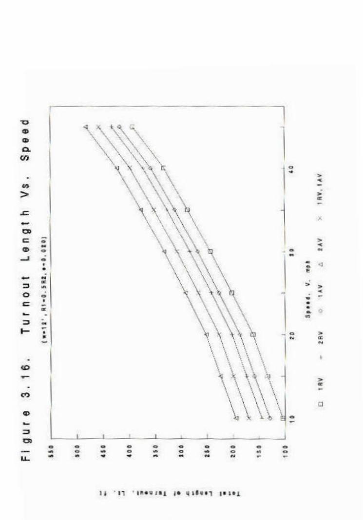
3.5.4 Total Length of Bus Turnout The total length of bus turnout is taken as the sum of the lateral distance of the acceleration and deceleration tapers and the stopping area. Mathematically, it can be expressed as follows: Lt = Ldt + Lat + Ls where : Lt = total length of bus turnout Ldt = lateral distance of deceleration taper Lat = lateral distance of acceleration taper For a symmetrical section, Ldt = Lat = Ltr, hence : Lt = 2Ltr + Ls The total length of bus turnouts for various combinations of bus types and a range of design speeds are presented in Figures 3.7 to 3.9, and Figures 3.10 to 3.12 for w = 11', R1=0.5R2 to R1=R2 and w = 12', R1 = 0.5R2 to R1=R2, respectively. The symbols used in these figures are as follows: 1 RV - one regular bus using the turnout 1 AV - one articulated bus using the turnout
Figure 3.6 Graphical Illustration of Taper Distance

2 RV - two regular buses using the turnout simultaneously 2 AV - two articulated buses using the turnout simultaneously 1 RV, 1 AV - one regular bus and one articulated bus using the turnout simultaneously The results show a non-linear relationship between speed and total length of bus turnout. 3.6 Additional facilities A waiting shed is considered an important facility especially during summer when the temperature reaches as high as 1100F-1150F. This will provide shelter to passengers who are forced to wait for long periods on various accounts such as unreliability of schedule of bus arrival, especially during peak hour traffic flow periods.

Table 3.8. Deceleration and/or Acceleration Taper Angles for Bus Turnouts
V,mph
Slope
e = 0.060, w = 12' e = 0.060, w = 11'
R1 = 0.5R2 R1 = 0.75R2 R1 = R2 R1 = 0.5R2 R1 = 0.75R2 R1 = R2
10 2 : 1 2 : 1 2 : 1 2 : 1 2 : 1 3 : 1
15 3 : 1 3 : 1 4 : 1 3 : 1 3 : 1 4 : 1
20 4 : 1 5 : 1 5 : 1 4 : 1 5 : 1 5 : 1
25 6 : 1 6 : 1 7 : 1 6 : 1 6 : 1 7 : 1
30 7 : 1 8 : 1 8 : 1 8 : 1 8 : 1 9 : 1
35 9 : 1 10 : 1 10 : 1 9 : 1 10 : 1 11 : 1
40 11 : 1 11 : 1 12 : 1 11 : 1 12 : 1 13 : 1
45 13 : 1 14 : 1 15 : 1 13 : 1 14 : 1 15 : 1
Note : Use a minimum slope angle of 3 : 1


4. LOCATION OF BUS TURNOUTS This section of the report addresses the issues related to the location of bus turnouts. The identification of candidate sites on Maryland Parkway (between Sahara Avenue and Flamingo Road) for the construction of turnouts is also discussed in this section. A brief discussion of some of the major concerns involved in the selection of locations for bus turnouts in general is presented first. The identification of candidate sites for bus turnouts specifically on Maryland Parkway is the subject of the rest of this section. The portion dealing with the identification of candidate sites consists of the following subsections: identification of existing bus stops; analysis of passenger volumes; analysis traffic volumes, queue lengths at bus stops, and lane configurations; a brief discussion of the right of way considerations; and the identification of candidate sites. 4.1 General Concerns The major concerns related to the selection of a location for a bus stop or a turnout include marketability, traffic conditions, safety, and right of way. A short discussion of each of these issues follows: 1. Marketability - The turnout should be located in areas close to main passenger generators such as
malls and shopping complexes, schools, public offices, etc. It should also be accessible to major transfer points.
2. Traffic - This includes both traffic signal phasing and traffic movements. If possible, the turnout should be located near intersections where "double start" of buses can be minimized. The bus turnout should be located away from any entrance/exit gates to private parking facilities. Else, bus-vehicle conflicts and weaving maneuvers could arise and these often result in delays, and possible unsafe maneuvers of vehicles.
3. Safety - Careful attention should be given to safety of pedestrians, passengers on board buses, passenger waiting at a stop, and other vehicle in the system. The turnout should be located near pedestrian crossing areas. This would help minimize passenger walking time and dissuade passengers from jaywalking or crossing the road outside of the designated pedestrian crossing areas.
4. Right of Way - The turnout should be located in an area with adequate space to satisfy design requirement. It should also provide space for shelter and pedestrian sidewalk.
A summary of these concerns is presented in Figure 4.1.


4.2 Existing Bus Stops There are a total of nineteen bus stops on Maryland Parkway from Tropicana Avenue to Sahara Avenue at present, fifteen of which serve the northbound traffic and five serve the southbound traffic. These bus stops are all used for passenger loading and unloading. A list of these stops is presented in Table 4.1 and illustrated in Figure 4.2.


Since the study area covers only the stretch from Flamingo Road to Sahara Avenue, the first three northbound bus stops shall not be considered in the analysis. 4.3 Frequency of Passengers Alighting and Boarding The volume of passengers at each stop is defined as the sum of passengers alighting and boarding. These data are used to assess the passenger demand from an area served by a particular stop or its potential to generate passengers. The observations show that the area with the most frequent and the most number of passengers are ranked as follows: 1. (#9) North of Sierra Vista Drive, 2. (#6) North of Twain Avenue, 3. (#14) North of Sahara Avenue, 4. (#8) North of Dumont Street, 5. (#4) South of Flamingo Road, 6. (#13) South of Laguna Avenue and 7. (#5) North of Flamingo Road. The one at the South of Humana Sunrise Hospital and South of Karen Avenue also have significant passenger demand. Several observations were made to estimate the passenger demand at the listed bus stops. In cases where two or more observations were made, the average value is used. In Table 4.1 List of Las Vegas Transit System Bus Stops in Maryland Parkway
Code
Bus Stop
Description of Zone
1
NORTHBOUND North of Tropicana Avenue
Gas station
2 South of University Road Shopping area, offices
3 South of Harmon Avenue University, shopping area, post office
4 South of Flamingo Road Commercial center, gas station
5 North of Flamingo Road Gas station, shopping area
6 South of Twain Avenue Shopping mall, theater, food shops
7 North of Twain Avenue LVT transfer point for mall hoppers, mall, commercial business district
8 North of Dumont Street Shopping area

Code
Bus Stop
Description of Zone
9 North of Sierra Vista Road Commercial center
10 North of Desert Inn Road Shopping centers, gas station
11 South of Sunrise Hospital Hospital and offices
12 South of Vegas Valley Drive Commercial centers
13 South of Laguna Avenue Medical center, offices
14 North of Sahara Avenue Shopping malls
15
SOUTHBOUND South of Karen Avenue
Commercial center, gas station
16 South of Vegas Valley Drive Bank, offices
17 North of Walk Bridge Hospital and offices
18 South of Desert Inn Road Commercial center, food shop
19 North of Sierra Vista Drive Right turn to Sierra Vista Drive, exits Maryland Parkway, residential area, bank, offices
the absence of detailed and more accurate ridership, boarding and alighting data, these data could be used as a first approximation for passenger demand at these stops. Figures 4.3 and 4.4 show the volume of passengers at each stop at different times of the day. 4.4 Traffic 4.4.1 Queuing at Bus Stops Several observations were made at each bus stop to obtain information on the average queue length formed behind a bus when it loads and/or unloads passengers. These are summarized in Figure 4.3. Supplementary graphs showing the distribution of queue length at the bus stops on various days and at various times of day are presented in Appendix C.


It was noted that queuing depends not only on the dwell time of the bus but also on the events occurring at the upstream intersection. Queuing is more likely when the traffic signal upstream of the stop changes from red to green while bus is at a stop and a platoon of vehicles arrives behind the bus. This is clearly noticeable at far-side bus stop locations. Another factor contributing to queue build up behind the bus is the volume of vehicles making right turns. These vehicles are more likely to be held by a bus, especially at near-side bus stop locations. The bus stops where queuing occurs frequently at any time of the day are the following: 1) North of Flamingo Road (# 5) 2) North of Sahara Avenue (# 14) 3) South of Laguna Avenue (# 13) 4) South of Sierra Vista (# 19) In addition to these stops, sizeable queues are also formed at the stops located at South of Karen Avenue and North of Desert Inn Road. In most instances, the number of vehicles queued is greater than the number of passengers serviced at the stop. This is particularly true at the stops located South of Laguna Avenue and North of Flamingo Road, where a very short bus dwell time creates shock wave effects on traffic, i.e., queues are formed even after the bus has recovered its lane and returned to its normal speed. At the North of Flamingo bus stop, random observations of dwell time were made. The results showed that in some instances, a 6 second dwell time caused a back-up of 3 vehicles, a 15 second dwell time caused 4 vehicles to back-up, and a 49 second dwell time caused 8 vehicles to queue up and this queue reached the intersection. At the South of Laguna bus stop, a 35 second dwell time caused a queue of 4 vehicles to be queued, and a 45 second dwell time resulted in 7 vehicles being queued. At the Sierra Vista bus stop, one observation showed a queue length of 8 vehicles for a 24 second dwell time. Another bus stop where the queue length appears to be much greater than the volume of passengers is the bus stop located South of Humana Sunrise Hospital. The lanes in this area are very narrow that a bus stopping in a through lane completely closes it.

4.4.2 Priority Ranking A summary showing the ranking of bus stops from the most to the least busy in terms of passenger volume and queue length is presented in Table 4.2. A graphical illustration of the same is shown in Figure 4.5. Ranking is based on the average daily average passenger volume and average queue length. The bus stops coded 1, 2 and 3 are located to the South of Flamingo Road and are not a part of the stretch of Maryland Parkway addressed in this study, namely from Flamingo Road to Sahara Avenue. Hence, they were not included in the ranking schemes.


4.4.2 Traffic Volumes and Turning Movements at Intersections Through traffic volume on Maryland Parkway were obtained from CC DPW for the following intersections: Flamingo Road, Twain Avenue, Sierra Vista Drive, Desert Inn Road, Vegas Valley Drive and Sahara Avenue. These data were based on observations made in July or September 1990 with a few exceptions where the data are not as current. Turning movement data were also obtained for the intersections of Maryland Parkway with Sahara Avenue, Twain Avenue and Vegas Valley Drive. These data will be used to determine whether the turnout will be located at a mid-block, far-side or near-side location. Data considered to be relevant to the study are presented in Figure 4.6. An explanation of the traffic flow/movement at each intersection follows: Table 4.2 Ranking of Bus Stops Based on Passenger Volumes and Queues
Code
Bus Stop
Rank Based from Average Daily Observation
Passenger
Volume
Queue
Length
Remarks
1
NORTHBOUND
North of Tropicana Avenue
2 South of University Road
3 South of Harmon Avenue
4 South of Flamingo Road 5 13 Double start always
occur
5 North of Flamingo Road 7 1
6 South of Twain Avenue 15 14
7 North of Twain Avenue 2 7
8 North of Dumont Street 4 11
9 North of Sierra Vista Road 16 15
10 North of Desert Inn Road 14 6

Code
Bus Stop
Rank Based from Average Daily Observation
11 South of Sunrise Hospital 8 8
12 South of Vegas Valley Drive 13 16
13 South of Laguna Avenue 6 3
14 North of Sahara Avenue 3 2
15
SOUTHBOUND
South of Karen Avenue
9
5
16 South of Vegas Valley Drive 12 10
17 North of Walk Bridge 11 9
18 South of Desert Inn Road 10 12
19 North of Sierra Vista Drive 1 4 Exits Maryland Parkway
1. Flamingo Road Intersection: Two bus stops are located on Maryland Parkway at this intersection in the Northbound direction. They are located at the near-side and far-side locations. Vehicles that are affected by a bus stopped at the near-side location are mainly those in the northbound direction and those turning east from Maryland Parkway to Flamingo Road. Traffic flow of main concern for the far-side bus stop location is that on the northbound leg of the intersection. This is due to a large volume of westbound turning right, eastbound vehicles turning left or the northbound through traffic at the intersection. A bus stopped upstream of this intersection in the northbound direction often results in a queue of vehicles making right turns from Flamingo Road onto Maryland Parkway. These queues often spill back into the intersection. The provision of a far-side bus turnout instead of the roadside bus stop at a location due north of the intersection will ease congestion due to a stopped bus in the outer lane of this intersection.


2. Twain Avenue Intersection: There are two bus stops near this intersection which serve northbound buses. One is a near-side stop located upstream of the intersection and the other is at the far-side location. Southbound traffic appears to be very high at this intersection especially in the afternoon peak period when the vehicle volumes exceeding 3000 vehicles per hour were recorded. However, this traffic is not likely to be affected by or affect the movement of buses in the northbound direction. The northbound traffic is moderately high. This traffic often affected by a bus stopping at the stop located upstream of the intersection. Buses stopping at the far-side bus stop affect the northbound through traffic, the vehicles turning right from the east, and the vehicles turning left from the west, especially in the afternoon peak period. However, the vehicles turning left from the west often occupy the innermost lane and are less likely to experience delays due to the effect of a stopped bus. 3. Desert Inn Intersection: There are two bus stops near this intersection. A far-side bus stop serves northbound buses and another far-side bus stop is located at the south side of the intersection to serve southbound buses. The presence of a stopped bus at the stop serving the northbound buses, is likely to affect the northbound through traffic, the vehicles turning right from the east, and the vehicles turning left from the west. The critical period in this respect usually occurs during the afternoon peak. Southbound vehicles with through movement across the intersection, vehicles through turning right from the west, and vehicles turning left from the east are affected by bus operations at the stop located downstream of the intersection in the southbound direction. These traffic volumes appear to be more critical than the traffic volumes in the northbound direction, especially in the afternoon peak period. 4. Vegas Valley Drive Intersection: Three bus stops are of main concern near this intersection. One bus stop is located upstream of the intersection in the northbound direction. The other two bus stops are located in southbound direction, one is located further upstream (near-midblock) and the other is located at the far-side of the intersection. Northbound through traffic and the northbound vehicles turning right are affected by a bus stopped at the roadside bus stop in the northbound direction. The northbound through traffic is also affected by a stopped bus at South of Laguna Road bus stop which is immediately downstream of this stop. The presence of a bus in the near-midblock bus stop in the southbound direction affects the movement of southbound through traffic, and southbound vehicles turning right to Vegas Valley Drive. Heavy volumes of vehicles are noted downstream of the intersection in the southbound direction. These

include the southbound through traffic, vehicles turning left from the east, and vehicles turning right from the west. A bus stopped at the far-side location in the southbound direction would usually affect the movement of these vehicles. 5. Sierra Vista Intersection: There are two bus stops near this intersection. One is located near-side of the intersection for northbound buses, and the other is at the near-side location in the southbound direction. Northbound through traffic, and the northbound vehicles turning right are affected by a northbound bus stopped at the near-side of the intersection. The southbound through traffic, the southbound vehicles turning right, and the southbound vehicles turning left are most impacted the southbound near-side stop. These vehicles, especially those turning right, are usually held up by a stopped bus at the near-side location of the intersection in the southbound direction. 6. Sahara Avenue Intersection: The bus stop for northbound buses is located at the far-side of the intersection. Northbound vehicles making right turns onto Sahara Avenue are served by an exclusive right turn lane and thereby do not significantly influence the northbound through traffic. There are large volumes of northbound through vehicles, and vehicles turning right onto Maryland Parkway from the east (Sahara). Both of these movements are affected by bus operations at this stop. Queuing at the far-side bus stop is most likely to be experienced by vehicles turning right from the east. These queues often spill back into the intersection. A far-side bus turnout would help alleviate such queuing problems experienced at this intersection. 7. Karen Avenue Intersection: Although not shown in Figure 4.6 due to the absence of current traffic data, the Karen Avenue intersection is considered significant. The bus stop is located at the far-side location of the intersection in the southbound direction. Southbound through traffic is high at this intersection, based on 1988 data, especially in the afternoon peak periods. If the westbound vehicles turning left and the eastbound vehicles turning right are considered, the total southbound traffic volumes would reach levels of saturation flow. The presence of a stopped bus at this far-side bus stop often creates conflicts between the stopped bus and vehicles making right turns from the west. It was observed that the through traffic is often affected by a stopped bus at this narrow intersection, causing queues to spill back into the intersection. 4.4.4 Lane Configuration Figure 4.7 shows the lane widths on Maryland Parkway at selected intersections included in this

study. The figure also shows the relative location of bus stops on Maryland Parkway near each of these intersections. The geometry of the lane is one of the factors that dictates the vehicle flow pattern and the mobility of vehicles.


Figure 4.7 Lane Geometry of Maryland Parkway Intersections


4.5 Right of Way The availability of space for a turnout is another important factor that will significantly influence the feasibility of locating a bus turnout. A detailed analysis of the availability of right of way is beyond the scope of this study. However, it was taken into consideration when choosing the candidate locations for the construction of proposed bus turnouts. It must be realized that the acquisition costs of available space may offset the benefits that could be gained from the provision of a bus turnout. It would be the responsibility of the planning committee to assess other non-quantifiable benefits or choose from other alternative sites wherein the net benefits gained from constructing a turnout may outweigh the costs associated with the construction of a turnout. 4.6 Candidate Locations The results of the preceding analysis of passenger volumes, queue lengths, and lane configurations at the bus stops located on the section of Maryland Parkway being studied were used to identify the candidate locations for the construction of bus turnouts. The following seven sites are identified as candidate sites. 1. Flamingo Road Intersection: There are two stops for northbound buses near this intersection, one at the near-side location and the other at the far-side location. It was noticed that at the near-side location, the bus usually experiences double or triple starts, especially during congested traffic flow conditions. In most cases, when the traffic signal turns red, the bus is trapped amidst a platoon of vehicles before it reaches the loading/unloading zone. It can only position itself in the loading/unloading zone when the traffic signal turns green and the traffic begins to move. But, the traffic signal often times turns red again as the bus attempts to leave the stop and before it reaches the intersection. The traffic signal's green phase is usually insufficient for a bus to load and unload passengers and cross the intersection in one signal cycle. The main problem at the far-side stop is experienced by the vehicles turning right from the westbound approach on Flamingo Road. Since there is a large volume of right turns, a stopped bus often creates queues that clog the intersection and normally conflict with through traffic movement in the northbound direction on Maryland Parkway. It is recommended that these two bus stops be merged into one. If the bus turnout is located at the far-side location, queuing caused by the bus stop could be avoided. This would also enable bus delays at the near-side stop to be totally eliminated. A portion of the large parking lot adjacent to Maryland Parkway could be considered as an option for locating such a turnout at the north-eastern

quadrant of the intersection. A bus turnout at the near-side location (northbound on Maryland Parkway, South of Flamingo Road) appears to be infeasible due to possible unavailability of undeveloped land. Besides, Route 5 buses coming from the east on Flamingo Road and turning right onto Maryland Parkway at this intersection cannot be serviced if the turnout is constructed at the near-side location. 2. Sierra Vista Drive Intersection: At present, vehicles other than buses experience delays not only when the bus stops at the roadside stop, but also when the bus makes a right turn onto Sierra Vista Road. The bus has to decelerate for this maneuver. Queue dispersal occurs only after the bus has completely left Maryland Parkway. Southbound traffic coming from the intersection at Desert Inn is also heavy. Since the roadway in this direction has only three narrow lanes, it may not be possible to eliminate vehicles queuing as long as a roadside stop exists in this area. Queuing at this intersection due to bus operations at this stop can be minimized if a turnout is placed instead of a roadside stop. However, the turnout will not help mitigate the queuing caused by the turning maneuver of the bus. 3. Desert Inn Road Intersection: A turnout can be located for northbound traffic due south of Humana Sunrise Hospital primarily for safety and humanitarian considerations. Most of the passengers alighting/boarding from this area are senior citizens or children. Consequently, bus dwell times are likely to be longer too. Considering the fact that the lanes are narrow, queuing will always be a problem even if there are only few passengers boarding and alighting. Since the area is frequented by senior citizens, handicapped and physically ill persons, it will be very beneficial if additional facilities such as a shelter and seats are provided. Construction of a bus turnout at the present location of the roadside stop may be infeasible due to space limitation. Alternatively, a location downstream of the hospital area may be considered as a candidate site. However, an entrance to the hospital is provided in this area. This may lead to conflicting traffic flow and weaving maneuvers to occur if a turnout is located in this area. 4. Twain Avenue Intersection: The land use of the area near this intersection (and bus stop) includes shopping centers, food stores and offices. This could lead to the generation of a large volume of passengers, thus bus dwell times are longer. A bus turnout placed at the far-side location or a little further downstream could help reduce delays to vehicles queued while the bus loads/unloads passengers.

5. Laguna Avenue Intersection: There are offices and health centers near this intersection which may generate passengers. Buses stopping at the stop in this area often cause queuing of other vehicles. Northbound through traffic, right turners from the east on Vegas Valley Drive and left turners from the west on Vegas Valley Drive intersection feed directly to this section. The heavy volume of through traffic which almost reaches saturation flow levels and the very narrow width of the three-lane section are factors that contribute to queuing at the bus stop. The construction of a turnout may help alleviate this queuing. 6. Sahara Avenue Intersection: This is the largest intersection in the study area. It is also very busy with heavy northbound traffic, westbound right turners and eastbound left turners. All these feed directly into the northbound leg of the intersection where the bus stop is currently located. In addition, located immediately upstream and downstream of the stop are accesses to a mall parking area. Conflict with right turning vehicle will take place as the bus tries to exit if a near-side bus turnout is provided while at a far-side stop, bus-vehicle conflict will occur at the parking entrance /exit. If a midblock turnout can be located between Sahara and Karen Avenues, the two existing bus stops can be merged into one thus delay to other vehicles caused by the Laguna Avenue bus stop can be avoided. A parking lot fronting the shopping center and fast food restaurant could possibly be used for this purpose. 7. Karen Avenue Intersection: The southbound bus stop is located at the far-side of the intersection. A bus stopped at the bus stop closes the outside lane to traffic. Heavy volumes of through southbound traffic and vehicles turning right from the west clog the narrow lanes in the southbound direction from the intersection when a bus is using the stop. This would result in queues spilling back into the intersection. If a bus turnout can be constructed at the far-side location, temporary lane closure and lane capacity reduction due to a stopped bus can be eliminated.

5. CONCLUSIONS AND RECOMMENDATIONS The conclusions and recommendations of this study are presented in two parts. The first part deals with the guidelines for geometric design of bus turnouts and the second part addresses the considerations for selecting locations for the construction of bus turnouts. 5.1 Geometry In general, the bus turnout should comprise of an adequate deceleration area, a stopping area for loading and unloading passengers, and an acceleration area for regaining speed as the bus rejoins the traffic stream. Some of the specifics related to these elements of the turnout are as follows: 1. The bus turnout should have a minimum width of 11' to 12'. This is primarily from a safety
standpoint considering the speeds of vehicles using the lane adjacent to the bus turnout. 2. The entry taper angle should be designed based on the speed of the bus as it approaches the turnout.
This speed should not be greater than the posted speed limit. At posted speed limit of 30 mph on Maryland Parkway, the actual approach speed may range from 15 to 25 mph. The taper angle could vary from 4:1 to 7:1. The exit taper may be made sharper but should not be less than a safe slope of 3:1.
3. There should be an adequate stopping area to accommodate at least two buses simultaneously with adequate clearance for the movement of the trailing bus.
The details of the guidelines for the design of bus turnouts are presented in Section 3.5. 5.2 Location A part of this study addressed issues related to the location of bus turnouts. The four major concerns related to the selection of a location for bus turnouts are: marketability, traffic conditions, safety and right of way. Some candidate sites for locating bus turnouts on Maryland Parkway, between Sahara Avenue and Flamingo Road, were also identified in this study. The prime candidate locations are the near the intersection of Maryland Parkway with the following streets (where stops exist currently): Flamingo Road, Sierra Vista Drive, Desert Inn Road, Twain Avenue, Laguna Avenue, Sahara Avenue, and Karen Avenue. Details of the analyses are presented in Section 4 of this report. Based on the experience gained from this study, the study team has come up with a list of some do's and dont's in the design and location of bus turnouts. These are as follows: 1. Do clear the bus turnout perimeter and waiting area of any obstruction such as newsracks and
magazine stands that may pose safety hazards to alighting and boarding passengers. 2. Do post a "BUS STOP ONLY" sign or other signage at the turnouts. These will remind other

drivers of bus turnout exclusivity. An added facet to this option is the possibility of imposing parking tickets with steep fines for violation of these signs.
3. Do not permit roadside parking near the vicinity of a bus turnout. This will help minimize the obstruction of view of oncoming vehicles to passengers and pedestrians in addition to eliminating bus-vehicle conflict.
4. Do not locate a bus turnout near an entrance or exit of large parking facility, such as a resort or valet parking, or any driveway or access/egress where traffic volumes can be expected to be high.
5. Do provide a means of ensuring priority right of way to buses leaving turnouts. This will minimize delays experienced by buses making an exit from the turnout and will lessen some of the drivers' indifference to this type of stop. The priority right of way may be ensured or enforced in many ways including the two following strategies: 1. provide an actuated bus priority signal at the exit taper to inform the vehicle to yield as the bus prepares to leave the turnout; 2. enact rules requiring all vehicles to yield the right of way to a bus leaving a bus turnout - a bus that has its turn indicators flashing, signalling its intent to reenter the traffic flow. The latter has in fact been put to use in Quebec, Canada.

REFERENCES American Association of State Highway and Transportation Official, A Policy on Geometric Design of
Highways and Streets, AASHTO, Washington D.C., 1984. Babkov, V. and Zamakhayev, M., Highway Engineering, Mir Publishers, Moscow, 1967. Brouwer, P., Position and Design of Bus Stops in Urban Areas, International Commission and
Urban Planning, UITP Revue, Vol. 32 No. 1, 1983, p.74-86. Cohen, S.L., "Effect of Bus Turnouts on Traffic Congestion and Fuel Consumption, Energy
Impacts of Geometrics : A Symposium," US Transportation Research Board, Washington D.C., p.33-38, 1983.
Demetsky, Michael J. and Brian Bin-Mau Lin, "Bus Stop Location and Design," Transportation Engineering Journal, ASCE, July 1982, p.313-324.
Dickey, John W., Metropolitan Transportation Planning, 2nd ed., Hemisphere Publishing Corporation, Washington, D.C.
Fittante, Steven R., "Designing Highways for Buses : The New Jersey Experience," Highway Geometrics, Interactive Graphics and Laser Mapping, Transportation Research Record 923, Transportation Research Board, Washington D.C., 1983, p.42-45.
Garber, Nicholas J. and Lester A. Hoel, Traffic and Highway Engineering, West Publishing Company, St. Paul, MN, 1988.
Gibson, Jaime, Baeza, Irene and Willumsen Luis, "Bus Stops, Congestion and Congested Bus Stops," Traffic Engineering and Controls Vol. 30 No.6, June 1989, p.291-296.
Homburger, Wolfgang S., (Editor), Transportation and Traffic Engineering Handbook, 2nd ed., Institute of Transportation Engineers, Prentice Hall, Inc., New Jersey, 1982.
Lin, Brian Bin-Mau and Demetsky, Michael J., "Efficiency in Bus Stop Location and Design," Virginia Highway and Transportation Research Council, Springfield Virginia, 1980.
Metropolitan Transit Commission, Guidelines for the Design of Transit Related Roadway Improvements, U.S. Department of Commerce, National Technical Information Service, 1983.
Reilly, William R., Kell, James H., Fullerton, Iris J., Transit and High Occupancy Vehicles, Urban Street Design, JHK and Associates, San Francisco, California, 1988.
Richards, M.J., "The Performance of Bus Bays," Cranfield Centre for Transport Studies, Report 9, Cranfield Institute of Technology, Cranfield Bedford, England, 1976.
Transportation Research Board, Special Report 209, Highway Capacity Manual, National Research Council, Washington D.C., 1985.

APPENDIX B

UNLV TRANSPORTATION RESEARCH CENTER/
CLARK COUNTRY DEPARTMENT OF PUBLIC WORKS
BUS TURNOUT STUDY
QUESTIONNAIRE
Date : ________________________
1. What is the total number of round trips you make along the ________
strip in a day?
2. What type of bus stop do you prefer? Roadside Turnout
3. Which type of bus stop do you think is safer for traffic? Why? Roadside Turnout
4. Which type of bus stop is safer or more comfortable for Roadside Turnout
passengers? Why?
5. What do you think of the design of existing bus turnouts at Good Bad
Flamingo Hilton, Mirage and Excalibur? Any comments?

6. With the current design, do you think it is easy to enter Yes No
these bus turnouts?
If not, is it because the entry curb is: too sharp or too Too short Too steep Both
short to properly decelerate and bring the bus to a stop at the
stopping area?
7. Does exit from bus turnouts ever present a problem? Why? Yes No
Are the bus turnout exits too short or too steep in order to safely Too short Too steep Both and efficiently
exit during congested conditions?
8. Is it better for the passengers to load/unload Yes No No difference
at a turnout rather than at a road side stop? Why?
9. Do you think the stopping areas at the turnouts are too wide, Too Wide Too Narrow Enough
too narrow, or just enough to stop without disruption of traffic?

10. Do you think the stopping areas at the turnouts are too wide, Too Wide Too Narrow Enough too
narrow, or just right to allow starting without difficulty
in seeing oncoming vehicles?
11. Which type of turnout design do you think is most appropriate? A B C None
(See attachment) Please comment.
12. Do you encounter situations when you are forced to load/ Often Seldom Never
unload passengers outside the turnout because of the
presence of vehicles stopped or parked in a turnout?
13. Do you prefer that turnouts be used exclusively for buses? Yes No No difference
If shared, what type of vehicles do you think would be Taxis Limousines Jitneys
appropriate for shared use? Passenger cars Other
14. Do you have any suggestions as to how the design of turnouts
can be improved for the convenience of bus drivers, passengers,
and traffic alike?

Thank you for your cooperation.

APPENDIX B


APPENDIX C


