proposals for improvement of the italian roundabout geometric design standard
TRANSCRIPT
Procedia - Social and Behavioral Sciences 53 ( 2012 ) 189 – 202
1877-0428 © 2012 The Authors. Published by Elsevier Ltd. Selection and/or peer-review under responsibility of SIIV2012 Scientifi c Committeedoi: 10.1016/j.sbspro.2012.09.872
SIIV - 5th International Congress - Sustainability of Road Infrastructures
Proposals for Improvement of the Italian Roundabout Geometric Design Standard
Alfonso Montellaa*, Shane Turnerb, Salvatore Chiaradonnaa, Dave Aldridgeb aUniversity of Naples Federico II, Department of Transportation Engineering, Via Claudio 21, Naples 80125, Italy
bBeca Infrastructure Ltd, 21 Pitt Street, Auckland 1010, New Zealand
Abstract
The paper presents a critical review of the Australasian, EU and US roundabout geometric design standards and guidelines and identifies inconsistencies of the Italian roundabout standard which deserve improvement. As a result, recommendations for improvement of the Italian standard are proposed. These recommendations are mainly based on the concepts of design flexibility and performance based design. Indeed, rigid standards which do not really take into account safety and operational consequences of the design decisions and the need to balance opposite demands might produce undesirable outcomes. © 2012 The Authors. Published by Elsevier Ltd. Selection and/or peer-review under responsibility of SIIV2012 Scientific Committee Keywords: Roundabouts; geometric design; speed control; standards.
1. Introduction
Intersections constitute only a small part of the overall highway system, yet intersection crashes constitute a significant portion of the total crashes [1]. To reduce crashes and increase capacity, many intersections have recently been converted into roundabouts [2]. In France, the number of roundabouts increased from 500 to 25,000 in twenty years [3]. In Denmark, single-lane roundabouts were used for decades mainly due to safety problems but the number of multi-lane roundabouts is increasing for capacity reason; today there are more than 1400 roundabouts. In Switzerland, there are approximately 2,000 roundabouts within a road network of approximately 71,000 km [4]. In the U.S., the number of roundabouts increased from less than 100 in the year 1997 to about 1,000 in the year 2007. The use of roundabouts improves intersection safety by eliminating or altering conflict types, reducing crash severity, and causing drivers to reduce speeds [5-8]. Indeed, large and highly significant
* Corresponding author. Tel.: + 39 081 7683941; fax: + 39 081 7683946. E-mail address: [email protected]
Available online at www.sciencedirect.com
© 2012 The Authors. Published by Elsevier Ltd. Selection and/or peer-review under responsibility of SIIV2012 Scientific Committee

190 Alfonso Montella et al. / Procedia - Social and Behavioral Sciences 53 ( 2012 ) 189 – 202
crash reductions were observed following a conversion of signalized and stop–controlled intersections to roundabouts [9].
Despite the good safety record, roundabout performance strictly depends on the design features and several issues that significantly affect both crash frequency and severity are observed in existing roundabouts [10-12]. Indeed, in several countries official design standard and/or guidelines for roundabouts have been developed only in the last years. Since several inconsistencies in the roundabout design practices and standards are observed, in this paper a critical review of Australasian [13, 14], European [5, 6, 8, 15-18], and North American [2, 7, 9] roundabout guidelines and standards is presented. It is noteworthy to observe that in Italy there are both regional and national standards and that the Lombardia Region standard prevails against the national standard. Based on the critical review of the standards, some recommendations for update the Italian roundabout standard are presented.
2. Roundabouts classification
2.1. Mini-Roundabouts
In Australia and New Zealand (NZ), there are not any mini-roundabout design standards. While there are a few mini-roundabouts, they are not popular and are progressively being replaced with single lane roundabouts. In all the other countries, mini-roundabouts are a design option only on local roads (Table 1). Indeed, mini-roundabouts are best suited to environments where speeds are already low and environmental constraints would preclude the use of a larger roundabout. In some countries, speed requirements are specified. In the US and UK, roundabouts are allowed only on roads with operating speeds (V85, 85th percentile of speed distribution of isolated vehicles in dry weather) respectively below 50 and 56 km/h. In UK and France (CERTU, 1999), maximum speed limit is respectively 48 and 50 km/h.
Table 1. Mini-roundabouts design characteristics
Parameter USA UK France CERTU Switzerland Italy-Lombardia Region
Italy-National standard
Highway type Local Local Local Local Local Local Operating speed (V85)
≤ 50 km/h ≤ 56 km/h - - - -
Speed limit - ≤ 48 km/h ≤ 50 km/h - - -
Minimum traffic - 2-way AADT
of all legs ≥ 500 v/d
- - - -
Maximum traffic AADT ≤ 15,000 v/da - -
AADT ≤ 15,000 v/d
Vent+Vcir ≤ 1,200 v/h
- -
Inscribed Circle Diameter
≥ 13 m ≤ 27 m ≤ 28 m ≥ 15 m
≤ 24 m ≥ 14 m ≤ 26 m
≥ 14 m ≤ 26 m
≥ 14 m ≤ 25 m
Central island treatment Fully traversable
Flush or slightly domed
h ≤ 0.10 m d ≤ 4 m
Domed 0.10 ≤ h ≤ 0.15
m
ICD < 18 m Fully traversable
ICD ≥ 18 m Non-traversable
+ truck apron
ICD < 18 m Fully traversable
ICD ≥ 18 m Non-traversable
+ truck apron
ICD < 18 m Fully traversable
ICD ≥ 18 m Non-traversable
+ truck apron
Splitter islands treatment
Raised, traversable, or
flushb Kerbed or flush Kerbed or flush - - -
a Typical daily service volume on 4-leg roundabout below which may be expected to operate without requiring a detailed capacity analysis. b Generally discouraged.
191 Alfonso Montella et al. / Procedia - Social and Behavioral Sciences 53 ( 2012 ) 189 – 202
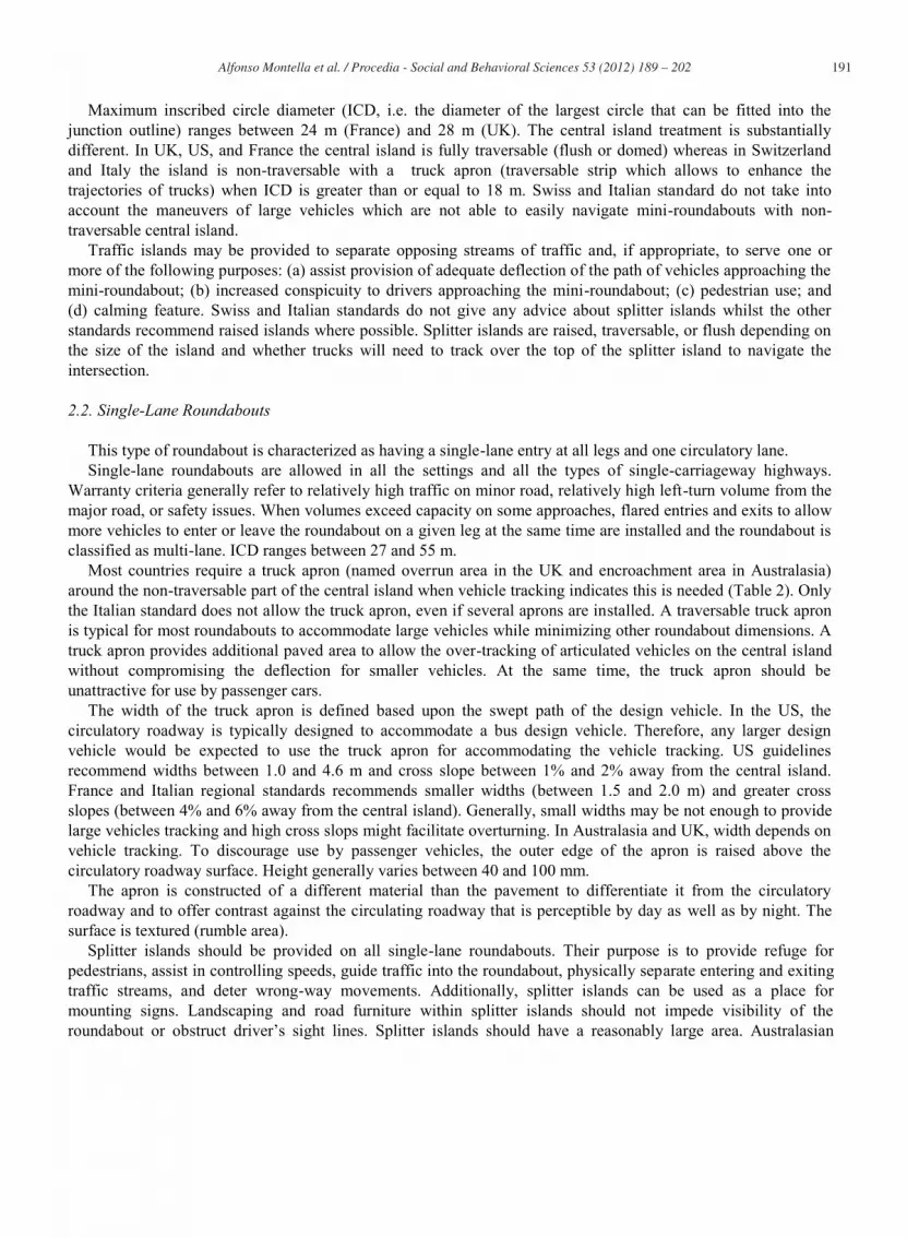
Maximum inscribed circle diameter (ICD, i.e. the diameter of the largest circle that can be fitted into the junction outline) ranges between 24 m (France) and 28 m (UK). The central island treatment is substantially different. In UK, US, and France the central island is fully traversable (flush or domed) whereas in Switzerland and Italy the island is non-traversable with a truck apron (traversable strip which allows to enhance the trajectories of trucks) when ICD is greater than or equal to 18 m. Swiss and Italian standard do not take into account the maneuvers of large vehicles which are not able to easily navigate mini-roundabouts with non-traversable central island.
Traffic islands may be provided to separate opposing streams of traffic and, if appropriate, to serve one or more of the following purposes: (a) assist provision of adequate deflection of the path of vehicles approaching the mini-roundabout; (b) increased conspicuity to drivers approaching the mini-roundabout; (c) pedestrian use; and (d) calming feature. Swiss and Italian standards do not give any advice about splitter islands whilst the other standards recommend raised islands where possible. Splitter islands are raised, traversable, or flush depending on the size of the island and whether trucks will need to track over the top of the splitter island to navigate the intersection.
2.2. Single-Lane Roundabouts
This type of roundabout is characterized as having a single-lane entry at all legs and one circulatory lane. Single-lane roundabouts are allowed in all the settings and all the types of single-carriageway highways.
Warranty criteria generally refer to relatively high traffic on minor road, relatively high left-turn volume from the major road, or safety issues. When volumes exceed capacity on some approaches, flared entries and exits to allow more vehicles to enter or leave the roundabout on a given leg at the same time are installed and the roundabout is classified as multi-lane. ICD ranges between 27 and 55 m.
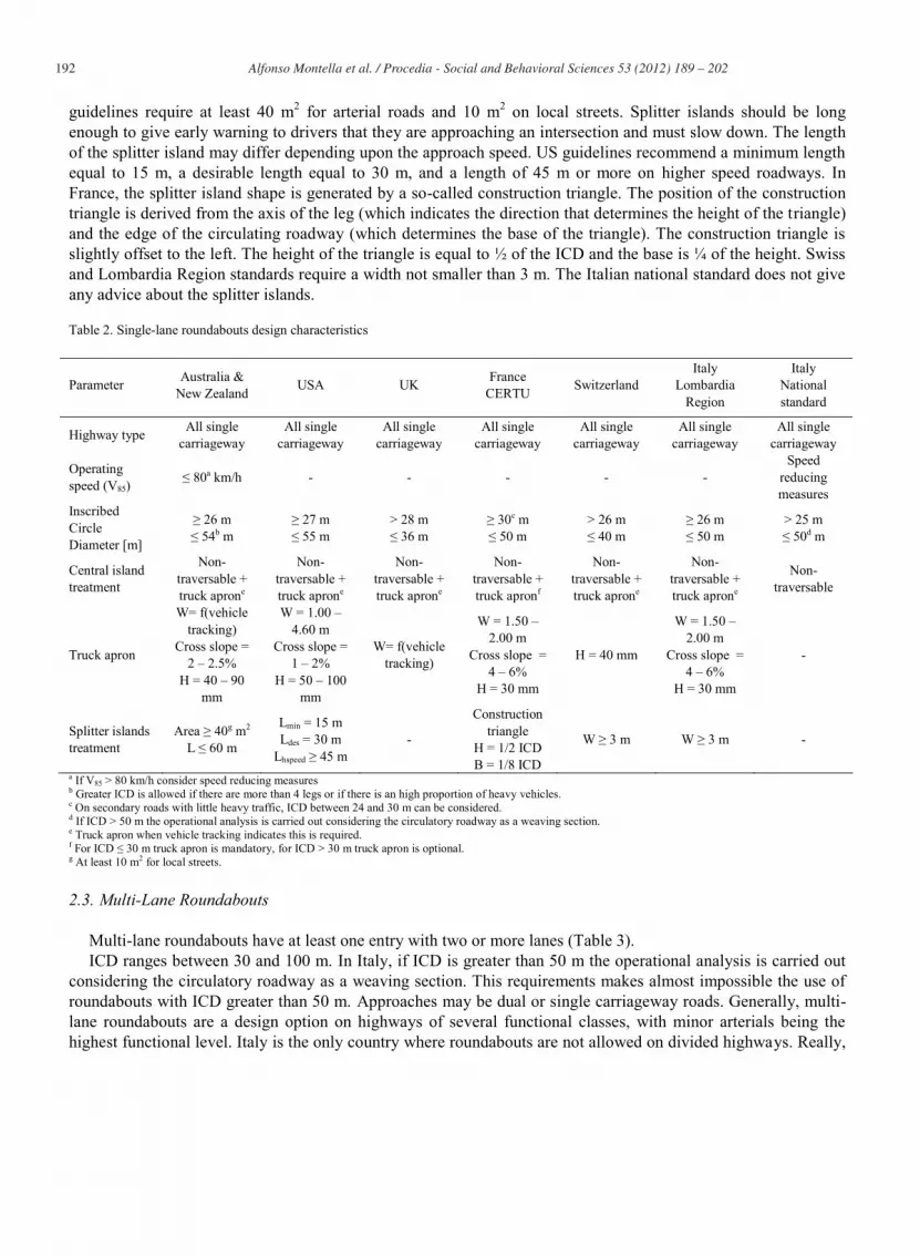
Most countries require a truck apron (named overrun area in the UK and encroachment area in Australasia) around the non-traversable part of the central island when vehicle tracking indicates this is needed (Table 2). Only the Italian standard does not allow the truck apron, even if several aprons are installed. A traversable truck apron is typical for most roundabouts to accommodate large vehicles while minimizing other roundabout dimensions. A truck apron provides additional paved area to allow the over-tracking of articulated vehicles on the central island without compromising the deflection for smaller vehicles. At the same time, the truck apron should be unattractive for use by passenger cars.
The width of the truck apron is defined based upon the swept path of the design vehicle. In the US, the circulatory roadway is typically designed to accommodate a bus design vehicle. Therefore, any larger design vehicle would be expected to use the truck apron for accommodating the vehicle tracking. US guidelines recommend widths between 1.0 and 4.6 m and cross slope between 1% and 2% away from the central island. France and Italian regional standards recommends smaller widths (between 1.5 and 2.0 m) and greater cross slopes (between 4% and 6% away from the central island). Generally, small widths may be not enough to provide large vehicles tracking and high cross slops might facilitate overturning. In Australasia and UK, width depends on vehicle tracking. To discourage use by passenger vehicles, the outer edge of the apron is raised above the circulatory roadway surface. Height generally varies between 40 and 100 mm.
The apron is constructed of a different material than the pavement to differentiate it from the circulatory roadway and to offer contrast against the circulating roadway that is perceptible by day as well as by night. The surface is textured (rumble area).
Splitter islands should be provided on all single-lane roundabouts. Their purpose is to provide refuge for pedestrians, assist in controlling speeds, guide traffic into the roundabout, physically separate entering and exiting traffic streams, and deter wrong-way movements. Additionally, splitter islands can be used as a place for mounting signs. Landscaping and road furniture within splitter islands should not impede visibility of the roundabout or obstruct driver’s sight lines. Splitter islands should have a reasonably large area. Australasian
192 Alfonso Montella et al. / Procedia - Social and Behavioral Sciences 53 ( 2012 ) 189 – 202
guidelines require at least 40 m2 for arterial roads and 10 m2 on local streets. Splitter islands should be long enough to give early warning to drivers that they are approaching an intersection and must slow down. The length of the splitter island may differ depending upon the approach speed. US guidelines recommend a minimum length equal to 15 m, a desirable length equal to 30 m, and a length of 45 m or more on higher speed roadways. In France, the splitter island shape is generated by a so-called construction triangle. The position of the construction triangle is derived from the axis of the leg (which indicates the direction that determines the height of the triangle) and the edge of the circulating roadway (which determines the base of the triangle). The construction triangle is slightly offset to the left. The height of the triangle is equal to ½ of the ICD and the base is ¼ of the height. Swiss and Lombardia Region standards require a width not smaller than 3 m. The Italian national standard does not give any advice about the splitter islands.
Table 2. Single-lane roundabouts design characteristics
Parameter Australia & New Zealand USA UK France
CERTU Switzerland Italy
Lombardia Region
Italy National standard
Highway type All single carriageway
All single carriageway
All single carriageway
All single carriageway
All single carriageway
All single carriageway
All single carriageway
Operating speed (V85)
≤ 80a km/h - - - - - Speed
reducing measures
Inscribed Circle Diameter [m]
≥ 26 m ≤ 54b m
≥ 27 m ≤ 55 m
> 28 m ≤ 36 m
≥ 30c m ≤ 50 m
> 26 m ≤ 40 m
≥ 26 m ≤ 50 m
> 25 m ≤ 50d m
Central island treatment
Non-traversable + truck aprone
Non-traversable + truck aprone
Non-traversable + truck aprone
Non-traversable + truck apronf
Non-traversable + truck aprone
Non-traversable + truck aprone
Non-traversable
Truck apron
W= f(vehicle tracking)
Cross slope = 2 – 2.5%
H = 40 – 90 mm
W = 1.00 – 4.60 m
Cross slope = 1 – 2%
H = 50 – 100 mm
W= f(vehicle tracking)
W = 1.50 – 2.00 m
Cross slope = 4 – 6%
H = 30 mm
H = 40 mm
W = 1.50 – 2.00 m
Cross slope = 4 – 6%
H = 30 mm
-
Splitter islands treatment
Area ≥ 40g m2 L ≤ 60 m
Lmin = 15 m Ldes = 30 m
Lhspeed ≥ 45 m -
Construction triangle
H = 1/2 ICD B = 1/8 ICD
W ≥ 3 m W ≥ 3 m -
a If V85 > 80 km/h consider speed reducing measures b Greater ICD is allowed if there are more than 4 legs or if there is an high proportion of heavy vehicles. c On secondary roads with little heavy traffic, ICD between 24 and 30 m can be considered. d If ICD > 50 m the operational analysis is carried out considering the circulatory roadway as a weaving section. e Truck apron when vehicle tracking indicates this is required. f For ICD ≤ 30 m truck apron is mandatory, for ICD > 30 m truck apron is optional. g At least 10 m2 for local streets.
2.3. Multi-Lane Roundabouts
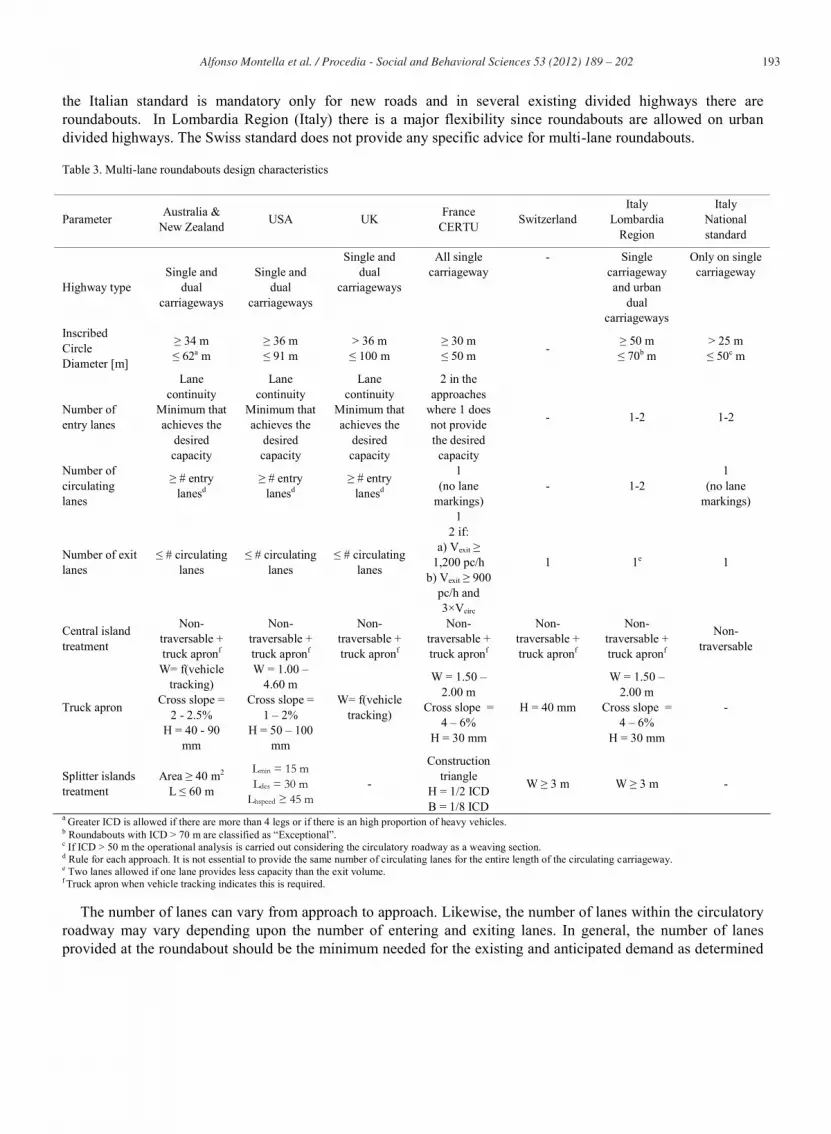
Multi-lane roundabouts have at least one entry with two or more lanes (Table 3). ICD ranges between 30 and 100 m. In Italy, if ICD is greater than 50 m the operational analysis is carried out
considering the circulatory roadway as a weaving section. This requirements makes almost impossible the use of roundabouts with ICD greater than 50 m. Approaches may be dual or single carriageway roads. Generally, multi-lane roundabouts are a design option on highways of several functional classes, with minor arterials being the highest functional level. Italy is the only country where roundabouts are not allowed on divided highways. Really,
193 Alfonso Montella et al. / Procedia - Social and Behavioral Sciences 53 ( 2012 ) 189 – 202
the Italian standard is mandatory only for new roads and in several existing divided highways there are roundabouts. In Lombardia Region (Italy) there is a major flexibility since roundabouts are allowed on urban divided highways. The Swiss standard does not provide any specific advice for multi-lane roundabouts.
Table 3. Multi-lane roundabouts design characteristics
Parameter Australia & New Zealand USA UK France
CERTU Switzerland Italy
Lombardia Region
Italy National standard
Highway type Single and
dual carriageways
Single and dual
carriageways
Single and dual
carriageways
All single carriageway
- Single carriageway and urban
dual carriageways
Only on single carriageway
Inscribed Circle Diameter [m]
≥ 34 m ≤ 62a m
≥ 36 m ≤ 91 m
> 36 m ≤ 100 m
≥ 30 m ≤ 50 m - ≥ 50 m
≤ 70b m > 25 m ≤ 50c m
Number of entry lanes
Lane continuity
Minimum that achieves the
desired capacity
Lane continuity
Minimum that achieves the
desired capacity
Lane continuity
Minimum that achieves the
desired capacity
2 in the approaches
where 1 does not provide the desired
capacity
- 1-2 1-2
Number of circulating lanes
≥ # entry lanesd
≥ # entry lanesd
≥ # entry lanesd
1 (no lane
markings) - 1-2
1 (no lane
markings)
Number of exit lanes
≤ # circulating lanes
≤ # circulating lanes
≤ # circulating lanes
1 2 if:
a) Vexit ≥ 1,200 pc/h
b) Vexit ≥ 900 pc/h and 3×Vcirc
1 1e 1
Central island treatment
Non-traversable + truck apronf
Non-traversable + truck apronf
Non-traversable + truck apronf
Non-traversable + truck apronf
Non-traversable + truck apronf
Non-traversable + truck apronf
Non-traversable
Truck apron
W= f(vehicle tracking)
Cross slope = 2 - 2.5%
H = 40 - 90 mm
W = 1.00 – 4.60 m
Cross slope = 1 – 2%
H = 50 – 100 mm
W= f(vehicle tracking)
W = 1.50 – 2.00 m
Cross slope = 4 – 6%
H = 30 mm
H = 40 mm
W = 1.50 – 2.00 m
Cross slope = 4 – 6%
H = 30 mm
-
Splitter islands treatment
Area ≥ 40 m2 L ≤ 60 m
Lmin = 15 m Ldes = 30 m
Lhspeed ≥ 45 m -
Construction triangle
H = 1/2 ICD B = 1/8 ICD
W ≥ 3 m W ≥ 3 m -
a Greater ICD is allowed if there are more than 4 legs or if there is an high proportion of heavy vehicles. b Roundabouts with ICD > 70 m are classified as “Exceptional”. c If ICD > 50 m the operational analysis is carried out considering the circulatory roadway as a weaving section. d Rule for each approach. It is not essential to provide the same number of circulating lanes for the entire length of the circulating carriageway. e Two lanes allowed if one lane provides less capacity than the exit volume. f Truck apron when vehicle tracking indicates this is required.
The number of lanes can vary from approach to approach. Likewise, the number of lanes within the circulatory roadway may vary depending upon the number of entering and exiting lanes. In general, the number of lanes provided at the roundabout should be the minimum needed for the existing and anticipated demand as determined
194 Alfonso Montella et al. / Procedia - Social and Behavioral Sciences 53 ( 2012 ) 189 – 202
by the operational analysis. Irrespective of capacity considerations it is generally important on arterial roads that lane continuity is available through roundabouts; that is, a roundabout serving a two-lane approach on a duplicated arterial road should have two entry lanes even if the calculations show that one-lane would have adequate capacity.
The number of circulating lanes from any particular approach must be equal to or greater than the number of entry lanes on that approach. It is not essential to provide the same number of circulating lanes for the entire length of the circulating carriageway as long as the appropriate multi-lane exits are provided prior to reducing the number of circulating lanes. In France and in Italy, the circulating roadway is a single wide lane operating without lane markings.
In Australasia, UK, and US the number of exit lanes must not be greater than the number of circulating lanes. The number of exit lanes is based on the lane usage as determined by the pavement arrows on the approaches. Where no pavement arrows are shown, the number of exit lanes should equal the number of circulating lanes prior to the exit. In France, Switzerland, and Italy different rules apply. In France, exits are designed with one lane, expect in the following cases: (a) Vexit ≥ 1,200 pc/h; (b) Vexit ≥ 900 pc/h and Vexit ≥ 3×Vcirc. In Italy and Swiss two lane exits are never allowed. It is worthwhile to observe that several exists of Italian existing roundabouts are designed with two lanes.
Finally, we observe that only in Italy the truck apron is not allowed on multi-lane roundabouts.
3. Geometric design
3.1. Speed control
Achieving appropriate vehicular speeds through the roundabout is the most critical design objective. A well designed roundabout reduces the relative speeds between conflicting traffic flows by requiring vehicles to negotiate the roundabout along a curved path (deflection). Indeed, several studies showed that a geometric design allowing high speeds entering and negotiating a roundabout is associated with angle crashes due to failure to give way to vehicles already on the roundabout and rear-end crashes when vehicles brake suddenly [11, 19, 20]. Main parameters used by standards to control speeds trough the roundabout are the radius of deflection, the entry path radius, and the deviation angle.
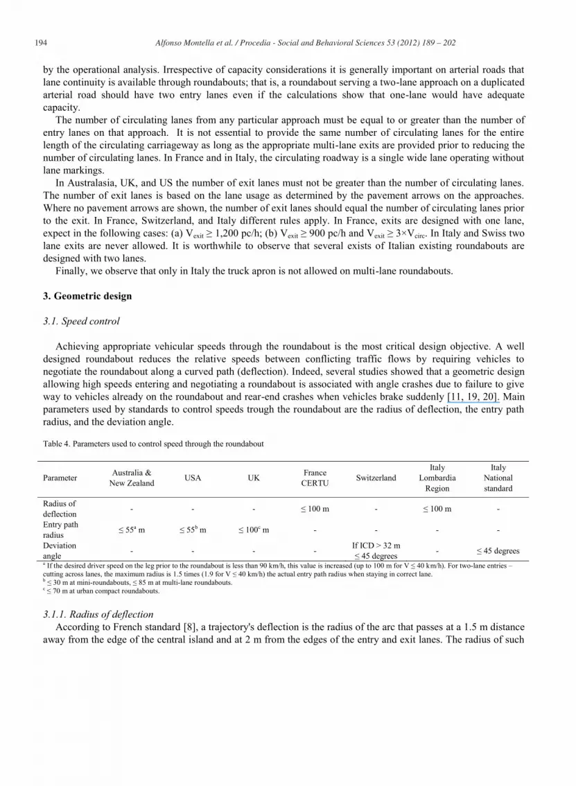
Table 4. Parameters used to control speed through the roundabout
Parameter Australia & New Zealand USA UK France
CERTU Switzerland Italy
Lombardia Region
Italy National standard
Radius of deflection - - - ≤ 100 m - ≤ 100 m -
Entry path radius ≤ 55a m ≤ 55b m ≤ 100c m - - - -
Deviation angle - - - - If ICD > 32 m
≤ 45 degrees - ≤ 45 degrees a If the desired driver speed on the leg prior to the roundabout is less than 90 km/h, this value is increased (up to 100 m for V ≤ 40 km/h). For two-lane entries – cutting across lanes, the maximum radius is 1.5 times (1.9 for V ≤ 40 km/h) the actual entry path radius when staying in correct lane. b ≤ 30 m at mini-roundabouts, ≤ 85 m at multi-lane roundabouts. c ≤ 70 m at urban compact roundabouts.
3.1.1. Radius of deflection According to French standard [8], a trajectory's deflection is the radius of the arc that passes at a 1.5 m distance
away from the edge of the central island and at 2 m from the edges of the entry and exit lanes. The radius of such

195 Alfonso Montella et al. / Procedia - Social and Behavioral Sciences 53 ( 2012 ) 189 – 202
an arc should be less than 100 m. Recommended value is 30 m. Generally, the fastest path is the trajectory traced by two opposing arms; in particular circumstances, the fastest path is the right turn maneuver.
3.1.2. Entry path radius Recently, there has been a move away from a focus on the deflection to controlling vehicle speeds through
geometry of the roundabout entry. This has meant a focus on the entry radius and the maximum central circulating radius. The entry path radius is a measure of the deflection imposed on vehicles entering a roundabout. It is an important determinant of safety at roundabouts because it governs the speed of vehicles through the junction and whether drivers are likely to give way to circulating vehicles. To determine the entry path radius, the fastest path allowed by the geometry is drawn. This is the smoothest, flattest path that a vehicle can take through the entry, round the central island and through the exit (in the absence of other traffic).
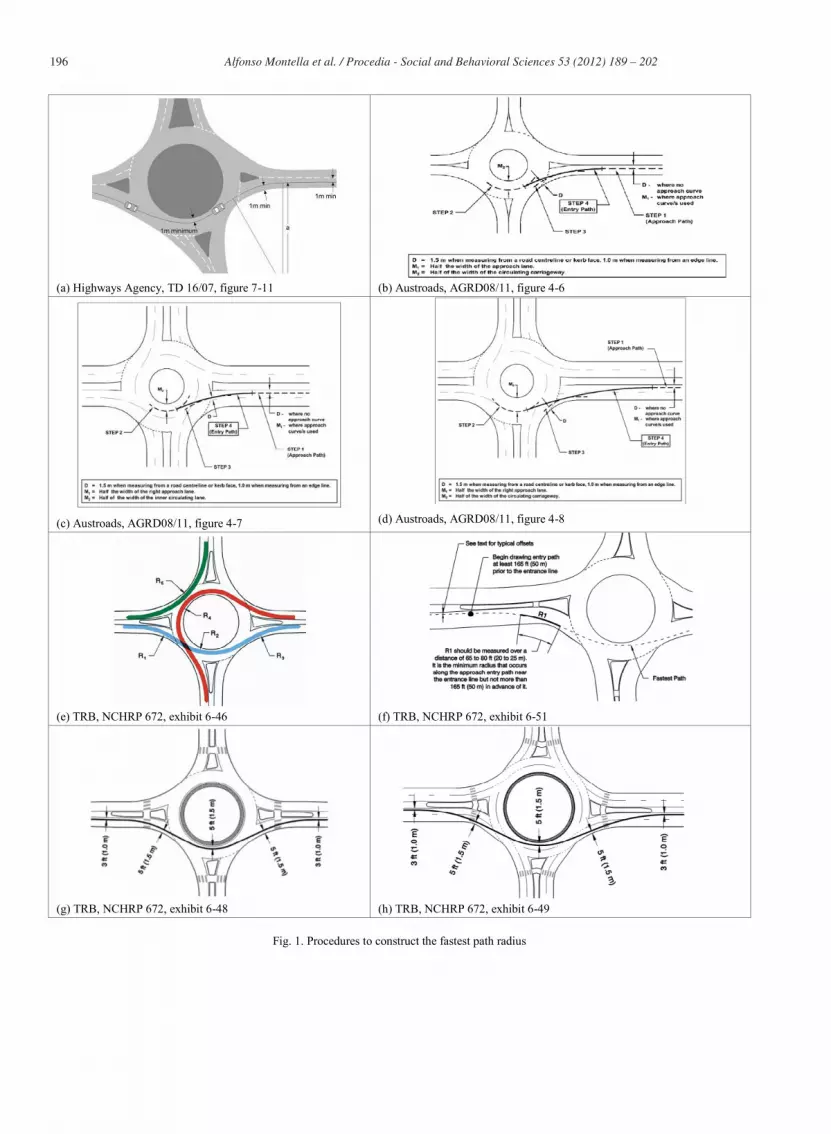
In the UK, the entry path is assumed to be 2 m wide so that the vehicle following it would maintain a distance of at least one meter between its centerline and any kerb or edge marking. The path starts 50 m in advance of the give way line. The smallest radius of this path on entry that occurs as it bends before joining the circulatory carriageway is called the entry path radius (Figure 1a). Entry path radius should be measured over the smallest best fit circular curve over a distance of 25 m occurring along the approach entry path in the vicinity of the give way line, but not more than 50m in advance of it. The entry path radius must be checked for all turning movements. It must not exceed 70 m at compact roundabouts in urban areas and 100 m at all other roundabout types.
In Australasia [13, 14], different procedures to construct the entry path are defined for single-lane entries (Figure 1b), two-lane entries – staying in correct lane (Figure 1c), and two-lane entries – cutting across lanes (Figure 21). For single-lane entries, steps are as follows: (1) draw a line parallel to the right edge of the approach lane at an offset ‘D’ (1 m from an edge line, 1.5 m from a kerb or a centerline) prior to the entry curve. This line is the approach path; (2) draw a curved line parallel to the edge of the central island at an offset ‘M2’ (half of the width of the circulating roadway). For an elliptical/oval/oblong roundabout, the line may comprise multiple radii; (3) draw a curved line parallel to the left edge of the entry lane at an offset ‘D’; (4) draw the entry path. This is a circular curve drawn tangentially to the lines constructed in Steps 1, 2 and 3. For two-lane entries – staying in correct lane, the procedure is similar to the previous one and refers to the right approach lane. For two-lane entries – cutting across lanes, it is assumed that the vehicles travels in the right lane (1 m from the edge line), enters in carriageway tangent to the line 1 m from the left edge line of the left lane and runs the carriageway in the middle of the two-lanes. For single-lane entries and two-lane entries – staying in correct lane, the maximum value of the entry path radius is 55 m. If the desired driver speed on the leg prior to the roundabout is less than 90 km/h, this value is increased (up to 100 m for V ≤ 40 km/h). For two-lane entries – cutting across lanes, the maximum radius is 1.5 times (1.9 for V ≤ 40 km/h) the actual entry path radius when staying in correct lane.
US guidelines state that the fastest paths must be drawn for all approaches and all movements, including left-turn movements (which generally represent the slowest of the fastest paths) and right-turn movements (which may be faster than the through movements at some roundabouts). Five critical path radii must be checked for each approach (Figure 1e). R1, the entry path radius, is the minimum radius on the fastest through path prior to the entrance line. R2, the circulating path radius, is the minimum radius on the fastest through path around the central island. R3, the exit path radius, is the minimum radius on the fastest through path into the exit. R4, the left-turn path radius, is the minimum radius on the path of the conflicting left-turn movement. R5, the right-turn path radius, is the minimum radius on the fastest path of a right-turning vehicle. The R1 through R5 radii represent the vehicle centerline in its path through the roundabout. A vehicle is assumed to be 2 m wide and maintain a minimum clearance of 0.5 m from a roadway centerline or concrete curb and flush with a painted edge line.
196 Alfonso Montella et al. / Procedia - Social and Behavioral Sciences 53 ( 2012 ) 189 – 202
(a) Highways Agency, TD 16/07, figure 7-11 (b) Austroads, AGRD08/11, figure 4-6
(c) Austroads, AGRD08/11, figure 4-7 (d) Austroads, AGRD08/11, figure 4-8
(e) TRB, NCHRP 672, exhibit 6-46 (f) TRB, NCHRP 672, exhibit 6-51
(g) TRB, NCHRP 672, exhibit 6-48 (h) TRB, NCHRP 672, exhibit 6-49
Fig. 1. Procedures to construct the fastest path radius
197 Alfonso Montella et al. / Procedia - Social and Behavioral Sciences 53 ( 2012 ) 189 – 202
The centerline of the vehicle path is drawn with the following distances to the particular geometric features (Figures 1f, 1g, and 1h): 1.5 m from a concrete curb, 1.5 m from a roadway centerline, and 1.0 m from a painted edge line. When drawing the path, a short length of tangent should be drawn between consecutive curves to account for the time it takes for a driver to turn the steering wheel.
US guidelines do not directly provide a maximum value of the entry path radius, but recommend maximum entry design speed for mini-roundabouts (30 km/h), single-lane roundabouts (40 km/h), and multi-lane roundabouts (40-50 km/h) and provide radius-speed relationship. Thus, maximum recommended entry path radii are 30 m for mini-roundabouts, 55 m for single-lane roundabouts, and 85 m for multi-lane roundabouts. Furthermore, relative speeds between conflicting traffic streams and between consecutive geometric elements should be minimized such that the maximum speed differential between movements should be no more than approximately 15 to 25 km/h.
3.1.3. Deviation Angle For roundabouts with ICD greater than 32 m, the Swiss standard requires a deviation angle imposed by the
central islands between two opposite legs greater than 45 degrees. The rationale is that if the vehicle flow is not deflected sufficiently from the straight direction of travel by the central island, this will lead to failures to give way, increased pass through speeds and underestimations of these speeds by conflicting parties. Experimental studies showed a correlation between smaller deviation angles and higher crash rates [4]. Italian standard requires a deviation angle greater than 45 degrees for all the roundabouts. However, this value of the deviation angle is not attainable for small roundabouts. This inconsistency is a great concern since the Italian standard is mandatory for all the new roundabouts.
3.2. Entry width
Entry width is measured from the point where the entrance line intersects the left edge of traveled way to the right edge of the traveled way, along a line perpendicular to the right curb line. Entry width is a key factor affecting capacity, in conjunction with length and sharpness of flare. The entry width should be able to accommodate the swept path of the entering design vehicle. However, it is important that the entry is not any wider than necessary as excessive entry widths can make it difficult for designers to achieve adequate speed reduction at the entries to roundabouts, with detrimental safety consequences.
For single-lane entrances, typical entry widths range from 4.0 to 5.5 m; these are often flared from upstream approach widths. Care should be taken with entry widths greater than 5.5 m, as drivers may mistakenly interpret the wide entry to be two lanes when there is only one receiving circulatory lane. In Switzerland and Italy, smaller entry widths are required (3.0 - 3.5 m). Entry width required in Italy is smaller than the lane width of the rural collectors (3.75 m), thus requiring a lane narrowing in the roundabout approach. Smaller entry widths, in the range from 2.5 to 4.0 m, are required in mini-roundabouts.
In multi-lane roundabouts, the required entry width for any given design is dependent upon the number of lanes and design vehicle. Approach flaring may provide an effective means of increasing capacity without requiring as much right-of-way as a full lane addition. UK research suggests that length of flare affects capacity without a direct effect on safety. Widths for individual lanes at entry range from 3.0 to 4.6 m.
3.3. Entry radius
The entry curb radius is an important factor in determining the operation of a roundabout because it affects both capacity and safety. Excessively large entry curb radii have a higher potential to produce faster entry speeds than desired. Care should also be taken to avoid entry radii that are too abrupt since these may lead to single-vehicle crashes. The outside line of the entry is commonly designed curvilinearly tangential to the outside edge of the

198 Alfonso Montella et al. / Procedia - Social and Behavioral Sciences 53 ( 2012 ) 189 – 202
circulatory roadway. Likewise, the projection of the inside edge of the entry roadway is commonly curvilinearly tangential to the central island. Some road authorities prefer that this projection passes through a point in the circulating roadway about 1.5 m from the central island in order to ensure that the vehicle tracks on the pavement rather than mounting the island.
At multi-lane roundabouts, the design of the entry curvature should balance the competing objectives of speed control and adequate alignment of the natural path. The use of small entry radii may produce low entry speeds but often leads to path overlap on the entry since tends to lead vehicles of the outside lane into the inside circulatory lane. Greater entry radii reduce the potential for path overlap. US guidelines recommend to use a compound curve or tangent along the outside curb. The design consists of an initial small-radius (20-35 m) entry curve set at least 6 m back from the edge of the circulatory road-way. A short section of a large-radius curve (> 45 m) or tangent is then provided between the entry curve and the circulatory roadway to align vehicles into the proper circulatory lane at the entrance line.
France and Switzerland require the smaller entry radii (10-15 m) whereas countries which control vehicles speeds by the limitation of the entry path radius are more flexible and give chance of greater radii. Italian standard does not give any advice.
3.4. Entry angle
The entry angle is the conflict angle between the entering and the circulating traffic. In general, too low entry angles produce poor angles of visibility to the left, requiring drivers to strain to look over their shoulders, and may encourage merging behavior similar to freeway on-ramps. Meanwhile too high entry angles may not provide enough positive alignment to discourage wrong-way movements, reduce capacity and may produce excessive entry deflection which can lead to sharp braking at entries accompanied by rear-end crashes. Swiss standard requires entry angles between 70 and 90 degrees, thus producing perpendicular entries, whilst the UK standard requires angles between 20 and 60 degrees (in these countries the definition of entry angle is slightly different).
3.5. Circulatory roadway width
The required width of the circulatory roadway is determined from the number of entering lanes and the turning requirements of the design vehicle. In general, the circulating width should be at least as wide as the maximum entry width and up to 120% of the maximum entry width.
For single-lane roundabouts, the circulatory roadway width usually remains constant throughout the roundabout. Typical circulatory roadway widths range from 4.8 to 7 m. Care should be taken to avoid making the circulatory roadway width too wide within a single-lane roundabout because drivers may think that two vehicles are allowed to circulate side-by-side. The circulatory roadway width should be comfortable for passenger car vehicles and should be wide enough to accommodate a design vehicle up to a bus. A truck apron will often need to be provided within the central island to accommodate larger design vehicles. Usually, the left-turn movement is the critical path for determining circulatory roadway width. At mini-roundabouts, larger circulatory widths are needed (typically from 7 to 8 m).
At multi-lane roundabouts, the circulatory roadway width may be variable depending upon the number of lanes and the design vehicle turning requirements. A constant width is not required throughout the entire circulatory roadway, and it is desirable to provide only the minimum width necessary to serve the required lane configurations within that specific portion of the roundabout. A common combination is two entering and exiting lanes along the major roadway, but only single entering and exiting lanes on the minor street. Multilane circulatory roadway lane widths typically range from 3.5 to 4.9 m. In France and in Italy, the circulating roadway is a single wider lane operating without lane markings.

199 Alfonso Montella et al. / Procedia - Social and Behavioral Sciences 53 ( 2012 ) 189 – 202
3.6. Exit width
The exit width is the width of the carriageway on the exit and is measured in a similar manner to the entry width. Exit lane widths need to be checked for vehicle swept paths to ensure that the design vehicle is properly accommodated. For single-lane exits, typical widths range from 4.0 to 7.5 m. Smaller exit widths, in the range from 2.5 to 4.5 m, are required in mini-roundabouts. For double-lane exits, typical widths range from 7.0 to 11.0 m.
3.7. Exit radius
In general, standards and guidelines require to use relatively large radius so that it is comfortable for drivers to exit roundabouts. In urban areas, this is balanced by the need to maintain slow speeds through the pedestrian crossing on exit. The exit edge is commonly designed to be curvilinearly tangential to the outside edge of the circulatory roadway. Likewise, the projection of the inside edge of the exit roadway is commonly curvilinearly tangential to the central island.
4. Sight distance
Sight distance significantly affects roundabout safety. Too small visibility is a common crash contributory factor [10, 11] but a too large field of view approaching the roundabout might encourage higher approach speeds and might distract the drivers’ focus from the roundabout entry. Recent research [19] indicates that there is a safety benefit of reducing the approach sight distance, as this helps manage approach speeds into the roundabout. As a consequence, the need for a proper control of the sight distance is an merging issue in roundabout design.
In Australasia, three sight distance criteria must be applied to the combination of vertical and horizontal geometry at roundabouts. Criterion 1 refers to approach sight distance. Criterion 2 relates to a car driver entering a roundabout having adequate sight distance to two potentially conflicting movements within the roundabout, namely a vehicle (1) entering from the approach immediately to the right (equivalent to left in countries with right-driving) and (b) travelling on the circulating roadway. Criterion 3 refers to a driver approaching a roundabout that is able to see other entering vehicles in time to stop before the yield line and avoid a vehicle driving through the roundabout. Criteria 1 and 2 are both mandatory requirements whereas criterion 3 is not mandatory. Recently, less emphasis is being placed on providing the extra sight distance of criterion 3.
In the UK, five sight distances must be provided: (1) stopping sight distance on the approach, (2) forward visibility at entry, (3) visibility to the right, (4) circulatory visibility, and (5) pedestrian visibility. On the approach, desirable minimum stopping sight distance for the design speed of the road must be provided. Drivers of vehicles approaching the give way line must be able to see forward and to the right, from the center of the nearside lane at a distance of 15 m back from the give way line, the full width of the circulatory carriageway for a visibility distance depending on the ICD. Visibility to the right must be provided also from the give way line. Furthermore, the visibility distance must be provided also on the circulatory roadway. Drivers approaching a roundabout with a zebra crossing across the entry must be able to see the full width of the crossing so that they can see whether there are pedestrians wishing to cross. At the give way line, drivers must be able to see the full width of a pedestrian crossing across the next exit if it is within 20 m of the give way line on that arm. It is important to observe that the British standard specifies that excessive visibility to the right can result in high entry speeds, potentially leading to accidents. Limiting visibility to the right by screening until the vehicle is within 15 m of the give way line can be helpful in reducing excessive approach speeds. The screening should be at least 2 m high to block the view of all road users.
In the US, stopping sight distance and intersection sight distance are required. Stopping sight distance should be checked at three critical types of locations: (1) approach, (2) circulatory roadway, and (3) crosswalk on exit.
200 Alfonso Montella et al. / Procedia - Social and Behavioral Sciences 53 ( 2012 ) 189 – 202
Intersection sight distance is the distance required for a driver without the right-of-way to perceive and react to the presence of conflicting vehicles. At roundabouts, the only locations requiring evaluation of intersection sight distance are the entries. The length of the approach leg of the sight triangle is limited to 15 m. If the approach leg of the sight triangle is greater than 15 m, it may be advisable to add landscaping to restrict sight distance to the minimum requirements. Two conflicting traffic streams should be checked at each entry: (1) entering stream, and (2) circulating stream.
In France, a complete view over the left quadrant of the circulating roadway at a distance of 15m from the entrance is required. Furthermore, the central island must not include any visual obstacles within less than 2 m of its peripheral curb (if there is no curb, 2.50 m from the edge marking surrounding the central island). In Italy, the same criterion applies.
In Switzerland, two sight distances must be provided: (1) stopping sight distance on the approach and (2) visibility to the left of the vehicles in the circulating roadway.
Overall, all the standards give emphasis on the sight distance requirements and there is consistency about stopping sight distance. As far as the visibility of conflicting vehicles from vehicles approaching the give way line, UK, US, and France ask for visibility 15 m before the line whereas Australasia considers this visibility as an extra sight distance and only visibility from the give way line is mandatory. There is also consistency in advising to add landscaping to restrict sight distance to the minimum requirements.
5. Recommendations for update the Italian Standard
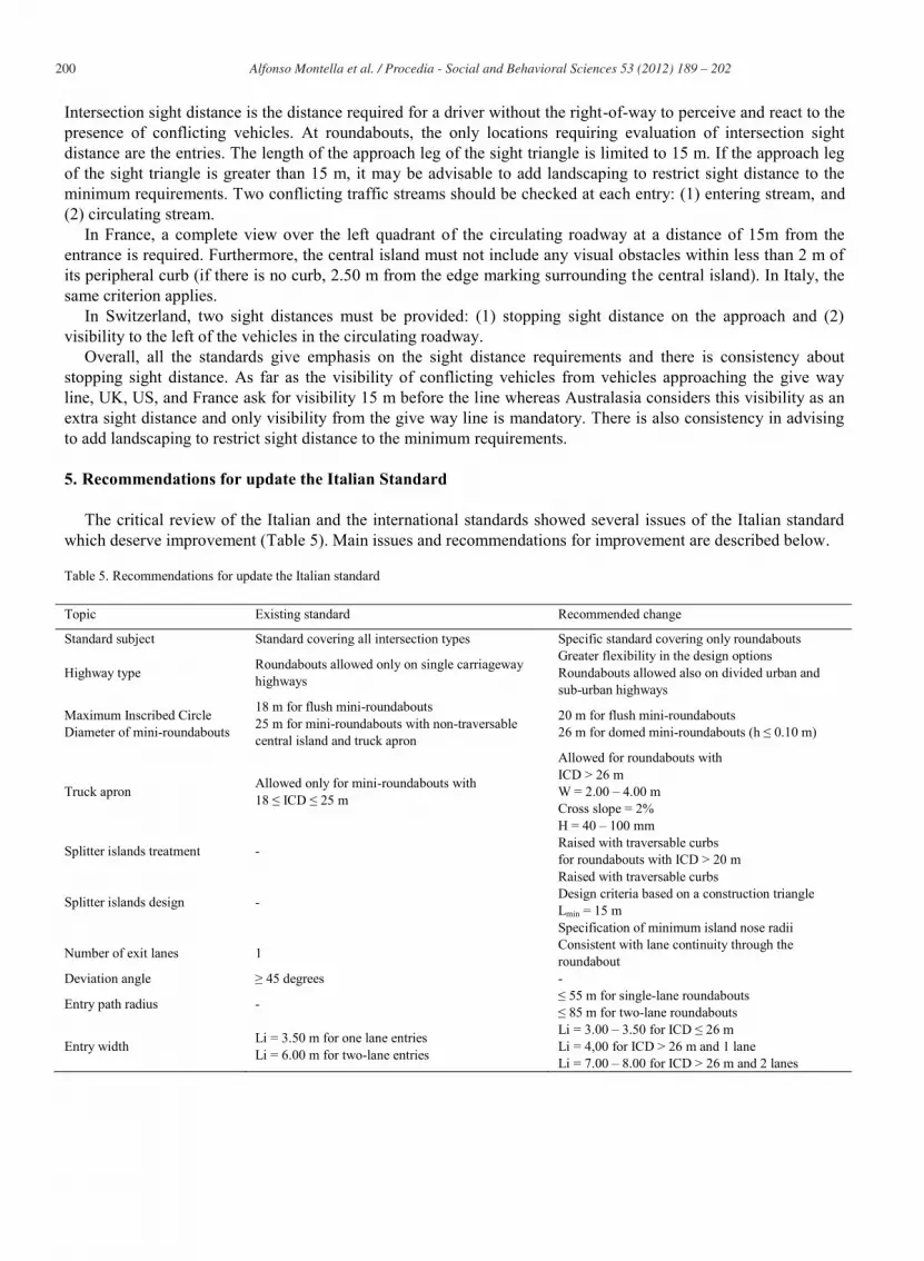
The critical review of the Italian and the international standards showed several issues of the Italian standard which deserve improvement (Table 5). Main issues and recommendations for improvement are described below.
Table 5. Recommendations for update the Italian standard
Topic Existing standard Recommended change
Standard subject Standard covering all intersection types Specific standard covering only roundabouts
Highway type Roundabouts allowed only on single carriageway highways
Greater flexibility in the design options Roundabouts allowed also on divided urban and sub-urban highways
Maximum Inscribed Circle Diameter of mini-roundabouts
18 m for flush mini-roundabouts 25 m for mini-roundabouts with non-traversable central island and truck apron
20 m for flush mini-roundabouts 26 m for domed mini-roundabouts (h ≤ 0.10 m)
Truck apron Allowed only for mini-roundabouts with 18 ≤ ICD ≤ 25 m
Allowed for roundabouts with ICD > 26 m W = 2.00 – 4.00 m Cross slope = 2% H = 40 – 100 mm
Splitter islands treatment - Raised with traversable curbs for roundabouts with ICD > 20 m
Splitter islands design -
Raised with traversable curbs Design criteria based on a construction triangle Lmin = 15 m Specification of minimum island nose radii
Number of exit lanes 1 Consistent with lane continuity through the roundabout
Deviation angle ≥ 45 degrees -
Entry path radius - ≤ 55 m for single-lane roundabouts ≤ 85 m for two-lane roundabouts
Entry width Li = 3.50 m for one lane entries Li = 6.00 m for two-lane entries
Li = 3.00 – 3.50 for ICD ≤ 26 m Li = 4,00 for ICD > 26 m and 1 lane Li = 7.00 – 8.00 for ICD > 26 m and 2 lanes
201 Alfonso Montella et al. / Procedia - Social and Behavioral Sciences 53 ( 2012 ) 189 – 202
All the countries have a specific standard covering roundabouts whereas in Italy there is one standard covering all intersection types which contains only three pages concerning roundabout design. We strongly recommend a specific standard on roundabouts.
Whilst in other countries multi-lane roundabouts are a design option on highways of several functional classes, with minor arterials being the highest functional level, Italy is the only country where roundabouts are not allowed on divided highways. Greater flexibility in the design options should be provided and we recommend to allow roundabouts also on divided urban and sub-urban highways.
Italian mini-roundabouts with ICD ranging from 18 to 25 m need a non-traversable central island. This is an issue for tracking of larger vehicles and is inconsistent with recommendations of the other main standards. To ensure accommodation of larger vehicles, we recommend to introduce non-traversable central island in mini-roundabouts. For the smaller diameters (e.g., ICD ≤ 20 m) the central island might be flush, whereas for the larger diameters the island might be domed. Maximum ICD of mini-roundabouts might be increased from 25 to at least 26 m. In mini-roundabouts with ICD > 20 m, splitter island should be raised with mountable curbs in order to prevent wrong-way exits, protect pedestrian, and assist provision of adequate deflection.
Splitter island design is not treated in the standard even if it is of paramount importance. We recommend to introduce rules for the splitter island design, such as: provision of raised islands with mountable curbs, design criteria based on a construction triangle, minimum length equal to 15 m, and specification of minimum island nose radii.
In the existing standard, number of exit lanes equal to 1 is always required irrespective of the number of lanes on the approach and on route after the roundabout, thus reducing capacity. We recommend the provision of a number of exit lanes consistent with lane continuity through the roundabout.
To achieve an appropriate speed control, the requirement of the Italian standard (based on deviation angle) is both not effective as well as not attainable in all the cases. The most effective parameter to control speed and improve safety is the entry path radius. We recommend a maximum value equal to 55 and 85 m respectively for single-lane and multi-lane roundabouts. Both the UK and the US procedure to construct the entry path might be appropriate.
Finally, the Italian standard shows an inconsistency between the lane width before the roundabout and in the roundabout entry. A lane narrowing in the entry is required (from 3.75 to 3.50 m in single-lane entries and from 6.50-7.50 m to 6.00 m in two-lane entries), thus reducing capacity and creating also potential safety issues. Furthermore, the entry widths are smaller than the ones of the other standards, except the Swiss standard which applies in a country with traffic conditions quite different from Italy. We recommend a smaller entry width for mini-roundabouts (3.00 – 3.50 m), an entry width equal to 4.00 m for single lane entries and an entry width from 7.00 to 8.00 for two-lane entries.
6. Conclusions
Geometric design criteria are of fundamental importance to achieve the best performance of roundabouts in terms of both capacity and safety. Since of the growing number of roundabouts several countries have recently updated their standards and guidelines. In spite of these concerns, the critical review of the Australasian, EU and US standards and guidelines presented in the paper showed several inconsistencies of the Italian standard which deserve improvement. As a result of the analysis, several recommendations for improvement of the Italian standard were proposed. These recommendations are mainly based on the concepts of design flexibility and performance based design. Indeed, rigid standards which do not really take into account safety and operational consequences of the design decisions and the need to balance opposite demands might produce undesirable outcomes.
Finally, we would like to highlight the need for further research on the relationships between roundabout geometric design criteria, drivers’ behavior and safety.

202 Alfonso Montella et al. / Procedia - Social and Behavioral Sciences 53 ( 2012 ) 189 – 202
References
[1] Neuman, T. R., Pfefer, R., Slack, K. L., Hardy, K. K., Harwood, D. W., Potts, I. B., Torbic, D. J., & Kohlman Rabbani, E. R. (2003). A Guide for Addressing Unsignalized Intersection Collisions. NCHRP Report 500, Vol. 5, Washington, DC, US. [2] Rodegerdts, L., Blogg, M., Wemple, E., Myers, E., Kyte, M., Dixon, M., List, G., Flannery, A., Troutbeck, R., Brilon, W., Wu, N., Persaud, B., Lyon, C., Harkey, D., & Carter, D. (2007). Roundabouts in the United States. NCHRP Report 572, Washington, DC, US. [3] Guichet, B. (2005). Evolution of Roundabout in France and New Uses. Transportation Research Circular E-C083, Washington, DC, US. [4] Spacek, P. (2004). Basis of the Swiss Design Standard for Roundabout. Transportation Research Record, No. 1881, 27-35. [5] Highways Agency (2007). Geometric Design of Roundabouts. Design Manual of Roads and Bridges, TD 16/07, London, UK. [6] Highways Agency (2007). Design of Mini-Roundabouts. Design Manual of Roads and Bridges, TD 54/07, London, UK. [7] Rodegerdts, L., Bansen, J., Tiesler, C., Knudsen, J., Myers, E., Johnsonm, M., Moule, M., Persaud, B., Lyon, C., Hallmark, S., Isebrands, H., Crown, R. B., Guichet., B., & O’Brien, A. (2010). Roundabouts: An Informational Guide, Second Edition. NCHRP Report 672, Washington, DC, US. [8] SETRA (1998). The Design of Interurban Intersections on Major Roads: At-grade Intersections. Bagneux Cedex, France. [9] Rodegerdts, L., Blogg, M., Wemple, E., Myers, E., Kyte, M., Dixon, M., List, G., Flannery, A., Troutbeck, R., Brilon, W., Wu, N., Persaud, B., Lyon, C., Harkey, D., & Carter, D. (2007b). Appendixes to NCHRP Report 572: Roundabouts in the United States. NCHRP Web-Only Document 94, Washington, DC, US. [10] Montella, A. (2007). Roundabout In-Service Safety Reviews: Safety Assessment Procedure. Transportation Research Record, No. 2019, 40-50. [11] Montella, A. (2011). Identifying crash contributory factors at urban roundabouts and using association rules to explore their relationships to different crash types. Accident Analysis and Prevention, Vol. 43(4), 1451-1463. [12] Transfund NZ (2000). The Ins and Out of Roundabout: a Safety Auditors’ Perspective. Wellington, New Zealand. [13] Austroads (2011). Guide to Road Design, Part 4B Roundabouts. Report AGRD08/11, Sydney, NSW, Australia. [14] QDMR, Queensland Department of Main Roads (2006). Roundabouts. In Road planning and design manual, chapter 14, accessed 27 March 2009, http://www.mainroads.qld.gov.au/web/partnersCR.nsf/DOCINDEX/Road+Planning+and+Design+Manual. [15] CERTU (1999). Carrefours urbains: Guide. Lyon, France. [16] Italian Ministry of Infrastructures and Transports (2006). Decree 19 April 2006: Guidelines for the Design of Road Intersections. Official Journal of Italian Republic, No. 170/2006, Rome, Italy. [17] Lombardia Region (2006). Regional Rule, No. 7, 24 April 2006 Standards for Highways Construction, Annex 2 Intersections Design. Official Journal of Lombardia Region, No. 17/2006, Milan, Italy. [18] VSS (1999). Swiss Standard SN 640 263: Carrefours, carrefours giratoires. Zurich, Swiss. [19] Turner, S., Wood, G., & Roozenberg, A. (2006). Accident Prediction Models for Roundabouts. 22nd ARRB Conference, Canberra, Australia. [20] Arndt, O. K., &Troutbeck, R. (2005). Relationship between unsignalised intersection geometry and accident rates. 3rd TRB International Symposium on Highway Geometric Design, Chicago, IL, US.