gd&t mini - prolotek technologies
TRANSCRIPT

Training | Services | Consultancy
www.prolotek.com
+91 98863 71971
GD&T Mini(In accordance with ASME Y14.5 - 2009 and 2018)
GD&T Mini (In accordance with ASME Y14.5 - 2009 and ASME Y14.5 - 2018)
By
Palaniyappan Kailasam
Prolotek Technologies Private Limited, Bangalore. +91 98863 71071 I [email protected] I www.prolotek.com
Copyright © 2020 Prolotek Technologies Private Limited

GD&T Mini (V1.0)
+91 98863 71971 | [email protected] | www.prolotek.com ii
Introduction GD&T Mini has been created to be a quick reference guide for anyone learning or applying Geometric Dimensioning and Tolerancing (GD&T) in accordance with the ASME Y14.5 – 2009 and ASME Y14.5 – 2018 standards.
The information contained in this book is intended to be reference for interpretation of dimensioning and tolerancing in engineering drawings produced in accordance with the standard.
The drawings included in this book are intentionally incomplete and should not be used as basis for design criteria or part acceptance.
This mini guide covers important topics from ASME Y14.5 – 2009 and ASME Y14.5 – 2018 standards, and it is not a replacement for the standard.
QR codes and links in appropriate sessions are available for videos that provide additional information on the topic for better understanding.
To enhance your GD&T skills, please contact Prolotek Technologies for available training options. We provide the most comprehensive GD&T Training in India.
Disclaimer: Prolotek Technologies and the Author assumes no responsibility for any changes, errors or ommissions in this book. We sprcifically disclaim any liability whatsoever, including any direct, indirect, incidental, consequential, special, or exemplary damages resulting in whole or in part, from the reader’s use or reliance upon the information, instructions, procedures, warnings, cautions, applications, or other matter contained in this book. We assume no responsibility for the activities of the reader.

GD&T Mini (V1.0)
+91 98863 71971 | [email protected] | www.prolotek.com
iii
About Prolotek Technologies Prolotek is transforming the lives of students and professionals to chase their dream careers by bridging the gap between industrial standards and their knowledge through its skill development courses. We at Prolotek have successfully completed “EMPLOYABILITY SKILLS DEVELOPMENT” workshop at Various Colleges. So far, we have trained over 250 Engineers (Working Professionals) on Fundamentals of GD&T, and Advance concepts of GD&T.
Prolotek feels pride in mentoring many fresh graduates in career development and guided them on college to corporate transition.
With Prolotek Technologies you can quantify your Tech skills, grow in your role and stay relevant on critical topics. With technology covering most of the industries today under its huge umbrella, it has become mandatory for students and professionals to be skilled in the trending technology. Although engineering colleges and institutions today are providing quality education, students need to master in Advanced Tools & Domains to work as productive employees in an industry.

GD&T Mini (V1.0)
+91 98863 71971 | [email protected] | www.prolotek.com
iv
About the Author Palaniyappan Kailasam (Palani) is an expert in Geometric Dimensioning and Tolerancing. As design professional, Palani was associated with Bosch Limited over 13 years, gained more than 19 years overall industrial experience putting GD&T to practice. Palani is committed in helping graduates succeed in their career and contributes to their professional development. He has trained more than 2500 engineers on Basics of GD&T. His teaching strategy utilizes a series of goals and objectives that reinforce concepts and produce measurable results.
You can follow the Author in Social Media for latest updates.
www.linkedin.com/in/palaniyappan
www.fb.com/palanikailash
www.youtube.com/c/palanikailash
www.twitter.com/palanikailash
GD&T Mini (V1.0)
+91 98863 71971 | [email protected] | www.prolotek.com v
Contents Sl. No. Description Page No.
1 Dimension Units………………………………………………………………………………….. 01
2 Fundamental Rules……………………………………………………………………………… 03
3 CO-Ordinate Tolerancing System…………………………………………………………….. 06
3.1 Square or Rectangular Tolerance Zone…………………………………………………….. 06
3.2 Fixed Size Tolerance Zone……………………………………………………………………… 07
3.3 Ambiguous Instruction for Inspection……………………………………………………… 08
4 Geometric Dimensioning and Tolerancing………………………………………………... 09
5 Comparison Between Co-Ordinate Tolerance and GD&T………………………………. 10
6 GD&T Benefits…………………………………………………………………………………….. 10
7 GD&T Standards……………………………………………………..……………………………. 11
8 GD&T Characteristic Symbols………………………………………………………………….. 12
9 Tolerance Zones of Geometric Characteristic Symbols………………………………… 13
10 Modifying Symbols……………………………………………………………………………… 14
11 Application of Modifiers……………………………………………………………………….. 15
12 Application of Datums and Datum Modifiers…………………………………………….. 16
13 Symbols Related to Datum……………………………………………………………………. 17
14 Dimensioning Symbols…………………………………………………………………………. 18
15 Useful ASME Standards…………………………………………………………………………. 19
16 General Terms…………………………………………………………………………………….. 21
16.1 Dimension…………………………………………………………………………………………. 21
16.2 Tolerance…………………………………………………………………………………………… 21
16.3 Nominal Size………………………………………………………………………………………. 21
16.4 Limit Tolerance Dimensioning………………………………………………………………... 21
16.5 Directly Toleranced Dimension………………………………………………………………. 21
16.6 Bilateral Tolerance………………………………………………………………………………. 21
16.7 Equal Bilateral Tolerance………………………………………………………………………. 21
16.8 Unequal Bilateral Tolerance…………………………………………………………………... 21
16.9 Unilateral Tolerance…………………………………………………………………………….. 21
16.10 Basic Dimension………………………………………………………………………………….. 21
GD&T Mini (V1.0)
+91 98863 71971 | [email protected] | www.prolotek.com
vi
Sl. No. Description Page No.
16.11 Reference Dimension…………………………………………………………………………. 21
16.12 Geometric Tolerance………………………………………………………………………….. 21
16.13 Single Limit Toleranced Dimension……………………………………………………….. 23
16.14 Directly Toleranced Radius………………………………………………………………….. 23
16.15 Controlled Radius Tolerance………………………………………………………………… 24
16.16 Dimension Origin………………………………………………………………………………. 24
17 GD&T Key Terms………………………………………………………………………………... 25
17.1 Feature……………………………………………………………………………………………. 25
17.2 Complex Feature……………………………………………………………………………….. 25
17.3 Interrupted Feature…………………………………………………………………………… 26
17.4 Repetitive features or dimensions………………………………………………………… 26
17.5 Feature of Size………………………………………………………………………………….. 27
17.6 Regular Feature of Size………………………………………………………………………. 27
17.7 Irregular Feature of Size (Type A) ………………………………………………………… 27
17.8 Irregular Feature of Size (Type B) ………………………………………………………… 28
17.9 Actual Local Size……………………………………………………………………………….. 28
17.10 Actual Mating Envelope……………………………………………………………………… 29
17.11 Unrelated Actual Mating Envelope………………………………………………………... 29
17.12 Related Actual Mating Envelope…………………………………………………………… 30
17.13 Actual Minimum Material Envelope………………………………………………………. 30
17.14 Unrelated Actual Minimum Material Envelope………………………………………… 31
17.15 Related Actual Minimum Material Envelope……………………………………………. 31
17.16 Axis of a feature………………………………………………………………………………... 32
17.17 Center Plane of a Feature……………………………………………………………………. 32
17.18 Derived Median Line………………………………………………………………………….. 33
17.19 Derived Median Plane………………………………………………………………………… 33
17.20 Modifiers…………………………………………………………………………………………. 33
17.21 Maximum Material Condition (MMC) ……………………………………………………... 33
17.22 Maximum Material Boundary (MMB) …………………………………………………….. 34
17.23 Least Material Condition (LMC) …………………………………………………………….. 34
17.24 Least Material Boundary (LMB) ……………………………………………………............ 34
GD&T Mini (V1.0)
+91 98863 71971 | [email protected] | www.prolotek.com
vii
Sl. No. Description Page No.
17.25 Regardless of feature size (RFS) ……………………………………………………........... 35
17.26 Regardless of Material Boundary (RMB) ………………………………………………… 35
17.27 Statistical Tolerancing Symbol…………………………………………………….............. 35
17.28 Projected Tolerance Zone……………………………………………………....................... 36
17.29 Tangent Plane……………………………………………………........................................... 36
17.30 Free State……………………………………………………................................................... 37
17.31 Continuous Feature Modifier……………………………………………………................. 38
17.32 Independency Modifier……………………………………………………........................... 38
17.33 Feature Control Frame……………………………………………………............................ 39
17.34 Composite Feature Control Frame……………………………………………………....... 40
17.35 Pattern Locating Tolerance Zone Framework (PLTZF) …………………………......... 40
17.36 Feature Relating Tolerance Zone Framework (FRTZF) …………………………......... 40
17.37 Bonus Tolerance……………………………………………………....................................... 41
17.38 Tolerance Diagram……………………………………………………................................... 41
17.39 Worst Case Boundary……………………………………………………............................... 42
17.40 Inner Boundary……………………………………………………......................................... 42
17.41 Outer Boundary……………………………………………………........................................ 42
17.42 Virtual Condition……………………………………………………....................................... 42
17.43 Resultant Condition……………………………………………………................................. 43
17.44 Pattern……………………………………………………........................................................ 43
17.45 Screw Threads……………………………………………………........................................... 44
17.46 Gears and Splines……………………………………………………..................................... 44
18 General Rules ……………………………………………………........................................... 45
18.1 Rule #1……………………………………………………........................................................ 45
18.2 Overriding Rule #1…………………………………………………….................................... 46
18.3 Limitation of Rule #1……………………………………………………............................... 46
18.4 Rule #1 Requirements……………………………………………………............................. 46
18.5 Rule #2……………………………………………………........................................................ 47
19 Datum Reference Frames……………………………………………………....................... 48
19.1 Datum…………………………………………………….......................................................... 48
19.2 Datum Feature…………………………………………………….......................................... 48
GD&T Mini (V1.0)
+91 98863 71971 | [email protected] | www.prolotek.com
viii
Sl. No. Description Page No.
19.3 Datum Reference……………………………………………………...................................... 48
19.4 True Geometric Counterpart…………………………………………………….................. 48
19.5 Datum Feature Simulator……………………………………………………....................... 48
19.6 Simulated datum……………………………………………………...................................... 49
19.7 Degrees of Freedom (DOF) …………………………………………………….................... 49
19.8 Constraint……………………………………………………................................................... 49
19.9 Implied Datum…………………………………………………….......................................... 49
19.10 Datum Precedance……………………………………………………................................... 50
19.11 Datum Reference Frame (DRF) ……………………………………………………............. 51
19.12 3 – 2 – 1 Rule…………………………………………………….............................................. 52
19.13 Datum Shift……………………………………………………................................................ 52
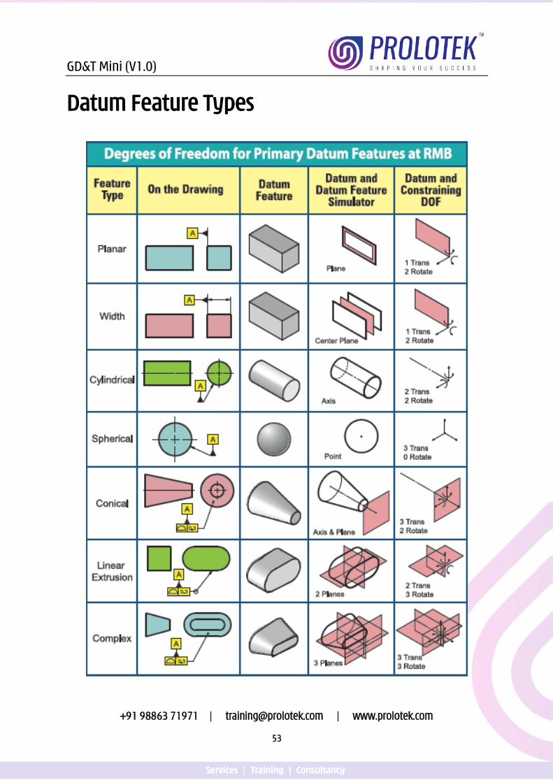
20 Datum Feature Types…………………………………………………….............................. 53
21 Datum Targets……………………………………………………........................................... 54
21.1 Datum Target Points……………………………………………………................................ 56
21.2 Datum Target Lines…………………………………………………….................................. 57
21.3 Datum Target Areas……………………………………………………................................. 58
22 Form Controls……………………………………………………............................................ 59
22.1 Straightness applied to Surface……………………………………………………............ 59
22.2 Straightness applied to Feature of Size………………………………………………….. 60
22.3 Flatness applied to Surface…………………………………………………….................... 62
22.4 Flatness applied to Feature of Size……………………………………………………...... 63
22.5 Circularity…………………………………………………….................................................... 65
22.6 Cylindricity…………………………………………………….................................................. 67
23 Orientation Controls……………………………………………………................................. 69
23.1 Angularity applied to Surface……………………………………………………................ 69
23.2 Angularity applied to Feature of Size…………………………………………………….. 70
23.3 Angularity – Alternate Practice……………………………………………………............. 71
23.4 Perpendicularity applied to Surface………………………………………………………. 73
23.5 Perpendicularity applied to Feature of Size…………………………………………….. 74
23.6 Parallelism applied to Surface……………………………………………………............... 76
23.7 Parallelism applied to Feature of Size……………………………………………………. 77
GD&T Mini (V1.0)
+91 98863 71971 | [email protected] | www.prolotek.com
ix
Sl. No. Description Page No.
24 Location……………………………………………………............................................................ 79
24.1 Position applied to a Hole……………………………………………………........................... 79
24.2 Position applied to Elongated Hole……………………………………………………........... 80
24.3 Concentricity……………………………………………………................................................... 82
24.4 Symmetry……………………………………………………......................................................... 84
25 Runout Controls…………………………………………………….............................................. 86
25.1 Circular Runout……………………………………………………............................................... 86
25.2 Total Runout…………………………………………………….................................................... 87
26 Profile Controls……………………………………………………............................................... 89
26.1 Profile of a Line…………………………………………………….............................................. 89
26.2 Profile of a Surface……………………………………………………........................................ 90
GD&T Mini (V1.0)
+91 98863 71971 | [email protected] | www.prolotek.com
1
Dimension Units (In accordance with ASME Y14.5 – 2009 & 2018)
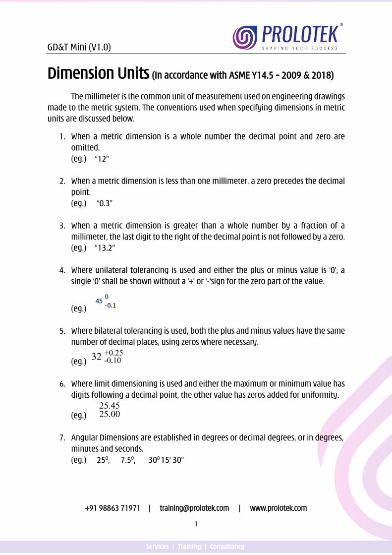
The millimeter is the common unit of measurement used on engineering drawings made to the metric system. The conventions used when specifying dimensions in metric units are discussed below.
1. When a metric dimension is a whole number the decimal point and zero are omitted. (eg.) “12”
2. When a metric dimension is less than one millimeter, a zero precedes the decimal point. (eg.) “0.3”
3. When a metric dimension is greater than a whole number by a fraction of a millimeter, the last digit to the right of the decimal point is not followed by a zero. (eg.) ”13.2”
4. Where unilateral tolerancing is used and either the plus or minus value is ‘0’, a single ‘0’ shall be shown without a ‘+’ or ‘-‘sign for the zero part of the value.
(eg.)
5. Where bilateral tolerancing is used, both the plus and minus values have the same number of decimal places, using zeros where necessary.
(eg.)
6. Where limit dimensioning is used and either the maximum or minimum value has digits following a decimal point, the other value has zeros added for uniformity.
(eg.)
7. Angular Dimensions are established in degrees or decimal degrees, or in degrees, minutes and seconds. (eg.) 250, 7.50, 300 15’ 30”
GD&T Mini (V1.0)
+91 98863 71971 | [email protected] | www.prolotek.com
2
8. Where a dimension is less than one degree, a zero precedes the decimal point (eg.) 0.50
9. Where only minutes or seconds are specified, a zero precedes the minutes and
seconds. (eg.) 00 15’ 30”
10. Where only whole number angle degree is specified, the value is followed by a degree symbol. A zero or decimal point is not shown after the degrees. (eg.) 300
In industry a general note would be given on the engineering drawing to invoke the metric system. (eg.) “UNLESS OTHERWISE SPECIFIED, ALL DIMENSIONS ARE IN MILLIMETERS”
Click the below link or scan the QR code for Video presentation
on Dimensional Units
https://youtu.be/AtBTUZbe7Pc
GD&T Mini (V1.0)
+91 98863 71971 | [email protected] | www.prolotek.com
3
Fundamental Dimensioning Rules (In accordance with ASME Y14.5 – 2018)
1. Each feature shall be toleranced. Tolerances may be applied directly to size dimensions. Tolerances shall be applied using feature control frames when feature definition is basic. Tolerances may also be indicated by a note or located in a supplementary block of the drawing format. See ASME Y14.1 and ASME Y14.1M. Those dimensions specifically identified as reference, maximum, minimum, or stock (commercial stock size) do not require the application of a tolerance.
2. Dimensioning and tolerancing shall be complete so there is full understanding of the characteristics of each feature. Values may be expressed in an engineering drawing or in a CAD product definition data set. See ASME Y14.41. Neither scaling (measuring directly from an engineering drawing graphics sheet) nor assumption of a distance or size is permitted, except in undimensioned drawings, such as loft, printed wiring, templates, and master layouts prepared on stable material, provided the necessary control dimensions are specified. Model data shall be queried when dimensions are not displayed on the model.
3. Each necessary dimension of an end product shall be shown or defined by model data. No more dimensions than those necessary for complete definition shall be given. The use of reference dimensions on a drawing should be minimized.
4. Dimensions shall be selected and arranged to suit the function and mating relationship of a part and shall not be subject to more than one interpretation.
5. The drawing should define a part without specifying manufacturing
methods. Thus, only the diameter of a hole is given without indicating whether it is to be drilled, reamed, punched, or made by another operation. However, in those instances where manufacturing, processing, quality assurance, or environmental information is essential to the definition of engineering requirements, the information shall be specified on the drawing or in a document referenced on the drawing.
6. Nonmandatory processing dimensions shall be identified by an appropriate note, such as NONMANDATORY (MFG DATA). Examples of nonmandatory data are processing dimensions that provide for finish allowance, shrink
GD&T Mini (V1.0)
+91 98863 71971 | [email protected] | www.prolotek.com
4
allowance, and other requirements, provided the final dimensions are given on the drawing.
7. Dimensions should be arranged to provide required information for
optimum readability.
8. Dimensions in orthographic views should be shown in true profile views and refer to visible outlines. When dimensions are shown in models, the dimensions shall be applied in a manner that shows the true value.
9. Wires, cables, sheets, rods, and other materials manufactured to gage or code
numbers shall be specified by linear dimensions indicating the diameter or thickness. Gage or code numbers may be shown in parentheses following the dimension.
10. An implied 90° angle shall apply where center lines and lines depicting
features are shown on orthographic views at right angles and no angle is specified. For information on applicable tolerances for implied 90° angles.
11. An implied 90° basic angle shall apply where center lines of features or surfaces shown at right angles on an orthographic view are located or defined by basic dimensions and no angle is specified. For information on applicable tolerances for implied 90° basic angles.
12. A zero basic dimension shall apply where axes, center planes, or surfaces are
shown coincident on ortho-graphic views and geometric tolerances establish the relationship between the features. On CAD models, the distance is basic when queried model distances are zero and geometric tolerances establish the relationship between the features. For information on applicable tolerances for zero basic dimensions.
13. Unless otherwise specified (UOS), all dimensions and tolerances are applicable at 20°C (68°F) in accordance with ASME B89.6.2. Compensation may be made for measurements made at other temperatures.
14. Unless otherwise specified (UOS), all dimensions and tolerances apply in a
free state condition. 15. Unless otherwise specified (UOS), all tolerances and datum features apply for
full depth, length, and width of the feature.

GD&T Mini (V1.0)
+91 98863 71971 | [email protected] | www.prolotek.com
5
16. Dimensions and tolerances apply only at the drawing level where they are specified. A dimension specified for a given feature on one level of drawing (e.g., a detail drawing) is not mandatory for that feature at any other level (e.g., an assembly drawing).
17. Unless otherwise specified (UOS) by a drawing/model note or reference to a
separate document, the as-designed dimension value does not establish a functional or manufacturing target.
18. Where a coordinate system is shown on the ortho-graphic views or in the
model, it shall be right-handed UOS. Each axis shall be labeled and the positive direction shown. NOTE: Where a model coordinate system is shown on the drawing, it shall be in compliance with ASME Y14.41.
19. Unless otherwise specified (UOS), elements of a surface include surface texture and flaws (e.g., burrs and scratches). All elements of a surface shall be within the applicable specified tolerance zone boundaries.
Click the below link or scan the QR code for Video
presentation on Implied 900 and Implied 900 Basic
https://youtu.be/DMc3DNJbhv8
Click the below link or scan the QR code for Video
presentation on Basic Zero
https://youtu.be/uxAEEsbXi4Y
GD&T Mini (V1.0)
+91 98863 71971 | [email protected] | www.prolotek.com
6
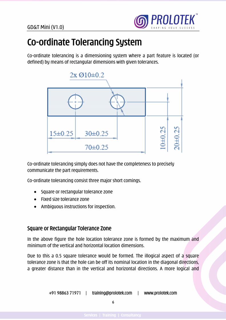
Co-ordinate Tolerancing System Co-ordinate tolerancing is a dimensioning system where a part feature is located (or defined) by means of rectangular dimensions with given tolerances.
Co-ordinate tolerancing simply does not have the completeness to precisely communicate the part requirements.
Co-ordinate tolerancing consist three major short comings.
• Square or rectangular tolerance zone
• Fixed size tolerance zone
• Ambiguous instructions for inspection.
Square or Rectangular Tolerance Zone
In the above figure the hole location tolerance zone is formed by the maximum and minimum of the vertical and horizontal location dimensions.
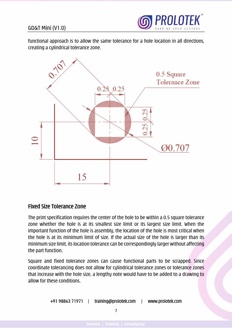
Due to this a 0.5 square tolerance would be formed. The illogical aspect of a square tolerance zone is that the hole can be off its nominal location in the diagonal directions, a greater distance than in the vertical and horizontal directions. A more logical and
GD&T Mini (V1.0)
+91 98863 71971 | [email protected] | www.prolotek.com
7
functional approach is to allow the same tolerance for a hole location in all directions, creating a cylindrical tolerance zone.
Fixed Size Tolerance Zone
The print specification requires the center of the hole to be within a 0.5 square tolerance zone whether the hole is at its smallest size limit or its largest size limit. When the important function of the hole is assembly, the location of the hole is most critical when the hole is at its minimum limit of size. If the actual size of the hole is larger than its minimum size limit, its location tolerance can be correspondingly larger without affecting the part function.
Square and fixed tolerance zones can cause functional parts to be scrapped. Since coordinate tolerancing does not allow for cylindrical tolerance zones or tolerance zones that increase with the hole size, a lengthy note would have to be added to a drawing to allow for these conditions.
GD&T Mini (V1.0)
+91 98863 71971 | [email protected] | www.prolotek.com
8
Ambiguous Instructions for Inspections
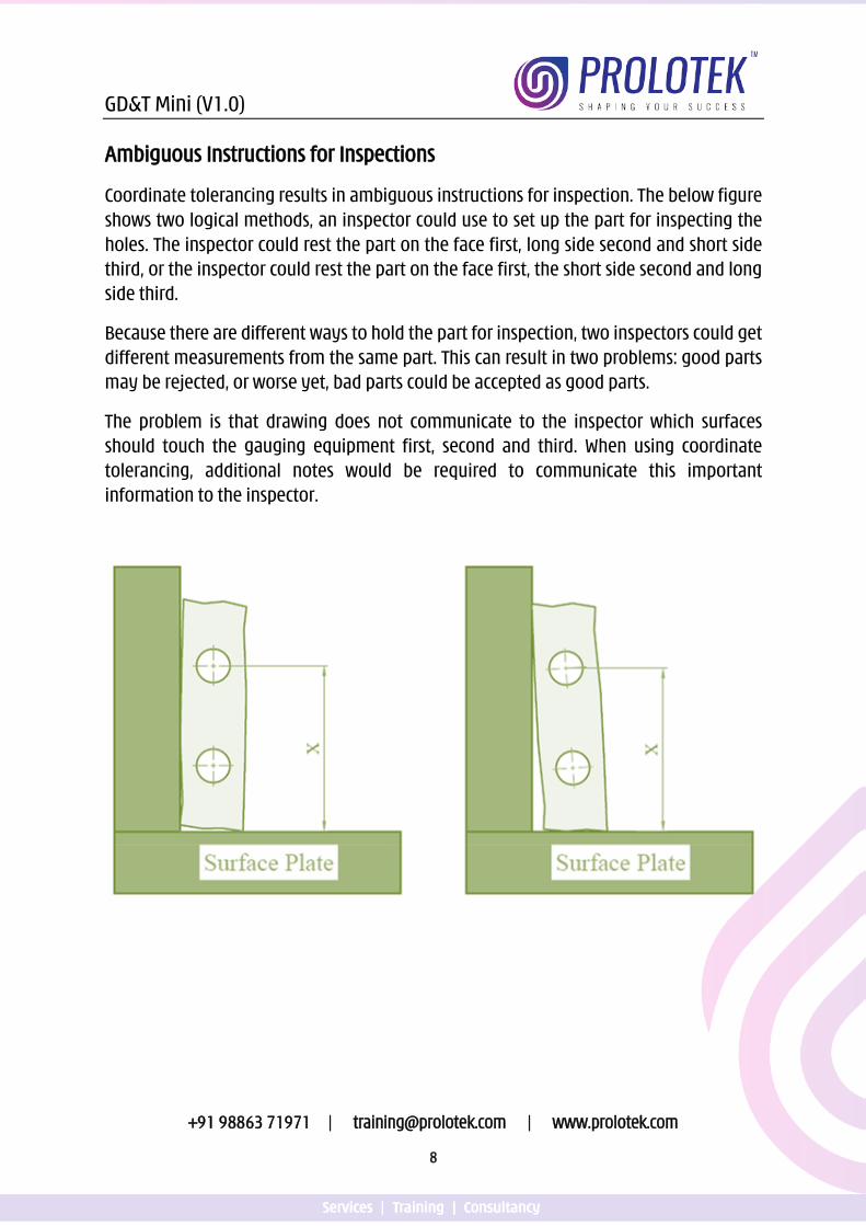
Coordinate tolerancing results in ambiguous instructions for inspection. The below figure shows two logical methods, an inspector could use to set up the part for inspecting the holes. The inspector could rest the part on the face first, long side second and short side third, or the inspector could rest the part on the face first, the short side second and long side third.
Because there are different ways to hold the part for inspection, two inspectors could get different measurements from the same part. This can result in two problems: good parts may be rejected, or worse yet, bad parts could be accepted as good parts.
The problem is that drawing does not communicate to the inspector which surfaces should touch the gauging equipment first, second and third. When using coordinate tolerancing, additional notes would be required to communicate this important information to the inspector.
GD&T Mini (V1.0)
+91 98863 71971 | [email protected] | www.prolotek.com
9
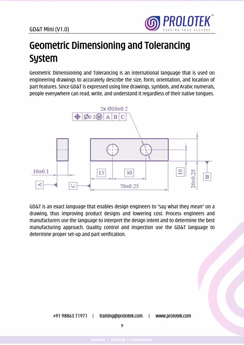
Geometric Dimensioning and Tolerancing System Geometric Dimensioning and Tolerancing is an international language that is used on engineering drawings to accurately describe the size, form, orientation, and location of part features. Since GD&T is expressed using line drawings, symbols, and Arabic numerals, people everywhere can read, write, and understand it regardless of their native tongues.
GD&T is an exact language that enables design engineers to "say what they mean" on a drawing, thus improving product designs and lowering cost. Process engineers and manufacturers use the language to interpret the design intent and to determine the best manufacturing approach. Quality control and inspection use the GD&T language to determine proper set-up and part verification.
GD&T Mini (V1.0)
+91 98863 71971 | [email protected] | www.prolotek.com
10
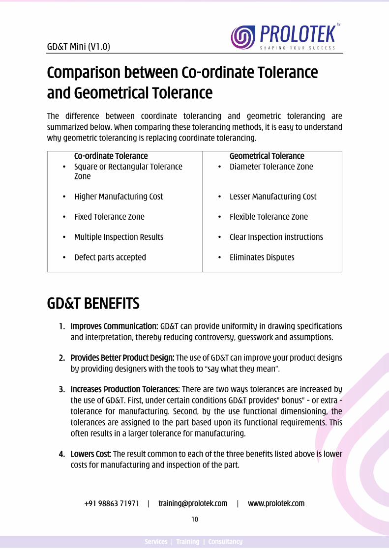
Comparison between Co-ordinate Tolerance and Geometrical Tolerance The difference between coordinate tolerancing and geometric tolerancing are summarized below. When comparing these tolerancing methods, it is easy to understand why geometric tolerancing is replacing coordinate tolerancing.
Co-ordinate Tolerance • Square or Rectangular Tolerance
Zone
• Higher Manufacturing Cost
• Fixed Tolerance Zone
• Multiple Inspection Results
• Defect parts accepted
Geometrical Tolerance • Diameter Tolerance Zone
• Lesser Manufacturing Cost
• Flexible Tolerance Zone
• Clear Inspection instructions
• Eliminates Disputes
GD&T BENEFITS 1. Improves Communication: GD&T can provide uniformity in drawing specifications
and interpretation, thereby reducing controversy, guesswork and assumptions.
2. Provides Better Product Design: The use of GD&T can improve your product designs by providing designers with the tools to “say what they mean”.
3. Increases Production Tolerances: There are two ways tolerances are increased by the use of GD&T. First, under certain conditions GD&T provides” bonus” – or extra - tolerance for manufacturing. Second, by the use functional dimensioning, the tolerances are assigned to the part based upon its functional requirements. This often results in a larger tolerance for manufacturing.
4. Lowers Cost: The result common to each of the three benefits listed above is lower costs for manufacturing and inspection of the part.
GD&T Mini (V1.0)
+91 98863 71971 | [email protected] | www.prolotek.com
11
GD&T Standards GD&T standards are based on ASME Y14.5-2009. This standard is considered as the
national standard for dimensioning and tolerancing in the United States. ISO (International Organization of Standards) also has published geometric dimensioning and tolerancing standards called GPS 1101 which is 90% similar to ASME Y14.-2009 standard. This text is based on ASME Y14.5-2009 and ASME Y14.5-2018 and hence forth will be referred to as Y14.5.
ASME – American Society of Mechanical Engineer
Y14.5 – Standard number for Dimensioning and Tolerancing
2009 – Year in which the standard was published
2018 – Year in which the standard was published
GPS – Geometric Product Specification
1101 – ISO Standard number for GPS
Click the below link or scan the QR code for Video presentation
on Coordinate Tolerancing System
https://youtu.be/AZbvNNsPGTk
GD&T Mini (V1.0)
+91 98863 71971 | [email protected] | www.prolotek.com
12
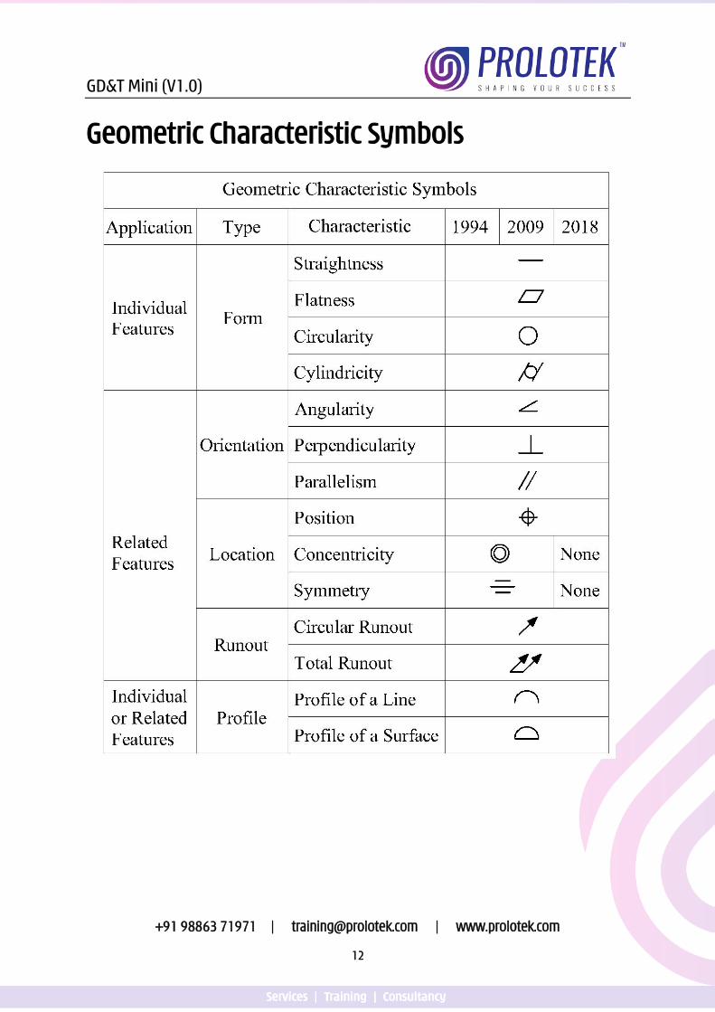
Geometric Characteristic Symbols
GD&T Mini (V1.0)
+91 98863 71971 | [email protected] | www.prolotek.com
13
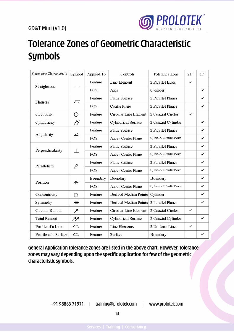
Tolerance Zones of Geometric Characteristic Symbols
General Application tolerance zones are listed in the above chart. However, tolerance zones may vary depending upon the specific application for few of the geometric characteristic symbols.
GD&T Mini (V1.0)
+91 98863 71971 | [email protected] | www.prolotek.com
16
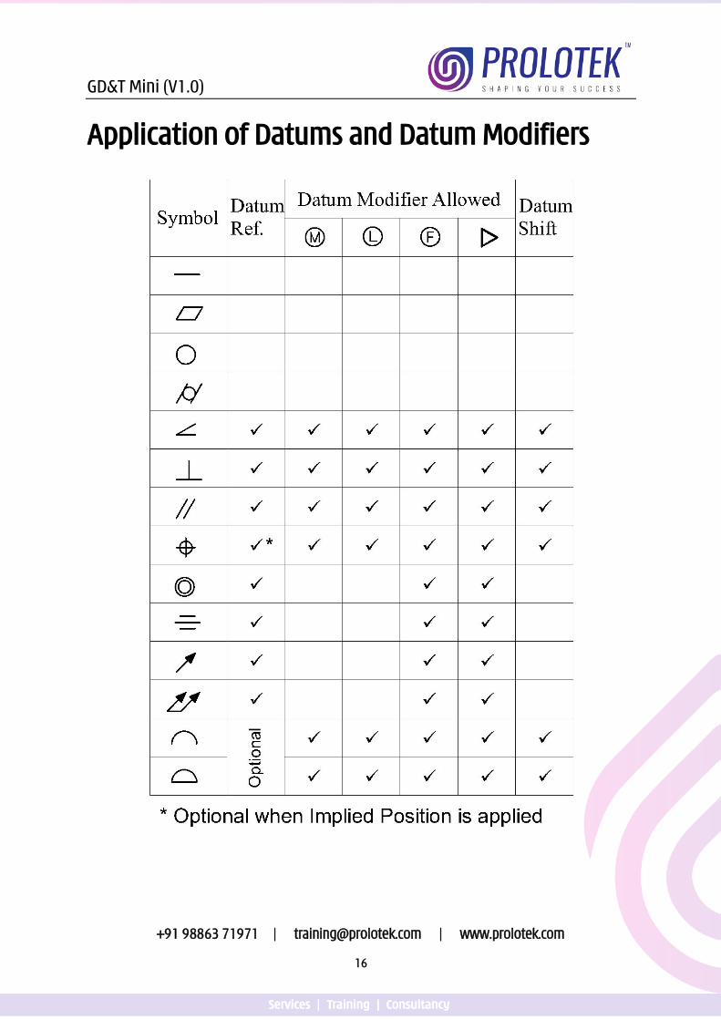
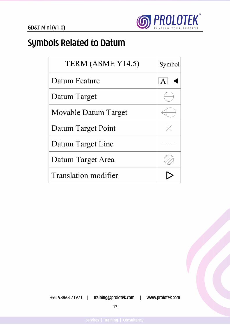
Application of Datums and Datum Modifiers
GD&T Mini (V1.0)
+91 98863 71971 | [email protected] | www.prolotek.com
19
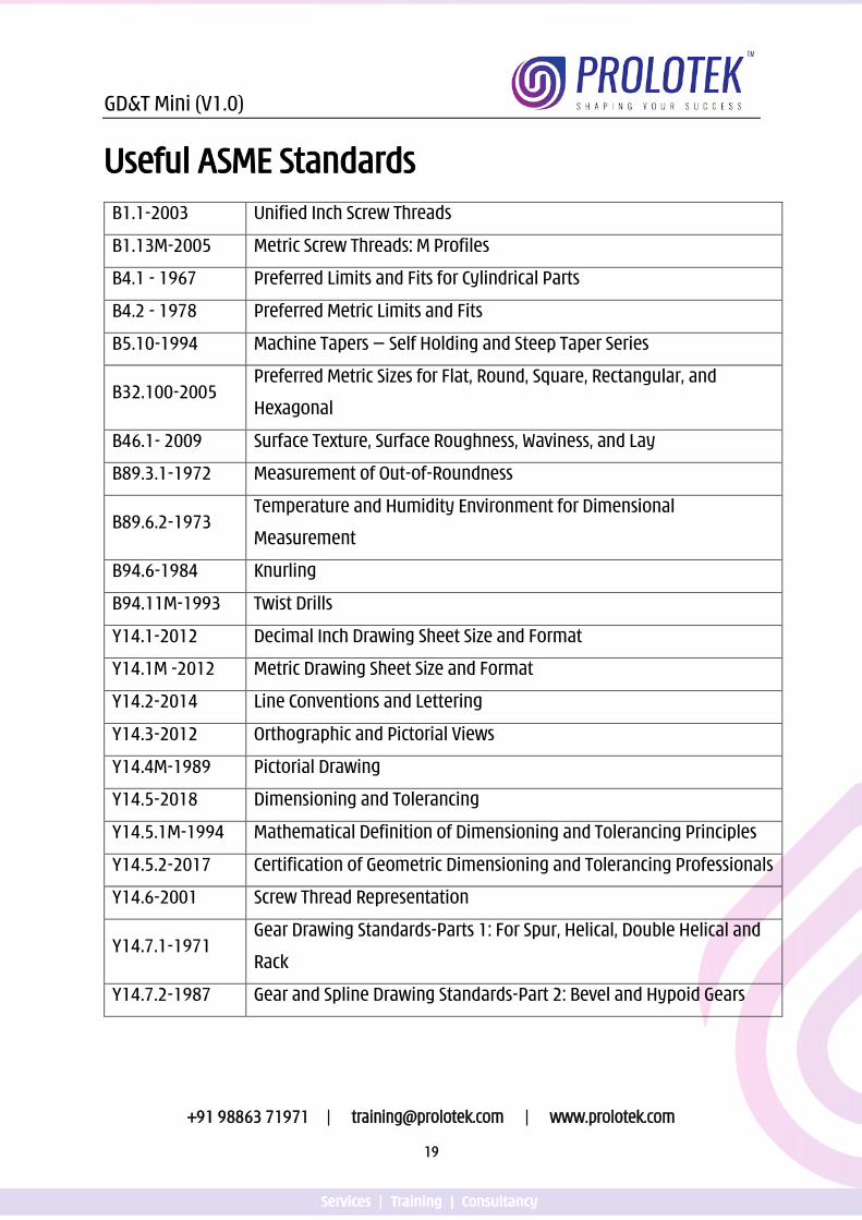
Useful ASME Standards B1.1-2003 Unified Inch Screw Threads
B1.13M-2005 Metric Screw Threads: M Profiles
B4.1 - 1967 Preferred Limits and Fits for Cylindrical Parts
B4.2 - 1978 Preferred Metric Limits and Fits
B5.10-1994 Machine Tapers — Self Holding and Steep Taper Series
B32.100-2005 Preferred Metric Sizes for Flat, Round, Square, Rectangular, and
Hexagonal
B46.1- 2009 Surface Texture, Surface Roughness, Waviness, and Lay
B89.3.1-1972 Measurement of Out-of-Roundness
B89.6.2-1973 Temperature and Humidity Environment for Dimensional
Measurement
B94.6-1984 Knurling
B94.11M-1993 Twist Drills
Y14.1-2012 Decimal Inch Drawing Sheet Size and Format
Y14.1M -2012 Metric Drawing Sheet Size and Format
Y14.2-2014 Line Conventions and Lettering
Y14.3-2012 Orthographic and Pictorial Views
Y14.4M-1989 Pictorial Drawing
Y14.5-2018 Dimensioning and Tolerancing
Y14.5.1M-1994 Mathematical Definition of Dimensioning and Tolerancing Principles
Y14.5.2-2017 Certification of Geometric Dimensioning and Tolerancing Professionals
Y14.6-2001 Screw Thread Representation
Y14.7.1-1971 Gear Drawing Standards-Parts 1: For Spur, Helical, Double Helical and
Rack
Y14.7.2-1987 Gear and Spline Drawing Standards-Part 2: Bevel and Hypoid Gears
GD&T Mini (V1.0)
+91 98863 71971 | [email protected] | www.prolotek.com
20
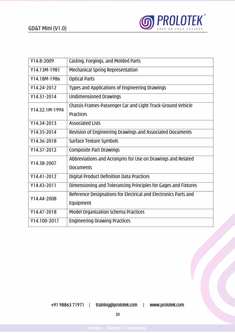
Y14.8-2009 Casting, Forgings, and Molded Parts
Y14.13M-1981 Mechanical Spring Representation
Y14.18M-1986 Optical Parts
Y14.24-2012 Types and Applications of Engineering Drawings
Y14.31-2014 Undimensioned Drawings
Y14.32.1M-1994 Chassis Frames-Passenger Car and Light Truck-Ground Vehicle
Practices
Y14.34-2013 Associated Lists
Y14.35-2014 Revision of Engineering Drawings and Associated Documents
Y14.36-2018 Surface Texture Symbols
Y14.37-2012 Composite Part Drawings
Y14.38-2007 Abbreviations and Acronyms for Use on Drawings and Related
Documents
Y14.41-2012 Digital Product Definition Data Practices
Y14.43-2011 Dimensioning and Tolerancing Principles for Gages and Fixtures
Y14.44-2008 Reference Designations for Electrical and Electronics Parts and
Equipment
Y14.47-2018 Model Organization Schema Practices
Y14.100-2017 Engineering Drawing Practices
GD&T Mini (V1.0)
+91 98863 71971 | [email protected] | www.prolotek.com
21
General Terms (In accordance with ASME Y14.5 – 2018)
Dimension [3.25]: is a numerical value(s) or mathematical expression in appropriate units of measure used to define the shape, size, orientation or location of a part feature or between part features.
Tolerance [3.62]: is the total amount that a specific dimension or feature is permitted to vary. It is the difference between the maximum and minimum limit.
Nominal Size [3.59]: is the designation used for the purpose of general identification.
Limit Tolerance Dimensioning: is where a dimension has its maximum and minimum limit stated. In limit dimensioning, the maximum value is placed on the top and minimum value is placed on the bottom.
Directly Toleranced Dimension [3.27]: is a dimension with an associated plus / minus general tolerance or limit dimension value.
Bilateral Tolerance [3.63]: is a tolerance in which variation is permitted in both directions from the specified dimension or true profile.
Equal Bilateral Tolerance [3.63.1]: is a tolerance in which variation is permitted equally in both directions from the specified dimension or true profile.
Unequal Bilateral Tolerance [3.63.2]: is a tolerance that permits unequal amounts of variation in both directions from the specified dimension or true profile.
Unilateral Tolerance [3.65]: is a tolerance in which variation is permitted in one direction from the specified dimension or true profile.
Basic Dimension [3.26]: is a numerical value used to describe the theoretically exact size, true profile, true position or orientation of a feature or a feature of size
Reference Dimension [3.28]: is a dimension used for information purposes only. It is a repeat dimension or is derived from other values shown on the drawing or on related drawings.
Geometric Tolerance [3.64]: is a tolerance indicated using a geometric characteristic symbol.
GD&T Mini (V1.0)
+91 98863 71971 | [email protected] | www.prolotek.com
22
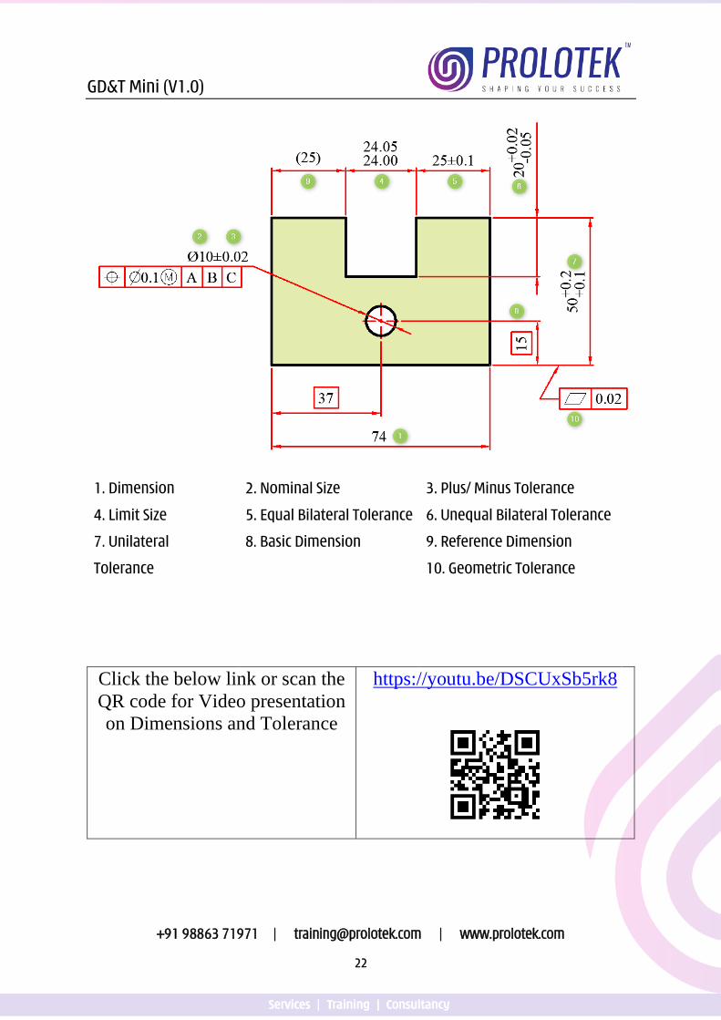
1. Dimension 2. Nominal Size 3. Plus/ Minus Tolerance
4. Limit Size 5. Equal Bilateral Tolerance 6. Unequal Bilateral Tolerance
7. Unilateral
Tolerance
8. Basic Dimension 9. Reference Dimension
10. Geometric Tolerance
Click the below link or scan the QR code for Video presentation on Dimensions and Tolerance
https://youtu.be/DSCUxSb5rk8
GD&T Mini (V1.0)
+91 98863 71971 | [email protected] | www.prolotek.com
23
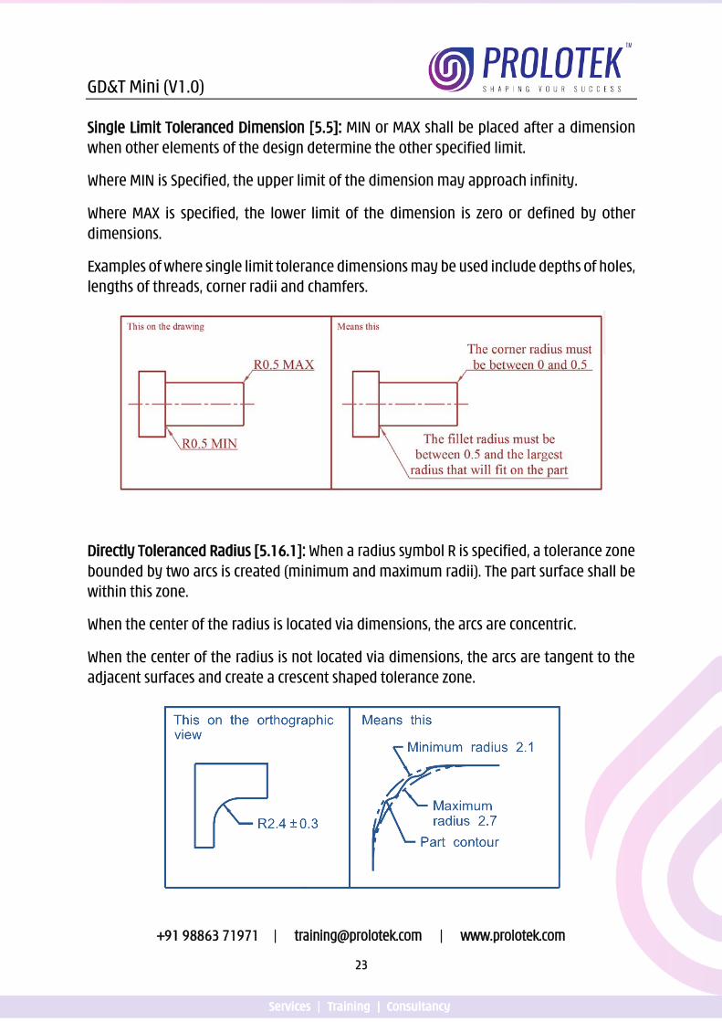
Single Limit Toleranced Dimension [5.5]: MIN or MAX shall be placed after a dimension when other elements of the design determine the other specified limit.
Where MIN is Specified, the upper limit of the dimension may approach infinity.
Where MAX is specified, the lower limit of the dimension is zero or defined by other dimensions.
Examples of where single limit tolerance dimensions may be used include depths of holes, lengths of threads, corner radii and chamfers.
Directly Toleranced Radius [5.16.1]: When a radius symbol R is specified, a tolerance zone bounded by two arcs is created (minimum and maximum radii). The part surface shall be within this zone.
When the center of the radius is located via dimensions, the arcs are concentric.
When the center of the radius is not located via dimensions, the arcs are tangent to the adjacent surfaces and create a crescent shaped tolerance zone.
GD&T Mini (V1.0)
+91 98863 71971 | [email protected] | www.prolotek.com
24
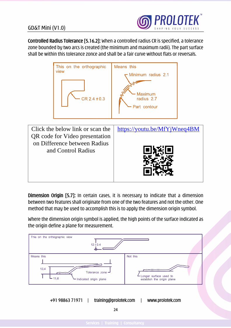
Controlled Radius Tolerance [5.16.2]: When a controlled radius CR is specified, a tolerance zone bounded by two arcs is created (the minimum and maximum radii). The part surface shall be within this tolerance zonce and shall be a fair curve without flats or reversals.
Click the below link or scan the QR code for Video presentation on Difference between Radius
and Control Radius
https://youtu.be/MfYjWneq4BM
Dimension Origin [5.7]: In certain cases, it is necessary to indicate that a dimension between two features shall originate from one of the two features and not the other. One method that may be used to accomplish this is to apply the dimension origin symbol.
Where the dimension origin symbol is applied, the high points of the surface indicated as the origin define a plane for measurement.
GD&T Mini (V1.0)
+91 98863 71971 | [email protected] | www.prolotek.com
25
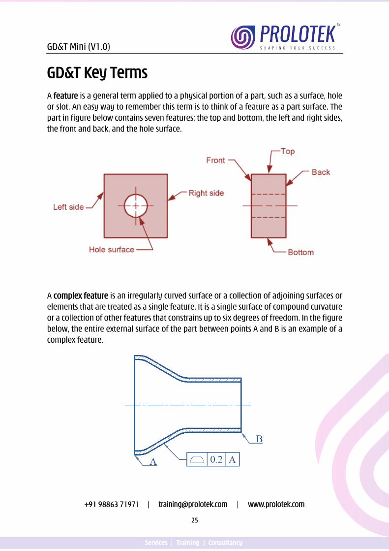
GD&T Key Terms A feature is a general term applied to a physical portion of a part, such as a surface, hole or slot. An easy way to remember this term is to think of a feature as a part surface. The part in figure below contains seven features: the top and bottom, the left and right sides, the front and back, and the hole surface.
A complex feature is an irregularly curved surface or a collection of adjoining surfaces or elements that are treated as a single feature. It is a single surface of compound curvature or a collection of other features that constrains up to six degrees of freedom. In the figure below, the entire external surface of the part between points A and B is an example of a complex feature.
GD&T Mini (V1.0)
+91 98863 71971 | [email protected] | www.prolotek.com
26
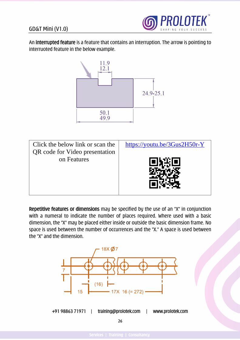
An interrupted feature is a feature that contains an interruption. The arrow is pointing to interruoted feature in the below example.
Click the below link or scan the QR code for Video presentation
on Features
https://youtu.be/3Gus2H50r-Y
Repetitive features or dimensions may be specified by the use of an "X" in conjunction with a numeral to indicate the number of places required. Where used with a basic dimension, the "X" may be placed either inside or outside the basic dimension frame. No space is used between the number of occurrences and the "X." A space is used between the "X" and the dimension.
GD&T Mini (V1.0)
+91 98863 71971 | [email protected] | www.prolotek.com
27
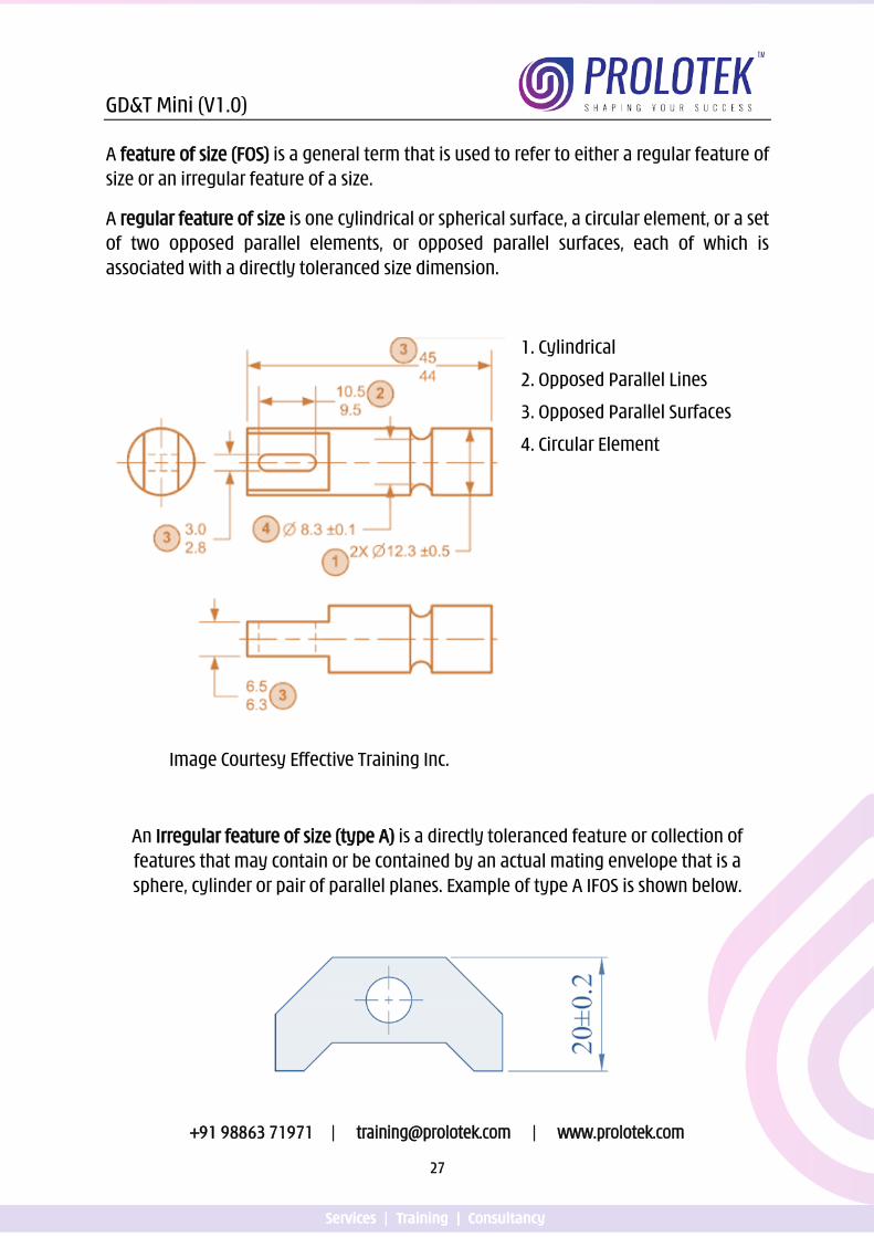
A feature of size (FOS) is a general term that is used to refer to either a regular feature of size or an irregular feature of a size.
A regular feature of size is one cylindrical or spherical surface, a circular element, or a set of two opposed parallel elements, or opposed parallel surfaces, each of which is associated with a directly toleranced size dimension.
1. Cylindrical
2. Opposed Parallel Lines
3. Opposed Parallel Surfaces
4. Circular Element
Image Courtesy Effective Training Inc.
An Irregular feature of size (type A) is a directly toleranced feature or collection of features that may contain or be contained by an actual mating envelope that is a sphere, cylinder or pair of parallel planes. Example of type A IFOS is shown below.
GD&T Mini (V1.0)
+91 98863 71971 | [email protected] | www.prolotek.com
28
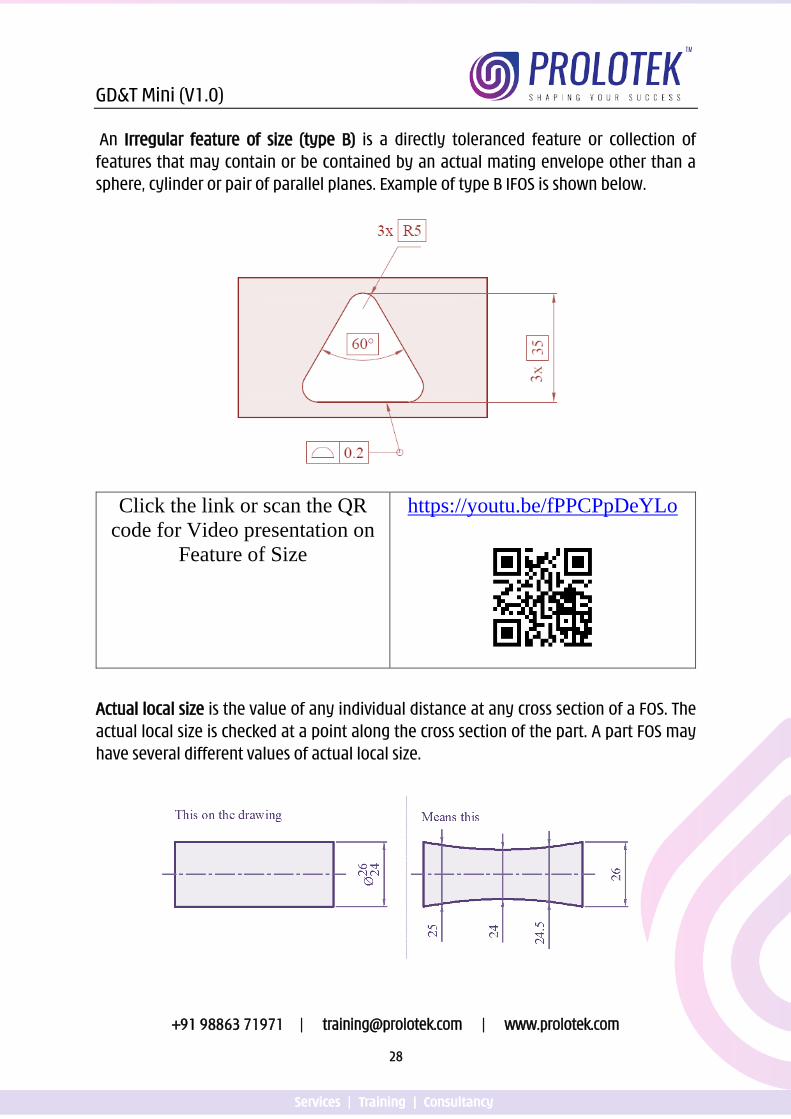
An Irregular feature of size (type B) is a directly toleranced feature or collection of features that may contain or be contained by an actual mating envelope other than a sphere, cylinder or pair of parallel planes. Example of type B IFOS is shown below.
Click the link or scan the QR code for Video presentation on
Feature of Size
https://youtu.be/fPPCPpDeYLo
Actual local size is the value of any individual distance at any cross section of a FOS. The actual local size is checked at a point along the cross section of the part. A part FOS may have several different values of actual local size.
GD&T Mini (V1.0)
+91 98863 71971 | [email protected] | www.prolotek.com
29
Actual Mating Envelope is a similar perfect feature counterpart of the smallest size that can be contracted about an external feature or largest size that can be expanded within an internal feature so that it coincides with the surface at the highest points.
Click the link or scan the QR code for Video presentation on
Actual Mating Envelope
https://youtu.be/ejRyx_FlQuE
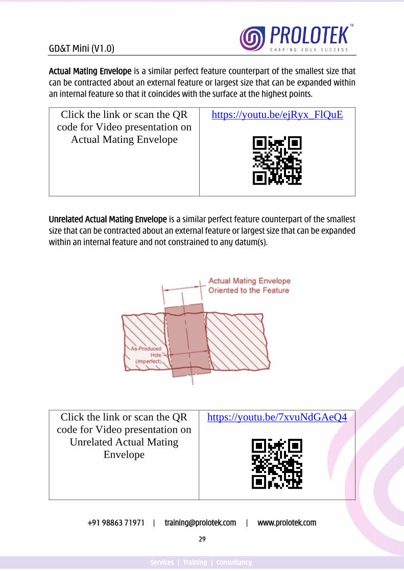
Unrelated Actual Mating Envelope is a similar perfect feature counterpart of the smallest size that can be contracted about an external feature or largest size that can be expanded within an internal feature and not constrained to any datum(s).
Click the link or scan the QR code for Video presentation on
Unrelated Actual Mating Envelope
https://youtu.be/7xvuNdGAeQ4
GD&T Mini (V1.0)
+91 98863 71971 | [email protected] | www.prolotek.com
30
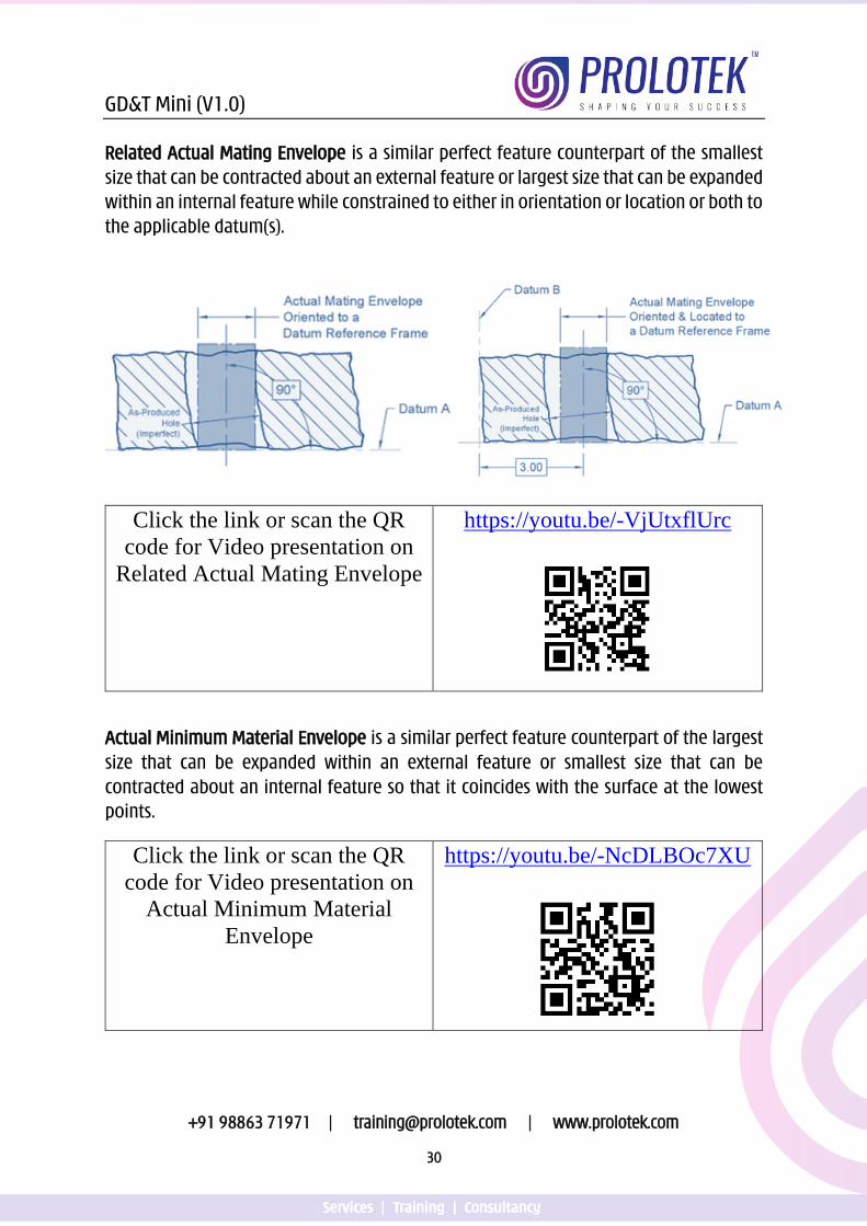
Related Actual Mating Envelope is a similar perfect feature counterpart of the smallest size that can be contracted about an external feature or largest size that can be expanded within an internal feature while constrained to either in orientation or location or both to the applicable datum(s).
0
Click the link or scan the QR code for Video presentation on
Related Actual Mating Envelope
https://youtu.be/-VjUtxflUrc
Actual Minimum Material Envelope is a similar perfect feature counterpart of the largest size that can be expanded within an external feature or smallest size that can be contracted about an internal feature so that it coincides with the surface at the lowest points.
Click the link or scan the QR code for Video presentation on
Actual Minimum Material Envelope
https://youtu.be/-NcDLBOc7XU

GD&T Mini (V1.0)
+91 98863 71971 | [email protected] | www.prolotek.com
31
Unrelated Actual Minimum Material Envelope is a similar perfect feature counterpart of the largest size that can be expanded within an external feature or smallest size that can be contracted about an internal feature so that it coincides with the surface at the lowest points not constrained to any datum reference frame.
Related Actual Minimum Material Envelope is a similar perfect feature counterpart of the largest size that can be expanded within an external feature or smallest size that can be contracted about an internal feature so that it coincides with the surface at the lowest
points while constrained in either orientation or location or both to the applicable datums.
GD&T Mini (V1.0)
+91 98863 71971 | [email protected] | www.prolotek.com
32
Click the link or scan the QR code for Video presentation on Related and Unrelated Actual Minimum Material Envelope
https://youtu.be/qm5Qz0mG6qw
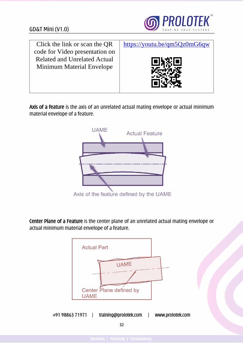
Axis of a feature is the axis of an unrelated actual mating envelope or actual minimum material envelope of a feature.
Center Plane of a Feature is the center plane of an unrelated actual mating envelope or actual minimum material envelope of a feature.
GD&T Mini (V1.0)
+91 98863 71971 | [email protected] | www.prolotek.com
33
Derived Median Line is an imperfect line that passes through the center points of all cross sections of the feature. These cross sections are normal to the center plane of the unrelated actual mating envelope.
Derived Median Plane is an imperfect plane formed by the center points of all line segments bounded by the feature. These line segments are normal to the center plane of the unrelated actual mating envelope.
Modifiers communicate the additional information about the drawing or tolerancing of a part.
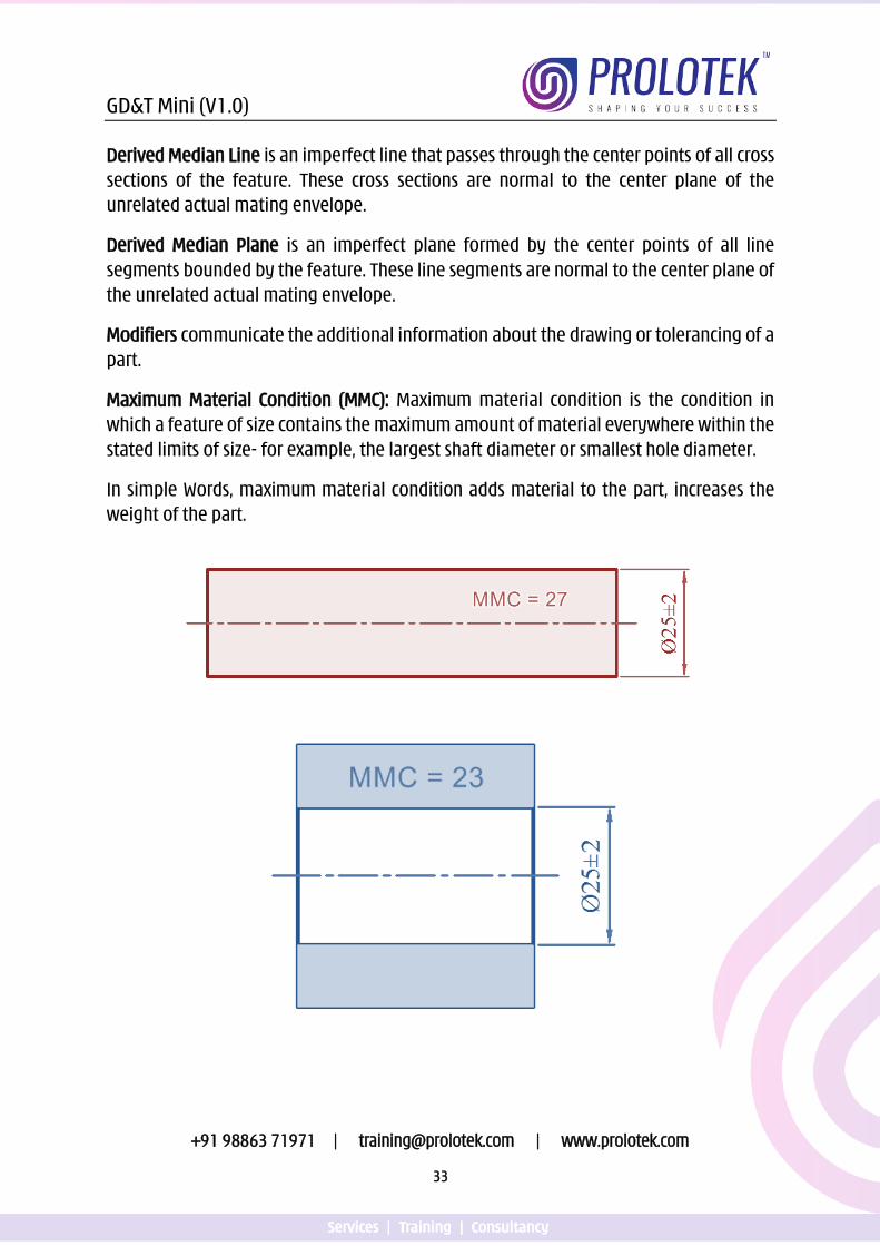
Maximum Material Condition (MMC): Maximum material condition is the condition in which a feature of size contains the maximum amount of material everywhere within the stated limits of size- for example, the largest shaft diameter or smallest hole diameter.
In simple Words, maximum material condition adds material to the part, increases the weight of the part.
GD&T Mini (V1.0)
+91 98863 71971 | [email protected] | www.prolotek.com
34
Maximum Material Boundary (MMB): Maximum material boundary is the limit defined by a tolerance or combination of tolerances that exists on or outside the material of a feature(s)
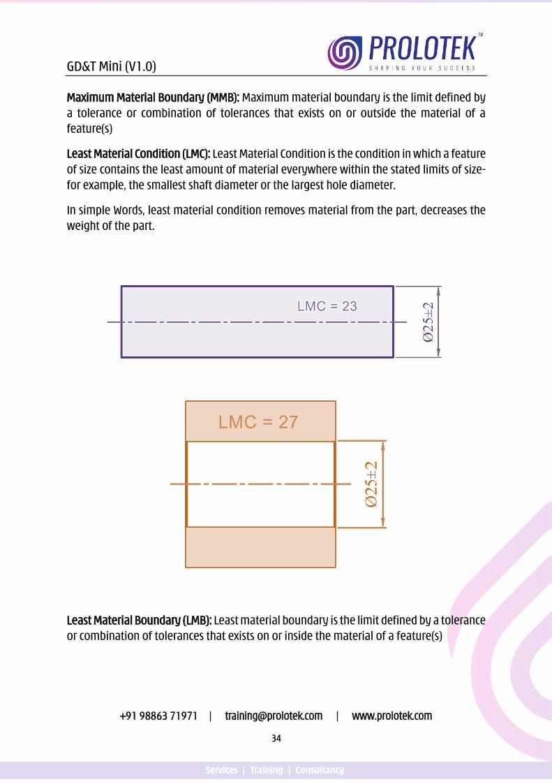
Least Material Condition (LMC): Least Material Condition is the condition in which a feature of size contains the least amount of material everywhere within the stated limits of size- for example, the smallest shaft diameter or the largest hole diameter.
In simple Words, least material condition removes material from the part, decreases the weight of the part.
Least Material Boundary (LMB): Least material boundary is the limit defined by a tolerance or combination of tolerances that exists on or inside the material of a feature(s)
GD&T Mini (V1.0)
+91 98863 71971 | [email protected] | www.prolotek.com
35
Regardless of feature size (RFS) is the term that indicates a geometric tolerance applies at any increment of size of the feature within its size tolerance. An-other way to visualize RFS is that the geometric tolerance applies at whatever size the part is produced. Every feature of size has a maximum and least material condition. Limit directions directly specify the maximum and least material condition of feature of size.
Regardless of Material Boundary (RMB) is a condition in which a movable or variable true geometric counterpart progresses from MMB towards LMB until it makes maximum allowable contact with the extremities of a datum feature(s) to establish a datum.
Click the link or scan the QR code for Video presentation on
Material Modifiers
https://youtu.be/xbhRJTRaRzI
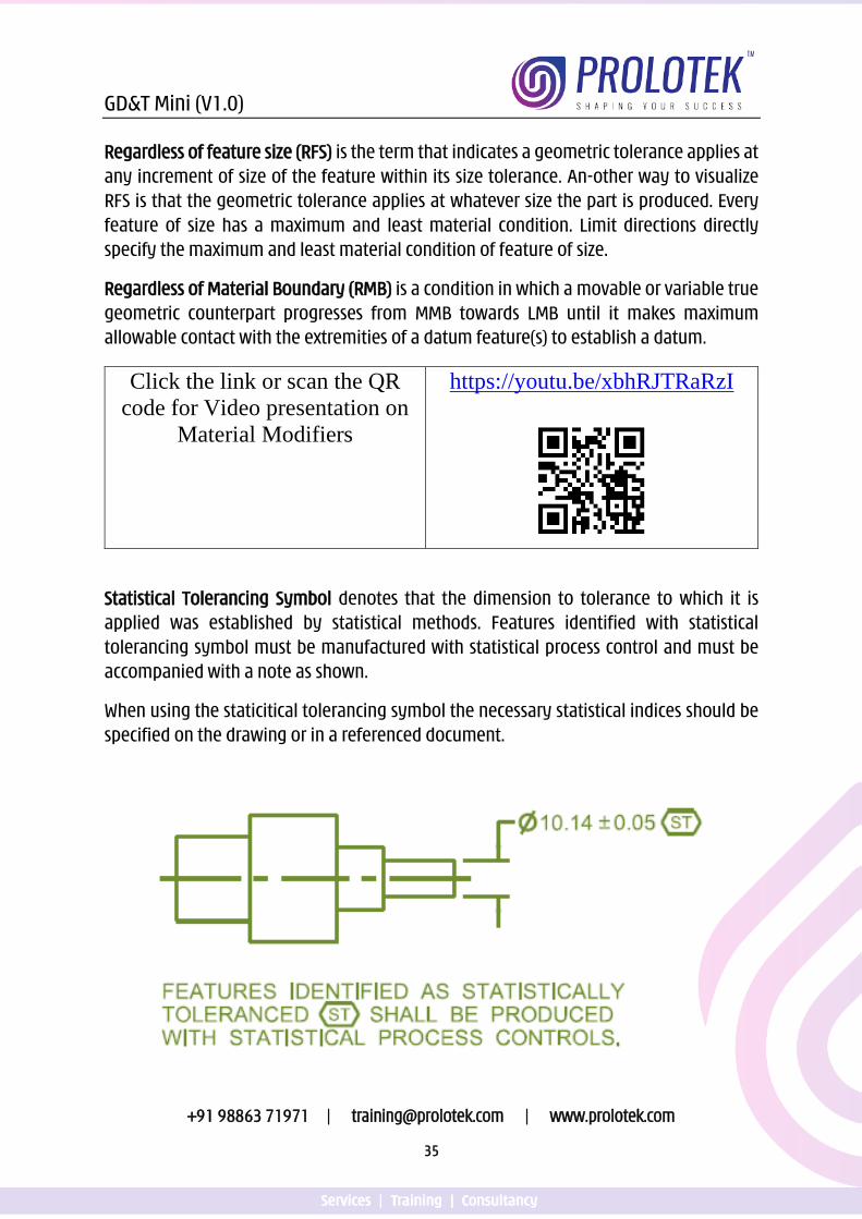
Statistical Tolerancing Symbol denotes that the dimension to tolerance to which it is applied was established by statistical methods. Features identified with statistical tolerancing symbol must be manufactured with statistical process control and must be accompanied with a note as shown.
When using the staticitical tolerancing symbol the necessary statistical indices should be specified on the drawing or in a referenced document.
GD&T Mini (V1.0)
+91 98863 71971 | [email protected] | www.prolotek.com
36
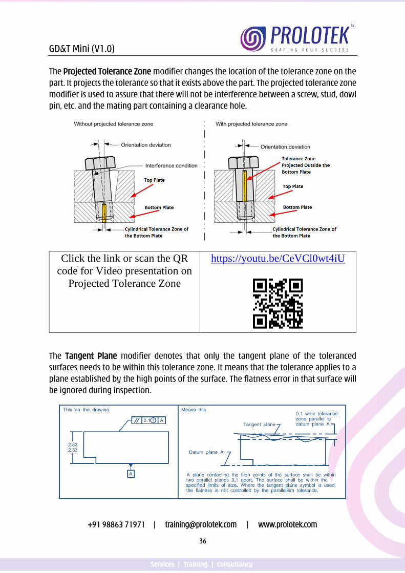
The Projected Tolerance Zone modifier changes the location of the tolerance zone on the part. It projects the tolerance so that it exists above the part. The projected tolerance zone modifier is used to assure that there will not be interference between a screw, stud, dowl pin, etc. and the mating part containing a clearance hole.
Click the link or scan the QR code for Video presentation on
Projected Tolerance Zone
https://youtu.be/CeVCl0wt4iU
The Tangent Plane modifier denotes that only the tangent plane of the toleranced surfaces needs to be within this tolerance zone. It means that the tolerance applies to a plane established by the high points of the surface. The flatness error in that surface will be ignored during inspection.
GD&T Mini (V1.0)
+91 98863 71971 | [email protected] | www.prolotek.com
37
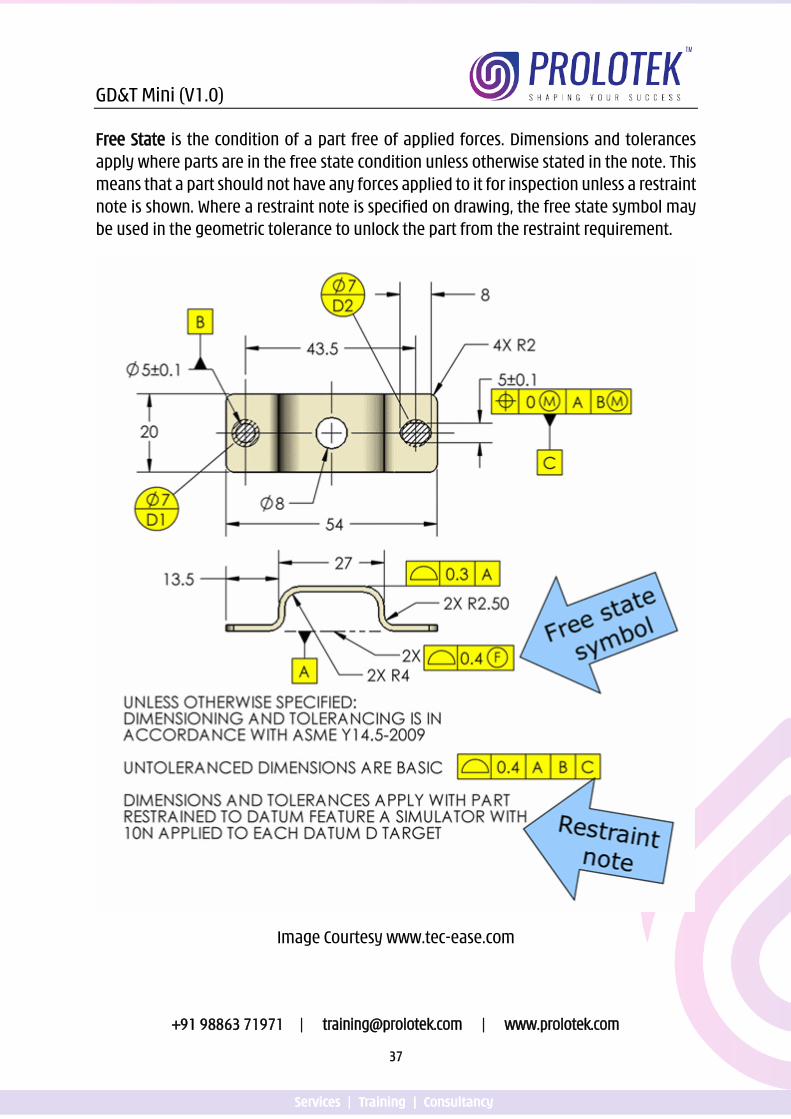
Free State is the condition of a part free of applied forces. Dimensions and tolerances apply where parts are in the free state condition unless otherwise stated in the note. This means that a part should not have any forces applied to it for inspection unless a restraint note is shown. Where a restraint note is specified on drawing, the free state symbol may be used in the geometric tolerance to unlock the part from the restraint requirement.
Image Courtesy www.tec-ease.com
GD&T Mini (V1.0)
+91 98863 71971 | [email protected] | www.prolotek.com
38
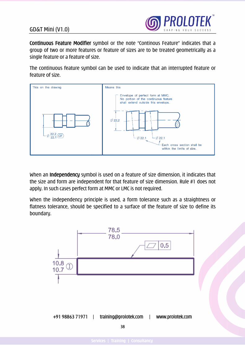
Continuous Feature Modifier symbol or the note “Continous Feature” indicates that a group of two or more features or feature of sizes are to be treated geometrically as a single feature or a feature of size.
The continuous feature symbol can be used to indicate that an interrupted feature or feature of size.
When an Independency symbol is used on a feature of size dimension, it indicates that the size and form are independent for that feature of size dimension. Rule #1 does not apply. In such cases perfect form at MMC or LMC is not required.
When the independency principle is used, a form tolerance such as a straightness or flatness tolerance, should be specified to a surface of the feature of size to define its boundary.
GD&T Mini (V1.0)
+91 98863 71971 | [email protected] | www.prolotek.com
39
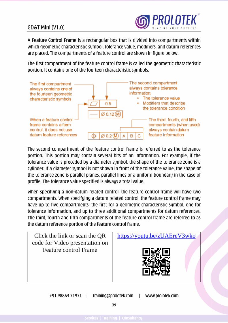
A Feature Control Frame is a rectangular box that is divided into compartments within which geometric characteristic symbol, tolerance value, modifiers, and datum references are placed. The compartments of a feature control are shown in figure below.
The first compartment of the feature control frame is called the geometric characteristic portion. It contains one of the fourteen characteristic symbols.
The second compartment of the feature control frame is referred to as the tolerance portion. This portion may contain several bits of an information. For example, if the tolerance value is preceded by a diameter symbol, the shape of the tolerance zone is a cylinder. If a diameter symbol is not shown in front of the tolerance value, the shape of the tolerance zone is parallel planes, parallel lines or a uniform boundary in the case of profile. The tolerance value specified is always a total value.
When specifying a non-datum related control, the feature control frame will have two compartments. When specifying a datum related control, the feature control frame may have up to five compartments: the first for a geometric characteristic symbol, one for tolerance information, and up to three additional compartments for datum references. The third, fourth and fifth compartments of the feature control frame are referred to as the datum reference portion of the feature control frame.
Click the link or scan the QR code for Video presentation on
Feature control Frame
https://youtu.be/zUAEreV3wko
GD&T Mini (V1.0)
+91 98863 71971 | [email protected] | www.prolotek.com
40
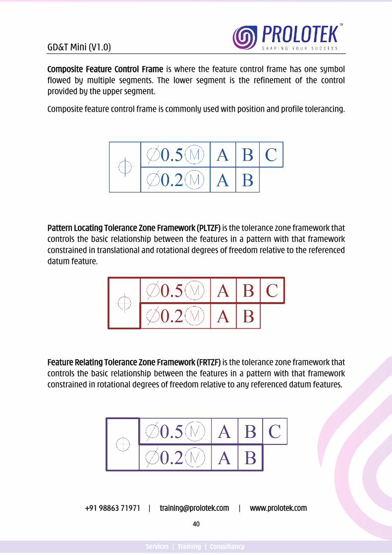
Composite Feature Control Frame is where the feature control frame has one symbol flowed by multiple segments. The lower segment is the refinement of the control provided by the upper segment.
Composite feature control frame is commonly used with position and profile tolerancing.
Pattern Locating Tolerance Zone Framework (PLTZF) is the tolerance zone framework that controls the basic relationship between the features in a pattern with that framework constrained in translational and rotational degrees of freedom relative to the referenced datum feature.
Feature Relating Tolerance Zone Framework (FRTZF) is the tolerance zone framework that controls the basic relationship between the features in a pattern with that framework constrained in rotational degrees of freedom relative to any referenced datum features.
GD&T Mini (V1.0)
+91 98863 71971 | [email protected] | www.prolotek.com
41
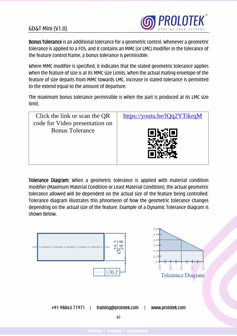
Bonus Tolerance is an additional tolerance for a geometric control. Whenever a geometric tolerance is applied to a FOS, and it contains an MMC (or LMC) modifier in the tolerance of the feature control frame, a bonus tolerance is permissible.
Where MMC modifier is specified, it indicates that the stated geometric tolerance applies when the feature of size is at its MMC size Limits. When the actual mating envelope of the feature of size departs from MMC towards LMC, increase in stated tolerance is permitted to the extend equal to the amount of departure.
The maximum bonus tolerance permissible is when the part is produced at its LMC size limit.
Click the link or scan the QR code for Video presentation on
Bonus Tolerance
https://youtu.be/lQq2YTikrqM
Tolerance Diagram: When a geometric tolerance is applied with material condition modifier (Maximum Material Condition or Least Material Condition), the actual geometric tolerance allowed will be dependent on the actual size of the feature being controlled. Tolerance diagram illustrates this phnomeon of how the geometric tolerance changes depending on the actual size of the feature. Example of a Dynamic Tolerance diagram is shown Below.
GD&T Mini (V1.0)
+91 98863 71971 | [email protected] | www.prolotek.com
42
Worst Case Boundary is a general term used to refer to an inner boundary, outer boundary, or virtual condition.
Inner Boundary is the worst case boundary generated by the smallest feature (MMC of hole and LMC of shaft) minus the stated geometric tolerance and any additional (if applicable) resulting from the feature’s departure from its specified material condition.
Inner boundary of an internal feature of size is a worst case boundary generated by the smallest feature of size (MMC) minus the effects of applicable geometric tolerance and applicable bonus if any.
Inner boundary of an external feature of size is a worst case boundary generated by the smallest feature of size (LMC) minus the effects of applicable geometric tolerance and applicable bonus if any.
Outer Boundary is the worst case boundary generated by the largest feature (LMC of hole and MMC of shaft) plus the stated geometric tolerance and any additional (if applicable) resulting from the feature’s departure from its specified material condition.
Outer boundary of an external feature of size is a worst case boundary generated by the largest feature of size (MMC) plus the effects of applicable geometric tolerance.
Outer boundary of an internal feature of size is a worst case boundary generated by the largest feature of size (LMC) plus the effects of applicable geometric tolerance and applicable bonus if any.
Virtual Condition is a fixed-size boundary generated by the collective effects of a considered feature of size’s specified MMC or LMC and the geometric tolerance for that material condition.
Virtual Condition boundaries are often used as the acceptance boundaries for verifying geometric tolerance.
The Virtual Condition Boundary concept is required for:
1. Establishing boundaries to ensure assembly 2. Allowing Bonus Tolerance 3. Establish size requirements for functional gauges 4. Establish acceptable boundaries for inspection.
GD&T Mini (V1.0)
+91 98863 71971 | [email protected] | www.prolotek.com
43
Click the link or scan the QR code for Video presentation on
Virtual Condition
https://youtu.be/WUxOqji-rYI
Resultant Condition is a single worst case boundary generated by the collective effects of a feature of size’s specified MMC or LMC, the geometric tolerance for that material condition, the size tolerance, and the additional geometric tolerance derived from the feature’s departure from its specified material condition.
Click the link or scan the QR code for Video presentation on
Resultant Condition
https://youtu.be/Dg0fc78fQ70
A Pattern is two or more features or features of size to which a geometric tolerance is applied by one of the following methods.
Methods of Specifying a Pattern nX n Coaxial Holes All Around All Over Between A and B From A to B n Surfaces Simultaneous Requirements
(n is a number)
GD&T Mini (V1.0)
+91 98863 71971 | [email protected] | www.prolotek.com
44
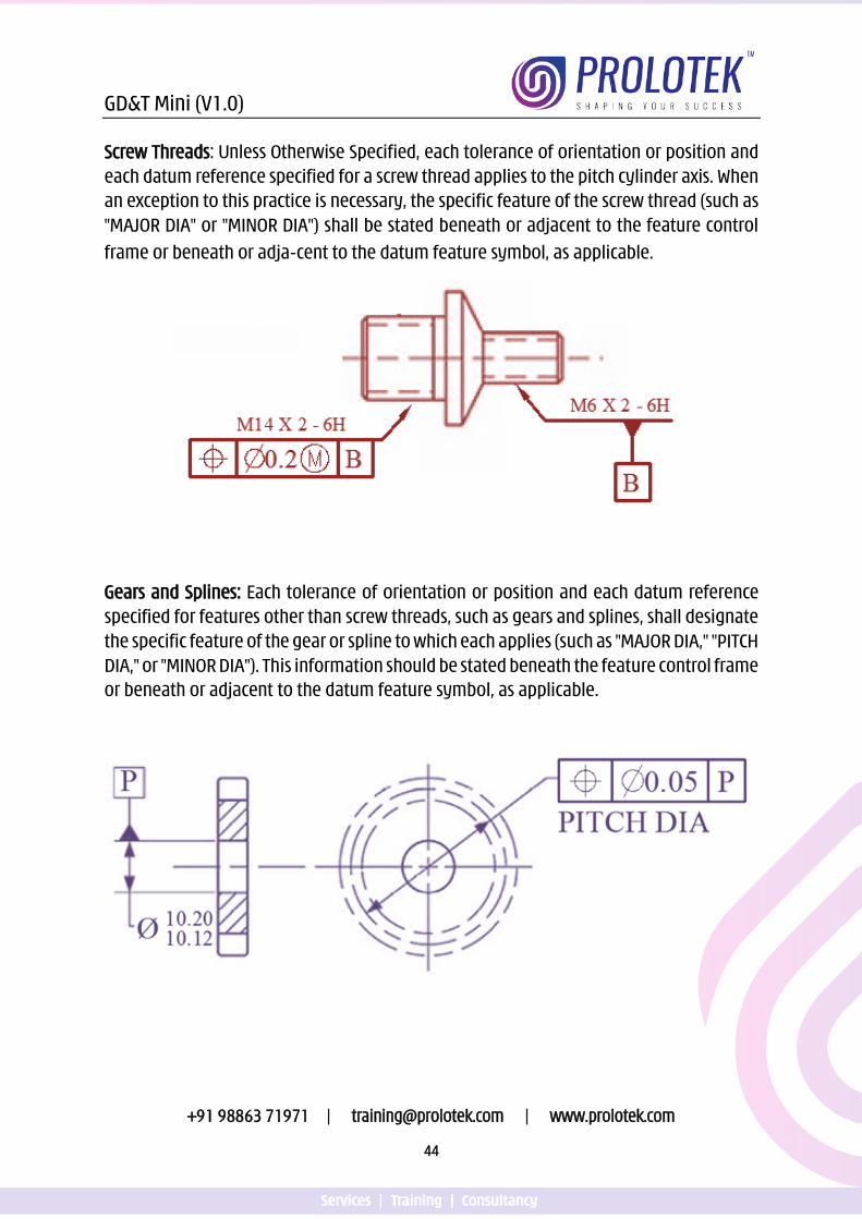
Screw Threads: Unless Otherwise Specified, each tolerance of orientation or position and each datum reference specified for a screw thread applies to the pitch cylinder axis. When an exception to this practice is necessary, the specific feature of the screw thread (such as "MAJOR DIA" or "MINOR DIA") shall be stated beneath or adjacent to the feature control
frame or beneath or adjacent to the datum feature symbol, as applicable.
Gears and Splines: Each tolerance of orientation or position and each datum reference specified for features other than screw threads, such as gears and splines, shall designate the specific feature of the gear or spline to which each applies (such as "MAJOR DIA," "PITCH DIA," or "MINOR DIA"). This information should be stated beneath the feature control frame or beneath or adjacent to the datum feature symbol, as applicable.
GD&T Mini (V1.0)
+91 98863 71971 | [email protected] | www.prolotek.com
45
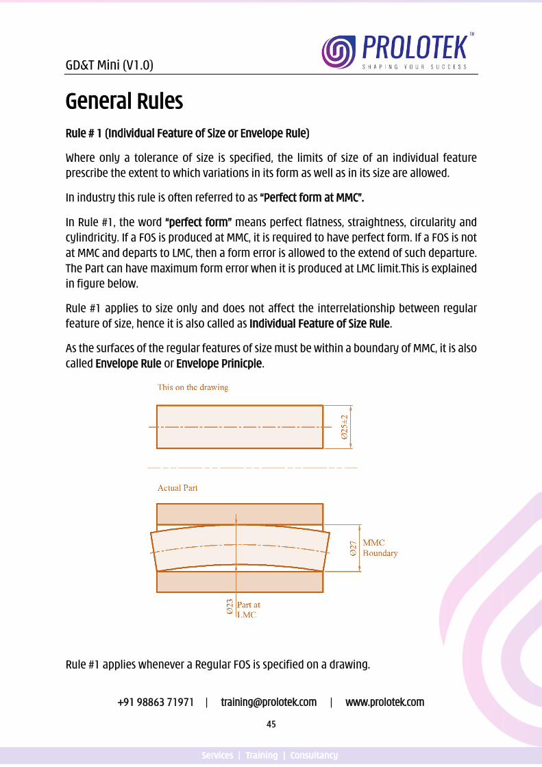
General Rules Rule # 1 (Individual Feature of Size or Envelope Rule)
Where only a tolerance of size is specified, the limits of size of an individual feature prescribe the extent to which variations in its form as well as in its size are allowed.
In industry this rule is often referred to as “Perfect form at MMC”.
In Rule #1, the word “perfect form” means perfect flatness, straightness, circularity and cylindricity. If a FOS is produced at MMC, it is required to have perfect form. If a FOS is not at MMC and departs to LMC, then a form error is allowed to the extend of such departure. The Part can have maximum form error when it is produced at LMC limit.This is explained in figure below.
Rule #1 applies to size only and does not affect the interrelationship between regular feature of size, hence it is also called as Individual Feature of Size Rule.
As the surfaces of the regular features of size must be within a boundary of MMC, it is also called Envelope Rule or Envelope Prinicple.
Rule #1 applies whenever a Regular FOS is specified on a drawing.
GD&T Mini (V1.0)
+91 98863 71971 | [email protected] | www.prolotek.com
46
Overriding Rule #1:
There are 3 ways Rule #1 can be overridden:
• If a straightness is applied to a regular feature of size, Rule #1 is overridden
• If a flatness control is applied to a regular feature of size, Rule #1 is overridden
• If independency symbol is specified next to a Regular FOS dimension, it exempts the Regular FOS dimension from Rule#1
Limitation of Rule #1
A part often contains multiple FOS. Rule #1 does not affect the location, orientation or relationship between features of size. FOS shown perpendicular, symmetrical, or coaxial must be controlled for location or orientation to avoid incomplete drawing specifications.
There are 3 exceptions to Rule #1:
• Rule #1 does not apply to irregular features of size
• Rule #1 does not apply to flexible parts that are not restrained.
• Rule #1 does not apply to stock sizes such as bar stock, tubing, sheet metal or structural shapes.
Rule #1 Requirements
1. The surfaces of the regular feature of size shall not extend beyond MMC boundary 2. When the regular Feature of size is produced at MMC, it must have perfect form 3. When actual local size of the regular feature of size departs from MMC towards LMC,
variation of form is allowed to the extend eual to the amount of departure from MMC.
4. There is no requirement of perfect form at LMC. 5. Where a geometric tolerance is specified at LMC, perfect form at LMC is required.
Click the link or scan the QR code for Video presentation on
Rule #1
https://youtu.be/Tb7_HczdspE
GD&T Mini (V1.0)
+91 98863 71971 | [email protected] | www.prolotek.com
47
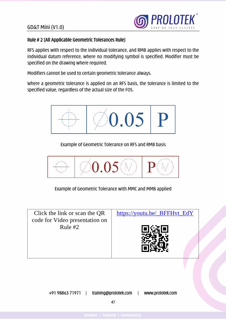
Rule # 2 (All Applicable Geometric Tolerances Rule)
RFS applies with respect to the individual tolerance, and RMB applies with respect to the individual datum reference, where no modifying symbol is specified. Modifier must be specified on the drawing where required.
Modifiers cannot be used to certain geometric tolerance always.
Where a geometric tolerance is applied on an RFS basis, the tolerance is limited to the specified value, regardless of the actual size of the FOS.
Example of Geometric Tolerance on RFS and RMB basis
Example of Geometric Tolerance with MMC and MMB applied
Click the link or scan the QR code for Video presentation on
Rule #2
https://youtu.be/_BFFHvt_EdY
GD&T Mini (V1.0)
+91 98863 71971 | [email protected] | www.prolotek.com
48
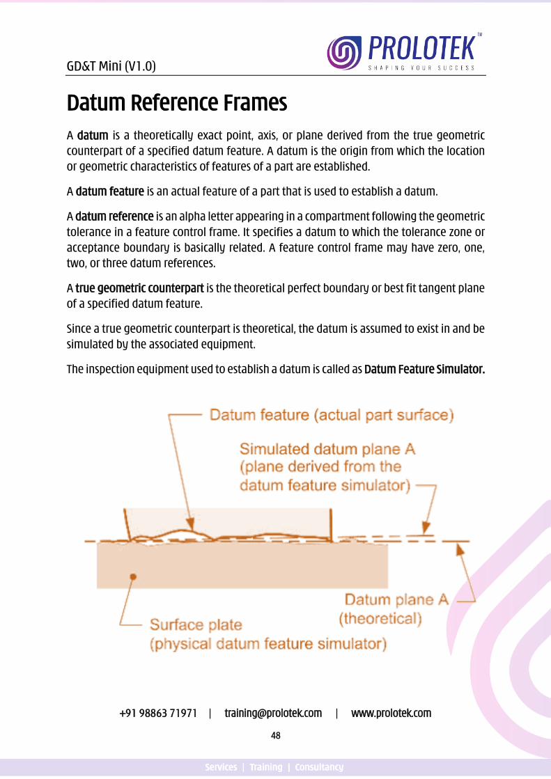
Datum Reference Frames A datum is a theoretically exact point, axis, or plane derived from the true geometric counterpart of a specified datum feature. A datum is the origin from which the location or geometric characteristics of features of a part are established.
A datum feature is an actual feature of a part that is used to establish a datum.
A datum reference is an alpha letter appearing in a compartment following the geometric tolerance in a feature control frame. It specifies a datum to which the tolerance zone or acceptance boundary is basically related. A feature control frame may have zero, one, two, or three datum references.
A true geometric counterpart is the theoretical perfect boundary or best fit tangent plane of a specified datum feature.
Since a true geometric counterpart is theoretical, the datum is assumed to exist in and be simulated by the associated equipment.
The inspection equipment used to establish a datum is called as Datum Feature Simulator.
GD&T Mini (V1.0)
+91 98863 71971 | [email protected] | www.prolotek.com
49
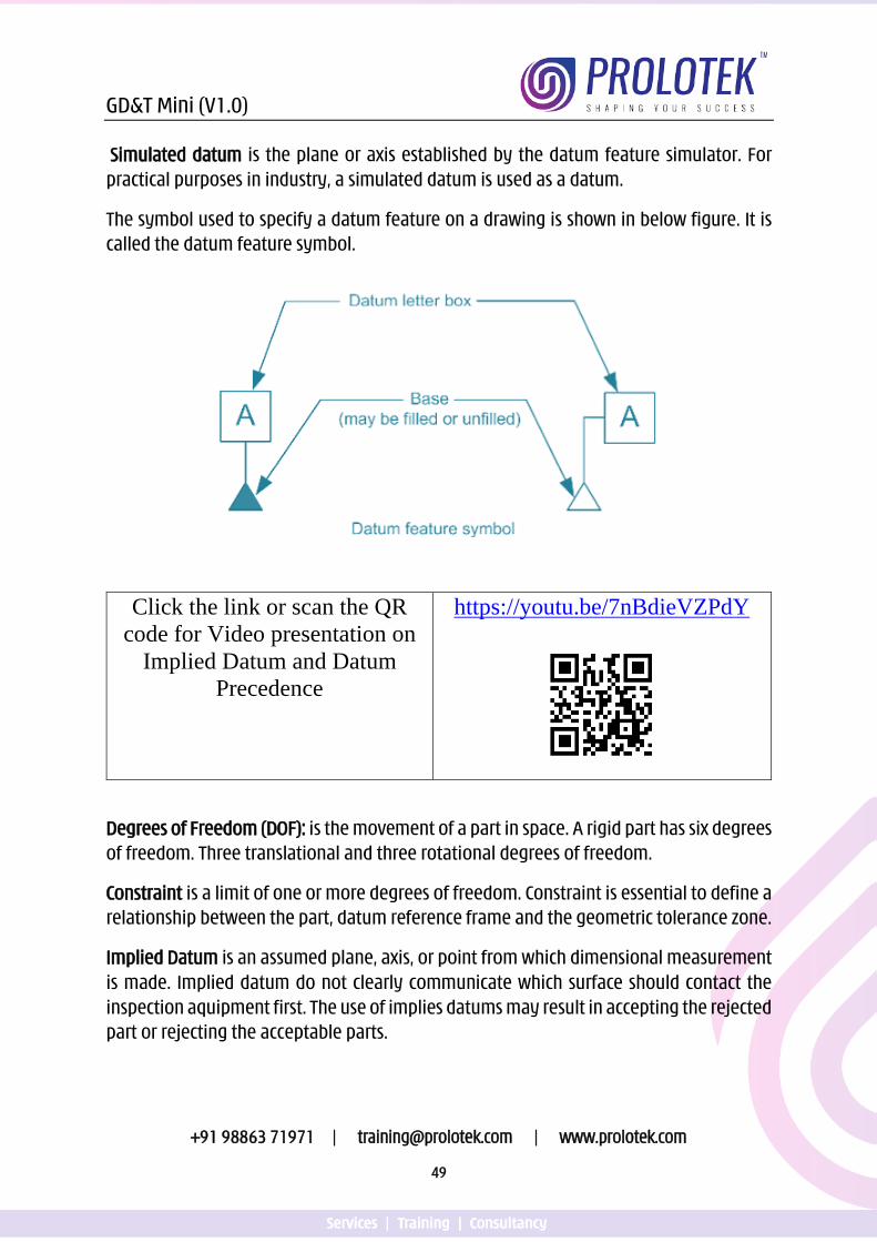
Simulated datum is the plane or axis established by the datum feature simulator. For practical purposes in industry, a simulated datum is used as a datum.
The symbol used to specify a datum feature on a drawing is shown in below figure. It is called the datum feature symbol.
Click the link or scan the QR code for Video presentation on
Implied Datum and Datum Precedence
https://youtu.be/7nBdieVZPdY
Degrees of Freedom (DOF): is the movement of a part in space. A rigid part has six degrees of freedom. Three translational and three rotational degrees of freedom.
Constraint is a limit of one or more degrees of freedom. Constraint is essential to define a relationship between the part, datum reference frame and the geometric tolerance zone.
Implied Datum is an assumed plane, axis, or point from which dimensional measurement is made. Implied datum do not clearly communicate which surface should contact the inspection aquipment first. The use of implies datums may result in accepting the rejected part or rejecting the acceptable parts.
GD&T Mini (V1.0)
+91 98863 71971 | [email protected] | www.prolotek.com
50
Datum Precedance: Datum Features are selected on the basis of the part function and assembly requirements. The datum features are often the features that orient (stabilize) and locate the part in its assembly.
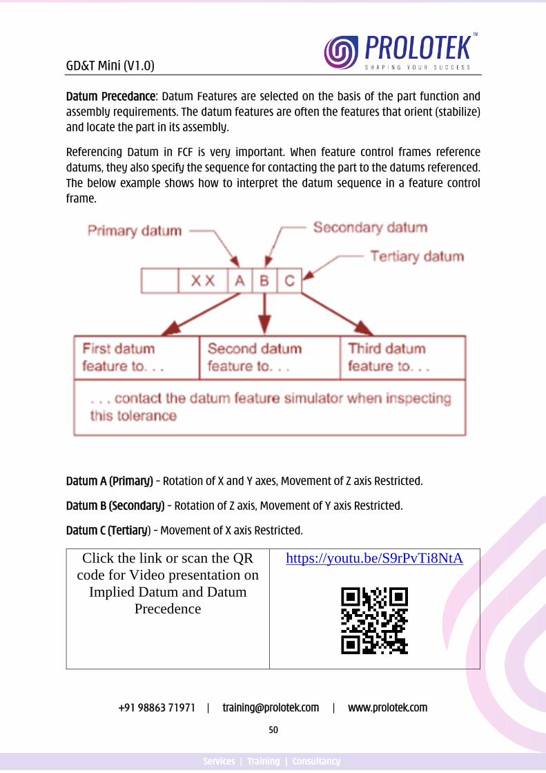
Referencing Datum in FCF is very important. When feature control frames reference datums, they also specify the sequence for contacting the part to the datums referenced. The below example shows how to interpret the datum sequence in a feature control frame.
Datum A (Primary) – Rotation of X and Y axes, Movement of Z axis Restricted.
Datum B (Secondary) – Rotation of Z axis, Movement of Y axis Restricted.
Datum C (Tertiary) – Movement of X axis Restricted.
Click the link or scan the QR code for Video presentation on
Implied Datum and Datum Precedence
https://youtu.be/S9rPvTi8NtA
GD&T Mini (V1.0)
+91 98863 71971 | [email protected] | www.prolotek.com
51
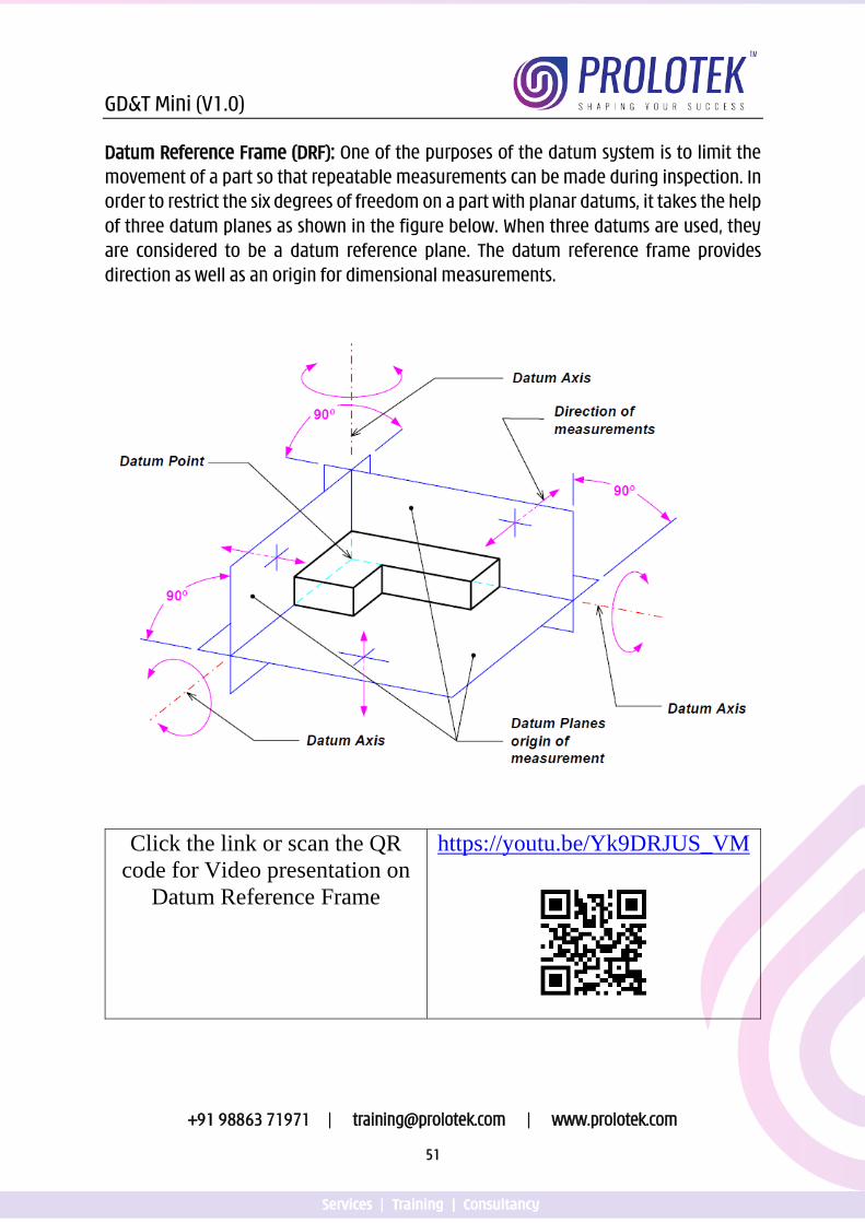
Datum Reference Frame (DRF): One of the purposes of the datum system is to limit the movement of a part so that repeatable measurements can be made during inspection. In order to restrict the six degrees of freedom on a part with planar datums, it takes the help of three datum planes as shown in the figure below. When three datums are used, they are considered to be a datum reference plane. The datum reference frame provides direction as well as an origin for dimensional measurements.
Click the link or scan the QR code for Video presentation on
Datum Reference Frame
https://youtu.be/Yk9DRJUS_VM
GD&T Mini (V1.0)
+91 98863 71971 | [email protected] | www.prolotek.com
52
The 3 – 2 – 1 Rule
The 3-2-1 rule defines the minimum number of points of contact required for a part datum feature with its primary, secondary and tertiary datum planes. The primary datum feature has at least three points of contact with its datum plane. The secondary datum feature has at least two points of contact with its datum plane. The tertiary datum feature has at least one point of contact with its datum plane. This rule applies to planer datum features only.
Click the link or scan the QR code for Video presentation on
3 – 2 – 1 Rule
https://youtu.be/PirUhGp2qwE
Datum Shift: When a feature of size is reference as a datum feature at Maximum Material Boundary (MMB), the daum deature simulator is a fixed size. When the datum feature on the actual part departs from its MMB, there will be clearance between the part and the datum feature simulator. This clearance is called datum shift.
Click the link or scan the QR code for Video presentation on
Datum Shift
https://youtu.be/biJbN-aef_4
GD&T Mini (V1.0)
+91 98863 71971 | [email protected] | www.prolotek.com
54
Click the link or scan the QR code for Video presentation on
Datum Types
https://youtu.be/biJbN-aef_4
GD&T Mini (V1.0)
+91 98863 71971 | [email protected] | www.prolotek.com
55
Datum Targets Datum targets are symbols that describe the shape, size and location of the gage elements that are used to establish datum planes or axes. Datum targets are specified on parts where it is not practically possible to use the entire planar surface as a datum feature.
Castings, forgings, irregularly shaped parts, plastics parts and weldments often do not have a planar datum feature or the datum feature is likely to be wrapped or bowed these results in an unsuitable contact with a full datum plane. Often the parts will rock, wobble or not rest in the same position on a full datum plane. In such case datum targets must be used.
The datum target identification symbol is divided into two parts with a horizontal line. The bottom half denotes the datum reference letter and the target number associated with that datum. The top half contains the datum feature simulator size information where ever applicable.
The three datum targets used on the drawings are:
• Datum Target Point
• Datum Target Line
• Datum Target Area
Datum Targets should be used whenever:
1. It is not possible to use the entire surface as a datum plane.
2. The designer suspects the part many rock or wobble when the datum feature contacts the datum plane.
3. Only a portion of the feature is used in the function of the part.
GD&T Mini (V1.0)
+91 98863 71971 | [email protected] | www.prolotek.com
56
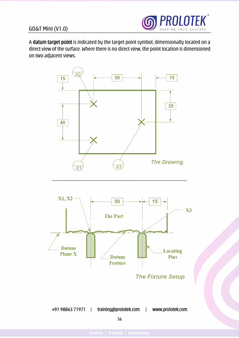
A datum target point is indicated by the target point symbol, dimensionally located on a direct view of the surface. Where there is no direct view, the point location is dimensioned on two adjacent views.
----------------------------------------------------------------------------------
GD&T Mini (V1.0)
+91 98863 71971 | [email protected] | www.prolotek.com
57
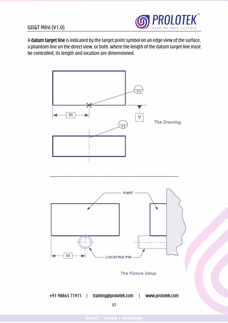
A datum target line is indicated by the target point symbol on an edge view of the surface, a phantom line on the direct view, or both. Where the length of the datum target line must be controlled, its length and location are dimensioned.
----------------------------------------------------------------------------------
GD&T Mini (V1.0)
+91 98863 71971 | [email protected] | www.prolotek.com
58
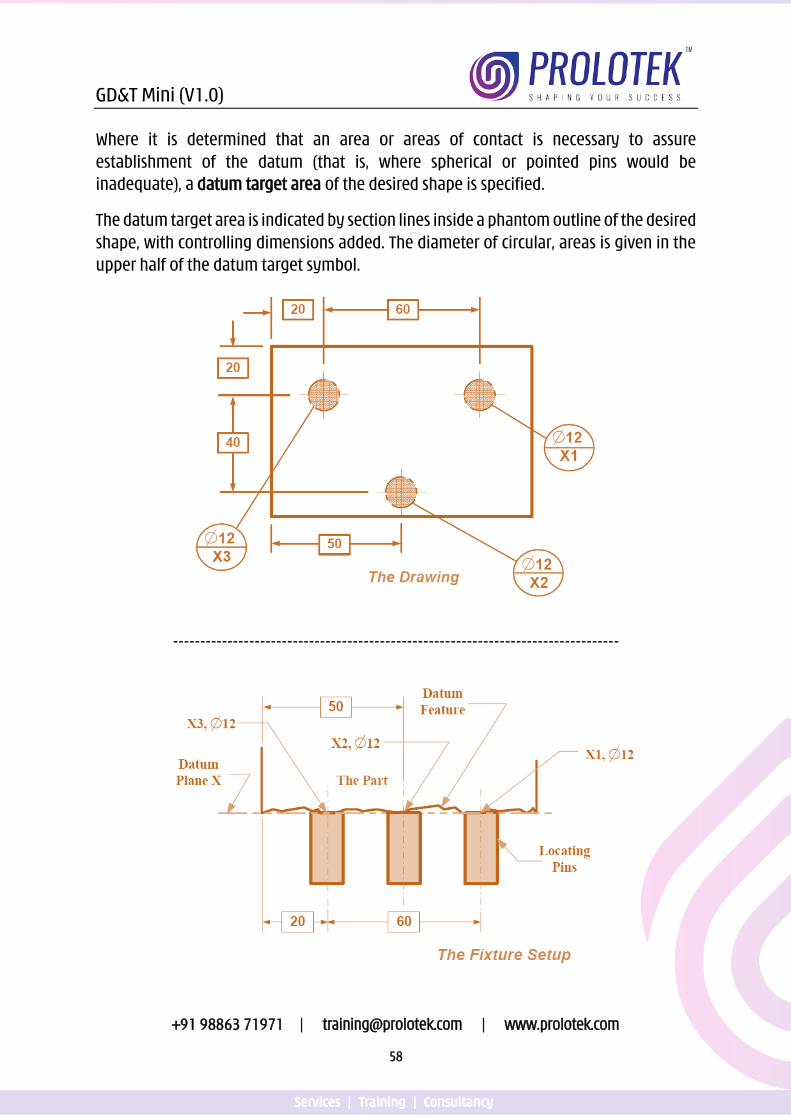
Where it is determined that an area or areas of contact is necessary to assure establishment of the datum (that is, where spherical or pointed pins would be inadequate), a datum target area of the desired shape is specified.
The datum target area is indicated by section lines inside a phantom outline of the desired shape, with controlling dimensions added. The diameter of circular, areas is given in the upper half of the datum target symbol.
----------------------------------------------------------------------------------
GD&T Mini (V1.0)
+91 98863 71971 | [email protected] | www.prolotek.com
59
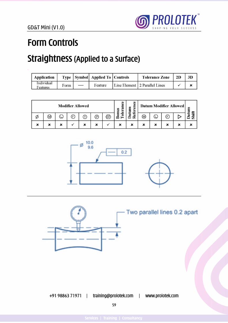
Form Controls
Straightness (Applied to a Surface)
GD&T Mini (V1.0)
+91 98863 71971 | [email protected] | www.prolotek.com
60
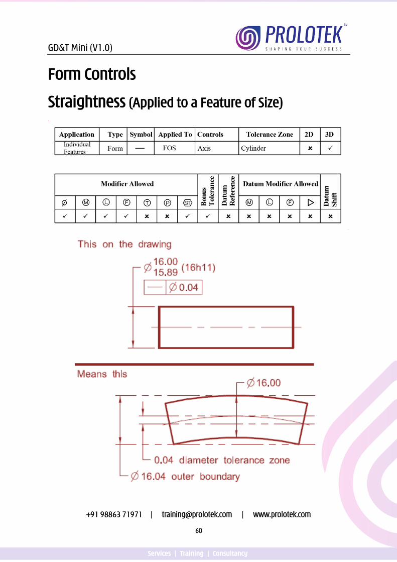
Form Controls
Straightness (Applied to a Feature of Size)
GD&T Mini (V1.0)
+91 98863 71971 | [email protected] | www.prolotek.com
61
Points to Remember for Straightness applied to a surface
1. The part must be within its size tolerance. 2. The control must be directed to the surface element. 3. The control must be applied in the view where the controlled elements are
shown as a line. 4. The tolerance value specified must be less than the size tolerance and any other
geometric controls that limit the form of the surface. 5. Rule #1 applies to the feature of size dimension.
Points to Remember for straightness applied to a Feature of Size
1. The part must be within its size tolerance. 2. The straightness control specifies a tolerance zone within which the axis must lie. 3. The tolerance value may be greater than the size limits. 4. Rule #1 is Overridden. 5. A fixed gauge may be used to verify the straightness.
Click the link or scan the QR code for Video presentation on
Straightness
https://youtu.be/viHVhnk8TZY
GD&T Mini (V1.0)
+91 98863 71971 | [email protected] | www.prolotek.com
62
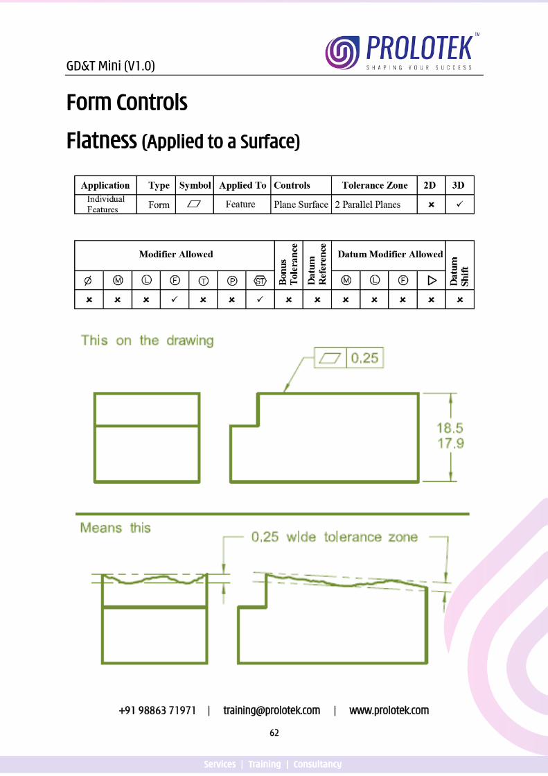
Form Controls
Flatness (Applied to a Surface)
GD&T Mini (V1.0)
+91 98863 71971 | [email protected] | www.prolotek.com
63
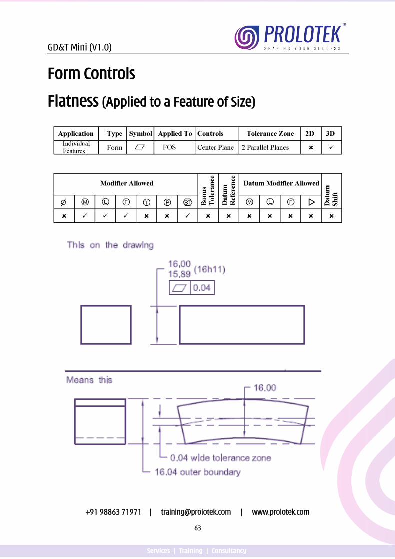
Form Controls
Flatness (Applied to a Feature of Size)
GD&T Mini (V1.0)
+91 98863 71971 | [email protected] | www.prolotek.com
64
Points to Remember for Flatness applied to a surface
1. The part must be within its size tolerance. 2. The control must be applied to a planer surface. 3. The tolerance value specified must be less than the size tolerance and any other
geometric controls that limit the form of the surface. 4. Rule #1 applies to the feature of size dimension.
Points to Remember for Flatness applied to a Feature of Size
1. The part must be within its size tolerance. 2. The flatness control specifies a tolerance zone within which the center plane
must lie. 3. The tolerance value may be greater than the size limits. 4. Rule #1 is Overridden. 5. A fixed gauge may be used to verify the straightness.
Click the link or scan the QR code for Video presentation on
Flatness
https://youtu.be/STfDv0A2Odg
GD&T Mini (V1.0)
+91 98863 71971 | [email protected] | www.prolotek.com
65
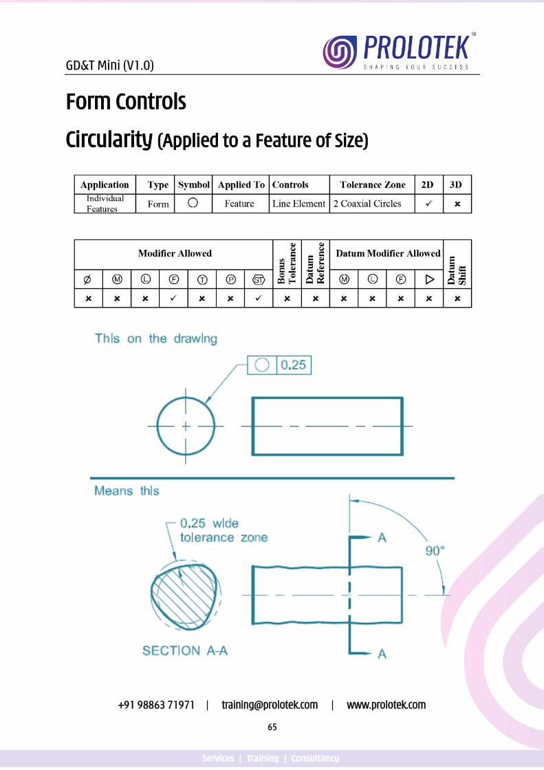
Form Controls
Circularity (Applied to a Feature of Size)
GD&T Mini (V1.0)
+91 98863 71971 | [email protected] | www.prolotek.com
66
Points to Remember for Circularity
1. The part must be within its size tolerance. 2. The control must be applied to a diametrical feature. 3. The tolerance value specified must be less than the size tolerance and any other
geometric controls that limit the form of the surface. 4. Rule #1 applies to the feature of size dimension. 5. Tolerance zone applies at every cross section.
Click the link or scan the QR code for Video presentation on
Circularity
https://youtu.be/3F36hbdUiSo
GD&T Mini (V1.0)
+91 98863 71971 | [email protected] | www.prolotek.com
67
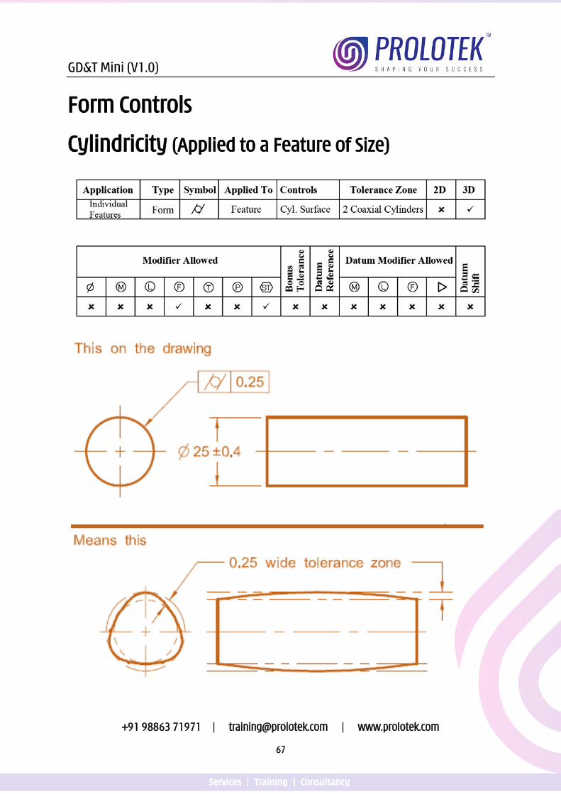
Form Controls
Cylindricity (Applied to a Feature of Size)
GD&T Mini (V1.0)
+91 98863 71971 | [email protected] | www.prolotek.com
68
Points to Remember for Cylindricity
1. The part must be within its size tolerance. 2. The control must be applied to a cylindrical feature. 3. The tolerance value specified must be less than the size tolerance and any other
geometric controls that limit the form of the surface. 4. Rule #1 applies to the feature of size dimension.
Click the link or scan the QR code for Video presentation on
Cylindricity
https://youtu.be/_Ho1PqO30Ug
GD&T Mini (V1.0)
+91 98863 71971 | [email protected] | www.prolotek.com
69
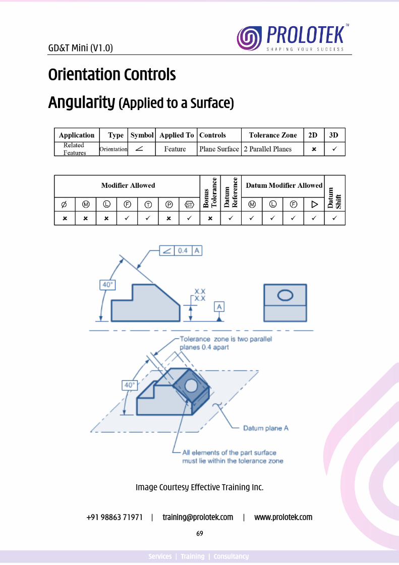
Orientation Controls
Angularity (Applied to a Surface)
Image Courtesy Effective Training Inc.
GD&T Mini (V1.0)
+91 98863 71971 | [email protected] | www.prolotek.com
70
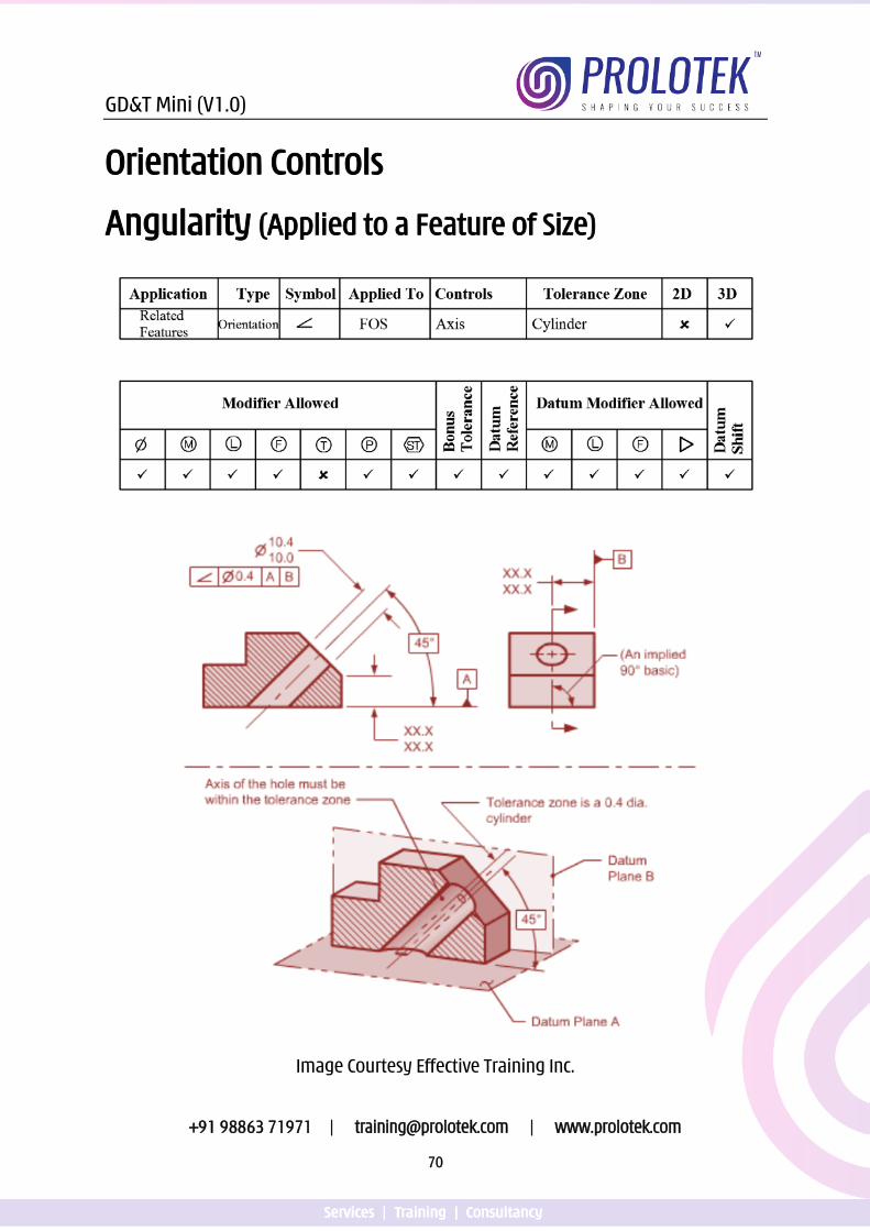
Orientation Controls
Angularity (Applied to a Feature of Size)
Image Courtesy Effective Training Inc.
GD&T Mini (V1.0)
+91 98863 71971 | [email protected] | www.prolotek.com
71
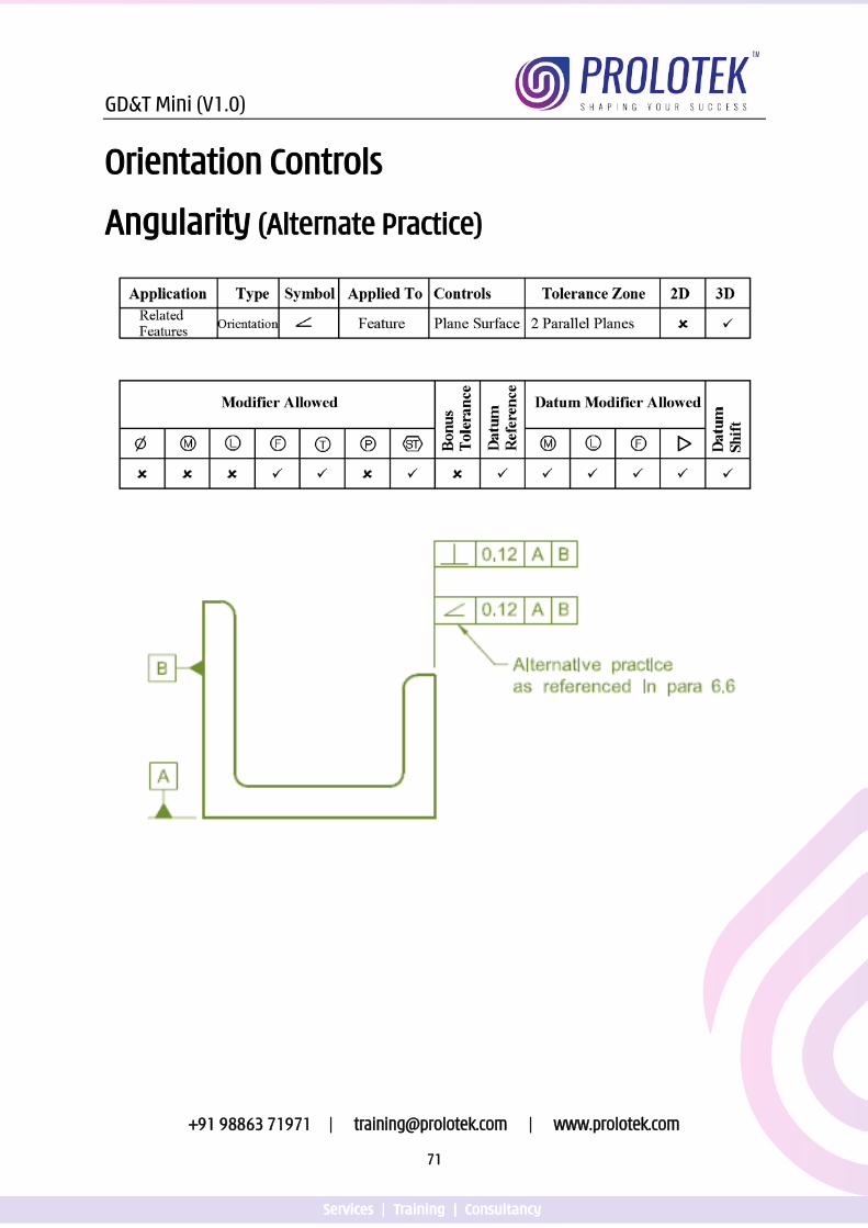
Orientation Controls
Angularity (Alternate Practice)
GD&T Mini (V1.0)
+91 98863 71971 | [email protected] | www.prolotek.com
72
Points to Remember for Angularity applied to A Surface
1. Basic dimensions must be specified from the tolerance surface to the datums referenced.
2. Controls the flatness of the surface 3. The tolerance value specified must be refinement of any other geometric
tolerances that control the angularity of the feature. 4. Multiple datum references may be used
Points to Remember for Angularity applied to a Feature of Size
1. Basic dimensions must be specified from the tolerance FOS to the datums referenced.
2. Toleranced FOS must be within the size limit. 3. Virtual condition will be affected when material condition modifiers are applied. 4. Multiple datum references may be used
Points to Remember for Angularity as alternate practice
1. Controls the flatness of the surface 2. The tolerance value specified must be refinement of any other geometric
tolerances that control the orientation of the feature. 3. Multiple datum references may be used 4. May be used in place of perpendicularity or parallelism
Click the link or scan the QR code for Video presentation on
Angularity
https://youtu.be/SOTEVkh57JY
GD&T Mini (V1.0)
+91 98863 71971 | [email protected] | www.prolotek.com
73
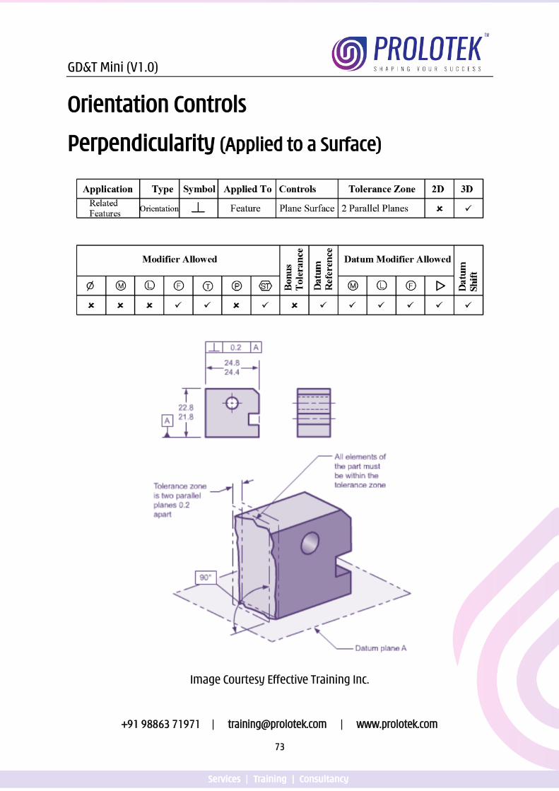
Orientation Controls
Perpendicularity (Applied to a Surface)
Image Courtesy Effective Training Inc.
GD&T Mini (V1.0)
+91 98863 71971 | [email protected] | www.prolotek.com
74
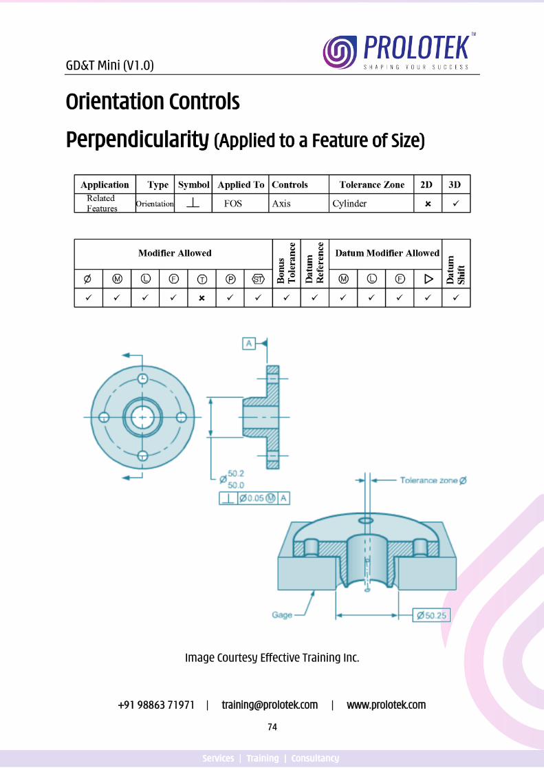
Orientation Controls
Perpendicularity (Applied to a Feature of Size)
Image Courtesy Effective Training Inc.
GD&T Mini (V1.0)
+91 98863 71971 | [email protected] | www.prolotek.com
75
Points to Remember for Perpendicularity applied to a Surface
1. Controls the flatness of the surface 2. The tolerance value specified must be refinement of any other geometric
tolerances that control the perpendicularity of the feature. 3. Multiple datum references may be used
Points to Remember Perpendicularity applied to a Feature of Size
1. Toleranced FOS must be within the size limit. 2. Virtual condition will be affected when material condition modifiers are applied. 3. Multiple datum references may be used
Click the link or scan the QR code for Video presentation on
Perpendicularity
https://youtu.be/9wFJdU-1ceQ
GD&T Mini (V1.0)
+91 98863 71971 | [email protected] | www.prolotek.com
76
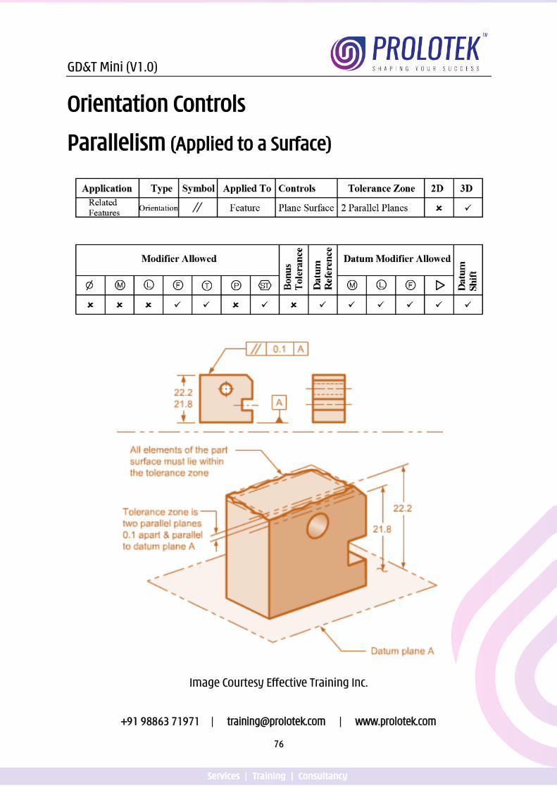
Orientation Controls
Parallelism (Applied to a Surface)
Image Courtesy Effective Training Inc.
GD&T Mini (V1.0)
+91 98863 71971 | [email protected] | www.prolotek.com
77
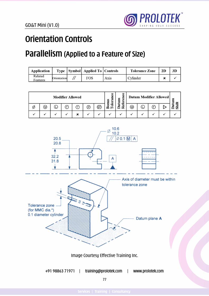
Orientation Controls
Parallelism (Applied to a Feature of Size)
Image Courtesy Effective Training Inc.
GD&T Mini (V1.0)
+91 98863 71971 | [email protected] | www.prolotek.com
78
Points to Remember for Parallelism applied to a Surface
1. Controls the flatness of the surface 2. Tolerance value must be less than the size tolerance. 3. The tolerance value specified must be refinement of any other geometric
tolerances that control the parallelism of the feature. 4. Multiple datum references may be used
Points to Remember for Parallelism applied to a Feature of Size
1. Toleranced FOS must be with in the size limit. 2. Virtual condition will be affected when material condition modifiers are appled. 3. Multiple datum references may be used
Click the link or scan the QR code for Video presentation on
Parellelism
https://youtu.be/9n8EaAOtauU
GD&T Mini (V1.0)
+91 98863 71971 | [email protected] | www.prolotek.com
79
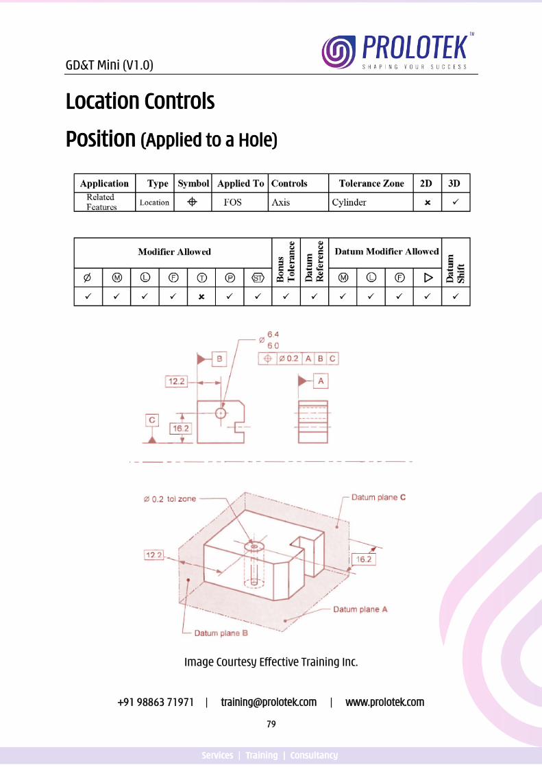
Location Controls
Position (Applied to a Hole)
Image Courtesy Effective Training Inc.
GD&T Mini (V1.0)
+91 98863 71971 | [email protected] | www.prolotek.com
80
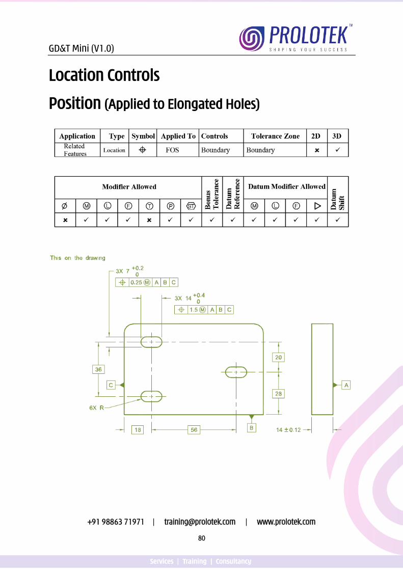
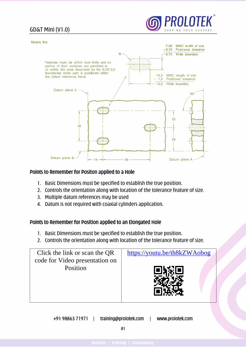
Location Controls
Position (Applied to Elongated Holes)
GD&T Mini (V1.0)
+91 98863 71971 | [email protected] | www.prolotek.com
81
Points to Remember for Positon applied to a Hole
1. Basic Dimensions must be specified to establish the true position. 2. Controls the orientation along with location of the tolerance feature of size. 3. Multiple datum references may be used 4. Datum is not required with coaxial cylinders application.
Points to Remember for Position applied to an Elongated Hole
1. Basic Dimensions must be specified to establish the true position. 2. Controls the orientation along with location of the tolerance feature of size.
Click the link or scan the QR code for Video presentation on
Position
https://youtu.be/th8kZWAobog
GD&T Mini (V1.0)
+91 98863 71971 | [email protected] | www.prolotek.com
82
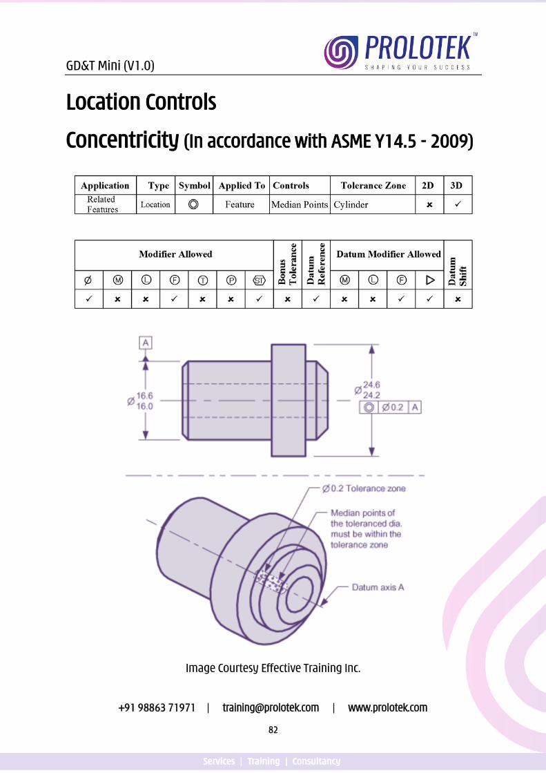
Location Controls
Concentricity (In accordance with ASME Y14.5 - 2009)
Image Courtesy Effective Training Inc.
GD&T Mini (V1.0)
+91 98863 71971 | [email protected] | www.prolotek.com
83
Points to Remember for Concentricity
1. The derived median points of the tolerance feature must be within the tolerance zone
2. The FCF must be applied to the surface of revolution that is coaxial to the datum axis
3. The Diameter symbol modifier must be used in the FCF 4. Consider using position or runout in place of concentricity
Click the link or scan the QR code for Video presentation on
Concentricity
https://youtu.be/_mjUQ_2TEUs
GD&T Mini (V1.0)
+91 98863 71971 | [email protected] | www.prolotek.com
84
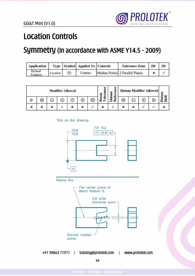
Location Controls
Symmetry (In accordance with ASME Y14.5 - 2009)
GD&T Mini (V1.0)
+91 98863 71971 | [email protected] | www.prolotek.com
85
Points to Remember for Symmetry
1. The FCF must be applied to a planar FOS that is symmetrical about the datum center plane.
2. Derived Median Points of the tolerance feature must be within the tolerance zone
3. Consider using position or profile in place of concentricity
Click the link or scan the QR code for Video presentation on
Symmetry
https://youtu.be/uFCgU0hBe5M
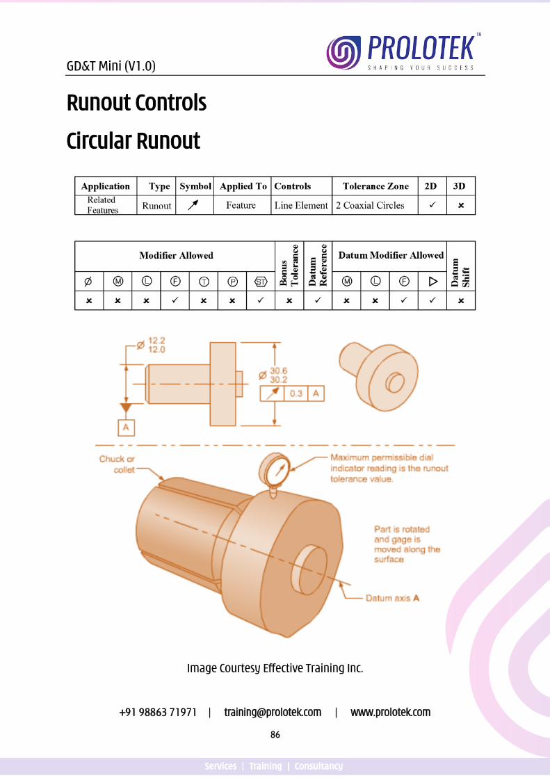
GD&T Mini (V1.0)
+91 98863 71971 | [email protected] | www.prolotek.com
86
Runout Controls
Circular Runout
Image Courtesy Effective Training Inc.
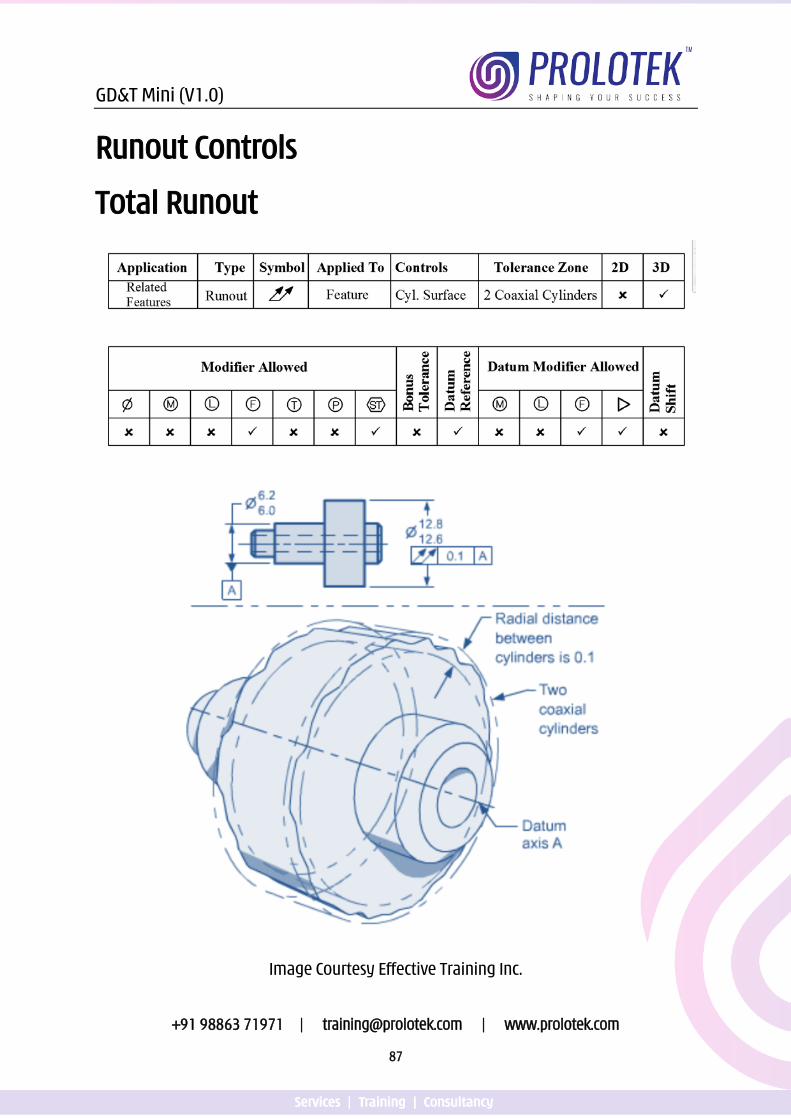
GD&T Mini (V1.0)
+91 98863 71971 | [email protected] | www.prolotek.com
87
Runout Controls
Total Runout
Image Courtesy Effective Training Inc.
GD&T Mini (V1.0)
+91 98863 71971 | [email protected] | www.prolotek.com
88
Points to Remember for Circular Runout
1. Applies to each circular element independently 2. Controls the Circularity and axis offset 3. May be applied to a partial diameter 4. Datum referenced must be a proper axis datum
Points to Remember for Total Runout
1. Applies to entire surface simultaneously. 2. Controls the cylindricity and axis offset 3. Datum referenced must be a proper axis datum
Click the link or scan the QR code for Video presentation on
Runouts
https://youtu.be/30GlFDSZAPs
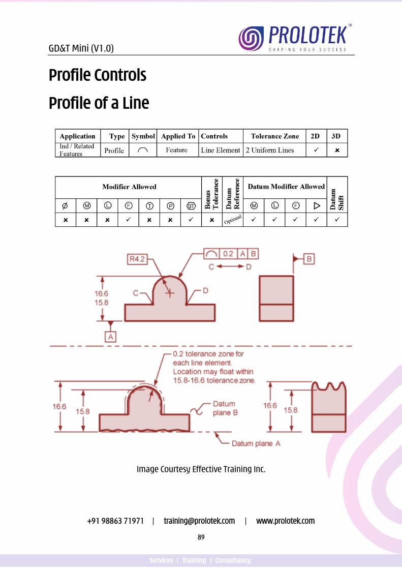
GD&T Mini (V1.0)
+91 98863 71971 | [email protected] | www.prolotek.com
89
Profile Controls
Profile of a Line
Image Courtesy Effective Training Inc.
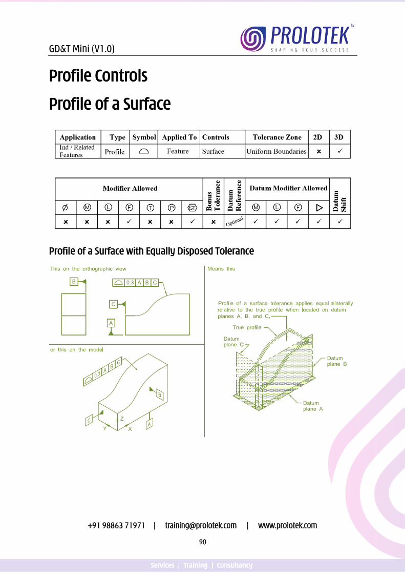
GD&T Mini (V1.0)
+91 98863 71971 | [email protected] | www.prolotek.com
90
Profile Controls
Profile of a Surface
Profile of a Surface with Equally Disposed Tolerance
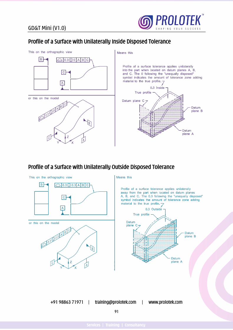
GD&T Mini (V1.0)
+91 98863 71971 | [email protected] | www.prolotek.com
91
Profile of a Surface with Unilaterally Inside Disposed Tolerance
Profile of a Surface with Unilaterally Outside Disposed Tolerance
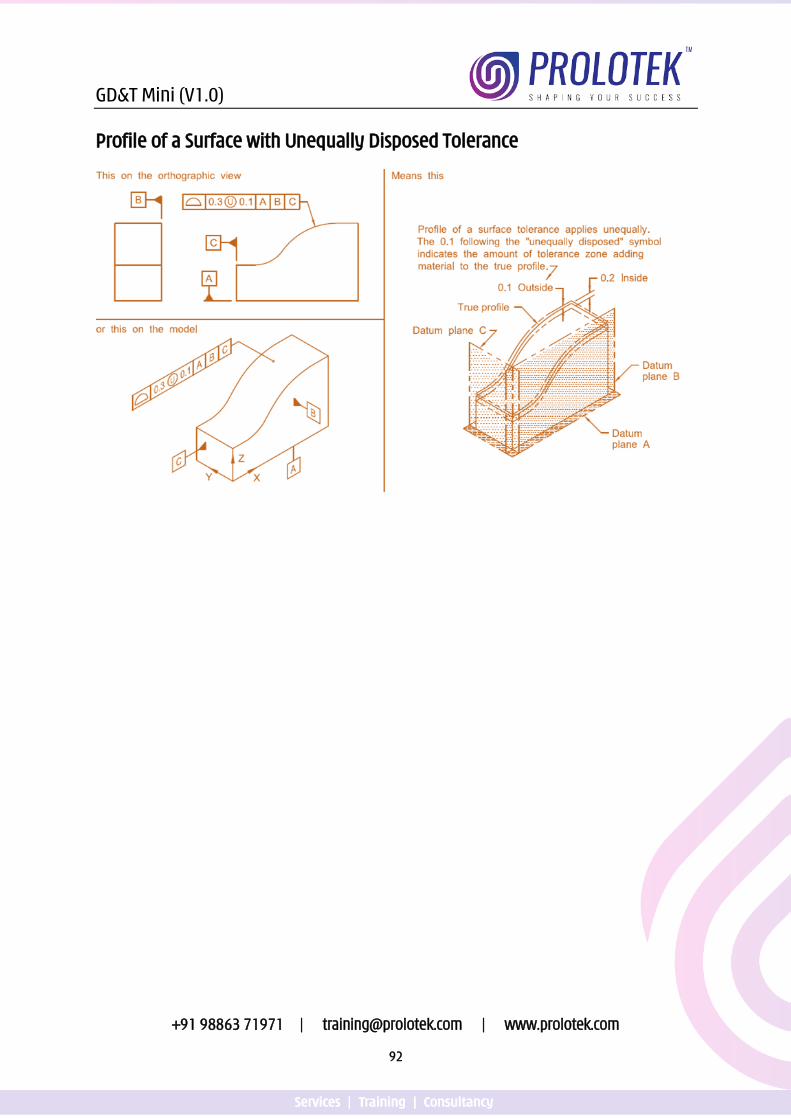
GD&T Mini (V1.0)
+91 98863 71971 | [email protected] | www.prolotek.com
92
Profile of a Surface with Unequally Disposed Tolerance
GD&T Mini (V1.0)
+91 98863 71971 | [email protected] | www.prolotek.com
93
Points to Remember for Profile of a Line
1. Only applies in the view the tolerance is specified 2. Can be used without a datum reference as form control 3. If the true profile is located with the tolerance dimensions, the profile tolerance
must be refinement of the tolerance value of the dimension. 4. Between, All Around, All Over, Unilaterally / Unequally Disposed, Dynamic Profile
and From To Modifiers can be applied.
Points to Remember for Profile of a Surface
1. Can be used without a datum reference as form control 2. If the true profile is located with the tolerance dimensions, the profile tolerance
must be refinement of the tolerance value of the dimension. 3. Between, All Around, All Over, Unilaterally / Unequally Disposed, Dynamic Profile
and From To Modifiers can be applied.
Click the link or scan the QR code for Video presentation on
Profile
https://youtu.be/wO6yYmox0kg
GD&T Mini (V1.0)
+91 98863 71971 | [email protected] | www.prolotek.com
94
Further Reading 1. American Society of Mechanical Engineers, Dimensioning and Tolerancing: ASME
Y14.5-2009 2. American Society of Mechanical Engineers, Dimensioning and Tolerancing: ASME
Y14.5-2018 3. Krulikowski, Alex. Fundamentals of Geometric Dimensioning and Tolerancing
Based on ASME Y14.5-1994. Westland, MI: Effective Training. 4. Don Day, The GD&T Hierarchy Y14.5 – 2018, Tec-Ease, Inc. 5. Krulikowski, Alex. Advance Concepts of Geometric Dimensioning and Tolerancing
Based on ASME Y14.5-2009. Westland, MI: Effective Training. 6. Scott Neumann & Al Neumann, GeoTol Pro, A practical guide to geometric
tolerancing per ASME Y14.5-2009, Technical Consultants Inc. 7. Meadows, James D. Geometric Dimensioning and Tolerancing: Applications,
Analysis & Measurement [per ASME Y14.5-2009]. James D. Meadows & Associates, Inc.,
8. David A. Madsen, Geometric Dimensioning and Tolerancing. The Goodheart Willcox Company, Inc.
9. Henzold, G. Handbook of Geometric Tolerancing: Design, Manufacturing and Inspection. England: Wiley & Sons.
GD&T Mini (V1.0)
+91 98863 71971 | [email protected] | www.prolotek.com
95
Our Training Programs Related to GD&T 1. Basic Concepts of GD&T
2. Fundamentals of GD&T in accordance with ASME Y14.5 – 2009 & 2018
3. Advanced Concepts of GD&T in accordance with ASME Y14.5 – 2009 & 2018
4. Best Drawing Practices and Blue Print Reading in accordance with ASME Y14.100
5. ASME GDTP Certification Exam Preparation Coaching
6. Digital Product Definition in accordance with ASME Y14.41

Training | Services | Consultancy
PROLOTEK TECHNOLOGIES PRIVATE LIMITED #936, SCK complex, 2nd floor, Channasandra,
Rajarajeshwari Nagar, Bengaluru, 560098
+91 98863 71971