fx05 controller
TRANSCRIPT
Platform Catalogue Section 1Product Bulletin FX05
Issue Date 08 2002
© 2002 Johnson Controls, Inc. 1Order Nr. 24.438 E, Rev. C www.johnsoncontrols.com
FX05 Controller
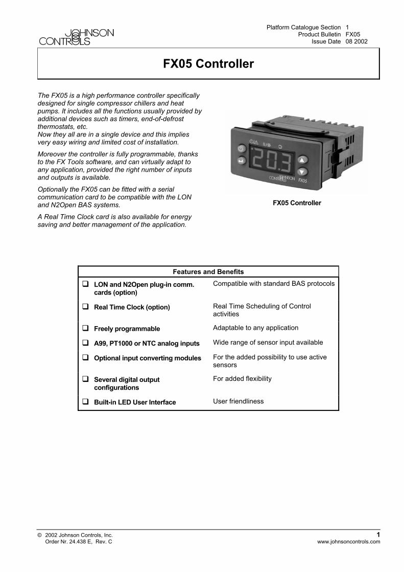
The FX05 is a high performance controller specificallydesigned for single compressor chillers and heatpumps. It includes all the functions usually provided byadditional devices such as timers, end-of-defrostthermostats, etc.Now they all are in a single device and this impliesvery easy wiring and limited cost of installation.
Moreover the controller is fully programmable, thanksto the FX Tools software, and can virtually adapt toany application, provided the right number of inputsand outputs is available.
Optionally the FX05 can be fitted with a serialcommunication card to be compatible with the LONand N2Open BAS systems.
A Real Time Clock card is also available for energysaving and better management of the application.
FX05 Controller
Features and Benefits
LON and N2Open plug-in comm.cards (option)
Compatible with standard BAS protocols
Real Time Clock (option) Real Time Scheduling of Controlactivities
Freely programmable Adaptable to any application
A99, PT1000 or NTC analog inputs Wide range of sensor input available
Optional input converting modules For the added possibility to use activesensors
Several digital outputconfigurations
For added flexibility
Built-in LED User Interface User friendliness
2 FX05
General featuresInput/Output• 4 analogue inputs (AI)
• 5 digital inputs (DI)
• 6 digital outputs (DO)
• 1 analogue output 0…10Vdc (AO)
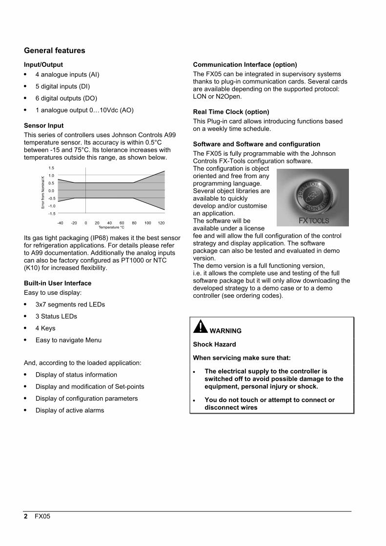
Sensor InputThis series of controllers uses Johnson Controls A99temperature sensor. Its accuracy is within 0.5°Cbetween -15 and 75°C. Its tolerance increases withtemperatures outside this range, as shown below.
Its gas tight packaging (IP68) makes it the best sensorfor refrigeration applications. For details please referto A99 documentation. Additionally the analog inputscan also be factory configured as PT1000 or NTC(K10) for increased flexibility.
Built-in User InterfaceEasy to use display:
• 3x7 segments red LEDs
• 3 Status LEDs
• 4 Keys
• Easy to navigate Menu
And, according to the loaded application:
• Display of status information
• Display and modification of Set-points
• Display of configuration parameters
• Display of active alarms
Communication Interface (option)The FX05 can be integrated in supervisory systemsthanks to plug-in communication cards. Several cardsare available depending on the supported protocol:LON or N2Open.
Real Time Clock (option)This Plug-in card allows introducing functions basedon a weekly time schedule.
Software and Software and configurationThe FX05 is fully programmable with the JohnsonControls FX-Tools configuration software.The configuration is objectoriented and free from anyprogramming language.Several object libraries areavailable to quicklydevelop and/or customisean application.The software will beavailable under a licensefee and will allow the full configuration of the controlstrategy and display application. The softwarepackage can also be tested and evaluated in demoversion.The demo version is a full functioning version,i.e. it allows the complete use and testing of the fullsoftware package but it will only allow downloading thedeveloped strategy to a demo case or to a democontroller (see ordering codes).
WARNING
Shock Hazard
When servicing make sure that:
• The electrical supply to the controller isswitched off to avoid possible damage to theequipment, personal injury or shock.
• You do not touch or attempt to connect ordisconnect wires
FX05 3
I/O Details
Controller Model Type Remark/ApplicationAnalog Input (AI)FX05P00 AI1 ÷ AI4 PT1000
Range: -40 to 100°CAccuracy: ±0.3°C @ 20°C ambient
(sensor error not included)
Application: temperature.
FX05P01 AI1, AI2,AI3, AI4
A99Range: -40 to 100°CAccuracy: ±0.3°C @ 20°C ambient
(sensor error not included)
Application: temperature.Humidity, pressure, etc. through InputConverter
AI1, AI2, AI3 A99Range: -40 to 100°CAccuracy: ±0.3°C @ 20°C ambient
(sensor error not included)
Application: temperature.Humidity, pressure, etc. through InputConverter
FX05P02 / P03
AI4 NTC K10Range: 0 to 100°CAccuracy: ±0.5°C @ 20°C ambient
For the Fan Speed control signalcoming from the Room CommandModule
Digital Input (DI)FX05P01 / P02 / P03 DI1, DI2,
DI3, DI4, DI5Voltage free contacts
Digital Output (DO)DO1 SPST 5A, 250 VAC power relay Double insulated from the other relay
group. Application: alarm output, etcFX05P00 / 01
DO2 ÷ DO6 SPST 5A, 250 VAC power relay Any combination of loads must notexceed 15A in total (the "commons"pins are internally connected).Max. 5A on C2/3Max. 5A on C4/5Max. 5A on C6
DO1, DO2, 0,5A / 24 VAC triacs 3-point valves, thermal actuators, etcFX05P02 / P03DO3 ÷ DO6 SPST 5A, 250 VAC power relay On the P02 model the DO3 ÷ DO5
relays are physically interlocked, i.e.one cannot be energised if the othertwo aren't off. Application: 3-speed fanmotors. The DO6 relay is free.On the P03 model all relays are freelyusable.Max. 5A on C3, C4, C5 and C6Any combination of loads must notexceed 15A in total
Analogue Outputs (AO)FX05P00 / P01 / P02 /P03
AO1 0…10 VDC Application: drive motor actuators,power triacs, frequency drives, etc.
4 FX05
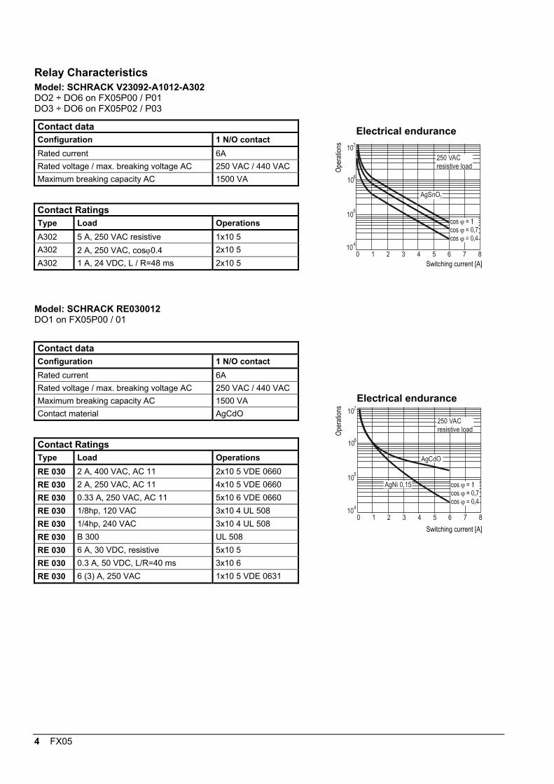
Relay CharacteristicsModel: SCHRACK V23092-A1012-A302DO2 ÷ DO6 on FX05P00 / P01DO3 ÷ DO6 on FX05P02 / P03
Contact dataConfiguration 1 N/O contactRated current 6ARated voltage / max. breaking voltage AC 250 VAC / 440 VACMaximum breaking capacity AC 1500 VA
Contact RatingsType Load OperationsA302 5 A, 250 VAC resistive 1x10 5A302 2 A, 250 VAC, cosϕ0.4 2x10 5A302 1 A, 24 VDC, L / R=48 ms 2x10 5
Model: SCHRACK RE030012DO1 on FX05P00 / 01
Contact dataConfiguration 1 N/O contactRated current 6ARated voltage / max. breaking voltage AC 250 VAC / 440 VACMaximum breaking capacity AC 1500 VAContact material AgCdO
Contact RatingsType Load OperationsRE 030 2 A, 400 VAC, AC 11 2x10 5 VDE 0660RE 030 2 A, 250 VAC, AC 11 4x10 5 VDE 0660RE 030 0.33 A, 250 VAC, AC 11 5x10 6 VDE 0660RE 030 1/8hp, 120 VAC 3x10 4 UL 508RE 030 1/4hp, 240 VAC 3x10 4 UL 508RE 030 B 300 UL 508RE 030 6 A, 30 VDC, resistive 5x10 5RE 030 0.3 A, 50 VDC, L/R=40 ms 3x10 6RE 030 6 (3) A, 250 VAC 1x10 5 VDE 0631
107
106
105
104
0 1 2 3 4 5 6 7 8
AgSnO2
250 VACresistive load
Electrical endurance
Ope
ratio
ns
Switching current [A]
107
106
105
104
0 1 2 3 4 5 6 7 8
AgCdO
AgNi 0,15
250 VACresistive load
Electrical endurance
Ope
ratio
ns
Switching current [A]
FX05 5
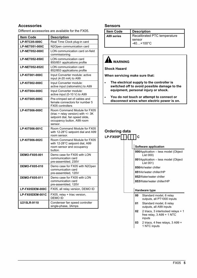
AccessoriesDifferent accessories are available for the FX05.
Item Code DescriptionLP-RTC05-000C Real Time Clock plug-in cardLP-NET051-000C N2Open communication cardLP-NET052-000C LON communication card on-field
commissioningLP-NET052-850C LON communication card
850/851 applications profileLP-NET052-852C LON communication card
852/853 applications profileLP-KIT001-000C Input Converter module: active
input (4-20 mA) to A99LP-KIT002-000C Input Converter module:
active input (ratiometric) to A99LP-KIT004-000C Input Converter module:
active input (0-10 V) to A99LP-KIT005-000C Pre-crimped set of cables and
female connectors for number 5FX05 controllers
LP-KIT006-000C Room Command Module for FX05(triac + relay version) with +/- 3Ksetpoint dial, fan speed slide,occupancy button, A99 roomsensor.
LP-KIT006-001C Room Command Module for FX05with 12-28°C setpoint dial and A99room sensor.
LP-KIT006-002C Room Command Module for FX05with 12-28°C setpoint dial, A99room sensor and occupancybutton.
DEMO-FX05-001 Demo case for FX05 with LONcommunication cardpre-assembled, 230V
DEMO-FX05-010 Demo case for FX05 with N2Opencommunication cardpre-assembled, 120V
DEMO-FX05-011 Demo case for FX05 with LONcommunication cardpre-assembled, 120V
LP-FX05DEM-000C FX05, all relay version, DEMO ID
LP-FX05DEM-001C FX05, relay + triac version,DEMO ID
U215LR-9110 Condenser fan speed controllersingle-phase, 3Amps
SensorsItem Code DescriptionA99 series Recalibrated PTC temperature
sensor-40…+100°C
WARNING
Shock Hazard
When servicing make sure that:
• The electrical supply to the controller isswitched off to avoid possible damage to theequipment, personal injury or shock.
• You do not touch or attempt to connect ordisconnect wires when electric power is on.
Ordering dataLP-FX05P - C
Software application000Application – less model (Object
List 000)001Application – less model (Object
List 001)850Air/water chiller851Air/water chiller/HP852Water/water chiller853Water/water chiller/HP
Hardware type00 Standard model, 6 relay
outputs, all PT1000 inputs01 Standard model, 6 relay
outputs, all A99 inputs02 2 triacs, 3 interlocked relays + 1
free relay, 3 A99 + 1 NTCinputs
03 2 triacs, 4 free relays, 3 A99 +1 NTC inputs
6 FX05
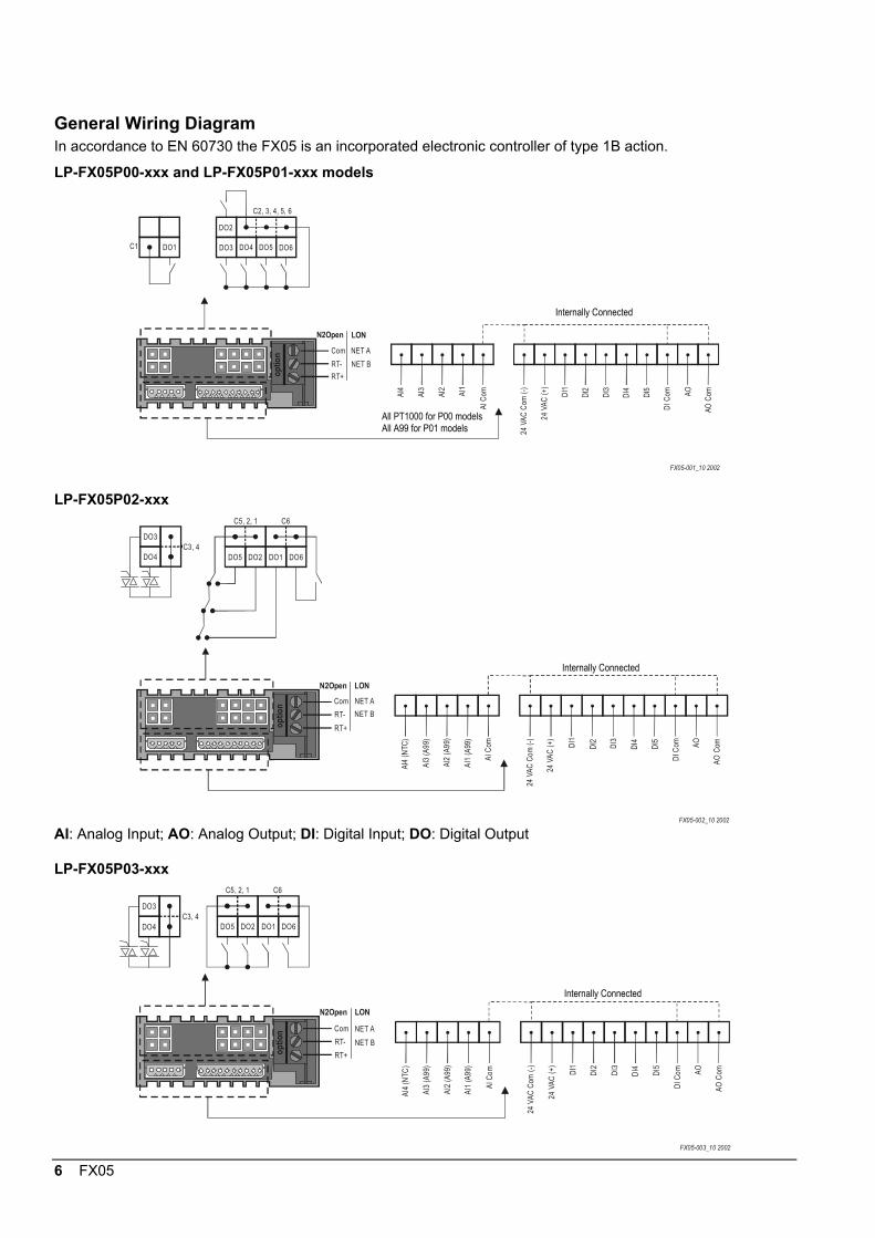
General Wiring DiagramIn accordance to EN 60730 the FX05 is an incorporated electronic controller of type 1B action.
LP-FX05P00-xxx and LP-FX05P01-xxx models
optio
n Com NET A
RT- NET B
RT+
AI4
AI3
AI2
AI1
AI C
om
24 V
AC C
om (-
)
24 V
AC (+
)
DI1
DI2
DI3
DI4 DI5
DI C
om AO
AO C
om
C1 DO1
DO2
DO3 DO4 DO5 DO6
N2Open LON
FX05-001_10 2002
C2, 3, 4, 5, 6
LP-FX05P02-xxx
FX05-002_10 2002
optio
n Com NET A
RT- NET B
RT+
AI4
(NTC
)
AI3
(A99
)
AI2
(A99
)
AI1
(A99
)
AI C
om
24 V
AC C
om (-
)
24 V
AC (+
)
DI1
DI2 DI3
DI4 DI5
DI C
om AO
AO C
om
DO4
DO3
DO5 DO2 DO1 DO6
N2Open LON
C3, 4
C5, 2, 1 C6
AI: Analog Input; AO: Analog Output; DI: Digital Input; DO: Digital Output
LP-FX05P03-xxx
FX05-003_10 2002
optio
n Com NET A
RT- NET B
RT+
AI4
(NTC
)
AI3
(A99
)
AI2
(A99
)
AI1
(A99
)
AI C
om
24 V
AC C
om (-
)
24 V
AC (+
)
DI1
DI2 DI3
DI4 DI5
DI C
om AO
AO C
om
N2Open LON
DO4
DO3
DO5 DO2 DO1 DO6C3, 4
C6C5, 2, 1
Internally Connected
Internally Connected
Internally Connected
All PT1000 for P00 modelsAll A99 for P01 models

FX05 7
Insulation DiagramIn relation to the CPU the insulation of the several I/Os is represented in the diagrams below:
CPU CPU
AI1 AI1DI1 DI1AI2 AI2DI2 DI2AI3 AI3DI3 DI3AI4 AI4DI4 DI4DI5 DI5
DO1 DO1 DO2DO2 DO3DO3 DO4DO4 DO5DO5 DO6DO6 AO AO
P00 / P01 models P02 / P03 models
Analog Inputs Digital Inputs
Analog OutputDigital Outputs
Com
mun
icat
ion
To S
uper
viso
r
Analog Inputs Digital Inputs
Analog OutputDigital Outputs
Com
mun
icat
ion
To S
uper
viso
r

8 FX05
N2Open Serial Card
Indentation to lock the card
Figure 1: Card Insertion
1 2 3
Figure 2: Wiring
220ΩRS485 bus (1200 mts max)
Controller 32Controller 2Controller 1
TR-
TR-
TR-
COM
COM
COM
TR+
TR+
TR+
RS232
ConverterRS232/RS485
IU-9100
Figure 3: Network Layout
The N2Open serial card is a plug-in, optional card,that allows the controllers of the FX05 line to beconnected in a N2Open serial network through theRS485 standard.
Card InsertionRemove the plastic part on the back of the controllerand insert the card until it is fully in and securelylocked by the small indentation present on the top ofthe plastic box (Figure 1).
WiringThe connection to the network is made by means ofthe 3 pins on the plug-in connector (Figure 2).The meaning of each pin is as follows:
Pin RS4851 COM2 RT-3 RT+
The network cable must be laid along a low voltagecable path. It must be placed at least at 30 cm fromcables carrying high voltages or currents (>230V or>30A). If strong interference fields are expected,the cable must be located at the greatest distancepossible from the source. The communication linemust be laid out on the multi-drop line principle,i.e. from one controller to the next until the lastcontroller has been connected. The line must beterminated at both ends with a 220 Ohm resistorbetween RT+ and RT- (Figure 3).RS485 line: maximum length without repeater:
1200 mts, AWG26 twisted pair withshield.
RS232C line: maximum length: 10 mts.
Devices: maximum of 32 per 1200 mts bussegment.
FX05 9
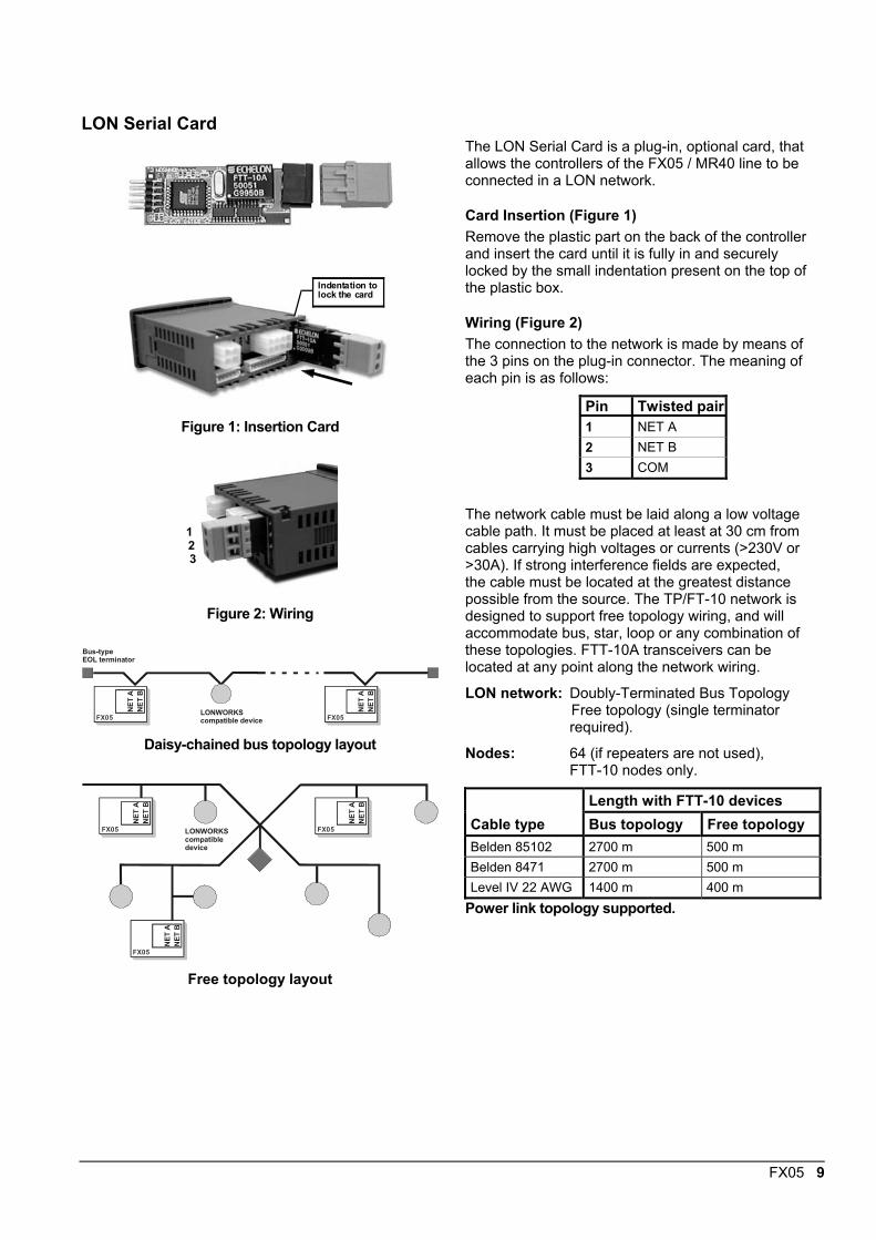
LON Serial Card
Indentation to lock the card
Figure 1: Insertion Card
1 2 3
Figure 2: Wiring
LONWORKScompatible device
Bus-type EOL terminator
FX05
NET
AN
ET B
FX05
NET
AN
ET B
Daisy-chained bus topology layout
LONWORKScompatible device
FX05
NET
ANE
T B
FX05
NET
ANE
T B
FX05
NET
ANE
T B
Free topology layout
The LON Serial Card is a plug-in, optional card, thatallows the controllers of the FX05 / MR40 line to beconnected in a LON network.
Card Insertion (Figure 1)Remove the plastic part on the back of the controllerand insert the card until it is fully in and securelylocked by the small indentation present on the top ofthe plastic box.
Wiring (Figure 2)The connection to the network is made by means ofthe 3 pins on the plug-in connector. The meaning ofeach pin is as follows:
Pin Twisted pair1 NET A2 NET B3 COM
The network cable must be laid along a low voltagecable path. It must be placed at least at 30 cm fromcables carrying high voltages or currents (>230V or>30A). If strong interference fields are expected,the cable must be located at the greatest distancepossible from the source. The TP/FT-10 network isdesigned to support free topology wiring, and willaccommodate bus, star, loop or any combination ofthese topologies. FTT-10A transceivers can belocated at any point along the network wiring.
LON network: Doubly-Terminated Bus TopologyFree topology (single terminatorrequired).
Nodes: 64 (if repeaters are not used),FTT-10 nodes only.
Length with FTT-10 devicesCable type Bus topology Free topologyBelden 85102 2700 m 500 mBelden 8471 2700 m 500 mLevel IV 22 AWG 1400 m 400 m
Power link topology supported.
10 FX05
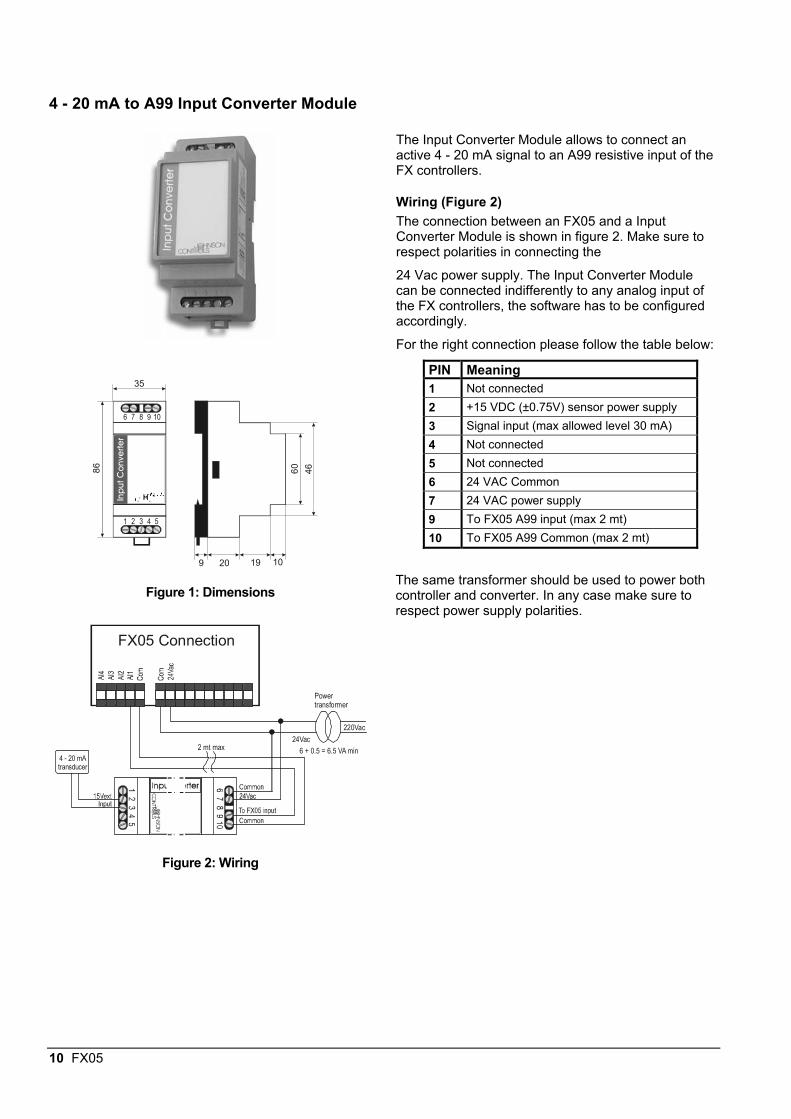
4 - 20 mA to A99 Input Converter ModuleIn
put
Co
nve
rter
1
6
4
9
5
10
35
86 4660
9 20 19 10
Figure 1: Dimensions
FX05 Connection
4 - 20 mAtransducer
Powertransformer
220Vac
24Vac2 mt max 6 + 0.5 = 6.5 VA min
Figure 2: Wiring
The Input Converter Module allows to connect anactive 4 - 20 mA signal to an A99 resistive input of theFX controllers.
Wiring (Figure 2)The connection between an FX05 and a InputConverter Module is shown in figure 2. Make sure torespect polarities in connecting the
24 Vac power supply. The Input Converter Modulecan be connected indifferently to any analog input ofthe FX controllers, the software has to be configuredaccordingly.
For the right connection please follow the table below:
PIN Meaning1 Not connected2 +15 VDC (±0.75V) sensor power supply3 Signal input (max allowed level 30 mA)4 Not connected5 Not connected6 24 VAC Common7 24 VAC power supply9 To FX05 A99 input (max 2 mt)10 To FX05 A99 Common (max 2 mt)
The same transformer should be used to power bothcontroller and converter. In any case make sure torespect power supply polarities.
FX05 11
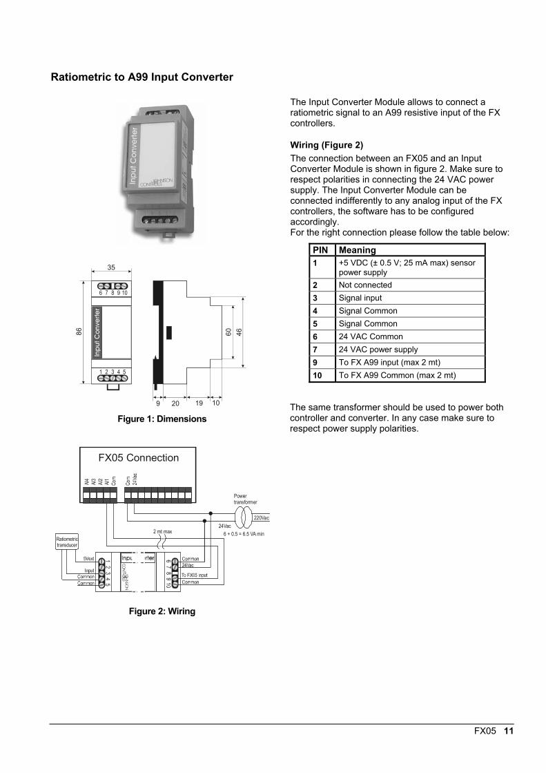
Ratiometric to A99 Input ConverterIn
put
Co
nve
rter
1
6
4
9
5
10
35
86 4660
9 20 19 10
Figure 1: Dimensions
FX05 Connection
Ratiometrictransducer
Powertransformer
220Vac
24Vac2 mt max 6 + 0.5 = 6.5 VA min
Figure 2: Wiring
The Input Converter Module allows to connect aratiometric signal to an A99 resistive input of the FXcontrollers.
Wiring (Figure 2)The connection between an FX05 and an InputConverter Module is shown in figure 2. Make sure torespect polarities in connecting the 24 VAC powersupply. The Input Converter Module can beconnected indifferently to any analog input of the FXcontrollers, the software has to be configuredaccordingly.For the right connection please follow the table below:
PIN Meaning1 +5 VDC (± 0.5 V; 25 mA max) sensor
power supply2 Not connected3 Signal input4 Signal Common5 Signal Common6 24 VAC Common7 24 VAC power supply9 To FX A99 input (max 2 mt)10 To FX A99 Common (max 2 mt)
The same transformer should be used to power bothcontroller and converter. In any case make sure torespect power supply polarities.
12 FX05
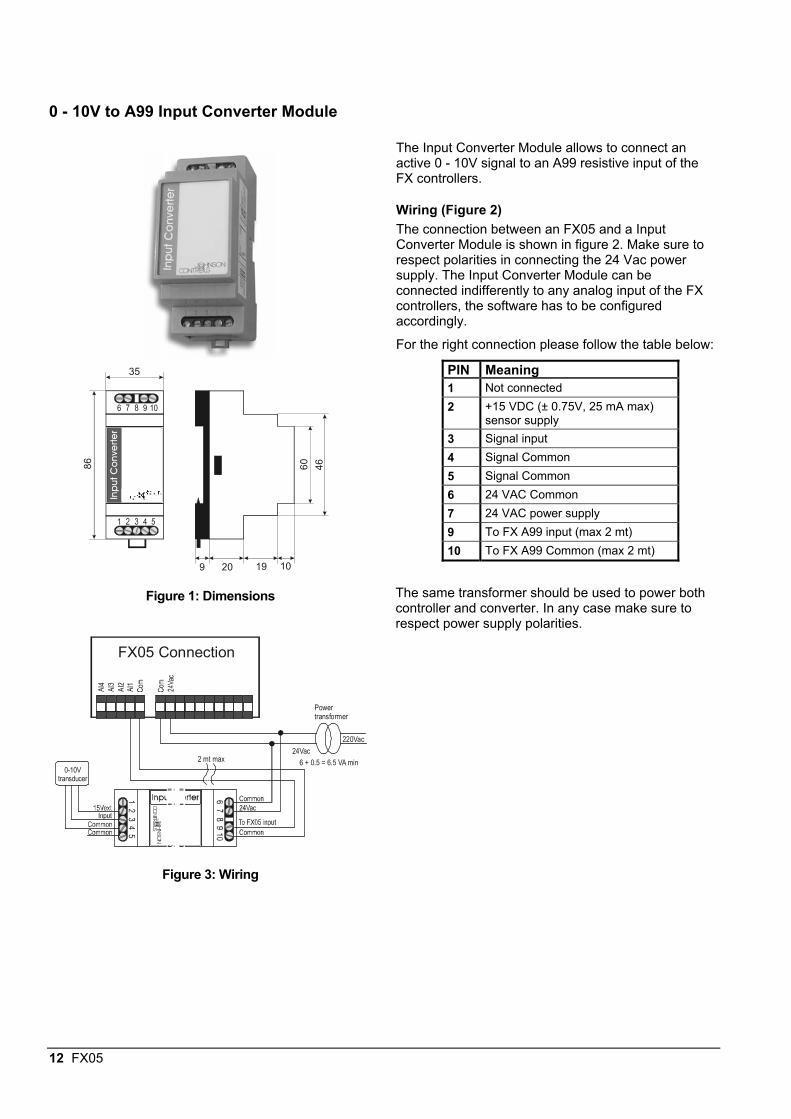
0 - 10V to A99 Input Converter ModuleIn
put
Co
nve
rter
1
6
4
9
5
10
35
86 4660
9 20 19 10
Figure 1: Dimensions
FX05 Connection
0-10Vtransducer
Powertransformer
220Vac
24Vac2 mt max 6 + 0.5 = 6.5 VA min
Figure 3: Wiring
The Input Converter Module allows to connect anactive 0 - 10V signal to an A99 resistive input of theFX controllers.
Wiring (Figure 2)The connection between an FX05 and a InputConverter Module is shown in figure 2. Make sure torespect polarities in connecting the 24 Vac powersupply. The Input Converter Module can beconnected indifferently to any analog input of the FXcontrollers, the software has to be configuredaccordingly.
For the right connection please follow the table below:
PIN Meaning1 Not connected2 +15 VDC (± 0.75V, 25 mA max)
sensor supply3 Signal input4 Signal Common5 Signal Common6 24 VAC Common7 24 VAC power supply9 To FX A99 input (max 2 mt)10 To FX A99 Common (max 2 mt)
The same transformer should be used to power bothcontroller and converter. In any case make sure torespect power supply polarities.
FX05 13
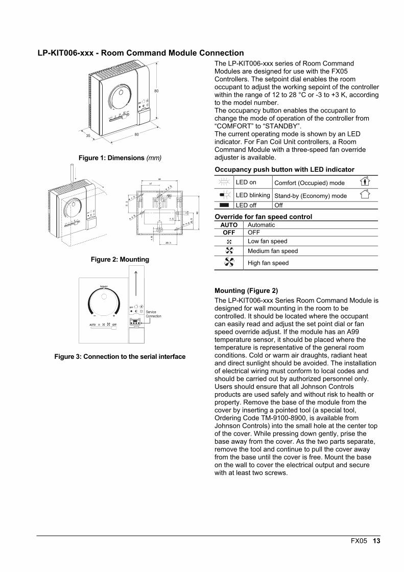
LP-KIT006-xxx - Room Command Module Connection
35 80
80
Figure 1: Dimensions (mm)
Figure 2: Mounting
AUTO OFF
+
Setpoint
OFF
ServiceConnection
Figure 3: Connection to the serial interface
The LP-KIT006-xxx series of Room CommandModules are designed for use with the FX05Controllers. The setpoint dial enables the roomoccupant to adjust the working sepoint of the controllerwithin the range of 12 to 28 °C or -3 to +3 K, accordingto the model number.The occupancy button enables the occupant tochange the mode of operation of the controller from“COMFORT” to “STANDBY”.The current operating mode is shown by an LEDindicator. For Fan Coil Unit controllers, a RoomCommand Module with a three-speed fan overrideadjuster is available.
Occupancy push button with LED indicator
LED on Comfort (Occupied) mode LED blinking Stand-by (Economy) modeLED off Off
Override for fan speed controlAUTO AutomaticOFF OFF
Low fan speedMedium fan speed
High fan speed
Mounting (Figure 2)The LP-KIT006-xxx Series Room Command Module isdesigned for wall mounting in the room to becontrolled. It should be located where the occupantcan easily read and adjust the set point dial or fanspeed override adjust. If the module has an A99temperature sensor, it should be placed where thetemperature is representative of the general roomconditions. Cold or warm air draughts, radiant heatand direct sunlight should be avoided. The installationof electrical wiring must conform to local codes andshould be carried out by authorized personnel only.Users should ensure that all Johnson Controlsproducts are used safely and without risk to health orproperty. Remove the base of the module from thecover by inserting a pointed tool (a special tool,Ordering Code TM-9100-8900, is available fromJohnson Controls) into the small hole at the center topof the cover. While pressing down gently, prise thebase away from the cover. As the two parts separate,remove the tool and continue to pull the cover awayfrom the base until the cover is free. Mount the baseon the wall to cover the electrical output and securewith at least two screws.
14 FX05
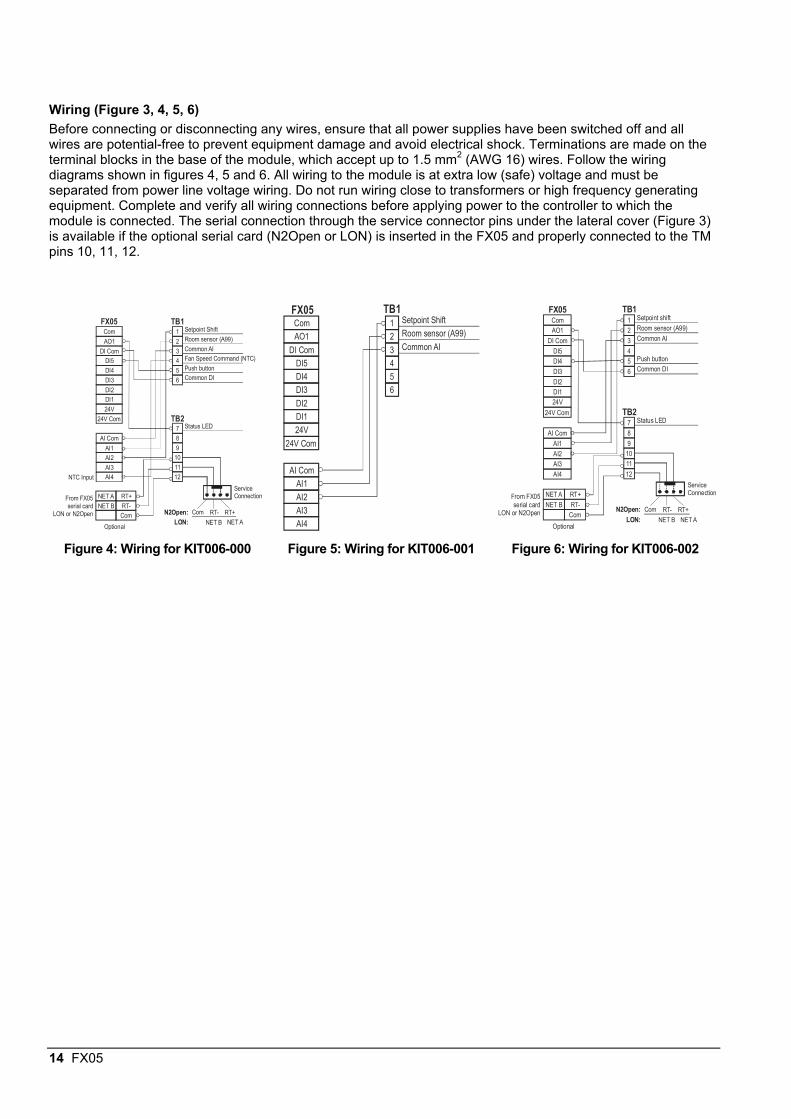
Wiring (Figure 3, 4, 5, 6)Before connecting or disconnecting any wires, ensure that all power supplies have been switched off and allwires are potential-free to prevent equipment damage and avoid electrical shock. Terminations are made on theterminal blocks in the base of the module, which accept up to 1.5 mm2 (AWG 16) wires. Follow the wiringdiagrams shown in figures 4, 5 and 6. All wiring to the module is at extra low (safe) voltage and must beseparated from power line voltage wiring. Do not run wiring close to transformers or high frequency generatingequipment. Complete and verify all wiring connections before applying power to the controller to which themodule is connected. The serial connection through the service connector pins under the lateral cover (Figure 3)is available if the optional serial card (N2Open or LON) is inserted in the FX05 and properly connected to the TMpins 10, 11, 12.
Com
AI Com
RT+
RT+
NET A
RT-
NET B
NET A
RT-NET B
Com Com
1
7
2
8
3
9
4
10
5
11
6
12
AO1
AI1
DI Com
AI2
DI5
AI3
DI4
AI4
DI3
DI2
DI1
24V
24V Com
Setpoint Shift
Status LED
Room sensor (A99)
Common AI
Fan Speed Command (NTC)
Push button
Common DI
TB1
TB2
NTC Input
From FX05serial card
LON or N2Open
FX05
ServiceConnection
Optional
N2Open:LON:
Com
AI Com
1
2
3
4
5
6
AO1
AI1
DI Com
AI2
DI5
AI3
DI4
AI4
DI3
DI2
DI1
24V
24V Com
Setpoint Shift
Room sensor (A99)
Common AI
TB1FX05Com
AI Com
RT+NET A
RT-NET BCom
1
7
2
8
3
9
4
10
5
11
6
12
AO1
AI1
DI Com
AI2
DI5
AI3
DI4
AI4
DI3
DI2DI124V
24V Com
Setpoint shift
Status LED
Room sensor (A99)
Common AI
Push buttonCommon DI
TB1
TB2
From FX05serial card
LON or N2Open
FX05
Optional
RT+
NET A
RT-
NET B
Com
ServiceConnection
N2Open:LON:
Figure 4: Wiring for KIT006-000 Figure 5: Wiring for KIT006-001 Figure 6: Wiring for KIT006-002
FX05 15
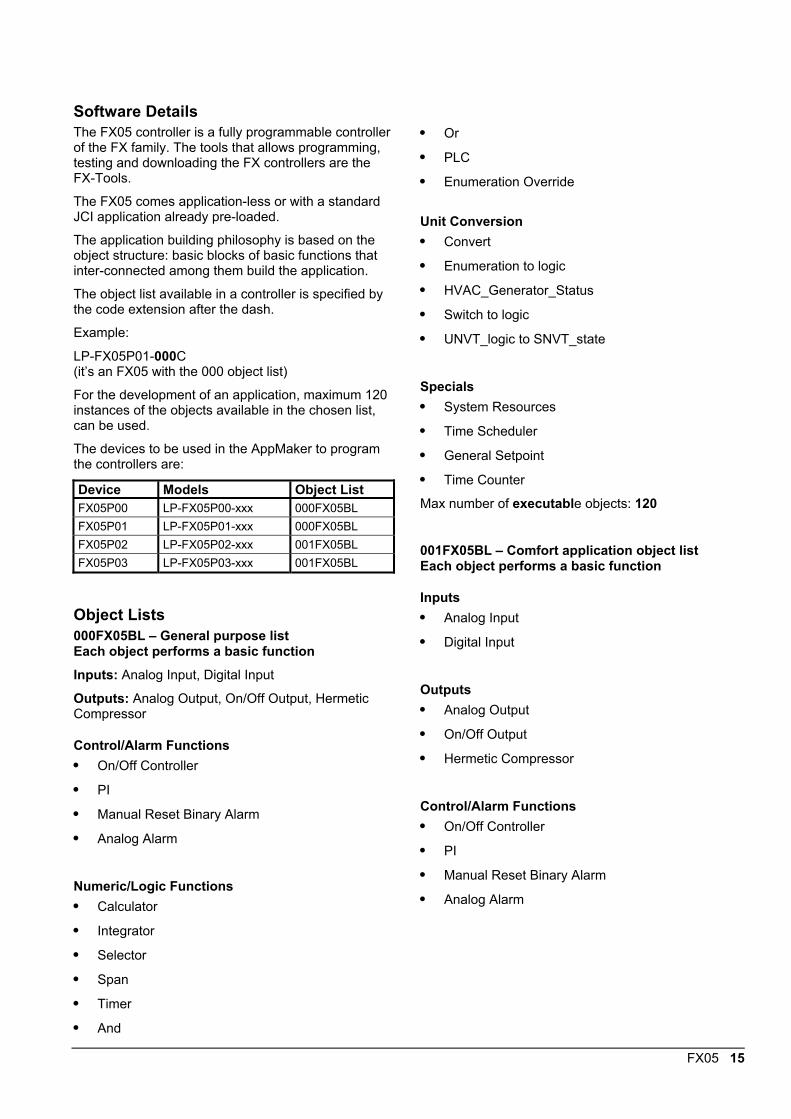
Software DetailsThe FX05 controller is a fully programmable controllerof the FX family. The tools that allows programming,testing and downloading the FX controllers are theFX-Tools.
The FX05 comes application-less or with a standardJCI application already pre-loaded.
The application building philosophy is based on theobject structure: basic blocks of basic functions thatinter-connected among them build the application.
The object list available in a controller is specified bythe code extension after the dash.
Example:
LP-FX05P01-000C(it’s an FX05 with the 000 object list)
For the development of an application, maximum 120instances of the objects available in the chosen list,can be used.
The devices to be used in the AppMaker to programthe controllers are:
Device Models Object ListFX05P00 LP-FX05P00-xxx 000FX05BLFX05P01 LP-FX05P01-xxx 000FX05BLFX05P02 LP-FX05P02-xxx 001FX05BLFX05P03 LP-FX05P03-xxx 001FX05BL
Object Lists000FX05BL – General purpose listEach object performs a basic functionInputs: Analog Input, Digital Input
Outputs: Analog Output, On/Off Output, HermeticCompressor
Control/Alarm Functions• On/Off Controller
• PI
• Manual Reset Binary Alarm
• Analog Alarm
Numeric/Logic Functions• Calculator
• Integrator
• Selector
• Span
• Timer
• And
• Or
• PLC
• Enumeration Override
Unit Conversion• Convert
• Enumeration to logic
• HVAC_Generator_Status
• Switch to logic
• UNVT_logic to SNVT_state
Specials• System Resources
• Time Scheduler
• General Setpoint
• Time Counter
Max number of executable objects: 120
001FX05BL – Comfort application object listEach object performs a basic function
Inputs• Analog Input
• Digital Input
Outputs• Analog Output
• On/Off Output
• Hermetic Compressor
Control/Alarm Functions• On/Off Controller
• PI
• Manual Reset Binary Alarm
• Analog Alarm

16 FX05
Numeric/Logic Functions• Calculator
• Integrator
• Selector
• Span
• Timer
• And
• Or
• PLC
• Enumeration Override
Unit Conversion• Convert
• Enumeration to logic
• HVAC_Generator_Status
• Switch to logic
• UNVT_logic to SNVT_state
Specials• System Resources
• Time Scheduler
• General Setpoint
• Time Counter
Max number of executable objects: 120
FX05 17
Application CodingStandard JCI applications are build by Johnson Controls application engineers. Standard applications come pre-loaded in the controller or in a library CD and downloaded in the field.
The application code, as for example the compressor chiller / HP one, 851FX0501-000BL, contains in itself allthe information to select the target controller:
• 851: application code number;
• FX05: target controller family;
• 01: minimum hardware configuration required, see ordering codes;
• 000: target object list
• B: FX05 standard version
• L: built-in display supported.
If the application is pre-loaded, the controller code will take the extension that specify the application itself.
Example:
LP-F05P01-851C is an FX05 with the 851FX0501-000BL application pre-loaded.
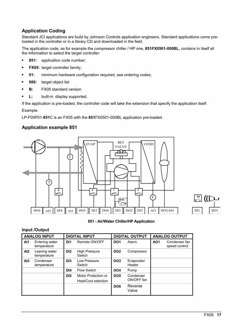
Application example 851
T
AI2
T
AI1
T
AI3
Q
DI4
P
DI3
P
DI2
T
DI5
MODE
DO2DO3DO4 DI1
ON
DO1DO5/A01DO6
EVAP CONDREVVALVE
851 - Air/Water Chiller/HP Application
Input /OutputANALOG INPUT DIGITAL INPUT DIGITAL OUTPUT ANALOG OUTPUTAI1 Entering water
temperatureDI1 Remote ON/OFF DO1 Alarm AO1 Condenser fan
speed controlAI2 Leaving water
temperatureDI2 High Pressure
SwitchDO2 Compressor
AI3 Condensertemperature
DI3 Low PressureSwitch
DO3 EvaporatorHeater
DI4 Flow Switch DO4 PumpDI5 Motor Protection or
Heat/Cool selectionDO5 Condenser
ON/OFF fan
DO6 ReverseValve
18 FX05
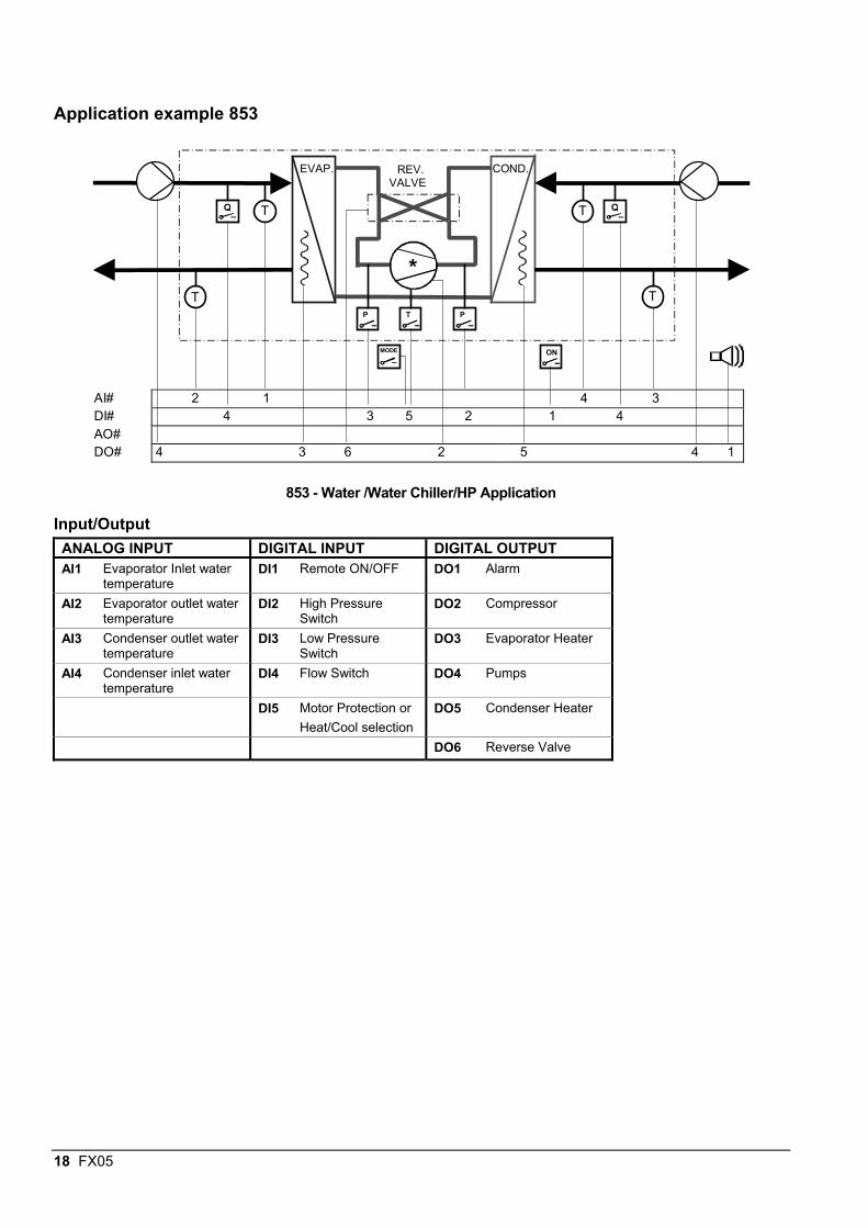
Application example 853
AI# 2 1 4 3DI# 4 3 5 2 1 4AO#DO# 4 3 6 2 5 4 1
T Q
MODE ON
EVAP. COND.REV.VALVE
TQ
T TPP T
*
853 - Water /Water Chiller/HP Application
Input/OutputANALOG INPUT DIGITAL INPUT DIGITAL OUTPUTAI1 Evaporator Inlet water
temperatureDI1 Remote ON/OFF DO1 Alarm
AI2 Evaporator outlet watertemperature
DI2 High PressureSwitch
DO2 Compressor
AI3 Condenser outlet watertemperature
DI3 Low PressureSwitch
DO3 Evaporator Heater
AI4 Condenser inlet watertemperature
DI4 Flow Switch DO4 Pumps
DI5 Motor Protection orHeat/Cool selection
DO5 Condenser Heater
DO6 Reverse Valve
FX05 19
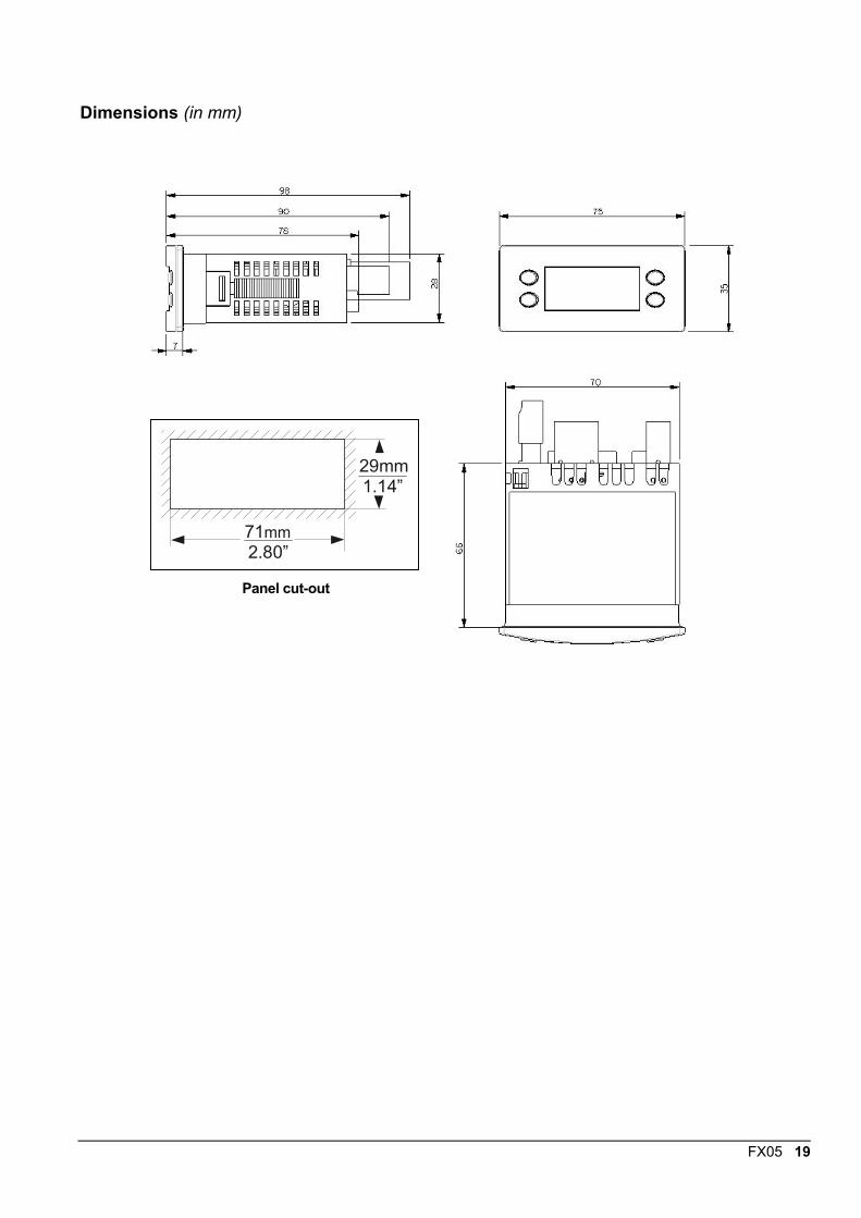
Dimensions (in mm)
71mm2.80”
29mm1.14”
Panel cut-out
20 FX05
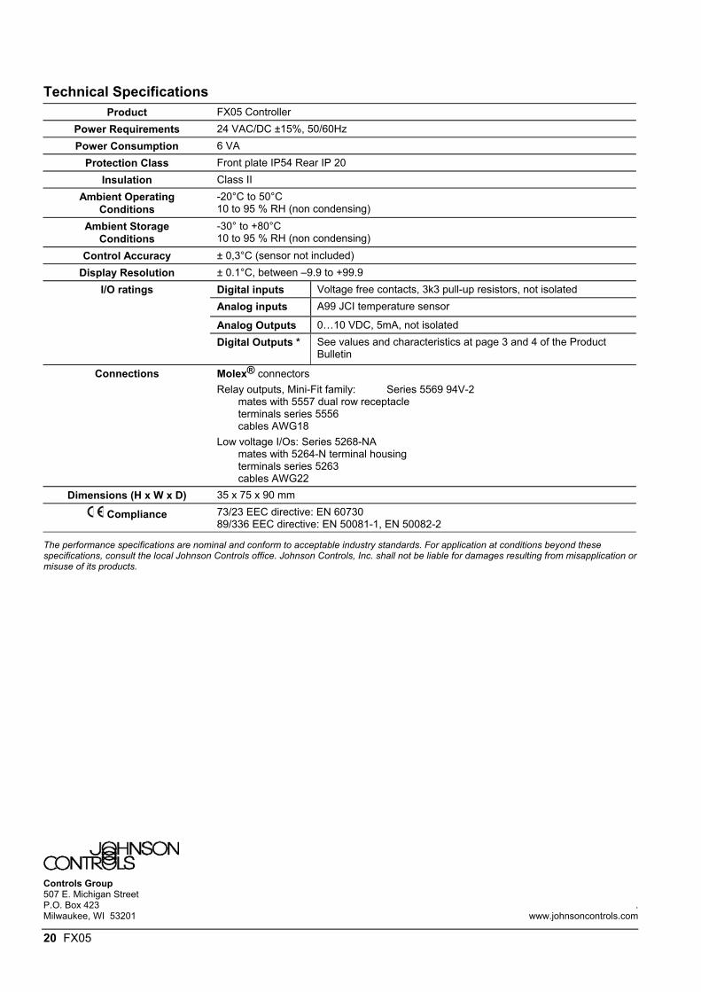
Technical SpecificationsProduct FX05 Controller
Power Requirements 24 VAC/DC ±15%, 50/60HzPower Consumption 6 VA
Protection Class Front plate IP54 Rear IP 20Insulation Class II
Ambient OperatingConditions
-20°C to 50°C10 to 95 % RH (non condensing)
Ambient StorageConditions
-30° to +80°C10 to 95 % RH (non condensing)
Control Accuracy ± 0,3°C (sensor not included)Display Resolution ± 0.1°C, between –9.9 to +99.9
Digital inputs Voltage free contacts, 3k3 pull-up resistors, not isolatedAnalog inputs A99 JCI temperature sensor
Analog Outputs 0…10 VDC, 5mA, not isolated
I/O ratings
Digital Outputs * See values and characteristics at page 3 and 4 of the ProductBulletin
Connections Molex® connectorsRelay outputs, Mini-Fit family: Series 5569 94V-2
mates with 5557 dual row receptacleterminals series 5556cables AWG18
Low voltage I/Os: Series 5268-NAmates with 5264-N terminal housingterminals series 5263cables AWG22
Dimensions (H x W x D) 35 x 75 x 90 mm
Compliance 73/23 EEC directive: EN 6073089/336 EEC directive: EN 50081-1, EN 50082-2
The performance specifications are nominal and conform to acceptable industry standards. For application at conditions beyond thesespecifications, consult the local Johnson Controls office. Johnson Controls, Inc. shall not be liable for damages resulting from misapplication ormisuse of its products.
Controls Group507 E. Michigan StreetP.O. Box 423 .Milwaukee, WI 53201 www.johnsoncontrols.com