fundamentals for condition monitoring and diagnostics for driving bucket wheel system with overload...
TRANSCRIPT
Nr 133Prace Naukowe Instytutu Górnictwa
Politechniki Wrocławskiej Nr 133Studia i Materiały Nr 40 2011
bucket wheel excavator,bucket wheel drive,
vibration condition monitoring
Walter BARTELMUS*
FUNDAMENTALS FOR CONDITION MONITORINGAND DIAGNOSTICS FOR DRIVING BUCKET
WHEEL SYSTEM WITH OVERLOAD MECHANISMOF BUCKET WHEEL EXCAVATOR
The paper gives fundamentals for condition monitoring and diagnostics for the drivingbucket wheel system of a bucket wheel excavator, which is designed for operation in increaseddigging resistance of strata. The fundamentals are given by development the characteristic fre-quencies as: meshing frequences, local fault freqencies, carrier frequencies for planetarygearboxes and so on.
1. INTRODUCTION
Condition monitoring and diagnostics of driving systems for bucket wheels ofbucket wheel excavators given in figure 1 and 2 are described in papers (Bartelmus,Zimroz, 2007; Bartelmus, Zimroz, 2009a; Bartelmus, Zimroz, 2009b; Bartelmus et al.,2010; Bartelmus, Zimroz, 2008; Bartelmus, Zimroz, 2010a; Bartelmus, Zimroz,2010b; Bartelmus, Zimroz, 2011). In a presented paper one can find fundamentals forthe condition monitoring of the new design of a gearbox system which drives a buckedwheel of a bucked wheel excavator. The scheme of a new system is given in figure 3.The characteristic difference between design of systems given in figure 1 or 2 and 3 isthat in system (fig. 3) is given an overload mechanism.
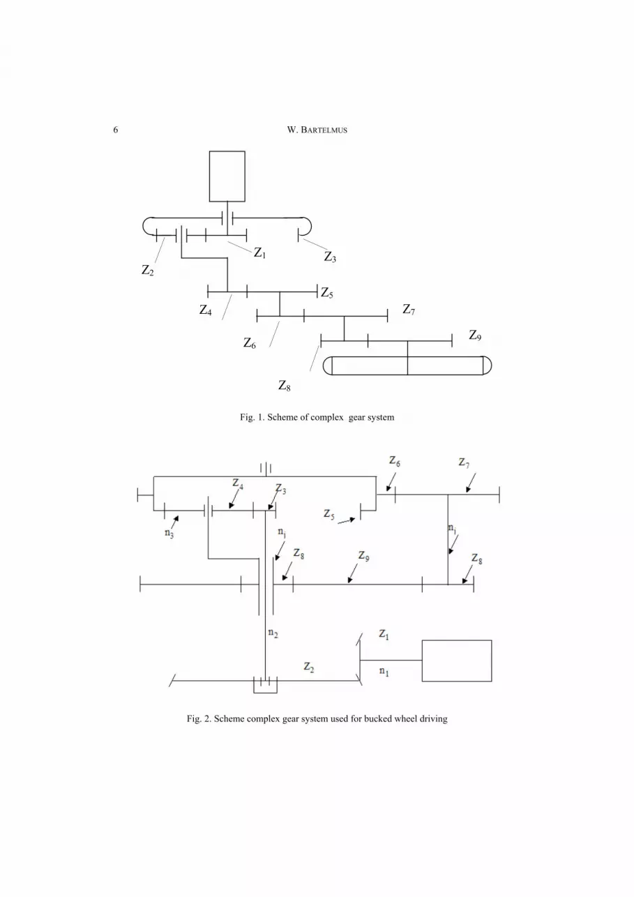
The term of a complex and compound gearbox is explained in (Bartelmus, Zimroz,2010b). The system given in figure 1 consists of planetary stage with gears z1, z2, z3
and three cylindrical stages, gears from z4 to z9.
_________* Politechnika Wrocławska, Wydział Geoinżynierii Górnictwa i Geologii, Instytut Górnictwa, Vibra-
tion and Diagnostic Scientific Laboratory, pl. Teatralny 2, 50-051 Wrocław.
6 W. BARTELMUS
Z3 Z1 Z2
Z4
Z6
Z5 Z7
Z9
Z8
Fig. 1. Scheme of complex gear system
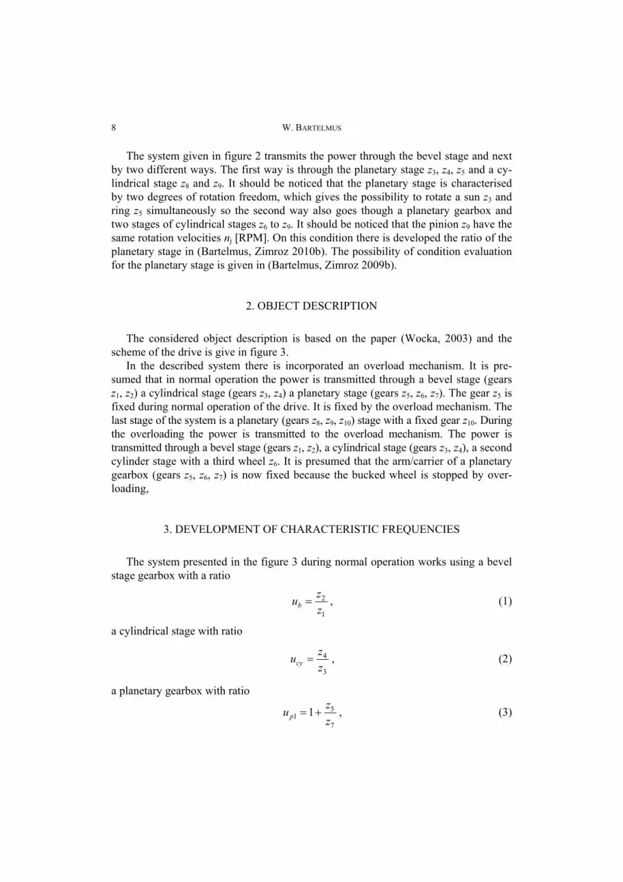
Fig. 2. Scheme complex gear system used for bucked wheel driving

Fundamentals for condition monitoring and diagnostics for driving bucket wheel system… 7
Fig. 3. Scheme of driving system for bucked wheel of bucked wheel excavatorwith overload mechanism
8 W. BARTELMUS
The system given in figure 2 transmits the power through the bevel stage and nextby two different ways. The first way is through the planetary stage z3, z4, z5 and a cy-lindrical stage z8 and z9. It should be noticed that the planetary stage is characterisedby two degrees of rotation freedom, which gives the possibility to rotate a sun z3 andring z5 simultaneously so the second way also goes though a planetary gearbox andtwo stages of cylindrical stages z6 to z9. It should be noticed that the pinion z9 have thesame rotation velocities nj [RPM]. On this condition there is developed the ratio of theplanetary stage in (Bartelmus, Zimroz 2010b). The possibility of condition evaluationfor the planetary stage is given in (Bartelmus, Zimroz 2009b).
2. OBJECT DESCRIPTION
The considered object description is based on the paper (Wocka, 2003) and thescheme of the drive is give in figure 3.
In the described system there is incorporated an overload mechanism. It is pre-sumed that in normal operation the power is transmitted through a bevel stage (gearsz1, z2) a cylindrical stage (gears z3, z4) a planetary stage (gears z5, z6, z7). The gear z5 isfixed during normal operation of the drive. It is fixed by the overload mechanism. Thelast stage of the system is a planetary (gears z8, z9, z10) stage with a fixed gear z10. Duringthe overloading the power is transmitted to the overload mechanism. The power istransmitted through a bevel stage (gears z1, z2), a cylindrical stage (gears z3, z4), a secondcylinder stage with a third wheel z6. It is presumed that the arm/carrier of a planetarygearbox (gears z5, z6, z7) is now fixed because the bucked wheel is stopped by over-loading,
3. DEVELOPMENT OF CHARACTERISTIC FREQUENCIES
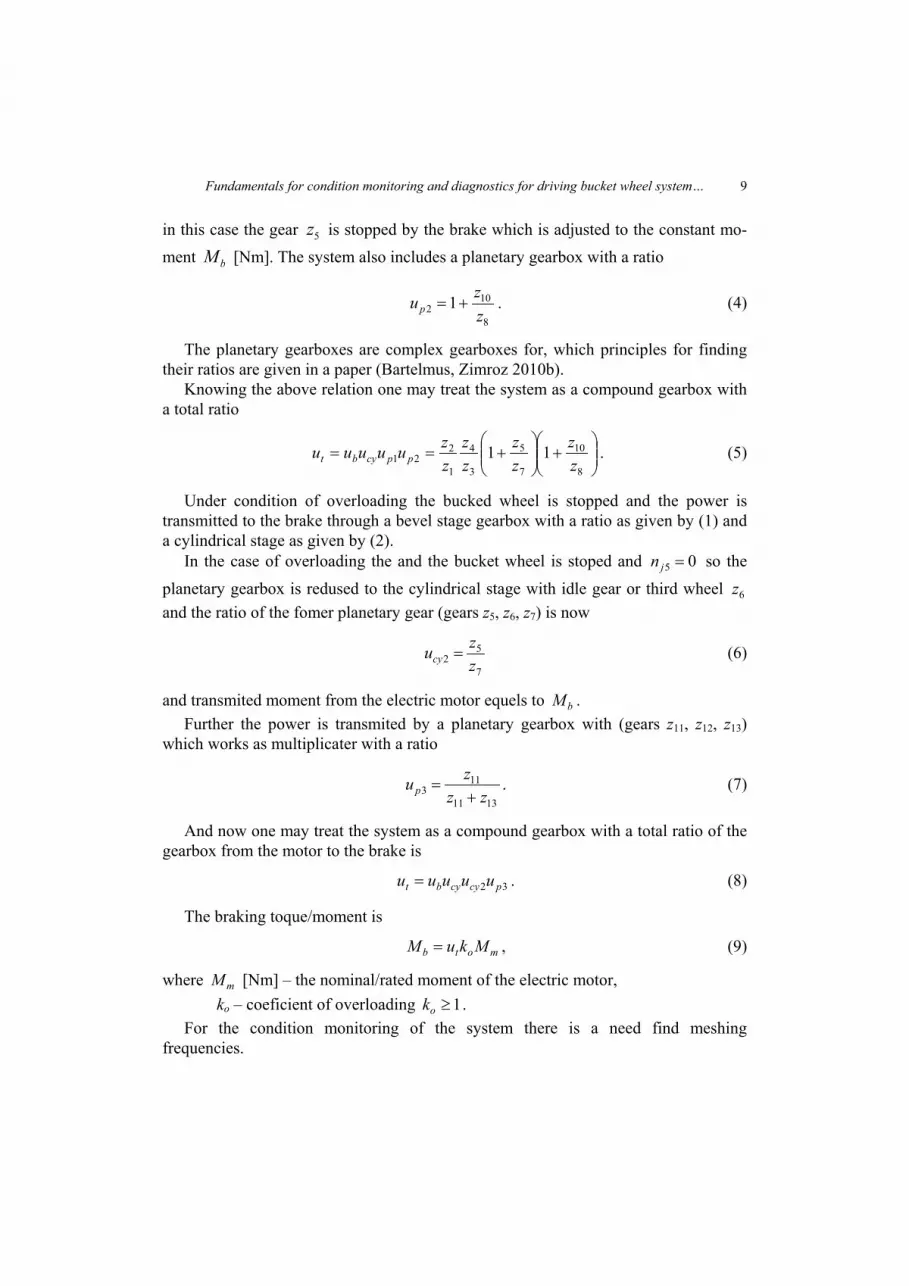
The system presented in the figure 3 during normal operation works using a bevelstage gearbox with a ratio
1
2
zzub = , (1)
a cylindrical stage with ratio
3
4
zzucy = , (2)
a planetary gearbox with ratio
7
51 1
zzup += , (3)
Fundamentals for condition monitoring and diagnostics for driving bucket wheel system… 9
in this case the gear 5z is stopped by the brake which is adjusted to the constant mo-ment bM [Nm]. The system also includes a planetary gearbox with a ratio
8
102 1
zzup += . (4)
The planetary gearboxes are complex gearboxes for, which principles for findingtheir ratios are given in a paper (Bartelmus, Zimroz 2010b).
Knowing the above relation one may treat the system as a compound gearbox witha total ratio
⎟⎟⎠
⎞⎜⎜⎝
⎛+⎟⎟
⎠
⎞⎜⎜⎝
⎛+==
8
10
7
5
3
4
1
221 11
zz
zz
zz
zzuuuuu ppcybt . (5)
Under condition of overloading the bucked wheel is stopped and the power istransmitted to the brake through a bevel stage gearbox with a ratio as given by (1) anda cylindrical stage as given by (2).
In the case of overloading the and the bucket wheel is stoped and 05 =jn so the
planetary gearbox is redused to the cylindrical stage with idle gear or third wheel 6zand the ratio of the fomer planetary gear (gears z5, z6, z7) is now
7
52 z
zucy = (6)
and transmited moment from the electric motor equels to bM .Further the power is transmited by a planetary gearbox with (gears z11, z12, z13)
which works as multiplicater with a ratio
1311
113 zz
zup += . (7)
And now one may treat the system as a compound gearbox with a total ratio of thegearbox from the motor to the brake is
32 pcycybt uuuuu = . (8)
The braking toque/moment is
motb MkuM = , (9)
where mM [Nm] – the nominal/rated moment of the electric motor,ko – coeficient of overloading 1≥ok .
For the condition monitoring of the system there is a need find meshingfrequencies.
10 W. BARTELMUS
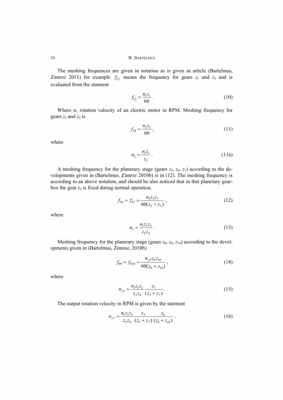
The meshing frequences are given in notation as is given in article (Bartelmus,Zimroz 2011) for example 12f means the frequency for gears z1 and z2 and isevaluated from the statment
6011
12znf = . (10)
Where n1 rotation valocity of an electric motor in RPM. Meshing frequency forgears z3 and z4 is
60
3234
znf = , (11)
where
2
112 z
znn = . (11a)
A meshing frequency for the planerary stage (gears z5, z6, z7) according to the de-velopments given in (Bartelmus, Zimroz 2010b) is in (12). The meshing frequency isaccording to an above notation, and should be also noticed that in that planetary gear-box the gear z5 is fixed during normal operation.
)(60 75
7536756 zz
zznff+
== , (12)
where
42
3113 zz
zznn = . (13)
Meshing frequency for the planerary stage (gears z8, z9, z10) according to the devel-opments given in (Bartelmus, Zimroz, 2010b)
)(60 108
108591089 zz
zznff j
+== , (14)
where
)( 75
7
42
3115 zz
zzzzznn j +
= . (15)
The output rotation velocity in RPM is given by the statment
)()( 108
8
75
7
42
3117 zz
zzz
zzzzznn j ++
= . (16)
Fundamentals for condition monitoring and diagnostics for driving bucket wheel system… 11
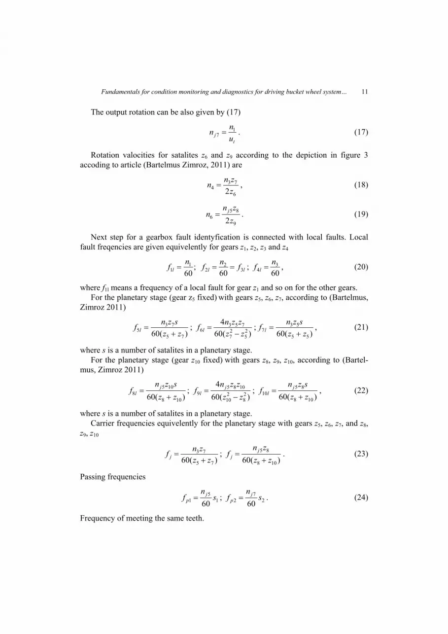
The output rotation can be also given by (17)
tj u
nn 17 = . (17)
Rotation valocities for satalites z6 and z9 according to the depiction in figure 3accoding to article (Bartelmus Zimroz, 2011) are
6
734 2z
znn = , (18)
9
856 2z
znn j= . (19)
Next step for a gearbox fault identyfication is connected with local faults. Localfault freqencies are given equivelently for gears z1, z2, z3 and z4
;60
11
nf l = ll fnf 32
2 60== ;
603
4nf l = , (20)
where f1l means a frequency of a local fault for gear z1 and so on for the other gears.For the planetary stage (gear z5 fixed) with gears z5, z6, z7, according to (Bartelmus,
Zimroz 2011)
)(60 75
735 zz
sznf l += ;
)(604
25
27
7536 zz
zznf l −= ;
)(60 55
537 zz
sznf l += , (21)
where s is a number of satalites in a planetary stage.For the planetary stage (gear z10 fixed) with gears z8, z9, z10, according to (Bartel-
mus, Zimroz 2011)
)(60 108
1058 zz
sznf j
l += ;
)(604
28
210
10859 zz
zznf j
l −= ;
)(60 108
8510 zz
sznf j
l += , (22)
where s is a number of satalites in a planetary stage.Carrier frequencies equivelently for the planetary stage with gears z5, z6, z7, and z8,
z9, z10
)(60 75
73
zzznf j +
= ; )(60 108
85
zzzn
f jj += . (23)
Passing frequencies
15
1 60s
nf j
p = ; 27
2 60s
nf j
p = . (24)
Frequency of meeting the same teeth.
12 W. BARTELMUS
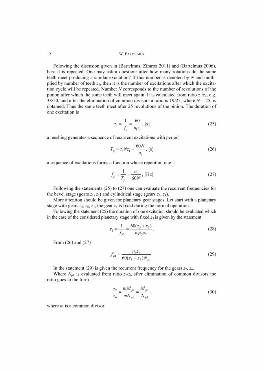
Folowing the discusion given in (Bartelmus, Zimroz 2011) and (Bartelmus 2006),here it is repeated. One may ask a question: after how many rotations do the sameteeth meet producing a similar excitation? If this number is denoted by N and multi-plied by number of teeth z1, then it is the number of excitations after which the excita-tion cycle will be repeated. Number N corresponds to the number of revolutions of thepinion after which the same teeth will meet again. It is calculated from ratio z1/z2, e.g.38/50, and after the elimination of common divisors a ratio is 19/25, where N = 25, isobtained. Thus the same teeth meet after 25 revolutions of the pinion. The duration ofone excitation is
111
601znfz
==τ , [s] (25)
a meshing generates a sequence of recurrent excitations with period
111
60n
NNzTp ==τ , [s] (26)
a sequence of excitations forms a function whose repetition rate is
Nn
Tf
pp 60
1 1== , [Hz] (27)
Following the statements (25) to (27) one can evaluate the recurrent frequencies forthe bevel stage (gears z1, z2) and cylindrical stage (gears z3, z4).
More attention should be given for planetary gear stages. Let start with a planetarystage with gears z5, z6, z7, the gear z6 is fixed during the normal operation.
Following the statement (25) the duration of one excitation should be evaluated whichin the case of the considered planetary stage with fixed z5 is given by the statement
753
75
561
)(601zzn
zzf
+==τ . (28)
From (26) and (27)
175
731 )(60 p
p Nzzznf
+= . (29)
In the statement (29) is given the recurrent frequency for the gears z7, z6.Where Np1 is evaluated from ratio z7/z6 after elimination of common divisors the
ratio goes to the form
1
1
1
1
6
7
p
p
p
p
NM
mNmM
zz
== , (30)
where m is a common divisor.
Fundamentals for condition monitoring and diagnostics for driving bucket wheel system… 13
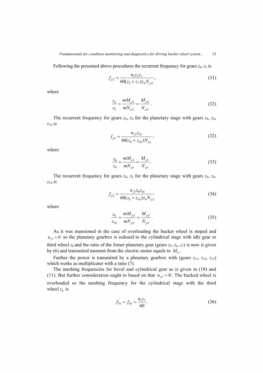
Following the presented above procedures the recurrent frequency for gears z6, z5 is
2675
7532 )(60 p
p Nzzzzznf
+= , (31)
where
2
2
2
2
5
6
p
p
p
p
NM
mNmM
zz
== . (32)
The recurrent frequency for gears z8, z9 for the planetary stage with gears z8, z9,z10 is
1108
1051 )(60 p
jp Nzz
znf
+= , (32)
where
1
1
1
1
9
8
p
p
p
p
NM
mNmM
zz
== . (33)
The recurrent frequency for gears z8, z9 for the planetary stage with gears z8, z9,z10 is
29108
10852 )(60 p
jp Nzzz
zznf
+= (34)
where
2
2
2
2
10
9
p
p
p
p
NM
mNmM
zz
== . (35)
As it was mansioned in the case of overloading the bucket wheel is stoped and05 =jn so the planetary gearbox is redused to the cylindrical stage with idle gear or
third wheel z6 and the ratio of the fomer planetary gear (gears z5, z6, z7) is now is givenby (6) and transmited moment from the electric motor equels to bM .
Further the power is transmited by a planetary gearbox with (gears z11, z12, z13)which works as multiplicater with a ratio (7).
The meshing frequencies for bevel and cylindrical gear as is given in (10) and(11). But further consideration ought to based on that 05 =jn . The bucked wheel isoverloaded so the meshing frequency for the cylindrical stage with the thirdwheel 6z is
6073
6576znff == . (36)
14 W. BARTELMUS
Meshing frequency for a planetary stage with (gears z11, z12, z13) is
)(60 1311
13111012131112 zz
zznff+
== . (37)
Frequency of local faults can be evaluated from the following statements
603
7nf l = ;
602 4
6nf l = ;
608
5j
ln
f = , (38)
where
6
734 z
znn = . (39)
The local faults for a planetary stage with (gears z11, z12, z13) and gear z13 fixed) ac-cording to (Bartelmus, Zimroz 2010b)
)(60 1310
131011 zz
sznf l += ;
)(604
211
213
13111012 zz
zznf l −= ;
)(60 1311
111010 zz
sznf l += , (40)
where s is a number of satalites in a planetary stage.The carrier frequency is
60)(606
1311
1110 jj
nzz
znf =+
= . (41)
The passing frequency
sn
f jp 60
61 = , (42)
where s – is a number of satalites in a planetary stage.The recurrent frequency for gears z11, z12 for the planetary stage with gears z11,
z12, z13 is
11311
13101 )(60 p
p Nzzznf
+= , (43)
where
1
1
1
1
12
11
p
p
p
p
NM
mNmM
zz
== . (44)
The recurrent frequency for gears z12, z13 for the planetary stage with gears z11, z12,z13 is
2121311
1311102 )(60 p
p Nzzzzznf
+= , (45)
Fundamentals for condition monitoring and diagnostics for driving bucket wheel system… 15
where
2
2
2
2
13
12
p
p
p
p
NM
mNmM
zz
== . (46)
4. FINAL CONSIDERATION
Gearbox is a system which may appear as a one stage gearbox or as a compound orcomplex gearbox. Most research on the gearbox damage process is done on the one stagegearbox. One stage gearbox system consists of gears, bearings and a case. Consideringthe damage process of the gearbox all the elements are treated separately by researchers.For example one may investigate the possibility of monitoring bearing faults makingartificial fault on one element of the bearing, an inner, outer ring or a ball. One may in-vestigate on condition monitoring of a making artificial breakage of a gear tooth. It asa wrong way of investigating on degradation process and possible condition monitoringor investigation and assessment of a gear fault. It is basic methodology error, becausethis investigation do not have too much in common with real degradation process. Firstof all one ought to treat the gearbox stage as a unity. For this unity it is a need to developthe measure of its condition. The measure should be made under deferent values of ex-ternal loads. The measure of one stage gearbox condition appeared to be a linear functionof applied external load (Bartelmus, Zimroz 2009b). This measure should evaluate aftergearbox run in. In the case of the compound or complex gearbox the measure of condi-tion should evaluate for each stage of the gearbox treating the stage as a unity. Thatmeans separately for a cylindrical stage, bevel stage or worm stage if one is consideringthe compound gearbox. In the case of complex gearboxes which incorporates planetarygearboxes one should give more attention to division the system into subsystems andreduce the complex system into the compound system. An example of a complex gear-box system is given in figures 1 to 3. For each stage or subsystem there is a need toevaluate the measure of its condition. In the process of a gearbox condition change.
5. CONCLUSIONS
In the paper is given consideration on developing the characteristic frequencieswhich can be used for condition monitoring of the new design of the drive of a buckedwheel for a bucked wheel excavator with overloading mechanism.
ACKNOWLEDGMENT
This paper was financially supported by Polish State Committee for Scientific research 2010–2013 asresearch project NN 504147838.

16 W. BARTELMUS
REFERENCES
BARTELMUS W., ZIMROZ.R., 2007, Metoda diagnostyki przekładni planetarnej, Górnictwo i geologiaIX (Red. nauk. Walter Bartelmus), Wrocław, Oficyna Wydawnicza PWr., 3–15.
BARTELMUS W., ZIMROZ R., 2009a, Vibration condition monitoring of planetary gearbox undervarying external load, Mechanical Systems and Signal Processing, 23, 246–257.
BARTELMUS W., ZIMROZ R., 2009b, A new feature for monitoring the condition of gearboxes in non-stationary operation conditions, Mechanical Systems and Signal Processing, 23, 1528.
BARTELMUS W., CHAARI F., ZIMROZ R., HADDAR M., 2010, Modelling of gearbox dynamics un-der time varying non-stationary operation for distributed fault detection and diagnosis, EuropeanJournal of Mechanics – A/Solids, 29, 637–646.
BARTELMUS W., ZIMROZ R., 2008, Problems and solutions in condition monitoring and diagnosticsof open cast monster machinery driving systems, Diagnostyka, 3/47, 55–60.
BARTELMUS W., 2009, Statistical feature estimation of the process describing object condition changefor maintenance decision, Prace Naukowe Instytutu Górnictwa Politechniki Wrocławskiej,Górnictwo i geologia XII, Wrocław.
BARTELMUS W., ZIMROZ R., 2010a, Way of non-stationary signal analysis generated by machineryfor feature extraction and their processing, International Congress on Noise Control Engineering,June 13–16, Lisbon, Portugal.
BARTELMUS W., ZIMROZ R., 2010b, Heavy machinery diagnostics and condition monitoring, Pro-ceedings of International Conference on Condition Monitoring and Machine Failure PreventionTechnology, June 22–24, Stratford upon Avon, England.
BARTELMUS W., ZIMROZ R., 2011, Vibration spectra characteristic frequencies for condition moni-toring of mining machinery compound and complex gearboxes, Górnictwo i Geologia, Scientific Pa-pers of the Institute of Mining.
BARTELMUS W., 2006, Condition monitoring of open cast mining machinery, Oficyna WydawniczaPolitechniki Wrocławskiej, Wrocław.
WOCKA N., 2003. Rola i znaczenie sprzęgła przeciążeniowego, Węgiel Brunatny, nr 4 (45), 20–27.
PODSTAWY MONITOROWANIA I DIAGNOSTYKI UKŁADU NAPĘDOWEGOZ MECHANIZMEM PRZECIĄŻENIOWYM KOŁA CZERPAKOWEGO KOPARKI KOŁOWEJ
Praca przedstawia podstawy monitorowania I diagnostyki stanu układu napędowego koła czerpako-wego, który został skonstruowany do eksploatacji złóż o zwiększonych oporach urabiania. Podstawyprzedstawiają częstotliwości charakterystyczne zazębienia, częstotliwości uszkodzeń lokalnych, często-tliwości obrotów jarzma itp.