fujitsu server primergy rx2540 m6
TRANSCRIPT

FUJITSU Server PRIMERGY RX2540 M6Upgrade and Maintenance Manual
Upgrade and Maintenance Manual - English
08/2021

Comments… Suggestions… Corrections…
The User Documentation Department would like to know your opinion of this manual. Yourfeedback helps us optimize our documentation to suit your individual needs.Feel free to send us your comments by e-mail to [email protected].
Documentation creation according to DIN EN ISO 9001:2015
To ensure a consistently high quality standard and user-friendliness, this documentation wascreated to meet the regulations of a quality management system which complies with therequirements of the standard DIN EN ISO 9001:2015.cognitas. Gesellschaft für Technik-Dokumentation mbH www.cognitas.de
Copyright and Trademarks
Copyright 2021 FUJITSU LIMITEDAll rights reserved.Delivery subject to availability; right of technical modifications reserved.All hardware and software names used are trademarks of their respective manufacturers.
– The contents of this manual may be revised without prior notice.
– Fujitsu assumes no liability for damages to third party copyrights or other rights arising fromthe use of any information in this manual.
– No part of this manual may be reproduced in any form without the prior written permissionof Fujitsu.
Microsoft, Windows, Windows Server, and Hyper-V are trademarks or registered trademarks ofMicrosoft Corporation in the USA and other countries.Intel and Xeon are trademarks or registered trademarks of Intel Corporation or its subsidiariesin the USA and other countries.
Before reading this manual
For your safety
This manual contains important information for safely and correctly using thisproduct.Carefully read the manual before using this product. Pay particular attention tothe accompanying manual "Safety Notes and Regulations" and ensure thatthese safety notes are understood before using the product. Keep this manualand the "Safety Notes and Regulations" manual in a safe place for easyreference while using this product.
Radio interference
This product is a "Class A" ITE (Information Technology Equipment). In adomestic environment this product may cause radio interference, in which casethe user may be required to take appropriate measures. VCCI-A
Aluminum electrolytic capacitors
The aluminum electrolytic capacitors used in the printed circuit boardassemblies of the product and in the mouse and keyboard are limited-lifecomponents. Use of these components beyond their operating life may resultin electrolyte leakage or depletion, potentially causing emission of foul odor orsmoke.As a guideline, in a normal office environment (25 °C) operating life is notexpected to be reached within the maintenance support period (5 years).However, operating life may be reached more quickly if, for example, theproduct is used in a hot environment. The customer shall bear the cost ofreplacing replaceable components which have exceeded their operating life.Note that these are only guidelines, and do not constitute a guarantee oftrouble-free operation during the maintenance support period.
High safety use
This product has been designed and manufactured to be used in commercialand/or industrial areas as a server.
RX2540 M6 Upgrade and Maintenance Manual

The product is not suitable for use at visual display workplaces according to §2of the Workplace Regulations (applies to all server systems except TX serversystems).When used as visual display workplace, it must not be placed in the direct fieldof view to avoid incommoding reflections (applies only to TX server systems).The device has not been designed or manufactured for uses which demand anextremely high level of safety and carry a direct and serious risk of life or bodyif such safety cannot be assured.These uses include control of nuclear reactions in nuclear power plants,automatic airplane flight control, air traffic control, traffic control in masstransport systems, medical devices for life support, and missile guidancecontrol in weapons systems (hereafter, "high safety use"). Customers shouldnot use this product for high safety use unless measures are in place forensuring the level of safety demanded of such use. Please consult the salesstaff of Fujitsu if intending to use this product for high safety use.
Measures against momentary voltage drop
This product may be affected by a momentary voltage drop in the power supplycaused by lightning. To prevent a momentary voltage drop, the use of anuninterruptible power supply is recommended.(This notice follows the guidelines of Voltage Dip Immunity of PersonalComputer issued by JEITA, the Japan Electronics and Information TechnologyIndustries Association.)
Technology controlled by the Foreign Exchange and Foreign TradeControl Law of Japan
Documents produced by Fujitsu may contain technology controlled by theForeign Exchange and Foreign Trade Control Law of Japan. Documents whichcontain such technology should not be exported from Japan or transferred tonon-residents of Japan without first obtaining authorization in accordance withthe above law.
Harmonic Current Standards
This product conforms to harmonic current standard JIS C 61000-3-2.
Upgrade and Maintenance Manual RX2540 M6
Only for Japan: About SATA HDDs
The SATA version of this server supports HDDs with SATA/BC-SATA storageinterfaces. Please note that the usage and operation conditions differdepending on the type of HDD used.For more information on the usage and operation conditions of each availabletype of HDD, see the following internet address:https://jp.fujitsu.com/platform/server/primergy/harddisk/
Only for Japan:
Shielded LAN cables should be used in this product.
UK Importer information
Fujitsu Services Limited22 Baker Street, London, W1U 3BW, United Kingdom
RX2540 M6 Upgrade and Maintenance Manual
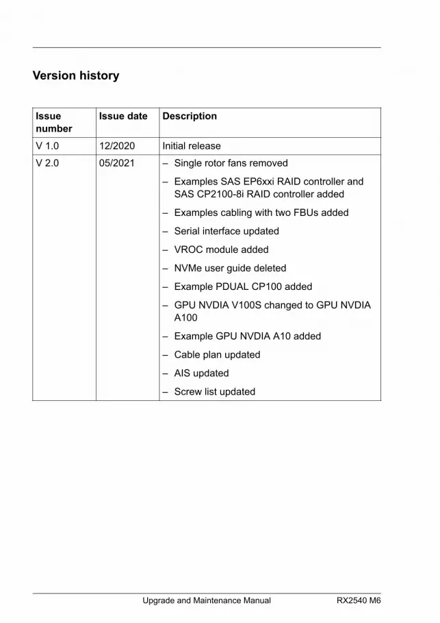
Version history
Issuenumber
Issue date Description
V 1.0 12/2020 Initial release
V 2.0 05/2021 – Single rotor fans removed
– Examples SAS EP6xxi RAID controller andSAS CP2100-8i RAID controller added
– Examples cabling with two FBUs added
– Serial interface updated
– VROC module added
– NVMe user guide deleted
– Example PDUAL CP100 added
– GPU NVDIA V100S changed to GPU NVDIAA100
– Example GPU NVDIA A10 added
– Cable plan updated
– AIS updated
– Screw list updated
Upgrade and Maintenance Manual RX2540 M6
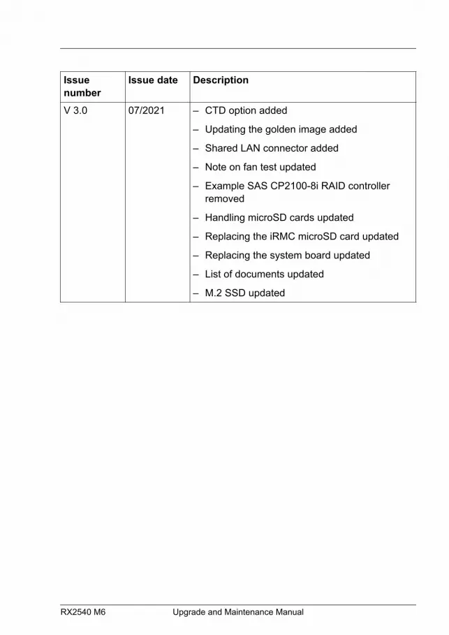
Issuenumber
Issue date Description
V 3.0 07/2021 – CTD option added
– Updating the golden image added
– Shared LAN connector added
– Note on fan test updated
– Example SAS CP2100-8i RAID controllerremoved
– Handling microSD cards updated
– Replacing the iRMC microSD card updated
– Replacing the system board updated
– List of documents updated
– M.2 SSD updated
RX2540 M6 Upgrade and Maintenance Manual

Upgrade and Maintenance Manual RX2540 M6
Content
1 Introduction 21
1.1 Concept and target groups of this manual 21
1.2 Notational conventions 21
2 Before you start 23
2.1 Basic information 232.1.1 Proceeding 232.1.2 Advanced Thermal Design (ATD) 232.1.3 Configuration Thermal Design (CTD) 242.1.4 Installing optional components 242.1.5 Replacing a defective component 25
2.2 Classification of procedures 252.2.1 Assignment of unit categories 252.2.2 Customer Replaceable Units (CRU) 262.2.3 Upgrade and Repair Units (URU) 272.2.4 Field Replaceable Units (FRU) 28
2.3 Average task duration 29
2.4 Tools you need at hand 30
2.5 Documentation overview 302.5.1 Downloading manuals 302.5.2 List of documents 31
3 Important information 35
3.1 Introduction 35
3.2 Safety instructions 353.2.1 Basic safety instructions 35
RX2540 M6 Upgrade and Maintenance Manual
3.2.2 Before starting up 363.2.3 Installation and operation 363.2.4 Batteries 393.2.5 Working with optical disk drives (ODDs) and media 393.2.6 Laser information 413.2.7 Modules with Electrostatic-Sensitive Devices (ESD modules) 413.2.8 Transporting the server 433.2.9 Installing the server in the rack 443.2.10 Other important information 44
3.3 CE conformity 45
3.4 FCC Class A Compliance Statement 45
3.5 Environmental protection 46
4 Basic hardware procedures 49
4.1 Using diagnostic information 494.1.1 Proceeding 494.1.2 Locating the defective server 494.1.3 Determining the error class 504.1.4 Locating the defective component 50
4.2 Removing the front cover with lock 52
4.3 Shutting down the server 52
4.4 Disconnecting the power cord 534.4.1 Disconnecting the power cord (AC PSU) 534.4.2 Disconnecting the power cord (DC PSU) 54
4.5 Getting access to the component 564.5.1 Safety notes 564.5.2 Extending the server out of the rack 564.5.3 Removing the server from the rack 574.5.4 Removing the top covers 59
4.6 Reassembling 604.6.1 Safety notes 60
Content
Upgrade and Maintenance Manual RX2540 M6
4.6.2 Installing the top covers 614.6.3 Installing the server in the rack 624.6.4 Sliding the server into the rack 64
4.7 Connecting the power cord 654.7.1 Connecting the power cord (AC PSU) 654.7.2 Connecting the power cord (DC PSU) 66
4.8 Switching on the server 69
4.9 Installing the front cover with lock 69
4.10 Handling riser modules 704.10.1 Removing a riser module 704.10.2 Installing a riser module 72
4.11 Handling the fan cage 744.11.1 Removing the fan cage 744.11.2 Installing the fan cage 76
4.12 Handling the air duct 784.12.1 Removing the air duct 784.12.2 Installing the air duct 79
4.13 Handling the cross bar 804.13.1 Removing the cross bar 804.13.2 Installing the cross bar 81
4.14 Handling the rear air grids 824.14.1 Removing a rear air grid 824.14.2 Installing a rear air grid 84
5 Basic software procedures 87
5.1 Validation 87
5.2 Starting the maintenance task 875.2.1 Suspending BitLocker functionality 875.2.2 Disabling the boot watchdog 885.2.3 Removing backup and optical disk media 90
Content
RX2540 M6 Upgrade and Maintenance Manual
5.2.4 Verifying and configuring the backup software solution 905.2.5 Switching on the ID indicator 90
5.3 Completing the maintenance task 915.3.1 Updating or recovering the BIOS and iRMC S5 915.3.2 Verifying system information backup or restore 945.3.3 Updating expansion card firmware 955.3.4 Reconfiguring the backup software solution 965.3.5 Resetting the boot retry counter 975.3.6 Enabling the boot watchdog 995.3.7 Enabling replaced components in the BIOS 1005.3.8 Verifying the system time settings 1005.3.9 Viewing and clearing the System Event Log (SEL) 1015.3.10 Updating the NIC configuration file in a Linux and VMware
environment 1045.3.11 Resuming BitLocker functionality 1055.3.12 Performing a RAID array rebuild 1065.3.13 Looking for MAC/WWN/GUID and SAS addresses 1075.3.13.1 Basic information 1075.3.13.2 Looking for the MAC address of a LAN controller 1075.3.13.3 Looking for the WWN address of a fibre channel controller 1085.3.13.4 Looking for the GUID address of an infiniband controller 1095.3.13.5 Looking for SAS addresses of SAS controllers for external
devices 1095.3.14 Using the Chassis ID Prom Tool 1105.3.15 Configuring LAN teaming 1135.3.16 Switching off the ID indicator 1145.3.17 Performing a fan test 1155.3.18 Updating the golden image 1175.3.18.1 Updating the golden image for iRMC S5 firmware 1175.3.18.2 Updating the golden image for BIOS firmware 118
6 Power supply unit (PSU) 121
6.1 Safety notes 121
6.2 Basic information 121
Content
Upgrade and Maintenance Manual RX2540 M6

6.3 Redundant power supply 1246.3.1 Installing a hot-plug PSU 1246.3.2 Removing a hot-plug PSU 1276.3.3 Replacing a hot-plug PSU 130
7 Hard disk drive (HDD) / solid state disk (SSD) 133
7.1 Safety notes 133
7.2 Basic information 134
7.3 Handling HDDs or SSDs without installation frame 1367.3.1 3.5-inch HDD and 3.5-inch installation frame 1367.3.2 2.5-inch HDD/SSD and 2.5-inch installation frame 1377.3.3 2.5-inch HDD/SSD and 3.5-inch installation frame 1397.3.4 EDSFF SSD and EDSFF installation frame 141
7.4 3.5-inch HDD configurations 1437.4.1 Overview of configurations 1437.4.1.1 Configuration with up to 10 HDD modules 1437.4.1.2 Configuration with up to 12 HDD modules 1447.4.2 Installing 3.5-inch HDD modules 1457.4.3 Removing 3.5-inch HDD modules 1487.4.4 Replacing a 3.5-inch HDD module 1507.4.5 Replacing the 10x 3.5-inch HDD backplane 1527.4.6 Replacing the 12x 3.5-inch HDD backplane 155
7.5 2.5-inch HDD/SSD configurations 1597.5.1 Overview of configurations 1597.5.1.1 Configuration with up to 16 HDD/SSD modules 1597.5.1.2 Configuration with up to 24 HDD/SSD/PCIe SSD modules 1607.5.1.3 Configuration with up to 24 PCIe SSD modules 1627.5.1.4 Configuration with rear 2.5-inch HDD/SSD/PCIe modules 1647.5.2 Installing 2.5-inch HDD/SSD modules 1657.5.3 Removing 2.5-inch HDD/SSD modules 1687.5.4 Replacing a 2.5-inch HDD/SSD module 1717.5.5 Installing 2.5-inch PCIe SSD modules 1727.5.6 Removing 2.5-inch PCIe SSD modules 175
Content
RX2540 M6 Upgrade and Maintenance Manual
7.5.7 Replacing a 2.5-inch PCIe SSD module 1787.5.8 Replacing a 8x 2.5-inch HDD backplane 1797.5.9 Replacing a 24x 2.5-inch HDD backplane and a switch board 1847.5.10 EDSFF SSD configurations 1887.5.10.1 Overview of configurations 1887.5.10.2 Installing EDSFF SSD modules 1917.5.10.3 Removing EDSFF SSD modules 1937.5.10.4 Replacing an EDSFF SSD module 1957.5.10.5 Replacing a 16x EDSFF SSD backplane (top) 1977.5.10.6 Replacing a 16x EDSFF SSD backplane (bottom) 201
7.6 SAS expander board 2047.6.1 Installing the SAS expander board 2047.6.2 Removing the SAS expander board 2087.6.3 Replacing the SAS expander board 210
7.7 Rear HDD/SSD extension box 2127.7.1 Positions of rear HDD cages 2127.7.2 Upgrading with rear HDD cage 1 2127.7.3 Upgrading with rear HDD cage 2 2177.7.4 Replacing a rear 4x 2.5-inch HDD backplane 2217.7.5 Replacing a rear 2x 2.5-inch HDD backplane 224
8 Fans 227
8.1 Safety notes 227
8.2 Basic information 227
8.3 Replacing a fan module 229
9 Expansion cards and backup units 233
9.1 Safety notes 233
9.2 Basic information 234
Content
Upgrade and Maintenance Manual RX2540 M6

9.3 Handling slot brackets 2379.3.1 Installing slot brackets 2379.3.2 Removing slot brackets 239
9.4 Handling SFP+ transceiver modules 2399.4.1 Installing SFP+ transceiver modules 2399.4.2 Removing SFP+ transceiver modules 245
9.5 OCP (Open Compute Project) modules 2499.5.1 Position of the OCP module 2499.5.2 Installing an OCP module 2499.5.3 Removing an OCP module 2529.5.4 Replacing the OCP module 254
9.6 Expansion cards in standard PCIe slots 2559.6.1 Installing an expansion card 2559.6.2 Removing an expansion card 2629.6.3 Replacing an expansion card 265
9.7 Internal RAID riser module 2679.7.1 Installing an internal RAID riser module 2679.7.2 Removing an internal RAID riser module 2739.7.3 Replacing an internal RAID riser module 2779.7.4 Replacing a riser card 278
9.8 Expansion cards in riser modules 2809.8.1 Installing an expansion card in a riser module 2809.8.2 Removing an expansion card from a riser module 2849.8.3 Replacing expansion cards from a riser module 2869.8.4 Replacing a riser card 288
9.9 GPU cards in riser modules 2919.9.1 Installing a GPU card in a riser module 2919.9.2 Removing a GPU card from a riser module 3079.9.3 Replacing a GPU card from a riser module 3129.9.4 Replacing a riser card 314
9.10 Flash backup unit (FBU) 3169.10.1 Positions of the FBUs 3169.10.2 Installing an FBU 3179.10.3 Removing an FBU 324
Content
RX2540 M6 Upgrade and Maintenance Manual
9.10.4 Replacing an FBU 325
10 Main memory 329
10.1 Safety notes 329
10.2 Basic information 33010.2.1 Slots and features 33010.2.2 General memory population rules 33210.2.3 DDR4 only - memory population rules 33310.2.4 DDR4 and Optane PMem - memory population rules 334
10.3 Installing memory modules 336
10.4 Removing memory modules 340
10.5 Replacing memory modules 341
10.6 Handling memory dummy modules 343
11 Processor (CPU) 345
11.1 Safety notes 345
11.2 Basic information 346
11.3 Upgrading to 2 CPUs configuration 348
11.4 Replacing a CPU or heat sink 359
12 Liquid cooling (LC) 367
12.1 Safety notes 367
12.2 Basic information 368
12.3 Replacing the CPU for LC device 369
Content
Upgrade and Maintenance Manual RX2540 M6
13 Accessible drives 385
13.1 Safety notes 385
13.2 Basic information 385
13.3 Optical disk drive (ODD) 38713.3.1 Storing the ODD latch 38713.3.2 Installing the ODD (2.5-inch chassis) 38713.3.3 Removing the ODD (2.5-inch chassis) 39013.3.4 Replacing the ODD (2.5-inch chassis) 39413.3.5 Installing the ODD (3.5-inch chassis) 39513.3.6 Removing the ODD (3.5-inch chassis) 40213.3.7 Replacing the ODD (3.5-inch chassis) 409
13.4 LTO drive 41113.4.1 Installing the LTO drive 41113.4.2 Removing the LTO drive 41913.4.3 Replacing the LTO drive 426
13.5 RDX drive 42813.5.1 Installing the RDX drive 42813.5.2 Removing the RDX drive 43713.5.3 Replacing the RDX drive 445
14 Front panel 447
14.1 Safety notes 447
14.2 Basic information 447
14.3 Common operation panel (COP) 44814.3.1 Replacing the COP 448
14.4 Front VGA 45414.4.1 Installing the front VGA 45414.4.2 Removing the front VGA 45714.4.3 Replacing the front VGA 460
Content
RX2540 M6 Upgrade and Maintenance Manual

15 Additional interfaces 463
15.1 Safety notes 463
15.2 Serial interface 46315.2.1 Installing the serial interface 46315.2.2 Removing the serial interface 46715.2.3 Replacing the serial interface 469
15.3 Rear VGA connector 47015.3.1 Replacing the rear VGA 470
16 System board and components 475
16.1 Safety notes 475
16.2 Basic information 475
16.3 CMOS battery 47616.3.1 Replacing the CMOS battery 476
16.4 Trusted Platform Module (TPM) 47916.4.1 TPM kit 47916.4.2 Position of the TPM 47916.4.3 Installing the TPM 48016.4.4 Removing the TPM 48316.4.5 Replacing the TPM 488
16.5 iRMC microSD card 49116.5.1 Note for embedded Lifecycle Management (eLCM) 49116.5.2 Installing the iRMC microSD card 49116.5.3 Removing the iRMC microSD card 49316.5.4 Replacing the iRMC microSD card 494
16.6 M.2 SSD 49716.6.1 Slots and bolts for M.2 SSDs 49716.6.2 Installing an M.2 SSD 49816.6.3 Removing an M.2 SSD 50216.6.4 Replacing an M.2 SSD 504
Content
Upgrade and Maintenance Manual RX2540 M6

16.7 Dual microSD 64GB Enterprise 50516.7.1 Position of the Dual microSD 64GB Enterprise 50516.7.2 Installing the Dual microSD 64GB Enterprise 50516.7.3 Removing the Dual microSD 64GB Enterprise 50916.7.4 Replacing the Dual microSD 64GB Enterprise 51216.7.5 Replacing the microSD card 514
16.8 VROC module 51616.8.1 Installing the VROC module 51616.8.2 Removing the VROC module 51716.8.3 Replacing the VROC module 519
16.9 System board 52016.9.1 Replacing the system board 520
17 Appendix A 535
17.1 Mechanical overview 53517.1.1 Server front 53517.1.1.1 3.5-inch HDD configuration 53517.1.1.2 2.5-inch HDD/SSD configuration 53617.1.1.3 EDSFF SSD configuration 53717.1.2 Server rear 53717.1.2.1 Servers with air cooling 53717.1.2.2 Servers with liquid cooling 53917.1.3 Server interior 54017.1.3.1 Servers with air cooling 54017.1.3.2 Servers with liquid cooling (LC) 541
17.2 Connectors and indicators 54217.2.1 Connectors and indicators on the system board 54217.2.1.1 System board D3891 54217.2.2 Server front 54817.2.2.1 Connectors on the front panel 54817.2.2.2 Indicators on the COP 54917.2.2.3 States of power-on indicator and time duration during
firmware restore 55217.2.2.4 Indicator on the ODD 556
Content
RX2540 M6 Upgrade and Maintenance Manual
17.2.2.5 Indicators on hot-plug HDD / SSD / PCIe SSD / EDSFF SSDmodules 557
17.2.3 Server rear 55917.2.3.1 Connectors on the server rear 55917.2.3.2 ID, CSS and Global Error indicators 56017.2.3.3 LAN indicators 56317.2.3.4 Indicator on hot-plug PSU 56517.2.4 Acoustic indicators 566
17.3 Onboard settings 567
17.4 Minimum startup configuration 568
18 Appendix B 571
18.1 Supplied documents 571
Content
Upgrade and Maintenance Manual RX2540 M6
1 Introduction
1.1 Concept and target groups of this manual
This upgrade and maintenance manual provides instructions for the followingprocedures:
– Upgrading the server configuration by adding optional hardwarecomponents.
– Upgrading the server configuration by replacing existing hardwarecomponents with superior ones.
– Replacing defective hardware components.
This manual focuses on on-site maintenance tasks. It is recommended toprepare each service assignment following remote diagnostics procedures, asdescribed in the "ServerView Suite Local Service Concept (LSC)" manual, see"Documentation overview" on page 30.
CAUTIONThe document at hand comprises procedures of a wide range ofcomplexity.▶ Check the profile of qualification for technicians before assigning
tasks.▶ Before you start, carefully read "Classification of procedures" on
page 25.
1.2 Notational conventions
The following notational conventions are used in this manual:
Text in bold Indicates references to names of interfaceelements.
Text in monospace Indicates commands and text to be entered bythe user.
RX2540 M6 Upgrade and Maintenance Manual 21

"Quotation marks" Indicate names of chapters and terms that arebeing emphasized.
▶ Describes activities that must be performed inthe order shown.
[Abc] Indicates keys on the keyboard.
CAUTION
Pay particular attention to texts marked with thissymbol. Failure to observe this warning mayendanger your life, destroy the system or leadto the loss of data.
Indicates additional information, notes and tips.
Indicates the procedure category in terms ofcomplexity and qualification requirements, see"Classification of procedures" on page 25.
Indicates the average task duration, see"Average task duration" on page 29.
Introduction
22 Upgrade and Maintenance Manual RX2540 M6

2 Before you start
2.1 Basic information
2.1.1 Proceeding
Before you start any upgrade or maintenance task, proceed as follows:▶ Carefully read the safety instructions, see "Important information" on
page 35.
▶ Make sure that all necessary manuals are available, see "Documentation overview" on page 30. Print the PDF files if required.
▶ Make yourself familiar with the procedure categories, see "Classification of procedures" on page 25.
▶ Ensure that all required tools are available, see "Tools you need at hand" on page 30.
2.1.2 Advanced Thermal Design (ATD)
The ATD option allows you to operate the system with a wider temperaturerange either of 5 °C to 40 °C or 5 °C to 45 °C, depending on your system andconfiguration.
This option can only be ordered from themanufacturer and is indicated by the respectivelogo on the identification rating plate.
CAUTION▶ In a system that is configured with ATD, only certain components
which support the respectively increased higher operatingtemperature range may be installed and used. For applicablerestrictions, see the official configurator tool.
RX2540 M6 Upgrade and Maintenance Manual 23
2.1.3 Configuration Thermal Design (CTD)
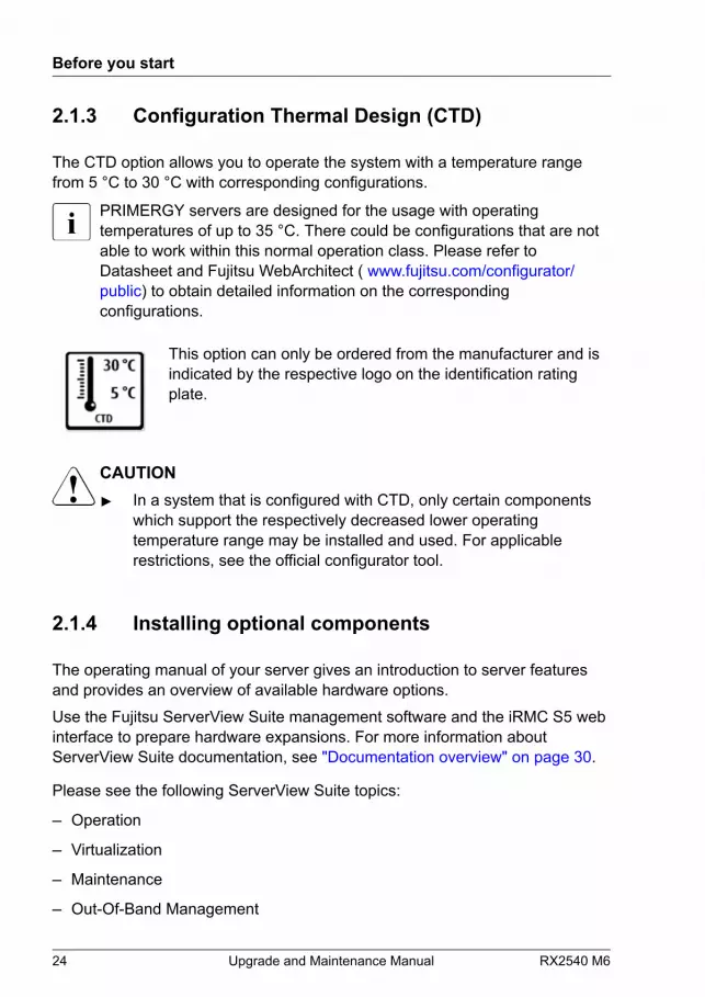
The CTD option allows you to operate the system with a temperature rangefrom 5 °C to 30 °C with corresponding configurations.
PRIMERGY servers are designed for the usage with operatingtemperatures of up to 35 °C. There could be configurations that are notable to work within this normal operation class. Please refer toDatasheet and Fujitsu WebArchitect ( www.fujitsu.com/configurator/public) to obtain detailed information on the correspondingconfigurations.
This option can only be ordered from the manufacturer and isindicated by the respective logo on the identification ratingplate.
CAUTION▶ In a system that is configured with CTD, only certain components
which support the respectively decreased lower operatingtemperature range may be installed and used. For applicablerestrictions, see the official configurator tool.
2.1.4 Installing optional components
The operating manual of your server gives an introduction to server featuresand provides an overview of available hardware options.Use the Fujitsu ServerView Suite management software and the iRMC S5 webinterface to prepare hardware expansions. For more information aboutServerView Suite documentation, see "Documentation overview" on page 30.
Please see the following ServerView Suite topics:
– Operation
– Virtualization
– Maintenance
– Out-Of-Band Management
Before you start
24 Upgrade and Maintenance Manual RX2540 M6
For the latest information on hardware options, see the hardwareconfigurator of your server, available online at the following address:https://www.fujitsu.com/fts/products/computing/servers/primergy/index.htmlFor Japan:https://www.fujitsu.com/jp/products/computing/servers/primergy/
Please contact your local Fujitsu customer service partner for details on how toorder expansion kits or spare parts.
2.1.5 Replacing a defective component
The Global Error indicator on the front of the server reports defective hardwarecomponents that need to be replaced. For more information on the controlsand indicators of your server, see the operating manual of your server and"Connectors and indicators" on page 542.If the system has been powered off in order to replace a non-hot plug unit, asystem of PRIMERGY diagnostic indicators guides you to the defectivecomponent. The "Indicate CSS" button enables the indicator next to thedefective component even if the server has been switched off anddisconnected from the mains. For more information, see "Using diagnostic information" on page 49 and "Indicators on the COP" on page 549.If the defective component is a customer replaceable unit included in the CSSconcept (Customer Self Service), the CSS indicator on the server front will lightup.It is recommended to prepare local maintenance tasks using remotediagnostics procedures, see the "ServerView Suite Local Service Concept(LSC)" manual.
2.2 Classification of procedures
2.2.1 Assignment of unit categories
The complexity of maintenance procedures varies significantly. Procedureshave been assigned to one of three unit categories, indicating the level ofdifficulty and required qualification.
Before you start
RX2540 M6 Upgrade and Maintenance Manual 25
At the beginning of each procedure, the involved unit category is indicated byone of the symbols introduced in this section.
Please ask your local Fujitsu service center for more information.
2.2.2 Customer Replaceable Units (CRU)
Customer Replaceable Units (CRU)
Customer Replaceable Units are intended for customer self service and maybe installed or replaced as hot-plug components during operation.
Components that the customer is entitled to replace may differaccording to the service form in his country.For Japan:https://www.fujitsu.com/jp/products/computing/servers/primergy/support/repair.html
Hot-plug components increase system availability and guarantee a high degreeof data integrity and fail-safe performance. Procedures can be carried outwithout shutting down the server or going offline.
Components that are handled as Customer Replaceable Units
– Hot-plug HDD/SSD modules
– Hot-plug PCIe SSD modules
– Hot-plug PSUs
– Hot-plug fan modules
– Memory modules (not allowed for Japan)
– Expansion cards (not allowed for Japan)
Before you start
26 Upgrade and Maintenance Manual RX2540 M6
Peripherals that are handled as Customer Replaceable Units
– Keyboard
– Mouse
2.2.3 Upgrade and Repair Units (URU)
Upgrade and Repair Units (URU)
Upgrade and Repair Units are non hot-plug components that can be orderedseparately to be installed as options (Upgrade Units) or are available to thecustomer through customer self service (Repair Units).
For Japan, customer allows only upgrade. For upgrade units ascustomer replaceable, see:https://www.fujitsu.com/jp/products/computing/servers/primergy/
Server management error messages and diagnostic indicators on thefront panel and system board will report defective Upgrade and RepairUnits as customer replaceable CSS components.
Upgrade and repair procedures involve shutting down and opening the server.CAUTIONThe device may be seriously damaged or cause damage if it is openedwithout authorization or if repairs are attempted by unauthorized anduntrained personnel.
Components that are handled as Upgrade Units
– CPU (upgrade kits)
– ODD
– Expansion cards
– Flash backup units (FBU)
– Memory modules
– OCP module
Before you start
RX2540 M6 Upgrade and Maintenance Manual 27
– iRMC microSD card
– M.2 SSDs
– Dual microSD 64GB Enterprise
– PCIe riser modules
Components that are handled solely as Repair Units
– CMOS battery
2.2.4 Field Replaceable Units (FRU)
Field Replaceable Units (FRU)
Removing and installing Field Replaceable Units involves complexmaintenance procedures on integral server components. Procedures willrequire shutting down, opening and disassembling the server.
CAUTIONMaintenance procedures involving Field Replaceable Units must beperformed exclusively by Fujitsu service personnel or technicianstrained by Fujitsu. Please note that unauthorized interference with thesystem will void the warranty and exempt the manufacturer from allliability.
Components that are handled as Field Replaceable Units
– CPU (replacement)
– HDD backplane (SAS/SATA/PCIe SSD) or EDSFF SSD backplane
– SAS expander board / PCIe switch board
– PCIe riser card
– Common Operation Panel (COP)
– System board
– Trusted Platform Module (TPM)
Before you start
28 Upgrade and Maintenance Manual RX2540 M6

– Liquid cooling (LC) kit
Please ask your local Fujitsu service center for more information.
2.3 Average task duration
Hardware: 10 minutes
The average task duration including preliminary and concluding steps isindicated at the beginning of each procedure next to the procedure class.The following table gives an overview of steps taken into account forcalculating the average task duration.
Step included Explanation
Server shutdown no
Shutdown time depends on hardware andsoftware configuration and may varysignificantly.Software tasks necessary beforemaintenance, see "Starting the maintenance task" on page 87.
Rack removal,disassembly yes Making the server available, removing the
server from the rack (if applicable).
Transport noTransporting the server to the service table(where required) depends on localcustomer conditions.
Maintenanceprocedures yes Maintenance procedures including
preliminary and concluding software tasks.
Transport noReturning the server to its installation site(where required) depends on localcustomer conditions.
Assembly, rackinstallation yes Reassembling the server, installing the
server in the rack (if applicable).
Before you start
RX2540 M6 Upgrade and Maintenance Manual 29
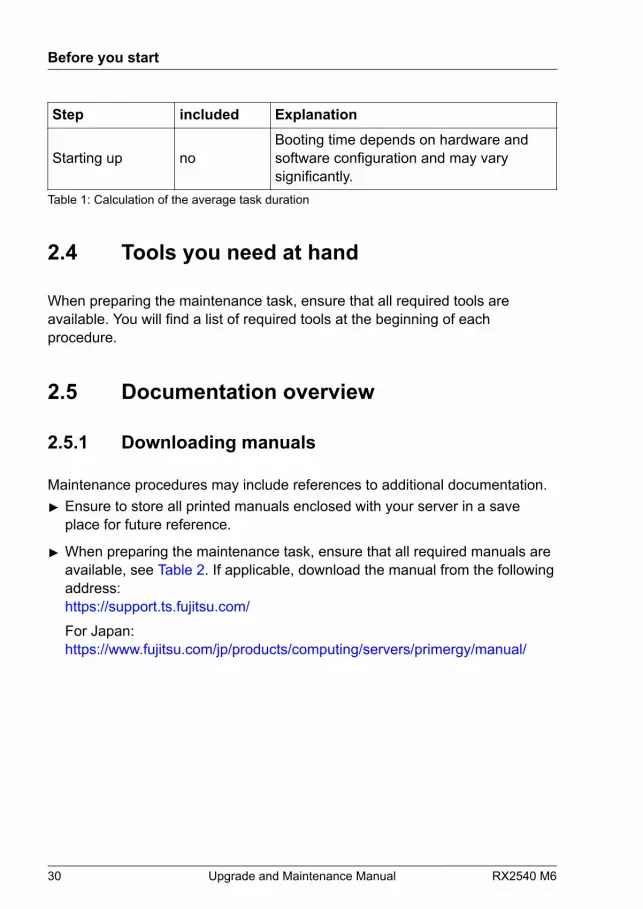
Step included Explanation
Starting up noBooting time depends on hardware andsoftware configuration and may varysignificantly.
Table 1: Calculation of the average task duration
2.4 Tools you need at hand
When preparing the maintenance task, ensure that all required tools areavailable. You will find a list of required tools at the beginning of eachprocedure.
2.5 Documentation overview
2.5.1 Downloading manuals
Maintenance procedures may include references to additional documentation.▶ Ensure to store all printed manuals enclosed with your server in a save
place for future reference.
▶ When preparing the maintenance task, ensure that all required manuals areavailable, see Table 2. If applicable, download the manual from the followingaddress:https://support.ts.fujitsu.com/For Japan:https://www.fujitsu.com/jp/products/computing/servers/primergy/manual/
Before you start
30 Upgrade and Maintenance Manual RX2540 M6
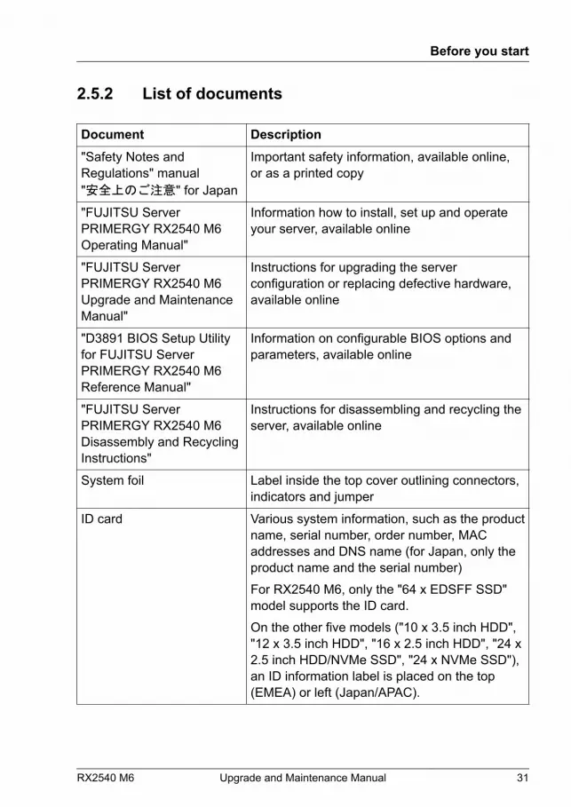
2.5.2 List of documents
Document Description"Safety Notes andRegulations" manual"安全上のご注意" for Japan
Important safety information, available online,or as a printed copy
"FUJITSU ServerPRIMERGY RX2540 M6Operating Manual"
Information how to install, set up and operateyour server, available online
"FUJITSU ServerPRIMERGY RX2540 M6Upgrade and MaintenanceManual"
Instructions for upgrading the serverconfiguration or replacing defective hardware,available online
"D3891 BIOS Setup Utilityfor FUJITSU ServerPRIMERGY RX2540 M6Reference Manual"
Information on configurable BIOS options andparameters, available online
"FUJITSU ServerPRIMERGY RX2540 M6Disassembly and RecyclingInstructions"
Instructions for disassembling and recycling theserver, available online
System foil Label inside the top cover outlining connectors,indicators and jumper
ID card Various system information, such as the productname, serial number, order number, MACaddresses and DNS name (for Japan, only theproduct name and the serial number)For RX2540 M6, only the "64 x EDSFF SSD"model supports the ID card.On the other five models ("10 x 3.5 inch HDD","12 x 3.5 inch HDD", "16 x 2.5 inch HDD", "24 x2.5 inch HDD/NVMe SSD", "24 x NVMe SSD"),an ID information label is placed on the top(EMEA) or left (Japan/APAC).
Before you start
RX2540 M6 Upgrade and Maintenance Manual 31
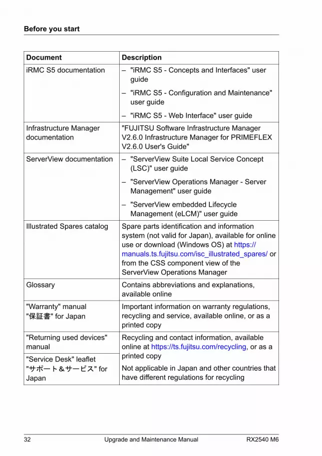
Document DescriptioniRMC S5 documentation – "iRMC S5 - Concepts and Interfaces" user
guide
– "iRMC S5 - Configuration and Maintenance"user guide
– "iRMC S5 - Web Interface" user guide
Infrastructure Managerdocumentation
"FUJITSU Software Infrastructure ManagerV2.6.0 Infrastructure Manager for PRIMEFLEXV2.6.0 User's Guide"
ServerView documentation – "ServerView Suite Local Service Concept(LSC)" user guide
– "ServerView Operations Manager - ServerManagement" user guide
– "ServerView embedded LifecycleManagement (eLCM)" user guide
Illustrated Spares catalog Spare parts identification and informationsystem (not valid for Japan), available for onlineuse or download (Windows OS) at https://manuals.ts.fujitsu.com/isc_illustrated_spares/ orfrom the CSS component view of theServerView Operations Manager
Glossary Contains abbreviations and explanations,available online
"Warranty" manual"保証書" for Japan
Important information on warranty regulations,recycling and service, available online, or as aprinted copy
"Returning used devices"manual
Recycling and contact information, availableonline at https://ts.fujitsu.com/recycling, or as aprinted copyNot applicable in Japan and other countries thathave different regulations for recycling
"Service Desk" leaflet"サポート&サービス" forJapan
Before you start
32 Upgrade and Maintenance Manual RX2540 M6

Document DescriptionAdditional documentation RAID documentation, "Intel Virtual RAID on
CPU (Intel VROC) User Guide", available onlineat https://support.ts.fujitsu.com/For Japan:https://www.fujitsu.com/jp/products/computing/servers/primergy/manual/
Third party documentation – Operating system documentation, online help
– Peripherals documentationTable 2: List of documents
Before you start
RX2540 M6 Upgrade and Maintenance Manual 33
Before you start
34 Upgrade and Maintenance Manual RX2540 M6
3 Important information
3.1 Introduction
In this chapter you will find essential information regarding safety when workingon your server.
Depending on your server or the installed options some information isnot valid for your server.
CAUTION▶ Before installing and starting up a server, please observe the safety
instructions listed in the following section. This will help you to avoidmaking serious errors that could impair your health, damage theserver and endanger the data base.
3.2 Safety instructions
3.2.1 Basic safety instructions
The following safety instructions are also provided in the manual "SafetyNotes and Regulations" or "安全上のご注意".
This server meets the relevant safety regulations for IT equipment. If you haveany questions about whether you can install the server in the intendedenvironment, please contact your sales outlet or our customer service team.▶ The actions described in this manual shall be performed by technical
specialists. A technical specialist is a person who is trained to install theserver including hardware and software.
▶ Repairs to the server that do not relate to CSS failures shall be performedby service personnel. Please note that unauthorized interference with theserver will void the warranty and exempt the manufacturer from all liability.
▶ Any failure to observe the guidelines in this manual, and any improperrepairs could expose the user to risks (electric shock, energy hazards, firehazards) or damage the equipment.
RX2540 M6 Upgrade and Maintenance Manual 35

▶ Only valid for non hot-plug componentsBefore installing/removing internal components to/from the server, turn offthe server, all peripheral devices, and any other connected devices. Alsounplug all power cords from the power outlet. Failure to do so can causeelectric shock or damage.
3.2.2 Before starting up
▶ During installation and before operating the server, observe the instructionson environmental conditions for your server.
▶ If the server is brought in from a cold environment, condensation may formboth inside and on the outside of the server.Wait until the server has acclimatized to room temperature and is absolutelydry before starting it up. Material damage may be caused to the server if thisrequirement is not observed.
▶ Only transport the server in its original packaging or in packaging thatprotects it from impacts and jolts.In Japan and APAC, transporting the server in its original packaging doesnot apply.
3.2.3 Installation and operation
▶ This server should not be operated in ambient temperatures above 35 °C.For servers with Advanced Thermal Design the ambient temperature canincrease to 40 °C or 45 °C.
▶ If the server is integrated into an installation that draws power from anindustrial power supply network with an IEC309 connector, the powersupply's fuse protection must comply with the requirements for non-industrial power supply networks for type A connectors.
▶ The server automatically adjusts itself to a mains voltage, see the type labelof your server. Ensure that the local mains voltage lies within these limits.
▶ This server must only be connected to properly grounded power outlets orconnected to the grounded rack internal power distribution server with testedand approved power cords.
Important information
36 Upgrade and Maintenance Manual RX2540 M6
▶ If a DC power cord is used, the server must be connected to a proper DCsource and earth ground stud/end.
▶ Ensure that the server is connected to a properly grounded power outletclose to the server.
▶ Ensure that the power sockets on the server and the properly groundedpower outlets are easily accessible.
▶ The On/Off button or the main power switch (if present) does not isolate theserver from the mains power supply. In case of repair or servicingdisconnect the server completely from the mains power supply, unplug allpower plugs from the properly grounded power outlets.
▶ Always connect the server and the attached peripheral devices to the samepower circuit. Otherwise you run the risk of losing data if, for example, theserver is still running but a peripheral device (e.g. memory subsystem) failsduring a power outage.
▶ The adequately shielded data cables must be used.All data and signal cables must have sufficient shielding. The use of cabletype S/FTP Cat5 or higher is recommended. Use of unshielded or badlyshielded cables may lead to increased emission of interference and/orreduced fault-tolerance of the device.
▶ Ethernet cabling has to comply with EN 50173 and EN 50174-1/2 standardsor ISO/IEC 11801 standard respectively. The minimum requirement is aCategory 5 shielded cable for 10/100 Ethernet, or a Category 5e cable forGigabit Ethernet.
▶ Route the cables in such a way that they do not create a potential hazard(ensure that no-one can trip over them) and that they cannot be damaged.When connecting the server, see the relevant instructions in this manual.
▶ Never connect or disconnect data transmission lines during a storm (risk oflightning hazard).
▶ Ensure that no objects (e.g. jewelry, paperclips etc.) or liquids can get insidethe server (risk of electric shock, short circuit).
▶ In emergencies (e.g. damaged casing, controls or cables, penetration ofliquids or foreign bodies), contact the server administrator or your customerservice team. Only disconnect the server from the mains power supply ifthere is no risk of harming yourself.
Important information
RX2540 M6 Upgrade and Maintenance Manual 37
▶ Proper operation of the server (in accordance with IEC 60950-1/62368-1resp. EN 60950-1/62368-1) is only ensured if the server is completelyassembled and the rear covers for the installation slots have been fitted(electric shock, cooling, fire protection, interference suppression).
▶ Only install server expansions that satisfy the requirements and rulesgoverning safety and electromagnetic compatibility and those relating totelecommunication terminals. If you install other expansions, they maydamage the server or violate the safety regulations. Information on whichserver expansions are approved for installation can be obtained from ourcustomer service center or your sales outlet.
▶ The components marked with a warning notice (e.g. lightning symbol) mayonly be opened, removed or exchanged by authorized, qualified personnel.Exception: CSS components can be replaced.
▶ The warranty is void if the server is damaged during installation orreplacement of server expansions.
▶ Only set screen resolutions and refresh rates that are specified in theoperating manual for the monitor. Otherwise, you may damage your monitor.If you are in any doubt, contact your sales outlet or customer service center.
▶ Only valid for non hot-plug componentsBefore installing/removing internal components to/from the server, turn offthe server, all peripheral devices, and any other connected devices. Alsounplug all power cords from the power outlet. Failure to do so can causeelectric shock or damage.Internal devices remain hot after shutdown. Wait for a while after shutdownbefore installing or removing internal options.
▶ Do not damage or modify internal cables or internal devices. Doing so maycause a server failure, fire, or electric shock and will void the warranty andexempt the manufacturer from all liability.
▶ The circuit boards and soldered parts of internal options are exposed andcan be damaged by static electricity. To ensure reliable protection, you mustwear an earthing band on your wrist when working with this type of moduleand connect it to an unpainted, conducting metal part of the server.
▶ Do not touch the circuitry on boards or soldered parts. Hold the metallicareas or the edges of the circuit boards.
Important information
38 Upgrade and Maintenance Manual RX2540 M6

▶ Install the screw removed during installation/detaching internal options informer position. To use a screw of the different kind can cause a breakdownof equipment.
▶ The procedure of installation on this notes might change depending on aconfiguration of option.
3.2.4 Batteries
▶ Incorrect replacement of batteries may lead to a risk of explosion. Thebatteries may only be replaced with identical batteries or with a typerecommended by the manufacturer.
▶ Do not throw batteries into the trash can.Batteries must be disposed of in accordance with local regulationsconcerning special waste.
▶ Ensure that you insert the battery the right way round.
▶ The battery used in this server may present a fire or chemical burn hazard ifmistreated. Do not disassemble, heat about 100 °C (212F), or incinerate thebattery.
▶ Replace the lithium battery on the system board in accordance with theinstructions in the corresponding Upgrade and Maintenance Manual,chapter "System board and components" > "CMOS battery".
▶ All batteries containing pollutants are marked with a symbol (a crossed-outgarbage can). In addition, the marking is provided with the chemical symbolof the heavy metal decisive for the classification as a pollutant:Cd CadmiumHg MercuryPb Lead
3.2.5 Working with optical disk drives (ODDs) andmedia
When working with ODDs, these instructions must be followed.
Important information
RX2540 M6 Upgrade and Maintenance Manual 39
CAUTION
▶ Only use CDs/DVDs/BDs that are in perfect condition, in order to preventdata loss, equipment damage and injury.
▶ Check each CD/DVD/BD for damage, cracks, breakages etc. beforeinserting it in the drive.Note that any additional labels applied may change the mechanicalproperties of a CD/DVD/BD and cause imbalance and vibrations.Damaged and imbalanced CDs/DVDs/BDs can break at high drive speeds(data loss).Under certain circumstances, sharp CD/DVD/BD fragments can pierce thecover of the ODD (equipment damage) and can fly out of the drive (dangerof injury, particularly to uncovered body parts such as the face or neck).
▶ High humidity and airborne dust levels are to be avoided. Electric shocksand/or server failures may be caused by liquids such as water, or metallicitems, such as paper clips, entering a drive.
▶ Shocks and vibrations are also to be avoided.
▶ Do not insert any objects other than the specified CDs/DVDs/BDs.
▶ Do not pull on, press hard, or otherwise handle the CD/DVD/BD trayroughly.
▶ Do not disassemble the ODD.
▶ Before use, clean the ODD tray using a soft, dry cloth.
▶ As a precaution, remove disks from the ODD when the drive is not to beused for a long time. Keep the ODD tray closed to prevent foreign matter,such as dust, from entering the ODD.
▶ Hold CDs/DVDs/BDs by their edges to avoid contact with the disk surface.
▶ Do not contaminate the CD/DVD/BD surface with fingerprints, oil, dust, etc.If dirty, clean with a soft, dry cloth, wiping from the center to the edge. Donot use benzene, thinners, water, record sprays, antistatic agents, orsilicone-impregnated cloth.
▶ Be careful not to damage the CD/DVD/BD surface.
▶ Keep the CDs/DVDs/BDs away from heat sources.
Important information
40 Upgrade and Maintenance Manual RX2540 M6
▶ Do not bend or place heavy objects on CDs/DVDs/BDs.
▶ Do not write with ballpoint pen or pencil on the label (printed) side.
▶ Do not attach stickers or similar to the label side. Doing so may causerotational eccentricity and abnormal vibrations.
▶ When a CD/DVD/BD is moved from a cold place to a warm place, moisturecondensation on the CD/DVD/BD surface can cause data read errors. In thiscase, wipe the CD/DVD/BD with a soft, dry cloth then let it air dry. Do not drythe CD/DVD/BD using devices such as a hair dryer.
▶ To avoid dust, damage, and deformation, keep the CD/DVD/BD in its casewhenever it is not in use.
▶ Do not store CDs/DVDs/BDs at high temperatures. Areas exposed toprolonged direct sunlight or near heating appliances are to be avoided.
You can prevent damage from the ODD and the CDs/DVDs/BDs, as wellas premature wear of the disks, by observing the following suggestions:
● Only insert disks in the drive when needed and remove them afteruse.
● Store the disks in suitable sleeves.
● Protect the disks from exposure to heat and direct sunlight.
3.2.6 Laser information
The ODD complies with IEC 60825-1 laser class 1.CAUTIONThe ODD contains a light-emitting diode (LED), which under certaincircumstances produces a laser beam stronger than laser class 1.Looking directly at this beam is dangerous.▶ Never remove parts of the ODD casing!
3.2.7 Modules with Electrostatic-Sensitive Devices(ESD modules)
ESD modules are identified by the following sticker:
Important information
RX2540 M6 Upgrade and Maintenance Manual 41

Figure 1: ESD label
The ESD label can be different.
When you handle ESD modules, you must always observe the following points:▶ Switch off the server and remove the power plugs from the power outlets
before installing or removing ESD modules.
▶ The circuit boards and soldered parts of internal options are exposed andcan be damaged by static electricity. To ensure reliable protection, you mustwear an earthing band on your wrist when working with ESD modules andconnect it to an unpainted, conducting metal part of the server.
▶ Any devices or tools that are used must be free of electrostatic charge.
▶ Wear a suitable grounding cable that connects you to the external chassis ofthe server.
▶ Always hold ESD modules at the edges or at the colored touch points.
▶ Do not touch any connectors or conduction paths on an ESD module.
▶ Place all the components on a pad which is free of electrostatic charge.
For a detailed description of how to handle ESD modules, see therelevant European or international standards (EN 61340-5-1, ANSI/ESD S20.20).
Important information
42 Upgrade and Maintenance Manual RX2540 M6
3.2.8 Transporting the server
CAUTION▶ Only transport the server in its original packaging or in packaging
that protects it from impacts and jolts.In Japan and APAC, transporting the server in its original packagingdoes not apply.
▶ Do not unpack the server until it is at its installation location.▶ If you need to lift or transport the server, ask other people to help
you.▶ Never lift or carry the server by the handles or the Quick Release
Levers (QRLs) on the front panel.
Important information
RX2540 M6 Upgrade and Maintenance Manual 43

3.2.9 Installing the server in the rack
CAUTION▶ For safety reasons, at least 2 people are required to install the
server in the rack because of its weight and size.(For Japan, see "安全上のご注意".)
▶ Never lift the server into the rack using the QRLs on the front panel.▶ When connecting and disconnecting cables, observe the relevant
instructions in the "Important Information" chapter of the technicalmanual for the corresponding rack. The technical manual issupplied with the corresponding rack.
▶ When installing the rack, ensure that the anti-tilt mechanism iscorrectly fitted.
▶ Do not extend more than one server out of the rack simultaneouslyeven if the tilt protection is in place. If several servers aresimultaneously extended from the rack, there is a risk that the rackcould tip over. See the safety information of the rack and thewarning label.
▶ If the server/rack is intended for permanent connection to the mainsonly an authorized specialist (electrician) is allowed to work. Pleasefollow the regulation of each country.
▶ If the server is integrated into an installation that draws power froman industrial power supply network with an IEC309 type connector,the power supply's fuse protection must comply with therequirements for non-industrial power supply networks for the typeA connector.
3.2.10 Other important information
▶ During cleaning, observe the instructions in the corresponding operatingmanual chapter "Operation" > "Cleaning the server".
▶ Keep all manuals close to the server. All documentation must be included ifthe equipment is passed on to a third party.
Important information
44 Upgrade and Maintenance Manual RX2540 M6

3.3 CE conformity
The system complies with the requirements of EuropeanRegulations. Find the CE declaration on certificate portal:https://sp.ts.fujitsu.com/sites/certificates/default.aspx
CAUTIONThis is a Class A product. In a domestic environment this product maycause RF interference.▶ In this case the user may be required to take adequate measures.
To open the CE declaration applicable for your system, proceed as follows:▶ Select the product class, e.g. "Industry Standard Servers".
▶ Select the subclass, e.g. "Rack server".
▶ Select your server, e.g. "PRIMERGY RX2540 M6".
▶ Select the document, e.g. "CE Cert PRIMERGY RX2540 M6".
3.4 FCC Class A Compliance Statement
If there is an FCC statement on the device, it applies to the products covered inthis manual, unless otherwise specified herein. The statement for otherproducts will appear in the accompanying documentation.
NOTE:
This equipment has been tested and found to comply with the limits for a"Class A" digital device, pursuant to Part 15 of the FCC rules and meets allrequirements of the Canadian Interference-Causing Equipment StandardICES-003 for digital apparatus. These limits are designed to providereasonable protection against harmful interference in a residential installation.This equipment generates, uses and can radiate radio frequency energy and, ifnot installed and used in strict accordance with the instructions, may causeharmful interference to radio communications. However, there is no warrantythat interference will not occur in a particular installation. If this equipment doescause harmful interference to radio or television reception, which can be
Important information
RX2540 M6 Upgrade and Maintenance Manual 45

determined by turning the equipment off and on, the user is encouraged to tryto correct the interference by one or more of the following measures:▶ Reorient or relocate the receiving antenna.
▶ Increase the separation between equipment and the receiver.
▶ Connect the equipment into an outlet on a circuit different from that to whichthe receiver is connected.
▶ Consult the dealer or an experienced radio/TV technician for help.
Fujitsu is not responsible for any radio or television interference caused byunauthorized modifications of this equipment or the substitution or attachmentof connecting cables and equipment other than those specified by Fujitsu. Thecorrection of interferences caused by such unauthorized modification,substitution or attachment will be the responsibility of the user.The use of shielded I/O cables is required when connecting this equipment toany and all optional peripheral or host devices. Failure to do so may violateFCC and ICES rules.
3.5 Environmental protection
Environmentally-friendly product design and development
This product has been designed in accordance with the Fujitsu standard for"environmentally friendly product design and development". This means thatkey factors such as durability, selection and labeling of materials, emissions,packaging, ease of dismantling and recycling have been taken into account.This saves resources and thus reduces the harm done to the environment.More information can be found at:https://ts.fujitsu.com/products/standard_servers/index.htmlFor Japan:https://jp.fujitsu.com/platform/server/primergy/concept/
Energy-saving information
Devices that do not need to be constantly switched on should be switched offuntil they are needed as well as during long breaks and after completion ofwork.
Important information
46 Upgrade and Maintenance Manual RX2540 M6

Packaging information
This packaging information does not apply in Japan and APAC. Do not throwaway the packaging. You may need it later for transporting the server. Ifpossible, the equipment should only be transported in its original packaging.
Information on handling consumables
Please dispose of printer consumables and batteries in accordance with theapplicable national regulations.In accordance with EU directives, batteries must not be disposed of withunsorted domestic waste. They can be returned free of charge to themanufacturer, dealer or an authorized agent for recycling or disposal.All batteries containing pollutants are marked with a symbol (a crossed-outgarbage can). They are also marked with the chemical symbol for the heavymetal that causes them to be categorized as containing pollutants:Cd CadmiumHg MercuryPb Lead
Labels on plastic casing parts
Please avoid sticking your own labels on plastic parts wherever possible, sincethis makes it difficult to recycle them.
Returns, recycling and disposal
Please handle returns, recycling and disposal in accordance with localregulations.
Important information
RX2540 M6 Upgrade and Maintenance Manual 47

The device must not be disposed of with domestic waste. Thisdevice is labeled in compliance with European directive2012/19/EU on waste electrical and electronic equipment(WEEE).This directive sets the framework for returning and recycling usedequipment and is valid across the EU. When returning your useddevice, please use the return and collection systems available toyou.More information can be found at:https://ts.fujitsu.com/recycling
Details regarding the return and recycling of devices and consumables withinEurope can also be found in the "Returning used devices" manual, via yourlocal Fujitsu branch, or at:https://ts.fujitsu.com/recycling
Important information
48 Upgrade and Maintenance Manual RX2540 M6

4 Basic hardware procedures
4.1 Using diagnostic information
4.1.1 Proceeding
Use the Fujitsu ServerView Suite management software to plan the upgrade orreplacement of hardware components:
▶ In ServerView Operations Manager Single System View selectMaintenance from the Information/Operation menu.
It is recommended to prepare local maintenance tasks using remotediagnostics procedures, see the "ServerView Suite Local Service Concept(LSC)" manual.
In Japan remote diagnostics procedures are not used.
Please contact your local Fujitsu customer service partner for details on theservice concept and on how to order expansion kits or spare parts.
4.1.2 Locating the defective server
Use the ID indicator for easy identification of the server, especially whenworking in a datacenter environment or a server room:
▶ Press the ID button on the front panel, use the iRMC S5 web interface, theServerView Operations Manager or Infrastructure Manager to switch on thesystem identification LEDs.
For more information, see the "ServerView Suite Local ServiceConcept (LSC)" manual, the iRMC user guides or the InfrastructureManager documentation.
▶ Remember to switch off the ID indicator after the maintenance task hasbeen concluded successfully.
RX2540 M6 Upgrade and Maintenance Manual 49

Using the ServerView Operations Manager
▶ To toggle the ID indicator from the ServerView Operations Manager, chooseSingle System View and press the Locate button.
Using the Infrastructure Manager
▶ To toggle the ID indicator from the Infrastructure Manager, select a nodefrom the Node List screen and operate the ID indicator from the Actionbutton.
4.1.3 Determining the error class
The Local Service Concept (LSC) allows you to identify defective servercomponents. Failure events are assigned to one of two error classes:
– Global Error (for non CSS components) events that need to be resolved bymaintenance personnel
– Customer Self Service (for CSS components) error events that may beresolved by operating personnel
The Global Error indicator and the CSS indicator can be found on the front sideand the rear side of the server.
In some cases the indicator on the rear is designed as a combinedindicator (Global Error, ID and CSS indicator).
The indicators also light up in standby mode and after a server restartdue to a power failure.
▶ Check the Global Error indicator and the CSS indicator.
4.1.4 Locating the defective component
After determining the error class by the CSS indicator or the Global Errorindicator, indicators on the components and onboard indicators on the systemboard allow you to identify the defective component, see "Determining the error class" on page 50.
Basic hardware procedures
50 Upgrade and Maintenance Manual RX2540 M6
For more information, see the "ServerView Suite Local Service Concept(LSC)" manual.
Possibilities to get more information about the defective component
– Checking the ServerView System Monitor, available on Windows or Linuxbased servers with ServerView agents installed.
For more information, see the "ServerView System Monitor" userguide.
– Checking the System Event Log (SEL), see "Viewing and clearing the System Event Log (SEL)" on page 101.
– Checking the indicators on the components, see "Connectors and indicators" on page 542.
– Checking the onboard indicators on the system board using the IndicateCSS button, see "Using the CSS button on the system board" on page 51.
Using the CSS button on the system board
If the system has been powered off, the onboard indicators guides you to thedefective component.
CAUTIONIt is mandatory to disconnect all power cords from the system in order touse the Indicate CSS functionality.
▶ Shut down and switch off the server.
▶ Disconnect all power cords from the system.
▶ Press the Indicate CSS button to highlight defective components. Theindicator next to the defective component lights up.
Basic hardware procedures
RX2540 M6 Upgrade and Maintenance Manual 51
4.2 Removing the front cover with lock
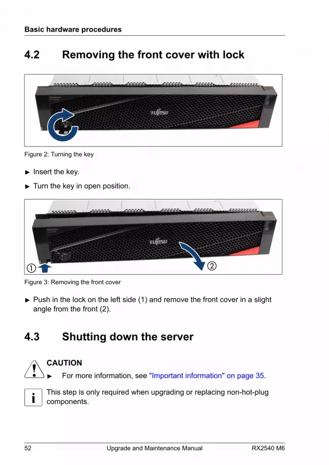
Figure 2: Turning the key
▶ Insert the key.
▶ Turn the key in open position.
Figure 3: Removing the front cover
▶ Push in the lock on the left side (1) and remove the front cover in a slightangle from the front (2).
4.3 Shutting down the server
CAUTION▶ For more information, see "Important information" on page 35.
This step is only required when upgrading or replacing non-hot-plugcomponents.
Basic hardware procedures
52 Upgrade and Maintenance Manual RX2540 M6

▶ Inform the system administrator that the server will be shut down and putoffline.
▶ Terminate all applications.
▶ Perform the required procedures described in the preliminary steps of eachupgrade or maintenance task.
▶ Shut down the server.
If the system is running an ACPI-compliant operating system (OS),pressing the On/Off button will perform a graceful shutdown.
4.4 Disconnecting the power cord
4.4.1 Disconnecting the power cord (AC PSU)
Figure 4: Unlocking the cable clamp of a PSU
▶ Press the cable clamp down until it disengages (1).
▶ Open the cable clamp (2).
Basic hardware procedures
RX2540 M6 Upgrade and Maintenance Manual 53
▶ Disconnect the power cord from the PSU and remove it from the cableclamp.
4.4.2 Disconnecting the power cord (DC PSU)
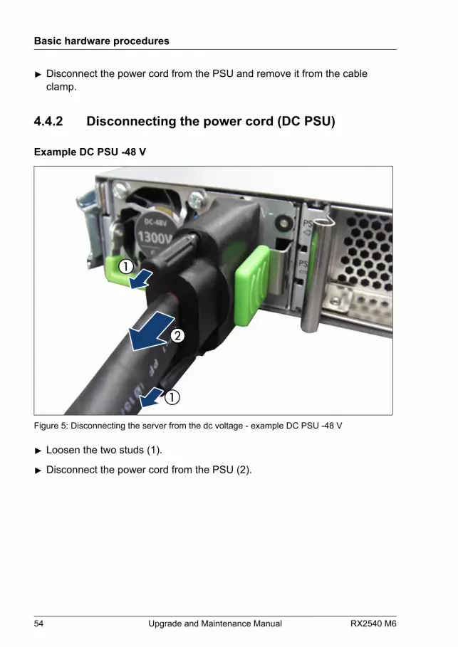
Example DC PSU -48 V
Figure 5: Disconnecting the server from the dc voltage - example DC PSU -48 V
▶ Loosen the two studs (1).
▶ Disconnect the power cord from the PSU (2).
Basic hardware procedures
54 Upgrade and Maintenance Manual RX2540 M6
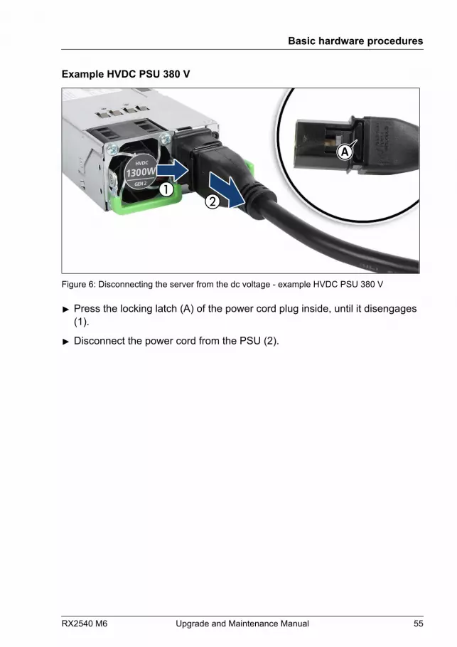
Example HVDC PSU 380 V
A
Figure 6: Disconnecting the server from the dc voltage - example HVDC PSU 380 V
▶ Press the locking latch (A) of the power cord plug inside, until it disengages(1).
▶ Disconnect the power cord from the PSU (2).
Basic hardware procedures
RX2540 M6 Upgrade and Maintenance Manual 55

4.5 Getting access to the component
4.5.1 Safety notes
CAUTION▶ Only for non-hot plug components:
● Before removing or attaching covers, turn off the server, allperipheral devices, and any other connected devices.
● Because there is a risk of electric shock or damage, pleasedisconnect all power cords from the outlet.
▶ The top cover must be replaced as soon as possible for purposesof cooling, to comply with EMC regulations (regulations regardingelectromagnetic compatibility) and to prevent fires.
▶ For more information, see "Important information" on page 35.
4.5.2 Extending the server out of the rack
CAUTION▶ Use the anti-tilt plate to prevent the rack from tipping when
installing the rack. Pulling the server out of the rack without havinginstalled the anti-tilt plate may cause the rack to tip over.
▶ Be careful not to pinch fingers or clothes when sliding out theserver or pushing it back. Failure to do so may cause injury.
▶ For more information, see "Important information" on page 35.
▶ Remove all remaining external cables from the I/O panel and expansioncards.
▶ If you are not using a cable management arm (CMA kit), ensure that the rearcables are long enough not to be strained or damaged when extending theserver out of the rack.
Basic hardware procedures
56 Upgrade and Maintenance Manual RX2540 M6
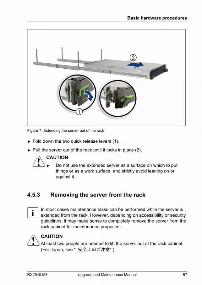
Figure 7: Extending the server out of the rack
▶ Fold down the two quick release levers (1).
▶ Pull the server out of the rack until it locks in place (2).CAUTION▶ Do not use the extended server as a surface on which to put
things or as a work surface, and strictly avoid leaning on oragainst it.
4.5.3 Removing the server from the rack
In most cases maintenance tasks can be performed while the server isextended from the rack. However, depending on accessibility or securityguidelines, it may make sense to completely remove the server from therack cabinet for maintenance purposes.
CAUTIONAt least two people are needed to lift the server out of the rack cabinet.(For Japan, see " 安全上のご注意".)
Basic hardware procedures
RX2540 M6 Upgrade and Maintenance Manual 57
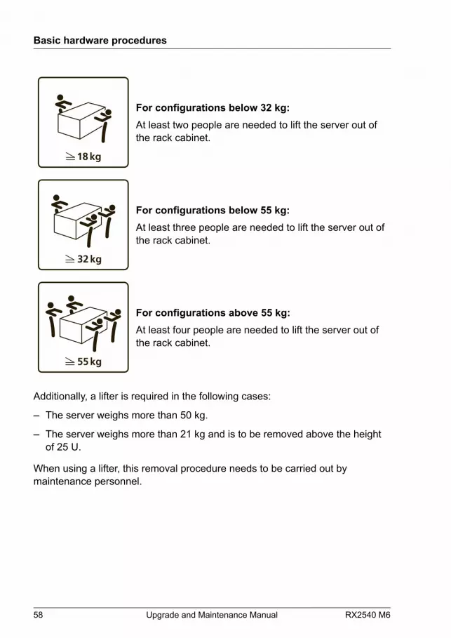
For configurations below 32 kg:At least two people are needed to lift the server out ofthe rack cabinet.
For configurations below 55 kg:At least three people are needed to lift the server out ofthe rack cabinet.
For configurations above 55 kg:At least four people are needed to lift the server out ofthe rack cabinet.
Additionally, a lifter is required in the following cases:
– The server weighs more than 50 kg.
– The server weighs more than 21 kg and is to be removed above the heightof 25 U.
When using a lifter, this removal procedure needs to be carried out bymaintenance personnel.
Basic hardware procedures
58 Upgrade and Maintenance Manual RX2540 M6
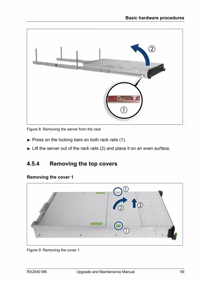
Figure 8: Removing the server from the rack
▶ Press on the locking bars on both rack rails (1).
▶ Lift the server out of the rack rails (2) and place it on an even surface.
4.5.4 Removing the top covers
Removing the cover 1
Figure 9: Removing the cover 1
Basic hardware procedures
RX2540 M6 Upgrade and Maintenance Manual 59
▶ Press the two green buttons inward to release the locking mechanism (1).
▶ Fold the cover 1 up (2).
▶ Remove the cover 1 upward (3).
Removing the cover 2
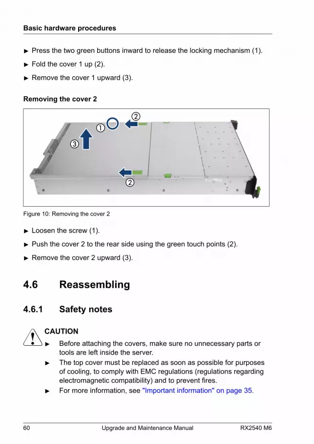
Figure 10: Removing the cover 2
▶ Loosen the screw (1).
▶ Push the cover 2 to the rear side using the green touch points (2).
▶ Remove the cover 2 upward (3).
4.6 Reassembling
4.6.1 Safety notes
CAUTION▶ Before attaching the covers, make sure no unnecessary parts or
tools are left inside the server.▶ The top cover must be replaced as soon as possible for purposes
of cooling, to comply with EMC regulations (regulations regardingelectromagnetic compatibility) and to prevent fires.
▶ For more information, see "Important information" on page 35.
Basic hardware procedures
60 Upgrade and Maintenance Manual RX2540 M6
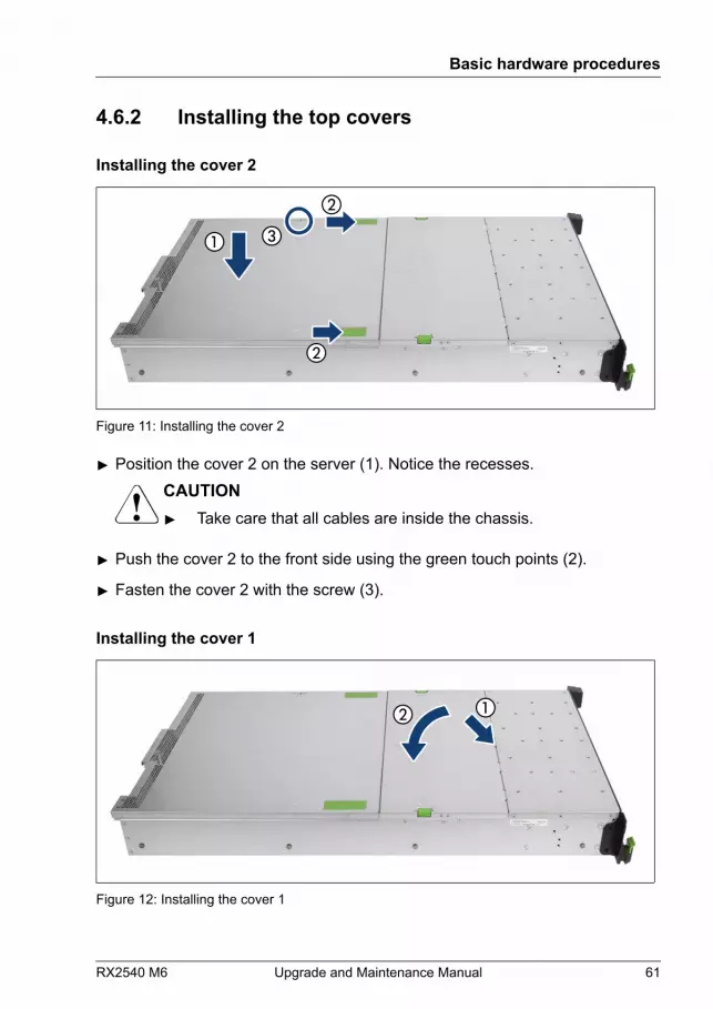
4.6.2 Installing the top covers
Installing the cover 2
Figure 11: Installing the cover 2
▶ Position the cover 2 on the server (1). Notice the recesses.CAUTION▶ Take care that all cables are inside the chassis.
▶ Push the cover 2 to the front side using the green touch points (2).
▶ Fasten the cover 2 with the screw (3).
Installing the cover 1
Figure 12: Installing the cover 1
Basic hardware procedures
RX2540 M6 Upgrade and Maintenance Manual 61
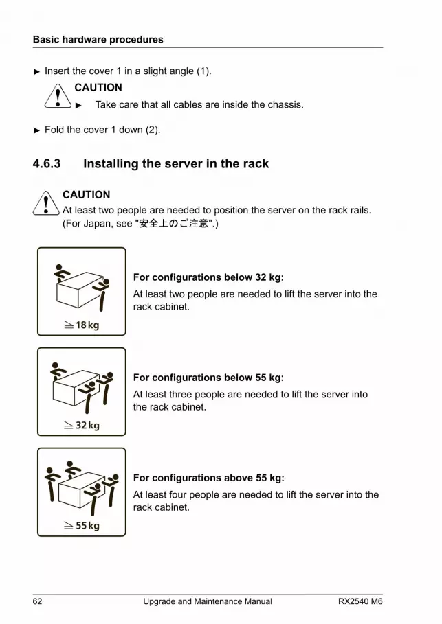
▶ Insert the cover 1 in a slight angle (1).CAUTION▶ Take care that all cables are inside the chassis.
▶ Fold the cover 1 down (2).
4.6.3 Installing the server in the rack
CAUTIONAt least two people are needed to position the server on the rack rails.(For Japan, see "安全上のご注意".)
For configurations below 32 kg:At least two people are needed to lift the server into therack cabinet.
For configurations below 55 kg:At least three people are needed to lift the server intothe rack cabinet.
For configurations above 55 kg:At least four people are needed to lift the server into therack cabinet.
Basic hardware procedures
62 Upgrade and Maintenance Manual RX2540 M6

Additionally, a lifter is required in the following cases:
– The server weighs more than 50 kg.
– The server weighs more than 21 kg and is to be installed above the height of25 U.
When using a lifter, this installation procedure needs to be carried out bymaintenance personnel.
Figure 13: Installing the server in the rack rails
▶ Fully extend the rack rails until they lock in place (1).
The rack rails must click into place so that they can no longer bemoved.
▶ At a slight angle, lower the server onto the rear mounting point on the rackrails (2).
▶ Ensure that all four rack mounting bolts are properly seated in the mountingpoints on the rack rails and that the locking bars engage.
Basic hardware procedures
RX2540 M6 Upgrade and Maintenance Manual 63

4.6.4 Sliding the server into the rack
Figure 14: Sliding the server into the rack
▶ Release the locking mechanism of both rails (1).
▶ Push the server as far as it will go into the rack (2) until the two quickrelease levers engage (3).
CAUTION▶ Be careful with your fingers. You can pinch them when the quick
release levers change to the release position.
▶ Connect all cables except the power cord to the server rear.
Basic hardware procedures
64 Upgrade and Maintenance Manual RX2540 M6
4.7 Connecting the power cord
4.7.1 Connecting the power cord (AC PSU)
CAUTIONThe AC PSU adjusts automatically to any mains voltage in the rangefrom 100 V - 240 V (AC PSU Platinum) or 200 V - 240 V (AC PSUTitanium).▶ You may only operate the server if its rated voltage range
corresponds to the local mains voltage.
▶ Connect the power cord to the PSU.
▶ If applicable, connect the main plug to an power outlet of the rack socketstrip.
To provide true phase redundancy, the second PSU should beconnected to a different AC power source from the other PSU. If oneAC power source should fail, the server will still continue to run.
▶ Ensure that the status indicator on the PSU is lit green, see "Indicator on hot-plug PSU" on page 565.
You can secure the power cord with a cable clamp to ensure that thepower cord cannot be disconnected from the server by mistake.
Basic hardware procedures
RX2540 M6 Upgrade and Maintenance Manual 65

Figure 15: Locking the cable clamp of a PSU
▶ Pull the cable clamp up (1).
▶ Thread the power cord through the cable clamp (2).
▶ Press the cable clamp down until it engages to secure the cable (3).
It will take about 60 seconds until the server can be powered on.
4.7.2 Connecting the power cord (DC PSU)
Example DC PSU -48 V
CAUTIONThe DC PSU adjusts automatically to any mains voltage in the rangefrom -40.5 V - -57 V.▶ You may only operate the server if its rated voltage range
corresponds to the local mains voltage.
Basic hardware procedures
66 Upgrade and Maintenance Manual RX2540 M6
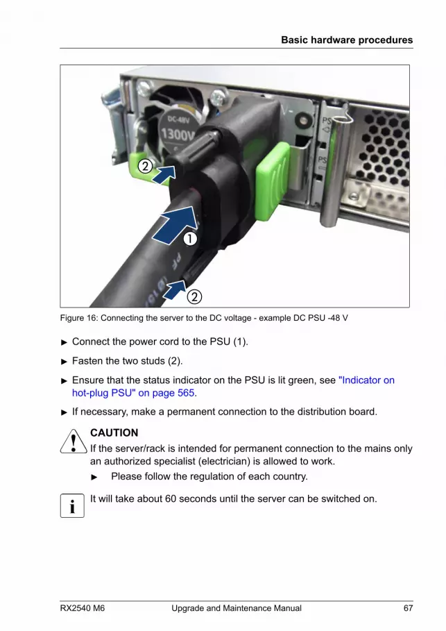
Figure 16: Connecting the server to the DC voltage - example DC PSU -48 V
▶ Connect the power cord to the PSU (1).
▶ Fasten the two studs (2).
▶ Ensure that the status indicator on the PSU is lit green, see "Indicator on hot-plug PSU" on page 565.
▶ If necessary, make a permanent connection to the distribution board.
CAUTIONIf the server/rack is intended for permanent connection to the mains onlyan authorized specialist (electrician) is allowed to work.▶ Please follow the regulation of each country.
It will take about 60 seconds until the server can be switched on.
Basic hardware procedures
RX2540 M6 Upgrade and Maintenance Manual 67

Example HVDC PSU 380 V
CAUTIONThe HVDC PSU adjusts automatically to any mains voltage in the rangefrom 200 V – 380 V.▶ You may only operate the server if its rated voltage range
corresponds to the local mains voltage.
A
B
Figure 17: Connecting the server to the DC voltage - example HVDC PSU 380 V
▶ Push the power cord plug into the PSU connector until it clicks in. The noseof the power cord plug (A) engages in the recess of the PSU connector (B).
▶ Ensure that the status indicator on the PSU is lit green, see "Indicator on hot-plug PSU" on page 565.
▶ If necessary, make a permanent connection to the distribution board.CAUTIONIf the server/rack is intended for permanent connection to the mainsonly an authorized specialist (electrician) is allowed to work.▶ Please follow the regulation of each country.
It will take about 60 seconds until the server can be switched on.
Basic hardware procedures
68 Upgrade and Maintenance Manual RX2540 M6
4.8 Switching on the server
CAUTION▶ Before switching on the server, make sure the top cover is closed.
In order to comply with applicable EMC regulations (regulations onelectromagnetic compatibility) and satisfy cooling requirements, theserver must not run while the top cover is removed.
▶ For more information, see "Important information" on page 35.
▶ Press the On/Off button to start up the server.
▶ Ensure that the power-on indicator is lit green.
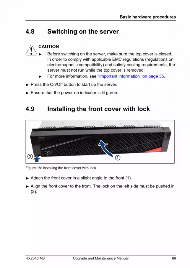
4.9 Installing the front cover with lock
Figure 18: Installing the front cover with lock
▶ Attach the front cover in a slight angle to the front (1).
▶ Align the front cover to the front. The lock on the left side must be pushed in(2).
Basic hardware procedures
RX2540 M6 Upgrade and Maintenance Manual 69
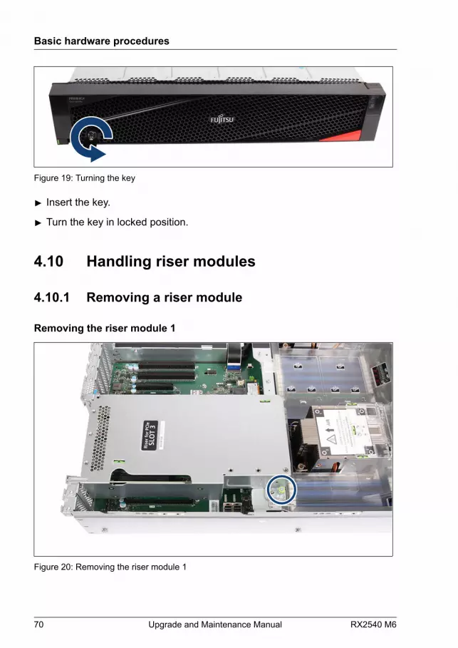
Figure 19: Turning the key
▶ Insert the key.
▶ Turn the key in locked position.
4.10 Handling riser modules
4.10.1 Removing a riser module
Removing the riser module 1
Figure 20: Removing the riser module 1
Basic hardware procedures
70 Upgrade and Maintenance Manual RX2540 M6

▶ Loosen the knurled screw (see circle).
▶ Carefully take out the riser module.
Removing the riser module 2
Figure 21: Removing the riser module 2
▶ Loosen the knurled screw (see circle).
▶ Carefully take out the riser module.
Basic hardware procedures
RX2540 M6 Upgrade and Maintenance Manual 71
4.10.2 Installing a riser module
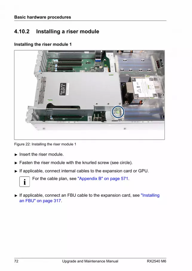
Installing the riser module 1
Figure 22: Installing the riser module 1
▶ Insert the riser module.
▶ Fasten the riser module with the knurled screw (see circle).
▶ If applicable, connect internal cables to the expansion card or GPU.
For the cable plan, see "Appendix B" on page 571.
▶ If applicable, connect an FBU cable to the expansion card, see "Installing an FBU" on page 317.
Basic hardware procedures
72 Upgrade and Maintenance Manual RX2540 M6

Installing the riser module 2
Figure 23: Installing the riser module 2
▶ Insert the riser module.
▶ Fasten the riser module with the knurled screw (see circle).
▶ If applicable, connect internal cables to the expansion card or GPU.
For the cable plan, see "Appendix B" on page 571.
▶ If applicable, connect an FBU cable to the expansion card, see "Installing an FBU" on page 317.
Basic hardware procedures
RX2540 M6 Upgrade and Maintenance Manual 73
4.11 Handling the fan cage
4.11.1 Removing the fan cage
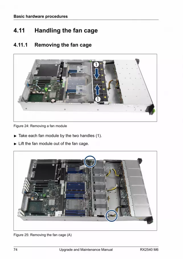
Figure 24: Removing a fan module
▶ Take each fan module by the two handles (1).
▶ Lift the fan module out of the fan cage.
Figure 25: Removing the fan cage (A)
Basic hardware procedures
74 Upgrade and Maintenance Manual RX2540 M6
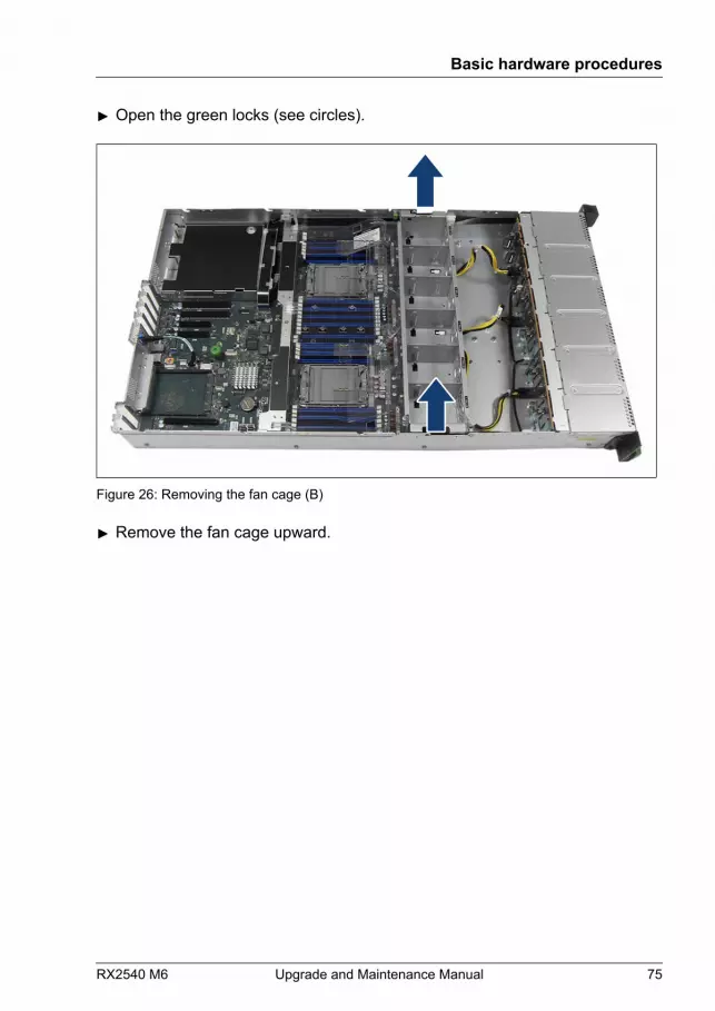
▶ Open the green locks (see circles).
Figure 26: Removing the fan cage (B)
▶ Remove the fan cage upward.
Basic hardware procedures
RX2540 M6 Upgrade and Maintenance Manual 75

4.11.2 Installing the fan cage
Figure 27: Installing the fan cage
▶ Install the fan cage.
Figure 28: Closing the locks
Basic hardware procedures
76 Upgrade and Maintenance Manual RX2540 M6
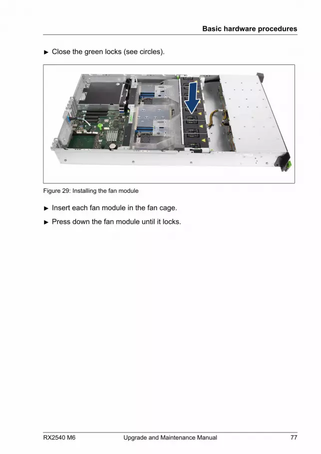
▶ Close the green locks (see circles).
Figure 29: Installing the fan module
▶ Insert each fan module in the fan cage.
▶ Press down the fan module until it locks.
Basic hardware procedures
RX2540 M6 Upgrade and Maintenance Manual 77

4.12 Handling the air duct
4.12.1 Removing the air duct
Figure 30: Removing the air duct
CAUTION▶ Be careful with the FBU cable.▶ If an FBU is installed, first follow the procedure that is described in
"Removing the FBU with the FBU holder" on page 324.
▶ Carefully pull out the air duct upward.
Basic hardware procedures
78 Upgrade and Maintenance Manual RX2540 M6
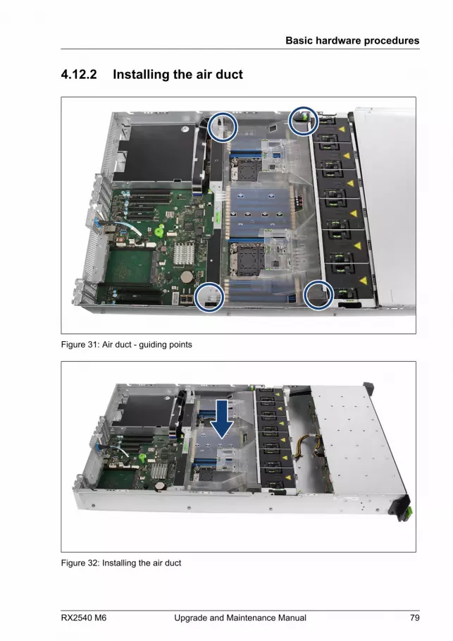
4.12.2 Installing the air duct
Figure 31: Air duct - guiding points
Figure 32: Installing the air duct
Basic hardware procedures
RX2540 M6 Upgrade and Maintenance Manual 79

▶ Install the air duct.
Ensure that the air duct engages in the guiding points.
If there is an FBU installed, see "Removing the FBU with the FBU holder" on page 324.
4.13 Handling the cross bar
4.13.1 Removing the cross bar
Figure 33: Removing the cross bar
▶ Remove the three screws (see circles).
▶ Remove the cross bar.
Basic hardware procedures
80 Upgrade and Maintenance Manual RX2540 M6
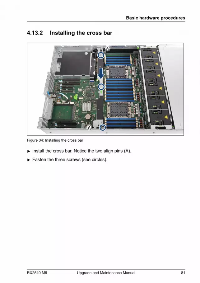
4.13.2 Installing the cross bar
A
A
Figure 34: Installing the cross bar
▶ Install the cross bar. Notice the two align pins (A).
▶ Fasten the three screws (see circles).
Basic hardware procedures
RX2540 M6 Upgrade and Maintenance Manual 81

4.14 Handling the rear air grids
4.14.1 Removing a rear air grid
Removing the rear air grid 1
Figure 35: Removing the rear air grid 1
▶ Remove the two screws (see circles).
▶ Remove the rear air grid.CAUTIONKeep the rear air grid for future use.▶ Always replace rear air grids into unused installation locations to
comply with applicable EMC regulations and satisfycoolingrequirements.
Basic hardware procedures
82 Upgrade and Maintenance Manual RX2540 M6

Removing the rear air grid 2
Figure 36: Removing the rear air grid 2
▶ Remove the two screws (see circles).
▶ Remove the rear air grid.CAUTIONKeep the rear air grid for future use.▶ Always replace rear air grids into unused installation locations to
comply with applicable EMC regulations and satisfycoolingrequirements.
Basic hardware procedures
RX2540 M6 Upgrade and Maintenance Manual 83
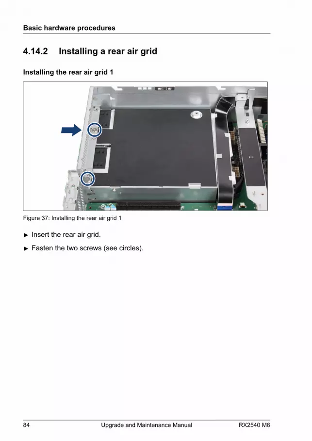
4.14.2 Installing a rear air grid
Installing the rear air grid 1
Figure 37: Installing the rear air grid 1
▶ Insert the rear air grid.
▶ Fasten the two screws (see circles).
Basic hardware procedures
84 Upgrade and Maintenance Manual RX2540 M6
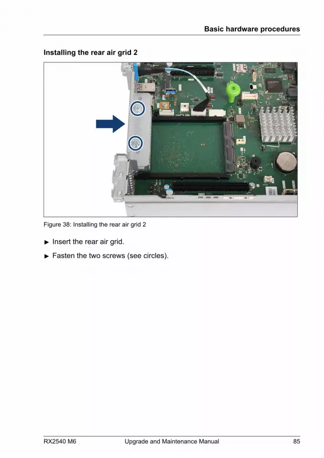
Installing the rear air grid 2
Figure 38: Installing the rear air grid 2
▶ Insert the rear air grid.
▶ Fasten the two screws (see circles).
Basic hardware procedures
RX2540 M6 Upgrade and Maintenance Manual 85
Basic hardware procedures
86 Upgrade and Maintenance Manual RX2540 M6
5 Basic software procedures
5.1 Validation
Depending on your server and the installed features some information isnot valid for your server.
5.2 Starting the maintenance task
5.2.1 Suspending BitLocker functionality
BitLocker Drive Encryption provides protection for OS and data drives byencrypting the contents and requiring users to authenticate their credentials toaccess the information. In the scenario described here, BitLocker uses thecompatible Trusted Platform Module (TPM) to detect if the computer's startupprocess has been modified from its original state.
For more information on how to use BitLocker on a computer without acompatible TPM, see the "BitLocker Drive Encryption" documentationpage at:https://technet.microsoft.com/library/cc731549.aspx
Suspending BitLocker Drive Encryption is a temporary method for removingBitLocker protection without decrypting the drive Windows is installed on.Suspend BitLocker before modifying the server’s hardware configuration orstartup files. Resume BitLocker again after the maintenance procedure iscomplete.
RX2540 M6 Upgrade and Maintenance Manual 87
CAUTION● With BitLocker features enabled, modifying the system configuration
(hardware or firmware settings) may render the system inaccessible.The system may enter Recovery Mode and require a 48-digitsrecovery password to return to normal operation. Ensure that yoususpend BitLocker drive encryption before maintaining the server.
● When suspended, BitLocker uses a plain text key instead of theTrusted Platform Module (TPM) to read encrypted files. Keep in mindthat information on this drive is not secure until BitLocker has beenre-enabled.
▶ Ask the system administrator to suspend BitLocker-protection on the systemvolume, using the BitLocker Drive Encryption control panel item.
This will temporarily disable BitLocker for maintenance purposes. Thevolume will not be decrypted and no keys will be discarded.
▶ Click Start - Control Panel - System and Security - BitLocker DriveEncryption to open the BitLocker Drive Encryption.
▶ Select the system volume, and click Suspend Protection.
▶ Click Yes to confirm that your data will not be protected while BitLocker issuspended.
In order to determine which features are accessible through theBitLocker setup wizard, it may be necessary to modify the BitLockerGroup Policy settings. For more information on how to suspendBitLocker drive encryption, see the Microsoft TechNet library at:https://technet.microsoft.com/library/cc731549.aspxFor more information, see the Fujitsu web pages.
5.2.2 Disabling the boot watchdog
The boot watchdog determines whether the OS boots within a preset timeframe. If the watchdog timer expires, the system will automatically reboot.If the system is to be started from removable boot media for firmware upgradepurposes, the boot watchdog needs to be disabled before starting maintenance
Basic software procedures
88 Upgrade and Maintenance Manual RX2540 M6
task. Otherwise, the boot watchdog might initiate a system reboot before theflash process is complete.
CAUTIONAn incomplete firmware upgrade process may render the serverinaccessible or result in damaged/destroyed hardware.
Timer settings can be configured in the BIOS or using the iRMC S5 webinterface.
Disabling the boot watchdog in the BIOS
▶ Enter the BIOS.
▶ Select the Management menu.
▶ Set Boot Watchdog to Enabled.
▶ Set Action to Continue.
▶ Save your changes and exit the BIOS.
For more information on BIOS settings, see the corresponding BIOSSetup Utility reference manual.
Disabling the boot watchdog using the iRMC S5 web interface
▶ Log in to the iRMC S5 web interface.
▶ Select the Settings menu.
▶ Open the Server Management page.
▶ In the Boot Watchdog group, check the Enable Boot Watchdog Supportoption. The Enable Boot Watchdog Support option must be selected.
▶ Select Continue from the Watchdog Action list.
▶ Click Apply for the changes to take effect.
For more information on iRMC settings, see the iRMC user guides.
Basic software procedures
RX2540 M6 Upgrade and Maintenance Manual 89
5.2.3 Removing backup and optical disk media
▶ Ask the system administrator to eject all remaining backup or optical mediafrom the backup drive or ODD before removing it from the server.
▶ If the backup media cannot be ejected by conventional means, and it ismandatory that the cartridge be removed prior to returning the drive forrepair or disposing it, a manual tape extraction needs to be performed.Please contact Fujitsu support, if "forcible" tape ejection is necessary.
Fujitsu does not assume responsibility for any damage to the tape drive,the data cartridge/tape or for the loss of any data resulting from manualtape extraction procedures.
5.2.4 Verifying and configuring the backup softwaresolution
This task only applies to Japan.
Depending on the backup software solution, it may be necessary to disable ordelete the backup drive from the backup software drive list before starting themaintenance task.
For more information on suitable backup software solutions and relateddocumentation, see the Fujitsu web pages.
5.2.5 Switching on the ID indicator
For easy identification of the server, switch on the ID indicator, especially whenworking in a datacenter environment or a server room. The ID indicator canalso be activated via the iRMC S5 web interface and its status is reported tothe iRMC S5.
For more information, see "Locating the defective server" on page 49 orthe "ServerView Suite Local Service Concept (LSC)", the iRMC userguides or the Infrastructure Manager documentation.
Basic software procedures
90 Upgrade and Maintenance Manual RX2540 M6
Using the ID button on the front panel
▶ Press the ID button on the front panel to switch on the system identificationLEDs.
For more information, see "Indicators on the COP" on page 549.
Using the ID icon in the iRMC S5 web interface
▶ Log in to the iRMC S5 web interface.The icon that represents the ID indicator resides on the right of the menubar. Its color symbolizes its status:blue: the ID indicator is on.grey: the ID indicator is off.
▶ Click the icon to switch the ID indicator on or off.
Using ServerView Operations Manager
▶ In ServerView Operations Manager Single System View press the Locatebutton in the title bar to switch on the ID indicators.
Using the Infrastructure Manager
▶ To switch on the ID indicator from the Infrastructure Manager, select a nodefrom the Node List screen and operate ID indicator from the Action button.
5.3 Completing the maintenance task
5.3.1 Updating or recovering the BIOS and iRMC S5
For Japan:Follow the instructions provided separately.
Basic software procedures
RX2540 M6 Upgrade and Maintenance Manual 91
When the system board is replaced, the BIOS and iRMC versions whichwere being used can be restored by removing the iRMC microSD cardfrom the original system board and installing it on the replaced systemboard.
The latest BIOS and iRMC versions are available from the Fujitsu supportinternet pages at:https://ts.fujitsu.com/support/For Japan:https://www.fujitsu.com/jp/products/computing/servers/primergy/downloads/
Note on the boot watchdogBefore updating or recovering the BIOS and iRMC, ensure that the bootwatchdog is disabled, see "Disabling the boot watchdog" on page 88.After updating or recovering the BIOS and iRMC, enable the bootwatchdog again, see "Enabling the boot watchdog" on page 99.
Fujitsu does not assume responsibility for any damage done to theserver or for the loss of any data resulting from BIOS updates.
BIOS flash procedure
▶ Perform the BIOS flash procedure as described in the "BIOS Setup Utility"reference manual of your server.
BIOS recovery procedure
▶ Perform the BIOS recovery procedure as described in the "BIOS SetupUtility" reference manual of your server.
iRMC flash procedure
▶ Prepare an USB stick including the bootable iRMC firmware update image.
▶ Connect the USB stick containing the iRMC firmware to an USB port.
▶ Restart the server. The system will start the POST process.
▶ During POST, press [F12] and select the connected USB stick as bootdevice. The system will detect the USB stick.
Basic software procedures
92 Upgrade and Maintenance Manual RX2540 M6
▶ Choose one of the following options from the update tool menu to start theiRMC update process:Normal:Choose this option to update an existing system board.Initial:Choose this option if the system board has been replaced prior to the iRMCupdate procedure. This option will perform all relevant flash procedures in arow, including the iRMC firmware and bootloader.
CAUTIONIf the process is interrupted, the iRMC may be permanentlycorrupted.▶ Do not interrupt the iRMC upgrade process after it has started.
If the iRMC does not work after flashing, disconnect the system fromthe mains and reconnect it again.
▶ After completion of the flash process, remove the USB stick and restart theserver.
iRMC recovery procedure
▶ Prepare an USB stick including the bootable iRMC firmware update image.
▶ Ensure that the server has been shut down and disconnected from themains, see "Disconnecting the power cord" on page 53.
▶ Connect the USB stick containing the iRMC firmware to an USB port.
▶ Connect the server to the mains while pushing the ID button on the frontpanel. Ask a second person to help you if necessary.
▶ Ensure that the Global Error indicator and the ID indicator are flashing toindicate that the server is entering the iRMC recovery state.
▶ Press the Power On/Off button. The system will start the POST process.
▶ During POST, press [F12] and select the connected USB stick as bootdevice. The system will detect the USB stick.
Basic software procedures
RX2540 M6 Upgrade and Maintenance Manual 93
▶ Choose the Recovery_L option from the update tool menu to start the iRMCupdate process.
CAUTIONIf the process is interrupted, the iRMC may be permanentlycorrupted.▶ Do not interrupt the iRMC upgrade process after it has started.
If the iRMC does not work after flashing, disconnect the system fromthe mains and reconnect it again.
▶ Shut down the server by pressing the power On/Off button.
▶ Disconnect the server from the mains to exit the iRMC recovery state.
5.3.2 Verifying system information backup or restore
To avoid the loss of non-default settings when replacing the system board, abackup copy of important system configuration data is automatically storedfrom the system board NVRAM to the Chassis ID EPROM. After replacing thesystem board the backup data is restored from the Chassis ID board to thenew system board.In order to verify whether the backup or restore process has been successful,check the System Event Log (SEL), see "Viewing and clearing the System Event Log (SEL)" on page 101.
When using the Infrastructure Manager, please refer to the followingmanuals about backup and restore function of system information.See manual "FUJITSU Software Infrastructure Manager Vx.x.x User'sGuide", section "2.10 Backup/Restore Hardware Settings", available at:https://ts.fujitsu.com/support/For Japan:See manual "FUJITSU Software Infrastructure Manager Vx.x.x 解説書",section "2.10 ハードウェア設定バックアップ/リストア機能", available at:https://www.fujitsu.com/jp/products/software/infrastructure-software/infrastructure-software/serverviewism/technical/
Basic software procedures
94 Upgrade and Maintenance Manual RX2540 M6
After replacing the system board
▶ Check the SEL log files to verify whether the backup data on the Chassis IDEPROM has been restored to the system board, see "Viewing and clearing the System Event Log (SEL)" on page 101.
Chassis IDPROM: Motherboard Exchange detected
Chassis IDPROM: BMC FW restore successful
Chassis IDPROM: BIOS restore successful
After replacing the front panel or Chassis ID EPROM
▶ Check the SEL log files to verify whether a backup copy of the system boardsettings has been transferred to the Chassis ID EPROM, see "Viewing and clearing the System Event Log (SEL)" on page 101.
Chassis IDPROM: BMC FW backup successful
5.3.3 Updating expansion card firmware
For Japan:Follow the instructions provided separately.
After replacing the expansion card, it is essential to upgrade the firmware tothe latest version without connecting any storage devices. The latestexpansion card firmware version is available from the Fujitsu support webpages at:https://ts.fujitsu.com/support/For Japan:https://www.fujitsu.com/jp/products/computing/servers/primergy/downloads/
Note on the boot watchdogBefore updating expansion card firmware, ensure that the bootwatchdog is disabled, see "Disabling the boot watchdog" on page 88.After updating expansion card firmware, enable the boot watchdogagain, see "Enabling the boot watchdog" on page 99.
Fujitsu does not assume responsibility for any damage done to theserver or for the loss of any data resulting from firmware updates.
Basic software procedures
RX2540 M6 Upgrade and Maintenance Manual 95
Using the ServerView Update Manager
For more information on how to update the expansion card firmware using theServerView Update Manager or Update Manager Express (UME), see thefollowing manuals:
– ServerView Update Manager: "ServerView Update Management" user guide
– ServerView Update Manager Express: "Local System Update forPRIMERGY Servers" user guide
Using the flash tool
The latest firmware files are available as ASPs (Autonomous SupportPackages) for Windows or as Linux tools from the Fujitsu support web pagesat:https://ts.fujitsu.com/support/For Japan:https://www.fujitsu.com/jp/products/computing/servers/primergy/downloads/
5.3.4 Reconfiguring the backup software solution
This task only applies to Japan.
Disabling backup drives
Depending on the backup software solution, it may be necessary to disable ordelete the backup drive from the backup software drive list and reconfigurebackup jobs after completing the maintenance task.
More information on suitable backup software solutions and relateddocumentation is available from the Fujitsu web pages.
Re-enabling backup drives
If a backup drive has been disabled or deleted from the backup software drivelist (see "Verifying and configuring the backup software solution" on page 90), ithas to be re-enabled to complete the maintenance task.▶ Re-enable backup drives and revise backup software settings and cronjobs.
Basic software procedures
96 Upgrade and Maintenance Manual RX2540 M6

More information on suitable backup software solutions and relateddocumentation is available from the Fujitsu web pages.
5.3.5 Resetting the boot retry counter
The boot retry counter is decremented from its preset value every time thePOST watchdog initiates a system reboot. When the value has reached ’0’, thesystem will shut down and power off.
Viewing the boot retry counter
The current boot retry counter status is available in the BIOS:▶ Enter the BIOS.
▶ Select the Management menu.
▶ Under Boot Retry Counter the current number of remaining boot attemptsis displayed. The value is further decremented with every failed boot attemptor system reboot resulting from critical system errors.
▶ Exit the BIOS.
Resetting the boot retry counter
The boot retry counter should be reset to its original value concluding everyservice task.
Please note, if the customer does not know about the original boot retryvalues:If the system boots up and no further errors occur within 6 hours afterthat successful boot attempt, the boot retry counter will automatically bereset to its default value. Please take into account, that the specifiednumber of boot attempts can only be determined after this period oftime.
If the customer knows about the original boot retry values, proceed as followsto reset or configure the boot retry counter:
Basic software procedures
RX2540 M6 Upgrade and Maintenance Manual 97
Resetting the boot retry counter in the BIOS
▶ Enter the BIOS.
▶ Select the Management menu.
▶ Under Boot Retry Counter press the [+] or [-] keys to specify the maximumnumber of boot attempts (0 to 7).
▶ Exit the BIOS.
Resetting the boot retry counter using the ServerView OperationsManager
▶ In the ServerView Operations Manager Administration view, select ServerConfiguration.
▶ If more than one server is managed in SVOM, select the target server andclick Next.
▶ From the Server Configuration menu pane, choose Restart Options.
▶ Under Reboot Retries, specify the maximum number of boot attempts (0 to7) in the Default for reboot tries field.
Resetting the boot retry counter using iRMC S5 web interface
▶ Log in to the iRMC S5 web interface.
▶ Select the Settings menu.
▶ Select the Server Management menu.
▶ The following boot retry counter settings are available under AutomaticSystem Recovery & Restart (ASR&R):
▶ Under Retry counter max specify the maximum number of attempts toboot the OS (0 to 7).
▶ Under Retry counter the current number of remaining boot attempts isdisplayed. Overwrite this value with the maximum number of bootattempts specified above in order to reset the boot retry counter.
▶ Click Apply for the changes to take effect.
Basic software procedures
98 Upgrade and Maintenance Manual RX2540 M6

For more information on iRMC settings, see the iRMC user guides.
5.3.6 Enabling the boot watchdog
If the boot watchdog has been disabled for firmware upgrade purposes (see"Disabling the boot watchdog" on page 88), it has to be re-enabled to completethe maintenance task.Timer settings can be configured in the BIOS or using the iRMC S5 webinterface.
Enabling the boot watchdog in the BIOS
▶ Enter the BIOS.
▶ Select the Management menu.
▶ Under Boot Watchdog set the Action setting to Reset.
▶ Save your changes and exit the BIOS.
For more information on how to access the BIOS and modify settings,see the corresponding BIOS Setup Utility reference manual.
Enabling the boot watchdog using the iRMC S5 web interface
▶ Log in to the iRMC S5 web interface.
▶ Select the Settings menu.
▶ Open the Server Management page.
▶ In the Boot Watchdog group, check the Enable Boot Watchdog option.The Enable Boot Watchdog option must be selected.
▶ Select Reset from the Watchdog Action list.
▶ Click Apply for the changes to take effect.
For more information on iRMC settings, see the iRMC user guides.
Basic software procedures
RX2540 M6 Upgrade and Maintenance Manual 99
5.3.7 Enabling replaced components in the BIOS
When an expansion card fails, the defective component will be set to Disabledor Failed in the BIOS. The server will then reboot with only the intact hardwarecomponents remaining in the system configuration.
● Communication between BIOS and iRMC temporarily failed during thePOST.
● Booting to execute iRMC Emergency Flash.
In this cases, the defective component needs to be reenabled in the BIOS afterreplacing it.▶ Enter the BIOS.
▶ Select the Configuration menu.
▶ Select the status menu of the desired component:
▶ Select PCI Status for expansion cards.
▶ Reset replaced components to Enabled.
▶ Save your changes and exit the BIOS.
For more information on how to access the BIOS and modify settings,see the corresponding BIOS Setup Utility reference manual.
5.3.8 Verifying the system time settings
This task only applies to Linux and VMware environments.
After the system board has been replaced, the system time is set automatically.By default, the RTC (Real Time Clock) time standard is set as the local time.
Basic software procedures
100 Upgrade and Maintenance Manual RX2540 M6

If a Linux/VMware OS is used and the hardware clock has been configured asUTC (Universal Time, Coordinated) in the OS, the BMC local time may not bemapped correctly.
▶ After replacing the system board, ask the system administrator whether theRTC or UTC time standard is to be used as system time.
If the system time (RTC) is set to UTC, the SEL (System Event Log)time stamps may differ from the local time.
▶ Enter the BIOS.
▶ Select the Information menu.
▶ Under System Time and System Date specify the correct time and date.
By default, the system time set in the BIOS is RTC (Real Time Clock)local time. If your IT infrastructure relies on universally accepted timestandards, set the System Time to UTC (Universal Time,Coordinated) instead. Greenwich Mean Time (GMT) can beconsidered equivalent to UTC.
▶ Save your changes and exit the BIOS.
For more information on how to access the BIOS and modify settings,see the corresponding BIOS Setup Utility reference manual.
5.3.9 Viewing and clearing the System Event Log (SEL)
You can view the System Event Log (SEL) using the ServerViewOperations Manager or the iRMC S5 web interface.
You can clear the System Event Log (SEL) using the iRMC S5 webinterface.
You can collect logs using the Infrastructure Manager.
Basic software procedures
RX2540 M6 Upgrade and Maintenance Manual 101
Viewing the SEL using the ServerView Operations Manager
▶ In ServerView Operations Manager Single System View selectMaintenance from the Information / Operation menu.
▶ Under Maintenance select System Event Log.
▶ Select the message type(s) you want to display:‐ Critical events‐ Major events‐ Minor events‐ Informational events
Note on the Driver Monitor of the ServerView Operations ManagerThe Driver Monitor view gives you an overview of the monitoredcomponents as well as the associated events contained in the systemevent log on the managed server.Under Monitored Components the monitored components are listed. Ifa component has the status Warning or Error, you can select it in thelist and click Acknowledge. This confirms the event on the server side.You may have to log on to the server beforehand. The status of thecomponent will then be reset to ok. To see the new status you mustrefresh the Driver Monitor view with Refresh.
For more information on how to view and sort the SEL using ServerViewOperations Manager, see the "ServerView Operations Manager - ServerManagement" user guide.
Viewing the SEL using the iRMC S5 web interface
▶ Log in to the iRMC S5 web interface.
▶ Open the Logs menu.
▶ Click System Event Log to open the System Event Log page.All events concerning the system are displayed in a table in the Event LogContent group.
▶ You can sort the table based on a column using the arrows in the headerfield.
Basic software procedures
102 Upgrade and Maintenance Manual RX2540 M6

▶ You can also filter the table using the filter lists in the header of somecolumns.
Note on the Driver Monitor of the iRMC S5 web interfaceThe Driver Monitor view gives you an overview of the monitoredcomponents.If a component has the status Warning or Error, you can click Resetstatus. You have to log on to the iRMC S5 web interface beforehand.The status of the component will then be reset to ok. To see the newstatus you must refresh the iRMC S5 web interface.
For more information on iRMC settings, see the iRMC user guides.
Clearing the SEL using the iRMC S5 web interface
▶ Log in to the iRMC S5 web interface.
▶ Open the Logs menu.
▶ Click System Event Log to open the System Event Log page.All events concerning the system are displayed in a table in the Event LogContent group.
▶ Click the Clear Logs button above the table to clear the SEL.
For more information on iRMC settings, see the iRMC user guides.
Collecting logs using the Infrastructure Manager
The Infrastructure Manager can collect various logs including System EventLog for system operation and maintainance.
Basic software procedures
RX2540 M6 Upgrade and Maintenance Manual 103

Please refer to the following manuals of Infrastructure Manager forcollecting logs from ISM.See manual "FUJITSU Software Infrastructure Manager Vx.x.x User'sGuide", section "2.5 Log Management", available at:https://ts.fujitsu.com/support/For Japan:See manual "FUJITSU Software Infrastructure Manager Vx.x.x 解説書",section "2.5 ログ管理機能", available at:https://www.fujitsu.com/jp/products/software/infrastructure-software/infrastructure-software/serverviewism/technical/
5.3.10 Updating the NIC configuration file in a Linux andVMware environment
In order to prevent errors caused by changing network device names (eth<x>),it is recommended to store the MAC address (hardware address) of a networkinterface card in the related NIC configuration file of the Linux/VMware OS.When replacing a network controller or the system board with onboard LANcontrollers in a server running Linux/VMware OS, the MAC address will changebut not automatically be updated in the definition file.In order to prevent communication problems, it is necessary to update thechanged MAC address stored in the related ifcfg-eth<x> definition file.
Procedures may differ depending on your Linux/VMware OS or thedefinition file on the client system. Use the following information asreference. Ask the system administrator to change the definition file.
To update the MAC address, proceed as follows:
Basic software procedures
104 Upgrade and Maintenance Manual RX2540 M6

▶ After replacing a network controller or the system board, switch on and bootthe server, see "Switching on the server" on page 69.The hardware configuration tool for Red Hat Linux, will launch at boot anddetect the new and/or changed hardware on your system.
▶ For the changes to take effect, you need to reboot the network by enteringthe following command:
# service network restart
If the system board or network controller offers multiple LAN ports, itis necessary to update the remaining ifcfg-eth<x> definition filesaccordingly.
▶ Update the NIC configuration file to reflect the new card sequence and MACaddress.
5.3.11 Resuming BitLocker functionality
If BitLocker Drive Encryption has been suspended for maintenance purposes(see "Suspending BitLocker functionality" on page 87), it has to be reenabledto complete the service task.▶ If applicable, ask the system administrator to enter the recovery key in order
to boot the OS.
If BitLocker Drive Encryption has been suspended prior to replacingcomponents you won't be asked for a recovery key when rebootingthe server after the maintenance task. However, if BitLockerfunctionality has not been suspended, Windows will enter recoverymode and ask you to input recovery key for further booting.
▶ Ask the system administrator to enable the previously suspended BitLockerprotection on the system volume, using the BitLocker Drive Encryptioncontrol panel item:
▶ Click Start - Control Panel - System and Security - BitLocker DriveEncryption to open the BitLocker Drive Encryption.
▶ Select the system volume, and click Resume Protection.
Basic software procedures
RX2540 M6 Upgrade and Maintenance Manual 105

For more information on how to resume BitLocker drive encryption, seethe Microsoft TechNet library at:https://technet.microsoft.com/library/cc731549.aspxFor more information, see the Fujitsu web pages.
5.3.12 Performing a RAID array rebuild
After replacing an HDD that has been combined into a RAID array, RAIDrebuild will be performed completely unattended as a background process.▶ Ensure that the RAID array rebuild has started normally. Wait until the
progress bar has reached at least one percent.
▶ Inform the customer about the remaining rebuild time, based on thedisplayed duration estimate.
Figure 39: Progress bar (RAID array rebuild)
CAUTIONThe system is now operational, however, data redundancy will not beavailable until the RAID array rebuild is complete. Depending on theHDD capacity the overall process can take up to several hours, in somecases even days.
Basic software procedures
106 Upgrade and Maintenance Manual RX2540 M6
You may notice a slight performance impact during rebuild.
5.3.13 Looking for MAC/WWN/GUID and SAS addresses
5.3.13.1 Basic information
The customer needs to know the new address of the controller:
– When replacing the system board with an onboard LAN controller
– When adding or replacing a network controller
– When adding or replacing a SAS controller
Different controllers send different addresses:
– LAN controller: MAC (Media Access Control) address
– Fibre channel controller: WWN (World Wide Name) address
– Infiniband controller: GUID (Globally Unique IDentifier) address
– SAS controller: SAS (Serial Attached SCSI) address
5.3.13.2 Looking for the MAC address of a LAN controller
There are several possible locations where these addresses can be found.▶ Inform the customer about the new or changed MAC address.
Checking the label
▶ If available, check the label on the controller. Beside the part number, youmay find the MAC address.
Using the BIOS
▶ Enter the BIOS.
▶ Select the Configuration menu.
Basic software procedures
RX2540 M6 Upgrade and Maintenance Manual 107
The addresses are displayed at the one or more of the following (it depends onthe behavior of the UEFI driver included in each controller).
1. The addresses are displayed at the UEFI driver menu included in eachcontroller in the Configuration menu.
2. Select the UEFI driver menu included in each controller. The addresses aredisplayed at the help for the UEFI driver menu included in each controller.
3. Enter the Network Device List menu. The addresses are displayed in theNetwork Device List menu.
Only network controllers supporting the Command Line Protocol (CLP)will be displayed.
Using the iRMC S5 web interface
▶ Log in to the iRMC S5 web interface.
▶ Open the System menu.
▶ Open the Network page.
▶ In the Network Adapters group, you will find detailed information on eachnetwork controller in the managed PRIMERGY server, including its MACaddress.
This information is only available with the iRMC S5 or above. Onlynetwork controllers supporting the Command Line Protocol (CLP) willbe displayed.
For add-in cards the vendors provide documentation and tools,offered on the Fujitsu support web pages:https://ts.fujitsu.com/support/Select the server, select Downloads - More Details - Driver. Somevendors bundle the documentation together with the driver package.
5.3.13.3 Looking for the WWN address of a fibre channel controller
There are several possible locations where these addresses can be found.▶ Inform the customer about the new or changed WWN address.
Basic software procedures
108 Upgrade and Maintenance Manual RX2540 M6
Checking the label
▶ If available, check the label on the controller. Beside the part number, youmay find the WWN address.
Using the BIOS
▶ Enter the BIOS setup menu.
▶ Select the Configuration menu.
The addresses are displayed at the one or more of the following (it depends onthe behavior of the UEFI driver included in each controller).
1. The addresses are displayed at the UEFI driver menu included in eachcontroller in the Configuration menu.
2. Select the UEFI driver menu included in each controller. The addresses aredisplayed at the help for the UEFI driver menu included in each controller.
3. Enter the Network Device List menu. The addresses are displayed in theNetwork Device List menu.
Only network controllers supporting the Command Line Protocol (CLP)will be displayed.
5.3.13.4 Looking for the GUID address of an infiniband controller
▶ If available, check the label on the controller. Beside the part number, youmay find the GUID address.
▶ Inform the customer about the new or changed GUID address.
5.3.13.5 Looking for SAS addresses of SAS controllers for externaldevices
These addresses can be found using the ServerView RAID Manager.
Basic software procedures
RX2540 M6 Upgrade and Maintenance Manual 109
▶ Start the ServerView RAID Manager and log in.
▶ Select the desired SAS controller.In the General tab you can find data on the selected object including its SASaddress.
For more information, see the "ServerView Operations Manager -Server Management" user guide and the "ServerView RAIDManager" user guide.
▶ Inform the customer about the new SAS address. The customer need thenew SAS address, especially when the server is connected to a FujitsuStorage ETERNUS system.
5.3.14 Using the Chassis ID Prom Tool
The Common Operation Panel (COP) contains the Chassis ID EPROM thatstores the following system information:
– server name and model
– housing type
– serial number
– manufacturing data
– information depending on the configuration:
– installed HDD/SSD/EDSFF backplanes
– installed rear HDD/SSD cages
– installed expansion cards (for example EP5xxi)
In order to integrate your system into the ServerView Managementenvironment and to enable server installation using the ServerView InstallationManager, system information needs to be completed and corrected.
Basic software procedures
110 Upgrade and Maintenance Manual RX2540 M6
System information has to be updated after one of the following tasks:
– HDD/SSD backplane (2.5-inch, 3.5-inch, PCIe, EDSFF)
– installing
– removing
– changing (the technology, for example from SAS/SATA to PCIe)
– Rear HDD/SSD cages
– installing
– removing
– Specified expansion cards (for example EP5xxi)
– installing
– changing
Update your system information using the Chassis ID Prom tool. The tool andmore information are available to maintenance personnel from the Fujitsu webpages:https://partners.ts.fujitsu.com/com/service/ps/Servers/PRIMERGY/▶ Select your PRIMERGY system from the main area of the page.
▶ From the categories selection, choose Software & Tools Documentation.
▶ In the Tools area click Tools: Chassis-IDProm Tool to download the file(tool-chassis-Idprom-Tool.zip).
For Japan:Follow the instructions provided separately.
Basic software procedures
RX2540 M6 Upgrade and Maintenance Manual 111
Note on Advanced Thermal Design (ATD)
If the Advanced Thermal Design (ATD) option is available and has beenenabled for your server, please set information within the Chassis IDProm Tool accordingly.The ATD option can only be ordered from the manufacturer as a factorypreset. To find out if your server is ATD-enabled, check for the ATD logoon the identification rating plate.For ATD logo and more information on Advanced Thermal Design(ATD), see the operating manual of your server.
CAUTIONResetting the ATD flag using the Chassis ID Prom Tool with Linux/Windows version is not possible!
Resetting the ATD flag using the Chassis ID Prom Tool with UEFIversion is possible.
Note on Configuration Thermal Design (CTD)
If the Configuration Thermal Design (CTD) option is available and hasbeen enabled for your server, please set information within the ChassisID Prom Tool accordingly.The CTD option can only be ordered from the manufacturer as a factorypreset. To find out if your server is CTD-enabled, check for the CTD logoon the identification rating plate.For CTD logo and more information on Configuration Thermal Design(CTD), see the operating manual of your server.
CAUTIONResetting the CTD flag using the Chassis ID Prom Tool with Linux/Windows version is not possible!
Resetting the CTD flag using the Chassis ID Prom Tool with UEFIversion is possible.
Basic software procedures
112 Upgrade and Maintenance Manual RX2540 M6
5.3.15 Configuring LAN teaming
Using ServerView Operations Manager
▶ Use the ServerView Operations Manager to obtain more information onexisting LAN teams:
▶ In ServerView Operations Manager Single System View select SystemStatus from the Information/Operation menu.
▶ Under Network Interfaces select LAN Teaming.
▶ The Network Interfaces (Summary) overview shows all configured LANteams and their components. Choose a LAN team to display furtherdetails:LAN Team Properties: Properties of the selected LAN teamLAN Team Statistics: Available statistics about the selected LAN team
For more information, see the "ServerView Operations Manager - ServerManagement" user guide.
Using Infrastructure Manager
When using Infrastructure Manager and replacing LAN controller or systemboard, you have to deapply the profile before replacing and apply the profileagain after replacing.
Please refer to the following manuals of the Infrastructure Manager.See manual "FUJITSU Software Infrastructure Manager Vx.x.x User'sGuide", section "2.4.2 Profiles and Policies", available at:https://ts.fujitsu.com/support/For Japan:See manual "FUJITSU Software Infrastructure Manager Vx.x.x 解説書",section "2.4.2 プロファイルとポリシー", available at:https://www.fujitsu.com/jp/products/software/infrastructure-software/infrastructure-software/serverviewism/technical/
Basic software procedures
RX2540 M6 Upgrade and Maintenance Manual 113

After replacing or upgrading LAN controllers
▶ You need to restore the configuration for the LAN Teaming, using the LANdriver utility or OS teaming software.Ensure that the controllers have been assigned as primary or secondaryaccording to your requirements.
For more information, see the relevant LAN driver manual.
After replacing a system board
The following procedure must be done for each system board that isreplaced.
▶ Confirm with the customer whether the onboard LAN controller you havereplaced has been used as part of a LAN teaming configuration.
▶ If LAN teaming has been active, you will need to restore the configurationusing the LAN driver utility or OS teaming software.
For more information, see the relevant LAN driver manual.
5.3.16 Switching off the ID indicator
▶ Press the ID button on the front panel, or use the ServerView OperationsManager, the iRMC S5 web interface or the Infrastructure Manager to switchoff the ID indicator after the maintenance task has been concludedsuccessfully.
For more information, see "Locating the defective server" on page 49 orthe "ServerView Suite Local Service Concept (LSC)", the iRMC userguides or the Infrastructure Manager documentation.
Using the ID button on the front panel
▶ Press the ID button on the front panel to switch off the ID indicators.
Basic software procedures
114 Upgrade and Maintenance Manual RX2540 M6
Using the ID icon in the iRMC S5 web interface
▶ Log in to the iRMC S5 web interface.The icon that represents the ID indicator resides on the right of the menubar. Its color symbolizes its status:blue: the ID indicator is on.grey: the ID indicator is off.
▶ Click the icon to switch the ID indicator on or off.
Using ServerView Operations Manager
▶ In ServerView Operations Manager Single System View and press theLocate button in the title bar to switch off the ID indicator.
Using the Infrastructure Manager
▶ To switch off the ID indicator from the Infrastructure Manager, select a nodefrom the Node List screen and operate the ID indicator from the Actionbutton.
5.3.17 Performing a fan test
Notes on replacing a defective fanAfter replacing a defective system fan or PSU containing a defective fan,the fan error indicators will stay lit until the next fan test. By default, a fantest is automatically started every 24 hours. The first automatic fan testbeing performed after replacing a fan will turn off the fan error indicator.
If you want to start the fan test manually, you can do so by following thedescription below:
Executing the fan test via the iRMC S5 web interface
▶ Log into the iRMC S5 web interface.The System menu is displayed on default.
▶ Open the Cooling page.
▶ Expand the Cooling Devices group.
Basic software procedures
RX2540 M6 Upgrade and Maintenance Manual 115

▶ Click Start Fan Test.
For more information on iRMC settings, see the iRMC user guides.
Executing the fan test via ServerView Operations Manager
▶ Open the ServerView Operations Manager and log in.
▶ Under Administration select Server Configuration.
▶ In the hierarchy tree of the Server list tab, select the server to beconfigured.
▶ In the right-hand side of the window, specify the details on the selectedserver and confirm your entries by clicking GO.... In the left-hand section ofthe window, the Configuration tab is being activated.
▶ In the navigation area of the Configuration tab, select Other Settings.
▶ Under Daily Fan Test, set the daily fan test time to a few minutes from thecurrent time. (Ensure to note down your previous setting.)
▶ Click Save Page.The fan test will be started at the specified time.
▶ After the fan test is complete, restore the time setting to its initial value andclick Save Page.
In case of maintenance done by Fujitsu engineers in Japan:Executing the fan test via Chassis ID Prom Tool
Please follow the instructions provided separately.
Basic software procedures
116 Upgrade and Maintenance Manual RX2540 M6

5.3.18 Updating the golden image
5.3.18.1 Updating the golden image for iRMC S5 firmware
The golden image is part of the PFR (Platform Firmware Resiliency)feature.The PFR feature provides protection of firmware, detection of tamperedfirmware and automatic recovery of firmware.
Prior to the firmware update the image file to be used is checked.
● The image file is verified to prevent an unauthorized image from being used.
● It is checked if the image file has been tampered with.
If the result of the check shows that the image file is not the original one anylonger you can configure an automatic recovery of the image file by using agolden image. This golden image is used for recovery and overwrites thetampered firmware image.During the recovery process of the iRMC S5 firmware image do not power-off/on the server. The Power-on LED blinks white during firmware recovery.The detection of a tampered firmware image and its recovery are logged to thesystem event log (SEL). The iRMC S5 settings of the firmware remain.
There are two ways to update the golden image:
● Update the active image and update the golden image implicitly with thesame version.
● Update the golden image individually to the same version as the activeimage.
You can update the golden image using the iRMC S5 web interface or theRedfish API of the iRMC S5.After the update of the golden image the iRMC S5 needs to be rebooted.
Updating the golden image using the iRMC S5 web interface
▶ Log in to the iRMC S5 web interface.
▶ Select the Tools menu.
▶ Open the Update page.
Basic software procedures
RX2540 M6 Upgrade and Maintenance Manual 117

▶ In the iRMC Update group, set the Update Source to Image file.
▶ Set the Image to Flash to the desired image.
▶ Click Golden Image Update to Perform.
▶ Click Reboot iRMC.
For more information on iRMC settings, see the iRMC user guides.
Updating the golden image using the Redfish API of the iRMC S5
Further information about the Redfish API of the iRMC S5, see the iRMC S5Redfish documentation on the Fujitsu support internet pages at:https://ts.fujitsu.com/support/
5.3.18.2 Updating the golden image for BIOS firmware
The golden image is part of the PFR (Platform Firmware Resiliency)feature.The PFR feature provides protection of firmware, detection of tamperedfirmware and automatic recovery of firmware.
Prior to the firmware update the image file to be used is checked.
● The image file is verified to prevent an unauthorized image from being used.
● It is checked if the image file has been tampered with.
If the result of the check shows that the image file is not the original one anylonger, system will automatically recover the image by golden image. Thisgolden image is used for recovery and overwrites the tampered firmwareimage.During the recovery process of the BIOS firmware image do not power-off/onthe server. The detection of a tampered firmware image and its recovery arelogged to the system event log (SEL). The BIOS settings will return to whatthey were when you updated the golden image.
Basic software procedures
118 Upgrade and Maintenance Manual RX2540 M6
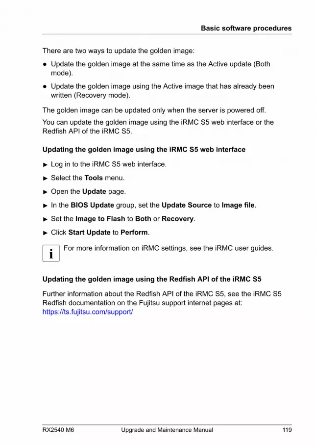
There are two ways to update the golden image:
● Update the golden image at the same time as the Active update (Bothmode).
● Update the golden image using the Active image that has already beenwritten (Recovery mode).
The golden image can be updated only when the server is powered off.You can update the golden image using the iRMC S5 web interface or theRedfish API of the iRMC S5.
Updating the golden image using the iRMC S5 web interface
▶ Log in to the iRMC S5 web interface.
▶ Select the Tools menu.
▶ Open the Update page.
▶ In the BIOS Update group, set the Update Source to Image file.
▶ Set the Image to Flash to Both or Recovery.
▶ Click Start Update to Perform.
For more information on iRMC settings, see the iRMC user guides.
Updating the golden image using the Redfish API of the iRMC S5
Further information about the Redfish API of the iRMC S5, see the iRMC S5Redfish documentation on the Fujitsu support internet pages at:https://ts.fujitsu.com/support/
Basic software procedures
RX2540 M6 Upgrade and Maintenance Manual 119

Basic software procedures
120 Upgrade and Maintenance Manual RX2540 M6
6 Power supply unit (PSU)
6.1 Safety notes
CAUTION▶ Do not disassemble the PSU. Doing so may cause electric shock.▶ Areas around the PSU may remain extremely hot after shutdown.
After shutting down the server, wait for hot components to cooldown before removing the PSU.
▶ When installing a PSU, ensure that the connector of the PSU is notdamaged or bent.
▶ The PSU is heavy, so handle it carefully. If you drop it by mistake,injuries may result.
▶ For more information, see "Important information" on page 35.
6.2 Basic information
The server can be equipped with up to two hot-plug AC PSUs or DC PSUs.
The connectors for the PSUs are integrated on the system board,therefore, the PSUs are connected directly to the system board.
Server equipped with up to two hot-plug AC PSUs
In its basic configuration, the server has one PSU that adjusts automatically toany mains voltage in the range of 100 V - 240 V (AC PSU Platinum) or 200 V -240 V (AC PSU Titanium). Besides the PSU, a second PSU can be installedoptionally to serve as a redundant power supply. If one PSU fails, the secondPSU in the redundant configuration ensures that operation can continueuninterrupted and the defective PSU can be replaced during operation (hot-plug). The second PSU can be installed during operation.
RX2540 M6 Upgrade and Maintenance Manual 121
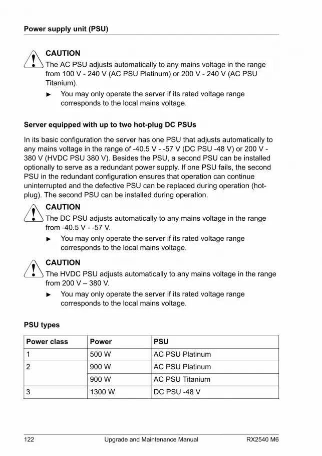
CAUTIONThe AC PSU adjusts automatically to any mains voltage in the rangefrom 100 V - 240 V (AC PSU Platinum) or 200 V - 240 V (AC PSUTitanium).▶ You may only operate the server if its rated voltage range
corresponds to the local mains voltage.
Server equipped with up to two hot-plug DC PSUs
In its basic configuration the server has one PSU that adjusts automatically toany mains voltage in the range of -40.5 V - -57 V (DC PSU -48 V) or 200 V -380 V (HVDC PSU 380 V). Besides the PSU, a second PSU can be installedoptionally to serve as a redundant power supply. If one PSU fails, the secondPSU in the redundant configuration ensures that operation can continueuninterrupted and the defective PSU can be replaced during operation (hot-plug). The second PSU can be installed during operation.
CAUTIONThe DC PSU adjusts automatically to any mains voltage in the rangefrom -40.5 V - -57 V.▶ You may only operate the server if its rated voltage range
corresponds to the local mains voltage.
CAUTIONThe HVDC PSU adjusts automatically to any mains voltage in the rangefrom 200 V – 380 V.▶ You may only operate the server if its rated voltage range
corresponds to the local mains voltage.
PSU types
Power class Power PSU1 500 W AC PSU Platinum
2 900 W AC PSU Platinum
900 W AC PSU Titanium
3 1300 W DC PSU -48 V
Power supply unit (PSU)
122 Upgrade and Maintenance Manual RX2540 M6
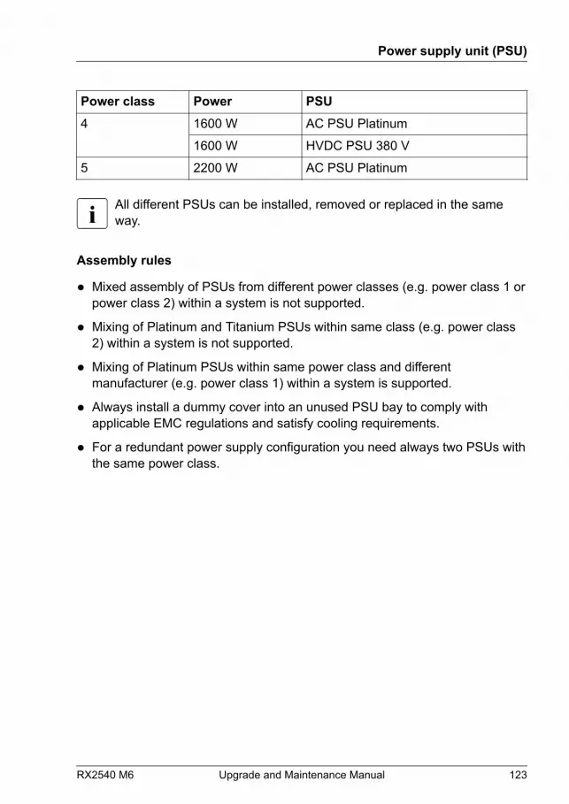
Power class Power PSU4 1600 W AC PSU Platinum
1600 W HVDC PSU 380 V
5 2200 W AC PSU Platinum
All different PSUs can be installed, removed or replaced in the sameway.
Assembly rules
● Mixed assembly of PSUs from different power classes (e.g. power class 1 orpower class 2) within a system is not supported.
● Mixing of Platinum and Titanium PSUs within same class (e.g. power class2) within a system is not supported.
● Mixing of Platinum PSUs within same power class and differentmanufacturer (e.g. power class 1) within a system is supported.
● Always install a dummy cover into an unused PSU bay to comply withapplicable EMC regulations and satisfy cooling requirements.
● For a redundant power supply configuration you need always two PSUs withthe same power class.
Power supply unit (PSU)
RX2540 M6 Upgrade and Maintenance Manual 123
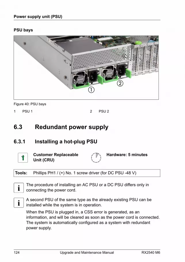
PSU bays
Figure 40: PSU bays
1 PSU 1 2 PSU 2
6.3 Redundant power supply
6.3.1 Installing a hot-plug PSU
Customer ReplaceableUnit (CRU)
Hardware: 5 minutes
Tools: Phillips PH1 / (+) No. 1 screw driver (for DC PSU -48 V)
The procedure of installing an AC PSU or a DC PSU differs only inconnecting the power cord.
A second PSU of the same type as the already existing PSU can beinstalled while the system is in operation.When the PSU is plugged in, a CSS error is generated, as aninformation, and will be cleared as soon as the power cord is connected.The system is automatically configured as a system with redundantpower supply.
Power supply unit (PSU)
124 Upgrade and Maintenance Manual RX2540 M6
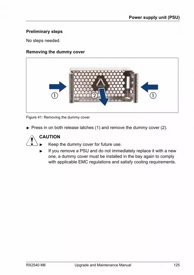
Preliminary steps
No steps needed.
Removing the dummy cover
Figure 41: Removing the dummy cover
▶ Press in on both release latches (1) and remove the dummy cover (2).
CAUTION▶ Keep the dummy cover for future use.▶ If you remove a PSU and do not immediately replace it with a new
one, a dummy cover must be installed in the bay again to complywith applicable EMC regulations and satisfy cooling requirements.
Power supply unit (PSU)
RX2540 M6 Upgrade and Maintenance Manual 125

Installing a hot-plug PSU
Figure 42: Folding up the handle
▶ Push the handle of the PSU halfway upward in the direction of the arrow.
Figure 43: Installing the PSU
▶ Push the PSU into its bay (1) as far as it will go until the release latch snapsin place.
▶ Fold down the handle on the PSU (2).
Power supply unit (PSU)
126 Upgrade and Maintenance Manual RX2540 M6
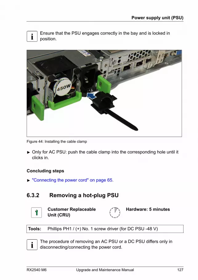
Ensure that the PSU engages correctly in the bay and is locked inposition.
Figure 44: Installing the cable clamp
▶ Only for AC PSU: push the cable clamp into the corresponding hole until itclicks in.
Concluding steps
▶ "Connecting the power cord" on page 65.
6.3.2 Removing a hot-plug PSU
Customer ReplaceableUnit (CRU)
Hardware: 5 minutes
Tools: Phillips PH1 / (+) No. 1 screw driver (for DC PSU -48 V)
The procedure of removing an AC PSU or a DC PSU differs only indisconnecting/connecting the power cord.
Power supply unit (PSU)
RX2540 M6 Upgrade and Maintenance Manual 127
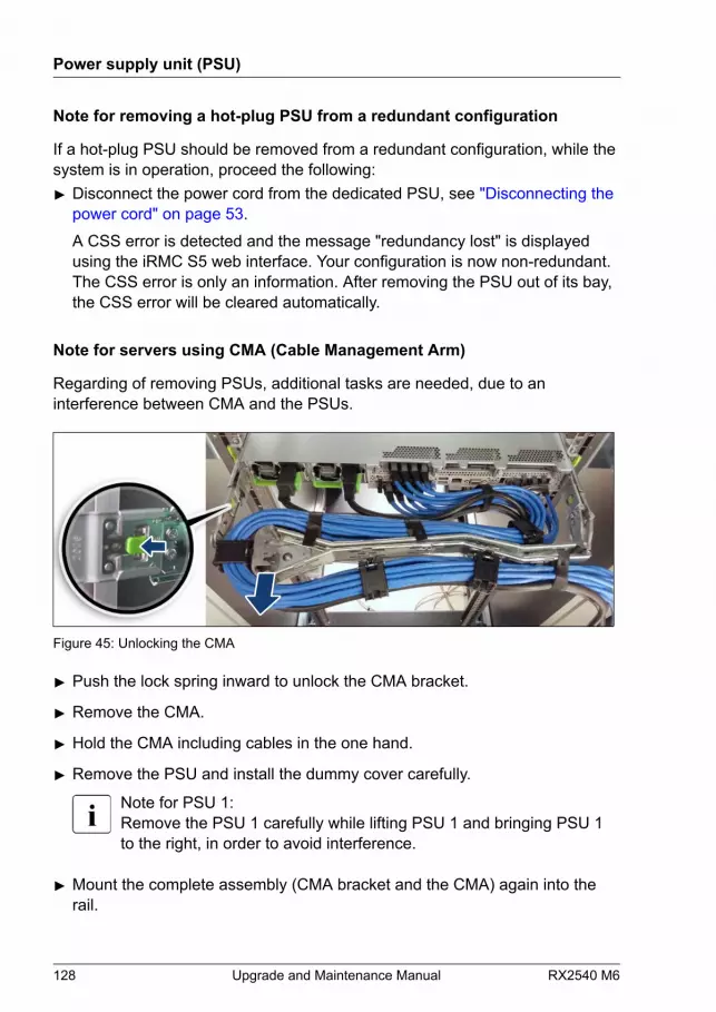
Note for removing a hot-plug PSU from a redundant configuration
If a hot-plug PSU should be removed from a redundant configuration, while thesystem is in operation, proceed the following:▶ Disconnect the power cord from the dedicated PSU, see "Disconnecting the
power cord" on page 53.A CSS error is detected and the message "redundancy lost" is displayedusing the iRMC S5 web interface. Your configuration is now non-redundant.The CSS error is only an information. After removing the PSU out of its bay,the CSS error will be cleared automatically.
Note for servers using CMA (Cable Management Arm)
Regarding of removing PSUs, additional tasks are needed, due to aninterference between CMA and the PSUs.
Figure 45: Unlocking the CMA
▶ Push the lock spring inward to unlock the CMA bracket.
▶ Remove the CMA.
▶ Hold the CMA including cables in the one hand.
▶ Remove the PSU and install the dummy cover carefully.
Note for PSU 1:Remove the PSU 1 carefully while lifting PSU 1 and bringing PSU 1to the right, in order to avoid interference.
▶ Mount the complete assembly (CMA bracket and the CMA) again into therail.
Power supply unit (PSU)
128 Upgrade and Maintenance Manual RX2540 M6
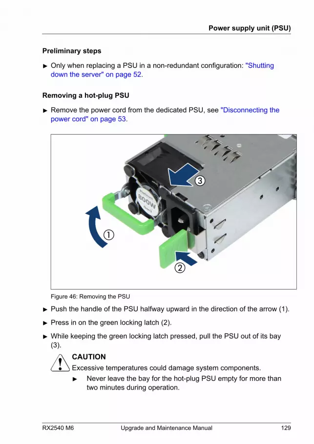
Preliminary steps
▶ Only when replacing a PSU in a non-redundant configuration: "Shutting down the server" on page 52.
Removing a hot-plug PSU
▶ Remove the power cord from the dedicated PSU, see "Disconnecting the power cord" on page 53.
Figure 46: Removing the PSU
▶ Push the handle of the PSU halfway upward in the direction of the arrow (1).
▶ Press in on the green locking latch (2).
▶ While keeping the green locking latch pressed, pull the PSU out of its bay(3).
CAUTIONExcessive temperatures could damage system components.▶ Never leave the bay for the hot-plug PSU empty for more than
two minutes during operation.
Power supply unit (PSU)
RX2540 M6 Upgrade and Maintenance Manual 129
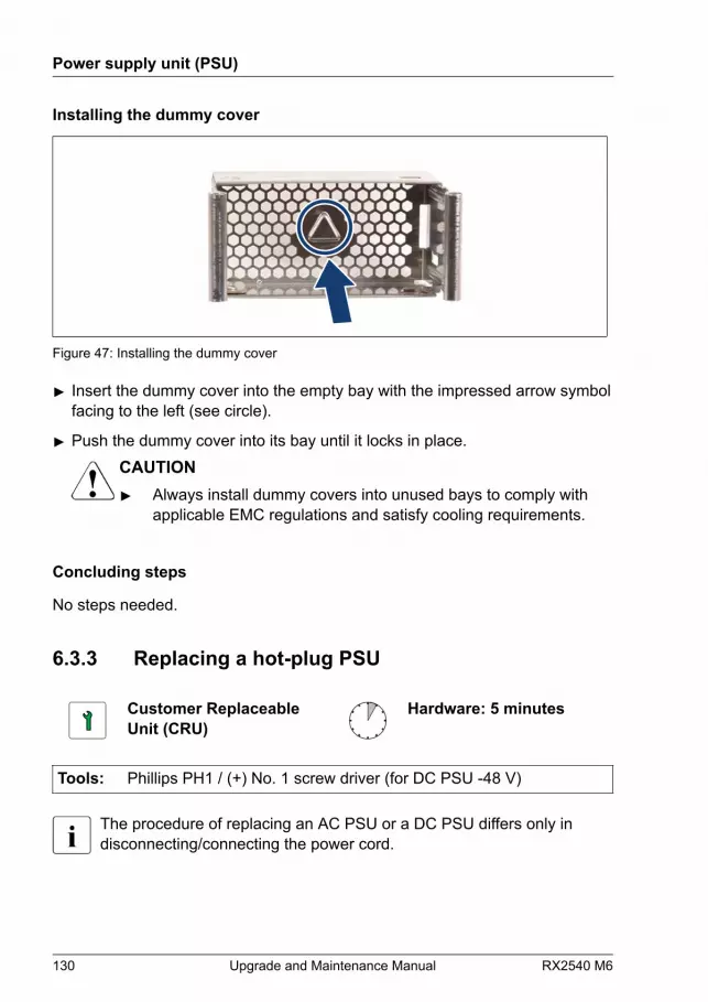
Installing the dummy cover
Figure 47: Installing the dummy cover
▶ Insert the dummy cover into the empty bay with the impressed arrow symbolfacing to the left (see circle).
▶ Push the dummy cover into its bay until it locks in place.CAUTION▶ Always install dummy covers into unused bays to comply with
applicable EMC regulations and satisfy cooling requirements.
Concluding steps
No steps needed.
6.3.3 Replacing a hot-plug PSU
Customer ReplaceableUnit (CRU)
Hardware: 5 minutes
Tools: Phillips PH1 / (+) No. 1 screw driver (for DC PSU -48 V)
The procedure of replacing an AC PSU or a DC PSU differs only indisconnecting/connecting the power cord.
Power supply unit (PSU)
130 Upgrade and Maintenance Manual RX2540 M6
CAUTION▶ When replacing a PSU in a non-redundant PSU configuration, the
server must be switched off first.▶ Replace the PSU after specifying the one that breaks down at work
by revitalization.
Note for servers using CMA (Cable Management Arm)
Regarding of removing PSUs, additional tasks are needed, due to aninterference between CMA and the PSUs.▶ Push the lock spring inward to unlock the CMA bracket, see Figure 45.
▶ Remove the CMA.
▶ Hold the CMA including cables in the one hand.
▶ Remove the PSU (see Figure 46) and install the new PSU carefully.
Note for PSU 1:Remove the PSU 1 carefully while lifting PSU 1 and bringing PSU 1to the right, in order to avoid interference.
▶ Mount the complete assembly (CMA bracket and the CMA) again into therail.
Preliminary steps
▶ "Locating the defective server" on page 49.
▶ Check which PSU is defective.PSU is defective when the PSU status indicator lights orange. For moreinformation, see "Indicator on hot-plug PSU" on page 565.
▶ Only when replacing a PSU in a non-redundant configuration: "Shutting down the server" on page 52.
▶ Remove the power cord from the defective PSU, see "Disconnecting the power cord" on page 53.
Removing the defective hot-plug PSU
▶ Remove the PSU, see "Removing a hot-plug PSU" on page 127.
Power supply unit (PSU)
RX2540 M6 Upgrade and Maintenance Manual 131
Installing the new hot-plug PSU
▶ Install the PSU, see "Installing a hot-plug PSU" on page 124.
Concluding steps
▶ "Connecting the power cord" on page 65.
▶ Only when replacing a PSU in a non-redundant configuration: "Switching on the server" on page 69.
▶ "Performing a fan test" on page 115.
A fan test does not need to be performed if the hot-plug PSU isactively replaced. iRMC runs automatically.
Power supply unit (PSU)
132 Upgrade and Maintenance Manual RX2540 M6
7 Hard disk drive (HDD) / solidstate disk (SSD)
7.1 Safety notes
CAUTION
▶ Before removing several HDD/SSD modules, make sure that all HDD/SSDmodules can be reinstalled into their original bay. Otherwise, data may belost.
▶ Do not touch the circuitry on boards or soldered parts. Hold circuit boards bytheir metallic areas or edges.
▶ Before removing an HDD, wait for about 30 seconds until the disk hasstopped spinning completely.
▶ When an HDD is starting up, a resonant noise may be audible for a shortwhile. This does not indicate a failure.
▶ Depending on the OS, you can configure the write cache settings for theHDDs. If a power failure should occur while the write cache is enabled,cached data may be lost.
▶ When disposing of, transferring, or returning an HDD or SSD, wipe out thedata on the drive for your own security.
▶ Rough handling of HDDs may damage the stored data. To cope with anyunexpected problems, always back up important data. When backing updata to another HDD, you should make backups on a file or partition basis.
▶ Be careful not to hit the HDD or bring it into contact with metallic objects.
▶ Handle the HDD and SSD on a shock and vibration free surface.
▶ Do not use the HDD and SSD in extremely hot or cold locations, or locationswith extreme temperature changes.
▶ Never attempt to disassemble the HDD or SSD.
▶ For more information, see "Important information" on page 35.
RX2540 M6 Upgrade and Maintenance Manual 133

7.2 Basic information
The HDD or SSD and the installation frame together make up the HDD moduleor SSD module.
The server is shipped with one of the following HDD or SSD subsystems:
– 3.5-inch HDD subsystem
– 2.5-inch HDD/SSD subsystem
– EDSFF SSD subsystem
3.5-inch HDD subsystem
Up to 10 3.5-inch SAS/SATA HDD modules or up to 12 3.5-inch SAS/SATAHDD modules can be installed depending on configuration.The HDD module is connected to the HDD backplane wirelessly. This allowsHDD modules to be plugged in or pulled out easily.
Hybrid configurations of SAS and SATA HDD modules are supported incombination with an optional HDD controller.
For information on RAID controllers controlling the HDD modules, see"Expansion cards and backup units" on page 233.
Hard disk drive (HDD) / solid state disk (SSD)
134 Upgrade and Maintenance Manual RX2540 M6
2.5-inch HDD/SSD subsystem
– Up to 16 2.5-inch SAS/SATA HDD/SSD modules can be installed dependingon configuration.
The HDD/SSD modules are connected to the HDD backplane wirelessly.This allows HDD/SSD modules to be plugged in or pulled out easily.
If the HDD/SSD modules are controlled by a RAID controller, defectiveHDD/SSD modules can also be replaced during operation.
– Up to 24 2.5-inch HDD/SSD/PCIe SSD modules can be installed dependingon configuration.
The HDD / SSD / PCIe SSD modules are connected to the HDD backplanewirelessly. This allows HDD/SSD/PCIe SSD modules to be plugged in orpulled out easily.
If the HDD/SSD/PCIe SSD modules are controlled by a RAID controller,defective HDD/SSD/PCIe SSD modules can be replaced during operation.
For information on RAID controllers controlling the HDD/SSD/PCIe SSDmodules, see "Expansion cards and backup units" on page 233.
EDSFF SSD subsystem
Up to 64 EDSFF SSD modules can be installed.The EDSFF SSD modules are connected to the EDSFF backplanes wirelessly.This allows EDSFF SSD modules to be plugged in or pulled out easily.
Base units
There are six base units available.
Base unit DescriptionType 1 Base unit with up to 10x 3.5-inch HDDs
Type 2 Base unit with up to 12x 3.5-inch HDDs
Type 3 Base unit for up to 16x 2.5-inch HDDs /SSDs
Type 4 Base unit for up to 24x 2.5-inch HDDs / SSDs /PCIe SSDs
Hard disk drive (HDD) / solid state disk (SSD)
RX2540 M6 Upgrade and Maintenance Manual 135

Base unit DescriptionType 5 Base unit for up to 24x 2.5-inch PCIe SSDs
Type 6 Base unit for up to 64x EDSFF SSDs
7.3 Handling HDDs or SSDs withoutinstallation frame
7.3.1 3.5-inch HDD and 3.5-inch installation frame
Installing or removing the installation frame is only necessary for Japan.
Customer ReplaceableUnit (CRU)
Hardware: 5 minutes
Tools: Phillips PH1 / (+) No. 1 screw driver
Preliminary steps
No steps needed.
Installing a 3.5-inch HDD in a 3.5-inch installation frame
Figure 48: Installing the 3.5-inch HDD in the 3.5-inch installation frame (A)
Hard disk drive (HDD) / solid state disk (SSD)
136 Upgrade and Maintenance Manual RX2540 M6
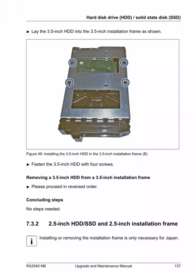
▶ Lay the 3.5-inch HDD into the 3.5-inch installation frame as shown.
Figure 49: Installing the 3.5-inch HDD in the 3.5-inch installation frame (B)
▶ Fasten the 3.5-inch HDD with four screws.
Removing a 3.5-inch HDD from a 3.5-inch installation frame
▶ Please proceed in reversed order.
Concluding steps
No steps needed.
7.3.2 2.5-inch HDD/SSD and 2.5-inch installation frame
Installing or removing the installation frame is only necessary for Japan.
Hard disk drive (HDD) / solid state disk (SSD)
RX2540 M6 Upgrade and Maintenance Manual 137

Customer ReplaceableUnit (CRU)
Hardware: 5 minutes
Tools: Phillips PH1 / (+) No. 1 screw driver
Preliminary steps
No steps needed.
Installing a 2.5-inch HDD/SSD in a 2.5-inch installation frame
Figure 50: Installing the 2.5-inch HDD/SSD in the 2.5-inch installation frame (A)
▶ Lay the 2.5-inch HDD/SSD into the 2.5-inch installation frame as shown.
Hard disk drive (HDD) / solid state disk (SSD)
138 Upgrade and Maintenance Manual RX2540 M6
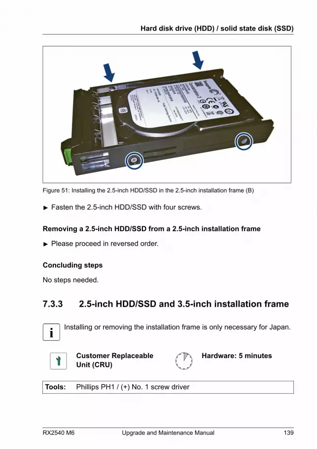
Figure 51: Installing the 2.5-inch HDD/SSD in the 2.5-inch installation frame (B)
▶ Fasten the 2.5-inch HDD/SSD with four screws.
Removing a 2.5-inch HDD/SSD from a 2.5-inch installation frame
▶ Please proceed in reversed order.
Concluding steps
No steps needed.
7.3.3 2.5-inch HDD/SSD and 3.5-inch installation frame
Installing or removing the installation frame is only necessary for Japan.
Customer ReplaceableUnit (CRU)
Hardware: 5 minutes
Tools: Phillips PH1 / (+) No. 1 screw driver
Hard disk drive (HDD) / solid state disk (SSD)
RX2540 M6 Upgrade and Maintenance Manual 139
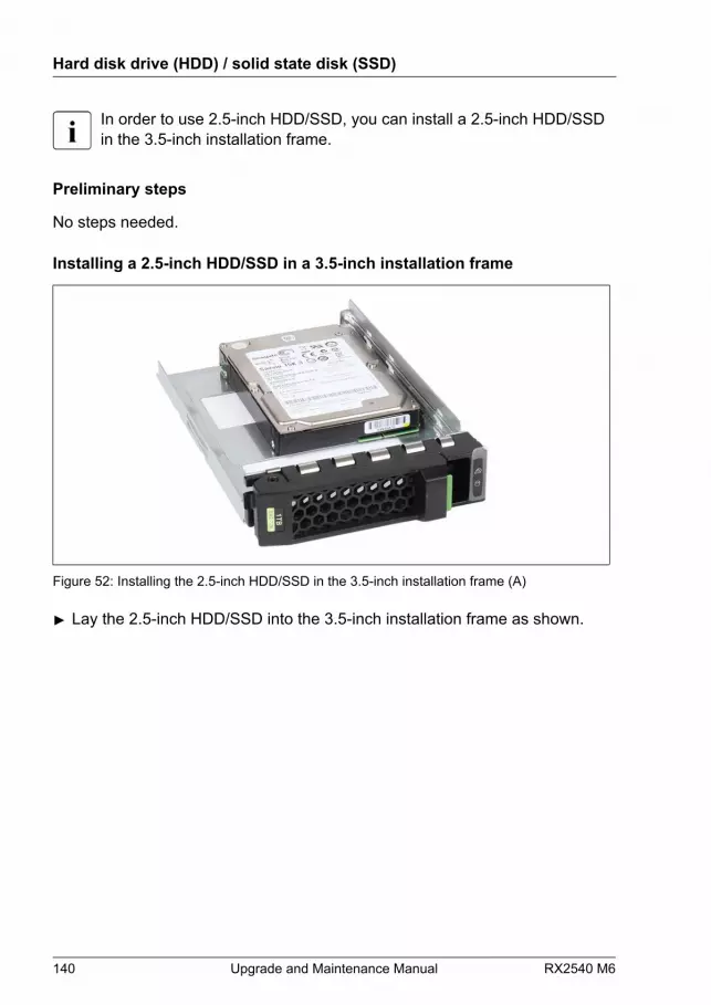
In order to use 2.5-inch HDD/SSD, you can install a 2.5-inch HDD/SSDin the 3.5-inch installation frame.
Preliminary steps
No steps needed.
Installing a 2.5-inch HDD/SSD in a 3.5-inch installation frame
Figure 52: Installing the 2.5-inch HDD/SSD in the 3.5-inch installation frame (A)
▶ Lay the 2.5-inch HDD/SSD into the 3.5-inch installation frame as shown.
Hard disk drive (HDD) / solid state disk (SSD)
140 Upgrade and Maintenance Manual RX2540 M6

Figure 53: Installing the 2.5-inch HDD/SSD in the 3.5-inch installation frame (B)
▶ Fasten the 2.5-inch HDD/SSD with four screws.
Removing a 2.5-inch HDD/SSD from a 3.5-inch installation frame
▶ Please proceed in reversed order.
Concluding steps
No steps needed.
7.3.4 EDSFF SSD and EDSFF installation frame
Installing or removing the installation frame is only necessary for Japan.
Customer ReplaceableUnit (CRU)
Hardware: 5 minutes
Tools: Phillips PH1 / (+) No. 1 screw driver
Hard disk drive (HDD) / solid state disk (SSD)
RX2540 M6 Upgrade and Maintenance Manual 141
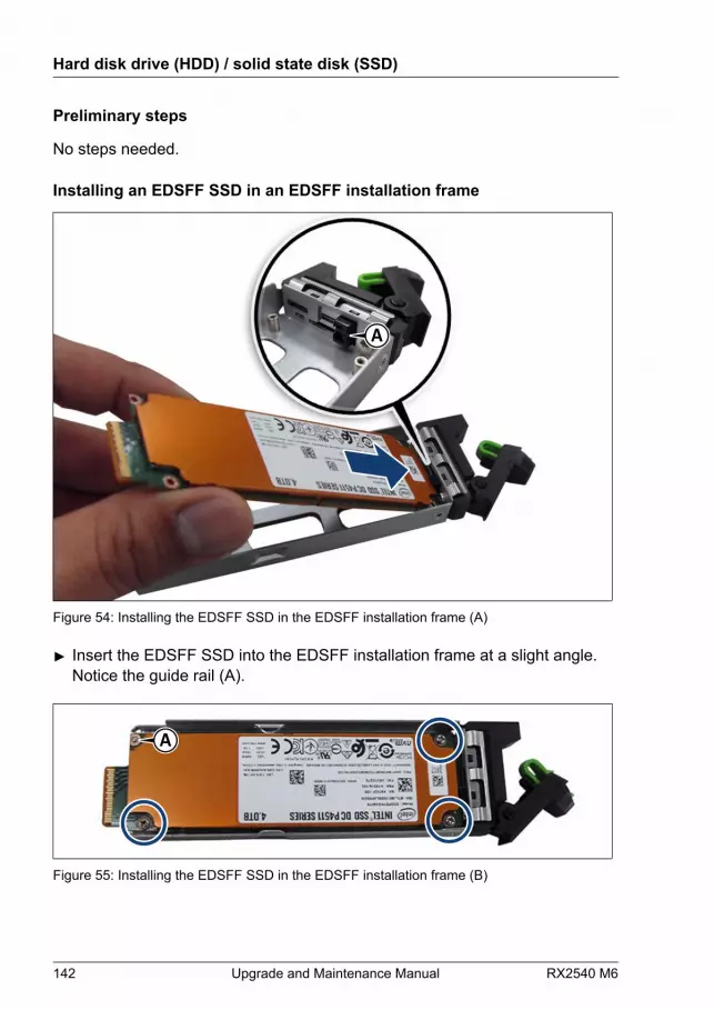
Preliminary steps
No steps needed.
Installing an EDSFF SSD in an EDSFF installation frame
A
Figure 54: Installing the EDSFF SSD in the EDSFF installation frame (A)
▶ Insert the EDSFF SSD into the EDSFF installation frame at a slight angle.Notice the guide rail (A).
A
Figure 55: Installing the EDSFF SSD in the EDSFF installation frame (B)
Hard disk drive (HDD) / solid state disk (SSD)
142 Upgrade and Maintenance Manual RX2540 M6
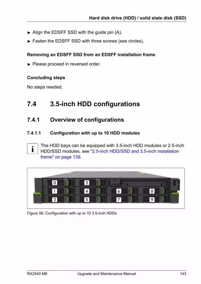
▶ Align the EDSFF SSD with the guide pin (A).
▶ Fasten the EDSFF SSD with three screws (see circles).
Removing an EDSFF SSD from an EDSFF installation frame
▶ Please proceed in reversed order.
Concluding steps
No steps needed.
7.4 3.5-inch HDD configurations
7.4.1 Overview of configurations
7.4.1.1 Configuration with up to 10 HDD modules
The HDD bays can be equipped with 3.5-inch HDD modules or 2.5-inchHDD/SSD modules, see "2.5-inch HDD/SSD and 3.5-inch installation frame" on page 139.
Figure 56: Configuration with up to 10 3.5-inch HDDs
Hard disk drive (HDD) / solid state disk (SSD)
RX2540 M6 Upgrade and Maintenance Manual 143

Position Logical drivenumber
ServerView RAID Manager displayname(Enclosure number: Port number)one SAS controller
[0] 0 Vendor Product (0)
[1] 1 Vendor Product (1)
[2] 2 Vendor Product (2)
[3] 3 Vendor Product (3)
[4] 4 Vendor Product (4)
[5] 5 Vendor Product (5)
[6] 6 Vendor Product (6)
[7] 7 Vendor Product (7)
[8] 8 Vendor Product (8)
[9] 9 Vendor Product (9)
7.4.1.2 Configuration with up to 12 HDD modules
The HDD bays can be equipped with 3.5-inch HDD modules or 2.5-inchHDD/SSD modules, see "2.5-inch HDD/SSD and 3.5-inch installation frame" on page 139.
Figure 57: Configuration with up to 12 3.5-inch HDDs
Hard disk drive (HDD) / solid state disk (SSD)
144 Upgrade and Maintenance Manual RX2540 M6
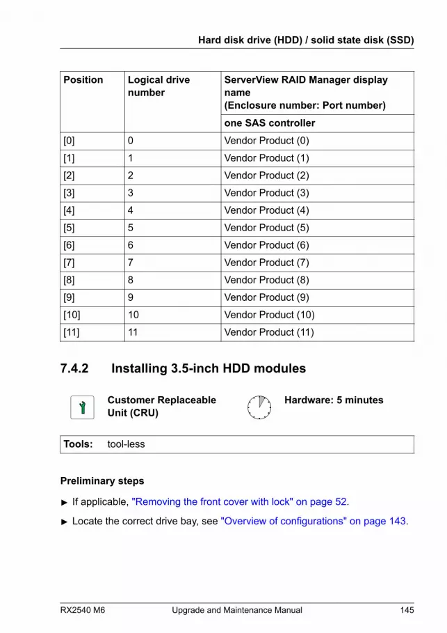
Position Logical drivenumber
ServerView RAID Manager displayname(Enclosure number: Port number)one SAS controller
[0] 0 Vendor Product (0)
[1] 1 Vendor Product (1)
[2] 2 Vendor Product (2)
[3] 3 Vendor Product (3)
[4] 4 Vendor Product (4)
[5] 5 Vendor Product (5)
[6] 6 Vendor Product (6)
[7] 7 Vendor Product (7)
[8] 8 Vendor Product (8)
[9] 9 Vendor Product (9)
[10] 10 Vendor Product (10)
[11] 11 Vendor Product (11)
7.4.2 Installing 3.5-inch HDD modules
Customer ReplaceableUnit (CRU)
Hardware: 5 minutes
Tools: tool-less
Preliminary steps
▶ If applicable, "Removing the front cover with lock" on page 52.
▶ Locate the correct drive bay, see "Overview of configurations" on page 143.
Hard disk drive (HDD) / solid state disk (SSD)
RX2540 M6 Upgrade and Maintenance Manual 145

Removing a 3.5-inch HDD dummy module
Unusable HDD bays contain a HDD dummy with dummy lock to preventcustomer from erroneously adding a HDD.
Figure 58: Removing the dummy lock
▶ Pull the dummy lock out of the dummy cover. Please be aware that thedummy lock can be damaged.
Figure 59: Removing the 3.5-inch dummy module
▶ Press both tabs together (1) and pull the dummy module out of its bay (2).CAUTION▶ Keep the dummy module for future use.▶ Always replace dummy modules into unused HDD/SSD bays to
comply with applicable EMC regulations and satisfy coolingrequirements.
Hard disk drive (HDD) / solid state disk (SSD)
146 Upgrade and Maintenance Manual RX2540 M6
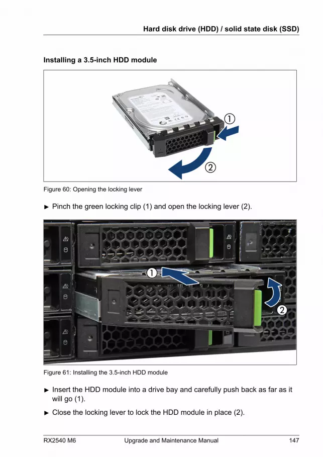
Installing a 3.5-inch HDD module
Figure 60: Opening the locking lever
▶ Pinch the green locking clip (1) and open the locking lever (2).
Figure 61: Installing the 3.5-inch HDD module
▶ Insert the HDD module into a drive bay and carefully push back as far as itwill go (1).
▶ Close the locking lever to lock the HDD module in place (2).
Hard disk drive (HDD) / solid state disk (SSD)
RX2540 M6 Upgrade and Maintenance Manual 147
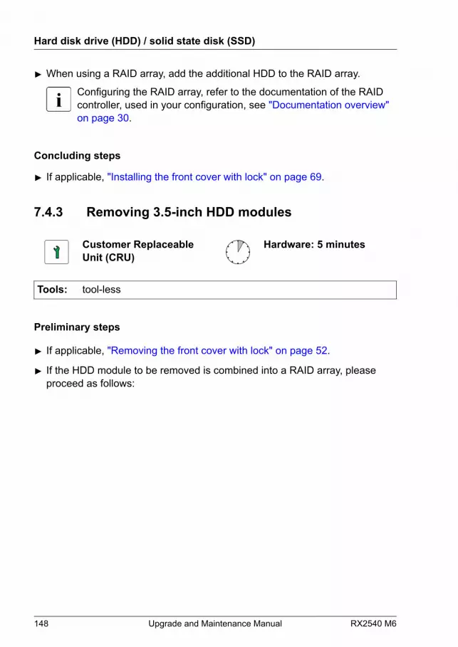
▶ When using a RAID array, add the additional HDD to the RAID array.
Configuring the RAID array, refer to the documentation of the RAIDcontroller, used in your configuration, see "Documentation overview" on page 30.
Concluding steps
▶ If applicable, "Installing the front cover with lock" on page 69.
7.4.3 Removing 3.5-inch HDD modules
Customer ReplaceableUnit (CRU)
Hardware: 5 minutes
Tools: tool-less
Preliminary steps
▶ If applicable, "Removing the front cover with lock" on page 52.
▶ If the HDD module to be removed is combined into a RAID array, pleaseproceed as follows:
Hard disk drive (HDD) / solid state disk (SSD)
148 Upgrade and Maintenance Manual RX2540 M6
RAID level ProcedureRAID 0 CAUTION
RAID 0 provides no data redundancy.In case of an HDD module is defect, alldata are lost!
RAID 1RAID 5
Removing an HDD module from a RAID 1 or RAID5 array will not result in data loss. However, theremoved drive needs to be replaced immediatelyby an HDD module of the same or larger capacity.
After replacing the HDD module, RAIDrebuild will be performed as a backgroundprocess, see "Performing a RAID array rebuild" on page 106.
In order to permanently remove an operational HDD module that is part of aRAID array from the server, you first need to delete the array using ServerViewRAID Manager.
CAUTIONAll data on all HDDs in the array will be lost when deleting the RAIDarray!▶ Be sure to back up your data before deleting a RAID array.▶ For more information, see the "ServerView Suite RAID
Management" user guide.
Removing a 3.5-inch HDD module
▶ Pinch the green locking clips and open the locking lever, see Figure 60.
▶ Pull the HDD module out a few centimeters.
▶ Wait about 30 seconds to allow the HDD to spin down.
This period is necessary for the RAID controller to recognize that anHDD module has been removed and for the HDD to come to a stop.
▶ Pull the HDD module completely out of its bay.
Hard disk drive (HDD) / solid state disk (SSD)
RX2540 M6 Upgrade and Maintenance Manual 149
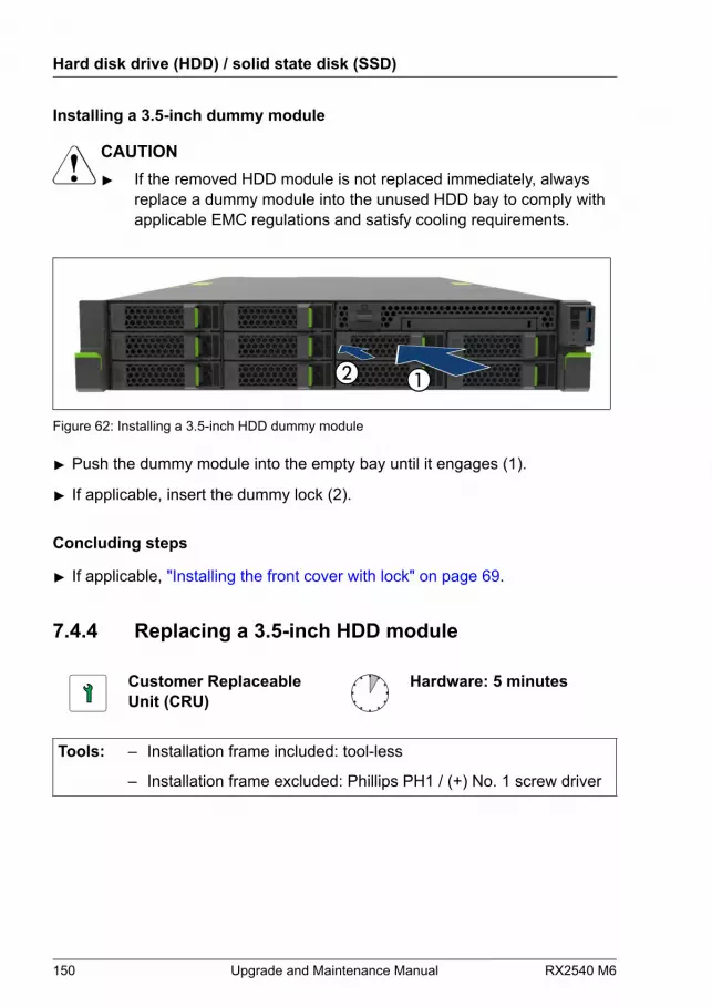
Installing a 3.5-inch dummy module
CAUTION▶ If the removed HDD module is not replaced immediately, always
replace a dummy module into the unused HDD bay to comply withapplicable EMC regulations and satisfy cooling requirements.
Figure 62: Installing a 3.5-inch HDD dummy module
▶ Push the dummy module into the empty bay until it engages (1).
▶ If applicable, insert the dummy lock (2).
Concluding steps
▶ If applicable, "Installing the front cover with lock" on page 69.
7.4.4 Replacing a 3.5-inch HDD module
Customer ReplaceableUnit (CRU)
Hardware: 5 minutes
Tools: – Installation frame included: tool-less
– Installation frame excluded: Phillips PH1 / (+) No. 1 screw driver
Hard disk drive (HDD) / solid state disk (SSD)
150 Upgrade and Maintenance Manual RX2540 M6
CAUTION▶ Only remove an HDD module during operation if the drive is not
currently being accessed. Observe the indicators on thecorresponding HDD module, see "Indicators on hot-plug HDD / SSD / PCIe SSD / EDSFF SSD modules" on page 557.
▶ An HDD module can be replaced while the system is in operation.RAID configuration with a RAID controller:
● Modular Host Bus Adapter with "Integrated RAID" (IR). RAIDlevels 0 and 1 are supported for internal HDD configurations.
● Modular RAID 0/1 controller with "MegaRAID functionality"(integrated MegaRAID). RAID levels 0, 1, 10, 5 and 50 aresupported for internal HDD configurations.
● Modular RAID 5/6 controller with "MegaRAID functionality"(MegaRAID). RAID levels 0, 1, 10, 5, 50, 6 and 60 are supportedfor internal HDD configurations. As an option, a flash backup unit(FBU) can save the memory content even if the power fails.Cache memory size of up to 8 GB is available.
▶ An HDD module can be replaced while the system is in operation.RAID configuration without a RAID controller:Please follow the instruction of each software e.g. VSAN, StorageSpaces, and Storage Spaces Direct, provided separately to use thesoftware RAID function of OS or Hypervisor.
▶ All HDD modules (drives) must be uniquely identified so that theycan be reinstalled in their original bays later. If this is not done,existing data can be lost.
Preliminary steps
▶ "Locating the defective server" on page 49.
▶ If applicable, "Removing the front cover with lock" on page 52.
▶ "Locating the defective component" on page 50.
Hard disk drive (HDD) / solid state disk (SSD)
RX2540 M6 Upgrade and Maintenance Manual 151

Removing the defective 3.5-inch HDD module
▶ Remove the HDD module, see "Removing a 3.5-inch HDD module" on page 149.
▶ If applicable, remove the HDD from the installation frame, see "Handling HDDs or SSDs without installation frame" on page 136.
Installing the new 3.5-inch HDD module
▶ If applicable, install the HDD in the installation frame, see "Handling HDDs or SSDs without installation frame" on page 136.
▶ Install the HDD module, see "Installing a 3.5-inch HDD module" on page 147.
Concluding steps
▶ If applicable, "Installing the front cover with lock" on page 69.
▶ If the HDD is configured using a RAID controller with a RAID level higherthan "0", the rebuild will start automatically, see "Performing a RAID array rebuild" on page 106.
7.4.5 Replacing the 10x 3.5-inch HDD backplane
Field Replaceable Unit(FRU)
Hardware: 15 minutes
Tools: Phillips PH2 / (+) No. 2 screw driver
Preliminary steps
▶ "Locating the defective server" on page 49.
▶ If applicable, "Removing the front cover with lock" on page 52.
▶ "Shutting down the server" on page 52.
▶ "Disconnecting the power cord" on page 53.
▶ "Getting access to the component" on page 56.
Hard disk drive (HDD) / solid state disk (SSD)
152 Upgrade and Maintenance Manual RX2540 M6
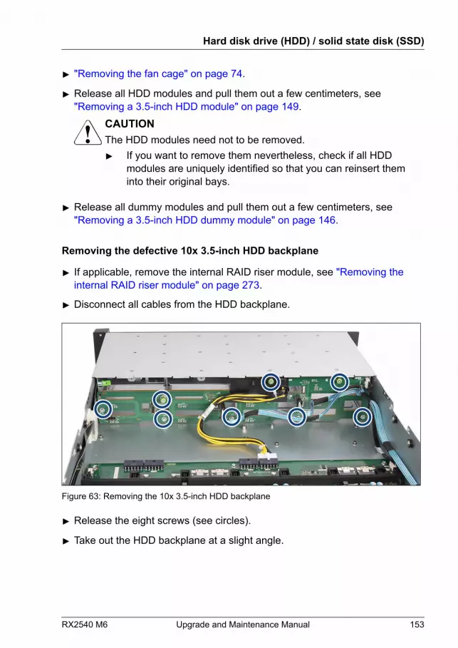
▶ "Removing the fan cage" on page 74.
▶ Release all HDD modules and pull them out a few centimeters, see"Removing a 3.5-inch HDD module" on page 149.
CAUTIONThe HDD modules need not to be removed.▶ If you want to remove them nevertheless, check if all HDD
modules are uniquely identified so that you can reinsert theminto their original bays.
▶ Release all dummy modules and pull them out a few centimeters, see"Removing a 3.5-inch HDD dummy module" on page 146.
Removing the defective 10x 3.5-inch HDD backplane
▶ If applicable, remove the internal RAID riser module, see "Removing the internal RAID riser module" on page 273.
▶ Disconnect all cables from the HDD backplane.
Figure 63: Removing the 10x 3.5-inch HDD backplane
▶ Release the eight screws (see circles).
▶ Take out the HDD backplane at a slight angle.
Hard disk drive (HDD) / solid state disk (SSD)
RX2540 M6 Upgrade and Maintenance Manual 153

Installing the new 10x 3.5-inch HDD backplane
Figure 64: Installing the 10x 3.5-inch HDD backplane
▶ Insert the HDD backplane into the chassis.
▶ Fasten the eight screws (see circles).
▶ If applicable, install the internal RAID riser module, see "Installing the internal RAID riser module" on page 271.
Figure 65: Connecting cables to the 10x 3.5-inch HDD backplane
▶ Connect the following cables to the HDD backplane:
Hard disk drive (HDD) / solid state disk (SSD)
154 Upgrade and Maintenance Manual RX2540 M6
1 SAS/SATA cable 2 SAS/SATA cable 3 Power cable 4 SAS/SATA cable 5 OOB cable
For the cable plan, see "Appendix B" on page 571.
Concluding steps
▶ Insert all HDD/SSD modules, see "Installing a 3.5-inch HDD module" on page 147.
Ensure that you install the HDD module in the bay it was locatedbefore the HDD backplane replacement.
▶ Insert all dummy modules, see "Installing a 3.5-inch dummy module" on page 150.
▶ "Installing the fan cage" on page 76.
▶ "Reassembling" on page 60.
▶ "Connecting the power cord" on page 65.
▶ "Switching on the server" on page 69.
▶ If applicable, "Installing the front cover with lock" on page 69.
7.4.6 Replacing the 12x 3.5-inch HDD backplane
Field Replaceable Unit(FRU)
Hardware: 15 minutes
Tools: Phillips PH2 / (+) No. 2 screw driver
Hard disk drive (HDD) / solid state disk (SSD)
RX2540 M6 Upgrade and Maintenance Manual 155
Preliminary steps
▶ "Locating the defective server" on page 49.
▶ If applicable, "Removing the front cover with lock" on page 52.
▶ "Shutting down the server" on page 52.
▶ "Disconnecting the power cord" on page 53.
▶ "Getting access to the component" on page 56.
▶ "Removing the fan cage" on page 74.
▶ Release all HDD modules and pull them out a few centimeters, see"Removing a 3.5-inch HDD module" on page 149.
CAUTIONThe HDD modules need not to be removed.▶ If you want to remove them nevertheless, check if all HDD
modules are uniquely identified so that you can reinsert theminto their original bays.
▶ Release all dummy modules and pull them out a few centimeters, see"Removing a 3.5-inch HDD dummy module" on page 146.
Removing the defective 12x 3.5-inch HDD backplane
▶ If applicable, remove the SAS expander board holder, see "Removing the SAS expander board holder" on page 209.
▶ Remove the internal RAID riser module, see "Removing the internal RAID riser module" on page 273.
▶ Disconnect all cables from the HDD backplane.
Hard disk drive (HDD) / solid state disk (SSD)
156 Upgrade and Maintenance Manual RX2540 M6
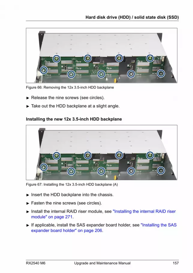
Figure 66: Removing the 12x 3.5-inch HDD backplane
▶ Release the nine screws (see circles).
▶ Take out the HDD backplane at a slight angle.
Installing the new 12x 3.5-inch HDD backplane
Figure 67: Installing the 12x 3.5-inch HDD backplane (A)
▶ Insert the HDD backplane into the chassis.
▶ Fasten the nine screws (see circles).
▶ Install the internal RAID riser module, see "Installing the internal RAID riser module" on page 271.
▶ If applicable, install the SAS expander board holder, see "Installing the SAS expander board holder" on page 206.
Hard disk drive (HDD) / solid state disk (SSD)
RX2540 M6 Upgrade and Maintenance Manual 157
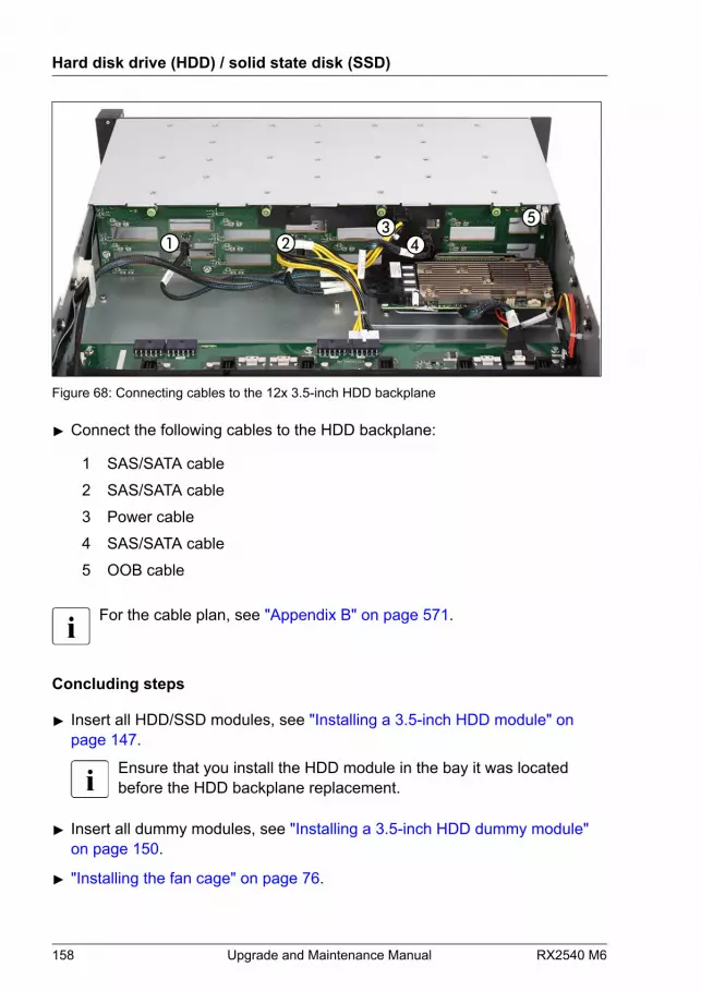
Figure 68: Connecting cables to the 12x 3.5-inch HDD backplane
▶ Connect the following cables to the HDD backplane:
1 SAS/SATA cable 2 SAS/SATA cable 3 Power cable 4 SAS/SATA cable 5 OOB cable
For the cable plan, see "Appendix B" on page 571.
Concluding steps
▶ Insert all HDD/SSD modules, see "Installing a 3.5-inch HDD module" on page 147.
Ensure that you install the HDD module in the bay it was locatedbefore the HDD backplane replacement.
▶ Insert all dummy modules, see "Installing a 3.5-inch HDD dummy module" on page 150.
▶ "Installing the fan cage" on page 76.
Hard disk drive (HDD) / solid state disk (SSD)
158 Upgrade and Maintenance Manual RX2540 M6

▶ "Reassembling" on page 60.
▶ "Connecting the power cord" on page 65.
▶ "Switching on the server" on page 69.
▶ If applicable, "Installing the front cover with lock" on page 69.
7.5 2.5-inch HDD/SSD configurations
7.5.1 Overview of configurations
7.5.1.1 Configuration with up to 16 HDD/SSD modules
Figure 69: Configuration with up to 16 2.5-inch HDDs/SSDs
Position Logical drivenumber
ServerView RAID Manager display name
one SAS controller two SAS controllers[0] 0 Vendor Product (0) Vendor Product (0:0)
[1] 1 Vendor Product (1) Vendor Product (0:1)
[2] 2 Vendor Product (2) Vendor Product (0:2)
[3] 3 Vendor Product (3) Vendor Product (0:3)
[4] 4 Vendor Product (4) Vendor Product (0:4)
[5] 5 Vendor Product (5) Vendor Product (0:5)
[6] 6 Vendor Product (6) Vendor Product (0:6)
[7] 7 Vendor Product (7) Vendor Product (0:7)
Hard disk drive (HDD) / solid state disk (SSD)
RX2540 M6 Upgrade and Maintenance Manual 159

Position Logical drivenumber
ServerView RAID Manager display name
one SAS controller two SAS controllers[8] 8 Vendor Product (8) Vendor Product (1:0)
[9] 9 Vendor Product (9) Vendor Product (1:1)
[10] 10 Vendor Product (10) Vendor Product (1:2)
[11] 11 Vendor Product (11) Vendor Product (1:3)
[12] 12 Vendor Product (12) Vendor Product (1:4)
[13] 13 Vendor Product (13) Vendor Product (1:5)
[14] 14 Vendor Product (14) Vendor Product (1:6)
[15] 15 Vendor Product (15) Vendor Product (1:7)
7.5.1.2 Configuration with up to 24 HDD/SSD/PCIe SSD modules
HDD/SSD
Figure 70: Configuration with up to 24 2.5-inch HDDs/SSDs
HDD/SSD PCIe SSD
Figure 71: Configuration with up to 16 2.5-inch HDDs/SSDs and up to eight 2.5-inch PCIeSSDs
Hard disk drive (HDD) / solid state disk (SSD)
160 Upgrade and Maintenance Manual RX2540 M6
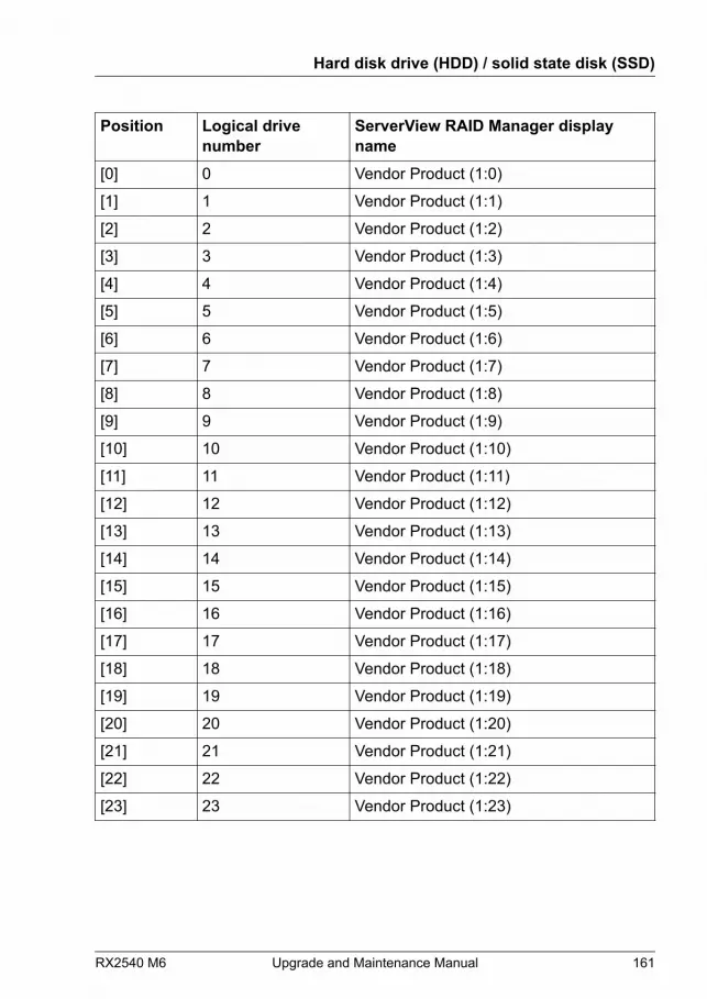
Position Logical drivenumber
ServerView RAID Manager displayname
[0] 0 Vendor Product (1:0)
[1] 1 Vendor Product (1:1)
[2] 2 Vendor Product (1:2)
[3] 3 Vendor Product (1:3)
[4] 4 Vendor Product (1:4)
[5] 5 Vendor Product (1:5)
[6] 6 Vendor Product (1:6)
[7] 7 Vendor Product (1:7)
[8] 8 Vendor Product (1:8)
[9] 9 Vendor Product (1:9)
[10] 10 Vendor Product (1:10)
[11] 11 Vendor Product (1:11)
[12] 12 Vendor Product (1:12)
[13] 13 Vendor Product (1:13)
[14] 14 Vendor Product (1:14)
[15] 15 Vendor Product (1:15)
[16] 16 Vendor Product (1:16)
[17] 17 Vendor Product (1:17)
[18] 18 Vendor Product (1:18)
[19] 19 Vendor Product (1:19)
[20] 20 Vendor Product (1:20)
[21] 21 Vendor Product (1:21)
[22] 22 Vendor Product (1:22)
[23] 23 Vendor Product (1:23)
Hard disk drive (HDD) / solid state disk (SSD)
RX2540 M6 Upgrade and Maintenance Manual 161
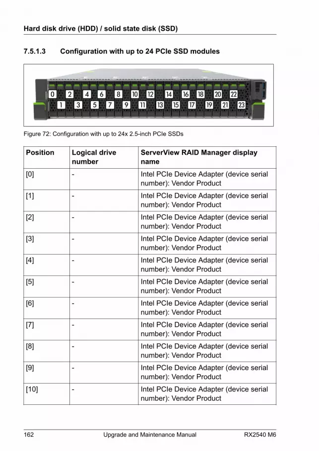
7.5.1.3 Configuration with up to 24 PCIe SSD modules
Figure 72: Configuration with up to 24x 2.5-inch PCIe SSDs
Position Logical drivenumber
ServerView RAID Manager displayname
[0] - Intel PCIe Device Adapter (device serialnumber): Vendor Product
[1] - Intel PCIe Device Adapter (device serialnumber): Vendor Product
[2] - Intel PCIe Device Adapter (device serialnumber): Vendor Product
[3] - Intel PCIe Device Adapter (device serialnumber): Vendor Product
[4] - Intel PCIe Device Adapter (device serialnumber): Vendor Product
[5] - Intel PCIe Device Adapter (device serialnumber): Vendor Product
[6] - Intel PCIe Device Adapter (device serialnumber): Vendor Product
[7] - Intel PCIe Device Adapter (device serialnumber): Vendor Product
[8] - Intel PCIe Device Adapter (device serialnumber): Vendor Product
[9] - Intel PCIe Device Adapter (device serialnumber): Vendor Product
[10] - Intel PCIe Device Adapter (device serialnumber): Vendor Product
Hard disk drive (HDD) / solid state disk (SSD)
162 Upgrade and Maintenance Manual RX2540 M6

Position Logical drivenumber
ServerView RAID Manager displayname
[11] - Intel PCIe Device Adapter (device serialnumber): Vendor Product
[12] - Intel PCIe Device Adapter (device serialnumber): Vendor Product
[13] - Intel PCIe Device Adapter (device serialnumber): Vendor Product
[14] - Intel PCIe Device Adapter (device serialnumber): Vendor Product
[15] - Intel PCIe Device Adapter (device serialnumber): Vendor Product
[16] - Intel PCIe Device Adapter (device serialnumber): Vendor Product
[17] - Intel PCIe Device Adapter (device serialnumber): Vendor Product
[18] - Intel PCIe Device Adapter (device serialnumber): Vendor Product
[19] - Intel PCIe Device Adapter (device serialnumber): Vendor Product
[20] - Intel PCIe Device Adapter (device serialnumber): Vendor Product
[21] - Intel PCIe Device Adapter (device serialnumber): Vendor Product
[22] - Intel PCIe Device Adapter (device serialnumber): Vendor Product
[23] - Intel PCIe Device Adapter (device serialnumber): Vendor Product
Hard disk drive (HDD) / solid state disk (SSD)
RX2540 M6 Upgrade and Maintenance Manual 163
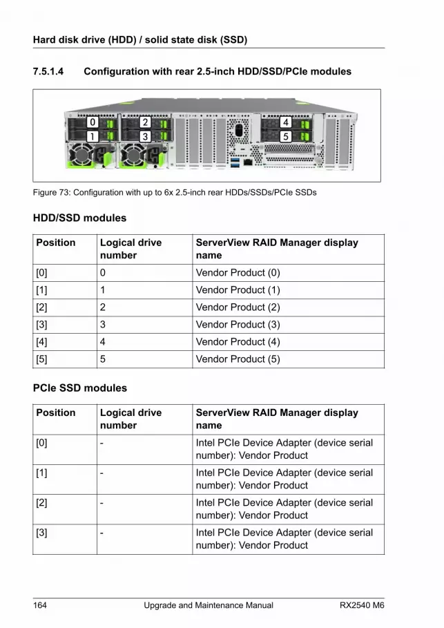
7.5.1.4 Configuration with rear 2.5-inch HDD/SSD/PCIe modules
Figure 73: Configuration with up to 6x 2.5-inch rear HDDs/SSDs/PCIe SSDs
HDD/SSD modules
Position Logical drivenumber
ServerView RAID Manager displayname
[0] 0 Vendor Product (0)
[1] 1 Vendor Product (1)
[2] 2 Vendor Product (2)
[3] 3 Vendor Product (3)
[4] 4 Vendor Product (4)
[5] 5 Vendor Product (5)
PCIe SSD modules
Position Logical drivenumber
ServerView RAID Manager displayname
[0] - Intel PCIe Device Adapter (device serialnumber): Vendor Product
[1] - Intel PCIe Device Adapter (device serialnumber): Vendor Product
[2] - Intel PCIe Device Adapter (device serialnumber): Vendor Product
[3] - Intel PCIe Device Adapter (device serialnumber): Vendor Product
Hard disk drive (HDD) / solid state disk (SSD)
164 Upgrade and Maintenance Manual RX2540 M6

Position Logical drivenumber
ServerView RAID Manager displayname
[4] - Intel PCIe Device Adapter (device serialnumber): Vendor Product
[5] - Intel PCIe Device Adapter (device serialnumber): Vendor Product
7.5.2 Installing 2.5-inch HDD/SSD modules
Customer ReplaceableUnit (CRU)
Hardware: 5 minutes
Tools: tool-less
Preliminary steps
▶ If applicable, "Removing the front cover with lock" on page 52.
▶ Locate the correct drive bay, see "Overview of configurations" on page 159.
Removing a 2.5-inch HDD/SSD dummy module
Unusable HDD bays contain a HDD/SSD dummy with dummy lock toprevent customer from erroneously adding a HDD.
Hard disk drive (HDD) / solid state disk (SSD)
RX2540 M6 Upgrade and Maintenance Manual 165

Figure 74: Removing the dummy lock
▶ Pull the dummy lock out of the dummy cover. Please be aware that thedummy lock can be damaged.
Figure 75: Removing a 2.5-inch HDD/SSD dummy module
▶ Press both tabs together (1) and pull the dummy module out of its bay (2).
CAUTION▶ Keep the dummy module for future use.▶ Always replace dummy modules into unused HDD/SSD bays to
comply with applicable EMC regulations and satisfy coolingrequirements.
Hard disk drive (HDD) / solid state disk (SSD)
166 Upgrade and Maintenance Manual RX2540 M6

Installing a 2.5-inch HDD/SSD module
Figure 76: Opening the locking lever
▶ Pinch the green locking clips (1) and open the locking lever (2).
Figure 77: Installing the 2.5-inch HDD/SSD module
▶ Insert the HDD/SSD module into a drive bay and carefully push back as faras it will go (1).
▶ Close the locking lever to lock the HDD/SSD module in place (2).
▶ When using a RAID array, add the additional HDD/SSD to the RAID array.
Hard disk drive (HDD) / solid state disk (SSD)
RX2540 M6 Upgrade and Maintenance Manual 167
Configuring the RAID array, see the documentation of the RAIDcontroller, used in your configuration, see "Documentation overview" on page 30.
Concluding steps
▶ If applicable, "Installing the front cover with lock" on page 69.
7.5.3 Removing 2.5-inch HDD/SSD modules
Customer ReplaceableUnit (CRU)
Hardware: 5 minutes
Tools: tool-less
Preliminary steps
▶ If applicable, "Removing the front cover with lock" on page 52.
▶ If the HDD/SSD module to be removed is combined into a RAID array,please proceed as follows:
Hard disk drive (HDD) / solid state disk (SSD)
168 Upgrade and Maintenance Manual RX2540 M6
RAID level ProcedureRAID 0 CAUTION
RAID 0 provides no data redundancy.In case of an HDD module is defect, alldata are lost!
RAID 1RAID 5
Removing an HDD/SSD module from a RAID 1 orRAID 5 array will not result in data loss. However,the removed drive needs to be replacedimmediately by an HDD/SSD module of the sameor larger capacity.
After replacing the HDD/SSD module,RAID rebuild will be performed as abackground process, see "Performing a RAID array rebuild" on page 106.
In order to permanently remove an operational HDD/SSD module that is part ofa RAID array from the server, you first need to delete the array usingServerView RAID Manager.
CAUTIONAll data on all HDDs/SSDs in the array will be lost when deleting theRAID array!▶ Be sure to back up your data before deleting a RAID array.▶ For more information, see the "ServerView Suite RAID
Management" user guide.
Removing a 2.5-inch HDD/SSD module
▶ Pinch the green locking clips and open the locking lever, see Figure 76.
▶ Pull the HDD/SSD module out a few centimeters.
▶ Wait about 30 seconds.
This period is necessary for the RAID controller to recognize that anHDD module has been removed and for the HDD to come to a stop.
This period is necessary for the RAID controller to recognize that anSSD module has been removed.
Hard disk drive (HDD) / solid state disk (SSD)
RX2540 M6 Upgrade and Maintenance Manual 169
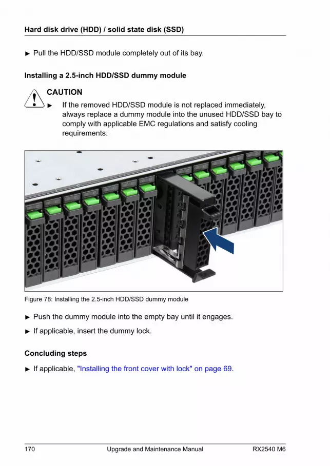
▶ Pull the HDD/SSD module completely out of its bay.
Installing a 2.5-inch HDD/SSD dummy module
CAUTION▶ If the removed HDD/SSD module is not replaced immediately,
always replace a dummy module into the unused HDD/SSD bay tocomply with applicable EMC regulations and satisfy coolingrequirements.
Figure 78: Installing the 2.5-inch HDD/SSD dummy module
▶ Push the dummy module into the empty bay until it engages.
▶ If applicable, insert the dummy lock.
Concluding steps
▶ If applicable, "Installing the front cover with lock" on page 69.
Hard disk drive (HDD) / solid state disk (SSD)
170 Upgrade and Maintenance Manual RX2540 M6

7.5.4 Replacing a 2.5-inch HDD/SSD module
Customer ReplaceableUnit (CRU)
Hardware: 5 minutes
Tools: – Installation frame included: tool-less
– Installation frame excluded: Phillips PH1 / (+) No. 1 screw driver
CAUTION▶ Only remove an HDD/SSD module during operation if the drive is
not currently being accessed. Observe the indicators on thecorresponding HDD/SSD module, see "Indicators on hot-plug HDD / SSD / PCIe SSD / EDSFF SSD modules" on page 557.
▶ An HDD/SSD module can be replaced while the system is inoperation. RAID configuration with a RAID controller:
● Modular Host Bus Adapter with "Integrated RAID" (IR). RAIDlevels 0 and 1 are supported for internal HDD configurations.
● Modular RAID 0/1 controller with "MegaRAID functionality"(integrated MegaRAID). RAID levels 0, 1, 10, 5 and 50 aresupported for internal HDD configurations.
● Modular RAID 5/6 controller with "MegaRAID functionality"(MegaRAID). RAID levels 0, 1, 10, 5, 50, 6 and 60 are supportedfor internal HDD configurations. As an option, a flash backup unit(FBU) can save the memory content even if the power fails.Cache memory size of up to 8 GB is available.
▶ An HDD/SSD module can be replaced while the system is inoperation. RAID configuration without a RAID controller:Please follow the instruction of each software e.g. VSAN, StorageSpaces, and Storage Spaces Direct, provided separately to use thesoftware RAID function of OS or Hypervisor.
▶ All HDD/SSD modules (drives) must be uniquely identified so thatthey can be reinstalled in their original bays later. If this is not done,existing data can be lost.
Hard disk drive (HDD) / solid state disk (SSD)
RX2540 M6 Upgrade and Maintenance Manual 171
Preliminary steps
▶ "Locating the defective server" on page 49.
▶ If applicable, "Removing the front cover with lock" on page 52.
▶ "Locating the defective component" on page 50.
Removing the defective 2.5-inch HDD/SSD module
▶ Remove the HDD/SSD module, see "Removing a 2.5-inch HDD/SSD module" on page 169.
▶ If applicable, remove the HDD/SSD from the installation frame, see"Handling HDDs or SSDs without installation frame" on page 136.
Installing the new 2.5-inch HDD module
▶ If applicable, install the HDD/SSD in the installation frame, see "Handling HDDs or SSDs without installation frame" on page 136.
▶ Install the HDD/SSD module, see "Installing a 2.5-inch HDD/SSD module" on page 167.
Concluding steps
▶ If applicable, "Installing the front cover with lock" on page 69.
▶ If the HDD/SSD is configured using a RAID controller with a RAID levelhigher than "0", the rebuild will start automatically, see "Performing a RAID array rebuild" on page 106.
7.5.5 Installing 2.5-inch PCIe SSD modules
Customer ReplaceableUnit (CRU)
Hardware: 5 minutes
Tools: tool-less
Hard disk drive (HDD) / solid state disk (SSD)
172 Upgrade and Maintenance Manual RX2540 M6
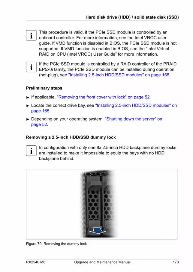
This procedure is valid, if the PCIe SSD module is controlled by anonboard controller. For more information, see the Intel VROC userguide. If VMD function is disabled in BIOS, the PCIe SSD module is notsupported. If VMD function is enabled in BIOS, see the "Intel VirtualRAID on CPU (Intel VROC) User Guide” for more information.
If the PCIe SSD module is controlled by a RAID controller of the PRAIDEP5x0i family, the PCIe SSD module can be installed during operation(hot-plug), see "Installing 2.5-inch HDD/SSD modules" on page 165.
Preliminary steps
▶ If applicable, "Removing the front cover with lock" on page 52.
▶ Locate the correct drive bay, see "Installing 2.5-inch HDD/SSD modules" on page 165.
▶ Depending on your operating system: "Shutting down the server" on page 52.
Removing a 2.5-inch HDD/SSD dummy lock
In configuration with only one 8x 2.5-inch HDD backplane dummy locksare installed to make it impossible to equip the bays with no HDDbackplane behind.
Figure 79: Removing the dummy lock
Hard disk drive (HDD) / solid state disk (SSD)
RX2540 M6 Upgrade and Maintenance Manual 173
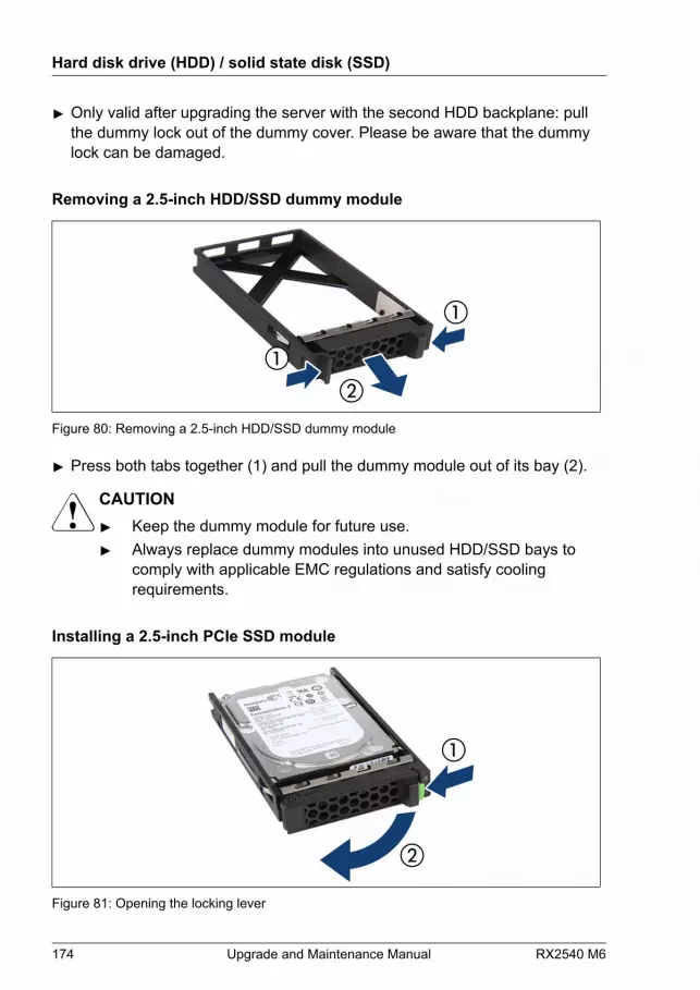
▶ Only valid after upgrading the server with the second HDD backplane: pullthe dummy lock out of the dummy cover. Please be aware that the dummylock can be damaged.
Removing a 2.5-inch HDD/SSD dummy module
Figure 80: Removing a 2.5-inch HDD/SSD dummy module
▶ Press both tabs together (1) and pull the dummy module out of its bay (2).
CAUTION▶ Keep the dummy module for future use.▶ Always replace dummy modules into unused HDD/SSD bays to
comply with applicable EMC regulations and satisfy coolingrequirements.
Installing a 2.5-inch PCIe SSD module
Figure 81: Opening the locking lever
Hard disk drive (HDD) / solid state disk (SSD)
174 Upgrade and Maintenance Manual RX2540 M6

▶ Pinch the green locking clips (1) and open the locking lever (2).
Figure 82: Installing the 2.5-inch PCIe SSD module
▶ Insert the PCIe SSD module into a drive bay and carefully push back as faras it will go (1).
▶ Close the locking lever to lock the PCIe SSD module in place (2).
Concluding steps
▶ If applicable, "Switching on the server" on page 69.
▶ If applicable, "Installing the front cover with lock" on page 69.
▶ If applicable, rescan available devices from your operating system.
7.5.6 Removing 2.5-inch PCIe SSD modules
Customer ReplaceableUnit (CRU)
Hardware: 5 minutes
Tools: tool-less
Hard disk drive (HDD) / solid state disk (SSD)
RX2540 M6 Upgrade and Maintenance Manual 175
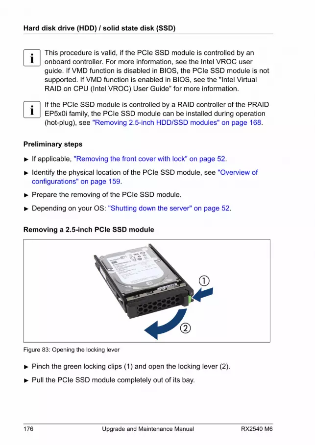
This procedure is valid, if the PCIe SSD module is controlled by anonboard controller. For more information, see the Intel VROC userguide. If VMD function is disabled in BIOS, the PCIe SSD module is notsupported. If VMD function is enabled in BIOS, see the "Intel VirtualRAID on CPU (Intel VROC) User Guide” for more information.
If the PCIe SSD module is controlled by a RAID controller of the PRAIDEP5x0i family, the PCIe SSD module can be installed during operation(hot-plug), see "Removing 2.5-inch HDD/SSD modules" on page 168.
Preliminary steps
▶ If applicable, "Removing the front cover with lock" on page 52.
▶ Identify the physical location of the PCIe SSD module, see "Overview of configurations" on page 159.
▶ Prepare the removing of the PCIe SSD module.
▶ Depending on your OS: "Shutting down the server" on page 52.
Removing a 2.5-inch PCIe SSD module
Figure 83: Opening the locking lever
▶ Pinch the green locking clips (1) and open the locking lever (2).
▶ Pull the PCIe SSD module completely out of its bay.
Hard disk drive (HDD) / solid state disk (SSD)
176 Upgrade and Maintenance Manual RX2540 M6

Installing a 2.5-inch HDD/SSD dummy module
CAUTION▶ If the removed HDD/SSD module is not replaced immediately,
always replace a dummy module into the unused HDD/SSD bay tocomply with applicable EMC regulations and satisfy coolingrequirements.
Figure 84: Installing the 2.5-inch HDD/SSD dummy module
▶ Push the dummy module into the empty bay until it engages.
▶ If applicable, insert the dummy lock.
Concluding steps
▶ If applicable, "Switching on the server" on page 69.
▶ If applicable, "Installing the front cover with lock" on page 69.
Hard disk drive (HDD) / solid state disk (SSD)
RX2540 M6 Upgrade and Maintenance Manual 177
7.5.7 Replacing a 2.5-inch PCIe SSD module
Customer ReplaceableUnit (CRU)
Hardware: 5 minutes
Tools: – Installation frame included: tool-less
– Installation frame excluded: Phillips PH1 / (+) No. 1 screw driver
This procedure is valid, if the PCIe SSD module is controlled by anonboard controller and the VMD function is enabled in the BIOS. Formore information, see the "Intel Virtual RAID on CPU (Intel VROC) UserGuide".
If the PCIe SSD module is controlled by a RAID controller of the PRAIDEP5xxi/CP5xxi/EP6xxi family, the PCIe SSD module can be installedduring operation (hot-plug), see "Removing 2.5-inch HDD/SSD modules" on page 168.
CAUTIONAll HDD/SSD modules (drives) must be uniquely identified so that theycan be reinstalled in their original bays later. If this is not done, existingdata can be lost.
Preliminary steps
▶ "Locating the defective server" on page 49.
▶ If applicable, "Removing the front cover with lock" on page 52.
▶ Identify the physical location of the PCIe SSD module, see "Overview of configurations" on page 159.
▶ Prepare the removing of the PCIe SSD module.
▶ Depending on your configuration and OS: "Shutting down the server" on page 52.
Hard disk drive (HDD) / solid state disk (SSD)
178 Upgrade and Maintenance Manual RX2540 M6

Removing the defective 2.5-inch PCIe SSD module
▶ Remove the PCIe SSD module, see "Removing a 2.5-inch PCIe SSD module" on page 176.
▶ If applicable, remove the PCIe SSD from the installation frame, see"Handling HDDs or SSDs without installation frame" on page 136.
Installing the new 2.5-inch PCIe SSD module
▶ If applicable, install the PCIe SSD in the installation frame, see "Handling HDDs or SSDs without installation frame" on page 136.
▶ Install the PCIe SSD module, see "Installing 2.5-inch PCIe SSD modules" on page 172.
Concluding steps
▶ If applicable, "Switching on the server" on page 69.
▶ If applicable, rescan available devices from your OS.
▶ If applicable, "Installing the front cover with lock" on page 69.
7.5.8 Replacing a 8x 2.5-inch HDD backplane
Field Replaceable Unit(FRU)
Hardware: 15 minutes
Tools: Phillips PH2 / (+) No. 2 screw driver
In configuration with 24x 2.5-inch HDD/SSD/PCIe modules the thirdbackplane is a combo HDD backplane that also allows to install PCIes.The replacing procedure is the same as a HDD backplane.
Preliminary steps
▶ "Locating the defective server" on page 49.
▶ If applicable, "Removing the front cover with lock" on page 52.
▶ "Shutting down the server" on page 52.
Hard disk drive (HDD) / solid state disk (SSD)
RX2540 M6 Upgrade and Maintenance Manual 179
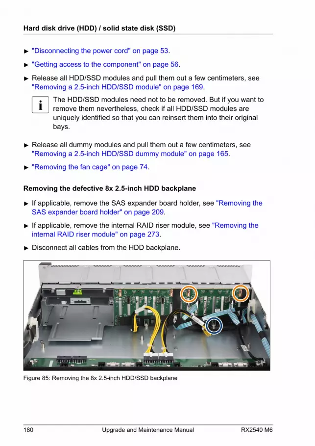
▶ "Disconnecting the power cord" on page 53.
▶ "Getting access to the component" on page 56.
▶ Release all HDD/SSD modules and pull them out a few centimeters, see"Removing a 2.5-inch HDD/SSD module" on page 169.
The HDD/SSD modules need not to be removed. But if you want toremove them nevertheless, check if all HDD/SSD modules areuniquely identified so that you can reinsert them into their originalbays.
▶ Release all dummy modules and pull them out a few centimeters, see"Removing a 2.5-inch HDD/SSD dummy module" on page 165.
▶ "Removing the fan cage" on page 74.
Removing the defective 8x 2.5-inch HDD backplane
▶ If applicable, remove the SAS expander board holder, see "Removing the SAS expander board holder" on page 209.
▶ If applicable, remove the internal RAID riser module, see "Removing the internal RAID riser module" on page 273.
▶ Disconnect all cables from the HDD backplane.
Figure 85: Removing the 8x 2.5-inch HDD/SSD backplane
Hard disk drive (HDD) / solid state disk (SSD)
180 Upgrade and Maintenance Manual RX2540 M6
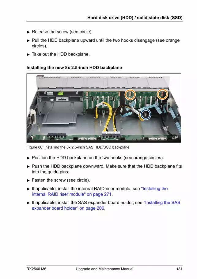
▶ Release the screw (see circle).
▶ Pull the HDD backplane upward until the two hooks disengage (see orangecircles).
▶ Take out the HDD backplane.
Installing the new 8x 2.5-inch HDD backplane
Figure 86: Installing the 8x 2.5-inch SAS HDD/SSD backplane
▶ Position the HDD backplane on the two hooks (see orange circles).
▶ Push the HDD backplane downward. Make sure that the HDD backplane fitsinto the guide pins.
▶ Fasten the screw (see circle).
▶ If applicable, install the internal RAID riser module, see "Installing the internal RAID riser module" on page 271.
▶ If applicable, install the SAS expander board holder, see "Installing the SAS expander board holder" on page 206.
Hard disk drive (HDD) / solid state disk (SSD)
RX2540 M6 Upgrade and Maintenance Manual 181

Figure 87: Connecting cables to the 8x 2.5-inch HDD backplane (example onboard SATA)
▶ Connect the following cables to the HDD backplane:
1 SAS/SATA cable 2 Power cable 3 SAS/SATA cable 4 OOB cable
For the cable plan, see "Appendix B" on page 571.
Example combo HDD backplane:
Hard disk drive (HDD) / solid state disk (SSD)
182 Upgrade and Maintenance Manual RX2540 M6
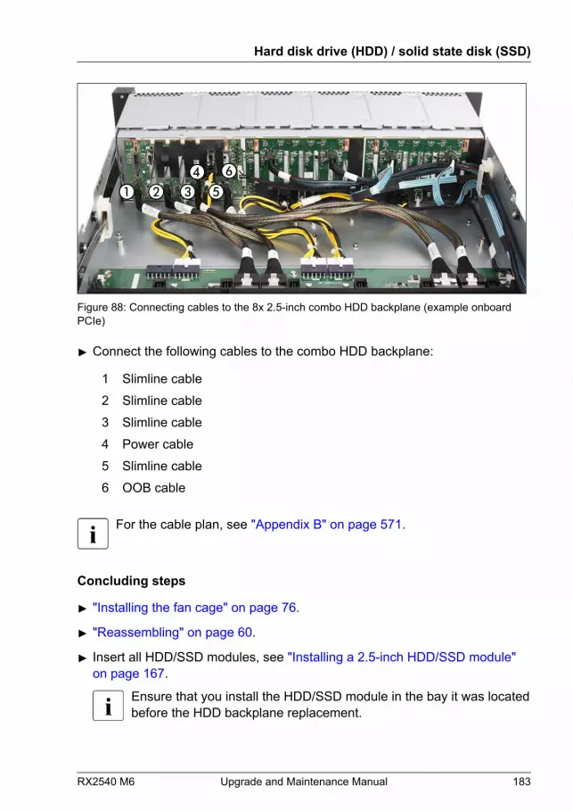
Figure 88: Connecting cables to the 8x 2.5-inch combo HDD backplane (example onboardPCIe)
▶ Connect the following cables to the combo HDD backplane:
1 Slimline cable 2 Slimline cable 3 Slimline cable 4 Power cable 5 Slimline cable 6 OOB cable
For the cable plan, see "Appendix B" on page 571.
Concluding steps
▶ "Installing the fan cage" on page 76.
▶ "Reassembling" on page 60.
▶ Insert all HDD/SSD modules, see "Installing a 2.5-inch HDD/SSD module" on page 167.
Ensure that you install the HDD/SSD module in the bay it was locatedbefore the HDD backplane replacement.
Hard disk drive (HDD) / solid state disk (SSD)
RX2540 M6 Upgrade and Maintenance Manual 183

▶ Insert all dummy modules, see "Installing a 2.5-inch HDD/SSD dummy module" on page 170.
▶ "Connecting the power cord" on page 65.
▶ "Switching on the server" on page 69.
▶ If applicable, "Installing the front cover with lock" on page 69.
7.5.9 Replacing a 24x 2.5-inch HDD backplane and aswitch board
The 24x 2.5-inch HDD backplane and the switch board are combinedinto one spare part.
Field Replaceable Unit(FRU)
Hardware: 15 minutes
Tools: Phillips PH2 / (+) No. 2 screw driver
Preliminary steps
▶ "Locating the defective server" on page 49.
▶ If applicable, "Removing the front cover with lock" on page 52.
▶ "Shutting down the server" on page 52.
▶ "Disconnecting the power cord" on page 53.
▶ "Getting access to the component" on page 56.
▶ Release all PCIe SSD modules and pull them out a few centimeters, see"Removing a 2.5-inch HDD/SSD module" on page 169.
The PCIe SSD modules need not to be removed. But if you want toremove them nevertheless, check if all PCIe SSD modules areuniquely identified so that you can reinsert them into their originalbays.
▶ Release all dummy modules and pull them out a few centimeters, see"Removing a 2.5-inch HDD/SSD dummy module" on page 165.
Hard disk drive (HDD) / solid state disk (SSD)
184 Upgrade and Maintenance Manual RX2540 M6
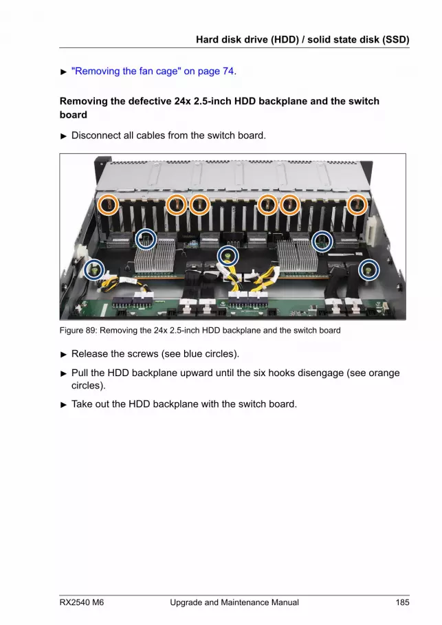
▶ "Removing the fan cage" on page 74.
Removing the defective 24x 2.5-inch HDD backplane and the switchboard
▶ Disconnect all cables from the switch board.
Figure 89: Removing the 24x 2.5-inch HDD backplane and the switch board
▶ Release the screws (see blue circles).
▶ Pull the HDD backplane upward until the six hooks disengage (see orangecircles).
▶ Take out the HDD backplane with the switch board.
Hard disk drive (HDD) / solid state disk (SSD)
RX2540 M6 Upgrade and Maintenance Manual 185
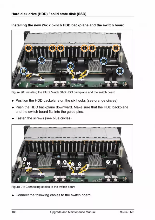
Installing the new 24x 2.5-inch HDD backplane and the switch board
Figure 90: Installing the 24x 2.5-inch SAS HDD backplane and the switch board
▶ Position the HDD backplane on the six hooks (see orange circles).
▶ Push the HDD backplane downward. Make sure that the HDD backplaneand the switch board fits into the guide pins.
▶ Fasten the screws (see blue circles).
Figure 91: Connecting cables to the switch board
▶ Connect the following cables to the switch board:
Hard disk drive (HDD) / solid state disk (SSD)
186 Upgrade and Maintenance Manual RX2540 M6
1 Signal cable 2 Power cable 3 Slimline cable 4 Slimline cable 5 Power cable 6 Power cable 7 Slimline cable 8 Slimline cable
For the cable plan, see "Appendix B" on page 571.
Concluding steps
▶ "Installing the fan cage" on page 76.
▶ "Reassembling" on page 60.
▶ Insert all PCIe SSD modules, see "Installing a 2.5-inch HDD/SSD module" on page 167.
Ensure that you install the PCIe SSD module in the bay it was locatedbefore the HDD backplane replacement.
▶ Insert all dummy modules, see "Installing the 2.5-inch HDD/SSD dummy module" on page 170.
▶ "Connecting the power cord" on page 65.
▶ "Switching on the server" on page 69.
▶ If applicable, "Installing the front cover with lock" on page 69.
Hard disk drive (HDD) / solid state disk (SSD)
RX2540 M6 Upgrade and Maintenance Manual 187
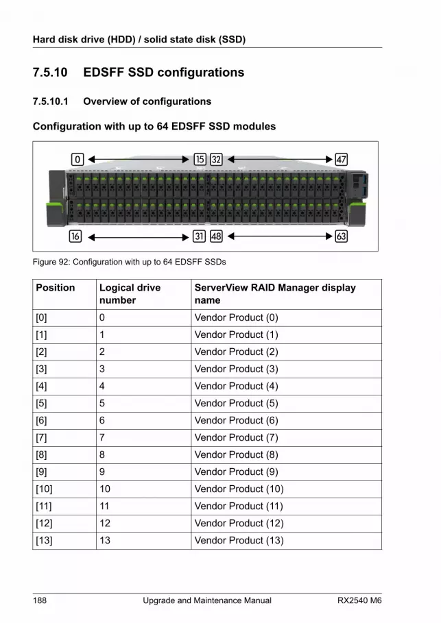
7.5.10 EDSFF SSD configurations
7.5.10.1 Overview of configurations
Configuration with up to 64 EDSFF SSD modules
Figure 92: Configuration with up to 64 EDSFF SSDs
Position Logical drivenumber
ServerView RAID Manager displayname
[0] 0 Vendor Product (0)
[1] 1 Vendor Product (1)
[2] 2 Vendor Product (2)
[3] 3 Vendor Product (3)
[4] 4 Vendor Product (4)
[5] 5 Vendor Product (5)
[6] 6 Vendor Product (6)
[7] 7 Vendor Product (7)
[8] 8 Vendor Product (8)
[9] 9 Vendor Product (9)
[10] 10 Vendor Product (10)
[11] 11 Vendor Product (11)
[12] 12 Vendor Product (12)
[13] 13 Vendor Product (13)
Hard disk drive (HDD) / solid state disk (SSD)
188 Upgrade and Maintenance Manual RX2540 M6

Position Logical drivenumber
ServerView RAID Manager displayname
[14] 14 Vendor Product (14)
[15] 15 Vendor Product (15)
[16] 16 Vendor Product (16)
[17] 17 Vendor Product (17)
[18] 18 Vendor Product (18)
[19] 19 Vendor Product (19)
[20] 20 Vendor Product (20)
[21] 21 Vendor Product (21)
[22] 22 Vendor Product (22)
[23] 23 Vendor Product (23)
[24] 24 Vendor Product (24)
[25] 25 Vendor Product (25)
[26] 26 Vendor Product (26)
[27] 27 Vendor Product (27)
[28] 28 Vendor Product (28)
[29] 29 Vendor Product (29)
[30] 30 Vendor Product (30)
[31] 31 Vendor Product (31)
[32] 32 Vendor Product (32)
[33] 33 Vendor Product (33)
[34] 34 Vendor Product (34)
[35] 35 Vendor Product (35)
[36] 36 Vendor Product (36)
[37] 37 Vendor Product (37)
[38] 38 Vendor Product (38)
[39] 39 Vendor Product (39)
[40] 40 Vendor Product (40)
Hard disk drive (HDD) / solid state disk (SSD)
RX2540 M6 Upgrade and Maintenance Manual 189
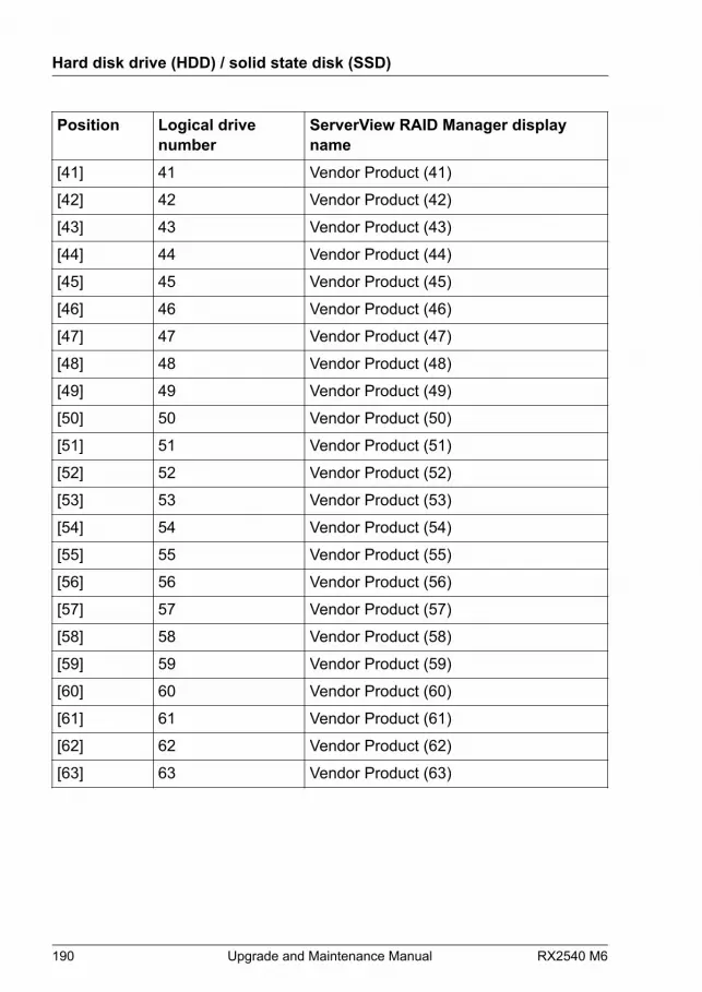
Position Logical drivenumber
ServerView RAID Manager displayname
[41] 41 Vendor Product (41)
[42] 42 Vendor Product (42)
[43] 43 Vendor Product (43)
[44] 44 Vendor Product (44)
[45] 45 Vendor Product (45)
[46] 46 Vendor Product (46)
[47] 47 Vendor Product (47)
[48] 48 Vendor Product (48)
[49] 49 Vendor Product (49)
[50] 50 Vendor Product (50)
[51] 51 Vendor Product (51)
[52] 52 Vendor Product (52)
[53] 53 Vendor Product (53)
[54] 54 Vendor Product (54)
[55] 55 Vendor Product (55)
[56] 56 Vendor Product (56)
[57] 57 Vendor Product (57)
[58] 58 Vendor Product (58)
[59] 59 Vendor Product (59)
[60] 60 Vendor Product (60)
[61] 61 Vendor Product (61)
[62] 62 Vendor Product (62)
[63] 63 Vendor Product (63)
Hard disk drive (HDD) / solid state disk (SSD)
190 Upgrade and Maintenance Manual RX2540 M6
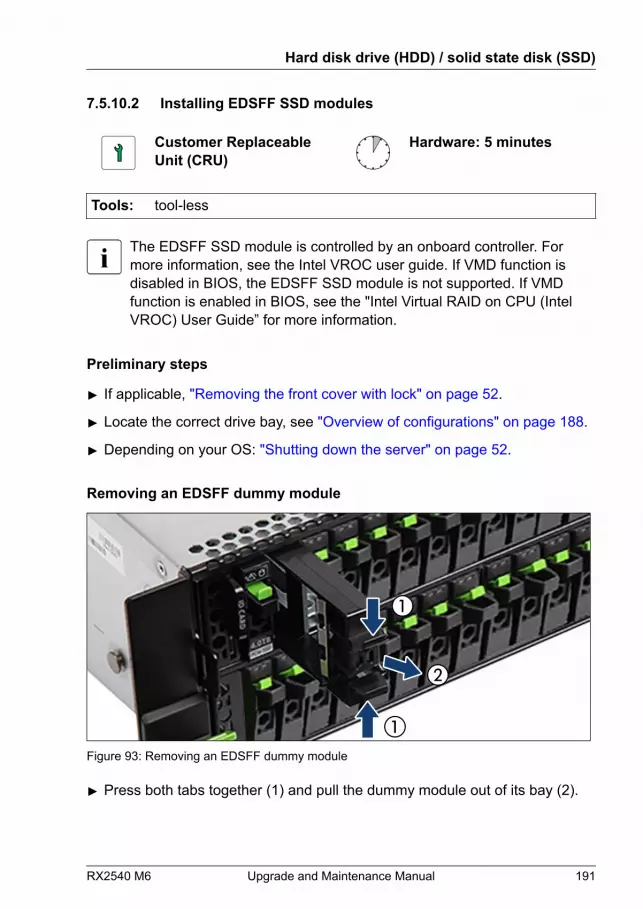
7.5.10.2 Installing EDSFF SSD modules
Customer ReplaceableUnit (CRU)
Hardware: 5 minutes
Tools: tool-less
The EDSFF SSD module is controlled by an onboard controller. Formore information, see the Intel VROC user guide. If VMD function isdisabled in BIOS, the EDSFF SSD module is not supported. If VMDfunction is enabled in BIOS, see the "Intel Virtual RAID on CPU (IntelVROC) User Guide” for more information.
Preliminary steps
▶ If applicable, "Removing the front cover with lock" on page 52.
▶ Locate the correct drive bay, see "Overview of configurations" on page 188.
▶ Depending on your OS: "Shutting down the server" on page 52.
Removing an EDSFF dummy module
Figure 93: Removing an EDSFF dummy module
▶ Press both tabs together (1) and pull the dummy module out of its bay (2).
Hard disk drive (HDD) / solid state disk (SSD)
RX2540 M6 Upgrade and Maintenance Manual 191

CAUTION▶ Keep the dummy module for future use.▶ Always replace dummy modules into unused HDD/SSD bays to
comply with applicable EMC regulations and satisfy coolingrequirements.
Installing an EDSFF SSD module
Figure 94: Opening the locking lever
▶ Pinch the green locking clips (1) and open the locking lever (2).
Hard disk drive (HDD) / solid state disk (SSD)
192 Upgrade and Maintenance Manual RX2540 M6

Figure 95: Installing the EDSFF SSD module
▶ Insert the EDSFF SSD module into a drive bay and carefully push back asfar as it will go (1).
▶ Close the locking lever to lock the EDSFF SSD module in place (2).
Concluding steps
▶ If applicable, "Switching on the server" on page 69.
▶ If applicable, rescan available devices from your OS.
▶ If applicable, "Installing the front cover with lock" on page 69.
7.5.10.3 Removing EDSFF SSD modules
Customer ReplaceableUnit (CRU)
Hardware: 5 minutes
Tools: tool-less
The EDSFF SSD module is controlled by an onboard controller. Formore information, see the Intel VROC user guide. If VMD function isdisabled in BIOS, the EDSFF SSD module is not supported. If VMDfunction is enabled in BIOS, see the "Intel Virtual RAID on CPU (IntelVROC) User Guide” for more information.
Hard disk drive (HDD) / solid state disk (SSD)
RX2540 M6 Upgrade and Maintenance Manual 193

Preliminary steps
▶ If applicable, "Removing the front cover with lock" on page 52.
▶ Identify the physical location of the EDSFF SSD module, see "Overview of configurations" on page 188.
▶ Prepare the removing of the EDSFF SSD module.
▶ Depending on your OS: "Shutting down the server" on page 52.
Removing an EDSFF SSD module
Figure 96: Opening the locking lever
▶ Pinch the green locking clips (1) and open the locking lever (2).
▶ Pull the EDSFF SSD module completely out of its bay.
Hard disk drive (HDD) / solid state disk (SSD)
194 Upgrade and Maintenance Manual RX2540 M6
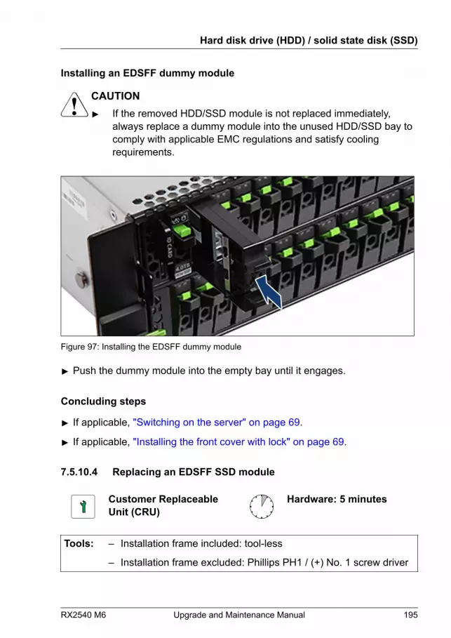
Installing an EDSFF dummy module
CAUTION▶ If the removed HDD/SSD module is not replaced immediately,
always replace a dummy module into the unused HDD/SSD bay tocomply with applicable EMC regulations and satisfy coolingrequirements.
Figure 97: Installing the EDSFF dummy module
▶ Push the dummy module into the empty bay until it engages.
Concluding steps
▶ If applicable, "Switching on the server" on page 69.
▶ If applicable, "Installing the front cover with lock" on page 69.
7.5.10.4 Replacing an EDSFF SSD module
Customer ReplaceableUnit (CRU)
Hardware: 5 minutes
Tools: – Installation frame included: tool-less
– Installation frame excluded: Phillips PH1 / (+) No. 1 screw driver
Hard disk drive (HDD) / solid state disk (SSD)
RX2540 M6 Upgrade and Maintenance Manual 195
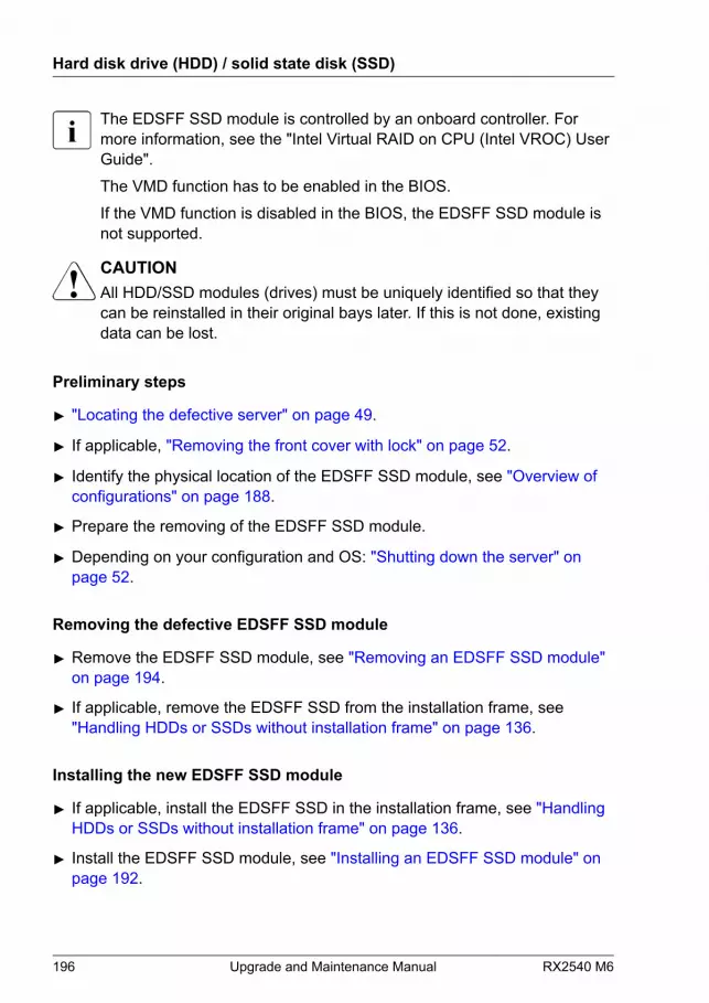
The EDSFF SSD module is controlled by an onboard controller. Formore information, see the "Intel Virtual RAID on CPU (Intel VROC) UserGuide".The VMD function has to be enabled in the BIOS.If the VMD function is disabled in the BIOS, the EDSFF SSD module isnot supported.
CAUTIONAll HDD/SSD modules (drives) must be uniquely identified so that theycan be reinstalled in their original bays later. If this is not done, existingdata can be lost.
Preliminary steps
▶ "Locating the defective server" on page 49.
▶ If applicable, "Removing the front cover with lock" on page 52.
▶ Identify the physical location of the EDSFF SSD module, see "Overview of configurations" on page 188.
▶ Prepare the removing of the EDSFF SSD module.
▶ Depending on your configuration and OS: "Shutting down the server" on page 52.
Removing the defective EDSFF SSD module
▶ Remove the EDSFF SSD module, see "Removing an EDSFF SSD module" on page 194.
▶ If applicable, remove the EDSFF SSD from the installation frame, see"Handling HDDs or SSDs without installation frame" on page 136.
Installing the new EDSFF SSD module
▶ If applicable, install the EDSFF SSD in the installation frame, see "Handling HDDs or SSDs without installation frame" on page 136.
▶ Install the EDSFF SSD module, see "Installing an EDSFF SSD module" on page 192.
Hard disk drive (HDD) / solid state disk (SSD)
196 Upgrade and Maintenance Manual RX2540 M6

Concluding steps
▶ If applicable, "Switching on the server" on page 69.
▶ If applicable, rescan available devices from your OS.
▶ If applicable, "Installing the front cover with lock" on page 69.
7.5.10.5 Replacing a 16x EDSFF SSD backplane (top)
Field Replaceable Unit(FRU)
Hardware: 10 minutes
Tools: Phillips PH2 / (+) No. 2 screw driver
Preliminary steps
▶ "Locating the defective server" on page 49.
▶ If applicable, "Removing the front cover with lock" on page 52.
▶ "Shutting down the server" on page 52.
▶ "Disconnecting the power cord" on page 53.
▶ "Getting access to the component" on page 56.
▶ Release all EDSFF SSD modules and pull them out a few centimeters, see"Removing an EDSFF SSD module" on page 194.
CAUTIONThe HDD/SSD modules need not to be removed.▶ If you want to remove them nevertheless, check if all HDD/SSD
modules are uniquely identified so that you can reinsert theminto their original bays.
▶ Release all dummy modules and pull them out a few centimeters, see"Removing an EDSFF dummy module" on page 191.
▶ "Removing the fan cage" on page 74.
Hard disk drive (HDD) / solid state disk (SSD)
RX2540 M6 Upgrade and Maintenance Manual 197
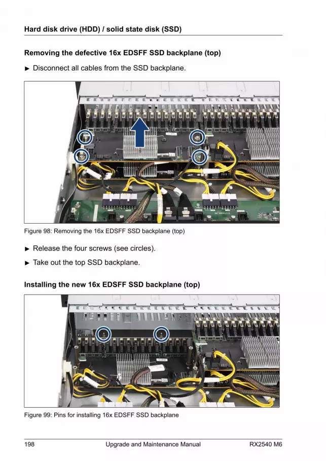
Removing the defective 16x EDSFF SSD backplane (top)
▶ Disconnect all cables from the SSD backplane.
Figure 98: Removing the 16x EDSFF SSD backplane (top)
▶ Release the four screws (see circles).
▶ Take out the top SSD backplane.
Installing the new 16x EDSFF SSD backplane (top)
Figure 99: Pins for installing 16x EDSFF SSD backplane
Hard disk drive (HDD) / solid state disk (SSD)
198 Upgrade and Maintenance Manual RX2540 M6

▶ Notice the two guide pins (see circles).
Figure 100: Installing the 16x EDSFF SSD backplane (top)
▶ Position the SSD backplane on the four hexagon standoffs and the twoguide pins.
CAUTION▶ Ensure that none of the cables are strained or damaged!
▶ Fasten the four screws (see circles).
Hard disk drive (HDD) / solid state disk (SSD)
RX2540 M6 Upgrade and Maintenance Manual 199
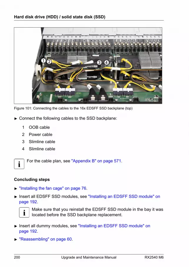
Figure 101: Connecting the cables to the 16x EDSFF SSD backplane (top)
▶ Connect the following cables to the SSD backplane:
1 OOB cable 2 Power cable 3 Slimline cable 4 Slimline cable
For the cable plan, see "Appendix B" on page 571.
Concluding steps
▶ "Installing the fan cage" on page 76.
▶ Insert all EDSFF SSD modules, see "Installing an EDSFF SSD module" on page 192.
Make sure that you reinstall the EDSFF SSD module in the bay it waslocated before the SSD backplane replacement.
▶ Insert all dummy modules, see "Installing an EDSFF SSD module" on page 192.
▶ "Reassembling" on page 60.
Hard disk drive (HDD) / solid state disk (SSD)
200 Upgrade and Maintenance Manual RX2540 M6

▶ "Connecting the power cord" on page 65.
▶ "Switching on the server" on page 69.
▶ If applicable, "Installing the front cover with lock" on page 69.
7.5.10.6 Replacing a 16x EDSFF SSD backplane (bottom)
Field Replaceable Unit(FRU)
Hardware: 10 minutes
Tools:– Phillips PH2 / (+) No. 2 screw driver
– Hexagon screw driver 7 mm
Preliminary steps
▶ "Locating the defective server" on page 49.
▶ If applicable, "Removing the front cover with lock" on page 52.
▶ "Shutting down the server" on page 52.
▶ "Disconnecting the power cord" on page 53.
▶ "Getting access to the component" on page 56.
▶ Release all EDSFF SSD modules and pull them out a few centimeters, see"Removing an EDSFF SSD module" on page 194.
CAUTIONThe HDD/SSD modules need not to be removed.▶ If you want to remove them nevertheless, check if all HDD/SSD
modules are uniquely identified so that you can reinsert theminto their original bays.
▶ Release all dummy modules and pull them out a few centimeters, see"Removing an EDSFF dummy module" on page 191.
▶ "Removing the fan cage" on page 74.
Hard disk drive (HDD) / solid state disk (SSD)
RX2540 M6 Upgrade and Maintenance Manual 201

Removing the defective 16x EDSFF SSD backplane (bottom)
▶ Remove the top SSD backplane, see "Removing the defective 16x EDSFF SSD backplane (top)" on page 198.
▶ Disconnect all cables from the SSD backplane (see circles).
Figure 102: Removing the 16x EDSFF SSD backplane (bottom)
▶ Remove the four hexagon standoffs (see circles).
▶ Take out the SSD backplane.
Installing the new 16x EDSFF SSD backplane (bottom)
Figure 103: Bolts for 16x EDSFF SSD backplane (bottom)
Hard disk drive (HDD) / solid state disk (SSD)
202 Upgrade and Maintenance Manual RX2540 M6
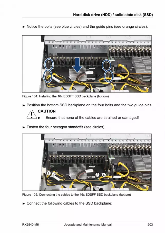
▶ Notice the bolts (see blue circles) and the guide pins (see orange circles).
Figure 104: Installing the 16x EDSFF SSD backplane (bottom)
▶ Position the bottom SSD backplane on the four bolts and the two guide pins.CAUTION▶ Ensure that none of the cables are strained or damaged!
▶ Fasten the four hexagon standoffs (see circles).
Figure 105: Connecting the cables to the 16x EDSFF SSD backplane (bottom)
▶ Connect the following cables to the SSD backplane:
Hard disk drive (HDD) / solid state disk (SSD)
RX2540 M6 Upgrade and Maintenance Manual 203

1 OOB cable 2 Power cable 3 Slimline cable 4 Slimline cable
For the cable plan, see "Appendix B" on page 571.
▶ Install the top SSD backplane, see "Installing the new 16x EDSFF SSD backplane (top)" on page 198.
Concluding steps
▶ "Installing the fan cage" on page 76.
▶ Insert all EDSFF SSD modules, see "Installing an EDSFF SSD module" on page 192.
Make sure that you reinstall the EDSFF SSD module in the bay it waslocated before the SSD backplane replacement.
▶ Insert all dummy modules, see "Installing an EDSFF SSD module" on page 192.
▶ "Reassembling" on page 60.
▶ "Connecting the power cord" on page 65.
▶ "Switching on the server" on page 69.
▶ If applicable, "Installing the front cover with lock" on page 69.
7.6 SAS expander board
7.6.1 Installing the SAS expander board
The SAS expander board is an option for the 12x 3.5-inch HDDconfiguration, the 16x 2.5-inch HDD/SSD configuration and the 24x 2.5-inch HDD/SSD configuration.
Hard disk drive (HDD) / solid state disk (SSD)
204 Upgrade and Maintenance Manual RX2540 M6
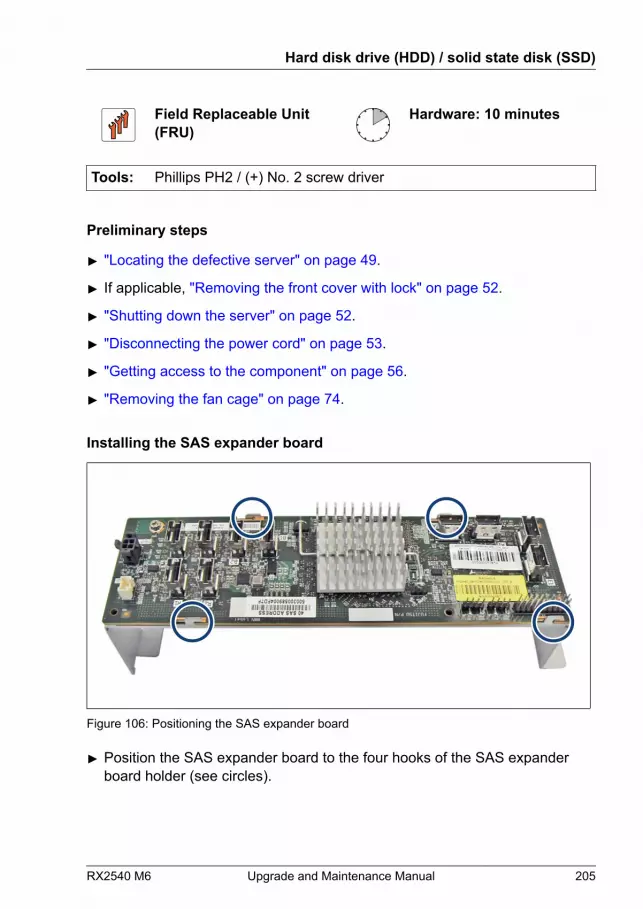
Field Replaceable Unit(FRU)
Hardware: 10 minutes
Tools: Phillips PH2 / (+) No. 2 screw driver
Preliminary steps
▶ "Locating the defective server" on page 49.
▶ If applicable, "Removing the front cover with lock" on page 52.
▶ "Shutting down the server" on page 52.
▶ "Disconnecting the power cord" on page 53.
▶ "Getting access to the component" on page 56.
▶ "Removing the fan cage" on page 74.
Installing the SAS expander board
Figure 106: Positioning the SAS expander board
▶ Position the SAS expander board to the four hooks of the SAS expanderboard holder (see circles).
Hard disk drive (HDD) / solid state disk (SSD)
RX2540 M6 Upgrade and Maintenance Manual 205
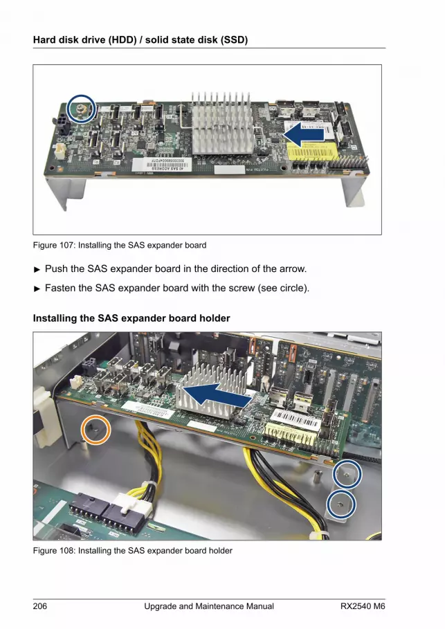
Figure 107: Installing the SAS expander board
▶ Push the SAS expander board in the direction of the arrow.
▶ Fasten the SAS expander board with the screw (see circle).
Installing the SAS expander board holder
Figure 108: Installing the SAS expander board holder
Hard disk drive (HDD) / solid state disk (SSD)
206 Upgrade and Maintenance Manual RX2540 M6
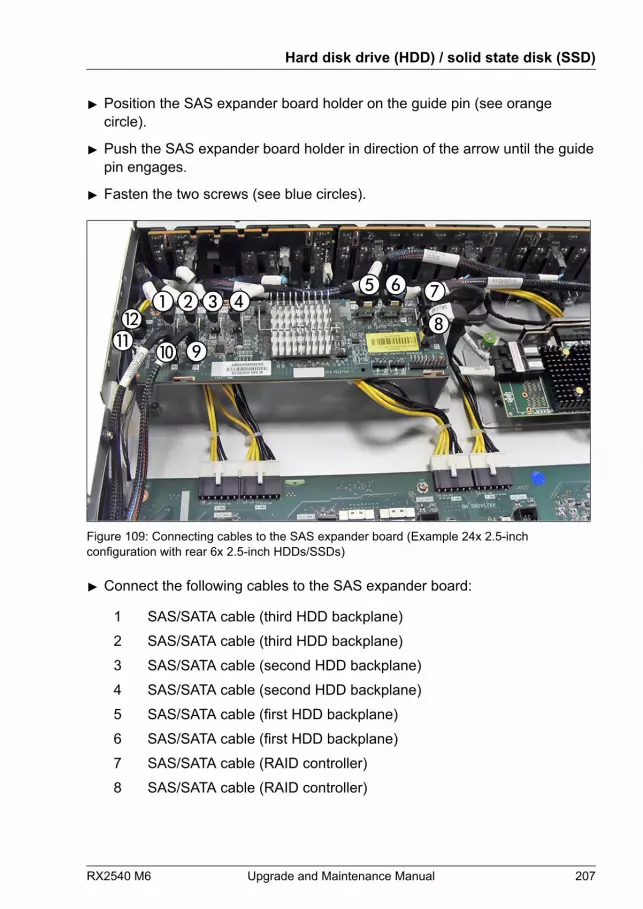
▶ Position the SAS expander board holder on the guide pin (see orangecircle).
▶ Push the SAS expander board holder in direction of the arrow until the guidepin engages.
▶ Fasten the two screws (see blue circles).
Figure 109: Connecting cables to the SAS expander board (Example 24x 2.5-inchconfiguration with rear 6x 2.5-inch HDDs/SSDs)
▶ Connect the following cables to the SAS expander board:
1 SAS/SATA cable (third HDD backplane) 2 SAS/SATA cable (third HDD backplane) 3 SAS/SATA cable (second HDD backplane) 4 SAS/SATA cable (second HDD backplane) 5 SAS/SATA cable (first HDD backplane) 6 SAS/SATA cable (first HDD backplane) 7 SAS/SATA cable (RAID controller) 8 SAS/SATA cable (RAID controller)
Hard disk drive (HDD) / solid state disk (SSD)
RX2540 M6 Upgrade and Maintenance Manual 207

9 SAS/SATA cable (rear HDD backplane) 10 SAS/SATA cable (rear HDD backplane) 11 Signal cable 12 Power cable
For the cable plan, see "Appendix B" on page 571.
Concluding steps
▶ "Installing the fan cage" on page 76.
▶ "Reassembling" on page 60.
▶ "Connecting the power cord" on page 65.
▶ "Switching on the server" on page 69.
▶ If applicable,"Installing the front cover with lock" on page 69.
7.6.2 Removing the SAS expander board
Field Replaceable Unit(FRU)
Hardware: 10 minutes
Tools: Phillips PH2 / (+) No. 2 screw driver
Preliminary steps
▶ "Locating the defective server" on page 49.
▶ If applicable, "Removing the front cover with lock" on page 52.
▶ "Shutting down the server" on page 52.
▶ "Disconnecting the power cord" on page 53.
▶ "Getting access to the component" on page 56.
▶ "Removing the fan cage" on page 74.
Hard disk drive (HDD) / solid state disk (SSD)
208 Upgrade and Maintenance Manual RX2540 M6

Removing the SAS expander board holder
▶ Disconnect all cables from the SAS expander board.
Figure 110: Removing the SAS expander board holder
▶ Remove the two screws (see circles).
▶ Push the SAS expander board holder in direction of the arrow until the guidepin disengages (see close-up).
▶ Remove the SAS expander board holder.
Hard disk drive (HDD) / solid state disk (SSD)
RX2540 M6 Upgrade and Maintenance Manual 209
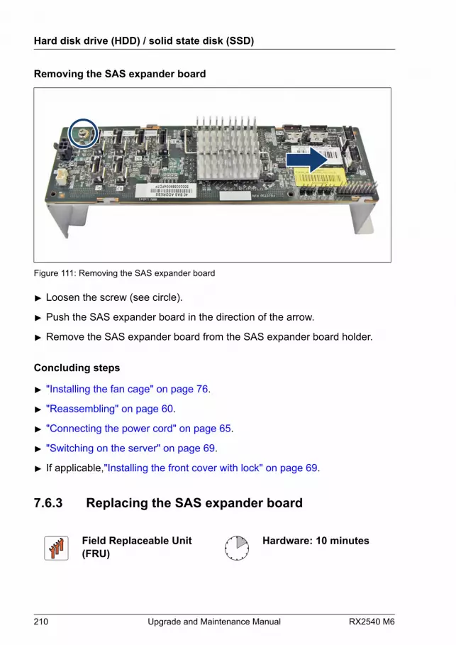
Removing the SAS expander board
Figure 111: Removing the SAS expander board
▶ Loosen the screw (see circle).
▶ Push the SAS expander board in the direction of the arrow.
▶ Remove the SAS expander board from the SAS expander board holder.
Concluding steps
▶ "Installing the fan cage" on page 76.
▶ "Reassembling" on page 60.
▶ "Connecting the power cord" on page 65.
▶ "Switching on the server" on page 69.
▶ If applicable,"Installing the front cover with lock" on page 69.
7.6.3 Replacing the SAS expander board
Field Replaceable Unit(FRU)
Hardware: 10 minutes
Hard disk drive (HDD) / solid state disk (SSD)
210 Upgrade and Maintenance Manual RX2540 M6
Tools: Phillips PH2 / (+) No. 2 screw driver
Preliminary steps
▶ "Locating the defective server" on page 49.
▶ If applicable, "Removing the front cover with lock" on page 52.
▶ "Shutting down the server" on page 52.
▶ "Disconnecting the power cord" on page 53.
▶ "Getting access to the component" on page 56.
▶ "Removing the fan cage" on page 74.
Removing the defective SAS expander board
▶ Disconnect all cables from the SAS expander board.
▶ Remove the SAS expander board, see "Removing the SAS expander board" on page 210.
Installing the new SAS expander board
▶ Install the SAS expander board, see "Installing the SAS expander board" on page 205.
▶ Connect the cables to the SAS expander board, see Figure 109.
Concluding steps
▶ "Installing the fan cage" on page 76.
▶ "Reassembling" on page 60.
▶ "Connecting the power cord" on page 65.
▶ "Switching on the server" on page 69.
▶ If applicable,"Installing the front cover with lock" on page 69.
Hard disk drive (HDD) / solid state disk (SSD)
RX2540 M6 Upgrade and Maintenance Manual 211
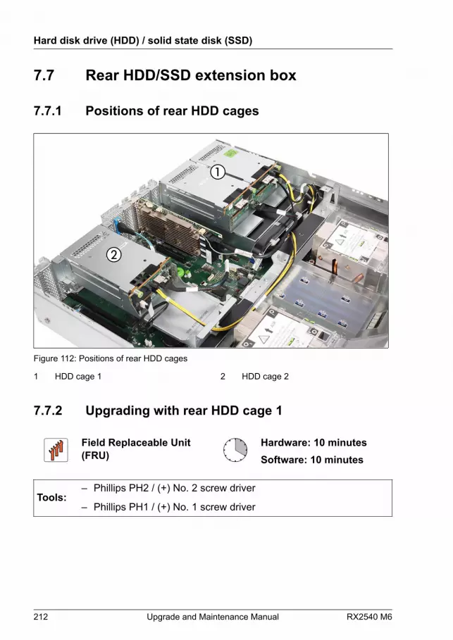
7.7 Rear HDD/SSD extension box
7.7.1 Positions of rear HDD cages
Figure 112: Positions of rear HDD cages
1 HDD cage 1 2 HDD cage 2
7.7.2 Upgrading with rear HDD cage 1
Field Replaceable Unit(FRU)
Hardware: 10 minutesSoftware: 10 minutes
Tools:– Phillips PH2 / (+) No. 2 screw driver
– Phillips PH1 / (+) No. 1 screw driver
Hard disk drive (HDD) / solid state disk (SSD)
212 Upgrade and Maintenance Manual RX2540 M6
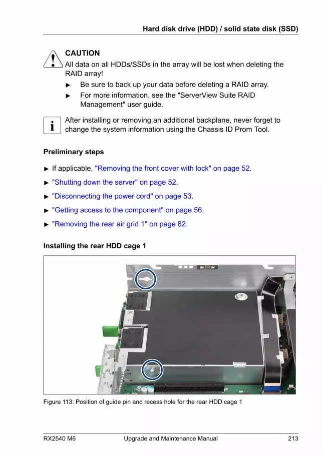
CAUTIONAll data on all HDDs/SSDs in the array will be lost when deleting theRAID array!▶ Be sure to back up your data before deleting a RAID array.▶ For more information, see the "ServerView Suite RAID
Management" user guide.
After installing or removing an additional backplane, never forget tochange the system information using the Chassis ID Prom Tool.
Preliminary steps
▶ If applicable, "Removing the front cover with lock" on page 52.
▶ "Shutting down the server" on page 52.
▶ "Disconnecting the power cord" on page 53.
▶ "Getting access to the component" on page 56.
▶ "Removing the rear air grid 1" on page 82.
Installing the rear HDD cage 1
Figure 113: Position of guide pin and recess hole for the rear HDD cage 1
Hard disk drive (HDD) / solid state disk (SSD)
RX2540 M6 Upgrade and Maintenance Manual 213

▶ Notice the guide pin on the PSU cage and the recess hole on the chassis(see circles).
Figure 114: Installing the rear HDD cage 1
▶ Position the rear HDD cage into the chassis (1).
▶ Push the rear HDD cage in the direction of the arrow (2) until the hook (seeorange circle) fit in place.
▶ Fasten the screw (3, see blue circle).
▶ If applicable, install a RAID controller or a retimer card, see "Installing an expansion card" on page 255.
Hard disk drive (HDD) / solid state disk (SSD)
214 Upgrade and Maintenance Manual RX2540 M6

Figure 115: Connecting the cables to the rear HDD backplane (example with SATA cable)
▶ Connect the following cables to the rear HDD backplane:
1 Power cable to HDD backplane and connector "PWR9" on systemboard
2 OOB cable to HDD backplane and connector "SMB3" on systemboard
3 SAS/SATA cable depending on configuration
For the cable plan, see chapter "Appendix B" on page 571.
Hard disk drive (HDD) / solid state disk (SSD)
RX2540 M6 Upgrade and Maintenance Manual 215

Figure 116: Connecting the cables to the rear HDD backplane (example with slimline cable)
▶ Connect the following cables to the rear HDD backplane:
1 Power cable to HDD backplane and connector "PWR9" on systemboard
2 OOB cable to HDD backplane and connector "SMB3" on systemboard
3 Slimline cable depending on configuration
For the cable plan, see chapter "Appendix B" on page 571.
Installing additional HDD/SSD/PCIe SSD modules
▶ Insert additional HDD/SSD modules, see "Installing 2.5-inch HDD/SSD modules" on page 165 or PCIe SSD modules, see "Installing 2.5-inch PCIe SSD modules" on page 172.
Hard disk drive (HDD) / solid state disk (SSD)
216 Upgrade and Maintenance Manual RX2540 M6
Concluding steps
▶ "Reassembling" on page 60.
▶ "Connecting the power cord" on page 65.
▶ "Switching on the server" on page 69.
▶ If applicable, "Installing the front cover with lock" on page 69.
▶ Update the system information of your server using the Chassis ID PromTool, see "Using the Chassis ID Prom Tool" on page 110. Select thecorresponding system name.
▶ "Performing a RAID array rebuild" on page 106.
7.7.3 Upgrading with rear HDD cage 2
Field Replaceable Unit(FRU)
Hardware: 10 minutesSoftware: 10 minutes
Tools:– Phillips PH2 / (+) No. 2 screw driver
– Phillips PH1 / (+) No. 1 screw driver
CAUTIONAll data on all HDDs/SSDs in the array will be lost when deleting theRAID array!▶ Be sure to back up your data before deleting a RAID array.▶ For more information, see the "ServerView Suite RAID
Management" user guide.
After installing or removing an additional backplane, never forget tochange the system information using the Chassis ID Prom Tool.
Preliminary steps
▶ If applicable, "Removing the front cover with lock" on page 52.
▶ "Shutting down the server" on page 52.
▶ "Disconnecting the power cord" on page 53.
Hard disk drive (HDD) / solid state disk (SSD)
RX2540 M6 Upgrade and Maintenance Manual 217

▶ "Getting access to the component" on page 56.
▶ "Removing the rear air grid 2" on page 83.
Installing the rear HDD cage 2
Figure 117: Position of the recess holes and guiding pins of the HDD cage
▶ Notice the two recess holes on the chassis and the two guiding pins on theHDD cage (see circles).
Figure 118: Installing the rear HDD cage
Hard disk drive (HDD) / solid state disk (SSD)
218 Upgrade and Maintenance Manual RX2540 M6
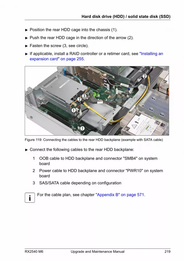
▶ Position the rear HDD cage into the chassis (1).
▶ Push the rear HDD cage in the direction of the arrow (2).
▶ Fasten the screw (3, see circle).
▶ If applicable, install a RAID controller or a retimer card, see "Installing an expansion card" on page 255.
Figure 119: Connecting the cables to the rear HDD backplane (example with SATA cable)
▶ Connect the following cables to the rear HDD backplane:
1 OOB cable to HDD backplane and connector "SMB4" on systemboard
2 Power cable to HDD backplane and connector "PWR10" on systemboard
3 SAS/SATA cable depending on configuration
For the cable plan, see chapter "Appendix B" on page 571.
Hard disk drive (HDD) / solid state disk (SSD)
RX2540 M6 Upgrade and Maintenance Manual 219
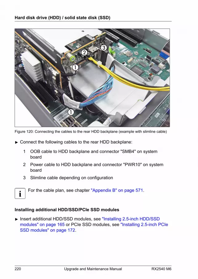
Figure 120: Connecting the cables to the rear HDD backplane (example with slimline cable)
▶ Connect the following cables to the rear HDD backplane:
1 OOB cable to HDD backplane and connector "SMB4" on systemboard
2 Power cable to HDD backplane and connector "PWR10" on systemboard
3 Slimline cable depending on configuration
For the cable plan, see chapter "Appendix B" on page 571.
Installing additional HDD/SSD/PCIe SSD modules
▶ Insert additional HDD/SSD modules, see "Installing 2.5-inch HDD/SSD modules" on page 165 or PCIe SSD modules, see "Installing 2.5-inch PCIe SSD modules" on page 172.
Hard disk drive (HDD) / solid state disk (SSD)
220 Upgrade and Maintenance Manual RX2540 M6
Concluding steps
▶ "Reassembling" on page 60.
▶ "Connecting the power cord" on page 65.
▶ "Switching on the server" on page 69.
▶ If applicable, "Installing the front cover with lock" on page 69.
▶ Update the system information of your server using the Chassis ID PromTool, see "Using the Chassis ID Prom Tool" on page 110. Select thecorresponding system name.
▶ "Performing a RAID array rebuild" on page 106.
7.7.4 Replacing a rear 4x 2.5-inch HDD backplane
Field Replaceable Unit(FRU)
Hardware: 10 minutes
Tools: Phillips PH2 / (+) No. 2 screw driver
Preliminary steps
▶ "Locating the defective server" on page 49.
▶ If applicable, "Removing the front cover with lock" on page 52.
▶ "Shutting down the server" on page 52.
▶ "Disconnecting the power cord" on page 53.
▶ "Getting access to the component" on page 56.
▶ Release all HDD/SSD modules and pull them out a few centimeters, see"Removing a 2.5-inch HDD/SSD module" on page 169.
The HDD/SSD modules need not to be removed. But if you want toremove them nevertheless, check if all HDD/SSD modules areuniquely identified so that you can reinsert them into their originalbays.
Hard disk drive (HDD) / solid state disk (SSD)
RX2540 M6 Upgrade and Maintenance Manual 221
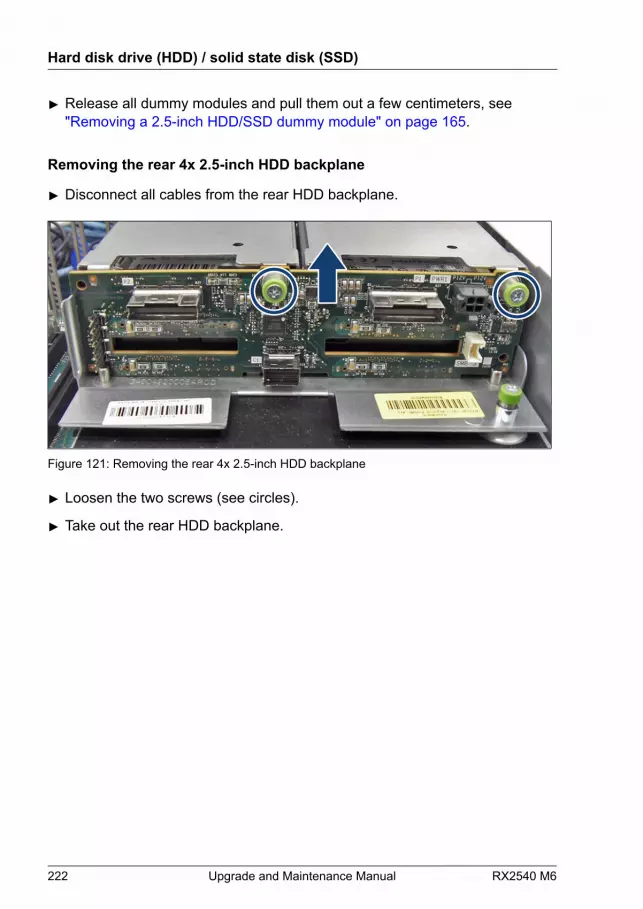
▶ Release all dummy modules and pull them out a few centimeters, see"Removing a 2.5-inch HDD/SSD dummy module" on page 165.
Removing the rear 4x 2.5-inch HDD backplane
▶ Disconnect all cables from the rear HDD backplane.
Figure 121: Removing the rear 4x 2.5-inch HDD backplane
▶ Loosen the two screws (see circles).
▶ Take out the rear HDD backplane.
Hard disk drive (HDD) / solid state disk (SSD)
222 Upgrade and Maintenance Manual RX2540 M6

Installing the rear 4x 2.5-inch HDD backplane
Figure 122: Installing the rear 4x 2.5-inch HDD backplane
▶ Position the rear HDD backplane.
▶ Fasten the screw (see circle).
▶ Connect the cables to the rear HDD backplane, see Figure 115 orFigure 116.
Concluding steps
▶ Insert all HDD/SSD modules, see "Installing a 2.5-inch HDD/SSD module" on page 167.
Ensure that you install the HDD/SSD module in the bay it was locatedbefore the HDD backplane replacement.
▶ Insert all dummy modules, see "Installing a 2.5-inch HDD/SSD dummy module" on page 170.
▶ "Reassembling" on page 60.
▶ "Connecting the power cord" on page 65.
▶ "Switching on the server" on page 69.
▶ If applicable, "Installing the front cover with lock" on page 69.
Hard disk drive (HDD) / solid state disk (SSD)
RX2540 M6 Upgrade and Maintenance Manual 223
7.7.5 Replacing a rear 2x 2.5-inch HDD backplane
Field Replaceable Unit(FRU)
Hardware: 10 minutes
Tools: Phillips PH2 / (+) No. 2 screw driver
Preliminary steps
▶ "Locating the defective server" on page 49.
▶ If applicable, "Removing the front cover with lock" on page 52.
▶ "Shutting down the server" on page 52.
▶ "Disconnecting the power cord" on page 53.
▶ "Getting access to the component" on page 56.
▶ Release all HDD/SSD modules and pull them out a few centimeters, see"Removing a 2.5-inch HDD/SSD module" on page 169.
The HDD/SSD modules need not to be removed. But if you want toremove them nevertheless, check if all HDD/SSD modules areuniquely identified so that you can reinsert them into their originalbays.
▶ Release all dummy modules and pull them out a few centimeters, see"Removing a 2.5-inch HDD/SSD dummy module" on page 165.
Removing the rear 2x 2.5-inch HDD backplane
▶ Disconnect all cables from the rear HDD backplane.
Hard disk drive (HDD) / solid state disk (SSD)
224 Upgrade and Maintenance Manual RX2540 M6
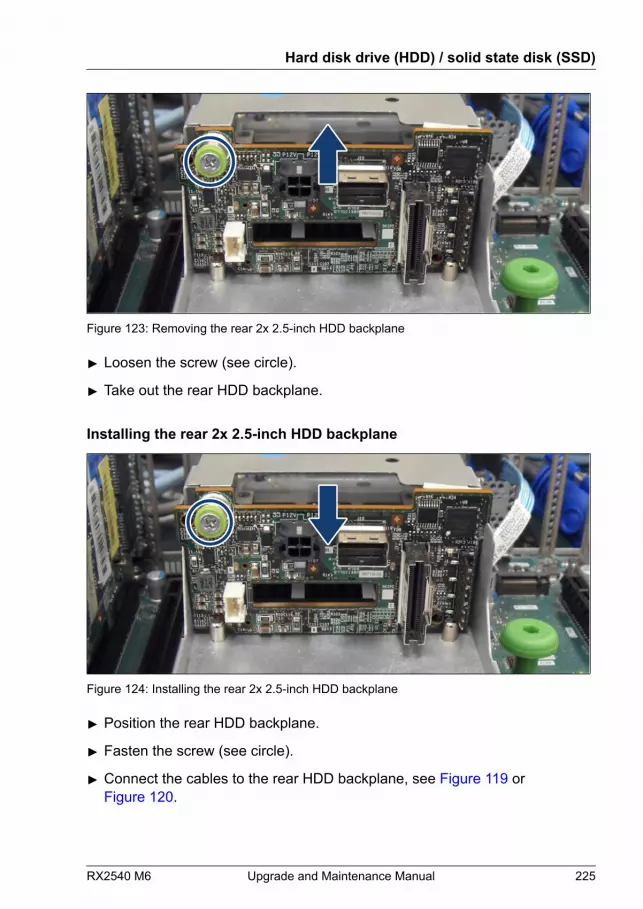
Figure 123: Removing the rear 2x 2.5-inch HDD backplane
▶ Loosen the screw (see circle).
▶ Take out the rear HDD backplane.
Installing the rear 2x 2.5-inch HDD backplane
Figure 124: Installing the rear 2x 2.5-inch HDD backplane
▶ Position the rear HDD backplane.
▶ Fasten the screw (see circle).
▶ Connect the cables to the rear HDD backplane, see Figure 119 orFigure 120.
Hard disk drive (HDD) / solid state disk (SSD)
RX2540 M6 Upgrade and Maintenance Manual 225
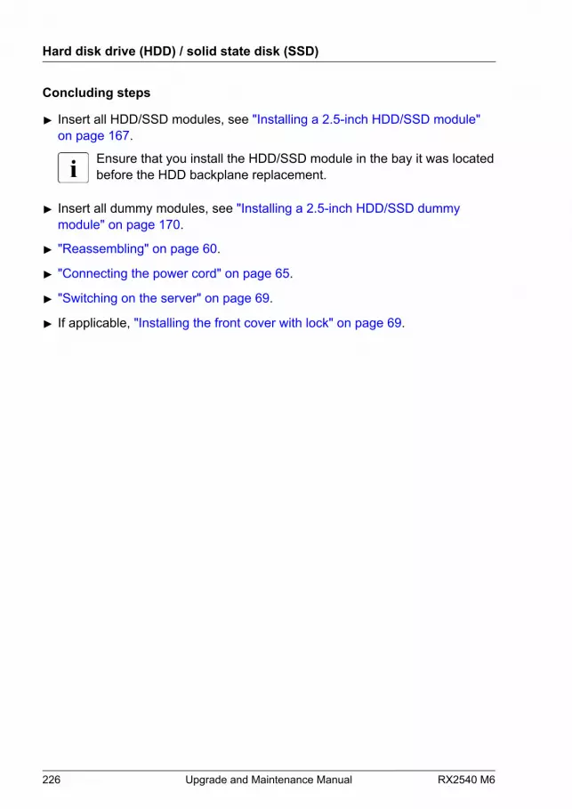
Concluding steps
▶ Insert all HDD/SSD modules, see "Installing a 2.5-inch HDD/SSD module" on page 167.
Ensure that you install the HDD/SSD module in the bay it was locatedbefore the HDD backplane replacement.
▶ Insert all dummy modules, see "Installing a 2.5-inch HDD/SSD dummy module" on page 170.
▶ "Reassembling" on page 60.
▶ "Connecting the power cord" on page 65.
▶ "Switching on the server" on page 69.
▶ If applicable, "Installing the front cover with lock" on page 69.
Hard disk drive (HDD) / solid state disk (SSD)
226 Upgrade and Maintenance Manual RX2540 M6
8 Fans
8.1 Safety notes
CAUTION▶ Do not damage or modify internal cables or devices. Doing so may
cause a device failure, fire, or electric shock.▶ Devices and components inside the server remain hot after
shutdown. After shutting down the server, wait for hot componentsto cool down before installing or removing internal options.
▶ Circuit boards and soldered parts of internal options are exposedand can be damaged by static electricity. Always discharge staticbuild-up (e.g. by touching a grounded object) before handlingelectrostatic-sensitive devices (ESDs).
▶ Do not touch the circuitry on boards or soldered parts. Hold circuitboards by their metallic areas or edges.
▶ If devices are installed or disassembled using methods other thanthose outlined in this chapter, the warranty will be invalidated.
▶ The procedure of installation on this notes might change dependingon a configuration of options.
▶ For more information, see "Important information" on page 35.
8.2 Basic information
Base units are supplied with three hot-plug fan modules (1 CPU configuration)or six hot-plug fan modules (2 CPU configuration).Base units with three fan modules operate in a 1 of 3 redundancy, base unitswith six fan modules operate in a 1 of 6 redundancy. In other words, if one ofthe three or six fan modules fails, the system will operate without any problem.The failed fan module can be exchanged without shutting down the server (hot-plug).There are dual rotor fan types installed.
RX2540 M6 Upgrade and Maintenance Manual 227

Fan type (FJ P/N: CA05950-2152) is a dual rotor fan. In the systeminformation (Chassis ID EPROM) the term "Dual Fan" is used in systemnames.
CAUTIONDepending on the configuration, different fan types are necessary!▶ Please check, if you ordered the correct fans.
Numbering of the fan modules
Figure 125: Numbering of the fan modules
Pos. CPU Dual rotor fans1 CPU 1 fan 1 (A/B)
2 CPU 1 fan 2 (A/B)
3 CPU 1 fan 3 (A/B)
4 CPU 2 fan 4 (A/B)
5 CPU 2 fan 5 (A/B)
6 CPU 2 fan 6 (A/B)
In case of 1 CPU configuration with dual rotor fans, the bays 4, 5, and 6are occupied with fan cage foams.
Fans
228 Upgrade and Maintenance Manual RX2540 M6
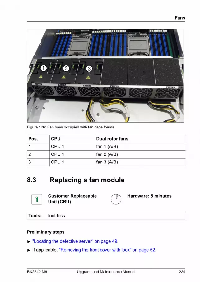
Figure 126: Fan bays occupied with fan cage foams
Pos. CPU Dual rotor fans1 CPU 1 fan 1 (A/B)
2 CPU 1 fan 2 (A/B)
3 CPU 1 fan 3 (A/B)
8.3 Replacing a fan module
Customer ReplaceableUnit (CRU)
Hardware: 5 minutes
Tools: tool-less
Preliminary steps
▶ "Locating the defective server" on page 49.
▶ If applicable, "Removing the front cover with lock" on page 52.
Fans
RX2540 M6 Upgrade and Maintenance Manual 229
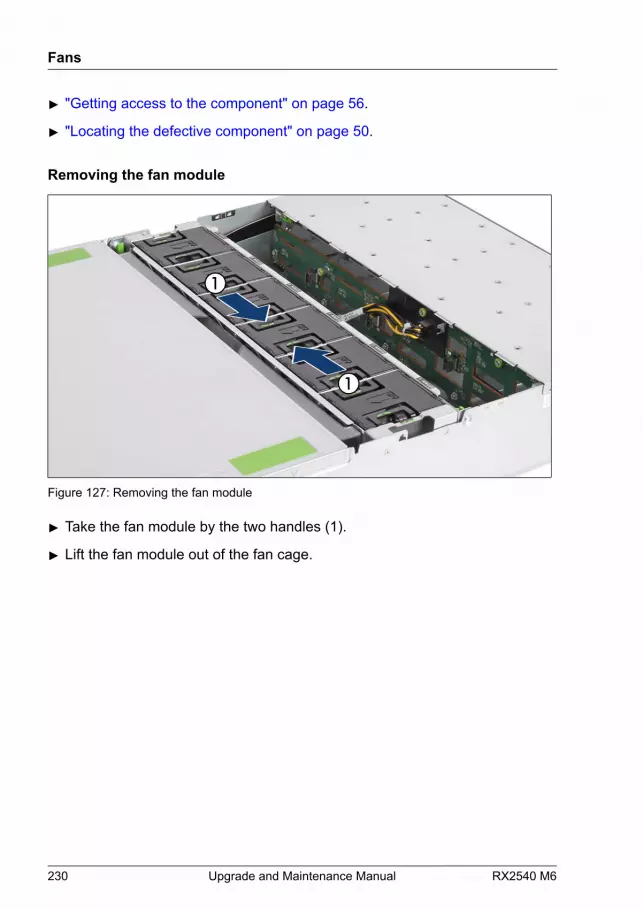
▶ "Getting access to the component" on page 56.
▶ "Locating the defective component" on page 50.
Removing the fan module
Figure 127: Removing the fan module
▶ Take the fan module by the two handles (1).
▶ Lift the fan module out of the fan cage.
Fans
230 Upgrade and Maintenance Manual RX2540 M6

Installing the fan module
Figure 128: Installing the fan module
▶ Insert the fan module in the fan cage.
▶ Press down the fan module until it locks.
Concluding steps
▶ "Reassembling" on page 60.
▶ If applicable, "Installing the front cover with lock" on page 69.
▶ "Performing a fan test" on page 115.
A fan test does not need to be performed if the fan module is activelyreplaced. iRMC runs automatically.
Fans
RX2540 M6 Upgrade and Maintenance Manual 231
Fans
232 Upgrade and Maintenance Manual RX2540 M6

9 Expansion cards and backupunits
9.1 Safety notes
CAUTION▶ Do not damage or modify internal cables or devices. Doing so may
cause a device failure, fire, or electric shock.▶ Devices and components inside the server remain hot after
shutdown. After shutting down the server, wait for hot componentsto cool down before installing or removing internal options.
▶ Circuit boards and soldered parts of internal options are exposedand can be damaged by static electricity. Always discharge staticbuild-up (e.g. by touching a grounded object) before handlingelectrostatic-sensitive devices (ESDs).
▶ Do not touch the circuitry on boards or soldered parts. Hold circuitboards by their metallic areas or edges.
▶ If devices are installed or disassembled using methods other thanthose outlined in this chapter, the warranty will be invalidated.
▶ For more information, see "Important information" on page 35.
RX2540 M6 Upgrade and Maintenance Manual 233
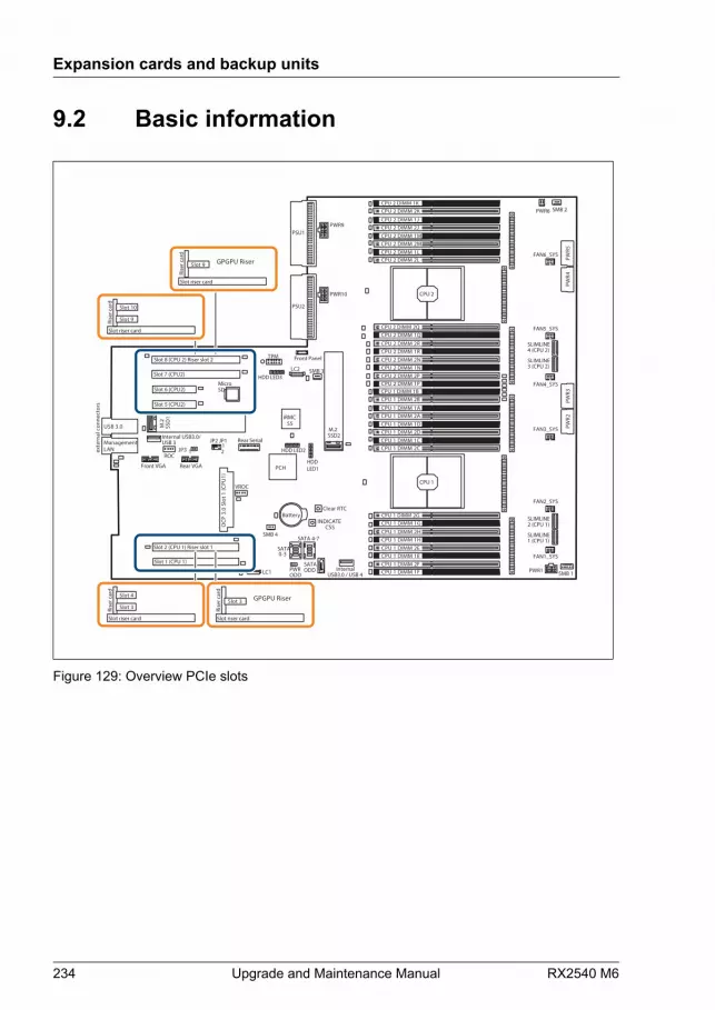
9.2 Basic information
iRMCS5
exte
rnal
con
nect
ors
INDICATE CSS
TPM
Slot 2 (CPU 1) Riser slot 1
Battery
SATA 0-3
Slot 1 (CPU 1)
Slot 8 (CPU 2) Riser slot 2
Rear Serial
PWRODD
Front Panel
SATA 4-7
SATAODD Internal
USB3.0 / USB 4
PSU1
PSU2
JP3 1
JP2 JP112
MicroSD
USB 3.0
SSD2 M.2
HDD LED2
Slot 7 (CPU2)
Slot 6 (CPU2)
Front VGA
Slot 5 (CPU2)
OCP
3.0
Slo
t 1 (C
PU1)
SSD
1 M
.2
LANManagement
Internal USB3.0/USB 3
Rear VGA
CPU 2 DIMM 2JCPU 2 DIMM 1M
CPU 2 DIMM 1LCPU 2 DIMM 2L
CPU 2 DIMM 1J
CPU 2 DIMM 2M
CPU 2 DIMM 2KCPU 2 DIMM 1K
CPU 2
CPU 1
CPU 1 DIMM 2ACPU 1 DIMM 1D
CPU 1 DIMM 1CCPU 1 DIMM 2C
CPU 1 DIMM 1A
CPU 1 DIMM 2D
CPU 1 DIMM 2BCPU 1 DIMM 1B
CPU 2 DIMM 1RCPU 2 DIMM 2N
CPU 2 DIMM 2PCPU 2 DIMM 1P
CPU 2 DIMM 2R
CPU 2 DIMM 1N
CPU 2 DIMM 1QCPU 2 DIMM 2Q
CPU 1 DIMM 1HCPU 1 DIMM 2E
CPU 1 DIMM 2FCPU 1 DIMM 1F
CPU 1 DIMM 2H
CPU 1 DIMM 1E
CPU 1 DIMM 1GCPU 1 DIMM 2G
SMB 4
LC1
SLIMLINE4 (CPU 2)
LC2
SMB 2
SMB 1
PWR9
PWR10
HDD LED3
HDD LED1
PWR6
PWR5
PWR4
PWR3
PWR2
PWR1
SLIMLINE3 (CPU 2)
SLIMLINE2 (CPU 1)
SLIMLINE1 (CPU 1)
FAN6_SYS
FAN5_SYS
FAN4_SYS
FAN3_SYS
FAN2_SYS
FAN1_SYS
ROC
VROC
SMB 3
Clear RTC
PCH
Slot riser card
Rise
r car
d
Slot 10
Slot 9
Slot riser card
Rise
r car
d
Slot 4
Slot 3
Slot riser card
Rise
r car
d
GPGPU RiserSlot 9
Slot riser card
Rise
r car
d
GPGPU RiserSlot 3
Figure 129: Overview PCIe slots
Expansion cards and backup units
234 Upgrade and Maintenance Manual RX2540 M6
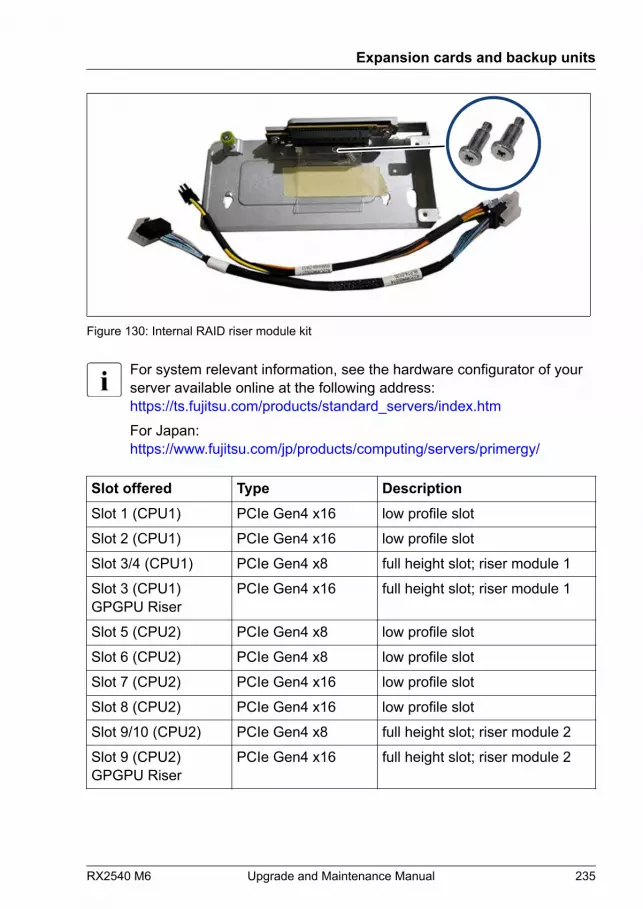
Figure 130: Internal RAID riser module kit
For system relevant information, see the hardware configurator of yourserver available online at the following address:https://ts.fujitsu.com/products/standard_servers/index.htmFor Japan:https://www.fujitsu.com/jp/products/computing/servers/primergy/
Slot offered Type DescriptionSlot 1 (CPU1) PCIe Gen4 x16 low profile slot
Slot 2 (CPU1) PCIe Gen4 x16 low profile slot
Slot 3/4 (CPU1) PCIe Gen4 x8 full height slot; riser module 1
Slot 3 (CPU1)GPGPU Riser
PCIe Gen4 x16 full height slot; riser module 1
Slot 5 (CPU2) PCIe Gen4 x8 low profile slot
Slot 6 (CPU2) PCIe Gen4 x8 low profile slot
Slot 7 (CPU2) PCIe Gen4 x16 low profile slot
Slot 8 (CPU2) PCIe Gen4 x16 low profile slot
Slot 9/10 (CPU2) PCIe Gen4 x8 full height slot; riser module 2
Slot 9 (CPU2)GPGPU Riser
PCIe Gen4 x16 full height slot; riser module 2
Expansion cards and backup units
RX2540 M6 Upgrade and Maintenance Manual 235
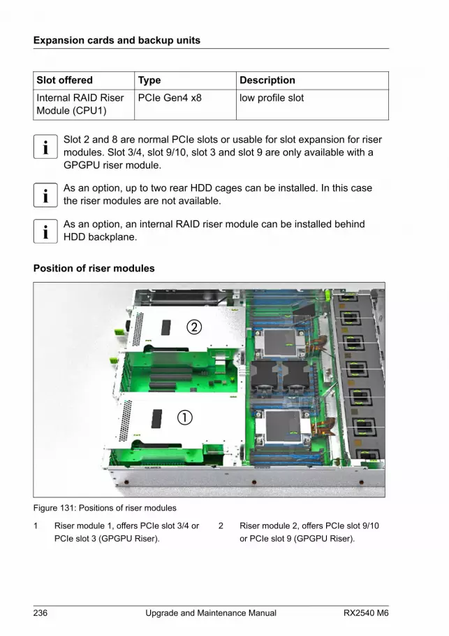
Slot offered Type DescriptionInternal RAID RiserModule (CPU1)
PCIe Gen4 x8 low profile slot
Slot 2 and 8 are normal PCIe slots or usable for slot expansion for risermodules. Slot 3/4, slot 9/10, slot 3 and slot 9 are only available with aGPGPU riser module.
As an option, up to two rear HDD cages can be installed. In this casethe riser modules are not available.
As an option, an internal RAID riser module can be installed behindHDD backplane.
Position of riser modules
Figure 131: Positions of riser modules
1 Riser module 1, offers PCIe slot 3/4 orPCIe slot 3 (GPGPU Riser).
2 Riser module 2, offers PCIe slot 9/10or PCIe slot 9 (GPGPU Riser).
Expansion cards and backup units
236 Upgrade and Maintenance Manual RX2540 M6

9.3 Handling slot brackets
9.3.1 Installing slot brackets
Upgrade and Repair Unit(URU)
Hardware: 5 minutes
Tools: Phillips PH2 / (+) No. 2 screw driver
Use the low profile bracket perforated for relevant controllers. Nobracket needed for installing the internal RAID controller in the internalRAID riser module.
Figure 132: Perforated and non-perforated slot brackets
1 Full height bracket non-perforated2 Full height bracket perforated
3 Low profile bracket perforated
Expansion cards and backup units
RX2540 M6 Upgrade and Maintenance Manual 237
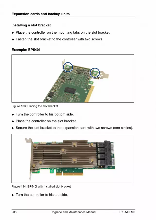
Installing a slot bracket
▶ Place the controller on the mounting tabs on the slot bracket.
▶ Fasten the slot bracket to the controller with two screws.
Example: EP540i
Figure 133: Placing the slot bracket
▶ Turn the controller to his bottom side.
▶ Place the controller on the slot bracket.
▶ Secure the slot bracket to the expansion card with two screws (see circles).
Figure 134: EP540i with installed slot bracket
▶ Turn the controller to his top side.
Expansion cards and backup units
238 Upgrade and Maintenance Manual RX2540 M6
9.3.2 Removing slot brackets
Upgrade and Repair Unit(URU)
Hardware: 5 minutes
Tools: Phillips PH2 / (+) No. 2 screw driver
Removing a slot bracket
▶ Remove the two screws.
▶ Remove the controller from the mounting tabs on the slot bracket.
9.4 Handling SFP+ transceiver modules
9.4.1 Installing SFP+ transceiver modules
Upgrade and Repair Unit(URU)
Hardware: 5 minutes
Tools: tool-less
The SFP+ transceiver modules are hot-pluggable.The activation replacement depends on the system configuration. Check it withthe customer who is managing the system or the system engineer.In addition, if the SFP+ transceiver module is independently registered as aspare part, the SFP+ transceiver module can be replaced independently. If thespare part unit consists of an SFP+ transceiver module and an expansion card,replace them in the set.
Expansion cards and backup units
RX2540 M6 Upgrade and Maintenance Manual 239

Installing SFP+ transceiver modules
Figure 135: Removing the protective cap
▶ Remove the SFP+ transceiver module from its protective packaging.
▶ Remove the protective cap from the new/additional SFP+ transceivermodule.
CAUTION▶ Always keep the protective caps attached to the SFP+
transceiver modules and fiber-optic cable connectors until youare ready to make a connection.
▶ Keep the protective cap for future use.
Expansion cards and backup units
240 Upgrade and Maintenance Manual RX2540 M6
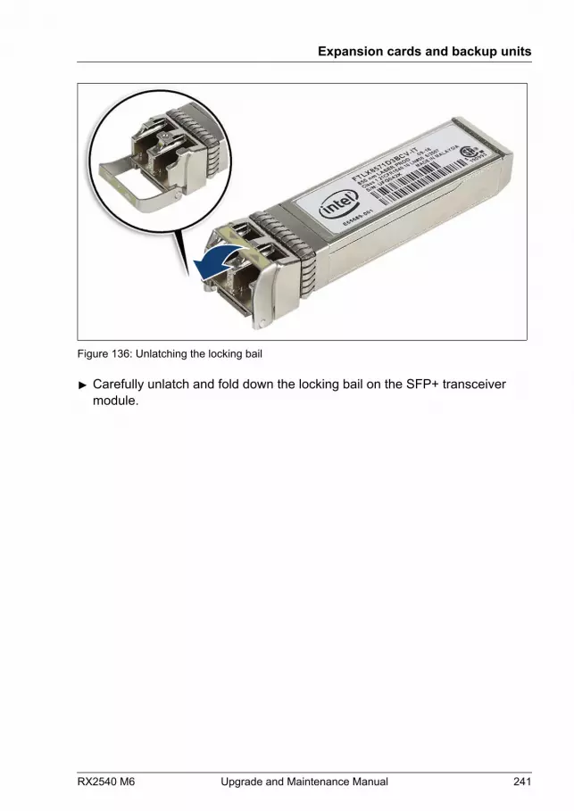
Figure 136: Unlatching the locking bail
▶ Carefully unlatch and fold down the locking bail on the SFP+ transceivermodule.
Expansion cards and backup units
RX2540 M6 Upgrade and Maintenance Manual 241

Figure 137: Inserting the SFP+ transceiver module
▶ Insert and slide the SFP+ transceiver module into the socket connector asfar as it will go.
Expansion cards and backup units
242 Upgrade and Maintenance Manual RX2540 M6
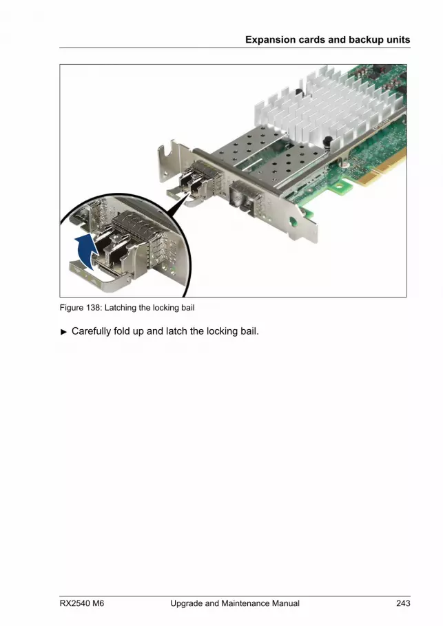
Figure 138: Latching the locking bail
▶ Carefully fold up and latch the locking bail.
Expansion cards and backup units
RX2540 M6 Upgrade and Maintenance Manual 243

Figure 139: Installing the protective cap
▶ If the SFP+ transceiver module is not immediately connected, attach theprotective cap to the SFP+ transceiver module.
Expansion cards and backup units
244 Upgrade and Maintenance Manual RX2540 M6

Figure 140: Installing the secondary SFP+ transceiver module
▶ If applicable, install the secondary SFP+ transceiver module accordingly.
9.4.2 Removing SFP+ transceiver modules
Upgrade and Repair Unit(URU)
Hardware: 5 minutes
Tools: tool-less
The SFP+ transceiver modules are hot-pluggable.The activation replacement depends on the system configuration. Check it withthe customer who is managing the system or the system engineer.In addition, if the SFP+ transceiver module is independently registered as aspare part, the SFP+ transceiver module can be replaced independently. If thespare part unit consists of an SFP+ transceiver module and an expansion card,replace them in the set.
Expansion cards and backup units
RX2540 M6 Upgrade and Maintenance Manual 245
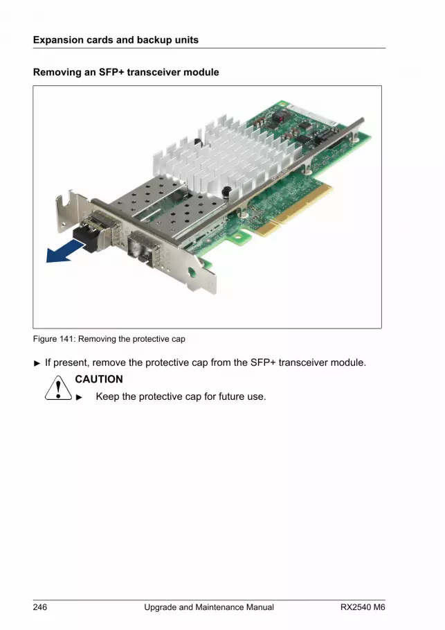
Removing an SFP+ transceiver module
Figure 141: Removing the protective cap
▶ If present, remove the protective cap from the SFP+ transceiver module.CAUTION▶ Keep the protective cap for future use.
Expansion cards and backup units
246 Upgrade and Maintenance Manual RX2540 M6
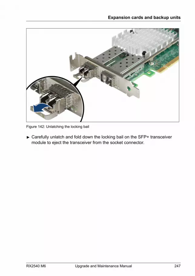
Figure 142: Unlatching the locking bail
▶ Carefully unlatch and fold down the locking bail on the SFP+ transceivermodule to eject the transceiver from the socket connector.
Expansion cards and backup units
RX2540 M6 Upgrade and Maintenance Manual 247
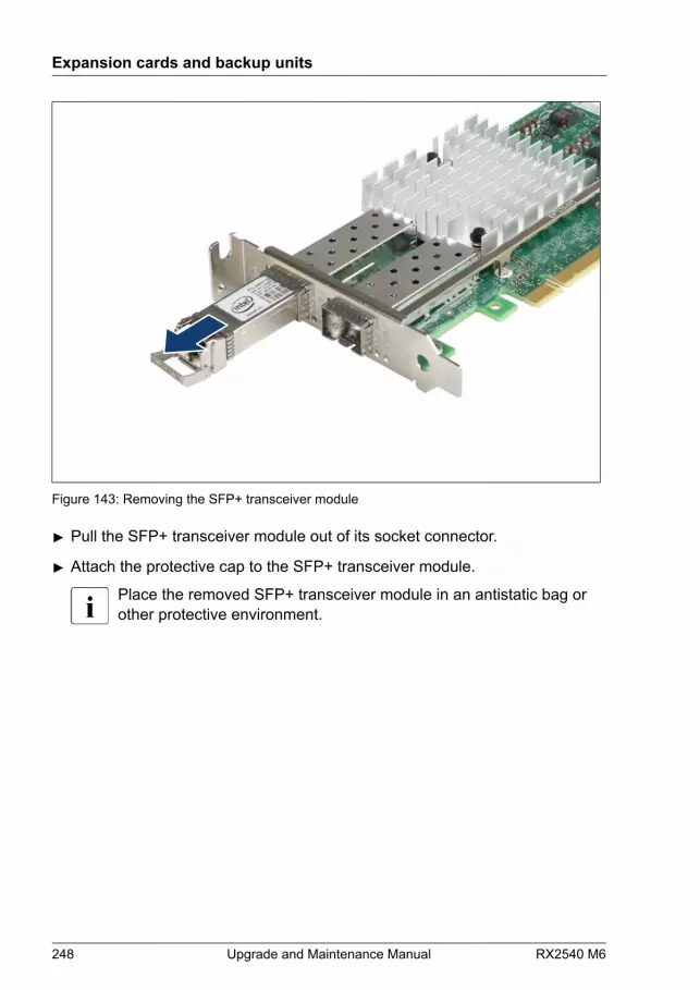
Figure 143: Removing the SFP+ transceiver module
▶ Pull the SFP+ transceiver module out of its socket connector.
▶ Attach the protective cap to the SFP+ transceiver module.
Place the removed SFP+ transceiver module in an antistatic bag orother protective environment.
Expansion cards and backup units
248 Upgrade and Maintenance Manual RX2540 M6
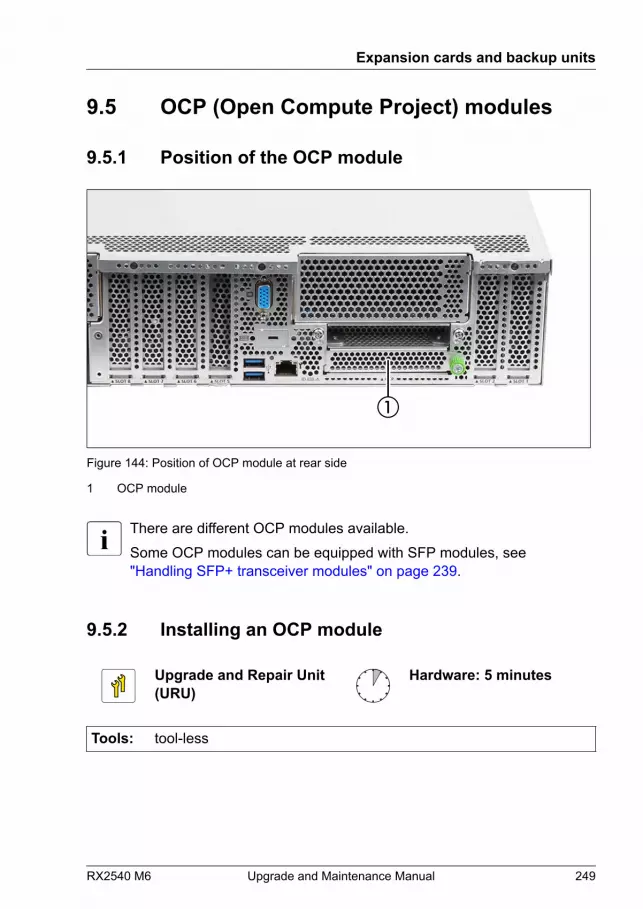
9.5 OCP (Open Compute Project) modules
9.5.1 Position of the OCP module
Figure 144: Position of OCP module at rear side
1 OCP module
There are different OCP modules available.Some OCP modules can be equipped with SFP modules, see"Handling SFP+ transceiver modules" on page 239.
9.5.2 Installing an OCP module
Upgrade and Repair Unit(URU)
Hardware: 5 minutes
Tools: tool-less
Expansion cards and backup units
RX2540 M6 Upgrade and Maintenance Manual 249
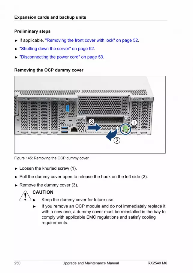
Preliminary steps
▶ If applicable, "Removing the front cover with lock" on page 52.
▶ "Shutting down the server" on page 52.
▶ "Disconnecting the power cord" on page 53.
Removing the OCP dummy cover
Figure 145: Removing the OCP dummy cover
▶ Loosen the knurled screw (1).
▶ Pull the dummy cover open to release the hook on the left side (2).
▶ Remove the dummy cover (3).CAUTION▶ Keep the dummy cover for future use.▶ If you remove an OCP module and do not immediately replace it
with a new one, a dummy cover must be reinstalled in the bay tocomply with applicable EMC regulations and satisfy coolingrequirements.
Expansion cards and backup units
250 Upgrade and Maintenance Manual RX2540 M6
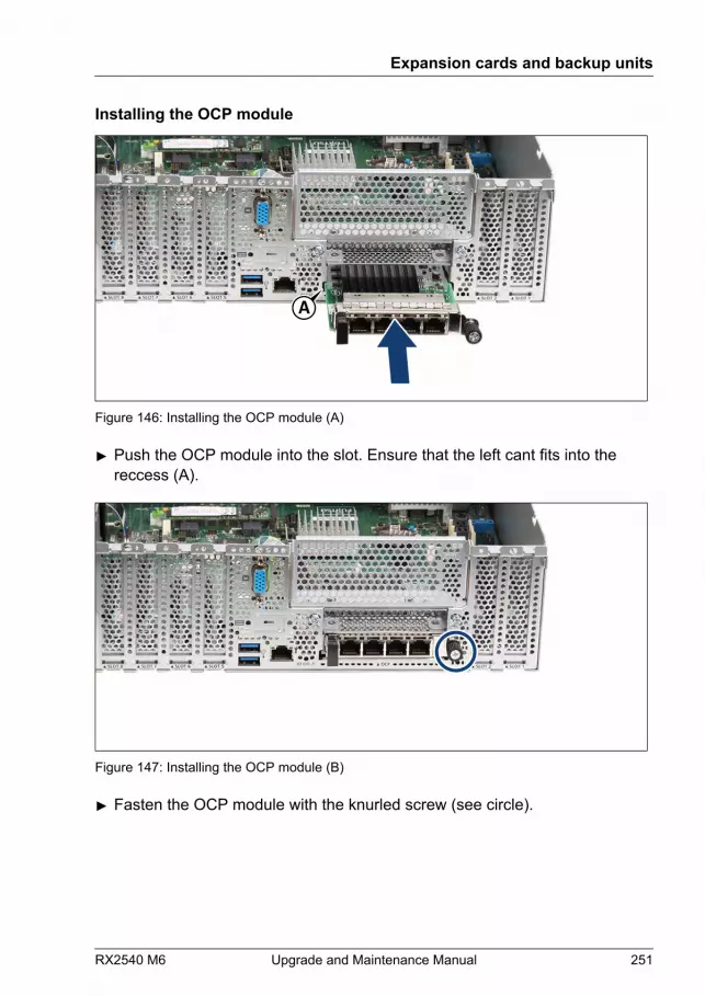
Installing the OCP module
A
Figure 146: Installing the OCP module (A)
▶ Push the OCP module into the slot. Ensure that the left cant fits into thereccess (A).
Figure 147: Installing the OCP module (B)
▶ Fasten the OCP module with the knurled screw (see circle).
Expansion cards and backup units
RX2540 M6 Upgrade and Maintenance Manual 251
Concluding steps
▶ "Connecting the power cord" on page 65.
▶ "Switching on the server" on page 69.
▶ If applicable, "Installing the front cover with lock" on page 69.
▶ Configure the new MAC address in the OS, if you have no VIOM(ServerView Virtual-IO Manager) installed. If you have VIOM installed, it isnot necessary to configure the MAC address. This is virtualized by VIOM.
▶ Inform the customer about new MAC addresses. For more information, see"Looking for MAC/WWN/GUID and SAS addresses" on page 107.
▶ "Updating the NIC configuration file in a Linux and VMware environment" on page 104.
▶ "Configuring LAN teaming" on page 113.
9.5.3 Removing an OCP module
Upgrade and Repair Unit(URU)
Hardware: 5 minutes
Tools: tool-less
Preliminary steps
▶ If applicable, "Removing the front cover with lock" on page 52.
▶ "Shutting down the server" on page 52.
▶ "Disconnecting the power cord" on page 53.
Expansion cards and backup units
252 Upgrade and Maintenance Manual RX2540 M6

Removing the OCP module
Figure 148: Removing the OCP module
▶ Loosen the knurled screw (see circle).
▶ Remove the OCP module.
Installing the OCP dummy cover
A
Figure 149: Installing the OCP dummy cover
Expansion cards and backup units
RX2540 M6 Upgrade and Maintenance Manual 253
▶ Insert the dummy cover at a slight angle (1). Notice the position of the hookand the reccess in the chassis (A).
▶ Push the dummy cover in place (2).
▶ Fasten the dummy cover with the knurled screw (3, see circle).
Concluding steps
▶ "Connecting the power cord" on page 65.
▶ "Switching on the server" on page 69.
▶ If applicable, "Installing the front cover with lock" on page 69.
9.5.4 Replacing the OCP module
Upgrade and Repair Unit(URU)
Hardware: 10 minutes
Tools: tool-less
MAC addresses are stored on the OCP module and are not stored onthe system board. When replacing an OCP module, the MAC addressesare changed. Inform the customer about that before starting the task.After doing the task, inform the customer about the changed MACaddresses.
Preliminary steps
▶ "Locating the defective server" on page 49.
▶ If applicable, "Removing the front cover with lock" on page 52.
▶ "Shutting down the server" on page 52.
▶ "Disconnecting the power cord" on page 53.
Removing the defective OCP module
▶ Remove the OCP module, see "Removing the OCP module" on page 253.
Expansion cards and backup units
254 Upgrade and Maintenance Manual RX2540 M6
Installing the new OCP module
▶ Install the OCP module, see "Installing the OCP module" on page 251.
Concluding steps
▶ "Connecting the power cord" on page 65.
▶ "Switching on the server" on page 69.
▶ If applicable, "Installing the front cover with lock" on page 69.
▶ Inform the customer about the changed MAC addresses, see "Looking for MAC/WWN/GUID and SAS addresses" on page 107.
▶ "Updating the NIC configuration file in a Linux and VMware environment" on page 104.
▶ "Configuring LAN teaming" on page 113.
9.6 Expansion cards in standard PCIe slots
9.6.1 Installing an expansion card
Upgrade and Repair Unit(URU)
Hardware: 5 minutesSoftware: 5 minutes
Tools: Phillips PH2 / (+) No. 2 screw driver
Preliminary steps
▶ "Suspending BitLocker functionality" on page 87.
▶ If applicable, "Removing the front cover with lock" on page 52.
▶ "Shutting down the server" on page 52.
▶ "Disconnecting the power cord" on page 53.
▶ "Getting access to the component" on page 56.
Expansion cards and backup units
RX2540 M6 Upgrade and Maintenance Manual 255
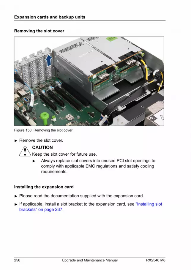
Removing the slot cover
Figure 150: Removing the slot cover
▶ Remove the slot cover.CAUTIONKeep the slot cover for future use.▶ Always replace slot covers into unused PCI slot openings to
comply with applicable EMC regulations and satisfy coolingrequirements.
Installing the expansion card
▶ Please read the documentation supplied with the expansion card.
▶ If applicable, install a slot bracket to the expansion card, see "Installing slot brackets" on page 237.
Expansion cards and backup units
256 Upgrade and Maintenance Manual RX2540 M6
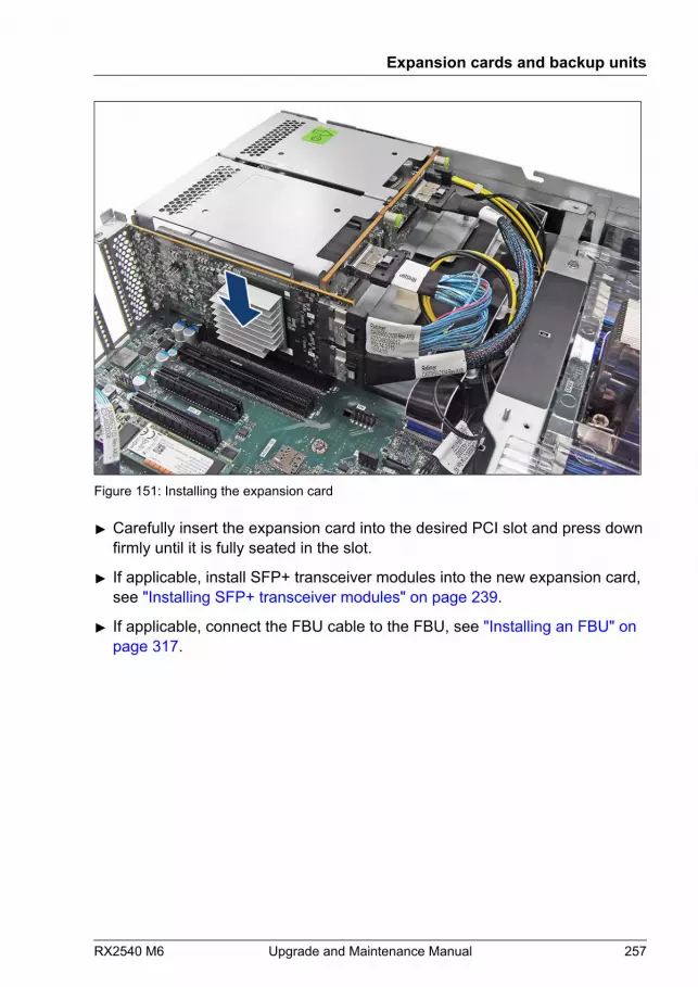
Figure 151: Installing the expansion card
▶ Carefully insert the expansion card into the desired PCI slot and press downfirmly until it is fully seated in the slot.
▶ If applicable, install SFP+ transceiver modules into the new expansion card,see "Installing SFP+ transceiver modules" on page 239.
▶ If applicable, connect the FBU cable to the FBU, see "Installing an FBU" on page 317.
Expansion cards and backup units
RX2540 M6 Upgrade and Maintenance Manual 257

Example PRAID EP5xxi
Figure 152: Connecting the cables to the PRAID EP5xxi
▶ Connect the following cables:
1 If applicable, FBU cable 2 If applicable, HDD LED cable
Expansion cards and backup units
258 Upgrade and Maintenance Manual RX2540 M6

Figure 153: Installing the PRAID EP5xxi
▶ Carefully insert the PRAID EP5xxi into the desired PCI slot and press downfirmly until it is fully seated in the slot.
▶ Connect the HDD LED cable to the system board (see circle).
▶ Connect the SAS cables to the corresponding HDD backplane.
For the cable plan, see "Appendix B" on page 571.
Expansion cards and backup units
RX2540 M6 Upgrade and Maintenance Manual 259

Example SAS CP5xxi
Figure 154: Connecting cables - SAS CP5xxi
▶ Connect the following cables:
1 If applicable, HDD LED cable
2 SAS cable
Expansion cards and backup units
260 Upgrade and Maintenance Manual RX2540 M6
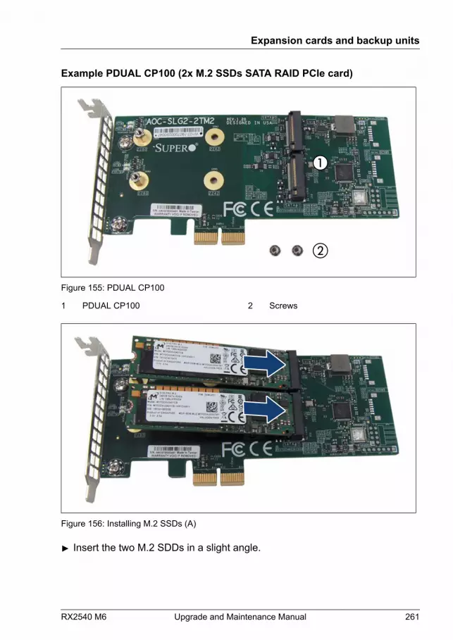
Example PDUAL CP100 (2x M.2 SSDs SATA RAID PCIe card)
Figure 155: PDUAL CP100
1 PDUAL CP100 2 Screws
Figure 156: Installing M.2 SSDs (A)
▶ Insert the two M.2 SDDs in a slight angle.
Expansion cards and backup units
RX2540 M6 Upgrade and Maintenance Manual 261
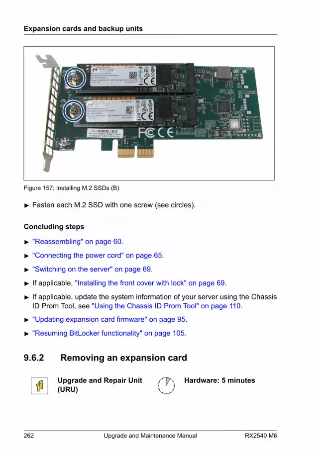
Figure 157: Installing M.2 SSDs (B)
▶ Fasten each M.2 SSD with one screw (see circles).
Concluding steps
▶ "Reassembling" on page 60.
▶ "Connecting the power cord" on page 65.
▶ "Switching on the server" on page 69.
▶ If applicable, "Installing the front cover with lock" on page 69.
▶ If applicable, update the system information of your server using the ChassisID Prom Tool, see "Using the Chassis ID Prom Tool" on page 110.
▶ "Updating expansion card firmware" on page 95.
▶ "Resuming BitLocker functionality" on page 105.
9.6.2 Removing an expansion card
Upgrade and Repair Unit(URU)
Hardware: 5 minutes
Expansion cards and backup units
262 Upgrade and Maintenance Manual RX2540 M6
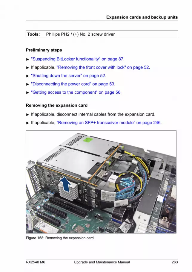
Tools: Phillips PH2 / (+) No. 2 screw driver
Preliminary steps
▶ "Suspending BitLocker functionality" on page 87.
▶ If applicable, "Removing the front cover with lock" on page 52.
▶ "Shutting down the server" on page 52.
▶ "Disconnecting the power cord" on page 53.
▶ "Getting access to the component" on page 56.
Removing the expansion card
▶ If applicable, disconnect internal cables from the expansion card.
▶ If applicable, "Removing an SFP+ transceiver module" on page 246.
Figure 158: Removing the expansion card
Expansion cards and backup units
RX2540 M6 Upgrade and Maintenance Manual 263
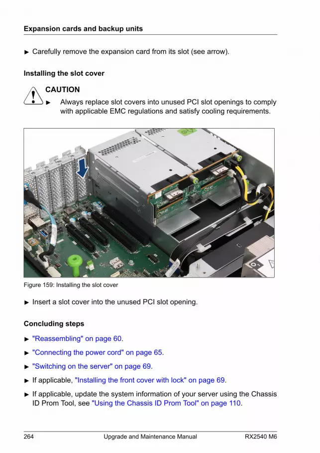
▶ Carefully remove the expansion card from its slot (see arrow).
Installing the slot cover
CAUTION▶ Always replace slot covers into unused PCI slot openings to comply
with applicable EMC regulations and satisfy cooling requirements.
Figure 159: Installing the slot cover
▶ Insert a slot cover into the unused PCI slot opening.
Concluding steps
▶ "Reassembling" on page 60.
▶ "Connecting the power cord" on page 65.
▶ "Switching on the server" on page 69.
▶ If applicable, "Installing the front cover with lock" on page 69.
▶ If applicable, update the system information of your server using the ChassisID Prom Tool, see "Using the Chassis ID Prom Tool" on page 110.
Expansion cards and backup units
264 Upgrade and Maintenance Manual RX2540 M6

▶ "Resuming BitLocker functionality" on page 105.
9.6.3 Replacing an expansion card
Upgrade and Repair Unit(URU)
Hardware: 10 minutesSoftware: 5 minutes
Tools: Phillips PH2 / (+) No. 2 screw driver
Note on network settings recovery
When replacing network controllers, network configuration settings inthe OS will be lost and replaced by default values. This applies to allstatic IP address and LAN teaming configurations.Ensure to note down your current network settings before replacing anetwork controller.
Preliminary steps
▶ "Locating the defective server" on page 49.
▶ If applicable, "Configuring LAN teaming" on page 113.
▶ "Suspending BitLocker functionality" on page 87.
▶ If applicable, "Removing the front cover with lock" on page 52.
▶ "Shutting down the server" on page 52.
▶ "Disconnecting the power cord" on page 53.
▶ "Getting access to the component" on page 56.
▶ "Locating the defective component" on page 50.
Expansion cards and backup units
RX2540 M6 Upgrade and Maintenance Manual 265
Removing the defective expansion card
▶ Remove the expansion card, see "Removing the expansion card" on page 263.
▶ If the slot bracket on the defective expansion card is to be reused, remove itfrom the expansion card, see "Removing slot brackets" on page 239.
Installing the new expansion card
▶ If applicable, install the slot bracket, see "Installing slot brackets" on page 237.
▶ Install the expansion card, see "Installing the expansion card" on page 256.
Concluding steps
▶ "Reassembling" on page 60.
▶ If applicable, connect external cables to the expansion card.
▶ "Connecting the power cord" on page 65.
▶ "Switching on the server" on page 69.
▶ If applicable, "Installing the front cover with lock" on page 69.
▶ "Enabling replaced components in the BIOS" on page 100.
▶ Inform the customer about changed WWN, MAC and SAS addresses, see"Looking for MAC/WWN/GUID and SAS addresses" on page 107.
▶ "Updating the NIC configuration file in a Linux and VMware environment" on page 104.
▶ "Updating expansion card firmware" on page 95.
▶ "Resuming BitLocker functionality" on page 105.
▶ If applicable, reconfigure your network settings in the operation systemaccording to the original configuration of the replaced controller (expansioncard).
Configuration of network settings should be performed by thecustomer. For more information, see "Note on network settings recovery" on page 265.
Expansion cards and backup units
266 Upgrade and Maintenance Manual RX2540 M6

▶ If applicable, restore LAN teaming configurations, see "After replacing or upgrading LAN controllers" on page 114.
9.7 Internal RAID riser module
9.7.1 Installing an internal RAID riser module
Upgrade and Repair Unit(URU)
Hardware: 5 minutesSoftware: 5 minutes
Tools: Phillips PH2 / (+) No. 2 screw driver
Preliminary steps
▶ "Suspending BitLocker functionality" on page 87.
▶ If applicable, "Removing the front cover with lock" on page 52.
▶ "Shutting down the server" on page 52.
▶ "Disconnecting the power cord" on page 53.
▶ "Getting access to the component" on page 56.
▶ "Removing the fan cage" on page 74.
Installing the expansion card into the internal RAID riser module
▶ Please read the documentation supplied with the expansion card.
▶ If applicable, remove the slot bracket from the expansion card, see"Removing slot brackets" on page 239.
Expansion cards and backup units
RX2540 M6 Upgrade and Maintenance Manual 267

Figure 160: Connecting cables to the internal RAID riser module
▶ Connect the following cables to the internal RAID riser module:
1 HDD LED cable (option) 2 NVMe cable, depending on configuration 3 Power cable
Expansion cards and backup units
268 Upgrade and Maintenance Manual RX2540 M6
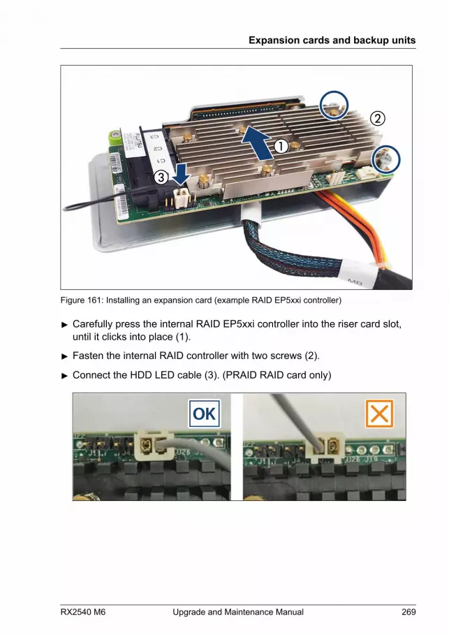
Figure 161: Installing an expansion card (example RAID EP5xxi controller)
▶ Carefully press the internal RAID EP5xxi controller into the riser card slot,until it clicks into place (1).
▶ Fasten the internal RAID controller with two screws (2).
▶ Connect the HDD LED cable (3). (PRAID RAID card only)
Expansion cards and backup units
RX2540 M6 Upgrade and Maintenance Manual 269

Figure 162: Installing an expansion card (example RAID EP6xxi controller)
▶ Carefully press the internal RAID EP6xxi controller into the riser card slot,until it clicks into place (1).
▶ Fasten the internal RAID controller with two screws (2).
▶ Connect the HDD LED cable (3). (PRAID RAID card only)
OK
Expansion cards and backup units
270 Upgrade and Maintenance Manual RX2540 M6
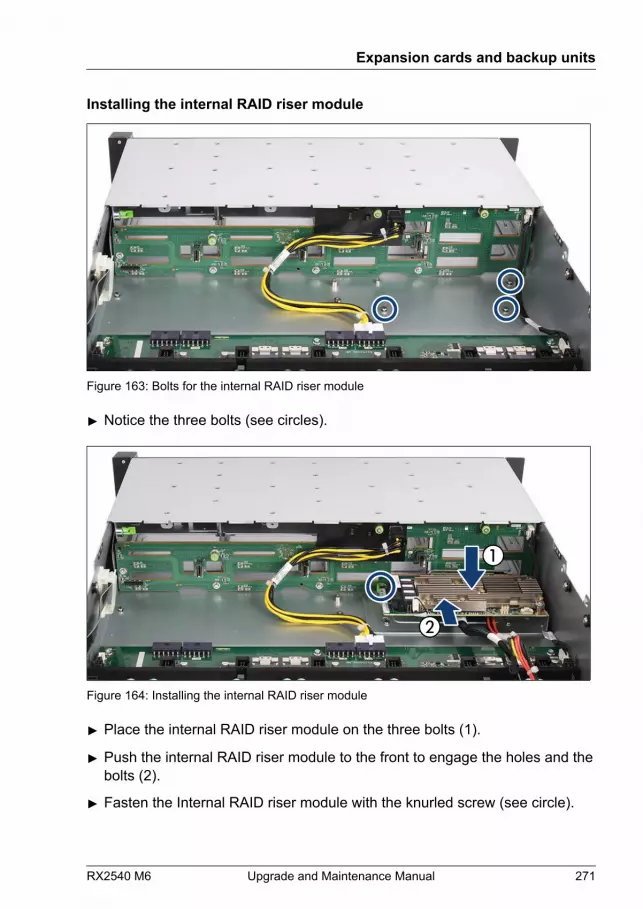
Installing the internal RAID riser module
Figure 163: Bolts for the internal RAID riser module
▶ Notice the three bolts (see circles).
Figure 164: Installing the internal RAID riser module
▶ Place the internal RAID riser module on the three bolts (1).
▶ Push the internal RAID riser module to the front to engage the holes and thebolts (2).
▶ Fasten the Internal RAID riser module with the knurled screw (see circle).
Expansion cards and backup units
RX2540 M6 Upgrade and Maintenance Manual 271
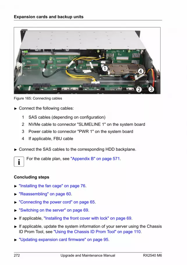
Figure 165: Connecting cables
▶ Connect the following cables:
1 SAS cables (depending on configuration) 2 NVMe cable to connector "SLIMELINE 1" on the system board 3 Power cable to connector "PWR 1" on the system board 4 If applicable, FBU cable
▶ Connect the SAS cables to the corresponding HDD backplane.
For the cable plan, see "Appendix B" on page 571.
Concluding steps
▶ "Installing the fan cage" on page 76.
▶ "Reassembling" on page 60.
▶ "Connecting the power cord" on page 65.
▶ "Switching on the server" on page 69.
▶ If applicable, "Installing the front cover with lock" on page 69.
▶ If applicable, update the system information of your server using the ChassisID Prom Tool, see "Using the Chassis ID Prom Tool" on page 110.
▶ "Updating expansion card firmware" on page 95.
Expansion cards and backup units
272 Upgrade and Maintenance Manual RX2540 M6

▶ "Resuming BitLocker functionality" on page 105.
9.7.2 Removing an internal RAID riser module
Upgrade and Repair Unit(URU)
Hardware: 5 minutes
Tools: Phillips PH2 / (+) No. 2 screw driver
Preliminary steps
▶ "Suspending BitLocker functionality" on page 87.
▶ If applicable, "Removing the front cover with lock" on page 52.
▶ "Shutting down the server" on page 52.
▶ "Disconnecting the power cord" on page 53.
▶ "Getting access to the component" on page 56.
▶ "Removing the fan cage" on page 74.
Removing the internal RAID riser module
▶ Disconnect all cables from the expansion card.
Expansion cards and backup units
RX2540 M6 Upgrade and Maintenance Manual 273
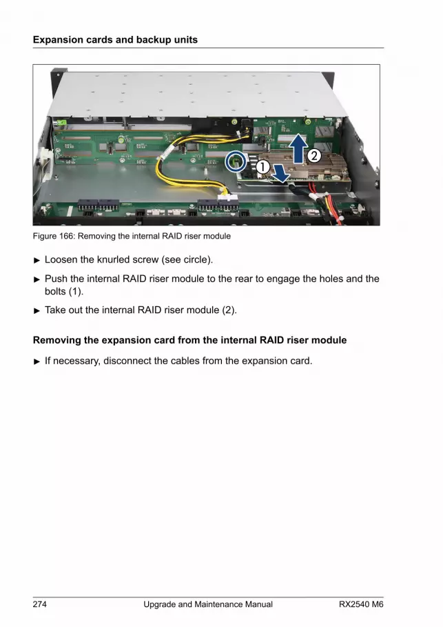
Figure 166: Removing the internal RAID riser module
▶ Loosen the knurled screw (see circle).
▶ Push the internal RAID riser module to the rear to engage the holes and thebolts (1).
▶ Take out the internal RAID riser module (2).
Removing the expansion card from the internal RAID riser module
▶ If necessary, disconnect the cables from the expansion card.
Expansion cards and backup units
274 Upgrade and Maintenance Manual RX2540 M6
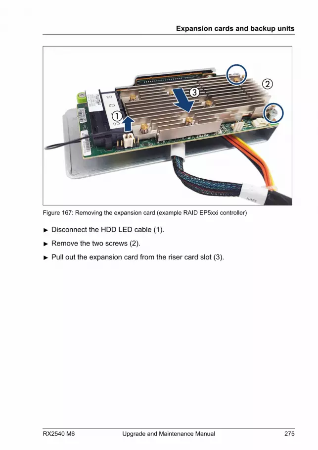
Figure 167: Removing the expansion card (example RAID EP5xxi controller)
▶ Disconnect the HDD LED cable (1).
▶ Remove the two screws (2).
▶ Pull out the expansion card from the riser card slot (3).
Expansion cards and backup units
RX2540 M6 Upgrade and Maintenance Manual 275

Figure 168: Removing the expansion card (example RAID EP6xxi controller)
▶ Disconnect the HDD LED cable (1).
▶ Remove the two screws (2).
▶ Pull out the expansion card from the riser card slot (3).
Concluding steps
▶ "Installing the fan cage" on page 76.
▶ "Reassembling" on page 60.
▶ "Connecting the power cord" on page 65.
▶ "Switching on the server" on page 69.
▶ If applicable, "Installing the front cover with lock" on page 69.
▶ If applicable, update the system information of your server using the ChassisID Prom Tool, see "Using the Chassis ID Prom Tool" on page 110.
▶ "Resuming BitLocker functionality" on page 105.
Expansion cards and backup units
276 Upgrade and Maintenance Manual RX2540 M6

9.7.3 Replacing an internal RAID riser module
Upgrade and Repair Unit(URU)
Hardware: 10 minutesSoftware: 5 minutes
Tools: Phillips PH2 / (+) No. 2 screw driver
Preliminary steps
▶ "Locating the defective server" on page 49.
▶ "Suspending BitLocker functionality" on page 87.
▶ If applicable, "Removing the front cover with lock" on page 52.
▶ "Shutting down the server" on page 52.
▶ "Disconnecting the power cord" on page 53.
▶ "Getting access to the component" on page 56.
▶ "Removing the fan cage" on page 74.
▶ "Locating the defective component" on page 50.
Removing the defective expansion card
▶ Remove the internal RAID riser module, see "Removing the internal RAID riser module" on page 273.
▶ Remove the expansion card, see "Removing the expansion card from the internal RAID riser module" on page 274.
Installing the new expansion card
▶ Install the expansion card, see "Installing the expansion card into the internal RAID riser module" on page 267.
▶ Install the internal RAID riser module, see "Installing the internal RAID riser module" on page 271.
Expansion cards and backup units
RX2540 M6 Upgrade and Maintenance Manual 277

Concluding steps
▶ "Installing the fan cage" on page 76.
▶ "Reassembling" on page 60.
▶ If applicable, connect external cables to the expansion card.
▶ "Connecting the power cord" on page 65.
▶ "Switching on the server" on page 69.
▶ If applicable, "Installing the front cover with lock" on page 69.
▶ "Enabling replaced components in the BIOS" on page 100.
▶ "Updating expansion card firmware" on page 95.
▶ "Resuming BitLocker functionality" on page 105.
9.7.4 Replacing a riser card
Field Replaceable Unit(FRU)
Hardware: 5 minutes
Tools: Phillips PH2 / (+) No. 2 screw driver
Preliminary steps
▶ "Locating the defective server" on page 49.
▶ If applicable, "Removing the front cover with lock" on page 52.
▶ "Shutting down the server" on page 52.
▶ "Disconnecting the power cord" on page 53.
▶ "Getting access to the component" on page 56.
▶ "Removing the fan cage" on page 74.
▶ "Locating the defective component" on page 50.
Expansion cards and backup units
278 Upgrade and Maintenance Manual RX2540 M6

Removing the defective riser card
▶ Remove the internal RAID riser module, see "Removing the internal RAID riser module" on page 273.
▶ Remove the expansion card, see "Removing the expansion card from the internal RAID riser module" on page 274.
Figure 169: Removing the riser card
▶ Remove the two screws (see circles).
▶ Remove the riser card.
Installing the new riser card
Figure 170: Installing the riser card
Expansion cards and backup units
RX2540 M6 Upgrade and Maintenance Manual 279

▶ Insert the riser card.
▶ Fasten the riser card with two screws (see circles).
▶ Install the expansion card, see "Installing the expansion card into the internal RAID riser module" on page 267.
▶ Install the internal RAID riser module, see "Installing the internal RAID riser module" on page 271.
Concluding steps
▶ "Installing the fan cage" on page 76.
▶ "Reassembling" on page 60.
▶ "Connecting the power cord" on page 65.
▶ "Switching on the server" on page 69.
▶ If applicable, "Installing the front cover with lock" on page 69.
9.8 Expansion cards in riser modules
9.8.1 Installing an expansion card in a riser module
Upgrade and Repair Unit(URU)
Hardware: 5 minutesSoftware: 5 minutes
Tools: – Phillips PH2 / (+) No. 2 screw driver
– Phillips PH1 / (+) No. 1 screw driver
Preliminary steps
▶ "Suspending BitLocker functionality" on page 87.
▶ If applicable, "Removing the front cover with lock" on page 52.
▶ "Shutting down the server" on page 52.
▶ "Disconnecting the power cord" on page 53.
Expansion cards and backup units
280 Upgrade and Maintenance Manual RX2540 M6
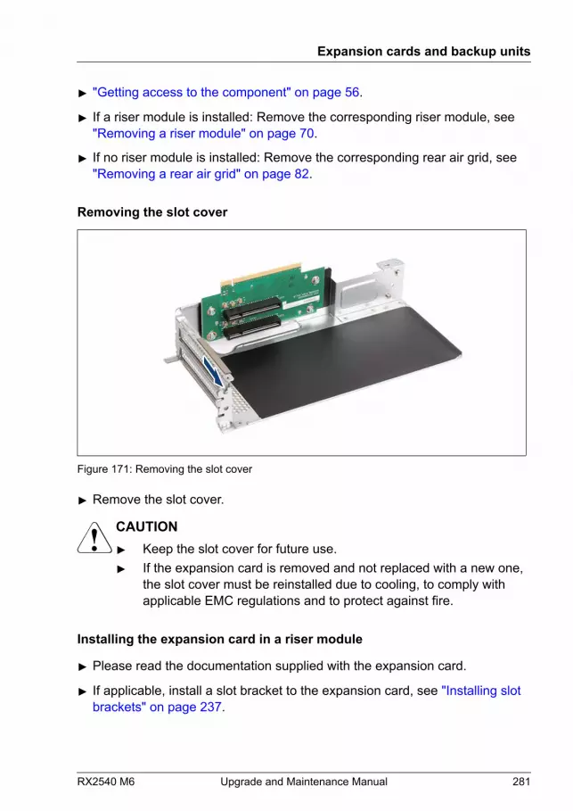
▶ "Getting access to the component" on page 56.
▶ If a riser module is installed: Remove the corresponding riser module, see"Removing a riser module" on page 70.
▶ If no riser module is installed: Remove the corresponding rear air grid, see"Removing a rear air grid" on page 82.
Removing the slot cover
Figure 171: Removing the slot cover
▶ Remove the slot cover.
CAUTION▶ Keep the slot cover for future use.▶ If the expansion card is removed and not replaced with a new one,
the slot cover must be reinstalled due to cooling, to comply withapplicable EMC regulations and to protect against fire.
Installing the expansion card in a riser module
▶ Please read the documentation supplied with the expansion card.
▶ If applicable, install a slot bracket to the expansion card, see "Installing slot brackets" on page 237.
Expansion cards and backup units
RX2540 M6 Upgrade and Maintenance Manual 281

Figure 172: Installing the expansion card in a riser module
▶ Carefully insert the expansion card into the desired PCI slot and press downfirmly until it is fully seated in the slot.
▶ If applicable, install SFP+ transceiver modules into the new expansion card,see "Installing SFP+ transceiver modules" on page 239.
▶ If applicable, connect the FBU cable to the FBU, see "Installing an FBU" on page 317.
Expansion cards and backup units
282 Upgrade and Maintenance Manual RX2540 M6
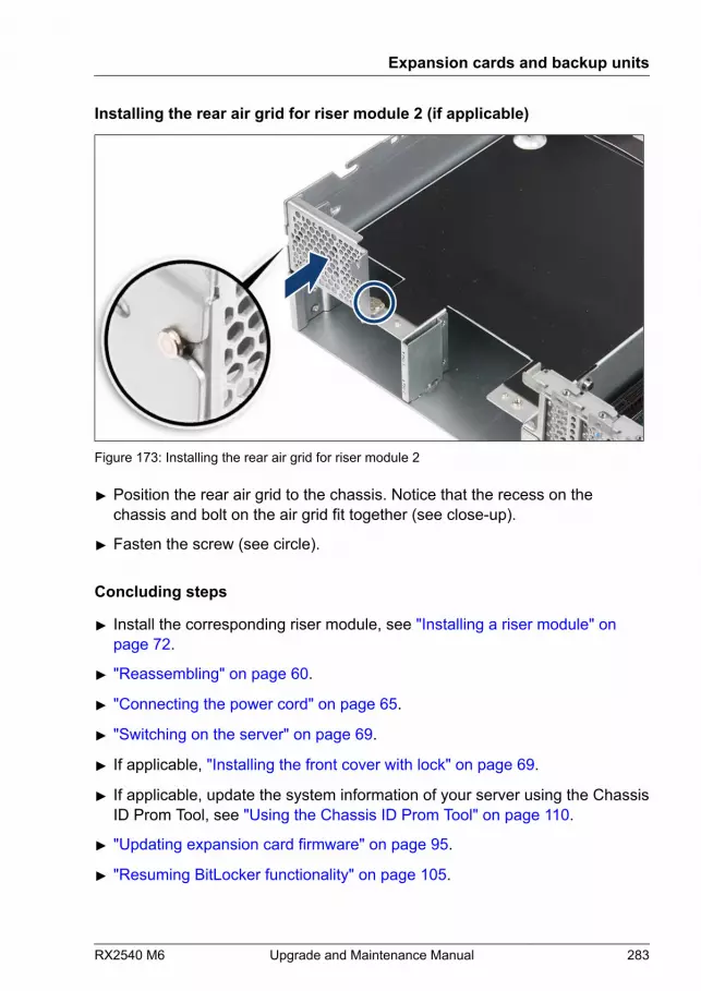
Installing the rear air grid for riser module 2 (if applicable)
Figure 173: Installing the rear air grid for riser module 2
▶ Position the rear air grid to the chassis. Notice that the recess on thechassis and bolt on the air grid fit together (see close-up).
▶ Fasten the screw (see circle).
Concluding steps
▶ Install the corresponding riser module, see "Installing a riser module" on page 72.
▶ "Reassembling" on page 60.
▶ "Connecting the power cord" on page 65.
▶ "Switching on the server" on page 69.
▶ If applicable, "Installing the front cover with lock" on page 69.
▶ If applicable, update the system information of your server using the ChassisID Prom Tool, see "Using the Chassis ID Prom Tool" on page 110.
▶ "Updating expansion card firmware" on page 95.
▶ "Resuming BitLocker functionality" on page 105.
Expansion cards and backup units
RX2540 M6 Upgrade and Maintenance Manual 283
9.8.2 Removing an expansion card from a riser module
Upgrade and Repair Unit(URU)
Hardware: 5 minutesSoftware: 5 minutes
Tools: Phillips PH2 / (+) No. 2 screw driver
Preliminary steps
▶ "Suspending BitLocker functionality" on page 87.
▶ If applicable, "Removing the front cover with lock" on page 52.
▶ "Shutting down the server" on page 52.
▶ "Disconnecting the power cord" on page 53.
▶ "Getting access to the component" on page 56.
▶ Remove the corresponding riser module, see "Removing a riser module" on page 70.
Removing the expansion card from a riser module
▶ If necessary, disconnect the cables from the expansion card.
▶ If applicable, "Removing SFP+ transceiver modules" on page 245.
Expansion cards and backup units
284 Upgrade and Maintenance Manual RX2540 M6
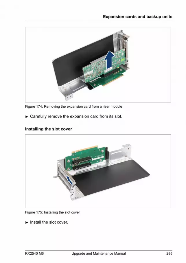
Figure 174: Removing the expansion card from a riser module
▶ Carefully remove the expansion card from its slot.
Installing the slot cover
Figure 175: Installing the slot cover
▶ Install the slot cover.
Expansion cards and backup units
RX2540 M6 Upgrade and Maintenance Manual 285

Concluding steps
▶ If applicable, install the corresponding riser module, see "Installing a riser module" on page 72.
▶ If applicable, install the corresponding rear air grid, see "Installing a rear air grid" on page 84.
▶ "Reassembling" on page 60.
▶ "Connecting the power cord" on page 65.
▶ "Switching on the server" on page 69.
▶ If applicable, "Installing the front cover with lock" on page 69.
▶ If applicable, update the system information of your server using the ChassisID Prom Tool, see "Using the Chassis ID Prom Tool" on page 110.
▶ "Resuming BitLocker functionality" on page 105.
9.8.3 Replacing expansion cards from a riser module
Upgrade and Repair Unit(URU)
Hardware: 10 minutesSoftware: 5 minutes
Tools: Phillips PH2 / (+) No. 2 screw driver
Note on network settings recovery
When replacing network controllers, network configuration settings inthe OS will be lost and replaced by default values. This applies to allstatic IP address and LAN teaming configurations.Ensure to note down your current network settings before replacing anetwork controller.
Preliminary steps
▶ "Locating the defective server" on page 49.
▶ If applicable, "Removing the front cover with lock" on page 52.
Expansion cards and backup units
286 Upgrade and Maintenance Manual RX2540 M6
▶ If applicable, "Configuring LAN teaming" on page 113.
▶ "Suspending BitLocker functionality" on page 87.
▶ "Shutting down the server" on page 52.
▶ "Disconnecting the power cord" on page 53.
▶ "Getting access to the component" on page 56.
▶ "Locating the defective component" on page 50.
▶ Remove the corresponding riser module, see "Removing a riser module" on page 70.
Removing the defective expansion card
▶ Remove the expansion card, see "Removing the expansion card from a riser module" on page 284.
▶ If the slot bracket on the defective expansion card is to be reused, remove itfrom the expansion card, see "Removing slot brackets" on page 239.
Installing the new expansion card
▶ If applicable, install the slot bracket, see "Installing slot brackets" on page 237.
▶ Install the expansion card, see "Installing the expansion card in a riser module" on page 281.
Concluding steps
▶ Install the corresponding riser module, see "Installing a riser module" on page 72.
▶ "Reassembling" on page 60.
▶ If applicable, connect external cables to the expansion card.
▶ "Connecting the power cord" on page 65.
▶ "Switching on the server" on page 69.
▶ If applicable, "Installing the front cover with lock" on page 69.
▶ "Enabling replaced components in the BIOS" on page 100.
Expansion cards and backup units
RX2540 M6 Upgrade and Maintenance Manual 287
▶ Inform the customer about changed WWN, MAC and SAS addresses, see"Looking for MAC/WWN/GUID and SAS addresses" on page 107.
▶ "Updating the NIC configuration file in a Linux and VMware environment" on page 104.
▶ "Updating expansion card firmware" on page 95.
▶ "Resuming BitLocker functionality" on page 105.
▶ If applicable, reconfigure your network settings in the operation systemaccording to the original configuration of the replaced controller (expansioncard or onboard).
Configuration of network settings should be performed by thecustomer. For more information, see "Note on network settings recovery" on page 286.
▶ If applicable, restore LAN teaming configurations, see "After replacing or upgrading LAN controllers" on page 114.
9.8.4 Replacing a riser card
Field Replaceable Unit(FRU)
Hardware: 5 minutes
Tools: Phillips PH2 / (+) No. 2 screw driver
Preliminary steps
▶ "Locating the defective server" on page 49.
▶ If applicable, "Removing the front cover with lock" on page 52.
▶ "Shutting down the server" on page 52.
▶ "Disconnecting the power cord" on page 53.
▶ "Getting access to the component" on page 56.
▶ "Locating the defective component" on page 50.
▶ Remove the corresponding riser module, see "Removing a riser module" on page 70.
Expansion cards and backup units
288 Upgrade and Maintenance Manual RX2540 M6
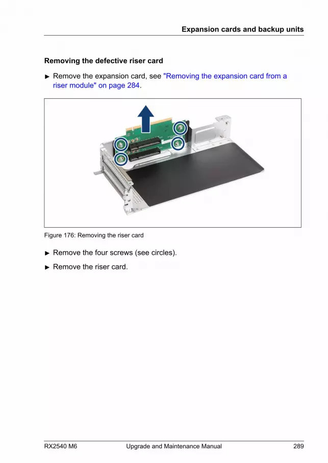
Removing the defective riser card
▶ Remove the expansion card, see "Removing the expansion card from a riser module" on page 284.
Figure 176: Removing the riser card
▶ Remove the four screws (see circles).
▶ Remove the riser card.
Expansion cards and backup units
RX2540 M6 Upgrade and Maintenance Manual 289

Installing the new riser card
Figure 177: Installing the riser card
▶ Insert the riser card.
▶ Fasten the riser card with four screws (see circles).
▶ Install the expansion card, see "Installing the expansion card in a riser module" on page 281.
Concluding steps
▶ Install the corresponding riser module, see "Installing a riser module" on page 72.
▶ "Reassembling" on page 60.
▶ "Connecting the power cord" on page 65.
▶ "Switching on the server" on page 69.
▶ If applicable, "Installing the front cover with lock" on page 69.
Expansion cards and backup units
290 Upgrade and Maintenance Manual RX2540 M6
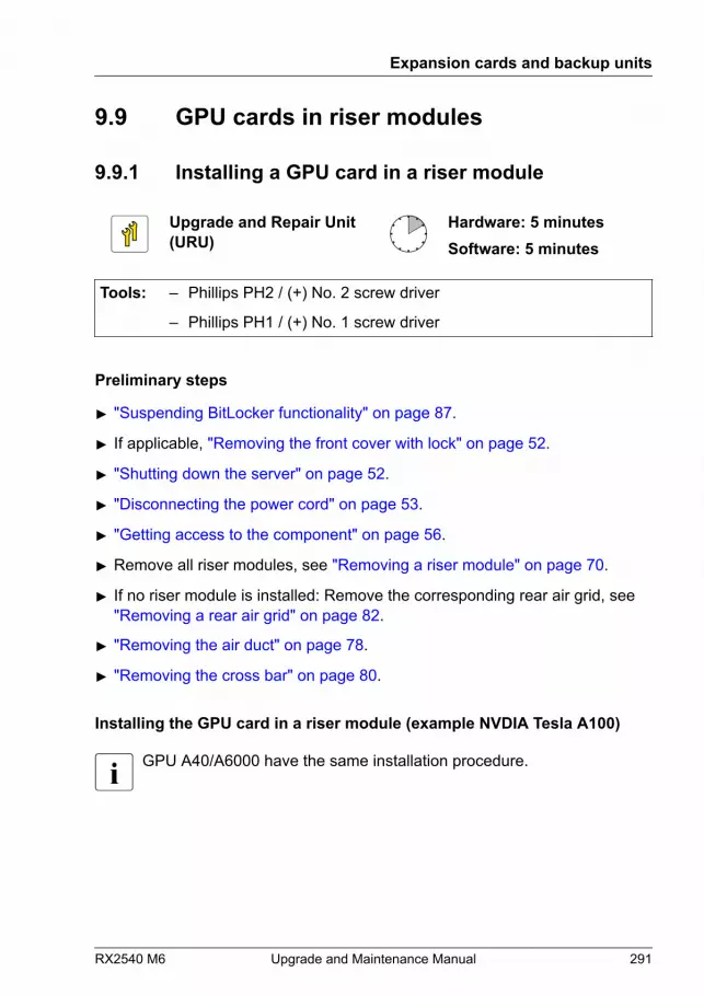
9.9 GPU cards in riser modules
9.9.1 Installing a GPU card in a riser module
Upgrade and Repair Unit(URU)
Hardware: 5 minutesSoftware: 5 minutes
Tools: – Phillips PH2 / (+) No. 2 screw driver
– Phillips PH1 / (+) No. 1 screw driver
Preliminary steps
▶ "Suspending BitLocker functionality" on page 87.
▶ If applicable, "Removing the front cover with lock" on page 52.
▶ "Shutting down the server" on page 52.
▶ "Disconnecting the power cord" on page 53.
▶ "Getting access to the component" on page 56.
▶ Remove all riser modules, see "Removing a riser module" on page 70.
▶ If no riser module is installed: Remove the corresponding rear air grid, see"Removing a rear air grid" on page 82.
▶ "Removing the air duct" on page 78.
▶ "Removing the cross bar" on page 80.
Installing the GPU card in a riser module (example NVDIA Tesla A100)
GPU A40/A6000 have the same installation procedure.
Expansion cards and backup units
RX2540 M6 Upgrade and Maintenance Manual 291
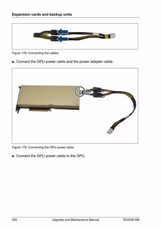
Figure 178: Connecting the cables
▶ Connect the GPU power cable and the power adapter cable.
Figure 179: Connecting the GPU power cable
▶ Connect the GPU power cable to the GPU.
Expansion cards and backup units
292 Upgrade and Maintenance Manual RX2540 M6

Figure 180: Removing the two slot covers
▶ Remove the two slot covers.
CAUTION▶ Keep the slot cover for future use.▶ If the expansion card is removed and not replaced with a new one,
the slot cover must be reinstalled due to cooling, to comply withapplicable EMC regulations and to protect against fire.
Expansion cards and backup units
RX2540 M6 Upgrade and Maintenance Manual 293
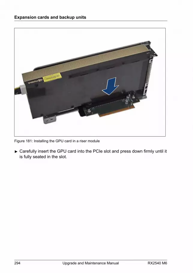
Figure 181: Installing the GPU card in a riser module
▶ Carefully insert the GPU card into the PCIe slot and press down firmly until itis fully seated in the slot.
Expansion cards and backup units
294 Upgrade and Maintenance Manual RX2540 M6

▶
Figure 182: Locking the GPU card
▶ Ensure that the GPU riser latch locks completely in the riser card (seecircle).
▶ Connect the GPU power cable to the system board connector "PWR 9"(riser module 2) or "PWR 10" (riser module 1).
▶ Install the cross bar, see "Installing the cross bar" on page 81.
▶ Install the air duct, see "Installing the air duct" on page 79.
▶ Install the corresponding riser module, see "Installing a riser module" on page 72.
Expansion cards and backup units
RX2540 M6 Upgrade and Maintenance Manual 295

Figure 183: Routing of the GPU power cable (example riser module 1)
▶ Route the GPU power cable as shown.
To install a second GPU riser module in slot 9, proceed with the GPU powercable of the first GPU riser module (in slot 3) as follows:
Expansion cards and backup units
296 Upgrade and Maintenance Manual RX2540 M6
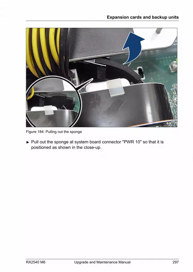
Figure 184: Pulling out the sponge
▶ Pull out the sponge at system board connector "PWR 10" so that it ispositioned as shown in the close-up.
Expansion cards and backup units
RX2540 M6 Upgrade and Maintenance Manual 297

Figure 185: Folding away the GPU power cable
▶ Fold away the GPU power cable of the first GPU riser module as shown.
Expansion cards and backup units
298 Upgrade and Maintenance Manual RX2540 M6
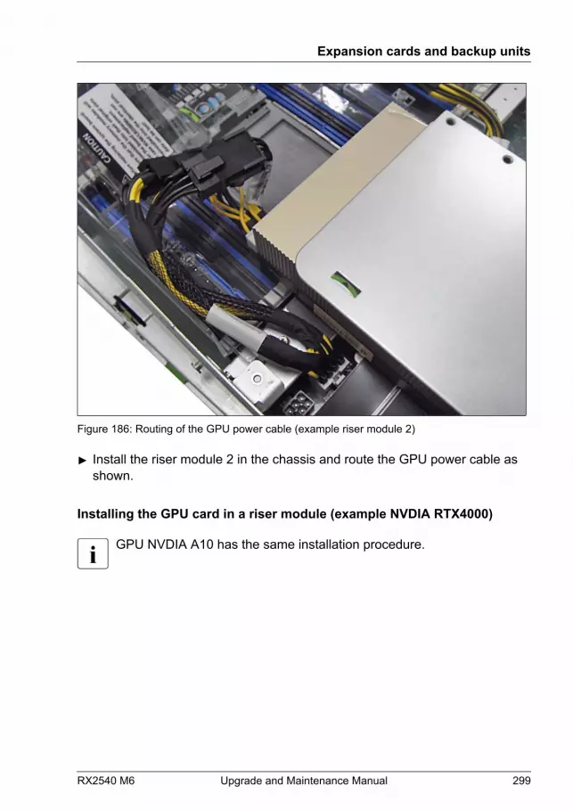
Figure 186: Routing of the GPU power cable (example riser module 2)
▶ Install the riser module 2 in the chassis and route the GPU power cable asshown.
Installing the GPU card in a riser module (example NVDIA RTX4000)
GPU NVDIA A10 has the same installation procedure.
Expansion cards and backup units
RX2540 M6 Upgrade and Maintenance Manual 299

Figure 187: Connecting the GPU power cable
▶ Connect the GPU power cable to the GPU.
Figure 188: Removing the lower slot cover
Expansion cards and backup units
300 Upgrade and Maintenance Manual RX2540 M6
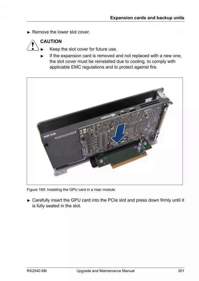
▶ Remove the lower slot cover.
CAUTION▶ Keep the slot cover for future use.▶ If the expansion card is removed and not replaced with a new one,
the slot cover must be reinstalled due to cooling, to comply withapplicable EMC regulations and to protect against fire.
Figure 189: Installing the GPU card in a riser module
▶ Carefully insert the GPU card into the PCIe slot and press down firmly until itis fully seated in the slot.
Expansion cards and backup units
RX2540 M6 Upgrade and Maintenance Manual 301

▶
Figure 190: Locking the GPU card
▶ Ensure that the GPU riser latch locks completely in the riser card (seecircle).
▶ Connect the GPU power cable to the system board connector "PWR 9"(riser module 2) or "PWR 10" (riser module 1).
▶ Install the cross bar, see "Installing the cross bar" on page 81.
▶ Install the air duct, see "Installing the air duct" on page 79.
▶ Install the corresponding riser module, see "Installing a riser module" on page 72.
Expansion cards and backup units
302 Upgrade and Maintenance Manual RX2540 M6

Figure 191: Routing of the GPU power cable (example riser module 1)
▶ Route the GPU power cable as shown.
To install a second GPU riser module in slot 9, proceed with the GPU powercable of the first GPU riser module (in slot 3) as follows:
Expansion cards and backup units
RX2540 M6 Upgrade and Maintenance Manual 303

Figure 192: Pulling out the sponge
▶ Pull out the sponge at system board connector "PWR 10" so that it ispositioned as shown in the close-up.
Expansion cards and backup units
304 Upgrade and Maintenance Manual RX2540 M6
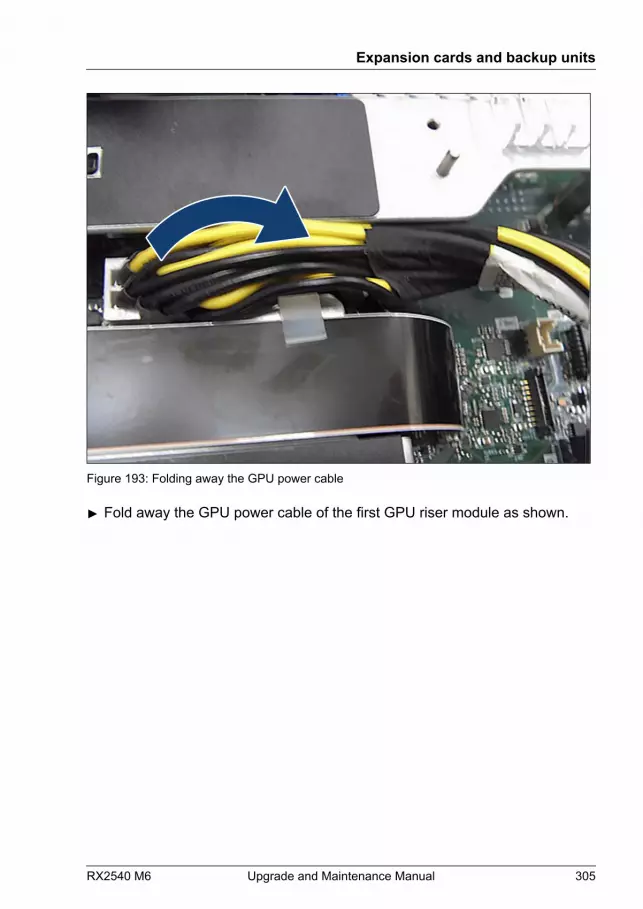
Figure 193: Folding away the GPU power cable
▶ Fold away the GPU power cable of the first GPU riser module as shown.
Expansion cards and backup units
RX2540 M6 Upgrade and Maintenance Manual 305
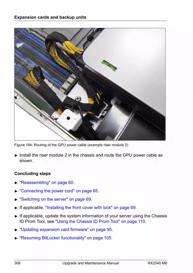
Figure 194: Routing of the GPU power cable (example riser module 2)
▶ Install the riser module 2 in the chassis and route the GPU power cable asshown.
Concluding steps
▶ "Reassembling" on page 60.
▶ "Connecting the power cord" on page 65.
▶ "Switching on the server" on page 69.
▶ If applicable, "Installing the front cover with lock" on page 69.
▶ If applicable, update the system information of your server using the ChassisID Prom Tool, see "Using the Chassis ID Prom Tool" on page 110.
▶ "Updating expansion card firmware" on page 95.
▶ "Resuming BitLocker functionality" on page 105.
Expansion cards and backup units
306 Upgrade and Maintenance Manual RX2540 M6
9.9.2 Removing a GPU card from a riser module
Upgrade and Repair Unit(URU)
Hardware: 5 minutesSoftware: 5 minutes
Tools: Phillips PH2 / (+) No. 2 screw driver
Preliminary steps
▶ "Suspending BitLocker functionality" on page 87.
▶ If applicable, "Removing the front cover with lock" on page 52.
▶ "Shutting down the server" on page 52.
▶ "Disconnecting the power cord" on page 53.
▶ "Getting access to the component" on page 56.
▶ Remove all riser modules, see "Removing a riser module" on page 70.
▶ "Removing an expansion card from a riser module" on page 284.
▶ If necessary, remove the cables from the expansion cards.
▶ "Removing the air duct" on page 78.
▶ Disconnect the GPU power cable from the system board connector.
Removing the GPU card from a riser module (example NVDIA Tesla A100)
GPU A40/A6000 have the same removement procedure.
Expansion cards and backup units
RX2540 M6 Upgrade and Maintenance Manual 307
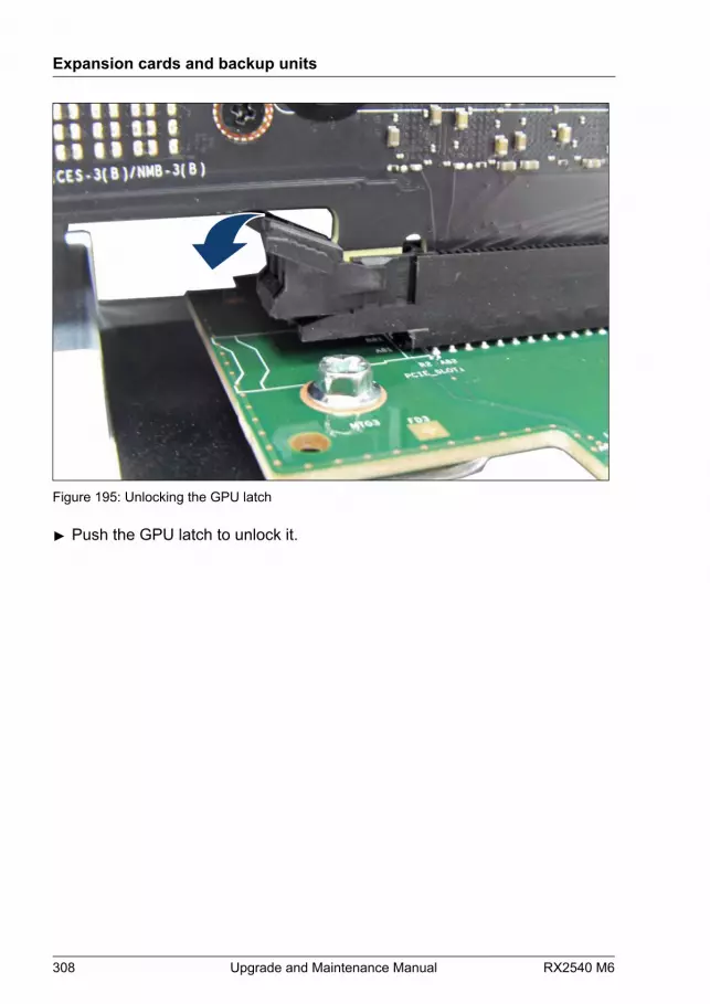
Figure 195: Unlocking the GPU latch
▶ Push the GPU latch to unlock it.
Expansion cards and backup units
308 Upgrade and Maintenance Manual RX2540 M6
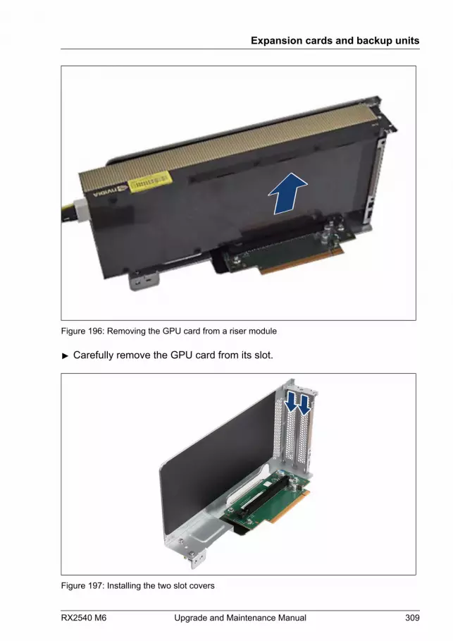
Figure 196: Removing the GPU card from a riser module
▶ Carefully remove the GPU card from its slot.
Figure 197: Installing the two slot covers
Expansion cards and backup units
RX2540 M6 Upgrade and Maintenance Manual 309
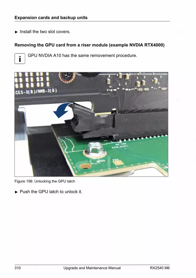
▶ Install the two slot covers.
Removing the GPU card from a riser module (example NVDIA RTX4000)
GPU NVDIA A10 has the same removement procedure.
Figure 198: Unlocking the GPU latch
▶ Push the GPU latch to unlock it.
Expansion cards and backup units
310 Upgrade and Maintenance Manual RX2540 M6
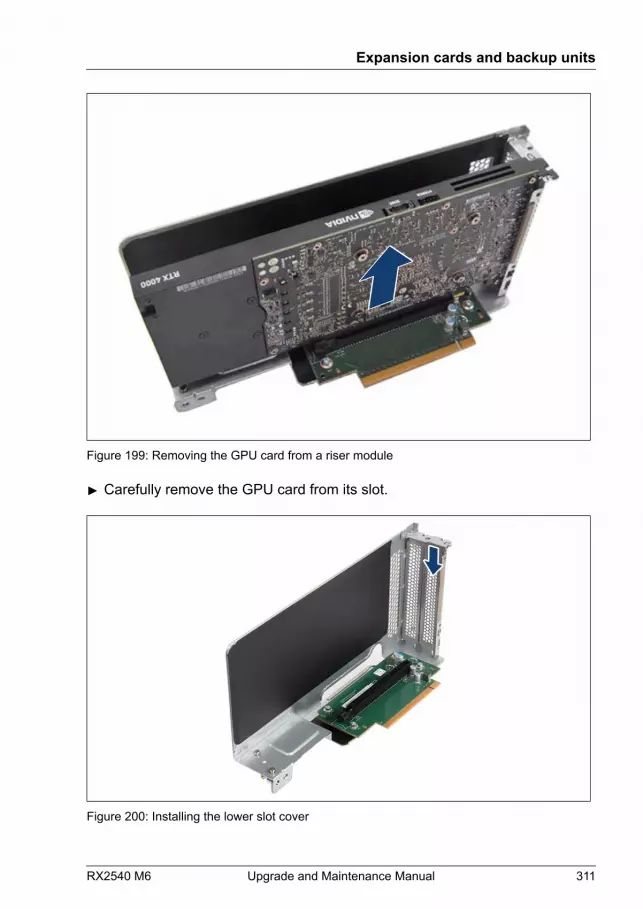
Figure 199: Removing the GPU card from a riser module
▶ Carefully remove the GPU card from its slot.
Figure 200: Installing the lower slot cover
Expansion cards and backup units
RX2540 M6 Upgrade and Maintenance Manual 311
▶ Install the lower slot cover.
Concluding steps
▶ "Installing the cross bar" on page 81.
▶ "Installing the air duct" on page 79.
▶ If applicable, install the corresponding riser module, see "Installing a riser module" on page 72.
▶ If applicable, install the corresponding rear air grid, see "Installing a rear air grid" on page 84.
▶ "Reassembling" on page 60.
▶ "Connecting the power cord" on page 65.
▶ "Switching on the server" on page 69.
▶ If applicable, "Installing the front cover with lock" on page 69.
▶ If applicable, update the system information of your server using the ChassisID Prom Tool, see "Using the Chassis ID Prom Tool" on page 110.
▶ "Resuming BitLocker functionality" on page 105.
9.9.3 Replacing a GPU card from a riser module
Upgrade and Repair Unit(URU)
Hardware: 10 minutesSoftware: 5 minutes
Tools: Phillips PH2 / (+) No. 2 screw driver
Note on network settings recovery
When replacing network controllers, network configuration settings inthe OS will be lost and replaced by default values. This applies to allstatic IP address and LAN teaming configurations.Ensure to note down your current network settings before replacing anetwork controller.
Expansion cards and backup units
312 Upgrade and Maintenance Manual RX2540 M6
Preliminary steps
▶ "Suspending BitLocker functionality" on page 87.
▶ If applicable, "Removing the front cover with lock" on page 52.
▶ "Shutting down the server" on page 52.
▶ "Disconnecting the power cord" on page 53.
▶ "Getting access to the component" on page 56.
▶ Remove all riser modules, see "Removing a riser module" on page 70.
▶ "Removing the cross bar" on page 80.
▶ If necessary, remove the cables from the expansion cards.
▶ "Removing the air duct" on page 78.
Removing the defective GPU card
▶ Remove the GPU card, see "Removing the GPU card from a riser module (example NVDIA Tesla A100)" on page 307 or "Removing the GPU card from a riser module (example NVDIA RTX4000)" on page 310.
Installing the new GPU card
▶ Install the GPU card, see "Installing the GPU card in a riser module (example NVDIA Tesla A100)" on page 291 or "Installing the GPU card in a riser module (example NVDIA RTX4000)" on page 299.
Concluding steps
▶ "Reassembling" on page 60.
▶ Connect all external cables to the expansion card(s).
▶ "Connecting the power cord" on page 65.
▶ "Switching on the server" on page 69.
▶ If applicable, "Installing the front cover with lock" on page 69.
▶ If applicable, update the system information of your server using the ChassisID Prom Tool, see "Using the Chassis ID Prom Tool" on page 110.
Expansion cards and backup units
RX2540 M6 Upgrade and Maintenance Manual 313

▶ "Updating expansion card firmware" on page 95.
▶ "Resuming BitLocker functionality" on page 105.
9.9.4 Replacing a riser card
Field Replaceable Unit(FRU)
Hardware: 5 minutes
Tools: Phillips PH2 / (+) No. 2 screw driver
Preliminary steps
▶ "Locating the defective server" on page 49.
▶ If applicable, "Removing the front cover with lock" on page 52.
▶ "Shutting down the server" on page 52.
▶ "Disconnecting the power cord" on page 53.
▶ "Getting access to the component" on page 56.
▶ "Locating the defective component" on page 50.
▶ Remove the corresponding riser module, see "Removing a riser module" on page 70.
Removing the defective riser card
▶ Remove the GPU card, see "Removing a GPU card from a riser module" on page 307.
Expansion cards and backup units
314 Upgrade and Maintenance Manual RX2540 M6
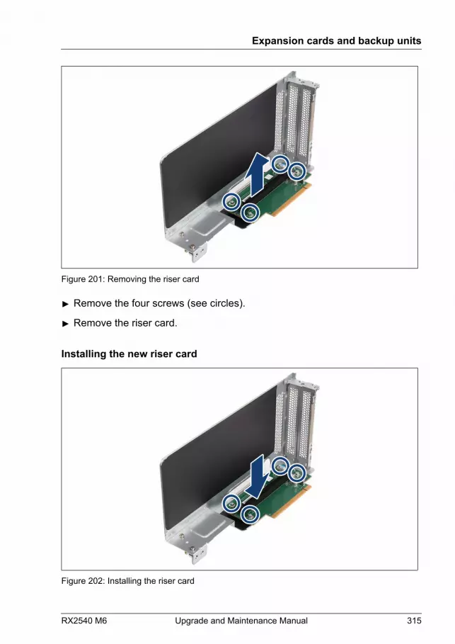
Figure 201: Removing the riser card
▶ Remove the four screws (see circles).
▶ Remove the riser card.
Installing the new riser card
Figure 202: Installing the riser card
Expansion cards and backup units
RX2540 M6 Upgrade and Maintenance Manual 315
▶ Insert the riser card.
▶ Fasten the riser card with four screws (see circles).
▶ Install the GPU card, see "Installing a GPU card in a riser module" on page 291.
Concluding steps
▶ Install the corresponding riser module, see "Installing a riser module" on page 72.
▶ "Reassembling" on page 60.
▶ "Connecting the power cord" on page 65.
▶ "Switching on the server" on page 69.
▶ If applicable, "Installing the front cover with lock" on page 69.
9.10 Flash backup unit (FBU)
9.10.1 Positions of the FBUs
You can install up to two FBUs.
Expansion cards and backup units
316 Upgrade and Maintenance Manual RX2540 M6

Figure 203: Positions of the FBUs
1 FBU 1 2 FBU 2
9.10.2 Installing an FBU
Upgrade and Repair Unit(URU)
Hardware: 15 minutes
Tools: Phillips PH2 / (+) No. 2 screw driver (for cover 2)
Preliminary steps
▶ If applicable, "Removing the front cover with lock" on page 52.
▶ "Shutting down the server" on page 52.
▶ "Disconnecting the power cord" on page 53.
▶ "Getting access to the component" on page 56.
Expansion cards and backup units
RX2540 M6 Upgrade and Maintenance Manual 317

Installing the FBU in the FBU holder
Figure 204: Installing the FBU in the holder
▶ At a slight angle, fit the FBU under both retaining brackets of the FBU holderas shown.Notice the right position of the FBU cable:
OK
▶ Push in the FBU until it locks in place (1).
▶ Connect the FBU adapter cable to the FBU (2).
▶ If applicable, connect the FBU adapter cable to the corresponding RAIDcontroller.
Expansion cards and backup units
318 Upgrade and Maintenance Manual RX2540 M6

Installing the FBU with the FBU holder
Figure 205: Bolts on the air duct
▶ Notice the three bolts on the air duct and key holes on the FBU holder (seecircles). The FBU holder is fixed with the bolts and the keyholes on the airduct.
Figure 206: Installing the FBU with the FBU holder
Expansion cards and backup units
RX2540 M6 Upgrade and Maintenance Manual 319

▶ Insert the FBU with the holder and slide in direction of the arrow until theFBU holder engages (see circle).
▶ Install the RAID controller, see "Installing an expansion card" on page 255.
Examples FBU cabling with two FBUs
Figure 207: 2x FBUs, 2x SAS EP5xxi RAID controller in internal RAID riser slot and PCIe slot1
1 Cable to FBU 1 and SAS EP5xxi RAIDcontroller
2 Cable to FBU 2 and SAS EP5xxi RAIDcontroller
Expansion cards and backup units
320 Upgrade and Maintenance Manual RX2540 M6
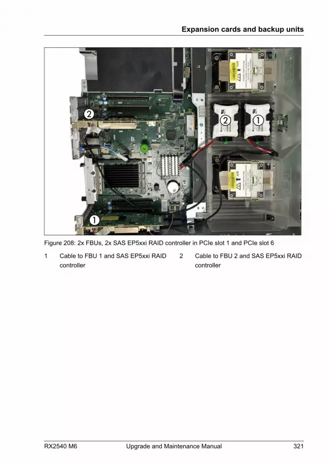
Figure 208: 2x FBUs, 2x SAS EP5xxi RAID controller in PCIe slot 1 and PCIe slot 6
1 Cable to FBU 1 and SAS EP5xxi RAIDcontroller
2 Cable to FBU 2 and SAS EP5xxi RAIDcontroller
Expansion cards and backup units
RX2540 M6 Upgrade and Maintenance Manual 321
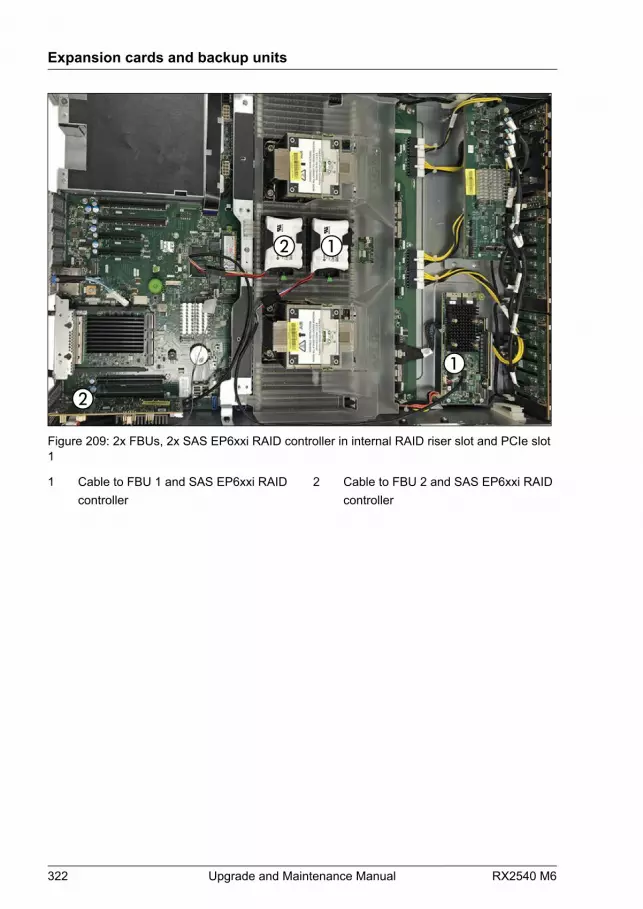
Figure 209: 2x FBUs, 2x SAS EP6xxi RAID controller in internal RAID riser slot and PCIe slot1
1 Cable to FBU 1 and SAS EP6xxi RAIDcontroller
2 Cable to FBU 2 and SAS EP6xxi RAIDcontroller
Expansion cards and backup units
322 Upgrade and Maintenance Manual RX2540 M6
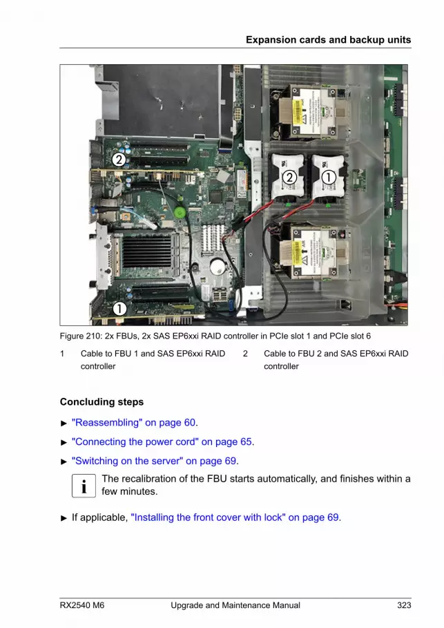
Figure 210: 2x FBUs, 2x SAS EP6xxi RAID controller in PCIe slot 1 and PCIe slot 6
1 Cable to FBU 1 and SAS EP6xxi RAIDcontroller
2 Cable to FBU 2 and SAS EP6xxi RAIDcontroller
Concluding steps
▶ "Reassembling" on page 60.
▶ "Connecting the power cord" on page 65.
▶ "Switching on the server" on page 69.
The recalibration of the FBU starts automatically, and finishes within afew minutes.
▶ If applicable, "Installing the front cover with lock" on page 69.
Expansion cards and backup units
RX2540 M6 Upgrade and Maintenance Manual 323
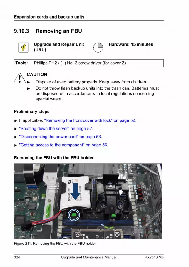
9.10.3 Removing an FBU
Upgrade and Repair Unit(URU)
Hardware: 15 minutes
Tools: Phillips PH2 / (+) No. 2 screw driver (for cover 2)
CAUTION▶ Dispose of used battery properly. Keep away from children.▶ Do not throw flash backup units into the trash can. Batteries must
be disposed of in accordance with local regulations concerningspecial waste.
Preliminary steps
▶ If applicable, "Removing the front cover with lock" on page 52.
▶ "Shutting down the server" on page 52.
▶ "Disconnecting the power cord" on page 53.
▶ "Getting access to the component" on page 56.
Removing the FBU with the FBU holder
Figure 211: Removing the FBU with the FBU holder
Expansion cards and backup units
324 Upgrade and Maintenance Manual RX2540 M6

▶ Lift up the green locking handle on the holder (see circle) while sliding theholder in direction of the arrow as far as it will go.
▶ Remove the FBU holder from the system air duct 1.
Removing the FBU
Figure 212: Removing the FBU from the holder
▶ Disconnect the FBU adapter cable (1).
▶ Remove the FBU from the holder (2).
Concluding steps
▶ "Reassembling" on page 60.
▶ "Connecting the power cord" on page 65.
▶ "Switching on the server" on page 69.
▶ If applicable, "Installing the front cover with lock" on page 69.
9.10.4 Replacing an FBU
Upgrade and Repair Unit(URU)
Hardware: 15 minutes
Expansion cards and backup units
RX2540 M6 Upgrade and Maintenance Manual 325
Tools: Phillips PH2 / (+) No. 2 screw driver (for cover 2)
CAUTION▶ Dispose of used battery properly. Keep away from children.▶ Do not throw flash backup units into the trash can. Batteries must
be disposed of in accordance with local regulations concerningspecial waste.
Preliminary steps
▶ "Locating the defective server" on page 49.
▶ If applicable, "Removing the front cover with lock" on page 52.
▶ "Shutting down the server" on page 52.
▶ "Disconnecting the power cord" on page 53.
▶ "Getting access to the component" on page 56.
Removing the defective FBU
▶ Remove the FBU with the FBU holder, see "Removing the FBU with the FBU holder" on page 324.
▶ Remove the FBU from the FBU holder, see "Removing the FBU" on page 325.
Installing the new FBU
▶ Install the FBU in the FBU holder and connect the FBU cable to the FBU,see "Installing the FBU in the FBU holder" on page 318.
▶ Install the FBU with the FBU holder, see "Installing the FBU with the FBU holder" on page 319.
Concluding steps
▶ "Reassembling" on page 60.
▶ "Connecting the power cord" on page 65.
Expansion cards and backup units
326 Upgrade and Maintenance Manual RX2540 M6

▶ "Switching on the server" on page 69.
The recalibration of the FBU starts automatically, and finishes within afew minutes.
▶ If applicable, "Installing the front cover with lock" on page 69.
Expansion cards and backup units
RX2540 M6 Upgrade and Maintenance Manual 327
Expansion cards and backup units
328 Upgrade and Maintenance Manual RX2540 M6

10 Main memory
10.1 Safety notes
CAUTION▶ Before removing several memory modules, make sure that all
memory modules can be reinstalled into their original slots.Otherwise, data may be lost.
▶ Do not install unsupported third party memory modules. For moreinformation on supported memory modules, see "Basic information" on page 330. Doing so may cause electric shock, afire, or failures.
▶ Memory modules remain hot after shutdown. Wait for componentsto cool down before installing or removing memory modules toprevent burns.
▶ Do not install and remove memory modules repeatedly. Doing somay cause failures.
▶ If the memory module has not been correctly installed, it may causea fire. Install the memory module with attention.Pressing out the securing clips on the memory module connectorwill eject the installed memory module. To prevent damage andinjuries eject memory modules carefully without applying excessiveforce.
▶ For more information, see "Important information" on page 35.
RX2540 M6 Upgrade and Maintenance Manual 329

10.2 Basic information
10.2.1 Slots and features
iRMCS5
exte
rnal
con
nect
ors
INDICATE CSS
TPM
Slot 2 (CPU 1) Riser slot 1
Battery
SATA 0-3
Slot 1 (CPU 1)
Slot 8 (CPU 2) Riser slot 2
Rear Serial
PWRODD
Front Panel
SATA 4-7
SATAODD Internal
USB3.0 / USB 4
PSU1
PSU2
JP3 1
JP2 JP112
MicroSD
USB 3.0
SSD2 M.2
HDD LED2
Slot 7 (CPU2)
Slot 6 (CPU2)
Front VGA
Slot 5 (CPU2)
OCP
3.0
Slo
t 1 (C
PU1)
SSD
1 M
.2
LANManagement
Internal USB3.0/USB 3
Rear VGA
CPU 2 DIMM 2JCPU 2 DIMM 1M
CPU 2 DIMM 1LCPU 2 DIMM 2L
CPU 2 DIMM 1J
CPU 2 DIMM 2M
CPU 2 DIMM 2KCPU 2 DIMM 1K
CPU 2
CPU 1
CPU 1 DIMM 2ACPU 1 DIMM 1D
CPU 1 DIMM 1CCPU 1 DIMM 2C
CPU 1 DIMM 1A
CPU 1 DIMM 2D
CPU 1 DIMM 2BCPU 1 DIMM 1B
CPU 2 DIMM 1RCPU 2 DIMM 2N
CPU 2 DIMM 2PCPU 2 DIMM 1P
CPU 2 DIMM 2R
CPU 2 DIMM 1N
CPU 2 DIMM 1QCPU 2 DIMM 2Q
CPU 1 DIMM 1HCPU 1 DIMM 2E
CPU 1 DIMM 2FCPU 1 DIMM 1F
CPU 1 DIMM 2H
CPU 1 DIMM 1E
CPU 1 DIMM 1GCPU 1 DIMM 2G
SMB 4
LC1
SLIMLINE4 (CPU 2)
LC2
SMB 2
SMB 1
PWR9
PWR10
HDD LED3
HDD LED1
PWR6
PWR5
PWR4
PWR3
PWR2
PWR1
SLIMLINE3 (CPU 2)
SLIMLINE2 (CPU 1)
SLIMLINE1 (CPU 1)
FAN6_SYS
FAN5_SYS
FAN4_SYS
FAN3_SYS
FAN2_SYS
FAN1_SYS
ROC
VROC
SMB 3
Clear RTC
PCH
Slot riser card
Rise
r car
d
Slot 10
Slot 9
Slot riser card
Rise
r car
d
Slot 4
Slot 3
Slot riser card
Rise
r car
d
GPGPU RiserSlot 9
Slot riser card
Rise
r car
d
GPGPU RiserSlot 3
Figure 213: Slots of the main memory
1 CPU 1 memory slots 2 CPU 2 memory slots
– Eight channel DDR4 memory architecture (per CPU), 2 DIMMs per channel
– 32 memory DIMM sockets R3 (16 per CPU)
– Supports RDIMM w/ ECC, 3DS-RDIMM, LRDIMM, and Optane PMemmodules
– Supports DDR4 up to 3200 MT/s
Main memory
330 Upgrade and Maintenance Manual RX2540 M6
– Supports Optane PMem modules up to 3200 MT/s
– Supports Optane PMem module capacity of 128 GB, 256 GB, and 512 GB
– Up to 4 TB/CPU using DDR4 DIMM (256 GB modules)
– Up to 12 TB/CPU using Optane PMem modules + DDR4
– Error detection and correction (ECC)
– Single Device Data Correction (SDDC)
– ADDDC Sparing (Virtual lockstep mode)
– Channel mirroring within a socket
– Hardware memory scrubbing
– Lockstep mode is not supported by BIOS on this platform
– Rank Level Sparing is not supported
The notation of the CPUs, memory channels and DIMM sockets correspond tothe silk print on the system board.
For system relevant information, see the hardware configurator of yourserver available online at the following address:http://ts.fujitsu.com/products/standard_servers/index.htmFor Japan:http://www.fujitsu.com/jp/products/computing/servers/primergy/
Optane PMem module features
– The Optane PMem modules are displayed as “NVM / LRDIMM”, accordingto the JEDEC specification. This occurs for example with the iRMC webinterface, when SPD data are retrieved.
– Supports Optane PMem module sizes of 128 GB, 256 GB, and 512 GB
– Supports Double Device Data Correction (DDDC)
– Supports DDR4 speeds of 2400/2666/2933/3200 MT/s
Main memory
RX2540 M6 Upgrade and Maintenance Manual 331
For Optane PMem modules, the following two modes are available:
● App Direct mode
● DDR4 DIMM operates as main memory
● Optane PMem module operates as non-volatile memory or storagedevice
● Memory mode
● DDR4 DIMM operates as cache
● Optane PMem module operates as main memory
App Direct mode and Memory mode can be used simultaneously.
10.2.2 General memory population rules
– Non-ECC DIMMs are not supported on this platform.
– All DIMMs must be either all DDR4 DIMMs and/or DDR4 DIMMs andOptane PMem modules.
– Mixing of LRDIMM with RDIMM type is not allowed per platform (i.e. thesame channel, across different channels, and across different sockets).
– Mixing of non-3DS and 3DS RDIMMs is not allowed in platform.
– Mixing of Optane PMem modules with RDIMMs or with LRDIMMs issupported.
– DIMMs with different frequencies can be mixed in the system, but lowestfrequency determines the system memory speed.
– There should be at least one DDR4 DIMM per CPU socket.
– If only one DIMM is populated in a channel, then populate it in the slotfurthest away from CPU (i.e. the black slot).
– Mixing Optane PMem capacities or generations or DDR4 capacities andtypes within a socket or across sockets is not supported for Optane PMemconfigurations.
– When different rank DIMMs are populated for 2DPC, always populate thehigher number rank DIMM first (starting from the black slot), for example,first octal rank, then quad rank, then dual rank, and last single rank DIMM.
Main memory
332 Upgrade and Maintenance Manual RX2540 M6

10.2.3 DDR4 only - memory population rules
– Unbalanced configurations can lead to significantly reduced bandwidthbecause the system will fracture the memory space into multiple regions.
– If two DIMM with different capacity are installed in one channel, the one withhigher capacity has to be placed in slot 1 of a channel. E.g. 1A, 1B, ….
– Rank sparing mode is not supported.
Normal mode
CPU CPUn iMC 0 1 2 3 DDR CH 0 1 0 1 0 1 0 1 Slot 0 1 0 1 0 1 0 1 0 1 0 1 0 1 0 1 Socket 1
A 2 A
1 B
2 B
1 C
2 C
1 D
2 D
1 E
2 E
1 F
2 F
1 G
2 G
1 H
2 H
#DIMMs 1 D 2 D D 4 D D D D 6 D D D D D D 8 * D D D D D D D D 12 D D D D D D D D D D D D 12 * D D D D D D D D D D D D 16 * D D D D D D D D D D D D D D D D * SGX is supported.
D DDR4 DIMM is installed
Mirroring mode
The DIMM population will exactly be identical for the mirrored channels.
Main memory
RX2540 M6 Upgrade and Maintenance Manual 333
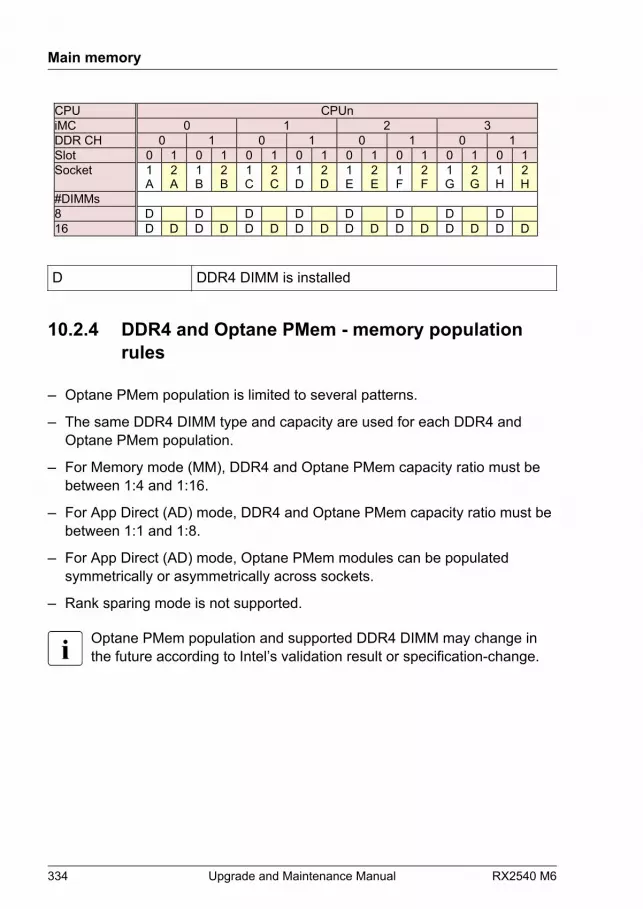
CPU CPUn iMC 0 1 2 3 DDR CH 0 1 0 1 0 1 0 1 Slot 0 1 0 1 0 1 0 1 0 1 0 1 0 1 0 1 Socket 1
A 2 A
1 B
2 B
1 C
2 C
1 D
2 D
1 E
2 E
1 F
2 F
1 G
2 G
1 H
2 H
#DIMMs 8 D D D D D D D D 16 D D D D D D D D D D D D D D D D D DDR4 DIMM is installed
10.2.4 DDR4 and Optane PMem - memory populationrules
– Optane PMem population is limited to several patterns.
– The same DDR4 DIMM type and capacity are used for each DDR4 andOptane PMem population.
– For Memory mode (MM), DDR4 and Optane PMem capacity ratio must bebetween 1:4 and 1:16.
– For App Direct (AD) mode, DDR4 and Optane PMem capacity ratio must bebetween 1:1 and 1:8.
– For App Direct (AD) mode, Optane PMem modules can be populatedsymmetrically or asymmetrically across sockets.
– Rank sparing mode is not supported.
Optane PMem population and supported DDR4 DIMM may change inthe future according to Intel’s validation result or specification-change.
Main memory
334 Upgrade and Maintenance Manual RX2540 M6

Normal mode
AD App Direct Mode
MM Memory Mode
B Optane PMem module is installed
D DDR4 DIMM is installedThe following DDR4 DIMMs are supported:
● RDIMM 1R 16 GB
● RDIMM 2R 16 GB
● RDIMM 2R 32 GB
● RDIMM 2R 64 GB
● RDIMM 3DS 128 GB
● RDIMM 3DS 256 GB
● RDIMM 4R 64 GB
● RDIMM 4R 128 GB
Mirroring mode
● Optane PMem is not supported full Mirroring mode.
● When Optane PMem is installed in a system, address range mirroring issupported in App Direct mode.
Main memory
RX2540 M6 Upgrade and Maintenance Manual 335
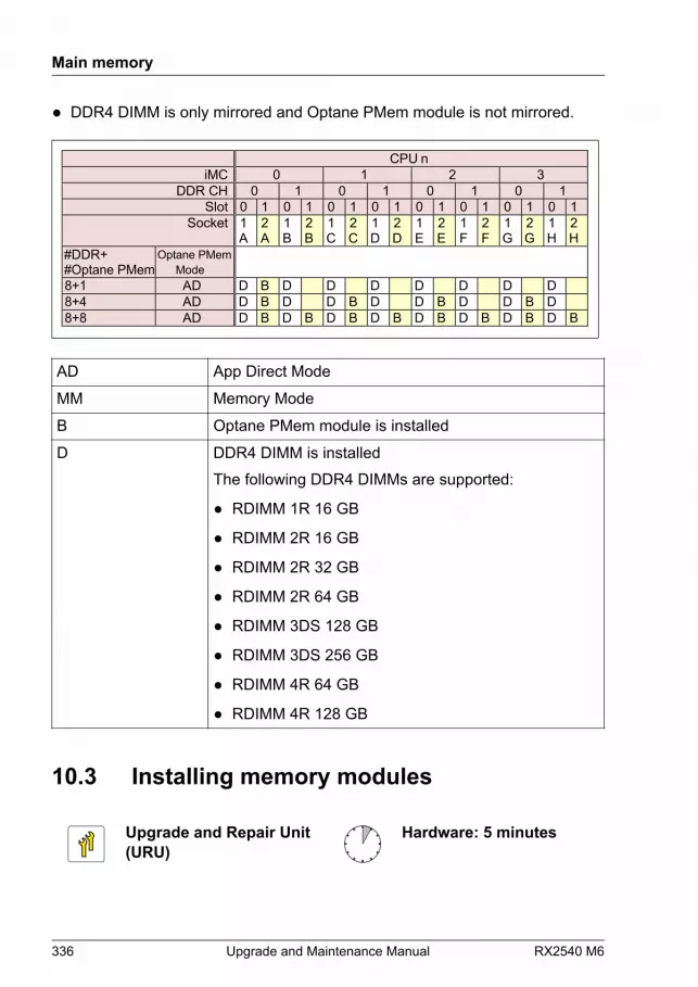
● DDR4 DIMM is only mirrored and Optane PMem module is not mirrored.
AD App Direct Mode
MM Memory Mode
B Optane PMem module is installed
D DDR4 DIMM is installedThe following DDR4 DIMMs are supported:
● RDIMM 1R 16 GB
● RDIMM 2R 16 GB
● RDIMM 2R 32 GB
● RDIMM 2R 64 GB
● RDIMM 3DS 128 GB
● RDIMM 3DS 256 GB
● RDIMM 4R 64 GB
● RDIMM 4R 128 GB
10.3 Installing memory modules
Upgrade and Repair Unit(URU)
Hardware: 5 minutes
Main memory
336 Upgrade and Maintenance Manual RX2540 M6
Tools: Phillips PH2 / (+) No. 2 screw driver (for cover 2)
CAUTION▶ Use only released configurations to ensure a faultless operation of
the system.▶ Before changing the memory configuration, verify if the
configuration is released. Please contact your sales outlet or ourcustomer service center.For more information on configurations of Optane PMem modulesand DDR4 DIMMs, see "Basic information" on page 330.
▶ Only for Optane PMem modules:Check if the Optane PMem firmware is released for your BIOSversion.
Preliminary steps
▶ "Suspending BitLocker functionality" on page 87.
▶ If applicable, "Removing the front cover with lock" on page 52.
▶ "Shutting down the server" on page 52.
▶ "Disconnecting the power cord" on page 53.
▶ "Getting access to the component" on page 56.
▶ "Removing the air duct" on page 78.
Selecting the memory slot
▶ Choose the memory slot according to the configuration rules, see "Basic information" on page 330.
Main memory
RX2540 M6 Upgrade and Maintenance Manual 337
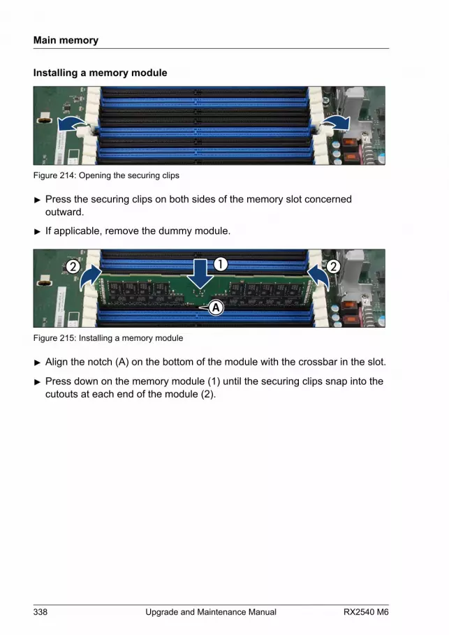
Installing a memory module
Figure 214: Opening the securing clips
▶ Press the securing clips on both sides of the memory slot concernedoutward.
▶ If applicable, remove the dummy module.
A
Figure 215: Installing a memory module
▶ Align the notch (A) on the bottom of the module with the crossbar in the slot.
▶ Press down on the memory module (1) until the securing clips snap into thecutouts at each end of the module (2).
Main memory
338 Upgrade and Maintenance Manual RX2540 M6
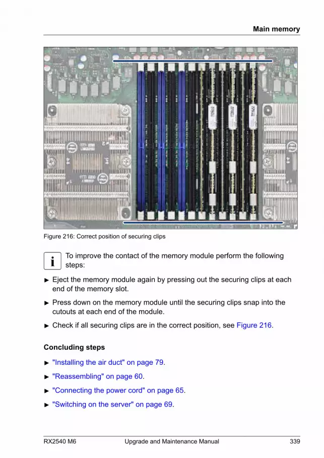
Figure 216: Correct position of securing clips
To improve the contact of the memory module perform the followingsteps:
▶ Eject the memory module again by pressing out the securing clips at eachend of the memory slot.
▶ Press down on the memory module until the securing clips snap into thecutouts at each end of the module.
▶ Check if all securing clips are in the correct position, see Figure 216.
Concluding steps
▶ "Installing the air duct" on page 79.
▶ "Reassembling" on page 60.
▶ "Connecting the power cord" on page 65.
▶ "Switching on the server" on page 69.
Main memory
RX2540 M6 Upgrade and Maintenance Manual 339
▶ If applicable, "Installing the front cover with lock" on page 69.
▶ "Resuming BitLocker functionality" on page 105.
10.4 Removing memory modules
Upgrade and Repair Unit(URU)
Hardware: 5 minutes
Tools: Phillips PH2 / (+) No. 2 screw driver (for cover 2)
CAUTION▶ Use only released configurations to ensure a faultless operation of
the system.▶ Before changing the memory configuration, verify if the
configuration is released. Please contact your sales outlet or ourcustomer service center.
Preliminary steps
▶ "Suspending BitLocker functionality" on page 87.
▶ If applicable, "Removing the front cover with lock" on page 52.
▶ "Shutting down the server" on page 52.
▶ "Disconnecting the power cord" on page 53.
▶ "Getting access to the component" on page 56.
▶ "Removing the air duct" on page 78.
Main memory
340 Upgrade and Maintenance Manual RX2540 M6
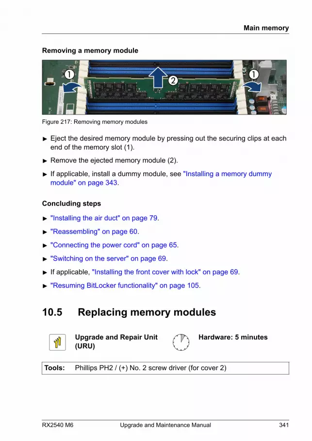
Removing a memory module
Figure 217: Removing memory modules
▶ Eject the desired memory module by pressing out the securing clips at eachend of the memory slot (1).
▶ Remove the ejected memory module (2).
▶ If applicable, install a dummy module, see "Installing a memory dummy module" on page 343.
Concluding steps
▶ "Installing the air duct" on page 79.
▶ "Reassembling" on page 60.
▶ "Connecting the power cord" on page 65.
▶ "Switching on the server" on page 69.
▶ If applicable, "Installing the front cover with lock" on page 69.
▶ "Resuming BitLocker functionality" on page 105.
10.5 Replacing memory modules
Upgrade and Repair Unit(URU)
Hardware: 5 minutes
Tools: Phillips PH2 / (+) No. 2 screw driver (for cover 2)
Main memory
RX2540 M6 Upgrade and Maintenance Manual 341
CAUTION▶ Use only released configurations to ensure a faultless operation of
the system.▶ Before changing the memory configuration, verify if the
configuration is released. Please contact your sales outlet or ourcustomer service center.For more information on configurations of Optane PMem modulesand DDR4 DIMMs, see "Basic information" on page 330.
▶ Only for Optane PMem modules:Check if the Optane PMem firmware is released for your BIOSversion.
Preliminary steps
▶ "Locating the defective server" on page 49.
▶ "Suspending BitLocker functionality" on page 87.
▶ If applicable, "Removing the front cover with lock" on page 52.
▶ "Shutting down the server" on page 52.
▶ "Disconnecting the power cord" on page 53.
▶ "Getting access to the component" on page 56.
▶ "Removing the air duct" on page 78.
▶ "Locating the defective component" on page 50.
Removing the defective memory module
▶ Remove the memory module, see "Removing a memory module" on page 341.
Installing the new memory module
▶ Install the memory module, see "Installing a memory module" on page 338.
Main memory
342 Upgrade and Maintenance Manual RX2540 M6
Concluding steps
▶ "Installing the air duct" on page 79.
▶ "Reassembling" on page 60.
▶ "Connecting the power cord" on page 65.
▶ "Switching on the server" on page 69.
▶ If applicable, "Installing the front cover with lock" on page 69.
▶ "Resuming BitLocker functionality" on page 105.
After replacing memory modules, the Memory Status of them are resetto Enabled automatically and CSS LED is off.If CSS LED is blinking after they are replaced, check the MemoryStatus in the Configuration menu of the BIOS.
10.6 Handling memory dummy modules
It is required to install dummy modules in free memory slots. There aredifferent dummy modules available. The variants can be mixed.
Removing a memory dummy module
▶ Eject the desired dummy module by pressing out the securing clips at eachend of the memory slot.
▶ Remove the ejected dummy module.
Installing a memory dummy module
▶ Press the securing clips on both sides of the memory slot concernedoutward.
Main memory
RX2540 M6 Upgrade and Maintenance Manual 343

Figure 218: Installing a memory dummy module - variant 1
Figure 219: Installing a memory dummy module - variant 2
▶ Align the notch on the bottom of the module with the crossbar in the slot.
▶ Press down on the dummy module until the securing clips snap into thecutouts at each end of the module.
Main memory
344 Upgrade and Maintenance Manual RX2540 M6

11 Processor (CPU)
11.1 Safety notes
CAUTION▶ Do not install unsupported CPUs. For more information on
supported CPUs, see "Basic information" on page 346.▶ Circuit boards and soldered parts of internal options are exposed
and can be damaged by static electricity. Always discharge staticbuild-up (e.g. by touching a grounded object) before handlingelectrostatic sensitive devices (ESDs).
▶ Do not touch the circuitry on boards or soldered parts. Hold circuitboards by their metallic areas or edges.
▶ When removing or installing CPUs, be careful not to touch or bendthe spring contacts on the CPU sockets.
▶ Never touch the underside of the CPUs. Even minor soiling such asgrease from the skin can impair the CPU’s operation or destroy theCPUs.
▶ For more information, see "Important information" on page 35.
RX2540 M6 Upgrade and Maintenance Manual 345
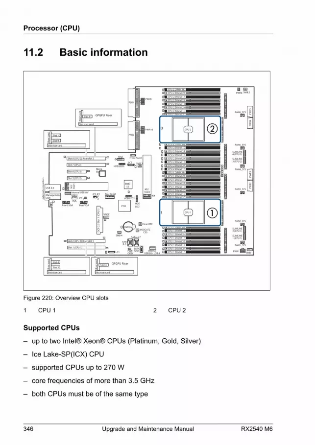
11.2 Basic information
iRMCS5
exte
rnal
con
nect
ors
INDICATE CSS
TPM
Slot 2 (CPU 1) Riser slot 1
Battery
SATA 0-3
Slot 1 (CPU 1)
Slot 8 (CPU 2) Riser slot 2
Rear Serial
PWRODD
Front Panel
SATA 4-7
SATAODD Internal
USB3.0 / USB 4
PSU1
PSU2
JP3 1
JP2 JP112
MicroSD
USB 3.0
SSD2 M.2
HDD LED2
Slot 7 (CPU2)
Slot 6 (CPU2)
Front VGA
Slot 5 (CPU2)
OCP
3.0
Slo
t 1 (C
PU1)
SSD
1 M
.2
LANManagement
Internal USB3.0/USB 3
Rear VGA
CPU 2 DIMM 2JCPU 2 DIMM 1M
CPU 2 DIMM 1LCPU 2 DIMM 2L
CPU 2 DIMM 1J
CPU 2 DIMM 2M
CPU 2 DIMM 2KCPU 2 DIMM 1K
CPU 2
CPU 1
CPU 1 DIMM 2ACPU 1 DIMM 1D
CPU 1 DIMM 1CCPU 1 DIMM 2C
CPU 1 DIMM 1A
CPU 1 DIMM 2D
CPU 1 DIMM 2BCPU 1 DIMM 1B
CPU 2 DIMM 1RCPU 2 DIMM 2N
CPU 2 DIMM 2PCPU 2 DIMM 1P
CPU 2 DIMM 2R
CPU 2 DIMM 1N
CPU 2 DIMM 1QCPU 2 DIMM 2Q
CPU 1 DIMM 1HCPU 1 DIMM 2E
CPU 1 DIMM 2FCPU 1 DIMM 1F
CPU 1 DIMM 2H
CPU 1 DIMM 1E
CPU 1 DIMM 1GCPU 1 DIMM 2G
SMB 4
LC1
SLIMLINE4 (CPU 2)
LC2
SMB 2
SMB 1
PWR9
PWR10
HDD LED3
HDD LED1
PWR6
PWR5
PWR4
PWR3
PWR2
PWR1
SLIMLINE3 (CPU 2)
SLIMLINE2 (CPU 1)
SLIMLINE1 (CPU 1)
FAN6_SYS
FAN5_SYS
FAN4_SYS
FAN3_SYS
FAN2_SYS
FAN1_SYS
ROC
VROC
SMB 3
Clear RTC
PCH
Slot riser card
Rise
r car
d
Slot 10
Slot 9
Slot riser card
Rise
r car
d
Slot 4
Slot 3
Slot riser card
Rise
r car
d
GPGPU RiserSlot 9
Slot riser card
Rise
r car
d
GPGPU RiserSlot 3
Figure 220: Overview CPU slots
1 CPU 1 2 CPU 2
Supported CPUs
– up to two Intel® Xeon® CPUs (Platinum, Gold, Silver)
– Ice Lake-SP(ICX) CPU
– supported CPUs up to 270 W
– core frequencies of more than 3.5 GHz
– both CPUs must be of the same type
Processor (CPU)
346 Upgrade and Maintenance Manual RX2540 M6
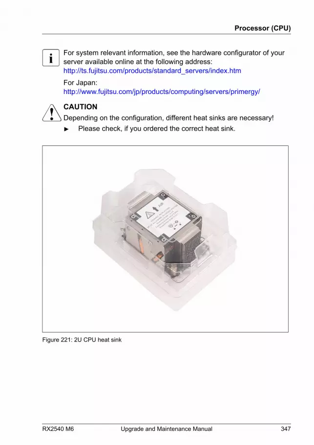
For system relevant information, see the hardware configurator of yourserver available online at the following address:http://ts.fujitsu.com/products/standard_servers/index.htmFor Japan:http://www.fujitsu.com/jp/products/computing/servers/primergy/
CAUTIONDepending on the configuration, different heat sinks are necessary!▶ Please check, if you ordered the correct heat sink.
Figure 221: 2U CPU heat sink
Processor (CPU)
RX2540 M6 Upgrade and Maintenance Manual 347
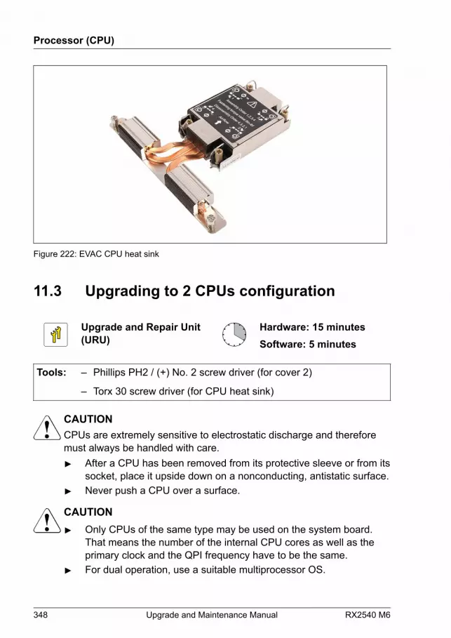
Figure 222: EVAC CPU heat sink
11.3 Upgrading to 2 CPUs configuration
Upgrade and Repair Unit(URU)
Hardware: 15 minutesSoftware: 5 minutes
Tools: – Phillips PH2 / (+) No. 2 screw driver (for cover 2)
– Torx 30 screw driver (for CPU heat sink)
CAUTIONCPUs are extremely sensitive to electrostatic discharge and thereforemust always be handled with care.▶ After a CPU has been removed from its protective sleeve or from its
socket, place it upside down on a nonconducting, antistatic surface.▶ Never push a CPU over a surface.
CAUTION▶ Only CPUs of the same type may be used on the system board.
That means the number of the internal CPU cores as well as theprimary clock and the QPI frequency have to be the same.
▶ For dual operation, use a suitable multiprocessor OS.
Processor (CPU)
348 Upgrade and Maintenance Manual RX2540 M6

Preliminary steps
▶ "Suspending BitLocker functionality" on page 87.
▶ "Shutting down the server" on page 52.
▶ "Disconnecting the power cord" on page 53.
▶ "Getting access to the component" on page 56.
▶ "Removing the air duct" on page 78.
Removing the CPU socket cover
Figure 223: Removing the CPU socket cover
▶ Press in the latches and remove the CPU socket cover.
▶ Save the CPU socket cover for future use.
Processor (CPU)
RX2540 M6 Upgrade and Maintenance Manual 349
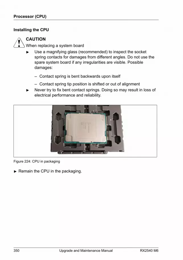
Installing the CPU
CAUTIONWhen replacing a system board▶ Use a magnifying glass (recommended) to inspect the socket
spring contacts for damages from different angles. Do not use thespare system board if any irregularities are visible. Possibledamages:
– Contact spring is bent backwards upon itself
– Contact spring tip position is shifted or out of alignment▶ Never try to fix bent contact springs. Doing so may result in loss of
electrical performance and reliability.
Figure 224: CPU in packaging
▶ Remain the CPU in the packaging.
Processor (CPU)
350 Upgrade and Maintenance Manual RX2540 M6

Figure 225: Installing the CPU frame on the CPU
▶ Click the CPU frame into the CPU. Ensure that the triangle marks on CPUand on CPU frame are on the same edge (see circles).
▶ Ensure that the CPU fits in its place.
Processor (CPU)
RX2540 M6 Upgrade and Maintenance Manual 351
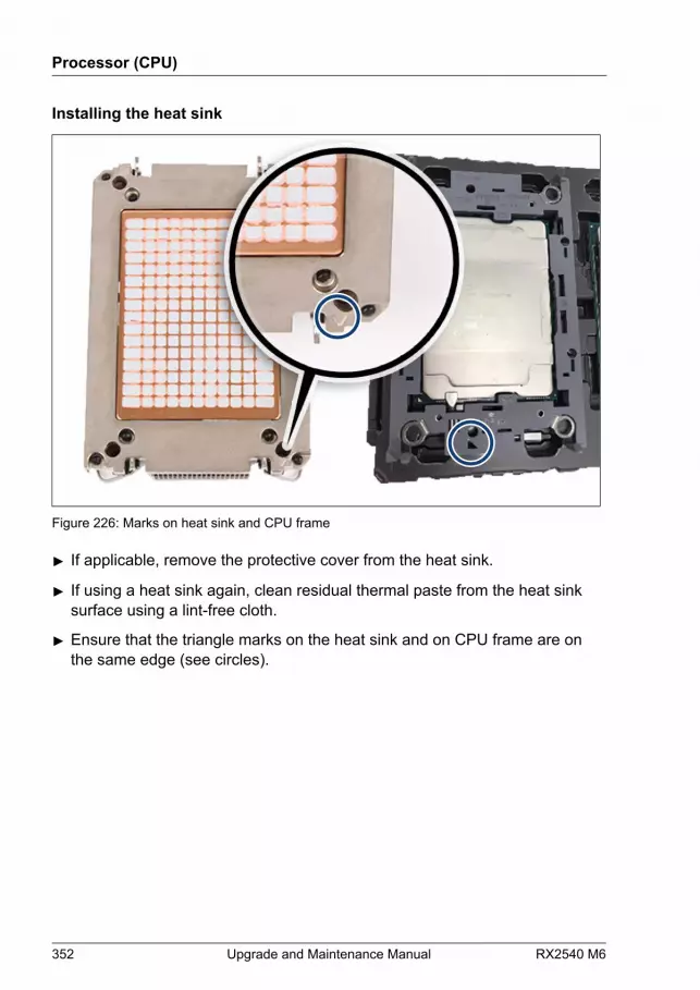
Installing the heat sink
Figure 226: Marks on heat sink and CPU frame
▶ If applicable, remove the protective cover from the heat sink.
▶ If using a heat sink again, clean residual thermal paste from the heat sinksurface using a lint-free cloth.
▶ Ensure that the triangle marks on the heat sink and on CPU frame are onthe same edge (see circles).
Processor (CPU)
352 Upgrade and Maintenance Manual RX2540 M6
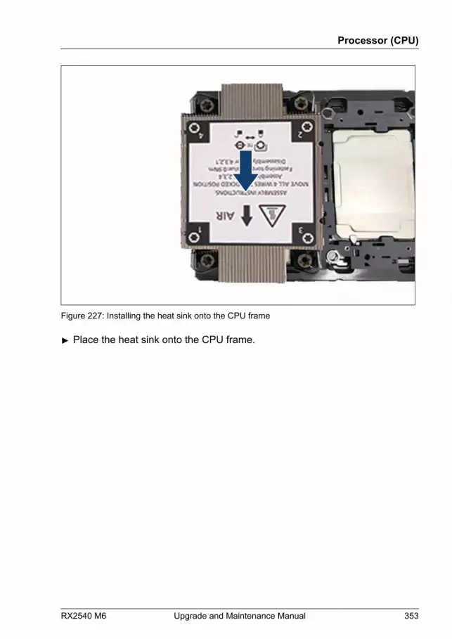
Figure 227: Installing the heat sink onto the CPU frame
▶ Place the heat sink onto the CPU frame.
Processor (CPU)
RX2540 M6 Upgrade and Maintenance Manual 353
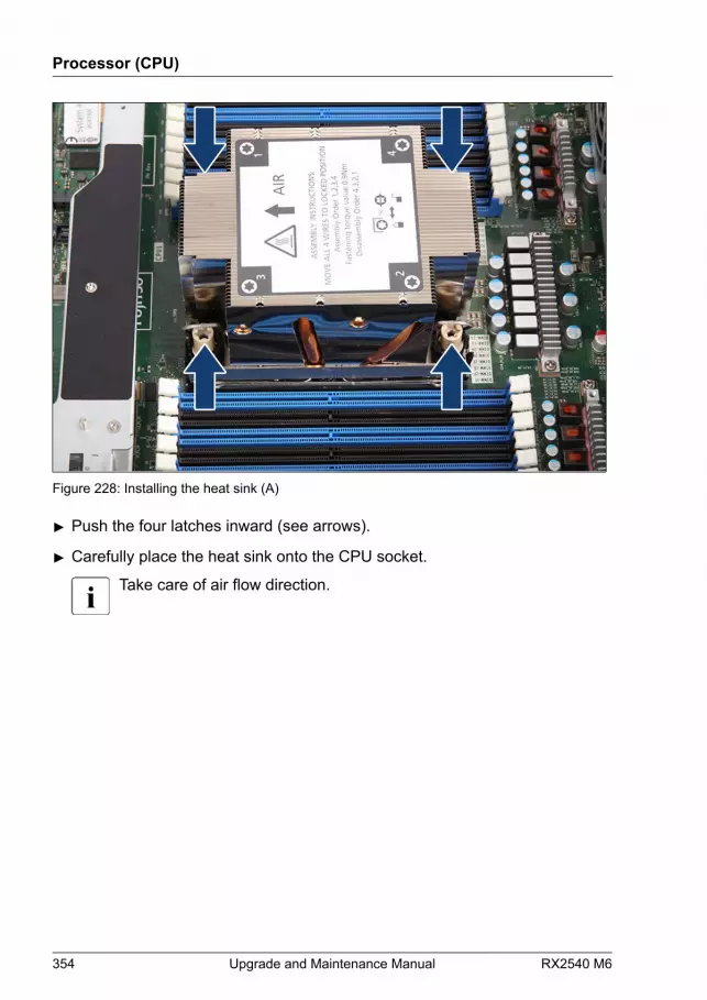
Figure 228: Installing the heat sink (A)
▶ Push the four latches inward (see arrows).
▶ Carefully place the heat sink onto the CPU socket.
Take care of air flow direction.
Processor (CPU)
354 Upgrade and Maintenance Manual RX2540 M6
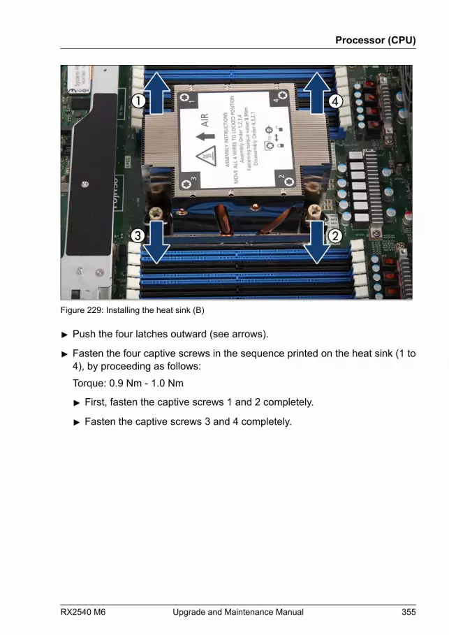
Figure 229: Installing the heat sink (B)
▶ Push the four latches outward (see arrows).
▶ Fasten the four captive screws in the sequence printed on the heat sink (1 to4), by proceeding as follows:Torque: 0.9 Nm - 1.0 Nm
▶ First, fasten the captive screws 1 and 2 completely.
▶ Fasten the captive screws 3 and 4 completely.
Processor (CPU)
RX2540 M6 Upgrade and Maintenance Manual 355
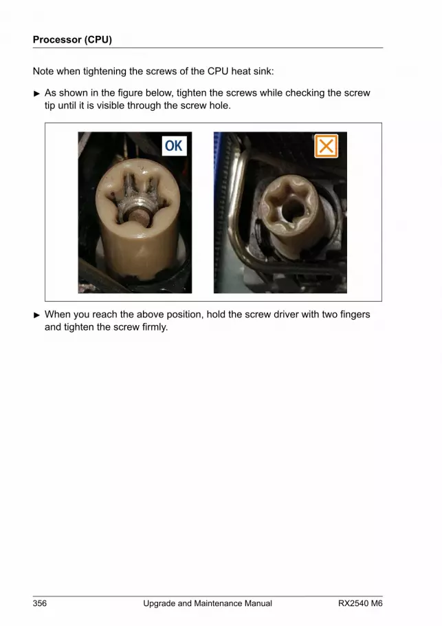
Note when tightening the screws of the CPU heat sink:
▶ As shown in the figure below, tighten the screws while checking the screwtip until it is visible through the screw hole.
▶ When you reach the above position, hold the screw driver with two fingersand tighten the screw firmly.
Processor (CPU)
356 Upgrade and Maintenance Manual RX2540 M6
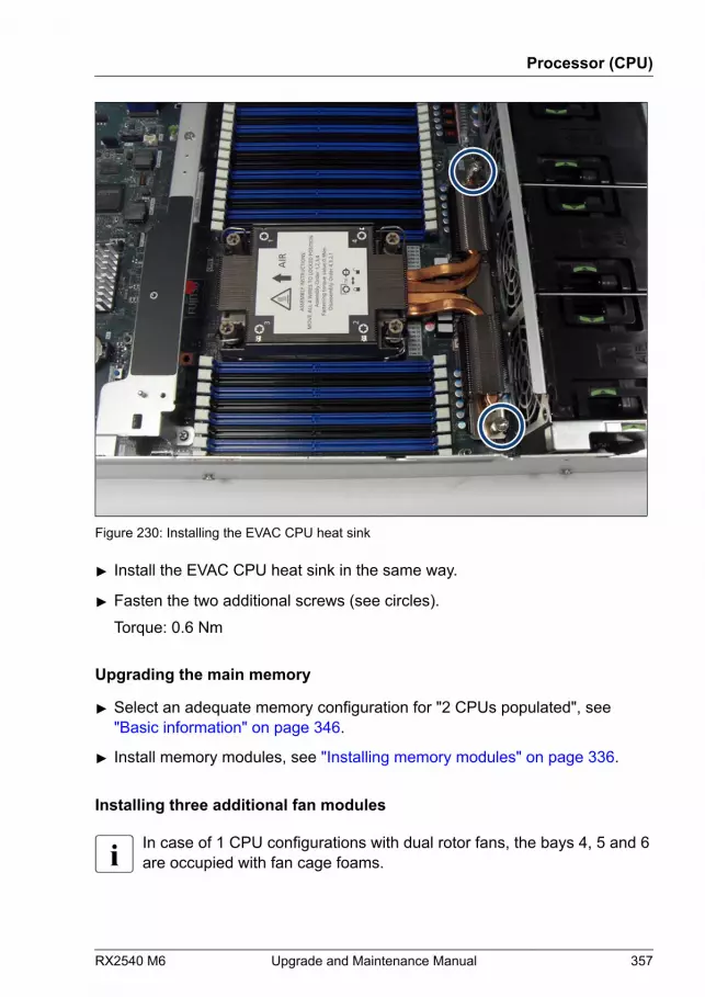
Figure 230: Installing the EVAC CPU heat sink
▶ Install the EVAC CPU heat sink in the same way.
▶ Fasten the two additional screws (see circles).Torque: 0.6 Nm
Upgrading the main memory
▶ Select an adequate memory configuration for "2 CPUs populated", see"Basic information" on page 346.
▶ Install memory modules, see "Installing memory modules" on page 336.
Installing three additional fan modules
In case of 1 CPU configurations with dual rotor fans, the bays 4, 5 and 6are occupied with fan cage foams.
Processor (CPU)
RX2540 M6 Upgrade and Maintenance Manual 357
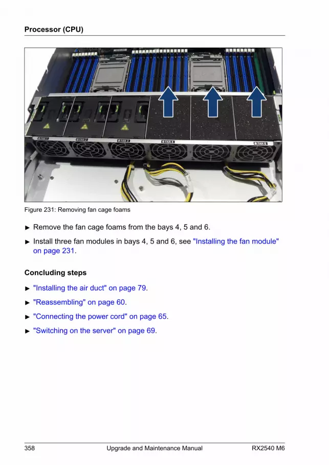
Figure 231: Removing fan cage foams
▶ Remove the fan cage foams from the bays 4, 5 and 6.
▶ Install three fan modules in bays 4, 5 and 6, see "Installing the fan module" on page 231.
Concluding steps
▶ "Installing the air duct" on page 79.
▶ "Reassembling" on page 60.
▶ "Connecting the power cord" on page 65.
▶ "Switching on the server" on page 69.
Processor (CPU)
358 Upgrade and Maintenance Manual RX2540 M6
When the system is powered on after a CPU has been replaced orupgraded, the Global Error indicator will start flashing with the messageCPU has been changed.This only indicates that the CPU configuration has been altered. Thereis no technical problem.
Proceed as follows:
● Restart your server.
● As soon as the startup screen appears, press the [F2] function key toenter the BIOS.
● If a password is assigned, enter the password and press [Enter].
● Select the Exit menu.
● Select Commit settings and Exit.
● Verify that the Global Error indicator stops flashing.
▶ "Resuming BitLocker functionality" on page 105.
11.4 Replacing a CPU or heat sink
Field Replaceable Unit(FRU)
Hardware: 15 minutesSoftware: 5 minutes
Tools: – Phillips PH2 / (+) No. 2 screw driver (for cover 2)
– Torx 30 screw driver (for CPU heat sink)
CAUTIONCPUs are extremely sensitive to electrostatic discharge and thereforemust always be handled with care.▶ After a CPU has been removed from its protective sleeve or from its
socket, place it upside down on a nonconducting, antistatic surface.▶ Never push a CPU over a surface.
Processor (CPU)
RX2540 M6 Upgrade and Maintenance Manual 359
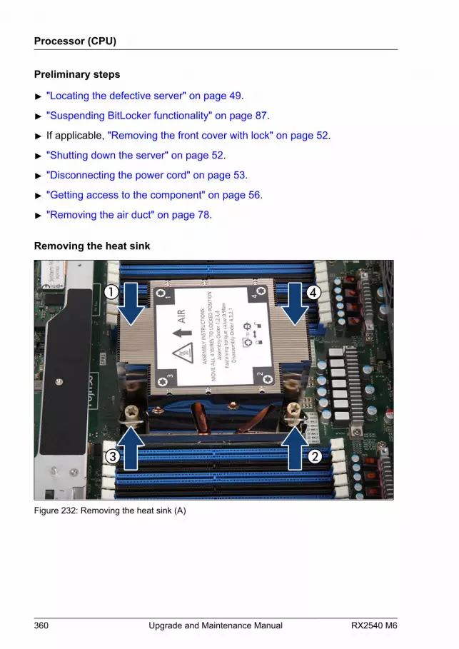
Preliminary steps
▶ "Locating the defective server" on page 49.
▶ "Suspending BitLocker functionality" on page 87.
▶ If applicable, "Removing the front cover with lock" on page 52.
▶ "Shutting down the server" on page 52.
▶ "Disconnecting the power cord" on page 53.
▶ "Getting access to the component" on page 56.
▶ "Removing the air duct" on page 78.
Removing the heat sink
Figure 232: Removing the heat sink (A)
Processor (CPU)
360 Upgrade and Maintenance Manual RX2540 M6
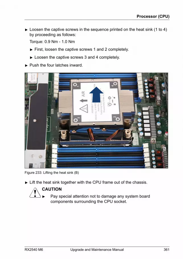
▶ Loosen the captive screws in the sequence printed on the heat sink (1 to 4)by proceeding as follows:Torque: 0.9 Nm - 1.0 Nm
▶ First, loosen the captive screws 1 and 2 completely.
▶ Loosen the captive screws 3 and 4 completely.
▶ Push the four latches inward.
Figure 233: Lifting the heat sink (B)
▶ Lift the heat sink together with the CPU frame out of the chassis.CAUTION▶ Pay special attention not to damage any system board
components surrounding the CPU socket.
Processor (CPU)
RX2540 M6 Upgrade and Maintenance Manual 361
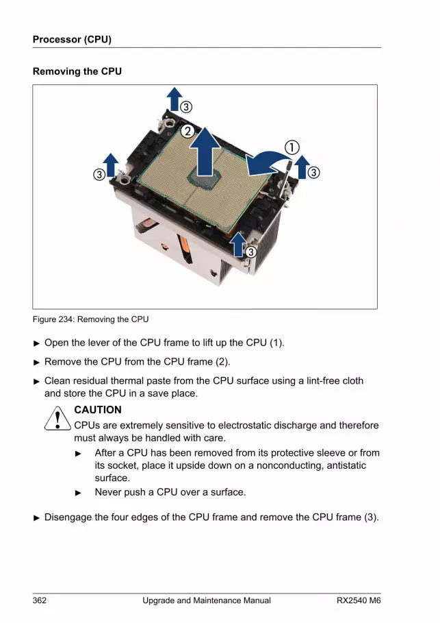
Removing the CPU
Figure 234: Removing the CPU
▶ Open the lever of the CPU frame to lift up the CPU (1).
▶ Remove the CPU from the CPU frame (2).
▶ Clean residual thermal paste from the CPU surface using a lint-free clothand store the CPU in a save place.
CAUTIONCPUs are extremely sensitive to electrostatic discharge and thereforemust always be handled with care.▶ After a CPU has been removed from its protective sleeve or from
its socket, place it upside down on a nonconducting, antistaticsurface.
▶ Never push a CPU over a surface.
▶ Disengage the four edges of the CPU frame and remove the CPU frame (3).
Processor (CPU)
362 Upgrade and Maintenance Manual RX2540 M6
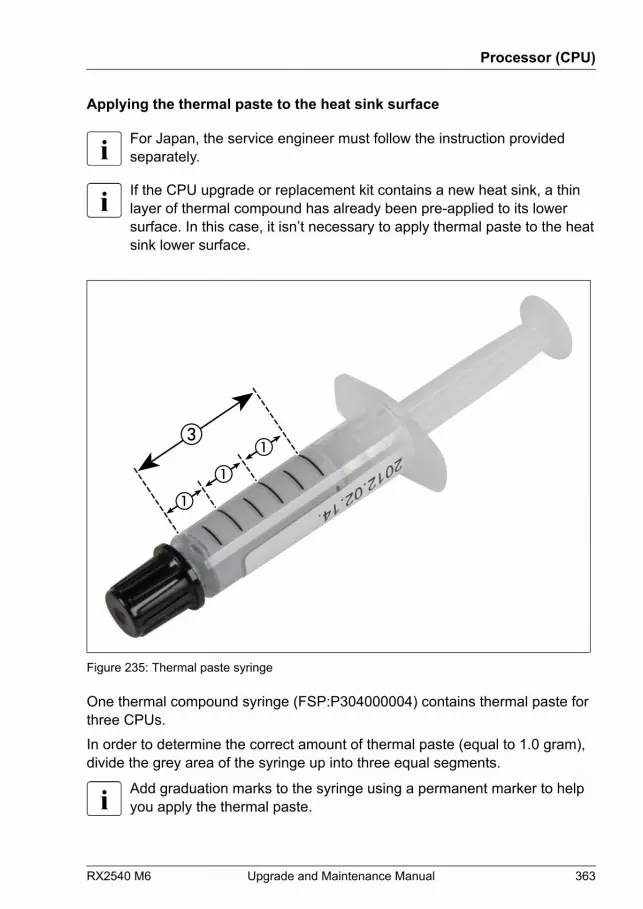
Applying the thermal paste to the heat sink surface
For Japan, the service engineer must follow the instruction providedseparately.
If the CPU upgrade or replacement kit contains a new heat sink, a thinlayer of thermal compound has already been pre-applied to its lowersurface. In this case, it isn’t necessary to apply thermal paste to the heatsink lower surface.
Figure 235: Thermal paste syringe
One thermal compound syringe (FSP:P304000004) contains thermal paste forthree CPUs.In order to determine the correct amount of thermal paste (equal to 1.0 gram),divide the grey area of the syringe up into three equal segments.
Add graduation marks to the syringe using a permanent marker to helpyou apply the thermal paste.
Processor (CPU)
RX2540 M6 Upgrade and Maintenance Manual 363
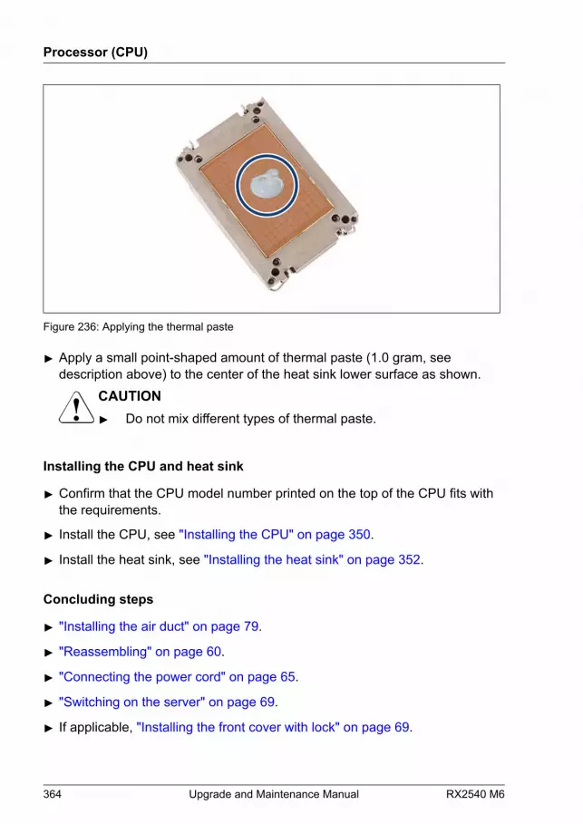
Figure 236: Applying the thermal paste
▶ Apply a small point-shaped amount of thermal paste (1.0 gram, seedescription above) to the center of the heat sink lower surface as shown.
CAUTION▶ Do not mix different types of thermal paste.
Installing the CPU and heat sink
▶ Confirm that the CPU model number printed on the top of the CPU fits withthe requirements.
▶ Install the CPU, see "Installing the CPU" on page 350.
▶ Install the heat sink, see "Installing the heat sink" on page 352.
Concluding steps
▶ "Installing the air duct" on page 79.
▶ "Reassembling" on page 60.
▶ "Connecting the power cord" on page 65.
▶ "Switching on the server" on page 69.
▶ If applicable, "Installing the front cover with lock" on page 69.
Processor (CPU)
364 Upgrade and Maintenance Manual RX2540 M6

When the system is powered on after a CPU has been replaced orupgraded, the Global Error indicator will start flashing with the messageCPU has been changed.This only indicates that the CPU configuration has been altered. Thereis no technical problem.
Proceed as follows:
● Restart your server.
● As soon as the startup screen appears, press the [F2] function key toenter the BIOS.
● If a password is assigned, enter the password and press [Enter].
● Select the Exit menu.
● Select Commit settings and Exit.
● Verify that the Global Error indicator stops flashing.
▶ "Resuming BitLocker functionality" on page 105.
Processor (CPU)
RX2540 M6 Upgrade and Maintenance Manual 365

Processor (CPU)
366 Upgrade and Maintenance Manual RX2540 M6
12 Liquid cooling (LC)
12.1 Safety notes
CAUTION▶ Do not install unsupported CPUs. For more information on
supported CPUs, see "Basic information" on page 368.▶ Circuit boards and soldered parts of internal options are exposed
and can be damaged by static electricity. Always discharge staticbuild-up (e.g. by touching a grounded object) before handlingelectrostatic sensitive devices (ESDs).
▶ Do not touch the circuitry on boards or soldered parts. Hold circuitboards by their metallic areas or edges.
▶ When removing or installing CPUs, be careful not to touch or bendthe spring contacts on the CPU sockets.
▶ Never touch the underside of the CPUs. Even minor soiling such asgrease from the skin can impair the CPU’s operation or destroy theCPUs.
▶ For more information, see "Important information" on page 35.
RX2540 M6 Upgrade and Maintenance Manual 367

12.2 Basic information
iRMCS5
exte
rnal
con
nect
ors
INDICATE CSS
TPM
Slot 2 (CPU 1) Riser slot 1
Battery
SATA 0-3
Slot 1 (CPU 1)
Slot 8 (CPU 2) Riser slot 2
Rear Serial
PWRODD
Front Panel
SATA 4-7
SATAODD Internal
USB3.0 / USB 4
PSU1
PSU2
JP3 1
JP2 JP112
MicroSD
USB 3.0
SSD2 M.2
HDD LED2
Slot 7 (CPU2)
Slot 6 (CPU2)
Front VGA
Slot 5 (CPU2)
OCP
3.0
Slo
t 1 (C
PU1)
SSD
1 M
.2
LANManagement
Internal USB3.0/USB 3
Rear VGA
CPU 2 DIMM 2JCPU 2 DIMM 1M
CPU 2 DIMM 1LCPU 2 DIMM 2L
CPU 2 DIMM 1J
CPU 2 DIMM 2M
CPU 2 DIMM 2KCPU 2 DIMM 1K
CPU 2
CPU 1
CPU 1 DIMM 2ACPU 1 DIMM 1D
CPU 1 DIMM 1CCPU 1 DIMM 2C
CPU 1 DIMM 1A
CPU 1 DIMM 2D
CPU 1 DIMM 2BCPU 1 DIMM 1B
CPU 2 DIMM 1RCPU 2 DIMM 2N
CPU 2 DIMM 2PCPU 2 DIMM 1P
CPU 2 DIMM 2R
CPU 2 DIMM 1N
CPU 2 DIMM 1QCPU 2 DIMM 2Q
CPU 1 DIMM 1HCPU 1 DIMM 2E
CPU 1 DIMM 2FCPU 1 DIMM 1F
CPU 1 DIMM 2H
CPU 1 DIMM 1E
CPU 1 DIMM 1GCPU 1 DIMM 2G
SMB 4
LC1
SLIMLINE4 (CPU 2)
LC2
SMB 2
SMB 1
PWR9
PWR10
HDD LED3
HDD LED1
PWR6
PWR5
PWR4
PWR3
PWR2
PWR1
SLIMLINE3 (CPU 2)
SLIMLINE2 (CPU 1)
SLIMLINE1 (CPU 1)
FAN6_SYS
FAN5_SYS
FAN4_SYS
FAN3_SYS
FAN2_SYS
FAN1_SYS
ROC
VROC
SMB 3
Clear RTC
PCH
Slot riser card
Rise
r car
d
Slot 10
Slot 9
Slot riser card
Rise
r car
d
Slot 4
Slot 3
Slot riser card
Rise
r car
d
GPGPU RiserSlot 9
Slot riser card
Rise
r car
d
GPGPU RiserSlot 3
Figure 237: Connectors for the LC, slots for CPUs and DIMMs
1 Connector for control cable of pump 1 2 Connector for control cable of pump 2
Liquid cooling (LC)
368 Upgrade and Maintenance Manual RX2540 M6

Parts of the LC kit
Figure 238: LC kit
1 Control cable for each pump2 Heat sink with pump for CPU 13 Heat sink with pump for CPU 2
4 Cable clip and distance holder5 Quick connector block6 Tubes with protective caps (orange)
12.3 Replacing the CPU for LC device
Field Replaceable Unit(FRU)
Hardware: 15 minutesSoftware: 5 minutes
Tools: – Phillips PH2 / (+) No. 2 screw driver
– Torx 30 screw driver
Liquid cooling (LC)
RX2540 M6 Upgrade and Maintenance Manual 369
CAUTIONCPUs are extremely sensitive to electrostatic discharge and thereforemust always be handled with care.▶ After a CPU has been removed from its protective sleeve or from its
socket, place it upside down on a nonconducting, antistatic surface.▶ Never push a CPU over a surface.
Preliminary steps
▶ "Locating the defective server" on page 49.
▶ "Suspending BitLocker functionality" on page 87.
▶ "Shutting down the server" on page 52.
▶ "Disconnecting the power cord" on page 53.
▶ "Getting access to the component" on page 56.
▶ "Removing the air duct" on page 78.
▶ If applicable, remove the riser module, see "Removing the riser module 1" on page 70.
Removing the LC kit
▶ Remove the cross bar, see "Removing the cross bar" on page 80.
Liquid cooling (LC)
370 Upgrade and Maintenance Manual RX2540 M6
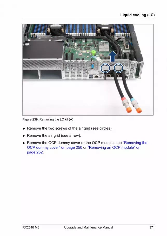
Figure 239: Removing the LC kit (A)
▶ Remove the two screws of the air grid (see circles).
▶ Remove the air grid (see arrow).
▶ Remove the OCP dummy cover or the OCP module, see "Removing the OCP dummy cover" on page 250 or "Removing an OCP module" on page 252.
Liquid cooling (LC)
RX2540 M6 Upgrade and Maintenance Manual 371
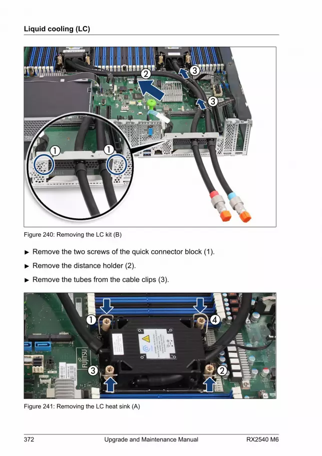
Figure 240: Removing the LC kit (B)
▶ Remove the two screws of the quick connector block (1).
▶ Remove the distance holder (2).
▶ Remove the tubes from the cable clips (3).
Figure 241: Removing the LC heat sink (A)
Liquid cooling (LC)
372 Upgrade and Maintenance Manual RX2540 M6

▶ Loosen the captive screws in the sequence printed on the heat sink (1 to 4)by proceeding as follows:Torque: 0.9 Nm
▶ First, loosen the captive screws 1 and 2 completely.
▶ Loosen the captive screws 3 and 4 completely.
▶ Push the four latches inward.
Figure 242: Removing the LC heat sink (B)
▶ Proceed for the second heat sink in the same way.
▶ Hold the heat sinks with both hands and lift up the complete LC kit.CAUTION▶ Pay special attention not to damage any system board
components surrounding the CPU socket.
Liquid cooling (LC)
RX2540 M6 Upgrade and Maintenance Manual 373

Removing the CPU
Figure 243: Removing the CPU
▶ Open the lever of the CPU frame to lift up the CPU (1).
▶ Remove the CPU from the CPU frame (2).
▶ Clean residual thermal paste from the CPU surface using a lint-free clothand store the CPU in a save place.
CAUTIONCPUs are extremely sensitive to electrostatic discharge and thereforemust always be handled with care.▶ After a CPU has been removed from its protective sleeve or from
its socket, place it upside down on a nonconducting, antistaticsurface.
▶ Never push a CPU over a surface.
▶ Disengage the four edges of the CPU frame and remove the CPU frame (3).
Liquid cooling (LC)
374 Upgrade and Maintenance Manual RX2540 M6
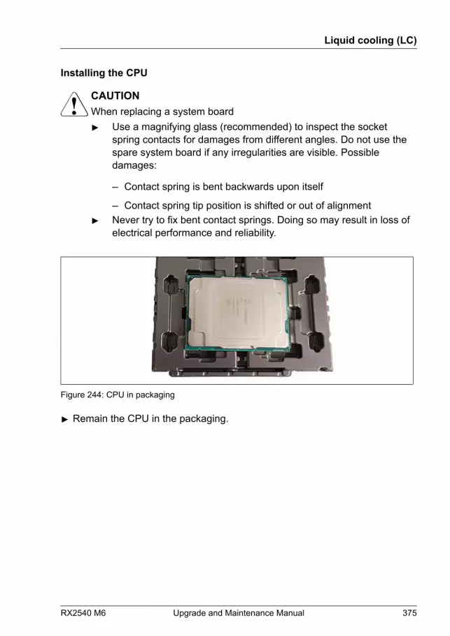
Installing the CPU
CAUTIONWhen replacing a system board▶ Use a magnifying glass (recommended) to inspect the socket
spring contacts for damages from different angles. Do not use thespare system board if any irregularities are visible. Possibledamages:
– Contact spring is bent backwards upon itself
– Contact spring tip position is shifted or out of alignment▶ Never try to fix bent contact springs. Doing so may result in loss of
electrical performance and reliability.
Figure 244: CPU in packaging
▶ Remain the CPU in the packaging.
Liquid cooling (LC)
RX2540 M6 Upgrade and Maintenance Manual 375

Figure 245: Installing the CPU frame on the CPU
▶ Click the CPU frame into the CPU. Ensure that the triangle marks on CPUand on CPU frame are on the same edge (see circles).
▶ Ensure that the CPU fits in its place.
Installing the LC kit
▶ When replacing the CPU, apply the thermal paste onto the LC heat sink, see"Applying the thermal paste to the heat sink surface" on page 363.
Liquid cooling (LC)
376 Upgrade and Maintenance Manual RX2540 M6
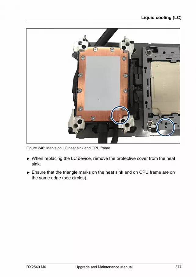
Figure 246: Marks on LC heat sink and CPU frame
▶ When replacing the LC device, remove the protective cover from the heatsink.
▶ Ensure that the triangle marks on the heat sink and on CPU frame are onthe same edge (see circles).
Liquid cooling (LC)
RX2540 M6 Upgrade and Maintenance Manual 377
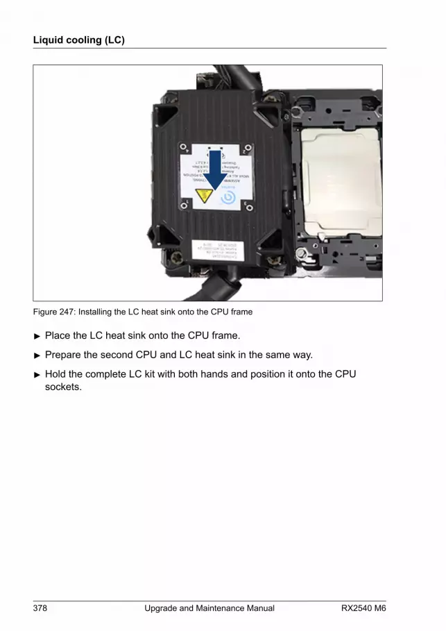
Figure 247: Installing the LC heat sink onto the CPU frame
▶ Place the LC heat sink onto the CPU frame.
▶ Prepare the second CPU and LC heat sink in the same way.
▶ Hold the complete LC kit with both hands and position it onto the CPUsockets.
Liquid cooling (LC)
378 Upgrade and Maintenance Manual RX2540 M6

Figure 248: Installing the LC heat sink (A)
▶ Push the four latches inward (see arrows).
▶ Carefully place the LC heat sink onto the CPU socket.
Take care of air flow direction.
Figure 249: Installing the LC heat sink (B)
Liquid cooling (LC)
RX2540 M6 Upgrade and Maintenance Manual 379
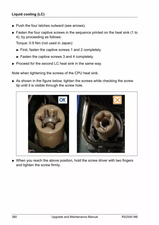
▶ Push the four latches outward (see arrows).
▶ Fasten the four captive screws in the sequence printed on the heat sink (1 to4), by proceeding as follows:Torque: 0.9 Nm (not used in Japan)
▶ First, fasten the captive screws 1 and 2 completely.
▶ Fasten the captive screws 3 and 4 completely.
▶ Proceed for the second LC heat sink in the same way.
Note when tightening the screws of the CPU heat sink:
▶ As shown in the figure below, tighten the screws while checking the screwtip until it is visible through the screw hole.
▶ When you reach the above position, hold the screw driver with two fingersand tighten the screw firmly.
Liquid cooling (LC)
380 Upgrade and Maintenance Manual RX2540 M6
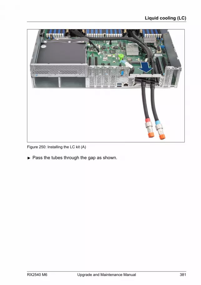
Figure 250: Installing the LC kit (A)
▶ Pass the tubes through the gap as shown.
Liquid cooling (LC)
RX2540 M6 Upgrade and Maintenance Manual 381
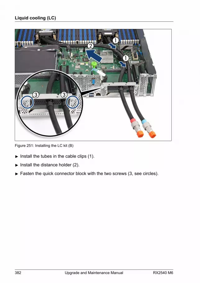
Figure 251: Installing the LC kit (B)
▶ Install the tubes in the cable clips (1).
▶ Install the distance holder (2).
▶ Fasten the quick connector block with the two screws (3, see circles).
Liquid cooling (LC)
382 Upgrade and Maintenance Manual RX2540 M6
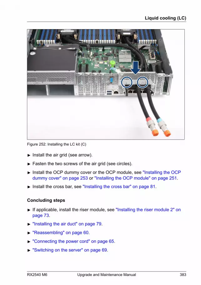
Figure 252: Installing the LC kit (C)
▶ Install the air grid (see arrow).
▶ Fasten the two screws of the air grid (see circles).
▶ Install the OCP dummy cover or the OCP module, see "Installing the OCP dummy cover" on page 253 or "Installing the OCP module" on page 251.
▶ Install the cross bar, see "Installing the cross bar" on page 81.
Concluding steps
▶ If applicable, install the riser module, see "Installing the riser module 2" on page 73.
▶ "Installing the air duct" on page 79.
▶ "Reassembling" on page 60.
▶ "Connecting the power cord" on page 65.
▶ "Switching on the server" on page 69.
Liquid cooling (LC)
RX2540 M6 Upgrade and Maintenance Manual 383

When the system is powered on after a CPU has been replaced orupgraded, the Global Error indicator will start flashing with the messageCPU has been changed.This only indicates that the CPU configuration has been altered. Thereis no technical problem.
Proceed as follows:
● Restart your server.
● As soon as the startup screen appears, press the [F2] function key toenter the BIOS.
● If a password is assigned, enter the password and press [Enter].
● Select the Save & Exit menu.
● Select Save Changes and Exit or Save Changes and Reset.
● Verify that the Global Error indicator stops flashing.
▶ "Enabling replaced components in the BIOS" on page 100.
▶ "Resuming BitLocker functionality" on page 105.
Liquid cooling (LC)
384 Upgrade and Maintenance Manual RX2540 M6

13 Accessible drives
13.1 Safety notes
CAUTION▶ Before installing an accessible drive, acquaint yourself with the
drive's user documentation.▶ When inserting an accessible drive into the server, ensure not to
pinch or strain any connected cables.▶ When installing an accessible drive, hold it by its sides. Applying
force to the top of the casing may cause failures.▶ When disposing of, transferring, or returning a backup drive, ensure
that all backup media has been removed from the drive.▶ Circuit boards and soldered parts of internal options are exposed
and can be damaged by static electricity. Always discharge staticbuild-up (e.g. by touching a grounded object) before handlingelectrostatic-sensitive devices (ESDs).
▶ Do not touch the circuitry on boards or soldered parts. Hold circuitboards by their metallic areas or edges.
▶ For more information, see "Important information" on page 35.
13.2 Basic information
Depending on the type of system, the PRIMERGY RX2540 M6 offers:
● one 5.25-inch accessible drive bay for ODDs
● one bay (optional) for an LTO drive or a RDX drive
ODD drive is not available for 12x 3.5-inch HDD versions, 24x 2.5-inchHDD versions and 64x EDSFF versions.LTO drive or RDX drive are not available for 3.5-inch HDD versions, 24x2.5-inch HDD versions and 64x EDSFF versions.
RX2540 M6 Upgrade and Maintenance Manual 385
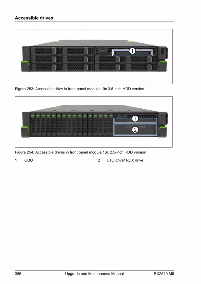
Figure 253: Accessible drive in front panel module 10x 3.5-inch HDD version
Figure 254: Accessible drives in front panel module 16x 2.5-inch HDD version
1 ODD 2 LTO drive/ RDX drive
Accessible drives
386 Upgrade and Maintenance Manual RX2540 M6

13.3 Optical disk drive (ODD)
13.3.1 Storing the ODD latch
Figure 255: Storing the ODD latch
The ODD latch is fastened with two screws to the cross bar (see circle).
13.3.2 Installing the ODD (2.5-inch chassis)
Upgrade and Repair Unit(URU)
Hardware: 5 minutes
Tools: – Phillips PH2 / (+) No. 2 screw driver (for cover 2)
– Torx Plus 6 screw driver (not valid for Japan)
– Phillips PH1 / (+) No. 1 screw driver (Japan)
Accessible drives
RX2540 M6 Upgrade and Maintenance Manual 387
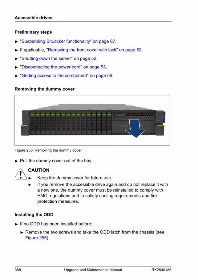
Preliminary steps
▶ "Suspending BitLocker functionality" on page 87.
▶ If applicable, "Removing the front cover with lock" on page 52.
▶ "Shutting down the server" on page 52.
▶ "Disconnecting the power cord" on page 53.
▶ "Getting access to the component" on page 56.
Removing the dummy cover
Figure 256: Removing the dummy cover
▶ Pull the dummy cover out of the bay.
CAUTION▶ Keep the dummy cover for future use.▶ If you remove the accessible drive again and do not replace it with
a new one, the dummy cover must be reinstalled to comply withEMC regulations and to satisfy cooling requirements and fireprotection measures.
Installing the ODD
▶ If no ODD has been installed before:
▶ Remove the two screws and take the ODD latch from the chassis (seeFigure 255).
Accessible drives
388 Upgrade and Maintenance Manual RX2540 M6
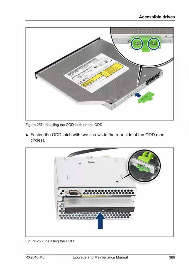
Figure 257: Installing the ODD latch on the ODD
▶ Fasten the ODD latch with two screws to the rear side of the ODD (seecircles).
Figure 258: Installing the ODD
Accessible drives
RX2540 M6 Upgrade and Maintenance Manual 389
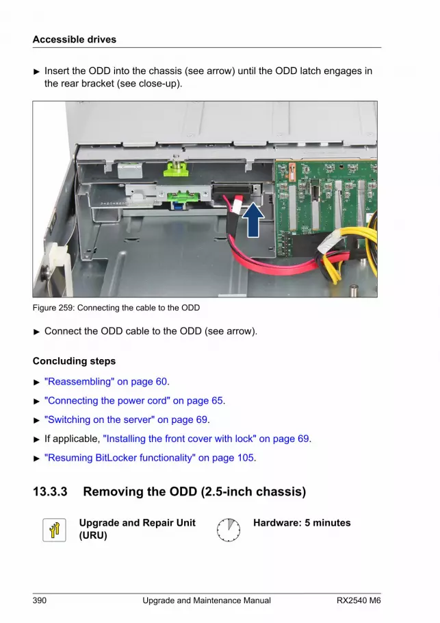
▶ Insert the ODD into the chassis (see arrow) until the ODD latch engages inthe rear bracket (see close-up).
Figure 259: Connecting the cable to the ODD
▶ Connect the ODD cable to the ODD (see arrow).
Concluding steps
▶ "Reassembling" on page 60.
▶ "Connecting the power cord" on page 65.
▶ "Switching on the server" on page 69.
▶ If applicable, "Installing the front cover with lock" on page 69.
▶ "Resuming BitLocker functionality" on page 105.
13.3.3 Removing the ODD (2.5-inch chassis)
Upgrade and Repair Unit(URU)
Hardware: 5 minutes
Accessible drives
390 Upgrade and Maintenance Manual RX2540 M6

Tools: – Phillips PH2 / (+) No. 2 screw driver (for cover 2)
– Torx Plus 6 screw driver (not valid for Japan)
– Phillips PH1 / (+) No. 1 screw driver (Japan)
Preliminary steps
▶ "Removing backup and optical disk media" on page 90.
▶ "Suspending BitLocker functionality" on page 87.
▶ If applicable, "Removing the front cover with lock" on page 52.
▶ "Shutting down the server" on page 52.
▶ "Disconnecting the power cord" on page 53.
▶ "Getting access to the component" on page 56.
Removing the ODD
Figure 260: Removing the ODD (A)
Accessible drives
RX2540 M6 Upgrade and Maintenance Manual 391

▶ Disconnect the ODD cable from the ODD (1).
▶ Unlock the ODD latch (2).
Figure 261: Removing the ODD (B)
▶ Remove the ODD.
Accessible drives
392 Upgrade and Maintenance Manual RX2540 M6
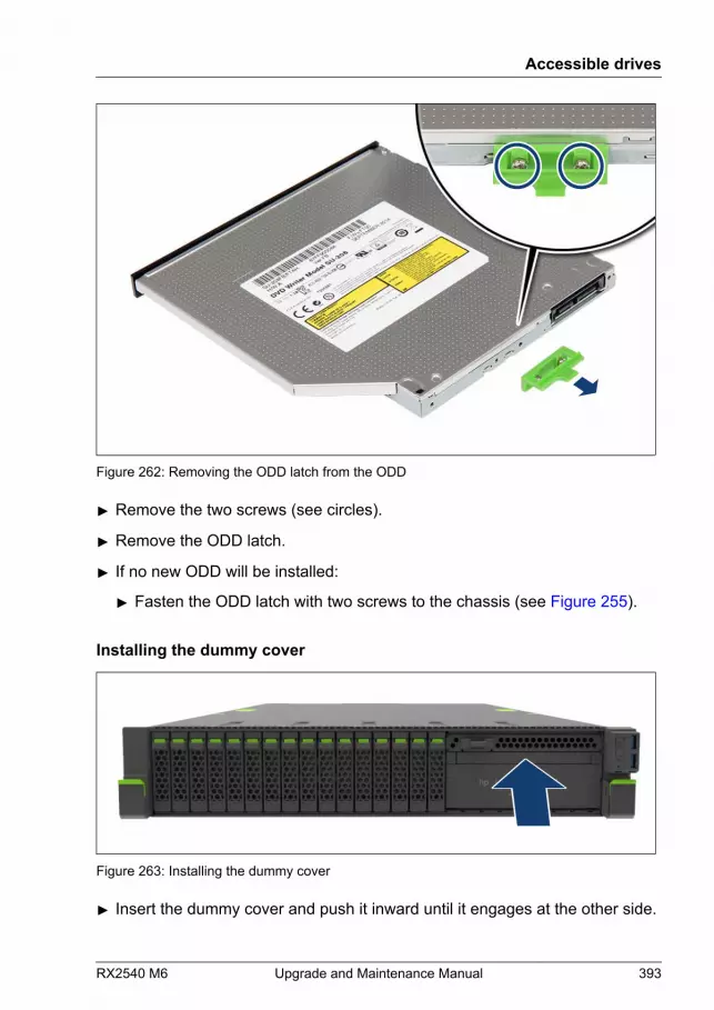
Figure 262: Removing the ODD latch from the ODD
▶ Remove the two screws (see circles).
▶ Remove the ODD latch.
▶ If no new ODD will be installed:
▶ Fasten the ODD latch with two screws to the chassis (see Figure 255).
Installing the dummy cover
Figure 263: Installing the dummy cover
▶ Insert the dummy cover and push it inward until it engages at the other side.
Accessible drives
RX2540 M6 Upgrade and Maintenance Manual 393
Concluding steps
▶ "Reassembling" on page 60.
▶ "Connecting the power cord" on page 65.
▶ "Switching on the server" on page 69.
▶ If applicable, "Installing the front cover with lock" on page 69.
▶ "Resuming BitLocker functionality" on page 105.
13.3.4 Replacing the ODD (2.5-inch chassis)
Upgrade and Repair Unit(URU)
Hardware: 5 minutes
Tools: – Phillips PH2 / (+) No. 2 screw driver (for cover 2)
– Torx Plus 6 screw driver (not valid for Japan)
– Phillips PH1 / (+) No. 1 screw driver (Japan)
Preliminary steps
▶ "Locating the defective server" on page 49.
▶ "Removing backup and optical disk media" on page 90.
▶ "Suspending BitLocker functionality" on page 87.
▶ If applicable, "Removing the front cover with lock" on page 52.
▶ "Shutting down the server" on page 52.
▶ "Disconnecting the power cord" on page 53.
▶ "Getting access to the component" on page 56.
Removing the defective ODD
▶ Remove the ODD, see "Removing the ODD (2.5-inch chassis)" on page 390.
Accessible drives
394 Upgrade and Maintenance Manual RX2540 M6
Installing the new ODD
▶ Install the ODD, see "Installing the ODD (2.5-inch chassis)" on page 387.
Concluding steps
▶ "Reassembling" on page 60.
▶ "Connecting the power cord" on page 65.
▶ "Switching on the server" on page 69.
▶ If applicable, "Installing the front cover with lock" on page 69.
▶ "Resuming BitLocker functionality" on page 105.
13.3.5 Installing the ODD (3.5-inch chassis)
Upgrade and Repair Unit(URU)
Hardware: 5 minutes
Tools: – Phillips PH2 / (+) No. 2 screw driver (for cover 2)
– Torx Plus 6 screw driver (not valid for Japan)
– Phillips PH1 / (+) No. 1 screw driver (Japan)
Preliminary steps
▶ "Suspending BitLocker functionality" on page 87.
▶ If applicable, "Removing the front cover with lock" on page 52.
▶ "Shutting down the server" on page 52.
▶ "Disconnecting the power cord" on page 53.
▶ "Getting access to the component" on page 56.
Accessible drives
RX2540 M6 Upgrade and Maintenance Manual 395
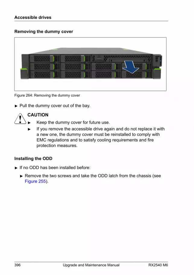
Removing the dummy cover
Figure 264: Removing the dummy cover
▶ Pull the dummy cover out of the bay.
CAUTION▶ Keep the dummy cover for future use.▶ If you remove the accessible drive again and do not replace it with
a new one, the dummy cover must be reinstalled to comply withEMC regulations and to satisfy cooling requirements and fireprotection measures.
Installing the ODD
▶ If no ODD has been installed before:
▶ Remove the two screws and take the ODD latch from the chassis (seeFigure 255).
Accessible drives
396 Upgrade and Maintenance Manual RX2540 M6

Figure 265: Installing the ODD latch on the ODD
▶ Fasten the ODD latch with two screws to the rear side of the ODD (seecircles).
Accessible drives
RX2540 M6 Upgrade and Maintenance Manual 397
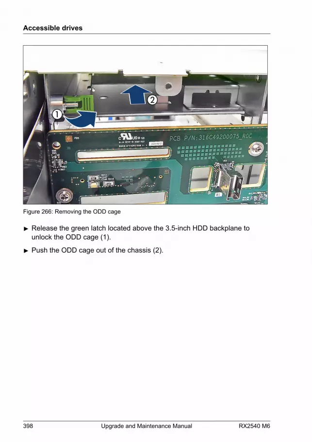
Figure 266: Removing the ODD cage
▶ Release the green latch located above the 3.5-inch HDD backplane tounlock the ODD cage (1).
▶ Push the ODD cage out of the chassis (2).
Accessible drives
398 Upgrade and Maintenance Manual RX2540 M6
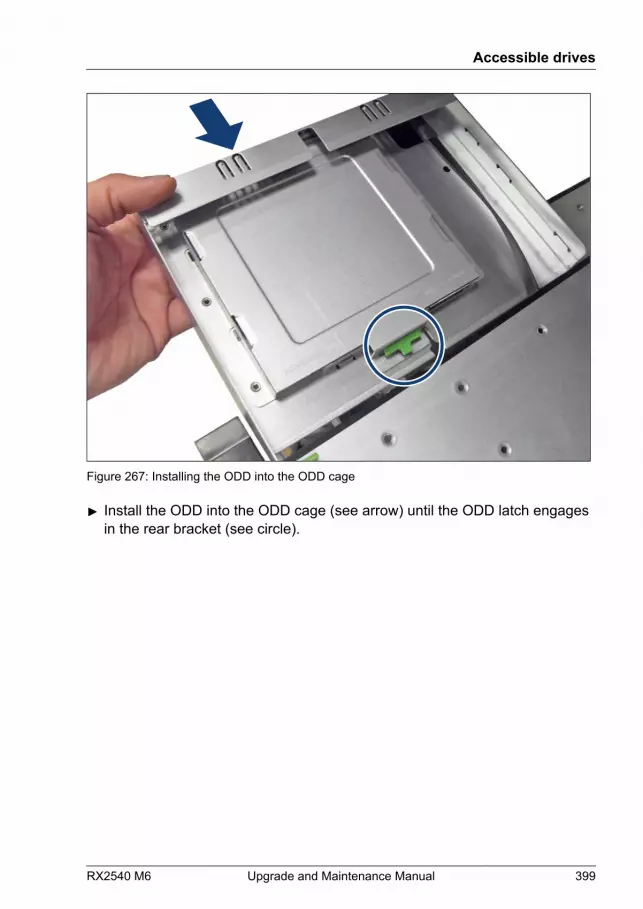
Figure 267: Installing the ODD into the ODD cage
▶ Install the ODD into the ODD cage (see arrow) until the ODD latch engagesin the rear bracket (see circle).
Accessible drives
RX2540 M6 Upgrade and Maintenance Manual 399
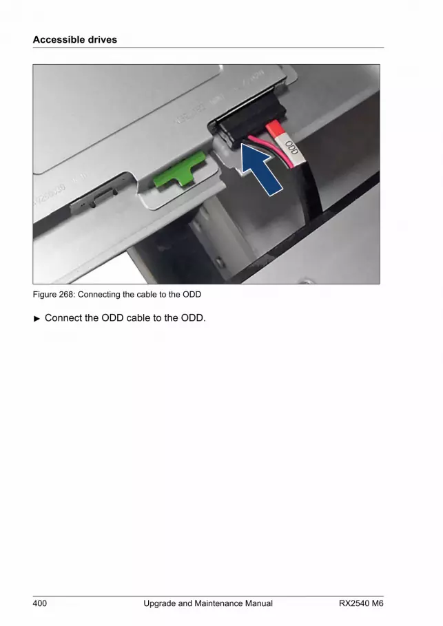
Figure 268: Connecting the cable to the ODD
▶ Connect the ODD cable to the ODD.
Accessible drives
400 Upgrade and Maintenance Manual RX2540 M6
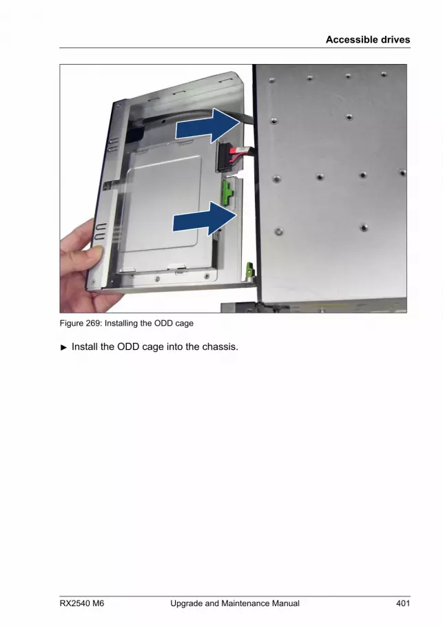
Figure 269: Installing the ODD cage
▶ Install the ODD cage into the chassis.
Accessible drives
RX2540 M6 Upgrade and Maintenance Manual 401
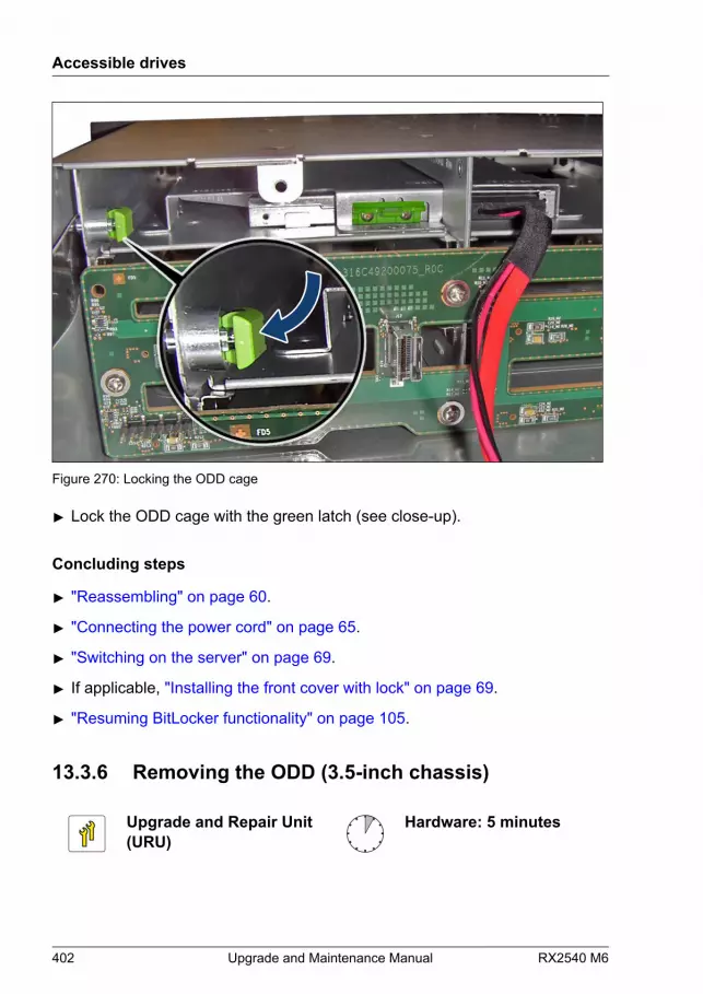
Figure 270: Locking the ODD cage
▶ Lock the ODD cage with the green latch (see close-up).
Concluding steps
▶ "Reassembling" on page 60.
▶ "Connecting the power cord" on page 65.
▶ "Switching on the server" on page 69.
▶ If applicable, "Installing the front cover with lock" on page 69.
▶ "Resuming BitLocker functionality" on page 105.
13.3.6 Removing the ODD (3.5-inch chassis)
Upgrade and Repair Unit(URU)
Hardware: 5 minutes
Accessible drives
402 Upgrade and Maintenance Manual RX2540 M6

Tools: – Phillips PH2 / (+) No. 2 screw driver (for cover 2)
– Torx Plus 6 screw driver (not valid for Japan)
– Phillips PH1 / (+) No. 1 screw driver (Japan)
Preliminary steps
▶ "Removing backup and optical disk media" on page 90.
▶ "Suspending BitLocker functionality" on page 87.
▶ If applicable, "Removing the front cover with lock" on page 52.
▶ "Shutting down the server" on page 52.
▶ "Disconnecting the power cord" on page 53.
▶ "Getting access to the component" on page 56.
Removing the ODD
Figure 271: Unlocking the ODD cage
Accessible drives
RX2540 M6 Upgrade and Maintenance Manual 403
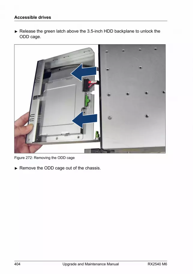
▶ Release the green latch above the 3.5-inch HDD backplane to unlock theODD cage.
Figure 272: Removing the ODD cage
▶ Remove the ODD cage out of the chassis.
Accessible drives
404 Upgrade and Maintenance Manual RX2540 M6
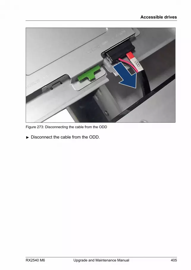
Figure 273: Disconnecting the cable from the ODD
▶ Disconnect the cable from the ODD.
Accessible drives
RX2540 M6 Upgrade and Maintenance Manual 405
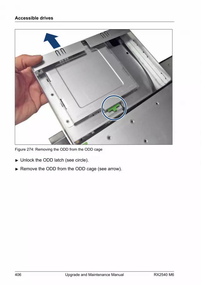
Figure 274: Removing the ODD from the ODD cage
▶ Unlock the ODD latch (see circle).
▶ Remove the ODD from the ODD cage (see arrow).
Accessible drives
406 Upgrade and Maintenance Manual RX2540 M6
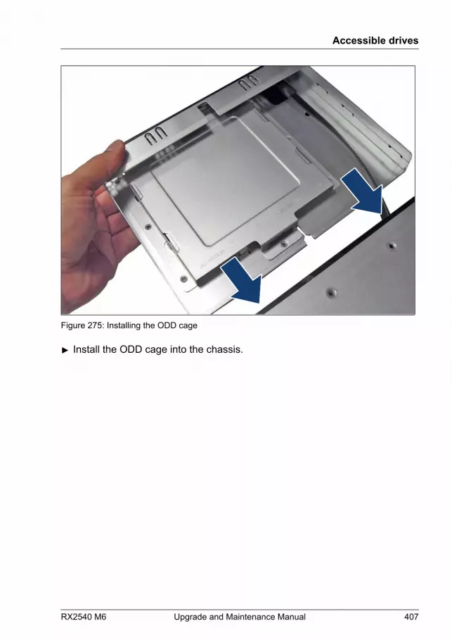
Figure 275: Installing the ODD cage
▶ Install the ODD cage into the chassis.
Accessible drives
RX2540 M6 Upgrade and Maintenance Manual 407
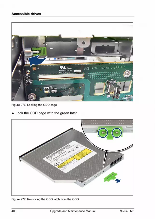
Figure 276: Locking the ODD cage
▶ Lock the ODD cage with the green latch.
Figure 277: Removing the ODD latch from the ODD
Accessible drives
408 Upgrade and Maintenance Manual RX2540 M6
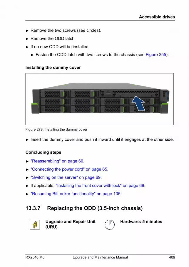
▶ Remove the two screws (see circles).
▶ Remove the ODD latch.
▶ If no new ODD will be installed:
▶ Fasten the ODD latch with two screws to the chassis (see Figure 255).
Installing the dummy cover
Figure 278: Installing the dummy cover
▶ Insert the dummy cover and push it inward until it engages at the other side.
Concluding steps
▶ "Reassembling" on page 60.
▶ "Connecting the power cord" on page 65.
▶ "Switching on the server" on page 69.
▶ If applicable, "Installing the front cover with lock" on page 69.
▶ "Resuming BitLocker functionality" on page 105.
13.3.7 Replacing the ODD (3.5-inch chassis)
Upgrade and Repair Unit(URU)
Hardware: 5 minutes
Accessible drives
RX2540 M6 Upgrade and Maintenance Manual 409

Tools: – Phillips PH2 / (+) No. 2 screw driver (for cover 2)
– Torx Plus 6 screw driver (not valid for Japan)
– Phillips PH1 / (+) No. 1 screw driver (Japan)
Preliminary steps
▶ "Locating the defective server" on page 49.
▶ "Removing backup and optical disk media" on page 90.
▶ "Suspending BitLocker functionality" on page 87.
▶ If applicable, "Removing the front cover with lock" on page 52.
▶ "Shutting down the server" on page 52.
▶ "Disconnecting the power cord" on page 53.
▶ "Getting access to the component" on page 56.
Removing the defective ODD
▶ Remove the ODD, see "Removing the ODD (3.5-inch chassis)" on page 402.
Installing the new ODD
▶ Install the ODD, see "Installing the ODD (3.5-inch chassis)" on page 395.
Concluding steps
▶ "Reassembling" on page 60.
▶ "Connecting the power cord" on page 65.
▶ "Switching on the server" on page 69.
▶ If applicable, "Installing the front cover with lock" on page 69.
▶ "Resuming BitLocker functionality" on page 105.
Accessible drives
410 Upgrade and Maintenance Manual RX2540 M6
13.4 LTO drive
13.4.1 Installing the LTO drive
Upgrade and Repair Unit(URU)
Hardware: 10 minutes
Tools: Phillips PH2 / (+) No. 2 screw driver
Preliminary steps
▶ "Suspending BitLocker functionality" on page 87.
▶ If applicable, "Removing the front cover with lock" on page 52.
▶ "Shutting down the server" on page 52.
▶ "Disconnecting the power cord" on page 53.
▶ "Getting access to the component" on page 56.
▶ "Removing the fan cage" on page 74.
Accessible drives
RX2540 M6 Upgrade and Maintenance Manual 411

Removing the front panel cage
Figure 279: Removing the front panel cage (A)
▶ Pull the locking latch in the direction of the arrow to unlock the front panelcage (see close-up).
Accessible drives
412 Upgrade and Maintenance Manual RX2540 M6

Figure 280: Removing the front panel cage (B)
▶ Remove the front panel cage out of its bay.
Accessible drives
RX2540 M6 Upgrade and Maintenance Manual 413
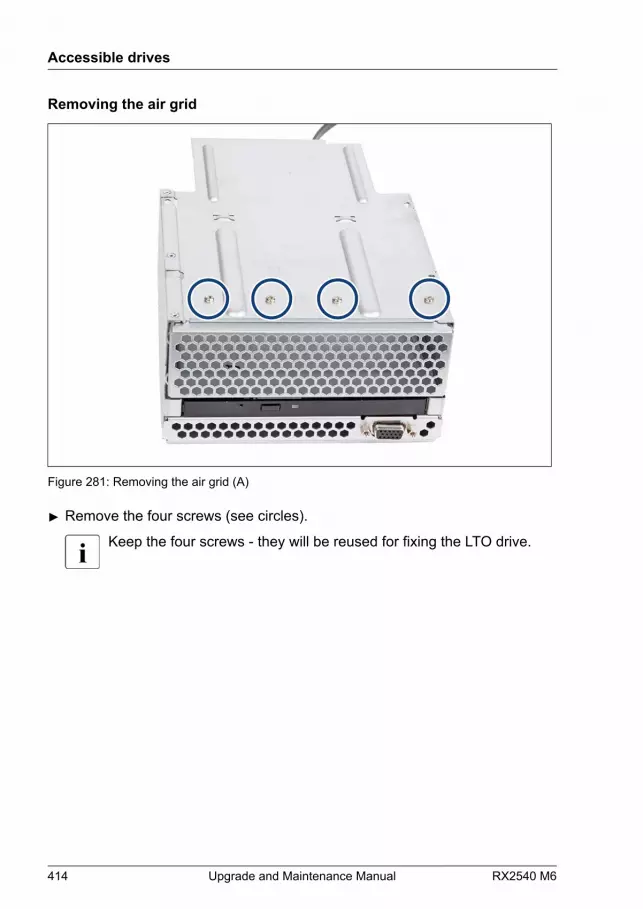
Removing the air grid
Figure 281: Removing the air grid (A)
▶ Remove the four screws (see circles).
Keep the four screws - they will be reused for fixing the LTO drive.
Accessible drives
414 Upgrade and Maintenance Manual RX2540 M6

Figure 282: Removing the air grid (B)
▶ Remove the air grid.CAUTIONSave the dummy cover (air grid) for future use.▶ Always replace dummy modules into unused drive bays to
comply with applicable EMC regulations and satisfy coolingrequirements.
Accessible drives
RX2540 M6 Upgrade and Maintenance Manual 415

Installing an LTO drive
Figure 283: Installing the LTO drive (A)
▶ Insert the LTO drive into the front panel module (see arrow).
▶ If applicable, fasten the LTO drive with four screws (see blue and orangecircles).
▶ In case of an LTO drive which has only three screw-holes, fasten with threescrews (see blue circles).
Accessible drives
416 Upgrade and Maintenance Manual RX2540 M6
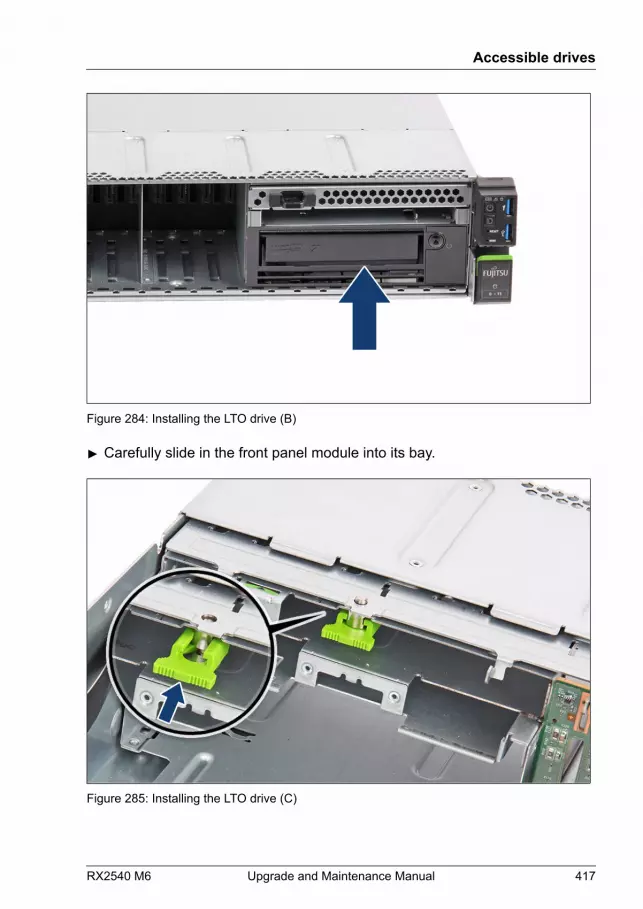
Figure 284: Installing the LTO drive (B)
▶ Carefully slide in the front panel module into its bay.
Figure 285: Installing the LTO drive (C)
Accessible drives
RX2540 M6 Upgrade and Maintenance Manual 417
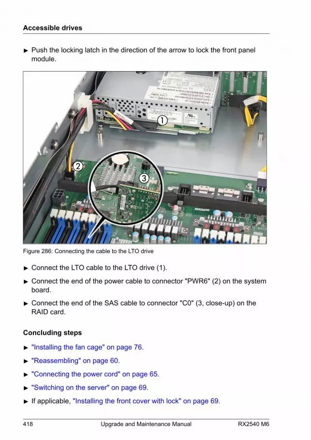
▶ Push the locking latch in the direction of the arrow to lock the front panelmodule.
Figure 286: Connecting the cable to the LTO drive
▶ Connect the LTO cable to the LTO drive (1).
▶ Connect the end of the power cable to connector "PWR6" (2) on the systemboard.
▶ Connect the end of the SAS cable to connector "C0" (3, close-up) on theRAID card.
Concluding steps
▶ "Installing the fan cage" on page 76.
▶ "Reassembling" on page 60.
▶ "Connecting the power cord" on page 65.
▶ "Switching on the server" on page 69.
▶ If applicable, "Installing the front cover with lock" on page 69.
Accessible drives
418 Upgrade and Maintenance Manual RX2540 M6
▶ "Resuming BitLocker functionality" on page 105.
13.4.2 Removing the LTO drive
Upgrade and Repair Unit(URU)
Hardware: 10 minutes
Tools: Phillips PH2 / (+) No. 2 screw driver
Preliminary steps
▶ "Removing backup and optical disk media" on page 90.
▶ "Suspending BitLocker functionality" on page 87.
▶ If applicable, "Removing the front cover with lock" on page 52.
▶ "Shutting down the server" on page 52.
▶ "Disconnecting the power cord" on page 53.
▶ "Getting access to the component" on page 56.
▶ "Removing the fan cage" on page 74.
Accessible drives
RX2540 M6 Upgrade and Maintenance Manual 419
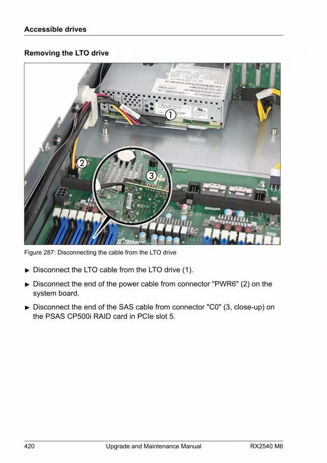
Removing the LTO drive
Figure 287: Disconnecting the cable from the LTO drive
▶ Disconnect the LTO cable from the LTO drive (1).
▶ Disconnect the end of the power cable from connector "PWR6" (2) on thesystem board.
▶ Disconnect the end of the SAS cable from connector "C0" (3, close-up) onthe PSAS CP500i RAID card in PCIe slot 5.
Accessible drives
420 Upgrade and Maintenance Manual RX2540 M6

Figure 288: Removing the LTO drive (A)
▶ Pull the locking latch in the direction of the arrow to unlock the front panelcage.
Figure 289: Removing the LTO drive (B)
Accessible drives
RX2540 M6 Upgrade and Maintenance Manual 421
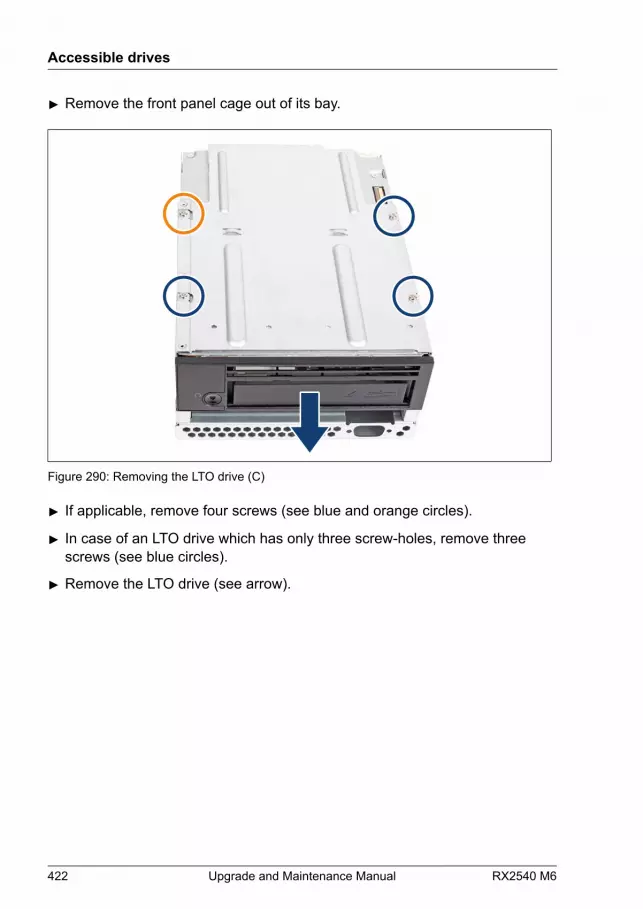
▶ Remove the front panel cage out of its bay.
Figure 290: Removing the LTO drive (C)
▶ If applicable, remove four screws (see blue and orange circles).
▶ In case of an LTO drive which has only three screw-holes, remove threescrews (see blue circles).
▶ Remove the LTO drive (see arrow).
Accessible drives
422 Upgrade and Maintenance Manual RX2540 M6
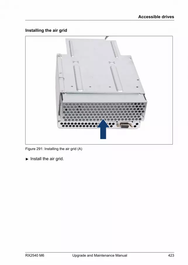
Installing the air grid
Figure 291: Installing the air grid (A)
▶ Install the air grid.
Accessible drives
RX2540 M6 Upgrade and Maintenance Manual 423
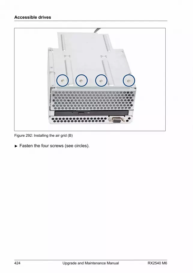
Figure 292: Installing the air grid (B)
▶ Fasten the four screws (see circles).
Accessible drives
424 Upgrade and Maintenance Manual RX2540 M6

Installing the front panel cage
Figure 293: Installing the front panel cage (A)
▶ Insert the front panel cage into its bay.
Accessible drives
RX2540 M6 Upgrade and Maintenance Manual 425
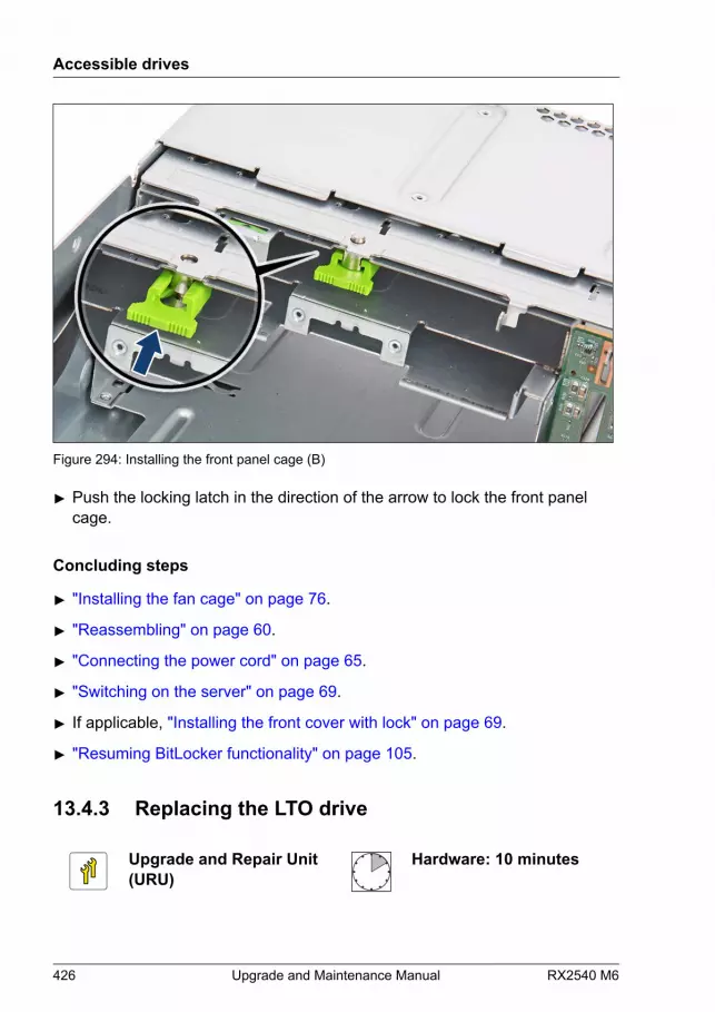
Figure 294: Installing the front panel cage (B)
▶ Push the locking latch in the direction of the arrow to lock the front panelcage.
Concluding steps
▶ "Installing the fan cage" on page 76.
▶ "Reassembling" on page 60.
▶ "Connecting the power cord" on page 65.
▶ "Switching on the server" on page 69.
▶ If applicable, "Installing the front cover with lock" on page 69.
▶ "Resuming BitLocker functionality" on page 105.
13.4.3 Replacing the LTO drive
Upgrade and Repair Unit(URU)
Hardware: 10 minutes
Accessible drives
426 Upgrade and Maintenance Manual RX2540 M6
Tools: Phillips PH2 / (+) No. 2 screw driver
Preliminary steps
▶ "Locating the defective server" on page 49.
▶ "Removing backup and optical disk media" on page 90.
▶ "Suspending BitLocker functionality" on page 87.
▶ If applicable, "Removing the front cover with lock" on page 52.
▶ "Shutting down the server" on page 52.
▶ "Disconnecting the power cord" on page 53.
▶ "Getting access to the component" on page 56.
▶ "Removing the fan cage" on page 74.
Removing the defective LTO drive
▶ Remove the LTO drive, see "Removing the LTO drive" on page 419.
Installing the new LTO drive
▶ Install the LTO drive, see "Installing the LTO drive" on page 411.
Concluding steps
▶ "Installing the fan cage" on page 76.
▶ "Reassembling" on page 60.
▶ "Connecting the power cord" on page 65.
▶ "Switching on the server" on page 69.
▶ If applicable,"Installing the front cover with lock" on page 69.
▶ "Resuming BitLocker functionality" on page 105.
Accessible drives
RX2540 M6 Upgrade and Maintenance Manual 427
13.5 RDX drive
13.5.1 Installing the RDX drive
Upgrade and Repair Unit(URU)
Hardware: 10 minutes
Tools: Phillips PH2 / (+) No. 2 screw driver
Preliminary steps
▶ "Suspending BitLocker functionality" on page 87.
▶ If applicable, "Removing the front cover with lock" on page 52.
▶ "Shutting down the server" on page 52.
▶ "Disconnecting the power cord" on page 53.
▶ "Getting access to the component" on page 56.
▶ "Removing the fan cage" on page 74.
Accessible drives
428 Upgrade and Maintenance Manual RX2540 M6
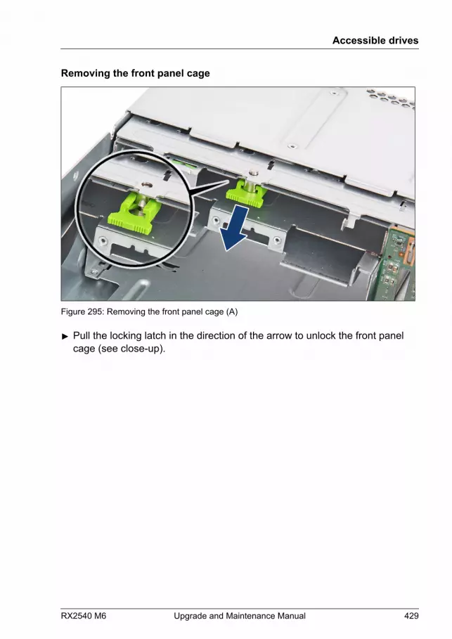
Removing the front panel cage
Figure 295: Removing the front panel cage (A)
▶ Pull the locking latch in the direction of the arrow to unlock the front panelcage (see close-up).
Accessible drives
RX2540 M6 Upgrade and Maintenance Manual 429
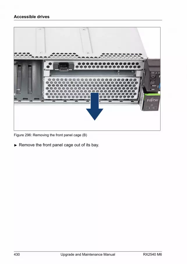
Figure 296: Removing the front panel cage (B)
▶ Remove the front panel cage out of its bay.
Accessible drives
430 Upgrade and Maintenance Manual RX2540 M6
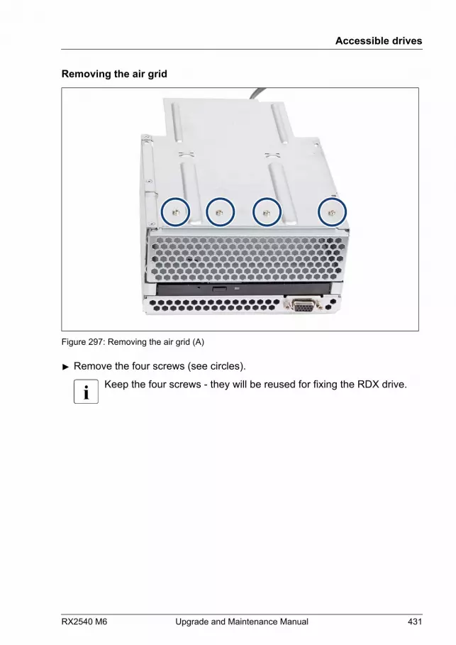
Removing the air grid
Figure 297: Removing the air grid (A)
▶ Remove the four screws (see circles).
Keep the four screws - they will be reused for fixing the RDX drive.
Accessible drives
RX2540 M6 Upgrade and Maintenance Manual 431
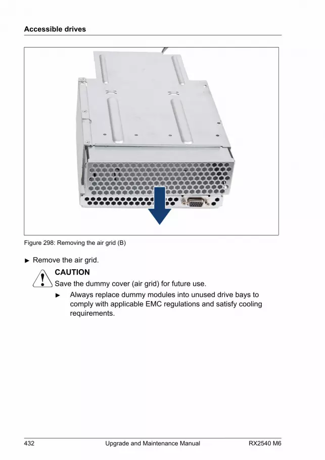
Figure 298: Removing the air grid (B)
▶ Remove the air grid.CAUTIONSave the dummy cover (air grid) for future use.▶ Always replace dummy modules into unused drive bays to
comply with applicable EMC regulations and satisfy coolingrequirements.
Accessible drives
432 Upgrade and Maintenance Manual RX2540 M6
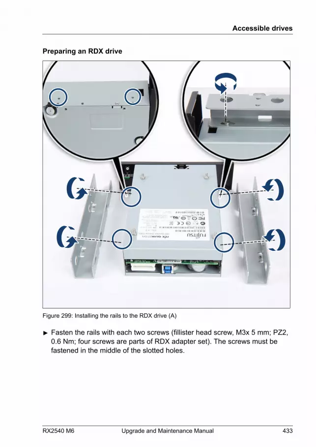
Preparing an RDX drive
Figure 299: Installing the rails to the RDX drive (A)
▶ Fasten the rails with each two screws (fillister head screw, M3x 5 mm; PZ2,0.6 Nm; four screws are parts of RDX adapter set). The screws must befastened in the middle of the slotted holes.
Accessible drives
RX2540 M6 Upgrade and Maintenance Manual 433

Figure 300: Installing the rails to the RDX drive (B)
▶ Ensure that the rails are in alignment with the RDX drive (see line).
Installing an RDX drive
Figure 301: Installing the RDX drive (A)
Accessible drives
434 Upgrade and Maintenance Manual RX2540 M6

▶ Insert the RDX drive into the front panel module (see arrow).
▶ Fasten the RDX drive with four screws (see circles).
Figure 302: Installing the RDX drive (B)
▶ Carefully slide in the front panel module into its bay.
Accessible drives
RX2540 M6 Upgrade and Maintenance Manual 435
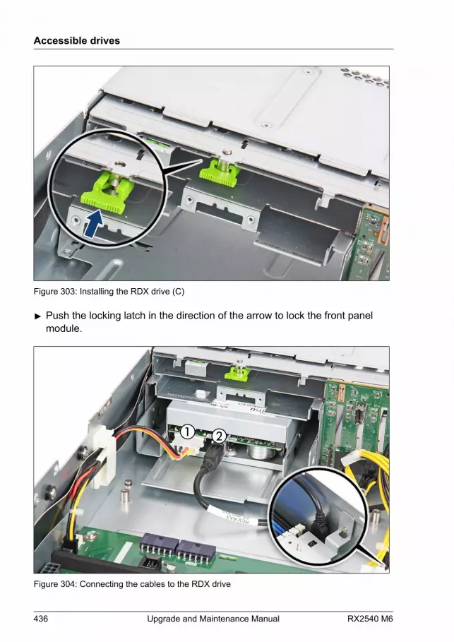
Figure 303: Installing the RDX drive (C)
▶ Push the locking latch in the direction of the arrow to lock the front panelmodule.
Figure 304: Connecting the cables to the RDX drive
Accessible drives
436 Upgrade and Maintenance Manual RX2540 M6
▶ Connect the power cable to the RDX drive (1).
▶ Connect the end of the power cable to connector "PWR6" on the systemboard.
▶ Connect the USB cable to the RDX drive (2).
▶ Connect the end of the USB cable to connector "USB4" (see close-up) onthe system board.
Concluding steps
▶ "Installing the fan cage" on page 76.
▶ "Reassembling" on page 60.
▶ "Connecting the power cord" on page 65.
▶ "Switching on the server" on page 69.
▶ If applicable, "Installing the front cover with lock" on page 69.
▶ "Resuming BitLocker functionality" on page 105.
13.5.2 Removing the RDX drive
Upgrade and Repair Unit(URU)
Hardware: 10 minutes
Tools: Phillips PH2 / (+) No. 2 screw driver
Preliminary steps
▶ "Removing backup and optical disk media" on page 90.
▶ "Suspending BitLocker functionality" on page 87.
▶ If applicable, "Removing the front cover with lock" on page 52.
▶ "Shutting down the server" on page 52.
▶ "Disconnecting the power cord" on page 53.
▶ "Getting access to the component" on page 56.
Accessible drives
RX2540 M6 Upgrade and Maintenance Manual 437

▶ "Removing the fan cage" on page 74.
Removing the RDX drive
Figure 305: Disconnecting the cables from the RDX drive
▶ Disconnect the power cable from the RDX drive (1).
▶ Disconnect the end of the power cable from connector "PWR6" on thesystem board.
▶ Disconnect the USB cable from the RDX drive (2).
▶ Disconnect the end of the USB cable from connector "USB4" (see close-up)on the system board.
Accessible drives
438 Upgrade and Maintenance Manual RX2540 M6

Figure 306: Removing the RDX drive (A)
▶ Pull the locking latch in the direction of the arrow to unlock the front panelcage.
Accessible drives
RX2540 M6 Upgrade and Maintenance Manual 439
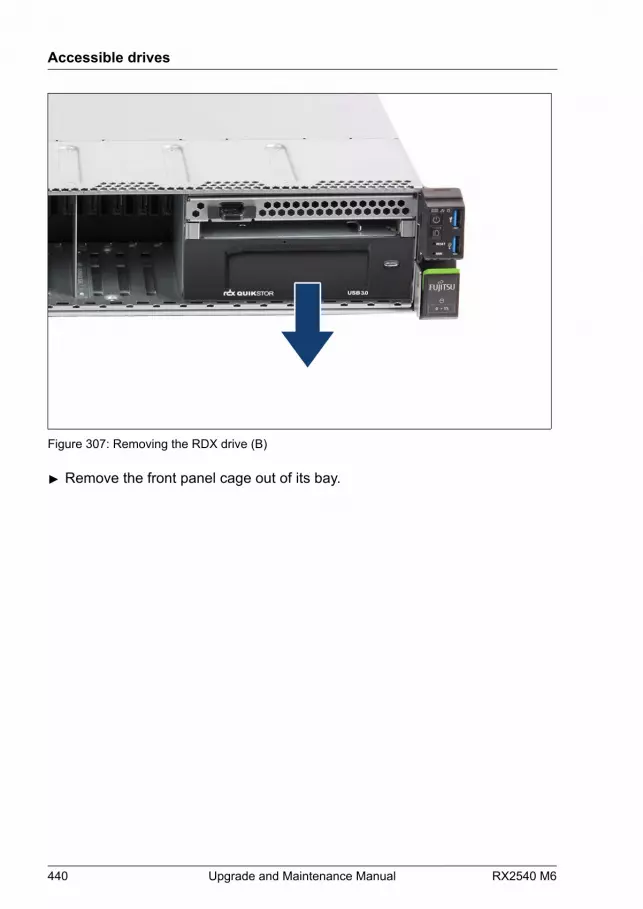
Figure 307: Removing the RDX drive (B)
▶ Remove the front panel cage out of its bay.
Accessible drives
440 Upgrade and Maintenance Manual RX2540 M6
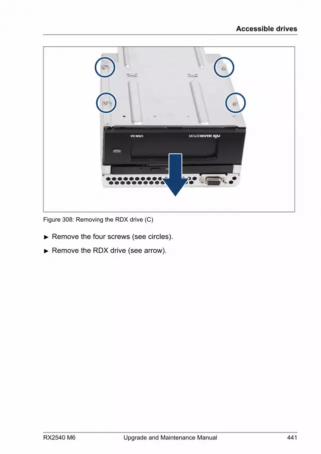
Figure 308: Removing the RDX drive (C)
▶ Remove the four screws (see circles).
▶ Remove the RDX drive (see arrow).
Accessible drives
RX2540 M6 Upgrade and Maintenance Manual 441

Installing the air grid
Figure 309: Installing the air grid (A)
▶ Install the air grid.
Accessible drives
442 Upgrade and Maintenance Manual RX2540 M6

Figure 310: Installing the air grid (B)
▶ Fasten the four screws (see circles).
Accessible drives
RX2540 M6 Upgrade and Maintenance Manual 443

Installing the front panel cage
Figure 311: Installing the front panel cage (A)
▶ Insert the front panel cage into its bay.
Accessible drives
444 Upgrade and Maintenance Manual RX2540 M6
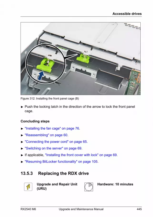
Figure 312: Installing the front panel cage (B)
▶ Push the locking latch in the direction of the arrow to lock the front panelcage.
Concluding steps
▶ "Installing the fan cage" on page 76.
▶ "Reassembling" on page 60.
▶ "Connecting the power cord" on page 65.
▶ "Switching on the server" on page 69.
▶ If applicable, "Installing the front cover with lock" on page 69.
▶ "Resuming BitLocker functionality" on page 105.
13.5.3 Replacing the RDX drive
Upgrade and Repair Unit(URU)
Hardware: 10 minutes
Accessible drives
RX2540 M6 Upgrade and Maintenance Manual 445
Tools: Phillips PH2 / (+) No. 2 screw driver
Preliminary steps
▶ "Locating the defective server" on page 49.
▶ "Removing backup and optical disk media" on page 90.
▶ "Suspending BitLocker functionality" on page 87.
▶ If applicable, "Removing the front cover with lock" on page 52.
▶ "Shutting down the server" on page 52.
▶ "Disconnecting the power cord" on page 53.
▶ "Getting access to the component" on page 56.
▶ "Removing the fan cage" on page 74.
Removing the defective RDX drive
▶ Remove the RDX drive, see "Removing the RDX drive" on page 437.
Installing the new RDX drive
▶ Install the RDX drive, see "Installing the RDX drive" on page 428.
Concluding steps
▶ "Installing the fan cage" on page 76.
▶ "Reassembling" on page 60.
▶ "Connecting the power cord" on page 65.
▶ "Switching on the server" on page 69.
▶ If applicable, "Installing the front cover with lock" on page 69.
▶ "Resuming BitLocker functionality" on page 105.
Accessible drives
446 Upgrade and Maintenance Manual RX2540 M6
14 Front panel
14.1 Safety notes
CAUTION▶ When inserting the COP (Common Operation Panel) into the
server, ensure not to pinch or strain any connected cables.▶ Circuit boards and soldered parts of internal options are exposed
and can be damaged by static electricity. Always discharge staticbuild-up (e.g. by touching a grounded object) before handlingelectrostatic-sensitive devices (ESDs).
▶ Do not touch the circuitry on boards or soldered parts. Hold circuitboards by their metallic areas or edges.
▶ For more information, see "Important information" on page 35.
14.2 Basic information
In case of a defective ambient temperature sensor, please replace CommonOperation panel (COP).
COP
The COP is mounted on the right side ear. A flat cable is used for connection tothe system board.
Front VGA (option)
A front VGA connector can be installed at the front panel of someconfigurations.
RX2540 M6 Upgrade and Maintenance Manual 447
14.3 Common operation panel (COP)
14.3.1 Replacing the COP
Field Replaceable Unit(FRU)
Hardware: 10 minutesSoftware: 5 minutes
Tools: – Phillips PH2 / (+) No. 2 screw driver (for cover 2)
– Phillips PH1 / (+) No. 1 screw driver (for COP)
Note on system information backup/restoreThe COP contains the Chassis ID EPROM that contains system informationlike server name and model, housing type, serial number and manufacturingdata. To avoid the loss of non-default settings when replacing the systemboard, a backup copy of important system configuration data is automaticallystored from the system board NVRAM to the Chassis ID EPROM.
CAUTIONFor that reason the COP and the system board must not be replacedsimultaneously! In this case, restoring the system configuration data onthe system board would fail.▶ Reconfigure the BIOS/iRMC and restore the system information like
server name, server model, housing type, serial number andmanufacturing data manually by Chassis ID Prom Tool.
Preliminary steps
▶ "Locating the defective server" on page 49.
▶ If applicable, "Removing the front cover with lock" on page 52.
▶ "Shutting down the server" on page 52.
▶ "Disconnecting the power cord" on page 53.
▶ "Getting access to the component" on page 56.
▶ If applicable, "Removing the riser module 2" on page 71.
▶ "Removing the fan cage" on page 74.
Front panel
448 Upgrade and Maintenance Manual RX2540 M6
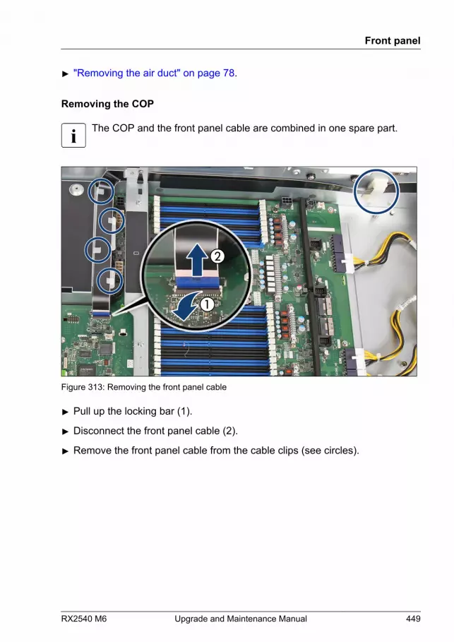
▶ "Removing the air duct" on page 78.
Removing the COP
The COP and the front panel cable are combined in one spare part.
Figure 313: Removing the front panel cable
▶ Pull up the locking bar (1).
▶ Disconnect the front panel cable (2).
▶ Remove the front panel cable from the cable clips (see circles).
Front panel
RX2540 M6 Upgrade and Maintenance Manual 449

Figure 314: Removing the COP (A)
▶ Remove the two screws (see circles).
Front panel
450 Upgrade and Maintenance Manual RX2540 M6

Figure 315: Removing the COP (B)
▶ Pull the COP together with the front panel cable out of the opening.
Installing the COP
Figure 316: Installing the COP (B)
Front panel
RX2540 M6 Upgrade and Maintenance Manual 451
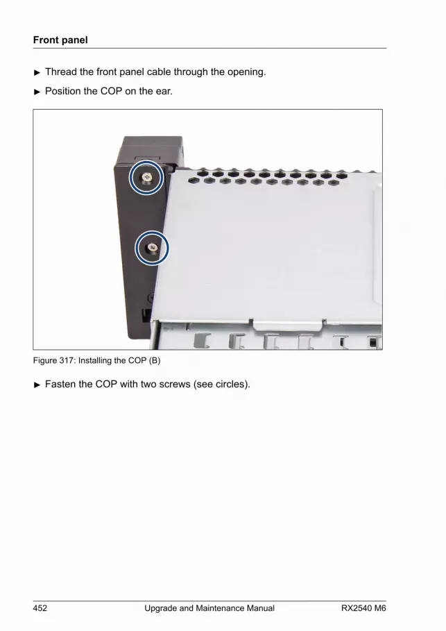
▶ Thread the front panel cable through the opening.
▶ Position the COP on the ear.
Figure 317: Installing the COP (B)
▶ Fasten the COP with two screws (see circles).
Front panel
452 Upgrade and Maintenance Manual RX2540 M6

Figure 318: Installing the front panel cable
▶ Bend the cable 90 degrees by hand for easier routing.
▶ Insert the front panel cable in the cable clips (see circles).
▶ Insert the front panel cable in the connector (1).
▶ Press down the locking bar (2).
Concluding steps
▶ "Installing the air duct" on page 79.
▶ "Removing the fan cage" on page 74.
▶ If applicable, "Installing the riser module 2" on page 73.
▶ "Reassembling" on page 60.
▶ "Connecting the power cord" on page 65.
▶ "Switching on the server" on page 69.
▶ If applicable, "Installing the front cover with lock" on page 69.
▶ "Verifying system information backup or restore" on page 94.
▶ "Resuming BitLocker functionality" on page 105.
Front panel
RX2540 M6 Upgrade and Maintenance Manual 453
14.4 Front VGA
14.4.1 Installing the front VGA
Upgrade and Repair Unit(URU)
Hardware: 5 minutes
Tools: – Phillips PH2 / (+) No. 2 screw driver (for cover 2)
– hexagon screw driver 5 mm (for front VGA)
Preliminary steps
▶ If applicable, "Removing the front cover with lock" on page 52.
▶ "Shutting down the server" on page 52.
▶ "Disconnecting the power cord" on page 53.
▶ "Getting access to the component" on page 56.
▶ If applicable, "Removing the riser module 1" on page 70.
▶ "Removing the fan cage" on page 74.
▶ "Removing the air duct" on page 78.
Front panel
454 Upgrade and Maintenance Manual RX2540 M6

Removing the dummy cover
Figure 319: Removing the dummy cover
▶ Remove the dummy cover.
Front panel
RX2540 M6 Upgrade and Maintenance Manual 455

Installing the front VGA
Figure 320: Installing the front VGA
▶ Insert the front VGA cable from the server inside through the opening.
▶ Fasten the front VGA connector with the two screws (see circles).
Figure 321: Installing the front VGA cable
Front panel
456 Upgrade and Maintenance Manual RX2540 M6
▶ Insert the front VGA cable in the cable clip (see circle).
▶ Connect the front VGA cable to the system board connector "Front VGA".
Concluding steps
▶ "Installing the air duct" on page 79.
▶ "Installing the fan cage" on page 76.
▶ If applicable, "Installing the riser module 1" on page 72.
▶ "Reassembling" on page 60.
▶ "Connecting the power cord" on page 65.
▶ "Switching on the server" on page 69.
▶ If applicable, "Installing the front cover with lock" on page 69.
14.4.2 Removing the front VGA
Upgrade and Repair Unit(URU)
Hardware: 5 minutes
Tools: – Phillips PH2 / (+) No. 2 screw driver (for cover 2)
– hexagon screw driver 5 mm (for front VGA)
Preliminary steps
▶ If applicable, "Removing the front cover with lock" on page 52.
▶ "Shutting down the server" on page 52.
▶ "Disconnecting the power cord" on page 53.
▶ "Getting access to the component" on page 56.
▶ If applicable, "Removing the riser module 1" on page 70.
▶ "Removing the fan cage" on page 74.
▶ "Removing the air duct" on page 78.
Front panel
RX2540 M6 Upgrade and Maintenance Manual 457
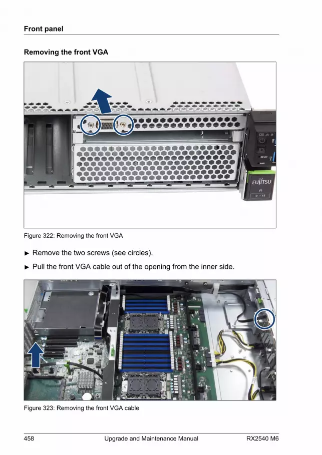
Removing the front VGA
Figure 322: Removing the front VGA
▶ Remove the two screws (see circles).
▶ Pull the front VGA cable out of the opening from the inner side.
Figure 323: Removing the front VGA cable
Front panel
458 Upgrade and Maintenance Manual RX2540 M6
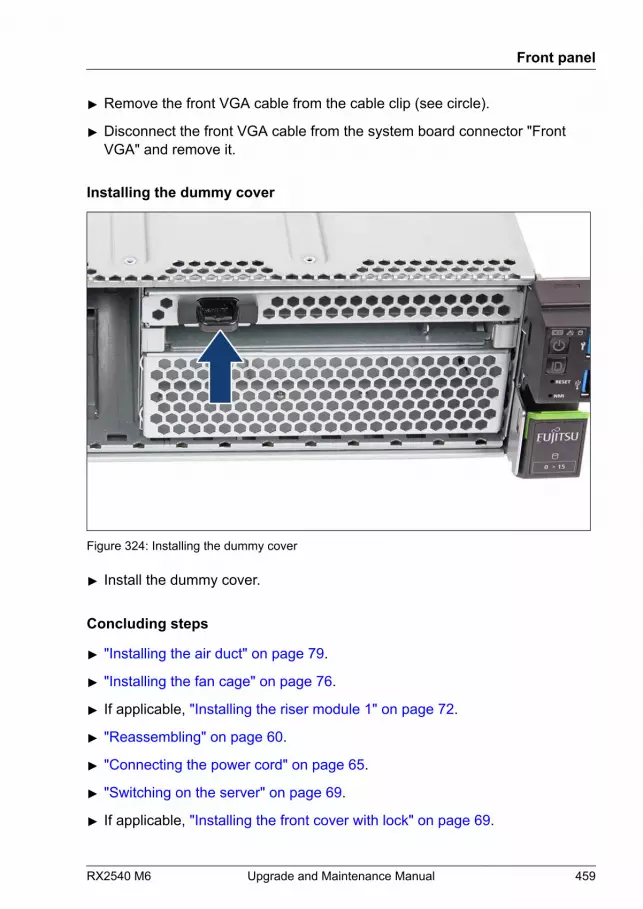
▶ Remove the front VGA cable from the cable clip (see circle).
▶ Disconnect the front VGA cable from the system board connector "FrontVGA" and remove it.
Installing the dummy cover
Figure 324: Installing the dummy cover
▶ Install the dummy cover.
Concluding steps
▶ "Installing the air duct" on page 79.
▶ "Installing the fan cage" on page 76.
▶ If applicable, "Installing the riser module 1" on page 72.
▶ "Reassembling" on page 60.
▶ "Connecting the power cord" on page 65.
▶ "Switching on the server" on page 69.
▶ If applicable, "Installing the front cover with lock" on page 69.
Front panel
RX2540 M6 Upgrade and Maintenance Manual 459

14.4.3 Replacing the front VGA
Upgrade and Repair Unit(URU)
Hardware: 5 minutes
Tools: – Phillips PH2 / (+) No. 2 screw driver (for cover 2)
– hexagon screw driver 5 mm (for front VGA)
Preliminary steps
▶ If applicable, "Removing the front cover with lock" on page 52.
▶ "Shutting down the server" on page 52.
▶ "Disconnecting the power cord" on page 53.
▶ "Getting access to the component" on page 56.
▶ If applicable, "Removing the riser module 1" on page 70.
▶ "Removing the fan cage" on page 74.
▶ "Removing the air duct" on page 78.
Removing the defective front VGA
▶ Remove the front VGA, see "Removing the front VGA " on page 457.
Installing the new front VGA
▶ Install the front VGA, see "Installing the front VGA" on page 454.
Concluding steps
▶ "Installing the air duct" on page 79.
▶ "Installing the fan cage" on page 76.
▶ If applicable, "Installing a riser module" on page 72.
▶ "Reassembling" on page 60.
▶ "Connecting the power cord" on page 65.
Front panel
460 Upgrade and Maintenance Manual RX2540 M6
▶ "Switching on the server" on page 69.
▶ If applicable, "Installing the front cover with lock" on page 69.
Front panel
RX2540 M6 Upgrade and Maintenance Manual 461
Front panel
462 Upgrade and Maintenance Manual RX2540 M6
15 Additional interfaces
15.1 Safety notes
CAUTION▶ For more information, see "Important information" on page 35.
15.2 Serial interface
15.2.1 Installing the serial interface
Upgrade and Repair Unit(URU)
Hardware: 5 minutes
Tools: – flat screw driver
– hexagon screw driver 5 mm
Preliminary steps
▶ If applicable, "Removing the front cover with lock" on page 52.
▶ "Shutting down the server" on page 52.
▶ "Disconnecting the power cord" on page 53.
▶ "Getting access to the component" on page 56.
RX2540 M6 Upgrade and Maintenance Manual 463

Breaking off the metal cover
Figure 325: Removing the metal cover
▶ Twist and break off the metal cover. Use a flat screw driver to break off themetal cover (see close-up).
Additional interfaces
464 Upgrade and Maintenance Manual RX2540 M6
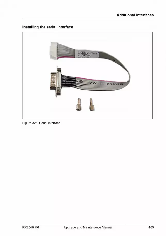
Installing the serial interface
Figure 326: Serial interface
Additional interfaces
RX2540 M6 Upgrade and Maintenance Manual 465
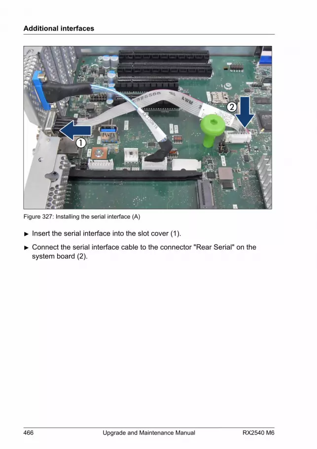
Figure 327: Installing the serial interface (A)
▶ Insert the serial interface into the slot cover (1).
▶ Connect the serial interface cable to the connector "Rear Serial" on thesystem board (2).
Additional interfaces
466 Upgrade and Maintenance Manual RX2540 M6

Figure 328: Installing the serial interface (B)
▶ Fasten the serial interface with two hexagon bolts (see circles).
Concluding steps
▶ "Reassembling" on page 60.
▶ "Connecting the power cord" on page 65.
▶ "Switching on the server" on page 69.
▶ If applicable, "Installing the front cover with lock" on page 69.
15.2.2 Removing the serial interface
Upgrade and Repair Unit(URU)
Hardware: 5 minutes
Tools: hexagon screw driver 5 mm
Additional interfaces
RX2540 M6 Upgrade and Maintenance Manual 467
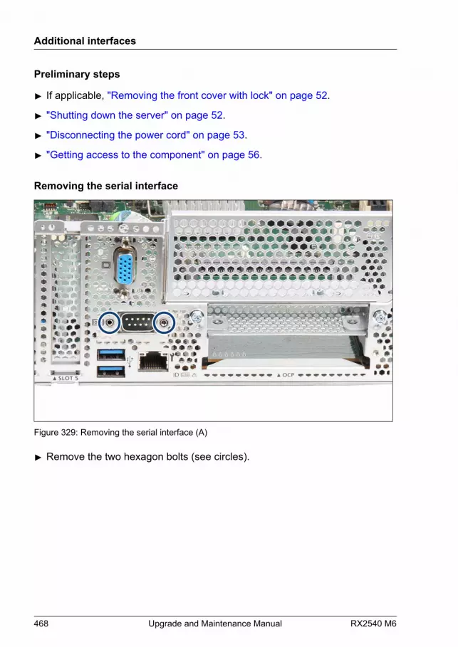
Preliminary steps
▶ If applicable, "Removing the front cover with lock" on page 52.
▶ "Shutting down the server" on page 52.
▶ "Disconnecting the power cord" on page 53.
▶ "Getting access to the component" on page 56.
Removing the serial interface
Figure 329: Removing the serial interface (A)
▶ Remove the two hexagon bolts (see circles).
Additional interfaces
468 Upgrade and Maintenance Manual RX2540 M6
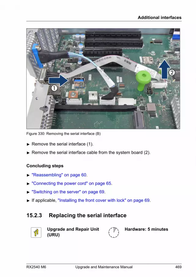
Figure 330: Removing the serial interface (B)
▶ Remove the serial interface (1).
▶ Remove the serial interface cable from the system board (2).
Concluding steps
▶ "Reassembling" on page 60.
▶ "Connecting the power cord" on page 65.
▶ "Switching on the server" on page 69.
▶ If applicable, "Installing the front cover with lock" on page 69.
15.2.3 Replacing the serial interface
Upgrade and Repair Unit(URU)
Hardware: 5 minutes
Additional interfaces
RX2540 M6 Upgrade and Maintenance Manual 469
Tools: hexagon screw driver 5 mm
Preliminary steps
▶ If applicable, "Removing the front cover with lock" on page 52.
▶ "Shutting down the server" on page 52.
▶ "Disconnecting the power cord" on page 53.
▶ "Getting access to the component" on page 56.
Removing the defective serial interface
▶ Remove the serial interface, see "Removing the serial interface" on page 467.
Installing the new serial interface
▶ Install the serial interface, see "Installing the serial interface" on page 463.
Concluding steps
▶ "Reassembling" on page 60.
▶ "Connecting the power cord" on page 65.
▶ "Switching on the server" on page 69.
▶ If applicable, "Installing the front cover with lock" on page 69.
15.3 Rear VGA connector
15.3.1 Replacing the rear VGA
Upgrade and Repair Unit(URU)
Hardware: 5 minutes
Additional interfaces
470 Upgrade and Maintenance Manual RX2540 M6

Tools: hexagon screw driver 5 mm
Preliminary steps
▶ If applicable, "Removing the front cover with lock" on page 52.
▶ "Shutting down the server" on page 52.
▶ "Disconnecting the power cord" on page 53.
▶ "Getting access to the component" on page 56.
Removing the rear VGA
Figure 331: Removing the rear VGA connector (A)
▶ Remove the two hexagon bolts (see circles).
Additional interfaces
RX2540 M6 Upgrade and Maintenance Manual 471

Figure 332: Removing the rear VGA connector (B)
▶ Remove the rear VGA connector (1).
▶ Remove the cable from the system board (2).
Additional interfaces
472 Upgrade and Maintenance Manual RX2540 M6

Installing the rear VGA
Figure 333: Installing the rear VGA connector (A)
▶ Insert the rear VGA connector into the slot cover (1).
▶ Connect the VGA cable to the connector "Rear VGA" on the system board(2).
Additional interfaces
RX2540 M6 Upgrade and Maintenance Manual 473
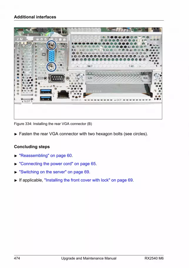
Figure 334: Installing the rear VGA connector (B)
▶ Fasten the rear VGA connector with two hexagon bolts (see circles).
Concluding steps
▶ "Reassembling" on page 60.
▶ "Connecting the power cord" on page 65.
▶ "Switching on the server" on page 69.
▶ If applicable, "Installing the front cover with lock" on page 69.
Additional interfaces
474 Upgrade and Maintenance Manual RX2540 M6
16 System board and components
16.1 Safety notes
CAUTION▶ Devices and components inside the server remain hot after
shutdown. After shutting down the server, wait for hot componentsto cool down before installing or removing internal options.
▶ Circuit boards and soldered parts of internal options are exposedand can be damaged by static electricity. Always discharge staticbuild-up (e.g. by touching a grounded object) before handlingelectrostatic-sensitive devices (ESDs).
▶ Do not touch the circuitry on boards or soldered parts. Hold circuitboards by their metallic areas or edges.
▶ For more information, see "Important information" on page 35.
16.2 Basic information
This section provides instructions for the system board and the followingcomponents:
● CMOS battery (CR2450)
The real-time clock is powered by a lithium coin cell (CMOS battery) whenmains get lost. This cell lasts up to five years, depending on ambienttemperature and use.
If the CMOS battery is depleted or falls below minimum voltage levels, itneed to be replaced immediately.
● TPM (Trusted Platform Module)
The system board is optionally equipped with a TPM. This module enablesprograms from third party manufacturers to store key information, forexample drive encryption using Windows Bitlocker Drive Encryption.
RX2540 M6 Upgrade and Maintenance Manual 475
● iRMC microSD card
The iRMC microSD card is necessary for using the embedded LifecycleManagement (eLCM) functionality of the iRMC.
● M.2 SSD
The system board offers two M.2 slots (Key M) with support 80 mm and110 mm long M.2 SSDs. With the M.2 SSD an internal SSD is offered. ThisSSD can be configured as a boot device or data storage device.
● Dual microSD 64GB Enterprise
The system board is optionally equipped with a Dual microSD 64GBEnterprise. The Dual microSD 64GB Enterprise offers an IntegratedHardware RAID solution based on RAID-on-Chip (ROC) technology.
● VROC module
The VROC module is necessary for using the VROC functionality. VROCprovides RAID solutions for NVMe SSDs and SATA devices.
16.3 CMOS battery
16.3.1 Replacing the CMOS battery
Upgrade and Repair Unit(URU)
Hardware: 5 minutes
Tools: – Phillips PH2 / (+) No. 2 screw driver (for cover 2)
– recommended: tooth pick (CMOS battery)
For this server the battery type CR2450 is used.
System board and components
476 Upgrade and Maintenance Manual RX2540 M6
CAUTION▶ The CMOS battery must be replaced with an identical battery or
with a battery type recommended by the manufacturer.▶ Keep lithium batteries away from children.▶ Do not throw batteries into the trash can. Lithium batteries must be
disposed of in accordance with local regulations concerning specialwaste.
▶ For more safety information, see "Environmental protection" in theoperating manual of your server.
▶ Ensure to insert the CMOS battery with the positive pole facingup!
Preliminary steps
▶ "Locating the defective server" on page 49.
▶ "Verifying the system time settings" on page 100.
▶ If applicable, "Removing the front cover with lock" on page 52.
▶ "Shutting down the server" on page 52.
▶ "Disconnecting the power cord" on page 53.
▶ "Getting access to the component" on page 56.
▶ If applicable, "Removing the riser module 1" on page 70.
System board and components
RX2540 M6 Upgrade and Maintenance Manual 477

Replacing the defective CMOS battery
1
23
4
Figure 335: Replacing the CMOS battery
▶ Press the locking spring into direction of the arrow (1), so that the CMOSbattery jumps out of its socket.
▶ Remove the CMOS battery (2).CAUTIONSharp tools such as screw drivers might damage system boardcomponents in case of slipping.▶ If the CMOS battery cannot be ejected without the help of a tool,
it is recommended to use a tooth pick.
▶ Insert a new CMOS battery of the same type into the socket (3) and (4).
Concluding steps
▶ Dispose of the CMOS battery in accordance with local regulationsconcerning special waste.
▶ If applicable, "Installing the riser module 1" on page 72.
▶ "Reassembling" on page 60.
▶ "Connecting the power cord" on page 65.
▶ "Switching on the server" on page 69.
▶ If applicable, "Installing the front cover with lock" on page 69.
System board and components
478 Upgrade and Maintenance Manual RX2540 M6
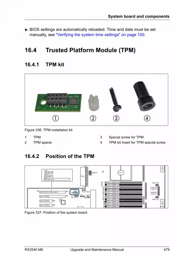
▶ BIOS settings are automatically reloaded. Time and date must be setmanually, see "Verifying the system time settings" on page 100.
16.4 Trusted Platform Module (TPM)
16.4.1 TPM kit
Figure 336: TPM installation kit
1 TPM2 TPM spacer
3 Special screw for TPM4 TPM bit insert for TPM special screw
16.4.2 Position of the TPM
iRMC
exte
rnal
con
nect
ors
TPMSlot 8 (CPU 2) Riser slot 2 Front Panel
PSU2
MicroSD
Slot 7 (CPU2)
Slot 6 (CPU2)
Slot 5 (CPU2)
SSD1
CPU 2
CPU 1 DIMM 2ACPU 1 DIMM 1A
CPU 1 DIMM 2BCPU 1 DIMM 1B
CPU 2 DIMM 1RCPU 2 DIMM 2N
CPU 2 DIMM 2PCPU 2 DIMM 1P
CPU 2 DIMM 2R
CPU 2 DIMM 1N
CPU 2 DIMM 1QCPU 2 DIMM 2Q
SLIMLINE4 (CPU 2)
LC2
PWR10
HDD LED3
PWR4
PWR3
PWR2
SLIMLINE3 (CPU 2)
FAN5_SYS
FAN4_SYS
SMB 3
Slot riser card
Rise
r car
d
Slot 10
Slot 9
Figure 337: Position of the system board
System board and components
RX2540 M6 Upgrade and Maintenance Manual 479
16.4.3 Installing the TPM
Field Replaceable Unit(FRU)
Hardware: 5 minutesSoftware: 5 minutes
Tools: – Phillips PH2 / (+) No. 2 screw driver (for cover 2)
– Bit screw driver
– TPM bit insert (*)
(*) For Japan:– TPM module fixing tool (S26361-F3552-L909)
Preliminary steps
▶ "Suspending BitLocker functionality" on page 87.
▶ If applicable, "Removing backup and optical disk media" on page 90.
▶ "Shutting down the server" on page 52.
▶ "Disconnecting the power cord" on page 53.
▶ "Getting access to the component" on page 56.
▶ If applicable, "Removing the riser module 2" on page 71.
▶ If applicable, "Removing an expansion card" on page 262.
System board and components
480 Upgrade and Maintenance Manual RX2540 M6
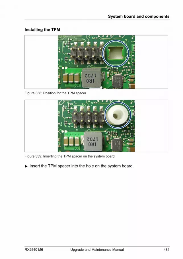
Installing the TPM
Figure 338: Position for the TPM spacer
Figure 339: Inserting the TPM spacer on the system board
▶ Insert the TPM spacer into the hole on the system board.
System board and components
RX2540 M6 Upgrade and Maintenance Manual 481

Figure 340: TPM bit insert
▶ Attach the TPM bit insert or TPM module fixing tool (for Japan) to a bit screwdriver.
Figure 341: Installing the TPM
▶ Connect the TPM to the system board (1).
▶ Fasten the TPM with the special screw for the TPM using the TPM bit insertor TPM module fixing tool (Japan) (2).
CAUTION▶ Do not fasten the screw too firmly.▶ Stop it by extent where the head of the screw lightly touches the
TPM. Torque: 0.6 Nm (not used in Japan).
System board and components
482 Upgrade and Maintenance Manual RX2540 M6
Concluding steps
▶ If applicable, "Installing an expansion card" on page 255.
▶ If applicable, "Installing the riser module 2" on page 73.
▶ "Reassembling" on page 60.
▶ "Connecting the power cord" on page 65.
▶ "Switching on the server" on page 69.
▶ If applicable, "Installing the front cover with lock" on page 69.
▶ "Resuming BitLocker functionality" on page 105.
▶ Enable the TPM in the system board BIOS, see "Enabling the TPM in the system board BIOS" on page 483.
Enabling the TPM in the system board BIOS
▶ Switch on or restart your server.
▶ As soon as the startup screen appears, press the [F2] function key to enterthe BIOS setup menu.
▶ Select the Configuration menu.
▶ Select the Security Configuration submenu.
▶ Set the TPM Support setting to Enabled.
▶ Under Pending TPM operation, select the desired TPM operation mode.
▶ Save your changes and exit the BIOS.
For more information on how to access the BIOS and modify settings,see the corresponding BIOS Setup Utility reference manual.
16.4.4 Removing the TPM
Field Replaceable Unit(FRU)
Hardware: 30 minutes
System board and components
RX2540 M6 Upgrade and Maintenance Manual 483

Tools: Removing the system board:– Phillips PH2 / (+) No. 2 screw driver
– Torx 30 screw driver
Removing the TPM:– Bit screw driver
– flat nose pliers
– TPM bit insert (*)
(*) For Japan:– TPM module fixing tool (S26361-F3552-L909)
CAUTION▶ Advise your contact persons that they must provide you with all
recovery keys which belong to the system to restore them in theTPM later.
Preliminary steps
Preliminary steps are not necessary, if a system board has to bereplaced and the TPM is used again.
▶ Before removing the TPM board, remove the BitLocker protection anddecrypt the volume, see "Removing BitLocker protection and decrypting the volume" on page 485.
▶ Disable the TPM in the system board BIOS, see "Disabling the TPM in the system board BIOS" on page 485.
▶ "Suspending BitLocker functionality" on page 87.
▶ If applicable, "Removing the front cover with lock" on page 52.
▶ "Shutting down the server" on page 52.
▶ "Disconnecting the power cord" on page 53.
▶ Remove all PSUs, see "Installing a hot-plug PSU" on page 124.
System board and components
484 Upgrade and Maintenance Manual RX2540 M6
▶ If applicable, remove the OCP module, see "Removing an OCP module" on page 252.
▶ "Getting access to the component" on page 56.
▶ Remove all riser modules, see "Removing a riser module" on page 70.
▶ "Removing the air duct" on page 78.
▶ "Removing the fan cage" on page 74.
▶ "Removing the cross bar" on page 80.
Removing BitLocker protection and decrypting the volume
▶ Before removing the TPM board, it is necessary to remove BitLockerprotection from the computer and to decrypt the volume. Ask the systemadministrator to turn off BitLocker protection using the BitLocker setupwizard available either from the Control Panel or Windows Explorer:
▶ Open Bitlocker Drive Encryption by clicking the Start button, clickingControl Panel, clicking Security, and then clicking Bitlocker DriveEncryption.
Administrator permission required: If you are prompted for anadministrator password or confirmation, type the password orprovide confirmation.
▶ To turn off BitLocker and decrypt the volume, click Turn Off BitLocker,and then click Decrypt the volume.
Decrypting the volume may be time-consuming. By decrypting thevolume, all of the information stored on that computer is decrypted.For more information on how to disable BitLocker drive encryption,see the Microsoft Knowledge Base. See the Fujitsu web pages formore details.
Disabling the TPM in the system board BIOS
▶ Switch on or restart your server.
▶ As soon as the startup screen appears, press the [F2] function key to enterthe BIOS setup menu.
System board and components
RX2540 M6 Upgrade and Maintenance Manual 485

▶ Select the Configuration menu.
▶ Select the Security Configuration submenu.
▶ Set the TPM Support setting to Disabled.
▶ Save your changes and exit the BIOS.
For more information on how to access the BIOS and modify settings,see the corresponding BIOS Setup Utility reference manual.
Removing the TPM
▶ Remove the system board, see "Removing the defective system board" on page 524.
▶ Lay the system board on a soft, antistatic surface with its component sidefacing down.
Figure 342: Removing the TPM screw
System board and components
486 Upgrade and Maintenance Manual RX2540 M6
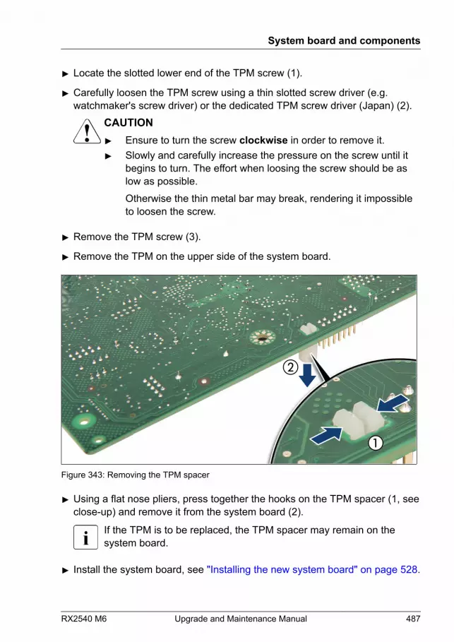
▶ Locate the slotted lower end of the TPM screw (1).
▶ Carefully loosen the TPM screw using a thin slotted screw driver (e.g.watchmaker's screw driver) or the dedicated TPM screw driver (Japan) (2).
CAUTION▶ Ensure to turn the screw clockwise in order to remove it.▶ Slowly and carefully increase the pressure on the screw until it
begins to turn. The effort when loosing the screw should be aslow as possible.Otherwise the thin metal bar may break, rendering it impossibleto loosen the screw.
▶ Remove the TPM screw (3).
▶ Remove the TPM on the upper side of the system board.
Figure 343: Removing the TPM spacer
▶ Using a flat nose pliers, press together the hooks on the TPM spacer (1, seeclose-up) and remove it from the system board (2).
If the TPM is to be replaced, the TPM spacer may remain on thesystem board.
▶ Install the system board, see "Installing the new system board" on page 528.
System board and components
RX2540 M6 Upgrade and Maintenance Manual 487
Concluding steps
▶ "Installing the cross bar" on page 81.
▶ "Installing the fan cage" on page 76.
▶ "Installing the air duct" on page 79.
▶ Install all riser modules, see "Installing a riser module" on page 72.
▶ "Reassembling" on page 60.
▶ If applicable, install the OCP module, see "Installing an OCP module" on page 249.
▶ Install all PSUs, see "Installing a hot-plug PSU" on page 124.
▶ "Connecting the power cord" on page 65.
▶ "Switching on the server" on page 69.
▶ If applicable, "Installing the front cover with lock" on page 69.
16.4.5 Replacing the TPM
Field Replaceable Unit(FRU)
Hardware: 35 minutes
System board and components
488 Upgrade and Maintenance Manual RX2540 M6
Tools: Removing the system board:– Phillips PH2 / (+) No. 2 screw driver
– Torx 30 screw driver
Replacing the TPM:– Bit screw driver
– TPM bit insert (*)
– flat nose pliers
– thin slotted screw driver (2 x 0.4 mm)(*)
(*) For Japan:– Dedicated TPM screw driver (CWZ8291A)
– TPM module fixing tool (S26361-F3552-L909)
CAUTION▶ Advise your contact persons that they must provide you with all
recovery keys which belong to the system to restore them in theTPM later.
Preliminary steps
▶ "Locating the defective server" on page 49.
▶ "Suspending BitLocker functionality" on page 87.
▶ If applicable, "Removing the front cover with lock" on page 52.
▶ "Shutting down the server" on page 52.
▶ "Disconnecting the power cord" on page 53.
▶ Remove all PSUs, see "Removing a hot-plug PSU" on page 127.
▶ If applicable, remove the OCP module, see "Removing an OCP module" on page 252.
▶ "Getting access to the component" on page 56.
▶ Remove all riser modules, see "Removing a riser module" on page 70.
System board and components
RX2540 M6 Upgrade and Maintenance Manual 489
▶ "Removing the air duct" on page 78.
▶ "Removing the fan cage" on page 74.
▶ "Removing the cross bar" on page 80.
Removing the defective TPM
▶ Remove the TPM, see "Removing the TPM" on page 483.
▶ Leave the TPM spacer on the system board when removing the defectiveTPM.
Installing the new TPM
The TPM spacer is already present on the system board.
▶ Install the TPM, see "Installing the TPM" on page 480.
Concluding steps
▶ "Installing the cross bar" on page 81.
▶ "Installing the fan cage" on page 76.
▶ "Installing the air duct" on page 79.
▶ Install all riser modules, see "Installing a riser module" on page 72.
▶ "Reassembling" on page 60.
▶ If applicable, install the OCP module, see "Installing an OCP module" on page 249.
▶ Install all PSUs, see "Installing a hot-plug PSU" on page 124.
▶ "Connecting the power cord" on page 65.
▶ "Switching on the server" on page 69.
▶ If applicable, "Installing the front cover with lock" on page 69.
▶ "Resuming BitLocker functionality" on page 105.
System board and components
490 Upgrade and Maintenance Manual RX2540 M6
You can find information on configuring the TPM in the correspondingBIOS Setup Utility reference manual.
16.5 iRMC microSD card
16.5.1 Note for embedded Lifecycle Management (eLCM)
The iRMC microSD card is necessary for using the embedded LifecycleManagement (eLCM) functionality of the iRMC. It requires a valid eLCMlicense key from user purchase order and activated through the iRMCweb interface.For more information, see the “ServerView embedded LifecycleManagement (eLCM)” user guide.
16.5.2 Installing the iRMC microSD card
Upgrade and Repair Unit(URU)
Hardware: 5 minutes
Tools: Phillips PH2 / (+) No. 2 screw driver (for cover 2)
Preliminary steps
▶ If applicable, "Removing the front cover with lock" on page 52.
▶ "Shutting down the server" on page 52.
▶ "Disconnecting the power cord" on page 53.
▶ "Getting access to the component" on page 56.
▶ If applicable, remove the expansion card from slot 5 and slot 6, see"Removing the expansion card" on page 263.
System board and components
RX2540 M6 Upgrade and Maintenance Manual 491
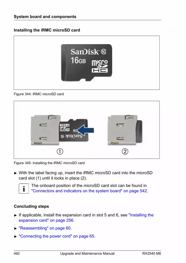
Installing the iRMC microSD card
Figure 344: iRMC microSD card
Figure 345: Installing the iRMC microSD card
▶ With the label facing up, insert the iRMC microSD card into the microSDcard slot (1) until it locks in place (2).
The onboard position of the microSD card slot can be found in"Connectors and indicators on the system board" on page 542.
Concluding steps
▶ If applicable, install the expansion card in slot 5 and 6, see "Installing the expansion card" on page 256.
▶ "Reassembling" on page 60.
▶ "Connecting the power cord" on page 65.
System board and components
492 Upgrade and Maintenance Manual RX2540 M6
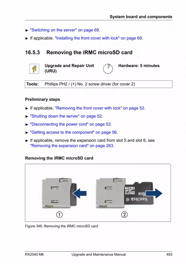
▶ "Switching on the server" on page 69.
▶ If applicable, "Installing the front cover with lock" on page 69.
16.5.3 Removing the iRMC microSD card
Upgrade and Repair Unit(URU)
Hardware: 5 minutes
Tools: Phillips PH2 / (+) No. 2 screw driver (for cover 2)
Preliminary steps
▶ If applicable, "Removing the front cover with lock" on page 52.
▶ "Shutting down the server" on page 52.
▶ "Disconnecting the power cord" on page 53.
▶ "Getting access to the component" on page 56.
▶ If applicable, remove the expansion card from slot 5 and slot 6, see"Removing the expansion card" on page 263.
Removing the iRMC microSD card
Figure 346: Removing the iRMC microSD card
System board and components
RX2540 M6 Upgrade and Maintenance Manual 493
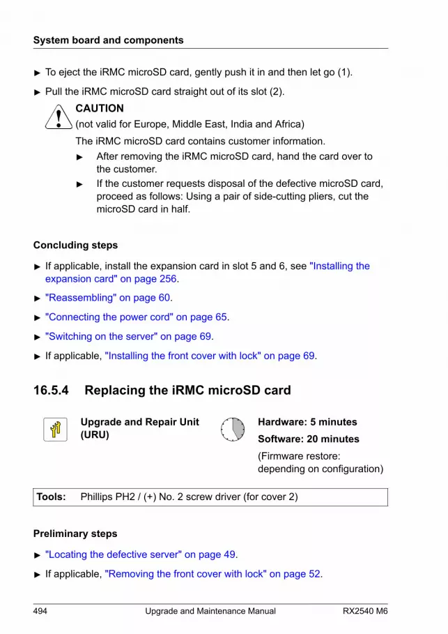
▶ To eject the iRMC microSD card, gently push it in and then let go (1).
▶ Pull the iRMC microSD card straight out of its slot (2).CAUTION(not valid for Europe, Middle East, India and Africa)The iRMC microSD card contains customer information.▶ After removing the iRMC microSD card, hand the card over to
the customer.▶ If the customer requests disposal of the defective microSD card,
proceed as follows: Using a pair of side-cutting pliers, cut themicroSD card in half.
Concluding steps
▶ If applicable, install the expansion card in slot 5 and 6, see "Installing the expansion card" on page 256.
▶ "Reassembling" on page 60.
▶ "Connecting the power cord" on page 65.
▶ "Switching on the server" on page 69.
▶ If applicable, "Installing the front cover with lock" on page 69.
16.5.4 Replacing the iRMC microSD card
Upgrade and Repair Unit(URU)
Hardware: 5 minutesSoftware: 20 minutes(Firmware restore:depending on configuration)
Tools: Phillips PH2 / (+) No. 2 screw driver (for cover 2)
Preliminary steps
▶ "Locating the defective server" on page 49.
▶ If applicable, "Removing the front cover with lock" on page 52.
System board and components
494 Upgrade and Maintenance Manual RX2540 M6

▶ "Shutting down the server" on page 52.
▶ "Disconnecting the power cord" on page 53.
▶ "Getting access to the component" on page 56.
▶ If applicable, remove the expansion card from slot 5 and slot 6, see"Removing an expansion card" on page 262.
Replacing the iRMC microSD card
▶ Remove the defective iRMC microSD card, see "Removing the iRMC microSD card" on page 493.
CAUTION(not valid for Europe, Middle East, India and Africa)The iRMC microSD card contains customer information.▶ After removing the iRMC microSD card, hand the card over to
the customer.▶ If the customer requests disposal of the defective microSD card,
proceed as follows: Using a pair of side-cutting pliers, cut themicroSD card in half.
▶ Install the new iRMC microSD card, see "Installing the iRMC microSD card" on page 491.
Concluding steps
▶ If applicable, install the expansion card in slot 5 and 6, see "Installing an expansion card" on page 255.
▶ "Reassembling" on page 60.
▶ "Connecting the power cord" on page 65.
▶ Update the BIOS or iRMC S5 firmware using the iRMC S5 web interface,see "Updating the BIOS or iRMC S5 firmware using the iRMC S5 web interface" on page 496.
▶ "Switching on the server" on page 69.
▶ If applicable, "Installing the front cover with lock" on page 69.
System board and components
RX2540 M6 Upgrade and Maintenance Manual 495
Updating the BIOS or iRMC S5 firmware using the iRMC S5 web interface
This operation will save the firmware image used for firmware restorefeature after system board exchange to the iRMC microSD card.
▶ Update the BIOS or iRMC S5 firmware using the iRMC S5 web interface:
▶ Use the firmware version that is currently in operation.
▶ Make sure to update the firmware using the iRMC S5 web interface.The firmware will not be saved to the iRMC microSD card when updatingusing a bootable USB stick or updating using ASP.
▶ For systems with PFR feature, when updating the BIOS using the iRMCS5 web interface, please select Active or Both for the Image to Flashsetting field. If you select Recovery, the saving process to the iRMCmicroSD card will not be executed.
▶ After the update is completed, check the SEL log files to verify if the updatewas successful.
If the update is successfully completed, the following messages will berecorded.For systems without PFR feature:
<iRMC> A backup of iRMC Firmware %1 has been successfully created on SD card.
<BIOS> BIOS backup to SD card succeeded.
For systems with PFR feature:
<iRMC> A backup of iRMC Firmware %1 has been successfully created on SD card.
<BIOS> BIOS backup to SD card succeeded.
If the update fails and is not saved to the iRMC microSD card, a SEL statingthat it failed will be recorded.
Even if an error occurs during the saving process, the BIOS backupimage already saved on the iRMC microSD will not be lost.
System board and components
496 Upgrade and Maintenance Manual RX2540 M6

16.6 M.2 SSD
16.6.1 Slots and bolts for M.2 SSDs
The system board offers two M.2 slots (Key M) with support for 80 mm and 110mm long M.2 SSDs. With the M.2 SSD an internal SSD is offered. This SSDcan be configured as a boot device or data storage device.
iRMCS5
exte
rnal
con
nect
ors
INDICATE CSS
TPM
Battery
Slot 8 (CPU 2) Riser slot 2
Rear Serial
Front Panel
PSU2
JP3 1
JP2 JP112
MicroSD
USB 3.0 SSD2 M.2
HDD LED2
Slot 7 (CPU2)
Slot 6 (CPU2)
Front VGA
Slot 5 (CPU2)
OCP
3.0
Slo
t 1 (
CPU
1)
SSD1
M.2
LANManagement
Internal USB3.0/USB 3
Rear VGA
CPU 2
CPU 1
CPU 1 DIMM 2ACPU 1 DIMM 1D
CPU 1 DIMM 1CCPU 1 DIMM 2C
CPU 1 DIMM 1A
CPU 1 DIMM 2D
CPU 1 DIMM 2BCPU 1 DIMM 1B
CPU 2 DIMM 1RCPU 2 DIMM 2N
CPU 2 DIMM 2PCPU 2 DIMM 1P
CPU 2 DIMM 2R
CPU 2 DIMM 1N
CPU 2 DIMM 1QCPU 2 DIMM 2Q
CPU 1 DIMM 2H
CPU 1 DIMM 1GCPU 1 DIMM 2G
SMB 4
SLIMLINE4 (CPU 2)
LC2
PWR10
HDD LED3
HDD LED1
PWR4
PWR3
PWR2
SLIMLINE3 (CPU 2)
SLIMLINE2 (CPU 1)
SLIMLINE1 (CPU 1)
FAN5_SYS
FAN4_SYS
FAN3_SYS
FAN2_SYS
ROC
VROC
SMB 3
Clear RTC
PCH
Slot riser card
Rise
r car
d
Slot 10
Slot 9
Figure 347: Slots for M.2 SSDs
▶ Identify the physical location according to the following table.
(SATA mode: AHCI)
M.2 SSD slot BIOS menu iRMC SEL1 M.2 SSD1 SSATA Port 4 (M.2 Slot 1) Port 1
2 M.2 SSD2 SSATA Port 2 (M.2 Slot 0) Port 0
(SATA mode: RAID)
M.2 SSD slot BIOS menu iRMC SEL1 M.2 SSD1 Port 4 Port 4
2 M.2 SSD2 Port 2 Port 2
System board and components
RX2540 M6 Upgrade and Maintenance Manual 497

16.6.2 Installing an M.2 SSD
Upgrade and Repair Unit(URU)
Hardware: 5 minutesSoftware: 15 minutes
Tools: Phillips PH2 / (+) No. 2 screw driver (for cover 2)
Preliminary steps
▶ If applicable, "Removing the front cover with lock" on page 52.
▶ "Shutting down the server" on page 52.
▶ "Disconnecting the power cord" on page 53.
▶ "Getting access to the component" on page 56.
Installing the M.2 SSD
CAUTIONAn M.2 SSD in M.2 SSD1 is not recognized, if M.2 SSD2 is free.▶ Install the M.2 SSD2 first.
To support different length of M.2 SSD, the M.2 SSD latch can bemoved to another position.
System board and components
498 Upgrade and Maintenance Manual RX2540 M6

▶ If applicable, move the M.2 SSD latch to a fitting position:
▶ Turn the M.2 SSD latch for 90 degrees (1).
▶ Remove the M.2 SSD latch (2).
▶ Install the M.2 SSD latch in the right position depending on the length ofthe M.2 SSD (3).
▶ Turn the M.2 SSD latch for 90 degrees (4).
System board and components
RX2540 M6 Upgrade and Maintenance Manual 499
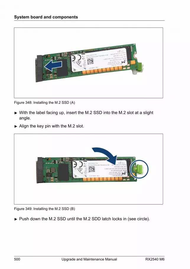
Figure 348: Installing the M.2 SSD (A)
▶ With the label facing up, insert the M.2 SSD into the M.2 slot at a slightangle.
▶ Align the key pin with the M.2 slot.
Figure 349: Installing the M.2 SSD (B)
▶ Push down the M.2 SSD until the M.2 SDD latch locks in (see circle).
System board and components
500 Upgrade and Maintenance Manual RX2540 M6

Concluding steps
▶ "Reassembling" on page 60.
▶ "Connecting the power cord" on page 65.
▶ "Switching on the server" on page 69.
▶ If applicable, "Installing the front cover with lock" on page 69.
Software configuration
In order to install the ESXi to the M.2 SSD, the VMware ESXi installer CD isrequired. To obtain the ESXi installer CD by purchasing the OEM Media Kit, ordownloading the ESXi Custom Image ISO file from the VMware website andburn the image to the CD.https://www.vmware.com/go/download-vsphereInstall the ESXi to the M.2 SSD by following the steps below:▶ Disconnect all storage devices from the server beside the M.2 SSD.
▶ Power on the server. Once the server has been started, then enter the BIOSsetup menu and select the DVD drive as primary boot device.
▶ Insert the CD into the DVD drive and reboot the server. The server will bootfrom the installer CD.
▶ Follow the on-screen instructions to install the ESXi. When the installation iscomplete, you will be asked to reboot the server.
▶ While the server is rebooting, enter the BIOS setup menu again and selectthe M.2 SSD as primary boot device.
The installation of the ESXi to the M.2 SSD is complete.
For more information on how to access the BIOS and modify settings,see the corresponding BIOS Setup Utility reference manual.
The M.2 SSD can be used only for boot device. Do not use VMFS onthe M.2 SSD because of not meeting required endurance. For moreinformation, see the VMware Knowledge Base 2145210.https://kb.vmware.com/s/article/2145210
System board and components
RX2540 M6 Upgrade and Maintenance Manual 501
For JapanIn order to setup the ESXi, see the corresponding version of the"VMware vSphere Software Description" from the following URL andreinstall ESXi to the M.2 SSD.https://jp.fujitsu.com/platform/server/primergy/software/vmware/manual/
16.6.3 Removing an M.2 SSD
Upgrade and Repair Unit(URU)
Hardware: 5 minutes
Tools: Phillips PH2 / (+) No. 2 screw driver (for cover 2)
Preliminary steps
▶ If applicable, "Removing the front cover with lock" on page 52.
▶ "Shutting down the server" on page 52.
▶ "Disconnecting the power cord" on page 53.
▶ "Getting access to the component" on page 56.
System board and components
502 Upgrade and Maintenance Manual RX2540 M6
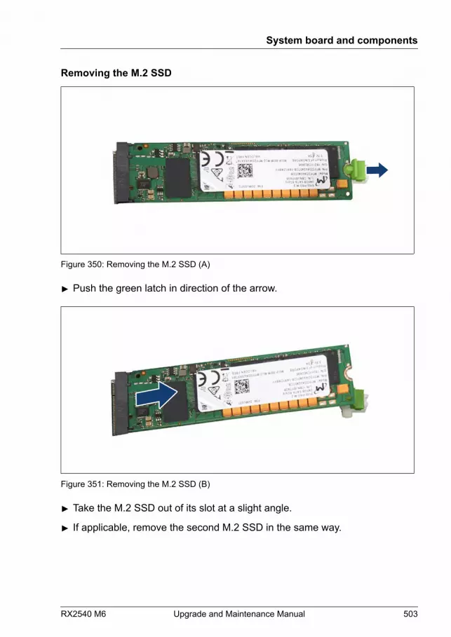
Removing the M.2 SSD
Figure 350: Removing the M.2 SSD (A)
▶ Push the green latch in direction of the arrow.
Figure 351: Removing the M.2 SSD (B)
▶ Take the M.2 SSD out of its slot at a slight angle.
▶ If applicable, remove the second M.2 SSD in the same way.
System board and components
RX2540 M6 Upgrade and Maintenance Manual 503
Concluding steps
▶ "Reassembling" on page 60.
▶ "Connecting the power cord" on page 65.
▶ "Switching on the server" on page 69.
▶ If applicable, "Installing the front cover with lock" on page 69.
16.6.4 Replacing an M.2 SSD
Upgrade and Repair Unit(URU)
Hardware: 5 minutesSoftware: 15 minutes
Tools: Phillips PH2 / (+) No. 2 screw driver (for cover 2)
Preliminary steps
▶ "Locating the defective server" on page 49.
▶ If applicable, "Removing the front cover with lock" on page 52.
▶ "Shutting down the server" on page 52.
▶ "Disconnecting the power cord" on page 53.
▶ "Getting access to the component" on page 56.
Replacing the M.2 SSD
▶ Remove the defective M.2 SSD, see "Removing the M.2 SSD" on page 503.
▶ Install the new M.2 SSD, see "Installing the M.2 SSD" on page 498.
Concluding steps
▶ "Reassembling" on page 60.
▶ "Connecting the power cord" on page 65.
▶ "Switching on the server" on page 69.
System board and components
504 Upgrade and Maintenance Manual RX2540 M6
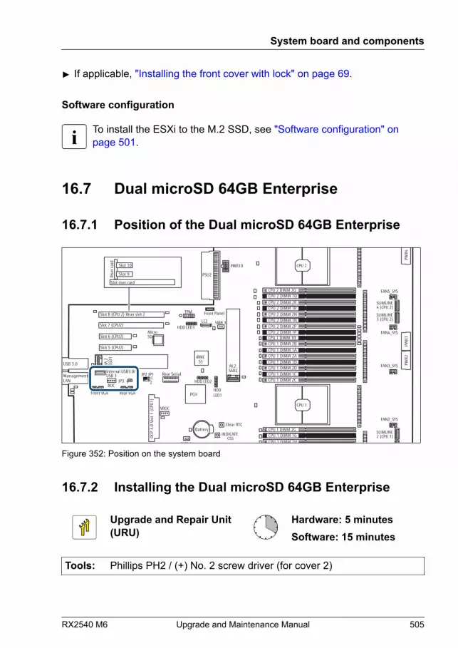
▶ If applicable, "Installing the front cover with lock" on page 69.
Software configuration
To install the ESXi to the M.2 SSD, see "Software configuration" on page 501.
16.7 Dual microSD 64GB Enterprise
16.7.1 Position of the Dual microSD 64GB Enterprise
iRMCS5
exte
rnal
con
nect
ors
INDICATE CSS
TPM
Battery
Slot 8 (CPU 2) Riser slot 2
Rear Serial
Front Panel
PSU2
JP3 1
JP2 JP112
MicroSD
USB 3.0 SSD2 M.2
HDD LED2
Slot 7 (CPU2)
Slot 6 (CPU2)
Front VGA
Slot 5 (CPU2)
OCP
3.0
Slo
t 1 (
CPU
1)
SSD1
M.2
LANManagement
Internal USB3.0/USB 3
Rear VGA
CPU 2
CPU 1
CPU 1 DIMM 2ACPU 1 DIMM 1D
CPU 1 DIMM 1CCPU 1 DIMM 2C
CPU 1 DIMM 1A
CPU 1 DIMM 2D
CPU 1 DIMM 2BCPU 1 DIMM 1B
CPU 2 DIMM 1RCPU 2 DIMM 2N
CPU 2 DIMM 2PCPU 2 DIMM 1P
CPU 2 DIMM 2R
CPU 2 DIMM 1N
CPU 2 DIMM 1QCPU 2 DIMM 2Q
CPU 1 DIMM 2H
CPU 1 DIMM 1GCPU 1 DIMM 2G
SMB 4
SLIMLINE4 (CPU 2)
LC2
PWR10
HDD LED3
HDD LED1
PWR4
PWR3
PWR2
SLIMLINE3 (CPU 2)
SLIMLINE2 (CPU 1)
SLIMLINE1 (CPU 1)
FAN5_SYS
FAN4_SYS
FAN3_SYS
FAN2_SYS
ROC
VROC
SMB 3
Clear RTC
PCH
Slot riser card
Rise
r car
d
Slot 10
Slot 9
Figure 352: Position on the system board
16.7.2 Installing the Dual microSD 64GB Enterprise
Upgrade and Repair Unit(URU)
Hardware: 5 minutesSoftware: 15 minutes
Tools: Phillips PH2 / (+) No. 2 screw driver (for cover 2)
System board and components
RX2540 M6 Upgrade and Maintenance Manual 505
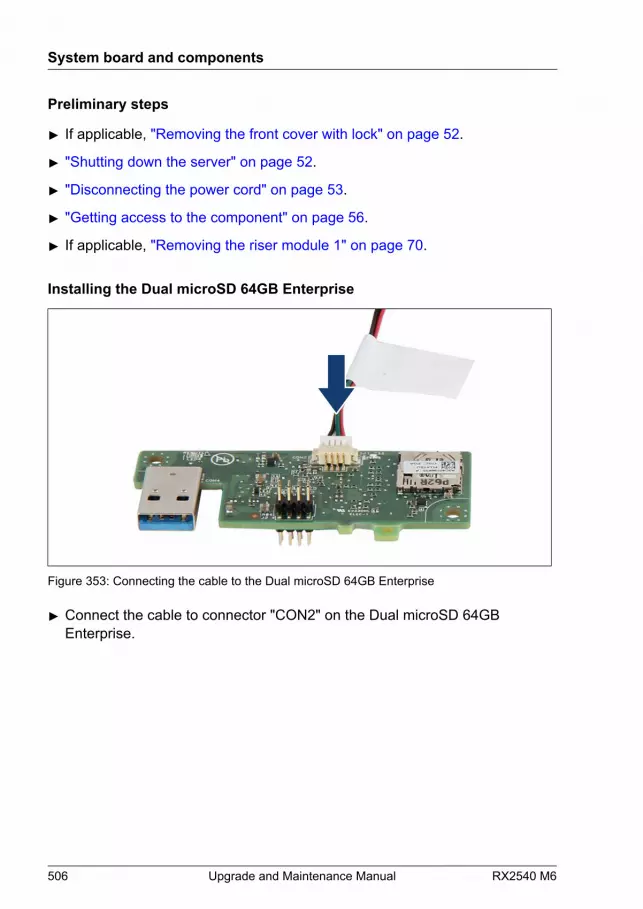
Preliminary steps
▶ If applicable, "Removing the front cover with lock" on page 52.
▶ "Shutting down the server" on page 52.
▶ "Disconnecting the power cord" on page 53.
▶ "Getting access to the component" on page 56.
▶ If applicable, "Removing the riser module 1" on page 70.
Installing the Dual microSD 64GB Enterprise
Figure 353: Connecting the cable to the Dual microSD 64GB Enterprise
▶ Connect the cable to connector "CON2" on the Dual microSD 64GBEnterprise.
System board and components
506 Upgrade and Maintenance Manual RX2540 M6
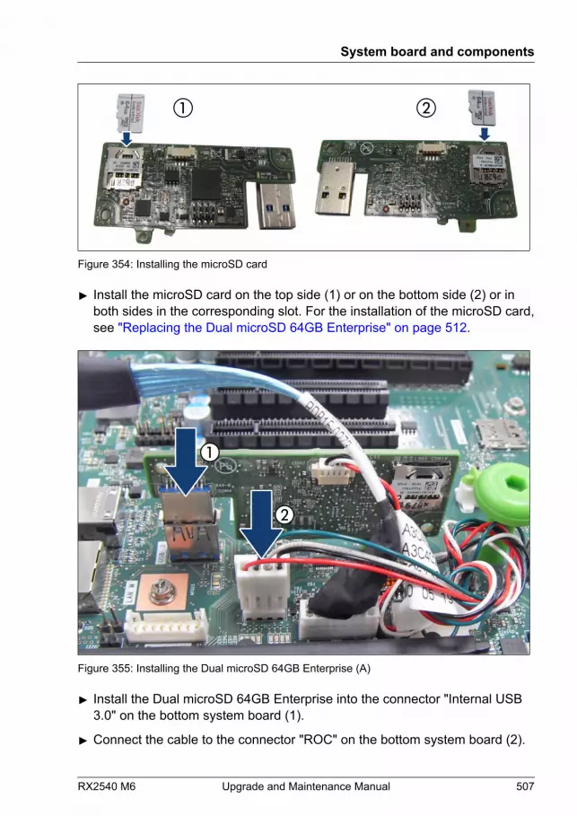
Figure 354: Installing the microSD card
▶ Install the microSD card on the top side (1) or on the bottom side (2) or inboth sides in the corresponding slot. For the installation of the microSD card,see "Replacing the Dual microSD 64GB Enterprise" on page 512.
Figure 355: Installing the Dual microSD 64GB Enterprise (A)
▶ Install the Dual microSD 64GB Enterprise into the connector "Internal USB3.0" on the bottom system board (1).
▶ Connect the cable to the connector "ROC" on the bottom system board (2).
System board and components
RX2540 M6 Upgrade and Maintenance Manual 507

Figure 356: Installing the Dual microSD 64GB Enterprise (B)
▶ Route the cable under the cable clip as shown (1, see close-up).
▶ Close the cable clip (2).
Concluding steps
▶ If applicable, "Installing the riser module 1" on page 72.
▶ "Reassembling" on page 60.
▶ "Connecting the power cord" on page 65.
▶ "Switching on the server" on page 69.
▶ If applicable, "Removing the front cover with lock" on page 52.
Software configuration
In order to install the ESXi to the Dual microSD 64GB Enterprise, the VMwareESXi installer CD is required. To obtain the ESXi installer CD by purchasing theOEM Media Kit, or downloading the ESXi Custom Image ISO file from the
System board and components
508 Upgrade and Maintenance Manual RX2540 M6

VMware website and burn the image to the CD.https://www.vmware.com/go/download-vsphereInstall the ESXi to the Dual microSD 64GB Enterprise by following the stepsbelow:▶ Disconnect all storage devices from the server beside the Dual microSD
64GB Enterprise.
▶ Power on the server. Once the server has been started, then enter the BIOSsetup menu and select the DVD drive as primary boot device.
▶ Insert the CD into the DVD drive and reboot the server. The server will bootfrom the installer CD.
▶ Follow the on-screen instructions to install the ESXi. When the installation iscomplete, you will be asked to reboot the server.
▶ While the server is rebooting, enter the BIOS setup menu again and selectthe Dual microSD 64GB Enterprise as primary boot device.
The installation of the ESXi to the Dual microSD 64GB Enterprise is complete.
For more information on how to access the BIOS and modify settings,see the corresponding BIOS Setup Utility reference manual.
The Dual microSD 64GB Enterprise can be used only for boot device.Do not use VMFS on the Dual microSD 64GB Enterprise because of notmeeting required endurance. For more information, see the VMwareKnowledge Base 2145210.https://kb.vmware.com/s/article/2145210
For JapanIn order to setup the ESXi, see the corresponding version of the"VMware vSphere Software Description" from the following URL andreinstall ESXi to the Dual microSD 64GB Enterprise.https://jp.fujitsu.com/platform/server/primergy/software/vmware/manual/
16.7.3 Removing the Dual microSD 64GB Enterprise
Upgrade and Repair Unit(URU)
Hardware: 5 minutes
System board and components
RX2540 M6 Upgrade and Maintenance Manual 509

Tools: Phillips PH2 / (+) No. 2 screw driver (for cover 2)
Preliminary steps
▶ If applicable, "Removing the front cover with lock" on page 52.
▶ "Shutting down the server" on page 52.
▶ "Disconnecting the power cord" on page 53.
▶ "Getting access to the component" on page 56.
▶ If applicable, "Removing the riser module 1" on page 70.
Removing the Dual microSD 64GB Enterprise
Figure 357: Removing the Dual microSD 64GB Enterprise (A)
▶ Disconnect the cable from the connector "ROC" on the system board (1).
▶ Pull the Dual microSD 64GB Enterprise out of its connector (2).
System board and components
510 Upgrade and Maintenance Manual RX2540 M6

Figure 358: Removing the Dual microSD 64GB Enterprise (B)
▶ Open the cable clip (1).
▶ Remove the cable from the cable clip (2, see close-up).
Concluding steps
▶ If applicable, "Installing the riser module 1" on page 72.
▶ "Reassembling" on page 60.
▶ "Connecting the power cord" on page 65.
▶ "Switching on the server" on page 69.
▶ If applicable, "Installing the front cover with lock" on page 69.
System board and components
RX2540 M6 Upgrade and Maintenance Manual 511

16.7.4 Replacing the Dual microSD 64GB Enterprise
Upgrade and Repair Unit(URU)
Hardware: 5 minutesSoftware: 15 minutes
Tools: Phillips PH2 / (+) No. 2 screw driver (for cover 2)
Preliminary steps
▶ "Locating the defective server" on page 49.
▶ If applicable, "Removing the front cover with lock" on page 52.
▶ "Shutting down the server" on page 52.
▶ "Disconnecting the power cord" on page 53.
▶ "Getting access to the component" on page 56.
▶ If applicable, "Removing the riser module 1" on page 70.
System board and components
512 Upgrade and Maintenance Manual RX2540 M6
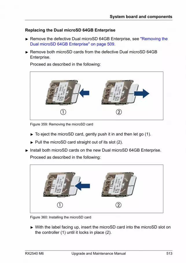
Replacing the Dual microSD 64GB Enterprise
▶ Remove the defective Dual microSD 64GB Enterprise, see "Removing the Dual microSD 64GB Enterprise" on page 509.
▶ Remove both microSD cards from the defective Dual microSD 64GBEnterprise.Proceed as described in the following:
Figure 359: Removing the microSD card
▶ To eject the microSD card, gently push it in and then let go (1).
▶ Pull the microSD card straight out of its slot (2).
▶ Install both microSD cards on the new Dual microSD 64GB Enterprise.Proceed as described in the following:
Figure 360: Installing the microSD card
▶ With the label facing up, insert the microSD card into the microSD slot onthe controller (1) until it locks in place (2).
System board and components
RX2540 M6 Upgrade and Maintenance Manual 513
▶ Install the new Dual microSD 64GB Enterprise, see "Installing the Dual microSD 64GB Enterprise" on page 505.
Concluding steps
▶ If applicable, "Installing the riser module 1" on page 72.
▶ "Reassembling" on page 60.
▶ "Connecting the power cord" on page 65.
▶ "Switching on the server" on page 69.
▶ If applicable, "Installing the front cover with lock" on page 69.
Software configuration
To install the ESXi to the Dual microSD 64GB Enterprise, see "Software configuration" on page 508.
16.7.5 Replacing the microSD card
Upgrade and Repair Unit(URU)
Hardware: 5 minutes
Tools: – Phillips PH2 / (+) No. 2 screw driver (for cover 2)
– a pair of side-cutting pliers
Preliminary steps
▶ "Locating the defective server" on page 49.
▶ If applicable, "Removing the front cover with lock" on page 52.
▶ "Shutting down the server" on page 52.
▶ "Disconnecting the power cord" on page 53.
▶ "Getting access to the component" on page 56.
▶ If applicable, "Removing the riser module 1" on page 70.
System board and components
514 Upgrade and Maintenance Manual RX2540 M6
Replacing the microSD card
CAUTION(not valid for Europe, Middle East, India and Africa)The microSD card contains customer information.▶ After removing the microSD card, hand the card over to the
customer.▶ If the customer requests disposal of the defective microSD card,
proceed as follows: Using a pair of side-cutting pliers, cut themicroSD card in half.
▶ Remove the Dual microSD 64GB Enterprise, see "Removing the Dual microSD 64GB Enterprise" on page 509.
▶ Remove the defective microSD card from the Dual microSD 64GBEnterprise.Proceed as described in the following:
▶ To eject the defective microSD card, gently push it in and then let go.
▶ Pull the microSD card straight out of its slot.
▶ Install the new microSD card on the Dual microSD 64GB Enterprise.Proceed as described in the following:
▶ With the label facing up, insert the microSD card into the microSD slot onthe controller until it locks in place.
▶ Install the Dual microSD 64GB Enterprise, see "Installing the Dual microSD 64GB Enterprise" on page 505.
Concluding steps
▶ If applicable, "Installing the riser module 1" on page 72.
▶ "Reassembling" on page 60.
▶ "Connecting the power cord" on page 65.
▶ "Switching on the server" on page 69.
▶ If applicable, "Installing the front cover with lock" on page 69.
System board and components
RX2540 M6 Upgrade and Maintenance Manual 515
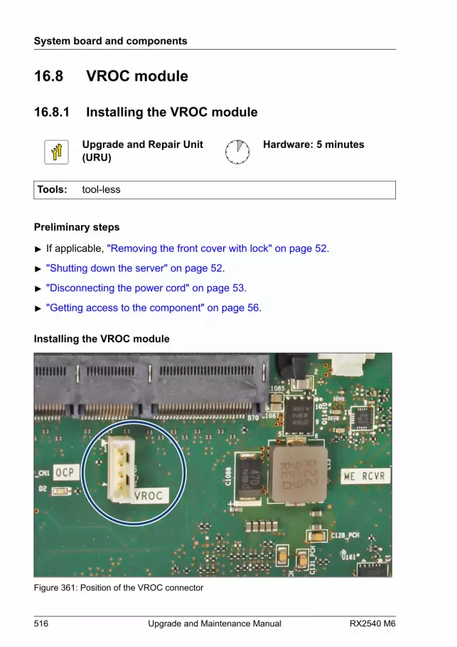
16.8 VROC module
16.8.1 Installing the VROC module
Upgrade and Repair Unit(URU)
Hardware: 5 minutes
Tools: tool-less
Preliminary steps
▶ If applicable, "Removing the front cover with lock" on page 52.
▶ "Shutting down the server" on page 52.
▶ "Disconnecting the power cord" on page 53.
▶ "Getting access to the component" on page 56.
Installing the VROC module
Figure 361: Position of the VROC connector
System board and components
516 Upgrade and Maintenance Manual RX2540 M6
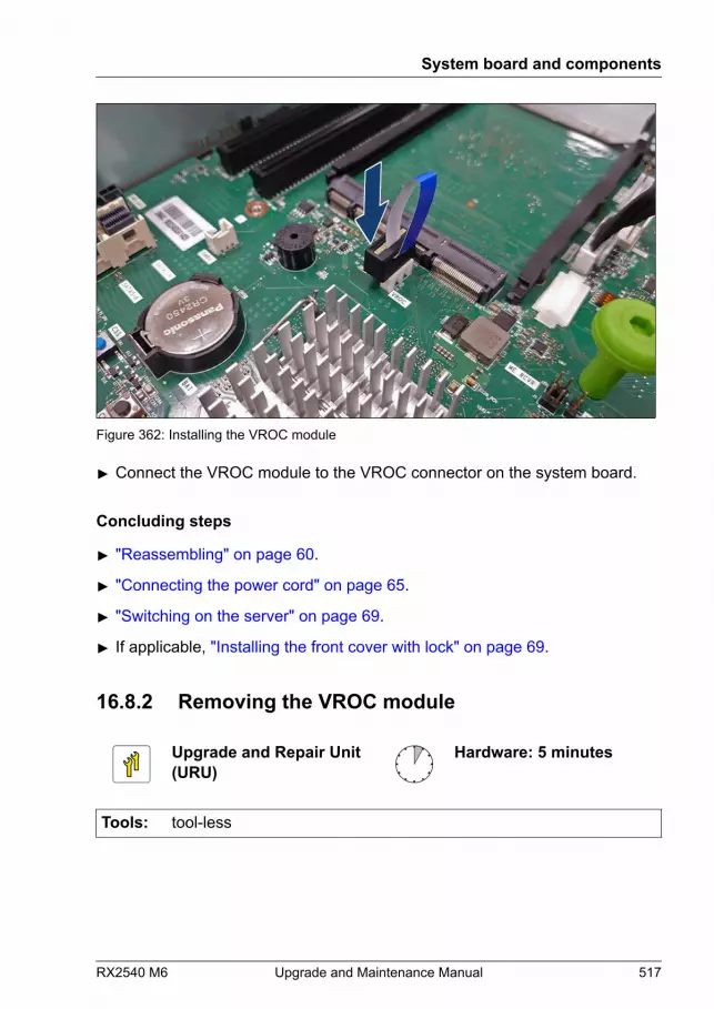
Figure 362: Installing the VROC module
▶ Connect the VROC module to the VROC connector on the system board.
Concluding steps
▶ "Reassembling" on page 60.
▶ "Connecting the power cord" on page 65.
▶ "Switching on the server" on page 69.
▶ If applicable, "Installing the front cover with lock" on page 69.
16.8.2 Removing the VROC module
Upgrade and Repair Unit(URU)
Hardware: 5 minutes
Tools: tool-less
System board and components
RX2540 M6 Upgrade and Maintenance Manual 517
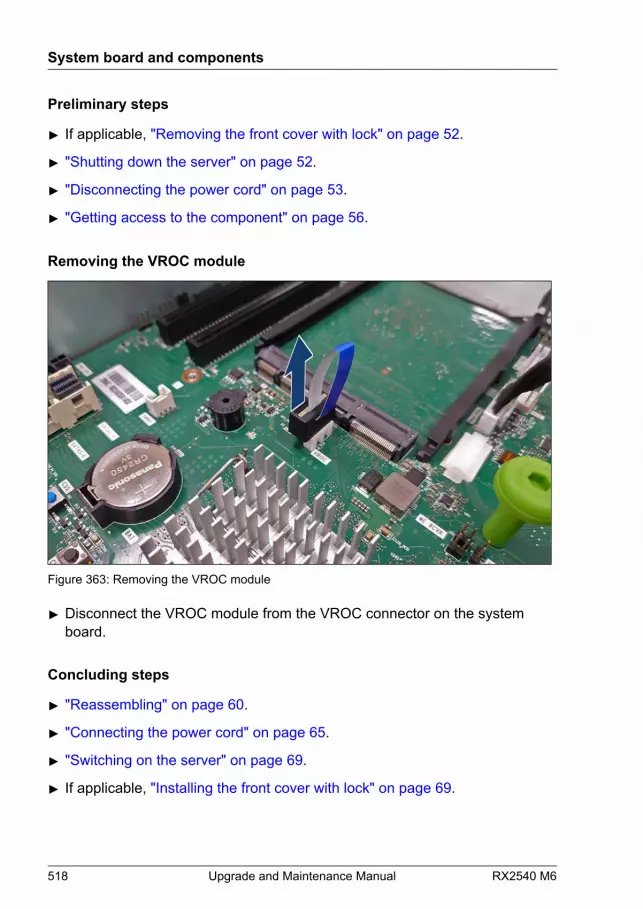
Preliminary steps
▶ If applicable, "Removing the front cover with lock" on page 52.
▶ "Shutting down the server" on page 52.
▶ "Disconnecting the power cord" on page 53.
▶ "Getting access to the component" on page 56.
Removing the VROC module
Figure 363: Removing the VROC module
▶ Disconnect the VROC module from the VROC connector on the systemboard.
Concluding steps
▶ "Reassembling" on page 60.
▶ "Connecting the power cord" on page 65.
▶ "Switching on the server" on page 69.
▶ If applicable, "Installing the front cover with lock" on page 69.
System board and components
518 Upgrade and Maintenance Manual RX2540 M6
16.8.3 Replacing the VROC module
Upgrade and Repair Unit(URU)
Hardware: 5 minutes
Tools: tool-less
Preliminary steps
▶ If applicable, "Removing the front cover with lock" on page 52.
▶ "Shutting down the server" on page 52.
▶ "Disconnecting the power cord" on page 53.
▶ "Getting access to the component" on page 56.
Replacing the VROC module
▶ Disconnect the VROC module from the VROC connector on the systemboard, see "Removing the VROC module" on page 517.
▶ Connect the VROC module to the VROC connector on the system board,see "Installing the VROC module" on page 516.
Concluding steps
▶ "Reassembling" on page 60.
▶ "Connecting the power cord" on page 65.
▶ "Switching on the server" on page 69.
▶ If applicable, "Installing the front cover with lock" on page 69.
System board and components
RX2540 M6 Upgrade and Maintenance Manual 519
16.9 System board
16.9.1 Replacing the system board
Field Replaceable Unit(FRU)
Hardware: 40 minutesSoftware: 20 minutes(Firmware restore:depending on configuration)
Tools: Replacing the system board:
– Phillips PH2 / (+) No. 2 screw driver
– Torx 30 screw driver
– Magnifying glass for inspecting CPU socket springs(recommended)
Replacing the TPM:
– Bit screw driver
– flat nose pliers
– TPM bit insert (*)
– thin slotted screw driver (2 x 0.4 mm) (*)
(*) For Japan:
– Dedicated TPM screw driver (CWZ8291A)
– TPM module fixing tool (S26361-F3552-L909)
CAUTIONThere are two system boards:
● D3891-A100 without PFR feature
● D3891-B100 with PFR feature
▶ Ensure that you ordered the right system board.
System board and components
520 Upgrade and Maintenance Manual RX2540 M6
Note on BIOS or iRMC S5 firmware restore feature
BIOS or iRMC S5 firmware restore feature is executed at the same timeas the power cord is connected after the system board replacement.Depending on the configuration of your server the firmware restorerequires different time, see "States of power-on indicator and time duration during firmware restore" on page 552:9 - 23 minutes (systems without PFR feature),18 - 38 minutes (systems with PFR feature).Do not perform the following operations after connecting the power cord.Please wait for the above time to elapse.
– Remove and reinsert the power cord
– Power button on/off
– Connecting and disconnecting other cables, etc.
For more information, see "Concluding steps" on page 529.
Note on MicroSD card
The MicroSD card on the system board contains the BIOS/iRMCfirmware that is running.After replacing the system board, the operating version number will berestored based on this information. Do not replace the system board andthe MicroSD card at the same time.
Note on TPM
The system board can be equipped with an optional TPM. This moduleenables third party programs to store key information (e. g. driveencryption using Windows Bitlocker Drive Encryption).If the customer is using TPM functionality, the TPM has to be removedfrom the defective system board and connected to the new systemboard. For more information, see "Replacing the TPM" on page 488.The TPM has to be enabled in the system BIOS.
System board and components
RX2540 M6 Upgrade and Maintenance Manual 521

CAUTION▶ Before replacing the system board, ask the customer whether TPM
functionality is used.▶ If the customer is using TPM functionality, remove the TPM from
the old system board and install it on the new system board.▶ Advise your contact persons that they must provide you with all
recovery keys which belong to the system to restore them in theTPM later.
Note on system information backup/restore
The front panel (front panel module, front panel board or front panel on QRL)contains the Chassis ID EPROM that contains system information like servername and model, housing type, serial number and manufacturing data. Toavoid the loss of non-default settings when replacing the system board, abackup copy of important system configuration data is automatically storedfrom the system board NVRAM to the Chassis ID EPROM.
CAUTIONFor that reason the front panel and system board must not be replacedsimultaneously! In this case, restoring the system configuration data onthe system board would fail.
After replacing the system board the backup data is restored from the ChassisID board to the new system board.
Note on configurations with Optane PMem modules (displayed as NVM/LRDIMM)
After replacing the system board, it is necessary to set the memoryoperation mode in the BIOS in the same way as before. However, thisstep is not required if Optane PMems are installed to the same slots asthe previous slots. Ensure to note down your current BIOS settingsbefore replacing the system board in case Optane PMems are installedto the different slot.
System board and components
522 Upgrade and Maintenance Manual RX2540 M6
Preliminary steps
▶ "Locating the defective server" on page 49.
▶ "Note on network settings recovery" on page 265.
▶ "Suspending BitLocker functionality" on page 87.
▶ If applicable, "Removing the front cover with lock" on page 52.
▶ "Shutting down the server" on page 52.
▶ "Disconnecting the power cord" on page 53.
▶ Disconnect all external cables.
▶ If applicable, remove the OCP modules, see "Removing an OCP module" on page 252.
▶ Remove all PSUs, see "Removing a hot-plug PSU" on page 127.
▶ "Getting access to the component" on page 56.
▶ For a system with air cooling, proceed as follows:
▶ "Removing the air duct" on page 78.
▶ Remove all memory modules, see "Removing a memory module" on page 341.
Before removing the memory modules, take a note on theinstallation slot number for each memory module. Ensure that youreinstall the memory modules in the slot they were located beforethe replacement.
CAUTIONIn case of Optane PMem modules are not reinstalled in the rightslots, data can be lost!
▶ If applicable, remove all dummy memory modules, see "Removing a memory module" on page 341.
System board and components
RX2540 M6 Upgrade and Maintenance Manual 523

▶ For a system with liquid cooling, proceed as follows:
▶ Remove the LC kit, see "Removing the LC kit" on page 370.
▶ Remove all memory modules, see "Removing a memory module" on page 341.
Before removing the memory modules, take a note on theinstallation slot number for each memory module. Ensure that youreinstall the memory modules in the slot they were located beforethe replacement.
CAUTIONIn case of Optane PMem modules are not reinstalled in the rightslots, data can be lost!
▶ Remove all riser modules, see "Removing a riser module" on page 70.
▶ "Removing the fan cage" on page 74.
▶ "Removing the cross bar" on page 80.
▶ If applicable, remove all expansion cards, see "Removing the expansion card" on page 263.
▶ Remove the iRMC microSD card, see "Removing the iRMC microSD card" on page 493.
▶ If applicable, remove all M.2 SSDs, see "Removing the M.2 SSD" on page 503.
▶ If applicable, remove the Dual microSD 64GB Enterprise, see "Removing the Dual microSD 64GB Enterprise" on page 510.
Removing the defective system board
▶ Disconnect all cables from the system board.
System board and components
524 Upgrade and Maintenance Manual RX2540 M6
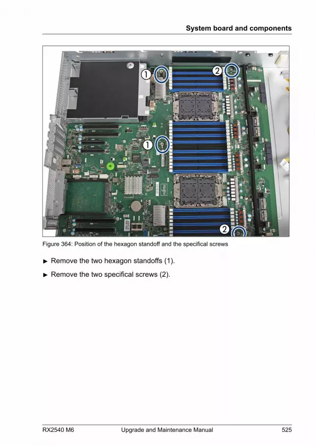
Figure 364: Position of the hexagon standoff and the specifical screws
▶ Remove the two hexagon standoffs (1).
▶ Remove the two specifical screws (2).
System board and components
RX2540 M6 Upgrade and Maintenance Manual 525
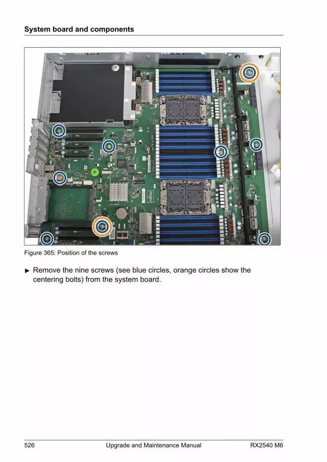
Figure 365: Position of the screws
▶ Remove the nine screws (see blue circles, orange circles show thecentering bolts) from the system board.
System board and components
526 Upgrade and Maintenance Manual RX2540 M6

Figure 366: Touch points of the system board
▶ Notice the two points of the system board (see circles).
▶ Hold the system board on the two touch points and lift the system boardcarefully out of the chassis in a slight angle. Thereby you pull the connectorsout of the I/O panel.
CAUTION▶ Always take the system board with both hands!▶ Never lift the system board one-sided or at a heat sink,
because the solder connections between the socket and thesystem board come under tension and increase the risk ofdamage and malfunction!
▶ Do not damage the EMI springs which are essential to complywith applicable EMC regulations and satisfy coolingrequirements and fire protection measures.
▶ Place the removed and the new system board on an antistatic surface.
System board and components
RX2540 M6 Upgrade and Maintenance Manual 527
▶ Remove the TPM, see "Removing the TPM" on page 486.
Installing the new system board
▶ Check the settings on the new system board, see "Onboard settings" on page 567.
▶ Hold the system board on the two touch points and insert it at a slight angle.Slide the connectors into the I/O panel.
▶ Lower the system board carefully into the chassis.
▶ Adjust the system board. If necessary adjust the position of the systemboard with a gentle twisting motion (orange circles in Figure 365 show thecentering bolts).
▶ Fasten the system board with nine screws, see Figure 365.
▶ Fasten the system board with two hexagon standoffs, see Figure 364.
▶ Fasten the system board with the two specifical screws, see Figure 365.
▶ System with air cooling:
▶ Remove the heat sink with the CPU from the defective system board, see"Removing the heat sink" on page 360.
▶ Remove the protective plastic cover from the CPU socket of the newsystem board and fit it onto the socket of the defective system boardwhich will be sent back to spares.
Returned system boards without this cover probably have to bescrapped.
▶ Install the heat sink with the CPU on the new system board, see"Installing the CPU and heat sink" on page 364.
▶ System with liquid cooling:
▶ Remove the protective plastic cover from the CPU socket of the newsystem board and fit it onto the socket of the defective system boardwhich will be sent back to spares.
Returned system boards without this cover probably have to bescrapped.
System board and components
528 Upgrade and Maintenance Manual RX2540 M6
▶ Connect all cables to the system board.For the cable plans, see "Appendix B" on page 571.
Concluding steps
▶ If applicable, install the TPM, see "Installing the TPM" on page 481.
▶ If applicable, install the Dual microSD 64GB Enterprise, see "Installing the Dual microSD 64GB Enterprise" on page 506.
▶ If applicable, install all M.2 SSDs, see "Installing the M.2 SSD" on page 498.
▶ Install the iRMC microSD card, see "Installing the iRMC microSD card" on page 492.
Ensure that you install the iRMC microSD card that was installed inthe system board before the replacement.
▶ If applicable, install all expansion cards, see "Installing the expansion card" on page 256.
▶ "Installing the cross bar" on page 81.
▶ "Installing the fan cage" on page 76.
▶ Install all riser modules, see "Installing a riser module" on page 72.
▶ For a system with air cooling, proceed as follows:
▶ Install all memory modules, see "Installing a memory module" on page 338.
Ensure that you reinstall each memory module in the slot it waslocated before the replacement.
CAUTIONIn case of Optane PMem modules are not reinstalled in the rightslots, data can be lost!
▶ If applicable, install all dummy memory modules, see "Installing a memory dummy module" on page 343.
System board and components
RX2540 M6 Upgrade and Maintenance Manual 529
▶ For a system with liquid cooling, proceed as follows:
▶ Install all memory modules, see "Installing a memory module" on page 338.
Ensure that you reinstall each memory module in the slot it waslocated before the replacement.
CAUTIONIn case of Optane PMem modules are not reinstalled in the rightslots, data can be lost!
▶ Install the LC kit, see "Installing the LC kit" on page 376.
▶ Only for system with air cooling: install the air duct, see "Installing the air duct" on page 79.
▶ "Reassembling" on page 60.
▶ If applicable, install the OCP modules, see "Installing the OCP module" on page 251.
▶ Install all PSUs, see "Installing a hot-plug PSU" on page 126.
▶ Connect all external cables.
▶ "Connecting the power cord" on page 65.
System board and components
530 Upgrade and Maintenance Manual RX2540 M6

▶ Wait until the firmware restore is completed.
BIOS or iRMC S5 firmware restore feature is executed at the sametime as the power cord is connected after the system boardreplacement.Depending on the configuration of your server the firmware restorerequires different time, see "States of power-on indicator and time duration during firmware restore" on page 552:9 - 23 minutes (systems without PFR feature),18 - 38 minutes (systems with PFR feature).Do not perform the following operations after connecting the powercord. Please wait for the above time to elapse.
– Remove and reinsert the power cord
– Power button on/off
– Connecting and disconnecting other cables, etc.
▶ Check the status of the power-on indicator to verify if the firmware restorewas successful, see "States of power-on indicator and time duration during firmware restore" on page 552.If the firmware restore is successfully completed, the power-on indicator is litwhite.If the power-on indicator is not lit white, an error has occured. Disconnectand connect the power cord and try to boot up, or replace the system boardagain.
▶ After completion of the firmware restore, connect to the iRMC and check theSEL log files, see "Messages of firmware restore in SEL log files" on page 532.
▶ Reboot the system by disconnecting and connecting the power cord. Afterdisconnecting the power cord, wait 60 seconds and connect it again.
▶ "Switching on the server" on page 69.
▶ Check that the Customer Production firmware version is restored to thecurrent BIOS or iRMC S5 version in the new system board using the BIOSSetup Utility.
▶ If applicable, "Installing the front cover with lock" on page 69.
System board and components
RX2540 M6 Upgrade and Maintenance Manual 531

When the system is powered on after a CPU has been replaced orupgraded, the Global Error indicator will start flashing with the messageCPU has been changed.This only indicates that the CPU configuration has been altered. Thereis no technical problem.
Proceed as follows:
● Restart your server.
● As soon as the startup screen appears, press the [F2] function key toenter the BIOS.
● If a password is assigned, enter the password and press [Enter].
● Select the Exit menu.
● Select Commit settings and Exit.
● Verify that the Global Error indicator stops flashing.
▶ "Verifying the system time settings" on page 100.
▶ "Verifying system information backup or restore" on page 94.
▶ For memory configurations with Optane PMem modules: check and set ifnecessary the memory operation mode in the BIOS in the same way asbefore replacing the system board. For more information, see thecorresponding BIOS Setup Utility reference manual.
▶ If applicable, activate TPM functionality in the system BIOS under Security> TPM (Security Chip) Setting > Security Chip. For more information, seethe corresponding BIOS Setup Utility reference manual.
▶ "Looking for MAC/WWN/GUID and SAS addresses" on page 107.
▶ "Resuming BitLocker functionality" on page 105.
Messages of firmware restore in SEL log files
If the firmware restore is successfully completed, the following messages willbe recorded.
System board and components
532 Upgrade and Maintenance Manual RX2540 M6
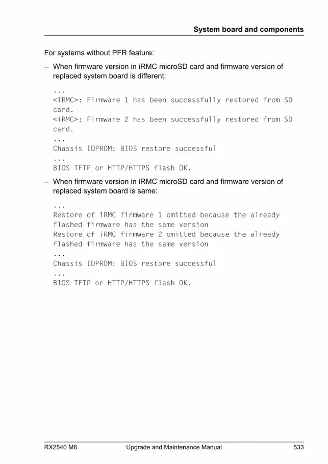
For systems without PFR feature:
– When firmware version in iRMC microSD card and firmware version ofreplaced system board is different:
...<iRMC>: Firmware 1 has been successfully restored from SDcard.<iRMC>: Firmware 2 has been successfully restored from SDcard....Chassis IDPROM: BIOS restore successful...BIOS TFTP or HTTP/HTTPS flash OK.
– When firmware version in iRMC microSD card and firmware version ofreplaced system board is same:
...Restore of iRMC firmware 1 omitted because the alreadyflashed firmware has the same versionRestore of iRMC firmware 2 omitted because the alreadyflashed firmware has the same version...Chassis IDPROM: BIOS restore successful...BIOS TFTP or HTTP/HTTPS flash OK.
System board and components
RX2540 M6 Upgrade and Maintenance Manual 533
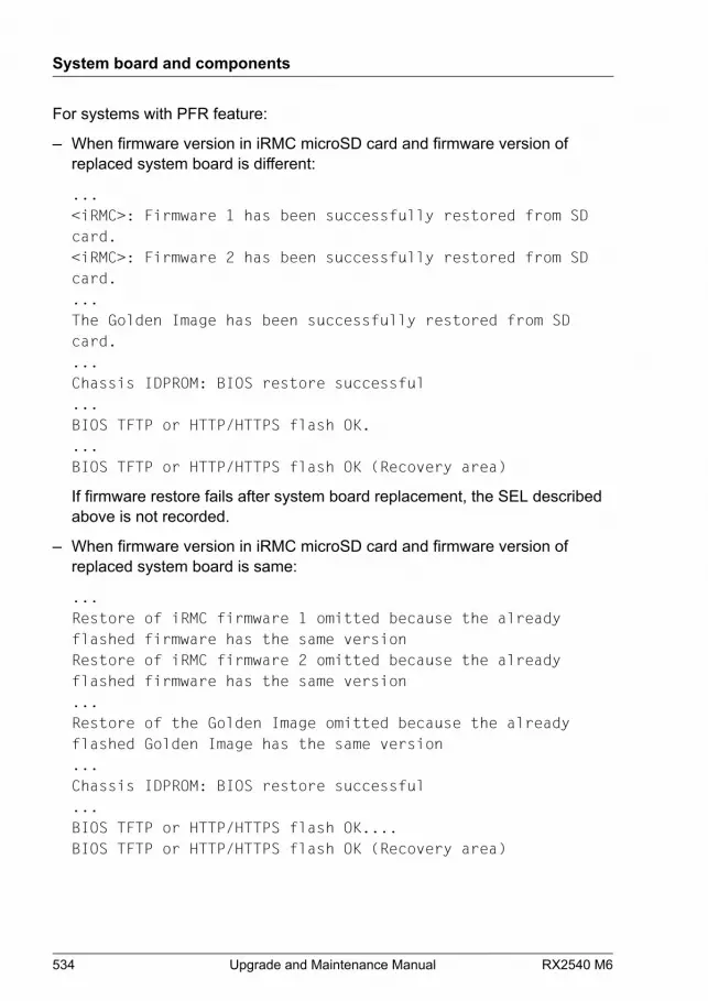
For systems with PFR feature:
– When firmware version in iRMC microSD card and firmware version ofreplaced system board is different:
...<iRMC>: Firmware 1 has been successfully restored from SDcard.<iRMC>: Firmware 2 has been successfully restored from SDcard....The Golden Image has been successfully restored from SDcard....Chassis IDPROM: BIOS restore successful...BIOS TFTP or HTTP/HTTPS flash OK....BIOS TFTP or HTTP/HTTPS flash OK (Recovery area)
If firmware restore fails after system board replacement, the SEL describedabove is not recorded.
– When firmware version in iRMC microSD card and firmware version ofreplaced system board is same:
...Restore of iRMC firmware 1 omitted because the alreadyflashed firmware has the same versionRestore of iRMC firmware 2 omitted because the alreadyflashed firmware has the same version...Restore of the Golden Image omitted because the alreadyflashed Golden Image has the same version...Chassis IDPROM: BIOS restore successful...BIOS TFTP or HTTP/HTTPS flash OK....BIOS TFTP or HTTP/HTTPS flash OK (Recovery area)
System board and components
534 Upgrade and Maintenance Manual RX2540 M6
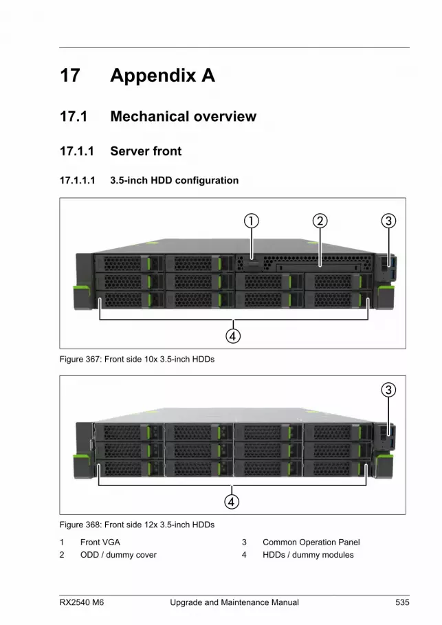
17 Appendix A
17.1 Mechanical overview
17.1.1 Server front
17.1.1.1 3.5-inch HDD configuration
Figure 367: Front side 10x 3.5-inch HDDs
Figure 368: Front side 12x 3.5-inch HDDs
1 Front VGA2 ODD / dummy cover
3 Common Operation Panel4 HDDs / dummy modules
RX2540 M6 Upgrade and Maintenance Manual 535

The ODD (2) and the front VGA (1) are options in some configurations.
17.1.1.2 2.5-inch HDD/SSD configuration
Figure 369: Front side 16x 2.5-inch HDDs / SSDs / PCIe SSDs
Figure 370: Front side 24x 2.5-inch HDDs / SSDs / PCIe SSDs
1 Front VGA2 Common Operation Panel3 ODD / dummy cover
4 LTO drive / RDX drive / dummy cover5 HDDs / SSDs / PCIe SSDs / dummy
modules
The ODD (3), the LTO drive or RDX drive (4) and the front VGA (1) are optionsin some configurations.
Appendix A
536 Upgrade and Maintenance Manual RX2540 M6

17.1.1.3 EDSFF SSD configuration
Figure 371: Front side 64x EDSFF SSDs
1 ID card2 Common Operation Panel
3 EDSFF SSDs / dummy modules
17.1.2 Server rear
17.1.2.1 Servers with air cooling
Figure 372: Server rear (standard configuration)
Appendix A
RX2540 M6 Upgrade and Maintenance Manual 537

Figure 373: Server rear (configuration with rear HDD cages)
Figure 374: Server rear (configuration with riser modules)
1 HDDs / SSDs / PCIe SSDs2 HDDs / SSDs / PCIe SSDs3 PCI slots 5-84 Rear VGA5 HDDs / SSDs / PCIe SSDs6 PCI slots 1-27 OCP module
8 Serial interface9 Management LAN10 USB 3.0 (2x)11 Up to two PSUs / dummy cover12 PCIe slots 9 or 9/10 / riser module 213 PCIe slots 3 or 3/4 / riser module 1
The OCP module (7) and the serial interface (8) are options. If no OCP modulehas been ordered, you find a dummy cover installed in this place (7).
Appendix A
538 Upgrade and Maintenance Manual RX2540 M6

17.1.2.2 Servers with liquid cooling
Figure 375: Server rear with liquid cooling
1 PCI slots 9 or 9/10 / riser module 22 PCI slots 5-83 Rear VGA4 Slot for liquid cooling connectors5 PCI slots 3 or 3/4 / riser module 16 PCI slots 1-2
7 OCP module8 Serial interface9 Management LAN10 USB 3.0 (2x)11 Up to two PSUs / dummy cover
The OCP module (7) and the serial interface (8) are options. If no OCP modulehas been ordered, you find a dummy cover installed in this place (7).
Appendix A
RX2540 M6 Upgrade and Maintenance Manual 539

17.1.3 Server interior
17.1.3.1 Servers with air cooling
Figure 376: PRIMERGY RX2540 M6 interior (example: 2.5-inch HDD model)
1 Up to 2 PSUs / dummy cover2 Main memory3 CPUs4 Front panel module / front VGA
(option) / dummy cover5 ODD (option) / dummy cover6 Up to 12x 3.5-inch HDDs / 24x 2.5-inch
HDDs / 64 EDSFF SSDs
7 Fan modules8 Air duct9 PCIe slot 1-210 OCP module 1
11 PCIe slots 3 or 3/4 / Riser module 112 PCI slots 5-813 PCIe slots 9 or 9/10 / Riser module 2
1) The OCP module is an option.
Appendix A
540 Upgrade and Maintenance Manual RX2540 M6

17.1.3.2 Servers with liquid cooling (LC)
Figure 377: Server interior with liquid cooling
1 Front panel module / front VGA(option) / dummy cover
2 ODD (option) / dummy cover3 Up to 12x 3.5-inch HDDs / 24x 2.5-inch
HDDs / 64 EDSFF SSDs4 Fan modules5 Main memory
6 CPUs with LC7 PCIe slot 1-28 PCIe slots 3 or 3/4 / Riser module 19 OCP module 2
10 PCI slots 5-811 PCIe slots 9 or 9/10 / Riser module 212 Up to 2 PSUs / dummy cover
2) The OCP module is an option.
Appendix A
RX2540 M6 Upgrade and Maintenance Manual 541
17.2 Connectors and indicators
17.2.1 Connectors and indicators on the system board
17.2.1.1 System board D3891
There are two system boards:
– D3891-A100 without PFR feature
– D3891-B100 with PFR feature
Appendix A
542 Upgrade and Maintenance Manual RX2540 M6
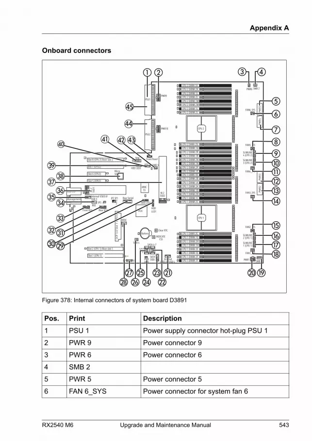
Onboard connectors
iRMCS5
INDICATE CSS
TPM
Slot 2 (CPU 1) Riser slot 1
Battery
SATA
0-3Slot 1 (CPU 1)
Slot 8 (CPU 2) Riser slot 2
Rear Serial
PWRODD
Front Panel
SATA 4-7
SATAODD Internal
USB3.0 / USB 4
PSU1
PSU2
JP3 1
JP2 JP112
MicroSD
USB 3.0 SSD2 M.2
HDD LED2
Slot 7 (CPU2)
Slot 6 (CPU2)
Front VGA
Slot 5 (CPU2)
OCP
3.0
Slo
t 1
(CP
U1
)
SSD
1 M
.2
LANManagement
Internal USB3.0/USB 3
Rear VGA
CPU 2 DIMM 2JCPU 2 DIMM 1M
CPU 2 DIMM 1LCPU 2 DIMM 2L
CPU 2 DIMM 1J
CPU 2 DIMM 2M
CPU 2 DIMM 2KCPU 2 DIMM 1K
CPU 2
CPU 1
CPU 1 DIMM 2ACPU 1 DIMM 1D
CPU 1 DIMM 1CCPU 1 DIMM 2C
CPU 1 DIMM 1A
CPU 1 DIMM 2D
CPU 1 DIMM 2BCPU 1 DIMM 1B
CPU 2 DIMM 1RCPU 2 DIMM 2N
CPU 2 DIMM 2PCPU 2 DIMM 1P
CPU 2 DIMM 2R
CPU 2 DIMM 1N
CPU 2 DIMM 1QCPU 2 DIMM 2Q
CPU 1 DIMM 1HCPU 1 DIMM 2E
CPU 1 DIMM 2FCPU 1 DIMM 1F
CPU 1 DIMM 2H
CPU 1 DIMM 1E
CPU 1 DIMM 1GCPU 1 DIMM 2G
SMB 4
LC1
SLIMLINE4 (CPU 2)
LC2
SMB 2
SMB 1
PWR9
PWR10
HDD LED3
HDD LED1
PWR6
PW
R5
PW
R4
PW
R3
PW
R2
PWR1
SLIMLINE3 (CPU 2)
SLIMLINE2 (CPU 1)
SLIMLINE1 (CPU 1)
FAN6_SYS
FAN5_SYS
FAN4_SYS
FAN3_SYS
FAN2_SYS
FAN1_SYS
ROC
VROC
SMB 3
Clear RTC
PCH
43
44
45
Figure 378: Internal connectors of system board D3891
Pos. Print Description1 PSU 1 Power supply connector hot-plug PSU 1
2 PWR 9 Power connector 9
3 PWR 6 Power connector 6
4 SMB 2
5 PWR 5 Power connector 5
6 FAN 6_SYS Power connector for system fan 6
Appendix A
RX2540 M6 Upgrade and Maintenance Manual 543

Pos. Print Description7 PWR 4 Power connector 4
8 FAN 5_SYS Power connector for system fan 5
9 SLIMLINE 4 (CPU 2)
10 SLIMLINE 3 (CPU 2)
11 FAN 4_SYS Power connector for system fan 4
12 PWR 3 Power connector 3
13 PWR 2 Power connector 2
14 FAN 3_SYS Power connector for system fan 3
15 FAN 2_SYS Power connector for system fan 2
16 SLIMLINE 2 (CPU 1)
17 SLIMLINE 1 (CPU 1)
18 FAN 1_SYS Power connector for system fan 1
19 SMB 1
20 PWR 1 Power connector 1
21 USB 4 USB 3.0 connector (internal)
22 SATA 4-7 SATA HDD connector
23 SATA ODD ODD data connector
24 PWR ODD ODD power connector
25 SATA 0-3 SATA HDD connector
26 SMB 4
27 LC 1 Liquid cooling connector CPU 1
28 VROC
29 HDD_led 1 LED activity connector 1
30 HDD_led 2 LED activity connector 2
31 Rear Serial Rear serial connector
32 Rear VGA Rear VGA connector
33 Front VGA Front VGA connector
Appendix A
544 Upgrade and Maintenance Manual RX2540 M6
Pos. Print Description34 ROC Connector for Dual microSD 64GB Enterprise
cable
35 Internal USB 3 USB 3.0 connector (internal)
36 M.2 SSD 1 M.2 slot 1
37 M.2 SSD 2 M.2 slot 2
38 Micro SD Slot for micro SD card
39 HDD_led 3 LED activity connector 3
40 LC 2 Liquid cooling connector CPU2
41 TPM Connector for Trusted Platform Module (TPM)
42 SMB 3
43 Front Panel Front panel connector
44 PSU 2 Power supply connector hot-plug PSU 2
45 PSU 1 Power supply connector hot-plug PSU 1
Appendix A
RX2540 M6 Upgrade and Maintenance Manual 545
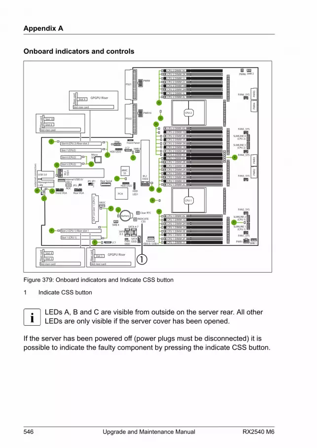
Onboard indicators and controls
iRMCS5
exte
rnal
con
nect
ors
INDICATE CSS
TPM
Slot 2 (CPU 1) Riser slot 1
Battery
SATA 0-3
Slot 1 (CPU 1)
Slot 8 (CPU 2) Riser slot 2
Rear Serial
PWRODD
Front Panel
SATA 4-7
SATAODD Internal
USB3.0 / USB 4
PSU1
PSU2
JP3 1
JP2 JP112
MicroSD
USB 3.0
SSD2 M.2
HDD LED2
C
I
L
P
O
Slot 7 (CPU2)
Slot 6 (CPU2)
Front VGA
FK
B A
Slot 5 (CPU2)
OCP
3.0
Slo
t 1 (C
PU1)
SSD
1 M
.2
LANManagement
F
F
F
O
P
Internal USB3.0/USB 3
Rear VGA
G
H
CPU 2 DIMM 2JCPU 2 DIMM 1M
CPU 2 DIMM 1LCPU 2 DIMM 2L
CPU 2 DIMM 1J
CPU 2 DIMM 2M
CPU 2 DIMM 2KCPU 2 DIMM 1K
CPU 2
CPU 1
CPU 1 DIMM 2ACPU 1 DIMM 1D
CPU 1 DIMM 1CCPU 1 DIMM 2C
CPU 1 DIMM 1A
CPU 1 DIMM 2D
CPU 1 DIMM 2BCPU 1 DIMM 1B
CPU 2 DIMM 1RCPU 2 DIMM 2N
CPU 2 DIMM 2PCPU 2 DIMM 1P
CPU 2 DIMM 2R
CPU 2 DIMM 1N
CPU 2 DIMM 1QCPU 2 DIMM 2Q
H
H
CPU 1 DIMM 1HCPU 1 DIMM 2E
CPU 1 DIMM 2FCPU 1 DIMM 1F
CPU 1 DIMM 2H
CPU 1 DIMM 1E
CPU 1 DIMM 1GCPU 1 DIMM 2G
H
G
SMB 4
LC1
LC2
SMB 2
SMB 1
PWR9
PWR10
HDD LED3
HDD LED1
PWR6
PWR5
PWR4
PWR3
PWR2
PWR1
FAN6_SYS
FAN5_SYS
FAN4_SYS
FAN3_SYS
FAN2_SYS
FAN1_SYS
ROC
VROC
SMB 3
Clear RTC
PCH
F
SLIMLINE 1(CPU 1)
SLIMLINE 2(CPU 1)
F
SLIMLINE 4(CPU 2)
SLIMLINE 3(CPU 2)
Slot riser card
Rise
r car
d
Slot 10
Slot 9
Slot riser card
Rise
r car
d
Slot 4
Slot 3
Slot riser card
Rise
r car
d
GPGPU RiserSlot 9
Slot riser card
Rise
r car
d
GPGPU RiserSlot 3
Figure 379: Onboard indicators and Indicate CSS button
1 Indicate CSS button
LEDs A, B and C are visible from outside on the server rear. All otherLEDs are only visible if the server cover has been opened.
If the server has been powered off (power plugs must be disconnected) it ispossible to indicate the faulty component by pressing the indicate CSS button.
Appendix A
546 Upgrade and Maintenance Manual RX2540 M6
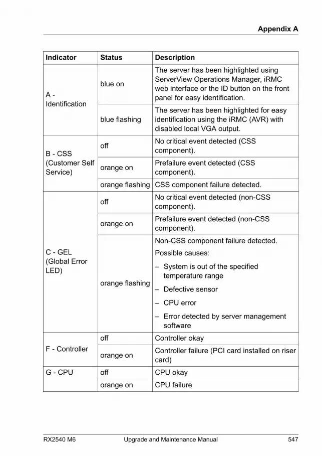
Indicator Status Description
A -Identification
blue on
The server has been highlighted usingServerView Operations Manager, iRMCweb interface or the ID button on the frontpanel for easy identification.
blue flashingThe server has been highlighted for easyidentification using the iRMC (AVR) withdisabled local VGA output.
B - CSS(Customer SelfService)
off No critical event detected (CSScomponent).
orange on Prefailure event detected (CSScomponent).
orange flashing CSS component failure detected.
C - GEL(Global ErrorLED)
off No critical event detected (non-CSScomponent).
orange on Prefailure event detected (non-CSScomponent).
orange flashing
Non-CSS component failure detected.Possible causes:
– System is out of the specifiedtemperature range
– Defective sensor
– CPU error
– Error detected by server managementsoftware
F - Controlleroff Controller okay
orange on Controller failure (PCI card installed on risercard)
G - CPU off CPU okay
orange on CPU failure
Appendix A
RX2540 M6 Upgrade and Maintenance Manual 547

Indicator Status DescriptionH - Memory off memory module running
orange on memory module failure
I - iRMC off iRMC S5 inactive
green flashing iRMC S5 okay
K - System fan off system fan running
orange on system fan failure
L - Battery orange on Battery failure
M - StandbyPower
orange on All standby voltages ok
O - M.2 SSD orange on M.2 SSD faulty
P - LC Pump orange on LC Pump faulty
17.2.2 Server front
17.2.2.1 Connectors on the front panel
Figure 380: Connectors on the front panel
1 USB 3.0 connector2 USB 3.0 connector
3 Front VGA connector
The front VGA connector is an option in some configurations.
Appendix A
548 Upgrade and Maintenance Manual RX2540 M6
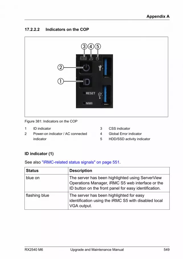
17.2.2.2 Indicators on the COP
Figure 381: Indicators on the COP
1 ID indicator2 Power-on indicator / AC connected
indicator
3 CSS indicator4 Global Error indicator5 HDD/SSD activity indicator
ID indicator (1)
See also "iRMC-related status signals" on page 551.
Status Descriptionblue on The server has been highlighted using ServerView
Operations Manager, iRMC S5 web interface or theID button on the front panel for easy identification.
flashing blue The server has been highlighted for easyidentification using the iRMC S5 with disabled localVGA output.
Appendix A
RX2540 M6 Upgrade and Maintenance Manual 549
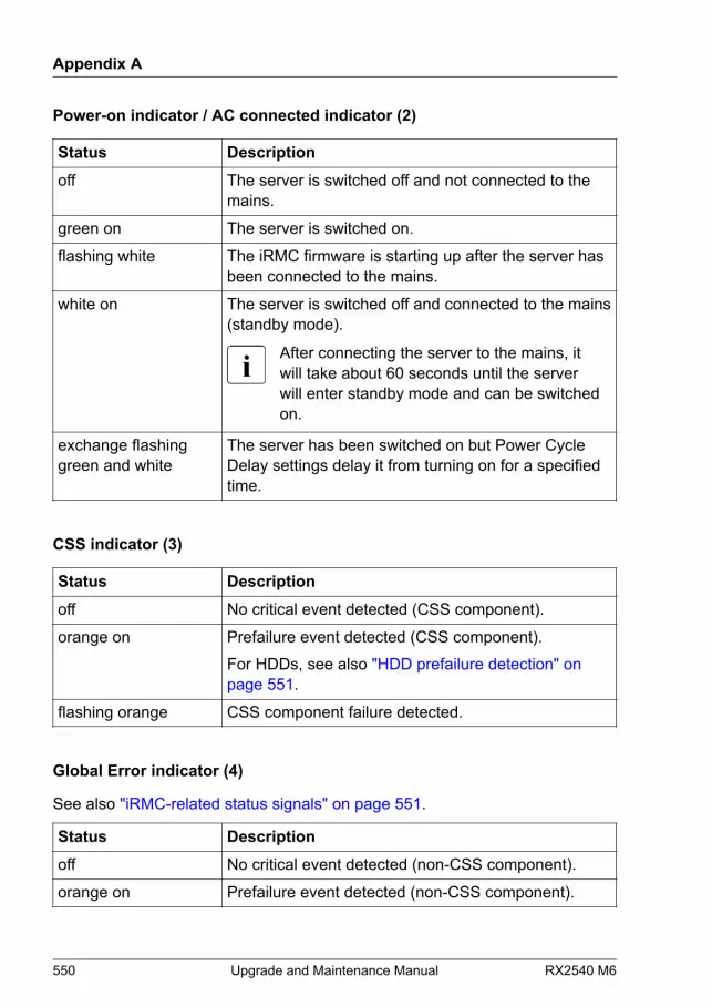
Power-on indicator / AC connected indicator (2)
Status Descriptionoff The server is switched off and not connected to the
mains.
green on The server is switched on.
flashing white The iRMC firmware is starting up after the server hasbeen connected to the mains.
white on The server is switched off and connected to the mains(standby mode).
After connecting the server to the mains, itwill take about 60 seconds until the serverwill enter standby mode and can be switchedon.
exchange flashinggreen and white
The server has been switched on but Power CycleDelay settings delay it from turning on for a specifiedtime.
CSS indicator (3)
Status Descriptionoff No critical event detected (CSS component).
orange on Prefailure event detected (CSS component).For HDDs, see also "HDD prefailure detection" on page 551.
flashing orange CSS component failure detected.
Global Error indicator (4)
See also "iRMC-related status signals" on page 551.
Status Descriptionoff No critical event detected (non-CSS component).
orange on Prefailure event detected (non-CSS component).
Appendix A
550 Upgrade and Maintenance Manual RX2540 M6
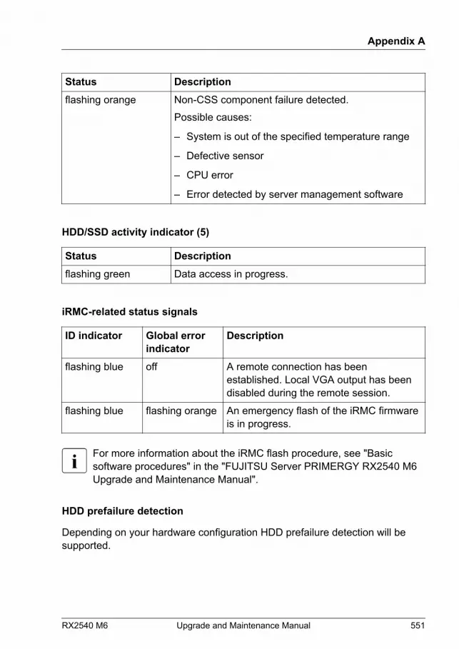
Status Descriptionflashing orange Non-CSS component failure detected.
Possible causes:
– System is out of the specified temperature range
– Defective sensor
– CPU error
– Error detected by server management software
HDD/SSD activity indicator (5)
Status Descriptionflashing green Data access in progress.
iRMC-related status signals
ID indicator Global errorindicator
Description
flashing blue off A remote connection has beenestablished. Local VGA output has beendisabled during the remote session.
flashing blue flashing orange An emergency flash of the iRMC firmwareis in progress.
For more information about the iRMC flash procedure, see "Basicsoftware procedures" in the "FUJITSU Server PRIMERGY RX2540 M6Upgrade and Maintenance Manual".
HDD prefailure detection
Depending on your hardware configuration HDD prefailure detection will besupported.
Appendix A
RX2540 M6 Upgrade and Maintenance Manual 551

The requirements are:
– iRMC S5 Firmware 1.2 or later
– supported OOB RAID system
17.2.2.3 States of power-on indicator and time duration duringfirmware restore
The power-on indicator changes as follows from the time the power cord isconnected until firmware restore is completed after system board replacement.
Systems without PFR feature
System state Power-onindicator
Time
a Power cord connected - -
b iRMC boot start, iRMC firmwarerestore from iRMC microSD card,iRMC restartRecord of the following message onSEL when completion.When iRMC version in iRMC microSDcard and iRMC version of replacedsystem board is different:
iRMC Firmware %1 has beensuccessfully restored from SDcard.
When iRMC version in iRMC microSDcard and iRMC version of replacedsystem board is same:
Restore of iRMC firmware %1omitted because the alreadyflashed firmware has the sameversion
flashingwhite
About 9 minutesWhen iRMCversion in iRMCmicroSD card andiRMC version ofreplaced systemboard is same,the time isshortenedbecause iRMCfirmware updateis skipped.
c iRMC boot complete, BIOS restoreprepare
white on About 1 minute
Appendix A
552 Upgrade and Maintenance Manual RX2540 M6
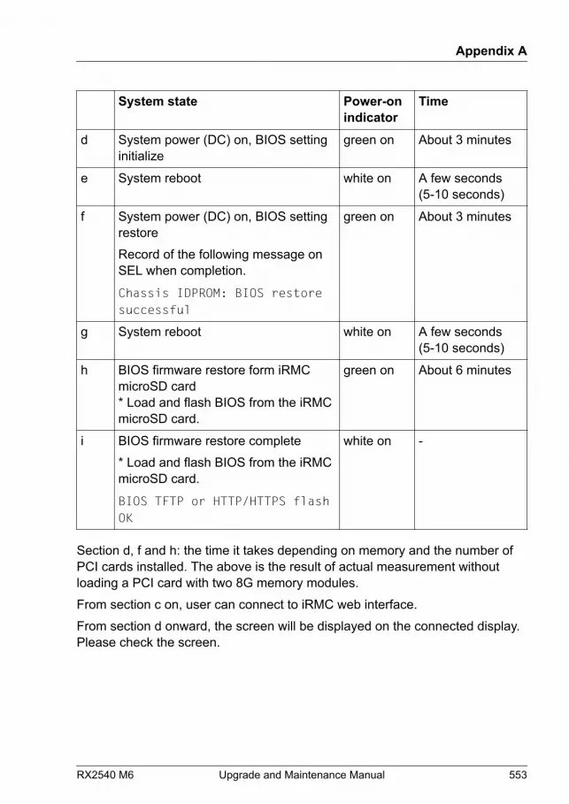
System state Power-onindicator
Time
d System power (DC) on, BIOS settinginitialize
green on About 3 minutes
e System reboot white on A few seconds(5-10 seconds)
f System power (DC) on, BIOS settingrestoreRecord of the following message onSEL when completion.
Chassis IDPROM: BIOS restoresuccessful
green on About 3 minutes
g System reboot white on A few seconds(5-10 seconds)
h BIOS firmware restore form iRMCmicroSD card* Load and flash BIOS from the iRMCmicroSD card.
green on About 6 minutes
i BIOS firmware restore complete* Load and flash BIOS from the iRMCmicroSD card.
BIOS TFTP or HTTP/HTTPS flashOK
white on -
Section d, f and h: the time it takes depending on memory and the number ofPCI cards installed. The above is the result of actual measurement withoutloading a PCI card with two 8G memory modules.From section c on, user can connect to iRMC web interface.From section d onward, the screen will be displayed on the connected display.Please check the screen.
Appendix A
RX2540 M6 Upgrade and Maintenance Manual 553

Systems with PFR feature
System state Power-onindicator
Time
a Power cord connected - -
b iRMC boot start, iRMC firmwarerestore from iRMC microSD card(included golden image), iRMC restartRecord of the following message onSEL when completion.When iRMC version in iRMC microSDcard and iRMC version of replacedsystem board is different:
iRMC Firmware %1 has beensuccessfully restored from SDcard.
The Golden Image has beensuccessfully restored from SDcard
When iRMC version in iRMC microSDcard and iRMC version of replacedsystem board is same:
Restore of iRMC firmware %1omitted because the alreadyflashed firmware has the sameversion
flashingwhite
About 13 minutesWhen iRMCversion in iRMCmicroSD card andiRMC version ofreplaced systemboard is same,the time isshortenedbecause iRMCfirmware updateis skipped.
c iRMC boot complete, BIOS restoreprepare
white on About 1 minute
d System power (DC) on, BIOS settinginitialize
green on About 3 minutes
e System reboot white on A few seconds(5-10 seconds)
Appendix A
554 Upgrade and Maintenance Manual RX2540 M6
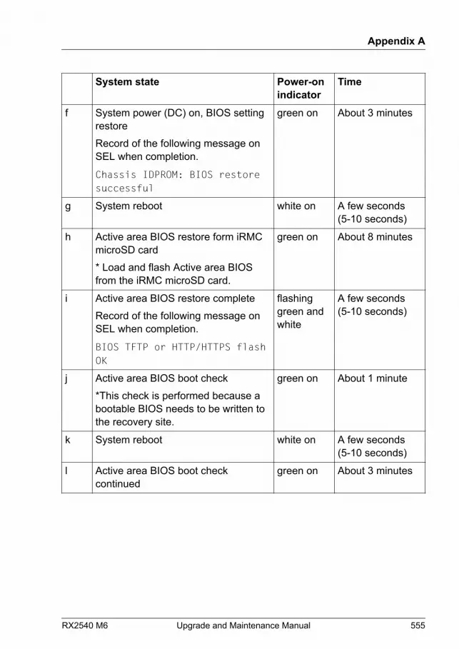
System state Power-onindicator
Time
f System power (DC) on, BIOS settingrestoreRecord of the following message onSEL when completion.
Chassis IDPROM: BIOS restoresuccessful
green on About 3 minutes
g System reboot white on A few seconds(5-10 seconds)
h Active area BIOS restore form iRMCmicroSD card* Load and flash Active area BIOSfrom the iRMC microSD card.
green on About 8 minutes
i Active area BIOS restore completeRecord of the following message onSEL when completion.
BIOS TFTP or HTTP/HTTPS flashOK
flashinggreen andwhite
A few seconds(5-10 seconds)
j Active area BIOS boot check*This check is performed because abootable BIOS needs to be written tothe recovery site.
green on About 1 minute
k System reboot white on A few seconds(5-10 seconds)
l Active area BIOS boot checkcontinued
green on About 3 minutes
Appendix A
RX2540 M6 Upgrade and Maintenance Manual 555

System state Power-onindicator
Time
m Active area BIOS boot checkcompletionRecovery area BIOS restoreAttention: the Power-on indicator isnot green but is reading the activearea BIOS and updating the recoveryarea.
white on About 5 minutes
n Recovery area BIOS restorecompletionRecord of the following message onSEL.
BIOS TFTP or HTTP/HTTPS flashOK (Recovery area)
white on -
Section d, f, h and l: the time it takes depending on memory and the number ofPCI cards installed. The above is the result of actual measurement withoutloading a PCI card with two 8G memory modules.From section c on, user can connect to iRMC web interface.From section d onward, the screen will be displayed on the connected display.Please check the screen.
17.2.2.4 Indicator on the ODD
ODDs may have an indicator or not.
Appendix A
556 Upgrade and Maintenance Manual RX2540 M6
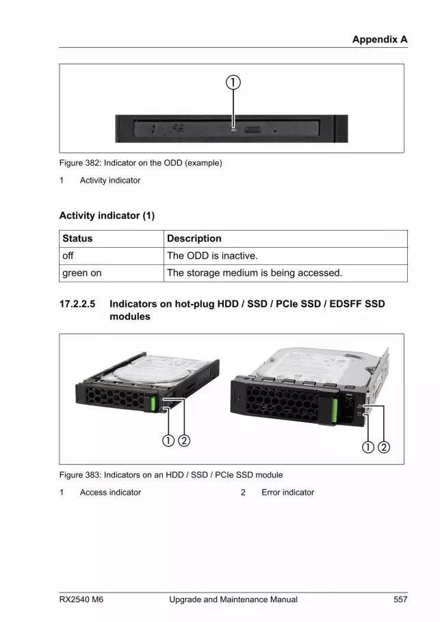
Figure 382: Indicator on the ODD (example)
1 Activity indicator
Activity indicator (1)
Status Descriptionoff The ODD is inactive.
green on The storage medium is being accessed.
17.2.2.5 Indicators on hot-plug HDD / SSD / PCIe SSD / EDSFF SSDmodules
Figure 383: Indicators on an HDD / SSD / PCIe SSD module
1 Access indicator 2 Error indicator
Appendix A
RX2540 M6 Upgrade and Maintenance Manual 557
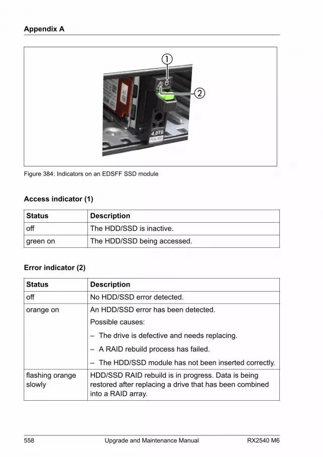
Figure 384: Indicators on an EDSFF SSD module
Access indicator (1)
Status Descriptionoff The HDD/SSD is inactive.
green on The HDD/SSD being accessed.
Error indicator (2)
Status Descriptionoff No HDD/SSD error detected.
orange on An HDD/SSD error has been detected.Possible causes:
– The drive is defective and needs replacing.
– A RAID rebuild process has failed.
– The HDD/SSD module has not been inserted correctly.
flashing orangeslowly
HDD/SSD RAID rebuild is in progress. Data is beingrestored after replacing a drive that has been combinedinto a RAID array.
Appendix A
558 Upgrade and Maintenance Manual RX2540 M6
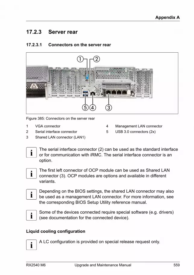
17.2.3 Server rear
17.2.3.1 Connectors on the server rear
Figure 385: Connectors on the server rear
1 VGA connector2 Serial interface connector3 Shared LAN connector (LAN1)
4 Management LAN connector5 USB 3.0 connectors (2x)
The serial interface connector (2) can be used as the standard interfaceor for communication with iRMC. The serial interface connector is anoption.
The first left connector of OCP module can be used as Shared LANconnector (3). OCP modules are options and available in differentvariants.
Depending on the BIOS settings, the shared LAN connector may alsobe used as a management LAN connector. For more information, seethe corresponding BIOS Setup Utility reference manual.
Some of the devices connected require special software (e.g. drivers)(see documentation for the connected device).
Liquid cooling configuration
A LC configuration is provided on special release request only.
Appendix A
RX2540 M6 Upgrade and Maintenance Manual 559
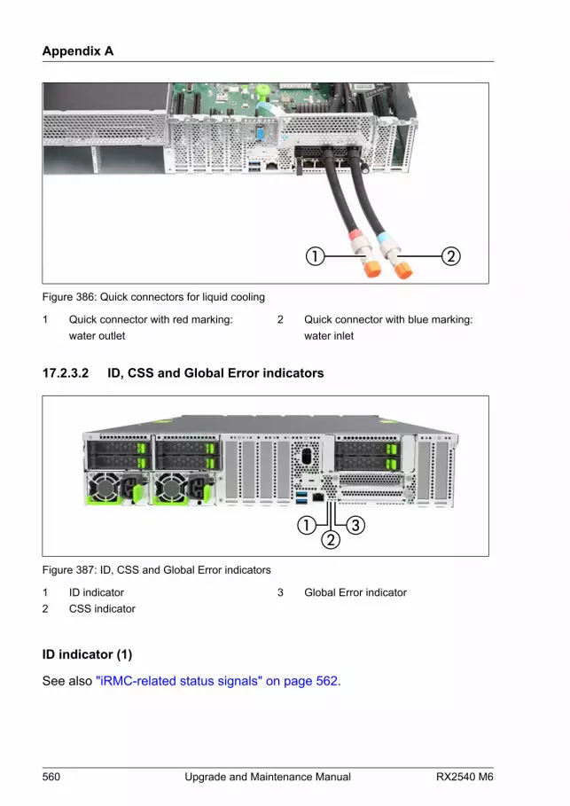
Figure 386: Quick connectors for liquid cooling
1 Quick connector with red marking:water outlet
2 Quick connector with blue marking:water inlet
17.2.3.2 ID, CSS and Global Error indicators
Figure 387: ID, CSS and Global Error indicators
1 ID indicator2 CSS indicator
3 Global Error indicator
ID indicator (1)
See also "iRMC-related status signals" on page 562.
Appendix A
560 Upgrade and Maintenance Manual RX2540 M6
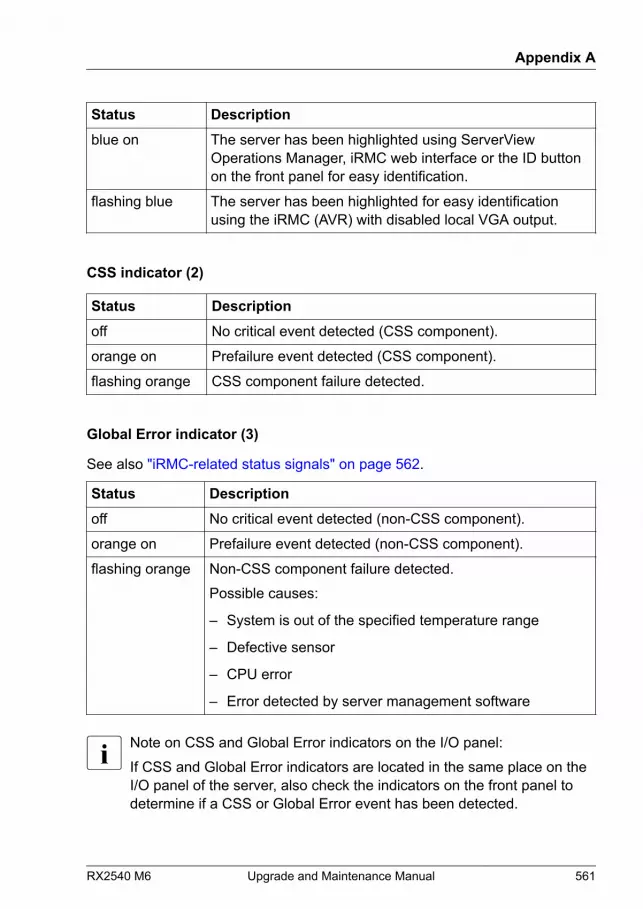
Status Descriptionblue on The server has been highlighted using ServerView
Operations Manager, iRMC web interface or the ID buttonon the front panel for easy identification.
flashing blue The server has been highlighted for easy identificationusing the iRMC (AVR) with disabled local VGA output.
CSS indicator (2)
Status Descriptionoff No critical event detected (CSS component).
orange on Prefailure event detected (CSS component).
flashing orange CSS component failure detected.
Global Error indicator (3)
See also "iRMC-related status signals" on page 562.
Status Descriptionoff No critical event detected (non-CSS component).
orange on Prefailure event detected (non-CSS component).
flashing orange Non-CSS component failure detected.Possible causes:
– System is out of the specified temperature range
– Defective sensor
– CPU error
– Error detected by server management software
Note on CSS and Global Error indicators on the I/O panel:If CSS and Global Error indicators are located in the same place on theI/O panel of the server, also check the indicators on the front panel todetermine if a CSS or Global Error event has been detected.
Appendix A
RX2540 M6 Upgrade and Maintenance Manual 561

For more information on detected errors, see the System Event Log oruse the ServerView Operations Manager or iRMC web interface.
iRMC-related status signals
ID indicator Global errorindicator
Description
flashing blue off A remote connection has beenestablished. Local VGA output has beendisabled during the remote session.
flashing blue flashing orange An emergency flash of the iRMC firmwareis in progress.
For more information about the iRMC flash procedure, see "Basicsoftware procedures" in the "FUJITSU Server PRIMERGY RX2540 M6Upgrade and Maintenance Manual".
Appendix A
562 Upgrade and Maintenance Manual RX2540 M6

17.2.3.3 LAN indicators
Figure 388: LAN indicators
1 LAN link/transfer 2 LAN speed
LAN link/transfer indicator (1)
Status Descriptiongreen on A LAN connection has been established.
off LAN is not connected.
flashing green LAN data transfer is in progress.
LAN speed indicator (2)
Status Descriptionyellow on Data traffic at a transfer rate of 1 Gbit/s.
green on Data traffic at a transfer rate of 100 Mbit/s.
Appendix A
RX2540 M6 Upgrade and Maintenance Manual 563

Status Descriptionoff Data traffic at a transfer rate of 10 Mbit/s.
Indication of LAN connection supporting Energy Efficient Ethernet (EEEmode)
To configure the EEE mode, it is necessary that an add-in LAN card supportsthis mode and the connected switch supports this mode as well.
LAN link/transfer indicator (1)
Status Descriptionshort flashing green 3x, then off A LAN connection has been established
(1 Gbit or 100 Mbit) and EEE mode isactive.
Table 3: LAN indicators if EEE mode is active
LAN speed indicator (2)
Status Descriptionshort flashing yellow 1x, then 2seconds offgreen off
Data traffic at a transfer rate of 1 Gbit/s.
short flashing green 1x, then 2seconds offyellow off
Data traffic at a transfer rate of 100 Mbit/s.
Table 4: LAN indicators if EEE mode is active
Appendix A
564 Upgrade and Maintenance Manual RX2540 M6
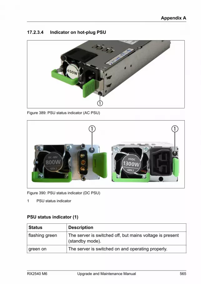
17.2.3.4 Indicator on hot-plug PSU
①
Figure 389: PSU status indicator (AC PSU)
Figure 390: PSU status indicator (DC PSU)
1 PSU status indicator
PSU status indicator (1)
Status Descriptionflashing green The server is switched off, but mains voltage is present
(standby mode).
green on The server is switched on and operating properly.
Appendix A
RX2540 M6 Upgrade and Maintenance Manual 565

Status Descriptionflashing orange An overload has been detected. The PSU is still running,
but failure might be imminent.
orange on A PSU failure has been detected.
17.2.4 Acoustic indicators
PEI Beep Codes
Pre-EFI Initialization (PEI) - memory Initialization (bootblock)
# ofBeep
Description Action
1 Memory not installed ▶ Check if the memory module isinstalled.
▶ Check if the memory module isinstalled correctly.
DXE Beep Codes
Driver Execution Environment (DXE) - main hardware Initialization (POST)
# ofBeep
Description Action
1 Invalid password ▶ Check for the correct password and tryagain. Make sure that the caps lock keyis deactivated.
6 BIOS flash update isfailed
A processing bar and an error message isdisplayed on the screen.This beep code is only an information.
Appendix A
566 Upgrade and Maintenance Manual RX2540 M6
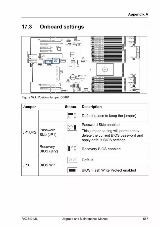
17.3 Onboard settings
iRMCS5
exte
rnal
con
nect
ors
INDICATE CSS
TPM
Slot 2 (CPU 1) Riser slot 1
Battery
SATA 0-3
Slot 1 (CPU 1)
Slot 8 (CPU 2) Riser slot 2
Rear Serial
PWRODD
Front Panel
SATA 4-7
SATAODD Internal
USB3.0 / USB 4
JP3 1
JP2 JP112
MicroSD
USB 3.0
SSD2 M.2
HDD LED2
Slot 7 (CPU2)
Slot 6 (CPU2)
Front VGA
Slot 5 (CPU2)
OCP
3.0
Slo
t 1 (C
PU1)
SSD
1 M
.2
LANManagement
Internal USB3.0/USB 3
Rear VGA
CPU 1
CPU 1 DIMM 2ACPU 1 DIMM 1D
CPU 1 DIMM 1CCPU 1 DIMM 2C
CPU 1 DIMM 1A
CPU 1 DIMM 2D
CPU 1 DIMM 2BCPU 1 DIMM 1B
CPU 2 DIMM 1RCPU 2 DIMM 2N
CPU 2 DIMM 2PCPU 2 DIMM 1P
CPU 2 DIMM 2R
CPU 2 DIMM 1N
CPU 1 DIMM 1HCPU 1 DIMM 2E
CPU 1 DIMM 2FCPU 1 DIMM 1F
CPU 1 DIMM 2H
CPU 1 DIMM 1E
CPU 1 DIMM 1GCPU 1 DIMM 2G
SMB 4
LC1
LC2
SMB 1
HDD LED3
HDD LED1
PWR3
PWR2
PWR1
FAN4_SYS
FAN3_SYS
FAN2_SYS
FAN1_SYS
ROC
VROC
SMB 3
Clear RTC
PCH
SLIMLINE 1(CPU 1)
SLIMLINE 2(CPU 1)
SLIMLINE 4(CPU 2)
SLIMLINE 3(CPU 2)
Figure 391: Position Jumper D3891
Jumper Status Description
JP1/JP2
Default (place to keep the jumper)
PasswordSkip (JP1)
Password Skip enabledThis jumper setting will permanentlydelete the current BIOS password andapply default BIOS settings.
RecoveryBIOS (JP2) Recovery BIOS enabled
JP3 BIOS WPDefault
BIOS Flash Write Protect enabled
Appendix A
RX2540 M6 Upgrade and Maintenance Manual 567
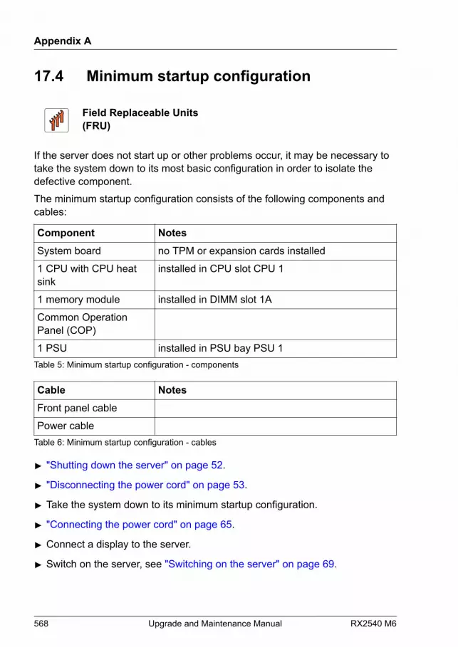
17.4 Minimum startup configuration
Field Replaceable Units(FRU)
If the server does not start up or other problems occur, it may be necessary totake the system down to its most basic configuration in order to isolate thedefective component.The minimum startup configuration consists of the following components andcables:
Component NotesSystem board no TPM or expansion cards installed
1 CPU with CPU heatsink
installed in CPU slot CPU 1
1 memory module installed in DIMM slot 1A
Common OperationPanel (COP)
1 PSU installed in PSU bay PSU 1Table 5: Minimum startup configuration - components
Cable NotesFront panel cable
Power cable Table 6: Minimum startup configuration - cables
▶ "Shutting down the server" on page 52.
▶ "Disconnecting the power cord" on page 53.
▶ Take the system down to its minimum startup configuration.
▶ "Connecting the power cord" on page 65.
▶ Connect a display to the server.
▶ Switch on the server, see "Switching on the server" on page 69.
Appendix A
568 Upgrade and Maintenance Manual RX2540 M6

CAUTION▶ Since the fan module is not included in the minimum startup
configuration, the server must be shut down immediately after thediagnostic process is complete (POST phase has been passed).
▶ The minimum startup configuration must be used exclusively fordiagnostic purposes by maintenance personnel, never in dailyoperation!
Appendix A
RX2540 M6 Upgrade and Maintenance Manual 569
Appendix A
570 Upgrade and Maintenance Manual RX2540 M6
18 Appendix B
18.1 Supplied documents
The following documents are available in this appendix:
● "Cable plan for FUJITSU Server PRIMERGY RX2540 M6 ReferenceManual"
● "List of Released Adapters incl. Installation sequence and priority"
● "Screw list for FUJITSU Server PRIMERGY RX2540 M6 Reference Manual"
RX2540 M6 Upgrade and Maintenance Manual 571
FUJITSU Server PRIMERGY RX2540 M6
System Cabling Overview
System Cabling Overview - English
Cable Plan for
June 2021
2RX2540 M6
Contents
Cable Plan
1 Frontpage2 Contents3 Contents (cont.)4 List of used cables5 List of used cables (cont.)6 List of used cables (cont1.)7 SysBoardConn8 Basic 10x/12x3.5" or 16x/24x2.5" or 64xEDSFF9 Basic ODD/VGA 10x3.5"/16x2.5"10 Basic Serial11 Basic LTO 16x2.5"12 Basic RDX 16x2.5"13 Basic OOB 10x3.5"14 Basic OOB 12x3.5"15 Basic OOB 16x2.5"16 Basic OOB 24x2.5" NVMe Mix17 Basic OOB 24x2.5" NVMe18 Basic OOB 64xEDSFF19 Basic OOB Rear 4x2.5"20 Basic OOB Rear 2x2.5"21 Basic OOB Expander Board_40 12 x3.5"/16 x2.5"/24 x2.5" NVMe Mix22 Power 10x3.5"23 Power 12x3,5"24 Power 16x2.5"25 Power 24x2.5" NVMe Mix26 Power 24x2.5" NVMe27 Power 64xEDSFF28 Power Expander Board_40 12x3.5"/16x2.5"/24x2.5" NVMe Mix29 Power Rear 4x2.5"30 Power Rear 2x2.5"31 Power Internal RAID Riser32 Power GPU A10 /RTX400033 Power GPU A40 /A6000/A10034 Data FBU EP5/6x0i/EP5/6x0e35 Data HDDActivity EP 5/6xxi36 Data HDDActivity CP 500i37 Data Internal RAID Riser38 PYR254 6R3N(TYPE1-1):Data 8xSATA 3.5" Onboard39 PYR254 6R3N(TYPE1-2):Data 8xSAS/SATA 3.5" CP/EP5xxi40 PYR254 6R3N(TYPE1-3a):Data 10xSAS/SATA 3.5" EP5x0i41 PYR254 6R3N(TYPE1-3b):Data 10xSAS/SATA 3.5" EP6x0i42 PYR254 6RAN(TYPE2-1a):Data 12xSAS/SATA 3.5" EP5x0i43 PYR254 6RAN(TYPE2-1b):Data 12xSAS/SATA 3.5" EP6x0i44 PYR254 6RBN(TYPE2-5):Data 12xSAS/SATA 3.5" Expander (CP/EP 5xxi)45 PYR254 6R2N/PYR2546RCN(TYPE3-1):Data 8xSATA 2.5"Onboard46 PYR254 6R2N/PYR2546RCN(TYPE3-2):Data 8xSAS/SATA 2.5" CP/ EP5xxi47 PYR254 6R2N/PYR2546RCN(TYPE3-3a):Data 16xSAS/SATA 2.5" EP5x0i48 PYR254 6R2N/PYR2546RCN(TYPE3-3b):Data 16xSAS/SATA 2.5" EP6x0i49 PYR254 6R2N/PYR2546RCN(TYPE3-4):Data 16xSAS/SATA 2.5" Dual RAID (CP/EP5xxi)x250 PYR254 6R2N/PYR2546RCN+PYBBA24PF/PY-BA24PF(TYPE3-5a):Data 8xSATA 2.5" Onboard+Rear 4xNVMe (EP5x0i)51 PYR254 6R2N/PYR2546RCN+PYBBA24PF/PY-BA24PF(TYPE3-5b):Data 8xSATA 2.5" Onboard+Rear 4xNVMe (EP6x0i)52 PYR254 6R2N/PYR2546RCN+PYBBA24PF/PY-BA24PF+PYBBA22P2 /PY-BA22P2(TYPE3-6):Data 8xSAS/SATA 2.5" CP/ EP5xxi+Rear 4x/6x NVMe (Retimer)53 PYR254 6R2N/PYR2546RCN+PYBBA24PF/PY-BA24PF+PYBBA22P2 /PY-BA22P2(TYPE3-8):Data 16xSAS/SATA 2.5" Dual RAID (CP/EP5xxi) x2+Rear 4x/6x NVMe (Retimer)54 PYR254 6R2N/PYR2546RCN+PYBBA24PF/PY-BA24PF(TYPE3-9a):Data 16xSAS/SATA 2.5"+Rear 4xNVMe (EP5x0i)x255 PYR254 6R2N/PYR2546RCN+PYBBA24PF/PY-BA24PF(TYPE3-9c):Data 16xSAS/SATA 2.5"+Rear 4xNVMe (EP6x0i)56 PYR254 6R2N/PYR2546RCN+PYBBA24PF/PY-BA24PF(TYPE3-9b):Data 16xSAS/ SATA 2.5"+Rear 4xNVMe (EP6x0i)x257 PYR254 6R2N/PYR2546RCN+PYBBA24PF/PY-BA24PF(TYPE3-9d):Data 16xSAS/ SATA 2.5"+Rear 4xNVMe (EP5x0i)58 PYR254 6R2N/PYR2546RCN+PYBBA24PF/PY-BA24PF+PYBBA22P2 /PY-BA22P2(TYPE3-10a):Data 16xSAS/SATA 2.5" (EP5 x0i)+Rear 4x/6x NVMe (Retimer)59 PYR254 6R2N/PYR2546RCN+PYBBA24PF/PY-BA24PF+PYBBA22P2 /PY-BA22P2(TYPE3-10b):Data 16xSAS/SATA 2.5" (EP6x0i)+Rear 4x/6x NVMe (Retimer)60 PYR254 6RDN/PYR2 546REN(TYPE3-11):Data 16xSAS/SATA 2.5" Expander(CP/EP5xxi)61 PYR254 6RDN/PYR2 546REN+PYBBA2 4S3/PY-BA24S3+PYBBA22S4/PY-BA22S4(TYPE3-12):Data 16xSAS/SATA 2.5" Expander(CP/EP5xxi)+Rear 4xSAS/SATA 2.5" Expander62 PYR254 6RDN/PYR2 546REN+PYBBA2 4PF/PY-BA24PF+PYBBA22P2 /PY-BA22P2(TYPE3-13):Data 16xSAS/SATA 2.5" Expander(CP/EP5xxi)+Rear 4x/6x NVMe (Retimer)63 PYR254 6RFN(TYPE4-1):Data 24xSAS/SATA 2.5" (CP/EP5xxi)x364 PYR254 6RFN(TYPE4-2a):Data 24xSAS/SATA 2.5" (EP5x0i)x265 PYR254 6RFN(TYPE4-2b):Data 24xSAS/STA 2.5" (EP6x0i)x266 PYR254 6RFN+PYBBA24S3/PY-BA24S3+PYBBA22S4/PY-BA22S4(TYPE4-3a):Data 24xSAS/ATA 2.5"+Rear 4xSAS/SATA 2. 5" (EP5x0i)x267 PYR254 6RFN+PYBBA24S3/PY-BA24S3+PYBBA22S4/PY-BA22S4(TYPE4-3b):Data 24xSAS/ SATA 2.5"+Rear 4xSAS/SATA 2 .5" (EP6x0i)x268 PYR254 6RFN+PYBBA24PF/PY-BA24PF+PYBBA22P2 /PY-BA22P2(TYPE4-4a):Data 24xSAS/SATA 2.5" (EP5x0i)x2+Rear 4x/6x NVMe (Retimer)69 PYR254 6RFN+PYBBA24PF/PY-BA24PF+PYBBA22P2 /PY-BA22P2(TYPE4-4b):Data 24xSAS/ SATA 2.5" (EP6x0i)x2+Rear 4x/6 x NVMe (Retimer)70 PYR254 6RFN(TYPE4-5):Data 8x2.5" SATA Onboard+8x2.5" NVMe Onboard71 PYR254 6RFN(TYPE4-6):Data 8xSAS/ATA 2.5" (CP/EP5xxi)+8x2.5" NVMe Onboard72 PYR254 6RFN(TYPE4-7):Data 16xSAS/SATA 2.5" (CP/EP5xxi)x2+8x2.5" NVMe Onboard73 PYR254 6RFN+PYBBA24PF/PY-BA24PF+PYBBA22P2 /PY-BA22P2(TYPE4-8):Data 16xSAS/SATA 2.5" (CP/EP5xxi)x2+8x2.5" NVMe Onboard+Rear 4x/6x NVMe (Retimer)74 PYR254 6RFN(TYPE4-9a):Data 16xSAS/SATA 2.5" (EP5x0i)+8x2.5" NVMe Onboard75 PYR254 6RFN(TYPE4-9b):Data 16xSAS/SATA 2.5" (EP6x0i)+8x2.5" NVMe Onboard76 PYR254 6RFN+PYBBA24PF/PY-BA24PF+PYBBA22P2 /PY-BA22P2(TYPE4-10a):Data 16xSAS/SATA 2.5" +8x2.5" NVMe Onboard+Rear 4 xNVMe (EP5x0i)x277 PYR254 6RFN+PYBBA24PF/PY-BA24PF+PYBBA22P2 /PY-BA22P2(TYPE4-10c):Data 16xSAS/SATA 2.5 " +8x2.5" NVMe Onboard+Rear 4xNVMe (EP6x0i)78 PYR254 6RFN+PYBBA24PF/PY-BA24PF+PYBBA22P2 /PY-BA22P2(TYPE4-10b):Data 16xSAS/SATA 2.5"+8x2.5" NVMe Onboard+Rear 4xNVMe (EP6x0i)x279 PYR254 6RFN+PYBBA24PF/PY-BA24PF+PYBBA22P2 /PY-BA22P2(TYPE4-10d):Data 16xSAS/SATA 2.5"+8x2.5" NVMe Onboard+Rear 4xNVMe (EP5x0i)80 PYR254 6RFN+PYBBA24PF/PY-BA24PF+PYBBA22P2 /PY-BA22P2(TYPE4-11a):Data 16xSAS/SATA 2.5" (EP5 x0i)+8x2.5" NVMe Onboard+Rear 4x/6x NVMe (Retimer)81 PYR254 6RFN+PYBBA24PF/PY-BA24PF+PYBBA22P2 /PY-BA22P2(TYPE4-11b):Data 16xSAS/SATA 2.5" (EP6x0i)+8x2.5" NVMe Onboard+Rear 4x/6x NVMe (Retimer)82 PYR254 6RGN(TYPE4-12):Data 24xSAS/SATA 2.5" Expander(CP/EP5xxi)83 PYR254 6RGN+PYBBA2 4S3/PY-BA24S3+PYBBA22S4/PY-BA22S4(TYPE4-13):Data 24xSAS/SATA 2.5" Expander(CP/EP5xxi)+Rear 4x/6x 2.5" (Expander)84 PYR254 6RGN+PYBBA2 4S3/PY-BA24S3+PYBBA22S4/PY-BA22S4(TYPE4-15a):Data 24xSAS/SATA 2.5" Expander+Rear 4x/6x 2.5"(EP5x0i) 85 PYR254 6RGN+PYBBA2 4S3/PY-BA24S3+PYBBA22S4/PY-BA22S4(TYPE4-15b):Data 24xSAS/SATA 2.5" Expander+Rear 4x/6x 2.5"(EP6x0i) 86 PYR254 6RGN+PYBBA2 4PF/PY-BA24PF+PYBBA22P2 /PY-BA22P2(TYPE4-16):Data 24xSAS/SATA 2.5" Expander(CP/EP5xxi)+Rear 4x/6x NVMe (Retimer)87 PYR254 6RGN+PYBBA2 4S3/PY-BA24S3+PYBBA22S4/PY-BA22S4(TYPE4-17):Data 16xSAS/SATA 2.5" Expander(CP/EP5xxi)+8xNVMe Onboard+Rear 4x/6x 2.5" (Expander)88 PYR254 6RGN+PYBBA2 4S3/PY-BA24S3+PYBBA22S4/PY-BA22S4(TYPE4-18a):Data 16x2.5" Expander(Rear EP5x0i only)+8xNVMe Onboard+Rear 4x/6x 2.5" (Rear EP5x0i only)
3RX2540 M6
Contents (cont.)
Cable Plan
89 PYR254 6RGN+PYBBA2 4S3/PY-BA24S3+PYBBA22S4/PY-BA22S4(TYPE4-18b):Data 16xSAS/SATA 2.5" Expander+8xNVMe Onboard+Rear 4x/6x 2.5" (EP6x0i)90 PYR254 6RGN+PYBBA2 4PF/PY-BA24PF+PYBBA22P2 /PY-BA22P2(TYPE4-19):Data 16xSAS/SATA 2.5" Expander(CP/EP5xxi)+8xNVMe Onboard+Rear 4x/6x NVMe (Retimer)91 PYR254 6RHN(TYPE5-1):Data 24xNVMe (Switch Board)92 PYR254 6RHN+PYBBA24 S3/PY-BA24S3+PYBBA22S4/PY-BA22S4(TYPE5-2a):Data 24xNVMe (Switch Board)+Rear 4x/6x 2.5"(Rear CP/EP5xxi) 93 PYR254 6RHN+PYBBA24 S3/PY-BA24S3+PYBBA22S4/PY-BA22S4(TYPE5-2b):Data 24xNVMe (Switch Board)+Rear 4x/6x 2.5"(Rear EP6x0i) 94 PYR254 6RHN+PYBBA24 PF/PY-BA24PF+PYBBA22P2 /PY-BA22P2(TYPE5-3):Data 24xNVMe (Switch Board)+Rear 4x/6 x NVMe (Retimer card)95 PYR254 6R6N(TYPE6):Data 64xEDSFF96 Data Dual microSD 64GB Enterprise
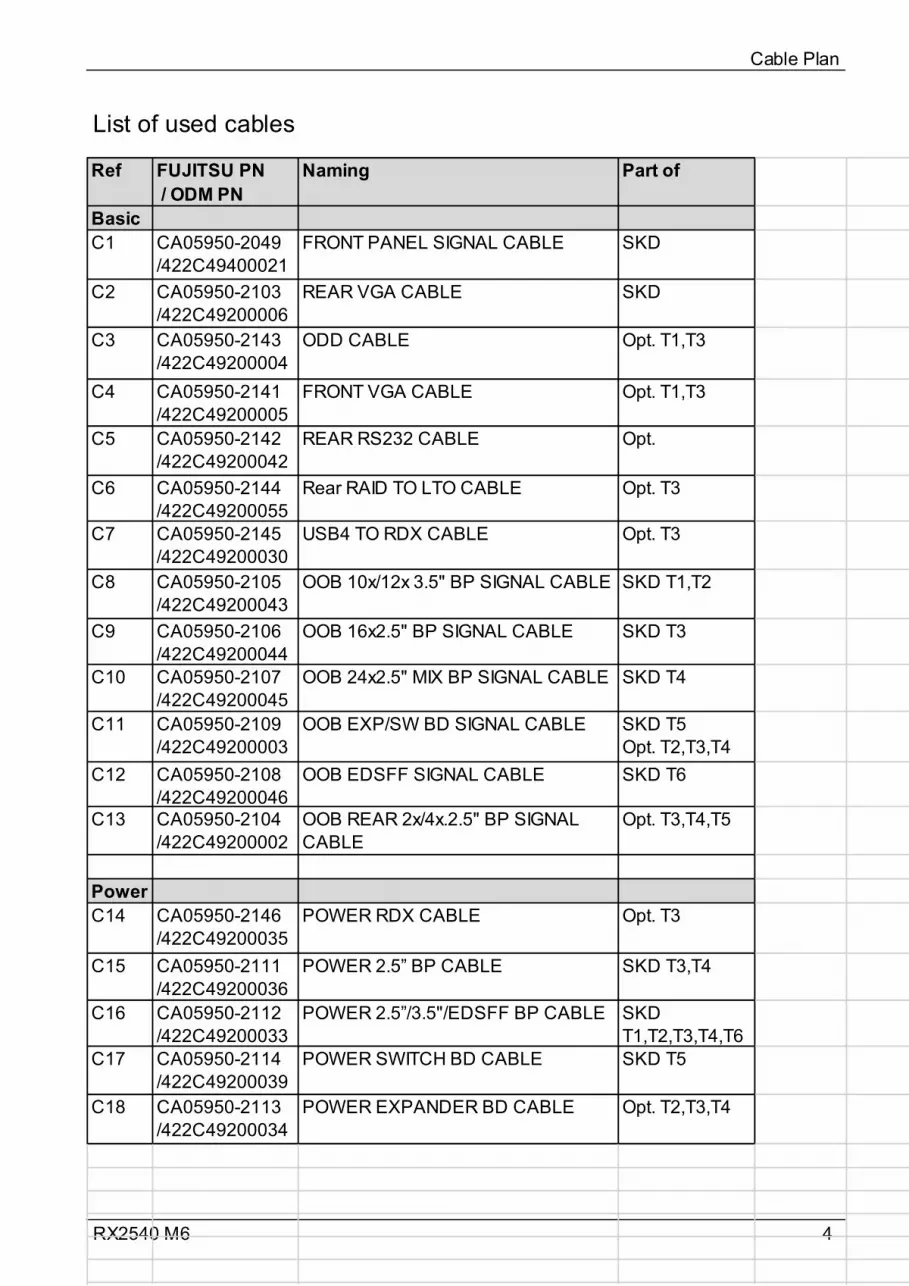
4RX2540 M6
List of used cables
Cable Plan
Ref FUJITSU PN / ODM PN
Naming Part of
BasicC1 CA05950-2049
/422C49400021FRONT PANEL SIGNAL CABLE SKD
C2 CA05950-2103 /422C49200006
REAR VGA CABLE SKD
C3 CA05950-2143 /422C49200004
ODD CABLE Opt. T1,T3
C4 CA05950-2141 /422C49200005
FRONT VGA CABLE Opt. T1,T3
C5 CA05950-2142 /422C49200042
REAR RS232 CABLE Opt.
C6 CA05950-2144 /422C49200055
Rear RAID TO LTO CABLE Opt. T3
C7 CA05950-2145 /422C49200030
USB4 TO RDX CABLE Opt. T3
C8 CA05950-2105 /422C49200043
OOB 10x/12x 3.5" BP SIGNAL CABLE SKD T1,T2
C9 CA05950-2106 /422C49200044
OOB 16x2.5" BP SIGNAL CABLE SKD T3
C10 CA05950-2107 /422C49200045
OOB 24x2.5" MIX BP SIGNAL CABLE SKD T4
C11 CA05950-2109 /422C49200003
OOB EXP/SW BD SIGNAL CABLE SKD T5Opt. T2,T3,T4
C12 CA05950-2108 /422C49200046
OOB EDSFF SIGNAL CABLE SKD T6
C13 CA05950-2104 /422C49200002
OOB REAR 2x/4x.2.5" BP SIGNAL CABLE
Opt. T3,T4,T5
PowerC14 CA05950-2146
/422C49200035POWER RDX CABLE Opt. T3
C15 CA05950-2111 /422C49200036
POWER 2.5” BP CABLE SKD T3,T4
C16 CA05950-2112 /422C49200033
POWER 2.5”/3.5"/EDSFF BP CABLE SKD T1,T2,T3,T4,T6
C17 CA05950-2114 /422C49200039
POWER SWITCH BD CABLE SKD T5
C18 CA05950-2113 /422C49200034
POWER EXPANDER BD CABLE Opt. T2,T3,T4
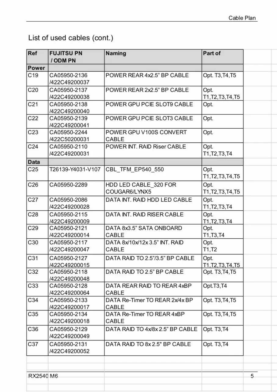
5RX2540 M6
List of used cables (cont.)
Cable Plan
Ref FUJITSU PN / ODM PN
Naming Part of
PowerC19 CA05950-2136
/422C49200037POWER REAR 4x2.5” BP CABLE Opt. T3,T4,T5
C20 CA05950-2137 /422C49200038
POWER REAR 2x2.5” BP CABLE Opt. T1,T2,T3,T4,T5
C21 CA05950-2138 /422C49200040
POWER GPU PCIE SLOT9 CABLE Opt.
C22 CA05950-2139 /422C49200041
POWER GPU PCIE SLOT3 CABLE Opt.
C23 CA05950-2244 /422C50200031
POWER GPU V100S CONVERT CABLE
Opt.
C24 CA05950-2110 /422C49200031
POWER INT. RAID Riser CABLE Opt. T1,T2,T3,T4
DataC25 T26139-Y4031-V107 CBL_TFM_EP540_550 Opt.
T1,T2,T3,T4,T5C26 CA05950-2289 HDD LED CABLE_320 FOR
COUGAR6/LYNX5Opt. T1,T2,T3,T4,T5
C27 CA05950-2086 /422C49200028
DATA INT. RAID HDD LED CABLE Opt. T1,T2,T3,T4
C28 CA05950-2115 /422C49200009
DATA INT. RAID RISER CABLE Opt. T1,T2,T3,T4
C29 CA05950-2121 /422C49200014
DATA 8x3.5” SATA ONBOARD CABLE
Opt.T1,T3,T4
C30 CA05950-2117 /422C49200047
DATA 8x/10x/12x 3.5” INT. RAID CABLE
Opt.T1,T2
C31 CA05950-2127 /422C49200015
DATA RAID TO 2.5”/3.5” BP CABLE Opt. T1,T2,T3,T4,T5
C32 CA05950-2118 /422C49200048
DATA RAID TO 2.5” BP CABLE Opt. T3,T4,T5
C33 CA05950-2128 /422C49200064
DATA REAR RAID TO REAR 4xBP CABLE
Opt.T3,T4
C34 CA05950-2133 /422C49200017
DATA Re-Timer TO REAR 2x/4x BP CABLE
Opt. T3,T4,T5
C35 CA05950-2134 /422C49200018
DATA Re-Timer TO REAR 4xBP CABLE
Opt. T3,T4,T5
C36 CA05950-2129 /422C49200049
DATA RAID TO 4x/8x 2.5” BP CABLE Opt. T3,T4
C37 CA05950-2131 /422C49200052
DATA RAID TO 8x 2.5" BP CABLE Opt. T3,T4
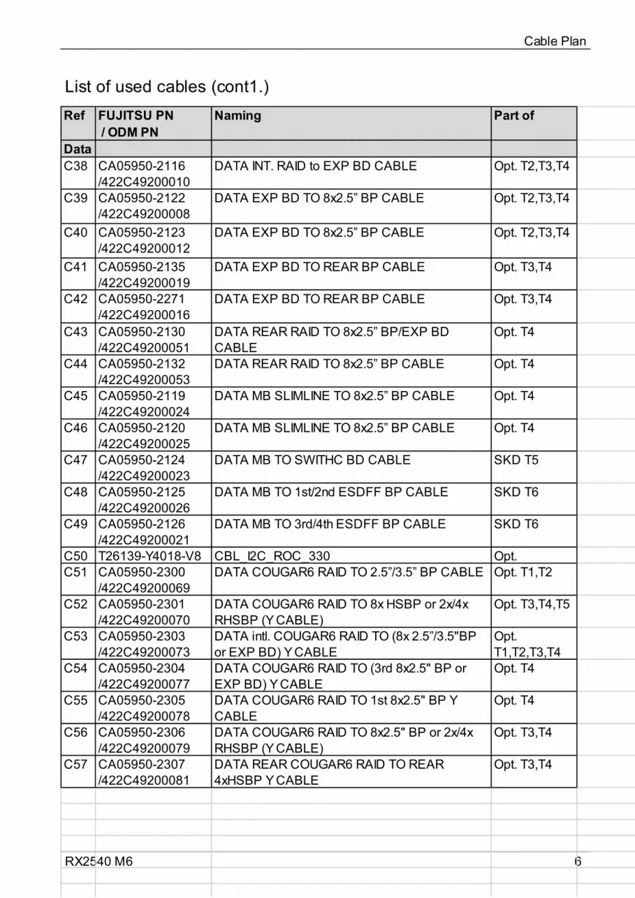
6RX2540 M6
List of used cables (cont1.)
Cable Plan
Ref FUJITSU PN / ODM PN
Naming Part of
DataC38 CA05950-2116
/422C49200010DATA INT. RAID to EXP BD CABLE Opt. T2,T3,T4
C39 CA05950-2122 /422C49200008
DATA EXP BD TO 8x2.5” BP CABLE Opt. T2,T3,T4
C40 CA05950-2123 /422C49200012
DATA EXP BD TO 8x2.5” BP CABLE Opt. T2,T3,T4
C41 CA05950-2135 /422C49200019
DATA EXP BD TO REAR BP CABLE Opt. T3,T4
C42 CA05950-2271 /422C49200016
DATA EXP BD TO REAR BP CABLE Opt. T3,T4
C43 CA05950-2130 /422C49200051
DATA REAR RAID TO 8x2.5” BP/EXP BD CABLE
Opt. T4
C44 CA05950-2132 /422C49200053
DATA REAR RAID TO 8x2.5” BP CABLE Opt. T4
C45 CA05950-2119 /422C49200024
DATA MB SLIMLINE TO 8x2.5” BP CABLE Opt. T4
C46 CA05950-2120 /422C49200025
DATA MB SLIMLINE TO 8x2.5” BP CABLE Opt. T4
C47 CA05950-2124 /422C49200023
DATA MB TO SWITHC BD CABLE SKD T5
C48 CA05950-2125 /422C49200026
DATA MB TO 1st/2nd ESDFF BP CABLE SKD T6
C49 CA05950-2126 /422C49200021
DATA MB TO 3rd/4th ESDFF BP CABLE SKD T6
C50 T26139-Y4018-V8 CBL_I2C_ROC_330 Opt.C51 CA05950-2300
/422C49200069DATA COUGAR6 RAID TO 2.5”/3.5” BP CABLE Opt. T1,T2
C52 CA05950-2301/422C49200070
DATA COUGAR6 RAID TO 8x HSBP or 2x/4x RHSBP (Y CABLE)
Opt. T3,T4,T5
C53 CA05950-2303/422C49200073
DATA intl. COUGAR6 RAID TO (8x 2.5”/3.5"BP or EXP BD) Y CABLE
Opt. T1,T2,T3,T4
C54 CA05950-2304/422C49200077
DATA COUGAR6 RAID TO (3rd 8x2.5" BP or EXP BD) Y CABLE
Opt. T4
C55 CA05950-2305/422C49200078
DATA COUGAR6 RAID TO 1st 8x2.5" BP Y CABLE
Opt. T4
C56 CA05950-2306/422C49200079
DATA COUGAR6 RAID TO 8x2.5" BP or 2x/4x RHSBP (Y CABLE)
Opt. T3,T4
C57 CA05950-2307/422C49200081
DATA REAR COUGAR6 RAID TO REAR 4xHSBP Y CABLE
Opt. T3,T4

7RX2540 M6
SysBoardConn
Cable Plan
System BoardD3891-A/B
Front Panel
USB(3.0) 3
Front VGA
SATA 4 - 7
SMB 1
SMB 2
SMB 3
SATA ODD
SATA 0 - 3
Rear VGA
HDD_led 1
HDD_led 2
HDD_led 3
ROC
VROC
USB(3.0) 4
Rear Serial
SMB 4
PWR 1...10
PWR ODD
SLIMLINE 1
SLIMLINE 2
SLIMLINE 3
SLIMLINE 4

8RX2540 M6
Basic 10x/12x3.5" or 16x/24x2.5" or 64xEDSFF
Cable Plan
CA05950-2049FRONTPANEL 1
Front Panel on QRL
CONN1
CA05950-2103 Rear VGA
System BoardD3891-A/B
Front Panel
Rear VGA
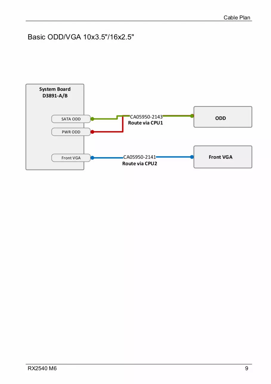
9RX2540 M6
Basic ODD/VGA 10x3.5"/16x2.5"
Cable Plan
System BoardD3891-A/B
PWR ODD
SATA ODD
Front VGA CA05950-2141 Front VGA
ODDCA05950-2143Route via CPU1
Route via CPU2
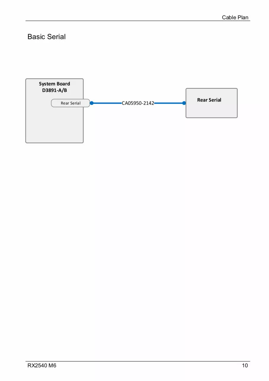
10RX2540 M6
Basic Serial
Cable Plan
System BoardD3891-A/B
Rear Serial CA05950-2142Rear Serial
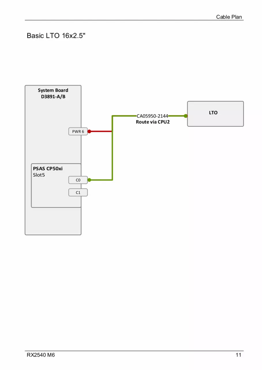
11RX2540 M6
Basic LTO 16x2.5"
Cable Plan
System BoardD3891-A/B
PWR 6
LTOCA05950-2144
MLC1
MLC2
C0
C1
Route via CPU2
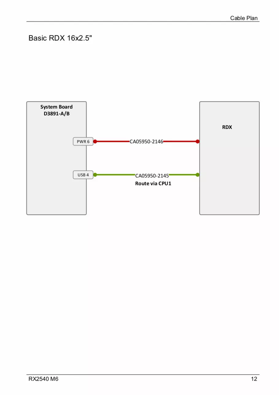
12RX2540 M6
Basic RDX 16x2.5"
Cable Plan
System BoardD3891-A/B
PWR 6
RDX
CA05950-2146
CA05950-2145USB 4
Route via CPU1

13RX2540 M6
Basic OOB 10x3.5"
Cable Plan
System BoardD3891-A/B
SMB 1 10x 3.5" HDD Backplane
SMB 1CA05950-2105SB BP
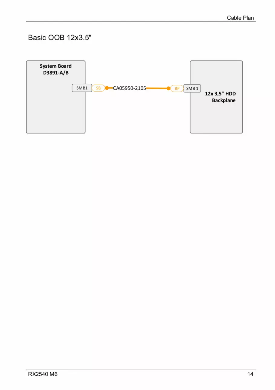
14RX2540 M6
Basic OOB 12x3.5"
Cable Plan
System BoardD3891-A/B
SMB1
12x 3,5" HDD Backplane
SMB 1CA05950-2105SB BP
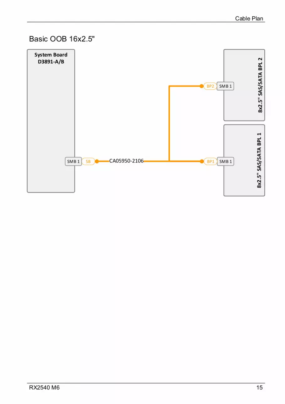
15RX2540 M6
Basic OOB 16x2.5"
Cable Plan
SMB 1
8x2
.5"
SAS/
SATA
BPL
2
SMB 1
8x2
.5"
SAS/
SATA
BPL
2
SMB 1
8x2
.5"
SAS/
SATA
BP
L 1
SMB 1
8x2
.5"
SAS/
SATA
BP
L 1
CA05950-2106SB BP1
BP2
System BoardD3891-A/B
SMB 1
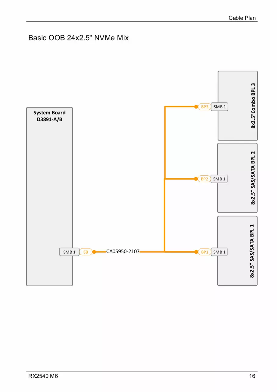
16RX2540 M6
Basic OOB 24x2.5" NVMe Mix
Cable Plan
SMB 1
8x2
.5"
SAS/
SATA
BPL
2
SMB 1
8x2
.5"
SAS/
SATA
BPL
2SMB 1
8x2
.5"
SAS/
SATA
BPL
1SMB 1
8x2
.5"
SAS/
SATA
BPL
1CA05950-2107SB BP1
BP2
System BoardD3891-A/B
SMB 18x
2.5
"Co
mb
o B
PL
3 8x
2.5
"Co
mb
o B
PL
3
BP3 SMB 1
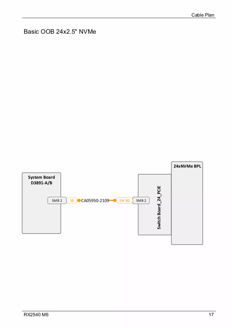
17RX2540 M6
Basic OOB 24x2.5" NVMe
Cable Plan
SMB 2
Swit
ch B
oar
d_2
4_P
CIE
SMB 2
Swit
ch B
oar
d_2
4_P
CIE
CA05950-2109SB SW BD
System BoardD3891-A/B
SMB 2
24xNVMe BPL
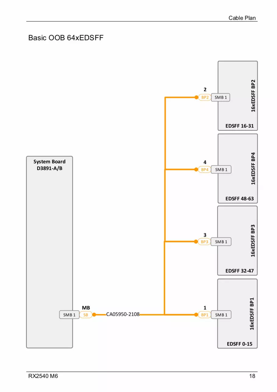
18RX2540 M6
Basic OOB 64xEDSFF
Cable Plan
16xE
DSF
F B
P3
16xE
DSF
F B
P3
16
xED
SFF
BP
11
6xE
DSF
F B
P1
CA05950-2108SB BP1
BP3
System BoardD3891-A/B
SMB 1
16xE
DSF
F B
P4
16xE
DSF
F B
P4
BP4
16xE
DSF
F B
P2
16xE
DSF
F B
P2
BP2
SMB 1
SMB 1
SMB 1
SMB 1
1MB
4
2
3
EDSFF 0-15
EDSFF 48-63
EDSFF 16-31
EDSFF 32-47
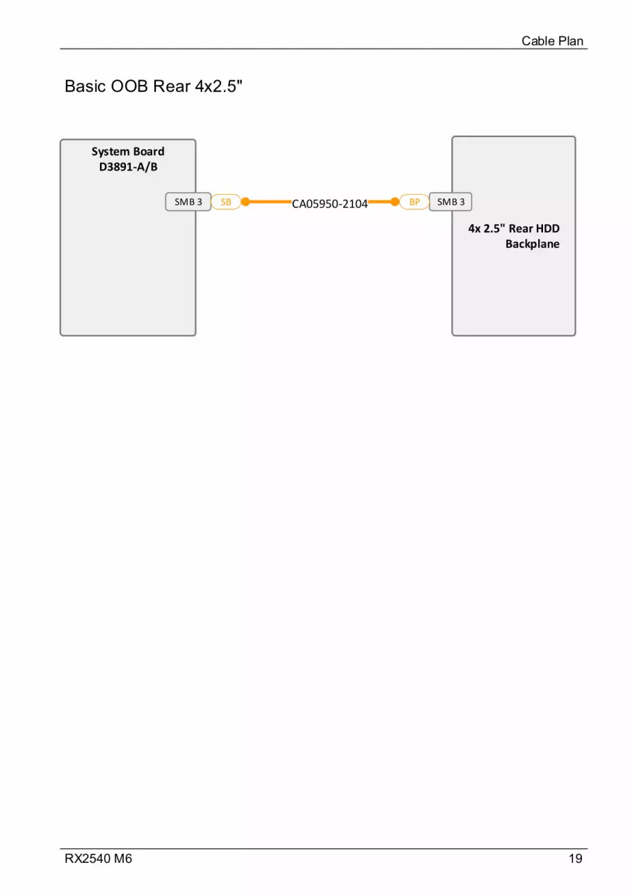
19RX2540 M6
Basic OOB Rear 4x2.5"
Cable Plan
System BoardD3891-A/B
SMB 3
4x 2.5" Rear HDD Backplane
SMB 3CA05950-2104SB BP
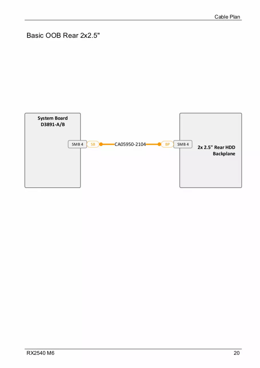
20RX2540 M6
Basic OOB Rear 2x2.5"
Cable Plan
System BoardD3891-A/B
SMB 42x 2.5" Rear HDD
Backplane
SMB 4CA05950-2104SB BP
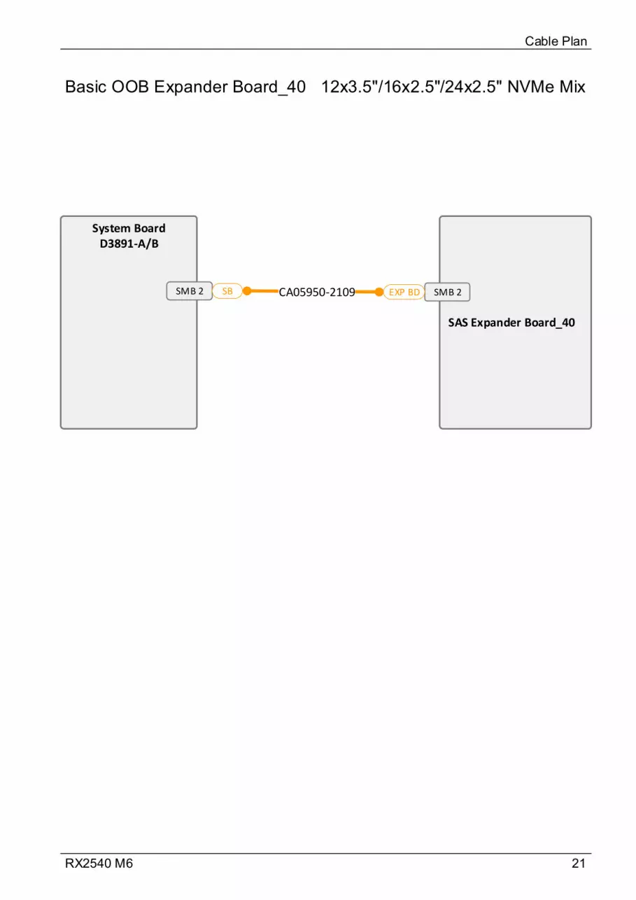
21RX2540 M6
Basic OOB Expander Board_40 12x3.5"/16x2.5"/24x2.5" NVMe Mix
Cable Plan
System BoardD3891-A/B
SMB 2
SAS Expander Board_40
SMB 2CA05950-2109SB EXP BD

22RX2540 M6
Power 10x3.5"
Cable Plan
CA05950-2112
System BoardD3891-A/B
PWR 2
10x3.5" HDD Backplane
PWR 1
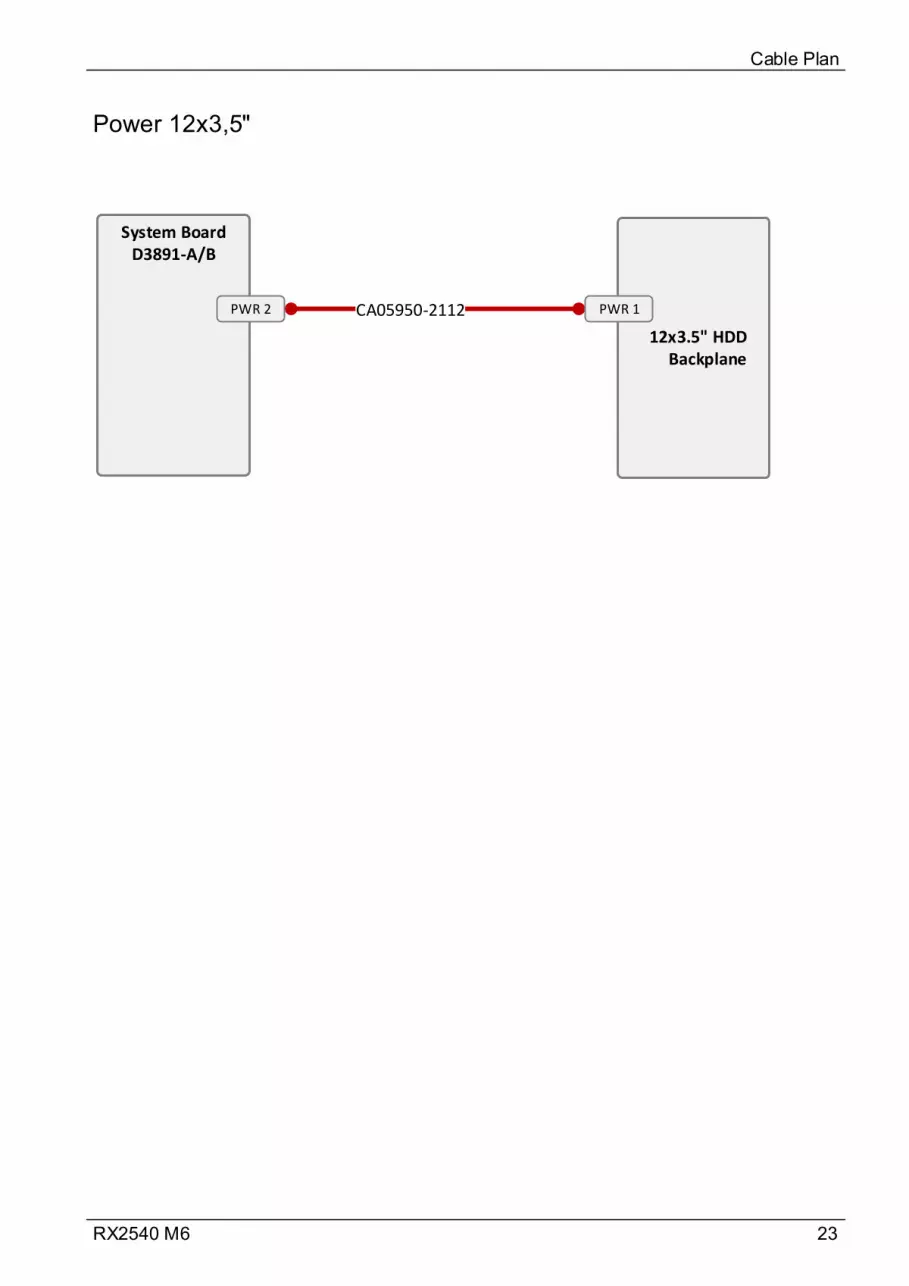
23RX2540 M6
Power 12x3,5"
Cable Plan
CA05950-2112
System BoardD3891-A/B
PWR 2
12x3.5" HDD Backplane
PWR 1
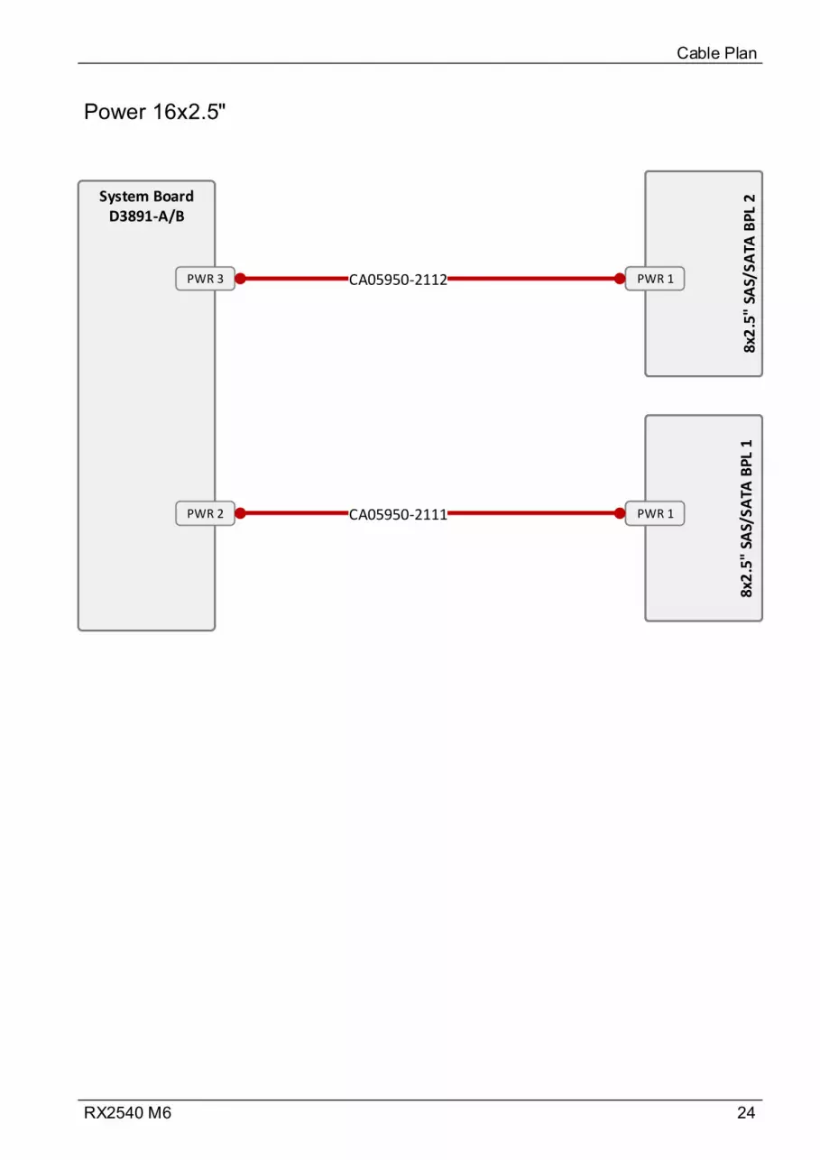
24RX2540 M6
Power 16x2.5"
Cable Plan
PWR 1
8x2
.5"
SAS/
SA
TA B
PL
2
PWR 1
8x2
.5"
SAS/
SA
TA B
PL
2
PWR 1
8x2
.5"
SAS/
SATA
BPL
1
PWR 1
8x2
.5"
SAS/
SATA
BPL
1
System BoardD3891-A/B
PWR 3
PWR 2 CA05950-2111
CA05950-2112
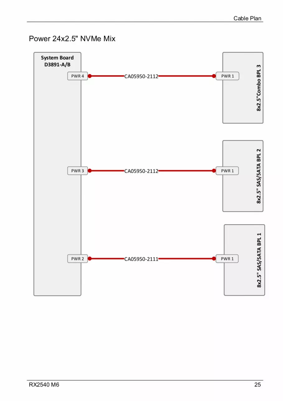
25RX2540 M6
Power 24x2.5" NVMe Mix
Cable Plan
PWR 1
8x2
.5"
SAS/
SATA
BP
L 2
PWR 1
8x2
.5"
SAS/
SATA
BP
L 2
PWR 18x
2.5
" SA
S/SA
TA B
PL 1
PWR 18x
2.5
" SA
S/SA
TA B
PL 1
System BoardD3891-A/B
PWR 3
PWR 2 CA05950-2111
CA05950-2112
PWR 4
8x2
.5"C
om
bo
BP
L 3
8x2
.5"C
om
bo
BP
L 3
PWR 1CA05950-2112
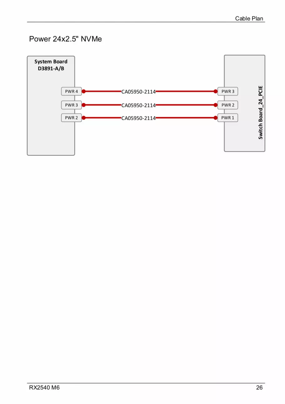
26RX2540 M6
Power 24x2.5" NVMe
Cable Plan
System BoardD3891-A/B
PWR 3
CA05950-2114
PWR 4
Swit
ch B
oar
d_2
4_P
CIE
PWR 2
PWR 3
CA05950-2114
CA05950-2114
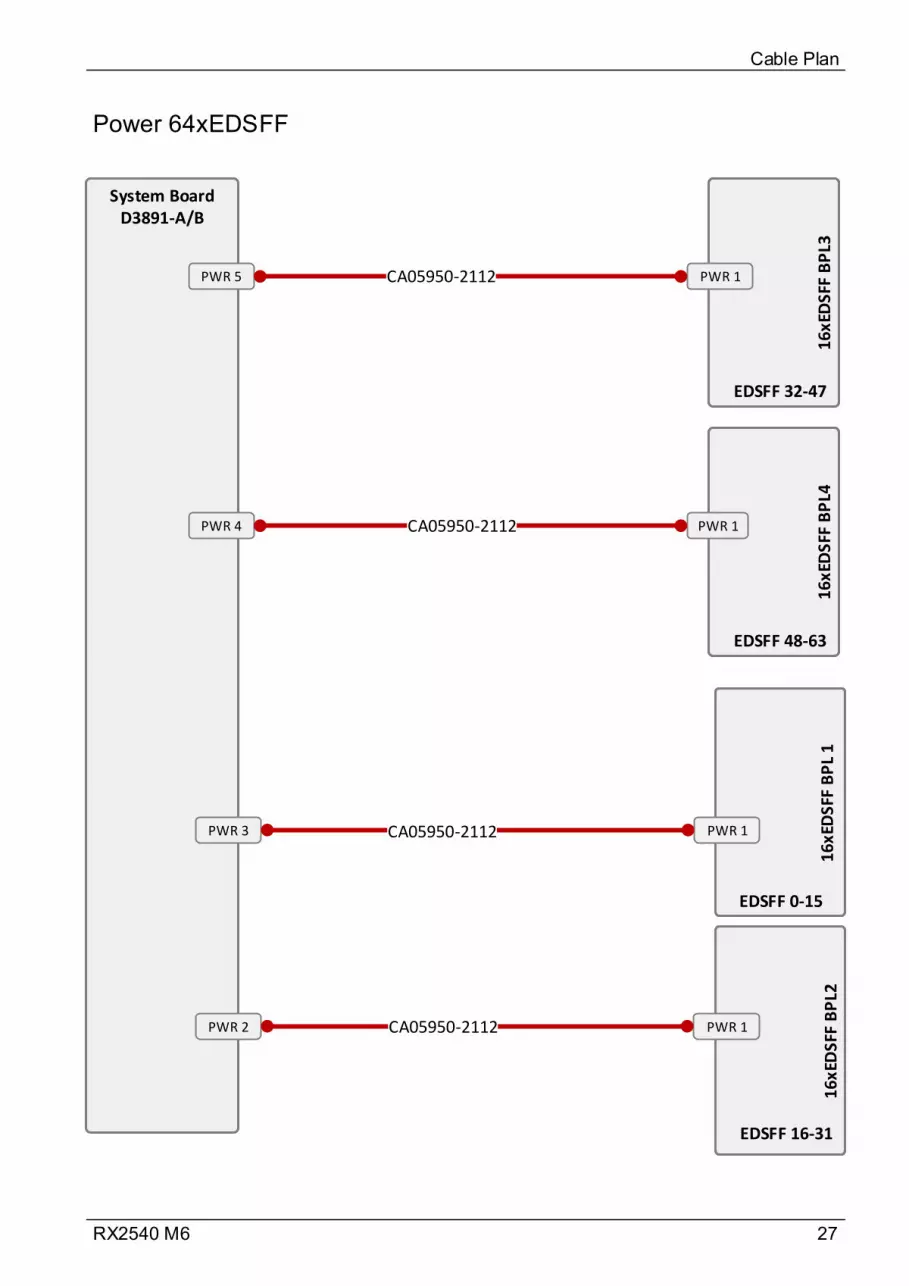
27RX2540 M6
Power 64xEDSFF
Cable Plan
16
xED
SFF
BP
L21
6x
EDSF
F B
PL2
16xE
DSF
F B
PL
116
xED
SFF
BP
L 1
16xE
DSF
F B
PL3
16xE
DSF
F B
PL3
16
xED
SFF
BP
L41
6xE
DS
FF B
PL4
PWR 1
PWR 1
PWR 1
PWR 1
EDSFF 0-15
EDSFF 32-47
EDSFF 48-63
EDSFF 16-31
System BoardD3891-A/B
PWR 2
PWR 3 CA05950-2112
PWR 5
PWR 4
CA05950-2112
CA05950-2112
CA05950-2112
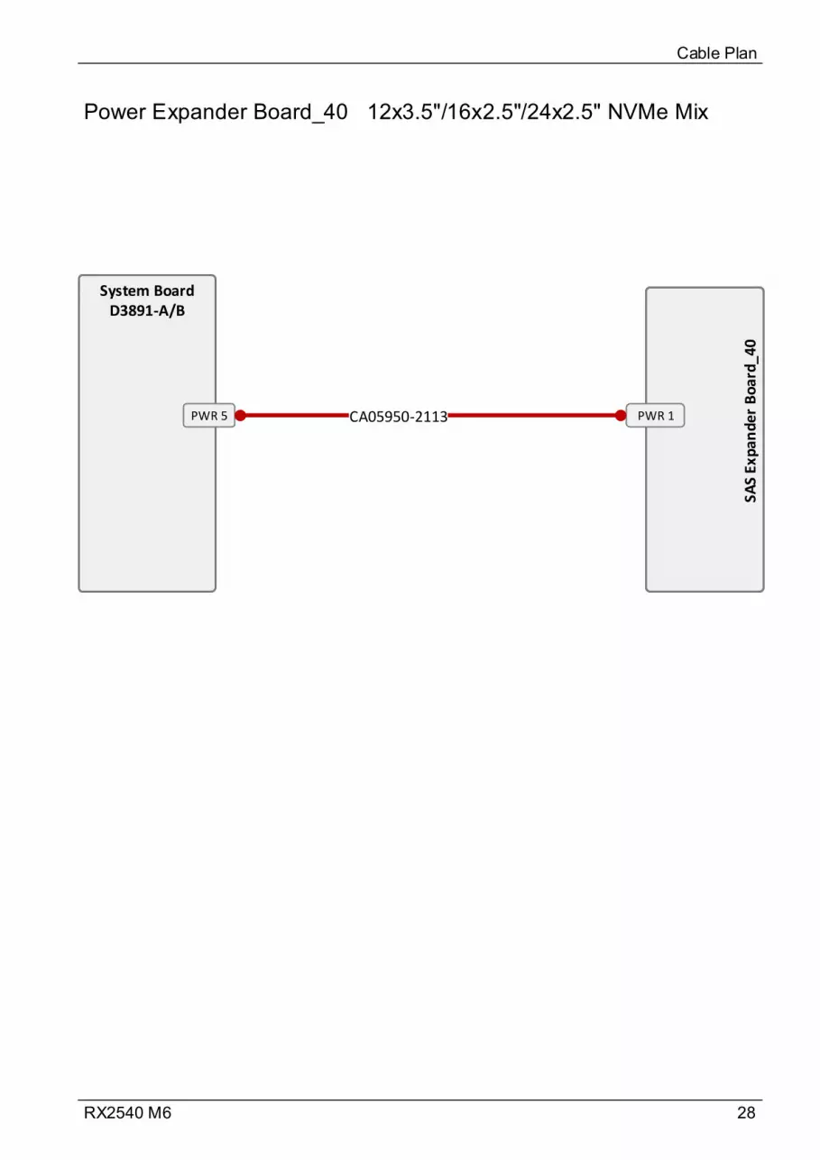
28RX2540 M6
Power Expander Board_40 12x3.5"/16x2.5"/24x2.5" NVMe Mix
Cable Plan
System BoardD3891-A/B
PWR 5
SAS
Expa
nd
er B
oar
d_4
0
PWR 1CA05950-2113
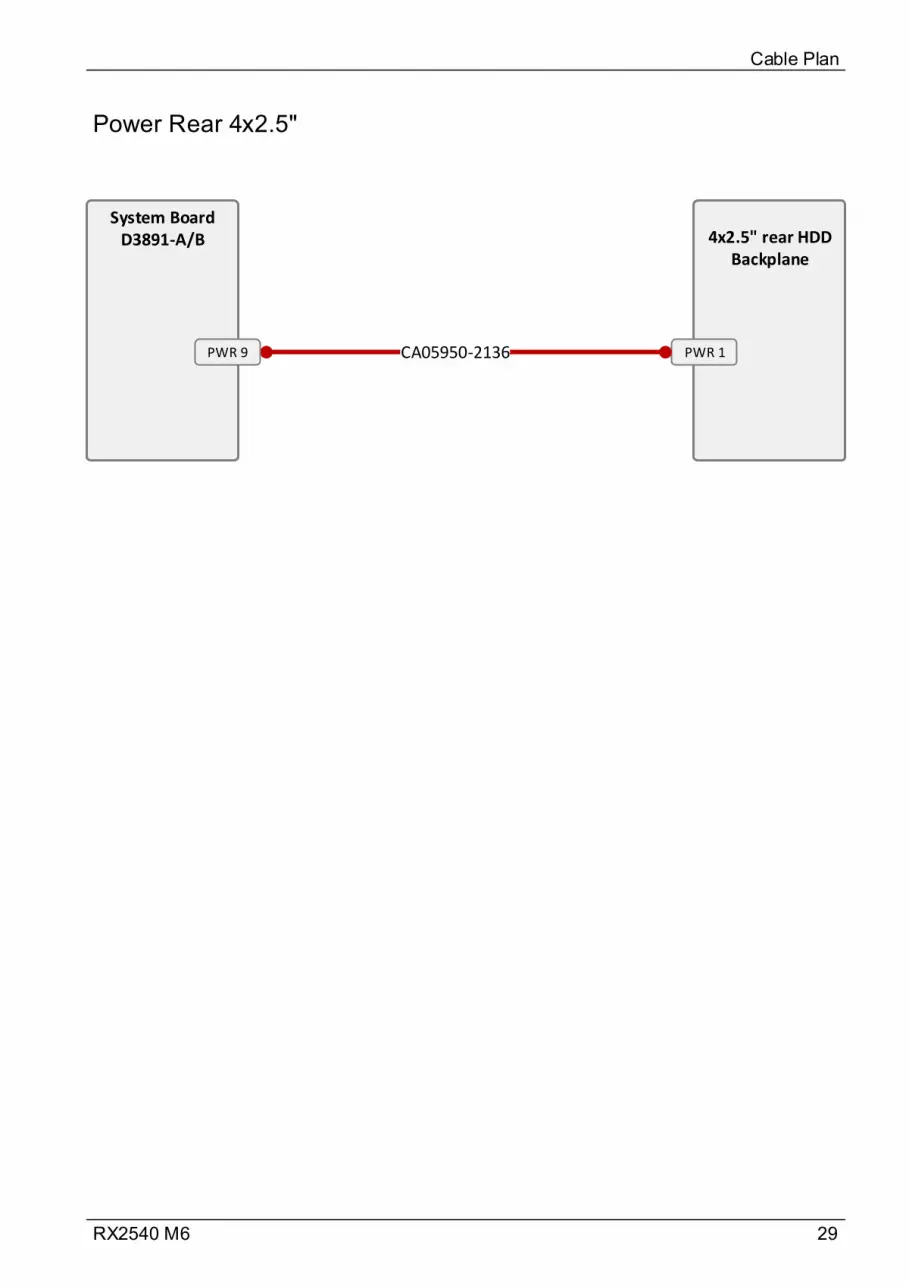
29RX2540 M6
Power Rear 4x2.5"
Cable Plan
System BoardD3891-A/B
PWR 1
4x2.5" rear HDD Backplane
CA05950-2136PWR 9

30RX2540 M6
Power Rear 2x2.5"
Cable Plan
System BoardD3891-A/B
PWR 1
2x2.5" rear HDD Backplane
CA05950-2137PWR 10
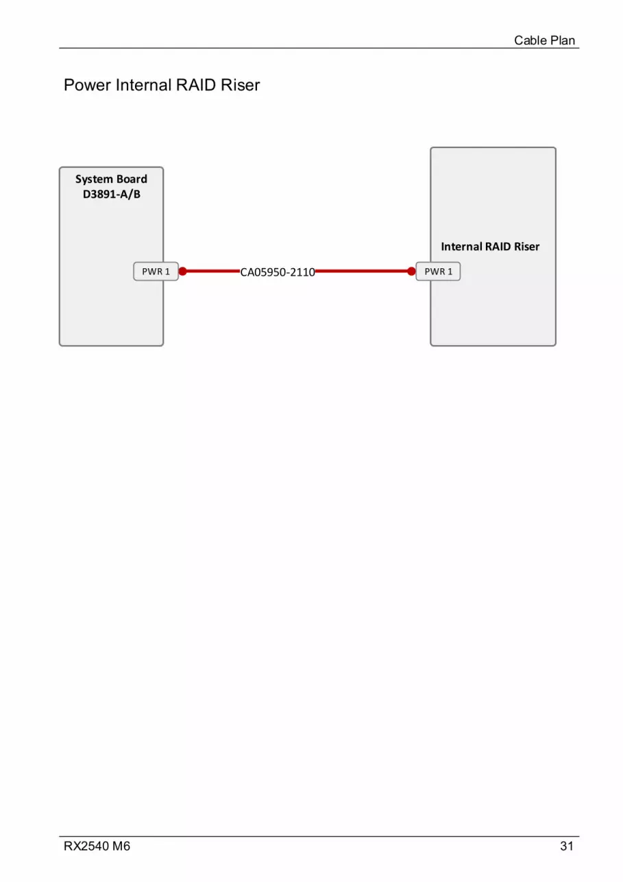
31RX2540 M6
Power Internal RAID Riser
Cable Plan
CA05950-2110
System BoardD3891-A/B
PWR 1
Internal RAID Riser
PWR 1
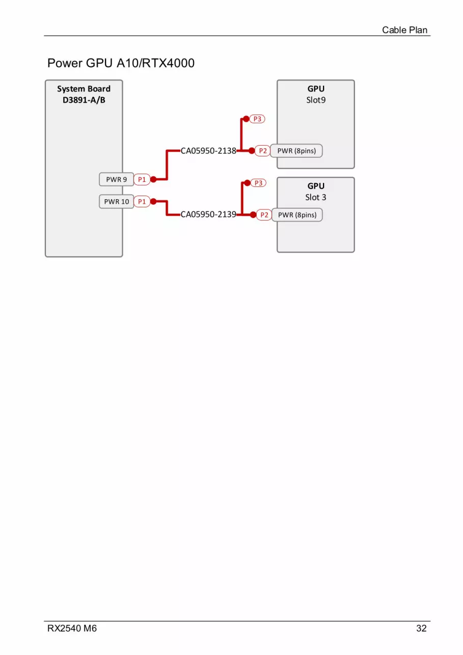
32RX2540 M6
Power GPU A10/RTX4000
Cable Plan
System BoardD3891-A/B
PWR 9
PWR 10
GPUSlot9
GPUSlot 3
PWR (8pins)
PWR (8pins)
CA05950-2138
CA05950-2139
P1
P1
P2
P2
P3
P3

33RX2540 M6
Power GPU A40/A6000/A100
Cable Plan
System BoardD3891-A/B
PWR 9
PWR 10
GPU Slot9
GPU Slot 3
PWR (8pins)
PWR (8pins)
CA05950-2138P1
P1
P2
P3
CA05950-2244
CA05950-2139P2
P3
CA05950-2244
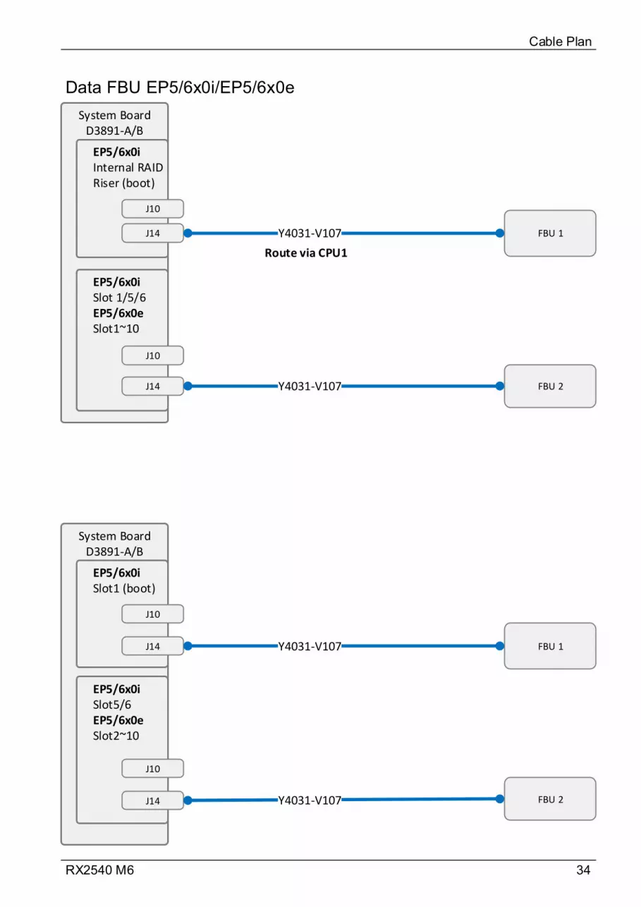
34RX2540 M6
Data FBU EP5/6x0i/EP5/6x0e
Cable Plan
System BoardD3891-A/B
EP5/6x0iInternal RAID Riser (boot)
J14 FBU 1Y4031-V107
J10
EP5/6x0iSlot 1/5/6EP5/6x0eSlot1~10
J14 FBU 2Y4031-V107
System BoardD3891-A/B
EP5/6x0iSlot1 (boot)
J14 FBU 1Y4031-V107
J10
EP5/6x0iSlot5/6EP5/6x0eSlot2~10
J14 FBU 2Y4031-V107
J10
J10
Route via CPU1

35RX2540 M6
Data HDDActivity EP 5/6xxi
Cable Plan
System BoardD3891-A/B
CA05950-2289
J10
HDD_Led1
CA05950-2289
HDD_Led2
HDD_Led3
CA05950-2289
EP 5/6xxiInternal RAID Riser
Internal RAID card
J10HDD Led CA05950-2086
NOTE:To insert HDD LED cable’s connector to MB’s HDD_Led 1/2/3 connector can be oriented in any direction.
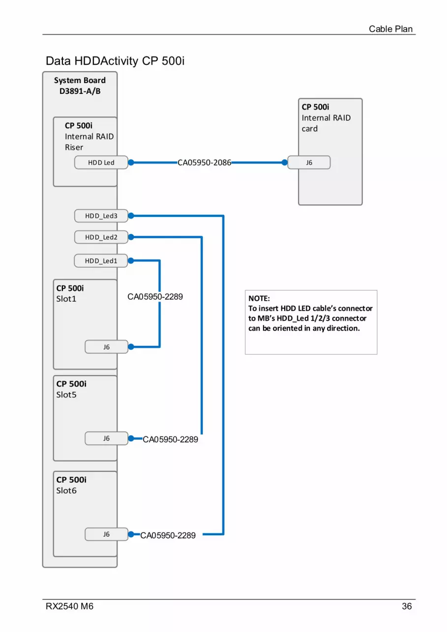
36RX2540 M6
Data HDDActivity CP 500i
Cable Plan
System BoardD3891-A/B
CP 500i
CA05950-2289
J6
HDD_Led1
CA05950-2289
HDD_Led2
HDD_Led3
CA05950-2289
CP 500iInternal RAID Riser
CP 500iInternal RAID card
J6HDD Led CA05950-2086
NOTE:To insert HDD LED cable’s connector to MB’s HDD_Led 1/2/3 connector can be oriented in any direction.
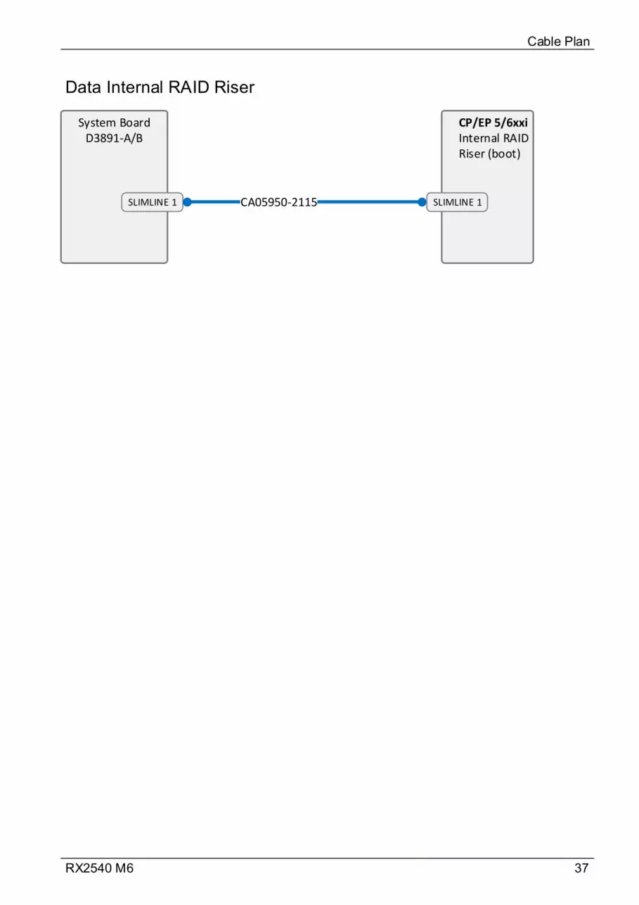
37RX2540 M6
Data Internal RAID Riser
Cable Plan
System BoardD3891-A/B
CP/EP 5/6xxiInternal RAID Riser (boot)
SLIMLINE 1 CA05950-2115 SLIMLINE 1
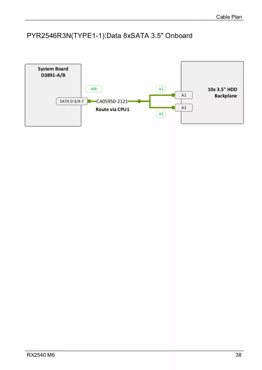
38RX2540 M6
PYR2546R3N(TYPE1-1):Data 8xSATA 3.5" Onboard
Cable Plan
System BoardD3891-A/B
SATA 0-3/4-7
10x 3.5" HDD BackplaneA1
A2
CA05950-2121
A1
A2
MB
Route via CPU1

39RX2540 M6
PYR2546R3N(TYPE1-2):Data 8xSAS/SATA 3.5" CP/EP5xxi
Cable Plan
System BoardD3891-A/B
C0
C1
10x 3.5" HDD Backplane
A1
A2CA05950-2117
CA05950-2117
3.5" HSBPRaid card
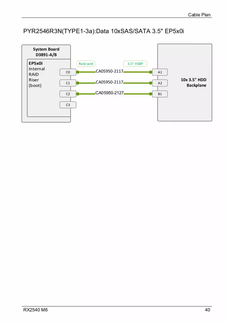
40RX2540 M6
PYR2546R3N(TYPE1-3a):Data 10xSAS/SATA 3.5" EP5x0i
Cable Plan
System BoardD3891-A/B
C0
C110x 3.5" HDD
Backplane
A1
A2CA05950-2117
CA05950-2117
C2 B1CA05950-2127
C3
3.5" HSBPRaid card

41RX2540 M6
PYR2546R3N(TYPE1-3b):Data 10xSAS/SATA 3.5" EP6x0i
Cable Plan
System BoardD3891-A/B
C0
10x 3.5" HDD Backplane
A1
A2
CA05950-2303
B1CA05950-2300C1
Port 1
Port 2
B1
Raid card
Raid card

42RX2540 M6
PYR2546RAN(TYPE2-1a):Data 12xSAS/SATA 3.5" EP5x0i
Cable Plan
System BoardD3891-A/B
C0
C112x 3.5" HDD
Backplane
A1
A2CA05950-2117
CA05950-2117
C2 B1CA05950-2127
C3
3.5" HSBPRaid card
3.5" HSBPRaid card
HSBPRaid card
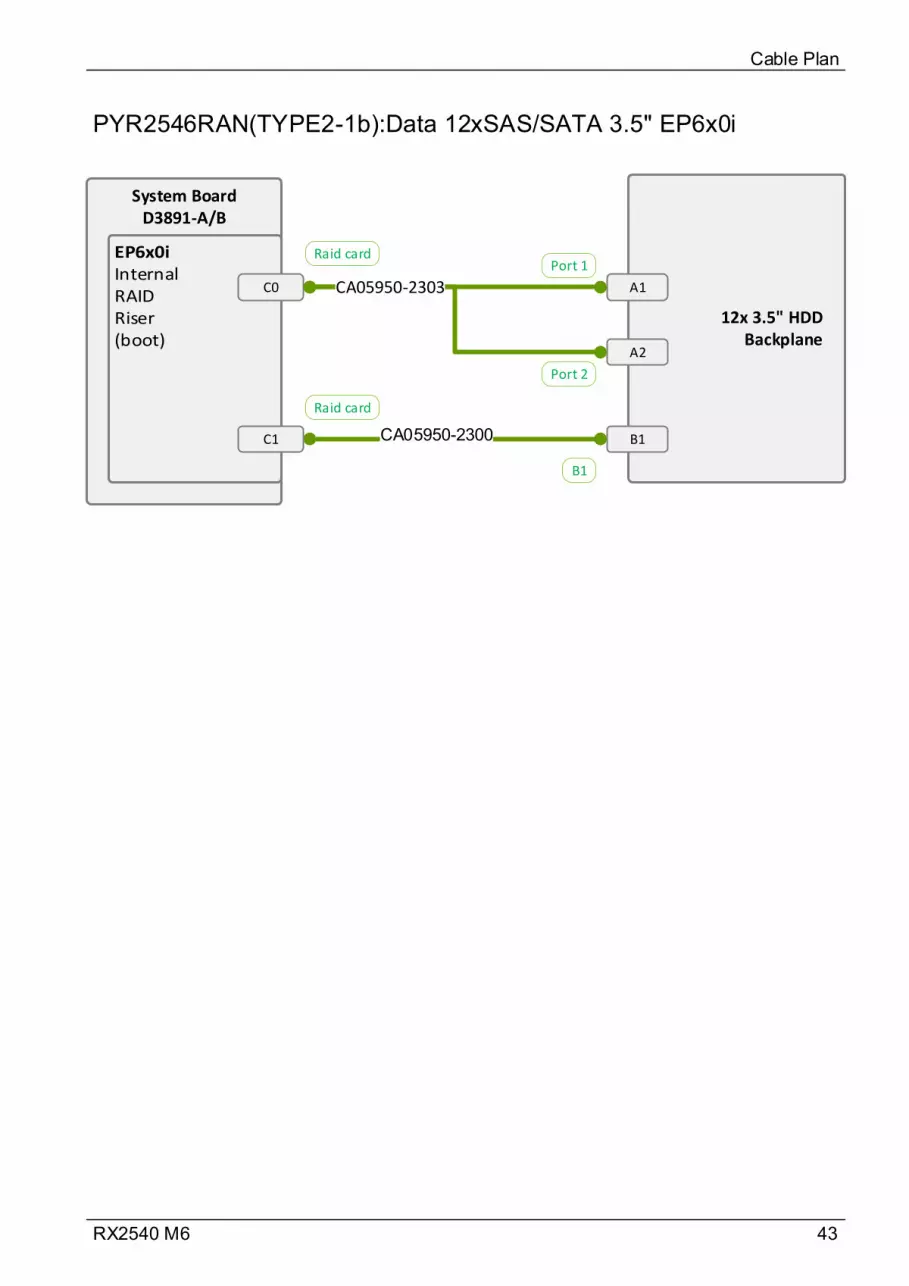
43RX2540 M6
PYR2546RAN(TYPE2-1b):Data 12xSAS/SATA 3.5" EP6x0i
Cable Plan
System BoardD3891-A/B
C0
12x 3.5" HDD Backplane
A1
A2
CA05950-2303
B1CA05950-2300C1
Port 1
Port 2
B1
Raid card
Raid card
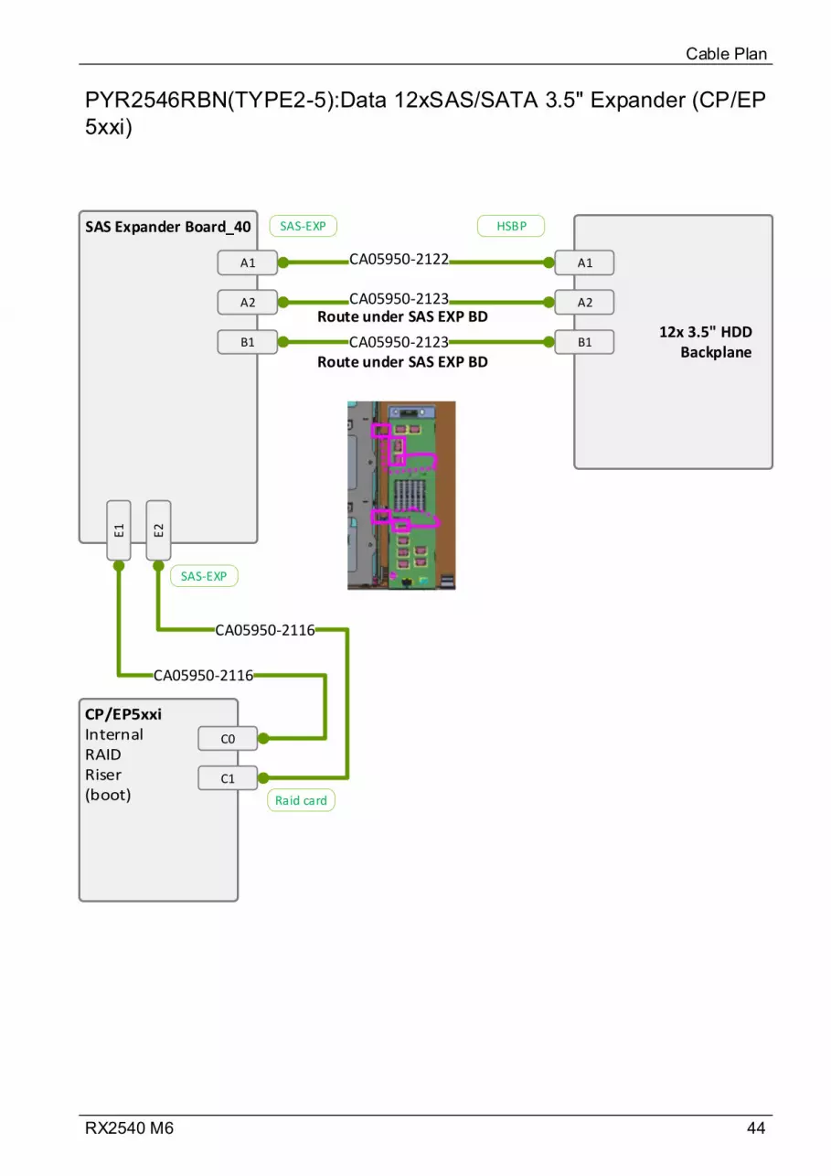
44RX2540 M6
PYR2546RBN(TYPE2-5):Data 12xSAS/SATA 3.5" Expander (CP/EP 5xxi)
Cable Plan
SAS Expander Board_40
A1
CA05950-2123
CA05950-2122
C0
C1
CA05950-2116
CA05950-2116
A2
B1 CA05950-2123
E1
E2
12x 3.5" HDD Backplane
A1
A2
B1
Raid card
SAS-EXP
SAS-EXP HSBP
Route under SAS EXP BD
Route under SAS EXP BD
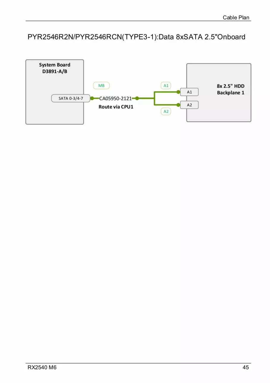
45RX2540 M6
PYR2546R2N/PYR2546RCN(TYPE3-1):Data 8xSATA 2.5"Onboard
Cable Plan
System BoardD3891-A/B
SATA 0-3/4-7
8x 2.5" HDD Backplane 1A1
A2
CA05950-2121
A1
A2
MB
Route via CPU1
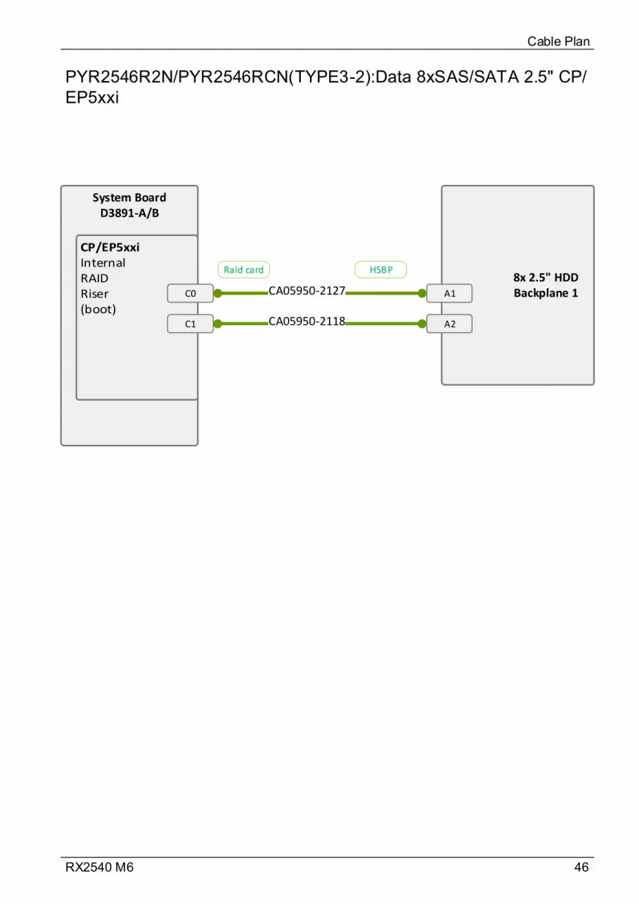
46RX2540 M6
PYR2546R2N/PYR2546RCN(TYPE3-2):Data 8xSAS/SATA 2.5" CP/EP5xxi
Cable Plan
System BoardD3891-A/B
C0
C1
8x 2.5" HDD Backplane 1A1
A2CA05950-2118
CA05950-2127
Raid card HSBP
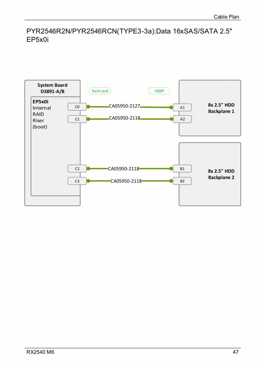
47RX2540 M6
PYR2546R2N/PYR2546RCN(TYPE3-3a):Data 16xSAS/SATA 2.5" EP5x0i
Cable Plan
System BoardD3891-A/B
C0
C1
8x 2.5" HDD Backplane 1
A1
A2CA05950-2118
CA05950-2127
8x 2.5" HDD Backplane 2
B1
B2
C2
C3
CA05950-2118
CA05950-2118
Raid card HSBP

48RX2540 M6
PYR2546R2N/PYR2546RCN(TYPE3-3b):Data 16xSAS/SATA 2.5" EP6x0i
Cable Plan
System BoardD3891-A/B
C0 8x 2.5" HDD Backplane 1
A1
A2
CA05950-2301
8x 2.5" HDD Backplane 2
B1
B2
C1 CA05950-2303
Port 1
Port 2
Port 1
Port 2
Raid card
Raid card
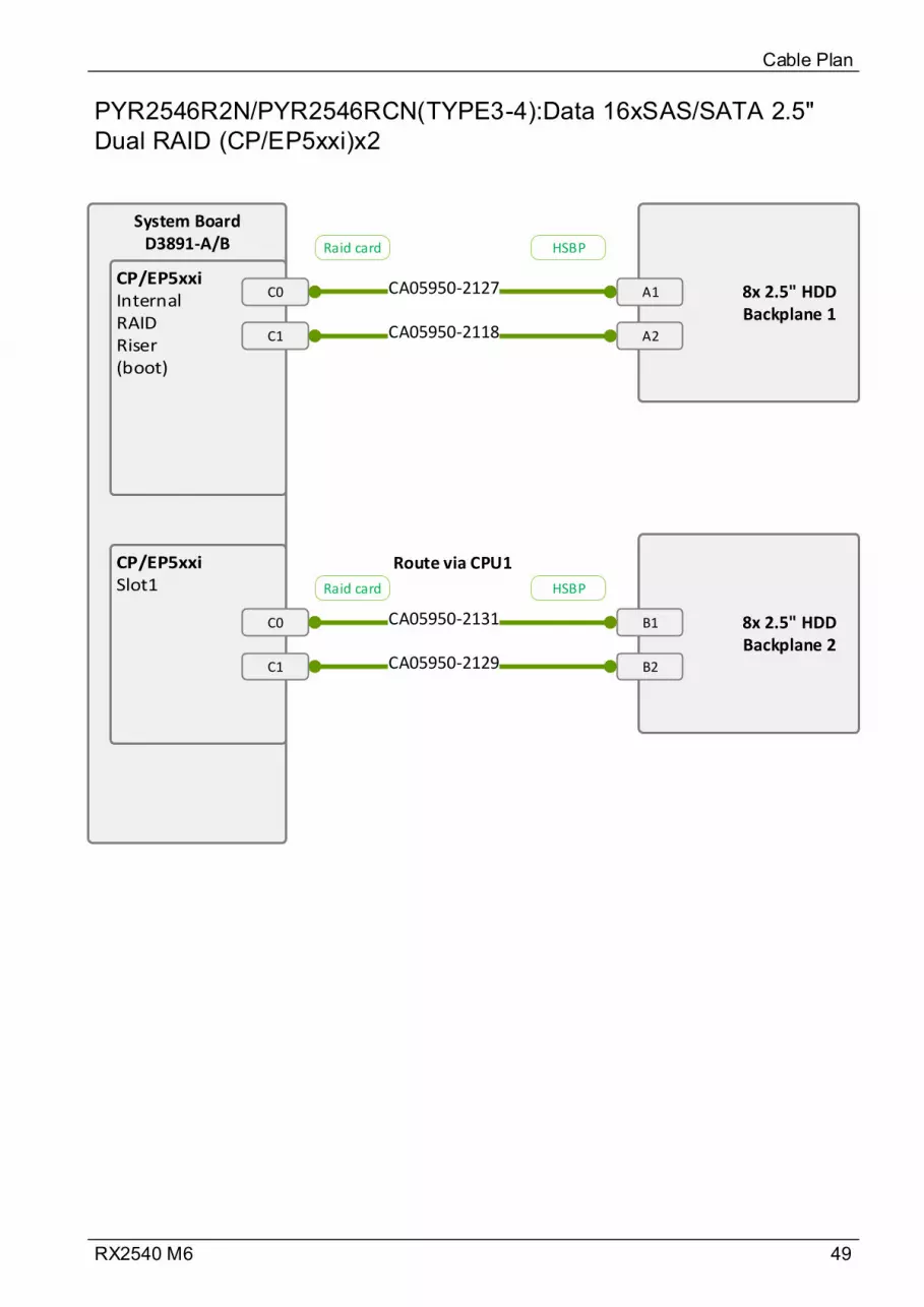
49RX2540 M6
PYR2546R2N/PYR2546RCN(TYPE3-4):Data 16xSAS/SATA 2.5" Dual RAID (CP/EP5xxi)x2
Cable Plan
System BoardD3891-A/B
C0
C1
8x 2.5" HDD Backplane 1
A1
A2CA05950-2118
CA05950-2127
8x 2.5" HDD Backplane 2
B1
B2
C0
C1
CA05950-2131
CA05950-2129
Raid card HSBP
Raid card HSBP
Route via CPU1
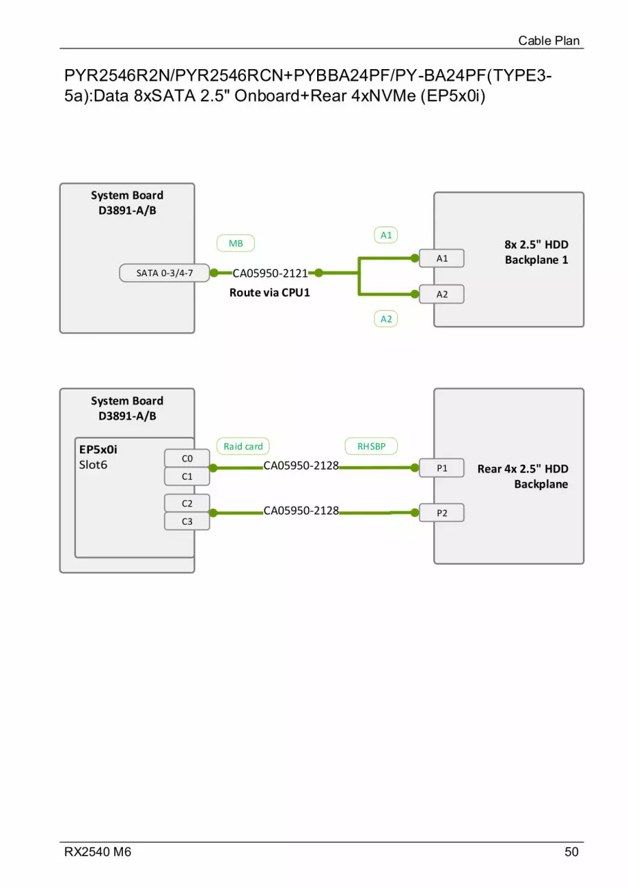
50RX2540 M6
PYR2546R2N/PYR2546RCN+PYBBA24PF/PY-BA24PF(TYPE3-5a):Data 8xSATA 2.5" Onboard+Rear 4xNVMe (EP5x0i)
Cable Plan
System BoardD3891-A/B
SATA 0-3/4-7
8x 2.5" HDD Backplane 1A1
A2
CA05950-2121
A1
A2
System BoardD3891-A/B
C1 Rear 4x 2.5" HDD
Backplane
P1CA05950-2128
P2CA05950-2128
C0
C2
C3
MB
Raid card RHSBP
Route via CPU1
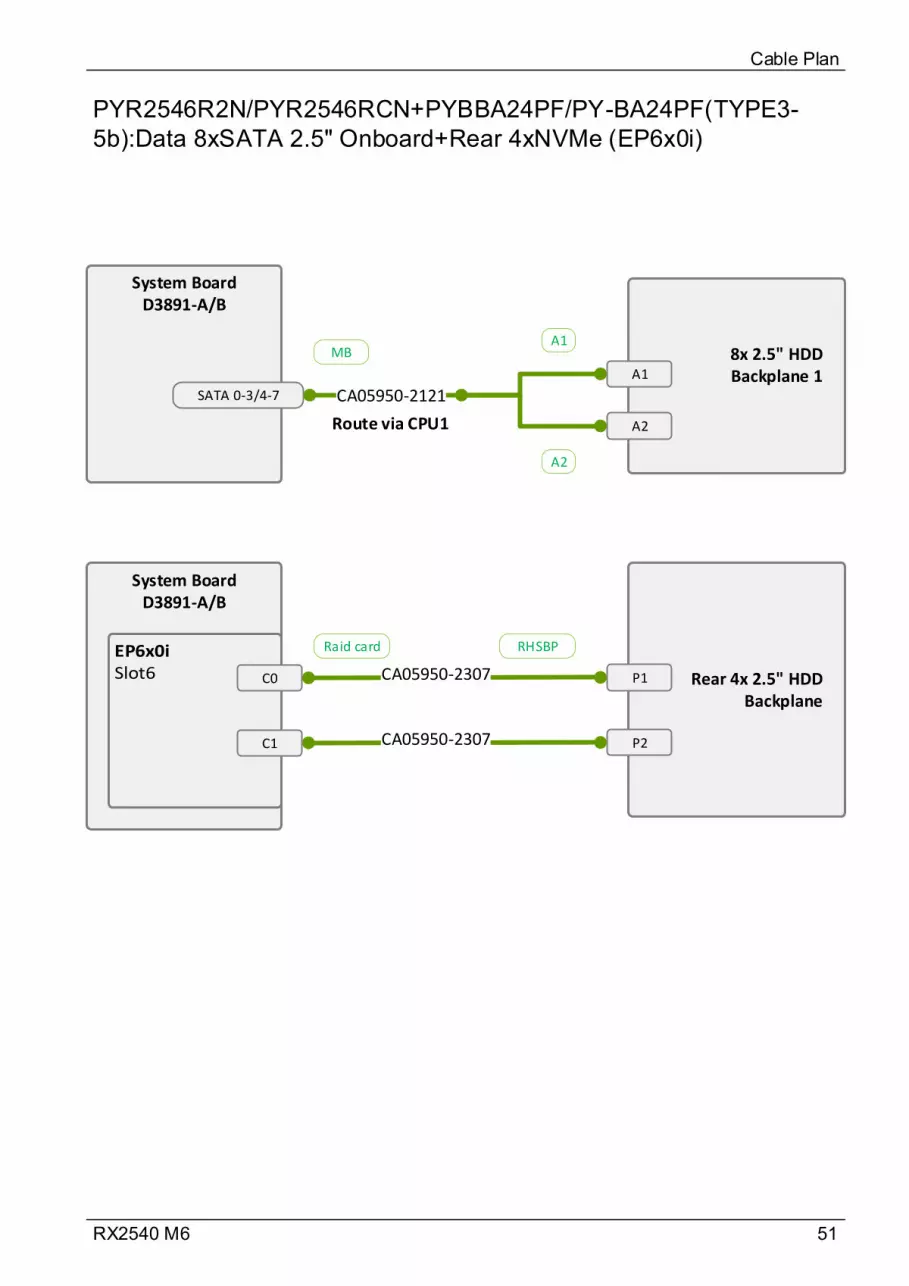
51RX2540 M6
PYR2546R2N/PYR2546RCN+PYBBA24PF/PY-BA24PF(TYPE3-5b):Data 8xSATA 2.5" Onboard+Rear 4xNVMe (EP6x0i)
Cable Plan
System BoardD3891-A/B
SATA 0-3/4-7
8x 2.5" HDD Backplane 1A1
A2
CA05950-2121
A1
A2
System BoardD3891-A/B
Rear 4x 2.5" HDD Backplane
P1CA05950-2307
P2CA05950-2307
C0
C1
MB
Raid card RHSBP
Route via CPU1

52RX2540 M6
PYR2546R2N/PYR2546RCN+PYBBA24PF/PY-BA24PF+PYBBA22P2/PY-BA22P2(TYPE3-6):Data 8xSAS/SATA 2.5" CP/EP5xxi+Rear 4x/6x NVMe (Retimer)
Cable Plan
System BoardD3891-A/B
C0
C1
8x 2.5" HDD Backplane 1
A1
A2CA05950-2118
CA05950-2127
System BoardD3891-A/B
P1
P2
Rear 4x 2.5" HDD Backplane
P1CA05950-2134
Rear 2x 2.5" HDD Backplane
P1
CA05950-2133 P2
P1
P2
CA05950-2133
Raid card HSBP
Retimer RHSBP
Retimer RHSBP

53RX2540 M6
PYR2546R2N/PYR2546RCN+PYBBA24PF/PY-BA24PF+PYBBA22P2/PY-BA22P2(TYPE3-8):Data 16xSAS/SATA 2.5" Dual RAID (CP/EP5xxi) x2+Rear 4x/6x NVMe (Retimer)
Cable Plan
System BoardD3891-A/B
C0
C1
8x 2.5" HDD Backplane 1A1
A2CA05950-2118
CA05950-2127
8x 2.5" HDD Backplane 2
B1
B2
C0
C1
CA05950-2131
CA05950-2129
System BoardD3891-A/B
P1
P2
Rear 4x 2.5" HDD BackplaneP1CA05950-2134
Rear 2x 2.5" HDD BackplaneP1
CA05950-2133 P2
P1
P2
CA05950-2133
Raid card HSBP
Raid card HSBP
Retimer RHSBP
Retimer RHSBP
Route via CPU1
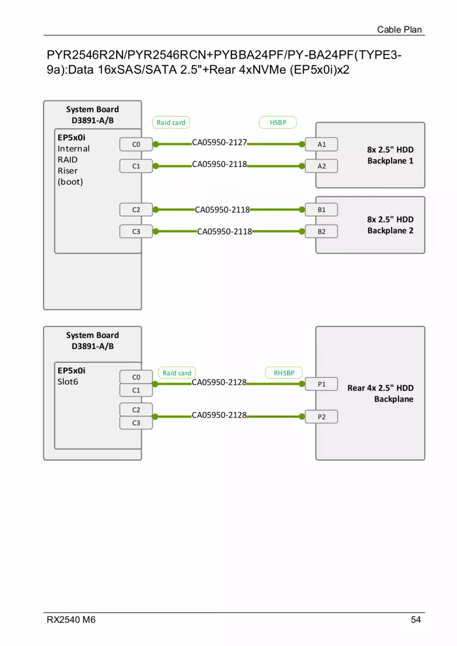
54RX2540 M6
PYR2546R2N/PYR2546RCN+PYBBA24PF/PY-BA24PF(TYPE3-9a):Data 16xSAS/SATA 2.5"+Rear 4xNVMe (EP5x0i)x2
Cable Plan
System BoardD3891-A/B
C0
C1
8x 2.5" HDD Backplane 1
A1
A2CA05950-2118
CA05950-2127
8x 2.5" HDD Backplane 2
B1
B2
C2
C3
CA05950-2118
CA05950-2118
System BoardD3891-A/B
C1 Rear 4x 2.5" HDD Backplane
P1CA05950-2128
P2CA05950-2128
C0
C2
C3
Raid card HSBP
Raid card RHSBP
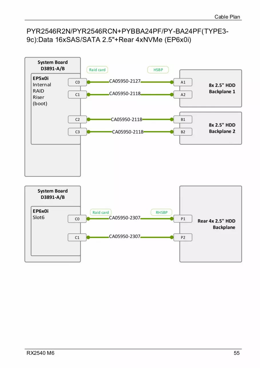
55RX2540 M6
PYR2546R2N/PYR2546RCN+PYBBA24PF/PY-BA24PF(TYPE3-9c):Data 16xSAS/SATA 2.5"+Rear 4xNVMe (EP6x0i)
Cable Plan
System BoardD3891-A/B
C0
C1
8x 2.5" HDD Backplane 1
A1
A2CA05950-2118
CA05950-2127
8x 2.5" HDD Backplane 2
B1
B2
C2
C3
CA05950-2118
CA05950-2118
System BoardD3891-A/B
Rear 4x 2.5" HDD Backplane
P1CA05950-2307
P2CA05950-2307
C0
C1
Raid card HSBP
Raid card RHSBP

56RX2540 M6
PYR2546R2N/PYR2546RCN+PYBBA24PF/PY-BA24PF(TYPE3-9b):Data 16xSAS/SATA 2.5"+Rear 4xNVMe (EP6x0i)x2
Cable Plan
System BoardD3891-A/B
C08x 2.5" HDD Backplane 1
A1
A2
CA05950-2301
8x 2.5" HDD Backplane 2
B1
B2
C1 CA05950-2303
System BoardD3891-A/B
Rear 4x 2.5" HDD Backplane
P1CA05950-2307
P2CA05950-2307
C0
C1
Port 1
Port 2
Port 1
Port 2
Raid card
Raid card
Raid card RHSBP
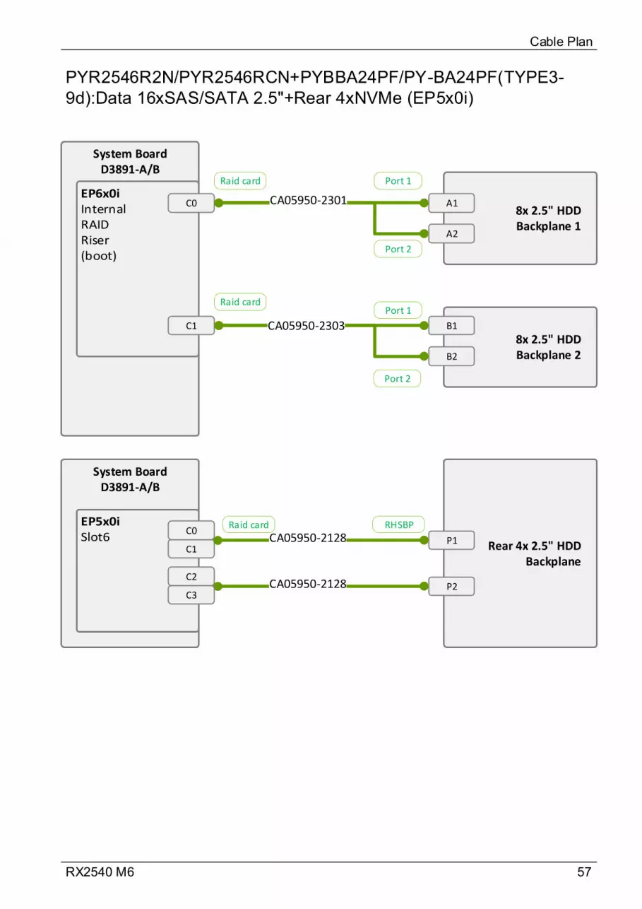
57RX2540 M6
PYR2546R2N/PYR2546RCN+PYBBA24PF/PY-BA24PF(TYPE3-9d):Data 16xSAS/SATA 2.5"+Rear 4xNVMe (EP5x0i)
Cable Plan
System BoardD3891-A/B
C08x 2.5" HDD Backplane 1
A1
A2
CA05950-2301
8x 2.5" HDD Backplane 2
B1
B2
C1 CA05950-2303
Rear 4x 2.5" HDD Backplane
P1
P2
Port 1
Port 2
Port 1
Port 2
Raid card
Raid card
System BoardD3891-A/B
C1CA05950-2128
CA05950-2128
C0
C2
C3
Raid card RHSBP
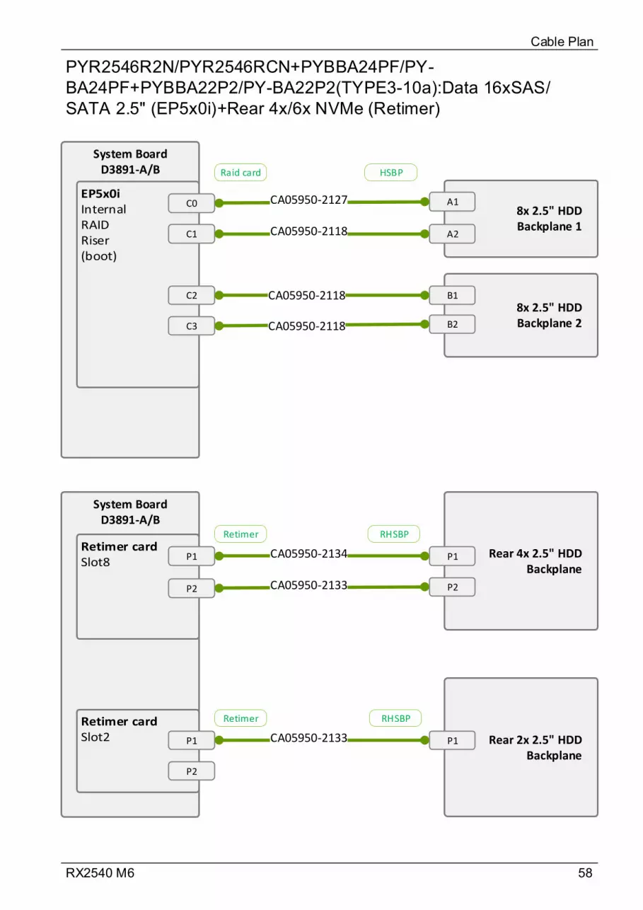
58RX2540 M6
PYR2546R2N/PYR2546RCN+PYBBA24PF/PY-BA24PF+PYBBA22P2/PY-BA22P2(TYPE3-10a):Data 16xSAS/SATA 2.5" (EP5x0i)+Rear 4x/6x NVMe (Retimer)
Cable Plan
System BoardD3891-A/B
C0
C1
8x 2.5" HDD Backplane 1
A1
A2CA05950-2118
CA05950-2127
8x 2.5" HDD Backplane 2
B1
B2
C2
C3
CA05950-2118
CA05950-2118
System BoardD3891-A/B
P1
P2
Rear 4x 2.5" HDD Backplane
P1CA05950-2134
Rear 2x 2.5" HDD Backplane
P1
CA05950-2133 P2
P1
P2
CA05950-2133
Raid card HSBP
Retimer RHSBP
Retimer RHSBP
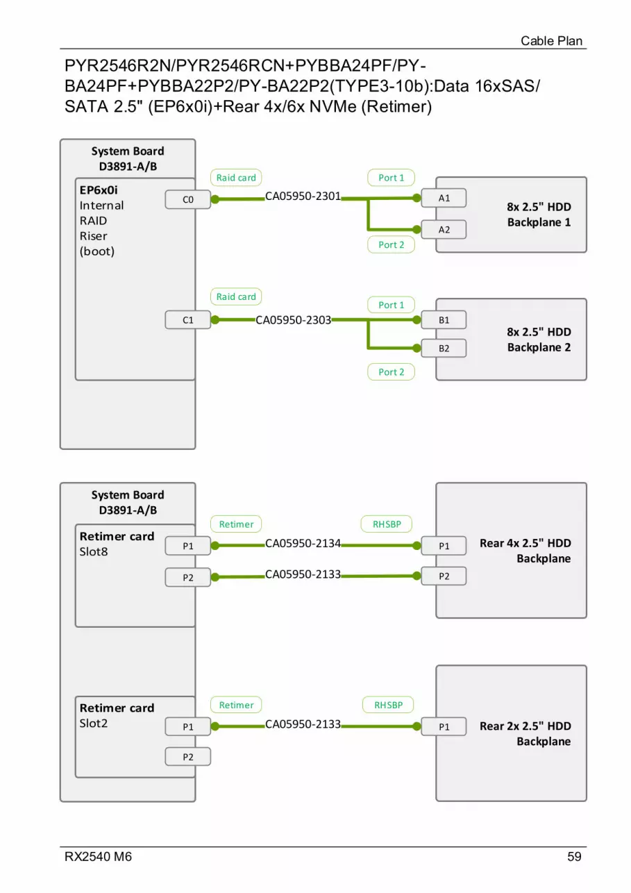
59RX2540 M6
PYR2546R2N/PYR2546RCN+PYBBA24PF/PY-BA24PF+PYBBA22P2/PY-BA22P2(TYPE3-10b):Data 16xSAS/SATA 2.5" (EP6x0i)+Rear 4x/6x NVMe (Retimer)
Cable Plan
System BoardD3891-A/B
C08x 2.5" HDD Backplane 1
A1
A2
CA05950-2301
8x 2.5" HDD Backplane 2
B1
B2
C1 CA05950-2303
System BoardD3891-A/B
P1
P2
Rear 4x 2.5" HDD Backplane
P1CA05950-2134
Rear 2x 2.5" HDD Backplane
P1
CA05950-2133 P2
P1
P2
CA05950-2133
Port 1
Port 2
Port 1
Port 2
Raid card
Raid card
Retimer RHSBP
Retimer RHSBP
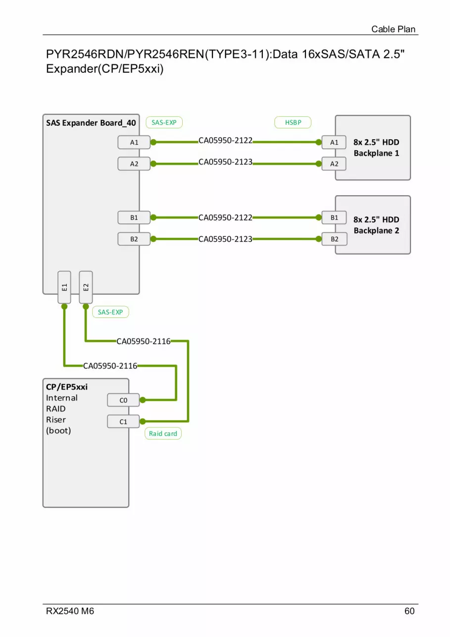
60RX2540 M6
PYR2546RDN/PYR2546REN(TYPE3-11):Data 16xSAS/SATA 2.5" Expander(CP/EP5xxi)
Cable Plan
SAS Expander Board_40
A1 8x 2.5" HDD Backplane 1
A1
CA05950-2123
CA05950-2122
8x 2.5" HDD Backplane 2
C0
C1
CA05950-2116
CA05950-2116
A2
B1
B2
A2
B1
B2
CA05950-2122
CA05950-2123
E1
E2
Raid card
SAS-EXP
SAS-EXP HSBP
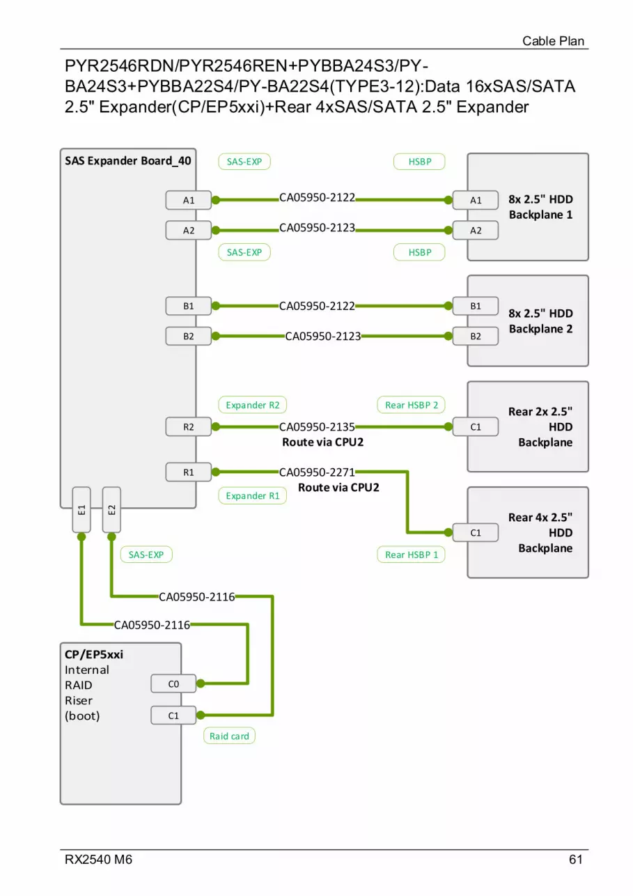
61RX2540 M6
PYR2546RDN/PYR2546REN+PYBBA24S3/PY-BA24S3+PYBBA22S4/PY-BA22S4(TYPE3-12):Data 16xSAS/SATA 2.5" Expander(CP/EP5xxi)+Rear 4xSAS/SATA 2.5" Expander
Cable Plan
SAS Expander Board_40
A1 8x 2.5" HDD Backplane 1
A1
CA05950-2123
CA05950-2122
8x 2.5" HDD Backplane 2
C0
E1
E2
C1
CA05950-2116
CA05950-2116
A2
B1
B2
A2
B1
B2
CA05950-2122
CA05950-2123
R2
R1
Rear 2x 2.5" HDD
Backplane
Rear 4x 2.5" HDD
Backplane
C1
C1
CA05950-2135
CA05950-2271
Raid card
SAS-EXP
SAS-EXP HSBP
Expander R2 Rear HSBP 2
SAS-EXP HSBP
Expander R1
Rear HSBP 1
Route via CPU2
Route via CPU2

62RX2540 M6
PYR2546RDN/PYR2546REN+PYBBA24PF/PY-BA24PF+PYBBA22P2/PY-BA22P2(TYPE3-13):Data 16xSAS/SATA 2.5" Expander(CP/EP5xxi)+Rear 4x/6x NVMe (Retimer)
Cable Plan
SAS Expander Board_40
A18x 2.5" HDD Backplane 1
A1
CA05950-2123
CA05950-2122
8x 2.5" HDD Backplane 2
C0
E1
E2
C1
CA05950-2116
CA05950-2116
A2
B1
B2
A2
B1
B2
CA05950-2122
CA05950-2123
System BoardD3891-A/B
P1
P2
Rear 4x 2.5" HDD
BackplaneP1CA05950-2134
Rear 2x 2.5" HDD
BackplaneP1
CA05950-2133 P2
P1
P2
CA05950-2133
Raid card
SAS-EXP
SAS-EXP HSBP
Retimer RHSBP
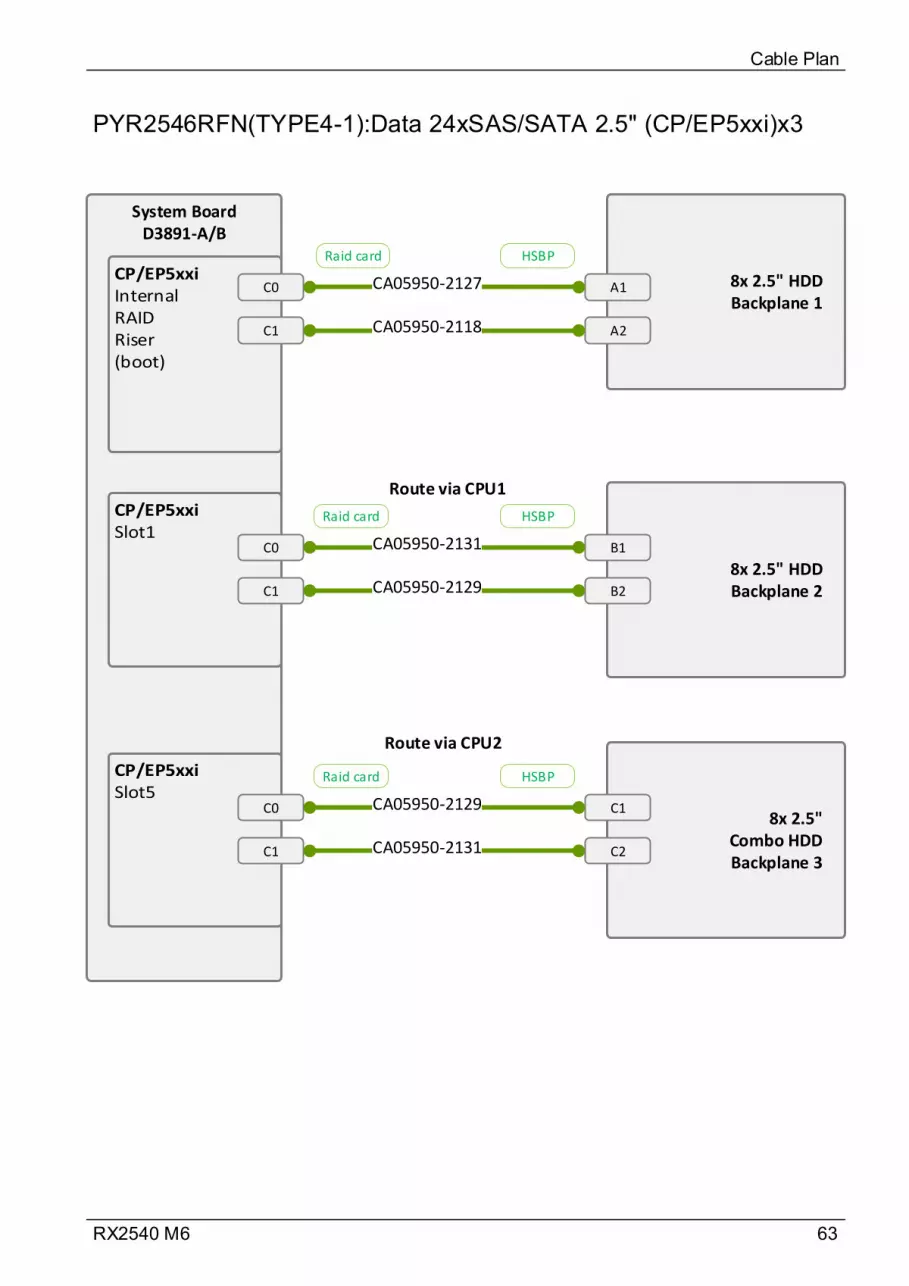
63RX2540 M6
PYR2546RFN(TYPE4-1):Data 24xSAS/SATA 2.5" (CP/EP5xxi)x3
Cable Plan
System BoardD3891-A/B
C0
C1
8x 2.5" HDD Backplane 1
A1
A2CA05950-2118
CA05950-2127
8x 2.5" HDD Backplane 2
B1
B2
C0
C1
CA05950-2131
CA05950-2129
8x 2.5" Combo HDD Backplane 3
C1
C2
C0
C1
CA05950-2129
CA05950-2131
Raid card HSBP
Raid card HSBP
Raid card HSBP
Route via CPU1
Route via CPU2
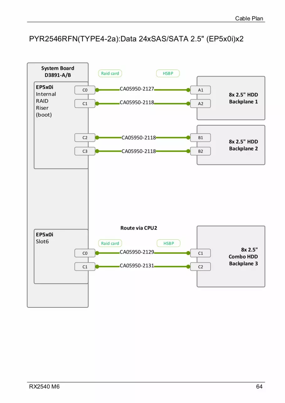
64RX2540 M6
PYR2546RFN(TYPE4-2a):Data 24xSAS/SATA 2.5" (EP5x0i)x2
Cable Plan
System BoardD3891-A/B
C0
C1
8x 2.5" HDD Backplane 1
A1
A2CA05950-2118
CA05950-2127
8x 2.5" HDD Backplane 2
B1
B2
C2
C3
CA05950-2118
CA05950-2118
8x 2.5" Combo HDD Backplane 3
C1
C2
C0
C1
CA05950-2129
CA05950-2131
Raid card HSBP
Raid card HSBP
Route via CPU2

65RX2540 M6
PYR2546RFN(TYPE4-2b):Data 24xSAS/STA 2.5" (EP6x0i)x2
Cable Plan
System BoardD3891-A/B
C08x 2.5" HDD Backplane 1
A1
A2
CA05950-2301
8x 2.5" HDD Backplane 2
B1
B2
C1 CA05950-2303
8x 2.5" Combo HDD Backplane 3
C1
C2
C0 CA05950-2306
Port 1
Port 2
Port 1
Port 2
Port 1
Port 2
Raid card
Raid card
Raid card
Route via CPU2
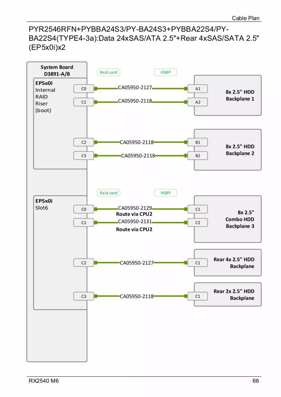
66RX2540 M6
PYR2546RFN+PYBBA24S3/PY-BA24S3+PYBBA22S4/PY-BA22S4(TYPE4-3a):Data 24xSAS/ATA 2.5"+Rear 4xSAS/SATA 2.5" (EP5x0i)x2
Cable Plan
System BoardD3891-A/B
C0
C1
8x 2.5" HDD Backplane 1
A1
A2CA05950-2118
CA05950-2127
8x 2.5" HDD Backplane 2
B1
B2
C2
C3
CA05950-2118
CA05950-2118
8x 2.5" Combo HDD Backplane 3
C1
C2
C0
C1
CA05950-2129
CA05950-2131
Rear 4x 2.5" HDD Backplane
C1
Rear 2x 2.5" HDD BackplaneC1
CA05950-2127C2
C3 CA05950-2118
Raid card HSBP
Raid card HSBP
Route via CPU2
Route via CPU2
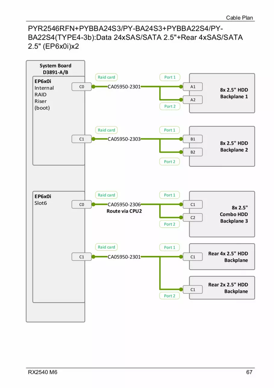
67RX2540 M6
PYR2546RFN+PYBBA24S3/PY-BA24S3+PYBBA22S4/PY-BA22S4(TYPE4-3b):Data 24xSAS/SATA 2.5"+Rear 4xSAS/SATA 2.5" (EP6x0i)x2
Cable Plan
System BoardD3891-A/B
C08x 2.5" HDD Backplane 1
A1
A2
CA05950-2301
8x 2.5" HDD Backplane 2
B1
B2
C1 CA05950-2303
8x 2.5" Combo HDD Backplane 3
C1
C2
C0 CA05950-2306
Rear 4x 2.5" HDD Backplane
C1
Rear 2x 2.5" HDD BackplaneC1
C1 CA05950-2301
Port 1
Port 2
Port 1
Port 2
Port 1
Port 2
Port 1
Port 2
Raid card
Raid card
Raid card
Raid card
Route via CPU2
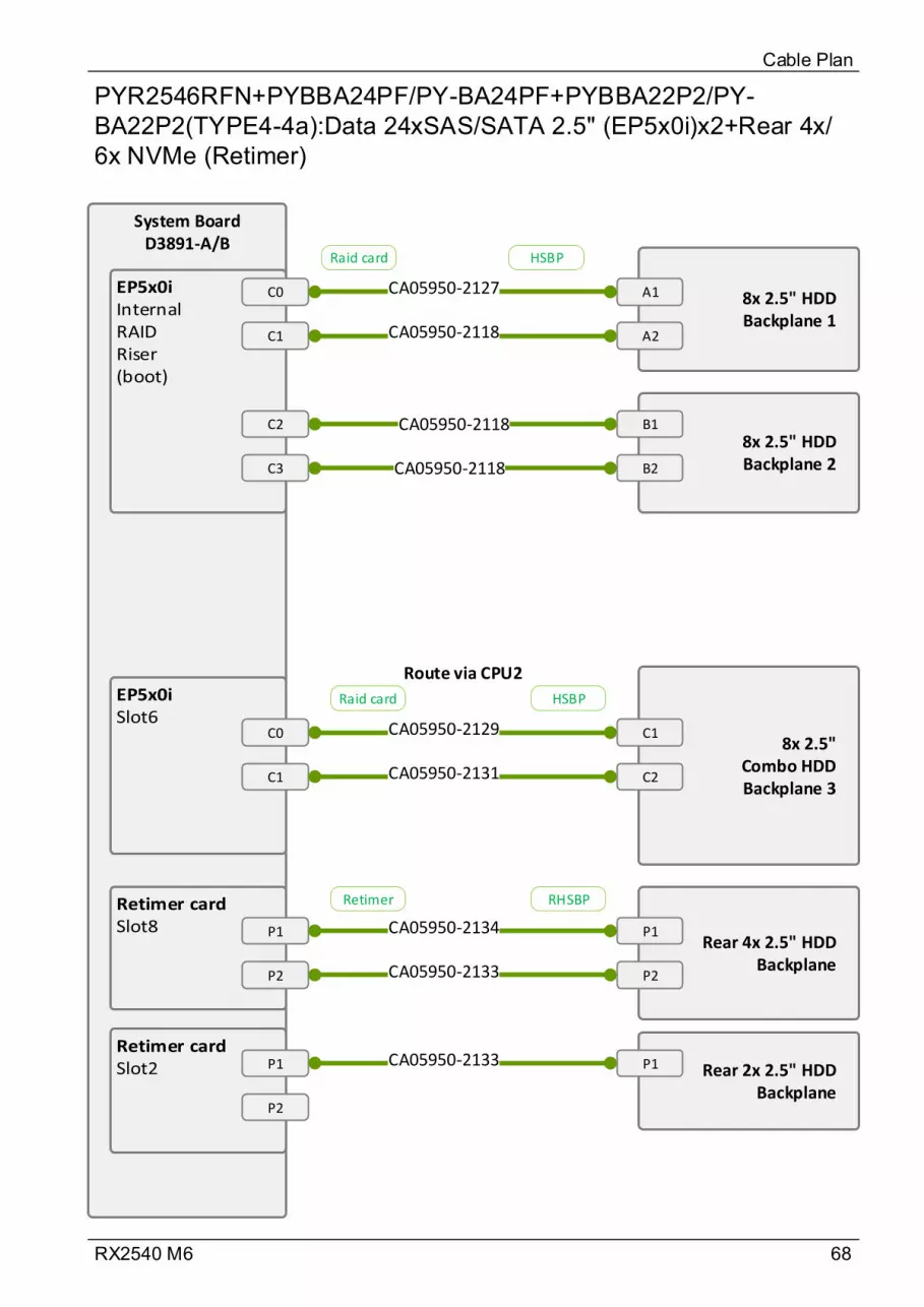
68RX2540 M6
PYR2546RFN+PYBBA24PF/PY-BA24PF+PYBBA22P2/PY-BA22P2(TYPE4-4a):Data 24xSAS/SATA 2.5" (EP5x0i)x2+Rear 4x/6x NVMe (Retimer)
Cable Plan
System BoardD3891-A/B
C0
C1
8x 2.5" HDD Backplane 1
A1
A2CA05950-2118
CA05950-2127
8x 2.5" HDD Backplane 2
B1
B2
C2
C3
CA05950-2118
CA05950-2118
8x 2.5" Combo HDD Backplane 3
C1
C2
C0
C1
CA05950-2129
CA05950-2131
P1
P2
Rear 4x 2.5" HDD Backplane
P1CA05950-2134
Rear 2x 2.5" HDD Backplane
P1
CA05950-2133 P2
P1
P2
CA05950-2133
Raid card HSBP
Raid card HSBP
Retimer RHSBP
Route via CPU2
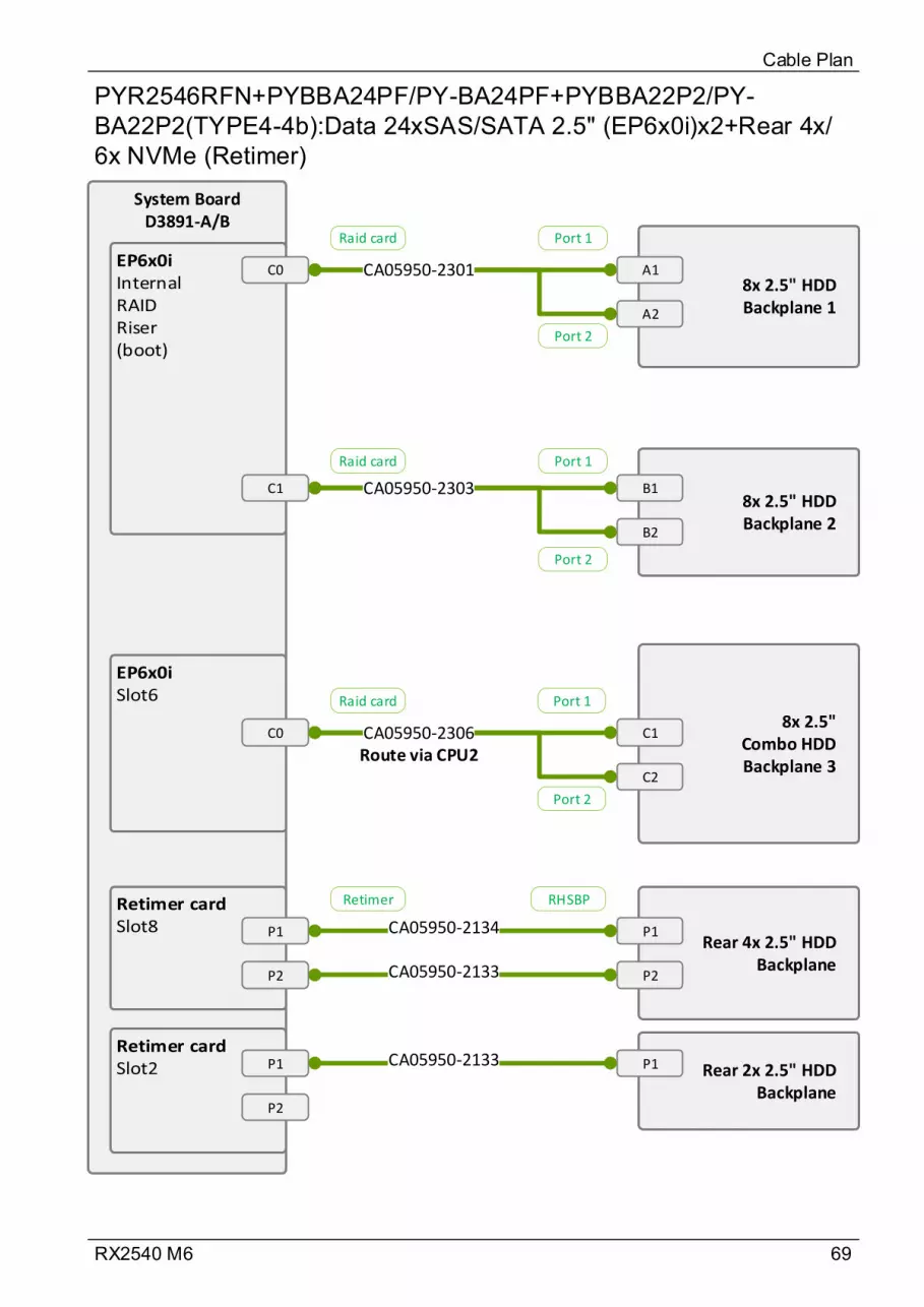
69RX2540 M6
PYR2546RFN+PYBBA24PF/PY-BA24PF+PYBBA22P2/PY-BA22P2(TYPE4-4b):Data 24xSAS/SATA 2.5" (EP6x0i)x2+Rear 4x/6x NVMe (Retimer)
Cable Plan
System BoardD3891-A/B
C08x 2.5" HDD Backplane 1
A1
A2
CA05950-2301
8x 2.5" HDD Backplane 2
B1
B2
C1 CA05950-2303
8x 2.5" Combo HDD Backplane 3
C1
C2
C0 CA05950-2306
Port 1
Port 2
Port 1
Port 2
Port 1
Port 2
P1
P2
Rear 4x 2.5" HDD Backplane
P1CA05950-2134
Rear 2x 2.5" HDD Backplane
P1
CA05950-2133 P2
P1
P2
CA05950-2133
Retimer RHSBP
Raid card
Raid card
Raid card
Route via CPU2

70RX2540 M6
PYR2546RFN(TYPE4-5):Data 8x2.5" SATA Onboard+8x2.5" NVMe Onboard
Cable Plan
System BoardD3891-A/B
SATA 0-3/4-7
8x 2.5" HDD Backplane 1A1
A2
CA05950-2121
A1
A2
8x 2.5" Combo HDD Backplane 3
P1
P2
CA05950-2119
CA05950-2119
SLIMLINE 1
SLIMLINE 2
SLIMLINE 3
SLIMLINE 4
P3
P4
CA05950-2120
CA05950-2120
MB
MB Combo HSBP
Route via CPU1
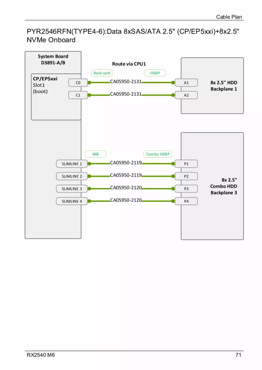
71RX2540 M6
PYR2546RFN(TYPE4-6):Data 8xSAS/ATA 2.5" (CP/EP5xxi)+8x2.5" NVMe Onboard
Cable Plan
System BoardD3891-A/B
C0
C1
8x 2.5" HDD Backplane 1
A1
A2CA05950-2131
CA05950-2131
8x 2.5" Combo HDD Backplane 3
P1
P2
CA05950-2119
CA05950-2119
SLIMLINE 1
SLIMLINE 2
SLIMLINE 3
SLIMLINE 4
P3
P4
CA05950-2120
CA05950-2120
Raid card HSBP
MB Combo HSBP
Route via CPU1
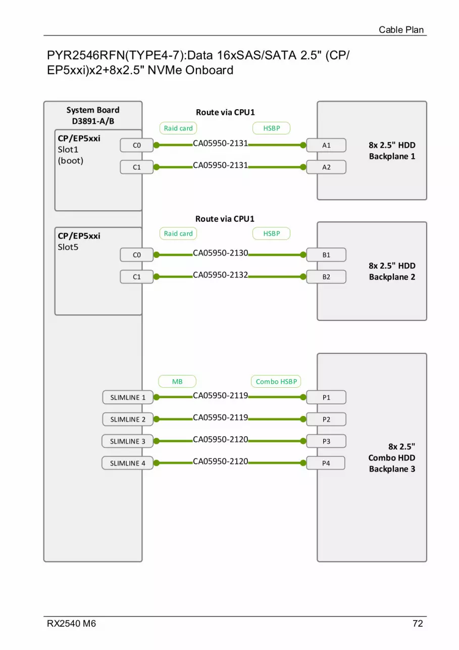
72RX2540 M6
PYR2546RFN(TYPE4-7):Data 16xSAS/SATA 2.5" (CP/EP5xxi)x2+8x2.5" NVMe Onboard
Cable Plan
System BoardD3891-A/B
C0
C1
8x 2.5" HDD Backplane 2
CA05950-2131
CA05950-2131
8x 2.5" Combo HDD Backplane 3
P1
P2
CA05950-2119
CA05950-2119
SLIMLINE 1
SLIMLINE 2
SLIMLINE 3
SLIMLINE 4
P3
P4
CA05950-2120
CA05950-2120
8x 2.5" HDD Backplane 1
B1
B2
A1
A2
C0
C1 CA05950-2132
CA05950-2130
Raid card HSBP
Raid card HSBP
MB Combo HSBP
Route via CPU1
Route via CPU1

73RX2540 M6
PYR2546RFN+PYBBA24PF/PY-BA24PF+PYBBA22P2/PY-BA22P2(TYPE4-8):Data 16xSAS/SATA 2.5" (CP/EP5xxi)x2+8x2.5" NVMe Onboard+Rear 4x/6x NVMe (Retimer)
Cable Plan
System BoardD3891-A/B
C0
C1
8x 2.5" HDD Backplane 2
CA05950-2131
CA05950-2131
8x 2.5" Combo HDD Backplane 3
P1
P2
CA05950-2119
CA05950-2119
SLIMLINE 1
SLIMLINE 2
SLIMLINE 3
SLIMLINE 4
P3
P4
CA05950-2120
CA05950-2120
8x 2.5" HDD Backplane 1
B1
B2
A1
A2
C0
C1 CA05950-2132
CA05950-2130
P1
P2
Rear 4x 2.5" HDD Backplane
P1CA05950-2134
Rear 2x 2.5" HDD Backplane
P1
CA05950-2133 P2
P1
P2
CA05950-2133
Raid card HSBP
Raid card HSBP
MB Combo HSBP
Retimer RHSBP
Route via CPU1
Route via CPU1

74RX2540 M6
PYR2546RFN(TYPE4-9a):Data 16xSAS/SATA 2.5" (EP5x0i)+8x2.5" NVMe Onboard
Cable Plan
System BoardD3891-A/B
(boot)
C0
C1
8x 2.5" HDD Backplane 2
CA05950-2131
CA05950-2131
8x 2.5" Combo HDD Backplane 3
P1
P2
CA05950-2119
CA05950-2119
SLIMLINE 1
SLIMLINE 2
SLIMLINE 3
SLIMLINE 4
P3
P4
CA05950-2120
CA05950-2120
8x 2.5" HDD Backplane 1
B1
B2
A1
A2
C2
C3 CA05950-2129
CA05950-2131
Raid card HSBP
MB Combo HSBP
Route via CPU1
Route via CPU1
Raid card HSBP
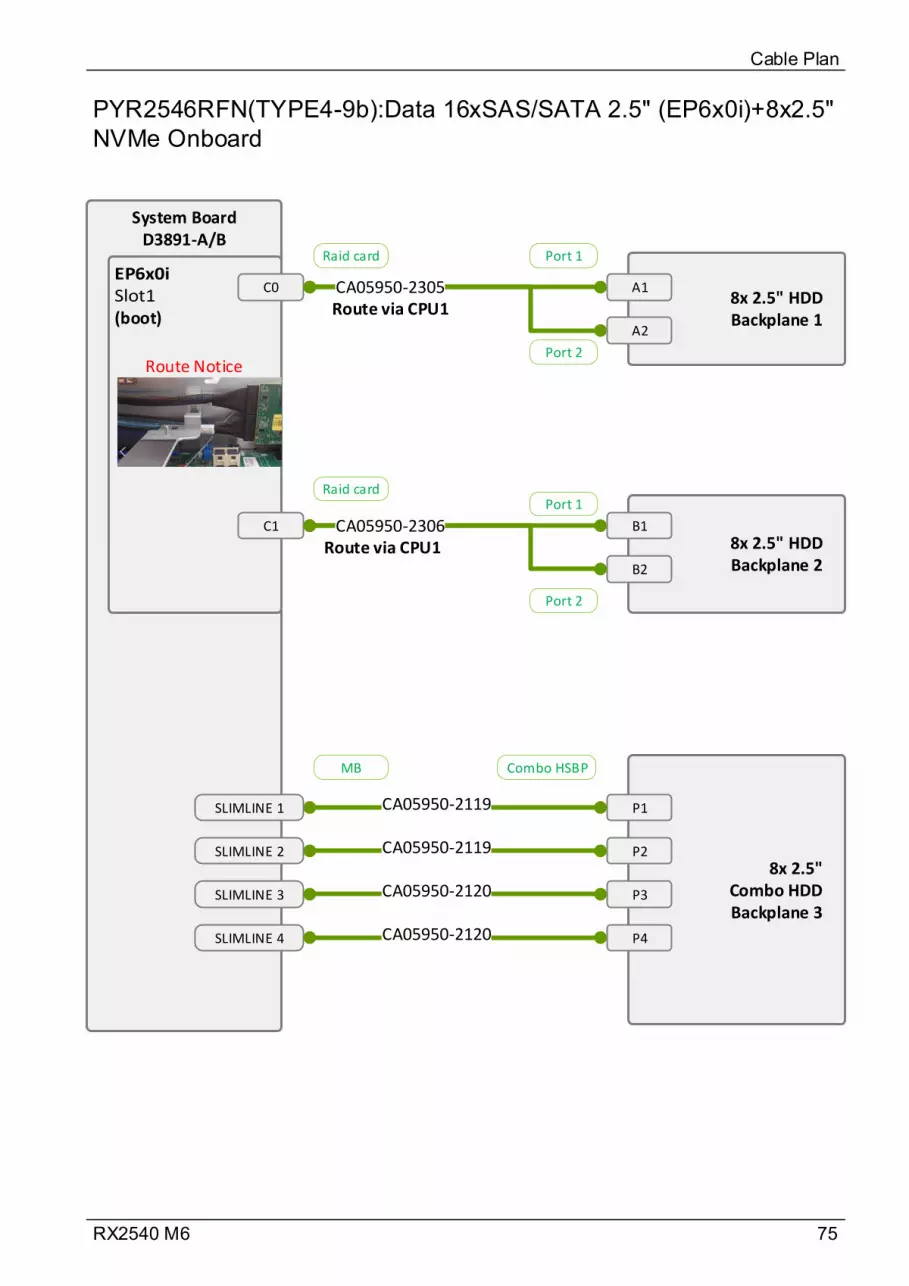
75RX2540 M6
PYR2546RFN(TYPE4-9b):Data 16xSAS/SATA 2.5" (EP6x0i)+8x2.5" NVMe Onboard
Cable Plan
System BoardD3891-A/B
(boot)
C0
8x 2.5" HDD Backplane 2
CA05950-2305
8x 2.5" Combo HDD Backplane 3
P1
P2
CA05950-2119
CA05950-2119
SLIMLINE 1
SLIMLINE 2
SLIMLINE 3
SLIMLINE 4
P3
P4
CA05950-2120
CA05950-2120
8x 2.5" HDD Backplane 1
B1
B2
A1
A2
C1 CA05950-2306
Port 1
Port 2
Port 1
Port 2
Raid card
Raid card
MB Combo HSBP
Route via CPU1
Route via CPU1
Route Notice
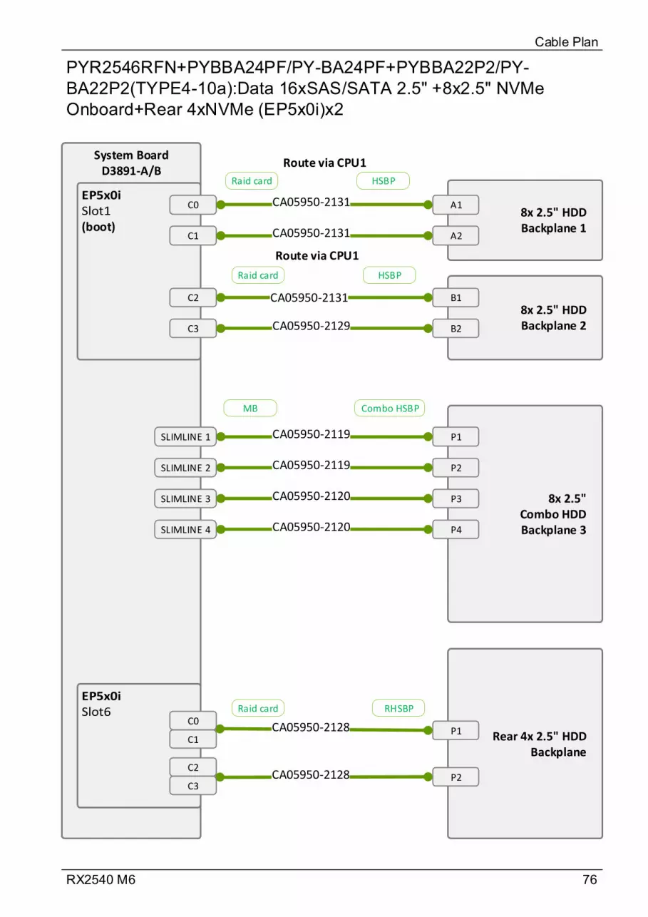
76RX2540 M6
PYR2546RFN+PYBBA24PF/PY-BA24PF+PYBBA22P2/PY-BA22P2(TYPE4-10a):Data 16xSAS/SATA 2.5" +8x2.5" NVMe Onboard+Rear 4xNVMe (EP5x0i)x2
Cable Plan
Rear 4x 2.5" HDD Backplane
P1CA05950-2128
P2CA05950-2128
System BoardD3891-A/B
(boot)
C0
C1
8x 2.5" HDD Backplane 2
CA05950-2131
CA05950-2131
8x 2.5" Combo HDD Backplane 3
P1
P2
CA05950-2119
CA05950-2119
SLIMLINE 1
SLIMLINE 2
SLIMLINE 3
SLIMLINE 4
P3
P4
CA05950-2120
CA05950-2120
8x 2.5" HDD Backplane 1
B1
B2
A1
A2
C2
C3 CA05950-2129
CA05950-2131
C1
C0
C2
C3
Raid card HSBP
MB Combo HSBP
Raid card RHSBP
Raid card HSBP
Route via CPU1
Route via CPU1
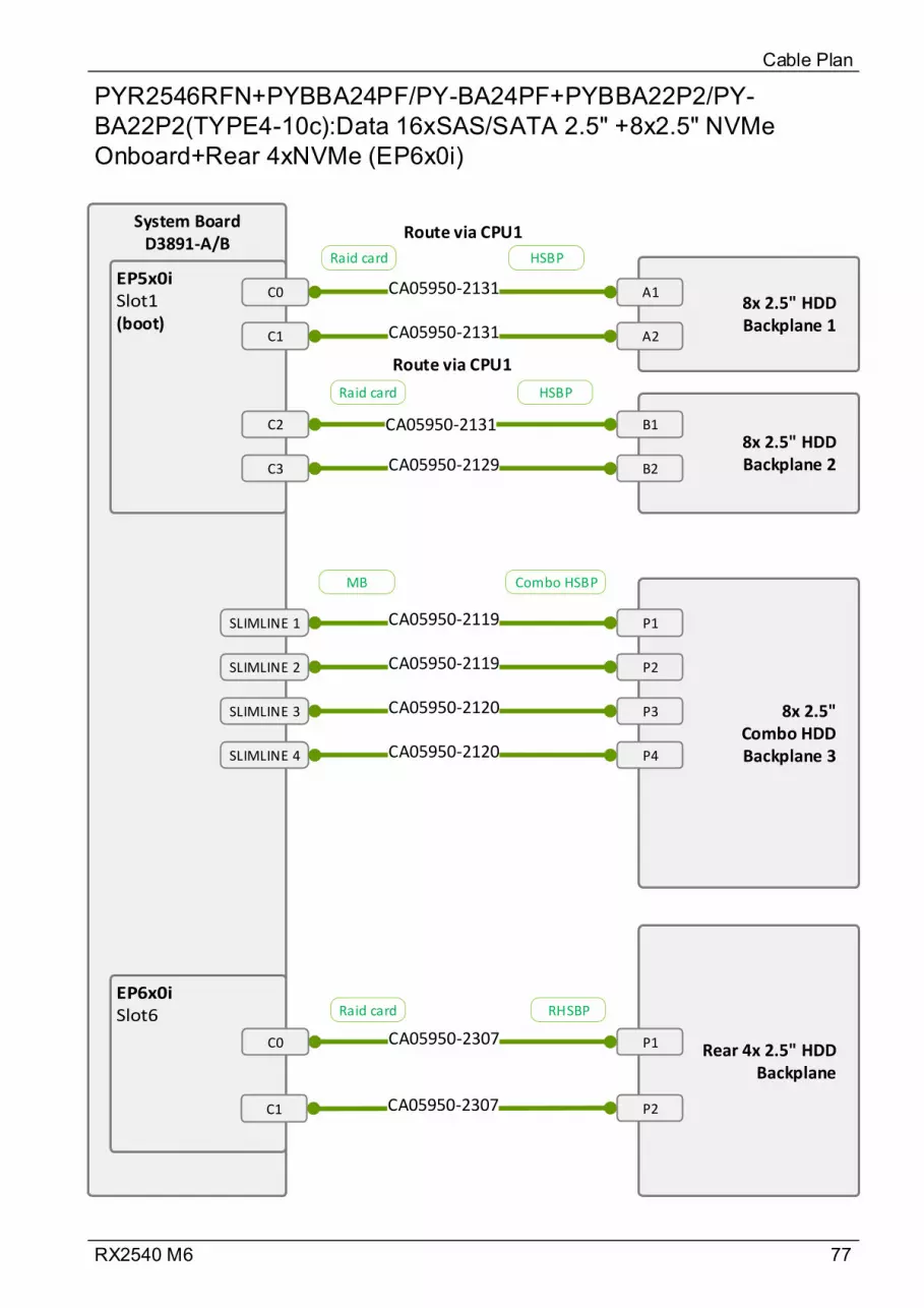
77RX2540 M6
PYR2546RFN+PYBBA24PF/PY-BA24PF+PYBBA22P2/PY-BA22P2(TYPE4-10c):Data 16xSAS/SATA 2.5" +8x2.5" NVMe Onboard+Rear 4xNVMe (EP6x0i)
Cable Plan
Rear 4x 2.5" HDD Backplane
P1
P2
System BoardD3891-A/B
(boot)
C0
C1
8x 2.5" HDD Backplane 2
CA05950-2131
CA05950-2131
8x 2.5" Combo HDD Backplane 3
P1
P2
CA05950-2119
CA05950-2119
SLIMLINE 1
SLIMLINE 2
SLIMLINE 3
SLIMLINE 4
P3
P4
CA05950-2120
CA05950-2120
8x 2.5" HDD Backplane 1
B1
B2
A1
A2
C2
C3 CA05950-2129
CA05950-2131
Raid card HSBP
MB Combo HSBP
Raid card HSBP
Route via CPU1
Route via CPU1
CA05950-2307
CA05950-2307C1
C0
Raid card RHSBP

78RX2540 M6
PYR2546RFN+PYBBA24PF/PY-BA24PF+PYBBA22P2/PY-BA22P2(TYPE4-10b):Data 16xSAS/SATA 2.5"+8x2.5" NVMe Onboard+Rear 4xNVMe (EP6x0i)x2
Cable Plan
Rear 4x 2.5" HDD Backplane
P1CA05950-2307
P2CA05950-2307
System BoardD3891-A/B
(boot)C0
8x 2.5" HDD Backplane 2
CA05950-2305
8x 2.5" Combo HDD Backplane 3
P1
P2
CA05950-2119
CA05950-2119
SLIMLINE 1
SLIMLINE 2
SLIMLINE 3
SLIMLINE 4
P3
P4
CA05950-2120
CA05950-2120
8x 2.5" HDD Backplane 1
B1
B2
A1
A2
C1 CA05950-2306
C1
Port 1
Port 2
Port 1
Port 2
C0
Raid card
Raid card
MB Combo HSBP
Raid card RHSBP
Route via CPU1
Route via CPU1
Route Notice

79RX2540 M6
PYR2546RFN+PYBBA24PF/PY-BA24PF+PYBBA22P2/PY-BA22P2(TYPE4-10d):Data 16xSAS/SATA 2.5"+8x2.5" NVMe Onboard+Rear 4xNVMe (EP5x0i)
Cable Plan
Rear 4x 2.5" HDD Backplane
P1
P2
System BoardD3891-A/B
(boot)C0
8x 2.5" HDD Backplane 2
CA05950-2305
8x 2.5" Combo HDD Backplane 3
P1
P2
CA05950-2119
CA05950-2119
SLIMLINE 1
SLIMLINE 2
SLIMLINE 3
SLIMLINE 4
P3
P4
CA05950-2120
CA05950-2120
8x 2.5" HDD Backplane 1
B1
B2
A1
A2
C1 CA05950-2306
Port 1
Port 2
Port 1
Port 2
Raid card
Raid card
MB Combo HSBP
Route via CPU1
Route via CPU1
Route Notice
CA05950-2128
CA05950-2128
C1
C0
C2
C3
Raid card RHSBP
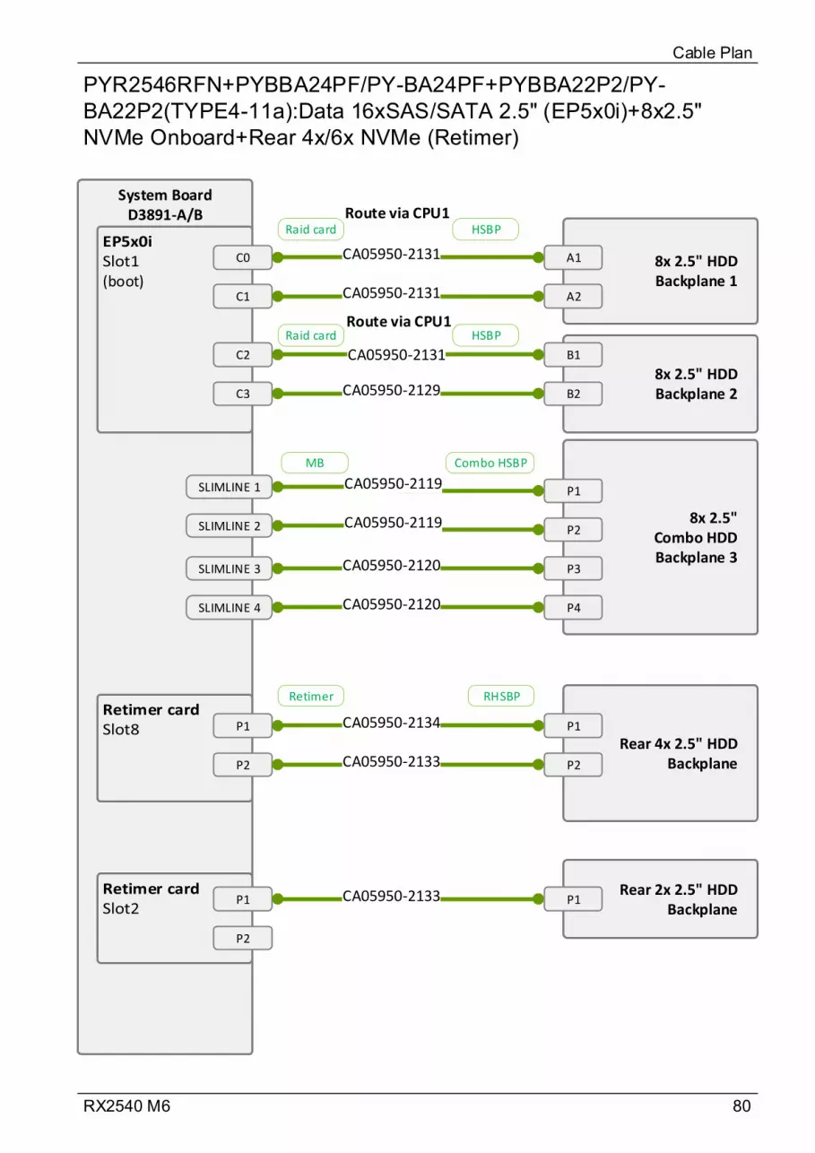
80RX2540 M6
PYR2546RFN+PYBBA24PF/PY-BA24PF+PYBBA22P2/PY-BA22P2(TYPE4-11a):Data 16xSAS/SATA 2.5" (EP5x0i)+8x2.5" NVMe Onboard+Rear 4x/6x NVMe (Retimer)
Cable Plan
System BoardD3891-A/B
(boot)
C0
C1
8x 2.5" HDD Backplane 2
CA05950-2131
CA05950-2131
8x 2.5" Combo HDD Backplane 3
P1
P2
CA05950-2119
CA05950-2119
SLIMLINE 1
SLIMLINE 2
SLIMLINE 3
SLIMLINE 4
P3
P4
CA05950-2120
CA05950-2120
8x 2.5" HDD Backplane 1
B1
B2
A1
A2
C2
C3 CA05950-2129
CA05950-2131
P1
P2
Rear 4x 2.5" HDD Backplane
P1CA05950-2134
Rear 2x 2.5" HDD Backplane
P1
CA05950-2133 P2
P1
P2
CA05950-2133
Raid card HSBP
MB Combo HSBP
Retimer RHSBP
Raid card HSBPRoute via CPU1
Route via CPU1
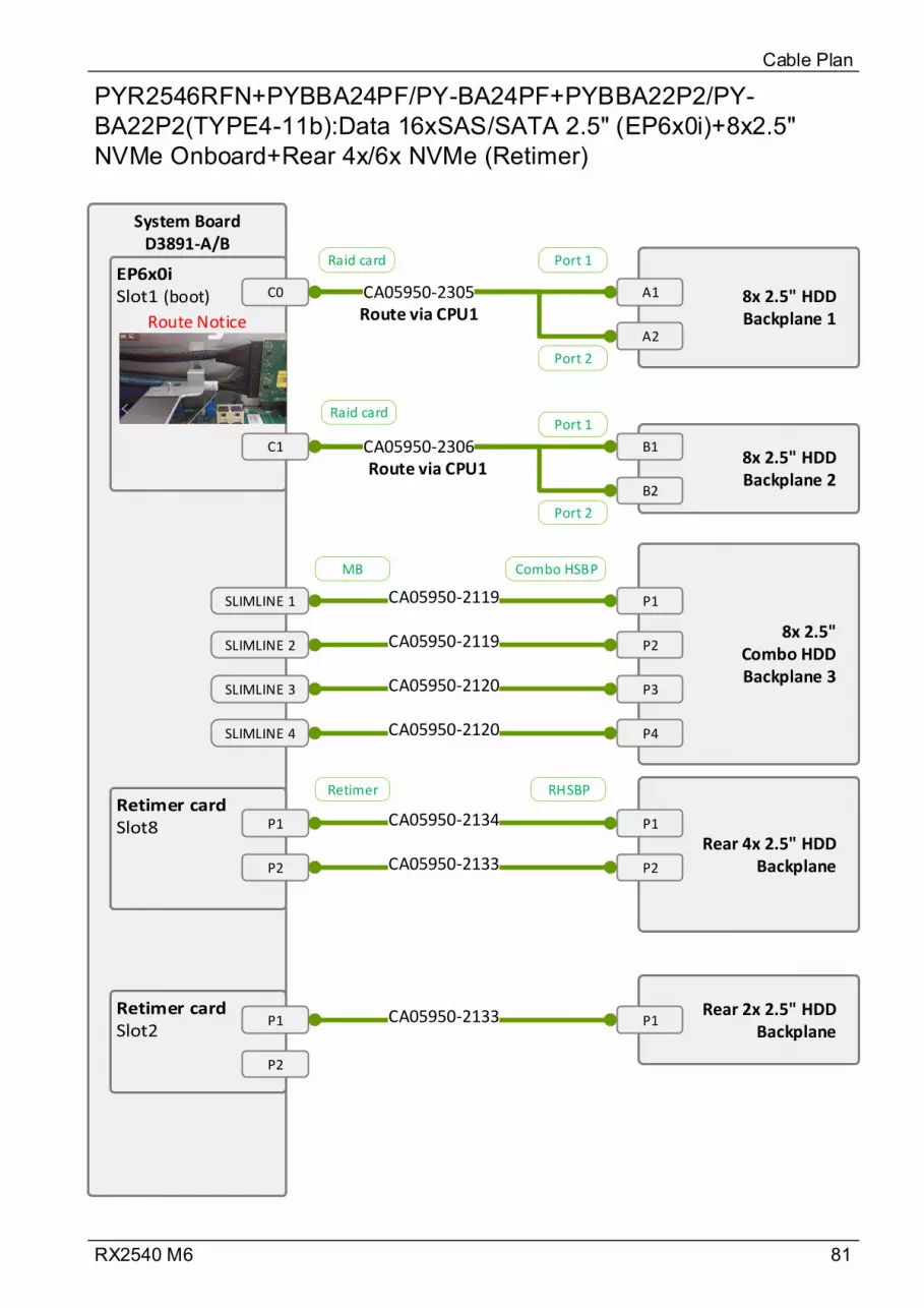
81RX2540 M6
PYR2546RFN+PYBBA24PF/PY-BA24PF+PYBBA22P2/PY-BA22P2(TYPE4-11b):Data 16xSAS/SATA 2.5" (EP6x0i)+8x2.5" NVMe Onboard+Rear 4x/6x NVMe (Retimer)
Cable Plan
System BoardD3891-A/B
(boot) C0
8x 2.5" HDD Backplane 2
CA05950-2305
8x 2.5" Combo HDD Backplane 3
P1
P2
CA05950-2119
CA05950-2119
SLIMLINE 1
SLIMLINE 2
SLIMLINE 3
SLIMLINE 4
P3
P4
CA05950-2120
CA05950-2120
8x 2.5" HDD Backplane 1
B1
B2
A1
A2
C1 CA05950-2306
P1
P2
Rear 4x 2.5" HDD Backplane
P1CA05950-2134
Rear 2x 2.5" HDD Backplane
P1
CA05950-2133 P2
P1
P2
CA05950-2133
Port 1
Port 2
Port 1
Port 2
Raid card
Raid card
MB Combo HSBP
Retimer RHSBP
Route via CPU1
Route via CPU1
Route Notice

82RX2540 M6
PYR2546RGN(TYPE4-12):Data 24xSAS/SATA 2.5" Expander(CP/EP5xxi)
Cable Plan
SAS Expander Board_40
A1 8x 2.5" HDD Backplane 1
A1
CA05950-2123
CA05950-2122
8x 2.5" HDD Backplane 2
C0
E1
E2
C1
CA05950-2116
CA05950-2116
A2
B1
B2
A2
B1
B2
CA05950-2122
CA05950-2123
8x 2.5" Combo HDD Backplane 3
C1
C2
C1 CA05950-2123
CA05950-2123C2
Raid card
SAS-EXP
SAS-EXP HSBP

83RX2540 M6
PYR2546RGN+PYBBA24S3/PY-BA24S3+PYBBA22S4/PY-BA22S4(TYPE4-13):Data 24xSAS/SATA 2.5" Expander(CP/EP5xxi)+Rear 4x/6x 2.5" (Expander)
Cable Plan
SAS Expander Board_40
A1 8x 2.5" HDD Backplane 1
A1
CA05950-2123
CA05950-2122
8x 2.5" HDD Backplane 2
C0
E1 E2
C1
CA05950-2116
CA05950-2116
A2
B1
B2
A2
B1
B2
CA05950-2122
CA05950-2123
8x 2.5" Combo HDD Backplane 3
C1
C2
C1 CA05950-2123
CA05950-2123C2
R1
R2
Rear 4x 2.5" HDD
Backplane
Rear 2x 2.5" HDD
Backplane
C1
C1
CA05950-2271
CA05950-2135
SAS-EXP HSBP
SAS-EXP HSBP
Expander R1 Rear HSBP 1
Expander R2
Rear HSBP 2
Raid card
SAS-EXP
Route via CPU2
Route via CPU2
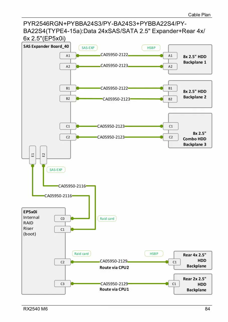
84RX2540 M6
PYR2546RGN+PYBBA24S3/PY-BA24S3+PYBBA22S4/PY-BA22S4(TYPE4-15a):Data 24xSAS/SATA 2.5" Expander+Rear 4x/6x 2.5"(EP5x0i)
Cable Plan
Rear 4x 2.5" HDD
BackplaneC1CA05950-2129
Rear 2x 2.5" HDD
Backplane
C1CA05950-2129
SAS Expander Board_40
A1 8x 2.5" HDD Backplane 1
A1
CA05950-2123
CA05950-2122
8x 2.5" HDD Backplane 2
C0
E1
E2
C1
CA05950-2116
CA05950-2116
A2
B1
B2
A2
B1
B2
CA05950-2122
CA05950-2123
8x 2.5" Combo HDD Backplane 3
C1
C2
C1 CA05950-2123
CA05950-2123C2
C2
C3
Raid card
SAS-EXP
SAS-EXP HSBP
Raid card HSBP
Route via CPU2
Route via CPU1
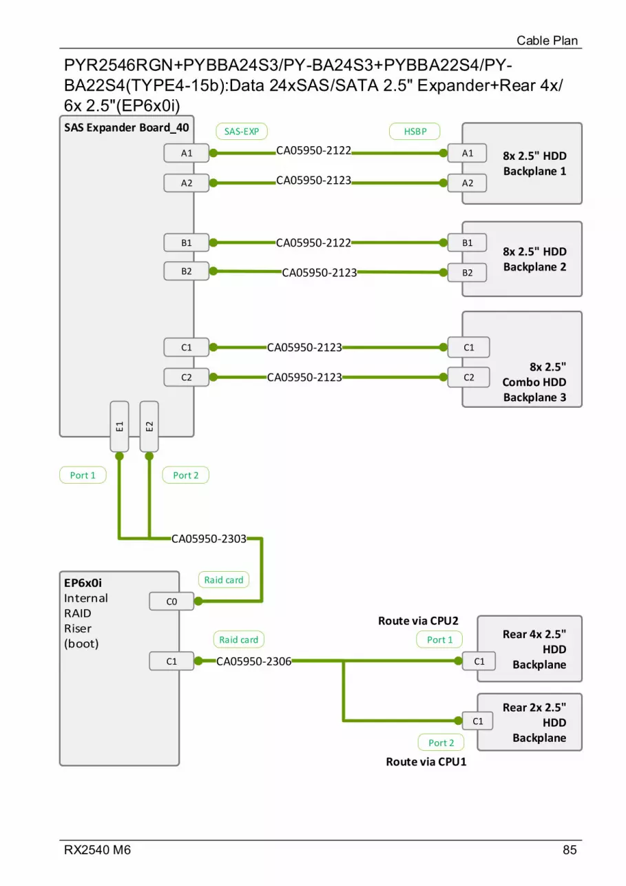
85RX2540 M6
PYR2546RGN+PYBBA24S3/PY-BA24S3+PYBBA22S4/PY-BA22S4(TYPE4-15b):Data 24xSAS/SATA 2.5" Expander+Rear 4x/6x 2.5"(EP6x0i)
Cable Plan
Rear 4x 2.5" HDD
BackplaneC1
Rear 2x 2.5" HDD
Backplane
C1
CA05950-2306
SAS Expander Board_40
A1 8x 2.5" HDD Backplane 1
A1
CA05950-2123
CA05950-2122
8x 2.5" HDD Backplane 2
C0
E1
E2
CA05950-2303
A2
B1
B2
A2
B1
B2
CA05950-2122
CA05950-2123
8x 2.5" Combo HDD Backplane 3
C1
C2
C1 CA05950-2123
CA05950-2123C2
C1
Port 2Port 1
Port 1
Port 2
Raid card
SAS-EXP HSBP
Raid card
Route via CPU2
Route via CPU1
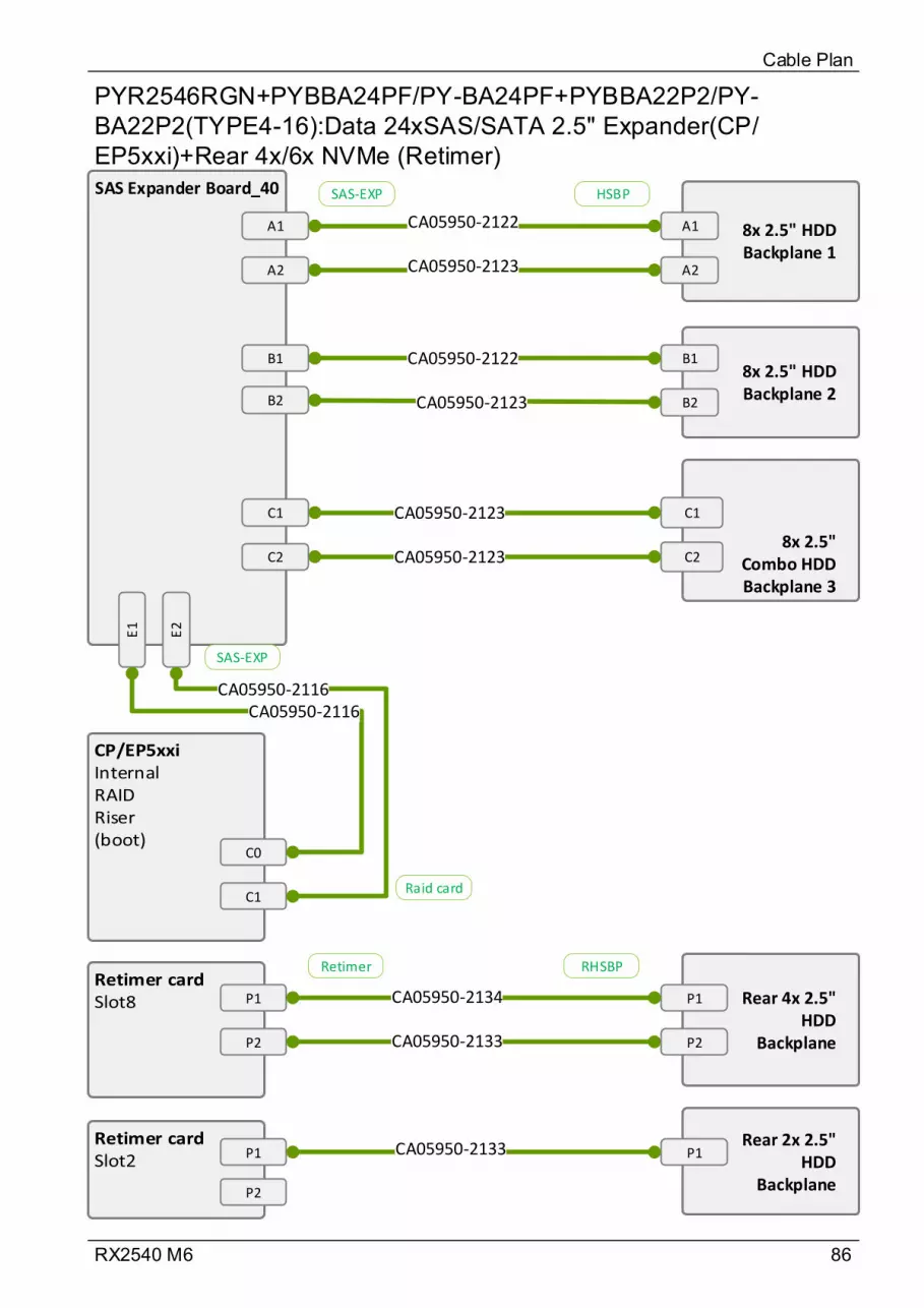
86RX2540 M6
PYR2546RGN+PYBBA24PF/PY-BA24PF+PYBBA22P2/PY-BA22P2(TYPE4-16):Data 24xSAS/SATA 2.5" Expander(CP/EP5xxi)+Rear 4x/6x NVMe (Retimer)
Cable Plan
P1
P2
Rear 4x 2.5" HDD
Backplane
P1CA05950-2134
Rear 2x 2.5" HDD
Backplane
P1
CA05950-2133 P2
P1
P2
CA05950-2133
SAS Expander Board_40
A1 8x 2.5" HDD Backplane 1
A1
CA05950-2123
CA05950-2122
8x 2.5" HDD Backplane 2
C0
E1
E2
C1
CA05950-2116CA05950-2116
A2
B1
B2
A2
B1
B2
CA05950-2122
CA05950-2123
8x 2.5" Combo HDD Backplane 3
C1
C2
C1 CA05950-2123
CA05950-2123C2
Raid card
SAS-EXP
SAS-EXP HSBP
Retimer RHSBP
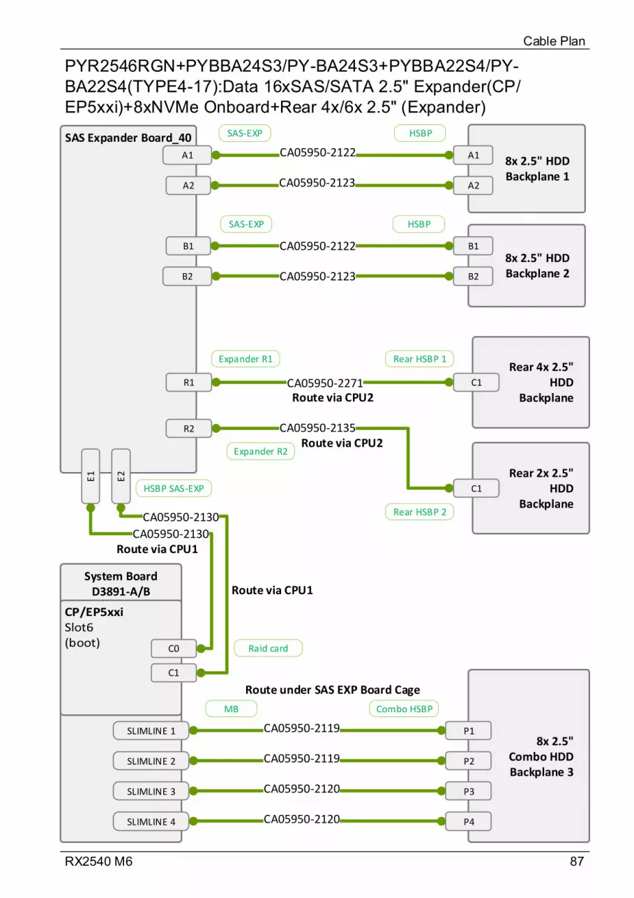
87RX2540 M6
PYR2546RGN+PYBBA24S3/PY-BA24S3+PYBBA22S4/PY-BA22S4(TYPE4-17):Data 16xSAS/SATA 2.5" Expander(CP/EP5xxi)+8xNVMe Onboard+Rear 4x/6x 2.5" (Expander)
Cable Plan
System BoardD3891-A/B
SAS Expander Board_40
A18x 2.5" HDD Backplane 1
A1
CA05950-2123
CA05950-2122
8x 2.5" HDD Backplane 2
E1
E2
CA05950-2130
CA05950-2130
A2
B1
B2
A2
B1
B2
CA05950-2122
CA05950-2123
8x 2.5" Combo HDD Backplane 3
P1
P2
CA05950-2119
CA05950-2119
SLIMLINE 1
SLIMLINE 2
SLIMLINE 3
SLIMLINE 4
P3
P4
CA05950-2120
CA05950-2120
R1
R2
Rear 4x 2.5" HDD
Backplane
Rear 2x 2.5" HDD
Backplane
C1
C1
CA05950-2271
CA05950-2135
SAS-EXP HSBP
SAS-EXP HSBP
Expander R1 Rear HSBP 1
Expander R2
Rear HSBP 2
Raid card
HSBP SAS-EXP
MB Combo HSBP
Route via CPU2
Route via CPU1
Route via CPU2
Route via CPU1
Route under SAS EXP Board Cage
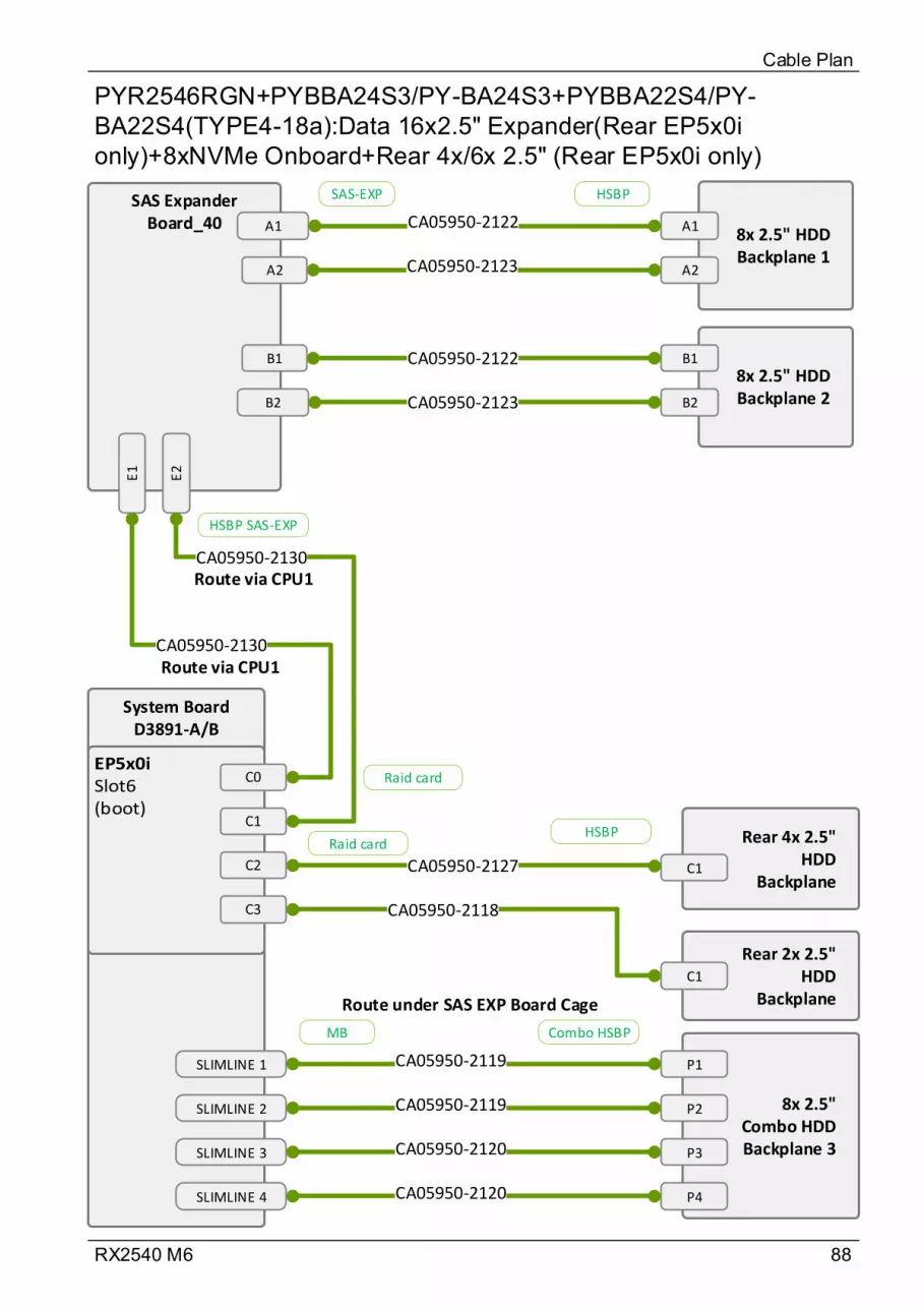
88RX2540 M6
PYR2546RGN+PYBBA24S3/PY-BA24S3+PYBBA22S4/PY-BA22S4(TYPE4-18a):Data 16x2.5" Expander(Rear EP5x0i only)+8xNVMe Onboard+Rear 4x/6x 2.5" (Rear EP5x0i only)
Cable Plan
Rear 4x 2.5" HDD
Backplane
Rear 2x 2.5" HDD
Backplane
C1
C1
CA05950-2127
CA05950-2118
System BoardD3891-A/B
SAS Expander Board_40 A1
8x 2.5" HDD Backplane 1
A1
CA05950-2123
CA05950-2122
8x 2.5" HDD Backplane 2
E1
E2
CA05950-2130
CA05950-2130
A2
B1
B2
A2
B1
B2
CA05950-2122
CA05950-2123
8x 2.5" Combo HDD Backplane 3
P1
P2
CA05950-2119
CA05950-2119
SLIMLINE 1
SLIMLINE 2
SLIMLINE 3
SLIMLINE 4
P3
P4
CA05950-2120
CA05950-2120
SAS-EXP HSBP
Raid card
HSBP SAS-EXP
MB Combo HSBP
Raid cardHSBP
Route via CPU1
Route via CPU1
Route under SAS EXP Board Cage
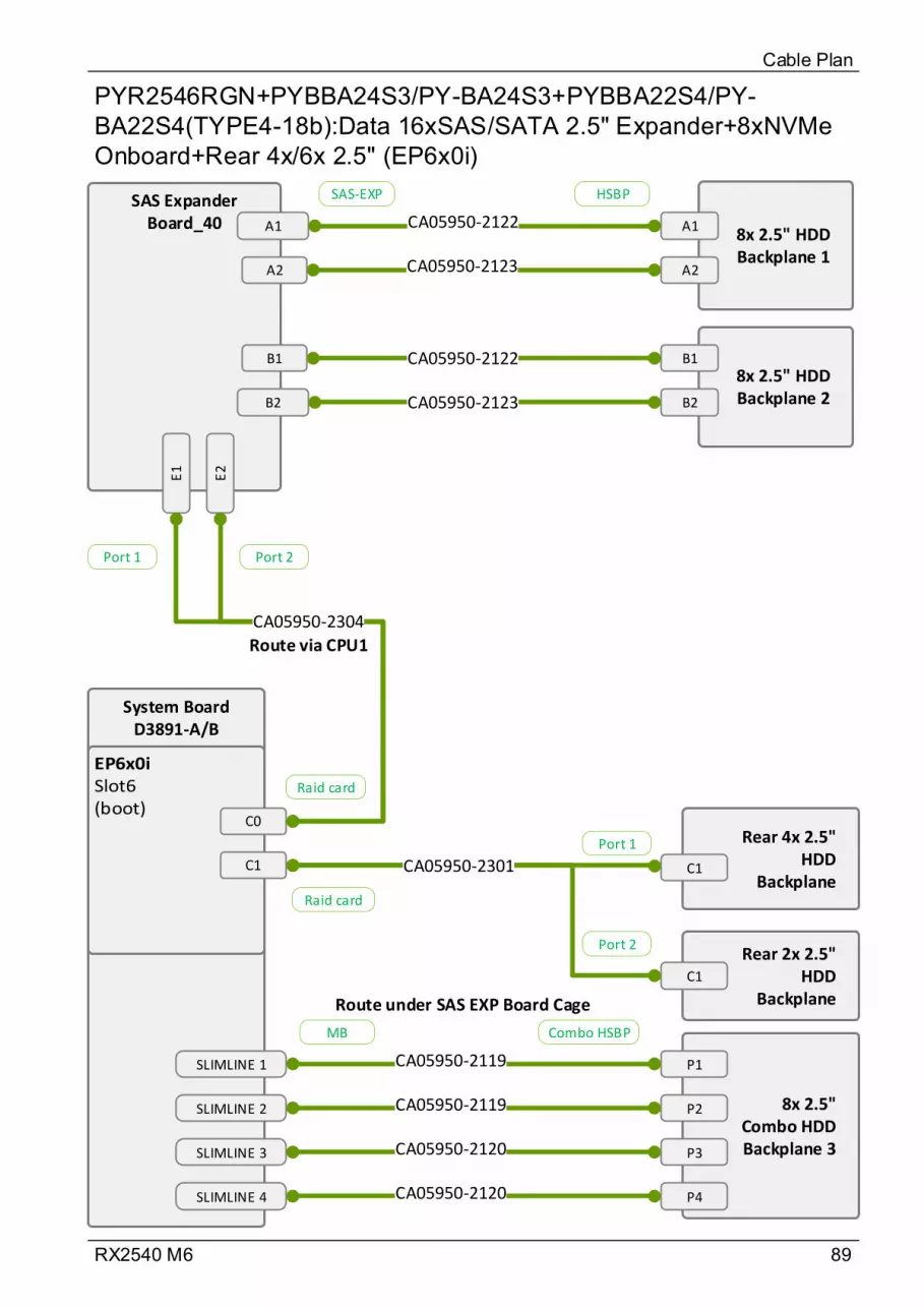
89RX2540 M6
PYR2546RGN+PYBBA24S3/PY-BA24S3+PYBBA22S4/PY-BA22S4(TYPE4-18b):Data 16xSAS/SATA 2.5" Expander+8xNVMe Onboard+Rear 4x/6x 2.5" (EP6x0i)
Cable Plan
Rear 4x 2.5" HDD
Backplane
Rear 2x 2.5" HDD
Backplane
C1
C1
CA05950-2301
System BoardD3891-A/B
SAS Expander Board_40 A1
8x 2.5" HDD Backplane 1
A1
CA05950-2123
CA05950-2122
8x 2.5" HDD Backplane 2
E1
E2
CA05950-2304
A2
B1
B2
A2
B1
B2
CA05950-2122
CA05950-2123
8x 2.5" Combo HDD Backplane 3
P1
P2
CA05950-2119
CA05950-2119
SLIMLINE 1
SLIMLINE 2
SLIMLINE 3
SLIMLINE 4
P3
P4
CA05950-2120
CA05950-2120
Port 2Port 1
Port 1
Port 2
Raid card
Raid card
SAS-EXP HSBP
MB Combo HSBP
Route via CPU1
Route under SAS EXP Board Cage
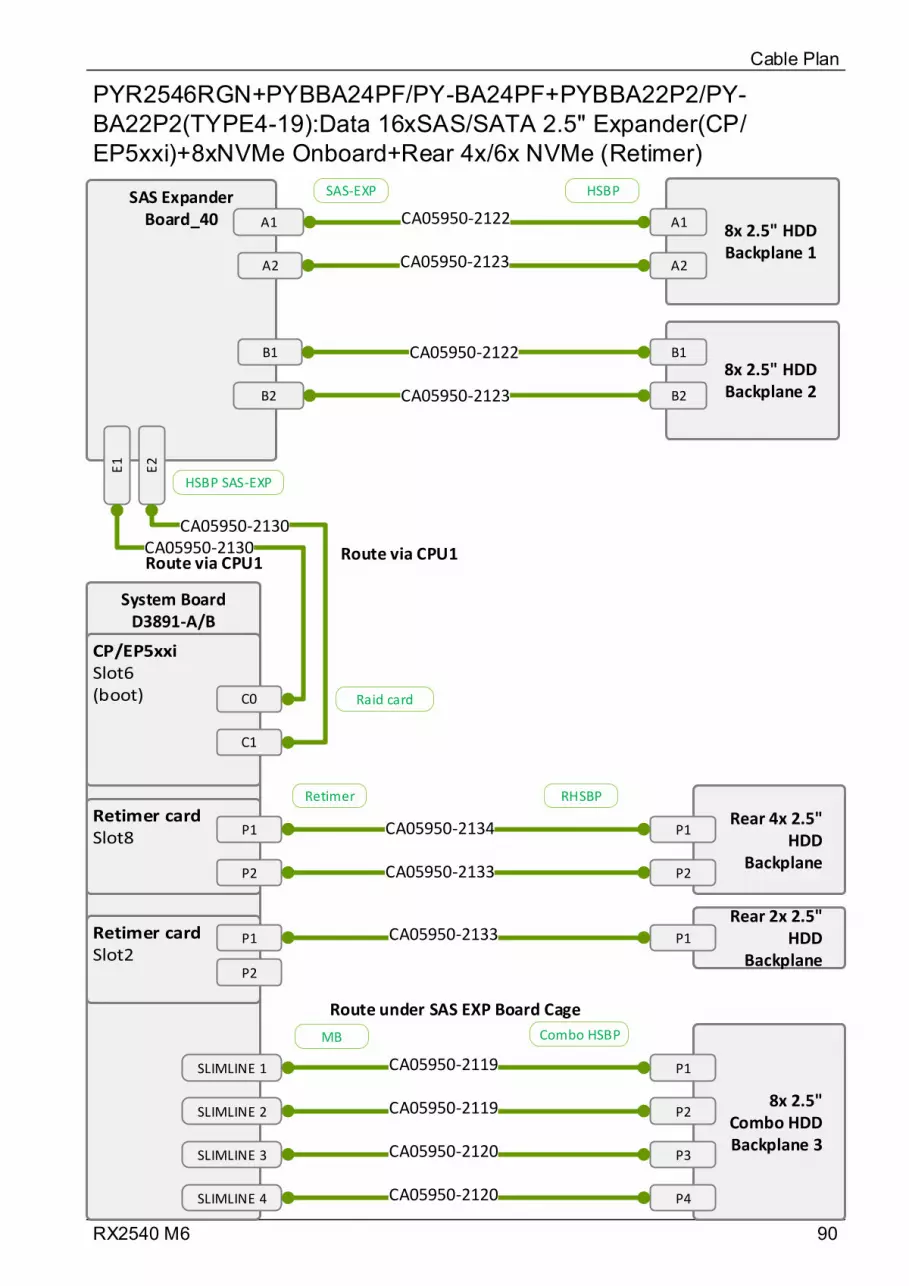
90RX2540 M6
PYR2546RGN+PYBBA24PF/PY-BA24PF+PYBBA22P2/PY-BA22P2(TYPE4-19):Data 16xSAS/SATA 2.5" Expander(CP/EP5xxi)+8xNVMe Onboard+Rear 4x/6x NVMe (Retimer)
Cable Plan
System BoardD3891-A/B
SAS Expander Board_40 A1
8x 2.5" HDD Backplane 1
A1
CA05950-2123
CA05950-2122
8x 2.5" HDD Backplane 2
E1
E2
CA05950-2130CA05950-2130
A2
B1
B2
A2
B1
B2
CA05950-2122
CA05950-2123
8x 2.5" Combo HDD Backplane 3
P1
P2
CA05950-2119
CA05950-2119
SLIMLINE 1
SLIMLINE 2
SLIMLINE 3
SLIMLINE 4
P3
P4
CA05950-2120
CA05950-2120
P1
P2
Rear 4x 2.5" HDD
Backplane
P1CA05950-2134
Rear 2x 2.5" HDD
BackplaneP1
CA05950-2133 P2
P1
P2
CA05950-2133
Raid card
HSBP SAS-EXP
SAS-EXP HSBP
MB Combo HSBP
Retimer RHSBP
Route via CPU1Route via CPU1
Route under SAS EXP Board Cage
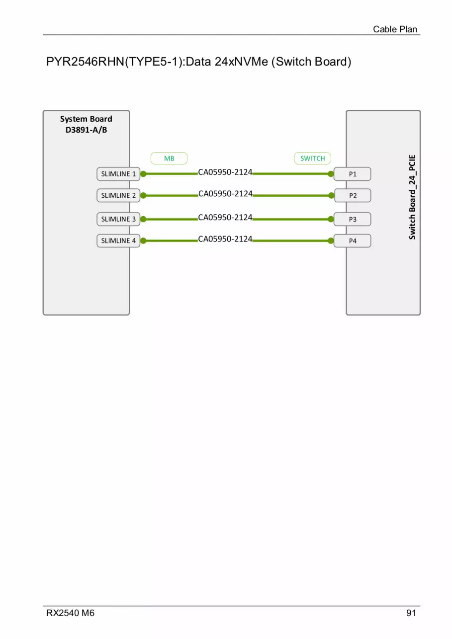
91RX2540 M6
PYR2546RHN(TYPE5-1):Data 24xNVMe (Switch Board)
Cable Plan
System BoardD3891-A/B
Swit
ch B
oa
rd_2
4_
PC
IE
P1
P2
CA05950-2124
CA05950-2124
P3
P4
CA05950-2124
CA05950-2124
MB SWITCH
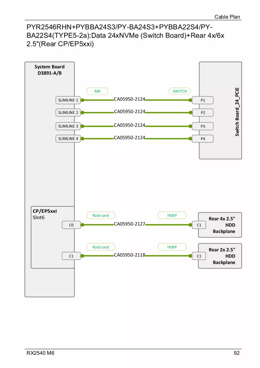
92RX2540 M6
PYR2546RHN+PYBBA24S3/PY-BA24S3+PYBBA22S4/PY-BA22S4(TYPE5-2a):Data 24xNVMe (Switch Board)+Rear 4x/6x 2.5"(Rear CP/EP5xxi)
Cable Plan
Rear 4x 2.5" HDD
BackplaneC1CA05950-2127
Rear 2x 2.5" HDD
Backplane
CA05950-2118
System BoardD3891-A/B
Swit
ch B
oar
d_2
4_PC
IE
C0
C1
P1
P2
CA05950-2124
CA05950-2124
P3
P4
CA05950-2124
CA05950-2124
C1
MB SWITCH
Raid card HSBP
Raid card HSBP
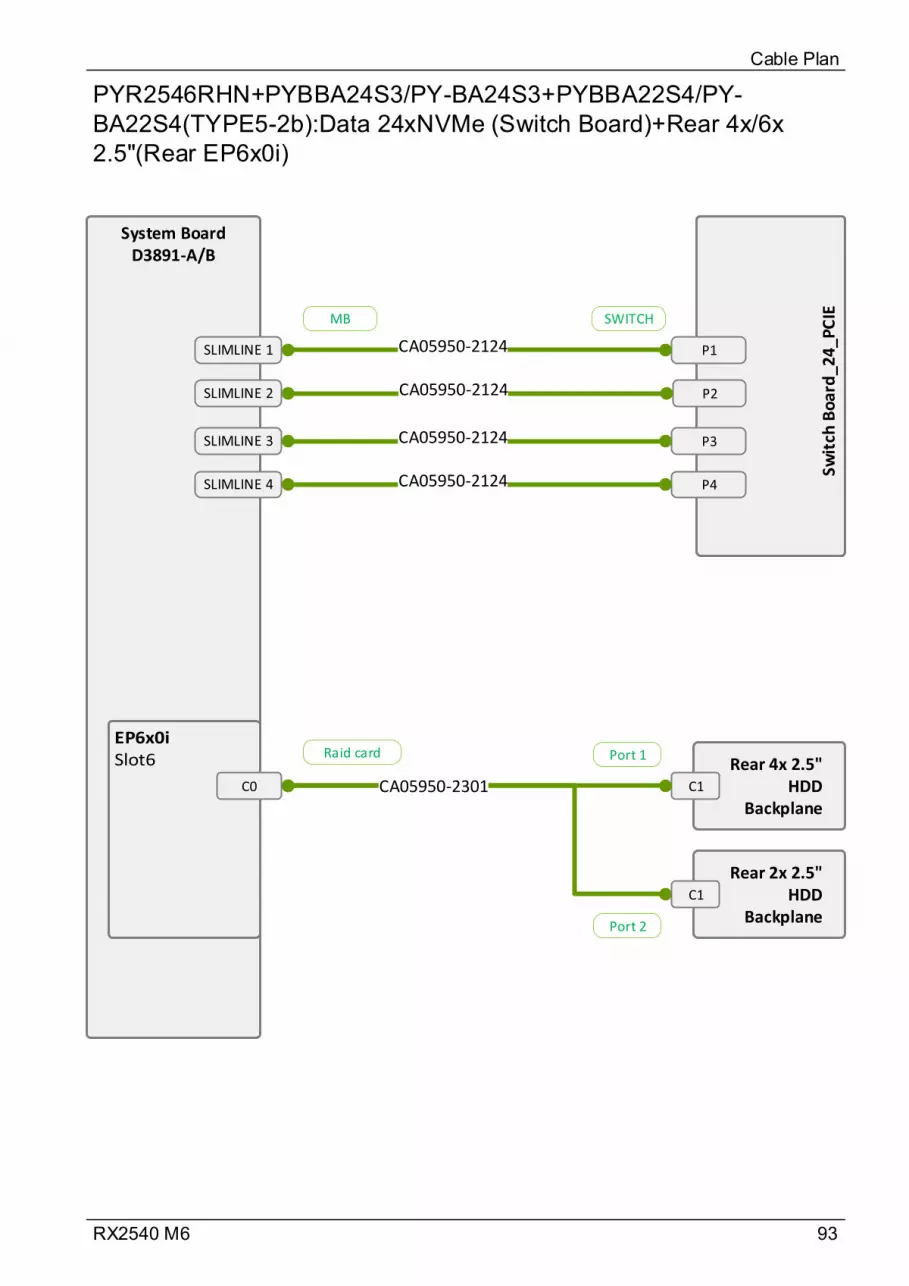
93RX2540 M6
PYR2546RHN+PYBBA24S3/PY-BA24S3+PYBBA22S4/PY-BA22S4(TYPE5-2b):Data 24xNVMe (Switch Board)+Rear 4x/6x 2.5"(Rear EP6x0i)
Cable Plan
Rear 4x 2.5" HDD
BackplaneC1
Rear 2x 2.5" HDD
Backplane
CA05950-2301
System BoardD3891-A/B
Swit
ch B
oar
d_2
4_PC
IE
C0
P1
P2
CA05950-2124
CA05950-2124
P3
P4
CA05950-2124
CA05950-2124
C1
Port 1
Port 2
MB SWITCH
Raid card
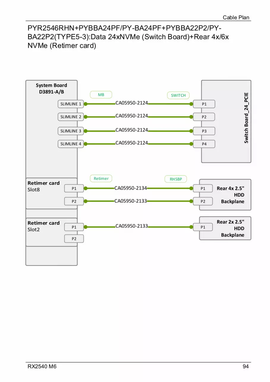
94RX2540 M6
PYR2546RHN+PYBBA24PF/PY-BA24PF+PYBBA22P2/PY-BA22P2(TYPE5-3):Data 24xNVMe (Switch Board)+Rear 4x/6x NVMe (Retimer card)
Cable Plan
System BoardD3891-A/B
Swit
ch B
oa
rd_2
4_
PC
IE
P1
P2
CA05950-2124
CA05950-2124
P3
P4
CA05950-2124
CA05950-2124
P1
P2
Rear 4x 2.5" HDD
Backplane
P1CA05950-2134
Rear 2x 2.5" HDD
Backplane
P1
CA05950-2133 P2
P1
P2
CA05950-2133
MB SWITCH
Retimer RHSBP
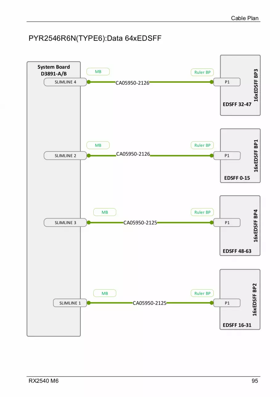
95RX2540 M6
PYR2546R6N(TYPE6):Data 64xEDSFF
Cable Plan
System BoardD3891-A/B
CA05950-2126SLIMLINE 4
SLIMLINE 2
SLIMLINE 3
SLIMLINE 1
CA05950-2125
CA05950-2126
16xE
DSF
F B
P4
16xE
DSF
F B
P4
16xE
DSF
F B
P2
16xE
DSF
F B
P2
16xE
DSF
F B
P1
16xE
DSF
F B
P1
16xE
DSF
F B
P3
16xE
DSF
F B
P3
EDSFF 16-31
EDSFF 0-15
EDSFF 32-47
EDSFF 48-63
P1
P1
P1CA05950-2125
MB Ruler BP
MB Ruler BP
MB Ruler BP
MB Ruler BP

96RX2540 M6
Data Dual microSD 64GB Enterprise
Cable Plan
Dual microSD
64GB Enterprise
-A/B
ROC CON2Y4018-V8
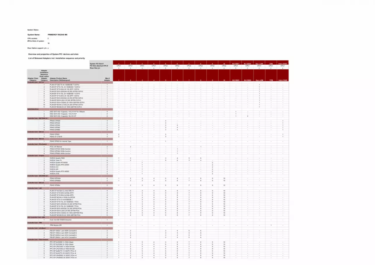
C
n
- - 1 - - - - - -
- -
-
- -
4 PFC EP LPe31002 2x 16Gb Emulex 7
- -
2 PFC EP QLE2692 2x 16Gb Qlogic 7
Controller Card - Fibre Channel
- - -
-
8 PFC EP LPe35002 2X 32GFC PCIe v4 7 1 2 3 4 5 6 7 8 9 10
10 - - - -5 6 7 8 91 2 3 4
- - -6 PFC EP QLE2772 2X 32GFC PCIe v4 7 1 2 3 4 5 6 7 8 9 10 -
- - -6 7 8 9 101 2 3 4 5
- - - -1 2 3 4 5 6 7 8 9 10 -
7 8 9 101 2 3 4 5
- - - -1 2 3 4 5 6 7 8 9 10 -
- - - - -6 7 8 9 101 2 3 4 51 PFC EP QLE2690 1x 16Gb Qlogic 7
3 PFC EP LPe31000 1x 16Gb Emulex 7
5 PFC EP QLE2770 1X 32GFC PCIe v4 7
7 PFC EP LPe35000 1X 32GFC PCIe v4 7
- - -6
5 6 -
1 PIB EP 100Gb 1 port HDR ConnextX-6 2 - - - - -4 5 61 2 3
- - - -4 PIB EP 200Gb 1 port HCA ConnextX-6 2 1 2 3 4
Controller Card - InfiniBand
- - - 1 -- - - - -- - - - -1 TPM Module SPI 1
Controller Card - TPM
- - - - -- - - - -- - - - -1 Dual microSD 64GB Enterprise 1
(SV) Controller Card - USB
- - - -7 8 9 10 -2 3 4 5 612 PLAN EP MCX6-DX 2X 100G QSFP28 PCIe 6 1
- - - -7 8 9 10 -2 3 4 5 611 PLAN EP E810-CQDA2 2X 100G QSFP28 PCIe 6 1
- - - -7 8 9 10 -2 3 4 5 610 PLAN EP E810-LDA2 2X 50G SFP28 PCIe 6 1
- - - -9 PLAN EP E810-XXVDA2 2X 25G SFP28 PCIe 6 1 2 3 4 5 6 7 8 9 10 -
- - - - -
-
8 PLAN EP X710-T2L 2X 10GBASE-T PCIe 6 1 2 3 4 5 6 7 8 9 10
10 - - - -5 6 7 8 91 2 3 4
- - - -6 PLAN EP X710-T4L 4X 10GBASE-T PCIe 1 1 2 3 4 5 6 7 8 9 10 -
- - - - -6 7 8 9 101 2 3 4 5
- - - -4 PLAN EP MCX4-LX 25Gb 2p SFP28 6 1 2 3 4 5 6 7 8 9 10 -
- - -8 9 101 2 3 4 5
- - - -2 PLAN EP X710-DA2 2x10Gb SFP+ 4 1 2 3 4 5 6 7 8 9 10 -
- - - - -6 7 8 9 101 2 3 4 51 PLAN CP 4x1Gbit Cu Intel I350-T4 4
3 PLAN EP X710-DA4 4x10Gb SFP+ 4
5 PLAN EP X710-T4 4x10GBASE-T 4
7 PLAN EP E810-XXVDA4 4X 25G SFP28 PCIe 6
- -6 7
Controller Card - LAN
Controller Card - SAS ext
- - - - -6 7 8 9 101 2 3 4 51 PSAS CP500e 2
7 8 9 10 -
- - - - -6 7 8 9 101 2 3 4 51 PRAID EP540e 4
- - - -2 PRAID EP680e 2 1 2 3 4 5 6
Controller Card - SAS RAID ext
- - - -- - 2 - -- 1 - - -8 NVIDIA A100 2 -
- - - -- - 2 - -- 1 - - -7 NVIDIA Quadro RTX A6000 2 -
- - - -- - 2 - -- 1 - - -6 NVIDIA A40 2 -
- - - -- - 2 - -- 1 - - -5 NVIDIA A10 2 -
- - - -4 NVIDIA Quadro RTX A4000 2 - - 1 - - - - - 2 - -
4 - - -
- - - - -- - - 2 -- - 1 - -
- - - -
3 NVIDIA Quadro RTX4000 2
- - - -1 NVIDIA Quadro P400 1 1 2 3 4 5 6 -
2 NVIDIA Tesla T4 6 1 2 - - 5 6 3
Controller Card – Graphic
-
- - -
- - - - -1 - - - -- - - - -
- - - -
- - -
- -- - 1 - -- 2 - - -1 PCIe x16 Retimer 2
4 PRAID EP680i NVMe function 1
2 PRAID EP540i NVMe function 1 - - - - - 1 - - - -
3 PRAID EP580i NVMe function 1 - - -
Controller Card - PCIe-Switch
Controller Card - SAS int. Backup - - - - -- - - - -- - - - 11 PSAS CP503i for internal Tape 1
- - - - -
- - - - 1- - - - -2 - - - 31 PSAS CP503i 3
- - - 12 PSAS CP 2100-8i 3 2 - - - 3 -
Controller Card - SAS int
- - - - 14 - - - -2 - - - 3
- - - 14 PRAID EP580i 2 2 - - - 3 4 - - - - -
- - -2 - - - 3
- - - 12 PRAID EP520i 3 2 - - - 3 - - - - - -
- - - - 1- - - - -2 - - - 31 PRAID CP500i 3
3 PRAID EP540i 2
5 PRAID EP680i 2
- 14 - - - -
Controller Card - SAS RAID int
2 - - -- - - - -- - - - -
- - - -
1 SSD SATA 6G <Capacity > M.2 N H-P for VMware 0
3 SSD SATA 6G <Capacity> M.2 N H-P 2
2 SSD SATA 6G <Capacity > M.2 N H-P 0 - - - - - 1
1
1
- - - - -- -
- - - - -
- - - - - - -
Solid-State-Drive
- 1 - -- - - - -- - - - -11 PLAN EP MCX6-DX 2X 100G QSFP28 OCPv3 1 -
- 1 - -- - - - -- - - - -10 PLAN EP MCX4-LX DA2 2X 25G SFP28 OCPv3 1 -
- 1 - -- - - - -- - - - -9 PLAN EP E810-CQDA2 2X 100G QSFP28 OCPv3 1 -
- 1 - -- - - - -- - - - -8 PLAN EP E810-LDA2 2X 50G SFP28 OCPv3 1 -
- 1 - -- - - - -- - - - -7 PLAN EP E810-XXVDA2 2X 25G SFP28 OCPv3 1 -
- 1 - -- - - - -- - - - -6 PLAN EP X710-DA2 2X 10G SFP+ OCPv3 1 -
- 1 - -- - - - -- - - - -5 PLAN EP X710-T2L 2X 10GBASE-T OCPv3 1 -
3 PLAN EP X710-DA4 4X 10G SFP+ OCPv3 1 -
- 1 - -- - - - -- - - - -4 PLAN EP E810-XXVDA4 4X 25G SFP28 OCPv3 1 -
- - - - -
- 1 - -- - - - -- - - - -
- - 1 - -1 PLAN CP I350-T4 4X 1000BASE-T OCPv3 1 - - - - - - - - - -
- 1 - -2 PLAN EP X710-T4L 4X 10GBASE-T OCPv3 1 - - - - - -
Riser Slot y/n n n y y
intern RAIDController Card - OCP V3
10 M.2 SSD1 M.2 SSD2 Dyn. LOM TPM3 4 5 6 7 8 9
y n n n nn n n n y
System PCI Slot #PCI Slot attached CPU # CPU1 CPU1 CPU1 CPU1 CPU2 CPU2 CPU2 CPU2 CPU2 CPU2 CPU1
9 10 M.2 SSD1 M.2 SSD2 Dyn. LOM4 5 6 7 8
- - - -
List of Released Adapters incl. Installation sequence and priority
1 2 3
#PCIe Slots of system:
10
Riser Option support: y/n y
Overview and properties of System PCI devices and slots
System Status:
System Name: PRIMERGY RX2540 M6
CPU sockets: 2
CPU1 CPU1 CPU1 CPU1TPM intern RAID
y
Adapter Class Category
Adapter Installation Sequence
Order within Adapter
Category Adapter Product NameDescription (Softwarepool)
Max # Adapter 1 2
-
2 PIB EP 100Gb 2 port HDR ConnextX-6 2 1 2 3 4 5 6 - - - - -
3 PIB EP 200Gb 2 port HCA ConnextX-6 2 1 2 3 4 5 6
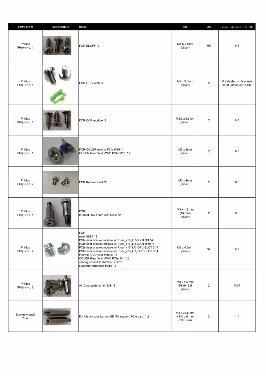
Screw driver Screw picture Usage type Q'ty Torque Tolerance ±10% (NM)
PhillipsPH/(+) No. 1 FOR EDSFF *3 M1.6 x 4mm
(silver) 192 0,2
PhillipsPH/(+) No. 1 FOR ODD latch *2 M2 x 3.5mm
(silver) 2 0.2 (fasten on bracket)0.09 (fasten on ODD)
PhillipsPH/(+) No. 1 FOR COP module *2 M2.5 x 6.5mm
(silver) 2 0,3
PhillipsPH/(+) No. 1
FOR COVER next to PCIe 9/10 *1COVER Rear Wall -W/O PCIe 9/10 * 2
M3 x 3mm(silver) 3 0,6
PhillipsPH/(+) No. 2 FOR Retimer card *2 M3 x 4mm
(silver) 2 0,6
PhillipsPH/(+) No. 1
FORInternal RAID card with Riser *2
M3 x 4.3 mm(14 mm)(silver)
2 0,6
PhillipsPH/(+) No. 2
FORruler HSBP *8PCIe riser bracket module w/ Riser_x16_LR-SLOT 3/4 *4PCIe riser bracket module w/ Riser_x16_LR-SLOT 9/10 *4PCIe riser bracket module w/ Riser_x16_LR_GPU-SLOT 3 *4PCIe riser bracket module w/ Riser_x16_LR_GPU-SLOT 9 *4internal RAID riser module *2COVER Rear Wall -W/O PCIe 3/4 * 2venting cover-LC Dummy BKT *2supporter expander board *2
M3 x 4.5mm(silver) 32 0,6
PhillipsPH/(+) No. 2 Air Duct guide pin on MB *2
M3 x 4.5 mmØ8.0x16.5
(silver)2 0,60
Socket wrench7mm For Metal cross bar on MB (To support PCIe card) * 2
M3 x 33.6 mm+ M4 x 6 mm
(39.6 mm) 2 1,0

Socket wrench7mm FOR EDSFF HSBP *8
M3 x 37.9 mm+ M4 x 7 mm
(44.9 mm)8 1,0
PhillipsPH/(+) No. 2
FOR For Operation Panel cage *4LTO *3RDX *4
M3 x 4 mm(silver) 4 0,6
PhillipsPH/(+) No. 2
FORHSBP-2.5"x8 *1 (2 sets)HSBP-2.5"x8 *1 (2.5" HDD x8 Combo)HSBP-2.5"x24 *2 (2.5" HDD x24 NVMe)
M4 x 6.5mm(silver) 5 0,6
Socket wrench5mm
FORVGA cable *2RS232 cable *2
#4-40 x 6.5mm(silver) 4 0,2
PhillipsPH/(+) No. 2
MB-chassis *9MB-PCIe supporter *3SAS-expander board *1
M3 x 4.5mm(silver) 13 0,7
PhillipsPH/(+) No. 2
FORHSBP-3.5"x12 *9HSBP-3.5"x10 *8
M3 x 5mm(silver) 17 0,7
PhillipsPH/(+) No. 2
FORInternal RAID riser module *1 M3 Thumb screw 1 0.6 (factory)
0.2 (user)
PhillipsPH/(+) No. 2
FOROCPv3 dummy bracket *1 M3 Thumb screw 1 0.6 (factory)
0.2 (user)
PhillipsPH/(+) No. 2
FORRear Top-cover *1 M3 captive screw 1 0,6
FORREAR 2.5"HDD-4X MODULE *1REAR 2.5"HDD-2X MODULE *1
2 0,6
PhillipsPH/(+) No. 2 M3 captive screw
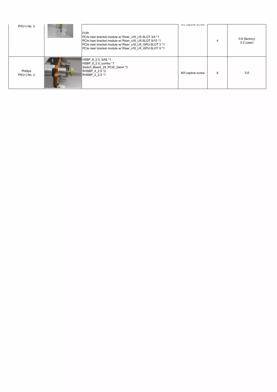
FORPCIe riser bracket module w/ Riser_x16_LR-SLOT 3/4 *1PCIe riser bracket module w/ Riser_x16_LR-SLOT 9/10 *1PCIe riser bracket module w/ Riser_x16_LR_GPU-SLOT 3 *1PCIe riser bracket module w/ Riser_x16_LR_GPU-SLOT 9 *1
4 0.6 (factory)0.2 (user)
PhillipsPH/(+) No. 2
FORHSBP_8_2.5_SAS *1HSBP_8_2.5_combo *1Switch_Board_24_PCIE_Gen4 *3RHSBP_4_2.5 *2RHSBP_2_2.5 *1 M3 captive screw 8 0,6
PhillipsPH/(+) No. 2 M3 captive screw
List of all used screws for PRIMERGY Servers
Assembled in WCZ and FIT
June 2021
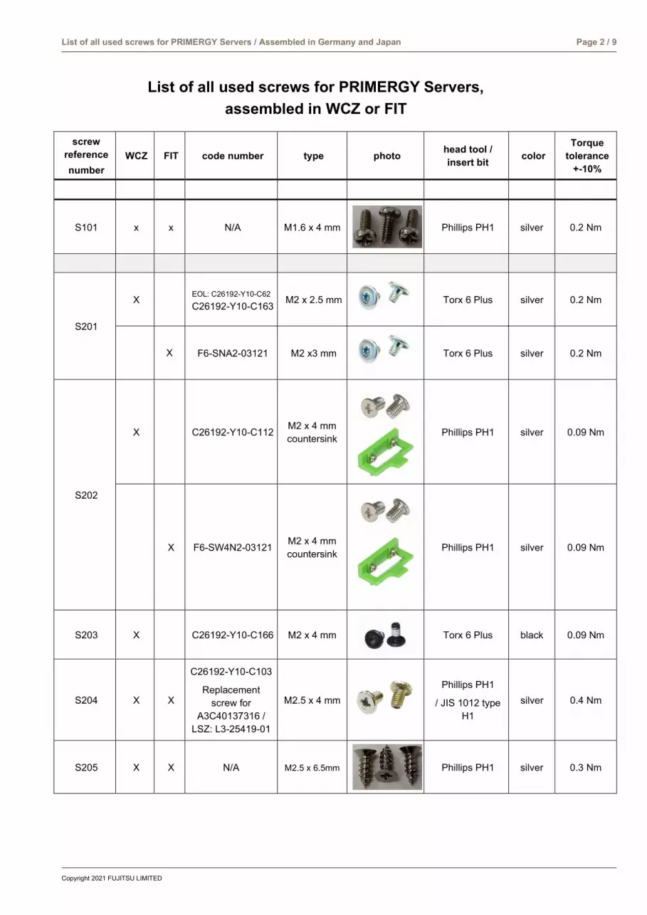
Copyright 2021 FUJITSU LIMITED
List of all used screws for PRIMERGY Servers / Assembled in Germany and Japan Page 2 / 9
List of all used screws for PRIMERGY Servers, assembled in WCZ or FIT
screw reference number
WCZ FIT code number type photo head tool / insert bit color
Torque tolerance
+-10%
S101 x x N/A M1.6 x 4 mm
Phillips PH1 silver 0.2 Nm
S201
X EOL: C26192-Y10-C62
C26192-Y10-C163 M2 x 2.5 mm
Torx 6 Plus silver 0.2 Nm
X F6-SNA2-03121 M2 x3 mm
Torx 6 Plus silver 0.2 Nm
S202
X C26192-Y10-C112 M2 x 4 mm countersink
Phillips PH1 silver 0.09 Nm
X F6-SW4N2-03121 M2 x 4 mm countersink
Phillips PH1 silver 0.09 Nm
S203 X C26192-Y10-C166 M2 x 4 mm
Torx 6 Plus black 0.09 Nm
S204 X X
C26192-Y10-C103
Replacement screw for
A3C40137316 / LSZ: L3-25419-01
M2.5 x 4 mm
Phillips PH1
/ JIS 1012 type H1
silver 0.4 Nm
S205 X X N/A M2.5 x 6.5mm
Phillips PH1 silver 0.3 Nm

Copyright 2021 FUJITSU LIMITED
List of all used screws for PRIMERGY Servers / Assembled in Germany and Japan Page 3 / 9
screw reference number
WCZ FIT code number type photo head tool / insert bit color
Torque tolerance
+-10%
S206 X X N/A M2 x 4.3mm
Phillips PH1 silver 0.2 Nm
S207 X X N/A M2 x 4 mm countersink
Phillips PH1 black 0.09 Nm
S208 X X N/A M2.5 x 8 mm self-tapping
Phillips PH1 black 0.4 Nm
S301
X C26192-Y10-C151 M3 x 3.5 mm
hexagon head 5 mm / cross
PZ2 black 0.6 Nm
X F6-SW2N3-05121 M3 x 5 mm with spring and washer
Phillips PH2 silver 0.6 Nm
S302
X C26192-Y10-C102 M3 x 3.5 mm
Phillips PH1 silver 0.4 Nm
X CA32432-0023 M3 x 3.5 mm
Phillips PH1
/ JIS 1012 type H1
silver 0.4 Nm
S303 X X A3C40109082 M3 x 4 mm
Phillips PH1 white 0.09 Nm
S304 X A3C40142649 M3 x 4 mm countersink
countersink
Phillips PH1 silver 0.4 Nm
S305 X X Screws in kit: S26361-D3305-A10
M3 x 4 mm
Phillips PH1 silver 0.4Nm

Copyright 2021 FUJITSU LIMITED
List of all used screws for PRIMERGY Servers / Assembled in Germany and Japan Page 4 / 9
screw reference number
WCZ FIT code number type photo head tool / insert bit color
Torque tolerance
+-10%
S306
X C26192-Y10-C67 M3 x 4.5 mm
hexagon head 5 mm / cross
PZ2 silver 0.6 Nm
X F6-SW2N3-05121 M3 x 5 mm with spring and washer
Phillips PH2 silver 0.6 Nm
S307
X C26192-Y10-C68 M3 x 6 mm
hexagon head 5 mm / cross
PZ2 silver 0.6 Nm
X F6-SW2N3-06121 M3 x 6 mm with spring and washer
Phillips PH2 silver 0.6 Nm
S308
X C26192-Y10-C111 M3 x 6 mm
countersink
Phillips PH2 silver 0.6 Nm
X F6-SSA3-06121 M3 x 6 mm
countersink
Phillips PH2 silver 0.6 Nm
S309 X X C26192-Y10-C69 M3 x 8 mm
hexagon head 5 mm / cross
PZ2 silver 0.6 Nm
S310 X C26192-Y10-C207 same as –C67 but not “self-tapping”
M3 x 4.5 mm
hexagon head 5 mm / cross
PZ2 silver 0.6 Nm
S311 X X C26361-B443-C220
M3 x 3.2 mm
Lens head screw cross PZ2
silver 0.2 Nm
S312 X X N/A M3 x 6.7 mm
Phillips PH2
silver 0.6 Nm
S313 X X N/A M3 Fastener Screw
Phillips PH2
silver 0.6 Nm

Copyright 2021 FUJITSU LIMITED
List of all used screws for PRIMERGY Servers / Assembled in Germany and Japan Page 5 / 9
screw reference number
WCZ FIT code number type photo head tool / insert bit color
Torque tolerance
+-10% S314 X X N/A M3 Captive
Screw
Phillips PH2
silver 0.2 Nm
S315 X X N/A M3 x 3 mm
Phillips PH1
silver 0.6 Nm
S316 X X N/A M3 x 4 mm
Phillips PH2
silver 0.6 Nm
S317 X X N/A M3 x 4.5 mm Ø8.0x16.5
Phillips PH2
silver 0.6 Nm
S318 X X N/A M3 x 4 mm
Phillips PH2
silver 0.6 Nm
S319 X X N/A M3 x 4.5 mm
Phillips PH2 silver 0.6 ~ 0.7
Nm
S320 X X N/A M3 x 5 mm
Phillips PH2
silver 0.7 Nm
S321 X X N/A M3 Captive Screw
Phillips PH2
silver 0.6 Nm
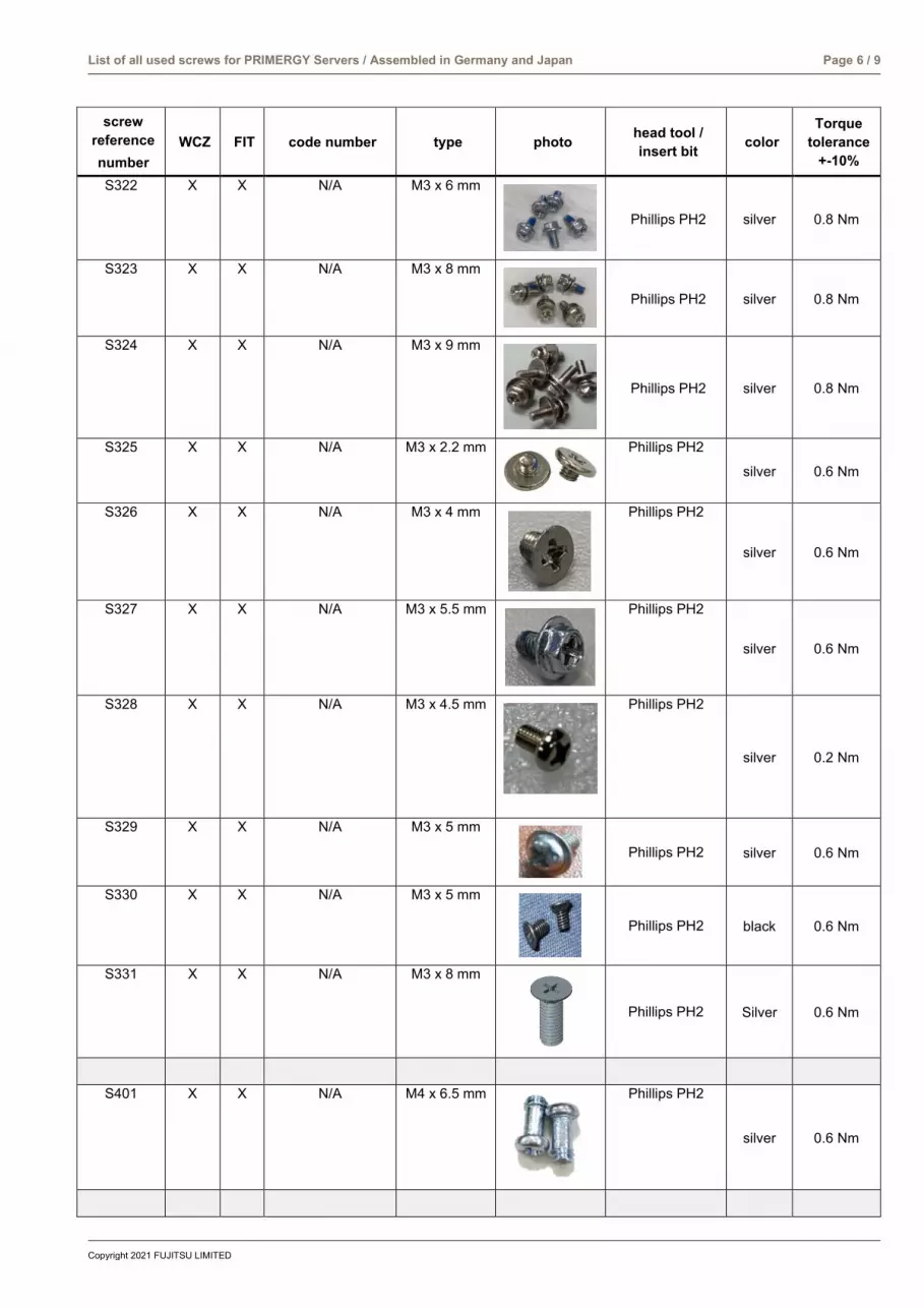
Copyright 2021 FUJITSU LIMITED
List of all used screws for PRIMERGY Servers / Assembled in Germany and Japan Page 6 / 9
screw reference number
WCZ FIT code number type photo head tool / insert bit color
Torque tolerance
+-10% S322 X X N/A M3 x 6 mm
Phillips PH2 silver 0.8 Nm
S323 X X N/A M3 x 8 mm
Phillips PH2 silver 0.8 Nm
S324 X X N/A M3 x 9 mm
Phillips PH2 silver 0.8 Nm
S325 X X N/A M3 x 2.2 mm
Phillips PH2
silver 0.6 Nm
S326 X X N/A M3 x 4 mm
Phillips PH2
silver 0.6 Nm
S327 X X N/A M3 x 5.5 mm
Phillips PH2
silver 0.6 Nm
S328 X X N/A M3 x 4.5 mm
Phillips PH2
silver 0.2 Nm
S329 X X N/A M3 x 5 mm
Phillips PH2 silver 0.6 Nm
S330 X X N/A M3 x 5 mm
Phillips PH2 black 0.6 Nm
S331 X X N/A M3 x 8 mm
Phillips PH2 Silver 0.6 Nm
S401 X X N/A M4 x 6.5 mm
Phillips PH2
silver 0.6 Nm
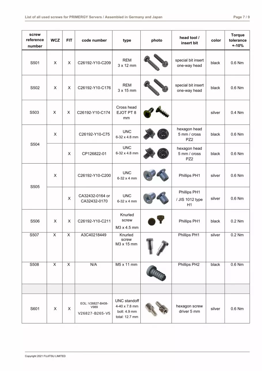
Copyright 2021 FUJITSU LIMITED
List of all used screws for PRIMERGY Servers / Assembled in Germany and Japan Page 7 / 9
screw reference number
WCZ FIT code number type photo head tool / insert bit color
Torque tolerance
+-10%
S501 X X C26192-Y10-C209 REM 3 x 12 mm
special bit insert one-way head black 0.6 Nm
S502 X X C26192-Y10-C176 REM 3 x 15 mm
special bit insert one-way head black 0.6 Nm
S503 X X C26192-Y10-C174 Cross head EJOT PT 8
mm
silver 0.4 Nm
S504
X C26192-Y10-C75 UNC 6-32 x 4.8 mm
hexagon head 5 mm / cross
PZ2 black 0.6 Nm
X CP126822-01 UNC
6-32 x 4.8 mm
hexagon head 5 mm / cross
PZ2 black 0.6 Nm
S505
X C26192-Y10-C200 UNC 6-32 x 4 mm
Phillips PH1 silver 0.6 Nm
X CA32432-0164 or CA32432-0170
UNC 6-32 x 4 mm
Phillips PH1
/ JIS 1012 type H1
silver 0.6 Nm
S506 X X C26192-Y10-C211 Knurled screw
M3 x 4.5 mm
Phillips PH1 black 0.2 Nm
S507 X X A3C40218449 Knurled screw
M3 x 15 mm
Phillips PH1 silver 0.2 Nm
S508 X X N/A M5 x 11 mm
Phillips PH2 black 0.6 Nm
S601 X X EOL: V26827-B408-
V989
V26827-B265-V5
UNC standoff 4-40 x 7.8 mm bolt: 4.9 mm
total: 12.7 mm
hexagon screw driver 5 mm silver 0.6 Nm

Copyright 2021 FUJITSU LIMITED
List of all used screws for PRIMERGY Servers / Assembled in Germany and Japan Page 8 / 9
screw reference number
WCZ FIT code number type photo head tool / insert bit color
Torque tolerance
+-10%
S602 X X C26192-Y1-C65
standoff M3 x 4.5 mm bolt: 5 mm
total: 9.5 mm
hexagon screw driver 5 mm
silver 0.6 Nm
S603 X X C26192-Y1-C66
standoff M3 x 6 mm bolt: 8 mm
total: 14 mm
hexagon screw driver 5 mm
silver 0.6 Nm
S604 X X C26192-Y1-C67
standoff M3 x 6 mm bolt: 12 mm total: 18 mm
hexagon screw driver 5 mm
silver 0.6 Nm
S605 X X C26361-B443-
C210
standoff M3 x 3 mm bolt: 4.1 mm total: 7.1 mm
hexagon screw driver 5 mm
silver 0.6 Nm
S606 X X (for on board M.2 StandOffNut)
C26361-B443-C210
standoff M3 x 3 mm bolt: 4.1 mm total: 7.1 mm
hexagon screw driver 5 mm
silver 0.3 Nm
S607 X X N/A UNC standoff 4-40 x 6.5 mm
hexagon screw driver 5 mm silver 0.2 Nm
S608 X X N/A M3 x 33.6 mm + M4 x 6 mm
hexagon screw driver 7 mm silver 1 Nm
S609 X X N/A M3 x 37.9 mm + M4 x 7 mm
hexagon screw driver 7 mm silver 1 Nm
S610 X X N/A M3 x 5 mm
Phillips PH2 silver 0.8 Nm
S611 X X N/A #2-32 x 12.6 mm
Phillips PH2 silver 0.2 Nm
(mechanic part in one chassis,
provided by chassis vendor)
X X C26361-K1444-C11
M3 X 4.5 mm cheese head screw with
spacer.
hexagon screw driver 5 mm /
cross PZ2 silver 0.6 Nm
(screw is part of PDUAL
AP200 kit)
X X C26361-Y10-C133 M2 x 3.5 mm
Flat head Phillips PH 0
silver 0.2 Nm
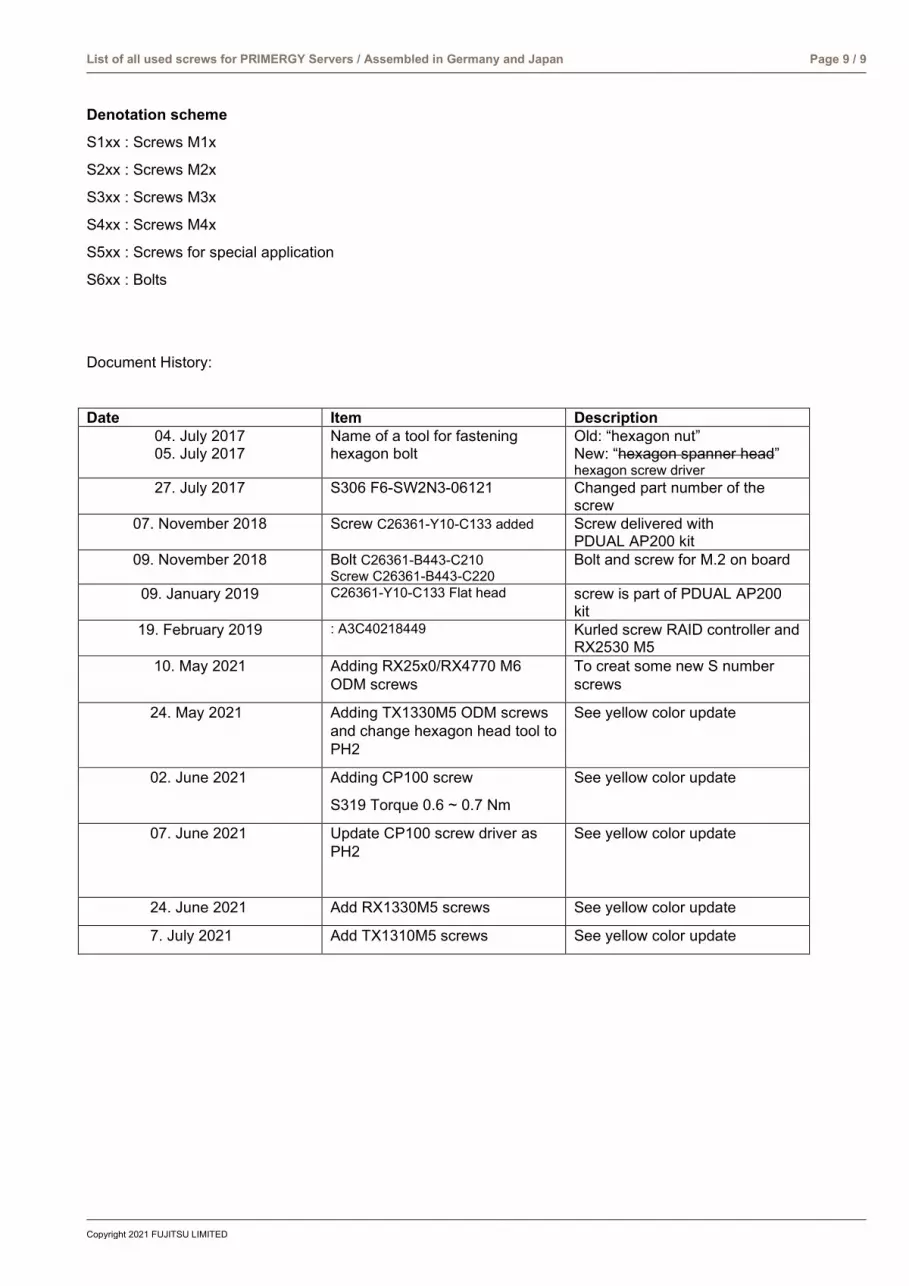
Copyright 2021 FUJITSU LIMITED
List of all used screws for PRIMERGY Servers / Assembled in Germany and Japan Page 9 / 9
Denotation scheme
S1xx : Screws M1x
S2xx : Screws M2x
S3xx : Screws M3x
S4xx : Screws M4x
S5xx : Screws for special application
S6xx : Bolts
Document History:
Date Item Description 04. July 2017 05. July 2017
Name of a tool for fastening hexagon bolt
Old: “hexagon nut” New: “hexagon spanner head” hexagon screw driver
27. July 2017 S306 F6-SW2N3-06121 Changed part number of the screw
07. November 2018 Screw C26361-Y10-C133 added Screw delivered with PDUAL AP200 kit
09. November 2018 Bolt C26361-B443-C210 Screw C26361-B443-C220
Bolt and screw for M.2 on board
09. January 2019 C26361-Y10-C133 Flat head screw is part of PDUAL AP200 kit
19. February 2019 : A3C40218449 Kurled screw RAID controller and RX2530 M5
10. May 2021 Adding RX25x0/RX4770 M6 ODM screws
To creat some new S number screws
24. May 2021 Adding TX1330M5 ODM screws and change hexagon head tool to PH2
See yellow color update
02. June 2021 Adding CP100 screw
S319 Torque 0.6 ~ 0.7 Nm
See yellow color update
07. June 2021 Update CP100 screw driver as PH2
See yellow color update
24. June 2021 Add RX1330M5 screws See yellow color update
7. July 2021 Add TX1310M5 screws See yellow color update