fsmd-based hardware accelerators for fpgas
TRANSCRIPT

1. Introduction
Current VLSI technology allows the design of sophisticated digital systems with escalated
demands in performance and power/energy consumption. The annual increase of chip
complexity is 58%, while human designers productivity increase is limited to 21% per annum
(ITRS, 2011). The growing technology-productivity gap is probably the most important
problem in the industrial development of innovative products. A dramatic increase in
designer productivity is only possible through the adoption of methodologies/tools that
raise the design abstraction level, ingeniously hiding low-level, time-consuming, error-prone
details. New EDA methodologies aim to generate digital designs from high-level descriptions,
a process called High-Level Synthesis (HLS) (Coussy & Morawiec, 2008) or else hardware
compilation (Wirth, 1998). The input to this process is an algorithmic description (for example
in C/C++/SystemC) generating synthesizable and verifiable Verilog/VHDL designs (IEEE,
2006; 2009).
Our aim is to highlight aspects regarding the organization and design of the targeted hardware
of such process. In this chapter, it is argued that a proper Model of Computation (MoC) for
the targeted hardware is an adapted and extended form of the FSMD (Finite-State Machine
with Datapath) model which is universal, well-defined and suitable for either data- or
control-dominated applications. Several design examples will be presented throughout the
chapter that illustrate our approach.
2. Higher-level representations of FSMDs
This section discusses issues related to higher-level representations of FSMDs (Gajski &
Ramachandran, 1994) focusing on textual intermediate representations (IRs). It first provides
a short overview of existing approaches focusing on the well-known GCC GIMPLE and
LLVM IRs. Then the BASIL (Bit-Accurate Symbolic Intermediate Language) is introduced
as a more appropriate lightweight IR for self-contained representation of FSMD-based
hardware architectures. Lower-level graph-based forms are presented focusing on the CDFG
(Control-Data Flow Graph) procedure-level representation using Graphviz (Graphviz, 2011)
files. This section also illustrates a linear CDFG construction algorithm from BASIL. In
addition, an end-to-end example is given illustrating algorithmic specifications in ANSI
FSMD-Based Hardware Accelerators for FPGAs
Nikolaos Kavvadias, Vasiliki Giannakopoulou and Kostas Masselos Department of Computer Science and Technology,
University of Peloponnese, Tripoli Greece
7
www.intechopen.com

2 Will-be-set-by-IN-TECH
C, BASIL, Graphviz CDFGs and their visualizations utilizing a 2D Euclidean distance
approximation function.
2.1 Overview of compiler intermediate representations
Recent compilation frameworks provide linear IRs for applying analyses, optimizations and
as input for backend code generation. GCC (GCC, 2011) supports the GIMPLE IR. Many
GCC optimizations have been rewritten for GIMPLE, but it is still undergoing grammar and
interface changes. The current GCC distribution incorporates backends for contemporary
processors such as the Cell SPU and the baseline Xtensa application processor (Gonzalez,
2000) but it is not suitable for rapid retargeting to non-trivial and/or custom architectures.
LLVM (LLVM, 2011) is a compiler framework that draws growing interest within the
compilation community. The LLVM compiler uses the homonymous LLVM bitcode, a
register-based IR, targeted by a C/C++ companion frontend named clang (clang homepage,
2011). It is written in a more pleasant coding style than GCC, but similarly the IR infrastructure
and semantics are excessive.
Other academic infrastructures include COINS (COINS, 2011), LANCE (LANCE, 2011) and
Machine-SUIF (Machine-SUIF, 2002). COINS is written entirely in Java, and supports two
IRs: the HIR (high level) and the LIR (low-level) which is based on S-expressions. COINS
features a powerful SSA-based optimizer, however its LISP-like IR is unsuitable for directly
expressing control and data dependencies and to fully automate the construction of a
machine backend. LANCE (Leupers et al., 2003) introduces an executable IR form (IR-C),
which combines the simplicity of three-address code with the executability of ANSI C code.
LANCE compilation passes accept and emit IR-C, which eases the integration of LANCE
into third-party environments. However, ANSI C semantics are neither general nor neutral
enough in order to express vastly different IR forms. Machine-SUIF is a research compiler
infrastructure built around the SUIFvm IR which has both a CFG (control-flow graph) and
SSA form. Past experience with this compiler has proved that it is overly difficult both to alter
or extend its semantics. It appears that the Phoenix (Microsoft, 2008) compiler is a rewrite and
extension of Machine-SUIF in C#. As an IR, the CIL (Common Intermediate Language) is used
which is entirely stack-based, a feature that hinders the application of modern optimization
techniques. Finally, CoSy (CoSy, 2011) is the prevalent commercial retargetable compiler
infrastructure. It uses the CCMIR intermediate language whose specification is confidential.
Most of these frameworks fall short in providing a minimal, multi-purpose compilation
infrastructure that is easy to maintain and extend.
The careful design of the compiler intermediate language is a necessity, due to its dual purpose
as both the program representation and an abstract target machine. Its design affects the
complexity, efficiency and ease of maintenance of all compilation phases; frontend, optimizer
and effortlessly retargetable backend.
The following subsection introduces the BASIL intermediate representation. BASIL supports
semantic-free n-input/m-output mappings, user-defined data types, and specifies a virtual
machine architecture. BASIL’s strength is its simplicity: it is inherently easy to develop a
CDFG (control/data flow graph) extraction API, apply graph-based IR transformations for
144 Embedded Systems – Theory and Design Methodology
www.intechopen.com

FSMD-Based Hardware Accelerators for FPGAs 3
Data type Regular expression ExampleUNSIGNED_INT [Uu][1-9][0-9]* u32SIGNED_INT [Ss][1-9][0-9]* s11UNSIGNED/SIGNED_FXP
[Qq][0-9]+.[0-9]+[S|U] q4.4u, q2.14s
FLP [Ff][0|1].[0-9]+.[0-9]+ F1.8.23fields: sign, exponent,mantissa
Table 1. Data type specifications in BASIL.
domain specialization, investigate SSA (Static Single Assignment) construction algorithms
and perform other compilation tasks.
2.2 Representing programs in BASIL
BASIL provides arbitrary n-to-m mappings allowing the elimination of implicit side-effects,
a single construct for all operations, and bit-accurate data types. It supports scalar,
single-dimensional array and streamed I/O procedure arguments. BASIL statements are
labels, n-address instructions or procedure calls.
BASIL is similar in concept to the GIMPLE and LLVM intermediate languages but with
certain unique features. For example, while BASIL supports SSA form, it provides very light
operation semantics. A single construct is required for supporting any given operation as an
m-to-n mapping between source and destination sites. An n-address operation is actually the
specification of a mapping from a set of n ordered inputs to a set of m ordered outputs. An
n-address instruction (or else termed as an n, m-operation) is formatted as follows:
outp1, ..., outpm <= operation inp1, ..., inpn; where:
• operation is a mnemonic referring to an IR-level instruction
• outp1, ..., outpm are the m outputs of the operation
• inp1, ..., inpn are the n inputs of the operation
In BASIL all declared objects (global variables, local variables, input and output procedure
arguments) have an explicit static type specification. BASIL uses the notions of “globalvar”
(a global scalar or single-dimensional array variable), “localvar” (a local scalar or
single-dimensional array variable), “in” (an input argument to the given procedure), and
“out” (an output argument to the given procedure).
BASIL supports bit-accurate data types for integer, fixed-point and floating-point arithmetic.
Data type specifications are essentially strings that can be easily decoded by a regular
expression scanner; examples are given in Table 1.
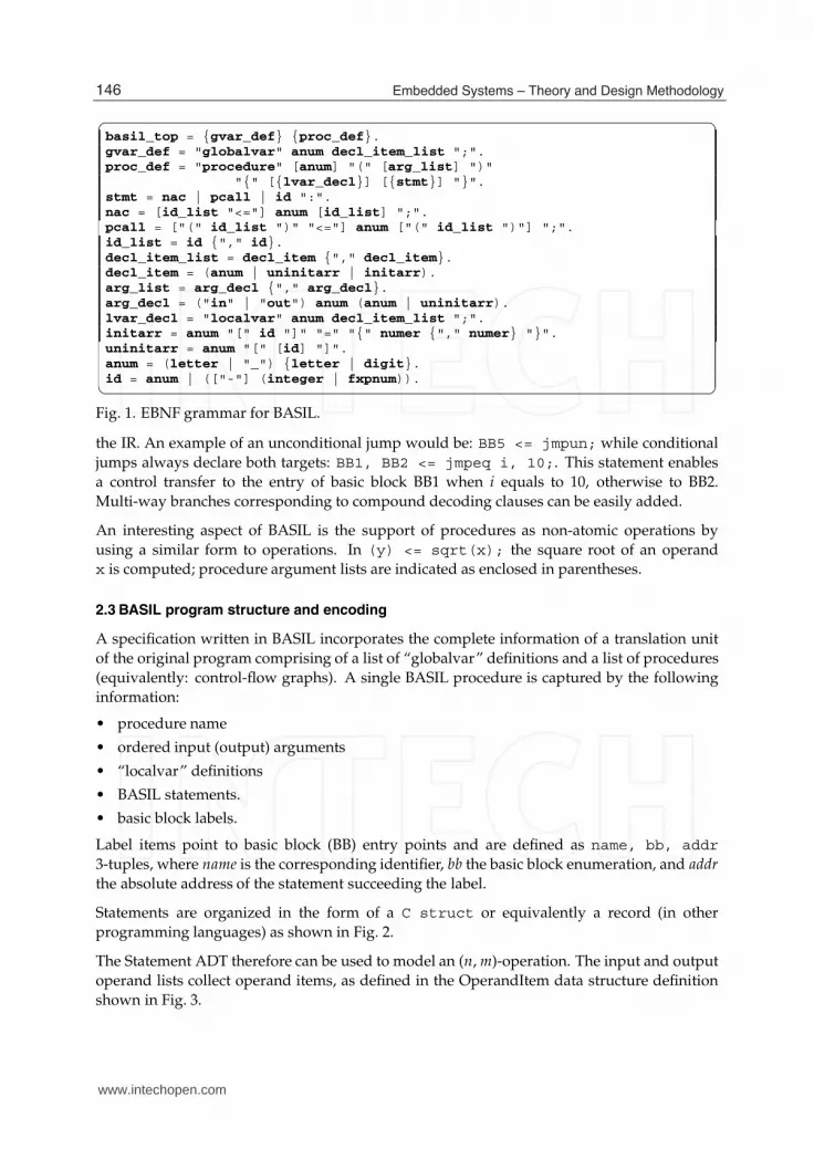
The EBNF grammar for BASIL is shown in Fig. 1 where it can be seen that rules “nac” and
“pcall” provide the means for the n-to-m generic mapping for operations and procedure calls,
respectively. It is important to note that BASIL has no predefined operator set; operators are
defined through a textual mnemonic.
For instance, an addition of two scalar operands is written: a <= add b, c;.
Control-transfer operations include conditional and unconditional jumps explicitly visible in
145FSMD-Based Hardware Accelerators for FPGAs
www.intechopen.com
4 Will-be-set-by-IN-TECH
✞ ☎basil_top = {gvar_def} {proc_def}.gvar_def = "globalvar" anum decl_item_list ";".proc_def = "procedure" [anum] "(" [arg_list] ")"
"{" [{lvar_decl}] [{stmt}] "}".stmt = nac | pcall | id ":".nac = [id_list "<="] anum [id_list] ";".pcall = ["(" id_list ")" "<="] anum ["(" id_list ")"] ";".id_list = id {"," id}.decl_item_list = decl_item {"," decl_item}.decl_item = (anum | uninitarr | initarr).arg_list = arg_decl {"," arg_decl}.arg_decl = ("in" | "out") anum (anum | uninitarr).lvar_decl = "localvar" anum decl_item_list ";".initarr = anum "[" id "]" "=" "{" numer {"," numer} "}".uninitarr = anum "[" [id] "]".anum = (letter | "_") {letter | digit}.id = anum | (["-"] (integer | fxpnum)).✝ �
Fig. 1. EBNF grammar for BASIL.
the IR. An example of an unconditional jump would be: BB5 <= jmpun; while conditional
jumps always declare both targets: BB1, BB2 <= jmpeq i, 10;. This statement enables
a control transfer to the entry of basic block BB1 when i equals to 10, otherwise to BB2.
Multi-way branches corresponding to compound decoding clauses can be easily added.
An interesting aspect of BASIL is the support of procedures as non-atomic operations by
using a similar form to operations. In (y) <= sqrt(x); the square root of an operand
x is computed; procedure argument lists are indicated as enclosed in parentheses.
2.3 BASIL program structure and encoding
A specification written in BASIL incorporates the complete information of a translation unit
of the original program comprising of a list of “globalvar” definitions and a list of procedures
(equivalently: control-flow graphs). A single BASIL procedure is captured by the following
information:
• procedure name
• ordered input (output) arguments
• “localvar” definitions
• BASIL statements.
• basic block labels.
Label items point to basic block (BB) entry points and are defined as name, bb, addr
3-tuples, where name is the corresponding identifier, bb the basic block enumeration, and addr
the absolute address of the statement succeeding the label.
Statements are organized in the form of a C struct or equivalently a record (in other
programming languages) as shown in Fig. 2.
The Statement ADT therefore can be used to model an (n, m)-operation. The input and output
operand lists collect operand items, as defined in the OperandItem data structure definition
shown in Fig. 3.
146 Embedded Systems – Theory and Design Methodology
www.intechopen.com

FSMD-Based Hardware Accelerators for FPGAs 5
✞ ☎typedef struct {char *mnemonic; /* Designates the statement type. */NodeType ntype; /* OPERATION or PROCEDURE_CALL. */List opnds_in; /* Collects all input operands. */List opnds_out; /* Collects all output operands. */int bb; /* Basic block number. */int addr; /* Absolute statement address. */
} _Statement;typedef _Statement *Statement;✝ �
Fig. 2. C-style record for encoding a BASIL statement.
✞ ☎typedef struct {char *name; /* Identifier name. */char *dataspec; /* Data type string spec. */OperandType otype; /* Operand type representation. */int ix; /* Absolute operand item index. */
} _OperandItem;typedef _OperandItem *OperandItem;✝ �
Fig. 3. C-style record for encoding an OperandItem.
The OperandItem data structure is used for representing input arguments (INVAR), output
arguments (OUTVAR), local (LOCALVAR) and global (GLOBALVAR) variables and constants
(CONSTANT). If using a graph-based intermediate representation, arguments and constants
could use node and incoming or outgoing edge representations, while it is meaningful to
represent variables as edges as long as their storage sites are not considered.
The typical BASIL program is structured as follows:
✞ ☎<Global variable declarations>
procedure name_1 (<comma-separated input arguments>,<comma-separated output arguments>
) {<Local variable declarations><BASIL labels, instructions, procedure calls>
}...procedure name_n (<comma-separated input arguments>,<comma-separated output arguments>
) {<Local variable declarations><BASIL labels, instructions, procedure calls>
}✝ �
Fig. 4. Translation unit structure for BASIL.
147FSMD-Based Hardware Accelerators for FPGAs
www.intechopen.com
6 Will-be-set-by-IN-TECH
Mnemonic Description (Ni, No)ldc Load constant (1,1)neg, mov Unary arithmetic op. (1,1)add, sub, abs, min, max, Binary arithmetic op. (2,1)mul, div, mod, shl, shrnot, and, ior, xor Logical (2,1)szz Comparison for zz: (2,1)
(eq,ne,lt,le,gt,ge)muxzz Conditional selection (3,1)load, store Load/Store register
from/to memory(2,1)
sxt, zxt, trunc Type conversion (1,1)jmpun Unconditional jump (0,1)jmpzz Conditional jump (2,2)print Diagnostic output (1,0)
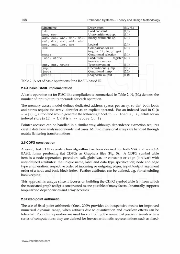
Table 2. A set of basic operations for a BASIL-based IR.
2.4 A basic BASIL implementation
A basic operation set for RISC-like compilation is summarized in Table 2. Ni (No) denotes the
number of input (output) operands for each operation.
The memory access model defines dedicated address spaces per array, so that both loads
and stores require the array identifier as an explicit operand. For an indexed load in C (b
= a[i];), a frontend would generate the following BASIL: b <= load a, i;, while for an
indexed store (a[i] = b;) it is a <= store b, i;.
Pointer accesses can be handled in a similar way, although dependence extraction requires
careful data flow analysis for non-trivial cases. Multi-dimensional arrays are handled through
matrix flattening transformations.
2.5 CDFG construction
A novel, fast CDFG construction algorithm has been devised for both SSA and non-SSA
BASIL forms producing flat CDFGs as Graphviz files (Fig. 5). A CDFG symbol table
item is a node (operation, procedure call, globalvar, or constant) or edge (localvar) with
user-defined attributes: the unique name, label and data type specification; node and edge
type enumeration; respective order of incoming or outgoing edges; input/output argument
order of a node and basic block index. Further attributes can be defined, e.g. for scheduling
bookkeeping.
This approach is unique since it focuses on building the CDFG symbol table (st) from which
the associated graph (cdfg) is constructed as one possible of many facets. It naturally supports
loop-carried dependencies and array accesses.
2.6 Fixed-point arithmetic
The use of fixed-point arithmetic (Yates, 2009) provides an inexpensive means for improved
numerical dynamic range, when artifacts due to quantization and overflow effects can be
tolerated. Rounding operators are used for controlling the numerical precision involved in a
series of computations; they are defined for inexact arithmetic representations such as fixed-
148 Embedded Systems – Theory and Design Methodology
www.intechopen.com

FSMD-Based Hardware Accelerators for FPGAs 7
✞ ☎BASILtoCDFG()input List BASILs, List variables, List labels, Graph cfg;output SymbolTable st, Graph cdfg;
begin
Insert constant, input/output arguments and global
variable operand nodes to st;Insert operation nodes;Insert incoming {global/constant/input, operation} and
outgoing {operation, global/output} edges;Add control-dependence edges among operation nodes;Add data-dependence edges among operation nodes,extract loop-carried dependencies via cfg-reachability;Generate cdfg from st;
end✝ �
Fig. 5. CDFG construction algorithm accepting BASIL input.
and floating-point. Proposed and in-use specifications for fixed-point arithmetic of related
practice include:
• the C99 standard (ISO/IEC JTC1/SC22, 2007)
• lightweight custom implementations such as (Edwards, 2006)
• explicit data types with open source implementations (Mentor Graphics, 2011; SystemC,
2006)
Fixed-point arithmetic is a variant of the typical integral representation (2’s-complement
signed or unsigned) where a binary point is defined, purely as a notational artifact to signify
integer powers of 2 with a negative exponent. Assuming an integer part of width IW > 0
and a fractional part with −FW < 0, the VHDL-2008 sfixed data type has a range of
2IW−1 − 2|FW | to −2IW−1 with a representable quantum of 2|FW | (Bishop, 2010a;b). The
corresponding ufixed type has the following range: 2IW − 2|FW | to 0. Both are defined
properly given a IW-1:-FW vector range.
BASIL currently supports a proposed list of extension operators for handling fixed-point
arithmetic:
• conversion from integer to fixed-point format: i2ufx, i2sfx
• conversion from fixed-point to integer format: ufx2i, sfx2i
• operand resizing: resize, using three input operands; source operand src1 and src2,
src3 as numerical values that denote the new size (high-to-low range) of the resulting
fixed-point operand
• rounding primitives: ceil, fix, floor, round, nearest, convergent for rounding
towards plus infinity, zero, minus infinity, and nearest (ties to greatest absolute value, plus
infinity and closest even, respectively).
2.7 Scan-based SSA construction algorithms for BASIL
In our experiments with BASIL we have investigated minimal SSA construction schemes – the
Appel (Appel, 1998) and Aycock-Horspool (Aycock & Horspool, 2000) algorithms – that don’t
require the computation of the iterated dominance frontier (Cytron et al., 1991).
149FSMD-Based Hardware Accelerators for FPGAs
www.intechopen.com

8 Will-be-set-by-IN-TECH
App. LOC LOC P/V/E #φs #Instr.(BASIL) (dot)
atsort 155 484 2/136/336 10 6907coins 105 509 2/121/376 10 405726cordic 56 178 1/57/115 7 256335easter 47 111 1/46/59 2 3082fixsqrt 32 87 1/29/52 6 833900perfect 31 65 1/23/36 4 6590739sieve 82 199 2/64/123 12 515687xorshift 26 80 1/29/45 0 2000
Table 3. Application profiling with a BASIL framework.
In traditional compilation infrastructures (GCC, LLVM) (GCC, 2011; LLVM, 2011), Cytron’s
approach (Cytron et al., 1991) is preferred since it enables bit-vector dataflow frameworks
and optimizations that require elaborate data structures and manipulations. It can be argued
that rapid prototyping compilers, integral parts of heterogeneous design flows, would benefit
from straightforward SSA construction schemes which don’t require the use of sophisticated
concepts and data structures (Appel, 1998; Aycock & Horspool, 2000).
The general scheme for these methods consists of series of passes for variable numbering,
φ-insertion, φ-minimization, and dead code elimination. The lists of BASIL statements,
localvars and labels are all affected by the transformations.
The first algorithm presents a “really-crude” approach for variable renaming and φ-function
insertion in two separate phases (Appel, 1998). In the first phase, every variable is split at BB
boundaries, while in the second phase φ-functions are placed for each variable in each BB.
Variable versions are actually preassigned in constant time and reflect a specific BB ordering
(e.g. DFS). Thus, variable versioning starts from a positive integer n, equal to the number of
BBs in the given CFG.
The second algorithm does not predetermine variable versions at control-flow joins but
accounts φs the same way as actual computations visible in the original CFG. Due to this
fact, φ-insertion also presents dissimilarities. Both methods share common φ-minimization
and dead code elimination phases.
2.8 Application profiling with BASILVM
BASIL programs can be translated to low-level C for the easy evaluation of nominal
performance on an abstract machine, called BASILVM. To show the applicability of BASILVM
profiling, a set of small realistic integer/fixed-point kernels has been selected: atsort (an all
topological sorts algorithm (Knuth, 2011)), coins (compute change with minimum amount
of coins), easter (Easter date calculations), fixsqrt (fixed-point square root (Turkowski, 1995)),
perfect (perfect number detection), sieve (prime sieve of Eratosthenes) and xorshift (100 calls
to George Marsaglia’s PRNG (Marsaglia, 2003) with a 2128 − 1 period, which passes Diehard
tests).
Static and dynamic metrics have been collected in Table 3. For each application (App.),
the lines of BASIL and resulting CDFGs are given in columns 2-3, number of CDFGs (P:
150 Embedded Systems – Theory and Design Methodology
www.intechopen.com

FSMD-Based Hardware Accelerators for FPGAs 9
✞ ☎void eda(int in1, int in2,
int *out1){
int t1, t2, t3,t4, t5, t6, t7;
int x, y;
t1 = ABS(in1);t2 = ABS(in2);x = MAX(t1, t2);y = MIN(t1, t2);t3 = x >> 3;t4 = y >> 1;t5 = x - t3;t6 = t4 + t5;t7 = MAX(t6, x);
*out1 = t7;}✝ �
(a) ANSI C code.
✞ ☎procedure eda (in s16 in1, in s16 in2,
out u16 out1){
localvar u16 x, y,t1, t2, t3,t4, t5, t6, t7;
S_1:t1 <= abs in1;t2 <= abs in2;x <= max t1, t2;y <= min t1, t2;t3 <= shr x, 3;t4 <= shr y, 1;t5 <= sub x, t3;t6 <= add t4, t5;t7 <= max t6, x;out1 <= mov t7;
}✝ �
(b) BASIL code.
abs
max
t1
min
t1
abs
t2 t2
add
max
t6
1
shr
1
3
shr
3
in1 in2
x
x
sub
x
mov
t7
y
out1
t3
t4
t5
(c) CDFG code.
Fig. 6. Different facets of an euclidean distance approximation computation.
procedures), vertices and edges (for each procedure) in columns 4-5, amount of φ statements
(column 6) and the number of dynamic instructions for the non-SSA case. The latter is
measured using gcc-3.4.4 on Cygwin/XP by means of the executed code lines with the gcov
code coverage tool.
2.9 Representative example: 2D Euclidean distance approximation
A fast linear algorithm for approximating the euclidean distance of a point (x, y) from the
origin is given in (Gajski et al., 2009) by the equation: eda = MAX((0.875 ∗ x + 0.5 ∗ y), x)where x = MAX(|a|, |b|) and y = MIN(|a|, |b|). The average error of this approximation
against the integer-rounded exact value (dist =√
a2 + b2) is 4.7% when compared to the
rounded-down ⌊dist⌋ and 3.85% to the rounded-up ⌈dist� value.
Fig. 6 shows the three relevant facets of eda: ANSI C code (Fig. 6(a)), a manually derived BASIL
implementation (Fig. 6(b)) and the corresponding CDFG (Fig. 6(c)). Constant multiplications
have been reduced to adds, subtracts and shifts. The latter subfigure naturally also shows the
ASAP schedule of the data flow graph, which is evidently of length 7.
3. Architecture and organization of extended FSMDs
This section deals with aspects of specification and design of FSMDs, especially their
interface, architecture and organization, as well as communication and integration issues. The
section is wrapped-up with realistic examples of CDFG mappings to FSMDs, alongside their
performance investigation with the help of HDL simulations.
151FSMD-Based Hardware Accelerators for FPGAs
www.intechopen.com

10 Will-be-set-by-IN-TECH
3.1 FSMD overview
A Finite State Machine with Data (FSMD) specification (Gajski & Ramachandran, 1994) is
an upgraded version of the well-known Finite State Machine representation providing the
same information as the equivalent CDFG (Gajski et al., 2009). The main difference is
the introduction of embedded actions within the next state generation logic. An FSMD
specification is timing-aware since it must be decided that each state is executed within a
certain amount of machine cycles. Also the precise RTL semantics of operations taking place
within these cycles must be determined. In this way, an FSMD can provide an accurate
model of an RTL design’s performance as well as serve as a synthesizable manifestation of
the designer’s intent. Depending on the RT-level specification (usually VHDL or Verilog) it
can convey sufficient details for hardware synthesis to a specific target platform, e.g. Xilinx
FPGA devices (Xilinx, 2011b).
3.2 Extended FSMDs
The FSMDs of our approach follow the established scheme of a Mealy FSM with
computational actions embedded within state logic (Chu, 2006). In this work, the extended
FSMD MoC describing the hardware architectures supports the following features, the most
relevant of which will be sufficiently described and supported by short examples:
• Support of scalar and array input and output ports.
• Support of streaming inputs and outputs and allowing mixed types of input and output
ports in the same design block.
• Communication with embedded block and distributed LUT memories.
• Design of a latency-insensitive local interface of the FSMD units to master FSMDs,
assuming the FSMD is a locally-interfaced slave.
• Design of memory interconnects for the FSMD units.
Advanced issues in the design of FSMDs that are not covered include the following:
• Mapping of SSA-form (Cytron et al., 1991) low-level IR (BASIL) directly to hardware, by
the hardware implementation of variable-argument φ functions.
• External interrupts.
• Communication to global aggregate type storage (global arrays) from within the context of
both root and non-root procedures using a multiplexer-based bus controlled by a scalable
arbiter.
3.2.1 Interface
The FSMDs of our approach use fully-synchronous conventions and register all their outputs
(Chu, 2006; Keating & Bricaud, 2002). The control interface is rather simple, yet can service all
possible designs:
• clk: signal from external clocking source
• reset (rst or arst): synchronous or asynchronous reset, depending on target specification
152 Embedded Systems – Theory and Design Methodology
www.intechopen.com

FSMD-Based Hardware Accelerators for FPGAs 11
Fig. 7. FSMD I/O interface.
• ready: the block is ready to accept new input
• valid: asserted when a certain data output port is streamed-out from the block (generally
it is a vector)
• done: end of computation for the block
ready signifies only the ability to accept new input (non-streamed) and does not address the
status of an output (streaming or not).
Multi-dimensional data ports are feasible based on their equivalent single-dimensional
flattened array type definition. Then, port selection is a matter of bitfield extraction. For
instance, data input din is defined as din: in std_logic_vector(M*N-1 downto
0);, where M, N are generics. The flattened vector defines M input ports of width N. A
selection of the form din((i+1)*N-1 downto i*N) is typical for a for-generate loop
in order to synthesize iterative structures.
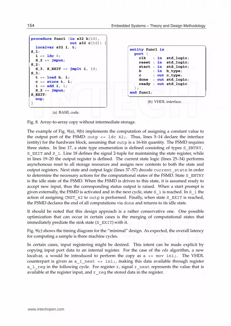
The following example (Fig. 8) illustrates an element-wise copy of array b to c without the use
of a local array resource. Each interface array consists of 10 elements. It should be assumed
that the physical content of both arrays lies in distributed LUT RAM, from which custom
connections can be implemented.
Fig. 8(a) illustrates the corresponding function func1. The VHDL interface of func1 is
shown in Fig. 8(b), where the derived array types b_type and c_type are used for b, c,
respectively. The definitions of these types can be easily devised as aliases to a basic type
denoted as: type cdt_type is array (9 downto 0) of std_logic_vector(31
downto 0);. Then, the alias for b is: alias b_type is cdt_type;
3.2.2 Architecture and organization
The FSMDs are organized as computations allocated into n + 2 states, where n is the number
of required control steps as derived by an operation scheduler. The two overhead states are
the entry (S_ENTRY) and the exit (S_EXIT) states which correspond to the source and sink
nodes of the control-data flow graph of the given procedure, respectively.
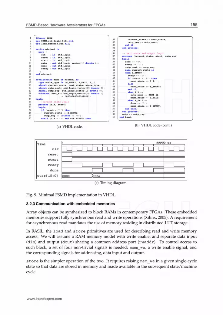
Fig. 9 shows the absolute minimal example of a compliant FSMD written in VHDL. The FSMD
is described in a two-process style using one process for the current state logic and another
process for a combined description of the next state and output logic. This code will serve as
a running example for better explaining the basic concepts of the FSMD paradigm.
153FSMD-Based Hardware Accelerators for FPGAs
www.intechopen.com
12 Will-be-set-by-IN-TECH
✞ ☎procedure func1 (in s32 b[10],
out s32 c[10]) {localvar s32 i, t;
S_1:i <= ldc 0;S_2 <= jmpun;
S_2:S_3, S_EXIT <= jmplt i, 10;
S_3:t <= load b, i;c <= store t, i;i <= add i, 1;S_2 <= jmpun;
S_EXIT:nop;
}✝ �
(a) BASIL code.
✞ ☎entity func1 is
port (clk : in std_logic;reset : in std_logic;start : in std_logic;b : in b_type;c : out c_type;done : out std_logic;ready : out std_logic
);end func1;✝ �
(b) VHDL interface.
Fig. 8. Array-to-array copy without intermediate storage.
The example of Fig. 9(a), 9(b) implements the computation of assigning a constant value to
the output port of the FSMD: outp <= ldc 42;. Thus, lines 5–14 declare the interface
(entity) for the hardware block, assuming that outp is a 16-bit quantity. The FSMD requires
three states. In line 17, a state type enumeration is defined consisting of types S_ENTRY,
S_EXIT and S_1. Line 18 defines the signal 2-tuple for maintaining the state register, while
in lines 19–20 the output register is defined. The current state logic (lines 25–34) performs
asynchonous reset to all storage resources and assigns new contents to both the state and
output registers. Next state and output logic (lines 37–57) decode current_state in order
to determine the necessary actions for the computational states of the FSMD. State S_ENTRY
is the idle state of the FSMD. When the FSMD is driven to this state, it is assumed ready to
accept new input, thus the corresponding status output is raised. When a start prompt is
given externally, the FSMD is activated and in the next cycle, state S_1 is reached. In S_1 the
action of assigning CNST_42 to outp is performed. Finally, when state S_EXIT is reached,
the FSMD declares the end of all computations via done and returns to its idle state.
It should be noted that this design approach is a rather conservative one. One possible
optimization that can occur in certain cases is the merging of computational states that
immediately prediate the sink state (S_EXIT) with it.
Fig. 9(c) shows the timing diagram for the “minimal” design. As expected, the overall latency
for computing a sample is three machine cycles.
In certain cases, input registering might be desired. This intent can be made explicit by
copying input port data to an internal register. For the case of the eda algorithm, a new
localvar, a would be introduced to perform the copy as a <= mov in1;. The VHDL
counterpart is given as a_1_next <= in1;, making this data available through register
a_1_reg in the following cycle. For register r, signal r_next represents the value that is
available at the register input, and r_reg the stored data in the register.
154 Embedded Systems – Theory and Design Methodology
www.intechopen.com
FSMD-Based Hardware Accelerators for FPGAs 13
✞ ☎1 library IEEE;2 use IEEE.std_logic_1164.all;3 use IEEE.numeric_std.all;45 entity minimal is
6 port (7 clk : in std_logic;8 reset : in std_logic;9 start : in std_logic;
10 outp : out std_logic_vector(15 downto 0);11 done : out std_logic;12 ready : out std_logic
13 );14 end minimal;1516 architecture fsmd of minimal is
17 type state_type is (S_ENTRY, S_EXIT, S_1);18 signal current_state, next_state: state_type;19 signal outp_next: std_logic_vector(15 downto 0);20 signal outp_reg: std_logic_vector(15 downto 0);21 constant CNST_42: std_logic_vector(15 downto 0)22 := "0000000000101010";23 begin
24 -- current state logic25 process (clk, reset)26 begin
27 if (reset = ’1’) then
28 current_state <= S_ENTRY;29 outp_reg <= (others => ’0’);30 elsif (clk = ’1’ and clk’EVENT) then
✝ �
(a) VHDL code.
✞ ☎31 current_state <= next_state;32 outp_reg <= outp_next;33 end if;34 end process;3536 -- next state and output logic37 process (current_state, start, outp_reg)38 begin
39 done <= ’0’;40 ready <= ’0’;41 outp_next <= outp_reg;42 case current_state is
43 when S_ENTRY =>44 ready <= ’1’;45 if (start = ’1’) then
46 next_state <= S_1;47 else
48 next_state <= S_ENTRY;49 end if;50 when S_1 =>51 outp_next <= CNST_42;52 next_state <= S_EXIT;53 when S_EXIT =>54 done <= ’1’;55 next_state <= S_ENTRY;56 end case;57 end process;58 outp <= outp_reg;59 end fsmd;
✝ �
(b) VHDL code (cont.)
(c) Timing diagram.
Fig. 9. Minimal FSMD implementation in VHDL.
3.2.3 Communication with embedded memories
Array objects can be synthesized to block RAMs in contemporary FPGAs. These embedded
memories support fully synchronous read and write operations (Xilinx, 2005). A requirement
for asynchronous read mandates the use of memory residing in distributed LUT storage.
In BASIL, the load and store primitives are used for describing read and write memory
access. We will assume a RAM memory model with write enable, and separate data input
(din) and output (dout) sharing a common address port (rwaddr). To control access to
such block, a set of four non-trivial signals is needed: mem_we, a write enable signal, and
the corresponding signals for addressing, data input and output.
store is the simpler operation of the two. It requires raising mem_we in a given single-cycle
state so that data are stored in memory and made available in the subsequent state/machine
cycle.
155FSMD-Based Hardware Accelerators for FPGAs
www.intechopen.com

14 Will-be-set-by-IN-TECH
✞ ☎when STATE_1 =>mem_addr <= index;waitstate_next <= not (waitstate_reg);if (waitstate_reg = ’1’) then
mysignal_next <= mem_dout;next_state <= STATE_2;
else
next_state <= STATE_1;end if;
when STATE_2 =>...
✝ �
Fig. 10. Wait-state-based communication for loading data from a block RAM.
Synchronous load requires the introduction of a waitstate register. This register assists in
devising a dual-cycle state for performing the load. Fig. 10 illustrates the implementation of
a load operation. During the first cycle of STATE_1 the memory block is addressed. In the
second cycle, the requested data are made available through mem_dout and are assigned to
register mysignal. This data can be read from mysignal_reg during STATE_2.
3.2.4 Hierarchical FSMDs
Our extended FSMD concept allows for hierarchical FSMDs defining entire systems with
calling and callee CDFGs. A two-state protocol can be used to describe a proper
communication between such FSMDs. The first state is considered as the “preparation” state
for the communication, while the latter state actually comprises an “evaluation” superstate
where the entire computation applied by the callee FSMD is effectively hidden.
The calling FSMD performs computations where new values are assigned to ⋆_next signals
and registered values are read from ⋆_reg signals. To avoid the problem of multiple signal
drivers, callee procedure instances produce ⋆_eval data outputs that can then be connected
to register inputs by hardwiring to the ⋆_next signal.
Fig. 11 illustrates a procedure call to an integer square root evaluation procedure. This
procedure uses one input and one output std_logic_vector operands, both considered
to represent integer values. Thus, a procedure call of the form (m) <= isqrt(x); is
implemented by the given code segment in Fig. 11.
STATE_1 sets up the callee instance. The following state is a superstate where control is
transferred to the component instance of the callee. When the callee instance terminates its
computation, the ready signal is raised. Since the start signal of the callee is kept low, the
generated output data can be transferred to the m register via its m_next input port. Control
then is handed over to state STATE_3.
The callee instance follows the established FSMD interface, reading x_reg data and
producing an exact integer square root in m_eval. Multiple copies of a given callee are
supported by versioning of the component instances.
156 Embedded Systems – Theory and Design Methodology
www.intechopen.com

FSMD-Based Hardware Accelerators for FPGAs 15
✞ ☎when STATE_1 =>isqrt_start <= ’1’;next_state <= SUPERSTATE_2;
when SUPERSTATE_2 =>if ((isqrt_ready = ’1’) and (isqrt_start = ’0’)) then
m_next <= m_eval;next_state <= STATE_3;
else
next_state <= SUPERSTATE_2;end if;
when STATE_3 =>...isqrt_0 : entity WORK.isqrt(fsmd)port map (
clk, reset,isqrt_start, x_reg, m_eval,isqrt_done, isqrt_ready
);✝ �
Fig. 11. State-superstate-based communication of a caller and callee procedure instance inVHDL.
✞ ☎(B) <= func1 (A);(C) <= func2 (B);(D) <= func3 (C);...
✝ �
Fig. 12. Example of a functional pipeline in BASIL.
3.2.5 Steaming ports
ANSI C is the archetypical example of a general-purpose imperative language that does
not support streaming primitives, i.e. it is not possible for someone to express and
process streams solely based on the semantics of such language. Streaming (e.g. through
queues) suits applications with near-complete absence of control flow. Such example would
be the functional pipeline of the form of Fig. 12 with A, B, C, D either compound types
(arrays/vectors). Control flow in general applications is complex and it is not easy to intermix
streamed and non-streamed inputs/outputs for each FSMD, either calling or callee.
3.2.6 Other issues
3.2.6.1 VHDL packages for implicit fixed-point arithmetic support
The latest approved IEEE 1076 standard (termed VHDL-2008) (IEEE, 2009) adds signed
and unsigned (sfixed, ufixed) fixed-point data types and a set of primitives for their
manipulation. The VHDL fixed-point package provides synthesizable implementations of
fixed-point primitives for arithmetic, scaling and operand resizing (Ashenden & Lewis, 2008).
3.2.6.2 Design organization of an FSMD hardware IP
A proper FSMD hardware IP should seamlessly integrate to a hypothetical system. FSMD IPs
would be viewed as black boxes adhering to certain principles such as registered outputs.
157FSMD-Based Hardware Accelerators for FPGAs
www.intechopen.com

16 Will-be-set-by-IN-TECH
✞ ☎globalvar B [...]=...;...() <= func1 (A);() <= func2 ();() <= func3 ();
✝ �
Fig. 13. The functional pipeline of Fig. 12 after argument globalization.
Unconstrained vectors help in maintaining generic blocks without the need of explicit
generics, and it is an interesting idea, however not easily applicable when derived types are
involved.
The outer product of two vectors A and B could be a theoretical case for a hardware block. The
outer (or “cross”) product is given by C = A × B or C = cross(A, B) for reading two matrices
A, B to calculate C. Matrices A, B, C will have appropriate derived types that are declared in
the cross_pkg.vhd package; a prerequisite for using the cross.vhd design file.
Regarding the block internals, the cross product of A, B is calculated and stored in a localvar
array called Clocal. Clocal is then copied (possibly in parallel) to the C interface array with
the help of a for-generate construct.
3.2.6.3 High-level optimizations relevant to hardware block development
Very important optimizations for increasing the efficiency of system-level communication are
matrix flattening and argument globalization. The latter optimization is related to choices at
the hardware interconnect level.
Matrix flattening deals with reducing the dimensions of an array from N to one. This
optimization creates multiple benefits:
• addressing simplification
• direct mapping to physical memory (where addressing is naturally single-dimensional)
• interface and communication simplifications
Argument globalization is useful for replacing multiple copies of a given array by a
single-access “globalvar” array. One important benefit is the prevention of exhausting
interconnect resources. This optimization is feasible for single-threaded applications. For
the example in Fig. 12 we assume that all changes can be applied sequentially on the B array,
and that all original data are stored in A.
The aforementioned optimization would rapidly increase the number of “globalvar” arrays.
A “safe” but conservative approach would apply a restriction on “globalvar” access, allowing
access to globals only by the root procedure of the call graph. This can be overcome by
the development of a bus-based hardware interface for “globalvar” arrays making globals
accessible by any procedure.
3.2.6.4 Low-level optimizations relevant to hardware block development
A significant low-level optimization that can boost performance while operating locally
at the basic block level is operation chaining. A scheduler supporting this optimization
158 Embedded Systems – Theory and Design Methodology
www.intechopen.com

FSMD-Based Hardware Accelerators for FPGAs 17
would assign to a single control step, multiple operations that are associated through
data dependencies. Operation chaining is popular for deriving custom instructions or
superinstructions that can be added to processor cores as instruction-set extensions (Pozzi
et al., 2006). Most techniques require a form of graph partitioning based on certain criteria
such as the maximum acceptable path delay.
A hardware developer could resort in a simpler means for selective operation chaining by
merging ASAP states to compound states. This optimization is only possible when a single
definition site is used per variable (thus SSA form is mandatory). Then, an intermediate
register is eliminated by assigning to a ⋆_next signal and reusing this value in the subsequent
chained computation, instead of reading from the stored ⋆_reg value.
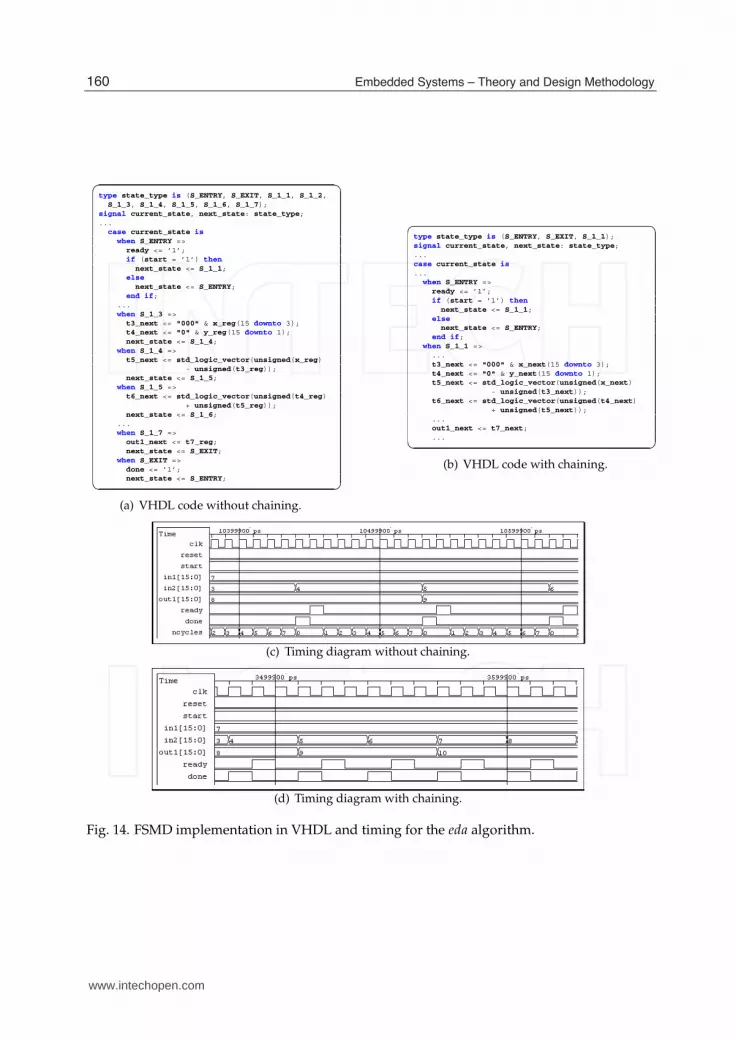
3.3 Hardware design of the 2D Euclidean distance approximation
The eda algorithm shows good potential for speedup via operation chaining. Without this
optimization, 7 cycles are required for computing the approximation, while chaining allows
to squeeze all computational states into one; thus three cycles are needed to complete the
operation. Fig. 14 depicts VHDL code segments for an ASAP schedule with chaining disabled
(Fig. 14(a)) and enabled (Fig. 14(b)). Figures 14(c) and 14(d) show cycle timings for the relevant
I/O signals for both cases.
4. Non-trivial examples
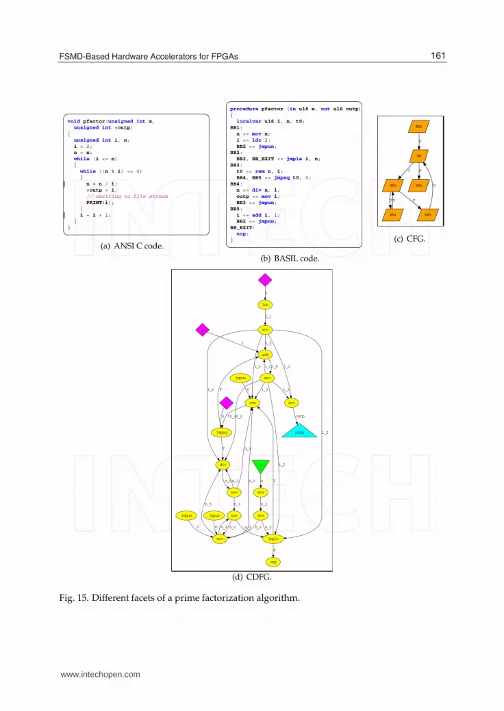
4.1 Integer factorization
The prime factorization algorithm (p f actor) is a paramount example of the use of streaming
outputs. Output outp is streaming and the data stemming from this port should be accessed
based on the valid status. The reader can observe that outp is accessed periodically in
context of basic block BB3 as shown in Fig. 15(b).
Fig. 15 shows the four relevant facets of p f actor: ANSI C code (Fig. 15(a)), a manually
derived BASIL implementation (Fig. 15(b)) and the corresponding CFG (Fig. 15(c)) and CDFG
(Fig. 15(d)) views.
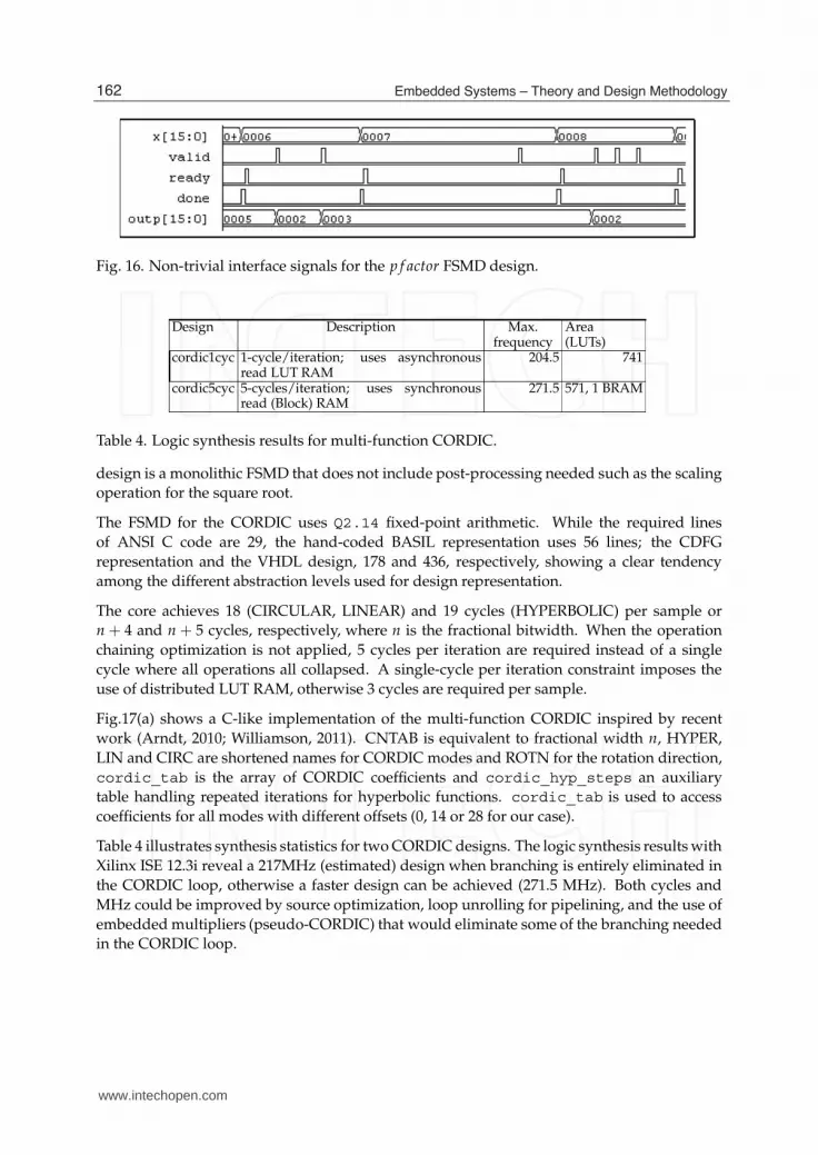
Fig. 16 shows the interface signals for factoring values 6 (a composite), 7 (a prime), and 8 (a
composite which is also a power-of-2).
4.2 Multi-function CORDIC
This example illustrates a universal CORDIC IP core supporting all directions (ROTATION,
VECTORING) and modes (CIRCULAR, LINEAR, HYPERBOLIC) (Andraka, 1998; Volder,
1959). The input/ouput interface is similar to e.g. the CORDIC IP generated by Xilinx
Core Generator (Xilinx, 2011a). It provides three data inputs (xin, yin, zin) and three data
outputs (xout, yout, zout) as well as the direction and mode control inputs. The testbench will
test the core for computing cos (xin), sin (yin), arctan(yin/xin), yin/xin ,√
w, 1/√
w, with
xin = w + 1/4, yin = w − 1/4, but it can be used for anything computable by CORDIC
iterations. The computation of 1/√
w is performed in two stages: a) y = 1/w, b) z =√
y. The
159FSMD-Based Hardware Accelerators for FPGAs
www.intechopen.com
18 Will-be-set-by-IN-TECH
✞ ☎type state_type is (S_ENTRY, S_EXIT, S_1_1, S_1_2,
S_1_3, S_1_4, S_1_5, S_1_6, S_1_7);signal current_state, next_state: state_type;...
case current_state is
when S_ENTRY =>ready <= ’1’;if (start = ’1’) then
next_state <= S_1_1;else
next_state <= S_ENTRY;end if;
...when S_1_3 =>
t3_next <= "000" & x_reg(15 downto 3);t4_next <= "0" & y_reg(15 downto 1);next_state <= S_1_4;
when S_1_4 =>t5_next <= std_logic_vector(unsigned(x_reg)
- unsigned(t3_reg));next_state <= S_1_5;
when S_1_5 =>t6_next <= std_logic_vector(unsigned(t4_reg)
+ unsigned(t5_reg));next_state <= S_1_6;
...when S_1_7 =>
out1_next <= t7_reg;next_state <= S_EXIT;
when S_EXIT =>done <= ’1’;next_state <= S_ENTRY;
✝ �
(a) VHDL code without chaining.
✞ ☎type state_type is (S_ENTRY, S_EXIT, S_1_1);signal current_state, next_state: state_type;...case current_state is
...when S_ENTRY =>
ready <= ’1’;if (start = ’1’) then
next_state <= S_1_1;else
next_state <= S_ENTRY;end if;
when S_1_1 =>...t3_next <= "000" & x_next(15 downto 3);t4_next <= "0" & y_next(15 downto 1);t5_next <= std_logic_vector(unsigned(x_next)
- unsigned(t3_next));t6_next <= std_logic_vector(unsigned(t4_next)
+ unsigned(t5_next));...out1_next <= t7_next;...
✝ �
(b) VHDL code with chaining.
(c) Timing diagram without chaining.
(d) Timing diagram with chaining.
Fig. 14. FSMD implementation in VHDL and timing for the eda algorithm.
160 Embedded Systems – Theory and Design Methodology
www.intechopen.com
FSMD-Based Hardware Accelerators for FPGAs 19
✞ ☎void pfactor(unsigned int x,
unsigned int *outp){
unsigned int i, n;i = 2;n = x;while (i <= n){
while ((n % i) == 0){
n = n / i;
*outp = i;// emitting to file streamPRINT(i);
}i = i + 1;
}}✝ �
(a) ANSI C code.
✞ ☎procedure pfactor (in u16 x, out u16 outp){
localvar u16 i, n, t0;BB1:
n <= mov x;i <= ldc 2;BB2 <= jmpun;
BB2:BB3, BB_EXIT <= jmple i, n;
BB3:t0 <= rem n, i;BB4, BB5 <= jmpeq t0, 0;
BB4:n <= div n, i;outp <= mov i;BB3 <= jmpun;
BB5:i <= add i, 1;BB2 <= jmpun;
BB_EXIT:nop;
}✝ �
(b) BASIL code.
BB1
BB
U
BB3
T
BB6
F
BB4
T
BB5
FU
U
(c) CFG.
add
mov
i_6
0
jmpeq
0
1
1
2
ldc
2
div
mov
n_5
F
T
jmple
nop
F
rem
T
jmpun
U
jmpun
mov
U
jmpun
U
mov
i_1
mov
mov
n_1
mov
outp
outp
n_3
mov
n_3
n_3
i_2
i_2
i_2
i_2i_2
i_2
i_2
i_2
i_2i_2
n_2n_2
n_3
n_3
n_3
n_2n_2
t0_4
x
x
(d) CDFG.
Fig. 15. Different facets of a prime factorization algorithm.
161FSMD-Based Hardware Accelerators for FPGAs
www.intechopen.com
20 Will-be-set-by-IN-TECH
Fig. 16. Non-trivial interface signals for the p f actor FSMD design.
Design Description Max.frequency
Area(LUTs)
cordic1cyc 1-cycle/iteration; uses asynchronousread LUT RAM
204.5 741
cordic5cyc 5-cycles/iteration; uses synchronousread (Block) RAM
271.5 571, 1 BRAM
Table 4. Logic synthesis results for multi-function CORDIC.
design is a monolithic FSMD that does not include post-processing needed such as the scaling
operation for the square root.
The FSMD for the CORDIC uses Q2.14 fixed-point arithmetic. While the required lines
of ANSI C code are 29, the hand-coded BASIL representation uses 56 lines; the CDFG
representation and the VHDL design, 178 and 436, respectively, showing a clear tendency
among the different abstraction levels used for design representation.
The core achieves 18 (CIRCULAR, LINEAR) and 19 cycles (HYPERBOLIC) per sample or
n + 4 and n + 5 cycles, respectively, where n is the fractional bitwidth. When the operation
chaining optimization is not applied, 5 cycles per iteration are required instead of a single
cycle where all operations all collapsed. A single-cycle per iteration constraint imposes the
use of distributed LUT RAM, otherwise 3 cycles are required per sample.
Fig.17(a) shows a C-like implementation of the multi-function CORDIC inspired by recent
work (Arndt, 2010; Williamson, 2011). CNTAB is equivalent to fractional width n, HYPER,
LIN and CIRC are shortened names for CORDIC modes and ROTN for the rotation direction,
cordic_tab is the array of CORDIC coefficients and cordic_hyp_steps an auxiliary
table handling repeated iterations for hyperbolic functions. cordic_tab is used to access
coefficients for all modes with different offsets (0, 14 or 28 for our case).
Table 4 illustrates synthesis statistics for two CORDIC designs. The logic synthesis results with
Xilinx ISE 12.3i reveal a 217MHz (estimated) design when branching is entirely eliminated in
the CORDIC loop, otherwise a faster design can be achieved (271.5 MHz). Both cycles and
MHz could be improved by source optimization, loop unrolling for pipelining, and the use of
embedded multipliers (pseudo-CORDIC) that would eliminate some of the branching needed
in the CORDIC loop.
162 Embedded Systems – Theory and Design Methodology
www.intechopen.com

FSMD-Based Hardware Accelerators for FPGAs 21
✞ ☎void cordic(dir, mode, xin, yin, zin, *xout, *yout, *zout) {
...x = xin; y = yin; z = zin;offset = ((mode == HYPER) ? 0 : ((mode == LIN) ? 14 : 28));kfinal = ((mode != HYPER) ? CNTAB : CNTAB+1);for (k = 0; k < kfinal; k++) {
d = ((dir == ROTN) ? ((z>=0) ? 0 : 1) : ((y<0) ? 0 : 1));kk = ((mode != HYPER) ? k :
cordic_hyp_steps[k]);xbyk = (x>>kk);ybyk = ((mode == HYPER) ? -(y>>kk) : ((mode == LIN) ? 0 :
(y>>kk)));tabval = cordic_tab[kk+offset];x1 = x - ybyk; x2 = x + ybyk;y1 = y + xbyk; y2 = y - xbyk;z1 = z - tabval; z2 = z + tabval;x = ((d == 0) ? x1 : x2);y = ((d == 0) ? y1 : y2);z = ((d == 0) ? z1 : z2);}
*xout = x; *yout = y; *zout = z;}✝ �
(a) C-like code.
✞ ☎process (*)begin
...case current_state is ...when S_3 =>
t1_next <= cordic_hyp_steps(to_integer(unsigned(k_reg(3 downto 0))));
if (mode /= CNST_2) then
kk_next <= k_reg;else
kk_next <= t1_next;end if;t2_next <= shr(y_reg, kk_next, ’1’);...x1_next <= x_reg - ybyk_next;y1_next <= y_reg + xbyk_next;z1_next <= z_reg - tabval_next;
...when S_4 =>
xout_next <= x_5_reg;yout_next <= y_5_reg;zout_next <= z_5_reg;next_state <= S_EXIT;
...end process;zout <= zout_reg;yout <= yout_reg;xout <= xout_reg;
✝ �
(b) Partial VHDL code.
Fig. 17. Multi-function CORDIC listings.
163FSMD-Based Hardware Accelerators for FPGAs
www.intechopen.com

22 Will-be-set-by-IN-TECH
5. Conclusion
In this chapter, a straightforward FSMD-style model of computation was introduced that
augments existing approaches. Our FSMD concept supports inter-FSMD communication,
embedded memories, streaming outputs, and seamless integration of user IPs/black boxes.
To raise the level of design abstraction, the BASIL typed assembly language is introduced
which can be used for capturing the user’s intend. We show that it is possible to convert this
intermediate representation to self-contained CDFGs and finally to provide an easier path for
designing a synthesizable VHDL implementation.
Along the course of this chapter, representative examples were used to illustrate the key
concepts of our approach such as a prime factorization algorithm and an improved FSMD
design of a multi-function CORDIC.
6. References
Andraka, R. (1998). A survey of CORDIC algorithms for FPGA based computers, 1998
ACM/SIGDA sixth international symposium on Field programmable gate arrays, Monterey,
CA, USA, pp. 191–200.
Appel, A. W. (1998). SSA is functional programming, ACM SIGPLAN Notices 33(4): 17–20.
URL: http://doi.acm.org/10.1145/278283.278285
Arndt, J. (2010). Matters Computational: Ideas, Algorithms, Source Code, Springer.
URL: http://www.jjj.de/fxt/
Ashenden, P. J. & Lewis, J. (2008). VHDL-2008: Just the New Stuff, Elsevier/Morgan Kaufmann
Publishers.
Aycock, J. & Horspool, N. (2000). Simple generation of static single assignment form,
Proceedings of the 9th International Conference in Compiler Construction, Vol. 1781 of
Lecture Notes in Computer Science, Springer, pp. 110–125.
URL: http://citeseer.ist.psu.edu/aycock00simple.html
Bishop, D. (2010a). Fixed point package user’s guide.
URL: http://www.eda.org/fphdl/fixed_ug.pdf
Bishop, D. (2010b). VHDL-2008 support library.
URL: http://www.eda.org/fphdl/
Chu, P. P. (2006). RTL Hardware Design Using VHDL: Coding for Efficiency, Portability, and
Scalability, Wiley-IEEE Press.
clang homepage (2011).
URL: http://clang.llvm.org
COINS (2011).
URL: http://www.coins-project.org
CoSy, A. (2011). ACE homepage.
URL: http://www.ace.nl
Coussy, P. & Morawiec, A. (eds) (2008). High-Level Synthesis: From Algorithm to Digital Circuits,
Springer.
Cytron, R., Ferrante, J., Rosen, B. K., Wegman, M. N. & Zadeck, F. K. (1991). Efficiently
computing static single assignment form and the control dependence graph, ACM
Transactions on Programming Languages and Systems 13(4): 451–490.
URL: http://doi.acm.org/10.1145/115372.115320
164 Embedded Systems – Theory and Design Methodology
www.intechopen.com

FSMD-Based Hardware Accelerators for FPGAs 23
Edwards, S. A. (2006). Using program specialization to speed SystemC fixed-point simulation,
Proceedings of the Workshop on Partial Evaluation and Progra Manipulation (PEPM),
Charleston, South Carolina, USA, pp. 21–28.
Gajski, D. D., Abdi, S., Gerstlauer, A. & Schirner, G. (2009). Embedded System Design: Modeling,
Synthesis and Verification, Springer.
Gajski, D. D. & Ramachandran, L. (1994). Introduction to high-level synthesis, IEEE Design &
Test of Computers 11(1): 44–54.
GCC (2011). The GNU compiler collection homepage.
URL: http://gcc.gnu.org
Gonzalez, R. (2000). Xtensa: A configurable and extensible processor, IEEE Micro 20(2): 60–70.
Graphviz (2011).
URL: http://www.graphviz.org
IEEE (2006). IEEE 1364-2005, IEEE Standard for Verilog Hardware Description Language.
IEEE (2009). IEEE 1076-2008 Standard VHDL Language Reference Manual.
ISO/IEC JTC1/SC22 (2007). ISO/IEC 9899:TC3 International Standard (Programming Language:
C), Committee Draft.
URL: http://www.open-std.org/jtc1/sc22/WG14/www/docs/n1256.pdf
ITRS (2011). International technology roadmap for semiconductors.
URL: http://www.itrs.net/reports.html
Keating, M. & Bricaud, P. (2002). Reuse Methodology Manual for System-on-a-Chip Designs, third
edition edn, Springer-Verlag. 2nd printing.
Knuth, D. E. (2011). Art of Computer Programming: Combinatorial Algorithms, number pt. 1 in
Addison-Wesley Series in Computer Science, Addison Wesley Professional.
LANCE (2011). LANCE retargetable C compiler.
URL: http://www.lancecompiler.com
Leupers, R., Wahlen, O., Hohenauer, M., Kogel, T. & Marwedel, P. (2003). An Executable
Intermediate Representation for Retargetable Compilation and High-Level Code
Optimization, Int. Conf. on Inf. Comm. Tech. in Education.
LLVM (2011).
URL: http://llvm.org
Machine-SUIF (2002).
URL: http://www.eecs.harvard.edu/hube/software/
Marsaglia, G. (2003). Xorshift RNGs, Journal of Statistical Software 8(14).
Mentor Graphics (2011). Algorithmic C data types.
URL: http://www.mentor.com/esl/catapult/algorithmic
Microsoft (2008). Phoenix compiler framework.
URL: http://connect.microsoft.com/Phoenix
Pozzi, L., Atasu, K. & Ienne, P. (2006). Exact and approximate algorithms for the extension of
embedded processor instruction sets, IEEE Transactions on CAD of Integrated Circuits
and Systems 25(7): 1209–1229.
SystemC (2006). IEEE 1666™-2005: Open SystemC Language Reference Manual.
Turkowski, K. (1995). Graphics gems v, Academic Press Professional, Inc., San Diego, CA,
USA, chapter Fixed-point square root, pp. 22–24.
Volder, J. E. (1959). The CORDIC Trigonometric Computing Technique, IRE Transactions on
Electronic Computers EC-8: 330–334.
165FSMD-Based Hardware Accelerators for FPGAs
www.intechopen.com

24 Will-be-set-by-IN-TECH
Williamson, J. (2011). Simple C code for fixed-point CORDIC.
URL: http://www.dcs.gla.ac.uk/ jhw/cordic/
Wirth, N. (1998). Hardware compilation: Translating programs into circuits, IEEE Computer
31(6): 25–31.
Xilinx (2005). Spartan-3 FPGA Family Using Block Spartan-3 Generation FPGAs (v2.0).
Xilinx (2011a). CORDIC v4.0 - Product Specifications, XILINX LogiCORE, DS249 (vl.5).
Xilinx (2011b). Xilinx.
URL: http://www.xilinx.com
Yates, R. (2009). Fixed-point arithmetic: An introduction, Technical reference, Digital Signal
Labs.
166 Embedded Systems – Theory and Design Methodology
www.intechopen.com

Embedded Systems - Theory and Design MethodologyEdited by Dr. Kiyofumi Tanaka
ISBN 978-953-51-0167-3Hard cover, 430 pagesPublisher InTechPublished online 02, March, 2012Published in print edition March, 2012
InTech EuropeUniversity Campus STeP Ri Slavka Krautzeka 83/A 51000 Rijeka, Croatia Phone: +385 (51) 770 447 Fax: +385 (51) 686 166www.intechopen.com
InTech ChinaUnit 405, Office Block, Hotel Equatorial Shanghai No.65, Yan An Road (West), Shanghai, 200040, China
Phone: +86-21-62489820 Fax: +86-21-62489821
Nowadays, embedded systems - the computer systems that are embedded in various kinds of devices andplay an important role of specific control functions, have permitted various aspects of industry. Therefore, wecan hardly discuss our life and society from now onwards without referring to embedded systems. For wide-ranging embedded systems to continue their growth, a number of high-quality fundamental and appliedresearches are indispensable. This book contains 19 excellent chapters and addresses a wide spectrum ofresearch topics on embedded systems, including basic researches, theoretical studies, and practical work.Embedded systems can be made only after fusing miscellaneous technologies together. Various technologiescondensed in this book will be helpful to researchers and engineers around the world.
How to referenceIn order to correctly reference this scholarly work, feel free to copy and paste the following:
Nikolaos Kavvadias, Vasiliki Giannakopoulou and Kostas Masselos (2012). FSMD-Based HardwareAccelerators for FPGAs, Embedded Systems - Theory and Design Methodology, Dr. Kiyofumi Tanaka (Ed.),ISBN: 978-953-51-0167-3, InTech, Available from: http://www.intechopen.com/books/embedded-systems-theory-and-design-methodology/fsmd-based-hardware-accelerators-for-fpgas