from multi-body to many-body dynamics
TRANSCRIPT
This item was submitted to Loughborough’s Institutional Repository (https://dspace.lboro.ac.uk/) by the author and is made available under the
following Creative Commons Licence conditions.
For the full text of this licence, please go to: http://creativecommons.org/licenses/by-nc-nd/2.5/
815
Tribology of compression ring-to-cylindercontact at reversalP C Mishra, S Balakrishnan, and H Rahnejat∗
Wolfson School of Mechanical and Manufacturing Engineering, University of Loughborough, Loughborough,Leicestershire, UK
The manuscript was received on 16 January 2008 and was accepted after revision for publication on 28 April 2008.
DOI: 10.1243/13506501JET410
Abstract: Piston ring-pack-to-cylinder contact accounts for one of the major sources of frictionallosses in internal combustion engines. The regime of lubrication alters during the piston cyclebecause of the transient nature of applied load and kinematic contact conditions. Ring geometry,surface topography, and lubricant rheology also play an important role. The aim is to attainfull fluid film lubrication, thus reducing friction because of boundary interactions. Therefore,accurate prediction of lubricant film thickness and pressure distribution constitutes the firststep in a proper analysis of piston ring–cylinder conjunction. The creation of a gap throughelastic deformation is sought in order to inhibit asperity tip interactions. The generated contactpressures in the lubricant film are due to combined entraining motion and squeeze film effect.The integrated pressure distribution balances the elastic force due to ring tension and the appliedcombustion pressure acting behind the ring. The article highlights a detailed analysis, whichforms the basis for its future expansion to include the study of mixed regime of lubrication,which may be prevalent in some real engines.
Keywords: piston ring, ring deformation, lubrication
1 INTRODUCTION
The contact conjunction between the piston compres-sion ring and the cylinder exhibits a range of lubrica-tion regimes through the engine cycle, from mixed tohydrodynamic and onto elastohydrodynamic (EHD).Although during most part of the engine cycle the ringruns under hydrodynamic or mixed regime of lubrica-tion, EHD conditions may also occur during the powerstroke and at maximum combustion pressure. Thisusually occurs a few degrees past the top dead centre(TDC). From the tribological viewpoint, it is clear thatthe lubricant film thickness in this conjunction is oneof the governing parameters of engine performancebecause of its significant share of frictional losses.Under transient conditions, film thickness shows alarge variation and hence needs careful investiga-tion. Frictional losses in this conjunction are affected
∗Corresponding author: Wolfson School of Mechanical and Manu-
facturing Engineering, University of Loughborough, Loughbor-
ough, Leicestershire LE11 3TU, UK. email: [email protected]
by inertial dynamics and modal behaviour (globaldeformation) of the ring, which are influenced by itsmaterial of construction, ring tension, and the appliedgas pressure.Thus, the frictional behaviour of the com-pression ring is often a determining factor, limitingengine performance through its contact load carryingcapacity.
For an incomplete circular ring of small cross-section, the basic classical equation of motion wasfirst derived by Love [1]. He assumed an undeformedcentral radial axis in order to evaluate the global defor-mation of an incomplete circular ring in terms of ringtension, flexural rigidity, and an applied shear force.The incomplete circular ring was considered with dif-ferent types of applied normal loads such as that fora slightly bent ring with an applied couple at its freeends in the radial plane. Other studies included thering ends being subjected to opposing tension, as wellas a couple applied at its ends perpendicular to theplane of the ring. Through these analyses, Love [1]obtained various modal frequencies for an incompletecircular ring, using the previous work of Mayer [2] andTimoshenko [3].
JET410 © IMechE 2008 Proc. IMechE Vol. 222 Part J: J. Engineering Tribology
816 P C Mishra, S Balakrishnan, and H Rahnejat
A study of flexural vibration of a curved beam inthe form of an arc of a circle was carried out by Lamb[4] through theoretical interpretation. He proposedan in-plane vibration model about the neutral axisof the ring in the radial direction. A general equationand terminal conditions were established, and thesimple statistical problem was solved for vibration ofa free–free bar.
The global deformation of the ring follows its vari-ous mode shapes, generally referred to as its in-planeand out-of-plane modes, described by Tian [5]. Amongthese, there are several important ring characteris-tics, which affect lubrication between the ring andthe cylinder. These include the degree of deformedring conformance to the cylinder geometry, as wellas ring twist and flutter. Tian [6] describes ring flut-ter and its effect on gas flow and oil transport, whichcan also have additional untoward effects in additionto the frictional losses. The analysis conducted by Tian[6] for a heavy duty diesel engine has shown the impor-tance of ring–cylinder interactions for friction, wear,and oil consumption. A pure twist of an incompletecircular ring with a non-isotropic hollow cross-sectionusing the method of toroidal elasticity was carried outby Lang [7]. Archer [8] also investigated small vibra-tions of a thin incomplete circular ring with a smallcross-section, using the classical equations of motion.In this analysis, natural frequency and modes werefound for rings with clamped ends. Vibrations wereconsidered to occur in the radial plane of the ring, thisbeing confined to its extensional mode.
The study of coupled twist-bending vibration ofan incomplete elastic ring, using three-dimensionallinear motion with generalized loading and viscousdamping through the usual classical beam theory,was carried out by Ojalvo [9]. The equations ofmotion were solved for coupled out-of-plane bend-ing and twisting dynamics. Results were generatedfor an incomplete circular ring, clamped at bothends. This study was a combination of the work ofLove [1] and Archer [8], providing three-dimensionallinear ring dynamics. Good agreement was shownwith the approximate analysis reported by Den Har-tog [10] and also by Brown [11]. Den Hartog [10]found the lowest natural frequency of a circular arc,which was clamped or hinged at its ends, using theRayleigh–Ritz energy method. Both extensional andin-extensional vibrations were investigated in orderto obtain the first- and second-natural frequencies.Brown’s [11] investigation was concerned with thelateral vibration of a ring-shaped frame and its nat-ural frequencies. Combined flexural and torsionalvibrations perpendicular to the plane of the ringwere investigated. The solution was an approximation,based on modifications made to the Rayleigh’s energymethod.
Okamoto and Sakai [12] estimated the contactpressure distribution of piston rings on the basis ofring shape, implementing the governing equation forcurved beams. This involved initially measuring thepiston ring-free contour and then calculating the con-tact pressure distribution on the ring circumference.Dunaevsky et al. [13] studied the three-dimensionaldistortion of a piston ring with an arbitrary cross-section in their study of oil flow and blow-by. It wasnoted that the three-dimensional distortion of thering is either caused by installation stresses or oper-ational parameters such as the gas pressure, inducedfriction, and thermal loads. Their model was appliedto several typical cross-sections. A three-dimensionaltheory for piston ring installation and global distor-tion was then developed. The aim was to achieve goodpiston ring-to-cylinder liner conformance, taking intoaccount the ring’s physical and geometrical attributes.However, most analyses described thus far assume nobore distortion. In practice, significant thermo-elasticbore distortion may occur. This requires ring–boreconformability analysis to be carried out in additionto the methods highlighted above. Dunaevsky [14]and Chittenden and Priest [15] have carried out suchanalyses.
There have been many attempts to predict pistonring-to-cylinder bore or liner tribological perfor-mance, based on pressure-induced localized deforma-tion, caused by EHD. Dowson et al. [16] carried outEHD lubrication analysis of the piston ring. Ruddyet al. [17] investigated the gas pressure within thering pack for a large bore diesel engine, with theobjective of overcoming the technical problems inher-ent in sealing a moving piston. It was noted thatthe ring gap could account for the gas leakage path,which is clearly as a result of combined local andglobal deformations of the ring. Knoll and Peeken[18] modelled the hydrodynamic lubrication of pis-ton skirt and cylinder liner conjunction through aniterative method, using open end boundary conditionto estimate the reaction force due to the generatedpressures. Ma et al. [19] performed analysis of lubri-cation and friction for a complete piston ring packwith an improved oil availability model. A piston ringfriction and lubrication model, capable of analysingasymmetric conditions, was developed to describe rel-ative ring location, oil accumulation, and mixed andboundary lubrication in a ring-pack. Balakrishnan andRahnejat [20] studied the transient conditions in thecontact of piston skirt and ring-pack against cylin-der liners during piston reversal. Their study showedchanges in the regime of lubrication during reversalat or near the TDC. They also showed that fluid filmlubrication can be encouraged by the introduction oflubricant retaining surface features. Their model onlytook into account local deformation of the contact
Proc. IMechE Vol. 222 Part J: J. Engineering Tribology JET410 © IMechE 2008
Tribology of compression ring-to-cylinder contact at reversal 817
caused by generated EHD pressures. The ring modelwas extended to include roughness and surface-modified features on the ring by Teodorescu et al. [21],who showed an enhanced lubricant film thicknessfor rough contacts. Experimental validation of thepredictions was undertaken by measuring film in afired engine using an ultrasonic method, as reportedby Dwyer-Joyce et al. [22]. This showed remarkableagreement with the results of Rahnejat et al. [23],but only for the piston-skirt-to-cylinder liner contactas the sensing head was larger than that requiredto resolve necessary measurements from the com-pression ring conjunction. Furthermore, the modelspresented in references [20] and [23] do not take intoaccount the effect of global deformation of the ringunder transient conditions.
It is therefore clear that a detailed lubrication modelis necessary to include combined local and globaldeformations of the ring. This paper describes suchan initial model, which combines EHD condition within-plane deformation of the ring under isothermalcondition. This is regarded as a necessary step towardsthe creation of a compression ring-specific model,which should then be extended to include roughnessand thermal effects.
2 THEORY
2.1 Elastic force due to ring global radialdeformation
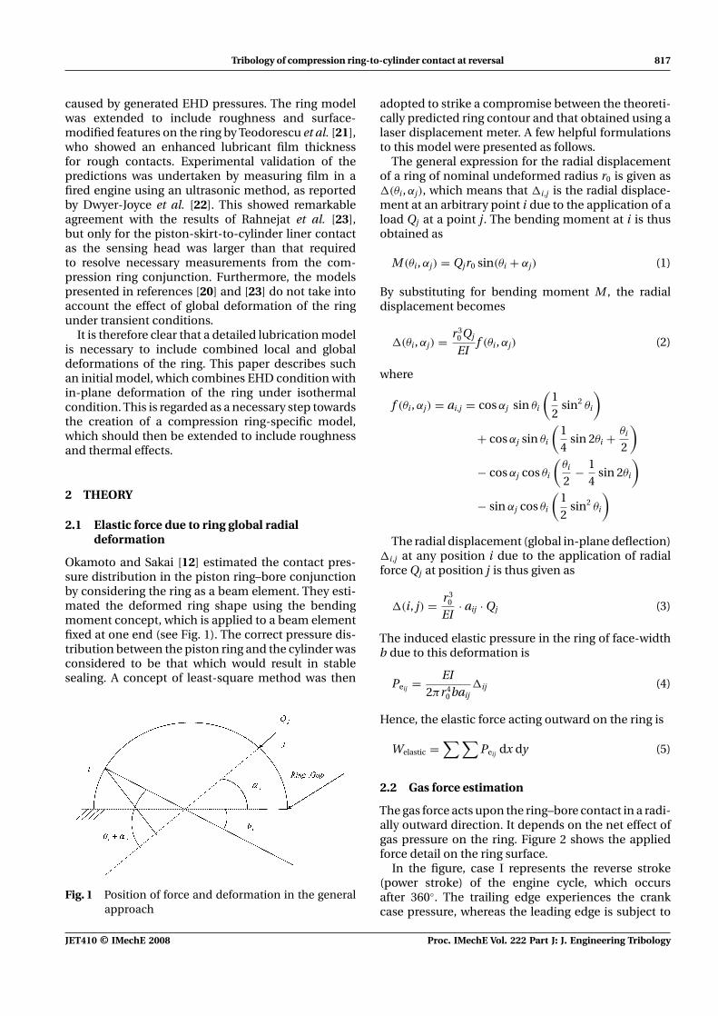
Okamoto and Sakai [12] estimated the contact pres-sure distribution in the piston ring–bore conjunctionby considering the ring as a beam element. They esti-mated the deformed ring shape using the bendingmoment concept, which is applied to a beam elementfixed at one end (see Fig. 1). The correct pressure dis-tribution between the piston ring and the cylinder wasconsidered to be that which would result in stablesealing. A concept of least-square method was then
Fig. 1 Position of force and deformation in the generalapproach
adopted to strike a compromise between the theoreti-cally predicted ring contour and that obtained using alaser displacement meter. A few helpful formulationsto this model were presented as follows.
The general expression for the radial displacementof a ring of nominal undeformed radius r0 is given as�(θi, αj), which means that �i,j is the radial displace-ment at an arbitrary point i due to the application of aload Qj at a point j. The bending moment at i is thusobtained as
M (θi, αj) = Qjr0 sin(θi + αj) (1)
By substituting for bending moment M , the radialdisplacement becomes
�(θi, αj) = r30 Qj
EIf (θi, αj) (2)
where
f (θi, αj) = ai,j = cos αj sin θi
(12
sin2 θi
)
+ cos αj sin θi
(14
sin 2θi + θi
2
)
− cos αj cos θi
(θi
2− 1
4sin 2θi
)
− sin αj cos θi
(12
sin2 θi
)
The radial displacement (global in-plane deflection)�i,j at any position i due to the application of radialforce Qj at position j is thus given as
�(i, j) = r30
EI· aij · Qj (3)
The induced elastic pressure in the ring of face-widthb due to this deformation is
Peij = EI2πr4
0 baij�ij (4)
Hence, the elastic force acting outward on the ring is
Welastic =∑ ∑
Peij dx dy (5)
2.2 Gas force estimation
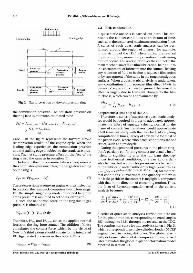
The gas force acts upon the ring–bore contact in a radi-ally outward direction. It depends on the net effect ofgas pressure on the ring. Figure 2 shows the appliedforce detail on the ring surface.
In the figure, case I represents the reverse stroke(power stroke) of the engine cycle, which occursafter 360◦. The trailing edge experiences the crankcase pressure, whereas the leading edge is subject to
JET410 © IMechE 2008 Proc. IMechE Vol. 222 Part J: J. Engineering Tribology
818 P C Mishra, S Balakrishnan, and H Rahnejat
Fig. 2 Gas force action on the compression ring
the combustion pressure. The net static pressure onthe ring face is, therefore, estimated to be
Psf = Pcrank_case + (Pgcombustion − Pcrank_case)
× xinlet + xcavitation
2b(6)
Case II in the figure represents the forward stroke(compression stroke) of the engine cycle, when theleading edge experiences the combustion pressureand the trailing edge is subject to the crank case pres-sure. The net static pressure effect on the face of thering is also the same as in equation (6).
The back of the ring is assumed always to experiencethe combustion pressure.Thus, the net gas force actingon the ring is
Pgas = (Pging_back − Psf ) (7)
These expressions assume an engine with a single ring.In practice, the ring-pack comprises two to four rings.For the simple single ring model described here, thecrank pressure is assumed to act on its lower side.
Hence, the net normal force on the ring due to gaspressure is obtained as
Wgas =∑ ∑
Pgas dx dy (8)
Therefore, Wgas and Welastic act as the applied normalforces on the ring–bore contact. The addition of theseconstitutes the contact force, which by the virtue ofNewton’s third axiom should equate to the integratedEHD-generated pressures in the contact. Thus
Wcontact = Wgas + Welastic (9)
2.3 EHD conjunction
A quasi-static analysis is carried out here. This rep-resents the contact conditions at an instant of time,such as at the instance of maximum combustion force.A series of such quasi-static analyses can be per-formed around the region of interest, for example,in the vicinity of the TDC, where during the reversalin piston motion, momentary cessation of entrainingmotion occurs. The reversal deprives the contact of themain mechanism of fluid film lubrication, being due tothe entrainment of lubricant into the contact, leavingany retention of fluid to be due to squeeze film actionor by entrapment of the same in the rough contiguoussurfaces. When a quasi-static analysis is undertaken,any contribution from squeeze film effect ∂h/∂t inReynolds’ equation is usually ignored, because thiseffect is largely due to transient changes to the filmthickness, which can be approximated by
∂hi,j
∂t≈ 1
�t(hi,j(n) − hi,j(n−1)) (10)
n represents a time step of size �t .Therefore, a series of successive quasi-static analy-
ses would be required in order to adequately approx-imate the effect of squeeze velocity, normal to theplane of contact. Such analyses would approximatea full transient study with the drawback of very longcomputational times, largely of little value for most ofthe piston cycle, where tribological conditions are notcritical such as at midcycle.
Noting that generated pressures in the piston ring–bore’s partially conforming contact are usually insuf-ficient to significantly alter the lubricant rheologyunder isothermal conditions, one can ignore den-sity changes, but account for piezo-viscous behaviourof the lubricant under sufficiently high pressures as:η = η/η0 = exp(ln η0+9.67)(−1+(1+5.1×10⁻⁹p)) [24] for isother-mal conditions. Furthermore, the quantity of flow inthe leakage side in the contact is negligible, comparedwith that in the direction of entraining motion. Thus,the form of Reynolds equation used in the currentanalysis becomes
∂
∂x
(h3
η
∂p∂x
)+ ∂
∂y
(h3
η
∂p∂y
)= 12
[uav
∂h∂x
+ ∂h∂t
]
(11)
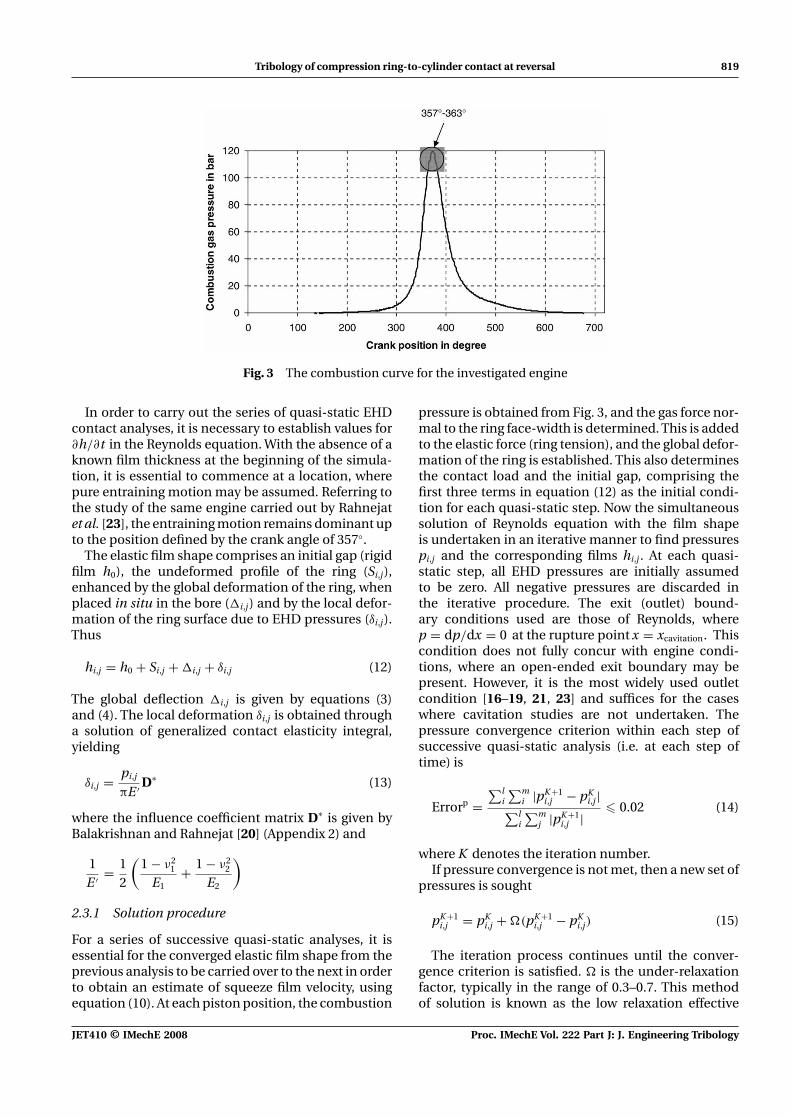
A series of quasi-static analyses carried out here arefor the piston motion, corresponding to crank angles357◦ through to 363◦, through the reversal at the TDC.The combustion curve for this study is shown in Fig. 3,which corresponds to a single-cylinder Honda 450 CRFengine, used in racing dirt bikes. The global elasti-cally deformed shape of its compression ring is usedlater to validate the global in-plane deformation modelreported in section 2.1.
Proc. IMechE Vol. 222 Part J: J. Engineering Tribology JET410 © IMechE 2008
Tribology of compression ring-to-cylinder contact at reversal 819
Fig. 3 The combustion curve for the investigated engine
In order to carry out the series of quasi-static EHDcontact analyses, it is necessary to establish values for∂h/∂t in the Reynolds equation. With the absence of aknown film thickness at the beginning of the simula-tion, it is essential to commence at a location, wherepure entraining motion may be assumed. Referring tothe study of the same engine carried out by Rahnejatet al. [23], the entraining motion remains dominant upto the position defined by the crank angle of 357◦.
The elastic film shape comprises an initial gap (rigidfilm h0), the undeformed profile of the ring (Si,j),enhanced by the global deformation of the ring, whenplaced in situ in the bore (�i,j) and by the local defor-mation of the ring surface due to EHD pressures (δi,j).Thus
hi,j = h0 + Si,j + �i,j + δi,j (12)
The global deflection �i,j is given by equations (3)and (4). The local deformation δi,j is obtained througha solution of generalized contact elasticity integral,yielding
δi,j = pi,j
πE ′ D∗ (13)
where the influence coefficient matrix D∗ is given byBalakrishnan and Rahnejat [20] (Appendix 2) and
1E ′ = 1
2
(1 − ν2
1
E1+ 1 − ν2
2
E2
)
2.3.1 Solution procedure
For a series of successive quasi-static analyses, it isessential for the converged elastic film shape from theprevious analysis to be carried over to the next in orderto obtain an estimate of squeeze film velocity, usingequation (10). At each piston position, the combustion
pressure is obtained from Fig. 3, and the gas force nor-mal to the ring face-width is determined. This is addedto the elastic force (ring tension), and the global defor-mation of the ring is established. This also determinesthe contact load and the initial gap, comprising thefirst three terms in equation (12) as the initial condi-tion for each quasi-static step. Now the simultaneoussolution of Reynolds equation with the film shapeis undertaken in an iterative manner to find pressurespi,j and the corresponding films hi,j . At each quasi-static step, all EHD pressures are initially assumedto be zero. All negative pressures are discarded inthe iterative procedure. The exit (outlet) bound-ary conditions used are those of Reynolds, wherep = dp/dx = 0 at the rupture point x = xcavitation. Thiscondition does not fully concur with engine condi-tions, where an open-ended exit boundary may bepresent. However, it is the most widely used outletcondition [16–19, 21, 23] and suffices for the caseswhere cavitation studies are not undertaken. Thepressure convergence criterion within each step ofsuccessive quasi-static analysis (i.e. at each step oftime) is
Errorp =∑l
i
∑mi |pK +1
i,j − pKi,j|∑l
i
∑mj |pK +1
i,j | � 0.02 (14)
where K denotes the iteration number.If pressure convergence is not met, then a new set of
pressures is sought
pK +1i,j = pK
i,j + (pK +1i,j − pK
i,j) (15)
The iteration process continues until the conver-gence criterion is satisfied. is the under-relaxationfactor, typically in the range of 0.3–0.7. This methodof solution is known as the low relaxation effective
JET410 © IMechE 2008 Proc. IMechE Vol. 222 Part J: J. Engineering Tribology
820 P C Mishra, S Balakrishnan, and H Rahnejat
influence Newton method, described by Jalali-Vahidet al. [25].
The integrated pressure distribution must equatethe contact load, determined by the combined elasticand gas force normal to the ring–bore contact surface,as indicated by equation (9). Thus
Wcontact =∫
x
∫y
pi,j dx dy (16)
Once convergence is obtained for the EHD pressuresfor each quasi-static step, load convergence is soughtwithin a specified error
∣∣∣∣Fapplied − Wcontact
Fapplied
∣∣∣∣ � 0.01 (17)
If load convergence remains unattained, then therigid gap (initially the nominal clearance) h0 betweenthe ring and the bore is altered through relaxation, andthe entire iterative procedure is repeated. Thus
hk0 = hk−1
0 −{ξdamping
∣∣∣∣Fapplied − Wcontact
Fapplied
∣∣∣∣}
(18)
where ξdamping is a damping factor in the range10−9−10−8.
Table 1 Compression ring specifi-cation (after Okamoto andSakai [12])
Ring details Value
Nominal diameter (mm) 82.2Axial width, h1(mm) 2Moment of inertia, I (mm4) 4.06Modulus of elasticity, E(GPa) 203Radius of neutral line, r0(mm) 39.7Tangential force (N) 10Ovality (out-of-roundness) (mm) 0.29
3 RESULTS AND DISCUSSION
3.1 Radial in-plane ring deformation
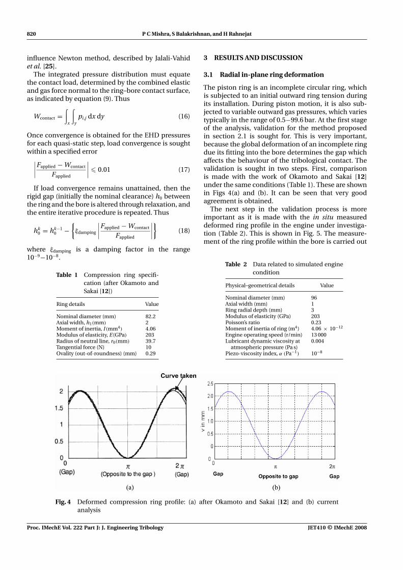
The piston ring is an incomplete circular ring, whichis subjected to an initial outward ring tension duringits installation. During piston motion, it is also sub-jected to variable outward gas pressures, which variestypically in the range of 0.5−99.6 bar. At the first stageof the analysis, validation for the method proposedin section 2.1 is sought for. This is very important,because the global deformation of an incomplete ringdue its fitting into the bore determines the gap whichaffects the behaviour of the tribological contact. Thevalidation is sought in two steps. First, comparisonis made with the work of Okamoto and Sakai [12]under the same conditions (Table 1). These are shownin Figs 4(a) and (b). It can be seen that very goodagreement is obtained.
The next step in the validation process is moreimportant as it is made with the in situ measureddeformed ring profile in the engine under investiga-tion (Table 2). This is shown in Fig. 5. The measure-ment of the ring profile within the bore is carried out
Table 2 Data related to simulated enginecondition
Physical–geometrical details Value
Nominal diameter (mm) 96Axial width (mm) 1Ring radial depth (mm) 3Modulus of elasticity (GPa) 203Poisson’s ratio 0.23Moment of inertia of ring (m4) 4.06 × 10⁻¹²
Engine operating speed (r/min) 13 000Lubricant dynamic viscosity at 0.004
atmospheric pressure (Pa s)Piezo-viscosity index, α (Pa−1) 10−8
Fig. 4 Deformed compression ring profile: (a) after Okamoto and Sakai [12] and (b) currentanalysis
Proc. IMechE Vol. 222 Part J: J. Engineering Tribology JET410 © IMechE 2008
Tribology of compression ring-to-cylinder contact at reversal 821
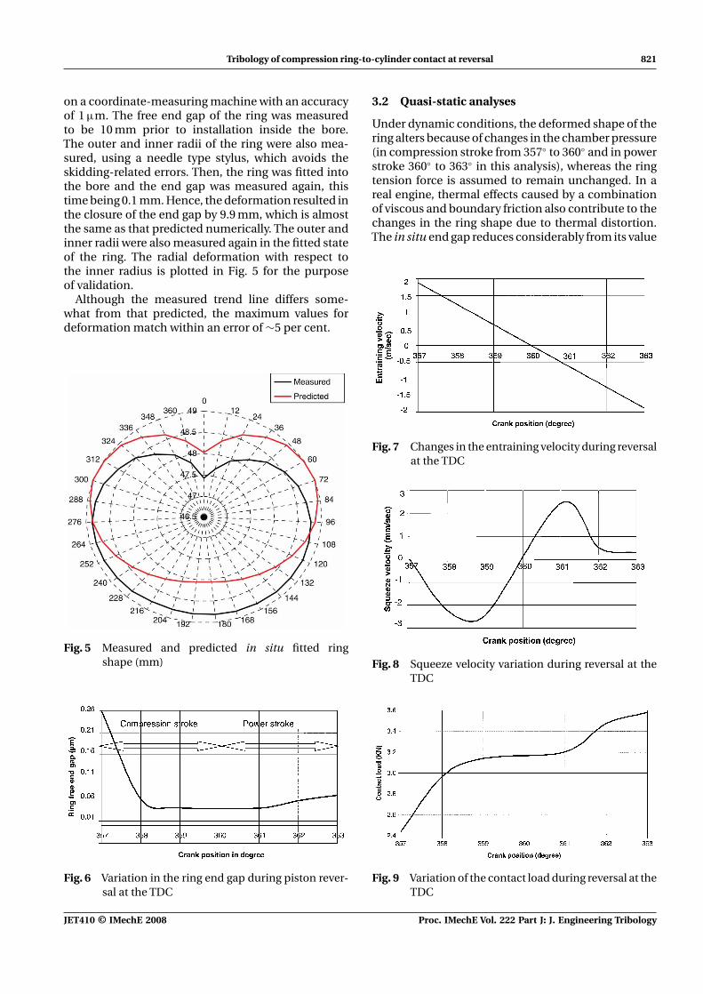
on a coordinate-measuring machine with an accuracyof 1 μm. The free end gap of the ring was measuredto be 10 mm prior to installation inside the bore.The outer and inner radii of the ring were also mea-sured, using a needle type stylus, which avoids theskidding-related errors. Then, the ring was fitted intothe bore and the end gap was measured again, thistime being 0.1 mm. Hence, the deformation resulted inthe closure of the end gap by 9.9 mm, which is almostthe same as that predicted numerically. The outer andinner radii were also measured again in the fitted stateof the ring. The radial deformation with respect tothe inner radius is plotted in Fig. 5 for the purposeof validation.
Although the measured trend line differs some-what from that predicted, the maximum values fordeformation match within an error of ∼5 per cent.
Fig. 5 Measured and predicted in situ fitted ringshape (mm)
Fig. 6 Variation in the ring end gap during piston rever-sal at the TDC
3.2 Quasi-static analyses
Under dynamic conditions, the deformed shape of thering alters because of changes in the chamber pressure(in compression stroke from 357◦ to 360◦ and in powerstroke 360◦ to 363◦ in this analysis), whereas the ringtension force is assumed to remain unchanged. In areal engine, thermal effects caused by a combinationof viscous and boundary friction also contribute to thechanges in the ring shape due to thermal distortion.The in situ end gap reduces considerably from its value
Fig. 7 Changes in the entraining velocity during reversalat the TDC
Fig. 8 Squeeze velocity variation during reversal at theTDC
Fig. 9 Variation of the contact load during reversal at theTDC
JET410 © IMechE 2008 Proc. IMechE Vol. 222 Part J: J. Engineering Tribology
822 P C Mishra, S Balakrishnan, and H Rahnejat
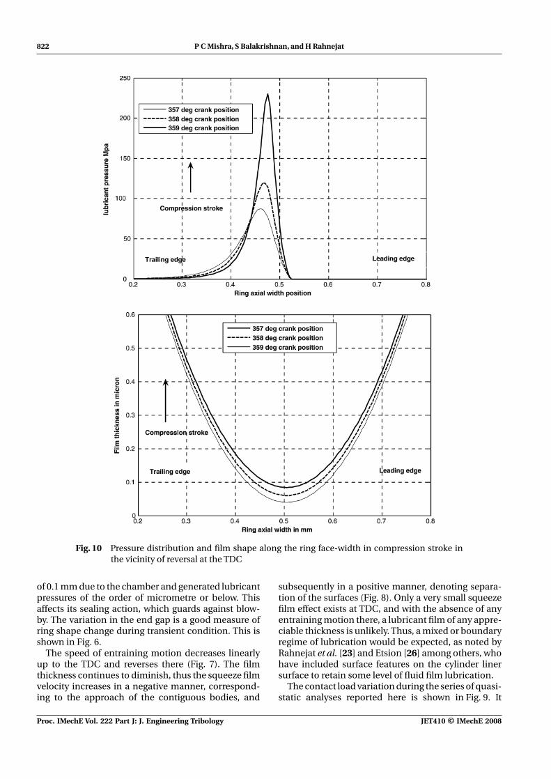
Fig. 10 Pressure distribution and film shape along the ring face-width in compression stroke inthe vicinity of reversal at the TDC
of 0.1 mm due to the chamber and generated lubricantpressures of the order of micrometre or below. Thisaffects its sealing action, which guards against blow-by. The variation in the end gap is a good measure ofring shape change during transient condition. This isshown in Fig. 6.
The speed of entraining motion decreases linearlyup to the TDC and reverses there (Fig. 7). The filmthickness continues to diminish, thus the squeeze filmvelocity increases in a negative manner, correspond-ing to the approach of the contiguous bodies, and
subsequently in a positive manner, denoting separa-tion of the surfaces (Fig. 8). Only a very small squeezefilm effect exists at TDC, and with the absence of anyentraining motion there, a lubricant film of any appre-ciable thickness is unlikely. Thus, a mixed or boundaryregime of lubrication would be expected, as noted byRahnejat et al. [23] and Etsion [26] among others, whohave included surface features on the cylinder linersurface to retain some level of fluid film lubrication.
The contact load variation during the series of quasi-static analyses reported here is shown in Fig. 9. It
Proc. IMechE Vol. 222 Part J: J. Engineering Tribology JET410 © IMechE 2008
Tribology of compression ring-to-cylinder contact at reversal 823
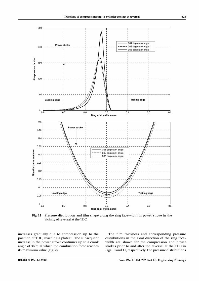
Fig. 11 Pressure distribution and film shape along the ring face-width in power stroke in thevicinity of reversal at the TDC
increases gradually due to compression up to theposition of TDC, reaching a plateau. The subsequentincrease in the power stroke continues up to a crankangle of 363◦, at which the combustion force reachesits maximum value (Fig. 2).
The film thickness and corresponding pressuredistributions in the axial direction of the ring face-width are shown for the compression and powerstrokes prior to and after the reversal at the TDC inFigs 10 and 11, respectively. The pressure distributions
JET410 © IMechE 2008 Proc. IMechE Vol. 222 Part J: J. Engineering Tribology
824 P C Mishra, S Balakrishnan, and H Rahnejat
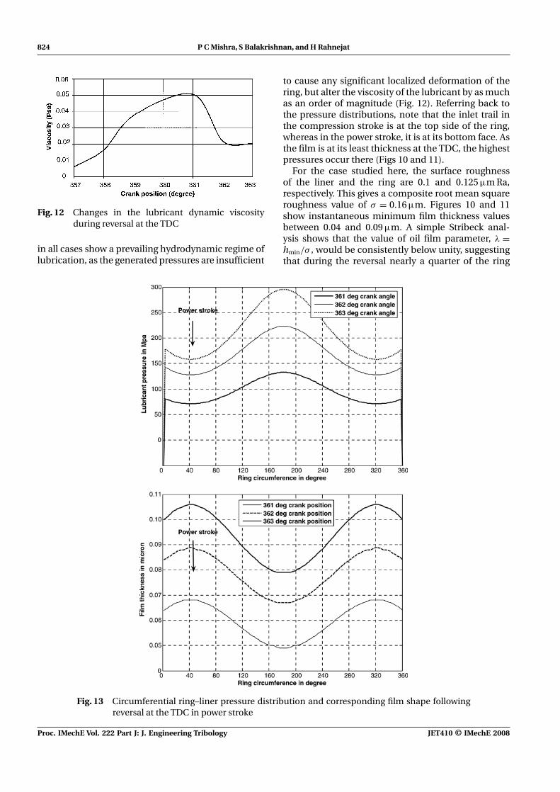
Fig. 12 Changes in the lubricant dynamic viscosityduring reversal at the TDC
in all cases show a prevailing hydrodynamic regime oflubrication, as the generated pressures are insufficient
to cause any significant localized deformation of thering, but alter the viscosity of the lubricant by as muchas an order of magnitude (Fig. 12). Referring back tothe pressure distributions, note that the inlet trail inthe compression stroke is at the top side of the ring,whereas in the power stroke, it is at its bottom face. Asthe film is at its least thickness at the TDC, the highestpressures occur there (Figs 10 and 11).
For the case studied here, the surface roughnessof the liner and the ring are 0.1 and 0.125 μm Ra,respectively. This gives a composite root mean squareroughness value of σ = 0.16 μm. Figures 10 and 11show instantaneous minimum film thickness valuesbetween 0.04 and 0.09 μm. A simple Stribeck anal-ysis shows that the value of oil film parameter, λ =hmin/σ , would be consistently below unity, suggestingthat during the reversal nearly a quarter of the ring
Fig. 13 Circumferential ring–liner pressure distribution and corresponding film shape followingreversal at the TDC in power stroke
Proc. IMechE Vol. 222 Part J: J. Engineering Tribology JET410 © IMechE 2008
Tribology of compression ring-to-cylinder contact at reversal 825
face-width for the region of minimum film thickness inthe circumferential direction suffers significant asper-ity interactions (Figs 11 and 13 for the circumferentialfilm shape through its minimum thickness). However,it should be noted that asperities undergo ploughing(in elastic or plastic mode) in EHL contacts. There-fore, the λ ratio can actually be different from thatused in a simple Stribeck analysis highlighted here forconvenience.
4 CONCLUSION
The analysis shows that the pressures generated inthe compression ring–cylinder conjunction, even atcontact loads of a few kilonewtons, are insufficient tocause significant local deformation of the contiguoussolids, while increasing the lubricant viscosity by anorder of magnitude. Thus, as far as localized condi-tions are concerned, a piezo-viscous rigid regime oflubrication results, which yields an insufficient filmthickness in parts of the contact. A repercussion isincreased friction due to asperity tip interactions atreversals (TDC results presented here). Therefore, itwould be important to include asperity adhesion andploughing deformation model to the analysis in orderto obtain more representative predictions. Addition-ally, thermal effects, particularly due to friction, wouldnot only affect the global distortion of the ring, butalso further reduce lubricant viscosity, thus its pres-sure generation capability. These additions will formthe future developments of the presented model.
REFERENCES
1 Love, A. E. H. A treatise on mathematical theory ofelasticity, 1944 (Dover, New York).
2 Mayer, R. Uber Elastizitat und Stabilitat des geschlosse-nen und offenen Kreisbogens. Zeitschr.f.angewandteMath.u.Phys., 1921, Bd.61, 246–322.
3 Timoshenko, S. Elementary theories and problems, 1955(D.Van Nostrand Co., London).
4 Lamb, H. On the flexure and vibrations of a curved bar.Proc. Lond. Math. Soc., 1888, 19, 365–376.
5 Tian, T. Dynamic behaviour of piston rings and theirpractical impact. Part I: ring flutter and ring collapse andtheir effects on gas flow and oil transport. Proc. InstnMech. Engrs, Part J: J. Engineering Tribology, 2002, 216,209–228.
6 Tian, T. Dynamic behaviour of piston rings and theirpractical impact. Part II: oil transport friction and wearof ring/liner interface and effects of piston and ringdynamics. Proc. Instn Mech. Engrs, Part J: J. EngineeringTribology, 2002, 216, 209–228.
7 Lang, A. Pure twist of a solid circular ring sector. Int. J.Solids Struct., 1983, 19(2), 131–140.
8 Archer, R. R. Small vibrations of thin incomplete circularrings. Int. J. Mech. Sci., 1959, 1, 45–56.
9 Ojalvo, I. U. Coupled twist-bending vibrations of incom-plete elastic ring. Int. J. Mech. Sci., 1962, 4, 58–72.
10 Den Hartog, J. P. The lowest natural frequency of circulararc. Philos. Mag., 1928, 5(7), 400–408.
11 Brown, F. H. Lateral vibration of ring shaped frames.J. Franklin Inst., 1934, 217, 41–48.
12 Okamoto, M. and Sakai, I. Contact pressure distributionof piston rings – calculation based on piston ring contour.SAE technical paper 2001-01-0571, 2001, pp. 1–7.
13 Dunaevsky, V. V., Alexandrov, S., and Barlat, F. Analy-sis of three-dimensional distortions of the piston ringswith arbitrary cross-section. SAE technical paper 2000-01-3453, 2000, pp. 1–7.
14 Dunaevsky, V. V. Analysis of distortions of cylinders andconformability of piston rings. STLE Tribol. Trans., 1990,33(10), 33–40.
15 Chittenden, R. J. and Priest, M. Analysis of the pistonassembly, bore distortion and future development. InEngine tribology (Ed. C. M. Taylor), 1993, pp. 241–270(Elsevier, Amsterdam).
16 Dowson, D., Ruddy, B. L., and Economou, P. N. Elastohydrodynamic lubrication of piston rings. Proc. R. Soc.,1983, A386, 409–430.
17 Ruddy, B., Dowson, D., and Economou, P. N. The predic-tion of gas pressure within ring packs of the larger borediesel engine. J. Mech. Sci., 1981, 23(6), 295–304.
18 Knoll, G. D. and Peeken, H. J. Hydrodynamic lubricationof piston skirt. Trans. ASME J. Lubr. Technol., 1982, 104,505–509.
19 Ma, M.-T., Smith, E. H., and Sherrington, I. Analysis oflubrication and friction for a complete piston ring packwith an improved oil availability model. Part 2: circum-ferentially variable film. Proc. Instn Mech. Engrs, Part J: J.Engineering Tribology, 1997, 211, 17–27.
20 Balakrishnan, S. and Rahnejat, H. Isothermal transientanalysis of piston skirt-to-cylinder wall contacts undercombined axial–lateral–tilting motion. J. Phys. D Appl.Phys., 2005, 38, 787–799.
21 Teodorescu, M., Balakrishnan, S., Rahnejat, H., Howell-Smith, S., and Dowson, D. Tribological analysis withina multi-physics framework. In Proceedings of the 31stLeeds–Lyon Symposium, Elsevier, Leeds, UK, September2004.
22 Dwyer-Joyce, R. S., Green, D. A., Balakrishnan, S.,Harper, P., Lewis, R., Howell-Smith, S., King, P. D.,and Rahnejat, H. The measurement of liner–piston skirtoil film thickness by an ultrasonic means. SAE paper2006-01-0648, 2006.
23 Rahnejat, H., Balakrishnan, S., King, P. D., and Howell-Smith, S. In-cylinder friction reduction using a surfacefinish optimization technique. Proc. IMechE, Part D: J.Automobile Engineering, 2006, 220(D9), 1309–1318.
24 Roelands, C. J. A. Correlation aspects of the viscosity–temperature–pressure relationships of lubricating oils,1966 (Groningen, Druk VRB Kleine der A3-4).
25 Jalali-Vahid, D., Rahnejat, H., Gohar, R., and Jin, Z. M.Prediction of oil-film thickness and shape in ellipti-cal point contacts under combined rolling and slidingmotion. Proc. Instn Mech. Engrs, Part J: J. EngineeringTribology, 2000, 214, 427–437.
26 Etsion, I. State of the art in laser surface. Trans. ASME J.Tribol., 2005, 127(1), 248–253.
JET410 © IMechE 2008 Proc. IMechE Vol. 222 Part J: J. Engineering Tribology
826 P C Mishra, S Balakrishnan, and H Rahnejat
APPENDIX 1
Notation
ai,j function related to radial ringdeformation (mm)
a large side of the rectangular contact(μm)
b ring axial width (mm)b small side of the rectangular contact
(μm)errorp error for pressure computationE1 modulus of elasticity for the ring
surface (N/m2)E2 modulus of elasticity for the
liner/bore surface (N/m2)E ′ apparent modulus of elasticity (N/m2)f (θi, αj) function related to radial ring
deformationFapplied applied load (N)h0, h undeformed minimum gap size and
film thickness (μm)i, j position vectors in ring deformation
measurementI area moment of inertia of incomplete
ring (mm4)K iteration stepM (θi, αj) moment due to displacement (N m)pi,j hydrodynamic pressure generated in
the film (N/m2)Pcrank_case pressure in the crank case end of the
ring (N/m2)Peij radial elastic pressure in the ring
(N/m2)Pgas net gas pressure in the ring (N/m2)Pgcombustion pressure in the combustion chamber
end of the ring (N/m2)
Pgring_back pressure in the back of the ring(N/m2)
Psf effective static pressure in the front ofthe ring (N/m2)
Qj force applied at various locations inthe ring circumference (N)
r radius of ring after deformation (mm)r0 initial radius of curvature of ring
(mm)Si,j shape function related to ring profile
(mm)t time (s)
uav, vav velocity of ring reciprocation (m/s)v(θi, αj) tangential component of ring
deformation (mm)Wcontact calculated reaction force in the
film (N)Welastic force due to elastic pressure (N)Wgas force due to the effective gas pressure
(N)x, y directional coordinates in the axial
and circumferential directionsxcavitation position of the starting of cavitationxinlet inlet position in the ring axial
direction
α piezo-viscosity indexαj position of application of force
(radian)δi,j elastic deformation of the ring (mm)�i,j deformed ring shape (mm)η lubricant dynamic viscosity (Pa s)η0 dynamic viscosity at atmospheric
pressure (Pa s)η non-dimensional viscosityθi position of deformation (radian)ν1 Poisson’s ratio for ring surfaceν2 Poisson’s ratio for liner/bore surfaceξdamping damping factor under relaxation factor
APPENDIX 2
D∗ = (x + b) ln( y + a) +
[( y + a)2 + (x + b)2
]1/2
( y − a) +[( y − a)2 + (x + b)2
]1/2
+ ( y + a) ln(x + b) +
[( y + a)2 + (x + b)2
]1/2
(x − b) +[( y + a)2 + (x − b)2
]1/2
+ (x − b) ln( y − a) +
[( y − a)2 + (x − b)2
]1/2
( y + a) +[( y + a)2 + (x − b)2
]1/2
+ ( y − a) ln(x − b) +
[( y − a)2 + (x − b)2
]1/2
(x + b) +[( y − a)2 + (x + b)2
]1/2
Proc. IMechE Vol. 222 Part J: J. Engineering Tribology JET410 © IMechE 2008