foundations of global positioning systems
TRANSCRIPT
GPS (Global Positioning System )
Global Positioning System – Satellite based, radio navigationsystem. Developed by the Department of Defense. Originally designed for military navigation. >24 satellites orbiting at 12,600 nautical mi. (20,200 km). Four satellites orbiting in six different planes inclined 55 tothe equator (overhead). Each satellite orbits the earth in 12 hrs. Four satellites are always in view.
Practical Applications in the Mapping Sciences
Control points for georectification of imagery. W aypoints for navigation. Point/target location analysis. Boundary placement, e.g. parks, other natural breaks, propertylines, fuzzy polygons (wildlife corridors, territorial habitats), etc. Linear mapping, e.g. streams, roads, irrigation canals
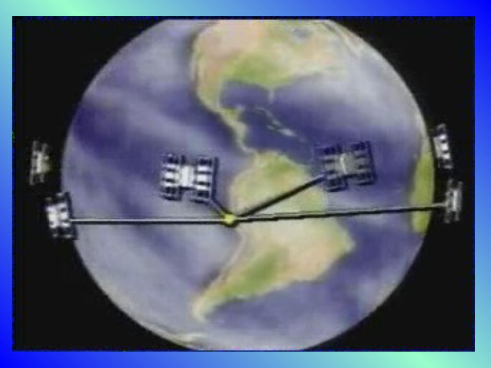
Satellite Trilateration Location is based upon a GPS receiver (rover), an optionalCBS (Community Base Station), and the constellation ofsatellites orbiting about the earth. The rover functions as the receiving device at a given station(ground location). The CBS functions as a means of establishing a precise“known location.” The satellites are the orbiting stations from which trilaterationwill be accomplished. Given a GPS receiver located somewhere at the surface, andreceiving satellite signals:
If the time duration of the satellite signal to the receiver is known, the distance from the receiver to the satellite can be computed. If the distance between the first satellite and the receiver are known, the position of the receiver will be somewhere on the surface of a sphere delineated by the distance from the satellite (center of the sphere) to the receiver. W hen the distance of each of the two satellites to the receiver position is known, the intersection of the two spheres will form a circle in which the receiver location will be contained.
W hen the distance of each of the three satellites to a receiver station is known, the intersection of the three spheres will intersect the circle at two points, one of which the receiver position will reside. W hen the distance of each of the four satellites to a receiver station is known, the intersection of the four spheres will intersect one point locating the position of the receiver.
Determ ining Distances to a Satellite By measuring travel time of a radio signal transmitted from the satellite to the GPS receiver. A pseudo random code is simultaneously generated by the GPS receiver and satellite (slide). The Garmin eTrex Vista receiver has 12 channels. Operates on a non-military encrypted course acquisition code (C/A).
Tracks satellites continuously and simultaneously. The GPS receiver determines the travel time of course acquisition code. A distance to a satellite is determined by multiplying the time and speed of light (186,000 mi/sec ; 299,793 km/sec.).
Synchronizing the satellite and GPS receiver clocks If the clocks of two satellites were exactly in sync.with the GPS receiver, the distances measured would intersect at a point. W ith three satellites exactly in sync. the three distances would also intersect at a point. The clock in the GPS receiver is not as precise as the clock in the satellites (cost).
Fast and varied clocks result in a longer time that yields larger circles per satellite. The computer in the receiver will adjust the tim e offset until a timed distance solution is achieved. A fourth satellite is required to determine a point position.
Establishing the Precise Instant the Signal is sent from theSatellite Use the same pseudo random code in the receiver (rover) andsatellites. Synchronize the satellites & receivers so that they generate thesame code at the same time (slide). M easure the incoming code & compare its position with that ofthe rover. M easure the timed displacement between two binary patterns(pseudo random) to establish the precise travel time.
One bit of code (one microsecond (1/1,000,000th sec) wide) iswithin a few percent of perfect sync. This translates into an error of 982 ft (300 m). One percentwould still be 3 m error. Corrected through higher frequency transmission. Pseudo random code allows one to jump anywhere into the bitstring. It allows many satellites to operate at the same frequency. It provides a way to increase the signal to noise ratio.
Transm ission Errors Light travels at a constant speed (186,000 mi/sec) in avacuum (through space). The speed of the signal is slowed down upon entering theionosphere and the atmosphere. The atomic clock and orbital path sometimes requireadjustment. M ultipath interference due to reflection off buildings, metalsurfaces, or other solid objects. Signals are also weakened when passing through leaves,glass, plastic, or when in proximity with microwavetransmitters.
Selective Availability Artificial degradation of the satellite signal by the DoD. Predetermined errors in navigation data (epsilon) resulting inan erroneous position. The satellite clock is also altered (dithering). Combined these errors result in large velocity, time, andultimately positional errors.
G PS Data Accuracy From 1 cm to >100 m with horizontal readings 2-5x more accurate than vertical readings. W ith selective availability off and no differential correction, horizontal accuracy is < 15 m (49 ft.) w/ 95% RM S. W ith selective availability on and no differential correction, horizontal accuracy is ~ 40 m (148 ft.) w/ 95% RM S.
W ith selective availability off and no differential correction,vertical errors are less than 70 m 50% of the time & less than173 m (2dRM S). Circular Error Probable – 50% of the positions are withina horizontal circle with a radius equal to the specified value,i.e. 40, 100, or 70 m respectively. A 2dRM S expresses two standard deviations from the meansuch that 95% of the positions will fall within the indicatedhorizontal radius.
Factors Affecting GPS Accuracy Time spent collecting a position (3 minutes optimal). Type of receivers (Trimble, M agellan, Garmin). Geometry of satellite constellation (position dilution of precision).
Dilution of Precision M athematical calculation Accounts for a satellite’s position with respect to othersatellites in the constellation. Used to predict the accuracy of positions obtained from theconstellation.
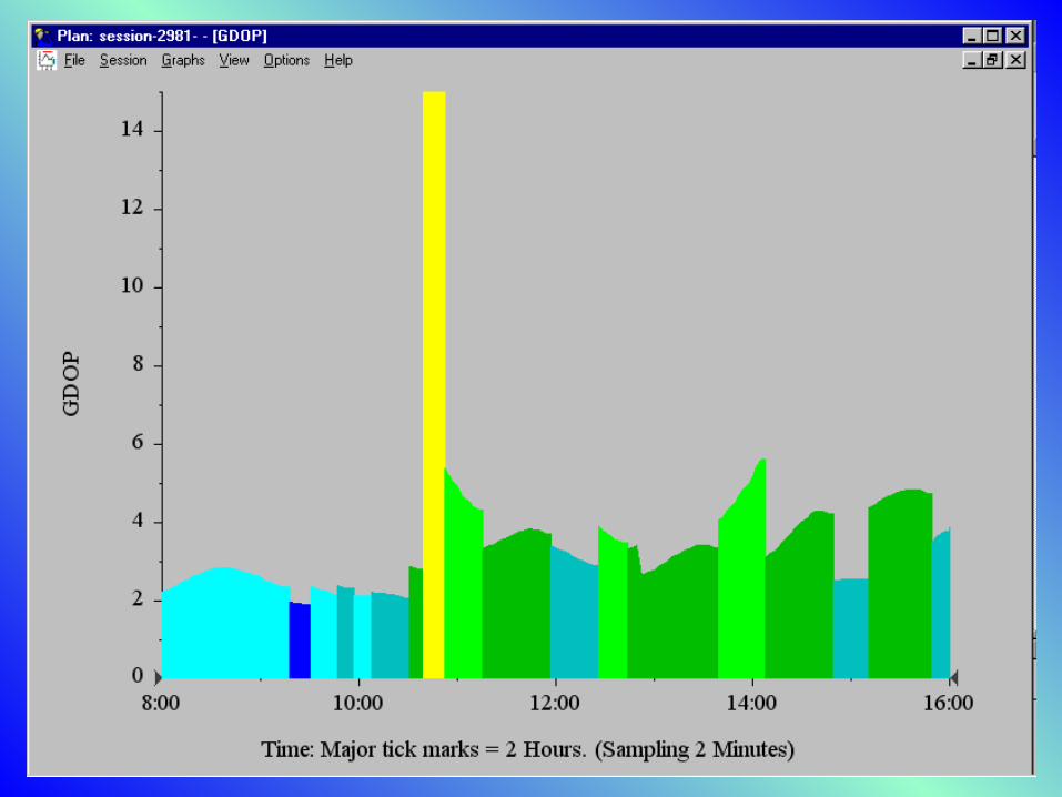
G eom etric Dilution of Precision (GDOP) The relative position of the viewable satellites throughout a field session. Ideally the position is a point where the satellite ranges intersect. In reality the position is located in an area of uncertainty due to satellite range errors.
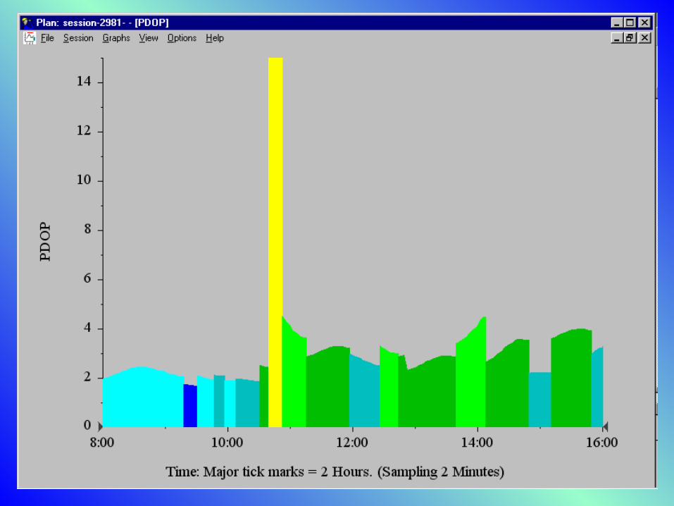
PDOP – refers to horizontal and vertical measurements(latitude, longitude, & altitude.
Values less than 4 are considered excellent. Values from 5 to 8 are considered acceptable. Values of 9 and greater are considered poor.
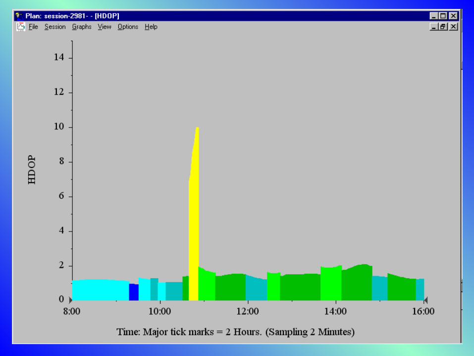
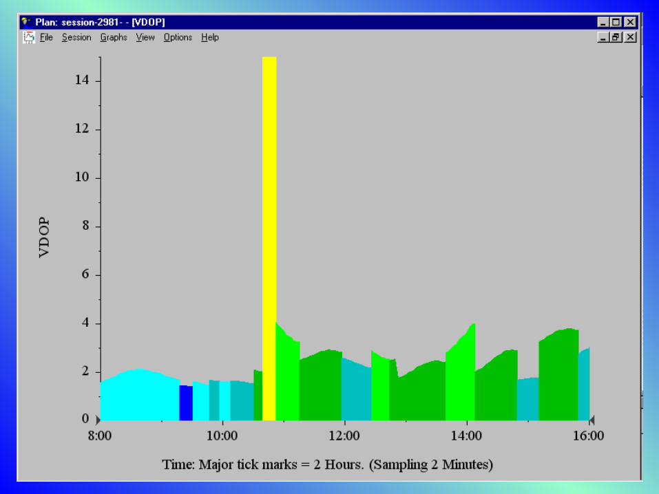
HDOP – refers to horizontal measurements only. VDOP – refers to vertical measurements only. TDOP – refers to the clock offset.
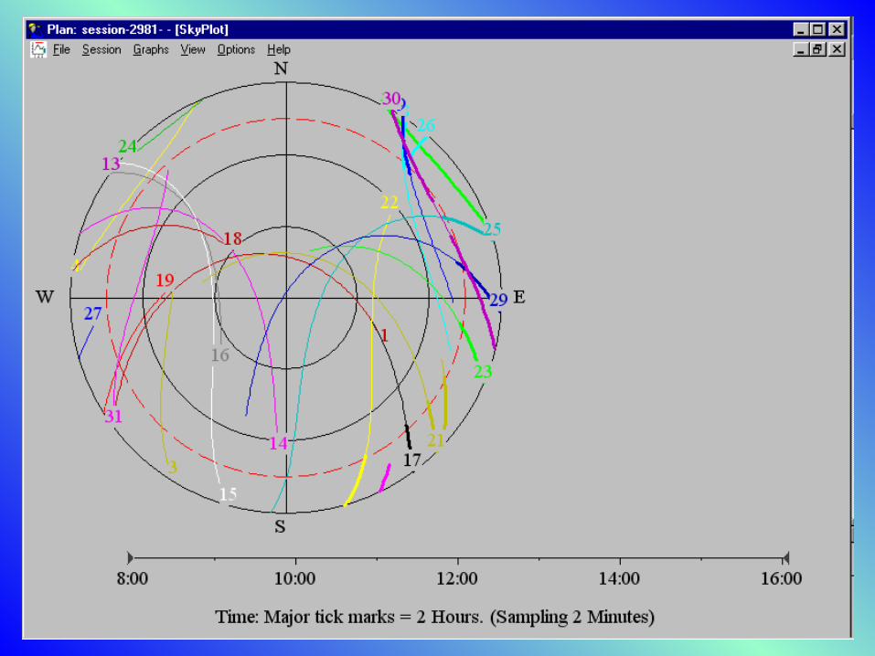
Sky Plots A 2-D plot of the constellation geometry derived fromQuickplan software. Expressed as a circular graph (overhead). The horizon is represented as the outer circle. The overhead position is represented at the center of the skyplot.
Ideal PDOP occurs when three satellites are equally distributedaround the circle near the horizon, and a forth satellite ispositioned near the center (vertically overhead). Good horizontal positions may be obtained from a low HDOP,yet high PDOP & VDOP values. Good vertical positions may be obtained with a low VDOP anda poor PDOP & HDOP geometry.
Differential Correction A technique employed to increase the accuracy of positionsderived from a GPS rover receiver. Differential correction operates on the premise that signalerrors are common to all GPS users within 500 km (300 mi). A known location with a high degree of precision is used as acalibration standard to correct errors propagated by a rover GPS.
Real -time corrections – a satellite signal error (offset value) iscalibrated and transmitted from the CBS directly to the rover. Post-processed corrections – a CBS records the positional errorfor each satellite into a computer file.
A rover receiver records its positions (pseudorange,ionospheric, & ephemeris data) into a computer file. Both files are processed through a software program tocorrect the positional errors of the rover positions.
Criteria to be m et for Differential Correction CBS must be tracking every satellite that the rover might use toestablish a position. Use an elevation mask of 10 for the CBS, 15 for the roverreceiver (overhead). A rover must be within 300 mi. (500 km) of the base stationfor effective post-processing. The CBS must be collecting the base files at exactly the sametime as the rover.
Office Procedures: Planning a Field Session
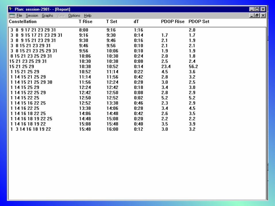
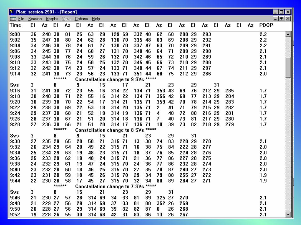
Session – a block of tim e during which field observations are m ade on a constellation of GPS satellites. Point – a station or survey mark from which observations are m ade. Alm anac – an ephemeris file containing orbital information including azim uths & elevations for the current satellites. The alm anac provides a record of satellite altitude, time of arrival, time of departure, number of satellites in a viewable constellation, & their present condition.
Pathfinder Office Software ver. 2.11
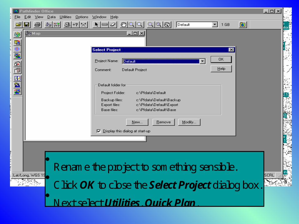
Rename the project to som ething sensible. Click OK to close the Select Project dialog box. Next select Utilities, Quick Plan.
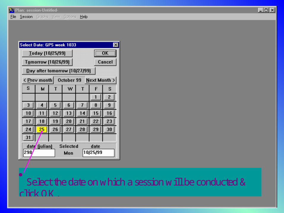
Select the date on which a session will be conducted &click OK.
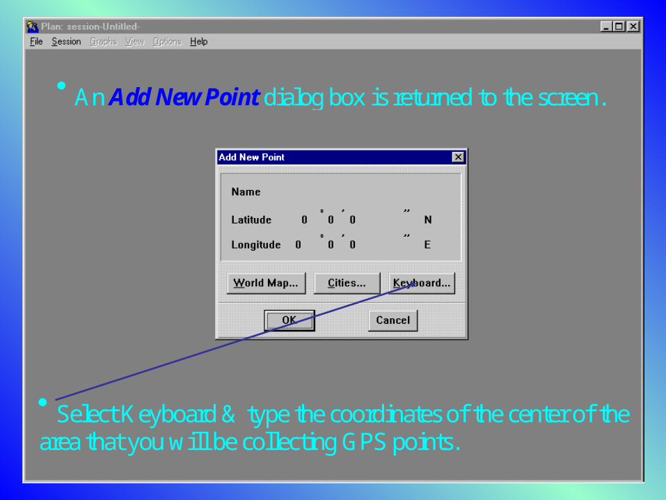
An Add New Point dialog box is returned to the screen.
Select Keyboard & type the coordinates of the center of thearea that you will be collecting GPS points.
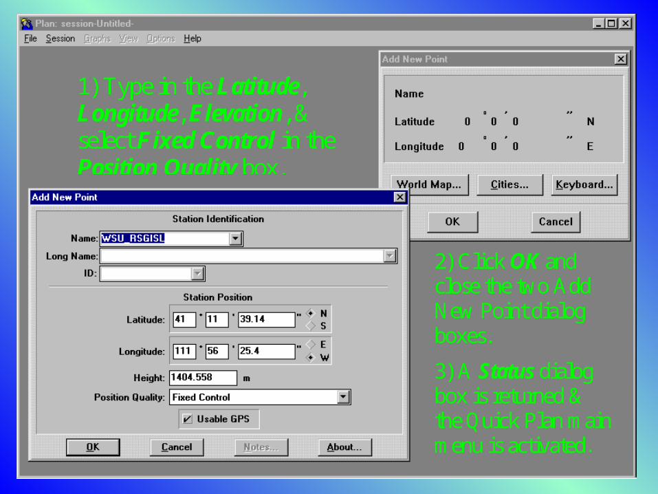
1) Type in the Latitude,Longitude, Elevation, &select F ixed Control in thePosition Quality box.
2) Click OK andclose the two AddNew Point dialogboxes.3) A Status dialogbox is returned &the Quick Plan mainm enu is activated.
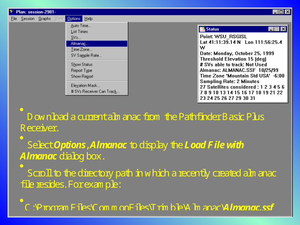
Download a current almanac from the Pathfinder Basic PlusReceiver. Select Options, Almanac to display the Load F ile withAlmanac dialog box. Scroll to the directory path in which a recently created almanacfile resides. For example:C:\ProgramFiles\Comm onFiles\Trim ble\Almanac\Almanac.ssf
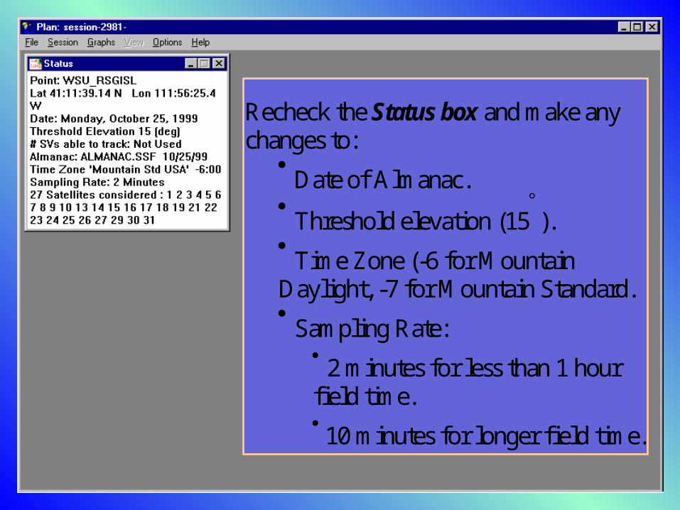
Recheck the Status box and make anychanges to:
Date of Almanac. Threshold elevation (15). Time Zone (-6 for M ountainDaylight, -7 for M ountain Standard. Sampling Rate:
2 minutes for less than 1 hourfield time. 10 minutes for longer field time.
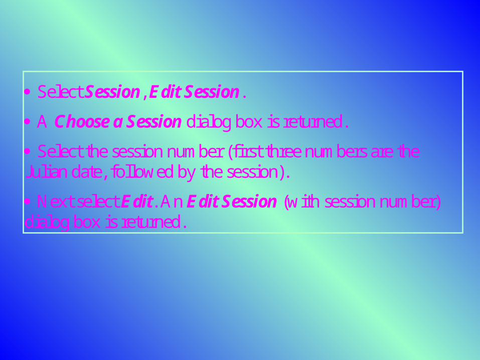
Select Session, Edit Session. A Choose a Session dialog box is returned. Select the session number (first three num bers are the Julian date, followed by the session). Next select E dit. An Edit Session (with session number) dialog box is returned.
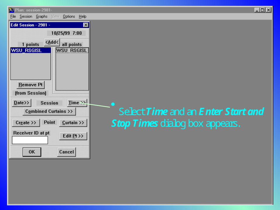
Select Time and an Enter Start andStop Times dialog box appears.
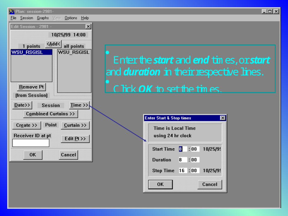
Enter the start and end times, or startand duration in their respective lines. Click OK to set the times.
Defining a Curtain A curtain is any obstruction that blocks a satellite signalfrom the GPS receiver. Lim its are set as azimuth (compass direction) and elevation(angular height above the horizon). Buildings, canyons, mountains, and other obstructions m ustbe taken into consideration when obtaining optimal conditionsfor satellite visibility.
Curtains are arranged from the perspective of a locationabove an observation point. Azimuth is from 0-360 clockwise with 0 at the top (north)along an outer circle of the polar grid. E levation is from 0 to 90, and begins at 0 on the outercircle of the polar grid, with 90 (zenith) at the center. The default value for the elevation mask (15) is the redcircle.
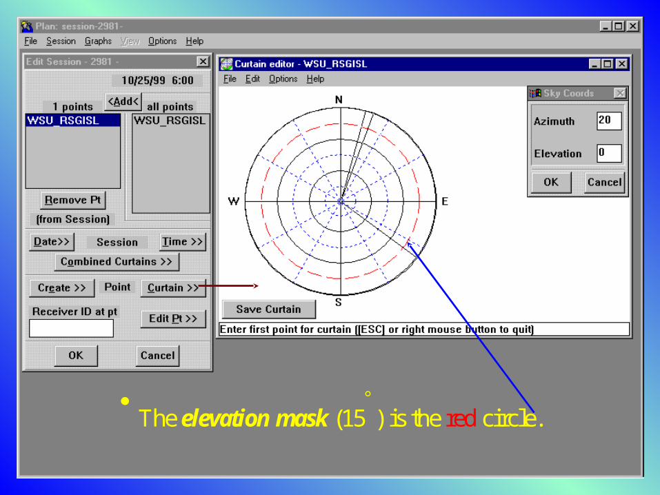
The elevation mask (15) is the red circle.
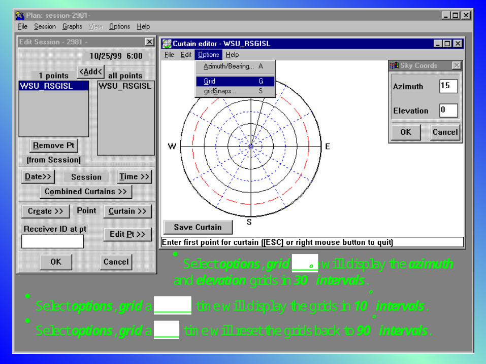
Select options, grid once will display the azimuth and elevation grids in 30 intervals.
Select options, grid a second time will display the grids in 10 intervals. Select options, grid a third time will reset the grids back to 90 intervals.
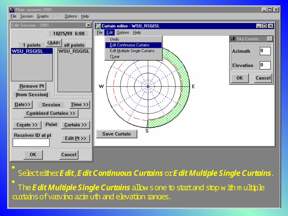
Select either Edit, Edit Continuous Curtains or Edit Multiple Single Curtains. The Edit Multiple Single Curtains allows one to start and stop with multiplecurtains of varying azimuth and elevation ranges.
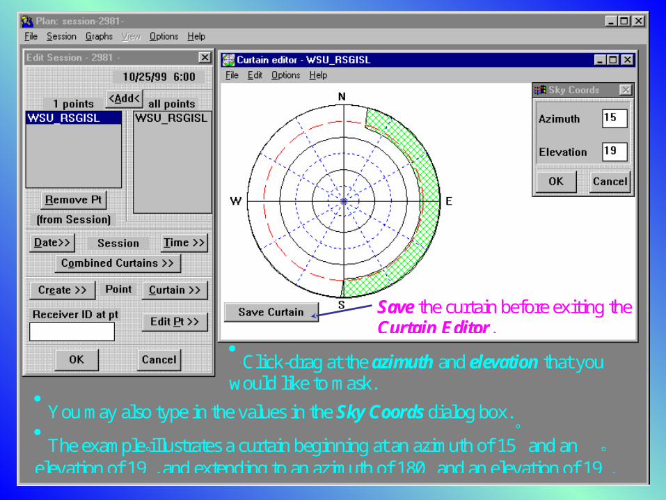
Click-drag at the azimuth and elevation that youwould like to m ask.
You may also type in the values in the Sky Coords dialog box. The example illustrates a curtain beginning at an azimuth of 15 and anelevation of 19, and extending to an azimuth of 180 and an elevation of 19.
Save the curtain before exiting theCurtain Editor.
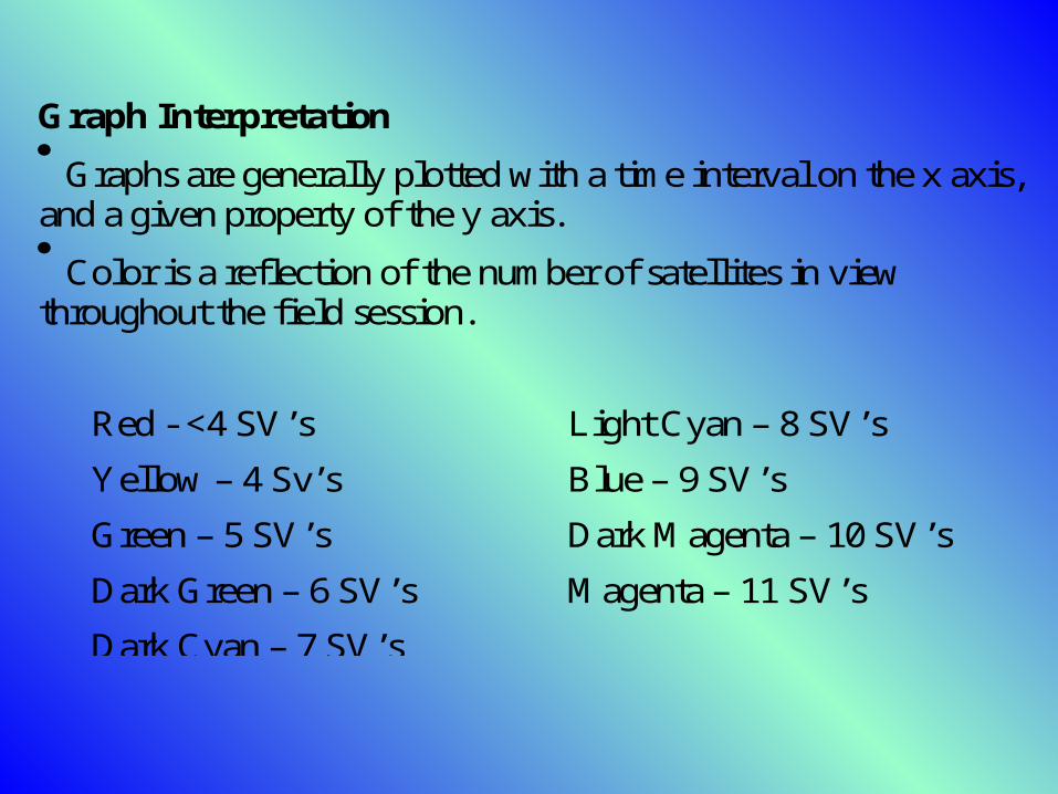
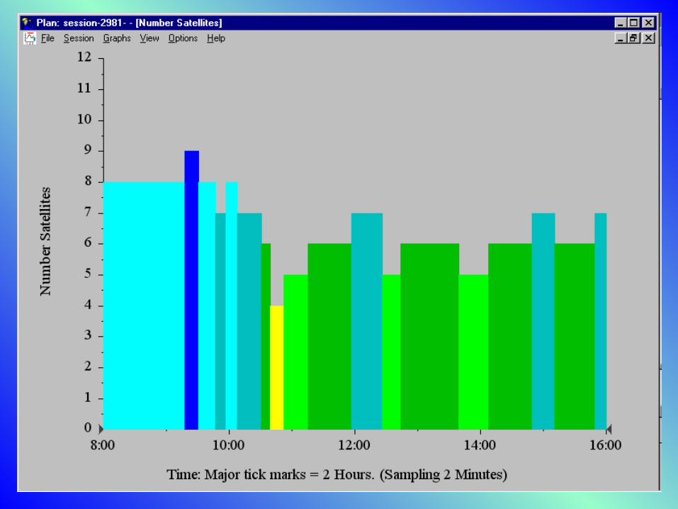
Graph Interpretation Graphs are generally plotted with a time interval on the x axis,and a given property of the y axis. Color is a reflection of the number of satellites in viewthroughout the field session.
Red - <4 SV’s Light Cyan – 8 SV’sYellow – 4 Sv’s Blue – 9 SV’sGreen – 5 SV’s Dark M agenta – 10 SV’sDark Green – 6 SV’s M agenta – 11 SV’sDark Cyan – 7 SV’s
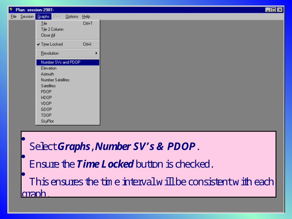
Select Graphs, Number SV’s & PDOP. Ensure the Time Locked button is checked. This ensures the time interval will be consistent with eachgraph.