forest road reconstruction or relocation? cameron north road improvement project
TRANSCRIPT

The International Mountain Logging and 11th Pacific Northwest Skyline Symposium 2001 215
Forest Road Reconstruction or Relocation? Cameron North RoadImprovement Project
Lawson W. StarnesAssistant Director/Operations Team Leader, Oregon State University Research Forests,
Corvallis, OR 97331, e-mail: [email protected]
Bennett J. StringhamInstructor, Forest Engineering Department, Oregon State University, Corvallis, OR 97331, e-
mail: [email protected],
John C. BlissStarker Chair for Private and Family Forestry, Department of Forest Resources, Oregon State
University, Corvallis, OR 97331, e-mail: [email protected]
ABSTRACT - Forest engineers need to follow a process to provide forestland ownersand managers with transportation systems that meet owner objectives and legalstandards. A process used to relocate and reconstruct an existing 1.3-mile road on thenorth portion of the Elizabeth Starker Cameron Demonstration Forest (a 260 acre timbertract donated to Oregon State University for private and family forestry) is described.Forest engineers found that careful communication with the tract manager and the forestplanning board was essential. Road management objectives had to be clearlyunderstood and documented. Forest engineers generated viable alternatives andexplained associated costs, constraints, and risks. It was the forest engineer’sresponsibility to assure that the tract manager understood and agreed with (or made)key decisions including final route selection and design standards to avoid costly reworklater. The process from initial discussions with the tract manager through finalconstruction is described. Survey, design and analysis tools used in the project arebriefly described. A restricted-use, low-maintenance, out-sloped design resulted.
Keywords: out-slope, fords, culverts, dips, drainage
INTRODUCTIONForest engineers need to follow a process to provide forestland owners and managers withtransportation systems that meet owner objectives and legal standards. A process used torelocate and reconstruct an existing 1.3-mile road on the north portion of the Elizabeth StarkerCameron Demonstration Forest (a 260 acre timber tract donated to Oregon State University forprivate and family forestry) is described. Forest engineers found that careful communicationwith the track manager and the forest planning board was essential. Road managementobjectives had to be clearly understood and documented. Forest engineers generated viablealternatives and explained associated costs, constraints, and risks. It was the forest engineer’sresponsibility to assure that the tract manager understood and agreed with (or made) keydecisions including final route selection and design standards to avoid costly rework later. Theprocess from initial discussions with the tract manager through final construction is described.Survey, design and analysis tools used in the project are briefly described. A restricted-use, low-maintenance, out-sloped design resulted. Process steps occurred in three broad phases: 1)transportation planning 2) road survey and design 3) construction.

The International Mountain Logging and 11th Pacific Northwest Skyline Symposium 2001 216
The 260 acre Elizabeth Starker Cameron Demonstration Forest (the "Cameron Tract") wasdonated to Oregon State University's College of Forestry in 1995 to serve as the foundation of anew Starker Program in Private and Family Forestry. The Tract, located in the Soap CreekValley, a rural-residential area on the fringe of Corvallis, Oregon, is actively managed todemonstrate forestry alternatives relevant to small, non-industrial private forest owners, and toproduce revenue to support the Program.
Among the initial tasks in developing the Cameron Tract management plan was to establish anAdvisory Board consisting of non-industrial private forest owners, Cameron Tract neighbors,consulting foresters, and OSU faculty and staff. The board was particularly concerned aboutdeveloping a constructive relationship with Cameron Tract neighbors. With the gift of theproperty came the requirement that, in the first year of OSU ownership, a sizeable donation forthe OSU library was to be generated from the sale of Cameron Tract timber. That timber saleconsisted of two clearcuts along the main road through Soap Creek Valley. The harvestsgenerated not only the necessary revenue, but also a good deal of ill will within theneighborhood.
In order to foster a more constructive relationship between the College and Cameron Tractneighbors, and to enhance communication between Soap Creek neighbors and non-industrialforest owners, we conducted an open planning process through which the views of majorstakeholder groups could be heard and incorporated. Over the course of three years anAdvisory Board was convened, a long range plan developed, a comprehensive Tract inventoryconducted, a transportation plan agreed upon, and a stand-by-stand management plan initiated.Initial stakeholder response to these accomplishments suggests that the open, slow-movingplanning process has indeed contributed to a positive, constructive working relationship in theneighborhood.
As a demonstration forest, the Cameron Tract's transportation needs are somewhat unique.Roads must not only serve management needs (access for resource management, fire control,and so on), but must also serve the Tract's educational mission. Roads must accommodateCollege of Forestry classes, landowner field days, and tours of visiting land managers and forestowners year-round. Moreover, the transportation system itself must offer opportunities fordemonstrating road design and construction alternatives.
TRANSPORTATION PLANNINGUnderstand the Forest Management PlanThe forest management plan is the foundation for the transportation plan. The effective forestengineer will have a good understanding of the broader forest plan. The CameronDemonstration Forest Management Plan was not well developed and documented whenengineers were asked to develop a logging transportation plan. The tract had not been enteredfor approximately fifty years except for two clearcuts on the extreme north and south ends of theproperty that had been logged in 1996 shortly after the property was donated to the College ofForestry. Forest management planning and transportation planning resumed simultaneouslybeginning in 1999 when the Starker Chair position for Private and Family Forestry was filled byDr. John Bliss.
Inventory the Existing Transportation System and Its ConditionA resource grade Global Positioning System (GPS) was used to map existing truck roads andmain skid trails. Except for the more recently used roads on the extreme north and south endsof the tract, the existing road system had not been used for log haul for approximately fifty years

The International Mountain Logging and 11th Pacific Northwest Skyline Symposium 2001 217
and was over grown and partially sloughed in with approximately 10 feet of road widthremaining. The road had evidently been side-cast constructed without a ditch and without rockfor a dry weather logging operation in the late 1940s. The road was on ground slopes thatranged from 10 to 45 percent averaging approximately 25 percent.
Road hazards to the watershed were observed. There was evidence that some widely spacedwater bars had been constructed. Some segments with grades in excess of 20 percent weredeeply eroded due to drainage problems that were still persisting at the time of the inventory. Nomajor fill failures or landslides from the existing road system had occurred. Segments of theroad system paralleled small type N streams and were within the riparian management areas(RMA) (Oregon Forest Practices Act, 1971). The Oregon Department of Forestry hasdeveloped a protocol that other ownerships may use for inventorying road hazards (ForestRoads Manual, 2000).
On the north half of the tract, which is the focus of this paper, there were several minimumradius curves of 15 meters (50-feet), one of which was on a 24 percent favorable grade.Another 20 percent grade had been located perpendicular to the contours and had deeplyeroded due to drainage problems. There was only one culvert in the entire road system on thenorth half of the tract; this culvert had long since plugged and rusted. The road had never beenrocked except for spot rock placed on steep grades.
The GPS data of the road was exported to ArcInfo and a 1:4800 scale 20-foot contour mapshowing the existing road, streams, property boundary, and recent clear cut with major skidtrails was plotted for logging systems/transportation planning. Contours were derived from lightdetection and ranging (LIDAR) data.
Identify Road Management ObjectivesIdentification of road management objectives (RMOs) is a critical early step to any road job.The burden is on the forest engineer to discover these objectives. If RMOs are not clearlyidentified in a forest or tract management plan, the forest engineer is well advised to collaboratewith the land manager in their development before investing great amounts of time on theproject.
What should be included in the RMO’s? Purpose of the road, integration with logging systems,access restrictions, critical vehicle, traffic level, season of use, limitations of construction costs,duration of use, other resource concerns such as water, wildlife, visuals, dwellings downslopefrom the project area, or other improvements that need protecting.
Specific RMOs for the Cameron Demonstration Forest were developed during meetings with theCameron Tract Planning Board to capture the Board’s intent and direction. The RMOs weredocumented and agreed to in writing by the forest engineer and forest manager. They included:
1. Provide a limited-access single-lane low-impact forest road system for long-term,intermittent, dry-season log haul integrated with a ground-based logging system.Construction is to be complete by June 30, 2001 to accommodate log haul for a summer,2001 timber sale of 300-500 MBF.
2. Provide all-season access for two-wheel drive vans, buses, and administrative vehicles to aturnaround at approximate milepost 1.0 on the existing road.

The International Mountain Logging and 11th Pacific Northwest Skyline Symposium 2001 218
3. Provide a parking area for approximately 20 vehicles including two-wheel drive vans, schoolbuses and administrative traffic in the existing clear cut on the north end of the tract.
4. Demonstrate low impact road designs such as out-sloped without ditch, crowned with ditch,capped and uncapped base course, un-rocked, and various drainage structures such asculverts, drivable dips and water bars, rubber belt cross drains, runoff filters, etc. Keep theroad as narrow as practical.
5. Vacate sections of an old road within the riparian area of the small N stream that separatesthe north and south portions of the Cameron tract (Figure 1).
6. Route haul north on Soap Creek Road to State Route 99 via the Coffin Butte Road ratherthan over the Sulphur Springs saddle to limit noise and traffic for nearby residents.
7. Locate, design and construct the road for low maintenance (relocate difficult to drainsegments that run perpendicular to contours, avoid unstable ground, layer compact fills, usebench construction on steeper side slopes, reduce the number of cross-drain culverts tomaintain by out-sloping sections of the road where feasible combined with rubber belt crossdrains, consider rocked fords on intermittent streams where winter traffic will be light).
8. Minimize impacts to RMAs and to water quality; do not adversely impact waters of the state.
9. Locate, design, and construct the road in accordance with the Oregon Forest PracticeRules.
10. Limit access with a lockable heavy-duty steel gate. Road running surface should not be abarrier to equestrian use (uncapped 6-inch base course would likely be a barrier toequestrian use).
Analyze logging systems and transportation opportunitiesThe manager of the College of Forestry student logging program and two students were askedto prepare a logging systems and transportation analysis of the forest. After intensivereconnaissance they determined that nearly the entire area could be tractor skidded downhill tothe existing road system as had been done 50 years earlier. The road would not need to berocked if logging was confined to the late summer dry season and if the road was inactivatedafter logging by waterbarring, revegetating, and blocking the road to motorized travel. Theanalysis also indicated that log haul could go uphill to an existing road system on adjacent landinstead of down hill to the existing county highway. Approximately five percent of the areawould require a gravity skyline system. Preparation of a logging and transportation plan wouldhave been very straightforward, were it not for the RMOs!
The forest manager and planning board wanted the first mile of the road open to vans andschool buses year round for tours and demonstration purposes. The transportation plannersrealized that a rocked running surface would be required if the road was to be open to motorizedtravel from mid-September through mid-June due to seasonal wet conditions in the WillametteValley. Additionally, two steep sections of the existing road with drainage problems would needto be relocated if the road was to remain open year round. Another challenge was thatapproximately 335 meters (1100 feet) of the existing road paralleled a small stream and waswithin the riparian area. Portions of the old road were within three meters (ten feet) slopedistance of the high water level of the stream. Road stewardship practices called for vacatingthe section of the old road that paralleled the riparian area (Cornell and Mills, 2000). The

The International Mountain Logging and 11th Pacific Northwest Skyline Symposium 2001 219
emerging forest plan was calling for a small sale of approximately 300-to 500 thousand boardfeet to be prepared on the north section of the forest during the 2001 operating season followedby frequent re-entries to place treated stands on an uneven-aged trajectory. This would affectdollars available to upgrade and maintain the road. It became evident that the entire roadsystem could not be upgraded at the same time due to the capital investment required;therefore the decision was made to only upgrade the road system on the north portion of theforest in 2001.
Figure 1. Road segments A, B, C, D, E, O, and P provided various combinationsof reconstruction and relocation alternatives to access the harvest unit in thenorth portion of the tract.
Alternative routes were flagged in the field. Alternative routes were added to the 20 footcontour LIDAR contour map. There were too many alternative routes to subjectively analyze(Figure 1). Fixed and variable costs of various road segments were estimated. The data wasinput to Network 2000 (Sessions and Chung) and six different haul alternatives were analyzed.The results were shared with the forest manager.
The north and south portions of the forest were divided by a deeply incised stream. The forestengineer arranged to walk the alternative routes with the tract manager, the Oregon Departmentof Forestry forest practice forester and geologist. The geologist assessed a proposed locationthat could connect the north and south portions of the forest for landslide and debris flow danger

The International Mountain Logging and 11th Pacific Northwest Skyline Symposium 2001 220
to a downstream dwelling in light of Senate Bill 12 which was a July, 1999 revision to theOregon Forest Practice Act that provided for public safety below steep, unstable slopes onforestland. The assessment indicated that channel morphology would not legally prohibitcrossing the stream with a carefully designed structure. The geologist suggested relocatinganother section to solve a drainage problem.
Decide on LocationAfter the review, the forest manager discussed the alternatives with the forest engineer andchose alternative C (Figure 2.). The route chosen by the manager was 2.0 kilometers (6700feet) in length. The first 1,600 kilometers (5,250 feet) were to be rocked for all season tourtraffic. The last 434 kilometers (1,420 feet) were to be native surface. Seventy-five percent ofthe selected route was reconstruction and twenty-five percent was relocated new construction.The selected route would cross small non-fish streams at 7 locations. Ground slopes varied upto 45 percent.
Figure 2. Alternative C (Cameron North Road) was selected to access theharvest unit in the north portion of the tract.
Alternative C was estimated to cost $13,744 more than the lowest cost alternative; however, themanager made the decision with knowledge of the tradeoff cost from Network 2000. Thedecision rationale was documented in the transportation plan as follows:
The International Mountain Logging and 11th Pacific Northwest Skyline Symposium 2001 221
Alternative C is the selected alternative for the following reasons:
1. Uses existing take off from Soap Creek Road which provides site distance and hauldirection toward State Route 99 via the Coffin Butte Road and achieves RMO number 6;
2. uses the existing road system locations which can be drained, are less than 20 percentgrade, and which do not infringe on the riparian area of a small type N stream which bisectsthe Cameron Track north and south sections to achieve RMO numbers 5 and 8;
3. relocates sections to eliminate two 20 percent favorable grades with problematic drainage tohelp achieve RMO number 7;
4. vacates an existing section parallel and adjacent to a small N stream to achieve RMOnumber 8, and eliminates the need for a road use agreement with a private landowner;
5. provides access to a large parking area to achieve RMO number 3;
6. provides access for downhill ground-based logging systems to achieve RMO number 1;
7. provides access to a turnaround near the middle of the Cameron Tract that achieves RMOnumber 2.
8. does not impact the northwest portion of stand 3407 with new road construction to helpachieve RMO number 4 (Road segment “O” will not be constructed).
9. total fixed and variable cost of Alternative C is mid-range compared to A, B, D, and E(Appendix A).
10. total fixed and variable cost of Alternative C is $13,744 more expensive than theunconstrained solution; however, the unconstrained solution does not meet the objectives ofhaul direction via Coffin Butte, minimizing impact to stand 3407, and providing all weatherparking accommodations for 20 vehicles including vans and school buses in the existingplantation. (The unconstrained solution builds segments O, P, ½ of D, and ½ of B. Forestengineers can use network analysis to help forest managers make informed decisionsconcerning the incremental cost of adding constraints to least-cost solutions.)
11. defers the decision to connect the north and south portions of the forest by crossing adeeply incised stream without eliminating the option in the future.
ROAD SURVEY AND DESIGNSurveyThe preliminary line (P-line) survey was done by Oregon State University College of Forestrystudents and the forest engineer December, 2000. The survey was done with a LaserTechnology Criterion 400 survey laser mounted on a monopod. The traverse, elevations, andcross-sections were all measured in one pass by a three to four-person crew. The laser was fastand had the ability to measure distance and vertical and horizontal angles. Although the laserprecisely measures distance, the crew noticed a one to two percent difference in foresight andback sight vertical angles on short shots between P-line stakes. This was due to parallax sincethe aiming scope on the laser is mounted above both the sending and receiving apertures onthe instrument. This problem can be mitigated by adjusting the scope for short distance shots.

The International Mountain Logging and 11th Pacific Northwest Skyline Symposium 2001 222
The crew used a tape and clinometer for cross-sectioning when shots were less than about 3meters (10 feet).
Measures were taken to guard against vandalism of P-line stakes. 50mm x 50mm x 305mm(2in. x 2in. x 12in.) wooden hubs were driven in flush with the ground to make them almostimpossible to pull out by hand. Tops of hubs were painted florescent orange. Hubs wereintermittently referenced to trees outside of the clearing limits with aluminum nails and tag. P-line stationing was painted on 1.2 meter (4 feet) lath. Lath was offset right or left from the hubson reconstructed sections to protect from trampling.
P-line station 0+00 and three other P-line stations were tied to the Oregon State PlaneCoordinate System using a Trimble global positioning system 12-channel Pro XR receiver withbeacon.
Decide on Design StandardsThe location and design standards were documented in a short report and the engineer askedthe manager to sign the approval line. By so doing, the engineer and manager had a clearunderstanding and written documentation on where the new road was to be constructed and towhat standard. This step in the process is important to eliminate costly rework or dissatisfactionwith the final product. The ball was now back in the engineer’s court. Design standards for theCameron North Road included the following:
1. Design vehicle: summer - log and rock trucks to P station 67+14; winter – 2-wheel drivevans and school buses to P station 51+48 (RMOs 1, 2, 3, 6, and 9)
2. Design speed of 10 mph (RMO 4)
3. Minimum impact to soil, watershed, and visual resource (RMOs 1, 4, 5, 7, 8, 9, and 10)
Note: Different road construction designs will be demonstrated on Segments A, B, C, and D asfollows: Segment A (Intersection with Soap Creek Road to end of Parking Area at P station14+01) - This segment will be designed to handle summer log truck traffic and all-weatheradministrative and visitor traffic. It will be rocked and will demonstrate minimum radius curves, athrough cut, unbalanced cut and fill sections, balanced sections, out-slope road sections forapproximately 600 feet, and a drivable dip or intermittent ford at approximate P station 5+47;Segment B – this reconstructed segment will be out-sloped for its entire length and it will berocked. A rocked high-water ford will be constructed across two swales (intermittent streams)and a culvert will be installed in another intermittent stream; Segment C will be a rocked newconstruction section to a turn-around. Section C will be out-sloped between approximatestations 42+69 to 49+17. A 24 to 30 inch culvert and fill will be installed at station 49+17. Aditched section will be constructed from approximate P-station 49+17 to 49+98 where waterfrom an old road will be intercepted to stop erosion; Segment D will be reconstructed withoutrock and out-sloped its entire length. A landing at the end of Segment D may be rocked.
Design Elements1. 12 foot running surface plus curve widening and widening for turnouts, intersections,
landings and for a 20-vehicle parking area (RMOs 1, 3, and 4)
2. Out-sloped subgrade without ditch on grades less than 10 percent where significantquantities of ground water are not expected from cut-slope interception and built to minimumwidth to achieve running surface width

The International Mountain Logging and 11th Pacific Northwest Skyline Symposium 2001 223
3. Crowned subgrade with one-foot deep ditch on grades greater than 10 percent and wheresignificant quantities of ground water are expected from cut-slope interception. Build to theminimum width to achieve the running surface width. Ditch slope to sub-grade will be 2:1.
4. ¾:1 cut slopes
5. 1-1/2:1 fill slopes
6. Cross drainage on out-sloped sections provided by 3 to 4 percent out-slope, drivable dips,drivable water bars, rubber belt cross drains
7. Cross drainage on crowned section with ditch provided by 18-inch high density polyethylenepipe or corrugated metal pipe.
8. 3-inch minus base course to turnaround (P station 51+48) at sufficient thickness to supporttraffic.
9. Cap base course with 1-1/2 inch minus aggregate to parking area (P station 12+78 to14+01) and on any rocked grades exceeding 12 percent.
10. Move the lockable gate far enough off Soap Creek Road to accommodate an unloaded logtruck with piggybacked reach.
11. Minimum turn radius of 60 feet.
12. Entry point onto Soap Creek Road is to meet county standards and provide access to route99 via the Coffin Butte Road (accomplishes RMO 6).
13. Designate stable waste areas.
14. Drain, block, and sign sections of existing roads to be vacated.
15. Slash disposal of clearing and grubbing debris by scattering.
16. Clearing limits in new construction sections: 3 feet above top of cut to toe of fill; Clearinglimits in reconstruction sections: 3 feet above top of cut to toe of fill.
17. Provide for takeoff at 1+40 to landing just across small stream.
18. Post appropriate road closed signage just beyond the turn-around to close the remainingportion of the road from October 15 to June 15 and during wet periods.
DesignThe offset paper design method was chosen for the entire length of the Cameron North Road.RoadEngTM by Softree Technical Systems, Inc. was used to design the road and to outputquantities, drawings, and staking notes. A minor problem was encountered with road surfacingdisplay and quantities on out-sloped cut and fill sections in that surface aggregate could not beplaced against the cut slope. Rock quantity was easily adjusted by hand computation. Therewas no problem with rock quantity in thru fills or cuts.
The USFS Earth and Aggregate Surfacing Design Guide for Low Volume Roads (Bolander et al,1996) was used to determine aggregate thickness. The guide indicated that 20 centimeters (8

The International Mountain Logging and 11th Pacific Northwest Skyline Symposium 2001 224
inches) of compacted aggregate would give a reliability level that ruts would be less than fivecentimeters (two inches) deep over 90 percent of the project length after expected log haul andadministrative traffic. Two 10-centimeter (4-inch) compacted layers of well-graded 3.8centimeter (1-1/2 inch) minus crushed aggregate were selected for the surface design. Pit-runbase course and fabric was added to strengthen the pavement in less well-drained sections ofthe road. Interestingly, fabric and pit-run base course was used on 9 percent of the projectlength after modifications to the original design. The out-sloped Cameron North Road is to bere-graded and rolled after log haul and before the rainy season to remove ruts and to reseal theroad for all season classroom and tour traffic on the rocked section.
Four in-stream culverts were designed to withstand the 50-year flood as required by the OregonForest Practice Act. A 0.5 headwater to depth ratio was used to size the inlet controlled culvertson the Cameron North Road instead of the more commonly used ratio of 1.0 to allow for partialplugging that is likely to occur during major storm events and to reduce discharge velocity at theoutlet. The streams were non-fish bearing so fish passage was not a design criterion. Thedesign strategy as described in the Oregon road/stream crossing restoration guide is anexcellent reference for the engineer needing to design a fish passage structure (Robison, E., etal, 1999).
The forest engineer should consider cost effectiveness when choosing a survey and designmethod. The level of accuracy needed, side slopes, grades, tight curves, drainage structures,traffic level, resources, condition of existing road, and other road management objectives needto be considered. In retrospect, field design may have been adequate and more cost effectivefor the un-rocked portion of the Cameron North Road. Successful results with field designrequire a high level of skill on the part of the engineer as well as some help from the roadconstruction contractor. Paper design and staking is time consuming, but was the right choicefor most of the Cameron North Road in the engineer’s opinion.
Plan-in-hand field reviewA plan-in hand field review of the draft road design is an important step. Improvements to thedesign are invariably discovered during a plan-in-hand review.
Prepare ContractA contract for the Cameron North Road was prepared for advertisement through Oregon StateUniversity Facilities Services. The contract included 28x43 centimeter (11x17 inch) RoadEngTM
multi-plot sheets of plan, profile, and mass haul.
Cost EstimateThe engineer’s estimate for the project was $62, 925.
Prepare Notification and Written PlanThe Oregon Department of Forestry was notified of the proposed road construction inaccordance with the Oregon Forest Practice Act. A written plan was not required since no partof the project was within 100 feet of a fish stream.
ConstructThe forest engineer staked the road with the assistance of students and staff. A hand level, levelrod, range pole, and steel tape were used. It took approximately 80 person hours to stake catchpoints for 146 sections on the 2,040 meter (6,690 feet) long road. None of the students hadprior staking experience, so considerable time was spent in training. Cut stakes were referencedwith hubs and lath. Line stakes were set upslope from reference stakes. Culverts, fords and

The International Mountain Logging and 11th Pacific Northwest Skyline Symposium 2001 225
turnout extents were also staked. Time could have been saved by only staking one side of theroad; however, control of road width during construction administration was easier with catchpoints staked on both sides of the road. Clearing limits on the cut side were flaggedconcurrently with staking.
Overburden in the form of sod was scraped off with a D4 crawler tractor. Approximately 205cubic meters (41 thousand board feet) of rights-of-way timber was felled, limbed, and buckedmanually. Many trees in the 51 to 91 centimeter (20 to 36 inch) diameter size range hadencroached into the clearing limits on sections of the existing road that were to bereconstructed. Logs were decked by a rubber-tired skidder or by the excavator. Stumps weregrubbed by the excavator. Stumps and slash were disposed of by scattering. Ten of the largerroot wads were end-hauled to waste areas to maintain the visual resource.
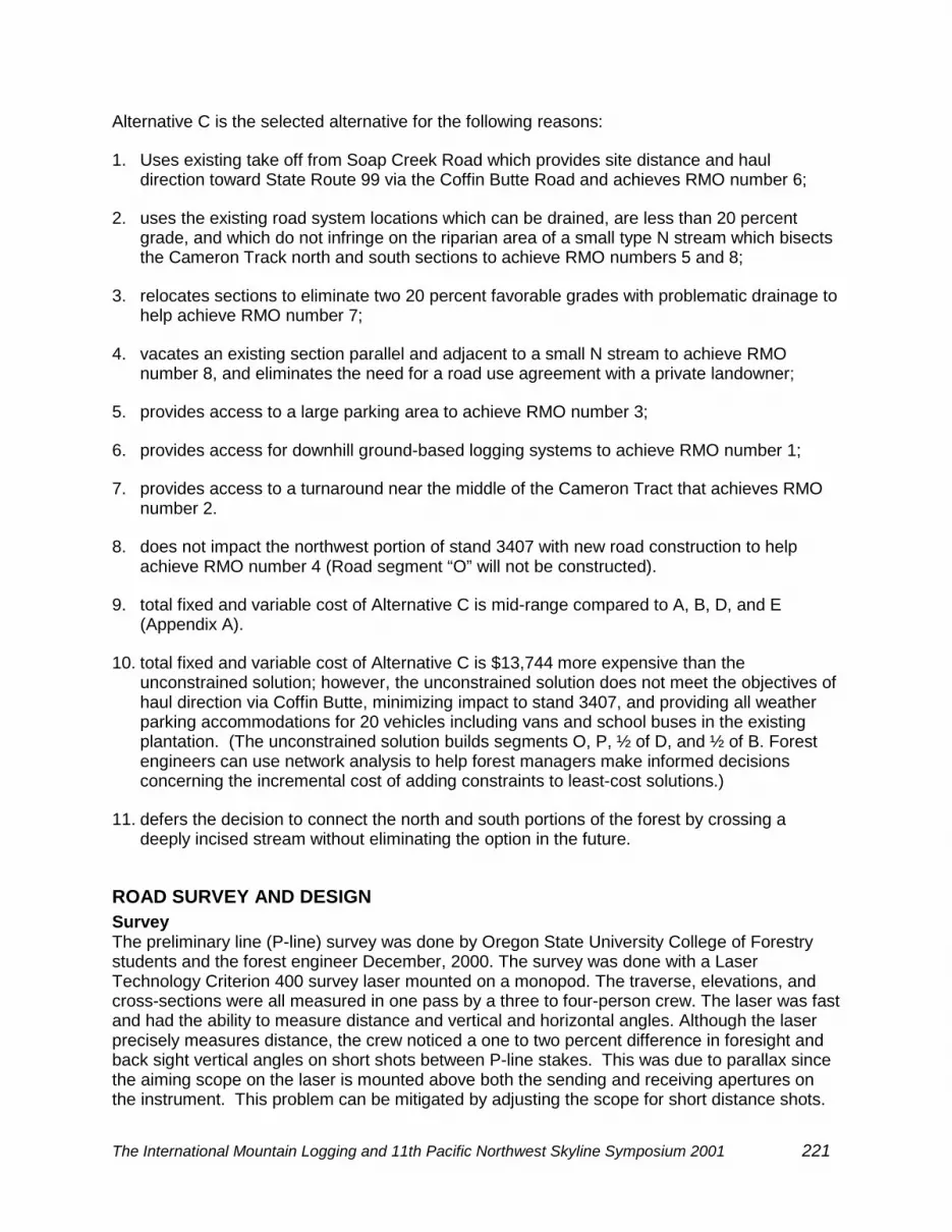
Excavation was done with a combination of machines including D-4 and D-6 crawlers, a smalland large excavator, and a backhoe. A 12 yard dump truck was used for overhaul. Most of theexcavation was done with the D-4 crawler due to the narrow width of the road. Fills werebrought up to grade in 20-centemeter (8-inch) layers. Each layer was compacted with avibratory sheep’s foot roller (Figure 3). Out-slope of the sub-grade was checked with a 12 footboard with level set at the proper angle (Figure 4). A 4 to 5 percent out-slope was required onthe first half of the road. A 3 to 5 percent out-slope was required on the second half of the road.
Figure 3. Dozer and sheepsfoot roller work together to bring fill up to grade incompacted layers for sub-grade stability on a segment of relocation.
Bench construction was required on a 200 foot section of new construction that was on a 40percent side slope. Although the section was not fully benched, the bench constructionstrengthened the fill. Fill failures on a narrow out-sloped road must be carefully guardedagainst.
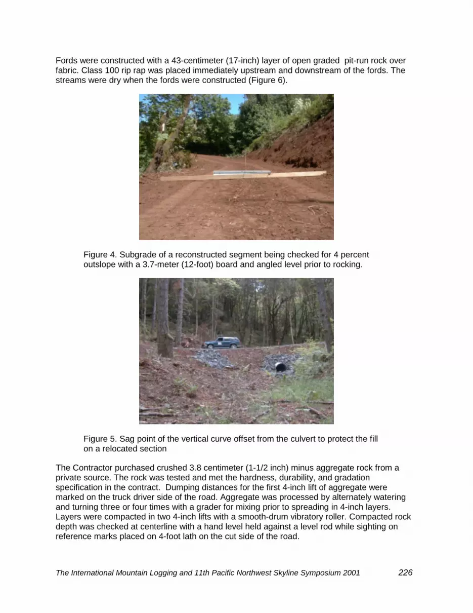
Culvert ends were staked and troughs were excavated. Select material or ¾ inch minusaggregate was used for bedding. Backfill was hand compacted in layers with a jumping jackcompactor. Culvert fills were armored with class 100 rip-rap. The sag point of a vertical curveover a 36 inch culvert was offset 9 meters (30 feet) from the culvert (Figure 5). This reduced theamount of fill likely to wash in the event the culvert plugs and water overtops the road. Fishpassage was not an issue since the streams were not fish bearing.
The International Mountain Logging and 11th Pacific Northwest Skyline Symposium 2001 226
Fords were constructed with a 43-centimeter (17-inch) layer of open graded pit-run rock overfabric. Class 100 rip rap was placed immediately upstream and downstream of the fords. Thestreams were dry when the fords were constructed (Figure 6).
Figure 4. Subgrade of a reconstructed segment being checked for 4 percentoutslope with a 3.7-meter (12-foot) board and angled level prior to rocking.
Figure 5. Sag point of the vertical curve offset from the culvert to protect the fillon a relocated section
The Contractor purchased crushed 3.8 centimeter (1-1/2 inch) minus aggregate rock from aprivate source. The rock was tested and met the hardness, durability, and gradationspecification in the contract. Dumping distances for the first 4-inch lift of aggregate weremarked on the truck driver side of the road. Aggregate was processed by alternately wateringand turning three or four times with a grader for mixing prior to spreading in 4-inch layers.Layers were compacted in two 4-inch lifts with a smooth-drum vibratory roller. Compacted rockdepth was checked at centerline with a hand level held against a level rod while sighting onreference marks placed on 4-foot lath on the cut side of the road.

The International Mountain Logging and 11th Pacific Northwest Skyline Symposium 2001 227
Figure 6. A ford constructed across an intermittent stream.
The contractor elected to start placing rock at the end of the project and progress out toward thebeginning of the project. This allowed rock trucks to find soft spots during haul. Soft spotsdeveloped even though the sub-grade had been layer compacted in 20 cm. (8 inch) lifts by asheep’s-foot vibratory compactor. Soft spots were strengthened as they developed withcompacted pit-run rock. Fabric was placed over pit-run rock where rutting had progressedmore than 10 cm. (4 inches). Fabric was placed under pit-run base course where rutting hadstarted but which had not occurred to a significant degree. Fabric was placed on approximately9 percent of the rocked portion of the road.
Two rubber belt cross drains were installed by the contractor on 12 and 14 percent road gradesafter rocking had been completed (Figure 7). The cross drains were constructed by students inaccordance with a design by Brian Kramer, P.E., Senior Instructor, Forest EngineeringDepartment, College of Forestry, Oregon State University. Students lag screwed heavy-dutyconveyor belting cut in 30 centimeter (12 inch) wide by 6 meter (20 foot) long strips onto theedge of treated 10x20 centimeter (4x8 inch) treated timbers. The contractor buried the timbersin the aggregate with approximately 10 centimeters (4 inches) of the belting protruding abovethe surfacing of the out-sloped road. The drains were skewed approximately 45 degrees.
DISCUSSIONCostAn invitation to bid (ITB) on construction of The Cameron North Road Improvement Project waswidely circulated to contractors by Oregon State University’s Facilities Services Office as apublic works contract subject to prevailing wage rates. Six bids were received ranging from$90,834 to $112,768 including slope staking. Slope staking was advertised as a deductive biditem in the ITB. Contractors’ bids for staking ranged from $6,985 to $14,681 (US dollars). Bidsfor slope staking were rejected. The contract was awarded to the low bidder without staking for$76,584. The forest engineer staked the road for approximately $2,400 with the help ofstudents and staff.
Road construction costs including engineering for the Cameron North Road were tracked bythree road types: 1) reconstruction rocked 2) reconstruction not rocked 3) relocation rocked(new construction rocked). The greatest difference in cost per kilometer was dependent on

The International Mountain Logging and 11th Pacific Northwest Skyline Symposium 2001 228
whether or not the road was rocked (Table 1). The addition of rock to reconstructed segmentsincreased the cost 221 percent over reconstructed un-rocked segments. In comparison, therewas relatively little difference in cost between rocked reconstruction and rocked relocation.Surprisingly, relocated segments cost 11 percent less than reconstructed segments that wererocked. In the case of the Cameron North Road, there were more drainage structures perkilometer needed in reconstructed segments than were needed in the relocated segments.Also, less fabric and rock was needed per kilometer in relocated segments. Rock accounted for59 percent of the total cost of the rocked portion of the road (Table 1). Engineering accountedfor 11 percent of the total cost of the road (Table 1).
Figure 7. Installing a rubber belt cross drain on a relocated out-sloped section.
The final construction cost excluding slope staking and other engineering was $93,260 orapproximately 22 percent higher than the bid price. Reasons for the overrun in constructioncost were the need for an additional 876 tons of pit-run and aggregate rock at a cost of $9,537to strengthen soft sections which became evident during rock hauling, an underestimate of 86tons of class 100 rip rap at a cost of $2,505 needed to more fully armor culvert fills, anunderestimate of 171 cubic yards of compacted fill material at a cost of $1,220 needed toconstruct the road (the 1.4 fill expansion factor used to estimate in-place bank excavationquantities should have been closer to 1.6 due to larger than expected quantities of unsuitablesod that had to be stripped from reconstructed sections of the old road), a design change toincrease the out-slope from 3 percent to 4 to 5 percent and to daylight several through cuts onthe first half of the road at a cost of $2,134, an additional 500 square yards of fabric at a cost of$500, the addition of two belt cross drains at a cost of $309 each and a concrete culvertextension at the take off from the county road at a cost of $162.
A cost increase of approximately fifty percent per installed culvert was experienced bydecreasing the headwater to depth ratio from 1.0 to 0.5 for the Cameron North Road in-streamculverts. In retrospect, a more cost effective design would have been to size the culverts usinga headwater to depth ratio of 1.0 but for the 100-year storm.
Watershed EnhancementThe Oregon plan for salmon and watersheds was reaffirmed January, 1999 “to restore Oregon’swild salmon and trout populations and fisheries to sustain productive levels that will providesubstantial environmental, cultural, and economic benefits and to improve water quality”

The International Mountain Logging and 11th Pacific Northwest Skyline Symposium 2001 229
(Executive Order No. 99-01, the Oregon plan for salmon and watersheds). An essential principleof the plan is to encourage efforts to improve conditions for salmon through non-regulatorymeans. The Cameron North Road Improvement Project will help to improve the health of theSoap Creek watershed by vacating approximately 0.3 kilometers (0.2 miles) of road within theriparian management areas of small non-fish tributaries, by placing aggregate surfacing on 1.1kilometers (0.7 miles) of existing non-surfaced road, and by improving six crossings of non-fishbearing tributaries to Soap Creek. These improvements will be reported to the OregonWatershed Enhancement Board that monitors improvement projects that help to achieve thepurpose of the Oregon Plan.
Table 1. Cost Itemization by Road Type
Item Reconstructionrocked
Reconstructionnot rocked
RelocationRocked
Total
Engineering 1/ $6,474 $2,567 $3,012 $12,053
Clear/grub $3,978 $1,578 $1,850 $7,406
Excavate $8,524 $2,534 $4,192 $15,250
Rock $38,492 0 $15,060 $53,552
Fabric $778 0 $53 $831
Fords $2,263 0 $1,225 $3,488
Culverts $2,949 0 $1,231 $4,180
Belt drains $309 0 $309 $618
Move gate 2/ $403 $160 $187 $750
Mobilization 2/ $3,863 $1,532 $1,796 $7,191
Total $68,033 $8,371 $28,915 $105,319
Length km (mile) 1.09 (0.68) 0.43 (0.27) 0.52 (0.32) 2.04 (1.27)Cost/kilometer $62,415 $19,467 $55,606Cost/mile $100,047 $31,004 $90,359Cost per station $1,895 $587 $1,711
1/ Engineering cost includes transportation planning, survey and design, slope staking,and on-site contract administration minus office overhead.
2/ Costs for mobilization and for moving the gate were prorated among the three roadtypes.
SUMMARYForest engineers need to follow a process to provide forestland owners and managers withtransportation systems that meet owner objectives and legal standards. The sequential processused during the Cameron North Road Improvement Project included the following steps:
The International Mountain Logging and 11th Pacific Northwest Skyline Symposium 2001 230
TRANSPORTATION PLANNINGUnderstand the Forest Management PlanIdentify Road Management ObjectivesIdentify AlternativesDecide on Location
SURVEY AND DESIGNSurveyDecide on Design StandardsDesignPlan-in-Hand ReviewPrepare ContractEstimate CostPrepare Notice and Written Plan
CONSTRUCTConstruct
Critical communication milestones between the forest engineer and the forest managerincluded:
Identification of the Road Management Objectives
Decision on Location and Design Standards
Plan-in hand field review
Construction Costs
REFERENCEBolander,P, Marocco, D., Kennedy, R.1996.Earth and aggregate surfacing design guide for low
volume roads. USDA For. Serv. Engineering Staff, Washington, DC, EM-7170-16. 302 p.
Chung, W., and J. Sessions. 2000. NETWORK 2000, a program for optimizing large fixed andvariable cost transportation problems. In Proceedings of the Eighth Symposium on SystemsAnalysis in Forest Resources. Edited by Arthaud, G.J. Society of American Foresters.Aspen, CO. (in press).
Cornell, J. and K. Mills, 2000. Forest road management guidebook. Oregon Department ofForestry. Salem, OR. 32p.
Executive Order No. EO 99-01, the Oregon plan for salmon and watersheds. January 8, 1999.State of Oregon, Salem, OR.
Kramer, Brian W., P.E., Senior Instructor, Forest Engineering Department, College of Forestry,Oregon State University. Road surface rubber water diverter plans. Unpublished.
Oregon Forest Practice Act, 1971 (with revisions through July, 1999). Oregon Revised Statutes527.610 to 527.770, 527.990 (1) and 527.992. Oregon State Legislature, Salem, OR

The International Mountain Logging and 11th Pacific Northwest Skyline Symposium 2001 231
Protocol for road hazard inventories, forest roads manual, appendix 1, 2000. OregonDepartment of Forestry, Salem, OR.
Robison, E., A. Mirati, M. Allen, 1999. Oregon road/stream crossing restoration guide (June 8,1999 advanced fish passage training version), Oregon Department of Forestry, Salem, OR.75p. Unpublished.
Softree Technical Systems, Inc., 1998. Location design user manual for RoadEng. #8-650Clyde Avenue, West Vancouver, B.C., Canada, V7T1E2. 130 p.