fluid power manual 2018 - the university of jordan
TRANSCRIPT
The University of Jordan
School of Engineering
Mechatronics Engineering Department
09
Fluid Power Engineering Lab 0908464
Lab Experiments Fluid Power Engineering Lab
2Page Copyrights’ are held by Eng. Rasha Noufal
EXPERIMENT N0. 1
Introduction to Automation Studio
Experiments No. Experiments Name Page No.
Experiment No. 1 Introduction to FluidSIM Program 3
Experiment No. 2 Pneumatic Control of a Double-acting Cylinder 15
Experiment No. 3 Electro pneumatics Control Technology 25
Experiment No. 4 Introduction to Hydraulic Trainer 35
Experiment No. 5 Sequential control of a 2 double acting cylinder 51
Experiment No. 6 Electro pneumatics Sequential control of a 2 double acting cylinder 62
Experiment No. 7 Regenerative Circuits 70
Experiment No. 8 Pneumatic sequential control of a 3 double acting cylinder 83
The University of Jordan
School of Engineering
Mechatronics Engineering Department
Fluid Power Engineering lab
Modified & Revised By: Eng. Rasha Noufal / 2018
EXPERIMENTS
Experiment No. 9 Electro pneumatic sequential control of a 3 double acting cylinder 88
Experiment No. 10 Hydraulic Motor Circuit 96
Lab Experiments Fluid Power Engineering Lab
3Page Copyrights’ are held by Eng. Rasha Noufal
Objective: Students develop a hydraulic and pneumatic circuit in FluidSIM.
The student should be able to build the circuit using FluidSIM and try
different loads in order to realize its effect on the system performance.
To understand how a double acting cylinder can be controlled using a four-way directional valve.
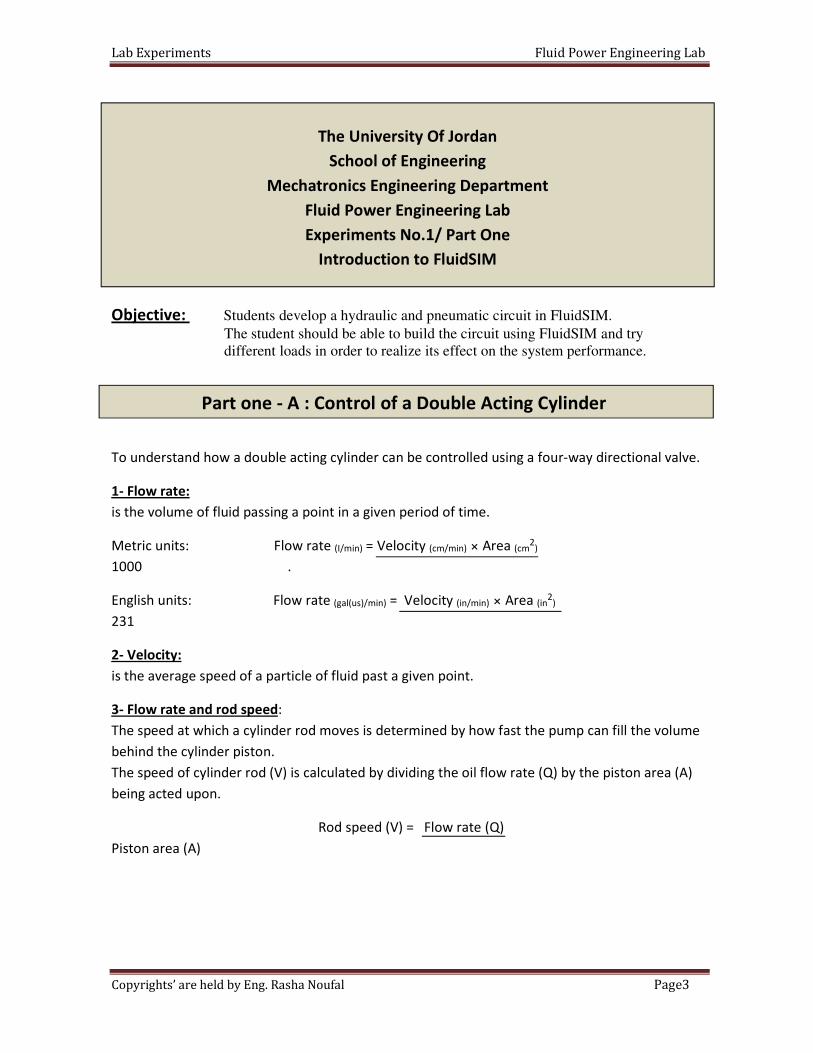
Flow rate: -1
is the volume of fluid passing a point in a given period of time.
) 2
(cmArea × (cm/min) = Velocity (I/min)Flow rate Metric units:
1000 .
) 2
in(Area × /min)in(= Velocity /min)gal(us)(English units: Flow rate
231
Velocity: -2
is the average speed of a particle of fluid past a given point.
: Flow rate and rod speed -3
The speed at which a cylinder rod moves is determined by how fast the pump can fill the volume
behind the cylinder piston.
The speed of cylinder rod (V) is calculated by dividing the oil flow rate (Q) by the piston area (A)
being acted upon.
Rod speed (V) = Flow rate (Q)
Piston area (A)
The University Of Jordan
School of Engineering
Mechatronics Engineering Department
Fluid Power Engineering Lab
Experiments No.1/ Part One
Introduction to FluidSIM
Part one - A : Control of a Double Acting Cylinder
Lab Experiments Fluid Power Engineering Lab
4Page Copyrights’ are held by Eng. Rasha Noufal
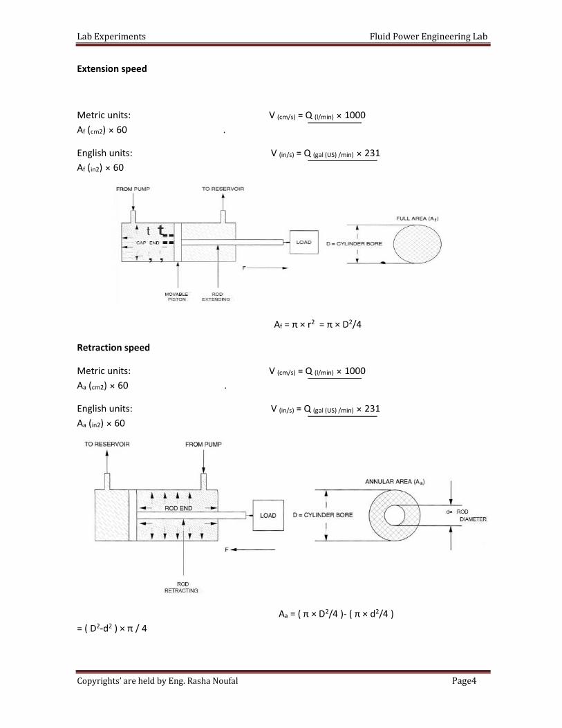
Extension speed
1000 × /min)l(= Q )s/(cmMetric units: V
60 . ×) cm2( fA
231 × /min)gal (US) (= Q )s/in(V English units:
60 ×) 2in( fA
/42= π × D 2= π × r fA
Retraction speed
1000 × /min)l(= Q )s/(cmMetric units: V
60 . ×) cm2( aA
312 × /min)gal (US) (= Q )s/in(English units: V
60 ×) 2in( aA
/4 ) 2( π × d -/4 )2= ( π × D aA
) × π / 4 2d-2= ( D
Lab Experiments Fluid Power Engineering Lab
5Page Copyrights’ are held by Eng. Rasha Noufal
Law:Pascal's -4
Pascal's Law states that pressure applied on a confined fluid is transmitted undiminished in all
direction, and acts with equal force on equal areas, and at right angles to them.
The generated pressure is equal to the force applied to the top of the stopper divided by the area
of the stopper.
10 × )N( Force= )KPa( PressureMetric units:
. ) 2
(cmArea
) lb(= Force )Psi(Pressure English units:
) 2
in(Area
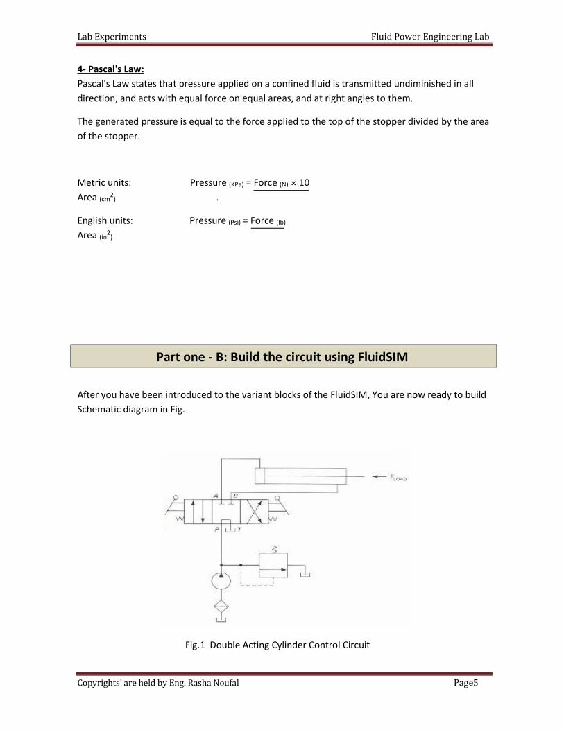
After you have been introduced to the variant blocks of the FluidSIM, You are now ready to build
Schematic diagram in Fig.
Fig.1 Double Acting Cylinder Control Circuit
Part one - B: Build the circuit using FluidSIM
Lab Experiments Fluid Power Engineering Lab
6Page Copyrights’ are held by Eng. Rasha Noufal
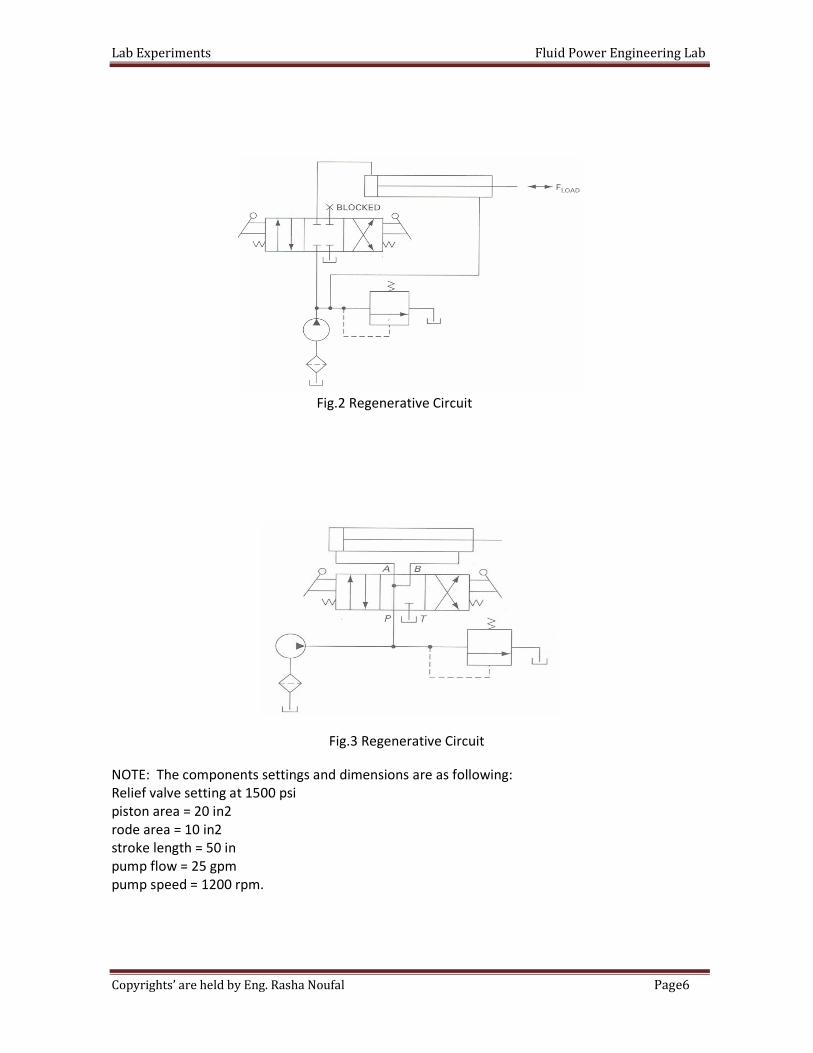
Fig.2 Regenerative Circuit
Fig.3 Regenerative Circuit
NOTE: The components settings and dimensions are as following:
Relief valve setting at 1500 psi
piston area = 20 in2
rode area = 10 in2
stroke length = 50 in
pump flow = 25 gpm
pump speed = 1200 rpm.
Lab Experiments Fluid Power Engineering Lab
7Page Copyrights’ are held by Eng. Rasha Noufal
Date:
Section:
Group's Names:
1-
2-
3-
4-
Q1: Brief description of how the above circuits work.
Q2: Calculate the extracting and retracting cylinder speeds in both cases
(normal and regenerative)? Comment on the results.
Q3: Calculate the maximum load that can be attached to the cylinder in both cases?
Comment on the results.
Q4: What is the purpose of a regenerative circuit? (Use equations to explain that).
The University Of Jordan
School of Engineering
Mechatronics Engineering Department
Fluid Power Engineering Lab
Experiments No.1/ Part One
Introduction to FluidSIM
In class Lab Report
Part three: Procedure
Lab Experiments Fluid Power Engineering Lab
8Page Copyrights’ are held by Eng. Rasha Noufal
Objective: Students Develop, connection and operation of simple, practical hydraulic and
pneumatic circuit in FluidSIM.
The student should be able to describe the operation of a directional control
valve.
Hydraulic and pneumatic systems perform a variety of tasks, ranging from very simple to the very
complex. Controlling cylinder is one of the most important aspects of hydraulics and pneumatics.
For example, two cylinders may be required to operate at the same speed, or a cylinder may
need to extend rapidly under no load conditions. FluidSIM is a design, animation and simulation
software tool. It was created for the automation industry, specifically to fulfill engineering,
training, and testing requirements.
To understand the sequence circuit and to know how build such circuit using FluidSIM.
: Operation of a basic hydraulic circuit
A hydraulic circuit is a path for Oil to flow through hoses and components.
1- The reservoir holds the oil
2- The pump (pushes) the oil, attempting to make it flow through the circuit.
3- The directional control valve allows the operator to manually control the oil flow to the
cylinder.
The University Of Jordan
School of Engineering
Mechatronics Engineering Department
Fluid Power Engineering Lab
Experiments No.1
Introduction to FluidSIM/ Part Two
Introduction
Part two – A : Hydraulic Cylinder Sequence Circuit
Lab Experiments Fluid Power Engineering Lab
9Page Copyrights’ are held by Eng. Rasha Noufal
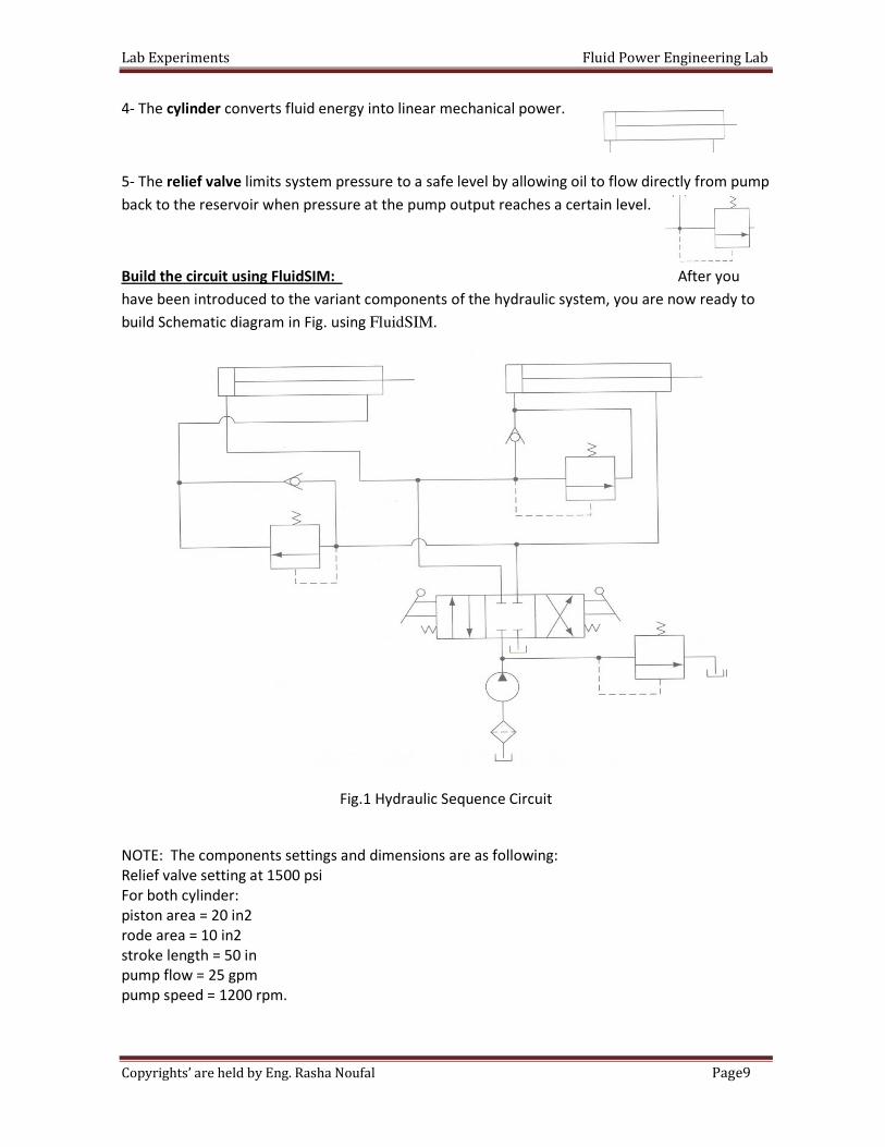
4- The cylinder converts fluid energy into linear mechanical power.
5- The relief valve limits system pressure to a safe level by allowing oil to flow directly from pump
back to the reservoir when pressure at the pump output reaches a certain level.
you After :FluidSIMBuild the circuit using
have been introduced to the variant components of the hydraulic system, you are now ready to
build Schematic diagram in Fig. using FluidSIM.
Fig.1 Hydraulic Sequence Circuit
NOTE: The components settings and dimensions are as following:
Relief valve setting at 1500 psi
For both cylinder:
piston area = 20 in2
rode area = 10 in2
stroke length = 50 in
pump flow = 25 gpm
pump speed = 1200 rpm.
Lab Experiments Fluid Power Engineering Lab
10Page Copyrights’ are held by Eng. Rasha Noufal
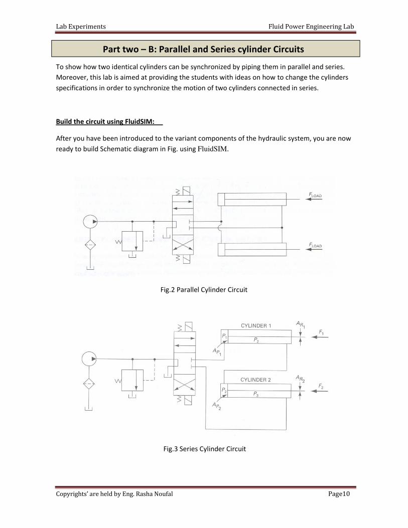
To show how two identical cylinders can be synchronized by piping them in parallel and series.
Moreover, this lab is aimed at providing the students with ideas on how to change the cylinders
specifications in order to synchronize the motion of two cylinders connected in series.
:FluidSIMBuild the circuit using
After you have been introduced to the variant components of the hydraulic system, you are now
ready to build Schematic diagram in Fig. using FluidSIM.
Fig.2 Parallel Cylinder Circuit
Fig.3 Series Cylinder Circuit
Part two – B: Parallel and Series cylinder Circuits
Lab Experiments Fluid Power Engineering Lab
11Page Copyrights’ are held by Eng. Rasha Noufal
Flow Control Valves (FCVs) are used in industry for cylinder speed control. Therefore, the aim of
this experiment is to illustrate the circuit for meter-in and meter-out speed control as well as the
difference between them.
A flow control valve as an adjustable resistance to flow that operates very much like a faucet. By
adjusting the resistance, or opening, of this valve, you can modify the rate of oil flow to a cylinder
and, therefore, the speed of its piston rod.
Flow control circuits:
There are two ways to meter the oil flow in order to control the speed of a cylinder, which are:
meter-in and meter-out.
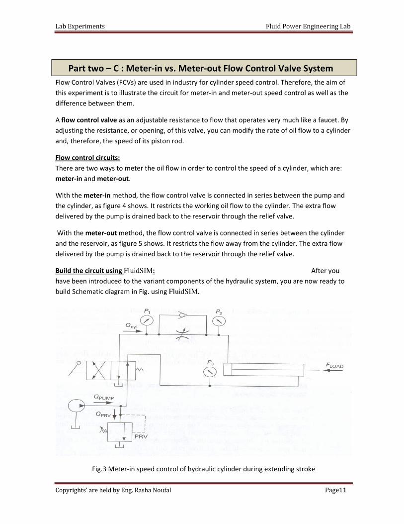
With the meter-in method, the flow control valve is connected in series between the pump and
the cylinder, as figure 4 shows. It restricts the working oil flow to the cylinder. The extra flow
delivered by the pump is drained back to the reservoir through the relief valve.
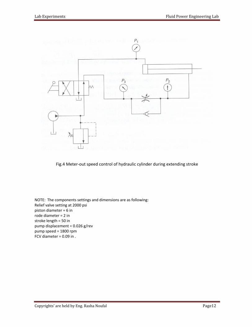
With the meter-out method, the flow control valve is connected in series between the cylinder
and the reservoir, as figure 5 shows. It restricts the flow away from the cylinder. The extra flow
delivered by the pump is drained back to the reservoir through the relief valve.
After you :FluidSIMBuild the circuit using
have been introduced to the variant components of the hydraulic system, you are now ready to
build Schematic diagram in Fig. using FluidSIM.
Fig.3 Meter-in speed control of hydraulic cylinder during extending stroke
Part two – C : Meter-in vs. Meter-out Flow Control Valve System
Lab Experiments Fluid Power Engineering Lab
12Page Copyrights’ are held by Eng. Rasha Noufal
Fig.4 Meter-out speed control of hydraulic cylinder during extending stroke
NOTE: The components settings and dimensions are as following:
Relief valve setting at 2000 psi
piston diameter = 6 in
rode diameter = 2 in
stroke length = 50 in
pump displacement = 0.026 g/rev
pump speed = 1800 rpm
FCV diameter = 0.09 in .
Lab Experiments Fluid Power Engineering Lab
13Page Copyrights’ are held by Eng. Rasha Noufal
Date:
Section:
Group's Names:
1-
2-
3-
4-
5-
Q1: Brief description of how the circuits Fig.1 work.
Q2: Calculate the maximum load that can be attached to the cylinder? Comment on the results.
The University Of Jordan
School of Engineering
Mechatronics Engineering Department
Fluid Power Engineering Lab
Experiments No.1/ Part Two
Introduction to FluidSIM
In class Lab Report
Part one: Hydraulic Cylinder Sequence Circuit
Lab Experiments Fluid Power Engineering Lab
14Page Copyrights’ are held by Eng. Rasha Noufal
Q1: Brief description of how the above circuits work.
Q2: For the series cylinder circuit, what pump pressure is required if the cylinder loads are 5000
lb each and cylinder 1 has a piston area of 10 in2?
Q1: What are the stroke speeds in both cases at 10%,50%,80% and 100% FCV opening?
Q2:Design a meter-in and meter-out control circuit of hydraulic cylinder during retracting stroke.
The following data are given:
Desired speed = 10 in/s.
Cylinder piston diameter = 2 in.
Cylinder load: 4000 lb.
PRV setting= 1000 psi.
Part two: Parallel and Series cylinder Circuits
Part three: Meter-in vs. Meter-out Flow Control Valve System
Lab Experiments Fluid Power Engineering Lab
15Page Copyrights’ are held by Eng. Rasha Noufal
Objective: Students will be able to control of double-acting cylinder, and knowing various
types of speed regulation of the piston rod movement of double-acting cylinder.
Pneumatics system performs a variety of tasks, ranging from the very simple to the very
complex. Controlling cylinders is one of the most important aspects of pneumatics. For example,
two cylinders may be required to operate at the same speed, or a cylinder may need to extend
rapidly under no load conditions.
Pre-Lab: the required pneumatic circuit diagrams using the FluidSIM; show the whole
connections and components required for each circuit.
In the lab: Connect the circuits and verify their operation. sure that the pressure is 4
bars and is connected correctly. Double check your connections before
switching the compressor on.
Direct control of a double-acting cylinder with push-button.
Aim:
This exercise provides direct control of double-acting cylinders with manually operated
5/2 directional control valves. In addition, the effect of adjustable spring cushioning in double-
acting cylinders can be observed.
Task:
- The piston rod of a double-working cylinder (Z1) should extend after actuating a button.
- After releasing the button (S1), the piston of the cylinder should retract automatically to
its back position.
The University Of Jordan
School of Engineering
Mechatronics Engineering Department
Fluid Power Engineering Lab
Experiments No.2
Pneumatic Control of a Double-acting Cylinder
Introduction
Part one: Control of a double-acting cylinder
Pre-Lab
Lab Experiments Fluid Power Engineering Lab
16Page Copyrights’ are held by Eng. Rasha Noufal
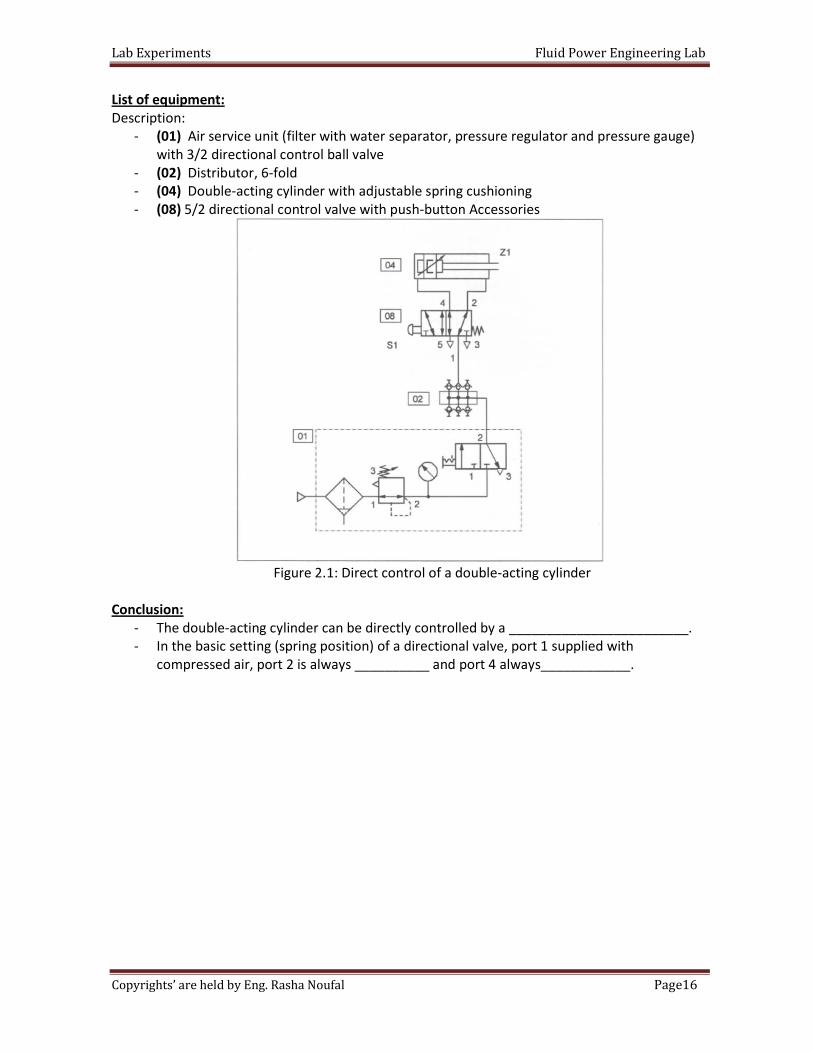
List of equipment:
Description:
- (01) Air service unit (filter with water separator, pressure regulator and pressure gauge)
with 3/2 directional control ball valve
- (02) Distributor, 6-fold
- (04) Double-acting cylinder with adjustable spring cushioning
- (08) 5/2 directional control valve with push-button Accessories
Figure 2.1: Direct control of a double-acting cylinder
Conclusion:
- The double-acting cylinder can be directly controlled by a ________________________.
- In the basic setting (spring position) of a directional valve, port 1 supplied with
compressed air, port 2 is always __________ and port 4 always____________.
Lab Experiments Fluid Power Engineering Lab
17Page Copyrights’ are held by Eng. Rasha Noufal
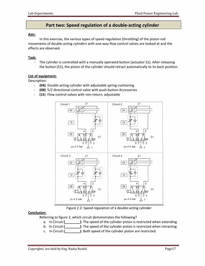
Aim:
In this exercise, the various types of speed regulation (throttling) of the piston rod
movements of double-acting cylinders with one-way flow control valves are looked at and the
effects are observed.
Task:
- The cylinder is controlled with a manually operated button (actuator S1). After releasing
the button (S1), the piston of the cylinder should retract automatically to its back position.
List of equipment:
Description:
- (04) Double-acting cylinder with adjustable spring cushioning
- (08) 5/2 directional control valve with push-button Accessories
- (15) Flow control valves with non-return, adjustable
Figure 2.2: Speed regulation of a double-acting cylinder
Conclusion:
Referring to figure 2, which circuit demonstrates the following?
a. In Circuit (________): The speed of the cylinder piston is restricted when extending.
b. In Circuit (________): The speed of the cylinder piston is restricted when retracting.
c. In Circuit (________): Both speed of the cylinder piston are restricted.
Part two: Speed regulation of a double-acting cylinder
Lab Experiments Fluid Power Engineering Lab
18Page Copyrights’ are held by Eng. Rasha Noufal
Aim:
In this exercise we examine how a pneumatically operated impulse valve functions when
controlling a double acting cylinder.
Upon the completion of this task, the student will be
• Familiar with indirect actuation of a double acting cylinder by using a double pilot valve.
• Using the 3/2 way roller valve for automatic return of the cylinder.
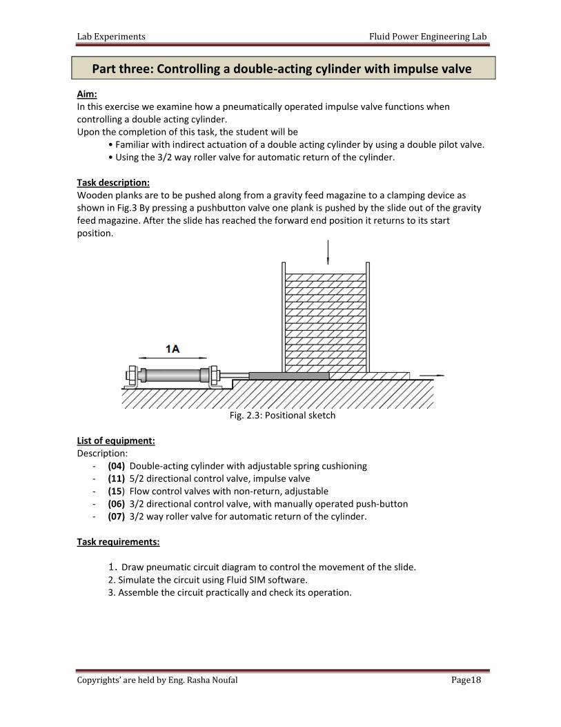
Task description:
Wooden planks are to be pushed along from a gravity feed magazine to a clamping device as
shown in Fig.3 By pressing a pushbutton valve one plank is pushed by the slide out of the gravity
feed magazine. After the slide has reached the forward end position it returns to its start
position.
Fig. 2.3: Positional sketch
List of equipment:
Description:
- (04) Double-acting cylinder with adjustable spring cushioning
- (11) 5/2 directional control valve, impulse valve
- (15) Flow control valves with non-return, adjustable
- (06) 3/2 directional control valve, with manually operated push-button
- (07) 3/2 way roller valve for automatic return of the cylinder.
Task requirements:
1. Draw pneumatic circuit diagram to control the movement of the slide.
2. Simulate the circuit using Fluid SIM software.
3. Assemble the circuit practically and check its operation.
Part three: Controlling a double-acting cylinder with impulse valve
Lab Experiments Fluid Power Engineering Lab
19Page Copyrights’ are held by Eng. Rasha Noufal
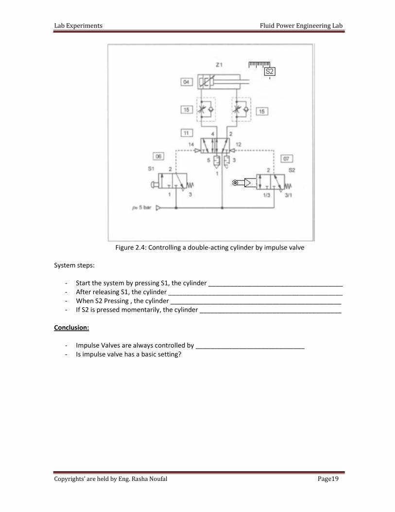
Figure 2.4: Controlling a double-acting cylinder by impulse valve
System steps:
- Start the system by pressing S1, the cylinder _____________________________________
- After releasing S1, the cylinder ________________________________________________
- When S2 Pressing , the cylinder _______________________________________________
- If S2 is pressed momentarily, the cylinder _______________________________________
Conclusion:
- Impulse Valves are always controlled by ______________________________
- Is impulse valve has a basic setting?
Lab Experiments Fluid Power Engineering Lab
20Page Copyrights’ are held by Eng. Rasha Noufal
Aim:
The displacement-dependent control of a double-acting cylinder by using limit switches in
demonstrated in this exercise.
Upon the completion of this task, the student will be
• Familiar with indirect actuation of a double acting cylinder by using a double pilot valve.
• Familiar with using different types of directional control valves
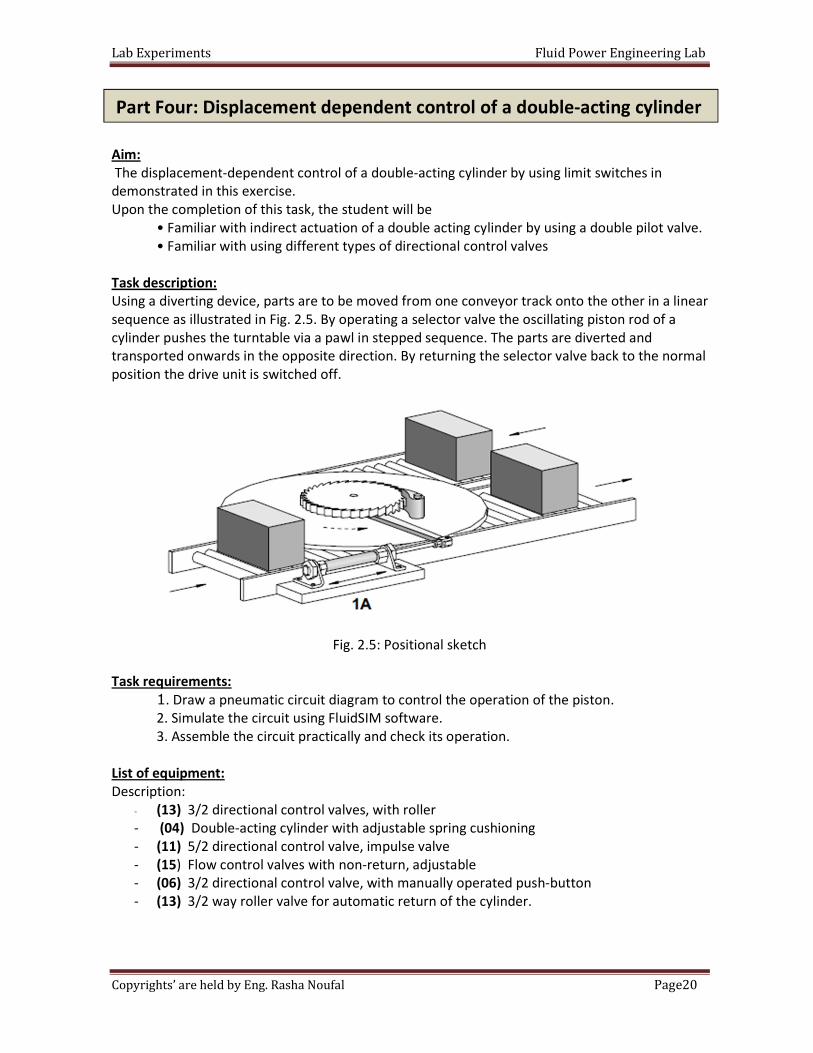
Task description:
Using a diverting device, parts are to be moved from one conveyor track onto the other in a linear
sequence as illustrated in Fig. 2.5. By operating a selector valve the oscillating piston rod of a
cylinder pushes the turntable via a pawl in stepped sequence. The parts are diverted and
transported onwards in the opposite direction. By returning the selector valve back to the normal
position the drive unit is switched off.
Fig. 2.5: Positional sketch
Task requirements:
1. Draw a pneumatic circuit diagram to control the operation of the piston.
2. Simulate the circuit using FluidSIM software.
3. Assemble the circuit practically and check its operation.
List of equipment:
Description:
- (13) 3/2 directional control valves, with roller
- (04) Double-acting cylinder with adjustable spring cushioning
- (11) 5/2 directional control valve, impulse valve
- (15) Flow control valves with non-return, adjustable
- (06) 3/2 directional control valve, with manually operated push-button
- (13) 3/2 way roller valve for automatic return of the cylinder.
Part Four: Displacement dependent control of a double-acting cylinder
Lab Experiments Fluid Power Engineering Lab
21Page Copyrights’ are held by Eng. Rasha Noufal
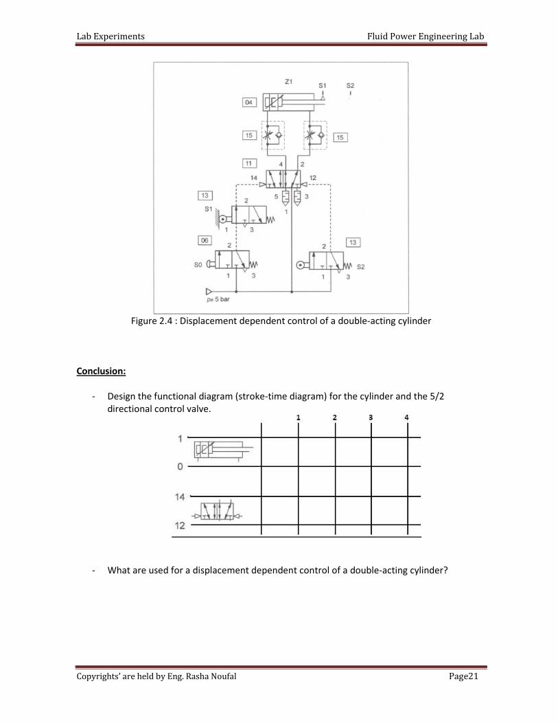
Figure 2.4 : Displacement dependent control of a double-acting cylinder
Conclusion:
- Design the functional diagram (stroke-time diagram) for the cylinder and the 5/2
directional control valve.
- What are used for a displacement dependent control of a double-acting cylinder?
Lab Experiments Fluid Power Engineering Lab
22Page Copyrights’ are held by Eng. Rasha Noufal
Aim:
By using a 3/2 directional control valve with adjustable minimum pressure of response, a
pressure dependent control (and in addition displacement dependent) control of a double acting
cylinder is put into effect.
Upon the completion of this task, the student will be
• Familiar with indirect actuation of a double acting cylinder with a double pilot valve.
• Able to use and adjust the pressure sequence valve.
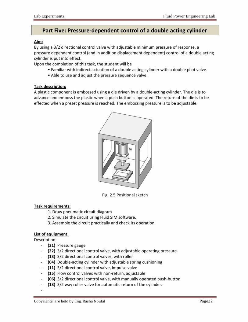
Task description:
A plastic component is embossed using a die driven by a double-acting cylinder. The die is to
advance and emboss the plastic when a push button is operated. The return of the die is to be
effected when a preset pressure is reached. The embossing pressure is to be adjustable.
Fig. 2.5 Positional sketch
Task requirements:
1. Draw pneumatic circuit diagram
2. Simulate the circuit using Fluid SIM software.
3. Assemble the circuit practically and check its operation
List of equipment:
Description:
- (21) Pressure gauge
- (22) 3/2 directional control valve, with adjustable operating pressure
- (13) 3/2 directional control valves, with roller
- (04) Double-acting cylinder with adjustable spring cushioning
- (11) 5/2 directional control valve, impulse valve
- (15) Flow control valves with non-return, adjustable
- (06) 3/2 directional control valve, with manually operated push-button
- (13) 3/2 way roller valve for automatic return of the cylinder.
-
Part Five: Pressure-dependent control of a double acting cylinder
Lab Experiments Fluid Power Engineering Lab
23Page Copyrights’ are held by Eng. Rasha Noufal
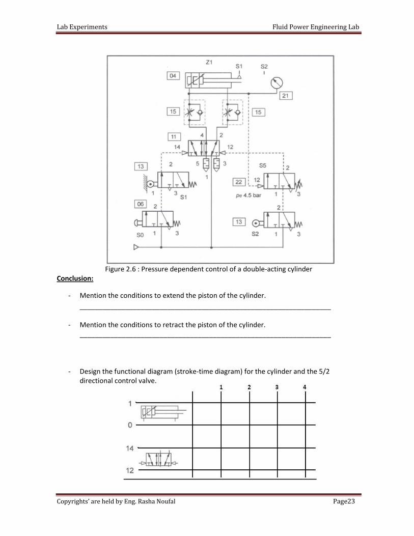
Figure 2.6 : Pressure dependent control of a double-acting cylinder
Conclusion:
- Mention the conditions to extend the piston of the cylinder.
__________________________________________________________________
- Mention the conditions to retract the piston of the cylinder.
__________________________________________________________________
- Design the functional diagram (stroke-time diagram) for the cylinder and the 5/2
directional control valve.

Lab Experiments Fluid Power Engineering Lab
24Page Copyrights’ are held by Eng. Rasha Noufal
Lab Experiments Fluid Power Engineering Lab
25Page Copyrights’ are held by Eng. Rasha Noufal
Objective: This exercises conveys basic knowledge and skills on setting up and
commissioning an electro pneumatic control using the example of a direct
electric activation of a single acting cylinder.
Pre-Lab: the required pneumatic circuit diagrams using the FluidSIM SW; show
the whole connections and components required for each circuit.
In the lab: Build your designs and verify their operation. sure that the pressure is 4 bars
and is connected correctly. Double check your connections before switching
the compressor on.
Aim:
This exercise demonstrates the control of a double-acting cylinder with an electrically controlled,
spring return 5/2 directional control valve without the use of a relay.
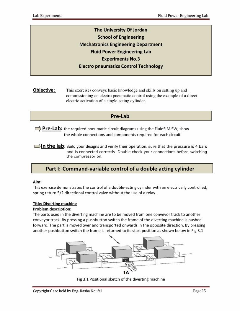
Title: Diverting machine
Problem description:
The parts used in the diverting machine are to be moved from one conveyor track to another
conveyor track. By pressing a pushbutton switch the frame of the diverting machine is pushed
forward. The part is moved over and transported onwards in the opposite direction. By pressing
another pushbutton switch the frame is returned to its start position as shown below in Fig 3.1
Fig 3.1 Positional sketch of the diverting machine
The University Of Jordan
School of Engineering
Mechatronics Engineering Department
Fluid Power Engineering Lab
Experiments No.3
Electro pneumatics Control Technology
Part I: Command-variable control of a double acting cylinder
Pre-Lab
Lab Experiments Fluid Power Engineering Lab
26Page Copyrights’ are held by Eng. Rasha Noufal
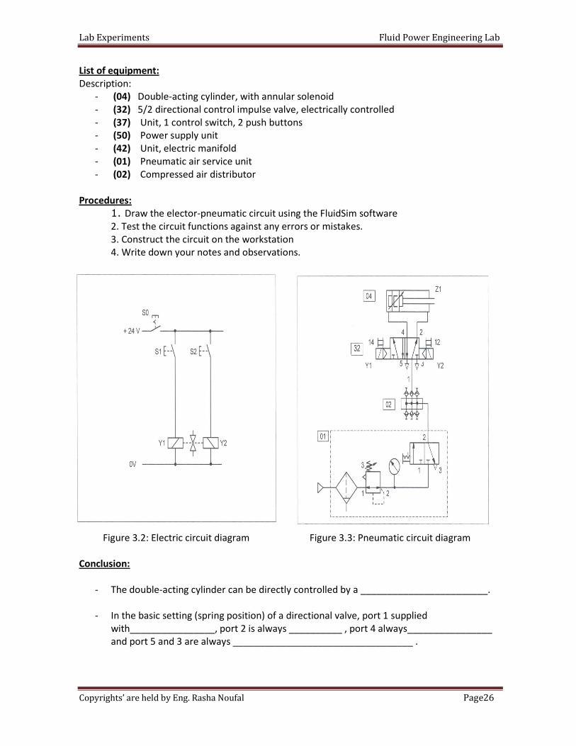
List of equipment:
Description:
- (04) Double-acting cylinder, with annular solenoid
- (32) 5/2 directional control impulse valve, electrically controlled
- (37) Unit, 1 control switch, 2 push buttons
- (50) Power supply unit
- (42) Unit, electric manifold
- (01) Pneumatic air service unit
- (02) Compressed air distributor
Procedures:
1. Draw the elector-pneumatic circuit using the FluidSim software
2. Test the circuit functions against any errors or mistakes.
3. Construct the circuit on the workstation
4. Write down your notes and observations.
Figure 3.2: Electric circuit diagram Figure 3.3: Pneumatic circuit diagram
Conclusion:
- The double-acting cylinder can be directly controlled by a ________________________.
- In the basic setting (spring position) of a directional valve, port 1 supplied
with________________, port 2 is always __________ , port 4 always________________
and port 5 and 3 are always __________________________________ .
Lab Experiments Fluid Power Engineering Lab
27Page Copyrights’ are held by Eng. Rasha Noufal
- Start the system by pressing S1 momentarily assuming that the switch S0 is on , step what
the system do:
__________________________________________________________________
__________________________________________________________________
__________________________________________________________________
__________________________________________________________________
- What the initial or center position for (32) 5/2 directional control impulse valve,
electrically controlled
_________________________________________________________________________
_________________________________________________________________________
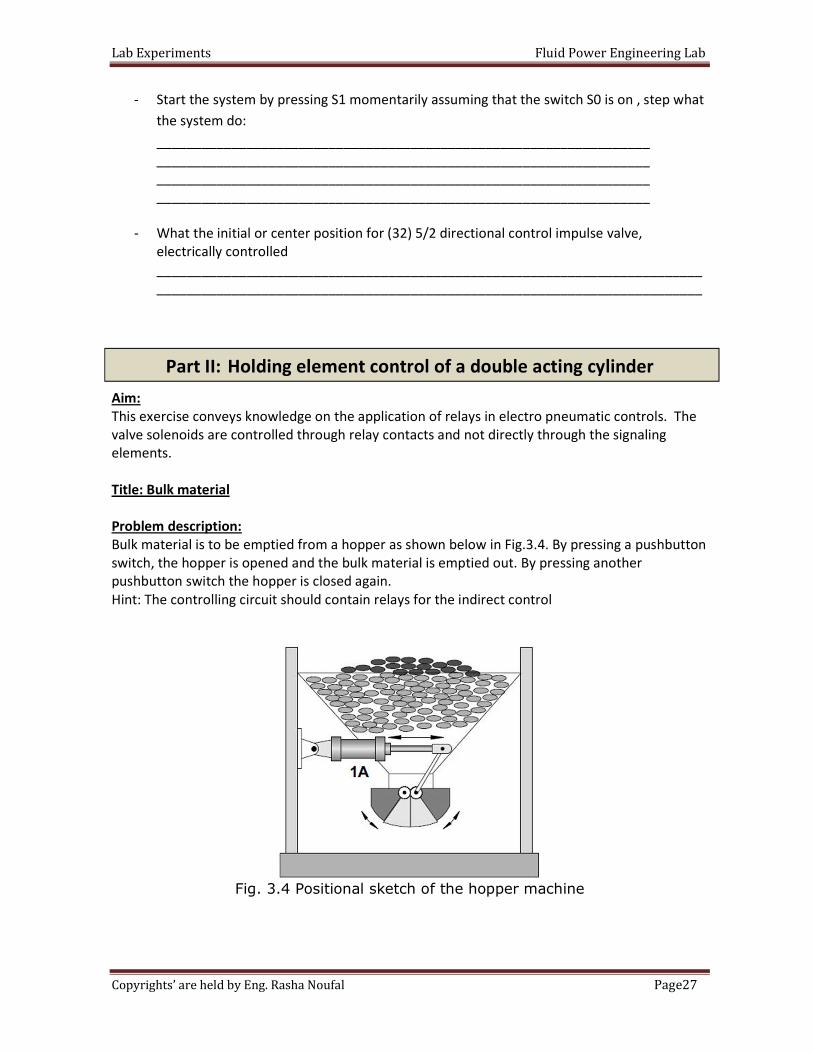
Aim:
This exercise conveys knowledge on the application of relays in electro pneumatic controls. The
valve solenoids are controlled through relay contacts and not directly through the signaling
elements.
Title: Bulk material
Problem description:
Bulk material is to be emptied from a hopper as shown below in Fig.3.4. By pressing a pushbutton
switch, the hopper is opened and the bulk material is emptied out. By pressing another
pushbutton switch the hopper is closed again.
Hint: The controlling circuit should contain relays for the indirect control
Fig. 3.4 Positional sketch of the hopper machine
Part II: Holding element control of a double acting cylinder
Lab Experiments Fluid Power Engineering Lab
28Page Copyrights’ are held by Eng. Rasha Noufal
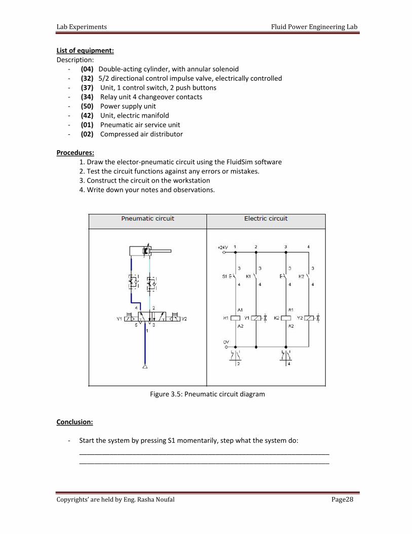
List of equipment:
Description:
- (04) Double-acting cylinder, with annular solenoid
- (32) 5/2 directional control impulse valve, electrically controlled
- (37) Unit, 1 control switch, 2 push buttons
- (34) Relay unit 4 changeover contacts
- (50) Power supply unit
- (42) Unit, electric manifold
- (01) Pneumatic air service unit
- (02) Compressed air distributor
Procedures:
1. Draw the elector-pneumatic circuit using the FluidSim software
2. Test the circuit functions against any errors or mistakes.
3. Construct the circuit on the workstation
4. Write down your notes and observations.
Figure 3.5: Pneumatic circuit diagram
Conclusion:
- Start the system by pressing S1 momentarily, step what the system do:
__________________________________________________________________
__________________________________________________________________
Lab Experiments Fluid Power Engineering Lab
29Page Copyrights’ are held by Eng. Rasha Noufal
- pressing S2 momentarily, step what the system do:
__________________________________________________________________
__________________________________________________________________
- what the different between part one and two
_________________________________________________________________________
_________________________________________________________________________
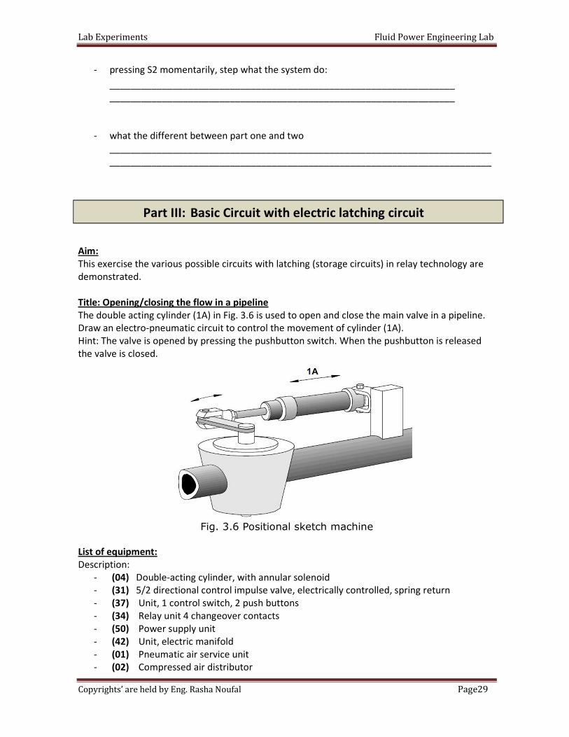
Aim:
This exercise the various possible circuits with latching (storage circuits) in relay technology are
demonstrated.
Title: Opening/closing the flow in a pipeline
The double acting cylinder (1A) in Fig. 3.6 is used to open and close the main valve in a pipeline.
Draw an electro-pneumatic circuit to control the movement of cylinder (1A).
Hint: The valve is opened by pressing the pushbutton switch. When the pushbutton is released
the valve is closed.
Fig. 3.6 Positional sketch machine
List of equipment:
Description:
- (04) Double-acting cylinder, with annular solenoid
- (31) 5/2 directional control impulse valve, electrically controlled, spring return
- (37) Unit, 1 control switch, 2 push buttons
- (34) Relay unit 4 changeover contacts
- (50) Power supply unit
- (42) Unit, electric manifold
- (01) Pneumatic air service unit
- (02) Compressed air distributor
Part III: Basic Circuit with electric latching circuit
Lab Experiments Fluid Power Engineering Lab
30Page Copyrights’ are held by Eng. Rasha Noufal
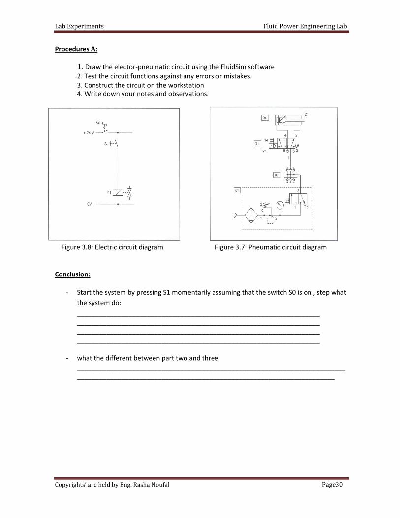
Procedures A:
1. Draw the elector-pneumatic circuit using the FluidSim software
2. Test the circuit functions against any errors or mistakes.
3. Construct the circuit on the workstation
4. Write down your notes and observations.
Figure 3.8: Electric circuit diagram Figure 3.7: Pneumatic circuit diagram
Conclusion:
- Start the system by pressing S1 momentarily assuming that the switch S0 is on , step what
the system do:
__________________________________________________________________
__________________________________________________________________
__________________________________________________________________
__________________________________________________________________
- what the different between part two and three
_________________________________________________________________________
______________________________________________________________________
Lab Experiments Fluid Power Engineering Lab
31Page Copyrights’ are held by Eng. Rasha Noufal
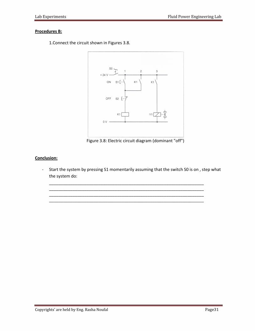
Procedures B:
1.Connect the circuit shown in Figures 3.8.
Figure 3.8: Electric circuit diagram (dominant "off")
Conclusion:
- Start the system by pressing S1 momentarily assuming that the switch S0 is on , step what
the system do:
__________________________________________________________________
__________________________________________________________________
__________________________________________________________________
__________________________________________________________________
Lab Experiments Fluid Power Engineering Lab
32Page Copyrights’ are held by Eng. Rasha Noufal
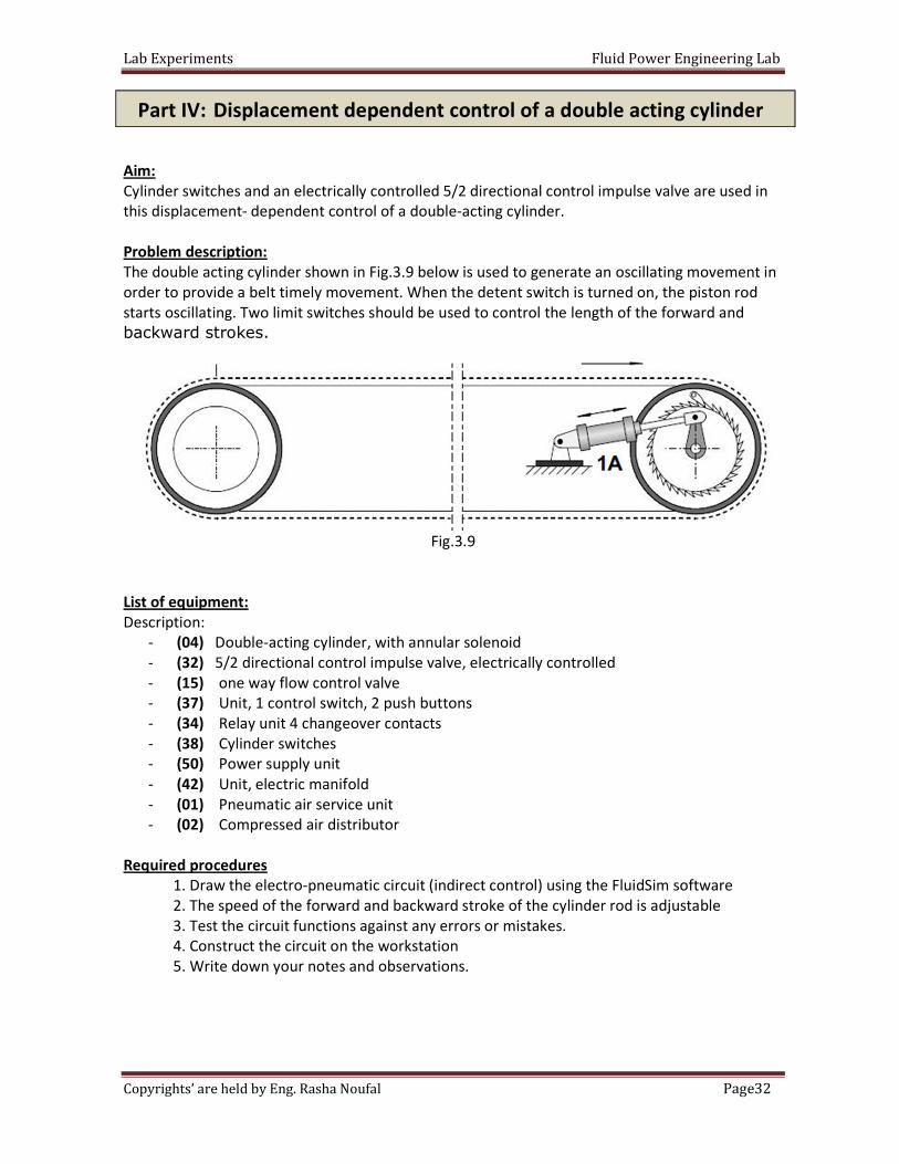
Aim:
Cylinder switches and an electrically controlled 5/2 directional control impulse valve are used in
this displacement- dependent control of a double-acting cylinder.
Problem description:
The double acting cylinder shown in Fig.3.9 below is used to generate an oscillating movement in
order to provide a belt timely movement. When the detent switch is turned on, the piston rod
starts oscillating. Two limit switches should be used to control the length of the forward and
backward strokes.
Fig.3.9
List of equipment:
Description:
- (04) Double-acting cylinder, with annular solenoid
- (32) 5/2 directional control impulse valve, electrically controlled
- (15) one way flow control valve
- (37) Unit, 1 control switch, 2 push buttons
- (34) Relay unit 4 changeover contacts
- (38) Cylinder switches
- (50) Power supply unit
- (42) Unit, electric manifold
- (01) Pneumatic air service unit
- (02) Compressed air distributor
Required procedures
1. Draw the electro-pneumatic circuit (indirect control) using the FluidSim software
2. The speed of the forward and backward stroke of the cylinder rod is adjustable
3. Test the circuit functions against any errors or mistakes.
4. Construct the circuit on the workstation
5. Write down your notes and observations.
Part IV: Displacement dependent control of a double acting cylinder
Lab Experiments Fluid Power Engineering Lab
33Page Copyrights’ are held by Eng. Rasha Noufal
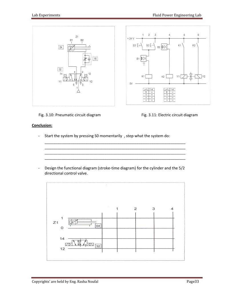
Fig. 3.10: Pneumatic circuit diagram Fig. 3.11: Electric circuit diagram
Conclusion:
- Start the system by pressing S0 momentarily , step what the system do:
__________________________________________________________________
__________________________________________________________________
__________________________________________________________________
__________________________________________________________________
- Design the functional diagram (stroke-time diagram) for the cylinder and the 5/2
directional control valve.
Lab Experiments Fluid Power Engineering Lab
34Page Copyrights’ are held by Eng. Rasha Noufal
Lab Experiments Fluid Power Engineering Lab
35Page Copyrights’ are held by Eng. Rasha Noufal
Objective: Students will be able to identify the hydraulics Trainer components and to safely operate the
trainer.
The student should be able to state the laws governing hydraulic, and perform simple calculation
involving force, pressure, area, velocity, and flow rate.
Pressure is the amount of force exerted against a given surface. Flow is the movement of fluid
caused by a difference in pressure between two points.
Fluid always flows from a higher pressure point to a lower pressure point.
When two parallel paths of flow are available, fluid will always take the path of least resistance.
In a hydraulic circuit, flow is produced by the action of a pump, which continuously discharges the
oil at a certain flow rate. Pressure is not created by the pump itself but by resistance to the oil
flow. When the oil is allowed to flow with no resistance through a hydraulic circuit, the pressure
in that circuit is theoretical zero.
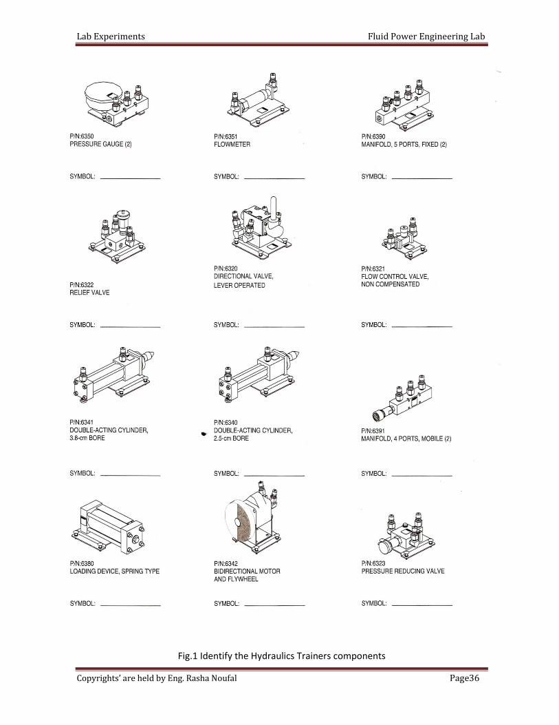
In the first part, you will identify the various components of your Hydraulics Trainer.
The components illustrated in Figure 1 are supplied with your Hydraulics Trainer. Draw the
symbol of each component:
University Of Jordan
School of Engineering
Mechatronics Engineering Department
Fluid Power Engineering Lab
Experiments No.4
Introduction to Hydraulic Trainer
Introduction
Part one: Identify the Hydraulic Trainer Components
Lab Experiments Fluid Power Engineering Lab
36Page Copyrights’ are held by Eng. Rasha Noufal
Fig.1 Identify the Hydraulics Trainers components
Lab Experiments Fluid Power Engineering Lab
37Page Copyrights’ are held by Eng. Rasha Noufal
The relief valve supplied with your kit of hydraulic components is called a pilot-operated
type. The valve body has three parts: a pressure (P) port, which is to be connected to the pump
pressure line, a tank (T) port, which is to be connected to the reservoir, and vent (V), which is to
be used for control of the valve from a remote point by external valve. The pressure at which the
relief valve begins to open is called cracking pressure.
In the part of the exercise, you measured the minimum pressure setting by a relief valve
which is connected between the pump pressure line and reservoir and by opening the valve
completely.
You then tested the effect of pressure limitation on a basic hydraulic circuit.
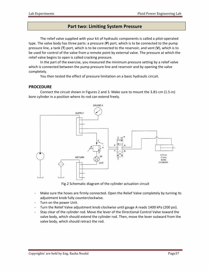
PROCEDURE Connect the circuit shown in Figures 2 and 3. Make sure to mount the 3.81-cm (1.5-in)
bore cylinder in a position where its rod can extend freely.
Fig.2 Schematic diagram of the cylinder actuation circuit
- Make sure the hoses are firmly connected. Open the Relief Valve completely by turning its
adjustment knob fully counterclockwise.
- Turn on the power Unit.
- Turn the Relief Valve adjustment knob clockwise until gauge A reads 1400 kPa (200 psi).
- Stay clear of the cylinder rod. Move the lever of the Directional Control Valve toward the
valve body, which should extend the cylinder rod. Then, move the lever outward from the
valve body, which should retract the rod.
Part two: Limiting System Pressure
Lab Experiments Fluid Power Engineering Lab
38Page Copyrights’ are held by Eng. Rasha Noufal
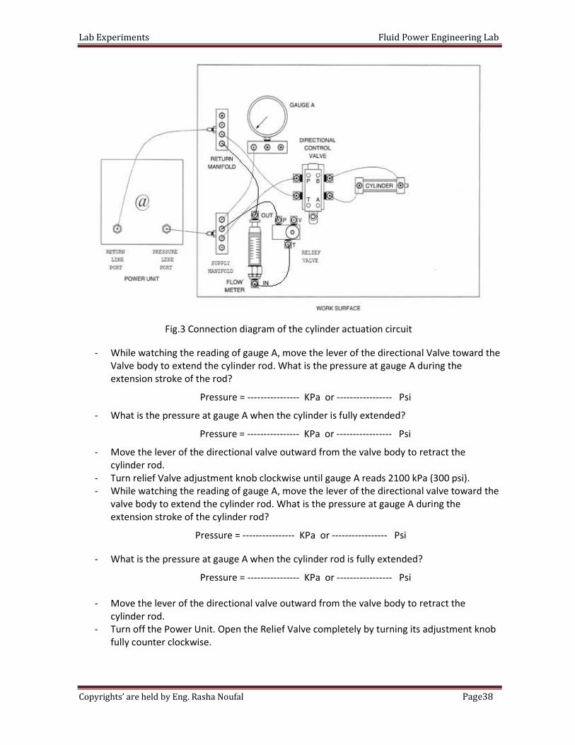
Fig.3 Connection diagram of the cylinder actuation circuit
- While watching the reading of gauge A, move the lever of the directional Valve toward the
Valve body to extend the cylinder rod. What is the pressure at gauge A during the
extension stroke of the rod?
Pressure = ---------------- KPa or ----------------- Psi
- What is the pressure at gauge A when the cylinder is fully extended?
Pressure = ---------------- KPa or ----------------- Psi
- Move the lever of the directional valve outward from the valve body to retract the
cylinder rod.
- Turn relief Valve adjustment knob clockwise until gauge A reads 2100 kPa (300 psi).
- While watching the reading of gauge A, move the lever of the directional valve toward the
valve body to extend the cylinder rod. What is the pressure at gauge A during the
extension stroke of the cylinder rod?
Pressure = ---------------- KPa or ----------------- Psi
- What is the pressure at gauge A when the cylinder rod is fully extended?
Pressure = ---------------- KPa or ----------------- Psi
- Move the lever of the directional valve outward from the valve body to retract the
cylinder rod.
- Turn off the Power Unit. Open the Relief Valve completely by turning its adjustment knob
fully counter clockwise.
Lab Experiments Fluid Power Engineering Lab
39Page Copyrights’ are held by Eng. Rasha Noufal
Q. Explain the reason for the nearly identical pressures registered during cylinder extension at
the two relief valve pressure settings.
Q. Why does the circuit pressure increase when the cylinder rod is fully extended?
- Disconnect all hoses. It may be necessary to move the directional valve lever back and
forth to relieve static pressure; the quick connects can then be removed. Wipe off any
hydraulic oil residue.
- Remove all components from the work surface and wipe off any hydraulic oil residue.
Return all components to their storage location.
The student should be describe the operation of a flow control valve, establish the
relationship between flow rate and velocity and operate meter-in and meter-out flow control
circuits.
Flow control circuits
There are three ways to meter the oil flow in order to control the speed of a cylinder,
which are: meter-in, meter-out, and bypass.
With the meter-in method, the flow control valve is connected in series between the
pump and the cylinder, as Figure 4(a) shows. It restricts the working oil flow to the cylinder. The
extra flow delivered by the pump is drained back to the reservoir through the relief valve. This
method is useful to control cylinders having a load that resists to the pump delivery, as cylinders
raising a load.
With the meter-out method, the flow control valve is connected in series between the
cylinder and the reservoir, as Figure 4(b) shows. It restricts the flow away from the cylinder. The
extra flow delivered by the pump is drained back to the reservoir through the relief valve. This
method is useful to slow down cylinders having a load that tends to run away, as cylinders
lowering a load.
With the bypass method, the flow control valve is connected between the pump and the
reservoir, as Figure 4 (c) shows. The extra flow is diverted directly to the reservoir through the
flow control valve. This method is more energy efficient than the meter-in and meter-out
methods because the extra flow returns to the reservoir at the load pressures' rather than at the
Part three: Flow rate and Velocity
Lab Experiments Fluid Power Engineering Lab
40Page Copyrights’ are held by Eng. Rasha Noufal
relief valve pressure. However, this method is less accurate because it does not provide direct
control of the working flow to the cylinder.
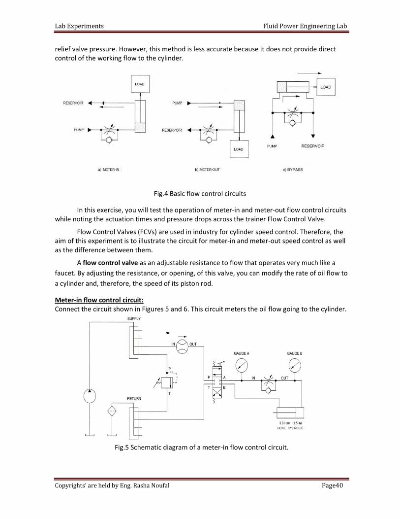
Fig.4 Basic flow control circuits
In this exercise, you will test the operation of meter-in and meter-out flow control circuits
while noting the actuation times and pressure drops across the trainer Flow Control Valve.
Flow Control Valves (FCVs) are used in industry for cylinder speed control. Therefore, the
aim of this experiment is to illustrate the circuit for meter-in and meter-out speed control as well
as the difference between them.
A flow control valve as an adjustable resistance to flow that operates very much like a
faucet. By adjusting the resistance, or opening, of this valve, you can modify the rate of oil flow to
a cylinder and, therefore, the speed of its piston rod.
Meter-in flow control circuit:
Connect the circuit shown in Figures 5 and 6. This circuit meters the oil flow going to the cylinder.
Fig.5 Schematic diagram of a meter-in flow control circuit.
Lab Experiments Fluid Power Engineering Lab
41Page Copyrights’ are held by Eng. Rasha Noufal
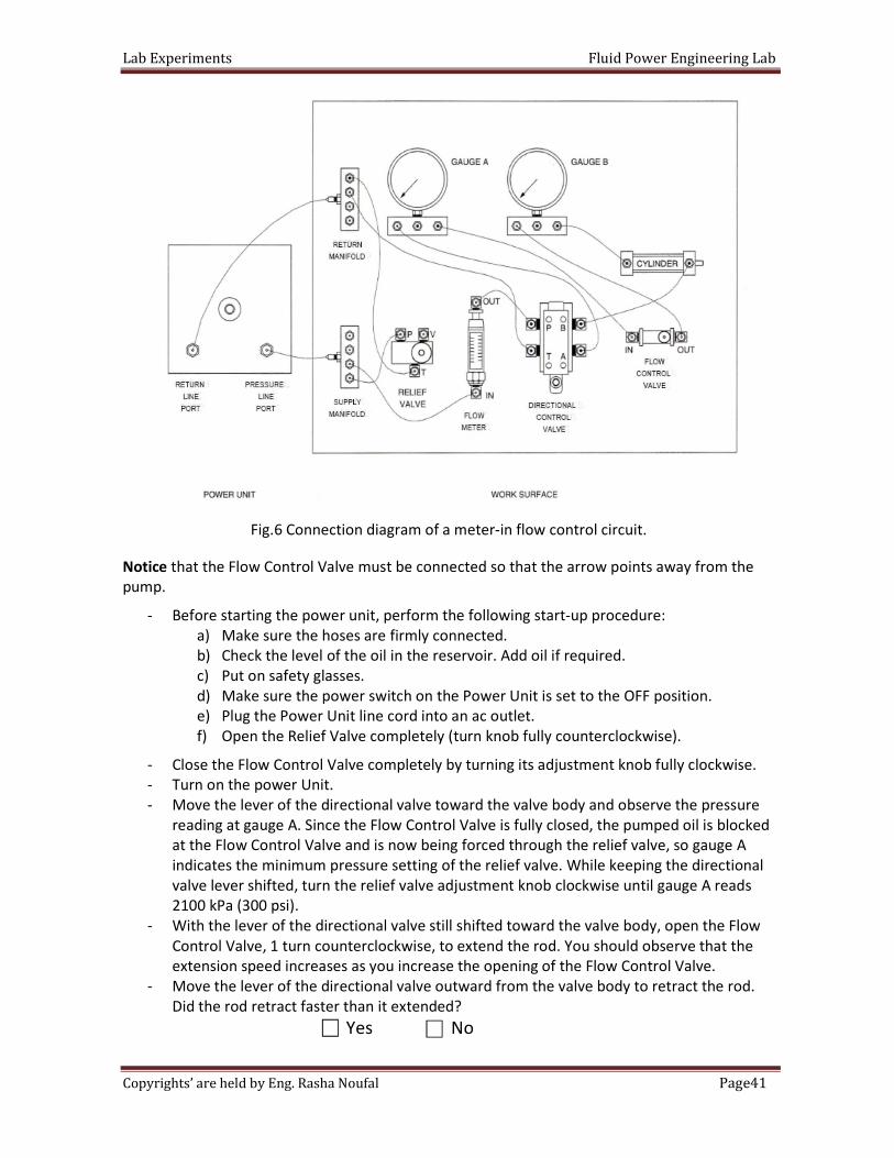
Fig.6 Connection diagram of a meter-in flow control circuit.
Notice that the Flow Control Valve must be connected so that the arrow points away from the
pump.
- Before starting the power unit, perform the following start-up procedure:
a) Make sure the hoses are firmly connected.
b) Check the level of the oil in the reservoir. Add oil if required.
c) Put on safety glasses.
d) Make sure the power switch on the Power Unit is set to the OFF position.
e) Plug the Power Unit line cord into an ac outlet.
f) Open the Relief Valve completely (turn knob fully counterclockwise).
- Close the Flow Control Valve completely by turning its adjustment knob fully clockwise.
- Turn on the power Unit.
- Move the lever of the directional valve toward the valve body and observe the pressure
reading at gauge A. Since the Flow Control Valve is fully closed, the pumped oil is blocked
at the Flow Control Valve and is now being forced through the relief valve, so gauge A
indicates the minimum pressure setting of the relief valve. While keeping the directional
valve lever shifted, turn the relief valve adjustment knob clockwise until gauge A reads
2100 kPa (300 psi).
- With the lever of the directional valve still shifted toward the valve body, open the Flow
Control Valve, 1 turn counterclockwise, to extend the rod. You should observe that the
extension speed increases as you increase the opening of the Flow Control Valve.
- Move the lever of the directional valve outward from the valve body to retract the rod.
Did the rod retract faster than it extended?
Yes No
Lab Experiments Fluid Power Engineering Lab
42Page Copyrights’ are held by Eng. Rasha Noufal
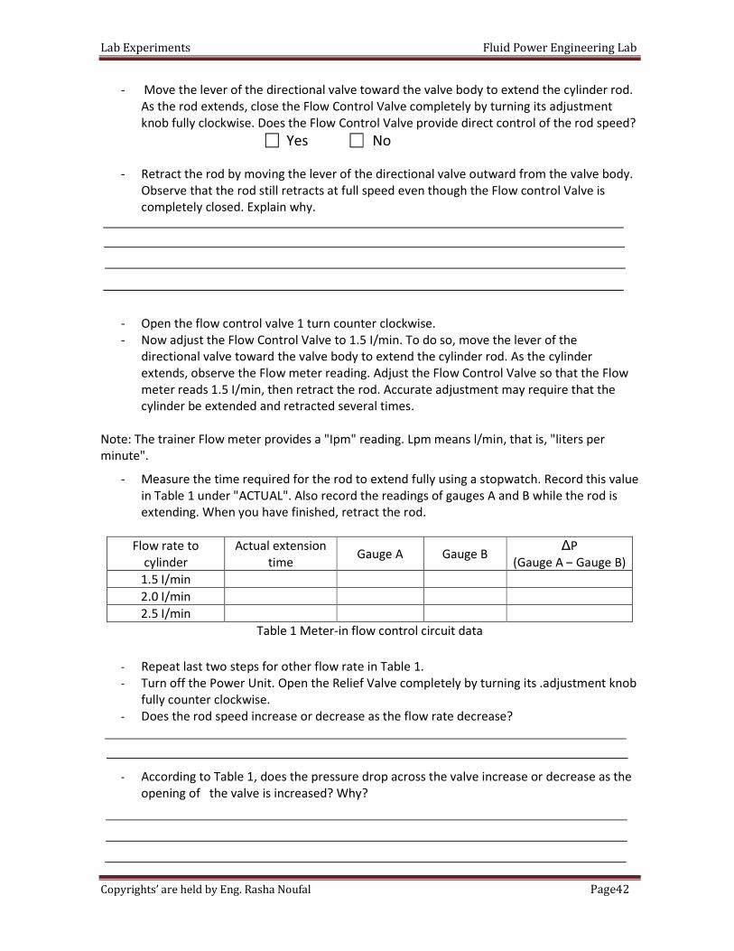
- Move the lever of the directional valve toward the valve body to extend the cylinder rod.
As the rod extends, close the Flow Control Valve completely by turning its adjustment
knob fully clockwise. Does the Flow Control Valve provide direct control of the rod speed?
Yes No
- Retract the rod by moving the lever of the directional valve outward from the valve body.
Observe that the rod still retracts at full speed even though the Flow control Valve is
completely closed. Explain why.
- Open the flow control valve 1 turn counter clockwise.
- Now adjust the Flow Control Valve to 1.5 I/min. To do so, move the lever of the
directional valve toward the valve body to extend the cylinder rod. As the cylinder
extends, observe the Flow meter reading. Adjust the Flow Control Valve so that the Flow
meter reads 1.5 I/min, then retract the rod. Accurate adjustment may require that the
cylinder be extended and retracted several times.
Note: The trainer Flow meter provides a "Ipm" reading. Lpm means l/min, that is, "liters per
minute".
- Measure the time required for the rod to extend fully using a stopwatch. Record this value
in Table 1 under "ACTUAL". Also record the readings of gauges A and B while the rod is
extending. When you have finished, retract the rod.
Flow rate to
cylinder
Actual extension
time Gauge A Gauge B
∆P
(Gauge A – Gauge B)
1.5 I/min
2.0 I/min
2.5 I/min
Table 1 Meter-in flow control circuit data
- Repeat last two steps for other flow rate in Table 1.
- Turn off the Power Unit. Open the Relief Valve completely by turning its .adjustment knob
fully counter clockwise.
- Does the rod speed increase or decrease as the flow rate decrease?
- According to Table 1, does the pressure drop across the valve increase or decrease as the
opening of the valve is increased? Why?
Lab Experiments Fluid Power Engineering Lab
43Page Copyrights’ are held by Eng. Rasha Noufal
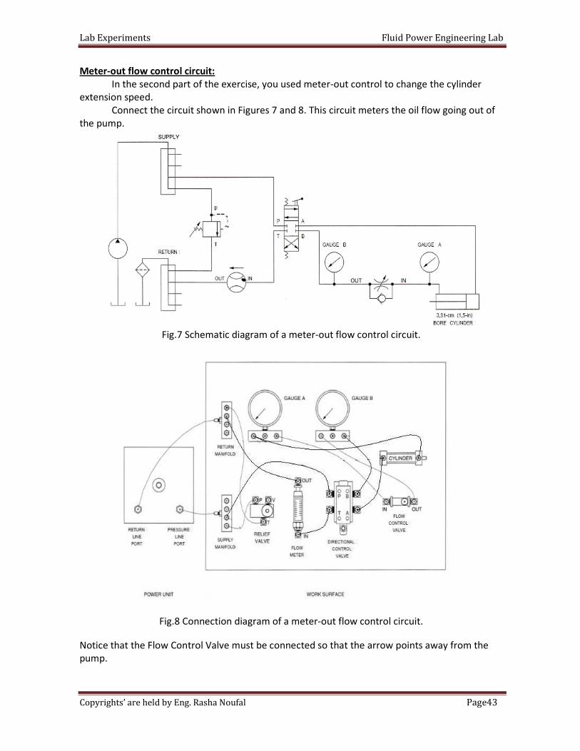
Meter-out flow control circuit:
In the second part of the exercise, you used meter-out control to change the cylinder
extension speed.
Connect the circuit shown in Figures 7 and 8. This circuit meters the oil flow going out of
the pump.
Fig.7 Schematic diagram of a meter-out flow control circuit.
Fig.8 Connection diagram of a meter-out flow control circuit.
Notice that the Flow Control Valve must be connected so that the arrow points away from the
pump.
Lab Experiments Fluid Power Engineering Lab
44Page Copyrights’ are held by Eng. Rasha Noufal
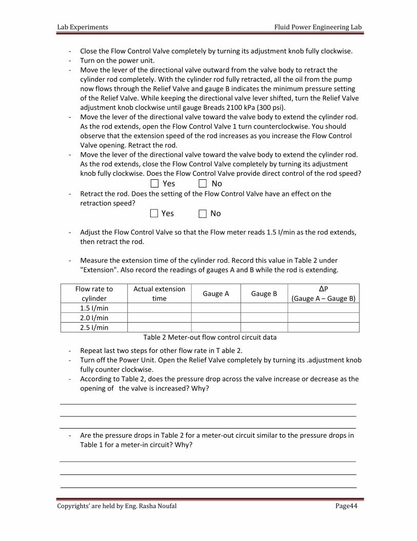
- Close the Flow Control Valve completely by turning its adjustment knob fully clockwise.
- Turn on the power unit.
- Move the lever of the directional valve outward from the valve body to retract the
cylinder rod completely. With the cylinder rod fully retracted, all the oil from the pump
now flows through the Relief Valve and gauge B indicates the minimum pressure setting
of the Relief Valve. While keeping the directional valve lever shifted, turn the Relief Valve
adjustment knob clockwise until gauge Breads 2100 kPa (300 psi).
- Move the lever of the directional valve toward the valve body to extend the cylinder rod.
As the rod extends, open the Flow Control Valve 1 turn counterclockwise. You should
observe that the extension speed of the rod increases as you increase the Flow Control
Valve opening. Retract the rod.
- Move the lever of the directional valve toward the valve body to extend the cylinder rod.
As the rod extends, close the Flow Control Valve completely by turning its adjustment
knob fully clockwise. Does the Flow Control Valve provide direct control of the rod speed?
Yes No
- Retract the rod. Does the setting of the Flow Control Valve have an effect on the
retraction speed?
Yes No
- Adjust the Flow Control Valve so that the Flow meter reads 1.5 I/min as the rod extends,
then retract the rod.
- Measure the extension time of the cylinder rod. Record this value in Table 2 under
"Extension". Also record the readings of gauges A and B while the rod is extending.
Flow rate to
cylinder
Actual extension
time Gauge A Gauge B
∆P
(Gauge A – Gauge B)
1.5 I/min
2.0 I/min
2.5 I/min
Table 2 Meter-out flow control circuit data
- Repeat last two steps for other flow rate in T able 2.
- Turn off the Power Unit. Open the Relief Valve completely by turning its .adjustment knob
fully counter clockwise.
- According to Table 2, does the pressure drop across the valve increase or decrease as the
opening of the valve is increased? Why?
- Are the pressure drops in Table 2 for a meter-out circuit similar to the pressure drops in
Table 1 for a meter-in circuit? Why?
Lab Experiments Fluid Power Engineering Lab
45Page Copyrights’ are held by Eng. Rasha Noufal
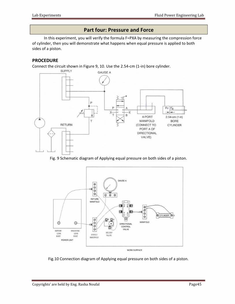
In this experiment, you will verify the formula F=PXA by measuring the compression force
of cylinder, then you will demonstrate what happens when equal pressure is applied to both
sides of a piston.
PROCEDURE Connect the circuit shown in Figure 9, 10. Use the 2.54-cm (1-in) bore cylinder.
Fig. 9 Schematic diagram of Applying equal pressure on both sides of a piston.
Fig.10 Connection diagram of Applying equal pressure on both sides of a piston.
Part four: Pressure and Force
Lab Experiments Fluid Power Engineering Lab
46Page Copyrights’ are held by Eng. Rasha Noufal
- Examine the circuit of Figure 9. Predict which side of the piston will develop the most
force.
- What do you think will happen to the cylinder rod?
-
- Turn on the power unit.
- Turn the Relief Valve adjustment knob clockwise until the circuit pressure at gauge A
equals 2100 kPa (300 psi).
- While observing the cylinder rod, move the lever of the directional valve toward the valve
body so that the pumped oil is directed toward both sides of the cylinder piston. In which
direction does the rod move? Why?
- Turn off the Power Unit. Open the relief valve completely (turn knob fully
counterclockwise) .
Lab Experiments Fluid Power Engineering Lab
47Page Copyrights’ are held by Eng. Rasha Noufal
Date:
Section:
Group's Names:
1-
2-
3-
4-
5-
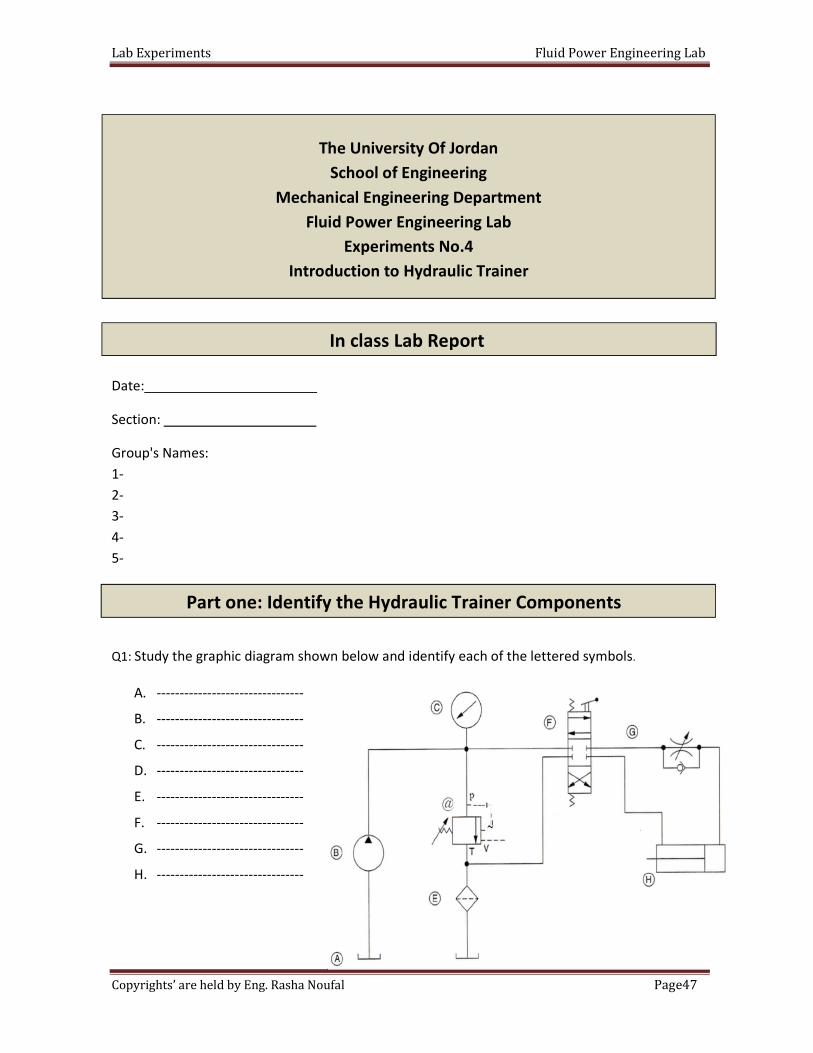
Q1: Study the graphic diagram shown below and identify each of the lettered symbols.
A. --------------------------------
B. --------------------------------
C. --------------------------------
D. --------------------------------
E. --------------------------------
F. --------------------------------
G. --------------------------------
H. --------------------------------
The University Of Jordan
School of Engineering
Mechanical Engineering Department
Fluid Power Engineering Lab
Experiments No.4
Introduction to Hydraulic Trainer
In class Lab Report
Part one: Identify the Hydraulic Trainer Components
Lab Experiments Fluid Power Engineering Lab
48Page Copyrights’ are held by Eng. Rasha Noufal
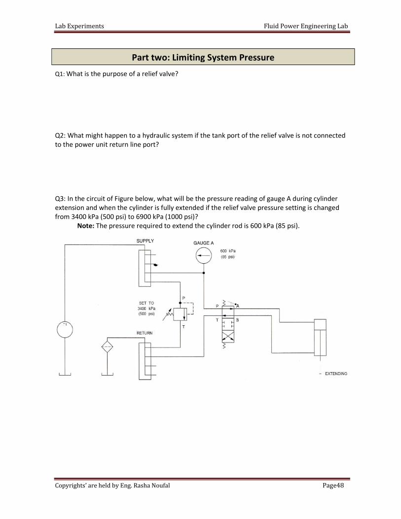
Q1: What is the purpose of a relief valve?
Q2: What might happen to a hydraulic system if the tank port of the relief valve is not connected
to the power unit return line port?
Q3: In the circuit of Figure below, what will be the pressure reading of gauge A during cylinder
extension and when the cylinder is fully extended if the relief valve pressure setting is changed
from 3400 kPa (500 psi) to 6900 kPa (1000 psi)?
Note: The pressure required to extend the cylinder rod is 600 kPa (85 psi).
Part two: Limiting System Pressure
Lab Experiments Fluid Power Engineering Lab
49Page Copyrights’ are held by Eng. Rasha Noufal
Q1: Find two ways to decrease the speed at which a cylinder rod extends or retracts.
Q2: What flow rate is required to make a 10.16 cm bore X 3.81 cm rod X 30.48 cm stroke cylinder
extend in 6 second?
Q3: What type of metering circuit is used to control cylinders having a load that resists to the
pump delivery, as cylinders raising a load?
Q4. What type of metering circuit is used to slow down cylinders having a load that tends to run
away, as cylinders lowering a load?
Q1. How much pressure must be applied to the cap end of a 2.54-cm (1-in) bore cylinder in order
to compress a spring 5.08 cm (2 in), if the spring rate is728 N/cm (416 Ib/in)?
Part three: Flow rate
Part four: Pressure and Force
Lab Experiments Fluid Power Engineering Lab
50Page Copyrights’ are held by Eng. Rasha Noufal
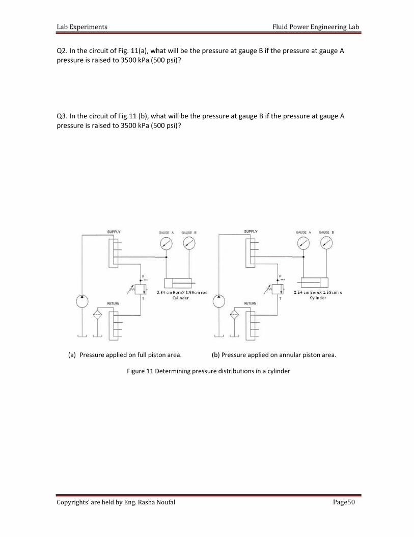
Q2. In the circuit of Fig. 11(a), what will be the pressure at gauge B if the pressure at gauge A
pressure is raised to 3500 kPa (500 psi)?
Q3. In the circuit of Fig.11 (b), what will be the pressure at gauge B if the pressure at gauge A
pressure is raised to 3500 kPa (500 psi)?
(a) Pressure applied on full piston area. (b) Pressure applied on annular piston area.
Figure 11 Determining pressure distributions in a cylinder
Lab Experiments Fluid Power Engineering Lab
51Page Copyrights’ are held by Eng. Rasha Noufal
Objective: This exercises helps to understand sequential controls and provides practical
knowledge of setting up and commissioning a control system with two
pneumatic drives.
Pre-Lab: the required pneumatic circuit diagrams using the FlwidSIM; show
the whole connections and components required for each circuit.
In the lab: Build your designs and verify their operation. sure that the pressure is 4 bars
and is connected correctly. Double check your connections before switching the compressor on.
Task 1: Pressing device with time control
Learning objectives:
Upon the completion of this task, the student will be
• Familiar with the set-up and mode of operation of a time delay valve normally closed.
• Able to recognize and sketch the time delay valve.
• Able to choose different pneumatic components according to the given conditions.
Problem Description:
A double acting cylinder is used to press glued components together. Upon operation of a push
button, the clamping cylinder extends as shown in Fig. 5.1 below. Once the fully advanced
position is reached, the cylinder is to remain for a time of T = 6 seconds and then retract to the
initial position automatically. The cylinder retraction is to be adjustable. A new start cycle is only
possible after the cylinder has fully retracted.
The University Of Jordan
School of Engineering
Mechatronics Engineering Department
Fluid Power Engineering Lab
Experiments No.5
Sequential control of a 2 double acting cylinder
Part I: Time delay valve and sequence control systems
Pre-Lab
Lab Experiments Fluid Power Engineering Lab
52Page Copyrights’ are held by Eng. Rasha Noufal
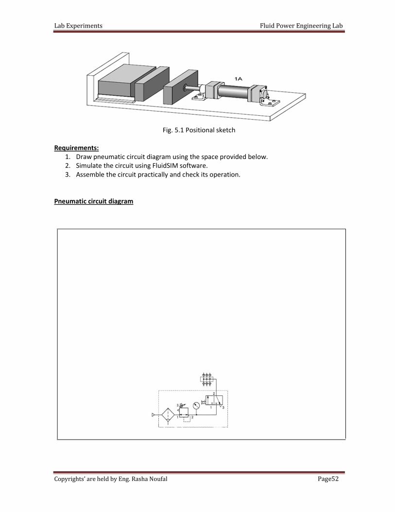
Fig. 5.1 Positional sketch
Requirements:
1. Draw pneumatic circuit diagram using the space provided below.
2. Simulate the circuit using FluidSIM software.
3. Assemble the circuit practically and check its operation.
Pneumatic circuit diagram
Lab Experiments Fluid Power Engineering Lab
53Page Copyrights’ are held by Eng. Rasha Noufal
Introduction to Quick Exhaust valve:
In many applications especially with single acting cylinders, it is a common practice to increase
the piston speed during retraction of the cylinder to save the cycle time.
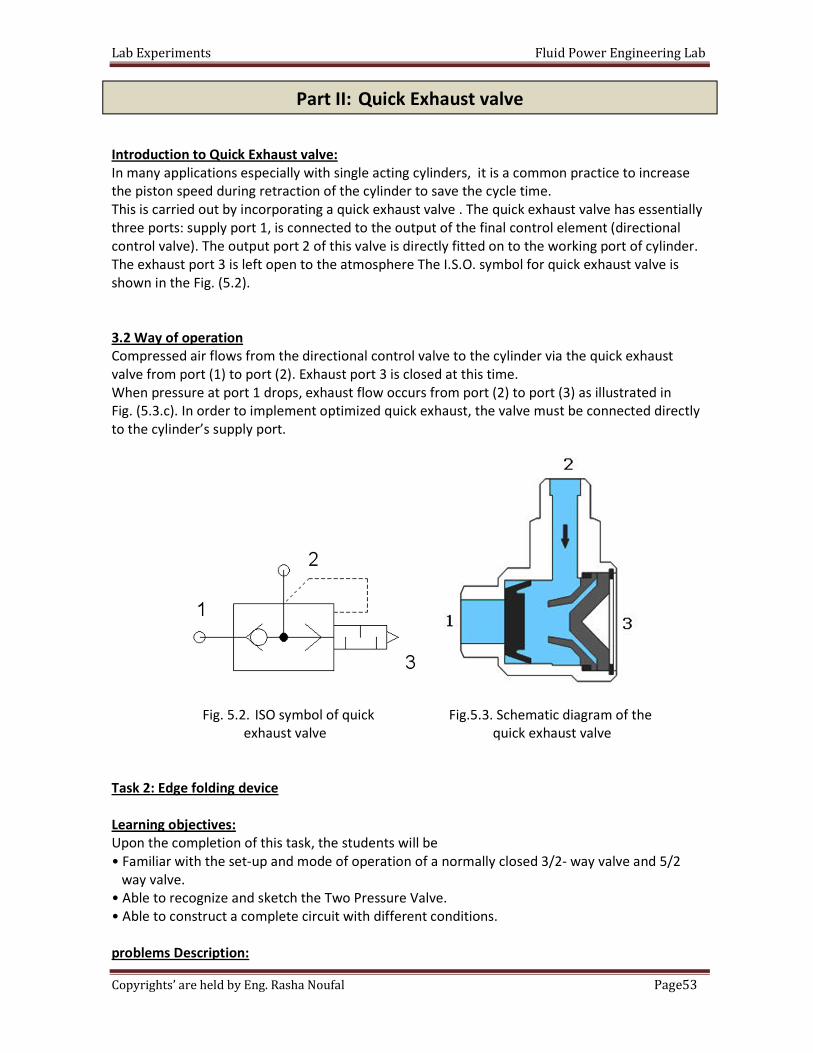
This is carried out by incorporating a quick exhaust valve . The quick exhaust valve has essentially
three ports: supply port 1, is connected to the output of the final control element (directional
control valve). The output port 2 of this valve is directly fitted on to the working port of cylinder.
The exhaust port 3 is left open to the atmosphere The I.S.O. symbol for quick exhaust valve is
shown in the Fig. (5.2).
3.2 Way of operation
Compressed air flows from the directional control valve to the cylinder via the quick exhaust
valve from port (1) to port (2). Exhaust port 3 is closed at this time.
When pressure at port 1 drops, exhaust flow occurs from port (2) to port (3) as illustrated in
Fig. (5.3.c). In order to implement optimized quick exhaust, the valve must be connected directly
to the cylinder’s supply port.
Fig. 5.2. ISO symbol of quick Fig.5.3. Schematic diagram of the
exhaust valve quick exhaust valve
Task 2: Edge folding device
Learning objectives:
Upon the completion of this task, the students will be
• Familiar with the set-up and mode of operation of a normally closed 3/2- way valve and 5/2
way valve.
• Able to recognize and sketch the Two Pressure Valve.
• Able to construct a complete circuit with different conditions.
problems Description:
Part II: Quick Exhaust valve
Lab Experiments Fluid Power Engineering Lab
54Page Copyrights’ are held by Eng. Rasha Noufal
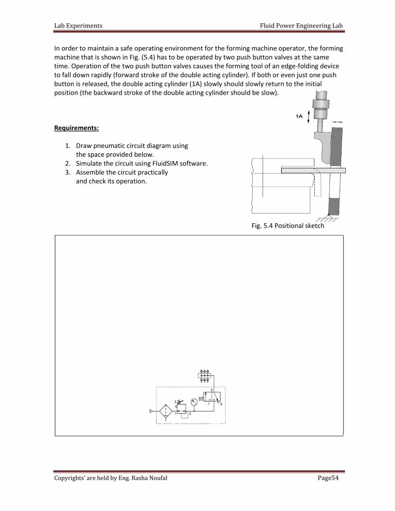
In order to maintain a safe operating environment for the forming machine operator, the forming
machine that is shown in Fig. (5.4) has to be operated by two push button valves at the same
time. Operation of the two push button valves causes the forming tool of an edge-folding device
to fall down rapidly (forward stroke of the double acting cylinder). If both or even just one push
button is released, the double acting cylinder (1A) slowly should slowly return to the initial
position (the backward stroke of the double acting cylinder should be slow).
Requirements:
1. Draw pneumatic circuit diagram using
the space provided below.
2. Simulate the circuit using FluidSIM software.
3. Assemble the circuit practically
and check its operation.
Fig. 5.4 Positional sketch
Lab Experiments Fluid Power Engineering Lab
55Page Copyrights’ are held by Eng. Rasha Noufal
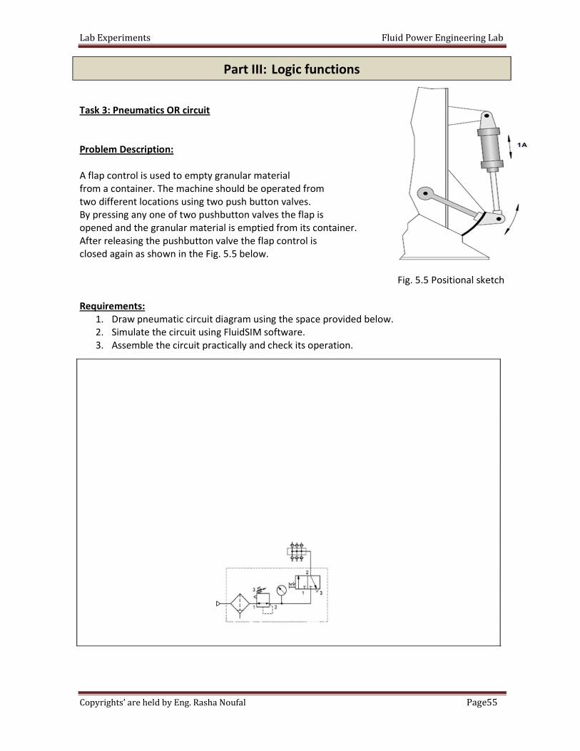
Task 3: Pneumatics OR circuit
Problem Description:
A flap control is used to empty granular material
from a container. The machine should be operated from
two different locations using two push button valves.
By pressing any one of two pushbutton valves the flap is
opened and the granular material is emptied from its container.
After releasing the pushbutton valve the flap control is
closed again as shown in the Fig. 5.5 below.
Fig. 5.5 Positional sketch
Requirements:
1. Draw pneumatic circuit diagram using the space provided below.
2. Simulate the circuit using FluidSIM software.
3. Assemble the circuit practically and check its operation.
Part III: Logic functions
Lab Experiments Fluid Power Engineering Lab
56Page Copyrights’ are held by Eng. Rasha Noufal
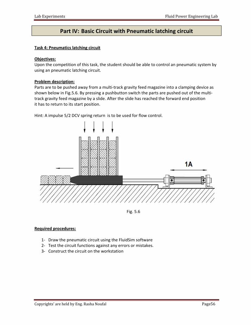
Task 4: Pneumatics latching circuit
Objectives:
Upon the competition of this task, the student should be able to control an pneumatic system by
using an pneumatic latching circuit.
Problem description:
Parts are to be pushed away from a multi-track gravity feed magazine into a clamping device as
shown below in Fig.5.6. By pressing a pushbutton switch the parts are pushed out of the multi-
track gravity feed magazine by a slide. After the slide has reached the forward end position
it has to return to its start position.
Hint: A impulse 5/2 DCV spring return is to be used for flow control.
Fig. 5.6
Required procedures:
1- Draw the pneumatic circuit using the FluidSim software
2- Test the circuit functions against any errors or mistakes.
3- Construct the circuit on the workstation
Part IV: Basic Circuit with Pneumatic latching circuit
Lab Experiments Fluid Power Engineering Lab
57Page Copyrights’ are held by Eng. Rasha Noufal
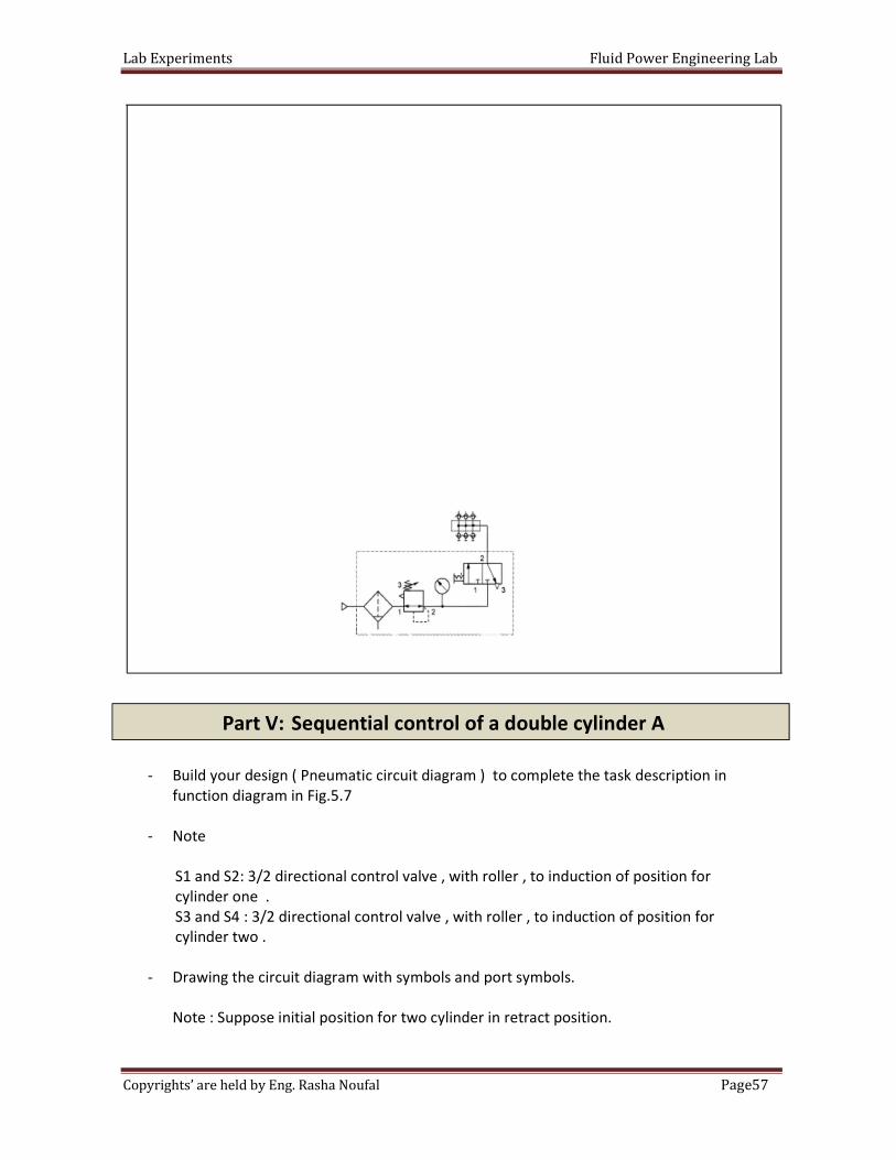
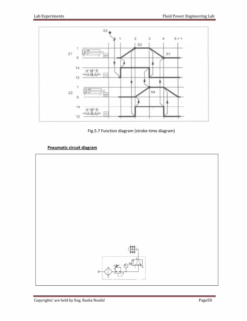
- Build your design ( Pneumatic circuit diagram ) to complete the task description in
function diagram in Fig.5.7
- Note
S1 and S2: 3/2 directional control valve , with roller , to induction of position for
cylinder one .
S3 and S4 : 3/2 directional control valve , with roller , to induction of position for
cylinder two .
- Drawing the circuit diagram with symbols and port symbols.
Note : Suppose initial position for two cylinder in retract position.
Part V: Sequential control of a double cylinder A
Lab Experiments Fluid Power Engineering Lab
58Page Copyrights’ are held by Eng. Rasha Noufal
Fig.5.7 Function diagram (stroke-time diagram)
Pneumatic circuit diagram
Lab Experiments Fluid Power Engineering Lab
59Page Copyrights’ are held by Eng. Rasha Noufal
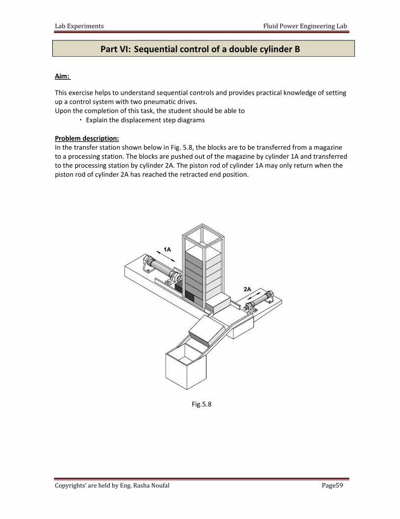
Aim:
This exercise helps to understand sequential controls and provides practical knowledge of setting
up a control system with two pneumatic drives.
Upon the completion of this task, the student should be able to
Explain the displacement step diagrams
Problem description:
In the transfer station shown below in Fig. 5.8, the blocks are to be transferred from a magazine
to a processing station. The blocks are pushed out of the magazine by cylinder 1A and transferred
to the processing station by cylinder 2A. The piston rod of cylinder 1A may only return when the
piston rod of cylinder 2A has reached the retracted end position.
Fig.5.8
Part VI: Sequential control of a double cylinder B
Lab Experiments Fluid Power Engineering Lab
60Page Copyrights’ are held by Eng. Rasha Noufal
Lab Experiments Fluid Power Engineering Lab
61Page Copyrights’ are held by Eng. Rasha Noufal
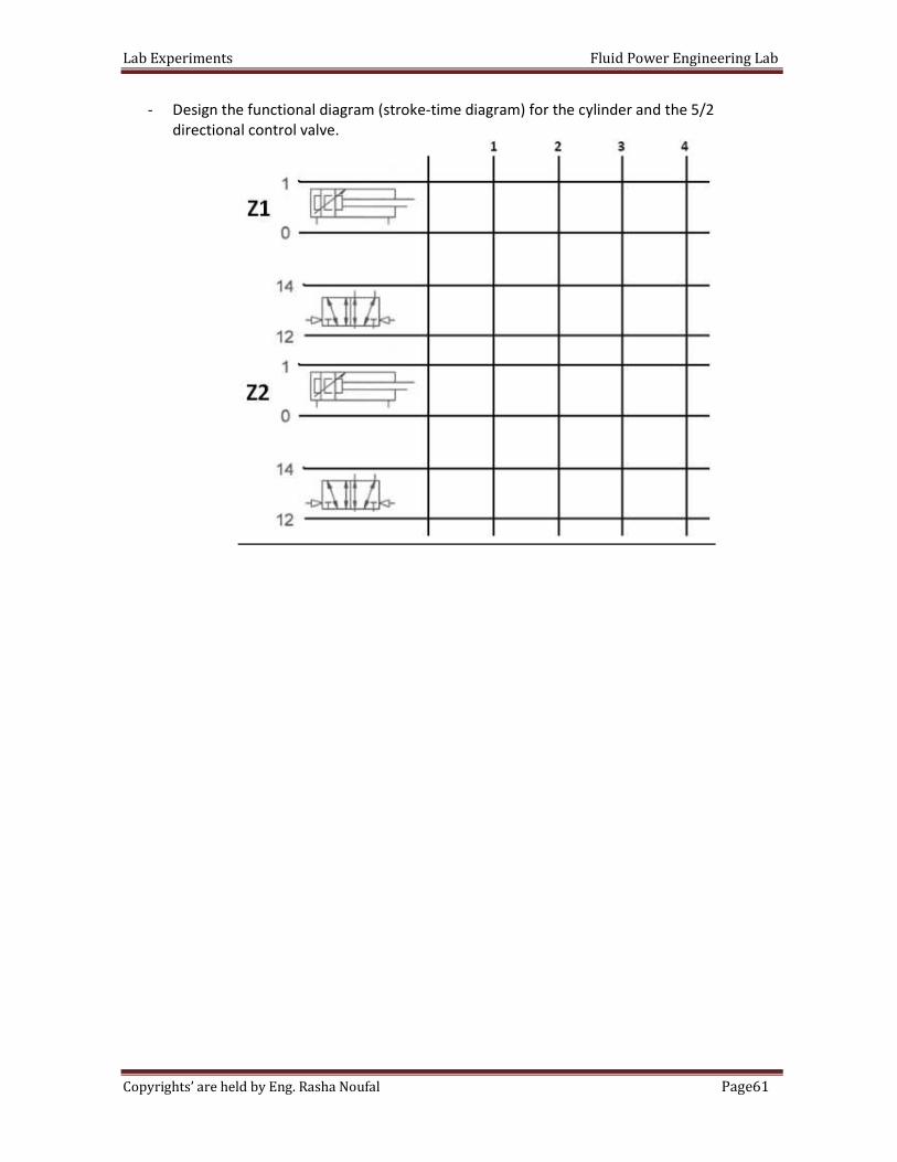
- Design the functional diagram (stroke-time diagram) for the cylinder and the 5/2
directional control valve.
Lab Experiments Fluid Power Engineering Lab
62Page Copyrights’ are held by Eng. Rasha Noufal
sa
Objective: This exercises helps to understand sequential controls and provides practical
knowledge of setting up and commissioning a control system with two
pneumatic drives.
Pre-Lab: the required pneumatic circuit diagrams using the FluidSIM; show
the whole connections and components required for each circuit.
In the lab: Build your designs and verify their operation. sure that the pressure is 4 bars
and is connected correctly. Double check your connections before switching
the compressor on.
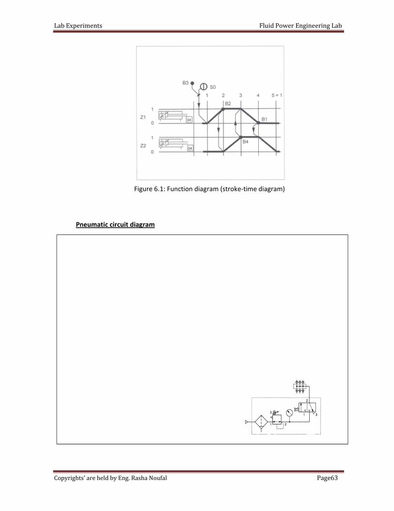
Task:
- Build your design ( Pneumatic circuit diagram and Electric circuit diagram ) to complete
the task description in function diagram in Figure 6.1
- Note
B1 and B2 : Electric limit switch with roller lever , to induction of position for
cylinder one .
B3 and B4 : Electric limit switch with roller lever, to induction of position for
cylinder two .
- Drawing the circuit diagram with symbols and port symbols.
Note : Suppose initial position for two cylinder in retract position.
The University Of Jordan
School of Engineering
Mechatronics Engineering Department
Fluid Power Engineering Lab
Experiments No.6
Electro pneumatics Sequential control of a 2 double acting cylinder
Part I: Electro pneumatics Sequential control of 2 double acting cylinders A
Pre-Lab
Lab Experiments Fluid Power Engineering Lab
63Page Copyrights’ are held by Eng. Rasha Noufal
Figure 6.1: Function diagram (stroke-time diagram)
Pneumatic circuit diagram
Lab Experiments Fluid Power Engineering Lab
64Page Copyrights’ are held by Eng. Rasha Noufal
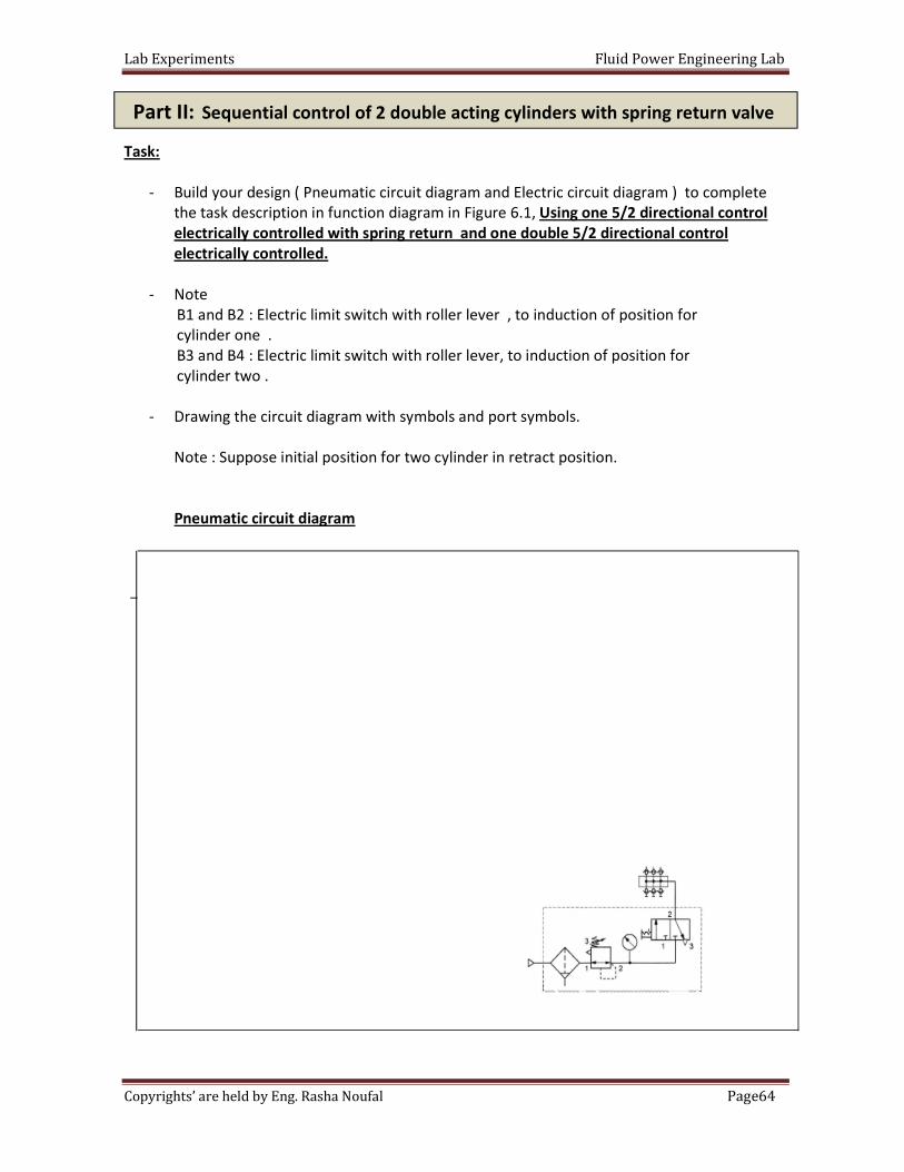
Task:
- Build your design ( Pneumatic circuit diagram and Electric circuit diagram ) to complete
the task description in function diagram in Figure 6.1, Using one 5/2 directional control
electrically controlled with spring return and one double 5/2 directional control
electrically controlled.
- Note
B1 and B2 : Electric limit switch with roller lever , to induction of position for
cylinder one .
B3 and B4 : Electric limit switch with roller lever, to induction of position for
cylinder two .
- Drawing the circuit diagram with symbols and port symbols.
Note : Suppose initial position for two cylinder in retract position.
Pneumatic circuit diagram
Part II: Sequential control of 2 double acting cylinders with spring return valve
Lab Experiments Fluid Power Engineering Lab
65Page Copyrights’ are held by Eng. Rasha Noufal
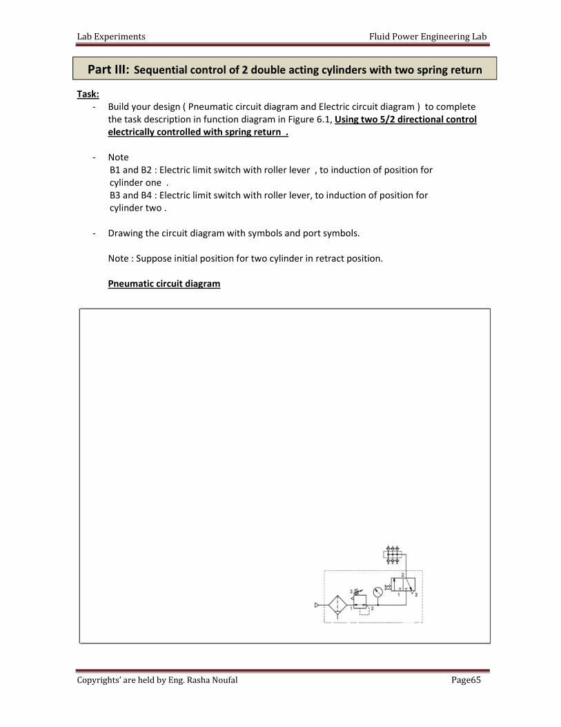
Task:
- Build your design ( Pneumatic circuit diagram and Electric circuit diagram ) to complete
the task description in function diagram in Figure 6.1, Using two 5/2 directional control
electrically controlled with spring return .
- Note
B1 and B2 : Electric limit switch with roller lever , to induction of position for
cylinder one .
B3 and B4 : Electric limit switch with roller lever, to induction of position for
cylinder two .
- Drawing the circuit diagram with symbols and port symbols.
Note : Suppose initial position for two cylinder in retract position.
Pneumatic circuit diagram
Part III: Sequential control of 2 double acting cylinders with two spring return
Lab Experiments Fluid Power Engineering Lab
66Page Copyrights’ are held by Eng. Rasha Noufal
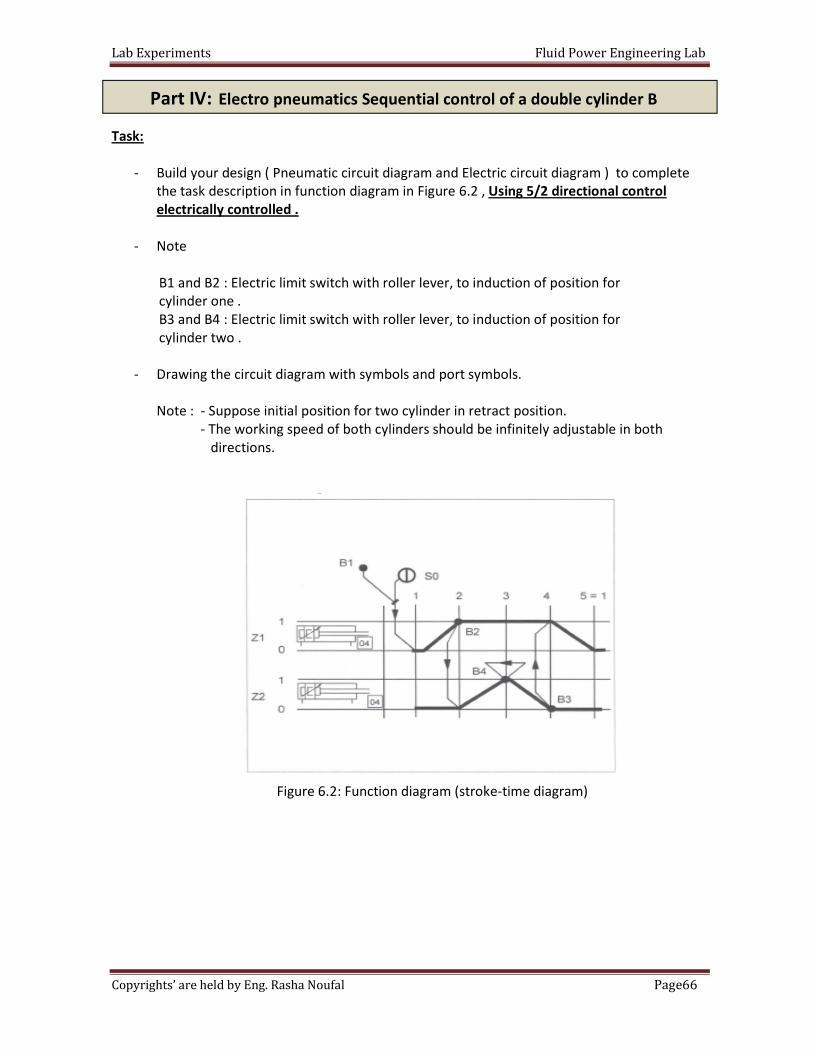
Task:
- Build your design ( Pneumatic circuit diagram and Electric circuit diagram ) to complete
the task description in function diagram in Figure 6.2 , Using 5/2 directional control
electrically controlled .
- Note
B1 and B2 : Electric limit switch with roller lever, to induction of position for
cylinder one .
B3 and B4 : Electric limit switch with roller lever, to induction of position for
cylinder two .
- Drawing the circuit diagram with symbols and port symbols.
Note : - Suppose initial position for two cylinder in retract position.
- The working speed of both cylinders should be infinitely adjustable in both
directions.
Figure 6.2: Function diagram (stroke-time diagram)
Part IV: Electro pneumatics Sequential control of a double cylinder B
Lab Experiments Fluid Power Engineering Lab
67Page Copyrights’ are held by Eng. Rasha Noufal
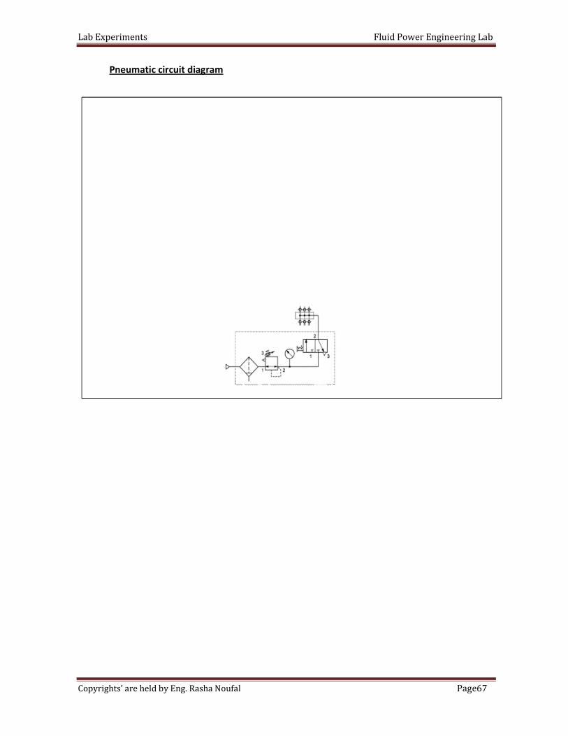
Pneumatic circuit diagram
Lab Experiments Fluid Power Engineering Lab
68Page Copyrights’ are held by Eng. Rasha Noufal
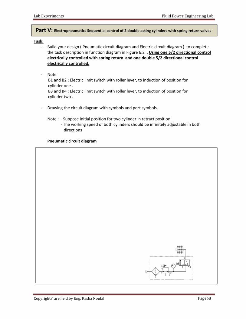
Task:
- Build your design ( Pneumatic circuit diagram and Electric circuit diagram ) to complete
the task description in function diagram in Figure 6.2 , Using one 5/2 directional control
electrically controlled with spring return and one double 5/2 directional control
electrically controlled.
- Note
B1 and B2 : Electric limit switch with roller lever, to induction of position for
cylinder one .
B3 and B4 : Electric limit switch with roller lever, to induction of position for
cylinder two .
- Drawing the circuit diagram with symbols and port symbols.
Note : - Suppose initial position for two cylinder in retract position.
- The working speed of both cylinders should be infinitely adjustable in both
directions
Pneumatic circuit diagram
Part V: Electropneumatics Sequential control of 2 double acting cylinders with spring return valves
Lab Experiments Fluid Power Engineering Lab
69Page Copyrights’ are held by Eng. Rasha Noufal
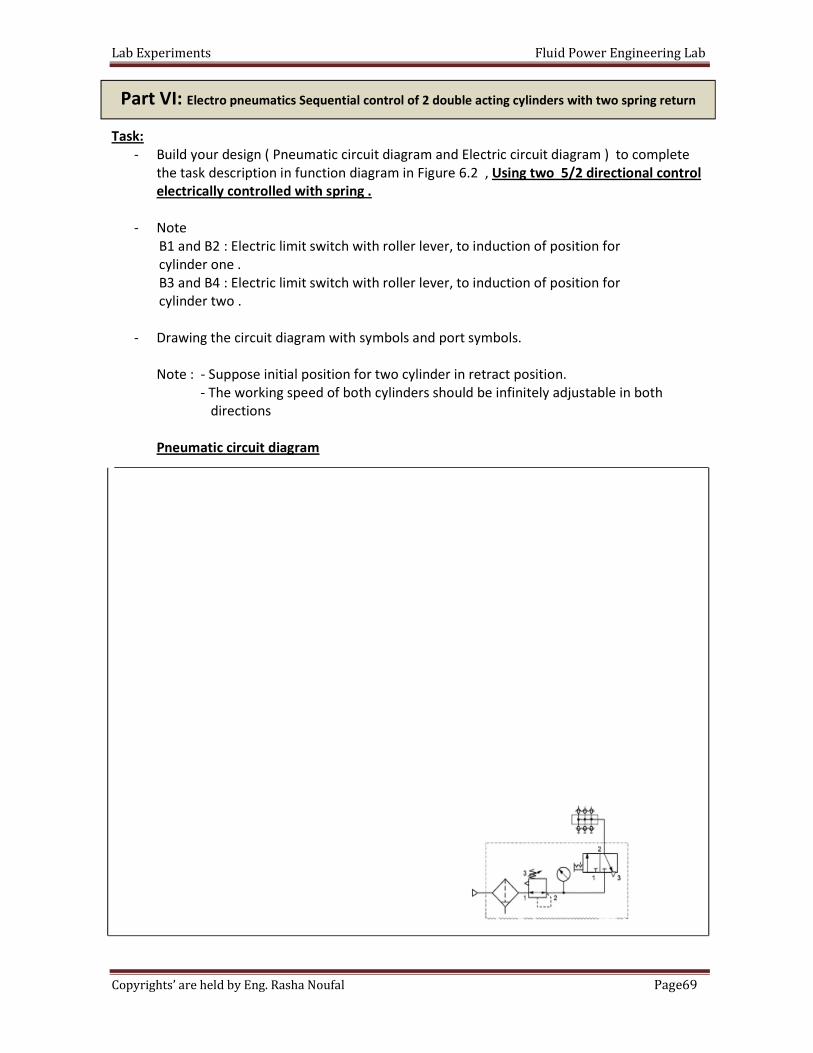
Task:
- Build your design ( Pneumatic circuit diagram and Electric circuit diagram ) to complete
the task description in function diagram in Figure 6.2 , Using two 5/2 directional control
electrically controlled with spring .
- Note
B1 and B2 : Electric limit switch with roller lever, to induction of position for
cylinder one .
B3 and B4 : Electric limit switch with roller lever, to induction of position for
cylinder two .
- Drawing the circuit diagram with symbols and port symbols.
Note : - Suppose initial position for two cylinder in retract position.
- The working speed of both cylinders should be infinitely adjustable in both
directions
Pneumatic circuit diagram
Part VI: Electro pneumatics Sequential control of 2 double acting cylinders with two spring return
valves
Lab Experiments Fluid Power Engineering Lab
70Page Copyrights’ are held by Eng. Rasha Noufal
Objective: Students will be able to describe the operation of a regenerative circuit,
describe the effect of regeneration on cylinder speed and describe the effect of
regeneration on cylinder force.
The primary purpose of regenerative circuits is to provide rapid extension speeds with
a minimum pump output flow. Regeneration is accomplished by sending the oil which flows out
of the rod end of a cylinder back into the cap end of this cylinder.
In this part of the exercise, you will determine the effect of regeneration on the extension time of
a cylinder. To do so, you will measure the time required for a cylinder to extend in both
regenerative and normal modes of operation. You will then compare the results obtained in each
mode.
In this exercise, you learned that a regenerative circuit increases the extension speed of
a cylinder. You caused a cylinder to extend more rapidly by applying equal pressures to both sides
of the piston. The extension time was reduced by a factor equal to the ratio of the full piston area
to the rod area, Af / Arod..
Cylinder speed during regeneration:
S.I Units:
Extension speed (cm/s) = Fow rate (l/min) × 1000
Rod area(cm2) × 60
English Units:
Extension speed (in/s) = Fow rate (gal/min) × 231
Rod area(in2) × 60
The University Of Jordan
School of Engineering & Technology
Mechatronics Engineering Department
Fluid Power Engineering Lab
Experiments No.7
Regenerative and Parallel Circuits
Introduction
Part I: Effect of regeneration on cylinder extension time
Lab Experiments Fluid Power Engineering Lab
71Page Copyrights’ are held by Eng. Rasha Noufal
The formula for calculating the amount of time required for a cylinder in regeneration to
complete its stroke is the formula for extension speed divided into the stroke length.
The formula is as follows:
S.I Units:
Extension time (s) = Rod area (cm2) × 60 × Stroke length (cm)
Flow rate(l/min) × 1000
English Units:
Extension time (s) = Rod area (in2) × 60 × Stroke length (in)
Flow rate(gal/min) × 231
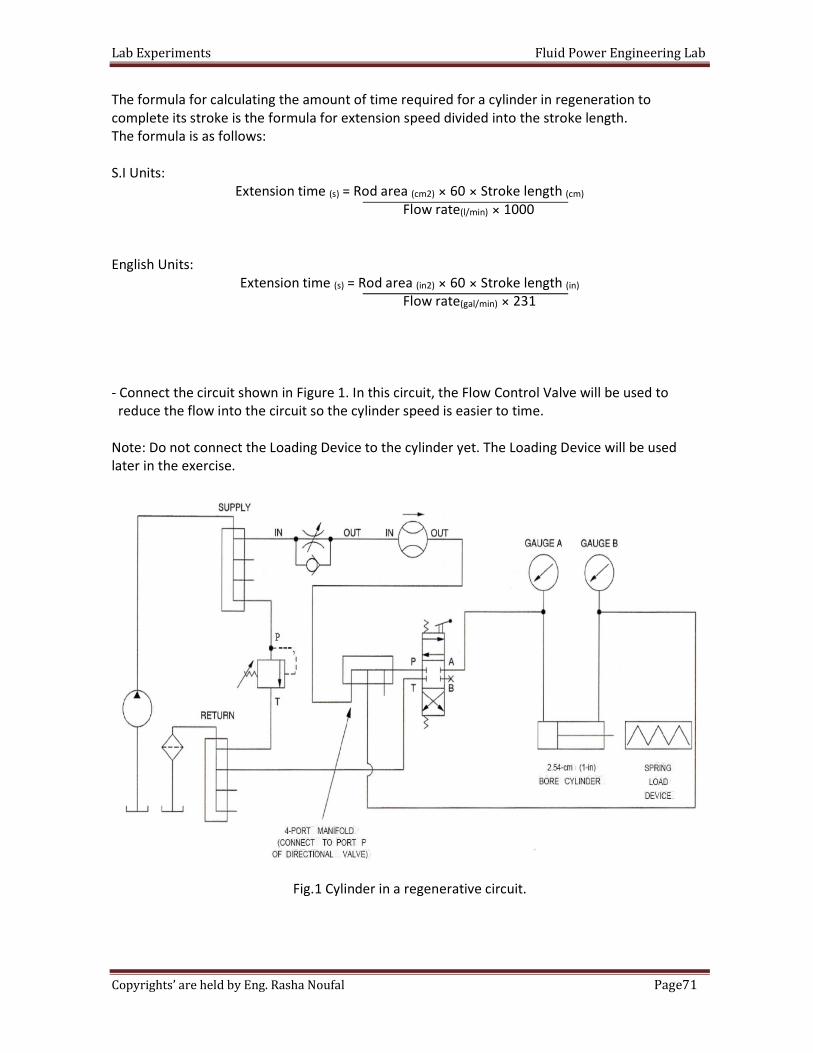
- Connect the circuit shown in Figure 1. In this circuit, the Flow Control Valve will be used to
reduce the flow into the circuit so the cylinder speed is easier to time.
Note: Do not connect the Loading Device to the cylinder yet. The Loading Device will be used
later in the exercise.
Fig.1 Cylinder in a regenerative circuit.
Lab Experiments Fluid Power Engineering Lab
72Page Copyrights’ are held by Eng. Rasha Noufal
- Before starting the power unit, perform the following start-up procedure.
a. Make sure the hoses are firmly connected.
b. Check the level of the oil in the reservoir. Add oil if required.
c. Put on safety glasses.
d. Make sure the power switch on the Power Unit is set to the OFF position.
e. Plug the Power Unit line cord into an ac outlet.
f. Open the Relief Valve completely (turn knob fully counterclockwise).
- Open the flow control valve completely (turn knob fully counterclockwise ).
- Turn on the power Unit.
- With the directional valve lever in the center position, the pump flow is blocked at the rod end
of the cylinder, and gauge B indicates the Relief Valve pressure setting. Turn the Relief Valve
adjustment knob clockwise until the circuit pressure at gauge B is 2100 kPa (300 psi).
- Move the lever of the directional valve toward the valve body to extend the cylinder and adjust
the Flow Control Valve so that the Flowmeter reads 1.5 I/min [0.4 gal(US)/min] during cylinder
extension, then retract the cylinder. Accurate adjustment may require that the cylinder be
extended and retracted several times.
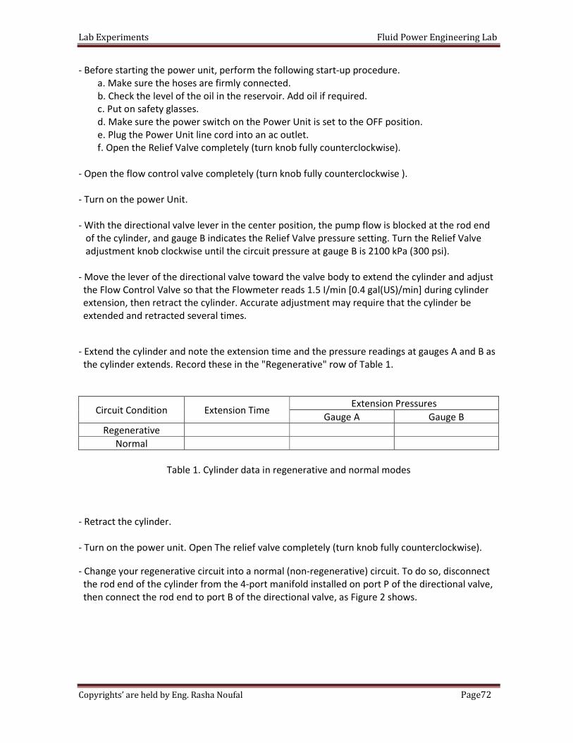
- Extend the cylinder and note the extension time and the pressure readings at gauges A and B as
the cylinder extends. Record these in the "Regenerative" row of Table 1.
Circuit Condition Extension Time Extension Pressures
Gauge A Gauge B
Regenerative
Normal
Table 1. Cylinder data in regenerative and normal modes
- Retract the cylinder.
- Turn on the power unit. Open The relief valve completely (turn knob fully counterclockwise).
- Change your regenerative circuit into a normal (non-regenerative) circuit. To do so, disconnect
the rod end of the cylinder from the 4-port manifold installed on port P of the directional valve,
then connect the rod end to port B of the directional valve, as Figure 2 shows.
Lab Experiments Fluid Power Engineering Lab
73Page Copyrights’ are held by Eng. Rasha Noufal
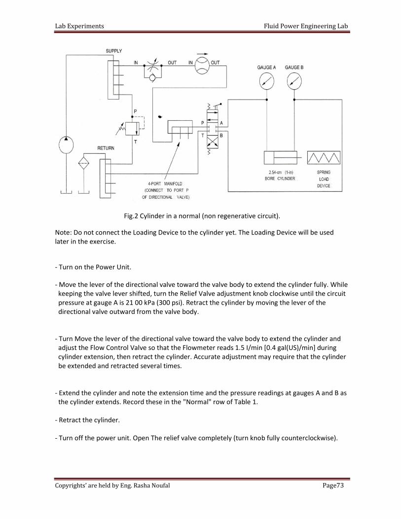
Fig.2 Cylinder in a normal (non regenerative circuit).
Note: Do not connect the Loading Device to the cylinder yet. The Loading Device will be used
later in the exercise.
- Turn on the Power Unit.
- Move the lever of the directional valve toward the valve body to extend the cylinder fully. While
keeping the valve lever shifted, turn the Relief Valve adjustment knob clockwise until the circuit
pressure at gauge A is 21 00 kPa (300 psi). Retract the cylinder by moving the lever of the
directional valve outward from the valve body.
- Turn Move the lever of the directional valve toward the valve body to extend the cylinder and
adjust the Flow Control Valve so that the Flowmeter reads 1.5 I/min [0.4 gal(US)/min] during
cylinder extension, then retract the cylinder. Accurate adjustment may require that the cylinder
be extended and retracted several times.
- Extend the cylinder and note the extension time and the pressure readings at gauges A and B as
the cylinder extends. Record these in the "Normal" row of Table 1.
- Retract the cylinder.
- Turn off the power unit. Open The relief valve completely (turn knob fully counterclockwise).
Lab Experiments Fluid Power Engineering Lab
74Page Copyrights’ are held by Eng. Rasha Noufal
- According to Table 3-8, is the extension time observed in regenerative mode shorter than that
observed in normal mode? Why?
- Calculate the theoretical extension time of the 2.54-cm (1-in) bore x 1.59-cm (0.625-in) rod
x 10.16-cm (4-in) stroke cylinder in regeneration when the flow rate
is 1.51/min [0.4 gal(US)/min]. Then, compare your result with the actual extension time
recorded in Table 1. Are these values approximately equal?
Lab Experiments Fluid Power Engineering Lab
75Page Copyrights’ are held by Eng. Rasha Noufal
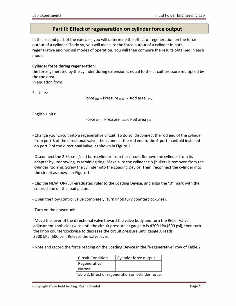
In the second part of the exercise, you will determine the effect of regeneration on the force
output of a cylinder. To do so, you will measure the force output of a cylinder in both
regenerative and normal modes of operation. You will then compare the results obtained in each
mode.
Cylinder force during regeneration:
the force generated by the cylinder during extension is equal to the circuit pressure multiplied by
the rod area.
In equation form:
S.I Units:
Force (N) = Pressure (Kpa) × Rod area (cm2)
English Units:
Force (lb) = Pressure (psi) × Rod area (in2)
- Change your circuit into a regenerative circuit. To do so, disconnect the rod end of the cylinder
from port B of the directional valve, then connect the rod end to the 4-port manifold installed
on port P of the directional valve, as shown in Figure 1.
- Disconnect the 2.54-cm (1-in) bore cylinder from the circuit. Remove the cylinder from its
adapter by unscrewing its retaining ring. Make sure the cylinder tip (bullet) is removed from the
cylinder rod end. Screw the cylinder into the Loading Device. Then, reconnect the cylinder into
the circuit as shown in-Figure 1.
- Clip the NEWTON/LBF-graduated ruler to the Loading Device, and align the "0" mark with the
colored line on the load piston.
- Open the flow control valve completely (turn knob fully counterclockwise).
- Turn on the power unit.
- Move the lever of the directional valve toward the valve body and turn the Relief Valve
adjustment knob clockwise until the circuit pressure at gauge A is 4200 kPa (600 psi), then turn
the knob counterclockwise to decrease the circuit pressure until gauge A reads
3500 kPa (500 psi). Release the valve lever.
- Note and record the force reading on the Loading Device in the "Regenerative" row of Table 2.
Circuit Condition Cylinder force output
Regenerative
Normal
Table 2. Effect of regeneration on cylinder force.
Part II: Effect of regeneration on cylinder force output
Lab Experiments Fluid Power Engineering Lab
76Page Copyrights’ are held by Eng. Rasha Noufal
- Retract the cylinder, then turn off the Power Unit. Open the Relief Valve completely (turn knob
fully counterclockwise).
- Change your regenerative circuit into a normal circuit. To do so, disconnect the rod end of the
cylinder from the 4-port manifold installed on port P of the directional valve, then connect the
rod end to port B of the directional valve, as shown in Figure 2.
- Turn on the power unit.
- Move the lever of the directional valve toward the valve body and turn the Relief Valve
adjustment knob clockwise until the circuit pressure at gauge A is 4200 kPa (600 psi), then turn
the knob counterclockwise to decrease the circuit pressure until gauge A reads 3500 kPa
(500 psi). Release the valve lever .
- Note and record the force reading on the Loading Device in the "Normal" row of Table 2.
- Retract the cylinder, then turn off the Power Unit. Open the Relief Valve completely (turn knob
fully counterclockwise).
- According to Table 2, is the force observed in regeneration mode reduced from that observed in
normal mode? Explain why.
- Calculate the theoretical force output of the 2.54-cm (1-in) bore x 1.59-cm (O.625-in) rod x
10.16-cm (4-in) stroke cylinder in regeneration. Then, compare your result with the actual force
output recorded in Table 2. Are these values approximately equal?
- Disconnect the Power Unit line cord from the wall outlet, then disconnect all hoses. Wipe off
any hydraulic oil residue.
- Remove all components from the work surface and wipe off any hydraulic oil residue. Return all
components to their storage location.
- Clean up any hydraulic oil from the floor and from the trainer. Properly dispose of any paper
towels and rags used to clean up oil.
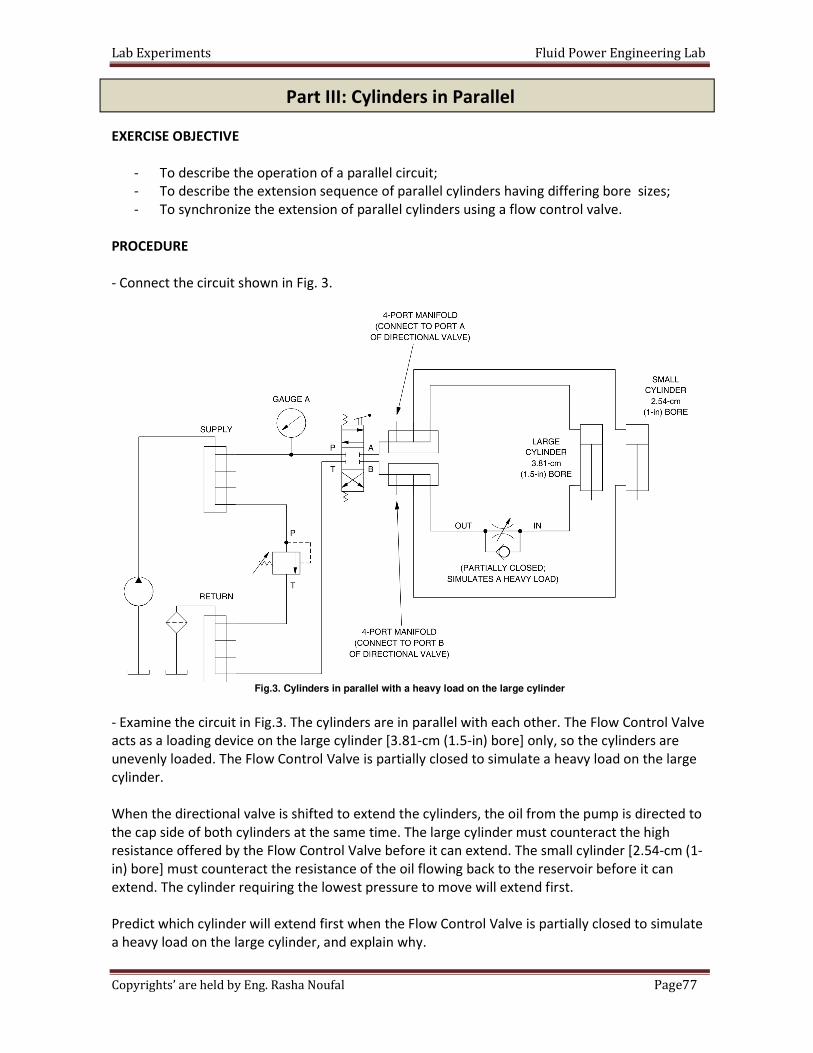
Lab Experiments Fluid Power Engineering Lab
77Page Copyrights’ are held by Eng. Rasha Noufal
EXERCISE OBJECTIVE
- To describe the operation of a parallel circuit;
- To describe the extension sequence of parallel cylinders having differing bore sizes;
- To synchronize the extension of parallel cylinders using a flow control valve.
PROCEDURE
- Connect the circuit shown in Fig. 3.
Fig.3. Cylinders in parallel with a heavy load on the large cylinder
- Examine the circuit in Fig.3. The cylinders are in parallel with each other. The Flow Control Valve
acts as a loading device on the large cylinder [3.81-cm (1.5-in) bore] only, so the cylinders are
unevenly loaded. The Flow Control Valve is partially closed to simulate a heavy load on the large
cylinder.
When the directional valve is shifted to extend the cylinders, the oil from the pump is directed to
the cap side of both cylinders at the same time. The large cylinder must counteract the high
resistance offered by the Flow Control Valve before it can extend. The small cylinder [2.54-cm (1-
in) bore] must counteract the resistance of the oil flowing back to the reservoir before it can
extend. The cylinder requiring the lowest pressure to move will extend first.
Predict which cylinder will extend first when the Flow Control Valve is partially closed to simulate
a heavy load on the large cylinder, and explain why.
Part III: Cylinders in Parallel
Lab Experiments Fluid Power Engineering Lab
78Page Copyrights’ are held by Eng. Rasha Noufal
- Before starting the Power Unit, perform the following start-up procedure:
a. Make sure the hoses are firmly connected.
b. Check the level of the oil in the reservoir. Add oil if required.
c. Put on safety glasses.
d. Make sure the power switch on the Power Unit is set to the OFF
e. position.
f. Plug the Power Unit line cord into an ac outlet.
g. Open the Relief Valve completely (turn knob fully counterclockwise).
- Close the Flow Control Valve completely (turn knob fully clockwise), then open it ½ turn.
- Turn on the Power Unit.
- Turn the relief valve adjustment knob clockwise until the circuit pressure at gauge A is 2100 kPa
(300 psi).
- Move the lever of the directional valve toward the valve body to extend the two cylinders and
observe them as they extend. Which cylinder extended first? Why?
- Retract the cylinders.
- Turn off the Power Unit. Open the Relief Valve completely (turn knob fully counterclockwise).
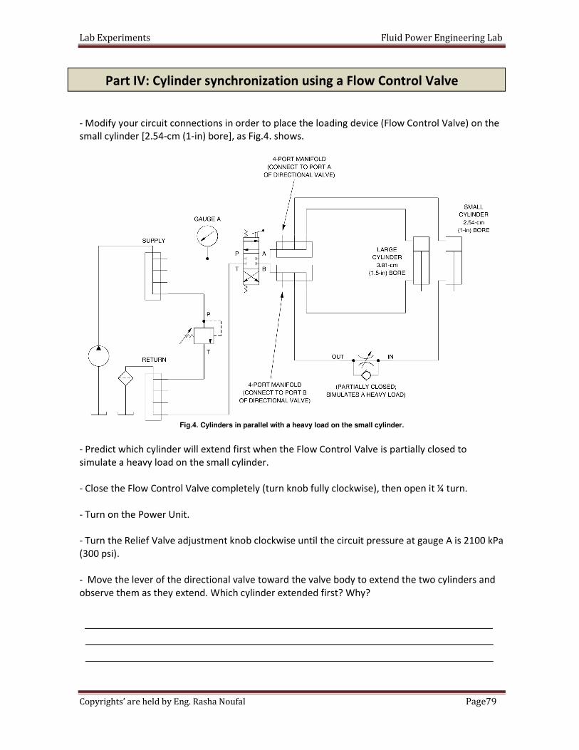
Lab Experiments Fluid Power Engineering Lab
79Page Copyrights’ are held by Eng. Rasha Noufal
- Modify your circuit connections in order to place the loading device (Flow Control Valve) on the
small cylinder [2.54-cm (1-in) bore], as Fig.4. shows.
Fig.4. Cylinders in parallel with a heavy load on the small cylinder.
- Predict which cylinder will extend first when the Flow Control Valve is partially closed to
simulate a heavy load on the small cylinder.
- Close the Flow Control Valve completely (turn knob fully clockwise), then open it ¼ turn.
- Turn on the Power Unit.
- Turn the Relief Valve adjustment knob clockwise until the circuit pressure at gauge A is 2100 kPa
(300 psi).
- Move the lever of the directional valve toward the valve body to extend the two cylinders and
observe them as they extend. Which cylinder extended first? Why?
Part IV: Cylinder synchronization using a Flow Control Valve
Lab Experiments Fluid Power Engineering Lab
80Page Copyrights’ are held by Eng. Rasha Noufal
- Retract the cylinders.
- Adjust the setting of the Flow Control Valve so that both cylinders complete their full stroke at
the same time during extension. Accurate adjustment may require that the cylinders be extended
and retracted several times.
- Extend and retract the cylinders several times with the new Flow Control Valve setting. Do the
cylinders remain synchronized?
Yes No
- Let the system run for about 15 minutes. Do not modify the Flow Control Valve setting.
- Extend and retract the cylinders several times. Did the cylinders stay in synchronization?
Yes No
- Does the Flow Control Valve have to be readjusted when the cylinders are operated over an
extended period of time? Explain why
- Try to adjust the Flow Control Valve so that the small cylinder completes its extension
approximately 2 seconds after the large cylinder completes its extension. Can the extension
sequence of the cylinders be controlled in a parallel circuit? Explain.
- Make sure the cylinders are fully retracted, then turn off the Power Unit.Open the Relief Valve
completely (turn knob fully counterclockwise).
- Disconnect the Power Unit line cord from the wall outlet, then disconnect all hoses. Wipe off
any hydraulic oil residue.
- Remove all components from the work surface and wipe off any hydraulic oil residue. Return all
components to their storage location.
- Clean up any hydraulic oil from the floor and from the trainer. Properly dispose of any paper
towels and rags used to clean up oil.
Lab Experiments Fluid Power Engineering Lab
81Page Copyrights’ are held by Eng. Rasha Noufal
Date:
Section:
Group's Names:
1-
2-
3-
4-
5-
Q1: What is the regenerative circuit?
Q2: Would a cylinder extend more rapidly in a normal circuit or a regenerative circuit?
The University Of Jordan
School of Engineering
Mechatronics Engineering Department
Fluid Power Engineering Lab
Experiments No.7
Regenerative Circuits
In class Lab Report
Part one: Effect of regeneration on cylinder extension time
Lab Experiments Fluid Power Engineering Lab
82Page Copyrights’ are held by Eng. Rasha Noufal
Q1: Would a cylinder generate more force in a normal circuit or in a regenerative circuit?
Q2: What happens to the extension speed and force generated in a regenerative circuit when the
piston rod diameter is decreased?
Q3: By which amount is the cylinder force output reduced in a regenerative circuit giving double
the normal extension speed?
Part two: Effect of regeneration on cylinder force output
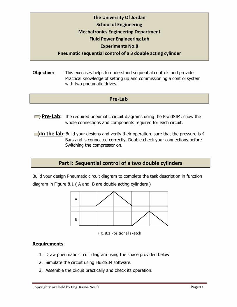
Lab Experiments Fluid Power Engineering Lab
83Page Copyrights’ are held by Eng. Rasha Noufal
Objective: This exercises helps to understand sequential controls and provides
Practical knowledge of setting up and commissioning a control system
with two pneumatic drives.
Pre-Lab: the required pneumatic circuit diagrams using the FlwidSIM; show the
whole connections and components required for each circuit.
In the lab: Build your designs and verify their operation. sure that the pressure is 4
Bars and is connected correctly. Double check your connections before Switching the compressor on.
Build your design Pneumatic circuit diagram to complete the task description in function
diagram in Figure 8.1 ( A and B are double acting cylinders )
Fig. 8.1 Positional sketch
Requirements:
1. Draw pneumatic circuit diagram using the space provided below.
2. Simulate the circuit using FluidSIM software.
3. Assemble the circuit practically and check its operation.
A
B
The University Of Jordan
School of Engineering
Mechatronics Engineering Department
Fluid Power Engineering Lab
Experiments No.8
Pneumatic sequential control of a 3 double acting cylinder
Part I: Sequential control of a two double cylinders
Pre-Lab
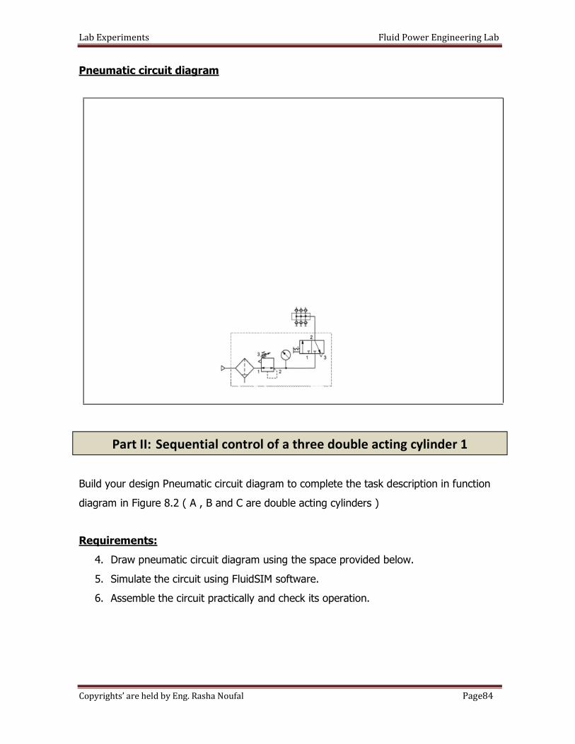
Lab Experiments Fluid Power Engineering Lab
84Page Copyrights’ are held by Eng. Rasha Noufal
Pneumatic circuit diagram
Build your design Pneumatic circuit diagram to complete the task description in function
diagram in Figure 8.2 ( A , B and C are double acting cylinders )
Requirements:
4. Draw pneumatic circuit diagram using the space provided below.
5. Simulate the circuit using FluidSIM software.
6. Assemble the circuit practically and check its operation.
Part II: Sequential control of a three double acting cylinder 1
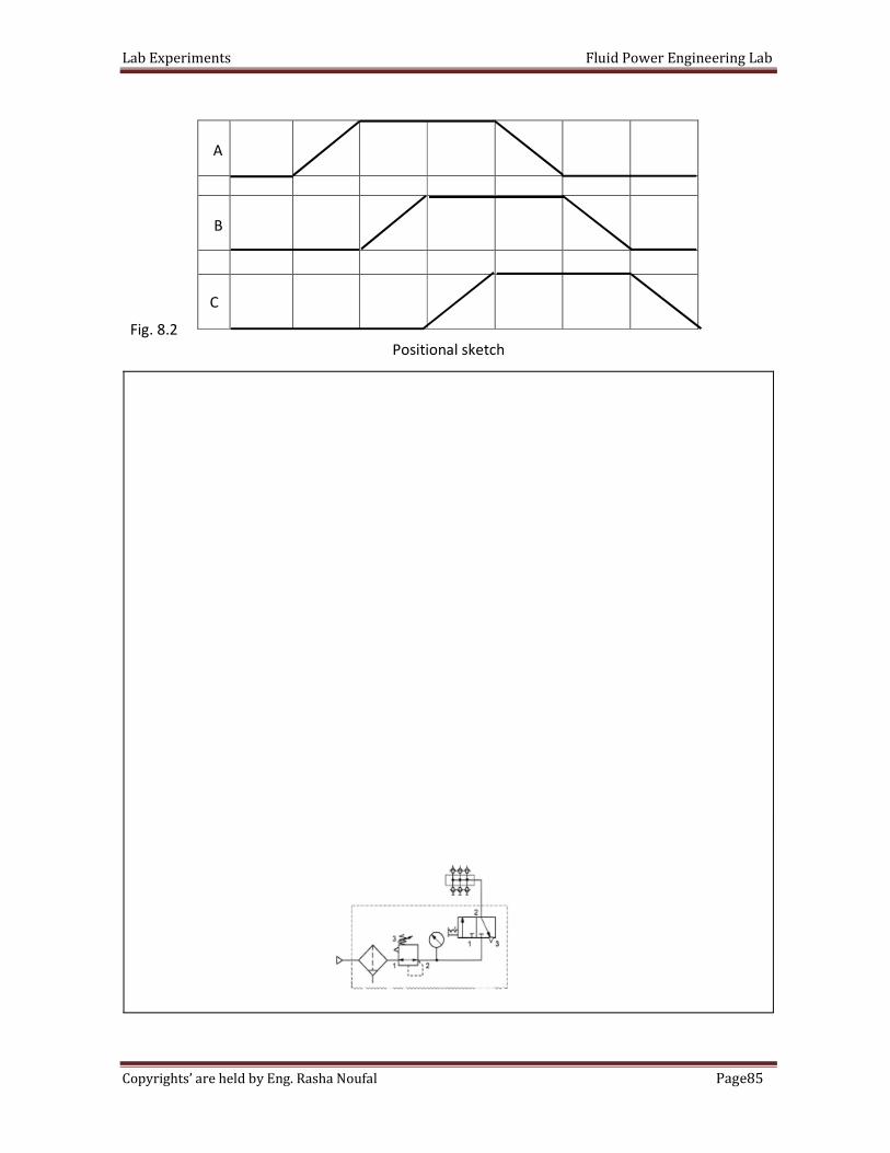
Lab Experiments Fluid Power Engineering Lab
85Page Copyrights’ are held by Eng. Rasha Noufal
Fig. 8.2
Positional sketch
A
B
C
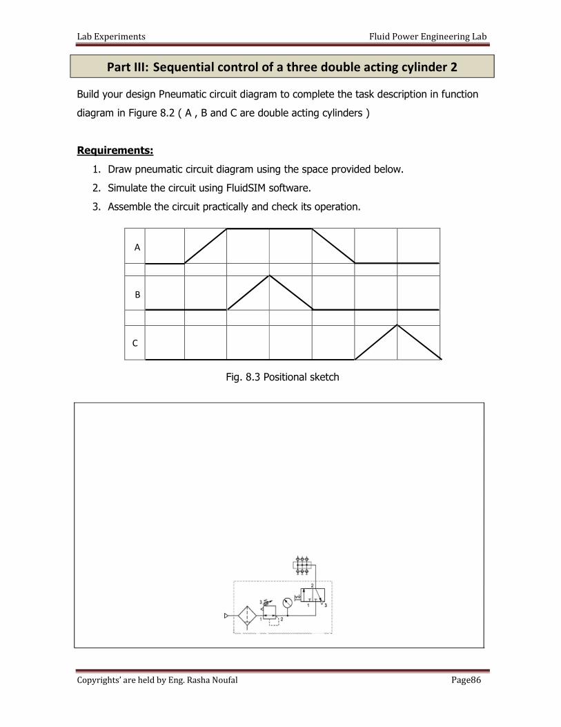
Lab Experiments Fluid Power Engineering Lab
86Page Copyrights’ are held by Eng. Rasha Noufal
Build your design Pneumatic circuit diagram to complete the task description in function
diagram in Figure 8.2 ( A , B and C are double acting cylinders )
Requirements:
1. Draw pneumatic circuit diagram using the space provided below.
2. Simulate the circuit using FluidSIM software.
3. Assemble the circuit practically and check its operation.
Fig. 8.3 Positional sketch
A
B
C
Part III: Sequential control of a three double acting cylinder 2
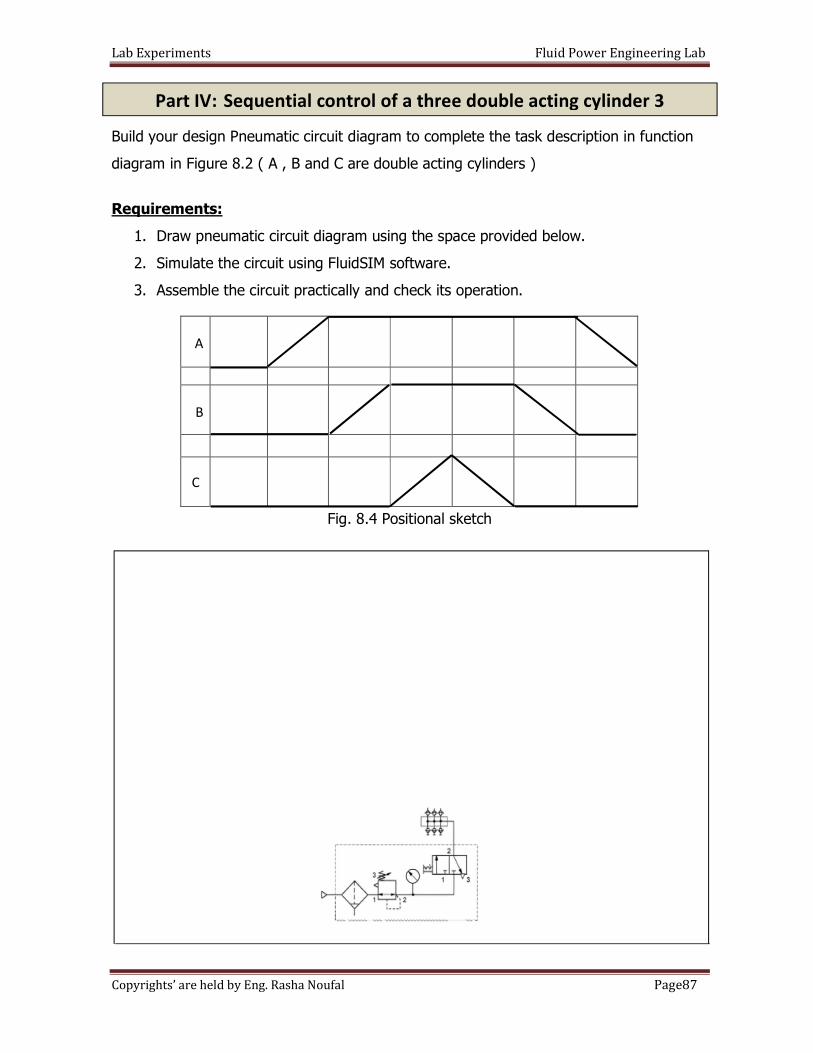
Lab Experiments Fluid Power Engineering Lab
87Page Copyrights’ are held by Eng. Rasha Noufal
=
Build your design Pneumatic circuit diagram to complete the task description in function
diagram in Figure 8.2 ( A , B and C are double acting cylinders )
Requirements:
1. Draw pneumatic circuit diagram using the space provided below.
2. Simulate the circuit using FluidSIM software.
3. Assemble the circuit practically and check its operation.
Fig. 8.4 Positional sketch
A
B
C
Part IV: Sequential control of a three double acting cylinder 3
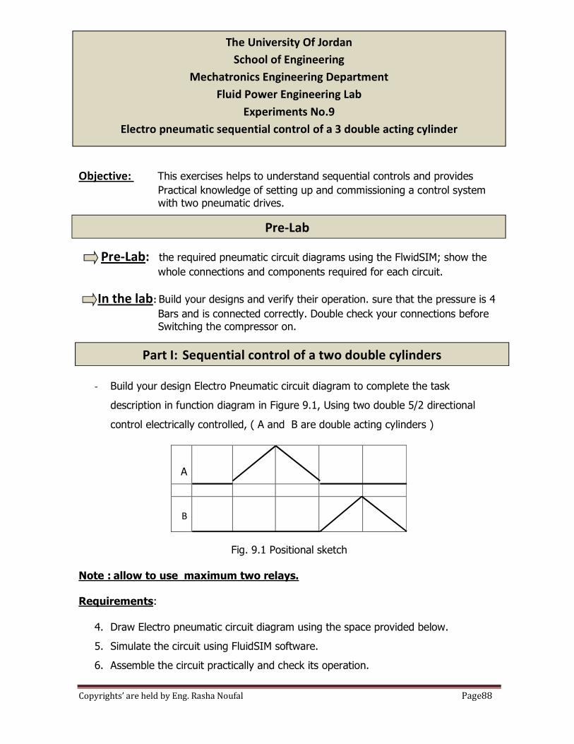
Lab Experiments Fluid Power Engineering Lab
88Page Copyrights’ are held by Eng. Rasha Noufal
Objective: This exercises helps to understand sequential controls and provides
Practical knowledge of setting up and commissioning a control system
with two pneumatic drives.
Pre-Lab: the required pneumatic circuit diagrams using the FlwidSIM; show the
whole connections and components required for each circuit.
In the lab: Build your designs and verify their operation. sure that the pressure is 4
Bars and is connected correctly. Double check your connections before Switching the compressor on.
- Build your design Electro Pneumatic circuit diagram to complete the task
description in function diagram in Figure 9.1, Using two double 5/2 directional
control electrically controlled, ( A and B are double acting cylinders )
Fig. 9.1 Positional sketch
Note : allow to use maximum two relays.
Requirements:
4. Draw Electro pneumatic circuit diagram using the space provided below.
5. Simulate the circuit using FluidSIM software.
6. Assemble the circuit practically and check its operation.
A
B
The University Of Jordan
School of Engineering
Mechatronics Engineering Department
Fluid Power Engineering Lab
Experiments No.9
Electro pneumatic sequential control of a 3 double acting cylinder
Part I: Sequential control of a two double cylinders
Pre-Lab
Lab Experiments Fluid Power Engineering Lab
89Page Copyrights’ are held by Eng. Rasha Noufal
Electro Pneumatic circuit diagram
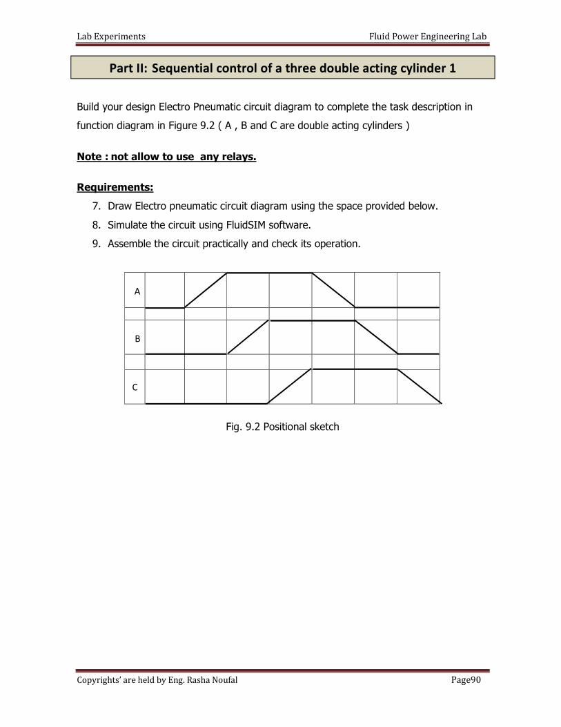
Lab Experiments Fluid Power Engineering Lab
90Page Copyrights’ are held by Eng. Rasha Noufal
Build your design Electro Pneumatic circuit diagram to complete the task description in
function diagram in Figure 9.2 ( A , B and C are double acting cylinders )
Note : not allow to use any relays.
Requirements:
7. Draw Electro pneumatic circuit diagram using the space provided below.
8. Simulate the circuit using FluidSIM software.
9. Assemble the circuit practically and check its operation.
Fig. 9.2 Positional sketch
A
B
C
Part II: Sequential control of a three double acting cylinder 1
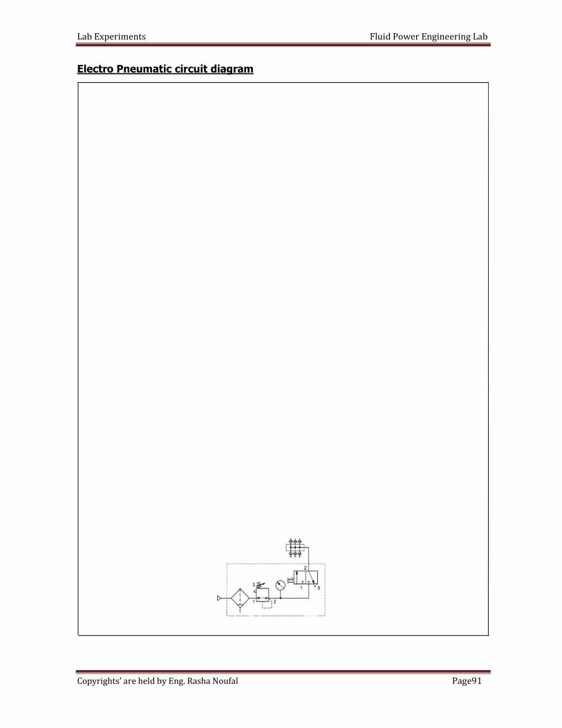
Lab Experiments Fluid Power Engineering Lab
91Page Copyrights’ are held by Eng. Rasha Noufal
Electro Pneumatic circuit diagram
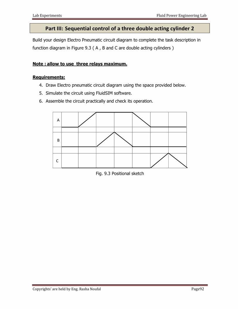
Lab Experiments Fluid Power Engineering Lab
92Page Copyrights’ are held by Eng. Rasha Noufal
Build your design Electro Pneumatic circuit diagram to complete the task description in
function diagram in Figure 9.3 ( A , B and C are double acting cylinders )
Note : allow to use three relays maximum.
Requirements:
4. Draw Electro pneumatic circuit diagram using the space provided below.
5. Simulate the circuit using FluidSIM software.
6. Assemble the circuit practically and check its operation.
Fig. 9.3 Positional sketch
A
B
C
Part III: Sequential control of a three double acting cylinder 2
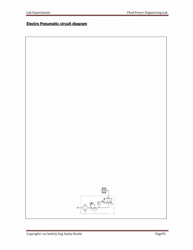
Lab Experiments Fluid Power Engineering Lab
93Page Copyrights’ are held by Eng. Rasha Noufal
Electro Pneumatic circuit diagram
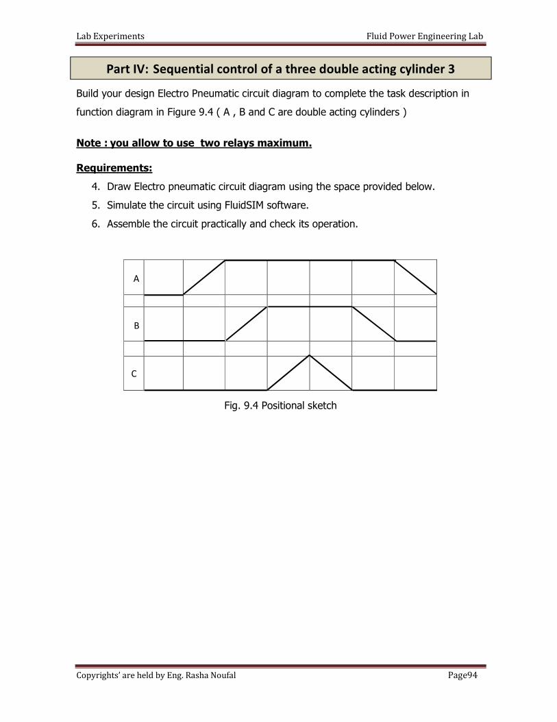
Lab Experiments Fluid Power Engineering Lab
94Page Copyrights’ are held by Eng. Rasha Noufal
=
Build your design Electro Pneumatic circuit diagram to complete the task description in
function diagram in Figure 9.4 ( A , B and C are double acting cylinders )
Note : you allow to use two relays maximum.
Requirements:
4. Draw Electro pneumatic circuit diagram using the space provided below.
5. Simulate the circuit using FluidSIM software.
6. Assemble the circuit practically and check its operation.
Fig. 9.4 Positional sketch
A
B
C
Part IV: Sequential control of a three double acting cylinder 3
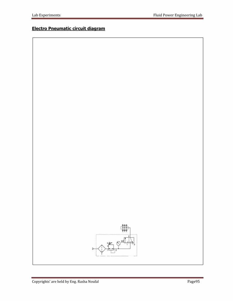
Lab Experiments Fluid Power Engineering Lab
95Page Copyrights’ are held by Eng. Rasha Noufal
Electro Pneumatic circuit diagram
Lab Experiments Fluid Power Engineering Lab
96Page Copyrights’ are held by Eng. Rasha Noufal
Objective: Students will be able to
1- Describe the design and operation of a hydraulic motor, calculate the speed of a hydraulic
motor, and determine the effect a change in flow rate or pressure has on motor operation.
2- To operate a hydraulic motor at constant speed under varying system pressures using a
pressure-compensated flow control valve.
3- how brake a hydraulic motor gradually and smoothly using a sequence valve.
Hydraulic motors convert hydraulic energy into mechanical rotary energy. This energy is used to
turn a resisting object by means of a shaft. Hydraulic motors have several advantages over
electric motors. They can be uni- or bi-directional. They are instantly reversible and they can
absorb severe shock loading without damage to the motor. They are smaller than electric motors
and respond faster. Hydraulic motors can be overloaded and stalled without damage because
excess pressure is diverted over the relief valve.
Motor speed and volumetric efficiency:
The speed at which a hydraulic motor turns is determined by how fast it is filled with oil. This
speed, then, is directly proportional to the oil flow rate through the motor, and inversely
proportional to the motor displacement. The formula for calculating the theoretical speed of a
motor is:
S.I Units:
Speed (r/min) = Flow rate (l/min) × 1000
Displacement(cm3/r)
English Units:
Speed (r/min) = Flow rate (gal(USA)/min) × 231
Displacement(in3/r)
The University Of Jordan
School of Engineering
Mechatronics Engineering Department
Fluid Power Engineering Lab
Experiments No.10
Hydraulic Motor Circuit
Introduction
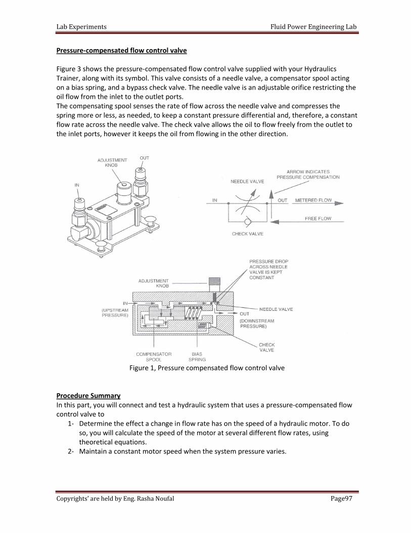
Lab Experiments Fluid Power Engineering Lab
97Page Copyrights’ are held by Eng. Rasha Noufal
Pressure-compensated flow control valve
Figure 3 shows the pressure-compensated flow control valve supplied with your Hydraulics
Trainer, along with its symbol. This valve consists of a needle valve, a compensator spool acting
on a bias spring, and a bypass check valve. The needle valve is an adjustable orifice restricting the
oil flow from the inlet to the outlet ports.
The compensating spool senses the rate of flow across the needle valve and compresses the
spring more or less, as needed, to keep a constant pressure differential and, therefore, a constant
flow rate across the needle valve. The check valve allows the oil to flow freely from the outlet to
the inlet ports, however it keeps the oil from flowing in the other direction.
Figure 1, Pressure compensated flow control valve
Procedure Summary
In this part, you will connect and test a hydraulic system that uses a pressure-compensated flow
control valve to
1- Determine the effect a change in flow rate has on the speed of a hydraulic motor. To do
so, you will calculate the speed of the motor at several different flow rates, using
theoretical equations.
2- Maintain a constant motor speed when the system pressure varies.
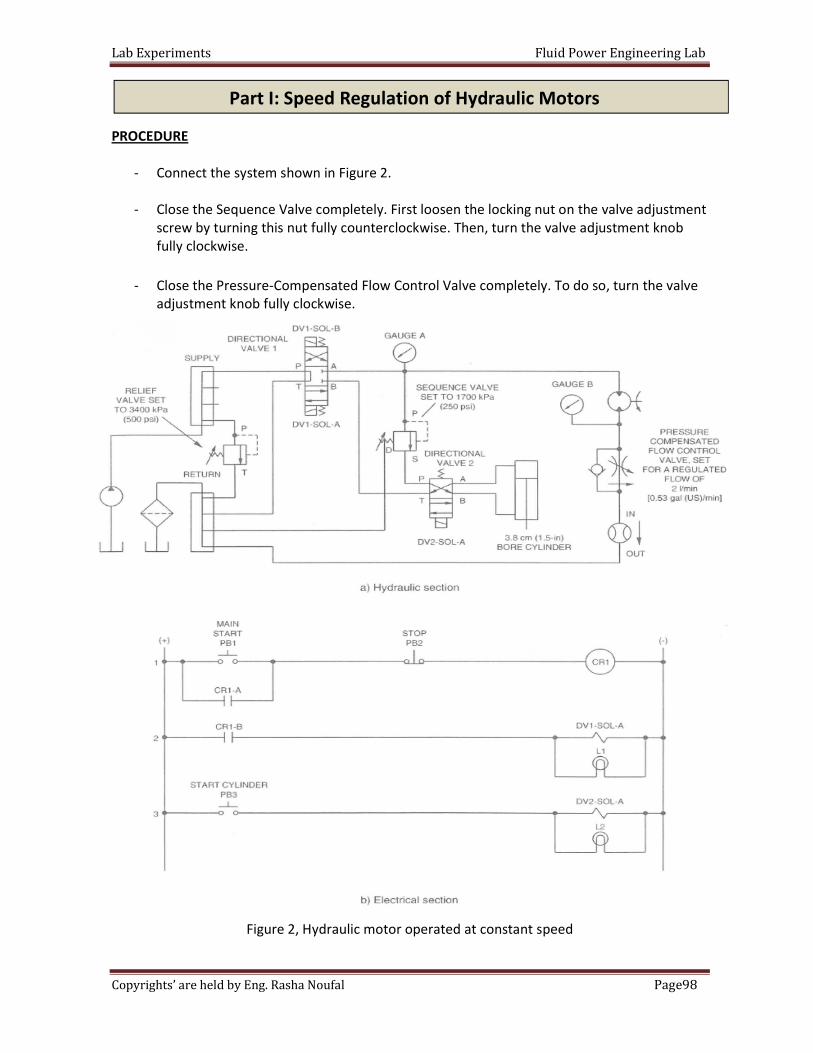
Lab Experiments Fluid Power Engineering Lab
98Page Copyrights’ are held by Eng. Rasha Noufal
PROCEDURE
- Connect the system shown in Figure 2.
- Close the Sequence Valve completely. First loosen the locking nut on the valve adjustment
screw by turning this nut fully counterclockwise. Then, turn the valve adjustment knob
fully clockwise.
- Close the Pressure-Compensated Flow Control Valve completely. To do so, turn the valve
adjustment knob fully clockwise.
Figure 2, Hydraulic motor operated at constant speed
Part I: Speed Regulation of Hydraulic Motors
Lab Experiments Fluid Power Engineering Lab
99Page Copyrights’ are held by Eng. Rasha Noufal
- Before starting the power unit, perform the following start-up procedure.
a. Make sure the hoses are firmly connected.
b. Check the level of the oil in the reservoir. Add oil if required.
c. Put on safety glasses.
d. Make sure the power switch on the Power Unit is set to the OFF position.
e. Open the Relief Valve completely (turn knob fully counterclockwise).
- Turn on the Power Unit. Then, turn on the 24 V DC Power Supply.
- Press the MAIN START pushbutton, PB1, to energize solenoid A of Directional Valve 1 and
shift this valve to the straight-arrows condition. Since the Sequence Valve and the Flow
Control Valve are closed, all the pumped oil is now being forced through the Relief Valve.
Turn the adjustment knob of the Relief Valve clockwise until the system pressure at
Pressure Gauge A is 3400 kPa (500 psi).
- Set the operating pressure of the Sequence Valve to 1700 kPa (250 psi). To do so, perform
the following steps:
- Turn off the Power Unit.
- Disconnect the hose coming from port S of the Sequence Valve at port P of
Directional Valve 2, then connect it to the return manifold.
- Turn on the Power Unit.
- Decrease the operating pressure of the Sequence Valve
(Turn knob counterclockwise) until Pressure Gauge A reads 1700 kPa (250 psi).
- Turn off the Power Unit.
- Disconnect the hose coming from port S of the Sequence Valve at the return line
manifold, then connect it to port P of Directional Valve 2.
- Turn on the Power Unit.
- Turn the Pressure-Compensated Flow Control Valve adjustment knob counterclockwise to
make the motor rotate. Adjust this valve until 2 I/min [0.53 gal(US)/min] is indicated by
the Flowmeter.
- Record the pressure level upstream of the Pressure-Compensated Flow Control Valve
( Pressure Gauge B) in the "RETRACTED" row of Table 1.
Cylinder Condition Flow meter Reading Gauge B Pressure
RETRACTED 2 l/min [0.53 gal(US)/min]
EXTENDING
Table 1, Circuit data with the pressure compensated Flow Control Valve.
- Now press and hold the START CYLINDER pushbutton, PB3, which will cause the cylinder
to extend and the pressure to drop upstream of the Pressure-Compensated Flow Control
Valve ( Pressure Gauge B). While the cylinder is extending, observe the Flowmeter
reading. A change in flow rate is a sign that the motor speed is changing. Does the motor
speed change as the cylinder is extending?
_______________________________________________________________________
Lab Experiments Fluid Power Engineering Lab
100Page Copyrights’ are held by Eng. Rasha
Noufal
- Release pushbutton PB3 to retract the cylinder if you have not already done this.
- Again press PB3 to extend the cylinder. While the cylinder is extending, measure the
Flowmeter reading and the reading of Pressure Gauge B. Record these in the
"EXTENDING" row of Table 1.
- According to Table 1-2, is the flow rate affected across the Pressure- Compensated Flow
Control Valve when the pressure upstream of this valve (Pressure Gauge B) decreases?
Explain why.
_________________________________________________________________________
_________________________________________________________________________
- Turn off the Power Unit. Disconnect the Pressure-Compensated Flow Control Valve from
the circuit and connect the Non-Compensated Flow Control Valve in its place.
- Close the Non-Compensated Flow Control Valve completely (turn knob fully clockwise).
Turn on the Power Unit.
- Turn the Non-Compensated Flow Control Valve adjustment knob counterclockwise to
make the motor rotate. Adjust this valve until 2 I/min [0.53 gal(US)/min] is indicated by
the Flowmeter.
- Record the pressure level upstream of the Non-Compensated Flow Control Valve
(Pressure Gauge B) in the "RETRACTED" row of Table 2.
Cylinder Condition Flow meter Reading Gauge B Pressure
RETRACTED 2 l/min [0.53 gal(US)/min]
EXTENDING
Table 2, Circuit data with the Non-compensated Flow Control Valve.
- Now press and hold the START CYLINDER pushbutton, PB3, which will cause the cylinder
to extend and the pressure to drop upstream of the Non-Compensated Flow Control Valve
(Pressure Gauge B). While the cylinder is extending, observe the Flowmeter reading. Does
the motor speed change as the cylinder is extending?
________________________________________________________________________
- Release pushbutton PB3 to retract the cylinder. Again press PB3 to extend the cylinder.
While the cylinder is extending, measure the Flowmeter reading and the reading of
Pressure Gauge B. Record these in the "EXTENDING" row of Table 4.
- According to Table 4, is the flow rate affected across the Non-Compensated Flow Control
Valve when the pressure upstream of this valve (Pressure Gauge B) decreases? Why?
________________________________________________________________________
________________________________________________________________________
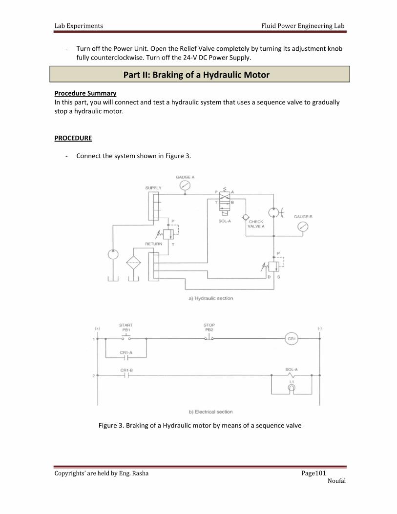
Lab Experiments Fluid Power Engineering Lab
101Page Copyrights’ are held by Eng. Rasha
Noufal
- Turn off the Power Unit. Open the Relief Valve completely by turning its adjustment knob
fully counterclockwise. Turn off the 24-V DC Power Supply.
Procedure Summary
In this part, you will connect and test a hydraulic system that uses a sequence valve to gradually
stop a hydraulic motor.
PROCEDURE
- Connect the system shown in Figure 3.
Figure 3. Braking of a Hydraulic motor by means of a sequence valve
Part II: Braking of a Hydraulic Motor

Lab Experiments Fluid Power Engineering Lab
102Page Copyrights’ are held by Eng. Rasha
Noufal
- Install the heavyweight flywheel onto the shaft of the motor. To do this, perform the
following steps:
- Slip the flywheel onto the motor shaft, taking care to align the set screw in the
flywheel hub with the notch in the motor shaft.
- Fully tighten the set screw, using the Allen key supplied with your hydraulic motor.
- Check that the set screw is completely screwed into its hole. The head of the set
screw should be flush with the flywheel hub. If not, this is likely because the flywheel
is not secured properly. In that case, loosen the set screw and realign the flywheel
properly. Retighten the set screw and again check that the set screw is completely
screwed into its hole.
- Close the Sequence Valve completely. First loosen the locking nut on the valve adjustment
screw by turning this nut fully counterclockwise. Then, turn the valve adjustment knob
fully clockwise.
- Turn on the Power Unit. Then, turn on the 24 V DC Power Supply.
- With the Directional Valve in the normal, crossed-arrows condition, the pumped oil is
blocked at the Check Valve and Pressure Gauge A indicates the current pressure setting of
the Relief Valve. Turn the adjustment knob of the Relief Valve clockwise until the system
pressure at Pressure Gauge A is 2100 kPa (300 psi).
- Press the START pushbutton, PB1, to energize solenoid A and start the motor. After the
motor has reached full speed, press the STOP pushbutton, PB2, and observe the pressure
spike at Pressure Gauge B when the motor stops. Record the magnitude of this spike in
the "MAXIMUM" row of Table 3.
-
SEQUENCE VALVE PRESSURE SETTING PRESSURE SPIKE AT GAUGE B BRAKE TIME
MAXIMUM (VALVE CLOSED)
1400 kPA (200 psi)
900 kPA (130 psi)
0 kPA (0 psi)
Table 3. Pressure spike and brake time versus the pressure setting of the sequence valve.
- Press the START pushbutton to start the motor. After the motor has reached full speed,
press the STOP pushbutton and measure the time required for the motor to stop, using a
stopwatch. Record this brake time in the "MAXIMUM" row of Table 5.
Note: After the STOP pushbutton is pressed, the motor will
come to a stop and then start to rotate in the opposite direction
for a brief period due to oil leakage through the motor. Stop your
stopwatch just before the motor starts to rotate in the opposite
direction.

Lab Experiments Fluid Power Engineering Lab
103Page Copyrights’ are held by Eng. Rasha
Noufal
- Adjust the operating pressure of the Sequence Valve to 1400 kPa (200 psi). To do so,
perform the following steps:
- Turn off the Power Unit. Remove the hose connecting the Check Valve to port B of
the Directional Valve. This will block the motor return line so the oil discharging from
the motor outlet will be forced to flow through the Sequence Valve at whatever
pressure this valve is set for. Turn on the Power Unit.
- Press the START pushbutton. Decrease the operating pressure (turn knob
counterclockwise) of the Sequence Valve until the motor begins to rotate. The
operating pressure of the Sequence Valve is now slightly lower than the 2100-kPa
(300-psi) pressure setting of the Relief Valve, as indicated by Pressure Gauge B.
Further decrease the operating pressure of the Sequence Valve until Pressure Gauge B
indicates 1400 kPa (200 psi). Press the STOP pushbutton.
- Turn off the Power Unit. Reconnect the Check Valve to port B of the Directional Valve.
Turn on the Power Unit.
- Press the START pushbutton, PB1, to energize solenoid A and start the motor. After the
motor has reached full speed, press the STOP pushbutton, PB2, and observe the pressure
spike at Pressure Gauge B when the motor stops. recording the requested information in
the "1400 kPa (200 psi)" row of Table 5.
- Press the START pushbutton to start the motor. After the motor has reached full speed,
press the STOP pushbutton and measure the time required for the motor to stop, using a
stopwatch. Record this brake time in the "1400 kPa (200 psi)" row of Table 5.
Note: After the STOP pushbutton is pressed, the motor will
come to a stop and then start to rotate in the opposite direction
for a brief period due to oil leakage through the motor. Stop your
stopwatch just before the motor starts to rotate in the opposite
direction.
- Set the operating pressure of the Sequence Valve to the lowest possible level
(900 kPal130 psi approximately) by turning its knob fully counterclockwise.
- Repeat last two steps, recording the requested information in the "900 kPa (130 psi)" row
of Table 5.
- Now bypass the Sequence Valve completely. To do so, turn off the Power Unit. Disconnect
the end of the hose connected to port P of the Sequence Valve and connect it directly to
the return manifold. Turn on the Power Unit.
- Repeat last two steps, recording the requested information in the "",0 kPa (0 psi)" row of
Table 5.
Lab Experiments Fluid Power Engineering Lab
104Page Copyrights’ are held by Eng. Rasha
Noufal
- Turn off the Power Unit. Open the Relief Valve completely by turning its adjustment knob
fully counterclockwise. Turn off the 24-V DC Power Supply.
- According to Table 5, how does decreasing the pressure setting of the Sequence Valve
affect the magnitude of the pressure spike? Why?
_________________________________________________________________________
_________________________________________________________________________
_________________________________________________________________________
- How does decreasing the pressure setting of the Sequence Valve affect the time required
to stop the motor? Why?
_________________________________________________________________________
_________________________________________________________________________
_________________________________________________________________________
Lab Experiments Fluid Power Engineering Lab
105Page Copyrights’ are held by Eng. Rasha
Noufal
Date:
Section:
Group's Names:
1-
2-
3-
4-
5-
Q1: What is the primary difference between a pressure-compensated flow control valve and a
non-compensated flow control valve?
Q2: What is the function of the pressure-compensated flow control valve in the system shown in
Figure 2 ?
The University Of Jordan
School of Engineering
Mechatronics Engineering Department
Control of Hydraulic & Pneumatic System Lab
Experiments No.10
Hydraulic Motor Circuit
In class Lab Report
Part I: Speed Regulation of Hydraulic Motors
Lab Experiments Fluid Power Engineering Lab
106Page Copyrights’ are held by Eng. Rasha
Noufal
Q1: What is the function of the sequence valve in the motor braking system of Figure 3?
Q2: Explain the operation of the sequence valve in the motor braking system of Figure 3?
Q3: In a motor braking system, why is it important to allow the oil to flow directly from the
reservoir into the rotating motor when the motor is braking?
Part II: Braking of a Hydraulic Motor