fluid control solutions
TRANSCRIPT
Fluid Control Solutions
3
FL
UID
CO
NT
RO
LS
OL
UT
ION
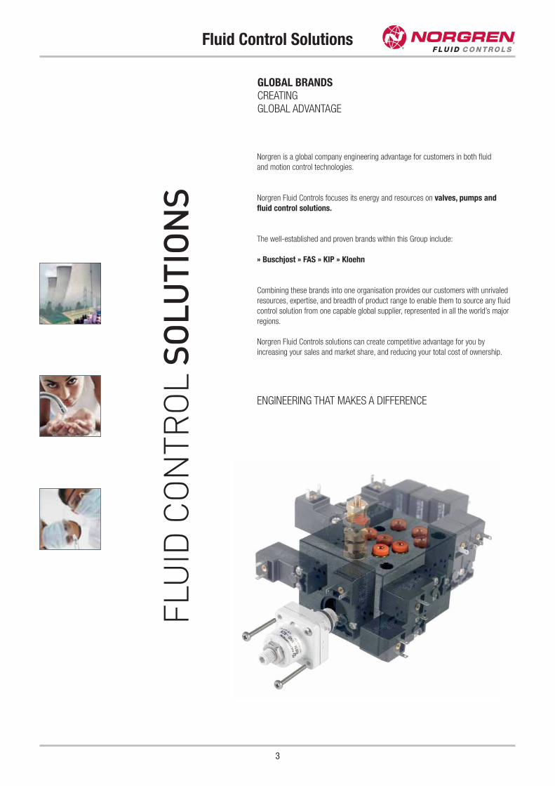
SNorgren is a global company engineering advantage for customers in both fluid
and motion control technologies.
Norgren Fluid Controls focuses its energy and resources on valves, pumps and
fluid control solutions.
The well-established and proven brands within this Group include:
» Buschjost » FAS » KIP » Kloehn
Combining these brands into one organisation provides our customers with unrivaled
resources, expertise, and breadth of product range to enable them to source any fluid
control solution from one capable global supplier, represented in all the world’s major
regions.
Norgren Fluid Controls solutions can create competitive advantage for you by
increasing your sales and market share, and reducing your total cost of ownership.
ENGINEERING THAT MAKES A DIFFERENCE
GLOBAL BRANDSCREATINGGLOBAL ADVANTAGE
Fluid Control Solutions
4
Our engineers are dedicated to the development of solenoid valves,
process valves, precision liquid handling technologies, and customised
manifolds & solutions.
Fully equipped clean room facilities, in several locations, meet the specific
needs of demanding market sectors such as Life Sciences and
semiconductor manufacturing.
Our manufacturing locations in Germany, Switzerland and the USA enable us
to stay close to our customers, and take advantage of local technological
expertise.The Norgren Fluid Controls facility in Geneva, for example, that
develops sophisticated miniature valve solutions, draws heavily on the
miniaturisation and precision traditions of the Swiss watch-making industry.
As a subsidiary of IMI plc, and part of the global Norgren group, we provide
our customers worldwide with the reassurance of dealing with an established
global supplier. This gives financial strength and security, and all the
advantages of a global sales and service network.
UNDERSTANDING YOUR NEEDS
» CLOSE PARTNERSHIPS
Our dedicated engineers work directly with your engineers to provide design
advice and assistance, develop customised solutions, and get your new
concepts to market faster.
» SECTOR AND APPLICATION EXPERTISE
Many decades of industry-specific experience means we speak your
language, and understand your operating environment.
» QUALITY AND CERTIFICATION
Products and processes conform to ISO 9001, ISO/TS 16949, KTA 1401,
APQP, ATEX, DB A1, FDA, NSF, UL, VDA. Selected production facilities
include GMP compliant assembly areas and Class 10,000 clean rooms.
PROVEN TECHNICAL SOLUTIONS
CREATING IDEAS THAT WORK HARDER
Fluid Control Solutions
5
» DELIVERY LEAD TIMES
A choice of flexible delivery arrangements can meet individual needs.
Customised supply chain solutions include Kanban and just-in-time
deliveries.
» COMPREHENSIVE SIZE RANGE
From 8 mm FAS miniature solenoid valves to 200 mm Buschjost process
valves.
» HIGH SPEED
Response times as low as 3 ms for sorting machines, inkjet printing etc.
» HIGH VACUUM
10-6 Torr (10-9 bar) or even lower, with a leak rate of 10-8 mbar l/sec.
» HIGH PRESSURE
Pressure range going up to 250 bar.
» HIGH FLOW-TO-SIZE RATIO
Highly compact solutions with no compromise on performance.
» MEDIA SEPARATED VALVES
Comprehensive range featuring industry leading flow-to-size ratio and small
or no dead volume. For use with ultra pure or corrosive media.
» PROPORTIONAL TECHNOLOGY
High flow precision and high repeatability combined with space, weight and
power savings.
» LAMINATED MANIFOLD TECHNOLOGY
Norgren's expertise in thermal, diffusion and solvent bonding processes
allow manifolding in acrylic and other high-grade polymers, and a precise
alignment of fluidic pathways as small as 250 μm.
» SYRINGE AND SYRINGE PUMP TECHNOLOGY
Superior design and manufacturing processes allow longer lifetimes, high
precision, and high accuracy for dispense down to nanoliters.
Contents
6
Solenoid Valves without Differential Pressure
Solenoid Valves with Differential Pressure
Page 8
Page 103
Page 132
Page 201
Page 221
Pressure Actuated Valves
Proportional Valves
Valves and Systems for Dust Filters
Page 227
Page 235
Page 255
Pressure Sensors
Air Preparation Equipment (FRL)
Fittings
Feature Pages
Page
Technical Information 276
Pressure Equipment Directive (PED) 316
Safety Instructions 318
ATEX 319
Index 322
Sales and Service Centres back cover
Page
Renewable Energies 17
KIP Solenoid Valves 86
Media Separated Valves 102
Sanitary Automation 110
Water Treatment and Purification 120
Oil & Gas 151
Chemical and Process Industries 160
Valve Islands 190
Dust Filtration 200
Life Sciences 220
KIP Liquid Level Switches 246
Kloehn - Precision Liquid Handling 254
Conventional Energies 263
Fittings and Accessories 274
Further Information
1
2
7
8
3
4
5
6
Contents
7
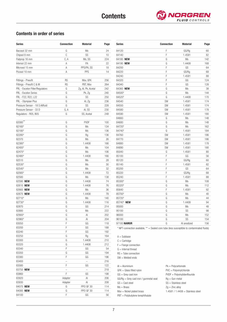
Contents in order of series
* NPT-connection available, ** = Sealed core tube (less susceptible to contaminated fluids)
A = Subbase
C = Cartridge
F = Flange connection
G = Internal thread
RS = Tube connection
SW = Welded ends
Series Connection Material Page
Bacosol 32 mm G Ms 24
Chipsol 8 mm C SS 10
Flatprop 16 mm C, A Ms, SS 224
Intersol 22 mm A PA 22
Microsol 15 mm A PPS/PA, SS 18
Picosol 10 mm A PPS 14
Fittings - Pneufit RS Msv, GFK 256
Fittings - Pneufit C & M RS PBT, Msv 264
FRL - Excelon Filter/Regulators G Zg, Al, Pk, Acetal 242
FRL - Excelon Series G Pk, Zg 240
FRL - F22, R22, L22 G SS 250
FRL - Olympian Plus G Al, Zg 236
Pressure Sensor - 18 S Allfluid G SS 228
Pressure Sensor - 33 D G, A Al, SS 230
Regulators - R05, B05 G SS, Acetal 248
82080** G PVDF 100
82160* G Ms 134
82180* G Ms 136
82280* G Rg 136
82370 G Ms 26
82380* G 1.4408 166
82400* G Ms 104
82470* G Ms 106
82480* G 1.4408 166
82510 G Ms 28
82530* G Ms 30
82540* G Ms 32
82560* G 1.4408 72
82580 G Ms 138
82590 NEW G 1.4408 74
82610 NEW G 1.4408 76
82660 NEW G Ms 36
82670 NEW G 1.4408 78
82710* G Ms 140
82730* G 1.4408 116
82870 G GG 214
82880 G Ms 222
82900* G Al 202
82960* G Al 204
83050 F GG 118
83200 F GG 188
83240 F GG 192
83250 G Rg 164
83300 G 1.4408 210
83320 G 1.4408 212
83340 F GG 54
83350 G GG 194
83380 F GG 196
83400 – – 216
83580 F GG 122
83750 NEW – – 218
83860 F GS 198
83920 Adapter Al 206
83930 Adapter Al 208
84070 NEW G PPO GF 30 114
84080 NEW G PPO GF 30 114
84100 F GG 56
Series Connection Material Page
84120 F GG/Rg 60
84140 F 1.4581 82
84180 NEW G Ms 142
84190 NEW G 1.4408 168
84200 F GS 64
84220 F GS/Rg 68
84240 F 1.4581 88
84320 F GG 124
84340 F GS 128
84360 NEW G Ms 38
84500* G Ms 144
84520* G 1.4408 170
84540 SW 1.4581 174
84550 SW 1.4581 174
84580 SW 1.4581 178
84590 SW 1.4581 180
84660 G Ms 148
84680 G Ms 148
84720* G Ms 162
84740* G 1.4581 184
84760 SW 1.4581 186
84770 SW 1.4581 186
84880 SW 1.4581 178
84890 SW 1.4581 180
85040 G 1.4581 80
85100 F GG 56
85120 F GG/Rg 60
85140 F 1.4581 82
85200 F GS 64
85220 F GS/Rg 68
85240 F 1.4581 88
85300* G Ms 108
85320* G Ms 112
85640 F 1.4581 92
85700* G Ms 40
85720* G Ms 44
85740* NEW G 1.4408 94
95000 G Ms 48
95100 G SS 98
96000 G Ms 152
96100 G SS 154
97100 NAMUR G Al anodized 156
Al = Aluminium
GFK = Glass filled nylon
GG = Grey cast iron
GG/Rg = Grey cast iron / gunmetal seat
GS = Cast steel
Ms = Brass
Msv = Nickel plated brass
PBT = Polybutylene terephthalate
Pk = Polycarbonate
PVC = Polyvinylchloride
PVDF = Polyvinylidenflouride
Rg = Gun metal
SS = Stainless steel
Zg = Zinc alloy
1.4581 / 1.4408 = Stainless steel
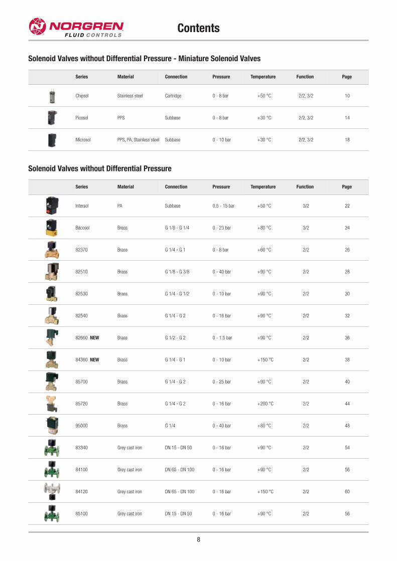
Contents
8
Solenoid Valves without Differential Pressure
Series Material Connection Pressure Temperature Function Page
Intersol PA Subbase 0.5 - 15 bar +50 °C 3/2 22
Bacosol Brass G 1/8 - G 1/4 0 - 23 bar +80 °C 3/2 24
82370 Brass G 1/4 - G 1 0 - 8 bar +60 °C 2/2 26
82510 Brass G 1/8 - G 3/8 0 - 40 bar +90 °C 2/2 28
82530 Brass G 1/4 - G 1/2 0 - 10 bar +90 °C 2/2 30
82540 Brass G 1/4 - G 2 0 - 16 bar +90 °C 2/2 32
82660 NEW Brass G 1/2 - G 2 0 - 1.5 bar +90 °C 2/2 36
84360 NEW Brass G 1/4 - G 1 0 - 10 bar +150 °C 2/2 38
85700 Brass G 1/4 - G 2 0 - 25 bar +90 °C 2/2 40
85720 Brass G 1/4 - G 2 0 - 16 bar +200 °C 2/2 44
95000 Brass G 1/4 0 - 40 bar +80 °C 2/2 48
83340 Grey cast iron DN 15 - DN 50 0 - 16 bar +90 °C 2/2 54
84100 Grey cast iron DN 65 - DN 100 0 - 16 bar +90 °C 2/2 56
84120 Grey cast iron DN 65 - DN 100 0 - 16 bar +150 °C 2/2 60
85100 Grey cast iron DN 15 - DN 50 0 - 16 bar +90 °C 2/2 56
Solenoid Valves without Differential Pressure - Miniature Solenoid Valves
Series Material Connection Pressure Temperature Function Page
Chipsol Stainless steel Cartridge 0 - 8 bar +50 °C 2/2, 3/2 10
Picosol PPS Subbase 0 - 8 bar +30 °C 2/2, 3/2 14
Microsol PPS, PA, Stainless steel Subbase 0 - 10 bar +30 °C 2/2, 3/2 18
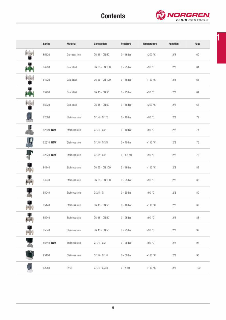
Contents
9
Series Material Connection Pressure Temperature Function Page
85120 Grey cast iron DN 15 - DN 50 0 - 16 bar +200 °C 2/2 60
84200 Cast steel DN 65 - DN 100 0 - 25 bar +90 °C 2/2 64
84220 Cast steel DN 65 - DN 100 0 - 16 bar +150 °C 2/2 68
85200 Cast steel DN 15 - DN 50 0 - 25 bar +90 °C 2/2 64
85220 Cast steel DN 15 - DN 50 0 - 16 bar +200 °C 2/2 68
82560 Stainless steel G 1/4 - G 1/2 0 - 10 bar +90 °C 2/2 72
82590 NEW Stainless steel G 1/4 - G 2 0 - 10 bar +90 °C 2/2 74
82610 NEW Stainless steel G 1/8 - G 3/8 0 - 40 bar +110 °C 2/2 76
82670 NEW Stainless steel G 1/2 - G 2 0 - 1.5 bar +90 °C 2/2 78
84140 Stainless steel DN 65 - DN 100 0 - 16 bar +110 °C 2/2 82
84240 Stainless steel DN 65 - DN 100 0 - 25 bar +90 °C 2/2 88
85040 Stainless steel G 3/8 - G 1 0 - 25 bar +90 °C 2/2 80
85140 Stainless steel DN 15 - DN 50 0 - 16 bar +110 °C 2/2 82
85240 Stainless steel DN 15 - DN 50 0 - 25 bar +90 °C 2/2 88
85640 Stainless steel DN 15 - DN 50 0 - 25 bar +90 °C 2/2 92
85740 NEW Stainless steel G 1/4 - G 2 0 - 25 bar +90 °C 2/2 94
95100 Stainless steel G 1/8 - G 1/4 0 - 50 bar +120 °C 2/2 98
82080 PVDF G 1/4 - G 3/8 0 - 7 bar +110 °C 2/2 100
1
10
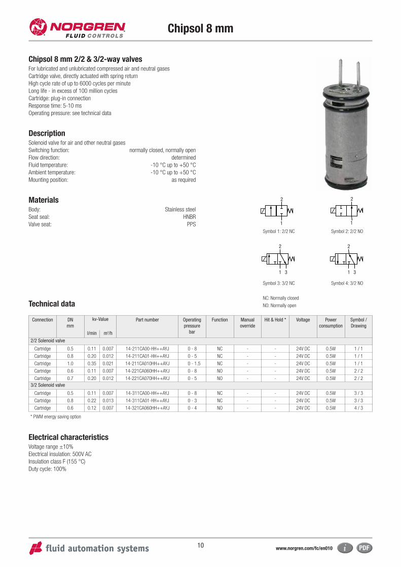
Chipsol 8 mm
Chipsol 8 mm 2/2 & 3/2-way valvesFor lubricated and unlubricated compressed air and neutral gases
Cartridge valve, directly actuated with spring return
High cycle rate of up to 6000 cycles per minute
Long life - in excess of 100 million cycles
Cartridge: plug-in connection
Response time: 5-10 ms
Operating pressure: see technical data
Description Solenoid valve for air and other neutral gases
Switching function: normally closed, normally open
Flow direction: determined
Fluid temperature: -10 °C up to +50 °C
Ambient temperature: -10 °C up to +50 °C
Mounting position: as required
MaterialsBody: Stainless steel
Seat seal: HNBR
Valve seat: PPS
Technical data
Connection DN
mm
kv-Value Part number Operating
pressure
bar
Function Manual
override
Hit & Hold * Voltage Power
consumption
Symbol /
Drawing
l/min m3/h
2/2 Solenoid valve
Cartridge 0.5 0.11 0.007 14-211CA00-HH++AYJ 0 - 8 NC - - 24V DC 0.5W 1 / 1
Cartridge 0.8 0.20 0.012 14-211CA01-HH++AYJ 0 - 5 NC - - 24V DC 0.5W 1 / 1
Cartridge 1.0 0.35 0.021 14-211CA010HH++AYJ 0 - 1.5 NC - - 24V DC 0.5W 1 / 1
Cartridge 0.6 0.11 0.007 14-221CA060HH++AYJ 0 - 8 NO - - 24V DC 0.5W 2 / 2
Cartridge 0.7 0.20 0.012 14-221CA070HH++AYJ 0 - 5 NO - - 24V DC 0.5W 2 / 2
3/2 Solenoid valve
Cartridge 0.5 0.11 0.007 14-311CA00-HH++AYJ 0 - 8 NC - - 24V DC 0.5W 3 / 3
Cartridge 0.8 0.22 0.013 14-311CA01-HH++AYJ 0 - 3 NC - - 24V DC 0.5W 3 / 3
Cartridge 0.6 0.12 0.007 14-321CA060HH++AYJ 0 - 4 NO - - 24V DC 0.5W 4 / 3
2
1 3
Symbol 1: 2/2 NC Symbol 2: 2/2 NO
Symbol 4: 3/2 NOSymbol 3: 3/2 NC
NC: Normally closed
NO: Normally open
2
1 3
Electrical characteristicsVoltage range ±10%
Electrical insulation: 500V AC
Insulation class F (155 °C)
Duty cycle: 100%
2
1
2
1
* PWM energy saving option
www.norgren.com/fc/en010
11
Chipsol 8 mm
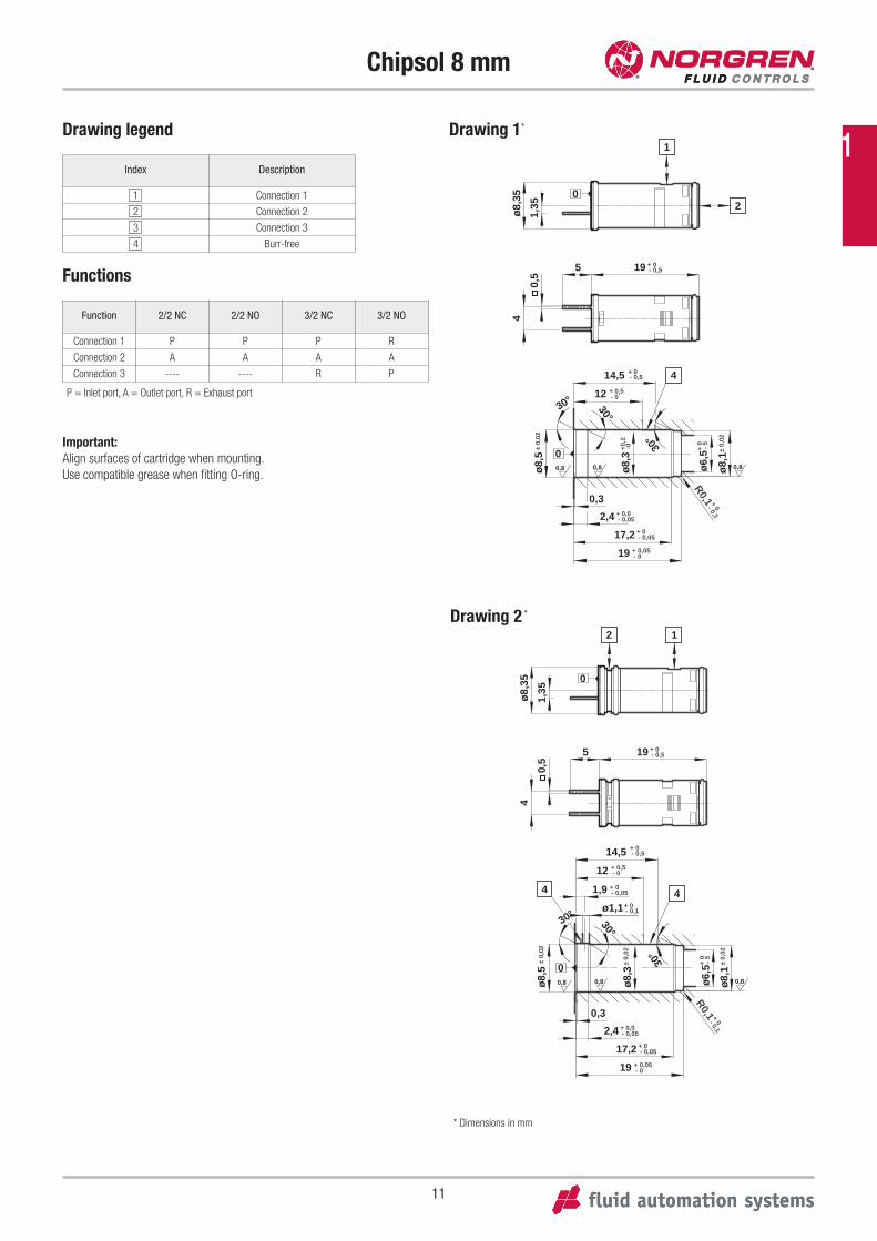
Drawing legend
Functions
Index Description
1 Connection 1
2 Connection 2
3 Connection 3
4 Burr-free
+ 0- 0,519
ø8,
354
1,35
0,5
5
1
20
0,8
0,8
0
- 0,05+ 0
- 0+ 0,05
0,8
17,2
0,3
ø8,
5
-0
ø8,
1
+0,2
ø8,
3
12
14,5
19
4
± 0,
02
± 0,
02
30°
30°
30°
+ 0- 0,5
- 0+ 0,5
- 0,05+ 0,02,4
R0,1 + 0- 0,1
ø6,
5+ 0
- 5
Drawing 1*
0,8
0,8
- 0,05+ 0
- 0,05+ 0,0
- 0+ 0,05
R0,1
0,8
- 0,05+ 0
17,2
2,4
0,3
ø8,
5
ø6,
5
ø8,
1
ø8,
3
ø1,1
1,9
12
14,5
19
44
30°
30°
± 0,
02
± 0,
02
± 0,
02
0
+ 0- 0,5
- 0+ 0,5
+ 0
- 5
+ 0- 0,1
+ 0- 0,1
30°
19
ø8,
354
1,35
5
2 1
0,5
0
+ 0- 0,5
Drawing 2 *
Function 2/2 NC 2/2 NO 3/2 NC 3/2 NO
Connection 1 P P P R
Connection 2 A A A A
Connection 3 ---- ---- R P
* Dimensions in mm
Important:
Align surfaces of cartridge when mounting.
Use compatible grease when fitting O-ring.
P = Inlet port, A = Outlet port, R = Exhaust port
1
12
Chipsol 8 mm
Drawing legend
Functions
Index Description
1 Connection 1
2 Connection 2
3 Connection 3
4 Burr-free
Function 2/2 NC 2/2 NO 3/2 NC 3/2 NO
Connection 1 P P P R
Connection 2 A A A A
Connection 3 ---- ---- R P
0,8
0,8
- 0,05+ 0
- 0,05+ 0,0
- 0+ 0,05
R0,1
0,8
- 0,05+ 0
17,2
2,4
0,3
ø8,
5
ø6,
5
ø8,
1
ø8,
3
ø1,1
1,9
12
14,5
19
44
30°
30°
± 0,
02
± 0,
02
± 0,
02
0
+ 0- 0,5
- 0+ 0,5
+ 0
- 5
+ 0- 0,1
+ 0- 0,1
30°
19
ø8,
354
1,35
5
3 2
1
0,5
0
+ 0- 0,5
Drawing 3 *
* Dimensions in mm
Important:
Align surfaces of cartridge when mounting.
Use compatible grease when fitting O-ring.
Please find the safety instructions for the FAS range on page 318.
P = Inlet port, A = Outlet port, R = Exhaust port
Fluid Control Solutions
13
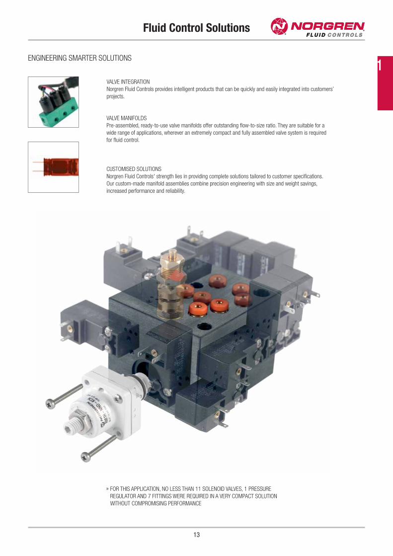
VALVE INTEGRATION
Norgren Fluid Controls provides intelligent products that can be quickly and easily integrated into customers’
projects.
VALVE MANIFOLDS
Pre-assembled, ready-to-use valve manifolds offer outstanding flow-to-size ratio. They are suitable for a
wide range of applications, wherever an extremely compact and fully assembled valve system is required
for fluid control.
CUSTOMISED SOLUTIONS
Norgren Fluid Controls' strength lies in providing complete solutions tailored to customer specifications.
Our custom-made manifold assemblies combine precision engineering with size and weight savings,
increased performance and reliability.
ENGINEERING SMARTER SOLUTIONS
» FOR THIS APPLICATION, NO LESS THAN 11 SOLENOID VALVES, 1 PRESSURE
REGULATOR AND 7 FITTINGS WERE REQUIRED IN A VERY COMPACT SOLUTION
WITHOUT COMPROMISING PERFORMANCE
1
14
Picosol 10 mm
Picosol 10 mm 2/2 & 3/2-way valvesFor lubricated and unlubricated compressed air, neutral liquids or gases
Poppet valve, directly actuated with spring return
High cycle rate of up to 1800 cycles per minute
Long life - in excess of 100 million cycles*
* Hit & Hold valves:
2/2 types with 1.6 mm orifice: 25 million cycles
3/2 types with 1.1 mm or 1.3 mm orifice: 50 million cycles
Sub-base mounted
Response time: 8 - 15 ms
Operating pressure: see technical data
DescriptionSolenoid valve for air, and neutral liquids or gases
Switching function: normally closed
Flow direction: determined
Fluid temperature: -10 °C up to +30 °C
Ambient temperature: -10 °C up to +50 °C
Mounting position: as required
MaterialsBody: PPS
Seat seal: NBR
Internal parts: Stainless steel, PA 6/6
Technical data
Connection DN
mm
kv-Value Part number Operating
pressure
bar
Function Manual
override
Hit & Hold * Voltage Power
consumption
Symbol /
Drawing
l/min m3/h
2/2 Direct acting valves / standard models
Flange 0.8 0.20 0.012 11-211P601-H0+1341+AYR** 0 - 8 NC No No 24V DC 1.2W 1 / 1
Flange 1.2 0.39 0.023 11-211P602-H0+1341+AYR** 0 - 4 NC No No 24V DC 1.2W 1 / 1
Flange 1.6 0.50 0.030 11-211P603-H0+6311+AZU 0 - 8 NC No Yes 24V DC 4W / 0.4W 1 / 1
3/2 Direct acting valves / standard models
Flange 0.8 0.19 0.011 11-311PI01-H0+1141+AYR** 2 - 8 NC Push only No 24V DC 1.2W 2 / 2
Flange 1.1 0.38 0.023 11-311PI011H0+6111+AZR 2 - 8 NC Push only Yes 24V DC 3W / 0.3W 2 / 2
Flange 1.3 0.50 0.030 11-311PI013H0+6111+AZR 2 - 6.5 NC Push only Yes 24V DC 3W / 0.3W 2 / 2
NC: Normally closed
2
1Symbol 1: 2/2 NC
2
1 3Symbol 2: 3/2 NC
Electrical characteristicsVoltage range +/- 10 %, duty cycle 100 %
Protection class according to EN 60529: IP51 with connector
Electrical insulation: 1000V AC
Insulation class F (155 °C)
Electrical connection: Molex®
* PWM energy saving option
** Optional surge suppression diode
www.norgren.com/fc/en14
15
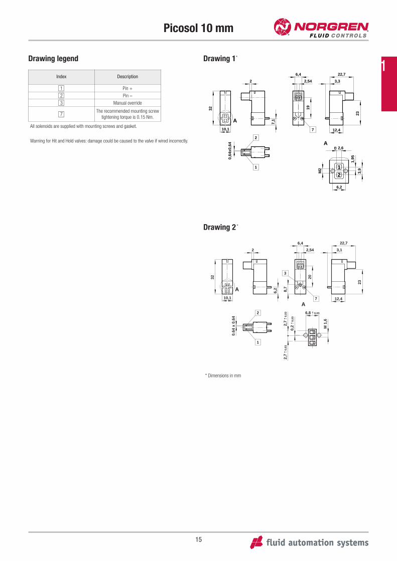
Picosol 10 mm
Drawing 1*
Drawing 2 *
32
10,1
2
7,1
12,4
22,7
3,3
23
6,4
2,54
A
A
12M
2
1,95
3,9
2,6
6,2
0,64
x0,6
4
19
1
7
2
2
6,2
32
10,1
A
12,4
22,7
3,1
23
6,4
2,54
20
8,7
0.64
x 0
.64
1
2
7
3
1
2
3
6,8 + 0,03
M 1
,6
-
2,7
+ 0,
03-
2,7
+ 0,
03-
0,2
+ 0,
03
A
-
Drawing legend
Index Description
1 Pin +
2 Pin –
3 Manual override
7The recommended mounting screw
tightening torque is 0.15 Nm.
All solenoids are supplied with mounting screws and gasket.
Warning for Hit and Hold valves: damage could be caused to the valve if wired incorrectly.
* Dimensions in mm
1
Picosol 10 mm
16
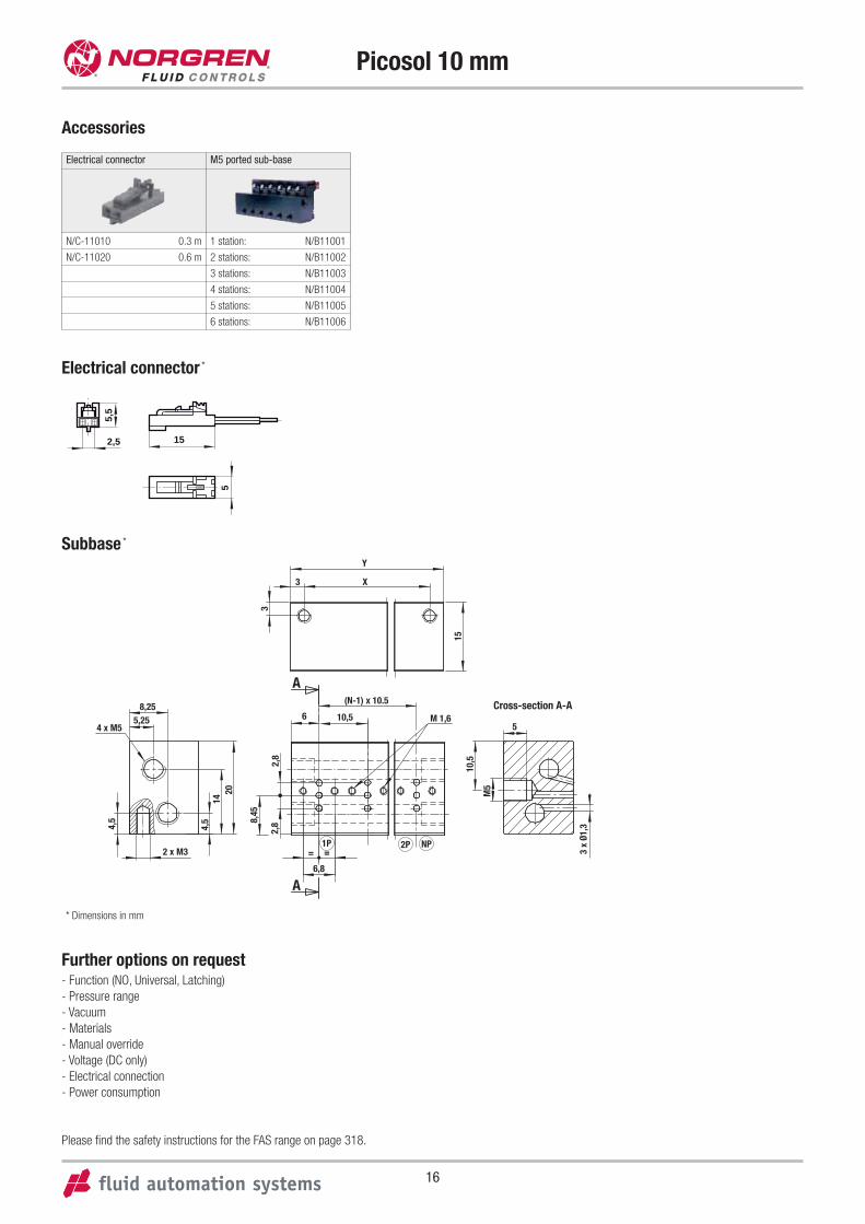
Accessories
Electrical connector *
Subbase *
15
5
5,5
2,5
Further options on request- Function (NO, Universal, Latching)
- Pressure range
- Vacuum
- Materials
- Manual override
- Voltage (DC only)
- Electrical connection
- Power consumption
Please find the safety instructions for the FAS range on page 318.
Y
X3
3
15
2014
4,5
4,5
8,255,25
4 x M5
2 x M3
8,45
2,8
2,8
6 10,5 M 1,6
(N-1) x 10.5
A
A6,8
==2P1P NP
5
10,5
M5
3 x
Ø1,3
Cross-section A-A
Electrical connector M5 ported sub-base
N/C-11010 0.3 m 1 station: N/B11001
N/C-11020 0.6 m 2 stations: N/B11002
3 stations: N/B11003
4 stations: N/B11004
5 stations: N/B11005
6 stations: N/B11006
* Dimensions in mm
17
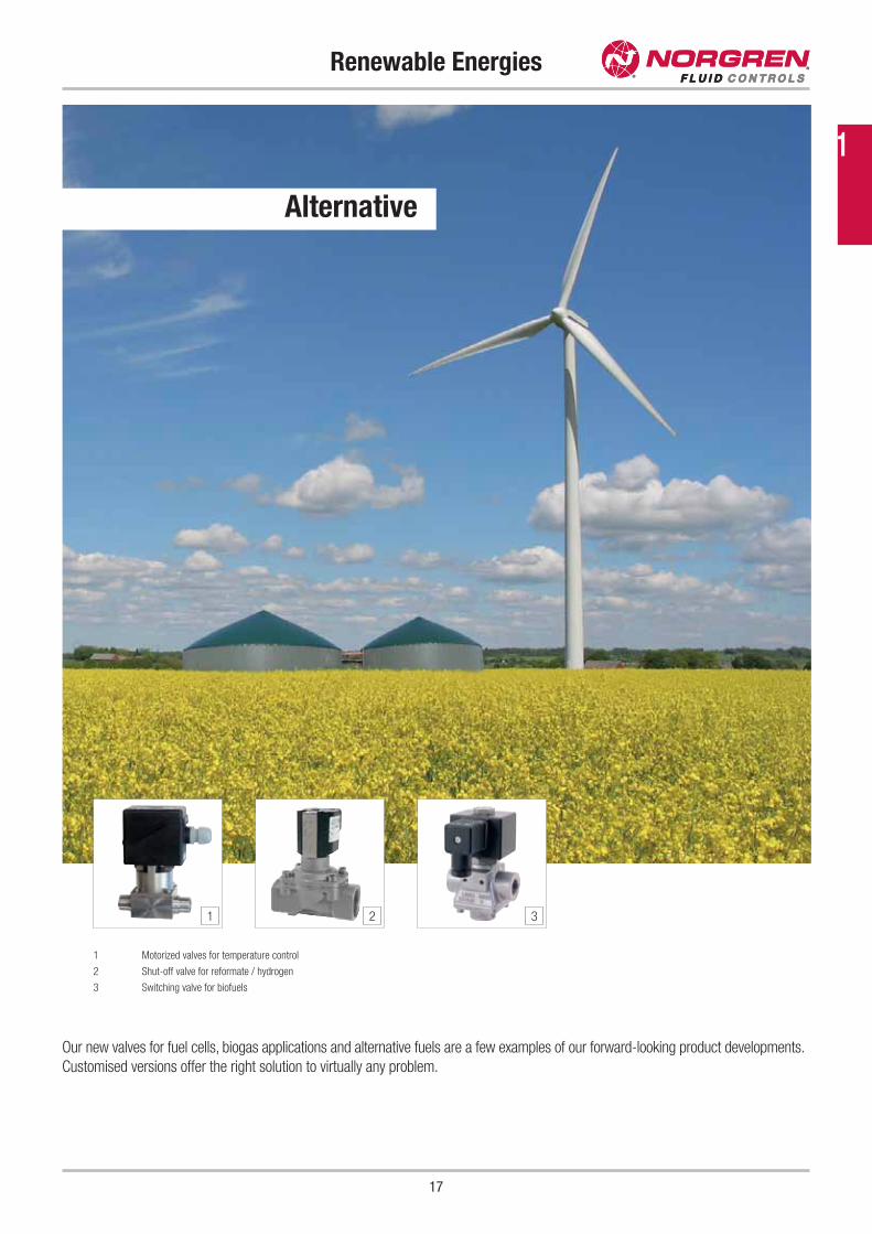
Renewable Energies
Our new valves for fuel cells, biogas applications and alternative fuels are a few examples of our forward-looking product developments.
Customised versions offer the right solution to virtually any problem.
1 Motorized valves for temperature control
2 Shut-off valve for reformate / hydrogen
3 Switching valve for biofuels
1 2 3
Alternative
1
18
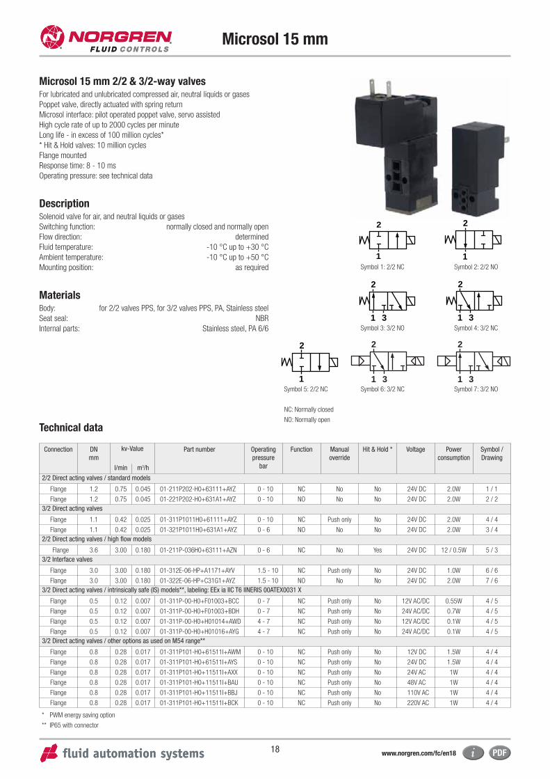
Microsol 15 mm
Microsol 15 mm 2/2 & 3/2-way valvesFor lubricated and unlubricated compressed air, neutral liquids or gases
Poppet valve, directly actuated with spring return
Microsol interface: pilot operated poppet valve, servo assisted
High cycle rate of up to 2000 cycles per minute
Long life - in excess of 100 million cycles*
* Hit & Hold valves: 10 million cycles
Flange mounted
Response time: 8 - 10 ms
Operating pressure: see technical data
DescriptionSolenoid valve for air, and neutral liquids or gases
Switching function: normally closed and normally open
Flow direction: determined
Fluid temperature: -10 °C up to +30 °C
Ambient temperature: -10 °C up to +50 °C
Mounting position: as required
MaterialsBody: for 2/2 valves PPS, for 3/2 valves PPS, PA, Stainless steel
Seat seal: NBR
Internal parts: Stainless steel, PA 6/6
Technical data
Connection DN
mm
kv-Value Part number Operating
pressure
bar
Function Manual
override
Hit & Hold * Voltage Power
consumption
Symbol /
Drawing
l/min m3/h
2/2 Direct acting valves / standard models
Flange 1.2 0.75 0.045 01-211P202-H0+63111+AYZ 0 - 10 NC No No 24V DC 2.0W 1 / 1
Flange 1.2 0.75 0.045 01-221P202-H0+631A1+AYZ 0 - 10 NO No No 24V DC 2.0W 2 / 2
3/2 Direct acting valves
Flange 1.1 0.42 0.025 01-311P1011H0+61111+AYZ 0 - 10 NC Push only No 24V DC 2.0W 4 / 4
Flange 1.1 0.42 0.025 01-321P1011H0+631A1+AYZ 0 - 6 NO No No 24V DC 2.0W 3 / 4
2/2 Direct acting valves / high flow models
Flange 3.6 3.00 0.180 01-211P-036H0+63111+AZN 0 - 6 NC No Yes 24V DC 12 / 0.5W 5 / 3
3/2 Interface valves
Flange 3.0 3.00 0.180 01-312E-06-HP+A1171+AYV 1.5 - 10 NC Push only No 24V DC 1.0W 6 / 6
Flange 3.0 3.00 0.180 01-322E-06-HP+C31G1+AYZ 1.5 - 10 NO No No 24V DC 2.0W 7 / 6
3/2 Direct acting valves / intrinsically safe (IS) models**, labeling: EEx ia IIC T6 IINERIS 00ATEX0031 X
Flange 0.5 0.12 0.007 01-311P-00-H0+F01003+BCC 0 - 7 NC Push only No 12V AC/DC 0.55W 4 / 5
Flange 0.5 0.12 0.007 01-311P-00-H0+F01003+BDH 0 - 7 NC Push only No 24V AC/DC 0.7W 4 / 5
Flange 0.5 0.12 0.007 01-311P-00-H0+H01014+AWD 4 - 7 NC Push only No 12V AC/DC 0.1W 4 / 5
Flange 0.5 0.12 0.007 01-311P-00-H0+H01016+AYG 4 - 7 NC Push only No 24V AC/DC 0.1W 4 / 5
3/2 Direct acting valves / other options as used on M54 range**
Flange 0.8 0.28 0.017 01-311P101-H0+61511I+AWM 0 - 10 NC Push only No 12V DC 1.5W 4 / 4
Flange 0.8 0.28 0.017 01-311P101-H0+61511I+AYS 0 - 10 NC Push only No 24V DC 1.5W 4 / 4
Flange 0.8 0.28 0.017 01-311P101-H0+11511I+AXX 0 - 10 NC Push only No 24V AC 1W 4 / 4
Flange 0.8 0.28 0.017 01-311P101-H0+11511I+BAU 0 - 10 NC Push only No 48V AC 1W 4 / 4
Flange 0.8 0.28 0.017 01-311P101-H0+11511I+BBJ 0 - 10 NC Push only No 110V AC 1W 4 / 4
Flange 0.8 0.28 0.017 01-311P101-H0+11511I+BCK 0 - 10 NC Push only No 220V AC 1W 4 / 4
2
1
2
1
2
1 3
2
1 3
2
1
Symbol 1: 2/2 NC Symbol 2: 2/2 NO
Symbol 4: 3/2 NCSymbol 3: 3/2 NO
Symbol 5: 2/2 NC
2
1 3Symbol 6: 3/2 NC
2
1 3Symbol 7: 3/2 NO
NC: Normally closed
NO: Normally open
* PWM energy saving option
** IP65 with connector
www.norgren.com/fc/en18
19
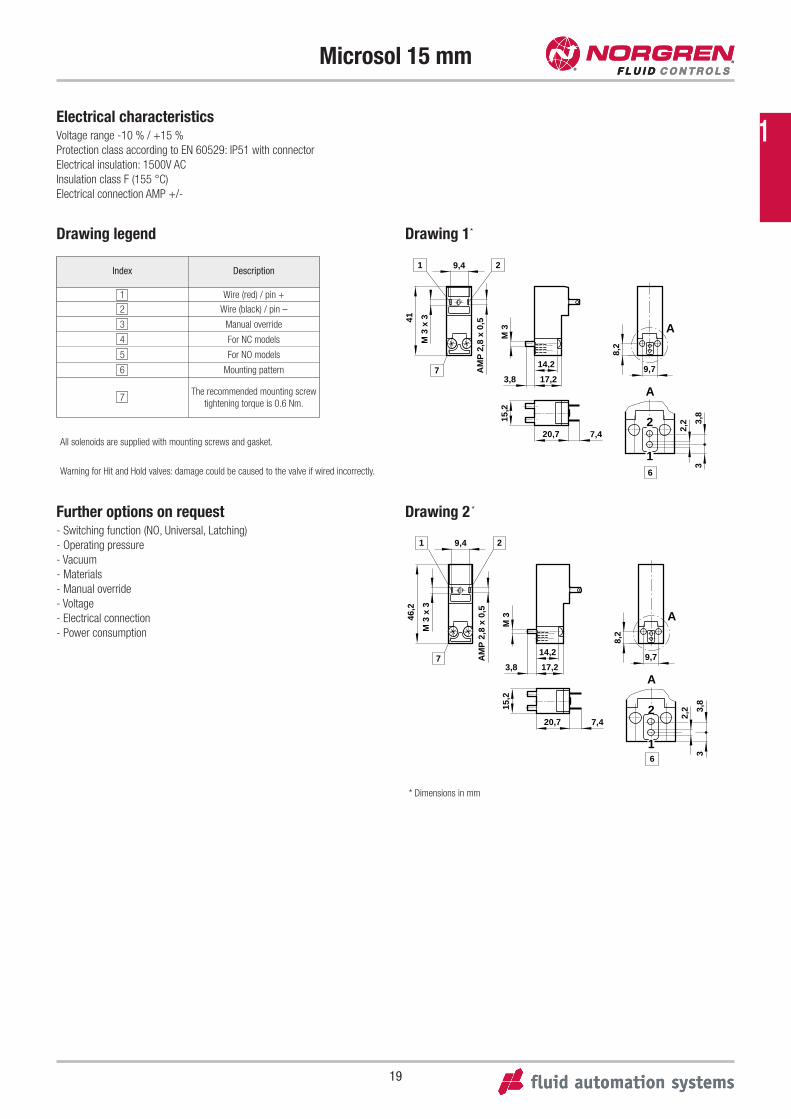
Microsol 15 mm
Drawing 1*
Drawing 2 *
41
AM
P 2
,8 x
0,5
14,2
17,2
15,2
20,7
9,7
8,2
7,4
A
A
9,4
M 3
M 3
x 3
2,2 3,
83
2
1
1 2
7
6
3,8
46,2
AM
P 2
,8 x
0,5
14,2
17,2
15,2
20,7
9,7
8,2
7,4
A
A
9,4
M 3
M 3
x 3
2,2 3,
83
2
1
1 2
3,87
6
Drawing legend
Index Description
1 Wire (red) / pin +
2 Wire (black) / pin –
3 Manual override
4 For NC models
5 For NO models
6 Mounting pattern
7The recommended mounting screw
tightening torque is 0.6 Nm.
Further options on request- Switching function (NO, Universal, Latching)
- Operating pressure
- Vacuum
- Materials
- Manual override
- Voltage
- Electrical connection
- Power consumption
Electrical characteristicsVoltage range -10 % / +15 %
Protection class according to EN 60529: IP51 with connector
Electrical insulation: 1500V AC
Insulation class F (155 °C)
Electrical connection AMP +/-
All solenoids are supplied with mounting screws and gasket.
Warning for Hit and Hold valves: damage could be caused to the valve if wired incorrectly.
* Dimensions in mm
1
20
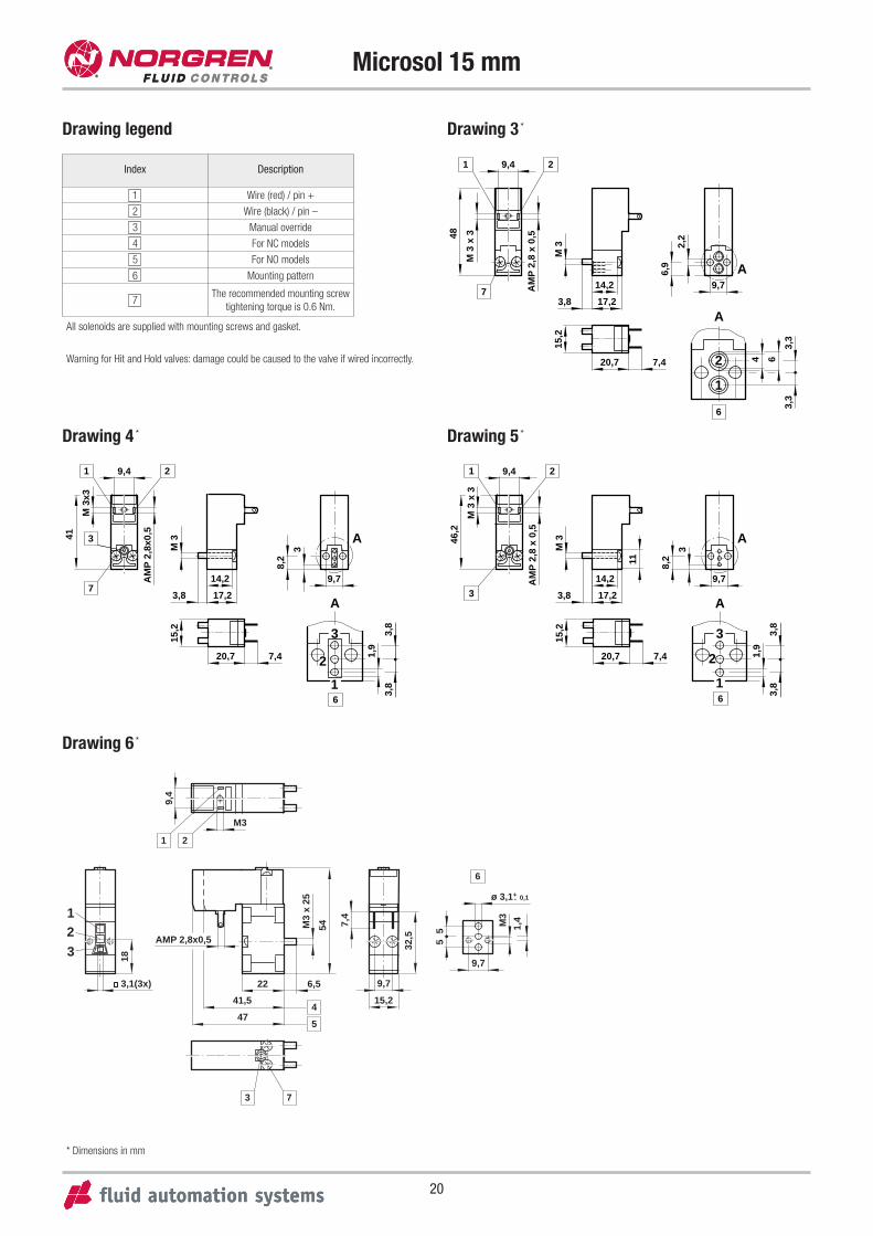
Microsol 15 mm
Drawing 4 * Drawing 5 *
41
AM
P 2
,8x0
,5
9,4
M 3
x3
9,7
8,2
3
15,2
20,7 7,4
14,2
3,8 17,2
M 3
1
3
7
2
3
A
2
1
1,9
3,8
3,8
A
6
46,2
AM
P 2
,8 x
0,5
9,4M
3 x
3
9,7
8,211
3
15,2
20,7 7,4
14,2
3,8 17,2
M 3
1
3
2
3
A
2
1
1,9
3,8
3,8
A
6
Drawing legend
* Dimensions in mm
Drawing 3 *
48
AM
P 2
,8 x
0,5
9,4
M 3
x 3
9,7
6,9
2,2
4 6
3,3
3,3
14,2
17,2
M 3
3,8
15,2
20,7 2
1
7,4
1 2
A
A
7
6
All solenoids are supplied with mounting screws and gasket.
Warning for Hit and Hold valves: damage could be caused to the valve if wired incorrectly.
Index Description
1 Wire (red) / pin +
2 Wire (black) / pin –
3 Manual override
4 For NC models
5 For NO models
6 Mounting pattern
7The recommended mounting screw
tightening torque is 0.6 Nm.
Drawing 6 *
47
41,5
22 6,5
54M3
x 25
AMP 2,8x0,5
32,5
15,2
9,7
18
3,1(3x)
55
9,7
1,4
ø 3,1+ 0,1
M3
-
7,41
23
3
6
4
5
7
M3
9,4
21
21
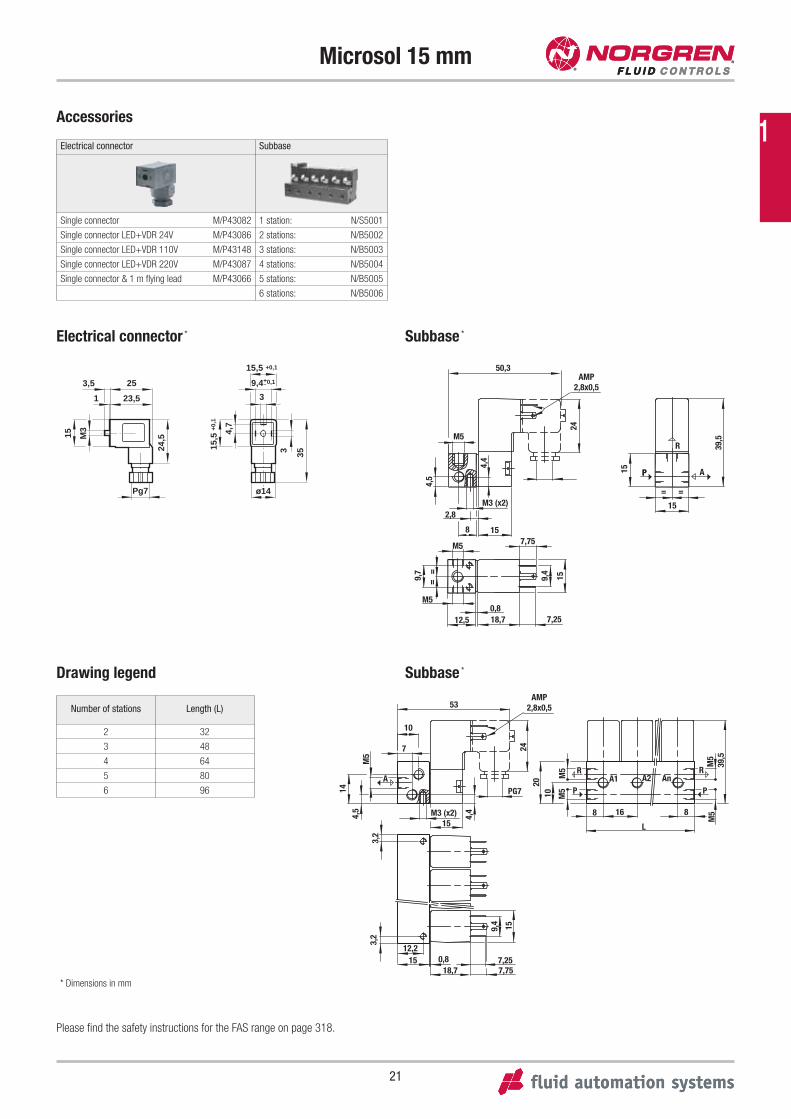
Microsol 15 mm
* Dimensions in mm
Please find the safety instructions for the FAS range on page 318.
Electrical connector Subbase
Single connector M/P43082 1 station: N/S5001
Single connector LED+VDR 24V M/P43086 2 stations: N/B5002
Single connector LED+VDR 110V M/P43148 3 stations: N/B5003
Single connector LED+VDR 220V M/P43087 4 stations: N/B5004
Single connector & 1 m flying lead M/P43066 5 stations: N/B5005
6 stations: N/B5006
15 M3
3,5
24,5
1 23,5
25
Pg7 ø14
3 35
4,7
15,5
+0,
1
15,5 +0,1
3
9,4+0,1 -
50,3
24
158
2,8M3 (x2)
4,4
4,5
M5
AMP2,8x0,5
= =
15
15
39,5
R
PP A
M5 7,759,
4
15
==9,
7
M50,8
12,5 18,7 7,25
AMP2,8x0,553
10
7
15M3 (x2) 4,
4
PG7A
M5
4,5
14
24
2010 M
5M
5 R
PA1 A2 An
R
P
M5
M5
39,5
8 16 8
L
3,2
3,2
159,4
1512,2
7,257,75
0,818,7
Subbase *
Subbase *Drawing legend
Number of stations Length (L)
2 32
3 48
4 64
5 80
6 96
Electrical connector *
Accessories
1
22
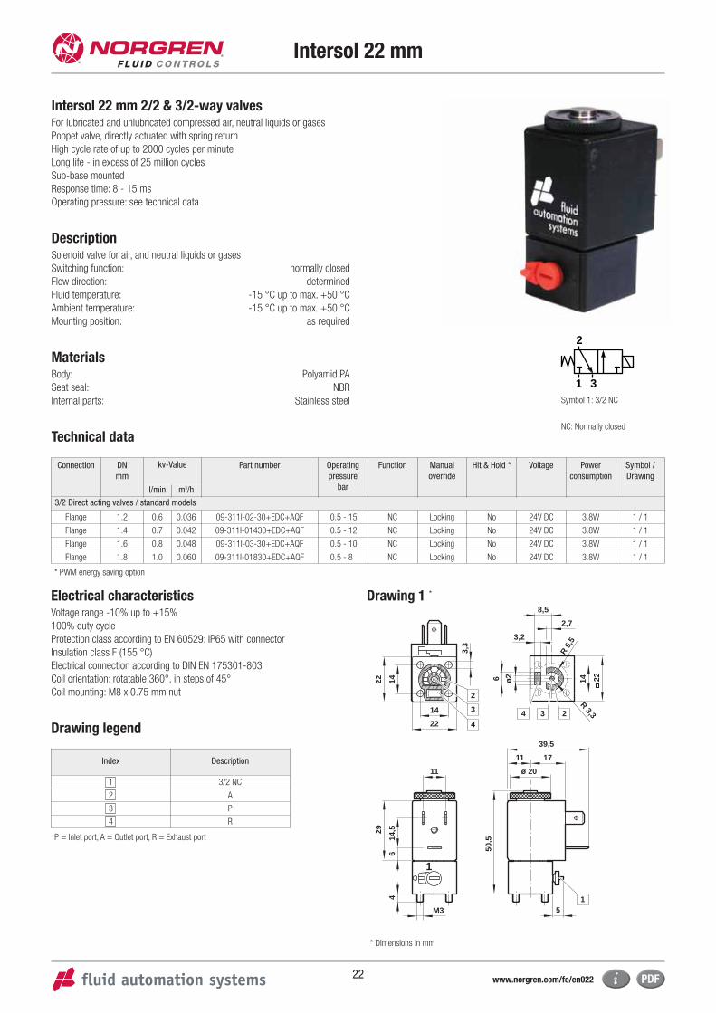
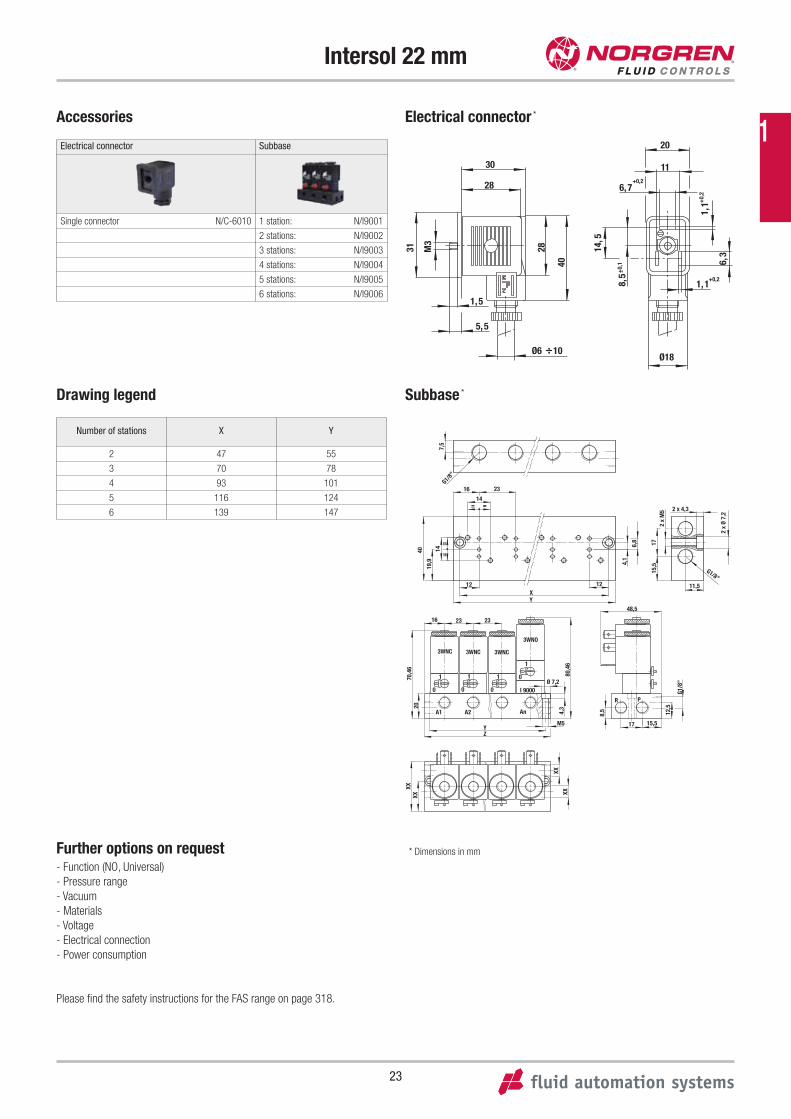
Drawing 1 *
* Dimensions in mm
Drawing legend
Index Description
1 3/2 NC
2 A
3 P
4 R
Intersol 22 mm
Intersol 22 mm 2/2 & 3/2-way valvesFor lubricated and unlubricated compressed air, neutral liquids or gases
Poppet valve, directly actuated with spring return
High cycle rate of up to 2000 cycles per minute
Long life - in excess of 25 million cycles
Sub-base mounted
Response time: 8 - 15 ms
Operating pressure: see technical data
Description Solenoid valve for air, and neutral liquids or gases
Switching function: normally closed
Flow direction: determined
Fluid temperature: -15 °C up to max. +50 °C
Ambient temperature: -15 °C up to max. +50 °C
Mounting position: as required
MaterialsBody: Polyamid PA
Seat seal: NBR
Internal parts: Stainless steel
Technical data
Symbol 1: 3/2 NC
NC: Normally closed
2
1 3
Electrical characteristicsVoltage range -10% up to +15%
100% duty cycle
Protection class according to EN 60529: IP65 with connector
Insulation class F (155 °C)
Electrical connection according to DIN EN 175301-803
Coil orientation: rotatable 360°, in steps of 45°
Coil mounting: M8 x 0.75 mm nut
Connection DN
mm
kv-Value Part number Operating
pressure
bar
Function Manual
override
Hit & Hold * Voltage Power
consumption
Symbol /
Drawing
l/min m3/h
3/2 Direct acting valves / standard models
Flange 1.2 0.6 0.036 09-311I-02-30+EDC+AQF 0.5 - 15 NC Locking No 24V DC 3.8W 1 / 1
Flange 1.4 0.7 0.042 09-311I-01430+EDC+AQF 0.5 - 12 NC Locking No 24V DC 3.8W 1 / 1
Flange 1.6 0.8 0.048 09-311I-03-30+EDC+AQF 0.5 - 10 NC Locking No 24V DC 3.8W 1 / 1
Flange 1.8 1.0 0.060 09-311I-01830+EDC+AQF 0.5 - 8 NC Locking No 24V DC 3.8W 1 / 1
* PWM energy saving option
2
24 33
1
4
14 ø26
14,5
6 50,5
29
4
3,3
11 ø 20
11 17
5
39,5
14
3,2
2,7
R 5
,5
8,5
R 3,3
22
M3
1
14
22
22
www.norgren.com/fc/en022
P = Inlet port, A = Outlet port, R = Exhaust port
23
Intersol 22 mm
Further options on request- Function (NO, Universal)
- Pressure range
- Vacuum
- Materials
- Voltage
- Electrical connection
- Power consumption
Please find the safety instructions for the FAS range on page 318.
31
8,5
1,1
6,328
40
M3
30
28
1,5
5,5
Ø6
1,1
6,7
11
20
10
14,5
+0,2
+0,
2
+0,2
+0,
1
Ø18
7,5
G1/8”
40
19,9
14=
=
4,1
6,8 17
15,5
2 x
M5
2 x
Ø 7,
2
G1/8
”
12,5
8,5
80,4
64,
3
70,4
620
XXXX
XX
XX
16 23
14==
12 12XY
48,5
17 15,5M5YZ
232316
11,5
2 x 4,3
G1/8”
Ø 7,2
A1 A2 An
1
0
1
0
1
0
1
0
3WNC 3WNC 3WNC
3WNO
I 9000
R P
Electrical connector *
Subbase *
* Dimensions in mm
Electrical connector Subbase
Single connector N/C-6010 1 station: N/I9001
2 stations: N/I9002
3 stations: N/I9003
4 stations: N/I9004
5 stations: N/I9005
6 stations: N/I9006
Drawing legend
Number of stations X Y
2 47 55
3 70 78
4 93 101
5 116 124
6 139 147
Accessories
1
24
Bacosol 32 mm
Bacosol 32 mm 2/2 & 3/2-way valvesFor lubricated and unlubricated compressed air, neutral liquids or gases
Poppet valve, directly actuated with spring return
High cycle rate of up to 1200 cycles per minute
Sub-base mounted
Response time: 15 ms
Operating pressure: see technical data
Description Solenoid valve for air, and neutral liquids or gases
Switching function: normally closed
Flow direction: determined
Fluid temperature: -10 °C up to max. +80 °C
Ambient temperature: -10 °C up to max. +50 °C
Mounting position: as required
MaterialsBody: Brass
Seat seal: NBR
Internal parts: Stainless steel
Technical data
Symbol 1: 3/2 NC
NC: Normally closed
2
1 3
* PWM energy saving option
Electrical characteristicsVoltage range -10 up to +15%
100% duty cycle
Protection class according to EN 60529: IP65 with connector
Insulation class H (180 °C)
Electrical connection according to DIN 43650A
Coil orientation: rotatable 360°
Coil mounting: with G 1/4 nut
Connection
size
G
DN
mm
kv-Value Part number Operating
pressure
bar
Function Manual
override
Hit & Hold * Voltage Power
consumption
Symbol /
Drawing
l/min m3/h
3/2 Direct acting valves G 1/8
1/8 0.8 0.4 0.024 04-311-101-20+EDC+ACC 0 - 23 NC No No 24V DC 10W 1 / 1
1/8 1.2 0.8 0.048 04-311-102-20+EDC+ACC 0 - 17 NC No No 24V DC 10W 1 / 1
1/8 1.6 1.4 0.084 04-311-103-20+EDC+ACC 0 - 14 NC No No 24V DC 10W 1 / 1
1/8 2.0 2.2 0.132 04-311-104-20+EDC+ACC 0 - 10 NC No No 24V DC 10W 1 / 1
1/8 2.4 2.8 0.168 04-311-105-20+EDC+ACC 0 - 8 NC No No 24V DC 10W 1 / 1
1/8 3.0 4.0 0.240 04-311-106-20+EDC+ACC 0 - 5.5 NC No No 24V DC 10W 1 / 1
3/2 Direct acting valves G 1/4
1/4 0.8 0.4 0.024 04-311-201-20+EDC+ACC 0 - 23 NC No No 24V DC 10W 1 / 1
1/4 1.2 0.8 0.048 04-311-202-20+EDC+ACC 0 - 17 NC No No 24V DC 10W 1 / 1
1/4 1.6 1.4 0.084 04-311-203-20+EDC+ACC 0 - 14 NC No No 24V DC 10W 1 / 1
1/4 2.0 2.2 0.132 04-311-204-20+EDC+ACC 0 - 10 NC No No 24V DC 10W 1 / 1
1/4 2.4 2.8 0.168 04-311-205-20+EDC+ACC 0 - 8 NC No No 24V DC 10W 1 / 1
1/4 3.0 4.0 0.240 04-311-206-20+EDC+ACC 0 - 5.5 NC No No 24V DC 10W 1 / 1
www.norgren.com/fc/en024
25
Bacosol 32 mm
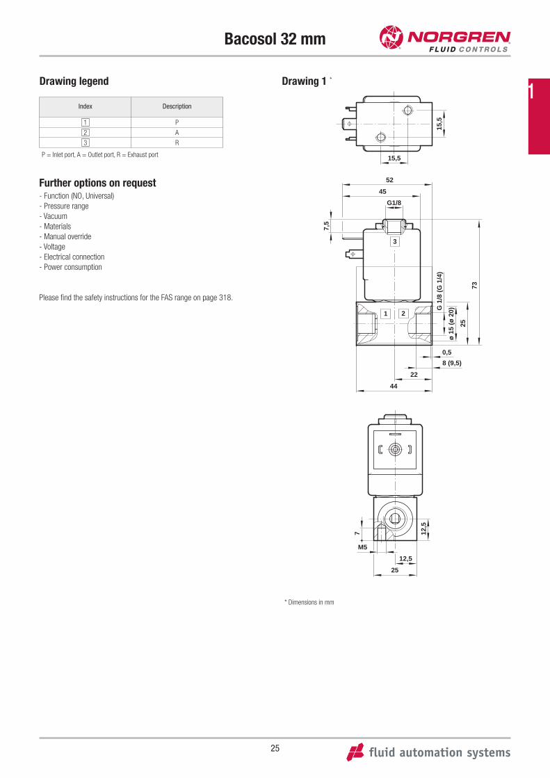
Drawing 1 *
15,5
45
25
22
G1/8
8 (9,5)
7,5
G 1
/8 (
G 1
/4)
ø 1
5 (ø
20)
73
15,5
52
44
0,5
1 2
3
Further options on request- Function (NO, Universal)
- Pressure range
- Vacuum
- Materials
- Manual override
- Voltage
- Electrical connection
- Power consumption
Please find the safety instructions for the FAS range on page 318.
* Dimensions in mm
12,5
12,5
7
M5
25
Drawing legend
Index Description
1 P
2 A
3 R
P = Inlet port, A = Outlet port, R = Exhaust port
1
26
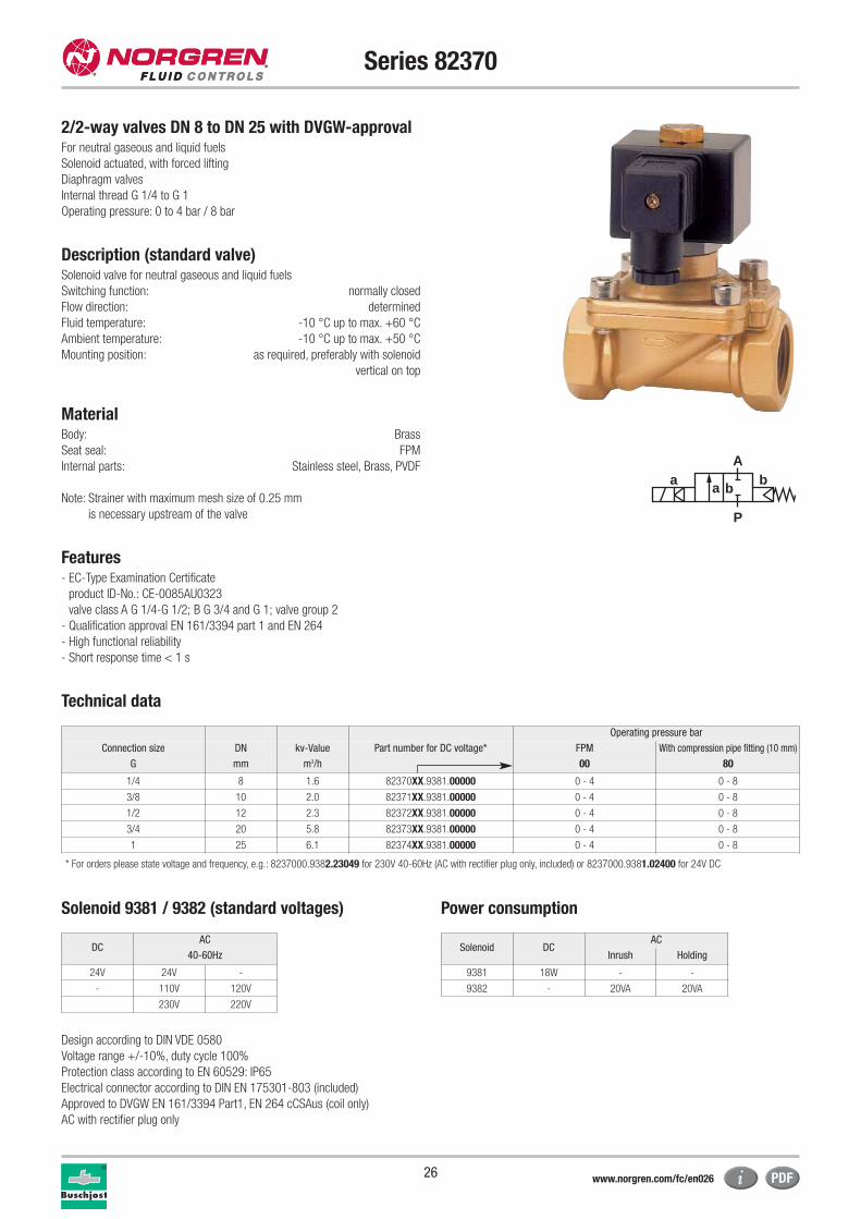
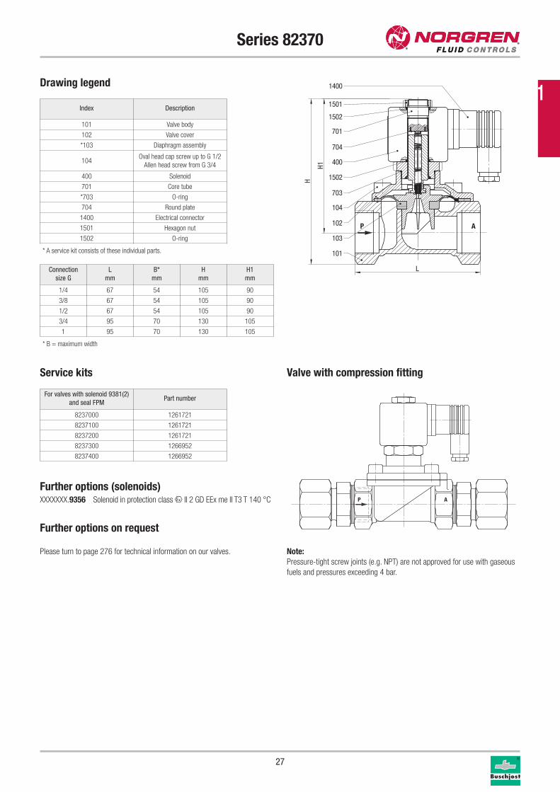
Series 82370
For neutral gaseous and liquid fuels
Solenoid actuated, with forced lifting
Diaphragm valves
Internal thread G 1/4 to G 1
Operating pressure: 0 to 4 bar / 8 bar
Description (standard valve)Solenoid valve for neutral gaseous and liquid fuels
Switching function: normally closed
Flow direction: determined
Fluid temperature: -10 °C up to max. +60 °C
Ambient temperature: -10 °C up to max. +50 °C
Mounting position: as required, preferably with solenoid
vertical on top
MaterialBody: Brass
Seat seal: FPM
Internal parts: Stainless steel, Brass, PVDF
Note: Strainer with maximum mesh size of 0.25 mm
is necessary upstream of the valve
Features- EC-Type Examination Certificate
product ID-No.: CE-0085AU0323
valve class A G 1/4-G 1/2; B G 3/4 and G 1; valve group 2
- Qualification approval EN 161/3394 part 1 and EN 264
- High functional reliability
- Short response time < 1 s
Technical data
a
P
Ab
a b
Operating pressure bar
Connection size DN kv-Value Part number for DC voltage* FPM With compression pipe fitting (10 mm)
G mm m3/h 00 80
1/4 8 1.6 82370XX.9381.00000 0 - 4 0 - 8
3/8 10 2.0 82371XX.9381.00000 0 - 4 0 - 8
1/2 12 2.3 82372XX.9381.00000 0 - 4 0 - 8
3/4 20 5.8 82373XX.9381.00000 0 - 4 0 - 8
1 25 6.1 82374XX.9381.00000 0 - 4 0 - 8
* For orders please state voltage and frequency, e.g.: 8237000.9382.23049 for 230V 40-60Hz (AC with rectifier plug only, included) or 8237000.9381.02400 for 24V DC
Solenoid DCAC
Inrush Holding
9381 18W - -
9382 - 20VA 20VA
Solenoid 9381 / 9382 (standard voltages) Power consumption
Design according to DIN VDE 0580
Voltage range +/-10%, duty cycle 100%
Protection class according to EN 60529: IP65
Electrical connector according to DIN EN 175301-803 (included)
Approved to DVGW EN 161/3394 Part1, EN 264 cCSAus (coil only)
AC with rectifier plug only
2/2-way valves DN 8 to DN 25 with DVGW-approval
DCAC
40-60Hz
24V 24V -
- 110V 120V
230V 220V
www.norgren.com/fc/en026
27
Series 82370
Service kits
Drawing legend
Index Description
101 Valve body
102 Valve cover
*103 Diaphragm assembly
104Oval head cap screw up to G 1/2
Allen head screw from G 3/4
400 Solenoid
701 Core tube
*703 O-ring
704 Round plate
1400 Electrical connector
1501 Hexagon nut
1502 O-ring
* A service kit consists of these individual parts.
For valves with solenoid 9381(2)
and seal FPMPart number
8237000 1261721
8237100 1261721
8237200 1261721
8237300 1266952
8237400 1266952
P A
400
701
704
1502
703
102
104
101
1502
1501
103
1400
H1
H
LConnection
size G
L
mm
B*
mm
H
mm
H1
mm
1/4 67 54 105 90
3/8 67 54 105 90
1/2 67 54 105 90
3/4 95 70 130 105
1 95 70 130 105
Further options (solenoids)XXXXXXX.9356 Solenoid in protection class x II 2 GD EEx me II T3 T 140 °C
Further options on request
Please turn to page 276 for technical information on our valves.
* B = maximum width
P A
Valve with compression fitting
Note:
Pressure-tight screw joints (e.g. NPT) are not approved for use with gaseous
fuels and pressures exceeding 4 bar.
1
28
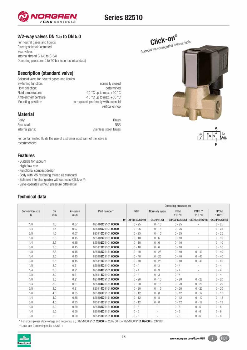
Series 82510
2/2-way valves DN 1.5 to DN 5.0For neutral gases and liquids
Directly solenoid actuated
Seat valves
Internal thread G 1/8 to G 3/8
Operating pressure: 0 to 40 bar (see technical data)
Description (standard valve)Solenoid valve for neutral gases and liquids
Switching function: normally closed
Flow direction: determined
Fluid temperature: -10 °C up to max. +90 °C
Ambient temperature: -10 °C up to max. +50 °C
Mounting position: as required, preferably with solenoid
vertical on top
MaterialBody: Brass
Seat seal: NBR
Internal parts: Stainless steel, Brass
For contaminated fluids the use of a strainer upstream of the valve is
recommended.
Features- Suitable for vacuum
- High flow rate
- Functional compact design
- Body with M5 fastening thread as standard
- Solenoid interchangeable without tools (Click-on®)
- Valve operates without pressure differential
Technical data
a
P
Ab
a b
Click-on®
Solenoid interchangeable without tools
Operating pressure bar
Connection size
G
DN
mm
kv-Value
m3/h
Part number* NBR Normally open FPM
110 °C
PTFE **
110 °C
EPDM
110 °C
00/20/40/60/80 01/21/41/61 03/23/43/63/83 06/26/46/66/86 04/24/44/64/84
1/8 1.5 0.07 825180X.9101.00000 0 - 25 0 - 16 0 - 25 - 0 - 25
1/4 1.5 0.07 825100X.9101.00000 0 - 25 0 - 16 0 - 25 - 0 - 25
3/8 1.5 0.07 825110X.9101.00000 0 - 25 0 - 16 0 - 25 - 0 - 25
1/8 2.5 0.15 825182X.9101.00000 0 - 10 0 - 6 0 - 10 - 0 - 10
1/4 2.5 0.15 825102X.9101.00000 0 - 10 0 - 6 0 - 10 - 0 - 10
3/8 2.5 0.15 825112X.9101.00000 0 - 10 0 - 6 0 - 10 - 0 - 10
1/8 2.5 0.15 825182X.9151.00000 0 - 40 0 - 25 0 - 40 0 - 40 0 - 40
1/4 2.5 0.15 825102X.9151.00000 0 - 40 0 - 25 0 - 40 0 - 40 0 - 40
3/8 2.5 0.15 825112X.9151.00000 0 - 40 0 - 25 0 - 40 0 - 40 0 - 40
1/8 3.0 0.21 825184X.9101.00000 0 - 4 0 - 3 0 - 4 - 0 - 4
1/4 3.0 0.21 825104X.9101.00000 0 - 4 0 - 3 0 - 4 - 0 - 4
3/8 3.0 0.21 825114X.9101.00000 0 - 4 0 - 3 0 - 4 - 0 - 4
1/8 3.0 0.21 825184X.9151.00000 0 - 20 0 - 16 0 - 20 0 - 20 0 - 20
1/4 3.0 0.21 825104X.9151.00000 0 - 20 0 - 16 0 - 20 0 - 20 0 - 20
3/8 3.0 0.21 825114X.9151.00000 0 - 20 0 - 16 0 - 20 0 - 20 0 - 20
1/8 4.0 0.35 825186X.9151.00000 0 - 12 0 - 8 0 - 12 0 - 12 0 - 12
1/4 4.0 0.35 825106X.9151.00000 0 - 12 0 - 8 0 - 12 0 - 12 0 - 12
3/8 4.0 0.35 825116X.9151.00000 0 - 12 0 - 8 0 - 12 0 - 12 0 - 12
1/8 5.0 0.50 825188X.9151.00000 0 - 6 - 0 - 6 0 - 6 0 - 6
1/4 5.0 0.50 825108X.9151.00000 0 - 6 - 0 - 6 0 - 6 0 - 6
3/8 5.0 0.50 825118X.9151.00000 0 - 6 - 0 - 6 0 - 6 0 - 6
* For orders please state voltage and frequency, e.g.: 8251000.9101.23050 for 230V 50Hz or 8251000.9101.02400 for 24V DC
** Leak rate E according to EN 12266-1
www.norgren.com/fc/en028
29
Series 82510
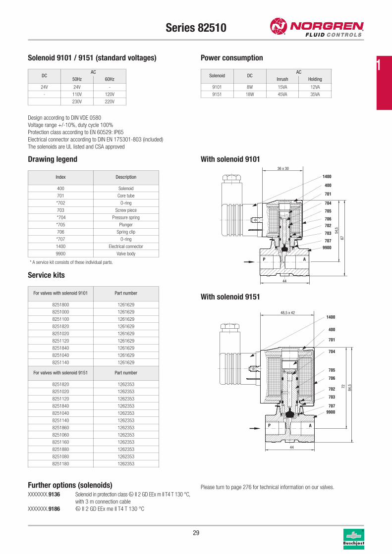
Service kits
Drawing legend
Index Description
400 Solenoid
701 Core tube
*702 O-ring
703 Screw piece
*704 Pressure spring
*705 Plunger
706 Spring clip
*707 O-ring
1400 Electrical connector
9900 Valve body
* A service kit consists of these individual parts.
For valves with solenoid 9101 Part number
8251800 1261629
8251000 1261629
8251100 1261629
8251820 1261629
8251020 1261629
8251120 1261629
8251840 1261629
8251040 1261629
8251140 1261629
For valves with solenoid 9151 Part number
8251820 1262353
8251020 1262353
8251120 1262353
8251840 1262353
8251040 1262353
8251140 1262353
8251860 1262353
8251060 1262353
8251160 1262353
8251880 1262353
8251080 1262353
8251180 1262353
P A
707
9900
1400
400
701
704
705
706702
703 54,5
67
36 x 30
44
Solenoid DCAC
Inrush Holding
9101 8W 15VA 12VA
9151 18W 45VA 35VA
DCAC
50Hz 60Hz
24V 24V -
- 110V 120V
230V 220V
Solenoid 9101 / 9151 (standard voltages) Power consumption
Design according to DIN VDE 0580
Voltage range +/-10%, duty cycle 100%
Protection class according to EN 60529: IP65
Electrical connector according to DIN EN 175301-803 (included)
The solenoids are UL listed and CSA approved
AP
1400
400
701
704
705
706
702
703
7079900
72
84,5
48,5 x 42
44
With solenoid 9101
With solenoid 9151
Further options (solenoids)XXXXXXX.9136 Solenoid in protection class x II 2 GD EEx m II T4 T 130 °C,
with 3 m connection cable
XXXXXXX.9186 x II 2 GD EEx me II T4 T 130 °C
Please turn to page 276 for technical information on our valves.
1
30
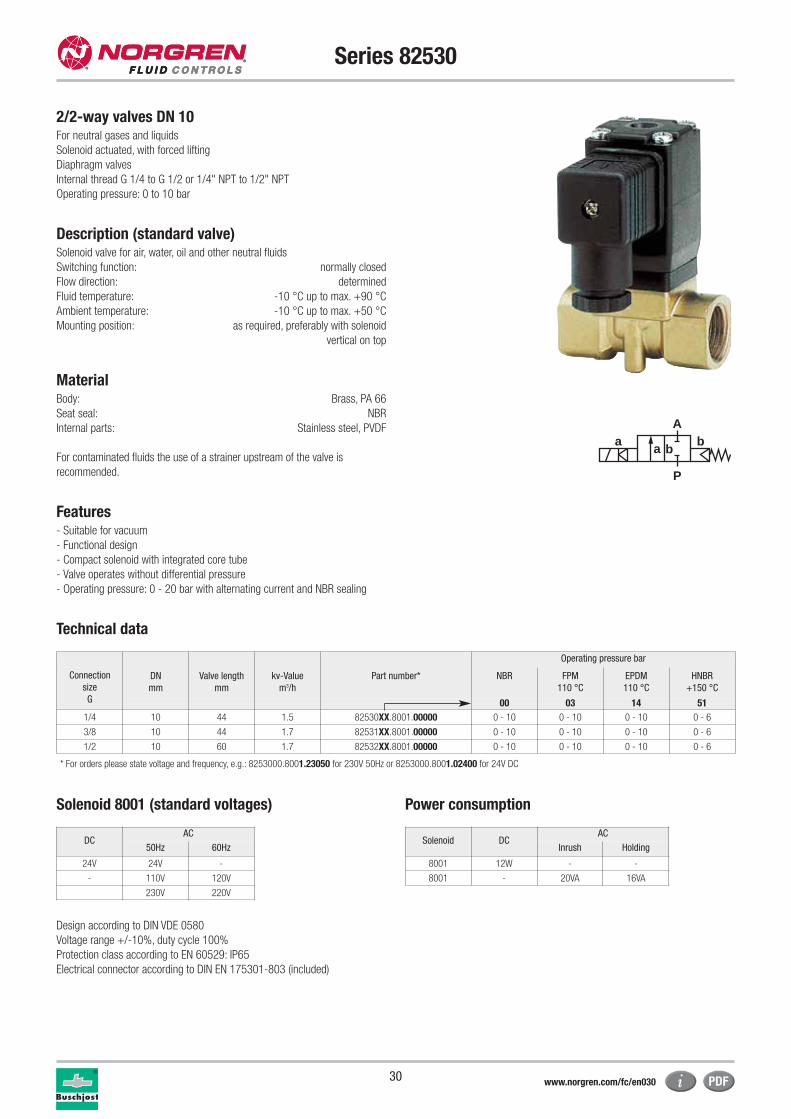
Series 82530
2/2-way valves DN 10For neutral gases and liquids
Solenoid actuated, with forced lifting
Diaphragm valves
Internal thread G 1/4 to G 1/2 or 1/4" NPT to 1/2" NPT
Operating pressure: 0 to 10 bar
Description (standard valve)Solenoid valve for air, water, oil and other neutral fluids
Switching function: normally closed
Flow direction: determined
Fluid temperature: -10 °C up to max. +90 °C
Ambient temperature: -10 °C up to max. +50 °C
Mounting position: as required, preferably with solenoid
vertical on top
MaterialBody: Brass, PA 66
Seat seal: NBR
Internal parts: Stainless steel, PVDF
For contaminated fluids the use of a strainer upstream of the valve is
recommended.
Features- Suitable for vacuum
- Functional design
- Compact solenoid with integrated core tube
- Valve operates without differential pressure
- Operating pressure: 0 - 20 bar with alternating current and NBR sealing
Technical data
a
P
Ab
a b
Operating pressure bar
Connection
size
G
DN
mm
Valve length
mm
kv-Value
m3/h
Part number* NBR FPM
110 °C
EPDM
110 °C
HNBR
+150 °C
00 03 14 51
1/4 10 44 1.5 82530XX.8001.00000 0 - 10 0 - 10 0 - 10 0 - 6
3/8 10 44 1.7 82531XX.8001.00000 0 - 10 0 - 10 0 - 10 0 - 6
1/2 10 60 1.7 82532XX.8001.00000 0 - 10 0 - 10 0 - 10 0 - 6
* For orders please state voltage and frequency, e.g.: 8253000.8001.23050 for 230V 50Hz or 8253000.8001.02400 for 24V DC
Solenoid DCAC
Inrush Holding
8001 12W - -
8001 - 20VA 16VA
DCAC
50Hz 60Hz
24V 24V -
- 110V 120V
230V 220V
Solenoid 8001 (standard voltages) Power consumption
Design according to DIN VDE 0580
Voltage range +/-10%, duty cycle 100%
Protection class according to EN 60529: IP65
Electrical connector according to DIN EN 175301-803 (included)
www.norgren.com/fc/en030
31
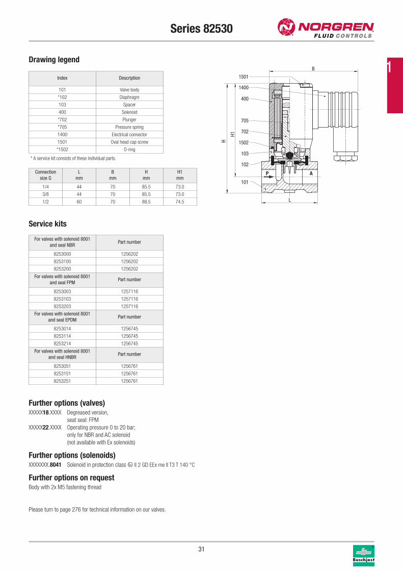
Series 82530
Service kits
Drawing legend
Index Description
101 Valve body
*102 Diaphragm
103 Spacer
400 Solenoid
*702 Plunger
*705 Pressure spring
1400 Electrical connector
1501 Oval head cap screw
*1502 O-ring
* A service kit consists of these individual parts.
For valves with solenoid 8001
and seal NBRPart number
8253000 1256202
8253100 1256202
8253200 1256202
For valves with solenoid 8001
and seal FPMPart number
8253003 1257116
8253103 1257116
8253203 1257116
For valves with solenoid 8001
and seal EPDMPart number
8253014 1256745
8253114 1256745
8253214 1256745
For valves with solenoid 8001
and seal HNBRPart number
8253051 1256761
8253151 1256761
8253251 1256761
P A
101
102
103
1502
702
705
1501
1400
400
B
H1
H
L
Connection
size G
L
mm
B
mm
H
mm
H1
mm
1/4 44 70 85.5 73.0
3/8 44 70 85.5 73.0
1/2 60 70 88.5 74.5
Further options (valves)XXXXX18.XXXX Degreased version,
seat seal: FPM
XXXXX22.XXXX Operating pressure 0 to 20 bar;
only for NBR and AC solenoid
(not available with Ex solenoids)
Further options (solenoids)XXXXXXX.8041 Solenoid in protection class x II 2 GD EEx me II T3 T 140 °C
Further options on requestBody with 2x M5 fastening thread
Please turn to page 276 for technical information on our valves.
1
32
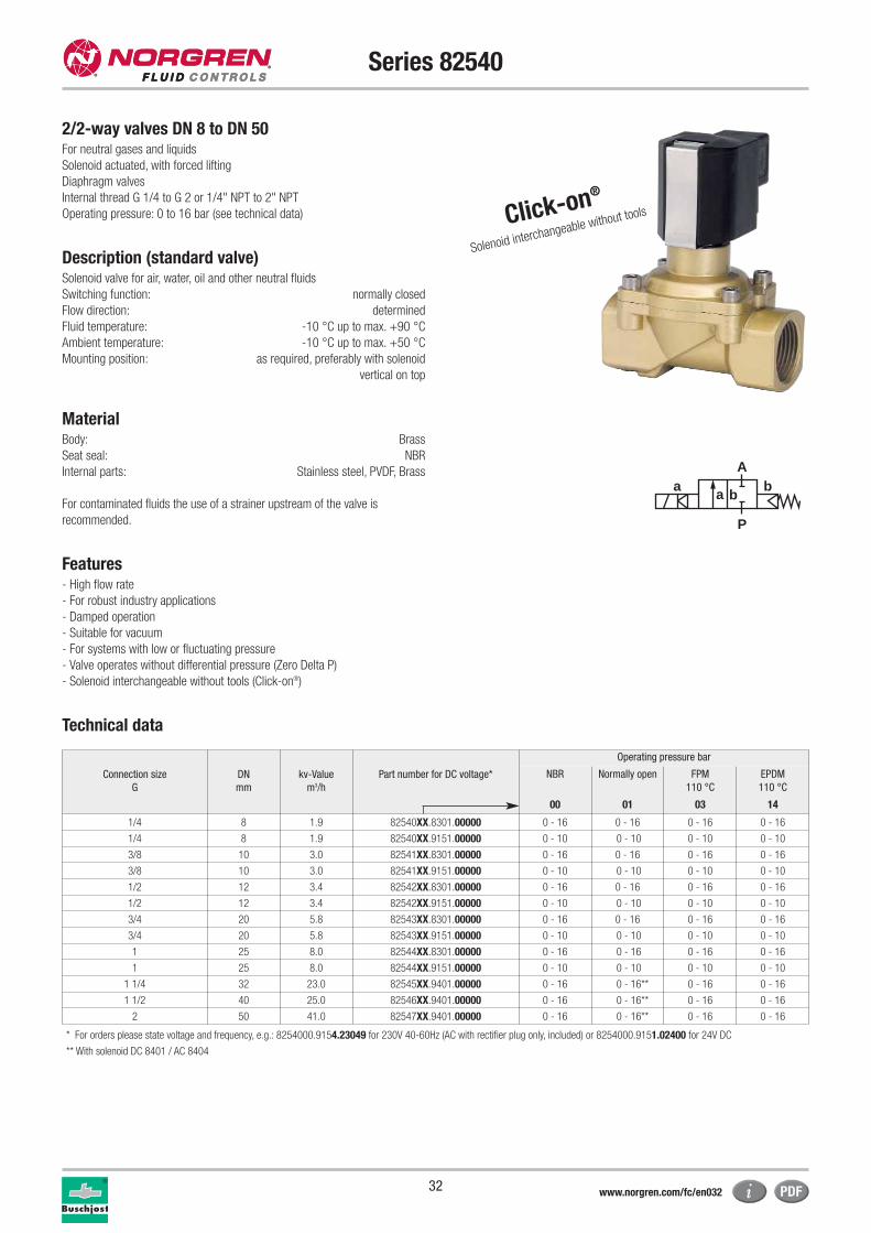
Series 82540
2/2-way valves DN 8 to DN 50For neutral gases and liquids
Solenoid actuated, with forced lifting
Diaphragm valves
Internal thread G 1/4 to G 2 or 1/4" NPT to 2" NPT
Operating pressure: 0 to 16 bar (see technical data)
Description (standard valve)Solenoid valve for air, water, oil and other neutral fluids
Switching function: normally closed
Flow direction: determined
Fluid temperature: -10 °C up to max. +90 °C
Ambient temperature: -10 °C up to max. +50 °C
Mounting position: as required, preferably with solenoid
vertical on top
MaterialBody: Brass
Seat seal: NBR
Internal parts: Stainless steel, PVDF, Brass
For contaminated fluids the use of a strainer upstream of the valve is
recommended.
Features- High flow rate
- For robust industry applications
- Damped operation
- Suitable for vacuum
- For systems with low or fluctuating pressure
- Valve operates without differential pressure (Zero Delta P)
- Solenoid interchangeable without tools (Click-on®)
Technical data
a
P
Ab
a b
Connection size
G
DN
mm
kv-Value
m3/h
Part number for DC voltage*
Operating pressure bar
NBR Normally open FPM
110 °C
EPDM
110 °C
00 01 03 14
1/4 8 1.9 82540XX.8301.00000 0 - 16 0 - 16 0 - 16 0 - 16
1/4 8 1.9 82540XX.9151.00000 0 - 10 0 - 10 0 - 10 0 - 10
3/8 10 3.0 82541XX.8301.00000 0 - 16 0 - 16 0 - 16 0 - 16
3/8 10 3.0 82541XX.9151.00000 0 - 10 0 - 10 0 - 10 0 - 10
1/2 12 3.4 82542XX.8301.00000 0 - 16 0 - 16 0 - 16 0 - 16
1/2 12 3.4 82542XX.9151.00000 0 - 10 0 - 10 0 - 10 0 - 10
3/4 20 5.8 82543XX.8301.00000 0 - 16 0 - 16 0 - 16 0 - 16
3/4 20 5.8 82543XX.9151.00000 0 - 10 0 - 10 0 - 10 0 - 10
1 25 8.0 82544XX.8301.00000 0 - 16 0 - 16 0 - 16 0 - 16
1 25 8.0 82544XX.9151.00000 0 - 10 0 - 10 0 - 10 0 - 10
1 1/4 32 23.0 82545XX.9401.00000 0 - 16 0 - 16** 0 - 16 0 - 16
1 1/2 40 25.0 82546XX.9401.00000 0 - 16 0 - 16** 0 - 16 0 - 16
2 50 41.0 82547XX.9401.00000 0 - 16 0 - 16** 0 - 16 0 - 16
** With solenoid DC 8401 / AC 8404
* For orders please state voltage and frequency, e.g.: 8254000.9154.23049 for 230V 40-60Hz (AC with rectifier plug only, included) or 8254000.9151.02400 for 24V DC
Click-on®
Solenoid interchangeable without tools
www.norgren.com/fc/en032
33
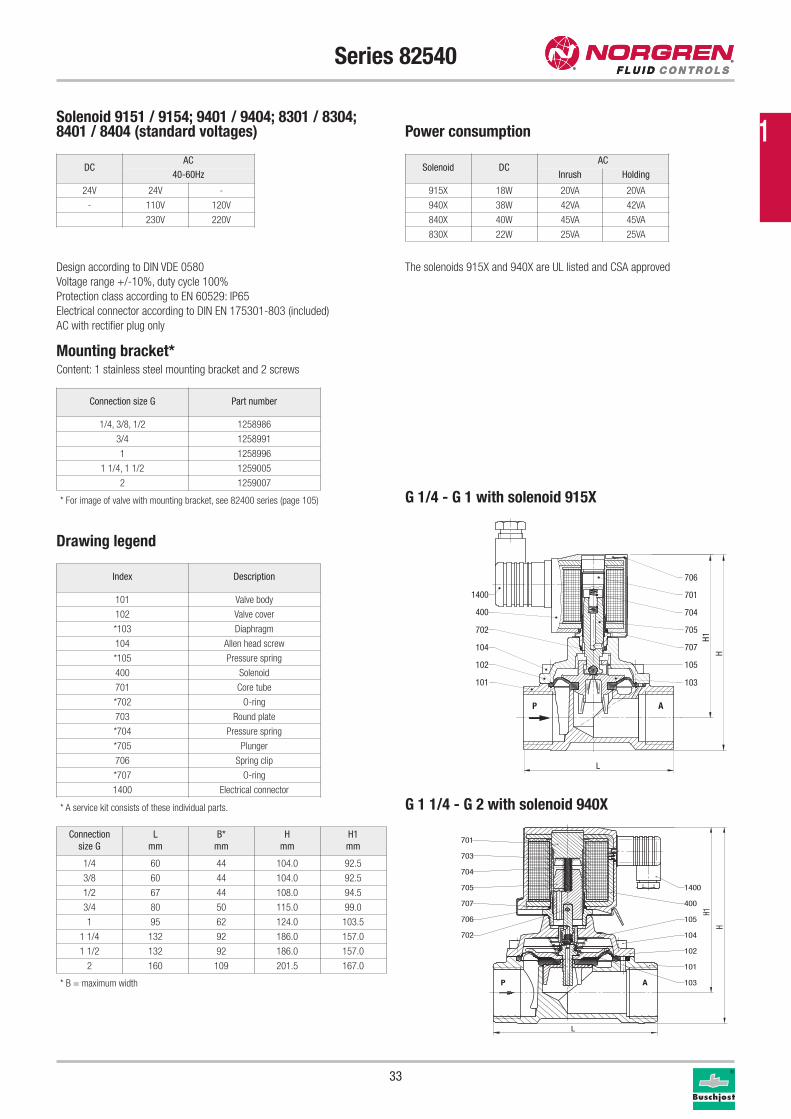
Series 82540
Connection size G Part number
1/4, 3/8, 1/2 1258986
3/4 1258991
1 1258996
1 1/4, 1 1/2 1259005
2 1259007
Mounting bracket*Content: 1 stainless steel mounting bracket and 2 screws
Drawing legend
G 1/4 - G 1 with solenoid 915X
Index Description
101 Valve body
102 Valve cover
*103 Diaphragm
104 Allen head screw
*105 Pressure spring
400 Solenoid
701 Core tube
*702 O-ring
703 Round plate
*704 Pressure spring
*705 Plunger
706 Spring clip
*707 O-ring
1400 Electrical connector
* A service kit consists of these individual parts.
706
701
704
705
707
105
103
AP
101
102
104
702
400
1400
L
H
H1
P A
101
102
103
104
105
1400
400
706
707
702
705
704
703
701
L
H1
H
Solenoid DCAC
Inrush Holding
915X 18W 20VA 20VA
940X 38W 42VA 42VA
840X 40W 45VA 45VA
830X 22W 25VA 25VA
DCAC
40-60Hz
24V 24V -
- 110V 120V
230V 220V
Solenoid 9151 / 9154; 9401 / 9404; 8301 / 8304;8401 / 8404 (standard voltages) Power consumption
Design according to DIN VDE 0580
Voltage range +/-10%, duty cycle 100%
Protection class according to EN 60529: IP65
Electrical connector according to DIN EN 175301-803 (included)
AC with rectifier plug only
The solenoids 915X and 940X are UL listed and CSA approved
Connection
size G
L
mm
B*
mm
H
mm
H1
mm
1/4 60 44 104.0 92.5
3/8 60 44 104.0 92.5
1/2 67 44 108.0 94.5
3/4 80 50 115.0 99.0
1 95 62 124.0 103.5
1 1/4 132 92 186.0 157.0
1 1/2 132 92 186.0 157.0
2 160 109 201.5 167.0
G 1 1/4 - G 2 with solenoid 940X
* For image of valve with mounting bracket, see 82400 series (page 105)
* B = maximum width
1
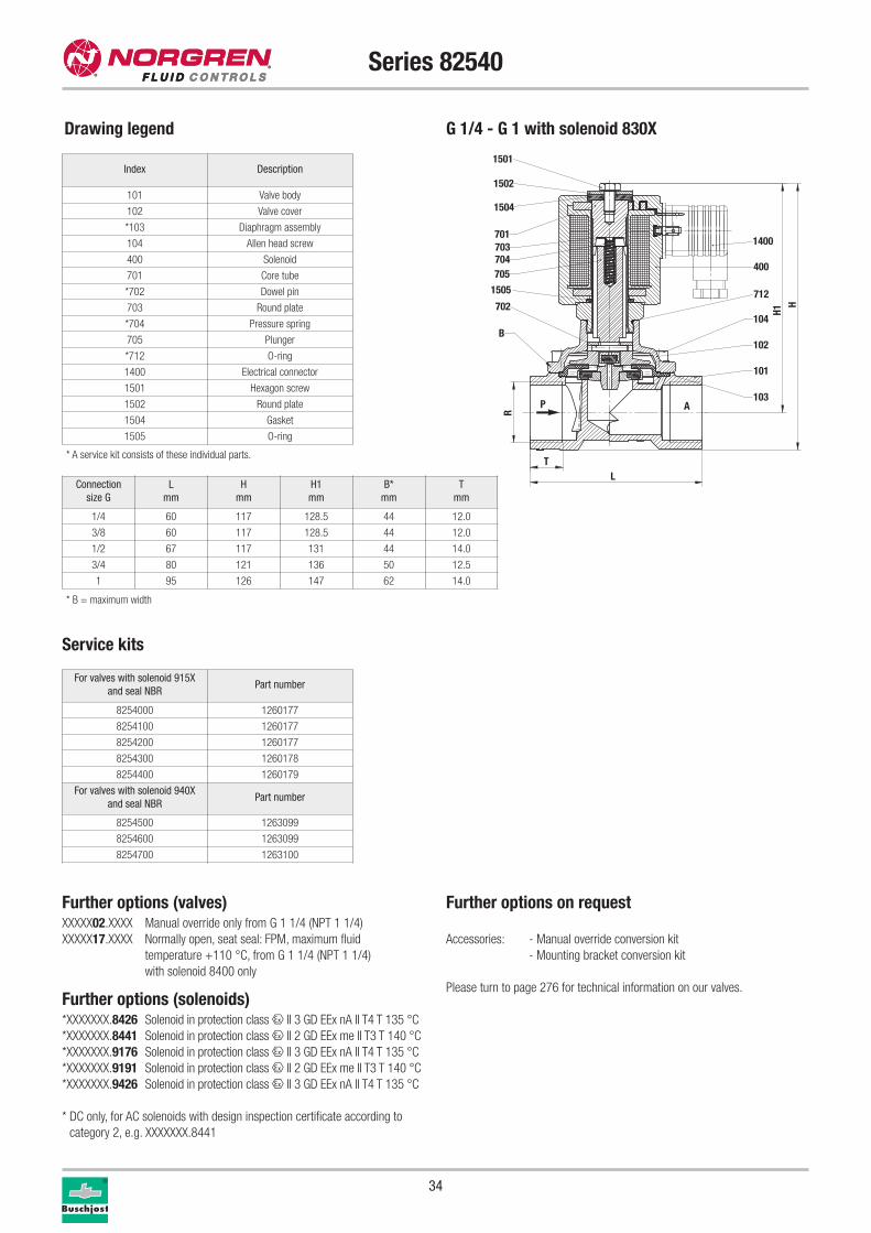
1501
1502
1504
701703704705
1505
702
400
712
104
102
101
103
1400
P A
LT
H1H
R
B
34
Series 82540
Service kits
For valves with solenoid 915X
and seal NBRPart number
8254000 1260177
8254100 1260177
8254200 1260177
8254300 1260178
8254400 1260179
For valves with solenoid 940X
and seal NBRPart number
8254500 1263099
8254600 1263099
8254700 1263100
Further options (valves)XXXXX02.XXXX Manual override only from G 1 1/4 (NPT 1 1/4)
XXXXX17.XXXX Normally open, seat seal: FPM, maximum fluid
temperature +110 °C, from G 1 1/4 (NPT 1 1/4)
with solenoid 8400 only
Further options (solenoids)*XXXXXXX.8426 Solenoid in protection class x II 3 GD EEx nA II T4 T 135 °C
*XXXXXXX.8441 Solenoid in protection class x II 2 GD EEx me II T3 T 140 °C
*XXXXXXX.9176 Solenoid in protection class x II 3 GD EEx nA II T4 T 135 °C
*XXXXXXX.9191 Solenoid in protection class x II 2 GD EEx me II T3 T 140 °C
*XXXXXXX.9426 Solenoid in protection class x II 3 GD EEx nA II T4 T 135 °C
* DC only, for AC solenoids with design inspection certificate according to
category 2, e.g. XXXXXXX.8441
Further options on request
Accessories: - Manual override conversion kit
- Mounting bracket conversion kit
Please turn to page 276 for technical information on our valves.
Drawing legend
Index Description
101 Valve body
102 Valve cover
*103 Diaphragm assembly
104 Allen head screw
400 Solenoid
701 Core tube
*702 Dowel pin
703 Round plate
*704 Pressure spring
705 Plunger
*712 O-ring
1400 Electrical connector
1501 Hexagon screw
1502 Round plate
1504 Gasket
1505 O-ring
* A service kit consists of these individual parts.
Connection
size G
L
mm
H
mm
H1
mm
B*
mm
T
mm
1/4 60 117 128.5 44 12.0
3/8 60 117 128.5 44 12.0
1/2 67 117 131 44 14.0
3/4 80 121 136 50 12.5
1 95 126 147 62 14.0
* B = maximum width
G 1/4 - G 1 with solenoid 830X
Fluid Control Solutions
35
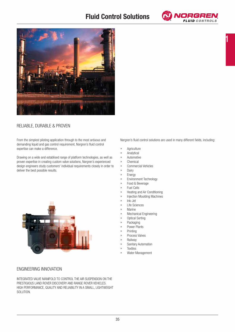
INTEGRATED VALVE MANIFOLD TO CONTROL THE AIR SUSPENSION ON THE
PRESTIGIOUS LAND ROVER DISCOVERY AND RANGE ROVER VEHICLES.
HIGH PERFORMANCE, QUALITY AND RELIABILITY IN A SMALL, LIGHTWEIGHT
SOLUTION.
Norgren’s fluid control solutions are used in many different fields, including:
» Agriculture
» Analytical
» Automotive
» Chemical
» Commercial Vehicles
» Dairy
» Energy
» Environment Technology
» Food & Beverage
» Fuel Cells
» Heating and Air Conditioning
» Injection Moulding Machines
» Ink-Jet
» Life Sciences
» Marine
» Mechanical Engineering
» Optical Sorting
» Packaging
» Power Plants
» Printing
» Process Valves
» Railway
» Sanitary Automation
» Textiles
» Water Management
From the simplest piloting application through to the most arduous and
demanding liquid and gas control requirement, Norgren’s fluid control
expertise can make a difference.
Drawing on a wide and establised range of platform technologies, as well as
proven expertise in creating custom valve solutions, Norgren’s experienced
design engineers study customers' individual requirements closely in order to
deliver the best possible results.
RELIABLE, DURABLE & PROVEN
ENGINEERING INNOVATION
1
36
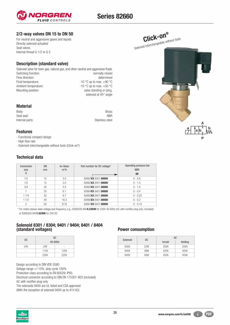
Series 82660
2/2-way valves DN 15 to DN 50For neutral and aggressive gases and liquids
Directly solenoid actuated
Seat valves
Internal thread G 1/2 to G 2
Description (standard valve)Solenoid valve for town gas, natural gas, and other neutral and aggressive fluids
Switching function: normally closed
Flow direction: determined
Fluid temperature: -10 °C up to max. +90 °C
Ambient temperature: -10 °C up to max. +50 °C
Mounting position: valve standing or lying,
solenoid at 45° angle
MaterialBody: Brass
Seat seal: NBR
Internal parts: Stainless steel
Features- Functional compact design
- High flow rate
- Solenoid interchangeable without tools (Click-on®)
Technical data
a
P
Ab
a b
Connection
size
G
DN
mm
kv-Value
m3/h
Part number for DC voltage* Operating pressure bar
NBR
00
1/2 15 3.0 82662XX.8301.00000 0 - 0.6
1/2 15 3.0 82662XX.9401.00000 0 - 1.5
3/4 20 5.5 82663XX.9401.00000 0 - 1.0
1 25 6.1 82664XX.9401.00000 0 - 0.4
1 1/4 32 8.7 82665XX.9401.00000 0 - 0.25
1 1/2 40 16.3 82666XX.8401.00000 0 - 0.2
2 50 27.6 82667XX.8401.00000 0 - 0.15
* For orders please state voltage and frequency, e.g.: 8266200.9404.23049 for 230V 40-60Hz (AC with rectifier plug only; included)
or 8266200.9401.02400 for 24V DC
Solenoid 8301 / 8304; 9401 / 9404; 8401 / 8404(standard voltages) Power consumption
Design according to DIN VDE 0580
Voltage range +/-10%, duty cycle 100%
Protection class according to EN 60529: IP65
Electrical connector according to DIN EN 175301-803 (included)
AC with rectifier plug only
The solenoids 94XX are UL listed and CSA approved
(With the exception of solenoid 94XX up to 41V AC)
Solenoid DCAC
Inrush Holding
830X 22W 25VA 25VA
940X 38W 42VA 42VA
840X 40W 45VA 45VA
DCAC
40-60Hz
24V 24V -
- 110V 120V
230V 220V
Click-on®
Solenoid interchangeable without tools
www.norgren.com/fc/en036
37
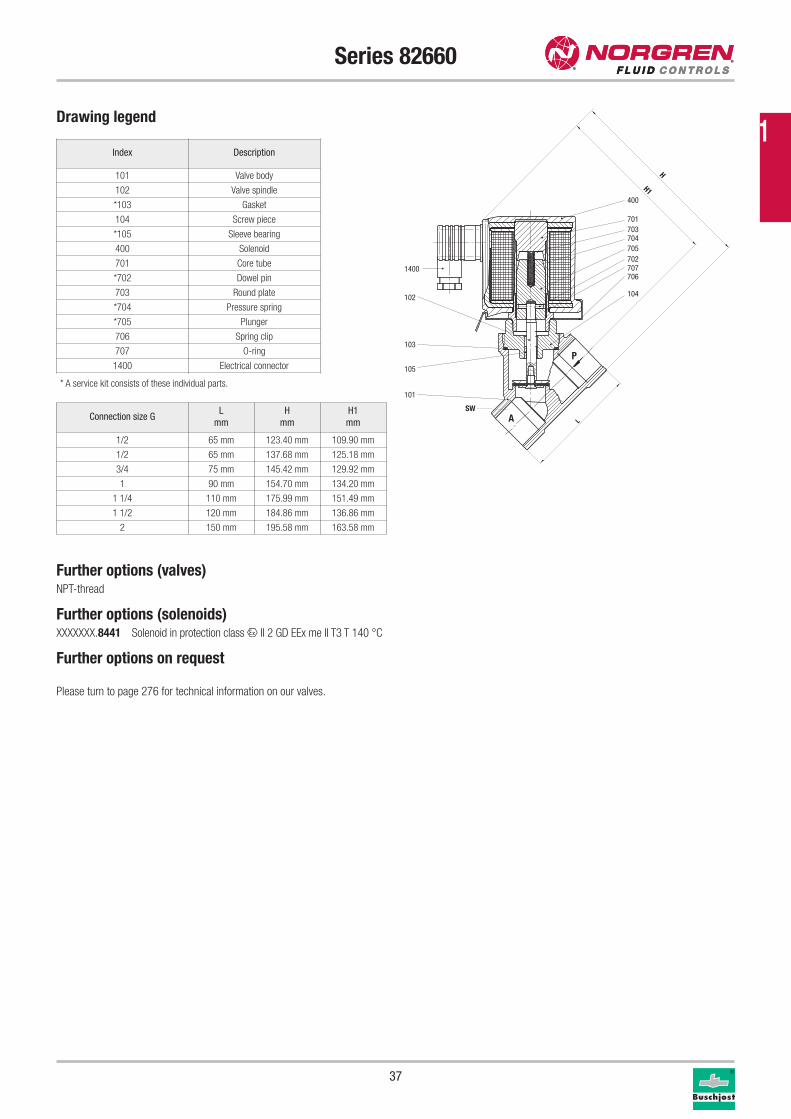
Series 82660
Drawing legend
Index Description
101 Valve body
102 Valve spindle
*103 Gasket
104 Screw piece
*105 Sleeve bearing
400 Solenoid
701 Core tube
*702 Dowel pin
703 Round plate
*704 Pressure spring
*705 Plunger
706 Spring clip
707 O-ring
1400 Electrical connector
* A service kit consists of these individual parts.
400
701703704705702707706
104
101
105
103
102
1400
A
P
H
H1
SW
L
Further options (valves)NPT-thread
Further options (solenoids)XXXXXXX.8441 Solenoid in protection class x II 2 GD EEx me II T3 T 140 °C
Further options on request
Please turn to page 276 for technical information on our valves.
Connection size GL
mm
H
mm
H1
mm
1/2 65 mm 123.40 mm 109.90 mm
1/2 65 mm 137.68 mm 125.18 mm
3/4 75 mm 145.42 mm 129.92 mm
1 90 mm 154.70 mm 134.20 mm
1 1/4 110 mm 175.99 mm 151.49 mm
1 1/2 120 mm 184.86 mm 136.86 mm
2 150 mm 195.58 mm 163.58 mm
1

38
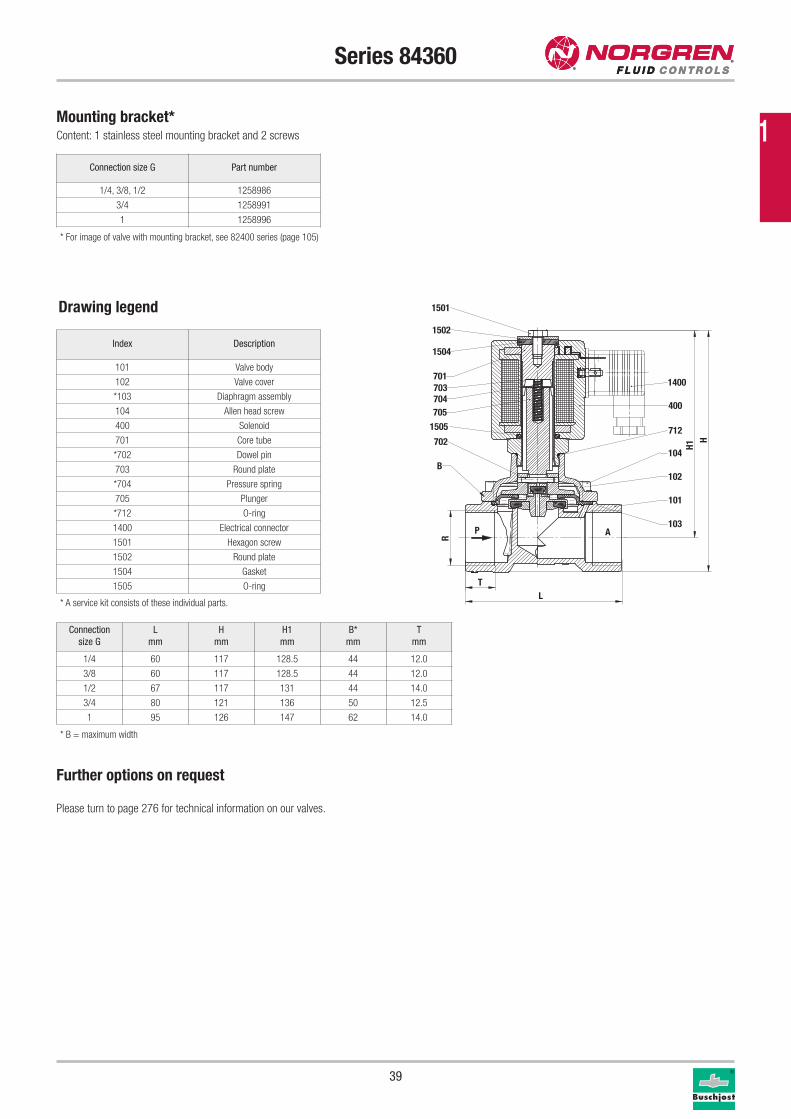
Series 84360
2/2-way valves DN 8 to DN 25For neutral steam and liquids
Solenoid actuated, with forced lifting
Diaphragm valves
Internal thread G 1/4 to G 1 or 1/4" NPT to 1" NPT
Operating pressure: 0 to 10 bar
Description (standard valve)Solenoid valve for steam, hot water, and other neutral liquids
Switching function: normally closed
Flow direction: determined
Fluid temperature: 0 °C up to max. +150 °C
Ambient temperature: 0 °C up to max. +60 °C
Mounting position: as required, preferably with solenoid
vertical on top
MaterialBody: Brass
Seat seal: HNBR
Internal parts: Brass, Stainless steel
For contaminated fluids the use of a strainer upstream of the valve is
recommended.
Features- Valve operates without differential pressure
- High flow rate
- Easily interchangeable solenoid
Technical data
a
P
Ab
a b
* For orders please state voltage and frequency, e.g.: 8436000.8306.23049 for 230V 40-60Hz (AC with rectifier plug only; included)
or 8436000.8302.02400 for 24V DC
** With gases or liquids up to 25 mm2/s (cSt)
Connection
size
G
DN
mm
kv-Value
m3/h
Part number for DC voltage* Operating pressure bar**
HNBR
00
1/4 8 1.9 84360XX.8302.00000 0 - 10
3/8 10 3.0 84361XX.8302.00000 0 - 10
1/2 12 3.8 84362XX.8302.00000 0 - 10
3/4 20 6.1 84363XX.8302.00000 0 - 10
1 25 9.5 84364XX.8302.00000 0 - 10
Solenoid 8302 / 8306 (standard voltages) Power consumption
Design according to DIN VDE 0580
Voltage range +/-10%, duty cycle 100%
Protection class according to EN 60529: IP65
Electrical connector according to DIN EN 175301-803 (included)
AC with rectifier plug only
Solenoid DCAC
Inrush Holding
8302 14W - -
8306 - 16VA 16VA
DCAC
40-60Hz
24V 24V -
- 110V 120V
230V 220V
www.norgren.com/fc/en038
39
Series 84360
Connection size G Part number
1/4, 3/8, 1/2 1258986
3/4 1258991
1 1258996
Mounting bracket*Content: 1 stainless steel mounting bracket and 2 screws
Drawing legend
Index Description
101 Valve body
102 Valve cover
*103 Diaphragm assembly
104 Allen head screw
400 Solenoid
701 Core tube
*702 Dowel pin
703 Round plate
*704 Pressure spring
705 Plunger
*712 O-ring
1400 Electrical connector
1501 Hexagon screw
1502 Round plate
1504 Gasket
1505 O-ring
* A service kit consists of these individual parts.
Connection
size G
L
mm
H
mm
H1
mm
B*
mm
T
mm
1/4 60 117 128.5 44 12.0
3/8 60 117 128.5 44 12.0
1/2 67 117 131 44 14.0
3/4 80 121 136 50 12.5
1 95 126 147 62 14.0
Further options on request
Please turn to page 276 for technical information on our valves.
1501
1502
1504
701703704705
1505
702
400
712
104
102
101
103
1400
P A
LT
H1H
R
B
* For image of valve with mounting bracket, see 82400 series (page 105)
* B = maximum width
1
40
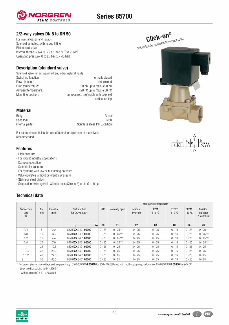
Series 85700
2/2-way valves DN 8 to DN 50For neutral gases and liquids
Solenoid actuated, with forced lifting
Piston seat valves
Internal thread G 1/4 to G 2 or 1/4" NPT to 2" NPT
Operating pressure: 0 to 25 bar (0 - 40 bar)
Description (standard valve)Solenoid valve for air, water, oil and other netural fluids
Switching function: normally closed
Flow direction: determined
Fluid temperature: -20 °C up to max. +90 °C
Ambient temperature: -20 °C up to max. +50 °C
Mounting position: as required, preferably with solenoid
vertical on top
MaterialBody: Brass
Seat seal: NBR
Internal parts: Stainless steel, PTFE/carbon
For contaminated fluids the use of a strainer upstream of the valve is
recommended.
Features- High flow rate
- For robust industry applications
- Damped operation
- Suitable for vacuum
- For systems with low or fluctuating pressure
- Valve operates without differential pressure
- Stainless steel piston
- Solenoid interchangeable without tools (Click-on®) up to G 1 thread
Technical data
Operating pressure bar
Connection
size
G
DN
mm
kv-Value
m3/h
Part number
for DC voltage*
NBR Normally open Manual
override
FPM
110 °C
PTFE**
110 °C
EPDM
110 °C
Position
indicator
2 switches
00 01 02 03 06 14 23
1/4 8 2.2 85700XX.9401.00000 0 - 25 0 - 25*** 0 - 25 0 - 25 0 - 16 0 - 25 0 - 25***
3/8 10 3.4 85701XX.9401.00000 0 - 25 0 - 25*** 0 - 25 0 - 25 0 - 16 0 - 25 0 - 25***
1/2 12 4.4 85702XX.9401.00000 0 - 25 0 - 25*** 0 - 25 0 - 25 0 - 16 0 - 25 0 - 25***
3/4 20 7.0 85703XX.9401.00000 0 - 25 0 - 25*** 0 - 25 0 - 25 0 - 16 0 - 25 0 - 25***
1 25 10.5 85704XX.9401.00000 0 - 25 0 - 25*** 0 - 25 0 - 25 0 - 16 0 - 25 0 - 25***
1 1/4 32 25.0 85705XX.8401.00000 0 - 25 0 - 25 0 - 25 0 - 25 0 - 16 0 - 25 0 - 25
1 1/2 40 27.0 85706XX.8401.00000 0 - 25 0 - 25 0 - 25 0 - 25 0 - 16 0 - 25 0 - 25
2 50 43.0 85707XX.8401.00000 0 - 25 0 - 25 0 - 25 0 - 25 0 - 16 0 - 25 0 - 25
* For orders please state voltage and frequency, e.g.: 8570200.9404.23049 for 230V 40-60Hz (AC with rectifier plug only, included) or 8570200.9401.02400 for 24V DC
** Leak rate E according to EN 12266-1
*** With solenoid DC 8401 / AC 8404
Click-on®
Solenoid interchangeable without tools
a
P
Ab
a b
www.norgren.com/fc/en040
41
Series 85700
Solenoid 9401 / 9404 / 8401 / 8404(standard voltages) Power consumption
Design according to DIN VDE 0580
Voltage range +/-10%, duty cycle 100%
Protection class according to EN 60529: IP65
Electrical connector according to DIN EN 175301-803 (included)
AC with rectifier plug only
The solenoids 94XX are UL listed and CSA approved
(With the exception of solenoid 94XX up to 41V AC)
Solenoid DCAC
Inrush Holding
9401 38W
9404 42VA 42VA
8401 40W
8404 45VA 45VA
Drawing legend
Index Description
101 Valve body
102 Valve cover
*103 Valve plate
104 Allen head screw
*105 Pressure spring
*106 Gasket
*107 O-ring
*108 Lip seal
400 Solenoid
701 Core tube
*702 Dowel pin
703 Round plate
*704 Pressure spring
*705 Plunger
706 Spring clip
*707 O-ring
1400 Electrical connector
P A
701
703
704
705
707
706
702
1400
400
103
101
108
107
106
104
105
102
H1H
LL1
T
R
ØA
* A service kit consists of these individual parts.
Connection
size G
øA
mm
H
mm
H1
mm
L
mm
L1
mm
T
mm
1/4 44.0 152.0 140.5 60.0 27.5 12.0
3/8 44.0 152.0 140.5 60.0 27.5 12.0
1/2 44.0 154.5 140.5 67.0 31.0 14.0
3/4 50.0 162.0 146.5 80.0 36.5 16.0
1 62.0 183.0 162.0 95.0 44.0 18.0
G 1/4 - G 1
DCAC
40-60Hz
24V 24V -
- 110V 120V
230V 220V
1
42
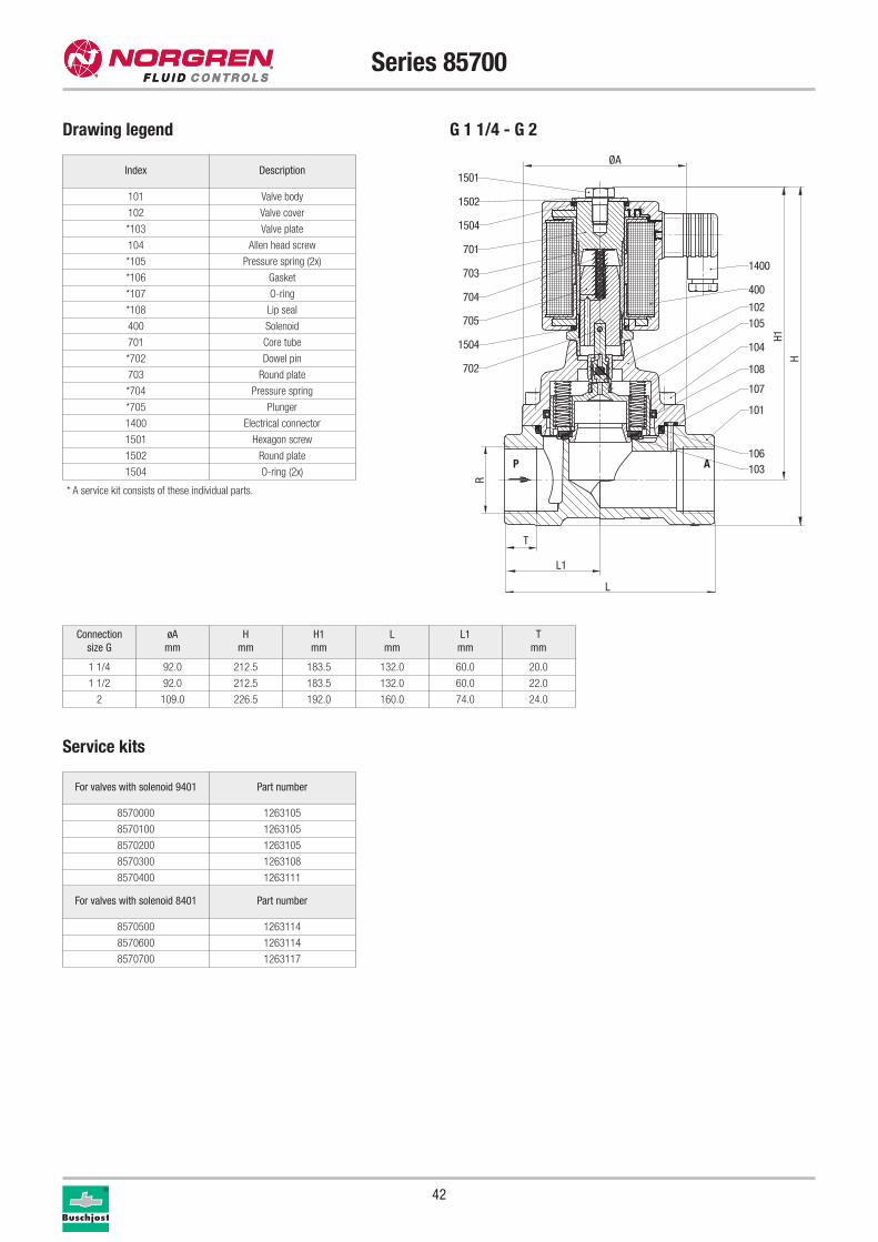
Series 85700
Connection
size G
øA
mm
H
mm
H1
mm
L
mm
L1
mm
T
mm
1 1/4 92.0 212.5 183.5 132.0 60.0 20.0
1 1/2 92.0 212.5 183.5 132.0 60.0 22.0
2 109.0 226.5 192.0 160.0 74.0 24.0
Service kits
For valves with solenoid 9401 Part number
8570000 1263105
8570100 1263105
8570200 1263105
8570300 1263108
8570400 1263111
For valves with solenoid 8401 Part number
8570500 1263114
8570600 1263114
8570700 1263117
Index Description
101 Valve body
102 Valve cover
*103 Valve plate
104 Allen head screw
*105 Pressure spring (2x)
*106 Gasket
*107 O-ring
*108 Lip seal
400 Solenoid
701 Core tube
*702 Dowel pin
703 Round plate
*704 Pressure spring
*705 Plunger
1400 Electrical connector
1501 Hexagon screw
1502 Round plate
1504 O-ring (2x)
* A service kit consists of these individual parts.
701
705
702
1400
400
103
101
108
107
106
102
104
P A
105
1504
704
703
1504
1502
1501
H1
H
L
L1
T
R
ØA
G 1 1/4 - G 2Drawing legend
43
Series 85700
Further options (valves)XXXXX17.XXXX Normally open, seat seal: FPM, fluid temperature -10 °C up
to +110 °C*, mounting position: with solenoid vertical on top,
only with solenoid 8400
XXXXX22.XXXX Maximum operating pressure: 40 bar
XXXXX25.XXXX Seat seal: FPM, with larger bleed orifices in the piston,
for fluids such as fuel and oil, viscosity: 80 mm2/s (cSt)
fluid temperature -10 °C up to +110 °C*
XXXXX28.XXXX Low temperature design: down to -20 °C
Accessories: - Manual override conversion kit
- Mounting bracket kit
Further options (solenoids)**XXXXXXX.8426 Solenoid in protection class x II 3 GD EEx nA II T4 T 135 °C
XXXXXXX.8441 Solenoid in protection class x II 2 GD EEx me II T3 T 140 °C
**XXXXXXX.9426 Solenoid in protection class x II 3 GD EEx nA II T4 T 135 °C
Further options on request
* Up to max. +200 °C fluid temperature with solenoid for higher temperature
** DC only, for AC solenoids with EC type examination, category 2,
use XXXXXXX.8441
Please turn to page 276 for technical information on our valves.
1
44
Series 85720
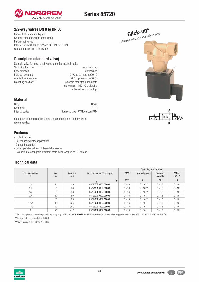
2/2-way valves DN 8 to DN 50For neutral steam and liquids
Solenoid actuated, with forced lifting
Piston seat valves
Internal thread G 1/4 to G 2 or 1/4" NPT to 2" NPT
Operating pressure: 0 to 16 bar
Description (standard valve)Solenoid valve for steam, hot water, and other neutral liquids
Switching function: normally closed
Flow direction: determined
Fluid temperature: 0 °C up to max. +200 °C
Ambient temperature: 0 °C up to max. +60 °C
Mounting position: solenoid mounted underneath
(up to max. +150 °C preferably
solenoid vertical on top)
MaterialBody: Brass
Seat seal: PTFE
Internal parts: Stainless steel, PTFE/carbon/FPM
For contaminated fluids the use of a strainer upstream of the valve is
recommended.
Features- High flow rate
- For robust industry applications
- Damped operation
- Valve operates without differential pressure
- Solenoid interchangeable without tools (Click-on®) up to G 1 thread
Technical data
Click-on®
Solenoid interchangeable without tools
a
P
Ab
a b
Connection size
G
DN
mm
kv-Value
m3/h
Part number for DC voltage*
Operating pressure bar
PTFE Normally open Manual
override
EPDM
130 °C
00** 01 02 14
1/4 8 1.9 85720XX.9402.00000 0 - 16 0 - 16*** 0 - 16 0 - 16
3/8 10 3.0 85721XX.9402.00000 0 - 16 0 - 16*** 0 - 16 0 - 16
1/2 12 3.8 85722XX.9402.00000 0 - 16 0 - 16*** 0 - 16 0 - 16
3/4 20 6.0 85723XX.9402.00000 0 - 16 0 - 16*** 0 - 16 0 - 16
1 25 9.5 85724XX.9402.00000 0 - 16 0 - 16*** 0 - 16 0 - 16
1 1/4 32 23.0 85725XX.8402.00000 0 - 16 0 - 16 0 - 16 0 - 16
1 1/2 40 25.0 85726XX.8402.00000 0 - 16 0 - 16 0 - 16 0 - 16
2 50 41.0 85727XX.8402.00000 0 - 16 0 - 16 0 - 16 0 - 16
* For orders please state voltage and frequency, e.g.: 8572200.9406.23049 for 230V 40-60Hz (AC with rectifier plug only, included) or 8572200.9402.02400 for 24V DC
** Leak rate E according to EN 12266-1
*** With solenoid DC 8402 / AC 8406
www.norgren.com/fc/en044
45
Series 85720
Solenoid 9402 / 9406 / 8402 / 8406(standard voltages) Power consumption
Design according to DIN VDE 0580
Voltage range +/-10%, duty cycle 100%
Protection class according to EN 60529: IP65
Electrical connector according to DIN EN 175301-803 (included)
AC with rectifier plug only
Solenoid DCAC
Inrush Holding
9402 29W
9406 33VA 33VA
8402 29W
8406 33VA 33VA
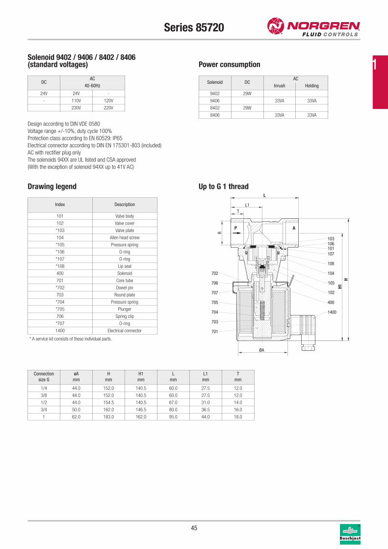
Drawing legend Up to G 1 thread
Index Description
101 Valve body
102 Valve cover
*103 Valve plate
104 Allen head screw
*105 Pressure spring
*106 O-ring
*107 O-ring
*108 Lip seal
400 Solenoid
701 Core tube
*702 Dowel pin
703 Round plate
*704 Pressure spring
*705 Plunger
706 Spring clip
*707 O-ring
1400 Electrical connector
1400
400
103
101
108
107
106
104
105
102
701
703
704
705
707
706
702
P A
H1H
L
L1T
R
ØA
* A service kit consists of these individual parts.
Connection
size G
øA
mm
H
mm
H1
mm
L
mm
L1
mm
T
mm
1/4 44.0 152.0 140.5 60.0 27.5 12.0
3/8 44.0 152.0 140.5 60.0 27.5 12.0
1/2 44.0 154.5 140.5 67.0 31.0 14.0
3/4 50.0 162.0 146.5 80.0 36.5 16.0
1 62.0 183.0 162.0 95.0 44.0 18.0
DCAC
40-60Hz
24V 24V -
- 110V 120V
230V 220V
The solenoids 94XX are UL listed and CSA approved
(With the exception of solenoid 94XX up to 41V AC)
1
46
Series 85720
Service kits
For valves with solenoid 9402 Part number
8572000 1263978
8572100 1263978
8572200 1263978
8572300 1263979
8572400 1263980
For valves with solenoid 8402 Part number
8572500 1263981
8572600 1263981
8572700 1263982
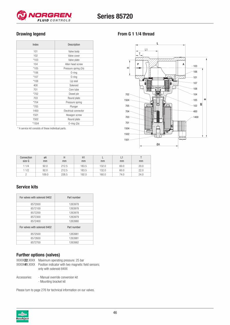
Further options (valves)XXXXX22.XXXX Maximum operating pressure: 25 bar
XXXXX41.XXXX Position indicator with two magnetic field sensors;
only with solenoid 84XX
Accessories: - Manual override conversion kit
- Mounting bracket kit
Please turn to page 276 for technical information on our valves.
Connection
size G
øA
mm
H
mm
H1
mm
L
mm
L1
mm
T
mm
1 1/4 92.0 212.5 183.5 132.0 60.0 20.0
1 1/2 92.0 212.5 183.5 132.0 60.0 22.0
2 109.0 226.5 192.0 160.0 74.0 24.0
Index Description
101 Valve body
102 Valve cover
*103 Valve plate
104 Allen head screw
*105 Pressure spring (2x)
*106 O-ring
*107 O-ring
*108 Lip seal
400 Solenoid
701 Core tube
*702 Dowel pin
703 Round plate
*704 Pressure spring
*705 Plunger
1400 Electrical connector
1501 Hexagon screw
1502 Round plate
*1504 O-ring (2x)
* A service kit consists of these individual parts.
701
705
702
1400
400
103
101
108
107
106
102
104
P A
1051504
704
703
1504
1502
1501
H1H
L
L1T
R
ØA
Drawing legend From G 1 1/4 thread
Fluid Control Solutions
47
BAutomatic Systems for Machines
Users are increasingly demandingcompact assemblies and systems
1
Cable gland
protection class EEx e, EEx d (ATEX),
Nickel plated brass
Connectors
EEx e 0588819 (for solenoids 42xx / 46xx M20 x 1.5) 0570275
Accessories
48
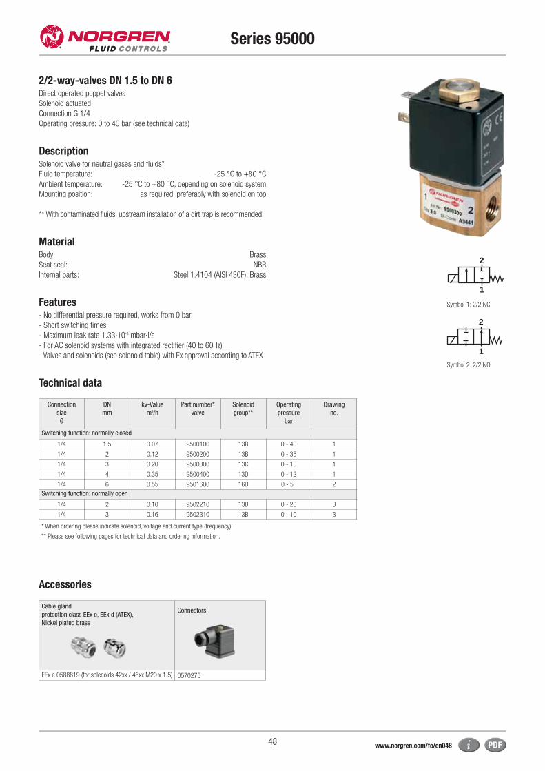
Series 95000
2/2-way-valves DN 1.5 to DN 6Direct operated poppet valves
Solenoid actuated
Connection G 1/4
Operating pressure: 0 to 40 bar (see technical data)
DescriptionSolenoid valve for neutral gases and fluids*
Fluid temperature: -25 °C to +80 °C
Ambient temperature: -25 °C to +80 °C, depending on solenoid system
Mounting position: as required, preferably with solenoid on top
** With contaminated fluids, upstream installation of a dirt trap is recommended.
MaterialBody: Brass
Seat seal: NBR
Internal parts: Steel 1.4104 (AISI 430F), Brass
Features - No differential pressure required, works from 0 bar
- Short switching times
- Maximum leak rate 1.33·10-3 mbar·l/s
- For AC solenoid systems with integrated rectifier (40 to 60Hz)
- Valves and solenoids (see solenoid table) with Ex approval according to ATEX
Technical data
2
1
2
1
Connection
size
G
DN
mm
kv-Value
m3/h
Part number*
valve
Solenoid
group**
Operating
pressure
bar
Drawing
no.
Switching function: normally closed
1/4 1.5 0.07 9500100 13B 0 - 40 1
1/4 2 0.12 9500200 13B 0 - 35 1
1/4 3 0.20 9500300 13C 0 - 10 1
1/4 4 0.35 9500400 13D 0 - 12 1
1/4 6 0.55 9501600 16D 0 - 5 2
Switching function: normally open
1/4 2 0.10 9502210 13B 0 - 20 3
1/4 3 0.16 9502310 13B 0 - 10 3
* When ordering please indicate solenoid, voltage and current type (frequency).
** Please see following pages for technical data and ordering information.
Symbol 1: 2/2 NC
Symbol 2: 2/2 NO
www.norgren.com/fc/en048
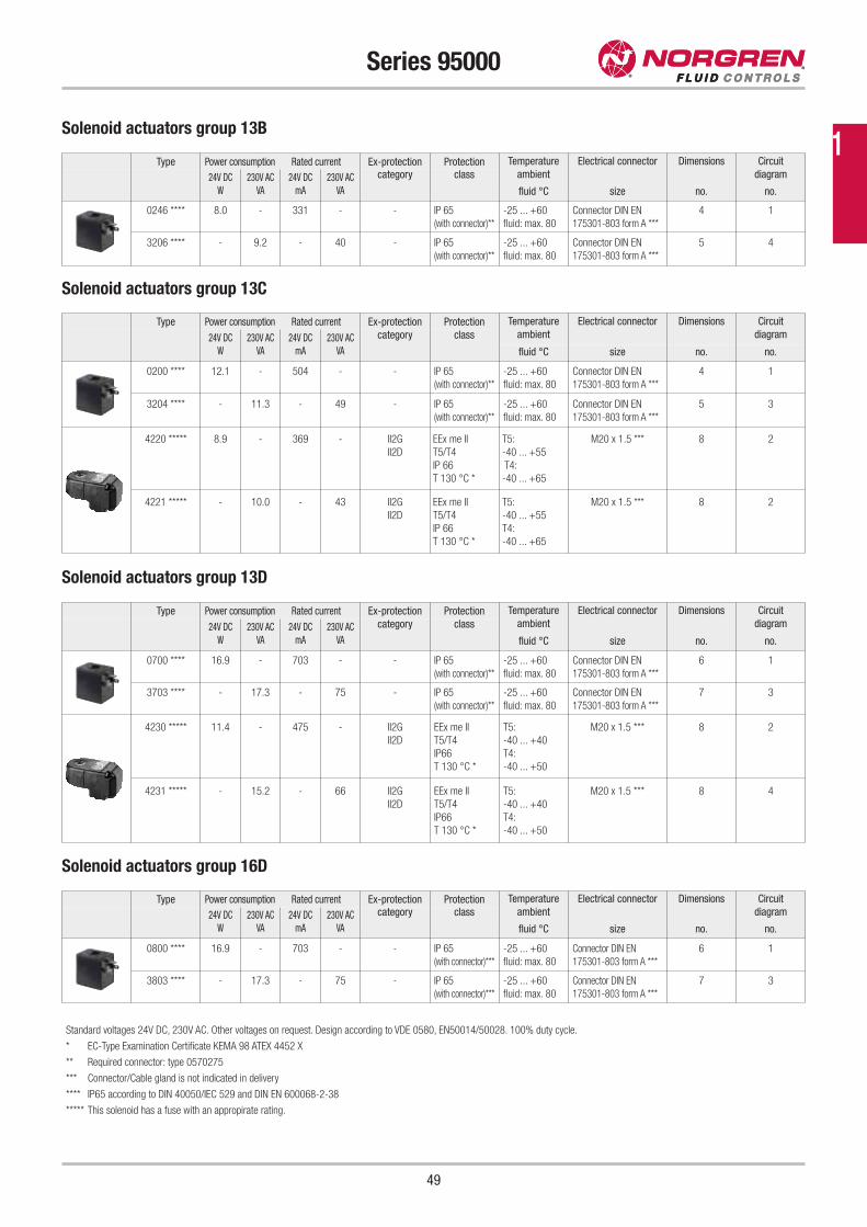
49
Series 95000
Type Power consumption Rated current Ex-protection Protection Temperature
ambient
Electrical connector Dimensions Circuit
diagram24V DC
W
230V AC
VA
24V DC
mA
230V AC
VA
category class
fluid °C size no. no.
0246 **** 8.0 - 331 - - IP 65
(with connector)**
-25 ... +60
fluid: max. 80
Connector DIN EN
175301-803 form A ***
4 1
3206 **** - 9.2 - 40 - IP 65
(with connector)**
-25 ... +60
fluid: max. 80
Connector DIN EN
175301-803 form A ***
5 4
Type Power consumption Rated current Ex-protection Protection Temperature
ambient
Electrical connector Dimensions Circuit
diagram24V DC
W
230V AC
VA
24V DC
mA
230V AC
VA
category class
fluid °C size no. no.
0800 **** 16.9 - 703 - - IP 65
(with connector)***
-25 ... +60
fluid: max. 80
Connector DIN EN
175301-803 form A ***
6 1
3803 **** - 17.3 - 75 - IP 65
(with connector)***
-25 ... +60
fluid: max. 80
Connector DIN EN
175301-803 form A ***
7 3
Type Power consumption Rated current Ex-protection Protection Temperature
ambient
Electrical connector Dimensions Circuit
diagram24V DC
W
230V AC
VA
24V DC
mA
230V AC
VA
category class
fluid °C size no. no.
0200 **** 12.1 - 504 - - IP 65
(with connector)**
-25 ... +60
fluid: max. 80
Connector DIN EN
175301-803 form A ***
4 1
3204 **** - 11.3 - 49 - IP 65
(with connector)**
-25 ... +60
fluid: max. 80
Connector DIN EN
175301-803 form A ***
5 3
4220 ***** 8.9 - 369 - II2G
II2D
EEx me II
T5/T4
IP 66
T 130 °C *
T5:
-40 ... +55
T4:
-40 ... +65
M20 x 1.5 *** 8 2
4221 ***** - 10.0 - 43 II2G
II2D
EEx me II
T5/T4
IP 66
T 130 °C *
T5:
-40 ... +55
T4:
-40 ... +65
M20 x 1.5 *** 8 2
Type Power consumption Rated current Ex-protection Protection Temperature
ambient
Electrical connector Dimensions Circuit
diagram24V DC
W
230V AC
VA
24V DC
mA
230V AC
VA
category class
fluid °C size no. no.
0700 **** 16.9 - 703 - - IP 65
(with connector)**
-25 ... +60
fluid: max. 80
Connector DIN EN
175301-803 form A ***
6 1
3703 **** - 17.3 - 75 - IP 65
(with connector)**
-25 ... +60
fluid: max. 80
Connector DIN EN
175301-803 form A ***
7 3
4230 ***** 11.4 - 475 - II2G
II2D
EEx me II
T5/T4
IP66
T 130 °C *
T5:
-40 ... +40
T4:
-40 ... +50
M20 x 1.5 *** 8 2
4231 ***** - 15.2 - 66 II2G
II2D
EEx me II
T5/T4
IP66
T 130 °C *
T5:
-40 ... +40
T4:
-40 ... +50
M20 x 1.5 *** 8 4
Solenoid actuators group 13B
Solenoid actuators group 13C
Solenoid actuators group 13D
Solenoid actuators group 16D
* EC-Type Examination Certificate KEMA 98 ATEX 4452 X
** Required connector: type 0570275
*** Connector/Cable gland is not indicated in delivery
**** IP65 according to DIN 40050/IEC 529 and DIN EN 600068-2-38
***** This solenoid has a fuse with an appropirate rating.
Standard voltages 24V DC, 230V AC. Other voltages on request. Design according to VDE 0580, EN50014/50028. 100% duty cycle.
1
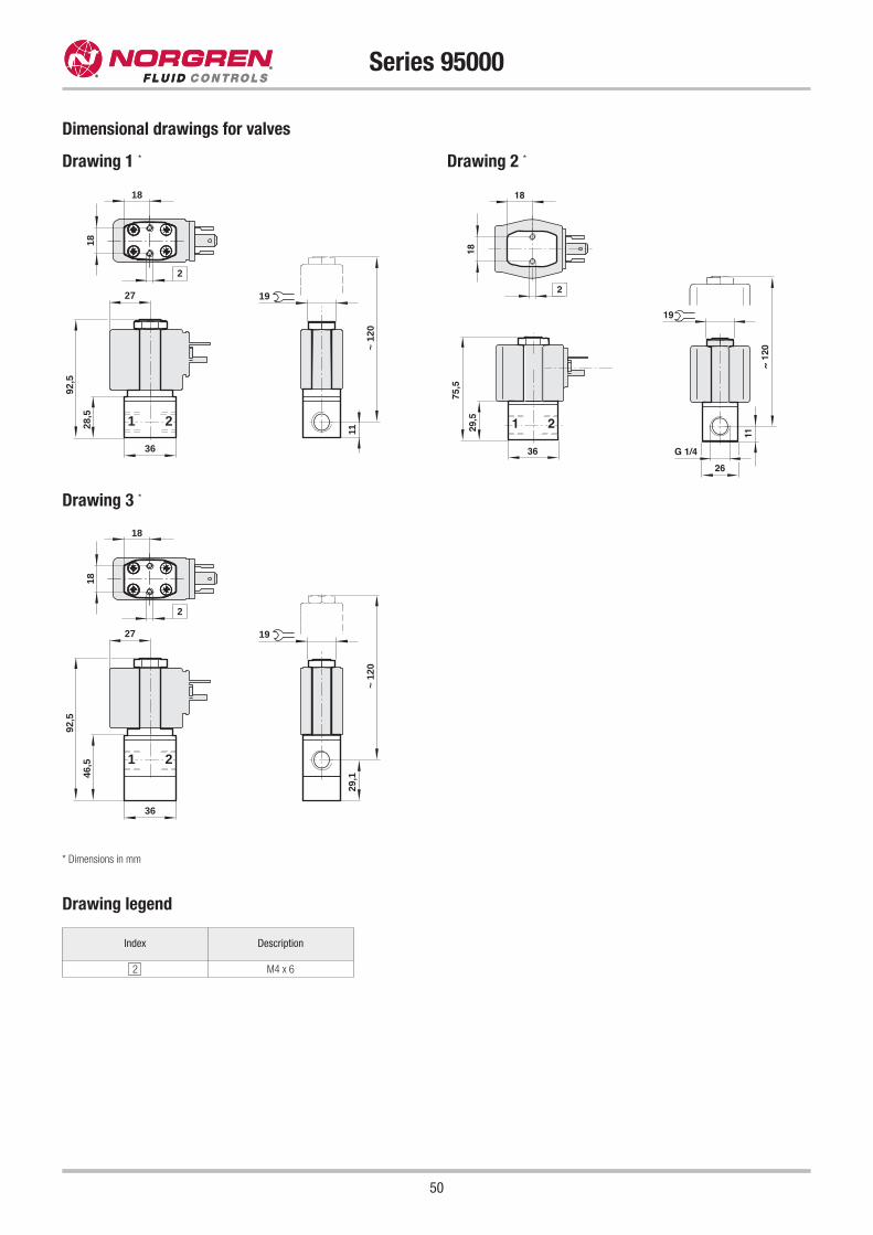
50
Series 95000
Dimensional drawings for valves
Drawing 1 * Drawing 2 *
Drawing 3 *
2
11
18
18
28,5
92,5
1 2
19
~ 1
20
36
27
18
18
29,5
75,5
1 2
36
2
11
19
G 1/4
26
~ 12
0
2
29,1
18
18
46,5
92,5
1 2
19
~ 1
20
36
27
Index Description
2 M4 x 6
Drawing legend
* Dimensions in mm
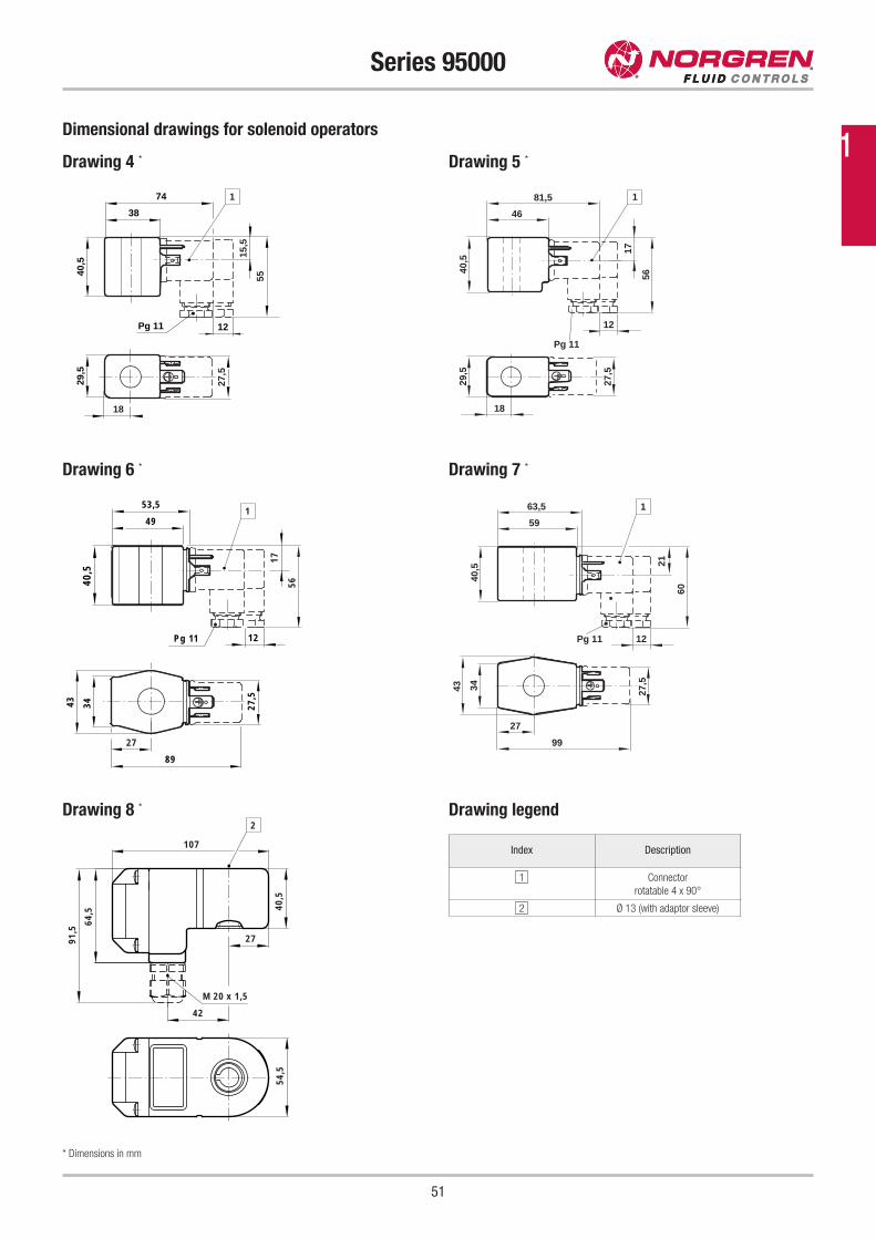
51
Series 95000
Drawing 6 * Drawing 7 *
Dimensional drawings for solenoid operators
Drawing 4 *
40,5
49
17
56
53,5
27
89
3443
Pg 11 12
27,5
1
40,5
59
21
60
63,5
27
99
34 27,5
43
Pg 11 12
1
54,5
107
64,5
91,5
42
M 20 x 1,5
27
40,5
2Drawing 8 *
40,5
38
15,5
55
74
18
29,5
Pg 11
27,5
12
1
40,5
46
17
56
81,5
18
29,5
27,5
12
Pg 11
1
Drawing 5 *
* Dimensions in mm
Drawing legend
Index Description
1 Connector
rotatable 4 x 90°
2 Ø 13 (with adaptor sleeve)
1
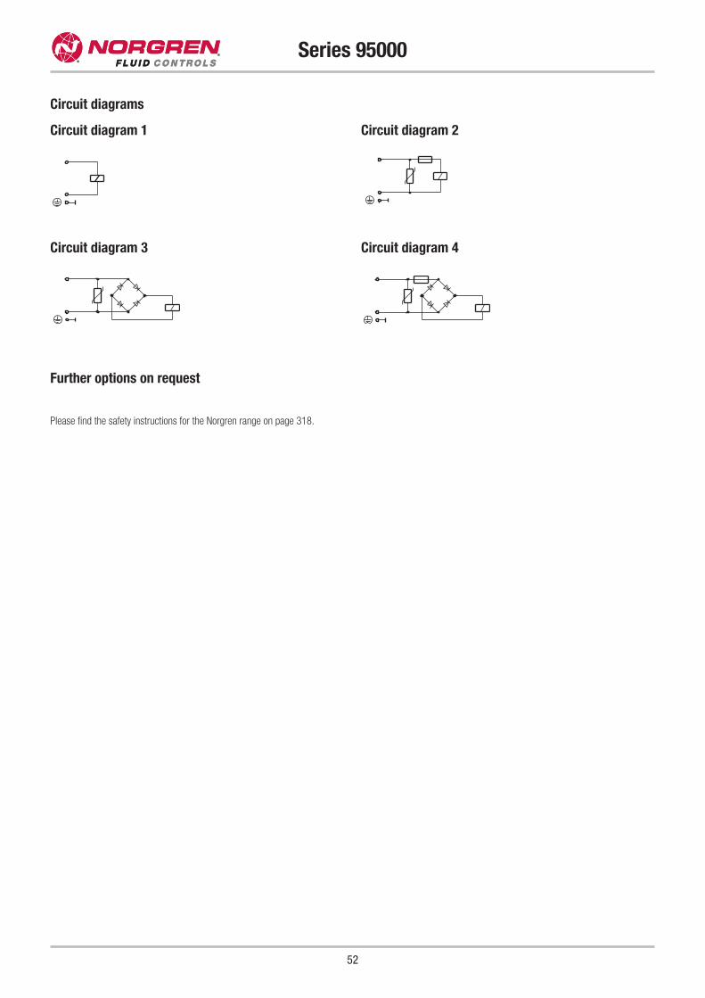
52
Series 95000
Circuit diagram 1
Circuit diagrams
Circuit diagram 2
Circuit diagram 3 Circuit diagram 4
Further options on request
Please find the safety instructions for the Norgren range on page 318.
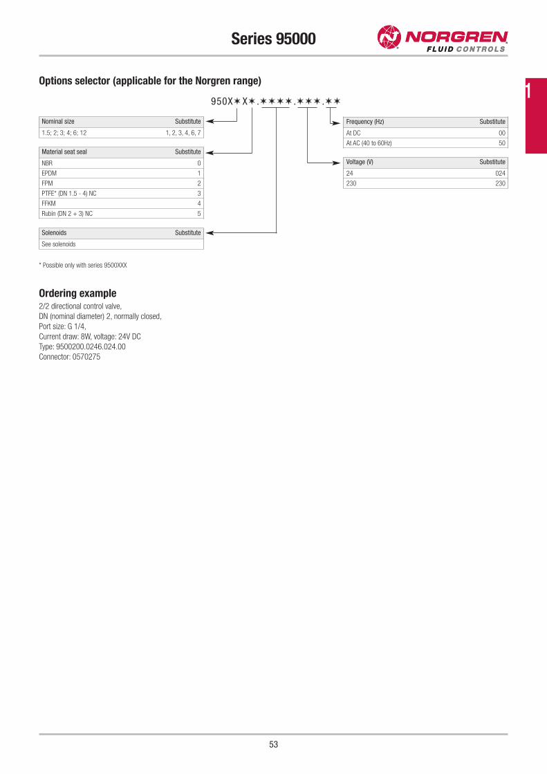
53
Series 95000
Options selector (applicable for the Norgren range)
Nominal size Substitute
1.5; 2; 3; 4; 6; 12 1, 2, 3, 4, 6, 7
Frequency (Hz) Substitute
At DC 00
At AC (40 to 60Hz) 50
Voltage (V) Substitute
24 024
230 230
Solenoids Substitute
See solenoids
Material seat seal Substitute
NBR 0
EPDM 1
FPM 2
PTFE* (DN 1.5 - 4) NC 3
FFKM 4
Rubin (DN 2 + 3) NC 5
950X✶ X✶ .✶✶✶✶ .✶✶✶ .✶✶
* Possible only with series 9500XXX
Ordering example2/2 directional control valve,
DN (nominal diameter) 2, normally closed,
Port size: G 1/4,
Current draw: 8W, voltage: 24V DC
Type: 9500200.0246.024.00
Connector: 0570275
1
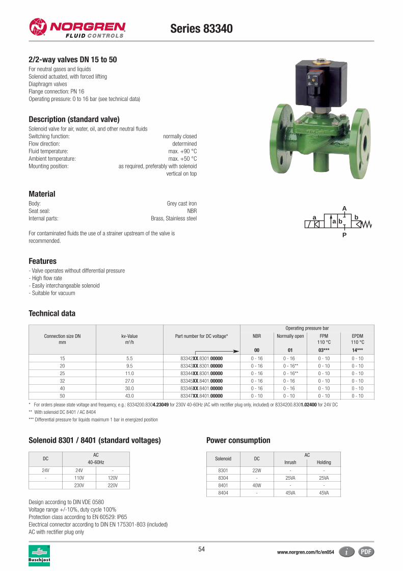
54
Series 83340
2/2-way valves DN 15 to 50For neutral gases and liquids
Solenoid actuated, with forced lifting
Diaphragm valves
Flange connection: PN 16
Operating pressure: 0 to 16 bar (see technical data)
Description (standard valve)Solenoid valve for air, water, oil, and other neutral fluids
Switching function: normally closed
Flow direction: determined
Fluid temperature: max. +90 °C
Ambient temperature: max. +50 °C
Mounting position: as required, preferably with solenoid
vertical on top
MaterialBody: Grey cast iron
Seat seal: NBR
Internal parts: Brass, Stainless steel
For contaminated fluids the use of a strainer upstream of the valve is
recommended.
Features- Valve operates without differential pressure
- High flow rate
- Easily interchangeable solenoid
- Suitable for vacuum
Technical data
Connection size DN
mm
kv-Value
m3/h
Part number for DC voltage*
Operating pressure bar
NBR Normally open FPM
110 °C
EPDM
110 °C
00 01 03*** 14***
15 5.5 83342XX.8301.00000 0 - 16 0 - 16 0 - 10 0 - 10
20 9.5 83343XX.8301.00000 0 - 16 0 - 16** 0 - 10 0 - 10
25 11.0 83344XX.8301.00000 0 - 16 0 - 16** 0 - 10 0 - 10
32 27.0 83345XX.8401.00000 0 - 16 0 - 16 0 - 10 0 - 10
40 30.0 83346XX.8401.00000 0 - 16 0 - 16 0 - 10 0 - 10
50 43.0 83347XX.8401.00000 0 - 10 0 - 10 0 - 10 0 - 10
* For orders please state voltage and frequency, e.g.: 8334200.8304.23049 for 230V 40-60Hz (AC with rectifier plug only, included) or 8334200.8301.02400 for 24V DC
** With solenoid DC 8401 / AC 8404
*** Differential pressure for liquids maximum 1 bar in energized position
Solenoid 8301 / 8401 (standard voltages) Power consumption
Design according to DIN VDE 0580
Voltage range +/-10%, duty cycle 100%
Protection class according to EN 60529: IP65
Electrical connector according to DIN EN 175301-803 (included)
AC with rectifier plug only
Solenoid DCAC
Inrush Holding
8301 22W - -
8304 - 25VA 25VA
8401 40W - -
8404 - 45VA 45VA
a
P
Ab
a b
DCAC
40-60Hz
24V 24V -
- 110V 120V
230V 220V
www.norgren.com/fc/en054
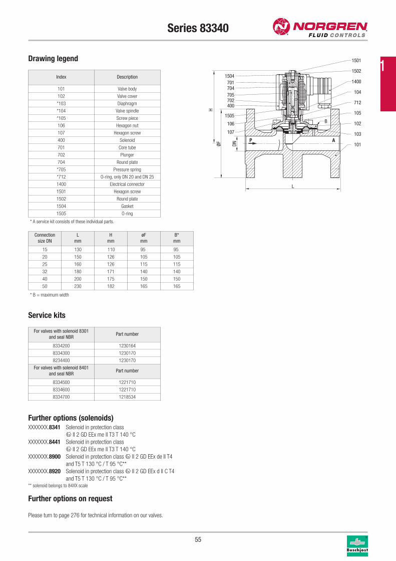
55
Series 83340
Drawing legend
Index Description
101 Valve body
102 Valve cover
*103 Diaphragm
*104 Valve spindle
*105 Screw piece
106 Hexagon nut
107 Hexagon screw
400 Solenoid
701 Core tube
702 Plunger
704 Round plate
*705 Pressure spring
*712 O-ring, only DN 20 and DN 25
1400 Electrical connector
1501 Hexagon screw
1502 Round plate
1504 Gasket
1505 O-ring
* A service kit consists of these individual parts.
Connection
size DN
L
mm
H
mm
øF
mm
B*
mm
15 130 110 95 95
20 150 126 105 105
25 160 126 115 115
32 180 171 140 140
40 200 175 150 150
50 230 182 165 165
P A
1400
104
712
105
102
101
1502
1501
1504701704705702400
1505
106
107 103
DNØF
L
H
B
* B = maximum width
1
Further options (solenoids)XXXXXXX.8341 Solenoid in protection class
x II 2 GD EEx me II T3 T 140 °C
XXXXXXX.8441 Solenoid in protection class
x II 2 GD EEx me II T3 T 140 °C
XXXXXXX.8900 Solenoid in protection class x II 2 GD EEx de II T4
and T5 T 130 °C / T 95 °C**
XXXXXXX.8920 Solenoid in protection class x II 2 GD EEx d II C T4
and T5 T 130 °C / T 95 °C**** solenoid belongs to 84XX scale
Further options on request
Please turn to page 276 for technical information on our valves.
Service kits
For valves with solenoid 8301
and seal NBRPart number
8334200 1230164
8334300 1230170
8234400 1230170
For valves with solenoid 8401
and seal NBRPart number
8334500 1221710
8334600 1221710
8334700 1218534
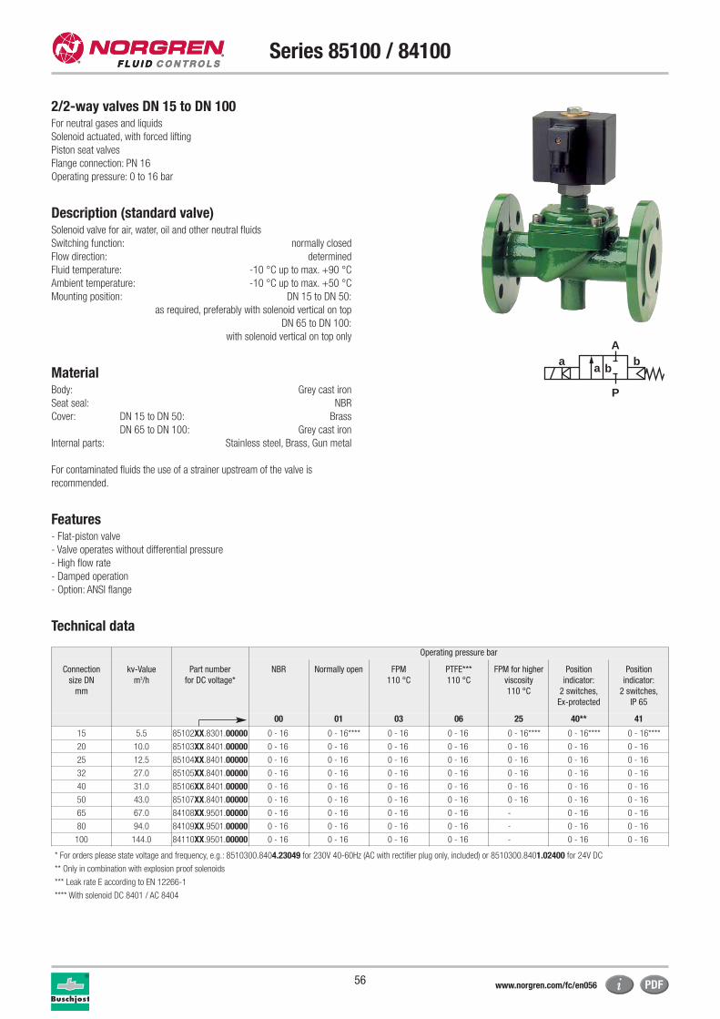
56
Series 85100 / 84100
2/2-way valves DN 15 to DN 100For neutral gases and liquids
Solenoid actuated, with forced lifting
Piston seat valves
Flange connection: PN 16
Operating pressure: 0 to 16 bar
Description (standard valve)Solenoid valve for air, water, oil and other neutral fluids
Switching function: normally closed
Flow direction: determined
Fluid temperature: -10 °C up to max. +90 °C
Ambient temperature: -10 °C up to max. +50 °C
Mounting position: DN 15 to DN 50:
as required, preferably with solenoid vertical on top
DN 65 to DN 100:
with solenoid vertical on top only
MaterialBody: Grey cast iron
Seat seal: NBR
Cover: DN 15 to DN 50: Brass
DN 65 to DN 100: Grey cast iron
Internal parts: Stainless steel, Brass, Gun metal
For contaminated fluids the use of a strainer upstream of the valve is
recommended.
Features- Flat-piston valve
- Valve operates without differential pressure
- High flow rate
- Damped operation
- Option: ANSI flange
Technical data
Operating pressure bar
Connection
size DN
mm
kv-Value
m3/h
Part number
for DC voltage*
NBR Normally open FPM
110 °C
PTFE***
110 °C
FPM for higher
viscosity
110 °C
Position
indicator:
2 switches,
Ex-protected
Position
indicator:
2 switches,
IP 65
00 01 03 06 25 40** 41
15 5.5 85102XX.8301.00000 0 - 16 0 - 16**** 0 - 16 0 - 16 0 - 16**** 0 - 16**** 0 - 16****
20 10.0 85103XX.8401.00000 0 - 16 0 - 16 0 - 16 0 - 16 0 - 16 0 - 16 0 - 16
25 12.5 85104XX.8401.00000 0 - 16 0 - 16 0 - 16 0 - 16 0 - 16 0 - 16 0 - 16
32 27.0 85105XX.8401.00000 0 - 16 0 - 16 0 - 16 0 - 16 0 - 16 0 - 16 0 - 16
40 31.0 85106XX.8401.00000 0 - 16 0 - 16 0 - 16 0 - 16 0 - 16 0 - 16 0 - 16
50 43.0 85107XX.8401.00000 0 - 16 0 - 16 0 - 16 0 - 16 0 - 16 0 - 16 0 - 16
65 67.0 84108XX.9501.00000 0 - 16 0 - 16 0 - 16 0 - 16 - 0 - 16 0 - 16
80 94.0 84109XX.9501.00000 0 - 16 0 - 16 0 - 16 0 - 16 - 0 - 16 0 - 16
100 144.0 84110XX.9501.00000 0 - 16 0 - 16 0 - 16 0 - 16 - 0 - 16 0 - 16
* For orders please state voltage and frequency, e.g.: 8510300.8404.23049 for 230V 40-60Hz (AC with rectifier plug only, included) or 8510300.8401.02400 for 24V DC
** Only in combination with explosion proof solenoids
*** Leak rate E according to EN 12266-1
**** With solenoid DC 8401 / AC 8404
a
P
Ab
a b
www.norgren.com/fc/en056
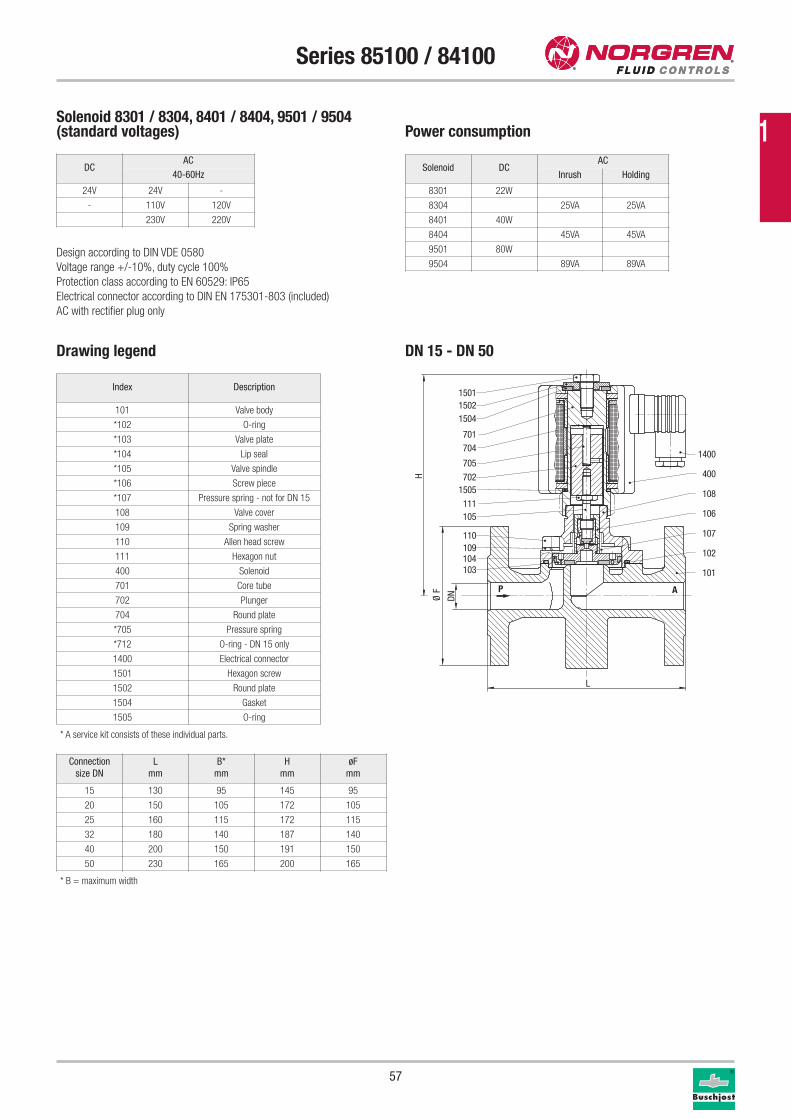
57
Series 85100 / 84100
Drawing legend
Index Description
101 Valve body
*102 O-ring
*103 Valve plate
*104 Lip seal
*105 Valve spindle
*106 Screw piece
*107 Pressure spring - not for DN 15
108 Valve cover
109 Spring washer
110 Allen head screw
111 Hexagon nut
400 Solenoid
701 Core tube
702 Plunger
704 Round plate
*705 Pressure spring
*712 O-ring - DN 15 only
1400 Electrical connector
1501 Hexagon screw
1502 Round plate
1504 Gasket
1505 O-ring
P A
103104109110
105111
1505702
705
704701
150415021501
101
102
107
106
108
400
1400
H
DNØ F
L
Solenoid 8301 / 8304, 8401 / 8404, 9501 / 9504(standard voltages) Power consumption
Design according to DIN VDE 0580
Voltage range +/-10%, duty cycle 100%
Protection class according to EN 60529: IP65
Electrical connector according to DIN EN 175301-803 (included)
AC with rectifier plug only
Solenoid DCAC
Inrush Holding
8301 22W
8304 25VA 25VA
8401 40W
8404 45VA 45VA
9501 80W
9504 89VA 89VA
Connection
size DN
L
mm
B*
mm
H
mm
øF
mm
15 130 95 145 95
20 150 105 172 105
25 160 115 172 115
32 180 140 187 140
40 200 150 191 150
50 230 165 200 165
* A service kit consists of these individual parts.
DN 15 - DN 50
DCAC
40-60Hz
24V 24V -
- 110V 120V
230V 220V
* B = maximum width
1
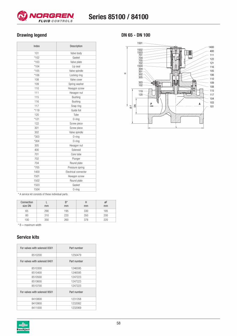
58
Series 85100 / 84100
Service kits
For valves with solenoid 8301 Part number
8510200 1250479
For valves with solenoid 8401 Part number
8510300 1246595
8510400 1246595
8510500 1247223
8510600 1247223
8510700 1247223
For valves with solenoid 9501 Part number
8410800 1231358
8410900 1232082
8411000 1232069
Connection
size DN
L
mm
B*
mm
H
mm
øF
mm
65 290 195 330 185
80 310 220 350 200
100 350 260 378 220
* A service kit consists of these individual parts.
Index Description
101 Valve body
*102 Gasket
*103 Valve plate
*104 Lip seal
*105 Valve spindle
*106 Locking ring
108 Valve cover
109 Spring washer
110 Hexagon screw
111 Hexagon nut
115 Bushing
116 Bushing
117 Snap ring
*119 Guide foil
120 Tube
*121 O-ring
122 Screw piece
301 Screw piece
302 Valve spindle
*303 O-ring
*304 O-ring
305 Hexagon nut
400 Solenoid
701 Core tube
702 Plunger
704 Round plate
*705 Pressure spring
1400 Electrical connector
1501 Hexagon screw
1502 Round plate
1503 Gasket
1504 O-ring
P A
1501
1502
701704705702
1504304301302305
303102
119120
1400400
122111
121116
1503
105106110109108
117115
104103101
H
DNØ F
L
DN 65 - DN 100Drawing legend
* B = maximum width
59
Series 85100 / 84100
Further options (valves)XXXXXX02.XXXX Manual override
XXXXXX14.XXXX Seal: EPDM, maximum temperature +110 °C
XXXXXX17.XXXX Normally open, seal: FPM, maximum temperature +110 °C,
mounting position: with solenoid vertical on top only
Further options (solenoids)XXXXXXX.8341 DN 15: Solenoid protection class
x II 2 GD EEx me II T3 T 140 °C
XXXXXXX.8436 DN 20 – DN 50: Solenoid protection class
x II 2 GD EEx me II T4 T 140 °C
XXXXXXX.8441 DN 20 – DN 50: Solenoid protection class
x II 2 GD EEx me II T3 T 140 °C
XXXXXXX.8900 DN 15 – DN 50: Solenoid protection class
x II 2 GD EEx de II C T4 and T5 T 130 °C / 95 °C
XXXXXXX.8920 DN 15 – DN 50: Solenoid protection class
x II 2 GD EEx d II T4 and T5 T 130 °C / 95 °C
XXXXXXX.9540 DN 65 – DN 100: Solenoid protection class
x II 2 GD EEx me II T3 and T4 T 140 °C
Further options on requestSpecial connections
Please turn to page 276 for technical information on our valves.
1
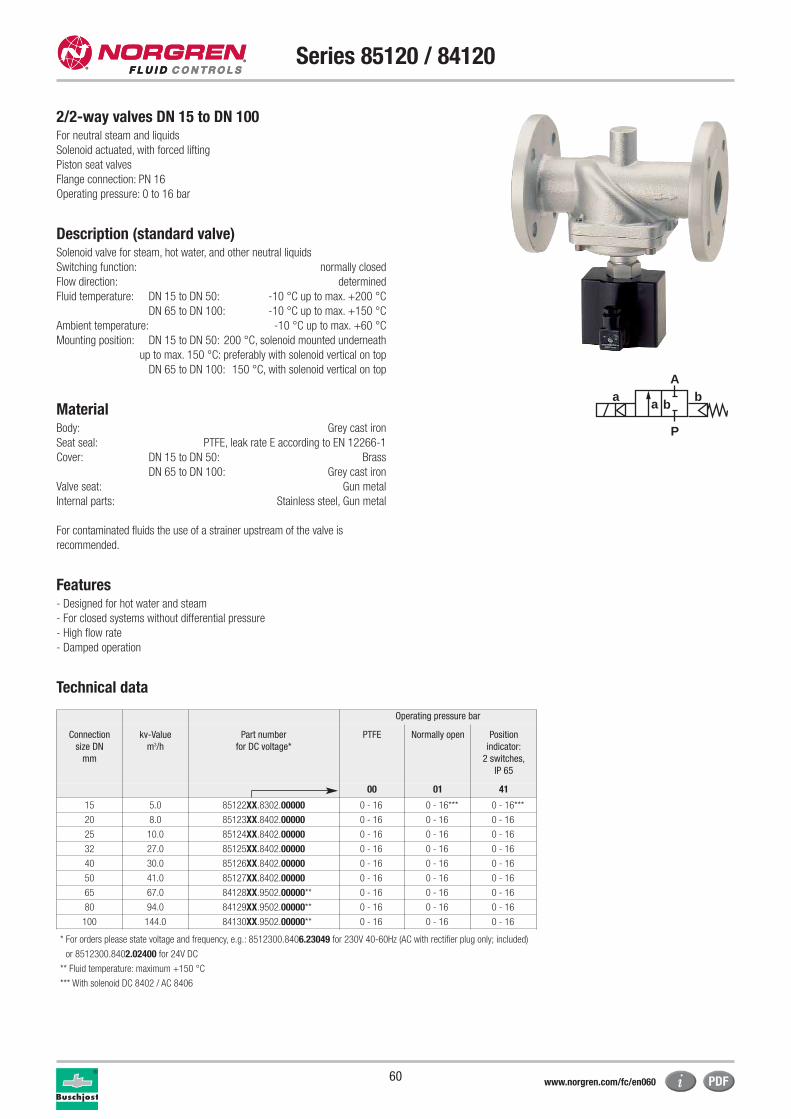
60
Series 85120 / 84120
2/2-way valves DN 15 to DN 100For neutral steam and liquids
Solenoid actuated, with forced lifting
Piston seat valves
Flange connection: PN 16
Operating pressure: 0 to 16 bar
Description (standard valve)Solenoid valve for steam, hot water, and other neutral liquids
Switching function: normally closed
Flow direction: determined
Fluid temperature: DN 15 to DN 50: -10 °C up to max. +200 °C
DN 65 to DN 100: -10 °C up to max. +150 °C
Ambient temperature: -10 °C up to max. +60 °C
Mounting position: DN 15 to DN 50: 200 °C, solenoid mounted underneath
up to max. 150 °C: preferably with solenoid vertical on top
DN 65 to DN 100: 150 °C, with solenoid vertical on top
MaterialBody: Grey cast iron
Seat seal: PTFE, leak rate E according to EN 12266-1
Cover: DN 15 to DN 50: Brass
DN 65 to DN 100: Grey cast iron
Valve seat: Gun metal
Internal parts: Stainless steel, Gun metal
For contaminated fluids the use of a strainer upstream of the valve is
recommended.
Features- Designed for hot water and steam
- For closed systems without differential pressure
- High flow rate
- Damped operation
Technical data
a
P
Ab
a b
Operating pressure bar
Connection
size DN
mm
kv-Value
m3/h
Part number
for DC voltage*
PTFE Normally open Position
indicator:
2 switches,
IP 65
00 01 41
15 5.0 85122XX.8302.00000 0 - 16 0 - 16*** 0 - 16***
20 8.0 85123XX.8402.00000 0 - 16 0 - 16 0 - 16
25 10.0 85124XX.8402.00000 0 - 16 0 - 16 0 - 16
32 27.0 85125XX.8402.00000 0 - 16 0 - 16 0 - 16
40 30.0 85126XX.8402.00000 0 - 16 0 - 16 0 - 16
50 41.0 85127XX.8402.00000 0 - 16 0 - 16 0 - 16
65 67.0 84128XX.9502.00000** 0 - 16 0 - 16 0 - 16
80 94.0 84129XX.9502.00000** 0 - 16 0 - 16 0 - 16
100 144.0 84130XX.9502.00000** 0 - 16 0 - 16 0 - 16
* For orders please state voltage and frequency, e.g.: 8512300.8406.23049 for 230V 40-60Hz (AC with rectifier plug only; included)
or 8512300.8402.02400 for 24V DC
** Fluid temperature: maximum +150 °C
*** With solenoid DC 8402 / AC 8406
www.norgren.com/fc/en060
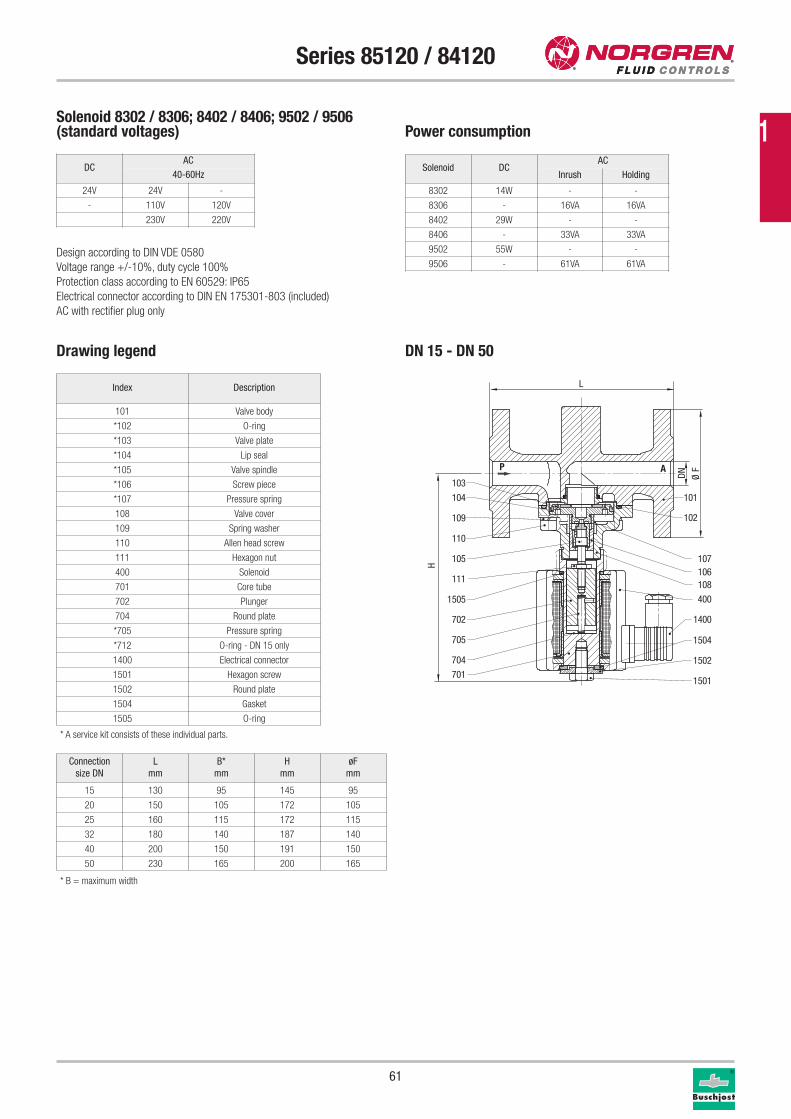
61
Series 85120 / 84120
Drawing legend
Index Description
101 Valve body
*102 O-ring
*103 Valve plate
*104 Lip seal
*105 Valve spindle
*106 Screw piece
*107 Pressure spring
108 Valve cover
109 Spring washer
110 Allen head screw
111 Hexagon nut
400 Solenoid
701 Core tube
702 Plunger
704 Round plate
*705 Pressure spring
*712 O-ring - DN 15 only
1400 Electrical connector
1501 Hexagon screw
1502 Round plate
1504 Gasket
1505 O-ring
P A103
104
109
110
105
111
1505
702
705
704
701
101
102
107106108
400
1400
1501
1502
1504
H
DN Ø F
L
Solenoid 8302 / 8306; 8402 / 8406; 9502 / 9506(standard voltages) Power consumption
Design according to DIN VDE 0580
Voltage range +/-10%, duty cycle 100%
Protection class according to EN 60529: IP65
Electrical connector according to DIN EN 175301-803 (included)
AC with rectifier plug only
Solenoid DCAC
Inrush Holding
8302 14W - -
8306 - 16VA 16VA
8402 29W - -
8406 - 33VA 33VA
9502 55W - -
9506 - 61VA 61VA
* A service kit consists of these individual parts.
Connection
size DN
L
mm
B*
mm
H
mm
øF
mm
15 130 95 145 95
20 150 105 172 105
25 160 115 172 115
32 180 140 187 140
40 200 150 191 150
50 230 165 200 165
DN 15 - DN 50
DCAC
40-60Hz
24V 24V -
- 110V 120V
230V 220V
* B = maximum width
1
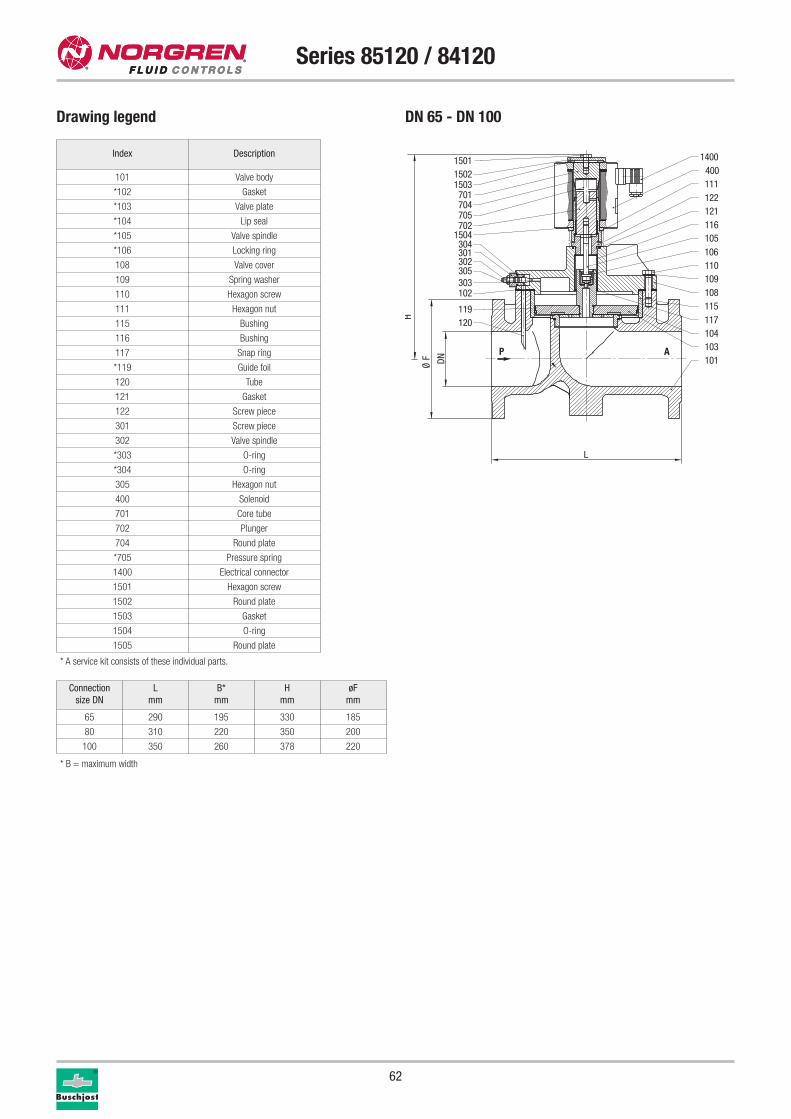
62
Series 85120 / 84120
* A service kit consists of these individual parts.
Index Description
101 Valve body
*102 Gasket
*103 Valve plate
*104 Lip seal
*105 Valve spindle
*106 Locking ring
108 Valve cover
109 Spring washer
110 Hexagon screw
111 Hexagon nut
115 Bushing
116 Bushing
117 Snap ring
*119 Guide foil
120 Tube
121 Gasket
122 Screw piece
301 Screw piece
302 Valve spindle
*303 O-ring
*304 O-ring
305 Hexagon nut
400 Solenoid
701 Core tube
702 Plunger
704 Round plate
*705 Pressure spring
1400 Electrical connector
1501 Hexagon screw
1502 Round plate
1503 Gasket
1504 O-ring
1505 Round plate
P A
15011502
701704705702
1504304301302305303102
119120
1400400
122111
121116
1503
105106110109108
117115
104103101
H
DNØ F
L
Connection
size DN
L
mm
B*
mm
H
mm
øF
mm
65 290 195 330 185
80 310 220 350 200
100 350 260 378 220
Drawing legend DN 65 - DN 100
* B = maximum width
63
Series 85120 / 84120
Further options (valves)XXXXXX02.XXXX Manual override
XXXXXX14.XXXX Seal: EPDM, maximum temperature +130 °C
XXXXXX33.XXXX Surfaces in contact with fluid are free from substances
that inhibit paint smoothness
Further options (solenoids)XXXXXXX.8406 DN 15 to DN 50: solenoid AC,
maximum temperature +200 °C
solenoid mounting position: vertical underneath only
XXXXXXX.8602 DN 65 – DN 100: maximum temperature +200 °C
solenoid mounting position: vertical underneath only
Further options on request
Please turn to page 276 for technical information on our valves.
1
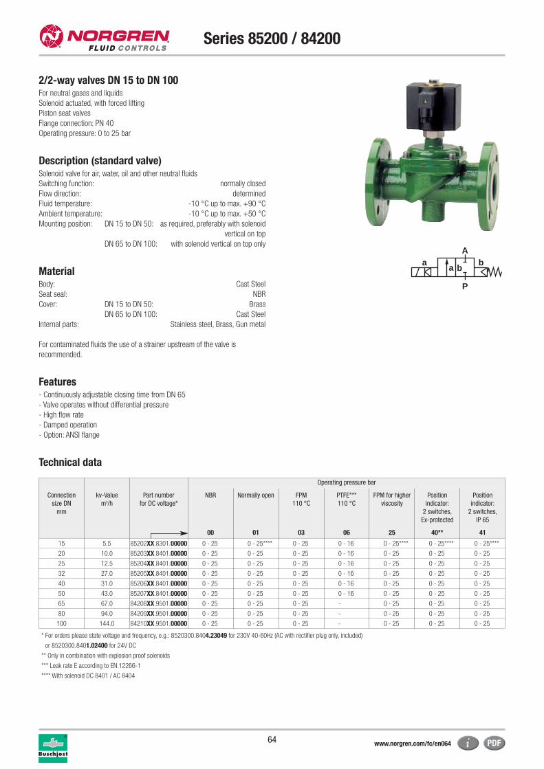
64
Series 85200 / 84200
2/2-way valves DN 15 to DN 100For neutral gases and liquids
Solenoid actuated, with forced lifting
Piston seat valves
Flange connection: PN 40
Operating pressure: 0 to 25 bar
Description (standard valve)Solenoid valve for air, water, oil and other neutral fluids
Switching function: normally closed
Flow direction: determined
Fluid temperature: -10 °C up to max. +90 °C
Ambient temperature: -10 °C up to max. +50 °C
Mounting position: DN 15 to DN 50: as required, preferably with solenoid
vertical on top
DN 65 to DN 100: with solenoid vertical on top only
Material Body: Cast Steel
Seat seal: NBR
Cover: DN 15 to DN 50: Brass
DN 65 to DN 100: Cast Steel
Internal parts: Stainless steel, Brass, Gun metal
For contaminated fluids the use of a strainer upstream of the valve is
recommended.
Features- Continuously adjustable closing time from DN 65
- Valve operates without differential pressure
- High flow rate
- Damped operation
- Option: ANSI flange
Technical data
Operating pressure bar
Connection
size DN
mm
kv-Value
m3/h
Part number
for DC voltage*
NBR Normally open FPM
110 °C
PTFE***
110 °C
FPM for higher
viscosity
Position
indicator:
2 switches,
Ex-protected
Position
indicator:
2 switches,
IP 65
00 01 03 06 25 40** 41
15 5.5 85202XX.8301.00000 0 - 25 0 - 25**** 0 - 25 0 - 16 0 - 25**** 0 - 25**** 0 - 25****
20 10.0 85203XX.8401.00000 0 - 25 0 - 25 0 - 25 0 - 16 0 - 25 0 - 25 0 - 25
25 12.5 85204XX.8401.00000 0 - 25 0 - 25 0 - 25 0 - 16 0 - 25 0 - 25 0 - 25
32 27.0 85205XX.8401.00000 0 - 25 0 - 25 0 - 25 0 - 16 0 - 25 0 - 25 0 - 25
40 31.0 85206XX.8401.00000 0 - 25 0 - 25 0 - 25 0 - 16 0 - 25 0 - 25 0 - 25
50 43.0 85207XX.8401.00000 0 - 25 0 - 25 0 - 25 0 - 16 0 - 25 0 - 25 0 - 25
65 67.0 84208XX.9501.00000 0 - 25 0 - 25 0 - 25 - 0 - 25 0 - 25 0 - 25
80 94.0 84209XX.9501.00000 0 - 25 0 - 25 0 - 25 - 0 - 25 0 - 25 0 - 25
100 144.0 84210XX.9501.00000 0 - 25 0 - 25 0 - 25 - 0 - 25 0 - 25 0 - 25
* For orders please state voltage and frequency, e.g.: 8520300.8404.23049 for 230V 40-60Hz (AC with rectifier plug only, included)
or 8520300.8401.02400 for 24V DC
** Only in combination with explosion proof solenoids
*** Leak rate E according to EN 12266-1
**** With solenoid DC 8401 / AC 8404
a
P
Ab
a b
www.norgren.com/fc/en064
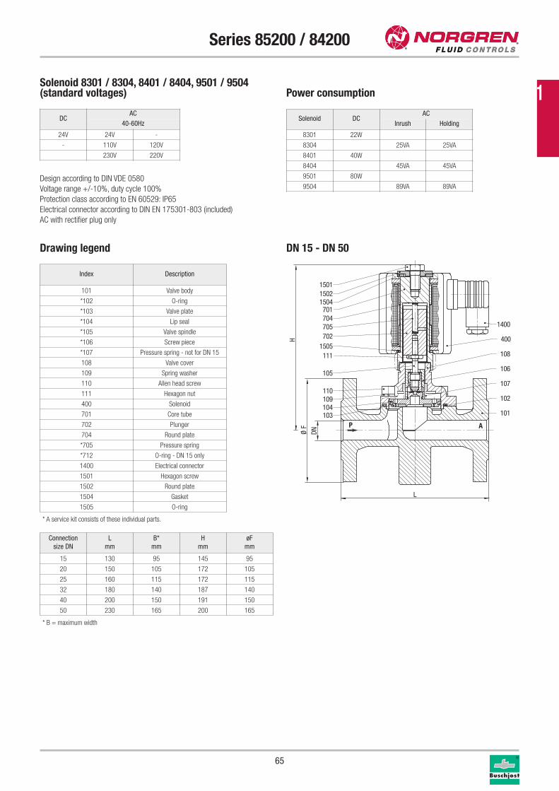
65
Series 85200 / 84200
Drawing legend
Index Description
101 Valve body
*102 O-ring
*103 Valve plate
*104 Lip seal
*105 Valve spindle
*106 Screw piece
*107 Pressure spring - not for DN 15
108 Valve cover
109 Spring washer
110 Allen head screw
111 Hexagon nut
400 Solenoid
701 Core tube
702 Plunger
704 Round plate
*705 Pressure spring
*712 O-ring - DN 15 only
1400 Electrical connector
1501 Hexagon screw
1502 Round plate
1504 Gasket
1505 O-ring
* A service kit consists of these individual parts.
Solenoid 8301 / 8304, 8401 / 8404, 9501 / 9504(standard voltages) Power consumption
Design according to DIN VDE 0580
Voltage range +/-10%, duty cycle 100%
Protection class according to EN 60529: IP65
Electrical connector according to DIN EN 175301-803 (included)
AC with rectifier plug only
Solenoid DCAC
Inrush Holding
8301 22W
8304 25VA 25VA
8401 40W
8404 45VA 45VA
9501 80W
9504 89VA 89VA
H
DNØ F
L
P A103104109110
105
1111505702705704701
150415021501
101
102
107
106
108
400
1400
Connection
size DN
L
mm
B*
mm
H
mm
øF
mm
15 130 95 145 95
20 150 105 172 105
25 160 115 172 115
32 180 140 187 140
40 200 150 191 150
50 230 165 200 165
DN 15 - DN 50
DCAC
40-60Hz
24V 24V -
- 110V 120V
230V 220V
* B = maximum width
1
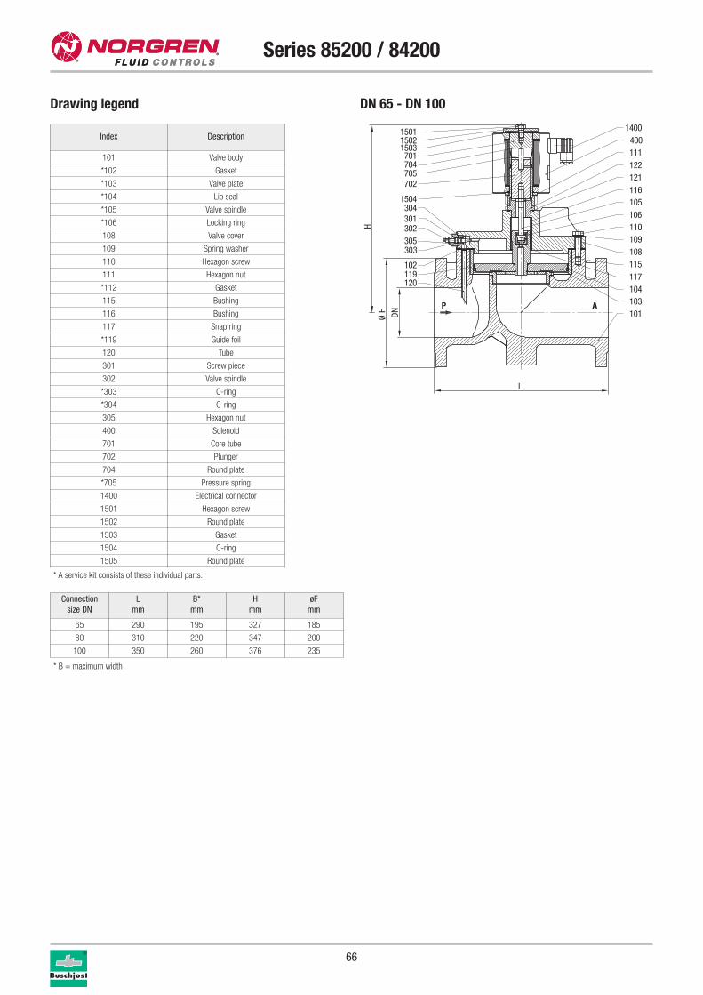
66
Series 85200 / 84200
Connection
size DN
L
mm
B*
mm
H
mm
øF
mm
65 290 195 327 185
80 310 220 347 200
100 350 260 376 235
Drawing legend
Index Description
101 Valve body
*102 Gasket
*103 Valve plate
*104 Lip seal
*105 Valve spindle
*106 Locking ring
108 Valve cover
109 Spring washer
110 Hexagon screw
111 Hexagon nut
*112 Gasket
115 Bushing
116 Bushing
117 Snap ring
*119 Guide foil
120 Tube
301 Screw piece
302 Valve spindle
*303 O-ring
*304 O-ring
305 Hexagon nut
400 Solenoid
701 Core tube
702 Plunger
704 Round plate
*705 Pressure spring
1400 Electrical connector
1501 Hexagon screw
1502 Round plate
1503 Gasket
1504 O-ring
1505 Round plate
P A
15011502
701704705702
1504304301302305303
102119120
1400400
122111
121116
1503
105106110109108
117115
104103101
H
DNØ F
L
* A service kit consists of these individual parts.
DN 65 - DN 100
* B = maximum width
67
Series 85200 / 84200
Further options (valves)
XXXXXX02.XXXX Manual override
XXXXXX14.XXXX Seal: EPDM, maximum temperature +110 °C
XXXXXX17.XXXX Normally open, seal: FPM, maximum temperature +110 °C,
mounting position: with solenoid vertical on top only
XXXXXX22.XXXX Pmax. 40 bar, DN 15 – DN 50
DN 15 Solenoid DC 8401 / AC 8404
Further options (solenoids)
XXXXXXX.8341 DN 15: Solenoid protection class
x II 2 GD EEx me II T3 T 140 °C
XXXXXXX.8436 DN 20 – DN 50: Solenoid protection class
x II 2 GD EEx me II T4 T 140 °C
XXXXXXX.8441 DN 20 – DN 50: Solenoid protection class
x II 2 GD EEx me II T3 T 140 °C
XXXXXXX.8900 DN 15 – DN 50: Solenoid protection class
x II 2 GD EEx de II C T4 and T5 T 130 °C / 95 °C
XXXXXXX.8920 DN 15 – DN 50: Solenoid protection class
x II 2 GD EEx d II C T4 and T5 T 130 °C / 95 °C
XXXXXXX.9540 DN 65 – DN 100: Solenoid protection class
x II 2 GD EEx me II T3/T4 T 140 °C
Further options on requestSolenoids
Special connections
Please turn to page 276 for technical information on our valves.
Service kits
For valves with solenoid 8301 Part number
8520200 1250479
For valves with solenoid 8401 Part number
8520300 1246595
8520400 1246595
8520500 1247223
8520600 1247223
8520700 1247224
For valves with solenoid 9501 Part number
8420800 1244013
8420900 1238279
8421000 1236593
1
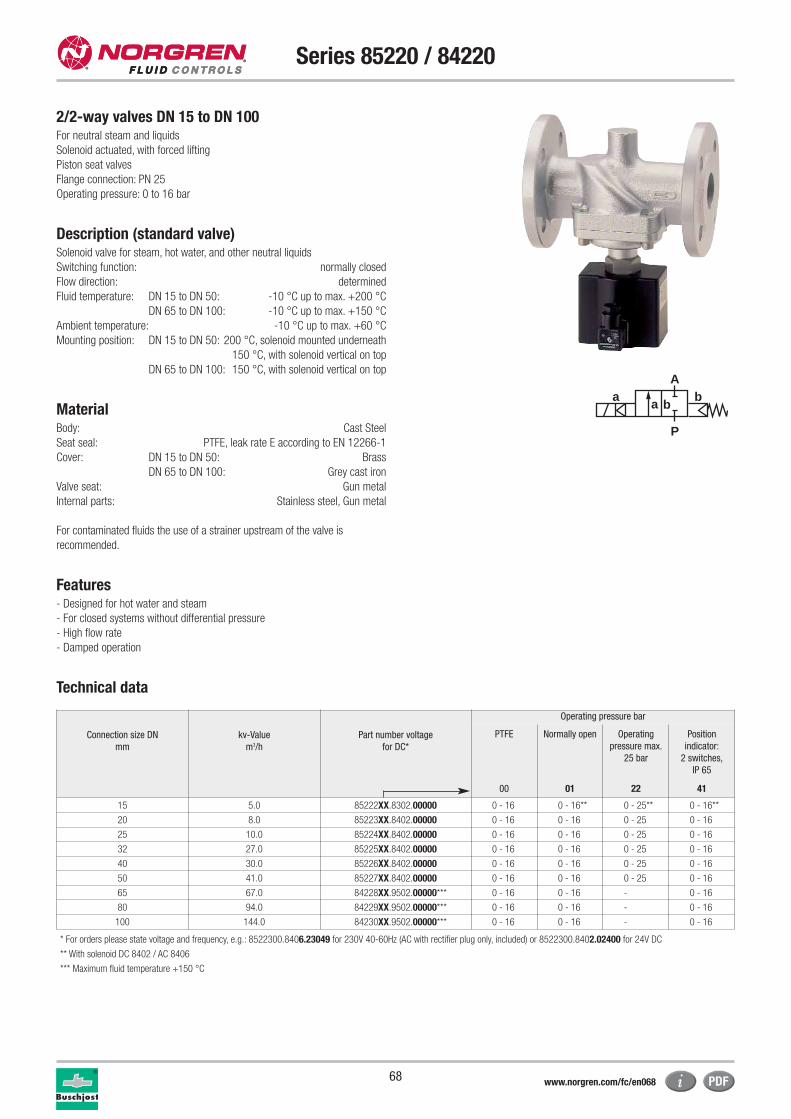
68
Series 85220 / 84220
2/2-way valves DN 15 to DN 100For neutral steam and liquids
Solenoid actuated, with forced lifting
Piston seat valves
Flange connection: PN 25
Operating pressure: 0 to 16 bar
Description (standard valve)Solenoid valve for steam, hot water, and other neutral liquids
Switching function: normally closed
Flow direction: determined
Fluid temperature: DN 15 to DN 50: -10 °C up to max. +200 °C
DN 65 to DN 100: -10 °C up to max. +150 °C
Ambient temperature: -10 °C up to max. +60 °C
Mounting position: DN 15 to DN 50: 200 °C, solenoid mounted underneath
150 °C, with solenoid vertical on top
DN 65 to DN 100: 150 °C, with solenoid vertical on top
MaterialBody: Cast Steel
Seat seal: PTFE, leak rate E according to EN 12266-1
Cover: DN 15 to DN 50: Brass
DN 65 to DN 100: Grey cast iron
Valve seat: Gun metal
Internal parts: Stainless steel, Gun metal
For contaminated fluids the use of a strainer upstream of the valve is
recommended.
Features- Designed for hot water and steam
- For closed systems without differential pressure
- High flow rate
- Damped operation
Technical data
a
P
Ab
a b
Connection size DN
mm
kv-Value
m3/h
Part number voltage
for DC*
Operating pressure bar
PTFE Normally open Operating
pressure max.
25 bar
Position
indicator:
2 switches,
IP 65
00 01 22 41
15 5.0 85222XX.8302.00000 0 - 16 0 - 16** 0 - 25** 0 - 16**
20 8.0 85223XX.8402.00000 0 - 16 0 - 16 0 - 25 0 - 16
25 10.0 85224XX.8402.00000 0 - 16 0 - 16 0 - 25 0 - 16
32 27.0 85225XX.8402.00000 0 - 16 0 - 16 0 - 25 0 - 16
40 30.0 85226XX.8402.00000 0 - 16 0 - 16 0 - 25 0 - 16
50 41.0 85227XX.8402.00000 0 - 16 0 - 16 0 - 25 0 - 16
65 67.0 84228XX.9502.00000*** 0 - 16 0 - 16 - 0 - 16
80 94.0 84229XX.9502.00000*** 0 - 16 0 - 16 - 0 - 16
100 144.0 84230XX.9502.00000*** 0 - 16 0 - 16 - 0 - 16
* For orders please state voltage and frequency, e.g.: 8522300.8406.23049 for 230V 40-60Hz (AC with rectifier plug only, included) or 8522300.8402.02400 for 24V DC
** With solenoid DC 8402 / AC 8406
*** Maximum fluid temperature +150 °C
www.norgren.com/fc/en068
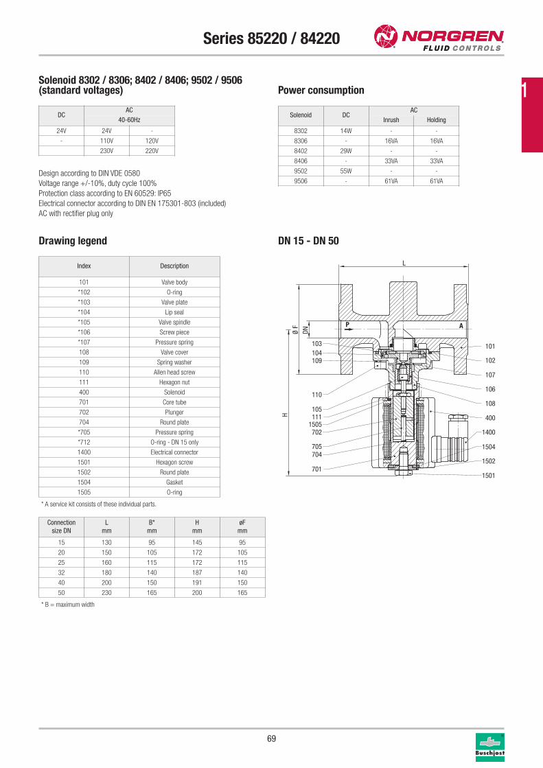
69
Series 85220 / 84220
Drawing legend
Index Description
101 Valve body
*102 O-ring
*103 Valve plate
*104 Lip seal
*105 Valve spindle
*106 Screw piece
*107 Pressure spring
108 Valve cover
109 Spring washer
110 Allen head screw
111 Hexagon nut
400 Solenoid
701 Core tube
702 Plunger
704 Round plate
*705 Pressure spring
*712 O-ring - DN 15 only
1400 Electrical connector
1501 Hexagon screw
1502 Round plate
1504 Gasket
1505 O-ring
* A service kit consists of these individual parts.
Solenoid 8302 / 8306; 8402 / 8406; 9502 / 9506(standard voltages) Power consumption
Design according to DIN VDE 0580
Voltage range +/-10%, duty cycle 100%
Protection class according to EN 60529: IP65
Electrical connector according to DIN EN 175301-803 (included)
AC with rectifier plug only
Solenoid DCAC
Inrush Holding
8302 14W - -
8306 - 16VA 16VA
8402 29W - -
8406 - 33VA 33VA
9502 55W - -
9506 - 61VA 61VA
P A
103104109
110
105111
1505702
705704
701
101
102
107
106
108
400
1400
1501
1502
1504
H
DNØ F
L
Connection
size DN
L
mm
B*
mm
H
mm
øF
mm
15 130 95 145 95
20 150 105 172 105
25 160 115 172 115
32 180 140 187 140
40 200 150 191 150
50 230 165 200 165
DN 15 - DN 50
DCAC
40-60Hz
24V 24V -
- 110V 120V
230V 220V
* B = maximum width
1
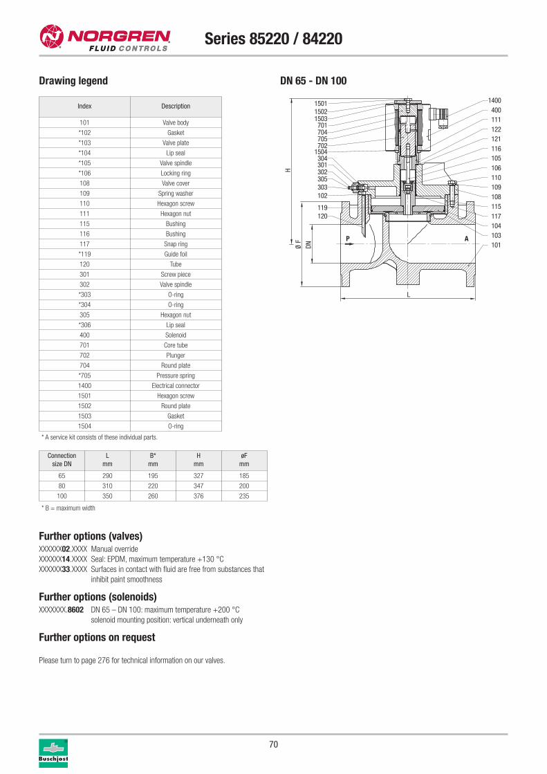
70
Series 85220 / 84220
Drawing legend
Connection
size DN
L
mm
B*
mm
H
mm
øF
mm
65 290 195 327 185
80 310 220 347 200
100 350 260 376 235
Index Description
101 Valve body
*102 Gasket
*103 Valve plate
*104 Lip seal
*105 Valve spindle
*106 Locking ring
108 Valve cover
109 Spring washer
110 Hexagon screw
111 Hexagon nut
115 Bushing
116 Bushing
117 Snap ring
*119 Guide foil
120 Tube
301 Screw piece
302 Valve spindle
*303 O-ring
*304 O-ring
305 Hexagon nut
*306 Lip seal
400 Solenoid
701 Core tube
702 Plunger
704 Round plate
*705 Pressure spring
1400 Electrical connector
1501 Hexagon screw
1502 Round plate
1503 Gasket
1504 O-ring
Further options (valves)XXXXXX02.XXXX Manual override
XXXXXX14.XXXX Seal: EPDM, maximum temperature +130 °C
XXXXXX33.XXXX Surfaces in contact with fluid are free from substances that
inhibit paint smoothness
Further options (solenoids)XXXXXXX.8602 DN 65 – DN 100: maximum temperature +200 °C
solenoid mounting position: vertical underneath only
Further options on request
Please turn to page 276 for technical information on our valves.
* A service kit consists of these individual parts.
P A
15011502
701704705702
1504304301302305303102
119120
1400400
122111
121116
1503
105106110109108
117115
104103101
H
DNØ F
L
DN 65 - DN 100
* B = maximum width
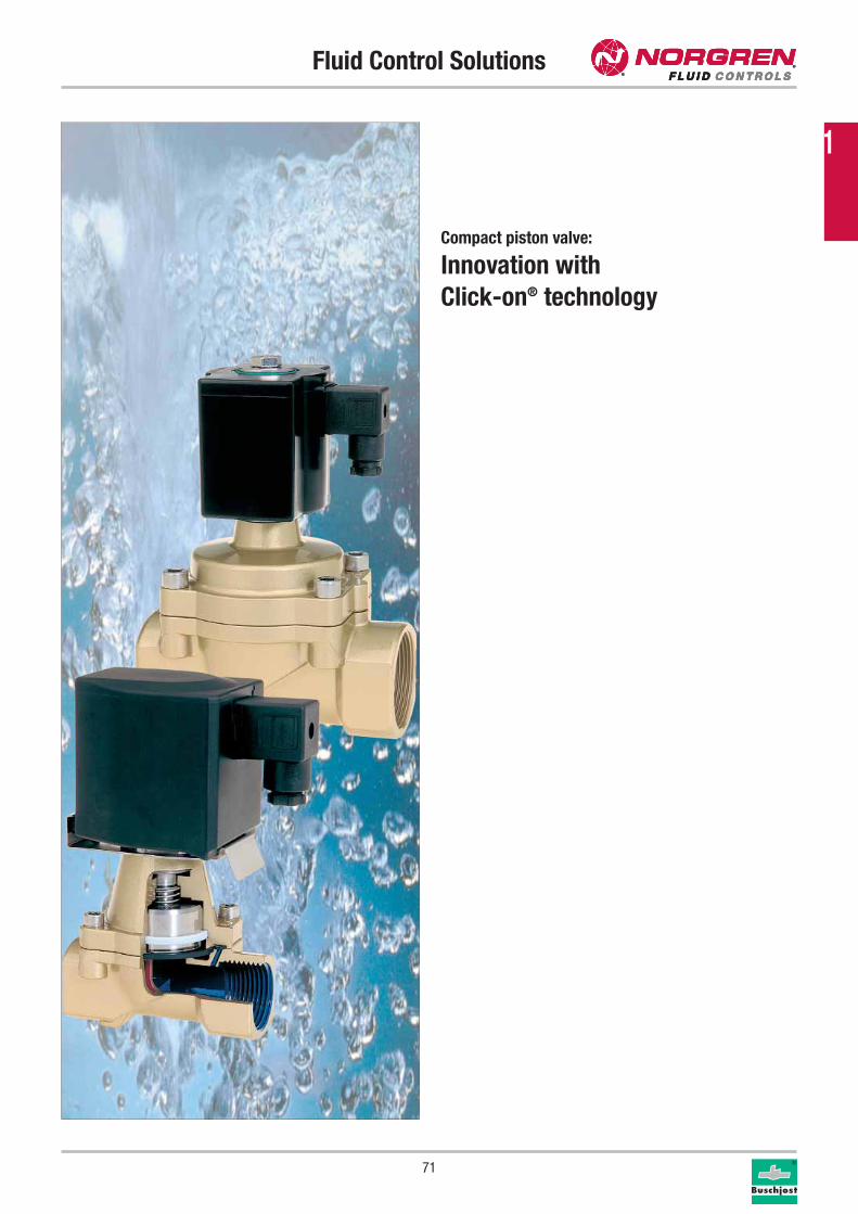
Fluid Control Solutions
71
Compact piston valve:
Innovation with
Click-on® technology
1
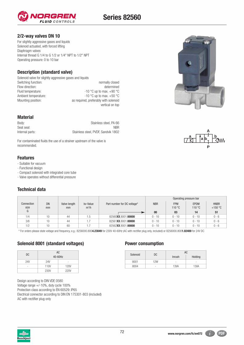
72
Series 82560
2/2-way valves DN 10For slightly aggressive gases and liquids
Solenoid actuated, with forced lifting
Diaphragm valves
Internal thread G 1/4 to G 1/2 or 1/4" NPT to 1/2" NPT
Operating pressure: 0 to 10 bar
Description (standard valve)Solenoid valve for slightly aggressive gases and liquids
Switching function: normally closed
Flow direction: determined
Fluid temperature: -10 °C up to max. +90 °C
Ambient temperature: -10 °C up to max. +50 °C
Mounting position: as required, preferably with solenoid
vertical on top
MaterialBody: Stainless steel, PA 66
Seat seal: NBR
Internal parts: Stainless steel, PVDF, Sandvik 1802
For contaminated fluids the use of a strainer upstream of the valve is
recommended.
Features- Suitable for vacuum
- Functional design
- Compact solenoid with integrated core tube
- Valve operates without differential pressure
Technical data
a
P
Ab
a b
Operating pressure bar
Connection
size
G
DN
mm
Valve length
mm
kv-Value
m3/h
Part number for DC voltage* NBR FPM
110 °C
EPDM
110 °C
HNBR
+150 °C
00 03 14 51
1/4 10 44 1.5 82560XX.8001.00000 0 - 10 0 - 10 0 - 10 0 - 6
3/8 10 44 1.7 82561XX.8001.00000 0 - 10 0 - 10 0 - 10 0 - 6
1/2 10 60 1.7 82562XX.8001.00000 0 - 10 0 - 10 0 - 10 0 - 6
* For orders please state voltage and frequency, e.g.: 8256000.8004.23049 for 230V 40-60Hz (AC with rectifier plug only, included) or 8256000.8001.02400 for 24V DC
Solenoid 8001 (standard voltages) Power consumption
Design according to DIN VDE 0580
Voltage range +/-10%, duty cycle 100%
Protection class according to EN 60529: IP65
Electrical connector according to DIN EN 175301-803 (included)
AC with rectifier plug only
Solenoid DCAC
Inrush Holding
8001 12W - -
8004 - 13VA 13VA
DCAC
40-60Hz
24V 24V -
- 110V 120V
230V 220V
www.norgren.com/fc/en072
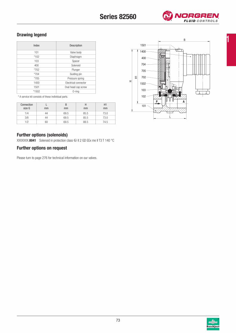
73
Series 82560
Drawing legend
Index Description
101 Valve body
*102 Diaphragm
103 Spacer
400 Solenoid
*702 Plunger
*704 Guiding pin
*705 Pressure spring
1400 Electrical connector
1501 Oval head cap screw
*1502 O-ring
* A service kit consists of these individual parts.
P A101
102
103
1502
702
705
704
1501
1400
400
H1
H
L
B
Connection
size G
L
mm
B
mm
H
mm
H1
mm
1/4 44 69.5 85.5 73.0
3/8 44 69.5 85.5 73.0
1/2 60 69.5 88.5 74.5
Further options (solenoids)XXXXXXX.8041 Solenoid in protection class x II 2 GD EEx me II T3 T 140 °C
Further options on request
Please turn to page 276 for technical information on our valves.
1
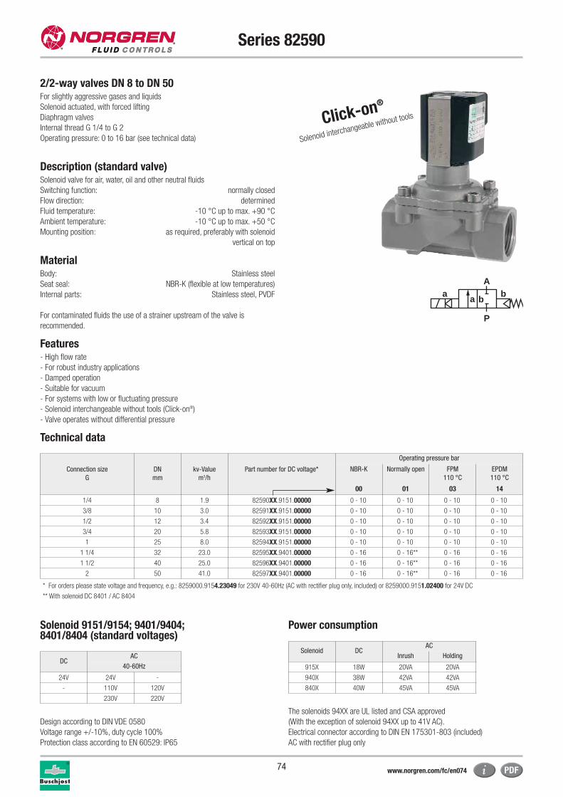
74
Series 82590
2/2-way valves DN 8 to DN 50For slightly aggressive gases and liquids
Solenoid actuated, with forced lifting
Diaphragm valves
Internal thread G 1/4 to G 2
Operating pressure: 0 to 16 bar (see technical data)
Description (standard valve)Solenoid valve for air, water, oil and other neutral fluids
Switching function: normally closed
Flow direction: determined
Fluid temperature: -10 °C up to max. +90 °C
Ambient temperature: -10 °C up to max. +50 °C
Mounting position: as required, preferably with solenoid
vertical on top
MaterialBody: Stainless steel
Seat seal: NBR-K (flexible at low temperatures)
Internal parts: Stainless steel, PVDF
For contaminated fluids the use of a strainer upstream of the valve is
recommended.
Features- High flow rate
- For robust industry applications
- Damped operation
- Suitable for vacuum
- For systems with low or fluctuating pressure
- Solenoid interchangeable without tools (Click-on®)
- Valve operates without differential pressure
Technical data
a
P
Ab
a b
Click-on®
Solenoid interchangeable without tools
Connection size
G
DN
mm
kv-Value
m3/h
Part number for DC voltage*
Operating pressure bar
NBR-K Normally open FPM
110 °C
EPDM
110 °C
00 01 03 14
1/4 8 1.9 82590XX.9151.00000 0 - 10 0 - 10 0 - 10 0 - 10
3/8 10 3.0 82591XX.9151.00000 0 - 10 0 - 10 0 - 10 0 - 10
1/2 12 3.4 82592XX.9151.00000 0 - 10 0 - 10 0 - 10 0 - 10
3/4 20 5.8 82593XX.9151.00000 0 - 10 0 - 10 0 - 10 0 - 10
1 25 8.0 82594XX.9151.00000 0 - 10 0 - 10 0 - 10 0 - 10
1 1/4 32 23.0 82595XX.9401.00000 0 - 16 0 - 16** 0 - 16 0 - 16
1 1/2 40 25.0 82596XX.9401.00000 0 - 16 0 - 16** 0 - 16 0 - 16
2 50 41.0 82597XX.9401.00000 0 - 16 0 - 16** 0 - 16 0 - 16
** With solenoid DC 8401 / AC 8404
* For orders please state voltage and frequency, e.g.: 8259000.9154.23049 for 230V 40-60Hz (AC with rectifier plug only, included) or 8259000.9151.02400 for 24V DC
Solenoid 9151/9154; 9401/9404; 8401/8404 (standard voltages)
Power consumption
Design according to DIN VDE 0580
Voltage range +/-10%, duty cycle 100%
Protection class according to EN 60529: IP65
The solenoids 94XX are UL listed and CSA approved
(With the exception of solenoid 94XX up to 41V AC).
Electrical connector according to DIN EN 175301-803 (included)
AC with rectifier plug only
Solenoid DCAC
Inrush Holding
915X 18W 20VA 20VA
940X 38W 42VA 42VA
840X 40W 45VA 45VA
DCAC
40-60Hz
24V 24V -
- 110V 120V
230V 220V
www.norgren.com/fc/en074
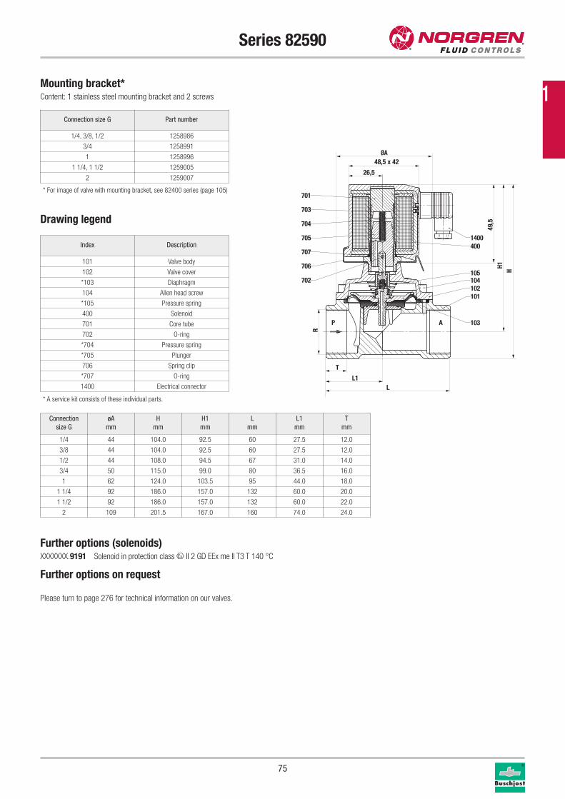
75
Series 82590
Connection size G Part number
1/4, 3/8, 1/2 1258986
3/4 1258991
1 1258996
1 1/4, 1 1/2 1259005
2 1259007
Mounting bracket*Content: 1 stainless steel mounting bracket and 2 screws
Drawing legend
Index Description
101 Valve body
102 Valve cover
*103 Diaphragm
104 Allen head screw
*105 Pressure spring
400 Solenoid
701 Core tube
702 O-ring
*704 Pressure spring
*705 Plunger
706 Spring clip
*707 O-ring
1400 Electrical connector
* A service kit consists of these individual parts.
Further options (solenoids)XXXXXXX.9191 Solenoid in protection class x II 2 GD EEx me II T3 T 140 °C
Further options on request
Please turn to page 276 for technical information on our valves.
P A
101102
103
104105
1400400
706
707
702
705
704
703
701
H1
R
ØA48,5 x 42
26,5
49,5
T
L1L
H
Connection
size G
øA
mm
H
mm
H1
mm
L
mm
L1
mm
T
mm
1/4 44 104.0 92.5 60 27.5 12.0
3/8 44 104.0 92.5 60 27.5 12.0
1/2 44 108.0 94.5 67 31.0 14.0
3/4 50 115.0 99.0 80 36.5 16.0
1 62 124.0 103.5 95 44.0 18.0
1 1/4 92 186.0 157.0 132 60.0 20.0
1 1/2 92 186.0 157.0 132 60.0 22.0
2 109 201.5 167.0 160 74.0 24.0
* For image of valve with mounting bracket, see 82400 series (page 105)
1
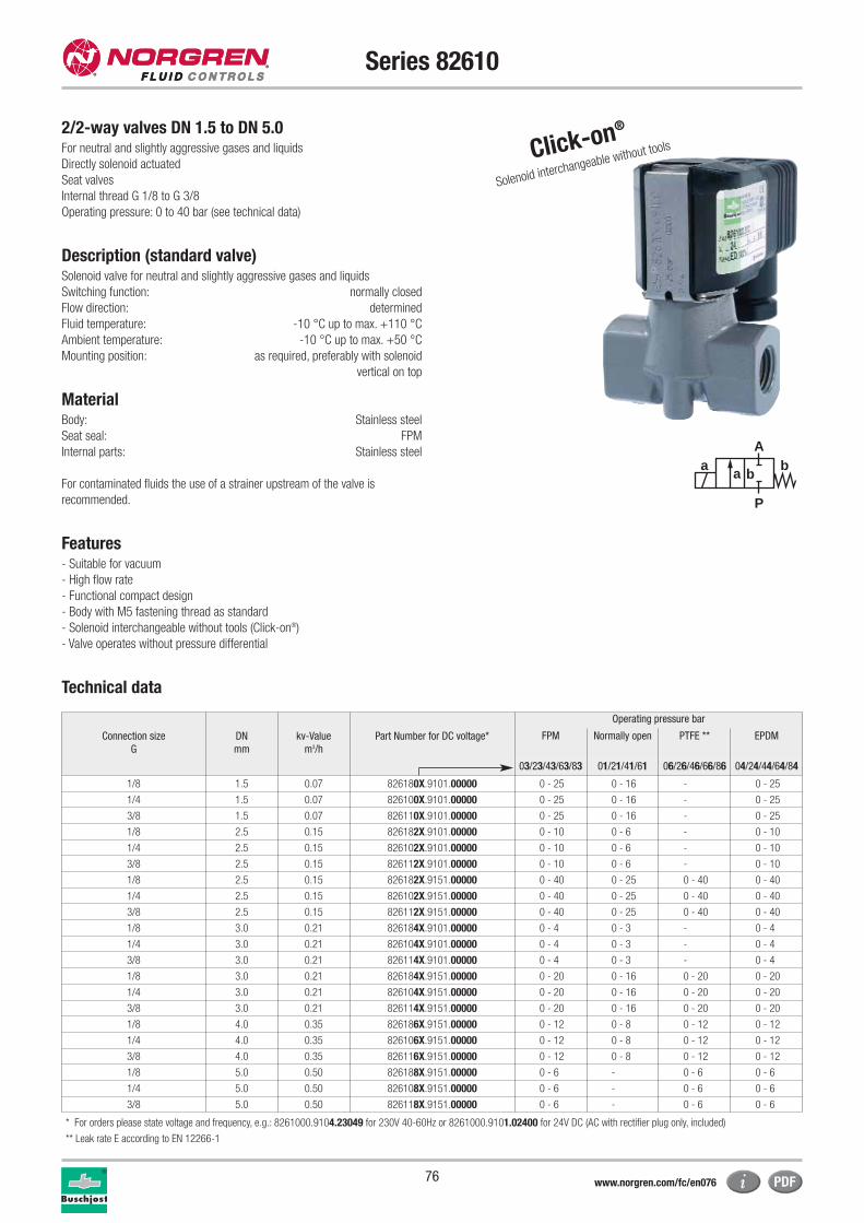
76
Series 82610
2/2-way valves DN 1.5 to DN 5.0For neutral and slightly aggressive gases and liquids
Directly solenoid actuated
Seat valves
Internal thread G 1/8 to G 3/8
Operating pressure: 0 to 40 bar (see technical data)
Description (standard valve)Solenoid valve for neutral and slightly aggressive gases and liquids
Switching function: normally closed
Flow direction: determined
Fluid temperature: -10 °C up to max. +110 °C
Ambient temperature: -10 °C up to max. +50 °C
Mounting position: as required, preferably with solenoid
vertical on top
MaterialBody: Stainless steel
Seat seal: FPM
Internal parts: Stainless steel
For contaminated fluids the use of a strainer upstream of the valve is
recommended.
Features- Suitable for vacuum
- High flow rate
- Functional compact design
- Body with M5 fastening thread as standard
- Solenoid interchangeable without tools (Click-on®)
- Valve operates without pressure differential
Technical data
Click-on®
Solenoid interchangeable without tools
a
P
Ab
a b
Connection size
G
DN
mm
kv-Value
m3/h
Part Number for DC voltage*
Operating pressure bar
FPM Normally open PTFE ** EPDM
03/23/43/63/83 01/21/41/61 06/26/46/66/86 04/24/44/64/84
1/8 1.5 0.07 826180X.9101.00000 0 - 25 0 - 16 - 0 - 25
1/4 1.5 0.07 826100X.9101.00000 0 - 25 0 - 16 - 0 - 25
3/8 1.5 0.07 826110X.9101.00000 0 - 25 0 - 16 - 0 - 25
1/8 2.5 0.15 826182X.9101.00000 0 - 10 0 - 6 - 0 - 10
1/4 2.5 0.15 826102X.9101.00000 0 - 10 0 - 6 - 0 - 10
3/8 2.5 0.15 826112X.9101.00000 0 - 10 0 - 6 - 0 - 10
1/8 2.5 0.15 826182X.9151.00000 0 - 40 0 - 25 0 - 40 0 - 40
1/4 2.5 0.15 826102X.9151.00000 0 - 40 0 - 25 0 - 40 0 - 40
3/8 2.5 0.15 826112X.9151.00000 0 - 40 0 - 25 0 - 40 0 - 40
1/8 3.0 0.21 826184X.9101.00000 0 - 4 0 - 3 - 0 - 4
1/4 3.0 0.21 826104X.9101.00000 0 - 4 0 - 3 - 0 - 4
3/8 3.0 0.21 826114X.9101.00000 0 - 4 0 - 3 - 0 - 4
1/8 3.0 0.21 826184X.9151.00000 0 - 20 0 - 16 0 - 20 0 - 20
1/4 3.0 0.21 826104X.9151.00000 0 - 20 0 - 16 0 - 20 0 - 20
3/8 3.0 0.21 826114X.9151.00000 0 - 20 0 - 16 0 - 20 0 - 20
1/8 4.0 0.35 826186X.9151.00000 0 - 12 0 - 8 0 - 12 0 - 12
1/4 4.0 0.35 826106X.9151.00000 0 - 12 0 - 8 0 - 12 0 - 12
3/8 4.0 0.35 826116X.9151.00000 0 - 12 0 - 8 0 - 12 0 - 12
1/8 5.0 0.50 826188X.9151.00000 0 - 6 - 0 - 6 0 - 6
1/4 5.0 0.50 826108X.9151.00000 0 - 6 - 0 - 6 0 - 6
3/8 5.0 0.50 826118X.9151.00000 0 - 6 - 0 - 6 0 - 6
* For orders please state voltage and frequency, e.g.: 8261000.9104.23049 for 230V 40-60Hz or 8261000.9101.02400 for 24V DC (AC with rectifier plug only, included)
** Leak rate E according to EN 12266-1
www.norgren.com/fc/en076
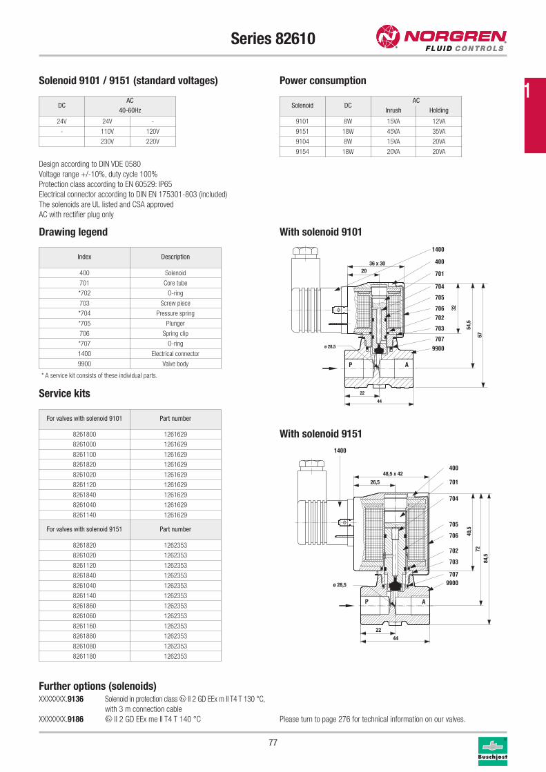
77
Series 82610
Drawing legend With solenoid 9101
With solenoid 9151
Index Description
400 Solenoid
701 Core tube
*702 O-ring
703 Screw piece
*704 Pressure spring
*705 Plunger
706 Spring clip
*707 O-ring
1400 Electrical connector
9900 Valve body
Service kits
* A service kit consists of these individual parts.
For valves with solenoid 9101 Part number
8261800 1261629
8261000 1261629
8261100 1261629
8261820 1261629
8261020 1261629
8261120 1261629
8261840 1261629
8261040 1261629
8261140 1261629
For valves with solenoid 9151 Part number
8261820 1262353
8261020 1262353
8261120 1262353
8261840 1262353
8261040 1262353
8261140 1262353
8261860 1262353
8261060 1262353
8261160 1262353
8261880 1262353
8261080 1262353
8261180 1262353
P A
707
9900
1400
400
701
704
705
706702
703
44
22
ø 28,5
2036 x 30
32
54,5
67
AP
1400
400
701
704
705
706
702
703
7079900
44
22
ø 28,5
26,5
48,5 x 4249
,5
7284
,5
Solenoid DCAC
Inrush Holding
9101 8W 15VA 12VA
9151 18W 45VA 35VA
9104 8W 15VA 20VA
9154 18W 20VA 20VA
Solenoid 9101 / 9151 (standard voltages) Power consumption
Design according to DIN VDE 0580
Voltage range +/-10%, duty cycle 100%
Protection class according to EN 60529: IP65
Electrical connector according to DIN EN 175301-803 (included)
The solenoids are UL listed and CSA approved
AC with rectifier plug only
DCAC
40-60Hz
24V 24V -
- 110V 120V
230V 220V
Further options (solenoids)XXXXXXX.9136 Solenoid in protection class x II 2 GD EEx m II T4 T 130 °C,
with 3 m connection cable
XXXXXXX.9186 x II 2 GD EEx me II T4 T 140 °C Please turn to page 276 for technical information on our valves.
1
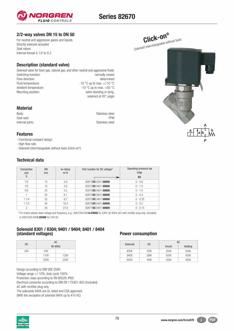
78
Series 82670
2/2-way valves DN 15 to DN 50For neutral and aggressive gases and liquids
Directly solenoid actuated
Seat valves
Internal thread G 1/2 to G 2
Description (standard valve)Solenoid valve for town gas, natural gas, and other neutral and aggressive fluids
Switching function: normally closed
Flow direction: determined
Fluid temperature: -10 °C up to max. +110 °C
Ambient temperature: -10 °C up to max. +50 °C
Mounting position: valve standing or lying,
solenoid at 45° angle
MaterialBody: Stainless steel
Seat seal: FPM
Internal parts: Stainless steel
Features- Functional compact design
- High flow rate
- Solenoid interchangeable without tools (Click-on®)
Technical data
a
P
Ab
a b
Connection
size
G
DN
mm
kv-Value
m3/h
Part number for DC voltage* Operating pressure bar
FPM
03
1/2 15 3.0 82672XX.8301.00000 0 - 0.6
1/2 15 3.0 82672XX.9401.00000 0 - 1.5
3/4 20 5.5 82673XX.9401.00000 0 - 1.0
1 25 6.1 82674XX.9401.00000 0 - 0.4
1 1/4 32 8.7 82675XX.9401.00000 0 - 0.25
1 1/2 40 16.3 82676XX.8401.00000 0 - 0.2
2 50 27.6 82677XX.8401.00000 0 - 0.15
* For orders please state voltage and frequency, e.g.: 8267200.9404.23049 for 230V 40-60Hz (AC with rectifier plug only; included)
or 8267200.9401.02400 for 24V DC
Solenoid 8301 / 8304; 9401 / 9404; 8401 / 8404(standard voltages) Power consumption
Design according to DIN VDE 0580
Voltage range +/-10%, duty cycle 100%
Protection class according to EN 60529: IP65
Electrical connector according to DIN EN 175301-803 (included)
AC with rectifier plug only
The solenoids 94XX are UL listed and CSA approved
(With the exception of solenoid 94XX up to 41V AC)
Solenoid DCAC
Inrush Holding
830X 22W 25VA 25VA
940X 38W 42VA 42VA
840X 40W 45VA 45VA
DCAC
40-60Hz
24V 24V -
- 110V 120V
230V 220V
Click-on®
Solenoid interchangeable without tools
www.norgren.com/fc/en078
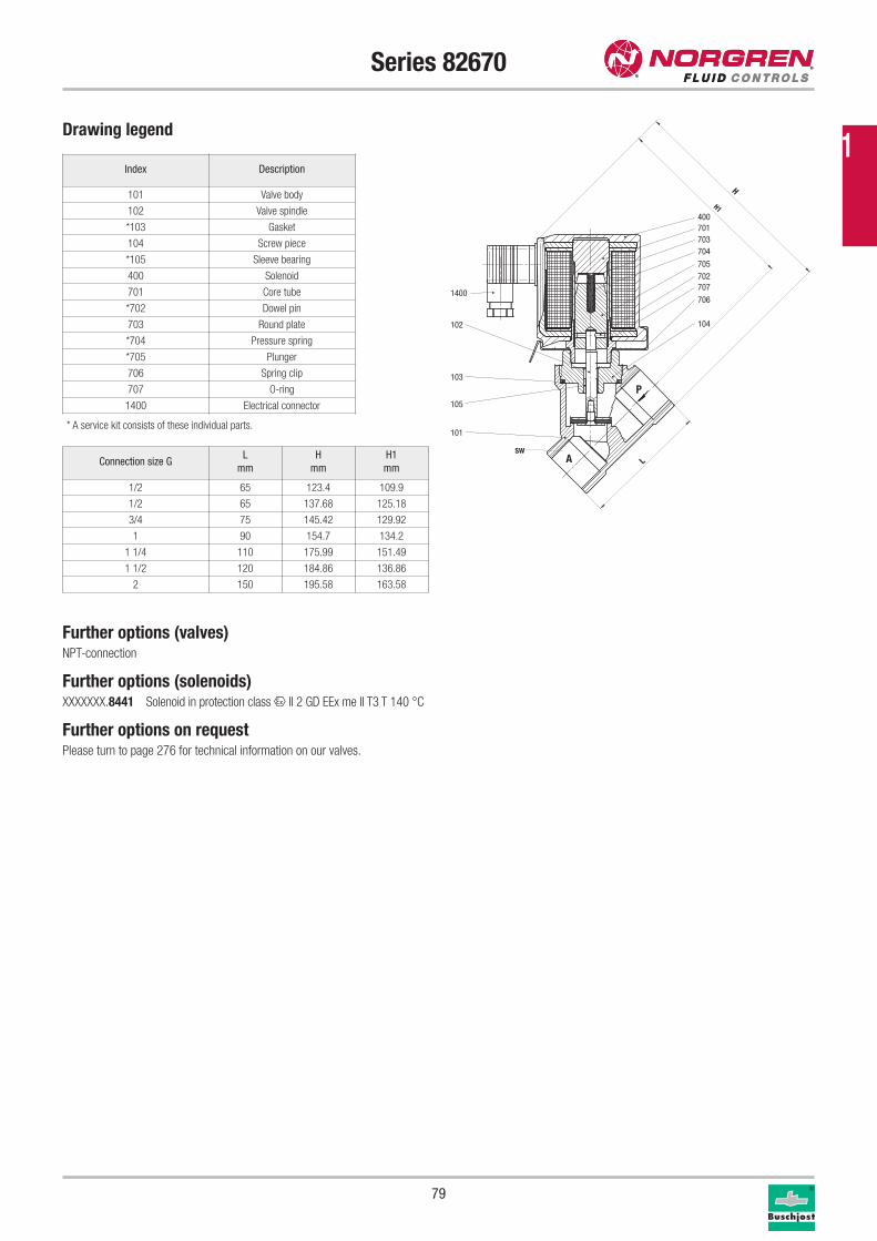
79
Series 82670
Drawing legend
Index Description
101 Valve body
102 Valve spindle
*103 Gasket
104 Screw piece
*105 Sleeve bearing
400 Solenoid
701 Core tube
*702 Dowel pin
703 Round plate
*704 Pressure spring
*705 Plunger
706 Spring clip
707 O-ring
1400 Electrical connector
* A service kit consists of these individual parts.
400701703704
705702707
706
104
101
105
103
102
1400
A
P
H
H1
SW
L
Further options (valves)NPT-connection
Further options (solenoids)XXXXXXX.8441 Solenoid in protection class x II 2 GD EEx me II T3 T 140 °C
Further options on requestPlease turn to page 276 for technical information on our valves.
Connection size GL
mm
H
mm
H1
mm
1/2 65 123.4 109.9
1/2 65 137.68 125.18
3/4 75 145.42 129.92
1 90 154.7 134.2
1 1/4 110 175.99 151.49
1 1/2 120 184.86 136.86
2 150 195.58 163.58
1
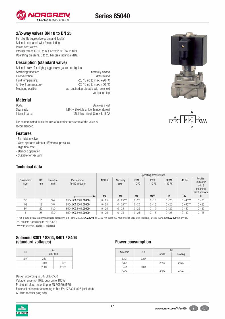
80
Series 85040
2/2-way valves DN 10 to DN 25For slightly aggressive gases and liquids
Solenoid actuated, with forced lifting
Piston seat valves
Internal thread G 3/8 to G 1 or 3/8" NPT to 1" NPT
Operating pressure: 0 to 25 bar (see technical data)
Description (standard valve)Solenoid valve for slightly aggressive gases and liquids
Switching function: normally closed
Flow direction: determined
Fluid temperature: -20 °C up to max. +90 °C
Ambient temperature: -20 °C up to max. +50 °C
Mounting position: as required, preferably with solenoid
vertical on top
MaterialBody: Stainless steel
Seat seal: NBR-K (flexible at low temperatures)
Internal parts: Stainless steel, Sandvik 1802
For contaminated fluids the use of a strainer upstream of the valve is
recommended.
Features- Flat-piston valve
- Valve operates without differential pressure
- High flow rate
- Damped operation
- Suitable for vacuum
Technical data
Operating pressure bar
Connection
size
G
DN
mm
kv-Value
m3/h
Part number
for DC voltage*
NBR-K Normally
open
FPM
110 °C
PTFE
110 °C
EPDM
110 °C
40 barPosition
indicator
with 2
magnetic
field sensors
00 01 03 06** 14 22 41
3/8 10 3.4 85041XX.8301.00000 0 - 25 0 - 25*** 0 - 25 0 - 16 0 - 25 0 - 40*** 0 - 25
1/2 12 3.8 85042XX.8301.00000 0 - 25 0 - 25*** 0 - 25 0 - 16 0 - 25 0 - 40*** 0 - 25
3/4 20 11.0 85043XX.8401.00000 0 - 25 0 - 25 0 - 25 0 - 16 0 - 25 0 - 40 0 - 25
1 25 13.0 85044XX.8401.00000 0 - 25 0 - 25 0 - 25 0 - 16 0 - 25 0 - 40 0 - 25
* For orders please state voltage and frequency, e.g.: 8504200.8304.23049 for 230V 40-60Hz (AC with rectifier plug only, included) or 8504200.8301.02400 for 24V DC
** Leak rate E according to EN 12266-1
*** With solenoid DC 8401 / AC 8404
Solenoid 8301 / 8304, 8401 / 8404(standard voltages) Power consumption
Design according to DIN VDE 0580
Voltage range +/-10%, duty cycle 100%
Protection class according to EN 60529: IP65
Electrical connector according to DIN EN 175301-803 (included)
AC with rectifier plug only
Solenoid DCAC
Inrush Holding
8301 22W
8304 25VA 25VA
8401 40W
8404 45VA 45VA
a
P
Ab
a b
DCAC
40-60Hz
24V 24V -
- 110V 120V
230V 220V
www.norgren.com/fc/en080
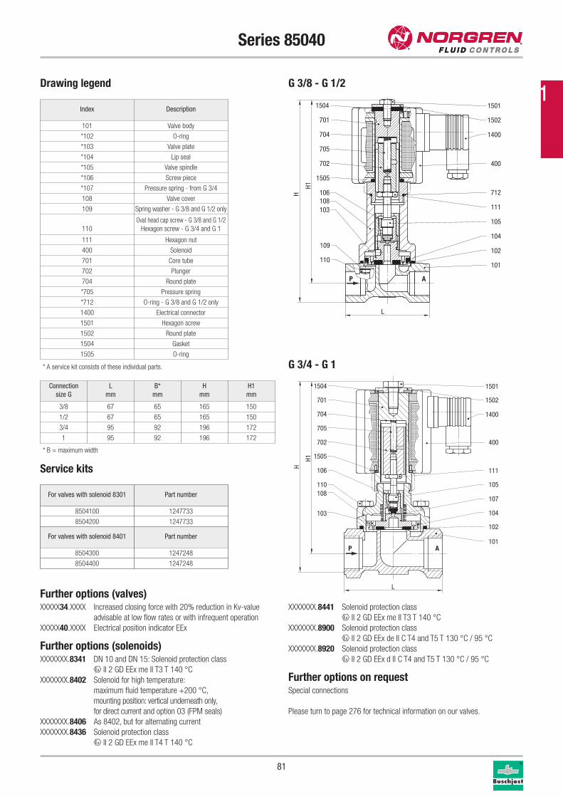
81
Series 85040
Drawing legend
Index Description
101 Valve body
*102 O-ring
*103 Valve plate
*104 Lip seal
*105 Valve spindle
*106 Screw piece
*107 Pressure spring - from G 3/4
108 Valve cover
109 Spring washer - G 3/8 and G 1/2 only
110
Oval head cap screw - G 3/8 and G 1/2
Hexagon screw - G 3/4 and G 1
111 Hexagon nut
400 Solenoid
701 Core tube
702 Plunger
704 Round plate
*705 Pressure spring
*712 O-ring - G 3/8 and G 1/2 only
1400 Electrical connector
1501 Hexagon screw
1502 Round plate
1504 Gasket
1505 O-ring
* A service kit consists of these individual parts.
Service kits
For valves with solenoid 8301 Part number
8504100 1247733
8504200 1247733
For valves with solenoid 8401 Part number
8504300 1247248
8504400 1247248
Further options (valves)XXXXX34.XXXX Increased closing force with 20% reduction in Kv-value
advisable at low flow rates or with infrequent operation
XXXXX40.XXXX Electrical position indicator EEx
Further options (solenoids)XXXXXXX.8341 DN 10 and DN 15: Solenoid protection class
x II 2 GD EEx me II T3 T 140 °C
XXXXXXX.8402 Solenoid for high temperature:
maximum fluid temperature +200 °C,
mounting position: vertical underneath only,
for direct current and option 03 (FPM seals)
XXXXXXX.8406 As 8402, but for alternating current
XXXXXXX.8436 Solenoid protection class
x II 2 GD EEx me II T4 T 140 °C
XXXXXXX.8441 Solenoid protection class
x II 2 GD EEx me II T3 T 140 °C
XXXXXXX.8900 Solenoid protection class
x II 2 GD EEx de II C T4 and T5 T 130 °C / 95 °C
XXXXXXX.8920 Solenoid protection class
x II 2 GD EEx d II C T4 and T5 T 130 °C / 95 °C
Further options on requestSpecial connections
Please turn to page 276 for technical information on our valves.
Connection
size G
L
mm
B*
mm
H
mm
H1
mm
3/8 67 65 165 150
1/2 67 65 165 150
3/4 95 92 196 172
1 95 92 196 172
H1
H
L
1504
701
704
705
702
1505
106
110108
103
1501
1502
1400
400
111
105
107
104
102
101AP
P A
1504
701
704
705
702
1505
106
103
109
108
110
1501
1502
1400
400
712
111
105
102
104
101
H1
H
L
G 3/4 - G 1
G 3/8 - G 1/2
* B = maximum width
1
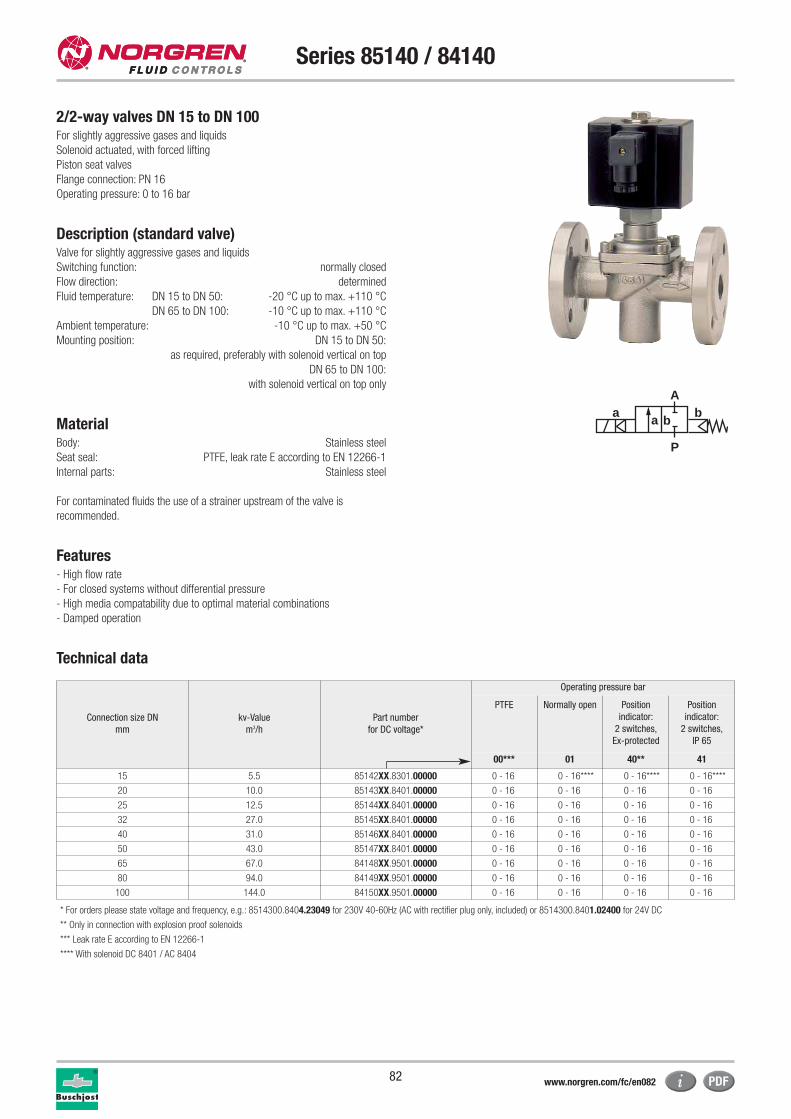
82
Series 85140 / 84140
2/2-way valves DN 15 to DN 100For slightly aggressive gases and liquids
Solenoid actuated, with forced lifting
Piston seat valves
Flange connection: PN 16
Operating pressure: 0 to 16 bar
Description (standard valve)Valve for slightly aggressive gases and liquids
Switching function: normally closed
Flow direction: determined
Fluid temperature: DN 15 to DN 50: -20 °C up to max. +110 °C
DN 65 to DN 100: -10 °C up to max. +110 °C
Ambient temperature: -10 °C up to max. +50 °C
Mounting position: DN 15 to DN 50:
as required, preferably with solenoid vertical on top
DN 65 to DN 100:
with solenoid vertical on top only
MaterialBody: Stainless steel
Seat seal: PTFE, leak rate E according to EN 12266-1
Internal parts: Stainless steel
For contaminated fluids the use of a strainer upstream of the valve is
recommended.
Features- High flow rate
- For closed systems without differential pressure
- High media compatability due to optimal material combinations
- Damped operation
Technical data
a
P
Ab
a b
Connection size DN
mm
kv-Value
m3/h
Part number
for DC voltage*
Operating pressure bar
PTFE Normally open Position
indicator:
2 switches,
Ex-protected
Position
indicator:
2 switches,
IP 65
00*** 01 40** 41
15 5.5 85142XX.8301.00000 0 - 16 0 - 16**** 0 - 16**** 0 - 16****
20 10.0 85143XX.8401.00000 0 - 16 0 - 16 0 - 16 0 - 16
25 12.5 85144XX.8401.00000 0 - 16 0 - 16 0 - 16 0 - 16
32 27.0 85145XX.8401.00000 0 - 16 0 - 16 0 - 16 0 - 16
40 31.0 85146XX.8401.00000 0 - 16 0 - 16 0 - 16 0 - 16
50 43.0 85147XX.8401.00000 0 - 16 0 - 16 0 - 16 0 - 16
65 67.0 84148XX.9501.00000 0 - 16 0 - 16 0 - 16 0 - 16
80 94.0 84149XX.9501.00000 0 - 16 0 - 16 0 - 16 0 - 16
100 144.0 84150XX.9501.00000 0 - 16 0 - 16 0 - 16 0 - 16
* For orders please state voltage and frequency, e.g.: 8514300.8404.23049 for 230V 40-60Hz (AC with rectifier plug only, included) or 8514300.8401.02400 for 24V DC
** Only in connection with explosion proof solenoids
*** Leak rate E according to EN 12266-1
**** With solenoid DC 8401 / AC 8404
www.norgren.com/fc/en082
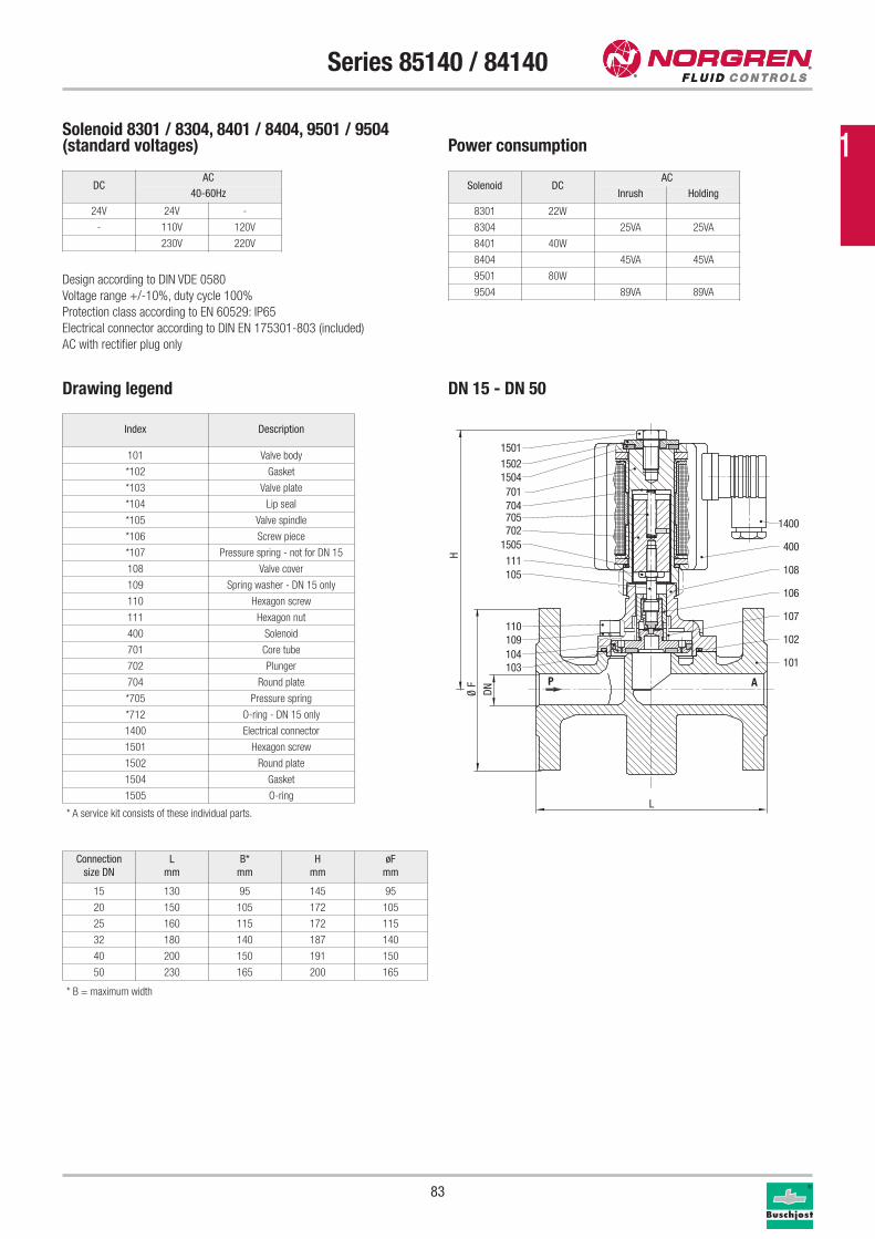
83
Series 85140 / 84140
Drawing legend
* A service kit consists of these individual parts.
Index Description
101 Valve body
*102 Gasket
*103 Valve plate
*104 Lip seal
*105 Valve spindle
*106 Screw piece
*107 Pressure spring - not for DN 15
108 Valve cover
109 Spring washer - DN 15 only
110 Hexagon screw
111 Hexagon nut
400 Solenoid
701 Core tube
702 Plunger
704 Round plate
*705 Pressure spring
*712 O-ring - DN 15 only
1400 Electrical connector
1501 Hexagon screw
1502 Round plate
1504 Gasket
1505 O-ring
P A103104109110
105111
1505702705704701
15041502
1501
101
102
107
106
108
400
1400
H
DNØ F
L
Solenoid 8301 / 8304, 8401 / 8404, 9501 / 9504(standard voltages) Power consumption
Design according to DIN VDE 0580
Voltage range +/-10%, duty cycle 100%
Protection class according to EN 60529: IP65
Electrical connector according to DIN EN 175301-803 (included)
AC with rectifier plug only
Solenoid DCAC
Inrush Holding
8301 22W
8304 25VA 25VA
8401 40W
8404 45VA 45VA
9501 80W
9504 89VA 89VA
DN 15 - DN 50
Connection
size DN
L
mm
B*
mm
H
mm
øF
mm
15 130 95 145 95
20 150 105 172 105
25 160 115 172 115
32 180 140 187 140
40 200 150 191 150
50 230 165 200 165
DCAC
40-60Hz
24V 24V -
- 110V 120V
230V 220V
* B = maximum width
1
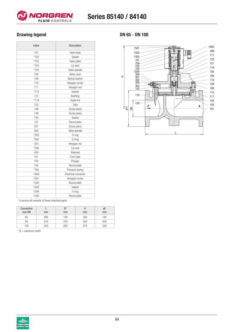
84
Series 85140 / 84140
Connection
size DN
L
mm
B*
mm
H
mm
øF
mm
65 290 195 330 185
80 310 220 350 200
100 350 260 378 220
Drawing legend
* A service kit consists of these individual parts.
Index Description
101 Valve body
*102 Gasket
*103 Valve plate
*104 Lip seal
*105 Valve spindle
108 Valve cover
109 Spring washer
110 Hexagon screw
111 Hexagon nut
*112 Gasket
115 Bushing
*119 Guide foil
120 Tube
148 Screw piece
149 Screw piece
150 Gasket
151 Round plate
301 Screw piece
302 Valve spindle
*303 O-ring
*304 O-ring
305 Hexagon nut
*306 Lip seal
400 Solenoid
701 Core tube
702 Plunger
704 Round plate
*705 Pressure spring
1400 Electrical connector
1501 Hexagon screw
1502 Round plate
1503 Gasket
1504 O-ring
1505 Round plate
H
DNØ F
L
P A
1501
1502
701704705702
1504304301302305303102
119
120
1400400
122111
121116
1503
105106110109108
117115
104103101
DN 65 - DN 100
* B = maximum width
85
Series 85140 / 84140
Further options (valves)XXXXXX02.XXXX Manual override
Version for aggressive fluids, liquids up to 80 mm2/s,
special connections e.g. ANSI flange
Further options (solenoids)XXXXXXX.8341 DN 15: Solenoid protection class
x II 2 GD EEx me II T3 T 140 °C
XXXXXXX.8402 DN 15 to DN 50: Solenoid DC,
maximum temperature +200 °C
solenoid mounting position vertical underneath only
XXXXXXX.8406 DN 15 to DN 50: Solenoid AC,
maximum temperature +200 °C
solenoid mounting position vertical underneath only
XXXXXXX.8436 DN 20 to DN 50: Solenoid protection class
x II 2 GD EEx me II T4 T 140 °C
XXXXXXX.8441 DN 20 to DN 50: Solenoid protection class
x II 2 GD EEx me II T3 T 140 °C
XXXXXXX.8900 DN 15 to DN 50: Solenoid protection class
x II 2 GD EEx de II C T4 and T5 T 130 °C / 95 °C
XXXXXXX.8920 DN 15 to DN 50: Solenoid protection class
x II 2 GD EEx d II C T4 and T5 T 130 °C / 95 °C
XXXXXXX.9540 DN 65 to DN 100: Solenoid protection class
x II 2 GD EEx me II T3/T4 T 140 °C
Further options on request
Please turn to page 276 for technical information on our valves.
Service kits
For valves with solenoid 8301 Part number
8514200 1254199
For valves with solenoid 8401 Part number
8514300 1248517
8514400 1248517
8514500 1248282
8514600 1248282
8514700 1248281
For valves with solenoid 9501 Part number
8414800 1239210
8414900 1233280
8415000 1249332
1
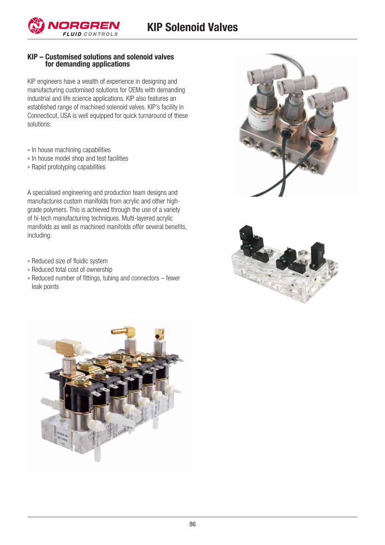
86
KIP Solenoid Valves
KIP – Customised solutions and solenoid valves for demanding applications
KIP engineers have a wealth of experience in designing and
manufacturing customised solutions for OEMs with demanding
industrial and life science applications. KIP also features an
established range of machined solenoid valves. KIP’s facility in
Connecticut, USA is well equipped for quick turnaround of these
solutions:
» In house machining capabilities
» In house model shop and test facilities
» Rapid prototyping capabilities
A specialised engineering and production team designs and
manufactures custom manifolds from acrylic and other high-
grade polymers. This is achieved through the use of a variety
of hi-tech manufacturing techniques. Multi-layered acrylic
manifolds as well as machined manifolds offer several benefits,
including:
» Reduced size of fluidic system
» Reduced total cost of ownership
» Reduced number of fittings, tubing and connectors – fewer
leak points
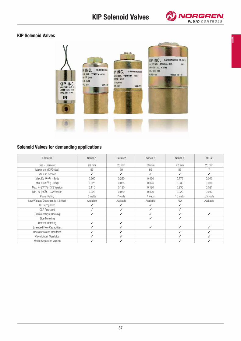
87
KIP Solenoid Valves
KIP Solenoid Valves
Solenoid Valves for demanding applications
Features Series 1 Series 2 Series 3 Series 6 KIP Jr.
Size - Diameter 26 mm 26 mm 30 mm 42 mm 20 mm
Maximum MOPD (bar) 55 69 69 83 7
Vacuum Service ✓ ✓ ✓ ✓ ✓
Max. Kv (m3/h) - Body 0.260 0.260 0.420 0.775 0.043
Min. Kv (m3/h) - Body 0.025 0.025 0.025 0.030 0.030
Max. Kv (m3/h) - 3/2 Version 0.110 0.120 0.120 0.230 0.021
Min. Kv (m3/h) - 3/2 Version 0.020 0.020 0.020 0.020 0.013
Power Rating 6 watts 7 watts 7 watts 10 watts .65 watts
Low Wattage Operators to 1.5 Watt Available Available Available N/A Available
UL Recognized ✓ ✓ ✓ ✓
CSA Approved ✓ ✓ ✓ ✓
Grommet Style Housing ✓ ✓ ✓ ✓ ✓
Side Metering ✓ ✓
Bottom Metering ✓ ✓
Extended Flow Capabilities ✓ ✓ ✓ ✓ ✓
Operator Mount Manifolds ✓ ✓ ✓ ✓
Valve Mount Manifolds ✓ ✓ ✓ ✓
Media Separated Version ✓ ✓ ✓ ✓
1
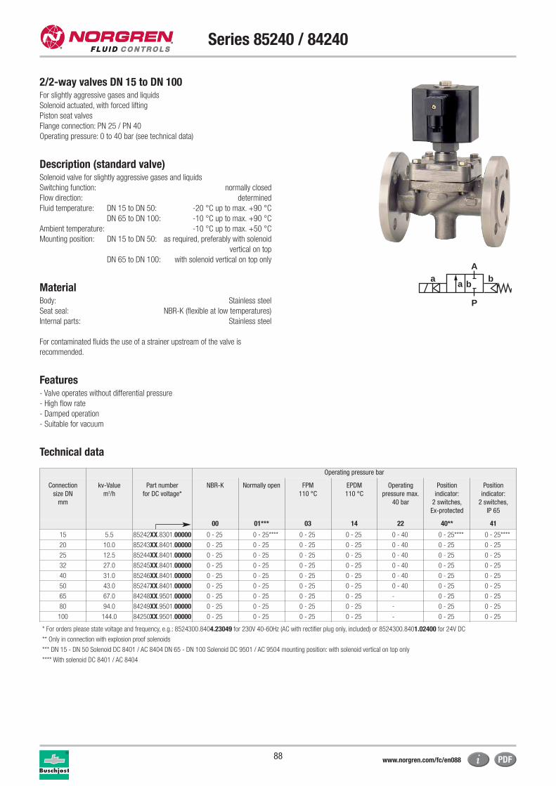
88
Series 85240 / 84240
2/2-way valves DN 15 to DN 100For slightly aggressive gases and liquids
Solenoid actuated, with forced lifting
Piston seat valves
Flange connection: PN 25 / PN 40
Operating pressure: 0 to 40 bar (see technical data)
Description (standard valve)Solenoid valve for slightly aggressive gases and liquids
Switching function: normally closed
Flow direction: determined
Fluid temperature: DN 15 to DN 50: -20 °C up to max. +90 °C
DN 65 to DN 100: -10 °C up to max. +90 °C
Ambient temperature: -10 °C up to max. +50 °C
Mounting position: DN 15 to DN 50: as required, preferably with solenoid
vertical on top
DN 65 to DN 100: with solenoid vertical on top only
MaterialBody: Stainless steel
Seat seal: NBR-K (flexible at low temperatures)
Internal parts: Stainless steel
For contaminated fluids the use of a strainer upstream of the valve is
recommended.
Features- Valve operates without differential pressure
- High flow rate
- Damped operation
- Suitable for vacuum
Technical data
a
P
Ab
a b
Operating pressure bar
Connection
size DN
mm
kv-Value
m3/h
Part number
for DC voltage*
NBR-K Normally open FPM
110 °C
EPDM
110 °C
Operating
pressure max.
40 bar
Position
indicator:
2 switches,
Ex-protected
Position
indicator:
2 switches,
IP 65
00 01*** 03 14 22 40** 41
15 5.5 85242XX.8301.00000 0 - 25 0 - 25**** 0 - 25 0 - 25 0 - 40 0 - 25**** 0 - 25****
20 10.0 85243XX.8401.00000 0 - 25 0 - 25 0 - 25 0 - 25 0 - 40 0 - 25 0 - 25
25 12.5 85244XX.8401.00000 0 - 25 0 - 25 0 - 25 0 - 25 0 - 40 0 - 25 0 - 25
32 27.0 85245XX.8401.00000 0 - 25 0 - 25 0 - 25 0 - 25 0 - 40 0 - 25 0 - 25
40 31.0 85246XX.8401.00000 0 - 25 0 - 25 0 - 25 0 - 25 0 - 40 0 - 25 0 - 25
50 43.0 85247XX.8401.00000 0 - 25 0 - 25 0 - 25 0 - 25 0 - 40 0 - 25 0 - 25
65 67.0 84248XX.9501.00000 0 - 25 0 - 25 0 - 25 0 - 25 - 0 - 25 0 - 25
80 94.0 84249XX.9501.00000 0 - 25 0 - 25 0 - 25 0 - 25 - 0 - 25 0 - 25
100 144.0 84250XX.9501.00000 0 - 25 0 - 25 0 - 25 0 - 25 - 0 - 25 0 - 25
* For orders please state voltage and frequency, e.g.: 8524300.8404.23049 for 230V 40-60Hz (AC with rectifier plug only, included) or 8524300.8401.02400 for 24V DC
** Only in connection with explosion proof solenoids
*** DN 15 - DN 50 Solenoid DC 8401 / AC 8404 DN 65 - DN 100 Solenoid DC 9501 / AC 9504 mounting position: with solenoid vertical on top only
**** With solenoid DC 8401 / AC 8404
www.norgren.com/fc/en088
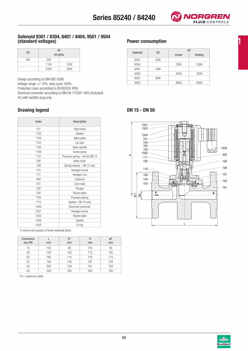
89
Series 85240 / 84240
Drawing legend
Index Description
101 Valve body
*102 Gasket
*103 Valve plate
*104 Lip seal
*105 Valve spindle
*106 Screw piece
*107 Pressure spring - not for DN 15
108 Valve cover
109 Spring washer - DN 15 only
110 Hexagon screw
111 Hexagon nut
400 Solenoid
701 Core tube
702 Plunger
704 Round plate
*705 Pressure spring
*712 Gasket - DN 15 only
1400 Electrical connector
1501 Hexagon screw
1502 Round plate
1504 Gasket
1505 O-ring
* A service kit consists of these individual parts.
Solenoid 8301 / 8304, 8401 / 8404, 9501 / 9504(standard voltages) Power consumption
Design according to DIN VDE 0580
Voltage range +/-10%, duty cycle 100%
Protection class according to EN 60529: IP65
Electrical connector according to DIN EN 175301-803 (included)
AC with rectifier plug only
Solenoid DCAC
Inrush Holding
8301 22W
8304 25VA 25VA
8401 40W
8404 45VA 45VA
9501 80W
9504 89VA 89VA
H
DNØ F
L
P A
103104109
110
105111
1505702705704701
1504
15021501
101
102
107
106
108
400
1400
Connection
size DN
L
mm
B*
mm
H
mm
øF
mm
15 130 95 145 95
20 150 105 172 105
25 160 115 172 115
32 180 140 187 140
40 200 150 191 150
50 230 165 200 165
DN 15 - DN 50
DCAC
40-60Hz
24V 24V -
- 110V 120V
230V 220V
* B = maximum width
1
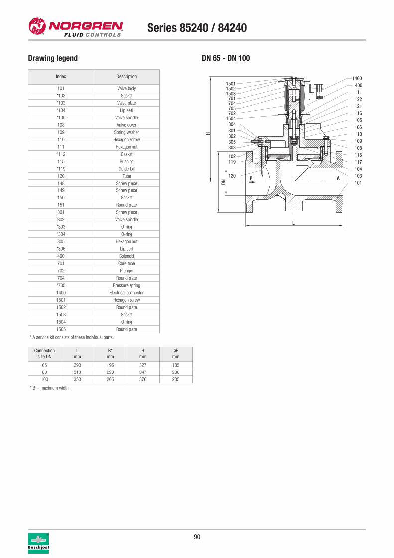
90
Series 85240 / 84240
Drawing legend
Connection
size DN
L
mm
B*
mm
H
mm
øF
mm
65 290 195 327 185
80 310 220 347 200
100 350 265 376 235
Index Description
101 Valve body
*102 Gasket
*103 Valve plate
*104 Lip seal
*105 Valve spindle
108 Valve cover
109 Spring washer
110 Hexagon screw
111 Hexagon nut
*112 Gasket
115 Bushing
*119 Guide foil
120 Tube
148 Screw piece
149 Screw piece
150 Gasket
151 Round plate
301 Screw piece
302 Valve spindle
*303 O-ring
*304 O-ring
305 Hexagon nut
*306 Lip seal
400 Solenoid
701 Core tube
702 Plunger
704 Round plate
*705 Pressure spring
1400 Electrical connector
1501 Hexagon screw
1502 Round plate
1503 Gasket
1504 O-ring
1505 Round plate
H
DNL
P A
15011502
701704705702
1504304301302305303
102119
120
1400400
122111
121116
1503
105106110109108
117115
104103101
* A service kit consists of these individual parts.
DN 65 - DN 100
* B = maximum width
91
Series 85240 / 84240
Further options (valves)XXXXXX02.XXXX Manual override
Special connections
Further options (solenoids)XXXXXXX.8341 DN 15: Solenoid protection class
x II 2 GD EEx me II T3 T 140 °C
XXXXXXX.8436 DN 20 – DN 50: Solenoid protection class
x II 2 GD EEx me II T4 T 140 °C
XXXXXXX.8441 DN 20 – DN 50: Solenoid protection class
x II 2 GD EEx me II T3 T 140 °C
XXXXXXX.8900 DN 15 – DN 50: Solenoid protection class
x II 2 GD EEx de II C T4 and T5 T 130 °C / 95 °C
XXXXXXX.8920 DN 15 – DN 50: Solenoid protection class
x II 2 GD EEx d II C T4 and T5 T 130 °C / 95 °C
XXXXXXX.9540 DN 65 – DN 100: Solenoid protection class
x II 2 GD EEx me II T3/T4 T 140 °C
Further options on request
Please turn to page 276 for technical information on our valves.
Service kits
For valves with solenoid 8301 Part number
8524200 -
For valves with solenoid 8401 Part number
8524300 -
8524400 -
8524500 -
8524600 1258239
8524700 1253401
For valves with solenoid 9501 Part number
8424800 -
8424900 1242184
8425000 -
1
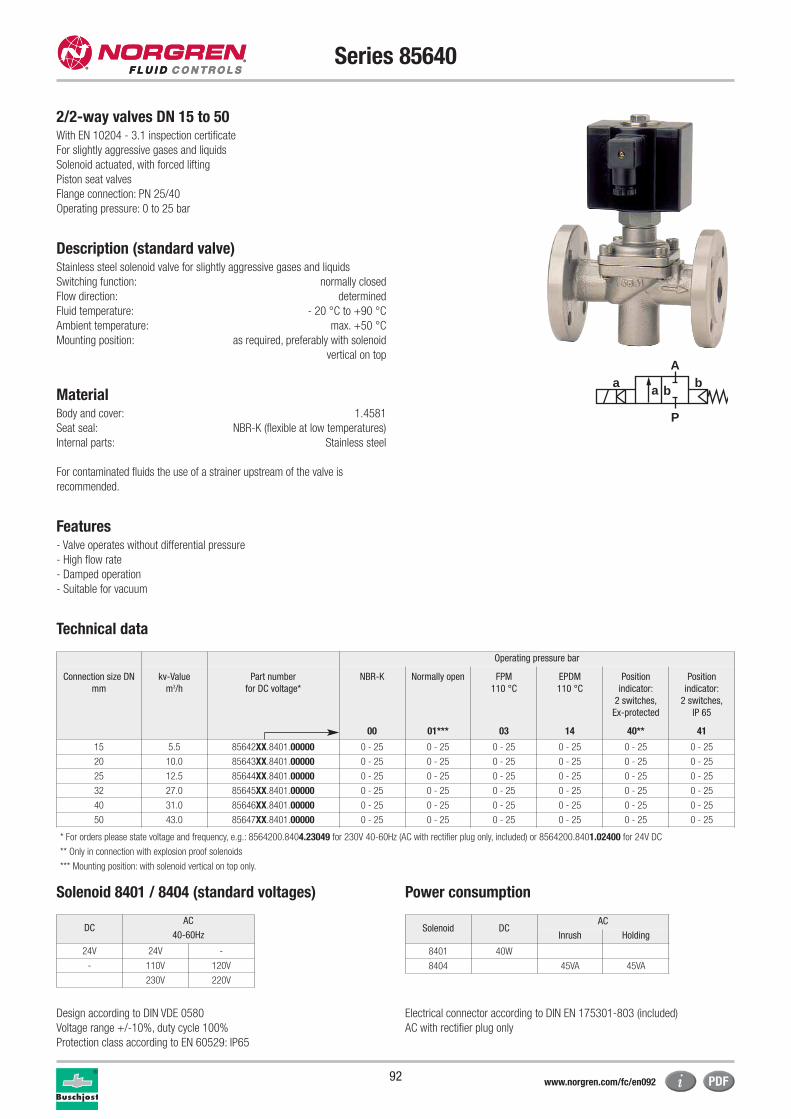
92
Series 85640
2/2-way valves DN 15 to 50With EN 10204 - 3.1 inspection certificate
For slightly aggressive gases and liquids
Solenoid actuated, with forced lifting
Piston seat valves
Flange connection: PN 25/40
Operating pressure: 0 to 25 bar
Description (standard valve)Stainless steel solenoid valve for slightly aggressive gases and liquids
Switching function: normally closed
Flow direction: determined
Fluid temperature: - 20 °C to +90 °C
Ambient temperature: max. +50 °C
Mounting position: as required, preferably with solenoid
vertical on top
MaterialBody and cover: 1.4581
Seat seal: NBR-K (flexible at low temperatures)
Internal parts: Stainless steel
For contaminated fluids the use of a strainer upstream of the valve is
recommended.
Features- Valve operates without differential pressure
- High flow rate
- Damped operation
- Suitable for vacuum
Technical data
Operating pressure bar
Connection size DN
mm
kv-Value
m3/h
Part number
for DC voltage*
NBR-K Normally open FPM
110 °C
EPDM
110 °C
Position
indicator:
2 switches,
Ex-protected
Position
indicator:
2 switches,
IP 65
00 01*** 03 14 40** 41
15 5.5 85642XX.8401.00000 0 - 25 0 - 25 0 - 25 0 - 25 0 - 25 0 - 25
20 10.0 85643XX.8401.00000 0 - 25 0 - 25 0 - 25 0 - 25 0 - 25 0 - 25
25 12.5 85644XX.8401.00000 0 - 25 0 - 25 0 - 25 0 - 25 0 - 25 0 - 25
32 27.0 85645XX.8401.00000 0 - 25 0 - 25 0 - 25 0 - 25 0 - 25 0 - 25
40 31.0 85646XX.8401.00000 0 - 25 0 - 25 0 - 25 0 - 25 0 - 25 0 - 25
50 43.0 85647XX.8401.00000 0 - 25 0 - 25 0 - 25 0 - 25 0 - 25 0 - 25
* For orders please state voltage and frequency, e.g.: 8564200.8404.23049 for 230V 40-60Hz (AC with rectifier plug only, included) or 8564200.8401.02400 for 24V DC
** Only in connection with explosion proof solenoids
*** Mounting position: with solenoid vertical on top only.
Solenoid 8401 / 8404 (standard voltages) Power consumption
Design according to DIN VDE 0580
Voltage range +/-10%, duty cycle 100%
Protection class according to EN 60529: IP65
Electrical connector according to DIN EN 175301-803 (included)
AC with rectifier plug only
Solenoid DCAC
Inrush Holding
8401 40W
8404 45VA 45VA
a
P
Ab
a b
DCAC
40-60Hz
24V 24V -
- 110V 120V
230V 220V
www.norgren.com/fc/en092
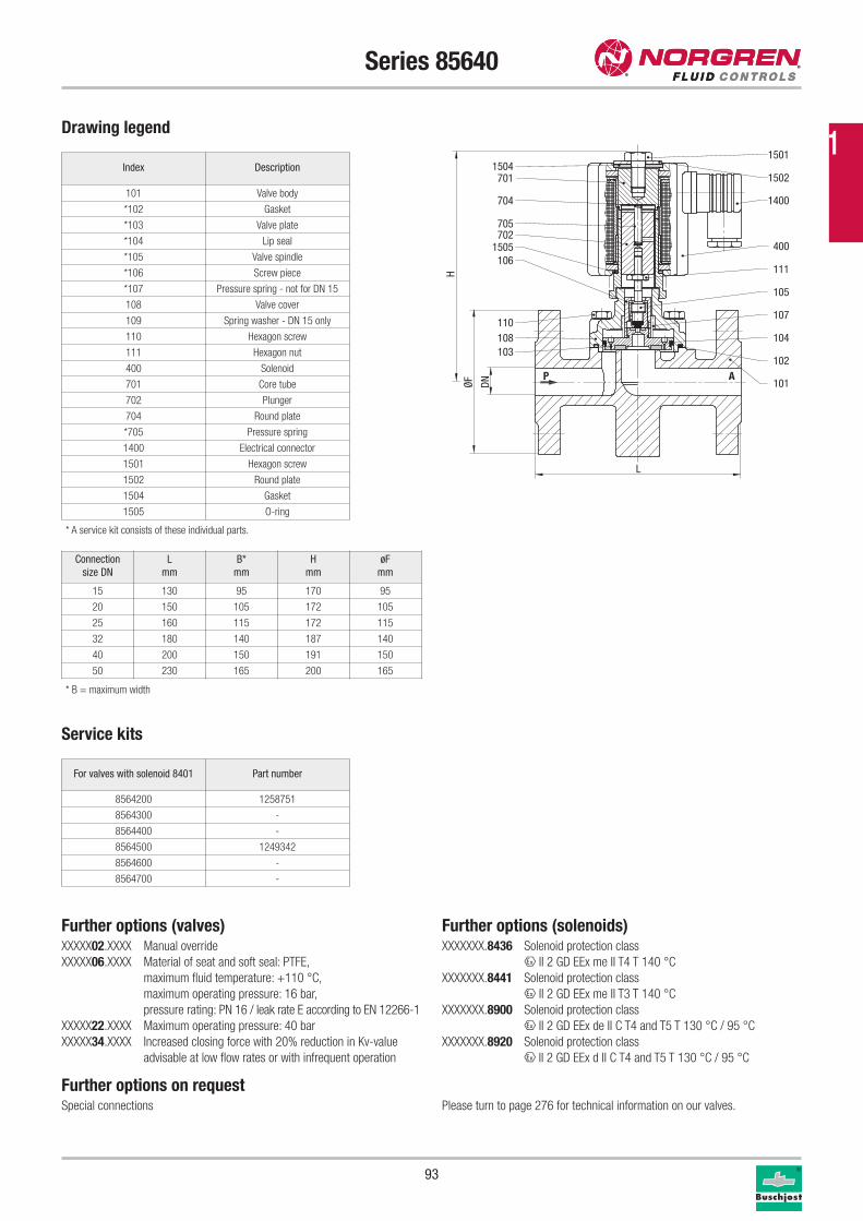
Further options (valves)XXXXX02.XXXX Manual override
XXXXX06.XXXX Material of seat and soft seal: PTFE,
maximum fluid temperature: +110 °C,
maximum operating pressure: 16 bar,
pressure rating: PN 16 / leak rate E according to EN 12266-1
XXXXX22.XXXX Maximum operating pressure: 40 bar
XXXXX34.XXXX Increased closing force with 20% reduction in Kv-value
advisable at low flow rates or with infrequent operation
Further options on requestSpecial connections
93
Series 85640
Drawing legend
Index Description
101 Valve body
*102 Gasket
*103 Valve plate
*104 Lip seal
*105 Valve spindle
*106 Screw piece
*107 Pressure spring - not for DN 15
108 Valve cover
109 Spring washer - DN 15 only
110 Hexagon screw
111 Hexagon nut
400 Solenoid
701 Core tube
702 Plunger
704 Round plate
*705 Pressure spring
1400 Electrical connector
1501 Hexagon screw
1502 Round plate
1504 Gasket
1505 O-ring
* A service kit consists of these individual parts.
Connection
size DN
L
mm
B*
mm
H
mm
øF
mm
15 130 95 170 95
20 150 105 172 105
25 160 115 172 115
32 180 140 187 140
40 200 150 191 150
50 230 165 200 165
Service kits
For valves with solenoid 8401 Part number
8564200 1258751
8564300 -
8564400 -
8564500 1249342
8564600 -
8564700 -
P A
1504701
704
705702
1505106
110108103
1501
1502
1400
400
111
101
102
105
107
104
H
DNØFL
* B = maximum width
Further options (solenoids)XXXXXXX.8436 Solenoid protection class
x II 2 GD EEx me II T4 T 140 °C
XXXXXXX.8441 Solenoid protection class
x II 2 GD EEx me II T3 T 140 °C
XXXXXXX.8900 Solenoid protection class
x II 2 GD EEx de II C T4 and T5 T 130 °C / 95 °C
XXXXXXX.8920 Solenoid protection class
x II 2 GD EEx d II C T4 and T5 T 130 °C / 95 °C
Please turn to page 276 for technical information on our valves.
1
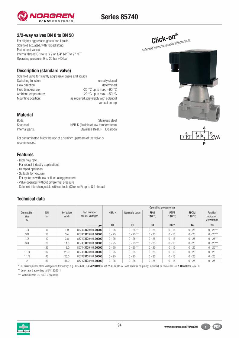
94
Series 85740
2/2-way valves DN 8 to DN 50For slightly aggressive gases and liquids
Solenoid actuated, with forced lifting
Piston seat valves
Internal thread G 1/4 to G 2 or 1/4" NPT to 2" NPT
Operating pressure: 0 to 25 bar (40 bar)
Description (standard valve)Solenoid valve for slightly aggressive gases and liquids
Switching function: normally closed
Flow direction: determined
Fluid temperature: -20 °C up to max. +90 °C
Ambient temperature: -20 °C up to max. +50 °C
Mounting position: as required, preferably with solenoid
vertical on top
MaterialBody: Stainless steel
Seat seal: NBR-K (flexible at low temperatures)
Internal parts: Stainless steel, PTFE/carbon
For contaminated fluids the use of a strainer upstream of the valve is
recommended.
Features- High flow rate
- For robust industry applications
- Damped operation
- Suitable for vacuum
- For systems with low or fluctuating pressure
- Valve operates without differential pressure
- Solenoid interchangeable without tools (Click-on®) up to G 1 thread
Technical data
Click-on®
Solenoid interchangeable without tools
a
P
Ab
a b
Operating pressure bar
Connection
size
G
DN
mm
kv-Value
m3/h
Part number
for DC voltage*NBR-K Normally open FPM
110 °C
PTFE
110 °C
EPDM
110 °C
Position
indicator:
2 switches
00 01 03 06** 14 23
1/4 8 1.9 85740XX.9401.00000 0 - 25 0 - 25*** 0 - 25 0 - 16 0 - 25 0 - 25***
3/8 10 3.4 85741XX.9401.00000 0 - 25 0 - 25*** 0 - 25 0 - 16 0 - 25 0 - 25***
1/2 12 3.8 85742XX.9401.00000 0 - 25 0 - 25*** 0 - 25 0 - 16 0 - 25 0 - 25***
3/4 20 11.0 85743XX.9401.00000 0 - 25 0 - 25*** 0 - 25 0 - 16 0 - 25 0 - 25***
1 25 13.0 85744XX.9401.00000 0 - 25 0 - 25*** 0 - 25 0 - 16 0 - 25 0 - 25***
1 1/4 32 23.0 85745XX.8401.00000 0 - 25 0 - 25 0 - 25 0 - 16 0 - 25 0 - 25
1 1/2 40 25.0 85746XX.8401.00000 0 - 25 0 - 25 0 - 25 0 - 16 0 - 25 0 - 25
2 50 41.0 85747XX.8401.00000 0 - 25 0 - 25 0 - 25 0 - 16 0 - 25 0 - 25
* For orders please state voltage and frequency, e.g.: 8574200.9404.23049 for 230V 40-60Hz (AC with rectifier plug only, included) or 8574200.9401.02400 for 24V DC
** Leak rate E according to EN 12266-1
*** With solenoid DC 8401 / AC 8404
www.norgren.com/fc/en094
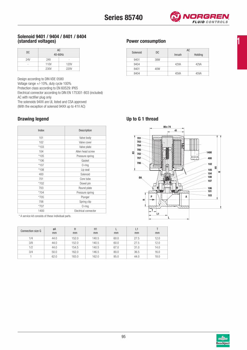
95
Series 85740
Solenoid 9401 / 9404 / 8401 / 8404(standard voltages) Power consumption
Design according to DIN VDE 0580
Voltage range +/-10%, duty cycle 100%
Protection class according to EN 60529: IP65
Electrical connector according to DIN EN 175301-803 (included)
AC with rectifier plug only
The solenoids 94XX are UL listed and CSA approved
(With the exception of solenoid 94XX up to 41V AC)
Solenoid DCAC
Inrush Holding
9401 38W
9404 42VA 42VA
8401 40W
8404 45VA 45VA
Drawing legend
Index Description
101 Valve body
102 Valve cover
*103 Valve plate
104 Allen head screw
*105 Pressure spring
*106 Gasket
*107 O-ring
*108 Lip seal
400 Solenoid
701 Core tube
*702 Dowel pin
703 Round plate
*704 Pressure spring
*705 Plunger
706 Spring clip
*707 O-ring
1400 Electrical connector
P A
701703704
705
707
706
702 1400
400
103
101
108107
106
104105
102
H1H
L
ØA
83
80x 7441
TL1
R
Connection size GøA
mm
H
mm
H1
mm
L
mm
L1
mm
T
mm
1/4 44.0 152.0 140.5 60.0 27.5 12.0
3/8 44.0 152.0 140.5 60.0 27.5 12.0
1/2 44.0 154.5 140.5 67.0 31.0 14.0
3/4 50.0 162.0 146.5 80.0 36.5 16.0
1 62.0 183.0 162.0 95.0 44.0 18.0
* A service kit consists of these individual parts.
Up to G 1 thread
DCAC
40-60Hz
24V 24V -
- 110V 120V
230V 220V
1
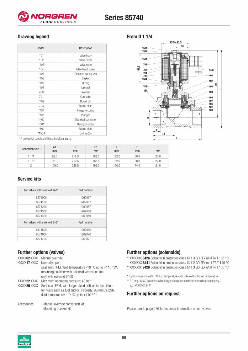
96
Connection size GøA
mm
H
mm
H1
mm
L
mm
L1
mm
T
mm
1 1/4 92.0 212.5 183.5 132.0 60.0 20.0
1 1/2 92.0 212.5 183.5 132.0 60.0 22.0
2 109.0 226.5 192.0 160.0 74.0 24.0
Service kits
For valves with solenoid 9401 Part number
8574000 1269067
8574100 1269067
8574200 1269067
8574300 1269068
8574400 1269069
For valves with solenoid 8401 Part number
8574500 1269070
8574600 1269070
8574700 1269071
Further options (valves)XXXXX02.XXXX Manual override
XXXXX17.XXXX Normally open,
seat seal: FPM, fluid temperature -10 °C up to +110 °C*,
mounting position: with solenoid vertical on top,
only with solenoid 8400
XXXXX22.XXXX Maximum operating pressure: 40 bar
XXXXX25.XXXX Seat seal: FPM, with larger bleed orifices in the piston,
for fluids such as fuel and oil, viscosity: 80 mm2/s (cSt),
fluid temperature: -10 °C up to +110 °C*
Accessories: - Manual override conversion kit
- Mounting bracket kit
Further options (solenoids)**XXXXXXX.8426 Solenoid in protection class x II 3 GD EEx nA II T4 T 135 °C
XXXXXXX.8441 Solenoid in protection class x II 2 GD EEx me II T3 T 140 °C
**XXXXXXX.9426 Solenoid in protection class x II 3 GD EEx nA II T4 T 135 °C
* Up to maximum +200 °C fluid temperature with solenoid for higher temperature
** DC only, for AC solenoids with design inspection certificate according to category 2,
e.g. XXXXXXX.8441
Further options on request
Please turn to page 276 for technical information on our valves.
Index Description
101 Valve body
102 Valve cover
*103 Valve plate
104 Allen head screw
*105 Pressure spring (2x)
*106 Gasket
*107 O-ring
*108 Lip seal
400 Solenoid
701 Core tube
*702 Dowel pin
703 Round plate
*704 Pressure spring
*705 Plunger
1400 Electrical connector
1501 Hexagon screw
1502 Round plate
*1504 O-ring (2x)
* A service kit consists of these individual parts.
701
705
702
1400
400
103101
108107106
102
104
P A
105
1504
704703
1504
15021501
ØA
H1H
L
R
TL1
3975,5x93,5
81,5
Series 85740
From G 1 1/4 Drawing legend
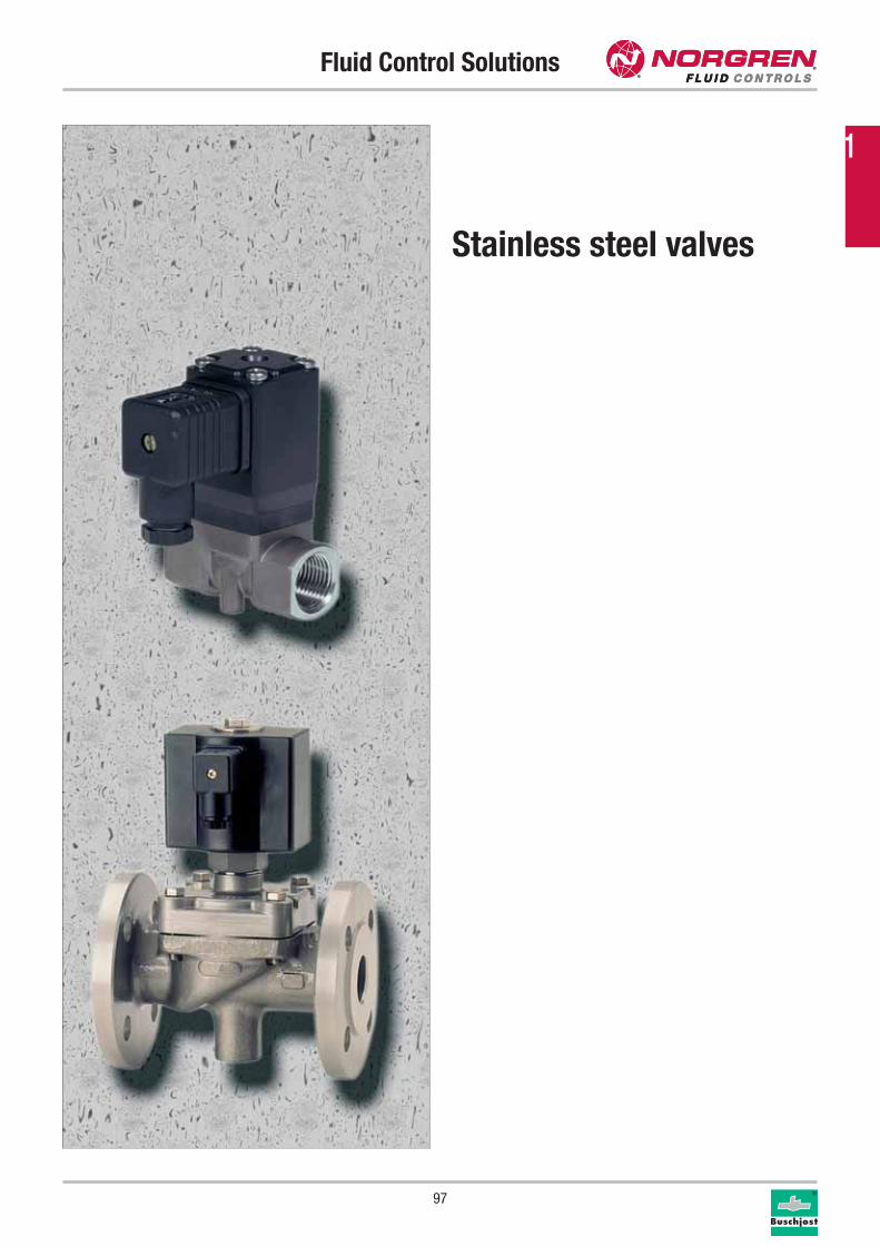
Fluid Control Solutions
97
Stainless steel valves
1
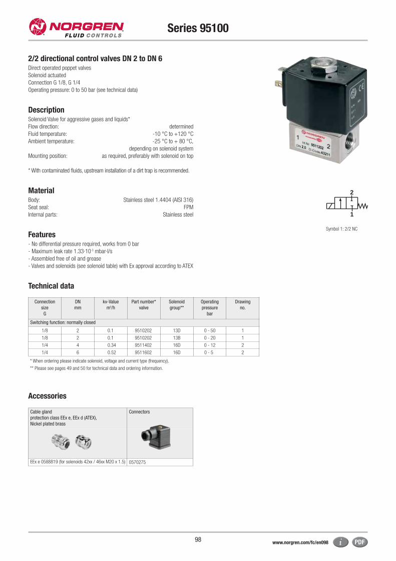
Cable gland
protection class EEx e, EEx d (ATEX),
Nickel plated brass
Connectors
EEx e 0588819 (for solenoids 42xx / 46xx M20 x 1.5) 0570275
98
Series 95100
2/2 directional control valves DN 2 to DN 6Direct operated poppet valves
Solenoid actuated
Connection G 1/8, G 1/4
Operating pressure: 0 to 50 bar (see technical data)
DescriptionSolenoid Valve for aggressive gases and liquids*
Flow direction: determined
Fluid temperature: -10 °C to +120 °C
Ambient temperature: -25 °C to + 80 °C,
depending on solenoid system
Mounting position: as required, preferably with solenoid on top
* With contaminated fluids, upstream installation of a dirt trap is recommended.
MaterialBody: Stainless steel 1.4404 (AISI 316)
Seat seal: FPM
Internal parts: Stainless steel
Features - No differential pressure required, works from 0 bar
- Maximum leak rate 1.33·10-3 mbar·I/s
- Assembled free of oil and grease
- Valves and solenoids (see solenoid table) with Ex approval according to ATEX
Technical data
2
1
* When ordering please indicate solenoid, voltage and current type (frequency).
** Please see pages 49 and 50 for technical data and ordering information.
Connection
size
G
DN
mm
kv-Value
m3/h
Part number*
valve
Solenoid
group**
Operating
pressure
bar
Drawing
no.
Switching function: normally closed
1/8 2 0.1 9510202 13D 0 - 50 1
1/8 2 0.1 9510202 13B 0 - 20 1
1/4 4 0.34 9511402 16D 0 - 12 2
1/4 6 0.52 9511602 16D 0 - 5 2
Symbol 1: 2/2 NC
Accessories
www.norgren.com/fc/en098

99
Series 95100
Index Description
2 M4 x 6
Drawing legend
* Dimensions in mm
Dimensional drawings for valves
Drawing 1 * Drawing 2 *
G1/
8
8,519
,5
66,5
1 2
32
27
27
23
2
21
12
42
G1/
4
11
24 21
74,5
27
27 21
23
2
Further options on request
Please find the safety instructions for the Norgren range on page 318.
Please find an example of the part numbering system applicable to the
Norgren range on page 53.
The actuating solenoids correspond to those of the 95000 series. You will find
them on page 49, the associated dimensions are on page 50.
The electric circuit diagrams are shown on page 52.
1
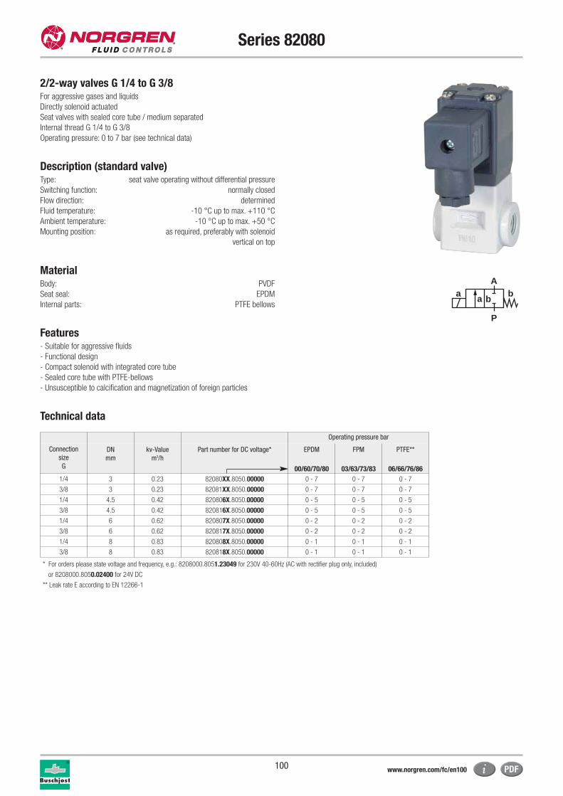
100
Series 82080
2/2-way valves G 1/4 to G 3/8For aggressive gases and liquids
Directly solenoid actuated
Seat valves with sealed core tube / medium separated
Internal thread G 1/4 to G 3/8
Operating pressure: 0 to 7 bar (see technical data)
Description (standard valve)Type: seat valve operating without differential pressure
Switching function: normally closed
Flow direction: determined
Fluid temperature: -10 °C up to max. +110 °C
Ambient temperature: -10 °C up to max. +50 °C
Mounting position: as required, preferably with solenoid
vertical on top
MaterialBody: PVDF
Seat seal: EPDM
Internal parts: PTFE bellows
Features- Suitable for aggressive fluids
- Functional design
- Compact solenoid with integrated core tube
- Sealed core tube with PTFE-bellows
- Unsusceptible to calcification and magnetization of foreign particles
Technical data
** Leak rate E according to EN 12266-1
* For orders please state voltage and frequency, e.g.: 8208000.8051.23049 for 230V 40-60Hz (AC with rectifier plug only, included)
or 8208000.8050.02400 for 24V DC
a
P
Ab
a b
Operating pressure bar
Connection
size
G
DN
mm
kv-Value
m3/h
Part number for DC voltage* EPDM FPM PTFE**
00/60/70/80 03/63/73/83 06/66/76/86
1/4 3 0.23 82080XX.8050.00000 0 - 7 0 - 7 0 - 7
3/8 3 0.23 82081XX.8050.00000 0 - 7 0 - 7 0 - 7
1/4 4.5 0.42 820806X.8050.00000 0 - 5 0 - 5 0 - 5
3/8 4.5 0.42 820816X.8050.00000 0 - 5 0 - 5 0 - 5
1/4 6 0.62 820807X.8050.00000 0 - 2 0 - 2 0 - 2
3/8 6 0.62 820817X.8050.00000 0 - 2 0 - 2 0 - 2
1/4 8 0.83 820808X.8050.00000 0 - 1 0 - 1 0 - 1
3/8 8 0.83 820818X.8050.00000 0 - 1 0 - 1 0 - 1
www.norgren.com/fc/en100
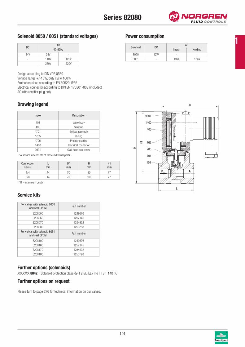
101
Series 82080
Drawing legend
Index Description
101 Valve body
400 Solenoid
*701 Bellow assembly
*705 O-ring
*706 Pressure spring
1400 Electrical connector
9901 Oval head cap screw
* A service kit consists of these individual parts.
Service kits
For valves with solenoid 8050
and seal EPDMPart number
8208000 1249676
8208060 1257145
8208070 1254932
8208080 1253798
For valves with solenoid 8051
and seal EPDMPart number
8208100 1249676
8208160 1257145
8208170 1254932
8208180 1253798
P A
400
706
701
705
101
9901
1400
B
L
H1
H
Solenoid DCAC
Inrush Holding
8050 12W - -
8051 - 13VA 13VA
Solenoid 8050 / 8051 (standard voltages) Power consumption
Design according to DIN VDE 0580
Voltage range +/-10%, duty cycle 100%
Protection class according to EN 60529: IP65
Electrical connector according to DIN EN 175301-803 (included)
AC with rectifier plug only
Connection
size G
L
mm
B*
mm
H
mm
H1
mm
1/4 44 70 90 77
3/8 44 70 90 77
Further options (solenoids)XXXXXXX.8042 Solenoid protection class x II 2 GD EEx me II T3 T 140 °C
Further options on request
Please turn to page 276 for technical information on our valves.
* B = maximum depth
DCAC
40-60Hz
24V 24V -
- 110V 120V
230V 220V
1
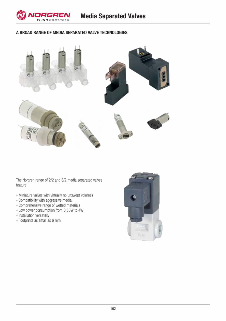
102
Media Separated Valves
A BROAD RANGE OF MEDIA SEPARATED VALVE TECHNOLOGIES
The Norgren range of 2/2 and 3/2 media separated valves
feature:
» Miniature valves with virtually no unswept volumes
» Compatibility with aggressive media
» Comprehensive range of wetted materials
» Low power consumption from 0.35W to 4W
» Installation versatility
» Footprints as small as 6 mm
Contents
103
Solenoid Valves with Differential Pressure - Miniature Solenoid Valves
Series Material Connection Pressure Temperature Function Page
Microsol PPS, PA, Stainless steel Subbase 0 - 10 bar +30 °C 2/2, 3/2 18
Solenoid Valves with Differential Pressure
Series Material Connection Pressure Temperature Function Page
82400 Brass G 1/4 - G 2 0.1 - 16 bar +90 °C 2/2 104
82470 Brass G 1/4 - G 1 0.1 - 10 bar +150 °C 2/2 106
85300 Brass G 1/4 - G 2 0.5 - 40 bar +90 °C 2/2 108
85320 Brass G 1/4 - G 1 1.0 - 25 bar +200 °C 2/2 112
84070 NEW PPO GF 30 G 1/2 - G 3/4 0.3 - 10.5 bar +50 °C 2/2 114
84080 NEW PPO GF 30 NPT 1/2 - NPT 3/4 0.3 - 10.5 bar +50 °C 2/2 114
82730 Stainless steel G 1/4 - G 2 0.1 - 16 bar +90 °C 2/2 116
83050 Grey cast iron DN 20 - DN 50 1.0 - 16 bar +80 °C 2/2 118
83580 Grey cast iron DN 65 - DN 150 0.5 - 10 bar +90 °C 2/2 122
84320 Grey cast iron DN 15 - DN 100 0.5 - 16 bar +90 °C 2/2 124
84340 Cast steel DN 15 - DN 100 0.5 - 40 bar +90 °C 2/2 128
2
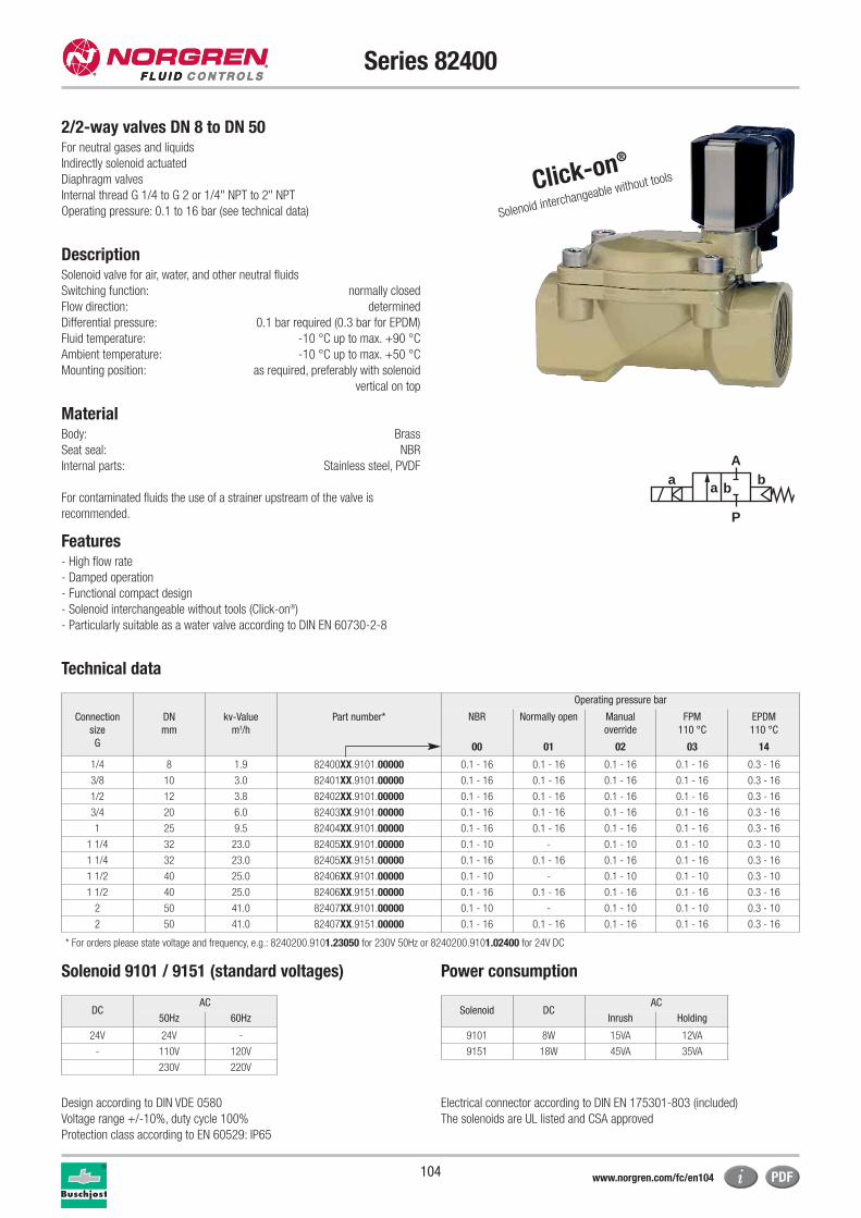
104
Series 82400
Connection
size
G
DN
mm
kv-Value
m3/h
Part number*
Operating pressure bar
NBR Normally open Manual
override
FPM
110 °C
EPDM
110 °C
00 01 02 03 14
1/4 8 1.9 82400XX.9101.00000 0.1 - 16 0.1 - 16 0.1 - 16 0.1 - 16 0.3 - 16
3/8 10 3.0 82401XX.9101.00000 0.1 - 16 0.1 - 16 0.1 - 16 0.1 - 16 0.3 - 16
1/2 12 3.8 82402XX.9101.00000 0.1 - 16 0.1 - 16 0.1 - 16 0.1 - 16 0.3 - 16
3/4 20 6.0 82403XX.9101.00000 0.1 - 16 0.1 - 16 0.1 - 16 0.1 - 16 0.3 - 16
1 25 9.5 82404XX.9101.00000 0.1 - 16 0.1 - 16 0.1 - 16 0.1 - 16 0.3 - 16
1 1/4 32 23.0 82405XX.9101.00000 0.1 - 10 - 0.1 - 10 0.1 - 10 0.3 - 10
1 1/4 32 23.0 82405XX.9151.00000 0.1 - 16 0.1 - 16 0.1 - 16 0.1 - 16 0.3 - 16
1 1/2 40 25.0 82406XX.9101.00000 0.1 - 10 - 0.1 - 10 0.1 - 10 0.3 - 10
1 1/2 40 25.0 82406XX.9151.00000 0.1 - 16 0.1 - 16 0.1 - 16 0.1 - 16 0.3 - 16
2 50 41.0 82407XX.9101.00000 0.1 - 10 - 0.1 - 10 0.1 - 10 0.3 - 10
2 50 41.0 82407XX.9151.00000 0.1 - 16 0.1 - 16 0.1 - 16 0.1 - 16 0.3 - 16
2/2-way valves DN 8 to DN 50For neutral gases and liquids
Indirectly solenoid actuated
Diaphragm valves
Internal thread G 1/4 to G 2 or 1/4" NPT to 2" NPT
Operating pressure: 0.1 to 16 bar (see technical data)
DescriptionSolenoid valve for air, water, and other neutral fluids
Switching function: normally closed
Flow direction: determined
Differential pressure: 0.1 bar required (0.3 bar for EPDM)
Fluid temperature: -10 °C up to max. +90 °C
Ambient temperature: -10 °C up to max. +50 °C
Mounting position: as required, preferably with solenoid
vertical on top
MaterialBody: Brass
Seat seal: NBR
Internal parts: Stainless steel, PVDF
For contaminated fluids the use of a strainer upstream of the valve is
recommended.
Features- High flow rate
- Damped operation
- Functional compact design
- Solenoid interchangeable without tools (Click-on®)
- Particularly suitable as a water valve according to DIN EN 60730-2-8
Technical data
Solenoid DCAC
Inrush Holding
9101 8W 15VA 12VA
9151 18W 45VA 35VA
DCAC
50Hz 60Hz
24V 24V -
- 110V 120V
230V 220V
Solenoid 9101 / 9151 (standard voltages) Power consumption
* For orders please state voltage and frequency, e.g.: 8240200.9101.23050 for 230V 50Hz or 8240200.9101.02400 for 24V DC
a
P
Ab
a b
Design according to DIN VDE 0580
Voltage range +/-10%, duty cycle 100%
Protection class according to EN 60529: IP65
Electrical connector according to DIN EN 175301-803 (included)
The solenoids are UL listed and CSA approved
Click-on®
Solenoid interchangeable without tools
www.norgren.com/fc/en104
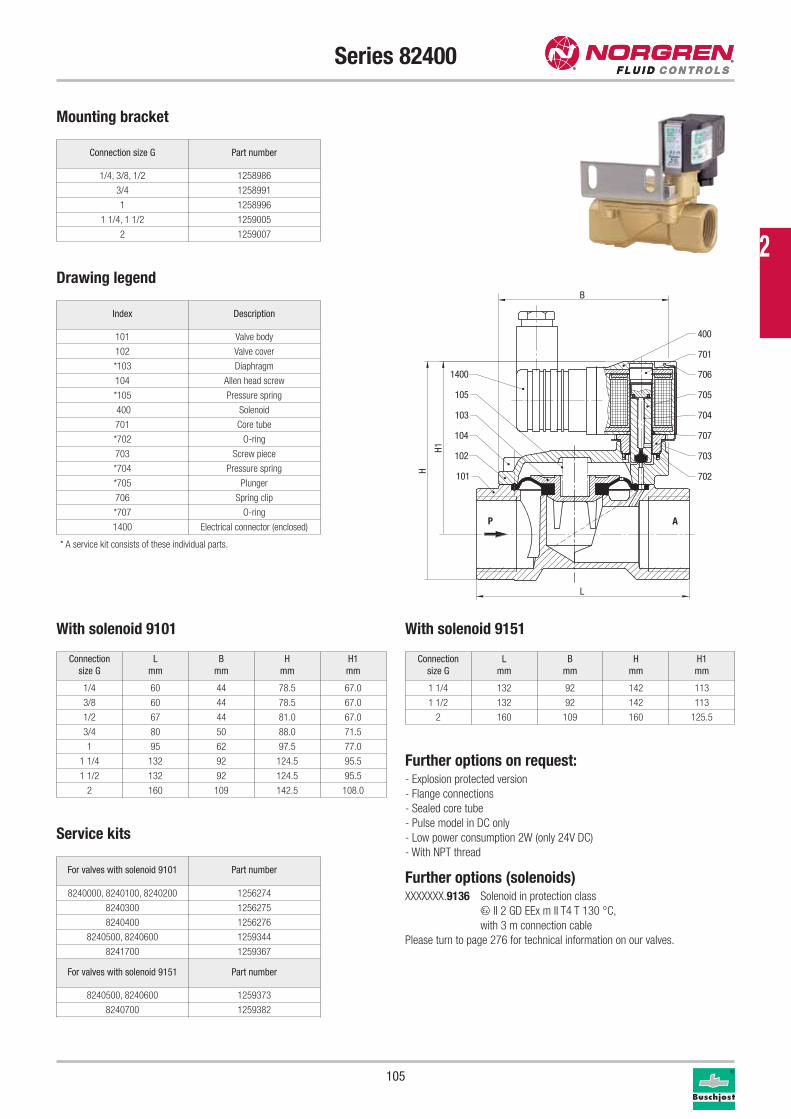
105
Series 82400
P A
101
102
104
103
105
1400
702
703
707
704
705
706
701
400
B
H1
H
L
Connection size G Part number
1/4, 3/8, 1/2 1258986
3/4 1258991
1 1258996
1 1/4, 1 1/2 1259005
2 1259007
Mounting bracket
Drawing legend
Connection
size G
L
mm
B
mm
H
mm
H1
mm
1/4 60 44 78.5 67.0
3/8 60 44 78.5 67.0
1/2 67 44 81.0 67.0
3/4 80 50 88.0 71.5
1 95 62 97.5 77.0
1 1/4 132 92 124.5 95.5
1 1/2 132 92 124.5 95.5
2 160 109 142.5 108.0
Index Description
101 Valve body
102 Valve cover
*103 Diaphragm
104 Allen head screw
*105 Pressure spring
400 Solenoid
701 Core tube
*702 O-ring
703 Screw piece
*704 Pressure spring
*705 Plunger
706 Spring clip
*707 O-ring
1400 Electrical connector (enclosed)
Connection
size G
L
mm
B
mm
H
mm
H1
mm
1 1/4 132 92 142 113
1 1/2 132 92 142 113
2 160 109 160 125.5
With solenoid 9151
Service kits
For valves with solenoid 9101 Part number
8240000, 8240100, 8240200 1256274
8240300 1256275
8240400 1256276
8240500, 8240600 1259344
8241700 1259367
For valves with solenoid 9151 Part number
8240500, 8240600 1259373
8240700 1259382
Further options on request:- Explosion protected version
- Flange connections
- Sealed core tube
- Pulse model in DC only
- Low power consumption 2W (only 24V DC)
- With NPT thread
Further options (solenoids)XXXXXXX.9136 Solenoid in protection class
x II 2 GD EEx m II T4 T 130 °C,
with 3 m connection cable
Please turn to page 276 for technical information on our valves.
* A service kit consists of these individual parts.
With solenoid 9101
2
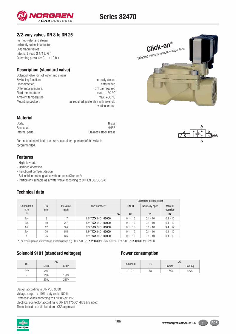
106
Series 82470
2/2-way valves DN 8 to DN 25For hot water and steam
Indirectly solenoid actuated
Diaphragm valves
Internal thread G 1/4 to G 1
Operating pressure: 0.1 to 10 bar
Description (standard valve)Solenoid valve for hot water and steam
Switching function: normally closed
Flow direction: determined
Differential pressure: 0.1 bar required
Fluid temperature: max. +150 °C
Ambient temperature: max. +60 °C
Mounting position: as required, preferably with solenoid
vertical on top
MaterialBody: Brass
Seat seal: HNBR
Internal parts: Stainless steel, Brass
For contaminated fluids the use of a strainer upstream of the valve is
recommended.
Features- High flow rate
- Damped operation
- Functional compact design
- Solenoid interchangeable without tools (Click-on®)
- Particularly suitable as a water valve according to DIN EN 60730-2-8
Technical data
Click-on®
Solenoid interchangeable without tools
a
P
Ab
a b
Operating pressure bar
Connection
size
G
DN
mm
kv-Value
m3/h
Part number* HNBR Normally open Manual
override
00 01 02
1/4 8 1.7 82470XX.9101.00000 0.1 - 10 0.1 - 10 0.1 - 10
3/8 10 2.7 82471XX.9101.00000 0.1 - 10 0.1 - 10 0.1 - 10
1/2 12 3.4 82472XX.9101.00000 0.1 - 10 0.1 - 10 0.1 - 10
3/4 20 5.5 82473XX.9101.00000 0.1 - 10 0.1 - 10 0.1 - 10
1 25 8.5 82474XX.9101.00000 0.1 - 10 0.1 - 10 0.1 - 10
* For orders please state voltage and frequency, e.g.: 8247200.9101.23050 for 230V 50Hz or 8247200.9101.02400 for 24V DC
Solenoid DCAC
Inrush Holding
9101 8W 15VA 12VA
DCAC
50Hz 60Hz
24V 24V -
- 110V 120V
230V 220V
Solenoid 9101 (standard voltages) Power consumption
Design according to DIN VDE 0580
Voltage range +/-10%, duty cycle 100%
Protection class according to EN 60529: IP65
Electrical connector according to DIN EN 175301-803 (included)
The solenoids are UL listed and CSA approved
www.norgren.com/fc/en106
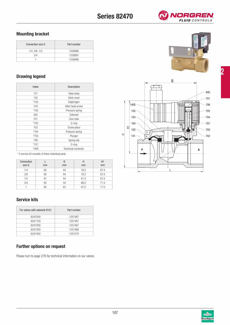
2
107
Series 82470
Connection size G Part number
1/4, 3/8, 1/2 1258986
3/4 1258991
1 1258996
Mounting bracket
Drawing legend
Index Description
101 Valve body
102 Valve cover
*103 Diaphragm
104 Allen head screw
*105 Pressure spring
400 Solenoid
701 Core tube
*702 O-ring
703 Screw piece
*704 Pressure spring
*705 Plunger
706 Spring clip
*707 O-ring
1400 Electrical connector
Service kits
For valves with solenoid 9101 Part number
8247000 1257467
8247100 1257467
8247200 1257467
8247300 1257468
8247400 1257470
* A service kit consists of these individual parts.
P A
101
102
104
103
105
1400
702
703
707
704
705
706
701
400
L
H
H1
B
Connection
size G
L
mm
B
mm
H
mm
H1
mm
1/4 60 44 78.5 67.0
3/8 60 44 78.5 67.0
1/2 67 44 81.0 67.0
3/4 80 50 88.0 71.5
1 95 62 97.5 77.0
Further options on request
Please turn to page 276 for technical information on our valves.
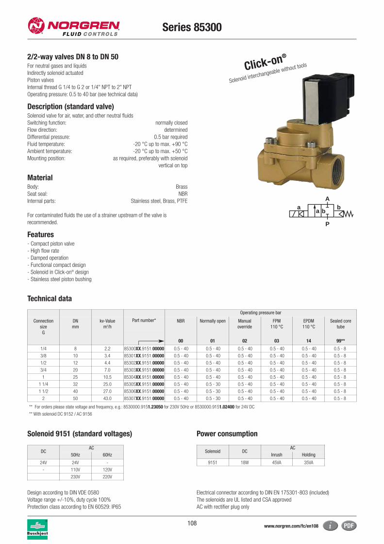
108
Series 85300
2/2-way valves DN 8 to DN 50For neutral gases and liquids
Indirectly solenoid actuated
Piston valves
Internal thread G 1/4 to G 2 or 1/4" NPT to 2" NPT
Operating pressure: 0.5 to 40 bar (see technical data)
Description (standard valve)Solenoid valve for air, water, and other neutral fluids
Switching function: normally closed
Flow direction: determined
Differential pressure: 0.5 bar required
Fluid temperature: -20 °C up to max. +90 °C
Ambient temperature: -20 °C up to max. +50 °C
Mounting position: as required, preferably with solenoid
vertical on top
MaterialBody: Brass
Seat seal: NBR
Internal parts: Stainless steel, Brass, PTFE
For contaminated fluids the use of a strainer upstream of the valve is
recommended.
Features- Compact piston valve
- High flow rate
- Damped operation
- Functional compact design
- Solenoid in Click-on® design
- Stainless steel piston bushing
Technical data
a
P
Ab
a b
Click-on®
Solenoid interchangeable without tools
Operating pressure bar
Connection
size
G
DN
mm
kv-Value
m3/h
Part number* NBR Normally open Manual
override
FPM
110 °C
EPDM
110 °C
Sealed core
tube
00 01 02 03 14 99**
1/4 8 2.2 85300XX.9151.00000 0.5 - 40 0.5 - 40 0.5 - 40 0.5 - 40 0.5 - 40 0.5 - 8
3/8 10 3.4 85301XX.9151.00000 0.5 - 40 0.5 - 40 0.5 - 40 0.5 - 40 0.5 - 40 0.5 - 8
1/2 12 4.4 85302XX.9151.00000 0.5 - 40 0.5 - 40 0.5 - 40 0.5 - 40 0.5 - 40 0.5 - 8
3/4 20 7.0 85303XX.9151.00000 0.5 - 40 0.5 - 40 0.5 - 40 0.5 - 40 0.5 - 40 0.5 - 8
1 25 10.5 85304XX.9151.00000 0.5 - 40 0.5 - 40 0.5 - 40 0.5 - 40 0.5 - 40 0.5 - 8
1 1/4 32 25.0 85305XX.9151.00000 0.5 - 40 0.5 - 30 0.5 - 40 0.5 - 40 0.5 - 40 0.5 - 8
1 1/2 40 27.0 85306XX.9151.00000 0.5 - 40 0.5 - 30 0.5 - 40 0.5 - 40 0.5 - 40 0.5 - 8
2 50 43.0 85307XX.9151.00000 0.5 - 40 0.5 - 30 0.5 - 40 0.5 - 40 0.5 - 40 0.5 - 8
** For orders please state voltage and frequency, e.g.: 8530000.9151.23050 for 230V 50Hz or 8530000.9151.02400 for 24V DC
** With solenoid DC 9152 / AC 9156
Solenoid 9151 (standard voltages) Power consumption
Design according to DIN VDE 0580
Voltage range +/-10%, duty cycle 100%
Protection class according to EN 60529: IP65
Electrical connector according to DIN EN 175301-803 (included)
The solenoids are UL listed and CSA approved
AC with rectifier plug only
Solenoid DCAC
Inrush Holding
9151 18W 45VA 35VA
DCAC
50Hz 60Hz
24V 24V -
- 110V 120V
230V 220V
www.norgren.com/fc/en108
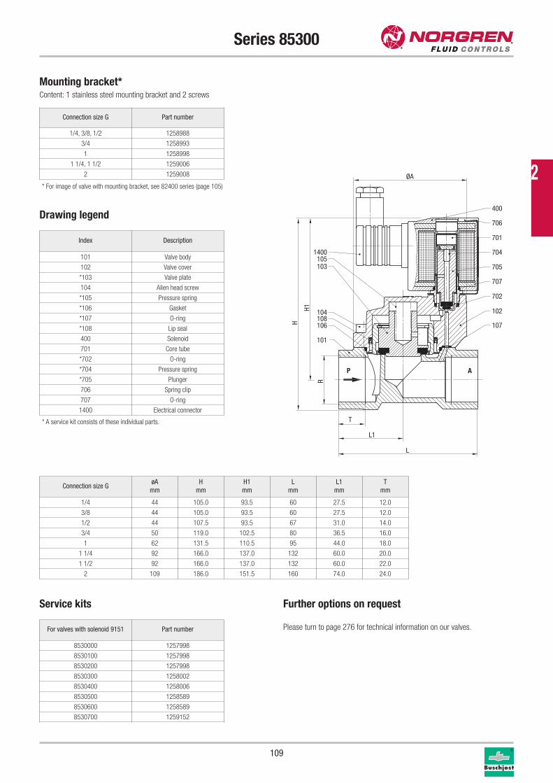
109
Series 85300
Connection size G Part number
1/4, 3/8, 1/2 1258988
3/4 1258993
1 1258998
1 1/4, 1 1/2 1259006
2 1259008
Mounting bracket*Content: 1 stainless steel mounting bracket and 2 screws
Drawing legend
Index Description
101 Valve body
102 Valve cover
*103 Valve plate
104 Allen head screw
*105 Pressure spring
*106 Gasket
*107 O-ring
*108 Lip seal
400 Solenoid
701 Core tube
*702 O-ring
*704 Pressure spring
*705 Plunger
706 Spring clip
707 O-ring
1400 Electrical connector
* A service kit consists of these individual parts.
Connection size GøA
mm
H
mm
H1
mm
L
mm
L1
mm
T
mm
1/4 44 105.0 93.5 60 27.5 12.0
3/8 44 105.0 93.5 60 27.5 12.0
1/2 44 107.5 93.5 67 31.0 14.0
3/4 50 119.0 102.5 80 36.5 16.0
1 62 131.5 110.5 95 44.0 18.0
1 1/4 92 166.0 137.0 132 60.0 20.0
1 1/2 92 166.0 137.0 132 60.0 22.0
2 109 186.0 151.5 160 74.0 24.0
Further options on request
Please turn to page 276 for technical information on our valves.
Service kits
For valves with solenoid 9151 Part number
8530000 1257998
8530100 1257998
8530200 1257998
8530300 1258002
8530400 1258006
8530500 1258589
8530600 1258589
8530700 1259152
P A
1400105103
104108106
101
400
701
706
704
705
707
702
102
107
L
H
H1
L1
T
R
ØA* For image of valve with mounting bracket, see 82400 series (page 105)
2
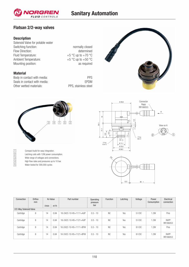
110
Sanitary Automation
Flatsan 2/2-way valves
DescriptionSolenoid Valve for potable water
Switching function: normally closed
Flow Direction: determined
Fluid Temperature: +5 °C up to +70 °C
Ambient Temperature: +5 °C up to +50 °C
Mounting position: as required
MaterialBody in contact with media: PPS
Seals in contact with media: EPDM
Other wetted materials: PPS, stainless steel
Connection Orifice
mm
Kv Value Part number Operating
pressure
bar
Function Latching Voltage Power
Consumption
Electrical
connection
l/min m3/h
2/2-Way Solenoid Valve
Cartridge 8 14 0.84 16-242C-10-H5+1111+AUP 0.5 - 10 NC Yes 5 V DC 1.2W Pins
Cartridge 8 14 0.84 16-242C-10-H5+1121+AUP 0.5 - 10 NC Yes 5 V DC 1.2W RAPP
RR166053
Cartridge 8 14 0.84 16-242C-10-H5+1111+BFW 0.5 - 10 NC Yes 9 V DC 1.2W Pins
Cartridge 8 14 0.84 16-242C-10-H5+1121+BFW 0.5 - 10 NC Yes 9 V DC 1.2W RAPP
RR166053
1 Compact build for easy integration.
2 Latching coils with 12W power consumption.
3 Wide range of voltages and connections.
4 High flow rates and pressures up to 10 bar.
5 Water tested for 300,000 cycles
2
1
A
12
39.1
1821
,1
9,9 6,
4
R 9
12,5 80 ` 5
11,1Ø
Ø 26,5
23,5Ø8.5x1.5
1,7
2,5
R 1
26x1.5
28,8Ø
View on A
O'ring
O'ring
Connector
Rapp
RR166053
25143
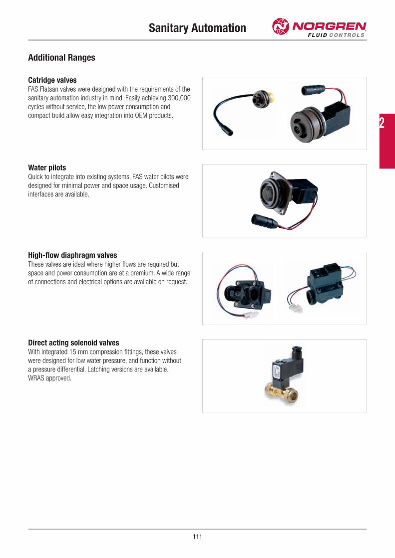
111
Sanitary Automation
Additional Ranges
Catridge valvesFAS Flatsan valves were designed with the requirements of the
sanitary automation industry in mind. Easily achieving 300,000
cycles without service, the low power consumption and
compact build allow easy integration into OEM products.
Direct acting solenoid valvesWith integrated 15 mm compression fittings, these valves
were designed for low water pressure, and function without
a pressure differential. Latching versions are available.
WRAS approved.
High-flow diaphragm valvesThese valves are ideal where higher flows are required but
space and power consumption are at a premium. A wide range
of connections and electrical options are available on request.
Water pilotsQuick to integrate into existing systems, FAS water pilots were
designed for minimal power and space usage. Customised
interfaces are available.
2
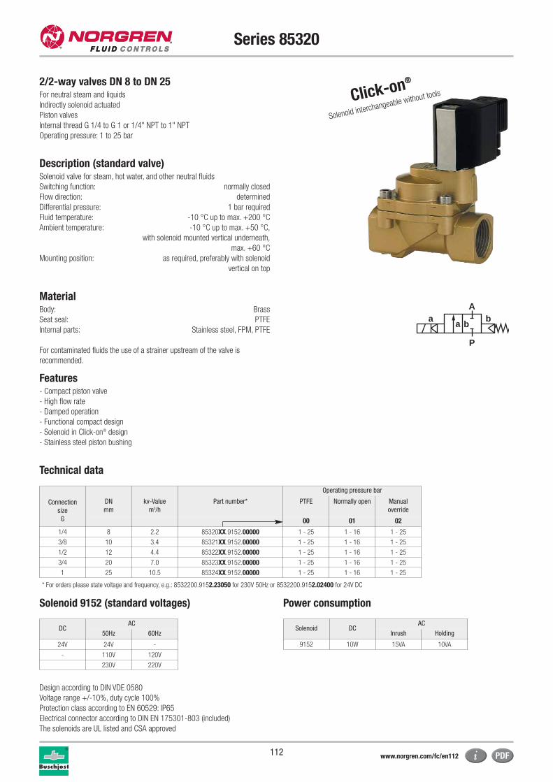
112
Series 85320
Operating pressure bar
Connection
size
G
DN
mm
kv-Value
m3/h
Part number* PTFE Normally open Manual
override
00 01 02
1/4 8 2.2 85320XX.9152.00000 1 - 25 1 - 16 1 - 25
3/8 10 3.4 85321XX.9152.00000 1 - 25 1 - 16 1 - 25
1/2 12 4.4 85322XX.9152.00000 1 - 25 1 - 16 1 - 25
3/4 20 7.0 85323XX.9152.00000 1 - 25 1 - 16 1 - 25
1 25 10.5 85324XX.9152.00000 1 - 25 1 - 16 1 - 25
* For orders please state voltage and frequency, e.g.: 8532200.9152.23050 for 230V 50Hz or 8532200.9152.02400 for 24V DC
2/2-way valves DN 8 to DN 25For neutral steam and liquids
Indirectly solenoid actuated
Piston valves
Internal thread G 1/4 to G 1 or 1/4" NPT to 1" NPT
Operating pressure: 1 to 25 bar
Description (standard valve)Solenoid valve for steam, hot water, and other neutral fluids
Switching function: normally closed
Flow direction: determined
Differential pressure: 1 bar required
Fluid temperature: -10 °C up to max. +200 °C
Ambient temperature: -10 °C up to max. +50 °C,
with solenoid mounted vertical underneath,
max. +60 °C
Mounting position: as required, preferably with solenoid
vertical on top
MaterialBody: Brass
Seat seal: PTFE
Internal parts: Stainless steel, FPM, PTFE
For contaminated fluids the use of a strainer upstream of the valve is
recommended.
Features- Compact piston valve
- High flow rate
- Damped operation
- Functional compact design
- Solenoid in Click-on® design
- Stainless steel piston bushing
Technical data
Solenoid 9152 (standard voltages) Power consumption
Design according to DIN VDE 0580
Voltage range +/-10%, duty cycle 100%
Protection class according to EN 60529: IP65
Electrical connector according to DIN EN 175301-803 (included)
The solenoids are UL listed and CSA approved
Solenoid DCAC
Inrush Holding
9152 10W 15VA 10VA
DCAC
50Hz 60Hz
24V 24V -
- 110V 120V
230V 220V
Click-on®
Solenoid interchangeable without tools
a
P
Ab
a b
www.norgren.com/fc/en112
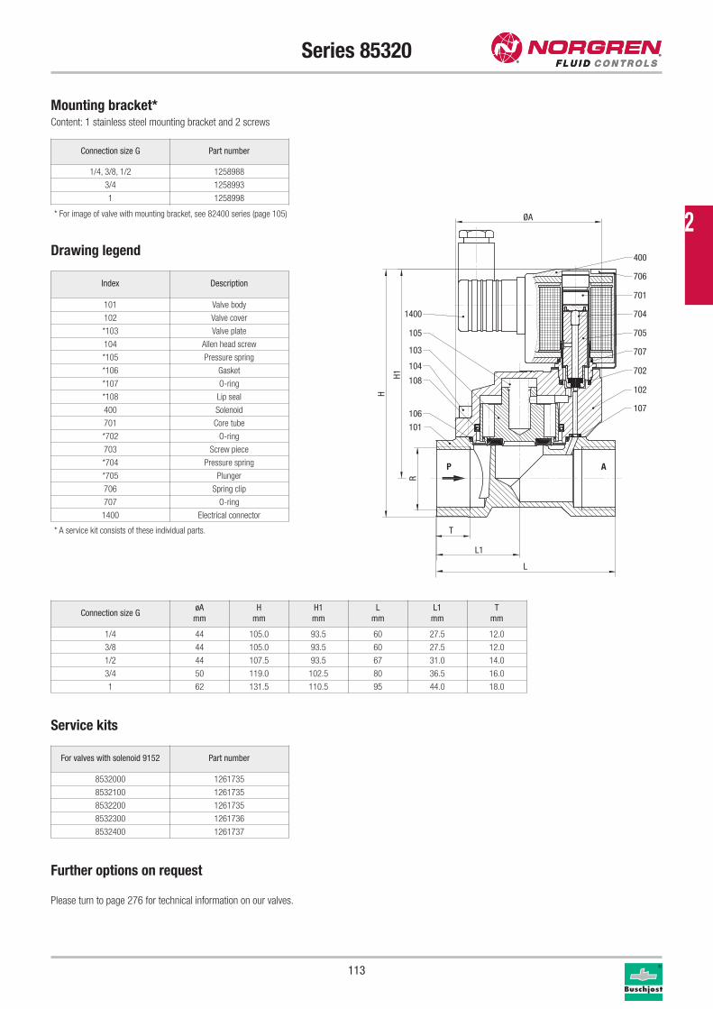
113
Series 85320
Connection size G Part number
1/4, 3/8, 1/2 1258988
3/4 1258993
1 1258998
Mounting bracket*Content: 1 stainless steel mounting bracket and 2 screws
Drawing legend
Index Description
101 Valve body
102 Valve cover
*103 Valve plate
104 Allen head screw
*105 Pressure spring
*106 Gasket
*107 O-ring
*108 Lip seal
400 Solenoid
701 Core tube
*702 O-ring
703 Screw piece
*704 Pressure spring
*705 Plunger
706 Spring clip
707 O-ring
1400 Electrical connector
* A service kit consists of these individual parts.
Connection size GøA
mm
H
mm
H1
mm
L
mm
L1
mm
T
mm
1/4 44 105.0 93.5 60 27.5 12.0
3/8 44 105.0 93.5 60 27.5 12.0
1/2 44 107.5 93.5 67 31.0 14.0
3/4 50 119.0 102.5 80 36.5 16.0
1 62 131.5 110.5 95 44.0 18.0
Further options on request
Please turn to page 276 for technical information on our valves.
Service kits
For valves with solenoid 9152 Part number
8532000 1261735
8532100 1261735
8532200 1261735
8532300 1261736
8532400 1261737
P A
1400
105
103
104
108
106
101
400
701
706
704
705
707
702
102
107
L
H
H1
L1
T
R
ØA* For image of valve with mounting bracket, see 82400 series (page 105)
2
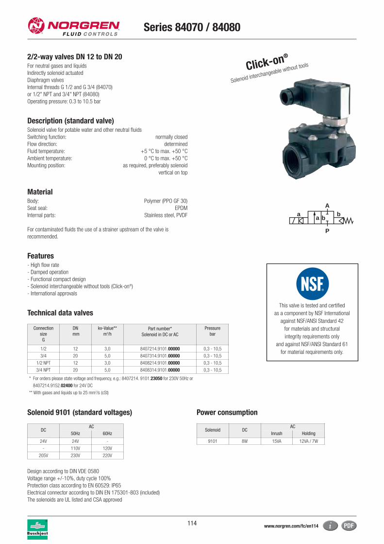
114
Series 84070 / 84080
2/2-way valves DN 12 to DN 20For neutral gases and liquids
Indirectly solenoid actuated
Diaphragm valves
Internal threads G 1/2 and G 3/4 (84070)
or 1/2" NPT and 3/4" NPT (84080)
Operating pressure: 0.3 to 10.5 bar
Description (standard valve)Solenoid valve for potable water and other neutral fluids
Switching function: normally closed
Flow direction: determined
Fluid temperature: +5 °C to max. +50 °C
Ambient temperature: 0 °C to max. +50 °C
Mounting position: as required, preferably solenoid
vertical on top
MaterialBody: Polymer (PPO GF 30)
Seat seal: EPDM
Internal parts: Stainless steel, PVDF
For contaminated fluids the use of a strainer upstream of the valve is
recommended.
Features- High flow rate
- Damped operation
- Functional compact design
- Solenoid interchangeable without tools (Click-on®)
- International approvals
Click-on®
Solenoid interchangeable without tools
* For orders please state voltage and frequency, e.g.: 8407214. 9101.23050 for 230V 50Hz or
8407214.9152.02400 for 24V DC
** With gases and liquids up to 25 mm2/s (cSt)
Technical data valves
Solenoid 9101 (standard voltages) Power consumption
Design according to DIN VDE 0580
Voltage range +/-10%, duty cycle 100%
Protection class according to EN 60529: IP65
Electrical connector according to DIN EN 175301-803 (included)
The solenoids are UL listed and CSA approved
Solenoid DCAC
Inrush Holding
9101 8W 15VA 12VA / 7W
DCAC
50Hz 60Hz
24V 24V -
- 110V 120V
205V 230V 220V
a
P
Ab
a b
Connection
size
G
DN
mm
kv-Value**
m3/hPart number*
Solenoid in DC or AC
Pressure
bar
1/2 12 3,0 8407214.9101.00000 0,3 - 10,5
3/4 20 5,0 8407314.9101.00000 0,3 - 10,5
1/2 NPT 12 3,0 8408214.9101.00000 0,3 - 10,5
3/4 NPT 20 5,0 8408314.9101.00000 0,3 - 10,5
www.norgren.com/fc/en114
This valve is tested and certified
as a component by NSF International
against NSF/ANSI Standard 42
for materials and structural
integrity requirements only
and against NSF/ANSI Standard 61
for material requirements only.
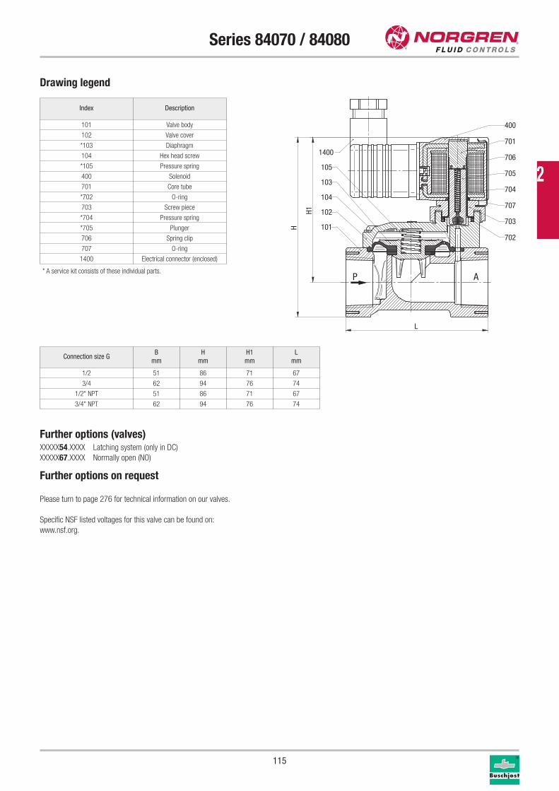
115
Series 84070 / 84080
Drawing legend
Index Description
101 Valve body
102 Valve cover
*103 Diaphragm
104 Hex head screw
*105 Pressure spring
400 Solenoid
701 Core tube
*702 O-ring
703 Screw piece
*704 Pressure spring
*705 Plunger
706 Spring clip
707 O-ring
1400 Electrical connector (enclosed)
* A service kit consists of these individual parts.
Further options (valves)XXXXX54.XXXX Latching system (only in DC)
XXXXX67.XXXX Normally open (NO)
Further options on request
Please turn to page 276 for technical information on our valves.
Specific NSF listed voltages for this valve can be found on:
www.nsf.org.
P A
400
701
706
705
704
707
703
702
1400
105
103
104
102
101
H1
H
L
Connection size GB
mm
H
mm
H1
mm
L
mm
1/2 51 86 71 67
3/4 62 94 76 74
1/2" NPT 51 86 71 67
3/4" NPT 62 94 76 74
2
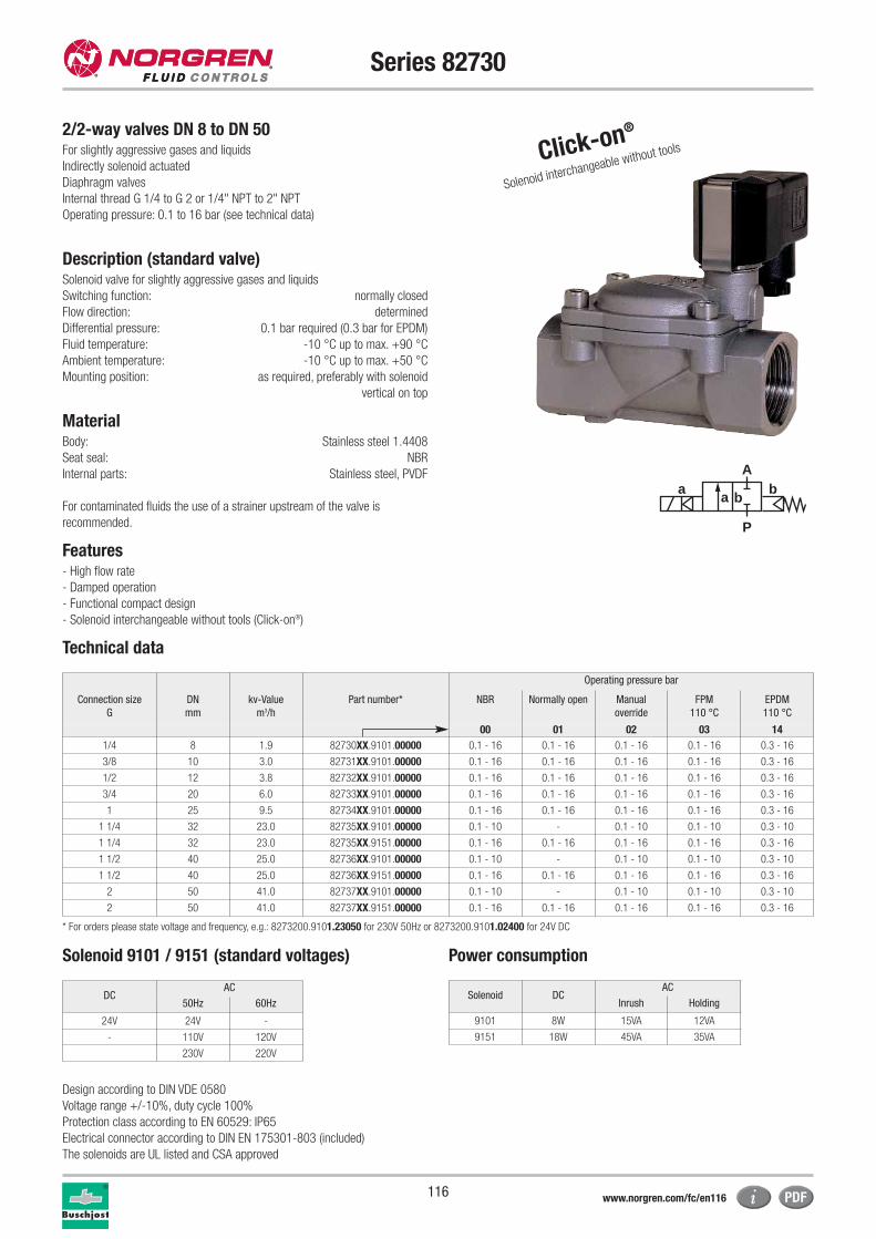
116
Series 82730
2/2-way valves DN 8 to DN 50For slightly aggressive gases and liquids
Indirectly solenoid actuated
Diaphragm valves
Internal thread G 1/4 to G 2 or 1/4" NPT to 2" NPT
Operating pressure: 0.1 to 16 bar (see technical data)
Description (standard valve)Solenoid valve for slightly aggressive gases and liquids
Switching function: normally closed
Flow direction: determined
Differential pressure: 0.1 bar required (0.3 bar for EPDM)
Fluid temperature: -10 °C up to max. +90 °C
Ambient temperature: -10 °C up to max. +50 °C
Mounting position: as required, preferably with solenoid
vertical on top
MaterialBody: Stainless steel 1.4408
Seat seal: NBR
Internal parts: Stainless steel, PVDF
For contaminated fluids the use of a strainer upstream of the valve is
recommended.
Features- High flow rate
- Damped operation
- Functional compact design
- Solenoid interchangeable without tools (Click-on®)
Technical data
Click-on®
Solenoid interchangeable without tools
a
P
Ab
a b
Operating pressure bar
Connection size
G
DN
mm
kv-Value
m3/h
Part number* NBR Normally open Manual
override
FPM
110 °C
EPDM
110 °C
00 01 02 03 14
1/4 8 1.9 82730XX.9101.00000 0.1 - 16 0.1 - 16 0.1 - 16 0.1 - 16 0.3 - 16
3/8 10 3.0 82731XX.9101.00000 0.1 - 16 0.1 - 16 0.1 - 16 0.1 - 16 0.3 - 16
1/2 12 3.8 82732XX.9101.00000 0.1 - 16 0.1 - 16 0.1 - 16 0.1 - 16 0.3 - 16
3/4 20 6.0 82733XX.9101.00000 0.1 - 16 0.1 - 16 0.1 - 16 0.1 - 16 0.3 - 16
1 25 9.5 82734XX.9101.00000 0.1 - 16 0.1 - 16 0.1 - 16 0.1 - 16 0.3 - 16
1 1/4 32 23.0 82735XX.9101.00000 0.1 - 10 - 0.1 - 10 0.1 - 10 0.3 - 10
1 1/4 32 23.0 82735XX.9151.00000 0.1 - 16 0.1 - 16 0.1 - 16 0.1 - 16 0.3 - 16
1 1/2 40 25.0 82736XX.9101.00000 0.1 - 10 - 0.1 - 10 0.1 - 10 0.3 - 10
1 1/2 40 25.0 82736XX.9151.00000 0.1 - 16 0.1 - 16 0.1 - 16 0.1 - 16 0.3 - 16
2 50 41.0 82737XX.9101.00000 0.1 - 10 - 0.1 - 10 0.1 - 10 0.3 - 10
2 50 41.0 82737XX.9151.00000 0.1 - 16 0.1 - 16 0.1 - 16 0.1 - 16 0.3 - 16
* For orders please state voltage and frequency, e.g.: 8273200.9101.23050 for 230V 50Hz or 8273200.9101.02400 for 24V DC
Solenoid 9101 / 9151 (standard voltages) Power consumption
Design according to DIN VDE 0580
Voltage range +/-10%, duty cycle 100%
Protection class according to EN 60529: IP65
Electrical connector according to DIN EN 175301-803 (included)
The solenoids are UL listed and CSA approved
Solenoid DCAC
Inrush Holding
9101 8W 15VA 12VA
9151 18W 45VA 35VA
DCAC
50Hz 60Hz
24V 24V -
- 110V 120V
230V 220V
www.norgren.com/fc/en116
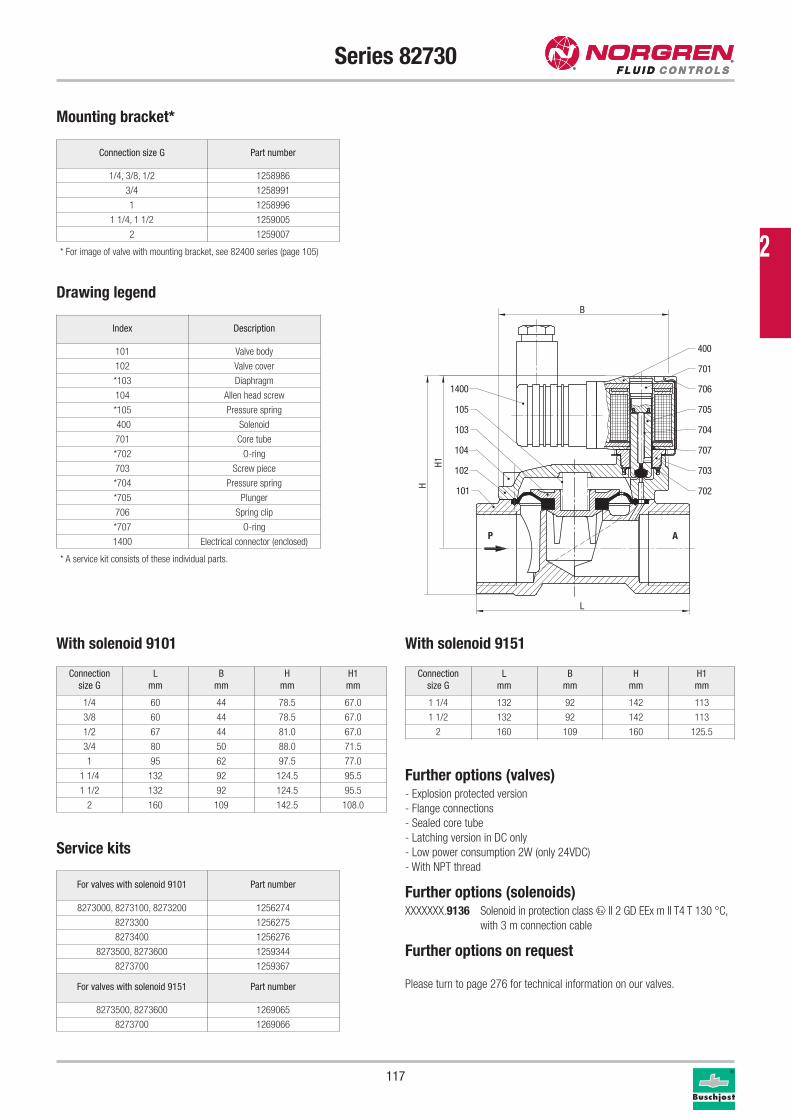
117
Series 82730
Connection size G Part number
1/4, 3/8, 1/2 1258986
3/4 1258991
1 1258996
1 1/4, 1 1/2 1259005
2 1259007
Mounting bracket*
Service kits
For valves with solenoid 9101 Part number
8273000, 8273100, 8273200 1256274
8273300 1256275
8273400 1256276
8273500, 8273600 1259344
8273700 1259367
For valves with solenoid 9151 Part number
8273500, 8273600 1269065
8273700 1269066
Further options (valves)- Explosion protected version
- Flange connections
- Sealed core tube
- Latching version in DC only
- Low power consumption 2W (only 24VDC)
- With NPT thread
Further options (solenoids)XXXXXXX.9136 Solenoid in protection class x II 2 GD EEx m II T4 T 130 °C,
with 3 m connection cable
Further options on request
Please turn to page 276 for technical information on our valves.
* For image of valve with mounting bracket, see 82400 series (page 105)
P A
101
102
104
103
105
1400
702
703
707
704
705
706
701
400
B
H1
H
L
Drawing legend
Connection
size G
L
mm
B
mm
H
mm
H1
mm
1/4 60 44 78.5 67.0
3/8 60 44 78.5 67.0
1/2 67 44 81.0 67.0
3/4 80 50 88.0 71.5
1 95 62 97.5 77.0
1 1/4 132 92 124.5 95.5
1 1/2 132 92 124.5 95.5
2 160 109 142.5 108.0
Index Description
101 Valve body
102 Valve cover
*103 Diaphragm
104 Allen head screw
*105 Pressure spring
400 Solenoid
701 Core tube
*702 O-ring
703 Screw piece
*704 Pressure spring
*705 Plunger
706 Spring clip
*707 O-ring
1400 Electrical connector (enclosed)
Connection
size G
L
mm
B
mm
H
mm
H1
mm
1 1/4 132 92 142 113
1 1/2 132 92 142 113
2 160 109 160 125.5
With solenoid 9151
* A service kit consists of these individual parts.
With solenoid 9101
2
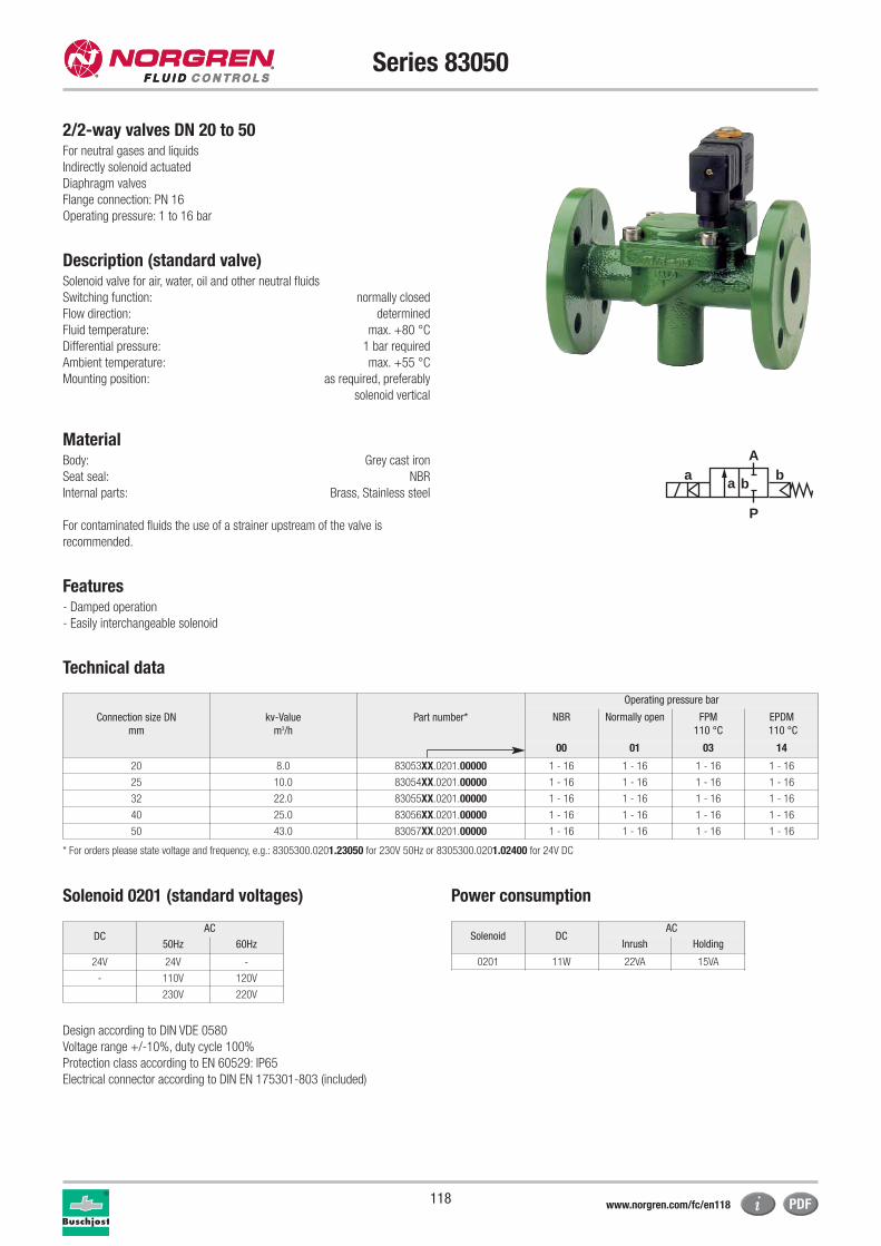
118
Series 83050
2/2-way valves DN 20 to 50For neutral gases and liquids
Indirectly solenoid actuated
Diaphragm valves
Flange connection: PN 16
Operating pressure: 1 to 16 bar
Description (standard valve)Solenoid valve for air, water, oil and other neutral fluids
Switching function: normally closed
Flow direction: determined
Fluid temperature: max. +80 °C
Differential pressure: 1 bar required
Ambient temperature: max. +55 °C
Mounting position: as required, preferably
solenoid vertical
MaterialBody: Grey cast iron
Seat seal: NBR
Internal parts: Brass, Stainless steel
For contaminated fluids the use of a strainer upstream of the valve is
recommended.
Features- Damped operation
- Easily interchangeable solenoid
Technical data
a
P
Ab
a b
Connection size DN
mm
kv-Value
m3/h
Part number*
Operating pressure bar
NBR Normally open FPM
110 °C
EPDM
110 °C
00 01 03 14
20 8.0 83053XX.0201.00000 1 - 16 1 - 16 1 - 16 1 - 16
25 10.0 83054XX.0201.00000 1 - 16 1 - 16 1 - 16 1 - 16
32 22.0 83055XX.0201.00000 1 - 16 1 - 16 1 - 16 1 - 16
40 25.0 83056XX.0201.00000 1 - 16 1 - 16 1 - 16 1 - 16
50 43.0 83057XX.0201.00000 1 - 16 1 - 16 1 - 16 1 - 16
* For orders please state voltage and frequency, e.g.: 8305300.0201.23050 for 230V 50Hz or 8305300.0201.02400 for 24V DC
Solenoid 0201 (standard voltages) Power consumption
Design according to DIN VDE 0580
Voltage range +/-10%, duty cycle 100%
Protection class according to EN 60529: IP65
Electrical connector according to DIN EN 175301-803 (included)
Solenoid DCAC
Inrush Holding
0201 11W 22VA 15VA
DCAC
50Hz 60Hz
24V 24V -
- 110V 120V
230V 220V
www.norgren.com/fc/en118
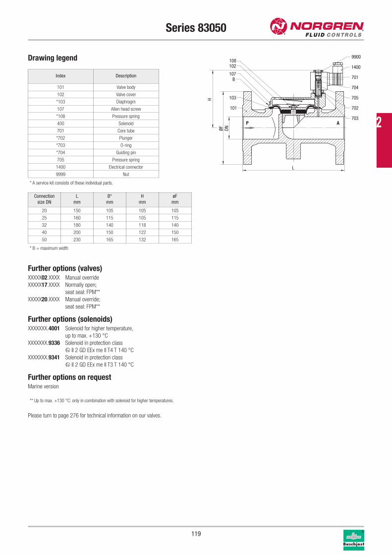
119
Series 83050
Drawing legend
Index Description
101 Valve body
102 Valve cover
*103 Diaphragm
107 Allen head screw
*108 Pressure spring
400 Solenoid
701 Core tube
*702 Plunger
*703 O-ring
*704 Guiding pin
705 Pressure spring
1400 Electrical connector
9999 Nut
* A service kit consists of these individual parts.
Further options (valves)XXXXX02.XXXX Manual override
XXXXX17.XXXX Normally open;
seat seal: FPM**
XXXXX20.XXXX Manual override;
seat seal: FPM**
Further options (solenoids)XXXXXXX.4001 Solenoid for higher temperature,
up to max. +130 °C
XXXXXXX.9336 Solenoid in protection class
x II 2 GD EEx me II T4 T 140 °C
XXXXXXX.9341 Solenoid in protection class
x II 2 GD EEx me II T3 T 140 °C
Further options on requestMarine version
** Up to max. +130 °C: only in combination with solenoid for higher temperatures.
Please turn to page 276 for technical information on our valves.
Connection
size DN
L
mm
B*
mm
H
mm
øF
mm
20 150 105 105 105
25 160 115 105 115
32 180 140 118 140
40 200 150 122 150
50 230 165 132 165
P A
103
101
107
102108
703
705
704
701
702
1400
9900
DNØF
H
L
B
* B = maximum width
2
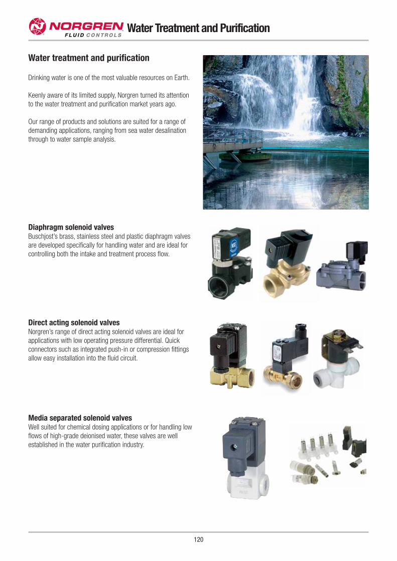
120
Water Treatment and Purification
Water treatment and purification
Drinking water is one of the most valuable resources on Earth.
Keenly aware of its limited supply, Norgren turned its attention
to the water treatment and purification market years ago.
Our range of products and solutions are suited for a range of
demanding applications, ranging from sea water desalination
through to water sample analysis.
Media separated solenoid valvesWell suited for chemical dosing applications or for handling low
flows of high-grade deionised water, these valves are well
established in the water purification industry.
Direct acting solenoid valvesNorgren’s range of direct acting solenoid valves are ideal for
applications with low operating pressure differential. Quick
connectors such as integrated push-in or compression fittings
allow easy installation into the fluid circuit.
Diaphragm solenoid valvesBuschjost’s brass, stainless steel and plastic diaphragm valves
are developed specifically for handling water and are ideal for
controlling both the intake and treatment process flow.

121
Water Treatment and Purification
Valve islands and pneumatic pilotsWhere flows or impurities are higher and pneumatically
operated valves are used, Norgren’s compact valve islands and
range of pneumatic pilots can save critical assembly time and
increase performance of the system.
Air preparationNorgren’s established range of air preparation equipment
includes filters, regulators, and lubricators as well as pneumatic
tubing and fittings.
Water Treatment and Purification
Buschjost’s new Series 84080 – designed for the demanding needs of the water purification market.
Solenoid interchangeable without tools (Click-on®)Solenoid completely encased; IP65 protection
Stainless steel jacketed threads
Optimised range offers excellent flow ratesReliable diaphragm guidance at high flow rates,
damped closing – water hammer free
2
This valve is tested and certified
as a component by NSF International
against NSF/ANSI Standard 42
for materials and structural
integrity requirements only
and against NSF/ANSI Standard 61
for material requirements only.
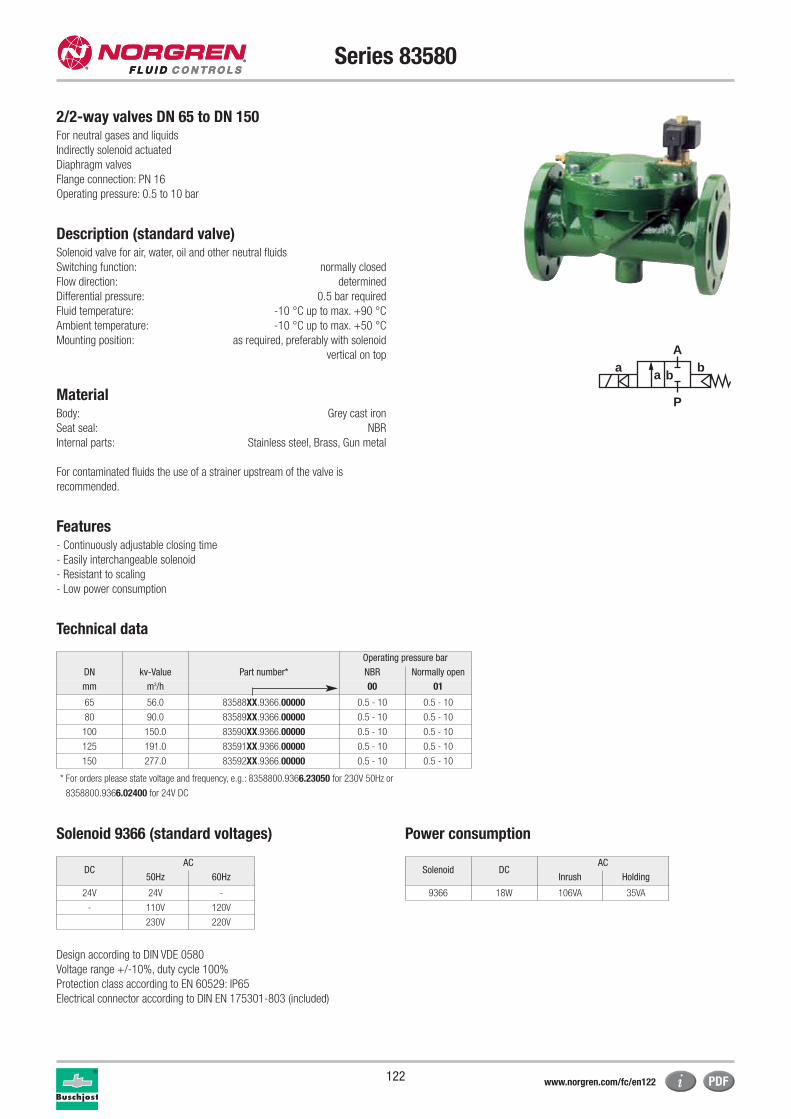
122
Series 83580
2/2-way valves DN 65 to DN 150For neutral gases and liquids
Indirectly solenoid actuated
Diaphragm valves
Flange connection: PN 16
Operating pressure: 0.5 to 10 bar
Description (standard valve)Solenoid valve for air, water, oil and other neutral fluids
Switching function: normally closed
Flow direction: determined
Differential pressure: 0.5 bar required
Fluid temperature: -10 °C up to max. +90 °C
Ambient temperature: -10 °C up to max. +50 °C
Mounting position: as required, preferably with solenoid
vertical on top
MaterialBody: Grey cast iron
Seat seal: NBR
Internal parts: Stainless steel, Brass, Gun metal
For contaminated fluids the use of a strainer upstream of the valve is
recommended.
Features- Continuously adjustable closing time
- Easily interchangeable solenoid
- Resistant to scaling
- Low power consumption
Technical data
a
P
Ab
a b
Operating pressure bar
DN kv-Value Part number* NBR Normally open
mm m3/h 00 01
65 56.0 83588XX.9366.00000 0.5 - 10 0.5 - 10
80 90.0 83589XX.9366.00000 0.5 - 10 0.5 - 10
100 150.0 83590XX.9366.00000 0.5 - 10 0.5 - 10
125 191.0 83591XX.9366.00000 0.5 - 10 0.5 - 10
150 277.0 83592XX.9366.00000 0.5 - 10 0.5 - 10
* For orders please state voltage and frequency, e.g.: 8358800.9366.23050 for 230V 50Hz or
8358800.9366.02400 for 24V DC
Solenoid 9366 (standard voltages) Power consumption
Design according to DIN VDE 0580
Voltage range +/-10%, duty cycle 100%
Protection class according to EN 60529: IP65
Electrical connector according to DIN EN 175301-803 (included)
Solenoid DCAC
Inrush Holding
9366 18W 106VA 35VA
DCAC
50Hz 60Hz
24V 24V -
- 110V 120V
230V 220V
www.norgren.com/fc/en122
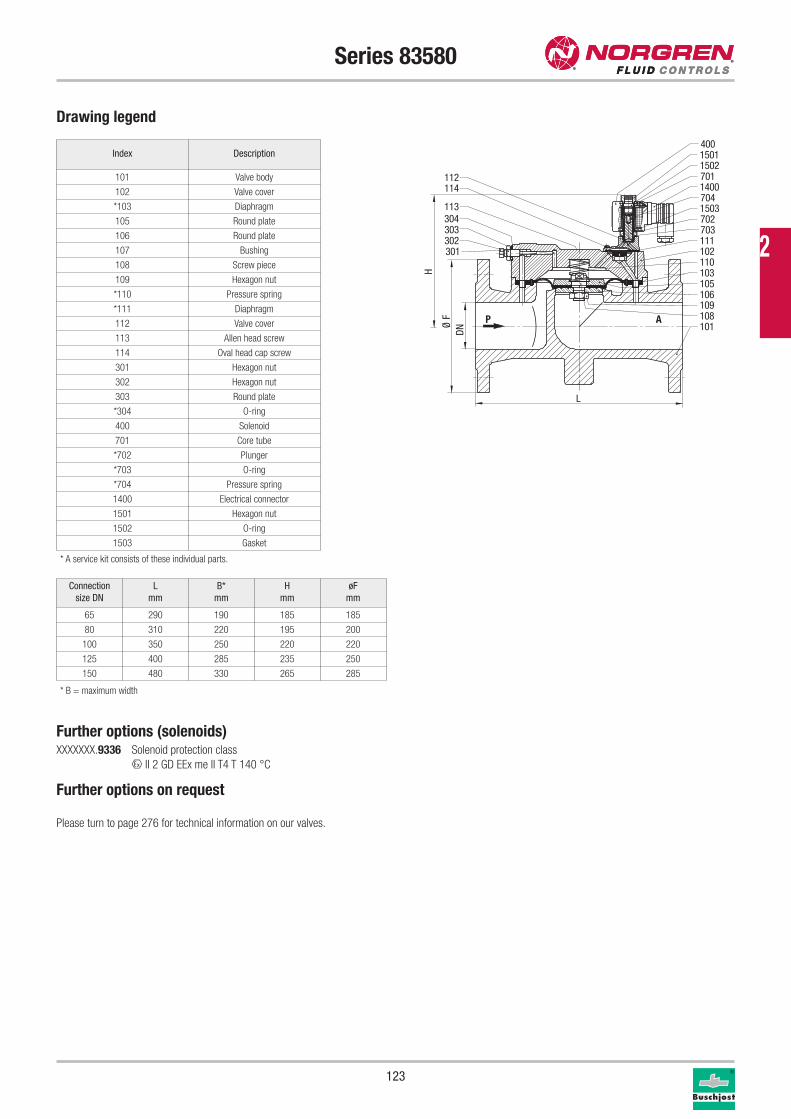
123
Series 83580
Drawing legend
Index Description
101 Valve body
102 Valve cover
*103 Diaphragm
105 Round plate
106 Round plate
107 Bushing
108 Screw piece
109 Hexagon nut
*110 Pressure spring
*111 Diaphragm
112 Valve cover
113 Allen head screw
114 Oval head cap screw
301 Hexagon nut
302 Hexagon nut
303 Round plate
*304 O-ring
400 Solenoid
701 Core tube
*702 Plunger
*703 O-ring
*704 Pressure spring
1400 Electrical connector
1501 Hexagon nut
1502 O-ring
1503 Gasket
* A service kit consists of these individual parts.
Further options (solenoids)XXXXXXX.9336 Solenoid protection class
x II 2 GD EEx me II T4 T 140 °C
Further options on request
Please turn to page 276 for technical information on our valves.
Connection
size DN
L
mm
B*
mm
H
mm
øF
mm
65 290 190 185 185
80 310 220 195 200
100 350 250 220 220
125 400 285 235 250
150 480 330 265 285
P A
301302303304113
114112
1011081091061051031101021117037021503704140070115021501400
DNØ
F
L
H
* B = maximum width
2
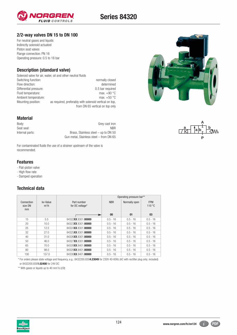
124
Series 84320
2/2-way valves DN 15 to DN 100For neutral gases and liquids
Indirectly solenoid actuated
Piston seat valves
Flange connection: PN 16
Operating pressure: 0.5 to 16 bar
Description (standard valve)Solenoid valve for air, water, oil and other neutral fluids
Switching function: normally closed
Flow direction: determined
Differential pressure: 0.5 bar required
Fluid temperature: max. +90 °C
Ambient temperature: max. +50 °C
Mounting position: as required, preferably with solenoid vertical on top,
from DN 65 vertical on top only
MaterialBody: Grey cast iron
Seat seal: NBR
Internal parts: Brass, Stainless steel – up to DN 50
Gun metal, Stainless steel – from DN 65
For contaminated fluids the use of a strainer upstream of the valve is
recommended.
Features- Flat-piston valve
- High flow rate
- Damped operation
Technical data
a
P
Ab
a b
Operating pressure bar**
Connection
size DN
mm
kv-Value
m3/h
Part number
for DC voltage*
NBR Normally open FPM
110 °C
00 01 03
15 5.5 84322XX.8301.00000 0.5 - 16 0.5 - 16 0.5 - 16
20 10.0 84323XX.8301.00000 0.5 - 16 0.5 - 16 0.5 - 16
25 12.5 84324XX.8301.00000 0.5 - 16 0.5 - 16 0.5 - 16
32 27.0 84325XX.8301.00000 0.5 - 16 0.5 - 16 0.5 - 16
40 31.0 84326XX.8301.00000 0.5 - 16 0.5 - 16 0.5 - 16
50 46.0 84327XX.8301.00000 0.5 - 16 0.5 - 16 0.5 - 16
65 70.0 84328XX.8401.00000 0.5 - 16 0.5 - 16 0.5 - 16
80 98.0 84329XX.8401.00000 0.5 - 16 0.5 - 16 0.5 - 16
100 157.0 84330XX.8401.00000 0.5 - 16 0.5 - 16 0.5 - 16
* For orders please state voltage and frequency, e.g.: 8432200.8304.23049 for 230V 40-60Hz (AC with rectifier plug only; included)
or 8432200.8301.02400 for 24V DC
** With gases or liquids up to 40 mm2/s (cSt)
www.norgren.com/fc/en124
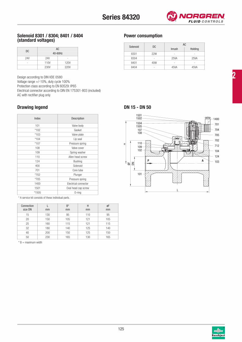
125
Solenoid 8301 / 8304; 8401 / 8404 (standard voltages)
Power consumption
Design according to DIN VDE 0580
Voltage range +/-10%, duty cycle 100%
Protection class according to EN 60529: IP65
Electrical connector according to DIN EN 175301-803 (included)
AC with rectifier plug only
Solenoid DCAC
Inrush Holding
8301 22W - -
8304 - 25VA 25VA
8401 40W - -
8404 - 45VA 45VA
Series 84320
Connection
size DN
L
mm
B*
mm
H
mm
øF
mm
15 130 95 110 95
20 150 105 121 105
25 160 115 121 115
32 180 140 125 140
40 200 150 125 150
50 230 165 130 165
* A service kit consists of these individual parts.
Index Description
101 Valve body
*102 Gasket
*103 Valve plate
*104 Lip seal
*107 Pressure spring
108 Valve cover
109 Spring washer
110 Allen head screw
124 Bushing
400 Solenoid
701 Core tube
*702 Plunger
*705 Pressure spring
1400 Electrical connector
1501 Oval head cap screw
*1505 O-ring
P A
107108
110109102
101
1505
1400
701
705
702
103
712
704
15011502
1504
124
104
DNØF
L
H
Drawing legend DN 15 - DN 50
DCAC
40-60Hz
24V 24V -
- 110V 120V
230V 220V
* B = maximum width
2
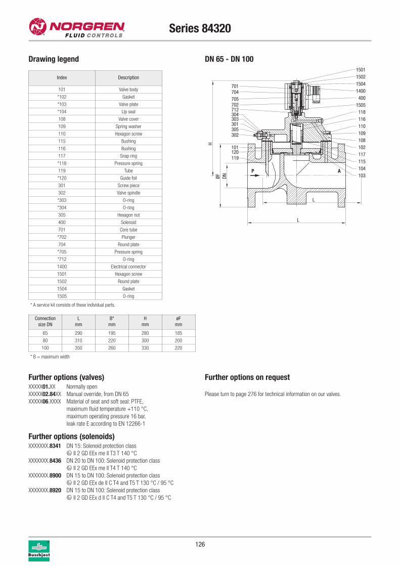
126
Series 84320
Connection
size DN
L
mm
B*
mm
H
mm
øF
mm
65 290 195 280 185
80 310 220 300 200
100 350 260 330 220
* A service kit consists of these individual parts.
Index Description
101 Valve body
*102 Gasket
*103 Valve plate
*104 LIp seal
108 Valve cover
109 Spring washer
110 Hexagon screw
115 Bushing
116 Bushing
117 Snap ring
*118 Pressure spring
119 Tube
*120 Guide foil
301 Screw piece
302 Valve spindle
*303 O-ring
*304 O-ring
305 Hexagon nut
400 Solenoid
701 Core tube
*702 Plunger
704 Round plate
*705 Pressure spring
*712 O-ring
1400 Electrical connector
1501 Hexagon screw
1502 Round plate
1504 Gasket
1505 O-ring
DNØFL
H
P A
301305302
304303
15021501
712702705704701
1400400
1505118116110109
117102
115104103
1504
108
120119
101
L
Drawing legend DN 65 - DN 100
Further options (valves)XXXXX01.XX Normally open
XXXXX02.84XX Manual override, from DN 65
XXXXX06.XXXX Material of seat and soft seal: PTFE,
maximum fluid temperature +110 °C,
maximum operating pressure 16 bar,
leak rate E according to EN 12266-1
Further options (solenoids)XXXXXXX.8341 DN 15: Solenoid protection class
x II 2 GD EEx me II T3 T 140 °C
XXXXXXX.8436 DN 20 to DN 100: Solenoid protection class
x II 2 GD EEx me II T4 T 140 °C
XXXXXXX.8900 DN 15 to DN 100: Solenoid protection class
x II 2 GD EEx de II C T4 and T5 T 130 °C / 95 °C
XXXXXXX.8920 DN 15 to DN 100: Solenoid protection class
x II 2 GD EEx d II C T4 and T5 T 130 °C / 95 °C
Further options on request
Please turn to page 276 for technical information on our valves.
* B = maximum width
Fluid Control Solutions
127
01
02
03
01 FLATPROP
With a frictionless design and up to 200 l/min flow rate (@4 bar / 58 psi), Flatprop sets new
standards in the field of proportional fluid control.
02 CLICK-ON® VALVES
Click-on® is the latest and most varied design within the range of solenoid valves. Due to its
modular system, high flexibility and fast availability is guaranteed.
03 DIRECT OPERATED SOLENOID VALVE
With a wide variety of coil, orifice and mounting options, KIP can provide a solution meeting many
demanding requirements. With a wide range of materials and pressure ratings, we can design
the correct valve to fit your application.
VALVE INTEGRATION
2
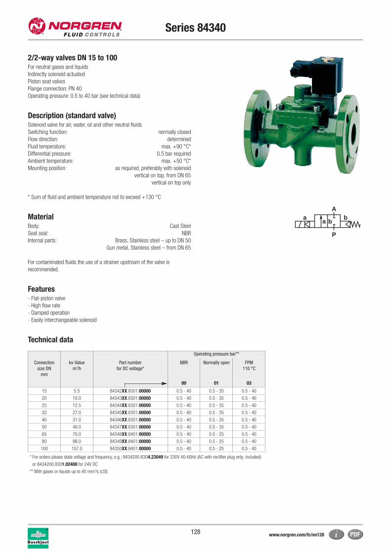
128
Series 84340
2/2-way valves DN 15 to 100For neutral gases and liquids
Indirectly solenoid actuated
Piston seat valves
Flange connection: PN 40
Operating pressure: 0.5 to 40 bar (see technical data)
Description (standard valve)Solenoid valve for air, water, oil and other neutral fluids
Switching function: normally closed
Flow direction: determined
Fluid temperature: max. +90 °C*
Differential pressure: 0.5 bar required
Ambient temperature: max. +50 °C*
Mounting position: as required, preferably with solenoid
vertical on top, from DN 65
vertical on top only
* Sum of fluid and ambient temperature not to exceed +130 °C
MaterialBody: Cast Steel
Seat seal: NBR
Internal parts: Brass, Stainless steel – up to DN 50
Gun metal, Stainless steel – from DN 65
For contaminated fluids the use of a strainer upstream of the valve is
recommended.
Features- Flat-piston valve
- High flow rate
- Damped operation
- Easily interchangeable solenoid
Technical data
Operating pressure bar**
Connection
size DN
mm
kv-Value
m3/h
Part number
for DC voltage*
NBR Normally open FPM
110 °C
00 01 03
15 5.5 84342XX.8301.00000 0.5 - 40 0.5 - 35 0.5 - 40
20 10.0 84343XX.8301.00000 0.5 - 40 0.5 - 35 0.5 - 40
25 12.5 84344XX.8301.00000 0.5 - 40 0.5 - 35 0.5 - 40
32 27.0 84345XX.8301.00000 0.5 - 40 0.5 - 35 0.5 - 40
40 31.0 84346XX.8301.00000 0.5 - 40 0.5 - 35 0.5 - 40
50 46.0 84347XX.8301.00000 0.5 - 40 0.5 - 35 0.5 - 40
65 70.0 84348XX.8401.00000 0.5 - 40 0.5 - 25 0.5 - 40
80 98.0 84349XX.8401.00000 0.5 - 40 0.5 - 25 0.5 - 40
100 157.0 84350XX.8401.00000 0.5 - 40 0.5 - 25 0.5 - 40
* For orders please state voltage and frequency, e.g.: 8434200.8304.23049 for 230V 40-60Hz (AC with rectifier plug only; included)
or 8434200.8301.02400 for 24V DC
** With gases or liquids up to 40 mm2/s (cSt)
a
P
Ab
a b
www.norgren.com/fc/en128
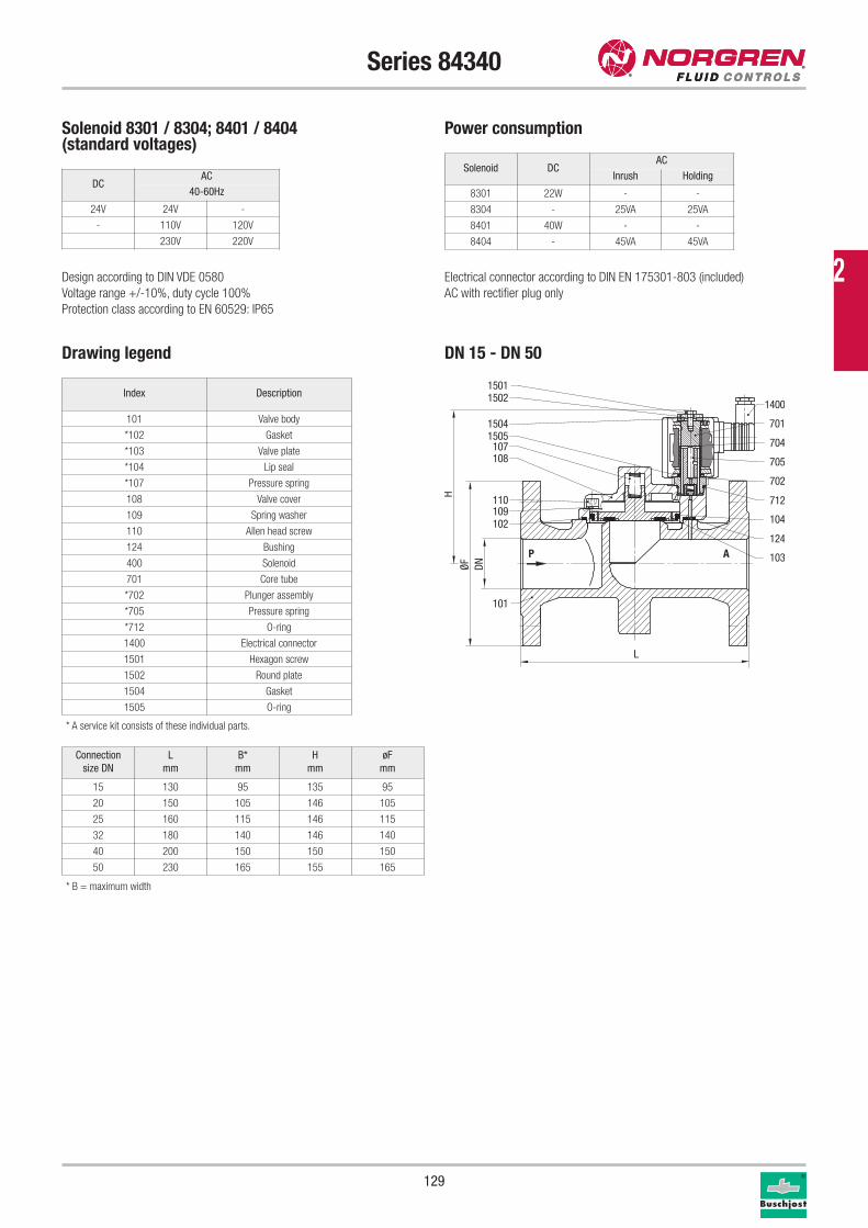
129
Solenoid 8301 / 8304; 8401 / 8404(standard voltages)
Power consumption
Design according to DIN VDE 0580
Voltage range +/-10%, duty cycle 100%
Protection class according to EN 60529: IP65
Electrical connector according to DIN EN 175301-803 (included)
AC with rectifier plug only
Solenoid DCAC
Inrush Holding
8301 22W - -
8304 - 25VA 25VA
8401 40W - -
8404 - 45VA 45VA
Series 84340
Connection
size DN
L
mm
B*
mm
H
mm
øF
mm
15 130 95 135 95
20 150 105 146 105
25 160 115 146 115
32 180 140 146 140
40 200 150 150 150
50 230 165 155 165
Index Description
101 Valve body
*102 Gasket
*103 Valve plate
*104 Lip seal
*107 Pressure spring
108 Valve cover
109 Spring washer
110 Allen head screw
124 Bushing
400 Solenoid
701 Core tube
*702 Plunger assembly
*705 Pressure spring
*712 O-ring
1400 Electrical connector
1501 Hexagon screw
1502 Round plate
1504 Gasket
1505 O-ring
P A
107108
110109102
101
1505
1400
701
705
702
103
712
704
15011502
1504
124
104
DNØF
L
H
* A service kit consists of these individual parts.
Drawing legend DN 15 - DN 50
DCAC
40-60Hz
24V 24V -
- 110V 120V
230V 220V
* B = maximum width
2
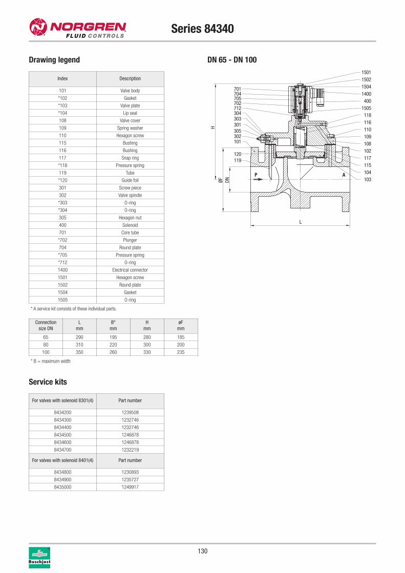
130
Series 84340
Service kits
For valves with solenoid 8301(4) Part number
8434200 1239508
8434300 1232746
8434400 1232746
8434500 1246878
8434600 1246878
8434700 1232219
For valves with solenoid 8401(4) Part number
8434800 1230893
8434900 1235727
8435000 1249917
Drawing legend DN 65 - DN 100
Index Description
101 Valve body
*102 Gasket
*103 Valve plate
*104 Lip seal
108 Valve cover
109 Spring washer
110 Hexagon screw
115 Bushing
116 Bushing
117 Snap ring
*118 Pressure spring
119 Tube
*120 Guide foil
301 Screw piece
302 Valve spindle
*303 O-ring
*304 O-ring
305 Hexagon nut
400 Solenoid
701 Core tube
*702 Plunger
704 Round plate
*705 Pressure spring
*712 O-ring
1400 Electrical connector
1501 Hexagon screw
1502 Round plate
1504 Gasket
1505 O-ring
* A service kit consists of these individual parts.
DNØFL
H
P A
301305302
304303
15021501
712702705704701
1400400
1505118116110109
117102
115104103
1504
108
120119
101
Connection
size DN
L
mm
B*
mm
H
mm
øF
mm
65 290 195 280 185
80 310 220 300 200
100 350 260 330 235
* B = maximum width
131
Series 84340
Further options (valves) XXXXX02.XXXX Manual override, from DN 65
XXXXX06.XXXX Seat seal: PTFE, up to DN 50,
maximum operating pressure 16 bar,
maximum fluid temperature +110 °C
leak rate E according to EN 12266-1
Further options (solenoids)XXXXXXX.8336 Solenoid in protection class
x II 2 GD EEx me II T4 T 140 °C
XXXXXXX.8436 Solenoid protection class
x II 2 GD EEx me II T4 T 140 °C
XXXXXXX.8900 Solenoid protection class
x II 2 GD EEx de II C T4 and T5 T 130 °C / 95 °C
XXXXXXX.8920 Solenoid protection class
x II 2 GD EEx d II C T4 and T5 T 130 °C / 95 °C
Further options on request
Please turn to page 276 for technical information on our valves.
2
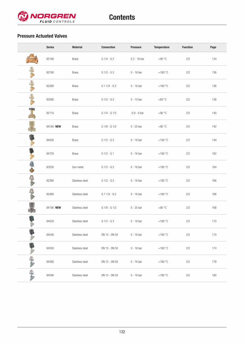
Contents
132
Pressure Actuated Valves
Series Material Connection Pressure Temperature Function Page
82160 Brass G 1/4 - G 2 0.2 - 16 bar +90 °C 2/2 134
82180 Brass G 1/2 - G 2 0 - 16 bar +180 °C 2/2 136
82280 Brass G 1 1/4 - G 2 0 - 16 bar +180 °C 2/2 136
82580 Brass G 1/2 - G 2 0 - 10 bar +60 °C 2/2 138
82710 Brass G 1/4 - G 1/2 -0.9 - 6 bar +90 °C 2/2 140
84180 NEW Brass G 1/8 - G 1/2 0 - 25 bar +90 °C 2/2 142
84500 Brass G 1/2 - G 3 0 - 16 bar +180 °C 2/2 144
84720 Brass G 1/2 - G 1 0 - 16 bar +180 °C 2/2 162
83250 Gun metal G 1/2 - G 2 0 - 16 bar +180 °C 2/2 164
82380 Stainless steel G 1/2 - G 2 0 - 16 bar +180 °C 2/2 166
82480 Stainless steel G 1 1/4 - G 2 0 - 16 bar +180 °C 2/2 166
84190 NEW Stainless steel G 1/8 - G 1/2 0 - 25 bar +90 °C 2/2 168
84520 Stainless steel G 1/2 - G 3 0 - 16 bar +180 °C 2/2 170
84540 Stainless steel DN 15 - DN 50 0 - 16 bar +180 °C 2/2 174
84550 Stainless steel DN 15 - DN 50 0 - 16 bar +180 °C 2/2 174
84580 Stainless steel DN 15 - DN 50 0 - 16 bar +180 °C 2/2 178
84590 Stainless steel DN 15 - DN 50 0 - 16 bar +180 °C 2/2 180
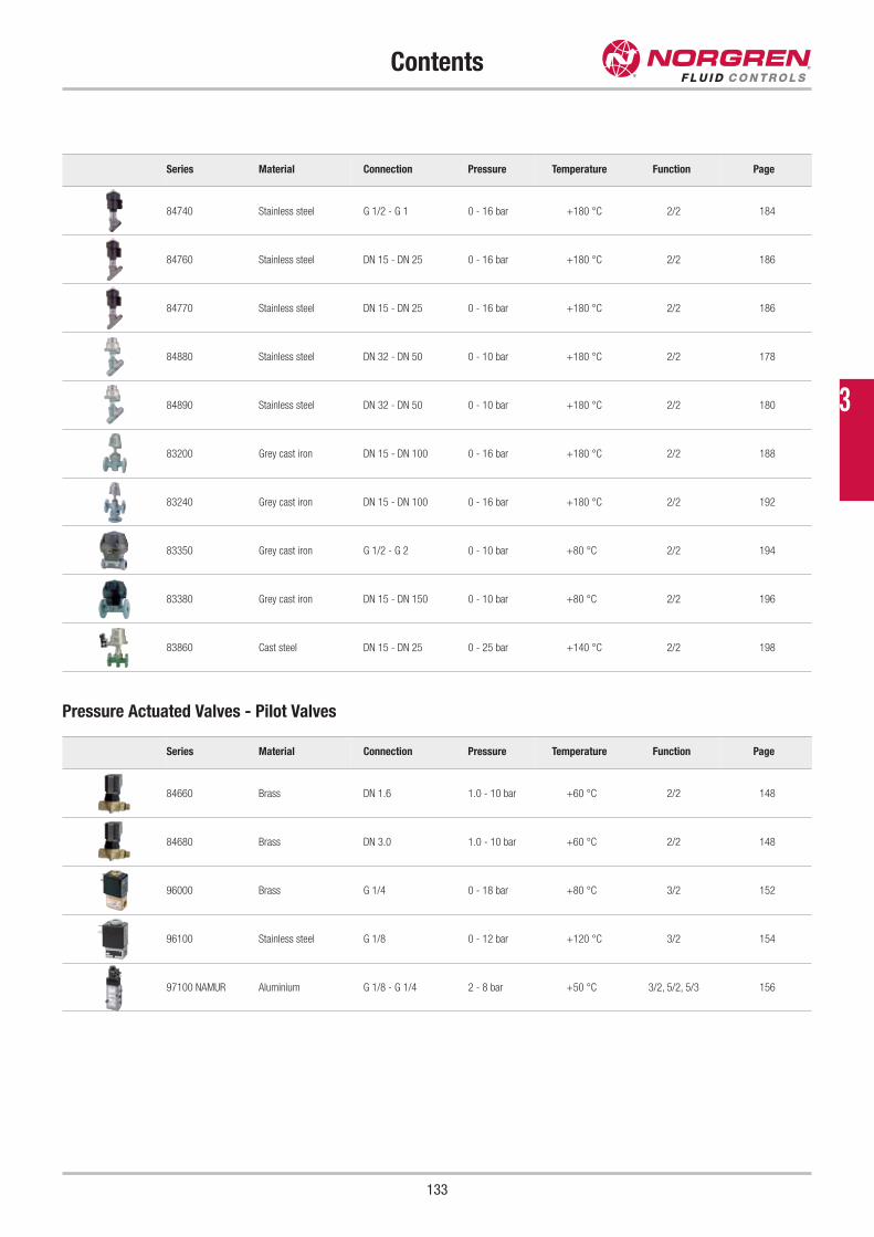
Contents
133
Series Material Connection Pressure Temperature Function Page
84740 Stainless steel G 1/2 - G 1 0 - 16 bar +180 °C 2/2 184
84760 Stainless steel DN 15 - DN 25 0 - 16 bar +180 °C 2/2 186
84770 Stainless steel DN 15 - DN 25 0 - 16 bar +180 °C 2/2 186
84880 Stainless steel DN 32 - DN 50 0 - 10 bar +180 °C 2/2 178
84890 Stainless steel DN 32 - DN 50 0 - 10 bar +180 °C 2/2 180
83200 Grey cast iron DN 15 - DN 100 0 - 16 bar +180 °C 2/2 188
83240 Grey cast iron DN 15 - DN 100 0 - 16 bar +180 °C 2/2 192
83350 Grey cast iron G 1/2 - G 2 0 - 10 bar +80 °C 2/2 194
83380 Grey cast iron DN 15 - DN 150 0 - 10 bar +80 °C 2/2 196
83860 Cast steel DN 15 - DN 25 0 - 25 bar +140 °C 2/2 198
Series Material Connection Pressure Temperature Function Page
84660 Brass DN 1.6 1.0 - 10 bar +60 °C 2/2 148
84680 Brass DN 3.0 1.0 - 10 bar +60 °C 2/2 148
96000 Brass G 1/4 0 - 18 bar +80 °C 3/2 152
96100 Stainless steel G 1/8 0 - 12 bar +120 °C 3/2 154
97100 NAMUR Aluminium G 1/8 - G 1/4 2 - 8 bar +50 °C 3/2, 5/2, 5/3 156
Pressure Actuated Valves - Pilot Valves
3
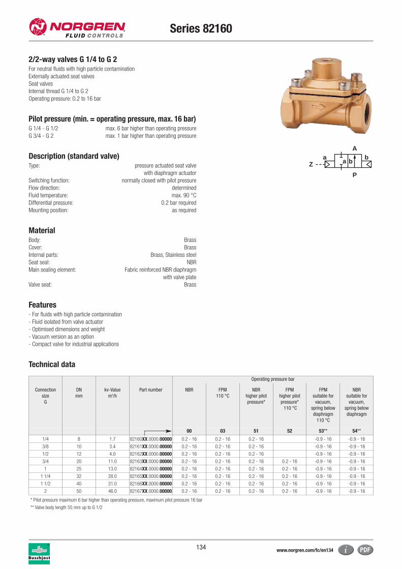
134
Series 82160
2/2-way valves G 1/4 to G 2For neutral fluids with high particle contamination
Externally actuated seat valves
Seat valves
Internal thread G 1/4 to G 2
Operating pressure: 0.2 to 16 bar
Pilot pressure (min. = operating pressure, max. 16 bar)G 1/4 - G 1/2 max. 6 bar higher than operating pressure
G 3/4 - G 2 max. 1 bar higher than operating pressure
Description (standard valve)Type: pressure actuated seat valve
with diaphragm actuator
Switching function: normally closed with pilot pressure
Flow direction: determined
Fluid temperature: max. 90 °C
Differential pressure: 0.2 bar required
Mounting position: as required
MaterialBody: Brass
Cover: Brass
Internal parts: Brass, Stainless steel
Seat seal: NBR
Main sealing element: Fabric reinforced NBR diaphragm
with valve plate
Valve seat: Brass
Features- For fluids with high particle contamination
- Fluid isolated from valve actuator
- Optimised dimensions and weight
- Vacuum version as an option
- Compact valve for industrial applications
Technical data
Operating pressure bar
Connection
size
G
DN
mm
kv-Value
m3/h
Part number NBR FPM
110 °C
NBR
higher pilot
pressure*
FPM
higher pilot
pressure*
110 °C
FPM
suitable for
vacuum,
spring below
diaphragm
110 °C
NBR
suitable for
vacuum,
spring below
diaphragm
00 03 51 52 53** 54**
1/4 8 1.7 82160XX.0000.00000 0.2 - 16 0.2 - 16 0.2 - 16 -0.9 - 16 -0.9 - 16
3/8 10 3.4 82161XX.0000.00000 0.2 - 16 0.2 - 16 0.2 - 16 -0.9 - 16 -0.9 - 16
1/2 12 4.0 82162XX.0000.00000 0.2 - 16 0.2 - 16 0.2 - 16 -0.9 - 16 -0.9 - 16
3/4 20 11.0 82163XX.0000.00000 0.2 - 16 0.2 - 16 0.2 - 16 0.2 - 16 -0.9 - 16 -0.9 - 16
1 25 13.0 82164XX.0000.00000 0.2 - 16 0.2 - 16 0.2 - 16 0.2 - 16 -0.9 - 16 -0.9 - 16
1 1/4 32 28.0 82165XX.0000.00000 0.2 - 16 0.2 - 16 0.2 - 16 0.2 - 16 -0.9 - 16 -0.9 - 16
1 1/2 40 31.0 82166XX.0000.00000 0.2 - 16 0.2 - 16 0.2 - 16 0.2 - 16 -0.9 - 16 -0.9 - 16
2 50 46.0 82167XX.0000.00000 0.2 - 16 0.2 - 16 0.2 - 16 0.2 - 16 -0.9 - 16 -0.9 - 16
a
P
Z
Ab
a b
* Pilot pressure maximum 6 bar higher than operating pressure, maximum pilot pressure 16 bar
** Valve body length 55 mm up to G 1/2
www.norgren.com/fc/en134
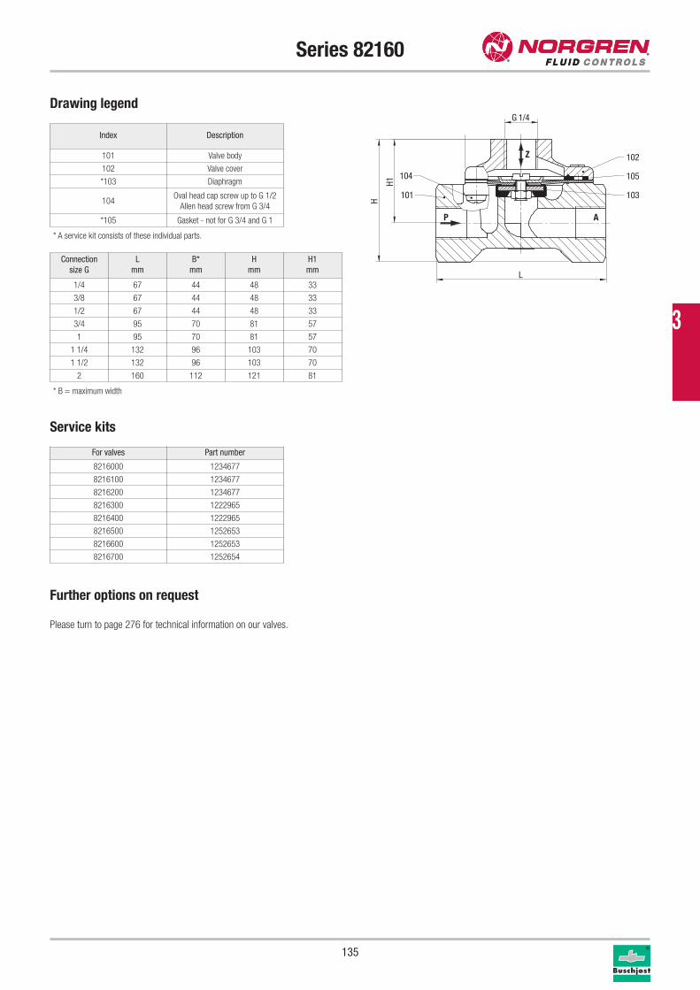
135
Series 82160
Service kits
For valves Part number
8216000 1234677
8216100 1234677
8216200 1234677
8216300 1222965
8216400 1222965
8216500 1252653
8216600 1252653
8216700 1252654
Drawing legend
Index Description
101 Valve body
102 Valve cover
*103 Diaphragm
104Oval head cap screw up to G 1/2
Allen head screw from G 3/4
*105 Gasket - not for G 3/4 and G 1
* A service kit consists of these individual parts.
P A
Z
105
102
101
104
103
G 1/4
H1
H
L
Connection
size G
L
mm
B*
mm
H
mm
H1
mm
1/4 67 44 48 33
3/8 67 44 48 33
1/2 67 44 48 33
3/4 95 70 81 57
1 95 70 81 57
1 1/4 132 96 103 70
1 1/2 132 96 103 70
2 160 112 121 81
Further options on request
Please turn to page 276 for technical information on our valves.
* B = maximum width
3

136
Series 82180 / 82280
2/2-way valves DN 15 to DN 50For neutral gases and liquids
Pressure actuated by external fluid
Seat valves
Internal thread G 1/2 to G 2 or 1/2" NPT to 2" NPT
Description (standard valve)Switching function: normally closed
Flow direction: determined
Mounting position: as required
Process fluid characteristics / Valve materialFluid temperature: -10 °C up to max. +180 °C
Ambient temperature: -10 °C up to max. +60 °C
Body / Valve seat: Dezincification resistant brass
Seat seal: PTFE
Internal parts: Brass, Stainless steel
Spindle sealing: PTFE / FPM, self-adjusting
Pilot fluid characteristics / Actuator materialPilot connection: G 1/4 or 1/4" NPT, respectively
Pilot fluid: neutral gases
Fluid temperature: max. +80 °C
Actuator: Body: Stainless steel, Aluminium
Bottom: WEMA-Kor coated
Seat seal: NBR
Internal parts: Coated steel
Features- High flow rate
- Suitable for contaminated process fluids
- Damped closing (valve closes against flow direction)
- For robust industry applications
- Suitable for vacuum up to max. 90%
Technical data
Operating pressure bar*
Connection size
G
DN
mm
kv-Value
m3/h
Part number PTFE Normally
open
Position
indicator:
2 switches,
Ex-protected
Position
indicator:
on / off with
micro switches
Fluid
temperature
+200 °C
00 01** 40 41 59
1/2 15 4.8 82182XX.0000.00000 0 - 16 0 - 16 0 - 16 0 - 16 0 - 16
3/4 20 10.0 82183XX.0000.00000 0 - 10 0 - 10 0 - 10 0 - 10 0 - 10
1 25 14.0 82184XX.0000.00000 0 - 10 0 - 10 0 - 10 0 - 10 0 - 10
1 1/4 32 23.0 82185XX.0000.00000 0 - 7 0 - 7 0 - 7 0 - 7 0 - 7
1 1/2 40 30.0 82186XX.0000.00000 0 - 4.5 0 - 4.5 0 - 4.5 0 - 4.5 0 - 4.5
2 50 37.0 82187XX.0000.00000 0 - 3 0 - 3 0 - 3 0 - 3 0 - 3
1 1/4 32 27.0 82285XX.0000.00000 0 - 16 0 - 16 0 - 16 0 - 16 0 - 16
1 1/2 40 37.0 82286XX.0000.00000 0 - 10 0 - 10 0 - 10 0 - 10 0 - 10
2 50 53.0 82287XX.0000.00000 0 - 10 0 - 10 0 - 10 0 - 10 0 - 10
aZ
P
Ab
a b
* Pilot pressure 3.5 - 8 bar
** Pilot pressure 1 - 6 bar
www.norgren.com/fc/en136
137
Series 82180 / 82280
Service kits
For valves Part number
8218200 1248931
8218300 1249643
8218400 1248994
8218500 1249645
8218600 1249646
8218700 1249647
8228500 1249648
8228600 1249649
8228700 1249650
Drawing legend
Index Description
101 Valve body
*102 Valve spindle assembly
*103 Gasket
104 Screw piece
*105 Pressure spring
*106 Spindle sealing
107 Spacer sleeve
*108 Sleeve bearing
109 Nut
110 Bottom of control head housing
*111 O-ring
*112 Lip seal
113 Round plate
*114 Lip seal
115 Round plate
*116 Seal-Lock® nut
117 Control head housing
*118 Pressure spring - G 1 and G 2 only
*119 Pressure spring
120 Hexagon screw
121 Screw tap
* A service kit consists of these individual parts.
121
119
117
115
113
120
110
109
105
118
116
114
112
111
108
107
106
104
103
102
101
P
A
Z
1H H
4/1 G
L
SW
B
Connection
size G
L
mm
B*
mm
H
mm
H1
mm
SW
mm
1/2 65 89.5 154.0 140.5 27
3/4 75 89.5 160.0 144.0 32
1 90 89.5 171.0 150.5 41
1 1/4 110 89.5 186.0 161.0 50
1 1/2 120 89.5 190.0 162.5 55
2 150 89.5 206.0 171.0 70
1 1/4 110 163.0 250.0 225.0 50
1 1/2 120 163.0 255.0 227.5 55
2 150 163.0 270.0 235.0 70
Further options (valves)XXXXX22.XXXX Increased operating pressure for G 1/2: 25 bar,
and for G 3/4: 16 bar
XXXXX52.XXXX Optical position indicator
Further options on requestFor hazardous environments
Please turn to page 276 for technical information on our valves.
Accessories3/2-way pilot valves 84660 / 84680, page 148
* B = maximum width
3
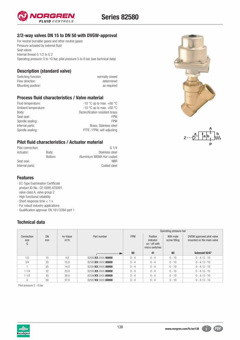
138
Series 82580
For neutral burnable gases and other neutral gases
Pressure actuated by external fluid
Seat valves
Internal thread G 1/2 to G 2
Operating pressure: 0 to 10 bar, pilot pressure 5 to 8 bar (see technical data)
Description (standard valve)Switching function: normally closed
Flow direction: determined
Mounting position: as required
Process fluid characteristics / Valve materialFluid temperature: -10 °C up to max. +60 °C
Ambient temperature: -10 °C up to max. +60 °C
Body: Dezincification resistant brass
Seat seal: FPM
Spindle sealing: FPM
Internal parts: Brass, Stainless steel
Spindle sealing: PTFE / FPM, self-adjusting
Pilot fluid characteristics / Actuator materialPilot connection: G 1/4
Actuator: Body: Stainless steel
Bottom: Aluminium WEMA-Kor coated
Seat seal: NBR
Internal parts: Coated steel
Features- EC-Type Examination Certificate
product ID-No.: CE-0085 AT0091,
valve class A, valve group 2
- High functional reliability
- Short response time < 1 s
- For robust industry applications
- Qualification approval: EN 161/3394 part 1
Technical data
aZ
P
Ab
a b
Connection
size
G
DN
mm
kv-Value
m3/h
Part number
Operating pressure bar
FPM Position
indicator:
on / off with
micro switches
With male
screw fitting
DVGW approved pilot valve
mounted on the main valve
00 41 80 Solenoid 0247
1/2 15 4.8 82582XX.0000.00000 0 - 4 0 - 4 0 - 10 0 - 4 / 0 - 10
3/4 20 10.0 82583XX.0000.00000 0 - 4 0 - 4 0 - 10 0 - 4 / 0 - 10
1 25 14.0 82584XX.0000.00000 0 - 4 0 - 4 0 - 10 0 - 4 / 0 - 10
1 1/4 32 23.0 82585XX.0000.00000 0 - 4 0 - 4 0 - 10 0 - 4 / 0 - 10
1 1/2 40 30.0 82586XX.0000.00000 0 - 4 0 - 4 0 - 10 0 - 4 / 0 - 10
2 50 37.0 82587XX.0000.00000 0 - 4 0 - 4 0 - 10 0 - 4 / 0 - 10
2/2-way valves DN 15 to DN 50 with DVGW-approval
Pilot pressure 5 - 8 bar
www.norgren.com/fc/en138
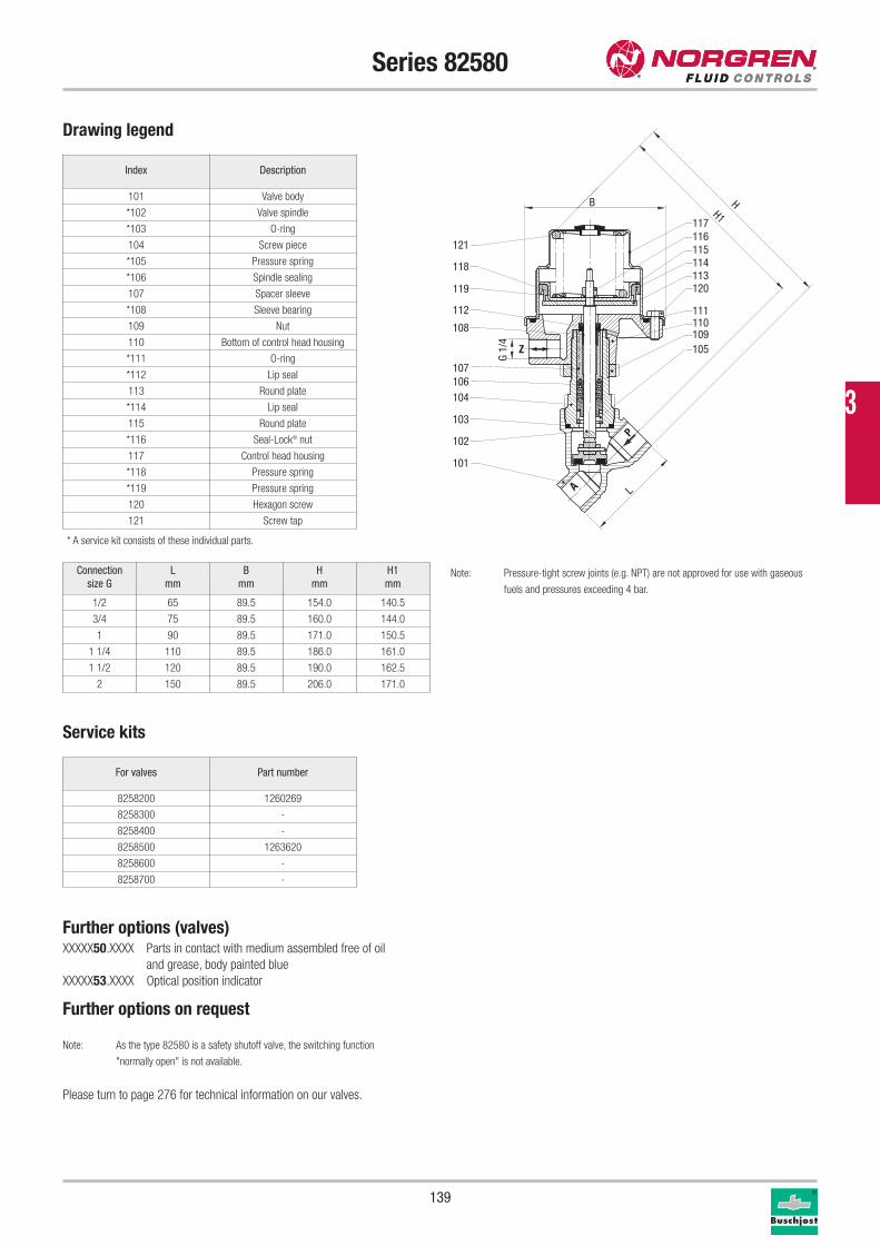
139
Series 82580
Drawing legend
Index Description
101 Valve body
*102 Valve spindle
*103 O-ring
104 Screw piece
*105 Pressure spring
*106 Spindle sealing
107 Spacer sleeve
*108 Sleeve bearing
109 Nut
110 Bottom of control head housing
*111 O-ring
*112 Lip seal
113 Round plate
*114 Lip seal
115 Round plate
*116 Seal-Lock® nut
117 Control head housing
*118 Pressure spring
*119 Pressure spring
120 Hexagon screw
121 Screw tap
Service kits
* A service kit consists of these individual parts.
For valves Part number
8258200 1260269
8258300 -
8258400 -
8258500 1263620
8258600 -
8258700 -
121
118
119
112
108
107106104
103
102
101
117116115114113120
111110109105
P
A
Z
H1
L
H
G 1/
4
B
Connection
size G
L
mm
B
mm
H
mm
H1
mm
1/2 65 89.5 154.0 140.5
3/4 75 89.5 160.0 144.0
1 90 89.5 171.0 150.5
1 1/4 110 89.5 186.0 161.0
1 1/2 120 89.5 190.0 162.5
2 150 89.5 206.0 171.0
Further options (valves)XXXXX50.XXXX Parts in contact with medium assembled free of oil
and grease, body painted blue
XXXXX53.XXXX Optical position indicator
Further options on request
Note: As the type 82580 is a safety shutoff valve, the switching function
"normally open" is not available.
Please turn to page 276 for technical information on our valves.
Note: Pressure-tight screw joints (e.g. NPT) are not approved for use with gaseous
fuels and pressures exceeding 4 bar.
3
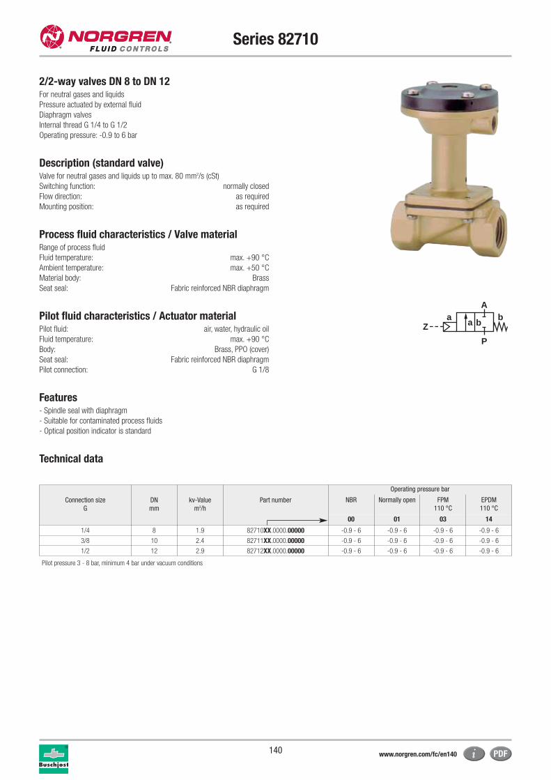
140
Series 82710
2/2-way valves DN 8 to DN 12For neutral gases and liquids
Pressure actuated by external fluid
Diaphragm valves
Internal thread G 1/4 to G 1/2
Operating pressure: -0.9 to 6 bar
Description (standard valve)Valve for neutral gases and liquids up to max. 80 mm2/s (cSt)
Switching function: normally closed
Flow direction: as required
Mounting position: as required
Process fluid characteristics / Valve materialRange of process fluid
Fluid temperature: max. +90 °C
Ambient temperature: max. +50 °C
Material body: Brass
Seat seal: Fabric reinforced NBR diaphragm
Pilot fluid characteristics / Actuator materialPilot fluid: air, water, hydraulic oil
Fluid temperature: max. +90 °C
Body: Brass, PPO (cover)
Seat seal: Fabric reinforced NBR diaphragm
Pilot connection: G 1/8
Features- Spindle seal with diaphragm
- Suitable for contaminated process fluids
- Optical position indicator is standard
Technical data
aZ
P
Ab
a b
Connection size
G
DN
mm
kv-Value
m3/h
Part number
Operating pressure bar
NBR Normally open FPM
110 °C
EPDM
110 °C
00 01 03 14
1/4 8 1.9 82710XX.0000.00000 -0.9 - 6 -0.9 - 6 -0.9 - 6 -0.9 - 6
3/8 10 2.4 82711XX.0000.00000 -0.9 - 6 -0.9 - 6 -0.9 - 6 -0.9 - 6
1/2 12 2.9 82712XX.0000.00000 -0.9 - 6 -0.9 - 6 -0.9 - 6 -0.9 - 6
Pilot pressure 3 - 8 bar, minimum 4 bar under vacuum conditions
www.norgren.com/fc/en140
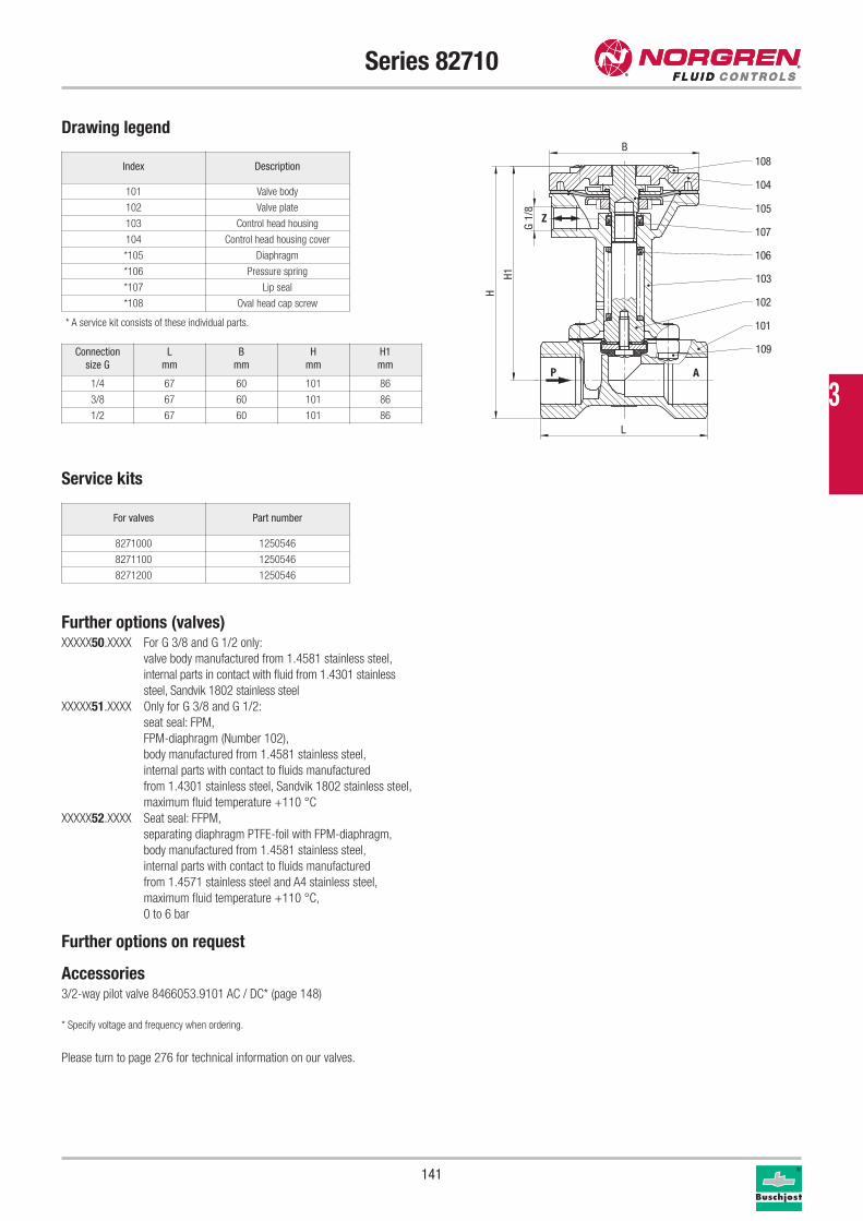
141
Series 82710
Drawing legend
Index Description
101 Valve body
102 Valve plate
103 Control head housing
104 Control head housing cover
*105 Diaphragm
*106 Pressure spring
*107 Lip seal
*108 Oval head cap screw
Service kits
* A service kit consists of these individual parts.
For valves Part number
8271000 1250546
8271100 1250546
8271200 1250546
P A
Z
109
101
102
103
107
104
108
105
106
L
H1
G 1/
8
H
B
Connection
size G
L
mm
B
mm
H
mm
H1
mm
1/4 67 60 101 86
3/8 67 60 101 86
1/2 67 60 101 86
Further options (valves)XXXXX50.XXXX For G 3/8 and G 1/2 only:
valve body manufactured from 1.4581 stainless steel,
internal parts in contact with fluid from 1.4301 stainless
steel, Sandvik 1802 stainless steel
XXXXX51.XXXX Only for G 3/8 and G 1/2:
seat seal: FPM,
FPM-diaphragm (Number 102),
body manufactured from 1.4581 stainless steel,
internal parts with contact to fluids manufactured
from 1.4301 stainless steel, Sandvik 1802 stainless steel,
maximum fluid temperature +110 °C
XXXXX52.XXXX Seat seal: FFPM,
separating diaphragm PTFE-foil with FPM-diaphragm,
body manufactured from 1.4581 stainless steel,
internal parts with contact to fluids manufactured
from 1.4571 stainless steel and A4 stainless steel,
maximum fluid temperature +110 °C,
0 to 6 bar
Further options on request
Accessories3/2-way pilot valve 8466053.9101 AC / DC* (page 148)
* Specify voltage and frequency when ordering.
Please turn to page 276 for technical information on our valves.
3
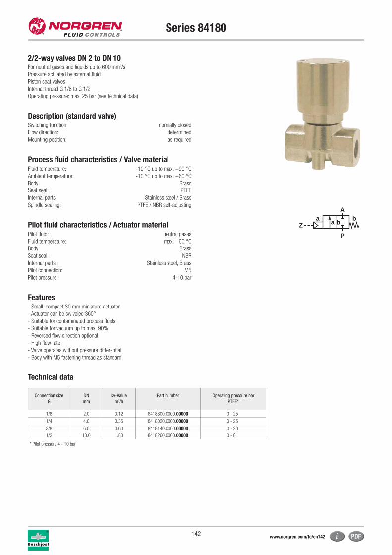
142
Series 84180
2/2-way valves DN 2 to DN 10For neutral gases and liquids up to 600 mm2/s
Pressure actuated by external fluid
Piston seat valves
Internal thread G 1/8 to G 1/2
Operating pressure: max. 25 bar (see technical data)
Description (standard valve)Switching function: normally closed
Flow direction: determined
Mounting position: as required
Process fluid characteristics / Valve materialFluid temperature: -10 °C up to max. +90 °C
Ambient temperature: -10 °C up to max. +60 °C
Body: Brass
Seat seal: PTFE
Internal parts: Stainless steel / Brass
Spindle sealing: PTFE / NBR self-adjusting
Pilot fluid characteristics / Actuator material Pilot fluid: neutral gases
Fluid temperature: max. +60 °C
Body: Brass
Seat seal: NBR
Internal parts: Stainless steel, Brass
Pilot connection: M5
Pilot pressure: 4-10 bar
Features- Small, compact 30 mm miniature actuator
- Actuator can be swiveled 360°
- Suitable for contaminated process fluids
- Suitable for vacuum up to max. 90%
- Reversed flow direction optional
- High flow rate
- Valve operates without pressure differential
- Body with M5 fastening thread as standard
Technical data
* Pilot pressure 4 - 10 bar
aZ
P
Ab
a b
Connection size
G
DN
mm
kv-Value
m3/h
Part number Operating pressure bar
PTFE*
1/8 2.0 0.12 8418800.0000.00000 0 - 25
1/4 4.0 0.35 8418020.0000.00000 0 - 25
3/8 6.0 0.60 8418140.0000.00000 0 - 20
1/2 10.0 1.80 8418260.0000.00000 0 - 8
www.norgren.com/fc/en142
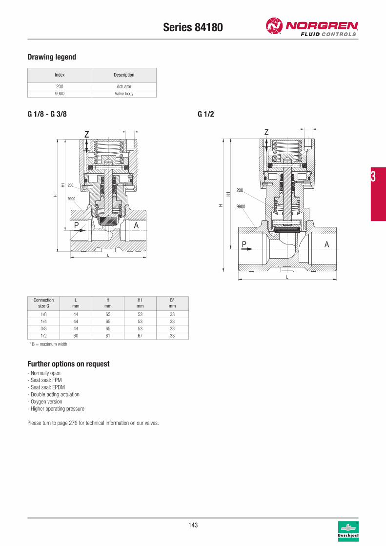
143
Series 84180
Drawing legend
Connection
size G
L
mm
H
mm
H1
mm
B*
mm
1/8 44 65 53 33
1/4 44 65 53 33
3/8 44 65 53 33
1/2 60 81 67 33
Index Description
200 Actuator
9900 Valve body
Further options on request- Normally open
- Seat seal: FPM
- Seat seal: EPDM
- Double acting actuation
- Oxygen version
- Higher operating pressure
Please turn to page 276 for technical information on our valves.
200
9900
P
Z
A
L
H
H1
200
9900
P
Z
A
L
H1
H
Z
G 1/8 - G 3/8 G 1/2
* B = maximum width
3
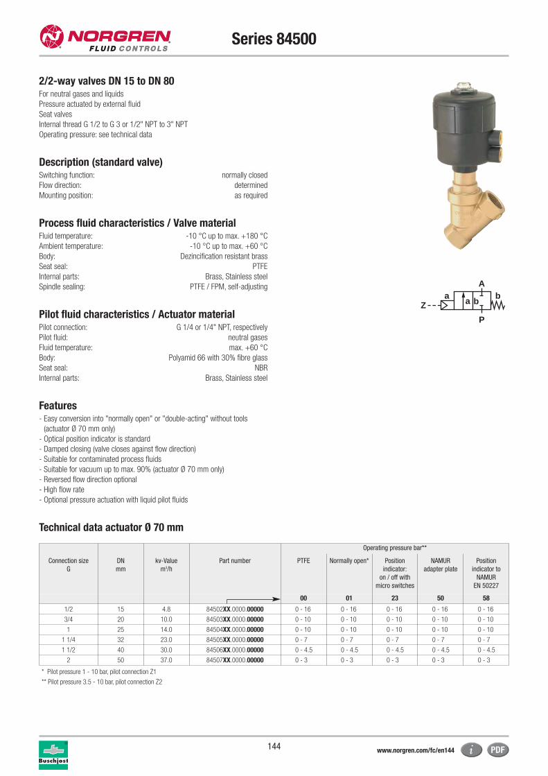
144
Series 84500
2/2-way valves DN 15 to DN 80For neutral gases and liquids
Pressure actuated by external fluid
Seat valves
Internal thread G 1/2 to G 3 or 1/2" NPT to 3" NPT
Operating pressure: see technical data
Description (standard valve)Switching function: normally closed
Flow direction: determined
Mounting position: as required
Process fluid characteristics / Valve material Fluid temperature: -10 °C up to max. +180 °C
Ambient temperature: -10 °C up to max. +60 °C
Body: Dezincification resistant brass
Seat seal: PTFE
Internal parts: Brass, Stainless steel
Spindle sealing: PTFE / FPM, self-adjusting
Pilot fluid characteristics / Actuator materialPilot connection: G 1/4 or 1/4" NPT, respectively
Pilot fluid: neutral gases
Fluid temperature: max. +60 °C
Body: Polyamid 66 with 30% fibre glass
Seat seal: NBR
Internal parts: Brass, Stainless steel
Features- Easy conversion into "normally open" or "double-acting" without tools
(actuator Ø 70 mm only)
- Optical position indicator is standard
- Damped closing (valve closes against flow direction)
- Suitable for contaminated process fluids
- Suitable for vacuum up to max. 90% (actuator Ø 70 mm only)
- Reversed flow direction optional
- High flow rate
- Optional pressure actuation with liquid pilot fluids
Technical data actuator Ø 70 mm
aZ
P
Ab
a b
Operating pressure bar**
Connection size
G
DN
mm
kv-Value
m3/h
Part number PTFE Normally open* Position
indicator:
on / off with
micro switches
NAMUR
adapter plate
Position
indicator to
NAMUR
EN 50227
00 01 23 50 58
1/2 15 4.8 84502XX.0000.00000 0 - 16 0 - 16 0 - 16 0 - 16 0 - 16
3/4 20 10.0 84503XX.0000.00000 0 - 10 0 - 10 0 - 10 0 - 10 0 - 10
1 25 14.0 84504XX.0000.00000 0 - 10 0 - 10 0 - 10 0 - 10 0 - 10
1 1/4 32 23.0 84505XX.0000.00000 0 - 7 0 - 7 0 - 7 0 - 7 0 - 7
1 1/2 40 30.0 84506XX.0000.00000 0 - 4.5 0 - 4.5 0 - 4.5 0 - 4.5 0 - 4.5
2 50 37.0 84507XX.0000.00000 0 - 3 0 - 3 0 - 3 0 - 3 0 - 3
* Pilot pressure 1 - 10 bar, pilot connection Z1
** Pilot pressure 3.5 - 10 bar, pilot connection Z2
www.norgren.com/fc/en144
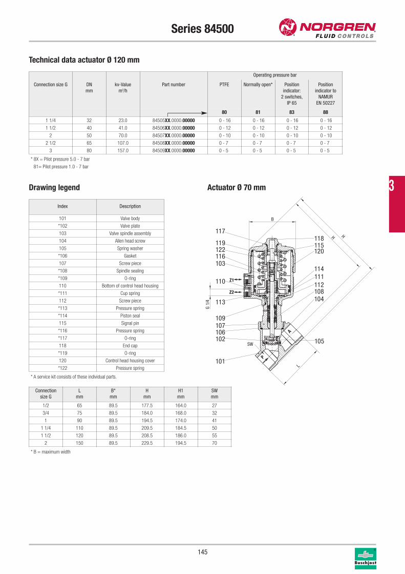
145
Series 84500
Drawing legend
* B = maximum width
Connection
size G
L
mm
B*
mm
H
mm
H1
mm
SW
mm
1/2 65 89.5 177.5 164.0 27
3/4 75 89.5 184.0 168.0 32
1 90 89.5 194.5 174.0 41
1 1/4 110 89.5 209.5 184.5 50
1 1/2 120 89.5 208.5 186.0 55
2 150 89.5 229.5 194.5 70
Index Description
101 Valve body
*102 Valve plate
103 Valve spindle assembly
104 Allen head screw
105 Spring washer
*106 Gasket
107 Screw piece
*108 Spindle sealing
*109 O-ring
110 Bottom of control head housing
*111 Cup spring
112 Screw piece
*113 Pressure spring
*114 Piston seal
115 Signal pin
*116 Pressure spring
*117 O-ring
118 End cap
*119 O-ring
120 Control head housing cover
*122 Pressure spring
* A service kit consists of these individual parts.
P
A
Z1
Z2
118115120
114111112108104
105
117
119122116103
110
113
109107106102
101
SW
H H
L
4/1
G
B
Operating pressure bar
Connection size G DN
mm
kv-Value
m3/h
Part number PTFE Normally open* Position
indicator:
2 switches,
IP 65
Position
indicator to
NAMUR
EN 50227
80 81 83 88
1 1/4 32 23.0 84505XX.0000.00000 0 - 16 0 - 16 0 - 16 0 - 16
1 1/2 40 41.0 84506XX.0000.00000 0 - 12 0 - 12 0 - 12 0 - 12
2 50 70.0 84507XX.0000.00000 0 - 10 0 - 10 0 - 10 0 - 10
2 1/2 65 107.0 84508XX.0000.00000 0 - 7 0 - 7 0 - 7 0 - 7
3 80 157.0 84509XX.0000.00000 0 - 5 0 - 5 0 - 5 0 - 5
* 8X = Pilot pressure 5.0 - 7 bar
81= Pilot pressure 1.0 - 7 bar
Technical data actuator Ø 120 mm
Actuator Ø 70 mm 3
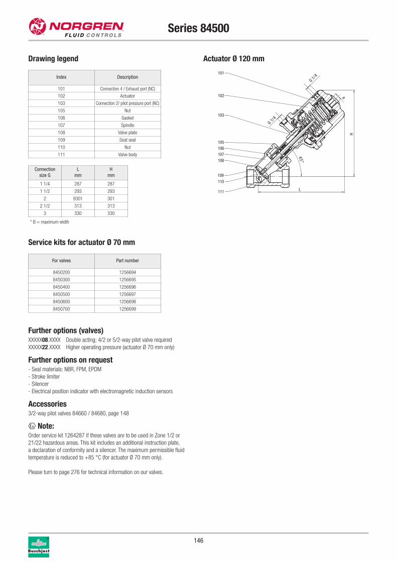
146
Series 84500
Service kits for actuator Ø 70 mm
For valves Part number
8450200 1256694
8450300 1256695
8450400 1256696
8450500 1256697
8450600 1256698
8450700 1256699
Further options (valves)XXXXX08.XXXX Double acting; 4/2 or 5/2-way pilot valve required
XXXXX22.XXXX Higher operating pressure (actuator Ø 70 mm only)
Further options on request- Seal materials: NBR, FPM, EPDM
- Stroke limiter
- Silencer
- Electrical position indicator with electromagnetic induction sensors
Accessories3/2-way pilot valves 84660 / 84680, page 148
x Note:Order service kit 1264287 if these valves are to be used in Zone 1/2 or
21/22 hazardous areas. This kit includes an additional instruction plate,
a declaration of conformity and a silencer. The maximum permissible fluid
temperature is reduced to +85 °C (for actuator Ø 70 mm only).
Please turn to page 276 for technical information on our valves.
Drawing legend
* B = maximum width
L
H
e45°
G 1/4
G 1/4
110
111
109
108
106107
105
102
103
101
Actuator Ø 120 mm
Connection
size G
L
mm
H
mm
1 1/4 287 287
1 1/2 293 293
2 9301 301
2 1/2 313 313
3 330 330
Index Description
101 Connection 4 / Exhaust port (NC)
102 Actuator
103 Connection 2/ pilot pressure port (NC)
105 Nut
106 Gasket
107 Spindle
108 Valve plate
109 Seat seal
110 Nut
111 Valve body
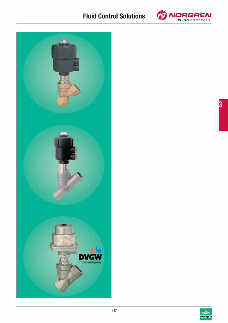
Fluid Control Solutions
147
3
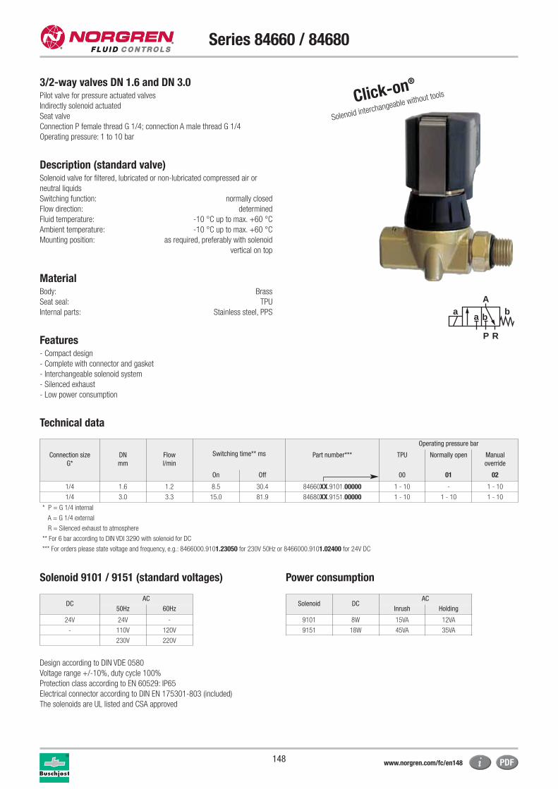
148
Series 84660 / 84680
3/2-way valves DN 1.6 and DN 3.0Pilot valve for pressure actuated valves
Indirectly solenoid actuated
Seat valve
Connection P female thread G 1/4; connection A male thread G 1/4
Operating pressure: 1 to 10 bar
Description (standard valve)Solenoid valve for filtered, lubricated or non-lubricated compressed air or
neutral liquids
Switching function: normally closed
Flow direction: determined
Fluid temperature: -10 °C up to max. +60 °C
Ambient temperature: -10 °C up to max. +60 °C
Mounting position: as required, preferably with solenoid
vertical on top
MaterialBody: Brass
Seat seal: TPU
Internal parts: Stainless steel, PPS
Features- Compact design
- Complete with connector and gasket
- Interchangeable solenoid system
- Silenced exhaust
- Low power consumption
Technical data
a
P R
Ab
a b
Switching time** ms
Operating pressure bar
Connection size
G*
DN
mm
Flow
l/min
Part number*** TPU Normally open Manual
override
On Off 00 01 02
1/4 1.6 1.2 8.5 30.4 84660XX.9101.00000 1 - 10 - 1 - 10
1/4 3.0 3.3 15.0 81.9 84680XX.9151.00000 1 - 10 1 - 10 1 - 10
* P = G 1/4 internal
A = G 1/4 external
R = Silenced exhaust to atmosphere
** For 6 bar according to DIN VDI 3290 with solenoid for DC
*** For orders please state voltage and frequency, e.g.: 8466000.9101.23050 for 230V 50Hz or 8466000.9101.02400 for 24V DC
Solenoid 9101 / 9151 (standard voltages) Power consumption
Design according to DIN VDE 0580
Voltage range +/-10%, duty cycle 100%
Protection class according to EN 60529: IP65
Electrical connector according to DIN EN 175301-803 (included)
The solenoids are UL listed and CSA approved
Solenoid DCAC
Inrush Holding
9101 8W 15VA 12VA
9151 18W 45VA 35VA
DCAC
50Hz 60Hz
24V 24V -
- 110V 120V
230V 220V
Click-on®
Solenoid interchangeable without tools
www.norgren.com/fc/en148
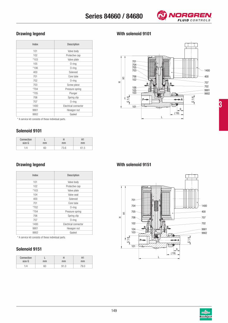
149
Series 84660 / 84680
Drawing legend
Index Description
101 Valve body
102 Protective cap
*103 Valve plate
105 O-ring
*106 O-ring
400 Solenoid
701 Core tube
702 O-ring
703 Screw piece
*704 Pressure spring
*705 Plunger
706 Spring clip
707 O-ring
1400 Electrical connector
9901 Hexagon nut
9902 Gasket
R R
AP
701704705703
706102
103105106
101
70770299019902
400
1400
G1/
4
H1H
919( )
L
G1/
4
* A service kit consists of these individual parts.
Connection
size G
L
mm
H
mm
H1
mm
1/4 60 73.6 61.5
Solenoid 9101
Connection
size G
L
mm
H
mm
H1
mm
1/4 60 91.0 79.0
Solenoid 9151
Index Description
101 Valve body
102 Protective cap
*103 Valve plate
104 Valve seat
400 Solenoid
701 Core tube
*702 O-ring
*704 Pressure spring
706 Spring clip
707 O-ring
1400 Electrical connector
9901 Hexagon nut
9902 Gasket
* A service kit consists of these individual parts.
R R
AP
701
704
705
707
702
400
1400
9901
101
102
103104
9902
706
G1/
4
919( )
L
G1/
4
H1H
Drawing legend
With solenoid 9101
With solenoid 9151
3
150
Series 84660 / 84680
Service kits
For valves Part number
8466000 1260613
8468000 1260615
Further options (valves)XXXXX53.XXXX Connection P female thread G 1/8,
connection A male thread G 1/8
Further options (Solenoids for series 84660)XXXXXXX.9136 Solenoid in protection class x II 2 GD EEx m II T4 T 130 °C,
with 3 m connection cable
Further options (Solenoids for series 84680)XXXXXXX.9191 Solenoid in protection class x II 2 GD EEx me II T3 T 140 °C
Further options on request
Please turn to page 276 for technical information on our valves.
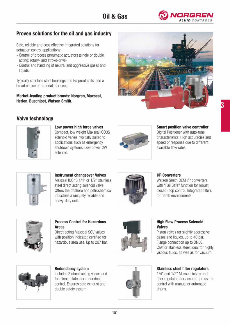
151
Oil & Gas
Proven solutions for the oil and gas industry
Safe, reliable and cost-effective integrated solutions for
actuation control applications:
» Control of process pneumatic actuators (single or double
acting; rotary- and stroke-drive)
» Control and handling of neutral and aggressive gases and
liquids
Typically stainless steel housings and Ex-proof coils, and a
broad choice of materials for seals.
Market-leading product brands: Norgren, Maxseal,
Herion, Buschjost, Watson Smith.
Low power high force valves
Compact, low weight Maxseal ICO3S
solenoid valves, typically suited to
applications such as emergency
shutdown systems. Low power 2W
solenoid.
Instrument changeover Valves
Maxseal ICO4S 1/4" or 1/2" stainless
steel direct acting solenoid valve.
Offers the offshore and petrochemical
industries a uniquely reliable and
heavy-duty unit.
Process Control for Hazardous
Areas
Direct acting Maxseal SOV valves
with position indicator, certified for
hazardous area use. Up to 207 bar.
Redundancy system
Includes 2 direct-acting valves and
functional plates for redundant
control. Ensures safe exhaust and
double safety system.
Smart position valve controller
Digital Positioner with auto-tune
characteristics. High accuracies and
speed of response due to different
available flow rates.
I/P Converters
Watson Smith OEM I/P converters
with "Fail Safe" function for robust
closed-loop control. Integrated filters
for harsh environments.
High Flow Process Solenoid
Valves
Piston valves for slightly aggressive
gases and liquids, up to 40 bar.
Flange connection up to DN50.
Cast or stainless steel. Ideal for highly
viscous fluids, as well as for vacuum.
Stainless steel filter regulators
1/4" and 1/2" Maxseal instrument
filter regulators for accurate pressure
control with manual or automatic
drains.
Valve technology
3
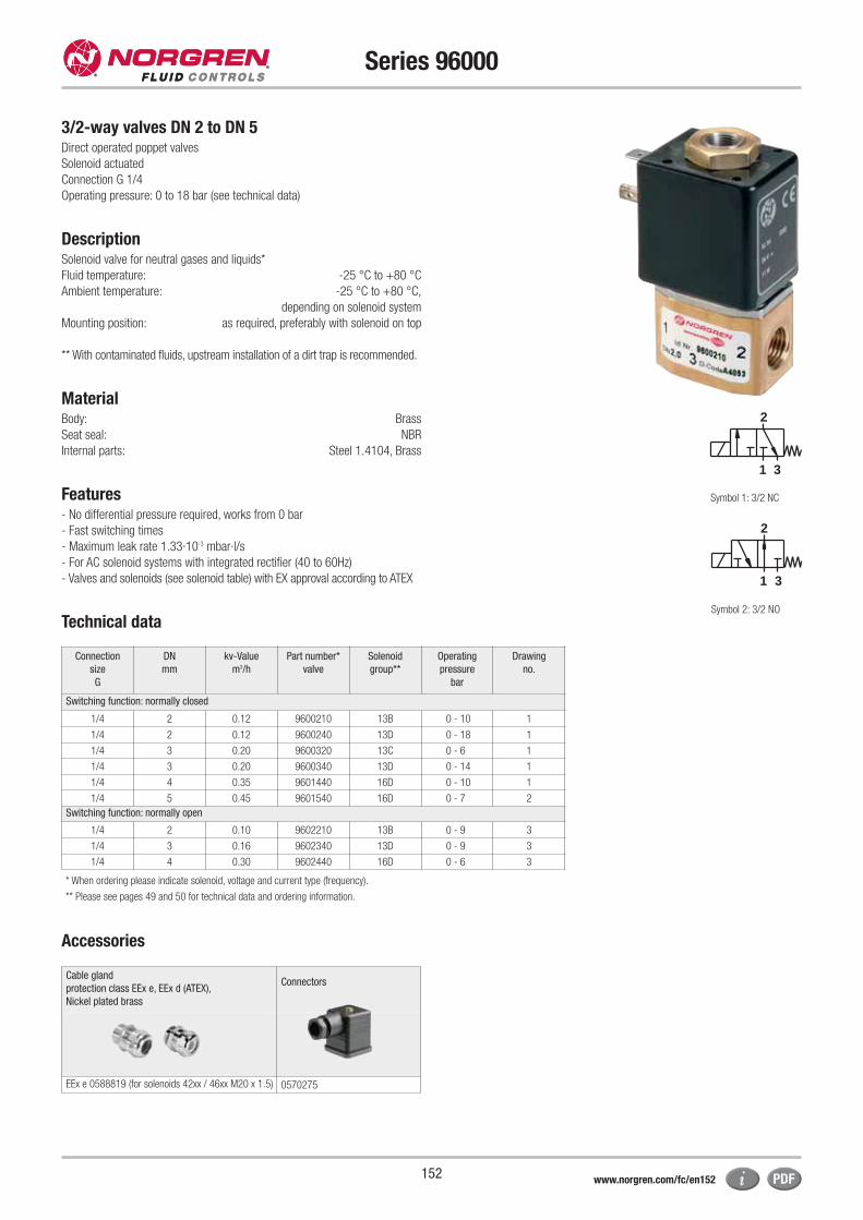
152
Series 96000
3/2-way valves DN 2 to DN 5Direct operated poppet valves
Solenoid actuated
Connection G 1/4
Operating pressure: 0 to 18 bar (see technical data)
DescriptionSolenoid valve for neutral gases and liquids*
Fluid temperature: -25 °C to +80 °C
Ambient temperature: -25 °C to +80 °C,
depending on solenoid system
Mounting position: as required, preferably with solenoid on top
** With contaminated fluids, upstream installation of a dirt trap is recommended.
MaterialBody: Brass
Seat seal: NBR
Internal parts: Steel 1.4104, Brass
Features - No differential pressure required, works from 0 bar
- Fast switching times
- Maximum leak rate 1.33·10-3 mbar·l/s
- For AC solenoid systems with integrated rectifier (40 to 60Hz)
- Valves and solenoids (see solenoid table) with EX approval according to ATEX
Technical data
2
31
2
31
* When ordering please indicate solenoid, voltage and current type (frequency).
** Please see pages 49 and 50 for technical data and ordering information.
Symbol 1: 3/2 NC
Symbol 2: 3/2 NO
Connection
size
G
DN
mm
kv-Value
m3/h
Part number*
valve
Solenoid
group**
Operating
pressure
bar
Drawing
no.
Switching function: normally closed
1/4 2 0.12 9600210 13B 0 - 10 1
1/4 2 0.12 9600240 13D 0 - 18 1
1/4 3 0.20 9600320 13C 0 - 6 1
1/4 3 0.20 9600340 13D 0 - 14 1
1/4 4 0.35 9601440 16D 0 - 10 1
1/4 5 0.45 9601540 16D 0 - 7 2
Switching function: normally open
1/4 2 0.10 9602210 13B 0 - 9 3
1/4 3 0.16 9602340 13D 0 - 9 3
1/4 4 0.30 9602440 16D 0 - 6 3
Cable gland
protection class EEx e, EEx d (ATEX),
Nickel plated brass
Connectors
EEx e 0588819 (for solenoids 42xx / 46xx M20 x 1.5) 0570275
Accessories
www.norgren.com/fc/en152
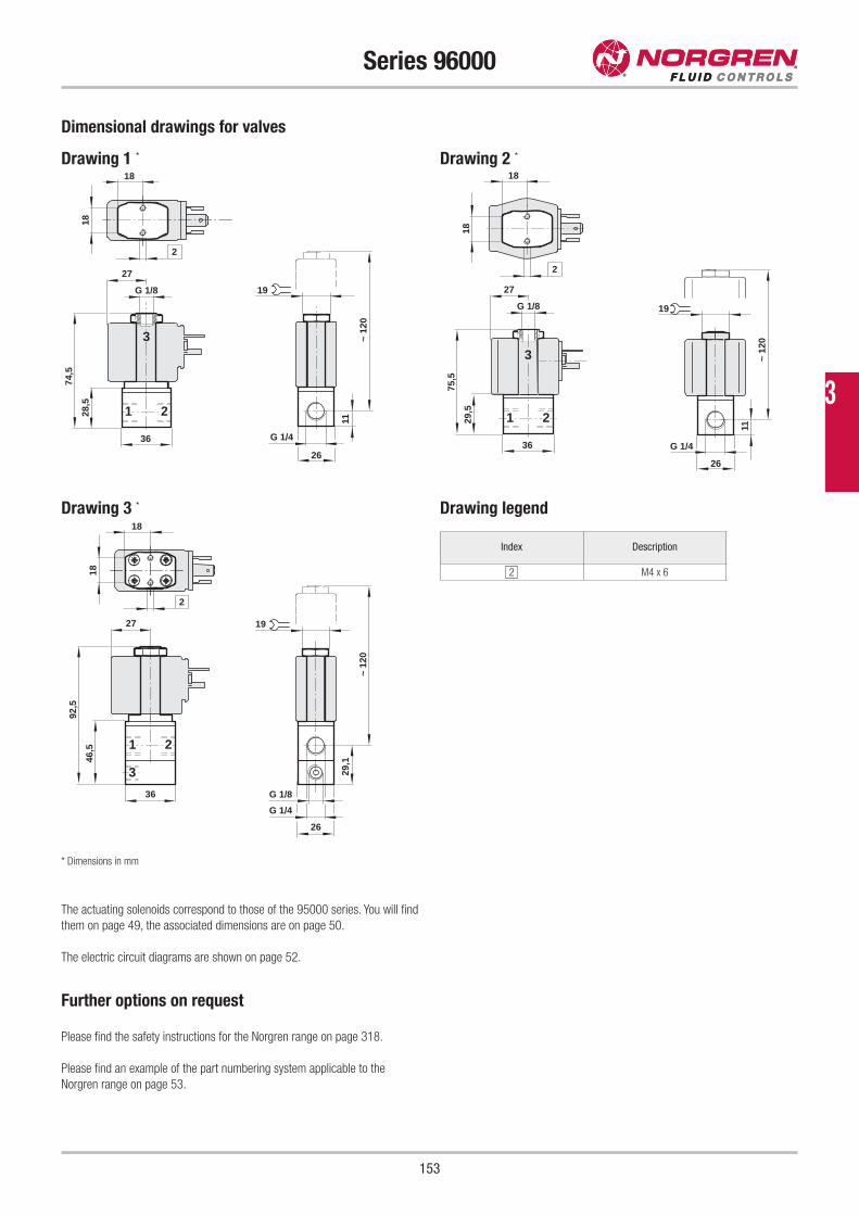
153
Series 96000
Drawing 3 *
26
G 1/4
G 1/8
2
29,1
18
18
46,5
92,5
1 2
19
~ 1
20
36
27
3
Index Description
2 M4 x 6
Drawing legend
* Dimensions in mm
Dimensional drawings for valves
Drawing 1 * Drawing 2 *
18
18
28,5
74,5
1 2
11
19
G 1/4
26
~ 1
20
36
2
27
3
G 1/8
18
18
29,5
75,5
1 2
3
36
2
11
19
G 1/4
26
~ 12
0
27
G 1/8
Further options on request
Please find the safety instructions for the Norgren range on page 318.
Please find an example of the part numbering system applicable to the
Norgren range on page 53.
The actuating solenoids correspond to those of the 95000 series. You will find
them on page 49, the associated dimensions are on page 50.
The electric circuit diagrams are shown on page 52.
3
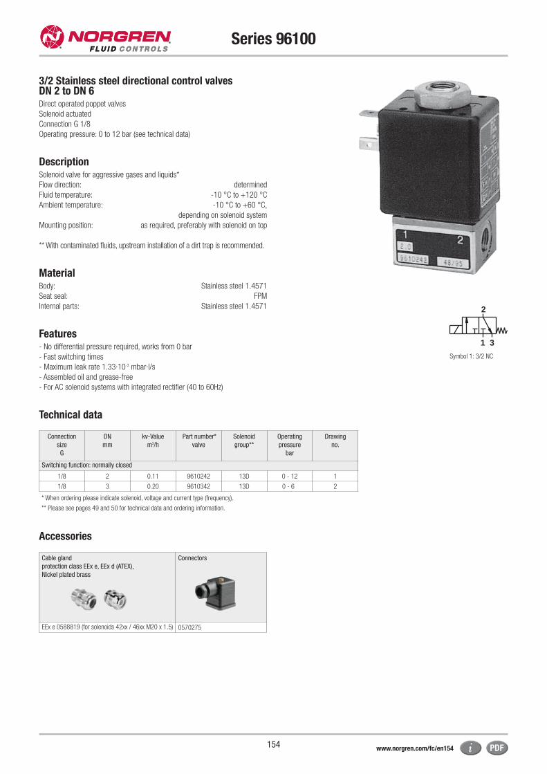
154
Series 96100
3/2 Stainless steel directional control valves DN 2 to DN 6Direct operated poppet valves
Solenoid actuated
Connection G 1/8
Operating pressure: 0 to 12 bar (see technical data)
DescriptionSolenoid valve for aggressive gases and liquids*
Flow direction: determined
Fluid temperature: -10 °C to +120 °C
Ambient temperature: -10 °C to +60 °C,
depending on solenoid system
Mounting position: as required, preferably with solenoid on top
** With contaminated fluids, upstream installation of a dirt trap is recommended.
MaterialBody: Stainless steel 1.4571
Seat seal: FPM
Internal parts: Stainless steel 1.4571
Features - No differential pressure required, works from 0 bar
- Fast switching times
- Maximum leak rate 1.33·10-3 mbar·l/s
- Assembled oil and grease-free
- For AC solenoid systems with integrated rectifier (40 to 60Hz)
Technical data
* When ordering please indicate solenoid, voltage and current type (frequency).
** Please see pages 49 and 50 for technical data and ordering information.
Connection
size
G
DN
mm
kv-Value
m3/h
Part number*
valve
Solenoid
group**
Operating
pressure
bar
Drawing
no.
Switching function: normally closed
1/8 2 0.11 9610242 13D 0 - 12 1
1/8 3 0.20 9610342 13D 0 - 6 2
2
31
Symbol 1: 3/2 NC
Cable gland
protection class EEx e, EEx d (ATEX),
Nickel plated brass
Connectors
EEx e 0588819 (for solenoids 42xx / 46xx M20 x 1.5) 0570275
Accessories
www.norgren.com/fc/en154
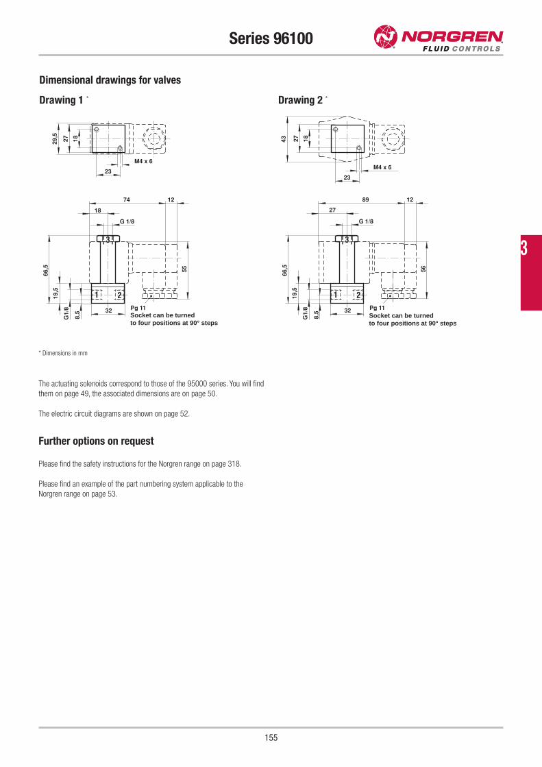
155
Series 96100
Dimensional drawings for valves
Drawing 1 * Drawing 2 *
G 1/8
3
Pg 11
55
32
G1/
8
8,5
19,5
27
66,5
21
74 12
18
M4 x 6
1829,5
23
G 1/8
3
Pg 11
56
32G
1/8
8,5
19,5
27
66,5
21
89 12
27
M4 x 6
18
23
43
* Dimensions in mm
Further options on request
Please find the safety instructions for the Norgren range on page 318.
Please find an example of the part numbering system applicable to the
Norgren range on page 53.
The actuating solenoids correspond to those of the 95000 series. You will find
them on page 49, the associated dimensions are on page 50.
The electric circuit diagrams are shown on page 52.
3
Socket can be turned to four positions at 90° steps
Socket can be turned to four positions at 90° steps
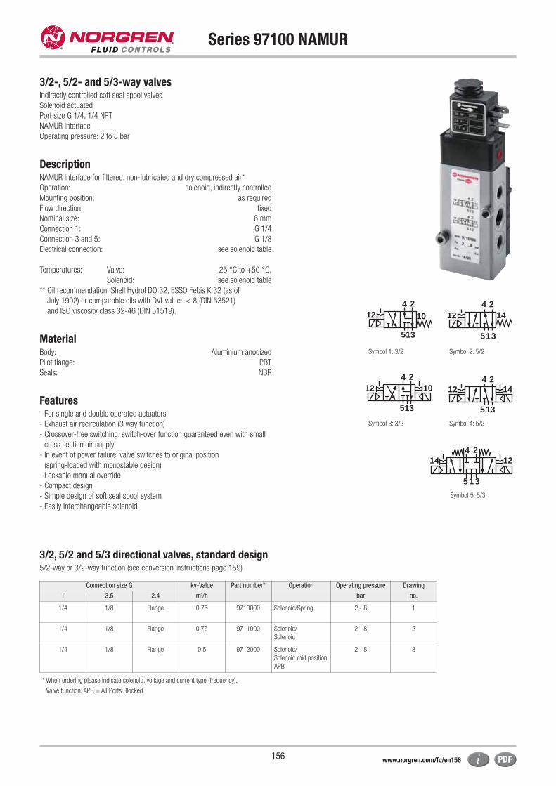
156
Series 97100 NAMUR
3/2-, 5/2- and 5/3-way valvesIndirectly controlled soft seal spool valves
Solenoid actuated
Port size G 1/4, 1/4 NPT
NAMUR Interface
Operating pressure: 2 to 8 bar
DescriptionNAMUR Interface for filtered, non-lubricated and dry compressed air*
Operation: solenoid, indirectly controlled
Mounting position: as required
Flow direction: fixed
Nominal size: 6 mm
Connection 1: G 1/4
Connection 3 and 5: G 1/8
Electrical connection: see solenoid table
Temperatures: Valve: -25 °C to +50 °C,
Solenoid: see solenoid table
** Oil recommendation: Shell Hydrol DO 32, ESSO Febis K 32 (as of
July 1992) or comparable oils with DVI-values < 8 (DIN 53521)
and ISO viscosity class 32-46 (DIN 51519).
MaterialBody: Aluminium anodized
Pilot flange: PBT
Seals: NBR
Features - For single and double operated actuators
- Exhaust air recirculation (3 way function)
- Crossover-free switching, switch-over function guaranteed even with small
cross section air supply
- In event of power failure, valve switches to original position
(spring-loaded with monostable design)
- Lockable manual override
- Compact design
- Simple design of soft seal spool system
- Easily interchangeable solenoid
12 14
513
4 2
Symbol 2: 5/2
4 2
15 3
12 10
Symbol 1: 3/2
12 14
513
4 2
Symbol 4: 5/2
35 1
4 214 12
Symbol 5: 5/3
4 2
15 3
12 10
Symbol 3: 3/2
Connection size G kv-Value Part number* Operation Operating pressure Drawing
1 3.5 2.4 m3/h bar no.
1/4 1/8 Flange 0.75 9710000 Solenoid/Spring 2 - 8 1
1/4 1/8 Flange 0.75 9711000 Solenoid/
Solenoid
2 - 8 2
1/4 1/8 Flange 0.5 9712000 Solenoid/
Solenoid mid position
APB
2 - 8 3
* When ordering please indicate solenoid, voltage and current type (frequency).
Valve function: APB = All Ports Blocked
3/2, 5/2 and 5/3 directional valves, standard design5/2-way or 3/2-way function (see conversion instructions page 159)
www.norgren.com/fc/en156
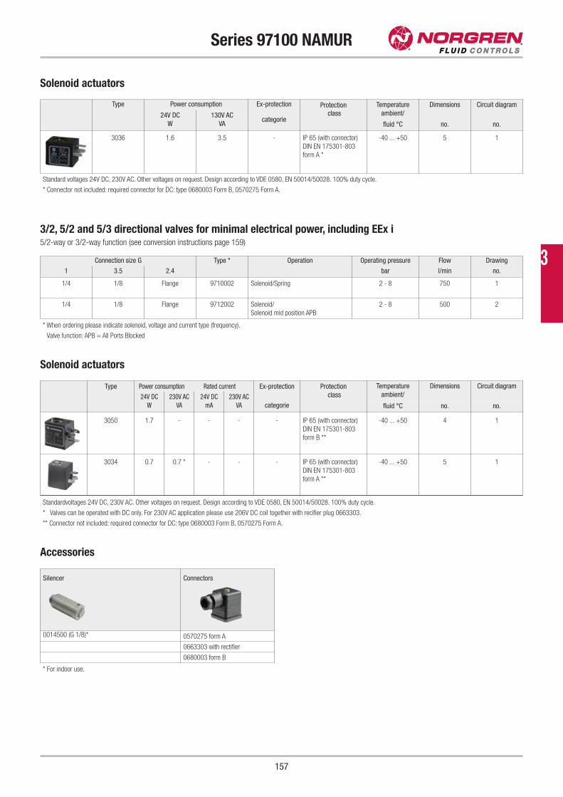
157
Series 97100 NAMUR
Type Power consumption Ex-protection Protection Temperature
ambient/
Dimensions Circuit diagram
24V DC
W
130V AC
VAcategorie
class
fluid °C no. no.
3036 1.6 3.5 - IP 65 (with connector)
DIN EN 175301-803
form A *
-40 ... +50 5 1
Solenoid actuators
* Connector not included: required connector for DC: type 0680003 Form B, 0570275 Form A.
Standard voltages 24V DC, 230V AC. Other voltages on request. Design according to VDE 0580, EN 50014/50028. 100% duty cycle.
Solenoid actuators
Connection size G Type * Operation Operating pressure Flow Drawing
1 3.5 2.4 bar l/min no.
1/4 1/8 Flange 9710002 Solenoid/Spring 2 - 8 750 1
1/4 1/8 Flange 9712002 Solenoid/
Solenoid mid position APB
2 - 8 500 2
* When ordering please indicate solenoid, voltage and current type (frequency).
Valve function: APB = All Ports Blocked
3/2, 5/2 and 5/3 directional valves for minimal electrical power, including EEx i5/2-way or 3/2-way function (see conversion instructions page 159)
Type Power consumption Rated current Ex-protection Protection Temperature
ambient/
Dimensions Circuit diagram
24V DC
W
230V AC
VA
24V DC
mA
230V AC
VA categorie
class
fluid °C no. no.
3050 1.7 - - - - IP 65 (with connector)
DIN EN 175301-803
form B **
-40 ... +50 4 1
3034 0.7 0.7 * - - - IP 65 (with connector)
DIN EN 175301-803
form A **
-40 ... +50 5 1
Standardvoltages 24V DC, 230V AC. Other voltages on request. Design according to VDE 0580, EN 50014/50028. 100% duty cycle.
* Valves can be operated with DC only. For 230V AC application please use 206V DC coil together with recifier plug 0663303.
** Connector not included: required connector for DC: type 0680003 Form B, 0570275 Form A.
Silencer Connectors
0014500 (G 1/8)* 0570275 form A
0663303 with rectifier
0680003 form B
Accessories
* For indoor use.
3
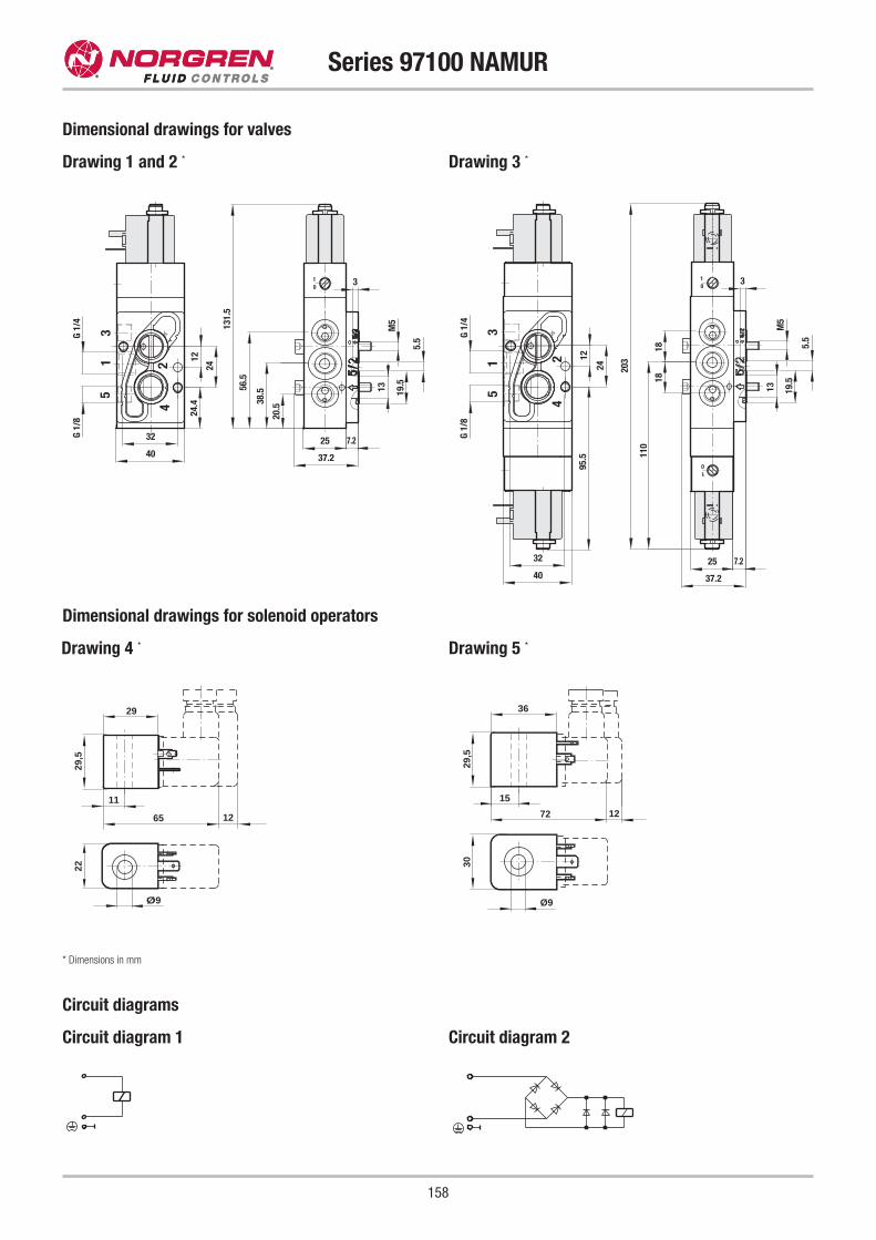
158
Series 97100 NAMUR
Dimensional drawings for valves
Drawing 1 and 2 * Drawing 3 *2
4
13
5
01
M5
3
5.5
19.513
25 7.2
37.2
32
40
G 1/
4G
1/8
24
1224
.4
20.5
56.5
38.5
131.
5
31
5
42
01
01
M5
3
5.5
19.5
13
25 7.2
37.2
32
40
G 1/
4G
1/8
24
1295
.5
1818
110
203
Dimensional drawings for solenoid operators
Drawing 4 *
29
65 12
11
29,5
22
Ø9
Drawing 5 *
36
15
72 12
29,5
30
Ø9
* Dimensions in mm
Circuit diagrams
Circuit diagram 1 Circuit diagram 2
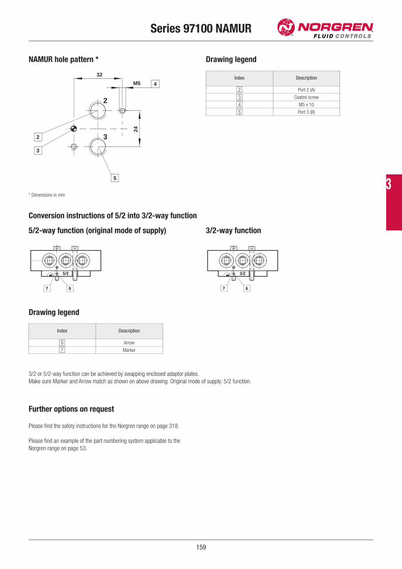
159
Series 97100 NAMUR
NAMUR hole pattern *
Conversion instructions of 5/2 into 3/2-way function
M5
32
2
243
3
5
4
2
5/2
67
3/2
67
Drawing legend
5/2-way function (original mode of supply) 3/2-way function
Index Description
2 Port 2 (A)
3 Coated screw
4 M5 x 10
5 Port 3 (R)
* Dimensions in mm
3/2 or 5/2-way function can be achieved by swapping enclosed adaptor plates.
Make sure Marker and Arrow match as shown on above drawing. Original mode of supply: 5/2 function.
Drawing legend
Index Description
6 Arrow
7 Marker
Further options on request
Please find the safety instructions for the Norgren range on page 318.
Please find an example of the part numbering system applicable to the
Norgren range on page 53.
3
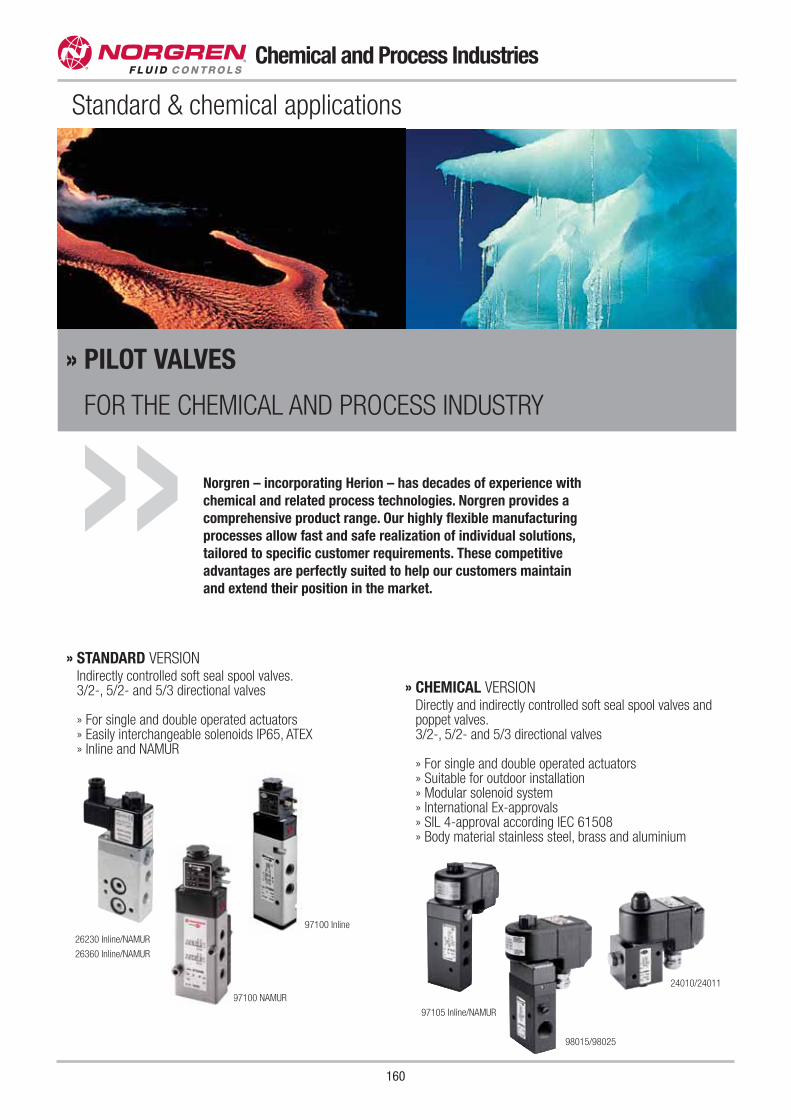
160
Chemical and Process Industries
Standard & chemical applications
Norgren – incorporating Herion – has decades of experience with
chemical and related process technologies. Norgren provides a
comprehensive product range. Our highly flexible manufacturing
processes allow fast and safe realization of individual solutions,
tailored to specific customer requirements. These competitive
advantages are perfectly suited to help our customers maintain
and extend their position in the market.
» STANDARD VERSIONIndirectly controlled soft seal spool valves.3/2-, 5/2- and 5/3 directional valves
» For single and double operated actuators» Easily interchangeable solenoids IP65, ATEX» Inline and NAMUR
» CHEMICAL VERSIONDirectly and indirectly controlled soft seal spool valves andpoppet valves.3/2-, 5/2- and 5/3 directional valves
» For single and double operated actuators» Suitable for outdoor installation» Modular solenoid system» International Ex-approvals» SIL 4-approval according IEC 61508» Body material stainless steel, brass and aluminium
26230 Inline/NAMUR
26360 Inline/NAMUR
97100 Inline
97100 NAMUR
97105 Inline/NAMUR
24010/24011
98015/98025
» PILOT VALVES
FOR THE CHEMICAL AND PROCESS INDUSTRY
»
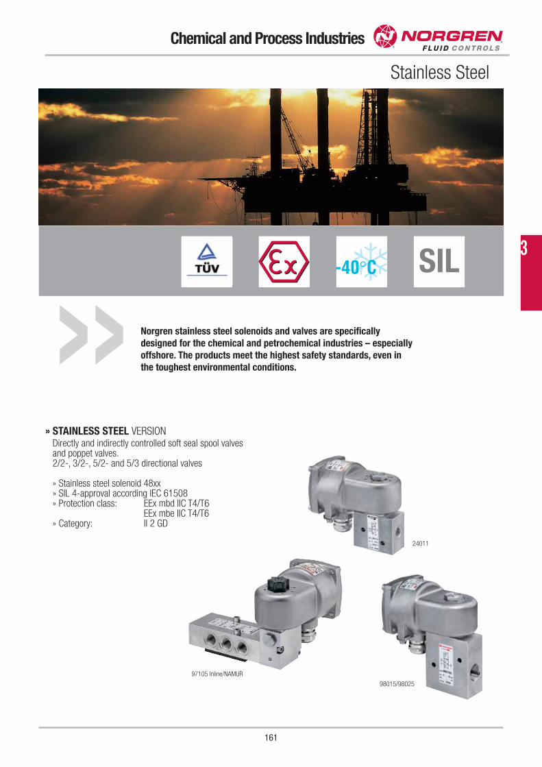
Norgren stainless steel solenoids and valves are specifically
designed for the chemical and petrochemical industries – especially
offshore. The products meet the highest safety standards, even in
the toughest environmental conditions.»
161
Chemical and Process Industries
SIL
Stainless Steel
» STAINLESS STEEL VERSIONDirectly and indirectly controlled soft seal spool valves and poppet valves.2/2-, 3/2-, 5/2- and 5/3 directional valves
» Stainless steel solenoid 48xx» SIL 4-approval according IEC 61508» Protection class: EEx mbd IIC T4/T6
EEx mbe IIC T4/T6» Category: II 2 GD
97105 Inline/NAMUR
24011
98015/98025
3
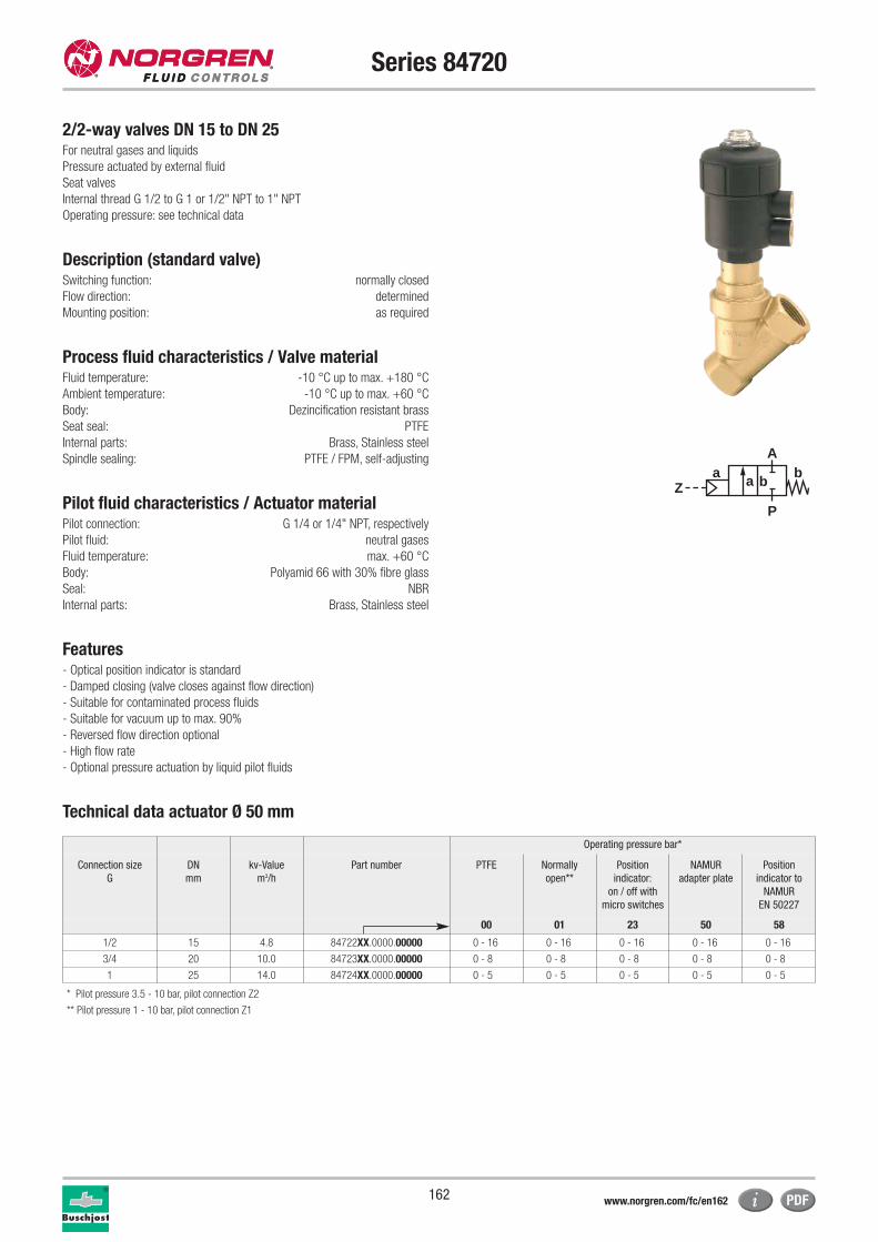
162
Series 84720
2/2-way valves DN 15 to DN 25For neutral gases and liquids
Pressure actuated by external fluid
Seat valves
Internal thread G 1/2 to G 1 or 1/2" NPT to 1" NPT
Operating pressure: see technical data
Description (standard valve)Switching function: normally closed
Flow direction: determined
Mounting position: as required
Process fluid characteristics / Valve materialFluid temperature: -10 °C up to max. +180 °C
Ambient temperature: -10 °C up to max. +60 °C
Body: Dezincification resistant brass
Seat seal: PTFE
Internal parts: Brass, Stainless steel
Spindle sealing: PTFE / FPM, self-adjusting
Pilot fluid characteristics / Actuator materialPilot connection: G 1/4 or 1/4" NPT, respectively
Pilot fluid: neutral gases
Fluid temperature: max. +60 °C
Body: Polyamid 66 with 30% fibre glass
Seal: NBR
Internal parts: Brass, Stainless steel
Features- Optical position indicator is standard
- Damped closing (valve closes against flow direction)
- Suitable for contaminated process fluids
- Suitable for vacuum up to max. 90%
- Reversed flow direction optional
- High flow rate
- Optional pressure actuation by liquid pilot fluids
Technical data actuator Ø 50 mm
Operating pressure bar*
Connection size
G
DN
mm
kv-Value
m3/h
Part number PTFE Normally
open**
Position
indicator:
on / off with
micro switches
NAMUR
adapter plate
Position
indicator to
NAMUR
EN 50227
00 01 23 50 58
1/2 15 4.8 84722XX.0000.00000 0 - 16 0 - 16 0 - 16 0 - 16 0 - 16
3/4 20 10.0 84723XX.0000.00000 0 - 8 0 - 8 0 - 8 0 - 8 0 - 8
1 25 14.0 84724XX.0000.00000 0 - 5 0 - 5 0 - 5 0 - 5 0 - 5
aZ
P
Ab
a b
* Pilot pressure 3.5 - 10 bar, pilot connection Z2
** Pilot pressure 1 - 10 bar, pilot connection Z1
www.norgren.com/fc/en162
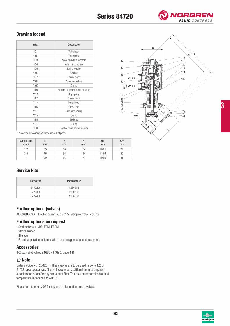
163
Series 84720
Drawing legend
Index Description
101 Valve body
*102 Valve plate
103 Valve spindle assembly
104 Allen head screw
105 Spring washer
*106 Gasket
107 Screw piece
*108 Spindle sealing
*109 O-ring
110 Bottom of control head housing
*111 Cup spring
112 Screw piece
*114 Piston seal
115 Signal pin
*116 Pressure spring
*117 O-ring
118 End cap
*119 O-ring
120 Control head housing cover
* A service kit consists of these individual parts.
Service kits
For valves Part number
8472200 1260318
8472300 1260566
8472400 1260568
Further options (valves)XXXXX08.XXXX Double acting; 4/2 or 5/2-way pilot valve required
Further options on request- Seal materials: NBR, FPM, EPDM
- Stroke limiter
- Silencer
- Electrical position indicator with electromagnetic induction sensors
Accessories3/2-way pilot valves 84660 / 84680, page 148
x Note:Order service kit 1264287 if these valves are to be used in Zone 1/2 or
21/22 hazardous areas. This kit includes an additional instruction plate,
a declaration of conformity and a dust filter. The maximum permissible fluid
temperature is reduced to +85 °C.
Please turn to page 276 for technical information on our valves.
Connection
size G
L
mm
B
mm
H
mm
H1
mm
SW
mm
1/2 65 66 154 140.5 27
3/4 75 66 160 144.5 32
1 90 66 171 150.5 41
P
A
Z1
Z2
117
119
116
110
103112108107106102
101
118115120114111
109
105104
SW
H1H
L
B
4/1
G
3
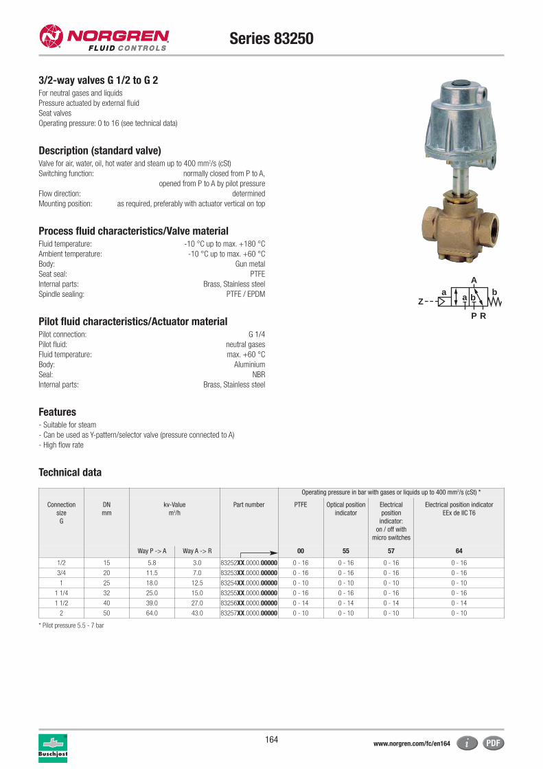
164
Series 83250
3/2-way valves G 1/2 to G 2For neutral gases and liquids
Pressure actuated by external fluid
Seat valves
Operating pressure: 0 to 16 (see technical data)
Description (standard valve)Valve for air, water, oil, hot water and steam up to 400 mm2/s (cSt)
Switching function: normally closed from P to A,
opened from P to A by pilot pressure
Flow direction: determined
Mounting position: as required, preferably with actuator vertical on top
Process fluid characteristics/Valve materialFluid temperature: -10 °C up to max. +180 °C
Ambient temperature: -10 °C up to max. +60 °C
Body: Gun metal
Seat seal: PTFE
Internal parts: Brass, Stainless steel
Spindle sealing: PTFE / EPDM
Pilot fluid characteristics/Actuator materialPilot connection: G 1/4
Pilot fluid: neutral gases
Fluid temperature: max. +60 °C
Body: Aluminium
Seal: NBR
Internal parts: Brass, Stainless steel
Features- Suitable for steam
- Can be used as Y-pattern/selector valve (pressure connected to A)
- High flow rate
Technical data
aZ
P R
Ab
a b
Operating pressure in bar with gases or liquids up to 400 mm2/s (cSt) *
Connection
size
G
DN
mm
kv-Value
m3/h
Part number PTFE Optical position
indicator
Electrical
position
indicator:
on / off with
micro switches
Electrical position indicator
EEx de IIC T6
Way P -> A Way A -> R 00 55 57 64
1/2 15 5.8 3.0 83252XX.0000.00000 0 - 16 0 - 16 0 - 16 0 - 16
3/4 20 11.5 7.0 83253XX.0000.00000 0 - 16 0 - 16 0 - 16 0 - 16
1 25 18.0 12.5 83254XX.0000.00000 0 - 10 0 - 10 0 - 10 0 - 10
1 1/4 32 25.0 15.0 83255XX.0000.00000 0 - 16 0 - 16 0 - 16 0 - 16
1 1/2 40 39.0 27.0 83256XX.0000.00000 0 - 14 0 - 14 0 - 14 0 - 14
2 50 64.0 43.0 83257XX.0000.00000 0 - 10 0 - 10 0 - 10 0 - 10
* Pilot pressure 5.5 - 7 bar
www.norgren.com/fc/en164
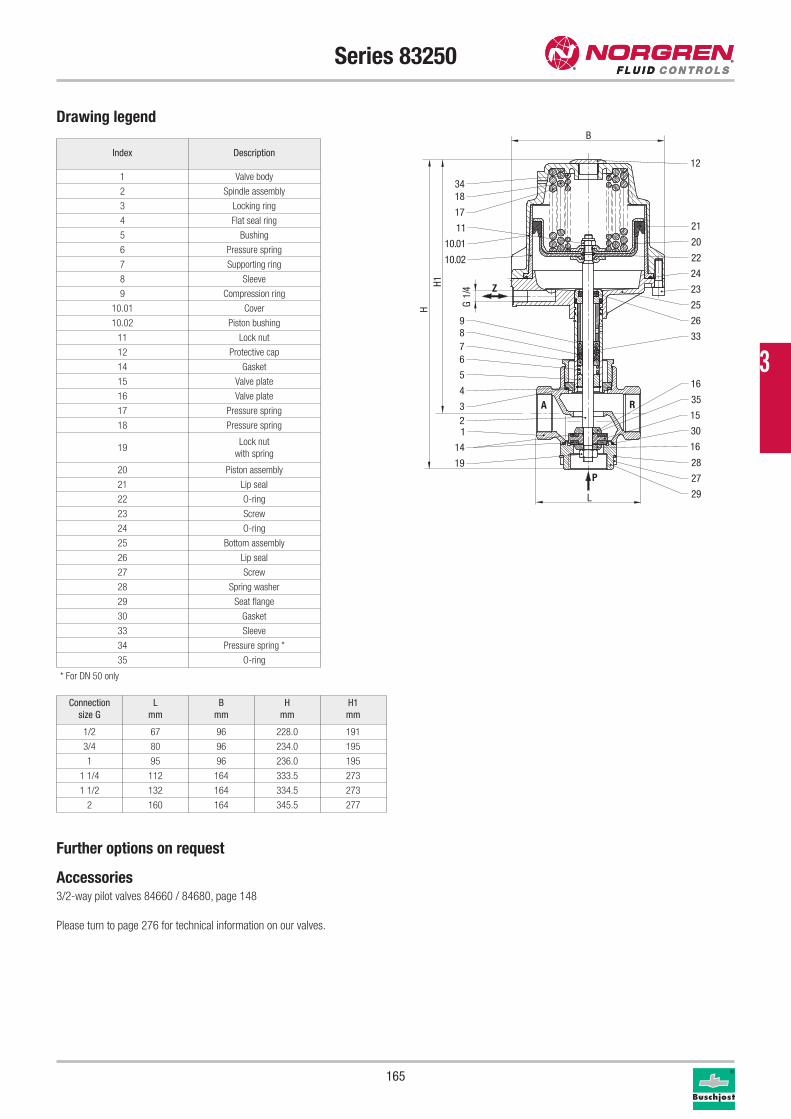
165
Series 83250
Drawing legend
Index Description
1 Valve body
2 Spindle assembly
3 Locking ring
4 Flat seal ring
5 Bushing
6 Pressure spring
7 Supporting ring
8 Sleeve
9 Compression ring
10.01 Cover
10.02 Piston bushing
11 Lock nut
12 Protective cap
14 Gasket
15 Valve plate
16 Valve plate
17 Pressure spring
18 Pressure spring
19Lock nut
with spring
20 Piston assembly
21 Lip seal
22 O-ring
23 Screw
24 O-ring
25 Bottom assembly
26 Lip seal
27 Screw
28 Spring washer
29 Seat flange
30 Gasket
33 Sleeve
34 Pressure spring *
35 O-ring
Further options on request
Accessories3/2-way pilot valves 84660 / 84680, page 148
Please turn to page 276 for technical information on our valves.
Connection
size G
L
mm
B
mm
H
mm
H1
mm
1/2 67 96 228.0 191
3/4 80 96 234.0 195
1 95 96 236.0 195
1 1/4 112 164 333.5 273
1 1/2 132 164 334.5 273
2 160 164 345.5 277
Z
RA
P
1834
17
11
987
5
21
12
21
20
22
24
23
25
26
33
15
10.01
10.02
6
4
3
14
35
16
16
30
28
27
29
19
L
H1H G
1/4
B
* For DN 50 only
3
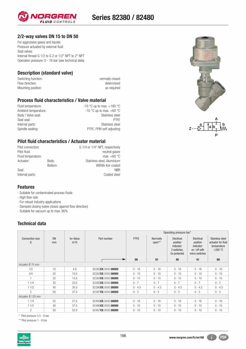
166
Series 82380 / 82480
2/2-way valves DN 15 to DN 50For aggressive gases and liquids
Pressure actuated by external fluid
Seat valves
Internal thread G 1/2 to G 2 or 1/2" NPT to 2" NPT
Operation pressure: 0 - 16 bar (see technical data)
Description (standard valve)Switching function: normally closed
Flow direction: determined
Mounting position: as required
Process fluid characteristics / Valve materialFluid temperature: -10 °C up to max. +180 °C
Ambient temperature: -10 °C up to max. +60 °C
Body / Valve seat: Stainless steel
Seat seal: PTFE
Internal parts: Stainless steel
Spindle sealing: PTFE, FPM self-adjusting
Pilot fluid characteristics / Actuator materialPilot connection: G 1/4 or 1/4" NPT, respectively
Pilot fluid: neutral gases
Fluid temperature: max. +60 °C
Actuator: Body: Stainless steel, Aluminium
Bottom: WEMA-Kor coated
Seal: NBR
Internal parts: Coated steel
Features- Suitable for contaminated process fluids
- High flow rate
- For robust industry applications
- Damped closing (valve closes against flow direction)
- Suitable for vacuum up to max. 90%
Technical data
aZ
P
Ab
a b
Operating pressure bar*
Connection size
G
DN
mm
kv-Value
m3/h
Part number PTFE Normally
open**
Electrical
position
indicator:
2 switches,
Ex-protected
Electrical
position
indicator:
on / off with
micro switches
Stainless steel
actuator for fluid
temperature
+200 °C
00 01 40 41 60
Actuator Ø 70 mm
1/2 15 4.8 82382XX.0000.00000 0 - 16 0 - 16 0 - 16 0 - 16 0 - 16
3/4 20 10.0 82383XX.0000.00000 0 - 10 0 - 10 0 - 10 0 - 10 0 - 10
1 25 14.0 82384XX.0000.00000 0 - 10 0 - 10 0 - 10 0 - 10 0 - 10
1 1/4 32 23.0 82385XX.0000.00000 0 - 7 0 - 7 0 - 7 0 - 7 0 - 7
1 1/2 40 30.0 82386XX.0000.00000 0 - 4.5 0 - 4.5 0 - 4.5 0 - 4.5 0 - 4.5
2 50 37.0 82387XX.0000.00000 0 - 3 0 - 3 0 - 3 0 - 3 0 - 3
Actuator Ø 125 mm
1 1/4 32 27.0 82485XX.0000.00000 0 - 16 0 - 16 0 - 16 0 - 16 0 - 16
1 1/2 40 37.0 82486XX.0000.00000 0 - 10 0 - 10 0 - 10 0 - 10 0 - 10
2 50 53.0 82487XX.0000.00000 0 - 10 0 - 10 0 - 10 0 - 10 0 - 10
* Pilot pressure 3.5 - 8 bar
** Pilot pressure 1 - 6 bar
www.norgren.com/fc/en166
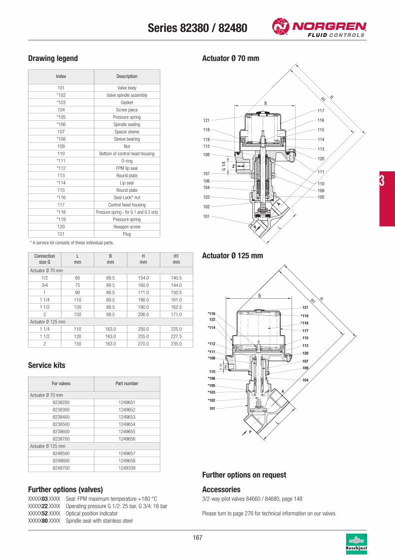
167
Series 82380 / 82480
Service kits
Drawing legend
Index Description
101 Valve body
*102 Valve spindle assembly
*103 Gasket
104 Screw piece
*105 Pressure spring
*106 Spindle sealing
107 Spacer sleeve
*108 Sleeve bearing
109 Nut
110 Bottom of control head housing
*111 O-ring
*112 FPM lip seal
113 Round plate
*114 Lip seal
115 Round plate
*116 Seal-Lock® nut
117 Control head housing
*118 Pressure spring - for G 1 and G 2 only
*119 Pressure spring
120 Hexagon screw
121 Plug
* A service kit consists of these individual parts.
For valves Part number
Actuator Ø 70 mm
8238200 1249651
8238300 1249652
8238400 1249653
8238500 1249654
8238600 1249655
8238700 1249656
Actuator Ø 125 mm
8248500 1249657
8248600 1249658
8248700 1249339
P
A
Z
101
102
103
104106
107
119
118
105109
110
111
120
114
113
115
116
117
121
108
112
LG
1/4
B
HH1
Connection
size G
L
mm
B
mm
H
mm
H1
mm
Actuator Ø 70 mm
1/2 65 89.5 154.0 140.5
3/4 75 89.5 160.0 144.0
1 90 89.5 171.0 150.5
1 1/4 110 89.5 186.0 161.0
1 1/2 120 89.5 190.0 162.5
2 150 89.5 206.0 171.0
Actuator Ø 125 mm
1 1/4 110 163.0 250.0 225.0
1 1/2 120 163.0 255.0 227.5
2 150 163.0 270.0 235.0
Further options (valves)XXXXX03.XXXX Seal: FPM maximum temperature +180 °C
XXXXX22.XXXX Operating pressure G 1/2: 25 bar, G 3/4: 16 bar
XXXXX52.XXXX Optical position indicator
XXXXX80.XXXX Spindle seal with stainless steel
Actuator Ø 70 mm
Actuator Ø 125 mm
A
Z
P
101
*102
*103
*105
*106
110109
120
*112
*114
*116
107
113
115
117
121
*119122
*111
104
*108
*118
L
G 1/
4
B HH1
Further options on request
Accessories3/2-way pilot valves 84660 / 84680, page 148
Please turn to page 276 for technical information on our valves.
3

168
Series 84190
2/2-way valves DN 2 to DN 10For aggressive gases and liquids to 600 mm2/s (cSt)
Pressure actuated by external fluid
Seat valves
Internal thread G 1/8 to G 1/2
Operating pressure: maximum 25 bar (see technical data)
Description (standard valve)Switching function: normally closed
Flow direction: determined
Mounting position: as required
Process fluid characteristics / Valve materialFluid temperature: -10 °C up to max. +90 °C
Ambient temperature: -10 °C up to max. +60 °C
Body: Stainless steel (1.4408)
Seat seal: PTFE
Internal parts: Stainless steel
Spindle sealing: PTFE / NBR, self-adjusting
Pilot fluid characteristics / Actuator material Pilot fluid: neutral gases
Fluid temperature: max. +60 °C
Body: Stainless steel (1.4404)
Seal: NBR
Internal parts: Stainless steel, Brass
Pilot connection: M5
Pilot pressure: 4-10 bar
Features- Small, compact 30 mm miniature actuator
- Actuator can be swiveled 360°
- Suitable for contaminated process fluids
- Suitable for vacuum up to max. 90%
- Reversed flow direction optional
- High flow rate
- Valve operates without pressure differential
- M5 mounting thread as standard
Technical data actuator Ø 70 mm
Connection size
G
DN
mm
kv-Value
m3/h
Part number Operating pressure bar
PTFE*
1/8 2.0 0.12 8419800.0000.00000 0 - 25
1/4 4.0 0.35 8419020.0000.00000 0 - 25
3/8 6.0 0.60 8419140.0000.00000 0 - 20
1/2 10.0 1.80 8419260.0000.00000 0 - 8
* Pilot pressure 4 - 10 bar
aZ
P
Ab
a b
www.norgren.com/fc/en168
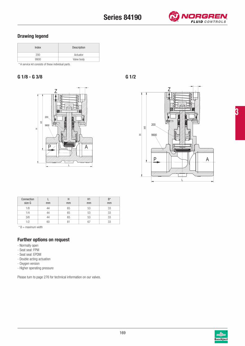
169
Series 84190
Drawing legend
* A service kit consists of these individual parts.
Connection
size G
L
mm
H
mm
H1
mm
B*
mm
1/8 44 65 53 33
1/4 44 65 53 33
3/8 44 65 53 33
1/2 60 81 67 33
Index Description
200 Actuator
9900 Valve body
Further options on request- Normally open
- Seat seal: FPM
- Seat seal: EPDM
- Double acting actuation
- Oxygen version
- Higher operating pressure
Please turn to page 276 for technical information on our valves.
200
9900
P
Z
A
L
H
H1
200
9900
P
Z
A
L
H1
H
G 1/8 - G 3/8 G 1/2
* B = maximum width
3
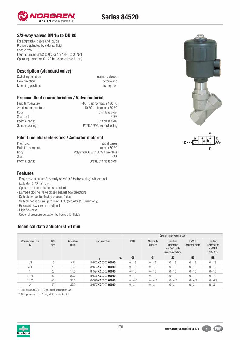
170
Series 84520
2/2-way valves DN 15 to DN 80For aggressive gases and liquids
Pressure actuated by external fluid
Seat valves
Internal thread G 1/2 to G 3 or 1/2" NPT to 3" NPT
Operating pressure: 0 - 20 bar (see technical data)
Description (standard valve)Switching function: normally closed
Flow direction: determined
Mounting position: as required
Process fluid characteristics / Valve materialFluid temperature: -10 °C up to max. +180 °C
Ambient temperature: -10 °C up to max. +60 °C
Body: Stainless steel
Seat seal: PTFE
Internal parts: Stainless steel
Spindle sealing: PTFE / FPM, self-adjusting
Pilot fluid characteristics / Actuator materialPilot fluid: neutral gases
Fluid temperature: max. +60 °C
Body: Polyamid 66 with 30% fibre glass
Seal: NBR
Internal parts: Brass, Stainless steel
Features- Easy conversion into "normally open" or "double-acting" without tool
(actuator Ø 70 mm only)
- Optical position indicator is standard
- Damped closing (valve closes against flow direction)
- Suitable for contaminated process fluids
- Suitable for vacuum up to max. 90% (actuator Ø 70 mm only)
- Reversed flow direction optional
- High flow rate
- Optional pressure actuation by liquid pilot fluids
Technical data actuator Ø 70 mm
aZ
P
Ab
a b
Operating pressure bar*
Connection size
G
DN
mm
kv-Value
m3/h
Part number PTFE Normally
open**
Position
indicator:
on / off with
micro switches
NAMUR
adapter plate
Position
indicator to
NAMUR
EN 50227
00 01 23 50 58
1/2 15 4.8 84522XX.0000.00000 0 - 16 0 - 16 0 - 16 0 - 16 0 - 16
3/4 20 10.0 84523XX.0000.00000 0 - 10 0 - 10 0 - 10 0 - 10 0 - 10
1 25 14.0 84524XX.0000.00000 0 - 10 0 - 10 0 - 10 0 - 10 0 - 10
1 1/4 32 23.0 84525XX.0000.00000 0 - 7 0 - 7 0 - 7 0 - 7 0 - 7
1 1/2 40 30.0 84526XX.0000.00000 0 - 4.5 0 - 4.5 0 - 4.5 0 - 4.5 0 - 4.5
2 50 37.0 84527XX.0000.00000 0 - 3 0 - 3 0 - 3 0 - 3 0 - 3
* Pilot pressure 3.5 - 10 bar, pilot connection Z2
** Pilot pressure 1 - 10 bar, pilot connection Z1
www.norgren.com/fc/en170
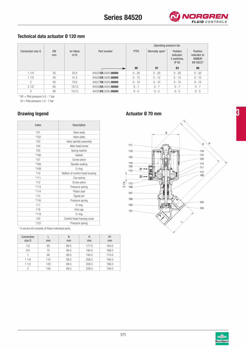
171
Operating pressure bar
Connection size G DN
mm
kv-Value
m3/h
Part number PTFE Normally open* Position
indicator:
2 switches,
IP 65
Position
indicator to
NAMUR
EN 50227
80 81 83 88
1 1/4 32 23.0 84525XX.0000.00000 0 - 20 0 - 20 0 - 20 0 - 20
1 1/2 40 41.0 84526XX.0000.00000 0 - 12 0 - 12 0 - 10 0 - 10
2 50 70.0 84527XX.0000.00000 0 - 10 0 - 10 0 - 10 0 - 10
2 1/2 65 107.0 84528XX.0000.00000 0 - 7 0 - 7 0 - 7 0 - 7
3 80 157.0 84529XX.0000.00000 0 - 5 0 - 5 0 - 5 0 - 5
Series 84520
Drawing legend
Connection
size G
L
mm
B
mm
H
mm
H1
mm
1/2 65 89.5 177.5 164.0
3/4 75 89.5 184.0 168.0
1 90 89.5 194.5 174.0
1 1/4 110 89.5 209.5 184.5
1 1/2 120 89.5 208.5 186.0
2 150 89.5 229.5 194.5
Index Description
101 Valve body
*102 Valve plate
103 Valve spindle assembly
104 Allen head screw
105 Spring washer
*106 Gasket
107 Screw piece
*108 Spindle sealing
*109 O-ring
110 Bottom of control head housing
*111 Cup spring
112 Screw piece
*113 Pressure spring
*114 Piston seal
115 Signal pin
*116 Pressure spring
117 O-ring
118 End cap
*119 O-ring
120 Control head housing cover
*122 Pressure spring
* A service kit consists of these individual parts.
117
119
122
116103
110
113109
107
106
102
101
118115120
114111
112108
104
105
P
A
Z1
Z2
H H
L
4/1
G
B
* 8X = Pilot pressure 5.0 - 7 bar
81= Pilot pressure 1.0 - 7 bar
Technical data actuator Ø 120 mm
Actuator Ø 70 mm 3
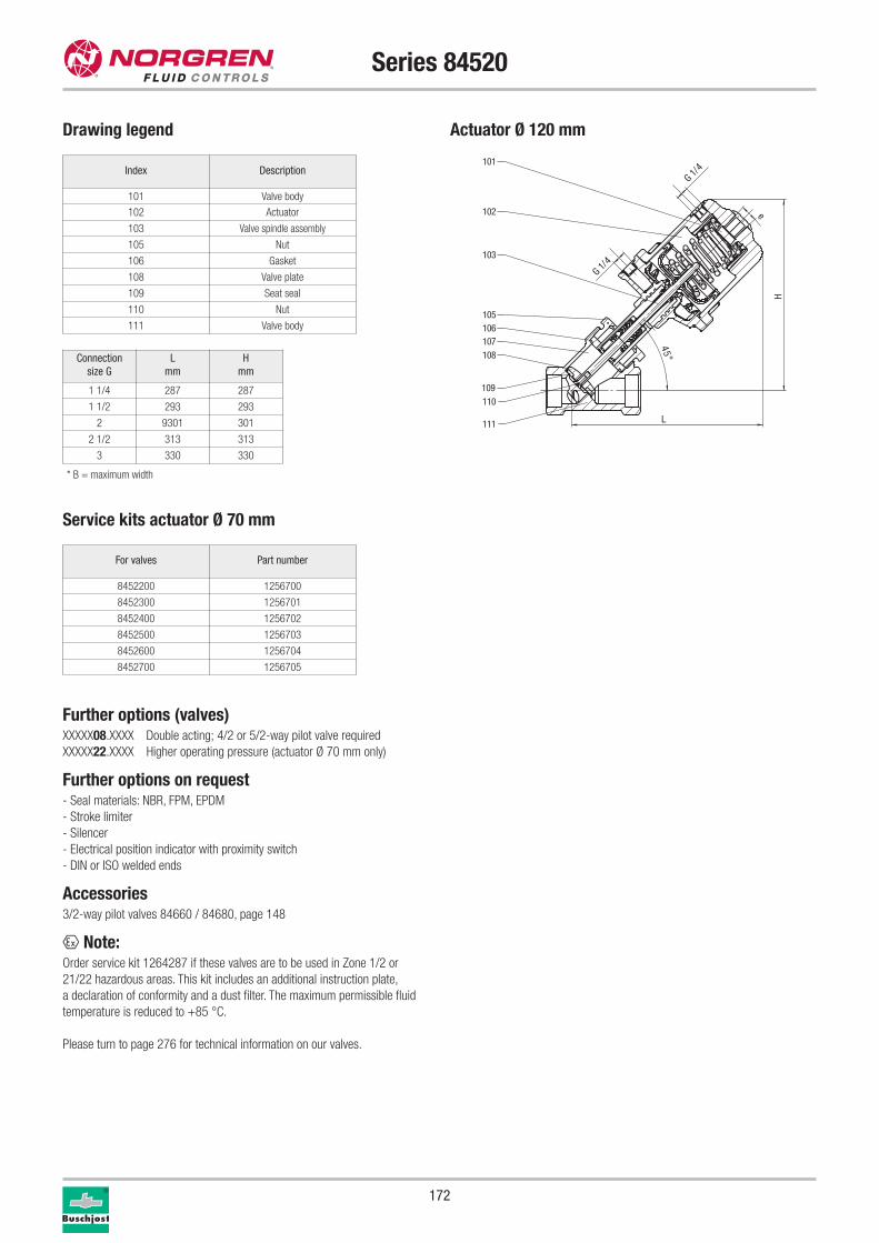
172
Series 84520
Service kits actuator Ø 70 mm
For valves Part number
8452200 1256700
8452300 1256701
8452400 1256702
8452500 1256703
8452600 1256704
8452700 1256705
Further options (valves)XXXXX08.XXXX Double acting; 4/2 or 5/2-way pilot valve required
XXXXX22.XXXX Higher operating pressure (actuator Ø 70 mm only)
Further options on request- Seal materials: NBR, FPM, EPDM
- Stroke limiter
- Silencer
- Electrical position indicator with proximity switch
- DIN or ISO welded ends
Accessories3/2-way pilot valves 84660 / 84680, page 148
x Note:Order service kit 1264287 if these valves are to be used in Zone 1/2 or
21/22 hazardous areas. This kit includes an additional instruction plate,
a declaration of conformity and a dust filter. The maximum permissible fluid
temperature is reduced to +85 °C.
Please turn to page 276 for technical information on our valves.
Drawing legend
L
H
e45°
G 1/4
G 1/4
110
111
109
108
106107
105
102
103
101
Actuator Ø 120 mm
Index Description
101 Valve body
102 Actuator
103 Valve spindle assembly
105 Nut
106 Gasket
108 Valve plate
109 Seat seal
110 Nut
111 Valve body
* B = maximum width
Connection
size G
L
mm
H
mm
1 1/4 287 287
1 1/2 293 293
2 9301 301
2 1/2 313 313
3 330 330
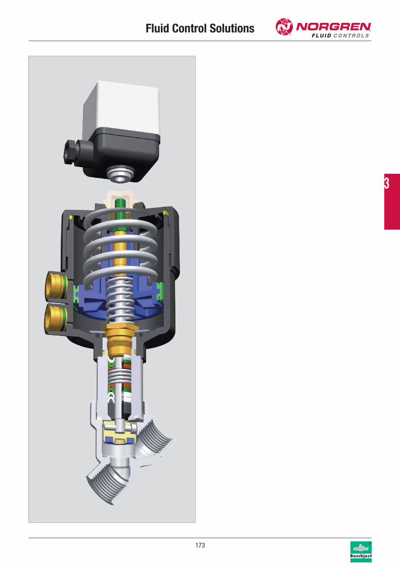
Fluid Control Solutions
173
3
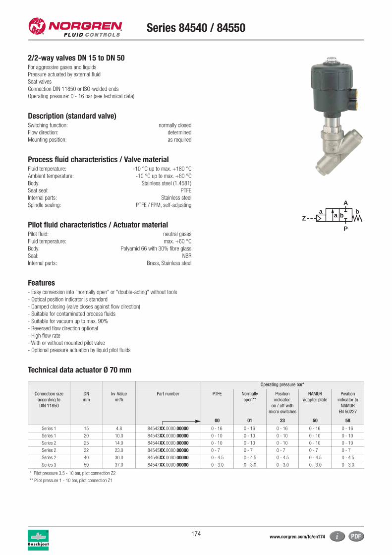
174
Series 84540 / 84550
2/2-way valves DN 15 to DN 50For aggressive gases and liquids
Pressure actuated by external fluid
Seat valves
Connection DIN 11850 or ISO-welded ends
Operating pressure: 0 - 16 bar (see technical data)
Description (standard valve)Switching function: normally closed
Flow direction: determined
Mounting position: as required
Process fluid characteristics / Valve materialFluid temperature: -10 °C up to max. +180 °C
Ambient temperature: -10 °C up to max. +60 °C
Body: Stainless steel (1.4581)
Seat seal: PTFE
Internal parts: Stainless steel
Spindle sealing: PTFE / FPM, self-adjusting
Pilot fluid characteristics / Actuator materialPilot fluid: neutral gases
Fluid temperature: max. +60 °C
Body: Polyamid 66 with 30% fibre glass
Seal: NBR
Internal parts: Brass, Stainless steel
Features- Easy conversion into "normally open" or "double-acting" without tools
- Optical position indicator is standard
- Damped closing (valve closes against flow direction)
- Suitable for contaminated process fluids
- Suitable for vacuum up to max. 90%
- Reversed flow direction optional
- High flow rate
- With or without mounted pilot valve
- Optional pressure actuation by liquid pilot fluids
Technical data actuator Ø 70 mm
aZ
P
Ab
a b
Operating pressure bar*
Connection size
according to
DIN 11850
DN
mm
kv-Value
m3/h
Part number PTFE Normally
open**
Position
indicator:
on / off with
micro switches
NAMUR
adapter plate
Position
indicator to
NAMUR
EN 50227
00 01 23 50 58
Series 1 15 4.8 84542XX.0000.00000 0 - 16 0 - 16 0 - 16 0 - 16 0 - 16
Series 1 20 10.0 84543XX.0000.00000 0 - 10 0 - 10 0 - 10 0 - 10 0 - 10
Series 2 25 14.0 84544XX.0000.00000 0 - 10 0 - 10 0 - 10 0 - 10 0 - 10
Series 2 32 23.0 84545XX.0000.00000 0 - 7 0 - 7 0 - 7 0 - 7 0 - 7
Series 2 40 30.0 84546XX.0000.00000 0 - 4.5 0 - 4.5 0 - 4.5 0 - 4.5 0 - 4.5
Series 3 50 37.0 84547XX.0000.00000 0 - 3.0 0 - 3.0 0 - 3.0 0 - 3.0 0 - 3.0
* Pilot pressure 3.5 - 10 bar, pilot connection Z2
** Pilot pressure 1 - 10 bar, pilot connection Z1
www.norgren.com/fc/en174
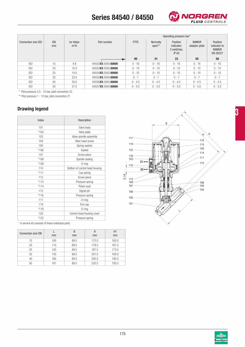
175
Series 84540 / 84550
Operating pressure bar*
Connection size ISO DN
mm
kv-Value
m3/h
Part number PTFE Normally
open**
Position
indicator:
2 switches,
IP 65
NAMUR
adapter plate
Position
indicator to
NAMUR
EN 50227
00 01 23 50 58
ISO 15 4.8 84552XX.0000.00000 0 - 16 0 - 16 0 - 16 0 - 16 0 - 16
ISO 20 10.0 84553XX.0000.00000 0 - 10 0 - 10 0 - 10 0 - 10 0 - 10
ISO 25 14.0 84554XX.0000.00000 0 - 10 0 - 10 0 - 10 0 - 10 0 - 10
ISO 32 23.0 84555XX.0000.00000 0 - 7 0 - 7 0 - 7 0 - 7 0 - 7
ISO 40 30.0 84556XX.0000.00000 0 - 4.5 0 - 4.5 0 - 4.5 0 - 4.5 0 - 4.5
ISO 50 37.0 84557XX.0000.00000 0 - 3.0 0 - 3.0 0 - 3.0 0 - 3.0 0 - 3.0
Drawing legend
Connection size DNL
mm
B
mm
H
mm
H1
mm
15 100 89.5 172.0 163.0
20 110 89.5 178.5 167.5
25 120 89.5 187.5 173.0
32 143 89.5 201.5 184.0
40 160 89.5 205.5 185.0
50 181 89.5 220.5 193.5
Index Description
101 Valve body
*102 Valve plate
103 Valve spindle assembly
104 Allen head screw
105 Spring washer
*106 Gasket
107 Screw piece
*108 Spindle sealing
*109 O-ring
110 Bottom of control head housing
*111 Cup spring
112 Screw piece
*113 Pressure spring
*114 Piston seal
115 Signal pin
*116 Pressure spring
117 O-ring
118 End cap
*119 O-ring
120 Control head housing cover
*122 Pressure spring
* A service kit consists of these individual parts.
117
119
122
116103
110
113109107
106
102
101
118
115120
114
111
112
108104105
Z1
Z2
P
A
H H
L
4/1
GB
* Pilot pressure 3.5 - 10 bar, pilot connection Z2
** Pilot pressure 1 - 10 bar, pilot connection Z1
3
176
Series 84540 / 84550
Service kits
For valves Part number DIN / ISO
8454200 1256700 DIN
8454300 1256701 DIN
8454400 1256702 DIN
8454500 1256703 DIN
8454600 1256704 DIN
8454700 1256705 DIN
8455200 1256700 ISO
8455300 1256701 ISO
8455400 1256702 ISO
8455500 1256703 ISO
8455600 1256704 ISO
8455700 1256705 ISO
Further options (valves)XXXXX08.XXXX Double acting; 4/2 or 5/2-way pilot valve required
XXXXX22.XXXX Higher operating pressure
Further options on request- Seal materials: NBR, FPM, EPDM
- Stroke limiter
- Silencer
- Electrical position indicator with proximity switch
Accessories3/2-way pilot valves 84660 / 84680, page 148
x Note:Order service kit 1264287 if these valves are to be used in Zone 1/2 or
21/22 hazardous areas. This kit includes an additional instruction plate,
a declaration of conformity and a dust filter. The maximum permissible fluid
temperature is reduced to +85 °C.
Please turn to page 276 for technical information on our valves.
Fluid Control Solutions
177
3

178
Series 84580 / 84880
2/2-way valves DN 15 to DN 50For aggressive gases and liquids
Pressure actuated by external fluid
Seat valves
Connection DIN 11850
Operating pressure: 0 to 16 bar (see technical data)
Description (standard valve)Switching function: normally closed
Flow direction: determined
Mounting position: as required
Process fluid characteristics / Valve materialFluid temperature: 0 °C up to max. +180 °C
Ambient temperature: 0 °C up to max. +60 °C
Body: Stainless steel (1.4581)
Seat seal: PTFE
Internal parts: Sandvik 1802 Stainless steel
Spindle sealing: PTFE / FPM, self-adjusting
Pilot fluid characteristics / Actuator materialPilot connection: G 1/4
Pilot fluid: neutral gases
Fluid temperature: max. +80 °C
Material body: Stainless steel, WEMA-Kor coated aluminium
Seal: NBR
Internal parts: Coated steel
Features- High flow rate
- Suitable for contaminated process fluids
- Damped closing (valve closes against flow direction)
- For robust industry applications
- Suitable for vacuum up to max. 90%
Technical data
aZ
P
Ab
a b
Operating pressure bar*
Connection size
according to
DIN 11850
DN
mm
kv-Value
m3/h
Part number PTFE Normally
open**
Position
indicator:
2 switches,
Ex-protected
Position
indicator:
on / off with
micro switches
Fluid
temperature
+200 °C
00 01 40 41 60
Actuator Ø 70 mm
Series 1 15 4.8 84582XX.0000.00000 0 - 16 0 - 16 0 - 16 0 - 16 0 - 16
Series 1 20 10.0 84583XX.0000.00000 0 - 10 0 - 10 0 - 10 0 - 10 0 - 10
Series 2 25 14.0 84584XX.0000.00000 0 - 10 0 - 10 0 - 10 0 - 10 0 - 10
Series 2 32 23.0 84585XX.0000.00000 0 - 7 0 - 7 0 - 7 0 - 7 0 - 7
Series 2 40 30.0 84586XX.0000.00000 0 - 4.5 0 - 4.5 0 - 4.5 0 - 4.5 0 - 4.5
Series 3 50 37.0 84587XX.0000.00000 0 - 3 0 - 3 0 - 3 0 - 3 0 - 3
Actuator Ø 125 mm
Series 2 32 27.0 84885XX.0000.00000 0 - 16 0 - 16 0 - 16 0 - 16 0 - 16
Series 2 40 37.0 84886XX.0000.00000 0 - 10 0 - 10 0 - 10 0 - 10 0 - 10
Series 3 50 53.0 84887XX.0000.00000 0 - 10 0 - 10 0 - 10 0 - 10 0 - 10
* Pilot pressure 3.5 - 8 bar
** Pilot pressure 1 - 6 bar
www.norgren.com/fc/en178
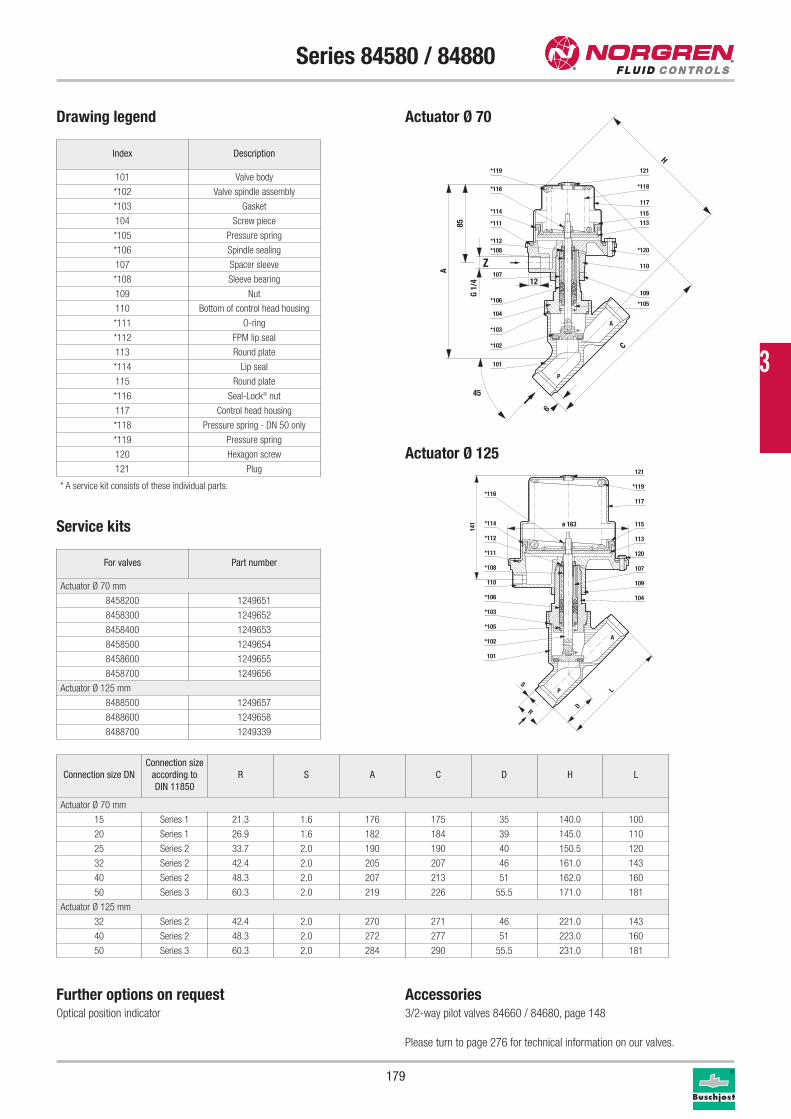
101
*102
*103
104
*106
107
*105
109
*120*108
*114
*116
*119
110
113115
117
121
*111
*118
*112
P
A
6
C
H
45
85
12
A
G 1/
4
Z
179
Series 84580 / 84880
Drawing legend
Index Description
101 Valve body
*102 Valve spindle assembly
*103 Gasket
104 Screw piece
*105 Pressure spring
*106 Spindle sealing
107 Spacer sleeve
*108 Sleeve bearing
109 Nut
110 Bottom of control head housing
*111 O-ring
*112 FPM lip seal
113 Round plate
*114 Lip seal
115 Round plate
*116 Seal-Lock® nut
117 Control head housing
*118 Pressure spring - DN 50 only
*119 Pressure spring
120 Hexagon screw
121 Plug
* A service kit consists of these individual parts.
Service kits
For valves Part number
Actuator Ø 70 mm
8458200 1249651
8458300 1249652
8458400 1249653
8458500 1249654
8458600 1249655
8458700 1249656
Actuator Ø 125 mm
8488500 1249657
8488600 1249658
8488700 1249339
Further options on requestOptical position indicator
Accessories3/2-way pilot valves 84660 / 84680, page 148
Please turn to page 276 for technical information on our valves.
Actuator Ø 70
Connection size DN
Connection size
according to
DIN 11850
R S A C D H L
Actuator Ø 70 mm
15 Series 1 21.3 1.6 176 175 35 140.0 100
20 Series 1 26.9 1.6 182 184 39 145.0 110
25 Series 2 33.7 2.0 190 190 40 150.5 120
32 Series 2 42.4 2.0 205 207 46 161.0 143
40 Series 2 48.3 2.0 207 213 51 162.0 160
50 Series 3 60.3 2.0 219 226 55.5 171.0 181
Actuator Ø 125 mm
32 Series 2 42.4 2.0 270 271 46 221.0 143
40 Series 2 48.3 2.0 272 277 51 223.0 160
50 Series 3 60.3 2.0 284 290 55.5 231.0 181
101
*102
*105
*103
*106
110 109
120
*112
*114
*116
107
113
115
117
121
*119
*111
104
*108
A
P
R
S
D
L
ø 163
141
Actuator Ø 125
3
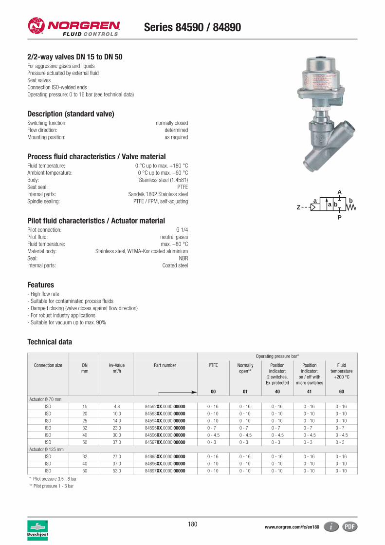
180
Series 84590 / 84890
2/2-way valves DN 15 to DN 50For aggressive gases and liquids
Pressure actuated by external fluid
Seat valves
Connection ISO-welded ends
Operating pressure: 0 to 16 bar (see technical data)
Description (standard valve)Switching function: normally closed
Flow direction: determined
Mounting position: as required
Process fluid characteristics / Valve materialFluid temperature: 0 °C up to max. +180 °C
Ambient temperature: 0 °C up to max. +60 °C
Body: Stainless steel (1.4581)
Seat seal: PTFE
Internal parts: Sandvik 1802 Stainless steel
Spindle sealing: PTFE / FPM, self-adjusting
Pilot fluid characteristics / Actuator materialPilot connection: G 1/4
Pilot fluid: neutral gases
Fluid temperature: max. +80 °C
Material body: Stainless steel, WEMA-Kor coated aluminium
Seal: NBR
Internal parts: Coated steel
Features- High flow rate
- Suitable for contaminated process fluids
- Damped closing (valve closes against flow direction)
- For robust industry applications
- Suitable for vacuum up to max. 90%
Technical data
aZ
P
Ab
a b
Operating pressure bar*
Connection size DN
mm
kv-Value
m3/h
Part number PTFE Normally
open**
Position
indicator:
2 switches,
Ex-protected
Position
indicator:
on / off with
micro switches
Fluid
temperature
+200 °C
00 01 40 41 60
Actuator Ø 70 mm
ISO 15 4.8 84592XX.0000.00000 0 - 16 0 - 16 0 - 16 0 - 16 0 - 16
ISO 20 10.0 84593XX.0000.00000 0 - 10 0 - 10 0 - 10 0 - 10 0 - 10
ISO 25 14.0 84594XX.0000.00000 0 - 10 0 - 10 0 - 10 0 - 10 0 - 10
ISO 32 23.0 84595XX.0000.00000 0 - 7 0 - 7 0 - 7 0 - 7 0 - 7
ISO 40 30.0 84596XX.0000.00000 0 - 4.5 0 - 4.5 0 - 4.5 0 - 4.5 0 - 4.5
ISO 50 37.0 84597XX.0000.00000 0 - 3 0 - 3 0 - 3 0 - 3 0 - 3
Actuator Ø 125 mm
ISO 32 27.0 84895XX.0000.00000 0 - 16 0 - 16 0 - 16 0 - 16 0 - 16
ISO 40 37.0 84896XX.0000.00000 0 - 10 0 - 10 0 - 10 0 - 10 0 - 10
ISO 50 53.0 84897XX.0000.00000 0 - 10 0 - 10 0 - 10 0 - 10 0 - 10
* Pilot pressure 3.5 - 8 bar
** Pilot pressure 1 - 6 bar
www.norgren.com/fc/en180
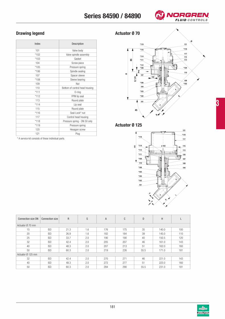
181
Series 84590 / 84890
Drawing legend Actuator Ø 70
101
*102
*103
104
*106
107
*105
109
*120*108
*114
*116
*119
110
113115
117
121
*111
*118
*112
P
A
6
C
H
45
85
12
A
G 1/
4
Z
101
*102
*105
*103
*106
110 109
120
*112
*114
*116
107
113
115
117
121
*119
*111
104
*108
A
P
R
S
D
L
ø 163
141
Index Description
101 Valve body
*102 Valve spindle assembly
*103 Gasket
104 Screw piece
*105 Pressure spring
*106 Spindle sealing
107 Spacer sleeve
*108 Sleeve bearing
109 Nut
110 Bottom of control head housing
*111 O-ring
*112 FPM lip seal
113 Round plate
*114 Lip seal
115 Round plate
*116 Seal-Lock® nut
117 Control head housing
*118 Pressure spring - DN 50 only
*119 Pressure spring
120 Hexagon screw
121 Plug
* A service kit consists of these individual parts.
Connection size DN Connection size R S A C D H L
Actuator Ø 70 mm
15 ISO 21.3 1.6 176 175 35 140.0 100
20 ISO 26.9 1.6 182 184 39 145.0 110
25 ISO 33.7 2.0 190 190 40 150.5 120
32 ISO 42.4 2.0 205 207 46 161.0 143
40 ISO 48.3 2.0 207 213 51 162.0 160
50 ISO 60.3 2.0 219 226 55.5 171.0 181
Actuator Ø 125 mm
32 ISO 42.4 2.0 270 271 46 221.0 143
40 ISO 48.3 2.0 272 277 51 223.0 160
50 ISO 60.3 2.0 284 290 55.5 231.0 181
Actuator Ø 125
3
182
Series 84590 / 84890
Service kits
For valves Part number
Actuator Ø 70 mm
8459200 1249651
8459300 1249652
8459400 1249653
8459500 1249654
8459600 1249655
8459700 1249656
Actuator Ø 125 mm
8489500 1249657
8489600 1249658
8489700 1249339
Further options on requestOptical position indicator
Accessories3/2-way pilot valves 84660 / 84680, page 148
Please turn to page 276 for technical information on our valves.
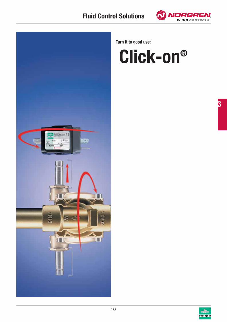
Fluid Control Solutions
183
Turn it to good use:
Click-on®
3
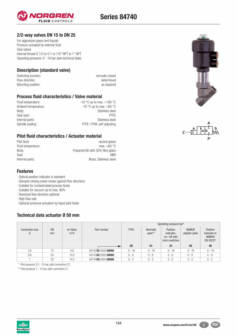
184
Series 84740
2/2-way valves DN 15 to DN 25For aggressive gases and liquids
Pressure actuated by external fluid
Seat valves
Internal thread G 1/2 to G 1 or 1/2" NPT to 1" NPT
Operating pressure: 0 - 16 bar (see technical data)
Description (standard valve)Switching function: normally closed
Flow direction: determined
Mounting position: as required
Process fluid characteristics / Valve materialFluid temperature: -10 °C up to max. +180 °C
Ambient temperature: -10 °C up to max. +60 °C
Body: Stainless steel
Seat seal: PTFE
Internal parts: Stainless steel
Spindle sealing: PTFE / FPM, self-adjusting
Pilot fluid characteristics / Actuator materialPilot fluid: neutral gases
Fluid temperature: max. +60 °C
Body: Polyamid 66 with 30% fibre glass
Seal: NBR
Internal parts: Brass, Stainless steel
Features- Optical position indicator is standard
- Damped closing (valve closes against flow direction)
- Suitable for contaminated process fluids
- Suitable for vacuum up to max. 90%
- Reversed flow direction optional
- High flow rate
- Optional pressure actuation by liquid pilot fluids
Technical data actuator Ø 50 mm
aZ
P
Ab
a b
Operating pressure bar*
Connection size
G
DN
mm
kv-Value
m3/h
Part number PTFE Normally
open**
Position
indicator:
on / off with
micro switches
NAMUR
adapter plate
Position
indicator to
NAMUR
EN 50227
00 01 23 50 58
1/2 15 4.8 84742XX.0000.00000 0 - 16 0 - 16 0 - 16 0 - 16 0 - 16
3/4 20 10.0 84743XX.0000.00000 0 - 8 0 - 8 0 - 8 0 - 8 0 - 8
1 25 14.0 84744XX.0000.00000 0 - 5 0 - 5 0 - 5 0 - 5 0 - 5
* Pilot pressure 3.5 - 10 bar, pilot connection Z2
** Pilot pressure 1 - 10 bar, pilot connection Z1
www.norgren.com/fc/en184
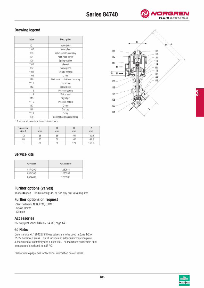
185
Series 84740
Drawing legend
Index Description
101 Valve body
*102 Valve plate
103 Valve spindle assembly
104 Allen head screw
105 Spring washer
*106 Gasket
107 Screw piece
*108 Spindle sealing
*109 O-ring
110 Bottom of control head housing
*111 Cup spring
112 Screw piece
*113 Pressure spring
*114 Piston seal
115 Signal pin
*116 Pressure spring
117 O-ring
118 End cap
*119 O-ring
120 Control head housing cover
* A service kit consists of these individual parts.
Service kits
For valves Part number
8474200 1260581
8474300 1260583
8474400 1268585
Further options (valves)XXXXX08.XXXX Double acting; 4/2 or 5/2-way pilot valve required
Further options on request- Seal materials: NBR, FPM, EPDM
- Stroke limiter
- Silencer
Accessories3/2-way pilot valves 84660 / 84680, page 148
x Note:Order service kit 1264287 if these valves are to be used in Zone 1/2 or
21/22 hazardous areas. This kit includes an additional instruction plate,
a declaration of conformity and a dust filter. The maximum permissible fluid
temperature is reduced to +85 °C.
Please turn to page 276 for technical information on our valves.
Connection
size G
L
mm
B
mm
H
mm
H1
mm
1/2 65 66 154 140.5
3/4 75 66 160 144.5
1 90 66 171 150.5
H1H
L
B
4/1G
Z1
Z2
P
A 3
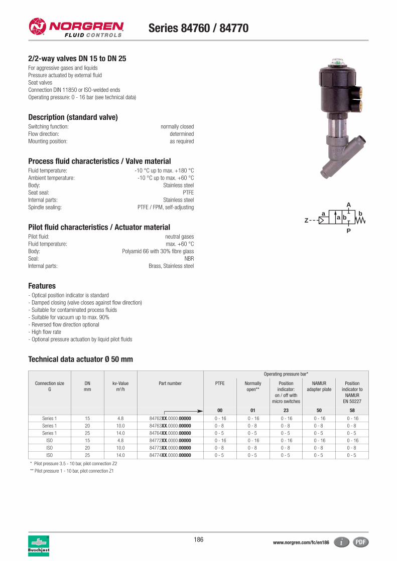
186
Series 84760 / 84770
2/2-way valves DN 15 to DN 25For aggressive gases and liquids
Pressure actuated by external fluid
Seat valves
Connection DIN 11850 or ISO-welded ends
Operating pressure: 0 - 16 bar (see technical data)
Description (standard valve)Switching function: normally closed
Flow direction: determined
Mounting position: as required
Process fluid characteristics / Valve materialFluid temperature: -10 °C up to max. +180 °C
Ambient temperature: -10 °C up to max. +60 °C
Body: Stainless steel
Seat seal: PTFE
Internal parts: Stainless steel
Spindle sealing: PTFE / FPM, self-adjusting
Pilot fluid characteristics / Actuator materialPilot fluid: neutral gases
Fluid temperature: max. +60 °C
Body: Polyamid 66 with 30% fibre glass
Seal: NBR
Internal parts: Brass, Stainless steel
Features- Optical position indicator is standard
- Damped closing (valve closes against flow direction)
- Suitable for contaminated process fluids
- Suitable for vacuum up to max. 90%
- Reversed flow direction optional
- High flow rate
- Optional pressure actuation by liquid pilot fluids
Technical data actuator Ø 50 mm
aZ
P
Ab
a b
Operating pressure bar*
Connection size
G
DN
mm
kv-Value
m3/h
Part number PTFE Normally
open**
Position
indicator:
on / off with
micro switches
NAMUR
adapter plate
Position
indicator to
NAMUR
EN 50227
00 01 23 50 58
Series 1 15 4.8 84762XX.0000.00000 0 - 16 0 - 16 0 - 16 0 - 16 0 - 16
Series 1 20 10.0 84763XX.0000.00000 0 - 8 0 - 8 0 - 8 0 - 8 0 - 8
Series 1 25 14.0 84764XX.0000.00000 0 - 5 0 - 5 0 - 5 0 - 5 0 - 5
ISO 15 4.8 84772XX.0000.00000 0 - 16 0 - 16 0 - 16 0 - 16 0 - 16
ISO 20 10.0 84773XX.0000.00000 0 - 8 0 - 8 0 - 8 0 - 8 0 - 8
ISO 25 14.0 84774XX.0000.00000 0 - 5 0 - 5 0 - 5 0 - 5 0 - 5
* Pilot pressure 3.5 - 10 bar, pilot connection Z2
** Pilot pressure 1 - 10 bar, pilot connection Z1
www.norgren.com/fc/en186
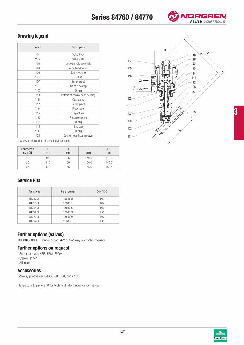
187
Series 84760 / 84770
Drawing legend
Index Description
101 Valve body
*102 Valve plate
103 Valve spindle assembly
104 Allen head screw
105 Spring washer
*106 Gasket
107 Screw piece
*108 Spindle sealing
*109 O-ring
110 Bottom of control head housing
*111 Cup spring
112 Screw piece
*114 Piston seal
115 Signal pin
*116 Pressure spring
117 O-ring
118 End cap
*119 O-ring
120 Control head housing cover
* A service kit consists of these individual parts.
Service kits
For valves Part number DIN / ISO
8476200 1260581 DIN
8476300 1260583 DIN
8476400 1268585 DIN
8477200 1260581 ISO
8477300 1260583 ISO
8477400 1268585 ISO
Further options (valves)XXXXX08.XXXX Double acting; 4/2 or 5/2-way pilot valve required
Further options on request- Seal materials: NBR, FPM, EPDM
- Stroke limiter
- Silencer
Accessories3/2-way pilot valves 84660 / 84680, page 148
Please turn to page 276 for technical information on our valves.
Connection
size DN
L
mm
B
mm
H
mm
H1
mm
15 100 66 149.5 140.5
20 110 66 156.0 145.0
25 120 66 165.0 150.5
H1H
L
B
4/1G
Z1
Z2
3
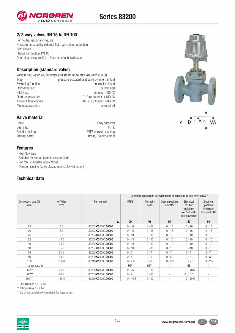
188
Series 83200
2/2-way valves DN 15 to DN 100For neutral gases and liquids
Pressure actuated by external fluid, with piston actuation
Seat valves
Flange connection: PN 16
Operating pressure: 0 to 16 bar (see technical data)
Description (standard valve)Valve for air, water, oil, hot water and steam up to max. 400 mm2/s (cSt)
Type: pressure actuated seat valve by external fluid
Switching function: normally closed
Flow direction: determined
Pilot fluid: air, max. +80 °C
Fluid temperature: -10 °C up to max. +180 °C
Ambient temperature: -10 °C up to max. +80 °C
Mounting position: as required
Valve materialBody: Grey cast iron
Seat seal: PTFE
Spindle sealing: PTFE chevron packing
Internal parts: Brass, Stainless steel
Features- High flow rate
- Suitable for contaminated process fluids
- For robust industry applications
- Damped closing (valve closes against flow direction)
Technical data
aZ
P
Ab
a b
Operating pressure in bar with gases or liquids up to 400 mm2/s (cSt) *
Connection size DN
mm
kv-Value
m3/h
Part number PTFE Normally
open
Optical position
indicator
Electrical
position
indicator:
on / off with
micro switches
Electrical
position
indicator:
EEx de IIC T6
00 01 55 57 64
15 3.6 83202XX.0000.00000 0 - 16 0 - 16 0 - 16 0 - 16 0 - 16
20 6.1 83203XX.0000.00000 0 - 16 0 - 16 0 - 16 0 - 16 0 - 16
25 9.5 83204XX.0000.00000 0 - 10 0 - 16 0 - 10 0 - 10 0 - 10
32 15.0 83205XX.0000.00000 0 - 10 0 - 10 0 - 10 0 - 10 0 - 10
40 23.0 83206XX.0000.00000 0 - 10 0 - 10 0 - 10 0 - 10 0 - 10
50 35.0 83207XX.0000.00000 0 - 10 0 - 10 0 - 10 0 - 10 0 - 10
65 61.0 83208XX.0000.00000 0 - 7 0 - 7 0 - 7 0 - 7 0 - 7
80 90.0 83209XX.0000.00000 0 - 5 0 - 5 0 - 5 0 - 5 0 - 5
100 138.0 83210XX.0000.00000 0 - 2.5 0 - 2.5 0 - 2.5 0 - 2.5 0 - 2.5
larger actuator 50* 80** - 65 -
65*** 61.0 83208XX.0000.00000 0 - 16 0 - 16 - 0 - 10.5 -
80*** 90.0 83209XX.0000.00000 0 - 9 0 - 16 - 0 - 10.5 -
100*** 138.0 83210XX.0000.00000 0 - 10.5 0 - 10 - 0 - 10.5 -
* Pilot pressure 5.5 - 7 bar
** Pilot pressure 1 - 7 bar
*** No dimensional drawing available for these valves
www.norgren.com/fc/en188
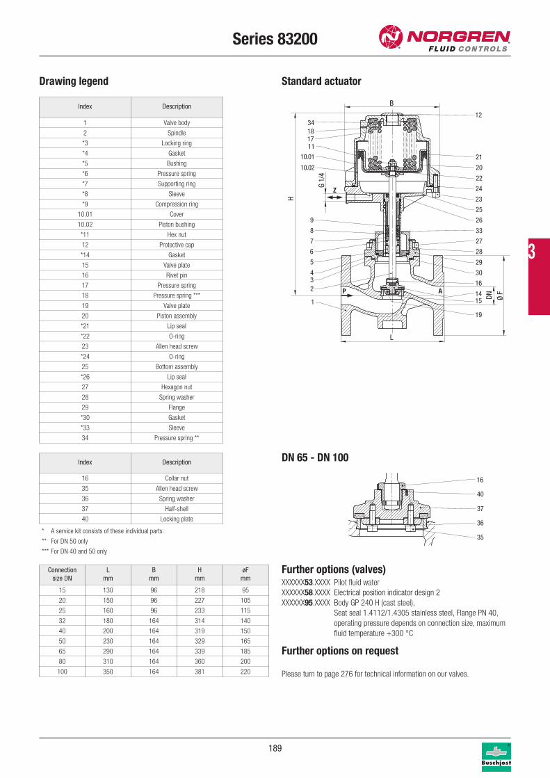
189
Series 83200
Drawing legend
* A service kit consists of these individual parts.
** For DN 50 only
*** For DN 40 and 50 only
Connection
size DN
L
mm
B
mm
H
mm
øF
mm
15 130 96 218 95
20 150 96 227 105
25 160 96 233 115
32 180 164 314 140
40 200 164 319 150
50 230 164 329 165
65 290 164 339 185
80 310 164 360 200
100 350 164 381 220
Index Description
1 Valve body
2 Spindle
*3 Locking ring
*4 Gasket
*5 Bushing
*6 Pressure spring
*7 Supporting ring
*8 Sleeve
*9 Compression ring
10.01 Cover
10.02 Piston bushing
*11 Hex nut
12 Protective cap
*14 Gasket
15 Valve plate
16 Rivet pin
17 Pressure spring
18 Pressure spring ***
19 Valve plate
20 Piston assembly
*21 Lip seal
*22 O-ring
23 Allen head screw
*24 O-ring
25 Bottom assembly
*26 Lip seal
27 Hexagon nut
28 Spring washer
29 Flange
*30 Gasket
*33 Sleeve
34 Pressure spring **
Index Description
16 Collar nut
35 Allen head screw
36 Spring washer
37 Half-shell
40 Locking plate
Further options (valves)XXXXXX53.XXXX Pilot fluid water
XXXXXX58.XXXX Electrical position indicator design 2
XXXXXX95.XXXX Body GP 240 H (cast steel),
Seat seal 1.4112/1.4305 stainless steel, Flange PN 40,
operating pressure depends on connection size, maximum
fluid temperature +300 °C
Further options on request
Please turn to page 276 for technical information on our valves.
P A
Z
1834
1711
9
8
7
6
5
432
1
12
21
20
22
24
23
25
26
33
27
28
29
30
14
16
19
15
10.01
10.02
DN Ø F
G 1/
4
L
H
B
16
35
36
40
37
Standard actuator
DN 65 - DN 100
3
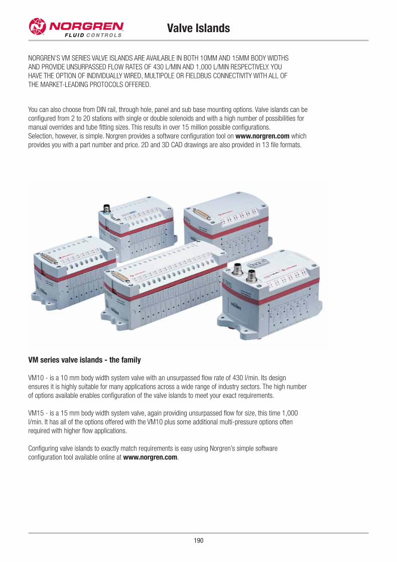
190
Valve Islands
NORGREN’S VM SERIES VALVE ISLANDS ARE AVAILABLE IN BOTH 10MM AND 15MM BODY WIDTHS
AND PROVIDE UNSURPASSED FLOW RATES OF 430 L/MIN AND 1,000 L/MIN RESPECTIVELY. YOU
HAVE THE OPTION OF INDIVIDUALLY WIRED, MULTIPOLE OR FIELDBUS CONNECTIVITY WITH ALL OF
THE MARKET-LEADING PROTOCOLS OFFERED.
You can also choose from DIN rail, through hole, panel and sub base mounting options. Valve islands can be
configured from 2 to 20 stations with single or double solenoids and with a high number of possibilities for
manual overrides and tube fitting sizes. This results in over 15 million possible configurations.
Selection, however, is simple. Norgren provides a software configuration tool on www.norgren.com which
provides you with a part number and price. 2D and 3D CAD drawings are also provided in 13 file formats.
VM series valve islands - the family
VM10 - is a 10 mm body width system valve with an unsurpassed flow rate of 430 l/min. Its design
ensures it is highly suitable for many applications across a wide range of industry sectors. The high number
of options available enables configuration of the valve islands to meet your exact requirements.
VM15 - is a 15 mm body width system valve, again providing unsurpassed flow for size, this time 1,000
l/min. It has all of the options offered with the VM10 plus some additional multi-pressure options often
required with higher flow applications.
Configuring valve islands to exactly match requirements is easy using Norgren’s simple software
configuration tool available online at www.norgren.com.
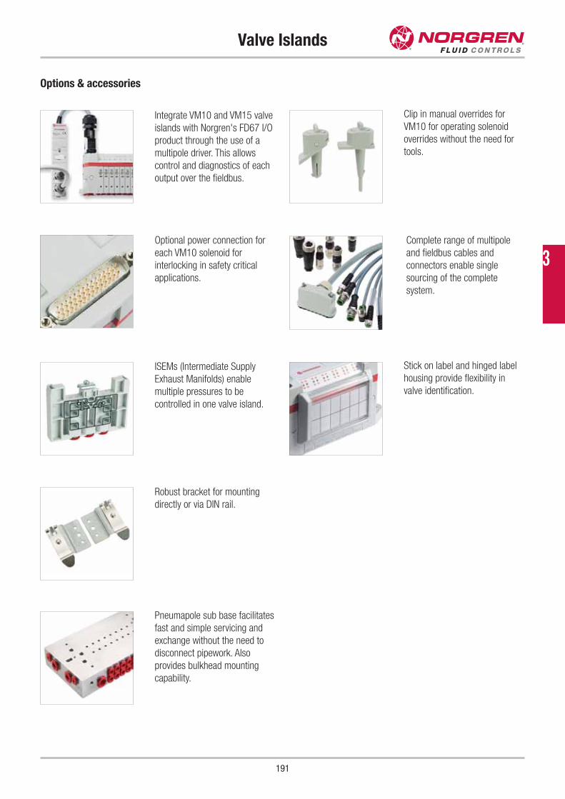
191
Valve Islands
Optional power connection for
each VM10 solenoid for
interlocking in safety critical
applications.
ISEMs (Intermediate Supply
Exhaust Manifolds) enable
multiple pressures to be
controlled in one valve island.
Robust bracket for mounting
directly or via DIN rail.
Clip in manual overrides for
VM10 for operating solenoid
overrides without the need for
tools.
Complete range of multipole
and fieldbus cables and
connectors enable single
sourcing of the complete
system.
Stick on label and hinged label
housing provide flexibility in
valve identification.
Integrate VM10 and VM15 valve
islands with Norgren's FD67 I/O
product through the use of a
multipole driver. This allows
control and diagnostics of each
output over the fieldbus.
Pneumapole sub base facilitates
fast and simple servicing and
exchange without the need to
disconnect pipework. Also
provides bulkhead mounting
capability.
Options & accessories
3
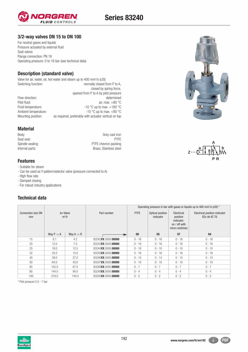
192
Series 83240
3/2-way valves DN 15 to DN 100For neutral gases and liquids
Pressure actuated by external fluid
Seat valves
Flange connection: PN 16
Operating pressure: 0 to 16 bar (see technical data)
Description (standard valve)Valve for air, water, oil, hot water and steam up to 400 mm2/s (cSt)
Switching function: normally closed from P to A,
closed by spring force,
opened from P to A by pilot pressure
Flow direction: determined
Pilot fluid: air, max. +80 °C
Fluid temperature: -10 °C up to max. +180 °C
Ambient temperature: -10 °C up to max. +80 °C
Mounting position: as required, preferably with actuator vertical on top
MaterialBody: Grey cast iron
Seat seal: PTFE
Spindle sealing: PTFE chevron packing
Internal parts: Brass, Stainless steel
Features- Suitable for steam
- Can be used as Y-pattern/selector valve (pressure connected to A)
- High flow rate
- Damped closing
- For robust industry applications
Technical data
aZ
P R
Ab
a b
Operating pressure in bar with gases or liquids up to 400 mm2/s (cSt) *
Connection size DN
mm
kv-Value
m3/h
Part number PTFE Optical position
indicator
Electrical
position
indicator:
on / off with
micro switches
Electrical position indicator
EEx de IIC T6
Way P -> A Way A -> R 00 55 57 64
15 6.1 4.2 83242XX.0000.00000 0 - 16 0 - 16 0 - 16 0 - 16
20 12.0 7.0 83243XX.0000.00000 0 - 16 0 - 16 0 - 16 0 - 16
25 19.0 12.5 83244XX.0000.00000 0 - 10 0 - 10 0 - 10 0 - 10
32 25.0 15.0 83245XX.0000.00000 0 - 16 0 - 16 0 - 16 0 - 16
40 39.0 27.0 83246XX.0000.00000 0 - 14 0 - 14 0 - 14 0 - 14
50 64.0 43.0 83247XX.0000.00000 0 - 10 0 - 10 0 - 10 0 - 10
65 102.0 67.0 83248XX.0000.00000 0 - 7 0 - 7 0 - 7 0 - 7
80 144.0 94.0 83249XX.0000.00000 0 - 4 0 - 4 0 - 4 0 - 4
100 219.0 144.0 83250XX.0000.00000 0 - 2 0 - 2 0 - 2 0 - 2
* Pilot pressure 5.5 - 7 bar
www.norgren.com/fc/en192
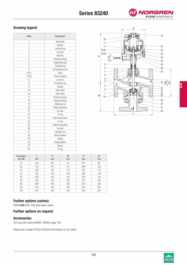
193
Series 83240
Drawing legend
Index Description
1 Valve body
2 Spindle
3 Locking ring
4 Flat seal
5 Bushing
6 Pressure spring
7 Supporting ring
8 Packing ring
9 Compression ring
10.01 Cover
10.02 Piston bushing
11 Lock nut
12 Protective cap
14 Gasket
15 Valve plate
16 Valve plate
17 Pressure spring
18 Pressure spring
19 Retaining nut
20 Piston assembly
21 Lip seal
22 O-ring
23 Allen head screw
24 O-ring
25 Bottom assembly
26 Lip seal
27 Hexagon nut
28 Spring washer
29 Flange
30 Flange gasket
33 Sleeve
35 O-ring
Further options (valves)XXXXXX53.XXXX Pilot fluid water valves
Further options on request
Accessories3/2-way pilot valves 84660 / 84680, page 148
Please turn to page 276 for technical information on our valves.
Connection
size DN
L
mm
B
mm
M
mm
H
mm
øF
mm
15 130 96 97 201 95
20 150 96 110 206 105
25 160 96 116 207 115
32 180 164 140 295 140
40 200 164 145 303 150
50 230 164 156 312 165
65 290 164 182 319 185
80 310 164 188 331 200
100 350 164 229 344 220
P
RA
Z
18
17
11
9
8
7
6
54
3
2
1
12
21
20
22
24
23
25
26
33
27
28
29
30
16
15
10.01
10.02
16
19
14
35
G 1/
4H
DN Ø F
M
L
B
3
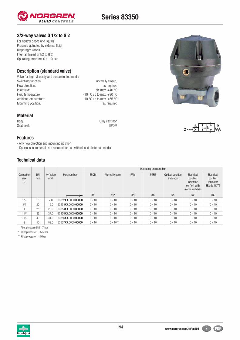
194
Series 83350
2/2-way valves G 1/2 to G 2For neutral gases and liquids
Pressure actuated by external fluid
Diaphragm valves
Internal thread G 1/2 to G 2
Operating pressure: 0 to 10 bar
Description (standard valve)Valve for high-viscosity and contaminated media
Switching function: normally closed,
Flow direction: as required
Pilot fluid: air, max. +40 °C
Fluid temperature: -10 °C up to max. +80 °C
Ambient temperature: -10 °C up to max. +55 °C
Mounting position: as required
MaterialBody: Grey cast iron
Seat seal: EPDM
Features- Any flow direction and mounting position
- Special seal materials are required for use with oil and oleiferous media
Technical data
aZ
ba b
Operating pressure bar
Connection
size
G
DN
mm
kv-Value
m3/h
Part number EPDM Normally open FPM PTFE Optical position
indicator
Electrical
position
indicator:
on / off with
micro switches
Electrical
position
indicator
EEx de IIC T6
00 01* 03 06 55 57 64
1/2 15 7.0 83352XX.0000.00000 0 - 10 0 - 10 0 - 10 0 - 10 0 - 10 0 - 10 0 - 10
3/4 20 15.0 83353XX.0000.00000 0 - 10 0 - 10 0 - 10 0 - 10 0 - 10 0 - 10 0 - 10
1 25 20.0 83354XX.0000.00000 0 - 10 0 - 10 0 - 10 0 - 10 0 - 10 0 - 10 0 - 10
1 1/4 32 37.0 83355XX.0000.00000 0 - 10 0 - 10 0 - 10 0 - 10 0 - 10 0 - 10 0 - 10
1 1/2 40 41.0 83356XX.0000.00000 0 - 10 0 - 10 0 - 10 0 - 10 0 - 10 0 - 10 0 - 10
2 50 82.0 83357XX.0000.00000 0 - 10 0 - 10** 0 - 10 0 - 10 0 - 10 0 - 10 0 - 10
Pilot pressure 5.5 - 7 bar
* Pilot pressure 1 - 5.5 bar
** Pilot pressure 1 - 5 bar
www.norgren.com/fc/en194
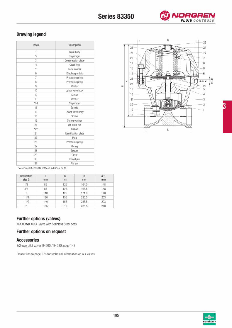
195
Series 83350
Drawing legend
Index Description
1 Valve body
*2 Diaphragm
3 Compression piece
*4 Quad ring
*5 Lock washer
6 Diaphragm disk
7 Pressure spring
8 Pressure spring
9 Washer
10 Upper valve body
12 Screw
13 Washer
*14 Diaphragm
15 Spindle
16 Lower valve body
18 Screw
19 Spring washer
21 Uni-stop-nut
*22 Gasket
24 Identification plate
25 Plug
26 Pressure spring
27 O-ring
28 Spacer
29 Cover
30 Dowel pin
31 Plunger
* A service kit consists of these individual parts.
Further options (valves)XXXXXX50.XXXX Valve with Stainless Steel body
Further options on request
Accessories3/2-way pilot valves 84660 / 84680, page 148
Please turn to page 276 for technical information on our valves.
Connection
size G
L
mm
B
mm
H
mm
øH1
mm
1/2 85 125 164.0 148
3/4 85 125 168.5 148
1 110 125 171.0 148
1 1/4 120 155 230.5 203
1 1/2 140 155 235.5 203
2 165 210 285.5 248
Z
25
24
10
8
7
9
6
5
4
3
2
1
26
29
12
13
21
14
27
28
15
16
30
31
19
18
22
H1
H
L
G 1/4
B
3
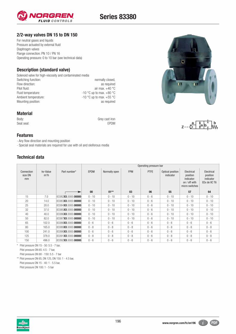
196
Series 83380
2/2-way valves DN 15 to DN 150For neutral gases and liquids
Pressure actuated by external fluid
Diaphragm valves
Flange connection: PN 10 / PN 16
Operating pressure: 0 to 10 bar (see technical data)
Description (standard valve)Solenoid valve for high-viscosity and contaminated media
Switching function: normally closed,
Flow direction: as required
Pilot fluid: air max. +40 °C
Fluid temperature: -10 °C up to max. +80 °C
Ambient temperature: -10 °C up to max. +55 °C
Mounting position: as required
MaterialBody: Grey cast iron
Seat seal: EPDM
Features- Any flow direction and mounting position
- Special seal materials are required for use with oil and oleiferous media
Technical data
aZ
ba b
Operating pressure bar
Connection
size DN
mm
kv-Value
m3/h
Part number* EPDM Normally open FPM PTFE Optical position
indicator
Electrical
position
indicator:
on / off with
micro switches
Electrical
position
indicator
EEx de IIC T6
00 01** 03 06 55 57 64
15 7.0 83382XX.0000.00000 0 - 10 0 - 10 0 - 10 0 - 6 0 - 10 0 - 10 0 - 10
20 14.0 83383XX.0000.00000 0 - 10 0 - 10 0 - 10 0 - 6 0 - 10 0 - 10 0 - 10
25 20.0 83384XX.0000.00000 0 - 10 0 - 10 0 - 10 0 - 6 0 - 10 0 - 10 0 - 10
32 37.0 83385XX.0000.00000 0 - 10 0 - 10 0 - 10 0 - 6 0 - 10 0 - 10 0 - 10
40 40.0 83386XX.0000.00000 0 - 10 0 - 10 0 - 10 0 - 6 0 - 10 0 - 10 0 - 10
50 82.0 83387XX.0000.00000 0 - 10 0 - 10 0 - 10 0 - 6 0 - 10 0 - 10 0 - 10
65 102.0 83388XX.0000.00000 0 - 6 0 - 6 0 - 6 0 - 6 0 - 6 0 - 6 0 - 6
80 165.0 83389XX.0000.00000 0 - 8 0 - 8 0 - 8 0 - 6 0 - 8 0 - 8 0 - 8
100 241.0 83390XX.0000.00000 0 - 6 0 - 6 0 - 6 0 - 6 0 - 6 0 - 6 0 - 6
125 378.0 83391XX.0000.00000 0 - 8 0 - 8 0 - 8 0 - 6 0 - 8 0 - 8 0 - 8
150 496.0 83392XX.0000.00000 0 - 6 0 - 6 0 - 6 0 - 6 0 - 6 0 - 6 0 - 6
* Pilot pressure DN 15 - 50: 5.5 - 7 bar,
Pilot pressure DN 65: 4.5 - 7 bar,
Pilot pressure DN 80 - 150: 5.5 - 7 bar
** Pilot pressure DN 65, DN 125, DN 150: 1 - 4.5 bar,
Pilot pressure DN 15 - 40: 1 - 5.5 bar,
Pilot pressure DN 100: 1 - 5 bar
www.norgren.com/fc/en196
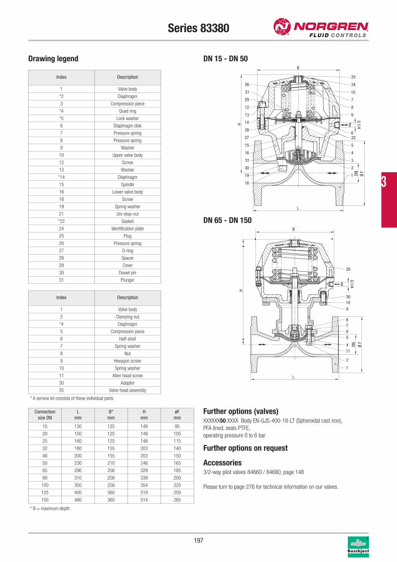
197
Series 83380
Drawing legend DN 15 - DN 50
DN 65 - DN 150
Index Description
1 Valve body
2 Clamping nut
*4 Diaphragm
5 Compression piece
6 Half-shell
7 Spring washer
8 Nut
9 Hexagon screw
10 Spring washer
11 Allen head screw
30 Adapter
35 Valve head assembly
* A service kit consists of these individual parts.
* B = maximum depth
Connection
size DN
L
mm
B*
mm
H
mm
øF
mm
15 130 125 148 95
20 150 125 148 105
25 160 125 148 115
32 180 155 203 140
40 200 155 203 150
50 230 210 248 165
65 290 256 329 185
80 310 256 339 200
100 350 256 354 220
125 400 360 519 250
150 480 360 514 285
Further options (valves)XXXXXX50.XXXX Body EN-GJS-400-18-LT (Spheroidal cast iron),
PFA lined, seals PTFE,
operating pressure 0 to 6 bar
Further options on request
Accessories3/2-way pilot valves 84660 / 84680, page 148
Please turn to page 276 for technical information on our valves.
Index Description
1 Valve body
*2 Diaphragm
3 Compression piece
*4 Quad ring
*5 Lock washer
6 Diaphragm disk
7 Pressure spring
8 Pressure spring
9 Washer
10 Upper valve body
12 Screw
13 Washer
*14 Diaphragm
15 Spindle
16 Lower valve body
18 Screw
19 Spring washer
21 Uni-stop-nut
*22 Gasket
24 Identification plate
25 Plug
26 Pressure spring
27 O-ring
28 Spacer
29 Cover
30 Dowel pin
31 Plunger
Z
25
24
10
8
7
9
6
5
4
3
2
1
26
29
12
13
21
14
27
28
15
16
30
31
19
18
22
L
DN Ø F
H
G 1/4
B
Z
10
9
8765
114
1
2
30
35
L
DN Ø F
H
B
G 1/4
3
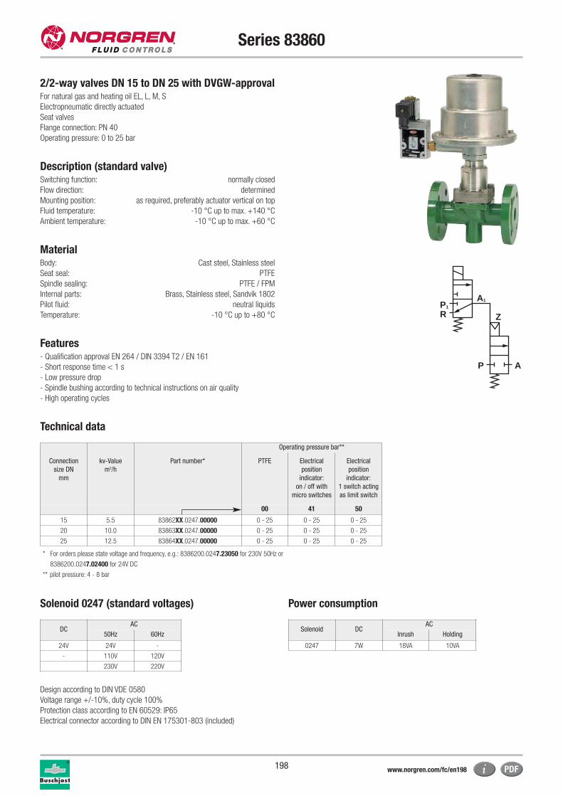
198
Series 83860
For natural gas and heating oil EL, L, M, S
Electropneumatic directly actuated
Seat valves
Flange connection: PN 40
Operating pressure: 0 to 25 bar
Description (standard valve)Switching function: normally closed
Flow direction: determined
Mounting position: as required, preferably actuator vertical on top
Fluid temperature: -10 °C up to max. +140 °C
Ambient temperature: -10 °C up to max. +60 °C
MaterialBody: Cast steel, Stainless steel
Seat seal: PTFE
Spindle sealing: PTFE / FPM
Internal parts: Brass, Stainless steel, Sandvik 1802
Pilot fluid: neutral liquids
Temperature: -10 °C up to +80 °C
Features- Qualification approval EN 264 / DIN 3394 T2 / EN 161
- Short response time < 1 s
- Low pressure drop
- Spindle bushing according to technical instructions on air quality
- High operating cycles
Technical data
P1
P A
R
A1
Z
Operating pressure bar**
Connection
size DN
mm
kv-Value
m3/h
Part number* PTFE Electrical
position
indicator:
on / off with
micro switches
Electrical
position
indicator:
1 switch acting
as limit switch
00 41 50
15 5.5 83862XX.0247.00000 0 - 25 0 - 25 0 - 25
20 10.0 83863XX.0247.00000 0 - 25 0 - 25 0 - 25
25 12.5 83864XX.0247.00000 0 - 25 0 - 25 0 - 25
* For orders please state voltage and frequency, e.g.: 8386200.0247.23050 for 230V 50Hz or
8386200.0247.02400 for 24V DC
** pilot pressure: 4 - 8 bar
Solenoid 0247 (standard voltages) Power consumption
Design according to DIN VDE 0580
Voltage range +/-10%, duty cycle 100%
Protection class according to EN 60529: IP65
Electrical connector according to DIN EN 175301-803 (included)
Solenoid DCAC
Inrush Holding
0247 7W 18VA 10VA
DCAC
50Hz 60Hz
24V 24V -
- 110V 120V
230V 220V
2/2-way valves DN 15 to DN 25 with DVGW-approval
www.norgren.com/fc/en198
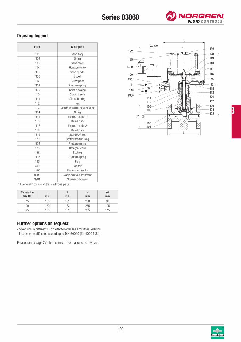
199
Series 83860
Drawing legend
Index Description
101 Valve body
*102 O-ring
103 Valve cover
104 Hexagon screw
*105 Valve spindle
*106 Gasket
107 Screw piece
*108 Pressure spring
*109 Spindle sealing
110 Spacer sleeve
*111 Sleeve bearing
112 Nut
113 Bottom of control head housing
*114 O-ring
*115 Lip seal: profile 1
116 Round plate
*117 Lip seal: profile 2
118 Round plate
*119 Seal-Lock® nut
120 Control head housing
*122 Pressure spring
123 Hexagon screw
126 Bushing
*135 Pressure spring
136 Plug
400 Solenoid
1400 Electrical connector
9900 Double screwed connection
9901 3/2-way pilot valve
* A service kit consists of these individual parts.
Further options on request- Solenoids in different EEx protection classes and other versions
- Inspection certificates according to DIN 50049 (EN 10204-3.1)
Please turn to page 276 for technical information on our valves.
Connection
size DN
L
mm
B
mm
H
mm
øF
mm
15 130 163 250 96
20 150 163 265 105
25 160 163 265 115
P A
P
RA Z
136
135
122120119
117
1181400
400 116
126
123115112
114
113
111
9901
9900
110
105
109
107
108 104
101103
106
102
DN ØF
H
ca. 180
B
L
3
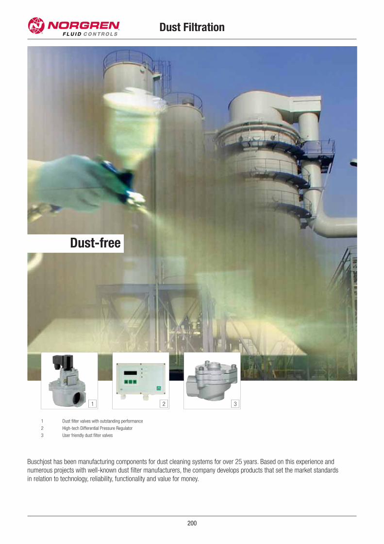
200
Dust Filtration
Buschjost has been manufacturing components for dust cleaning systems for over 25 years. Based on this experience and
numerous projects with well-known dust filter manufacturers, the company develops products that set the market standards
in relation to technology, reliability, functionality and value for money.
1 Dust filter valves with outstanding performance
2 High-tech Differential Pressure Regulator
3 User friendly dust filter valves
1 2 3
Dust-free
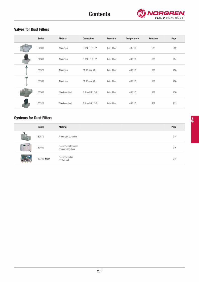
Contents
201
Series Material Connection Pressure Temperature Function Page
82900 Aluminium G 3/4 - G 2 1/2 0.4 - 8 bar +85 °C 2/2 202
82960 Aluminium G 3/4 - G 2 1/2 0.4 - 8 bar +85 °C 2/2 204
83920 Aluminium DN 25 and 40 0.4 - 8 bar +85 °C 2/2 206
83930 Aluminium DN 25 and 40 0.4 - 8 bar +85 °C 2/2 208
83300 Stainless steel G 1 and G 1 1/2 0.4 - 8 bar +85 °C 2/2 210
83320 Stainless steel G 1 and G 1 1/2 0.4 - 8 bar +85 °C 2/2 212
Valves for Dust Filters
Series Material Page
82870 Pneumatic controller 214
83400Electronic differential
pressure regulator216
83750 NEWElectronic pulse
control unit218
Systems for Dust Filters 4
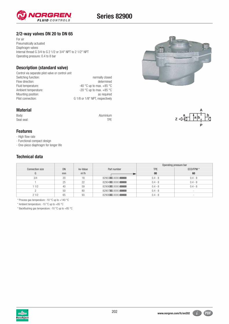
202
Series 82900
2/2-way valves DN 20 to DN 65For air
Pneumatically actuated
Diaphragm valves
Internal thread G 3/4 to G 2 1/2 or 3/4" NPT to 2 1/2" NPT
Operating pressure: 0.4 to 8 bar
Description (standard valve)Control via separate pilot valve or control unit
Switching function: normally closed
Flow direction: determined
Fluid temperature: -40 °C up to max. +85 °C
Ambient temperature: -20 °C up to max. +85 °C
Mounting position: as required
Pilot connection: G 1/8 or 1/8" NPT, respectively
MaterialBody: Aluminium
Seat seal: TPE
Features- High flow rate
- Functional compact design
- One-piece diaphragm for longer life
Technical data
a
P
Z
Ab
a b
Operating pressure bar
Connection size DN kv-Value Part number TPE ECO/FPM *
G mm m3/h 00 60
3/4 20 18 82903XX.0000.00000 0.4 - 8 0.4 - 8
1 25 22 82904XX.0000.00000 0.4 - 8 0.4 - 8
1 1/2 40 59 82906XX.0000.00000 0.4 - 8 0.4 - 8
2 50 80 82907XX.0000.00000 0.4 - 8 -
2 1/2 65 93 82908XX.0000.00000 0.4 - 8 -
* Process gas temperature: -10 °C up to +140 °C
* Ambient temperature: -10 °C up to +85 °C
* Backflushing gas temperature: -10 °C up to +85 °C
www.norgren.com/fc/en202
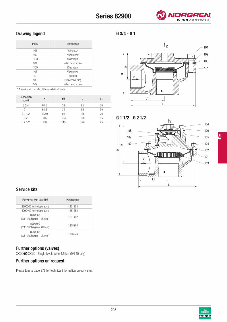
203
Series 82900
Drawing legend
G 1 1/2 - G 2 1/2
G 3/4 - G 1
Index Description
101 Valve body
102 Valve cover
*103 Diaphragm
104 Allen head screw
*105 Diaphragm
106 Valve cover
*107 Silencer
108 Silencer housing
109 Allen head screw
* A service kit consists of these individual parts.
Service kits
For valves with seal TPE Part number
8290300 (only diaphragm) 1261253
8290400 (only diaphragm) 1261253
8290600
(both diaphragm + silencer)1261402
8290700
(both diaphragm + silencer)1268274
8290800
(both diaphragm + silencer)1268274
Further options (valves)XXXXX90.XXXX Single-level; up to 4.5 bar (DN 40 only)
Further options on request
Please turn to page 276 for technical information on our valves.
P
A
Z
102
104
101
103
105
106
104
108
107
109
H
L1
L
H1
P
A
Z 104
102
103
101
L
L1
HH1
Connection
size GH H1 L L1
G 3/4 61.5 39 95 50
G 1 61.5 39 95 50
G 1 1/2 122.0 91 135 70
G 2 145 104 170 95
G 2 1/2 160 115 170 95
4

204
Series 82960
2/2-way valves DN 20 to DN 65For air
Indirectly solenoid actuated
Diaphragm valves
Internal thread G 3/4 to G 2 1/2 or 3/4" NPT to 2 1/2" NPT
Operating pressure: 0.4 to 8 bar
Description (standard valve)Switching function: normally closed
Flow direction: determined
Fluid temperature: -40 °C up to max. +85 °C
Ambient temperature: -20 °C up to max. +85 °C
Mounting position: as required, preferably with solenoid
vertical on top
MaterialBody: Aluminium
Seat seal: TPE
Internal parts: TPU
Features- High flow rate
- All internal components captive
- Functional compact design
- Solenoid interchangeable without tools
- Integrated silencer
- One-piece diaphragm for longer life
Technical data
a
P
Ab
a b
Operating pressure bar
Connection size DN kv-Value Part number* TPE ECO/FPM **
G mm m3/h 00 60
3/4 20 18 82963XX.8171.00000 0.4 - 8 0.4 - 8
1 25 22 82964XX.8171.00000 0.4 - 8 0.4 - 8
1 1/2 40 59 82966XX.8171.00000 0.4 - 8 0.4 - 8
2 50 80 82967XX.8171.00000 0.4 - 8 -
2 1/2 65 93 82968XX.8171.00000 0.4 - 8 -
Solenoid 8171 (standard voltages) Power consumption
Design according to DIN VDE 0580
Voltage range +/-10%, duty cycle 100%
Protection class according to EN 60529: IP65
Electrical connector according to DIN EN 175301-803 (included)
The solenoids are UL listed and CSA approved
Solenoid DCAC
Inrush Holding
8171 12W - -
8171 - 23VA 16VA
DCAC
50Hz 60Hz
24V 24V -
- 110V 120V
230V 220V
* For orders please state voltage and frequency, e.g.: 8296400.8171.23050 for 230V 50Hz or 8296400.8171.02400 for 24V DC
** Process gas temperatur: -10 °C up to +140 °C
Ambient temperature: -10 °C up to +85 °C
Backflushing gas temperature: -10 °C up to +85 °C
www.norgren.com/fc/en204
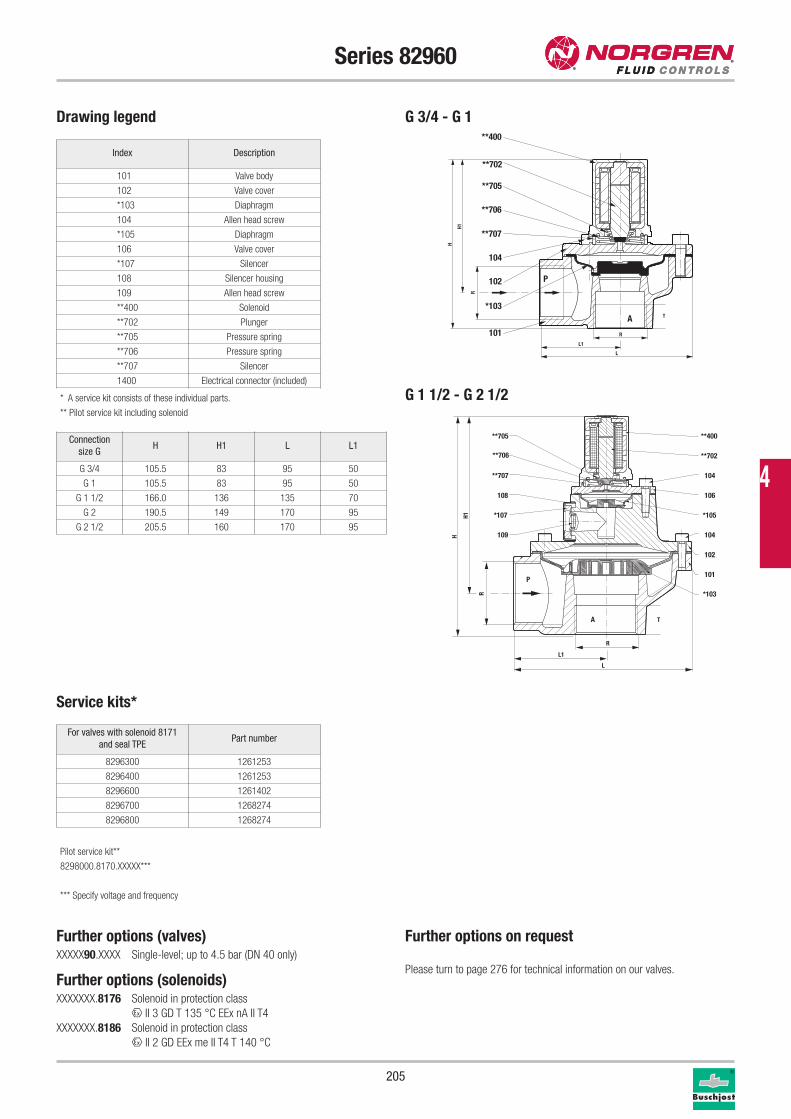
205
Series 82960
Drawing legend
Index Description
101 Valve body
102 Valve cover
*103 Diaphragm
104 Allen head screw
*105 Diaphragm
106 Valve cover
*107 Silencer
108 Silencer housing
109 Allen head screw
**400 Solenoid
**702 Plunger
**705 Pressure spring
**706 Pressure spring
**707 Silencer
1400 Electrical connector (included)
* A service kit consists of these individual parts.
** Pilot service kit including solenoid
Service kits*
For valves with solenoid 8171
and seal TPEPart number
8296300 1261253
8296400 1261253
8296600 1261402
8296700 1268274
8296800 1268274
A
P
104
**707
**400
**702
**705
**706
102
*103
101
L
H
H1
R
T
L1
R
Further options (valves)XXXXX90.XXXX Single-level; up to 4.5 bar (DN 40 only)
Further options (solenoids)XXXXXXX.8176 Solenoid in protection class
x II 3 GD T 135 °C EEx nA II T4
XXXXXXX.8186 Solenoid in protection class
x II 2 GD EEx me II T4 T 140 °C
Further options on request
Please turn to page 276 for technical information on our valves.
Connection
size GH H1 L L1
G 3/4 105.5 83 95 50
G 1 105.5 83 95 50
G 1 1/2 166.0 136 135 70
G 2 190.5 149 170 95
G 2 1/2 205.5 160 170 95
G 1 1/2 - G 2 1/2
G 3/4 - G 1
102
104
101
*105
106
104
108
*107
109
**705
**706
**707
**702
**400
P
A
*103
L
H
H1
R
T
L1
R
Pilot service kit**
8298000.8170.XXXXX***
*** Specify voltage and frequency
4
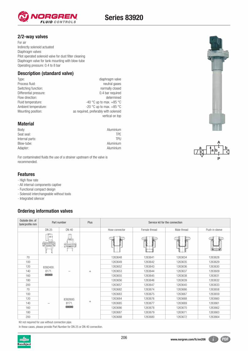
206
Series 83920
2/2-way valvesFor air
Indirectly solenoid actuated
Diaphragm valves
Pilot operated solenoid valve for dust filter cleaning
Diaphragm valve for tank mounting with blow-tube
Operating pressure: 0.4 to 8 bar
Description (standard valve)Type: diaphragm valve
Process fluid: neutral gases
Switching function: normally closed
Differential pressure: 0.4 bar required
Flow direction: determined
Fluid temperature: -40 °C up to max. +85 °C
Ambient temperature: -20 °C up to max. +85 °C
Mounting position: as required, preferably with solenoid
vertical on top
MaterialBody: Aluminium
Seat seal: TPE
Internal parts: TPU
Blow-tube: Aluminium
Adapter: Aluminium
For contaminated fluids the use of a strainer upstream of the valve is
recommended.
Features- High flow rate
- All internal components captive
- Functional compact design
- Solenoid interchangeable without tools
- Integrated silencer
Ordering information valves
a
P
Ab
a b
Outside dim. of
tank/profile mmPart number Plus Service kit for the connection
DN 25 DN 40 Hose connector Female thread Male thread Push-in sleeve
70
8392400.
8171.
00000– +
1263648 1263641 1263634 1263628
100 1263649 1263642 1263635 1263629
120 1263652 1263643 1263636 1263630
140 1263653 1263644 1263637 1263609
160 1263655 1263645 1263638 1263631
180 1263656 1263646 1263639 1263632
200 1263657 1263647 1263640 1263633
70
–8392600.
8171.
00000
+
1263682 1263674 1263666 1263658
100 1263683 1263675 1263667 1263659
120 1263684 1263676 1263668 1263660
140 1263685 1263677 1263669 1263661
160 1263686 1263678 1263670 1263662
180 1263687 1263679 1263671 1263663
200 1263688 1263680 1263672 1263664
Kit not required for use without connection pipe.
In these cases, please provide Part Number for DN 25 or DN 40 connection.
www.norgren.com/fc/en206
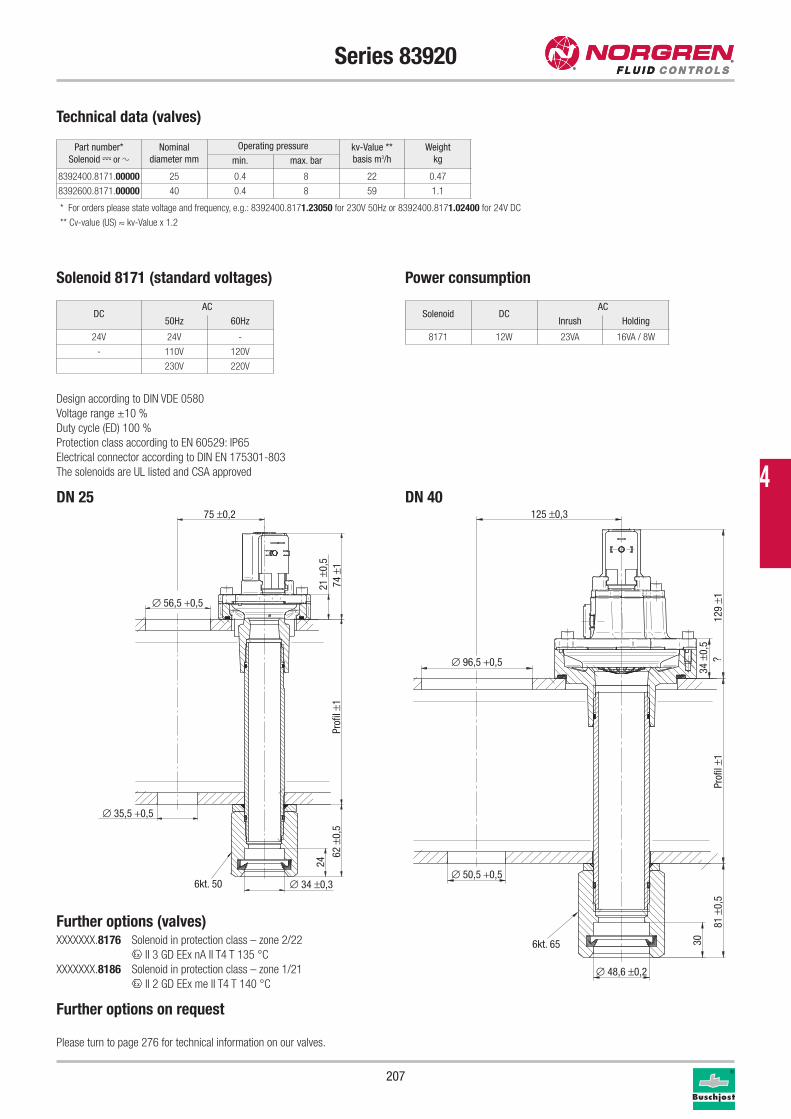
207
Series 83920
Further options (valves)XXXXXXX.8176 Solenoid in protection class – zone 2/22
x II 3 GD EEx nA II T4 T 135 °C
XXXXXXX.8186 Solenoid in protection class – zone 1/21
x II 2 GD EEx me II T4 T 140 °C
Further options on request
Please turn to page 276 for technical information on our valves.
Part number*
Solenoid 1 or 2Nominal
diameter mm
Operating pressure kv-Value **
basis m3/h
Weight
kgmin. max. bar
8392400.8171.00000 25 0.4 8 22 0.47
8392600.8171.00000 40 0.4 8 59 1.1
* For orders please state voltage and frequency, e.g.: 8392400.8171.23050 for 230V 50Hz or 8392400.8171.02400 for 24V DC
** Cv-value (US) ≈ kv-Value x 1.2
Technical data (valves)
Solenoid 8171 (standard voltages) Power consumption
Design according to DIN VDE 0580
Voltage range ±10 %
Duty cycle (ED) 100 %
Protection class according to EN 60529: IP65
Electrical connector according to DIN EN 175301-803
The solenoids are UL listed and CSA approved
Solenoid DCAC
Inrush Holding
8171 12W 23VA 16VA / 8W
DCAC
50Hz 60Hz
24V 24V -
- 110V 120V
230V 220V
∅ 56,5 +0,5
75 ±0,2
∅ 35,5 +0,5
Prof
il ±1
62 ±
0,5
24
∅ 34 ±0,36kt. 50
21 ±
0,5
74 ±
1
DN 25
?
6kt. 65
∅ 50,5 +0,5
∅ 96,5 +0,5
125 ±0,3
129
±1Pr
ofil
±1
∅ 48,6 ±0,2
30
81 ±
0,5
34 ±
0,5
DN 404
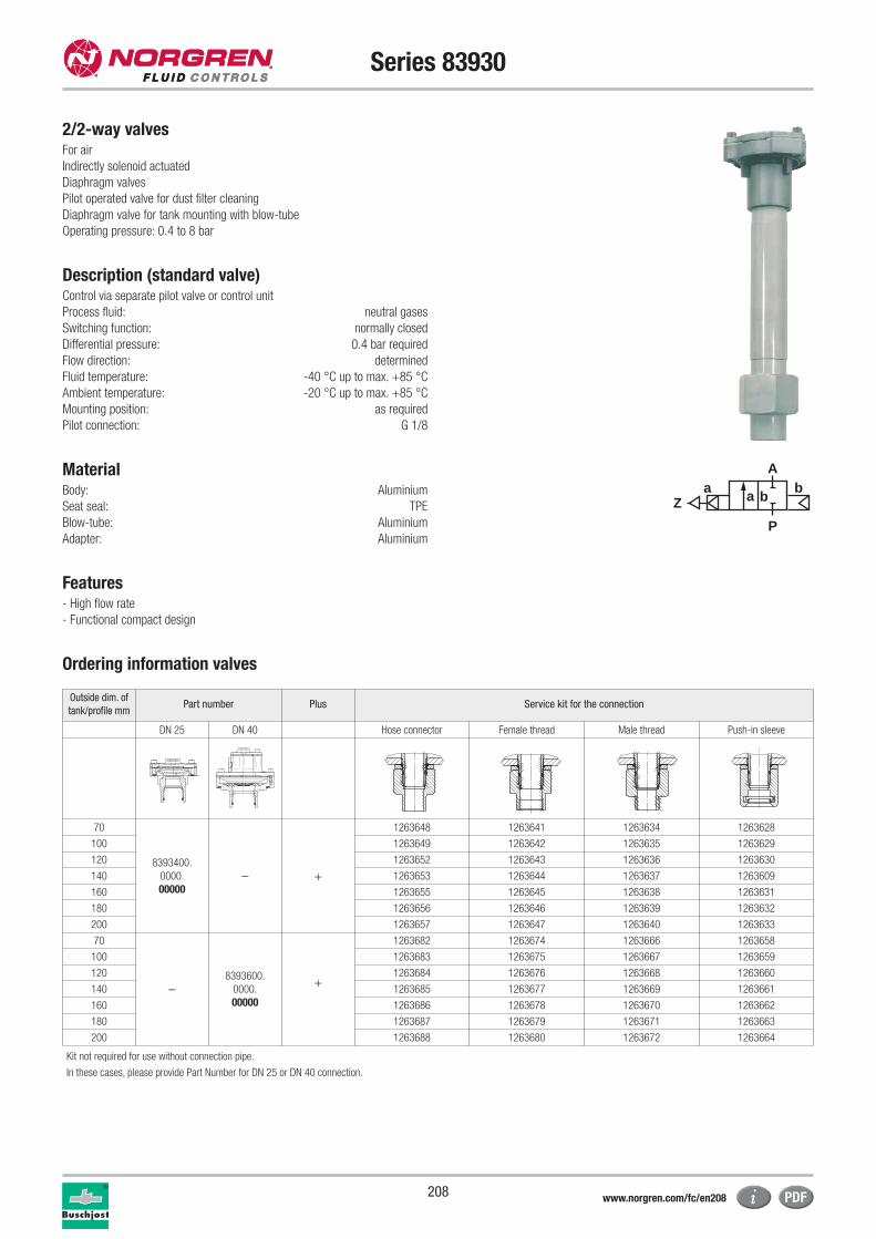
208
Series 83930
2/2-way valvesFor air
Indirectly solenoid actuated
Diaphragm valves
Pilot operated valve for dust filter cleaning
Diaphragm valve for tank mounting with blow-tube
Operating pressure: 0.4 to 8 bar
Description (standard valve)Control via separate pilot valve or control unit
Process fluid: neutral gases
Switching function: normally closed
Differential pressure: 0.4 bar required
Flow direction: determined
Fluid temperature: -40 °C up to max. +85 °C
Ambient temperature: -20 °C up to max. +85 °C
Mounting position: as required
Pilot connection: G 1/8
MaterialBody: Aluminium
Seat seal: TPE
Blow-tube: Aluminium
Adapter: Aluminium
Features- High flow rate
- Functional compact design
Ordering information valves
a
P
Z
Ab
a b
Outside dim. of
tank/profile mmPart number Plus Service kit for the connection
DN 25 DN 40 Hose connector Female thread Male thread Push-in sleeve
70
8393400.
0000.
00000– +
1263648 1263641 1263634 1263628
100 1263649 1263642 1263635 1263629
120 1263652 1263643 1263636 1263630
140 1263653 1263644 1263637 1263609
160 1263655 1263645 1263638 1263631
180 1263656 1263646 1263639 1263632
200 1263657 1263647 1263640 1263633
70
–8393600.
0000.
00000
+
1263682 1263674 1263666 1263658
100 1263683 1263675 1263667 1263659
120 1263684 1263676 1263668 1263660
140 1263685 1263677 1263669 1263661
160 1263686 1263678 1263670 1263662
180 1263687 1263679 1263671 1263663
200 1263688 1263680 1263672 1263664
Kit not required for use without connection pipe.
In these cases, please provide Part Number for DN 25 or DN 40 connection.
www.norgren.com/fc/en208
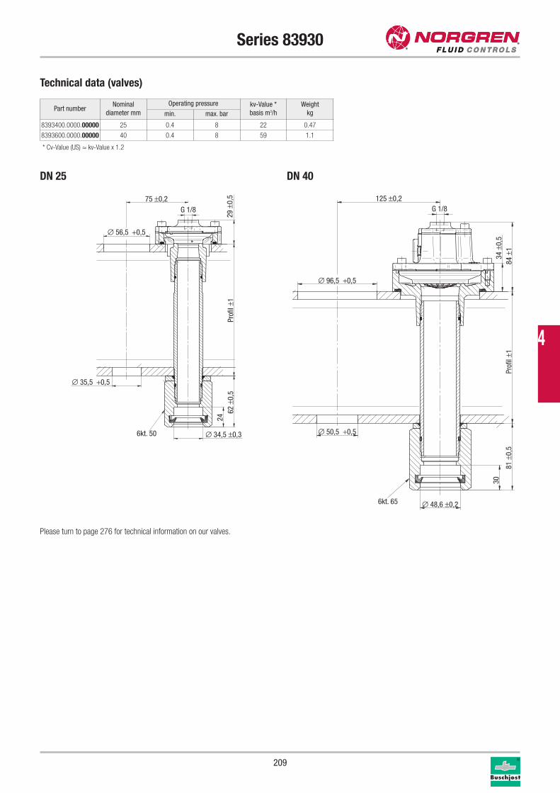
209
Series 83930
Part numberNominal
diameter mm
Operating pressure kv-Value *
basis m3/h
Weight
kgmin. max. bar
8393400.0000.00000 25 0.4 8 22 0.47
8393600.0000.00000 40 0.4 8 59 1.1
* Cv-Value (US) ≈ kv-Value x 1.2
Technical data (valves)
∅ 56,5 +0,5
75 ±0,2
29 ±
0,5
∅ 35,5 +0,5
Prof
il ±1
G 1/8
62 ±
0,5
24
∅ 34,5 ±0,36kt. 50
DN 25
34 ±
0,5
6kt. 65
∅ 50,5 +0,5
∅ 96,5 +0,5
125 ±0,2
Prof
il ±1
G 1/8
84 ±
1∅ 48,6 ±0,2
30
81 ±
0,5
DN 40
Please turn to page 276 for technical information on our valves.
4
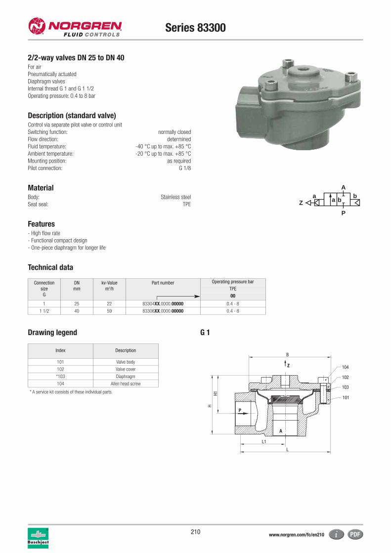
210
Series 83300
2/2-way valves DN 25 to DN 40For air
Pneumatically actuated
Diaphragm valves
Internal thread G 1 and G 1 1/2
Operating pressure: 0.4 to 8 bar
Description (standard valve)Control via separate pilot valve or control unit
Switching function: normally closed
Flow direction: determined
Fluid temperature: -40 °C up to max. +85 °C
Ambient temperature: -20 °C up to max. +85 °C
Mounting position: as required
Pilot connection: G 1/8
MaterialBody: Stainless steel
Seat seal: TPE
Features- High flow rate
- Functional compact design
- One-piece diaphragm for longer life
Technical data
a
P
Z
Ab
a b
Connection
size
G
DN
mm
kv-Value
m3/h
Part number Operating pressure bar
TPE
00
1 25 22 83304XX.0000.00000 0.4 - 8
1 1/2 40 59 83306XX.0000.00000 0.4 - 8
Drawing legend
* A service kit consists of these individual parts.
Index Description
101 Valve body
102 Valve cover
*103 Diaphragm
104 Allen head screw
G 1
P
A
Z 104
102
103
101
L
L1
H1H
B
www.norgren.com/fc/en210
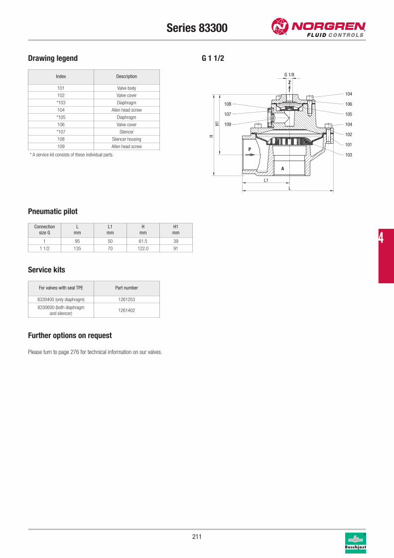
211
P
A
Z
102
104
101
103
105
106
104
108
107
109
L
L1
H1H
G 1/8
Series 83300
Pneumatic pilot
Connection
size G
L
mm
L1
mm
H
mm
H1
mm
1 95 50 61.5 39
1 1/2 135 70 122.0 91
Further options on request
Please turn to page 276 for technical information on our valves.
Service kits
For valves with seal TPE Part number
8330400 (only diaphragm) 1261253
8330600 (both diaphragm
and silencer)1261402
Drawing legend
* A service kit consists of these individual parts.
Index Description
101 Valve body
102 Valve cover
*103 Diaphragm
104 Allen head screw
*105 Diaphragm
106 Valve cover
*107 Silencer
108 Silencer housing
109 Allen head screw
G 1 1/2
4
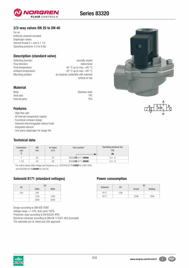
212
Series 83320
2/2-way valves DN 25 to DN 40For air
Indirectly solenoid actuated
Diaphragm valves
Internal thread G 1 and G 1 1/2
Operating pressure: 0.4 to 8 bar
Description (standard valve)Switching function: normally closed
Flow direction: determined
Fluid temperature: -40 °C up to max. +85 °C
Ambient temperature: -20 °C up to max. +85 °C
Mounting position: as required, preferably with solenoid
vertical on top
MaterialBody: Stainless steel
Seat seal: TPE
Internal parts: TPU
Features- High flow rate
- All internal components captive
- Functional compact design
- Solenoid interchangeable without tools
- Integrated silencer
- One-piece diaphragm for longer life
Technical data
a
P
Ab
a b
Connection
size
G
DN
mm
kv-Value
m3/h
Part number* Operating pressure bar
TPE
00
1 25 22 83324XX.8171.00000 0.4 - 8
1 1/2 40 59 83326XX.8171.00000 0.4 - 8
Solenoid 8171 (standard voltages) Power consumption
Design according to DIN VDE 0580
Voltage range +/-10%, duty cycle 100%
Protection class according to EN 60529: IP65
Electrical connector according to DIN EN 175301-803 (included)
The solenoids are UL listed and CSA approved
Solenoid DCAC
Inrush Holding
8171 12W - -
8171 - 23VA 16VA
DCAC
50Hz 60Hz
24V 24V -
- 110V 120V
230V 220V
* For orders please state voltage and frequency, e.g.: 8332400.8171.23050 for 230V 50Hz
and 8332400.8171.02400 for 24V DC
www.norgren.com/fc/en212
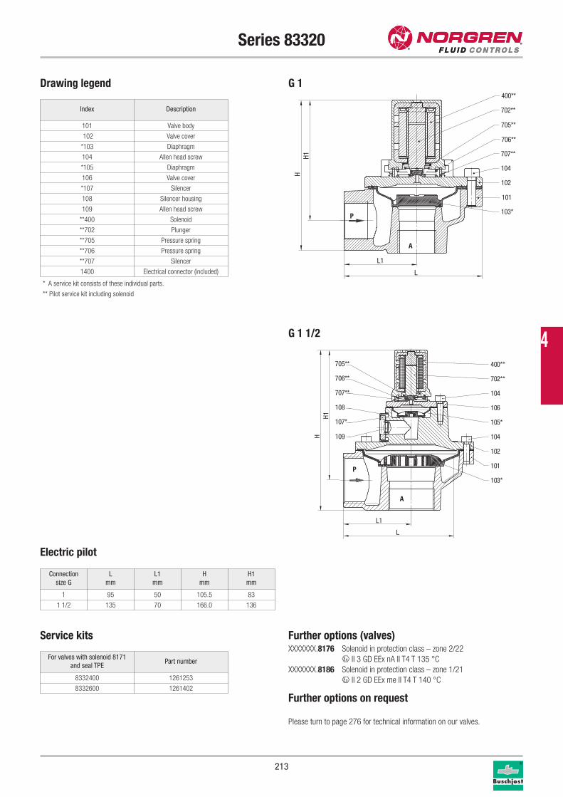
213
Series 83320
Index Description
101 Valve body
102 Valve cover
*103 Diaphragm
104 Allen head screw
*105 Diaphragm
106 Valve cover
*107 Silencer
108 Silencer housing
109 Allen head screw
**400 Solenoid
**702 Plunger
**705 Pressure spring
**706 Pressure spring
**707 Silencer
1400 Electrical connector (included)
Drawing legend
* A service kit consists of these individual parts.
** Pilot service kit including solenoid
Electric pilot
Connection
size G
L
mm
L1
mm
H
mm
H1
mm
1 95 50 105.5 83
1 1/2 135 70 166.0 136
Further options (valves)XXXXXXX.8176 Solenoid in protection class – zone 2/22
x II 3 GD EEx nA II T4 T 135 °C
XXXXXXX.8186 Solenoid in protection class – zone 1/21
x II 2 GD EEx me II T4 T 140 °C
Further options on request
Please turn to page 276 for technical information on our valves.
Service kits
For valves with solenoid 8171
and seal TPEPart number
8332400 1261253
8332600 1261402
P
A
102
104
101
103*
105*
106
104
108
107*
109
705**
706**
707**
702**
400**
L
L1
H1H
G 1
L
L1
H1H
P
A
400**
702**
705**
706**
707**
104
102
101
103*
G 1 1/2 4
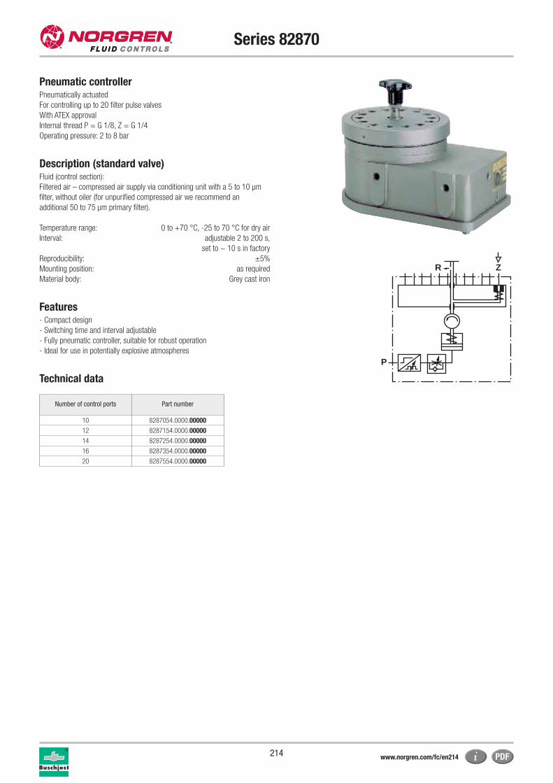
214
Series 82870
Pneumatic controllerPneumatically actuated
For controlling up to 20 filter pulse valves
With ATEX approval
Internal thread P = G 1/8, Z = G 1/4
Operating pressure: 2 to 8 bar
Description (standard valve) Fluid (control section):
Filtered air – compressed air supply via conditioning unit with a 5 to 10 μm
filter, without oiler (for unpurified compressed air we recommend an
additional 50 to 75 μm primary filter).
Temperature range: 0 to +70 °C, -25 to 70 °C for dry air
Interval: adjustable 2 to 200 s,
set to ~ 10 s in factory
Reproducibility: ±5%
Mounting position: as required
Material body: Grey cast iron
Features- Compact design
- Switching time and interval adjustable
- Fully pneumatic controller, suitable for robust operation
- Ideal for use in potentially explosive atmospheres
Technical data
P
ZR
Number of control ports Part number
10 8287054.0000.00000
12 8287154.0000.00000
14 8287254.0000.00000
16 8287354.0000.00000
20 8287554.0000.00000
www.norgren.com/fc/en214
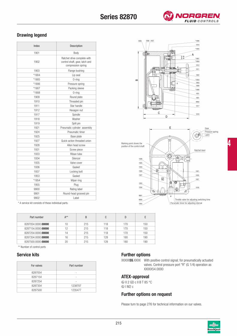
215
Series 82870
Drawing legend
Index Description
1901 Body
1902
Ratchet drive complete with
control shaft, gear, latch and
compression spring
1903 Flange bushing
*1904 Lip seal
*1905 O-ring
*1906 Pressure spring
*1907 Packing sleeve
*1908 O-ring
1909 Round plate
1910 Threaded pin
1911 Star handle
1912 Hexagon nut
1917 Spindle
1918 Washer
1919 Split pin
1921 Pneumatic cylinder assembly
1924 Pneumatic timer
1925 Base plate
1927 Quick-action threaded union
1928 Allen head screw
1931 Screw piece
1933 Rilsan tube
1934 Silencer
1935 Valve cover
1936 Gasket
1937 Locking bolt
1953 Gasket
*1954 Wiper ring
1955 Plug
9900 Rating label
9901 Round-head grooved pin
9902 Label
Service kits
* A service kit consists of these individual parts.
For valves Part number
8287054 -
8287154 -
8287254 -
8287354 1238707
8287500 1235477
Part number A** B C D E
8287054.0000.00000 10 215 118 170 150
8287154.0000.00000 12 215 118 170 150
8287254.0000.00000 14 215 118 170 150
8287354.0000.00000 16 215 128 180 190
8287500.0000.00000 20 215 128 180 190
** Number of control ports
Further optionsXXXXX55.XXXX With positive control signal; for pneumatically actuated
valves. Control pressure port "R" (G 1/4) operation as
XXXXX54.0000
ATEX-approvalx II 2 GD c II B T 85 °C
x I M2 c
Further options on request
Please turn to page 276 for technical information on our valves.
1935
1918
1917
1901
1931
*1908
1909
1903
1902
1911
1912
*1954
*1904
*1907
*1905
1910
*1906
9902
1936 1937
9901
1953
1927
1924
1933
1925
1928
1955
9900
1934 1919
1927
1933
1921
Ratschenhebel
Drossel für Schaltzeiteinstellung
P
Impulsgenerator für Pausenzeiteinstellung
Zahnrad
Druckfeder
Klinke
Z
R
Markierungspunkt zeigtdie Lage der Steuerwelle an
Gear
Pressure spring
Latch
Ratchet lever
Throttle valve for adjusting switching time
Pocumatic timer for adjusting interval
Marking point shows the
position of the control shaft 4
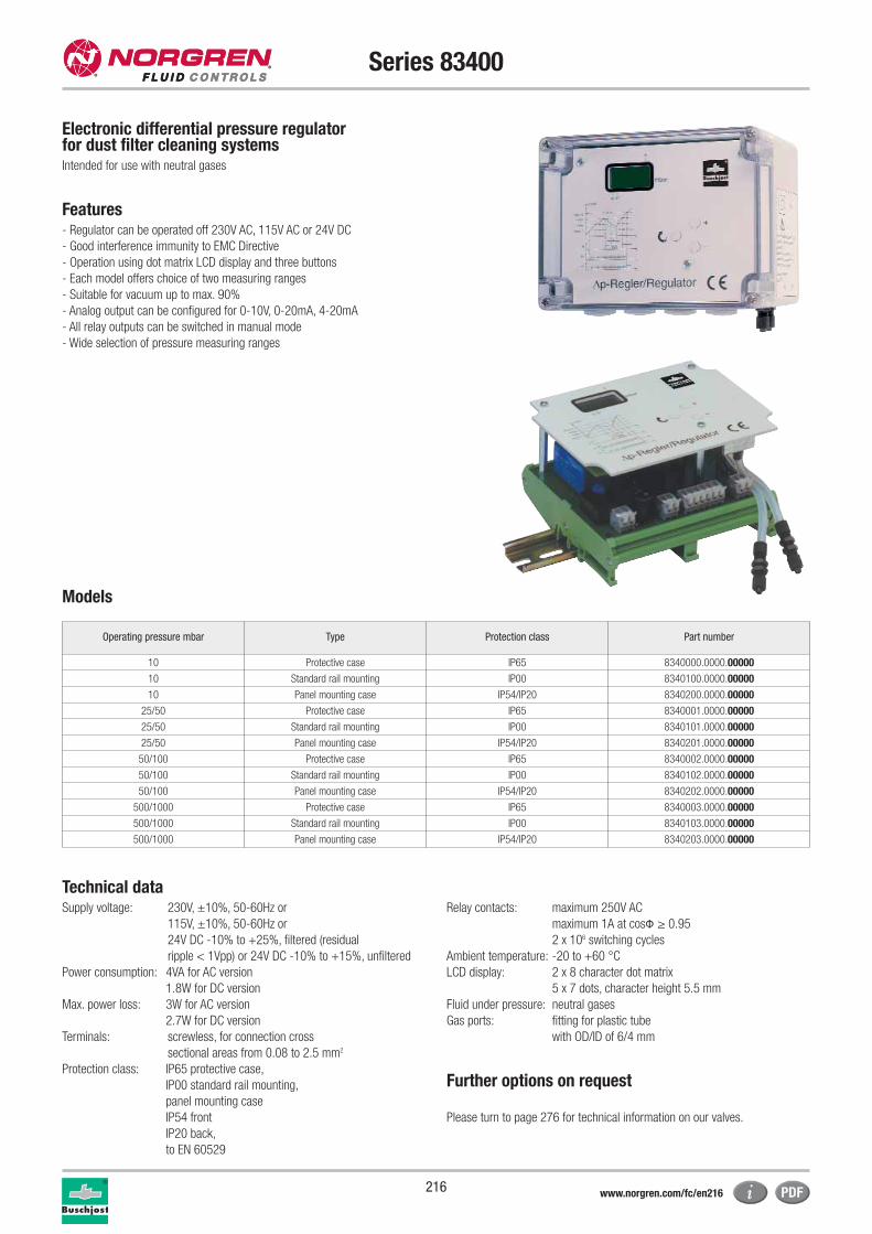
216
Series 83400
Electronic differential pressure regulator for dust filter cleaning systemsIntended for use with neutral gases
Features- Regulator can be operated off 230V AC, 115V AC or 24V DC
- Good interference immunity to EMC Directive
- Operation using dot matrix LCD display and three buttons
- Each model offers choice of two measuring ranges
- Suitable for vacuum up to max. 90%
- Analog output can be configured for 0-10V, 0-20mA, 4-20mA
- All relay outputs can be switched in manual mode
- Wide selection of pressure measuring ranges
Operating pressure mbar Type Protection class Part number
10 Protective case IP65 8340000.0000.00000
10 Standard rail mounting IP00 8340100.0000.00000
10 Panel mounting case IP54/IP20 8340200.0000.00000
25/50 Protective case IP65 8340001.0000.00000
25/50 Standard rail mounting IP00 8340101.0000.00000
25/50 Panel mounting case IP54/IP20 8340201.0000.00000
50/100 Protective case IP65 8340002.0000.00000
50/100 Standard rail mounting IP00 8340102.0000.00000
50/100 Panel mounting case IP54/IP20 8340202.0000.00000
500/1000 Protective case IP65 8340003.0000.00000
500/1000 Standard rail mounting IP00 8340103.0000.00000
500/1000 Panel mounting case IP54/IP20 8340203.0000.00000
Models
Technical dataSupply voltage: 230V, ±10%, 50-60Hz or
115V, ±10%, 50-60Hz or
24V DC -10% to +25%, filtered (residual
ripple < 1Vpp) or 24V DC -10% to +15%, unfiltered
Power consumption: 4VA for AC version
1.8W for DC version
Max. power loss: 3W for AC version
2.7W for DC version
Terminals: screwless, for connection cross
sectional areas from 0.08 to 2.5 mm2
Protection class: IP65 protective case,
IP00 standard rail mounting,
panel mounting case
IP54 front
IP20 back,
to EN 60529
Relay contacts: maximum 250V AC
maximum 1A at cosº ≥ 0.95
2 x 10⁶ switching cycles
Ambient temperature: -20 to +60 °C
LCD display: 2 x 8 character dot matrix
5 x 7 dots, character height 5.5 mm
Fluid under pressure: neutral gases
Gas ports: fitting for plastic tube
with OD/ID of 6/4 mm
Further options on request
Please turn to page 276 for technical information on our valves.
www.norgren.com/fc/en216
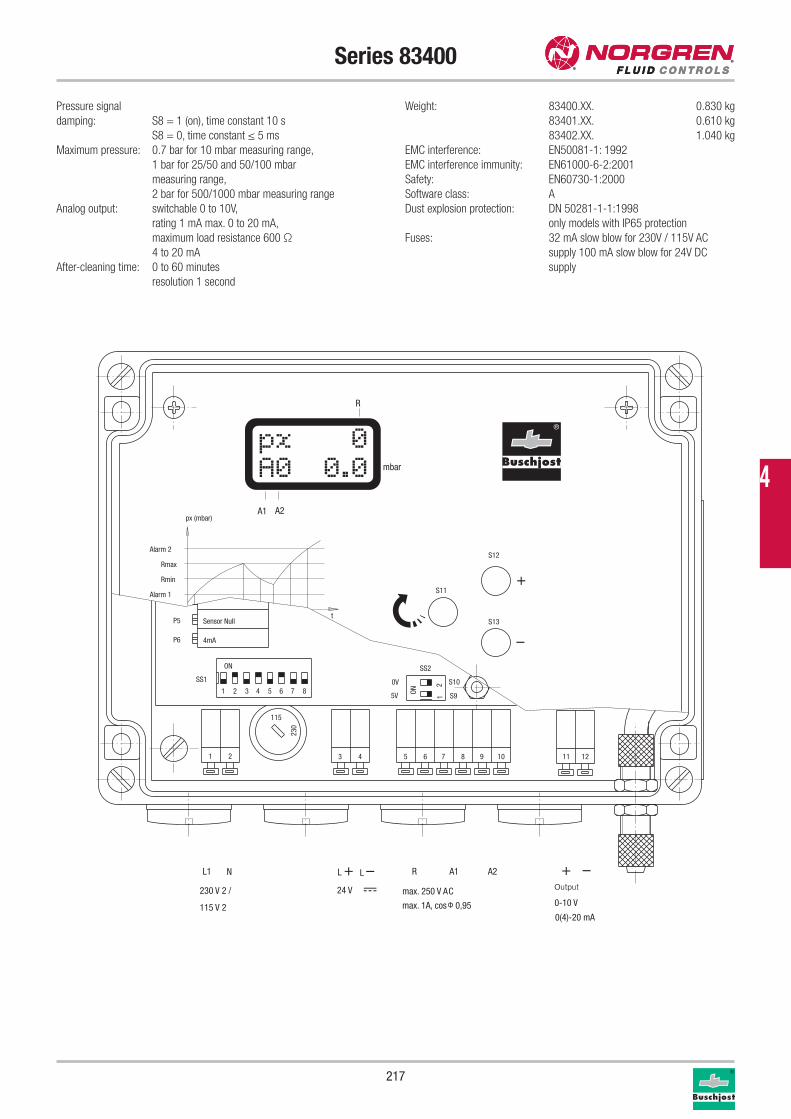
217
Series 83400
A2A1
mbar
R
px (mbar)
Alarm 2
Rmax
Rmin
Alarm 1
Sensor Null
4mA
ON
21 3 5 74 6 8
P5
P6
SS1
SS2
S12
S13
S11
0V
5V
S10
S9
230
115
3 4 5 6 7 8 9 10 11 121 2
230 V 2 /
115 V 20(4)-20 mA
0-10 Vmax. 250 V AC
max. 1A, cos j 0,95
L1 N
24 V
L + L – R A1 A2
t
12
ON
+
+
–
–
Pressure signal
damping: S8 = 1 (on), time constant 10 s
S8 = 0, time constant ≤ 5 ms
Maximum pressure: 0.7 bar for 10 mbar measuring range,
1 bar for 25/50 and 50/100 mbar
measuring range,
2 bar for 500/1000 mbar measuring range
Analog output: switchable 0 to 10V,
rating 1 mA max. 0 to 20 mA,
maximum load resistance 600 Ω
4 to 20 mA
After-cleaning time: 0 to 60 minutes
resolution 1 second
Weight: 83400.XX. 0.830 kg
83401.XX. 0.610 kg
83402.XX. 1.040 kg
EMC interference: EN50081-1: 1992
EMC interference immunity: EN61000-6-2:2001
Safety: EN60730-1:2000
Software class: A
Dust explosion protection: DN 50281-1-1:1998
only models with IP65 protection
Fuses: 32 mA slow blow for 230V / 115V AC
supply 100 mA slow blow for 24V DC
supply
º
Output
4
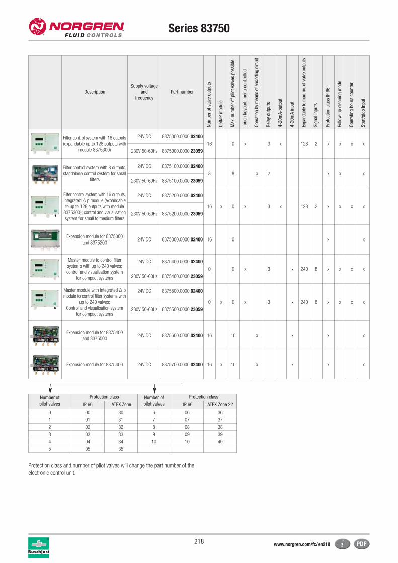
218
Series 83750
Description
Supply voltage
and
frequency
Part number
Num
ber
of v
alve
out
puts
Del
taP
mod
ule
Max
.num
ber
of p
ilot
valv
es p
ossi
ble
Touc
h ke
ypad
,men
u co
ntro
lled
Ope
ratio
n by
mea
ns o
f enc
odin
g ci
rcui
t
Rel
ay o
utpu
ts
4-2
0m
A-o
utpu
t
4-2
0m
A in
put
Expa
ndab
le to
max
.no.
of v
alve
out
puts
Sig
nal i
nput
s
Pro
tect
ion
clas
s IP
66
Follo
w-u
p cl
eani
ng m
ode
Ope
ratin
g ho
urs
coun
ter
Sta
rt/s
top
inpu
t
Filter control system with 16 outputs
(expandable up to 128 outputs with
module 8375300)
24V DC 8375000.0000.02400
16 0 x 3 x 128 2 x x x x
230V 50-60Hz 8375000.0000.23059
Filter control system with 8 outputs;
standalone control system for small
filters
24V DC 8375100.0000.02400
8 8 x 2 x x x
230V 50-60Hz 8375100.0000.23059
Filter control system with 16 outputs,
integrated Δ p module (expandable
to up to 128 outputs with module
8375300); control and visualisation
system for small to medium filters
24V DC 8375200.0000.02400
16 x 0 x 3 x 128 2 x x x x
230V 50-60Hz 8375200.0000.23059
Expansion module for 8375000
and 837520024V DC 8375300.0000.02400 16 0 x x
Master module to control filter
systems with up to 240 valves;
control and visualisation system
for compact systems
24V DC 8375400.0000.02400
0 0 x 3 x 240 8 x x x x
230V 50-60Hz 8375400.0000.23059
Master module with integrated Δ p
module to control filter systems with
up to 240 valves;
Control and visualisation system
for compact systems
24V DC 8375500.0000.02400
0 x 0 x 3 x 240 8 x x x x
230V 50-60Hz 8375500.0000.23059
Expansion module for 8375400
and 837550024V DC 8375600.0000.02400 16 10 x x x x
Expansion module for 8375400 24V DC 8375700.0000.02400 16 x 10 x x x x
Number of
pilot valves
Protection class Number of
pilot valves
Protection class
IP 66 ATEX Zone IP 66 ATEX Zone 22
0 00 30 6 06 36
1 01 31 7 07 37
2 02 32 8 08 38
3 03 33 9 09 39
4 04 34 10 10 40
5 05 35
Protection class and number of pilot valves will change the part number of the
electronic control unit.
www.norgren.com/fc/en218
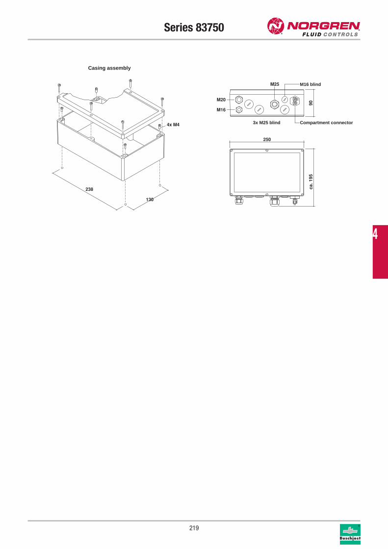
219
Series 83750
4x M4
238
130
ca. 1
95
250
90
M25
M16
M20
Seitenabstand: 1,0Objektabstand: 6,22665
4
Casing assembly
M16 blind
3x M25 blind Compartment connector
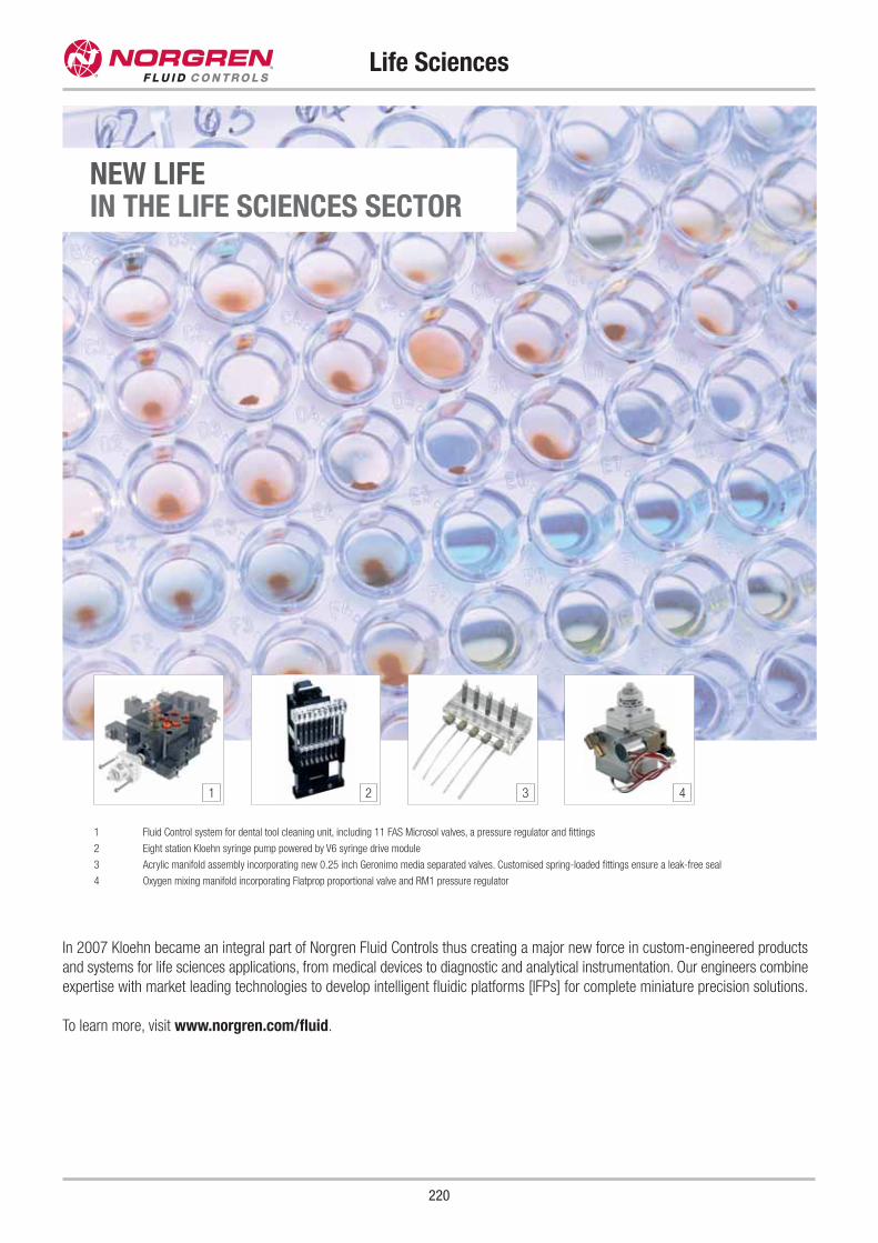
220
Life Sciences
In 2007 Kloehn became an integral part of Norgren Fluid Controls thus creating a major new force in custom-engineered products
and systems for life sciences applications, from medical devices to diagnostic and analytical instrumentation. Our engineers combine
expertise with market leading technologies to develop intelligent fluidic platforms [IFPs] for complete miniature precision solutions.
To learn more, visit www.norgren.com/fluid.
NEW LIFEIN THE LIFE SCIENCES SECTOR
1 Fluid Control system for dental tool cleaning unit, including 11 FAS Microsol valves, a pressure regulator and fittings
2 Eight station Kloehn syringe pump powered by V6 syringe drive module
3 Acrylic manifold assembly incorporating new 0.25 inch Geronimo media separated valves. Customised spring-loaded fittings ensure a leak-free seal
4 Oxygen mixing manifold incorporating Flatprop proportional valve and RM1 pressure regulator
1 2 3 4
Contents
221
Series Material Connection Pressure Temperature Function Page
82880 Brass G 1/2 - G 1 -0.9 - 10 bar +90 °C 2/2 222
Flatprop Brass, Stainless steel Cartridge, Subbase 0 - 12 bar +50 °C 2/2 224
Proportional Valves
5
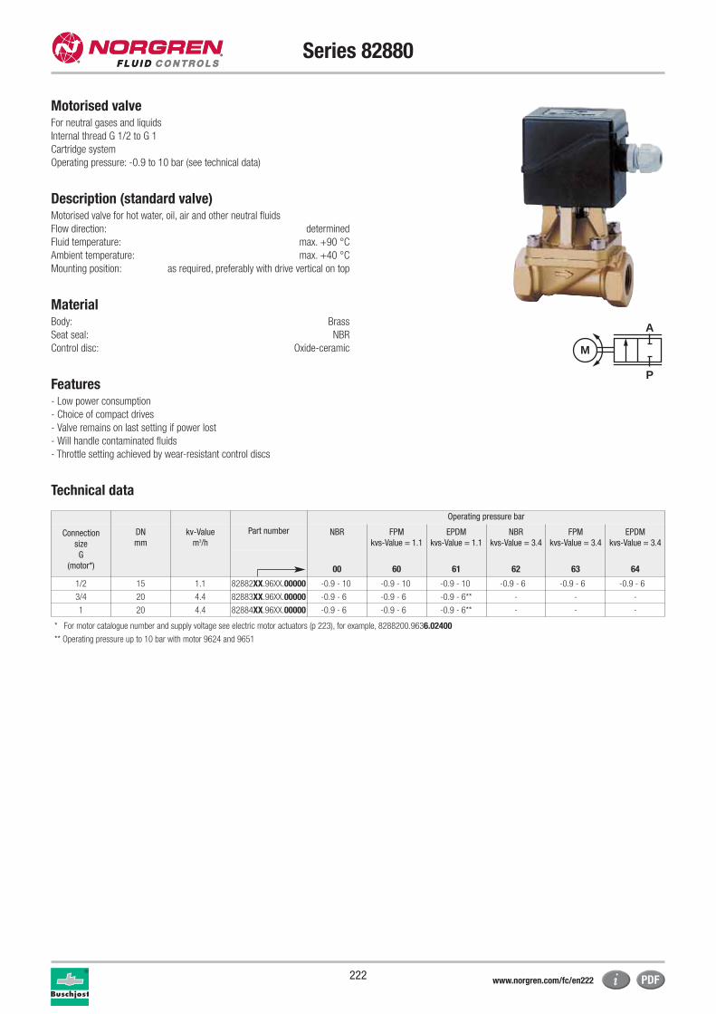
222
Series 82880
Motorised valveFor neutral gases and liquids
Internal thread G 1/2 to G 1
Cartridge system
Operating pressure: -0.9 to 10 bar (see technical data)
Description (standard valve)Motorised valve for hot water, oil, air and other neutral fluids
Flow direction: determined
Fluid temperature: max. +90 °C
Ambient temperature: max. +40 °C
Mounting position: as required, preferably with drive vertical on top
MaterialBody: Brass
Seat seal: NBR
Control disc: Oxide-ceramic
Features- Low power consumption
- Choice of compact drives
- Valve remains on last setting if power lost
- Will handle contaminated fluids
- Throttle setting achieved by wear-resistant control discs
Technical data
P
A
M
Operating pressure bar
Connection
size
G
(motor*)
DN
mm
kv-Value
m3/h
Part number NBR FPM
kvs-Value = 1.1
EPDM
kvs-Value = 1.1
NBR
kvs-Value = 3.4
FPM
kvs-Value = 3.4
EPDM
kvs-Value = 3.4
00 60 61 62 63 64
1/2 15 1.1 82882XX.96XX.00000 -0.9 - 10 -0.9 - 10 -0.9 - 10 -0.9 - 6 -0.9 - 6 -0.9 - 6
3/4 20 4.4 82883XX.96XX.00000 -0.9 - 6 -0.9 - 6 -0.9 - 6** - - -
1 20 4.4 82884XX.96XX.00000 -0.9 - 6 -0.9 - 6 -0.9 - 6** - - -
* For motor catalogue number and supply voltage see electric motor actuators (p 223), for example, 8288200.9636.02400
** Operating pressure up to 10 bar with motor 9624 and 9651
www.norgren.com/fc/en222
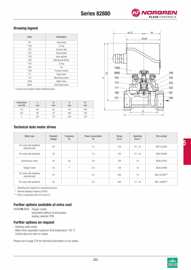
223
Series 82880
Drawing legend
Index Description
101 Valve body
*102 O-ring
103 Ceramic disc
104 Round plate
*105 Valve spindle
106 Mechanical fixture
*107 O-ring
108 Pin
*109 Pressure spring
111 Valve cover
112 Mounting screws
1000 Motor drive
9900 Oval head screw
Technical data motor drives
* A service kit consists of these individual parts.
Connection
size DN
L
mm
B
mm
H
mm
H1
mm
1/2 65 55 147 134
3/4 95 70 164 140
1 95 70 164 140
Further options available at extra costXXXXX75.96XX Oxygen model,
assembled without oil and grease,
sealing material: FPM
Further options on request- Stainless steel model
- Motor drive separated: maximum fluid temperature 130 °C
- Control discs for other kv values
Please turn to page 276 for technical information on our valves.
Motor type Standard
voltage
Frequency
Hz
Power consumption
W
Torque
N cm
Operating
time s*
Part number
DC motor with feedback
potentiometer24 1.5 120 10 - 14 9615.02400
DC motor with positioner 24 1.5 120 10 - 16 9650.02400
Synchronous motor 24 50 3.0 120 10 9636.02450
Stepper motor 24 ** 5.0 120 10 9638.02400
DC motor with feedback
potentiometer24 2.0 200 13 9624.02400***
DC motor with positioner 24 2.5 200 13 - 16 9651.02400***
BL
H1
H
82x53
4075ca.
A P
103
106
112
105
1000
9900
108
107
104
102
109
101
111
* Operating time depends on operating pressure
** Nominal stepping frequency 200Hz
*** Only in conjunction with G 3/4 and G 1
5
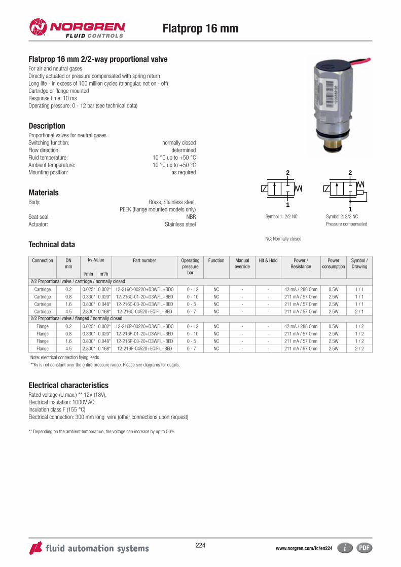
224
Flatprop 16 mm
Flatprop 16 mm 2/2-way proportional valveFor air and neutral gases
Directly actuated or pressure compensated with spring return
Long life - in excess of 100 million cycles (triangular, not on - off)
Cartridge or flange mounted
Response time: 10 ms
Operating pressure: 0 - 12 bar (see technical data)
DescriptionProportional valves for neutral gases
Switching function: normally closed
Flow direction: determined
Fluid temperature: 10 °C up to +50 °C
Ambient temperature: 10 °C up to +50 °C
Mounting position: as required
MaterialsBody: Brass, Stainless steel,
PEEK (flange mounted models only)
Seat seal: NBR
Actuator: Stainless steel
Technical data
Connection DN
mm
kv-Value Part number Operating
pressure
bar
Function Manual
override
Hit & Hold Power /
Resistance
Power
consumption
Symbol /
Drawing
l/min m3/h
2/2 Proportional valve / cartridge / normally closed
Cartridge 0.2 0.025* 0.002* 12-216C-00220+D3WFIL+BDO 0 - 12 NC - - 42 mA / 288 Ohm 0.5W 1 / 1
Cartridge 0.8 0.330* 0.020* 12-216C-01-20+D3WFIL+BED 0 - 10 NC - - 211 mA / 57 Ohm 2.5W 1 / 1
Cartridge 1.6 0.800* 0.048* 12-216C-03-20+D3WFIL+BED 0 - 5 NC - - 211 mA / 57 Ohm 2.5W 1 / 1
Cartridge 4.5 2.800* 0.168* 12-216C-04520+EQIFIL+BED 0 - 7 NC - - 211 mA / 57 Ohm 2.5W 2 / 1
2/2 Proportional valve / flanged / normally closed
Flange 0.2 0.025* 0.002* 12-216P-00220+D3WFIL+BDO 0 - 12 NC - - 42 mA / 288 Ohm 0.5W 1 / 2
Flange 0.8 0.330* 0.020* 12-216P-01-20+D3WFIL+BED 0 - 10 NC - - 211 mA / 57 Ohm 2.5W 1 / 2
Flange 1.6 0.800* 0.048* 12-216P-03-20+D3WFIL+BED 0 - 5 NC - - 211 mA / 57 Ohm 2.5W 1 / 2
Flange 4.5 2.800* 0.168* 12-216P-04520+EQIFIL+BED 0 - 7 NC - - 211 mA / 57 Ohm 2.5W 2 / 2
Note: electrical connection flying leads
**Kv is not constant over the entire pressure range. Please see diagrams for details.
Electrical characteristicsRated voltage (U max.) ** 12V (18V),
Electrical insulation: 1000V AC
Insulation class F (155 °C)
Electrical connection: 300 mm long wire (other connections upon request)
** Depending on the ambient temperature, the voltage can increase by up to 50%
2
1
2
1Symbol 1: 2/2 NC Symbol 2: 2/2 NC
Pressure compensated
NC: Normally closed
www.norgren.com/fc/en224
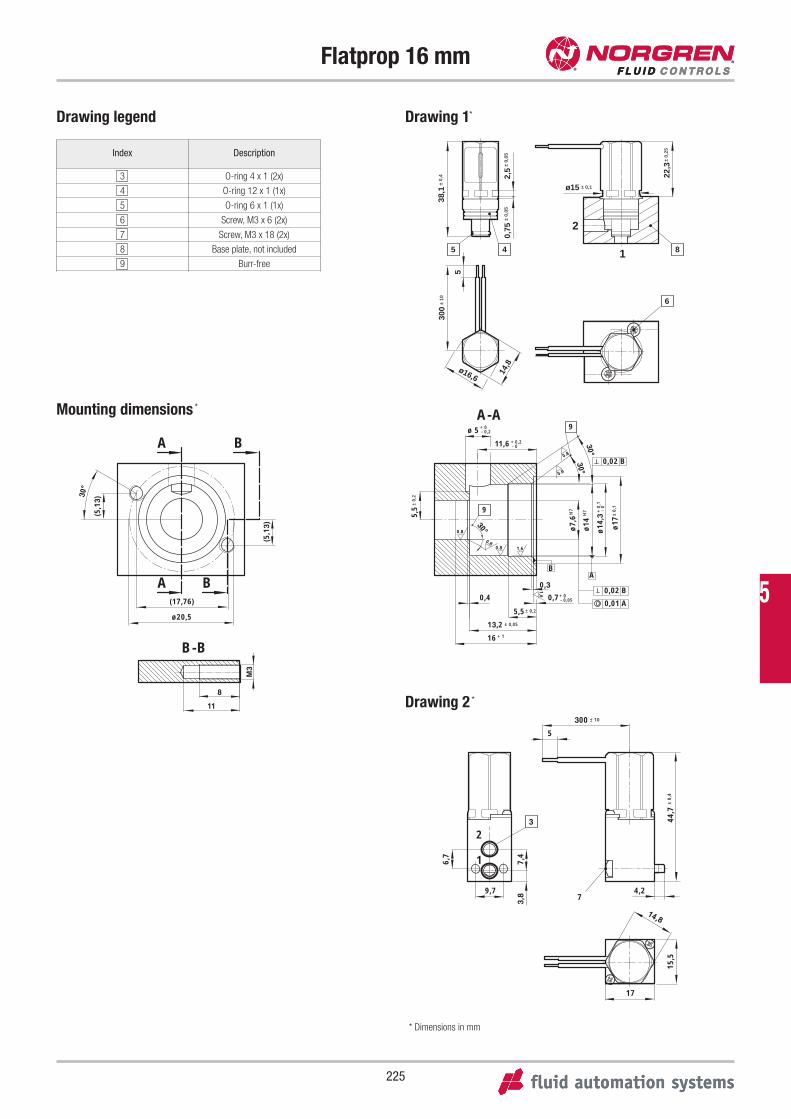
225
Flatprop 16 mm
Drawing legend
Index Description
3 O-ring 4 x 1 (2x)
4 O-ring 12 x 1 (1x)
5 O-ring 6 x 1 (1x)
6 Screw, M3 x 6 (2x)
7 Screw, M3 x 18 (2x)
8 Base plate, not included
9 Burr-free
1
2
45
6
22,3
38,1
2,5
ø15
0,75
± 10
± 0,
4
± 0,
05
± 0,
25
± 0,
05
5
300
14,8ø16,6
8
± 0,1
2
1 7,4
6,7
44,7
3,8
15,5
17
14,8
9,7
± 10
± 0,
4
300
5
4,27
3
B-B
30°
11
8
M3
A B
A B
(5,1
3)
(17,76)
ø20,5
(5,1
3)
A-A
0,3
30°
30°
30°
0.8
0.8
0.8
1,6
1,6
0.8
0.8
AB
± 0,
2
± 0,
1± 0,2
± 0,05
9
9
- 0
+ 0,
1ø
14,3
ø17
H7
ø7,
6 H7
ø14
5,5
- 0,2+ 0ø 5
- 0+ 0,211,6
0,02 B
0,01 A
+ 116
- 0,05+ 00,70,4
13,2
5,5
0,02 B
Mounting dimensions *
Drawing 1*
Drawing 2 *
* Dimensions in mm
5
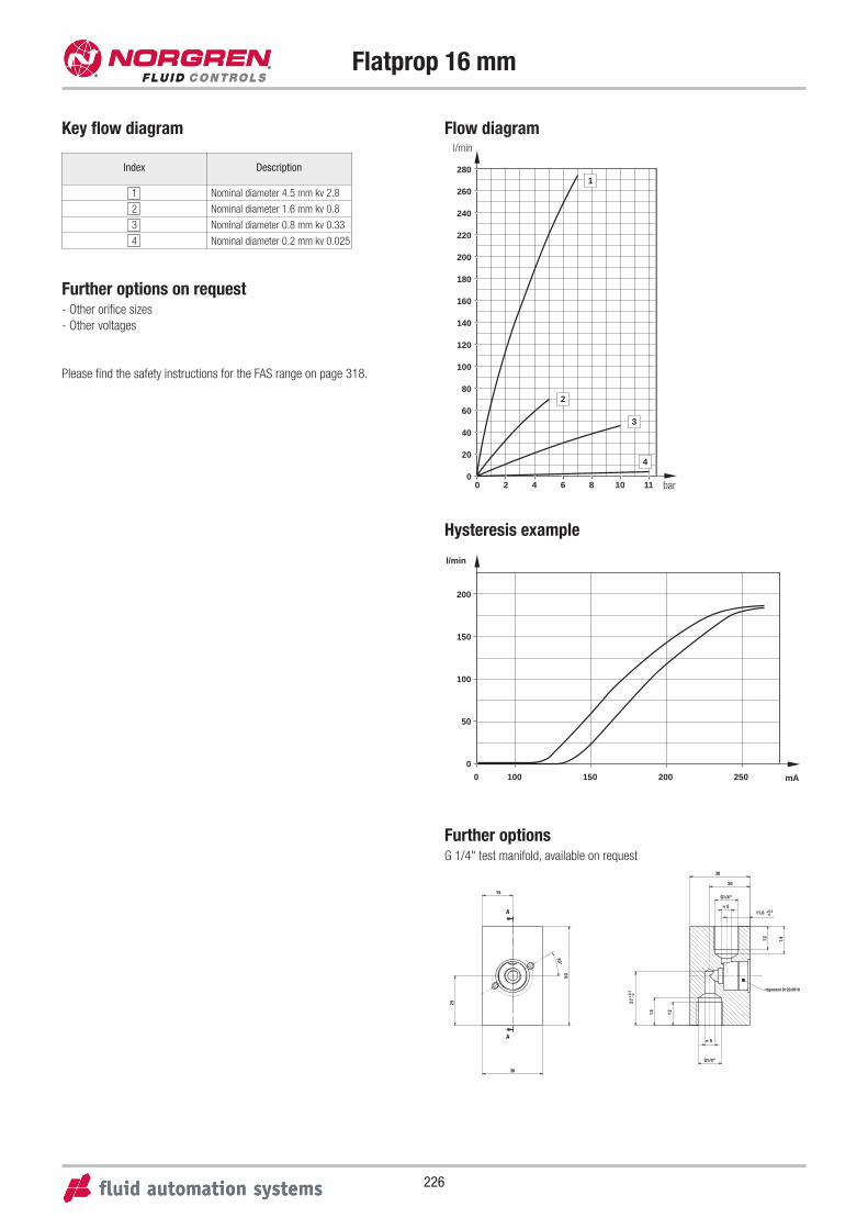
226
Flatprop 16 mm
00
20
40
60
80
100
120
140
160
180
200
220
240
260
280
2 4 6 8 10 11
1
2
3
4
Flow diagram
200
l/min
mA
150
100
50
0
0 100 150 200 250
Hysteresis example
Key flow diagram
Index Description
1 Nominal diameter 4.5 mm kv 2.8
2 Nominal diameter 1.6 mm kv 0.8
3 Nominal diameter 0.8 mm kv 0.33
4 Nominal diameter 0.2 mm kv 0.025
Further options on request- Other orifice sizes
- Other voltages
l/min
bar
Please find the safety instructions for the FAS range on page 318.
Further optionsG 1/4" test manifold, available on request
A
A
30°
15
50
30
14
G1/4"
12
27- 00,
2+
30
n 5
logement D120.0010
5n11,6 - 0
0,2+
25
G1/4"
12
20
14
Contents
227
Series Material Connection Pressure Temperature Function Page
18 S Allfluid Stainless steel G 1/4 male 0 - 800 bar +85 °C – 228
33 D
Aluminium,
Stainless steel,
Polyester foil
G 1/4 Flange -1 - 630 bar +80 °C – 230
Pressure Sensors
6
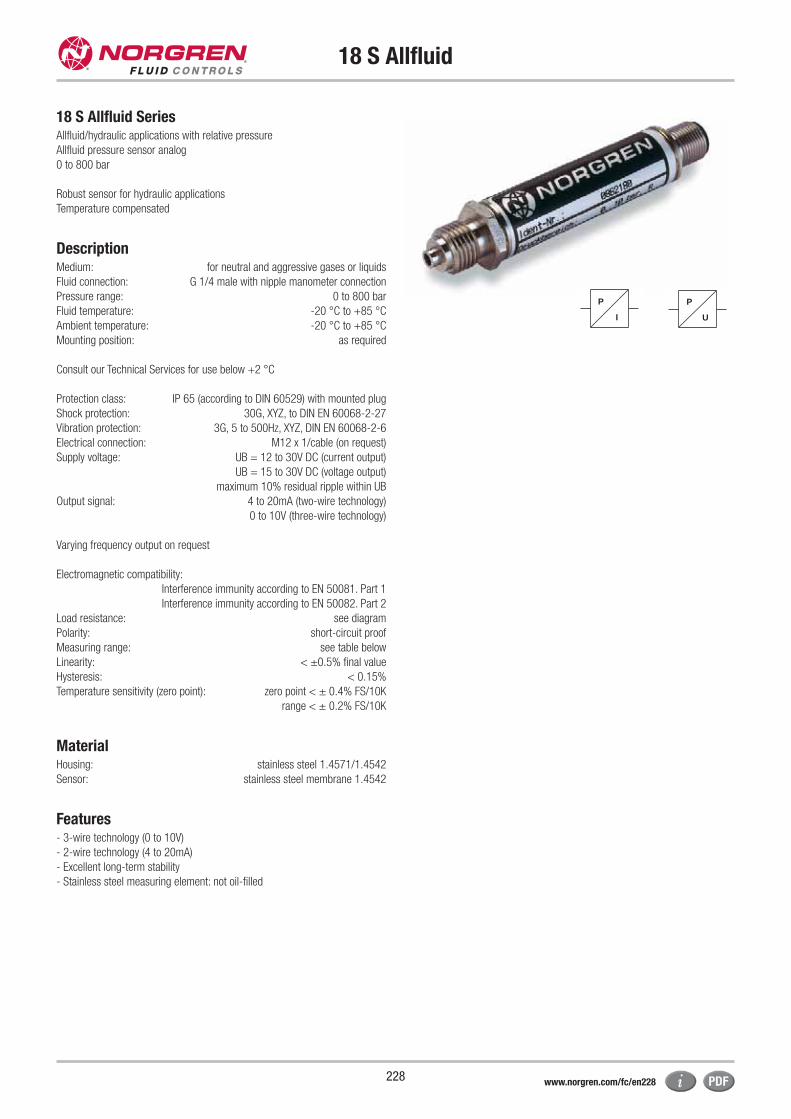
18 S Allfluid
228
18 S Allfluid SeriesAllfluid/hydraulic applications with relative pressure
Allfluid pressure sensor analog
0 to 800 bar
Robust sensor for hydraulic applications
Temperature compensated
DescriptionMedium: for neutral and aggressive gases or liquids
Fluid connection: G 1/4 male with nipple manometer connection
Pressure range: 0 to 800 bar
Fluid temperature: -20 °C to +85 °C
Ambient temperature: -20 °C to +85 °C
Mounting position: as required
Consult our Technical Services for use below +2 °C
Protection class: IP 65 (according to DIN 60529) with mounted plug
Shock protection: 30G, XYZ, to DIN EN 60068-2-27
Vibration protection: 3G, 5 to 500Hz, XYZ, DIN EN 60068-2-6
Electrical connection: M12 x 1/cable (on request)
Supply voltage: UB = 12 to 30V DC (current output)
UB = 15 to 30V DC (voltage output)
maximum 10% residual ripple within UB
Output signal: 4 to 20mA (two-wire technology)
0 to 10V (three-wire technology)
Varying frequency output on request
Electromagnetic compatibility:
Interference immunity according to EN 50081. Part 1
Interference immunity according to EN 50082. Part 2
Load resistance: see diagram
Polarity: short-circuit proof
Measuring range: see table below
Linearity: < ±0.5% final value
Hysteresis: < 0.15%
Temperature sensitivity (zero point): zero point < ± 0.4% FS/10K
range < ± 0.2% FS/10K
MaterialHousing: stainless steel 1.4571/1.4542
Sensor: stainless steel membrane 1.4542
Features- 3-wire technology (0 to 10V)
- 2-wire technology (4 to 20mA)
- Excellent long-term stability
- Stainless steel measuring element: not oil-filled
P
I
P
U
www.norgren.com/fc/en228
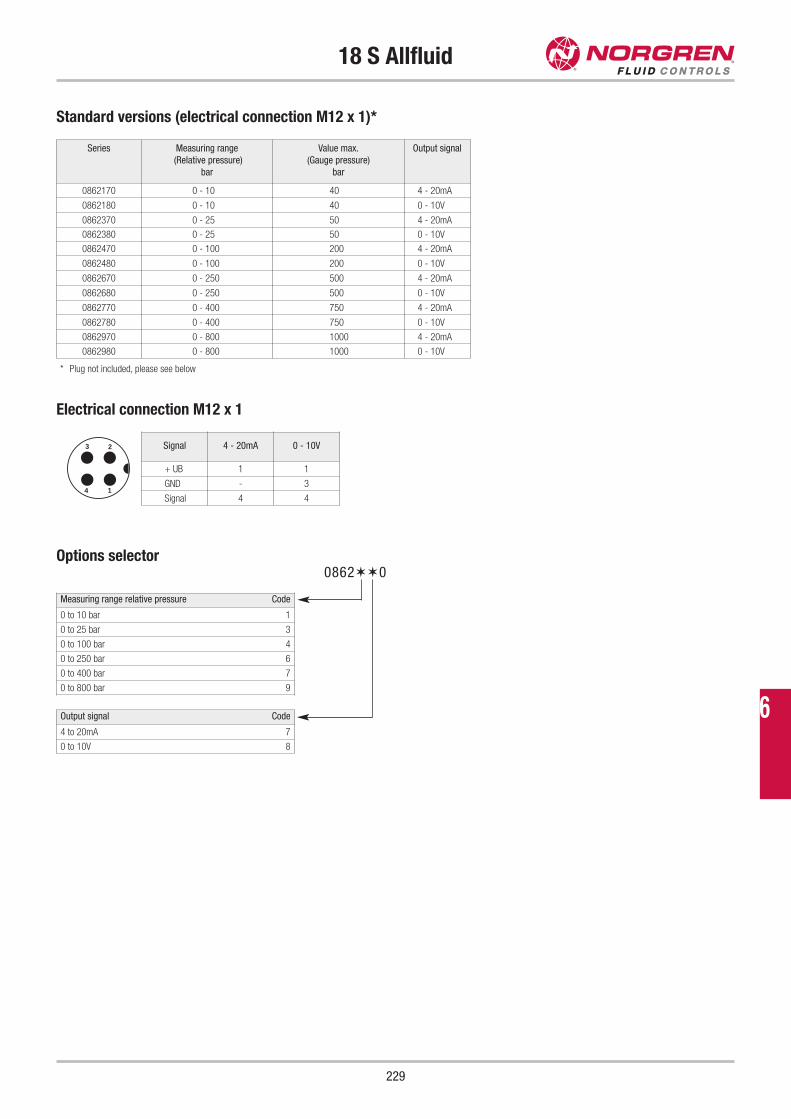
18 S Allfluid
229
Standard versions (electrical connection M12 x 1)*
Electrical connection M12 x 1
Options selector
Output signal Code
4 to 20mA 7
0 to 10V 8
Measuring range relative pressure Code
0 to 10 bar 1
0 to 25 bar 3
0 to 100 bar 4
0 to 250 bar 6
0 to 400 bar 7
0 to 800 bar 9
0862✶✶0
Series Measuring range
(Relative pressure)
bar
Value max.
(Gauge pressure)
bar
Output signal
0862170 0 - 10 40 4 - 20mA
0862180 0 - 10 40 0 - 10V
0862370 0 - 25 50 4 - 20mA
0862380 0 - 25 50 0 - 10V
0862470 0 - 100 200 4 - 20mA
0862480 0 - 100 200 0 - 10V
0862670 0 - 250 500 4 - 20mA
0862680 0 - 250 500 0 - 10V
0862770 0 - 400 750 4 - 20mA
0862780 0 - 400 750 0 - 10V
0862970 0 - 800 1000 4 - 20mA
0862980 0 - 800 1000 0 - 10V
Signal 4 - 20mA 0 - 10V
+ UB 1 1
GND - 3
Signal 4 4
* Plug not included, please see below
3 2
4 1
6
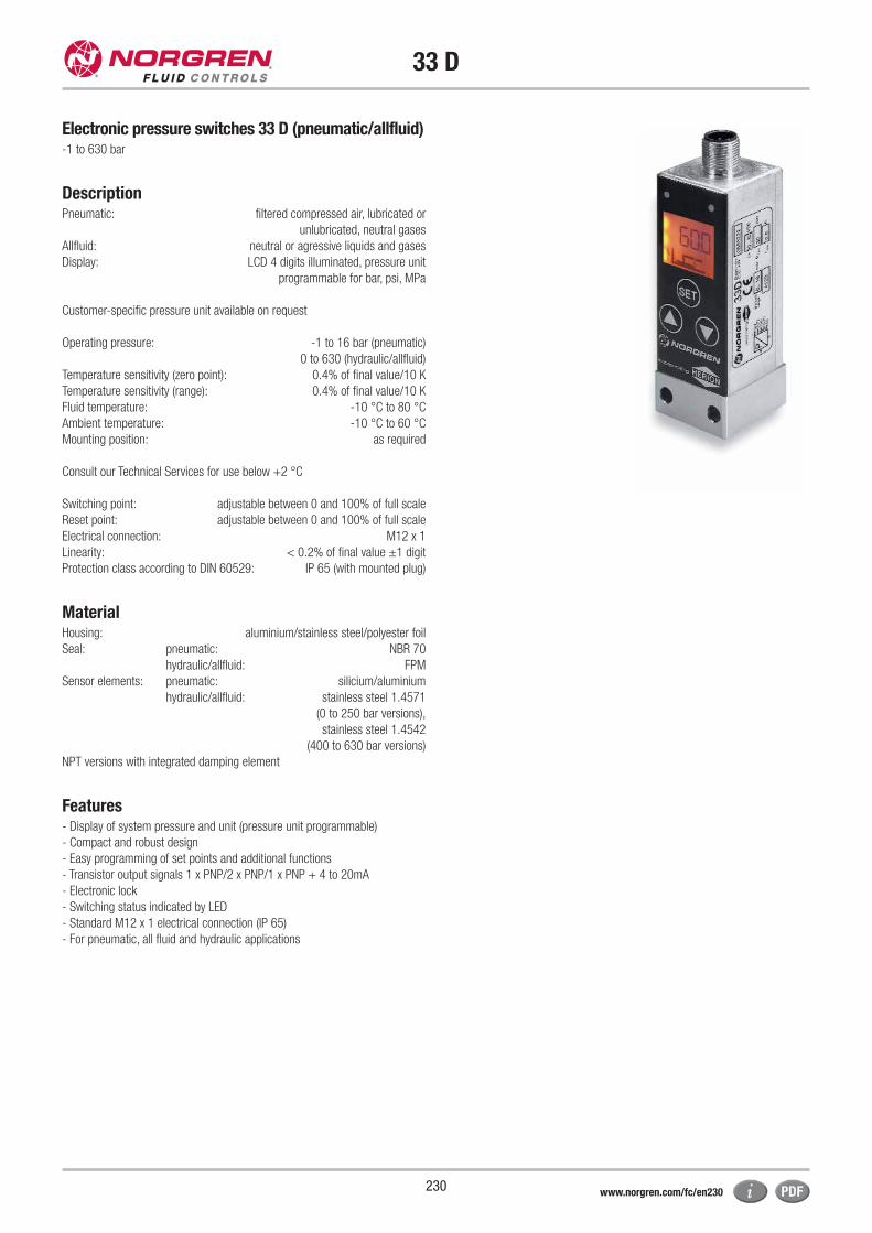
33 D
230
Electronic pressure switches 33 D (pneumatic/allfluid)-1 to 630 bar
DescriptionPneumatic: filtered compressed air, lubricated or
unlubricated, neutral gases
Allfluid: neutral or agressive liquids and gases
Display: LCD 4 digits illuminated, pressure unit
programmable for bar, psi, MPa
Customer-specific pressure unit available on request
Operating pressure: -1 to 16 bar (pneumatic)
0 to 630 (hydraulic/allfluid)
Temperature sensitivity (zero point): 0.4% of final value/10 K
Temperature sensitivity (range): 0.4% of final value/10 K
Fluid temperature: -10 °C to 80 °C
Ambient temperature: -10 °C to 60 °C
Mounting position: as required
Consult our Technical Services for use below +2 °C
Switching point: adjustable between 0 and 100% of full scale
Reset point: adjustable between 0 and 100% of full scale
Electrical connection: M12 x 1
Linearity: < 0.2% of final value ±1 digit
Protection class according to DIN 60529: IP 65 (with mounted plug)
MaterialHousing: aluminium/stainless steel/polyester foil
Seal: pneumatic: NBR 70
hydraulic/allfluid: FPM
Sensor elements: pneumatic: silicium/aluminium
hydraulic/allfluid: stainless steel 1.4571
(0 to 250 bar versions),
stainless steel 1.4542
(400 to 630 bar versions)
NPT versions with integrated damping element
Features- Display of system pressure and unit (pressure unit programmable)
- Compact and robust design
- Easy programming of set points and additional functions
- Transistor output signals 1 x PNP/2 x PNP/1 x PNP + 4 to 20mA
- Electronic lock
- Switching status indicated by LED
- Standard M12 x 1 electrical connection (IP 65)
- For pneumatic, all fluid and hydraulic applications
www.norgren.com/fc/en230
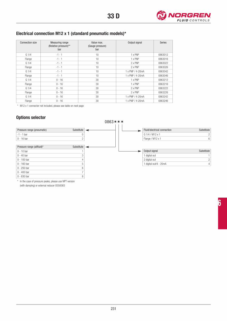
33 D
231
Connection size Measuring range
(Relative pressure)**
bar
Value max.
(Gauge pressure)
bar
Output signal Series
G 1/4 -1 - 1 10 1 x PNP 0863012
Flange -1 - 1 10 1 x PNP 0863016
G 1/4 -1 - 1 10 2 x PNP 0863022
Flange -1 - 1 10 2 x PNP 0863026
G 1/4 -1 - 1 10 1 x PNP / 4-20mA 0863042
Flange -1 - 1 10 1 x PNP / 4-20mA 0863046
G 1/4 0 - 16 30 1 x PNP 0863212
Flange 0 - 16 30 1 x PNP 0863216
G 1/4 0 - 16 30 2 x PNP 0863222
Flange 0 - 16 30 2 x PNP 0863226
G 1/4 0 - 16 30 1 x PNP / 4-20mA 0863242
Flange 0 - 16 30 1 x PNP / 4-20mA 0863246
Electrical connection M12 x 1 (standard pneumatic models)*
* M12 x 1 connector not included, please see table on next page
* In the case of pressure peaks, please use NPT version
(with damping) or external reducer 0550083
Options selector
Pressure range (allfluid)* Substitute
0 - 10 bar 1
0 - 40 bar 3
0 - 100 bar 4
0 - 160 bar 5
0 - 250 bar 6
0 - 400 bar 7
0 - 630 bar 8
Pressure range (pneumatic) Substitute
-1 - 1 bar 0
0 - 16 bar 2
Fluid/electrical connection Substitute
G 1/4 / M12 x 1 2
Flange / M12 x 1 6
Output signal Substitute
1 digital out 1
2 digital out 2
1 digital out/4 - 20mA 4
0863✶✶✶
6
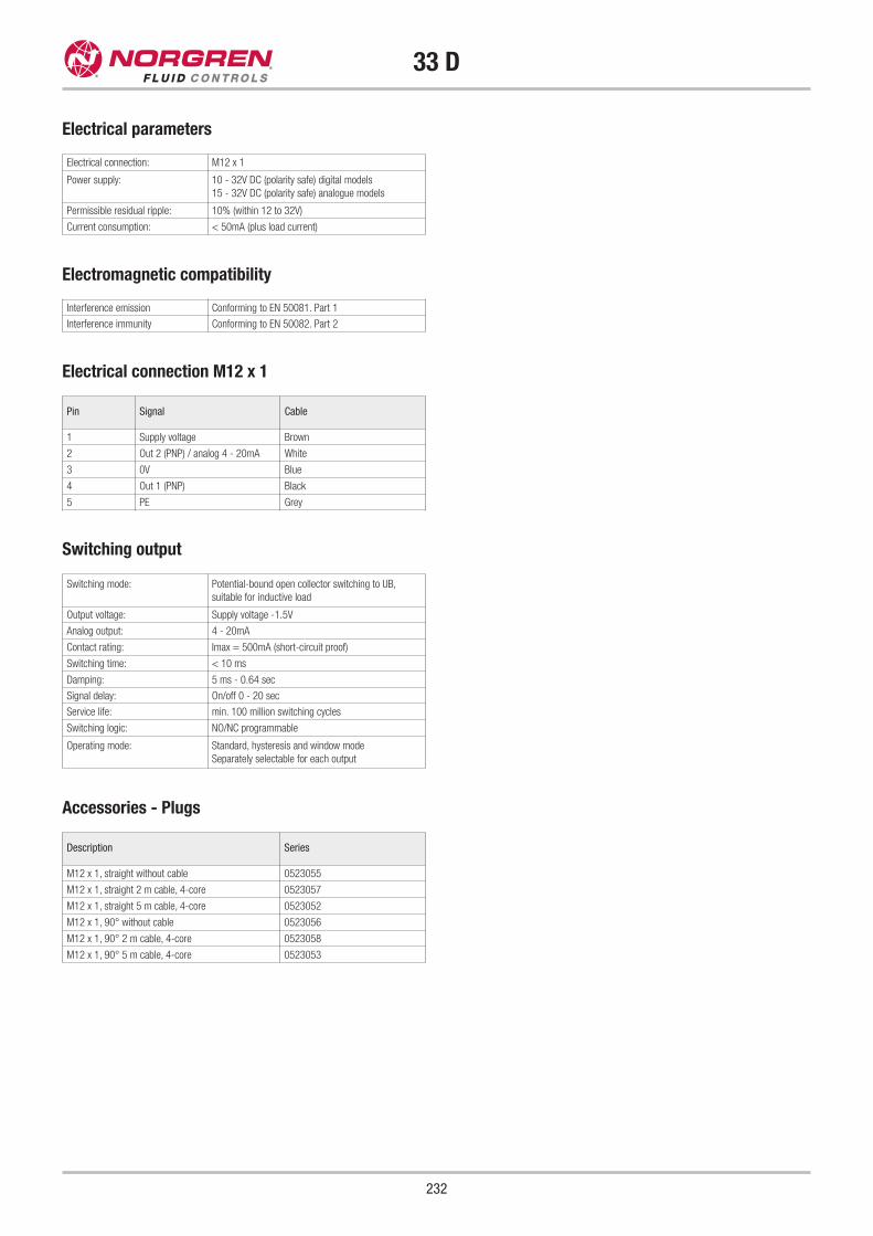
33 D
232
Electrical connection: M12 x 1
Power supply: 10 - 32V DC (polarity safe) digital models
15 - 32V DC (polarity safe) analogue models
Permissible residual ripple: 10% (within 12 to 32V)
Current consumption: < 50mA (plus load current)
Electrical parameters
Switching mode: Potential-bound open collector switching to UB,
suitable for inductive load
Output voltage: Supply voltage -1.5V
Analog output: 4 - 20mA
Contact rating: Imax = 500mA (short-circuit proof)
Switching time: < 10 ms
Damping: 5 ms - 0.64 sec
Signal delay: On/off 0 - 20 sec
Service life: min. 100 million switching cycles
Switching logic: NO/NC programmable
Operating mode: Standard, hysteresis and window mode
Separately selectable for each output
Switching output
Electrical connection M12 x 1
Interference emission Conforming to EN 50081. Part 1
Interference immunity Conforming to EN 50082. Part 2
Electromagnetic compatibility
Pin Signal Cable
1 Supply voltage Brown
2 Out 2 (PNP) / analog 4 - 20mA White
3 0V Blue
4 Out 1 (PNP) Black
5 PE Grey
Accessories - Plugs
Description Series
M12 x 1, straight without cable 0523055
M12 x 1, straight 2 m cable, 4-core 0523057
M12 x 1, straight 5 m cable, 4-core 0523052
M12 x 1, 90° without cable 0523056
M12 x 1, 90° 2 m cable, 4-core 0523058
M12 x 1, 90° 5 m cable, 4-core 0523053
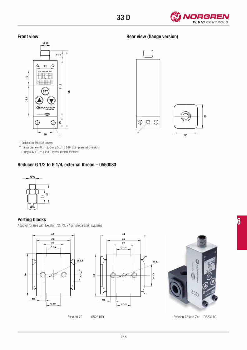
33 D
233
Front view Rear view (flange version)
Reducer G 1/2 to G 1/4, external thread – 0550083
M 12
11.5
22
19
SET
71.5
98
39.7
15
20
OUT1 HYS WIN OUT2
*
Incorporating
30
30**
* Suitable for M5 x 35 screws
** Flange diameter 8 x 1.2, O-ring 5 x 1.5 (NBR 70) - pneumatic version,
O-ring 4.47 x 1.78 (FPM) - hydraulic/allfluid version
G1/4
G1/2
31
43
Porting blocksAdaptor for use with Excelon 72, 73, 74 air preparation systems
40
32
20
G 1/4
Ø 3,3
40
M5
G 1
/4
G 1/4
44
32
20
G 1/4
40
M5
G 1/4
G 1
/2
Ø 3,3
Excelon 72 0523109 Excelon 73 and 74 0523110
6
Fluid Control Solutions
234
Special Approvals
We will gladly provide you with any further
information required.
235
Contents
Series Material Connection Pressure Temperature Function Page
Olympian Plus Al, Zg G 1/2 - G 1 1/2 0.3 - 10 bar +80 °C – 236
Excelon Pk, Zg G 1/2 - G 3/4 0.3 - 10 bar +50 °C – 240
Excelon
Filter / RegulatorsZg, Al, Pk, Acetal G 1/4 & G 3/4 0.3 - 10 bar +50 °C – 242
R05/B05 SS, Acetal 1/4 PTF 0.3 - 8.6 bar +66 °C – 248
F22/R22/L22 SS 1/2 PTF 0.4 - 10 bar +80 °C – 250
Air Preparation Equipment (FRL)
SS = Stainless Steel
Al = Aluminium
Pk = Polycarbonate
Zg = Zinc alloy
7
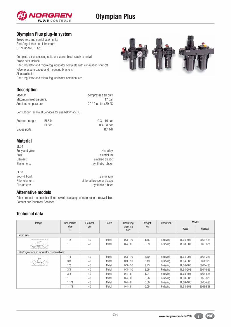
Olympian Plus
236
Olympian Plus plug-in systemBoxed sets and combination units
Filter/regulators and lubricators
G 1/4 up to G 1 1/2
Complete air processing units pre-assembled, ready to install
Boxed sets include:
Filter/regulator and micro-fog lubricator complete with exhausting shut-off
valve, pressure gauge and mounting brackets
Also available:
Filter-regulator and micro-fog lubricator combinations
DescriptionMedium: compressed air only
Maximum inlet pressure: 17 bar
Ambient temperature: -20 °C up to +80 °C
Consult our Technical Services for use below +2 °C
Pressure range: BL64: 0.3 - 10 bar
BL68: 0.4 - 8 bar
Gauge ports: RC 1/8
MaterialBL64
Body and yoke: zinc alloy
Bowl: aluminium
Element: sintered plastic
Elastomers: synthetic rubber
BL68
Body & bowl: aluminium
Filter element: sintered bronze or plastic
Elastomers: synthetic rubber
Alternative models Other products and combinations as well as a range of accessories are available.
Contact our Technical Services
Technical data
Image Connection
size
G
Element
μm
Bowls Operating
pressure
bar*
Weight
kg
Operation Model
Auto Manual
Boxed sets
1/2 40 Metal 0.3 - 10 4.15 Relieving BL64-401 BL64-421
1 40 Metal 0.4 - 8 5.99 Relieving BL68-801 BL68-821
Filter/regulator and lubricator combinations
1/4 40 Metal 0.3 - 10 3.19 Relieving BL64-208 BL64-228
3/8 40 Metal 0.3 - 10 3.19 Relieving BL64-308 BL64-328
1/2 40 Metal 0.3 - 10 2.73 Relieving BL64-408 BL64-428
3/4 40 Metal 0.3 - 10 3.56 Relieving BL64-608 BL64-628
3/4 40 Metal 0.4 - 8 4.94 Relieving BL68-608 BL68-628
1 40 Metal 0.4 - 8 5.26 Relieving BL68-808 BL68-828
1 1/4 40 Metal 0.4 - 8 6.50 Relieving BL68-A08 BL68-A28
1 1/2 40 Metal 0.4 - 8 6.05 Relieving BL68-B08 BL68-B28
www.norgren.com/fc/en236
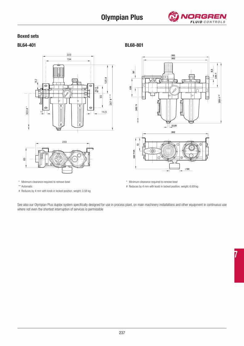
Olympian Plus
237
Boxed sets
BL64-401 BL68-801
287
# *
**
125
#
8530
3 #
*
233
223
194
8,2
14,5
93
30,5
11
283
# **
G1/8
135
#
∅50
160
TYP.
362
362 381
345
*#
100
50
72
8,5
* Minimum clearance required to remove bowl
** Automatic
# Reduces by 4 mm with knob in locked position, weight: 3.58 kg
* Minimum clearance required to remove bowl
# Reduces by 4 mm with knob in locked position, weight: 6.69 kg
See also our Olympian Plus duplex system specifically designed for use in process plant, on main machinery installations and other equipment in continuous use
where not even the shortest interruption of services is permissible
7
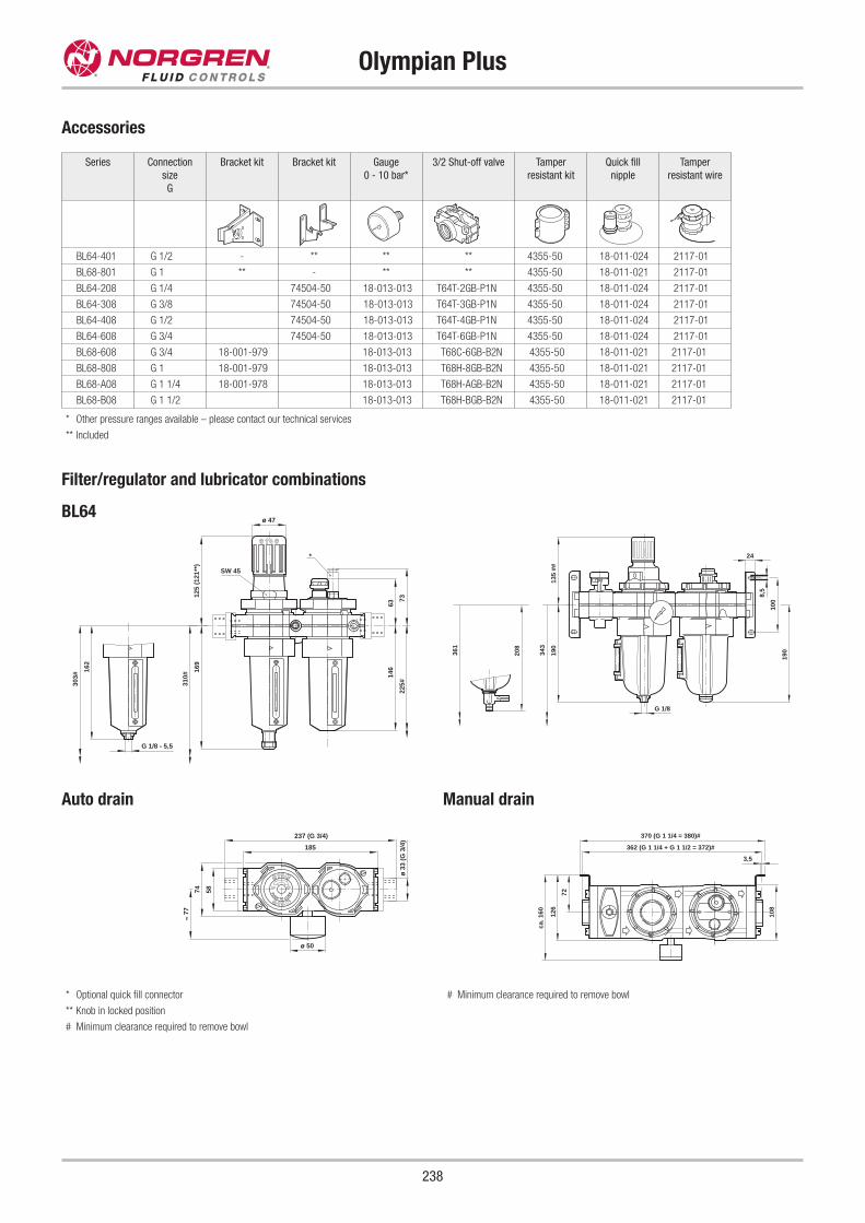
Olympian Plus
238
Accessories
Series Connection
size
G
Bracket kit Bracket kit Gauge
0 - 10 bar*
3/2 Shut-off valve Tamper
resistant kit
Quick fill
nipple
Tamper
resistant wire
BL64-401 G 1/2 - ** ** ** 4355-50 18-011-024 2117-01
BL68-801 G 1 ** - ** ** 4355-50 18-011-021 2117-01
BL64-208 G 1/4 74504-50 18-013-013 T64T-2GB-P1N 4355-50 18-011-024 2117-01
BL64-308 G 3/8 74504-50 18-013-013 T64T-3GB-P1N 4355-50 18-011-024 2117-01
BL64-408 G 1/2 74504-50 18-013-013 T64T-4GB-P1N 4355-50 18-011-024 2117-01
BL64-608 G 3/4 74504-50 18-013-013 T64T-6GB-P1N 4355-50 18-011-024 2117-01
BL68-608 G 3/4 18-001-979 18-013-013 T68C-6GB-B2N 4355-50 18-011-021 2117-01
BL68-808 G 1 18-001-979 18-013-013 T68H-8GB-B2N 4355-50 18-011-021 2117-01
BL68-A08 G 1 1/4 18-001-978 18-013-013 T68H-AGB-B2N 4355-50 18-011-021 2117-01
BL68-B08 G 1 1/2 18-013-013 T68H-BGB-B2N 4355-50 18-011-021 2117-01
* Other pressure ranges available – please contact our technical services
** Included
Filter/regulator and lubricator combinations
BL64
*
G 1/8 - 5,5
ø 47
162
303#
310#
169
SW 45
125
(121
**)
146
225#
63
73
185
5874
237 (G 3/4)
ø 3
3 (G
3/4
)
≈ 77
ø 50
135
##
100
190
24
8,5
G 1/8
19036
1
208
343
Auto drain
108
72
126
ca. 1
60
3,5
370 (G 1 1/4 = 380)#
362 (G 1 1/4 + G 1 1/2 = 372)#
Manual drain
* Optional quick fill connector
** Knob in locked position
# Minimum clearance required to remove bowl
# Minimum clearance required to remove bowl
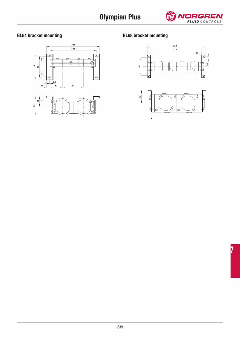
Olympian Plus
239
BL64 bracket mounting BL68 bracket mounting
223
194
85
48
2
2,8
110
93
30,5
8,2
14,5 57 80
333
315
100
72
8,5
15
7
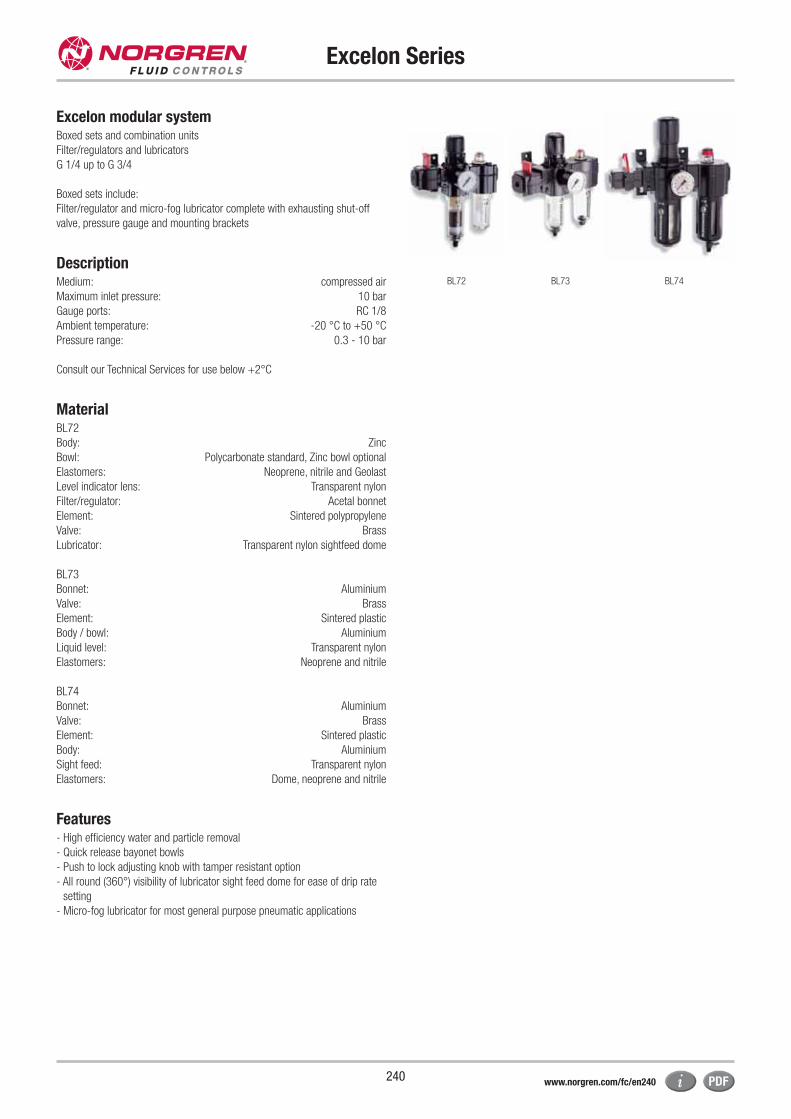
Excelon Series
240
Excelon modular systemBoxed sets and combination units
Filter/regulators and lubricators
G 1/4 up to G 3/4
Boxed sets include:
Filter/regulator and micro-fog lubricator complete with exhausting shut-off
valve, pressure gauge and mounting brackets
DescriptionMedium: compressed air
Maximum inlet pressure: 10 bar
Gauge ports: RC 1/8
Ambient temperature: -20 °C to +50 °C
Pressure range: 0.3 - 10 bar
Consult our Technical Services for use below +2°C
MaterialBL72
Body: Zinc
Bowl: Polycarbonate standard, Zinc bowl optional
Elastomers: Neoprene, nitrile and Geolast
Level indicator lens: Transparent nylon
Filter/regulator: Acetal bonnet
Element: Sintered polypropylene
Valve: Brass
Lubricator: Transparent nylon sightfeed dome
BL73
Bonnet: Aluminium
Valve: Brass
Element: Sintered plastic
Body / bowl: Aluminium
Liquid level: Transparent nylon
Elastomers: Neoprene and nitrile
BL74
Bonnet: Aluminium
Valve: Brass
Element: Sintered plastic
Body: Aluminium
Sight feed: Transparent nylon
Elastomers: Dome, neoprene and nitrile
Features- High efficiency water and particle removal
- Quick release bayonet bowls
- Push to lock adjusting knob with tamper resistant option
- All round (360°) visibility of lubricator sight feed dome for ease of drip rate
setting
- Micro-fog lubricator for most general purpose pneumatic applications
BL72 BL73 BL74
www.norgren.com/fc/en240
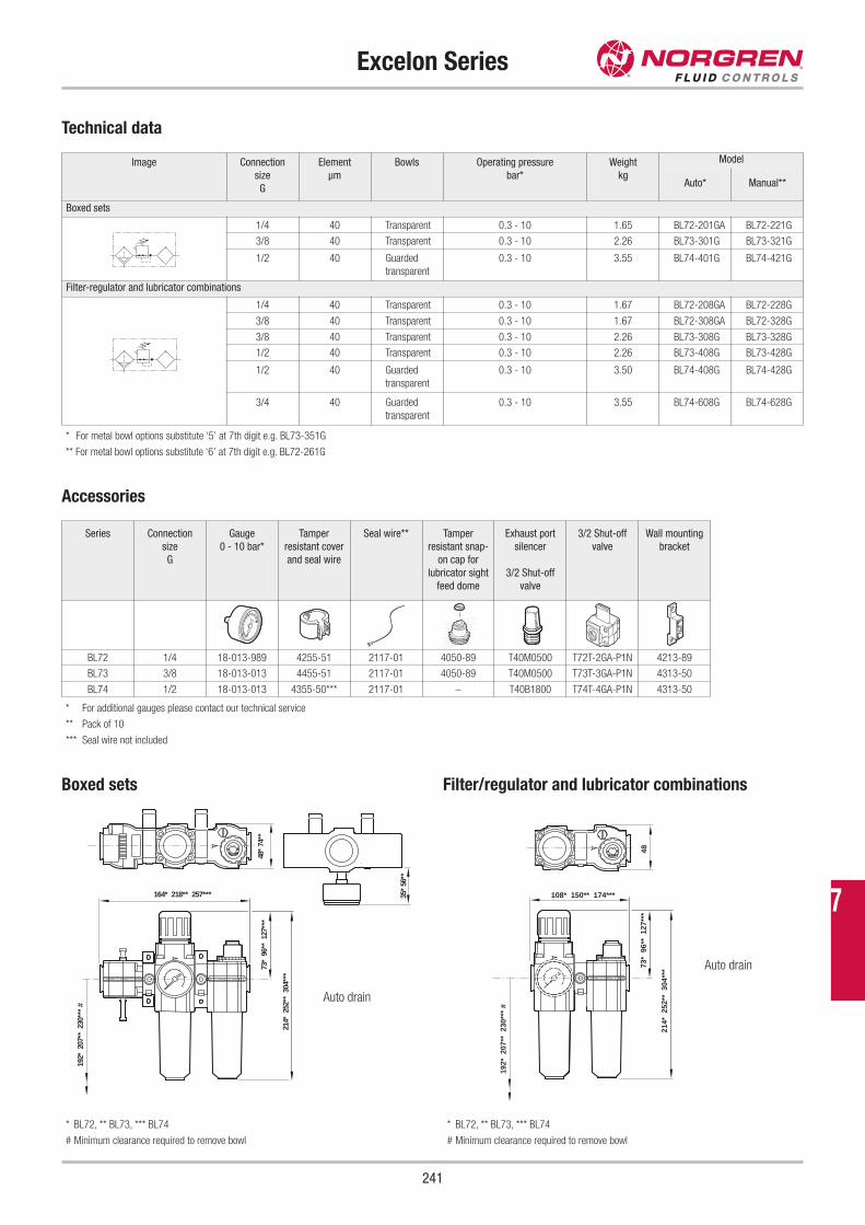
Excelon Series
241
Image Connection
size
G
Element
μm
Bowls Operating pressure
bar*
Weight
kg
Model
Auto* Manual**
Boxed sets
1/4 40 Transparent 0.3 - 10 1.65 BL72-201GA BL72-221G
3/8 40 Transparent 0.3 - 10 2.26 BL73-301G BL73-321G
1/2 40 Guarded
transparent
0.3 - 10 3.55 BL74-401G BL74-421G
Filter-regulator and lubricator combinations
1/4 40 Transparent 0.3 - 10 1.67 BL72-208GA BL72-228G
3/8 40 Transparent 0.3 - 10 1.67 BL72-308GA BL72-328G
3/8 40 Transparent 0.3 - 10 2.26 BL73-308G BL73-328G
1/2 40 Transparent 0.3 - 10 2.26 BL73-408G BL73-428G
1/2 40 Guarded
transparent
0.3 - 10 3.50 BL74-408G BL74-428G
3/4 40 Guarded
transparent
0.3 - 10 3.55 BL74-608G BL74-628G
* For metal bowl options substitute ‘5’ at 7th digit e.g. BL73-351G
** For metal bowl options substitute ‘6’ at 7th digit e.g. BL72-261G
Accessories
Series Connection
size
G
Gauge
0 - 10 bar*
Tamper
resistant cover
and seal wire
Seal wire** Tamper
resistant snap-
on cap for
lubricator sight
feed dome
Exhaust port
silencer
3/2 Shut-off
valve
3/2 Shut-off
valve
Wall mounting
bracket
BL72 1/4 18-013-989 4255-51 2117-01 4050-89 T40M0500 T72T-2GA-P1N 4213-89
BL73 3/8 18-013-013 4455-51 2117-01 4050-89 T40M0500 T73T-3GA-P1N 4313-50
BL74 1/2 18-013-013 4355-50*** 2117-01 – T40B1800 T74T-4GA-P1N 4313-50
* For additional gauges please contact our technical service
** Pack of 10
*** Seal wire not included
Boxed sets
214*
252
** 3
04**
*
73*
96*
* 1
27**
* 4
8* 7
4**
192*
207
** 2
30**
* #
164* 218** 257*** 35*
56**
* BL72, ** BL73, *** BL74
# Minimum clearance required to remove bowl
Auto drain
Filter/regulator and lubricator combinations
214*
252
** 3
04**
*
192*
207
** 2
30**
* #
73*
96*
* 1
27**
*48
108* 150** 174***
* BL72, ** BL73, *** BL74
# Minimum clearance required to remove bowl
Auto drain
Technical data
7
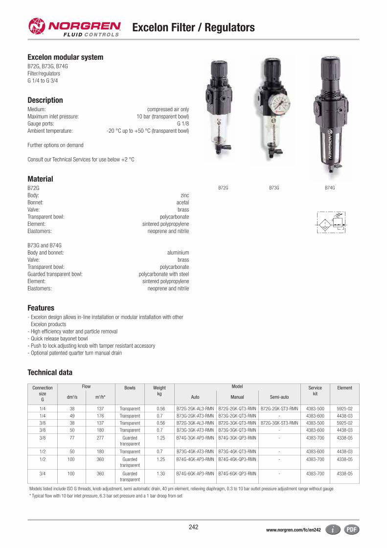
Excelon Filter / Regulators
242
Excelon modular systemB72G, B73G, B74G
Filter/regulators
G 1/4 to G 3/4
DescriptionMedium: compressed air only
Maximum inlet pressure: 10 bar (transparent bowl)
Gauge ports: G 1/8
Ambient temperature: -20 °C up to +50 °C (transparent bowl)
Further options on demand
Consult our Technical Services for use below +2 °C
MaterialB72G
Body: zinc
Bonnet: acetal
Valve: brass
Transparent bowl: polycarbonate
Element: sintered polypropylene
Elastomers: neoprene and nitrile
B73G and B74G
Body and bonnet: aluminium
Valve: brass
Transparent bowl: polycarbonate
Guarded transparent bowl: polycarbonate with steel
Element: sintered polypropylene
Elastomers: neoprene and nitrile
Features- Excelon design allows in-line installation or modular installation with other
Excelon products
- High efficiency water and particle removal
- Quick release bayonet bowl
- Push to lock adjusting knob with tamper resistant accessory
- Optional patented quarter turn manual drain
Technical data
B72G B73G B74G
Connection
size
G
Flow Bowls Weight
kg
Model Service
kit
Element
dm3/s m3/h* Auto Manual Semi-auto
1/4 38 137 Transparent 0.56 B72G-2GK-AL3-RMN B72G-2GK-QT3-RMN B72G-2GK-ST3-RMN 4383-500 5925-02
1/4 49 176 Transparent 0.7 B73G-2GK-AT3-RMN B73G-2GK-QT3-RMN - 4383-600 4438-03
3/8 38 137 Transparent 0.56 B72G-3GK-AL3-RMN B72G-3GK-QT3-RMN B72G-3GK-ST3-RMN 4383-500 5925-02
3/8 50 180 Transparent 0.7 B73G-3GK-AT3-RMN B73G-3GK-QT3-RMN - 4383-600 4438-03
3/8 77 277 Guarded
transparent
1.25 B74G-3GK-AP3-RMN B74G-3GK-QP3-RMN - 4383-700 4338-05
1/2 50 180 Transparent 0.7 B73G-4GK-AT3-RMN B73G-4GK-QT3-RMN - 4383-600 4438-03
1/2 100 360 Guarded
transparent
1.25 B74G-4GK-AP3-RMN B74G-4GK-QP3-RMN - 4383-700 4338-05
3/4 100 360 Guarded
transparent
1.30 B74G-6GK-AP3-RMN B74G-6GK-QP3-RMN - 4383-700 4338-05
Models listed include ISO G threads, knob adjustment, semi automatic drain, 40 μm element, relieving diaphragm, 0.3 to 10 bar outlet pressure adjustment range without gauge
* Typical flow with 10 bar inlet pressure, 6.3 bar set pressure and a 1 bar droop from set
www.norgren.com/fc/en242
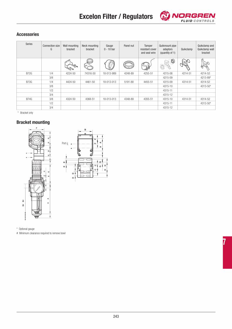
Excelon Filter / Regulators
243
Accessories
* Bracket only
EC
B#
AG
H
*
F
GE
D
HC
B
A
F
*
* Optional gauge
# Minimum clearance required to remove bowl
Port CL
SeriesConnection size
G
Wall mounting
bracket
Neck mounting
bracket
Gauge
0 - 10 bar
Panel nut Tamper
resistant cover
and seal wire
Quikmount pipe
adaptors
(quantity of 1)
Quikclamp
Quikclamp and
Quikclamp wall
bracket
B72G 1/4 4224-50 74316-50 18-013-989 4248-89 4255-51 4215-08 4214-51 4214-52
3/8 4215-09 4213-89*
B73G 1/4 4424-50 4461-50 18-013-013 5191-88 4455-51 4315-09 4314-51 4314-52
3/8 4315-10 4313-50*
1/2 4315-11
3/4 4315-12
B74G 3/8 4324-50 4368-51 18-013-013 4348-89 4355-51 4315-10 4314-51 4314-52
1/2 4315-11 4313-50*
3/4 4315-12
EC
B#
AG
H
*
F
GE
D
HC
B
A
F
*
Bracket mounting
7
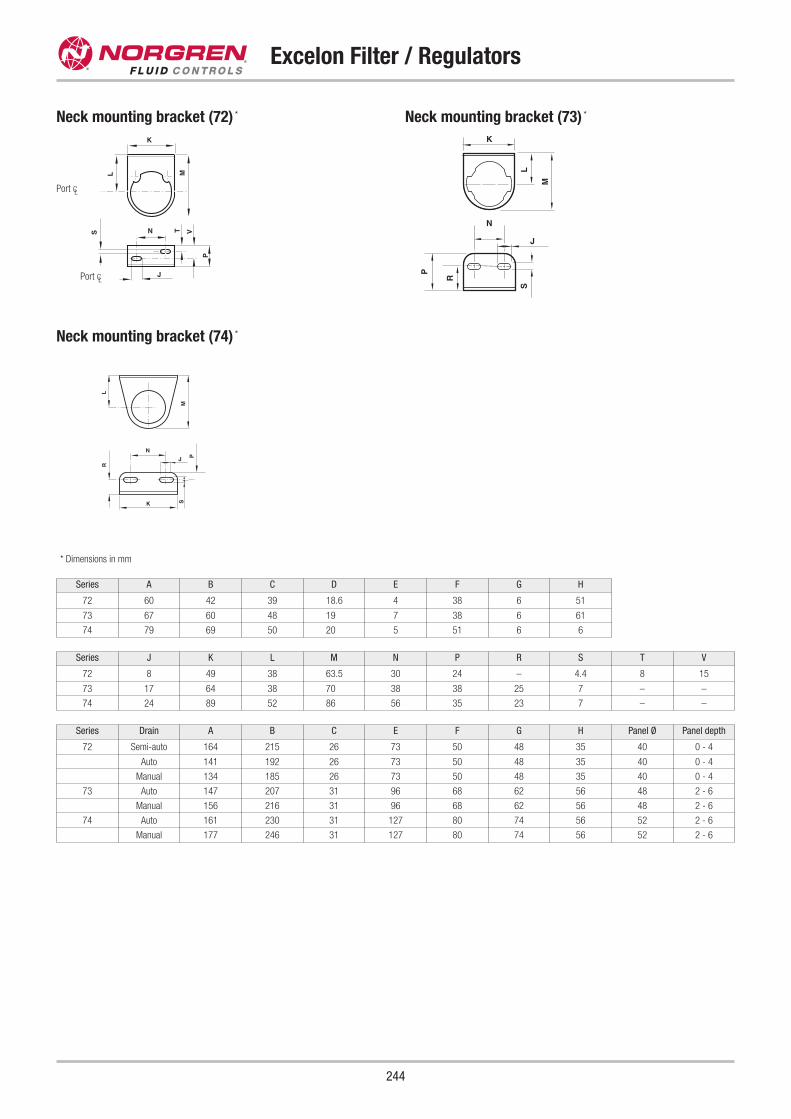
Series A B C D E F G H
72 60 42 39 18.6 4 38 6 51
73 67 60 48 19 7 38 6 61
74 79 69 50 20 5 51 6 6
Series Drain A B C E F G H Panel Ø Panel depth
72 Semi-auto 164 215 26 73 50 48 35 40 0 - 4
Auto 141 192 26 73 50 48 35 40 0 - 4
Manual 134 185 26 73 50 48 35 40 0 - 4
73 Auto 147 207 31 96 68 62 56 48 2 - 6
Manual 156 216 31 96 68 62 56 48 2 - 6
74 Auto 161 230 31 127 80 74 56 52 2 - 6
Manual 177 246 31 127 80 74 56 52 2 - 6
Series J K L M N P R S T V
72 8 49 38 63.5 30 24 – 4.4 8 15
73 17 64 38 70 38 38 25 7 – –
74 24 89 52 86 56 35 23 7 – –
Excelon Filter / Regulators
244
Neck mounting bracket (72) * Neck mounting bracket (73) *
Neck mounting bracket (74) *
K
NS
L M
P
J
T V
K
N
M
L
P
R J
S
M
L
K
P
R
N
J
S
Port CL
Port CL
* Dimensions in mm
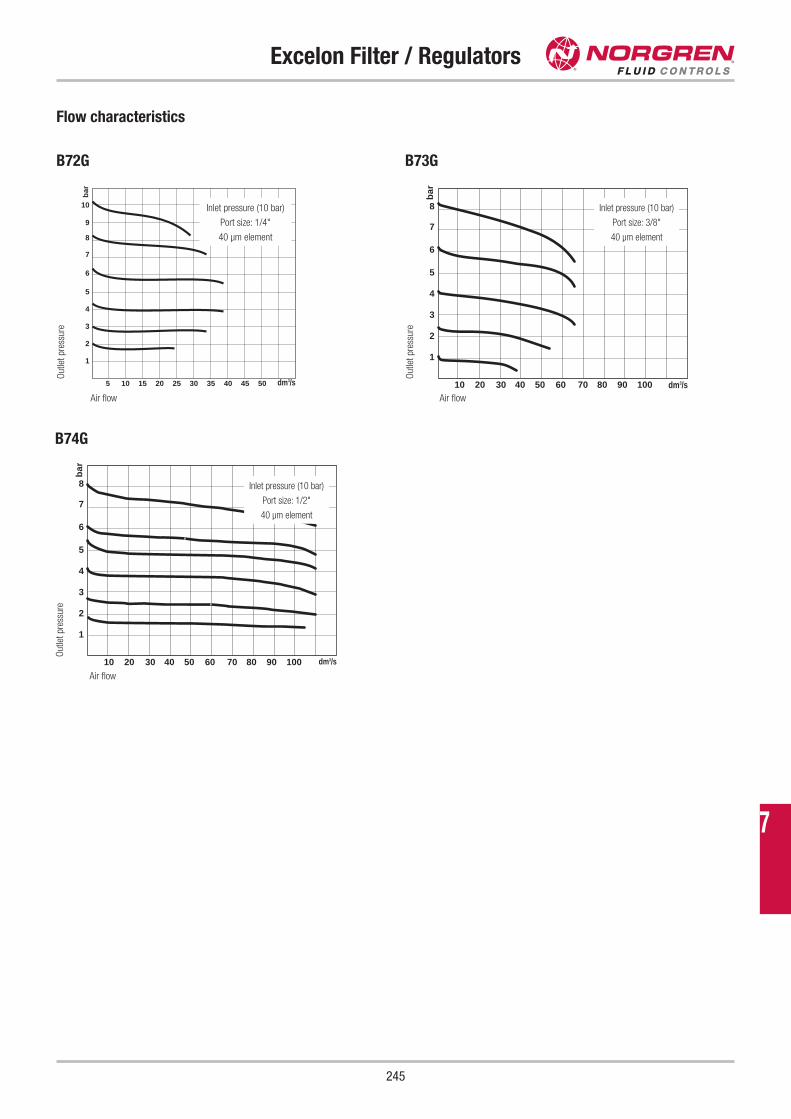
Excelon Filter / Regulators
245
Flow characteristics
B72G B73G
5
6
7
8
10
9
4
3
2
1
5 10 15 20 25 30 35 40 45 50
bar
5
6
7
8
4
3
2
1
10 20 30 40 50 60 70 80 90 100
bar
Air flow
Inlet pressure (10 bar)
Port size: 1/4"
40 μm element
Inlet pressure (10 bar)
Port size: 3/8"
40 μm element
Air flowO
utle
t pr
essu
re
B74G
5
6
7
8
4
3
2
1
10 20 30 40 50 60 70 80 90 100
bar
Inlet pressure (10 bar)
Port size: 1/2"
40 μm element
Air flow
Out
let
pres
sure
O
utle
t pr
essu
re
7
dm3/s
dm3/s
dm3/s
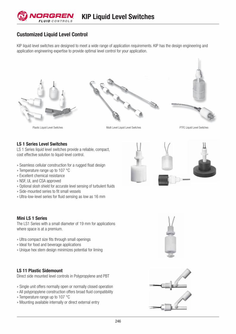
KIP Liquid Level Switches
Customized Liquid Level Control
KIP liquid level switches are designed to meet a wide range of application requirements. KIP has the design engineering and
application engineering expertise to provide optimal level control for your application.
LS 11 Plastic SidemountDirect side mounted level controls in Polypropylene and PBT
» Single unit offers normally open or normally closed operation
» All polypropylene construction offers broad fluid compatibility
» Temperature range up to 107 °C
» Mounting available internally or direct external entry
Mini LS 1 SeriesThe LS1 Series with a small diameter of 19 mm for applications
where space is at a premium.
» Ultra compact size fits through small openings
» Ideal for food and beverage applications
» Unique hex stem design minimizes potential for liming
LS 1 Series Level SwitchesLS 1 Series liquid level switches provide a reliable, compact,
cost effective solution to liquid-level control.
» Seamless cellular construction for a rugged float design
» Temperature range up to 107 °C
» Excellent chemical resistance
» NSF, UL and CSA approved
» Optional slosh shield for accurate level sensing of turbulent fluids
» Side-mounted series to fit small vessels
» Ultra-low-level series for fluid sensing as low as 16 mm
246
Plastic Liquid Level Switches Multi Level Liquid Level Switches PTFE Liquid Level Switches
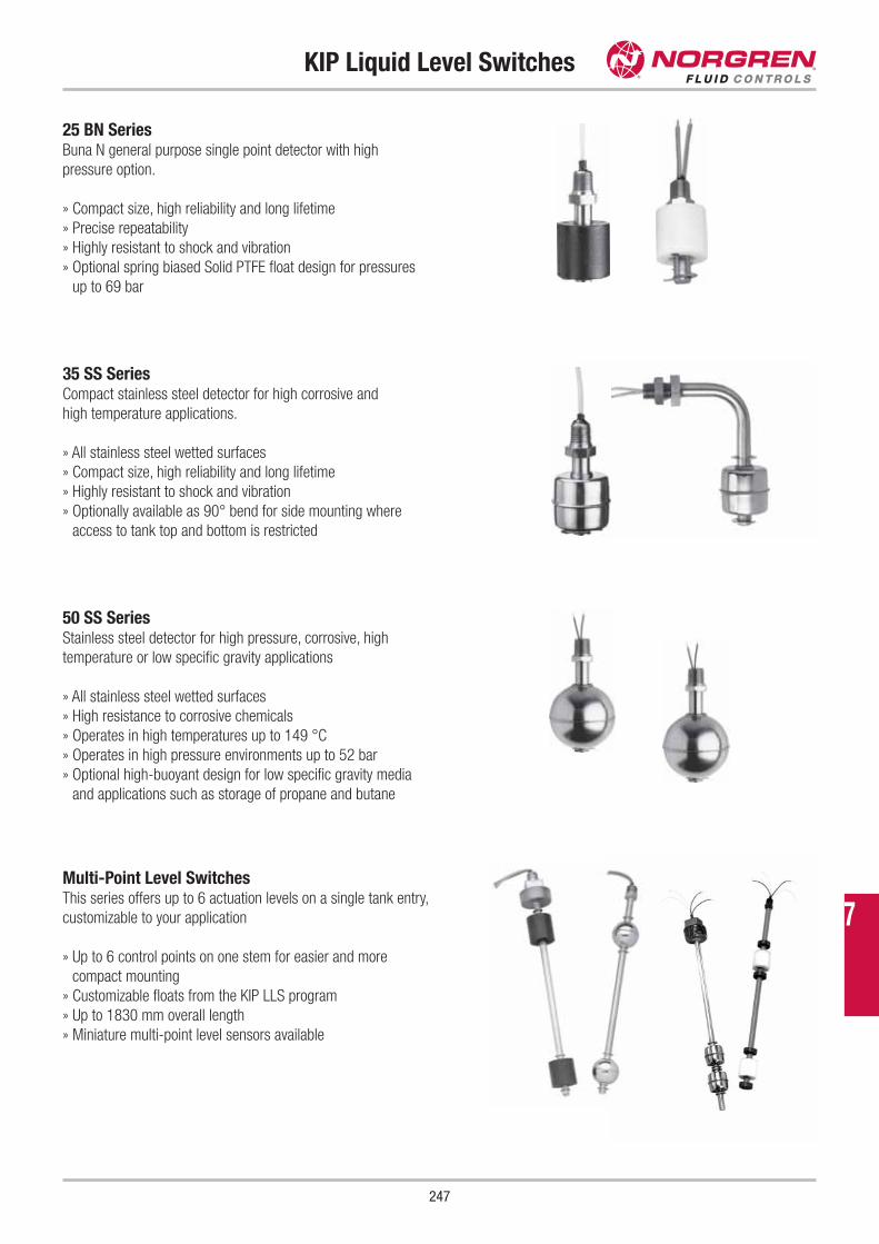
247
KIP Liquid Level Switches
25 BN Series Buna N general purpose single point detector with high
pressure option.
» Compact size, high reliability and long lifetime
» Precise repeatability
» Highly resistant to shock and vibration
» Optional spring biased Solid PTFE float design for pressures
up to 69 bar
Multi-Point Level Switches This series offers up to 6 actuation levels on a single tank entry,
customizable to your application
» Up to 6 control points on one stem for easier and more
compact mounting
» Customizable floats from the KIP LLS program
» Up to 1830 mm overall length
» Miniature multi-point level sensors available
50 SS SeriesStainless steel detector for high pressure, corrosive, high
temperature or low specific gravity applications
» All stainless steel wetted surfaces
» High resistance to corrosive chemicals
» Operates in high temperatures up to 149 °C
» Operates in high pressure environments up to 52 bar
» Optional high-buoyant design for low specific gravity media
and applications such as storage of propane and butane
35 SS Series Compact stainless steel detector for high corrosive and
high temperature applications.
» All stainless steel wetted surfaces
» Compact size, high reliability and long lifetime
» Highly resistant to shock and vibration
» Optionally available as 90° bend for side mounting where
access to tank top and bottom is restricted
7
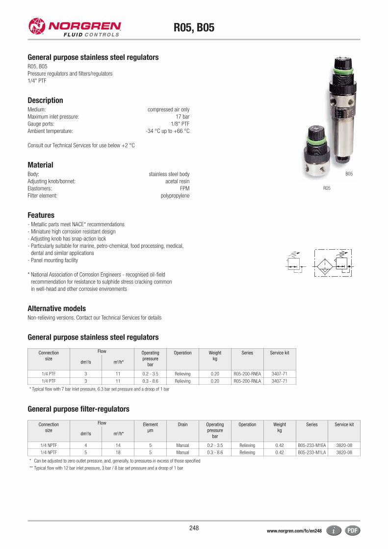
R05, B05
248
General purpose stainless steel regulatorsR05, B05
Pressure regulators and filters/regulators
1/4" PTF
DescriptionMedium: compressed air only
Maximum inlet pressure: 17 bar
Gauge ports: 1/8" PTF
Ambient temperature: -34 °C up to +66 °C
Consult our Technical Services for use below +2 °C
MaterialBody: stainless steel body
Adjusting knob/bonnet: acetal resin
Elastomers: FPM
Filter element: polypropylene
Features- Metallic parts meet NACE* recommendations
- Miniature high corrosion resistant design
- Adjusting knob has snap-action lock
- Particularly suitable for marine, petro-chemical, food processing, medical,
dental and similar applications
- Panel mounting facility
* National Association of Corrosion Engineers - recognised oil-field
recommendation for resistance to sulphide stress cracking common
in well-head and other corrosive environments
Alternative modelsNon-relieving versions. Contact our Technical Services for details
B05
R05
Connection
size
Flow Operating
pressure
bar
Operation Weight
kg
Series Service kit
dm3/s m3/h*
1/4 PTF 3 11 0.2 - 3.5 Relieving 0.20 R05-200-RNEA 3407-71
1/4 PTF 3 11 0.3 - 8.6 Relieving 0.20 R05-200-RNLA 3407-71
Connection
size
Flow Element
μm
Drain Operating
pressure
bar
Operation Weight
kg
Series Service kit
dm3/s m3/h*
1/4 NPTF 4 14 5 Manual 0.2 - 3.5 Relieving 0.42 B05-233-M1EA 3820-08
1/4 NPTF 5 18 5 Manual 0.3 - 8.6 Relieving 0.42 B05-233-M1LA 3820-08
* Typical flow with 7 bar inlet pressure, 6.3 bar set pressure and a droop of 1 bar
* Can be adjusted to zero outlet pressure, and, generally, to pressures in excess of those specified
** Typical flow with 12 bar inlet pressure, 3 bar / 8 bar set pressure and a droop of 1 bar
General purpose stainless steel regulators
General purpose filter-regulators
www.norgren.com/fc/en248
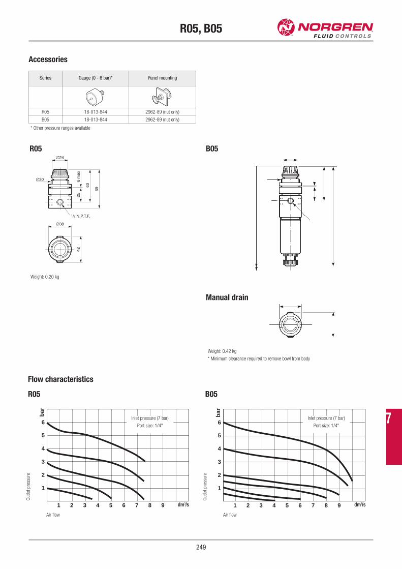
R05, B05
249
Accessories
R05 B05
Series Gauge (0 - 6 bar)* Panel mounting
R05 18-013-844 2962-89 (nut only)
B05 18-013-844 2962-89 (nut only)
* Other pressure ranges available
6 m
ax
∅24
∅30
25
60
69
∅38
42
1/8 N.P.T.F.
Weight: 0.20 kg
Weight: 0.42 kg
* Minimum clearance required to remove bowl from body
Manual drain
Flow characteristics
R05 B05
5
6
4
3
2
1
1 2 3 4 5 6 7 8 9
bar
5
6
4
3
2
1
1 2 3 4 5 6 7 8 9
bar
Air flow
Inlet pressure (7 bar)
Port size: 1/4"
Inlet pressure (7 bar)
Port size: 1/4"
Air flow
Out
let
pres
sure
Out
let
pres
sure
7
dm3/s dm3/s
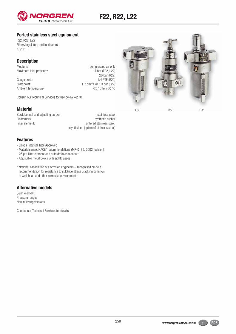
F22, R22, L22
250
Ported stainless steel equipmentF22, R22, L22
Filters/regulators and lubricators
1/2" PTF
DescriptionMedium: compressed air only
Maximum inlet pressure: 17 bar (F22, L22)
20 bar (R22)
Gauge ports: 1/4 PTF (R22)
Start point: 1.7 dm3/s @ 6.3 bar (L22)
Ambient temperature: -20 °C to +80 °C
Consult our Technical Services for use below +2 °C
MaterialBowl, bonnet and adjusting screw: stainless steel
Elastomers: synthetic rubber
Filter element: sintered stainless steel,
polyethylene (option of stainless steel)
Features- Lloyds Register Type Approved
- Materials meet NACE* recommendations (MR-0175, 2002 revision)
- 25 μm filter element and auto drain as standard
- Adjustable metal bowls with sightglasses
* National Association of Corrosion Engineers – recognised oil-field
recommendation for resistance to sulphide stress cracking common
in well-head and other corrosive environments
Alternative models5 μm element
Pressure ranges
Non-relieving versions
Contact our Technical Services for details
R22 L22F22
www.norgren.com/fc/en250
F22, R22, L22
251
Connection size Flow Element
μm
Drain Bowl Weight
kg
Series Service kit
dm3/s m3/h*
1/2 PTF 57 205 25 Auto Metal 1.88 F22-400-A2DA F22-100A
1/2 PTF 57 205 25 Manual Metal 1.84 F22-400-M2DA F22-100M
Filters
* Maximum flow with 6.3 bar inlet pressure and droop of 0.5 bar
Pressure regulators
* Maximum flow with 10 bar inlet pressure, 6.3 bar outlet pressure and a droop of 1 bar from set
Connection size Flow Range
bar
Operation Weight
kg
Series Service kit
dm3/s m3/h*
1/2 PTF 50 180 0.4 - 10 Relieving 1.52 R22-401-RNMA R22-100R
1/2 PTF 50 180 0.4 - 10 Non-relieving 1.54 R22-401-NNMA R22-100NR
Connection size Flow Start point
dm3/s *
Operation Bowl Bowl capacity Weight
kg
Series ** Service kit
dm3/s m3/h*
1/2 PTF 48 173 1.7 Oil-fog Metal 0.2 l 1.93 L22-400-OP8A L22-100
Lubricators
* Typical flow with 6.3 bar inlet pressure and 0.5 bar droop
** Start point at 6.3 bar
Accessories
Series Bracket kit Gauge
0 - 10 bar*
Neck mounting bracket
F22 18-001-962
R22 18-001-962 18-013-909** 18-001-959 (Panel nut and single bracket)
L22 18-001-962
* Other pressure ranges available
** Stainless steel items not strictly to NACE standard MR-01-75
7
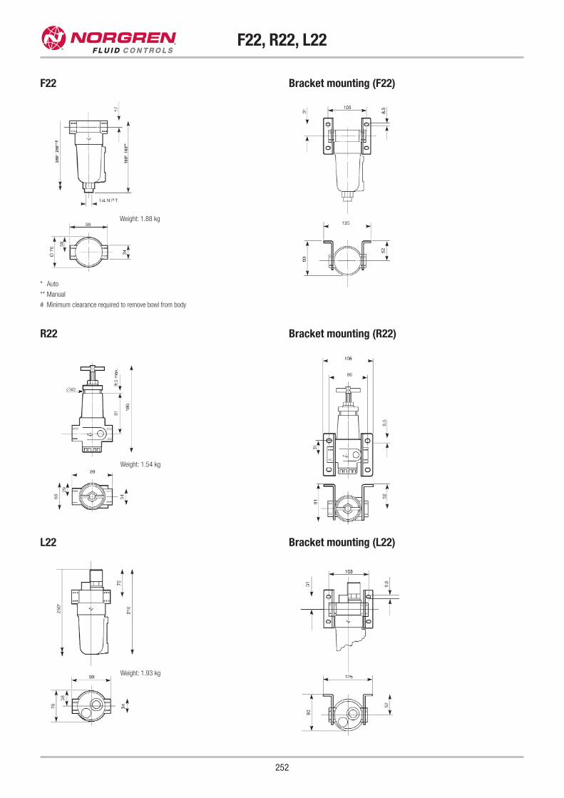
F22, R22, L22
252
* Auto
** Manual
# Minimum clearance required to remove bowl from body
Weight: 1.88 kg
F22 Bracket mounting (F22)
R22 Bracket mounting (R22)
L22 Bracket mounting (L22)
Weight: 1.93 kg
Weight: 1.54 kg
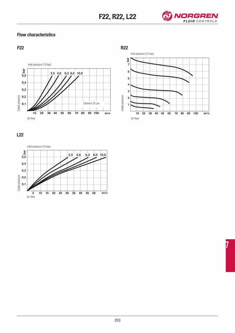
F22, R22, L22
253
Flow characteristics
F22 R22
0,5
0,4
0,3
0,2
0,1
10 20 30 40 50 60 70 80 90 100
2,5 4,0 6,3 8,0 10,0bar
5
6
7
4
3
2
1
10 20 30 40 50 60 70 80 90 100
bar
Air flow
Inlet pressure (10 bar)
Element 25 μm
Inlet pressure (10 bar)
Inlet pressure (10 bar)
Air flow
Out
let
pres
sure
L22
0,5
0,4
0,3
0,2
0,1
5 10 15 20 25 30 35 40 45 50
bar
2.5 4,0 6,3 8,0 10,0
Air flow
Out
let
pres
sure
O
utle
t pr
essu
re
7
dm3/sdm3/s
dm3/s
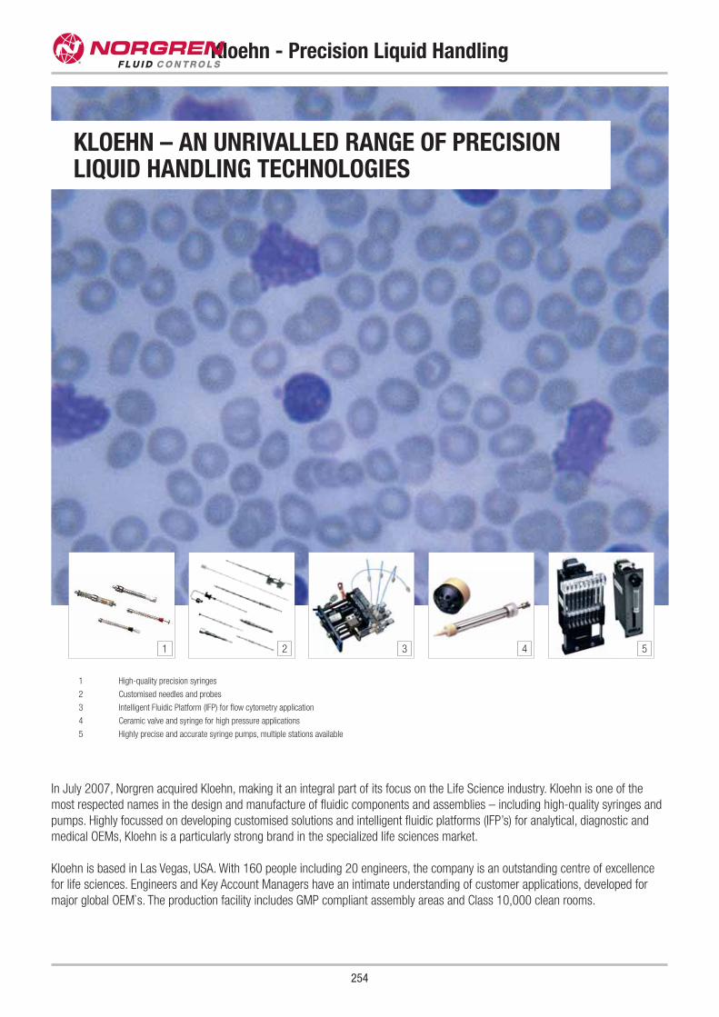
254
Kloehn - Precision Liquid Handling
In July 2007, Norgren acquired Kloehn, making it an integral part of its focus on the Life Science industry. Kloehn is one of the
most respected names in the design and manufacture of fluidic components and assemblies – including high-quality syringes and
pumps. Highly focussed on developing customised solutions and intelligent fluidic platforms (IFP’s) for analytical, diagnostic and
medical OEMs, Kloehn is a particularly strong brand in the specialized life sciences market.
Kloehn is based in Las Vegas, USA. With 160 people including 20 engineers, the company is an outstanding centre of excellence
for life sciences. Engineers and Key Account Managers have an intimate understanding of customer applications, developed for
major global OEM`s. The production facility includes GMP compliant assembly areas and Class 10,000 clean rooms.
1 High-quality precision syringes
2 Customised needles and probes
3 Intelligent Fluidic Platform (IFP) for flow cytometry application
4 Ceramic valve and syringe for high pressure applications
5 Highly precise and accurate syringe pumps, multiple stations available
1 2 3 4 5
KLOEHN – AN UNRIVALLED RANGE OF PRECISION LIQUID HANDLING TECHNOLOGIES
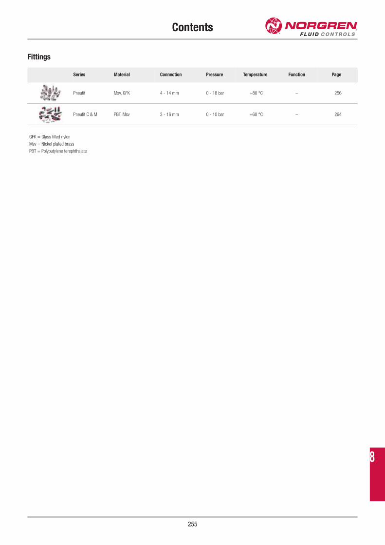
Contents
255
Series Material Connection Pressure Temperature Function Page
Pneufit Msv, GFK 4 - 14 mm 0 - 18 bar +80 °C – 256
Pneufit C & M PBT, Msv 3 - 16 mm 0 - 10 bar +60 °C – 264
Fittings
GFK = Glass filled nylon
Msv = Nickel plated brass
PBT = Polybutylene terephthalate
8
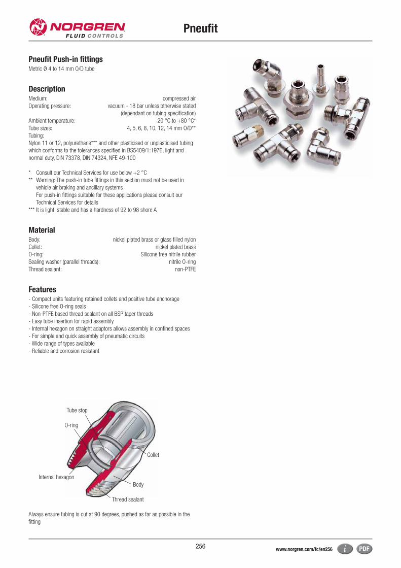
Tube stop
O-ring
Collet
Body
Thread sealant
Internal hexagon
256
Pneufit
Pneufit Push-in fittingsMetric Ø 4 to 14 mm O/D tube
DescriptionMedium: compressed air
Operating pressure: vacuum - 18 bar unless otherwise stated
(dependant on tubing specification)
Ambient temperature: -20 °C to +80 °C*
Tube sizes: 4, 5, 6, 8, 10, 12, 14 mm O/D**
Tubing:
Nylon 11 or 12, polyurethane*** and other plasticised or unplasticised tubing
which conforms to the tolerances specified in BS5409/1:1976, light and
normal duty, DIN 73378, DIN 74324, NFE 49-100
* Consult our Technical Services for use below +2 °C
** Warning: The push-in tube fittings in this section must not be used in
vehicle air braking and ancillary systems
For push-in fittings suitable for these applications please consult our
Technical Services for details
*** It is light, stable and has a hardness of 92 to 98 shore A
MaterialBody: nickel plated brass or glass filled nylon
Collet: nickel plated brass
O-ring: Silicone free nitrile rubber
Sealing washer (parallel threads): nitrile O-ring
Thread sealant: non-PTFE
Features- Compact units featuring retained collets and positive tube anchorage
- Silicone free O-ring seals
- Non-PTFE based thread sealant on all BSP taper threads
- Easy tube insertion for rapid assembly
- Internal hexagon on straight adaptors allows assembly in confined spaces
- For simple and quick assembly of pneumatic circuits
- Wide range of types available
- Reliable and corrosion resistant
Always ensure tubing is cut at 90 degrees, pushed as far as possible in the
fitting
www.norgren.com/fc/en256
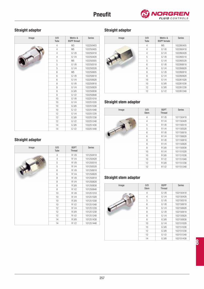
257
Pneufit
Image O/D
Tube
Metric &
BSPP thread
Series
4 M3 102250403
4 M5 102250405
4 G 1/8 102250418
4 G 1/4 102250428
5 M5 102250505
5 G 1/8 102250518
5 G 1/4 102250528
6 M5 102250605
6 G 1/8 102250618
6 G 1/4 102250628
8 G 1/8 102250818
8 G 1/4 102250828
8 G 3/8 102250838
8 G 1/2 102250848
10 G 1/8 102251018
10 G 1/4 102251028
10 G 3/8 102251038
10 G 1/2 102251048
12 G 1/4 102251228
12 G 3/8 102251238
12 G 1/2 102251248
14 G 3/8 102251438
14 G 1/2 102251448
Image O/D
Tube
Metric &
BSPP female
Series
4 M5 102260405
4 G 1/8 102260418
4 G 1/4 102260428
5 G 1/8 102260518
5 G 1/4 102260528
6 G 1/8 102260618
6 G 1/4 102260628
8 G 1/8 102260818
8 G 1/4 102260828
10 G 1/4 102261028
10 G 3/8 102261038
12 G 3/8 102261238
12 G 1/2 102261248
Image O/D
Tube
BSPT
Thread
Series
4 R 1/8 101250418
4 R 1/4 101250428
5 R 1/8 101250518
5 R 1/4 101250528
6 R 1/8 101250618
6 R 1/4 101250628
8 R 1/8 101250818
8 R 1/4 101250828
8 R 3/8 101250838
8 R 1/2 101250848
10 R 1/8 101251018
10 R 1/4 101251028
10 R 3/8 101251038
10 R 1/2 101251048
12 R 1/4 101251228
12 R 3/8 101251238
12 R 1/2 101251248
14 R 3/8 101251438
14 R 1/2 101251448
Image O/D
Stem
BSPT
Thread
Series
4 R 1/8 101150418
4 R 1/4 101150428
5 R 1/8 101150518
5 R 1/4 101150528
6 R 1/8 101150618
6 R 1/4 101150628
8 R 1/8 101150818
8 R 1/4 101150828
8 R 3/8 101150838
10 R 1/4 101151028
10 R 3/8 101151038
10 R 1/2 101151048
12 R 3/8 101151238
12 R 1/2 101151248
Image O/D
Stem
BSPP
Thread
Series
4 G 1/8 102150418
4 G 1/4 102150428
5 G 1/8 102150518
6 G 1/8 102150618
6 G 1/4 102150628
8 G 1/8 102150818
8 G 1/4 102150828
8 G 3/8 102150838
10 G 1/4 102151028
10 G 3/8 102151038
12 G 3/8 102151238
12 G 1/2 102151248
14 G 3/8 102151438
Straight adaptor
Straight adaptor
Straight adaptor
Straight stem adaptor
Straight stem adaptor
8
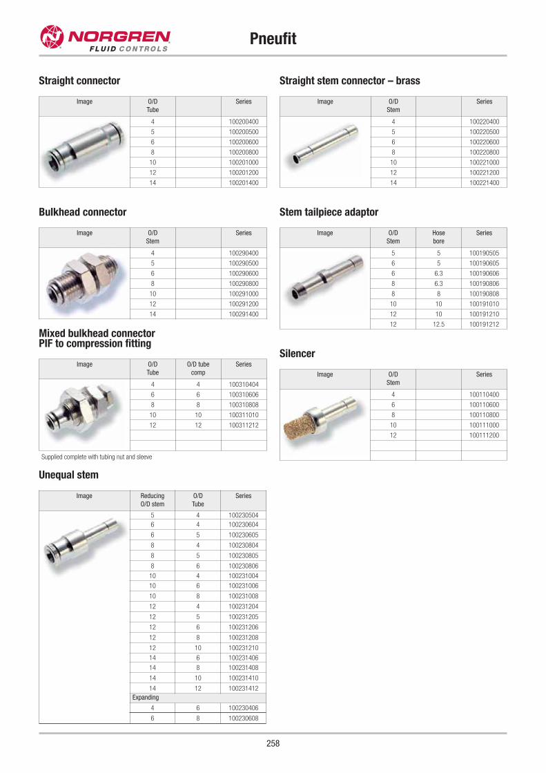
258
Pneufit
Straight connector
Bulkhead connector
Image O/D
Tube
Series
4 100200400
5 100200500
6 100200600
8 100200800
10 100201000
12 100201200
14 100201400
Image O/D
Stem
Series
4 100290400
5 100290500
6 100290600
8 100290800
10 100291000
12 100291200
14 100291400
Straight stem connector – brass
Image O/D
Stem
Series
4 100220400
5 100220500
6 100220600
8 100220800
10 100221000
12 100221200
14 100221400
Stem tailpiece adaptor
Silencer
Image O/D
Stem
Series
4 100110400
6 100110600
8 100110800
10 100111000
12 100111200
Mixed bulkhead connectorPIF to compression fitting
Image O/D
Tube
O/D tube
comp
Series
4 4 100310404
6 6 100310606
8 8 100310808
10 10 100311010
12 12 100311212
Supplied complete with tubing nut and sleeve
Unequal stem
Image Reducing
O/D stem
O/D
Tube
Series
5 4 100230504
6 4 100230604
6 5 100230605
8 4 100230804
8 5 100230805
8 6 100230806
10 4 100231004
10 6 100231006
10 8 100231008
12 4 100231204
12 5 100231205
12 6 100231206
12 8 100231208
12 10 100231210
14 6 100231406
14 8 100231408
14 10 100231410
14 12 100231412
Expanding
4 6 100230406
6 8 100230608
Image O/D
Stem
Hose
bore
Series
5 5 100190505
6 5 100190605
6 6.3 100190606
8 6.3 100190806
8 8 100190808
10 10 100191010
12 10 100191210
12 12.5 100191212
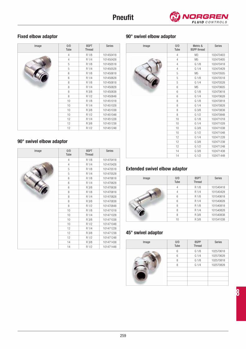
259
Pneufit
Fixed elbow adaptor
Image O/D
Tube
BSPT
Thread
Series
4 R 1/8 101450418
4 R 1/4 101450428
5 R 1/8 101450518
5 R 1/4 101450528
6 R 1/8 101450618
6 R 1/4 101450628
8 R 1/8 101450818
8 R 1/4 101450828
8 R 3/8 101450838
8 R 1/2 101450848
10 R 1/8 101451018
10 R 1/4 101451028
10 R 3/8 101451038
10 R 1/2 101451048
12 R 1/4 101451228
12 R 3/8 101451238
12 R 1/2 101451248
Extended swivel elbow adaptor
Image O/D
Tube
BSPT
Thread
Series
4 R 1/8 101540418
4 R 1/4 101540428
6 R 1/8 101540618
6 R 1/4 101540628
8 R 1/8 101540818
8 R 1/4 101540828
8 R 3/8 101540838
10 R 3/8 101541038
45° swivel adaptor
Image O/D
Tube
BSPP
Thread
Series
6 G 1/8 102570618
6 G 1/4 102570628
8 G 1/8 102570818
8 G 1/4 102570828
90° swivel elbow adaptor
Image O/D
Tube
BSPT
Thread
Series
4 R 1/8 101470418
4 R 1/4 101470428
5 R 1/8 101470518
5 R 1/4 101470528
6 R 1/8 101470618
6 R 1/4 101470628
6 R 3/8 101470638
8 R 1/8 101470818
8 R 1/4 101470828
8 R 3/8 101470838
8 R 1/2 101470848
10 R 1/8 101471018
10 R 1/4 101471028
10 R 3/8 101471038
10 R 1/2 101471048
12 R 1/4 101471228
12 R 3/8 101471238
12 R 1/2 101471248
14 R 3/8 101471438
14 R 1/2 101471448
90° swivel elbow adaptor
Image O/D
Tube
Metric &
BSPP thread
Series
4 M3 102470403
4 M5 102470405
4 G 1/8 102470418
4 G 1/4 102470428
5 M5 102470505
5 G 1/8 102470518
5 G 1/4 102470528
6 M5 102470605
6 G 1/8 102470618
6 G 1/4 102470628
8 G 1/8 102470818
8 G 1/4 102470828
8 G 3/8 102470838
8 G 1/2 102470848
10 G 1/8 102471018
10 G 1/4 102471028
10 G 3/8 102471038
10 G 1/2 102471048
12 G 1/4 102471228
12 G 3/8 102471238
12 G 1/2 102471248
14 G 3/8 102471438
14 G 1/2 102471448
8
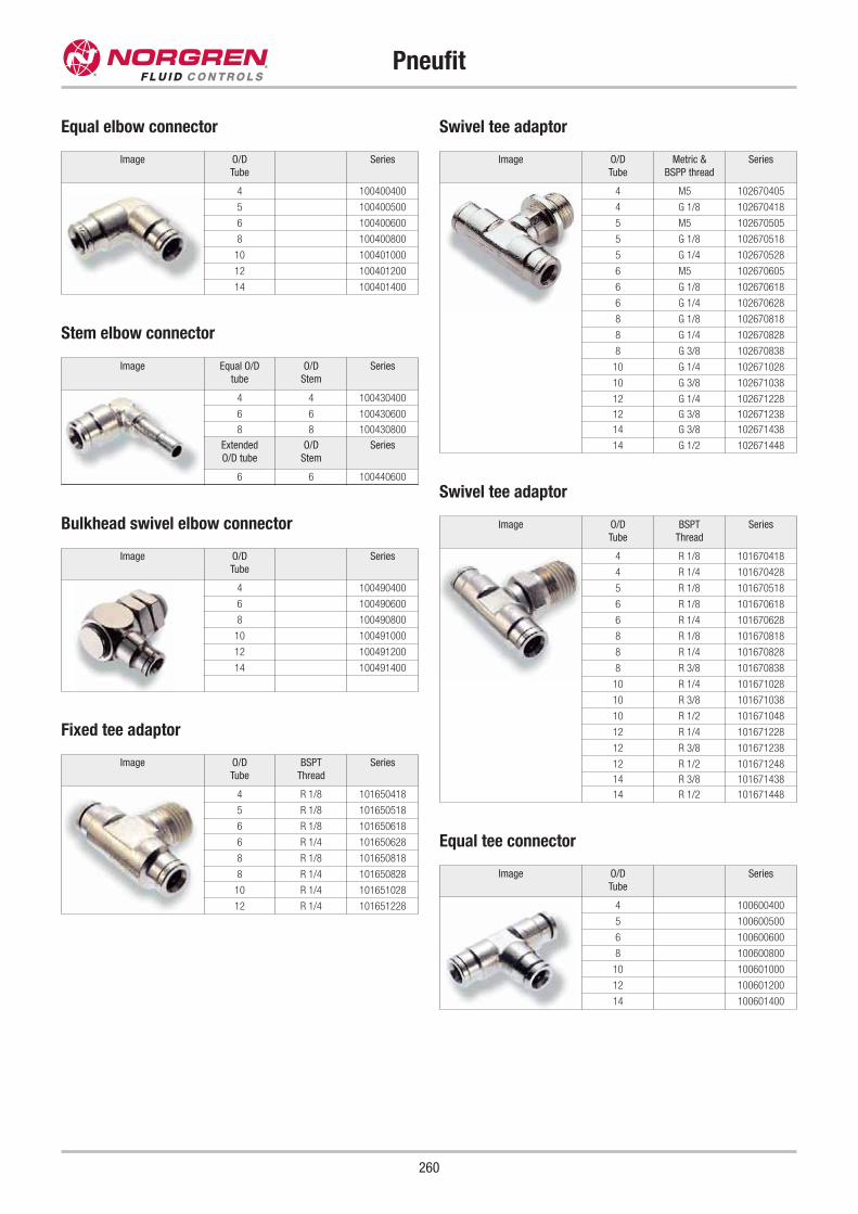
260
Pneufit
Equal elbow connector
Image O/D
Tube
Series
4 100400400
5 100400500
6 100400600
8 100400800
10 100401000
12 100401200
14 100401400
Equal tee connector
Image O/D
Tube
Series
4 100600400
5 100600500
6 100600600
8 100600800
10 100601000
12 100601200
14 100601400
Stem elbow connector
Image Equal O/D
tube
O/D
Stem
Series
4 4 100430400
6 6 100430600
8 8 100430800
Extended
O/D tube
O/D
Stem
Series
6 6 100440600
Bulkhead swivel elbow connector
Image O/D
Tube
Series
4 100490400
6 100490600
8 100490800
10 100491000
12 100491200
14 100491400
Fixed tee adaptor
Image O/D
Tube
BSPT
Thread
Series
4 R 1/8 101650418
5 R 1/8 101650518
6 R 1/8 101650618
6 R 1/4 101650628
8 R 1/8 101650818
8 R 1/4 101650828
10 R 1/4 101651028
12 R 1/4 101651228
Swivel tee adaptor
Image O/D
Tube
Metric &
BSPP thread
Series
4 M5 102670405
4 G 1/8 102670418
5 M5 102670505
5 G 1/8 102670518
5 G 1/4 102670528
6 M5 102670605
6 G 1/8 102670618
6 G 1/4 102670628
8 G 1/8 102670818
8 G 1/4 102670828
8 G 3/8 102670838
10 G 1/4 102671028
10 G 3/8 102671038
12 G 1/4 102671228
12 G 3/8 102671238
14 G 3/8 102671438
14 G 1/2 102671448
Swivel tee adaptor
Image O/D
Tube
BSPT
Thread
Series
4 R 1/8 101670418
4 R 1/4 101670428
5 R 1/8 101670518
6 R 1/8 101670618
6 R 1/4 101670628
8 R 1/8 101670818
8 R 1/4 101670828
8 R 3/8 101670838
10 R 1/4 101671028
10 R 3/8 101671038
10 R 1/2 101671048
12 R 1/4 101671228
12 R 3/8 101671238
12 R 1/2 101671248
14 R 3/8 101671438
14 R 1/2 101671448
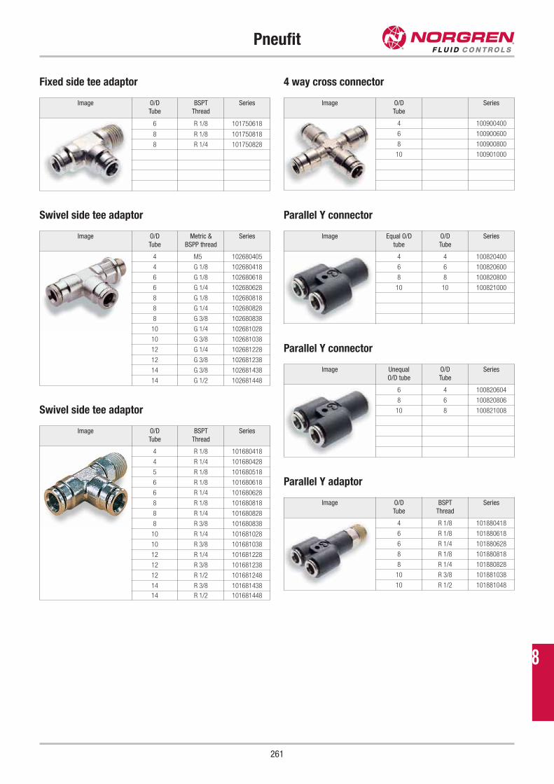
261
Pneufit
Fixed side tee adaptor
Image O/D
Tube
BSPT
Thread
Series
6 R 1/8 101750618
8 R 1/8 101750818
8 R 1/4 101750828
Image Equal O/D
tube
O/D
Tube
Series
4 4 100820400
6 6 100820600
8 8 100820800
10 10 100821000
4 way cross connector
Image O/D
Tube
Series
4 100900400
6 100900600
8 100900800
10 100901000
Swivel side tee adaptor
Image O/D
Tube
Metric &
BSPP thread
Series
4 M5 102680405
4 G 1/8 102680418
6 G 1/8 102680618
6 G 1/4 102680628
8 G 1/8 102680818
8 G 1/4 102680828
8 G 3/8 102680838
10 G 1/4 102681028
10 G 3/8 102681038
12 G 1/4 102681228
12 G 3/8 102681238
14 G 3/8 102681438
14 G 1/2 102681448
Parallel Y adaptor
Image O/D
Tube
BSPT
Thread
Series
4 R 1/8 101880418
6 R 1/8 101880618
6 R 1/4 101880628
8 R 1/8 101880818
8 R 1/4 101880828
10 R 3/8 101881038
10 R 1/2 101881048
Swivel side tee adaptor
Image O/D
Tube
BSPT
Thread
Series
4 R 1/8 101680418
4 R 1/4 101680428
5 R 1/8 101680518
6 R 1/8 101680618
6 R 1/4 101680628
8 R 1/8 101680818
8 R 1/4 101680828
8 R 3/8 101680838
10 R 1/4 101681028
10 R 3/8 101681038
12 R 1/4 101681228
12 R 3/8 101681238
12 R 1/2 101681248
14 R 3/8 101681438
14 R 1/2 101681448
Parallel Y connector
Image Unequal
O/D tube
O/D
Tube
Series
6 4 100820604
8 6 100820806
10 8 100821008
Parallel Y connector
8
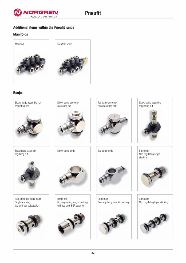
Pneufit
262
Manifolds
Additional items within the Pneufit range
Banjos
Elbow banjo assembly non
regulating bolt
Elbow banjo assembly
regulating out
Tee banjo assembly
non regulating bolt
Manifold Manifold union
Elbow banjo assembly
regulating out
Elbow banjo assembly
regulating out
Elbow banjo body Tee banjo body Banjo bolt
Non regulating single
stacking
Regulating out banjo bolts
Single stacking
(screwdriver adjustable)
Banjo bolt
Non-regulating single stacking
with top port (BSP parallel)
Banjo bolt
Non regulating double stacking
Banjo bolt
Non regulating triple stacking
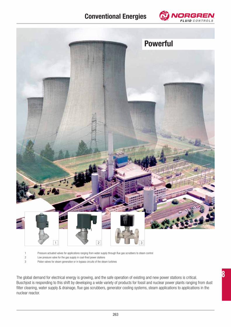
263
Conventional Energies
The global demand for electrical energy is growing, and the safe operation of existing and new power stations is critical.
Buschjost is responding to this shift by developing a wide variety of products for fossil and nuclear power plants ranging from dust
filter cleaning, water supply & drainage, flue gas scrubbers, generator cooling systems, steam applications to applications in the
nuclear reactor.
1 Pressure actuated valves for applications ranging from water supply through flue gas scrubbers to steam control
2 Low pressure valve for the gas supply in coal-fired power stations
3 Piston valves for steam generation or in bypass circuits of the steam turbines
1 2 3
Powerful
8
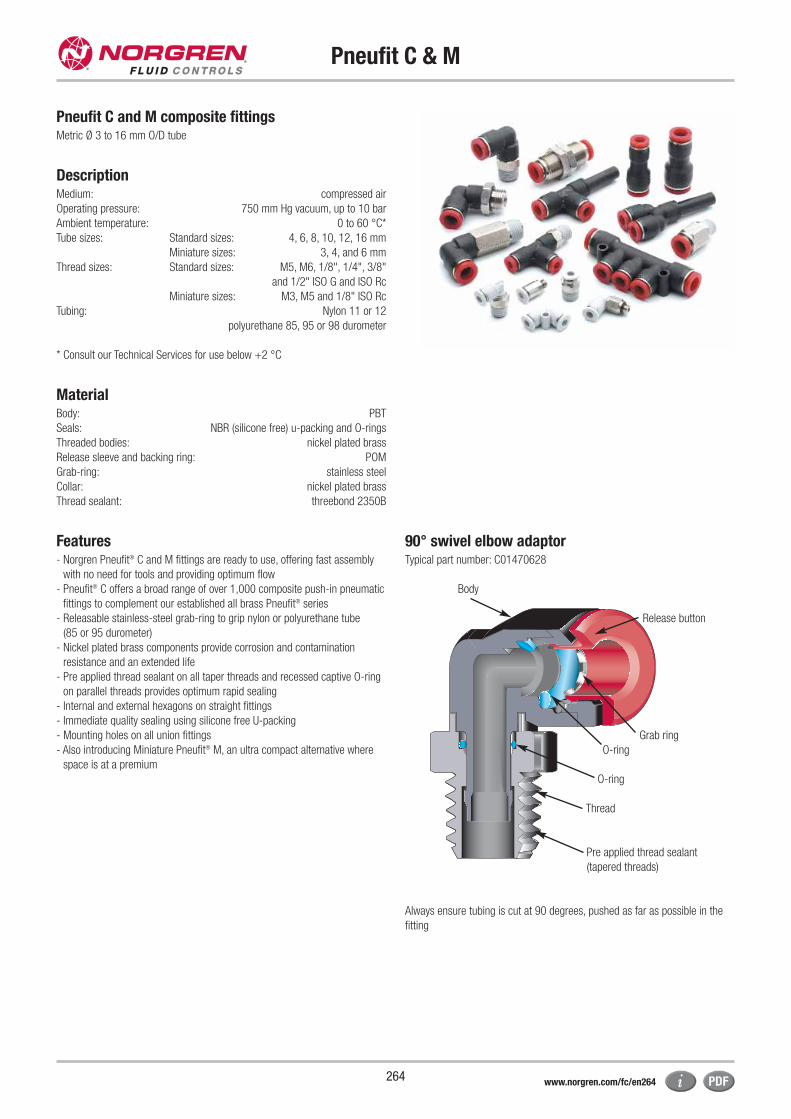
Pneufit C & M
264
Pneufit C and M composite fittingsMetric Ø 3 to 16 mm O/D tube
DescriptionMedium: compressed air
Operating pressure: 750 mm Hg vacuum, up to 10 bar
Ambient temperature: 0 to 60 °C*
Tube sizes: Standard sizes: 4, 6, 8, 10, 12, 16 mm
Miniature sizes: 3, 4, and 6 mm
Thread sizes: Standard sizes: M5, M6, 1/8", 1/4", 3/8"
and 1/2" ISO G and ISO Rc
Miniature sizes: M3, M5 and 1/8" ISO Rc
Tubing: Nylon 11 or 12
polyurethane 85, 95 or 98 durometer
* Consult our Technical Services for use below +2 °C
MaterialBody: PBT
Seals: NBR (silicone free) u-packing and O-rings
Threaded bodies: nickel plated brass
Release sleeve and backing ring: POM
Grab-ring: stainless steel
Collar: nickel plated brass
Thread sealant: threebond 2350B
Features- Norgren Pneufit® C and M fittings are ready to use, offering fast assembly
with no need for tools and providing optimum flow
- Pneufit® C offers a broad range of over 1,000 composite push-in pneumatic
fittings to complement our established all brass Pneufit® series
- Releasable stainless-steel grab-ring to grip nylon or polyurethane tube
(85 or 95 durometer)
- Nickel plated brass components provide corrosion and contamination
resistance and an extended life
- Pre applied thread sealant on all taper threads and recessed captive O-ring
on parallel threads provides optimum rapid sealing
- Internal and external hexagons on straight fittings
- Immediate quality sealing using silicone free U-packing
- Mounting holes on all union fittings
- Also introducing Miniature Pneufit® M, an ultra compact alternative where
space is at a premium
Always ensure tubing is cut at 90 degrees, pushed as far as possible in the
fitting
Body
Release button
Grab ring
O-ring
Thread
Pre applied thread sealant
(tapered threads)
O-ring
90° swivel elbow adaptorTypical part number: C01470628
www.norgren.com/fc/en264
Pneufit C & M
265
Image O/D
Tube
Series
4 C00200400
6 C00200600
8 C00200800
10 C00201000
12 C00201200
16 C00201600
Straight union
Straight union (unequal)
Image O/D
Tube
O/D
Tube
Series
6 4 C00200604
8 6 C00200806
10 8 C00201008
12 10 C00201210
16 12 C00201612
Image O/D
Tube
BSPT
Thread
Series
4 R 1/8 C01250418
4 R 1/4 C01250428
4 R 3/8 C01250438
6 R 1/8 C01250618
6 R 1/4 C01250628
6 R 3/8 C01250638
6 R 1/2 C01250648
8 R 1/8 C01250818
8 R 1/4 C01250828
8 R 3/8 C01250838
8 R 1/2 C01250848
10 R 1/8 C01251018
10 R 1/4 C01251028
10 R 3/8 C01251038
10 R 1/2 C01251048
12 R 1/8 C01251218
12 R 1/4 C01251228
12 R 3/8 C01251238
12 R 1/2 C01251248
16 R 3/8 C01251638
16 R 1/2 C01251648
Straight adaptor (external + internal hex)
Image O/D
Tube
Metric &
BSPP thread
Series
4 M5 C02250405
4 M6 C02250406
4 G 1/8 C02250418
4 G 1/4 C02250428
4 G 3/8 C02250438
6 M5 C02250605
6 M6 C02250606
6 G 1/8 C02250618
6 G 1/4 C02250628
6 G 3/8 C02250638
8 G 1/8 C02250818
8 G 1/4 C02250828
8 G 3/8 C02250838
8 G 1/2 C02250848
10 G 1/8 C02251018
10 G 1/4 C02251028
10 G 3/8 C02251038
10 G 1/2 C02251048
12 G 1/4 C02251228
12 G 3/8 C02251238
12 G 1/2 C02251248
16 G 3/8 C02251638
16 G 1/2 C02251648
Straight adaptor (external + internal hex)
Image O/D
Tube
Metric &
BSPT thread
Series
4 M5 C022A0405
4 M6 C022A0406
4 R 1/8 C012A0418
4 R 1/4 C012A0428
4 R 3/8 C012A0438
6 M5 C022A0605
6 M6 C022A0606
6 R 1/8 C012A0618
6 R 1/4 C012A0628
6 R 3/8 C012A0638
8 R 1/8 C012A0818
8 R 1/4 C012A0828
8 R 3/8 C012A0838
8 R 1/2 C012A0848
10 R 1/8 C012A1018
10 R 1/4 C012A1028
10 R 3/8 C012A1038
10 R 1/2 C012A1048
12 R 1/8 C012A1218
12 R 1/4 C012A1228
12 R 3/8 C012A1238
12 R 1/2 C012A1248
Straight adaptor (internal hex only)
8
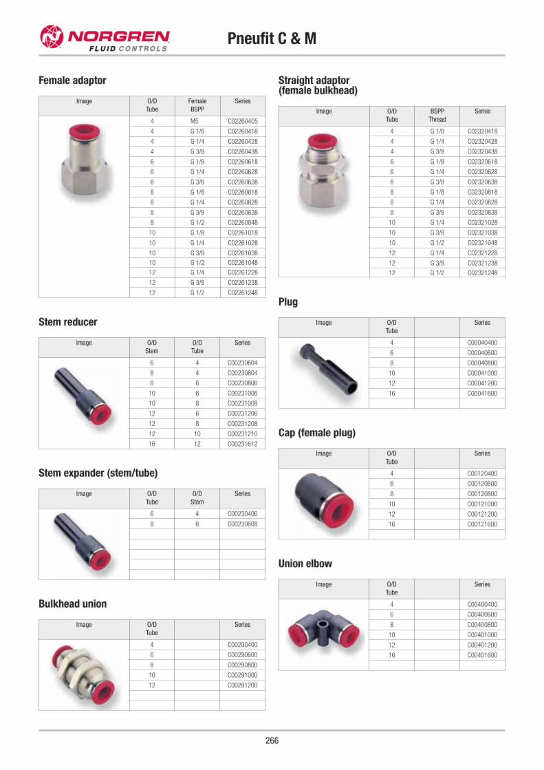
Pneufit C & M
266
Image O/D
Tube
Female
BSPP
Series
4 M5 C02260405
4 G 1/8 C02260418
4 G 1/4 C02260428
4 G 3/8 C02260438
6 G 1/8 C02260618
6 G 1/4 C02260628
6 G 3/8 C02260638
8 G 1/8 C02260818
8 G 1/4 C02260828
8 G 3/8 C02260838
8 G 1/2 C02260848
10 G 1/8 C02261018
10 G 1/4 C02261028
10 G 3/8 C02261038
10 G 1/2 C02261048
12 G 1/4 C02261228
12 G 3/8 C02261238
12 G 1/2 C02261248
Female adaptor
Image O/D
Tube
BSPP
Thread
Series
4 G 1/8 C02320418
4 G 1/4 C02320428
4 G 3/8 C02320438
6 G 1/8 C02320618
6 G 1/4 C02320628
6 G 3/8 C02320638
8 G 1/8 C02320818
8 G 1/4 C02320828
8 G 3/8 C02320838
10 G 1/4 C02321028
10 G 3/8 C02321038
10 G 1/2 C02321048
12 G 1/4 C02321228
12 G 3/8 C02321238
12 G 1/2 C02321248
Straight adaptor (female bulkhead)
Image O/D
Stem
O/D
Tube
Series
6 4 C00230604
8 4 C00230804
8 6 C00230806
10 6 C00231006
10 8 C00231008
12 6 C00231206
12 8 C00231208
12 10 C00231210
16 12 C00231612
Stem reducer
Image O/D
Tube
O/D
Stem
Series
6 4 C00230406
8 6 C00230608
Stem expander (stem/tube)
Image O/D
Tube
Series
4 C00290400
6 C00290600
8 C00290800
10 C00291000
12 C00291200
Bulkhead union
Image O/D
Tube
Series
4 C00040400
6 C00040600
8 C00040800
10 C00041000
12 C00041200
16 C00041600
Plug
Image O/D
Tube
Series
4 C00120400
6 C00120600
8 C00120800
10 C00121000
12 C00121200
16 C00121600
Cap (female plug)
Image O/D
Tube
Series
4 C00400400
6 C00400600
8 C00400800
10 C00401000
12 C00401200
16 C00401600
Union elbow
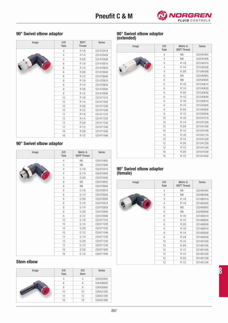
Pneufit C & M
267
Image O/D
Tube
BSPT
Thread
Series
4 R 1/8 C01470418
4 R 1/4 C01470428
4 R 3/8 C01470438
6 R 1/8 C01470618
6 R 1/4 C01470628
6 R 3/8 C01470638
6 R 1/2 C01470648
8 R 1/8 C01470818
8 R 1/4 C01470828
8 R 3/8 C01470838
8 R 1/2 C01470848
10 R 1/8 C01471018
10 R 1/4 C01471028
10 R 3/8 C01471038
10 R 1/2 C01471048
12 R 1/8 C01471218
12 R 1/4 C01471228
12 R 3/8 C01471238
12 R 1/2 C01471248
16 R 3/8 C01471638
16 R 1/2 C01471648
90° Swivel elbow adaptor
Image O/D
Tube
Metric &
BSPP Thread
Series
4 M5 C02470405
4 M6 C02470406
4 G 1/8 C02470418
4 G 1/4 C02470428
4 G 3/8 C02470438
6 M5 C02470605
6 M6 C02470606
6 G 1/8 C02470618
6 G 1/4 C02470628
6 G 3/8 C02470638
8 G 1/8 C02470818
8 G 1/4 C02470828
8 G 3/8 C02470838
8 G 1/2 C02470848
10 G 1/8 C02471018
10 G 1/4 C02471028
10 G 3/8 C02471038
10 G 1/2 C02471048
12 G 1/4 C02471228
12 G 3/8 C02471238
12 G 1/2 C02471248
16 G 3/8 C02471638
16 G 1/2 C02471648
90° Swivel elbow adaptor
90° Swivel elbow adaptor (extended)
Image O/D
Tube
O/D
Stem
Series
4 4 C00430400
6 6 C00430600
8 8 C00430800
10 10 C00431000
12 12 C00431200
16 16 C00431600
Stem elbow
Image O/D
Tube
Metric &
BSPT Thread
Series
4 M5 C02540405
4 M6 C02540406
4 R 1/8 C01540418
4 R 1/4 C01540428
4 R 3/8 C01540438
6 M5 C02540605
6 M6 C02540606
6 R 1/8 C01540618
6 R 1/4 C01540628
6 R 3/8 C01540638
6 R 1/2 C01540648
8 R 1/8 C01540818
8 R 1/4 C01540828
8 R 3/8 C01540838
8 R 1/2 C01540848
10 R 1/8 C01541018
10 R 1/4 C01541028
10 R 3/8 C01541038
10 R 1/2 C01541048
12 R 1/8 C01541218
12 R 1/4 C01541228
12 R 3/8 C01541238
12 R 1/2 C01541248
16 R 3/8 C01541638
16 R 1/2 C01541648
90° Swivel elbow adaptor (female)
Image O/D
Tube
Metric &
BSPT Thread
Series
4 M5 C02480405
4 M6 C02480406
4 R 1/8 C01480418
4 R 1/4 C01480428
6 M5 C02480605
6 M6 C02480606
6 R 1/8 C01480618
6 R 1/4 C01480628
6 R 3/8 C01480638
8 R 1/8 C01480818
8 R 1/4 C01480828
8 R 3/8 C01480838
10 R 1/4 C01481028
10 R 3/8 C01481038
10 R 1/2 C01481048
12 R 1/4 C01481228
12 R 3/8 C01481238
12 R 1/2 C01481248
8
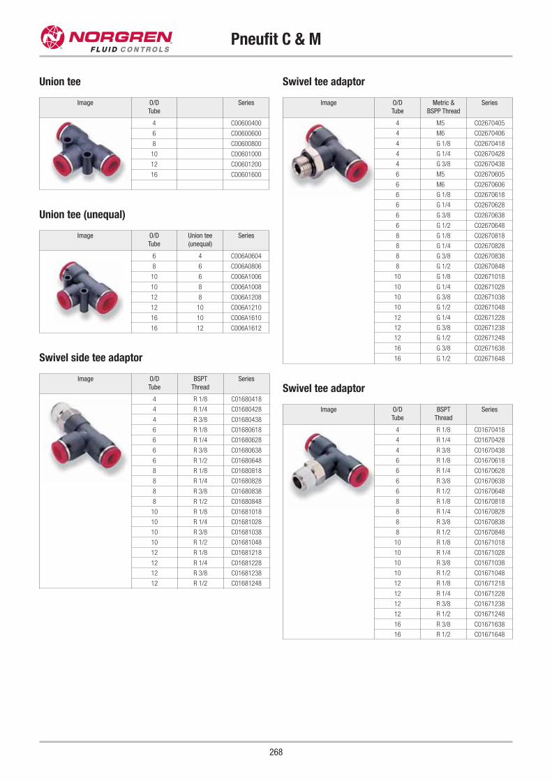
Pneufit C & M
268
Swivel tee adaptor
Image O/D
Tube
Metric &
BSPP Thread
Series
4 M5 C02670405
4 M6 C02670406
4 G 1/8 C02670418
4 G 1/4 C02670428
4 G 3/8 C02670438
6 M5 C02670605
6 M6 C02670606
6 G 1/8 C02670618
6 G 1/4 C02670628
6 G 3/8 C02670638
6 G 1/2 C02670648
8 G 1/8 C02670818
8 G 1/4 C02670828
8 G 3/8 C02670838
8 G 1/2 C02670848
10 G 1/8 C02671018
10 G 1/4 C02671028
10 G 3/8 C02671038
10 G 1/2 C02671048
12 G 1/4 C02671228
12 G 3/8 C02671238
12 G 1/2 C02671248
16 G 3/8 C02671638
16 G 1/2 C02671648
Swivel tee adaptor
Image O/D
Tube
BSPT
Thread
Series
4 R 1/8 C01670418
4 R 1/4 C01670428
4 R 3/8 C01670438
6 R 1/8 C01670618
6 R 1/4 C01670628
6 R 3/8 C01670638
6 R 1/2 C01670648
8 R 1/8 C01670818
8 R 1/4 C01670828
8 R 3/8 C01670838
8 R 1/2 C01670848
10 R 1/8 C01671018
10 R 1/4 C01671028
10 R 3/8 C01671038
10 R 1/2 C01671048
12 R 1/8 C01671218
12 R 1/4 C01671228
12 R 3/8 C01671238
12 R 1/2 C01671248
16 R 3/8 C01671638
16 R 1/2 C01671648
Swivel side tee adaptor
Image O/D
Tube
BSPT
Thread
Series
4 R 1/8 C01680418
4 R 1/4 C01680428
4 R 3/8 C01680438
6 R 1/8 C01680618
6 R 1/4 C01680628
6 R 3/8 C01680638
6 R 1/2 C01680648
8 R 1/8 C01680818
8 R 1/4 C01680828
8 R 3/8 C01680838
8 R 1/2 C01680848
10 R 1/8 C01681018
10 R 1/4 C01681028
10 R 3/8 C01681038
10 R 1/2 C01681048
12 R 1/8 C01681218
12 R 1/4 C01681228
12 R 3/8 C01681238
12 R 1/2 C01681248
Image O/D
Tube
Series
4 C00600400
6 C00600600
8 C00600800
10 C00601000
12 C00601200
16 C00601600
Union tee
Image O/D
Tube
Union tee
(unequal)
Series
6 4 C006A0604
8 6 C006A0806
10 6 C006A1006
10 8 C006A1008
12 8 C006A1208
12 10 C006A1210
16 10 C006A1610
16 12 C006A1612
Union tee (unequal)
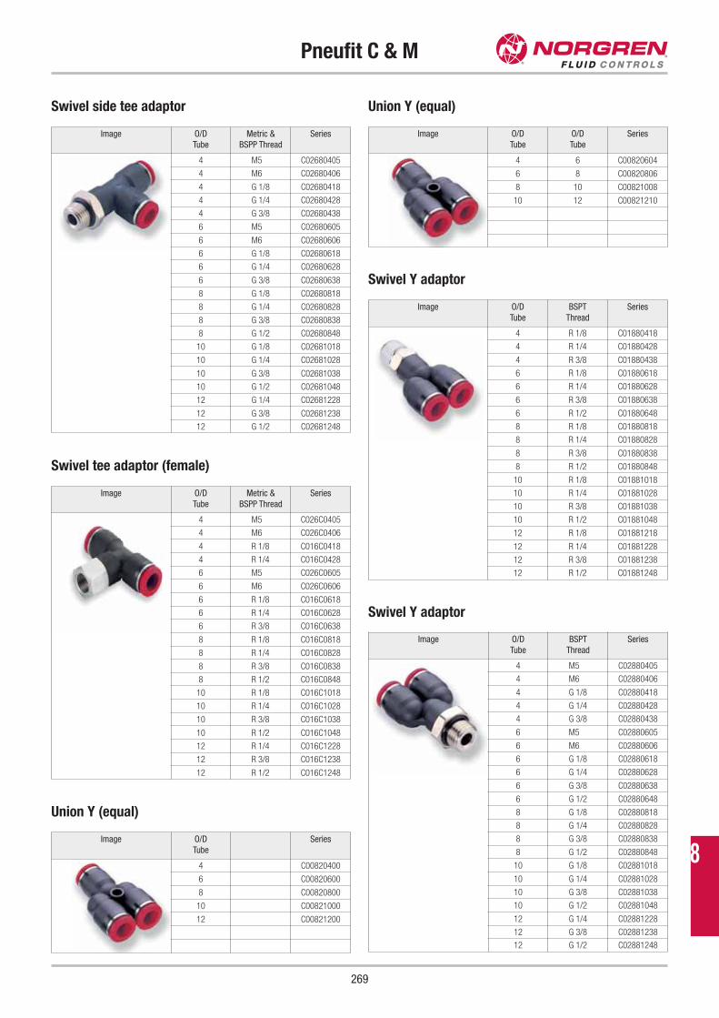
Pneufit C & M
269
Swivel side tee adaptor
Image O/D
Tube
Metric &
BSPP Thread
Series
4 M5 C02680405
4 M6 C02680406
4 G 1/8 C02680418
4 G 1/4 C02680428
4 G 3/8 C02680438
6 M5 C02680605
6 M6 C02680606
6 G 1/8 C02680618
6 G 1/4 C02680628
6 G 3/8 C02680638
8 G 1/8 C02680818
8 G 1/4 C02680828
8 G 3/8 C02680838
8 G 1/2 C02680848
10 G 1/8 C02681018
10 G 1/4 C02681028
10 G 3/8 C02681038
10 G 1/2 C02681048
12 G 1/4 C02681228
12 G 3/8 C02681238
12 G 1/2 C02681248
Swivel tee adaptor (female)
Image O/D
Tube
Metric &
BSPP Thread
Series
4 M5 C026C0405
4 M6 C026C0406
4 R 1/8 C016C0418
4 R 1/4 C016C0428
6 M5 C026C0605
6 M6 C026C0606
6 R 1/8 C016C0618
6 R 1/4 C016C0628
6 R 3/8 C016C0638
8 R 1/8 C016C0818
8 R 1/4 C016C0828
8 R 3/8 C016C0838
8 R 1/2 C016C0848
10 R 1/8 C016C1018
10 R 1/4 C016C1028
10 R 3/8 C016C1038
10 R 1/2 C016C1048
12 R 1/4 C016C1228
12 R 3/8 C016C1238
12 R 1/2 C016C1248
Image O/D
Tube
Series
4 C00820400
6 C00820600
8 C00820800
10 C00821000
12 C00821200
Union Y (equal)
Image O/D
Tube
O/D
Tube
Series
4 6 C00820604
6 8 C00820806
8 10 C00821008
10 12 C00821210
Union Y (equal)
Swivel Y adaptor
Image O/D
Tube
BSPT
Thread
Series
4 R 1/8 C01880418
4 R 1/4 C01880428
4 R 3/8 C01880438
6 R 1/8 C01880618
6 R 1/4 C01880628
6 R 3/8 C01880638
6 R 1/2 C01880648
8 R 1/8 C01880818
8 R 1/4 C01880828
8 R 3/8 C01880838
8 R 1/2 C01880848
10 R 1/8 C01881018
10 R 1/4 C01881028
10 R 3/8 C01881038
10 R 1/2 C01881048
12 R 1/8 C01881218
12 R 1/4 C01881228
12 R 3/8 C01881238
12 R 1/2 C01881248
Swivel Y adaptor
Image O/D
Tube
BSPT
Thread
Series
4 M5 C02880405
4 M6 C02880406
4 G 1/8 C02880418
4 G 1/4 C02880428
4 G 3/8 C02880438
6 M5 C02880605
6 M6 C02880606
6 G 1/8 C02880618
6 G 1/4 C02880628
6 G 3/8 C02880638
6 G 1/2 C02880648
8 G 1/8 C02880818
8 G 1/4 C02880828
8 G 3/8 C02880838
8 G 1/2 C02880848
10 G 1/8 C02881018
10 G 1/4 C02881028
10 G 3/8 C02881038
10 G 1/2 C02881048
12 G 1/4 C02881228
12 G 3/8 C02881238
12 G 1/2 C02881248
8
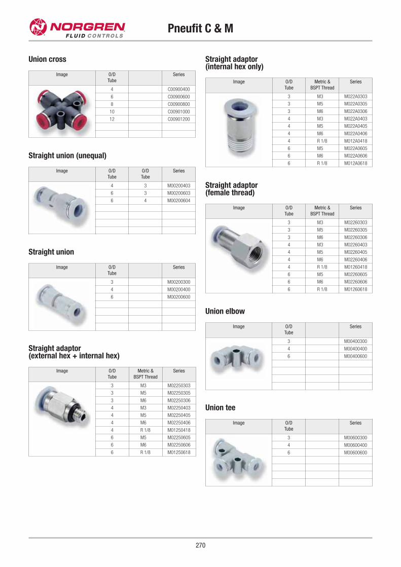
Pneufit C & M
270
Image O/D
Tube
Series
4 C00900400
6 C00900600
8 C00900800
10 C00901000
12 C00901200
Union cross
Image O/D
Tube
O/D
Tube
Series
4 3 M00200403
6 3 M00200603
6 4 M00200604
Straight union (unequal)
Image O/D
Tube
Series
3 M00200300
4 M00200400
6 M00200600
Straight union
Image O/D
Tube
Series
3 M00400300
4 M00400400
6 M00400600
Union elbow
Image O/D
Tube
Series
3 M00600300
4 M00600400
6 M00600600
Union tee
Straight adaptor (external hex + internal hex)
Image O/D
Tube
Metric &
BSPT Thread
Series
3 M3 M02250303
3 M5 M02250305
3 M6 M02250306
4 M3 M02250403
4 M5 M02250405
4 M6 M02250406
4 R 1/8 M01250418
6 M5 M02250605
6 M6 M02250606
6 R 1/8 M01250618
Straight adaptor (internal hex only)
Image O/D
Tube
Metric &
BSPT Thread
Series
3 M3 M022A0303
3 M5 M022A0305
3 M6 M022A0306
4 M3 M022A0403
4 M5 M022A0405
4 M6 M022A0406
4 R 1/8 M012A0418
6 M5 M022A0605
6 M6 M022A0606
6 R 1/8 M012A0618
Straight adaptor (female thread)
Image O/D
Tube
Metric &
BSPT Thread
Series
3 M3 M02260303
3 M5 M02260305
3 M6 M02260306
4 M3 M02260403
4 M5 M02260405
4 M6 M02260406
4 R 1/8 M01260418
6 M5 M02260605
6 M6 M02260606
6 R 1/8 M01260618
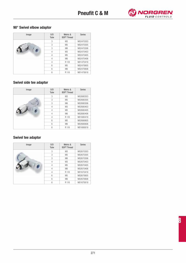
Pneufit C & M
271
90° Swivel elbow adaptor
Image O/D
Tube
Metric &
BSPT Thread
Series
3 M3 M02470303
3 M5 M02470305
3 M6 M02470306
4 M3 M02470403
4 M5 M02470405
4 M6 M02470406
4 R 1/8 M01470418
6 M5 M02470605
6 M6 M02470606
6 R 1/8 M01470618
Swivel side tee adaptor
Image O/D
Tube
Metric &
BSPT Thread
Series
3 M3 M02680303
3 M5 M02680305
3 M6 M02680306
4 M3 M02680403
4 M5 M02680405
4 M6 M02680406
4 R 1/8 M01680418
6 M5 M02680605
6 M6 M02680606
6 R 1/8 M01680618
Swivel tee adaptor
Image O/D
Tube
Metric &
BSPT Thread
Series
3 M3 M02670303
3 M5 M02670305
3 M6 M02670306
4 M3 M02670403
4 M5 M02670405
4 M6 M02670406
4 R 1/8 M01670418
6 M5 M02670605
6 M6 M02670606
6 R 1/8 M01670618
8
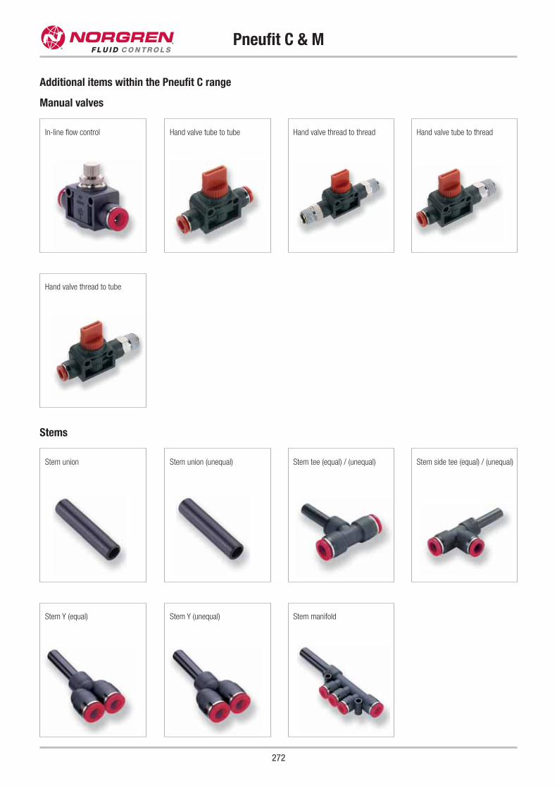
Pneufit C & M
272
Manual valves
Additional items within the Pneufit C range
Stems
Stem union (unequal)
Hand valve thread to tube
In-line flow control Hand valve tube to threadHand valve tube to tube Hand valve thread to thread
Stem union Stem side tee (equal) / (unequal)Stem tee (equal) / (unequal)
Stem Y (unequal)Stem Y (equal) Stem manifold
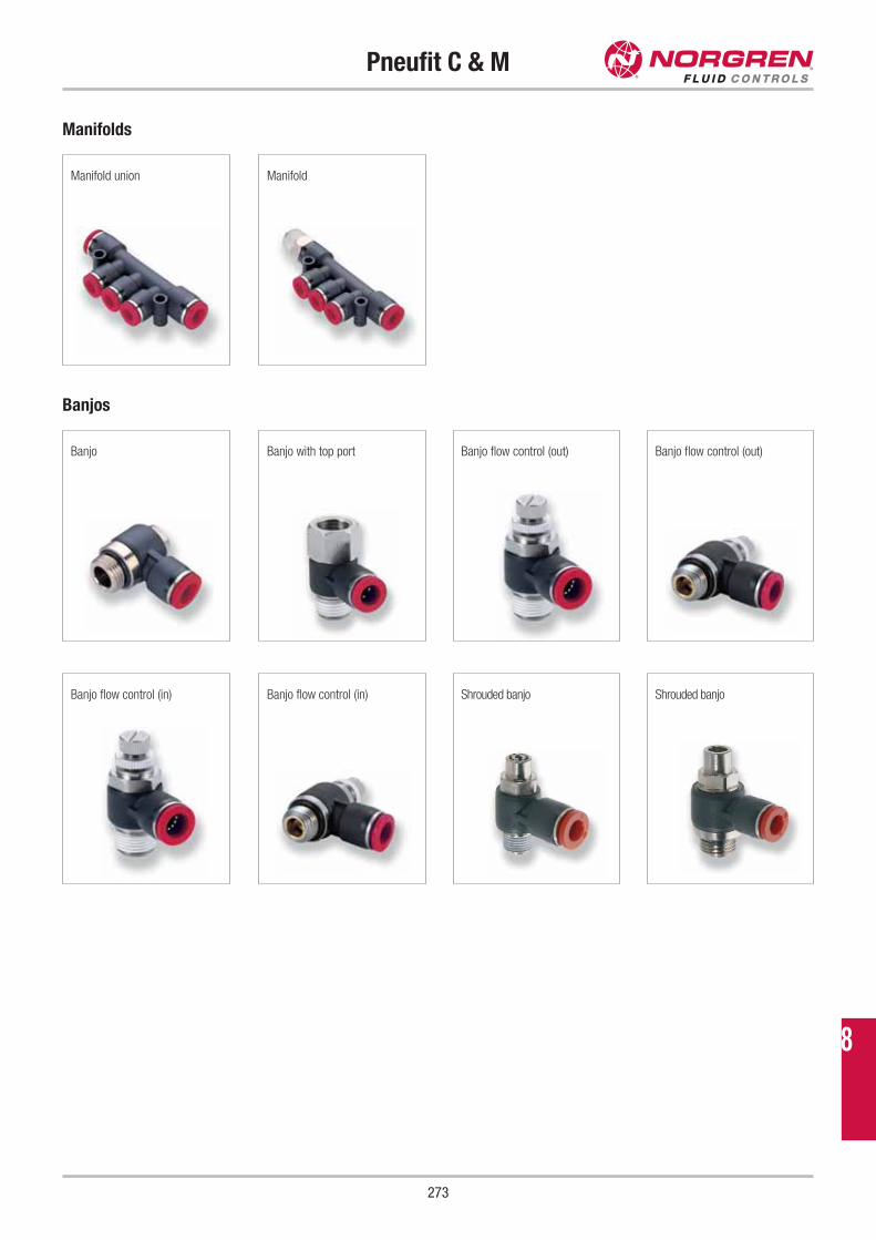
Pneufit C & M
273
Manifolds
Manifold union Manifold
Banjos
Banjo Banjo with top port Banjo flow control (out) Banjo flow control (out)
Banjo flow control (in) Banjo flow control (in) Shrouded banjo Shrouded banjo
8
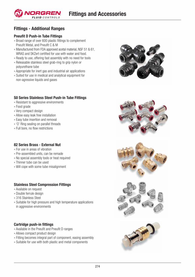
Fittings and Accessories
Fittings - Additional Ranges
Pneufit D Push-in Tube Fittings» Broad range of over 600 plastic fittings to complement
Pneufit Metal, and Pneufit C & M
» Manufactured from FDA approved acetal material, NSF 51 & 61,
WRAS and SKZert certified for use with water and food.
» Ready to use, offering fast assembly with no need for tools
» Releasable stainless steel grab-ring to grip nylon or
polyurethane tube
» Appropriate for inert gas and industrial air applications
» Suited for use in medical and analytical equipment for
non-agressive liquids and gases
Cartridge push-in fittings» Available in the Pneufit and Pneufit D ranges
» Allows compact product design
» Fitting becomes integral part of component, easing assembly
» Suitable for use with both plastic and metal components
Stainless Steel Compression Fittings» Available on request
» Double ferrule design
» 316 Stainless Steel
» Suitable for high pressure and high temperature applications
in aggressive environments
82 Series Brass - External Nut» For use in areas of vibration
» Pre-assembled units, can be remade
» No special assembly tools or heat required
» Thinner tube can be used
» Will cope with some tube misalignment
S0 Series Stainless Steel Push-in Tube Fittings» Resistant to aggressive environments
» Food grade
» Very compact design
» Allow easy leak free installation
» Easy tube insertion and removal
» ‘O’ Ring sealing on parallel threads
» Full bore, no flow restrictions
274
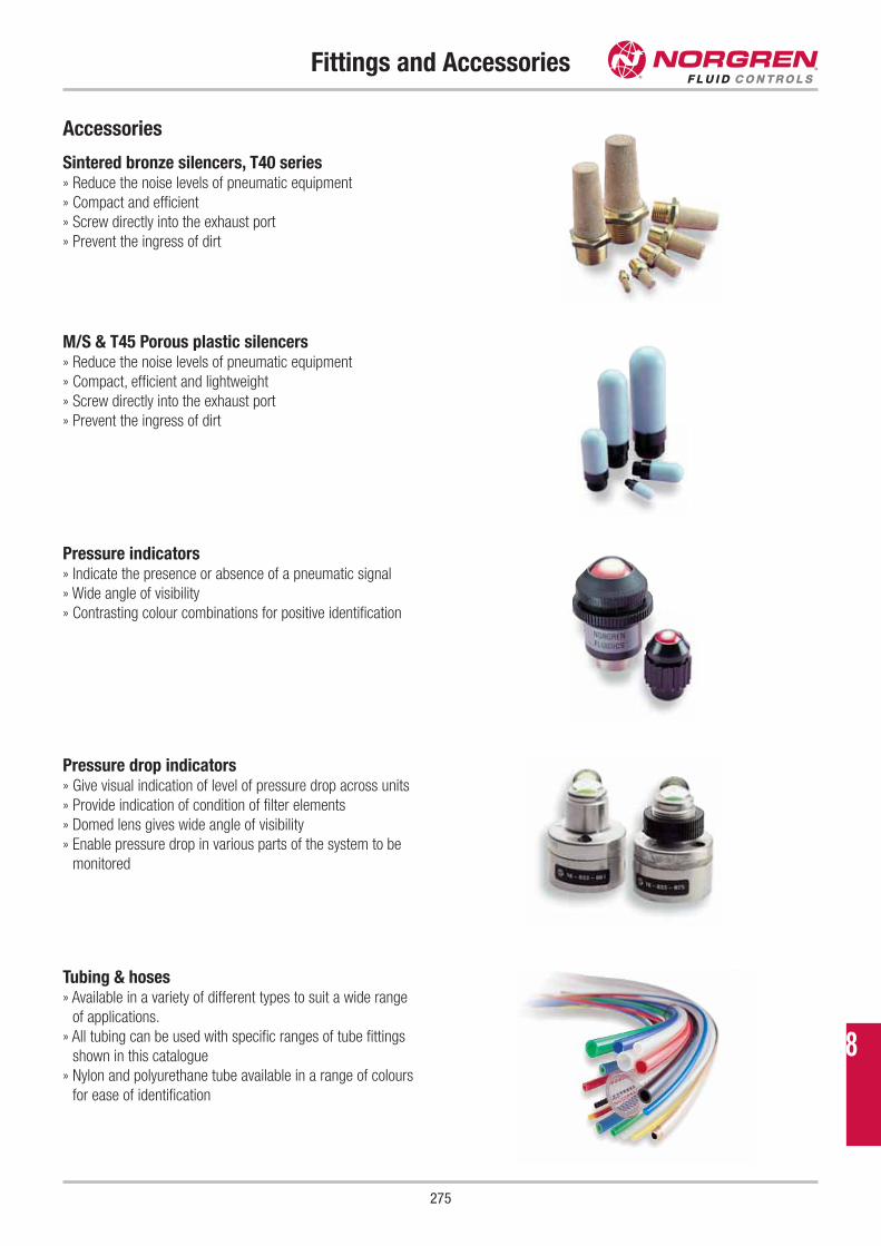
275
Fittings and Accessories
Accessories
Sintered bronze silencers, T40 series» Reduce the noise levels of pneumatic equipment
» Compact and efficient
» Screw directly into the exhaust port
» Prevent the ingress of dirt
Tubing & hoses» Available in a variety of different types to suit a wide range
of applications.
» All tubing can be used with specific ranges of tube fittings
shown in this catalogue
» Nylon and polyurethane tube available in a range of colours
for ease of identification
Pressure drop indicators» Give visual indication of level of pressure drop across units
» Provide indication of condition of filter elements
» Domed lens gives wide angle of visibility
» Enable pressure drop in various parts of the system to be
monitored
Pressure indicators» Indicate the presence or absence of a pneumatic signal
» Wide angle of visibility
» Contrasting colour combinations for positive identification
M/S & T45 Porous plastic silencers» Reduce the noise levels of pneumatic equipment
» Compact, efficient and lightweight
» Screw directly into the exhaust port
» Prevent the ingress of dirt
8
Technical Information
276
Solenoid Valve BasicsSwitching Functions & Symbols . . . . . . . . . . . . . . . . . . . . . . .280
Number of Ways . . . . . . . . . . . . . . . . . . . . . . . . . . . . . . . . . .281
Direct Acting Solenoid Valves . . . . . . . . . . . . . . . . . . . . . . . .282
Solenoid Valves without Differential Pressure . . . . . . . . . . . . .282
Solenoid Valves with Differential Pressure . . . . . . . . . . . . . . .283
Media Separated Solenoid Valves . . . . . . . . . . . . . . . . . . . . .283
Proportional Solenoid Valves . . . . . . . . . . . . . . . . . . . . . . . . .284
Motorised Proportional Valves . . . . . . . . . . . . . . . . . . . . . . . .285
Motorised Proportional Valve Characteristic . . . . . . . . . . . . . .286
Seat Valves . . . . . . . . . . . . . . . . . . . . . . . . . . . . . . . . . . . . .286
Zero Delta P Valves . . . . . . . . . . . . . . . . . . . . . . . . . . . . . . . .287
Operating Voltage . . . . . . . . . . . . . . . . . . . . . . . . . . . . . . . . .287
Explosion Protection . . . . . . . . . . . . . . . . . . . . . . . . . . . . . . .288
Response Time & Cycling Rate . . . . . . . . . . . . . . . . . . . . . . .288
Manual Override . . . . . . . . . . . . . . . . . . . . . . . . . . . . . . . . . .289
Protection Class (IP Protection) . . . . . . . . . . . . . . . . . . . . . . .289
Valve Selection Criteria . . . . . . . . . . . . . . . . . . . . . . . . . . . . .290
Materials - Seals . . . . . . . . . . . . . . . . . . . . . . . . . . . . . . . . .290
Materials - Polymers . . . . . . . . . . . . . . . . . . . . . . . . . . . . . . .291
Materials - Metals . . . . . . . . . . . . . . . . . . . . . . . . . . . . . . . .291
Click-on® Solenoid ValvesClick-on® - Solenoid Valves . . . . . . . . . . . . . . . . . . . . . . . . . .292
Click-on® - Diaphragm Valve . . . . . . . . . . . . . . . . . . . . . . . . .292
Click-on® - Piston Valve . . . . . . . . . . . . . . . . . . . . . . . . . . . .292
Pressure Actuated ValvesPressure Actuated Valves – Principle of Operation . . . . . . . . .293
Pressure Actuated Valves – Conversion from NC to NO . . . . . .293
Electric Position Indicator . . . . . . . . . . . . . . . . . . . . . . . . . . .294
Stroke Limiting System . . . . . . . . . . . . . . . . . . . . . . . . . . . . .294
NAMUR Adapter Plate . . . . . . . . . . . . . . . . . . . . . . . . . . . . . .295
Pressure, Flow and MediaPressure Ranges . . . . . . . . . . . . . . . . . . . . . . . . . . . . . . . . .296
Vacuum and Buschjost Valves . . . . . . . . . . . . . . . . . . . . . . . .296
Calculating Flow Rates . . . . . . . . . . . . . . . . . . . . . . . . . . . . .297
Viscosity . . . . . . . . . . . . . . . . . . . . . . . . . . . . . . . . . . . . . . .297
pH-Value . . . . . . . . . . . . . . . . . . . . . . . . . . . . . . . . . . . . . . .298
Ammonia & Buschjost Valves . . . . . . . . . . . . . . . . . . . . . . . .298
Steam, Hot Water & Buschjost Valves . . . . . . . . . . . . . . . . . . .299
Liquefied Gas & Buschjost Valves . . . . . . . . . . . . . . . . . . . . .299
Oxygen & Buschjost Valves . . . . . . . . . . . . . . . . . . . . . . . . . .300
Dust Collector CleaningDust Collector Valves and Systems . . . . . . . . . . . . . . . . . . . .301
Facts about Buschjost Dust Collectors Valves . . . . . . . . . . . . .302
Dust Collector Valves & Blow Tubes . . . . . . . . . . . . . . . . . . . .302
Differential Pressure Regulators . . . . . . . . . . . . . . . . . . . . . .303
Pressure Build-up Time . . . . . . . . . . . . . . . . . . . . . . . . . . . . .303
Air Tanks . . . . . . . . . . . . . . . . . . . . . . . . . . . . . . . . . . . . . . .304
Timer Solenoids . . . . . . . . . . . . . . . . . . . . . . . . . . . . . . . . . .304
Pneumatic Valve Controller . . . . . . . . . . . . . . . . . . . . . . . . . .305
Humidity and Frost . . . . . . . . . . . . . . . . . . . . . . . . . . . . . . . .305
Commercial VehiclesValves in Commercial Vehicles . . . . . . . . . . . . . . . . . . . . . . .306
Heating Circuits In Commercial Vehicles . . . . . . . . . . . . . . . .306
Buschjost TechnologiesBuschjost Part Numbering System . . . . . . . . . . . . . . . . . . . . .307
Installation . . . . . . . . . . . . . . . . . . . . . . . . . . . . . . . . . . . . . .307
Maintenance . . . . . . . . . . . . . . . . . . . . . . . . . . . . . . . . . . . .308
Electrical Connection . . . . . . . . . . . . . . . . . . . . . . . . . . . . . .308
Buschjost Solenoids . . . . . . . . . . . . . . . . . . . . . . . . . . . . . . .309
Buschjost Solenoids - Heating . . . . . . . . . . . . . . . . . . . . . . . .309
Latching Buschjost Valves . . . . . . . . . . . . . . . . . . . . . . . . . . .310
Timer Solenoid . . . . . . . . . . . . . . . . . . . . . . . . . . . . . . . . . . .310
EMC Electromagnetic Compability . . . . . . . . . . . . . . . . . . . . .311
Flange Dimensions . . . . . . . . . . . . . . . . . . . . . . . . . . . . . . . .311
Available Strainers . . . . . . . . . . . . . . . . . . . . . . . . . . . . . . . .312
Position Indicators . . . . . . . . . . . . . . . . . . . . . . . . . . . . . . . .312
Servo Amplifier . . . . . . . . . . . . . . . . . . . . . . . . . . . . . . . . . . .313
Valve Seat Tightness . . . . . . . . . . . . . . . . . . . . . . . . . . . . . . .313
Valve Blocks . . . . . . . . . . . . . . . . . . . . . . . . . . . . . . . . . . . . .314
EC Type examined Valves to DVGW requirements . . . . . . . . . .314
Test Certificates to DIN 50 049 / EN 10 204 . . . . . . . . . . . . .315
Quality and Environmental Management . . . . . . . . . . . . . . . .315
Pressure Equipment DirectivePressure Equipment Directive (PED) . . . . . . . . . . . . . . . . . . . .316
Safety InstructionsSafety Instructions for all Norgren and FAS series . . . . . . . . . .318
ATEX and Buschjost ValvesATEX . . . . . . . . . . . . . . . . . . . . . . . . . . . . . . . . . . . . . . . . . .319
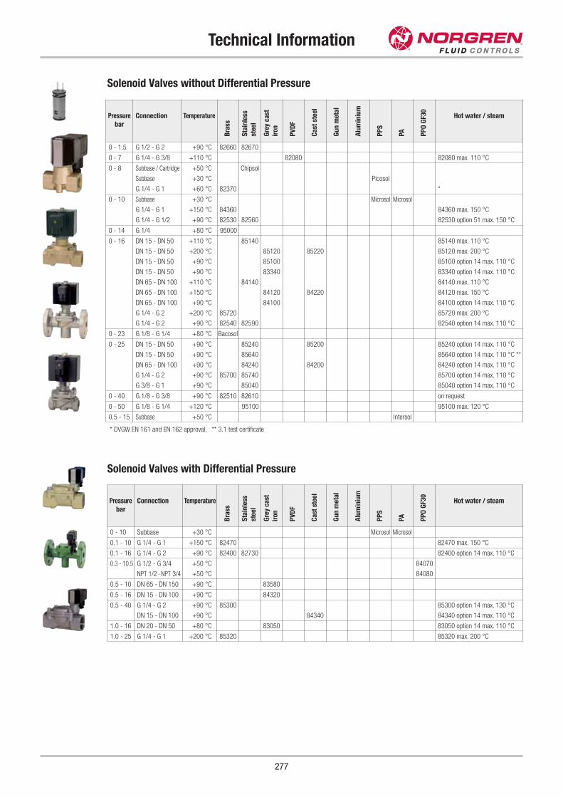
Technical Information
277
Solenoid Valves without Differential Pressure
* DVGW EN 161 and EN 162 approval, ** 3.1 test certificate
Solenoid Valves with Differential Pressure
Pressure
bar
Connection Temperature
Bra
ss
Sta
inle
ss
stee
l
Gre
y ca
st
iron
PV
DF
Ca
st s
teel
Gu
n m
eta
l
Alu
min
ium
PP
S
PA PP
O G
F30
Hot water / steam
0 - 10 Subbase +30 °C Microsol Microsol
0.1 - 10 G 1/4 - G 1 +150 °C 82470 82470 max. 150 °C
0.1 - 16 G 1/4 - G 2 +90 °C 82400 82730 82400 option 14 max. 110 °C
0.3 - 10.5 G 1/2 - G 3/4 +50 °C 84070
NPT 1/2 - NPT 3/4 +50 °C 84080
0.5 - 10 DN 65 - DN 150 +90 °C 83580
0.5 - 16 DN 15 - DN 100 +90 °C 84320
0.5 - 40 G 1/4 - G 2 +90 °C 85300 85300 option 14 max. 130 °C
DN 15 - DN 100 +90 °C 84340 84340 option 14 max. 110 °C
1.0 - 16 DN 20 - DN 50 +80 °C 83050 83050 option 14 max. 110 °C
1.0 - 25 G 1/4 - G 1 +200 °C 85320 85320 max. 200 °C
Pressure
bar
Connection Temperature
Bra
ss
Sta
inle
ss
stee
l
Gre
y ca
st
iron
PV
DF
Ca
st s
teel
Gu
n m
eta
l
Alu
min
ium
PP
S
PA PP
O G
F30
Hot water / steam
0 - 1.5 G 1/2 - G 2 +90 °C 82660 82670
0 - 7 G 1/4 - G 3/8 +110 °C 82080 82080 max. 110 °C
0 - 8 Subbase / Cartridge +50 °C Chipsol
Subbase +30 °C Picosol
G 1/4 - G 1 +60 °C 82370 *
0 - 10 Subbase +30 °C Microsol Microsol
G 1/4 - G 1 +150 °C 84360 84360 max. 150 °C
G 1/4 - G 1/2 +90 °C 82530 82560 82530 option 51 max. 150 °C
0 - 14 G 1/4 +80 °C 95000
0 - 16 DN 15 - DN 50 +110 °C 85140 85140 max. 110 °C
DN 15 - DN 50 +200 °C 85120 85220 85120 max. 200 °C
DN 15 - DN 50 +90 °C 85100 85100 option 14 max. 110 °C
DN 15 - DN 50 +90 °C 83340 83340 option 14 max. 110 °C
DN 65 - DN 100 +110 °C 84140 84140 max. 110 °C
DN 65 - DN 100 +150 °C 84120 84220 84120 max. 150 °C
DN 65 - DN 100 +90 °C 84100 84100 option 14 max. 110 °C
G 1/4 - G 2 +200 °C 85720 85720 max. 200 °C
G 1/4 - G 2 +90 °C 82540 82590 82540 option 14 max. 110 °C
0 - 23 G 1/8 - G 1/4 +80 °C Bacosol
0 - 25 DN 15 - DN 50 +90 °C 85240 85200 85240 option 14 max. 110 °C
DN 15 - DN 50 +90 °C 85640 85640 option 14 max. 110 °C **
DN 65 - DN 100 +90 °C 84240 84200 84240 option 14 max. 110 °C
G 1/4 - G 2 +90 °C 85700 85740 85700 option 14 max. 110 °C
G 3/8 - G 1 +90 °C 85040 85040 option 14 max. 110 °C
0 - 40 G 1/8 - G 3/8 +90 °C 82510 82610 on request
0 - 50 G 1/8 - G 1/4 +120 °C 95100 95100 max. 120 °C
0.5 - 15 Subbase +50 °C Intersol
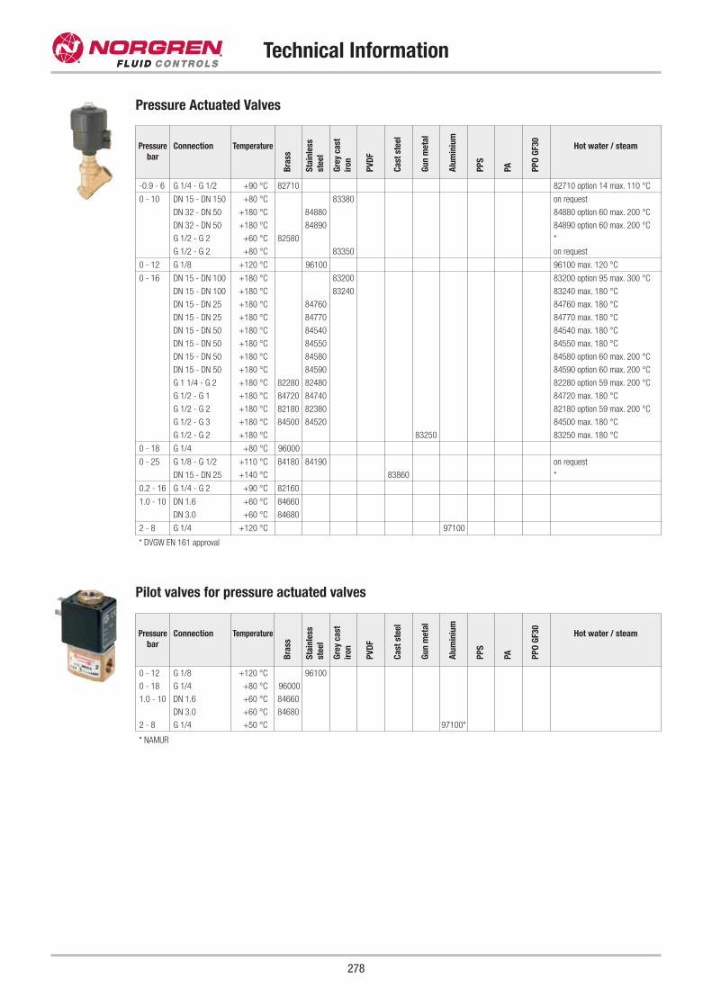
Technical Information
278
Pressure Actuated Valves
Pilot valves for pressure actuated valves
Pressure
bar
Connection Temperature
Bra
ss
Sta
inle
ss
stee
l
Gre
y ca
st
iron
PV
DF
Ca
st s
teel
Gu
n m
eta
l
Alu
min
ium
PP
S
PA PP
O G
F30
Hot water / steam
-0.9 - 6 G 1/4 - G 1/2 +90 °C 82710 82710 option 14 max. 110 °C
0 - 10 DN 15 - DN 150 +80 °C 83380 on request
DN 32 - DN 50 +180 °C 84880 84880 option 60 max. 200 °C
DN 32 - DN 50 +180 °C 84890 84890 option 60 max. 200 °C
G 1/2 - G 2 +60 °C 82580 *
G 1/2 - G 2 +80 °C 83350 on request
0 - 12 G 1/8 +120 °C 96100 96100 max. 120 °C
0 - 16 DN 15 - DN 100 +180 °C 83200 83200 option 95 max. 300 °C
DN 15 - DN 100 +180 °C 83240 83240 max. 180 °C
DN 15 - DN 25 +180 °C 84760 84760 max. 180 °C
DN 15 - DN 25 +180 °C 84770 84770 max. 180 °C
DN 15 - DN 50 +180 °C 84540 84540 max. 180 °C
DN 15 - DN 50 +180 °C 84550 84550 max. 180 °C
DN 15 - DN 50 +180 °C 84580 84580 option 60 max. 200 °C
DN 15 - DN 50 +180 °C 84590 84590 option 60 max. 200 °C
G 1 1/4 - G 2 +180 °C 82280 82480 82280 option 59 max. 200 °C
G 1/2 - G 1 +180 °C 84720 84740 84720 max. 180 °C
G 1/2 - G 2 +180 °C 82180 82380 82180 option 59 max. 200 °C
G 1/2 - G 3 +180 °C 84500 84520 84500 max. 180 °C
G 1/2 - G 2 +180 °C 83250 83250 max. 180 °C
0 - 18 G 1/4 +80 °C 96000
0 - 25 G 1/8 - G 1/2 +110 °C 84180 84190 on request
DN 15 - DN 25 +140 °C 83860 *
0.2 - 16 G 1/4 - G 2 +90 °C 82160
1.0 - 10 DN 1.6 +60 °C 84660
DN 3.0 +60 °C 84680
2 - 8 G 1/4 +120 °C 97100
* DVGW EN 161 approval
* NAMUR
Pressure
bar
Connection Temperature
Bra
ss
Sta
inle
ss
stee
l
Gre
y ca
st
iron
PV
DF
Ca
st s
teel
Gu
n m
eta
l
Alu
min
ium
PP
S
PA PP
O G
F30
Hot water / steam
0 - 12 G 1/8 +120 °C 96100
0 - 18 G 1/4 +80 °C 96000
1.0 - 10 DN 1.6 +60 °C 84660
DN 3.0 +60 °C 84680
2 - 8 G 1/4 +50 °C 97100*
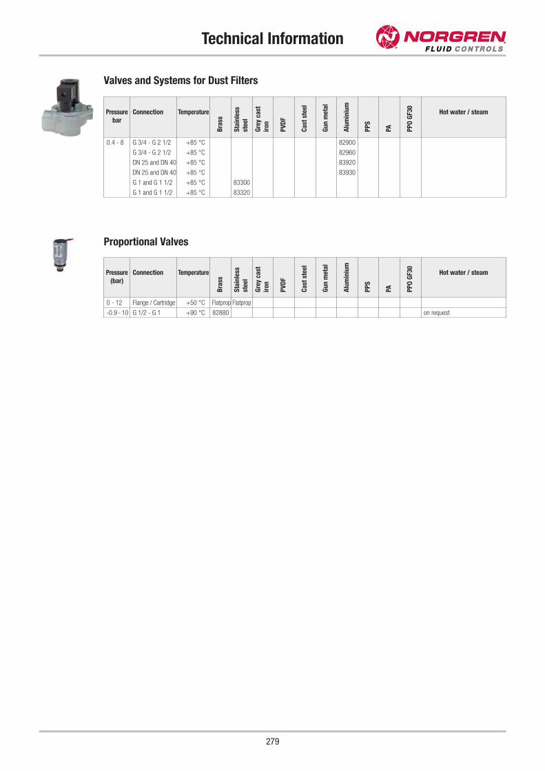
Technical Information
279
Valves and Systems for Dust Filters
Pressure
bar
Connection Temperature
Bra
ss
Sta
inle
ss
stee
l
Gre
y ca
st
iron
PV
DF
Ca
st s
teel
Gu
n m
eta
l
Alu
min
ium
PP
S
PA PP
O G
F30
Hot water / steam
0.4 - 8 G 3/4 - G 2 1/2 +85 °C 82900
G 3/4 - G 2 1/2 +85 °C 82960
DN 25 and DN 40 +85 °C 83920
DN 25 and DN 40 +85 °C 83930
G 1 and G 1 1/2 +85 °C 83300
G 1 and G 1 1/2 +85 °C 83320
Proportional Valves
Pressure
(bar)
Connection Temperature
Bra
ss
Sta
inle
ss
stee
l
Gre
y ca
st
iron
PV
DF
Ca
st s
teel
Gu
n m
eta
l
Alu
min
ium
PP
S
PA PP
O G
F30
Hot water / steam
0 - 12 Flange / Cartridge +50 °C Flatprop Flatprop
-0.9 - 10 G 1/2 - G 1 +90 °C 82880 on request
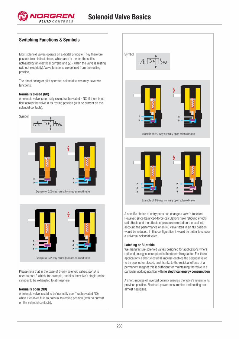
Switching Functions & Symbols
Most solenoid valves operate on a digital principle. They therefore
possess two distinct states, which are (1) - when the coil is
activated by an electrical current, and (2) - when the valve is resting
(without electricity). Valve functions are defined from the resting
position.
The direct acting or pilot operated solenoid valves may have two
functions:
Normally closed (NC)
A solenoid valve is normally closed (abbreviated - NC) if there is no
flow across the valve in its resting position (with no current on the
solenoid contacts).
Symbol
Please note that in the case of 3-way solenoid valves, port A is
open to port R which, for example, enables the valve’s single-action
cylinder to be exhausted to atmosphere.
Normally open (NO)
A solenoid valve is said to be“normally open” (abbreviated NO)
when it enables fluid to pass in its resting position (with no current
on the solenoid contacts).
Symbol
A specific choice of entry ports can change a valve’s function.
However, since balanced-force calculations take rebound effects,
coil effects and the effects of pressure exerted on the seal into
account, the performance of an NC valve fitted in an NO position
would be reduced. In this configuration it would be better to choose
a universal solenoid valve.
Latching or Bi-stable
We manufacture solenoid valves designed for applications where
reduced energy consumption is the determining factor. For these
applications a short electrical impulse enables the solenoid valve
to be opened or closed, and thanks to the residual effects of a
permanent magnet this is sufficient for maintaining the valve in a
particular working position with no electrical energy consumption.
A short impulse of inverted polarity ensures the valve’s return to its
previous position. Electrical power consumption and heating are
almost negligible.
P
A
P
A
P
R
A
P
R
A
R
P
A
R
P
A
P
A
P
A
a
P
Ab
a b
Solenoid Valve Basics
280
Example of 2/2-way normally closed solenoid valve
Example of 3/2-way normally closed solenoid valve
Example of 3/2-way normally open solenoid valve
Example of 2/2-way normally open solenoid valve
a
P
Ab
a b
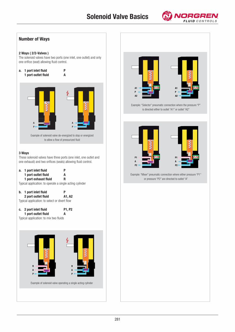
Solenoid Valve Basics
281
Number of Ways
2 Ways ( 2/2-Valves )
The solenoid valves have two ports (one inlet, one outlet) and only
one orifice (seat) allowing fluid control.
a. 1 port inlet fluid P
1 port outlet fluid A
3 Ways
These solenoid valves have three ports (one inlet, one outlet and
one exhaust) and two orifices (seats) allowing fluid control.
a. 1 port inlet fluid P
1 port outlet fluid A
1 port exhaust fluid R
Typical application: to operate a single acting cylinder
b. 1 port inlet fluid P
2 port outlet fluid A1, A2
Typical application: to select or divert flow
c. 2 port inlet fluid P1, P2
1 port outlet fluid A
Typical application: to mix two fluids
P
A
P
A
Example of solenoid valve de-energized to stop or energized
to allow a flow of pressurized fluid
P
R
A
P
R
A
A2
A1
P
A2
A1
P
P2
P1
A
P2
P1
A
Example of solenoid valve operating a single acting cylinder
Example: “Selector” pneumatic connection where the pressure “P”
is directed either to outlet “A1” or outlet “A2”
Example: “Mixer” pneumatic connection where either pressure “P1”
or pressure “P2” are directed to outlet “A”
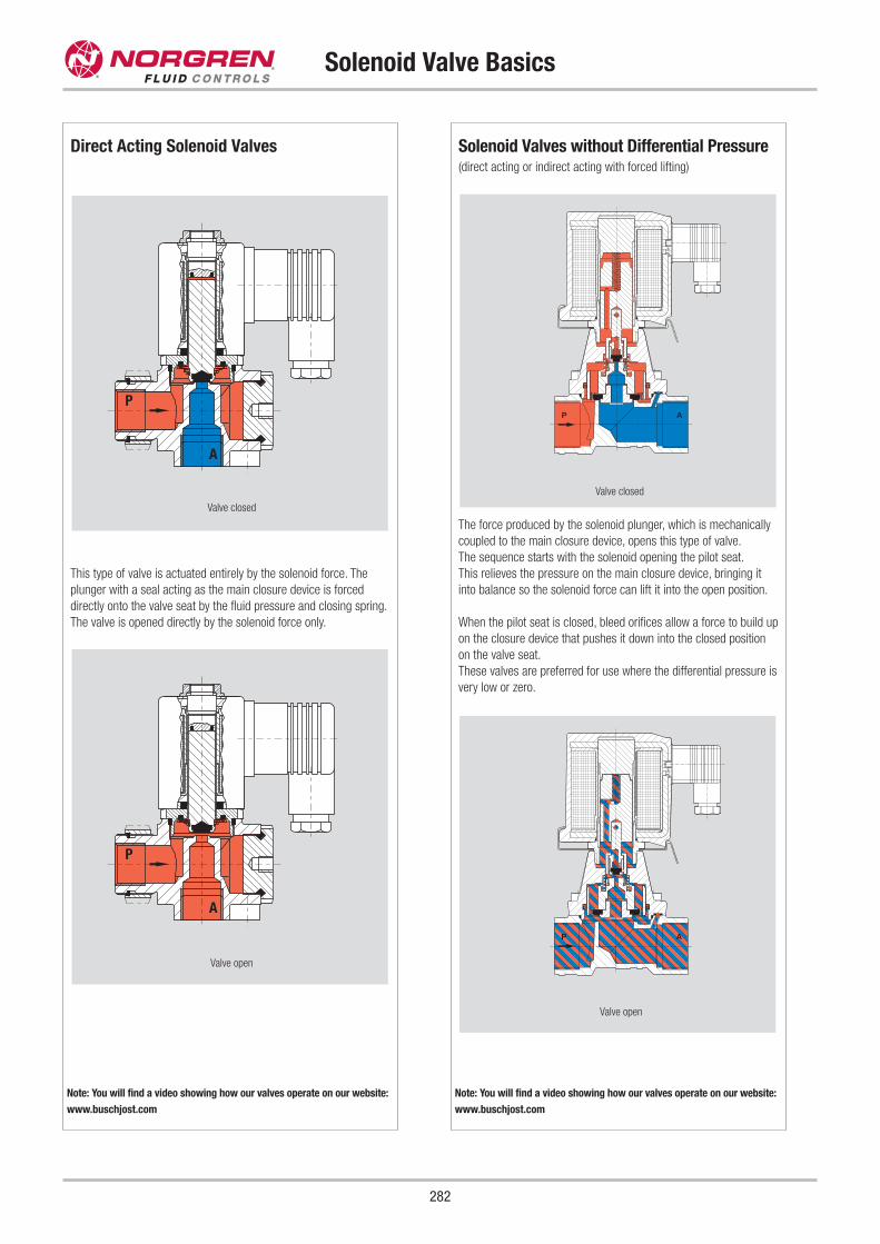
Solenoid Valves without Differential Pressure(direct acting or indirect acting with forced lifting)
The force produced by the solenoid plunger, which is mechanically
coupled to the main closure device, opens this type of valve.
The sequence starts with the solenoid opening the pilot seat.
This relieves the pressure on the main closure device, bringing it
into balance so the solenoid force can lift it into the open position.
When the pilot seat is closed, bleed orifices allow a force to build up
on the closure device that pushes it down into the closed position
on the valve seat.
These valves are preferred for use where the differential pressure is
very low or zero.
Direct Acting Solenoid Valves
This type of valve is actuated entirely by the solenoid force. The
plunger with a seal acting as the main closure device is forced
directly onto the valve seat by the fluid pressure and closing spring.
The valve is opened directly by the solenoid force only.
P
A
Valve closed
P
A
Valve open
P A
Valve closed
P A
Valve open
Solenoid Valve Basics
282
Note: You will find a video showing how our valves operate on our website:
www.buschjost.com
Note: You will find a video showing how our valves operate on our website:
www.buschjost.com
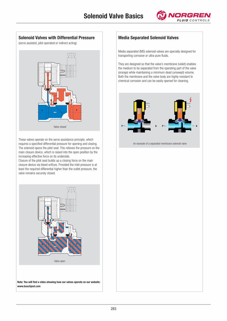
Solenoid Valves with Differential Pressure(servo assisted, pilot operated or indirect acting)
These valves operate on the servo assistance principle, which
requires a specified differential pressure for opening and closing.
The solenoid opens the pilot seat. This relieves the pressure on the
main closure device, which is raised into the open position by the
increasing effective force on its underside.
Closure of the pilot seat builds up a closing force on the main
closure device via bleed orifices. Provided the inlet pressure is at
least the required differential higher than the outlet pressure, the
valve remains securely closed.
PA
Valve closed
Media Separated Solenoid Valves
Media separated (MS) solenoid valves are specially designed for
transporting corrosive or ultra-pure fluids.
They are designed so that the valve’s membrane (violet) enables
the medium to be separated from the operating part of the valve
(orange) while maintaining a minimum dead (unswept) volume.
Both the membrane and the valve body are highly resistant to
chemical corrosion and can be easily opened for cleaning.
Solenoid Valve Basics
283
Note: You will find a video showing how our valves operate on our website:
www.buschjost.com
AP AP
PA
Valve open
An example of a separated membrane solenoid valve
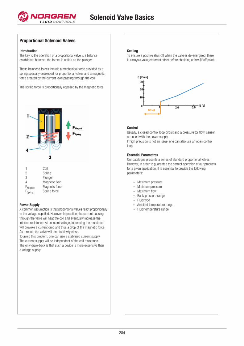
Solenoid Valve Basics
284
Proportional Solenoid Valves
Introduction
The key to the operation of a proportional valve is a balance
established between the forces in action on the plunger.
These balanced forces include a mechanical force provided by a
spring specially developed for proportional valves and a magnetic
force created by the current level passing through the coil.
The spring force is proportionally opposed by the magnetic force.
1 Coil
2 Spring
3 Plunger
4 Magnetic field
FMagnet Magnetic force
FSpring Spring force
Power Supply
A common assumption is that proportional valves react proportionally
to the voltage supplied. However, in practice, the current passing
through the valve will heat the coil and eventually increase the
internal resistance. At constant voltage, increasing the resistance
will provoke a current drop and thus a drop of the magnetic force.
As a result, the valve will tend to slowly close.
To avoid this problem, one can use a stabilized current supply.
The current supply will be independent of the coil resistance.
The only draw-back is that such a device is more expensive than
a voltage supply.
Sealing
To ensure a positive shut-off when the valve is de-energized, there
is always a voltage/current offset before obtaining a flow (liftoff point).
Control
Usually, a closed control loop circuit and a pressure (or flow) sensor
are used with the power supply.
If high precision is not an issue, one can also use an open control
loop.
Essential Parametres
Our catalogue presents a series of standard proportional valves.
However, in order to guarantee the correct operation of our products
for a given application, it is essential to provide the following
parameters:
» Maximum pressure
» Minimum pressure
» Maximum flow
» Back-pressure range
» Fluid type
» Ambient temperature range
» Fluid temperature range
U [V]0
Q [l/min]
Offset1 2,0 3,0
10
20
30
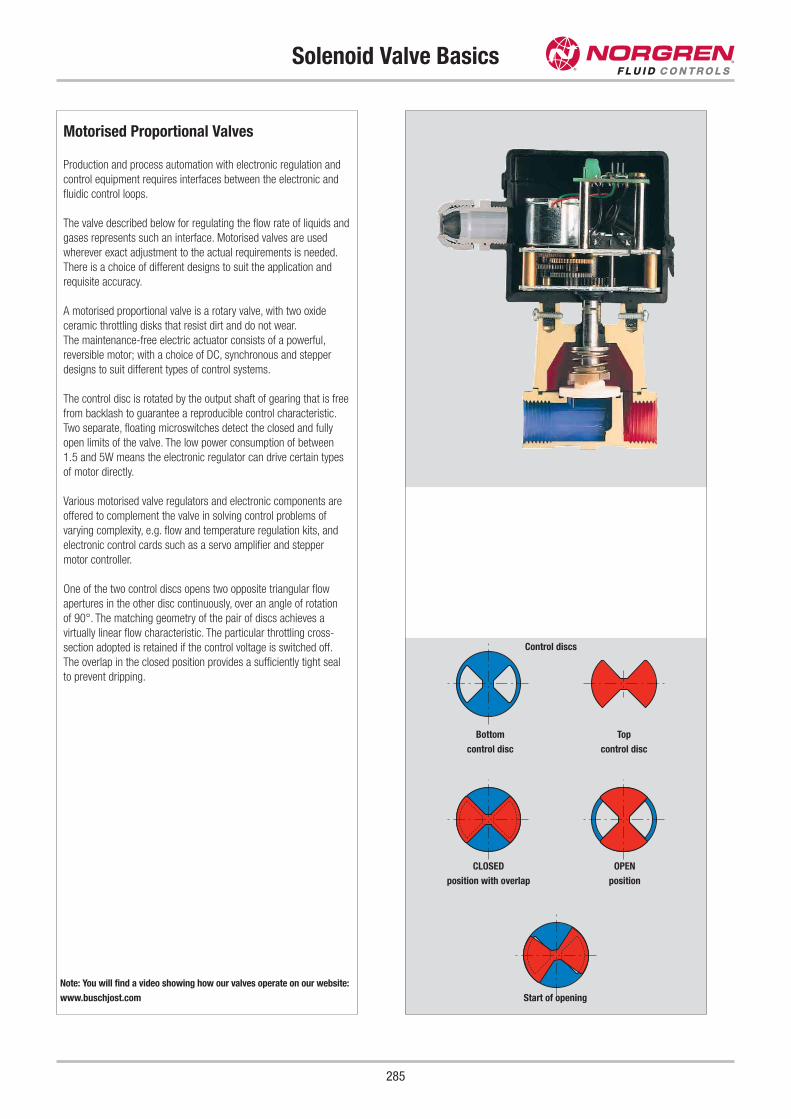
Solenoid Valve Basics
285
Control discs
Motorised Proportional Valves
Production and process automation with electronic regulation and
control equipment requires interfaces between the electronic and
fluidic control loops.
The valve described below for regulating the flow rate of liquids and
gases represents such an interface. Motorised valves are used
wherever exact adjustment to the actual requirements is needed.
There is a choice of different designs to suit the application and
requisite accuracy.
A motorised proportional valve is a rotary valve, with two oxide
ceramic throttling disks that resist dirt and do not wear.
The maintenance-free electric actuator consists of a powerful,
reversible motor; with a choice of DC, synchronous and stepper
designs to suit different types of control systems.
The control disc is rotated by the output shaft of gearing that is free
from backlash to guarantee a reproducible control characteristic.
Two separate, floating microswitches detect the closed and fully
open limits of the valve. The low power consumption of between
1.5 and 5W means the electronic regulator can drive certain types
of motor directly.
Various motorised valve regulators and electronic components are
offered to complement the valve in solving control problems of
varying complexity, e.g. flow and temperature regulation kits, and
electronic control cards such as a servo amplifier and stepper
motor controller.
One of the two control discs opens two opposite triangular flow
apertures in the other disc continuously, over an angle of rotation
of 90°. The matching geometry of the pair of discs achieves a
virtually linear flow characteristic. The particular throttling cross-
section adopted is retained if the control voltage is switched off.
The overlap in the closed position provides a sufficiently tight seal
to prevent dripping.
Note: You will find a video showing how our valves operate on our website:
www.buschjost.com
Bottom
control disc
CLOSED
position with overlap
Top
control disc
OPEN
position
Start of opening
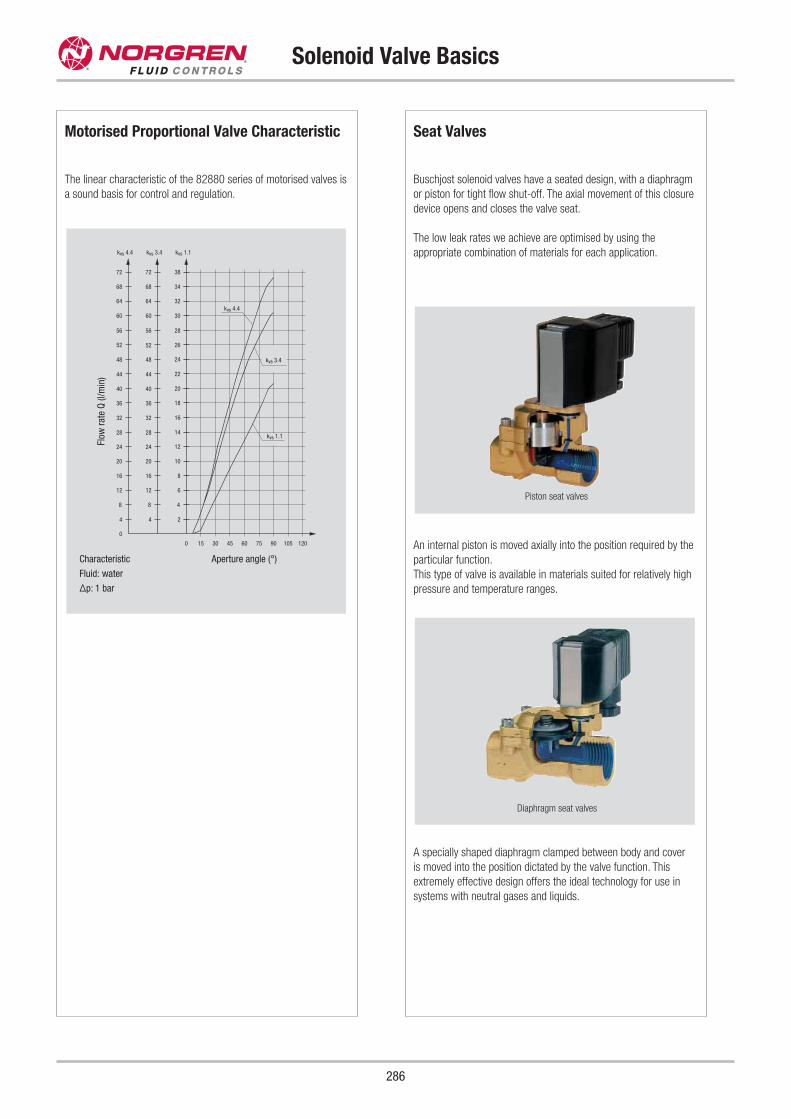
Motorised Proportional Valve Characteristic
The linear characteristic of the 82880 series of motorised valves is
a sound basis for control and regulation.
0 15 30 45 60 75 90 105 120
2
4
6
8
10
12
14
16
18
20
22
24
26
28
30
32
34
38
56
60
64
68
72
20
24
28
32
36
40
44
48
52
4
8
12
16
0
20
24
28
32
36
40
44
48
4
8
12
16
56
60
64
68
72
52
kvs 4.4 kvs 3.4 kvs 1.1
kvs 4.4
kvs 3.4
kvs 1.1
Seat Valves
Buschjost solenoid valves have a seated design, with a diaphragm
or piston for tight flow shut-off. The axial movement of this closure
device opens and closes the valve seat.
The low leak rates we achieve are optimised by using the
appropriate combination of materials for each application.
An internal piston is moved axially into the position required by the
particular function.
This type of valve is available in materials suited for relatively high
pressure and temperature ranges.
A specially shaped diaphragm clamped between body and cover
is moved into the position dictated by the valve function. This
extremely effective design offers the ideal technology for use in
systems with neutral gases and liquids.
Solenoid Valve Basics
286
Characteristic
Fluid: water
Δp: 1 bar
Aperture angle (°)
Flow
rat
e Q
(l/
min
)
Piston seat valves
Diaphragm seat valves
Operating Voltage
We differ basically between DC and AC solenoids. As alternating
voltage is more frequently available, it would seem obvious to give
preference to the AC solenoids.
However, from a certain size the latter have definite disadvantages
in comparison to the DC solenoids in terms of lifetime and magnetic
force, so that DC solenoids with intermediate rectifiers are
preferred.
This voltage rectifier is integrated in the electrical connector or
within the solenoid.
The main advantage of the DC solenoid is its constant current
consumption, which leads to smooth switching and a coil that can
cope with mechanical obstructions.
Voltage surges (inductive peaks) can be avoided by connecting a
varistor, diode or RC-network in parallel.
The voltage tolerances permitted are ±10 %. If AC solenoids
designed for 50 Hz have to be used with 60 Hz, this entails a
reduction in performance. In such cases our technical services
should be consulted beforehand.
DC coils supplied via rectifiers can be operated between
40 and 60 Hz.
Solenoid Valve Basics
287
Zero Delta P Valves(diaphragm valves without differential pressure)
The Zero series is designed for reliable service in the vacuum and
low-pressure range, where the differential pressure available is
insufficient to allow the use of servo assisted solenoid valves.
It is also suited for higher pressure ranges up to 16 bar.
The pressure or vacuum level and presence of a pressure
differential are therefore no longer important considerations.
These combined advantages are the basis for the application
versatility of Zero Delta P Valves.
In the 0 to 16 bar pressure range the Zero series is available
with G 1/4 to G 2 connections.
We will gladly provide you with any further information required.
P A
Response Time & Cycling Rate
The response time of a solenoid valve is the lapse of time
between the electrical signal and the outlet of a fluid signal.
The C.E.T.O.P. defines the test conditions as follows:
Test pressure: air at 6 kg/cm2
Ambient temperature: 20 °C
Response Time at Energising
Lapse of time between energizing of the solenoid until the outlet
pressure reaches 90 % of the maximum test pressure (see chart
for AC and DC).
Response Time at De-Energising
Lapse of time between de-energizing of the solenoid until the
pressure outlet drops to 10 % of the test pressure (see chart
for AC and DC).
Effect of Alternating Current on Response Time
The response time of a solenoid valve operating on alternating
current depends on the phase of the current at the time of the
electrical command. If the command is given at an unfavorable
moment, the system will be delayed for a fraction period, which
is generally unknown, until the available current is sufficient to
re-activate the solenoid valve. This lapse of time should be added
to the nominal response time of the solenoid valve.
Cycling Rate
The cycling rate of a solenoid valve depends directly on its response
time. It is the number of cycles per minute calculated for continuous
operations. The valve should not be reversed at less than 90 %,
or above 10 % of reference pressure. The cycling rates shown in
this catalogue are the maximum possible cycles per minute of the
solenoid valve. It varies when the valve is mounted in a circuit which
then depends on the installation pressure drop.
Solenoid Valve Basics
288
Explosion Protection
The goal of explosion protection is to prevent oxygen, flammable
substances and ignition sources arising simultaneously.
Electrical devices in hazardous areas are regarded as an ignition
source, and are therefore subject to special building and installation
regulations that have undergone international harmonisation.
The members of the "European Committee for Electrotechnical
Standardisation", or CENELEC for short, have devised European
standards that have been adopted as national standards in all
countries. The test certificates issued by the national bodies are
therefore recognised throughout the EU.
Hazardous areas are defined as areas in which local and service
conditions can give rise to a dangerous, explosive atmosphere.
The frequency of occurrence is used to subdivide the areas into
zones.
Electrical devices installed in these areas must be approved for the
relevant zones and marked as defined in EN 50014.
Example Ex me II T4
x II 2 G
EEx
Examples of devices with European certification
for hazardous areas.
Explosion protection techniques (e.g. "me")
Type of measures adopted to prevent ignition of the
ambient atmosphere
Gas groups (e.g. II)
Group I Methane
Group II Other explosive gases
Temperature classifications (e.g. T4)
Maximum permissible surface temperature on any part
of the electrical device.
Ignition temperature of the explosive atmosphere.
The organisation operating the installation is responsible for
determining the zone and use of approved apparatus therein.
We will gladly provide you with any further information required.
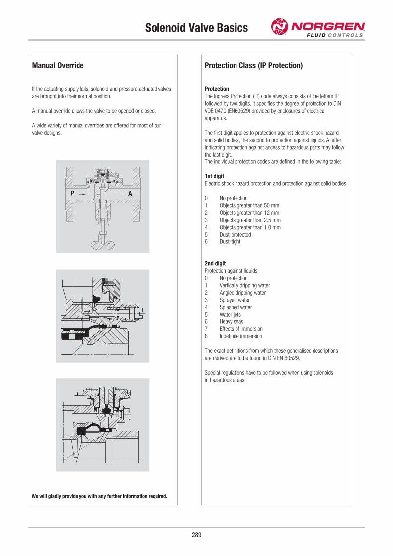
Protection Class (IP Protection)
Protection
The Ingress Protection (IP) code always consists of the letters IP
followed by two digits. It specifies the degree of protection to DIN
VDE 0470 (EN60529) provided by enclosures of electrical
apparatus.
The first digit applies to protection against electric shock hazard
and solid bodies, the second to protection against liquids. A letter
indicating protection against access to hazardous parts may follow
the last digit.
The individual protection codes are defined in the following table:
1st digit
Electric shock hazard protection and protection against solid bodies
0 No protection
1 Objects greater than 50 mm
2 Objects greater than 12 mm
3 Objects greater than 2.5 mm
4 Objects greater than 1.0 mm
5 Dust-protected
6 Dust-tight
2nd digit
Protection against liquids
0 No protection
1 Vertically dripping water
2 Angled dripping water
3 Sprayed water
4 Splashed water
5 Water jets
6 Heavy seas
7 Effects of immersion
8 Indefinite immersion
The exact definitions from which these generalised descriptions
are derived are to be found in DIN EN 60529.
Special regulations have to be followed when using solenoids
in hazardous areas.
Solenoid Valve Basics
289
We will gladly provide you with any further information required.
Manual Override
If the actuating supply fails, solenoid and pressure actuated valves
are brought into their normal position.
A manual override allows the valve to be opened or closed.
A wide variety of manual overrides are offered for most of our
valve designs.
P A
Materials - Seals
Material selection
Information about the concentration, temperature and the degree of
contamination of the fluid is important in making the right choice of
materials. Further criteria are the operating pressure and maximum
flow rate.
Besides extreme temperatures, pressures and flow rates must be
taken into consideration when choosing a material.
NBR Nitrile Butadiene Rubber
Standard flexible material for neutral fluids such as air, water, oil.
Good resistance to mechanical loads. Temperature range depending
on working conditions from -10 to +90 °C.
HNBR Hydrogenated Nitrile Rubber
Similar in many features to NBR. Particularly suitable for hot water
and steam. Temperature range depending on working conditions
from -20 to +150 °C.
EPDM Ethylene Propylene Diene Monomer Rubber
Resistant to alkalis and acids of mid-range concentration, water, hot
water and steam. Not resistant to oils and greases. Temperature
range depending on working conditions from -20 to +130 °C.
FPM Fluorocarbon Rubber
A highly temperature and weatherproof elastomer. Suitable for
many acids, bases, fuels and oils (including synthetic). Not resistant
to steam. Temperature range depending on working conditions from
-10 to +180 °C.
CR Polychloroprene Rubber
Similar in many features to NBR. Particularly suitable for most
refrigerants. Temperature range depending on working conditions
from -20 to +90 °C.
PTFE Polytetrafluoroethene
A duroplastic, not a flexible material and therefore not suitable for
the conventional diaphragms (separating membranes are possible).
Resistance is almost universal in the temperature ranges from -20
to +200 °C.
Valve bodies and internal parts are also made of this material.
FFPM Perfluoride Elastomer
A flexible material with the same resistance as PTFE and excellent
sealing qualities. Temperature range depending on working
conditions from -30 to +200 °C.
TPE Thermoplastic elastomers
Very durable yet flexible over a wide temperature range. Resist oils,
grease, many solvents and weathering.
Solenoid Valve Basics
290
Valve Selection Criteria
The following factors are important in making the right commercial
and technical choice:
- Valve actuation
· solenoid
· pressure
· proportional
· motorised
- Number of ways
· 2/2 Valve
· 3/2 Valve
- Switching function
· normally closed (NC)
· normally open (NO)
- Connection size
· flow rate
· kv (flow coefficient) value
- Type of connection
· threaded
· flanged
· weld ends
- Working pressure
· upstream of valve
· downstream of valve
· differential pressure
· vacuum
- Process fluid
· neutral to aggressive
· gas to liquid
· filtered to contaminated
- Fluid temperature
· range from - to + °C
- Ambient temperature
· range from - to + °C
· ambient atmosphere
- Solenoid power supply
· voltage
· frequency
- Protection classification
· IP
· EEx
- Control fluid supply
· control fluid
· control pressure
· temperature of control fluid from - to + °C
· ambient temperature from - to + °C
- Accessories and options
- Safety requirements
· TÜV approval/test certificates
· specific certifications
Materials - Metals
Material selection
Information about the concentration, temperature and the degree
of contamination of the fluid is important in making the right choice
of materials. Further criteria are the operating pressure and
maximum flow rate.
Brass (Ms 58)
Has many applications, not suitable for aggressive and ammoniacal
fluids.
Brass
(CuZn36Pb2As)
Suitable in agressive fluids and seawater.
Grey cast iron (G 1/4-25)
Mainly for flanged valve bodies up to PN 16, the temperature range
is limited, suitable for neutral fluids.
Spheroidal cast iron (GGG-40.3)
Mainly for flanged valve bodies up to PN 16, suitable for neutral
fluids.
Cast steel (GS-C 25)
Mainly for flanged valve bodies up to PN 40, high temperature
range, suitable for neutral fluids.
Gun metal (Rg 5)
(CuSn 5 ZnPb)
Seawater,mildly aggressive water or steam.
Cast stainless steel
(G-X 7 CrNiMo 18 10)
Austenitic high-alloy steel for aggressive fluids.
Stainless steel - Ingot material
(X 10 CrNiMoTi 18 10)
Austenitic high-alloy steel for aggressive fluids.
Stainless steel
(X 5 CrNi 18 9)
Low-alloy austenitic stainless steel for valve's internal parts.
Stainless steel
(X 12 CrMo S 17)
- Corrosion-resistant magnetisable stainless steel, not suitable
aggressive fluids or seawater.
- Sandvik Stainless steel 1802.
- Magnetic stainless steel, suitable for aggressive fluids.
Aluminium
(AlSi 8 Cu 3)
Aluminium die casting for bodies up to PN 16, suitable for neutral
fluids.
Solenoid Valve Basics
291
Materials - Polymers
Material selection
The design of the valve is decided by the application, with the
materials' ability to resist the operating fluid constituting an
important factor.
Information about the concentration, temperature and the degree of
contamination of the fluid is important in making the right choice of
materials. Further criteria are the operating pressure and maximum
flow rate.
All of the materials used for the bodies, seals, solenoids, etc. of
Buschjost valves are carefully selected to suit various applications.
Plastics for valve bodies
PVC Polyvinyl Chloride
Resistant to most acids, alkalis, salt solutions and organic solutions;
miscible with water. Not resistant to aromatic and chlorinated
hydrocarbons.
PVDF Polyvinylidene Fluoride
Suitable for nearly all aggressive fluids in the temperature range
from -20 to +100 °C.
PFA Perfluoralkoxy
As resistant as PVDF but in a higher temperature range from -20 to
+150 °C.
PP Polypropylene
Resistant to aqueous solutions of acids, alkalis and salts, depending
on concentration and temperature.
POM Polyoxymethylene
A material with a high degree of hardness and low water absorption.
Not suitable for bases, acids or oxidising agents.
PA Polyamid
Suitable for all neutral fluids and gases
PPS Polyphenylene Sulfide
Suitable for all neutral fluids and gases.
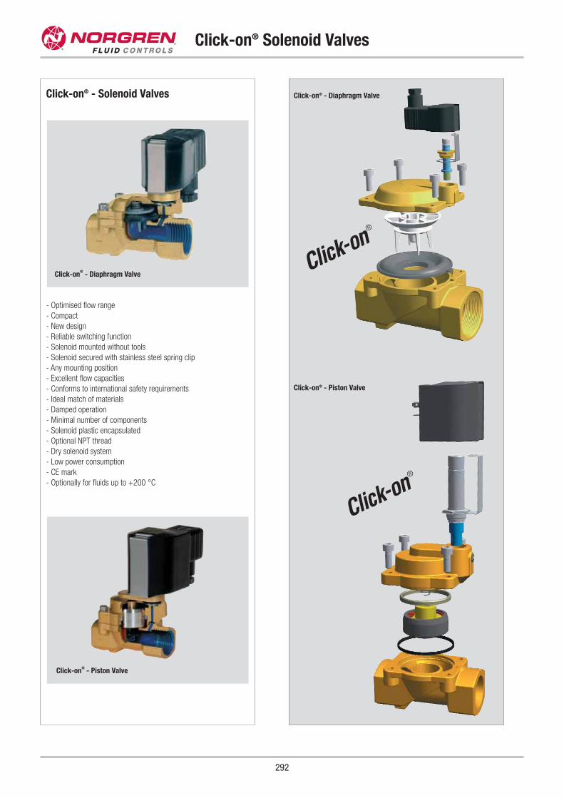
Click-on® - Solenoid Valves
- Optimised flow range
- Compact
- New design
- Reliable switching function
- Solenoid mounted without tools
- Solenoid secured with stainless steel spring clip
- Any mounting position
- Excellent flow capacities
- Conforms to international safety requirements
- Ideal match of materials
- Damped operation
- Minimal number of components
- Solenoid plastic encapsulated
- Optional NPT thread
- Dry solenoid system
- Low power consumption
- CE mark
- Optionally for fluids up to +200 °C
Click-on® - Piston Valve
Click-on® - Diaphragm Valve
Click-on® Solenoid Valves
292
Click-on®
- Piston Valve
Click-on®
- Diaphragm Valvec
c

Pressure Actuated Valves –Principle of Operation(pneumatically actuated isolating valves)
This type of valve is controlled by a pilot fluid supplied to the
actuator by means of a pilot valve.
A stem connects the closure device to the control element of the
actuator. The spring acting on the control element forces the
closure device down into the closed position on the valve seat.
The pilot supply overcomes the spring force to lift the control
element into the open position.
These valves are mainly suitable for contaminated or extremely
viscous process fluids.
P
A
P
A
Pressure Actuated Valves –Conversion from NC to NO
The pressure actuated 84 500, 84 520 and 84 540 series of
valves are designed to allow relatively simple conversion of the
standard switching function – normally closed (NC) – to normally
open (NO).
NC to NO the easy way:
Step 1 Vent actuator
Step 2 Use 36 mm ring or socket spanner to release
and unscrew actuator cover (120). This fully
releases the compression spring(s) in the
actuator.
Step 3 Remove the compression springs (116 and 122)
(not present in all types of valve).
Step 4 Replace actuator cover (120) and tighten firmly.
The factory fitted compression spring (113) will
now move the depressurised piston into the
normally open (NO) position.
Step 5 The top port of the two is to be used as the pilot.
Step 6 Prior to commissioning, it is advisable to carry
out an operating test of the actuator with air as
the pilot fluid and without process fluid.
Step 7 Check actuator and valve body leak tightness to
atmosphere, and tightness of the stem seals
using the vent in the screw piece (107).
Z107 113 116 122 120
Pressure Actuated Valves
293
Valve closed
Valve open
Note: You will find a video showing how our valves operate on our website:
www.buschjost.com
Normally open - under spring force
NO
NC
NO
NC
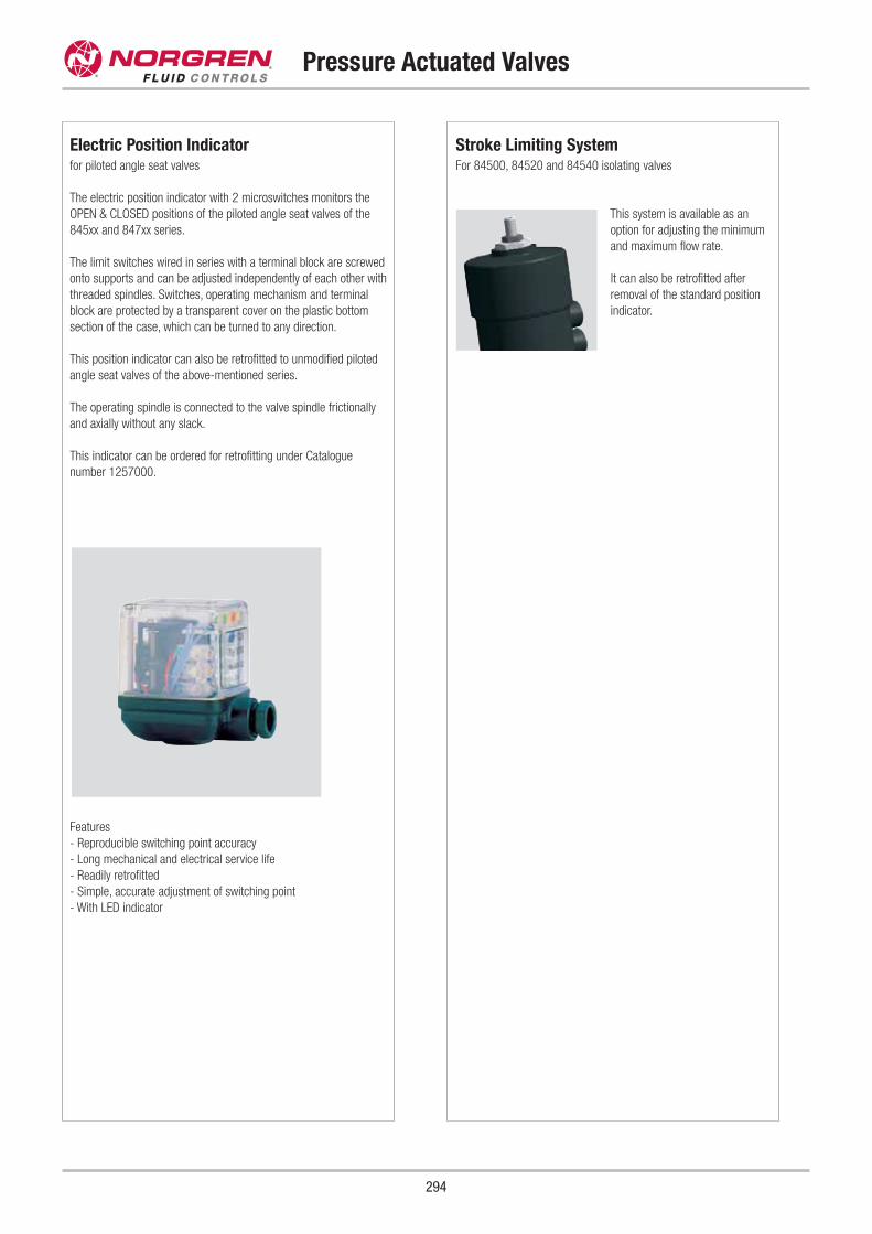
Stroke Limiting SystemFor 84500, 84520 and 84540 isolating valves
This system is available as an
option for adjusting the minimum
and maximum flow rate.
It can also be retrofitted after
removal of the standard position
indicator.
Pressure Actuated Valves
294
Electric Position Indicator for piloted angle seat valves
The electric position indicator with 2 microswitches monitors the
OPEN & CLOSED positions of the piloted angle seat valves of the
845xx and 847xx series.
The limit switches wired in series with a terminal block are screwed
onto supports and can be adjusted independently of each other with
threaded spindles. Switches, operating mechanism and terminal
block are protected by a transparent cover on the plastic bottom
section of the case, which can be turned to any direction.
This position indicator can also be retrofitted to unmodified piloted
angle seat valves of the above-mentioned series.
The operating spindle is connected to the valve spindle frictionally
and axially without any slack.
This indicator can be ordered for retrofitting under Catalogue
number 1257000.
Features
- Reproducible switching point accuracy
- Long mechanical and electrical service life
- Readily retrofitted
- Simple, accurate adjustment of switching point
- With LED indicator
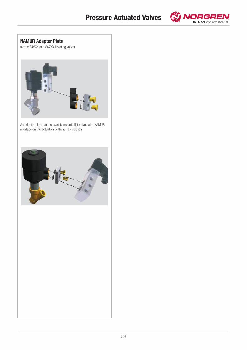
Pressure Actuated Valves
295
NAMUR Adapter Platefor the 845XX and 847XX isolating valves
An adapter plate can be used to mount pilot valves with NAMUR
interface on the actuators of these valve series.
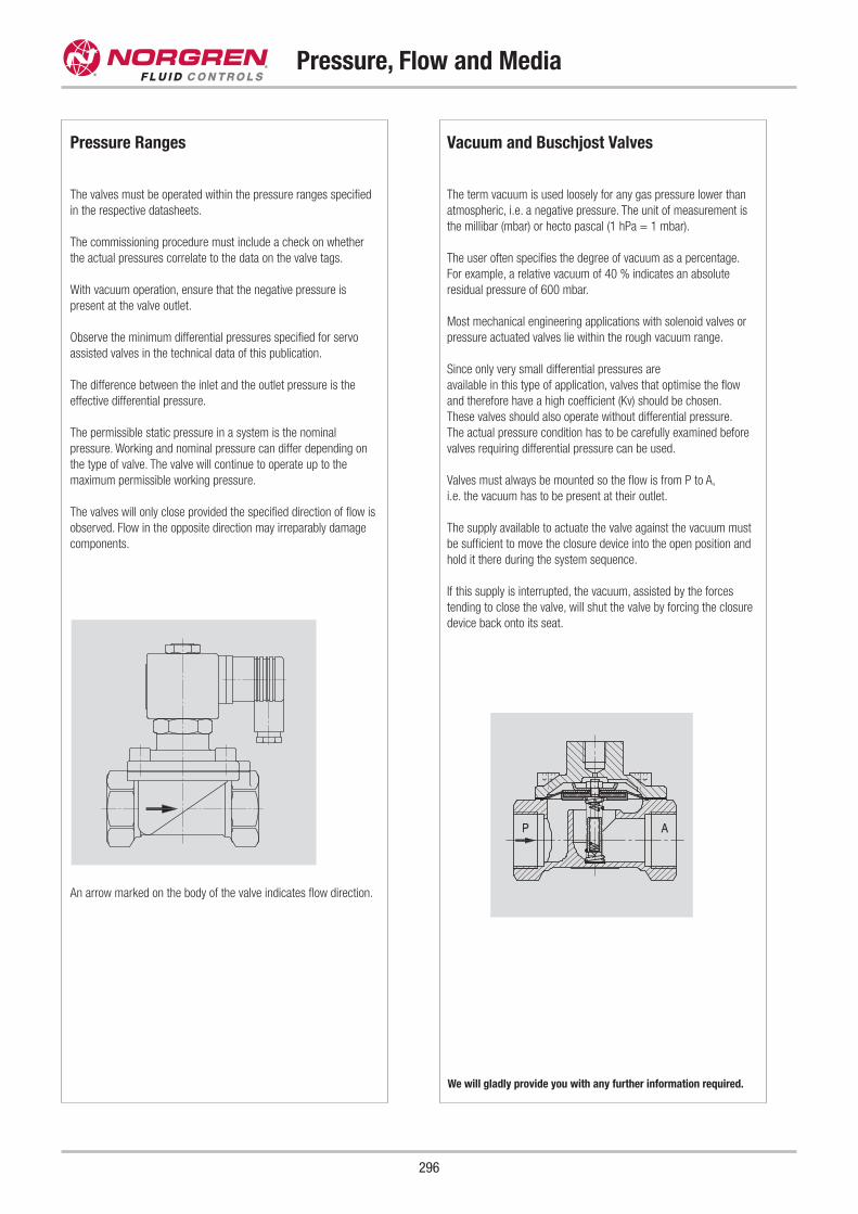
Pressure, Flow and Media
296
Pressure Ranges
The valves must be operated within the pressure ranges specified
in the respective datasheets.
The commissioning procedure must include a check on whether
the actual pressures correlate to the data on the valve tags.
With vacuum operation, ensure that the negative pressure is
present at the valve outlet.
Observe the minimum differential pressures specified for servo
assisted valves in the technical data of this publication.
The difference between the inlet and the outlet pressure is the
effective differential pressure.
The permissible static pressure in a system is the nominal
pressure. Working and nominal pressure can differ depending on
the type of valve. The valve will continue to operate up to the
maximum permissible working pressure.
The valves will only close provided the specified direction of flow is
observed. Flow in the opposite direction may irreparably damage
components.
An arrow marked on the body of the valve indicates flow direction.
Vacuum and Buschjost Valves
The term vacuum is used loosely for any gas pressure lower than
atmospheric, i.e. a negative pressure. The unit of measurement is
the millibar (mbar) or hecto pascal (1 hPa = 1 mbar).
The user often specifies the degree of vacuum as a percentage.
For example, a relative vacuum of 40 % indicates an absolute
residual pressure of 600 mbar.
Most mechanical engineering applications with solenoid valves or
pressure actuated valves lie within the rough vacuum range.
Since only very small differential pressures are
available in this type of application, valves that optimise the flow
and therefore have a high coefficient (Kv) should be chosen.
These valves should also operate without differential pressure.
The actual pressure condition has to be carefully examined before
valves requiring differential pressure can be used.
Valves must always be mounted so the flow is from P to A,
i.e. the vacuum has to be present at their outlet.
The supply available to actuate the valve against the vacuum must
be sufficient to move the closure device into the open position and
hold it there during the system sequence.
If this supply is interrupted, the vacuum, assisted by the forces
tending to close the valve, will shut the valve by forcing the closure
device back onto its seat.
We will gladly provide you with any further information required.
Pressure, Flow and Media
297
Calculating Flow Rates
With kv (flow coefficient)
Valve models must be carefully selected and accurately sized
to suit the system application.
Once the switching function and the nominal pressure have been
chosen, together with the permissible pressure drop across the
valve, the medium type, density, viscosity, temperature and flow
rate govern the connection size.
The flow coefficient tabulated for each valve allows calculation
of service parameters such as flow rate or pressure drop for
steady-state flow.
kv is the flow rate in m3/h of water at a temperature between 5 and
30 °C, with a pressure drop of 1 bar across the valve. Its value has
been determined for the different models according to VDI/ VDE
2173 guidelines and tabulated in the catalogue's characteristic
data.
Example:
Calculation of the flow rate through
8240400.9101 valve
Water at 20 °C, kv = 9.5, Δp = 3 bar
Q = kv · ��Δp
Q = 16.45 m3/h
Calculation of the pressure drop across
82 404.00.9101 valve
Water at 20 °C, Q = 12m3/h, kv = 9.5
Δp = ( Qkv)
2
Δp = 1.6 bar
Viscosity
The kinematic viscosity in mm2/s is a measure of the internal friction
of gases and liquids. It represents the resistance to movement of the
contact surfaces of adjoining layers of different (external friction) or
identical (internal friction, viscosity) material.
The viscosity depends on pressure and temperature, and decreases
with increasing temperature. Its value is measured at +20 °C from
the rate of efflux from capillaries or speed at which balls sink in test
fluids.
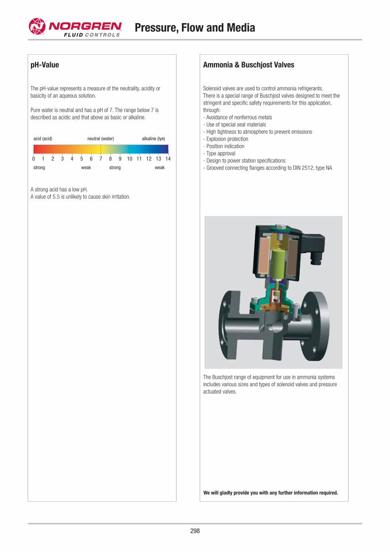
pH-Value
The pH-value represents a measure of the neutrality, acidity or
basicity of an aqueous solution.
Pure water is neutral and has a pH of 7. The range below 7 is
described as acidic and that above as basic or alkaline.
A strong acid has a low pH.
A value of 5.5 is unlikely to cause skin irritation.
0 1 2 3 4 5 6 7 8 9 10 11 12 13 14
Pressure, Flow and Media
298
acid (acid)
strong weak strong weak
neutral (water) alkaline (lye)
We will gladly provide you with any further information required.
Ammonia & Buschjost Valves
Solenoid valves are used to control ammonia refrigerants.
There is a special range of Buschjost valves designed to meet the
stringent and specific safety requirements for this application,
through:
- Avoidance of nonferrous metals
- Use of special seal materials
- High tightness to atmosphere to prevent emissions
- Explosion protection
- Position indication
- Type approval
- Design to power station specifications
- Grooved connecting flanges according to DIN 2512, type NA
The Buschjost range of equipment for use in ammonia systems
includes various sizes and types of solenoid valves and pressure
actuated valves.
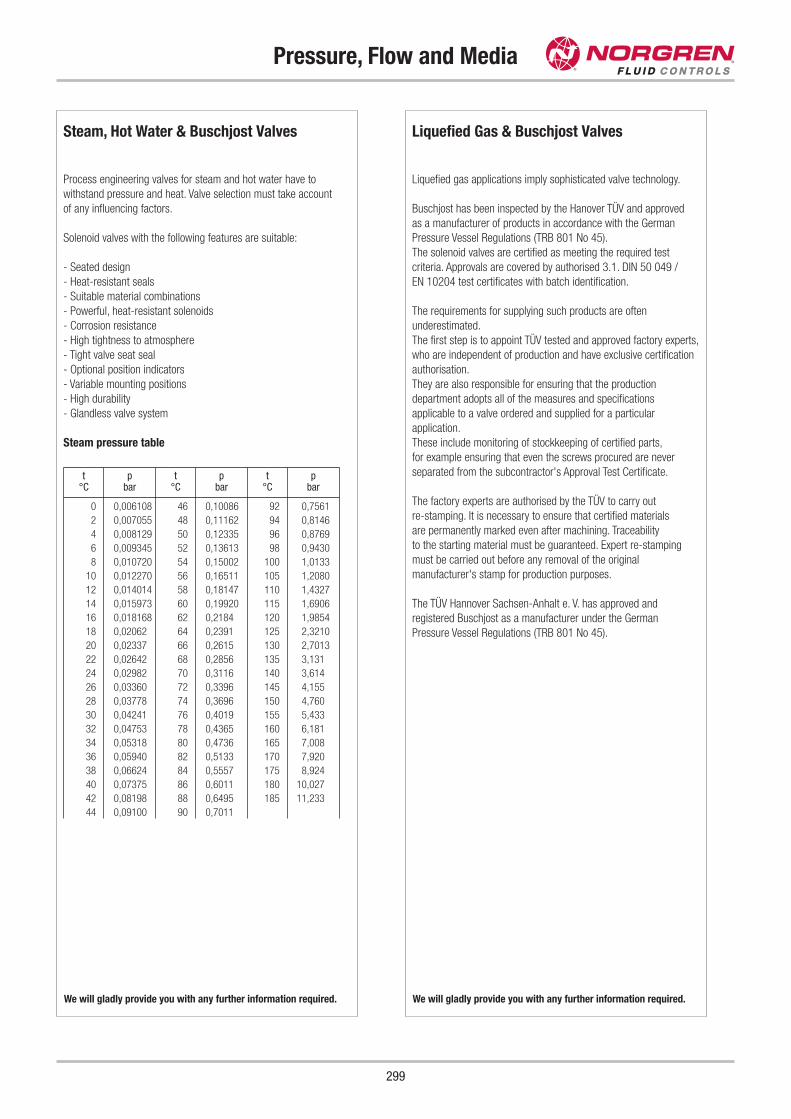
Pressure, Flow and Media
299
Steam, Hot Water & Buschjost Valves
Process engineering valves for steam and hot water have to
withstand pressure and heat. Valve selection must take account
of any influencing factors.
Solenoid valves with the following features are suitable:
- Seated design
- Heat-resistant seals
- Suitable material combinations
- Powerful, heat-resistant solenoids
- Corrosion resistance
- High tightness to atmosphere
- Tight valve seat seal
- Optional position indicators
- Variable mounting positions
- High durability
- Glandless valve system
Steam pressure table
t°C
pbar
t°C
pbar
t°C
pbar
0 0,006108 46 0,10086 92 0,7561
2 0,007055 48 0,11162 94 0,8146
4 0,008129 50 0,12335 96 0,8769
6 0,009345 52 0,13613 98 0,9430
8 0,010720 54 0,15002 100 1,0133
10 0,012270 56 0,16511 105 1,2080
12 0,014014 58 0,18147 110 1,4327
14 0,015973 60 0,19920 115 1,6906
16 0,018168 62 0,2184 120 1,9854
18 0,02062 64 0,2391 125 2,3210
20 0,02337 66 0,2615 130 2,7013
22 0,02642 68 0,2856 135 3,131
24 0,02982 70 0,3116 140 3,614
26 0,03360 72 0,3396 145 4,155
28 0,03778 74 0,3696 150 4,760
30 0,04241 76 0,4019 155 5,433
32 0,04753 78 0,4365 160 6,181
34 0,05318 80 0,4736 165 7,008
36 0,05940 82 0,5133 170 7,920
38 0,06624 84 0,5557 175 8,924
40 0,07375 86 0,6011 180 10,027
42 0,08198 88 0,6495 185 11,233
44 0,09100 90 0,7011
We will gladly provide you with any further information required.
Liquefied Gas & Buschjost Valves
Liquefied gas applications imply sophisticated valve technology.
Buschjost has been inspected by the Hanover TÜV and approved
as a manufacturer of products in accordance with the German
Pressure Vessel Regulations (TRB 801 No 45).
The solenoid valves are certified as meeting the required test
criteria. Approvals are covered by authorised 3.1. DIN 50 049 /
EN 10204 test certificates with batch identification.
The requirements for supplying such products are often
underestimated.
The first step is to appoint TÜV tested and approved factory experts,
who are independent of production and have exclusive certification
authorisation.
They are also responsible for ensuring that the production
department adopts all of the measures and specifications
applicable to a valve ordered and supplied for a particular
application.
These include monitoring of stockkeeping of certified parts,
for example ensuring that even the screws procured are never
separated from the subcontractor's Approval Test Certificate.
The factory experts are authorised by the TÜV to carry out
re-stamping. It is necessary to ensure that certified materials
are permanently marked even after machining. Traceability
to the starting material must be guaranteed. Expert re-stamping
must be carried out before any removal of the original
manufacturer's stamp for production purposes.
The TÜV Hannover Sachsen-Anhalt e. V. has approved and
registered Buschjost as a manufacturer under the German
Pressure Vessel Regulations (TRB 801 No 45).
We will gladly provide you with any further information required.
Oxygen & Buschjost Valves
Increasing importance is being attached to the safe handling and
control of oxygen.
Buschjost has had the Bundesanstalt für Material-
forschung und -prüfung (BAM) (German Federal Institute of
Materials Research and Testing) carry out the necessary tests for
certain series of valves.
The materials in contact with the medium in the following valves
conform to the German Safety Regulations for Oxygen (UVV
Sauerstoff VBG 62). All nonmetallic materials have been subjected
to a special test by the BAM.
Valve testing covers the following criteria:
- Material strength and durability.
- Burnout resistance under pressure surge.
Oxygen up to 16 bar
82 400 36.9101 series
Technical requirements:
- Working pressure up to 16 bar
- Pressure rating PN16
- Degreased
- FPM seals
- Maximum fluid temperature +60 °C
- Maximum ambient temperature +60 °C
Oxygen up to 25 bar
The type and materials of the following types of valve were tested
by the BAM for burnout resistance at higher pressures. The valves
can be used for oxygen at up to 25 bar.
Technical requirements:
- Working pressure up to 25 bar
- Pressure rating PN25
- Degreased
- FPM seals
- Maximum fluid temperature +60 °C
- Maximum ambient temperature +60 °C
Buschjost
G 1/2 8497300.84XX.00000
G 3/4 8497301.84XX.00000
G 1 8497302.84XX.00000
G 1 1/4 8497303.84XX.00000
G 1 1/2 8497304.84XX.00000
G 2 8497305.84XX.00000
FAS
FAS miniature valves are available for applications involving oxygen.
Please contact our technical services.
Pressure, Flow and Media
300
We will gladly provide you with any further information required.
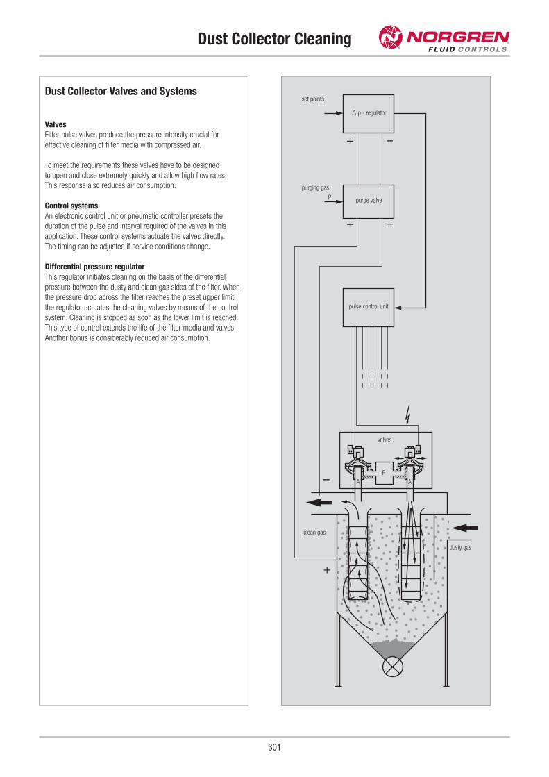
Dust Collector Cleaning
301
+
–
+
+ –
–
Dust Collector Valves and Systems
Valves
Filter pulse valves produce the pressure intensity crucial for
effective cleaning of filter media with compressed air.
To meet the requirements these valves have to be designed
to open and close extremely quickly and allow high flow rates.
This response also reduces air consumption.
Control systems
An electronic control unit or pneumatic controller presets the
duration of the pulse and interval required of the valves in this
application. These control systems actuate the valves directly.
The timing can be adjusted if service conditions change.
Differential pressure regulator
This regulator initiates cleaning on the basis of the differential
pressure between the dusty and clean gas sides of the filter. When
the pressure drop across the filter reaches the preset upper limit,
the regulator actuates the cleaning valves by means of the control
system. Cleaning is stopped as soon as the lower limit is reached.
This type of control extends the life of the filter media and valves.
Another bonus is considerably reduced air consumption.
set points
purging gas
P
P
A A
purge valve
pulse control unit
valves
clean gas
dusty gas
Δ p - regulator
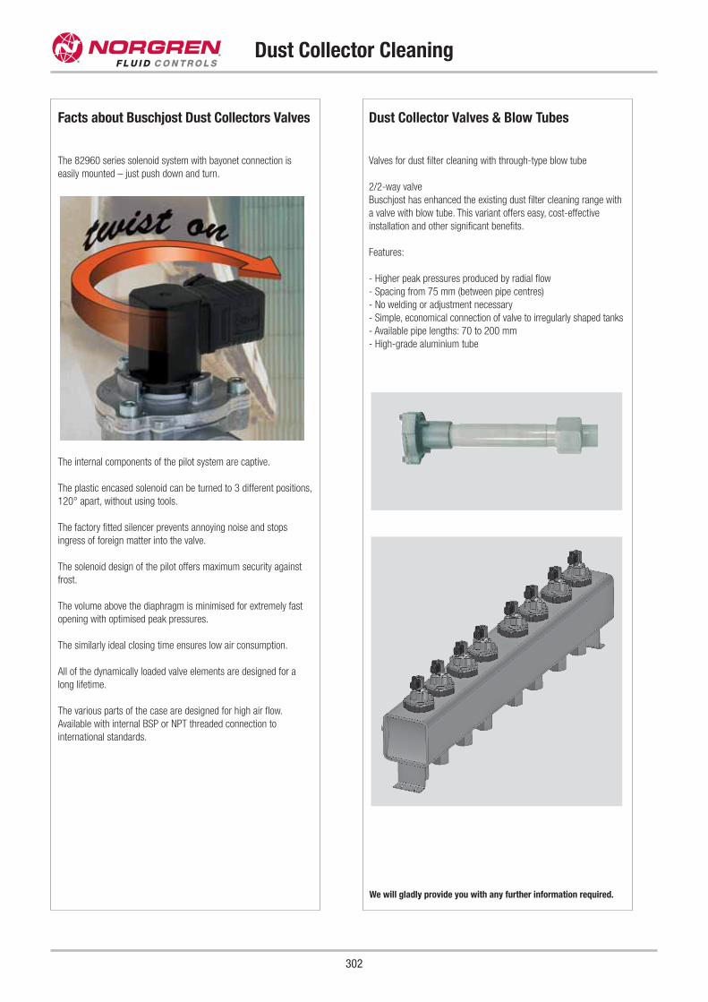
Dust Collector Valves & Blow Tubes
Valves for dust filter cleaning with through-type blow tube
2/2-way valve
Buschjost has enhanced the existing dust filter cleaning range with
a valve with blow tube. This variant offers easy, cost-effective
installation and other significant benefits.
Features:
- Higher peak pressures produced by radial flow
- Spacing from 75 mm (between pipe centres)
- No welding or adjustment necessary
- Simple, economical connection of valve to irregularly shaped tanks
- Available pipe lengths: 70 to 200 mm
- High-grade aluminium tube
Dust Collector Cleaning
302
Facts about Buschjost Dust Collectors Valves
The 82960 series solenoid system with bayonet connection is
easily mounted – just push down and turn.
The internal components of the pilot system are captive.
The plastic encased solenoid can be turned to 3 different positions,
120° apart, without using tools.
The factory fitted silencer prevents annoying noise and stops
ingress of foreign matter into the valve.
The solenoid design of the pilot offers maximum security against
frost.
The volume above the diaphragm is minimised for extremely fast
opening with optimised peak pressures.
The similarly ideal closing time ensures low air consumption.
All of the dynamically loaded valve elements are designed for a
long lifetime.
The various parts of the case are designed for high air flow.
Available with internal BSP or NPT threaded connection to
international standards.
We will gladly provide you with any further information required.
Dust Collector Cleaning
303
Pressure Build-up Time
Background
The valves used are designed to release almost explosive pulses of
air that shake the dust particles off the filter bags.
However, this method is not effective if the pressure rises too slowly
or the flow coefficient (kv) of the filter pulse valve is too low. The
nominal diameter of the valve also has to match the filter volume.
The flow coefficient and the pressure rise time therefore represent
the most important technical parameters for filter valves.
Reasons
If the pressure rises too slowly, the flow rate increases too gradually
to shake the dust off the filter bags. Effective cleaning therefore
requires the valve to open abruptly and blow a very short burst of
compressed air (just a few milliseconds) into the filter. If the flow
time is too long (just a few hundred milliseconds), the cleaning is
not much more effective, but the air consumption is much higher.
The dust is also not shaken off if the pressure increases very
quickly but the air throughput is insufficient. The volume released is
then too small to subject the filter bags to a shock wave.
Summary
For effective cleaning, the pressure rise time has to be very short
and the flow coefficient (kv) as large as possible.
Differential Pressure Regulators
The 83400 series of regulators can be used in combination with the
83720 series of electronic pulse control units to automatically
adapt the cleaning to the dust loading.
A dust-resistant piezoresistive pressure sensor measures the
differential between the clean and dusty sides of the filter system,
which depends on the build-up, and provides a continuous digital
readout.
All of the settings can be programmed with the buttons.
The host pulse control unit continues to operate until cleaning has
progressed to the extent where the preset limit is reached.
Any after-cleaning programmed is then started. Its duration is
adjustable.
Two other switching points, Alarm 1 and Alarm 2, set above or
below the set points as required, can be used to give an alarm in
the event of faults.
The switching outputs can also be operated manually.
The regulator can be switched between 0 to 10V, 0 to 20mA
or 4 to 20mA analog output signals and can be operated off
230V AC or 24V DC.
The unit conforms to the Electromagnetic Compatibility Directive
89/336/EEC and the Low Voltage Directive 73/23/EEC.
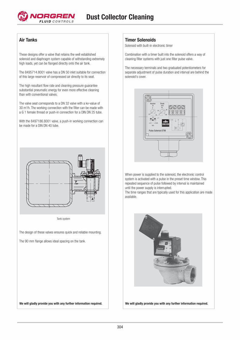
Timer SolenoidsSolenoid with built-in electronic timer
Combination with a timer built into the solenoid offers a way of
cleaning filter systems with just one filter pulse valve.
The necessary terminals and two graduated potentiometers for
separate adjustment of pulse duration and interval are behind the
solenoid's cover.
When power is supplied to the solenoid, the electronic control
system is activated with a pulse in the preset time window. This
repeated sequence of pulse followed by interval is maintained
until the power supply is interrupted.
The time ranges that are typically used for this application are made
available.
Dust Collector Cleaning
304
Air Tanks
These designs offer a valve that retains the well established
solenoid and diaphragm system capable of withstanding extremely
high loads, yet can be flanged directly onto the air tank.
The 8495714.8001 valve has a DN 50 inlet suitable for connection
of this large reservoir of compressed air directly to its seat.
The high resultant flow rate and cleaning pressure guarantee
substantial pneumatic energy for even more effective cleaning
than with conventional valves.
The valve seat corresponds to a DN 32 valve with a kv-value of
30 m3/h. The working connection with the filter can be made with
a G 1 female thread or push-in connection for a DIN DN 25 tube.
With the 8497186.8001 valve, a push-in working connection can
be made for a DIN DN 40 tube.
Tank system
The design of these valves ensures quick and reliable mounting.
The 90 mm flange allows ideal spacing on the tank.
We will gladly provide you with any further information required. We will gladly provide you with any further information required.
6
90
60
30
5
–+(–)
12010
Test
ON
x 0,1
x 1
x 0,05
0,5
Break[min]
Impulse[s]
Pulse Solenoid ETM
P
A
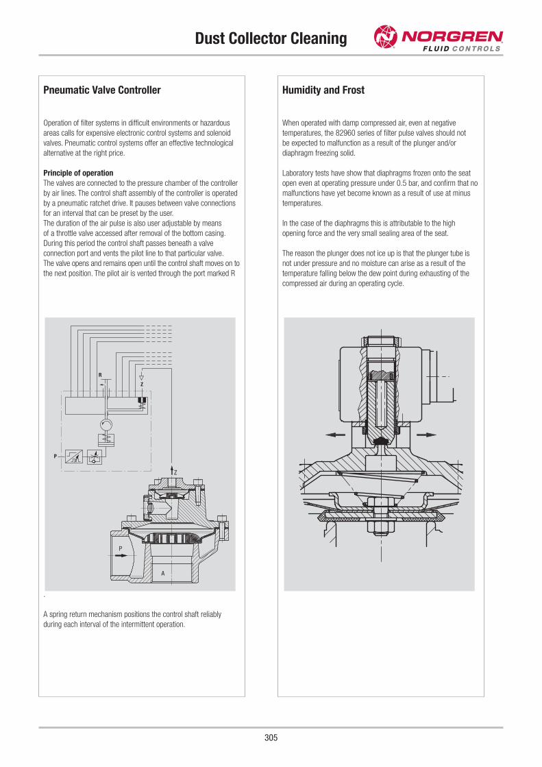
Dust Collector Cleaning
305
Humidity and Frost
When operated with damp compressed air, even at negative
temperatures, the 82960 series of filter pulse valves should not
be expected to malfunction as a result of the plunger and/or
diaphragm freezing solid.
Laboratory tests have show that diaphragms frozen onto the seat
open even at operating pressure under 0.5 bar, and confirm that no
malfunctions have yet become known as a result of use at minus
temperatures.
In the case of the diaphragms this is attributable to the high
opening force and the very small sealing area of the seat.
The reason the plunger does not ice up is that the plunger tube is
not under pressure and no moisture can arise as a result of the
temperature falling below the dew point during exhausting of the
compressed air during an operating cycle.
Pneumatic Valve Controller
Operation of filter systems in difficult environments or hazardous
areas calls for expensive electronic control systems and solenoid
valves. Pneumatic control systems offer an effective technological
alternative at the right price.
Principle of operation
The valves are connected to the pressure chamber of the controller
by air lines. The control shaft assembly of the controller is operated
by a pneumatic ratchet drive. It pauses between valve connections
for an interval that can be preset by the user.
The duration of the air pulse is also user adjustable by means
of a throttle valve accessed after removal of the bottom casing.
During this period the control shaft passes beneath a valve
connection port and vents the pilot line to that particular valve.
The valve opens and remains open until the control shaft moves on to
the next position. The pilot air is vented through the port marked R
.
A spring return mechanism positions the control shaft reliably
during each interval of the intermittent operation.
P
Z
R
P
A
Z
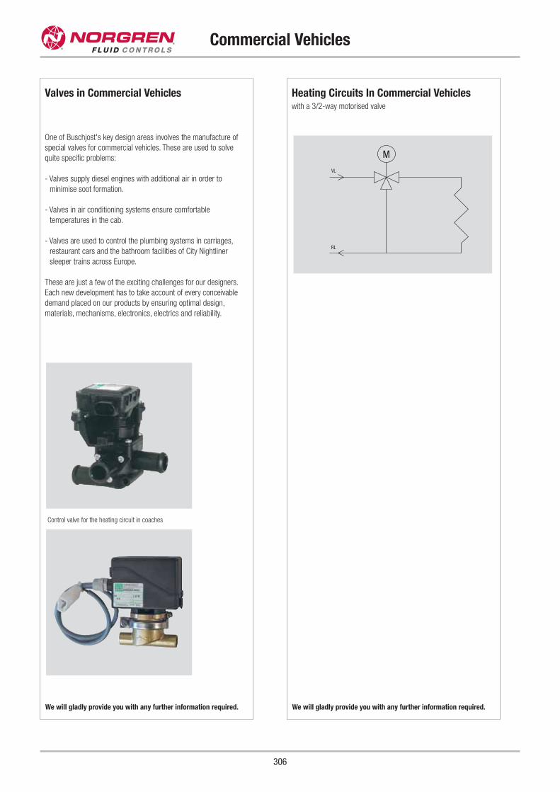
Heating Circuits In Commercial Vehicles with a 3/2-way motorised valve
Commercial Vehicles
306
Valves in Commercial Vehicles
One of Buschjost's key design areas involves the manufacture of
special valves for commercial vehicles. These are used to solve
quite specific problems:
- Valves supply diesel engines with additional air in order to
minimise soot formation.
- Valves in air conditioning systems ensure comfortable
temperatures in the cab.
- Valves are used to control the plumbing systems in carriages,
restaurant cars and the bathroom facilities of City Nightliner
sleeper trains across Europe.
These are just a few of the exciting challenges for our designers.
Each new development has to take account of every conceivable
demand placed on our products by ensuring optimal design,
materials, mechanisms, electronics, electrics and reliability.
Control valve for the heating circuit in coaches
We will gladly provide you with any further information required. We will gladly provide you with any further information required.
M
VL
RL
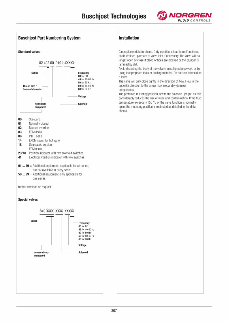
Buschjost Technologies
307
Installation
Clean pipework beforehand. Dirty conditions lead to malfunctions,
so fit strainer upstream of valve inlet if necessary. The valve will no
longer open or close if bleed orifices are blocked or the plunger is
jammed by dirt.
Avoid distorting the body of the valve in misaligned pipework, or by
using inappropriate tools or sealing material. Do not use solenoid as
a lever.
The valve will only close tightly in the direction of flow. Flow in the
opposite direction to the arrow may irreparably damage
components.
The preferred mounting position is with the solenoid upright, as this
considerably reduces the risk of wear and contamination. If the fluid
temperature exceeds +150 °C or the valve function is normally
open, the mounting position is restricted as detailed in the data
sheets.
Buschjost Part Numbering System
Standard valves
00 Standard
01 Normally closed
02 Manual override
03 FPM seals
06 PTFE seals
14 EPDM seals, for hot water
18 Degreased version;
FPM seals
23/40 Position indicator with two solenoid switches
41 Electrical Position indicator with two switches
01 ... 49 = Additional equipment, applicable for all series,
but not available in every series.
50 ... 99 = Additional equipment, only applicable for
one series.
further versions on request
Special valves
82 402 00 .9101 .XXXXX
Solenoid
Series Frequency
00 for DC
49 for 40-60 Hz
50 for 50 Hz
59 for 50-60 Hz
60 for 60 Hz
Voltage
Thread size /
Nominal diameter
Additional-
equipment
849 XXXX .XXXX .XXXXX
Solenoid
Series
Voltage
consecutively
numbered
Frequency
00 for DC
49 for 40-60 Hz
50 for 50 Hz
59 for 50-60 Hz
60 for 60 Hz
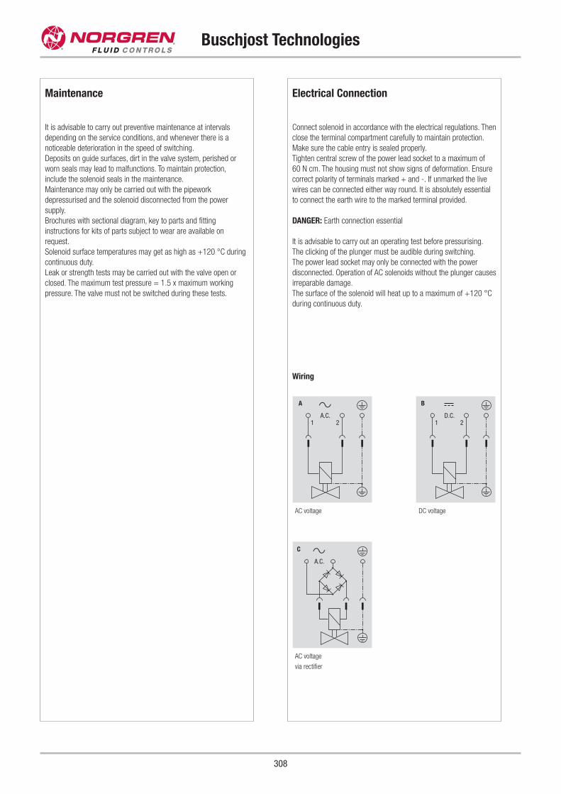
Electrical Connection
Connect solenoid in accordance with the electrical regulations. Then
close the terminal compartment carefully to maintain protection.
Make sure the cable entry is sealed properly.
Tighten central screw of the power lead socket to a maximum of
60 N cm. The housing must not show signs of deformation. Ensure
correct polarity of terminals marked + and -. If unmarked the live
wires can be connected either way round. It is absolutely essential
to connect the earth wire to the marked terminal provided.
DANGER: Earth connection essential
It is advisable to carry out an operating test before pressurising.
The clicking of the plunger must be audible during switching.
The power lead socket may only be connected with the power
disconnected. Operation of AC solenoids without the plunger causes
irreparable damage.
The surface of the solenoid will heat up to a maximum of +120 °C
during continuous duty.
Wiring
AC voltage
via rectifier
DC voltageAC voltage
Buschjost Technologies
308
Maintenance
It is advisable to carry out preventive maintenance at intervals
depending on the service conditions, and whenever there is a
noticeable deterioration in the speed of switching.
Deposits on guide surfaces, dirt in the valve system, perished or
worn seals may lead to malfunctions. To maintain protection,
include the solenoid seals in the maintenance.
Maintenance may only be carried out with the pipework
depressurised and the solenoid disconnected from the power
supply.
Brochures with sectional diagram, key to parts and fitting
instructions for kits of parts subject to wear are available on
request.
Solenoid surface temperatures may get as high as +120 °C during
continuous duty.
Leak or strength tests may be carried out with the valve open or
closed. The maximum test pressure = 1.5 x maximum working
pressure. The valve must not be switched during these tests.
1 2A.C.
A
A.C.
C
1 2D.C.
B
Buschjost Technologies
309
Buschjost Solenoids - Heating
The solenoids are normally designed for continuous duty, so under
normal conditions there is no danger of the permanent operating
temperature of the coil reaching an impermissible value.
The coil temperature that is reached during operation is influenced
by 3 factors:
- the self-heating
- the temperature of the fluid flowing through
- the ambient temperature
The highest permissible solenoid temperature is generally
determined by the thermal durability of the material used for
insulation.
In order to ensure that there is no thermal damage, the
specifications for the maximum permitted fluid and ambient
temperatures should not be exceeded.
In this context, particular attention should be paid to the power
consumption of the solenoids. Many valve manufacturers give their
power consumption at operating temperature, which is lower than
the specifications given in this catalogue, because of the high coil
resistance.
Particular attention should be paid to the passage in the Buschjost
data sheets:
The power consumption is measured according to VDE 0580
at a coil temperature of +20 °C. Physical factors reduce the
value by up to about 30 % when the DC solenoid coil has
reached normal operating temperature.
The actuating solenoids are offered with a range of different
connections. The most common are the sockets to
DIN EN175 301-803, terminals in the terminal compartment
with cable passing through a gland or directly encapsulated
in the coil area (moulded cable).
At continuous duty the surface temperature of the solenoid can
reach up to 120 °C.
Buschjost Solenoids
General
Valve actuating solenoids are designed for the service conditions
and conform to VDE 0580.
Power supply, voltage ranges
The preferred voltages are specified in the separate publications.
Special voltages are possible on request.
The permissible voltage range is ±10 % of the nominal value.
Type of supply
Solenoids are available for connection to a DC or AC supply.
Those designed for AC may only be used at the specified frequency.
The more powerful solenoids are a DC design. They can be
operated off an AC supply via a rectifier, which is connected in
series as standard. The permissible frequency is then 40 to 60Hz.
Duty cycle
All standard solenoids are designed for continuous duty in order to
rule out the possibility of the winding overheating during normal
service conditions.
DC solenoids
The main advantage of this type is constant current consumption.
This gives soft switching and makes the winding less sensitive to
binding of the plunger. The maximum frequency of operation is only
limited by the system's electrical and mechanical inertia.
AC solenoids
The current consumption of this system depends on the position of
the plunger. The plunger must be able to reach its limit unhindered,
otherwise the winding will overheat.
Special spark quenching is generally not necessary.
Ensure that the mains frequency agrees with the value specified on
the name plate. If it is higher, the solenoid will develop less force
and may burn out, since the plunger cannot reach its limit. At a
lower frequency the smaller inductive reactance causes more
heating, which can influence the lifetime of the coil.
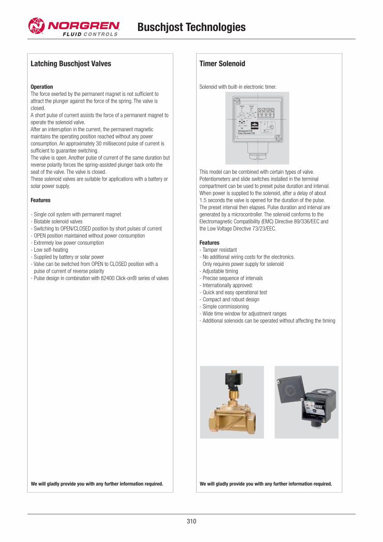
Timer Solenoid
Solenoid with built-in electronic timer.
This model can be combined with certain types of valve.
Potentiometers and slide switches installed in the terminal
compartment can be used to preset pulse duration and interval.
When power is supplied to the solenoid, after a delay of about
1.5 seconds the valve is opened for the duration of the pulse.
The preset interval then elapses. Pulse duration and interval are
generated by a microcontroller. The solenoid conforms to the
Electromagnetic Compatibility (EMC) Directive 89/336/EEC and
the Low Voltage Directive 73/23/EEC.
Features
- Tamper resistant
- No additional wiring costs for the electronics.
Only requires power supply for solenoid
- Adjustable timing
- Precise sequence of intervals
- Internationally approved:
- Quick and easy operational test
- Compact and robust design
- Simple commissioning
- Wide time window for adjustment ranges
- Additional solenoids can be operated without affecting the timing
Buschjost Technologies
310
Latching Buschjost Valves
Operation
The force exerted by the permanent magnet is not sufficient to
attract the plunger against the force of the spring. The valve is
closed.
A short pulse of current assists the force of a permanent magnet to
operate the solenoid valve.
After an interruption in the current, the permanent magnetic
maintains the operating position reached without any power
consumption. An approximately 30 millisecond pulse of current is
sufficient to guarantee switching.
The valve is open. Another pulse of current of the same duration but
reverse polarity forces the spring-assisted plunger back onto the
seat of the valve. The valve is closed.
These solenoid valves are suitable for applications with a battery or
solar power supply.
Features
- Single coil system with permanent magnet
- Bistable solenoid valves
- Switching to OPEN/CLOSED position by short pulses of current
- OPEN position maintained without power consumption
- Extremely low power consumption
- Low self-heating
- Supplied by battery or solar power
- Valve can be switched from OPEN to CLOSED position with a
pulse of current of reverse polarity
- Pulse design in combination with 82400 Click-on® series of valves
We will gladly provide you with any further information required.We will gladly provide you with any further information required.
6
90
60
30
5
–+(–)
12010
Test
ON
x 0,1
x 1
x 0,05
0,5
Pause[min]
Impuls[s]
Taktmagnet ETMPulse Solenoid ETM
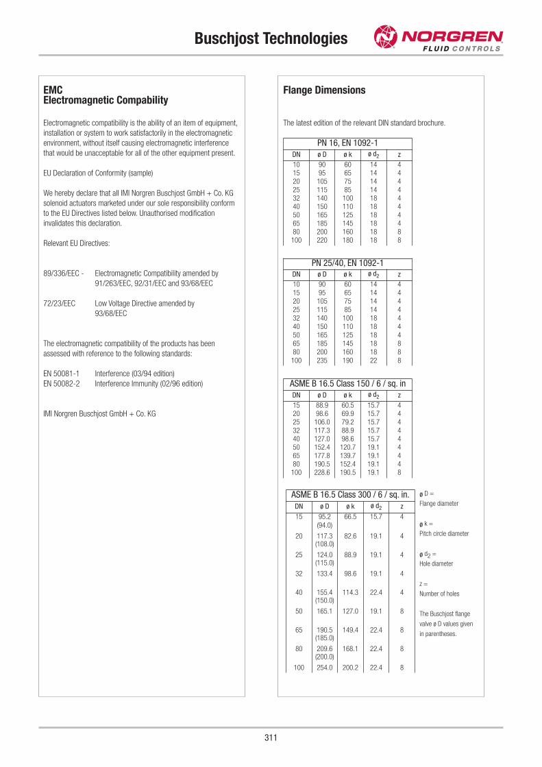
Buschjost Technologies
311
Flange Dimensions
The latest edition of the relevant DIN standard brochure.
ø D =
Flange diameter
ø k =
Pitch circle diameter
ø d2 =
Hole diameter
z =
Number of holes
The Buschjost flange
valve ø D values given
in parentheses.
ASME B 16.5 Class 300 / 6 / sq. in.
DN ø D ø k ø d2 z
15 95.2 66.5 15.7 4(94.0)
20 117.3 82.6 19.1 4(108.0)
25 124.0 88.9 19.1 4(115.0)
32 133.4 98.6 19.1 4
40 155.4 114.3 22.4 4(150.0)
50 165.1 127.0 19.1 8
65 190.5 149.4 22.4 8(185.0)
80 209.6 168.1 22.4 8(200.0)
100 254.0 200.2 22.4 8
ASME B 16.5 Class 150 / 6 / sq. in
DN ø D ø k ø d2 z
15 88.9 60.5 15.7 420 98.6 69.9 15.7 425 106.0 79.2 15.7 432 117.3 88.9 15.7 440 127.0 98.6 15.7 450 152.4 120.7 19.1 465 177.8 139.7 19.1 480 190.5 152.4 19.1 4
100 228.6 190.5 19.1 8
PN 25/40, EN 1092-1DN ø D ø k ø d2 z
10 90 60 14 415 95 65 14 420 105 75 14 425 115 85 14 432 140 100 18 440 150 110 18 450 165 125 18 465 185 145 18 880 200 160 18 8
100 235 190 22 8
PN 16, EN 1092-1
DN ø D ø k ø d2 z
10 90 60 14 415 95 65 14 420 105 75 14 425 115 85 14 432 140 100 18 440 150 110 18 450 165 125 18 465 185 145 18 480 200 160 18 8
100 220 180 18 8
EMCElectromagnetic Compability
Electromagnetic compatibility is the ability of an item of equipment,
installation or system to work satisfactorily in the electromagnetic
environment, without itself causing electromagnetic interference
that would be unacceptable for all of the other equipment present.
EU Declaration of Conformity (sample)
We hereby declare that all IMI Norgren Buschjost GmbH + Co. KG
solenoid actuators marketed under our sole responsibility conform
to the EU Directives listed below. Unauthorised modification
invalidates this declaration.
Relevant EU Directives:
89/336/EEC - Electromagnetic Compatibility amended by
91/263/EEC, 92/31/EEC and 93/68/EEC
72/23/EEC Low Voltage Directive amended by
93/68/EEC
The electromagnetic compatibility of the products has been
assessed with reference to the following standards:
EN 50081-1 Interference (03/94 edition)
EN 50082-2 Interference Immunity (02/96 edition)
IMI Norgren Buschjost GmbH + Co. KG
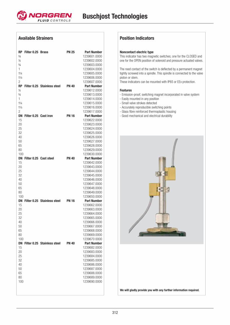
Position Indicators
Noncontact electric type
This indicator has two magnetic switches; one for the CLOSED and
one for the OPEN position of solenoid and pressure actuated valves.
The reed contact of the switch is deflected by a permanent magnet
tightly screwed into a spindle. This spindle is connected to the valve
piston or stem.
These indicators can be mounted with IP65 or EEx protection.
Features
- Emission-proof, switching magnet incorporated in valve system
- Easily mounted in any position
- Small valve strokes detected
- Accurately reproducible switching points
- Glass fibre reinforced thermoplastic housing
- Good mechanical and electrical durability
Buschjost Technologies
312
Available Strainers
RP Filter 0.25 Brass PN 25 Part Number
h 1239601.0000
i 1239602.0000
j 1239603.0000
1 1239604.0000
k 1239605.0000
l 1239606.0000
2 1239607.0000
RP Filter 0.25 Stainless steel PN 40 Part Number
i 1239612.0000
j 1239613.0000
1 1239614.0000
k 1239615.0000
l 1239616.0000
2 1239617.0000
DN Filter 0.25 Cast iron PN 16 Part Number
15 1239622.0000
20 1239623.0000
25 1239624.0000
32 1239625.0000
40 1239626.0000
50 1239627.0000
65 1239628.0000
80 1239629.0000
100 1239630.0000
DN Filter 0.25 Cast steel PN 40 Part Number
15 1239642.0000
20 1239643.0000
25 1239644.0000
32 1239645.0000
40 1239646.0000
50 1239647.0000
65 1239648.0000
80 1239649.0000
100 1239650.0000
DN Filter 0.25 Stainless steel PN 16 Part Number
15 1239662.0000
20 1239663.0000
25 1239664.0000
32 1239665.0000
40 1239666.0000
50 1239667.0000
65 1239668.0000
80 1239669.0000
100 1239670 0000
DN Filter 0.25 Stainless steel PN 40 Part Number
15 1239682.0000
20 1239683.0000
25 1239684.0000
32 1239685.0000
40 1239686.0000
50 1239687.0000
65 1239688.0000
80 1239689.0000
100 1239690.0000
We will gladly provide you with any further information required.
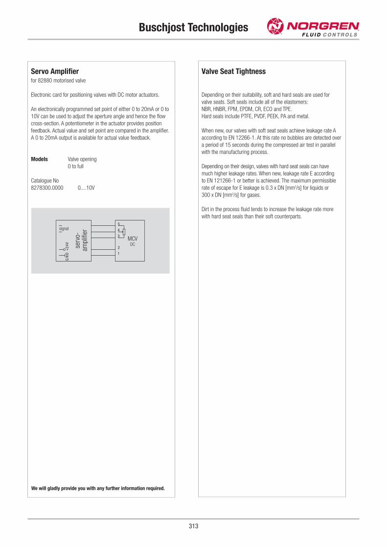
Servo Amplifierfor 82880 motorised valve
Electronic card for positioning valves with DC motor actuators.
An electronically programmed set point of either 0 to 20mA or 0 to
10V can be used to adjust the aperture angle and hence the flow
cross-section. A potentiometer in the actuator provides position
feedback. Actual value and set point are compared in the amplifier.
A 0 to 20mA output is available for actual value feedback.
Models Valve opening
0 to full
Catalogue No
8278300.0000 0....10V
1
2
3
4
5
V42+
DN
G
Buschjost Technologies
313
Valve Seat Tightness
Depending on their suitability, soft and hard seals are used for
valve seats. Soft seals include all of the elastomers:
NBR, HNBR, FPM, EPDM, CR, ECO and TPE.
Hard seals include PTFE, PVDF, PEEK, PA and metal.
When new, our valves with soft seat seals achieve leakage rate A
according to EN 12266-1. At this rate no bubbles are detected over
a period of 15 seconds during the compressed air test in parallel
with the manufacturing process.
Depending on their design, valves with hard seat seals can have
much higher leakage rates. When new, leakage rate E according
to EN 121266-1 or better is achieved. The maximum permissible
rate of escape for E leakage is 0.3 x DN [mm3/s] for liquids or
300 x DN [mm3/s] for gases.
Dirt in the process fluid tends to increase the leakage rate more
with hard seat seals than their soft counterparts.
We will gladly provide you with any further information required.
MCVDC
signal
serv
o-am
plifi
er
EC Type examined Valves to DVGW (German GAS installation and plumbingassociation) requirements
Firing systems, gas turbines and other oil and gas appliances are
operated with safety valves that shut off the fuel supply should
dangerous conditions arise.
Type examination is mandatory to establish their suitability for
this purpose.
For the gases specified by DVGW Code of Practice G 260, the
requirements of EN 161 and DIN 3394 Part 1 have to be met for
working pressures in excess of 4 bar. Liquid fuels are governed
by the requirements of EN 264.
The old DIN DVGW registration number has been superseded
in the course of EU harmonisation.
Safety shut-off valves are not gas appliances ready for use as
defined in the Gas Appliance Directive. The valves are marked with
the CE product identification number rather than the CE mark.
Buschjost has developed 3 series of electrically and
electropneumatically actuated valves. The 82580 series is only
suitable for gaseous fuels, the others cater for gaseous and liquid
fuels.
These valves are described in greater detail on their data sheets.
Overview
Series Product ID No Page
82370 CE-0085AU0323 26
82580 CE-0085AT0091 138
83860 CE-0085AS0104 198
Buschjost Technologies
314
We will gladly provide you with any further information required.
Valve Blocks
System solutions achieved through integration
Professional system solutions offer the machine manufacturer the
option of concentrating in-house resources on core competencies.
As a valve specialist, Buschjost provides compact solutions that
have been well thought out on the basis of relevant experience.
These are realised in a modern Buschjost valve factory with
optimised methods of production and assembly. The user receives
a tested module with the added benefit of a significant reduction in
spare parts inventory.
We will gladly provide you with any further information required.
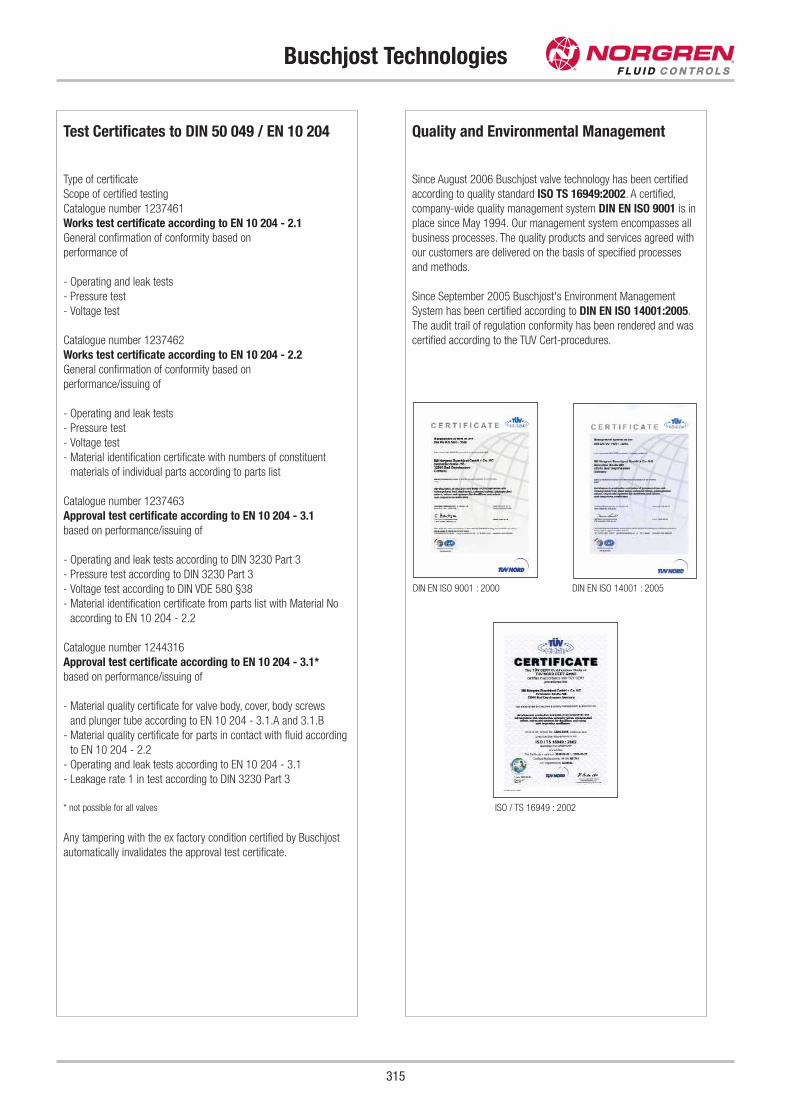
Quality and Environmental Management
Since August 2006 Buschjost valve technology has been certified
according to quality standard ISO TS 16949:2002. A certified,
company-wide quality management system DIN EN ISO 9001 is in
place since May 1994. Our management system encompasses all
business processes. The quality products and services agreed with
our customers are delivered on the basis of specified processes
and methods.
Since September 2005 Buschjost's Environment Management
System has been certified according to DIN EN ISO 14001:2005.
The audit trail of regulation conformity has been rendered and was
certified according to the TUV Cert-procedures.
Buschjost Technologies
315
Test Certificates to DIN 50 049 / EN 10 204
Type of certificate
Scope of certified testing
Catalogue number 1237461
Works test certificate according to EN 10 204 - 2.1
General confirmation of conformity based on
performance of
- Operating and leak tests
- Pressure test
- Voltage test
Catalogue number 1237462
Works test certificate according to EN 10 204 - 2.2
General confirmation of conformity based on
performance/issuing of
- Operating and leak tests
- Pressure test
- Voltage test
- Material identification certificate with numbers of constituent
materials of individual parts according to parts list
Catalogue number 1237463
Approval test certificate according to EN 10 204 - 3.1
based on performance/issuing of
- Operating and leak tests according to DIN 3230 Part 3
- Pressure test according to DIN 3230 Part 3
- Voltage test according to DIN VDE 580 §38
- Material identification certificate from parts list with Material No
according to EN 10 204 - 2.2
Catalogue number 1244316
Approval test certificate according to EN 10 204 - 3.1*
based on performance/issuing of
- Material quality certificate for valve body, cover, body screws
and plunger tube according to EN 10 204 - 3.1.A and 3.1.B
- Material quality certificate for parts in contact with fluid according
to EN 10 204 - 2.2
- Operating and leak tests according to EN 10 204 - 3.1
- Leakage rate 1 in test according to DIN 3230 Part 3
* not possible for all valves
Any tampering with the ex factory condition certified by Buschjost
automatically invalidates the approval test certificate.
DIN EN ISO 9001 : 2000
ISO / TS 16949 : 2002
DIN EN ISO 14001 : 2005
Pressure Equipment Directive
316
Pressure Equipment Directive (PED)
The Pressure Equipment Directive (PED) is generally applicable to
equipment with a working pressure greater than 0.5 bar. Valves as
components of this equipment come under the scope of the
directive. However, only valves above a certain nominal size are
required to bear CE markings.
Valves suitable for different (e.g. neutral, toxic or flammable) fluids
only require CED markings above a nominal size of DN 25. Smaller
valves must not bear a CE mark in accordance with the
Pressure Equipment Directive. This equipment must be
designed in line with standard engineering practice so that it meets
the requirements of the directive.
Almost all of the valves over DN 25 in size requiring marking should
be assigned to Categories I and II. This means their design and
testing is in the responsibility of the manufacturer, i.e. Norgren
Buschjost in the case. Module A1 has been chosen as the related
method of evaluating conformity and certified by the "nominated
body" (TÜV Nord).
The products are also subject to other EU Directives such as EMC,
Low Voltage, etc. The products bear a CE mark as a declaration of
conformity with all of these. Where applicable (sizes > DN 25) this
mark also serves as a declaration of conformity with the Pressure
Equipment Directive. Category II valves are also marked with the
identification number of the nominated body; CE 0045 for TÜV
Nord.
PED1
Applies to the following series:
82370, 82380, 82480, 82510, 82530, 82560, 82960, 83320, 83860, 83920, 84070, 84080, 84660, 84680, 82080, 82610,
PED2
Applies to the following series:
82710, 82870, 82900, 83300, 83930, 82160
PED3
Applies to the following series:
82180, 82280, 82340, 82400, 82470, 82540, 82580, 82590, 82660, 82670, 83050, 83200, 83240, 83250, 83340, 83350, 83380, 83580, 84100, 84120,
84140, 84180, 84190, 84200, 84220, 84240, 84320, 84340, 84360, 84500, 84520, 84540, 84550, 84580, 84590, 84720, 84740, 84760, 84770, 84880,
84890, 85040, 85100, 85120, 85140, 85200, 85220, 85240, 85300, 85320, 85640, 85700, 85720, 85740
PED4
Applies to the following series:
82730, 82880
Pressure Equipment Directive
317
Note to Pressure Equipment Directive (PED):
The valves of this series are according to Art. 3 § 3 of the Pressure
Equipment Directive (PED) 97/23/EG.
This means interpretation and production are in accordance to common
engineering practices in the member countries.
The CE-sign at the valve does not refer to the PED. Thus the declaration of
comformity is not longer applicable for this directive.
Note to Electromagnetic Compatibility Guideline (EEC):
The valves shall be provided with an electrical circuit which ensures the limits
of the harmonised standards EN 61000-6-3 and EN 61000-6-1 are
observed, and hence the requirements of the Electromagnetic Guildeline
(2004/108/EC) satisfied.
Note to Pressure Equipment Directive (PED):
The valves of this series, including the connection-size DN 25 (G 1),
are according to Art. 3 § 3 of the Pressure Equipment Directive (PED)
97/23/EG. This means interpretation and production are in accordance to
common engineering practices in the member countries.
The CE-sign at the valve does not refer to the PED. Thus the declaration of
conformity is not longer applicable for this directive.
For valves > DN 25 (G 1) Art. 3 § (1) No.1.4 applies.
The basic requirements of the Enclosure I of the PED must be fulfilled.
The CE-sign at the valve includes the PED. A certificate of conformity of this
directive will be available on request.
Note to Electromagnetic Compatibility Guideline (EEC):
The valves shall be provided with an electrical circuit which ensures th e
limits of the harmonised standards EN 61000-6-3 and EN 61000-6-1 are
observed, and hence the requirements of the Electromagnetic Compatibility
Guideline (2004/108/EG) satisfied.
Note to Pressure Equipment Directive (PED):
The valves of this series are according to Art. 3 § 3 of the Pressure
Equipment Directive (PED) 97/23/EG.
This means interpretation and production are in accordance to common
engineering practices in the member countries.
The CE-sign at the valve does not refer to the PED. Thus the declaration of
conformity is not longer applicable for this directive.
Note to Electromagnetic Compatibility Guideline (EEC):
The valves shall be provided with an electrical circuit which ensures th e
limits of the harmonised standards EN 61000-6-3 and EN 61000-6-1 are
observed, and hence the requirements of the Electromagnetic Compatibility
Guideline (2004/108/EEC) satisfied.
Note to Pressure Equipment Directive (PED):
The valves of this series are according to Art. 3 § 3 of the Pressure
Equipment Directive (PED) 97/23/EG
This means interpretation and production are in accordance to
common engineering practices in the member countries.
A certificate of conformity is not designated.
Safety Instructions
318
Safety Instructions for the Norgren and FAS range
These products are intended for use in industrial compressed air
systems only. Do not use these products where pressures and
temperatures can exceed those listed under "Technical data".
Before using these products with fluids other than those specified,
for non-industrial applications, life-support systems, or other
applications not within published specifications, consult NORGREN
FLUID CONTROLS.
Through misuse, age, or malfunction, components used in fluid
power systems can fail in various modes.
The system designer is warned to consider the failure modes of all
component parts used in fluid power systems and to provide
adequate safeguards to prevent personal injury or damage to
equipment in the event of such failure.
System designers must provide a warning to end users in
the system instructional manual if protection against a
failure mode cannot be adequately provided.
System designers and end users are cautioned to review specific
warnings found in instructions sheets packed and shipped with
these products.
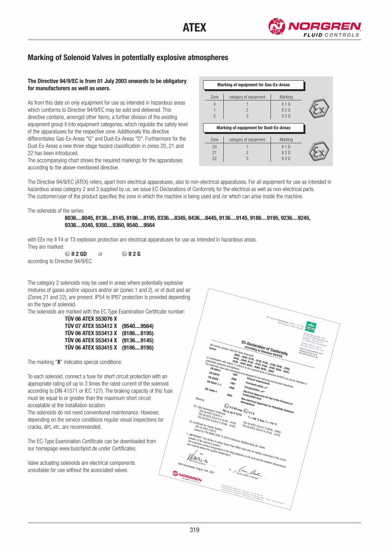
Marking of Solenoid Valves in potentially explosive atmospheres
The Directive 94/9/EC is from 01 July 2003 onwards to be obligatory
for manufacturers as well as users.
As from this date on only equipment for use as intended in hazardous areas
which conforms to Directive 94/9/EC may be sold and delivered. This
directive contains, amongst other items, a further division of the existing
equipment group II into equipment categories, which regulate the safety level
of the apparatuses for the respective zone. Additionally this directive
differentiates Gas-Ex-Areas "G" and Dust-Ex-Areas "D". Furthermore for the
Dust-Ex-Areas a new three-stage hazard classification in zones 20, 21 and
22 has been introduced.
The accompanying chart shows the required markings for the apparatuses
according to the above-mentioned directive.
The Directive 94/9/EC (ATEX) refers, apart from electrical apparatuses, also to non-electrical apparatuses. For all equipment for use as intended in
hazardous areas category 2 and 3 supplied by us, we issue EC-Declarations of Conformity for the electrical as well as non-electrical parts.
The customer/user of the product specifies the zone in which the machine is being used and /or which can arise inside the machine.
The solenoids of the series
8036....8045, 8136....8145, 8186....8195, 8336....8345, 8436....8445, 9136....9145, 9186....9195, 9236....9245,
9336....9345, 9350....9360, 9540....9564
with EEx me II T4 or T3 explosion protection are electrical apparatuses for use as intended in hazardous areas.
They are marked:
x II 2 GD or x II 2 G
according to Directive 94/9/EC.
The category 2 solenoids may be used in areas where potentially explosive
mixtures of gases and/or vapours and/or air (zones 1 and 2), or of dust and air
(Zones 21 and 22), are present. IP54 to IP67 protection is provided depending
on the type of solenoid.
The solenoids are marked with the EC Type Examination Certificate number:
TÜV 06 ATEX 553076 X
TÜV 07 ATEX 553412 X (9540....9564)
TÜV 06 ATEX 553413 X (8186....8195)
TÜV 06 ATEX 553414 X (9136....9145)
TÜV 06 ATEX 553415 X (9186....9195)
The marking "X" indicates special conditions:
To each solenoid, connect a fuse for short circuit protection with an
appropriate rating (of up to 3 times the rated current of the solenoid
according to DIN 41571 or IEC 127). The braking capacity of this fuse
must be equal to or greater than the maximum short circuit
acceptable at the installation location.
The solenoids do not need conventional maintenance. However,
depending on the service conditions regular visual inspections for
cracks, dirt, etc, are recommended.
The EC-Type Examination Certificate can be downloaded from
our homepage www.buschjost.de under Certificates.
Valve actuating solenoids are electrical components
unsuitable for use without the associated valves.
319
ATEX
HRA 498 Bad Oeynhausen · US t - I dN r. : DE 126 009 482
Komp lemen tä r : IM I No rg ren Busch j o s t Ve rwa l t ungs GmbH · HRB 91 Bad Oeynhausen
Geschä f t s f üh re r : M i chae l P r e i ne r s t o r f e r, O l i v e r Wehk i ng
De tmo lde r S t raße 256
D- 32545 Bad Oeynhausen
Pos t f ach 10 02 52-53D- 32502 Bad Oeynhausen
Te l e f on 05731 / 7 91-0Te l e f a x 05731 / 7 91-179
www.norg renflu id .com
www.busch jos t.dema i l@busch jos t .de
IM I No rg ren Busch jos t GmbH + Co . KG
Ven t i l t e chn i k und Sys t eme
EC-Declaration of Conformity
according to Directive 94/9/EC
We hereby declare, that the Valve Solenoids:
Series:
8036…8045, 8136…8145, 8186…8195, 8336…8345,
8436…8445, 9136…9145, 9186…9195, 9236…9245,
9336…9345, 9350…9360, 9540…9564
in combination with valves *) conform to the requirements of Directive 94/9/EC for use as intended in
potentially explosive atmospheres.
The solenoids have been developed and designed to the following harmonised standards:
EN 500141997
General requirements
EN 500192000
Increased safety „e“
EN 500281987
Encapsulation „m“
EN 50281-1-11998
Electrical Apparatus for Use in the Presence of
Combustible Dust
EN 13463-12002
Non-electrical Apparatus for Potentially Explosive
Atmospheres
Marking:
x II 2 GD resp.x II 2 GEEx m (e) II T3/T4
T = 140 °C bzw. T = 110 °C
EC-Type Examination CertificateTÜV 06 ATEX 553076 X
TÜV 06 ATEX 553412 X (9540....9564)
TÜV 06 ATEX 553413 X (8186....8195)TÜV 06 ATEX 553414 X (9136....9145)
TÜV 06 ATEX 553415 X (9186....9195)
EC-Certificate for Quality System:TÜV 03 ATEX 2158 QIssued by TÜV NORD CERT, D-30519 Hannover (Notified Body No. 0044)
*) IMPORTANT!: The bodies of valves larger than DN65 must also be reliably connected to the circuit
breaker of the electrical system!
The maximum surface temperature of the body depends on the fluid and the ambient temperatures
and must be below the ignition temperature.
Bad Oeynhausen, August 14th, 2007
p
ATEX Representative
pp
Quality Assurance Manager
Marking of equipment for Gas-Ex-Areas
Zone
0
1
2
category of equipment
1
2
3
Marking
II 1 G
II 2 G
II 3 G
Zone
20
21
22
category of equipment
1
2
3
Marking
II 1 D
II 2 D
II 3 D
Marking of equipment for Dust-Ex-Areas
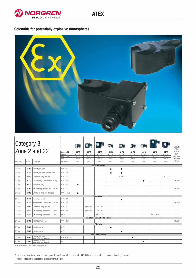
320
ATEX
Solenoids for potentially explosive atmospheres
* For use in explosive atmosphere category 3, zone 2 and 22 according to 94/9/EC a special electrical connector housing is required.
Please indicate this application explicitly in your order.
Further information please consult the data sheet.
Category 3
Zone 2 and 22separate
ATEX-
socket
kit*
only with
standard
solenoid
Solenoid 8026 8326 8426 9116 9176 8176 9326 9526 9426Category Ex II 3 GD Ex II 3 GD Ex II 3 GD Ex II 3 GD Ex II 3 GD Ex II 3 GD Ex II 3 GD Ex II 3 GD Ex II 3 GD
Protection class IP 65 IP 65 IP 65 IP 65 IP 65 IP 65 IP 65 IP 65 IP 65
Body Polymer Polymer Polymer Polymer Polymer Polymer Polymer Steel Polymer
Execution Series Description Connection Socket Socket Socket Socket Socket Socket Socket Socket Socket
Diaphragm design
2/2 way 82400 indirectly actuated G1/4 – G2
2/2 way 82730 indirectly actuated - stainless steel G1/4 – G1
2/2 way 82540 with forced lifting - DC only G1/4 – G2 up to G 1 G1 1/4 – G2
2/2 way 82370 with forced lifting - DVGW certificate - DC only G1/4 – G1 1262560
2/2 way 82530 with forced lifting G1/4 – G1/2
2/2 way 84360 with forced lifting - steam +150° C - DC only G1/4 – G1 1262560
2/2 way 82560 with forced lifting - stainless steel G1/4 – G1/2
Piston design
2/2 way 85300 indirectly actuated G1/4 – G2
2/2 way 85320 indirectly actuated - steam +200° C - DC only G1/4 – G1 1262560
2/2 way 85000 with forced lifting - DC only G1/2 – G2 up to G1/2 G3/4 – G2
2/2 way 85040 with forced lifting - stainless steel - DC only G3/8 – G1 up to G1/2 G3/4 – G1
2/2 way 85140 with forced lifting - stainless steel - DC only DN15 – 50 DN15 DN20 – 50 DN65 – 100
Sealed core tube with PTFE-bellows
2/2 way 82080 directly actuatedwith sealed core tube G1/4 – G3/8 1262560
Pilot valve
3/2 way 84660 directly actuated G1/4
3/2 way 84680 directly actuated G1/4
Dust cleaning valves
2/2 way 82960 indirectly actuatedelectromagnetic operated G3/4,G1,G1 1/2
2/2 way 82860 indirectly actuatedelectromagnetic operated G2
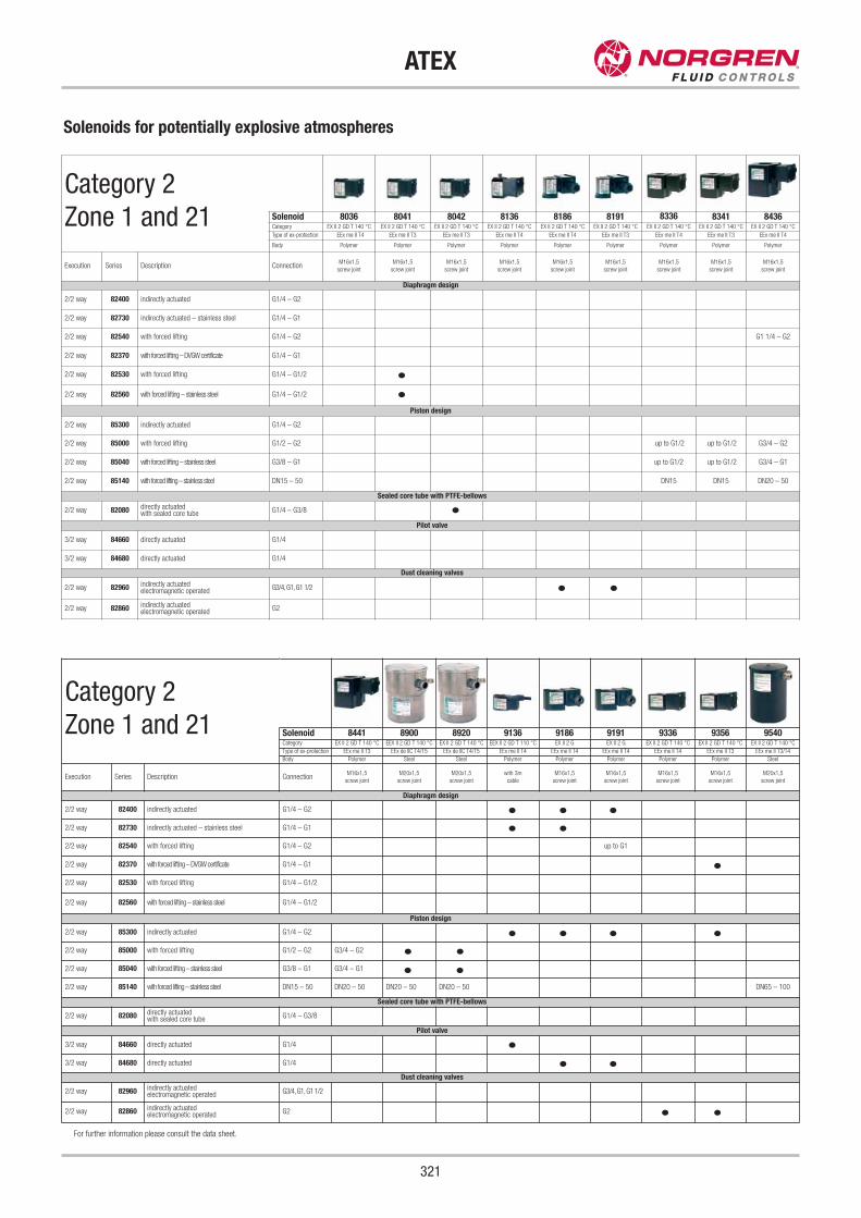
Further information please consult the data sheet.
Category 2
Zone 1 and 21 Solenoid 8441 8900 8920 9136 9186 9191 9336 9356 9540Category EX II 2 GD T 140 °C EEX II 2 GD T 140 °C EX II 2 GD T 140 °C EEX II 2 GD T 110 °C EX II 2 G EX II 2 G EX II 2 GD T 140 °C EX II 2 GD T 140 °C EX II 2 GD T 140 °C
Type of ex-protection EEx me II T3 EEx de IIC T4/T5 EEx de IIC T4/T5 EEx me II T4 EEx me II T4 EEx me II T4 EEx me II T4 EEx me II T3 EEx me II T3/T4
Body Polymer Steel Steel Polymer Polymer Polymer Polymer Polymer Steel
Execution Series Description ConnectionM16x1,5
screw joint
M20x1,5
screw joint
M20x1,5
screw joint
with 3m
cable
M16x1,5
screw joint
M16x1,5
screw joint
M16x1,5
screw joint
M16x1,5
screw joint
M20x1,5
screw joint
Diaphragm design
2/2 way 82400 indirectly actuated G1/4 – G2
2/2 way 82730 indirectly actuated – stainless steel G1/4 – G1
2/2 way 82540 with forced lifting G1/4 – G2 up to G1
2/2 way 82370 with forced lifting – DVGW certificate G1/4 – G1
2/2 way 82530 with forced lifting G1/4 – G1/2
2/2 way 82560 with forced lifting – stainless steel G1/4 – G1/2
Piston design
2/2 way 85300 indirectly actuated G1/4 – G2
2/2 way 85000 with forced lifting G1/2 – G2 G3/4 – G2
2/2 way 85040 with forced lifting – stainless steel G3/8 – G1 G3/4 – G1
2/2 way 85140 with forced lifting – stainless steel DN15 – 50 DN20 – 50 DN20 – 50 DN20 – 50 DN65 – 100
Sealed core tube with PTFE-bellows
2/2 way 82080 directly actuatedwith sealed core tube G1/4 – G3/8
Pilot valve
3/2 way 84660 directly actuated G1/4
3/2 way 84680 directly actuated G1/4
Dust cleaning valves
2/2 way 82960 indirectly actuatedelectromagnetic operated G3/4,G1,G1 1/2
2/2 way 82860 indirectly actuatedelectromagnetic operated G2
321
ATEX
Solenoids for potentially explosive atmospheres
For further information please consult the data sheet.
Category 2
Zone 1 and 21 Solenoid 8036 8041 8042 8136 8186 8191 8336 8341 8436Category EX II 2 GD T 140 °C EX II 2 GD T 140 °C EX II 2 GD T 140 °C EX II 2 GD T 140 °C EX II 2 GD T 140 °C EX II 2 GD T 140 °C EX II 2 GD T 140 °C EX II 2 GD T 140 °C EX II 2 GD T 140 °C
Type of ex-protection EEx me II T4 EEx me II T3 EEx me II T3 EEx me II T4 EEx me II T4 EEx me II T3 EEx me II T4 EEx me II T3 EEx me II T4
Body Polymer Polymer Polymer Polymer Polymer Polymer Polymer Polymer Polymer
Execution Series Description ConnectionM16x1,5
screw joint
M16x1,5
screw joint
M16x1,5
screw joint
M16x1,5
screw joint
M16x1,5
screw joint
M16x1,5
screw joint
M16x1,5
screw joint
M16x1,5
screw joint
M16x1,5
screw joint
Diaphragm design
2/2 way 82400 indirectly actuated G1/4 – G2
2/2 way 82730 indirectly actuated – stainless steel G1/4 – G1
2/2 way 82540 with forced lifting G1/4 – G2 G1 1/4 – G2
2/2 way 82370 with forced lifting – DVGW certificate G1/4 – G1
2/2 way 82530 with forced lifting G1/4 – G1/2
2/2 way 82560 with forced lifting – stainless steel G1/4 – G1/2
Piston design
2/2 way 85300 indirectly actuated G1/4 – G2
2/2 way 85000 with forced lifting G1/2 – G2 up to G1/2 up to G1/2 G3/4 – G2
2/2 way 85040 with forced lifting – stainless steel G3/8 – G1 up to G1/2 up to G1/2 G3/4 – G1
2/2 way 85140 with forced lifting – stainless steel DN15 – 50 DN15 DN15 DN20 – 50
Sealed core tube with PTFE-bellows
2/2 way 82080 directly actuatedwith sealed core tube G1/4 – G3/8
Pilot valve
3/2 way 84660 directly actuated G1/4
3/2 way 84680 directly actuated G1/4
Dust cleaning valves
2/2 way 82960 indirectly actuatedelectromagnetic operated G3/4,G1,G1 1/2
2/2 way 82860 indirectly actuatedelectromagnetic operated G2
Index
322
Contents in order of series
* NPT-connection available
** = Sealed core tube (Unsusceptible to contaminated fluids)
Series Page
Bacosol 32 mm 24
Chipsol 8 mm 10
Flatprop 16 mm 224
Intersol 22 mm 22
Microsol 15 mm 18
Picosol 10 mm 14
Fittings - Pneufit 256
Fittings - Pneufit C & M 264
FRL - Excelon Filter/Regulators 242
FRL - Excelon Series 240
FRL - F22, R22, L22 250
FRL - Olympian Plus 236
Pressure Sensor - 18 S Allfluid 228
Pressure Sensor - 33 D 230
Regulators - R05, B05 248
82080** 100
82160* 134
82180* 136
82280* 136
82370 26
82380* 166
82400* 104
82470* 106
82480* 166
82510 28
82530* 30
82540* 32
82560* 72
82580 138
82590 NEW 74
82610 NEW 76
82660 NEW 36
82670 NEW 78
82710* 140
82730* 116
82870 214
82880 222
82900* 202
82960* 204
83050 118
83200 188
83240 192
83250 164
83300 210
83320 212
83340 54
83350 194
83380 196
83400 216
83580 122
83750 NEW 218
83860 198
83920 206
83930 208
84070 NEW 114
84080 NEW 114
84100 56
Series Page
84120 60
84140 82
84180 NEW 142
84190 NEW 168
84200 64
84220 68
84240 88
84320 124
84340 128
84360 NEW 38
84500* 144
84520* 170
84540 174
84550 174
84580 178
84590 180
84660 148
84680 148
84720* 162
84740* 184
84760 186
84770 186
84880 178
84890 180
85040 80
85100 56
85120 60
85140 82
85200 64
85220 68
85240 88
85300* 108
85320* 112
85640 92
85700* 40
85720* 44
85740* NEW 94
95000 48
95100 98
96000 152
96100 154
97100 NAMUR 156