systematic supervisory control solutions for under-load tap-changing transformers
TRANSCRIPT
ARTICLE IN PRESS
0967-0661/$ - se
doi:10.1016/j.co
�CorrespondE-mail addr
(W.M. Wonham
Control Engineering Practice 16 (2008) 1035–1054
www.elsevier.com/locate/conengprac
Systematic supervisory control solutions for under-loadtap-changing transformers
A. Afzaliana,�, Ali Saadatpoorb, W.M. Wonhamb
aDepartment of Control Systems Engineering, Shahid Abbaspour University of Technology, P.O. Box 16765-1719, Tehran, IranbDepartment of Electrical and Computer Engineering, University of Toronto, 10 King’s College Road, Toronto, Ont., Canada, M5S 3G4
Received 2 June 2006; accepted 15 November 2007
Available online 10 January 2008
Abstract
Discrete-event systems (DES) can be found as essential integrated subsystems in many complex systems, e.g. electrical power systems.
Under-load tap-changing (ULTC) transformers which obviously have discrete-event behavior are widely used in transmission systems to
take care of instantaneous variations in the load conditions in substations. In this paper, the voltage control problem in ULTC is solved
in different modes of operation, using DES-based solutions. These solutions include: DES supervisory control, timed DES supervisory
control and a hierarchical structure for the control system. It is shown that the specifications are controllable and the closed-loop control
system is non-blocking.
r 2007 Elsevier Ltd. All rights reserved.
Keywords: Supervisory control; Discrete-event systems; Timed discrete-event systems; Hierarchical control structure; Under-load tap-changing
transformers
1. Introduction
A discrete-event system (DES) is a dynamic system that evolves in accordance with the sudden occurrence of physicalevents at possibly unknown irregular intervals (Ramadge & Wonham, 1989). The supervisory control technique is aneffective analytical tool for automation and control of DES (Ramadge & Wonham, 1987). Discrete-event models aregenerally used to describe systems where coordination and control are required to ensure the orderly flow of events, and/orto prevent the occurrence of undesired chains of events. DES can be employed to describe a wide variety of behaviors inindustrial and physical systems. These include control and scheduling of electrical power systems, manufacturing systems,queuing systems and communication protocols, and database management systems. The behavior of electrical powersystems can be characterized by interactions between continuous dynamics and discrete events.
In the last two decades, DES have been studied by researchers from different fields, with respect to modeling, analysis,and control. Several models have been proposed and investigated. These models can be classified as untimed DES modelsand timed DES models. In an untimed model, when considering the state evolution, only the sequence of states visited is ofconcern. That is, only the logical behavior is of interest. In a timed model, both logical behavior and timing information areconsidered. Brandin and Wonham (1994) adjoined to the structure of untimed DES (Ramadge & Wonham, 1989) thetiming features of timed transition models. The BW framework, which is used in this paper, retains the concept ofmaximally permissive supervision introduced in Brandin and Wonham (1994), allows the timed modeling of DES, admitssubsystem composition, and admits forcing and disablement as means of control. Different synthesize methods have beendeveloped and implemented as the software TCT (for untimed models) and TTCT (for timed models) (Wonham, 2006) to
e front matter r 2007 Elsevier Ltd. All rights reserved.
nengprac.2007.11.006
ing author. Fax : +98 21 7731 0425.
esses: [email protected] (A. Afzalian), [email protected] (A. Saadatpoor), [email protected]
).
ARTICLE IN PRESSA. Afzalian et al. / Control Engineering Practice 16 (2008) 1035–10541036
compute controllers that are optimal in the sense that the controlled system not only satisfies the specifications but is also aspermissive as possible. TCT and TTCT are used in this study for synthesizing the supervisory controllers. There are othersoftware tools available for simulation and analysis of DES (Basile, Carbone, & Chiacchio, 2007).
There are good reasons for organizing the control of large systems in a distributed hierarchy structure. Among these are:deeper understanding facilitated by the hierarchical structure, reduction in complexity of communication and computation,modularity and adaptability to change, robustness, and generalization. The supervisory control of DES can be designed tobe hierarchically structured. Implementation of this approach to a control problem in electrical power systems is alsodiscussed in the present paper.
A power system, in its simplest representation, comprises a set of lines intersecting at nodes (buses). Energy is injected atbuses by generators, and loads can be considered as negative injections. The flow of power along lines to and from buses isa phenomenon of primary interest in power system operation and control. Transformers with tap-changing facilitiesconstitute an important means of controlling voltage throughout electrical power systems at all voltage levels.Transformers with off-load tap-changing facilities can help to maintain satisfactory voltage profiles. Under-load tap-changing (ULTC) transformers can be used to take care of daily, hourly, and minute-by-minute variations in systemconditions. ULTC may be controlled either automatically or manually (Kundur, 1994). Many dynamic subsystems in apower system exhibit discrete-event behavior. Typically, the continuous dynamics relate to components that obey physicallaws. Event-driven discrete behavior results from logical rules that govern the system. The continuous trajectory of thesystem state can be interrupted by discrete control actions and uncontrolled disturbances, which may be frequent orinfrequent. The time scale for these events changes from milliseconds, through seconds and minutes, to hours, days, andweeks or longer (Fink, 1999).
DES theory has been applied to problems in electrical power systems (Afzalian & Wonham, 2006; Lee & Lim, 2004, Lin,Ho, & Lin, 2004; Prosser, Selinsky, Kwatny, & Kam, 1995). These applications include: supervisory control, modeling andanalysis, and monitoring and diagnosis of power systems. A hierarchical DES supervisory control is synthesized in Yasarand Ray (2007) to coordinate the operation of twin engine propulsion system. The synthesize of a DES-based supervisorycontrol for ULTC was introduced in Afzalian, Saadatpoor, and Wonham (2006), where the ULTC along with differentspecifications (control logics) were modeled as automata. The automatic voltage control of a tap-changer transformer canbe regarded as a DES. The processes associated with this system may be regarded as asynchronous and discrete in timeand/or state space. A DES generating a formal language can be considered as a representation of this tap-changertransformer (plant).
After a brief review on DES supervisory approaches, this paper starts with the modeling of ULTC as an automaton.Control specifications in each mode of operation are also modeled as some finite automata. Then supervisory controllersare designed for the ULTC in Automatic and Auto/Manual modes of operation, as the first solution. The second solutionemploys the timed DES approach to design a supervisory control for the ULTC. A hierarchical structure for thesupervisory control of the problem is also investigated as the third solution to the ULTC control problem. A two-levelhierarchy structure has been used to control the ULTC. A manager has been introduced in the high level to shutdown thesystem in certain contingencies. The manager deals with an abstract model of the plant in the high level, and so can applythe control requirements easily. It is shown that a high-level manager can easily supervise the plant using this abstractmodel of the low-level subsystem, i.e. the low-level closed-loop control system of ULTC.
The contributions of the paper are summarized as follows:
(1)
DES modeling of a ULTC transformer and its control specification. (2) Evaluation of the required properties for the supervisory control system, i.e. controllability, non-blocking, and non-conflicting.
(3) Systematic approaches are given to synthesize supervisory control solutions in the monolithic, modular andhierarchical structure, separately.
Section 2 reviews briefly the untimed and timed DES supervisory control as well as the hierarchical structure. The ULTCtransformer is discussed in Section 3. The DES modeling of the plant and control logic, and the design and implementationof the supervisory control using untimed DES are discussed in Section 4. The two-level hierarchical DES supervisorycontrol for the ULTC is given in Section 5. And finally, Section 6 discusses the TDES version of the solution.
2. Supervisory control of DES
The supervisory control problem for a DES is formulated by modeling the plant as well as its control logic(specifications) as finite automata. To solve the supervisory control problem, it is necessary to show that a controller whichforces the specification to be met exists and is constructible (Wonham, 2006).
ARTICLE IN PRESSA. Afzalian et al. / Control Engineering Practice 16 (2008) 1035–1054 1037
2.1. Discrete-event models
ADES model is specified by: the set of states (including an initial state, and marker states which can be desired states in someapplications), the set of events, and the state transition function of the system. Formally, a DES is represented by an automaton
G ¼ ðQ;S; d; q0;QmÞ in which Q is a finite set of states, with q0 2 Q as the initial state and Qm � Q being the desired (marker)states; S is a finite set of events ðsÞ which is referred to as an alphabet, and finally d is a transition mapping d : Q� S! Q :dðq;sÞ ¼ q0 which gives the next state q0 after an event s occurs. G plays the role of the plant and, together with its states, eventsand transition operator (mapping) models a physical process. G is called a generator, as it generates a set of strings (sequence ofevents). In other words it generates a language LðGÞ, consisting of strings of events which are physically possible in the plant.
A prefix of a string s is an initial subsequence of s, i.e. if r and s are strings in S�, u is a prefix of s if ur ¼ s. A set whichcontains all the prefixes of each of its elements is said to be prefix closed. Clearly, S� is a prefix closed set. As some sets ofstrings may not contain all of their prefixes, the prefix closure of a set A, denoted by A is defined which contains all theprefixes of each element of A. If A ¼ A, then the set A is prefix-closed. If A is not prefix-closed, then A � A. The languageLðGÞ is the set of all event sequences which are physically possible in the plant. LðGÞ ¼ fsjs 2 S�; dðq0; sÞg is defined.
Clearly, LðGÞ is a subset of S�, and LðGÞ is also prefix-closed, because no event sequence in the plant can occur withoutits prefix occurring first. Those strings which can be extended to a marker state are of particular importance. The Marked
language which is denoted by LmðGÞ consists of all strings which reach the marker states. LmðGÞ is a subset of LðGÞ and canbe formally given as: LmðGÞ ¼ fs 2 LðGÞ jdðq0; sÞ 2 Qmg.
A DES is said to be non-blocking if LmðGÞ ¼ LðGÞ. This means that there always exists a sequence of events which takesthe plant from any (reachable) state to a marker state. In some applications of DES models, it is necessary to considerseveral independent and asynchronous processes simultaneously. There is a procedure called synchronous product whichcombines two DES (G1 and G2) into a single, more complex DES, i.e. G3 ¼ G1jjG2. The synchronous product defines newstates for G3 as ordered pairs of states from G1 and G2. The events set G3 is the union of events in G1 and G2. The initialand marker states of G3 are defined similarly.
2.2. Controllable specifications and non-blocking supervisor
A discrete-event plant must be controlled based on certain specifications (required behavior logic). By adjoiningcontroller structure to the plant, it is possible to vary the language generated by the closed-loop system within certainlimits. The desired performance of such a controlled plant will be specified by stating that its generated language must becontained in some specification language. It is often possible to meet these specifications in a minimally restrictive way,called optimal supervision in the DES literature.
Suppose G ¼ ðQ;S; d; q0;QmÞ, is a nonempty DES representing the plant which must be controlled. S ¼ Sc [ Su is the setof controllable and uncontrollable events in the plant. Sc is the set of controllable events which can be enabled or disabledby an external agent (supervisor). A possible set of enabled events which includes some controllable events and alluncontrollable events is called a control pattern ðgÞ. Uncontrollable events ðSuÞ are always enabled by their nature. Then itis clearly true that S � g � Su. The set of all control patterns, which is actually a set of sets, is defined as:G ¼ fg 2 PwrðSÞjg � Sug. A supervisory control for the plant G is any function V : LðGÞ ! G. The pair ðG;V Þ is writtenV=G, to suggest the concept of ‘‘G under the supervision of V’’.
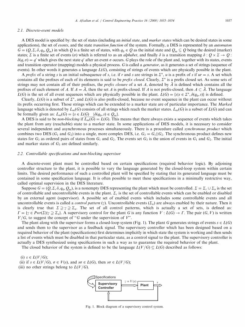
The plant along with the supervisor forms a closed-loop system (Fig. 1). The plant G generates strings of events s 2 LðGÞ
and sends them to the supervisor as a feedback signal. The supervisory controller which has been designed based on arequired behavior of the plant (specifications) first determines implicitly in which state the system is working and then sendsa list of events which must be disabled in that particular state, as a control signal to the plant. The supervisory controller isactually a DES synthesized using specifications in such a way as to guarantee the required behavior of the plant.
The closed behavior of the system is defined to be the language LðV=GÞ � LðGÞ described as follows:
(i)
e 2 LðV=GÞ; (ii) if s 2 LðV=GÞ, s 2 V ðsÞ, and ss 2 LðGÞ, then ss 2 LðV=GÞ; (iii) no other strings belong to LðV=GÞ.Supervisory
Controller Plant
� = V (s) s
Specifications
Fig. 1. Block diagram of a supervisory control system.
ARTICLE IN PRESSA. Afzalian et al. / Control Engineering Practice 16 (2008) 1035–10541038
In other words, the closed-loop system only generates either the ‘‘empty’’ string or a string of the plant which isconcatenated immediately by an event decided by the supervisor to be allowed. Clearly LðV=GÞ is nonempty and closed.The marked behavior of V=G is LmðV=GÞ ¼ LðV=GÞ \ LmðGÞ. In other words, the strings reaching marker states in V=G
are exactly the strings of LmðGÞ that survive under supervision by V. It is always true that Ø � LmðV=GÞ � LmðGÞ.The supervisor V is said to be non-blocking (for G) if LmðV=GÞ ¼ LðV=GÞ. A language K representing some specification
of a plant G is said to be controllable (with respect to G) if its prefix-closure K does not change under the occurrence ofuncontrollable events in G. In other words, K is controllable if and only if KSu \ LðGÞ � K , where KSu ¼
fssjs 2 K ;s 2 Sug. Therefore, the controllability condition on specification K only constrains K \ LðGÞ. Based on thisdefinition, to test the controllability of K, one only needs to test its closure K .
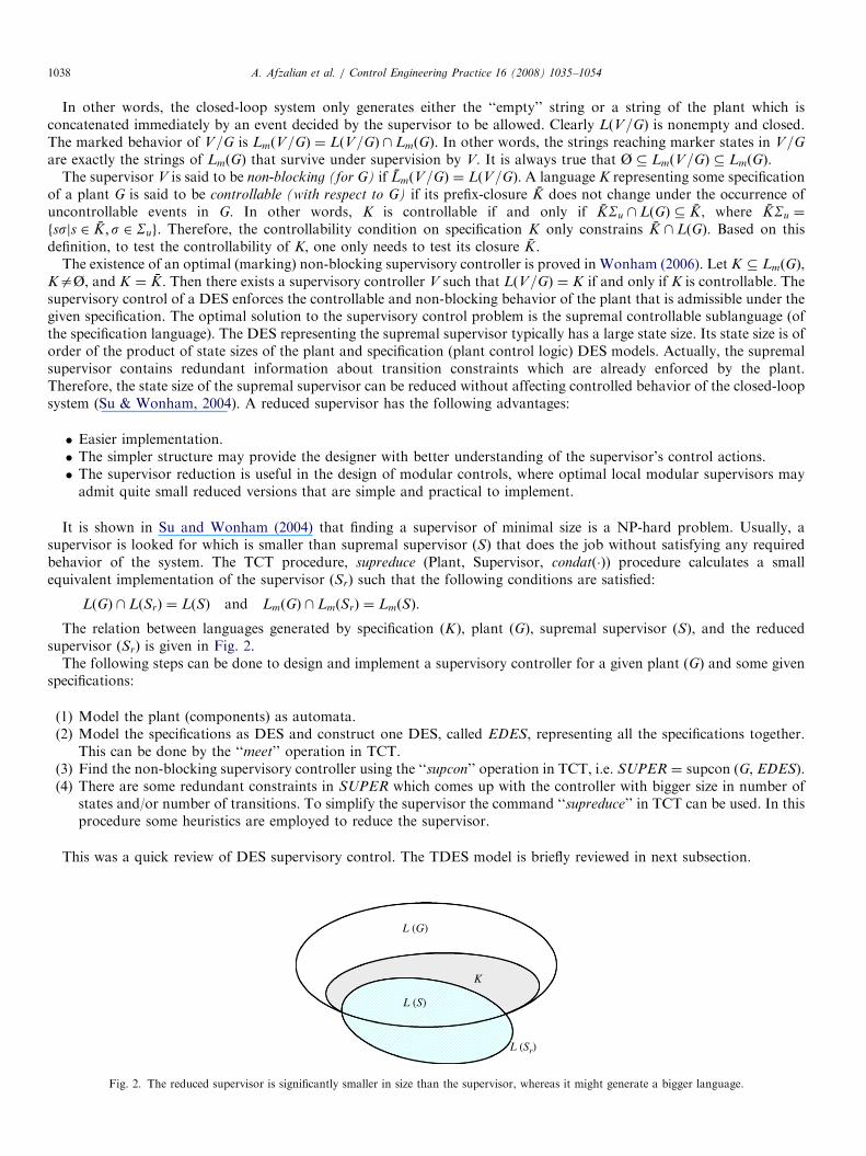
The existence of an optimal (marking) non-blocking supervisory controller is proved in Wonham (2006). Let K � LmðGÞ,KaØ, and K ¼ K . Then there exists a supervisory controller V such that LðV=GÞ ¼ K if and only if K is controllable. Thesupervisory control of a DES enforces the controllable and non-blocking behavior of the plant that is admissible under thegiven specification. The optimal solution to the supervisory control problem is the supremal controllable sublanguage (ofthe specification language). The DES representing the supremal supervisor typically has a large state size. Its state size is oforder of the product of state sizes of the plant and specification (plant control logic) DES models. Actually, the supremalsupervisor contains redundant information about transition constraints which are already enforced by the plant.Therefore, the state size of the supremal supervisor can be reduced without affecting controlled behavior of the closed-loopsystem (Su & Wonham, 2004). A reduced supervisor has the following advantages:
�
Easier implementation. � The simpler structure may provide the designer with better understanding of the supervisor’s control actions. � The supervisor reduction is useful in the design of modular controls, where optimal local modular supervisors mayadmit quite small reduced versions that are simple and practical to implement.It is shown in Su and Wonham (2004) that finding a supervisor of minimal size is a NP-hard problem. Usually, asupervisor is looked for which is smaller than supremal supervisor ðSÞ that does the job without satisfying any requiredbehavior of the system. The TCT procedure, supreduce (Plant, Supervisor, condatð�Þ) procedure calculates a smallequivalent implementation of the supervisor ðSrÞ such that the following conditions are satisfied:
LðGÞ \ LðSrÞ ¼ LðSÞ and LmðGÞ \ LmðSrÞ ¼ LmðSÞ.
The relation between languages generated by specification ðKÞ, plant ðGÞ, supremal supervisor ðSÞ, and the reducedsupervisor ðSrÞ is given in Fig. 2.
The following steps can be done to design and implement a supervisory controller for a given plant ðGÞ and some givenspecifications:
(1)
Model the plant (components) as automata. (2) Model the specifications as DES and construct one DES, called EDES, representing all the specifications together.This can be done by the ‘‘meet’’ operation in TCT.
(3) Find the non-blocking supervisory controller using the ‘‘supcon’’ operation in TCT, i.e. SUPER ¼ supcon (G, EDES). (4) There are some redundant constraints in SUPER which comes up with the controller with bigger size in number ofstates and/or number of transitions. To simplify the supervisor the command ‘‘supreduce’’ in TCT can be used. In thisprocedure some heuristics are employed to reduce the supervisor.
This was a quick review of DES supervisory control. The TDES model is briefly reviewed in next subsection.
K
L (Sr)
L (S)
L (G)
Fig. 2. The reduced supervisor is significantly smaller in size than the supervisor, whereas it might generate a bigger language.
ARTICLE IN PRESSA. Afzalian et al. / Control Engineering Practice 16 (2008) 1035–1054 1039
2.3. Timed DESs
This section briefly reviews the TDES model proposed by Brandin and Wonham (1994). First, a finite automatonGact ¼ ðA;Sact; dact; a0;AmÞ is introduced, which is called an activity transition graph (ATG) to describe the untimedbehavior of the system. In Gact, A is the finite set of activities, Sact is the finite set of events, a partial function dact :A� Sact ! A is the activity transition function, a0 2 A is the initial activity, and Am � A is the set of marked activities. Inorder to construct a TDES model, timing information is introduced into Gact. Let N denote a set of nonnegative integers. InSact, each event s will be equipped with a lower time bound ls 2 N and an upper time bound us 2 N [ f1g such that lspus.Then the set of events is decomposed into two subsets Sspe ¼ fs 2 Sactjus 2 Ng and Srem ¼ fs 2 Sactjus ¼ 1g. The lowertime bound would typically represent a delay, while an upper time bound is a hard deadline.
For each s 2 Sact, the timer interval Ts is defined as
Ts ¼½0; us if s 2 Sspe;
½0; ls if s 2 Srem:
(
The TDES defined by Brandin and Wonham (1994) is a finite automaton G ¼ ðQ;S; d; q0;QmÞ which can be displayed by itstimed transition graph (TTG). The state set Q is defined as Q ¼ A�
QfTsjs 2 Sactg. A state q 2 Q is of the form
q ¼ ða; ftsjs 2 SactgÞ, where a 2 A and ts 2 Ts. The initial state q0 2 Q is defined as q0 ¼ ða0; fts;0js 2 SactgÞ, where
ts;0 ¼us if s 2 Sspe;
ls if s 2 Srem:
(
The set Qm � Q is given by a subset of Am �QfTsjs 2 Sactg. The event set S is defined as S ¼ Sact [ ftickg, where the
additional event tick represents the passage of one time unit. The state transition function d : Q� S! Q is defined asfollows. For any s 2 S and any q ¼ ða; fttjt 2 SactgÞ 2 Q; dðq;sÞ is defined, written dðq;sÞ!, if and only if one of thefollowing conditions holds:
�
s ¼ tick and 8t 2 Sspe; dactða; tÞ!) tt40; � s 2 Sspe and dactða;sÞ! and 0ptspus ls; � s 2 Srem and dactða;sÞ! and ts ¼ 0.When dðq;sÞ!; q0 ¼ dðq; sÞ ¼ ða0; ft0tjt 2 SactgÞ is defined as follows:
�
if s ¼ tick then a0 ¼ a and for all t 2 Sact,t0t:¼tt 1 if dactða; tÞ! ^ tt40;
tt otherwise;
(
0(
�
if s 2 Sact then a0 ¼ dactða;sÞ; t0s ¼ ts;0, and for t 2 Sact if tas then t0t:¼tt if dactða ; tÞ!tt;0 otherwise:
Let S� be the set of all finite strings of elements in S, including the empty string e. The function d is extended tod : Q� S� ! Q in the natural way.
The closed behavior, the strings that are generated by G, and marked behavior, the strings that are generated by G andlead to a marker state, of the TDES G are defined by LðGÞ ¼ fs 2 S�jdðq0; sÞ!g and LmðGÞ ¼ fs 2 S�jdðq0; sÞ 2 Qmg,respectively. G is called non-blocking if LmðGÞ ¼ LðGÞ. As in untimed supervisory control, the set Sact is partitioned intotwo subsets Sc and Su of controllable and uncontrollable events. An event d that can preempt the event tick is called aforcible event. The set of forcible events is denoted by Sfor. A forcible event can be either controllable or uncontrollable. Byforcing an enabled event in Sfor to occur, the event tick can be disabled. In this framework a supervisor repeatedly decidesto disable or enable each event in Sc [ ftickg.
The simplest way to visualize the behavior of a TDES G under supervision is first to consider the infinite reachability treeof G before any control is operative (Wonham, 2006). Each node of the tree corresponds to a unique string s of LðGÞ. Ateach node of the tree the subset of eligible events can be defined by EligGðsÞ:¼fs 2 Sjss 2 LðGÞg. In order to define thenotion of controllability a language K � LðGÞ is considered to define: EligK ðsÞ:¼fs 2 Sjss 2 Kg. K is controllable withrespect to G if, for all s 2 K ,
EligK ðsÞ �EligGðsÞ \ ðSu [ ftickgÞ; EligK ðsÞ \ Sfor ¼ f;
EligGðsÞ \ Su; EligK ðsÞ \ Sforaf:
(
ARTICLE IN PRESSA. Afzalian et al. / Control Engineering Practice 16 (2008) 1035–10541040
The control objective is, for the given plant language LðGpÞ and the specification language LðGsÞ, to find a supervisorsuch that the closed-loop language is, in the sense of set inclusion, the largest sublanguage of LmðGpÞ \ LmðGsÞ which iscontrollable w.r.t Gp and also non-blocking, written supCðLmðGpÞ;LmðGsÞÞ.
2.4. Hierarchical control structure
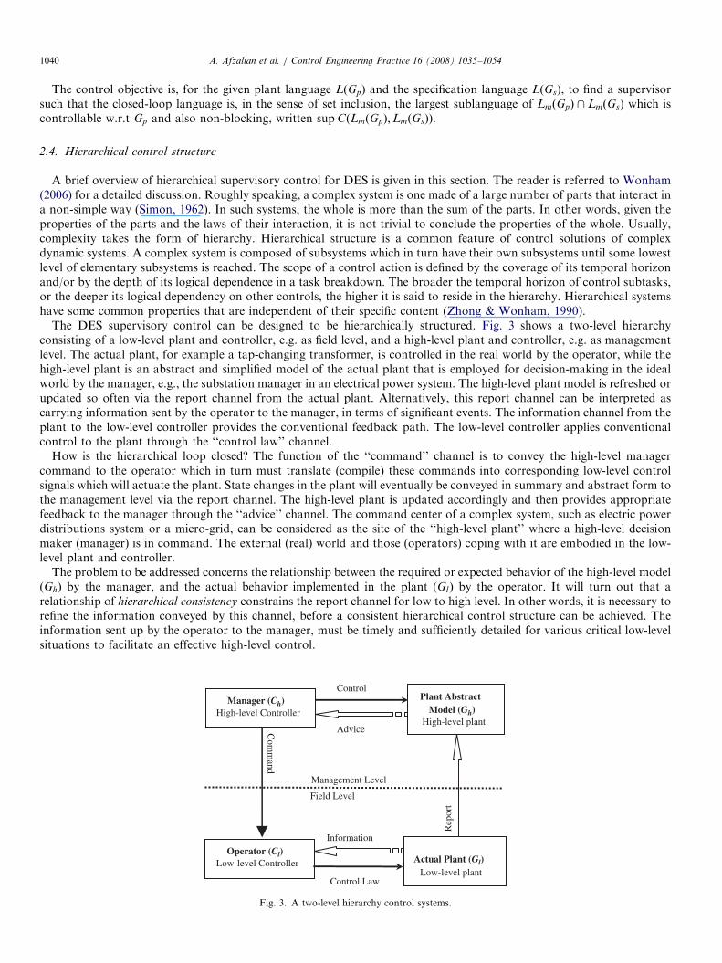
A brief overview of hierarchical supervisory control for DES is given in this section. The reader is referred to Wonham(2006) for a detailed discussion. Roughly speaking, a complex system is one made of a large number of parts that interact ina non-simple way (Simon, 1962). In such systems, the whole is more than the sum of the parts. In other words, given theproperties of the parts and the laws of their interaction, it is not trivial to conclude the properties of the whole. Usually,complexity takes the form of hierarchy. Hierarchical structure is a common feature of control solutions of complexdynamic systems. A complex system is composed of subsystems which in turn have their own subsystems until some lowestlevel of elementary subsystems is reached. The scope of a control action is defined by the coverage of its temporal horizonand/or by the depth of its logical dependence in a task breakdown. The broader the temporal horizon of control subtasks,or the deeper its logical dependency on other controls, the higher it is said to reside in the hierarchy. Hierarchical systemshave some common properties that are independent of their specific content (Zhong & Wonham, 1990).
The DES supervisory control can be designed to be hierarchically structured. Fig. 3 shows a two-level hierarchyconsisting of a low-level plant and controller, e.g. as field level, and a high-level plant and controller, e.g. as managementlevel. The actual plant, for example a tap-changing transformer, is controlled in the real world by the operator, while thehigh-level plant is an abstract and simplified model of the actual plant that is employed for decision-making in the idealworld by the manager, e.g., the substation manager in an electrical power system. The high-level plant model is refreshed orupdated so often via the report channel from the actual plant. Alternatively, this report channel can be interpreted ascarrying information sent by the operator to the manager, in terms of significant events. The information channel from theplant to the low-level controller provides the conventional feedback path. The low-level controller applies conventionalcontrol to the plant through the ‘‘control law’’ channel.
How is the hierarchical loop closed? The function of the ‘‘command’’ channel is to convey the high-level managercommand to the operator which in turn must translate (compile) these commands into corresponding low-level controlsignals which will actuate the plant. State changes in the plant will eventually be conveyed in summary and abstract form tothe management level via the report channel. The high-level plant is updated accordingly and then provides appropriatefeedback to the manager through the ‘‘advice’’ channel. The command center of a complex system, such as electric powerdistributions system or a micro-grid, can be considered as the site of the ‘‘high-level plant’’ where a high-level decisionmaker (manager) is in command. The external (real) world and those (operators) coping with it are embodied in the low-level plant and controller.
The problem to be addressed concerns the relationship between the required or expected behavior of the high-level modelðGhÞ by the manager, and the actual behavior implemented in the plant ðGlÞ by the operator. It will turn out that arelationship of hierarchical consistency constrains the report channel for low to high level. In other words, it is necessary torefine the information conveyed by this channel, before a consistent hierarchical control structure can be achieved. Theinformation sent up by the operator to the manager, must be timely and sufficiently detailed for various critical low-levelsituations to facilitate an effective high-level control.
Manager (Ch) High-level Controller
Plant AbstractModel (Gh)
High-level plant
Actual Plant (Gl) Low-level plant
Operator (Cl) Low-level Controller
Field Level
Management Level
Advice
Information
Control
Control Law
Rep
ort
Com
mand
Fig. 3. A two-level hierarchy control systems.
ARTICLE IN PRESSA. Afzalian et al. / Control Engineering Practice 16 (2008) 1035–1054 1041
2.5. Hierarchical control action in a two-level controlled DES
Suppose the actual plant is modeled by an automaton Gl ¼ ðQ;S; d; q0;QmÞ that generates a language Ll :¼LðGlÞ � S�
as its uncontrolled behavior. S� is the set of finite strings s, for which the extended transition map d : Q� S� ! Q
is defined.Recall from DES supervisory control (Section 2) that to every specification represented by a closed language El , there
corresponds a supervisor as the (closed) supremal controllable sublanguage supCðEl \ LðGlÞÞ. The following notation isused for this supervisor: M":¼supCðMÞ.
The refined information flow through the ‘‘report’’ channel which consists of significant event s can be represented by thelanguage T. Thus the ‘‘report’’ can be modeled as a causal map y : Ll ! T� with following properties: yðeÞ ¼ e;yðssÞ ¼ either yðsÞ or yðsÞt, for some t 2 T , s 2 Ll , and s 2 S.
An abstract model for the plant in the high level can be given as an automaton Gh that generates a language Lh:¼yðLlÞ � T�.The high-level controller Ch that observes only the state of Gh must be able to make meaningful control decision. Followingsteps and related TCT procedures were proposed to formulate the suitable control structure (Wonham, 2006):
(1)
Adopting the usual supervisory structure having the same type as in Gl (Supcon(.,.)). (2) Refining the state structure of Gl (Recode(.)). (3) Extending the high-level event alphabet T (Vocalize(.,.)). (4) Finding the corresponding structure for Gh ðHigenðGlÞÞ. (5) Partitioning this extension into controllable and uncontrollable subsets to provide manager the ability of settingup specifications in terms of controllable events. This was achieved by converting the Gl to a new DES called‘‘output-control-consistent’’ in which each output event is unambiguously controllable or uncontrollableðOutconsisðGlÞÞ.
(6)
Designing a high-level supervisory control using a given specification ðEhÞ for Gh (Supcon(.,.)).The behavior Eh expected by the manager in Gh may be larger than what the operator can actually realize. In otherwords the manager is optimistic is respect to the effectiveness of the command-control process. But if Eh is not larger thanoperator realization, i.e. yððy1ðEhÞÞ
"Þ ¼ Eh, holds for every closed and controllable language Eh � Lh, then the pair (Gl ,
Gh) is said to possess hierarchical consistency. Achieving this equality in the hierarchical control system requires a furtherrefinement of the transition structure in DES model of the lower plant, in other words, enhancing the information sent upto the high level. Such enhancement might or might not be feasible in an application. In TCT, hierarchical consistency canbe achieved by computing the HiconsisðGlÞ procedure.
The two-level hierarchy discussed here can be extended to any number of levels. Once hierarchical consistency has beenachieved for the bottom level and first level up, the construction may be repeated on assigning state outputs in the first leveland bringing in the next higher level.
3. Tap-changing transformer
Transformers with tap-changing facilities constitute an important means of controlling voltage throughout electricalpower systems at all voltage levels. Transformers with ULTC are widely used in transmission systems. For example,Ontario Hydro provided ULTC facilities on most 500/230 kV autotransformers and on all ‘‘area supply’’ transformersstepping down from 230 or 115 to 44, 27.6, or 13.8 kV (Kundur, 1994).
Whereas many articles considered ULTC as a nonlinear element in the power system model for voltage stability studies,a Petri net based model for tap-changer has been used in a framework of differential, switched algebraic and state-resetequations (Hiskens & Sokolowski, 2001).
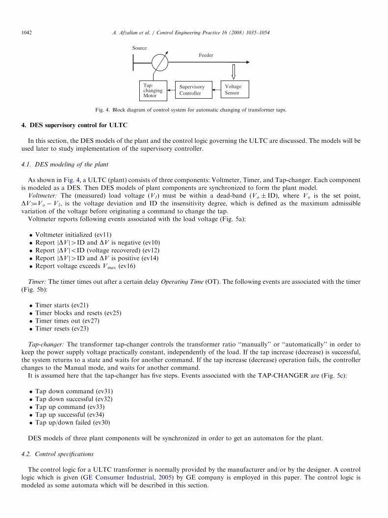
The control logic for tap-changer transformers can be found in the literature (Kundur, 1994; Ohtsuki, Yokoyama, &Sekine, 1991; Otomega, Sermanson, & Cutsem, 2003) as well as in manufacturers’ catalogues (e.g. GE ConsumerIndustrial, 2005) in different detail. When the voltage is not ‘‘normal’’ (outside a desired limit), the controller changes tapratio after a time delay to recover the voltage, i.e. bring it back into its dead-band. The delay time is used to preventunnecessary tap changes in response to transient voltage variations and to introduce the desired time delay before a tapmovement. Fig. 4 shows the block diagram of a ULTC.
The timing behavior of the ULTC suggests a TDES approach to the supervisory control solution. To synthesize asupervisory control for the ULTC, the designer needs to be equipped with DES (TDES) models of the plant and thecontrol specifications which is given in Section 4. In Sections 4, 5, and 6 DES, hierarchical structure, and TDES approachesare employed respectively to implement the supervisory control for the ULTC.
ARTICLE IN PRESS
VoltageSensor
Tap-changing Motor
Supervisory Controller
SourceFeeder
Fig. 4. Block diagram of control system for automatic changing of transformer taps.
A. Afzalian et al. / Control Engineering Practice 16 (2008) 1035–10541042
4. DES supervisory control for ULTC
In this section, the DES models of the plant and the control logic governing the ULTC are discussed. The models will beused later to study implementation of the supervisory controller.
4.1. DES modeling of the plant
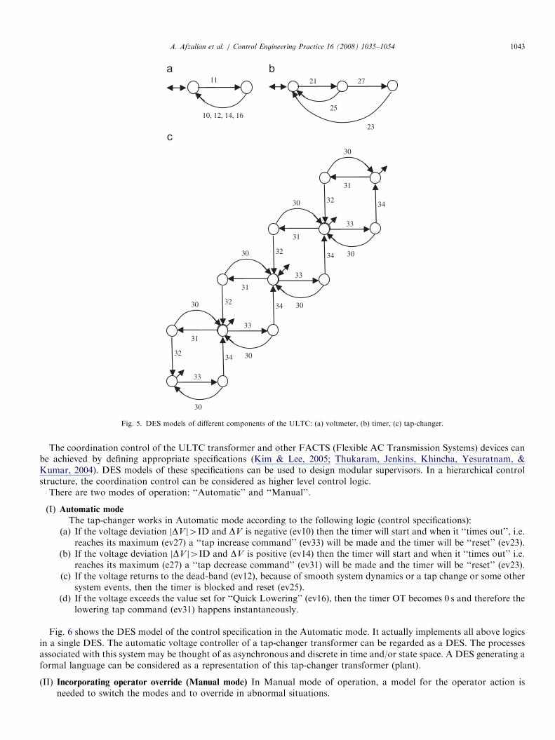
As shown in Fig. 4, a ULTC (plant) consists of three components: Voltmeter, Timer, and Tap-changer. Each componentis modeled as a DES. Then DES models of plant components are synchronized to form the plant model.
Voltmeter: The (measured) load voltage ðV lÞ must be within a dead-band (Vo � ID), where Vo is the set point,DV :¼Vo V l , is the voltage deviation and ID the insensitivity degree, which is defined as the maximum admissiblevariation of the voltage before originating a command to change the tap.
Voltmeter reports following events associated with the load voltage (Fig. 5a):
�
Voltmeter initialized (ev11) � Report jDV j4ID and DV is negative (ev10) � Report jDV joID (voltage recovered) (ev12) � Report jDV j4ID and DV is positive (ev14) � Report voltage exceeds V max (ev16)Timer: The timer times out after a certain delay Operating Time (OT). The following events are associated with the timer(Fig. 5b):
�
Timer starts (ev21) � Timer blocks and resets (ev25) � Timer times out (ev27) � Timer resets (ev23)Tap-changer: The transformer tap-changer controls the transformer ratio ‘‘manually’’ or ‘‘automatically’’ in order tokeep the power supply voltage practically constant, independently of the load. If the tap increase (decrease) is successful,the system returns to a state and waits for another command. If the tap increase (decrease) operation fails, the controllerchanges to the Manual mode, and waits for another command.
It is assumed here that the tap-changer has five steps. Events associated with the TAP-CHANGER are (Fig. 5c):
�
Tap down command (ev31) � Tap down successful (ev32) � Tap up command (ev33) � Tap up successful (ev34) � Tap up/down failed (ev30)DES models of three plant components will be synchronized in order to get an automaton for the plant.
4.2. Control specifications
The control logic for a ULTC transformer is normally provided by the manufacturer and/or by the designer. A controllogic which is given (GE Consumer Industrial, 2005) by GE company is employed in this paper. The control logic ismodeled as some automata which will be described in this section.
ARTICLE IN PRESS
10, 12, 14, 16
11
25
21
23
27
31
30
32
33
34
30
31
30
32
33
34
30
31
30
32
33
34
30
31
30
32
33
34
30
Fig. 5. DES models of different components of the ULTC: (a) voltmeter, (b) timer, (c) tap-changer.
A. Afzalian et al. / Control Engineering Practice 16 (2008) 1035–1054 1043
The coordination control of the ULTC transformer and other FACTS (Flexible AC Transmission Systems) devices canbe achieved by defining appropriate specifications (Kim & Lee, 2005; Thukaram, Jenkins, Khincha, Yesuratnam, &Kumar, 2004). DES models of these specifications can be used to design modular supervisors. In a hierarchical controlstructure, the coordination control can be considered as higher level control logic.
There are two modes of operation: ‘‘Automatic’’ and ‘‘Manual’’.
(I)
Automatic modeThe tap-changer works in Automatic mode according to the following logic (control specifications):(a) If the voltage deviation jDV j4ID and DV is negative (ev10) then the timer will start and when it ‘‘times out’’, i.e.
reaches its maximum (ev27) a ‘‘tap increase command’’ (ev33) will be made and the timer will be ‘‘reset’’ (ev23).(b) If the voltage deviation jDV j4ID and DV is positive (ev14) then the timer will start and when it ‘‘times out’’ i.e.
reaches its maximum (e27) a ‘‘tap decrease command’’ (ev31) will be made and the timer will be ‘‘reset’’ (ev23).(c) If the voltage returns to the dead-band (ev12), because of smooth system dynamics or a tap change or some other
system events, then the timer is blocked and reset (ev25).(d) If the voltage exceeds the value set for ‘‘Quick Lowering’’ (ev16), then the timer OT becomes 0 s and therefore the
lowering tap command (ev31) happens instantaneously.
Fig. 6 shows the DES model of the control specification in the Automatic mode. It actually implements all above logicsin a single DES. The automatic voltage controller of a tap-changer transformer can be regarded as a DES. The processesassociated with this system may be thought of as asynchronous and discrete in time and/or state space. A DES generating aformal language can be considered as a representation of this tap-changer transformer (plant).
(II)
Incorporating operator override (Manual mode) In Manual mode of operation, a model for the operator action isneeded to switch the modes and to override in abnormal situations.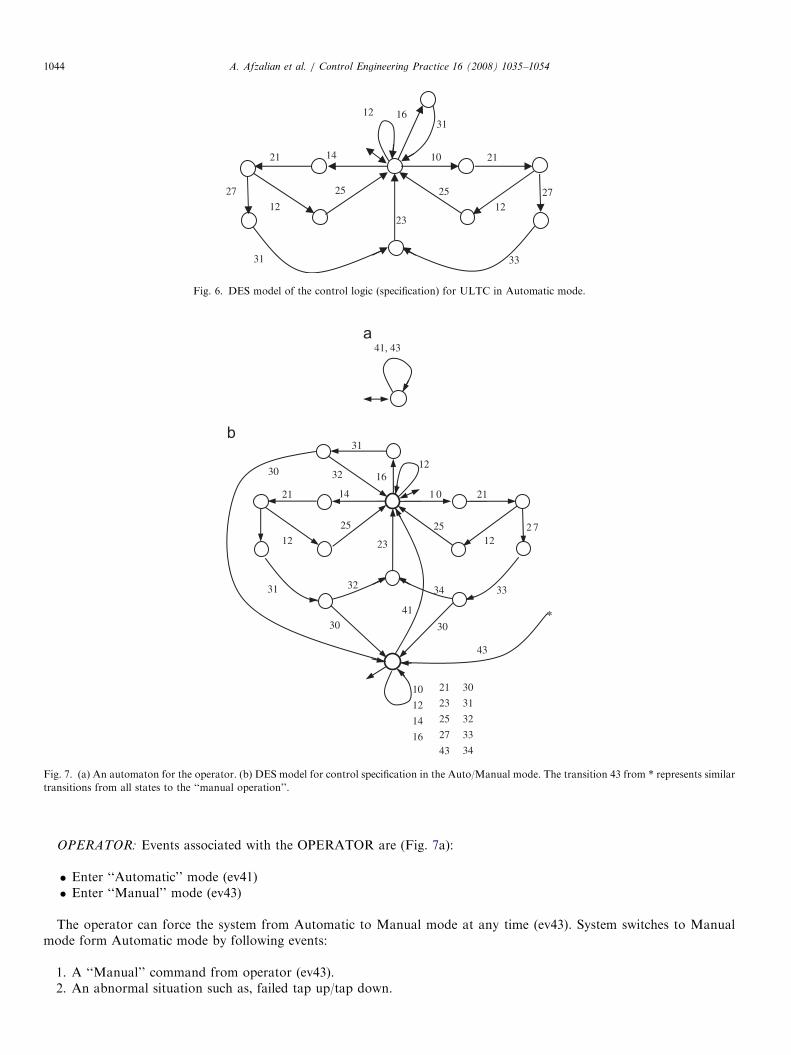
ARTICLE IN PRESS
25
10
23
21
27
33
12
21 14
12
25 27
31
31 16 12
Fig. 6. DES model of the control logic (specification) for ULTC in Automatic mode.
41, 43
*
25
1 0
23
21
2 7
33
12
21 14
12
25
31
31
1612
3432
3030
41
43
21
23
25
27
43
30
31
32
33
34
10
12
14
16
3230
Fig. 7. (a) An automaton for the operator. (b) DES model for control specification in the Auto/Manual mode. The transition 43 from * represents similar
transitions from all states to the ‘‘manual operation’’.
A. Afzalian et al. / Control Engineering Practice 16 (2008) 1035–10541044
OPERATOR: Events associated with the OPERATOR are (Fig. 7a):
�
Enter ‘‘Automatic’’ mode (ev41) � Enter ‘‘Manual’’ mode (ev43)The operator can force the system from Automatic to Manual mode at any time (ev43). System switches to Manualmode form Automatic mode by following events:
1.
A ‘‘Manual’’ command from operator (ev43). 2. An abnormal situation such as, failed tap up/tap down.
ARTICLE IN PRESS
Control data are displayed as a list of supervisor stateswhere disabling occurs, together with the events that mustbe disabled there.
0: 21 31 33 1: 11 25 31 33 2: 11 25 31 33 3: 11 21 33 4: 11 23 31 5: 11 23 33 6: 21 31 33 7: 11 25 31 33 8: 11 25 31 33 9: 11 25 31 33 10: 11 21 33 11: 21 31 33 12: 11 21 31 33 13: 11 23 31 14: 11 23 33 15: 11 25 31 33 16: 11 21 33 17: 11 18: 11 23 31 19: 11 23 33 20: 11 21: 11 21
Fig. 8. The reduced order supervisor (a) and the control data (b) in the Automatic mode.
A. Afzalian et al. / Control Engineering Practice 16 (2008) 1035–1054 1045
In Manual mode the system is waiting for ‘‘Tap-up’’, ‘‘Tap-down’’, ‘‘Automatic’’, or ‘‘Stop’’ commands. When returningto Automatic mode the controller is reinitialized at ‘‘state 0’’ of the Automatic mode specification. A specification for theAuto/Manual mode (SPEC2) can be achieved by inserting some transitions after the occurrence of ev31 and ev33 and alsoby adding a new state as the ‘‘Manual-operation’’ state. ‘‘Manual’’ command (ev43) takes the system from any state (*) tothe Manual-operation state. Then ev41 takes this state back to the initial state. Fig. 7b shows the DES model for controlspecification in the Auto/Manual mode.
4.3. Design of the DES supervisor
The plant and the specification DES models are implemented in the TCT software. A brief description of TCTprocedures which are used in this paper are given in Appendix. The supervisory control and its reduced mode have beendesigned for the Automatic and Auto/Manual modes of operation separately.
(I)
Automatic modeThe supervisor and the control data for the ULTC in the Automatic mode are calculated using TCT.
SUPER1 ¼ Supcon(PLANT1,SPEC1) (78,171)CONDAT1 ¼ Condat(PLANT1,SUPER1) Controllable.SIMSUP1 ¼ Supreduce(PLANT1,SUPER1,CONDAT1) (22,92;slb ¼ 20)
SIMSUP1 is the reduced order supervisor with 19 states and 60 transitions. The reduced order supervisory controland the control data are shown in Fig. 8.
ARTICLE IN PRESS
Fig. 9. The reduced order supervisor in Auto/Manual mode.
A. Afzalian et al. / Control Engineering Practice 16 (2008) 1035–10541046
(II)
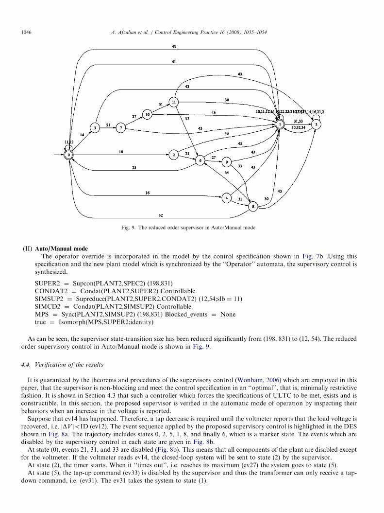
Auto/Manual modeThe operator override is incorporated in the model by the control specification shown in Fig. 7b. Using thisspecification and the new plant model which is synchronized by the ‘‘Operator’’ automata, the supervisory control issynthesized.
SUPER2 ¼ Supcon(PLANT2,SPEC2) (198,831)CONDAT2 ¼ Condat(PLANT2,SUPER2) Controllable.SIMSUP2 ¼ Supreduce(PLANT2,SUPER2,CONDAT2) (12,54;slb ¼ 11)SIMCD2 ¼ Condat(PLANT2,SIMSUP2) Controllable.MPS ¼ Sync(PLANT2,SIMSUP2) (198,831) Blocked_events ¼ Nonetrue ¼ Isomorph(MPS,SUPER2;identity)
As can be seen, the supervisor state-transition size has been reduced significantly from (198, 831) to (12, 54). The reducedorder supervisory control in Auto/Manual mode is shown in Fig. 9.
4.4. Verification of the results
It is guaranteed by the theorems and procedures of the supervisory control (Wonham, 2006) which are employed in thispaper, that the supervisor is non-blocking and meet the control specification in an ‘‘optimal’’, that is, minimally restrictivefashion. It is shown in Section 4.3 that such a controller which forces the specifications of ULTC to be met, exists and isconstructible. In this section, the proposed supervisor is verified in the automatic mode of operation by inspecting theirbehaviors when an increase in the voltage is reported.
Suppose that ev14 has happened. Therefore, a tap decrease is required until the voltmeter reports that the load voltage isrecovered, i.e. jDV joID (ev12). The event sequence applied by the proposed supervisory control is highlighted in the DESshown in Fig. 8a. The trajectory includes states 0, 2, 5, 1, 8, and finally 6, which is a marker state. The events which aredisabled by the supervisory control in each state are given in Fig. 8b.
At state (0), events 21, 31, and 33 are disabled (Fig. 8b). This means that all components of the plant are disabled exceptfor the voltmeter. If the voltmeter reads ev14, the closed-loop system will be sent to state (2) by the supervisor.
At state (2), the timer starts. When it ‘‘times out’’, i.e. reaches its maximum (ev27) the system goes to state (5).At state (5), the tap-up command (ev33) is disabled by the supervisor and thus the transformer can only receive a tap-
down command, i.e. (ev31). The ev31 takes the system to state (1).
ARTICLE IN PRESSA. Afzalian et al. / Control Engineering Practice 16 (2008) 1035–1054 1047
At state (1), if the tap-down is successful (ev32), the supervisor sends the plant to state (8), where the timer will be reset(ev23) first, and then the system goes to state (6).
State (6) is a marker state where the voltmeter is activated to read new voltages. If the voltmeter reads ev12, i.e. thevoltage is recovered, then the system stays in this state, unless the voltmeter reads ev10 or ev14. If ev10 happens, thetrajectory would go through states 8, 13, 7, 1, and 0 (the dotted line in Fig. 8a).
Similarly, one can follow the supervisor actions on this trajectory.
5. Hierarchical solution
High-level management executes a ‘‘Stop’’ command only after occurrence of abnormal behavior in the plant, suchas a specific number of tap up/down failures, to shutdown the regulation mechanism of the tap-changer. As described inSection 2, following steps are taken to synthesize a hierarchical supervisory structure.
(1)
A supervisor has been synthesized for the Automatic mode of the ULTC (SUPER1) and is considered as the low-levelplant. The DES model of SUPER1 is shown in Fig. 8a.(2)
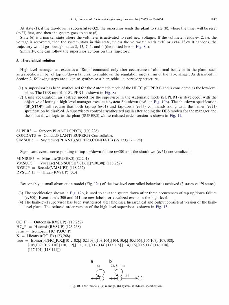
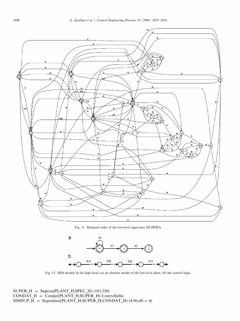
Using vocalization, an abstract model for the supervisor in the Automatic mode (SUPER1) is developed, with theobjective of letting a high-level manager execute a system Shutdown (ev61 in Fig. 10b). The shutdown specification(SP_STOP) will require that both tap-up (ev31) and tap-down (ev33) commands along with the Timer (ev21)specification be disabled. A supervisory control s synthesized again after adding the DES models for the manager andthe shout-down logic to the plant (SUPER3) whose reduced order version is shown in Fig. 11.SUPER3 ¼ Supcon(PLANT3,SPEC3) (100,228)CONDAT3 ¼ Condat(PLANT3,SUPER3) Controllable.SIMSUP3 ¼ Supreduce(PLANT3,SUPER3,CONDAT3) (29,123;slb ¼ 28)
Significant events corresponding to tap up/down failure (ev30) and the shutdown (ev61) are vocalized.
MINSUP3 ¼ Minstate(SUPER3) (82,201)VMSUP3 ¼ Vocalize(MINSUP3,[[*,61,61],[*,30,30]) (118,252)RVSUP ¼ Recode(VMSUP3) (118,252)RVSUP_H ¼ Higen(RVSUP) (3,3)
Reasonably, a small abstraction model (Fig. 12a) of the low-level controlled behavior is achieved (3 states vs. 29 states).
(3)
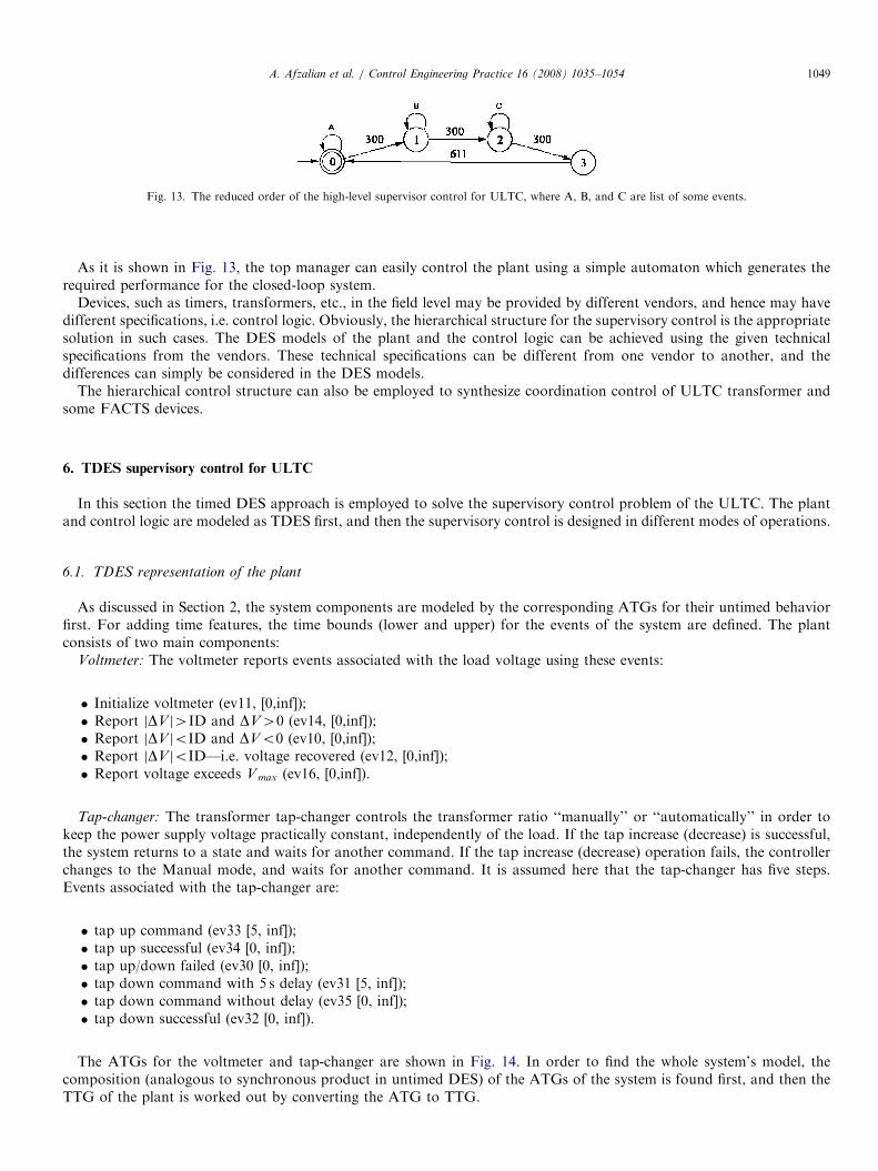
The specification shown in Fig. 12b, is used to shut the system down after three occurrences of tap up/down failure(ev300). Event labels 300 and 611 are new labels for vocalized events in the high level.(4)
The high-level supervisor has been synthesized after finding a hierarchical and output consistent version of the high-level plant. The reduced order version of the high-level supervisor is shown in Fig. 13.OC_P ¼ Outconsis(RVSUP) (119,252)HC_P ¼ Hiconsis(RVSUP) (123,268)false ¼ Isomorph(HC_P,OC_P)X ¼ Hiconsis(OC_P) (123,268)true ¼ Isomorph(HC_P,X;[[101,102],[102,103],[103,104],[104,105],[105,106],[106,107],[107,108],
[108,109],[109,110],[110,112],[111,113],[112,114],[113,115],[114,116],[115,117],[116,118],[117,101],[118,111]])
61 21, 31
61
33
Fig. 10. DES models: (a) manage, (b) system shutdown specification.
ARTICLE IN PRESS
Fig. 12. DES models in the high level: (a) an abstract model of the low-level plant, (b) the control logic.
Fig. 11. Reduced order of the low-level supervisor (SUPER3).
A. Afzalian et al. / Control Engineering Practice 16 (2008) 1035–10541048
SUPER_H ¼ Supcon(PLANT_H,SPEC_H) (103,330)CONDAT_H ¼ Condat(PLANT_H,SUPER_H) Controllable.SIMSUP_H ¼ Supreduce(PLANT_H,SUPER_H,CONDAT_H) (4,96;slb ¼ 4)
ARTICLE IN PRESS
Fig. 13. The reduced order of the high-level supervisor control for ULTC, where A, B, and C are list of some events.
A. Afzalian et al. / Control Engineering Practice 16 (2008) 1035–1054 1049
As it is shown in Fig. 13, the top manager can easily control the plant using a simple automaton which generates therequired performance for the closed-loop system.
Devices, such as timers, transformers, etc., in the field level may be provided by different vendors, and hence may havedifferent specifications, i.e. control logic. Obviously, the hierarchical structure for the supervisory control is the appropriatesolution in such cases. The DES models of the plant and the control logic can be achieved using the given technicalspecifications from the vendors. These technical specifications can be different from one vendor to another, and thedifferences can simply be considered in the DES models.
The hierarchical control structure can also be employed to synthesize coordination control of ULTC transformer andsome FACTS devices.
6. TDES supervisory control for ULTC
In this section the timed DES approach is employed to solve the supervisory control problem of the ULTC. The plantand control logic are modeled as TDES first, and then the supervisory control is designed in different modes of operations.
6.1. TDES representation of the plant
As discussed in Section 2, the system components are modeled by the corresponding ATGs for their untimed behaviorfirst. For adding time features, the time bounds (lower and upper) for the events of the system are defined. The plantconsists of two main components:
Voltmeter: The voltmeter reports events associated with the load voltage using these events:
�
Initialize voltmeter (ev11, [0,inf]); � Report jDV j4ID and DV40 (ev14, [0,inf]); � Report jDV joID and DVo0 (ev10, [0,inf]); � Report jDV joID—i.e. voltage recovered (ev12, [0,inf]); � Report voltage exceeds V max (ev16, [0,inf]).Tap-changer: The transformer tap-changer controls the transformer ratio ‘‘manually’’ or ‘‘automatically’’ in order tokeep the power supply voltage practically constant, independently of the load. If the tap increase (decrease) is successful,the system returns to a state and waits for another command. If the tap increase (decrease) operation fails, the controllerchanges to the Manual mode, and waits for another command. It is assumed here that the tap-changer has five steps.Events associated with the tap-changer are:
�
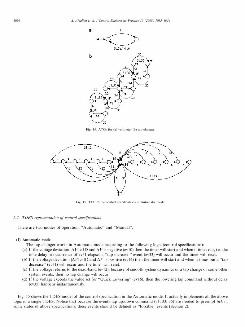
tap up command (ev33 [5, inf]); � tap up successful (ev34 [0, inf]); � tap up/down failed (ev30 [0, inf]); � tap down command with 5 s delay (ev31 [5, inf]); � tap down command without delay (ev35 [0, inf]); � tap down successful (ev32 [0, inf]).The ATGs for the voltmeter and tap-changer are shown in Fig. 14. In order to find the whole system’s model, thecomposition (analogous to synchronous product in untimed DES) of the ATGs of the system is found first, and then theTTG of the plant is worked out by converting the ATG to TTG.
ARTICLE IN PRESS
Fig. 14. ATGs for (a) voltmeter (b) tap-changer.
Fig. 15. TTG of the control specifications in Automatic mode.
A. Afzalian et al. / Control Engineering Practice 16 (2008) 1035–10541050
6.2. TDES representation of control specifications
There are two modes of operation: ‘‘Automatic’’ and ‘‘Manual’’.
(I)
Automatic modeThe tap-changer works in Automatic mode according to the following logic (control specifications):(a) If the voltage deviation jDV j4ID and DV is negative (ev10) then the timer will start and when it times out, i.e. the
time delay in occurrence of ev31 elapses a ‘‘tap increase ’’ event (ev33) will occur and the timer will reset.(b) If the voltage deviation jDV j4ID and DV is positive (ev14) then the timer will start and when it times out a ‘‘tap
decrease’’ (ev31) will occur and the timer will reset.(c) If the voltage returns to the dead-band (ev12), because of smooth system dynamics or a tap change or some other
system events, then no tap change will occur.(d) If the voltage exceeds the value set for ‘‘Quick Lowering’’ (ev16), then the lowering tap command without delay
(ev35) happens instantaneously.
Fig. 15 shows the TDES model of the control specification in the Automatic mode. It actually implements all the abovelogic in a single TDES. Notice that because the events tap up/down command (31, 33, 35) are needed to preempt tick insome states of above specifications, these events should be defined as ‘‘forcible’’ events (Section 2).
ARTICLE IN PRESSA. Afzalian et al. / Control Engineering Practice 16 (2008) 1035–1054 1051
(II)
Fig. 1
opera
Auto/Manual mode
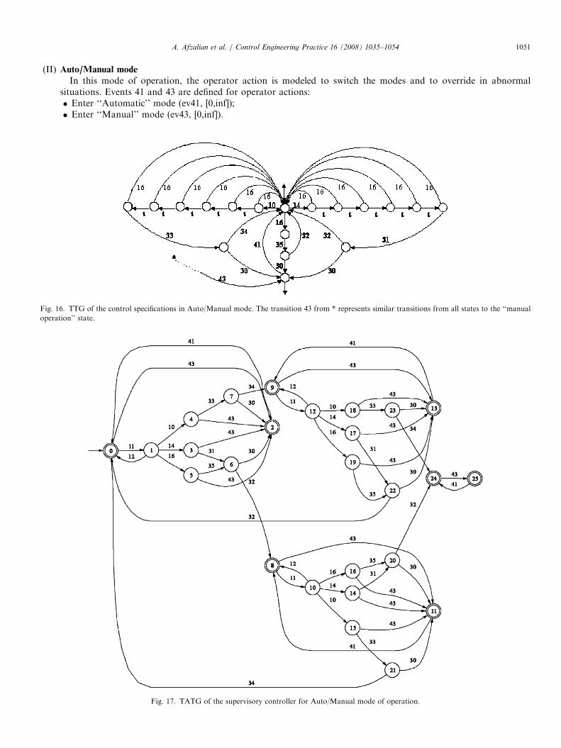
In this mode of operation, the operator action is modeled to switch the modes and to override in abnormalsituations. Events 41 and 43 are defined for operator actions:� Enter ‘‘Automatic’’ mode (ev41, [0,inf]);� Enter ‘‘Manual’’ mode (ev43, [0,inf]).
6. T
tion
TG of the control specifications in Auto/Manual mode. The transition 43 from * represents similar transitions from all states to the ‘‘manual
’’ state.
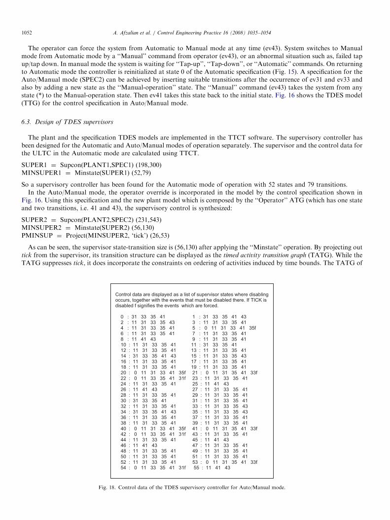
Fig. 17. TATG of the supervisory controller for Auto/Manual mode of operation.
ARTICLE IN PRESSA. Afzalian et al. / Control Engineering Practice 16 (2008) 1035–10541052
The operator can force the system from Automatic to Manual mode at any time (ev43). System switches to Manualmode from Automatic mode by a ‘‘Manual’’ command from operator (ev43), or an abnormal situation such as, failed tapup/tap down. In manual mode the system is waiting for ‘‘Tap-up’’, ‘‘Tap-down’’, or ‘‘Automatic’’ commands. On returningto Automatic mode the controller is reinitialized at state 0 of the Automatic specification (Fig. 15). A specification for theAuto/Manual mode (SPEC2) can be achieved by inserting suitable transitions after the occurrence of ev31 and ev33 andalso by adding a new state as the ‘‘Manual-operation’’ state. The ‘‘Manual’’ command (ev43) takes the system from anystate (*) to the Manual-operation state. Then ev41 takes this state back to the initial state. Fig. 16 shows the TDES model(TTG) for the control specification in Auto/Manual mode.
6.3. Design of TDES supervisors
The plant and the specification TDES models are implemented in the TTCT software. The supervisory controller hasbeen designed for the Automatic and Auto/Manual modes of operation separately. The supervisor and the control data forthe ULTC in the Automatic mode are calculated using TTCT.
SUPER1 ¼ Supcon(PLANT1,SPEC1) (198,300)MINSUPER1 ¼ Minstate(SUPER1) (52,79)
So a supervisory controller has been found for the Automatic mode of operation with 52 states and 79 transitions.In the Auto/Manual mode, the operator override is incorporated in the model by the control specification shown in
Fig. 16. Using this specification and the new plant model which is composed by the ‘‘Operator’’ ATG (which has one stateand two transitions, i.e. 41 and 43), the supervisory control is synthesized:
SUPER2 ¼ Supcon(PLANT2,SPEC2) (231,543)MINSUPER2 ¼ Minstate(SUPER2) (56,130)PMINSUP ¼ Project(MINSUPER2, ‘tick’) (26,53)
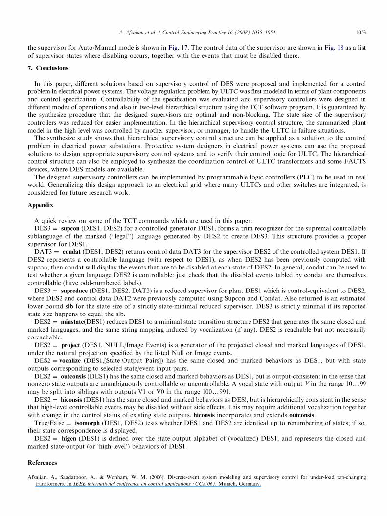
As can be seen, the supervisor state-transition size is (56,130) after applying the ‘‘Minstate’’ operation. By projecting outtick from the supervisor, its transition structure can be displayed as the timed activity transition graph (TATG). While theTATG suppresses tick, it does incorporate the constraints on ordering of activities induced by time bounds. The TATG of
Control data are displayed as a list of supervisor states where disabling occurs, together with the events that must be disabled there. If TICK is disabled f signifies the events which are forced.
0 : 31 33 35 41 1 : 31 33 35 41 43 2 : 11 31 33 35 43 3 : 11 31 33 35 41 4 : 11 31 33 35 41 5 : 0 11 31 33 41 35f 6 : 11 31 33 35 41 7 : 11 31 33 35 41 8 : 11 41 43 9 : 11 31 33 35 41 10 : 11 31 33 35 41 11 : 31 33 35 41 12 : 11 31 33 35 41 13 : 11 31 33 35 41 14 : 31 33 35 41 43 15 : 11 31 33 35 43 16 : 11 31 33 35 41 17 : 11 31 33 35 41 18 : 11 31 33 35 41 19 : 11 31 33 35 41 20 : 0 11 31 33 41 35f 21 : 0 11 31 35 41 33f 22 : 0 11 33 35 41 31f 23 : 11 31 33 35 41 24 : 11 31 33 35 41 25 : 11 41 43 26 : 11 41 43 27 : 11 31 33 35 41 28 : 11 31 33 35 41 29 : 11 31 33 35 41 30 : 31 33 35 41 31 : 11 31 33 35 41 32 : 11 31 33 35 41 33 : 11 31 33 35 43 34 : 31 33 35 41 43 35 : 11 31 33 35 43 36 : 11 31 33 35 41 37 : 11 31 33 35 41 38 : 11 31 33 35 41 39 : 11 31 33 35 41 40 : 0 11 31 33 41 35f 41 : 0 11 31 35 41 33f 42 : 0 11 33 35 41 31f 43 : 11 31 33 35 41 44 : 11 31 33 35 41 45 : 11 41 43 46 : 11 41 43 47 : 11 31 33 35 41 48 : 11 31 33 35 41 49 : 11 31 33 35 41 50 : 11 31 33 35 41 51 : 11 31 33 35 41 52 : 11 31 33 35 41 53 : 0 11 31 35 41 33f 54 : 0 11 33 35 41 31f 55 : 11 41 43
Fig. 18. Control data of the TDES supervisory controller for Auto/Manual mode.
ARTICLE IN PRESSA. Afzalian et al. / Control Engineering Practice 16 (2008) 1035–1054 1053
the supervisor for Auto/Manual mode is shown in Fig. 17. The control data of the supervisor are shown in Fig. 18 as a listof supervisor states where disabling occurs, together with the events that must be disabled there.
7. Conclusions
In this paper, different solutions based on supervisory control of DES were proposed and implemented for a controlproblem in electrical power systems. The voltage regulation problem by ULTC was first modeled in terms of plant componentsand control specification. Controllability of the specification was evaluated and supervisory controllers were designed indifferent modes of operations and also in two-level hierarchical structure using the TCT software program. It is guaranteed bythe synthesize procedure that the designed supervisors are optimal and non-blocking. The state size of the supervisorycontrollers was reduced for easier implementation. In the hierarchical supervisory control structure, the summarized plantmodel in the high level was controlled by another supervisor, or manager, to handle the ULTC in failure situations.
The synthesize study shows that hierarchical supervisory control structure can be applied as a solution to the controlproblem in electrical power substations. Protective system designers in electrical power systems can use the proposedsolutions to design appropriate supervisory control systems and to verify their control logic for ULTC. The hierarchicalcontrol structure can also be employed to synthesize the coordination control of ULTC transformers and some FACTSdevices, where DES models are available.
The designed supervisory controllers can be implemented by programmable logic controllers (PLC) to be used in realworld. Generalizing this design approach to an electrical grid where many ULTCs and other switches are integrated, isconsidered for future research work.
Appendix
A quick review on some of the TCT commands which are used in this paper:DES3 ¼ supcon (DES1, DES2) for a controlled generator DES1, forms a trim recognizer for the supremal controllable
sublanguage of the marked (‘‘legal’’) language generated by DES2 to create DES3. This structure provides a propersupervisor for DES1.
DAT3 ¼ condat (DES1, DES2) returns control data DAT3 for the supervisor DES2 of the controlled system DES1. IfDES2 represents a controllable language (with respect to DES1), as when DES2 has been previously computed withsupcon, then condat will display the events that are to be disabled at each state of DES2. In general, condat can be used totest whether a given language DES2 is controllable: just check that the disabled events tabled by condat are themselvescontrollable (have odd-numbered labels).
DES3 ¼ supreduce (DES1, DES2, DAT2) is a reduced supervisor for plant DES1 which is control-equivalent to DES2,where DES2 and control data DAT2 were previously computed using Supcon and Condat. Also returned is an estimatedlower bound slb for the state size of a strictly state-minimal reduced supervisor. DES3 is strictly minimal if its reportedstate size happens to equal the slb.
DES2 ¼ minstate(DES1) reduces DES1 to a minimal state transition structure DES2 that generates the same closed andmarked languages, and the same string mapping induced by vocalization (if any). DES2 is reachable but not necessarilycoreachable.
DES2 ¼ project (DES1, NULL/Image Events) is a generator of the projected closed and marked languages of DES1,under the natural projection specified by the listed Null or Image events.
DES2 ¼ vocalize (DES1,[State-Output Pairs]) has the same closed and marked behaviors as DES1, but with stateoutputs corresponding to selected state/event input pairs.
DES2 ¼ outconsis (DES1) has the same closed and marked behaviors as DES1, but is output-consistent in the sense thatnonzero state outputs are unambiguously controllable or uncontrollable. A vocal state with output V in the range 10y99may be split into siblings with outputs V1 or V0 in the range 100y991.
DES2 ¼ hiconsis (DES1) has the same closed and marked behaviors as DES!, but is hierarchically consistent in the sensethat high-level controllable events may be disabled without side effects. This may require additional vocalization togetherwith change in the control status of existing state outputs. hiconsis incorporates and extends outconsis.
True/False ¼ isomorph (DES1, DES2) tests whether DES1 and DES2 are identical up to renumbering of states; if so,their state correspondence is displayed.
DES2 ¼ higen (DES1) is defined over the state-output alphabet of (vocalized) DES1, and represents the closed andmarked state-output (or ‘high-level’) behaviors of DES1.
References
Afzalian, A., Saadatpoor, A., & Wonham, W. M. (2006). Discrete-event system modeling and supervisory control for under-load tap-changing
transformers. In IEEE international conference on control applications (CCA’06), Munich, Germany.
ARTICLE IN PRESSA. Afzalian et al. / Control Engineering Practice 16 (2008) 1035–10541054
Afzalian, A. & Wonham, W. M. (2006). Discrete-event system supervisory controller design for an electrical power transmission network. In 14th Iranian
conference on electrical engineering (ICEE’06), Tehran.
Basile, F., Carbone, C., & Chiacchio, P. (2007). Simulation and analysis of discrete-event control systems based on Petri nets using PNetLab. Control
Engineering Practice, 15(2), 241–259.
Brandin, B. A., & Wonham, W. M. (1994). Supervisory control of timed discrete-event systems. IEEE Transactions on Automatic Control, 39(2), 329–342.
Fink, L. H. (1999). Discrete events in power systems. Discrete Event Dynamic Systems, 9(4), 319–330.
GE Consumer Industrial, M. (2005). DTR—Digital tap changer controller instruction manual GEK-106305A (pp. 7–12).
Hiskens, I. A., & Sokolowski, P. J. (2001). Systematic modeling and symbolically assisted simulation of power systems. IEEE Transactions on Power
Systems, 16(2), 229–234.
Kim, G. W., & Lee, K. Y. (2005). Coordination control of ULTC transformer and STATCOM based on an artificial neural network. IEEE Transactions
on Power Systems, 20(2), 580–586.
Kundur, P. (1994). Power system stability and control. New York: McGraw-Hill.
Lee, M. S., & Lim, J. T. (2004). Restoration strategy for power distribution networks using optimal supervisory control. IEE Proceedings Generation,
Transmission and Distribution, 151(3), 367–372.
Lin, S. Y., Ho, Y. C., & Lin, C. H. (2004). An ordinal optimization theory-based algorithm for solving the optimal power flow problem with discrete
control variables. IEEE Transactions on Power Systems, 19(1), 276–286.
Ohtsuki, H., Yokoyama, A., & Sekine, Y. (1991). Reverse action of on-load tap changer in association with voltage collapse. IEEE Transactions on Power
Systems, 6(1), 300–306.
Otomega, B., Sermanson, V., Cutsem, T. V. (2003). Reverse-logic control of load tap changers in emergency voltage conditions. In IEEE power tech
conference proceedings, Bologna.
Prosser, J., Selinsky, J., Kwatny, H., & Kam, M. (1995). Supervisory control of electric power transmission networks. IEEE Transactions on Power
Systems, 10(2), 104–1110.
Ramadge, P., & Wonham, W. (1987). Supervisory control of a class of discrete event processes. SIAM Journal on Control and Optimization, 25(1),
206–230.
Ramadge, P. J. G., & Wonham, W. M. (1989). The control of discrete event systems. Proceedings of the IEEE, 77(1), 81–98.
Simon, H. A. (1962). The architecture of complexity. Proceedings of the American Philosophical Society, 106(6), 467–482.
Su, R., & Wonham, W. M. (2004). Supervisor reduction for discrete-event systems. Discrete Event Dynamic Systems, 14(1), 31–53.
Thukaram, D., Jenkins, L., Khincha, H. P., Yesuratnam, G., & Kumar, B. R. (2004). Monitoring the effects of on-load tap changing transformers on
voltage stability. International Conference on Power System Technology, 1, 419–424.
Wonham, W. M. (2006). Supervisory control of discrete-event systems, The University of Toronto. Available from: hhttp://www.control.utoronto.
ca/DES/i.
Yasar, M., & Ray, A. (2007). Hierarchical control of aircraft propulsion systems: Discrete event supervisor approach. Control Engineering Practice, 15(2),
149–162.
Zhong, H., & Wonham, W. M. (1990). On the consistency of hierarchical supervision in discrete-event systems. IEEE Transactions on Automatic Control,
35(10), 1125–1134.