motor drive and control solutions
TRANSCRIPT
2 | Motor Drive and Control Solutions Texas Instruments
Motor Drive and Control SolutionsTable of Contents
Motor Drive and Control Solutions2 Introduction
2 Motor Control System Functions
Microcontrollers for Motor Control3 C2000™ Microcontrollers Feature
Highlights
3 C2000™ Microcontroller Family
4 C2000™ MCU Software Solutions for Mot or Control
4 InstaSPIN™ MCU Motor Software Solutions
4 C2000™ MCU Motor Control Software Libraries
5-6 Tiva™ C Series Kits
7 Hercules™ TMS570 32-Bit ARM® Cortex™-R4 Safety Microcontrollers
Special Purpose Processors for Motion Control8 Trajectory controllers
Integrated Fan Motor Drivers9 The TI Advantage – Maximum
Integration
9 Integrated Fan Motor Drivers
DRV8x Integrated Motor Drivers10 Introduction
10 Bipolar Stepper Motor driver
Selection Guides for Analog Motor Solutions11 Stepper Motor Drivers
12 Brushed and Brushless DC Motor Drivers
Selection Guide for Signal Chain Solutions13 Low Offset is the TI Advantage
13 DRV5000 Hall Effect Sensors
14 Industrial Communications (Interface)
14 Industrial Interface Transceivers
15 Industrial Ethernet
16 Digital Isolators
17 ISO5500 Family Isolated Gate Drivers
18 Delta-Sigma Modulators in Current Measurement and Motor Control
18 20MHz, Second-Order, Isolated Delta-Sigma Modulators for Current-Sense Measurement
18 Modulators for Current Measurement Applications
19 Simultaneous-Sampling ADCs for High-End Drives
19 ADCs for Motor Control
Selection Guides for Power Management Solutions20 Input Power Protection
20 Window Comparator
20 LDO Linear Regulators
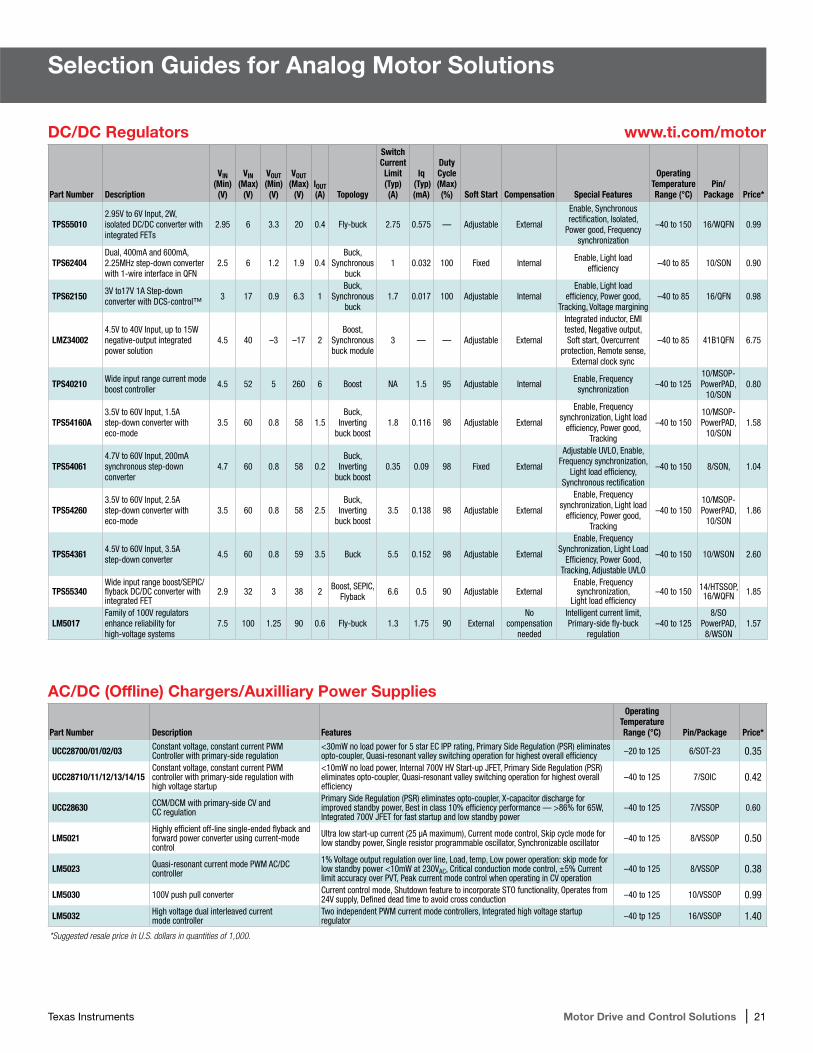
21 DC/DC Regulators
21 AC/DC (Offline) Chargers/Auxiliary Power Supplies
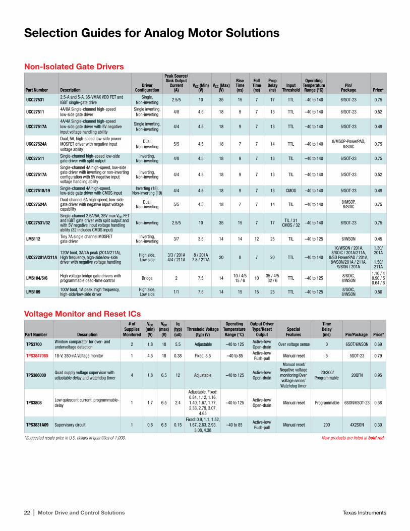
22 Non-Isolated Gate Drivers
22 Voltage Monitor and Reset ICs
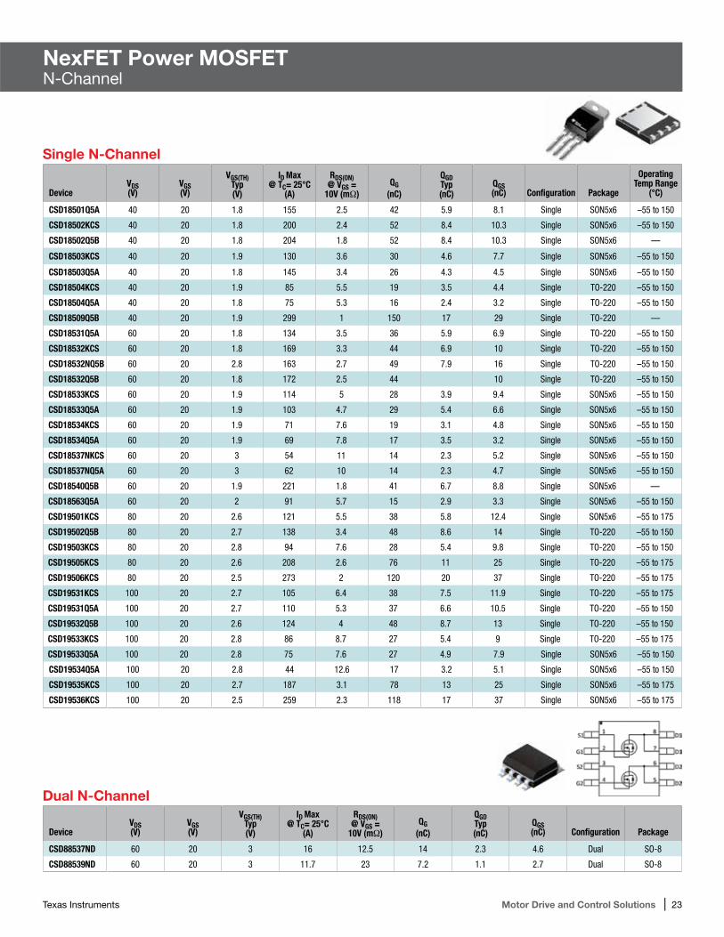
NexFET Power MOSFET23 Single N-Channel
23 Dual N-Channel
TI Designs 24-26 TI Designs for Motor Drives
Complete TI Motor Drive Solutions 27 Stepper Motors
27 Brushed DC Motors
28 Brushless DC (BLDC) Motors
28 Permanent Magnet Synchronous Motors (PMSMs)
29 AC Induction Motors (ACIMs)
29 Third-Party Network Devlelopers
Introduction
Texas Instruments (TI) is a global market leader that provides complete Motor Drive and control solutions along with broad analog and microcontroller portfolios. TI offers compre hensive tools, software and support to deliver efficient, reliable, cost-effective motor solutions. Customers can get the right products with the right performance to quickly spin motors such as AC induction motors (ACIMs), brushed DC motors, brushless DC (BLDC) motors, permanent-magnet synchronous motors (PMSMs) and stepper motors.
When you want the broadest motor expertise, breadth of selection and comprehensive support, you want TI as your partner for efficient, reliable and cost-effective Motor Drive and control solutions.
Motor Control System Functions
Host – Motion profile, logic controller or user interface, often communicating over a standard or proprietary field bus (CAN, serial, and Ethernet such as EtherCAT, Ethernet POWERLINK or EtherNet/IP).
Digital Isolation – Protection and level shifting between different voltage levels.
Controller – Generates the proper switching patterns to control the motor’s motion based on feedback and motion profile information from the host.
Gate Drivers – Generate the neces-sary voltage and current required to accurately and efficiently drive the MOSFETS or IGBTs.
Power Stage – IGBTs or MOSFETS
Sensing – Analog circuitry which processes/conditions the feedback from the motor to control torque, speed or position.
Learn more at: www.ti.com/motor
Pre-Driver – Gate drivers, sensing and protection circuitryintegrated into a single device or package that may also include control logic.
Integrated Motor Driver – Gate driver, FETs and protection circuitry integrated into a single device or package that may also include control logic and sensing circuitry.
Texas Instruments Motor Drive and Control Solutions | 3
Microcontrollers for Motor ControlC2000™ Real-Time MicrocontrollersMicrocontrollers for Motor Control C2000™ Real-Time Microcontrollers
C2000™ Microcontroller Families
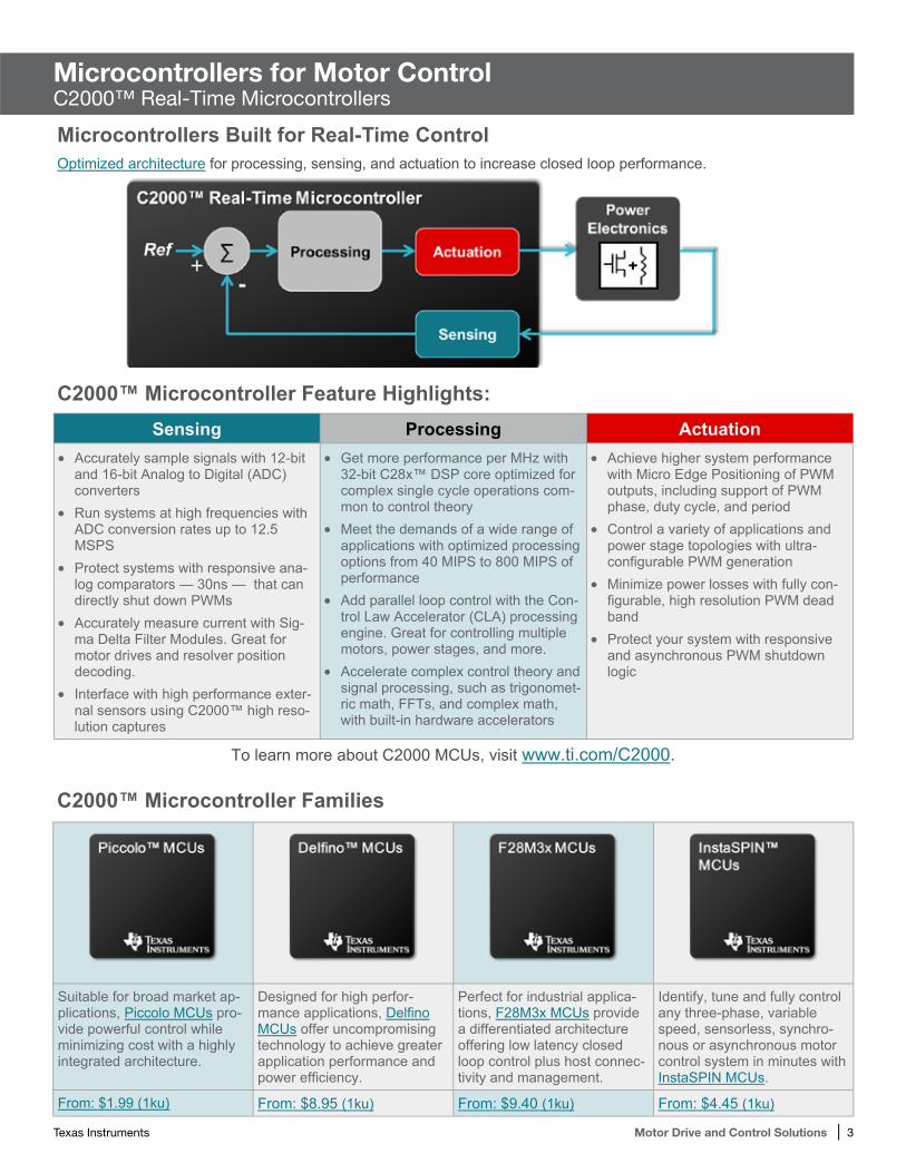
Suitable for broad market ap-plications, Piccolo MCUs pro-vide powerful control while minimizing cost with a highly integrated architecture.
Designed for high perfor-mance applications, Delfino MCUs offer uncompromising technology to achieve greater application performance and power efficiency.
Perfect for industrial applica-tions, F28M3x MCUs provide a differentiated architecture offering low latency closed loop control plus host connec-tivity and management.
Identify, tune and fully control any three-phase, variable speed, sensorless, synchro-nous or asynchronous motor control system in minutes with InstaSPIN MCUs.
From: $1.99 (1ku) From: $8.95 (1ku) From: $9.40 (1ku) From: $4.45 (1ku)
Sensing Processing Actuation Accurately sample signals with 12-bit
and 16-bit Analog to Digital (ADC) converters
Run systems at high frequencies with ADC conversion rates up to 12.5 MSPS
Protect systems with responsive ana-log comparators — 30ns — that can directly shut down PWMs
Accurately measure current with Sig-ma Delta Filter Modules. Great for motor drives and resolver position decoding.
Interface with high performance exter-nal sensors using C2000™ high reso-lution captures
Get more performance per MHz with 32-bit C28x™ DSP core optimized for complex single cycle operations com-mon to control theory
Meet the demands of a wide range of applications with optimized processing options from 40 MIPS to 800 MIPS of performance
Add parallel loop control with the Con-trol Law Accelerator (CLA) processing engine. Great for controlling multiple motors, power stages, and more.
Accelerate complex control theory and signal processing, such as trigonomet-ric math, FFTs, and complex math, with built-in hardware accelerators
Achieve higher system performance with Micro Edge Positioning of PWM outputs, including support of PWM phase, duty cycle, and period
Control a variety of applications and power stage topologies with ultra-configurable PWM generation
Minimize power losses with fully con-figurable, high resolution PWM dead band
Protect your system with responsive and asynchronous PWM shutdown logic
Microcontrollers Built for Real-Time Control Optimized architecture for processing, sensing, and actuation to increase closed loop performance.
C2000™ Microcontroller Feature Highlights:
To learn more about C2000 MCUs, visit www.ti.com/C2000.
4 | Motor Drive and Control Solutions Texas Instruments
Microcontrollers for Motor ControlC2000™ Real-Time MicrocontrollersMicrocontrollers for Motor Control C2000™ Real-Time Microcontrollers
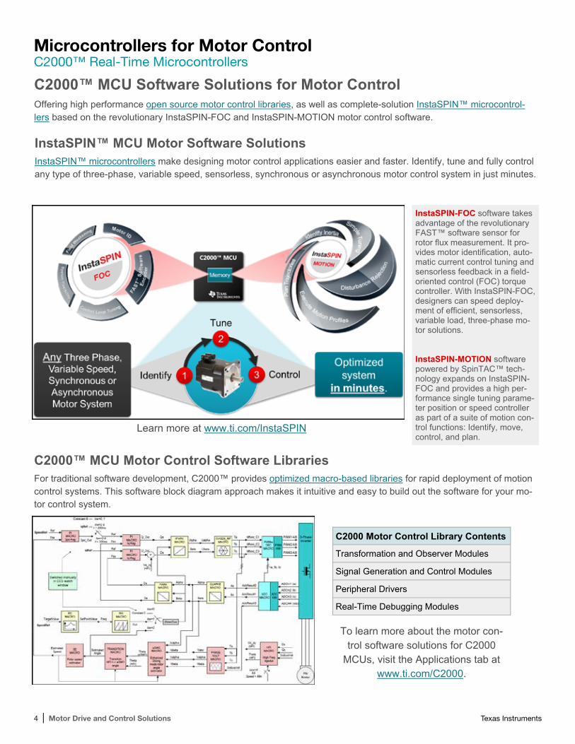
C2000™ MCU Software Solutions for Motor Control Offering high performance open source motor control libraries, as well as complete-solution InstaSPIN™ microcontrol-lers based on the revolutionary InstaSPIN-FOC and InstaSPIN-MOTION motor control software.
C2000™ MCU Motor Control Software Libraries For traditional software development, C2000™ provides optimized macro-based libraries for rapid deployment of motion control systems. This software block diagram approach makes it intuitive and easy to build out the software for your mo-tor control system.
C2000 Motor Control Library Contents
Transformation and Observer Modules
Signal Generation and Control Modules
Peripheral Drivers
Real-Time Debugging Modules
To learn more about the motor con-trol software solutions for C2000
MCUs, visit the Applications tab at www.ti.com/C2000.
InstaSPIN™ MCU Motor Software Solutions InstaSPIN™ microcontrollers make designing motor control applications easier and faster. Identify, tune and fully control any type of three-phase, variable speed, sensorless, synchronous or asynchronous motor control system in just minutes.
Learn more at www.ti.com/InstaSPIN
InstaSPIN-FOC software takes advantage of the revolutionary FAST™ software sensor for rotor flux measurement. It pro-vides motor identification, auto-matic current control tuning and sensorless feedback in a field-oriented control (FOC) torque controller. With InstaSPIN-FOC, designers can speed deploy-ment of efficient, sensorless, variable load, three-phase mo-tor solutions. InstaSPIN-MOTION software powered by SpinTAC™ tech-nology expands on InstaSPIN-FOC and provides a high per-formance single tuning parame-ter position or speed controller as part of a suite of motion con-trol functions: Identify, move, control, and plan.
Texas Instruments Motor Drive and Control Solutions | 5
Texas Instruments is the industry leader in bringing 32-bit capabilities and the full benefits of ARM® Cortex™-M-based microcontrollers to market. MCUs with Cortex-M offer a direct path to the strongest ecosystem of development tools, software and knowledge in the industry. Designers who migrate to MCUs will benefit from great tools, small code footprint and outstanding performance.
With large on-chip memories, enhanced power management and expanded I/O and control capabilities, MCUs are optimized for industrial applications requiring reliable connectivity, precise motor/motion control and remote monitoring. Some typical applications are factory automation, HVAC and building control, gaming equipment, medical instrumentation, consumer appliances, CCTV monitoring and fire security
Precision Motion Control
The microcontrollers features deterministic performance and IP especially designed for simultaneous advanced motion control and real-time connectivity. These microcontrollers include up to 16 full channels of control with deadband generators and shoot-through protection for applications such as three-phase inverter bridges. Fault-condition handling in hardware quickly provides low-latency shutdown and synchronization of timers to enable precise alignment of all edges.
•Motion-control PWMs with deadband and fault detection support safe and efficient operation of motors
•Quadrature encoder inputs (QEIs) support incremental encoders, tachometers, generators/resolvers and TDC detectors
•High-speed ADCs support current measurement using Hall sensors or shunts to optimize algorithms
• Independent integrated analog compar ators can be configured to drive an out put or generate an ADC interrupt event
Key Features• Interleaved average current-mode
PWM control with inherent current matching
• ARM Cortex-M4F core• 32 to 256KB of flash• 80-MHz CPU clock speeds•Deterministic fast-interrupt
processing (12 cycles)•Real-time multitasking capabilities• Integrated analog peripherals• 12-bit analog-to-digital converter•Pulse-width modulators (PWMs) with
programmable deadband timers•Operating modes with clock gating
for lower power•Single-cycle multiply/accumulate
(MAC)• IEEE 754 single-precision floating-
point unit (FPU)
Unique MCU Capabilities•Two CAN protocol version
2.0 part A/B •Advanced communication
capabilities, including UARTs, synchronous serial interfaces, USB, USB OTG, CAN controllers and I2C
• 5-V tolerant GPIOs with programmable drive capability
•Single-cycle flash up to 40 MHz•Royalty-free software with serial
bootloaders and DriverLib available in ROM
•Open-tooled reference design kits and quick-start evaluation kits
•Up to two quadrature encoder inputs
Ware Software•Extensive suite of software designed
to reduce development cycle time•Peripheral library•USB library•Graphics library•Code examples•Available as object library and
source code
Hardware Kits•Schematics, BOM and Gerber
files are available for all hardware kits and include all accessories to start evaluation and software development.
For more information on MCUs for motor-control applications, visit www.ti.com/c2000
Microcontrollers for ControlTiva™ C Series Kits
6 | Motor Drive and Control Solutions Texas Instruments
Microcontrollers for ControlTiva™ C Series Kits
Evaluation kit
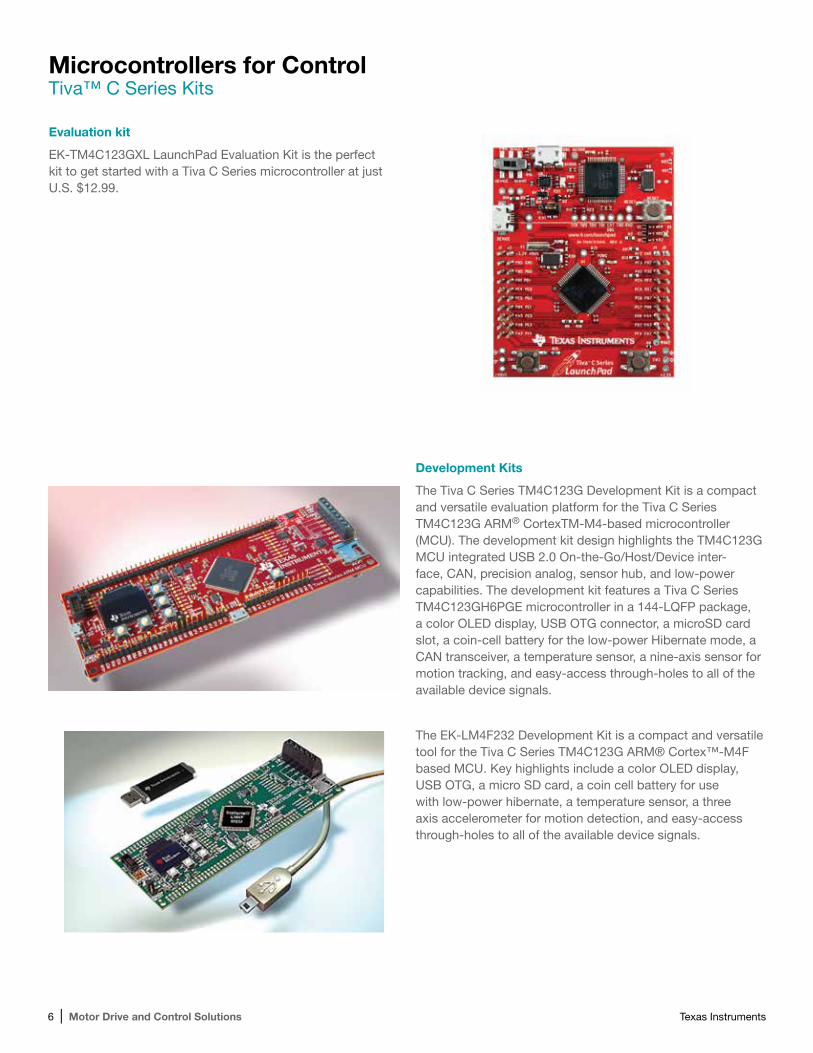
EK-TM4C123GXL LaunchPad Evaluation Kit is the perfect kit to get started with a Tiva C Series microcontroller at just U.S. $12.99.
Development Kits
The Tiva C Series TM4C123G Development Kit is a compact and versatile evaluation platform for the Tiva C Series TM4C123G ARM® CortexTM-M4-based microcontroller (MCU). The development kit design highlights the TM4C123G MCU integrated USB 2.0 On-the-Go/Host/Device inter-face, CAN, precision analog, sensor hub, and low-power capabilities. The development kit features a Tiva C Series TM4C123GH6PGE microcontroller in a 144-LQFP package, a color OLED display, USB OTG connector, a microSD card slot, a coin-cell battery for the low-power Hibernate mode, a CAN transceiver, a temperature sensor, a nine-axis sensor for motion tracking, and easy-access through-holes to all of the available device signals.
The EK-LM4F232 Development Kit is a compact and versatile tool for the Tiva C Series TM4C123G ARM® Cortex™-M4F based MCU. Key highlights include a color OLED display, USB OTG, a micro SD card, a coin cell battery for use with low-power hibernate, a temperature sensor, a three axis accelerometer for motion detection, and easy-access through-holes to all of the available device signals.
Texas Instruments Motor Drive and Control Solutions | 7
Microcontrollers for Motor ControlHercules™ TMS570 32-Bit ARM® Cortex™-R4 Safety Microcontrollers
The Hercules TMS570 microcontroller family enables customers to easily build motor-control applications that meet specific safety standards. Devices are available today with up to 220 MHz of floating-point performance and include an integrated safety concept.
A wide choice of communication peripherals like Ethernet, CAN, USB, FlexRay® and LIN, in combination with a powerful high-end timer (HET) coprocessor module, makes the family a flexible solution for safety-critical control applications.
The Hercules TMS570 Cortex™-R4 microcontroller family was developed according to the ISO26262 ASIL-D and IEC 61508 SIL3 safety standards. Dual-core lockstep CPU architecture, hardware BIST, MPU, ECC and on-chip clock and voltage monitoring are some of the key functional safety features available. A safety manual is available with guidelines on how to make the safety implementation as easy as possible.
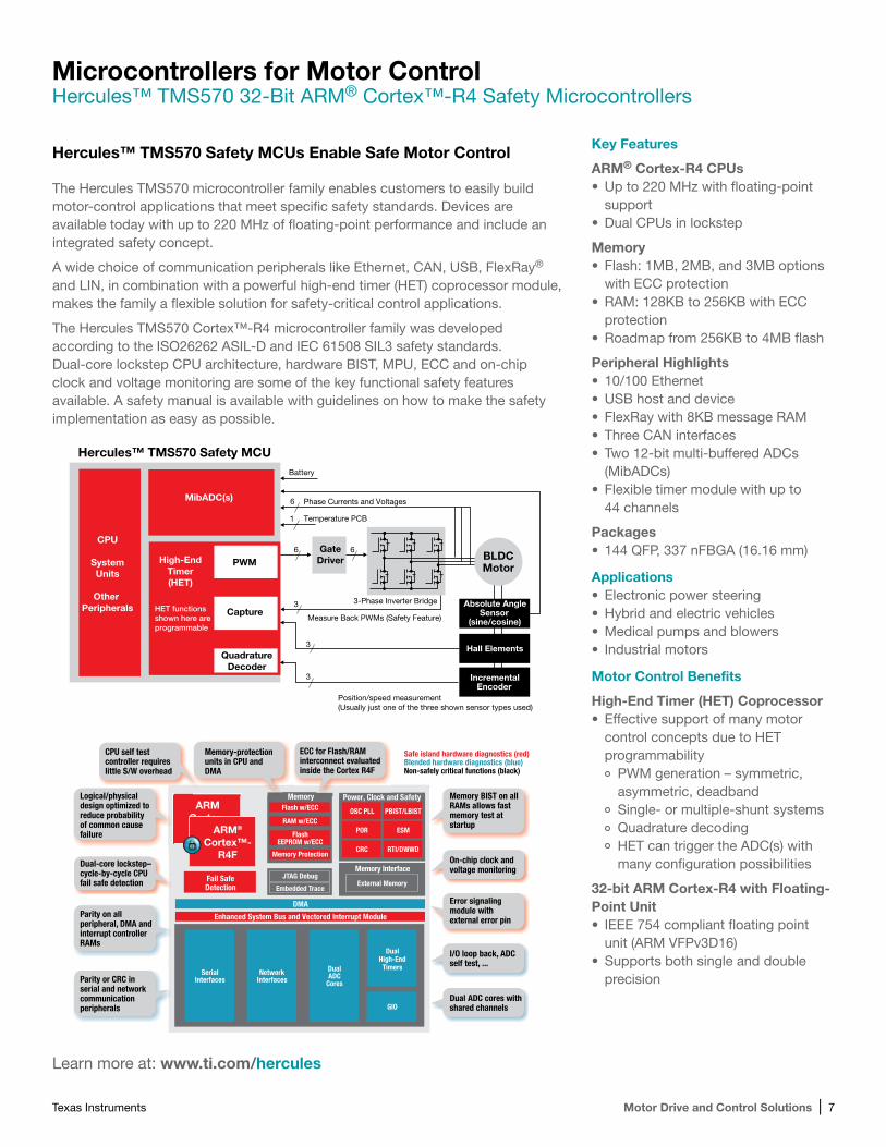
Hercules™ TMS570 Safety MCUs Enable Safe Motor Control
Learn more at: www.ti.com/hercules
Key Features
ARM® Cortex-R4 CPUs•Up to 220 MHz with floating-point
support•Dual CPUs in lockstep
Memory•Flash: 1MB, 2MB, and 3MB options
with ECC protection•RAM: 128KB to 256KB with ECC
protection•Roadmap from 256KB to 4MB flash
Peripheral Highlights• 10/100 Ethernet•USB host and device•FlexRay with 8KB message RAM•Three CAN interfaces•Two 12-bit multi-buffered ADCs
(MibADCs)•Flexible timer module with up to
44 channels
Packages• 144 QFP, 337 nFBGA (16.16 mm)
Applications•Electronic power steering•Hybrid and electric vehicles•Medical pumps and blowers• Industrial motors
Motor Control Benefits
High-End Timer (HET) Coprocessor• Effective support of many motor
control concepts due to HET programmability
PWM generation – symmetric, asymmetric, deadbandSingle- or multiple-shunt systemsQuadrature decodingHET can trigger the ADC(s) with many configuration possibilities
32-bit ARM Cortex-R4 with Floating-Point Unit• IEEE 754 compliant floating point
unit (ARM VFPv3D16)•Supports both single and double
precision
Hercules™ TMS570 Safety MCU
BLDCMotor
Absolute AngleSensor
(sine/cosine)
Hall Elements
IncrementalEncoder
HET functionsshown here areprogrammable
Battery
Temperature PCB
Phase Currents and Voltages6
6
3
3
3
6
1
3-Phase Inverter Bridge
Position/speed measurement(Usually just one of the three shown sensor types used)
Measure Back PWMs (Safety Feature)
GateDriver
CPU
SystemUnits
Other Peripherals
MibADC(s)
PWM
Capture
QuadratureDecoder
High-EndTimer(HET)
Fail Safe
PBIST/LBIST
Safe island hardware diagnostics (red)Blended hardware diagnostics (blue)Non-safely critical functions (black)
OSC PLL
POR
CRC RTI/DWWD
ESM
Enhanced System Bus and Vectored Interrupt Module
DMA
Flash w/ECC
RAM w/ECC
Memory Interface
External Memory
FlashEEPROM w/ECC
Memory Protection
R4F
ARMCortex-
R4F160 MHz
DualADC
Cores
DualHigh-EndTimers
GIO
Embedded Trace
JTAG Debug
ARM®
Cortex™-R4F
NetworkInterfaces
SerialInterfaces
CPU self testcontroller requireslittle S/W overhead
Logical/physicaldesign optimized toreduce probabilityof common causefailure
Memory BIST on allRAMs allows fastmemory test atstartup
Error signalingmodule with external error pin
On-chip clock and voltage monitoring
I/O loop back, ADCself test, ...
Dual ADC cores withshared channels
Parity on all peripheral, DMA andinterrupt controllerRAMs
Parity or CRC inserial and networkcommunicationperipherals
Dual-core lockstep–cycle-by-cycle CPUfail safe detection
ECC for Flash/RAM interconnect evaluatedinside the Cortex R4F
Memory-protectionunits in CPU and DMA
Detection
Power, Clock and SafetyMemory
8 | Motor Drive and Control Solutions Texas Instruments
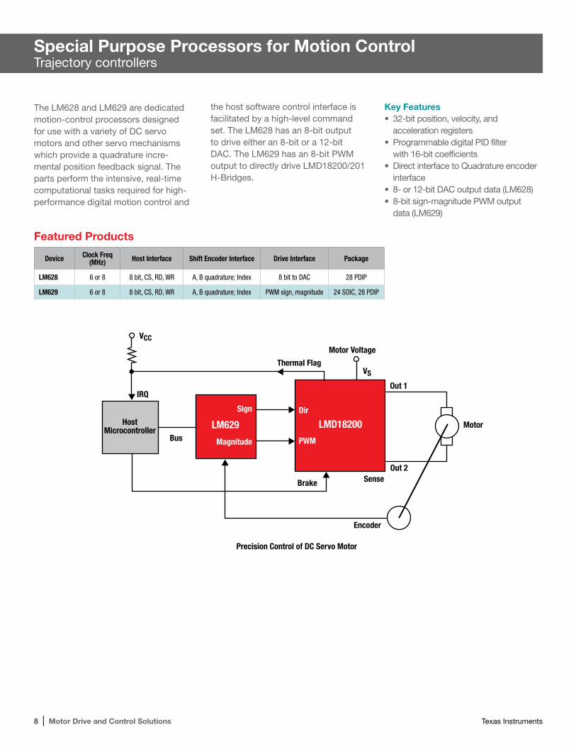
The LM628 and LM629 are dedicated motion-control processors designed for use with a variety of DC servo motors and other servo mechanisms which provide a quadrature incre-mental position feedback signal. The parts perform the intensive, real-time computational tasks required for high-performance digital motion control and
the host software control interface is facilitated by a high-level command set. The LM628 has an 8-bit output to drive either an 8-bit or a 12-bit DAC. The LM629 has an 8-bit PWM output to directly drive LMD18200/201 H-Bridges.
Special Purpose Processors for Motion ControlTrajectory controllers
Featured Products
Device Clock Freq (MHz) Host Interface Shift Encoder Interface Drive Interface Package
LM628 6 or 8 8 bit, CS, RD, WR A, B quadrature; Index 8 bit to DAC 28 PDIP
LM629 6 or 8 8 bit, CS, RD, WR A, B quadrature; Index PWM sign, magnitude 24 SOIC, 28 PDIP
Key Features• 32-bit position, velocity, and
acceleration registers• Programmable digital PID filter
with 16-bit coefficients• Direct interface to Quadrature encoder
interface• 8- or 12-bit DAC output data (LM628)• 8-bit sign-magnitude PWM output
data (LM629)
Texas Instruments Motor Drive and Control Solutions | 9
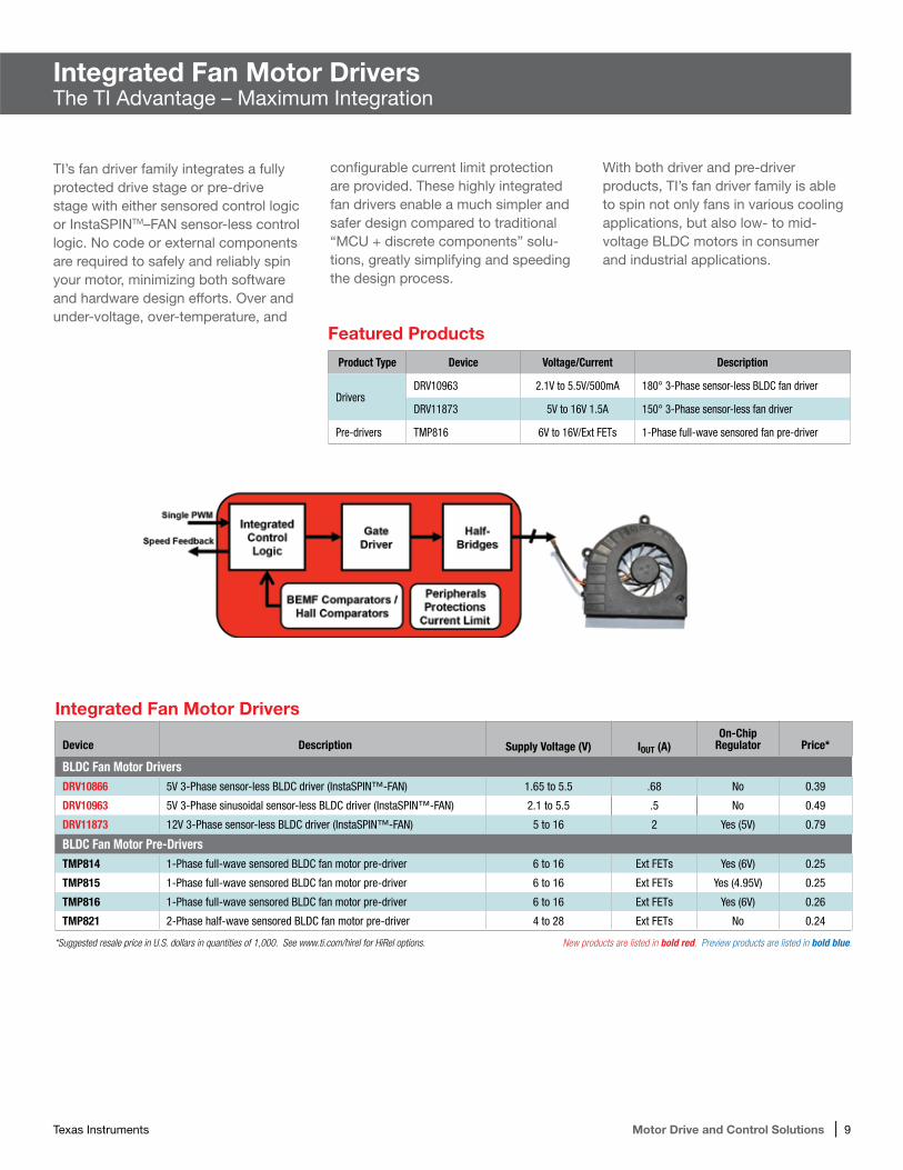
TI’s fan driver family integrates a fully protected drive stage or pre-drive stage with either sensored control logic or InstaSPINTM–FAN sensor-less control logic. No code or external components are required to safely and reliably spin your motor, minimizing both software and hardware design efforts. Over and under-voltage, over-temperature, and
configurable current limit protection are provided. These highly integrated fan drivers enable a much simpler and safer design compared to traditional “MCU + discrete components” solu-tions, greatly simplifying and speeding the design process.
Integrated Fan Motor DriversThe TI Advantage – Maximum Integration
With both driver and pre-driver products, TI’s fan driver family is able to spin not only fans in various cooling applications, but also low- to mid-voltage BLDC motors in consumer and industrial applications.
Featured Products
Product Type Device Voltage/Current Description
DriversDRV10963 2.1V to 5.5V/500mA 180° 3-Phase sensor-less BLDC fan driver
DRV11873 5V to 16V 1.5A 150° 3-Phase sensor-less fan driver
Pre-drivers TMP816 6V to 16V/Ext FETs 1-Phase full-wave sensored fan pre-driver
Integrated Fan Motor Drivers
Device Description Supply Voltage (V) IOUT (A)On-Chip
Regulator Price*
BLDC Fan Motor DriversDRV10866 5V 3-Phase sensor-less BLDC driver (InstaSPIN™-FAN) 1.65 to 5.5 .68 No 0.39
DRV10963 5V 3-Phase sinusoidal sensor-less BLDC driver (InstaSPIN™-FAN) 2.1 to 5.5 .5 No 0.49
DRV11873 12V 3-Phase sensor-less BLDC driver (InstaSPIN™-FAN) 5 to 16 2 Yes (5V) 0.79
BLDC Fan Motor Pre-DriversTMP814 1-Phase full-wave sensored BLDC fan motor pre-driver 6 to 16 Ext FETs Yes (6V) 0.25
TMP815 1-Phase full-wave sensored BLDC fan motor pre-driver 6 to 16 Ext FETs Yes (4.95V) 0.25
TMP816 1-Phase full-wave sensored BLDC fan motor pre-driver 6 to 16 Ext FETs Yes (6V) 0.26
TMP821 2-Phase half-wave sensored BLDC fan motor pre-driver 4 to 28 Ext FETs No 0.24
*Suggested resale price in U.S. dollars in quantities of 1,000. See www.ti.com/hirel for HiRel options. New products are listed in bold red. Preview products are listed in bold blue.
10 | Motor Drive and Control Solutions Texas Instruments
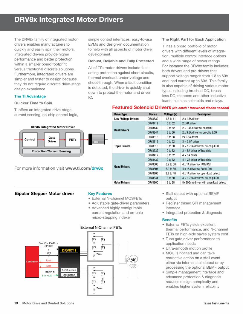
Key Features•External N-channel MOSFETs•Adjustable gate-driver parameters•Advanced highly configurable
current regulation and on-chip micro-stepping indexer
DRV8x Integrated Motor Drivers
2.5 to 10.8V
Step/Dir, PWM or lrtC IPS
FAULT
8 to +52V
SPI Fault Stall
/
/
BEMF
Controller
DRV8711
Stall Detect
1/256 u-step
External N-Channel FETs VM
RISENSE
VM
RISENSE
M
The DRV8x family of integrated motor drivers enables manufacturers to quickly and easily spin their motors. Integrated drivers provide higher performance and better protection within a smaller board footprint versus traditional discrete solutions. Furthermore, integrated drivers are simpler and faster to design because they do not require discrete drive-stage design experience
The TI Advantage
Quicker Time to Spin
TI offers an integrated drive-stage, current sensing, on-chip control logic,
simple control interfaces, easy-to-use EVMs and design-in documentation to help with all aspects of motor drive development.
Robust, Reliable and Fully Protected
All of TI’s motor drivers include fast-acting protection against short circuits, thermal overload, under-voltage and shoot-through. When a fault condition is detected, the driver is quickly shut down to protect the motor and driver IC.
The Right Part for Each Application
TI has a broad portfolio of motor drivers with different levels of integra-tion, multiple control interface options and a wide range of power ratings. For instance the DRV8x family includes both drivers and pre-drivers that support voltage ranges from 1.8 to 60V and load current up to 60A. This family is also capable of driving various motor types including brushed DC, brush-less DC, steppers and other inductive loads, such as solenoids and relays.
GateDriver FETsControl
Protection/Current Sensing
DRV8x Integrated Motor Driver
Featured Solenoid Drivers (No catch / freewheel diodes needed)
DriverType Device Voltage (V) DescriptionLow-Voltage Drivers DRV8839 1.8 to 11 2 x 1.8A driver
Dual Drivers
DRV8412 0 to 52 2 x 6A driver
DRV8432 0 to 52 2 × 14A driver w/ heatsink
DRV8844 8 to 60 2 x 3.5A driver w/ on-chip LDO
DRV8816 8 to 38 2x 2.8A driver
Triple DriversDRV8312 0 to 52 3 × 3.5A driver
DRV8313 8 to 60 3 × 1.75A driver w/ on-chip LDO
DRV8332 0 to 52 3 × 8A driver w/ heatsink
Quad Drivers
DRV8412 0 to 52 4 × 3A driver
DRV8432 0 to 52 4 × 7A driver w/ heatsink
DRV8803 8.2 to 60 4 x 1A driver w/ PWM Ctrl
DRV8804 8.2 to 60 4 x 1A driver w/ Serial Ctrl
DRV8806 8.2 to 40 4 x 1A driver w/ open-load detect
DRV8844 8 to 60 4 × 1.75A driver w/ on-chip LDO
Octal Drivers DRV8860 8 to 38 8x 200mA driver with open load detect
For more information visit www.ti.com/drv8x
Bipolar Stepper Motor driver •Stall detect with optional BEMF output
•Register based SPI management interface
• Integrated protection & diagnosis
Benefits•External FETs yields excellent
thermal performance, and N-channel FETs on high-side saves system cost
•Tune gate driver performance to application needs
•Ultra-smooth motion profile•MCU is notified and can take
corrective action on a stall event either via internal stall detect or by processing the optional BEMF output
•Simple management interface and advanced protection & diagnosis reduces design complexity and enables higher system reliability
Texas Instruments Motor Drive and Control Solutions | 11
Selection Guides for Analog Motor Solutions
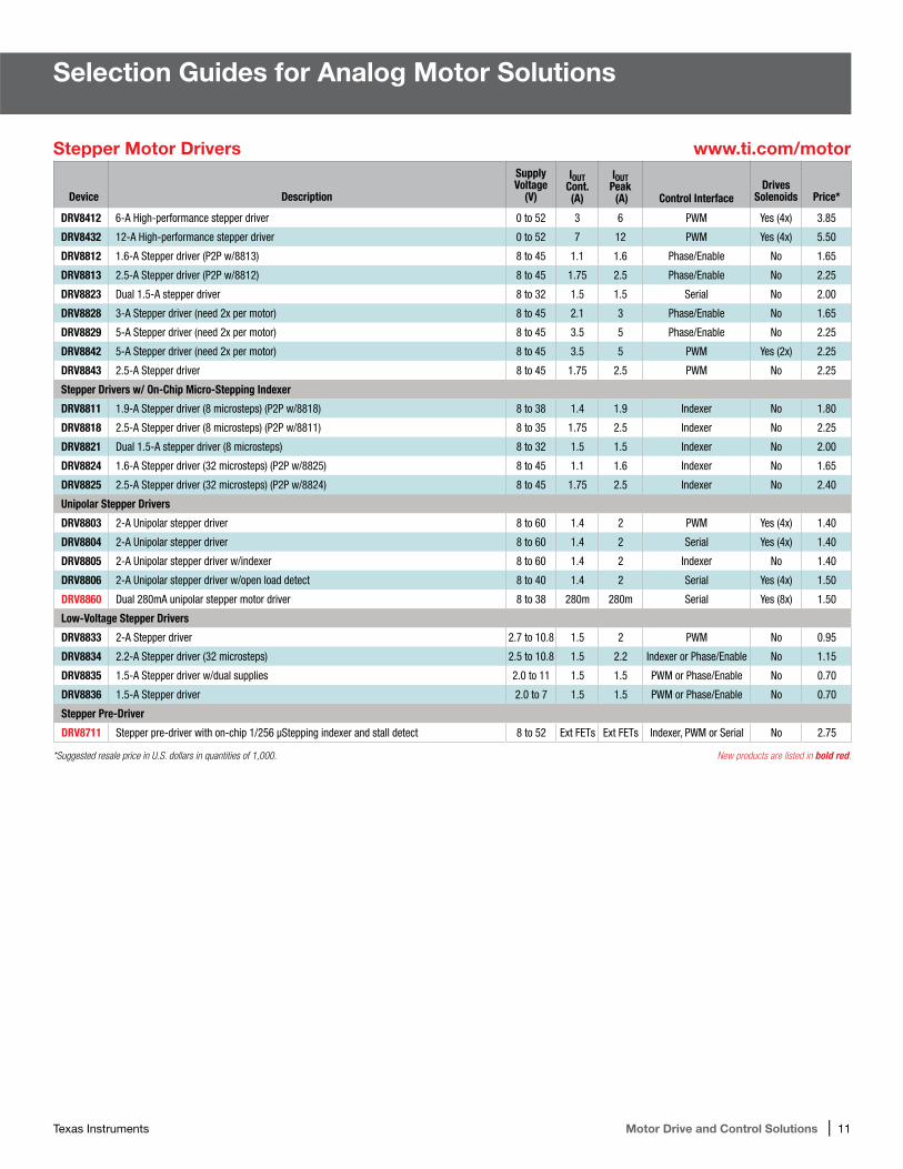
Stepper Motor Drivers www.ti.com/motor
Device Description
Supply Voltage
(V)
IOUT Cont. (A)
IOUT Peak (A) Control Interface
Drives Solenoids Price*
DRV8412 6-A High-performance stepper driver 0 to 52 3 6 PWM Yes (4x) 3.85
DRV8432 12-A High-performance stepper driver 0 to 52 7 12 PWM Yes (4x) 5.50
DRV8812 1.6-A Stepper driver (P2P w/8813) 8 to 45 1.1 1.6 Phase/Enable No 1.65
DRV8813 2.5-A Stepper driver (P2P w/8812) 8 to 45 1.75 2.5 Phase/Enable No 2.25
DRV8823 Dual 1.5-A stepper driver 8 to 32 1.5 1.5 Serial No 2.00
DRV8828 3-A Stepper driver (need 2x per motor) 8 to 45 2.1 3 Phase/Enable No 1.65
DRV8829 5-A Stepper driver (need 2x per motor) 8 to 45 3.5 5 Phase/Enable No 2.25
DRV8842 5-A Stepper driver (need 2x per motor) 8 to 45 3.5 5 PWM Yes (2x) 2.25
DRV8843 2.5-A Stepper driver 8 to 45 1.75 2.5 PWM No 2.25
Stepper Drivers w/ On-Chip Micro-Stepping Indexer
DRV8811 1.9-A Stepper driver (8 microsteps) (P2P w/8818) 8 to 38 1.4 1.9 Indexer No 1.80
DRV8818 2.5-A Stepper driver (8 microsteps) (P2P w/8811) 8 to 35 1.75 2.5 Indexer No 2.25
DRV8821 Dual 1.5-A stepper driver (8 microsteps) 8 to 32 1.5 1.5 Indexer No 2.00
DRV8824 1.6-A Stepper driver (32 microsteps) (P2P w/8825) 8 to 45 1.1 1.6 Indexer No 1.65
DRV8825 2.5-A Stepper driver (32 microsteps) (P2P w/8824) 8 to 45 1.75 2.5 Indexer No 2.40
Unipolar Stepper Drivers
DRV8803 2-A Unipolar stepper driver 8 to 60 1.4 2 PWM Yes (4x) 1.40
DRV8804 2-A Unipolar stepper driver 8 to 60 1.4 2 Serial Yes (4x) 1.40
DRV8805 2-A Unipolar stepper driver w/indexer 8 to 60 1.4 2 Indexer No 1.40
DRV8806 2-A Unipolar stepper driver w/open load detect 8 to 40 1.4 2 Serial Yes (4x) 1.50
DRV8860 Dual 280mA unipolar stepper motor driver 8 to 38 280m 280m Serial Yes (8x) 1.50
Low-Voltage Stepper Drivers
DRV8833 2-A Stepper driver 2.7 to 10.8 1.5 2 PWM No 0.95
DRV8834 2.2-A Stepper driver (32 microsteps) 2.5 to 10.8 1.5 2.2 Indexer or Phase/Enable No 1.15
DRV8835 1.5-A Stepper driver w/dual supplies 2.0 to 11 1.5 1.5 PWM or Phase/Enable No 0.70
DRV8836 1.5-A Stepper driver 2.0 to 7 1.5 1.5 PWM or Phase/Enable No 0.70
Stepper Pre-Driver
DRV8711 Stepper pre-driver with on-chip 1/256 μStepping indexer and stall detect 8 to 52 Ext FETs Ext FETs Indexer, PWM or Serial No 2.75
*Suggested resale price in U.S. dollars in quantities of 1,000. New products are listed in bold red.
12 | Motor Drive and Control Solutions Texas Instruments
Device Description
Supply Voltage
(V)
IOUT Cont. (A)
IOUT Peak (A) Control Interface
Drives Solenoids Price*
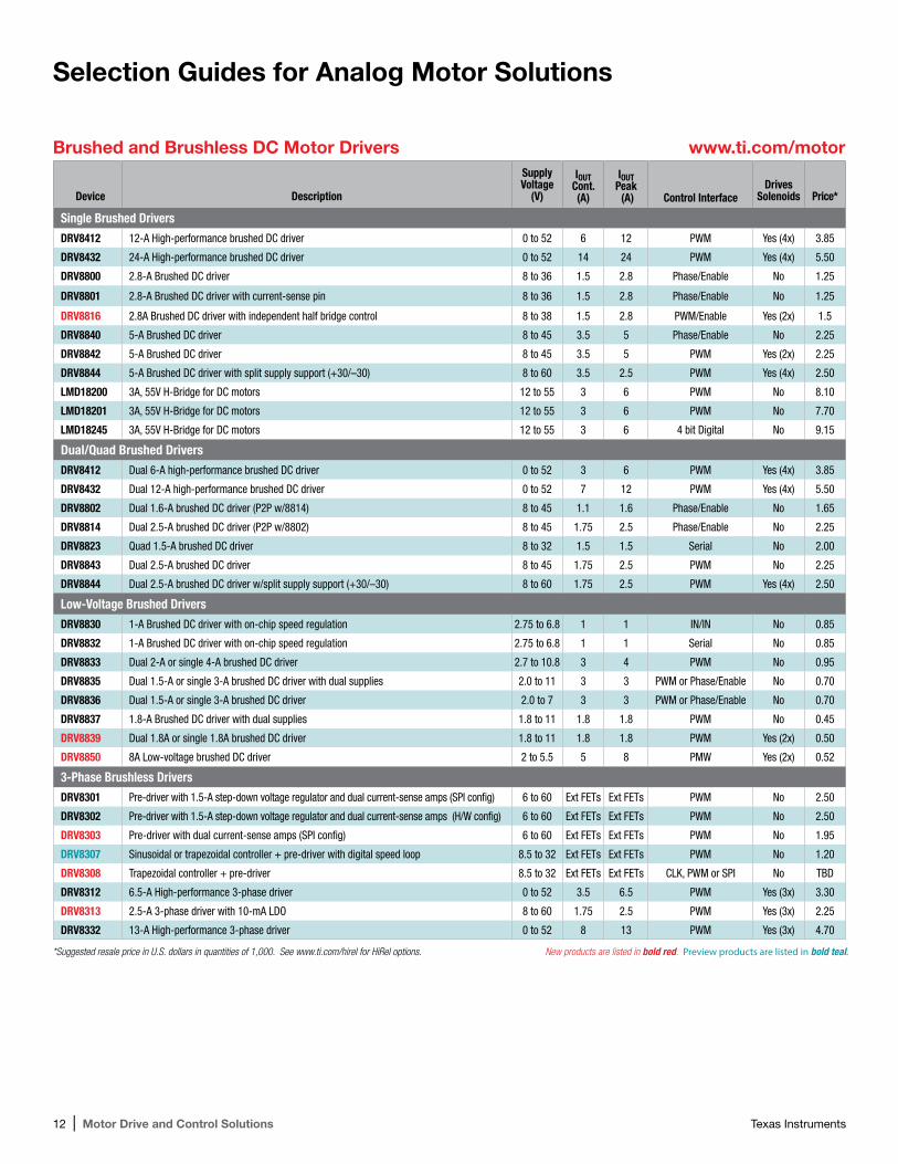
Single Brushed DriversDRV8412 12-A High-performance brushed DC driver 0 to 52 6 12 PWM Yes (4x) 3.85
DRV8432 24-A High-performance brushed DC driver 0 to 52 14 24 PWM Yes (4x) 5.50
DRV8800 2.8-A Brushed DC driver 8 to 36 1.5 2.8 Phase/Enable No 1.25
DRV8801 2.8-A Brushed DC driver with current-sense pin 8 to 36 1.5 2.8 Phase/Enable No 1.25
DRV8816 2.8A Brushed DC driver with independent half bridge control 8 to 38 1.5 2.8 PWM/Enable Yes (2x) 1.5
DRV8840 5-A Brushed DC driver 8 to 45 3.5 5 Phase/Enable No 2.25
DRV8842 5-A Brushed DC driver 8 to 45 3.5 5 PWM Yes (2x) 2.25
DRV8844 5-A Brushed DC driver with split supply support (+30/–30) 8 to 60 3.5 2.5 PWM Yes (4x) 2.50
LMD18200 3A, 55V H-Bridge for DC motors 12 to 55 3 6 PWM No 8.10
LMD18201 3A, 55V H-Bridge for DC motors 12 to 55 3 6 PWM No 7.70
LMD18245 3A, 55V H-Bridge for DC motors 12 to 55 3 6 4 bit Digital No 9.15
Dual/Quad Brushed DriversDRV8412 Dual 6-A high-performance brushed DC driver 0 to 52 3 6 PWM Yes (4x) 3.85
DRV8432 Dual 12-A high-performance brushed DC driver 0 to 52 7 12 PWM Yes (4x) 5.50
DRV8802 Dual 1.6-A brushed DC driver (P2P w/8814) 8 to 45 1.1 1.6 Phase/Enable No 1.65
DRV8814 Dual 2.5-A brushed DC driver (P2P w/8802) 8 to 45 1.75 2.5 Phase/Enable No 2.25
DRV8823 Quad 1.5-A brushed DC driver 8 to 32 1.5 1.5 Serial No 2.00
DRV8843 Dual 2.5-A brushed DC driver 8 to 45 1.75 2.5 PWM No 2.25
DRV8844 Dual 2.5-A brushed DC driver w/split supply support (+30/–30) 8 to 60 1.75 2.5 PWM Yes (4x) 2.50
Low-Voltage Brushed DriversDRV8830 1-A Brushed DC driver with on-chip speed regulation 2.75 to 6.8 1 1 IN/IN No 0.85
DRV8832 1-A Brushed DC driver with on-chip speed regulation 2.75 to 6.8 1 1 Serial No 0.85
DRV8833 Dual 2-A or single 4-A brushed DC driver 2.7 to 10.8 3 4 PWM No 0.95
DRV8835 Dual 1.5-A or single 3-A brushed DC driver with dual supplies 2.0 to 11 3 3 PWM or Phase/Enable No 0.70
DRV8836 Dual 1.5-A or single 3-A brushed DC driver 2.0 to 7 3 3 PWM or Phase/Enable No 0.70
DRV8837 1.8-A Brushed DC driver with dual supplies 1.8 to 11 1.8 1.8 PWM No 0.45
DRV8839 Dual 1.8A or single 1.8A brushed DC driver 1.8 to 11 1.8 1.8 PWM Yes (2x) 0.50
DRV8850 8A Low-voltage brushed DC driver 2 to 5.5 5 8 PMW Yes (2x) 0.52
3-Phase Brushless DriversDRV8301 Pre-driver with 1.5-A step-down voltage regulator and dual current-sense amps (SPI config) 6 to 60 Ext FETs Ext FETs PWM No 2.50
DRV8302 Pre-driver with 1.5-A step-down voltage regulator and dual current-sense amps (H/W config) 6 to 60 Ext FETs Ext FETs PWM No 2.50
DRV8303 Pre-driver with dual current-sense amps (SPI config) 6 to 60 Ext FETs Ext FETs PWM No 1.95
DRV8307 Sinusoidal or trapezoidal controller + pre-driver with digital speed loop 8.5 to 32 Ext FETs Ext FETs PWM No 1.20
DRV8308 Trapezoidal controller + pre-driver 8.5 to 32 Ext FETs Ext FETs CLK, PWM or SPI No TBD
DRV8312 6.5-A High-performance 3-phase driver 0 to 52 3.5 6.5 PWM Yes (3x) 3.30
DRV8313 2.5-A 3-phase driver with 10-mA LDO 8 to 60 1.75 2.5 PWM Yes (3x) 2.25
DRV8332 13-A High-performance 3-phase driver 0 to 52 8 13 PWM Yes (3x) 4.70
Brushed and Brushless DC Motor Drivers www.ti.com/motor
Selection Guides for Analog Motor Solutions
*Suggested resale price in U.S. dollars in quantities of 1,000. See www.ti.com/hirel for HiRel options. New products are listed in bold red. Preview products are listed in bold teal.
Texas Instruments Motor Drive and Control Solutions | 13
Signal Chain SolutionsCurrent-Sense Amplifiers
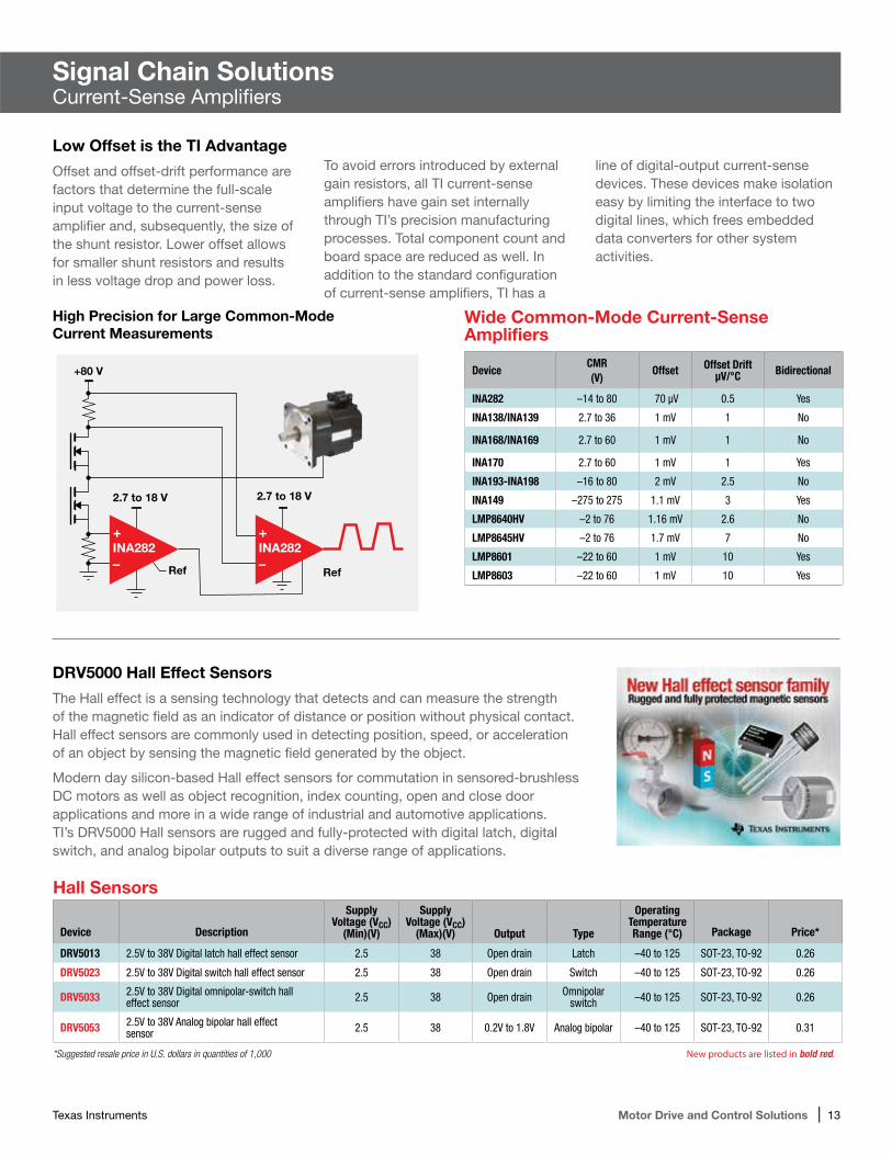
Low Offset is the TI Advantage
Offset and offset-drift performance are factors that determine the full-scale input voltage to the current-sense amplifier and, subsequently, the size of the shunt resistor. Lower offset allows for smaller shunt resistors and results in less voltage drop and power loss.
To avoid errors introduced by external gain resistors, all TI current-sense amplifiers have gain set internally through TI’s precision manufacturing processes. Total component count and board space are reduced as well. In addition to the standard configuration of current-sense amplifiers, TI has a
line of digital-output current-sense devices. These devices make isolation easy by limiting the interface to two digital lines, which frees embedded data converters for other system activities.
High Precision for Large Common-Mode Current Measurements
+80 V
2.7 to 18 V 2.7 to 18 V
RefRef
+INA282–
+INA282–
Wide Common-Mode Current-Sense Amplifiers
DeviceCMR (V)
Offset Offset DriftμV/°C Bidirectional
INA282 –14 to 80 70 μV 0.5 Yes
INA138/INA139 2.7 to 36 1 mV 1 No
INA168/INA169 2.7 to 60 1 mV 1 No
INA170 2.7 to 60 1 mV 1 Yes
INA193-INA198 –16 to 80 2 mV 2.5 No
INA149 –275 to 275 1.1 mV 3 Yes
LMP8640HV –2 to 76 1.16 mV 2.6 No
LMP8645HV –2 to 76 1.7 mV 7 No
LMP8601 –22 to 60 1 mV 10 Yes
LMP8603 –22 to 60 1 mV 10 Yes
Hall Sensors
Device Description
Supply Voltage (VCC)
(Min)(V)
Supply Voltage (VCC)
(Max)(V) Output Type
Operating Temperature Range (°C) Package Price*
DRV5013 2.5V to 38V Digital latch hall effect sensor 2.5 38 Open drain Latch –40 to 125 SOT-23, TO-92 0.26
DRV5023 2.5V to 38V Digital switch hall effect sensor 2.5 38 Open drain Switch –40 to 125 SOT-23, TO-92 0.26
DRV5033 2.5V to 38V Digital omnipolar-switch hall effect sensor 2.5 38 Open drain Omnipolar
switch –40 to 125 SOT-23, TO-92 0.26
DRV5053 2.5V to 38V Analog bipolar hall effect sensor 2.5 38 0.2V to 1.8V Analog bipolar –40 to 125 SOT-23, TO-92 0.31
*Suggested resale price in U.S. dollars in quantities of 1,000 New products are listed in bold red.
DRV5000 Hall Effect Sensors
The Hall effect is a sensing technology that detects and can measure the strength of the magnetic field as an indicator of distance or position without physical contact. Hall effect sensors are commonly used in detecting position, speed, or acceleration of an object by sensing the magnetic field generated by the object.
Modern day silicon-based Hall effect sensors for commutation in sensored-brushless DC motors as well as object recognition, index counting, open and close door applications and more in a wide range of industrial and automotive applications. TI’s DRV5000 Hall sensors are rugged and fully-protected with digital latch, digital switch, and analog bipolar outputs to suit a diverse range of applications.
14 | Motor Drive and Control Solutions Texas Instruments
Signal Chain SolutionsIndustrial Communications
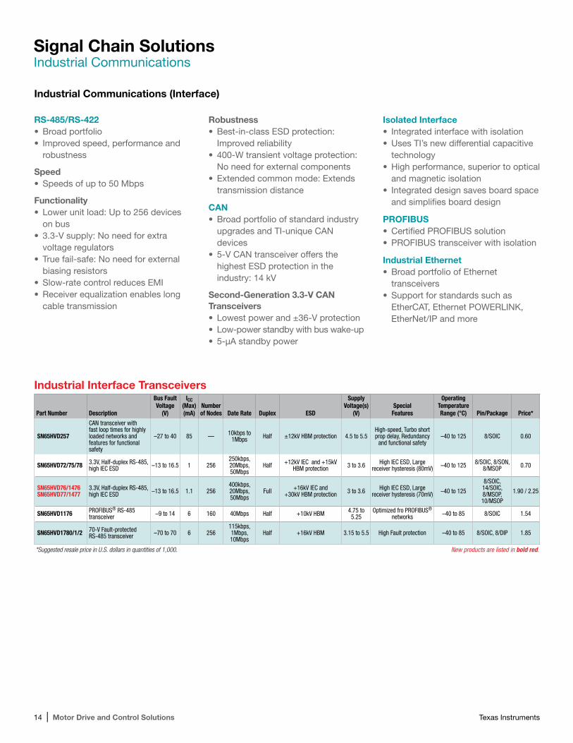
RS-485/RS-422 •Broad portfolio • Improved speed, performance and
robustness
Speed•Speeds of up to 50 Mbps
Functionality• Lower unit load: Up to 256 devices
on bus • 3.3-V supply: No need for extra
voltage regulators•True fail-safe: No need for external
biasing resistors•Slow-rate control reduces EMI•Receiver equalization enables long
cable transmission
Robustness•Best-in-class ESD protection:
Improved reliability• 400-W transient voltage protection:
No need for external components•Extended common mode: Extends
transmission distance
CAN•Broad portfolio of standard industry
upgrades and TI-unique CAN devices
• 5-V CAN transceiver offers the highest ESD protection in the industry: 14 kV
Second-Generation 3.3-V CAN Transceivers• Lowest power and ±36-V protection• Low-power standby with bus wake-up• 5-µA standby power
Isolated Interface• Integrated interface with isolation•Uses TI’s new differential capacitive
technology •High performance, superior to optical
and magnetic isolation • Integrated design saves board space
and simplifies board design
PROFIBUS•Certified PROFIBUS solution•PROFIBUS transceiver with isolation
Industrial Ethernet•Broad portfolio of Ethernet
transceivers•Support for standards such as
EtherCAT, Ethernet POWERLINK, EtherNet/IP and more
Industrial Communications (Interface)
Industrial Interface Transceivers
Part Number Description
Bus Fault Voltage
(V)
ICC (Max) (mA)
Number of Nodes Date Rate Duplex ESD
Supply Voltage(s)
(V)Special
Features
Operating Temperature Range (°C) Pin/Package Price*
SN65HVD257
CAN transceiver with fast loop times for highly loaded networks and features for functional safety
–27 to 40 85 — 10kbps to 1Mbps Half ±12kV HBM protection 4.5 to 5.5
High-speed, Turbo short prop delay, Redundancy
and functional safety–40 to 125 8/SOIC 0.60
SN65HVD72/75/78 3.3V, Half-duplex RS-485, high IEC ESD –13 to 16.5 1 256
250kbps, 20Mbps, 50Mbps
Half +12kV IEC and +15kV HBM protection 3 to 3.6 High IEC ESD, Large
receiver hysteresis (80mV) –40 to 125 8/SOIC, 8/SON, 8/MSOP 0.70
SN65HVD76/1476SN65HVD77/1477
3.3V, Half-duplex RS-485, high IEC ESD –13 to 16.5 1.1 256
400kbps, 20Mbps, 50Mbps
Full +16kV IEC and +30kV HBM protection 3 to 3.6 High IEC ESD, Large
receiver hysteresis (70mV) –40 to 125
8/SOIC, 14/SOIC, 8/MSOP, 10/MSOP
1.90 / 2.25
SN65HVD1176 PROFIBUS® RS-485 transceiver –9 to 14 6 160 40Mbps Half +10kV HBM 4.75 to
5.25Optimized fro PROFIBUS®
networks –40 to 85 8/SOIC 1.54
SN65HVD1780/1/2 70-V Fault-protected RS-485 transceiver –70 to 70 6 256
115kbps, 1Mbps, 10Mbps
Half +16kV HBM 3.15 to 5.5 High Fault protection –40 to 85 8/SOIC, 8/DIP 1.85
*Suggested resale price in U.S. dollars in quantities of 1,000. New products are listed in bold red.
Texas Instruments Motor Drive and Control Solutions | 15
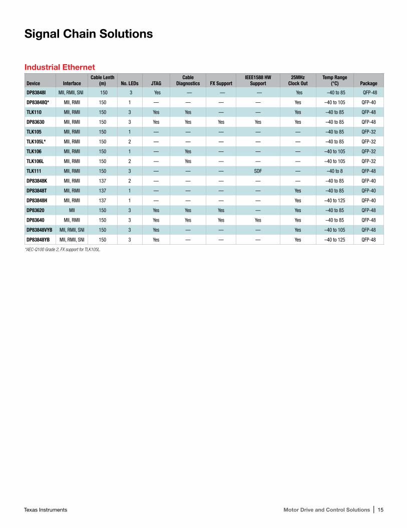
Industrial Ethernet
Device InterfaceCable Lenth
(m) No. LEDs JTAGCable
Diagnostics FX SupportIEEE1588 HW
Support25MHz
Clock OutTemp Range
(°C) Package
DP83848I MII, RMII, SNI 150 3 Yes — — — Yes –40 to 85 QFP-48
DP83848Q* MII, RMII 150 1 — — — — Yes –40 to 105 QFP-40
TLK110 MII, RMII 150 3 Yes Yes — — Yes –40 to 85 QFP-48
DP83630 MII, RMII 150 3 Yes Yes Yes Yes Yes –40 to 85 QFP-48
TLK105 MII, RMII 150 1 — — — — — –40 to 85 QFP-32
TLK105L* MII, RMII 150 2 — — — — — –40 to 85 QFP-32
TLK106 MII, RMII 150 1 — Yes — — — –40 to 105 QFP-32
TLK106L MII, RMII 150 2 — Yes — — — –40 to 105 QFP-32
TLK111 MII, RMII 150 3 — — — SDF — –40 to 8 QFP-48
DP83848K MII, RMII 137 2 — — — — — –40 to 85 QFP-40
DP83848T MII, RMII 137 1 — — — — Yes –40 to 85 QFP-40
DP83848H MII, RMII 137 1 — — — — Yes –40 to 125 QFP-40
DP83620 MII 150 3 Yes Yes Yes — Yes –40 to 85 QFP-48
DP83640 MII, RMII 150 3 Yes Yes Yes Yes Yes –40 to 85 QFP-48
DP83848VYB MII, RMII, SNI 150 3 Yes — — — Yes –40 to 105 QFP-48
DP83848YB MII, RMII, SNI 150 3 Yes — — — Yes –40 to 125 QFP-48
*AEC-Q100 Grade 2, FX support for TLK105L.
Signal Chain Solutions
16 | Motor Drive and Control Solutions Texas Instruments
*Suggested resale price in U.S. dollars in quantities of 1,000. See www.ti.com/hirel for HiRel options. New products are listed in bold red. Preview products are listed in bold teal.
Digital Isolators
Part Number Description
Isolation Rating (Vrms)
Peak Isolation Rating (Vpk)
Working Voltage (Vpk)
Forward /Reverse
Channels
Speed (Max)
(Mbps)
VCC (Min) (V)
VCC (Max)
(V)Default Output
Propagation Delay (Typ)
(ns)
Operating Temperature Range (°C) Pin/Package Price*
ISO7842High-immunity, 5.7kVRMS reinforced quad-channel 2/2 digital isolator, 100Mbps
5700 8061 2121 2/2 100 2.25 5.5 High 11 –55 to 125 16/SOIC 3.49
ISO7342C Robust EMC, low power, quad-channel 2/2 digital isolator 3000 4242 1414 2/2 25 3 5.5 High/Low
(F) 31 –40 to 125 16/SOIC 1.80
ISO7140/1(F)CCISO7142CC
4242-VPK Small-footprint and low-power quad channel digital isolators with noise filter
2500 4242 560 4/0, 3/1, 2/2 50 2.7 5 High/Low (F) 23 –40 to 125 16/SSOP 1.90
ISO7131CC4242-VPK Small-footprint and low-power 2/1 triple channel digital isolator with noise filter
2500 4242 560 2/1 50 2.7 5 Low 23 –40 to 125 16/SSOP 1.60
Signal Chain Solutions
Digital Isolators
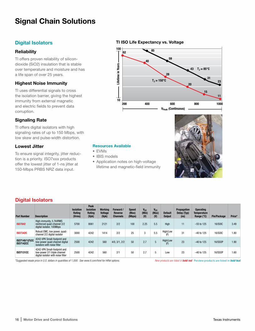
Reliability
TI offers proven reliability of silicon- dioxide (SiO2) insulation that is stable over temperature and moisture and has a life span of over 25 years.
Highest Noise Immunity
TI uses differential signals to cross the isolation barrier, giving the highest immunity from external magnetic and electric fields to prevent data corruption.
Signaling Rate
TI offers digital isolators with high signaling rates of up to 150 Mbps, with low skew and pulse-width distortion.
Lowest Jitter
To ensure signal integrity, jitter reduc-tion is a priority. ISO7xxx products offer the lowest jitter of 1-ns jitter at 150-Mbps PRBS NRZ data input.
Resources Available•EVMs• IBIS models•Application notes on high-voltage
lifetime and magnetic-field immunity
100
200VPeak (Continuous)
Life
time
in Y
ears
600 100080040010
62
40
85
59
43 TJ = 85°C
TJ = 150°C31
23
28
20
1511
TI ISO Life Expectancy vs. Voltage
Texas Instruments Motor Drive and Control Solutions | 17
Signal Chain Solutions
Isolated IGBT Gate Drivers
Part Number DescriptionIsolation Rating
(Vrms)
Input VCC (Min)
(V)
Input VCC (Max)
(V)
Output VCC (Min) (V)
Output VCC (Max)
(V)
Output Current (Min)(A)
Propagation Delay (Max)
(ns)
Operating Temperature Range (°C) Pin/Package Price*
ISO5500 2.5-A isolated IGBT/MOSFET gate driver 3 3 5.5 15 30 2.5 300 –40 to 125 16/SOIC 3.00
*Suggested resale price in U.S. dollars in quantities of 1,000
μC
PWM
FAULT
M3-PhaseInput
ISO 5500
ISO 5500
ISO 5500
ISO 5500
ISO 5500
ISO 5500
Isolation Barrier
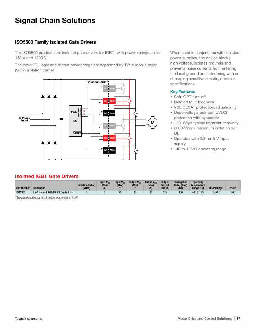
When used in conjunction with isolated power supplies, the device blocks high voltage, isolates grounds and prevents noise currents from entering the local ground and interfering with or damaging sensitive circuitry.dards or specifications.
Key Features•Soft IGBT turn-off• Isolated fault feedback•VCE DESAT protection/adjustability•Undervoltage lock-out (UVLO)
protection with hysteresis•±50-kV/µs typical transient immunity• 6000-Vpeak maximum isolation per
UL•Operates with 3.3- or 5-V input
supply• –40 to 125°C operating range
ISO5500 Family Isolated Gate Drivers
TI’s ISO5500 products are isolated gate drivers for IGBTs with power ratings up to 150 A and 1200 V.
The input TTL logic and output power stage are separated by TI’s silicon- dioxide (SiO2) isolation barrier
18 | Motor Drive and Control Solutions Texas Instruments
Signal Chain SolutionsDiscrete Analog-to-Digital Converters (ADCs)
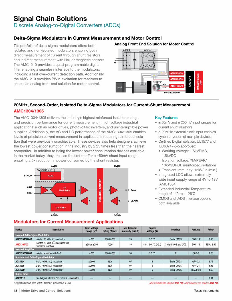
TI’s portfolio of delta-sigma modulators offers both isolated and non-isolated modulators enabling both direct measurement of current through shunt resistors and indirect measurement with Hall or magnetic sensors. The AMC1210 provides a quad-programmable digital filter enabling a seamless interface to the modulators, including a fast over-current detection path. Additionally, the AMC1210 provides PWM excitation for resolvers to enable an analog front-end solution for motor control.
Delta-Sigma Modulators in Current Measurement and Motor Control
TM
S32
0F28
0xx
DS
P
AMC1203/4
AMC1203/4
ADS1205/9 AM
C12
10
PWM Excitation
Resolversincos
InverterAC/DC
UV
W
Load
Modulators for Current Measurement Applications
Device Description Input Voltage Range (mV)
Isolation Rating (Vpeak)
Min Transient Immunity (kV/uS)
Supply Voltage (V) Interface Package Price*
Isolated Delta-Sigma Modulator
AMC1204/1204B Isolated 20 MHz ∆∑ modulator ±250 4000/4250 15 3.3 / 5 Serial CMOS SOIC-16 3.45
AMC1304/05 Isolated 20 MHz ∆∑ modulator with reinforced isolation ±50 or ±250 7000 15 4.0-18.0 / 3.0-5.5 Serial CMOS and LVDS SOIC-16 TBD / 3.50
Isolated AmplifierAMC1200/1200B Isolated amplifier with G=8 ±250 4000/4250 10 3.3 / 5 N SOP-8 2.20
Non-Isolated Delta-Sigma Modulator
ADS1204 4-ch, 10 MHz ∆∑ modulator ±2000 N/A N/A 5 Serial CMOS QFN-32 6.75
ADS1205 2-ch, 10 MHz ∆∑ modulator ±2000 N/A N/A 5 Serial CMOS QFN-24 4.95
ADS1209 2-ch, 10 MHz ∆∑ modulator ±2300 N/A N/A 5 Serial CMOS TSSOP-24 4.50
Digital Filter
AMC1210 Quad digital filter for 2nd-order ∆∑ modulator — — — — — — 1.34
Analog Front End Solution for Motor Control
Key Features• ± 50mV and ± 250mV input ranges for
current shunt resistors• 5-20MHz external clock input enables
synchronization of multiple devices• Certified Digital Isolation: UL1577 and
IEC60747-5-5 approved:Working voltage: 1.5kVRMS, 1.5kVDCIsolation voltage: 7kVPEAK/ 10kVSURGE (reinforced isolation)Transient Immunity: 15kV/µs (min.)
• Integrated LDO allows extremely wide input supply range of 4V to 18V (AMC1304)
•Extended Industrial Temperature range of –40 to +125˚C
• CMOS and LVDS interface options both available
20MHz, Second-Order, Isolated Delta-Sigma Modulators for Current-Shunt MeasurementAMC1304/1305
The AMC1304/1305 delivers the industry’s highest reinforced isolation ratings and precision performance for current measurement in high voltage industrial applications such as motor drives, photovoltaic inverters, and uninterruptible power supplies. Additionally, the AC and DC performance of the AMC1304/1305 enables levels of precision current measurement in applications requiring reinforced isola-tion that were previously unachievable. These devices also help designers achieve the lowest power consumption in the industry by 2.25 times less than the nearest competitor. In addition to being the lowest power consumption devices available in the market today, they are also the first to offer a ±50mV shunt input range – enabling a 5x reduction in power consumed by the shunt resistor.
*Suggested resale price in U.S. dollars in quantities of 1,000. New products are listed in bold red. New products are listed in bold red.
AGND DGND
AVDD
AMC1304 Only
LDO_IN
AINPData
CLKIN
AINN
DVDD
ISO
LAT
ION
BA
RR
IER
2.5V REF
ΔΣModulator
LDO
Texas Instruments Motor Drive and Control Solutions | 19
Signal Chain SolutionsDiscrete Analog-to-Digital Converters (ADCs)
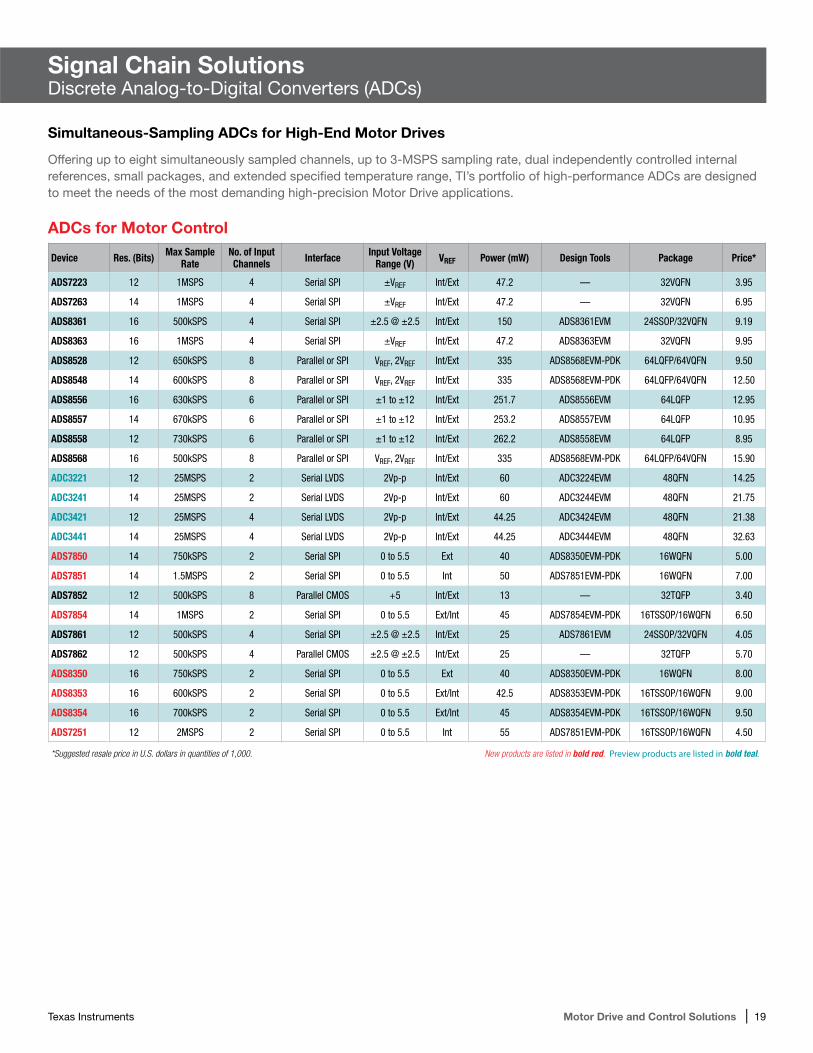
Simultaneous-Sampling ADCs for High-End Motor Drives
ADCs for Motor Control
Device Res. (Bits) Max Sample Rate
No. of Input Channels Interface Input Voltage
Range (V) VREF Power (mW) Design Tools Package Price*
ADS7223 12 1MSPS 4 Serial SPI ±VREF Int/Ext 47.2 — 32VQFN 3.95
ADS7263 14 1MSPS 4 Serial SPI ±VREF Int/Ext 47.2 — 32VQFN 6.95
ADS8361 16 500kSPS 4 Serial SPI ±2.5 @ ±2.5 Int/Ext 150 ADS8361EVM 24SSOP/32VQFN 9.19
ADS8363 16 1MSPS 4 Serial SPI ±VREF Int/Ext 47.2 ADS8363EVM 32VQFN 9.95
ADS8528 12 650kSPS 8 Parallel or SPI VREF, 2VREF Int/Ext 335 ADS8568EVM-PDK 64LQFP/64VQFN 9.50
ADS8548 14 600kSPS 8 Parallel or SPI VREF, 2VREF Int/Ext 335 ADS8568EVM-PDK 64LQFP/64VQFN 12.50
ADS8556 16 630kSPS 6 Parallel or SPI ±1 to ±12 Int/Ext 251.7 ADS8556EVM 64LQFP 12.95
ADS8557 14 670kSPS 6 Parallel or SPI ±1 to ±12 Int/Ext 253.2 ADS8557EVM 64LQFP 10.95
ADS8558 12 730kSPS 6 Parallel or SPI ±1 to ±12 Int/Ext 262.2 ADS8558EVM 64LQFP 8.95
ADS8568 16 500kSPS 8 Parallel or SPI VREF, 2VREF Int/Ext 335 ADS8568EVM-PDK 64LQFP/64VQFN 15.90
ADC3221 12 25MSPS 2 Serial LVDS 2Vp-p Int/Ext 60 ADC3224EVM 48QFN 14.25
ADC3241 14 25MSPS 2 Serial LVDS 2Vp-p Int/Ext 60 ADC3244EVM 48QFN 21.75
ADC3421 12 25MSPS 4 Serial LVDS 2Vp-p Int/Ext 44.25 ADC3424EVM 48QFN 21.38
ADC3441 14 25MSPS 4 Serial LVDS 2Vp-p Int/Ext 44.25 ADC3444EVM 48QFN 32.63
ADS7850 14 750kSPS 2 Serial SPI 0 to 5.5 Ext 40 ADS8350EVM-PDK 16WQFN 5.00
ADS7851 14 1.5MSPS 2 Serial SPI 0 to 5.5 Int 50 ADS7851EVM-PDK 16WQFN 7.00
ADS7852 12 500kSPS 8 Parallel CMOS +5 Int/Ext 13 — 32TQFP 3.40
ADS7854 14 1MSPS 2 Serial SPI 0 to 5.5 Ext/Int 45 ADS7854EVM-PDK 16TSSOP/16WQFN 6.50
ADS7861 12 500kSPS 4 Serial SPI ±2.5 @ ±2.5 Int/Ext 25 ADS7861EVM 24SSOP/32VQFN 4.05
ADS7862 12 500kSPS 4 Parallel CMOS ±2.5 @ ±2.5 Int/Ext 25 — 32TQFP 5.70
ADS8350 16 750kSPS 2 Serial SPI 0 to 5.5 Ext 40 ADS8350EVM-PDK 16WQFN 8.00
ADS8353 16 600kSPS 2 Serial SPI 0 to 5.5 Ext/Int 42.5 ADS8353EVM-PDK 16TSSOP/16WQFN 9.00
ADS8354 16 700kSPS 2 Serial SPI 0 to 5.5 Ext/Int 45 ADS8354EVM-PDK 16TSSOP/16WQFN 9.50
ADS7251 12 2MSPS 2 Serial SPI 0 to 5.5 Int 55 ADS7851EVM-PDK 16TSSOP/16WQFN 4.50
*Suggested resale price in U.S. dollars in quantities of 1,000. New products are listed in bold red. Preview products are listed in bold teal.
Offering up to eight simultaneously sampled channels, up to 3-MSPS sampling rate, dual independently controlled internal references, small packages, and extended specified temperature range, TI’s portfolio of high-performance ADCs are designed to meet the needs of the most demanding high-precision Motor Drive applications.
20 | Motor Drive and Control Solutions Texas Instruments
LDO Linear Regulators
Part Number Description Output Options
IOUT (Max)
(A)
VIN (Min) (V)
VIN (Max)
(V)
VOUT (Min) (V)
VOUT (Max)
(V)
Iq (Typ) (mA)
Vdo (Typ) (mV)
Noise (uVrms) Additional Features
Operating Temperature Range (°C)
Pin/Package Price*
TPS7A3001 VIN 3V to 36V, 150mA, ultra-low noise, high PSRR, low-dropout linear regulator
Adjustable output, Negative output 0.2 –36 –3 –33 –1.2 0.05 216 15
Enable, Overcurrent protection, Soft start, Thermal shutdown,
Fast transient response –40 to 125 MSOP-
PowerPAD 1.50
TPS7A4901 VIN –3V to –36V, –200mA, ultra-low noise, high PSRR, low-dropout linear regulator Adjustable output 0.15 3 36 1.2 33 0.06 260 15
Enable, Overcurrent protection, Soft start, Thermal shutdown,
Fast transient response –40 to 125 MSOP-
PowerPAD 1.10
TPS70933 150-mA, 30-V, 1-µA IQ voltage regulator with enable Fixed output 0.15 2.7 30 3.3 3.3 0.001 300 —
Enable, Overcurrent protection, Soft start, Thermal shutdown,
Fast transient response–40 to 125 SON/
SOT-23 0.39
TLV73333PCapacitor-free, 300-mA, low-dropout regulator with foldback current limit
Fixed output 0.3 1.4 5.5 3.3 3.3 0.034 122 — Enable, Foldback overcurrent protection, Output discharge,
Thermal shutdown— — —
TPS75005 Dual, 500mA low-dropout regulators and triple voltage rail monitor
Adjustable output, Fixed outputs 1.8, 1.9, 3.3
0.5 4 6.5 Fixed outputs
Fixed outputs 0.175 300 —
Enable, Over current protection, Thermal shutdown, PG, Sequencing
and monitoring, Soft start–40 to 125 20/VQFN 1.90
LP5907 250mA, Ultra-low noise low-dropout regulator Fixed output 0.25 2.2 5.5 1.2 4.5 0.012 50 6.5
Enable, Overcurrent protection, Thermal shutdown, Output discharge
–40 to 125 DSBGA/SOT-23/X2SON
0.14
LP38691 500mA Low dropout CMOS linear regulators Fixed output 0.5 2.7 10 1.8 5 0.055 250 —
Enable, Overcurrent protection, Thermal shutdown,
Foldback overcurrent protection –40 to 125 TO-252/
WSON 0.50
*Suggested resale price in U.S. dollars in quantities of 1,000. New products are listed in bold red. Preview products are listed in bold teal.
Window Comparator
Part Number Description
Vs (Min)
(V)
Vs (Max)
(V)
tRESP Low-to-High (µs)
Vos (Offset Voltage @ 25
(°C) (Max) (mV)
Iq per Channel (Max) (mA)
Output Type
Input Bias
Current (±)
(Max) (nA)
Number of Channels Special Features
Rail-Rail
Operating Temperature Range (°C)
Pin/Package Price*
LMV762 Low voltage, precision comparator with push-pull output 2.7 5 0.12 1 0.7 Push-pull 0.005 2 — — –40 to 125 8/SOIC,
8/VSSOP 0.85
TPS3700 High-voltage (18V) window comparator with over- and undervoltage detection 1.8 18 29 5.5 0.013 Open
drain 25 1 Hysteresis, Internal reference, Window comparator In –40 to 125 6/SOT,
6/WSON 0.70
.
Selection Guides for Power Management Solutions
Input Power Protection
Part Number DescriptionVIN (Min)
(V)VIN (Max)
(V)Current Limit Threshold (A) Enable Fault Response Special Features
Operating Temperature Range (°C) Pin/Package Price*
LM5060 High-side protection controller with low quiescent current 5.5 65 Externally
adjustable Yes Latch off No external RSENSE –40 to 125 10/VSSOP 1.09
LM5069 Positive high voltage hot swap / Inrush current controller with power limiting
9 80 Externally adjustable Yes Latch off/Retry Reverse hookup
protection –40 to 125 10VSSOP 1.47
TPS24750/1 12A Integrated hot-swap protector with current monitor 2.5 18 Externally
adjustable Yes Latch off/Retry Programmable fault timer –40 to 85 36VQFN 1.65
Texas Instruments Motor Drive and Control Solutions | 21
AC/DC (Offline) Chargers/Auxilliary Power Supplies
Part Number Description Features
Operating Temperature Range (°C) Pin/Package Price*
UCC28700/01/02/03 Constant voltage, constant current PWM Controller with primary-side regulation
<30mW no load power for 5 star EC IPP rating, Primary Side Regulation (PSR) eliminates opto-coupler, Quasi-resonant valley switching operation for highest overall efficiency –20 to 125 6/SOT-23 0.35
UCC28710/11/12/13/14/15Constant voltage, constant current PWM controller with primary-side regulation with high voltage startup
<10mW no load power, Internal 700V HV Start-up JFET, Primary Side Regulation (PSR) eliminates opto-coupler, Quasi-resonant valley switching operation for highest overall efficiency
–40 to 125 7/SOIC 0.42
UCC28630 CCM/DCM with primary-side CV and CC regulation
Primary Side Regulation (PSR) eliminates opto-coupler, X-capacitor discharge for improved standby power, Best in class 10% efficiency performance — >86% for 65W, Integrated 700V JFET for fast startup and low standby power
–40 to 125 7/VSSOP 0.60
LM5021Highly efficient off-line single-ended flyback and forward power converter using current-mode control
Ultra low start-up current (25 µA maximum), Current mode control, Skip cycle mode for low standby power, Single resistor programmable oscillator, Synchronizable oscillator –40 to 125 8/VSSOP 0.50
LM5023 Quasi-resonant current mode PWM AC/DC controller
1% Voltage output regulation over line, Load, temp, Low power operation: skip mode for low standby power <10mW at 230VAC, Critical conduction mode control, ±5% Current limit accuracy over PVT, Peak current mode control when operating in CV operation
–40 to 125 8/VSSOP 0.38
LM5030 100V push pull converter Current control mode, Shutdown feature to incorporate STO functionality, Operates from 24V supply, Defined dead time to avoid cross conduction –40 to 125 10/VSSOP 0.99
LM5032 High voltage dual interleaved current mode controller
Two independent PWM current mode controllers, Integrated high voltage startup regulator –40 tp 125 16/VSSOP 1.40
*Suggested resale price in U.S. dollars in quantities of 1,000.
Selection Guides for Analog Motor Solutions
DC/DC Regulators www.ti.com/motor
Part Number Description
VIN (Min)
(V)
VIN (Max)
(V)
VOUT (Min)
(V)
VOUT (Max)
(V)IOUT (A) Topology
Switch Current
Limit (Typ) (A)
Iq (Typ) (mA)
Duty Cycle (Max) (%) Soft Start Compensation Special Features
Operating Temperature Range (°C)
Pin/Package Price*
TPS550102.95V to 6V Input, 2W, isolated DC/DC converter with integrated FETs
2.95 6 3.3 20 0.4 Fly-buck 2.75 0.575 — Adjustable External
Enable, Synchronous rectification, Isolated,
Power good, Frequency synchronization
–40 to 150 16/WQFN 0.99
TPS62404Dual, 400mA and 600mA, 2.25MHz step-down converter with 1-wire interface in QFN
2.5 6 1.2 1.9 0.4Buck,
Synchronous buck
1 0.032 100 Fixed Internal Enable, Light load efficiency –40 to 85 10/SON 0.90
TPS62150 3V to17V 1A Step-down converter with DCS-control™ 3 17 0.9 6.3 1
Buck, Synchronous
buck1.7 0.017 100 Adjustable Internal
Enable, Light load efficiency, Power good,
Tracking, Voltage margining–40 to 85 16/QFN 0.98
LMZ340024.5V to 40V Input, up to 15W negative-output integrated power solution
4.5 40 –3 –17 2Boost,
Synchronous buck module
3 — — Adjustable External
Integrated inductor, EMI tested, Negative output, Soft start, Overcurrent
protection, Remote sense, External clock sync
–40 to 85 41B1QFN 6.75
TPS40210 Wide input range current mode boost controller 4.5 52 5 260 6 Boost NA 1.5 95 Adjustable Internal Enable, Frequency
synchronization –40 to 12510/MSOP-PowerPAD,
10/SON0.80
TPS54160A3.5V to 60V Input, 1.5A step-down converter with eco-mode
3.5 60 0.8 58 1.5Buck,
Inverting buck boost
1.8 0.116 98 Adjustable External
Enable, Frequency synchronization, Light load
efficiency, Power good, Tracking
–40 to 15010/MSOP-PowerPAD,
10/SON1.58
TPS540614.7V to 60V Input, 200mA synchronous step-down converter
4.7 60 0.8 58 0.2Buck,
Inverting buck boost
0.35 0.09 98 Fixed External
Adjustable UVLO, Enable, Frequency synchronization,
Light load efficiency, Synchronous rectification
–40 to 150 8/SON, 1.04
TPS542603.5V to 60V Input, 2.5A step-down converter with eco-mode
3.5 60 0.8 58 2.5Buck,
Inverting buck boost
3.5 0.138 98 Adjustable External
Enable, Frequency synchronization, Light load
efficiency, Power good, Tracking
–40 to 15010/MSOP-PowerPAD,
10/SON1.86
TPS54361 4.5V to 60V Input, 3.5A step-down converter 4.5 60 0.8 59 3.5 Buck 5.5 0.152 98 Adjustable External
Enable, Frequency Synchronization, Light Load
Efficiency, Power Good, Tracking, Adjustable UVLO
–40 to 150 10/WSON 2.60
TPS55340Wide input range boost/SEPIC/flyback DC/DC converter with integrated FET
2.9 32 3 38 2 Boost, SEPIC, Flyback 6.6 0.5 90 Adjustable External
Enable, Frequency synchronization,
Light load efficiency–40 to 150 14/HTSSOP,
16/WQFN 1.85
LM5017Family of 100V regulators enhance reliability for high-voltage systems
7.5 100 1.25 90 0.6 Fly-buck 1.3 1.75 90 ExternalNo
compensation needed
Intelligent current limit, Primary-side fly-buck
regulation–40 to 125
8/SO PowerPAD, 8/WSON
1.57
22 | Motor Drive and Control Solutions Texas Instruments
Selection Guides for Analog Motor Solutions
Non-Isolated Gate Drivers
Part Number DescriptionDriver
Configuration
Peak Source/Sink Output
Current (A)
VCC (Min)(V)
VCC (Max) (V)
Rise Time (ns)
Fall Time (ns)
Prop Delay (ns)
Input Threshold
Operating Temperature Range (°C)
Pin/ Package Price*
UCC27531 2.5-A and 5-A, 35-VMAX VDD FET and IGBT single-gate drive
Single, Non-inverting 2.5/5 10 35 15 7 17 TTL –40 to 140 6/SOT-23 0.75
UCC27511 4A/8A Single-channel high-speed low-side gate driver
Single inverting, Non-inverting 4/8 4.5 18 9 7 13 TTL –40 to 140 6/SOT-23 0.52
UCC27517A4A/4A Single-channel high-speed low-side gate driver with 5V negative input voltage handling ability
Single inverting, Non-inverting 4/4 4.5 18 9 7 13 TTL –40 to 140 5/SOT-23 0.49
UCC27524ADual, 5A, high-speed low-side power MOSFET driver with negative input voltage ability
Dual, Non-inverting 5/5 4.5 18 7 7 14 TTL –40 to 140 8/MSOP-PowerPAD,
8/SOIC 0.75
UCC27511 Single-channel high-speed low-side gate driver with split output
Inverting,Non-inverting 4/8 4.5 18 9 7 13 TIL –40 to 140 6/SOT-23 0.75
UCC27517A
Single-channel 4A high-speed, low-side gate driver with inverting or non-inverting configuration with 5V negative input voltage handling ability
Inverting,Non-inverting 4/4 4.5 18 9 7 13 TIL –40 to 140 5/SOT-23 0.52
UCC27518/19 Single-channel 4A high-speed, low-side gate driver with CMOS input
Inverting (18), Non-inverting (19) 4/4 4.5 18 9 7 13 CMOS –40 to 140 5/SOT-23 0.49
UCC27524ADual-channel 5A high-speed, low-side gate driver with negative input voltage capability
Dual,Non-inverting 5/5 4.5 18 7 7 14 TIL –40 to 140 8/MSOP,
8/SOIC 0.75
UCC27531/32
Single-channel 2.5A/5A, 35V max VDD FET and IGBT gate driver with split output and with 5V negative input voltage handling ability (32 includes CMOS input)
Non-inverting 2.5/5 10 35 15 7 17 TIL / 31 CMOS / 32 –40 to 140 6/SOT-23 0.75
LM5112 Tiny 7A single channel MOSFET gate driver
Inverting,Non-inverting 3/7 3.5 14 14 12 25 TIL –40 to 125 6/WSON 0.45
UCC27201A/211A120V boot, 3A/4A peak (201A/211A), High frequency, high-side/low-side driver with negative voltage handling
High side,Low side
3/3 / 201A4/4 / 211A
8 / 201A7.8 / 211A 20 8 7 20 TTL –40 to 140
10/WSON / 201A,8/SOIC / 201A/211A,
8/SO PowerPAD / 201A,8/VSON/201A / 211A,
9/SON / 201A
1.30/ 201A
1.50/ 211A
LM5104/5/6 High voltage bridge gate drivers with programmable dead-time control Bridge 2 7.5 14 10 / 4/5
15 / 6 10 35 / 4/532 / 6 TTL –40 to 125 8/SOIC,
8/WSON
1.10 / 4 0.90 / 5 0.64 / 6
LM5109 100V boot, 1A peak, high frequency, high-side/low-side driver
High side,Low side 1/1 7.5 14 15 15 25 TTL –40 to 125 8/SOIC,
8/WSON 0.50
Voltage Monitor and Reset ICs
Part Number Description
# of Supplies
Monitored
VCC (min)
(V)
VCC (max)
(V)
Iq (typ) (uA)
Threshold Voltage (typ) (V)
Operating Temperature Range (°C)
Output Driver Type/Reset
Output Special
Features
Time Delay (ms) Pin/Package Price*
TPS3700 Window comparator for over- and undervoltage detection 2 1.8 18 5.5 Adjustable –40 to 125 Active-low/
Open-drain Over voltage sense 0 6SOT/6WSON 0.69
TPS3847085 18-V, 380-nA Voltage monitor 1 4.5 18 0.38 Fixed: 8.5 –40 to 85 Active-low/Push-pull Manual reset 5 5SOT-23 0.79
TPS386000 Quad supply voltage supervisor with adjustable delay and watchdog timer 4 1.8 6.5 12 Adjustable –40 to 125 Active-low/
Open-drain
Manual reset/Negative voltage monitoring/Over voltage sense/
Watchdog timer
20/300/Programmable 20QFN 0.95
TPS3808 Low quiescent current, programmable-delay 1 1.7 6.5 2.4
Adjustable, Fixed: 0.84, 1.12, 1.16, 1.40, 1.67, 1.77, 2.33, 2.79, 3.07,
4.65
–40 to 125 Active-low/Open-drain Manual reset Programmable 6SON/6SOT-23 0.68
TPS3831A09 Supervisory circuit 1 0.6 6.5 0.15Fixed: 0.9, 1.1, 1.52,
1.67, 2.63, 2.93, 3.08, 4.38
–40 to 85 Active-low/Push-pull Manual reset 200 4X2SON 0.30
*Suggested resale price in U.S. dollars in quantities of 1,000. New products are listed in bold red.
Texas Instruments Motor Drive and Control Solutions | 23
NexFET Power MOSFETN-Channel
Single N-Channel
DeviceVDS(V)
VGS(V)
VGS(TH)Typ(V)
ID Max @ TC= 25°C
(A)
RDS(ON) @ VGS =
10V (mΩ)QG
(nC)
QGDTyp (nC)
QGS(nC) Configuration Package
Operating Temp Range
(°C)
CSD18501Q5A 40 20 1.8 155 2.5 42 5.9 8.1 Single SON5x6 –55 to 150
CSD18502KCS 40 20 1.8 200 2.4 52 8.4 10.3 Single SON5x6 –55 to 150
CSD18502Q5B 40 20 1.8 204 1.8 52 8.4 10.3 Single SON5x6 —
CSD18503KCS 40 20 1.9 130 3.6 30 4.6 7.7 Single SON5x6 –55 to 150
CSD18503Q5A 40 20 1.8 145 3.4 26 4.3 4.5 Single SON5x6 –55 to 150
CSD18504KCS 40 20 1.9 85 5.5 19 3.5 4.4 Single TO-220 –55 to 150
CSD18504Q5A 40 20 1.8 75 5.3 16 2.4 3.2 Single TO-220 –55 to 150
CSD18509Q5B 40 20 1.9 299 1 150 17 29 Single TO-220 —
CSD18531Q5A 60 20 1.8 134 3.5 36 5.9 6.9 Single TO-220 –55 to 150
CSD18532KCS 60 20 1.8 169 3.3 44 6.9 10 Single TO-220 –55 to 150
CSD18532NQ5B 60 20 2.8 163 2.7 49 7.9 16 Single TO-220 –55 to 150
CSD18532Q5B 60 20 1.8 172 2.5 44 10 Single TO-220 –55 to 150
CSD18533KCS 60 20 1.9 114 5 28 3.9 9.4 Single SON5x6 –55 to 150
CSD18533Q5A 60 20 1.9 103 4.7 29 5.4 6.6 Single SON5x6 –55 to 150
CSD18534KCS 60 20 1.9 71 7.6 19 3.1 4.8 Single SON5x6 –55 to 150
CSD18534Q5A 60 20 1.9 69 7.8 17 3.5 3.2 Single SON5x6 –55 to 150
CSD18537NKCS 60 20 3 54 11 14 2.3 5.2 Single SON5x6 –55 to 150
CSD18537NQ5A 60 20 3 62 10 14 2.3 4.7 Single SON5x6 –55 to 150
CSD18540Q5B 60 20 1.9 221 1.8 41 6.7 8.8 Single SON5x6 —
CSD18563Q5A 60 20 2 91 5.7 15 2.9 3.3 Single SON5x6 –55 to 150
CSD19501KCS 80 20 2.6 121 5.5 38 5.8 12.4 Single SON5x6 –55 to 175
CSD19502Q5B 80 20 2.7 138 3.4 48 8.6 14 Single TO-220 –55 to 150
CSD19503KCS 80 20 2.8 94 7.6 28 5.4 9.8 Single TO-220 –55 to 150
CSD19505KCS 80 20 2.6 208 2.6 76 11 25 Single TO-220 –55 to 175
CSD19506KCS 80 20 2.5 273 2 120 20 37 Single TO-220 –55 to 175
CSD19531KCS 100 20 2.7 105 6.4 38 7.5 11.9 Single TO-220 –55 to 175
CSD19531Q5A 100 20 2.7 110 5.3 37 6.6 10.5 Single TO-220 –55 to 150
CSD19532Q5B 100 20 2.6 124 4 48 8.7 13 Single TO-220 –55 to 150
CSD19533KCS 100 20 2.8 86 8.7 27 5.4 9 Single TO-220 –55 to 175
CSD19533Q5A 100 20 2.8 75 7.6 27 4.9 7.9 Single SON5x6 –55 to 150
CSD19534Q5A 100 20 2.8 44 12.6 17 3.2 5.1 Single SON5x6 –55 to 150
CSD19535KCS 100 20 2.7 187 3.1 78 13 25 Single SON5x6 –55 to 175
CSD19536KCS 100 20 2.5 259 2.3 118 17 37 Single SON5x6 –55 to 175
Dual N-Channel
DeviceVDS(V)
VGS(V)
VGS(TH)Typ(V)
ID Max @ TC= 25°C
(A)
RDS(ON) @ VGS =
10V (mΩ)QG
(nC)
QGDTyp (nC)
QGS(nC) Configuration Package
CSD88537ND 60 20 3 16 12.5 14 2.3 4.6 Dual SO-8
CSD88539ND 60 20 3 11.7 23 7.2 1.1 2.7 Dual SO-8
24 | Motor Drive and Control Solutions Texas Instruments
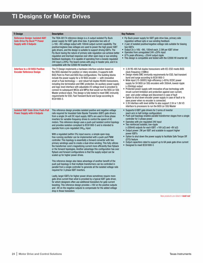
TI Designs for Motor Drives
TI Design Description Key Features
Reference Design: Isolated IGBT Gate-Drive Fly-Buck™ Power Supply with 4 Outputs
The TIDA-00174 reference design is a 4-output isolated Fly-Buck power supply for IGBT gate drive bias. It generates two sets of (+16V, –9V) voltage output with 100mA output current capability. The positive/negtaive bias voltages are used to power the high power IGBT gate drivers, and the design is suitable to support driving IGBTs. The Fly-Buck having the nature of primary side regulation can achieve better regulation and line/load response over other open-loop or aux winding feedback topologies. It is capable of operating from a loosely regulated 24V input (±20%). The board comes with plug-in header pins, and it is compatible with the C2000 HV inverter kit.
• Fly-Buck power supply for IGBT gate drive bias, primary side regulation without opto or aux winding feedback
• 2 pair of isolated positive/negative voltage rails suitable for biasing two IGBTs
• Output 2x (+16V, –9V), 100mA each, 2.5W per IGBT driver• Operates from unregulated 24V ±20% input• 87% peak efficiency, <55mV output ripple• This design is compatible and tested with the C2000 HV inverter kit
Interface to a 5V BiSS Position Encoder Reference Design
This TI Design implements a hardware interface solution based on the BiSS standard for position or rotary encoders. It supports both BiSS Point-to-Point and BiSS Bus configurations. The building blocks include the power supply for a 5V BiSS encoder — with innovative smart e-Fuse technology — and robust full-duplex RS485 transceivers, including line termination and EMC protection. An auxiliary power supply and logic level interface with adjustable I/O voltage level is provided to connect to subsequent MCUs and MPUs that would run the BiSS (or SSI) Master protocol stack. This design is fully tested to meet EMC immunity requirements for ESD, Fast Transient Burst and Surge according to IEC61800-3.
• 3.3V RS-485 full-duplex transceivers with IEC-ESD meets BiSS clock frequency (10Mhz)
• Design meets EMC immunity requirements for ESD, fast transient burst and surge according to IEC61800-3
• Wide input (15-30VDC) high-efficiency (>85%) DCDC power supply for 5V BiSS (or SSI) encoders with 350mA, lowest-ripple (<20mVpp) output
• Protected power supply with innovative eFuse technology with inrush current limitation and protection against over-current, over- and under-voltage and disconnect in case of fault
• Option to shut down encoder power supply in case of fault or to save power when no encoder is connected.
• 3.3V interface with level shifter to also support 2.5V or 1.8V I/O interface to processors to run the BiSS (or SSI) Master
Isolated IGBT Gate-Drive Push-Pull Power Supply with 4 Outputs
This reference design provides isolated positive and negative voltage rails required for Insulated Gate Bipolar Transistor (IGBT) gate drivers from a single 24-volt DC input supply. IGBTs are used in three phase inverters for variable-frequency drives to control the speed of AC motors. This reference design uses a push-pull isolated control topology and provides isolation compliant to IEC61800-5 and is intended to operate from a pre-regulated 24VDC input.
With a regulated (within 5%) input source, a simple open-loop, free-running oscillator can be implemented with a push-pull PWM controller. This topology is essentially a forward converter with two primary windings used to create a dual-drive winding. This fully utilizes the transformer core’s magnetizing current more efficiently than flyback or the forward topologies. Another advantage this configuration has over flyback and forward configurations is that the supply output can be scaled up for higher power drives.
This reference design also takes advantage of another benefit of the push pull topology in that multiple transformers can be controlled in parallel from a single controller to generate all the isolated voltage rails required for 3-phase IGBT inverters.
Lastly, larger IGBTs for higher power drives sometimes require more gate drive current than what is provided by a typical IGBT gate driver, for which designers often use additional transistors for gate current boosting. This reference design provides +16V on the positive outputs and –8V on the negative outputs to compensate for the added voltage drop in those transistors
• Supports 6 IGBT gate drivers for 3 arms of inverter (each arm in half-bridge configuration)
• Push-pull topology enables parallel transformer stages from a single controller for 3-phase power
• Operates with pre-regulated 24V input• Two reinforced isolated, low-ripple
(<200mV) outputs for each IGBT: +16V (x2) and –8V (x2)• Output power: 2W per IGBT and scalable to support higher
power IGBTs • Option to shut down the power supply to facilitate Safe Torque Off
(STO) feature• Output capacitors rated to support up to 6A peak gate drive current• Designed to meet IEC61800-5
New products are listed in bold red.
Texas Instruments Motor Drive and Control Solutions | 25
TI Designs for Motor Drives (continued)
TI Design Description Key Features
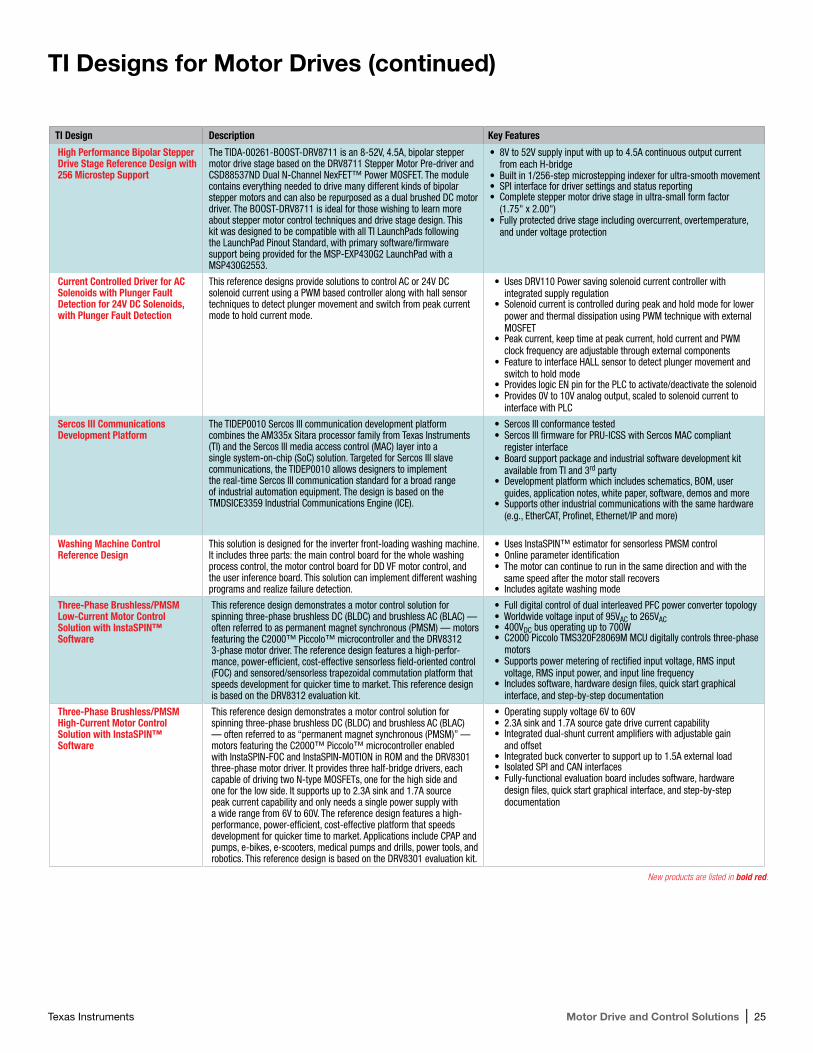
High Performance Bipolar Stepper Drive Stage Reference Design with 256 Microstep Support
The TIDA-00261-BOOST-DRV8711 is an 8-52V, 4.5A, bipolar stepper motor drive stage based on the DRV8711 Stepper Motor Pre-driver and CSD88537ND Dual N-Channel NexFET™ Power MOSFET. The module contains everything needed to drive many different kinds of bipolar stepper motors and can also be repurposed as a dual brushed DC motor driver. The BOOST-DRV8711 is ideal for those wishing to learn more about stepper motor control techniques and drive stage design. This kit was designed to be compatible with all TI LaunchPads following the LaunchPad Pinout Standard, with primary software/firmware support being provided for the MSP-EXP430G2 LaunchPad with a MSP430G2553.
• 8V to 52V supply input with up to 4.5A continuous output current from each H-bridge
• Built in 1/256-step microstepping indexer for ultra-smooth movement• SPI interface for driver settings and status reporting• Complete stepper motor drive stage in ultra-small form factor
(1.75" x 2.00")• Fully protected drive stage including overcurrent, overtemperature,
and under voltage protection
Current Controlled Driver for AC Solenoids with Plunger Fault Detection for 24V DC Solenoids, with Plunger Fault Detection
This reference designs provide solutions to control AC or 24V DC solenoid current using a PWM based controller along with hall sensor techniques to detect plunger movement and switch from peak current mode to hold current mode.
• Uses DRV110 Power saving solenoid current controller with integrated supply regulation
• Solenoid current is controlled during peak and hold mode for lower power and thermal dissipation using PWM technique with external MOSFET
• Peak current, keep time at peak current, hold current and PWM clock frequency are adjustable through external components
• Feature to interface HALL sensor to detect plunger movement and switch to hold mode
• Provides logic EN pin for the PLC to activate/deactivate the solenoid• Provides 0V to 10V analog output, scaled to solenoid current to
interface with PLC
Sercos III Communications Development Platform
The TIDEP0010 Sercos III communication development platform combines the AM335x Sitara processor family from Texas Instruments (TI) and the Sercos III media access control (MAC) layer into a single system-on-chip (SoC) solution. Targeted for Sercos III slave communications, the TIDEP0010 allows designers to implement the real-time Sercos III communication standard for a broad range of industrial automation equipment. The design is based on the TMDSICE3359 Industrial Communications Engine (ICE).
• Sercos III conformance tested• Sercos III firmware for PRU-ICSS with Sercos MAC compliant
register interface• Board support package and industrial software development kit
available from TI and 3rd party• Development platform which includes schematics, BOM, user
guides, application notes, white paper, software, demos and more• Supports other industrial communications with the same hardware
(e.g., EtherCAT, Profinet, Ethernet/IP and more)
Washing Machine Control Reference Design
This solution is designed for the inverter front-loading washing machine. It includes three parts: the main control board for the whole washing process control, the motor control board for DD VF motor control, and the user inference board. This solution can implement different washing programs and realize failure detection.
• Uses InstaSPIN™ estimator for sensorless PMSM control• Online parameter identification• The motor can continue to run in the same direction and with the
same speed after the motor stall recovers• Includes agitate washing mode
Three-Phase Brushless/PMSM Low-Current Motor Control Solution with InstaSPIN™ Software
This reference design demonstrates a motor control solution for spinning three-phase brushless DC (BLDC) and brushless AC (BLAC) — often referred to as permanent magnet synchronous (PMSM) — motors featuring the C2000™ Piccolo™ microcontroller and the DRV8312 3-phase motor driver. The reference design features a high-perfor-mance, power-efficient, cost-effective sensorless field-oriented control (FOC) and sensored/sensorless trapezoidal commutation platform that speeds development for quicker time to market. This reference design is based on the DRV8312 evaluation kit.
• Full digital control of dual interleaved PFC power converter topology• Worldwide voltage input of 95VAC to 265VAC• 400VDC bus operating up to 700W• C2000 Piccolo TMS320F28069M MCU digitally controls three-phase
motors• Supports power metering of rectified input voltage, RMS input
voltage, RMS input power, and input line frequency• Includes software, hardware design files, quick start graphical
interface, and step-by-step documentation
Three-Phase Brushless/PMSM High-Current Motor Control Solution with InstaSPIN™ Software
This reference design demonstrates a motor control solution for spinning three-phase brushless DC (BLDC) and brushless AC (BLAC) — often referred to as “permanent magnet synchronous (PMSM)” — motors featuring the C2000™ Piccolo™ microcontroller enabled with InstaSPIN-FOC and InstaSPIN-MOTION in ROM and the DRV8301 three-phase motor driver. It provides three half-bridge drivers, each capable of driving two N-type MOSFETs, one for the high side and one for the low side. It supports up to 2.3A sink and 1.7A source peak current capability and only needs a single power supply with a wide range from 6V to 60V. The reference design features a high-performance, power-efficient, cost-effective platform that speeds development for quicker time to market. Applications include CPAP and pumps, e-bikes, e-scooters, medical pumps and drills, power tools, and robotics. This reference design is based on the DRV8301 evaluation kit.
• Operating supply voltage 6V to 60V• 2.3A sink and 1.7A source gate drive current capability• Integrated dual-shunt current amplifiers with adjustable gain
and offset• Integrated buck converter to support up to 1.5A external load• Isolated SPI and CAN interfaces• Fully-functional evaluation board includes software, hardware
design files, quick start graphical interface, and step-by-step documentation
New products are listed in bold red.
26 | Motor Drive and Control Solutions Texas Instruments
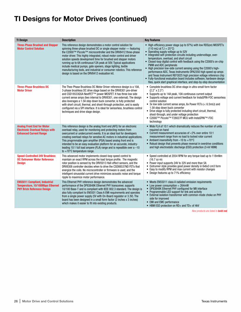
TI Designs for Motor Drives (continued)
TI Design Description Key Features
Three-Phase Brushed and Stepper Motor Control Solution
This reference design demonstrates a motor control solution for spinning three-phase brushed DC or single stepper motor — featuring the C2000™ Piccolo™ microcontroller and the DRV8412 three-phase motor driver. This highly integrated, robust motor control and driver solution speeds development time for brushed and stepper motors running up to 6A continuous/12A peak at 50V. Typical applications include medical pumps, gate openers, stage lighting, textile manufacturing tools, and industrial or consumer robotics. This reference design is based on the DRV8412 evaluation kit.
• High-efficiency power stage (up to 97%) with low RDS(on) MOSFETs (110 mΩ at TJ = 25°C)
• Operating supply voltage up to 52V• Integrated self-protection circuits including undervoltage, over-
temperature, overload, and short circuit• Closed-loop digital control with feedback using the C2000’s on-chip
PWM and ADC peripherals• High precision low-side current sensing using the C2000’s high-
performance ADC, Texas Instruments OPA2350 high speed op-amps and Texas Instrument REF3025 high precision voltage reference chip
• Fully-functional evaluation board includes software, hardware design files, quick start graphical interface, and step-by-step documentation
Three-Phase Brushless DC Motor Driver
The Thee-Phase Brushless DC Motor Driver reference design is a 10A, 3-phase brushless DC drive stage based on the DRV8301 pre-driver and CSD18533Q5A NextFET™ power MOSFET. It has three low side current sense amps (two internal to DRV8301, one external). The design also leverages a 1.5A step down buck converter, is fully protected with short circuit, thermal, and shoot-through protection, and is easily configured via a SPI interface. It is ideal for sensorless, brushless control techniques and drive stage design.
• Complete brushless DC drive stage in ultra-small form factor (2.2" x 2.3")
• Supports up to 14A peak, 10A continuous current output• Supports voltage and current feedback for InstaSPIN-FOC sensorless
control solution• 3x low side current sense amps, 6x Power FETs (< 6.5mΩ) and
1.5A step down buck converter• Drive stage is fully protected including short circuit, thermal,
shoot-through, and under voltage protection• C2000™ Piccolo™ F28027F MCU with InstaSPIN™-FOC
technology
Analog Front End for Motor Electronic Overload Relays with Enhanced Current Range
This reference design is the analog front end (AFE) for an electronic overload relay, used for monitoring and protecting motors from overcurrent or undercurrent events. It is an ideal tool for developers creating overload relays for senstive AC motors in industrial applications. This progrmmable gain amplifier (PGA) based analog front end is intended to be an easy evaluation platform for an accurate, industry-leading 10:1 full load ampere (FLA) range and is repeatible over a –10 to +70°C temperature range.
• Wide FLA of 10:1 which dramatically reduces the number of units required on-hand
• Current measurement accuracies of <2% over entire 10:1 measurement range from no load to locked rotor current
• Ambient insensitivity from –10 to +70°C• Robust design that prevents phase reversal in overdrive conditions
and high electrostatic discharge (ESD) protection (3-kV HBM)
Speed-Controlled 24V Brushless DC Outrunner Motor Reference Design
This advanced motor implements closed-loop speed control to maintain an exact RPM across the load torque profile. The magnetic rotor position is sensed by the DRV5013 Hall-effect sensors, and the DRV8308 controller decides when to drive the CSD88537ND FETs that energize the coils. No microcontroller or firmware is used, and the intelligent sinusoidal current drive minimizes acoustic noise and torque ripple to maximize motor performance.
• Speed controlled at 2054 RPM for any torque load up to 118mNm (16.7 oz-in)
• Power input supports 24V to 32V and more than 5A• Outrunner style provides good power density in 6x6x3 cm3 form• Easy to modify RPM and max current with resistor changes• Design features up to 71% efficiency
EN55011 Compliant, Industrial Temperature, 10/100Mbps Ethernet PHY Brick Reference Design
This Ethernet PHY reference design demonstrates the advanced performance of the DP83848K Ethernet PHY transceiver, supports 10/100 Base-T and is compliant with IEEE 802.3 standard. The design is also fully compliant to EN5501 Class A EMI requirements and operates from a single power supply (5V with On-Board regulator or 3.3V). The board has been designed in a small form factor (2 inches x 3 inches) which makes it easier to fit into existing products.
• Meets EN55011 class A radiated emission requirements• Low power consumption = 264mW• DP83848K Ethernet PHY configured for MII interface• Programmable LED support for link and activity• External isolation transformer with common-mode choke on PHY
side for improved • EMI and EMC performance• HBM ESD protection on RD± and TD± of 4kV
New products are listed in bold red.
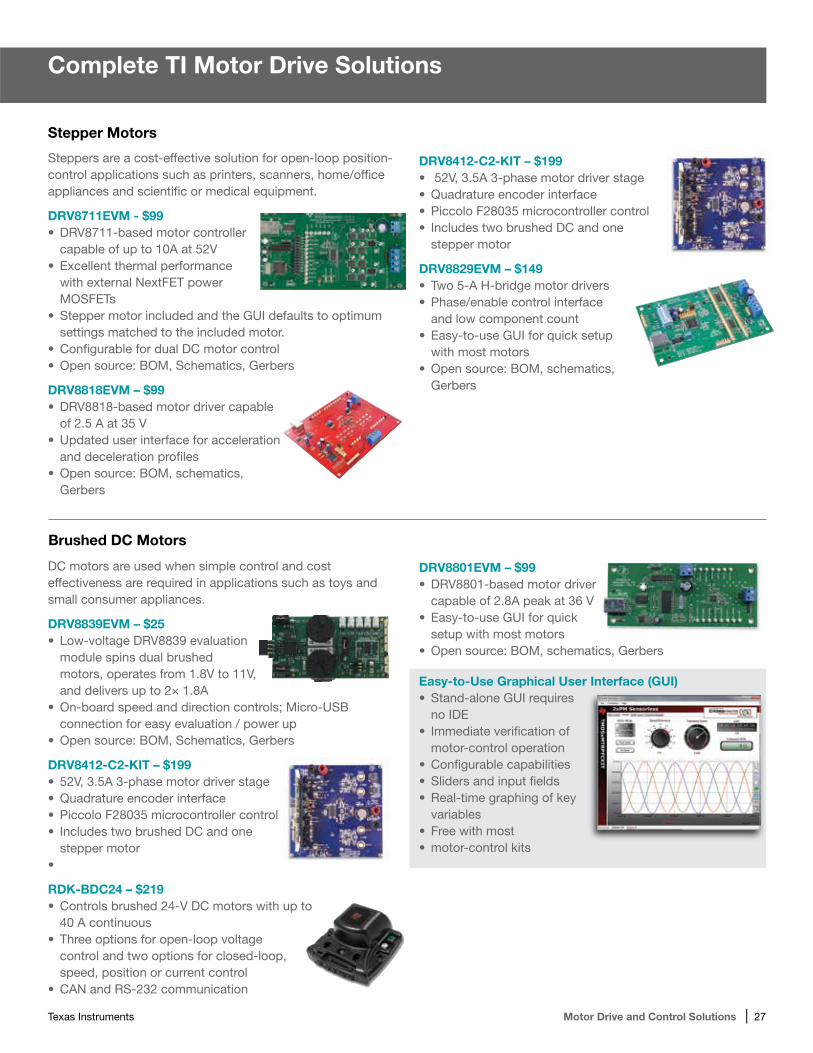
Texas Instruments Motor Drive and Control Solutions | 27
Complete TI Motor Drive Solutions
Stepper Motors
Steppers are a cost-effective solution for open-loop position-control applications such as printers, scanners, home/office appliances and scientific or medical equipment.
DRV8711EVM - $99•DRV8711-based motor controller
capable of up to 10A at 52V•Excellent thermal performance
with external NextFET power MOSFETs
•Stepper motor included and the GUI defaults to optimum settings matched to the included motor.
•Configurable for dual DC motor control•Open source: BOM, Schematics, Gerbers
DRV8818EVM – $99•DRV8818-based motor driver capable
of 2.5 A at 35 V•Updated user interface for acceleration
and deceleration profiles•Open source: BOM, schematics,
Gerbers
DC motors are used when simple control and cost effectiveness are required in applications such as toys and small consumer appliances.
DRV8839EVM – $25• Low-voltage DRV8839 evaluation
module spins dual brushed motors, operates from 1.8V to 11V, and delivers up to 2× 1.8A
•On-board speed and direction controls; Micro-USB connection for easy evaluation / power up
•Open source: BOM, Schematics, Gerbers
DRV8412-C2-KIT – $199• 52V, 3.5A 3-phase motor driver stage•Quadrature encoder interface•Piccolo F28035 microcontroller control• Includes two brushed DC and one
stepper motor•
RDK-BDC24 – $219•Controls brushed 24-V DC motors with up to
40 A continuous•Three options for open-loop voltage
control and two options for closed-loop, speed, position or current control
•CAN and RS-232 communication
DRV8412-C2-KIT – $199• 52V, 3.5A 3-phase motor driver stage•Quadrature encoder interface•Piccolo F28035 microcontroller control• Includes two brushed DC and one
stepper motor
DRV8829EVM – $149•Two 5-A H-bridge motor drivers•Phase/enable control interface
and low component count•Easy-to-use GUI for quick setup
with most motors•Open source: BOM, schematics,
Gerbers
DRV8801EVM – $99•DRV8801-based motor driver
capable of 2.8A peak at 36 V•Easy-to-use GUI for quick
setup with most motors•Open source: BOM, schematics, Gerbers
Easy-to-Use Graphical User Interface (GUI)• Stand-alone GUI requires
no IDE• Immediate verification of
motor-control operation•Configurable capabilities•Sliders and input fields• Real-time graphing of key
variables•Free with most •motor-control kits
Brushed DC Motors
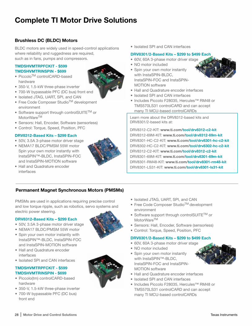
28 | Motor Drive and Control Solutions Texas Instruments
Complete TI Motor Drive Solutions
PMSMs are used in applications requiring precise control and low torque ripple, such as robotics, servo systems and electric power steering.
DRV8312-Based Kits – $299 Each• 50V, 3.5A 3-phase motor driver stage•NEMA17 BLDC/PMSM 55W motor•Spin your own motor instantly with
InstaSPIN™-BLDC, InstaSPIN-FOC and InstaSPIN-MOTION software
•Hall and Quadrature encoder interfaces
• Isolated SPI and CAN interfaces
TMDSHVMTRPFCKIT - $599 TMDSHVMTRINSPIN - $699•Piccolo(tm) controlCARD-based
hardware• 350-V, 1.5-kW three-phase inverter• 700-W bypassable PFC (DC bus)
front end
Brushless DC (BLDC) Motors
BLDC motors are widely used in speed-control applications where reliability and ruggedness are required, such as in fans, pumps and compressors.
TMDSHVMTRPFCKIT - $599 TMDSHVMTRINSPIN - $699•PiccoloTM controlCARD-based
hardware• 350-V, 1.5-kW three-phase inverter• 700-W bypassable PFC (DC bus) front end• Isolated JTAG, UART, SPI, and CAN•Free Code Composer StudioTM development
environment•Software support through controlSUITETM or
MotorWareTM
•Sensors: Hall, Encoder, Software (sensorless)•Control: Torque, Speed, Position, PFC
DRV8312-Based Kits – $299 Each• 50V, 3.5A 3-phase motor driver stage•NEMA17 BLDC/PMSM 55W motor
Spin your own motor instantly with InstaSPIN™-BLDC, InstaSPIN-FOC and InstaSPIN-MOTION software
•Hall and Quadrature encoder interfaces
Learn more about the DRV8312-based kits and DRV8301/2-based kits at:
DRV8312-C2-KIT: www.ti.com/tool/drv8312-c2-kit DRV8312-69M-KIT: www.ti.com/tool/drv8312-69m-kit DRV8301-HC-C2-KIT: www.ti.com/tool/drv8301-hc-c2-kit DRV8302-HC-C2-KIT: www.ti.com/tool/drv8302-hc-c2-kit DRV8312-C2-KIT: www.ti.com/tool/drv8312-c2-kit DRV8301-69M-KIT: www.ti.com/tool/drv8301-69m-kit DRV8301-RM48-KIT: www.ti.com/tool/drv8301-rm48-kit DRV8301-LS31-KIT: www.ti.com/tool/drv8301-ls31-kit
• Isolated SPI and CAN interfaces
DRV8301/2-Based Kits – $299 to $499 Each• 60V, 60A 3-phase motor driver stage•NO motor included•Spin your own motor instantly
with InstaSPIN-BLDC, InstaSPIN-FOC and InstaSPIN- MOTION software
•Hall and Quadrature encoder interfaces• Isolated SPI and CAN interfaces• Includes Piccolo F28035, Hercules™ RM48 or
TMS570LS31 controlCARD and can accept many TI MCU-based controlCARDs
• Isolated JTAG, UART, SPI, and CAN•Free Code Composer StudioTM development
environment•Software support through controlSUITETM or
MotorWareTM
•Sensors: Hall, Encoder, Software (sensorless)•Control: Torque, Speed, Position, PFC
DRV8301/2-Based Kits – $299 to $499 Each• 60V, 60A 3-phase motor driver stage•NO motor included•Spin your own motor instantly
with InstaSPIN™-BLDC, InstaSPIN-FOC and InstaSPIN- MOTION software
•Hall and Quadrature encoder interfaces• Isolated SPI and CAN interfaces• Includes Piccolo F28035, Hercules™ RM48 or
TMS570LS31 controlCARD and can accept many TI MCU-based controlCARDs
Permanent Magnet Synchronous Motors (PMSMs)
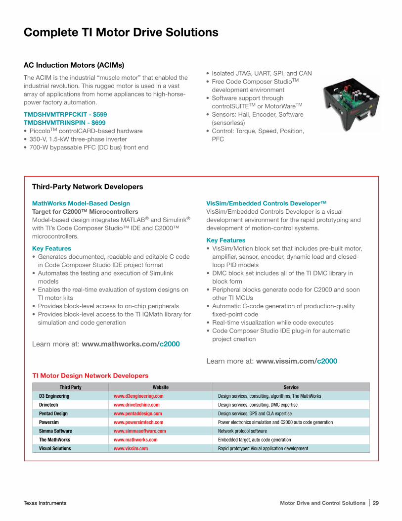
Texas Instruments Motor Drive and Control Solutions | 29
Complete TI Motor Drive Solutions
AC Induction Motors (ACIMs)
The ACIM is the industrial “muscle motor” that enabled the industrial revolution. This rugged motor is used in a vast array of applications from home appliances to high- horse-power factory automation.
TMDSHVMTRPFCKIT - $599 TMDSHVMTRINSPIN - $699•PiccoloTM controlCARD-based hardware• 350-V, 1.5-kW three-phase inverter• 700-W bypassable PFC (DC bus) front end
• Isolated JTAG, UART, SPI, and CAN•Free Code Composer StudioTM
development environment•Software support through
controlSUITETM or MotorWareTM
•Sensors: Hall, Encoder, Software (sensorless)
•Control: Torque, Speed, Position, PFC
MathWorks Model-Based Design Target for C2000™ Microcontrollers Model-based design integrates MATLAB® and Simulink® with TI’s Code Composer Studio™ IDE and C2000™ microcontrollers.
Key Features•Generates documented, readable and editable C code
in Code Composer Studio IDE project format•Automates the testing and execution of Simulink
models•Enables the real-time evaluation of system designs on
TI motor kits•Provides block-level access to on-chip peripherals• Provides block-level access to the TI IQMath library for
simulation and code generation
VisSim/Embedded Controls Developer™ VisSim/Embedded Controls Developer is a visual development environment for the rapid prototyping and development of motion-control systems.
Key Features•VisSim/Motion block set that includes pre-built motor,
amplifier, sensor, encoder, dynamic load and closed-loop PID models
•DMC block set includes all of the TI DMC library in block form
•Peripheral blocks generate code for C2000 and soon other TI MCUs
•Automatic C-code generation of production-quality fixed-point code
•Real-time visualization while code executes•Code Composer Studio IDE plug-in for automatic
project creation
TI Motor Design Network Developers
Third Party Website Service
D3 Engineering www.d3engineering.com Design services, consulting, algorithms, The MathWorks
Drivetech www.drivetechinc.com Design services, consulting, DMC expertise
Pentad Design www.pentaddesign.com Design services, DPS and CLA expertise
Powersim www.powersimtech.com Power electronics simulation and C2000 auto code generation
Simma Software www.simmasoftware.com Network protocol software
The MathWorks www.mathworks.com Embedded target, auto code generation
Visual Solutions www.vissim.com Rapid prototyper: Visual application development
Third-Party Network Developers
Learn more at: www.mathworks.com/c2000
Learn more at: www.vissim.com/c2000
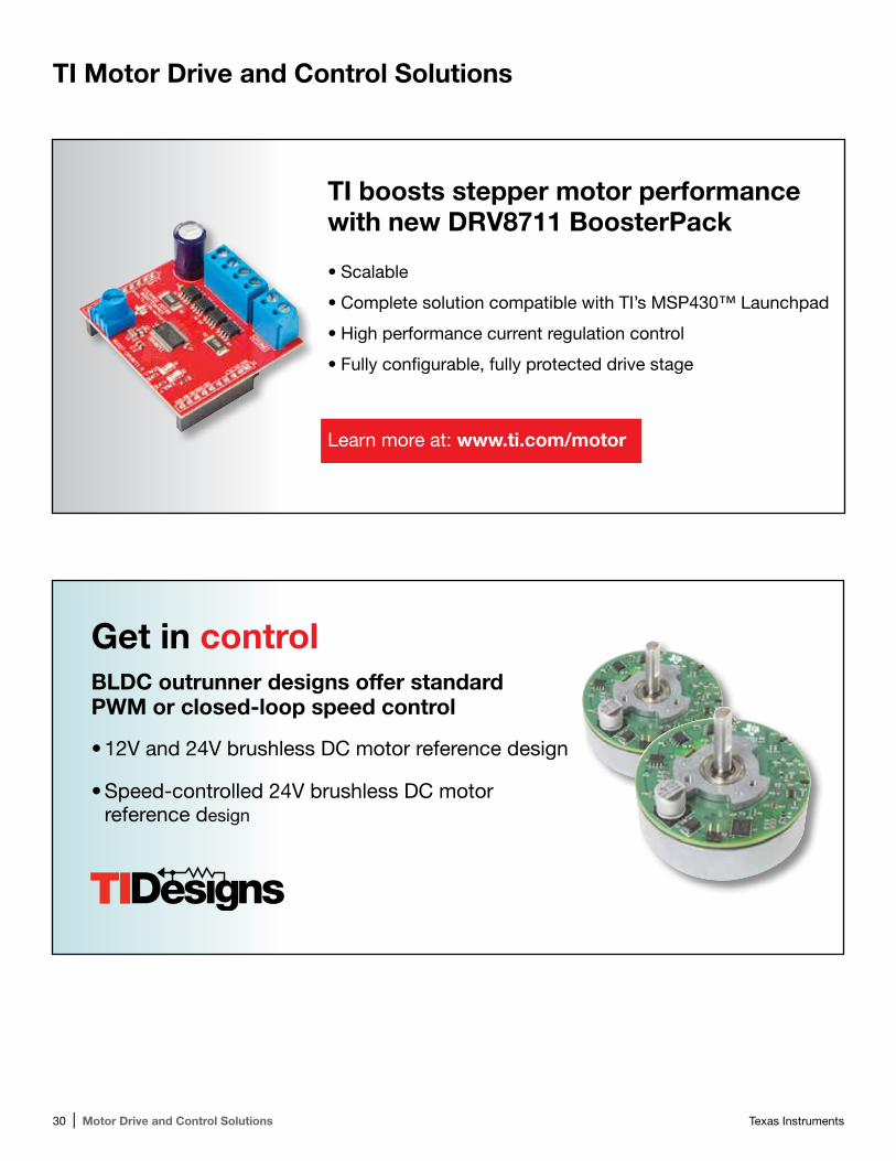
30 | Motor Drive and Control Solutions Texas Instruments
TI Motor Drive and Control Solutions
TI boosts stepper motor performancewith new DRV8711 BoosterPack
•Scalable
•Complete solution compatible with TI’s MSP430™ Launchpad
•High performance current regulation control
•Fully configurable, fully protected drive stage
Learn more at: www.ti.com/motor
Get in controlBLDC outrunner designs offer standardPWM or closed-loop speed control
•12V and 24V brushless DC motor reference design
•Speed-controlled 24V brushless DC motor reference design

Texas Instruments Motor Drive and Control Solutions | 31
TI Motor Drive and Control Solutions
Don’t miss TI’s Motor SolutionsNewsletter and updates•Get the latest information on TI’s solutions for Motor Drive and control
•Learn about new products, TI Designs, software and more that have been designed to support you in your motor system development
Subscribe at: www.ti.com/newsletter
NOTES:
____________________________________________________________________________________________
____________________________________________________________________________________________
____________________________________________________________________________________________
____________________________________________________________________________________________
____________________________________________________________________________________________
____________________________________________________________________________________________
____________________________________________________________________________________________
____________________________________________________________________________________________
____________________________________________________________________________________________
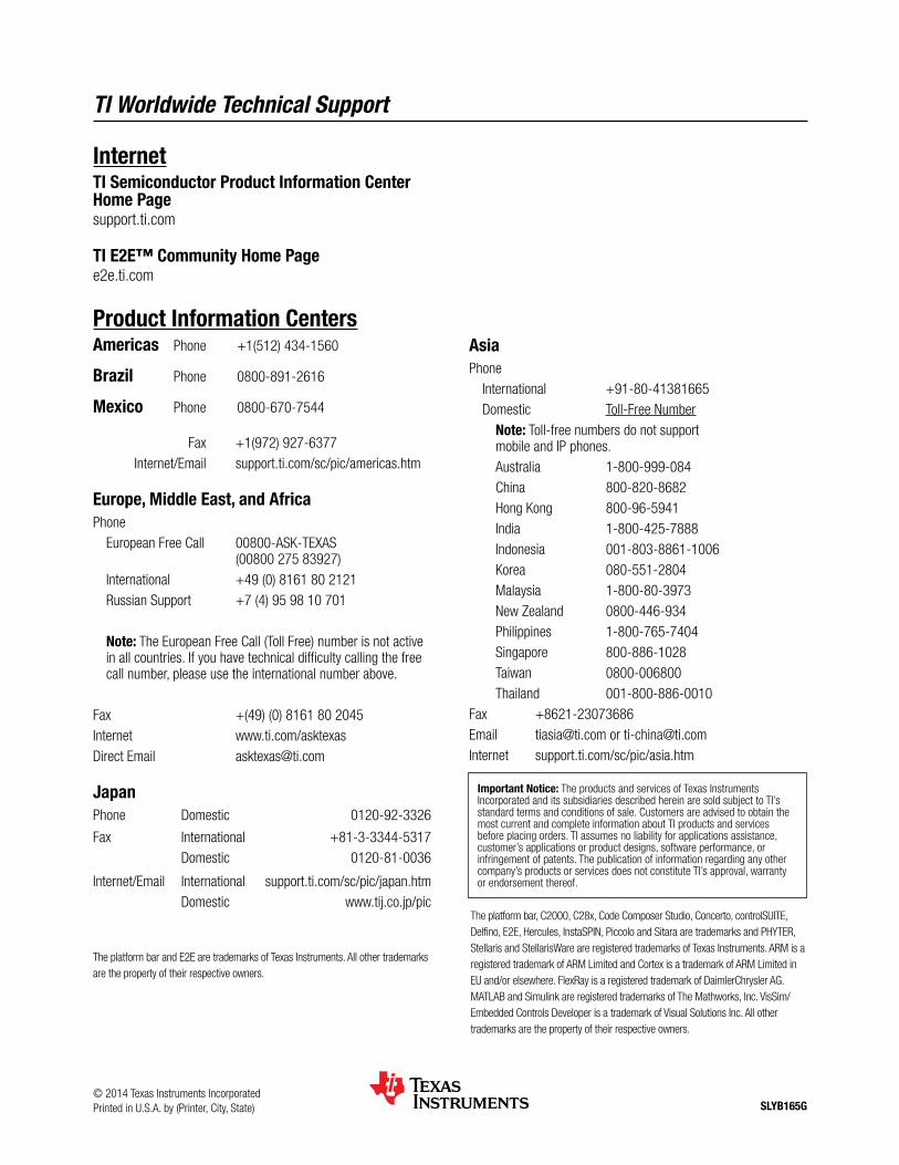
SLYB165G
The platform bar, C2000, C28x, Code Composer Studio, Concerto, controlSUITE, Delfino, E2E, Hercules, InstaSPIN, Piccolo and Sitara are trademarks and PHYTER, Stellaris and StellarisWare are registered trademarks of Texas Instruments. ARM is a registered trademark of ARM Limited and Cortex is a trademark of ARM Limited in EU and/or elsewhere. FlexRay is a registered trademark of DaimlerChrysler AG. MATLAB and Simulink are registered trademarks of The Mathworks, Inc. VisSim/Embedded Controls Developer is a trademark of Visual Solutions Inc. All other trademarks are the property of their respective owners.
TI Worldwide Technical Support
InternetTI Semiconductor Product Information Center Home Pagesupport.ti.com
TI E2E™ Community Home Pagee2e.ti.com
Product Information CentersAmericas Phone +1(512) 434-1560
Brazil Phone 0800-891-2616
Mexico Phone 0800-670-7544
Fax +1(972) 927-6377 Internet/Email support.ti.com/sc/pic/americas.htm
Europe, Middle East, and AfricaPhone European Free Call 00800-ASK-TEXAS (00800 275 83927) International +49 (0) 8161 80 2121 Russian Support +7 (4) 95 98 10 701
Note: The European Free Call (Toll Free) number is not active in all countries. If you have technical difficulty calling the free call number, please use the international number above.
Fax +(49) (0) 8161 80 2045Internet www.ti.com/asktexasDirect Email [email protected]
JapanPhone Domestic 0120-92-3326
Fax International +81-3-3344-5317 Domestic 0120-81-0036
Internet/Email International support.ti.com/sc/pic/japan.htm Domestic www.tij.co.jp/pic
AsiaPhone International +91-80-41381665 Domestic Toll-Free Number Note: Toll-free numbers do not support
mobile and IP phones. Australia 1-800-999-084 China 800-820-8682 Hong Kong 800-96-5941 India 1-800-425-7888 Indonesia 001-803-8861-1006 Korea 080-551-2804 Malaysia 1-800-80-3973 New Zealand 0800-446-934 Philippines 1-800-765-7404 Singapore 800-886-1028 Taiwan 0800-006800 Thailand 001-800-886-0010Fax +8621-23073686Email [email protected] or [email protected] support.ti.com/sc/pic/asia.htm
Important Notice: The products and services of Texas Instruments Incorporated and its subsidiaries described herein are sold subject to TI’s standard terms and conditions of sale. Customers are advised to obtain the most current and complete information about TI products and services before placing orders. TI assumes no liability for applications assistance, customer’s applications or product designs, software performance, or infringement of patents. The publication of information regarding any other company’s products or services does not constitute TI’s approval, warranty or endorsement thereof.
© 2014 Texas Instruments IncorporatedPrinted in U.S.A. by (Printer, City, State)
The platform bar and E2E are trademarks of Texas Instruments. All other trademarks are the property of their respective owners.
IMPORTANT NOTICETexas Instruments Incorporated and its subsidiaries (TI) reserve the right to make corrections, enhancements, improvements and otherchanges to its semiconductor products and services per JESD46, latest issue, and to discontinue any product or service per JESD48, latestissue. Buyers should obtain the latest relevant information before placing orders and should verify that such information is current andcomplete. All semiconductor products (also referred to herein as “components”) are sold subject to TI’s terms and conditions of salesupplied at the time of order acknowledgment.TI warrants performance of its components to the specifications applicable at the time of sale, in accordance with the warranty in TI’s termsand conditions of sale of semiconductor products. Testing and other quality control techniques are used to the extent TI deems necessaryto support this warranty. Except where mandated by applicable law, testing of all parameters of each component is not necessarilyperformed.TI assumes no liability for applications assistance or the design of Buyers’ products. Buyers are responsible for their products andapplications using TI components. To minimize the risks associated with Buyers’ products and applications, Buyers should provideadequate design and operating safeguards.TI does not warrant or represent that any license, either express or implied, is granted under any patent right, copyright, mask work right, orother intellectual property right relating to any combination, machine, or process in which TI components or services are used. Informationpublished by TI regarding third-party products or services does not constitute a license to use such products or services or a warranty orendorsement thereof. Use of such information may require a license from a third party under the patents or other intellectual property of thethird party, or a license from TI under the patents or other intellectual property of TI.Reproduction of significant portions of TI information in TI data books or data sheets is permissible only if reproduction is without alterationand is accompanied by all associated warranties, conditions, limitations, and notices. TI is not responsible or liable for such altereddocumentation. Information of third parties may be subject to additional restrictions.Resale of TI components or services with statements different from or beyond the parameters stated by TI for that component or servicevoids all express and any implied warranties for the associated TI component or service and is an unfair and deceptive business practice.TI is not responsible or liable for any such statements.Buyer acknowledges and agrees that it is solely responsible for compliance with all legal, regulatory and safety-related requirementsconcerning its products, and any use of TI components in its applications, notwithstanding any applications-related information or supportthat may be provided by TI. Buyer represents and agrees that it has all the necessary expertise to create and implement safeguards whichanticipate dangerous consequences of failures, monitor failures and their consequences, lessen the likelihood of failures that might causeharm and take appropriate remedial actions. Buyer will fully indemnify TI and its representatives against any damages arising out of the useof any TI components in safety-critical applications.In some cases, TI components may be promoted specifically to facilitate safety-related applications. With such components, TI’s goal is tohelp enable customers to design and create their own end-product solutions that meet applicable functional safety standards andrequirements. Nonetheless, such components are subject to these terms.No TI components are authorized for use in FDA Class III (or similar life-critical medical equipment) unless authorized officers of the partieshave executed a special agreement specifically governing such use.Only those TI components which TI has specifically designated as military grade or “enhanced plastic” are designed and intended for use inmilitary/aerospace applications or environments. Buyer acknowledges and agrees that any military or aerospace use of TI componentswhich have not been so designated is solely at the Buyer's risk, and that Buyer is solely responsible for compliance with all legal andregulatory requirements in connection with such use.TI has specifically designated certain components as meeting ISO/TS16949 requirements, mainly for automotive use. In any case of use ofnon-designated products, TI will not be responsible for any failure to meet ISO/TS16949.Products ApplicationsAudio www.ti.com/audio Automotive and Transportation www.ti.com/automotiveAmplifiers amplifier.ti.com Communications and Telecom www.ti.com/communicationsData Converters dataconverter.ti.com Computers and Peripherals www.ti.com/computersDLP® Products www.dlp.com Consumer Electronics www.ti.com/consumer-appsDSP dsp.ti.com Energy and Lighting www.ti.com/energyClocks and Timers www.ti.com/clocks Industrial www.ti.com/industrialInterface interface.ti.com Medical www.ti.com/medicalLogic logic.ti.com Security www.ti.com/securityPower Mgmt power.ti.com Space, Avionics and Defense www.ti.com/space-avionics-defenseMicrocontrollers microcontroller.ti.com Video and Imaging www.ti.com/videoRFID www.ti-rfid.comOMAP Applications Processors www.ti.com/omap TI E2E Community e2e.ti.comWireless Connectivity www.ti.com/wirelessconnectivity
Mailing Address: Texas Instruments, Post Office Box 655303, Dallas, Texas 75265Copyright © 2014, Texas Instruments Incorporated