fire and security dual scope system - falcon panel products
TRANSCRIPT

www.falconpp.co.uk
FPP-DSM-SDSB-401-C
Fire and Security Dual Scope System
Falcon Panel Products
STREBORD® 44 / 54STREDOR® 44 / 54
FD30 / PAS24


1. Introduction to Dual Scope Certification 41.1 and Doorset System 41.2 System Features 41.3 Fire and Smoke Performance 51.4 Security Performance 5
2. Door Cores 63. Lippings and Facings 8
3.1 Lippings 83.2 Facings 93.3 Decorative Grooves 103.4 Decorative Mouldings 11
4. Approved Dimensions and Operating Gaps 124.1 Approved Leaf Dimensions 124.2 Operating Gaps and Alignment 12
5. Seals 135.1 Intumescent Seals 135.2 Smoke Seals 155.3 Automatic Drop Seals and Thresholds 16
6. Glazing 176.1 Glass 176.2 Area and Position 186.3 Beading 186.4 Glazing Seal Systems 196.5 Vision Panel Machining, Assembly and Fitting 196.6 Approved Glazing Configurations 20
7. Framing 217.1 Door Frames 217.2 Minimum Frame Dimensions 217.3 Frame Joints 227.4 Architrave 22
8. Hardware 238.1 Preparation and Fixing of Hardware 238.2 Intumescent Protection 248.3 Hinges 248.4 Locking Systems 258.5 Cylinders 268.6 Handles 268.7 Door Viewers 268.8 Automatic Closing Devices 278.9 Letter Plates 288.10 Decorative and Ancillary Hardware 28
9. Installation 299.1 Adjusting Door Leafs 309.2 Sealing to Structural Opening (Fire Stopping) 309.3 Fire Stopping Solutions with Primary Test Evidence 309.4 Assessed Fire Stopping Solutions 329.5 Associated Standards 339.6 Installation Fixings 33
10. Labelling and Marking 3410.1 Labelling for Fire Performance 3410.2 Labelling for Security 35
Appendix A 36Appendix B 60
Contents

4
This document outlines the details and requirements of the Falcon Panel Products Strebord and Stredor Fire and Security Dual Scope System.
1.1 and Doorset SystemHaving been subject to an extensive, robust, ongoing testing and certification program, the market-leading brands for door core and door blank products, Strebord and Stredor, have been incorporated into a doorset system that is certified by BM Trada Q Mark for both Fire and Enhanced Security door schemes.
This system provides our customers with additional support - particularly when working in the flat entrance door market - to ensure there is no conflict between the Building Regulations for fire safety (Part B) and security (Part Q) where specifiers require both to be met. Manufacturing doorsets from this fully tested system complies with both fire and security requirements. Furthermore, manufacturers can certify the doorsets produced under the BM Trada Q Mark third-party product certification scheme, providing clients and end users with additional confidence that their properties and loved ones are safe and secure.
A joint publication: ‘A Guide for Selecting Flat Entrance Doorsets; A publication for housing associations, landlords, building owners and local authorities in England’, relates to new doorsets and is the product of DHF (Door & Hardware Federation), Secured by Design (SBD) and the Fire Industry Association (FIA).
The publication brings together the best collaborative advice available from the industry in one straightforward document to highlight the fundamental issues of fire safety and security for those selecting fire doorsets.
1.2 System Features• FD30s and Enhanced Security• Choice of Strebord (Solid Particleboard)
or Stredor (Solid Timber) for door leaf construction
• Evidence to support both 44mm and 54mm door leaf thicknesses
• Auto-firing, multi-point security lock• Economically designed timber frame
section (nominal 2” x 4” section)
• Includes evidence for both overhead and jamb mounted concealed automatic closing devices
• Options for key/key and key/thumbturn cylinders
• Up to 1047mm x 2402mm leaf sizes for fire and security
• Provision for glazed apertures using fire rated P1A glazing
• Tested to BS 476: Part 22, BS EN 1634-1, BS EN 1634-3, PAS 24:2016, BS 6375-1, BS 6375-2 & BS 6375-3
1. Introduction to Dual Scope Certification

5
1.3 Fire and Smoke PerformanceThe dual scope system is certified by the Q Mark Fire Door Manufacturer Scheme, and will perform to 30 minutes for fire and smoke. The components of the system have been extensively tested to the British Standard BS 476: Part 22, and to European Standards BS EN 1634-1, BS EN 1634-3.
1.4 Security PerformanceThe dual scope system is certified by the Q Mark Enhanced Security Scheme. The system has been tested to PAS24: 2016. All of the permitted ironmongery components have also been rigorously tested individually and hold robust certification.
The dual scope system is licensed by Secured by Design, the Official Police Security Initiative. As noted in the Secure By Design ‘Homes 2019’ Brochure, Section 21.5; “Where there is a requirement for a doorset to be both fire and security rated, … the manufacturer or fabricator supplying the finished product to site is required to present independent third party dual certification from a single UKAS accredited certification body for both elements.”

6
Strebord is a robust graduated density particleboard core. Strebord particleboard is the market leader for fire-rated, as well as non fire-rated door cores, and is easy to process and work with using modern joinery practices. This core is suited to an internal setting, in corridors or otherwise internally in buildings.
The dual scope system offers two of the market leading door cores from Falcon Panel Products, Strebord and Stredor, with the option of using the 44mm and 54mm variant of each. Both cores are available with FSC Certification, and Strebord is available with PEFC Certification.
Stredor is a lighter weight, solid laminated timber core. Stredor does not have core perimeter framing like other laminated timber cores, meaning that it can be processed easily and without restriction to size reduction. Ply faced Stredor cores are suitable for an internal or external setting.
2. Door Cores

7
Table 1 - Core Details
Strebord 44 Strebord 54 Stredor 44 Ply Stredor 54 Ply
TypeThree layer particleboard
specially developed as a highperformance door core
Three layer particleboard specially developed as a high
performance door core
Engineered multi-layered solid timber
Engineered multi-layered solid timber
Raw Material (Wood
Content)
Produced with softwood (Spruce / Pine / Fir) with hardwood(Birch , Chestnut) and using recycled wood based raw
materials
Produced with softwood (Spruce / Pine / Fir) with hardwood(Birch , Chestnut) and using recycled wood based raw
materials
Produced with Poplar, Beech, Spruce/Pine/Fir/ and Redwood
Produced with Poplar, Beech, Spruce/Pine/Fir/ and Redwood
Adhesive Urea Formaldehyde Urea Formaldehyde Melamine and PVA Melamine and PVA
Moisture Content
8% + or - 2% moisture 8% + or - 2% moisture 8% + or - 2% moisture 8% + or - 2% moisture
FireTested to BS476: Part 22:
1987 and BS EN 1634-1:2014+A1:2018, opening in
both directions
Tested to BS476: Part 22: 1987 and BS EN 1634-
1:2014+A1:2018, opening in both directions
Tested to BS476: Part 22: 1987 and BS EN 1634-
1:2014+A1:2018, opening in both directions
Tested to BS476: Part 22: 1987 and BS EN 1634-
1:2014+A1:2018, opening in both directions
Sheet Size
Note - non standard sizes available to
special order
2060 x 840mm 2135 x 915mm2440 x 915mm
2440 x 1220mm 2740 x 915mm
3300 x 1000mmTolerance: Height & Width +/- 0.5mm
Thickness +/- 0.2mm
2135 x 915mm2440 x 915mm 2440 x 915mm2740 x 915mm
Tolerance: Height & Width +/- 0.5mm Thickness +/- 0.2mm
2135 x 915mm2440 x 1220 mm2745 x 1220 mm3050 x 1220 mm
Tolerance: Height & Width +/- 0.5mm Thickness +/- 0.2mm
2135 x 915mm2440 x 1220mm2740 x 915mm
Tolerance: Height & Width +/- 0.5mm Thickness +/- 0.2mm
Surface
Has a precision finish meeting the highest requirements and
is suitable as a base for use with a wide range of facing
materials including delicate veneers, laminates and thin foils.
Has a precision finish meeting the highest requirements and
is suitable as a base for use with a wide range of facing
materials including delicate veneers, laminates and thin foils.
Beech or EV veneered suitable for painting and staining, or for use with a wide range of facing
materials including delicate veneers, laminates and thin foils.
Beech or EV veneered suitable for painting and staining, or for use with a wide range of facing
materials including delicate veneers, laminates and thin foils.
Density Avg. bulk density = 570 ~ 620kgs/m3
Avg. bulk density = 570 ~ 610kgs/m3 Avg. bulk density = 505 kg/m3 Avg. bulk density = 505 kg/m3
Weight Nom. 27kgs/m2 Nom. 34kgs/m2 Nom. 22kgs/m2 Nom. 27kgs/m2
MachiningSuitable for use with standard
woodworking tools andmachinery
Suitable for use with standard woodworking tools and
machinery
Suitable for use with standard woodworking tools and
machinery
Suitable for use with standard woodworking tools and
machinery
Table 1a - Core Performance Summary
Core Thickness (mm) Fire App.
Max
dB
(RW
)PA
S24
Secu
rity
Ther
mal
Ran
ge
Certification COC
DD17
1/BS
EN
119
2BS
EN
139
86Pe
rimet
er F
ram
ing
Rece
ssed
Pan
els
Parti
cleb
oard
Solid
Tim
ber
Spec
ialis
t35 44 54 57 FD
30FD
60FD
90FD
120
Inte
rnal
Exte
rnal
Certi
fire
Q M
ark
IFCC
FSC
PEFC
EUTR
Strebord 44 35 * E1
Strebord 54 36 * E1
Stredor 44 33 E1
Stredor 54 37 E1
*If specified at the point of order

8
3.1 LippingsLippings provide stability and durability to the edges of a door leaf, and are more aesthetically desirable than the exposed door core.
The dual scope system requires that door leafs be lipped on all four edges. The lipping material must be an approved timber with a minimum density of 640kg/m³. Hardwood for lipping should be straight grained, joinery quality, and free from knots, splits and checks.
Lippings for Stredor 44mm and 54mm blanks should be 6 – 12mm thick all around. Lippings for Strebord 44mm and 54mm blanks should be 6 – 12mm thick all around, with the head lipping increasing to 18-28mm thick if using a concealed closer.
Lippings should be bonded to the door leaf using a Polyurethane (PU) or Polyurethane-Reactive (PUR) adhesives.
Door may be lipped before or after the facing is applied.
Table 2 - Lipping Details
Material Dimensions Density
Strebord 44 Sapele, Oak, Meranti, Ash, Mahogany,
Maple, Utile, Beech, Walnut, Wenge,
European Cherry, KSK, Strelip
6-12mm thick (all 4 sides). Head increased to 18-23mm thick if using a concealed overhead closer
640Strebord 54 6-12mm thick (all 4 sides). Head increased to 18-23mm thick if using a concealed overhead closer
Stredor 44 Ply 6-12mm thick (all 4 sides)
Stredor 54 Ply 6-12mm thick (all 4 sides)
3. Lippings and Facings

9
Lippings at the closing and meeting stiles may need to be profiled either at the time of manufacture, or on site at the time of installation, to ensure correct operation while maintaining operating gaps to the satisfaction of BS 4787-1:1980. Profiling is only to be carried out where necessary and should not be done as standard practise.
It is important to ensure that the lipping material and the cores are properly dried and have similar moisture contents (10-12% for internal use). Timber can shrink or grow by up to 1% across the grain for every 4% variation in moisture content. Differential movement between the core and lipping resulting from adverse environmental conditions or use of components with different moisture contents can give rise to ‘telegraphing’ of the core and, in extreme circumstances, splitting of veneer facings.
Pencil round to the leading edge Maximum 2.5° chamfer to the leading edge
3.2 FacingsFacings are the decorative layers applied to the outside of a door core.
As solid core constructions, Strebord and Stredor provide a stable base for the application of door facings. Under the Dual Scope system, doors can be faced with a variety of facings.
The adhesives used for the application of door facings should be suitable for use with the particular material for bonding onto a wood or chipboard base.
Core calibration is limited to 0.5mm to each face (1mm over the total thickness of the door). Veneer facings may be laid with a vertical or horizontal grain direction.
Plastic laminate or PVC facings should not extend over or wrap around the door edges. Metallic facings are not approved.
Table 3 - Facing Options
Approved Facings Dimension
Paint / Paper Foils Max 0.5mm
Timber veneers / PVC / Laminates Max 2mm
Timber substrates / MDF Max 6mm
2.5°

10
3.3 Decorative Grooves
Doors may be face-machined to provide decorative grooves. Decorative grooves may be applied in vertical and/or horizontal orientation, in any configuration that complies with the minimum spacings.
Decorative grooves must be a minimum of 95mm from the edges, with 240mm spacing between the grooves. The measurements are made from the outside of the finished groove. The decorative grooves must not exceed 5mm wide and 4mm deep.
Face grooves require a timber infill prior to the decorative groove being machined. The timber infill must not exceed 10x10mm and must be a hardwood timber species.
Maximum 10x10mm machined from each face for timber infill
Timber infill fitted and calibrated. Infills can be fitted before or after the facing is applied
Maximum 5mm wide and 4mm deep decorative grooves machined into the timber infill
95 95240 240 24095
95240
240240
240240
240240
240

11
3.4 Decorative MouldingsDecorative mouldings can be applied to both faces of the leaf. Mouldings can be used to create faux panels or to continue a design theme.
Mouldings must be surface applied to the door leaf without the use of mechincal fixings, using a suitable adhesive.Mouldings must be a maximum size of 30mm high (proud of the door face) x 50mm wide, and can be of any profile.No more than 20% of the door area can be covered by the mouldings.Any timber species can be used, and mouldings may have any finish applied.

12
4.1 Approved Leaf DimensionsUnder the dual scope system, the maximum door leaf size is consistent for Strebord 44 and 54, and Stredor 44 and 54, at 1047mm wide by 2402mm high. This is the maximum measurement for the door leaf, including the lipping, and not including the door frame.
4.2 Operating Gaps and AlignmentThe following describes the minimum and maximum approved operating gaps and door leaf positioning for the dual scope system. The recommended margins are 3mm at the head and stiles. The operating gap at the threshold is a maximum of 10mm, but should be manufactured in accordance with the manufacturers recommendations of any dropseal or threshold that is fitted.Table 4 - Operating Gaps and Alignment
Location Dimension
Head and stiles edge gaps Minimum = 2mmMaximum = 4mm
Threshold Maximum = 10mm above finsished floor level*
Alignment Leafs must not project beyond the face of the frame by more than 1mm
4. Approved Dimensions and Operating Gaps
*Subject to dropseal or threshold manufacturer’s installation instructions
1600
1700
1800
1900
2000
2100
2200
2300
2400
2500
2600
2700
2800
2900
600
700
800
900
1000
1100
1200
1600
1700
1800
1900
2000
2100
2200
2300
2400
2500
2600
2700
2800
2900
1600
1700
1800
1900
2000
2100
2200
2300
2400
2500
2600
2700
2800
290060
0
700
800
900
1000
1100
1200
1600
1700
1800
1900
2000
2100
2200
2300
2400
2500
2600
2700
2800
2900
LSASD - 1047x240244mm Strebord and 44mm Stredor
LSASD - 1047x240254mm Strebord and 54mm Stredor

13
5.1 Intumescent SealsAn intumescent seal contains a material that is chemically designed to expand and swell when exposed to heat. Intumescent seals are used to fill operating gaps in the event of a fire.The use of intumescent seals within the dual scope system is essential to achieve the potential fire performance. The dual scope system has been tested with PVC encapsulated graphite based intumescent seals.
4
10
10
10
EQUAL
EQUAL
4
15
10
15
EQUAL
EQUAL
Seal arrangement to suit Strebord 44 and Stredor 44
Seal arrangement to suit Strebord 54 and Stredor 54
5. Seals

14
Table 5 - Approved Intumescent Seals and Intumescent Seal Arrangements
Strebord 44 Stredor 44 Strebord 54 Stredor 54Seal Type Sealed Tight Solutions Ltd ST104FO Sealed Tight Solutions Ltd ST154FO
Size 10x4mm 15x4mm
Quantity 2
Position Fitted 5mm either side of the frame reveal centre line
It is important to ensure that the seals extend the full height and width of the perimeter, to enable suitable sealing at the top joints of the frame.
Ensure that the seal grooves are machined cleanly and are free of any deviation, defect or contaminant.
Cut the seal to size before removal of adhesive cover. Peel off the adhesive cover and ensure the adhesive does not contact fingers, or any other contaminants. Place the seal directly into the pre-prepared groove, applying firm, overall pressure to achieve a good bond to the contact area. Do not remove the seal once fitted.
If the surface has been primed, lacquered or painted, it must be completely dry before the seal is fitted.
If surface materials and/or the self-adhesive tape are too cold the adhesive will harden, severely affecting the bonding process. Apply the seals in temperatures above 10°C, and ideally between 20°C - 30°C. The seal will withstand extremes of cold and heat when properly applied.
Intumescent seals should be carefully fitted in accordance with the manufacturer’s recommendations, these should be referred to if in any doubt.
Once installed, the exposed surface of the seal may be painted over if required.
See Appendix A for data sheets

15
5.2 Smoke SealsSmoke seals are fitted between the door leaf and frame to reduce the passage of smoke.If the doorset is required to provide for a smoke control function, there is allowance in the dual scope system for smoke seals, as shown below.
Table 6 - Approved Smoke Seals and Smoke Seal Arrangements
All CoresSeal Type Sealed Tight Solutions Ltd ST1009
Size 11x5mm
Quantity 1
Position Fitted in swipe or compression mode, to the stop or to the frame reveal
For optimum performance, seals should compress to approx. 50% of maximum. Over compression can lead to distortion of the seal with subsequent leakage and possible interference with the door operation.
Smoke seals should be fitted the full length and width of the frame reveal. The smoke seals that are approved for the dual scope system can be fitted in swipe or compression configuration, although compression mode is recommended for the best operation of the door and longevity of the seal.
Regardless of fitting configuration, smoke seals must not compromise the operation of the door.
Seals should be checked for any damage or defect. Cut the seal to size before removal of any protective tape. Ensure that the area of application is sound, clean, dry and dust-free.
Peel off the protective tape and ensure the adhesive does not contact fingers, or any other contaminants. Place the seal directly onto the stop or frame reveal, applying firm, overall pressure to achieve a good bond to the contact area. Do not remove the seal once fitted.
It is not acceptable to apply paint or similar finishes to the smoke seal. Smoke seals should be applied after the final finish.
Note that dropseals as described in the following section are also integral to the smoke sealing system of the doorset.
Smoke seal in compression mode
Smoke seal in swipe mode
See Appendix A for data sheets

16
5.3 Automatic Drop Seals and ThresholdsThe gap underneath the door cannot be controlled by the doorset manufacturer, who can only assemble doorsets to provide for a nominal dimension from the bottom of the door to the bottom of the frame jamb. Similarly, it may be difficult for the installation contractor to control under door gaps, as these are influenced to a major degree by the quality of the surrounding structure, and the quality and nature of the floor preparation and finish. In the dual scope system, automatic drop seals and thresholds may be used to control the gap underneath the door, and control smoke passage or weather ingress.
The dual scope system allows for the following automatic drop seals and thresholds.
Table 7 - Approved Automatic Drop Seals and Thresholds
Product Type Dimension LocationSealed Tight Solutions Ltd ST422 Drop Seal 12x20mm Central in door leaf
Sealed Tight Solutions Ltd STH004 Threshold 62x15mm Installed to finished floor, as manufacturers instructions
Exitex MXS/FS15 Threshold 62x15mm Installed to finished floor, as manufacturers instructions
Stormguard Slimline Threshold 62x15mm Installed to finished floor, as manufacturers instructions
Dropseal fitted centrally in the door leaf Dropseal and threshold fitted with manufacturer’s tolerances allowed
The drop seal should be machined in the centre of the width of the door leaf, and installed in accordance with the manufacturer’s recommendations.
Suitable tolerances at the bottom of the door should be allowed for a threshold, and the threshold should be installed in accordance with the manufacturer’s recommendations.
Where it is impractical to provide for seals at the threshold, the maximum threshold gap between the bottom of the door and the top of the finished floor should not exceed 3mm.
If a smoke rating is required then a drop seal must be fitted.
See Appendix A for data sheets

17
Doors are glazed primarily for the safety of users of a building. Glazing is often also incorporated as an aesthetic consideration, or to allow for the passage of light. The dual scope system allows for apertures to be machined, glazed with approved glass, lined with an approved system of glazing tape and glazing liner, and secured with a hardwood beading.
6. Glazing
6.1 GlassThe dual scope system allows for the use of two types of 30 minute fire rated, minimum P1A security rated monolithic glass, as described in the table below.
Table 8 - Approved Glass Types
Product Thickness Glazing Type Grade Safety
RatingBurglar
Resistance Fire dBrw
AGC Pyrobelite 9EG 12mm Single External Class 1(B)1 P2A E30 30 37
Pilkington Pyrostop 30-10 15mm Single External Class 2(B)2 P1A EI30 30 38
Insulation
See Appendix A for Declarations of Performance

18
6.2 Area and PositionThe glazing apertures must be located to ensure an adequate margin between the nearest edge of the door, and between apertures. Apertures cut into the door leaf must be a minimum of 150mm from the edges of the leaf, and a minimum of 140mm between apertures.
The maximum glazed area allowed is 0.6m2. This can be in one aperture or split over several apertures, in any configuration that complies with the restrictions on position.
150150
140
6.3 BeadingThe dual scope system allows for a hardwood splayed bolection bead. The beading material must be a hardwood timber with a minimum density of 640kg/m³. Hardwood for beading should be straight grained, joinery quality, and free from knots split and checks.
Table 9- Glazing Systems
Core Glass Overall Dimensions (WxH) Bolection (WxH)Config. 1 Strebord 44 Pyrobelite 9EG 22 x 22mm 8 x 7mm
Config. 2 Strebord 44 Pyrostop 30-10 20.5 x 22mm 8 x 7mm
Config. 3 Strebord 54 Pyrobelite 9EG 27 x 24mm 8 x 7mm
Config. 4 Strebord 54 Pyrostop 30-10 25.5 x 23.5mm 8 x 7mm
Config. 5 Stredor 44 Ply Pyrobelite 9EG 22 x 22mm 8 x 7mm
Config. 6 Stredor 44 Ply Pyrostop 30-10 20.5 x 22mm 8 x 7mm
Config. 7 Stredor 54 Ply Pyrobelite 9EG 27 x 24mm 8 x 7mm
Config. 8 Stredor 54 Ply Pyrostop 30-10 25.5 x 23.5mm 8 x 7mm

19
6.4 Glazing Seal Systems Glazing seal systems are intended to the glass in place for regular use of the door, and not to be detrimental in the event of a fire.
Where a hardwood glazing liner is required, it must be 6mm thick, made of hardwood of minumum density of 640 kg/m3 and be fixed with PUR/PU adhesive.
The dual scope system allows for the following glazing system options.
Table 10 - Glazing Systems
Core Glass Hardwood Liner Glazing Gaskets Glazing Liner
Config. 1 Strebord 44 Pyrobelite 9EG Required Sealed Tight Solutions 105GT-3-DS Sealed Tight Solutions 14x2GL Full Perimeter
Config. 2 Strebord 44 Pyrostop 30-10 Required Sealed Tight Solutions 105GT-3-DS Not required
Config. 3 Strebord 54 Pyrobelite 9EG Required Sealed Tight Solutions 105GT-3-DS Sealed Tight Solutions 14x2GL Full Perimeter
Config. 4 Strebord 54 Pyrostop 30-10 Required Sealed Tight Solutions 105GT-3-DS Not required
Config. 5 Stredor 44 Ply Pyrobelite 9EG Not required Sealed Tight Solutions 105GT-3-DS Sealed Tight Solutions 14x2GL Full Perimeter
Config. 6 Stredor 44 Ply Pyrostop 30-10 Not required Sealed Tight Solutions 105GT-3-DS Not required
Config. 7 Stredor 54 Ply Pyrobelite 9EG Not required Sealed Tight Solutions 105GT-3-DS Sealed Tight Solutions 14x2GL Full Perimeter
Config. 8 Stredor 54 Ply Pyrostop 30-10 Not required Sealed Tight Solutions 105GT-3-DS Not required
Beadings must be fixed securely to prevent any movement of the glass in the event of a fire.
Beadings should be fixed with 4x50mm screws, fitted a maximum of 50mm from each corner and a maximum of 150mm centres. Screws should be inserted at 35-40 degrees to the vertical.
35-40°
6.5 Vision Panel Machining, Assembly and FittingAll processes and specifications described in sections 6.1 - 6.4 must only be carried out by a certificated company/operative, demonstrating competency to do so as required by the scheme.In most cases, this will be the system fabricator having the fire and security dual scope documents listed on their Q Mark certificate(s).
50mm

20
15
25.5
23.5
7
8
54
16°
15
20.5
22
7
8
44
16°
15
20.5
22
7
8
44
616°
15
25.5
23.5
7
8
54
16°
18
12
22
22
7
8
44
616°
12
27
24
7
8
54
16°
12
22
22
7
8
44
16°
12
27
247
8
54
16°
Config. 1 Config. 2
Config. 3 Config. 4
Config. 5 Config. 6
Config. 7 Config. 8
6.6 Approved Glazing Configurations
6

21
7.1 Door FramesThe dual scope system requires that doors be framed on three sides, the two vertical sides and the top.
The dual scope allows for a variety of framing materials, with the required minimum density of 510kg/m3. Approved materials are; Redwood, Poplar, Sapele, Oak, Meranti, Ash, Mahogany, Maple, Utile, Beech, Walnut, Wenge, European Cherry, KSK and Streframe E.
Hardwood for door frames should be straight grained, joinery quality, and free from knots split and checks. Any minor defects should be orientated away from intumescent seal activation.
The moisture content should be 9-13% on average.Under the dual scope system, transoms, over panels and side screens are not permitted.
7. Framing
Door frames must be a minimum of 90mm depth x 40mm thick, with a rebated stop that is 15mm thick.
A 47mm rebate should be allowed for a 44mm door leaf, a 57mm rebate should be allowed for a 54mm door leaf. Where any other thickness is used, allow 3mm on the door leaf thickness.
7.2 Minimum Frame DimensionsVARIES47 / 57
1529
90
44

22
7.3 Frame JointsFrames should be manufactured and installed plumb and square. Frames should be assembled with mortice and tenon, mitred, butt or half lap joints with PVA D4 adhesive and mechanical fixings. All joints should be of a tight fit. Pilot holes should be drilled to receive mechanical fixings.
Mortice and Tenon
Butt Half Lap
Mitre
7.4 ArchitraveThe use of architrave is recommended for fire doors, and aesthetically, it conceals the joint between door frame and wall.
Architraves should be minimum of 12mm thickness and conform with the material specifications applicable to frames.

23
8.1 Preparation and Fixing of HardwarePreparation of hardware should be carried out in accordance with the manufacturer’s instructions. It should be ensured that any hardware is tightly fitting in the cut openings and that any intumescent protection is allowed for.
Strebord and Stredor cores provide for universal screw fixing without the need for timber blocking.
It is recommended that hardware is fixed using fully threaded, suitable wood or chipboard screws. The recommended screw size for load bearing items is detailed in each of the following sections. Pilot holes should always be drilled to receive fixings.
Fixings supplied with the hardware or recommended by the manufacturer will generally be sufficient for use, and will have been tested to the relevant standards for use in this door set system.
8. Hardware

24
8.2 Intumescent ProtectionStrebord and Stredor cores rely on the core material to erode at a predictable rate, and for intumescent materials to fill gaps to ensure their fire performance. As such, the removal of core and intumescent material to accommodate hardware potentially creates weaknesses that could be detrimental to performance in the event of a fire. As such, it can be important to line the hardware recesses with intumescent material. Where intumescent protection is noted as ‘Optional’, it is recommended to always include the protection.
The specific protection required for each type of hardware is detailed in the following sections.
8.3 HingesThe following hinges are permitted under the dual scope system.
Table 11 - Approved Hinges
Hinge Quantity Blade Size Fixing ProtectionRoyde and Tucker
H101 3 100x35mm 5no 4.2x30mm screws to leaf5no 4.2x30mm screws to frame
Sealed Tight Solutions 1mm Raw Graphite (OPTIONAL)
Royde and Tucker H208 3 102x36mm 4no 5x32mm screws to leaf
4no 5x32mm screws to frameSealed Tight Solutions 1mm Raw
Graphite (OPTIONAL)
Cooke Brothers CB7765 (RH)CB7766 (LH)
3 102x36.5mm 4no 4.2x30mm screws to leaf4no 4.2x30mm screws to frame
Sealed Tight Solutions 1mm Raw Graphite (OPTIONAL)
It should be ensured that the hinge fits tightly in the recess and that if hinge protection is used, it is allowed for in the recess depth. The face of the hinge should sit flush with the face of the door leaf or frame.
Pilot holes should be drilled to receive hinge fixing screws. Hinges should be fitted to allow for maximum opening angle, taking into consideration all fitted hardware and the surrounding supporting construction.
Double action pivots or floor spring devices are not permitted under the dual scope system.
Table 12 - Hinge Positions
Top 150 - 180mm from top of the leaf to top of the hinge
Middle Equally spaced between top and bottom hinge
Bottom 180 - 250mm from bottom of the leaf to bottom of the hinge
150
- 180
EQUA
LEQ
UAL
180
- 250
See Appendix A for Data Sheets

25
8.4 Locking SystemsThe following Locking System is permitted under the dual scope system.
Table 13 - Approved Locks
Lock Length Backset Fixing Position Protection
ERA Surefire Classic 1634mm 45mm 11no 4x30mm
screws to leaf Min. 900mm
Sealed Tight Solutions 1mm Raw Graphite fitted both sides of the centre latch body, fully encasing the top and
bottom lock body, and under latch forends
Under the dual scope system, the lock must be fitted with the lock spindle at minimum 900mm from the bottom of the door leaf.
It should be ensured that the lock is fitted tightly into the recess and in accordance with the manufacturer’s fitting instructions.
Ensure that where intumescent protection is used, it fully covers the required areas as per the manufacturer’s fitting instructions. Ensure that any intumescent protection does not hinder the operation of the lock.
The frame keeps used should be those recommended by the manufacturer and be suitable for the handing of the door leaf.
The following keeps are permitted under the dual scope system.
Table 13 - Approved Keeps
Lock ERA Surefire Classic
Centre
DKSFCKL23487 - Left HandDKSFCKL24272 - Left Hand (Extended Strike)
DKSFCKR23488 - Right HandDKSFCKR24271 - Right Hand (Extended Strike)
Upper and Lower
DKSFHKL23489 - Left HandDKSFHKL24274 - Left Hand (Extended Strike)
DKSFHKR23490 - Right HandDKSFHKR24273 - Right Hand (Extended Strike)
Fixing Centre - 3no 4.2x30mm screwsUpper and Lower - 2no 4.2x30mm screws
Protection Sealed Tight Solutions 1mm Raw Graphite fitted under all keeps
The keeps used must be securely fixed and in line with the latch/bolt/hooks, and must provide for smooth operation of the lock.
Min
imum
900
mm
See Appendix A for Data Sheets

26
8.5 CylindersThe following cylinder is permitted under the dual scope system.
Table 14 - Approved Cylinders
Cylinder Dimensions Fixing Protection ConfigurationERA Fortress 3* Euro
Profile Cylinder70 (44mm) /
80mm (54mm)1no M5 (size varied with cylinder dimension) supplied with cylinder Not required Key / Key
Key / Thumbturn
It is important to ensure that the cylinder is fitted in the correct orientation. Cylinders will be marked to indicate the external face. It should be ensured that the cylinder is fitted into the machined opening tightly. The fixings supplied with the cylinder should be used, and the cylinder should be fitted in accordance with the manufacturer’s instructions.
8.6 HandlesThe following handle is permitted under the dual scope system.
Table 15 - Approved Handles
Handle Dimensions Fixing ProtectionERA Fab & Fix Balmoral 243x32mm base plate and
120x17mm handle2no machine screws supplied
with handle Not required
Handles should be fitted in accordance with the manufacturer’s instructions.
8.7 Door ViewersThe following door viewer is permitted under the dual scope system.
Table 16 - Approved Door Viewer
Handle Dimensions Fixing Protection
Sealed Tight Solutions STS4008 14mm barrel diameter Fixed through door leaf with integral bolt system
Sealed Tight Solutions 1mm Raw Graphite
lining the cutout through the leaf
It should be ensured that the door viewer is fitted into the machined opening tightly, and that the intumescent protection lines the machined opening completely. Door viewers should be fitted below 1600mm, and in accordance with the manufacturer’s instructions.
See Appendix A for Data Sheets
See Appendix A for Data Sheets
See Appendix A for Data Sheets

27
8.8 Automatic Closing DevicesThe following hinges are permitted under the dual scope system.
Table 17 - Approved Closers
Closer Core Fixing Position ProtectionRutland ITS 11204
Concealed Overhead Closer Strebord 44 As supplied with closerTop of the leaf/head of
frame as per manufacturers instructions
Rutland intumescent kit supplied with closer must
be fitted
Rutland ITS 11205 Concealed Overhead Closer Strebord 54 As supplied with closer
Top of the leaf/head of frame as per manufacturers
instructions
Rutland intumescent kit supplied with closer must
be fitted
Astra 4000 Concealed Jamb Closer
Strebord 44Strebord 54
Stredor 44 PlyStredor 54 Ply
As supplied with closer
At the door edge/frame jamb. Mounted between 800-1200mm from the bottom of the door leaf
Providing that rebates are tight to the hardware, no intumescent protection is
required
Rutland TS3204 Overhead Face Fixed Closer
Strebord 44Strebord 54
Stredor 44 PlyStredor 54 Ply
As supplied with closerFaced fixed at top of the
leaf/head of frame as per manufacturers instructions
Not required
Dorma TS73V Overhead Face Fixed Closer
Strebord 44Strebord 54
Stredor 44 PlyStredor 54 Ply
As supplied with closerFaced fixed at top of the
leaf/head of frame as per manufacturers instructions
Not required
Dorma TS71 Overhead Face Fixed Closer
Strebord 44Strebord 54
Stredor 44 PlyStredor 54 Ply
As supplied with closerFaced fixed at top of the
leaf/head of frame as per manufacturers instructions
Not required
Briton 1110 Overhead Face Fixed Closer
Strebord 44Strebord 54
Stredor 44 PlyStredor 54 Ply
As supplied with closerFaced fixed at top of the
leaf/head of frame as per manufacturers instructions
Not required
Automatic closing devices must either be as tested or components of equal specification that have demonstrated contribution to the required performance of these types of 30 minute doorset designs, when tested to BS 476: Part 22: 1987, BS EN 1634-1 or BS EN 1634-2.
Closers should be fitted in accordance with the manufacturer’s instructions. All adjustments to closing forces or fitting should be made in line with the manufacturer’s instructions. Closers should not impede the operation of the door, and should close the door from any position to fully closed in under 25 seconds.
See Appendix A for Data Sheets

28
8.9 Letter PlatesThe following Letter Plates are permitted under the dual scope system.
Table 18 - Approved Letter Plates
Letterplate Dimensions Position ProtectionRoyde and Tucker
LP08250x40mm
aperture
Below 1200mm from the bottom of the leaf, minimum
150mm from any edgeProtection integral to unit as supplied
ERA Nu Mail with Nu Mail Shield Security Cowl
264x40mm aperture
Below 1200mm from the bottom of the leaf, minimum
150mm from any edge
Sealed Tight Solutions 40x2mm Graphite ORFire and Acoustic Seals 100x40x1.3mm Spartan
FASGP1013
Letterplates should adhere to the same edge margins as glazing. Letterplates must be fitted at 400 - 1200mm above the threshold level. It should be ensured that the letterplate is fitted into the machined opening tightly, and that the intumescent protection lines the machined opening completely. Letterplates must have a current TS008 Kitemark license. Letterplates should be fitted in accordance with the manufacturer’s instructions.
8.10 Decorative and Ancillary HardwareThe following items of decorative hardware are permitted under the dual scope system.
Table 19 - Approved Decorative Hardware
Hardware Details Direct Test Evidence
Push Plates / Kick PlatesSteel, stainless steel, or brass. Mechincally fixed at max. 20% of the door leaf area, bonded at max. 30% of the
door leaf area. No return on door edges allowedGeneric
Pull Handles Face fixed or through bolted with max. 1mm clearance on stud Generic
Signage Plastic or metal surface mounted with glue or screws Generic
Recessed Signage 2mm aluminium or 3mm PVC, max. 45mm dia. flush fitted at min. 50mm from any edge Generic
Security Chain Steel, stainless steel, or brass. Mechincally fixed with fixings provided
ERA Fab&Fix PVCu/Timber Door Chain 791-65
Numerals Metal, mechincally fixed with fixings provided ERA Fab&Fix Door Numerals FFNUM8BC
Knocker Stainless Steel, mechincally fixed using fixings provided. ERA Ingot Door Knocker 4A550
See Appendix A for Data Sheets
See Appendix A for Data Sheets

29
9. Installation
Doorsets are not freestanding products and they will not provide for any design performance until they have been competently installed into a suitable structure. If the installed doorset is difficult to operate the users of the building may disable elements of the doorset on the basis of user convenience with consequential safety risks, for example by wedging the doors in an open position.
It is vital that performance doorsets are installed by competent tradesmen and it is strongly recommended that the installer is a member of a recognised quality assurance scheme. Installers should be familiar with the content of BS 8214: 2008 - Code of practice for fire door assemblies.
The dual scope system is approved for installation into most structures, including:
All structures should provide for secure fixings and in the case of Steel stud partitions, the jamb fixing studs should be generally be back filled with softwood to receive fixings.Doorsets may be fixed to some propriety steel stud partitions where the partition system has been successfully tested to the required performance with timber doorsets. In this event fixings must comply with the partition suppliers or manufacturer specifications.
• Cast dense concrete• Dense concrete blocks or brickwork• Lightweight concrete
• Lightweight aerated concrete• Timber stud partition• Steel stud partition

30
9.2 Sealing to Structural Opening (Fire Stopping)For second fixing of doorsets into prepared openings it is essential that there is an installation gap between the frame and the surrounding structure.
It should be ensured that structural openings are plumb and square, and are prepared to accurate dimensions.
Table 20 - Fire Stopping, Direct Evidence
Product Type Product Test
StdFrame
MaterialSupporting
Construction Architrave PackersTest
Duration (min)
Acrylic Mastic STS ST88
BS 476: Part 22:
1987Softwood Plasterboard clad
timber stud45x18mm Softwood Softwood 51 1
Acrylic Mastic
Norseal Firewizard
BS 476: Part 22:
1987Softwood Plasterboard clad
timber stud45x18mm Softwood Softwood 31 1
Acrylic Mastic
Mann MacGowan
Pyromas
BS 476: Part 22:
1987
Engineered Softwood
Plasterboard clad timber stud
45x18mm MDF Softwood 36 1
Acrylic Mastic Firewise
BS 476: Part 22:
1987Softwood Plasterboard clad
timber stud None Softwood 39 2
Acrylic Mastic
Everbuild Sealant
300
BS 476: Part 22:
1987Hardwood Plasterboard clad
steel stud45x18mm Softwood Plastic 50 3
Intumescent Foam STS ST99
BS 476: Part 22:
1987Softwood Plasterboard clad
steel stud55x18mm Softwood Plastic 40 4
Selected primary supporting evidence. Further evidence is available on request.
9.1 Adjusting Door LeafsThe extent to which door leafs need to be adjusted will be influenced by a number of factors including provisions made at the time of manufacture, environmental conditions affecting moisture content during transport and storage, and quality of installation.
When installed, the operating gaps between the door and the frame and at the meeting stiles of pairs should comply with BS 4787 Part 1: 1980 when measured from the opening face of the door leaf.
It is recommended that the moisture content of the door leaf is checked before attempting adjustment, and that possible shrinkage should be considered in the adjustment.
Additional care is required where doorsets are fitted with smoke seals to ensure smooth operation and to reduce wear on the seal.
9.3 Fire Stopping Solutions with Primary Test EvidenceThe following details a selection of methods of fire stopping with Primary Test Evidence. Please find illustrations of these methods on Page 26.
Method

31
Method 1Softwood frame fitted to a plasterboard clad timber stud partition, with 45x18mm softwood architrave. Structural opening gap packed with Rockwool and sealed with acrylic intumescent mastic.
Method 2Softwood frame fitted to a plasterboard clad timber stud partition, with no architrave. Structural opening gap packed with Rockwool and sealed with acrylic intumescent mastic.
Method 3Hardwood frame fitted to a plasterboard clad steel stud partition, with 45x18mm softwood architrave. Structural opening gap packed with Rockwool and sealed with acrylic intumescent mastic.
Method 4Softwood frame fitted to a plasterboard clad steel stud partition, with 45x18mm softwood architrave. Structural opening gap filled with intumescent expanding foam.
9.3 Fire Stopping Solutions with Primary Test Evidence Continued

32
The following details a selection of methods of Assessed fire stopping for the Dual Scope System.
Gaps up to 10mm must be sealed on both sides with a 10mm depth of acrylic intumescent mastic. Joint must be fitted with 15mm thick architraves overlapping by at least 15mm each side.
Gaps up to 10mm and 20mm may be tightly packed with mineral fibre, capped on both sides with a 10mm depth of acrylic intumescent mastic. Architraves are optional.
Gaps up to 20mm are filled with proprietary fire stopping product (e.g. expanding PU foam or compressible intumescent foam). Products must be fitted with 15mm thick architraves overlapping by at least 15mm each side.
Timber based or non-combustible sub-frame up to 50mm thick, with no gaps between the components. Joint must be fitted with architraves overlapping by at least 15mm each side.
Timber based or non-combustible sub-frame up to 50mm thick, with gaps up to 10mm between the components filled on both sides with 10mm depth of acrylic intumescent mastic or full depth expanding PU foam. Joint must be fitted with 15mm architraves overlapping by at least 15mm each side.
9.4 Assessed Fire Stopping Solutions

33
9.6 Installation FixingsFasteners used for the installation of doorsets must be of a size and type suitable for securing into the medium to which the doorset is to be installed. Fixings must penetrate the structure to a minimum depth of 40mm.
Steel wood screws are approved for use with timber stud partitions and for use with steel stud partitions that incorporate a timber infill. When fixing to propriety metal stud partitions without timber infill the fixings must be of the size and type approved by the partition manufacturers fire test/assessment data. The positioning of installation fixings in height should be planned to avoid conflicts with hardware, sealing systems and other building elements.
The fixings can be covered by using timber pellets or by fixing behind the intumescent seals.
The maximum fixing centres are 100mm from the top and bottom, with maximum 600mm between each fixing. A fixing can be fitted to the head of the frame if required.
100100
Max. 600
Max. 600
Max. 600
Max. 600
Maximum fixing centres
9.5 Associated StandardsGuidance for various methods of sealing the frame to structural opening gap is also given in BS 8214: 2008, ‘Code of Practice for Fire Door Assemblies’, which may be referred to where appropriate.

34
10.1 Labelling for Fire PerformanceThe Q Mark Fire Door Manufacture scheme requires that a series of coloured plugs be fitted to the door set to indicate fire door type, componentry, scope of certification, member details and installation. The outer ring indicates the fire integrity, the inner tree colour indicates the status of manufacture and installation, and the number within the central tree is the manufacturers unique certification number. Typically, doorsets manufactured under the dual scope system will require a plug comprising a yellow surround and silver central tree (FD30 Complete certified factory hung doorset). If the doorset is glazed, it will also require a plug comprising a yellow surround with an orange central tree (FD30 Approved factory fitted glazing).
Plugs should be fitted to the edge of the door leaf in a place that is visible for onsite and ongoing inspections.
For further details, please refer to the BM Trada plug details document in Appendix A.
10. Labelling and Marking
Doorsets manufactured under the dual scope system should be labelled or marked appropriately to enable quick and easy identification of the fire and security rating. Doors can also be labelled separately to assist with distribution on site or to assist with manufacturing and chain of custody requirements.
The dual scope system is certificated by BM Trada under the Q Mark Fire Door manufacture and Q Mark Enhanced security doorset schemes. BM Trada will supply suitable labelling for the relevant schemes to doorset manufacturers.

35
10.2 Labelling for SecurityThe Q Mark Enhanced Security scheme requires that a silver self-adhesive label be fitted to the door set to indicate scope of certification, manufacturer, date of manufacture and classification.
Manufacturers must mark each label with the year and quarter in which the doorset was manufactured. The label will be supplied by BM Trada already marked with the doorset classification. In the case of a doorset manufactured under the dual scope system, the classification is ‘D’.
The label should be fitted to the edge of the door leaf in a place that is visible for onsite and ongoing inspections.

36
STS ST104FO Intumescent SealSTS ST1009 Smoke SealSTS ST422 Drop SealSTS STH004 ThresholdExitex MXS/FS15 ThresholdStormguard Slimline ThresholdPyrobelite 9EG GlassPyrostop 30-10 GlassRoyde and Tucker H101 HingeERA Surefire Classic Locking SystemERA Fortress 3* CylinderERA Balmoral Fab&Fix HandleRutland ITS11204 Concealed CloserRutland ITS11205 Concealed CloserAstra 4000 Concealed Jamb CloserRutland TS3204 Face Fixed CloserDorma TS73V Face Fixed CloserDorma TS71 Face Fixed CloserBriton 1110 Face Fixed CloserRoyde and Tucker LP08 LetterplateERA NuMail LetterplateERA NuMail Letterplate Security CowlERA Fab&Fix PVCu/Timber Door Chain 791-65ERA Fab&Fix Door Numerals FFNUM8BCERA Ingot Door Knocker 4A550
Appendix A
37383536394041424344454647484950515253545556575859
Page
Appendix A compiles the pertinent pages from data sheets and declarations of performance for the seals, glass and hardware components that are approved under the Dual Scope system.
Please note that all data sheets within Appendix A of this manual are produced by 3rd parties.Whilst every effort has been made to ensure the accuracy of the information given, Falcon Panel Products cannot accept liability for loss or damage arising from the use of informationprovided in these documents.

37
125 315 800 2000 5000Frequency (Hz)
10
20
30
40
50
60
Soun
d R
educ
tion
Inde
x (d
B)
Rw Ref. Curve
Sound Reduction Index (dB)
s moke
All STS acoustic data is sourced, supplied and verified by independent, UKAS-accredited test facilities
in accordance with all relevant British and European standards.
* See also: “Acoustic Performance Standards for the Priority Schools Building Programme”including: “Technical Guidance Document TGD-021-5 Acoustic Performance in Schools”
acoustic test data
Approved Document ‘E’Approved Document ‘B’
Approved Document ‘M’Building Bulletin 93
(Passage of Sound)(Fire Safety)(Access To and Use of Buildings)(Acoustic design in schools)*
[email protected]+44 (0)1661 830101 +44 (0)1661 897454 www.sealedtightsolutions.comUnits 1B & 1C Princess Court, Prudhoe, Northumberland. NE42 6NP.
All STS acoustic data is sourced, supplied and verified by independent, UKAS-accredited test facilities
in accordance with all relevant British and European standards.
fire & smoke test data
SEALED TIGHT SOLUTIONS
‘B’‘M’
(Fire Safety)(Access To and Use of Buildings)
Approved DocumentApproved Document
fire
(t)
(°C)
20 40 60 80 100 120 140
800
600
400
200
:13STS INTUMESCENT SEALS
BS 9999BS 476: 22 - 1987BS 8214 - 2008BS EN 1634 - 1: 2008
BS EN 1634 - 3: 2004BS 476: 31 - 1
*Others available on request. MOQ may apply.
**Fire, smoke & acoustic test data available on request.
PVCGraphite
NylonButyl
Material
BROWNBLACKGREYWHITE
Colour(s)*
Outer box section: Active product:Brush (FS only):Blade (SBS only):
Standard lengths*
2100mm, 2400mm, 3000mm** SEE NOTEFD30 / FD60
Performance**
Characteristics / features - all products (unless otherwise stated)
Intumescent & Smoke (brush)
Product code Size*
10mm x 4mm15mm x 4mm
STS 104FSSTS 154FS
Intumescent Only
Product code Size*
10mm x 4mm15mm x 4mm20mm x 4mm
STS 104FOSTS 154FOSTS 204FO
Intumescent, Smoke & Acoustic
STS “SBS”
Product code Size*
10mm x 4mm15mm x 4mm
STS 104SBSSTS 154SBS
Table 5 - Sealed Tight Solutions ST104FO Intumescent

38
Table 6 - Sealed Tight Solutions ST1009 Smoke Seal
:20STS 1009 Acoustic/smoke perimeter seal
[email protected]+44 (0)1661 830101 +44 (0)1661 897454 www.sealedtightsolutions.comDerwent House, Station Industrial Estate, Prudhoe, NE42 6NP.
Characteristics / features
Product code Size / Length Colour(s)
See below2100mm2400mm2700mm3000mm
BBKCLGW
Performance
ACOUSTIC -See STS data sheets :01 - :16
STS 1009 * “COLOUR/SIZE” BROWNBLACKCLEARGREYWHITE
SMOKE / FIRE -STS test data available on request
Used in “compression”, the ST1009 fits to the active face of the door-stop and thus has a minimal effecton the force required to close the door. The low co-efficient of the material ensures even less resistanceto compression and excellent product recovery when the door is opened.
Available in both kerf-fit and self-adhesive versions, the ST1009 is the most versatile, cost-effectiveperimeter seal on the market. It offers simple solutions and is specifically designed to have no adverseeffects on the operational integrity of the door.
5
11
(t)
(°C)
20 40 60 80 100 120 140
800
600
400
200
6.8
Material(s)
NEOPRENE/BUTYL
Characteristics / features
Protects against / Resisits Fitting / installation
STS 1009 - self-adhesiveSTS 1009K* - kerf/push-fit
SMOKESOUNDDRAUGHTDUSTINFESTATION
STS 1009
Perimeter acoustic/smoke seal
125 315 800 2000 5000Frequency (Hz)
10
20
30
40
50
60
Soun
d R
educ
tion
Inde
x (d
B)
Rw Ref. Curve
Sound Reduction Index (dB)
All STS acoustic data is sourced, supplied and verified by independent, UKAS-accredited test facilities
in accordance with all relevant British and European standards.
* See also: “Acoustic Performance Standards for the Priority Schools Building Programme”including: “Technical Guidance Document TGD-021-5 Acoustic Performance in Schools”
acoustic test data
SEALED TIGHT SOLUTIONS
‘E’‘B’‘M’93
(Passage of Sound)(Fire Safety)(Access To and Use of Buildings)(Acoustic design in schools)*
Approved Document -Approved Document -Approved Document -
Building Bulletin -

39
:16STS 422 Door-bottom seal
[email protected]+44 (0)1661 830101 +44 (0)1661 897454 www.sealedtightsolutions.comDerwent House, Station Industrial Estate, Prudhoe, NE42 6NP.
mm
max
STS 422 - ”SIZE”
Characteristics / features
Product code Size / Length
Material(s)
Colour(s)
See table belowVARIOUSSee table below
Casing: ALUMINIUM (T60/60)Seal: NEOPRENE/BUTYLMechanism: STEEL/NYLON
Characteristics / features
Protects against / Resisits Fitting / installation
See STS data sheet :17FIRESMOKESOUNDDRAUGHTDUSTINFESTATION
Performance
ACOUSTIC -See STS data sheets :01 - :16
Sizes
Product size (pre-cut) mm
330 530 730 830 930 1030 1130 1330
Product cuts back by (maximum) mm
70 200 200 200 200 200 200 200
125 315 800 2000 5000Frequency (Hz)
10
20
30
40
50
60
Soun
d R
educ
tion
Inde
x (d
B)
Rw Ref. Curve
Sound Reduction Index (dB)
All STS acoustic data is sourced, supplied and verified by independent, UKAS-accredited test facilities
in accordance with all relevant British and European standards.
* See also: “Acoustic Performance Standards for the Priority Schools Building Programme”including: “Technical Guidance Document TGD-021-5 Acoustic Performance in Schools”
acoustic test data
SEALED TIGHT SOLUTIONS
‘E’‘B’‘M’93
(Passage of Sound)(Fire Safety)(Access To and Use of Buildings)(Acoustic design in schools)*
Approved Document -Approved Document -Approved Document -
Building Bulletin -
N / A
14
12
20
Please notePre-cut sizes are available at 925mm, 825mm & 725mm to suitstandard width doorsets.
Table 7 - Sealed Tight Solutions ST422 Drop Seal

40
Table 7 - Stormguard Slimline Threshold
For door sills to work to their maximum performance they must be hermetically sealed and rigidly fastened to the floor to prevent any possibility of water penetration under the door sill.
IN-0904
TOOLS REQUIRED: Pencil, small hacksaw, wood saw, wood chisel, drill, tube of silicone sealant, pliers.
1 If necessary cut the door sill to the correct length i.e. the exact width of the door frame opening. This will normally be a fraction wider than the door itself. Place the back edge of the door sill against the inside face of the door when in its closed position, and mark along its length with as sharp pencil or marking tool. 2 Remove the door from its hinges and saw along a line parallel to the mark and 3mm above it to allow 3mm clearance between the door bottom and the rear upstand of the door sill. Smooth down the sawn surface with sandpaper. For ideal operation gloss paint or varnish the surface to ensure surface is smooth. (PLEASE NOTE: Any paint/ varnish must dry completely before closing the door on the sill.) 3 Chisel out sufficient from the bottom of the frame on both sides to receive the front of the door sill, shaping the cut to the profile of the front of the door sill (fig 3). 4 Rehang the door and place door sill in position. Ensure that the door opens and closes freely, the front face of the door butts up to the front seal of the door sill all along its length and the door bottom makes contact with the door sill centre seal. Mark through fixing holes for pre-drilling the threshold. If the threshold is not of wood these holes will have to be plugged to accept the screw. The door sill is now ready for permanently fixing into place. Take a tube of sealant and fill the channel located along the underside of the door sill (see large image below). Ensure that the threshold surface is perfectly dry and apply the sealant. The sealant must be applied to both surfaces, i.e. to the door sill mastic channel and to the floor surface all along their lengths. 5 Bed the door sill firmly into place and close the door to re-check for exact positioning. Screw down all fixing screws. IMPORTANT: The screws must be bedded in sealant to ensure fixing holes are waterproof. Apply extra sealant where the door sill meets the door frame, there must be a watertight seal where the ends of the door sill meet the door frame (figs 4 & 5). IMPORTANT: Correct fitting may result in the back edge of the Stormguard protruding slightly beyond the inside face of the door.
1
2
3
4
5

41
Table 8 - Pyrobelite 9EG Glass

42
Table 8 - Pyrostop 30-10 Glass
Declaration of Performance
CE DOP 10/215228/1
The undersigned, representing the following:
Company placing on the market:NSG Group European Technical Centre Hall Lane Lathom Nr Ormskirk Lancashire L40 5UF
Manufacturing Plant:Pilkington Deutschland AG, Gelsenkirchen, Germany (Addresses of other sites kept on record)
Herewith declare that the following product: Pilkington Pyrostop® 30-10, 15 mm
is in conformity with the provisions of the following EU Regulation when installed in accordance with the installation instructions contained in the productdocumentation:Regulation (EU) No 305/2011 Construction Products Regulation.
The following product standard referenced below has been applied:EN 14449: 2005 + AC:2005 Laminated safety glass, intended to be used in buildings and construction works
Declared Performance
Essential Characteristics AVCP Systems Performance
Resistance to Fire 1 EI30
Reaction to Fire 3,4 NPD
External Fire Performance 3,4 NPD
Bullet Resistance 1 NPD
Explosion Resistance 1 NPD
Burglar Resistance 3 P1A
Pendulum Body Impact Resistance 3 2(B)2
Resistance Against Sudden Temperature Changes and Temperature Differentials 4 40 K
Wind, Snow, Permanent and Imposed Load Resistance 4 NPD
Direct Airborne Sound Insulation 3 38 (0; -2) dB
Thermal Properties 3 5.1 W/m2K
Radiation Properties
Light Transmittance / Reflectance 3 0.87/0.08/0.08
Solar Transmittance / Reflectance 3 0.69/0.07/0.07
g Value 3 0.75
Durability 3,4 Pass
Notified production control certification body number1121, 0432, 0757, 1750, 1234, 1004, 1680, 2509, 1314, 1488, 1812, 0833
Martin NeiferOperations Director Fire Protection Glass01/07/2013
Nils BrinkmannCommercial Director Fire Protection Glass01/07/2013

43
Table 11 - Royde and Tucker H101 Hinge
Royde & Tucker H101 HI-LOAD lift-off hinge
Web technical product download sheetRoyde & Tucker
• 100x88x3mm Lift-off hinge• Maximum adjusted door weight 80kg• To BS EN 1935 Grade 11• Minimum door thickness 44mm• Maintenance free, guaranteed for 25 years• CE Certificate No. 1121-CPR-AC0029 (SS)• CE Certificate No. 1121-CPR-AC0020 (MS)• Suitable for use on fire doors: Certifire approved – CF209• To be fitted with HP102 intumescent hinge pads, if being installed on fire doors• c/w metric 5 x 32mm wood screws• Unless stated Mild steel substrate, Grade 304 or 316 stainless steel available
Royde & Tucker LtdBilton Road
Cadwell laneHitchin
SG4 0SBTel: 01462 444444 Fax: 01462 444433www.ratman.co.uk
e-mail: [email protected]

44
Table 12 - ERA Surefire Classic Locking System
Motor DLSF-MOTOR-12VHook Keep
Centre Keep
SureFire Classic Multi-Point Door Lock
B
FBDL
OL
THBH
KEYBackset
Face Bar
Datum Line
Overall Length
Top Hook
Bottom Hook
To select the required 2 hook MPL partnumber, use the below to determine:
1. The face bar and backset 2. The overall length of the unit3. The position of the hooks
Description
Centre Keep Right Hand DKSFCKR23488* Centre Keep Left Hand DKSFCKL23487*
KEEPS
B FB DL OL TH BH Part No.
45 “ “ “ “ “ DLSF-45-609-85 35 20 788 1634 715 680 DLSF-35-609-85
ROUND END
B FB DL OL TH BH Part No.
45 “ “ “ “ “ DLSF-45-604-85 35 20 977 2137 715 680 DLSF-35-604-85
SQUARE END
Ordering Details
Hook Keep Left Hand DKSFHKL23489*
24.0
36.0
8.5 45.0
10.3
72.75 145.50
11.0
3.0
13.5
6.0
22.5
45.0°
24
36
10
50
112.5
3
6
13.5
31
23.5
37.3 54.6
45°
Hook Keep Right Hand DKSFHKR23490*
DKSFCKR0044 DKSFCKL0044
DKSFHKL0044 DKSFHKR0044
Diagram illustrates product in locked position. Not to scale.All dimensions are in mm and are nominal. ERA reserves the right to change specification
without notice. It is the responsibility of the door manufacturer to ensure that the finished product meets any required safety and performance specification.
Available -
Trigger: Stainless Steel
Latch Bolts: Stainless Steel 304
Technical InformationCorrosion resistance
Operation
Meets the requirements of BS EN 1670:2007 Grade 4 (240 hours)
Endurance tested in excess of 150,000 cycles
Hooks: Aluminium anodised 2A50-T6
Lock case: BZP CR3 Passivate + Seal
Face bar: Stainless Steel 430
Deadbolt: Zinc CR3 Passivate + Seal, PTFE insert
Material Specification
Maintenance
All moving parts should be lightly lubricated using a light non-acidic mineral oil (e.g. “3 in 1”) twice per year and the surface cleaned with a soft damp cloth. The product may need to be adjusted and fixings tightened to ensure a satisfactory operation.
PackagingLocks: 5 locks per box
PerformanceTested to meet the requirements of PAS 24 as part of a compliant door set.Fire test to BS 476 FD30 and FD60, and EN 1634 FD30. *Suitable for fire door applications in appropriate door assemblies, subject to approval by an accredited and authorised third party organisation.
Keeps: 50 keeps per box
Keeps: Zinc with Brass roller
Tel: +44 1922 490049 Fax: +44 1922 494420 [email protected] Valiant Way, Wolverhampton, West Midlands WV9 5GB United Kingdom
www.eraeverywhere.com
Composite & Timber, Fire (Steel)
Timber, Non-Fire(Zinc)
92.0 36.1
213.6
150.0 150.0
FB
TH
BH
DL
OL
B
WEATHERSEALS
STEEL
CROMPTON
VIRTICAL
SLIDING DOORS
TILT & TURN
WINDOW
S
CASEMENT W
INDOWS
SHED,GARAGES,
GATES & OTHER
FRENCH PATIO
&SLIDING DOORS
INTERNAL DOORS
EXTERNAL DOORS
SureFire Classic 2 Hook Multi-Point Door Lock
Multi-Point Locks For Timber/ Composite

45
Table 14 - ERA Fortress 3* Cylinder
Fortress 3 Star BS Double Euro Profile Cylinder
Fortress 3 Star BS Double Euro Profile Thumbturn Cylinder
Fortress 3 Star BS Single Euro Profile Cylinder
Tel: +44 1922 490049 Fax: +44 1922 494420 [email protected] Valiant Way, Wolverhampton, West Midlands WV9 5GB United Kingdom
www.eraeverywhere.com
PerformanceIndependently tested to meet the requirements of BS EN 1303:2005 and accredited to TS007 3*. BSI Kitemark License No. 553031. Designed to meet the requirements of PAS 24 in a compliant door set. Fire test to BS 476 FD30 and FD60, and EN 1634 FD30.
Technical InformationCorrosion resistance
Operation
Meets the requirements of BS EN 1670:2007 Grade 3
Endurance tested in excess of 100,000 cycles
Pins: 2 hardened pins, anti bump anti pick and anti-drill
Cylinder: Brass
Cam: Sintered Steel
Key: Nickel plated brass
Screw: M5 x 45mm and M5 x 70mm nickel plated screws
Finish: Satin nickel plated brass with brass keyhole
Material Specification
All dimensions are in mm and are nominal. ERA reserves the right to change specification without notice
It is the responsibility of the door manufacturer to ensure that the finished product meets any required safety and performance specification.
PackagingFortress 3 Star Cylinder1 cylinder per box, 10 per outer box
Wipe the surface periodically with a soft cloth to remove excess grease or moisture.
Maintenance
Dual701060DualDual
6560
1010
5550
DualDualDual
5551.547.5
101010
4541.537.5
BS-FOR-6010-DC-1KBS-FOR-5510-DC-1KBS-FOR-5010-DC-1KBS-FOR-4510-DC-1KBS-FOR-4010-DC-1KBS-FOR-3510-DC-1K
Part No.FinishDimensions
CBA
Part No.FinishDimensions
CBA
DualDual1005050 BS-FOR-T5050-DC-TP2KDual
Dual955045 BS-FOR-T4550-DC-1KDual955045 BS-FOR-T4550-DC-TP2K
Dual904545 BS-FOR-T4545-DC-1KDual904545 BS-FOR-T4545-DC-TP2K
Dual
Dual954550 BS-FOR-T5045-DC-TP2KDual
100
100
96.5
95
45
50
55
45
BS 3* Fortress Cylinder Key Blank
55
50
41.5
50
DualDual
91.586.5
5045
41.541.5
DualDual
Dual7537.537.5 BS-FOR-T3535-DC-TP2KDual
Dual
8382.5
75
79
41.545
37.5
41.5
41.537.5
37.5
37.5
Key Blank
Double Thumbturn
Dual1005050 BS-FOR-5050-DC-TP2KDualDual1005545 BS-FOR-4555-DC-TP2KDual
100
100
50
55
50
45Dual955045 BS-FOR-4550-DC-TP2KDualDual904545 BS-FOR-4545-DC-TP2KDual
Dual96.55541.5 BS-FOR-4055-DC-TP2KDual
Dual
95
90
96.5
101.5
50
45
55
60
45
45
41.5
41.5
DualDual86.54541.5 BS-FOR-4045-DC-TP2KDual
91.5
86.5
50
45
41.5
41.5Dual8341.541.5 BS-FOR-4040-DC-TP2KDualDual
Dual7537.537.5 BS-FOR-3535-DC-TP2KDual
Dual
8382.5
75
79
41.545
37.5
41.5
41.537.5
37.5
37.5
Part No.
BS-FOR-KEYBLANK-K
BS-FOR-T5545-DC-1K
BS-FOR-T5050-DC-1K
BS-FOR-T5045-DC-1K
BS-FOR-T4055-DC-1KBS-FOR-T4050-DC-1KBS-FOR-T4045-DC-1KBS-FOR-T4040-DC-1KBS-FOR-T3545-DC-1KBS-FOR-T3540-DC-1K
BS-FOR-T3535-DC-1K
BS-FOR-5050-DC-1K
BS-FOR-4555-DC-1K
BS-FOR-4550-DC-1K
BS-FOR-4545-DC-1KBS-FOR-4060-DC-1K
BS-FOR-4055-DC-1KBS-FOR-4050-DC-1K
BS-FOR-4045-DC-1K
BS-FOR-4040-DC-1KBS-FOR-3545-DC-1KBS-FOR-3540-DC-1K
BS-FOR-3535-DC-1K
FinishDimensionsCBA
Double
Single
Ordering Details
Door Cylinders WEATHERSEALS
STEEL
CROMPTON
VIRTICAL
SLIDING DOORS
TILT & TURN
WINDOW
S
CASEMENT W
INDOWS
SHED,GARAGES,
GATES & OTHER
FRENCH PATIO
&SLIDING DOORS
INTERNAL DOORS
EXTERNAL DOORS
British Standard 3 Star Anti Snap Euro Profile Cylinder

46
Table 15 - ERA Fab&Fix Balmoral Handle
Door Handles
All dimensions are in mm and are nominal. Fab&Fix reserves the right to change specification without notice
It is the responsibility of the door manufacturer to ensure that the finished product meets any required safety and performance specification.
Tel: +44 1922 490049 Fax: +44 1922 494420 [email protected] Valiant Way, Wolverhampton, West Midlands WV9 5GB United Kingdom
www.eraeverywhere.com
Balmoral Inline Lever LeverFinish Part No.
Product
Hardex Graphite 1D008
Antique Black 1D006
Hardex Gold 1D005Hardex Bronze 1D003Hardex Satin 1D002Hardex Chrome 1D001
Silver 1A002Black 1A001White 1A000
Ordering Details
Coatings:
Handle Grip and Backplate:
Spindle / Screws:
Cylinder:
Hardex Chrome, Hardex Satin, Hardex Bronze, Hardex Gold, Hardex Graphite, Hardex Pewter, Antique Black, White, Black and Silver
High quality Zinc for all Hardex finishes and Antique Black. High quality Aluminium for White, Black and Silver finishes
Machine screws with colour coordinated heads for handle. 60mm - 70mm profiles (1 x 8mm x 120mm spindle; 2 x M5 x 70mm and 2x M5 x 80mm screws)
Euro Cylinder, 92mm PZ
Technical InformationCorrosion resistance
PerformanceTested to meet the requirements of PAS 24 as part of a compliant door set.30 minute fire test to BS 476: Part 20/22: 1987
Operation
Meets the requirements of BS EN 1670:2007 Grade 5 (480 hours)
Endurance tested in excess of 200,000 cycles
Material Specification
PackagingHandlesIndividually bagged with screws, spindle and care instructions. 15 handles in an outer box.
For continued protection of the quality finish and appearance, Fab&Fix advise routine cleaning of all our external hardware. Moving parts should also be lightly lubricated at least twice a year. This procedure is particularly essential if products are used within a 25-mile radius of coastal areas or close proximity to building sites or large industrial areas, where more frequent cleaning may be required to prevent the accumulation of corrosive contaminants.
Maintenance
For additional part numbers please contact our sales o�ce.
Hardex Pewter 1D009
WEATHERSEALS
STEEL
CROMPTON
VERTICAL
SLIDING DOORS
TILT & TURN
WINDOW
S
CASEMENT W
INDOWS
SHED,GARAGES,
GATES & OTHER
FRENCH PATIO
&SLIDING DOORS
INTERNAL DOORS
EXTERNAL DOORS
Balmoral Inline Lever Lever
243
211
92
32
17
120
66.6
10.7
6.5

47
Table 17 - Rutland ITS11204 Concealed Closer
57
ITS.11204 | Co
ncealed
Slide A
rm D
oo
r Clo
ser
Technical Information
Options
All dimensions shown are in mm.
Specification Overview
Fire Tested to EN1634
Max Door Weight up to 80kg
UniversalApplication
FIRE TESTED MAXIMUMDOOR WEIGHT
OPEN ANGLE
ADJUSTABLELATCH ACTION
GUARANTEE
GUARANTEEMAXIMUMDOOR WIDTH
ADJUSTABLECLOSING SPEED
BACK CHECK
UNIVERSALAPPLICATION
EN2-4 GUARANTEE
FIRE TESTED MAXIMUMDOOR WEIGHT
OPEN ANGLE
ADJUSTABLELATCH ACTION
GUARANTEE
GUARANTEEMAXIMUMDOOR WIDTH
ADJUSTABLECLOSING SPEED
BACK CHECK
UNIVERSALAPPLICATION
EN2-4 GUARANTEEPower Size
EN2-4
FIRE TESTED MAXIMUMDOOR WEIGHT
OPEN ANGLE
ADJUSTABLELATCH ACTION
GUARANTEE
GUARANTEEMAXIMUMDOOR WIDTH
ADJUSTABLECLOSING SPEED
BACK CHECK
UNIVERSALAPPLICATION
EN2-4 GUARANTEE
Opening Angle110º
FIRE TESTED MAXIMUMDOOR WEIGHT
OPEN ANGLE
ADJUSTABLELATCH ACTION
GUARANTEE
GUARANTEEMAXIMUMDOOR WIDTH
ADJUSTABLECLOSING SPEED
BACK CHECK
UNIVERSALAPPLICATION
EN2-4 GUARANTEE
Adjustable Latch Speed
FIRE TESTED MAXIMUMDOOR WEIGHT
OPEN ANGLE
ADJUSTABLELATCH ACTION
GUARANTEE
GUARANTEEMAXIMUMDOOR WIDTH
ADJUSTABLECLOSING SPEED
BACK CHECK
UNIVERSALAPPLICATION
EN2-4 GUARANTEE
Max Door Width1100mm
FIRE TESTED MAXIMUMDOOR WEIGHT
OPEN ANGLE
ADJUSTABLELATCH ACTION
GUARANTEE
GUARANTEEMAXIMUMDOOR WIDTH
ADJUSTABLECLOSING SPEED
BACK CHECK
UNIVERSALAPPLICATION
EN2-4 GUARANTEE
Min Door Thickness 44mm
MIN DOORTHICKNESS
11204250CP R071118
Endurance DDA DoPAdjustableClosing Speed
FIRE TESTED MAXIMUMDOOR WEIGHT
OPEN ANGLE
ADJUSTABLELATCH ACTION
GUARANTEE
GUARANTEEMAXIMUMDOOR WIDTH
ADJUSTABLECLOSING SPEED
BACK CHECK
UNIVERSALAPPLICATION
EN2-4 GUARANTEE
Min Door 835mm
Endurance DDA DoPRut LockRUT Lock
5582
256
461
32
30
5582
256
461
32
30
• Mechanical hold open slide rail (Not to be used on fire doors.Not covered by CE)
• Anti-Ligature
• For uninsulated doors see code in components list for intumescent kit
ITT Timber Leaf & Timber Frame: May be fitted in previously tested single-acting, latched or unlatched, intumescent sealed timber door and timber frame assemblies.
IMM & MM Timber Leaf & Timber Frame:May be fitted in previously tested single-acting steel door assemblies, if required in latched or unlatched un-insulating or insulating steel door leaf and steel frame assemblies.
FIRE DOORSIntumescent MUST be used on fire doors – please enquire for latest testing details.
3 8 24 1 1 3
BS EN 1154 ClassificationITS.11204 door closers have been independently tested to conform with the EN 1154 performance standard. They are CE marked and classified as follows:
BS EN 1634 Fire TestITS.11204 closers have been tested to EN 1634 requirements up to 60 minutes– please specify intumescent gasket IP.114. Test certificates are available on request.
Guarantee IFCC 1417
For fitting instructions see website - www.rutlanduk.co.uk
FIRE TESTED MAXIMUMDOOR WEIGHT
OPEN ANGLE
ADJUSTABLELATCH ACTION
GUARANTEE
GUARANTEEMAXIMUMDOOR WIDTH
ADJUSTABLECLOSING SPEED
BACK CHECK
UNIVERSALAPPLICATION
EN2-4 GUARANTEE
48
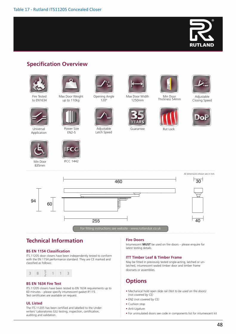
Table 17 - Rutland ITS11205 Concealed Closer
61
ITS.11205 | Co
ncealed
Slide A
rm D
oo
r Clo
ser
Technical Information
Options
All dimensions shown are in mm.
Specification Overview
• Mechanical hold open slide rail (Not to be used on fire doors) (not covered by CE)
• EN2 (not covered by CE)
• Cushion stop
• Anti-Ligature
• For uninsulated doors see code in components list for intumescent kit
Fire DoorsIntumescent MUST be used on fire doors – please enquire for latest testing details.
ITT Timber Leaf & Timber FrameMay be fitted in previously tested single-acting, latched or un-latched, intumescent sealed timber door and timber frame
doorsets or assemblies.
UL ListedThe ITS.11205 has been certified and labelled to the Under-writers’ Laboratories (UL) testing, inspection, certification, auditing and validation.
3 8 52 1 1 3
BS EN 1154 ClassificationITS.11205 door closers have been independently tested to conform with the EN 1154 performance standard. They are CE marked and classified as follows:
BS EN 1634 Fire TestITS.11205 closers have been tested to EN 1634 requirements up to 60 minutes – please specify intumescent gasket IP.115. Test certificates are available on request.
6094
255
460
40
30
6094
255
460
40
30
Fire Tested to EN1634
Max Door Weight up to 110kg
UniversalApplication
FIRE TESTED MAXIMUMDOOR WEIGHT
OPEN ANGLE
ADJUSTABLELATCH ACTION
GUARANTEE
GUARANTEEMAXIMUMDOOR WIDTH
ADJUSTABLECLOSING SPEED
BACK CHECK
UNIVERSALAPPLICATION
EN2-4 GUARANTEE
FIRE TESTED MAXIMUMDOOR WEIGHT
OPEN ANGLE
ADJUSTABLELATCH ACTION
GUARANTEE
GUARANTEEMAXIMUMDOOR WIDTH
ADJUSTABLECLOSING SPEED
BACK CHECK
UNIVERSALAPPLICATION
EN2-4 GUARANTEE
FIRE TESTED MAXIMUMDOOR WEIGHT
OPEN ANGLE
ADJUSTABLELATCH ACTION
GUARANTEE
GUARANTEEMAXIMUMDOOR WIDTH
ADJUSTABLECLOSING SPEED
BACK CHECK
UNIVERSALAPPLICATION
EN2-4 GUARANTEEPower Size
EN2-5
FIRE TESTED MAXIMUMDOOR WEIGHT
OPEN ANGLE
ADJUSTABLELATCH ACTION
GUARANTEE
GUARANTEEMAXIMUMDOOR WIDTH
ADJUSTABLECLOSING SPEED
BACK CHECK
UNIVERSALAPPLICATION
EN2-4 GUARANTEE
Opening Angle120º
FIRE TESTED MAXIMUMDOOR WEIGHT
OPEN ANGLE
ADJUSTABLELATCH ACTION
GUARANTEE
GUARANTEEMAXIMUMDOOR WIDTH
ADJUSTABLECLOSING SPEED
BACK CHECK
UNIVERSALAPPLICATION
EN2-4 GUARANTEE
Adjustable Latch Speed
FIRE TESTED MAXIMUMDOOR WEIGHT
OPEN ANGLE
ADJUSTABLELATCH ACTION
GUARANTEE
GUARANTEEMAXIMUMDOOR WIDTH
ADJUSTABLECLOSING SPEED
BACK CHECK
UNIVERSALAPPLICATION
EN2-4 GUARANTEE
Max Door Width1250mm
FIRE TESTED MAXIMUMDOOR WEIGHT
OPEN ANGLE
ADJUSTABLELATCH ACTION
GUARANTEE
GUARANTEEMAXIMUMDOOR WIDTH
ADJUSTABLECLOSING SPEED
BACK CHECK
UNIVERSALAPPLICATION
EN2-4 GUARANTEE
Min Door Thickness 54mm
MIN DOORTHICKNESS
AdjustableClosing Speed
FIRE TESTED MAXIMUMDOOR WEIGHT
OPEN ANGLE
ADJUSTABLELATCH ACTION
GUARANTEE
GUARANTEEMAXIMUMDOOR WIDTH
ADJUSTABLECLOSING SPEED
BACK CHECK
UNIVERSALAPPLICATION
EN2-4 GUARANTEE
Rut LockRUT LockEndurance DDA DoPGuarantee
Min Door 835mm
Endurance DDA DoPIFCC 1442
For fitting instructions see website - www.rutlanduk.co.uk

49
Table 17 - Astra 4000 Series Jamb Concealed Closer
4000 SeriesFollowing market research and feedback gathered from a combination of architects, interior designers, architectural ironmongers, doorset manufacturers and joiners it became apparent that there was a demand in the market for a jamb mounted concealed closer that was efficient, fully concealed but also easier to install compared to the current products available. Our Research and Development Department were tasked to produce a concealed jamb mounted door control that was fully concealed when the door is closed, seamless to fit in to the doorset at the factory stage through CNC machines, easy to install on site, and fully adjustable once the closer is installed.
The UK-manufactured 4000 Series includes three different power size door closers each with easily adjustable speed: the 4001, 4002 and 4003. It is manufactured with a single spring and hydraulic unit, that offers a higher efficiency rate than a typical overhead closer so it does not require any adjustable latching. The 4000 Series does not need to be removed to adjust the closing speed, this can be done with a flat headed screwdriver with the door closer installed.
The Astra 4000 Series door closers are tested and certified to all British and international performance standards and programmes, including FD30 & FD60 fire tests conducted in accordance with BS EN1634-1:2000 (test report CHILT/RF06118). It will allow specifiers to meet PAS 24 standards for residential entrance doors since it is Secured by Design (SBD) accredited. Astra 4000 Series door closers have also been successfully included in tests in both Halspan and Streboard core 44mm and 54mm doors and has successfully completed in house-testing to over 500,000 cycles.
An ultra-compact high efficiency design makes the Astra 4000 Series the perfect choice for both new-build and refurbishment projects.
They are ideally suited to a wide variety of applications including hotel bedrooms, office doors, residential dwellings, student accommodation and any setting with a reduced ligature requirement.
4000 Series Dimensions

50
Table 17 - Rutland TS3204 Face Fixed Closer
11
TS.3
204
| Scissor A
rm D
oo
r Clo
ser
Technical Information Options
All dimensions shown are in mm.Mechanism Cover
Specification Overview
• Hold-Open arm (Not to be used on fire doors)
• Hollow door fixing pack
• Drop plate
Options not covered by CE.
• Silver and Plated finishes
4 8 3 3 1 3
3 8 3 1 1 3
BS EN 1154 ClassificationTS.3204 door closers have been independently tested to conform with the EN 1154 performance standard. They are CE marked and classified as follows:
Standard Arm Fig 1.
Parallel Arm Fig 66.
BS EN 1634 Fire TestTS.3204 closers have been tested to EN 1634 for 30, 60 and 120 minute door sets. Test certificates are available on request.
UL ListedThe TS.3204 has been certified and labelled to the Underwriters’ Laboratories (UL) testing, inspection, certification, auditing and validation.
Fire Tested to EN1634
& UL 10C
Max Door Weight 80kg
Opening Angle180º
Max Door Width930mm
AdjustableClosing Speed
UniversalApplication
Power Size EN3
Adjustable Latch Speed
Guarantee
FIRE TESTED MAXIMUMDOOR WEIGHT
OPEN ANGLE
ADJUSTABLELATCH ACTION
GUARANTEE
GUARANTEEMAXIMUMDOOR WIDTH
ADJUSTABLECLOSING SPEED
BACK CHECK
UNIVERSALAPPLICATION
EN2-4 GUARANTEE
FIRE TESTED MAXIMUMDOOR WEIGHT
OPEN ANGLE
ADJUSTABLELATCH ACTION
GUARANTEE
GUARANTEEMAXIMUMDOOR WIDTH
ADJUSTABLECLOSING SPEED
BACK CHECK
UNIVERSALAPPLICATION
EN2-4 GUARANTEE
FIRE TESTED MAXIMUMDOOR WEIGHT
OPEN ANGLE
ADJUSTABLELATCH ACTION
GUARANTEE
GUARANTEEMAXIMUMDOOR WIDTH
ADJUSTABLECLOSING SPEED
BACK CHECK
UNIVERSALAPPLICATION
EN2-4 GUARANTEE
FIRE TESTED MAXIMUMDOOR WEIGHT
OPEN ANGLE
ADJUSTABLELATCH ACTION
GUARANTEE
GUARANTEEMAXIMUMDOOR WIDTH
ADJUSTABLECLOSING SPEED
BACK CHECK
UNIVERSALAPPLICATION
EN2-4 GUARANTEE
FIRE TESTED MAXIMUMDOOR WEIGHT
OPEN ANGLE
ADJUSTABLELATCH ACTION
GUARANTEE
GUARANTEEMAXIMUMDOOR WIDTH
ADJUSTABLECLOSING SPEED
BACK CHECK
UNIVERSALAPPLICATION
EN2-4 GUARANTEE
FIRE TESTED MAXIMUMDOOR WEIGHT
OPEN ANGLE
ADJUSTABLELATCH ACTION
GUARANTEE
GUARANTEEMAXIMUMDOOR WIDTH
ADJUSTABLECLOSING SPEED
BACK CHECK
UNIVERSALAPPLICATION
EN2-4 GUARANTEE
FIRE TESTED MAXIMUMDOOR WEIGHT
OPEN ANGLE
ADJUSTABLELATCH ACTION
GUARANTEE
GUARANTEEMAXIMUMDOOR WIDTH
ADJUSTABLECLOSING SPEED
BACK CHECK
UNIVERSALAPPLICATION
EN2-4 GUARANTEE
FIRE TESTED MAXIMUMDOOR WEIGHT
OPEN ANGLE
ADJUSTABLELATCH ACTION
GUARANTEE
GUARANTEEMAXIMUMDOOR WIDTH
ADJUSTABLECLOSING SPEED
BACK CHECK
UNIVERSALAPPLICATION
EN2-4 GUARANTEEFIRE TESTED MAXIMUMDOOR WEIGHT
OPEN ANGLE
ADJUSTABLELATCH ACTION
GUARANTEE
GUARANTEEMAXIMUMDOOR WIDTH
ADJUSTABLECLOSING SPEED
BACK CHECK
UNIVERSALAPPLICATION
EN2-4 GUARANTEE
Other Benefits
32040000 CPR101218
Endurance DDA DoP 1432
Rut LockRUT Lock
59
68
20
16
220
224 44
42
59
68
20
16
220
224 44
42
For fitting instructions see website - www.rutlanduk.co.uk

51
Table 17 - Dorma TS73V Face Fixed Closer
2
dormakaba TS 73 V
Easy to fix, and even easier to adjustOutstanding versatility. Quality assured.Tested to EN 1154. The classic dormakaba TS 73 range has matured into the world’s most specified hydraulic door closer for all types of interior doors.Its pedigree has been proven by the countless imitations that have appeared over the years.
With the introduction of the TS 73 V, now more than ever, this technically superior closer has more features and has become simpler to specify and install.The spring strength of the closer can now be easily and steplessly adjusted by mean of an allen key, ensuring optimum performance in every situation.Certified to ISO 9001.
Plus points…
…for the trade• The TS73 V covers the application and spring strength
requirements of most standard interior doors (parallel arm bracket included with closer).
• Non-standard door and frame details are no problem with our wide range of fixing brackets and accessories.
• Stockholding requirements are reduced to a minimum without affecting service levels.
…for the installer• Quick and easy to fix – completely straightforward.• Closing speed, latching speed and spring strength all simply
adjusted with common handtools.• Each boxed unit comes complete with fixings for timber and
a parallel arm conversion bracket.
…for the specifier/architect• Compact dimensions in a classic shape.• Versatile in application, with a wide range of finishes.• Designed to cope with most door and frame details, and
backed by a wide range of accessories.
…for the user• Peace of mind – a closer that works well and goes on working
year after year.• High mechanical efficiency, low sensitivity to temperature
change, wide opening angle, pressure relief valve to protect hydraulics from abuse.
• Optimum wall and door protection thanks to “thinking” backcheck.
The TS 73 V complies with the requirements and/or recommendations of the following: CERTIFIRE approved for fire doors ITT 120; MM/IMM 240; Ref. CF 117
Data and features TS73 VTS73 VBC DC
Closing force adjustable
Size EN2–4
EN1–4
Standard doors1) ≤ 1100 mmExternal doors, opening outwards1) – –
Fire and smoke check doors1)≤ 1100 mmNon-handed
Arm StandardClosing force adjustable by means of setting screwClosing speed adjustable at 2 separate valves
180° – 15° 15° – 0°
Backcheck self-regulatingadjustable at valve
Adjustable latching action by arm
Delayed action –
Hold-openWeight in kg 1.3 1.3Dimensions in mm
Length Depth Height
225 40 60
245 46 60
Door closer tested to EN 1154
mark for construction products2 Yes – No " Option
1) For high and heavy doors, external doors, and for doors required to close against high wind pressure, we recommend dormakaba TS 83.

52
Table 17 - Dorma TS71 Face Fixed Closer
2
dormakaba TS 71
EN 3
EN 443
193, 5 59
76,5225050232
4538
105
4543
15
ca. 280
45
68
The inexpensive solution for standard doors – With quality assuredWith the TS 71, dormakaba has developed a door closer that rounds off its Classic Line series perfectly. The ease and speed with which it can be fixed, the fact that its spring strength can be so easily adapted to the door size – by simply turning round the hinge plate – and its competitive price should make it the ideal choice for your application.Certified to ISO 9001
BenefitsFor the trade• Increased stocking flexibility
thanks to use of the standard ClassicLine series arm.
• Complements the ClasscLine series as a competitive model for standard doors.
For the installer• Non-handed design.• Easy and quick to fix.
For the architect/specifier• Competitive and reliable.• Compact construction
combined with classic design.
For the user• Constant closing action
virtually unaffected by temperature fluctuations.
• Optimum closing speed adjustment with two regulating valves.
• Reliable closing with adjustable latching action.
The dormakaba TS 71 is CERTIFIRE approved (Certificate No. CF 268) for doortypes ITT 120 and MM/IMM 240
Data and features TS 71
Spring strength (adjustable by Size EN 3/4 turning round the hinge plate)Standard doors ≤ 1100 mm1) External doors, outward opening –Fire doors Non-handed Arm type Standard Slide channel –Closing speed adjustable 180° – 15° at 2 separate valves 115° – 10°Latching action adjustable (by arm) Backcheck –Delayed action –Hold-open Weight in kg 1.2Dimensions in mm Length 232 Overall depth 245 Height 68Door closer tested and approved to EN 1154 CE Marked
= Yes – = No = Option
1) With parallel-arm fixing, the closing force is approx. 20 Nm (for doors up to 950 mm)
12
4
2
1 50°
1
15 °
3
Standard and optional functions
1 Closing speed adjustable in the range 180° – 15°. 2 Closing speed adjustable in the range 15° – 0°. 3 Latching action. 4 Hold-open range for model with hold-open arm (optional extra).
Closing force settings
Door width Setting≤ 950 EN 3≤ 1100 EN 4
With the TS 71, the spring strength (size setting) of the closer isadjusted to the door width concerned by merely turning round thehinge plate.

53
Table 17 - Briton 1110 Face Fixed Closer10212 ZINS B337
éàéé

54
Table 18 - Royde and Tucker LP08
R T Te c h n i c a l S a l e s – Te l : 0 1 4 6 2 4 4 4 4 4 4 F a x : 0 1 4 6 2 4 4 4 4 3 3 w w w. r a t m a n . c o . u k R T Te c h n i c a l S a l e s – Te l : 0 1 4 6 2 4 4 4 4 4 4 F a x : 0 1 4 6 2 4 4 4 4 3 3 w w w. r a t m a n . c o . u k
LP08 – Approved Document Q
• Supplied complete with external and internal flaps,aperture liner and security cowl
• System includes for fire/smoke resistant models FD30S and FD60S doors
• System included integral weather seals• Appropriate for installation where fire risk may be
from either side of the door• Suitable for use on acoustic doorsets. Achieves
31Db/Rw sound reduction on an appropriate door• Security Tested to TS008:2015• To suit door thicknesses:
42–47mm, 47–52mm, 52–57mm and 70mm• Flaps held in the closed position on magnets• Easy to install, either at works or on site• Suitable for use on timber and some UPVC doors,
please contact the sales office for guidance
TS008:2015 approved letterplate & security cowl (complete kit)Classification
PARTSMild Steel/Stainless Steel frames and flaps and cowlLP08-44: E30/E60 Fire rated inc Smoke seals 42–47mm DoorsLP08-49: E30/E60 Fire rated inc Smoke seals 47–52mm DoorsLP08-54: E30/E60 Fire rated inc Smoke seals 52–57mm DoorsLP08-70: E30/E60 Fire rated inc Smoke seals 70mm Doors (suitable for some UPVC doors)Finishes*: Silver Anodised Finish – SAA,, Brushed Stainless Steel – BSS, Polished Stainless Steel – PSS, Polished Brass Lacquered – PBL, Imitation Bronze – RBZ, Antique Brass – ABR, Dark Bronze – DBZ, Colour Powder Coated – NST
* (For some finishes the frame is a different finish to the flaps. Please contact the same office if in doubt).
96
TO SUIT WOODEN DOOR THICKNESS 42-47mm, 47-52mm, 52-57mm
INCLUSIVE SUITS CERTAIN 70mm uPVC APPLICATIONS
92
8 THRU FIXING
HOLE
OV
ERA
LL D
IMEN
SIO
N
312
SLEEVE APERTURE
OVERALL DIMENSION
270
292
60
80
POSTAL APERTURESLEE
VE
APE
RTUR
E
HOLE SPACING
250
40
POST
AL
APE
RTUR
E
CLASSIFICATION
Classification of enhanced security and general requirementsare detailed below –
1st Digit: Product type A = Without any remotely fitted security hardware B = With remotely fitted security hardware p.7 of 22
2nd Digit: Aperture type Type: 1 = Letterplate assemblies 2 = Slide through box
3rd Digit: Enhanced security level 1 = Resistance to thumb-turn manipulation 2 = Resistance to thumb-turn manipulation and fishing
4th Digit: Option to lock the letter plate to prevent delivery of mail N = No not lockable Y = Yes lockable
5th Digit: Corrosion 3 = 96 hours 4 = 240 hours 5 = 480 hours
6th Digit: Resistance to water penetration N = No performance determined Y = Pass
7th Digit: Fire Resistance (to either BS476– 22 or EN 1634-1) 0 = No Fire resistance 1 = Yes
8th Digit: Arson attackGrade 0 = No performance determinedGrade 1 = Yes
A 1 2 N 3 Y 1 0

55
Table 18 - ERA Nu Mail Letterplate
All dimensions are in mm and are nominal. Fab&Fix reserves the right to change specification without notice
It is the responsibility of the door manufacturer to ensure that the finished product meets any required safety and performance specification.
Overall Frame Size - 310mm
Flap Size - 278mm
68m
m o
r 76
mm
Recommended Routing Detail
264mm
280mm
Sleeve Length - 257mm
Fixing Screws Centres - 270mm
Panel Sleeve Set20mm-40mm
Midrail Sleeve Set40mm-80mm
Unit 4 The Moorings Business Park, Channel Way, Exhall, Coventry, CV6 6RH United Kingdom
www.erahomesecurity.comTel: +44 1922 490049 Fax: +44 1922 494420 [email protected]
Antique Black 3C0063C2063C0183C211
Midrail 76(40-80)
3C001
Panel 76(20-40)
3C009
9B000
3C2093C0088D0013C0003C200
3C0053C2053C0033C2033C0023C202
3C201
3C1063C306Hardex Graphite 3C1113C311Hardex GoldHardex BronzeHardex Satin
*Easy Fit Rubber Drip Gasket
Silver
Midrail 68(40-80)
3C101
Panel 68(20-40)
3C1093C3093C1083C3083C1003C300
3C1053C3053C1033C3033C1023C302
3C301
BlackWhite
Hardex Chrome
Product
Nu Mail LetterplatePart No.Finish
Ordering Details
PerformanceTested as part of a complete door set that successfully achieved PAS23 (rubber gasket fitted)Tested as part of a complete door set that successfully achieved PAS24
Technical InformationCorrosion resistance
ScrewsMidrail version includes 2 x M5 x 50mm machine screws, 2 x M5 x 70mm machine screws and 2 screw guidesPanel version includes 2 x M5 x 28mm machine screws and 2 screw guides
Operation
Meets the requirements of BS EN 1670:2007 Grade 5 (480 hours)
Flap cycle tested to 30,000 cyclesConforms to the requirements of BS EN 13724: 2002
180˚
44mm68mm or 76mm
Fixing Screws Provided
Coatings:
Frame and Flap:
Hardex Chrome, Hardex Satin, Hardex Bronze, Hardex Gold, Hardex Graphite, Antique Black, White, Black and Silver.
High quality Zinc
Material Specification
For continued protection of the quality finish and appearance, Fab&Fix advise routine cleaning of all our external hardware. Moving parts should also be lightly lubricated at least twice a year. This procedure is particularly essential if products are used within a 25-mile radius of coastal areas or close proximity to building sites or large industrial areas, where more frequent cleaning may be required to prevent the accumulation of corrosive contaminants.
Maintenance
PackagingNu Mail LetterplateIndividually boxed with fixings and care instructions. 15 letterplates in an outer box.
Letterplates WEATHERSEALS
STEEL
CROMPTON
VIRTICAL
SLIDING DOORS
TILT & TURN
WINDOW
S
CASEMENT W
INDOWS
SHED,GARAGES,
GATES & OTHER
FRENCH PATIO
&SLIDING DOORS
INTERNAL DOORS
EXTERNAL DOORS
Nu Mail Letterplate

56
Table 18 - ERA Nu Mail Letterplate Cowl
71.
83
354.00
79.
50
Letterplates
ERA Straight Road, Short Heath, Willenhall, West Midlands WV12 5RA United KingdomTel: +44 1922 490049 Fax: +44 1922 494420 [email protected]
www.eraeverywhere.com
Ordering Details
Hardex ChromeHardex Bronze
3F0023F003
Hardex GoldHardex Graphite
3F0043F005
Antique BlackWhite
3F0063F000
Black 3F001
Nu Mail Letterplate Security Shield Part No.Finish
All dimensions are in mm.ERA reserves the right to change specification without notice.
It is the responsibility of the door manufacturer to ensure that the finished product meets any required safety and performance specification.
PerformanceIndependently tested to meet the requirements of TS008: 2015 (Inc. Corr, No 1) when used in conjunction with the Fab&Fix 3C 76mm Nu Mail Letterplate. Designed to meet the requirements of PAS 24 in a compliant door set.
Technical InformationCorrosion resistance
FixingsIncludes 4 x M5 x 65mm screws, 4 x Jack Nuts and 2 x cover caps.
Meets the requirements of BS EN 1670:2007 Grade 5 (480 hours)
Coatings:
Frame:
Hardex Chrome, Hardex Bronze, Hardex Gold, Hardex Graphite, Antique Black, White and Black.
High quality Zinc
Material Specification
For continued protection of the quality finish and appearance, Fab&Fix advise routine cleaning of all our external hardware. Moving parts should also be lightly lubricated at least twice a year. This procedure is particularly essential if products are used within a 25-mile radius of coastal areas or close proximity to building sites or large industrial areas, where more frequent cleaning may be required to prevent the accumulation of corrosive contaminants.
Maintenance
The Nu Mail Security Shield (Cowl) has been certified to TS008:2015 and carries the following classification:
Classification
Classification
Category
00N3N21B
87654321
PackagingNu Mail Letterplate Security ShieldIndividually boxed with fixings and care instructions. 10 letterplate shields in an outer box.
EXTERNAL DOORS
Nu Mail Letterplate Security Shield
280
264
48
12
=
=
= =
R6
Routing Detail
Letterplate Shield

57
Table 19 - ERA Fab&Fix PVCu/Timber Door Chain 791-65
Door Chain
Door Restrictor
Slide Chain
Door ViewerConcealed Door Chain
Tel: +44 1922 490049 Fax: +44 1922 494420 [email protected] ERA. Straight Road, Short Heath, Willenhall, West Midlands WV12 5RA United Kingdom
www.erahomesecurity.com
Concealed Door Chain
Door Viewer
Product
Ordering Details
All dimensions are in mm.ERA reserves the right to change
specification without notice.It is the responsibility of the window
manufacturer to ensure that the finished product meets any required safety
and performance specification
56
16 10 27
47
214
34
25.5
8.5
30.542
50
20.5
14
42
25.5
51
16
12
AdjustableMin 35Max 54
28
14
9130.5
19
50
11 4.5
15
3838
200
41
86
41
65
107
65
59
8
32
160º Chrome - Plastic Lens Wide Angle 191 - 62
180º Chrome - Plastic Lens Wide Angle 192 - 62180º Brass - Plastic Lens Wide Angle 192 - 32
160º Brass - Plastic Lens Wide Angle 191 - 32
160º Chrome - Glass Lens 784 - 62
120º Chrome - Plastic Lens 190 - 62120º Brass - Plastic Lens 190 - 32
160º Brass - Glass Lens
786 - 32120º Brass - Glass Lens
786 - 62784 - 32
120º Chrome - Glass Lens
Part No.
Satin 700 - 32700 - 52
Brassed
Slide Door Chain
Satin 787-32787-52
Brass
Timber/ PVCu Door Chain
Satin 791-32791-52
Brassed
Chrome 791-62
Door Restrictor
Chrome789-32789-62
Brassed
Door Viewer1 per clam, 10 per box.
Concealed Door Chain:1 per clam, 10 per box.
Door Chains:1 per clam, 10 per box.
Door Restrictor:1 per clam, 10 per box.
Packaging
MaintenanceThe surface should be cleaned with a soft cloth to remove any dust or grime. The product should be periodically adjusted and the fixings tightened to ensure a satisfactory operation
Door Accessories WEATHERSEALS
STEEL
CROMPTON
VIRTICAL
SLIDING DOORS
TILT & TURN
WINDOW
S
CASEMENT W
INDOWS
SHED,GARAGES,
GATES & OTHER
FRENCH PATIO
&SLIDING DOORS
INTERNAL DOORS
EXTERNAL DOORS
Door Chains and Viewers

58
Table 19 - ERA Fab&Fix Door Numerals FFNUM8BC
All dimensions are in mm and are nominal. Fab&Fix reserves the right to change specification without notice
It is the responsibility of the door manufacturer to ensure that the finished product meets any required safety and performance specification.
Unit 4 The Moorings Business Park, Channel Way, Exhall, Coventry, CV6 6RH United Kingdom
www.erahomesecurity.comTel: +44 1922 490049 Fax: +44 1922 494420 [email protected]
Screws: Includes 2 X M3.5 x 25mm colour coordinated countersunk flat head screw
Standard width of all letters and
numerals - 4.50mm
2 x Screws ProvidedPer Numeral
Antique Black
0
4B704
8
4B654
7
4B604
6 or 9
4B554
5
4B504
4
4B454
3
4B404
Hardex GraphiteHardex GoldHardex BronzeHardex Satin
Silver
2
4B354
1
4B304
BlackWhite
Hardex Chrome
Part No.Finish
Numbers 0 - 9
Ordering Details
Approximate height of all numerals - 80mm
4B7054B6554B6054B5554B5054B4554B4054B3554B3054B7064B6564B6064B5564B5064B4564B4064B3564B3064B7084B6584B6084B5584B5084B4584B4084B3584B3084B7124B6624B6124B5624B5124B4624B4124B3624B3124B7094B6594B6094B5594B5094B4594B4094B3594B3094B7004B6504B6004B5504B5004B4504B4004B3504B3004B7014B6514B6014B5514B5014B4514B4014B3514B3014B7024B6524B6024B5524B5024B4524B4024B3524B302
Coatings:
Numerals:
Hardex Chrome, Hardex Satin, Hardex Bronze, Hardex Gold, Hardex Graphite, Antique Black, White and Silver
High quality Zinc
Technical InformationCorrosion resistanceMeets the requirements of BS EN 1670:2007 Grade 5 (480 hours)
Material Specification
For continued protection of the quality finish and appearance, Fab&Fix advise routine cleaning of all our external hardware. Moving parts should also be lightly lubricated at least twice a year. This procedure is particularly essential if products are used within a 25-mile radius of coastal areas or close proximity to building sites or large industrial areas, where more frequent cleaning may be required to prevent the accumulation of corrosive contaminants.
Maintenance
PackagingNumeralsIndividually bagged with screws and care instructions. 10 in an outer box.
Door Accessories WEATHERSEALS
STEEL
CROMPTON
VIRTICAL
SLIDING DOORS
TILT & TURN
WINDOW
S
CASEMENT W
INDOWS
SHED,GARAGES,
GATES & OTHER
FRENCH PATIO
&SLIDING DOORS
INTERNAL DOORS
EXTERNAL DOORS
Numbers 0-9

59
Table 19 - ERA Ingot Door Knocker 4A550
140
52.528.3
74
17
7.4
3
127
10
14
74
91
5822
95
22
5
5
5
5
All dimensions are in mm and are nominal. Fab&Fix reserves the right to change specification without notice
It is the responsibility of the door manufacturer to ensure that the finished product meets any required safety and performance specification.
Tel: +44 2476 585785 Fax: +44 2476 585786 [email protected] Unit 4 The Moorings Business Park, Channel Way, Exhall, Coventry, CV6 6RH United Kingdom
www.erahomesecurity.com
Ingot KnockerPart No.Finish
Product
Brushed Steel 4A550
Ordering Details
Technical InformationCorrosion resistance
Operation
Salt spray tested to 1000 hours (BS EN1670: Class 5)
Tested to 200,000 cycles
Handle Grip and Backplate: Stainless Steel
Coatings: Brushed Steel
Material Specification
MaintenanceTo maintain your stainless steel product in best condition, we recommend routine cleaning once a month. All exposed stainless steel surfaces should be wiped over with a clean cloth and warm water with a mild detergent on a frequent and routine basis. Cleaning should always be immediately followed by rinsing in clean hot water and the surface then wiped completely with a dry towel. For more stubborn dirt or stains use mild, non-scratching abrasive powders such as typical household cleaners. These can be used with bristle brushes, sponges or non-abrasive scourers. For more aggressive cleaning a small amount of vinegar can be added to the powder. Carbon steel brushes and steel wool should be avoided as they may leave particles embedded in the surface, which can lead to rusting.
Door Accessories WEATHERSEALS
STEEL
CROMPTON
VERTICAL
SLIDING DOORS
TILT & TURN
WINDOW
S
CASEMENT W
INDOWS
SHED,GARAGES,
GATES & OTHER
FRENCH PATIO
&SLIDING DOORS
INTERNAL DOORS
EXTERNAL DOORS
Ingot Door Knocker

60
Q Mark Fire CertificateQ Mark Enhanced Security CertificateQ Mark Fire Door Plug DetailsLinks
Appendix B
61626364
Page
Appendix B compiles the relevant certification held by Falcon Panel Products, details on Q Mark Labelling and links to other useful documents and websites.

61
Robert Veitch Executive Vice President Fire & Building Products
Element Materials Technology
Certificate Number
020
Date of Initial Certification 27 January 2009
Date of Last Issue 20 July 2018
Date of Expiry 28 September 2021
Warringtonfire Testing and Certification Limited t/a BM TRADA, Chiltern House, Stocking Lane, High Wycombe, Buckinghamshire, HP14 4ND, UK Registered Office: Warringtonfire Testing and Certification Limited, 10 Lower Grosvenor Place, London, SW1W 0EN, UK.
Reg No. 11371436.
This certificate remains the property of Warringtonfire Testing and Certification Limited. This certificate and all copies or reproductions of the certificate shall be returned to Warringtonfire Testing and Certification Limited or destroyed if requested. Further clarification regarding the
scope of this certificate and verification of the certificate is available through BM TRADA or at the above address or at www.bmtrada.com
CERTIFICATE OF REGISTRATION This is to certify that
Falcon Panel Products Ltd Clock House Station Approach Shepperton Middlesex TW17 8AN Meets the requirements of the BM TRADA Q-Mark Fire Door Manufacture scheme to STD 006

62
Robert Veitch Executive Vice President Fire & Building Products
Element Materials Technology
Certificate Number
297
Date of Initial Certification 29 November 2019
Date of Last Issue 2 December 2019
Date of Expiry 28 September 2021
Warringtonfire Testing and Certification Limited t/a BM TRADA, Chiltern House, Stocking Lane, High Wycombe, Buckinghamshire, HP14 4ND, UK Registered Office: Warringtonfire Testing and Certification Limited, 10 Lower Grosvenor Place, London, SW1W 0EN, UK.
Reg No. 11371436.
This certificate remains the property of Warringtonfire Testing and Certification Limited. This certificate and all copies or reproductions of the certificate shall be returned to Warringtonfire Testing and Certification Limited or destroyed if requested. Further clarification regarding the
scope of this certificate and verification of the certificate is available through BM TRADA or at the above address or at www.bmtrada.com
CERTIFICATE OF REGISTRATION This is to certify that
Falcon Panel Products Ltd Clock House Station Approach Shepperton Middlesex TW17 8AN Meets the requirements of the BM TRADA Q-Mark Enhanced Security Door scheme to PAS 24:2016 and BS 644:2012 Timber All companies manufacturing doorsets to the certified specification must hold permission from Falcon Panel Products Ltd and hold QMark certification in their own name in order to claim to be certified by BM TRADA for these products

63
Fire Door Certification SchemeOuter colour - period of fire integrity.Inner/tree colour - status of manufacture.Unique certified company’s number.
043
Outer colour - Period of fire
integrity (mins)
30
(Yellow)
60
(Blue)
90
(Brown)
120
(Black)
(Red)
Inner/Tree colourApproved door leaf and/or frame* (FD30 & FD60 only).Intumescent strips not supplied.
(Green)
Approved door leaf and/or frame* (FD30 & FD60 only).Intumescent strips prepared for & supplied.
(Orange)
Approved factory fitted glazing.
(Silver)
Complete certified factory hung doorset.
(Gold)
Certified installation of a complete factory hung doorset.
*Where the frame and leaf are produced by separate Q-Mark companies, both the frame and leaf must
have their own red/green plug.
For details of the scheme and list of certified companies visit
www.bmtrada.com or call +44 (0) 1494 569960

64
LinksStrebord & Stredor 44 & 54 FD30 Front Entrance Door Global Assessment - WF407090https://www.falconpp.co.uk/media/16049/strebord-stredor-front-entrance-door-30-minute-assessment-wf407090.pdf
Strebord Door Coreshttps://www.falconpp.co.uk/products/door-cores/strebord-door-cores/
Stredor Door Coreshttps://www.falconpp.co.uk/products/door-blanks/stredor/
BM Trada/Q Markhttps://www.bmtrada.com/
Hardware and SealsSealed Tight Solutionshttp://sealedtightsolutions.com/
Stormguard Thresholdhttps://www.stormguard.co.uk/stormguard-products/slimline-inward-opening/
Royde and Tucker Hardwarehttps://www.ratman.co.uk/
ERA Hardwarehttps://www.eraeverywhere.com/
Rutland Closershttps://www.rutlanduk.co.uk/
Astra Closershttp://www.astradoorcontrols.com/products/4000-series/
Dorma Closershttps://www.dormakaba.com/gb-en/solutions/products/door-hardware/door-closers
Briton Closershttps://www.allegion.co.uk/en/productcatalogue/doorcontrols.html

Gateshead DepotHaydock DepotHigh Wycombe DepotLeeds DepotNottingham DepotTilbury DepotWest Bromwich Depot
Falcon Panel Products LtdClock HouseStation ApproachShepperton, MiddlesexTW17 8ANE [email protected]
www.falconpp.co.uk
Falcon Panel Products Ltd reserves the right to alter specifications without notice. A Consolidated Timber Holdings Group Company
T 0191 338 8208 E [email protected] 01744 416 600 E [email protected] 01494 291 777 E [email protected] 0113 887 2222 E [email protected] 0115 919 2000 E [email protected] 01375 487 300 E [email protected] 0121 525 8844 E [email protected]
For technical support, training and guidanceFalcon Panel Products LtdDoor Technical OfficeUnit 1 Block 2Birch House Business CentreHen Lon ParcwrRuthinDenbighshireLL15 1NA
t: 01824 730266e: [email protected]
All product names, trademark and registered trademarks are property of their respective owners and are used in this document for the purpose of identification only.