scope corder dl750
TRANSCRIPT
DL750ScopeCorder
Up to 16 analog channels and 16-bit logic input
Up to 1 GigaWord total memory
GIGAZoom function
DualCapture function
10.4-inch SVGA color TFT liquid crystal display
10 MS/s, 12-bit A/D resolution, 2-channel isolation module
Floppy disk, ZIP® disk and PC card drives available
20-GB internal hard drive (optional)
Bulletin 7012-00E
DSP math function (optional) Voice memo function
Wave window trigger High-speed 10 MS/s 12-bit non-isolation module (2 CH) Strain modules (2 CH)
High-voltage 100 kS/s 16-bit isolation module (with RMS) (2 CH)
New Functions/New Modules
www.yokogawa.com/tm/... and subscribe to “Newswave,”our free e-mail newsletter
2
Leading-Edge Mounting Technology andASICs Reduce the Size of 2-Channel Modules
Modules
701250 701251 701255 701260 701265 701270 701271
High-Speed 10 MS/s 12-Bit Isolation Module (701250)Broad bandwidth (3 MHz) and high accuracy (0.5%) inputs
High-Speed 1 MS/s 16-Bit Isolation Module (701251)High resolution inputs combined with high-sensitivity (1 mV/div)
Temperature/High-Precision Voltage Module (701265)100 Hz frequency range, high-accuracy (0.08%) voltagemeasurements, and an ultra high-sensitivity range value (100µV/div)
High-Speed 10 MS/s 12-Bit Non-Isolation Module(701255)Non-isolated model with the same performance as themodel 701250
High-Voltage 100 kS/s 16-Bit Isolation Module (withRMS) (701260)850 V (DC+ACpeak) direct input, RMS modeAccuracy of 0.25%
Strain Modules (701270 & 701271)NDIS-type (701270) and DSUB-type (701271)Wide range of bridge voltages (2 V, 5 V, & 10 V)Accuracy of 0.5%
4 new modules for a variety of applications
NEWNEW NEW NEW
NEW
NEW
NEW
3
Voice Memo
VoiceComment
Image
Voice Event
Waveform
Save waveformdata and voice
memo in one file(WVF format)
Save image dataand voice memo in
separate files
Innovative Solutions for Long-Term Recording
DualCapture: A Powerful Tool for Durability Test Data Analysis
During durability testing, it is necessary to monitor the long-term trends of your data as well as capture the high speedtransients that might occur. This presents a challenge as trenddata is usually recorded at a slower sampling speed that mightmiss the transient phenomena. To meet this challenge, theDL750 offers the DualCapture function.
Using DualCapture, you can now record your trend data with aslow sampling speed and still be able to capture the transientphenomena with a faster sampling speed.
Integration of a High-Speed Sampler (Oscilloscope) andLow-Speed Sampler (Recorder) in a Single UnitHigh-speed sampler: Trigger on abnormal high-speed phenomenaLow-speed sampler: Roll recording (trend recording)
Separate Memory Management for Each SamplerMaximum memory for low-speed sampler: 100 MWMaximum memory for high-speed sampler:10 kW × 100 screens
High-Speed Sampling Triggered Only by AbnormalPhenomena Occurring During Long-Term Observation(Low-Speed Sampling)Effective for separately capturing data at high speed duringmeasurements.
Long Memory Equivalentto 1 TerawordTo acquire many hours ofdata at the higher samplingrate (10 MS/s) wouldrequire Terawords ofmemory(8 hr-240 hr) × 60 min × 60sec × 10 MS/s × 16channels= 4.6-138 TW
The waveform shown above was captured at a sampling rateof 50 kS/s. The occurrence of noise can be confirmed in thegraph, but the time resolution is too low to capture thewaveform accurately.
With DualCapture, the user sets triggers for capturing suddenphenomena. Up to 100 phenomena can be collected in a memorylength of 10 kW at a maximum sampling rate of 10 MS/s.
Simultaneous High-Speed and Low-Speed Recording Using DualCapture
10 kW
Phenomena canbe accuratelyassessed at 10MS/s
Maximum 100 phenomena
Voice Memo Function: Save Audio Comments along with Waveform Data and Images
Enables You to Record and Playback 2 Types of Voice Data
Voice MemoSimply press a switch to record your voice while simultaneouslyrecording waveforms. Make multiple recordings per waveform (100seconds total, min. 3 seconds per recording).
Voice CommentRecord and save an explanatory comment (approx. 3-10 seconds)together with your image files.
The 701951 Earphone-Mic (with PUSH switch) is required to recordvoice memos and to listen to recorded voice memos.
GIGAZoom Function for Instantaneous Full-Length Display of 1 GW of Data1 GW memory for full-length display and instantaneouszooming (to user-specified size)
A large-scale, high speedASIC was created to givethe DL750 the ability toshow the entire 1 GW ofdata on the display in realtime
Two zoom windows areavailable for displaying upto 500 MW of data.Zooming can be done inreal-time or after datarecording has stopped.
Roll-mode view
Seconds
100 seconds
600
9000
72000
864000
2592000
Minutes
1.67
10 minutes
150 minutes
1200
14400
43200
Hours
0.028
0.167
2.5 hours
20 hours
240.0
720.0
Days
0.001
0.007
0.10
0.83 day
10 days
30 days
Sample Rate
10 MS/s
1 MS/s
100 kS/s
10 kS/s
1 kS/s
200 S/s
Maximum Recording Time
Amount of time data can be recorded with 1 GW memory
NEW
User-specifiedcaptured screenand thecorrespondingtime are displayed.
This is the limit for50 kS/s.
Samephenomenon
Maximum 100 MW
4
Up to 2000 screens ofHistory Memory data.
Abnormal waveforms in the specified zone are extracted.
Zonesetting
Accurately Measure and Display Complex Signals
A Wide Range of Trigger Functions for Accurately Capturing a Variety of WaveformsHaving a wide range of triggers is of course very useful for obtaining stable observations of variety of different waveforms. Inaddition, the GUI menu makes setting trigger conditions easy and intuitive.
Action-On TriggerAutomatically Save Measured Data
When this trigger is activated, the DL750performs a specified action each time awaveform is captured and displayed on thescreen. This feature is useful for saving dataautomatically and reliably (e.g., for datacollection in automated, continuous tests).
Manual TriggerA Trigger Can Be Activated with Press of a Button.
With this feature, a trigger canbe executed whenever you like,separate from the presettrigger conditions.
History Memory and Smart Search for Effective Access to Large Amounts of Captured Data
History Memory and History Search (Zone Search)Occasionally, you may capture an abnormal waveform and then have itquickly disappear from the display as new data is acquired. It is not always possible to manually Start andStop data acquisition to catch the abnormal waveform and have it displayed.The History Memory function was designed for such situations. It divides long memory into a number ofblocks and automatically stores up to 2000 previously captured waveforms. This means you can reliablysave displayed waveforms to memory even when there are phenomena for which trigger conditions cannotbe set.The Zone Search function lets you define zones on the screen, and find all previously capturedwaveforms that either pass or don’t pass through the user-defined zone. Up to four zones can be defined.
Search (Edge Search) and ZoomThe Edge Search counts rising and falling edges in the captured data. It automaticallysearches for the desired edges and displays them on a zoom screen.
Simple and Enhanced Triggers
Wave Window TriggerAutomatically Triggers on Abnormalities in Power Supply Waveforms
This function comes standard with the DL750 to allow observation power supply waveforms. Inaddition to traditional power supply troubles, such as sudden outages, sags, and surges, youcan make efficient real time observations of frequency fluctuations and voltage drops. Thistrigger activates when a signal exceeds the allowable values determined by comparing adefined waveform (wave window) with an actual waveform in real time. Comparative waveformscan be automatically produced in real time based on measured waveforms. Detection on all 16analog channels is available (with OR conditions).
Edge trigger: Set a regular edge triggerA B (N):
A Delay B:
Edge on A:
OR: B > TIME:B < TIME:B TIME OUT: Period: Window:Wave Window:
Triggers the n-th time that condition B goes true after condition A has gone true.Triggers if condition B goes true after condition A has gone true and an interval at least equal to the delay setting has elapsed. Activates an edge trigger on another input during the interval when trigger condition A is true.Triggers when any one of the individual channel conditions set with the patterns goes true.Triggers when the pulse width is longer than the set timeTriggers when the pulse width is less than the timeTriggers when a preset time-out time is reachedTriggers when a preset waveform frequency condition goes true.Triggers when a trigger source enters or leaves a level set by two points Triggers when a signal leaves an automatically-defined "wave window" that surrounds the waveform
triggerdetection
sag
sagsuddenoutage
surgewave window
Capturing Signals Using the Longest Memory Capacity Ever
For Accurately Capturing Complex Signals or Long Waveforms
The DL750’s standard memory capacity is 50 MW (2.5 MW perchannel). This can be expanded (optional) to as much as 1 GW(50 MW per channel). Benefits of GigaWord Recording
You can record data for 10 days (1 day/div) on the main screen, whiledisplaying 1-second recordings (100 ms/div) in real time on the zoomscreen. The large memory capacity lets you capture all of your datawhile still maintaining a sample rate fast enough to see any abnormalphenomena.
Efficient Memory UseSufficient memory length is available even when 16 channels are used,so you can conduct extended observations on multiple channels (2.5MW per channel with standard memory, 50 MW per channel withmaximum memory). Multi-Channel 2-Location Zoom Function
NEW
5
Analyze Captured Waveform Data
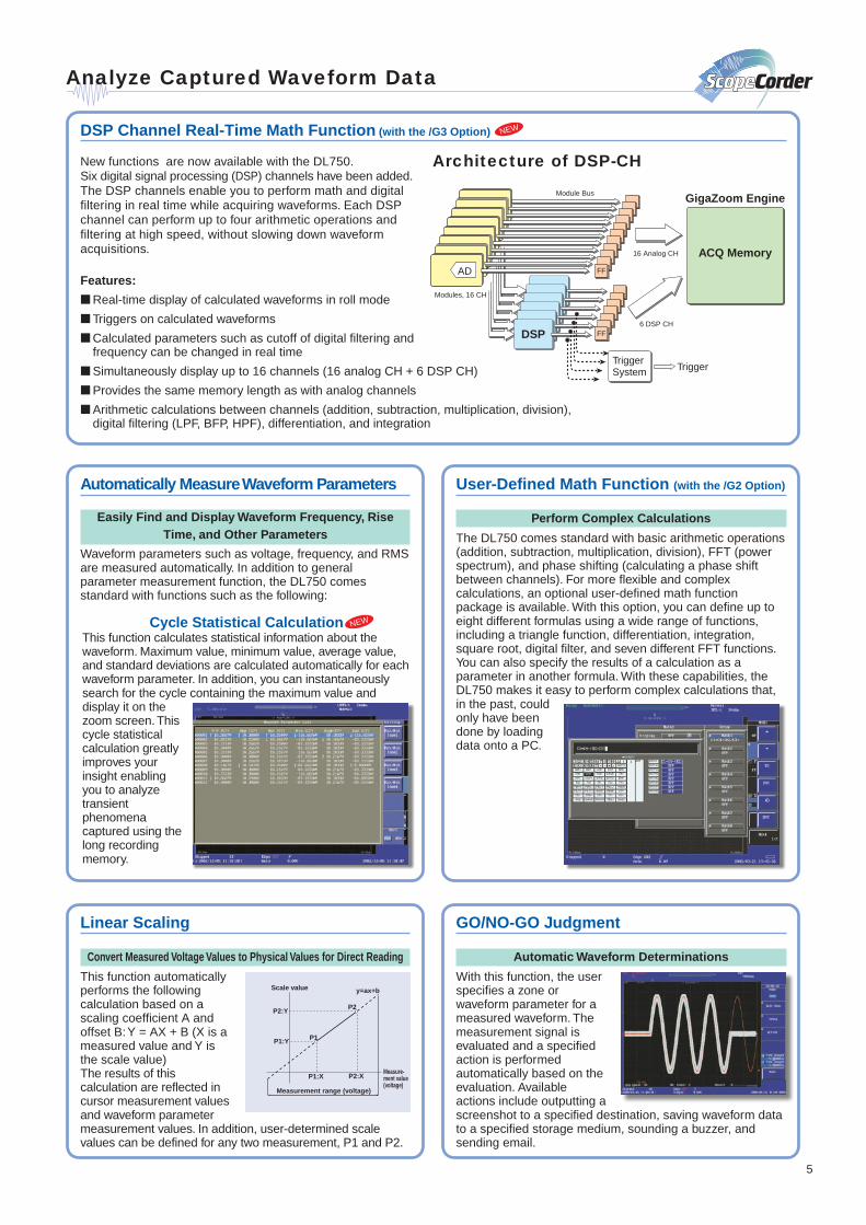
DSP Channel Real-Time Math Function (with the /G3 Option)
Cycle Statistical CalculationThis function calculates statistical information about thewaveform. Maximum value, minimum value, average value,and standard deviations are calculated automatically for eachwaveform parameter. In addition, you can instantaneouslysearch for the cycle containing the maximum value anddisplay it on thezoom screen. Thiscycle statisticalcalculation greatlyimproves yourinsight enablingyou to analyzetransientphenomenacaptured using thelong recordingmemory.
Linear Scaling
Convert Measured Voltage Values to Physical Values for Direct Reading
This function automaticallyperforms the followingcalculation based on ascaling coefficient A andoffset B: Y = AX + B (X is ameasured value and Y isthe scale value)The results of thiscalculation are reflected incursor measurement valuesand waveform parametermeasurement values. In addition, user-determined scalevalues can be defined for any two measurement, P1 and P2.
GO/NO-GO Judgment
Automatic Waveform Determinations
With this function, the userspecifies a zone orwaveform parameter for ameasured waveform. Themeasurement signal isevaluated and a specifiedaction is performedautomatically based on theevaluation. Availableactions include outputting ascreenshot to a specified destination, saving waveform datato a specified storage medium, sounding a buzzer, andsending email.
User-Defined Math Function (with the /G2 Option)
Perform Complex Calculations
The DL750 comes standard with basic arithmetic operations(addition, subtraction, multiplication, division), FFT (powerspectrum), and phase shifting (calculating a phase shiftbetween channels). For more flexible and complexcalculations, an optional user-defined math functionpackage is available. With this option, you can define up toeight different formulas using a wide range of functions,including a triangle function, differentiation, integration,square root, digital filter, and seven different FFT functions.You can also specify the results of a calculation as aparameter in another formula. With these capabilities, theDL750 makes it easy to perform complex calculations that,in the past, couldonly have beendone by loadingdata onto a PC.
Measurement range (voltage)
P1
P2
P1:X P2:X
P1:Y
P2:Y
y=ax+b
Measure-ment value (voltage)
Scale value
Automatically Measure Waveform Parameters
Easily Find and Display Waveform Frequency, RiseTime, and Other Parameters
Waveform parameters such as voltage, frequency, and RMSare measured automatically. In addition to generalparameter measurement function, the DL750 comesstandard with functions such as the following:
New functions are now available with the DL750.Six digital signal processing (DSP) channels have been added.The DSP channels enable you to perform math and digitalfiltering in real time while acquiring waveforms. Each DSPchannel can perform up to four arithmetic operations andfiltering at high speed, without slowing down waveformacquisitions.
Features:
Real-time display of calculated waveforms in roll mode
Triggers on calculated waveforms
Calculated parameters such as cutoff of digital filtering andfrequency can be changed in real time
Simultaneously display up to 16 channels (16 analog CH + 6 DSP CH)
Provides the same memory length as with analog channels
Arithmetic calculations between channels (addition, subtraction, multiplication, division),digital filtering (LPF, BFP, HPF), differentiation, and integration
Architecture of DSP-CH
GigaZoom Engine
ACQ Memory
DSP
AD
TriggerSystem Trigger
FF
FF
Module Bus
Modules, 16 CH
16 Analog CH
6 DSP CH
NEW
NEW
6
Display and Data Recording Functions
Real-Time Hard Drive Recording (with the /C8 Option)
Recorder-Like Real-Time Data Recording over Extended Periods
With the optional internalhard drive, you can recordmeasurements to the harddrive in real time. Thismakes it easier to manageand analyze data usingPCs and other tools.Maximum data capacity:1 GWMaximum sampling rate:100 kS/s(using 1 channel only)
Memory Backup Function
Protects Your Data Even If the Power Supply Goes Out
This function backs upabout 10 hours of datasaved to the acquisitionmemory immediately priorto power loss. Memorybackup helps you avoidlosing important data evenif the power supply isunstable and gets cut off.(Backup time variesaccording to the usageenvironment. Four AAbatteries are required formemory backup.)
Snapshot Function
Enables On-Screen Waveform Comparisons
Using the snapshot function, you can keep the currentlydisplayed waveform with the touch of a button. Snapshotsare useful for comparing a reference waveform with an inputwaveform. In addition, snapshots can be saved to andloaded from the storage media.
X-Y Display Function
Display an Overlay of up to Four X-Y Displays
This function lets you display multiple X-Y plots together,making relative phase comparisons easy. The X-Y displayfunction is a powerful tool for applications such asevaluating DC motors based on a Lissajous waveform.
All-Channel Setup Menu
Quickly View the Setup of All Channels
This menu lets you review and modify all of the channelsetups from a single screen display. Parameters such asvoltage axis sensitivity, screen scale settings, and linearscaling can be configured for each channel.
Wide Waveform Display
Increase the Viewing Area of Display
With the SVGA color TFT liquid crystal display, the numberof display pixels has been greatly increased. For widewaveform display, set the resolution to 750 × 512 pixels.
7
Complete Connectivity
Internal hard drive (optional):20 GB (FAT32)
Drive (select one of three options)• Floppy• Zip® (250 MB/100 MB)• PC card(Flash ATA card, Compact
Flash, Microdrive)1
(up to 5 GB)
SCSI interface
USB—PC jack (complies with USB Rev.1.1) For use with a USB mouse/keyboard/printer
USB peripheral jacks1
GO/NO-GO I/OExternal start/stop
External trigger input
Voice memo input/outputEarphone-Mic input/outputVolume control for recording andplayback
Video Out (SVGA)Outputs a video signal sowaveform can be viewed on anexternal monitor
SERIAL (RS232)
Logic input (8 bits × 2)
Trigger output/external clock input (switch)Outputs TTL level trigger signalsExternal clocks as fast as 1 MHz can beused (with 701250 or 701251).
1. Ask for information on compatible products.
GP-IB
Ethernet (optional)Supports 100BASE-TX and10BASE-T
USB
• Connecting to a PC(Supported operating systems: Windows 98 SE, Windows2000 Pro, Windows Me)Just as for RS232 and GB-IB,you can write your owncustom programs in VisualC++ 6.0 or Visual Basic 6.0 tocontrol the DL750 through aUSB interface.PC communications are madeeasy with the WaveformViewer and Wirepullersoftware programs.
• Connecting USB Peripheral EquipmentUSB keyboards, USB mouse and USB printers can bedirectly connected to the DL750.
Ethernet (Optional)
• Connecting to a PC Web Server and FTP ServerThe DL750 has a variety ofserver functions that let youperform remote controls ordownload waveform dataand screen images onto aPC. You can also access theDL750 through the InternetExplorer. Just as for RS232and GB-IB, you can writeyour own custom programsin Visual C++ 6.0 or VisualBasic 6.0 to control the DL750 through a USB interface.
IMAGE SAVE Key and Thumbnail Screen Images
Simply press the IMAGESAVE key to save imagedata to a CompactFlashcard or other storagemedia. The saved imagedata (PNG, JPEG, BMP,or PostScript format) canthen be displayed on theDL750’s screen asthumbnails.
The PRINT key lets yououtput images to theDL750’s build-in printer, aUSB printer, or a network printer.
Thumbnail display
8
Advanced Networking and PC Connectivity
Web Server FunctionsConnect the DL750 to your PC through the Ethernet connection. This allows for easy remoteoperation using Internet Explorer.
FTPYou can easily copyand paste files to andfrom a PC and theinstrument’s flashmemory or otherstorage media.
Data CaptureThis function downloads values of waveformparameters periodically, launches MS Exceland graphs the parameters on a spreadsheetvalues. This enables you to check theparameter trends at a glance.
MeasurementTrendUsing Internet Explorer,you can periodically ormanually downloadscreen images to a PCfor remote waveformmonitoring. You can alsodownload waveform data,start or stop ameasurement, or setup asplit display all from a PC.
Software for Waveform Measurement on a PCSoftware for Remotely Controlling the DL Series
WirepullerThe Wirepuller softwareprogram displays a screenimage of the DL’s front panelon your PC so that you canmonitor waveform signals.In addition, you can use thePC’s mouse and keyboardto control the DL. The DLcan be controlled via anEthernet, USB, or GP-IB.
Software for Using Your PC to Check Waveform DataCaptured in Long Memory
Waveform Viewer for DL SeriesThe Waveform Viewer softwareprogram lets you viewwaveform signals on your PCjust as they appear on the DLscreen. This includes zoomdisplay, X-Y display and thehistory memory thumbnaildisplays. In addition, data canbe converted to CSV format foruse in programs like Excel.
This software program can be downloaded from the following URL(requires registration):http://www.yokogawa.com/tm/Bu/DLsoft/wire/Further details are available at the YOKOGAWA web site.
A trial version of this software program can be downloaded from thefollowing URL:http://www.yokogawa.com/tm/Bu/700919/Further details are available at the YOKOGAWA web site.
Main Unit Specifications
Basic Specifications
InputType Plug-in module (Each unit has a build-in A/D
converter)Slots 8Logic inputs 16 (8 bits 3 2)
HorizontalMaximum record length 2.5 MW/CH, 50 MW total (standard)
10 MW/CH, 250 MW total (with /M1 option)25 MW/CH, 500 MW total (with /M2 option)50 MW/CH, 1 GW total (with /M3 option)
Time axis accuracy1 ±0.005%Sweep time 500 ns to 5 sec/div (in steps of 1, 2, or 5), 10 sec/
div, 20 sec/div, 30 sec/div3, 4, 6, 8, 10, 20, 30 sec/div1 to 10 min/div (1 min steps), 12 min/div, 15 min/div, 30 min/div1 to 10 h/div (1 h steps), 12 h/div1 day/div, 2 days/div, 3 days/div
Acquisition modesNormal Maximum sampling rate: 10 MS/sEnvelope Holds peak value at maximum sampling rate,
regardless of time/div settingBox average Increases A/D resolution up to 4 bits (up to 16 bits)Averaging Number of averaging: 2 to 65,536 (2n steps)Roll 100 msec/div or less
TriggersModes AUTO, AUTO LEVEL, NORMAL, SINGLE, SINGLE (N), LOGPretrigger 0 to 100% (in 0.1% step)Simple trigger source CH1 to CH16, DSP1 to DSP6, LINE, EXT,
LOGIC_A, LOGIC_B, TIMESlope selection CH1 to CH16, DSP1 to DSP6: Rise, fall, rise-fall
EXT (external trigger input), LOGIC_A, LOGIC_B:Rise, fallTime: Date (year/month/date), hour (hours/minutes), time interval (1 minute to 24 hours)
Enhanced trigger source CH1 to CH16, LOGIC_A, LOGIC_BEnhanced trigger type A → B (N), A delay B, B > Time, B < Time, B Time
Out, Period, Window, OR, Edge On A, WaveWindow
Screen updating rate Maximum 30 screens/sec for a single waveform1. Typical operating conditions: Ambient temperature of 23°C ± 5°C, ambient
humidity (RH) of 55 ± 10%
Display
Display 10.4-inch color TFT liquid crystal displayEffective screen size 211.2 mm 3 158.4 mmResolution 800 3 6001
Waveform display pixels 650 3 512 (in normal waveform display mode)750 3 512 (in wide waveform display mode)
Display modes Split Single, dual, triad, quad, octalZoom Main, Main & Z1, Main & Z1 & Z2, Main & Z2, Z1
Only, Z2 Only, Z1 & Z2 (Z1 and Z2 are
9
Main Unit Specifications
For detailed specifications, go to the following URL: http://www.yokogawa.com/tm/Bu/DL750/
abbreviations for zoom area 1 and zoom 2,respectively)
XY Single Mode (X is fixed, Y is set by user), QuadMode (XY1, XY2, XY3, XY4)
Accumulation PERSIST Overlays in one color.1. The LCD may contain some pixels that are always off or always on. In
addition, brightness may vary due to the characteristics of the liquid crystaldisplay. This is not an indication of any problem with the display.
Recorder
Built-in printerPrinting method Thermal line-dot printingPaper width 112 mmEffective recording width 104 mmFunctions Screen printing, long printing
Real-time hard drive recording (with /C8 option)Data capacity 1 GW (for one time record)Maximum sampling rate 100 kS/s (using 1 channel)
DualCapture
This function captures the same waveform data at two different sampling rates.Main (low-speed) maximum sampling rate
Roll mode area at 100 kS/sSub (high-speed) maximum sampling rate
10 MS/sMain maximum memory length
100 MW (with /M3 option)Sub memory length 10 kW (fixed)Sub maximum number of captured screens
100
Analysis Functions
Channel-to-channel calculation functionDefinable math waveforms 8Calculable record length 800 kW (using MATH1 only)
100 kW (using MATH1 through MATH8)Standard operators Addition, subtraction, multiplication, division, binary
conversion, phase shifting, FFTFFT type PS (Power Spectrum)
Number of points 1000, 2000, 10,000Window functions Rectangular, Hanning, Flat-Top
User-defined math function (with /G2 option)Operators ABS, SQR, LOG, EXP, NEG, SIN, COS, TAN,
ATAN, PH, DIF, DDIF, INTG, BIN, P2, P3, F1, F2,FV, PWHH, PWHL, PWLH, PWLL, PWXX, FILT1,FILT2, HLBT, MEAN, MAG, LOGMAG, PHASE,REAL, IMAG
FFT types LS, PS, PSD, CS, TF, CHNumber of points 1000, 2000, 10,000Window functions Rectangular, Hanning, Flat-Top
DSP Channel Function (with the /G3 option)
DSP channels 6Maximum sampling rate1 100 kS/s (when exceeding 100 kS/s, the sampling
rate is resampled at 100 kS/s)Operators Calculation between channels (addition,
subtraction, multiplication, division), differentiation(w/ LPF), integration, digital filtering (LPF/HPF/BPF,FIR type, IIR type, variable cutoff frequency)
Digital filtering cutoff setting rangeIIR type: 0.2 to 30% of sampling frequencyFIR type: 2 to 30% of sampling frequency
Calculation delay 4 sampling + digital filtering calculation delay1. When the DSP channel is ON, the maximum sampling rate of the analog
channel is 5 MS/s.
Waveform Measurement Functions
CursorsTypes Horizontal Two cursors
Vertical Two cursorsMarker Four markersDegree Cursor measurement on the horizontal axis is
displayed in a degree. (for TY display only)H&V (for XY display only)
Automatic measurement of waveform parametersMaximum number of measured parameters
24Measured parameters P-P, Max, Min, High, Low, Avg, Rms, Amp, StdDev,
1Oshot, –Oshot, Rise, Fall, Freq, Period, 1Duty,1Width, –Width, Pulse Burst1, Burst2, Avg Freq,Avg Period, Delay, Int1TY, Int2TY, Int1XY, Int2XY
Cycle statistical processMaximum number of cycles 24,000 (for one parameter)Maximum total number of parameters
24,000 (total measured results)Statistical values Maximum/minimum/average/standard deviations/
number of samplesMaximum measurement range 10 MW
Search function Edge, voice, auto scroll History search function Zone GO/NO-GO Judgment
Parameter: Make judgments using combinations of 16waveform parameters.
Zone: Make judgments using combination of up to 6waveform zones (AND, OR)
Actions: One or more of the followings: outputs screenimage data, saves waveform data, sounds abuzzer, sends email
Screen Data Output (Printer)
Destinations Select built-in printer, external USB printer, ornetwork printer (with /C10 option)
Formats Normal Outputs hard copy of screen shotLong Zooms displayed waveform along time axis and
outputs (The zoom factor differs depending on thetime/div.)
Screen Data Output (Image Saving)
Destinations Installed drive (floppy drive, Zip® drive, or PC card),external SCSI drive, internal hard drive (with /C8option), network drive (with /C10 option)
Formats PNG, JPEG, BMP, PostScript
External I/O
LOGIC input specificationsInput points 8 bits 3 2Maximum sampling rate 10 MS/sCompatible probes 8-bit non-isolated (700986), 8-bit isolated (700987)
EXT TRIG IN/EXT TRIG OUTConnector RCA pin jackInput/output level TTL (0 to 5 V)
EXT Clock INConnector RCA pin jackInput level TTL (0 to 5 V)Input frequency Up to 1 MHz (for module 701250/701251/701255),
up to 100 kHz (for module 701260/701270/701271,DSP-CH), up to 500 Hz (for module 701265)
Communication interfacesGP-IB, USB peripheral equipment jacks (USBkeyboards and USB printers), USB (complies withRev. 1.1, for connection to PC), Ethernet (complieswith 100BASE-TX and 10BASE-T; with /C10option), serial (RS232), and SCSI
GO/NO-GO I/OConnector type Modular jack (RJ12)I/O level TTL (0 to 5 V)
Probe power terminal (with /P4 option)Maximum number of probes powered 4Compatible probes Current probes 700937 (15 Apeak) and 701930
(150 Arms)Maximum number of current probes that can be used at one time
4 (for module 700937), 2 (for module 701930)
Voice Memo Function
Voice memoRecord (roll mode)
Flexible: Multiple recording (min. 3 sec up to 100 sec, total100 sec)
Fixed: Select from 5 sec 3 20, 10 sec 3 10, 20 sec 3 5,25 sec 3 4, 50 sec 2, 100 sec 3 1
Save Save together with waveform data (binary, samefile)
Playback Voice data loaded on the main unit is outputtedfrom microphone terminal and speaker outputterminal (GO/NO-GO)
Voice commentRecord 3 to 100 secSave When image saving is executed (separate file)Playback Playback from microphone terminal and speaker
output terminal (GO/NO-GO)
Acquisition Memory Backup
Batteries Four AA alkaline dry cells (AA/R6) (JIS and IECtype name: LR6) or four nickel metal-hydriderechargeable batteries
Backed up data Acquisition memory, waveform data, voice dataBackup duration (reference value)2
Approximately 10 hours (with /M3 option)2. Actual backup duration will vary according to the usage conditions.
Media Drives
Internal media drives Floppy drive, Zip® drive, or PC card (choose one),and 20 GB hard drive (with /C8 option)
General Specifications
Rated supply voltage 100 to 120 VAC/200 to 240 VAC (automaticallyswitched)
Rated supply frequency 50/60 HzPower consumed Approximately 200 VA-MAXMaximum voltage 1500 VAC for one minute across power supply and
groundInsulating resistance 10 MΩ or greater at 500 VDC across power supply
and groundExterior 355 3 250 3 180 mm (WHD), excluding knobs and
protrusionsWeight Approx. 6.6 kg (main unit with full options, including
M3, C8, C10, and P4)Approx. 9 kg (main unit and eight 701250 modules)
Operating temperature range5 to 40°C
10
Plug-In Module Specifications
High-Speed 10 MS/s 12-Bit Isolation Module (701250)
Input channels 2Input couplings AC, DC, GNDMaximum sampling rate 10 MS/sA/D conversion resolution 12 bits (150 LSB/div)Input type Isolated unbalancedFrequency range(–3 dB)1 DC, up to 3 MHzInput range (10:1) 50 mV/div to 200 V/div (in steps of 1, 2, or 5),
(1:1) 5 mV/div to 20 V/div (in steps of 1, 2, or 5)Effective measurement range 20 div (display range: 10 div)DC offset ±5 divMaximum input voltage (1 kHz or less)
In combination with 700929 (10:1) 2
600 V (DC + ACpeak)Direct input (1:1) 6, 10 250 V (DC + ACpeak)
Maximum allowable in-phase voltageIn combination with 700929 (10:1) 3
400 Vrms (CAT I), 300 Vrms (CAT II)In combination with 7019in steps of 1, 2, or 5+701954 (1:1) 9
400 Vrms (CAT I), 300 Vrms (CAT II)Main unit only (1:1) 11 42 V (DC + ACpeak) (CAT I and CAT II, 30 Vrms)
DC accuracy1 ±(0.5% of 10 div)Input impedance 1 MΩ ± 1%, approx. 35 pFConnector type Isolation type BNC connectorInput filter OFF, 500 Hz, 5 kHz, 50 kHz, 500 kHzTemperature coefficient
Zero point ±(0.05% of 10 div)/°C (typical value)Gain ±(0.02% of 10 div)/°C (typical value)
High-Speed 1 MS/s 16-Bit Isolation Module (701251)
Input channels 2Input couplings AC, DC, GNDMaximum sampling rate 1 MS/sA/D conversion resolution 16 bits (2400 LSB/div)Input type Isolated unbalancedFrequency range (–3 dB)1 DC, up to 300 kHz (20 V/div to 5 mV/div)Input range
(10:1) 10 mV/div to 200 V/div (in steps of 1, 2, or 5)(1:1) 1 mV/div to 20 V/div (in steps of 1, 2, or 5)
Maximum input voltage (1 kHz or less)In combination with 700929 (10:1) 2
600 V (DC + ACpeak)Direct input (1:1) 6, 10 140 V (DC + ACpeak)Maximum allowable in-phase voltage
In combination with 700929 (10:1) 3
400 Vrms (CAT I), 300 Vrms (CAT II)In combination with 701901+701954 (1:1) 9
400 Vrms (CAT I), 300 Vrms (CAT II)Main unit only (1:1) 11 42 V (DC + ACpeak) (CAT I and CAT II, 30 Vrms)DC accuracy1
5 mV/div to 20 V/div ±(0.25% of 10 div)2 mV/div ±(0.3% of 10 div)1 mV/div ±(0.5% of 10 div)
Input impedance 1 MΩ ± 1%, approx. 35 pFConnector type Isolated type BNC connectorInput filter OFF, 400 Hz, 4 kHz, 40 kHzTemperature coefficient
Zero point 5 mV/div to 20 V/div: ±(0.02% of 10 div)/°C (typical value)2 mV/div: ±(0.05% of 10 div)/°C (typical value)1 mV/div: ±(0.10% of 10 div)/°C (typical value)
Gain 1 mV/div to 20 V/div: ±(0.02% of 10 div)/°C (typical value)
High-Speed 10 MS/s 12-Bit Non-Isolation Module (701255)
Input channels 2Input couplings AC, DC, GNDMaximum sampling rate 10 MS/sA/D conversion resolution 12 bits (150 LSB/div)Input type Non-isolated unbalancedFrequency range (–3 dB)1 DC, up to 3 MHzInput range (10:1) 50 mV/div to 200 V/div (in steps of 1, 2, or 5)
(1:1) 5 mV/div to 20 V/div (in steps of 1, 2, or 5)Effective measurement range 20 div (display range 10 div)DC offset ±5 divMaximum input voltage (1 kHz or less)
In combination with 701940 (10:1)600 V (DC + ACpeak)
Direct input (1:1) 250 V (DC + ACpeak)DC accuracy1 ±(0.5% of 10 div)Input impedance 1 MΩ ± 1%, approx. 35 pFConnector type Metal type BNC connectorInput filter OFF, 500 Hz, 5 kHz, 50 kHz, 500 kHzTemperature coefficient
Zero point ±(0.05% of 10 div)/°C (typical value)Gain ±(0.02% of 10 div)/°C (typical value)
Adaptive passive probe (10:1) 701940
High-Voltage 100 kS/s 16-Bit Isolation Module (with RMS) (701260)
Input channels 2Input couplings AC, DC, GND, AC-RMS, DC-RMSMaximum sampling rate 100 kS/sA/D conversion resolution 16 bits (2400 LSB/div)Input type Isolated unbalancedFrequency range (–3 dB)1
Waveform measurement modeDC, up to 40 kHz
RMS measurement mode DC, 40 Hz to 10 kHzInput range (10:1) 200 mV/div to 2000 V/div (in steps of 1, 2, or 5)
(1:1) 20 mV/div to 200 V/div (in steps of 1, 2, or 5)Effective measurement range 20 div (display range 10 div)DC offset ±5 divMaximum input voltage (1 kHz or less)
In combination with 700929 (10:1) 2
1000 V (DC + ACpeak)In combination with 701901+701954 (1:1) 6
850 V (DC + ACpeak)Maximum allowable in-phase voltage
In combination with 700929 (10:1)H side: 1000 Vrms (CAT II) 4, L side: 400 Vrms (CAT II) 5
In combination with 701901+701954 (1:1)H side: 700 Vrms (CAT II) 7, L side: 400 Vrms (CAT II) 8
Direct input (when using a cable which doesn’t comply with the safety standard)H/L sides: 30 Vrms (42 V DC + ACpeak)11
DC accuracy (waveform measurement mode)1
±(0.25% of 10 div)DC accuracy (RMS measurement mode)1
±(1.0% of 10 div)AC accuracy (RMS measurement mode)1
Sine wave input ±(1.5% of 10 div)Crest factor of 2 or less ±(2.0% of 10 div)Crest factor of 3 or less ±(3.0% of 10 div)
Input impedance 1 MΩ ± 1%, approx. 35 pFConnector type Isolated type BNC connectorInput filter OFF, 100 Hz, 1 kHz, 10 kHzTemperature coefficient (waveform measurement mode)
Zero point ±(0.02% of 10 div)/°C (typical value)Gain ±(0.02% of 10 div)/°C (typical value)
Response time (RMS mode)Rise (0 to 90% of 10 div) 100 ms (typical)Fall (100 to 10% of 10 div) 250 ms (typical)
Crest factor (only at RMS measurement)3 or less
* Please use 701901 (1:1 safety adaptor lead) or 700929 (10:1 safety probe), whichcomplies with the safety standard, for high-voltage input.
* It is very dangerous to use cables that do not comply with the safety standard.
Temperature/High-Precision Voltage Module (701265)
Input channels 2Input couplings TC (thermocouple), DC, GNDInput type Isolated unbalancedApplicable sensors (input coupling: TC)
K, E, J, T, L, U, N, R, S, B, W, iron-doped gold/chromelData updating rate 500 HzFrequency range (-3 dB)1 DC, up to 100 HzVoltage accuracy1 (at voltage mode)
±(0.08% of 10 div + 2 µV)Temperature measurement accuracy 1, 12
Type Measured range AccuracyK –200°C to 1300°C ±(0.1% of reading + 1.5°C)E –200°C to 800°C except –200 to 0°C:J –200°C to 1100°C ±(0.2% of reading + 1.5°C)T –200°C to 400°CL –200°C to 900°CU –200°C to 400°CN 0°C to 1300°CR, S 0°C to 1700°C ±(0.1% of reading + 3°C)
except 0 to 200°C: ±8°C200 to 800°C: ±5°C
B 0°C to 1800°C ±(0.1% of reading + 2°C),except 400 to 700°C: ±8°CEffective range: 400 to 1800°C
W 0°C to 2300°C ±(0.1% of reading + 3°C)Iron-doped gold/chromel 0 to 300 K 0 to 50 K: ±4 K
50 to 300 K: ±2.5 KMaximum input voltage (1 kHz or less)
42 V (DC + ACpeak) (CAT I and CAT II, 30 Vrms)Input range (for 10 div display)
100 µV/div to 10 V/div (in steps of 1, 2, or 5)Input connector Binding postInput impedance Approx. 1 MΩInput filter OFF, 2 Hz, 8 Hz, 30 HzTemperature coefficient (for voltage)
Zero point ±((0.01% of 10 div)/°C + 0.05 µV)/°C (typical value)Gain ±(0.02% of 10 div)/°C (typical value)
Strain Module (NDIS) (701270)
Input channels 2Input types DC bridge input (automatic balancing), balanced
differential input, DC amplifier (floating)Automatic balancing method Electronic auto-balanceAutomatic balancing range ±10,000 µSTR (1 gauge method)Bridge voltages Select from 2 V, 5 V, or 10 VGauge resistances 120 to 1000 Ω (bridge voltage of 2 V)
350 to 1000 Ω (bridge voltage of 2/5/10 V)Gauge rate 1.90 to 2.20 (variable in steps of 0.01)A/D resolution 16 bits (4800 LSB/div: Upper=1FS, Lower=–FS)Maximum sampling rate 100 kS/sFrequency range (–3 dB)1 DC, up to 20 kHzDC accuracy1 ±(0.5% of FS + 5 µSTR)Measurement range/measurable range
Measurement range (FS) Measurable range (–FS to +FS)500 µSTR –500 µSTR to 500 µSTR1000 µSTR –1000 µSTR to 1000 µSTR2000 µSTR –2000 µSTR to 2000 µSTR5000 µSTR –5000 µSTR to 5000 µSTR10,000 µSTR –10,000 µSTR to 10,000 µSTR20,000 µSTR –20,000 µSTR to 20,000 µSTR
mV/V range support mV/V range = 0.5 3 (µSTR range/1000)Maximum allowable input voltage (1 kHz or less)
10 V (DC + ACpeak)Maximum allowable in-phase voltage
42 V (DC + ACpeak) (CAT I and CAT II, 30 Vrms)Temperature coefficient
Zero point ±5 µSTR/°C (typical value)Gain ±(0.02% of FS)/°C (typical value)
Internal filter OFF, 1 kHz, 100 Hz, 10 HzInput connector NDIS standardAccessory (a set of connector shell for solder connection)
2 NDIS connectors (A1002JC)Recommended bridge head (NDIS type) (sold separately)
701955 (bridge resistance of 120 Ω) (w/ 5 m cable)701956 (bridge resistance of 350 Ω) (w/ 5 m cable)
11
Plug-In Module Specifications
Alligator clip (701954)
Dolphin type, red/black
Isolated probe (700929) Passive probe for DL750 (701940) Safety adaptor lead (701901) Differential probe (700924)ratio: 1/100, 1/1000 (variable)
Max. differential allowable voltage: ±1400 V
High-speed logic probe (700986) Isolated logic probe (700987) Bridge head (701955 & 701956) Conversion adaptor (366928)
For external trigger and external clockNDIS-120 Ω/350 Ω, Enhanced Shield
Earphone Mic (w/ PUSH switch) (701951)
For the voice memo function
50 MHz bandwidth current probe (700937)
Input range: 15 Apeak
10 MHz bandwidth current probe (701930)
Input range: 150 Arms
Accessories
Strain Module (DSUB, Shunt-cal) (701271)
Input channels 2Input types DC bridge input (automatic balancing), balanced
differential input, DC amplifier (floating)Automatic balancing method Electronic auto-balanceAutomatic balancing range ±10,000 µSTR (1 gauge method)Bridge voltages Select from 2 V, 5 V, or 10 VGauge resistances 120 to 1000 Ω (bridge voltage of 2 V)
350 to 1000 Ω (bridge voltage of 2/5/10 V)Gauge rate 1.90 to 2.20 (variable in steps of 0.01)A/D resolution 16 bits (4800 LSB/div: Upper=1FS, Lower=–FS)Maximum sampling rate 100 kS/sFrequency range (–3 dB)1 DC, up to 20 kHzDC accuracy1 ±(0.5% of FS + 5 µSTR)Measurement range/measurable range
Measurement range (FS) Measurable range (–FS to 1FS)500 µSTR –500 µSTR to 500 µSTR1000 µSTR –1000 µSTR to 1000 µSTR2000 µSTR –2000 µSTR to 2000 µSTR5000 µSTR –5000 µSTR to 5000 µSTR10,000 µSTR –10,000 µSTR to 10,000 µSTR20,000 µSTR –20,000 µSTR to 20,000 µSTR
mV/V range support mV/V range = 0.5 3 (µSTR range/1000)Maximum allowable input voltage (1 kHz or less)
10 V (DC + ACpeak)Maximum allowable in-phase voltage
42 V (DC + ACpeak) (CAT I and CAT II, 30 Vrms)Temperature coefficient
Zero point ±5 µSTR/°C (typical value)Gain ±(0.02% of FS)/°C (typical value)
Internal filter OFF, 1 kHz, 100 Hz, 10 HzInput connector DSUBAccessory (a set of connector shell for solder connection)
2 DSUB connectorsRecommended bridge head (DSUB, Shunt-cal) (sold separately)
701957 (bridge resistance of 120 Ω) (w/ 5 m cable)701958 (bridge resistance of 350 Ω) (w/ 5 m cable)
High-Speed Logic Probe (700986)
Number of inputs 8Input types Non-isolated (common ground for all bits; logic module
and bits share common ground)Maximum input voltage (1 kHz or less) (between probe tip and case ground)
42 V (DC +ACpeak) (CAT I and II, 30 Vrms)Response time 1 µS or lessInput impedance Approximately 100 kΩThreshold level Approximately 1.4 V
Isolated Logic Probe (700987)
Number of inputs 8Input types Isolated (all individual bits are isolated)Input connector Safety connector (banana plug) 3 8Input switching capability AC/DC input switching for each bitApplicable input ranges
DC input H/L detection for 10 V DC to 250 V DCAC input H/L detection (50/60 Hz) for 80 V AC to 250 V AC
Threshold levelsDC input 6 V DC ± 50%AC input 50 V AC ± 50%
Response timesDC input 1 ms or lessAC input 20 ms or less
Maximum input voltage (1 kHz or less)(between H and L of each bit) 250 Vrms (CAT I and II)
Maximum allowable in-phase voltage250 Vrms (CAT I and II)
Maximum allowable voltage between bits250 Vrms (CAT I and II)
Input impedance Approximately 100 kΩ1. Under reference operating conditions (ambient temperature of 23°C ± 5°C, ambient
humidity (RH) of 55% ± 10%; after calibration following 30- minute warmup period)12. Does not include reference contact compensation accuracy.
WarningDo not exceed the maximum input voltage, withstand voltage, or surge current.In order to prevent electric shock, be sure to ground the main unit. In order toprevent electric shock, be sure to tighten the module’s screws. Electricalprotective functions and mechanical protective functions will not be effective.
Measuring inverter I/O signalsand control signals using the10 MS/s high-speed 12-bitisolated module, current probe700937 and isolated probe700929The model 700937 can bepowered when the /P4 optionis selected.
H
L
701901 701954
98
6 7
In combination with 701901+701954
700929
In combination with 700929
H
L 35
24
H
LBNC
1110
Direct input(with a cable which doesn't comply with the safety standard)
Related Products
DL7440/DL7480 Digital Oscilloscopes
DL1620/DL1640/DL1640L Digital Oscilloscopes
1. Plug-in modules are not included. 2. Choose one. 3. Choose one. 4. Choose one.
DL750 Model Number and Suffix CodesModel/Options
701210
Power cable
Internal media drive
Help language
Memory expansion
Others
Suffix Code
-D
-F
-Q
-R
-J1
-J2
-J3
-HE
-HJ
/M1
/M2
/M3
/C8
/C10
/G2
/G3
/P4
Description
DL750 ScopeCorder1
UL and CSA standard
VDE standard
BS standard
SAA standard
Floppy drive2
Zip® drive2
PC card interface2
English and Japanese online help3
Japanese and English online help3
Memory expansion to 10 MW/CH4
Memory expansion to 25 MW/CH4
Memory expansion to 50 MW/CH4
Internal 20 GB hard drive (FAT32)
Ethernet interface
User-defined math function
DSP channel function
Probe power (4-output)
Standard AccessoriesProduct
Power cable
User's manuals (one set)
Transparent front cover
Printer roll paper (10 meters)
Cover panels (for blank module slots)
Rubber feet (four per set)
Soft case (for storing accessories)
Order Q'ty
1
1
1
3
8
1
1
1. Probes are not included with any modules. Probes must be purchased separately as accessories if required.
Plug-In Module Model Numbers1
Description
High-speed 10 MS/s 12-bit isolation module (2 CH)
High-speed 1 MS/s 16-bit isolation module (2 CH)
High-speed 10 MS/s 12-bit non-isolation module (2 CH)
High-voltage 100 kS/s 16-bit isolation module (with RMS) (2 CH)
Temperature/high-precision voltage module (2 CH)
Strain module (NDIS, 2 CH)
Strain module (DSUB, Shunt-cal, 2 CH)
Model No.
701250
701251
701255
701260
701265
701270
701271
is a registered trademark of YOKOGAWA Electric Corporation.Microsoft, MS-DOS, and Windows are either trademarks or registered trademarks ofMicrosoft Corporation in the US and/or other countries.Ethernet is a registered trademark of Xerox Corporation.Zip is a trademark or registered trademark of Iomega Corporation in the US and/or othercountries.Other company names and product names appearing in this document are trademarks orregistered trademarks of their respective companies.
Yokogawa's Approach to Preserving the Global Environment Yokogawa's products are developed and produced in facilities that have received ISO14001 approval.
In order to protect the global environment, Yokogawa's electrical products are designed in accordance with Yokogawa's Environmentally Friendly Product Design Guidelines and Product Design Assessment Criteria.
Subject to change without notice.[Ed : 02/b] Copyright ©2002
Printed in Japan, 302(YG)
YOKOGAWA ELECTRIC CORPORATIONTest and Measurement Business Div./Phone: (81)-55-243-0313, Fax: (81)-55-243-0396E-mail: [email protected] CORPORATION OF AMERICA Phone: (1)-770-253-7000, Fax: (1)-770-251-2088YOKOGAWA EUROPE B.V. Phone: (31)-33-4641806, Fax: (31)-33-4641807YOKOGAWA ENGINEERING ASIA PTE. LTD Phone: (65)-62419933, Fax: (65)-62412606 MS-12E
NOTICE Before operating the product, read the user's manual thoroughly for
proper and safe operation. If this product is for use with a system requiring safeguards that directly
involve personnel safety, please contact the Yokogawa sales offices.
Exterior Dimensions
Probes, Cables, and ConvertersProduct
Isolated probe
1:1 BNC safety adapter lead(with combination with followings)
Large alligator clip (dolphin type)
Alligator adapter (rated voltage: 1000 V)
Alligator adapter (rated voltage: 300 V)
Folk terminal adaptor set
Passive probe for DL750 (10:1)
BNC alligator clip
Current probe
Current probe
Differential probe
Bridge head (NDIS 120 Ω/350 Ω)
Bridge head(DSUB shunt-CAL 120 Ω/350 Ω)
GO/NO-GO cable
Earphone-Mic (w/ PUSH switch)
Speaker cable (for voice memo)
BNC adaptor
Printer roll paper
High-speed logic probe
Isolated logic probe
Measurement lead set (75 cm)
Conversion adaptor
Safety BNC cable (1 meter)
Safety BNC cable (2 meters)
Description
10000 Vrms-CAT II for 701250, 701251, and 701260 (10:1)
1000 Vrms-CAT II for 701250, 701251, 701260 (10:1)
1000 Vrms-CAT II (2 per set)
1000 Vrms-CAT II (2 per set)
300 Vrms-CAT II (2 per set)
1000 Vrms-CATII (2 per set) (for 4-mm screw terminal)
Non-isolated 600 Vpk (701255) 42 V or less (others)
Non-isolated 42 V or less for 701250/51/55 (1:1)
15 Apeak, DC to 50 MHz, support probe power
150 Arms, DC to 10 MHz, support probe power
1400 pk, 1000 Vrms-CAT II
With 5 m cable
With 5 m cable
GO/NO-GO input/output, start input
For voice memo function
For connection to external speakers
500 Vrms-CAT II, BNC-banana conversion
10-meter roll × 10
8-bit, non-isolated, response speed: 1 µs
8-bit, each channel isolated, response speed: 20 ms (for AC)
Isolated logic measurement lead (2 per set)Alligator clip is required separately.
BNC (jack)-RCA (plug) conversion
1000 Vrms-CAT II (BNC-BNC)
1000 Vrms-CAT II (BNC-BNC)
Model No.
700929
701901
701954
758929
758922
758921
701940
366926
700937
701930
700924
701955/56
701957/58
366973
701951
701952
758924
B9988AE
700986
700987
758917
366928
701902
701903
180
355 (13.98)
250
(9.8
)4
8(0
.16)
(0.3
2) 21(7.09) (0.83)
13.5(0.53)
Unit: mm (inch)