fast ethernet board/data server operator's manual b
TRANSCRIPT
FANUC FAST Ethernet BoardEthernet BoardEthernet BoardEthernet Board
FANUC FAST DATA SERVER DATA SERVER DATA SERVER DATA SERVER
OPERATOR’S MANUAL
B-63644EN/02
- No part of this manual may be reproduced in any form.- All specifications and designs are subject to change without notice.
The export of this product is subject to the authorization of the government ofthe country from where the product is exported.
In this manual we have tried as much as possible to describe all thevariousmatters.However, we cannot describe all the matters which must not be done,or whichcannot be done, because there are so many possibilities.Therefore, matters which are not especially described as possible inthismanual should be regarded as ”impossible”.
* Ethernet is a registered trademark of Xerox.
B-63644EN/02 SAFETY PRECAUTIONS
s-1
SAFETY PRECAUTIONSThis section describes the safety precautions related to the use of CNCunits, to ensure safe operation of machines fitted with FANUC CNCunits. Read this section carefully before attempting to use anyfuncction described in this manaul.Users ahould also read the relevant descriptions in the Operator’sManual to become fully familiar with the functions to be used.
Contens1.1 DEFINITION OF WARNING, CAUTION, AND NOTE........... 21.2 GENERAL WARNINGS AND CAUTIONS.............................. 3
SAFETY PRECAUTIONS B-63644EN/02
s-2
1.1 DEFINITION OF WARNING, CAUTION, AND NOTE
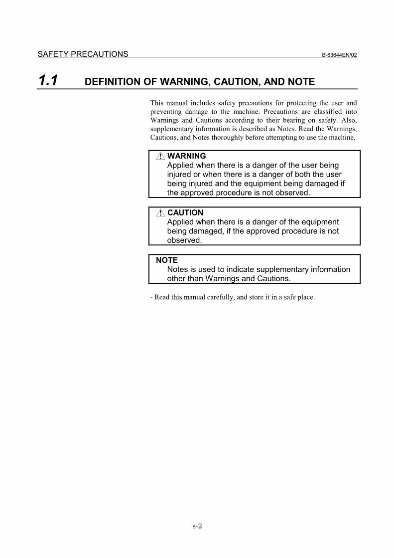
This manual includes safety precautions for protecting the user andpreventing damage to the machine. Precautions are classified intoWarnings and Cautions according to their bearing on safety. Also,supplementary information is described as Notes. Read the Warnings,Cautions, and Notes thoroughly before attempting to use the machine.
WARNINGApplied when there is a danger of the user beinginjured or when there is a danger of both the userbeing injured and the equipment being damaged ifthe approved procedure is not observed.
CAUTIONApplied when there is a danger of the equipmentbeing damaged, if the approved procedure is notobserved.
NOTENotes is used to indicate supplementary informationother than Warnings and Cautions.
- Read this manual carefully, and store it in a safe place.
B-63644EN/02 SAFETY PRECAUTIONS
s-3
1.2 GENERAL WARNINGS AND CAUTIONS
WARNING1 Before operating the machine, thoroughly check the
entered data. Operating the machine with incorrectlyspecified data may result in the machine behavingunexpectedly, possibly causing damage to theworkpiece and/or machine itself, or injury to the user.
2 Never attempt to machine a workpiece without firstchecking the programmed value, compensation value,current position, and external signal settings. Also, neverattempt to machine a workpiece without first checkingthe operation of the machine. Before starting aproduction run, ensure that the machine is operatingcorrectly by performing a trial run using, for example, thesingle block, feedrate override, or machine lock function,or by operating the machine with neither a tool norworkpiece mounted. Failure to confirm the correctoperation of the machine may result in the machinebehaving unexpectedly, possibly causing damage to theworkpiece and/or machine itself, or injury to the user.
3 Ensure that the specified feedrate is appropriate for theintended operation. Generally, for each machine, thereis a maximum allowable feedrate. The appropriatefeedrate varies with the intended operation. Refer to themanual provided with the machine to determine themaximum allowable feedrate. If a machine is run at otherthan the correct speed, it may behave unexpectedly,possibly causing damage to the workpiece and/ormachine itself, or injury to the user.
4 When using a tool compensation function, thoroughlycheck the direction and amount of compensation.Operating the machine with incorrectly specified datamay result in the machine behaving unexpectedly,possibly causing damage to the workpiece and/ormachine itself, or injury to the user.
5 The parameters for the CNC and PMC are factory-set.Usually, there is no need to change them. When,however, there is no alternative other than to change aparameter, ensure that you fully Failure to set aparameter correctly may result in the machine behavingunexpectedly, possibly causing damage to theworkpiece and/or machine itself, or injury to the user.
SAFETY PRECAUTIONS B-63644EN/02
s-4
CAUTION1 Immediately after switching on the power, do not touch
any of the keys on the MDI panel until the positiondisplay or alarm screen appears on the CNC unit.Some of the keys on the MDI panel are dedicated tomaintenance or other special operations. Pressing anyof these keys may place the CNC unit in other than itsnormal state. Starting the machine in this state maycause it to behave unexpectedly.
2 The operator's manual for Ethernet board describes allthe basic functions of the CNC, including the optionalfunctions. The selected optional functions vary with themachine. Some functions described in this manual maynot, therefore, be supported by your machine. Check themachine specifications before using Ethernet board.
3 Some machine operations and screen functions areimplemented by the machine tool builder. For anexplanation of their usage and related notes, refer to themanual provided by the machine tool builder.For example:- On some machines, executing a tool function causes
the tool change unit to operate. When executing atool function on such a machine, stand well clear ofthe tool change unit. Otherwise, there is a danger ofinjury to the operator.
- Many auxiliary functions trigger physical operations,such as rotation of the spindle. Before attempting touse an auxiliary function, therefore, ensure that youare fully aware of the operation to be triggered by thatfunction.
NOTECommand programs, parameters, and variables arestored in nonvolatile memory in the CNC. Generally, thecontents of memory are not lost by a power on/offoperation. However, the contents of memory may beerased by mistake, or important data in nonvolatilememory may have to be erased upon recovering from afailure.To enable the restoration of data as soon as possible ifsuch a situation arises, always make a backup of thedata in advance.
B-63644EN/02 TABLE OF CONTENTS
c-1
TABLE OF CONTENTS
SAFETY PRECAUTIONS.......................................................................... s-1
I. GENERAL
1 GENERAL ..............................................................................................31.1 ORGANIZATION............................................................................................41.2 APPLICABLE MODELS.................................................................................51.3 RELATED MANUALS....................................................................................6
II. SPECIFICATION
1 ETHERNET FUNCTIONS.....................................................................111.1 FACTOLINK FUNCTION .............................................................................121.2 DNC1/ETHERNET FUNCTION ...................................................................131.3 FOCAS1/ETHERNET FUNCTION...............................................................141.4 DATA SERVER FUNCTION ........................................................................16
III. SETTING
1 FACTOLINK FUNCTIONS FOR THE 16i/18i/21i ................................211.1 PRECAUTIONS WHEN USING THE ETHERNET BOARD
FOR THE FIRST TIME ................................................................................221.2 ETHERNET PARAMETER SCREEN ..........................................................231.3 PARAMETERS ............................................................................................291.4 CONFIGURING A SMALL-SCALE NETWORK...........................................311.5 CONFIGURING A LARGE-SCALE NETWORK ..........................................33
2 DNC1/Ethernet FUNCTIONS FOR THE 16i/18i/21i/PMi ....................342.1 PRECAUTIONS WHEN USING THE DNC1/Ethernet
FOR THE FIRST TIME ................................................................................352.2 ETHERNET PARAMETER SCREEN ..........................................................362.3 PARAMETERS ............................................................................................422.4 CONFIGURING A SMALL-SCALE NETWORK...........................................432.5 CONFIGURING A LARGE-SCALE NETWORK ..........................................44
3 FOCAS1/Ethernet FUNCTIONS FOR THE 16i/18i/21i/PMi................453.1 PRECAUTIONS TO BE OBSERVED WHEN
USING THE FOCAS1/Ethernet FUNCTIONS FOR THE FIRST TIME........463.2 ETHERNET PARAMETER SCREEN ..........................................................47
TABLE OF CONTENTS B-63644EN/02
c-2
3.3 PARAMETERS ............................................................................................523.4 CONFIGURING A SMALL-SCALE NETWORK...........................................533.5 CONFIGURING A LARGE-SCALE NETWORK ..........................................54
4 DATA SERVER FUNCTIONS FOR THE 16i/18i/21i............................554.1 PRECAUTIONS TO BE OBSERVED WHEN
USING THE DATA SERVER FUNCTIONS FOR THE FIRST TIME............564.2 ETHERNET PARAMETER SCREEN ..........................................................584.3 PARAMETERS ............................................................................................734.4 CONFIGURING A SMALL-SCALE NETWORK...........................................754.5 CONFIGURING A LARGE-SCALE NETWORK ..........................................76
5 FOCAS1/Ethernet FUNCTIONS FOR THE 15i ...................................775.1 PRECAUTIONS TO BE OBSERVED WHEN
USING THE FOCAS1/Ethernet FUNCTIONS FOR THE FIRST TIME........785.2 ETHERNET PARAMETER SCREEN ..........................................................795.3 PARAMETERS ............................................................................................855.4 CONFIGURING A SMALL-SCALE NETWORK...........................................865.5 CONFIGURING A LARGE-SCALE NETWORK ..........................................87
6 DATA SERVER FUNCTIONS FOR THE 15i ........................................886.1 PRECAUTIONS TO BE OBSERVED WHEN
USING THE DATA SERVER FUNCTIONS FOR THE FIRST TIME............896.2 ETHERNET PARAMETER SCREEN ..........................................................906.3 PARAMETERS ............................................................................................976.4 CONFIGURING A SMALL-SCALE NETWORK...........................................996.5 CONFIGURING A LARGE-SCALE NETWORK ........................................100
IV. OPERATION
1 16i/18i/21i FACTOLINK FUNCTIONS...............................................1031.1 FACTOLINK SCREEN...............................................................................1041.2 ETHERNET ERROR MESSAGE SCREEN...............................................105
2 16i/18i/21i/PMi DNC1/Ethernet FUNCTIONS...................................1072.1 ETHERNET ERROR MESSAGE SCREEN...............................................108
3 16i/18i/21i/PMi FOCAS1/Ethernet FUNCTIONS ..............................1103.1 ETHERNET ERROR MESSAGE SCREEN...............................................111
4 16i/18i/21i DATA SERVER FUNCTIONS ..........................................1134.1 RULES GOVERNING THE USE OF THE DATA SERVER FUNCTIONS .114
B-63644EN/02 TABLE OF CONTENTS
c-3
4.1.1 Data Server Modes .............................................................................................. 1144.1.2 Differences Between a File Number, O Number, and File Name....................... 1174.1.3 Entering a File Number, O Number, and File Name........................................... 1174.1.4 Differences Between a Hard Disk File and Host File ......................................... 1184.1.5 Hard Disk File Names ......................................................................................... 1194.1.6 NC Program Format ............................................................................................ 1204.1.7 List File Formats.................................................................................................. 1214.1.8 Buffer Mode Specifications................................................................................. 126
4.1.8.1 How to use the buffer mode .............................................................................1274.1.8.2 How to divide an NC program into several files ..............................................129
4.1.9 Data Server Screen Manipulation and Status Indication..................................... 1314.2 HARD DISK FILE DIR SCREEN................................................................133
4.2.1 Displaying a List of Hard Disk Files ................................................................... 1364.2.2 Searching for a Hard Disk File ............................................................................ 1374.2.3 Deleting a Hard Disk File.................................................................................... 1384.2.4 Copying a Hard Disk File .................................................................................... 1404.2.5 Changing a Hard Disk File Name........................................................................ 1414.2.6 Creating a Directory on the ATA Card ............................................................... 1424.2.7 Deleting a Directory from the ATA Card............................................................ 1434.2.8 Moving to Another Directory on the ATA Card ................................................. 1444.2.9 Executing Hard Disk File PUT............................................................................ 1454.2.10 Executing Hard Disk File MPUT ........................................................................ 1474.2.11 Executing Hard Disk File LIST-PUT .................................................................. 1484.2.12 Executing Hard Disk File LIST-DELETE .......................................................... 149
4.3 HOST FILE DIR SCREEN .........................................................................1504.3.1 Displaying a List of Host Files ............................................................................ 1534.3.2 Searching for a Host File ..................................................................................... 1544.3.3 Deleting a Host File............................................................................................. 1554.3.4 Executing Host File GET .................................................................................... 1564.3.5 Executing Host File MGET................................................................................. 1584.3.6 Executing Host File LIST-GET........................................................................... 160
4.4 INPUTTING AN NC PROGRAM................................................................1614.5 OUTPUTTING AN NC PROGRAM............................................................1644.6 DNC OPERATIONS...................................................................................1664.7 DNC OPERATION BY A SUBPROGRAM CALL (M198)...........................1694.8 DATA INPUT/OUTPUT..............................................................................173
4.8.1 Inputting the Parameter ....................................................................................... 174
TABLE OF CONTENTS B-63644EN/02
c-4
4.8.2 Outputting the Parameter..................................................................................... 1754.8.3 Inputting Tool Offsets ......................................................................................... 1764.8.4 Outputting Tool Offsets....................................................................................... 1774.8.5 Inputting Custom Macro Variables ..................................................................... 1784.8.6 Outputting Custom Macro Variables................................................................... 1794.8.7 Inputting Workpiece Origin Offsets .................................................................... 1804.8.8 Outputting Workpiece Origin Offsets ................................................................. 1814.8.9 Inputting Pitch Error Compensation Data ........................................................... 1824.8.10 Outputting Pitch Error Compensation Data ........................................................ 1834.8.11 Inputting an M-Code Group ................................................................................ 1844.8.12 Outputting an M-Code Group.............................................................................. 1854.8.13 Inputting Operation History Data ........................................................................ 1864.8.14 Outputting Operation History Data ..................................................................... 187
4.9 CONNECT HOST SCREEN ......................................................................1884.9.1 Checking the Connected Host ............................................................................. 1894.9.2 Changing the Connected Host ............................................................................. 190
4.10 FTP SERVER FUNCTIONS ......................................................................1914.11 MAINTENANCE OF DATA SERVER SCREEN.........................................192
4.11.1 Checking the ATA Card ...................................................................................... 1944.11.2 Formatting the ATA Card.................................................................................... 1954.11.3 Switching Data Server Modes ............................................................................. 1974.11.4 Displaying Error Examination Data .................................................................... 198
4.12 ETHERNET ERROR MESSAGE SCREEN...............................................199
5 15i FOCAS1/Ethernet FUNCTIONS..................................................2015.1 ETHERNET ERROR MESSAGE SCREEN...............................................202
6 15i DATA SERVER FUNCTIONS ......................................................2046.1 RULES GOVERNING THE USE OF THE DATA SERVER FUNCTIONS .205
6.1.1 Data Server Modes .............................................................................................. 2056.1.2 Differences Between a File Number, O Number, and File Name....................... 2086.1.3 Entering a File Number, O Number, and File Name........................................... 2086.1.4 Differences Between a Hard Disk File and Host File ......................................... 2096.1.5 Hard Disk File Names ......................................................................................... 2106.1.6 NC Program Format ............................................................................................ 2116.1.7 List File Formats.................................................................................................. 2126.1.8 Buffer Mode Specifications................................................................................. 217
6.1.8.1 How to use the buffer mode .............................................................................2186.1.8.2 How to divide an NC program into several files ..............................................220
B-63644EN/02 TABLE OF CONTENTS
c-5
6.1.9 Data Server Screen Manipulation and Status Indication..................................... 2226.2 HARD DISK FILE DIRECTORY SCREEN.................................................223
6.2.1 Displaying a List of Hard Disk Files ................................................................... 2266.2.2 Searching for a Hard Disk File ............................................................................ 2276.2.3 Deleting a Hard Disk File.................................................................................... 2286.2.4 Copying a Hard Disk File .................................................................................... 2306.2.5 Changing a Hard Disk File Name........................................................................ 2316.2.6 Creating a Directory on the ATA Card ............................................................... 2326.2.7 Deleting a Directory from the ATA Card............................................................ 2336.2.8 Moving a Directory on the ATA Card................................................................. 2346.2.9 Executing Hard Disk File PUT............................................................................ 2356.2.10 Executing Hard Disk File MPUT ........................................................................ 2386.2.11 Executing Hard Disk File LIST-PUT .................................................................. 2396.2.12 Executing Hard Disk File LIST-DELETE .......................................................... 240
6.3 HOST DIRECTORY SCREEN...................................................................2416.3.1 Displaying a List of Host Files ............................................................................ 2456.3.2 Searching for a Host File ..................................................................................... 2466.3.3 Deleting a Host File............................................................................................. 2476.3.4 Executing Host File GET .................................................................................... 2486.3.5 Executing Host File MGET................................................................................. 2506.3.6 Executing Host File LIST-GET........................................................................... 251
6.4 INPUTTING AN NC PROGRAM................................................................2526.5 OUTPUTTING AN NC PROGRAM............................................................2556.6 DNC OPERATIONS...................................................................................2576.7 DNC OPERATION BY A SUBPROGRAM CALL (M198)...........................2606.8 DATA INPUT/OUTPUT..............................................................................264
6.8.1 Inputting Parameters............................................................................................ 2656.8.2 Outputting Parameters ......................................................................................... 2666.8.3 Inputting Tool Offsets ......................................................................................... 2676.8.4 Outputting Tool Offsets....................................................................................... 2686.8.5 Inputting Custom Macro Variables ..................................................................... 2696.8.6 Outputting Custom Macro Variables................................................................... 2706.8.7 Inputting Workpiece Origin Offsets .................................................................... 2716.8.8 Outputting Workpiece Origin Offsets ................................................................. 2726.8.9 Inputting Pitch Error Compensation Data ........................................................... 2736.8.10 Outputting Pitch Error Compensation Data ........................................................ 2746.8.11 Outputting Operation History Data ..................................................................... 275
TABLE OF CONTENTS B-63644EN/02
c-6
6.9 SELECTION OF HOST SCREEN..............................................................2766.9.1 Checking the Connected Host ............................................................................. 2776.9.2 Changing the Connected Host ............................................................................. 278
6.10 FTP SERVER FUNCTIONS ......................................................................2796.11 DATA SERVER (MAINTENANCE) SCREEN ............................................280
6.11.1 Checking the ATA Card ...................................................................................... 2826.11.2 Formatting the ATA Card.................................................................................... 2836.11.3 Switching Data Server Modes ............................................................................. 2846.11.4 Displaying Error Examination Data .................................................................... 285
6.12 ETHERNET ERROR MESSAGE SCREEN...............................................286
V. CONNECTION
1 PREFACE ..........................................................................................2912 SETTING............................................................................................292
2.1 ENVIRONMENTAL CONDITIONS FOR INSTALLING A CNC..................2932.2 POWER SUPPLY CAPACITY ...................................................................2942.3 HEAT DISSIPATION..................................................................................295
3 INSTALLATION..................................................................................2963.1 LCD-MOUNTED TYPE Series 16i/18i/21i-A/B ..........................................297
3.1.1 Installing an Board............................................................................................... 2973.1.2 Installing an ATA Flash Card.............................................................................. 2993.1.3 Connection Diagram............................................................................................ 301
3.2 STAND-ALONE TYPE Series 16i/18i/21i-A/B, Series 15i-B,Power Mate i..............................................................................................3023.2.1 Installing an Board............................................................................................... 3023.2.2 Installing an ATA Flash Card.............................................................................. 3043.2.3 Connection Diagram............................................................................................ 305
4 HARDWARE CONNECTIONS ...........................................................3064.1 CONNECTING TO ETHERNET ................................................................3074.2 LEADING OUT THE ETHERNET CABLE .................................................3084.3 100BASE-TX CONNECTOR (CD38R, CD38T) PIN ASSIGNMENTS.......3094.4 TWISTED-PAIR CABLE SPECIFICATION................................................310
4.4.1 Cable Connection ................................................................................................ 3104.4.2 Cable Materials.................................................................................................... 3114.4.3 Connector Specification ...................................................................................... 313
4.5 ELECTRICAL NOISE COUNTERMEASURES..........................................314
B-63644EN/02 TABLE OF CONTENTS
c-7
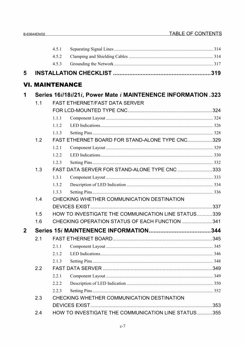
4.5.1 Separating Signal Lines ....................................................................................... 3144.5.2 Clamping and Shielding Cables .......................................................................... 3144.5.3 Grounding the Network ....................................................................................... 317
5 INSTALLATION CHECKLIST ............................................................319
VI. MAINTENANCE
1 Series 16i/18i/21i, Power Mate i MAINTENENCE INFORMATION .3231.1 FAST ETHERNET/FAST DATA SERVER
FOR LCD-MOUNTED TYPE CNC.............................................................3241.1.1 Component Layout .............................................................................................. 3241.1.2 LED Indications................................................................................................... 3261.1.3 Setting Pins .......................................................................................................... 328
1.2 FAST ETHERNET BOARD FOR STAND-ALONE TYPE CNC..................3291.2.1 Component Layout .............................................................................................. 3291.2.2 LED Indications................................................................................................... 3301.2.3 Setting Pins .......................................................................................................... 332
1.3 FAST DATA SERVER FOR STAND-ALONE TYPE CNC .........................3331.3.1 Component Layout .............................................................................................. 3331.3.2 Description of LED Indication ............................................................................ 3341.3.3 Setting Pins .......................................................................................................... 336
1.4 CHECKING WHETHER COMMUNICATION DESTINATIONDEVICES EXIST........................................................................................337
1.5 HOW TO INVESTIGATE THE COMMUNICATION LINE STATUS...........3391.6 CHECKING OPERATION STATUS OF EACH FUNCTION ......................341
2 Series 15i MAINTENENCE INFORMATION......................................3442.1 FAST ETHERNET BOARD........................................................................345
2.1.1 Component Layout .............................................................................................. 3452.1.2 LED Indications................................................................................................... 3462.1.3 Setting Pins .......................................................................................................... 348
2.2 FAST DATA SERVER ...............................................................................3492.2.1 Component Layout .............................................................................................. 3492.2.2 Description of LED Indication ............................................................................ 3502.2.3 Setting Pins .......................................................................................................... 352
2.3 CHECKING WHETHER COMMUNICATION DESTINATIONDEVICES EXIST........................................................................................353
2.4 HOW TO INVESTIGATE THE COMMUNICATION LINE STATUS...........355
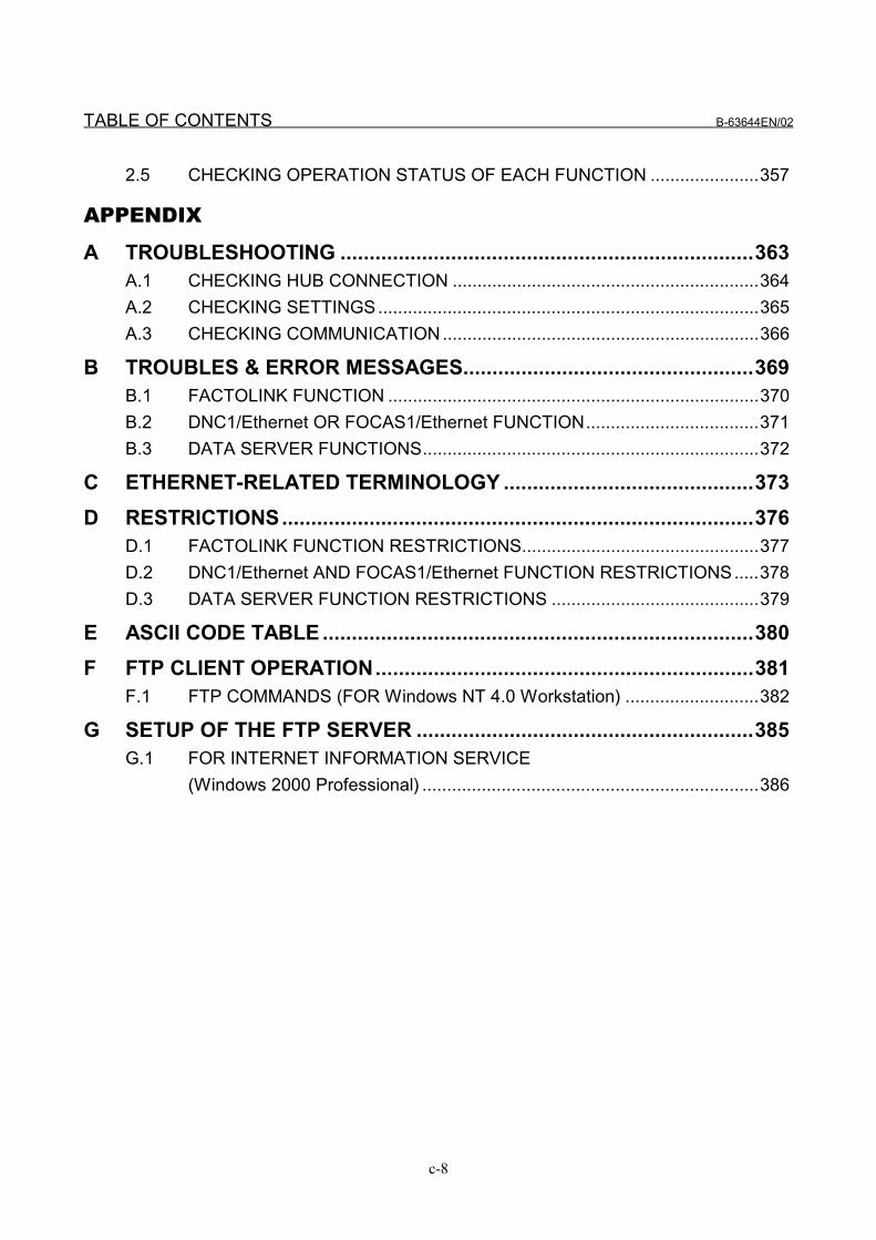
TABLE OF CONTENTS B-63644EN/02
c-8
2.5 CHECKING OPERATION STATUS OF EACH FUNCTION ......................357
APPENDIX
A TROUBLESHOOTING .......................................................................363A.1 CHECKING HUB CONNECTION ..............................................................364A.2 CHECKING SETTINGS.............................................................................365A.3 CHECKING COMMUNICATION................................................................366
B TROUBLES & ERROR MESSAGES..................................................369B.1 FACTOLINK FUNCTION ...........................................................................370B.2 DNC1/Ethernet OR FOCAS1/Ethernet FUNCTION...................................371B.3 DATA SERVER FUNCTIONS....................................................................372
C ETHERNET-RELATED TERMINOLOGY ...........................................373D RESTRICTIONS.................................................................................376
D.1 FACTOLINK FUNCTION RESTRICTIONS................................................377D.2 DNC1/Ethernet AND FOCAS1/Ethernet FUNCTION RESTRICTIONS.....378D.3 DATA SERVER FUNCTION RESTRICTIONS ..........................................379
E ASCII CODE TABLE ..........................................................................380F FTP CLIENT OPERATION.................................................................381
F.1 FTP COMMANDS (FOR Windows NT 4.0 Workstation) ...........................382
G SETUP OF THE FTP SERVER ..........................................................385G.1 FOR INTERNET INFORMATION SERVICE
(Windows 2000 Professional) ....................................................................386

I. GENERAL


B-63644EN/02 I. GENERAL 1.GENERAL
- 3 -
1 GENERALThis part explains the organization of this manual.
1.GENERAL I. GENERAL B-63644EN/02
- 4 -
1.1 Organization
This manual consists of the following parts:
SAFETY PRECAUTIONSThis section describes the precautions to be observed when readingthis manual.
I GENERALThis section describes the chapter organization, applicable models,and related manuals.
II SPECIFICATIONThis section describes the specifications related to using the FastEthernet board and Fast data server.
III SETTINGThis section describes the settings needed to use the Fast Ethernetboard and Fast data server.
IV OPERATIONThis section describes the procedures for using the Fast Ethernetboard and Fast data server.
V CONNECTIONThis section describes the specifications related to connectingdevices for using the Fast Ethernet board and Fast data server, andrelated precautions.
VI MAINTENANCEThis section describes the Fast Ethernet board and Fast data serverdrawing numbers, and the meanings of the LED indications.
APPENDIXESThese appendixes describe additional information such as thatrelated to troubleshooting, the operation of the FTP client, andhow to set up the FTP server.
B-63644EN/02 I. GENERAL 1.GENERAL
- 5 -
1.2 Applicable Models
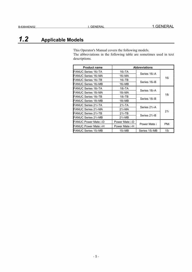
This Operator's Manual covers the following models.The abbreviations in the following table are sometimes used in textdescriptions.
Product name AbbreviationsFANUC Series 16i-TA 16i-TAFANUC Series 16i-MA 16i-MA
Series 16i-A
FANUC Series 16i-TB 16i-TBFANUC Series 16i-MB 16i-MB
Series 16i-B16i
FANUC Series 18i-TA 18i-TAFANUC Series 18i-MA 18i-MA
Series 18i-A
FANUC Series 18i-TB 18i-TBFANUC Series 18i-MB 18i-MB
Series 18i-B18i
FANUC Series 21i-TA 21i-TAFANUC Series 21i-MA 21i-MA
Series 21i-A
FANUC Series 21i-TB 21i-TBFANUC Series 21i-MB 21i-MB
Series 21i-B21i
FANUC Power Mate i-D Power Mate i-DFANUC Power Mate i-H Power Mate i-H
Power Mate i PMi
FANUC Series 15i-MB 15i-MB Series 15i-MB 15i
1.GENERAL I. GENERAL B-63644EN/02
- 6 -
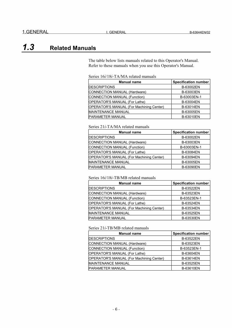
1.3 Related Manuals
The table below lists manuals related to this Operator's Manual.Refer to these manuals when you use this Operator's Manual.
Series 16i/18i-TA/MA related manualsManual name Specification number
DESCRIPTIONS B-63002ENCONNECTION MANUAL (Hardware) B-63003ENCONNECTION MANUAL (Function) B-63003EN-1OPERATOR'S MANUAL (For Lathe) B-63004ENOPERATOR'S MANUAL (For Machining Center) B-63014ENMAINTENANCE MANUAL B-63005ENPARAMETER MANUAL B-63010EN
Series 21i-TA/MA related manualsManual name Specification number
DESCRIPTIONS B-63002ENCONNECTION MANUAL (Hardware) B-63003ENCONNECTION MANUAL (Function) B-63003EN-1OPERATOR'S MANUAL (For Lathe) B-63084ENOPERATOR'S MANUAL (For Machining Center) B-63094ENMAINTENANCE MANUAL B-63005ENPARAMETER MANUAL B-63090EN
Series 16i/18i-TB/MB related manualsManual name Specification number
DESCRIPTIONS B-63522ENCONNECTION MANUAL (Hardware) B-63523ENCONNECTION MANUAL (Function) B-63523EN-1OPERATOR'S MANUAL (For Lathe) B-63524ENOPERATOR'S MANUAL (For Machining Center) B-63534ENMAINTENANCE MANUAL B-63525ENPARAMETER MANUAL B-63530EN
Series 21i-TB/MB related manualsManual name Specification number
DESCRIPTIONS B-63522ENCONNECTION MANUAL (Hardware) B-63523ENCONNECTION MANUAL (Function) B-63523EN-1OPERATOR'S MANUAL (For Lathe) B-63604ENOPERATOR'S MANUAL (For Machining Center) B-63614ENMAINTENANCE MANUAL B-63525ENPARAMETER MANUAL B-63610EN
B-63644EN/02 I. GENERAL 1.GENERAL
- 7 -
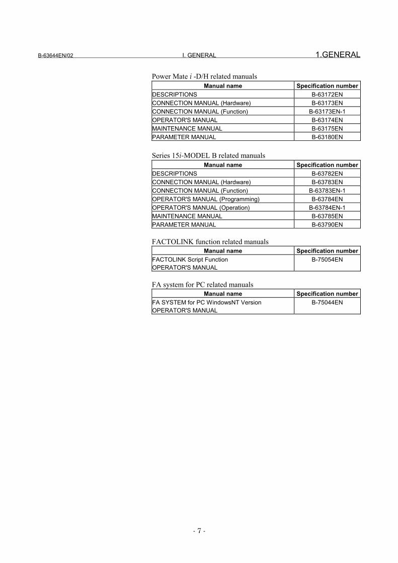
Power Mate i -D/H related manualsManual name Specification number
DESCRIPTIONS B-63172ENCONNECTION MANUAL (Hardware) B-63173ENCONNECTION MANUAL (Function) B-63173EN-1OPERATOR'S MANUAL B-63174ENMAINTENANCE MANUAL B-63175ENPARAMETER MANUAL B-63180EN
Series 15i-MODEL B related manualsManual name Specification number
DESCRIPTIONS B-63782ENCONNECTION MANUAL (Hardware) B-63783ENCONNECTION MANUAL (Function) B-63783EN-1OPERATOR'S MANUAL (Programming) B-63784ENOPERATOR'S MANUAL (Operation) B-63784EN-1MAINTENANCE MANUAL B-63785ENPARAMETER MANUAL B-63790EN
FACTOLINK function related manualsManual name Specification number
FACTOLINK Script FunctionOPERATOR'S MANUAL
B-75054EN
FA system for PC related manualsManual name Specification number
FA SYSTEM for PC WindowsNT VersionOPERATOR'S MANUAL
B-75044EN


II. SPECIFICATION

B-63644EN/02 II. SPECIFICATION 1.ETHERNET FUNCTIONS
- 11 -
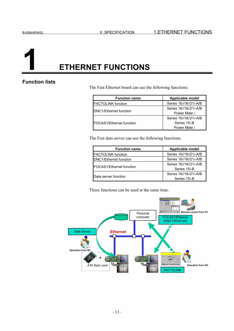
1 ETHERNET FUNCTIONSFunction lists
The Fast Ethernet board can use the following functions:
Function name Applicable modelFACTOLINK function Series 16i/18i/21i-A/B
DNC1/Ethernet functionSeries 16i/18i/21i-A/B
Power Mate i
FOCAS1/Ethernet functionSeries 16i/18i/21i-A/B
Series 15i-BPower Mate i
The Fast data server can use the following functions:
Function name Applicable modelFACTOLINK function Series 16i/18i/21i-A/BDNC1/Ethernet function Series 16i/18i/21i-A/B
FOCAS1/Ethernet functionSeries 16i/18i/21i-A/B
Series 15i-B
Data server functionSeries 16i/18i/21i-A/B
Series 15i-B
These functions can be used at the same time.
Personalcomputer
Ethernet
FACTOLINK
FOCAS1/Ethernet(DNC1/Ethernet)
Data Server
+
ATA flash card Operation from NC
Operation from NC
Remote control from PC
1.ETHERNET FUNCTIONS II. SPECIFICATION B-63644EN/02
- 12 -
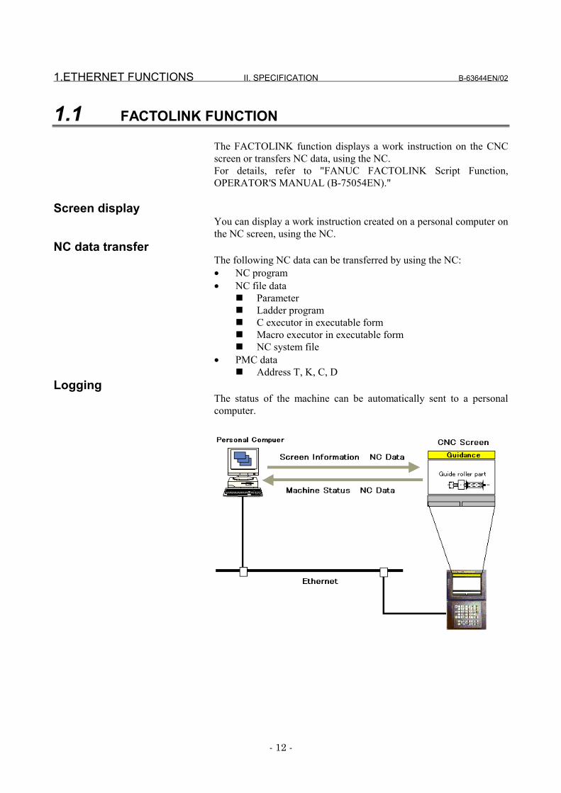
1.1 FACTOLINK FUNCTION
The FACTOLINK function displays a work instruction on the CNCscreen or transfers NC data, using the NC.For details, refer to "FANUC FACTOLINK Script Function,OPERATOR'S MANUAL (B-75054EN)."
Screen displayYou can display a work instruction created on a personal computer onthe NC screen, using the NC.
NC data transferThe following NC data can be transferred by using the NC:• NC program• NC file data
� Parameter� Ladder program� C executor in executable form� Macro executor in executable form� NC system file
• PMC data� Address T, K, C, D
LoggingThe status of the machine can be automatically sent to a personalcomputer.
B-63644EN/02 II. SPECIFICATION 1.ETHERNET FUNCTIONS
- 13 -
1.2 DNC1/Ethernet FUNCTION
The DNC1/Ethernet function enables the remote control andmonitoring of the CNC from a personal computer.For details, refer to "FANUC FA SYSTEM for PC WindowsNTVersion, OPERATOR'S MANUAL (B-75044EN)."
NC data transferThe following data can be transferred using a personal computer:• NC program• Directory information of tape memory• NC file data
� Parameter� Tool offset value� Custom macro variable
• Alarm information• NC system identifying information• PMC data
� Address G, F, Y, X, A, R, T, K, C, DRemote control
The following operations can be controlled remotely using a personalcomputer:• Selection of NC program• Deletion of NC program• External rerset
OperationThe following operation can be controlled remotely using a personalcomputer:• DNC operation
1.ETHERNET FUNCTIONS II. SPECIFICATION B-63644EN/02
- 14 -
1.3 FOCAS1/Ethernet FUNCTION
The FOCAS1/Ethernet function enables the remote control andmonitoring of the CNC from a personal computer.For details, refer to "FANUC Open CNC FOCAS1/EthernetCNC/PMC Data Window Library."
NC data transferThe following data can be transferred using a personal computer:• Deletion of NC program Data related to the controlled axis and
spindle� Absolute position� Relative position� Machine position� Distance to go� Actual feedrate
• Deletion of NC program NC program• Deletion of NC program Directory information of tape memory• Deletion of NC program NC file data
� Parameter� Tool offset value� Custom macro variable� Workpiece origin offset� Setting data� P-code macro variable� Pitch error compensation data
• Deletion of NC program Tool life management data• Deletion of NC program History data
� Operation history data� Alarm history data
• Deletion of NC program Data related to servo and spindle• Deletion of NC program Data related to waveform diagnosis• Deletion of NC program Modal data• Deletion of NC program Diagnosis data• Deletion of NC program A/D conversion parameter• Deletion of NC program Alarm information• Deletion of NC program NC system-identifying information• Deletion of NC program PMC data
� Address G, F, Y, X, A, R, T, K, C, D� Extended maintenance type data
Remote controlThe following operations can be controlled remotely using a personalcomputer:• Selection of NC program• Deletion of NC program• External reset
B-63644EN/02 II. SPECIFICATION 1.ETHERNET FUNCTIONS
- 15 -
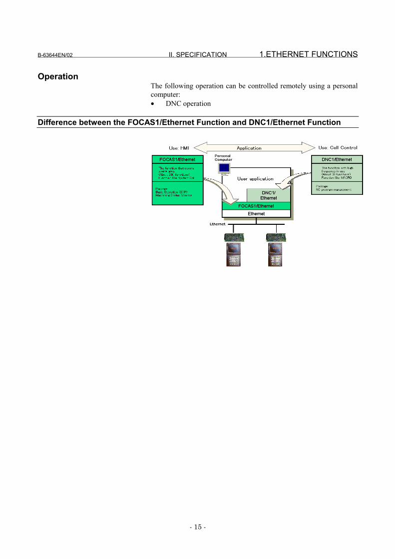
OperationThe following operation can be controlled remotely using a personalcomputer:• DNC operation
Difference between the FOCAS1/Ethernet Function and DNC1/Ethernet Function
1.ETHERNET FUNCTIONS II. SPECIFICATION B-63644EN/02
- 16 -
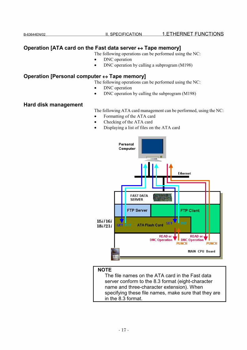
1.4 DATA SERVER FUNCTION
The data server function uses FTP to transfer NC data or operate theDNC.This function is mainly used as an FTP client, but is also used as anFTP server.This function uses ATA flash card (ATA card) mounted on (connectedto) the data server board as the storage area for the NC data.
NC data transfer [Personal computer ↔↔↔↔ ATA card on the Fast data server] <FTPclient>
The data server function is used as an FTP client, by using the NC, thusproviding the following services:• GET• MGET• PUT• MPUT• DIR• DEL
NC data transfer [Personal computer ↔↔↔↔ ATA card on the Fast data server] <FTPserver>
The data server function is used as an FTP server, using a personalcomputer, thus providing the following services:• GET• MGET• PUT• MPUT• DIR• DEL
NC data transfer [ATA card on the Fast data server ↔↔↔↔ Tape memory]The data server function can transfer the following data, using the NC:• NC program• NC file data
� Parameter� Tool offset value� Custom macro variable� Workpiece origin offset value� Pitch error compensation data� M-code group (for Series 16i/18i-A/B only)
• History data� Operation history data
B-63644EN/02 II. SPECIFICATION 1.ETHERNET FUNCTIONS
- 17 -
Operation [ATA card on the Fast data server ↔↔↔↔ Tape memory]The following operations can be performed using the NC:• DNC operation• DNC operation by calling a subprogram (M198)
Operation [Personal computer ↔↔↔↔ Tape memory]The following operations can be performed using the NC:• DNC operation• DNC operation by calling the subprogram (M198)
Hard disk managementThe following ATA card management can be performed, using the NC:• Formatting of the ATA card• Checking of the ATA card• Displaying a list of files on the ATA card
NOTEThe file names on the ATA card in the Fast dataserver conform to the 8.3 format (eight-charactername and three-character extension). Whenspecifying these file names, make sure that they arein the 8.3 format.


III. SETTING

B-63644EN/02 III. SETTING 1.FACTOLINK FUNCTIONS FOR THE 16i/18i/21i
- 21 -
1 FACTOLINK FUNCTIONS FOR THE16i/18i/21i
This section describes the settings needed to use the FACTOLINKfunctions with the Series 16i/18i/21i-A/B.
1.FACTOLINK FUNCTIONS FOR THE 16i/18i/21i III. SETTING B-63644EN/02
- 22 -
1.1 PRECAUTIONS WHEN USING THE ETHERNET BOARDFOR THE FIRST TIME
CAUTIONWhen the Fast Ethernet board is used for the firsttime, consult with your company's networkadministrator to determine the IP addresses andother settings. Then, conduct a communications test.If incorrect IP addresses and other settings are set,communications may be interfered with or the entirenetwork might be adversely affected.Particularly, if a duplicate IP address is set,communication errors are caused intermittently. Thismay result in a CNC's system error. To checkwhether the IP address duplicates any one already inuse, see "Checking IP addresses for duplication" inAppendix A.3, "Checking Communication."
NOTE1 One of the following option functions is needed when
the FACTOLINK functions are used:Series16i-TA A02B-0236-S708Series 16i-MA A02B-0237-S708Series 18i-TA A02B-0238-S708Series 18i-MA A02B-0239-S708Series 21i-TA A02B-0247-S708Series 21i-MA A02B-0248-S708Series16i-TB A02B-0281-S708Series 16i-MB A02B-0282-S708Series 18i-TB A02B-0283-S708Series 18i-MB A02B-0284-S708Series 21i-TB A02B-0285-S708Series 21i-MB A02B-0286-S708
2 Only one server can be connected to one CNC unitby the FACTOLINK function.

B-63644EN/02 III. SETTING 1.FACTOLINK FUNCTIONS FOR THE 16i/18i/21i
- 23 -
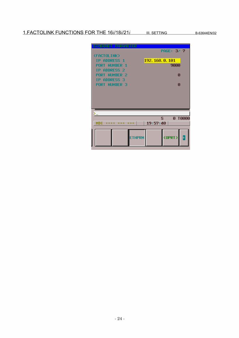
1.2 ETHERNET PARAMETER SCREEN
The Ethernet Parameter screen is used to set the parameters that areneeded to use the FACTOLINK functions.
DisplayProcedure
1 Place the CNC in MDI mode.2 Press function key SYSTEM .3 Press the Continuation menu key at the bottom right of the soft
key menu.4 When you press soft key [ETHPRM], the "Ethernet Parameter"
screen appears.For the Series 16i/18i/21i-B, to display the "Ethernet Parameter"screen, press soft key [ETHPRM] and then soft key [BOARD].If parameters have already been registered, those parametersettings are displayed.
5 Enter or update the data using the MDI or soft keys.6 Select the desired page using the PAGE
PAGE page keys.
1.FACTOLINK FUNCTIONS FOR THE 16i/18i/21i III. SETTING B-63644EN/02
- 24 -
B-63644EN/02 III. SETTING 1.FACTOLINK FUNCTIONS FOR THE 16i/18i/21i
- 25 -
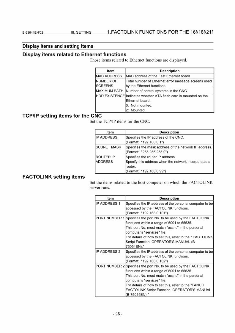
Display items and setting itemsDisplay items related to Ethernet functions
Those items related to Ethernet functions are displayed.
Item DescriptionMAC ADDRESS MAC address of the Fast Ethernet boardNUMBER OFSCREENS
Total number of Ethernet error message screens usedby the Ethernet functions
MAXIMUM PATH Number of control systems in the CNCHDD EXISTENCE Indicates whether ATA flash card is mounted on the
Ethernet board.0: Not mounted.2: Mounted.
TCP/IP setting items for the CNCSet the TCP/IP items for the CNC.
Item DescriptionIP ADDRESS Specifies the IP address of the CNC.
(Format: "192.168.0.1")SUBNET MASK Specifies the mask address of the network IP address.
(Format: "255.255.255.0")ROUTER IPADDRESS
Specifies the router IP address.Specify this address when the network incorporates arouter.(Format: "192.168.0.99")
FACTOLINK setting itemsSet the items related to the host computer on which the FACTOLINKserver runs.
Item DescriptionIP ADDRESS 1 Specifies the IP address of the personal computer to be
accessed by the FACTOLINK functions.(Format: "192.168.0.101")
PORT NUMBER 1 Specifies the port No. to be used by the FACTOLINKfunctions within a range of 5001 to 65535.This port No. must match "ocsnc" in the personalcomputer's "services" file.For details of how to set this, refer to the " FACTOLINKScript Function, OPERATOR'S MANUAL (B-75054EN)."
IP ADDRESS 2 Specifies the IP address of the personal computer to beaccessed by the FACTOLINK functions.(Format: "192.168.0.102")
PORT NUMBER 2 Specifies the port No. to be used by the FACTOLINKfunctions within a range of 5001 to 65535.This port No. must match "ocsnc" in the personalcomputer's "services" file.For details of how to set this, refer to the "FANUCFACTOLINK Script Function, OPERATOR'S MANUAL(B-75054EN)."
1.FACTOLINK FUNCTIONS FOR THE 16i/18i/21i III. SETTING B-63644EN/02
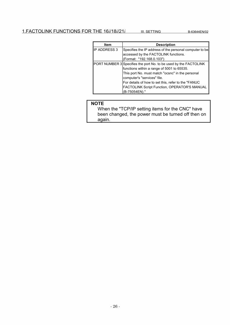
- 26 -
Item DescriptionIP ADDRESS 3 Specifies the IP address of the personal computer to be
accessed by the FACTOLINK functions.(Format: "192.168.0.103")
PORT NUMBER 3 Specifies the port No. to be used by the FACTOLINKfunctions within a range of 5001 to 65535.This port No. must match "ocsnc" in the personalcomputer's "services" file.For details of how to set this, refer to the "FANUCFACTOLINK Script Function, OPERATOR'S MANUAL(B-75054EN)."
NOTEWhen the "TCP/IP setting items for the CNC" havebeen changed, the power must be turned off then onagain.

B-63644EN/02 III. SETTING 1.FACTOLINK FUNCTIONS FOR THE 16i/18i/21i
- 27 -
Entering dataThe following describes the basic method for entering data.
Procedure1 Place the CNC in MDI mode.2 Display the "Ethernet Parameter" screen.3 Position the cursor to the desired item by using the cursor
movement keys.4 Enter the desired data by using the MDI keys.5 Press soft key [INPUT] or function key INPUT to fix the data.
NOTEAlready-set data can be deleted. To delete numericaldata, enter 0. To delete character data, enter a space(SP).
Example: To set the IP address to "192.168.0.1"(a) Position the cursor to "IP ADDRESS."

1.FACTOLINK FUNCTIONS FOR THE 16i/18i/21i III. SETTING B-63644EN/02
- 28 -
(b) Enter "192.168.0.1" using the MDI keys.
(c) Press soft key [INPUT] or function key INPUT to fix the data.This causes the parameters to be saved to the non-volatilememory of the CNC.
B-63644EN/02 III. SETTING 1.FACTOLINK FUNCTIONS FOR THE 16i/18i/21i
- 29 -
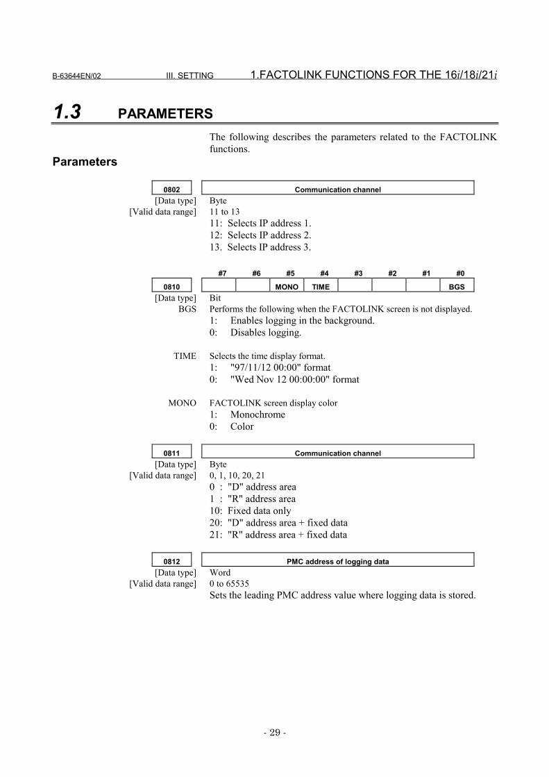
1.3 PARAMETERSThe following describes the parameters related to the FACTOLINKfunctions.
Parameters
0802 Communication channel[Data type] Byte
[Valid data range] 11 to 1311: Selects IP address 1.12: Selects IP address 2.13. Selects IP address 3.
#7 #6 #5 #4 #3 #2 #1 #0
0810 MONO TIME BGS[Data type] Bit
BGS Performs the following when the FACTOLINK screen is not displayed.1: Enables logging in the background.0: Disables logging.
TIME Selects the time display format.1: "97/11/12 00:00" format0: "Wed Nov 12 00:00:00" format
MONO FACTOLINK screen display color1: Monochrome0: Color
0811 Communication channel[Data type] Byte
[Valid data range] 0, 1, 10, 20, 210 : "D" address area1 : "R" address area10: Fixed data only20: "D" address area + fixed data21: "R" address area + fixed data
0812 PMC address of logging data[Data type] Word
[Valid data range] 0 to 65535Sets the leading PMC address value where logging data is stored.
1.FACTOLINK FUNCTIONS FOR THE 16i/18i/21i III. SETTING B-63644EN/02
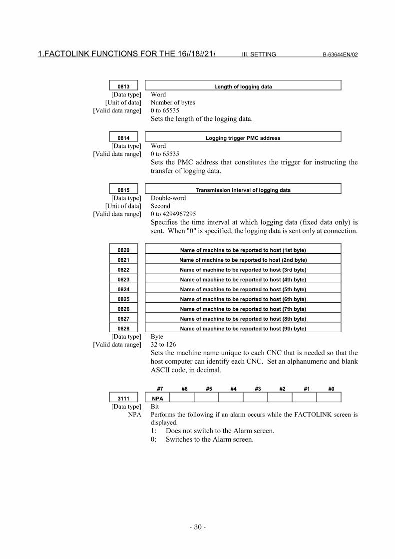
- 30 -
0813 Length of logging data[Data type] Word
[Unit of data] Number of bytes[Valid data range] 0 to 65535
Sets the length of the logging data.
0814 Logging trigger PMC address[Data type] Word
[Valid data range] 0 to 65535Sets the PMC address that constitutes the trigger for instructing thetransfer of logging data.
0815 Transmission interval of logging data[Data type] Double-word
[Unit of data] Second[Valid data range] 0 to 4294967295
Specifies the time interval at which logging data (fixed data only) issent. When "0" is specified, the logging data is sent only at connection.
0820 Name of machine to be reported to host (1st byte)
0821 Name of machine to be reported to host (2nd byte)
0822 Name of machine to be reported to host (3rd byte)
0823 Name of machine to be reported to host (4th byte)
0824 Name of machine to be reported to host (5th byte)
0825 Name of machine to be reported to host (6th byte)
0826 Name of machine to be reported to host (7th byte)
0827 Name of machine to be reported to host (8th byte)
0828 Name of machine to be reported to host (9th byte)[Data type] Byte
[Valid data range] 32 to 126Sets the machine name unique to each CNC that is needed so that thehost computer can identify each CNC. Set an alphanumeric and blankASCII code, in decimal.
#7 #6 #5 #4 #3 #2 #1 #0
3111 NPA[Data type] Bit
NPA Performs the following if an alarm occurs while the FACTOLINK screen isdisplayed.1: Does not switch to the Alarm screen.0: Switches to the Alarm screen.
B-63644EN/02 III. SETTING 1.FACTOLINK FUNCTIONS FOR THE 16i/18i/21i
- 31 -
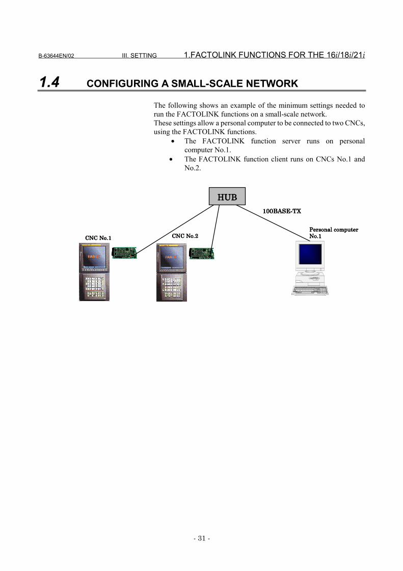
1.4 CONFIGURING A SMALL-SCALE NETWORK
The following shows an example of the minimum settings needed torun the FACTOLINK functions on a small-scale network.These settings allow a personal computer to be connected to two CNCs,using the FACTOLINK functions.
• The FACTOLINK function server runs on personalcomputer No.1.
• The FACTOLINK function client runs on CNCs No.1 andNo.2.
Personal computerPersonal computerPersonal computerPersonal computerNo.1No.1No.1No.1CNC No.2CNC No.2CNC No.2CNC No.2CNC No.1CNC No.1CNC No.1CNC No.1
100BASE-TX100BASE-TX100BASE-TX100BASE-TX
HUBHUBHUBHUB
1.FACTOLINK FUNCTIONS FOR THE 16i/18i/21i III. SETTING B-63644EN/02
- 32 -
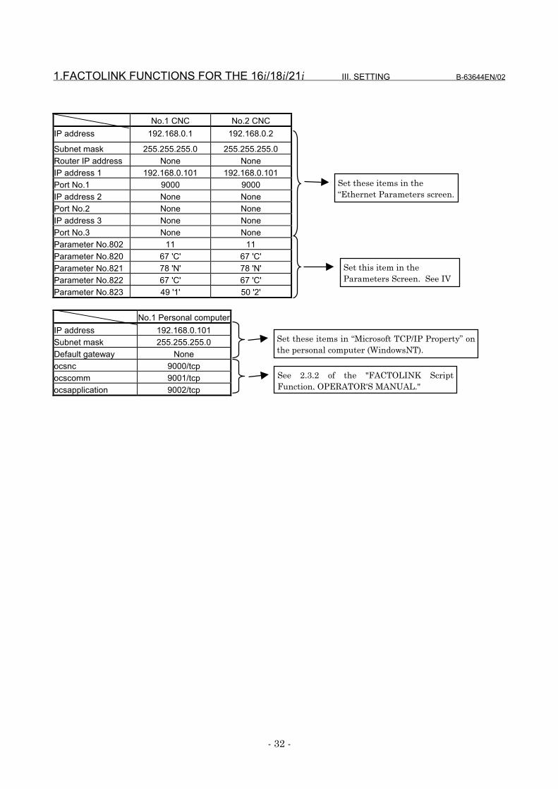
No.1 CNC No.2 CNCIP address 192.168.0.1 192.168.0.2
Subnet mask 255.255.255.0 255.255.255.0Router IP address None NoneIP address 1 192.168.0.101 192.168.0.101Port No.1 9000 9000IP address 2 None NonePort No.2 None NoneIP address 3 None NonePort No.3 None NoneParameter No.802 11 11Parameter No.820 67 'C' 67 'C'Parameter No.821 78 'N' 78 'N'Parameter No.822 67 'C' 67 'C'Parameter No.823 49 '1' 50 '2'
No.1 Personal computerIP address 192.168.0.101Subnet mask 255.255.255.0Default gateway Noneocsnc 9000/tcpocscomm 9001/tcpocsapplication 9002/tcp
Set these items in “Microsoft TCP/IP Property” onthe personal computer (WindowsNT).
See 2.3.2 of the "FACTOLINK ScriptFunction, OPERATOR'S MANUAL."
Set these items in the“Ethernet Parameters screen.
Set this item in theParameters Screen. See IV
B-63644EN/02 III. SETTING 1.FACTOLINK FUNCTIONS FOR THE 16i/18i/21i
- 33 -
1.5 CONFIGURING A LARGE-SCALE NETWORK
Before you configure a large-scale network or add such a network to anexisting network, consult with your company's network administratorto determine IP addresses, subnet masks, and router IP addresses.
2.DNC1/Ethernet FUNCTIONS FOR THE 16i/18i/21i/PMi III. SETTING B-63644EN/02
- 34 -
2 DNC1/Ethernet FUNCTIONS FOR THE16iiii/18iiii/21iiii/PMiiii
The following describes the settings needed to use the DNC1/Ethernetfunctions with the Series 16i/18i/21i-A/B and Power Mate i.
B-63644EN/02 III. SETTING 2.DNC1/Ethernet FUNCTIONS FOR THE 16i/18i/21i/PMi
- 35 -
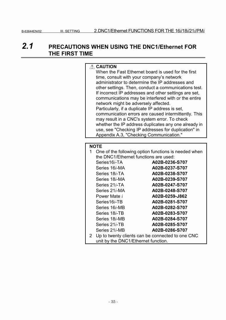
2.1 PRECAUTIONS WHEN USING THE DNC1/Ethernet FORTHE FIRST TIME
CAUTIONWhen the Fast Ethernet board is used for the firsttime, consult with your company’s networkadministrator to determine the IP addresses andother settings. Then, conduct a communications test.If incorrect IP addresses and other settings are set,communications may be interfered with or the entirenetwork might be adversely affected.Particularly, if a duplicate IP address is set,communication errors are caused intermittently. Thismay result in a CNC's system error. To checkwhether the IP address duplicates any one already inuse, see "Checking IP addresses for duplication" inAppendix A.3, "Checking Communication."
NOTE1 One of the following option functions is needed when
the DNC1/Ethernet functions are used:Series16i-TA A02B-0236-S707Series 16i-MA A02B-0237-S707Series 18i-TA A02B-0238-S707Series 18i-MA A02B-0239-S707Series 21i-TA A02B-0247-S707Series 21i-MA A02B-0248-S707Power Mate i A02B-0259-J862Series16i-TB A02B-0281-S707Series 16i-MB A02B-0282-S707Series 18i-TB A02B-0283-S707Series 18i-MB A02B-0284-S707Series 21i-TB A02B-0285-S707Series 21i-MB A02B-0286-S707
2 Up to twenty clients can be connected to one CNCunit by the DNC1/Ethernet function.
2.DNC1/Ethernet FUNCTIONS FOR THE 16i/18i/21i/PMi III. SETTING B-63644EN/02
- 36 -
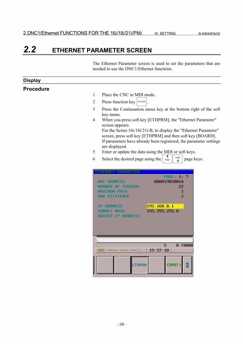
2.2 ETHERNET PARAMETER SCREEN
The Ethernet Parameter screen is used to set the parameters that areneeded to use the DNC1/Ethernet functions.
DisplayProcedure
1 Place the CNC in MDI mode.2 Press function key SYSTEM .3 Press the Continuation menu key at the bottom right of the soft
key menu.4 When you press soft key [ETHPRM], the "Ethernet Parameter"
screen appears.For the Series 16i/18i/21i-B, to display the "Ethernet Parameter"screen, press soft key [ETHPRM] and then soft key [BOARD].If parameters have already been registered, the parameter settingsare displayed.
5 Enter or update the data using the MDI or soft keys.6 Select the desired page using the PAGE
PAGE page keys.

B-63644EN/02 III. SETTING 2.DNC1/Ethernet FUNCTIONS FOR THE 16i/18i/21i/PMi
- 37 -
2.DNC1/Ethernet FUNCTIONS FOR THE 16i/18i/21i/PMi III. SETTING B-63644EN/02
- 38 -
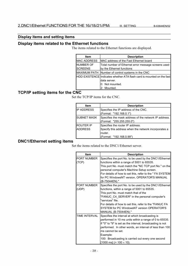
Display items and setting itemsDisplay items related to the Ethernet functions
The items related to the Ethernet functions are displayed.
Item DescriptionMAC ADDRESS MAC address of the Fast Ethernet boardNUMBER OFSCREENS
Total number of Ethernet error message screens usedby the Ethernet functions
MAXIMUM PATH Number of control systems in the CNCHDD EXISTENCE Indicates whether ATA flash card is mounted on the fast
data server.0: Not mounted.2: Mounted.
TCP/IP setting items for the CNCSet the TCP/IP items for the CNC.
Item DescriptionIP ADDRESS Specifies the IP address of the CNC.
(Format: "192.168.0.1")SUBNET MASK Specifies the mask address of the network IP address.
(Format: "255.255.255.0")ROUTER IPADDRESS
Specifies the router IP address.Specify this address when the network incorporates arouter.(Format: "192.168.0.99")
DNC1/Ethernet setting itemsSet the items related to the DNC1/Ethernet server.
Item DescriptionPORT NUMBER(TCP)
Specifies the port No. to be used by the DNC1/Ethernetfunctions within a range of 5001 to 65535.This port No. must match the "NC TCP port No." on thepersonal computer's Machine Setup screen.For details of how to set this, refer to the " FA SYSTEMfor PC WindowsNT version, OPERATOR'S MANUAL(B-75044EN)."
PORT NUMBER(UDP)
Specifies the port No. to be used by the DNC1/Ethernetfunctions, within a range of 5001 to 65535.This port No. must match that of the"FANUC_C4_SERVER" in the personal computer's"services" file.For details of how to set this, refer to the "FANUC FASYSTEM for PC WindowsNT version OPERATOR'SMANUAL (B-75044EN)."
TIME INTERVAL Specifies the interval at which broadcasting isperformed in 10 ms units within a range of 0 to 65535.If "0" to "9" is set as the interval, broadcasting is notperformed. In other words, an interval of less than 100ms cannot be set.Example:100: Broadcasting is carried out every one second[1000 ms] (= 100 × 10).

B-63644EN/02 III. SETTING 2.DNC1/Ethernet FUNCTIONS FOR THE 16i/18i/21i/PMi
- 39 -
NOTE1 When the "TCP/IP setting items for the CNC" have
been changed, the power must be turned off then onagain.
2 The value set for "TIME INTERVAL," describedunder "DNC1/Ethernet setting items," may cause thecommunications load to increase, and adverselyaffecting network performance.

2.DNC1/Ethernet FUNCTIONS FOR THE 16i/18i/21i/PMi III. SETTING B-63644EN/02
- 40 -
Entering dataThe following describes the basic method for entering data.
Procedure1 Place the CNC in MDI mode.2 Display the "Ethernet Parameter" screen.3 Position the cursor to the desired item using the cursor movement
keys.4 Enter the desired data using the MDI keys.5 Press soft key [INPUT] or function key INPUT to fix the data.
NOTEAlready-set data can be deleted. To delete numericaldata, enter 0. To delete character data, enter a space(SP).
Example: To set the IP address to "192.168.0.1"(a) Move the cursor to "IP ADDRESS."

B-63644EN/02 III. SETTING 2.DNC1/Ethernet FUNCTIONS FOR THE 16i/18i/21i/PMi
- 41 -
(b) Enter "192.168.0.1" using the MDI keys.
(c) Press soft key [INPUT] or function key INPUT to fix the data.This causes the parameter to be saved into the non-volatilememory of the CNC.
2.DNC1/Ethernet FUNCTIONS FOR THE 16i/18i/21i/PMi III. SETTING B-63644EN/02
- 42 -
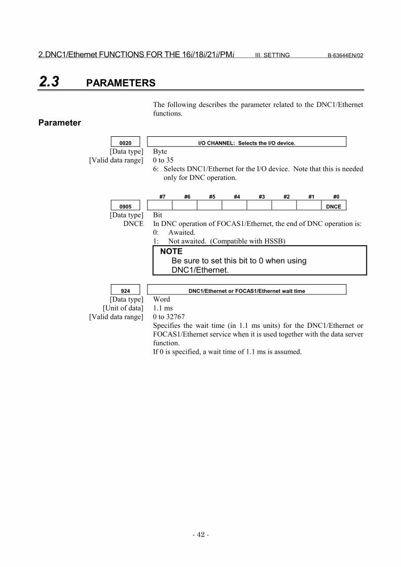
2.3 PARAMETERS
The following describes the parameter related to the DNC1/Ethernetfunctions.
Parameter
0020 I/O CHANNEL: Selects the I/O device.[Data type] Byte
[Valid data range] 0 to 356: Selects DNC1/Ethernet for the I/O device. Note that this is needed
only for DNC operation.
#7 #6 #5 #4 #3 #2 #1 #0
0905 DNCE[Data type] Bit
DNCE In DNC operation of FOCAS1/Ethernet, the end of DNC operation is:0: Awaited.1: Not awaited. (Compatible with HSSB)
NOTEBe sure to set this bit to 0 when usingDNC1/Ethernet.
924 DNC1/Ethernet or FOCAS1/Ethernet wait time[Data type] Word
[Unit of data] 1.1 ms[Valid data range] 0 to 32767
Specifies the wait time (in 1.1 ms units) for the DNC1/Ethernet orFOCAS1/Ethernet service when it is used together with the data serverfunction.If 0 is specified, a wait time of 1.1 ms is assumed.

B-63644EN/02 III. SETTING 2.DNC1/Ethernet FUNCTIONS FOR THE 16i/18i/21i/PMi
- 43 -
2.4 CONFIGURING A SMALL-SCALE NETWORK
The following shows an example of the minimum settings needed touse the DNC1/Ethernet functions with a small-scale network.These settings allow a personal computer to be connected to two CNCs,using the DNC1/Ethernet functions.• The DNC1/Ethernet function client runs on personal computer
No.1.• The DNC1/Ethernet function server runs on CNCs No.1 and
No.2.
CNC No.1 CNC No.2IP address 192.168.0.1 192.168.0.2Subnet mask 255.255.255.0 255.255.255.0Router IP address None NoneTCP port No. 8193 8193UDP port No. 8192 8192Time interval 100 100Parameter No.20 6 6
Personal computer No.1IP address 192.168.0.101Subnet mask 255.255.255.0Default gateway NoneFANUC_C4_SERVER 8192/udpCNC No.1 Machine No. 1NC IP address 192.168.0.1NC TCP port number 8193CNC No.2 Machine No. 2NC IP address 192.168.0.2NC TCP port number 8193
Set these items on the "EthernetParameter" screen.
Set these items in "Microsoft TCP/IP Property" on the personalcomputer (WindowsNT).
Refer to the "FANUC FA SYSTEM for PC WindowsNT versionOPERATOR'S MANUAL."
Set this item on the"Parameter" screen.
Personal computerPersonal computerPersonal computerPersonal computerNo.1No.1No.1No.1CNC No.2CNC No.2CNC No.2CNC No.2CNC No.1CNC No.1CNC No.1CNC No.1
100BASE-TX100BASE-TX100BASE-TX100BASE-TX
HUBHUBHUBHUB
2.DNC1/Ethernet FUNCTIONS FOR THE 16i/18i/21i/PMi III. SETTING B-63644EN/02
- 44 -
2.5 CONFIGURING A LARGE-SCALE NETWORK
Before you configure a large-scale network or add such a network to anexisting network, consult with your company's network administratorto determine IP addresses, subnet masks, and router IP addresses.
B-63644EN/02 III. SETTING 3.FOCAS1/Ethernet FUNCTIONS FOR THE 16i/18i/21i/PMi
- 45 -
3 FOCAS1/Ethernet FUNCTIONS FOR THE16i/18i/21i/PMi
The following describes the settings needed to run theFOCAS1/Ethernet functions for the Series 16i/18i/21i-A/B and PowerMate i.
3.FOCAS1/Ethernet FUNCTIONS FOR THE 16i/18i/21i/PMi III. SETTING B-63644EN/02
- 46 -
3.1 PRECAUTIONS TO BE OBSERVED WHEN USING THEFOCAS1/Ethernet FUNCTIONS FOR THE FIRST TIME
CAUTIONWhen the Fast Ethernet board is used for the firsttime, consult with your company’s networkadministrator to determine the IP addresses andother settings. Then, conduct a communications test.If incorrect IP addresses and other settings are set,communications may be interfered with or the entirenetwork might be adversely affected.Particularly, if a duplicate IP address is set,communication errors are caused intermittently. Thismay result in a CNC's system error. To checkwhether the IP address duplicates any one already inuse, see "Checking IP addresses for duplication" inAppendix A.3, "Checking Communication."
NOTE1 One of the following option functions is needed when
the FOCAS1/Ethernet functions are used:Series16i-TA A02B-0236-S707Series 16i-MA A02B-0237-S707Series 18i-TA A02B-0238-S707Series 18i-MA A02B-0239-S707Series 21i-TA A02B-0247-S707Series 21i-MA A02B-0248-S707Power Mate i A02B-0259-J862Series16i-TB A02B-0281-S707Series 16i-MB A02B-0282-S707Series 18i-TB A02B-0283-S707Series 18i-MB A02B-0284-S707Series 21i-TB A02B-0285-S707Series 21i-MB A02B-0286-S707Series16i/18i/21i-A A02B-0207-J800Power Mate i A02B-0259-J847
2 Up to twenty FOCAS1/Ethernet clients can beconnected to one CNC by the FOCAS1/Ethernetfunctions.
B-63644EN/02 III. SETTING 3.FOCAS1/Ethernet FUNCTIONS FOR THE 16i/18i/21i/PMi
- 47 -
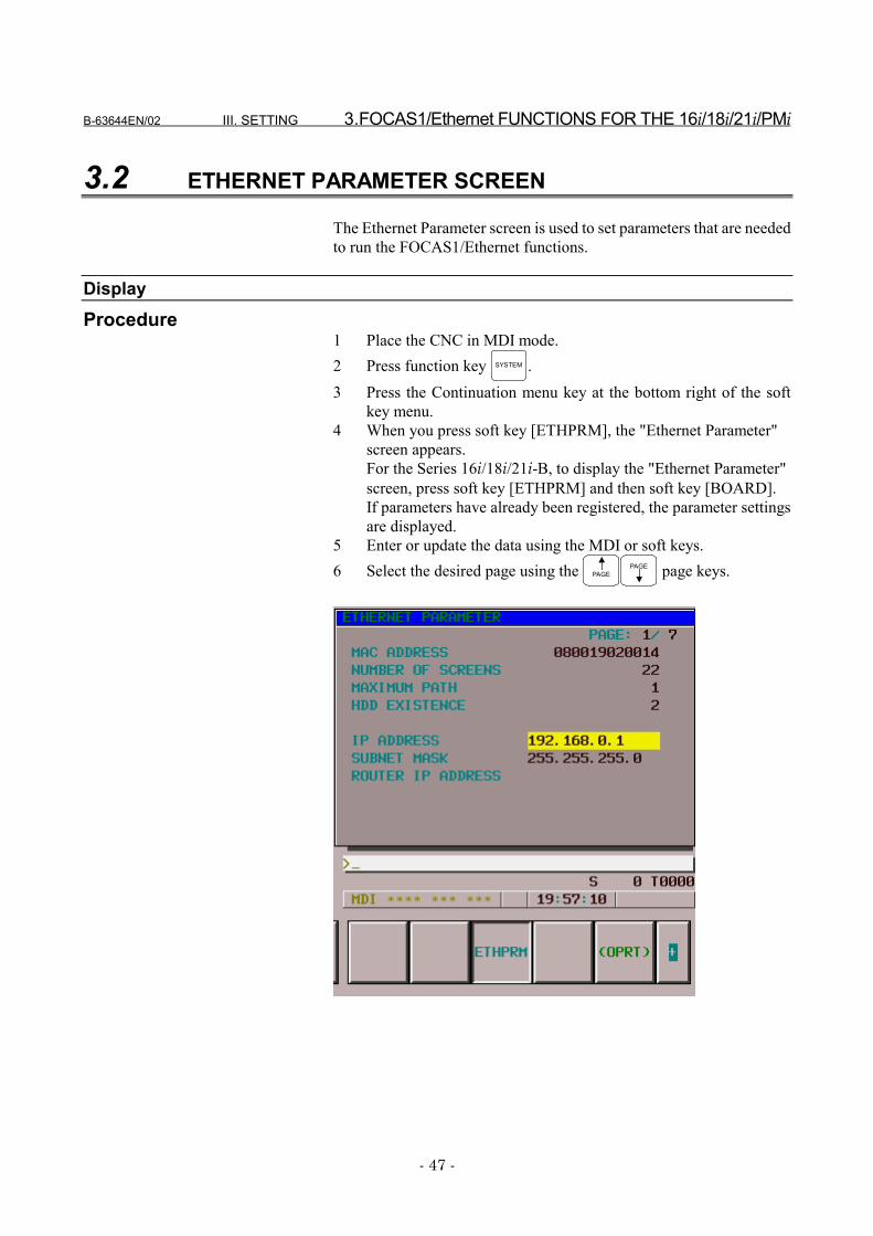
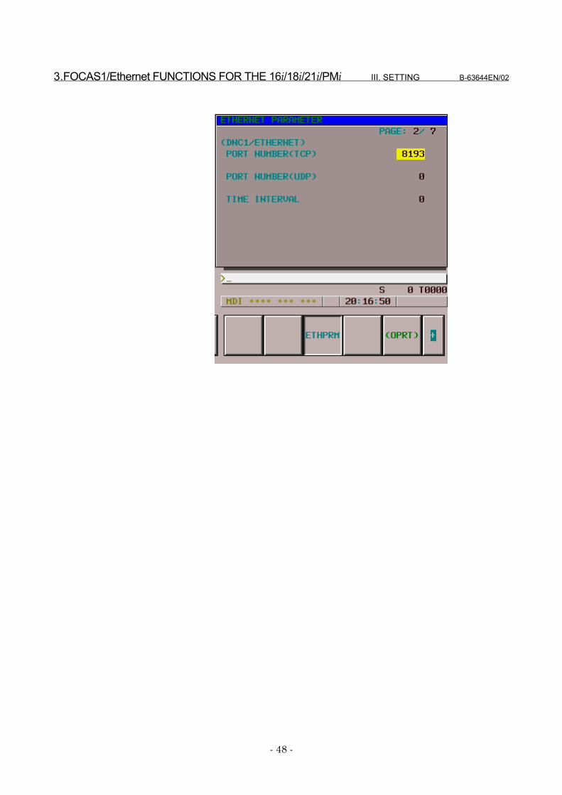
3.2 ETHERNET PARAMETER SCREEN
The Ethernet Parameter screen is used to set parameters that are neededto run the FOCAS1/Ethernet functions.
DisplayProcedure
1 Place the CNC in MDI mode.2 Press function key SYSTEM .3 Press the Continuation menu key at the bottom right of the soft
key menu.4 When you press soft key [ETHPRM], the "Ethernet Parameter"
screen appears.For the Series 16i/18i/21i-B, to display the "Ethernet Parameter"screen, press soft key [ETHPRM] and then soft key [BOARD].If parameters have already been registered, the parameter settingsare displayed.
5 Enter or update the data using the MDI or soft keys.6 Select the desired page using the PAGE
PAGE page keys.
3.FOCAS1/Ethernet FUNCTIONS FOR THE 16i/18i/21i/PMi III. SETTING B-63644EN/02
- 48 -
B-63644EN/02 III. SETTING 3.FOCAS1/Ethernet FUNCTIONS FOR THE 16i/18i/21i/PMi
- 49 -
Display items and setting itemsDisplay items related to the Ethernet functions
The items related to the Ethernet functions are displayed.
Item DescriptionMAC ADDRESS MAC address of the Fast Ethernet boardNUMBER OFSCREENS
Total number of Ethernet error message screens usedby the Ethernet functions
MAXIMUM PATH Number of control systems in the CNCHDD EXISTENCE Indicates whether ATA flash card is mounted on the fast
data server.0: Not mounted.2: Mounted.
TCP/IP setting items for the CNCSet the TCP/IP items for the CNC.
Item DescriptionIP ADDRESS Specifies the IP address of the CNC.
(Format: "192.168.0.1")SUBNET MASK Specifies the mask address of the network IP address.
(Format: "255.255.255.0")ROUTER IPADDRESS
Specifies the router IP address.Specify this address when the network incorporates arouter.(Format: "192.168.0.99")
FOCAS1/Ethernet setting itemsSet the items related to the FOCAS1/Ethernet server.
Item DescriptionPORT NUMBER(TCP)
Specifies the port No. to be used by theFOCAS1/Ethernet functions, within a range of 5001 to65535.
PORT NUMBER(UDP)
Not used by the FOCAS1/Ethernet functions.Set 0.
TIME INTERVAL Not used by the FOCAS1/Ethernet functions.Set 0.
NOTEWhen the "TCP/IP setting items for the CNC" havebeen changed, the power must be turned off then onagain.
3.FOCAS1/Ethernet FUNCTIONS FOR THE 16i/18i/21i/PMi III. SETTING B-63644EN/02
- 50 -
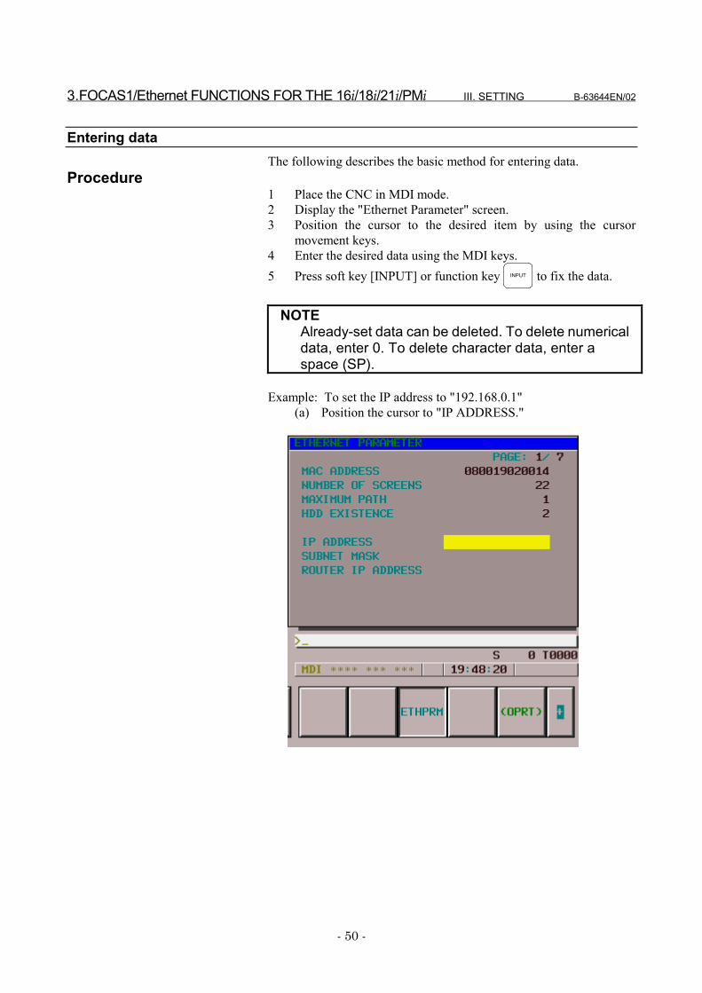
Entering dataThe following describes the basic method for entering data.
Procedure1 Place the CNC in MDI mode.2 Display the "Ethernet Parameter" screen.3 Position the cursor to the desired item by using the cursor
movement keys.4 Enter the desired data using the MDI keys.5 Press soft key [INPUT] or function key INPUT to fix the data.
NOTEAlready-set data can be deleted. To delete numericaldata, enter 0. To delete character data, enter aspace (SP).
Example: To set the IP address to "192.168.0.1"(a) Position the cursor to "IP ADDRESS."
B-63644EN/02 III. SETTING 3.FOCAS1/Ethernet FUNCTIONS FOR THE 16i/18i/21i/PMi
- 51 -
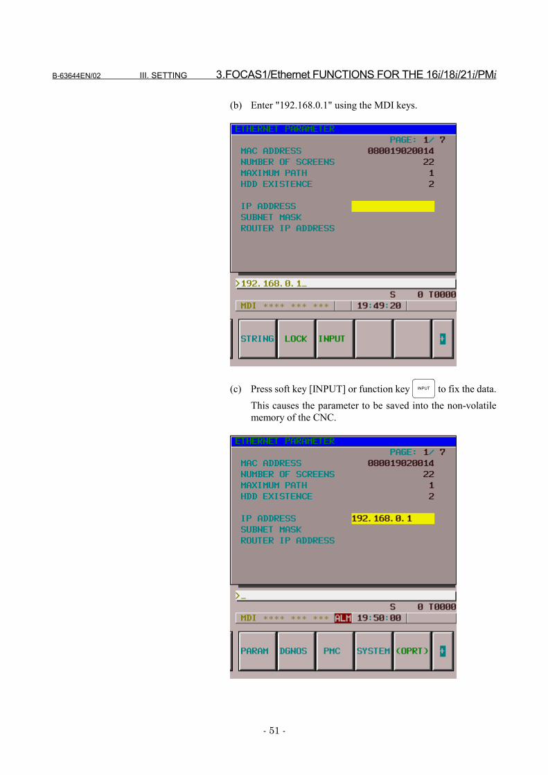
(b) Enter "192.168.0.1" using the MDI keys.
(c) Press soft key [INPUT] or function key INPUT to fix the data.This causes the parameter to be saved into the non-volatilememory of the CNC.
3.FOCAS1/Ethernet FUNCTIONS FOR THE 16i/18i/21i/PMi III. SETTING B-63644EN/02
- 52 -
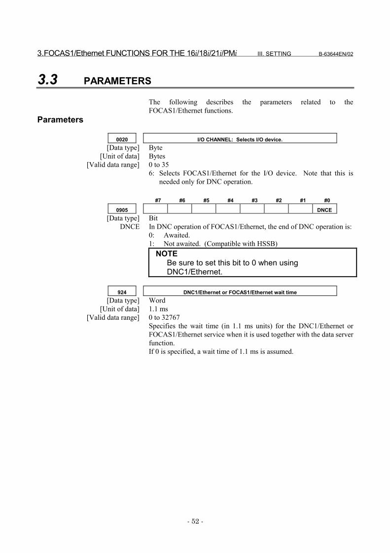
3.3 PARAMETERS
The following describes the parameters related to theFOCAS1/Ethernet functions.
Parameters
0020 I/O CHANNEL: Selects I/O device.[Data type] Byte
[Unit of data] Bytes[Valid data range] 0 to 35
6: Selects FOCAS1/Ethernet for the I/O device. Note that this isneeded only for DNC operation.
#7 #6 #5 #4 #3 #2 #1 #0
0905 DNCE[Data type] Bit
DNCE In DNC operation of FOCAS1/Ethernet, the end of DNC operation is:0: Awaited.1: Not awaited. (Compatible with HSSB)
NOTEBe sure to set this bit to 0 when usingDNC1/Ethernet.
924 DNC1/Ethernet or FOCAS1/Ethernet wait time[Data type] Word
[Unit of data] 1.1 ms[Valid data range] 0 to 32767
Specifies the wait time (in 1.1 ms units) for the DNC1/Ethernet orFOCAS1/Ethernet service when it is used together with the data serverfunction.If 0 is specified, a wait time of 1.1 ms is assumed.

B-63644EN/02 III. SETTING 3.FOCAS1/Ethernet FUNCTIONS FOR THE 16i/18i/21i/PMi
- 53 -
3.4 CONFIGURING A SMALL-SCALE NETWORK
The following shows an example of the minimum settings needed torun the FOCAS1/Ethernet functions on a small-scale network.These settings allow a personal computer to be connected to two CNCsby the FOCAS1/Ethernet functions.
� The FOCAS1/Ethernet function client runs on personalcomputer No.1.
� The FOCAS1/Ethernet function server runs on CNCs No.1and No.2.
CNC No.1 CNC No.2IP address 192.168.0.1 192.168.0.2Subnet mask 255.255.255.0 255.255.255.0Router IP address None NoneTCP port No. 8193 8193UDP port No. 0 0Time interval 0 0Parameter No.20 6 6
Personal computer No.1IP address 192.168.0.101Subnet mask 255.255.255.0Default gateway None
IP address 192.168.0.1CNC No.1Port number 8193IP address 192.168.0.2CNC No.2Port number 8193
Set these items on the"Ethernet Parameter" screen.
Set this item on the"Parameter" screen.
Set these items in "Microsoft TCP/IP Property" on the
personal computer (Windows95/98/NT/2000).
Specify these items with the arguments of the data
window library function "cnc_allclibhnd13."
Personal computerPersonal computerPersonal computerPersonal computerNo.1No.1No.1No.1CNC No.2CNC No.2CNC No.2CNC No.2CNC No.1CNC No.1CNC No.1CNC No.1
100BASE-TX100BASE-TX100BASE-TX100BASE-TX
HUBHUBHUBHUB

3.FOCAS1/Ethernet FUNCTIONS FOR THE 16i/18i/21i/PMi III. SETTING B-63644EN/02
- 54 -
3.5 CONFIGURING A LARGE-SCALE NETWORK
Before you configure a large-scale network or add such a network to anexisting network, consult your company's network administrator todetermine IP addresses, subnet masks, and router IP addresses.
B-63644EN/02 III. SETTING 4.DATA SERVER FUNCTIONS FOR THE 16i/18i/21i
- 55 -
4 DATA SERVER FUNCTIONS FOR THE16i/18i/21i
The following describes the settings needed to run the data serverfunctions for the Series 16i/18i/21i–A/B.
4.DATA SERVER FUNCTIONS FOR THE 16i/18i/21i III. SETTING B-63644EN/02
- 56 -
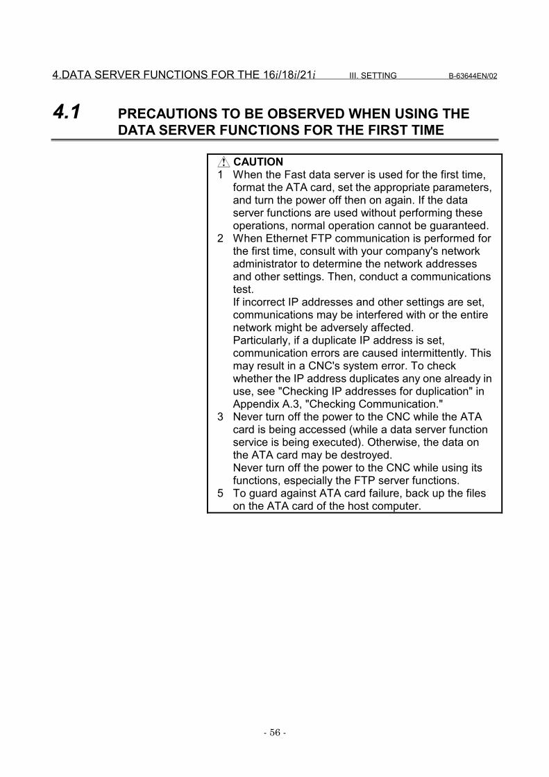
4.1 PRECAUTIONS TO BE OBSERVED WHEN USING THEDATA SERVER FUNCTIONS FOR THE FIRST TIME
CAUTION1 When the Fast data server is used for the first time,
format the ATA card, set the appropriate parameters,and turn the power off then on again. If the dataserver functions are used without performing theseoperations, normal operation cannot be guaranteed.
2 When Ethernet FTP communication is performed forthe first time, consult with your company's networkadministrator to determine the network addressesand other settings. Then, conduct a communicationstest.If incorrect IP addresses and other settings are set,communications may be interfered with or the entirenetwork might be adversely affected.Particularly, if a duplicate IP address is set,communication errors are caused intermittently. Thismay result in a CNC's system error. To checkwhether the IP address duplicates any one already inuse, see "Checking IP addresses for duplication" inAppendix A.3, "Checking Communication."
3 Never turn off the power to the CNC while the ATAcard is being accessed (while a data server functionservice is being executed). Otherwise, the data onthe ATA card may be destroyed.Never turn off the power to the CNC while using itsfunctions, especially the FTP server functions.
5 To guard against ATA card failure, back up the fileson the ATA card of the host computer.
B-63644EN/02 III. SETTING 4.DATA SERVER FUNCTIONS FOR THE 16i/18i/21i
- 57 -
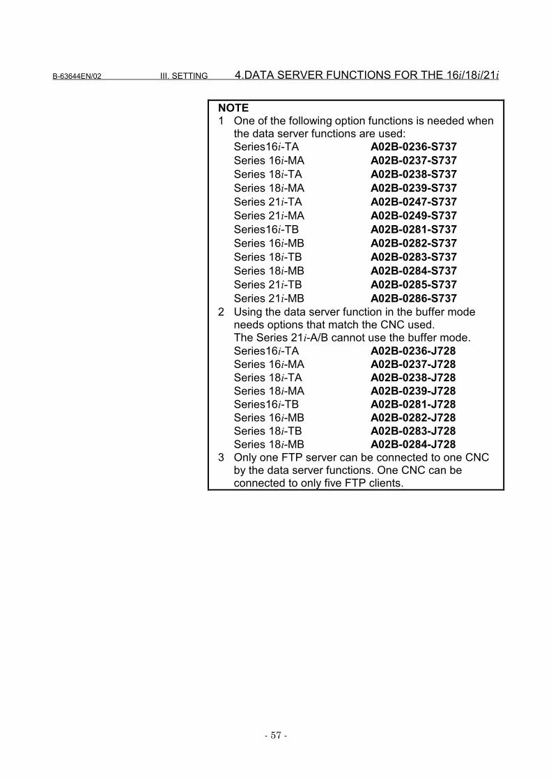
NOTE1 One of the following option functions is needed when
the data server functions are used:Series16i-TA A02B-0236-S737Series 16i-MA A02B-0237-S737Series 18i-TA A02B-0238-S737Series 18i-MA A02B-0239-S737Series 21i-TA A02B-0247-S737Series 21i-MA A02B-0249-S737Series16i-TB A02B-0281-S737Series 16i-MB A02B-0282-S737Series 18i-TB A02B-0283-S737Series 18i-MB A02B-0284-S737Series 21i-TB A02B-0285-S737Series 21i-MB A02B-0286-S737
2 Using the data server function in the buffer modeneeds options that match the CNC used.The Series 21i-A/B cannot use the buffer mode.Series16i-TA A02B-0236-J728Series 16i-MA A02B-0237-J728Series 18i-TA A02B-0238-J728Series 18i-MA A02B-0239-J728Series16i-TB A02B-0281-J728Series 16i-MB A02B-0282-J728Series 18i-TB A02B-0283-J728Series 18i-MB A02B-0284-J728
3 Only one FTP server can be connected to one CNCby the data server functions. One CNC can beconnected to only five FTP clients.

4.DATA SERVER FUNCTIONS FOR THE 16i/18i/21i III. SETTING B-63644EN/02
- 58 -
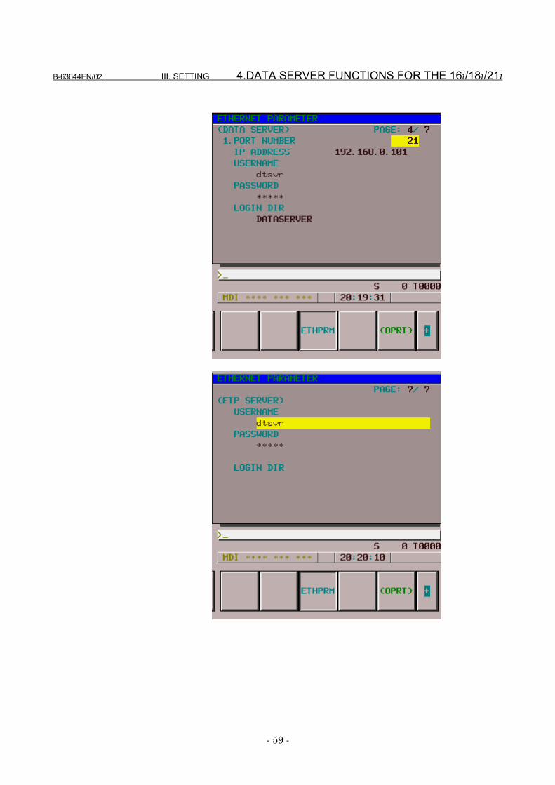
4.2 ETHERNET PARAMETER SCREEN
The Ethernet Parameter screen is used to set the parameters that areneeded for the data server functions.
DisplayProcedure
1 Place the CNC in MDI mode.2 Press function key SYSTEM .3 Press the Continuation menu key at the bottom right of the soft
key menu.4 When you press soft key [ETHPRM], the "Ethernet Parameter"
screen appears.For the Series 16i/18i/21i-B, to display the "Ethernet Parameter"screen, press soft key [ETHPRM] and then soft key [BOARD].If parameters are already registered, the parameter settings aredisplayed.
5 Enter or update the data using the MDI or soft keys.6 Select the desired page using the PAGE
PAGE page keys.
B-63644EN/02 III. SETTING 4.DATA SERVER FUNCTIONS FOR THE 16i/18i/21i
- 59 -
4.DATA SERVER FUNCTIONS FOR THE 16i/18i/21i III. SETTING B-63644EN/02
- 60 -
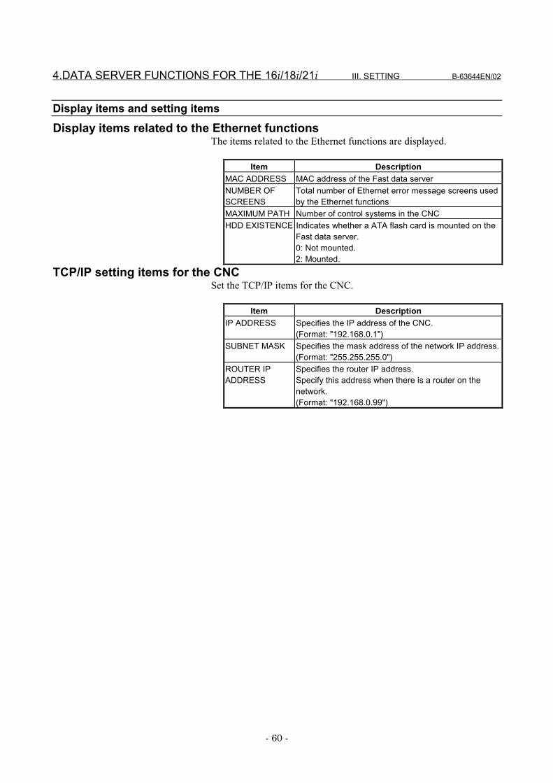
Display items and setting itemsDisplay items related to the Ethernet functions
The items related to the Ethernet functions are displayed.
Item DescriptionMAC ADDRESS MAC address of the Fast data serverNUMBER OFSCREENS
Total number of Ethernet error message screens usedby the Ethernet functions
MAXIMUM PATH Number of control systems in the CNCHDD EXISTENCE Indicates whether a ATA flash card is mounted on the
Fast data server.0: Not mounted.2: Mounted.
TCP/IP setting items for the CNCSet the TCP/IP items for the CNC.
Item DescriptionIP ADDRESS Specifies the IP address of the CNC.
(Format: "192.168.0.1")SUBNET MASK Specifies the mask address of the network IP address.
(Format: "255.255.255.0")ROUTER IPADDRESS
Specifies the router IP address.Specify this address when there is a router on thenetwork.(Format: "192.168.0.99")
B-63644EN/02 III. SETTING 4.DATA SERVER FUNCTIONS FOR THE 16i/18i/21i
- 61 -
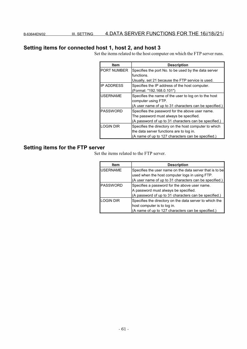
Setting items for connected host 1, host 2, and host 3Set the items related to the host computer on which the FTP server runs.
Item DescriptionPORT NUMBER Specifies the port No. to be used by the data server
functions.Usually, set 21 because the FTP service is used.
IP ADDRESS Specifies the IP address of the host computer.(Format: "192.168.0.101")
USERNAME Specifies the name of the user to log on to the hostcomputer using FTP.(A user name of up to 31 characters can be specified.)
PASSWORD Specifies the password for the above user name.The password must always be specified.(A password of up to 31 characters can be specified.)
LOGIN DIR Specifies the directory on the host computer to whichthe data server functions are to log in.(A name of up to 127 characters can be specified.)
Setting items for the FTP serverSet the items related to the FTP server.
Item DescriptionUSERNAME Specifies the user name on the data server that is to be
used when the host computer logs in using FTP.(A user name of up to 31 characters can be specified.)
PASSWORD Specifies a password for the above user name.A password must always be specified.(A password of up to 31 characters can be specified.)
LOGIN DIR Specifies the directory on the data server to which thehost computer is to log in.(A name of up to 127 characters can be specified.)
4.DATA SERVER FUNCTIONS FOR THE 16i/18i/21i III. SETTING B-63644EN/02
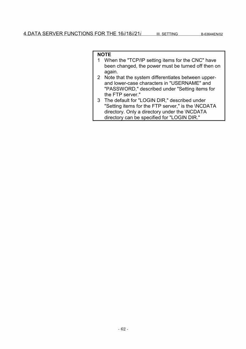
- 62 -
NOTE1 When the "TCP/IP setting items for the CNC" have
been changed, the power must be turned off then onagain.
2 Note that the system differentiates between upper-and lower-case characters in "USERNAME" and"PASSWORD," described under "Setting items forthe FTP server."
3 The default for "LOGIN DIR," described under"Setting items for the FTP server," is the \NCDATAdirectory. Only a directory under the \NCDATAdirectory can be specified for "LOGIN DIR."

B-63644EN/02 III. SETTING 4.DATA SERVER FUNCTIONS FOR THE 16i/18i/21i
- 63 -
Entering dataThe following describes the basic method for entering data.
Procedure1 Place the CNC in MDI mode.2 Display the "Ethernet Parameter" screen.3 Position the cursor to the desired item by using the cursor
movement keys.4 Enter the desired data using the MDI keys.5 Press soft key [INPUT] or function key INPUT to fix the data.
NOTEAlready-set data can be deleted. To delete numericaldata, enter 0. To delete character data, enter aspace (SP).
Example: To set the IP address to "192.168.0.1"(a) Position the cursor to "IP ADDRESS."
4.DATA SERVER FUNCTIONS FOR THE 16i/18i/21i III. SETTING B-63644EN/02
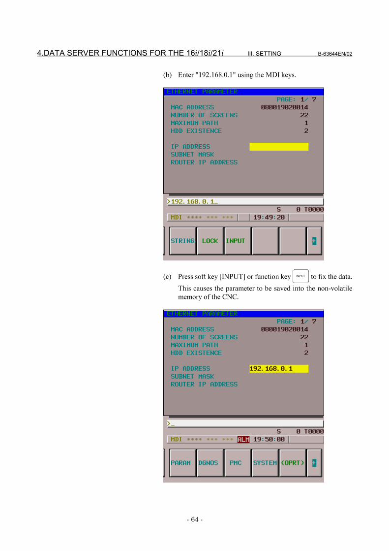
- 64 -
(b) Enter "192.168.0.1" using the MDI keys.
(c) Press soft key [INPUT] or function key INPUT to fix the data.This causes the parameter to be saved into the non-volatilememory of the CNC.
B-63644EN/02 III. SETTING 4.DATA SERVER FUNCTIONS FOR THE 16i/18i/21i
- 65 -
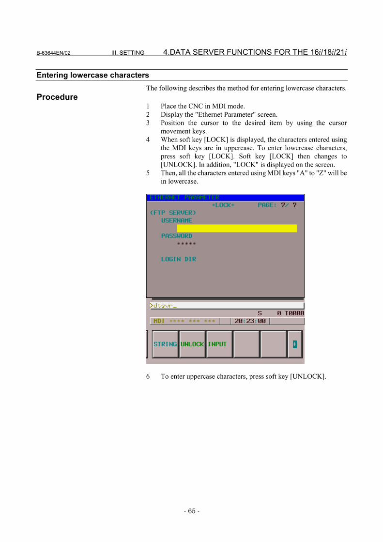
Entering lowercase charactersThe following describes the method for entering lowercase characters.
Procedure1 Place the CNC in MDI mode.2 Display the "Ethernet Parameter" screen.3 Position the cursor to the desired item by using the cursor
movement keys.4 When soft key [LOCK] is displayed, the characters entered using
the MDI keys are in uppercase. To enter lowercase characters,press soft key [LOCK]. Soft key [LOCK] then changes to[UNLOCK]. In addition, "LOCK" is displayed on the screen.
5 Then, all the characters entered using MDI keys "A" to "Z" will bein lowercase.
6 To enter uppercase characters, press soft key [UNLOCK].
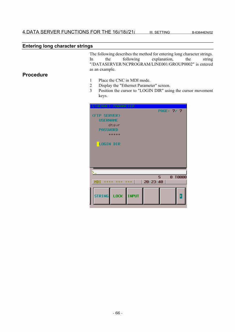
4.DATA SERVER FUNCTIONS FOR THE 16i/18i/21i III. SETTING B-63644EN/02
- 66 -
Entering long character stringsThe following describes the method for entering long character strings.In the following explanation, the string"/DATASERVER/NCPROGRAM/LINE001/GROUP0002" is enteredas an example.
Procedure1 Place the CNC in MDI mode.2 Display the "Ethernet Parameter" screen.3 Position the cursor to "LOGIN DIR" using the cursor movement
keys.
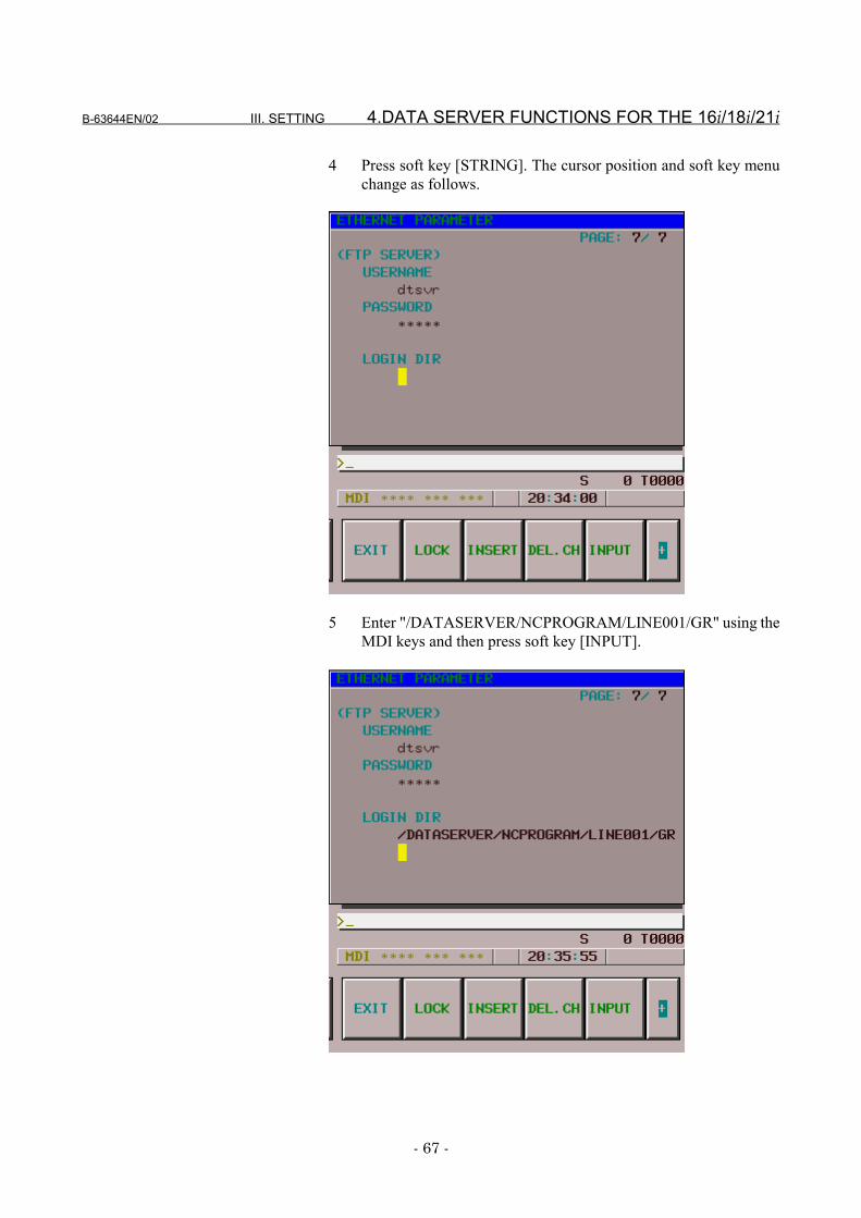
B-63644EN/02 III. SETTING 4.DATA SERVER FUNCTIONS FOR THE 16i/18i/21i
- 67 -
4 Press soft key [STRING]. The cursor position and soft key menuchange as follows.
5 Enter "/DATASERVER/NCPROGRAM/LINE001/GR" using theMDI keys and then press soft key [INPUT].
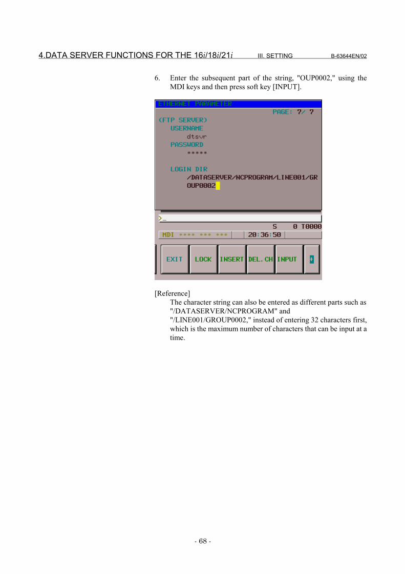
4.DATA SERVER FUNCTIONS FOR THE 16i/18i/21i III. SETTING B-63644EN/02
- 68 -
6. Enter the subsequent part of the string, "OUP0002," using theMDI keys and then press soft key [INPUT].
[Reference]The character string can also be entered as different parts such as"/DATASERVER/NCPROGRAM" and"/LINE001/GROUP0002," instead of entering 32 characters first,which is the maximum number of characters that can be input at atime.
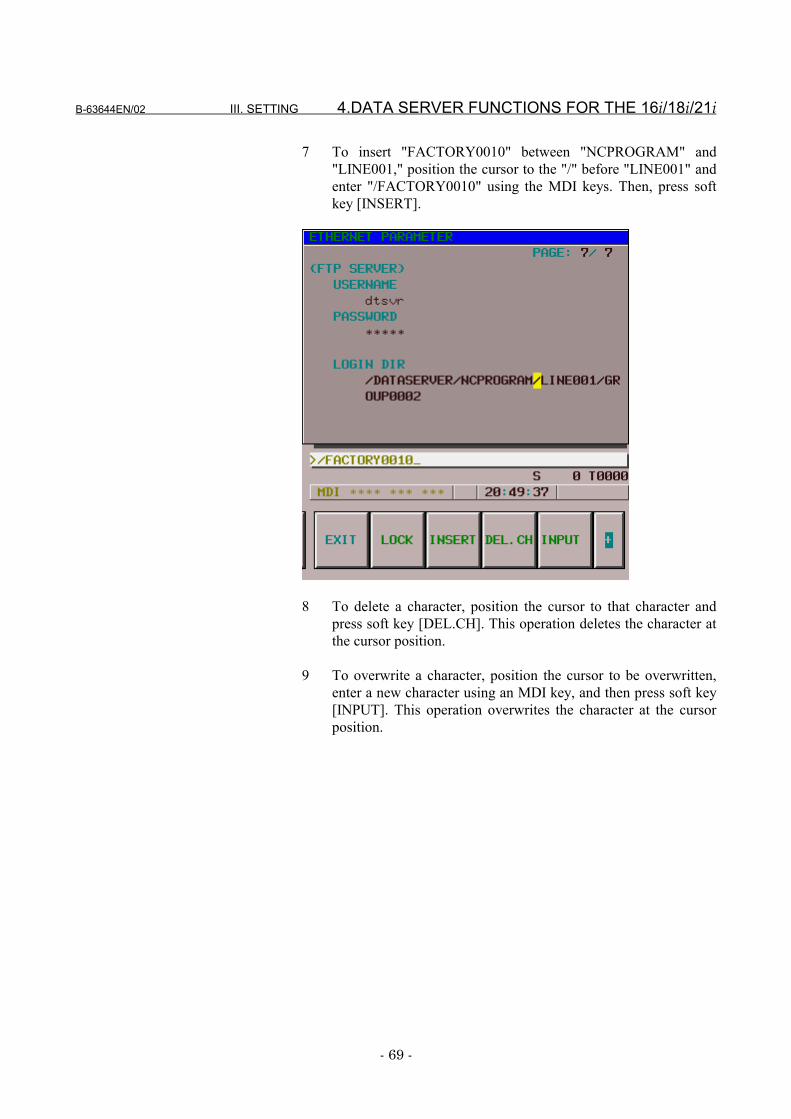
B-63644EN/02 III. SETTING 4.DATA SERVER FUNCTIONS FOR THE 16i/18i/21i
- 69 -
7 To insert "FACTORY0010" between "NCPROGRAM" and"LINE001," position the cursor to the "/" before "LINE001" andenter "/FACTORY0010" using the MDI keys. Then, press softkey [INSERT].
8 To delete a character, position the cursor to that character andpress soft key [DEL.CH]. This operation deletes the character atthe cursor position.
9 To overwrite a character, position the cursor to be overwritten,enter a new character using an MDI key, and then press soft key[INPUT]. This operation overwrites the character at the cursorposition.
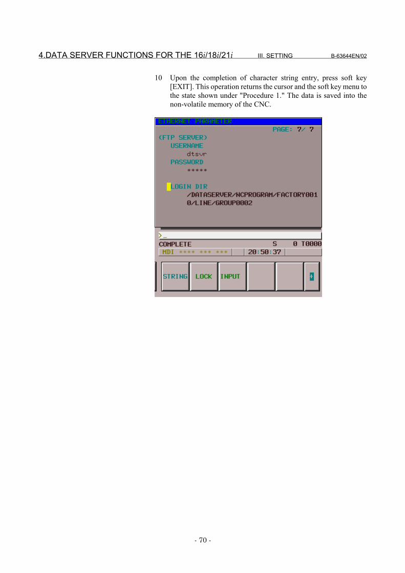
4.DATA SERVER FUNCTIONS FOR THE 16i/18i/21i III. SETTING B-63644EN/02
- 70 -
10 Upon the completion of character string entry, press soft key[EXIT]. This operation returns the cursor and the soft key menu tothe state shown under "Procedure 1." The data is saved into thenon-volatile memory of the CNC.
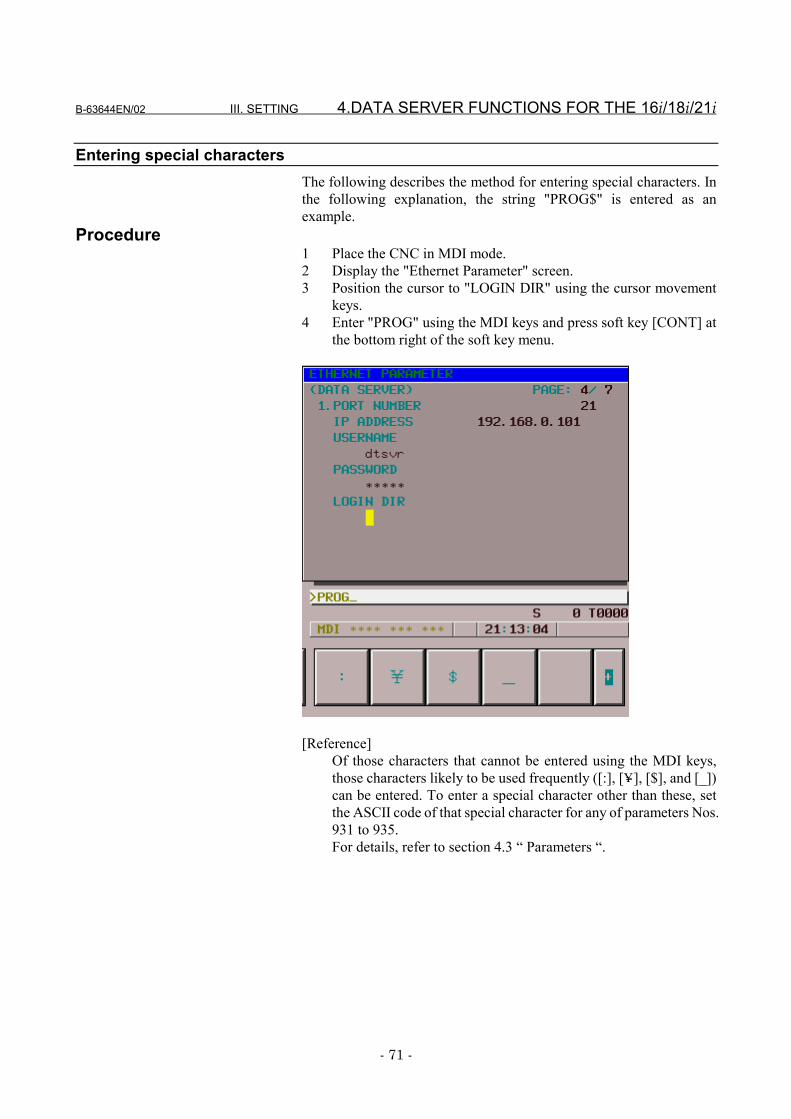
B-63644EN/02 III. SETTING 4.DATA SERVER FUNCTIONS FOR THE 16i/18i/21i
- 71 -
Entering special charactersThe following describes the method for entering special characters. Inthe following explanation, the string "PROG$" is entered as anexample.
Procedure1 Place the CNC in MDI mode.2 Display the "Ethernet Parameter" screen.3 Position the cursor to "LOGIN DIR" using the cursor movement
keys.4 Enter "PROG" using the MDI keys and press soft key [CONT] at
the bottom right of the soft key menu.
[Reference]Of those characters that cannot be entered using the MDI keys,those characters likely to be used frequently ([:], [Y], [$], and [_])can be entered. To enter a special character other than these, setthe ASCII code of that special character for any of parameters Nos.931 to 935.For details, refer to section 4.3 “ Parameters “.
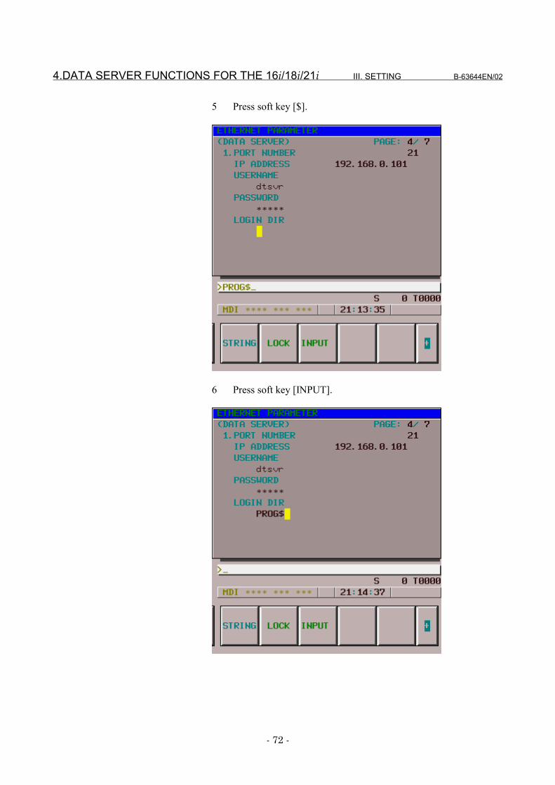
4.DATA SERVER FUNCTIONS FOR THE 16i/18i/21i III. SETTING B-63644EN/02
- 72 -
5 Press soft key [$].
6 Press soft key [INPUT].
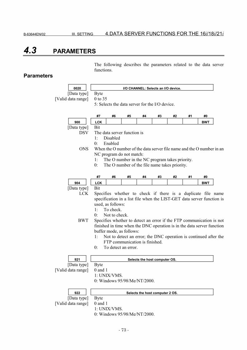
B-63644EN/02 III. SETTING 4.DATA SERVER FUNCTIONS FOR THE 16i/18i/21i
- 73 -
4.3 PARAMETERS
The following describes the parameters related to the data serverfunctions.
Parameters
0020 I/O CHANNEL: Selects an I/O device.[Data type] Byte
[Valid data range] 0 to 355: Selects the data server for the I/O device.
#7 #6 #5 #4 #3 #2 #1 #0
900 LCK BWT[Data type] Bit
DSV The data server function is1: Disabled0: Enabled
ONS When the O number of the data server file name and the O number in anNC program do not match:1: The O number in the NC program takes priority.0: The O number of the file name takes priority.
#7 #6 #5 #4 #3 #2 #1 #0
904 LCK BWT[Data type] Bit
LCK Specifies whether to check if there is a duplicate file namespecification in a list file when the LIST-GET data server function isused, as follows:1: To check.0: Not to check.
BWT Specifies whether to detect an error if the FTP communication is notfinished in time when the DNC operation is in the data server functionbuffer mode, as follows:1: Not to detect an error; the DNC operation is continued after the
FTP communication is finished.0: To detect an error.
921 Selects the host computer OS.[Data type] Byte
[Valid data range] 0 and 11: UNIX/VMS.0: Windows 95/98/Me/NT/2000.
922 Selects the host computer 2 OS.[Data type] Byte
[Valid data range] 0 and 11: UNIX/VMS.0: Windows 95/98/Me/NT/2000.
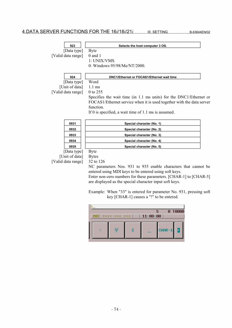
4.DATA SERVER FUNCTIONS FOR THE 16i/18i/21i III. SETTING B-63644EN/02
- 74 -
923 Selects the host computer 3 OS.[Data type] Byte
[Valid data range] 0 and 11: UNIX/VMS.0: Windows 95/98/Me/NT/2000.
924 DNC1/Ethernet or FOCAS1/Ethernet wait time[Data type] Word
[Unit of data] 1.1 ms[Valid data range] 0 to 255
Specifies the wait time (in 1.1 ms units) for the DNC1/Ethernet orFOCAS1/Ethernet service when it is used together with the data serverfunction.If 0 is specified, a wait time of 1.1 ms is assumed.
0931 Special character (No. 1)
0932 Special character (No. 2)
0933 Special character (No. 3)
0934 Special character (No. 4)
0935 Special character (No. 5)[Data type] Byte
[Unit of data] Bytes[Valid data range] 32 to 126
NC parameters Nos. 931 to 935 enable characters that cannot beentered using MDI keys to be entered using soft keys.Enter non-zero numbers for these parameters. [CHAR-1] to [CHAR-5]are displayed as the special character input soft keys.
Example: When "33" is entered for parameter No. 931, pressing softkey [CHAR-1] causes a "!" to be entered.
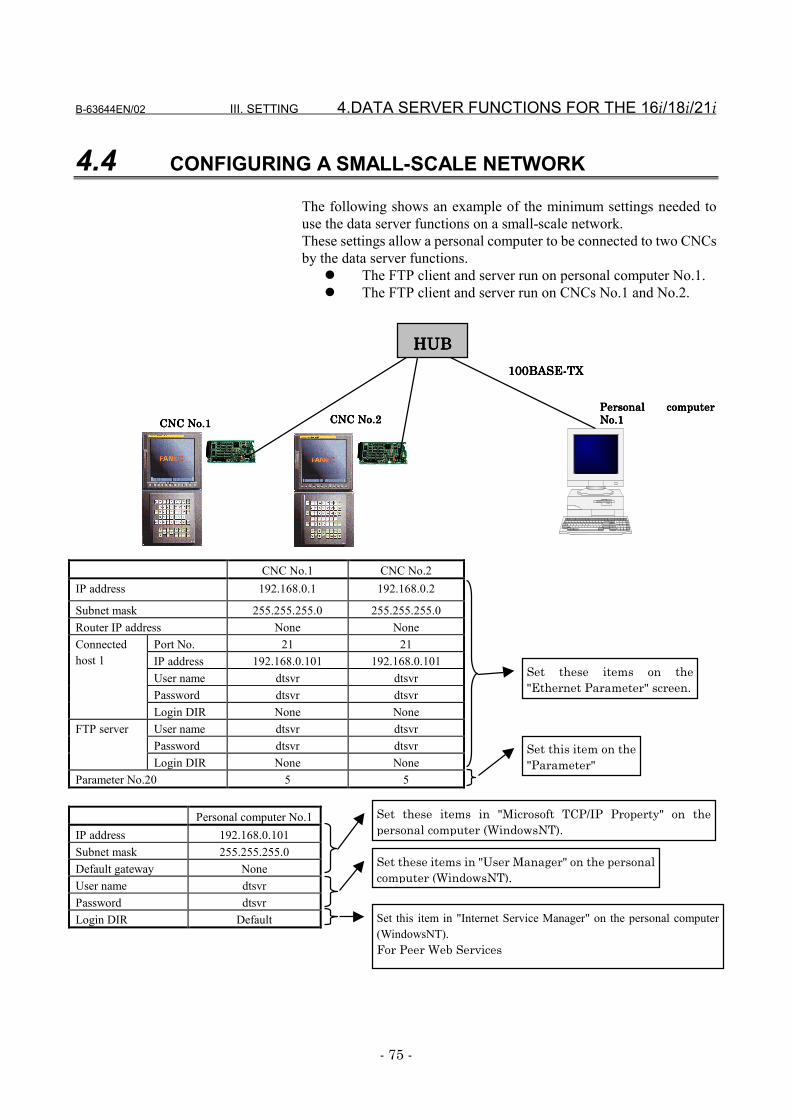
B-63644EN/02 III. SETTING 4.DATA SERVER FUNCTIONS FOR THE 16i/18i/21i
- 75 -
4.4 CONFIGURING A SMALL-SCALE NETWORK
The following shows an example of the minimum settings needed touse the data server functions on a small-scale network.These settings allow a personal computer to be connected to two CNCsby the data server functions.
� The FTP client and server run on personal computer No.1.� The FTP client and server run on CNCs No.1 and No.2.
CNC No.1 CNC No.2IP address 192.168.0.1 192.168.0.2
Subnet mask 255.255.255.0 255.255.255.0Router IP address None None
Port No. 21 21IP address 192.168.0.101 192.168.0.101User name dtsvr dtsvrPassword dtsvr dtsvr
Connectedhost 1
Login DIR None NoneUser name dtsvr dtsvrPassword dtsvr dtsvr
FTP server
Login DIR None NoneParameter No.20 5 5
Personal computer No.1IP address 192.168.0.101Subnet mask 255.255.255.0Default gateway NoneUser name dtsvrPassword dtsvrLogin DIR Default
Personal computerPersonal computerPersonal computerPersonal computerNo.1No.1No.1No.1CNC No.2CNC No.2CNC No.2CNC No.2CNC No.1CNC No.1CNC No.1CNC No.1
100BASE-TX100BASE-TX100BASE-TX100BASE-TX
HUBHUBHUBHUB
Set these items in "Microsoft TCP/IP Property" on thepersonal computer (WindowsNT).
Set these items in "User Manager" on the personalcomputer (WindowsNT).
Set this item in "Internet Service Manager" on the personal computer(WindowsNT).For Peer Web Services
Set these items on the"Ethernet Parameter" screen.
Set this item on the"Parameter"
4.DATA SERVER FUNCTIONS FOR THE 16i/18i/21i III. SETTING B-63644EN/02
- 76 -
4.5 CONFIGURING A LARGE-SCALE NETWORK
Before you configure a large-scale network or add such a network to anexisting network, consult with your company's network administratorto determine IP addresses, subnet masks, and router IP addresses.
B-63644EN/02 III. SETTING 5.FOCAS1/Ethernet FUNCTIONS FOR THE 15i
- 77 -
5 FOCAS1/Ethernet FUNCTIONS FOR THE15i
The following describes the settings needed to run theFOCAS1/Ethernet functions for the Series 15i-B.
5.FOCAS1/Ethernet FUNCTIONS FOR THE 15i III. SETTING B-63644EN/02
- 78 -
5.1 PRECAUTIONS TO BE OBSERVED WHEN USING THEFOCAS1/Ethernet FUNCTIONS FOR THE FIRST TIME
CAUTIONWhen the Fast Ethernet board is used for the firsttime, consult with your company’s networkadministrator to determine the IP addresses andother settings. Then, conduct a communications test.If incorrect IP addresses and other settings are set,communications may be interfered with or the entirenetwork might be adversely affected.Particularly, if a duplicate IP address is set,communication errors are caused intermittently. Thismay result in a CNC's system error. To checkwhether the IP address duplicates any one already inuse, see "Checking IP addresses for duplication" inAppendix A.3, "Checking Communication."
NOTE1 One of the following option functions is needed when
the FOCAS1/Ethernet functions are used:Series15i-MB A02B-0298-J647
A02B-0207-J8012 Up to twenty FOCAS1/Ethernet clients can be
connected to one CNC by the FOCAS1/Ethernetfunctions.
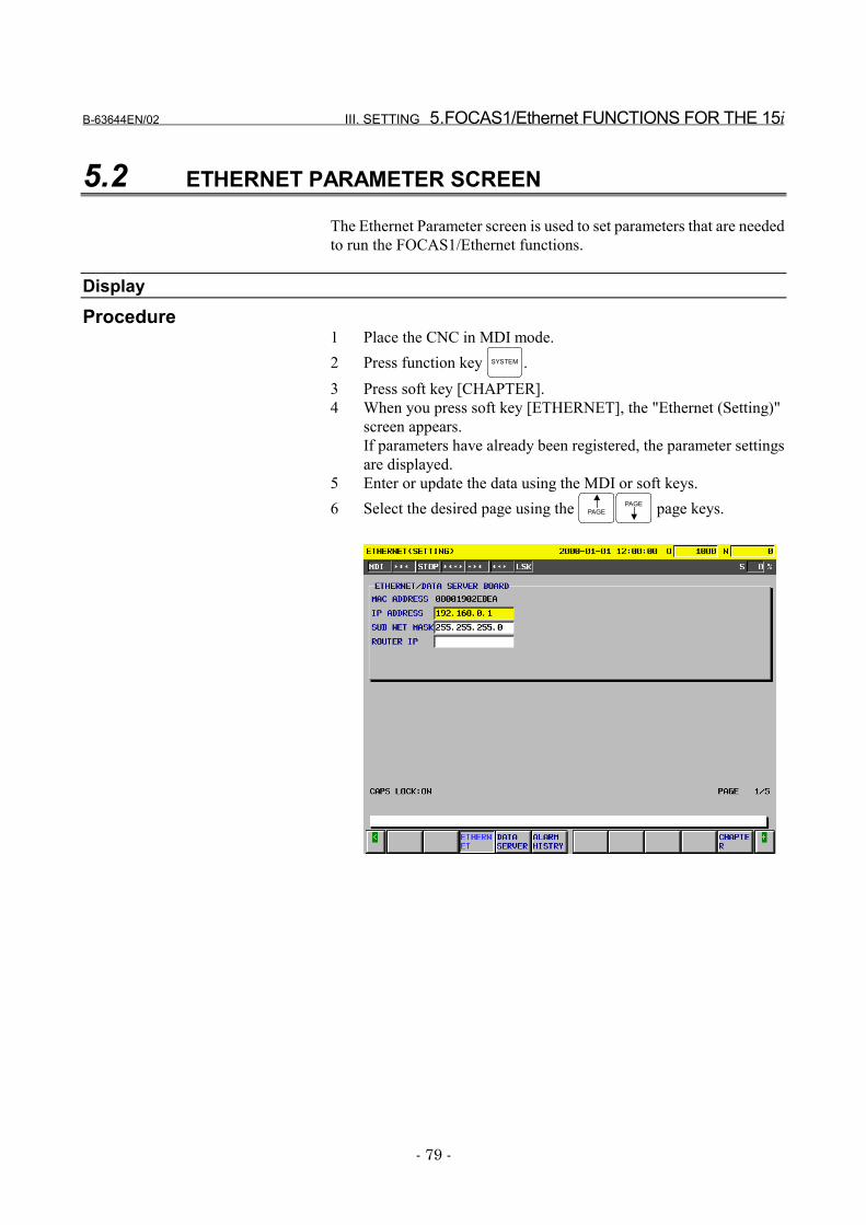
B-63644EN/02 III. SETTING 5.FOCAS1/Ethernet FUNCTIONS FOR THE 15i
- 79 -
5.2 ETHERNET PARAMETER SCREEN
The Ethernet Parameter screen is used to set parameters that are neededto run the FOCAS1/Ethernet functions.
DisplayProcedure
1 Place the CNC in MDI mode.2 Press function key SYSTEM .3 Press soft key [CHAPTER].4 When you press soft key [ETHERNET], the "Ethernet (Setting)"
screen appears.If parameters have already been registered, the parameter settingsare displayed.
5 Enter or update the data using the MDI or soft keys.6 Select the desired page using the PAGE
PAGE page keys.
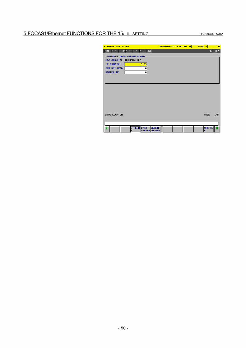
5.FOCAS1/Ethernet FUNCTIONS FOR THE 15i III. SETTING B-63644EN/02
- 80 -
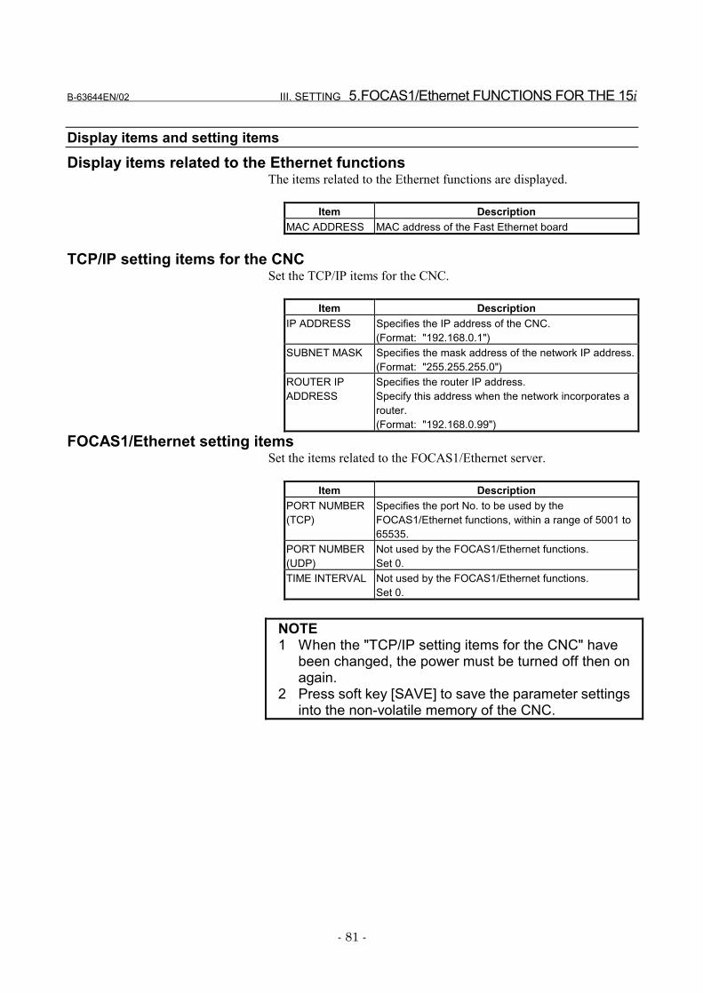
B-63644EN/02 III. SETTING 5.FOCAS1/Ethernet FUNCTIONS FOR THE 15i
- 81 -
Display items and setting itemsDisplay items related to the Ethernet functions
The items related to the Ethernet functions are displayed.
Item DescriptionMAC ADDRESS MAC address of the Fast Ethernet board
TCP/IP setting items for the CNCSet the TCP/IP items for the CNC.
Item DescriptionIP ADDRESS Specifies the IP address of the CNC.
(Format: "192.168.0.1")SUBNET MASK Specifies the mask address of the network IP address.
(Format: "255.255.255.0")ROUTER IPADDRESS
Specifies the router IP address.Specify this address when the network incorporates arouter.(Format: "192.168.0.99")
FOCAS1/Ethernet setting itemsSet the items related to the FOCAS1/Ethernet server.
Item DescriptionPORT NUMBER(TCP)
Specifies the port No. to be used by theFOCAS1/Ethernet functions, within a range of 5001 to65535.
PORT NUMBER(UDP)
Not used by the FOCAS1/Ethernet functions.Set 0.
TIME INTERVAL Not used by the FOCAS1/Ethernet functions.Set 0.
NOTE1 When the "TCP/IP setting items for the CNC" have
been changed, the power must be turned off then onagain.
2 Press soft key [SAVE] to save the parameter settingsinto the non-volatile memory of the CNC.
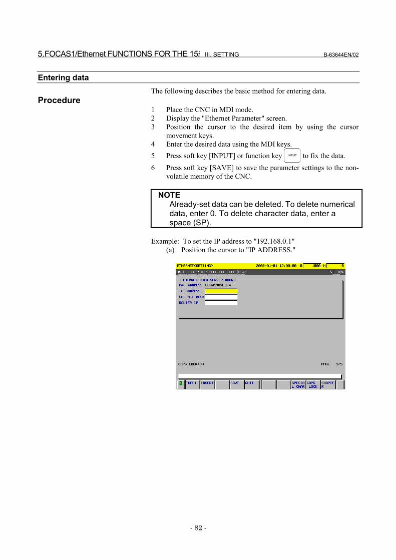
5.FOCAS1/Ethernet FUNCTIONS FOR THE 15i III. SETTING B-63644EN/02
- 82 -
Entering dataThe following describes the basic method for entering data.
Procedure1 Place the CNC in MDI mode.2 Display the "Ethernet Parameter" screen.3 Position the cursor to the desired item by using the cursor
movement keys.4 Enter the desired data using the MDI keys.5 Press soft key [INPUT] or function key INPUT to fix the data.6 Press soft key [SAVE] to save the parameter settings to the non-
volatile memory of the CNC.
NOTEAlready-set data can be deleted. To delete numericaldata, enter 0. To delete character data, enter aspace (SP).
Example: To set the IP address to "192.168.0.1"(a) Position the cursor to "IP ADDRESS."
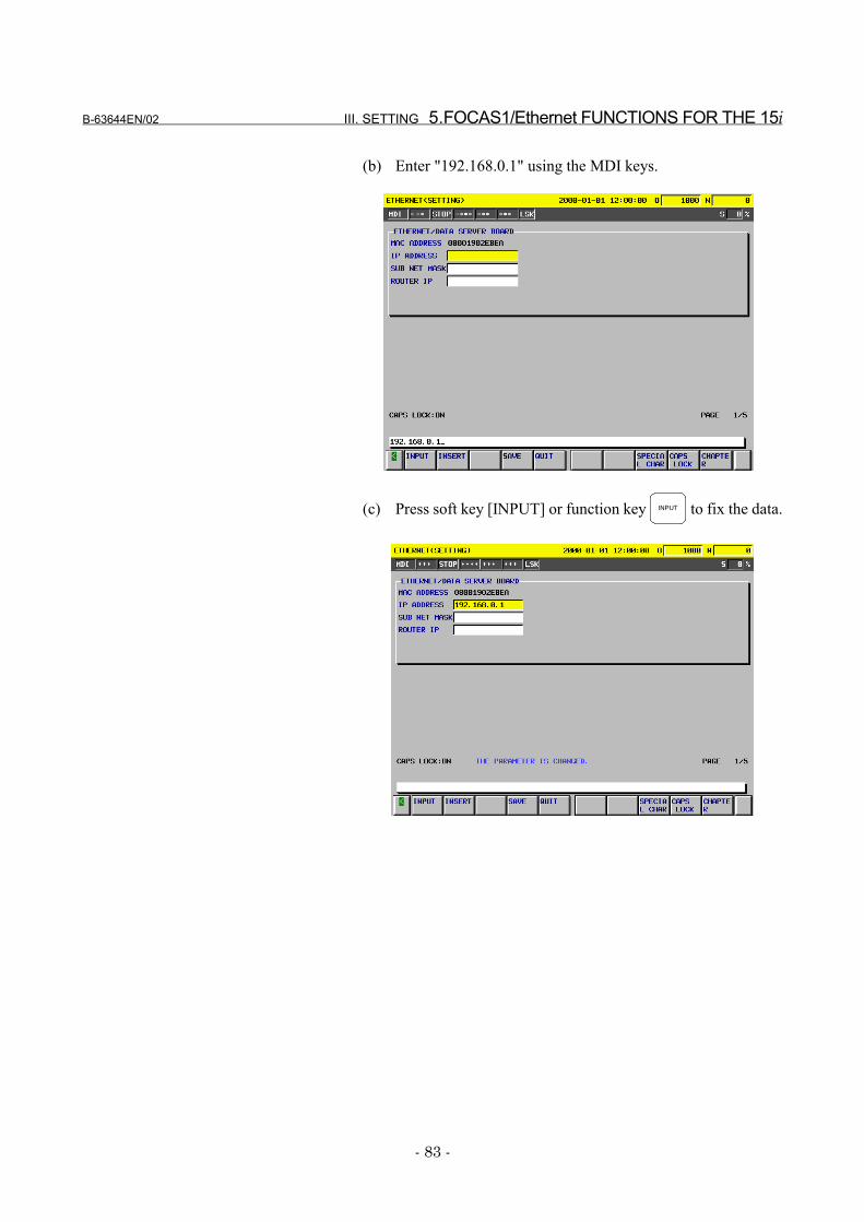
B-63644EN/02 III. SETTING 5.FOCAS1/Ethernet FUNCTIONS FOR THE 15i
- 83 -
(b) Enter "192.168.0.1" using the MDI keys.
(c) Press soft key [INPUT] or function key INPUT to fix the data.
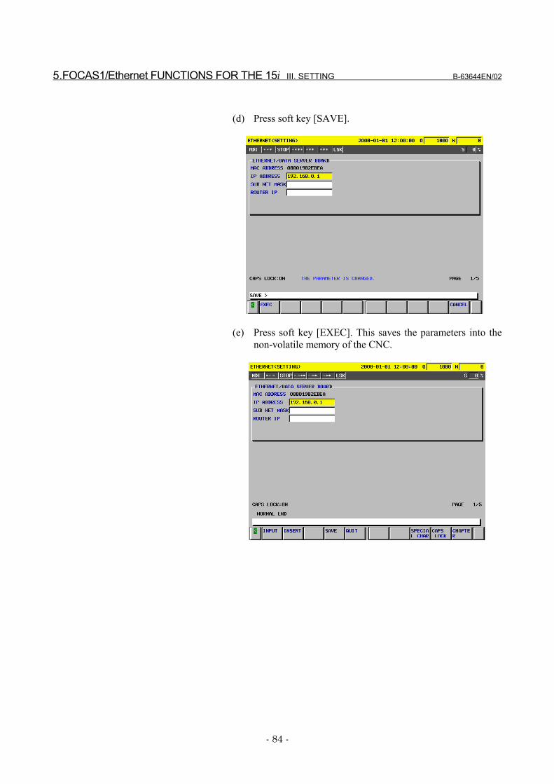
5.FOCAS1/Ethernet FUNCTIONS FOR THE 15i III. SETTING B-63644EN/02
- 84 -
(d) Press soft key [SAVE].
(e) Press soft key [EXEC]. This saves the parameters into thenon-volatile memory of the CNC.
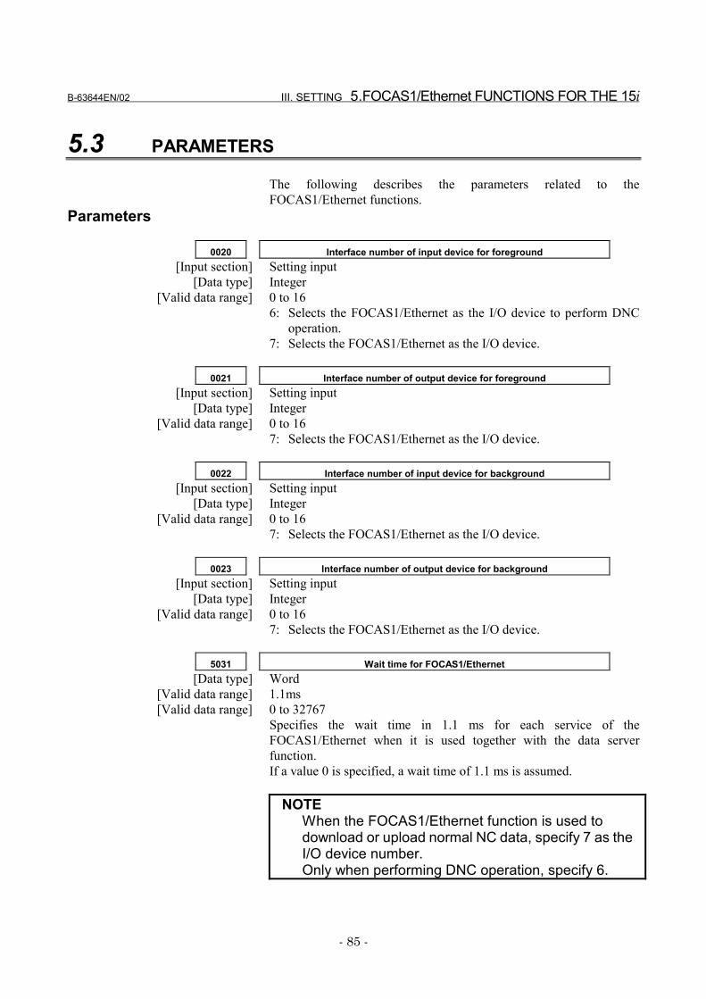
B-63644EN/02 III. SETTING 5.FOCAS1/Ethernet FUNCTIONS FOR THE 15i
- 85 -
5.3 PARAMETERS
The following describes the parameters related to theFOCAS1/Ethernet functions.
Parameters
0020 Interface number of input device for foreground[Input section] Setting input
[Data type] Integer[Valid data range] 0 to 16
6: Selects the FOCAS1/Ethernet as the I/O device to perform DNCoperation.
7: Selects the FOCAS1/Ethernet as the I/O device.
0021 Interface number of output device for foreground[Input section] Setting input
[Data type] Integer[Valid data range] 0 to 16
7: Selects the FOCAS1/Ethernet as the I/O device.
0022 Interface number of input device for background[Input section] Setting input
[Data type] Integer[Valid data range] 0 to 16
7: Selects the FOCAS1/Ethernet as the I/O device.
0023 Interface number of output device for background[Input section] Setting input
[Data type] Integer[Valid data range] 0 to 16
7: Selects the FOCAS1/Ethernet as the I/O device.
5031 Wait time for FOCAS1/Ethernet[Data type] Word
[Valid data range] 1.1ms[Valid data range] 0 to 32767
Specifies the wait time in 1.1 ms for each service of theFOCAS1/Ethernet when it is used together with the data serverfunction.If a value 0 is specified, a wait time of 1.1 ms is assumed.
NOTEWhen the FOCAS1/Ethernet function is used todownload or upload normal NC data, specify 7 as theI/O device number.Only when performing DNC operation, specify 6.
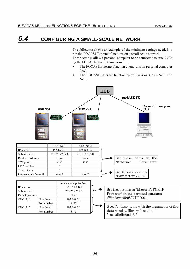
5.FOCAS1/Ethernet FUNCTIONS FOR THE 15i III. SETTING B-63644EN/02
- 86 -
5.4 CONFIGURING A SMALL-SCALE NETWORK
The following shows an example of the minimum settings needed torun the FOCAS1/Ethernet functions on a small-scale network.These settings allow a personal computer to be connected to two CNCsby the FOCAS1/Ethernet functions.• The FOCAS1/Ethernet function client runs on personal computer
No.1.• The FOCAS1/Ethernet function server runs on CNCs No.1 and
No.2.
CNC No.1 CNC No.2IP address 192.168.0.1 192.168.0.2Subnet mask 255.255.255.0 255.255.255.0Router IP address None NoneTCP port No. 8193 8193UDP port No. 0 0Time interval 0 0Parameter No.20 to 23 6 or 7 6 or 7
Personal computer No.1IP address 192.168.0.101Subnet mask 255.255.255.0Default gateway None
IP address 192.168.0.1CNC No.1Port number 8193IP address 192.168.0.2CNC No.2Port number 8193
Set these items on the"Ethernet Parameter"
Set this item on the"Parameter" screen.
Set these items in "Microsoft TCP/IPProperty" on the personal computer(Windows95/98/NT/2000).
Specify these items with the arguments of thedata window library function"cnc_allclibhnd13."
Personal computerPersonal computerPersonal computerPersonal computerNo.1No.1No.1No.1CNC No.2CNC No.2CNC No.2CNC No.2CNC No.1CNC No.1CNC No.1CNC No.1
111100000BASE-T0BASE-T0BASE-T0BASE-TXXXX
HUBHUBHUBHUB

B-63644EN/02 III. SETTING 5.FOCAS1/Ethernet FUNCTIONS FOR THE 15i
- 87 -
5.5 CONFIGURING A LARGE-SCALE NETWORK
Before you configure a large-scale network or add such a network to anexisting network, consult your company's network administrator todetermine IP addresses, subnet masks, and router IP addresses.
6.DATA SERVER FUNCTIONS FOR THE 15i III. SETTING B-63644EN/02
- 88 -
6 DATA SERVER FUNCTIONS FOR THE15i
The following describes the settings needed to run the data serverfunctions for the Series 15i-B.
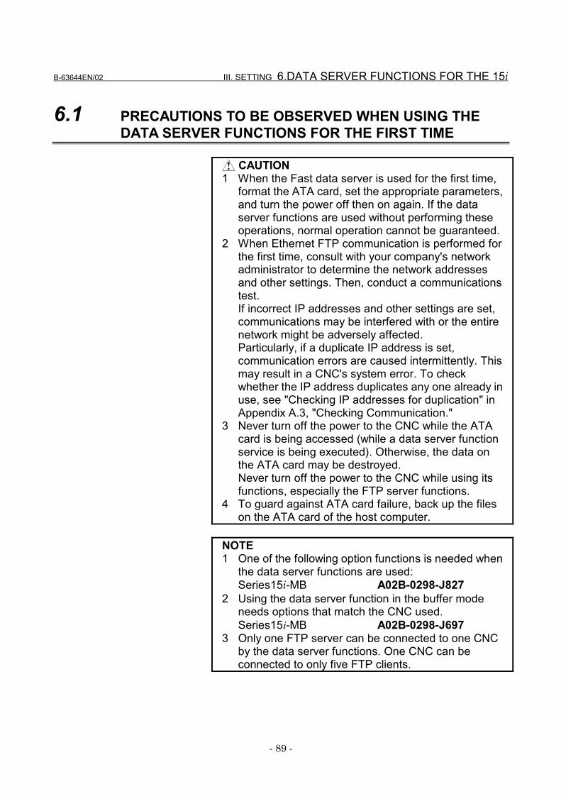
B-63644EN/02 III. SETTING 6.DATA SERVER FUNCTIONS FOR THE 15i
- 89 -
6.1 PRECAUTIONS TO BE OBSERVED WHEN USING THEDATA SERVER FUNCTIONS FOR THE FIRST TIME
CAUTION1 When the Fast data server is used for the first time,
format the ATA card, set the appropriate parameters,and turn the power off then on again. If the dataserver functions are used without performing theseoperations, normal operation cannot be guaranteed.
2 When Ethernet FTP communication is performed forthe first time, consult with your company's networkadministrator to determine the network addressesand other settings. Then, conduct a communicationstest.If incorrect IP addresses and other settings are set,communications may be interfered with or the entirenetwork might be adversely affected.Particularly, if a duplicate IP address is set,communication errors are caused intermittently. Thismay result in a CNC's system error. To checkwhether the IP address duplicates any one already inuse, see "Checking IP addresses for duplication" inAppendix A.3, "Checking Communication."
3 Never turn off the power to the CNC while the ATAcard is being accessed (while a data server functionservice is being executed). Otherwise, the data onthe ATA card may be destroyed.Never turn off the power to the CNC while using itsfunctions, especially the FTP server functions.
4 To guard against ATA card failure, back up the fileson the ATA card of the host computer.
NOTE1 One of the following option functions is needed when
the data server functions are used:Series15i-MB A02B-0298-J827
2 Using the data server function in the buffer modeneeds options that match the CNC used.Series15i-MB A02B-0298-J697
3 Only one FTP server can be connected to one CNCby the data server functions. One CNC can beconnected to only five FTP clients.
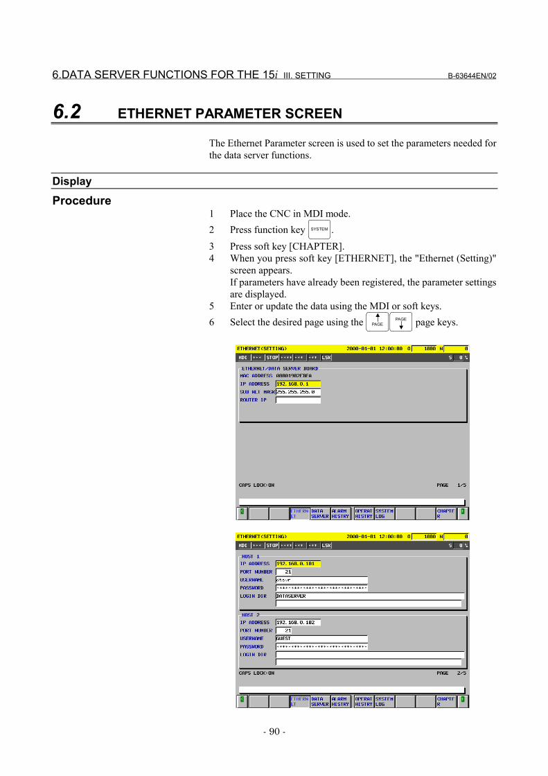
6.DATA SERVER FUNCTIONS FOR THE 15i III. SETTING B-63644EN/02
- 90 -
6.2 ETHERNET PARAMETER SCREEN
The Ethernet Parameter screen is used to set the parameters needed forthe data server functions.
DisplayProcedure
1 Place the CNC in MDI mode.2 Press function key SYSTEM .3 Press soft key [CHAPTER].4 When you press soft key [ETHERNET], the "Ethernet (Setting)"
screen appears.If parameters have already been registered, the parameter settingsare displayed.
5 Enter or update the data using the MDI or soft keys.6 Select the desired page using the PAGE
PAGE page keys.
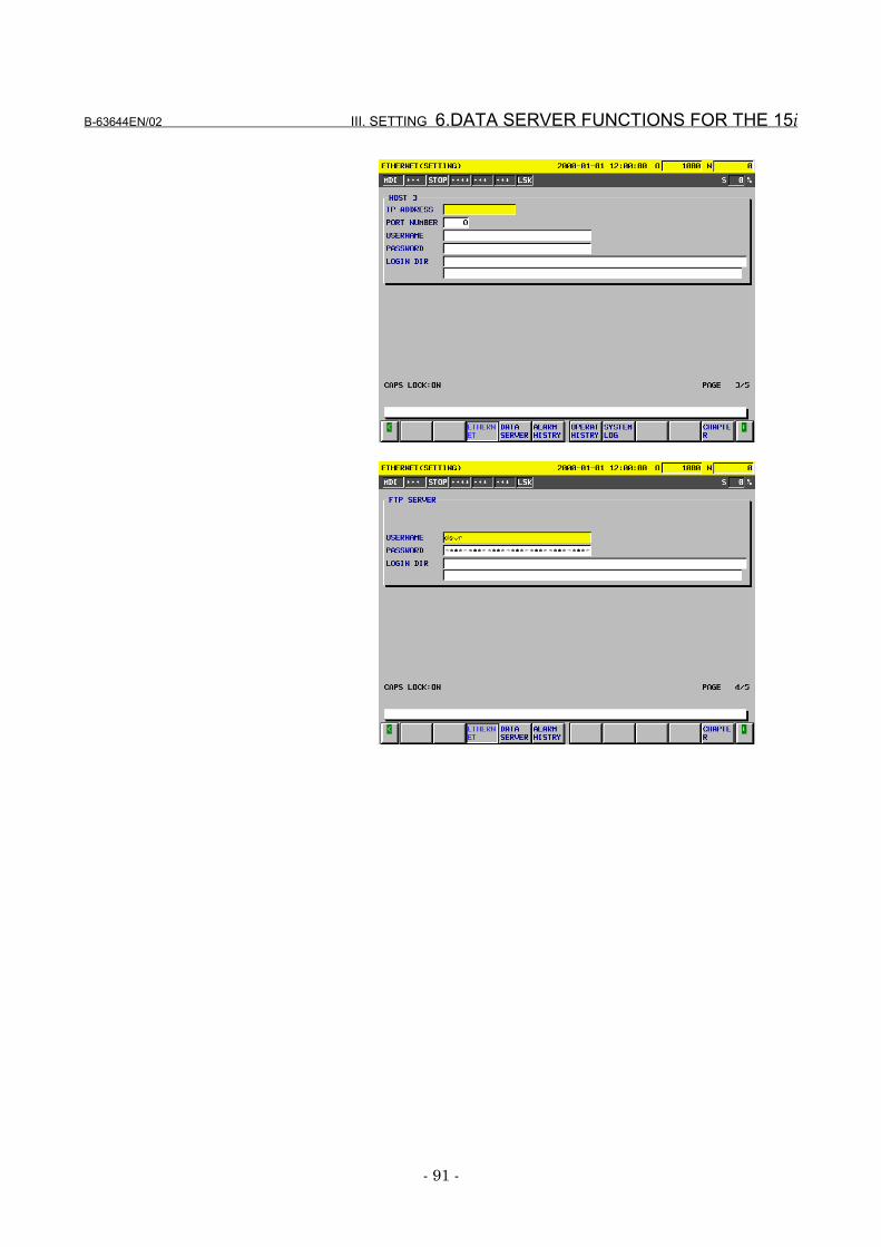
B-63644EN/02 III. SETTING 6.DATA SERVER FUNCTIONS FOR THE 15i
- 91 -
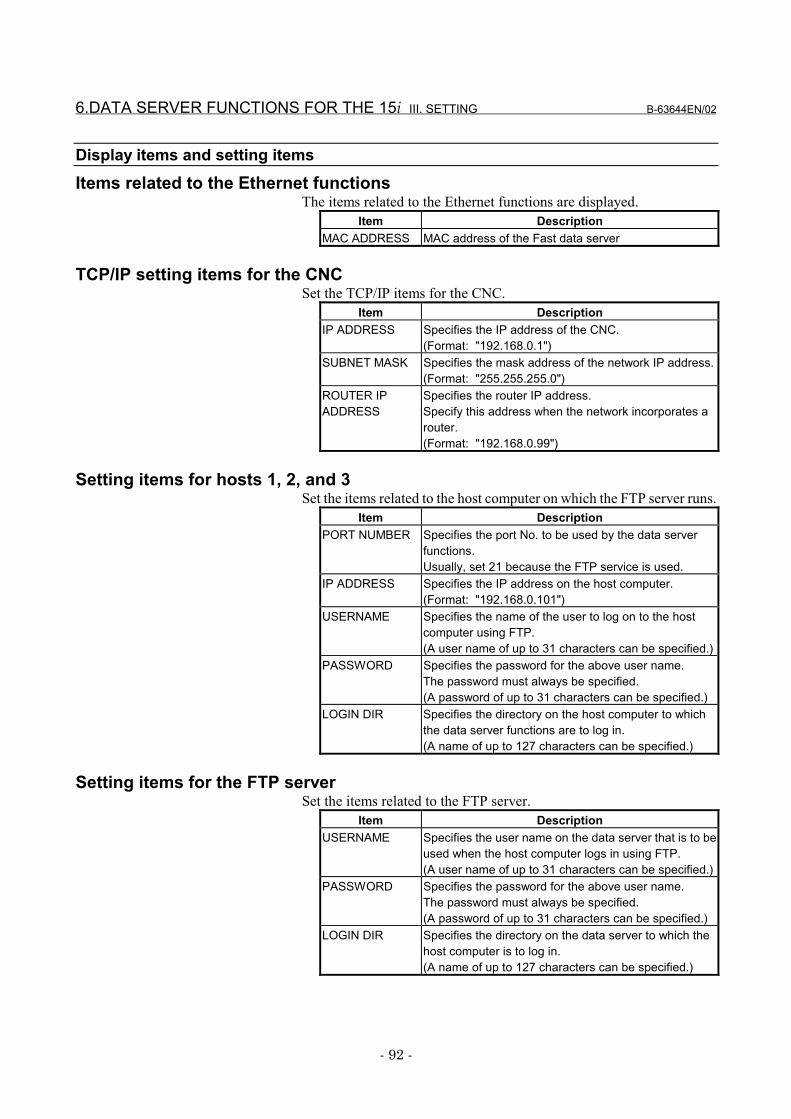
6.DATA SERVER FUNCTIONS FOR THE 15i III. SETTING B-63644EN/02
- 92 -
Display items and setting itemsItems related to the Ethernet functions
The items related to the Ethernet functions are displayed.Item Description
MAC ADDRESS MAC address of the Fast data server
TCP/IP setting items for the CNCSet the TCP/IP items for the CNC.
Item DescriptionIP ADDRESS Specifies the IP address of the CNC.
(Format: "192.168.0.1")SUBNET MASK Specifies the mask address of the network IP address.
(Format: "255.255.255.0")ROUTER IPADDRESS
Specifies the router IP address.Specify this address when the network incorporates arouter.(Format: "192.168.0.99")
Setting items for hosts 1, 2, and 3Set the items related to the host computer on which the FTP server runs.
Item DescriptionPORT NUMBER Specifies the port No. to be used by the data server
functions.Usually, set 21 because the FTP service is used.
IP ADDRESS Specifies the IP address on the host computer.(Format: "192.168.0.101")
USERNAME Specifies the name of the user to log on to the hostcomputer using FTP.(A user name of up to 31 characters can be specified.)
PASSWORD Specifies the password for the above user name.The password must always be specified.(A password of up to 31 characters can be specified.)
LOGIN DIR Specifies the directory on the host computer to whichthe data server functions are to log in.(A name of up to 127 characters can be specified.)
Setting items for the FTP serverSet the items related to the FTP server.
Item DescriptionUSERNAME Specifies the user name on the data server that is to be
used when the host computer logs in using FTP.(A user name of up to 31 characters can be specified.)
PASSWORD Specifies the password for the above user name.The password must always be specified.(A password of up to 31 characters can be specified.)
LOGIN DIR Specifies the directory on the data server to which thehost computer is to log in.(A name of up to 127 characters can be specified.)
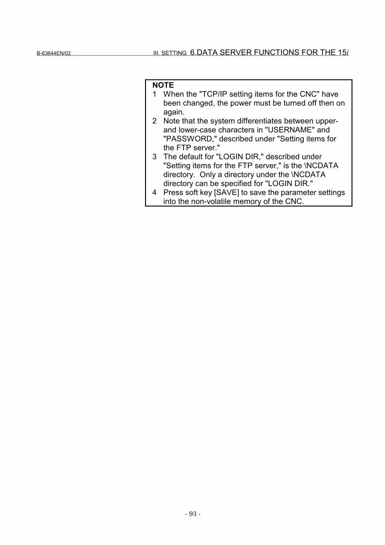
B-63644EN/02 III. SETTING 6.DATA SERVER FUNCTIONS FOR THE 15i
- 93 -
NOTE1 When the "TCP/IP setting items for the CNC" have
been changed, the power must be turned off then onagain.
2 Note that the system differentiates between upper-and lower-case characters in "USERNAME" and"PASSWORD," described under "Setting items forthe FTP server."
3 The default for "LOGIN DIR," described under"Setting items for the FTP server," is the \NCDATAdirectory. Only a directory under the \NCDATAdirectory can be specified for "LOGIN DIR."
4 Press soft key [SAVE] to save the parameter settingsinto the non-volatile memory of the CNC.
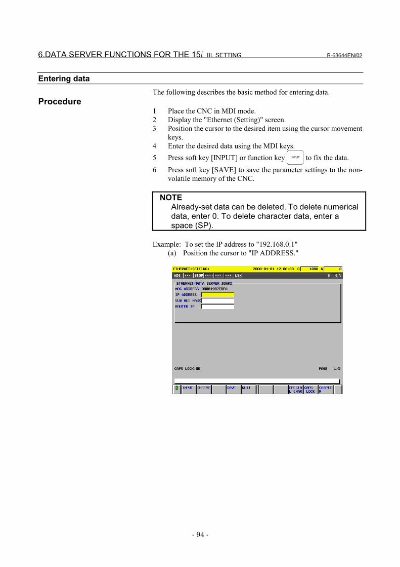
6.DATA SERVER FUNCTIONS FOR THE 15i III. SETTING B-63644EN/02
- 94 -
Entering dataThe following describes the basic method for entering data.
Procedure1 Place the CNC in MDI mode.2 Display the "Ethernet (Setting)" screen.3 Position the cursor to the desired item using the cursor movement
keys.4 Enter the desired data using the MDI keys.5 Press soft key [INPUT] or function key INPUT to fix the data.6 Press soft key [SAVE] to save the parameter settings to the non-
volatile memory of the CNC.
NOTEAlready-set data can be deleted. To delete numericaldata, enter 0. To delete character data, enter aspace (SP).
Example: To set the IP address to "192.168.0.1"(a) Position the cursor to "IP ADDRESS."
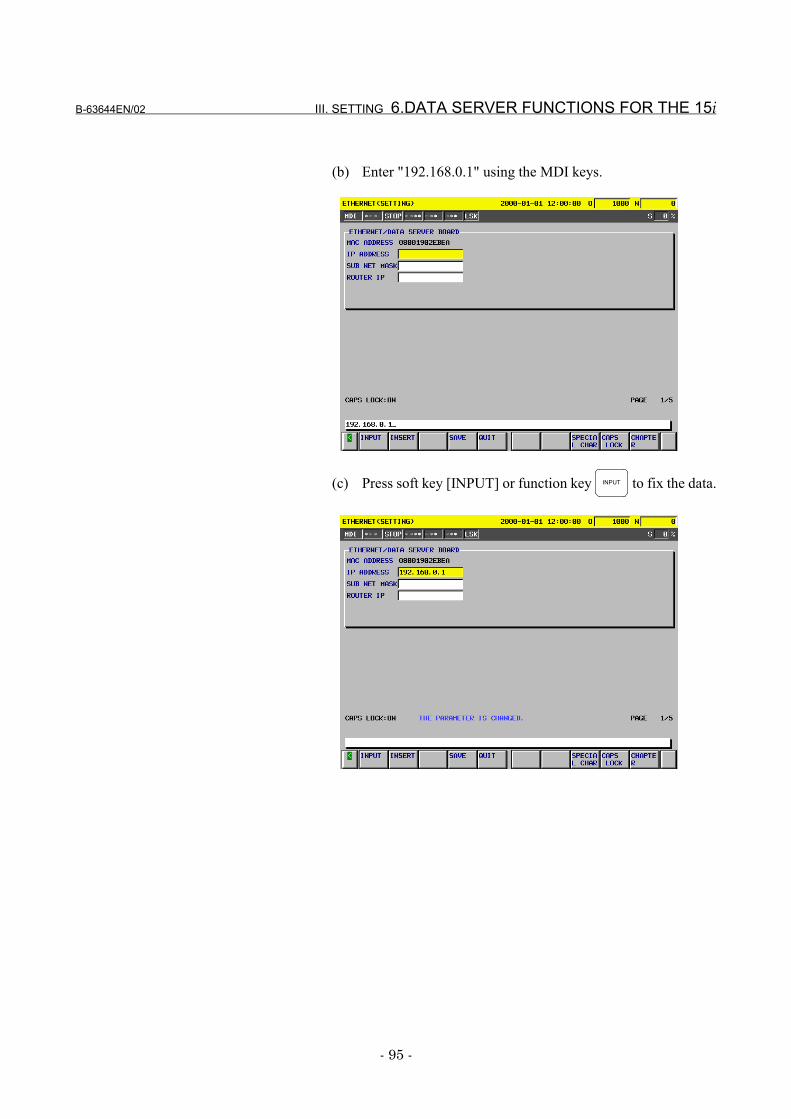
B-63644EN/02 III. SETTING 6.DATA SERVER FUNCTIONS FOR THE 15i
- 95 -
(b) Enter "192.168.0.1" using the MDI keys.
(c) Press soft key [INPUT] or function key INPUT to fix the data.
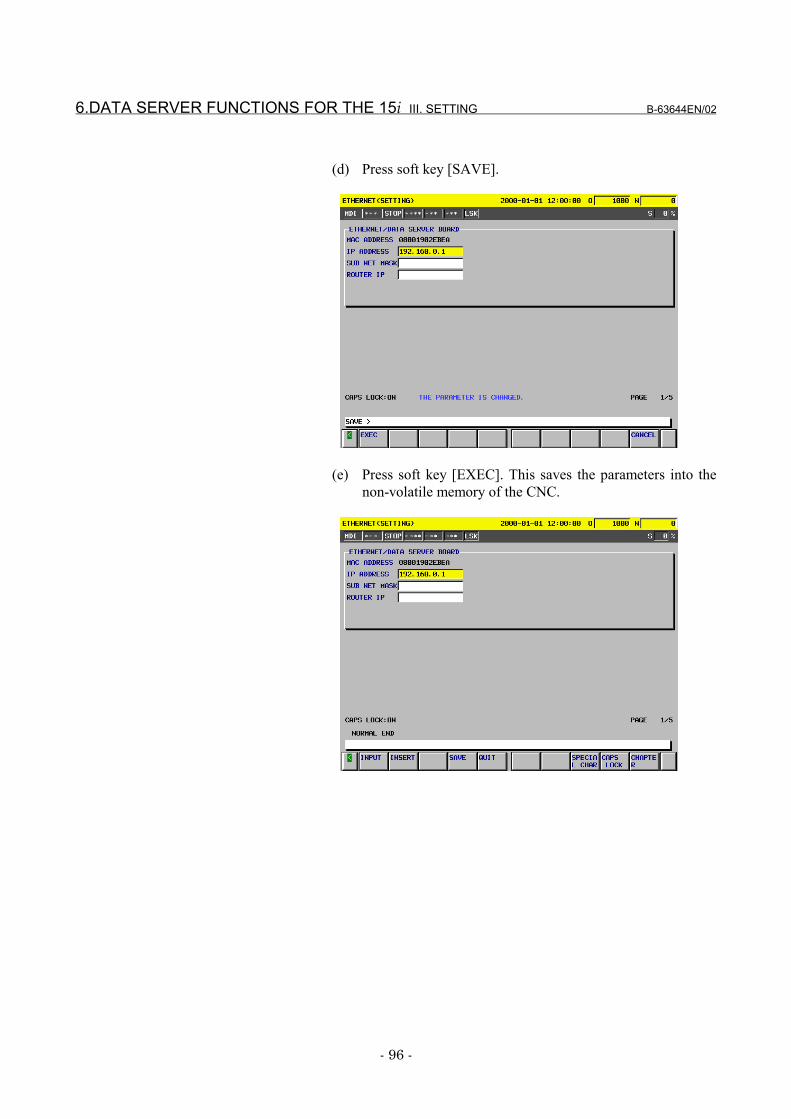
6.DATA SERVER FUNCTIONS FOR THE 15i III. SETTING B-63644EN/02
- 96 -
(d) Press soft key [SAVE].
(e) Press soft key [EXEC]. This saves the parameters into thenon-volatile memory of the CNC.
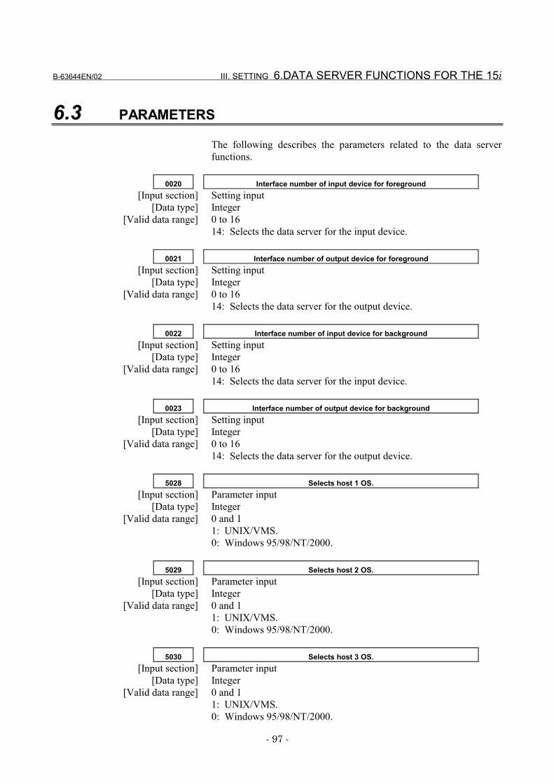
B-63644EN/02 III. SETTING 6.DATA SERVER FUNCTIONS FOR THE 15i
- 97 -
6.3 PARAMETERS
The following describes the parameters related to the data serverfunctions.
0020 Interface number of input device for foreground[Input section] Setting input
[Data type] Integer[Valid data range] 0 to 16
14: Selects the data server for the input device.
0021 Interface number of output device for foreground[Input section] Setting input
[Data type] Integer[Valid data range] 0 to 16
14: Selects the data server for the output device.
0022 Interface number of input device for background[Input section] Setting input
[Data type] Integer[Valid data range] 0 to 16
14: Selects the data server for the input device.
0023 Interface number of output device for background[Input section] Setting input
[Data type] Integer[Valid data range] 0 to 16
14: Selects the data server for the output device.
5028 Selects host 1 OS.[Input section] Parameter input
[Data type] Integer[Valid data range] 0 and 1
1: UNIX/VMS.0: Windows 95/98/NT/2000.
5029 Selects host 2 OS.[Input section] Parameter input
[Data type] Integer[Valid data range] 0 and 1
1: UNIX/VMS.0: Windows 95/98/NT/2000.
5030 Selects host 3 OS.[Input section] Parameter input
[Data type] Integer[Valid data range] 0 and 1
1: UNIX/VMS.0: Windows 95/98/NT/2000.
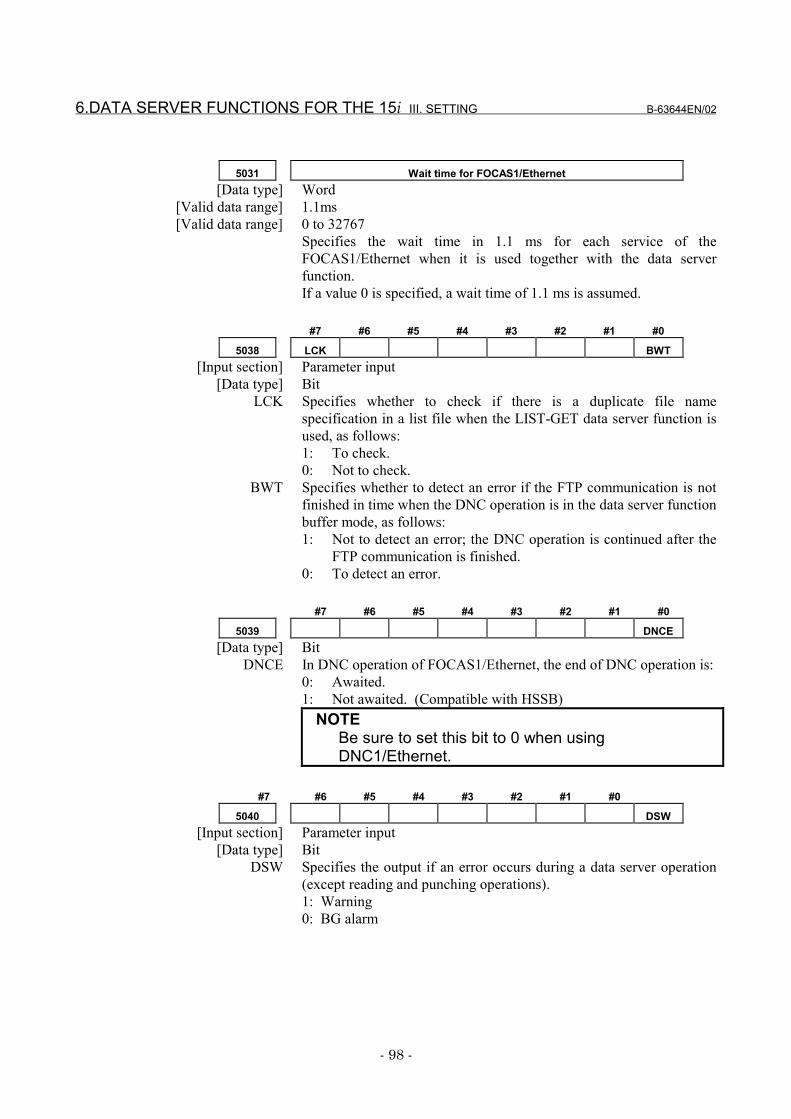
6.DATA SERVER FUNCTIONS FOR THE 15i III. SETTING B-63644EN/02
- 98 -
5031 Wait time for FOCAS1/Ethernet[Data type] Word
[Valid data range] 1.1ms[Valid data range] 0 to 32767
Specifies the wait time in 1.1 ms for each service of theFOCAS1/Ethernet when it is used together with the data serverfunction.If a value 0 is specified, a wait time of 1.1 ms is assumed.
#7 #6 #5 #4 #3 #2 #1 #0
5038 LCK BWT[Input section] Parameter input
[Data type] BitLCK Specifies whether to check if there is a duplicate file name
specification in a list file when the LIST-GET data server function isused, as follows:1: To check.0: Not to check.
BWT Specifies whether to detect an error if the FTP communication is notfinished in time when the DNC operation is in the data server functionbuffer mode, as follows:1: Not to detect an error; the DNC operation is continued after the
FTP communication is finished.0: To detect an error.
#7 #6 #5 #4 #3 #2 #1 #0
5039 DNCE[Data type] Bit
DNCE In DNC operation of FOCAS1/Ethernet, the end of DNC operation is:0: Awaited.1: Not awaited. (Compatible with HSSB)
NOTEBe sure to set this bit to 0 when usingDNC1/Ethernet.
#7 #6 #5 #4 #3 #2 #1 #0
5040 DSW[Input section] Parameter input
[Data type] BitDSW Specifies the output if an error occurs during a data server operation
(except reading and punching operations).1: Warning0: BG alarm
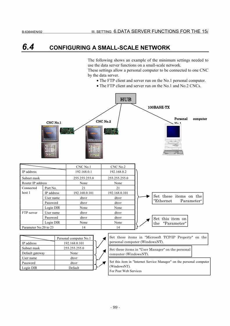
B-63644EN/02 III. SETTING 6.DATA SERVER FUNCTIONS FOR THE 15i
- 99 -
6.4 CONFIGURING A SMALL-SCALE NETWORK
The following shows an example of the minimum settings needed touse the data server functions on a small-scale network.These settings allow a personal computer to be connected to one CNCby the data server.
• The FTP client and server run on the No.1 personal computer.• The FTP client and server run on the No.1 and No.2 CNCs.
CNC No.1 CNC No.2IP address 192.168.0.1 192.168.0.2
Subnet mask 255.255.255.0 255.255.255.0Router IP address None None
Port No. 21 21IP address 192.168.0.101 192.168.0.101User name dtsvr dtsvrPassword dtsvr dtsvr
Connectedhost 1
Login DIR None NoneUser name dtsvr dtsvrPassword dtsvr dtsvr
FTP server
Login DIR None NoneParameter No.20 to 23 14 14
Personal computer No.1IP address 192.168.0.101Subnet mask 255.255.255.0Default gateway NoneUser name dtsvrPassword dtsvrLogin DIR Default
Personal computerPersonal computerPersonal computerPersonal computerNo 1No 1No 1No 1
CNC No.2CNC No.2CNC No.2CNC No.2CNC No.1CNC No.1CNC No.1CNC No.1
101010100000BASE-TBASE-TBASE-TBASE-TXXXX
HUBHUBHUBHUB
Set these items in "Microsoft TCP/IP Property" on thepersonal computer (WindowsNT).
Set these items in "User Manager" on the personalcomputer (WindowsNT).
Set this item in "Internet Service Manager" on the personal computer(WindowsNT).For Peer Web Services
Set these items on the"Ethernet Parameter"
Set this item onthe "Parameter"

6.DATA SERVER FUNCTIONS FOR THE 15i III. SETTING B-63644EN/02
- 100 -
6.5 CONFIGURING A LARGE-SCALE NETWORK
Before you configure a large-scale network or add such a network to anexisting network, consult with your company's network administratorto determine IP addresses, subnet masks, and router IP addresses.
IV. OPERATION

B-63644EN/02 IV. OPERATION 1.16i/18i/21i FACTOLINK FUNCTIONS
- 103 -
1 16i/18i/21i FACTOLINK FUNCTIONSThis section describes how to use the series 16i/18i/21i-A/BFACTOLINK functions.
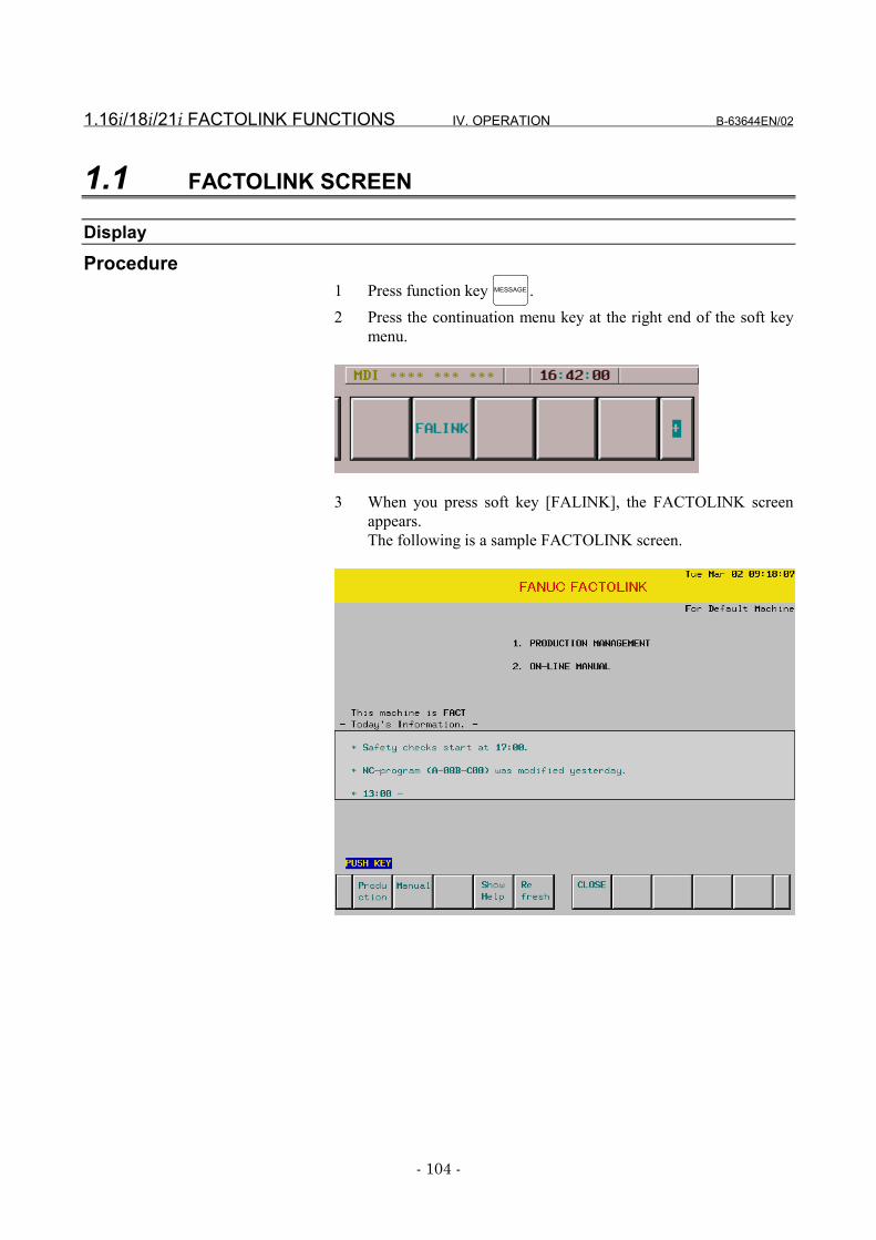
1.16i/18i/21i FACTOLINK FUNCTIONS IV. OPERATION B-63644EN/02
- 104 -
1.1 FACTOLINK SCREEN
DisplayProcedure
1 Press function key MESSAGE .2 Press the continuation menu key at the right end of the soft key
menu.
3 When you press soft key [FALINK], the FACTOLINK screenappears.The following is a sample FACTOLINK screen.
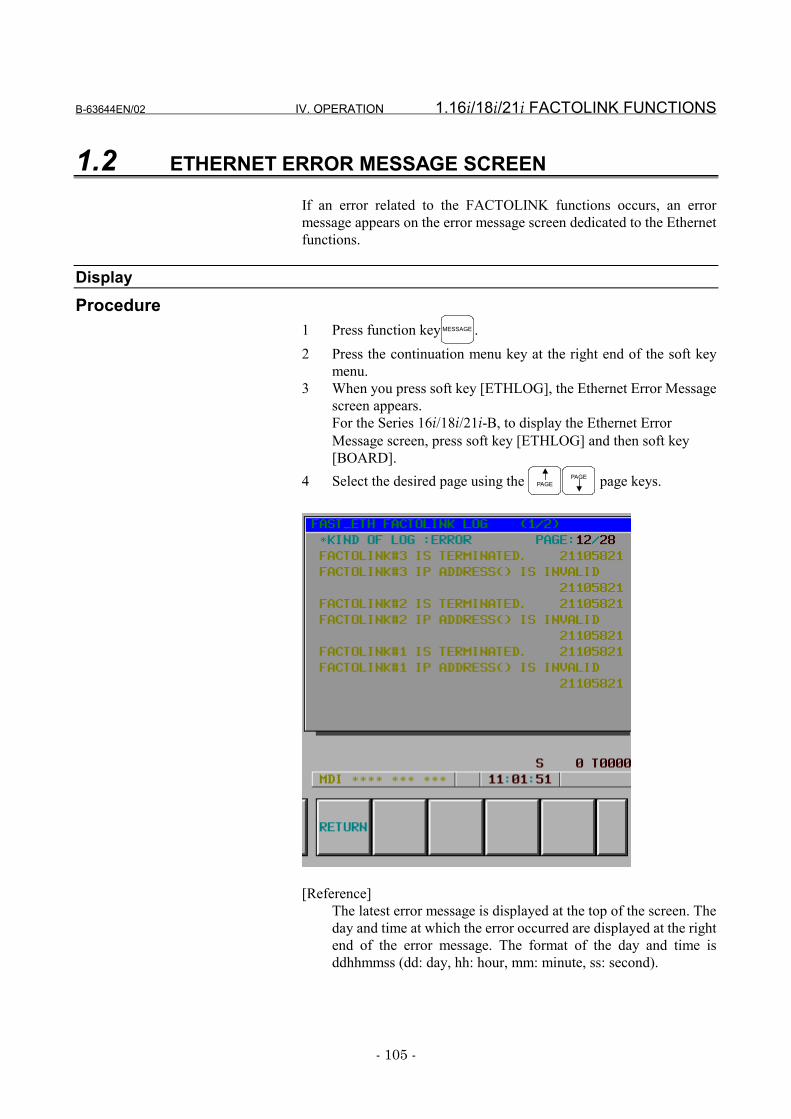
B-63644EN/02 IV. OPERATION 1.16i/18i/21i FACTOLINK FUNCTIONS
- 105 -
1.2 ETHERNET ERROR MESSAGE SCREEN
If an error related to the FACTOLINK functions occurs, an errormessage appears on the error message screen dedicated to the Ethernetfunctions.
DisplayProcedure
1 Press function key MESSAGE .2 Press the continuation menu key at the right end of the soft key
menu.3 When you press soft key [ETHLOG], the Ethernet Error Message
screen appears.For the Series 16i/18i/21i-B, to display the Ethernet ErrorMessage screen, press soft key [ETHLOG] and then soft key[BOARD].
4 Select the desired page using the PAGEPAGE page keys.
[Reference]The latest error message is displayed at the top of the screen. Theday and time at which the error occurred are displayed at the rightend of the error message. The format of the day and time isddhhmmss (dd: day, hh: hour, mm: minute, ss: second).
1.16i/18i/21i FACTOLINK FUNCTIONS IV. OPERATION B-63644EN/02
- 106 -
ConfigurationThe following titles are provided for the Ethernet error message screen:
• FAST_ETH SYSTEM LOG screen• FAST_ETH TCP/IP LOG screen• FAST_ETH PARAMETER LOG screen• FAST_ETH FACTOLINK LOG screen
B-63644EN/02 IV. OPERATION 2.16i/18i/21i/PMi DNC1/Ethernet FUNCTIONS
- 107 -
2 16i/18i/21i/PMi DNC1/EthernetFUNCTIONS
This section describes how to use the Series 16i/18i/21i-A/B, PowerMate i , DNC1/Ethernet functions.
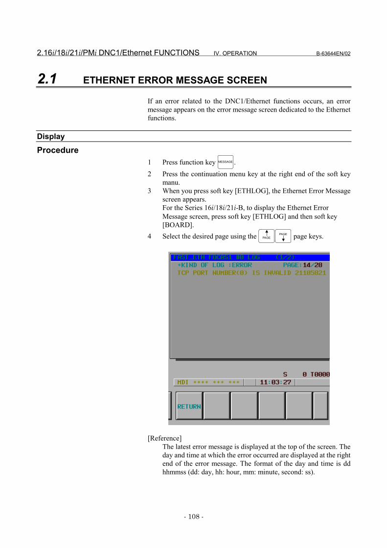
2.16i/18i/21i/PMi DNC1/Ethernet FUNCTIONS IV. OPERATION B-63644EN/02
- 108 -
2.1 ETHERNET ERROR MESSAGE SCREEN
If an error related to the DNC1/Ethernet functions occurs, an errormessage appears on the error message screen dedicated to the Ethernetfunctions.
DisplayProcedure
1 Press function key MESSAGE .2 Press the continuation menu key at the right end of the soft key
manu.3 When you press soft key [ETHLOG], the Ethernet Error Message
screen appears.For the Series 16i/18i/21i-B, to display the Ethernet ErrorMessage screen, press soft key [ETHLOG] and then soft key[BOARD].
4 Select the desired page using the PAGEPAGE page keys.
[Reference]The latest error message is displayed at the top of the screen. Theday and time at which the error occurred are displayed at the rightend of the error message. The format of the day and time is ddhhmmss (dd: day, hh: hour, mm: minute, second: ss).
B-63644EN/02 IV. OPERATION 2.16i/18i/21i/PMi DNC1/Ethernet FUNCTIONS
- 109 -
ConfigurationThe following titles are provided for the Ethernet error message screen:
• FAST_ETH SYSTEM LOG screen• FAST_ETH TCP/IP LOG screen• FAST_ETH PARAMETER LOG screen• FAST_ETH FOCAS1 #0 LOG screen• FAST_ETH FOCAS1 #1 LOG screen• FAST_ETH FOCAS1 #2 LOG screen• FAST_ETH DNC1/ETH UDP LOG screen
3.16i/18i/21i/PMi FOCAS1/Ethernet FUNCTIONS IV. OPERATION B-63644EN/02
- 110 -
3 16i/18i/21i/PMi FOCAS1/EthernetFUNCTIONS
This section describes how to use the Series 16i/18i/21i-A/B andPower Mate i FOCAS1/Ethernet functions.
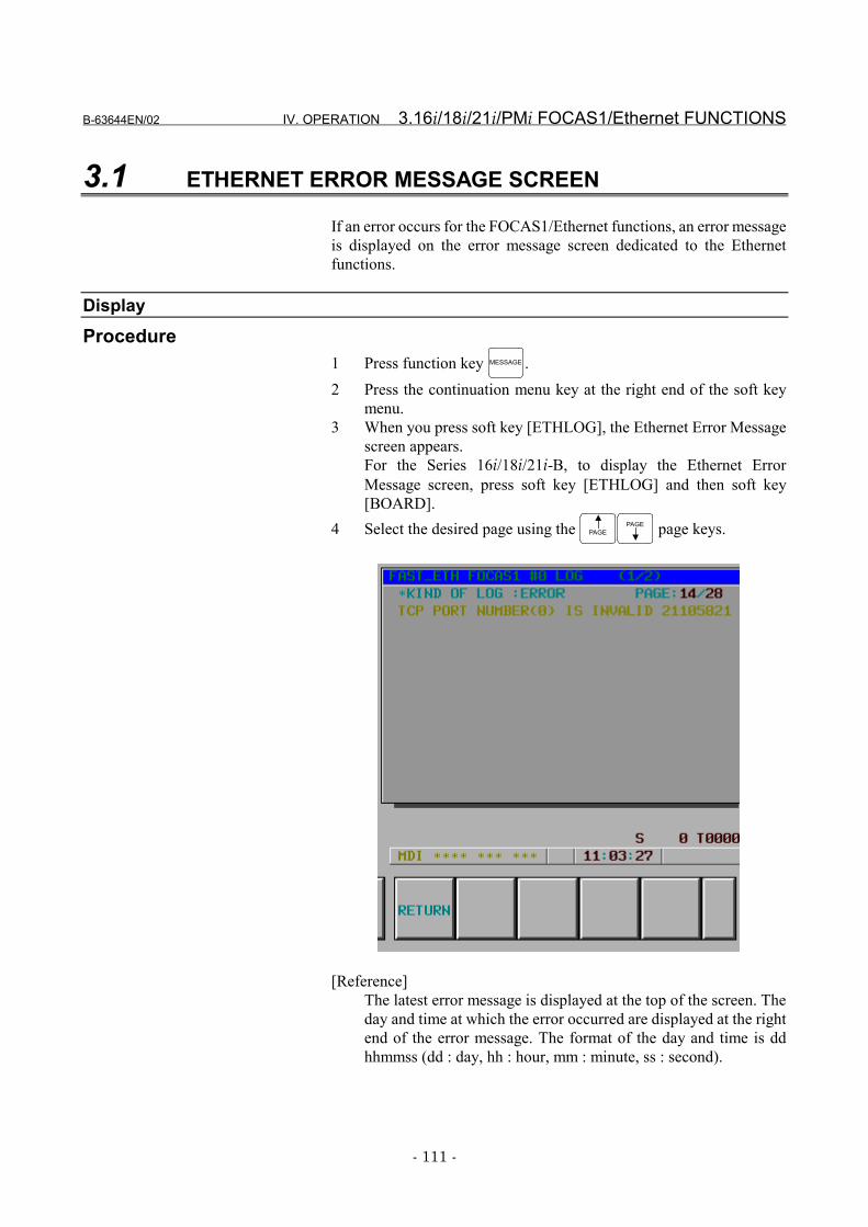
B-63644EN/02 IV. OPERATION 3.16i/18i/21i/PMi FOCAS1/Ethernet FUNCTIONS
- 111 -
3.1 ETHERNET ERROR MESSAGE SCREEN
If an error occurs for the FOCAS1/Ethernet functions, an error messageis displayed on the error message screen dedicated to the Ethernetfunctions.
DisplayProcedure
1 Press function key MESSAGE .2 Press the continuation menu key at the right end of the soft key
menu.3 When you press soft key [ETHLOG], the Ethernet Error Message
screen appears.For the Series 16i/18i/21i-B, to display the Ethernet ErrorMessage screen, press soft key [ETHLOG] and then soft key[BOARD].
4 Select the desired page using the PAGEPAGE page keys.
[Reference]The latest error message is displayed at the top of the screen. Theday and time at which the error occurred are displayed at the rightend of the error message. The format of the day and time is ddhhmmss (dd : day, hh : hour, mm : minute, ss : second).
3.16i/18i/21i/PMi FOCAS1/Ethernet FUNCTIONS IV. OPERATION B-63644EN/02
- 112 -
ConfigurationThe following titles are provided for the Ethernet error message screen:
• FAST_ETH SYSTEM LOG screen• FAST_ETH TCP/IP LOG screen• FAST_ETH PARAMETER LOG screen• FAST_ETH FOCAS1 #0 LOG screen• FAST_ETH FOCAS1 #1 LOG screen• FAST_ETH FOCAS1 #2 LOG screen• FAST_ETH CNC SCREEN #1 LOG screen• FAST_ETH CNC SCREEN #2 LOG screen• FAST_ETH PMC LOG screen• FAST_ETH REMOTE DIAG LOG screen
B-63644EN/02 IV. OPERATION 4.16i/18i DATA SERVER FUNCTIONS
- 113 -
4 16i/18i/21i DATA SERVER FUNCTIONSThis section describes how to use the series 16i/18i/21i-A/B data serverfunctions.
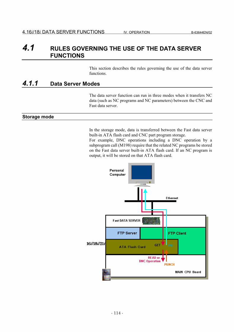
4.16i/18i DATA SERVER FUNCTIONS IV. OPERATION B-63644EN/02
- 114 -
4.1 RULES GOVERNING THE USE OF THE DATA SERVERFUNCTIONS
This section describes the rules governing the use of the data serverfunctions.
4.1.1 Data Server Modes
The data server function can run in three modes when it transfers NCdata (such as NC programs and NC parameters) between the CNC andFast data server.
Storage mode
In the storage mode, data is transferred between the Fast data serverbuilt-in ATA flash card and CNC part program storage.For example, DNC operations including a DNC operation by asubprogram call (M198) require that the related NC programs be storedon the Fast data server built-in ATA flash card. If an NC program isoutput, it will be stored on that ATA flash card.
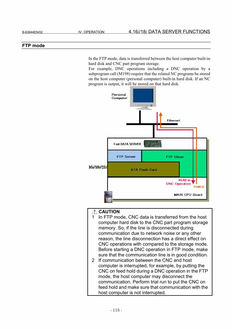
B-63644EN/02 IV. OPERATION 4.16i/18i DATA SERVER FUNCTIONS
- 115 -
FTP mode
In the FTP mode, data is transferred between the host computer built-inhard disk and CNC part program storage.For example, DNC operations including a DNC operation by asubprogram call (M198) require that the related NC programs be storedon the host computer (personal computer) built-in hard disk. If an NCprogram is output, it will be stored on that hard disk.
CAUTION1 In FTP mode, CNC data is transferred from the host
computer hard disk to the CNC part program storagememory. So, if the line is disconnected duringcommunication due to network noise or any otherreason, the line disconnection has a direct effect onCNC operations with compared to the storage mode.Before starting a DNC operation in FTP mode, makesure that the communication line is in good condition.
2 If communication between the CNC and hostcomputer is interrupted, for example, by putting theCNC on feed hold during a DNC operation in the FTPmode, the host computer may disconnect thecommunication. Perform trial run to put the CNC onfeed hold and make sure that communication with thehost computer is not interrupted.
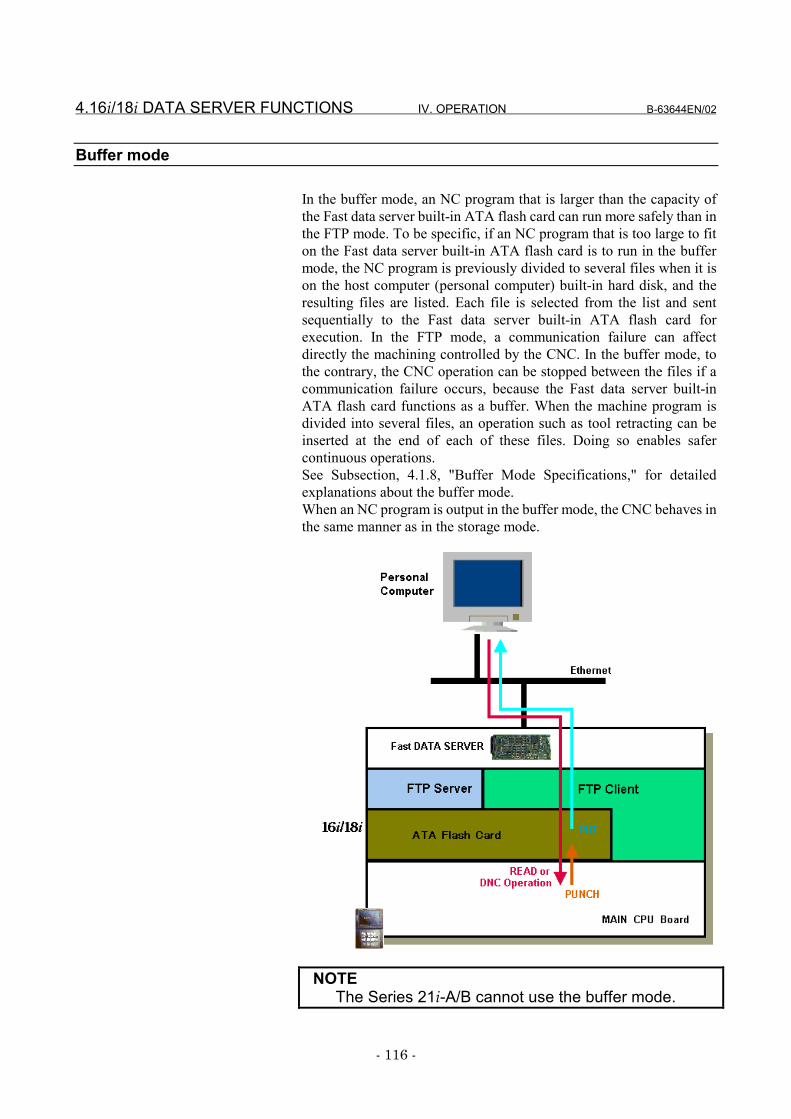
4.16i/18i DATA SERVER FUNCTIONS IV. OPERATION B-63644EN/02
- 116 -
Buffer mode
In the buffer mode, an NC program that is larger than the capacity ofthe Fast data server built-in ATA flash card can run more safely than inthe FTP mode. To be specific, if an NC program that is too large to fiton the Fast data server built-in ATA flash card is to run in the buffermode, the NC program is previously divided to several files when it ison the host computer (personal computer) built-in hard disk, and theresulting files are listed. Each file is selected from the list and sentsequentially to the Fast data server built-in ATA flash card forexecution. In the FTP mode, a communication failure can affectdirectly the machining controlled by the CNC. In the buffer mode, tothe contrary, the CNC operation can be stopped between the files if acommunication failure occurs, because the Fast data server built-inATA flash card functions as a buffer. When the machine program isdivided into several files, an operation such as tool retracting can beinserted at the end of each of these files. Doing so enables safercontinuous operations.See Subsection, 4.1.8, "Buffer Mode Specifications," for detailedexplanations about the buffer mode.When an NC program is output in the buffer mode, the CNC behaves inthe same manner as in the storage mode.
NOTEThe Series 21i-A/B cannot use the buffer mode.
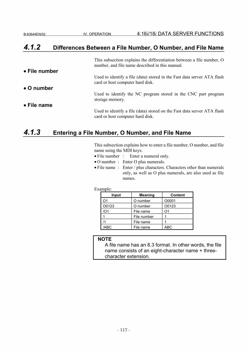
B-63644EN/02 IV. OPERATION 4.16i/18i DATA SERVER FUNCTIONS
- 117 -
4.1.2 Differences Between a File Number, O Number, and File Name
This subsection explains the differentiation between a file number, Onumber, and file name described in this manual.
•••• File numberUsed to identify a file (data) stored in the Fast data server ATA flashcard or host computer hard disk.
•••• O numberUsed to identify the NC program stored in the CNC part programstorage memory.
•••• File nameUsed to identify a file (data) stored on the Fast data server ATA flashcard or host computer hard disk.
4.1.3 Entering a File Number, O Number, and File Name
This subsection explains how to enter a file number, O number, and filename using the MDI keys.• File number : Enter a numeral only.• O number : Enter O plus numerals.• File name : Enter / plus characters. Characters other than numerals
only, as well as O plus numerals, are also used as filenames.
Example:Input Meaning Content
O1 O number O0001O0123 O number O0123/O1 File name O11 File number 1/1 File name 1/ABC File name ABC
NOTEA file name has an 8.3 format. In other words, the filename consists of an eight-character name + three-character extension.
4.16i/18i DATA SERVER FUNCTIONS IV. OPERATION B-63644EN/02
- 118 -
4.1.4 Differences Between a Hard Disk File and Host File
This subsection explains the differentiation between a hard disk fileand host file described in this manual.
•••• Hard disk fileStored on the ATA flash card of the CNC Fast data server (hereaftercalled a Fast data server built-in ATA card).
•••• Host fileStored on the hard disk of the host computer (hereafter called the hostcomputer built-in hard disk).
B-63644EN/02 IV. OPERATION 4.16i/18i DATA SERVER FUNCTIONS
- 119 -
4.1.5 Hard Disk File Names
The name of any file on the Fast data server built-in ATA card isrepresented using the 8.3 file name format (8 characters in the file nameand 3 characters in the file name extension) originally adopted forMS-DOS.If a file to be subjected to an FTP transfer is specified only with a filename that is not in the 8.3 format, it is converted to an 8.3-format filename according to the following conversion rules.
Rules for conversion to 8.3-format file names1 The first 8 characters in the specified file name are used as a
post-conversion file name.2 The 3 characters in the specified file name between the first and
second periods are used as a post-conversion file name extension.3 Any blank character in the specified file name is ignored.
Examples of converting to 8.3-format file names1 “NCPROGRAM.DAT” → “NCPROGRA.DAT”
Because the file name has more than 8 characters, the first 8characters are accepted as valid, and the post-conversion filename becomes as stated above.
2 “NCFILE.TEXT” → “NCFILE.TEX”Because the file name extension has more than 3 characters, thefirst 3 characters in the file name extension are accepted as valid,and the post-conversion file name becomes as stated above.
3 “NCFILE.PRG.TXT” → “NCFILE.PRG”The characters between the first and second periods are acceptedas valid, and the post-conversion file name becomes as statedabove.
4 “NC PROGRAM.DATA.TXT” → “NCPROGRA.DAT”Because the first 8 characters, excluding the blank character, inthe file name are accepted as valid, and the first 3 charactersbetween the first and second periods are accepted as an file nameextension, the post-conversion file name becomes as stated above.
NOTEIf the file names of different files on the host computerbuilt-in hard disk are converted to 8.3-format filenames for registration with the Fast data serverbuilt-in ATA card automatically as described above,the post-conversion file names may becomeidentical.
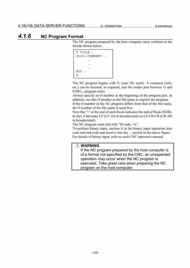
4.16i/18i DATA SERVER FUNCTIONS IV. OPERATION B-63644EN/02
- 120 -
4.1.6 NC Program FormatThe NC program prepared by the host computer must conform to theformat shown below.
The NC program begins with % (start file mark). A comment (title,etc.) can be inserted, as required, into the reader part between % andEOB (;, program start).Always specify an O number at the beginning of the program part. Inaddition, use this O number as the file name to register the program.If the O number in the NC program differs from that of the file name,the O number of the file name is used first.Note that ";" at the end of each block indicates the end of block (EOB).In fact, it becomes LF (LF: 0A in hexadecimal) or LF-CR-CR (CR: 0Din hexadecimal).The NC program must end with "M code ; %."To perform binary input, enclose it in the binary input operation startcode and end code and insert it into the ... section in the above figure.For details of binary input, refer to each CNC operator's manual.
WARNINGIf the NC program prepared by the host computer isof a format not specified by the CNC, an unexpectedoperation may occur when the NC program isexecuted. Take great care when preparing the NCprogram on the host computer.
% TITLE ;O0001(COMMENT) ;
.
.
.M30 ;%
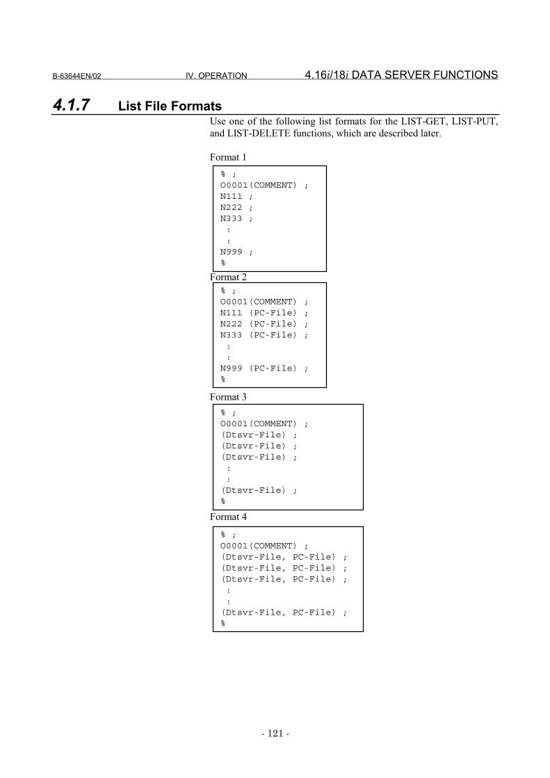
B-63644EN/02 IV. OPERATION 4.16i/18i DATA SERVER FUNCTIONS
- 121 -
4.1.7 List File FormatsUse one of the following list formats for the LIST-GET, LIST-PUT,and LIST-DELETE functions, which are described later.
Format 1
Format 2
Format 3
Format 4
% ;O0001(COMMENT) ;N111 (PC-File) ;N222 (PC-File) ;N333 (PC-File) ;::
N999 (PC-File) ;%
% ;O0001(COMMENT) ;(Dtsvr-File) ;(Dtsvr-File) ;(Dtsvr-File) ;::
(Dtsvr-File) ;%
% ;O0001(COMMENT) ;(Dtsvr-File, PC-File) ;(Dtsvr-File, PC-File) ;(Dtsvr-File, PC-File) ;::
(Dtsvr-File, PC-File) ;%
% ;O0001(COMMENT) ;N111 ;N222 ;N333 ;::
N999 ;%
4.16i/18i DATA SERVER FUNCTIONS IV. OPERATION B-63644EN/02
- 122 -
Specifications common to all formats<1> The list file begins with "%" (start file mark).<2> An O number must be specified in the next block. The list file
must be named using the same O number.A comment enclosed in parentheses "(" and ")" can be insertedbetween the O number and an EOB.
<3> Process files are specified in the subsequent blocks.<4> The list file must end with "%."
Specifications of format 1The specifications of the format-1 list file are as follows:<1> In this format, process files are identified using "Oxxxx" (where
"xxxx" represents a four-digit number). File names are specifiedby substituting "N" for "O" in "Oxxxx." Zeros in the four-digitnumber can be suppressed. The process files included in thisexample are treated as "O0111," "O0222," "O0333," ..., and"O0999" sequentially.
<2> The LIST-GET service transfers "Oxxxx" files from the hostcomputer built-in hard disk to the Fast data server built-in ATAcard without renaming them. The LIST-PUT service transfers"Oxxxx" files from the Fast data server built-in ATA card to thehost computer built-in hard disk without renaming them. TheLIST-DELETE service deletes "Oxxxx" files from the Fast dataserver built-in ATA card.
Specifications of format 2The specifications of the format-2 list file are as follows:<1> In this format, process files are identified using "Oxxxx" (where
"xxxx" represents a four-digit number) when they are on the Fastdata server built-in ATA card and arbitrary names when they areon the host computer built-in hard disk. The file names used on theFast data server built-in ATA card are specified by substituting"N" for "O" in "Oxxxx." Zeros in the four-digit number can besuppressed. The process files included in this example are treatedas "O0111," "O0222," "O0333," ..., and "O0999" sequentially.On the host computer built-in hard disk, files can be assigned anarbitrary name enclosed in parentheses "(" and ")" after thecorresponding "Nxxxx," provided that the name consists of acombination of those selected from the following 76 differentASCII characters:Digits 0 to 9Lowercase letters a to zUppercase letters A to Z14 different special characters . (period), ! , #, $, %, &, -, @, ^, _, ',{, }, and ~
<2> The LIST-GET service transfers files having the arbitrary name"PC-File" from the host computer built-in hard disk to the Fastdata server built-in ATA card as "Oxxxx" files. The LIST-PUTservice transfers "Oxxxx" files from the Fast data server built-inATA card to the host computer built-in hard disk as files havingthe arbitrary name "PC-File." The LIST-DELETE service deletes"Oxxxx" files from the Fast data server built-in ATA card.
B-63644EN/02 IV. OPERATION 4.16i/18i DATA SERVER FUNCTIONS
- 123 -
Specifications of format 3The specifications of the format-3 list files are as follows:<1> In this format, process files have an arbitrary name. It is assumed
that each file has the same name when it is on the Fast data serverbuilt-in ATA card and when it is on the host computer built-inhard disk.The "arbitrary" file name is specified in parentheses "(" and ")"and must consist of a combination of characters selected from thefollowing 76 different ASCII characters:Digits 0 to 9Lowercase letters a to zUppercase letters A to Z14 different special characters . (period), ! , #, $, %, &, -, @, ^, _,', {, }, and ~
<2> The LIST-GET service transfers files having the arbitrary name"Dtsvr-File" from the host computer built-in hard disk to the Fastdata server built-in ATA card without renaming them.The LIST-PUT service transfers files having the arbitrary name"Dtsvr-File" from the Fast data server built-in ATA card to thehost computer built-in hard disk without renaming them.The LIST-DELETE service deletes "Dtsvr-File" files from theFast data server built-in ATA card.
Specifications of format 4The specifications of the format-4 list file are as follows:<1> In this format, process files have an arbitrary name. It is assumed
that each file has a different name between when it is on the Fastdata server built-in ATA card and when it is on the host computerbuilt-in hard disk.An "arbitrary" file name used on the Fast data server built-in ATAcard and that on the host computer built-in hard disk are bothspecified in parentheses "(" and ")." They must be separated fromeach other using a comma "," and must consist of a combination ofcharacters selected from the following 76 different ASCIIcharacters:Digits 0 to 9Lowercase letters a to zUppercase letters A to Z14 different special characters . period), ! , #, $, %, &, -, @, ^, _, ',{, }, and ~
<2> The LIST-GET service transfers files having the arbitrary name"PC-File" from the host computer built-in hard disk to the Fastdata server built-in ATA card as "Dtsvr-File" files.The LIST-PUT service transfers files having the arbitrary name"Dtsvr-File" from the Fast data server built-in ATA card to thehost computer built-in hard disk as files having the arbitrary filename "PC-File."The LIST-DELETE service deletes "Dtsvr-File" files from theFast data server built-in ATA card.
4.16i/18i DATA SERVER FUNCTIONS IV. OPERATION B-63644EN/02
- 124 -
Restrictions on file names in the list fileThe following restrictions apply when file names are specified in thelist file.<1> Only the following 76 different ASCII characters can be used in
arbitrary file names.Digits 0 to 9Lowercase letters a to zUppercase letters A to Z14 different special characters . (period), ! , #, $, %, &, -, @, ^, _,', {, }, and ~This restriction applies also when the name of a file held on thehost computer built-in hard disk is specified.
<2> The arbitrary file name can be up to 255 characters. If an attemptis made to specify a larger arbitrary file name, an error is detected.
<3> Any file to be used on the Fast data server built-in ATA card mustbe in the 8.3 format. If an "arbitrary" file name is not in the 8.3format, it is converted to an 8.3-format file name automaticallyaccording to the following rule:- If the first 8 characters in the original "arbitrary" file name
include no period, they are used as the post-conversion filename. If they include a period, the characters before theperiod are used as the post-conversion file name. If the first 3characters after the period include no period, they are used asthe post-conversion file extension. If they contain periods, acharacters between the first and second periods are used asthe post-conversion file name extension.Example 1) If the original file name is
"LONGFILENAME.LONGEXT," the post-conversion file name is: "LONGFILE.LON"
Example 2) If the original file name is"ABCD.EFGH.TXT," the post-conversion filename is: "ABCD.EFG"
NOTEThe names of files handled in the data server must bein the 8.3 format. If "arbitrary" file names are not inthe 8.3 format, they are converted to this formatautomatically when they are handled in the dataserver. Different "arbitrary" file names may beconverted to the same file name in the 8.3 format;therefore, they will be regarded as the same file.
B-63644EN/02 IV. OPERATION 4.16i/18i DATA SERVER FUNCTIONS
- 125 -
List file storage locationThe LIST-GET, LIST-PUT, and LIST-DELETE services are useful tomanage more than one NC program in a group.The storage location for the list file varies depending on what service isto be executed.If the LIST-GET service is to be used, the list file is to be prepared onthe host computer built-in hard disk, because the NC programs to beexecuted are on that hard disk.If the LIST-PUT or LIST-DELETE service is to be used, the list file isto be prepared on the Fast data server built-in ATA card, because theNC programs to be executed are on that hard disk.
4.16i/18i DATA SERVER FUNCTIONS IV. OPERATION B-63644EN/02
- 126 -
4.1.8 Buffer Mode Specifications
The buffer mode is designed to handle NC programs larger than thecapacity of the Fast data server built-in ATA card. In this mode, theFast data server built-in ATA card is used as a temporary, intermediatebuffer.In the buffer mode, two areas (A and B) are previously prepared on thehard disk. While an NC program is being supplied from one (A) of theareas to the CNC, the rest of the NC program is read from the hostcomputer into the other area (B), using the FTP. When the data transferfrom area A ends, a data transfer from area B to the CNC is started, andthe NC program transfer from the host computer to the emptied area(A) is resumed, using the FTP.Repeating this sequence enables an NC program larger than thecapacity of the Fast data server built-in ATA card to be handled. Usingthe buffer mode, however, requires that the NC program be previouslydivided into several files in the host computer.The size of resulting smaller files must not be larger than half theremaining capacity of the Fast data server built-in ATA card. If the filesize is very large (for example, not smaller than 100 MB), it will take afairly long time to read the first file from the host computer, thusdelaying the start of the operation.
NOTEThe Series 21i-A/B cannot use the buffer mode.
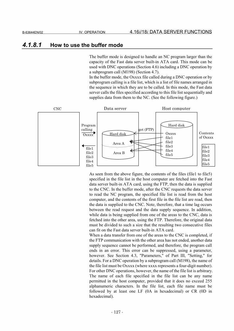
B-63644EN/02 IV. OPERATION 4.16i/18i DATA SERVER FUNCTIONS
- 127 -
4.1.8.1 How to use the buffer mode
The buffer mode is designed to handle an NC program larger than thecapacity of the Fast data server built-in ATA card. This mode can beused with DNC operations (Section 4.6) including a DNC operation bya subprogram call (M198) (Section 4.7).In the buffer mode, the Oxxxx file called during a DNC operation or bysubprogram calling is a file list, which is a list of file names arranged inthe sequence in which they are to be called. In this mode, the Fast dataserver calls the files specified according to this file list sequentially andsupplies data from them to the NC. (See the following figure.)
As seen from the above figure, the contents of the files (file1 to file5)specified in the file list in the host computer are fetched into the Fastdata server built-in ATA card, using the FTP, then the data is suppliedto the CNC. In the buffer mode, after the CNC requests the data serverto read the NC program, the specified file list is read from the hostcomputer, and the contents of the first file in the file list are read, thenthe data is supplied to the CNC. Note, therefore, that a time lag occursbetween the read request and the data supply sequence. In addition,while data is being supplied from one of the areas to the CNC, data isfetched into the other area, using the FTP. Therefore, the original datamust be divided to such a size that the resulting two consecutive filescan fit on the Fast data server built-in ATA card.When a data transfer from one of the areas to the CNC is completed, ifthe FTP communication with the other area has not ended, another datasupply sequence cannot be performed, and therefore, the program callends in an error. This error can be suppressed, using a parameter,however. See Section 4.3, "Parameters," of Part III, "Setting," fordetails. For a DNC operation by a subprogram call (M198), the name ofthe file list must be Oxxxx (where xxxx represents a four-digit number).For other DNC operations, however, the name of the file list is arbitrary.The name of each file specified in the file list can be any namepermitted in the host computer, provided that it does no exceed 255alphanumeric characters. In the file list, each file name must befollowed by at least one LF (0A in hexadecimal) or CR (0D inhexadecimal).
Contentsof Oxxxx
file1file2file3file4file5
Hard diskget (FTP)
ProgramcallingOxxxx Oxxxx
file1file2file3file4file5
file1file2file3file4file5
Hard disk
Area A
Area B
CNC Data server Host computer
4.16i/18i DATA SERVER FUNCTIONS IV. OPERATION B-63644EN/02
- 128 -
NOTEEven in the buffer mode, it is possible to newlyregister files on the Fast data server built-in ATAcard, using operations such as "NC program GET"and "output to NC program." These operations,however, may cause a buffer mode DNC operationerror, if the capacity of the Fast data server built-inATA card necessary for buffer mode operations isused up. Therefore, do not register new files on theFast data server built-in ATA card during buffer modeoperations. Always make sure that there remains anenough free space.
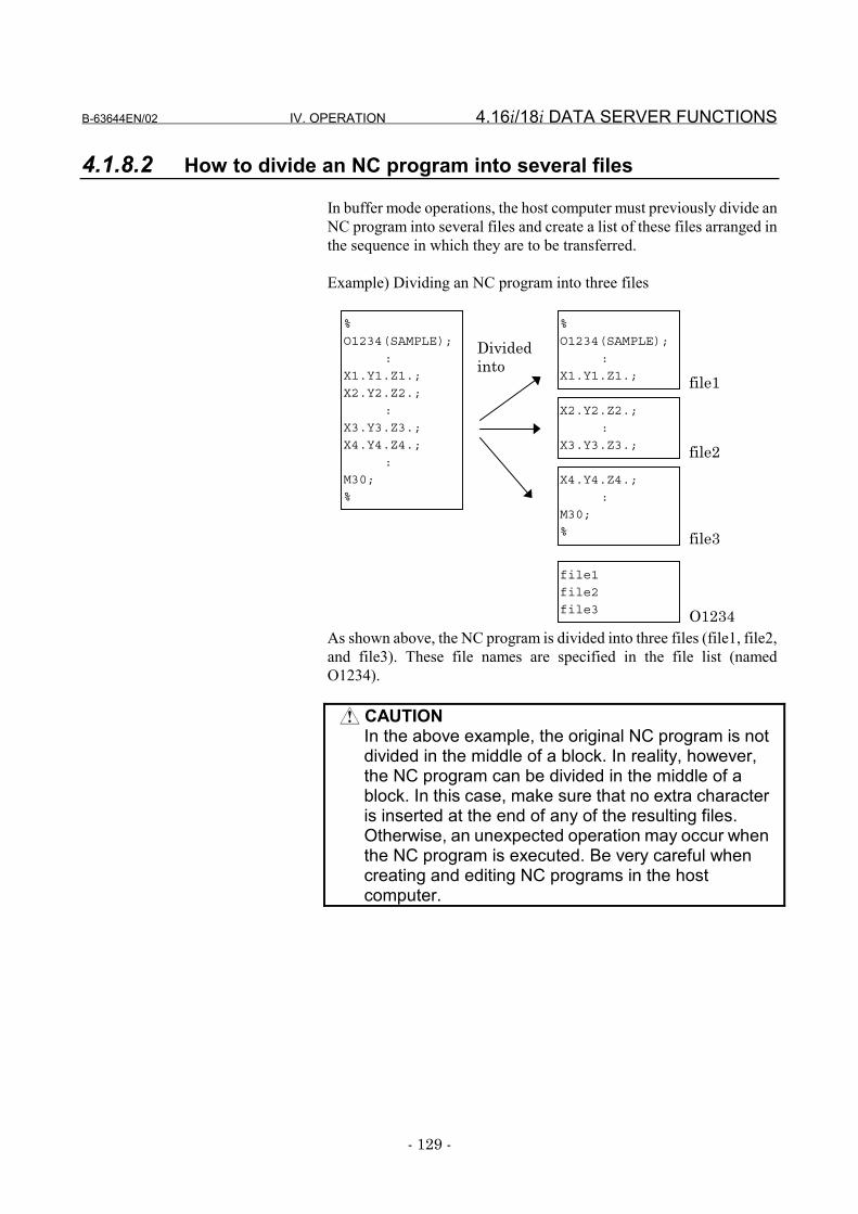
B-63644EN/02 IV. OPERATION 4.16i/18i DATA SERVER FUNCTIONS
- 129 -
4.1.8.2 How to divide an NC program into several files
In buffer mode operations, the host computer must previously divide anNC program into several files and create a list of these files arranged inthe sequence in which they are to be transferred.
Example) Dividing an NC program into three files
As shown above, the NC program is divided into three files (file1, file2,and file3). These file names are specified in the file list (namedO1234).
CAUTIONIn the above example, the original NC program is notdivided in the middle of a block. In reality, however,the NC program can be divided in the middle of ablock. In this case, make sure that no extra characteris inserted at the end of any of the resulting files.Otherwise, an unexpected operation may occur whenthe NC program is executed. Be very careful whencreating and editing NC programs in the hostcomputer.
%
O1234(SAMPLE);
:
X1.Y1.Z1.;
%
O1234(SAMPLE);
:
X1.Y1.Z1.;
X2.Y2.Z2.;
:
X3.Y3.Z3.;
X4.Y4.Z4.;
:
M30;
%
X2.Y2.Z2.;
:
X3.Y3.Z3.;
X4.Y4.Z4.;
:
M30;
%
file1
file2
file3
file1
Dividedinto
file2
file3
O1234
4.16i/18i DATA SERVER FUNCTIONS IV. OPERATION B-63644EN/02
- 130 -
NOTE1 The size of files into which an NC program is divided
should be 20 to 30 MB. If the size is very large, therewill be much idle time before the DNC operationbegins. If the size is very small, data may beinterrupted between files, resulting in a cutter markbeing left on the workpiece.
2 An NC program can be divided in the middle of ablock, but it should be divided between blocks. Inaddition, a tool retract operation should be inserted atthe end of each file resulting from NC programdivision. Doing so can avoid an interruption of databetween files, therefore preventing a cutter mark.
3 The file list and the files contained in the list must bestored in the same directory of the same hostcomputer.
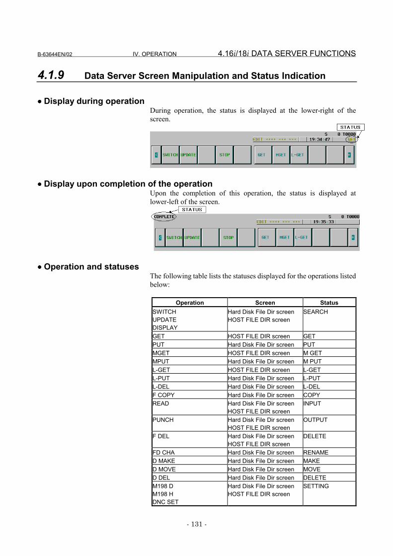
B-63644EN/02 IV. OPERATION 4.16i/18i DATA SERVER FUNCTIONS
- 131 -
4.1.9 Data Server Screen Manipulation and Status Indication
•••• Display during operationDuring operation, the status is displayed at the lower-right of thescreen.
•••• Display upon completion of the operationUpon the completion of this operation, the status is displayed atlower-left of the screen.
•••• Operation and statusesThe following table lists the statuses displayed for the operations listedbelow:
Operation Screen StatusSWITCHUPDATEDISPLAY
Hard Disk File Dir screenHOST FILE DIR screen
SEARCH
GET HOST FILE DIR screen GETPUT Hard Disk File Dir screen PUTMGET HOST FILE DIR screen M GETMPUT Hard Disk File Dir screen M PUTL-GET HOST FILE DIR screen L-GETL-PUT Hard Disk File Dir screen L-PUTL-DEL Hard Disk File Dir screen L-DELF COPY Hard Disk File Dir screen COPYREAD Hard Disk File Dir screen
HOST FILE DIR screenINPUT
PUNCH Hard Disk File Dir screenHOST FILE DIR screen
OUTPUT
F DEL Hard Disk File Dir screenHOST FILE DIR screen
DELETE
FD CHA Hard Disk File Dir screen RENAMED MAKE Hard Disk File Dir screen MAKED MOVE Hard Disk File Dir screen MOVED DEL Hard Disk File Dir screen DELETEM198 DM198 HDNC SET
Hard Disk File Dir screenHOST FILE DIR screen
SETTING
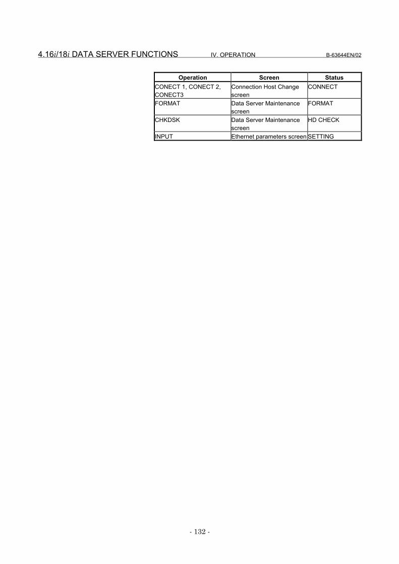
4.16i/18i DATA SERVER FUNCTIONS IV. OPERATION B-63644EN/02
- 132 -
Operation Screen StatusCONECT 1, CONECT 2,CONECT3
Connection Host Changescreen
CONNECT
FORMAT Data Server Maintenancescreen
FORMAT
CHKDSK Data Server Maintenancescreen
HD CHECK
INPUT Ethernet parameters screen SETTING
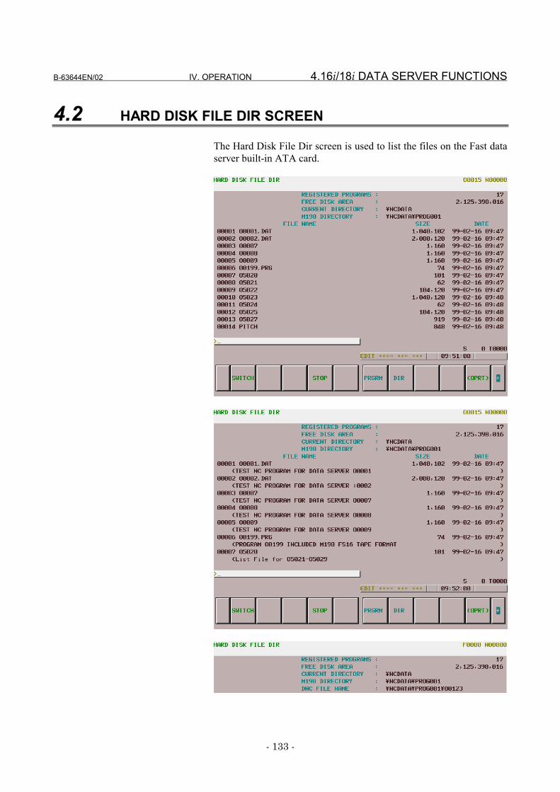
B-63644EN/02 IV. OPERATION 4.16i/18i DATA SERVER FUNCTIONS
- 133 -
4.2 HARD DISK FILE DIR SCREEN
The Hard Disk File Dir screen is used to list the files on the Fast dataserver built-in ATA card.
4.16i/18i DATA SERVER FUNCTIONS IV. OPERATION B-63644EN/02
- 134 -
Display items
•••• REGISTERED PROGRAMSDisplays the number of files stored in the current work directory.
•••• FREE DISK AREADisplays the amount of free space, in bytes, on the Fast data serverbuilt-in ATA card.
•••• CURRENT DIRECTORYDisplays the work directory of the Fast data server built-in ATA card.
•••• M198 DIRECTORYDisplays the directory (folder) for a DNC operation by a subprogramcall (M198).
•••• DNC FILE NAMEDisplays the name of the file for which DNC operation is performed.
•••• SIZEDisplays the file size, in bytes.
•••• DATEDisplays the date and time at which the file was created.
•••• COMMENTDisplays a comment statement appearing immediately after an Onumber in the NC program. If this statement does not exist, the contentsare displayed from the beginning of the NC program or file. Thecomment is displayed only on the Hard Disk File Dir screen (detaileddisplay).
Operations
•••• SWITCHSwitches between normal display and detailed display.
•••• STOPStops [F COPY], [F DEL], [PUT], [MPUT], [L-PUT], and [L-DEL]operations.
•••• DISPLAYUpdates the screen, using the file specified by the file number or nameas the first one.
•••• DNC SETSpecifies the files needed for DNC operation. This operation ispossible only when the data server is in the storage mode and the CNCis in the RMT mode.
•••• F COPYCopies files from the Fast data server built-in ATA card.
•••• FD CHAChanges file names on the Fast data server built-in ATA card.
•••• F DELDeletes files from the Fast data server built-in ATA card.
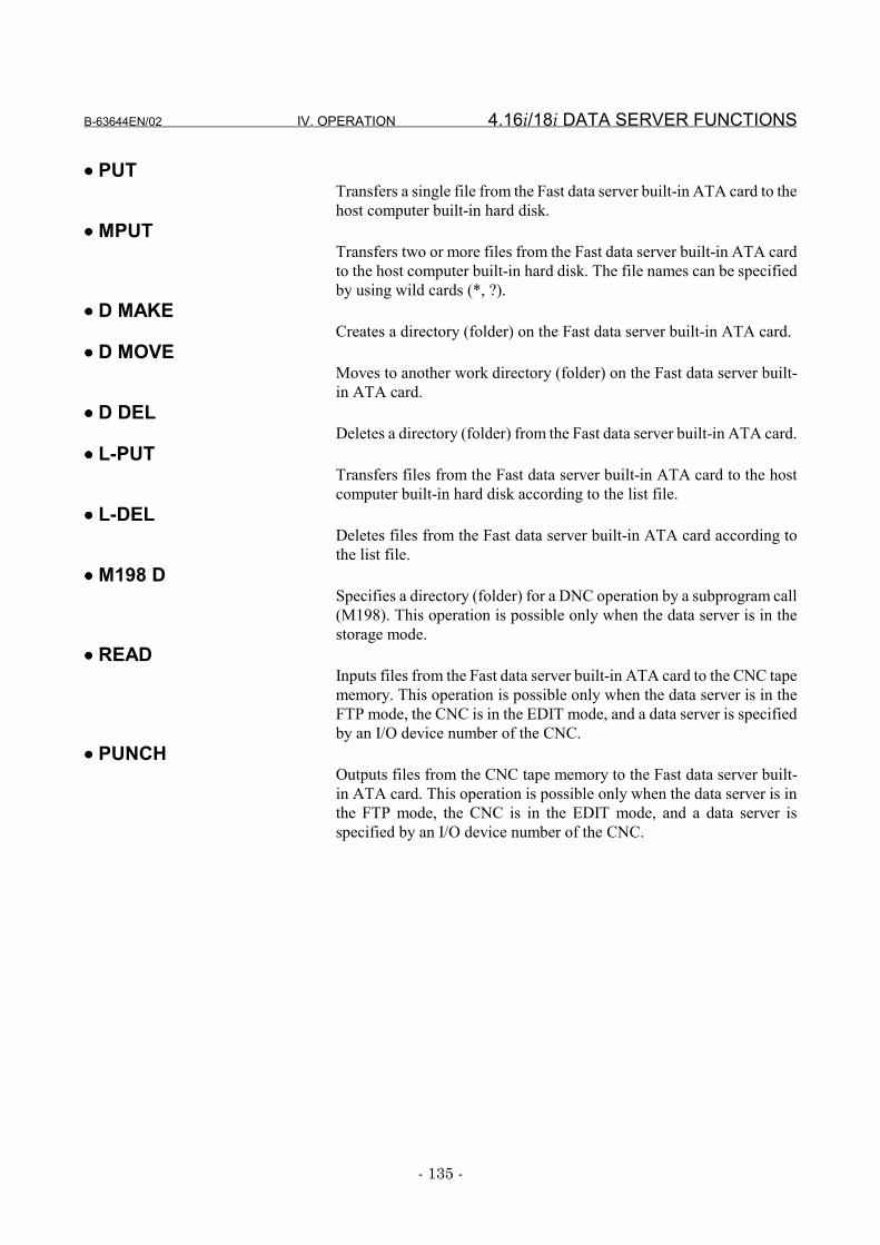
B-63644EN/02 IV. OPERATION 4.16i/18i DATA SERVER FUNCTIONS
- 135 -
•••• PUTTransfers a single file from the Fast data server built-in ATA card to thehost computer built-in hard disk.
•••• MPUTTransfers two or more files from the Fast data server built-in ATA cardto the host computer built-in hard disk. The file names can be specifiedby using wild cards (*, ?).
•••• D MAKECreates a directory (folder) on the Fast data server built-in ATA card.
•••• D MOVEMoves to another work directory (folder) on the Fast data server built-in ATA card.
•••• D DELDeletes a directory (folder) from the Fast data server built-in ATA card.
•••• L-PUTTransfers files from the Fast data server built-in ATA card to the hostcomputer built-in hard disk according to the list file.
•••• L-DELDeletes files from the Fast data server built-in ATA card according tothe list file.
•••• M198 DSpecifies a directory (folder) for a DNC operation by a subprogram call(M198). This operation is possible only when the data server is in thestorage mode.
•••• READInputs files from the Fast data server built-in ATA card to the CNC tapememory. This operation is possible only when the data server is in theFTP mode, the CNC is in the EDIT mode, and a data server is specifiedby an I/O device number of the CNC.
•••• PUNCHOutputs files from the CNC tape memory to the Fast data server built-in ATA card. This operation is possible only when the data server is inthe FTP mode, the CNC is in the EDIT mode, and a data server isspecified by an I/O device number of the CNC.
4.16i/18i DATA SERVER FUNCTIONS IV. OPERATION B-63644EN/02
- 136 -
4.2.1 Displaying a List of Hard Disk Files
Display a list of the files stored on the Fast data server built-in ATAcard.
Procedure1 Press function key PROG .2 Press the continuation menu key at the right end of the soft key
menu.3 When you press soft key [HD-DIR], the Hard Disk File Dir screen
appears.4 Select the desired page using the PAGE
PAGE page keys.5 When you press soft key [SWITCH], the Hard Disk File Dir
screen (details) appears.
B-63644EN/02 IV. OPERATION 4.16i/18i DATA SERVER FUNCTIONS
- 137 -
4.2.2 Searching for a Hard Disk File
Display a list of the files stored on the Fast data server built-in ATAcard by using the specified file as the first. Specify the file with the filenumber or name.
Procedure1 Display the Hard Disk File Dir screen.2 Press soft key [(OPRT)].3 Press soft key [DISPLAY].4 Enter the number or name of the file to be searched, starting using
the MDI keys.[Input format]
<file-number> or <file-name>5 Press soft key [EXEC].6 During search, "SEARCH" blinks in the lower-right part of the
screen.
NOTE1 If the specified file does not exist on the Fast data
server built-in ATA card, the file list is displayed usingthe file following the specified file as the first, in ASCIIcharacter order.
2 The data server function contains the FTP serverfunction. As a result, a new file may be transferred tothe Fast data server built-in ATA card. Alternatively, afile for which operation was made may be deletedinadvertently. So, the file number indicating thespecified file may be changed inadvertently. Beforemanipulating a file by specifying it with a file number,perform this operation to make sure that the filenumber corresponds to the target file name.
4.16i/18i DATA SERVER FUNCTIONS IV. OPERATION B-63644EN/02
- 138 -
4.2.3 Deleting a Hard Disk File
Delete files stored on the Fast data server built-in ATA card.
Deleting a single fileProcedure
1 Display the Hard Disk File Dir screen.2 Press soft key [(OPRT)].3 Press soft key [F DEL].4 Enter the number or name of the file to be deleted using the MDI
keys.[Input format]
<file-number> or <file-name>5 Press soft key [EXEC].6 During deletion, "DELETE" blinks in the lower-right part of the
screen.
NOTESpecifying a file to be deleted with its file number isvalid only for those files displayed on the Hard DiskFile Dir screen.
B-63644EN/02 IV. OPERATION 4.16i/18i DATA SERVER FUNCTIONS
- 139 -
Deleting two or more filesProcedure
1 Display the Hard Disk File Dir screen.2 Press soft key [(OPRT)].3 Press soft key [F DEL].4 Enter the names of the files (including wild cards) to be deleted
using the MDI keys.[Input format]
<file-name (including wild cards)>5 Press soft key [EXEC].6 When "FILE DELETE" is displayed in the lower-left part of the
screen, press soft key [EXEC]. To cancel the deletion, press softkey [CAN].
7 During deletion, "DELETE" blinks in lower-right part of thescreen.
8 To stop the deletion, press soft key [STOP].
[Example]Enter the file name as *.* to delete all the files displayed on theHard Disk File Dir screen from the Fast data server built-in ATAcard.
NOTEWhen two or more files are being deleted, if soft key[STOP] is pressed, the files deleted prior to soft key[STOP] being pressed cannot be restored.
4.16i/18i DATA SERVER FUNCTIONS IV. OPERATION B-63644EN/02
- 140 -
4.2.4 Copying a Hard Disk File
Copy files stored in the Fast data server built-in ATA card.Procedure
1 Display the Hard Disk File Dir screen.2 Press soft key [(OPRT)].3 Press soft key [F COPY].4 Enter the number or name of the copy source file and the name of
the copy destination file using the MDI keys.[Input format]
<copy-source-file-number>, <copy-destination-file-name>or <copy-source-file-name>, <copy-destination-file-name>
5 Press soft key [EXEC].6 During the copy operation, "COPY" blinks in the lower-right part
of the screen.
NOTE1 The copy source file number or name must be
separated from the copy destination file name by acomma (,).
2 An error occurs if the name of a file stored on the Fastdata server built-in ATA card is specified as the copydestination file name.
3 Specifying a copy source file with its file number isvalid only for those files displayed on the Hard DiskFile Dir screen.
B-63644EN/02 IV. OPERATION 4.16i/18i DATA SERVER FUNCTIONS
- 141 -
4.2.5 Changing a Hard Disk File Name
Change the name of a file stored on the Fast data server built-in ATAcard.
Procedure1 Display the Hard Disk File Dir screen.2 Press soft key [(OPRT)].3 Press soft key [FD CHA].4 Enter the number or name of the old file and the new file name
using the MDI keys.[Input format]
<old-file-number>, <new-file-name> or <old-copy-source-file-name>, <new-file-name>
5 Press soft key [EXEC].6 During the change operation, "RENAME" blinks in the lower-
right part of the screen.
NOTE1 The old file number or name must be separated from
the new file name by a comma (,).2 An error occurs if the name of the file stored on the
Fast data server built-in ATA card is specified as anew file name.
3 Specifying an old file with its file number is valid onlyfor those files displayed on the Hard Disk File Dirscreen.
4.16i/18i DATA SERVER FUNCTIONS IV. OPERATION B-63644EN/02
- 142 -
4.2.6 Creating a Directory on the ATA Card
Create a directory (folder) on the Fast data server built-in ATA card.Procedure
1 Display the Hard Disk File Dir screen.2 Press soft key [(OPRT)].3 Press the continuation menu key at the right end of the soft key
menu.4 Press soft key [D MAKE].5 Enter the name of a directory (folder) to be created on the Fast
data server built-in ATA card, using the MDI keys. [Input format]
<Directory name>6 Press soft key [EXEC].7 During the meke operation, " MAKE " blinks in the lower-right
part of the screen.
B-63644EN/02 IV. OPERATION 4.16i/18i DATA SERVER FUNCTIONS
- 143 -
4.2.7 Deleting a Directory from the ATA Card
Delete a directory (folder) from the Fast data server built-in ATA card.Procedure
1 Display the Hard Disk File Dir screen.2 Press soft key [(OPRT)].3 Press the continuation menu key at the right end of the soft key
menu.4 Press soft key [D DEL].5 Enter the name of a directory (folder) to be deleted from the Fast
data server built-in ATA card, using the MDI keys. [Input format]
<Directory number>or<Directory name>
6 Press soft key [EXEC].7 During deletion, "DELETE" blinks in lower-right part of the
screen.
NOTE1 If a directory (folder) contains files, an attempt to
delete it ends in an error. Before deleting a directory,delete all files from the directory.
2 A directory to be deleted can be specified using adirectory number only if the directory is displayed onthe Hard Disk File Directory screen.
4.16i/18i DATA SERVER FUNCTIONS IV. OPERATION B-63644EN/02
- 144 -
4.2.8 Moving to Another Directory on the ATA Card
Changes the work directory on the Fast data server built-in ATA card.Procedure
1 Display the Hard Disk File Dir screen.2 Press soft key [(OPRT)].3 Press the continuation menu key at the right end of the soft key
menu.4 Press soft key [D MOVE].5 Enter the name or number of a work directory (folder) to be
changed on the Fast data server built-in ATA card, using the MDIkeys. [Input format]
<Directory number>or<Directory name>
6 Press soft key [EXEC].7 During the copy operation, "MOVE" blinks in the lower-right part
of the screen.
NOTE1 If a directory contains many files, it may take much
time to move to that directory.2 A destination directory can be specified using a
directory number only if the directory is displayed onthe Hard Disk File Directory screen.
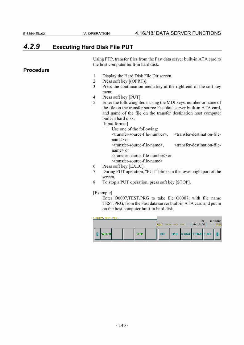
B-63644EN/02 IV. OPERATION 4.16i/18i DATA SERVER FUNCTIONS
- 145 -
4.2.9 Executing Hard Disk File PUT
Using FTP, transfer files from the Fast data server built-in ATA card tothe host computer built-in hard disk.
Procedure1 Display the Hard Disk File Dir screen.2 Press soft key [(OPRT)].3 Press the continuation menu key at the right end of the soft key
menu.4 Press soft key [PUT].5 Enter the following items using the MDI keys: number or name of
the file on the transfer source Fast data server built-in ATA card,and name of the file on the transfer destination host computerbuilt-in hard disk.[Input format]
Use one of the following:<transfer-source-file-number>, <transfer-destination-file-name> or<transfer-source-file-name>, <transfer-destination-file-name> or<transfer-source-file-number> or<transfer-source-file-name>
6 Press soft key [EXEC].7 During PUT operation, "PUT" blinks in the lower-right part of the
screen.8 To stop a PUT operation, press soft key [STOP].
[Example]Enter O0007,TEST.PRG to take file O0007, with file nameTEST.PRG, from the Fast data server built-in ATA card and put inon the host computer built-in hard disk.
4.16i/18i DATA SERVER FUNCTIONS IV. OPERATION B-63644EN/02
- 146 -
NOTE1 The transfer source file number or name must be
separated from the transfer destination file name by acomma (,).
2 The transfer destination file name and delimiter (,)can be omitted. In such a case, the transferdestination file name is the same as the transfersource file name.
3 If an error occurs, determine the cause of the errorfrom the Ethernet Error Message screen.
4 Specifying the file to be transferred with the filenumber is valid only for those files displayed on theHard Disk File Dir screen.
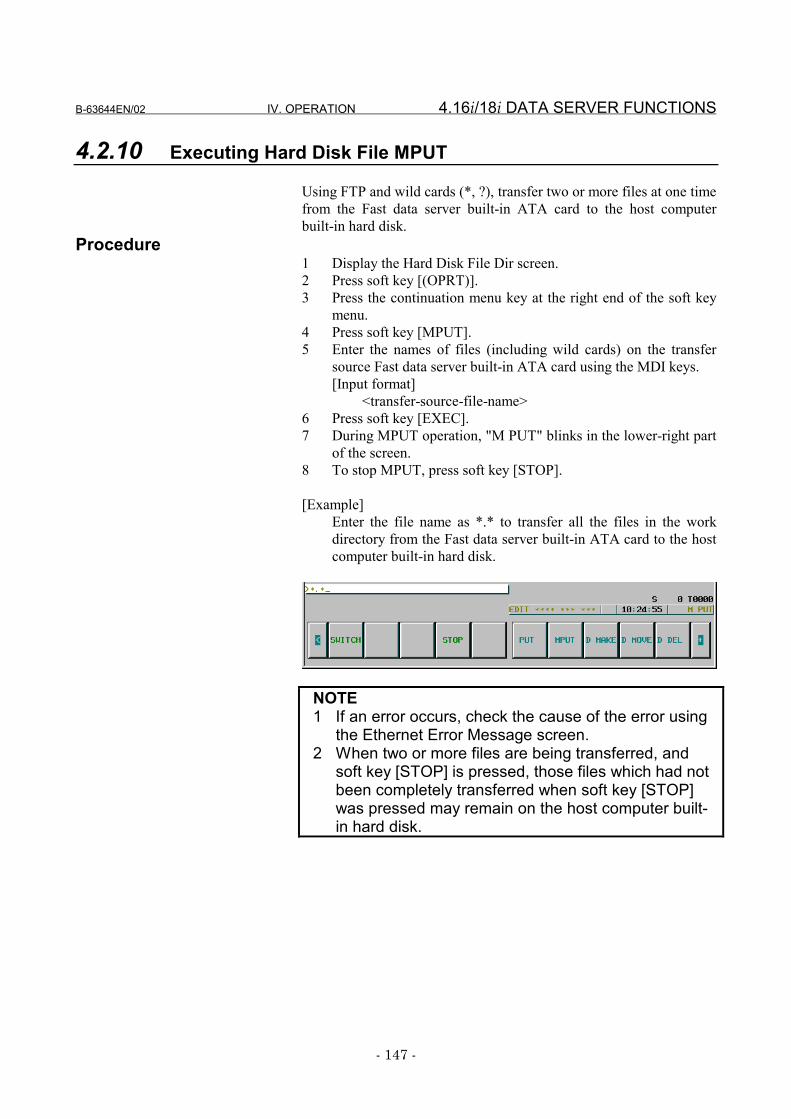
B-63644EN/02 IV. OPERATION 4.16i/18i DATA SERVER FUNCTIONS
- 147 -
4.2.10 Executing Hard Disk File MPUT
Using FTP and wild cards (*, ?), transfer two or more files at one timefrom the Fast data server built-in ATA card to the host computerbuilt-in hard disk.
Procedure1 Display the Hard Disk File Dir screen.2 Press soft key [(OPRT)].3 Press the continuation menu key at the right end of the soft key
menu.4 Press soft key [MPUT].5 Enter the names of files (including wild cards) on the transfer
source Fast data server built-in ATA card using the MDI keys.[Input format]
<transfer-source-file-name>6 Press soft key [EXEC].7 During MPUT operation, "M PUT" blinks in the lower-right part
of the screen.8 To stop MPUT, press soft key [STOP].
[Example]Enter the file name as *.* to transfer all the files in the workdirectory from the Fast data server built-in ATA card to the hostcomputer built-in hard disk.
NOTE1 If an error occurs, check the cause of the error using
the Ethernet Error Message screen.2 When two or more files are being transferred, and
soft key [STOP] is pressed, those files which had notbeen completely transferred when soft key [STOP]was pressed may remain on the host computer built-in hard disk.
4.16i/18i DATA SERVER FUNCTIONS IV. OPERATION B-63644EN/02
- 148 -
4.2.11 Executing Hard Disk File LIST-PUT
Transfer files from the Fast data server built-in ATA card to the hostcomputer built-in hard disk according to the contents of the list file,using the FTP.
Procedure1 Display the Hard Disk File Dir screen.2 Press soft key [(OPRT)].3 Press the continuation menu key at the right end of the soft key
menu.4 Press soft key [L-PUT].5 Enter the name of the list file held on the Fast data server built-in
ATA card, using the MDI keys. [Input format]
<name-of-list-file>6 Press soft key [EXEC].7 During LIST-PUT operation, " L-PUT " blinks in the lower-right
part of the screen.8 To stop LIST-PUT, press soft key [STOP].
NOTE1 If an error occurs, check the cause of the error using
the Ethernet Error Message screen.2 If more than one file is specified to be transferred,
pressing soft key [STOP] before the completion of thefile transfer may allow transferred files to be left onthe host computer built-in hard disk even after thesoft key is pressed.
3 See Subsection 4.1.7, "List File Formats," forexplanations about the formats of the list file.
B-63644EN/02 IV. OPERATION 4.16i/18i DATA SERVER FUNCTIONS
- 149 -
4.2.12 Executing Hard Disk File LIST-DELETE
Delete files from the Fast data server built-in ATA card according tothe contents of the list file.
Procedure1 Display the Hard Disk File Dir screen.2 Press soft key [(OPRT)].3 Press the continuation menu key at the right end of the soft key
menu.4 Press soft key [L-DEL].5 Enter the name of the list file held on the Fast data server built-in
ATA card, using the MDI keys. [Input format]
<name-of-list-file>6 Press soft key [EXEC].7 During LIST-DELET operation, " L-DEL " blinks in the lower-
right part of the screen.8 To stop LIST-DELET, press soft key [STOP].
NOTE1 If an error occurs, check the cause of the error using
the Ethernet Error Message screen.2 If more than one file is specified to be deleted,
pressing soft key [STOP] before the completion of thefile deletion makes it impossible to restore thedeleted file(s).
3 See Subsection 4.1.7, "List File Formats," forexplanations about the formats of the list file.
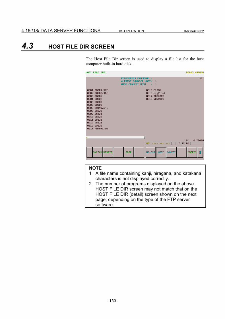
4.16i/18i DATA SERVER FUNCTIONS IV. OPERATION B-63644EN/02
- 150 -
4.3 HOST FILE DIR SCREEN
The Host File Dir screen is used to display a file list for the hostcomputer built-in hard disk.
NOTE1 A file name containing kanji, hiragana, and katakana
characters is not displayed correctly.2 The number of programs displayed on the above
HOST FILE DIR screen may not match that on theHOST FILE DIR (detail) screen shown on the nextpage, depending on the type of the FTP serversoftware.
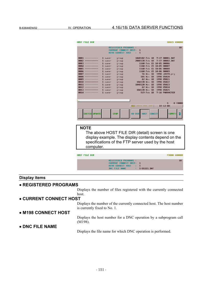
B-63644EN/02 IV. OPERATION 4.16i/18i DATA SERVER FUNCTIONS
- 151 -
NOTEThe above HOST FILE DIR (detail) screen is onedisplay example. The display contents depend on thespecifications of the FTP server used by the hostcomputer.
Display items•••• REGISTERED PROGRAMS
Displays the number of files registered with the currently connectedhost.
•••• CURRENT CONNECT HOSTDisplays the number of the currently connected host. The host numberis currently fixed to No. 1.
•••• M198 CONNECT HOSTDisplays the host number for a DNC operation by a subprogram call(M198).
•••• DNC FILE NAMEDisplays the file name for which DNC operation is performed.
4.16i/18i DATA SERVER FUNCTIONS IV. OPERATION B-63644EN/02
- 152 -
Operations•••• SWITCH
Switches between normal display and detailed display.•••• UPDATE
Updates the display contents.•••• STOP
Stops the [GET], [MGET], and [L-GET] operations.•••• DISPLAY
Updates the screen using the file specified by the file number or nameas the first.
•••• DNC SETSpecifies the file for which DNC operation is performed. Thisoperation is possible only when the data server and CNC are in the FTPand RMT modes, respectively.
•••• M198 HSpecifies the host number for a DNC operation by a subprogram call(M198). This operation is possible only when the data server is in theFTP mode.
•••• F DELDeletes files from the host computer built-in hard disk.
•••• GETTransfers a single file from the host computer built-in hard disk to theFast data server built-in ATA card.
•••• MGETTransfers two or more files from the host computer built-in hard disk tothe Fast data server built-in ATA card. File names can be specified byusing wild cards (*, ?).
•••• L-GETTransfers files from the host computer built-in hard disk to the Fastdata server built-in ATA card according to the list file.
•••• READInputs files from the built-in hard disk of the host computer to the partprogram storage memory of the CNC. This operation is possible onlywhen the data server is in the FTP mode, the CNC is in the EDIT mode,and a data server is specified by an I/O device number of the CNC.
•••• PUNCHOutputs files from the part program storage memory of the CNC to thebuilt-in hard disk of the host computer. This operation is possible onlywhen the data server is in the FTP mode, the CNC is in the EDIT mode,and a data server is specified by an I/O device number of the CNC.
B-63644EN/02 IV. OPERATION 4.16i/18i DATA SERVER FUNCTIONS
- 153 -
4.3.1 Displaying a List of Host Files
Display a list of files stored on the host computer built-in hard disk.Procedure
1 Press function key PROG .2 Press the continuation menu key at the right end of the soft key
menu.3 When you press soft key [HOST], the Host File Dir screen
appears.With the Series 16i/18i/21i-B, the HOST FILE DIR screenappears when you press soft key [HOST] then soft key [BOARD].
4 Select the desired page using the PAGEPAGE page keys.
5 When you press soft key [UPDATE], the contents of the Host FileDir screen are updated.
6 When you press soft key [SWITCH], the HOST FILE DIR (detail)screen appears.
4.16i/18i DATA SERVER FUNCTIONS IV. OPERATION B-63644EN/02
- 154 -
4.3.2 Searching for a Host File
Display a list of files stored on the host computer built-in hard disk byusing the file specified with the file number as the first.
Procedure1 Display the Host File Dir screen.2 Press soft key [(OPRT)].3 Press soft key [DISPLAY].4 Enter the number of the file to be searched for using the MDI
keys.[Input format]
<file-number>5 Press soft key [EXEC].6 During search, "SEARCH" blinks in the lower-right part of the
screen.
B-63644EN/02 IV. OPERATION 4.16i/18i DATA SERVER FUNCTIONS
- 155 -
4.3.3 Deleting a Host File
Delete files stored on the host computer built-in hard disk.Procedure
1 Display the Host File Dir screen.2 Press soft key [(OPRT)].3 Press soft key [F DEL].4 Enter the number or name of the file to be deleted using the MDI
keys.[Input format]
<file-number> or <file-name>5 Press soft key [EXEC].6 During deletion, "DELETE" blinks in the lower-right part of the
screen.
NOTE1 Specifying the file to be deleted with its file number is
valid only for those files displayed on the Host File Dirscreen.
2 Information displayed at the right end of the HOSTFILE DIR (detail) screen is recognized as a file name.Therefore, when deleting a host file by specifying itsfile number from the HOST FILE DIR (detail) screen,confirm that the file name is displayed at the right endof the screen, then specify the file number.
3 If a host file name contains kanji, hiragana, orkatakana characters, switch the HOST FILE DIR(detail) screen to the HOST FILE LIST screen,specify the file number, then delete the host file.
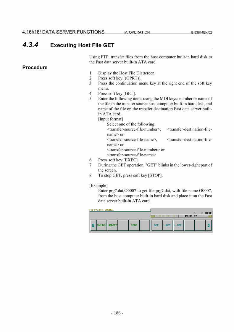
4.16i/18i DATA SERVER FUNCTIONS IV. OPERATION B-63644EN/02
- 156 -
4.3.4 Executing Host File GET
Using FTP, transfer files from the host computer built-in hard disk tothe Fast data server built-in ATA card.
Procedure1 Display the Host File Dir screen.2 Press soft key [(OPRT)].3 Press the continuation menu key at the right end of the soft key
menu.4 Press soft key [GET].5 Enter the following items using the MDI keys: number or name of
the file in the transfer source host computer built-in hard disk, andname of the file on the transfer destination Fast data server built-in ATA card.[Input format]
Select one of the following:<transfer-source-file-number>, <transfer-destination-file-name> or<transfer-source-file-name>, <transfer-destination-file-name> or<transfer-source-file-number> or<transfer-source-file-name>
6 Press soft key [EXEC].7 During the GET operation, "GET" blinks in the lower-right part of
the screen.8 To stop GET, press soft key [STOP].
[Example]Enter prg7.dat,O0007 to get file prg7.dat, with file name O0007,from the host computer built-in hard disk and place it on the Fastdata server built-in ATA card.
B-63644EN/02 IV. OPERATION 4.16i/18i DATA SERVER FUNCTIONS
- 157 -
NOTE1 The number or name of a transfer source file must be
separated from a transfer destination file name by acomma (,).
2 The transfer destination file name and delimiter ","can be omitted. In this case, the transfer destinationfile name is the same as the transfer source filename.
3 If an error occurs, check the cause of the error usingthe Ethernet Error Message screen.
4 Specify a file name that does not exist on the Fastdata server built-in ATA card, as the transferdestination file name. An error occurs if the name ofan existing file is specified.
5 Information displayed at the right end of the HOSTFILE DIR (detail) screen is recognized as a file name.Therefore, to get a host file from the HOST FILE DIR(detail) screen by specifying the file number, confirmthat the file name is displayed at the right end of thescreen, then specify the file number.
6 If a file name contains kanji, hiragana, or katakanacharacters, switch the HOST FILE DIR (detail) screento the Host File Dir screen, specify the file number,then get the host file. Be sure to specify the<transfer-destination-file-name>.
7 When only the transfer source file name is specified,if the file name is not in the 8.3 format, it is convertedto an 8.3-format file name automatically in order toGET the data onto the Fast data server built-in ATAcard. See Subsection 4.1.5, "Hard Disk File Names,"for explanations about the rules for converting filenames to 8.3-format file names.
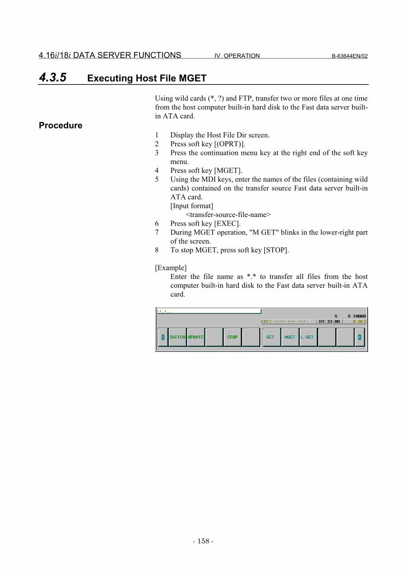
4.16i/18i DATA SERVER FUNCTIONS IV. OPERATION B-63644EN/02
- 158 -
4.3.5 Executing Host File MGET
Using wild cards (*, ?) and FTP, transfer two or more files at one timefrom the host computer built-in hard disk to the Fast data server built-in ATA card.
Procedure1 Display the Host File Dir screen.2 Press soft key [(OPRT)].3 Press the continuation menu key at the right end of the soft key
menu.4 Press soft key [MGET].5 Using the MDI keys, enter the names of the files (containing wild
cards) contained on the transfer source Fast data server built-inATA card.[Input format]
<transfer-source-file-name>6 Press soft key [EXEC].7 During MGET operation, "M GET" blinks in the lower-right part
of the screen.8 To stop MGET, press soft key [STOP].
[Example]Enter the file name as *.* to transfer all files from the hostcomputer built-in hard disk to the Fast data server built-in ATAcard.
B-63644EN/02 IV. OPERATION 4.16i/18i DATA SERVER FUNCTIONS
- 159 -
NOTE1 Wild card interpretation depends on the host
computer specifications.2 If a work directory on the host computer built-in hard
disk contains a subdirectory, and a wild card that canrepresent the subdirectory is used to specify atransfer source file name, an error may be detectedor the files may be transferred from the subdirectoryas directed by GET, depending on the type of thehost computer.
3 If an error occurs, determine the cause of the errorfrom the Ethernet Error Message screen.
4 If the Fast data server built-in ATA card contains a filehaving the same name as the file that was to betransferred, the file is not transferred.
5 If the transfer source file name is not in the 8.3format, it is converted to an 8.3-format file nameautomatically in order to GET the data onto the Fastdata server built-in ATA card. See Subsection 4.1.5,"Hard Disk File Names," for explanations about therules for converting file names to 8.3-format filenames.
4.16i/18i DATA SERVER FUNCTIONS IV. OPERATION B-63644EN/02
- 160 -
4.3.6 Executing Host File LIST-GET
Transfer files from the host computer built-in hard disk to the Fast dataserver built-in ATA card according to the contents of the list file, usingthe FTP.
Procedure1 Display the Host File Dir screen.2 Press soft key [(OPRT)].3 Press the continuation menu key at the right end of the soft key
menu.4 Press soft key [L-GET].5 Enter the name of the list file held on the host computer built-in
hard disk, using the MDI keys. [Input format]
<name-of-list-file>6 Press soft key [EXEC].7 During LIST-GET operation, "L-GET" blinks in the lower-right
part of the screen.8 To stop LIST-GET, press soft key [STOP].
NOTE1 If an error occurs, determine the cause of the error
from the Ethernet Error Message screen.2 If the transfer destination file name is not in the 8.3
format, it is converted to an 8.3-format file nameautomatically in order to GET the data onto the Fastdata server built-in ATA card. See Subsection 4.1.7,"List File Formats," for explanations about the list file.
B-63644EN/02 IV. OPERATION 4.16i/18i DATA SERVER FUNCTIONS
- 161 -
4.4 INPUTTING AN NC PROGRAM
Input a file (NC program) from the Fast data server built-in ATA cardor host computer built-in hard disk to the tape memory.
For the Hard Disk File Dir screen or Host File Dir screenProcedure
1 Place the CNC in EDIT mode.2 In storage mode, the Hard Disk File Dir screen is displayed. In
FTP mode, the Host File Dir screen is displayed.3 Press soft key [(OPRT)].4 Press the continuation menu key at the right end of the soft key
menu.5 Press soft key [READ].6 Enter the file number or name of the NC program using the MDI
keys.[Input format]
<file-number> or <file-name>7 Press soft key [EXEC].8 During input, "INPUT" blinks in the lower-right part of the
screen.
CAUTION1 When bit 2 of parameter No.3201 is 1, if an NC
program having the same O number as the NCprogram to be input is already contained in the tapememory, it is overwritten.
2 When bit 0 of parameter No.3201 is 1, if an NCprogram is input, all NC programs are automaticallyeliminated from the tape memory. Afterwards, the NCprogram is input.
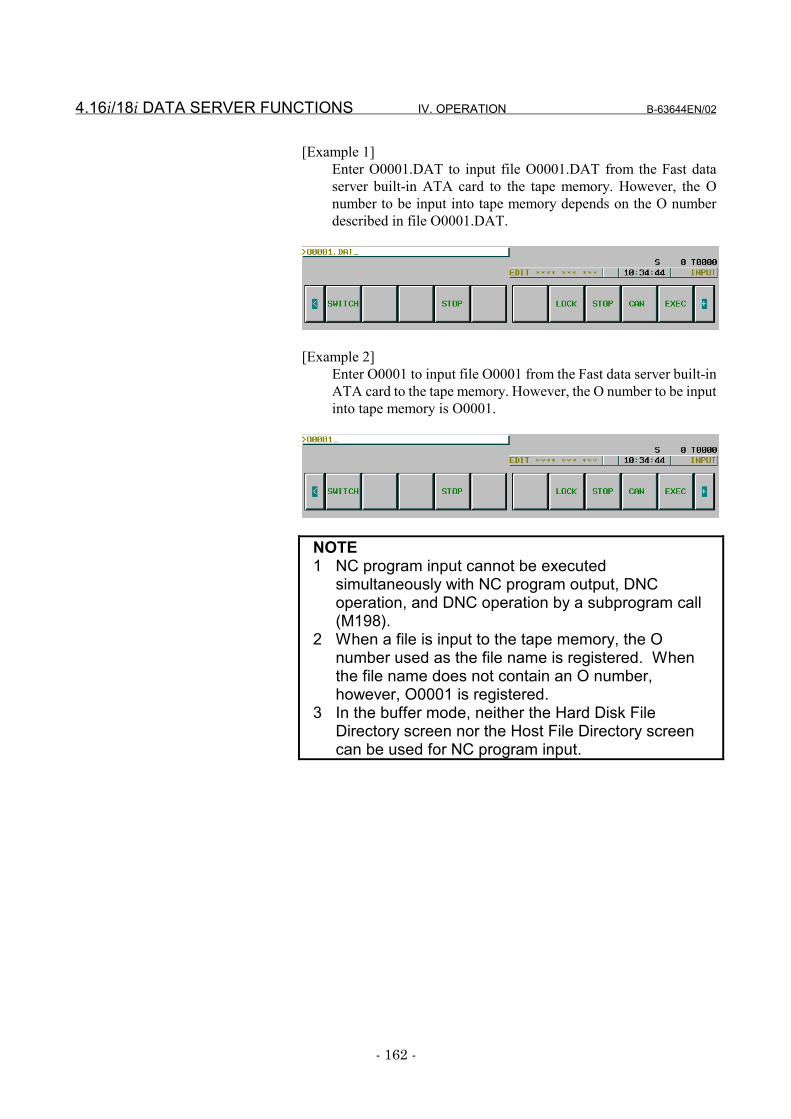
4.16i/18i DATA SERVER FUNCTIONS IV. OPERATION B-63644EN/02
- 162 -
[Example 1]Enter O0001.DAT to input file O0001.DAT from the Fast dataserver built-in ATA card to the tape memory. However, the Onumber to be input into tape memory depends on the O numberdescribed in file O0001.DAT.
[Example 2]Enter O0001 to input file O0001 from the Fast data server built-inATA card to the tape memory. However, the O number to be inputinto tape memory is O0001.
NOTE1 NC program input cannot be executed
simultaneously with NC program output, DNCoperation, and DNC operation by a subprogram call(M198).
2 When a file is input to the tape memory, the Onumber used as the file name is registered. Whenthe file name does not contain an O number,however, O0001 is registered.
3 In the buffer mode, neither the Hard Disk FileDirectory screen nor the Host File Directory screencan be used for NC program input.
B-63644EN/02 IV. OPERATION 4.16i/18i DATA SERVER FUNCTIONS
- 163 -
For the program screenProcedure
1 Place the CNC in EDIT mode.2 Press function key PROG .3 Press the continuation menu key at the right end of the soft key
menu.4 When you press soft key [PRGRM], the Program screen is
displayed.5 Press soft key [(OPRT)].6 Press the continuation menu key at the right end of the soft key
menu.7 Press soft key [READ].8 Enter the O number of the NC program to be entered using the
MDI keys.[Input format]
<O-number>9 Press soft key [EXEC].10 During input, "INPUT" blinks in the lower-right part of the
screen.
CAUTION1 When bit 2 of parameter No.3201 is 1, if the NC
program having the same O number as the NCprogram to be input exists in the tape memory, it isoverwritten.
2 When bit 0 of parameter No.3201 is 1, if an NCprogram is input, all NC programs in the tape memoryare automatically cleared. Subsequently, the NCprogram is input.
NOTE1 NC program input cannot be executed
simultaneously with NC program output, DNCoperation, and DNC operation by a subprogram call(M198).
2 The O number used for input to the tape memory isvalid only for file name Oxxxx (xxxx: numeral).However, an O number used for input to the tapememory depends on the setting of parameterNo.0900#1.
3 In the buffer mode, a specified O number is assumedto represent a list of files resulting from NC programdivision. Therefore, an NC program is input byregarding the files in the file list as a virtually singlecontinuous file.
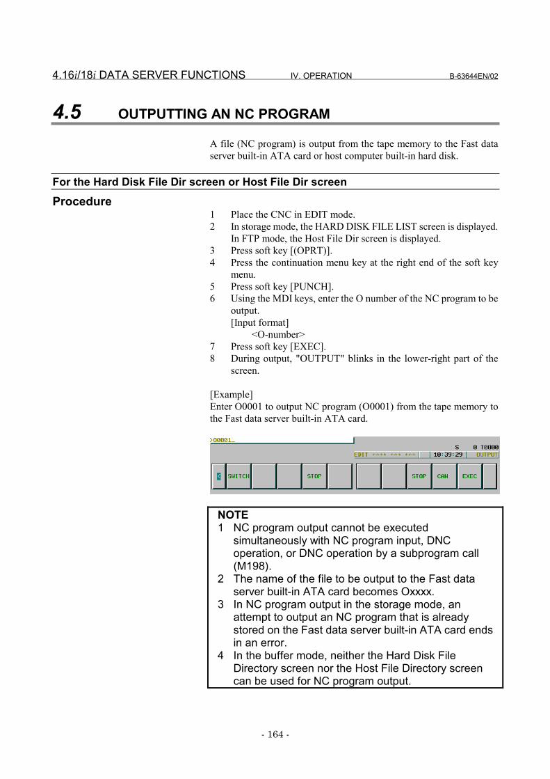
4.16i/18i DATA SERVER FUNCTIONS IV. OPERATION B-63644EN/02
- 164 -
4.5 OUTPUTTING AN NC PROGRAM
A file (NC program) is output from the tape memory to the Fast dataserver built-in ATA card or host computer built-in hard disk.
For the Hard Disk File Dir screen or Host File Dir screenProcedure
1 Place the CNC in EDIT mode.2 In storage mode, the HARD DISK FILE LIST screen is displayed.
In FTP mode, the Host File Dir screen is displayed.3 Press soft key [(OPRT)].4 Press the continuation menu key at the right end of the soft key
menu.5 Press soft key [PUNCH].6 Using the MDI keys, enter the O number of the NC program to be
output.[Input format]
<O-number>7 Press soft key [EXEC].8 During output, "OUTPUT" blinks in the lower-right part of the
screen.
[Example]Enter O0001 to output NC program (O0001) from the tape memory tothe Fast data server built-in ATA card.
NOTE1 NC program output cannot be executed
simultaneously with NC program input, DNCoperation, or DNC operation by a subprogram call(M198).
2 The name of the file to be output to the Fast dataserver built-in ATA card becomes Oxxxx.
3 In NC program output in the storage mode, anattempt to output an NC program that is alreadystored on the Fast data server built-in ATA card endsin an error.
4 In the buffer mode, neither the Hard Disk FileDirectory screen nor the Host File Directory screencan be used for NC program output.
B-63644EN/02 IV. OPERATION 4.16i/18i DATA SERVER FUNCTIONS
- 165 -
For the program screenProcedure
1 Place the CNC in EDIT mode.2 Press function key PROG .3 Press the continuation menu key at the right end of the soft key
menu.4 When you press soft key [PRGRM], the Program screen appears.5 Press soft key [(OPRT)].6 Press the continuation menu key at the right end of the soft key
menu.7 Press soft key [PUNCH].8 Using the MDI keys, enter the O number of the NC program to be
output.[Input format]
<O-number>9 Press soft key [EXEC].10 During output, "OUTPUT" blinks in the lower-right part of the
screen.
NOTE1 NC program output is executed simultaneously with
NC program input, DNC operation, and DNCoperation by a subprogram call (M198).
2 The name of the file to be output to the Fast dataserver built-in ATA card becomes Oxxxx.
3 In the buffer mode, the output destination of NCprograms is the Fast data server built-in ATA card.
4 In NC program output in either the storage or buffermode, an attempt to output an NC program that isalready stored on the Fast data server built-in ATAcard ends in an error.
4.16i/18i DATA SERVER FUNCTIONS IV. OPERATION B-63644EN/02
- 166 -
4.6 DNC OPERATIONS
DNC operation is performed using an NC program stored on the Fastdata server built-in ATA card or on the host computer built-in harddisk.
For DNC operation in storage modeProcedure
1 Place the CNC in RMT mode.2 Display the Hard Disk File Directory screen and move to the
directory holding an NC program used to perform a DNCoperation.
3 Press soft key [(OPRT)].4 Press soft key [DNC SET].5 Using the MDI keys, enter the file number or file name of the NC
program for which DNC operation is to be executed.[Input format]
<file-number> or <file-name>6 Press soft key [EXEC]. The file name of the NC program for
which DNC operation is to be performed is displayed in DNCFILE NAME in the upper part of the screen.
7 When the cycle start is executed, DNC operation is executed.
CAUTIONFor multipath control, DNC operation cannot besimultaneously executed for two or more paths.
NOTEDNC operation cannot be executed simultaneouslywith NC program input, NC program output, or DNCoperation by a subprogram call (M198).
B-63644EN/02 IV. OPERATION 4.16i/18i DATA SERVER FUNCTIONS
- 167 -
For DNC operation in FTP modeProcedure
1 Place the CNC in RMT mode.2 Select the host number for the host holding a file list to be used for
an DNC operation according to the procedure described inSubsection 4.9.2, "Reconnecting the Host," to display the HostFile Directory screen.
3 Press soft key [(OPRT)].4 Press soft key [DNC SET].5 Using the MDI keys, enter the file number or name of the NC
program for which DNC operation is to be performed.[Input format]
<file-number> or <file-name>6 Press soft key [EXEC]. The connect host number and file name of
the NC program for which DNC operation is to be performed isdisplayed in DNC FILE NAME at the top of the screen.
7 When cycle start is executed, DNC operation is executed.
CAUTIONFor multipath control, DNC operation cannot besimultaneously executed for two or more paths.
NOTEDNC operation cannot be executed simultaneouslywith NC program input, NC program output, or DNCoperation by a subprogram call (M198).
4.16i/18i DATA SERVER FUNCTIONS IV. OPERATION B-63644EN/02
- 168 -
For DNC operation in buffer modeProcedure
1 Place the CNC in RMT mode.2 Select the host number for the host holding a file list to be used for
an DNC operation according to the procedure described inSubsection 4.9.2, "Reconnecting the Host," to display the HostFile Directory screen.
3 Press soft key [(OPRT)].4 Press soft key [DNC SET].5 Using the MDI keys, enter the file number or name of the file list
for which DNC operation is to be performed.[Input format]
<file-number> or <file-name>6 Press soft key [EXEC]. The connect host number and file name of
the file list for which DNC operation is to be performed isdisplayed in DNC FILE NAME at the top of the screen.
7 When cycle start is executed, DNC operation is executed.
CAUTIONFor multipath control, DNC operation cannot besimultaneously executed for two or more paths.
NOTEDNC operation cannot be executed simultaneouslywith NC program input, NC program output, or DNCoperation by a subprogram call (M198).
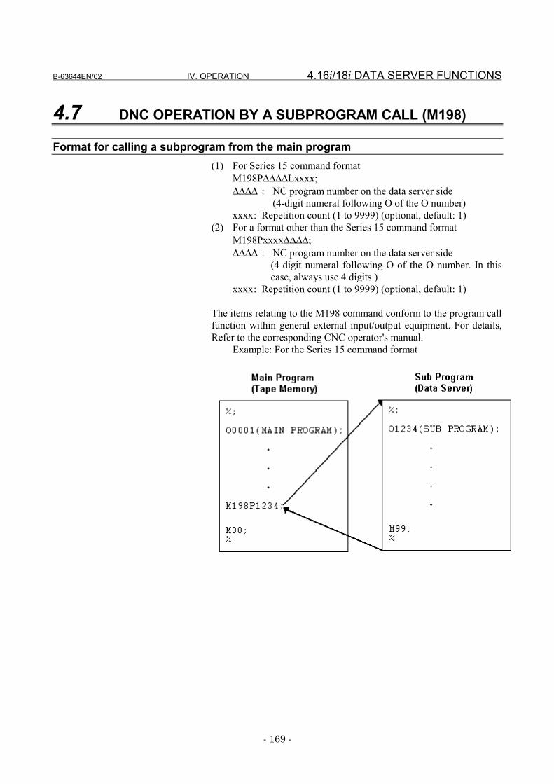
B-63644EN/02 IV. OPERATION 4.16i/18i DATA SERVER FUNCTIONS
- 169 -
4.7 DNC OPERATION BY A SUBPROGRAM CALL (M198)
Format for calling a subprogram from the main program(1) For Series 15 command format
M198P∆∆∆∆Lxxxx;∆∆∆∆ : NC program number on the data server side
(4-digit numeral following O of the O number)xxxx: Repetition count (1 to 9999) (optional, default: 1)
(2) For a format other than the Series 15 command formatM198Pxxxx∆∆∆∆;∆∆∆∆ : NC program number on the data server side
(4-digit numeral following O of the O number. In thiscase, always use 4 digits.)
xxxx: Repetition count (1 to 9999) (optional, default: 1)
The items relating to the M198 command conform to the program callfunction within general external input/output equipment. For details,Refer to the corresponding CNC operator's manual.
Example: For the Series 15 command format
4.16i/18i DATA SERVER FUNCTIONS IV. OPERATION B-63644EN/02
- 170 -
DNC operation by a subprogram call (M198) in the storage modeProcedure
1 Place the CNC in MEM mode.2 Display the Hard Disk File Directory screen and move to the
directory holding an NC program to be called by a subprogram.3 Press soft key [(OPRT)].4 Press soft key [M198 D].5 Press soft key [EXEC]. The name of the current work directory is
displayed to the right of "M198 DIRECTORY" on the screen.6 An automatic operation is performed based on the NC program
containing the M198 command.
NOTE1 If a subprogram is called with M98 from a DNC
operation subprogram called by an M198subprogram call, and the M198 command is specifiedfrom within the called subprogram, the second M198command is treated as an M code for amiscellaneous function command. If the M198command is specified in a DNC operationsubprogram, PS alarm 210 is issued.
2 DNC operation by a subprogram call (M198) cannotbe executed simultaneously with NC program input,NC program output, or DNC operation.
3 The file name of the subprogram to be called by DNCoperation by a subprogram call (M198) must beOxxxx.
4 When viewed from the CNC, the data server functionis handled in the same way as for other input/outputequipment. Therefore, the subprogram callrestrictions are the same as those for otherinput/output equipment.
5 Multipath control can be performed on DNCoperations by a subprogram call (M198) on multiplepaths at a time; however, the programs must be inthe same work directory.
B-63644EN/02 IV. OPERATION 4.16i/18i DATA SERVER FUNCTIONS
- 171 -
DNC operation by a subprogram call (M198) in the FTP modeProcedure
1 Place the CNC in MEM mode.2 Select the host number for the host holding an NC program to be
called by a subprogram according to the procedure described inSubsection 4.9.2, "Reconnecting the Host," to display the HostFile Directory screen.
3 Press soft key [(OPRT)].4 Press soft key [M198 H].5 Press soft key [EXEC]. The host number of the currently
connected host is displayed to the right of "M198 CONNECTHOST" on the screen.
6 An automatic operation is performed based on the NC programcontaining the M198 command.
NOTE1 If a subprogram is called with M98 from a DNC
operation subprogram called by an M198subprogram call, and the M198 command is specifiedfrom within the called subprogram, the second M198command is treated as an M code for amiscellaneous function command. If the M198command is specified in a DNC operationsubprogram, PS alarm 210 is issued.
2 DNC operation by a subprogram call (M198) cannotbe executed simultaneously with NC program input,NC program output, or DNC operation.
3 The file name of the subprogram to be called by DNCoperation by a subprogram call (M198) must beOxxxx.
4 When viewed from the CNC, the data server functionis handled in the same way as for other input/outputequipment. Therefore, the subprogram callrestrictions are the same as those for otherinput/output equipment.
5 Multipath control can be performed on DNCoperations by a subprogram call (M198) on multiplepaths at a time; however, the programs must be inthe same work directory.
4.16i/18i DATA SERVER FUNCTIONS IV. OPERATION B-63644EN/02
- 172 -
DNC operation by a subprogram call (M198) in the buffer modeProcedure
1 Place the CNC in MEM mode.2 Select the host number for the host holding a file list to be called
by a subprogram according to the procedure described inSubsection 4.9.2, "Reconnecting the Host," to display the HostFile Directory screen.
3 Press soft key [(OPRT)].4 Press soft key [M198 H].5 Press soft key [EXEC]. The host number of the currently
connected host is displayed to the right of "M198 CONNECTHOST" on the screen.
6 An automatic operation is performed based on the NC programcontaining the M198 command.
NOTE1 If a subprogram is called with M98 from a DNC
operation subprogram called by an M198subprogram call, and the M198 command is specifiedfrom within the called subprogram, the second M198command is treated as an M code for amiscellaneous function command. If the M198command is specified in a DNC operationsubprogram, PS alarm 210 is issued.
2 DNC operation by a subprogram call (M198) cannotbe executed simultaneously with NC program input,NC program output, or DNC operation.
3 The file name of the subprogram to be called by DNCoperation by a subprogram call (M198) must beOxxxx.
4 When viewed from the CNC, the data server functionis handled in the same way as for other input/outputequipment. Therefore, the subprogram callrestrictions are the same as those for otherinput/output equipment.
5 Multipath control can be performed on DNCoperations by a subprogram call (M198) on multiplepaths at a time; however, the programs must be inthe same work directory.
B-63644EN/02 IV. OPERATION 4.16i/18i DATA SERVER FUNCTIONS
- 173 -
4.8 DATA INPUT/OUTPUT
The data listed below can be transferred between the Fast data serverand CNC. How to transfer the data is explained later.1 NC parameter2 Tool offset value3 Custom macro value4 Workpiece zero point offset value5 Pitch error compensation data6 M code group7 operation history data
NOTEThe transfer of the data listed above cannot beperformed simultaneously with NC program input, NCprogram output, DNC operation, or DNC operation bya subprogram call (M198).
4.16i/18i DATA SERVER FUNCTIONS IV. OPERATION B-63644EN/02
- 174 -
4.8.1 Inputting the Parameter
Input files (NC parameters) from the Fast data server built-in ATA cardor host computer built-in hard disk to CNC memory.
For the Parameter screenProcedure
1 Place the CNC in EDIT mode.2 Press function key SYSTEM .3 Press the continuation menu key at the right end of the soft key
menu.4 When you press soft key [PARAM], the Parameter screen is
displayed.5 Press soft key [(OPRT)].6 Press the continuation menu key at the right end of the soft key
menu.7 Press soft key [READ].8 Press soft key [EXEC].9 During input, "INPUT" blinks in the lower-right part of the
screen.
File nameFixed to PRAMETER.
File formats and restrictionsRefer to the corresponding CNC operator's manual.
Input sourceIn storage mode : Fast data server built-in ATA cardIn FTP mode : Host computer built-in hard diskIn buffer mode : Host computer built-in hard disk
NOTEIn the buffer mode, a specified file behaves as a filelist of files resulting from NC program division.
B-63644EN/02 IV. OPERATION 4.16i/18i DATA SERVER FUNCTIONS
- 175 -
4.8.2 Outputting the Parameter
Output files (NC parameters) from CNC memory to the Fast data serverbuilt-in ATA card or host computer built-in hard disk.
For the Parameter screenProcedure
1 Place the CNC in EDIT mode.2 Press function key SYSTEM .3 Press the continuation menu key at the right end of the soft key
menu.4 When you press soft key [PARAM], the Parameter screen is
displayed.5 Press soft key [(OPRT)].6 Press the continuation menu key at the right end of the soft key
menu.7 Press soft key [PUNCH].8 Press soft key [EXEC].9 During output, "OUTPUT" blinks in the lower-right part of the
screen.
File nameFixed to PRAMETER.
File formats and restrictionsRefer to the corresponding CNC operator's manual.
Output destinationIn storage mode : Fast data server built-in ATA cardIn FTP mode : Host computer built-in hard diskIn buffer mode : Fast data server built-in ATA card
4.16i/18i DATA SERVER FUNCTIONS IV. OPERATION B-63644EN/02
- 176 -
4.8.3 Inputting Tool Offsets
A file (tool offset value) is input from the Fast data server built-in ATAcard or host computer built-in hard disk to the CNC memory.
For the Tool Compensation screenProcedure
1 Place the CNC in EDIT mode.2 Press function key OFFSET
SETTING .3 Press the continuation menu key at the right end of the soft key
menu.4 When you press soft key [OFFSET], the Tool Compensation
screen is displayed.5 Press soft key [(OPRT)].6 Press the continuation menu key at the right end of the soft key
menu.7 Press soft key [READ].8 Press soft key [EXEC].9 During input, "INPUT" blinks in the lower-right part of the
screen.
File nameFixed to TOOLOFS.
File formats and restrictionsRefer to the corresponding CNC operator's manual.
Input sourceIn storage mode : Fast data server built-in ATA cardIn FTP mode : Host computer built-in hard diskIn buffer mode : Host computer built-in hard disk
NOTEIn the buffer mode, a specified file behaves as a filelist of files resulting from NC program division.
B-63644EN/02 IV. OPERATION 4.16i/18i DATA SERVER FUNCTIONS
- 177 -
4.8.4 Outputting Tool Offsets
A file (tool offset value) is output from the CNC memory to the Fastdata server built-in ATA card or host computer built-in hard disk.
For the Tool Compensation screenProcedure
1 Place the CNC in EDIT mode.2 Press function key OFFSET
SETTING .3 Press the continuation menu key at the right end of the soft key
menu.4 When you press soft key [OFFSET], the Tool Compensation
screen is displayed.5 Press soft key [(OPRT)].6 Press the continuation menu key at the right end of the soft key
menu.7 Press soft key [PUNCH].8 Press soft key [EXEC].9 During output, "OUTPUT" blinks in the lower-right part of the
screen.
File nameFixed to TOOLOFS.
File formats and restrictionsRefer to the corresponding CNC operator's manual.
Output destinationIn storage mode : Fast data server built-in ATA cardIn FTP mode : Host computer built-in hard diskIn buffer mode : Fast data server built-in ATA card
4.16i/18i DATA SERVER FUNCTIONS IV. OPERATION B-63644EN/02
- 178 -
4.8.5 Inputting Custom Macro Variables
A file (custom macro variables) is input from the Fast data serverbuilt-in ATA card or host computer built-in hard disk to the CNCmemory. Custom macro variable input is executed in the same way asfor DNC operation.
To input custom macro variablesProcedure
1 Place the CNC in RMT mode.2 In storage mode, the Hard Disk File Dir screen is displayed. In
FTP mode or buffer mode, the Host File Dir screen is displayed.3 Press soft key [(OPRT)].4 Press soft key [DNC SET].5 Using the MDI keys, enter custom macro variable file name
MACRO to be input.6 Press soft key [EXEC]. MACRO is displayed in DNC FILE
NAME on the screen.7 When the cycle start is executed, custom macro variable input is
executed.
File nameFixed to MACRO.
File formats and restrictionsRefer to the corresponding CNC operator's manual.
Input sourceIn storage mode : Fast data server built-in ATA cardIn FTP mode : Host computer built-in hard diskIn buffer mode : Host computer built-in hard disk
NOTEIn the buffer mode, a specified file behaves as a filelist of files resulting from NC program division.
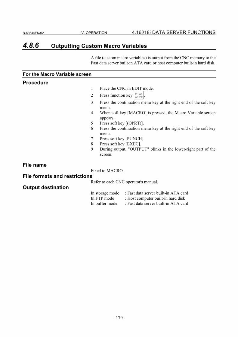
B-63644EN/02 IV. OPERATION 4.16i/18i DATA SERVER FUNCTIONS
- 179 -
4.8.6 Outputting Custom Macro Variables
A file (custom macro variables) is output from the CNC memory to theFast data server built-in ATA card or host computer built-in hard disk.
For the Macro Variable screenProcedure
1 Place the CNC in EDIT mode.2 Press function key OFFSET
SETTING .3 Press the continuation menu key at the right end of the soft key
menu.4 When soft key [MACRO] is pressed, the Macro Variable screen
appears.5 Press soft key [(OPRT)].6 Press the continuation menu key at the right end of the soft key
menu.7 Press soft key [PUNCH].8 Press soft key [EXEC].9 During output, "OUTPUT" blinks in the lower-right part of the
screen.
File nameFixed to MACRO.
File formats and restrictionsRefer to each CNC operator's manual.
Output destinationIn storage mode : Fast data server built-in ATA cardIn FTP mode : Host computer built-in hard diskIn buffer mode : Fast data server built-in ATA card
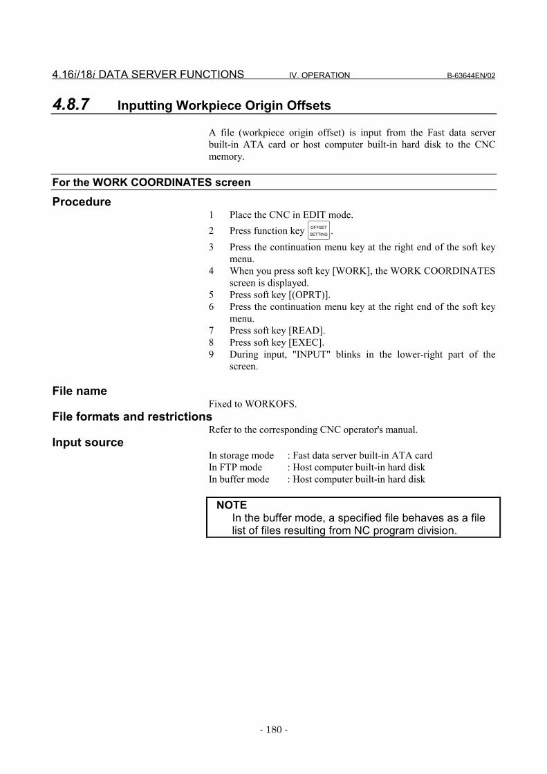
4.16i/18i DATA SERVER FUNCTIONS IV. OPERATION B-63644EN/02
- 180 -
4.8.7 Inputting Workpiece Origin Offsets
A file (workpiece origin offset) is input from the Fast data serverbuilt-in ATA card or host computer built-in hard disk to the CNCmemory.
For the WORK COORDINATES screen
Procedure1 Place the CNC in EDIT mode.2 Press function key OFFSET
SETTING .3 Press the continuation menu key at the right end of the soft key
menu.4 When you press soft key [WORK], the WORK COORDINATES
screen is displayed.5 Press soft key [(OPRT)].6 Press the continuation menu key at the right end of the soft key
menu.7 Press soft key [READ].8 Press soft key [EXEC].9 During input, "INPUT" blinks in the lower-right part of the
screen.
File nameFixed to WORKOFS.
File formats and restrictionsRefer to the corresponding CNC operator's manual.
Input sourceIn storage mode : Fast data server built-in ATA cardIn FTP mode : Host computer built-in hard diskIn buffer mode : Host computer built-in hard disk
NOTEIn the buffer mode, a specified file behaves as a filelist of files resulting from NC program division.

B-63644EN/02 IV. OPERATION 4.16i/18i DATA SERVER FUNCTIONS
- 181 -
4.8.8 Outputting Workpiece Origin Offsets
A file (workpiece origin offset) is output from the CNC memory to theFast data server built-in ATA card or host computer built-in hard disk.
For the WORK COORDINATES screenProcedure
1 Place the CNC in EDIT mode.2 Press function key OFFSET
SETTING .3 Press the continuation menu key at the right end of the soft key
menu.4 When you press soft key [WORK], the WORK COORDINATES
screen appears.5 Press soft key [(OPRT)].6 Press the continuation menu key at the right end of the soft key
menu.7 Press soft key [PUNCH].8 Press soft key [EXEC].9 During output, "OUTPUT" blinks in the lower-right part of the
screen.
File nameFixed to WORKOFS.
File formats and restrictionsRefer to the corresponding CNC operator's manual.
Output destinationIn storage mode : Fast data server built-in ATA cardIn FTP mode : Host computer built-in hard diskIn buffer mode : Fast data server built-in ATA card
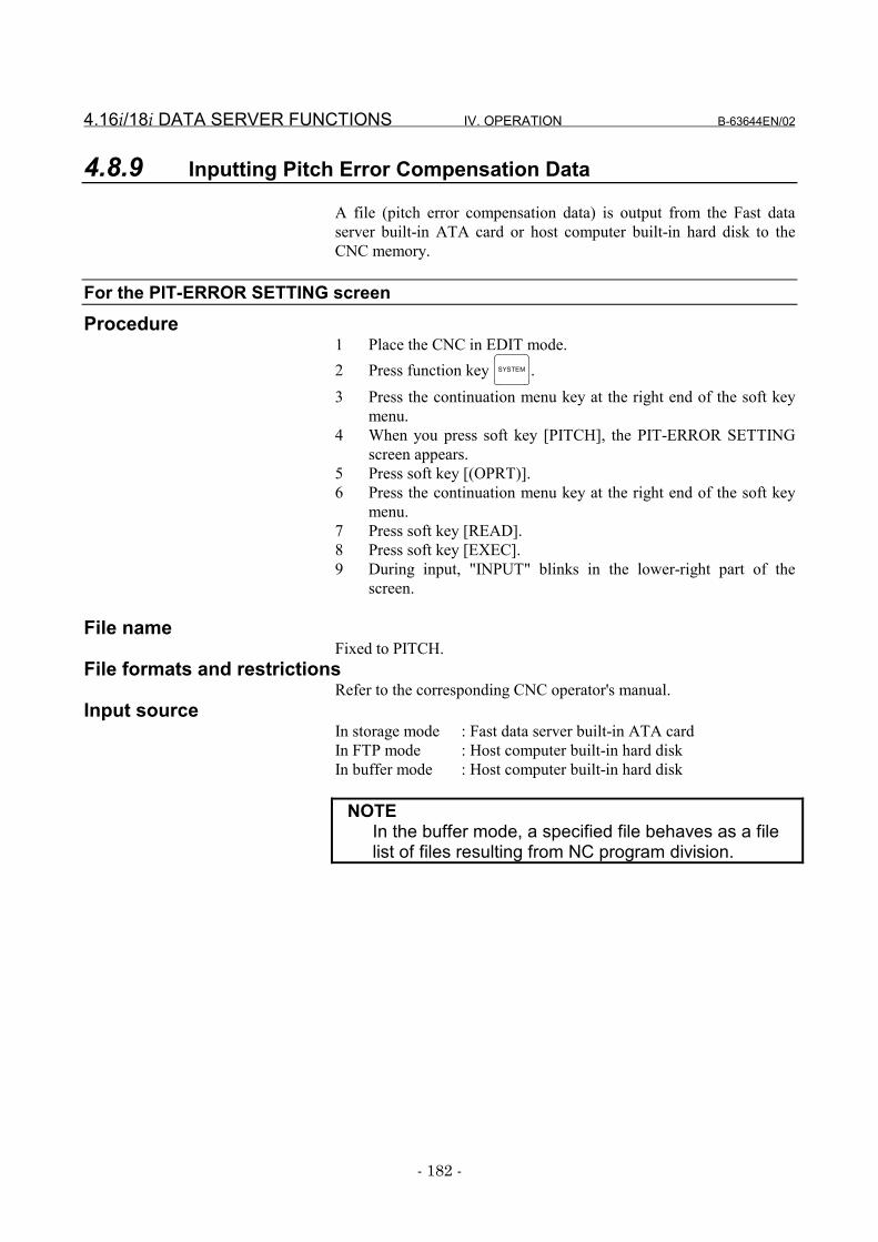
4.16i/18i DATA SERVER FUNCTIONS IV. OPERATION B-63644EN/02
- 182 -
4.8.9 Inputting Pitch Error Compensation Data
A file (pitch error compensation data) is output from the Fast dataserver built-in ATA card or host computer built-in hard disk to theCNC memory.
For the PIT-ERROR SETTING screen
Procedure1 Place the CNC in EDIT mode.2 Press function key SYSTEM .3 Press the continuation menu key at the right end of the soft key
menu.4 When you press soft key [PITCH], the PIT-ERROR SETTING
screen appears.5 Press soft key [(OPRT)].6 Press the continuation menu key at the right end of the soft key
menu.7 Press soft key [READ].8 Press soft key [EXEC].9 During input, "INPUT" blinks in the lower-right part of the
screen.
File nameFixed to PITCH.
File formats and restrictionsRefer to the corresponding CNC operator's manual.
Input sourceIn storage mode : Fast data server built-in ATA cardIn FTP mode : Host computer built-in hard diskIn buffer mode : Host computer built-in hard disk
NOTEIn the buffer mode, a specified file behaves as a filelist of files resulting from NC program division.
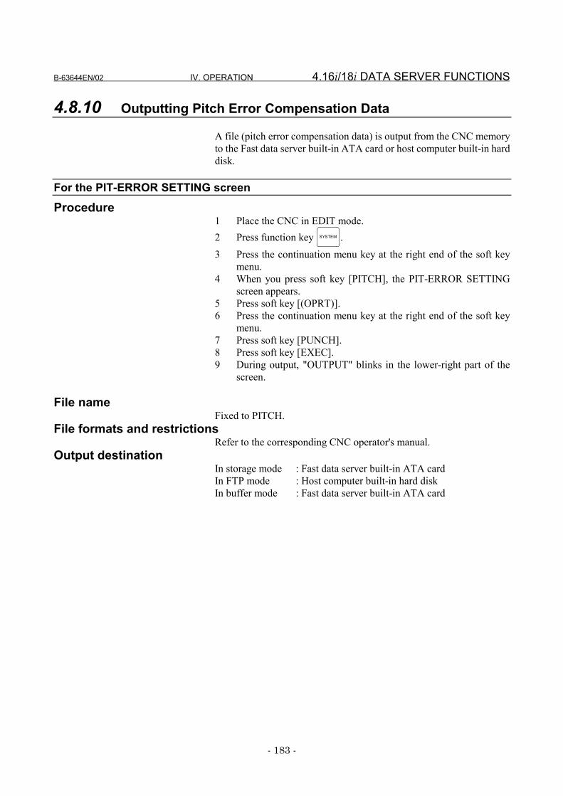
B-63644EN/02 IV. OPERATION 4.16i/18i DATA SERVER FUNCTIONS
- 183 -
4.8.10 Outputting Pitch Error Compensation Data
A file (pitch error compensation data) is output from the CNC memoryto the Fast data server built-in ATA card or host computer built-in harddisk.
For the PIT-ERROR SETTING screen
Procedure1 Place the CNC in EDIT mode.2 Press function key SYSTEM .3 Press the continuation menu key at the right end of the soft key
menu.4 When you press soft key [PITCH], the PIT-ERROR SETTING
screen appears.5 Press soft key [(OPRT)].6 Press the continuation menu key at the right end of the soft key
menu.7 Press soft key [PUNCH].8 Press soft key [EXEC].9 During output, "OUTPUT" blinks in the lower-right part of the
screen.
File nameFixed to PITCH.
File formats and restrictionsRefer to the corresponding CNC operator's manual.
Output destinationIn storage mode : Fast data server built-in ATA cardIn FTP mode : Host computer built-in hard diskIn buffer mode : Fast data server built-in ATA card
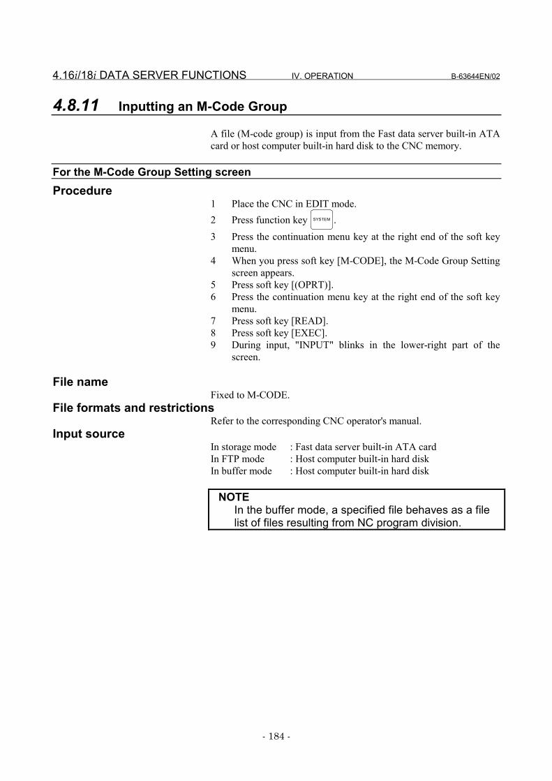
4.16i/18i DATA SERVER FUNCTIONS IV. OPERATION B-63644EN/02
- 184 -
4.8.11 Inputting an M-Code Group
A file (M-code group) is input from the Fast data server built-in ATAcard or host computer built-in hard disk to the CNC memory.
For the M-Code Group Setting screenProcedure
1 Place the CNC in EDIT mode.2 Press function key SYSTEM .3 Press the continuation menu key at the right end of the soft key
menu.4 When you press soft key [M-CODE], the M-Code Group Setting
screen appears.5 Press soft key [(OPRT)].6 Press the continuation menu key at the right end of the soft key
menu.7 Press soft key [READ].8 Press soft key [EXEC].9 During input, "INPUT" blinks in the lower-right part of the
screen.
File nameFixed to M-CODE.
File formats and restrictionsRefer to the corresponding CNC operator's manual.
Input sourceIn storage mode : Fast data server built-in ATA cardIn FTP mode : Host computer built-in hard diskIn buffer mode : Host computer built-in hard disk
NOTEIn the buffer mode, a specified file behaves as a filelist of files resulting from NC program division.
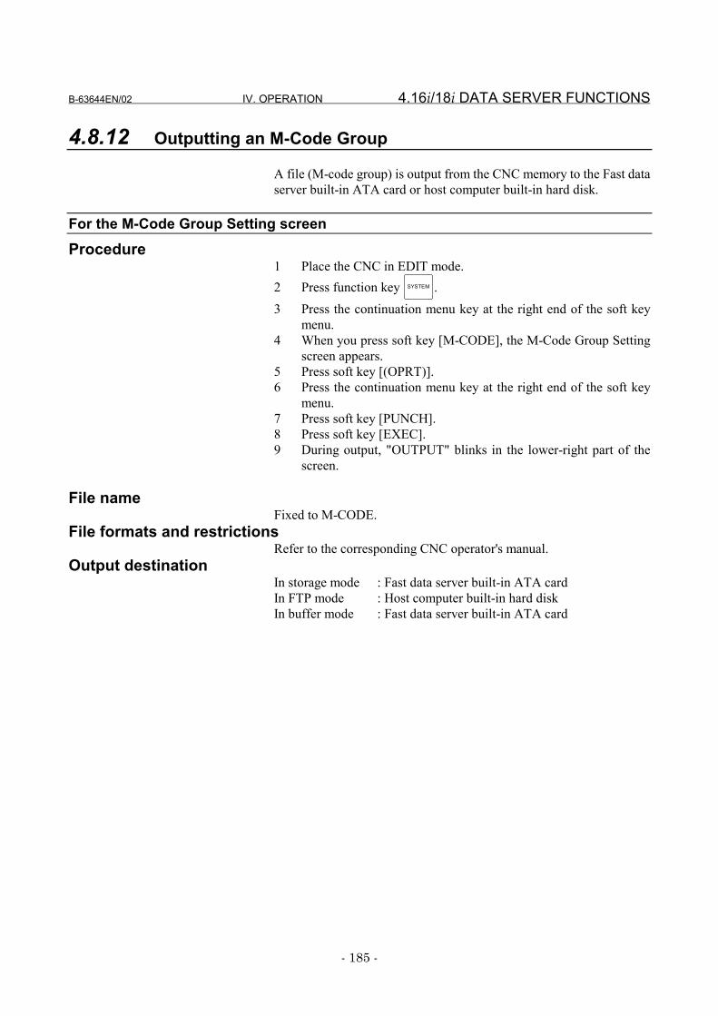
B-63644EN/02 IV. OPERATION 4.16i/18i DATA SERVER FUNCTIONS
- 185 -
4.8.12 Outputting an M-Code Group
A file (M-code group) is output from the CNC memory to the Fast dataserver built-in ATA card or host computer built-in hard disk.
For the M-Code Group Setting screenProcedure
1 Place the CNC in EDIT mode.2 Press function key SYSTEM .3 Press the continuation menu key at the right end of the soft key
menu.4 When you press soft key [M-CODE], the M-Code Group Setting
screen appears.5 Press soft key [(OPRT)].6 Press the continuation menu key at the right end of the soft key
menu.7 Press soft key [PUNCH].8 Press soft key [EXEC].9 During output, "OUTPUT" blinks in the lower-right part of the
screen.
File nameFixed to M-CODE.
File formats and restrictionsRefer to the corresponding CNC operator's manual.
Output destinationIn storage mode : Fast data server built-in ATA cardIn FTP mode : Host computer built-in hard diskIn buffer mode : Fast data server built-in ATA card
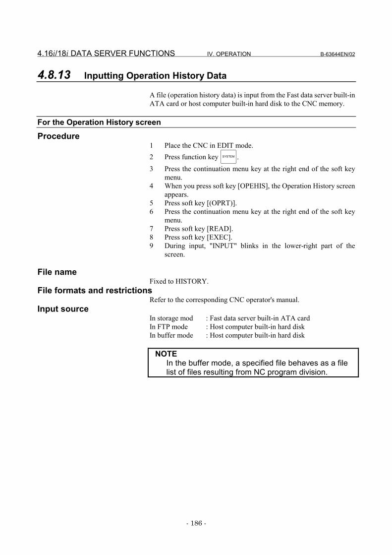
4.16i/18i DATA SERVER FUNCTIONS IV. OPERATION B-63644EN/02
- 186 -
4.8.13 Inputting Operation History Data
A file (operation history data) is input from the Fast data server built-inATA card or host computer built-in hard disk to the CNC memory.
For the Operation History screenProcedure
1 Place the CNC in EDIT mode.2 Press function key SYSTEM .3 Press the continuation menu key at the right end of the soft key
menu.4 When you press soft key [OPEHIS], the Operation History screen
appears.5 Press soft key [(OPRT)].6 Press the continuation menu key at the right end of the soft key
menu.7 Press soft key [READ].8 Press soft key [EXEC].9 During input, "INPUT" blinks in the lower-right part of the
screen.
File nameFixed to HISTORY.
File formats and restrictionsRefer to the corresponding CNC operator's manual.
Input sourceIn storage mod : Fast data server built-in ATA cardIn FTP mode : Host computer built-in hard diskIn buffer mode : Host computer built-in hard disk
NOTEIn the buffer mode, a specified file behaves as a filelist of files resulting from NC program division.
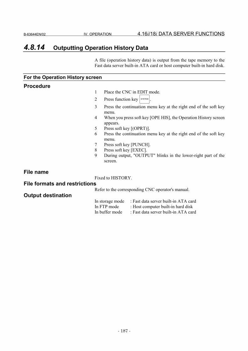
B-63644EN/02 IV. OPERATION 4.16i/18i DATA SERVER FUNCTIONS
- 187 -
4.8.14 Outputting Operation History Data
A file (operation history data) is output from the tape memory to theFast data server built-in ATA card or host computer built-in hard disk.
For the Operation History screenProcedure
1 Place the CNC in EDIT mode.2 Press function key SYSTEM .3 Press the continuation menu key at the right end of the soft key
menu.4 When you press soft key [OPE HIS], the Operation History screen
appears.5 Press soft key [(OPRT)].6 Press the continuation menu key at the right end of the soft key
menu.7 Press soft key [PUNCH].8 Press soft key [EXEC].9 During output, "OUTPUT" blinks in the lower-right part of the
screen.
File nameFixed to HISTORY.
File formats and restrictionsRefer to the corresponding CNC operator's manual.
Output destinationIn storage mode : Fast data server built-in ATA cardIn FTP mode : Host computer built-in hard diskIn buffer mode : Fast data server built-in ATA card
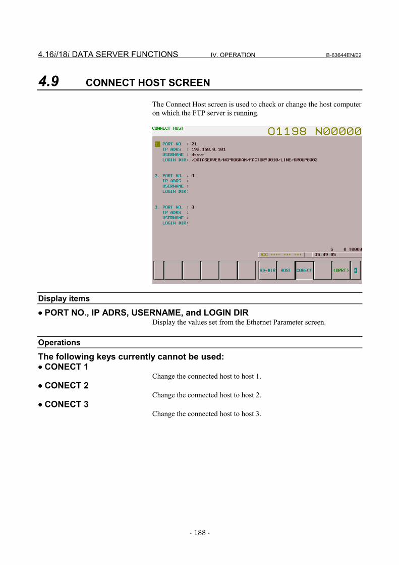
4.16i/18i DATA SERVER FUNCTIONS IV. OPERATION B-63644EN/02
- 188 -
4.9 CONNECT HOST SCREEN
The Connect Host screen is used to check or change the host computeron which the FTP server is running.
Display items
•••• PORT NO., IP ADRS, USERNAME, and LOGIN DIRDisplay the values set from the Ethernet Parameter screen.
OperationsThe following keys currently cannot be used:•••• CONECT 1
Change the connected host to host 1.•••• CONECT 2
Change the connected host to host 2.•••• CONECT 3
Change the connected host to host 3.
B-63644EN/02 IV. OPERATION 4.16i/18i DATA SERVER FUNCTIONS
- 189 -
4.9.1 Checking the Connected Host
Check the host computer on which the FTP server, or thecommunication destination of the current Fast data server, is running.
Procedure1 Press function key PROG .2 Press the continuation menu key at the right end of the soft key
menu.3 When you press soft key [CONECT], the Connection Host screen
appears.With the Series 16i/18i/21i-B, the CONNECT HOST screenappears when you press soft key [CONECT] then soft key[BOARD].
4 The title of the host computer set as the communicationdestination of the current Fast data server is displayed in reversevideo.
4.16i/18i DATA SERVER FUNCTIONS IV. OPERATION B-63644EN/02
- 190 -
4.9.2 Changing the Connected Host
Check the host computer on which the FTP server, or thecommunication destination of the current Fast data server, is running.
Procedure1 Press function key PROG .2 Press the continuation menu key at the right end of the soft key
menu.3 When you press soft key [CONECT], the Connection Host screen
appears.With the Series 16i/18i/21i-B, the CONNECT HOST screenappears when you press soft key [CONECT] then soft key[BOARD].
4 The title of the host computer currently selected is displayed inreverse video.
5 Press the continuation menu key at the right end of the soft keymenu.
6 Press soft key [CONNECT 1], [CONNECT 2], or [CONNECT 3]to connect to the desired host computer.

B-63644EN/02 IV. OPERATION 4.16i/18i DATA SERVER FUNCTIONS
- 191 -
4.10 FTP SERVER FUNCTIONS
Communication is possible with the FTP client that runs on the hostcomputer (personal computer).
NOTE1 Five FTP clients can be connected to the FTP server.
However, some FTP client software may internallyattempt to connect two or more FTP clients to theFTP server at the same time. So, note that there maybe a mismatch with the number of connectable FTPclient applications.
2 If the FTP client specifies a non-8.3-format file forregistration with the FTP server, it is registered usingan 8.3-format file name obtained from automaticconversion. See Subsection 4.1.5, "Hard Disk FileNames," for explanations about the rules forconverting file names to 8.3-format file names.
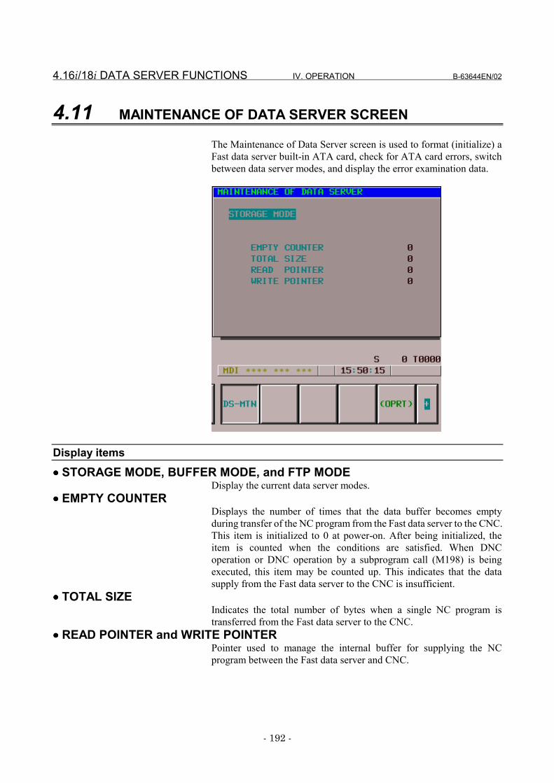
4.16i/18i DATA SERVER FUNCTIONS IV. OPERATION B-63644EN/02
- 192 -
4.11 MAINTENANCE OF DATA SERVER SCREEN
The Maintenance of Data Server screen is used to format (initialize) aFast data server built-in ATA card, check for ATA card errors, switchbetween data server modes, and display the error examination data.
Display items•••• STORAGE MODE, BUFFER MODE, and FTP MODE
Display the current data server modes.•••• EMPTY COUNTER
Displays the number of times that the data buffer becomes emptyduring transfer of the NC program from the Fast data server to the CNC.This item is initialized to 0 at power-on. After being initialized, theitem is counted when the conditions are satisfied. When DNCoperation or DNC operation by a subprogram call (M198) is beingexecuted, this item may be counted up. This indicates that the datasupply from the Fast data server to the CNC is insufficient.
•••• TOTAL SIZEIndicates the total number of bytes when a single NC program istransferred from the Fast data server to the CNC.
•••• READ POINTER and WRITE POINTERPointer used to manage the internal buffer for supplying the NCprogram between the Fast data server and CNC.
B-63644EN/02 IV. OPERATION 4.16i/18i DATA SERVER FUNCTIONS
- 193 -
Operations•••• STORAGE
Changes the current mode to the storage mode.•••• FTP
Changes the current mode to the FTP mode.•••• BUFFER
Changes the current mode to the buffer mode.
4.16i/18i DATA SERVER FUNCTIONS IV. OPERATION B-63644EN/02
- 194 -
4.11.1 Checking the ATA Card
Check whether the ATA card contains a faulty sector.Procedure
1 Place the CNC in MDI mode.2 Press function key SYSTEM .3 Press the continuation menu key at the right end of the soft key
menu.4 When you press soft key [DS-MIN], the Maintenance of Data
Server screen appears.5 Press soft key [MIN].6 When you press soft key [CHK DSK], the results are displayed on
the screen.• Normal : "CHECK DISK:NORMAL"• Abnormal: "CHECK DISK:ABNORMAL"
CAUTIONIf an abnormal condition occurs, check the cause ofthe error by referencing the error message displayedon the Ethernet Error Message screen. Back up thefiles on the ATA card as quickly as possible.Subsequently, format the ATA card.
NOTEAn error is likely to occur if ATA card check isperformed concurrently with other data serverfunctions.
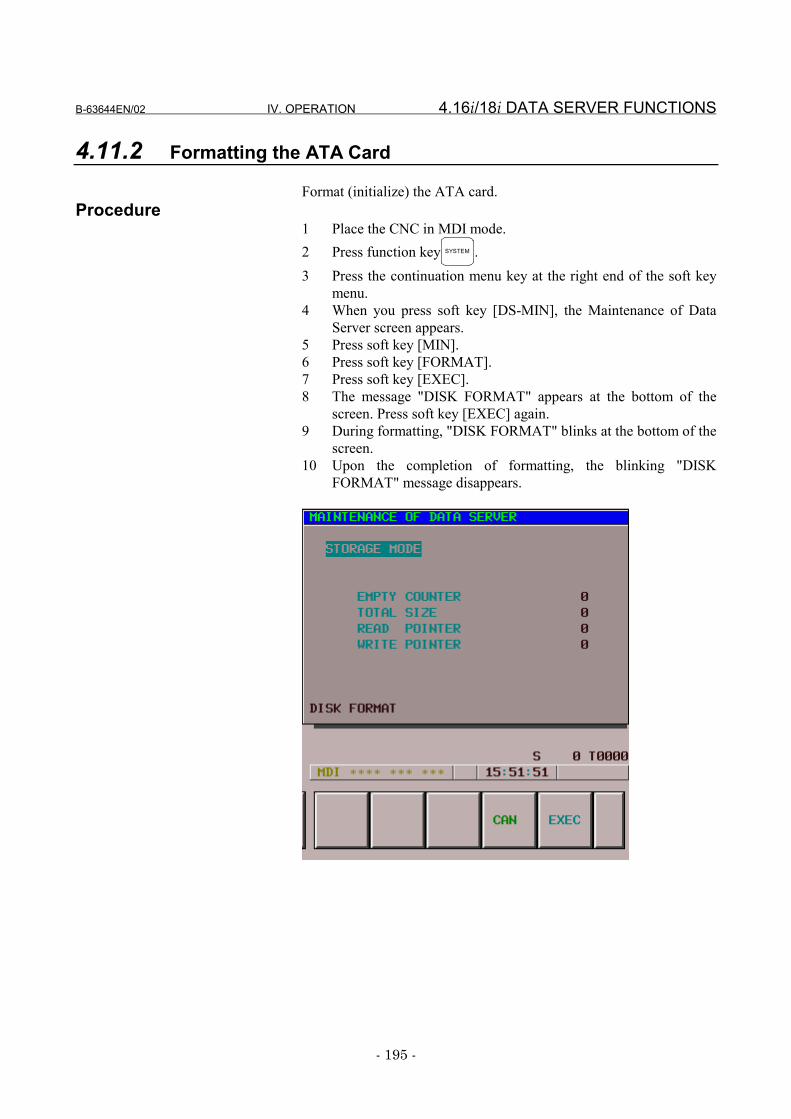
B-63644EN/02 IV. OPERATION 4.16i/18i DATA SERVER FUNCTIONS
- 195 -
4.11.2 Formatting the ATA Card
Format (initialize) the ATA card.Procedure
1 Place the CNC in MDI mode.2 Press function key SYSTEM .3 Press the continuation menu key at the right end of the soft key
menu.4 When you press soft key [DS-MIN], the Maintenance of Data
Server screen appears.5 Press soft key [MIN].6 Press soft key [FORMAT].7 Press soft key [EXEC].8 The message "DISK FORMAT" appears at the bottom of the
screen. Press soft key [EXEC] again.9 During formatting, "DISK FORMAT" blinks at the bottom of the
screen.10 Upon the completion of formatting, the blinking "DISK
FORMAT" message disappears.
4.16i/18i DATA SERVER FUNCTIONS IV. OPERATION B-63644EN/02
- 196 -
CAUTION1 If the CNC power is turned off during ATA card
formatting, the ATA card may be destroyed. Neverturn off the CNC power while formatting the ATAcard.
2 If the ATA card is formatted, all the files on the ATAcard are erased. Back up the ATA card files asrequired, then format the ATA card.
NOTEAn error is likely to occur if ATA card formatting isperformed concurrently with other data serverfunctions.
B-63644EN/02 IV. OPERATION 4.16i/18i DATA SERVER FUNCTIONS
- 197 -
4.11.3 Switching Data Server Modes
Switch data server modes.Procedure
1 Press function key SYSTEM .2 Press the continuation menu key at the right end of the soft key
menu.3 When you press soft key [DS-MIN], the Maintenance of Data
Server screen appears.4 To change to storage mode, press soft key [STORAGE].
To change to FTP mode, press soft key [FTP].To change to buffer mode, press soft key [BUFFER].
5 Press soft key [EXEC].
NOTE1 Operations in the buffer mode need the optional
buffer mode functions.2 The Series 21i-A/B cannot use the buffer mode.
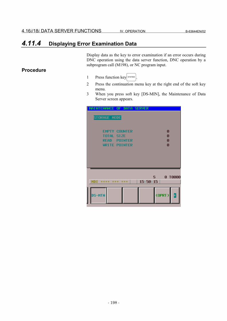
4.16i/18i DATA SERVER FUNCTIONS IV. OPERATION B-63644EN/02
- 198 -
4.11.4 Displaying Error Examination Data
Display data as the key to error examination if an error occurs duringDNC operation using the data server function, DNC operation by asubprogram call (M198), or NC program input.
Procedure1 Press function key SYSTEM .2 Press the continuation menu key at the right end of the soft key
menu.3 When you press soft key [DS-MIN], the Maintenance of Data
Server screen appears.
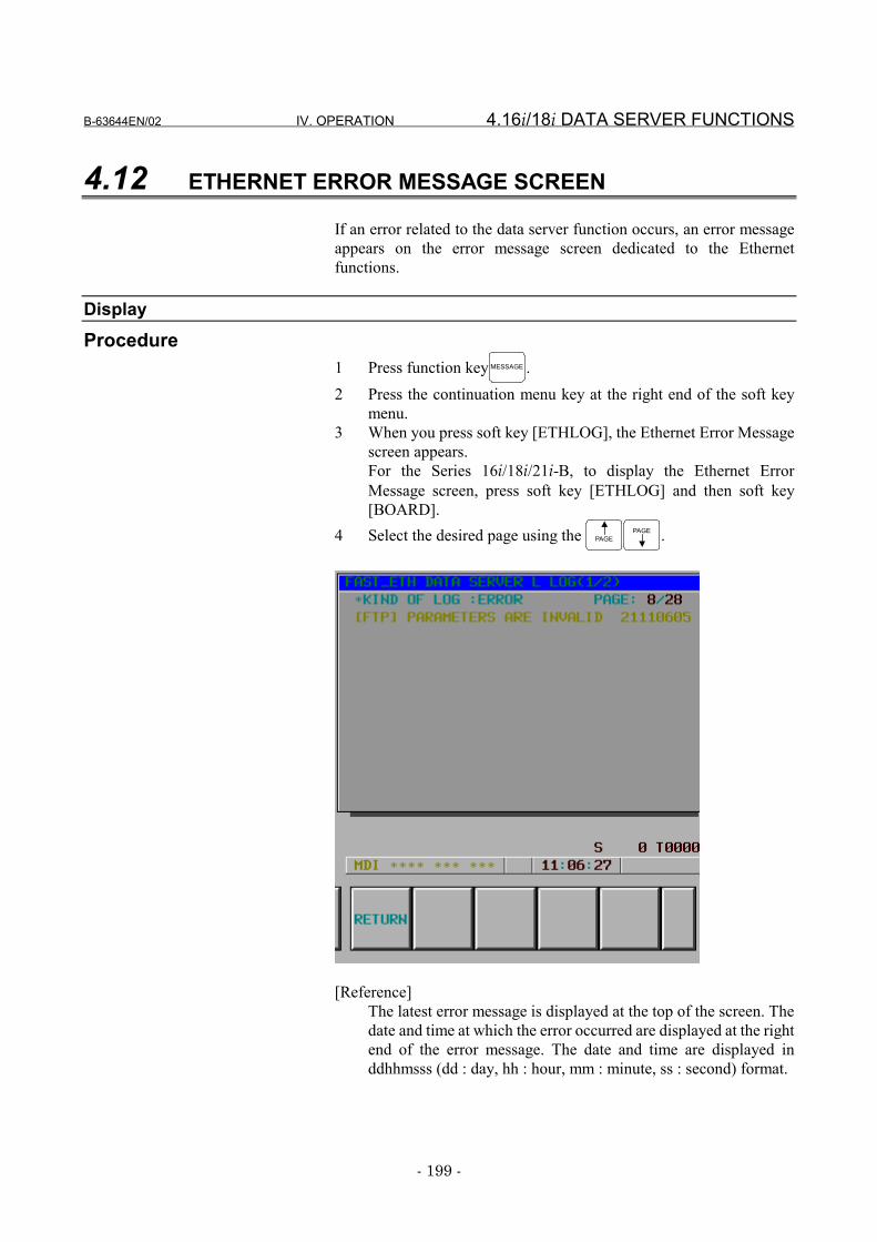
B-63644EN/02 IV. OPERATION 4.16i/18i DATA SERVER FUNCTIONS
- 199 -
4.12 ETHERNET ERROR MESSAGE SCREEN
If an error related to the data server function occurs, an error messageappears on the error message screen dedicated to the Ethernetfunctions.
DisplayProcedure
1 Press function key MESSAGE .2 Press the continuation menu key at the right end of the soft key
menu.3 When you press soft key [ETHLOG], the Ethernet Error Message
screen appears.For the Series 16i/18i/21i-B, to display the Ethernet ErrorMessage screen, press soft key [ETHLOG] and then soft key[BOARD].
4 Select the desired page using the PAGEPAGE .
[Reference]The latest error message is displayed at the top of the screen. Thedate and time at which the error occurred are displayed at the rightend of the error message. The date and time are displayed inddhhmsss (dd : day, hh : hour, mm : minute, ss : second) format.
4.16i/18i DATA SERVER FUNCTIONS IV. OPERATION B-63644EN/02
- 200 -
ConfigurationThe following titles are provided for the Ethernet Error Messagescreen:
• FAST_ETH SYSTEM LOG screen• FAST_ETH TCP/IP LOG screen• FAST_ETH PARAMETER LOG screen• FAST_ETH FTP SERVER LOG screen• FAST_ETH DATA SERVER L LOG screen• FAST_ETH DATA SERVER F LOG screen
B-63644EN/02 IV. OPERATION 5.15i FOCAS1/Ethernet FUNCTIONS
- 201 -
5 15i FOCAS1/Ethernet FUNCTIONSThis section describes how to use the Series 15i-BFOCAS1/Ethernetfunctions.
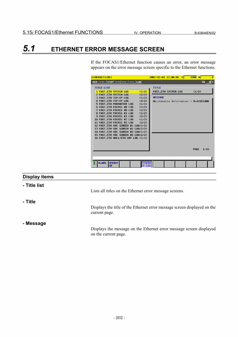
5.15i FOCAS1/Ethernet FUNCTIONS IV. OPERATION B-63644EN/02
- 202 -
5.1 ETHERNET ERROR MESSAGE SCREEN
If the FOCAS1/Ethernet function causes an error, an error messageappears on the error message screen specific to the Ethernet functions.
Display items- Title list
Lists all titles on the Ethernet error message screens.
- TitleDisplays the title of the Ethernet error message screen displayed on thecurrent page.
- MessageDisplays the message on the Ethernet error message screen displayedon the current page.
B-63644EN/02 IV. OPERATION 5.15i FOCAS1/Ethernet FUNCTIONS
- 203 -
DisplayProcedure
1 Press function key MESSAGE .2 Press soft key [CHAPTER].3 When you press soft key [ETHERNET LOG], the "Ethernet
(Log)" screen appears.4 Select the desired page using the PAGE
PAGE page keys.
[Reference]The latest error message is displayed at the top of the screen. Thedate and time at which the error occurred are displayed at the rightend of the error message. The date and time are displayed inddhhmmss (dd : day, hh : hour, mm : minute, ss : second) format.
6.15i i i i DATA SERVER FUNCTIONS IV. OPERATION B-63644EN/02
- 204 -
6 15i DATA SERVER FUNCTIONSThis section describes how to operate the Series 15i-B data serverfunctions.
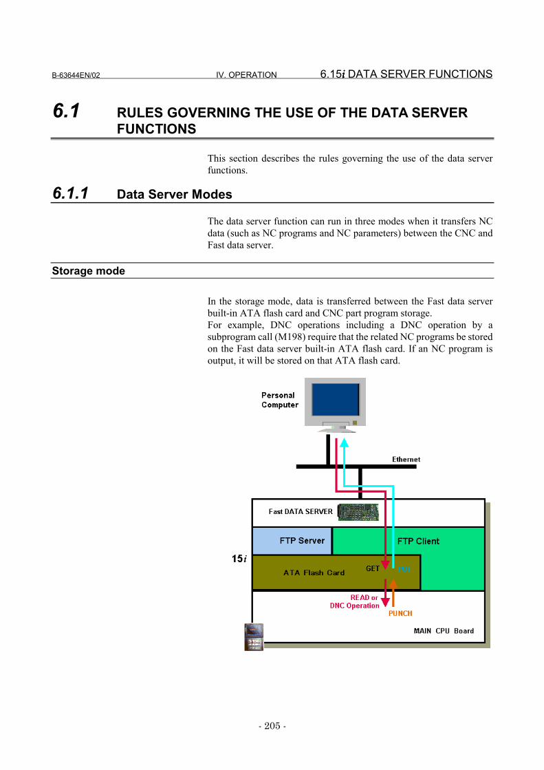
B-63644EN/02 IV. OPERATION 6.15i i i i DATA SERVER FUNCTIONS
- 205 -
6.1 RULES GOVERNING THE USE OF THE DATA SERVERFUNCTIONS
This section describes the rules governing the use of the data serverfunctions.
6.1.1 Data Server Modes
The data server function can run in three modes when it transfers NCdata (such as NC programs and NC parameters) between the CNC andFast data server.
Storage mode
In the storage mode, data is transferred between the Fast data serverbuilt-in ATA flash card and CNC part program storage.For example, DNC operations including a DNC operation by asubprogram call (M198) require that the related NC programs be storedon the Fast data server built-in ATA flash card. If an NC program isoutput, it will be stored on that ATA flash card.
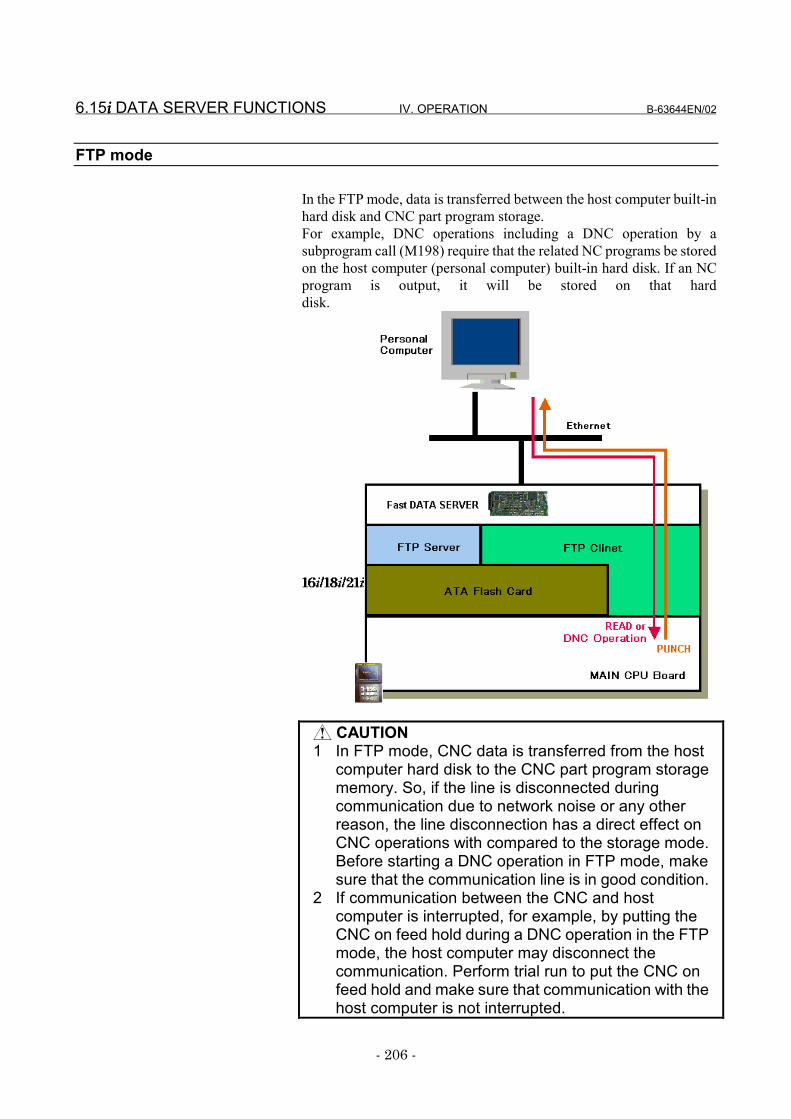
6.15i i i i DATA SERVER FUNCTIONS IV. OPERATION B-63644EN/02
- 206 -
FTP mode
In the FTP mode, data is transferred between the host computer built-inhard disk and CNC part program storage.For example, DNC operations including a DNC operation by asubprogram call (M198) require that the related NC programs be storedon the host computer (personal computer) built-in hard disk. If an NCprogram is output, it will be stored on that harddisk.
CAUTION1 In FTP mode, CNC data is transferred from the host
computer hard disk to the CNC part program storagememory. So, if the line is disconnected duringcommunication due to network noise or any otherreason, the line disconnection has a direct effect onCNC operations with compared to the storage mode.Before starting a DNC operation in FTP mode, makesure that the communication line is in good condition.
2 If communication between the CNC and hostcomputer is interrupted, for example, by putting theCNC on feed hold during a DNC operation in the FTPmode, the host computer may disconnect thecommunication. Perform trial run to put the CNC onfeed hold and make sure that communication with thehost computer is not interrupted.
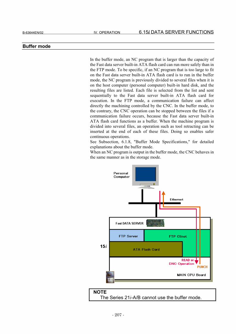
B-63644EN/02 IV. OPERATION 6.15i i i i DATA SERVER FUNCTIONS
- 207 -
Buffer mode
In the buffer mode, an NC program that is larger than the capacity ofthe Fast data server built-in ATA flash card can run more safely than inthe FTP mode. To be specific, if an NC program that is too large to fiton the Fast data server built-in ATA flash card is to run in the buffermode, the NC program is previously divided to several files when it ison the host computer (personal computer) built-in hard disk, and theresulting files are listed. Each file is selected from the list and sentsequentially to the Fast data server built-in ATA flash card forexecution. In the FTP mode, a communication failure can affectdirectly the machining controlled by the CNC. In the buffer mode, tothe contrary, the CNC operation can be stopped between the files if acommunication failure occurs, because the Fast data server built-inATA flash card functions as a buffer. When the machine program isdivided into several files, an operation such as tool retracting can beinserted at the end of each of these files. Doing so enables safercontinuous operations.See Subsection, 6.1.8, "Buffer Mode Specifications," for detailedexplanations about the buffer mode.When an NC program is output in the buffer mode, the CNC behaves inthe same manner as in the storage mode.
NOTEThe Series 21i-A/B cannot use the buffer mode.
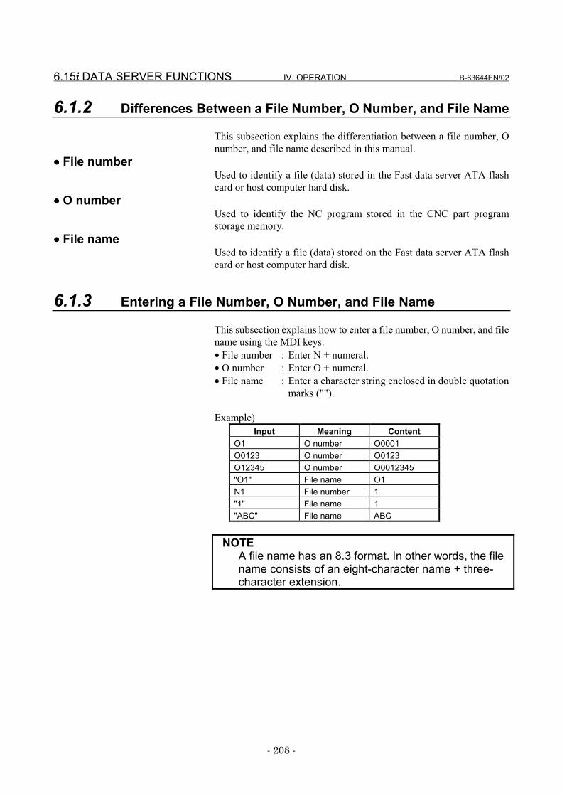
6.15i i i i DATA SERVER FUNCTIONS IV. OPERATION B-63644EN/02
- 208 -
6.1.2 Differences Between a File Number, O Number, and File Name
This subsection explains the differentiation between a file number, Onumber, and file name described in this manual.
•••• File numberUsed to identify a file (data) stored in the Fast data server ATA flashcard or host computer hard disk.
•••• O numberUsed to identify the NC program stored in the CNC part programstorage memory.
•••• File nameUsed to identify a file (data) stored on the Fast data server ATA flashcard or host computer hard disk.
6.1.3 Entering a File Number, O Number, and File Name
This subsection explains how to enter a file number, O number, and filename using the MDI keys.• File number : Enter N + numeral.• O number : Enter O + numeral.• File name : Enter a character string enclosed in double quotation
marks ("").
Example)Input Meaning Content
O1 O number O0001O0123 O number O0123O12345 O number O0012345"O1" File name O1N1 File number 1"1" File name 1"ABC" File name ABC
NOTEA file name has an 8.3 format. In other words, the filename consists of an eight-character name + three-character extension.

B-63644EN/02 IV. OPERATION 6.15i i i i DATA SERVER FUNCTIONS
- 209 -
6.1.4 Differences Between a Hard Disk File and Host File
This subsection explains the differentiation between a hard disk fileand host file described in this manual.
•••• Hard disk fileStored on the ATA flash card of the CNC Fast data server (hereaftercalled a Fast data server built-in ATA card).
•••• Host fileStored on the hard disk of the host computer (hereafter called the hostcomputer built-in hard disk).
6.15i i i i DATA SERVER FUNCTIONS IV. OPERATION B-63644EN/02
- 210 -
6.1.5 Hard Disk File Names
The name of any file on the Fast data server built-in ATA card isrepresented using the 8.3 file name format (8 characters in the file nameand 3 characters in the file name extension) originally adopted forMS-DOS.If a file to be subjected to an FTP transfer is specified only with a filename that is not in the 8.3 format, it is converted to an 8.3-format filename according to the following conversion rules.
Rules for conversion to 8.3-format file names1 The first 8 characters in the specified file name are used as a
post-conversion file name.2 The 3 characters in the specified file name between the first and
second periods are used as a post-conversion file name extension.3 Any blank character in the specified file name is ignored.
Examples of converting to 8.3-format file names1 “NCPROGRAM.DAT” → “NCPROGRA.DAT”
Because the file name has more than 8 characters, the first 8characters are accepted as valid, and the post-conversion filename becomes as stated above.
2 “NCFILE.TEXT” → “NCFILE.TEX”Because the file name extension has more than 3 characters, thefirst 3 characters in the file name extension are accepted as valid,and the post-conversion file name becomes as stated above.
3 “NCFILE.PRG.TXT” → “NCFILE.PRG”The characters between the first and second periods are acceptedas valid, and the post-conversion file name becomes as statedabove.
4 “NC PROGRAM.DATA.TXT” → “NCPROGRA.DAT”Because the first 8 characters, excluding the blank character, inthe file name are accepted as valid, and the first 3 charactersbetween the first and second periods are accepted as an file nameextension, the post-conversion file name becomes as stated above.
NOTEIf the file names of different files on the host computerbuilt-in hard disk are converted to 8.3-format filenames for registration with the Fast data serverbuilt-in ATA card automatically as described above,the post-conversion file names may becomeidentical.
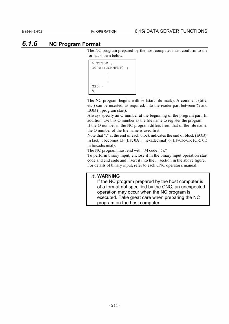
B-63644EN/02 IV. OPERATION 6.15i i i i DATA SERVER FUNCTIONS
- 211 -
6.1.6 NC Program FormatThe NC program prepared by the host computer must conform to theformat shown below.
The NC program begins with % (start file mark). A comment (title,etc.) can be inserted, as required, into the reader part between % andEOB (;, program start).Always specify an O number at the beginning of the program part. Inaddition, use this O number as the file name to register the program.If the O number in the NC program differs from that of the file name,the O number of the file name is used first.Note that ";" at the end of each block indicates the end of block (EOB).In fact, it becomes LF (LF: 0A in hexadecimal) or LF-CR-CR (CR: 0Din hexadecimal).The NC program must end with "M code ; %."To perform binary input, enclose it in the binary input operation startcode and end code and insert it into the ... section in the above figure.For details of binary input, refer to each CNC operator's manual.
WARNINGIf the NC program prepared by the host computer isof a format not specified by the CNC, an unexpectedoperation may occur when the NC program isexecuted. Take great care when preparing the NCprogram on the host computer.
% TITLE ;O0001(COMMENT) ;
.
.
.M30 ;%
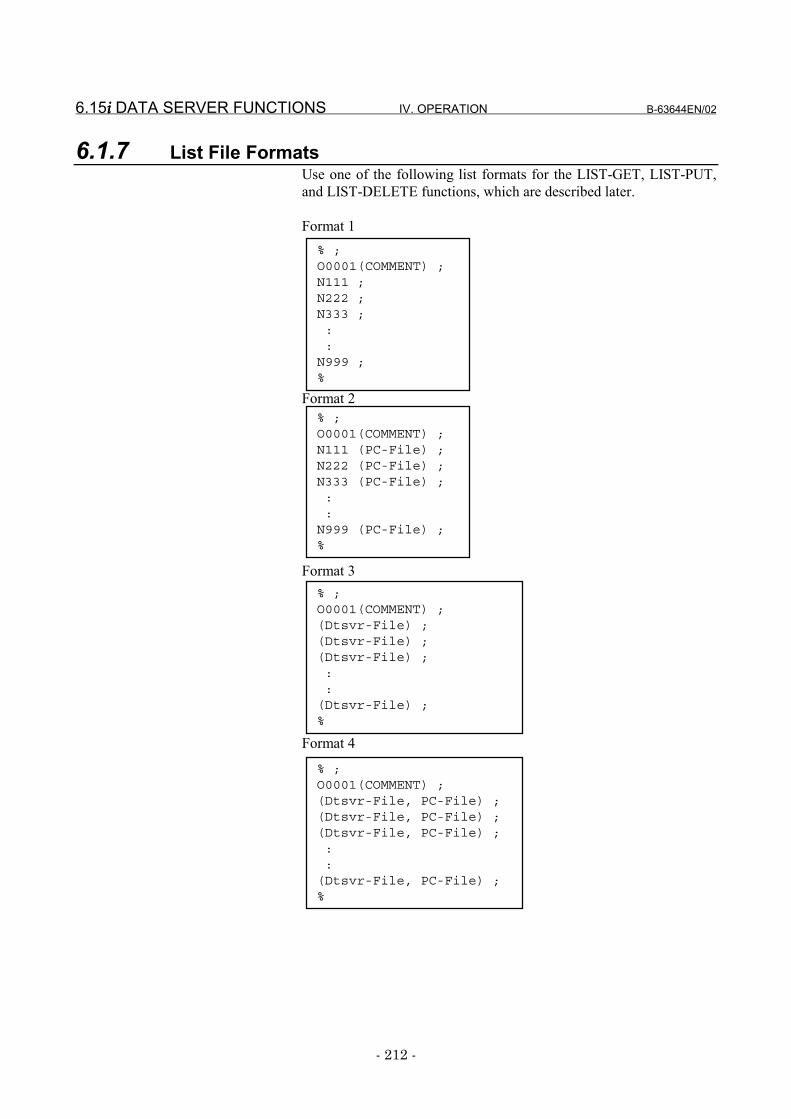
6.15i i i i DATA SERVER FUNCTIONS IV. OPERATION B-63644EN/02
- 212 -
6.1.7 List File FormatsUse one of the following list formats for the LIST-GET, LIST-PUT,and LIST-DELETE functions, which are described later.
Format 1
Format 2
Format 3
Format 4
% ;O0001(COMMENT) ;N111 (PC-File) ;N222 (PC-File) ;N333 (PC-File) ;::
N999 (PC-File) ;%
% ;O0001(COMMENT) ;(Dtsvr-File) ;(Dtsvr-File) ;(Dtsvr-File) ;::
(Dtsvr-File) ;%
% ;O0001(COMMENT) ;(Dtsvr-File, PC-File) ;(Dtsvr-File, PC-File) ;(Dtsvr-File, PC-File) ;::
(Dtsvr-File, PC-File) ;%
% ;O0001(COMMENT) ;N111 ;N222 ;N333 ;::
N999 ;%
B-63644EN/02 IV. OPERATION 6.15i i i i DATA SERVER FUNCTIONS
- 213 -
Specifications common to all formats<1> The list file begins with "%" (start file mark).<2> An O number must be specified in the next block. The list file
must be named using the same O number.A comment enclosed in parentheses "(" and ")" can be insertedbetween the O number and an EOB.
<3> Process files are specified in the subsequent blocks.<4> The list file must end with "%."
Specifications of format 1The specifications of the format-1 list file are as follows:<1> In this format, process files are identified using "Oxxxx" (where
"xxxx" represents a four-digit number). File names are specifiedby substituting "N" for "O" in "Oxxxx." Zeros in the four-digitnumber can be suppressed. The process files included in thisexample are treated as "O0111," "O0222," "O0333," ..., and"O0999" sequentially.
<2> The LIST-GET service transfers "Oxxxx" files from the hostcomputer built-in hard disk to the Fast data server built-in ATAcard without renaming them. The LIST-PUT service transfers"Oxxxx" files from the Fast data server built-in ATA card to thehost computer built-in hard disk without renaming them. TheLIST-DELETE service deletes "Oxxxx" files from the Fast dataserver built-in ATA card.
Specifications of format 2The specifications of the format-2 list file are as follows:<1> In this format, process files are identified using "Oxxxx" (where
"xxxx" represents a four-digit number) when they are on the Fastdata server built-in ATA card and arbitrary names when they areon the host computer built-in hard disk. The file names used on theFast data server built-in ATA card are specified by substituting"N" for "O" in "Oxxxx." Zeros in the four-digit number can besuppressed. The process files included in this example are treatedas "O0111," "O0222," "O0333," ..., and "O0999" sequentially.On the host computer built-in hard disk, files can be assigned anarbitrary name enclosed in parentheses "(" and ")" after thecorresponding "Nxxxx," provided that the name consists of acombination of those selected from the following 76 differentASCII characters:Digits 0 to 9Lowercase letters a to zUppercase letters A to Z14 different special characters . (period), ! , #, $, %, &, -, @, ^, _, ',{, }, and ~
<2> The LIST-GET service transfers files having the arbitrary name"PC-File" from the host computer built-in hard disk to the Fastdata server built-in ATA card as "Oxxxx" files. The LIST-PUTservice transfers "Oxxxx" files from the Fast data server built-inATA card to the host computer built-in hard disk as files havingthe arbitrary name "PC-File." The LIST-DELETE service deletes"Oxxxx" files from the Fast data server built-in ATA card.
6.15i i i i DATA SERVER FUNCTIONS IV. OPERATION B-63644EN/02
- 214 -
Specifications of format 3The specifications of the format-3 list files are as follows:<1> In this format, process files have an arbitrary name. It is assumed
that each file has the same name when it is on the Fast data serverbuilt-in ATA card and when it is on the host computer built-inhard disk.The "arbitrary" file name is specified in parentheses "(" and ")"and must consist of a combination of characters selected from thefollowing 76 different ASCII characters:Digits 0 to 9Lowercase letters a to zUppercase letters A to Z14 different special characters . (period), ! , #, $, %, &, -, @, ^, _,', {, }, and ~
<2> The LIST-GET service transfers files having the arbitrary name"Dtsvr-File" from the host computer built-in hard disk to the Fastdata server built-in ATA card without renaming them.The LIST-PUT service transfers files having the arbitrary name"Dtsvr-File" from the Fast data server built-in ATA card to thehost computer built-in hard disk without renaming them.The LIST-DELETE service deletes "Dtsvr-File" files from theFast data server built-in ATA card.
Specifications of format 4The specifications of the format-4 list file are as follows:<1> In this format, process files have an arbitrary name. It is assumed
that each file has a different name between when it is on the Fastdata server built-in ATA card and when it is on the host computerbuilt-in hard disk.An "arbitrary" file name used on the Fast data server built-in ATAcard and that on the host computer built-in hard disk are bothspecified in parentheses "(" and ")." They must be separated fromeach other using a comma "," and must consist of a combination ofcharacters selected from the following 76 different ASCIIcharacters:Digits 0 to 9Lowercase letters a to zUppercase letters A to Z14 different special characters . period), ! , #, $, %, &, -, @, ^, _, ',{, }, and ~
<2> The LIST-GET service transfers files having the arbitrary name"PC-File" from the host computer built-in hard disk to the Fastdata server built-in ATA card as "Dtsvr-File" files.The LIST-PUT service transfers files having the arbitrary name"Dtsvr-File" from the Fast data server built-in ATA card to thehost computer built-in hard disk as files having the arbitrary filename "PC-File."The LIST-DELETE service deletes "Dtsvr-File" files from theFast data server built-in ATA card.
B-63644EN/02 IV. OPERATION 6.15i i i i DATA SERVER FUNCTIONS
- 215 -
Restrictions on file names in the list fileThe following restrictions apply when file names are specified in thelist file.<1> Only the following 76 different ASCII characters can be used in
arbitrary file names.Digits 0 to 9Lowercase letters a to zUppercase letters A to Z14 different special characters . (period), ! , #, $, %, &, -, @, ^, _,', {, }, and ~This restriction applies also when the name of a file held on thehost computer built-in hard disk is specified.
<2> The arbitrary file name can be up to 255 characters. If an attemptis made to specify a larger arbitrary file name, an error is detected.
<3> Any file to be used on the Fast data server built-in ATA card mustbe in the 8.3 format. If an "arbitrary" file name is not in the 8.3format, it is converted to an 8.3-format file name automaticallyaccording to the following rule:- If the first 8 characters in the original "arbitrary" file name
include no period, they are used as the post-conversion filename. If they include a period, the characters before theperiod are used as the post-conversion file name. If the first 3characters after the period include no period, they are used asthe post-conversion file extension. If they contain periods, acharacters between the first and second periods are used asthe post-conversion file name extension.Example 1) If the original file name is
"LONGFILENAME.LONGEXT," the post-conversion file name is: "LONGFILE.LON"
Example 2) If the original file name is"ABCD.EFGH.TXT," the post-conversion filename is: "ABCD.EFG"
NOTE1 The names of files handled in the data server must be
in the 8.3 format. If "arbitrary" file names are not inthe 8.3 format, they are converted to this formatautomatically when they are handled in the dataserver. Different "arbitrary" file names may beconverted to the same file name in the 8.3 format;therefore, they will be regarded as the same file.
2 If the O number is anywhere between 1 and 9999, theO number-format file name is represented by"Oxxxx." If it is anywhere between 10000 and9999999, the O number-format file name isrepresented by "Oxxxxxxx." If it is anywhere between10000000 and 99999999, the O number-format filename is represented by "xxxxxxxx." ("xxxx" means anumber.)
6.15i i i i DATA SERVER FUNCTIONS IV. OPERATION B-63644EN/02
- 216 -
List file storage locationThe LIST-GET, LIST-PUT, and LIST-DELETE services are useful tomanage more than one NC program in a group.The storage location for the list file varies depending on what service isto be executed.If the LIST-GET service is to be used, the list file is to be prepared onthe host computer built-in hard disk, because the NC programs to beexecuted are on that hard disk.If the LIST-PUT or LIST-DELETE service is to be used, the list file isto be prepared on the Fast data server built-in ATA card, because theNC programs to be executed are on that hard disk.
B-63644EN/02 IV. OPERATION 6.15i i i i DATA SERVER FUNCTIONS
- 217 -
6.1.8 Buffer Mode Specifications
The buffer mode is designed to handle NC programs larger than thecapacity of the Fast data server built-in ATA card. In this mode, theFast data server built-in ATA card is used as a temporary, intermediatebuffer.In the buffer mode, two areas (A and B) are previously prepared on thehard disk. While an NC program is being supplied from one (A) of theareas to the CNC, the rest of the NC program is read from the hostcomputer into the other area (B), using the FTP. When the data transferfrom area A ends, a data transfer from area B to the CNC is started, andthe NC program transfer from the host computer to the emptied area(A) is resumed, using the FTP.Repeating this sequence enables an NC program larger than thecapacity of the Fast data server built-in ATA card to be handled. Usingthe buffer mode, however, requires that the NC program be previouslydivided into several files in the host computer.The size of resulting smaller files must not be larger than half theremaining capacity of the Fast data server built-in ATA card. If the filesize is very large (for example, not smaller than 100 MB), it will take afairly long time to read the first file from the host computer, thusdelaying the start of the operation.
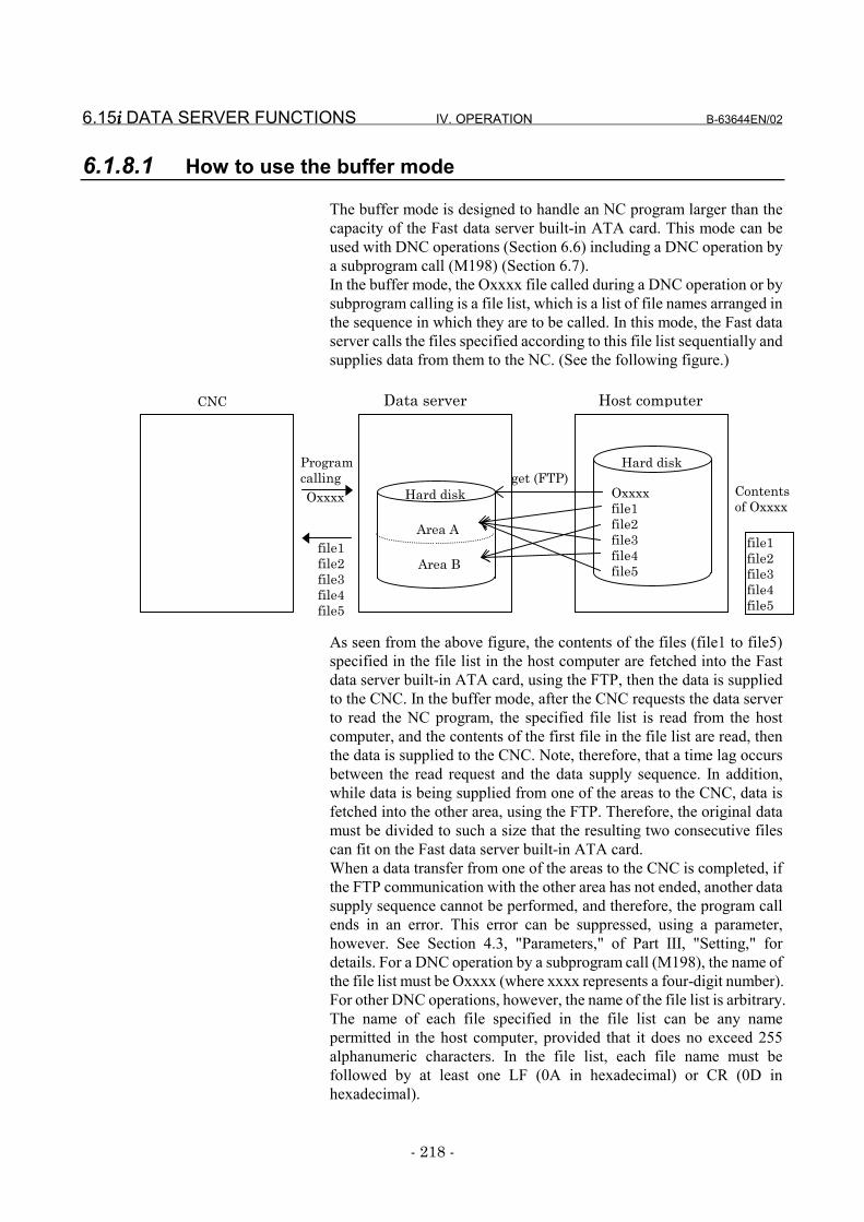
6.15i i i i DATA SERVER FUNCTIONS IV. OPERATION B-63644EN/02
- 218 -
6.1.8.1 How to use the buffer mode
The buffer mode is designed to handle an NC program larger than thecapacity of the Fast data server built-in ATA card. This mode can beused with DNC operations (Section 6.6) including a DNC operation bya subprogram call (M198) (Section 6.7).In the buffer mode, the Oxxxx file called during a DNC operation or bysubprogram calling is a file list, which is a list of file names arranged inthe sequence in which they are to be called. In this mode, the Fast dataserver calls the files specified according to this file list sequentially andsupplies data from them to the NC. (See the following figure.)
As seen from the above figure, the contents of the files (file1 to file5)specified in the file list in the host computer are fetched into the Fastdata server built-in ATA card, using the FTP, then the data is suppliedto the CNC. In the buffer mode, after the CNC requests the data serverto read the NC program, the specified file list is read from the hostcomputer, and the contents of the first file in the file list are read, thenthe data is supplied to the CNC. Note, therefore, that a time lag occursbetween the read request and the data supply sequence. In addition,while data is being supplied from one of the areas to the CNC, data isfetched into the other area, using the FTP. Therefore, the original datamust be divided to such a size that the resulting two consecutive filescan fit on the Fast data server built-in ATA card.When a data transfer from one of the areas to the CNC is completed, ifthe FTP communication with the other area has not ended, another datasupply sequence cannot be performed, and therefore, the program callends in an error. This error can be suppressed, using a parameter,however. See Section 4.3, "Parameters," of Part III, "Setting," fordetails. For a DNC operation by a subprogram call (M198), the name ofthe file list must be Oxxxx (where xxxx represents a four-digit number).For other DNC operations, however, the name of the file list is arbitrary.The name of each file specified in the file list can be any namepermitted in the host computer, provided that it does no exceed 255alphanumeric characters. In the file list, each file name must befollowed by at least one LF (0A in hexadecimal) or CR (0D inhexadecimal).
Contentsof Oxxxx
file1file2file3file4file5
Hard diskget (FTP)
ProgramcallingOxxxx Oxxxx
file1file2file3file4file5
file1file2file3file4file5
Hard disk
Area A
Area B
CNC Data server Host computer
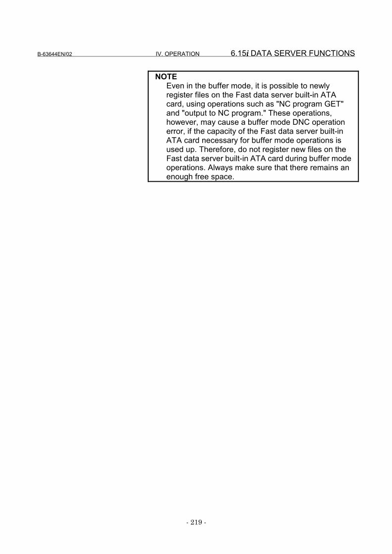
B-63644EN/02 IV. OPERATION 6.15i i i i DATA SERVER FUNCTIONS
- 219 -
NOTEEven in the buffer mode, it is possible to newlyregister files on the Fast data server built-in ATAcard, using operations such as "NC program GET"and "output to NC program." These operations,however, may cause a buffer mode DNC operationerror, if the capacity of the Fast data server built-inATA card necessary for buffer mode operations isused up. Therefore, do not register new files on theFast data server built-in ATA card during buffer modeoperations. Always make sure that there remains anenough free space.
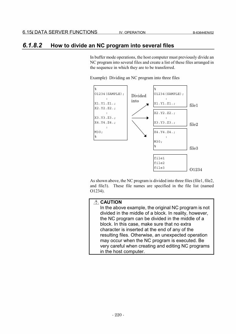
6.15i i i i DATA SERVER FUNCTIONS IV. OPERATION B-63644EN/02
- 220 -
6.1.8.2 How to divide an NC program into several files
In buffer mode operations, the host computer must previously divide anNC program into several files and create a list of these files arranged inthe sequence in which they are to be transferred.
Example) Dividing an NC program into three files
As shown above, the NC program is divided into three files (file1, file2,and file3). These file names are specified in the file list (namedO1234).
CAUTIONIn the above example, the original NC program is notdivided in the middle of a block. In reality, however,the NC program can be divided in the middle of ablock. In this case, make sure that no extracharacter is inserted at the end of any of theresulting files. Otherwise, an unexpected operationmay occur when the NC program is executed. Bevery careful when creating and editing NC programsin the host computer.
%
O1234(SAMPLE);
:
X1.Y1.Z1.;
%
O1234(SAMPLE);
:
X1.Y1.Z1.;
X2.Y2.Z2.;
:
X3.Y3.Z3.;
X4.Y4.Z4.;
:
M30;
%
X2.Y2.Z2.;
:
X3.Y3.Z3.;
X4.Y4.Z4.;
:
M30;
%
file1
file2
file3
file1
Dividedinto
file2
file3
O1234
B-63644EN/02 IV. OPERATION 6.15i i i i DATA SERVER FUNCTIONS
- 221 -
NOTE1 The size of files into which an NC program is divided
should be 20 to 30 MB. If the size is very large, therewill be much idle time before the DNC operationbegins. If the size is very small, data may beinterrupted between files, resulting in a cutter markbeing left on the workpiece.
2 An NC program can be divided in the middle of ablock, but it should be divided between blocks. Inaddition, a tool retract operation should be insertedat the end of each file resulting from NC programdivision. Doing so can avoid an interruption of databetween files, therefore preventing a cutter mark.
3 The file list and the files contained in the list must bestored in the same directory of the same hostcomputer.
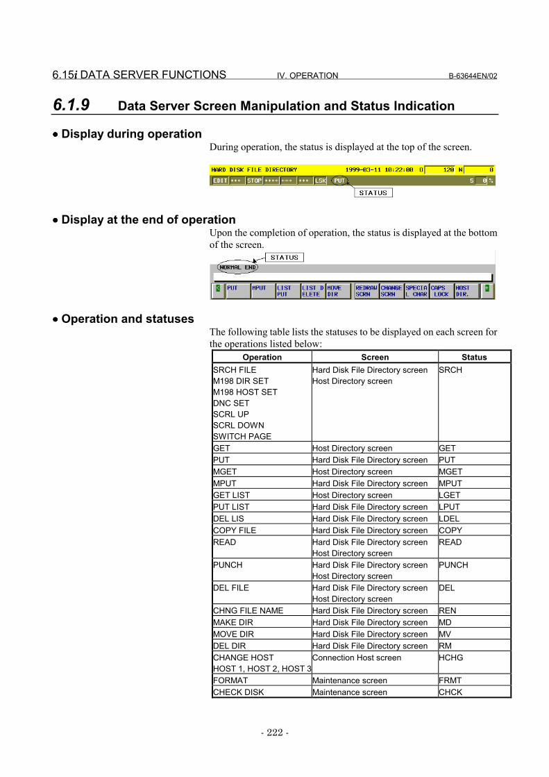
6.15i i i i DATA SERVER FUNCTIONS IV. OPERATION B-63644EN/02
- 222 -
6.1.9 Data Server Screen Manipulation and Status Indication
•••• Display during operationDuring operation, the status is displayed at the top of the screen.
•••• Display at the end of operationUpon the completion of operation, the status is displayed at the bottomof the screen.
•••• Operation and statusesThe following table lists the statuses to be displayed on each screen forthe operations listed below:
Operation Screen StatusSRCH FILEM198 DIR SETM198 HOST SETDNC SETSCRL UPSCRL DOWNSWITCH PAGE
Hard Disk File Directory screenHost Directory screen
SRCH
GET Host Directory screen GETPUT Hard Disk File Directory screen PUTMGET Host Directory screen MGETMPUT Hard Disk File Directory screen MPUTGET LIST Host Directory screen LGETPUT LIST Hard Disk File Directory screen LPUTDEL LIS Hard Disk File Directory screen LDELCOPY FILE Hard Disk File Directory screen COPYREAD Hard Disk File Directory screen
Host Directory screenREAD
PUNCH Hard Disk File Directory screenHost Directory screen
PUNCH
DEL FILE Hard Disk File Directory screenHost Directory screen
DEL
CHNG FILE NAME Hard Disk File Directory screen RENMAKE DIR Hard Disk File Directory screen MDMOVE DIR Hard Disk File Directory screen MVDEL DIR Hard Disk File Directory screen RMCHANGE HOSTHOST 1, HOST 2, HOST 3
Connection Host screen HCHG
FORMAT Maintenance screen FRMTCHECK DISK Maintenance screen CHCK
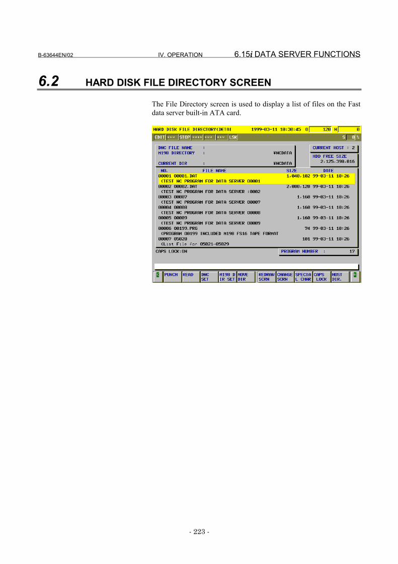
B-63644EN/02 IV. OPERATION 6.15i i i i DATA SERVER FUNCTIONS
- 223 -
6.2 HARD DISK FILE DIRECTORY SCREEN
The File Directory screen is used to display a list of files on the Fastdata server built-in ATA card.
6.15i i i i DATA SERVER FUNCTIONS IV. OPERATION B-63644EN/02
- 224 -
Display items
•••• DNC FILE NAMEDisplays the file name for which DNC operation is performed.
•••• M198 DIRECTORYDisplays the directory for DNC operation to be performed by asubprogram call (M198).
•••• CURRENT DIRDisplays the current work directory of the Fast data server built-inATA card.
•••• CURRENT HOSTDisplays the number of the currently connected host.
•••• PROGRAM NUMBERDisplays the number of files stored in the current work directory.
•••• HDD FREE SIZEDisplays the free size (in bytes) of the Fast data server built-in ATAcard.
•••• SIZEFile size, in bytes
•••• DATEDisplays the date and time when a file was created.
•••• COMMENTDisplays the comment statement appearing immediately after the Onumber in the NC program. If this comment statement does not exist,the contents are displayed from the beginning of the NC program or file.The comment is displayed only on the Hard Disk File Directory(Detailed) screen.
Operations•••• READ
Inputs a file from the Fast data server built-in ATA card to the CNCtape memory. This operation is possible only when the data server is instorage mode and the CNC is in EDIT mode.
•••• PUNCHOutputs a file from the CNC tape memory to the Fast data serverbuilt-in ATA card. This operation is possible only when the data serveris in storage mode and the CNC is in EDIT mode.
•••• DNC SETSpecifies the file for which DNC operation is to be performed. Thisoperation is possible only when the data server is in the storage mode.
•••• M198 DIR SETSpecifies the directory for the DNC operation by a subprogram call(M198). This operation is possible only when the data server is in thestorage mode.
•••• PUTTransfers a single file from the Fast data server built-in ATA card to thehost computer built-in hard disk.
B-63644EN/02 IV. OPERATION 6.15i i i i DATA SERVER FUNCTIONS
- 225 -
•••• MPUTTransfers two or more files from the Fast data server built-in ATA cardto the host computer built-in hard disk. Wild cards (*, ?) can be used tospecify file names.
•••• PUT LISTTransfers files from the Fast data server built-in ATA card to the hostcomputer built-in hard disk according to the list file.
•••• DEL LISTDeletes files from the Fast data server built-in ATA card according tothe list file.
•••• COPY FILECopies a file from the Fast data server built-in ATA card.
•••• DEL FILEDeletes a file from the Fast data server built-in ATA card.
•••• CHANGE FILE NAMEChanges a file name on the Fast data server built-in ATA card.
•••• SRCH FILESearches the Fast data server built-in ATA card for a file by using a filenumber or name.
•••• MAKE DIRCreates the directory on the Fast data server built-in ATA card.
•••• DEL DIRDeletes a directory from the Fast data server built-in ATA card.
•••• MOVE DIRMoves the work directory on the Fast data server built-in ATA card.
•••• REDRAW SCRNUpdates the Hard Disk File Directory screen.
•••• CHANGE SCRNSwitches between normal display and detailed display.
•••• SPECIAL CHAREnables highly-used characters to be entered when not supported by theMDI keys.
•••• CAPS LOCKSwitches the alphabetic character input mode (uppercase letter inputmode and lowercase letter input mode).
•••• HOST DIR.Switches the current screen to the Host Directory screen.
6.15i i i i DATA SERVER FUNCTIONS IV. OPERATION B-63644EN/02
- 226 -
6.2.1 Displaying a List of Hard Disk Files
Display a list of files stored on the Fast data server built-in ATA card.Procedure
1 Press function key PROG .2 Press soft key [CHAPTER].3 When you press [HDD DIR.], the Hard Disk File Directory screen
appears.4 Press the operation menu key at the right end of the soft key menu.5 When you press [REDRAW SCRN], the contents of the Hard
Disk File Directory screen appear.6 Select the desired page using the PAGE
PAGE page keys.7 When you press soft key [CHANGE SCRN], the Hard Disk File
Directory (Detail) screen appears.
B-63644EN/02 IV. OPERATION 6.15i i i i DATA SERVER FUNCTIONS
- 227 -
6.2.2 Searching for a Hard Disk File
To display a list of files stored on the Fast data server built-in ATA card,select the first file by specifying its number or name.
Procedure1 Display the Hard Disk File Directory screen.2 Press the operation menu key at the end of the soft key menu.3 Press soft key [SRCH FILE].4 Using the MDI keys, enter the number or name of the file to be
searched for. Alternatively, select this file using the cursor.[Input format]
<file-number>, <file-name>, or <cursor>5 Press soft key [EXEC].6 During search, SRCH blinks at the top of the screen.
NOTE1 If the specified file does not exist on the Fast data
server built-in ATA card, a file list appears, in ASCIIcharacter order of file names, using the file followingthe specified file as the first.
2 The data server functions contain the FTP serverfunction. As a result, the following may occur withoutbeing noticed by an operator: a new file is transferredto the Fast data server built-in ATA card or the file forwhich a search was being made is deleted. So, thefile number indicating the specified file may bechanged without being noticed by the operator.When specifying the file number, check the file namebefore operation.
6.15i i i i DATA SERVER FUNCTIONS IV. OPERATION B-63644EN/02
- 228 -
6.2.3 Deleting a Hard Disk File
Delete a file stored on the Fast data server built-in ATA card.
To delete a single file:Procedure
1 Display the Hard Disk File Directory screen.2 Press the operation menu key at the right end of the soft key menu.3 Press soft key [DEL FILE].4 Using the MDI keys, enter the number or name of the file to be
deleted. Alternatively, select this file using the cursor keys.[Input format]
<file-number>, <file-name>, or <cursor>5 Press soft key [EXEC].6 During deletion, DEL blinks at the top of the screen.
NOTEDeleting a file by specifying its file number is validonly for those files displayed on the Hard Disk FileDirectory screen.
B-63644EN/02 IV. OPERATION 6.15i i i i DATA SERVER FUNCTIONS
- 229 -
To delete two or more filesProcedure
1 Display the Hard Disk File Directory screen.2 Press the operation menu key at the right end of the soft key menu.3 Press soft key [DEL FILE].4 Using the MDI keys, enter the name of the file to be deleted
(including wild cards).[Input format]
<file-name (including wild cards)>5 Press soft key [EXEC].6 If "FILE DELETE?" is displayed at the lower-left corner of the
screen, press soft key [EXEC]. To cancel the deletion, press softkey [CAN].
7 During deletion, DEL blinks at the top of the screen.8 To stop the deletion, press soft key [STOP].
[Example]Enter * for the file name to delete all the files displayed on the HardDisk File Directory screen from the Fast data server built-in ATA card.
NOTEWhen two or more files are being deleted, and softkey [STOP] is pressed, the files deleted until soft key[STOP] is pressed cannot be restored.
6.15i i i i DATA SERVER FUNCTIONS IV. OPERATION B-63644EN/02
- 230 -
6.2.4 Copying a Hard Disk File
Copy a file stored on the Fast data server built-in ATA card.Procedure
1 Display the Hard Disk File Directory screen.2 Press the operation menu key at the right end of the soft key menu.3 Press soft key [COPY FILE].4 Using the MDI keys, enter the number or name of the copy source
file and the name of the copy destination file. The copy sourcefile can also be selected using the cursor.[Input format]
Select one of the following:<copy-source-file-number>, <copy-destination-file-name><copy-source-file-name>, <copy-destination-file-name><cursor>, <copy-destination-file-name>
5 Press soft key [EXEC].6 During the copy operation, COPY blinks at the top of the screen.
NOTE1 An error occurs if the name of a file stored on the Fast
data server built-in ATA card is specified as the copydestination file name.
2 Specifying the copy source file with a file number isvalid only for those files displayed on the Hard DiskFile Directory screen.
B-63644EN/02 IV. OPERATION 6.15i i i i DATA SERVER FUNCTIONS
- 231 -
6.2.5 Changing a Hard Disk File Name
Change the name of a file stored on the Fast data server built-in ATAcard.
Procedure1 Display the Hard Disk File Directory screen.2 Press the operation menu key at the right end of the soft key menu.3 Press soft key [CHNG FILE NAME].4 Using the MDI keys, enter the original number or name of the file
and the name to which it is to be changed. The file can also beselected using the cursor keys.[Input format]
Select one of the following:<pre-change-file-number>, <post-change-file-name><pre-change-file-name>, <post-change-file-name><cursor>, <post-change-file-name>
5 Press soft key [EXEC].6 During the change operation, REN blinks at the top of the screen.
NOTE1 An error occurs if the name of a file stored on the Fast
data server built-in ATA card is specified as thepost-change file name.
2 Specifying the pre-change file with a file number isvalid only for those files displayed on the Hard DiskFile Directory screen.
6.15i i i i DATA SERVER FUNCTIONS IV. OPERATION B-63644EN/02
- 232 -
6.2.6 Creating a Directory on the ATA Card
Create a directory(folder) on the Fast data server built-in ATA card.Procedure
1 Display the Hard Disk File Directory screen.2 Press the operation menu key at the right end of the soft key menu.3 Press soft key [MAKE DIR].4 Enter a directory name using the MDI keys.
[Input format]<directory-name>
5 Press soft key [EXEC].6 During creation, MD blinks at the top of the screen.
B-63644EN/02 IV. OPERATION 6.15i i i i DATA SERVER FUNCTIONS
- 233 -
6.2.7 Deleting a Directory from the ATA Card
Delete a directory(folder) from the Fast data server built-in ATA card.Procedure
1 Display the Hard Disk File Directory screen.2 Press the operation menu key at the right end of the soft key menu.3 Press soft key [DEL DIR].4 Using the MDI keys, enter the number or name of the directory to
be deleted. This directory can also be selected using the cursorkeys.[Input format]
<directory-number>, <directory-name>, or <cursor>5 Press soft key [EXEC].6 During deletion, RM blinks at the top of the screen.
NOTE1 If a directory (folder) contains files, an attempt to
delete it ends in an error. Before deleting a directory,delete all files from the directory.
2 A directory to be deleted can be specified using adirectory number only if the directory is displayed onthe Hard Disk File Directory screen.
6.15i i i i DATA SERVER FUNCTIONS IV. OPERATION B-63644EN/02
- 234 -
6.2.8 Moving a Directory on the ATA Card
Move a work directory on the Fast data server built-in ATA card.Procedure
1 Display the Hard Disk File Directory screen.2 Press the operation menu key at the right end of the soft key menu.3 Press soft key [MOVE DIR].4 Using the MDI keys, enter the number or name of the movement
destination directory. Alternatively, select this directory using thecursor keys.[Input format]
<directory-number>, <directory-name>, or <cursor>5 Press soft key [EXEC].6 During movement, MV blinks at the top of the screen.
NOTE1 If a directory contains many files, it may take much
time to move to that directory.2 A destination directory can be specified using a
directory number only if the directory is displayed onthe Hard Disk File Directory screen.
B-63644EN/02 IV. OPERATION 6.15i i i i DATA SERVER FUNCTIONS
- 235 -
6.2.9 Executing Hard Disk File PUT
Using FTP, transfer a file from the Fast data server built-in ATA card tothe host computer built-in hard disk.
Procedure1 Display the Hard Disk File Directory screen.2 Press the operation menu key at the right end of the soft key menu.3 Press soft key [PUT].4 Using the MDI keys, enter the number or name of the file on the
transfer source Fast data server built-in ATA card and the name ofthe file on the transfer destination host computer built-in hard disk.The file on the transfer source Fast data server built-in ATA cardcan also be selected by using the cursor keys.[Input format]
Select one of the following:<transfer-source-file-number>,<transfer-destination-file-name><transfer-source-file-name>,<transfer-destination-file-name><cursor>, <transfer-destination-file-name><transfer-source-file-name><transfer-source-file-number><cursor>
5 Press soft key [EXEC].6 During the PUT operation, PUT blinks at the top of the screen.7 To stop the PUT operation, press soft key [CAN].
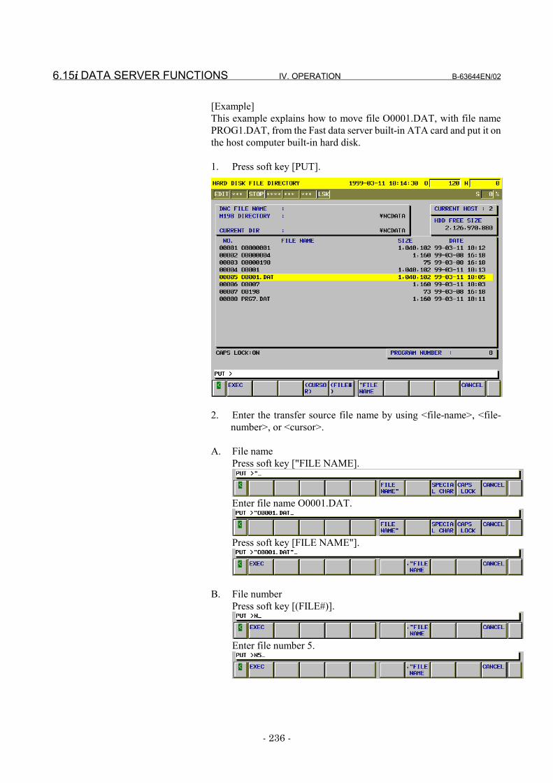
6.15i i i i DATA SERVER FUNCTIONS IV. OPERATION B-63644EN/02
- 236 -
[Example]This example explains how to move file O0001.DAT, with file namePROG1.DAT, from the Fast data server built-in ATA card and put it onthe host computer built-in hard disk.
1. Press soft key [PUT].
2. Enter the transfer source file name by using <file-name>, <file-number>, or <cursor>.
A. File namePress soft key ["FILE NAME].
Enter file name O0001.DAT.
Press soft key [FILE NAME"].
B. File numberPress soft key [(FILE#)].
Enter file number 5.
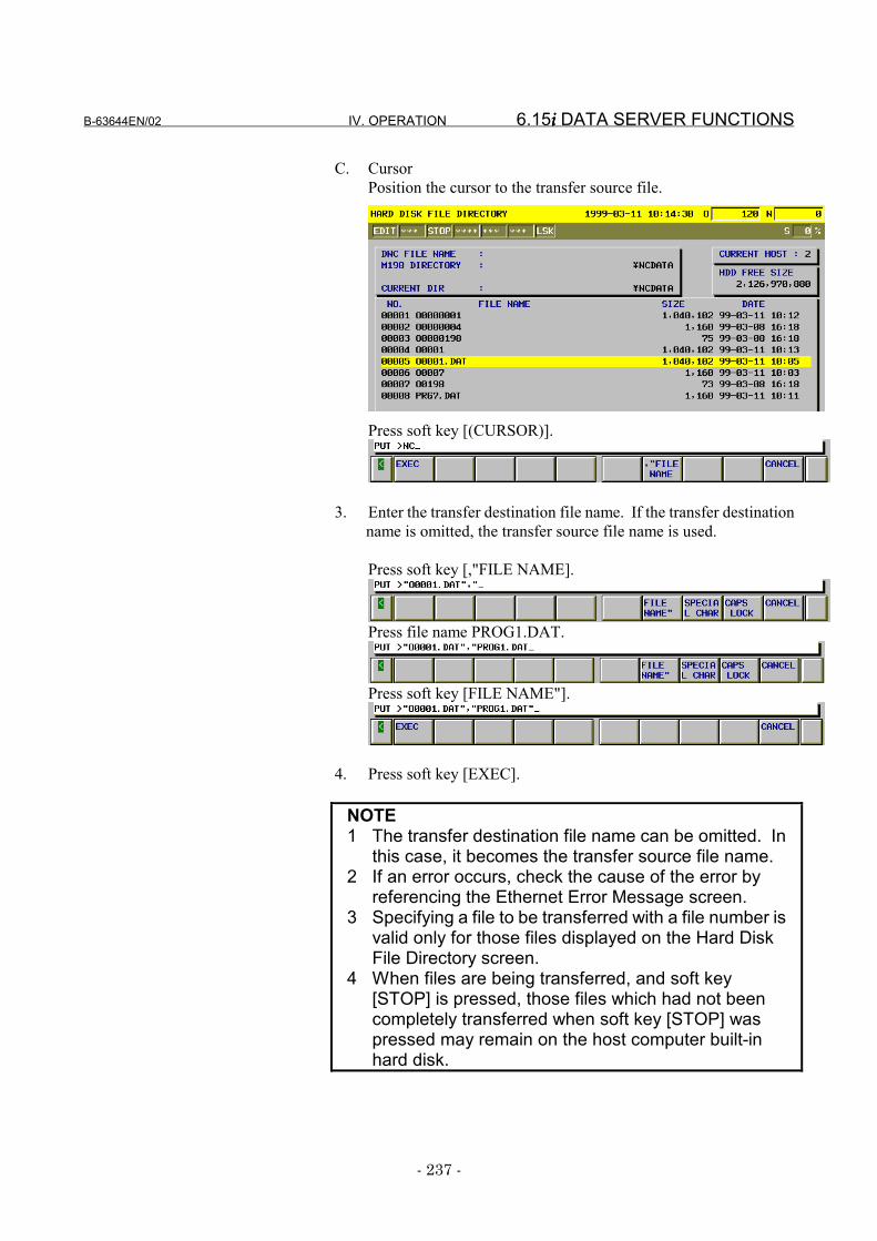
B-63644EN/02 IV. OPERATION 6.15i i i i DATA SERVER FUNCTIONS
- 237 -
C. CursorPosition the cursor to the transfer source file.
Press soft key [(CURSOR)].
3. Enter the transfer destination file name. If the transfer destinationname is omitted, the transfer source file name is used.
Press soft key [,"FILE NAME].
Press file name PROG1.DAT.
Press soft key [FILE NAME"].
4. Press soft key [EXEC].
NOTE1 The transfer destination file name can be omitted. In
this case, it becomes the transfer source file name.2 If an error occurs, check the cause of the error by
referencing the Ethernet Error Message screen.3 Specifying a file to be transferred with a file number is
valid only for those files displayed on the Hard DiskFile Directory screen.
4 When files are being transferred, and soft key[STOP] is pressed, those files which had not beencompletely transferred when soft key [STOP] waspressed may remain on the host computer built-inhard disk.
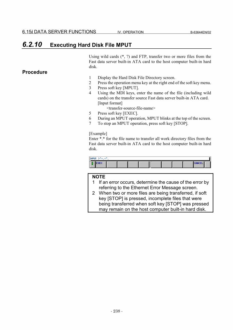
6.15i i i i DATA SERVER FUNCTIONS IV. OPERATION B-63644EN/02
- 238 -
6.2.10 Executing Hard Disk File MPUT
Using wild cards (*, ?) and FTP, transfer two or more files from theFast data server built-in ATA card to the host computer built-in harddisk.
Procedure1 Display the Hard Disk File Directory screen.2 Press the operation menu key at the right end of the soft key menu.3 Press soft key [MPUT].4 Using the MDI keys, enter the name of the file (including wild
cards) on the transfer source Fast data server built-in ATA card.[Input format]
<transfer-source-file-name>5 Press soft key [EXEC].6 During an MPUT operation, MPUT blinks at the top of the screen.7 To stop an MPUT operation, press soft key [STOP].
[Example]Enter *.* for the file name to transfer all work directory files from theFast data server built-in ATA card to the host computer built-in harddisk.
NOTE1 If an error occurs, determine the cause of the error by
referring to the Ethernet Error Message screen.2 When two or more files are being transferred, if soft
key [STOP] is pressed, incomplete files that werebeing transferred when soft key [STOP] was pressedmay remain on the host computer built-in hard disk.
B-63644EN/02 IV. OPERATION 6.15i i i i DATA SERVER FUNCTIONS
- 239 -
6.2.11 Executing Hard Disk File LIST-PUT
Transfer files from the Fast data server built-in ATA card to the hostcomputer built-in hard disk according to the contents of the list file,using the FTP.
Procedure1 Display the Hard Disk File Dir screen.2 Press the operation menu key at the right end of the soft key menu.3 Press soft key [PUT LIST].4 Enter the name of the list file held on the Fast data server built-in
ATA card, using the MDI keys. [Input format]
<number-of-list-file>or<name-of-list-file>or<Cursor>
5 Press soft key [EXEC].6 During LIST-PUT operation, " LPUT " blinks in the lower-right
part of the screen.7 To stop LIST-PUT, press soft key [STOP].
NOTE1 If an error occurs, check the cause of the error using
the Ethernet Error Message screen.2 If more than one file is specified to be transferred,
pressing soft key [STOP] before the completion of thefile transfer may allow transferred files to be left onthe host computer built-in hard disk even after thesoft key is pressed.
3 A method of using a file number to specify a file to betransferred can be used only for files displayed on theHard Disk File Directory screen.
4 See Subsection 6.1.7, "List File Formats," forexplanations about the formats of the list file.
6.15i i i i DATA SERVER FUNCTIONS IV. OPERATION B-63644EN/02
- 240 -
6.2.12 Executing Hard Disk File LIST-DELETE
Delete files from the Fast data server built-in ATA card according tothe contents of the list file.
Procedure1 Display the Hard Disk File Dir screen.2 Press the operation menu key at the right end of the soft key menu.3 Press soft key [DEL LIST].4 Enter the name of the list file held on the Fast data server built-in
ATA card, using the MDI keys. [Input format]
<number-of-list-file>or<name-of-list-file>or<Cursor>
5 Press soft key [EXEC].6 During LIST-DELET operation, " LDEL " blinks in the lower-
right part of the screen.7 To stop LIST-DELET, press soft key [STOP].
NOTE1 If an error occurs, check the cause of the error using
the Ethernet Error Message screen.2 If more than one file is specified to be deleted,
pressing soft key [STOP] before the completion of thefile deletion makes it impossible to restore thedeleted file(s).
3 A method of using a file number to specify a file to bedeleted can be used only for files displayed on theHard Disk File Directory screen.
4 See Subsection 6.1.7, "List File Formats," forexplanations about the formats of the list file.
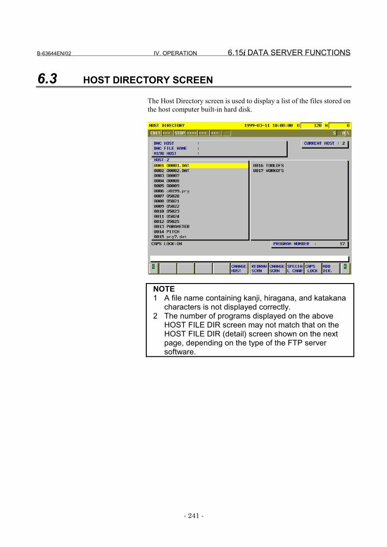
B-63644EN/02 IV. OPERATION 6.15i i i i DATA SERVER FUNCTIONS
- 241 -
6.3 HOST DIRECTORY SCREEN
The Host Directory screen is used to display a list of the files stored onthe host computer built-in hard disk.
NOTE1 A file name containing kanji, hiragana, and katakana
characters is not displayed correctly.2 The number of programs displayed on the above
HOST FILE DIR screen may not match that on theHOST FILE DIR (detail) screen shown on the nextpage, depending on the type of the FTP serversoftware.
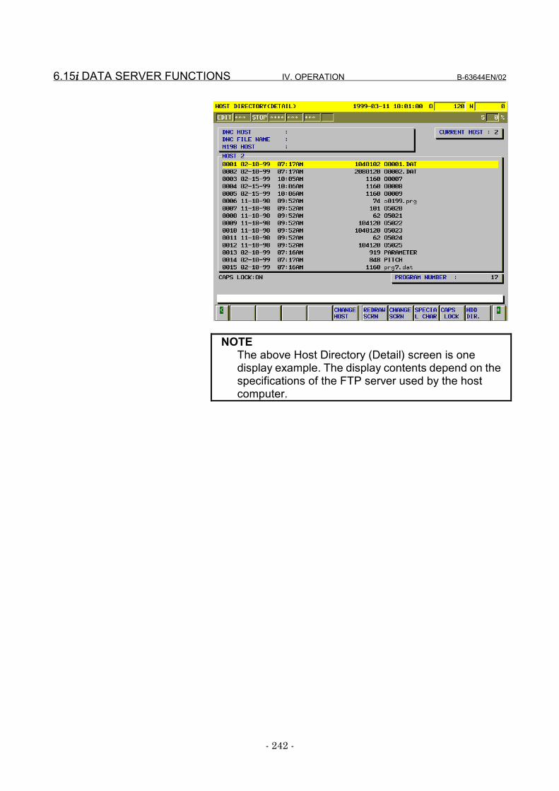
6.15i i i i DATA SERVER FUNCTIONS IV. OPERATION B-63644EN/02
- 242 -
NOTEThe above Host Directory (Detail) screen is onedisplay example. The display contents depend on thespecifications of the FTP server used by the hostcomputer.
B-63644EN/02 IV. OPERATION 6.15i i i i DATA SERVER FUNCTIONS
- 243 -
Display items•••• DNC HOST
Displays the host number for DNC operation.•••• DNC FILE NAME
Displays the file name for DNC operation.•••• M198 HOST
Displays the host number for DNC operation by a subprogram call(M198).
•••• CURRENT HOSTDisplays the number of the currently connected host.
•••• PROGRAM NUMBERDisplays the number of files contained in the current directory.
•••• SIZEDisplays the file size, in bytes.
•••• DATEDisplays the date and time at which the file was created.
Operations
•••• READInputs a file from the host computer built-in hard disk to CNC tapememory. This operation is possible only when the data server is in FTPmode and the CNC is in EDIT mode.
•••• PUNCHOutputs a file from CNC tape memory to an host computer built-in harddisk file. This operation is possible only when the data server is in FTPmode and the CNC is in EDIT mode.
•••• DNC SETSpecifies the file for which DNC operation is to be performed. Thisoperation is possible only when the data server is in the FTP mode orbuffer mode.
•••• M198 HOST SETSpecifies the host number for the DNC operation by a subprogram call(M198). This operation is possible only when the data server is in theFTP mode or buffer mode.
•••• GETTransfers a single file from the host computer built-in hard disk to theFast data server built-in ATA card.
•••• MGETTransfers two or more files from the host computer built-in hard disk tothe Fast data server built-in ATA card. Wild cards (*, ?) can be used tospecify file names.
•••• GET LISTTransfers files from the host computer built-in hard disk to the Fastdata server built-in ATA card according to the list file.
•••• SRCH FILESearches the host computer built-in hard disk for a file with the filenumber.
6.15i i i i DATA SERVER FUNCTIONS IV. OPERATION B-63644EN/02
- 244 -
•••• DEL FILEDeletes files from the host computer built-in hard disk.
•••• CHANGE HOSTSwitches the current screen to the Connection Host screen.
•••• REDRAW SCRNUpdates the Host Directory screen.
•••• CHANGE SCRNSwitches between normal display and detailed display.
•••• SPECIAL CHAREnables highly-used characters to be entered when not supported by theMDI keys.
•••• CAPS LOCKSwitches between alphabetic character input modes (uppercase letterinput mode and lowercase input mode).
•••• HDD DIR.Switches the current screen to the Hard Disk File Directory screen.
B-63644EN/02 IV. OPERATION 6.15i i i i DATA SERVER FUNCTIONS
- 245 -
6.3.1 Displaying a List of Host FilesDisplay a list of the files stored on the host computer built-in hard disk.
Procedure1 Press function key PROG .2 Press soft key [CHAPTER].3 When you press soft key [HOST DIR.], the Host Directory screen
is displayed.4 Press the operation menu key at the right end of the soft key menu.5 When you press soft key [REDRAW SCRN], the contents of the
Host Directory screen are displayed.6 Select the desired page using the PAGE
PAGE page keys.7 When you press soft key [CHANGE SCRN], the Host Directory
(Detail) screen appears.
6.15i i i i DATA SERVER FUNCTIONS IV. OPERATION B-63644EN/02
- 246 -
6.3.2 Searching for a Host File
To display a list of files stored on the host computer built-in hard disk,specify the file number of the first file.
Procedure1 Display the Host Directory screen.2 Press the operation menu key at the right end of the soft key menu.3 Press soft key [SRCH FILE].4 Using the MDI keys, enter the number or name of the file for
which a search is to be made. Alternatively, select this file usingthe cursor keys.[Input format]
<file-number>, <file-name>, or <cursor>5 Press soft key [EXEC].6 During search, SRCH blinks at the top of the screen.
B-63644EN/02 IV. OPERATION 6.15i i i i DATA SERVER FUNCTIONS
- 247 -
6.3.3 Deleting a Host File
Delete a file from the host computer built-in hard disk.Procedure
1 Display the Host Directory screen.2 Press the operation menu key at the right end of the soft key menu.3 Press soft key [DEL FILE].4 Using the MDI keys, enter the number or name of the file to be
deleted. Alternatively, select this file using the cursor keys.[Input format]
<file-number>, <file-name>, or <cursor>5 Press soft key [EXEC].6 During deletion, DEL blinks at the top of the screen.
NOTE1 Specifying the file to be deleted with the file number is
valid only for those files displayed on the HostDirectory screen.
2 Information displayed at the right end of the HostDirectory (Detail) screen is recognized as the filename. Therefore, to delete a host file from the HostDirectory (Detail) screen by specifying the filenumber, confirm that the file name is displayed at theright end of the screen, then specify the file number.
3 If a file name contains kanji, hiragana, or katakanacharacters, switch the Host Directory (Detail) screento the Host Directory screen, specify the host filenumber or select the file using the cursor keys, thendelete it.
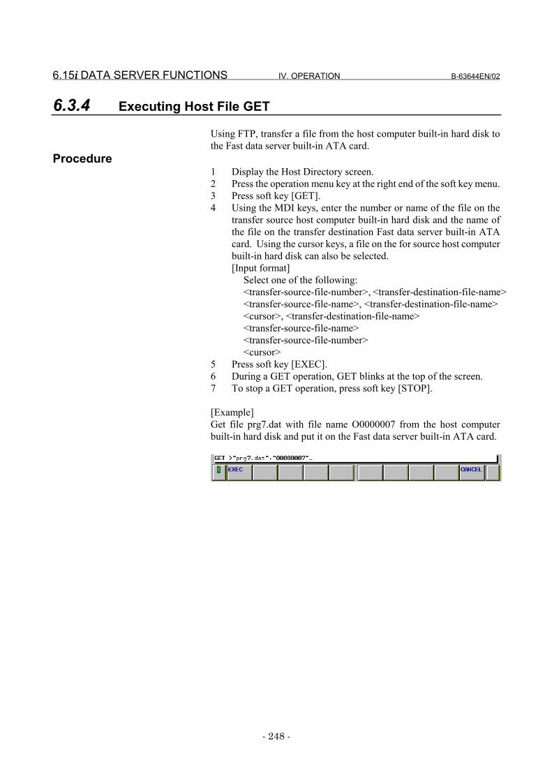
6.15i i i i DATA SERVER FUNCTIONS IV. OPERATION B-63644EN/02
- 248 -
6.3.4 Executing Host File GET
Using FTP, transfer a file from the host computer built-in hard disk tothe Fast data server built-in ATA card.
Procedure1 Display the Host Directory screen.2 Press the operation menu key at the right end of the soft key menu.3 Press soft key [GET].4 Using the MDI keys, enter the number or name of the file on the
transfer source host computer built-in hard disk and the name ofthe file on the transfer destination Fast data server built-in ATAcard. Using the cursor keys, a file on the for source host computerbuilt-in hard disk can also be selected.[Input format]
Select one of the following:<transfer-source-file-number>, <transfer-destination-file-name><transfer-source-file-name>, <transfer-destination-file-name><cursor>, <transfer-destination-file-name><transfer-source-file-name><transfer-source-file-number><cursor>
5 Press soft key [EXEC].6 During a GET operation, GET blinks at the top of the screen.7 To stop a GET operation, press soft key [STOP].
[Example]Get file prg7.dat with file name O0000007 from the host computerbuilt-in hard disk and put it on the Fast data server built-in ATA card.
B-63644EN/02 IV. OPERATION 6.15i i i i DATA SERVER FUNCTIONS
- 249 -
NOTE1 A transfer destination file name can be omitted. In
this case, the transfer source file name is used.2 If an error occurs, determine the cause of the error by
referring to the Ethernet Error Message screen.3 As the transfer destination file name, specify the
name of a file not existing on the Fast data serverbuilt-in ATA card. An error occurs if the name of a fileexisting on this hard disk is specified.
4 Information displayed at the right end of the HostDirectory (Detail) screen is recognized as the filename. Therefore, to get a host file from the HostDirectory (Detail) screen by specifying the filenumber, confirm that the file name is displayed at theright end of the screen, then specify the file number.
5 If a file name contains kanji, hiragana, or katakanacharacters, switch the Host Directory (Detail) screento the Host Directory screen, specify the file numberor select the file using the cursor keys, then get thehost file. Be sure to specify the <transfer-destination-file-name>.
6 When only the transfer source file name is specified,if the file name is not in the 8.3 format, it is convertedto an 8.3-format file name automatically in order toGET the data onto the Fast data server built-in ATAcard. See Subsection 6.1.5, "Hard Disk File Names,"for explanations about the rules for converting filenames to 8.3-format file names.
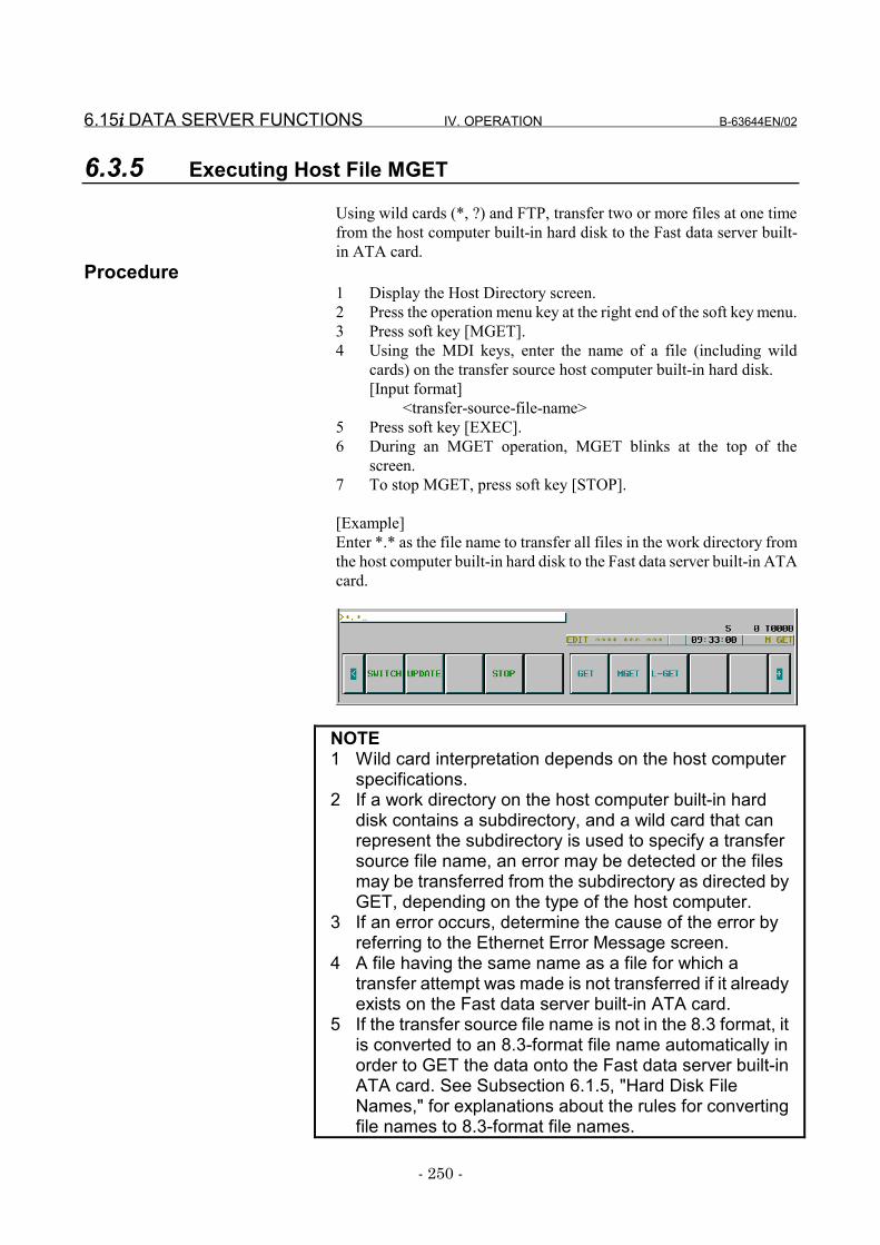
6.15i i i i DATA SERVER FUNCTIONS IV. OPERATION B-63644EN/02
- 250 -
6.3.5 Executing Host File MGET
Using wild cards (*, ?) and FTP, transfer two or more files at one timefrom the host computer built-in hard disk to the Fast data server built-in ATA card.
Procedure1 Display the Host Directory screen.2 Press the operation menu key at the right end of the soft key menu.3 Press soft key [MGET].4 Using the MDI keys, enter the name of a file (including wild
cards) on the transfer source host computer built-in hard disk.[Input format]
<transfer-source-file-name>5 Press soft key [EXEC].6 During an MGET operation, MGET blinks at the top of the
screen.7 To stop MGET, press soft key [STOP].
[Example]Enter *.* as the file name to transfer all files in the work directory fromthe host computer built-in hard disk to the Fast data server built-in ATAcard.
NOTE1 Wild card interpretation depends on the host computer
specifications.2 If a work directory on the host computer built-in hard
disk contains a subdirectory, and a wild card that canrepresent the subdirectory is used to specify a transfersource file name, an error may be detected or the filesmay be transferred from the subdirectory as directed byGET, depending on the type of the host computer.
3 If an error occurs, determine the cause of the error byreferring to the Ethernet Error Message screen.
4 A file having the same name as a file for which atransfer attempt was made is not transferred if it alreadyexists on the Fast data server built-in ATA card.
5 If the transfer source file name is not in the 8.3 format, itis converted to an 8.3-format file name automatically inorder to GET the data onto the Fast data server built-inATA card. See Subsection 6.1.5, "Hard Disk FileNames," for explanations about the rules for convertingfile names to 8.3-format file names.
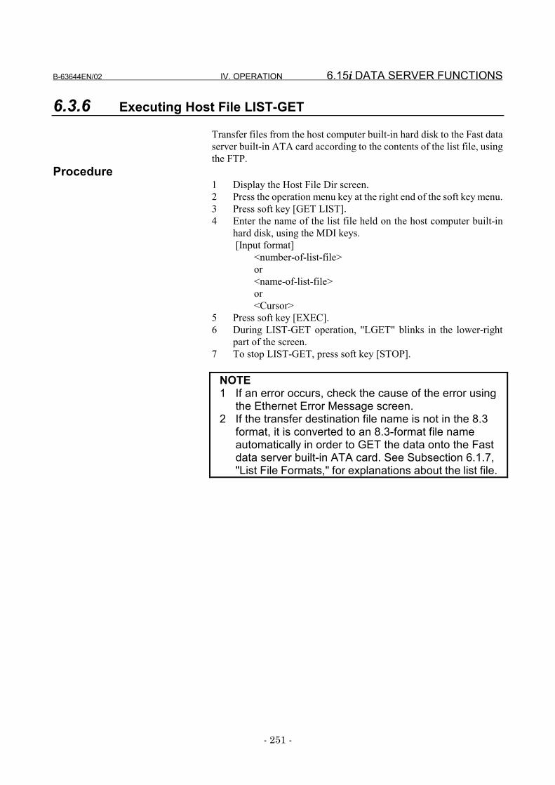
B-63644EN/02 IV. OPERATION 6.15i i i i DATA SERVER FUNCTIONS
- 251 -
6.3.6 Executing Host File LIST-GET
Transfer files from the host computer built-in hard disk to the Fast dataserver built-in ATA card according to the contents of the list file, usingthe FTP.
Procedure1 Display the Host File Dir screen.2 Press the operation menu key at the right end of the soft key menu.3 Press soft key [GET LIST].4 Enter the name of the list file held on the host computer built-in
hard disk, using the MDI keys. [Input format]
<number-of-list-file>or<name-of-list-file>or<Cursor>
5 Press soft key [EXEC].6 During LIST-GET operation, "LGET" blinks in the lower-right
part of the screen.7 To stop LIST-GET, press soft key [STOP].
NOTE1 If an error occurs, check the cause of the error using
the Ethernet Error Message screen.2 If the transfer destination file name is not in the 8.3
format, it is converted to an 8.3-format file nameautomatically in order to GET the data onto the Fastdata server built-in ATA card. See Subsection 6.1.7,"List File Formats," for explanations about the list file.
6.15i i i i DATA SERVER FUNCTIONS IV. OPERATION B-63644EN/02
- 252 -
6.4 INPUTTING AN NC PROGRAM
Input a file (NC program) from the Fast data server built-in ATA cardor host computer built-in hard disk to tape memory.
For the Hard Disk File Directory screen or Host Directory screenProcedure
1 In storage mode, display the Hard Disk File Directory screen. InFTP mode, display the Host Directory screen.
2 Press the operation menu key at the right end of the soft key menu.3 Press soft key [READ].4 Using the MDI keys, enter the number or name of the NC program
to be input. Alternatively, this NC program can also be selectedusing the cursor keys.[Input format]
<file-number>, <file-name>, or <cursor>5 Press soft key [ALL].6 During input, READ blinks at the top of the screen.
CAUTION1 If bit 1 of parameter No.2200 is set to 1, and an NC
program having the same O number as the NCprogram to be input exists in the tape memory, it isoverwritten.
2 If bit 0 of parameter No.2200 is set to 1, and an NCprogram is input, all NC programs in tape memory areautomatically erased. Subsequently, the NC programis input.
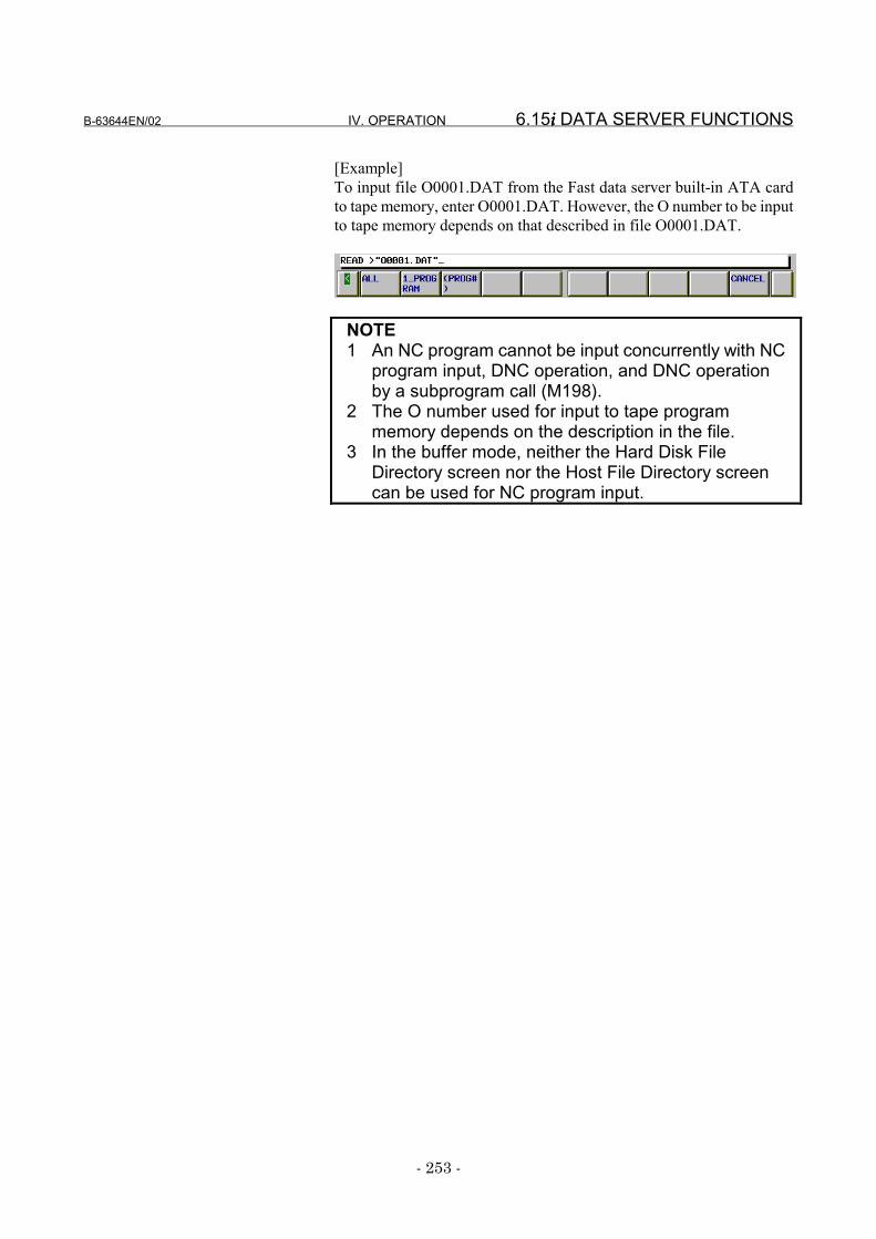
B-63644EN/02 IV. OPERATION 6.15i i i i DATA SERVER FUNCTIONS
- 253 -
[Example]To input file O0001.DAT from the Fast data server built-in ATA cardto tape memory, enter O0001.DAT. However, the O number to be inputto tape memory depends on that described in file O0001.DAT.
NOTE1 An NC program cannot be input concurrently with NC
program input, DNC operation, and DNC operationby a subprogram call (M198).
2 The O number used for input to tape programmemory depends on the description in the file.
3 In the buffer mode, neither the Hard Disk FileDirectory screen nor the Host File Directory screencan be used for NC program input.
6.15i i i i DATA SERVER FUNCTIONS IV. OPERATION B-63644EN/02
- 254 -
For the Program (Edit) screenProcedure
1 Place the CNC in EDIT mode.2 Press function key PROG .3 Press soft key [CHAPTER].4 When you press soft key [TXT], the Program (Edit) screen
appears.5 Press the operation menu key at the right end of the soft key menu.6 Press soft key [READ].7 Using the MDI keys, enter the file number or name of the NC
program to be input.[Input format]
<file-number> or <file-name>8 Press soft key [ALL].9 During input, READ blinks at the top of the screen.
CAUTION1 If bit 1 of parameter No.2200 is set to 1, and an NC
program having the same O number as the NCprogram to be input exists in tape memory, it isoverwritten.
2 If bit 0 of parameter No.2200 is set to 1, and an NCprogram is input, all NC programs in tape memory areautomatically erased. Subsequently, the NC programis input.
NOTE1 An NC program cannot be input concurrently with NC
program output, DNC operation, or DNC operation bya subprogram call (M198).
2 The O number used for input to tape memorydepends on the described in the file.
3 In the buffer mode, a specified file is assumed torepresent a list of files resulting from NC programdivision. Therefore, an NC program is input byregarding the files in the file list as a virtually singlecontinuous file.
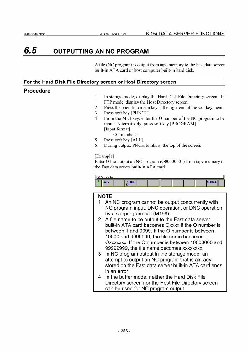
B-63644EN/02 IV. OPERATION 6.15i i i i DATA SERVER FUNCTIONS
- 255 -
6.5 OUTPUTTING AN NC PROGRAM
A file (NC program) is output from tape memory to the Fast data serverbuilt-in ATA card or host computer built-in hard disk.
For the Hard Disk File Directory screen or Host Directory screenProcedure
1 In storage mode, display the Hard Disk File Directory screen. InFTP mode, display the Host Directory screen.
2 Press the operation menu key at the right end of the soft key menu.3 Press soft key [PUNCH].4 From the MDI key, enter the O number of the NC program to be
input. Alternatively, press soft key [PROGRAM].[Input format]
<O-number>5 Press soft key [ALL].6 During output, PNCH blinks at the top of the screen.
[Example]Enter O1 to output an NC program (O00000001) from tape memory tothe Fast data server built-in ATA card.
NOTE1 An NC program cannot be output concurrently with
NC program input, DNC operation, or DNC operationby a subprogram call (M198).
2 A file name to be output to the Fast data serverbuilt-in ATA card becomes Oxxxx if the O number isbetween 1 and 9999. If the O number is between10000 and 9999999, the file name becomesOxxxxxxx. If the O number is between 10000000 and99999999, the file name becomes xxxxxxxx.
3 In NC program output in the storage mode, anattempt to output an NC program that is alreadystored on the Fast data server built-in ATA card endsin an error.
4 In the buffer mode, neither the Hard Disk FileDirectory screen nor the Host File Directory screencan be used for NC program output.
6.15i i i i DATA SERVER FUNCTIONS IV. OPERATION B-63644EN/02
- 256 -
For the Program (Edit) screenProcedure
1 Place the CNC in EDIT mode.2 Press function key PROG .3 Press soft key [CHAPTER].4 When you press [TXT], the Program (Edit) screen appears.5 Press the operation menu key at the right end of the soft key menu.6 Press soft key [PUNCH].7 Using the MDI keys, enter the O number of the NC program to be
output. Alternatively, press soft key [PROGRAM].[Input format]
<O-number>8 Press soft key [ALL].9 During output, PNCH blinks at the top of the screen.
NOTE1 An NC program cannot be output concurrently with
NC program input, DNC operation, or DNC operationby a subprogram call (M198).
2 A file name to be output to the Fast data serverbuilt-in ATA card becomes Oxxxx if the O number isbetween 1 and 9999. If the O number is between10000 and 9999999, the file name becomesOxxxxxxx. If the O number is between 10000000 and99999999, the file number becomes xxxxxxxx.
3 In the buffer mode, the output destination of NCprograms is the Fast data server built-in ATA card.
4 In NC program output in either the storage or buffermode, an attempt to output an NC program that isalready stored on the Fast data server built-in ATAcard ends in an error.
B-63644EN/02 IV. OPERATION 6.15i i i i DATA SERVER FUNCTIONS
- 257 -
6.6 DNC OPERATIONS
DNC operation is performed by using an NC program stored on theFast data server built-in ATA card or on the host computer built-in harddisk.
For DNC operation in storage modeProcedure
1 Place the CNC in DNC mode.2 Display the Hard Disk File Directory screen and move to the
directory holding an NC program used to perform a DNCoperation.
3 Press the operation menu key at the right end of the soft key menu.4 Press soft key [DNC SET].5 Using the MDI keys, enter the file number or name of the NC
program for which DNC operation is to be performed.Alternatively, this NC program can also be selected using thecursor keys.[Input format]
<file-number>, <file-name>, or <cursor>6 Press soft key [EXEC]. The file name of the NC program for
DNC operation is displayed in DNC FILE NAME on the screen.7 When cycle start is performed, DNC operation is executed.
NOTEDNC operation cannot be executed concurrently withNC program input, NC program output, or DNCoperation by a subprogram call (M198).
6.15i i i i DATA SERVER FUNCTIONS IV. OPERATION B-63644EN/02
- 258 -
For DNC operation in FTP modeProcedure
1 Place the CNC in DNC mode.2 Select the host number for the host holding a file list to be used for
an DNC operation according to the procedure described inSubsection 6.9.2, "Reconnecting the Host," to display the HostDirectory screen.
3 Press the operation menu key at the right end of the soft key menu.4 Press soft key [DNC SET].5 Using the MDI keys, enter the file number or name of the NC
program for which DNC operation is to be performed. This NCprogram can also be selected using the cursor keys.[Input format]
<file-number>, <file-name>, or <cursor>6 Press soft key [EXEC]. The host number of a host connected for
DNC operations is displayed to the right of "DNC HOST" on thescreen, and the file name for an NC program for the DNCoperations is displayed to the right of "DNC FILE NAME" on thescreen.
7 When the cycle start is executed, DNC operation is performed.
NOTEDNC operation cannot be performed concurrentlywith NC program input, NC program output, and DNCoperation by a subprogram call (M198).
B-63644EN/02 IV. OPERATION 6.15i i i i DATA SERVER FUNCTIONS
- 259 -
For DNC operation in buffer modeProcedure
1 Place the CNC in DNC mode.2 Select the host number for the host holding a file list to be used for
an DNC operation according to the procedure described inSubsection 6.9.2, "Reconnecting the Host," to display the HostDirectory screen.
3 Press the operation menu key at the right end of the soft key menu.4 Press soft key [DNC SET].5 Using the MDI keys, enter the file number or name of the NC
program for which DNC operation is to be performed. This NCprogram can also be selected using the cursor keys.[Input format]
<file-number>, <file-name>, or <cursor>6 Press soft key [EXEC]. The host number of a host connected for
DNC operations is displayed to the right of "DNC HOST" on thescreen, and the file name for an NC program for the DNCoperations is displayed to the right of "DNC FILE NAME" on thescreen.
7 When the cycle start is executed, DNC operation is performed.
NOTEDNC operation cannot be performed concurrentlywith NC program input, NC program output, and DNCoperation by a subprogram call (M198).
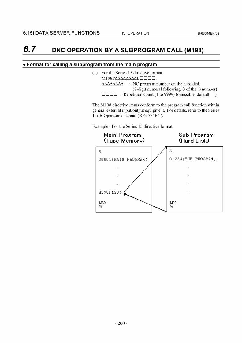
6.15i i i i DATA SERVER FUNCTIONS IV. OPERATION B-63644EN/02
- 260 -
6.7 DNC OPERATION BY A SUBPROGRAM CALL (M198)
•••• Format for calling a subprogram from the main program(1) For the Series 15 directive format
M198P∆∆∆∆∆∆∆∆L����;∆∆∆∆∆∆∆∆ : NC program number on the hard disk
(8-digit numeral following O of the O number)���� : Repetition count (1 to 9999) (omissible, default: 1)
The M198 directive items conform to the program call function withingeneral external input/output equipment. For details, refer to the Series15i-B Operator's manual (B-63784EN).
Example: For the Series 15 directive format
M30%
M99%
B-63644EN/02 IV. OPERATION 6.15i i i i DATA SERVER FUNCTIONS
- 261 -
For DNC operation by a subprogram call (M198) in storage modeProcedure
1 Place the CNC in MEM mode.2 Display the Hard Disk File Directory screen and move to the
directory holding an NC program to be called by a subprogram.3 Press the operation menu key at the right end of the soft key menu.4 Press soft key [M198 DIR SET].5 Press soft key [EXEC]. The current work directory name is
displayed in M198 DIRECTORY on the screen.6 The NC program containing the M198 directive is automatically
executed.
NOTE1 DNC operation by a subprogram call (M198) cannot
be executed concurrently with NC program input, NCprogram output, and DNC operation.
2 The file name of the subprogram to be called duringDNC operation by a subprogram call (M198)becomes Oxxxx if the O number is between 1 and9999. If the O number is between 10000 and9999999, the file name becomes Oxxxxxxx. If the Onumber is between 10000000 and 99999999, the filename becomes xxxxxxxx.
3 Assume that a subprogram call is further performedin the subprogram called by the DNC operation by asubprogram call (M198). If the subprogram to becalled exists in tape memory, it can be executed as asubprogram. If, however, this subprogram exists onthe Fast data server built-in ATA card, it cannot beexecuted as a subprogram.
4 When viewed from the CNC, the data serverfunctions are handled in the same way as otherinput/output equipment. So, the subprogram callrestrictions are equivalent to those for otherinput/output equipment.
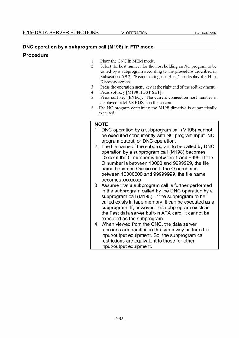
6.15i i i i DATA SERVER FUNCTIONS IV. OPERATION B-63644EN/02
- 262 -
DNC operation by a subprogram call (M198) in FTP modeProcedure
1 Place the CNC in MEM mode.2 Select the host number for the host holding an NC program to be
called by a subprogram according to the procedure described inSubsection 6.9.2, "Reconnecting the Host," to display the HostDirectory screen.
3 Press the operation menu key at the right end of the soft key menu.4 Press soft key [M198 HOST SET].5 Press soft key [EXEC]. The current connection host number is
displayed in M198 HOST on the screen.6 The NC program containing the M198 directive is automatically
executed.
NOTE1 DNC operation by a subprogram call (M198) cannot
be executed concurrently with NC program input, NCprogram output, or DNC operation.
2 The file name of the subprogram to be called by DNCoperation by a subprogram call (M198) becomesOxxxx if the O number is between 1 and 9999. If theO number is between 10000 and 9999999, the filename becomes Oxxxxxxx. If the O number isbetween 10000000 and 99999999, the file namebecomes xxxxxxxx.
3 Assume that a subprogram call is further performedin the subprogram called by the DNC operation by asubprogram call (M198). If the subprogram to becalled exists in tape memory, it can be executed as asubprogram. If, however, this subprogram exists inthe Fast data server built-in ATA card, it cannot beexecuted as the subprogram.
4 When viewed from the CNC, the data serverfunctions are handled in the same way as for otherinput/output equipment. So, the subprogram callrestrictions are equivalent to those for otherinput/output equipment.
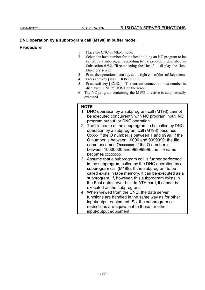
B-63644EN/02 IV. OPERATION 6.15i i i i DATA SERVER FUNCTIONS
- 263 -
DNC operation by a subprogram call (M198) in buffer modeProcedure
1 Place the CNC in MEM mode.2 Select the host number for the host holding an NC program to be
called by a subprogram according to the procedure described inSubsection 6.9.2, "Reconnecting the Host," to display the HostDirectory screen.
3 Press the operation menu key at the right end of the soft key menu.4 Press soft key [M198 HOST SET].5 Press soft key [EXEC]. The current connection host number is
displayed in M198 HOST on the screen.6 The NC program containing the M198 directive is automatically
executed.
NOTE1 DNC operation by a subprogram call (M198) cannot
be executed concurrently with NC program input, NCprogram output, or DNC operation.
2 The file name of the subprogram to be called by DNCoperation by a subprogram call (M198) becomesOxxxx if the O number is between 1 and 9999. If theO number is between 10000 and 9999999, the filename becomes Oxxxxxxx. If the O number isbetween 10000000 and 99999999, the file namebecomes xxxxxxxx.
3 Assume that a subprogram call is further performedin the subprogram called by the DNC operation by asubprogram call (M198). If the subprogram to becalled exists in tape memory, it can be executed as asubprogram. If, however, this subprogram exists inthe Fast data server built-in ATA card, it cannot beexecuted as the subprogram.
4 When viewed from the CNC, the data serverfunctions are handled in the same way as for otherinput/output equipment. So, the subprogram callrestrictions are equivalent to those for otherinput/output equipment.
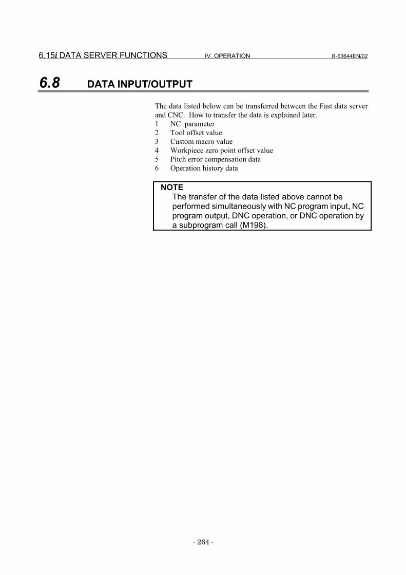
6.15i i i i DATA SERVER FUNCTIONS IV. OPERATION B-63644EN/02
- 264 -
6.8 DATA INPUT/OUTPUT
The data listed below can be transferred between the Fast data serverand CNC. How to transfer the data is explained later.1 NC parameter2 Tool offset value3 Custom macro value4 Workpiece zero point offset value5 Pitch error compensation data6 Operation history data
NOTEThe transfer of the data listed above cannot beperformed simultaneously with NC program input, NCprogram output, DNC operation, or DNC operation bya subprogram call (M198).
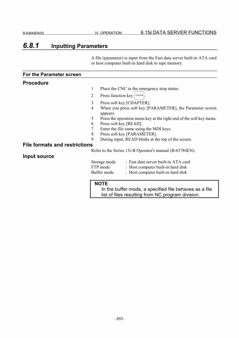
B-63644EN/02 IV. OPERATION 6.15i i i i DATA SERVER FUNCTIONS
- 265 -
6.8.1 Inputting Parameters
A file (parameter) is input from the Fast data server built-in ATA cardor host computer built-in hard disk to tape memory.
For the Parameter screenProcedure
1 Place the CNC in the emergency stop status.2 Press function key SYSTEM .3 Press soft key [CHAPTER].4 When you press soft key [PARAMETER], the Parameter screen
appears.5 Press the operation menu key at the right end of the soft key menu.6 Press soft key [READ].7 Enter the file name using the MDI keys.8 Press soft key [PARAMETER].9 During input, READ blinks at the top of the screen.
File formats and restrictionsRefer to the Series 15i-B Operator's manual (B-63784EN).
Input sourceStorage mode : Fast data server built-in ATA cardFTP mode : Host computer built-in hard diskBuffer mode : Host computer built-in hard disk
NOTEIn the buffer mode, a specified file behaves as a filelist of files resulting from NC program division.
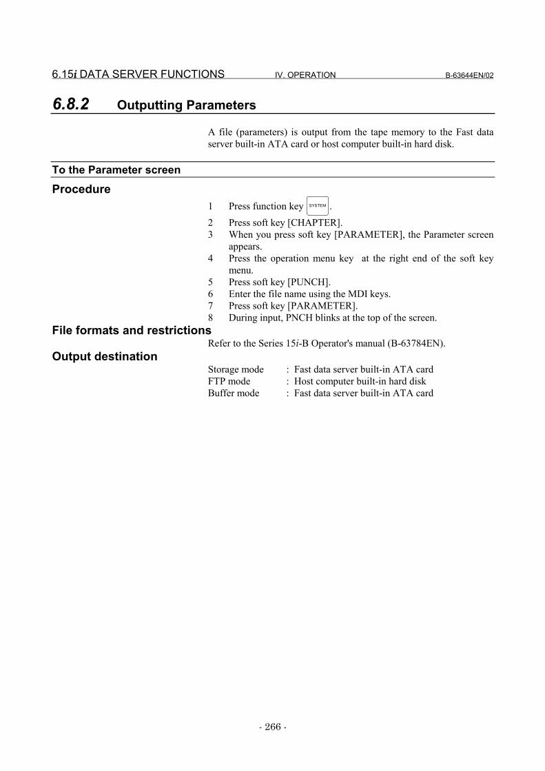
6.15i i i i DATA SERVER FUNCTIONS IV. OPERATION B-63644EN/02
- 266 -
6.8.2 Outputting Parameters
A file (parameters) is output from the tape memory to the Fast dataserver built-in ATA card or host computer built-in hard disk.
To the Parameter screenProcedure
1 Press function key SYSTEM .2 Press soft key [CHAPTER].3 When you press soft key [PARAMETER], the Parameter screen
appears.4 Press the operation menu key at the right end of the soft key
menu.5 Press soft key [PUNCH].6 Enter the file name using the MDI keys.7 Press soft key [PARAMETER].8 During input, PNCH blinks at the top of the screen.
File formats and restrictionsRefer to the Series 15i-B Operator's manual (B-63784EN).
Output destinationStorage mode : Fast data server built-in ATA cardFTP mode : Host computer built-in hard diskBuffer mode : Fast data server built-in ATA card
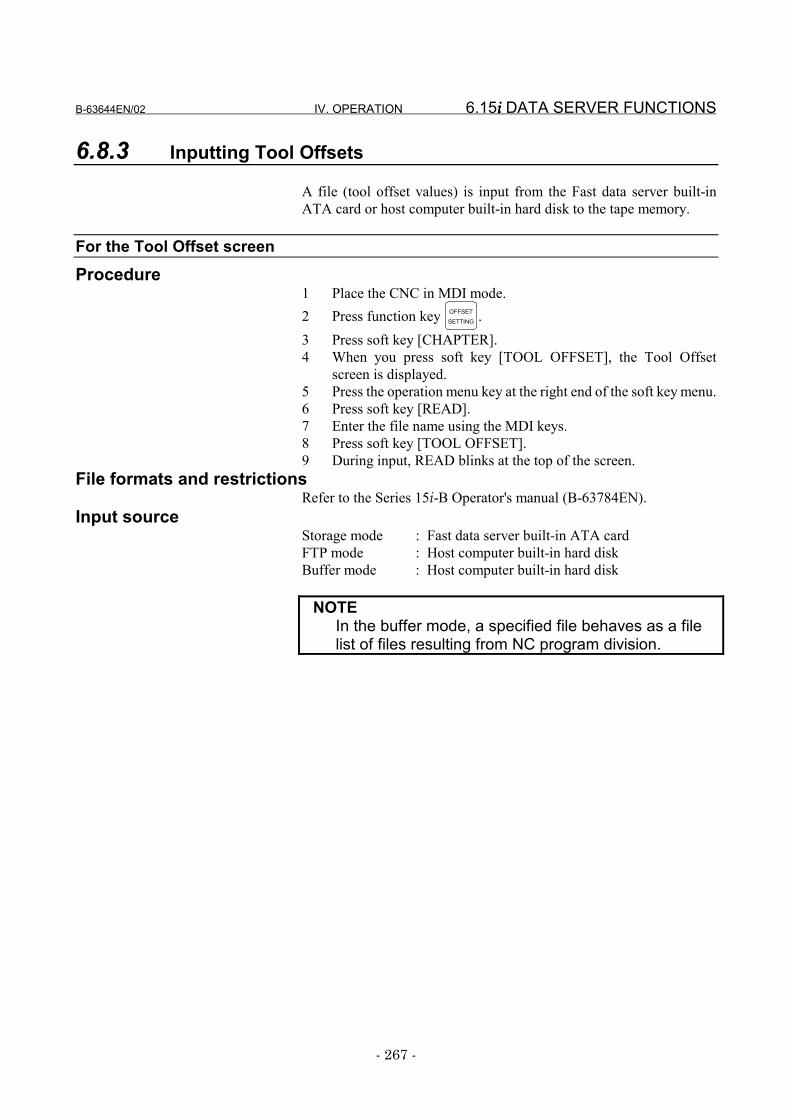
B-63644EN/02 IV. OPERATION 6.15i i i i DATA SERVER FUNCTIONS
- 267 -
6.8.3 Inputting Tool Offsets
A file (tool offset values) is input from the Fast data server built-inATA card or host computer built-in hard disk to the tape memory.
For the Tool Offset screenProcedure
1 Place the CNC in MDI mode.2 Press function key OFFSET
SETTING .3 Press soft key [CHAPTER].4 When you press soft key [TOOL OFFSET], the Tool Offset
screen is displayed.5 Press the operation menu key at the right end of the soft key menu.6 Press soft key [READ].7 Enter the file name using the MDI keys.8 Press soft key [TOOL OFFSET].9 During input, READ blinks at the top of the screen.
File formats and restrictionsRefer to the Series 15i-B Operator's manual (B-63784EN).
Input sourceStorage mode : Fast data server built-in ATA cardFTP mode : Host computer built-in hard diskBuffer mode : Host computer built-in hard disk
NOTEIn the buffer mode, a specified file behaves as a filelist of files resulting from NC program division.

6.15i i i i DATA SERVER FUNCTIONS IV. OPERATION B-63644EN/02
- 268 -
6.8.4 Outputting Tool Offsets
A file (tool offset values) is output from tape memory to the Fast dataserver built-in ATA card or host computer built-in hard disk.
For the Tool Offset screenProcedure
1 Press function key OFFSETSETTING .
2 Press soft key [CHAPTER].3 When you press soft key [TOOL OFFSET], the Tool Offset
screen appears.4 Press the operation menu key at the right end of the soft key
menu.5 Press soft key [PUNCH].6 Enter the file name using the MDI keys.7 Press soft key [TOOL OFFSET].8 During output, PNCH blinks at the top of the screen.
File formats and restrictionsRefer to . the Series 15i-B Operator's manual (B-63784EN)
Output destinationStorage mode : Fast data server built-in ATA cardFTP mode : Host computer built-in hard diskBuffer mode : Fast data server built-in ATA card
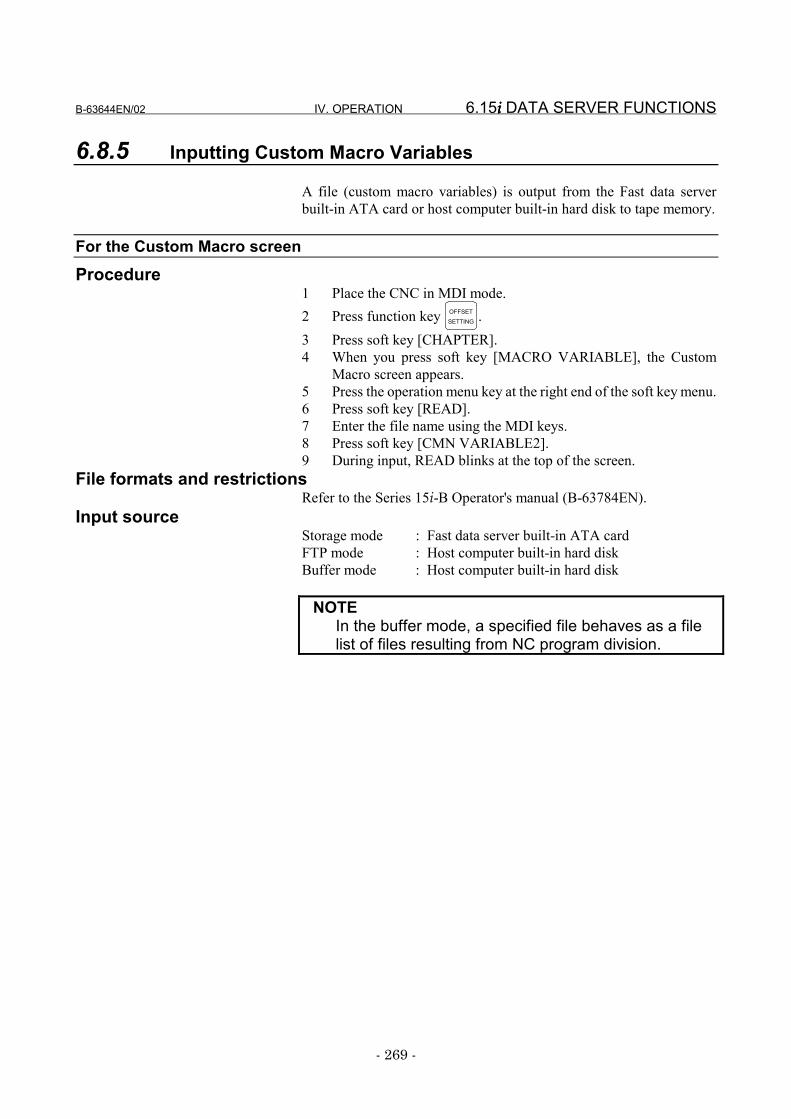
B-63644EN/02 IV. OPERATION 6.15i i i i DATA SERVER FUNCTIONS
- 269 -
6.8.5 Inputting Custom Macro Variables
A file (custom macro variables) is output from the Fast data serverbuilt-in ATA card or host computer built-in hard disk to tape memory.
For the Custom Macro screenProcedure
1 Place the CNC in MDI mode.2 Press function key OFFSET
SETTING .3 Press soft key [CHAPTER].4 When you press soft key [MACRO VARIABLE], the Custom
Macro screen appears.5 Press the operation menu key at the right end of the soft key menu.6 Press soft key [READ].7 Enter the file name using the MDI keys.8 Press soft key [CMN VARIABLE2].9 During input, READ blinks at the top of the screen.
File formats and restrictionsRefer to the Series 15i-B Operator's manual (B-63784EN).
Input sourceStorage mode : Fast data server built-in ATA cardFTP mode : Host computer built-in hard diskBuffer mode : Host computer built-in hard disk
NOTEIn the buffer mode, a specified file behaves as a filelist of files resulting from NC program division.

6.15i i i i DATA SERVER FUNCTIONS IV. OPERATION B-63644EN/02
- 270 -
6.8.6 Outputting Custom Macro Variables
A file (custom macro variables) is output from tape memory to the Fastdata server built-in ATA card or host computer built-in hard disk.
For the Custom Macro screenProcedure
1 Press function key OFFSETSETTING .
2 Press soft key [CHAPTER].3 When you press soft key [MACRO VARIABLE], the Custom
Macro screen appears.4 Press the operation menu key at the right end of the soft key
menu.5 Press soft key [PUNCH].6 Enter the file name using the MDI keys.7 Press soft key [CMN VARIABLE2].8 During output, PNCH blinks at the top of the screen.
File formats and restrictionsRefer to the Series 15i-B Operator's manual (B-63784EN).
Output destinationStorage mode : Fast data server built-in ATA cardFTP mode : Host computer built-in hard diskBuffer mode : Fast data server built-in ATA card
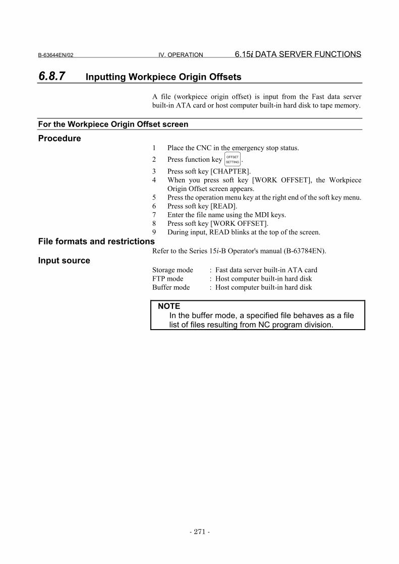
B-63644EN/02 IV. OPERATION 6.15i i i i DATA SERVER FUNCTIONS
- 271 -
6.8.7 Inputting Workpiece Origin Offsets
A file (workpiece origin offset) is input from the Fast data serverbuilt-in ATA card or host computer built-in hard disk to tape memory.
For the Workpiece Origin Offset screenProcedure
1 Place the CNC in the emergency stop status.2 Press function key OFFSET
SETTING .3 Press soft key [CHAPTER].4 When you press soft key [WORK OFFSET], the Workpiece
Origin Offset screen appears.5 Press the operation menu key at the right end of the soft key menu.6 Press soft key [READ].7 Enter the file name using the MDI keys.8 Press soft key [WORK OFFSET].9 During input, READ blinks at the top of the screen.
File formats and restrictionsRefer to the Series 15i-B Operator's manual (B-63784EN).
Input sourceStorage mode : Fast data server built-in ATA cardFTP mode : Host computer built-in hard diskBuffer mode : Host computer built-in hard disk
NOTEIn the buffer mode, a specified file behaves as a filelist of files resulting from NC program division.
6.15i i i i DATA SERVER FUNCTIONS IV. OPERATION B-63644EN/02
- 272 -
6.8.8 Outputting Workpiece Origin Offsets
A file (workpiece origin offset) is output from tape memory to the Fastdata server built-in ATA card or host computer built-in hard disk.
For the Workpiece Offset screenProcedure
1 Press function key OFFSETSETTING .
2 Press soft key [CHAPTER].3 When you press soft key [WORK OFFSET], the Workpiece
Origin Offset screen appears.4 Press the operation menu key at the right end of the soft key menu.5 Press soft key [PUNCH].6 Enter the file name using the MDI keys.7 Press soft key [WORK OFFSET].8 During output, PNCH blinks at the top of the screen.
File formats and restrictionsRefer to the Series 15i-B Operator's manual (B-63784EN).
Output destinationStorage mode : Fast data server built-in ATA cardFTP mode : Host computer built-in hard diskBuffer mode : Fast data server built-in ATA card
B-63644EN/02 IV. OPERATION 6.15i i i i DATA SERVER FUNCTIONS
- 273 -
6.8.9 Inputting Pitch Error Compensation Data
A file (pitch error compensation data) is input from the Fast data serverbuilt-in ATA card or host computer built-in hard disk to tape memory.
For the Pitch Error Compensation screenProcedure
1 Place the CNC in emergency stop status.2 Press function key SYSTEM .3 Press soft key [CHAPTER].4 When you press soft key [PITCH ERROR], the Pitch Error
Compensation screen appears.5 Press the operation menu key at the right end of the soft key menu.6 Press soft key [READ].7 Enter the file name using the MDI keys.8 Press soft key [PITCH ERROR].9 During input, READ blinks at the top of the screen.
File formats and restrictionsRefer to the Series 15i-B Operator's manual (B-63784EN).
Input sourceStorage mode : Fast data server built-in ATA cardFTP mode : Host computer built-in hard diskBuffer mode : Host computer built-in hard disk
NOTEIn the buffer mode, a specified file behaves as a filelist of files resulting from NC program division.

6.15i i i i DATA SERVER FUNCTIONS IV. OPERATION B-63644EN/02
- 274 -
6.8.10 Outputting Pitch Error Compensation Data
A file (pitch error compensation data) is output from tape memory tothe Fast data server built-in ATA card or host computer built-in harddisk.
For the Pitch Error Compensation screen
Procedure1 Press function key SYSTEM .2 Press soft key [CHAPTER].3 When you press soft key [PITCH ERROR], the Pitch Error
Compensation screen appears.4 Press the operation menu key at the right end of the soft key menu.5 Press soft key [PUNCH].6 Enter the file name using the MDI keys.7 Press soft key [PITCH ERROR].8 During output, PNCH blinks at the top of the screen.
File formats and restrictionsRefer to the Series 15i-B Operator's manual (B-63784EN).
Output destinationStorage mode : Fast data server built-in ATA cardFTP mode : Host computer built-in hard diskBuffer mode : Fast data server built-in ATA card
B-63644EN/02 IV. OPERATION 6.15i i i i DATA SERVER FUNCTIONS
- 275 -
6.8.11 Outputting Operation History Data
A file (operation history data) is output from tape memory to the Fastdata server built-in ATA card or host computer built-in hard disk.
To the Operation History screenProcedure
1 Press function key SYSTEM .2 Press soft key [CHAPTER].3 When you press soft key [OPE HIS], the Operation History screen
appears.4 Press the operation menu key at the right end of the soft key menu.5 Press soft key [PUNCH].6 Press soft key [OPE HIS].7 During output, PNCH blinks at the top of the screen.
File formats and restrictionsRefer to the Series 15i-B Operator's manual (B-63784EN).
Output destinationStorage mode : Fast data server built-in ATA cardFTP mode : Host computer built-in hard diskBuffer mode : Fast data server built-in ATA card
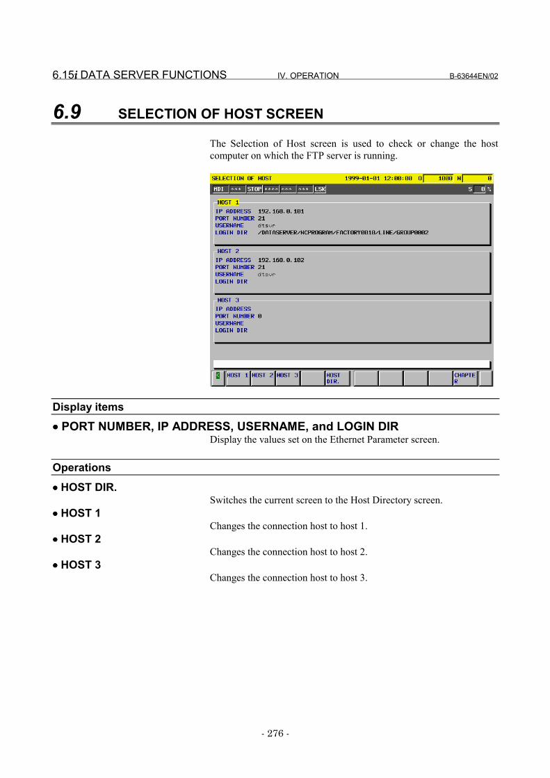
6.15i i i i DATA SERVER FUNCTIONS IV. OPERATION B-63644EN/02
- 276 -
6.9 SELECTION OF HOST SCREEN
The Selection of Host screen is used to check or change the hostcomputer on which the FTP server is running.
Display items
•••• PORT NUMBER, IP ADDRESS, USERNAME, and LOGIN DIRDisplay the values set on the Ethernet Parameter screen.
Operations
•••• HOST DIR.Switches the current screen to the Host Directory screen.
•••• HOST 1Changes the connection host to host 1.
•••• HOST 2Changes the connection host to host 2.
•••• HOST 3Changes the connection host to host 3.
B-63644EN/02 IV. OPERATION 6.15i i i i DATA SERVER FUNCTIONS
- 277 -
6.9.1 Checking the Connected Host
Check the host computer on which the FTP server, or the connectiondestination of the current Fast data server, is running.
Procedure1 Press function key PROG .2 Press the operation menu key at the right end of the soft key menu.3 When you press soft key [CHANGE HOST], the Selection of
Host screen appears.
[Reference]The title of the host computer, or communication destination of thecurrent Fast data server, is displayed in reverse video.
6.15i i i i DATA SERVER FUNCTIONS IV. OPERATION B-63644EN/02
- 278 -
6.9.2 Changing the Connected Host
Change the host computer on which the FTP server, or communicationdestination of the current Fast data server, is running.
Procedure1 Display the Selection of Host screen.2 Press the operation menu key at the right end of the soft key
menu.3 Press soft key [HOST 1], [HOST 2], or [HOST 3].4 Press soft key [EXEC].
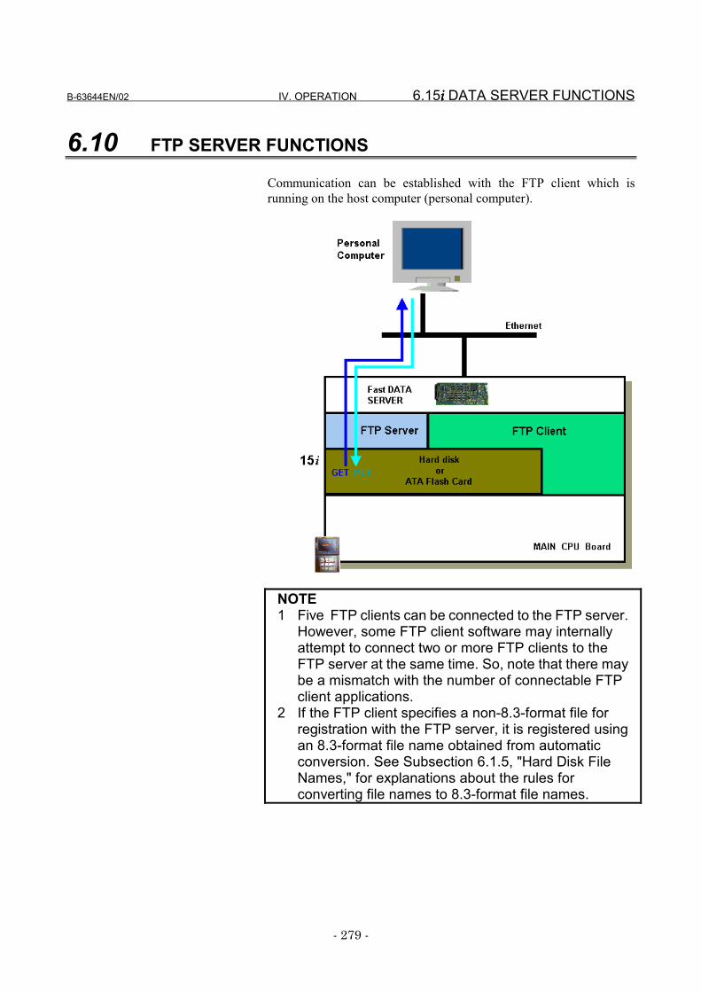
B-63644EN/02 IV. OPERATION 6.15i i i i DATA SERVER FUNCTIONS
- 279 -
6.10 FTP SERVER FUNCTIONS
Communication can be established with the FTP client which isrunning on the host computer (personal computer).
NOTE1 Five FTP clients can be connected to the FTP server.
However, some FTP client software may internallyattempt to connect two or more FTP clients to theFTP server at the same time. So, note that there maybe a mismatch with the number of connectable FTPclient applications.
2 If the FTP client specifies a non-8.3-format file forregistration with the FTP server, it is registered usingan 8.3-format file name obtained from automaticconversion. See Subsection 6.1.5, "Hard Disk FileNames," for explanations about the rules forconverting file names to 8.3-format file names.
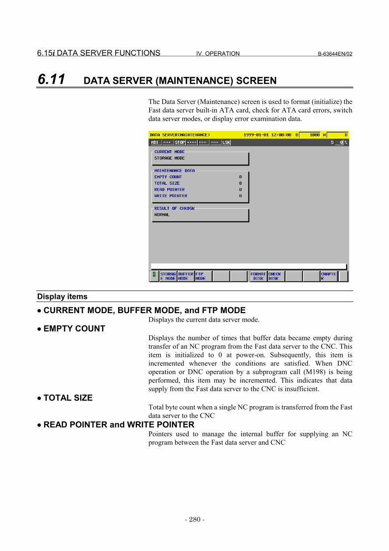
6.15i i i i DATA SERVER FUNCTIONS IV. OPERATION B-63644EN/02
- 280 -
6.11 DATA SERVER (MAINTENANCE) SCREEN
The Data Server (Maintenance) screen is used to format (initialize) theFast data server built-in ATA card, check for ATA card errors, switchdata server modes, or display error examination data.
Display items
•••• CURRENT MODE, BUFFER MODE, and FTP MODEDisplays the current data server mode.
•••• EMPTY COUNTDisplays the number of times that buffer data became empty duringtransfer of an NC program from the Fast data server to the CNC. Thisitem is initialized to 0 at power-on. Subsequently, this item isincremented whenever the conditions are satisfied. When DNCoperation or DNC operation by a subprogram call (M198) is beingperformed, this item may be incremented. This indicates that datasupply from the Fast data server to the CNC is insufficient.
•••• TOTAL SIZETotal byte count when a single NC program is transferred from the Fastdata server to the CNC
•••• READ POINTER and WRITE POINTERPointers used to manage the internal buffer for supplying an NCprogram between the Fast data server and CNC
B-63644EN/02 IV. OPERATION 6.15i i i i DATA SERVER FUNCTIONS
- 281 -
•••• RESULT OF CHKDSKDisplays the results of the previous check disk execution.
NO EXEC : Check disk is not executed after power-on.NORMAL : NormalABNORMAL : AbnormalNONE : No ATA card is connected.
Operations•••• STORAGE MODE
Changes the current mode to storage mode.•••• FTP MODE
Changes the current mode to FTP mode.•••• BUFFER MODE
Changes the current mode to buffer mode.
6.15i i i i DATA SERVER FUNCTIONS IV. OPERATION B-63644EN/02
- 282 -
6.11.1 Checking the ATA Card
Check whether the ATA card contains a faulty sector.Procedure
1 Place the CNC in MDI mode.2 Press function key SYSTEM .3 Press soft key [CHAPTER].4 When you press [MIN DATA SERVER], the Data Server
(Maintenance) screen appears.5 Press the operation menu key at the right end of the soft key
menu.6 Press soft key [CHECK DISK].7 Press soft key [EXEC]. The results are displayed in RESULT OF
CHKDSK� Normal status : NORMAL� Abnormal status : ABNORMAL
CAUTIONIf an abnormal status arises, check the cause of theerror by referring to the error message displayed onthe Ethernet Error Message screen. Then, quicklyback up the files stored on the ATA card.Subsequently, format the ATA card.
NOTEAn error occurs if other data server functions areexecuted concurrently with ATA card check.
B-63644EN/02 IV. OPERATION 6.15i i i i DATA SERVER FUNCTIONS
- 283 -
6.11.2 Formatting the ATA Card
Format (initialize) the ATA card.Procedure
1 Place the CNC in MDI mode.2 Press function key SYSTEM .3 Press soft key [CHAPTER].4 When you press soft key [MIN DATA SERVER], the Data Server
(Maintenance) screen appears.5 Press the operation menu key at the right end of the soft key
menu.6 Press soft key [FORMAT].7 Press soft key [EXEC].8 Message "HARD DISK FORMATTED?" is displayed. Press soft
key [EXEC] again.9 During formatting, FRMT blinks at the top of the screen.
CAUTION1 If the CNC power is turned off during ATA card
formatting, the ATA card may be destroyed. Neverturn off the CNC power during ATA card formatting.
2 When the ATA card is formatted, all files in the ATAcard are erased. Back up ATA card files as requiredbefore formatting the ATA card.
NOTEAn error will occur if other data server functions areperformed concurrently with ATA card formatting.
6.15i i i i DATA SERVER FUNCTIONS IV. OPERATION B-63644EN/02
- 284 -
6.11.3 Switching Data Server Modes
Switch data server modes.Procedure
1 Place the CNC in MDI mode.2 Press function key SYSTEM .3 Press soft key [CHAPTER].4 When you press soft key [MIN DATA SERVER], the Data Server
(Maintenance) screen appears.5 To change to storage mode, press soft key [STORAGE MODE].
To change to FTP mode, press soft key [FTP MODE].To change to buffer mode, press soft key [BUFFER].
6 Press soft key [EXEC].
NOTEOperations in the buffer mode need the optionalbuffer mode functions.
B-63644EN/02 IV. OPERATION 6.15i i i i DATA SERVER FUNCTIONS
- 285 -
6.11.4 Displaying Error Examination Data
If an error occurs during DNC operation using the data server function,DNC operation by a subprogram call (M198), or NC program input,data is displayed as the key to the error examination.
Procedure1 Press function key SYSTEM .2 Press soft key [CHAPTER].3 When you press soft key [MIN DATA SERVER], the Data Server
(Maintenance) screen appears.
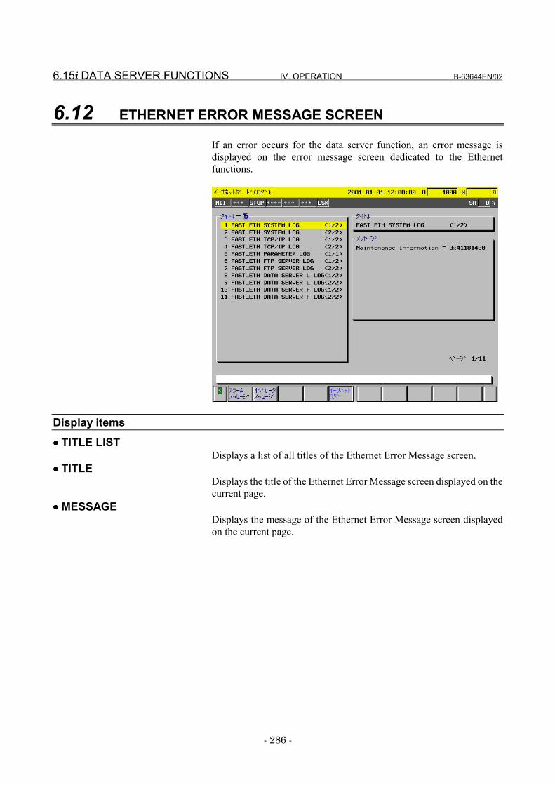
6.15i i i i DATA SERVER FUNCTIONS IV. OPERATION B-63644EN/02
- 286 -
6.12 ETHERNET ERROR MESSAGE SCREEN
If an error occurs for the data server function, an error message isdisplayed on the error message screen dedicated to the Ethernetfunctions.
Display items
•••• TITLE LISTDisplays a list of all titles of the Ethernet Error Message screen.
•••• TITLEDisplays the title of the Ethernet Error Message screen displayed on thecurrent page.
•••• MESSAGEDisplays the message of the Ethernet Error Message screen displayedon the current page.
B-63644EN/02 IV. OPERATION 6.15i i i i DATA SERVER FUNCTIONS
- 287 -
DisplayProcedure
1 Press function key MESSAGE .2 Press soft key [CHAPTER].3 When you press soft key [ETHERNET LOG], the Ethernet (Log)
screen appears.4 Select the desired page using the PAGE
PAGE page keys.
[Reference]The latest error message is displayed at the top of the screen. The dateand time at which the error occurred are displayed at the right end ofthe error message. The date and time are displayed in ddhhmmss (dd:day, hh: hour, mm: minute, ss: second) format.


V. CONNECTION

B-63644EN/02 V. CONNECTION 1.PREFACE
- 291 -
1 PREFACEIn this manual, "Fast data server" refers to a board that can use the dataserver function, while "Fast Ethernet board" refers to a board thatcannot use this function.
Board name Supported functionFast Ethernet board • FACTOLINK function
• DNC1/Ethernet function• FOCAS1/Ethernet function
Fast data server • FACTOLINK function• DNC1/Ethernet function• FOCAS1/Ethernet function• Data server function

2.SETTING V. CONNECTION B-63644EN/02
- 292 -
2 SETTINGThis chapter describes the information needed to install an FastEthernet board and Fast data server.
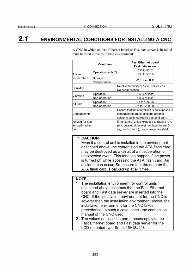
B-63644EN/02 V. CONNECTION 2.SETTING
- 293 -
2.1 ENVIRONMENTAL CONDITIONS FOR INSTALLING A CNC
A CNC in which an Fast Ethernet board or Fast data server is installedmust be used in the following environment.
Condition Fast Ethernet boardFast data server
Operation (Note 2) 0°C to 55°C(0°C to 58°C)Ambient
temperature Storage ortransportation -20°C to 60°C
Humidity Relative humidity 30% to 95% or lessNo condensation
Operation 0.5 G or lessVibration
Non-operation 1.0 G or lessOperation Up to 1000 m
AltitudeNon-operation Up to 12000 m
ContaminantsEnsure that the control unit is not exposed tocontaminants (dust, coolant, organicsolvents, acid, corrosive gas, and salt).
Ionized (or non-ionized) radiantray
If the control unit is exposed to radiant rays(microwave, ultraviolet ray, laser beam, Xray, and so forth), use a protective shield.
CAUTIONEven if a control unit is installed in the environmentdescribed above, the contents on the ATA flash cardmay be destroyed as a result of a misoperation orunexpected event. This tends to happen if the poweris turned off while accessing the ATA flash card. Anaccident can occur. So, ensure that the data on theATA flash card is backed up at all times.
NOTE1 The installation environment for control units
described above assumes that the Fast Ethernetboard and Fast data server are inserted into theCNC. If the installation environment for the CNC isseverer than the installation environment above, theinstallation environment for the CNC takesprecedence. In such a case, check the connectionmanual of the CNC used.
2 The values enclosed in parentheses apply to theFast Ethernet board and Fast data server for theLCD-mounted type Series16i/18i/21i.
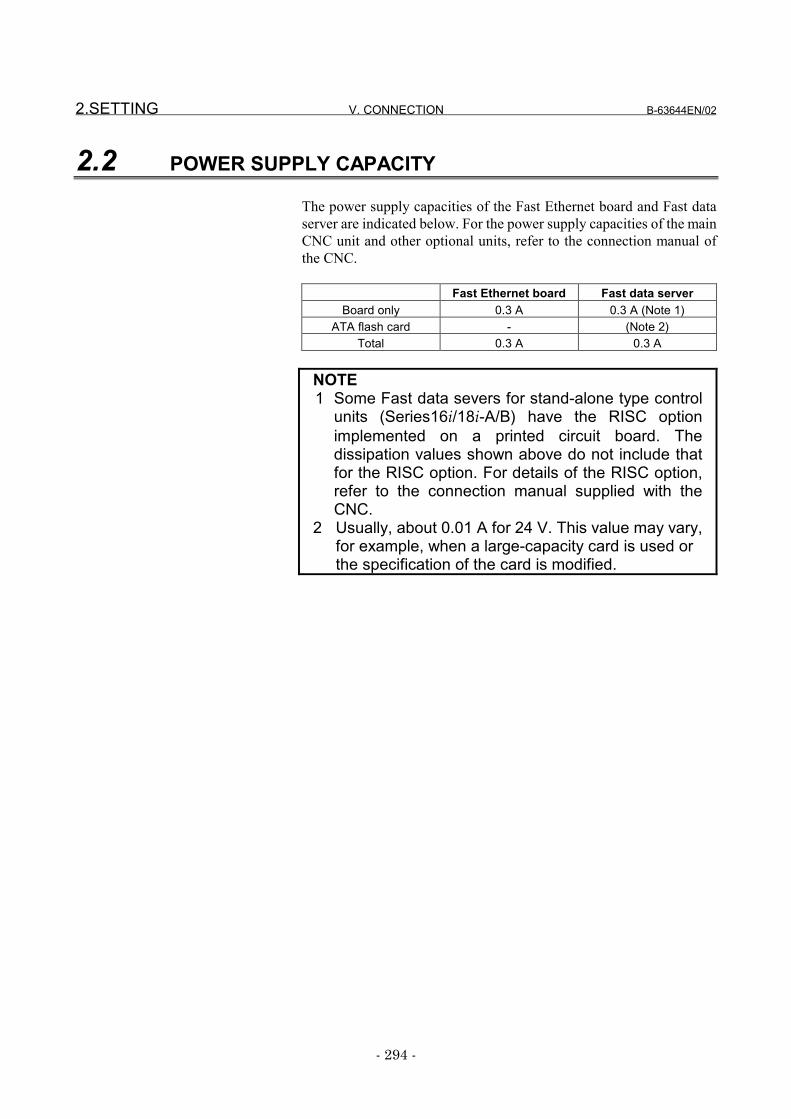
2.SETTING V. CONNECTION B-63644EN/02
- 294 -
2.2 POWER SUPPLY CAPACITY
The power supply capacities of the Fast Ethernet board and Fast dataserver are indicated below. For the power supply capacities of the mainCNC unit and other optional units, refer to the connection manual ofthe CNC.
Fast Ethernet board Fast data serverBoard only 0.3 A 0.3 A (Note 1)
ATA flash card - (Note 2)Total 0.3 A 0.3 A
NOTE1 Some Fast data severs for stand-alone type control
units (Series16i/18i-A/B) have the RISC optionimplemented on a printed circuit board. Thedissipation values shown above do not include thatfor the RISC option. For details of the RISC option,refer to the connection manual supplied with theCNC.
2 Usually, about 0.01 A for 24 V. This value may vary,for example, when a large-capacity card is used orthe specification of the card is modified.
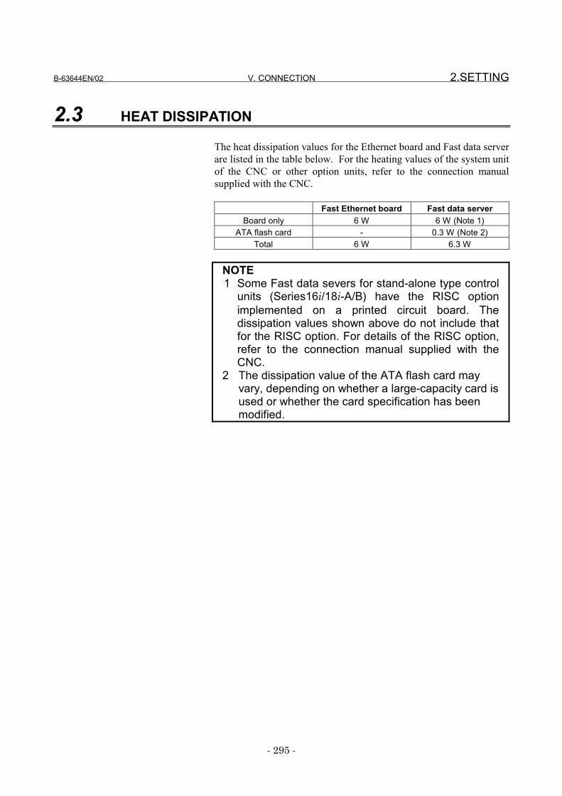
B-63644EN/02 V. CONNECTION 2.SETTING
- 295 -
2.3 HEAT DISSIPATION
The heat dissipation values for the Ethernet board and Fast data serverare listed in the table below. For the heating values of the system unitof the CNC or other option units, refer to the connection manualsupplied with the CNC.
Fast Ethernet board Fast data serverBoard only 6 W 6 W (Note 1)
ATA flash card - 0.3 W (Note 2)Total 6 W 6.3 W
NOTE1 Some Fast data severs for stand-alone type control
units (Series16i/18i-A/B) have the RISC optionimplemented on a printed circuit board. Thedissipation values shown above do not include thatfor the RISC option. For details of the RISC option,refer to the connection manual supplied with theCNC.
2 The dissipation value of the ATA flash card mayvary, depending on whether a large-capacity card isused or whether the card specification has beenmodified.

3.INSTALLATION V. CONNECTION B-63644EN/02
- 296 -
3 INSTALLATIONThis chapter provides information relating to the installation of the FastEthernet board and Fast data server.
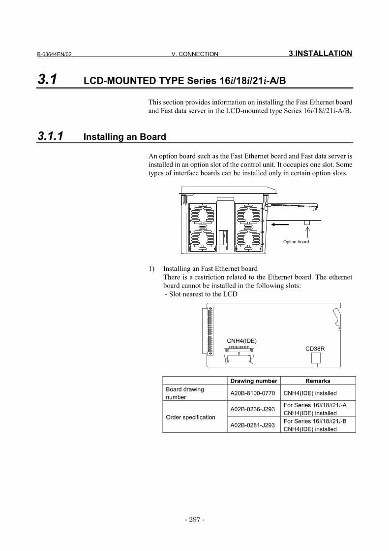
B-63644EN/02 V. CONNECTION 3.INSTALLATION
- 297 -
3.1 LCD-MOUNTED TYPE Series 16iiii/18iiii/21iiii-A/B
This section provides information on installing the Fast Ethernet boardand Fast data server in the LCD-mounted type Series 16i/18i/21i-A/B.
3.1.1 Installing an Board
An option board such as the Fast Ethernet board and Fast data server isinstalled in an option slot of the control unit. It occupies one slot. Sometypes of interface boards can be installed only in certain option slots.
Option board
1) Installing an Fast Ethernet boardThere is a restriction related to the Ethernet board. The ethernetboard cannot be installed in the following slots: - Slot nearest to the LCD
Drawing number RemarksBoard drawingnumber A20B-8100-0770 CNH4(IDE) installed
A02B-0236-J293For Series 16i/18i/21i-ACNH4(IDE) installed
Order specificationA02B-0281-J293
For Series 16i/18i/21i-BCNH4(IDE) installed
CNH4(IDE)CD38R
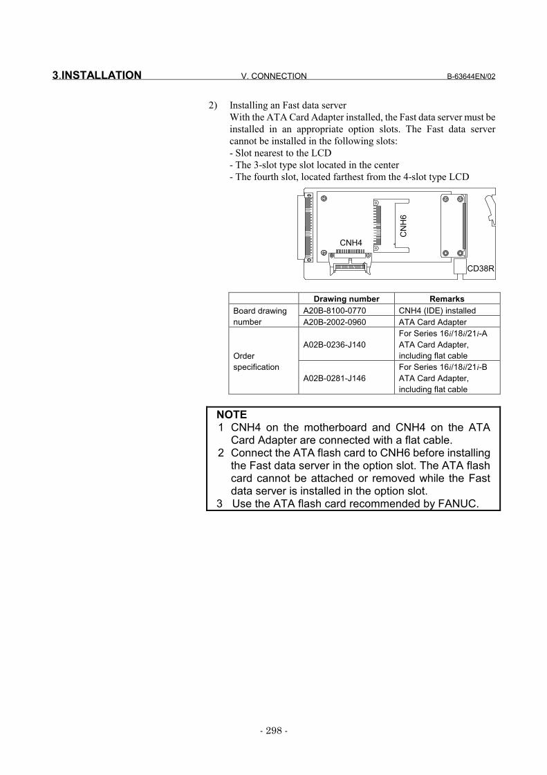
3.INSTALLATION V. CONNECTION B-63644EN/02
- 298 -
2) Installing an Fast data serverWith the ATA Card Adapter installed, the Fast data server must beinstalled in an appropriate option slots. The Fast data servercannot be installed in the following slots:- Slot nearest to the LCD- The 3-slot type slot located in the center- The fourth slot, located farthest from the 4-slot type LCD
Drawing number RemarksA20B-8100-0770 CNH4 (IDE) installedBoard drawing
number A20B-2002-0960 ATA Card Adapter
A02B-0236-J140For Series 16i/18i/21i-AATA Card Adapter,including flat cableOrder
specificationA02B-0281-J146
For Series 16i/18i/21i-BATA Card Adapter,including flat cable
NOTE1 CNH4 on the motherboard and CNH4 on the ATA
Card Adapter are connected with a flat cable.2 Connect the ATA flash card to CNH6 before installing
the Fast data server in the option slot. The ATA flashcard cannot be attached or removed while the Fastdata server is installed in the option slot.
3 Use the ATA flash card recommended by FANUC.
CD38R
CNH4
CN
H6
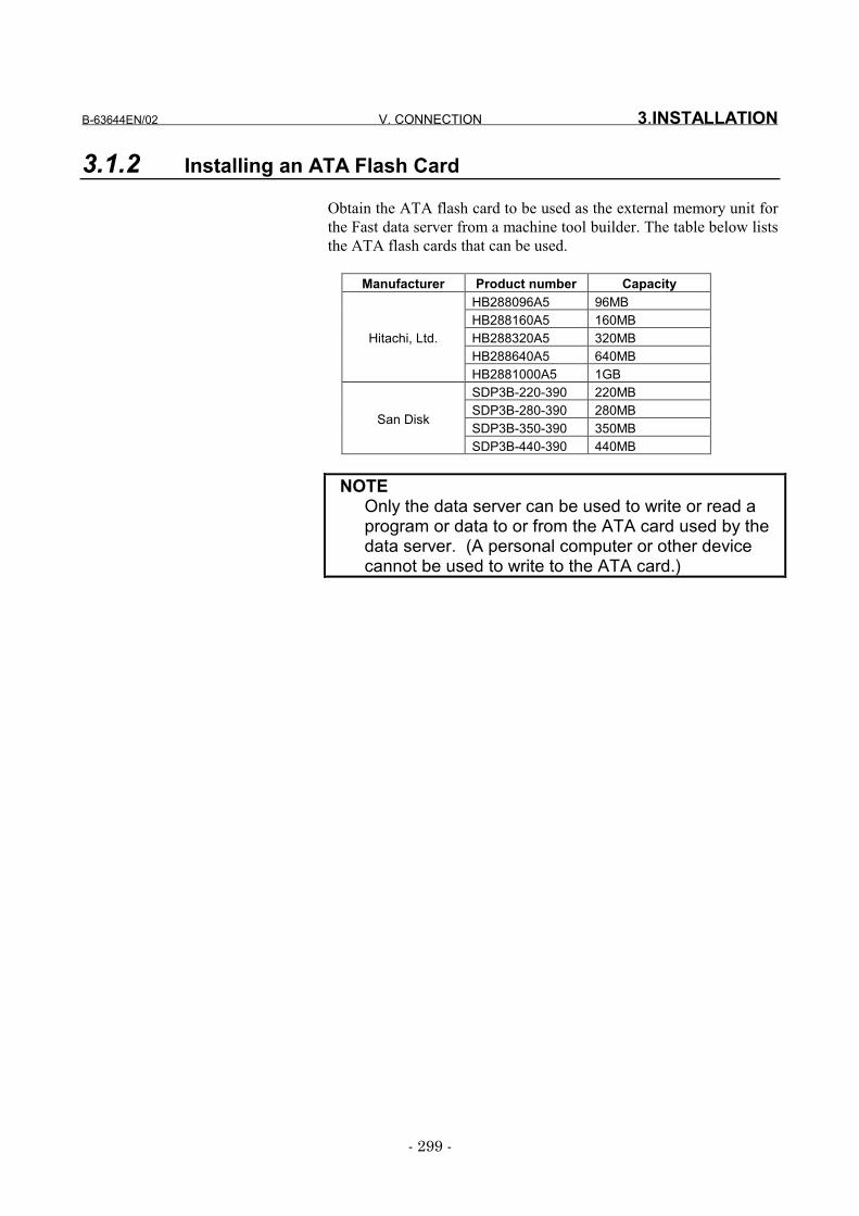
B-63644EN/02 V. CONNECTION 3.INSTALLATION
- 299 -
3.1.2 Installing an ATA Flash Card
Obtain the ATA flash card to be used as the external memory unit forthe Fast data server from a machine tool builder. The table below liststhe ATA flash cards that can be used.
Manufacturer Product number CapacityHB288096A5 96MBHB288160A5 160MBHB288320A5 320MBHB288640A5 640MB
Hitachi, Ltd.
HB2881000A5 1GBSDP3B-220-390 220MBSDP3B-280-390 280MBSDP3B-350-390 350MB
San Disk
SDP3B-440-390 440MB
NOTEOnly the data server can be used to write or read aprogram or data to or from the ATA card used by thedata server. (A personal computer or other devicecannot be used to write to the ATA card.)
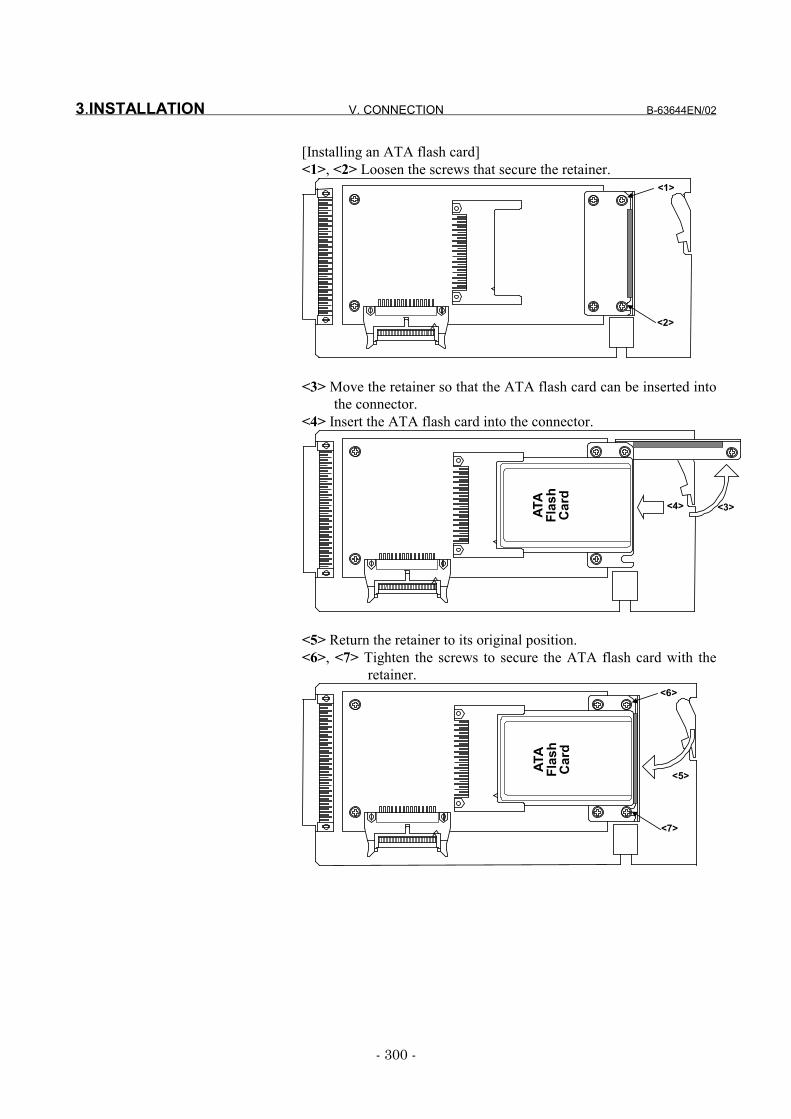
3.INSTALLATION V. CONNECTION B-63644EN/02
- 300 -
[Installing an ATA flash card]<1>, <2> Loosen the screws that secure the retainer.
<1>
<2>
<3> Move the retainer so that the ATA flash card can be inserted intothe connector.
<4> Insert the ATA flash card into the connector.
ATA
Flash
Card
<4> <3>
<5> Return the retainer to its original position.<6>, <7> Tighten the screws to secure the ATA flash card with the
retainer.
ATA
Flash
Card
<5>
<6>
<7>
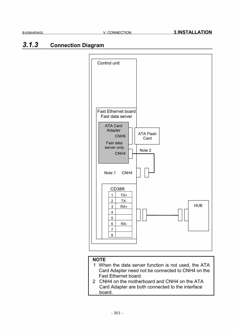
B-63644EN/02 V. CONNECTION 3.INSTALLATION
- 301 -
3.1.3 Connection Diagram
CD38R1 TX+2 TX-3 RX+456 RX-78
CNH4
CNH6
ATA CardAdapter
Fast Ethernet boardFast data server
Control unit
HUB
ATA FlashCard
Note 1 CNH4
Note 2
Fast dataserver only
NOTE1 When the data server function is not used, the ATA
Card Adapter need not be connected to CNH4 on theFast Ethernet board.
2 CNH4 on the motherboard and CNH4 on the ATACard Adapter are both connected to the interfaceboard.
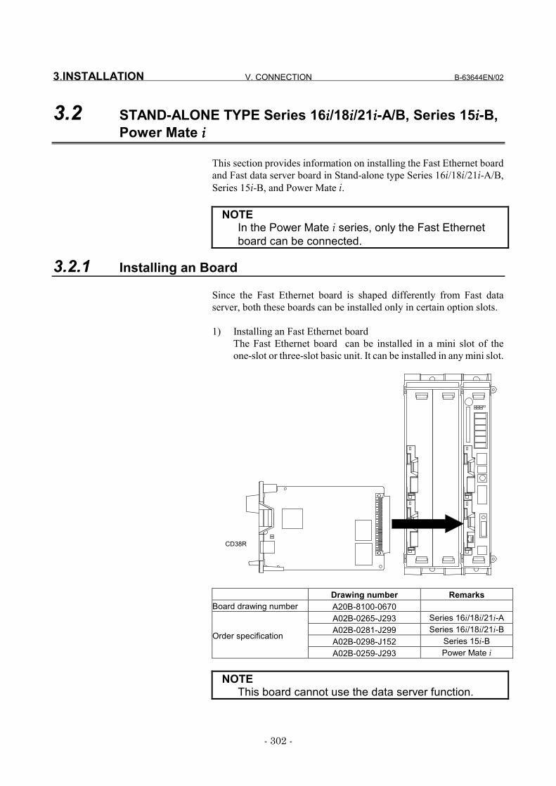
3.INSTALLATION V. CONNECTION B-63644EN/02
- 302 -
3.2 STAND-ALONE TYPE Series 16iiii/18iiii/21iiii-A/B, Series 15iiii-B,Power Mate iiii
This section provides information on installing the Fast Ethernet boardand Fast data server board in Stand-alone type Series 16i/18i/21i-A/B,Series 15i-B, and Power Mate i.
NOTEIn the Power Mate i series, only the Fast Ethernetboard can be connected.
3.2.1 Installing an Board
Since the Fast Ethernet board is shaped differently from Fast dataserver, both these boards can be installed only in certain option slots.
1) Installing an Fast Ethernet boardThe Fast Ethernet board can be installed in a mini slot of theone-slot or three-slot basic unit. It can be installed in any mini slot.
CD38R
Drawing number RemarksBoard drawing number A20B-8100-0670
A02B-0265-J293 Series 16i/18i/21i-AA02B-0281-J299 Series 16i/18i/21i-BA02B-0298-J152 Series 15i-BOrder specification
A02B-0259-J293 Power Mate i
NOTEThis board cannot use the data server function.
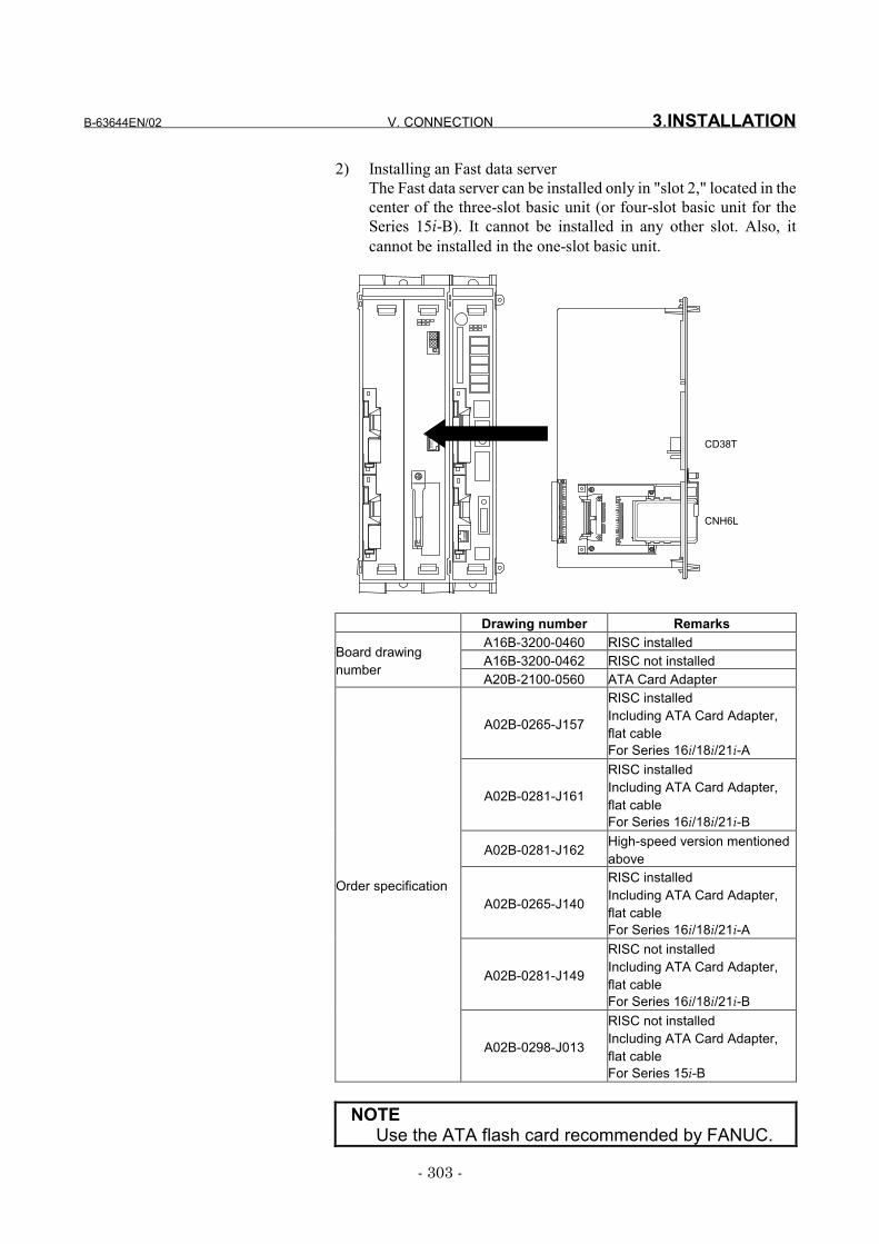
B-63644EN/02 V. CONNECTION 3.INSTALLATION
- 303 -
2) Installing an Fast data serverThe Fast data server can be installed only in "slot 2," located in thecenter of the three-slot basic unit (or four-slot basic unit for theSeries 15i-B). It cannot be installed in any other slot. Also, itcannot be installed in the one-slot basic unit.
CD38T
CNH6L
Drawing number RemarksA16B-3200-0460 RISC installedA16B-3200-0462 RISC not installedBoard drawing
numberA20B-2100-0560 ATA Card Adapter
A02B-0265-J157
RISC installedIncluding ATA Card Adapter,flat cableFor Series 16i/18i/21i-A
A02B-0281-J161
RISC installedIncluding ATA Card Adapter,flat cableFor Series 16i/18i/21i-B
A02B-0281-J162 High-speed version mentionedabove
A02B-0265-J140
RISC installedIncluding ATA Card Adapter,flat cableFor Series 16i/18i/21i-A
A02B-0281-J149
RISC not installedIncluding ATA Card Adapter,flat cableFor Series 16i/18i/21i-B
Order specification
A02B-0298-J013
RISC not installedIncluding ATA Card Adapter,flat cableFor Series 15i-B
NOTEUse the ATA flash card recommended by FANUC.
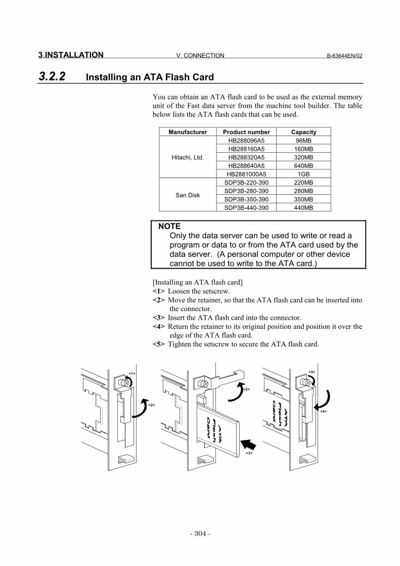
3.INSTALLATION V. CONNECTION B-63644EN/02
- 304 -
3.2.2 Installing an ATA Flash Card
You can obtain an ATA flash card to be used as the external memoryunit of the Fast data server from the machine tool builder. The tablebelow lists the ATA flash cards that can be used.
Manufacturer Product number CapacityHB288096A5 96MBHB288160A5 160MBHB288320A5 320MBHB288640A5 640MB
Hitachi, Ltd.
HB2881000A5 1GBSDP3B-220-390 220MBSDP3B-280-390 280MBSDP3B-350-390 350MB
San Disk
SDP3B-440-390 440MB
NOTEOnly the data server can be used to write or read aprogram or data to or from the ATA card used by thedata server. (A personal computer or other devicecannot be used to write to the ATA card.)
[Installing an ATA flash card]<1> Loosen the setscrew.<2> Move the retainer, so that the ATA flash card can be inserted into
the connector.<3> Insert the ATA flash card into the connector.<4> Return the retainer to its original position and position it over the
edge of the ATA flash card.<5> Tighten the setscrew to secure the ATA flash card.
<1>
<2>
<2>
<3>
<4>
<5>
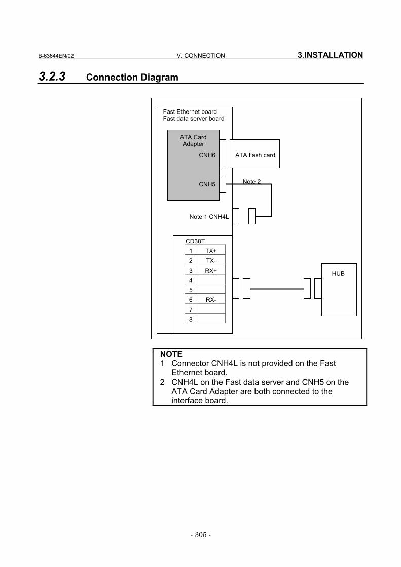
B-63644EN/02 V. CONNECTION 3.INSTALLATION
- 305 -
3.2.3 Connection Diagram
NOTE1 Connector CNH4L is not provided on the Fast
Ethernet board.2 CNH4L on the Fast data server and CNH5 on the
ATA Card Adapter are both connected to theinterface board.
CD38T1 TX+2 TX-3 RX+456 RX-78
Note 1 CNH4L
CNH5
CNH6
ATA CardAdapter
Fast Ethernet boardFast data server board
ATA flash card
HUB
Note 2
4.HARDWARE CONNECTIONS V. CONNECTION B-63644EN/02
- 306 -
4 HARDWARE CONNECTIONSThis section describes information relating to the physical Ethernetconnection.
CAUTION1 Before connecting or disconnecting cables to and
from the Fast Ethernet board or Fast data server, cutthe power supply of CNC.
2 Please inquire of each manufacturer about theconstruction of network or the condition of using theequipment except the Fast Ethernet board/Fast dataserver (hub, transceiver, cable etc.). Whenconfiguring your network, you must take othersources of electrical noise into consideration toprevent your network from being influenced byelectrical noise. Make sure that network wiring issufficiently separated from power lines and othersources of electrical noise such as motors, andground each of the devices as necessary. Also, ahigh and insufficient ground impedance may causeinterference during communications. After installingthe machine, conduct a communications test beforeyou actually start operating the machine.We cannot ensure operation that is influenced bynetwork trouble caused by a device other than theFast Ethernet board or Fast data server.
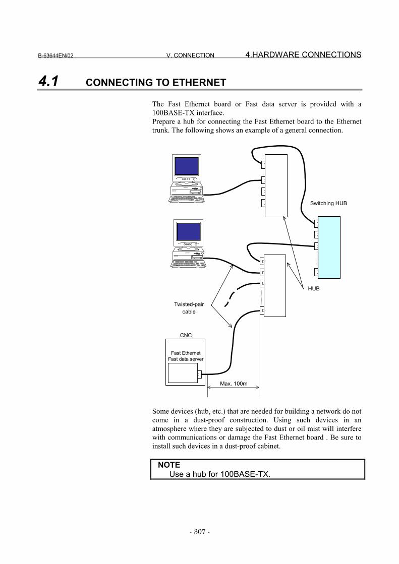
B-63644EN/02 V. CONNECTION 4.HARDWARE CONNECTIONS
- 307 -
4.1 CONNECTING TO ETHERNET
The Fast Ethernet board or Fast data server is provided with a100BASE-TX interface.Prepare a hub for connecting the Fast Ethernet board to the Ethernettrunk. The following shows an example of a general connection.
HUB
CNC
Fast EthernetFast data server
Max. 100m
Twisted-paircable
Switching HUB
Some devices (hub, etc.) that are needed for building a network do notcome in a dust-proof construction. Using such devices in anatmosphere where they are subjected to dust or oil mist will interferewith communications or damage the Fast Ethernet board . Be sure toinstall such devices in a dust-proof cabinet.
NOTEUse a hub for 100BASE-TX.
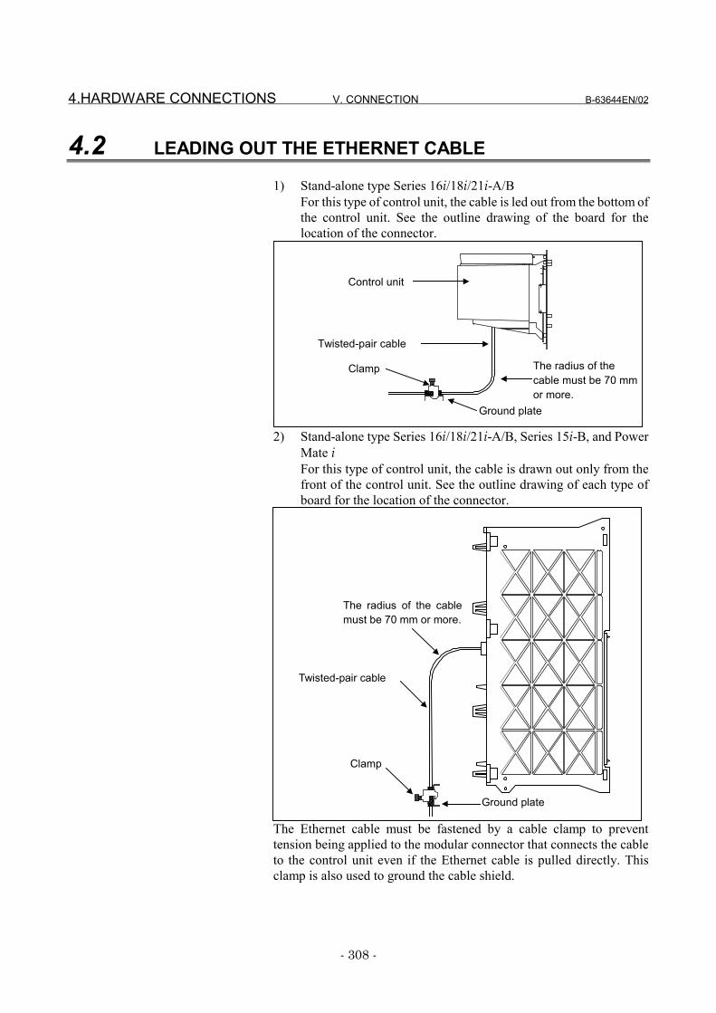
4.HARDWARE CONNECTIONS V. CONNECTION B-63644EN/02
- 308 -
4.2 LEADING OUT THE ETHERNET CABLE
1) Stand-alone type Series 16i/18i/21i-A/BFor this type of control unit, the cable is led out from the bottom ofthe control unit. See the outline drawing of the board for thelocation of the connector.
Control unit
Twisted-pair cable
Ground plate
Clamp The radius of thecable must be 70 mmor more.
2) Stand-alone type Series 16i/18i/21i-A/B, Series 15i-B, and PowerMate iFor this type of control unit, the cable is drawn out only from thefront of the control unit. See the outline drawing of each type ofboard for the location of the connector.
The radius of the cablemust be 70 mm or more.
Twisted-pair cable
Clamp
Ground plate
The Ethernet cable must be fastened by a cable clamp to preventtension being applied to the modular connector that connects the cableto the control unit even if the Ethernet cable is pulled directly. Thisclamp is also used to ground the cable shield.
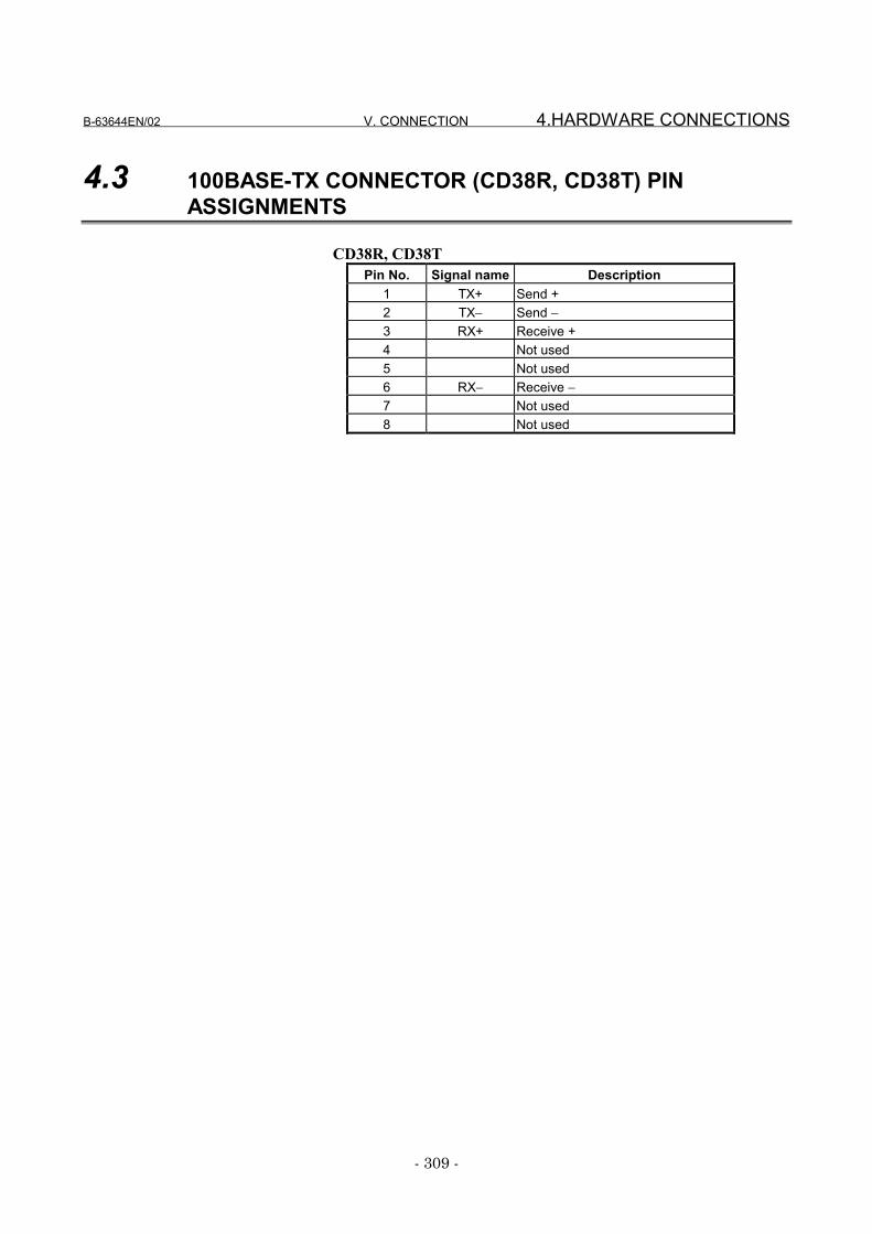
B-63644EN/02 V. CONNECTION 4.HARDWARE CONNECTIONS
- 309 -
4.3 100BASE-TX CONNECTOR (CD38R, CD38T) PINASSIGNMENTS
CD38R, CD38TPin No. Signal name Description
1 TX+ Send +2 TX− Send −3 RX+ Receive +4 Not used5 Not used6 RX− Receive −7 Not used8 Not used
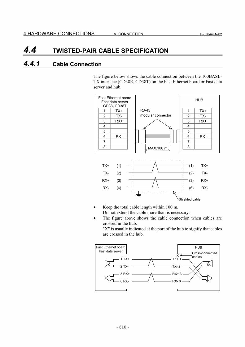
4.HARDWARE CONNECTIONS V. CONNECTION B-63644EN/02
- 310 -
4.4 TWISTED-PAIR CABLE SPECIFICATION
4.4.1 Cable Connection
The figure below shows the cable connection between the 100BASE-TX interface (CD38R, CD38T) on the Fast Ethernet board or Fast dataserver and hub.
• Keep the total cable length within 100 m.Do not extend the cable more than is necessary.
• The figure above shows the cable connection when cables arecrossed in the hub."X" is usually indicated at the port of the hub to signify that cablesare crossed in the hub.
1 TX+2 TX-3 RX+456 RX-78
Fast Ethernet boardFast data serverCD38, CD38T
1 TX+2 TX-3 RX+456 RX-78
HUB
TX+ (1)
TX- (2)
RX+ (3)
RX- (6)
(1) TX+
(2) TX-
(3) RX+
(6) RX-
Shielded cable
RJ-45modular connector
MAX.100 m
1 TX+
2 TX-
3 RX+
6 RX-
TX+ 1
TX- 2
RX+ 3
RX- 6
HUB
X
Fast Ethernet boardFast data server Cross-connected
cables
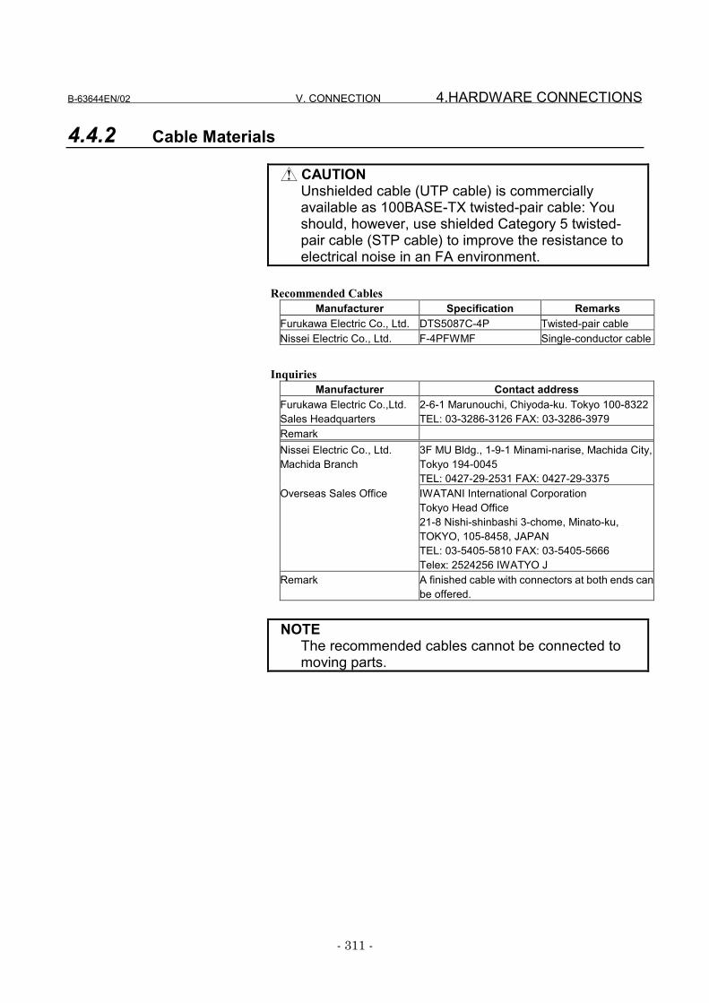
B-63644EN/02 V. CONNECTION 4.HARDWARE CONNECTIONS
- 311 -
4.4.2 Cable Materials
CAUTIONUnshielded cable (UTP cable) is commerciallyavailable as 100BASE-TX twisted-pair cable: Youshould, however, use shielded Category 5 twisted-pair cable (STP cable) to improve the resistance toelectrical noise in an FA environment.
Recommended CablesManufacturer Specification Remarks
Furukawa Electric Co., Ltd. DTS5087C-4P Twisted-pair cableNissei Electric Co., Ltd. F-4PFWMF Single-conductor cable
InquiriesManufacturer Contact address
Furukawa Electric Co.,Ltd.Sales Headquarters
2-6-1 Marunouchi, Chiyoda-ku. Tokyo 100-8322TEL: 03-3286-3126 FAX: 03-3286-3979
RemarkNissei Electric Co., Ltd.Machida Branch
3F MU Bldg., 1-9-1 Minami-narise, Machida City,Tokyo 194-0045TEL: 0427-29-2531 FAX: 0427-29-3375
Overseas Sales Office IWATANI International CorporationTokyo Head Office21-8 Nishi-shinbashi 3-chome, Minato-ku,TOKYO, 105-8458, JAPANTEL: 03-5405-5810 FAX: 03-5405-5666Telex: 2524256 IWATYO J
Remark A finished cable with connectors at both ends canbe offered.
NOTEThe recommended cables cannot be connected tomoving parts.
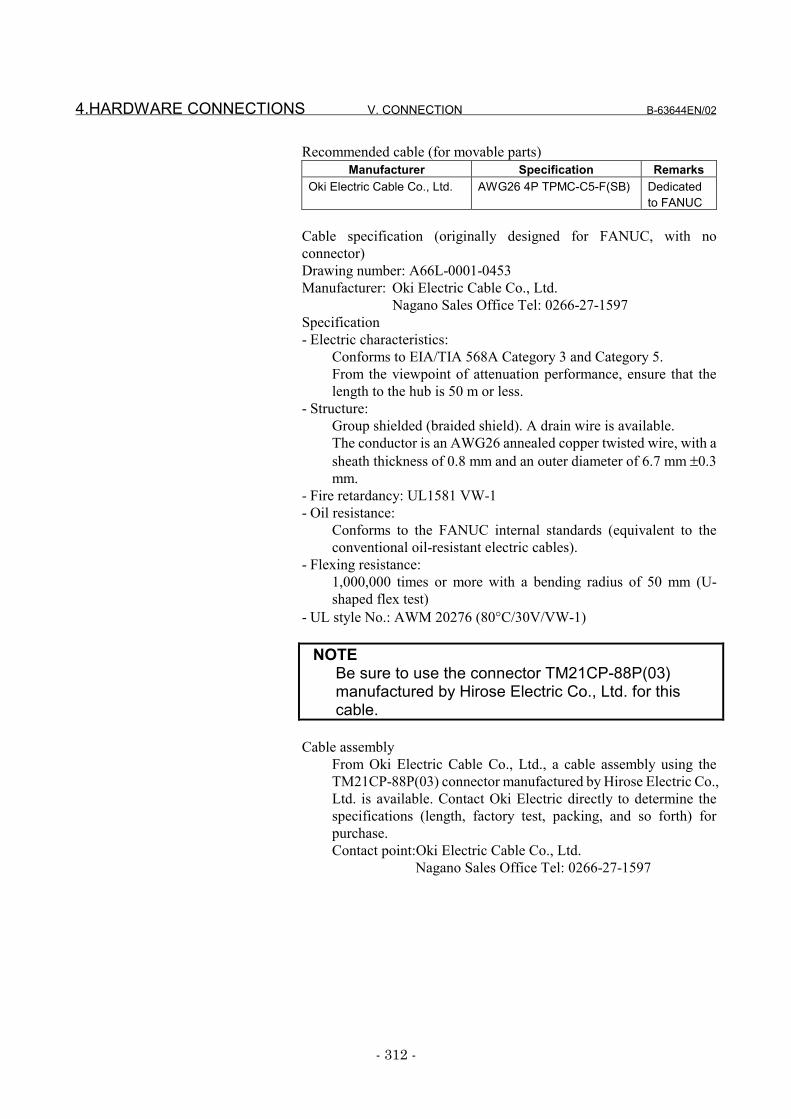
4.HARDWARE CONNECTIONS V. CONNECTION B-63644EN/02
- 312 -
Recommended cable (for movable parts)Manufacturer Specification Remarks
Oki Electric Cable Co., Ltd. AWG26 4P TPMC-C5-F(SB) Dedicatedto FANUC
Cable specification (originally designed for FANUC, with noconnector)Drawing number: A66L-0001-0453Manufacturer: Oki Electric Cable Co., Ltd.
Nagano Sales Office Tel: 0266-27-1597Specification- Electric characteristics:
Conforms to EIA/TIA 568A Category 3 and Category 5.From the viewpoint of attenuation performance, ensure that thelength to the hub is 50 m or less.
- Structure:Group shielded (braided shield). A drain wire is available.The conductor is an AWG26 annealed copper twisted wire, with asheath thickness of 0.8 mm and an outer diameter of 6.7 mm ±0.3mm.
- Fire retardancy: UL1581 VW-1- Oil resistance:
Conforms to the FANUC internal standards (equivalent to theconventional oil-resistant electric cables).
- Flexing resistance:1,000,000 times or more with a bending radius of 50 mm (U-shaped flex test)
- UL style No.: AWM 20276 (80°C/30V/VW-1)
NOTEBe sure to use the connector TM21CP-88P(03)manufactured by Hirose Electric Co., Ltd. for thiscable.
Cable assemblyFrom Oki Electric Cable Co., Ltd., a cable assembly using theTM21CP-88P(03) connector manufactured by Hirose Electric Co.,Ltd. is available. Contact Oki Electric directly to determine thespecifications (length, factory test, packing, and so forth) forpurchase.Contact point:Oki Electric Cable Co., Ltd.
Nagano Sales Office Tel: 0266-27-1597
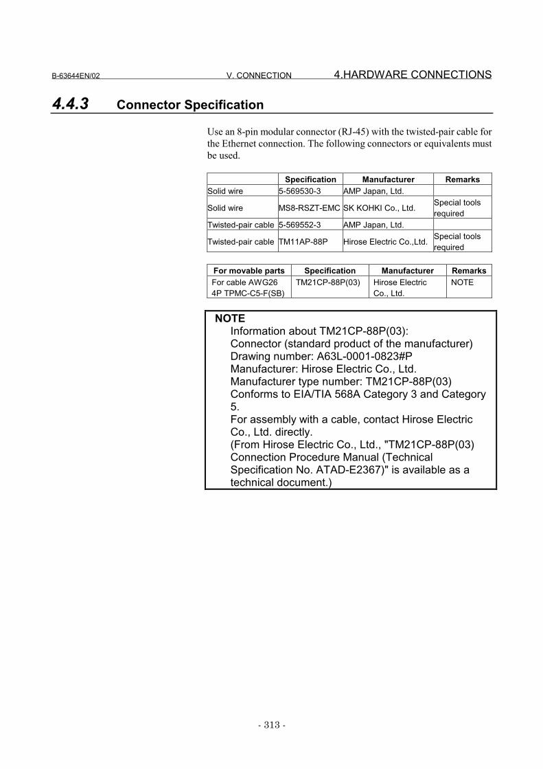
B-63644EN/02 V. CONNECTION 4.HARDWARE CONNECTIONS
- 313 -
4.4.3 Connector Specification
Use an 8-pin modular connector (RJ-45) with the twisted-pair cable forthe Ethernet connection. The following connectors or equivalents mustbe used.
Specification Manufacturer RemarksSolid wire 5-569530-3 AMP Japan, Ltd.
Solid wire MS8-RSZT-EMC SK KOHKI Co., Ltd. Special toolsrequired
Twisted-pair cable 5-569552-3 AMP Japan, Ltd.
Twisted-pair cable TM11AP-88P Hirose Electric Co.,Ltd. Special toolsrequired
For movable parts Specification Manufacturer RemarksFor cable AWG264P TPMC-C5-F(SB)
TM21CP-88P(03) Hirose ElectricCo., Ltd.
NOTE
NOTEInformation about TM21CP-88P(03):Connector (standard product of the manufacturer)Drawing number: A63L-0001-0823#PManufacturer: Hirose Electric Co., Ltd.Manufacturer type number: TM21CP-88P(03)Conforms to EIA/TIA 568A Category 3 and Category5.For assembly with a cable, contact Hirose ElectricCo., Ltd. directly.(From Hirose Electric Co., Ltd., "TM21CP-88P(03)Connection Procedure Manual (TechnicalSpecification No. ATAD-E2367)" is available as atechnical document.)
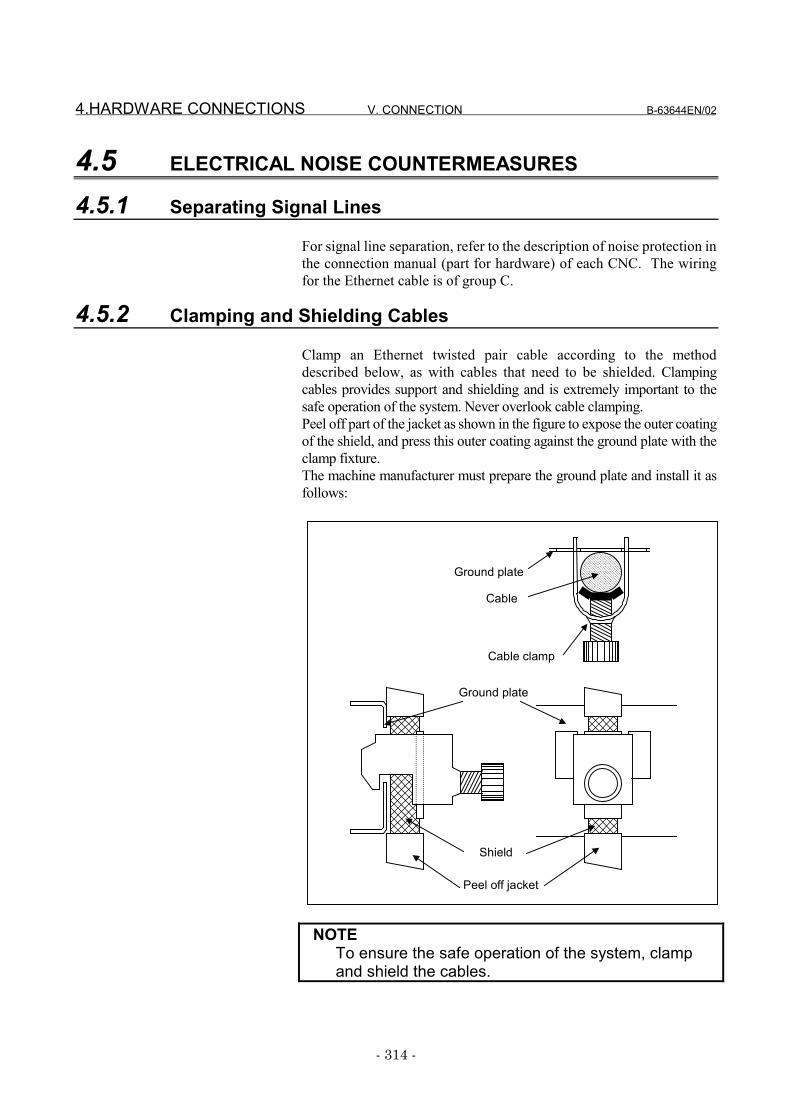
4.HARDWARE CONNECTIONS V. CONNECTION B-63644EN/02
- 314 -
4.5 ELECTRICAL NOISE COUNTERMEASURES
4.5.1 Separating Signal Lines
For signal line separation, refer to the description of noise protection inthe connection manual (part for hardware) of each CNC. The wiringfor the Ethernet cable is of group C.
4.5.2 Clamping and Shielding Cables
Clamp an Ethernet twisted pair cable according to the methoddescribed below, as with cables that need to be shielded. Clampingcables provides support and shielding and is extremely important to thesafe operation of the system. Never overlook cable clamping.Peel off part of the jacket as shown in the figure to expose the outer coatingof the shield, and press this outer coating against the ground plate with theclamp fixture.The machine manufacturer must prepare the ground plate and install it asfollows:
NOTETo ensure the safe operation of the system, clampand shield the cables.
Shield
Peel off jacket
Ground plate
Ground plate
Cable
Cable clamp
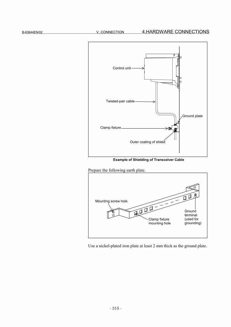
B-63644EN/02 V. CONNECTION 4.HARDWARE CONNECTIONS
- 315 -
Control unit
Twisted-pair cable
Ground plate
Clamp fixture
Outer coating of shield
Example of Shielding of Transceiver Cable
Prepare the following earth plate.
Mounting screw hole
Groundterminal(used forgrounding)
Clamp fixturemounting hole
Use a nickel-plated iron plate at least 2 mm thick as the ground plate.
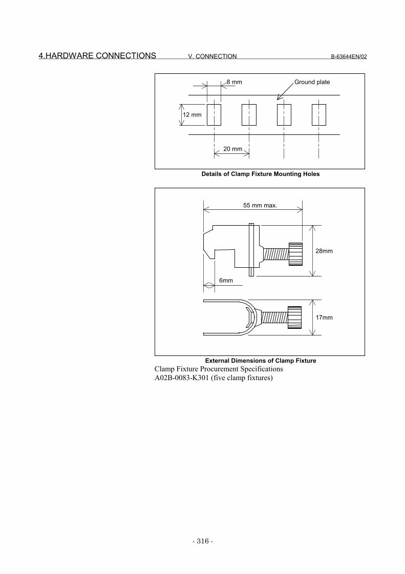
4.HARDWARE CONNECTIONS V. CONNECTION B-63644EN/02
- 316 -
Ground plate 8 mm
12 mm
20 mm
Details of Clamp Fixture Mounting Holes
55 mm max.
28mm
6mm
17mm
External Dimensions of Clamp FixtureClamp Fixture Procurement SpecificationsA02B-0083-K301 (five clamp fixtures)
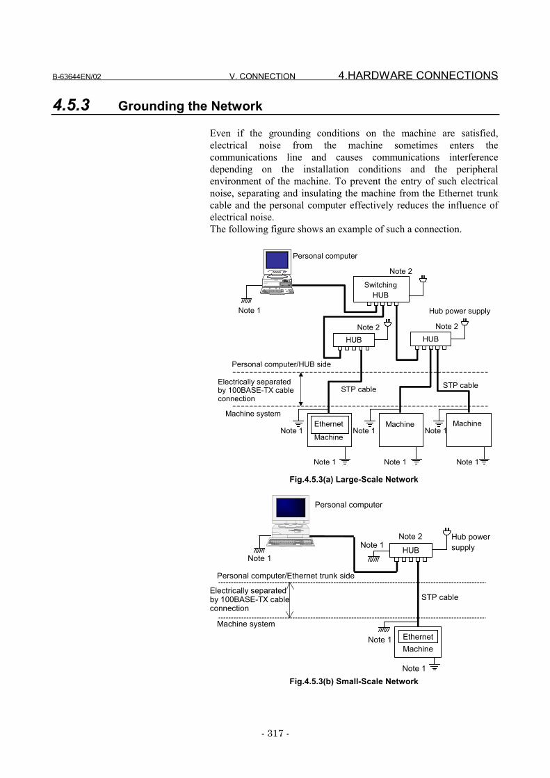
B-63644EN/02 V. CONNECTION 4.HARDWARE CONNECTIONS
- 317 -
4.5.3 Grounding the Network
Even if the grounding conditions on the machine are satisfied,electrical noise from the machine sometimes enters thecommunications line and causes communications interferencedepending on the installation conditions and the peripheralenvironment of the machine. To prevent the entry of such electricalnoise, separating and insulating the machine from the Ethernet trunkcable and the personal computer effectively reduces the influence ofelectrical noise.The following figure shows an example of such a connection.
Note 1
Electrically separatedby 100BASE-TX cableconnection
Note 1Note 1
Note 1
Note 2
Note 1Note 1
Note 1
Ethernet
MachineMachine Machine
STP cable STP cable
Personal computer/HUB side
Machine system
Note 2
HUBHUB
SwitchingHUB
Personal computer
Note 2
Hub power supply
Fig.4.5.3(a) Large-Scale Network
Hub powersupply
Electrically separatedby 100BASE-TX cableconnection
Note 1
HUB
STP cable
Personal computer
Note 1
Note 1Note 1
Personal computer/Ethernet trunk side
Machine systemEthernetMachine
Note 2
Fig.4.5.3(b) Small-Scale Network
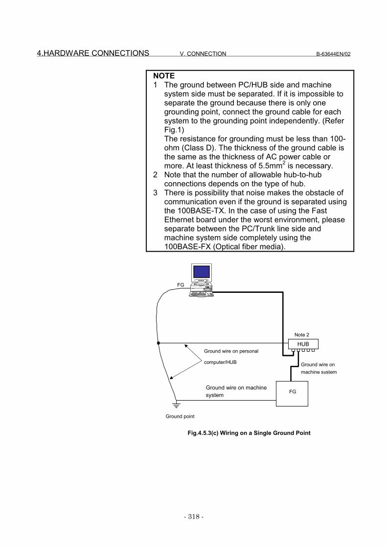
4.HARDWARE CONNECTIONS V. CONNECTION B-63644EN/02
- 318 -
NOTE1 The ground between PC/HUB side and machine
system side must be separated. If it is impossible toseparate the ground because there is only onegrounding point, connect the ground cable for eachsystem to the grounding point independently. (ReferFig.1)The resistance for grounding must be less than 100-ohm (Class D). The thickness of the ground cable isthe same as the thickness of AC power cable ormore. At least thickness of 5.5mm2 is necessary.
2 Note that the number of allowable hub-to-hubconnections depends on the type of hub.
3 There is possibility that noise makes the obstacle ofcommunication even if the ground is separated usingthe 100BASE-TX. In the case of using the FastEthernet board under the worst environment, pleaseseparate between the PC/Trunk line side andmachine system side completely using the100BASE-FX (Optical fiber media).
Ground wire onmachine system
Note 2
Ground wire on machinesystem
Ground point
FG
Ground wire on personal
computer/HUB
HUB
FG
Fig.4.5.3(c) Wiring on a Single Ground Point
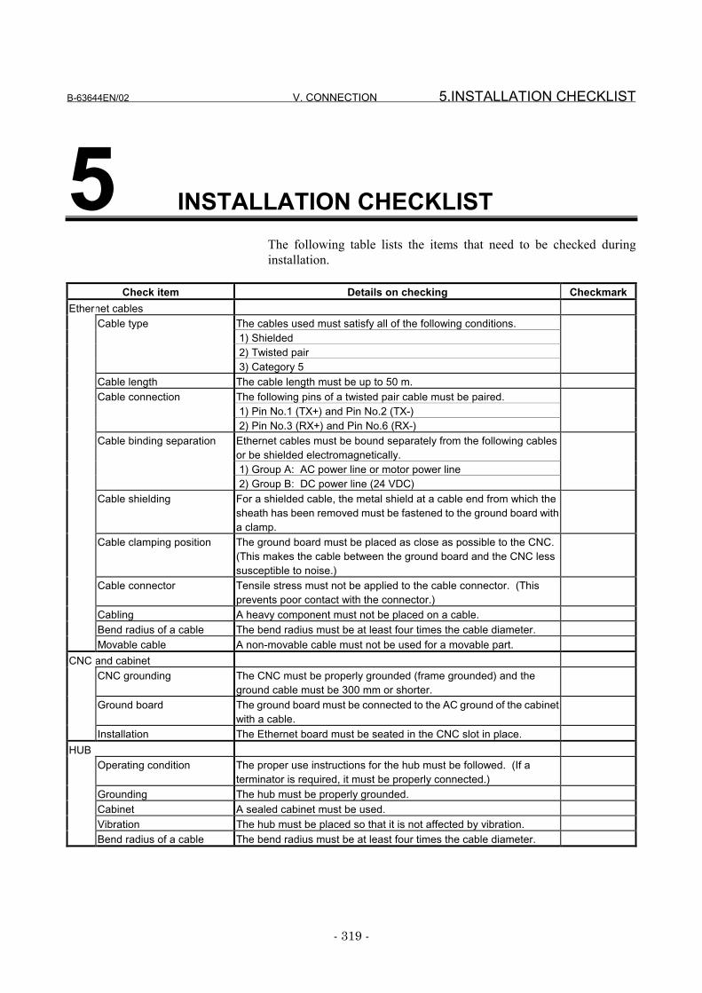
B-63644EN/02 V. CONNECTION 5.INSTALLATION CHECKLIST
- 319 -
5 INSTALLATION CHECKLISTThe following table lists the items that need to be checked duringinstallation.
Check item Details on checking CheckmarkEthernet cables
The cables used must satisfy all of the following conditions. 1) Shielded 2) Twisted pair
Cable type
3) Category 5Cable length The cable length must be up to 50 m.
The following pins of a twisted pair cable must be paired. 1) Pin No.1 (TX+) and Pin No.2 (TX-)
Cable connection
2) Pin No.3 (RX+) and Pin No.6 (RX-)Ethernet cables must be bound separately from the following cablesor be shielded electromagnetically. 1) Group A: AC power line or motor power line
Cable binding separation
2) Group B: DC power line (24 VDC)Cable shielding For a shielded cable, the metal shield at a cable end from which the
sheath has been removed must be fastened to the ground board witha clamp.
Cable clamping position The ground board must be placed as close as possible to the CNC.(This makes the cable between the ground board and the CNC lesssusceptible to noise.)
Cable connector Tensile stress must not be applied to the cable connector. (Thisprevents poor contact with the connector.)
Cabling A heavy component must not be placed on a cable.Bend radius of a cable The bend radius must be at least four times the cable diameter.Movable cable A non-movable cable must not be used for a movable part.
CNC and cabinetCNC grounding The CNC must be properly grounded (frame grounded) and the
ground cable must be 300 mm or shorter.Ground board The ground board must be connected to the AC ground of the cabinet
with a cable.Installation The Ethernet board must be seated in the CNC slot in place.
HUBOperating condition The proper use instructions for the hub must be followed. (If a
terminator is required, it must be properly connected.)Grounding The hub must be properly grounded.Cabinet A sealed cabinet must be used.Vibration The hub must be placed so that it is not affected by vibration.Bend radius of a cable The bend radius must be at least four times the cable diameter.


VI. MAINTENANCE

B-63644EN/02 VI. MAINTENANCE 1.Series 16i/18i/21i, Power Mate i MAINTENENCE INFORMATION
- 323 -
1 Series 16i/18i/21i, Power Mate iMAINTENENCE INFORMATION
This chapter describes the maintenance information for the FastEthernet and Fast data server for 16i/18i/21i-A/B and Power Mate i,.
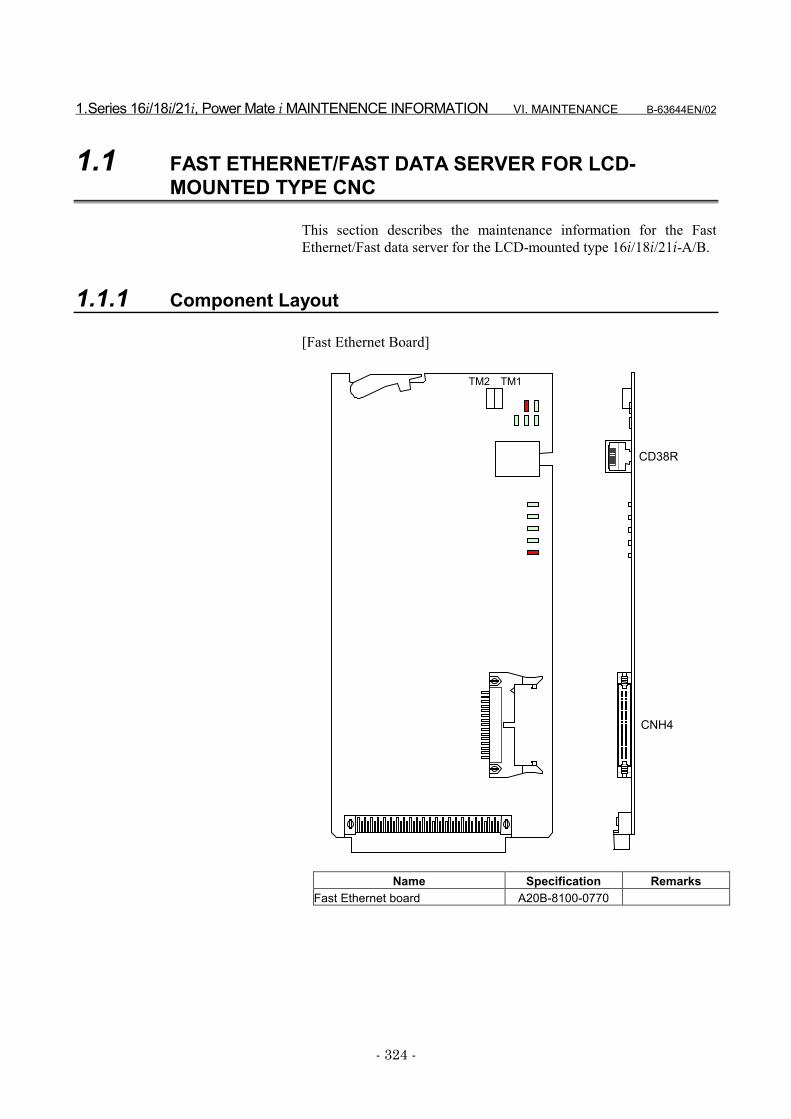
1.Series 16i/18i/21i, Power Mate i MAINTENENCE INFORMATION VI. MAINTENANCE B-63644EN/02
- 324 -
1.1 FAST ETHERNET/FAST DATA SERVER FOR LCD-MOUNTED TYPE CNC
This section describes the maintenance information for the FastEthernet/Fast data server for the LCD-mounted type 16i/18i/21i-A/B.
1.1.1 Component Layout
[Fast Ethernet Board]
CNH4
CD38R
TM2 TM1
Name Specification RemarksFast Ethernet board A20B-8100-0770
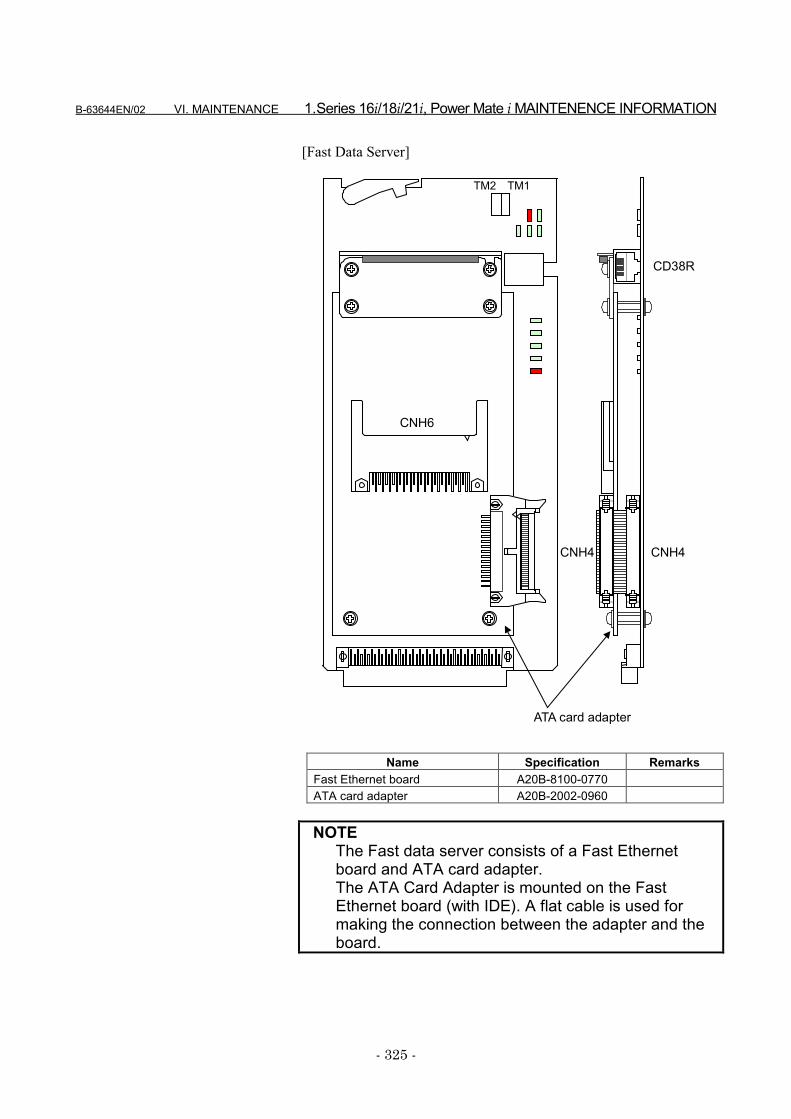
B-63644EN/02 VI. MAINTENANCE 1.Series 16i/18i/21i, Power Mate i MAINTENENCE INFORMATION
- 325 -
[Fast Data Server]
ATA card adapter
CNH4
CD38R
CNH6
CNH4
TM2 TM1
Name Specification RemarksFast Ethernet board A20B-8100-0770ATA card adapter A20B-2002-0960
NOTEThe Fast data server consists of a Fast Ethernetboard and ATA card adapter.The ATA Card Adapter is mounted on the FastEthernet board (with IDE). A flat cable is used formaking the connection between the adapter and theboard.
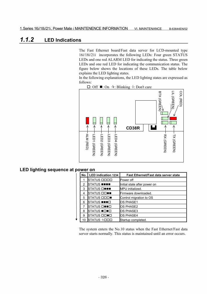
1.Series 16i/18i/21i, Power Mate i MAINTENENCE INFORMATION VI. MAINTENANCE B-63644EN/02
- 326 -
1.1.2 LED Indications
The Fast Ethernet board/Fast data server for LCD-mounted type16i/18i/21i incorporates the following LEDs: Four green STATUSLEDs and one red ALARM LED for indicating the status. Three greenLEDs and one red LED for indicating the communication status. Thefigure below shows the locations of these LEDs. The table belowexplains the LED lighting states.In the following explanations, the LED lighting states are expressed asfollows:
�: Off �: On �: Blinking �: Don't care
CD38R
LED4 (G
REEN
)
LED3 (G
REEN
)
LED2 (G
REEN
)
LED1 (G
REEN
)
ALM (R
ED)
RX (G
REEN
)
TX (GR
EEN)
BTX (GR
EEN)
CO
L (RED
)
LIL (GR
EEN)
LED lighting sequence at power onNo. LED indication 1234 Fast Ethernet/Fast data server state1 STATUS ���� Power off2 STATUS ���� Initial state after power on3 STATUS ���� MPU initialized.4 STATUS ���� Firmware downloaded.5 STATUS ���� Control migration to OS6 STATUS ���� OS PHASE17 STATUS ���� OS PHASE28 STATUS ���� OS PHASE39 STATUS ���� OS PHASE4
10 STATUS ���� Startup completed.
The system enters the No.10 status when the Fast Ethernet/Fast dataserver starts normally. This status is maintained until an error occurs.
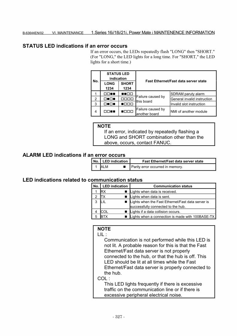
B-63644EN/02 VI. MAINTENANCE 1.Series 16i/18i/21i, Power Mate i MAINTENENCE INFORMATION
- 327 -
STATUS LED indications if an error occursIf an error occurs, the LEDs repeatedly flash "LONG" then "SHORT."(For "LONG," the LED lights for a long time. For "SHORT," the LEDlights for a short time.)
STATUS LEDindicationNo. LONG
1234SHORT
1234
Fast Ethernet/Fast data server state
1 ���� ���� SDRAM paruty alarm2 ���� ���� General invalid instruction3 ���� ����
Failure caused bythis board
Invalid slot instruction
4 ���� ����Failure caused byanother board NMI of another module
NOTEIf an error, indicated by repeatedly flashing aLONG and SHORT combination other than theabove, occurs, contact FANUC.
ALARM LED indications if an error occursNo. LED indication Fast Ethernet/Fast data server state1 ALM � Parity error occurred in memory.
LED indications related to communication statusNo. LED indication Communication status1 RX � Lights when data is received.2 TX � Lights when data is sent.3 LIL � Lights when the Fast Ethernet/Fast data server is
successfully connected to the hub.4 COL � Lights if a data collision occurs.5 BTX � Lights when a connection is made with 100BASE-TX.
NOTELIL :
Communication is not performed while this LED isnot lit. A probable reason for this is that the FastEthernet/Fast data server is not properlyconnected to the hub, or that the hub is off. ThisLED should be lit at all times while the FastEthernet/Fast data server is properly connected tothe hub.
COL :This LED lights frequently if there is excessivetraffic on the communication line or if there isexcessive peripheral electrical noise.
1.Series 16i/18i/21i, Power Mate i MAINTENENCE INFORMATION VI. MAINTENANCE B-63644EN/02
- 328 -
1.1.3 Setting Pins
On the board, the setting pins (TM1, TM2) are installed. Connect eachjumper plug to side A (factory-set state). Do not remove a jumper plug,and do not change the setting of a jumper plug. Otherwise, the boarddoes not operate normally.
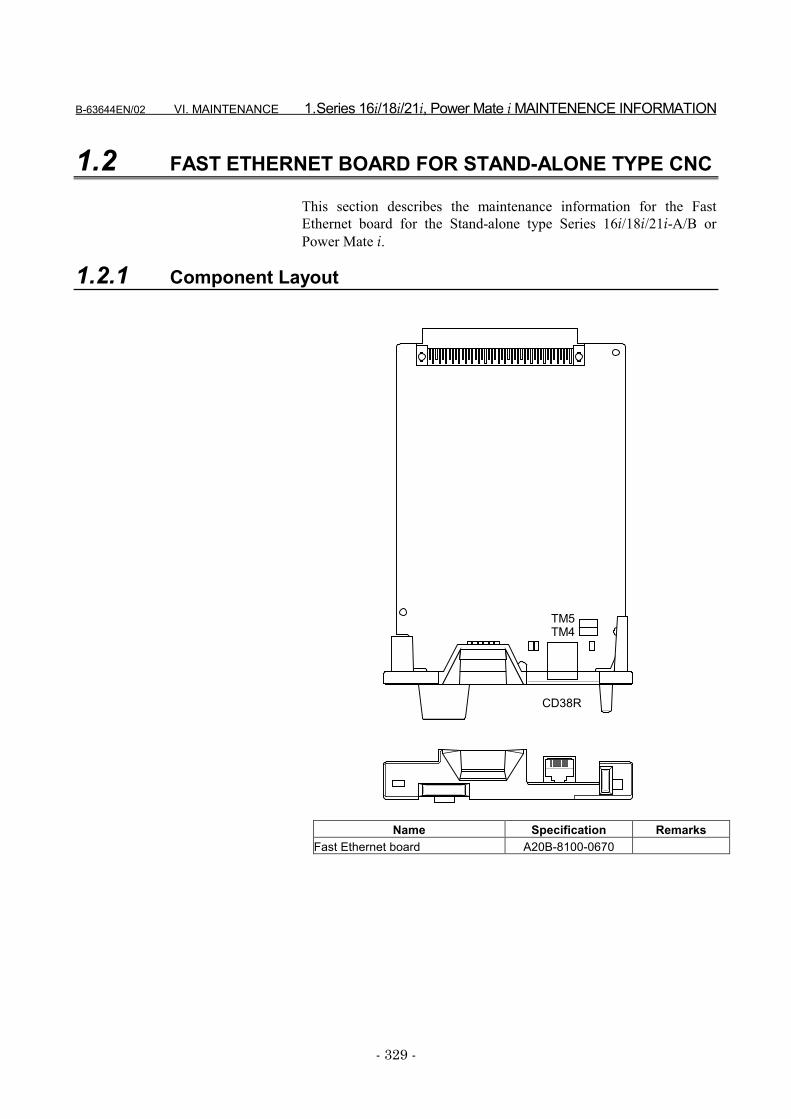
B-63644EN/02 VI. MAINTENANCE 1.Series 16i/18i/21i, Power Mate i MAINTENENCE INFORMATION
- 329 -
1.2 FAST ETHERNET BOARD FOR STAND-ALONE TYPE CNC
This section describes the maintenance information for the FastEthernet board for the Stand-alone type Series 16i/18i/21i-A/B orPower Mate i.
1.2.1 Component Layout
CD38R
TM5TM4
Name Specification RemarksFast Ethernet board A20B-8100-0670
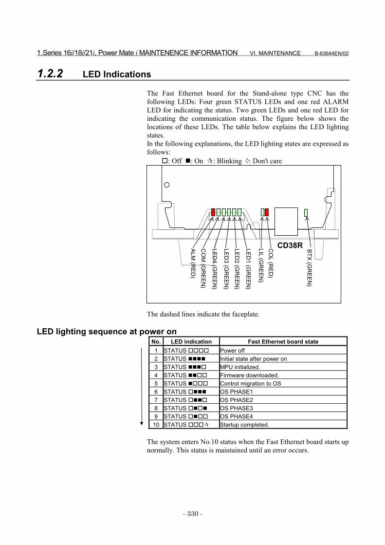
1.Series 16i/18i/21i, Power Mate i MAINTENENCE INFORMATION VI. MAINTENANCE B-63644EN/02
- 330 -
1.2.2 LED Indications
The Fast Ethernet board for the Stand-alone type CNC has thefollowing LEDs: Four green STATUS LEDs and one red ALARMLED for indicating the status. Two green LEDs and one red LED forindicating the communication status. The figure below shows thelocations of these LEDs. The table below explains the LED lightingstates.In the following explanations, the LED lighting states are expressed asfollows:
�: Off �: On �: Blinking �: Don't care
CD38RLED4 (G
REEN
)
LED3 (G
REEN
)
LED2 (G
REEN
)
LED1 (G
REEN
)
ALM (R
ED)
LIL (GR
EEN)
CO
L (RED
)
CO
M (G
REEN
)
BTX (GR
EEN)
The dashed lines indicate the faceplate.
LED lighting sequence at power onNo. LED indication Fast Ethernet board state1 STATUS ���� Power off2 STATUS ���� Initial state after power on3 STATUS ���� MPU initialized.4 STATUS ���� Firmware downloaded.5 STATUS ���� Control migration to OS6 STATUS ���� OS PHASE17 STATUS ���� OS PHASE28 STATUS ���� OS PHASE39 STATUS ���� OS PHASE4
10 STATUS ���� Startup completed.
The system enters No.10 status when the Fast Ethernet board starts upnormally. This status is maintained until an error occurs.
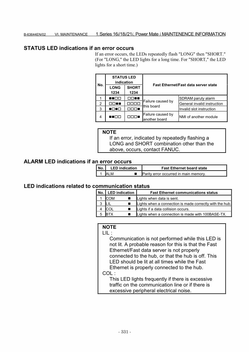
B-63644EN/02 VI. MAINTENANCE 1.Series 16i/18i/21i, Power Mate i MAINTENENCE INFORMATION
- 331 -
STATUS LED indications if an error occursIf an error occurs, the LEDs repeatedly flash "LONG" then "SHORT."(For "LONG," the LED lights for a long time. For "SHORT," the LEDlights for a short time.)
STATUS LEDindicationNo. LONG
1234SHORT
1234
Fast Ethernet/Fast data server state
1 ���� ���� SDRAM paruty alarm2 ���� ���� General invalid instruction3 ���� ����
Failure caused bythis board
Invalid slot instruction
4 ���� ����Failure caused byanother board NMI of another module
NOTEIf an error, indicated by repeatedly flashing aLONG and SHORT combination other than theabove, occurs, contact FANUC.
ALARM LED indications if an error occursNo. LED indication Fast Ethernet board state1 ALM � Parity error occurred in main memory.
LED indications related to communication statusNo. LED indication Fast Ethernet communications status1 COM � Lights when data is sent.3 LIL � Lights when a connection is made correctly with the hub.4 COL � Lights if a data collision occurs.5 BTX � Lights when a connection is made with 100BASE-TX.
NOTELIL :
Communication is not performed while this LED isnot lit. A probable reason for this is that the FastEthernet/Fast data server is not properlyconnected to the hub, or that the hub is off. ThisLED should be lit at all times while the FastEthernet is properly connected to the hub.
COL :This LED lights frequently if there is excessivetraffic on the communication line or if there isexcessive peripheral electrical noise.

1.Series 16i/18i/21i, Power Mate i MAINTENENCE INFORMATION VI. MAINTENANCE B-63644EN/02
- 332 -
1.2.3 Setting Pins
On the board, the setting pins (TM4, TM5) are installed. Connect eachjumper plug to side A (factory-set state). Do not remove a jumper plug,and do not change the setting of a jumper plug. Otherwise, the boarddoes not operate normally.
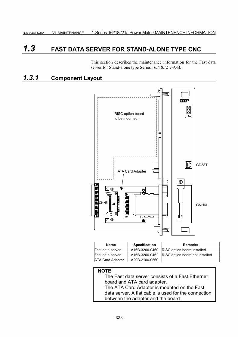
B-63644EN/02 VI. MAINTENANCE 1.Series 16i/18i/21i, Power Mate i MAINTENENCE INFORMATION
- 333 -
1.3 FAST DATA SERVER FOR STAND-ALONE TYPE CNC
This section describes the maintenance information for the Fast dataserver for Stand-alone type Series 16i/18i/21i-A/B.
1.3.1 Component Layout
RISC option boardto be mounted.
CD38T
CNH6L
ATA Card Adapter
CNH5
Name Specification RemarksFast data server A16B-3200-0460 RISC option board installedFast data server A16B-3200-0462 RISC option board not installedATA Card Adapter A20B-2100-0560
NOTEThe Fast data server consists of a Fast Ethernetboard and ATA card adapter.The ATA Card Adapter is mounted on the Fastdata server. A flat cable is used for the connectionbetween the adapter and the board.
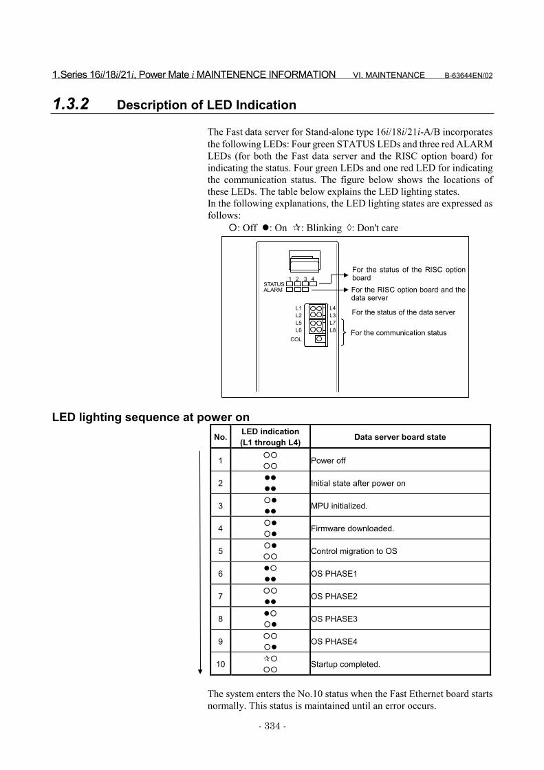
1.Series 16i/18i/21i, Power Mate i MAINTENENCE INFORMATION VI. MAINTENANCE B-63644EN/02
- 334 -
1.3.2 Description of LED Indication
The Fast data server for Stand-alone type 16i/18i/21i-A/B incorporatesthe following LEDs: Four green STATUS LEDs and three red ALARMLEDs (for both the Fast data server and the RISC option board) forindicating the status. Four green LEDs and one red LED for indicatingthe communication status. The figure below shows the locations ofthese LEDs. The table below explains the LED lighting states.In the following explanations, the LED lighting states are expressed asfollows:
�: Off �: On �: Blinking �: Don't care
LED lighting sequence at power onNo. LED indication
(L1 through L4) Data server board state
1 ��
��Power off
2 ��
��Initial state after power on
3 ��
��MPU initialized.
4 ��
��Firmware downloaded.
5 ��
��Control migration to OS
6 ��
��OS PHASE1
7 ��
��OS PHASE2
8 ��
��OS PHASE3
9 ��
��OS PHASE4
10 ��
��Startup completed.
The system enters the No.10 status when the Fast Ethernet board startsnormally. This status is maintained until an error occurs.
STATUS1 2 3 4
L1 For the status of the data server
For the communication status
L2L4L3
L5L6
L7L8
ALARM
COL
For the status of the RISC optionboardFor the RISC option board and thedata server
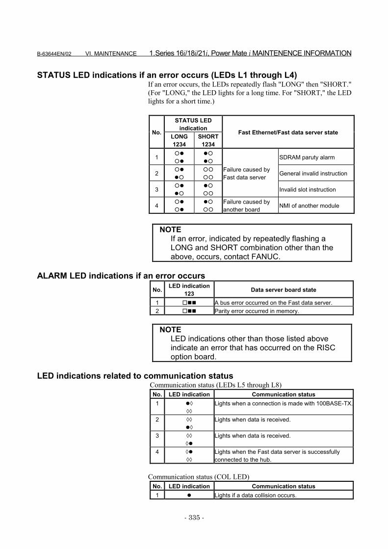
B-63644EN/02 VI. MAINTENANCE 1.Series 16i/18i/21i, Power Mate i MAINTENENCE INFORMATION
- 335 -
STATUS LED indications if an error occurs (LEDs L1 through L4)If an error occurs, the LEDs repeatedly flash "LONG" then "SHORT."(For "LONG," the LED lights for a long time. For "SHORT," the LEDlights for a short time.)
STATUS LEDindicationNo. LONG
1234SHORT
1234
Fast Ethernet/Fast data server state
1 ��
��
��
��SDRAM paruty alarm
2 ��
��
��
��General invalid instruction
3 ��
��
��
��
Failure caused byFast data server
Invalid slot instruction
4 ��
��
��
��
Failure caused byanother board NMI of another module
NOTEIf an error, indicated by repeatedly flashing aLONG and SHORT combination other than theabove, occurs, contact FANUC.
ALARM LED indications if an error occursNo. LED indication
123 Data server board state
1 ��� A bus error occurred on the Fast data server.2 ��� Parity error occurred in memory.
NOTELED indications other than those listed aboveindicate an error that has occurred on the RISCoption board.
LED indications related to communication status Communication status (LEDs L5 through L8)
No. LED indication Communication status1 ��
��
Lights when a connection is made with 100BASE-TX.
2 ��
��
Lights when data is received.
3 ��
��
Lights when data is received.
4 ��
��
Lights when the Fast data server is successfullyconnected to the hub.
Communication status (COL LED)No. LED indication Communication status1 � Lights if a data collision occurs.
1.Series 16i/18i/21i, Power Mate i MAINTENENCE INFORMATION VI. MAINTENANCE B-63644EN/02
- 336 -
NOTECOL:
This LED lights frequently if there is excessivetraffic on the communication line or if there isexcessive peripheral electrical noise.
1.3.3 Setting Pins
On the board, the setting pins (TM3, TM4) are installed. Connect eachjumper plug to side A (factory-set state). Do not remove a jumper plug,and do not change the setting of a jumper plug. Otherwise, the boarddoes not operate normally.
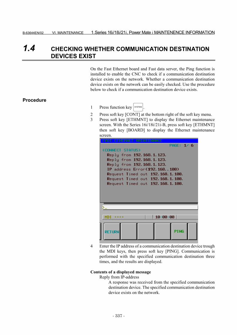
B-63644EN/02 VI. MAINTENANCE 1.Series 16i/18i/21i, Power Mate i MAINTENENCE INFORMATION
- 337 -
1.4 CHECKING WHETHER COMMUNICATION DESTINATIONDEVICES EXIST
On the Fast Ethernet board and Fast data server, the Ping function isinstalled to enable the CNC to check if a communication destinationdevice exists on the network. Whether a communication destinationdevice exists on the network can be easily checked. Use the procedurebelow to check if a communication destination device exists.
Procedure1 Press function key SYSTEM .2 Press soft key [CONT] at the bottom right of the soft key menu.3 Press soft key [ETHMNT] to display the Ethernet maintenance
screen. With the Series 16i/18i/21i-B, press soft key [ETHMNT]then soft key [BOARD] to display the Ethernet maintenancescreen.
4 Enter the IP address of a communication destination device troughthe MDI keys, then press soft key [PING]. Communication isperformed with the specified communication destination threetimes, and the results are displayed.
Contents of a displayed messageReply from IP-address
A response was received from the specified communicationdestination device. The specified communication destinationdevice exists on the network.
1.Series 16i/18i/21i, Power Mate i MAINTENENCE INFORMATION VI. MAINTENANCE B-63644EN/02
- 338 -
Request Timed out IP-addressNo response was received from the specified communicationdestination device. The specified communication destinationdevice does not exist on the network. Check if the power tothe communication destination device is turned on, andcheck also if the parameters are set and the network isinstalled correctly.
IP address Error (IP-address)The specified IP address is incorrect. Check the entered IPaddress.
Ping Service Error [error-code]The Ping function failed. Check if the parameters are setcorrectly.
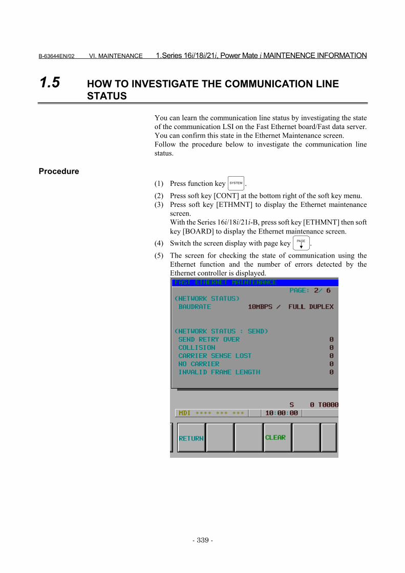
B-63644EN/02 VI. MAINTENANCE 1.Series 16i/18i/21i, Power Mate i MAINTENENCE INFORMATION
- 339 -
1.5 HOW TO INVESTIGATE THE COMMUNICATION LINESTATUS
You can learn the communication line status by investigating the stateof the communication LSI on the Fast Ethernet board/Fast data server.You can confirm this state in the Ethernet Maintenance screen.Follow the procedure below to investigate the communication linestatus.
Procedure(1) Press function key SYSTEM .(2) Press soft key [CONT] at the bottom right of the soft key menu.(3) Press soft key [ETHMNT] to display the Ethernet maintenance
screen.With the Series 16i/18i/21i-B, press soft key [ETHMNT] then softkey [BOARD] to display the Ethernet maintenance screen.
(4) Switch the screen display with page key PAGE .(5) The screen for checking the state of communication using the
Ethernet function and the number of errors detected by theEthernet controller is displayed.
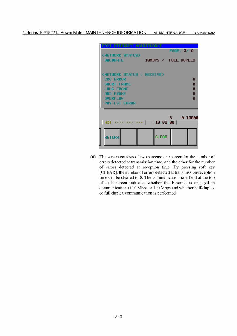
1.Series 16i/18i/21i, Power Mate i MAINTENENCE INFORMATION VI. MAINTENANCE B-63644EN/02
- 340 -
(6) The screen consists of two screens: one screen for the number oferrors detected at transmission time, and the other for the numberof errors detected at reception time. By pressing soft key[CLEAR], the number of errors detected at transmission/receptiontime can be cleared to 0. The communication rate field at the topof each screen indicates whether the Ethernet is engaged incommunication at 10 Mbps or 100 Mbps and whether half-duplexor full-duplex communication is performed.
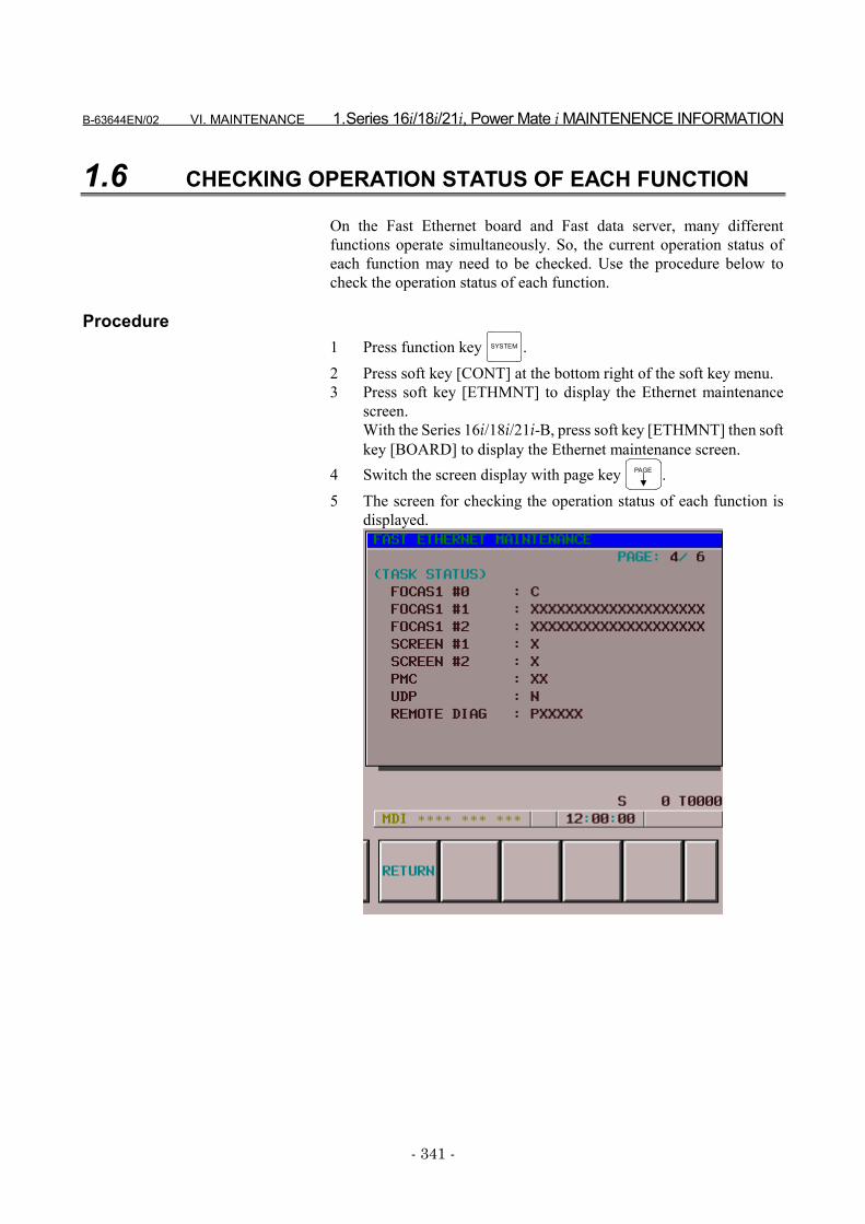
B-63644EN/02 VI. MAINTENANCE 1.Series 16i/18i/21i, Power Mate i MAINTENENCE INFORMATION
- 341 -
1.6 CHECKING OPERATION STATUS OF EACH FUNCTION
On the Fast Ethernet board and Fast data server, many differentfunctions operate simultaneously. So, the current operation status ofeach function may need to be checked. Use the procedure below tocheck the operation status of each function.
Procedure1 Press function key SYSTEM .2 Press soft key [CONT] at the bottom right of the soft key menu.3 Press soft key [ETHMNT] to display the Ethernet maintenance
screen.With the Series 16i/18i/21i-B, press soft key [ETHMNT] then softkey [BOARD] to display the Ethernet maintenance screen.
4 Switch the screen display with page key PAGE .5 The screen for checking the operation status of each function is
displayed.
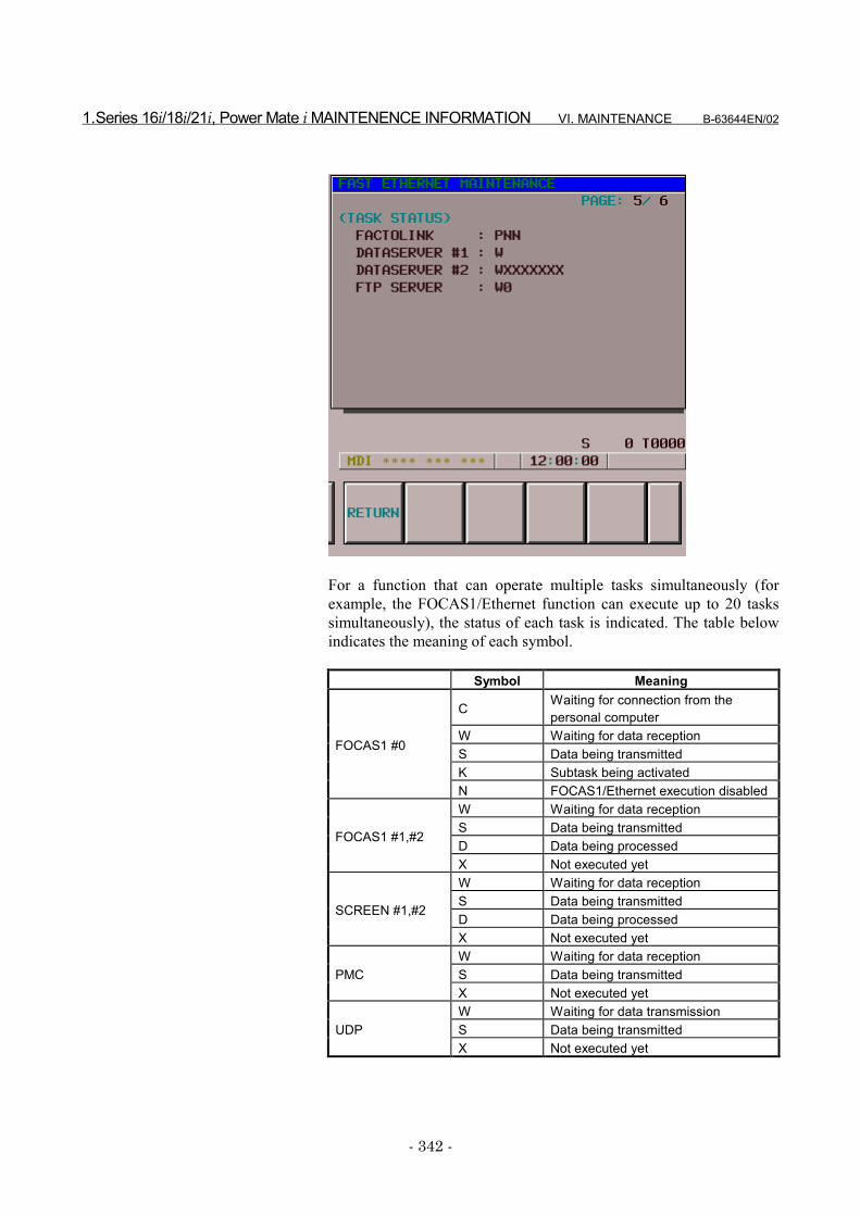
1.Series 16i/18i/21i, Power Mate i MAINTENENCE INFORMATION VI. MAINTENANCE B-63644EN/02
- 342 -
For a function that can operate multiple tasks simultaneously (forexample, the FOCAS1/Ethernet function can execute up to 20 taskssimultaneously), the status of each task is indicated. The table belowindicates the meaning of each symbol.
Symbol Meaning
C Waiting for connection from thepersonal computer
W Waiting for data receptionS Data being transmittedK Subtask being activated
FOCAS1 #0
N FOCAS1/Ethernet execution disabledW Waiting for data receptionS Data being transmittedD Data being processed
FOCAS1 #1,#2
X Not executed yetW Waiting for data receptionS Data being transmittedD Data being processed
SCREEN #1,#2
X Not executed yetW Waiting for data receptionS Data being transmittedPMCX Not executed yetW Waiting for data transmissionS Data being transmittedUDPX Not executed yet
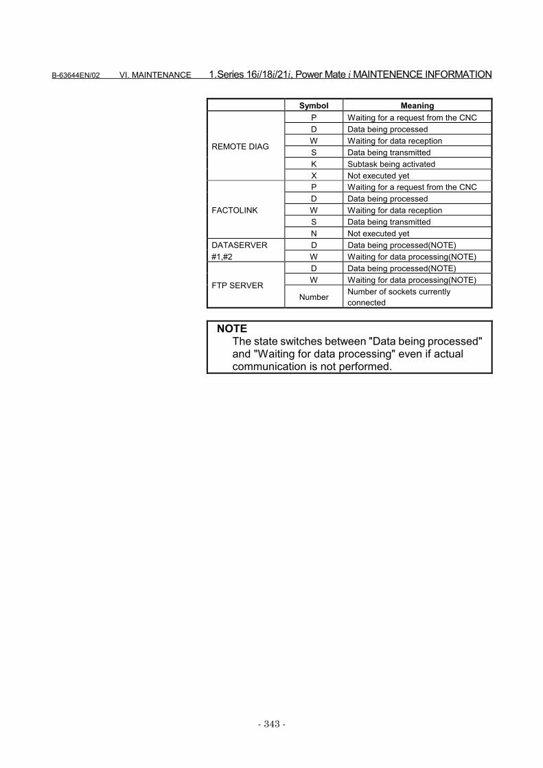
B-63644EN/02 VI. MAINTENANCE 1.Series 16i/18i/21i, Power Mate i MAINTENENCE INFORMATION
- 343 -
Symbol MeaningP Waiting for a request from the CNCD Data being processedW Waiting for data receptionS Data being transmittedK Subtask being activated
REMOTE DIAG
X Not executed yetP Waiting for a request from the CNCD Data being processedW Waiting for data receptionS Data being transmitted
FACTOLINK
N Not executed yetDATASERVER D Data being processed(NOTE)#1,#2 W Waiting for data processing(NOTE)
D Data being processed(NOTE)W Waiting for data processing(NOTE)FTP SERVER
Number Number of sockets currentlyconnected
NOTEThe state switches between "Data being processed"and "Waiting for data processing" even if actualcommunication is not performed.
2.Series 16i/18i/21i, Power Mate i MAINTENENCE INFORMATION VI. MAINTENANCE B-63644EN/02
- 344 -
2 Series 15i MAINTENENCEINFORMATION
This chapter describes the maintenance information for the 15i-B, FastEthernet/Fast data server.
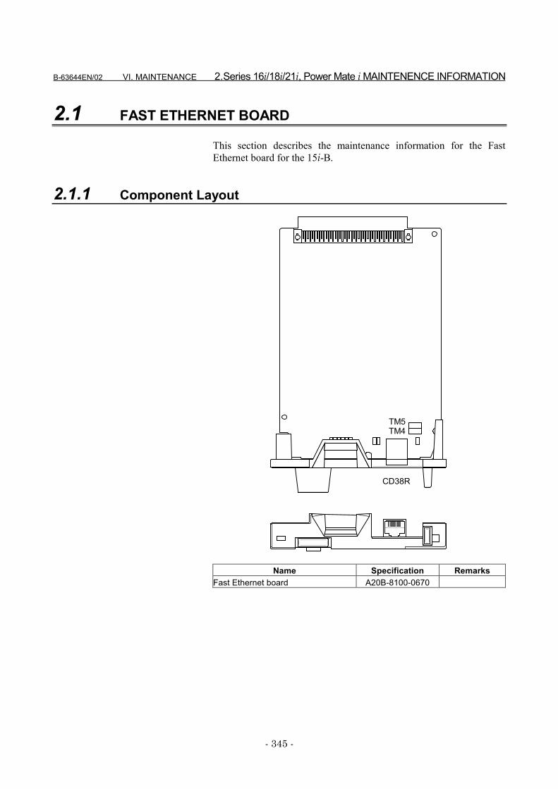
B-63644EN/02 VI. MAINTENANCE 2.Series 16i/18i/21i, Power Mate i MAINTENENCE INFORMATION
- 345 -
2.1 FAST ETHERNET BOARD
This section describes the maintenance information for the FastEthernet board for the 15i-B.
2.1.1 Component Layout
CD38R
TM5TM4
Name Specification RemarksFast Ethernet board A20B-8100-0670
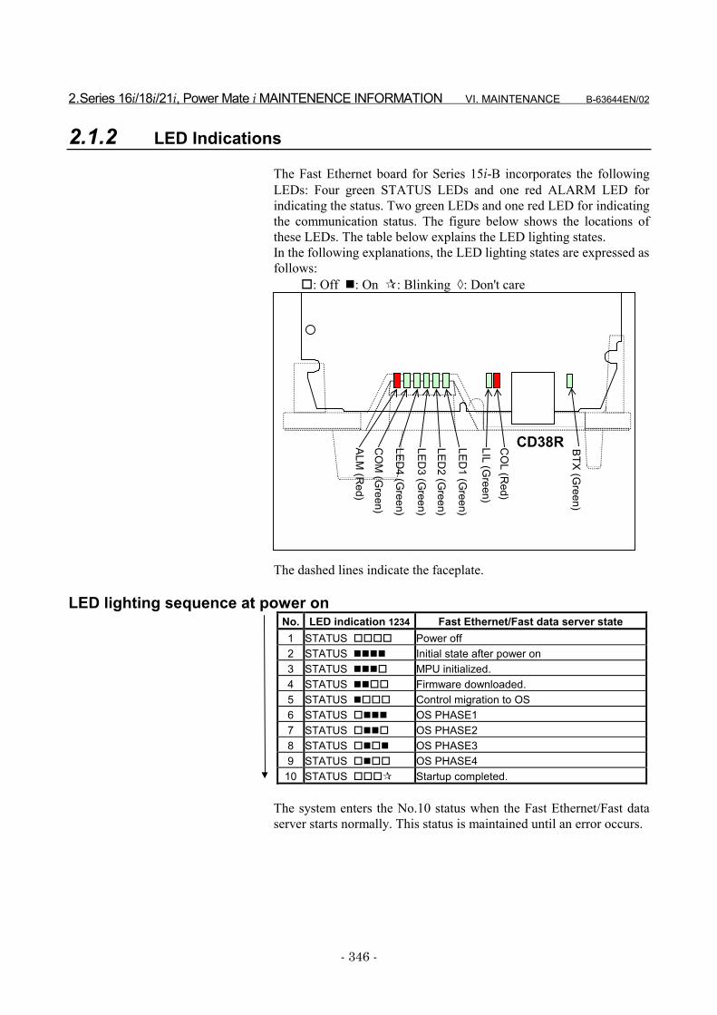
2.Series 16i/18i/21i, Power Mate i MAINTENENCE INFORMATION VI. MAINTENANCE B-63644EN/02
- 346 -
2.1.2 LED Indications
The Fast Ethernet board for Series 15i-B incorporates the followingLEDs: Four green STATUS LEDs and one red ALARM LED forindicating the status. Two green LEDs and one red LED for indicatingthe communication status. The figure below shows the locations ofthese LEDs. The table below explains the LED lighting states.In the following explanations, the LED lighting states are expressed asfollows:
�: Off �: On �: Blinking �: Don't care
CD38RLED4 (G
reen)
LED3 (G
reen)
LED2 (G
reen)
LED1 (G
reen)
ALM (R
ed)
LIL (Green)
CO
L (Red)
CO
M (G
reen)
BTX (Green)
The dashed lines indicate the faceplate.
LED lighting sequence at power onNo. LED indication 1234 Fast Ethernet/Fast data server state1 STATUS ���� Power off2 STATUS ���� Initial state after power on3 STATUS ���� MPU initialized.4 STATUS ���� Firmware downloaded.5 STATUS ���� Control migration to OS6 STATUS ���� OS PHASE17 STATUS ���� OS PHASE28 STATUS ���� OS PHASE39 STATUS ���� OS PHASE4
10 STATUS ���� Startup completed.
The system enters the No.10 status when the Fast Ethernet/Fast dataserver starts normally. This status is maintained until an error occurs.
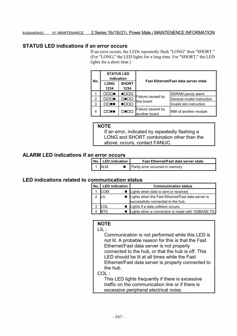
B-63644EN/02 VI. MAINTENANCE 2.Series 16i/18i/21i, Power Mate i MAINTENENCE INFORMATION
- 347 -
STATUS LED indications if an error occursIf an error occurs, the LEDs repeatedly flash "LONG" then "SHORT."(For "LONG," the LED lights for a long time. For "SHORT," the LEDlights for a short time.)
STATUS LEDindicationNo. LONG
1234SHORT
1234
Fast Ethernet/Fast data server state
1 ���� ���� SDRAM paruty alarm2 ���� ���� General invalid instruction3 ���� ����
Failure caused bythis board
Invalid slot instruction
4 ���� ����Failure caused byanother board NMI of another module
NOTEIf an error, indicated by repeatedly flashing aLONG and SHORT combination other than theabove, occurs, contact FANUC.
ALARM LED indications if an error occursNo. LED indication Fast Ethernet/Fast data server state1 ALM � Parity error occurred in memory.
LED indications related to communication statusNo. LED indication Communication status1 COM � Lights when data is sent or received.2 LIL � Lights when the Fast Ethernet/Fast data server is
successfully connected to the hub.3 COL � Lights if a data collision occurs.4 BTX � Lights when a connection is made with 100BASE-TX.
NOTELIL :
Communication is not performed while this LED isnot lit. A probable reason for this is that the FastEthernet/Fast data server is not properlyconnected to the hub, or that the hub is off. ThisLED should be lit at all times while the FastEthernet/Fast data server is properly connected tothe hub.
COL :This LED lights frequently if there is excessivetraffic on the communication line or if there isexcessive peripheral electrical noise.

2.Series 16i/18i/21i, Power Mate i MAINTENENCE INFORMATION VI. MAINTENANCE B-63644EN/02
- 348 -
2.1.3 Setting Pins
On the board, the setting pins (TM4, TM5) are installed. Connect eachjumper plug to side A (factory-set state). Do not remove a jumper plug,and do not change the setting of a jumper plug. Otherwise, the boarddoes not operate normally.
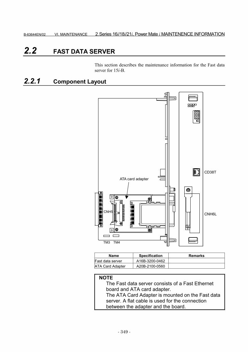
B-63644EN/02 VI. MAINTENANCE 2.Series 16i/18i/21i, Power Mate i MAINTENENCE INFORMATION
- 349 -
2.2 FAST DATA SERVER
This section describes the maintenance information for the Fast dataserver for 15i-B.
2.2.1 Component Layout
CD38T
CNH6L
ATA card adapter
CNH5
TM3 TM4
Name Specification RemarksFast data server A16B-3200-0462ATA Card Adapter A20B-2100-0560
NOTEThe Fast data server consists of a Fast Ethernetboard and ATA card adapter.The ATA Card Adapter is mounted on the Fast dataserver. A flat cable is used for the connectionbetween the adapter and the board.
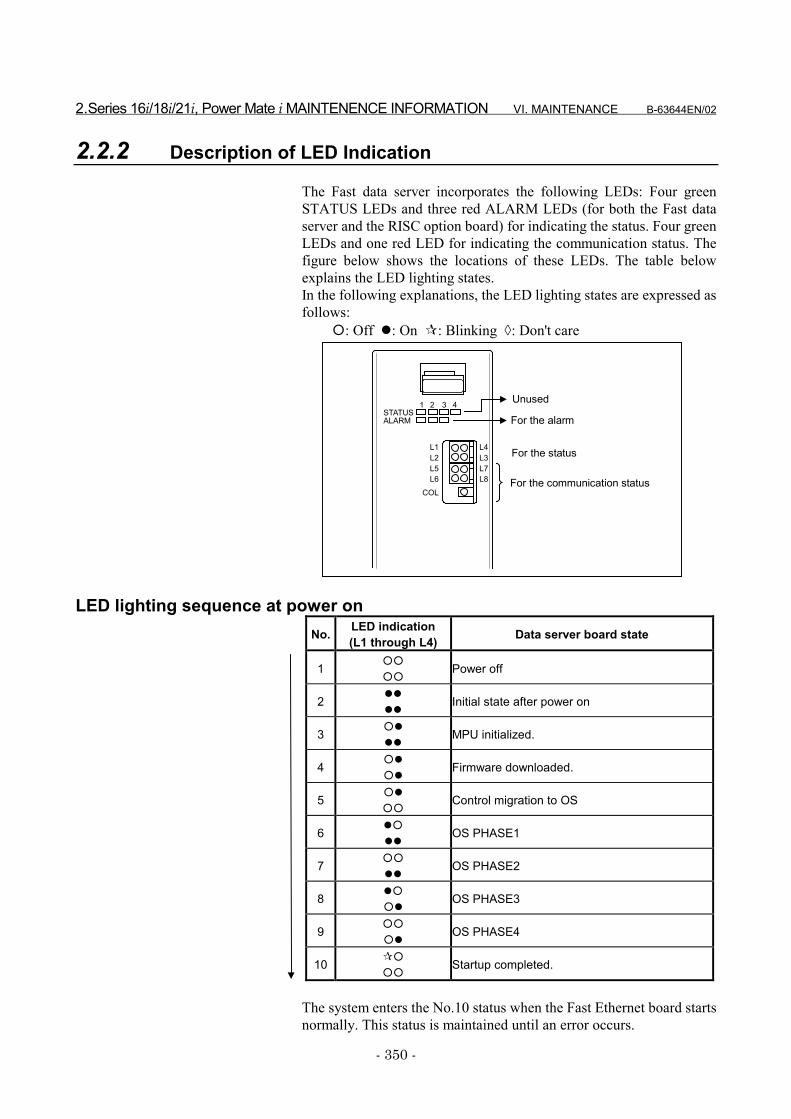
2.Series 16i/18i/21i, Power Mate i MAINTENENCE INFORMATION VI. MAINTENANCE B-63644EN/02
- 350 -
2.2.2 Description of LED Indication
The Fast data server incorporates the following LEDs: Four greenSTATUS LEDs and three red ALARM LEDs (for both the Fast dataserver and the RISC option board) for indicating the status. Four greenLEDs and one red LED for indicating the communication status. Thefigure below shows the locations of these LEDs. The table belowexplains the LED lighting states.In the following explanations, the LED lighting states are expressed asfollows:
�: Off �: On �: Blinking �: Don't care
LED lighting sequence at power onNo. LED indication
(L1 through L4) Data server board state
1 ��
��Power off
2 ��
��Initial state after power on
3 ��
��MPU initialized.
4 ��
��Firmware downloaded.
5 ��
��Control migration to OS
6 ��
��OS PHASE1
7 ��
��OS PHASE2
8 ��
��OS PHASE3
9 ��
��OS PHASE4
10 ��
��Startup completed.
The system enters the No.10 status when the Fast Ethernet board startsnormally. This status is maintained until an error occurs.
STATUS1 2 3 4
L1 For the status
For the communication status
L2L4L3
L5L6
L7L8
ALARM
COL
Unused
For the alarm
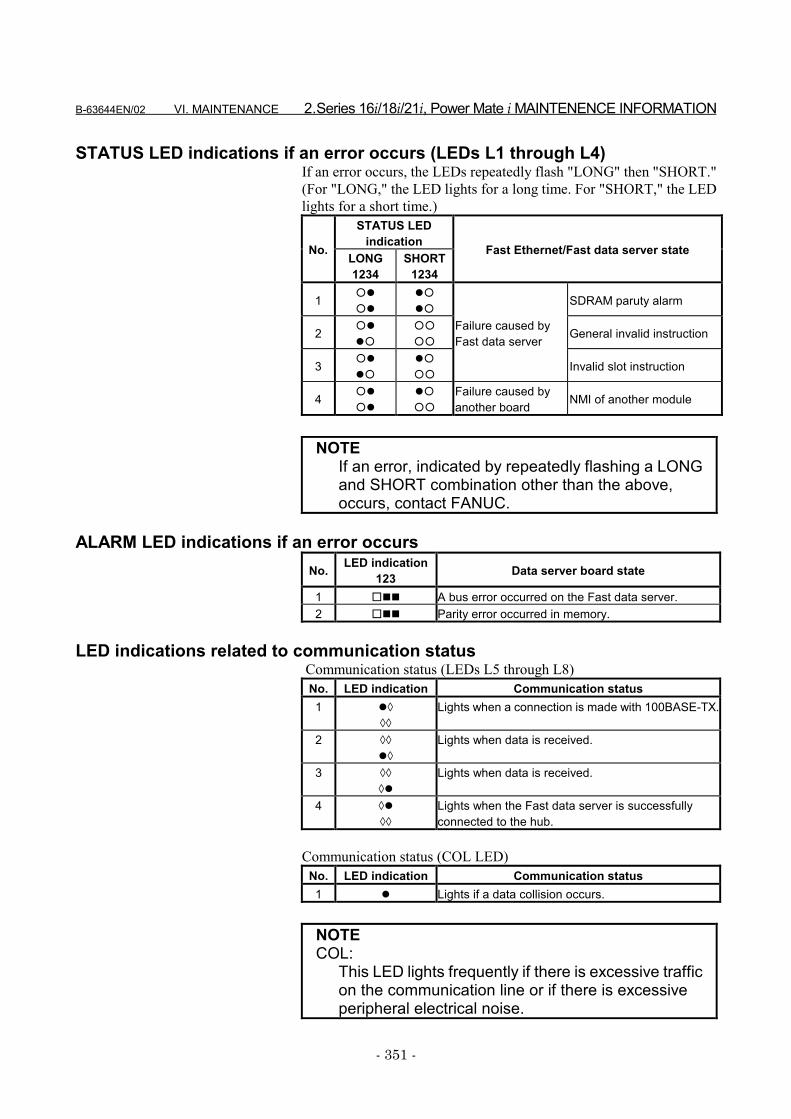
B-63644EN/02 VI. MAINTENANCE 2.Series 16i/18i/21i, Power Mate i MAINTENENCE INFORMATION
- 351 -
STATUS LED indications if an error occurs (LEDs L1 through L4)If an error occurs, the LEDs repeatedly flash "LONG" then "SHORT."(For "LONG," the LED lights for a long time. For "SHORT," the LEDlights for a short time.)
STATUS LEDindicationNo. LONG
1234SHORT
1234
Fast Ethernet/Fast data server state
1 ��
��
��
��SDRAM paruty alarm
2 ��
��
��
��General invalid instruction
3 ��
��
��
��
Failure caused byFast data server
Invalid slot instruction
4 ��
��
��
��
Failure caused byanother board NMI of another module
NOTEIf an error, indicated by repeatedly flashing a LONGand SHORT combination other than the above,occurs, contact FANUC.
ALARM LED indications if an error occursNo. LED indication
123 Data server board state
1 ��� A bus error occurred on the Fast data server.2 ��� Parity error occurred in memory.
LED indications related to communication status Communication status (LEDs L5 through L8)
No. LED indication Communication status1 ��
��
Lights when a connection is made with 100BASE-TX.
2 ��
��
Lights when data is received.
3 ��
��
Lights when data is received.
4 ��
��
Lights when the Fast data server is successfullyconnected to the hub.
Communication status (COL LED)No. LED indication Communication status1 � Lights if a data collision occurs.
NOTECOL:
This LED lights frequently if there is excessive trafficon the communication line or if there is excessiveperipheral electrical noise.

2.Series 16i/18i/21i, Power Mate i MAINTENENCE INFORMATION VI. MAINTENANCE B-63644EN/02
- 352 -
2.2.3 Setting Pins
On the board, the setting pins (TM3, TM4) are installed. Connect eachjumper plug to side A (factory-set state). Do not remove a jumper plug,and do not change the setting of a jumper plug. Otherwise, the boarddoes not operate normally.
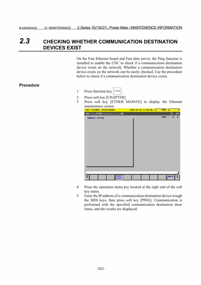
B-63644EN/02 VI. MAINTENANCE 2.Series 16i/18i/21i, Power Mate i MAINTENENCE INFORMATION
- 353 -
2.3 CHECKING WHETHER COMMUNICATION DESTINATIONDEVICES EXIST
On the Fast Ethernet board and Fast data server, the Ping function isinstalled to enable the CNC to check if a communication destinationdevice exists on the network. Whether a communication destinationdevice exists on the network can be easily checked. Use the procedurebelow to check if a communication destination device exists.
Procedure1 Press function key SYSTEM .2 Press soft key [CHAPTER].3 Press soft key [ETHER MAINTE] to display the Ethernet
maintenance screen.
4 Press the operation menu key located at the right end of the softkey menu.
5 Enter the IP address of a communication destination device troughthe MDI keys, then press soft key [PING]. Communication isperformed with the specified communication destination threetimes, and the results are displayed.
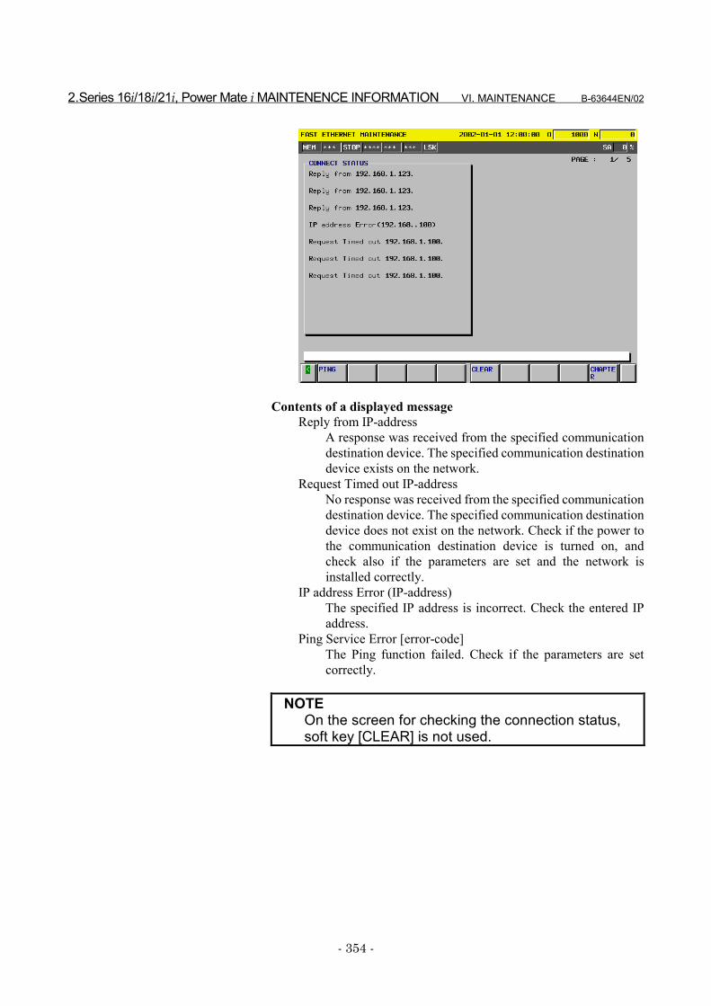
2.Series 16i/18i/21i, Power Mate i MAINTENENCE INFORMATION VI. MAINTENANCE B-63644EN/02
- 354 -
Contents of a displayed messageReply from IP-address
A response was received from the specified communicationdestination device. The specified communication destinationdevice exists on the network.
Request Timed out IP-addressNo response was received from the specified communicationdestination device. The specified communication destinationdevice does not exist on the network. Check if the power tothe communication destination device is turned on, andcheck also if the parameters are set and the network isinstalled correctly.
IP address Error (IP-address)The specified IP address is incorrect. Check the entered IPaddress.
Ping Service Error [error-code]The Ping function failed. Check if the parameters are setcorrectly.
NOTEOn the screen for checking the connection status,soft key [CLEAR] is not used.
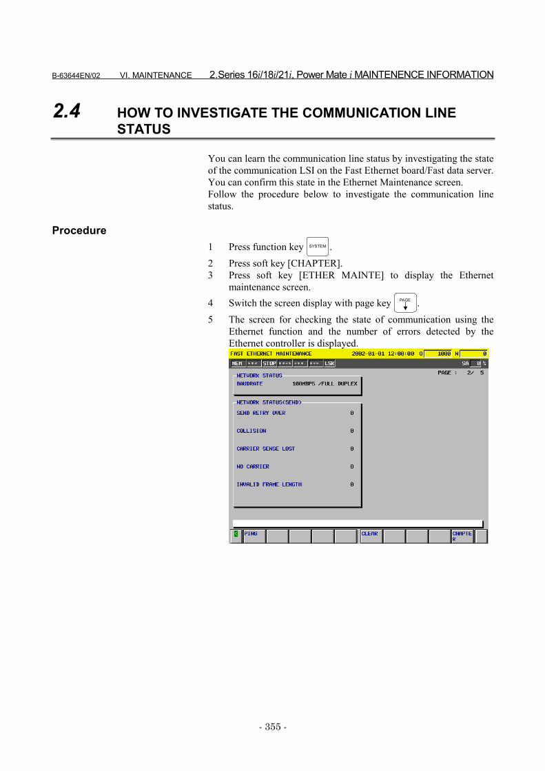
B-63644EN/02 VI. MAINTENANCE 2.Series 16i/18i/21i, Power Mate i MAINTENENCE INFORMATION
- 355 -
2.4 HOW TO INVESTIGATE THE COMMUNICATION LINESTATUS
You can learn the communication line status by investigating the stateof the communication LSI on the Fast Ethernet board/Fast data server.You can confirm this state in the Ethernet Maintenance screen.Follow the procedure below to investigate the communication linestatus.
Procedure1 Press function key SYSTEM .2 Press soft key [CHAPTER].3 Press soft key [ETHER MAINTE] to display the Ethernet
maintenance screen.4 Switch the screen display with page key PAGE .5 The screen for checking the state of communication using the
Ethernet function and the number of errors detected by theEthernet controller is displayed.
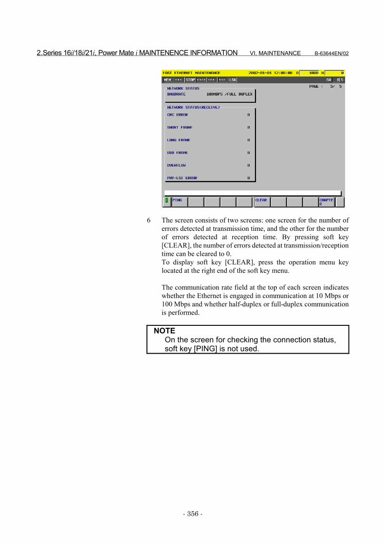
2.Series 16i/18i/21i, Power Mate i MAINTENENCE INFORMATION VI. MAINTENANCE B-63644EN/02
- 356 -
6 The screen consists of two screens: one screen for the number oferrors detected at transmission time, and the other for the numberof errors detected at reception time. By pressing soft key[CLEAR], the number of errors detected at transmission/receptiontime can be cleared to 0.To display soft key [CLEAR], press the operation menu keylocated at the right end of the soft key menu.
The communication rate field at the top of each screen indicateswhether the Ethernet is engaged in communication at 10 Mbps or100 Mbps and whether half-duplex or full-duplex communicationis performed.
NOTEOn the screen for checking the connection status,soft key [PING] is not used.
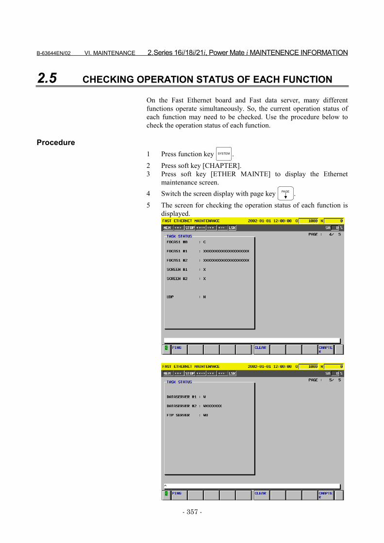
B-63644EN/02 VI. MAINTENANCE 2.Series 16i/18i/21i, Power Mate i MAINTENENCE INFORMATION
- 357 -
2.5 CHECKING OPERATION STATUS OF EACH FUNCTION
On the Fast Ethernet board and Fast data server, many differentfunctions operate simultaneously. So, the current operation status ofeach function may need to be checked. Use the procedure below tocheck the operation status of each function.
Procedure1 Press function key SYSTEM .2 Press soft key [CHAPTER].3 Press soft key [ETHER MAINTE] to display the Ethernet
maintenance screen.4 Switch the screen display with page key PAGE .5 The screen for checking the operation status of each function is
displayed.

2.Series 16i/18i/21i, Power Mate i MAINTENENCE INFORMATION VI. MAINTENANCE B-63644EN/02
- 358 -
NOTEOn the screen for checking the connection status,soft key [PING] or [CLEAR] is not used.
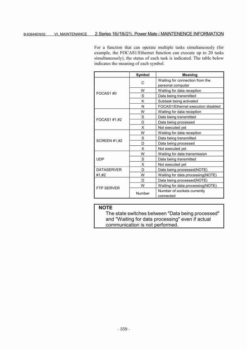
B-63644EN/02 VI. MAINTENANCE 2.Series 16i/18i/21i, Power Mate i MAINTENENCE INFORMATION
- 359 -
For a function that can operate multiple tasks simultaneously (forexample, the FOCAS1/Ethernet function can execute up to 20 taskssimultaneously), the status of each task is indicated. The table belowindicates the meaning of each symbol.
Symbol Meaning
C Waiting for connection from thepersonal computer
W Waiting for data receptionS Data being transmittedK Subtask being activated
FOCAS1 #0
N FOCAS1/Ethernet execution disabledW Waiting for data receptionS Data being transmittedD Data being processed
FOCAS1 #1,#2
X Not executed yetW Waiting for data receptionS Data being transmittedD Data being processed
SCREEN #1,#2
X Not executed yetW Waiting for data transmissionS Data being transmittedUDPX Not executed yet
DATASERVER D Data being processed(NOTE)#1,#2 W Waiting for data processing(NOTE)
D Data being processed(NOTE)W Waiting for data processing(NOTE)FTP SERVER
Number Number of sockets currentlyconnected
NOTEThe state switches between "Data being processed"and "Waiting for data processing" even if actualcommunication is not performed.


APPENDIX


B-63644EN/02 APPENDIX A.TROUBLESHOOTING
- 363 -
A TROUBLESHOOTINGThis appendix describes how to check for and correct problems thatmay occur during communication over an Ethernet network.
A.TROUBLESHOOTING APPENDIX B-63644EN/02
- 364 -
A.1 CHECKING HUB CONNECTION
1) Make sure that the STP cable between the hub and the Fast FastEthernet board is connected.
2) Make sure that cables are properly wired.• Though communication is carried out when the cable pair
(see "2.3.1 Cable connection") at the send and receive sidesis not properly mounted, communications errors may occurmore frequently.
3) Make sure that a proper hub is used.• If a hub for 100BASE-TX is used, the communication
destination device must also support 100BASE-TX.4) Make sure that the hub is ON.5) Make sure that the LIL LED on the Fast Fast Ethernet board is lit
at all times.• The LIL LED will not light if the Fast Fast Ethernet board is
not connected to the hub or if the hub is not ON.6) Make sure that the LED (LINK indicator LED) on the connected
hub is lit at all times.• Some hubs do not have a LINK indicator LED.• The LINK indicator LED will not light if the hub is not
connected to the Fast Fast Ethernet board or the Fast FastEthernet board is not ON.
• For details on how to connect, see "V. Connection."
B-63644EN/02 APPENDIX A.TROUBLESHOOTING
- 365 -
A.2 CHECKING SETTINGS
The following describes how to check the minimum settings needed forcommunications.
NOTEFor details on IP addresses, subnet mask and otherset values, consult with the network administrator.
• Checking settings on the Fast Fast Ethernet board or Fast dataserver1) Make sure that the MAC address of the Fast Fast Ethernet
board or Fast data server is displayed.• This address is appended to each board before shipment
from the factory, and is automatically displayed in theSetting screen. This address need not be set by the user.For details, see "IV Operation Manual, 1.4 SettingScreen."
2) Make sure that the IP address is set.3) Make sure that the subnet mask is set.4) When a router is used, make sure that the router IP address is
set.
• Checking settings on the personal computer1) Make sure that the IP address is set.2) Make sure that the subnet mask is set.3) When a router is used, make sure that the router IP address is
set.
• For details on how to set, see "III. Setting."
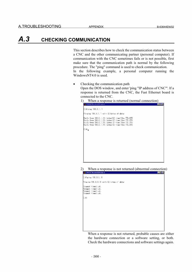
A.TROUBLESHOOTING APPENDIX B-63644EN/02
- 366 -
A.3 CHECKING COMMUNICATION
This section describes how to check the communication status betweena CNC and the other communicating partner (personal computer). Ifcommunication with the CNC sometimes fails or is not possible, firstmake sure that the communication path is normal by the followingprocedure. The "ping" command is used to check communication.In the following example, a personal computer running theWindowsNT4.0 is used.
• Checking the communication pathOpen the DOS window, and enter 'ping "IP address of CNC"'. If aresponse is returned from the CNC, the Fast Ethernet board isconnected to the CNC.1) When a response is returned (normal connection)
2) When a response is not returned (abnormal connection)
When a response is not returned, probable causes are eitherthe hardware connection or a software setting, or both.Check the hardware connections and software settings again.
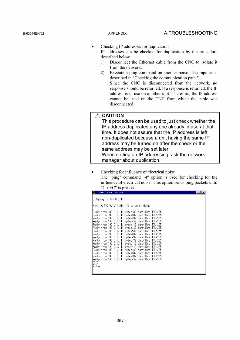
B-63644EN/02 APPENDIX A.TROUBLESHOOTING
- 367 -
• Checking IP addresses for duplicationIP addresses can be checked for duplication by the proceduredescribed below.1) Disconnect the Ethernet cable from the CNC to isolate it
from the network.2) Execute a ping command on another personal computer as
described in "Checking the communication path."Since the CNC is disconnected from the network, noresponse should be returned. If a response is returned, the IPaddress is in use on another unit. Therefore, the IP addresscannot be used on the CNC from which the cable wasdisconnected.
CAUTIONThis procedure can be used to just check whether theIP address duplicates any one already in use at thattime. It does not assure that the IP address is leftnon-duplicated because a unit having the same IPaddress may be turned on after the check or thesame address may be set later.When setting an IP addressing, ask the networkmanager about duplication.
• Checking for influence of electrical noiseThe "ping" command "-t" option is used for checking for theinfluence of electrical noise. This option sends ping packets until"Ctrl+C" is pressed.
A.TROUBLESHOOTING APPENDIX B-63644EN/02
- 368 -
1 About the influence of electrical noise from peripheralmachinery (devices)1) Turn the machine in which the Fast Ethernet board is
mounted ON to enable communications.2) Press the EMERGENCY STOP button on the machine
with the servo/spindle amplifier OFF, and issue the"ping" command from the personal computer.
3) Count the number of lost packets (packets for which aresponse was not returned).f a lost packet occurs in this state, the machine isprobably being affected by electrical influence fromperipheral machines.Countermeasure:Pin-point the source of the electrical noise, and checkthe wiring again to prevent the influence of electricalnoise.
2 About the influence of electrical noise from mountedmachinery1) Start up the machine in the same way as 1. above.2) Cancel the emergency stop on the machine with the
servo/spindle amplifier ON, and issue the "ping"command from the personal computer.
3) Count the number of lost packets.If more lost packets than in 1 above are occurring, aprobable cause is the influence of electrical noise on themachine itself. General probable causes are the state ofthe ground on the machine or on the communicatingparty.Countermeasure:Check the state of the ground on the machine or on thecommunicating party, and insulate the communicationstrunk with the machine.
• For details on how to check the operating status orcommunications status of the Fast Ethernet board other thanthe above, see "VI. Maintenance."
B-63644EN/02 APPENDIX B.TROUBLES & ERROR MESSAGES
- 369 -
B TROUBLES & ERROR MESSAGESAppendix B describes the relationship between troubles that may occurthrough use of the Ethernet functions and error messages that aredisplayed.Note that Appendix B does not list error messages for all potentialtroubles; it lists only troubles that may occur during normal use.
When trouble occurs, an Error Message screen is displayed to identifythe cause of the trouble. Check the details of the error in this screen.The following pages list the error messages that may be displayed whentrouble occurs. For this reason, one error message may be displayedtwice or more times when two or more troubles occur simultaneously.
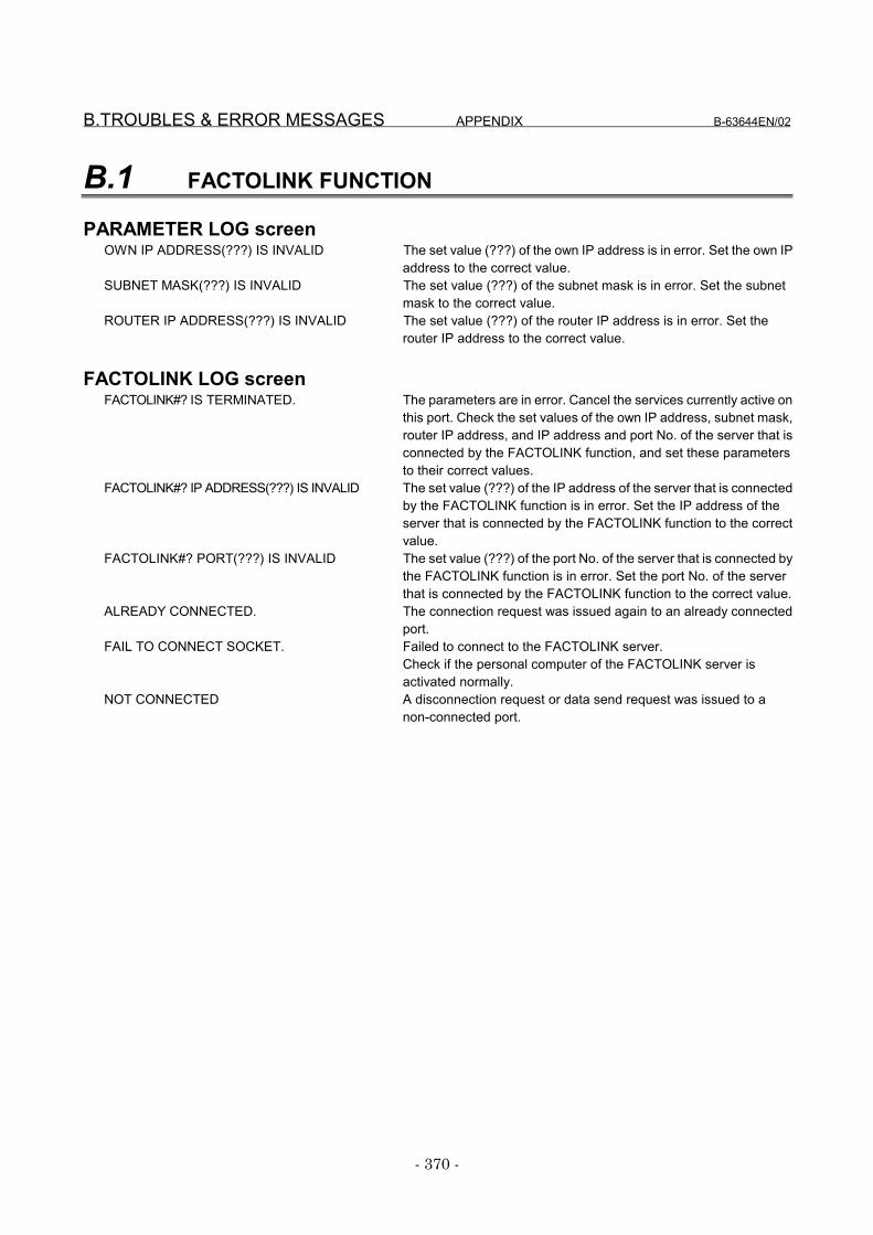
B.TROUBLES & ERROR MESSAGES APPENDIX B-63644EN/02
- 370 -
B.1 FACTOLINK FUNCTION
PARAMETER LOG screenOWN IP ADDRESS(???) IS INVALID The set value (???) of the own IP address is in error. Set the own IP
address to the correct value.SUBNET MASK(???) IS INVALID The set value (???) of the subnet mask is in error. Set the subnet
mask to the correct value.ROUTER IP ADDRESS(???) IS INVALID The set value (???) of the router IP address is in error. Set the
router IP address to the correct value.
FACTOLINK LOG screenFACTOLINK#? IS TERMINATED. The parameters are in error. Cancel the services currently active on
this port. Check the set values of the own IP address, subnet mask,router IP address, and IP address and port No. of the server that isconnected by the FACTOLINK function, and set these parametersto their correct values.
FACTOLINK#? IP ADDRESS(???) IS INVALID The set value (???) of the IP address of the server that is connectedby the FACTOLINK function is in error. Set the IP address of theserver that is connected by the FACTOLINK function to the correctvalue.
FACTOLINK#? PORT(???) IS INVALID The set value (???) of the port No. of the server that is connected bythe FACTOLINK function is in error. Set the port No. of the serverthat is connected by the FACTOLINK function to the correct value.
ALREADY CONNECTED. The connection request was issued again to an already connectedport.
FAIL TO CONNECT SOCKET. Failed to connect to the FACTOLINK server.Check if the personal computer of the FACTOLINK server isactivated normally.
NOT CONNECTED A disconnection request or data send request was issued to anon-connected port.
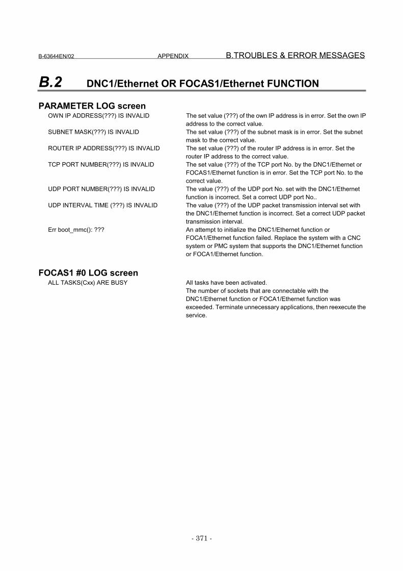
B-63644EN/02 APPENDIX B.TROUBLES & ERROR MESSAGES
- 371 -
B.2 DNC1/Ethernet OR FOCAS1/Ethernet FUNCTION
PARAMETER LOG screenOWN IP ADDRESS(???) IS INVALID The set value (???) of the own IP address is in error. Set the own IP
address to the correct value.SUBNET MASK(???) IS INVALID The set value (???) of the subnet mask is in error. Set the subnet
mask to the correct value.ROUTER IP ADDRESS(???) IS INVALID The set value (???) of the router IP address is in error. Set the
router IP address to the correct value.TCP PORT NUMBER(???) IS INVALID The set value (???) of the TCP port No. by the DNC1/Ethernet or
FOCAS1/Ethernet function is in error. Set the TCP port No. to thecorrect value.
UDP PORT NUMBER(???) IS INVALID The value (???) of the UDP port No. set with the DNC1/Ethernetfunction is incorrect. Set a correct UDP port No..
UDP INTERVAL TIME (???) IS INVALID The value (???) of the UDP packet transmission interval set withthe DNC1/Ethernet function is incorrect. Set a correct UDP packettransmission interval.
Err boot_mmc(): ??? An attempt to initialize the DNC1/Ethernet function orFOCA1/Ethernet function failed. Replace the system with a CNCsystem or PMC system that supports the DNC1/Ethernet functionor FOCA1/Ethernet function.
FOCAS1 #0 LOG screenALL TASKS(Cxx) ARE BUSY All tasks have been activated.
The number of sockets that are connectable with theDNC1/Ethernet function or FOCA1/Ethernet function wasexceeded. Terminate unnecessary applications, then reexecute theservice.
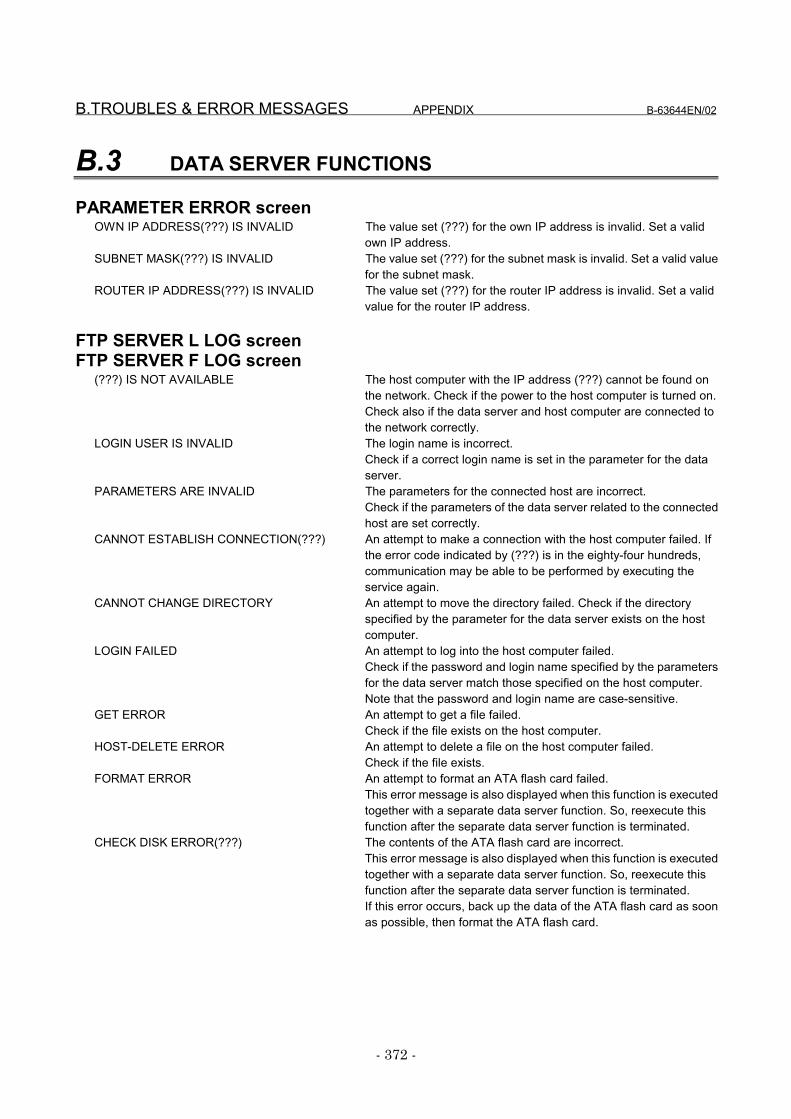
B.TROUBLES & ERROR MESSAGES APPENDIX B-63644EN/02
- 372 -
B.3 DATA SERVER FUNCTIONS
PARAMETER ERROR screenOWN IP ADDRESS(???) IS INVALID The value set (???) for the own IP address is invalid. Set a valid
own IP address.SUBNET MASK(???) IS INVALID The value set (???) for the subnet mask is invalid. Set a valid value
for the subnet mask.ROUTER IP ADDRESS(???) IS INVALID The value set (???) for the router IP address is invalid. Set a valid
value for the router IP address.
FTP SERVER L LOG screenFTP SERVER F LOG screen
(???) IS NOT AVAILABLE The host computer with the IP address (???) cannot be found onthe network. Check if the power to the host computer is turned on.Check also if the data server and host computer are connected tothe network correctly.
LOGIN USER IS INVALID The login name is incorrect.Check if a correct login name is set in the parameter for the dataserver.
PARAMETERS ARE INVALID The parameters for the connected host are incorrect.Check if the parameters of the data server related to the connectedhost are set correctly.
CANNOT ESTABLISH CONNECTION(???) An attempt to make a connection with the host computer failed. Ifthe error code indicated by (???) is in the eighty-four hundreds,communication may be able to be performed by executing theservice again.
CANNOT CHANGE DIRECTORY An attempt to move the directory failed. Check if the directoryspecified by the parameter for the data server exists on the hostcomputer.
LOGIN FAILED An attempt to log into the host computer failed.Check if the password and login name specified by the parametersfor the data server match those specified on the host computer.Note that the password and login name are case-sensitive.
GET ERROR An attempt to get a file failed.Check if the file exists on the host computer.
HOST-DELETE ERROR An attempt to delete a file on the host computer failed.Check if the file exists.
FORMAT ERROR An attempt to format an ATA flash card failed.This error message is also displayed when this function is executedtogether with a separate data server function. So, reexecute thisfunction after the separate data server function is terminated.
CHECK DISK ERROR(???) The contents of the ATA flash card are incorrect.This error message is also displayed when this function is executedtogether with a separate data server function. So, reexecute thisfunction after the separate data server function is terminated.If this error occurs, back up the data of the ATA flash card as soonas possible, then format the ATA flash card.
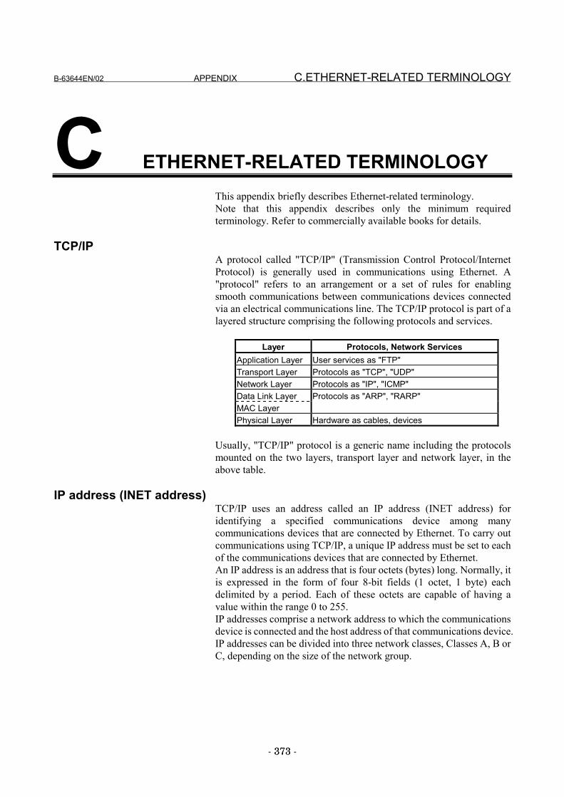
B-63644EN/02 APPENDIX C.ETHERNET-RELATED TERMINOLOGY
- 373 -373
C ETHERNET-RELATED TERMINOLOGYThis appendix briefly describes Ethernet-related terminology.Note that this appendix describes only the minimum requiredterminology. Refer to commercially available books for details.
TCP/IPA protocol called "TCP/IP" (Transmission Control Protocol/InternetProtocol) is generally used in communications using Ethernet. A"protocol" refers to an arrangement or a set of rules for enablingsmooth communications between communications devices connectedvia an electrical communications line. The TCP/IP protocol is part of alayered structure comprising the following protocols and services.
Layer Protocols, Network ServicesApplication Layer User services as "FTP"Transport Layer Protocols as "TCP", "UDP"Network Layer Protocols as "IP", "ICMP"Data Link Layer Protocols as "ARP", "RARP"MAC LayerPhysical Layer Hardware as cables, devices
Usually, "TCP/IP" protocol is a generic name including the protocolsmounted on the two layers, transport layer and network layer, in theabove table.
IP address (INET address)TCP/IP uses an address called an IP address (INET address) foridentifying a specified communications device among manycommunications devices that are connected by Ethernet. To carry outcommunications using TCP/IP, a unique IP address must be set to eachof the communications devices that are connected by Ethernet.An IP address is an address that is four octets (bytes) long. Normally, itis expressed in the form of four 8-bit fields (1 octet, 1 byte) eachdelimited by a period. Each of these octets are capable of having avalue within the range 0 to 255.IP addresses comprise a network address to which the communicationsdevice is connected and the host address of that communications device.IP addresses can be divided into three network classes, Classes A, B orC, depending on the size of the network group.
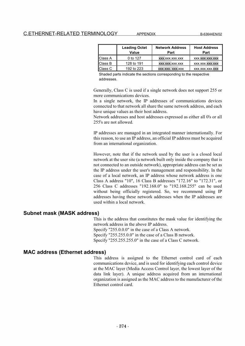
C.ETHERNET-RELATED TERMINOLOGY APPENDIX B-63644EN/02
- 374 -374
Leading OctetValue
Network AddressPart
Host AddressPart
Class A 0 to 127 xxx.xxx.xxx.xxx xxx.xxx.xxx.xxxClass B 128 to 191 xxx.xxx.xxx.xxx xxx.xxx.xxx.xxxClass C 192 to 223 xxx.xxx. xxx.xxx xxx.xxx.xxx.xxxShaded parts indicate the sections corresponding to the respectiveaddresses.
Generally, Class C is used if a single network does not support 255 ormore communications devices.In a single network, the IP addresses of communications devicesconnected to that network all share the same network address, and eachhave unique values as their host address.Network addresses and host addresses expressed as either all 0's or all255's are not allowed.
IP addresses are managed in an integrated manner internationally. Forthis reason, to use an IP address, an official IP address must be acquiredfrom an international organization.
However, note that if the network used by the user is a closed localnetwork at the user site (a network built only inside the company that isnot connected to an outside network), appropriate address can be set asthe IP address under the user's management and responsibility. In thecase of a local network, an IP address whose network address is oneClass A address "10", 16 Class B addresses "172.16" to "172.31", or256 Class C addresses "192.168.0" to "192.168.255" can be usedwithout being officially registered. So, we recommend using IPaddresses having these network addresses when the IP addresses areused within a local network.
Subnet mask (MASK address)This is the address that constitutes the mask value for identifying thenetwork address in the above IP address.Specify "255.0.0.0" in the case of a Class A network.Specify "255.255.0.0" in the case of a Class B network.Specify "255.255.255.0" in the case of a Class C network.
MAC address (Ethernet address)This address is assigned to the Ethernet control card of eachcommunications device, and is used for identifying each control deviceat the MAC layer (Media Access Control layer, the lowest layer of thedata link layer). A unique address acquired from an internationalorganization is assigned as the MAC address to the manufacturer of theEthernet control card.
B-63644EN/02 APPENDIX C.ETHERNET-RELATED TERMINOLOGY
- 375 -375
Port Number.This is a 16-bit integer value for linking the processes of the TCP/IPtransport layer (TCP or UDP) and the application layer. Port Number. 0to 8000 are assigned to standard applications such as Telnet or FTPgenerally referred to as "well-known port numbers." Assignment ofPort Number. is described in Assigned Numbers [RFC1340].When the DNC1/Ethernet or FACTOLINK functions are used, assign aPort Number. other than a well-known port number.
BroadcastingThe sending of messages to all nodes in the same segment
ClientThe device or application that requests a service
ServerThe device or application that provides a service

D.RESTRICTIONS APPENDIX B-63644EN/02
- 376 -376
D RESTRICTIONSThis appendix describes the restrictions imposed on the FACTOLINK,DNC1/Ethernet, FOCAS1/Ethernet and data server functions.
B-63644EN/02 APPENDIX D.RESTRICTIONS
- 377 -377
D.1 FACTOLINK FUNCTION RESTRICTIONS
The FACTOLINK function supports the connection of only oneFACTOLINK server to one CNC. However, the CNC can store the IPaddresses and port numbers of up to three FACTOLINK servers. Youcan select the FACTOLINK server to be connected by changing thesetting of CNC parameter No.802. For each personal computer, there isone FACTOLINK server.
D.RESTRICTIONS APPENDIX B-63644EN/02
- 378 -378
D.2 DNC1/Ethernet AND FOCAS1/Ethernet FUNCTIONRESTRICTIONS
The DNC1/Ethernet or FOCAS1/Ethernet function supports thelinkage of up to twenty application software packages (process) to oneCNC.The DNC1/Ethernet or FOCAS1/Ethernet function establishes acommunication line for each application software package (for eachprocess). Therefore, when there is one DNC1/Ethernet orFOCAS1/Ehternet application software package for each personalcomputer, up to twenty personal computers can be connected to oneCNC. Also, more than one DNC1/Ethernet or FOCAS1/Ethernetapplication software package can run on each personal computer.When one DNC1/Ethernet application software package and two ofFOCAS1/Ethernet application software packages are run on onepersonal computer, six personal computers can be connected to theCNC.
B-63644EN/02 APPENDIX D.RESTRICTIONS
- 379 -379
D.3 DATA SERVER FUNCTION RESTRICTIONS
The data server function (FTP client) supports the connection of onlyone FTP server to one CNC.The data server function (FTP server) supports the connection of fiveFTP clients to one CNC.Some FTP client software may internally use two or more FTP clients.So, note that the number of FTP clients is not equal to the number ofapplications.
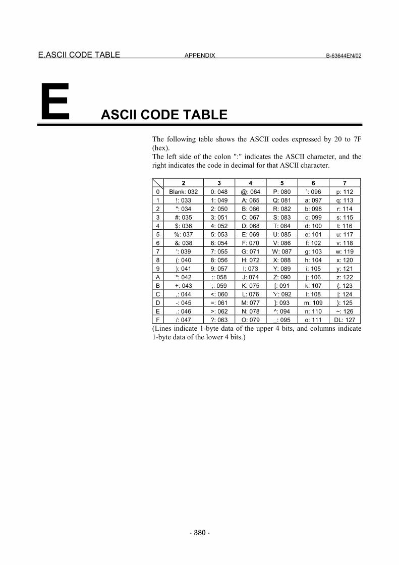
E.ASCII CODE TABLE APPENDIX B-63644EN/02
- 380 -380
E ASCII CODE TABLEThe following table shows the ASCII codes expressed by 20 to 7F(hex).The left side of the colon ":" indicates the ASCII character, and theright indicates the code in decimal for that ASCII character.
2 3 4 5 6 70 Blank: 032 0: 048 @: 064 P: 080 `: 096 p: 1121 !: 033 1: 049 A: 065 Q: 081 a: 097 q: 1132 ": 034 2: 050 B: 066 R: 082 b: 098 r: 1143 #: 035 3: 051 C: 067 S: 083 c: 099 s: 1154 $: 036 4: 052 D: 068 T: 084 d: 100 t: 1165 %: 037 5: 053 E: 069 U: 085 e: 101 u: 1176 &: 038 6: 054 F: 070 V: 086 f: 102 v: 1187 ': 039 7: 055 G: 071 W: 087 g: 103 w: 1198 (: 040 8: 056 H: 072 X: 088 h: 104 x: 1209 ): 041 9: 057 I: 073 Y: 089 i: 105 y: 121A *: 042 :: 058 J: 074 Z: 090 j: 106 z: 122B +: 043 ;: 059 K: 075 [: 091 k: 107 {: 123C ,: 044 <: 060 L: 076 : 092 l: 108 |: 124D -: 045 =: 061 M: 077 ]: 093 m: 109 }: 125E .: 046 >: 062 N: 078 ^: 094 n: 110 ~: 126F /: 047 ?: 063 O: 079 _: 095 o: 111 DL: 127
(Lines indicate 1-byte data of the upper 4 bits, and columns indicate1-byte data of the lower 4 bits.)

B-63644EN/02 APPENDIX F.FTP CLIENT OPERATION
- 381 -
F FTP CLIENT OPERATIONThis appendix describes how to operate an FTP client running on apersonal computer that is used to enable the data server function.
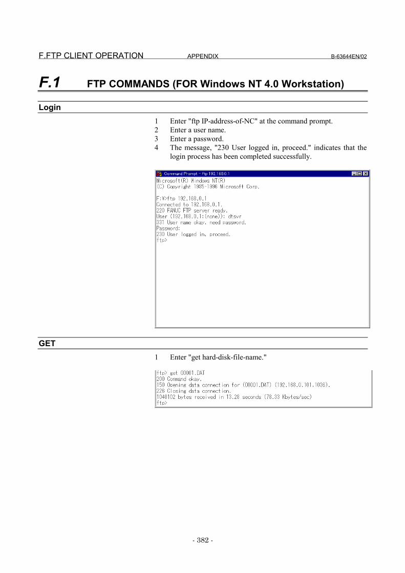
F.FTP CLIENT OPERATION APPENDIX B-63644EN/02
- 382 -
F.1 FTP COMMANDS (FOR Windows NT 4.0 Workstation)
Login1 Enter "ftp IP-address-of-NC" at the command prompt.2 Enter a user name.3 Enter a password.4 The message, "230 User logged in, proceed." indicates that the
login process has been completed successfully.
GET1 Enter "get hard-disk-file-name."
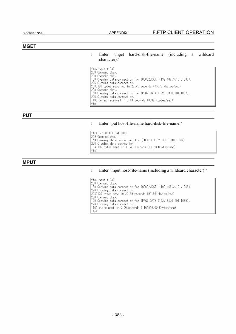
B-63644EN/02 APPENDIX F.FTP CLIENT OPERATION
- 383 -
MGET1 Enter "mget hard-disk-file-name (including a wildcard
character)."
PUT1 Enter "put host-file-name hard-disk-file-name."
MPUT1 Enter "mput host-file-name (including a wildcard character)."
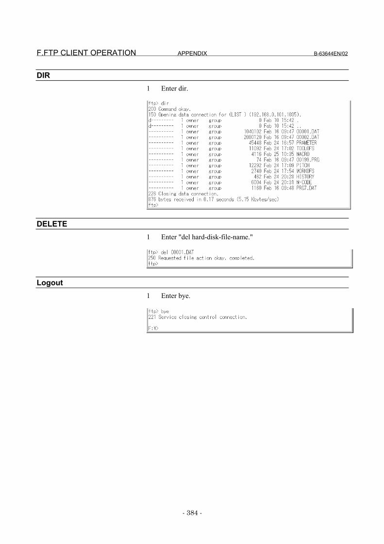
F.FTP CLIENT OPERATION APPENDIX B-63644EN/02
- 384 -
DIR1 Enter dir.
DELETE1 Enter "del hard-disk-file-name."
Logout1 Enter bye.

B-63644EN/02 APPENDIX G.SETUP OF THE FTP SERVER
- 385 -385
G SETUP OF THE FTP SERVERThis appendix describes the method of setting up the FTP server thatoperates on a personal computer used with the data server function.
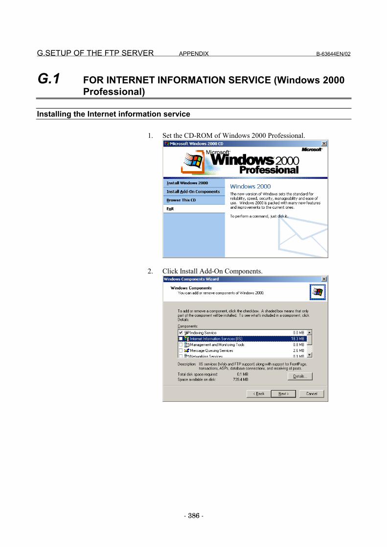
G.SETUP OF THE FTP SERVER APPENDIX B-63644EN/02
- 386 -386
G.1 FOR INTERNET INFORMATION SERVICE (Windows 2000Professional)
Installing the Internet information service
1. Set the CD-ROM of Windows 2000 Professional.
2. Click Install Add-On Components.
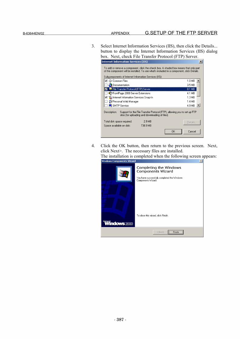
B-63644EN/02 APPENDIX G.SETUP OF THE FTP SERVER
- 387 -387
3. Select Internet Information Services (IIS), then click the Details...button to display the Internet Information Services (IIS) dialogbox. Next, check File Transfer Protocol (FTP) Server.
4. Click the OK button, then return to the previous screen. Next,click Next>. The necessary files are installed.The installation is completed when the following screen appears:
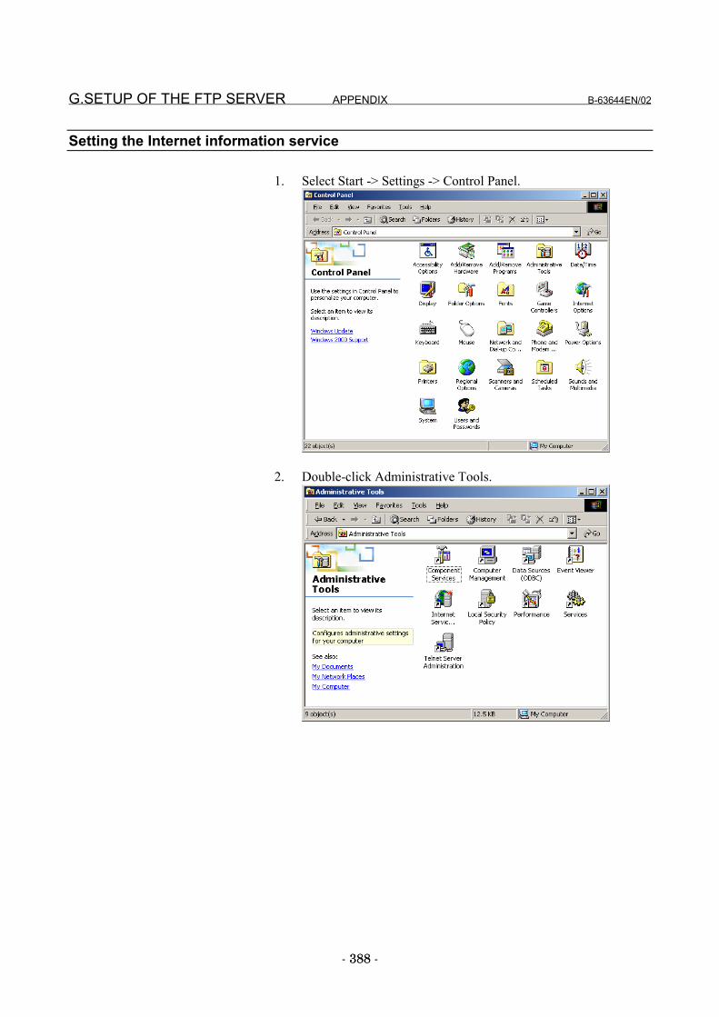
G.SETUP OF THE FTP SERVER APPENDIX B-63644EN/02
- 388 -388
Setting the Internet information service
1. Select Start -> Settings -> Control Panel.
2. Double-click Administrative Tools.
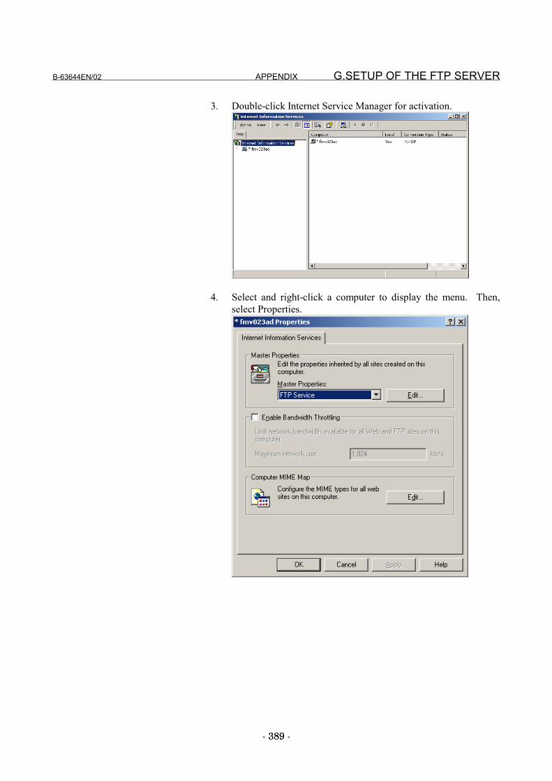
B-63644EN/02 APPENDIX G.SETUP OF THE FTP SERVER
- 389 -389
3. Double-click Internet Service Manager for activation.
4. Select and right-click a computer to display the menu. Then,select Properties.
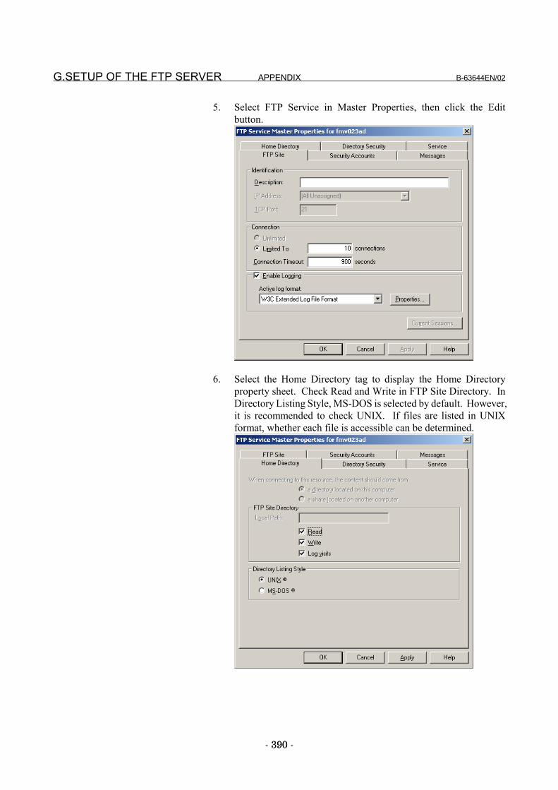
G.SETUP OF THE FTP SERVER APPENDIX B-63644EN/02
- 390 -390
5. Select FTP Service in Master Properties, then click the Editbutton.
6. Select the Home Directory tag to display the Home Directoryproperty sheet. Check Read and Write in FTP Site Directory. InDirectory Listing Style, MS-DOS is selected by default. However,it is recommended to check UNIX. If files are listed in UNIXformat, whether each file is accessible can be determined.
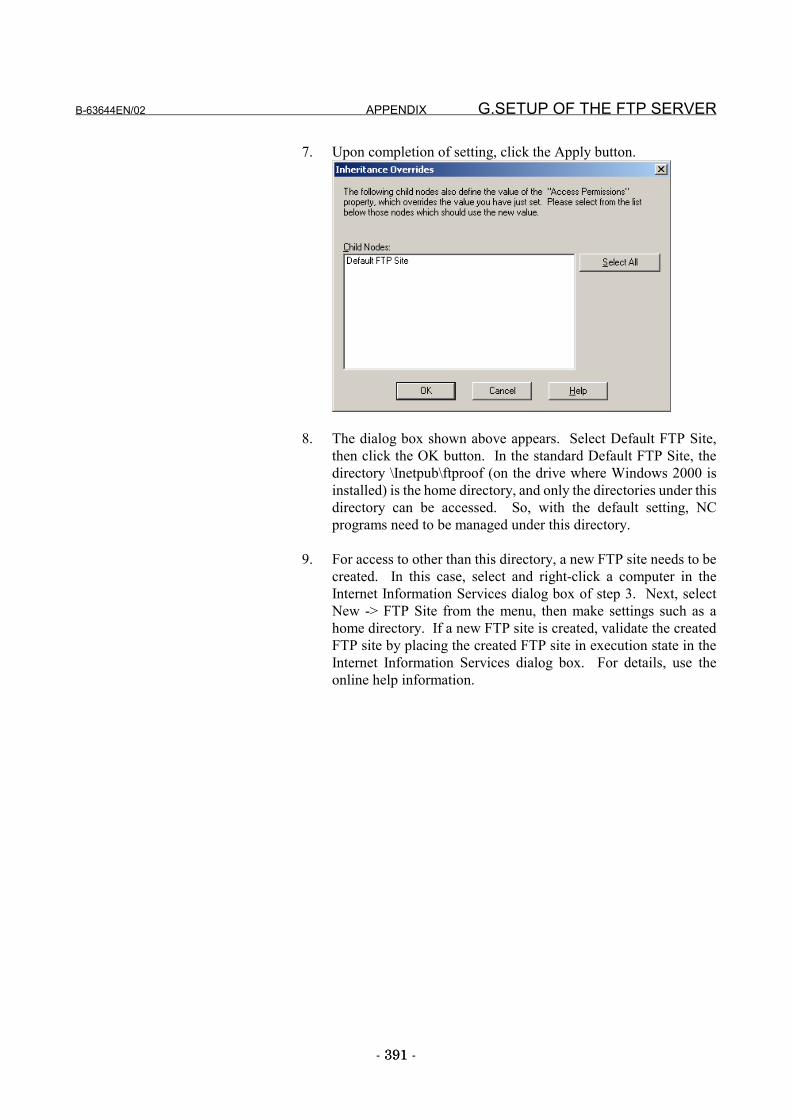
B-63644EN/02 APPENDIX G.SETUP OF THE FTP SERVER
- 391 -391
7. Upon completion of setting, click the Apply button.
8. The dialog box shown above appears. Select Default FTP Site,then click the OK button. In the standard Default FTP Site, thedirectory \Inetpub\ftproof (on the drive where Windows 2000 isinstalled) is the home directory, and only the directories under thisdirectory can be accessed. So, with the default setting, NCprograms need to be managed under this directory.
9. For access to other than this directory, a new FTP site needs to becreated. In this case, select and right-click a computer in theInternet Information Services dialog box of step 3. Next, selectNew -> FTP Site from the menu, then make settings such as ahome directory. If a new FTP site is created, validate the createdFTP site by placing the created FTP site in execution state in theInternet Information Services dialog box. For details, use theonline help information.
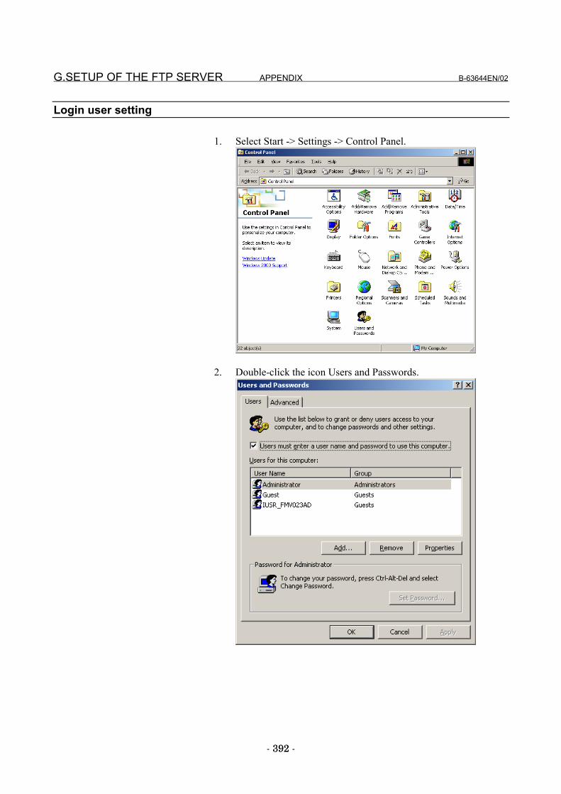
G.SETUP OF THE FTP SERVER APPENDIX B-63644EN/02
- 392 -392
Login user setting
1. Select Start -> Settings -> Control Panel.
2. Double-click the icon Users and Passwords.
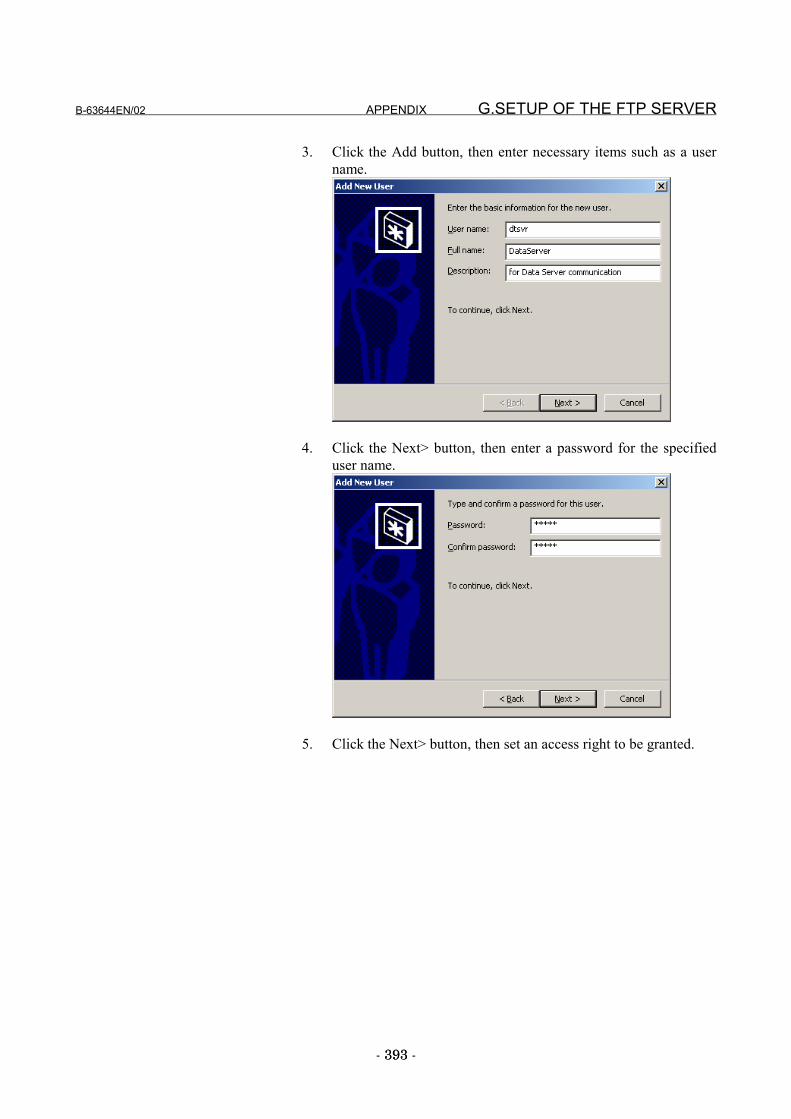
B-63644EN/02 APPENDIX G.SETUP OF THE FTP SERVER
- 393 -393
3. Click the Add button, then enter necessary items such as a username.
4. Click the Next> button, then enter a password for the specifieduser name.
5. Click the Next> button, then set an access right to be granted.
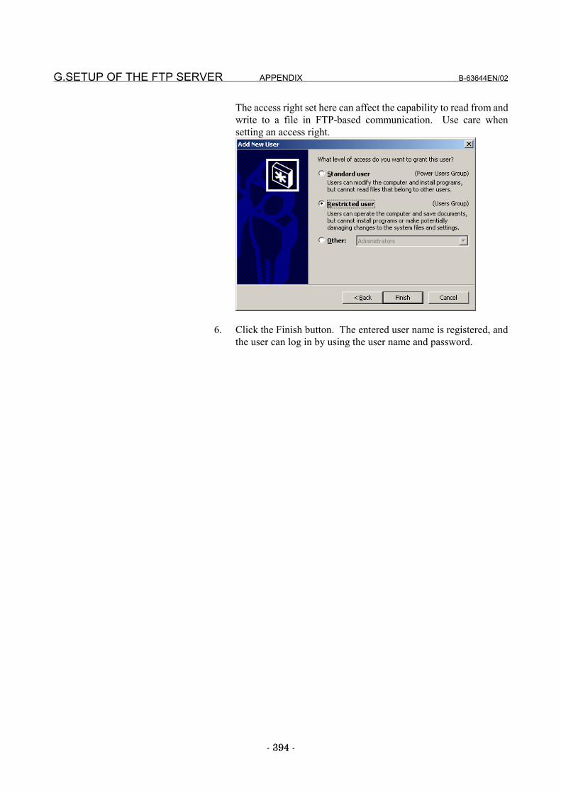
G.SETUP OF THE FTP SERVER APPENDIX B-63644EN/02
- 394 -394
The access right set here can affect the capability to read from andwrite to a file in FTP-based communication. Use care whensetting an access right.
6. Click the Finish button. The entered user name is registered, andthe user can log in by using the user name and password.
B-63644EN/02 INDEX
i-1
INDEX<Number>
100BASE-TX CONNECTOR (CD38R, CD38T) PIN
ASSIGNMENTS .......................................................... 30915i DATA SERVER FUNCTIONS.............................. 204
15i FOCAS1/Ethernet FUNCTIONS ........................... 201
16i/18i/21i DATA SERVER FUNCTIONS ................. 113
16i/18i/21i FACTOLINK FUNCTIONS...................... 103
16i/18i/21i/PMi DNC1/Ethernet FUNCTIONS ........... 107
16i/18i/21i/PMi FOCAS1/Ethernet FUNCTIONS....... 110
<A>APPLICABLE MODELS................................................. 5
ASCII CODE TABLE .................................................. 380
<B>Buffer Mode Specifications .................................. 126, 217
<C>Cable Connection ......................................................... 310
Cable Materials............................................................. 311
Changing a Hard Disk File Name......................... 141, 231
Changing the Connected Host .............................. 190, 278
CHECKING COMMUNICATION .............................. 366
CHECKING HUB CONNECTION.............................. 364
CHECKING OPERATION STATUS OF EACH
FUNCTION.......................................................... 341, 357
CHECKING SETTINGS.............................................. 365
Checking the ATA Card ....................................... 194, 282
Checking the Connected Host ...................................... 189
Checking the Connected Host ...................................... 277
CHECKING WHETHER COMMUNICATION
DESTINATION DEVICES EXIST...................... 337, 353
Clamping and Shielding Cables.................................... 314
Component Layout ....................... 324, 329, 333, 345, 349
CONFIGURING A LARGE-SCALE NETWORK
.................... 33, 44, 54, 76, 87, 100, 31, 43, 53, 75, 86, 99
CONNECT HOST SCREEN........................................ 188
CONNECTING TO ETHERNET................................. 307
Connection Diagram............................................. 301, 305
Connector Specification ............................................... 313
Copying a Hard Disk File ..................................... 140, 230
Creating a Directory on the ATA Card ................. 142, 232
<D>DATA INPUT/OUTPUT...................................... 173, 264
DATA SERVER (MAINTENANCE) SCREEN .......... 280
DATA SERVER FUNCTION ........................................ 16
DATA SERVER FUNCTION RESTRICTIONS ......... 379
DATA SERVER FUNCTIONS.................................... 372DATA SERVER FUNCTIONS FOR THE 15 i i ........... 88
DATA SERVER FUNCTIONS FOR THE 16i/18i/21i .. 55
Data Server Modes ............................................... 114, 205
Data Server Screen Manipulation and Status Indication
.............................................................................. 131, 222
Deleting a Directory from the ATA Card.............. 143, 233
Deleting a Hard Disk File ..................................... 138, 228
Deleting a Host File .............................................. 155, 247
Description of LED Indication ............................. 334, 350
Differences Between a File Number, O Number, and File
Name..................................................................... 117, 208
Differences Between a Hard Disk File and Host File
.............................................................................. 118, 209
Displaying a List of Hard Disk Files..................... 136, 226
Displaying a List of Host Files ............................. 153, 245
Displaying Error Examination Data...................... 198, 285
DNC OPERATION BY A SUBPROGRAM CALL
(M198).................................................................. 169, 260
DNC OPERATIONS ............................................ 166, 257
DNC1/Ethernet AND FOCAS1/Ethernet FUNCTION
RESTRICTIONS .......................................................... 378
DNC1/ETHERNET FUNCTION ................................... 13DNC1/Ethernet FUNCTIONS FOR THE 16i/18i/21i/PMi
........................................................................................ 34
DNC1/Ethernet OR FOCAS1/Ethernet FUNCTION.... 371
<E>ELECTRICAL NOISE COUNTERMEASURES......... 314
Entering a File Number, O Number, and File Name117, 208
ENVIRONMENTAL CONDITIONS FOR INSTALLING
A CNC .......................................................................... 293
ETHERNET ERROR MESSAGE SCREEN
.............................................. 105, 108, 111, 199, 202, 286
ETHERNET FUNCTIONS............................................. 11
ETHERNET PARAMETER SCREEN
.................................................. 23, 36, 47, 58, 79, 90, 373
INDEX B-63644EN/02
i-2
Executing Hard Disk File LIST-DELETE............ 149, 240
Executing Hard Disk File LIST-PUT ................... 148, 239
Executing Hard Disk File MPUT ......................... 147, 238
Executing Hard Disk File PUT............................. 145, 235
Executing Host File GET...................................... 156, 248
Executing Host File LIST-GET............................ 160, 251
Executing Host File MGET .................................. 158, 250
<F>FACTOLINK FUNCTION..................................... 12, 370
FACTOLINK FUNCTION RESTRICTIONS.............. 377FACTOLINK FUNCTIONS FOR THE 16i/18i/21i....... 21
FACTOLINK SCREEN ............................................... 104
FAST DATA SERVER ................................................ 349
FAST DATA SERVER FOR STAND-ALONE TYPE
CNC.............................................................................. 333
FAST ETHERNET BOARD ........................................ 345
FAST ETHERNET BOARD FOR STAND-ALONE TYPE
CNC.............................................................................. 329
FAST ETHERNET/FAST DATA SERVER FOR LCD-
MOUNTED TYPE CNC .............................................. 324
FOCAS1/ETHERNET FUNCTION............................... 14FOCAS1/Ethernet FUNCTIONS FOR THE 15i ............ 77
FOCAS1/Ethernet FUNCTIONS FOR THE16i/18i/21i/PMi .............................................................. 45
FOR INTERNET INFORMATION SERVICE (Windows
2000 Professional) ........................................................ 386
Formatting the ATA Card..................................... 195, 283
FTP CLIENT OPERATION......................................... 381
FTP COMMANDS (FOR Windows NT 4.0 Workstation)
...................................................................................... 382
FTP SERVER FUNCTIONS........................................ 191
FTP SERVER FUNCTIONS........................................ 279
<G>Grounding the Network ................................................ 317
<H>HARD DISK FILE DIR SCREEN ............................... 133
HARD DISK FILE DIRECTORY SCREEN................ 223
Hard Disk File Names........................................... 119, 210
HARDWARE CONNECTIONS .................................. 306
HEAT DISSIPATION .................................................. 295
HOST DIRECTORY SCREEN.................................... 241
HOST FILE DIR SCREEN .......................................... 150
How to divide an NC program into several files... 129, 220
HOW TO INVESTIGATE THE COMMUNICATION
LINE STATUS ..................................................... 339, 355
How to use the buffer mode.................................. 127, 218
<I>Inputting an M-Code Group ......................................... 184
INPUTTING AN NC PROGRAM ....................... 161, 252
Inputting Custom Macro Variables....................... 178, 269
Inputting Operation History Data ................................. 186
Inputting Parameters..................................................... 265
Inputting Pitch Error Compensation Data............. 182, 273
Inputting the Parameter................................................. 174
Inputting Tool Offsets........................................... 176, 267
Inputting Workpiece Origin Offsets...................... 180, 271
INSTALLATION.......................................................... 296
INSTALLATION CHECKLIST................................... 319
Installing an ATA Flash Card ............................... 299, 304
Installing an Board................................................ 297, 302
<L>LCD-MOUNTED TYPE Series 16i/18i/21i -A/B ........ 297
LEADING OUT THE ETHERNET CABLE................ 308
LED Indications............................................ 326, 330, 346
List File Formats................................................... 121, 212
<M>MAINTENANCE OF DATA SERVER SCREEN....... 192
Moving a Directory on the ATA Card .......................... 234
Moving to Another Directory on the ATA Card........... 144
<N>NC Program Format.............................................. 120, 211
<O>ORGANIZATION ............................................................ 4
Outputting an M-Code Group....................................... 185
OUTPUTTING AN NC PROGRAM.................... 164, 255
Outputting Custom Macro Variables .................... 179, 270
Outputting Operation History Data....................... 187, 275
Outputting Parameters .................................................. 266
Outputting Pitch Error Compensation Data.......... 183, 274
Outputting the Parameter .............................................. 175
Outputting Tool Offsets ........................................ 177, 268
Outputting Workpiece Origin Offsets................... 181, 272
<P>PARAMETERS................................ 29, 42, 52, 73, 85, 97
B-63644EN/02 INDEX
i-3
POWER SUPPLY CAPACITY.................................... 294
PRECAUTIONS TO BE OBSERVED WHEN USING
THE DATA SERVER FUNCTIONS FOR THE FIRST
TIME ........................................................................ 56, 89
PRECAUTIONS TO BE OBSERVED WHEN USING
THE FOCAS1/Ethernet FUNCTIONS FOR THE FIRST
TIME ........................................................................ 46, 78
PRECAUTIONS WHEN USING THE DNC1/Ethernet
FOR THE FIRST TIME ................................................. 35
PRECAUTIONS WHEN USING THE ETHERNET
BOARD FOR THE FIRST TIME .................................. 22
<R>RELATED MANUALS.................................................... 6
RESTRICTIONS .......................................................... 376
RULES GOVERNING THE USE OF THE DATA
SERVER FUNCTIONS........................................ 114, 205
<S>SAFETY PRECAUTIONS.............................................s-1
Searching for a Hard Disk File ............................. 137, 227
Searching for a Host File ...................................... 154, 246
SELECTION OF HOST SCREEN............................... 276
Separating Signal Lines ................................................ 314Series 15i MAINTENENCE INFORMATION ............ 344
Series 16i/18i/21i, Power Mate i MAINTENENCE
INFORMATION .......................................................... 323
SETTING...................................................................... 292
SETUP OF THE FTP SERVER................................... 385STAND-ALONE TYPE Series 16i/18i/21i-A/B, Series
15i-B, Power Mate i ..................................................... 302
Switching Data Server Modes .............................. 197, 284
<T>TROUBLES & ERROR MESSAGES.......................... 369
TROUBLESHOOTING................................................ 363
TWISTED-PAIR CABLE SPECIFICATION .............. 310

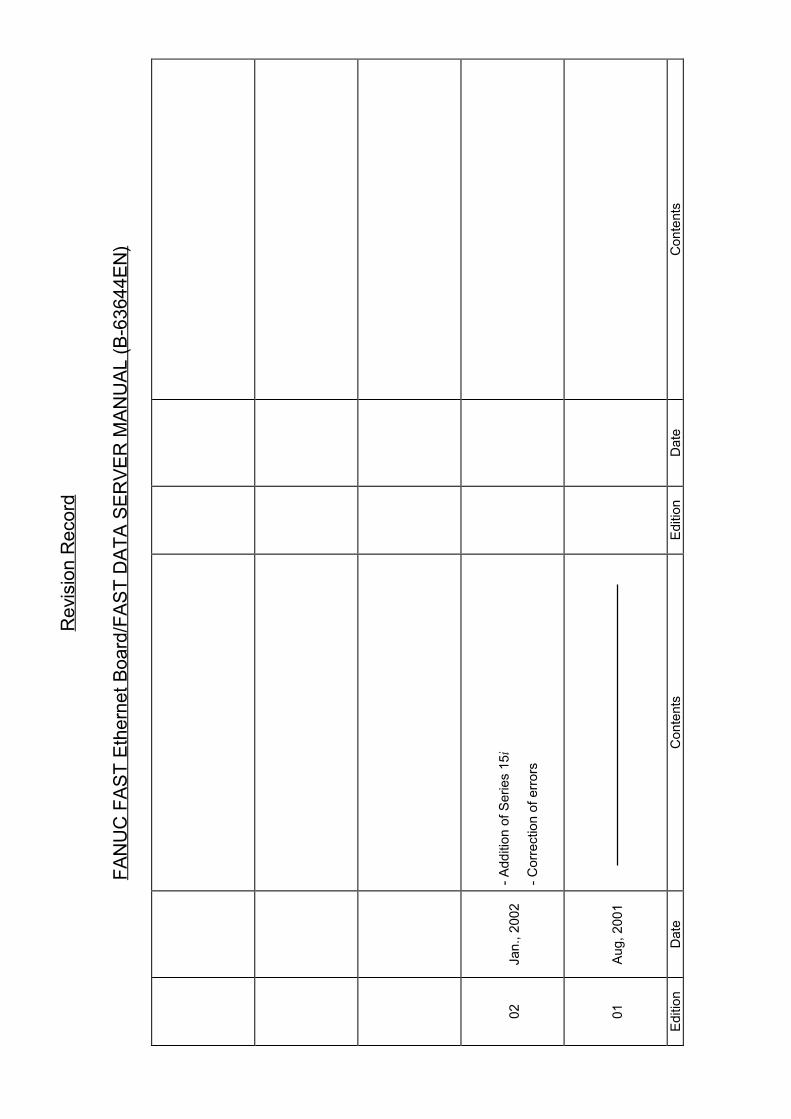
Rev
isio
n R
ecor
d
FAN
UC
FAS
T Et
hern
et B
oard
/FAS
T D
ATA
SER
VER
MAN
UAL
(B-6
3644
EN)
02Ja
n., 2
002
- Ad
ditio
n of
Ser
ies
15i
- C
orre
ctio
n of
erro
rs
01Au
g, 2
001
Editi
onD
ate
Con
tent
sEd
ition
Dat
eC
onte
nts
