dual-port ethernet/fast ethernet board for compactpci applications
TRANSCRIPT
CP341
Dual-Port Ethernet/Fast Ethernet Board
for CompactPCI Applications
Manual ID 18845, Rev. Index 010220 Nov 98
The product described in this manual isin compliance with all applied CE stan-dards.

® PEP Modular Computers GmbH
This page was intentionally left blank.
CP341 Preface
Preface
Revision History ........................................................... 0 - 4
Trademarks.................................................................. 0 - 4
Explanation of Symbols ............................................... 0 - 5
For Your Safety............................................................ 0 - 6
High Voltage Safety Instructions .............................. 0 - 6
Special Handling and Unpacking Instructions .......... 0 - 6
General Instructions on Usage................................. 0 - 7
Two Years Warranty .................................................... 0 - 8
Table of Contents......................................................... 0 - 9
ID 18845, Rev. 0102 Page 0 - 3® PEP Modular Computers GmbH
Preface CP341
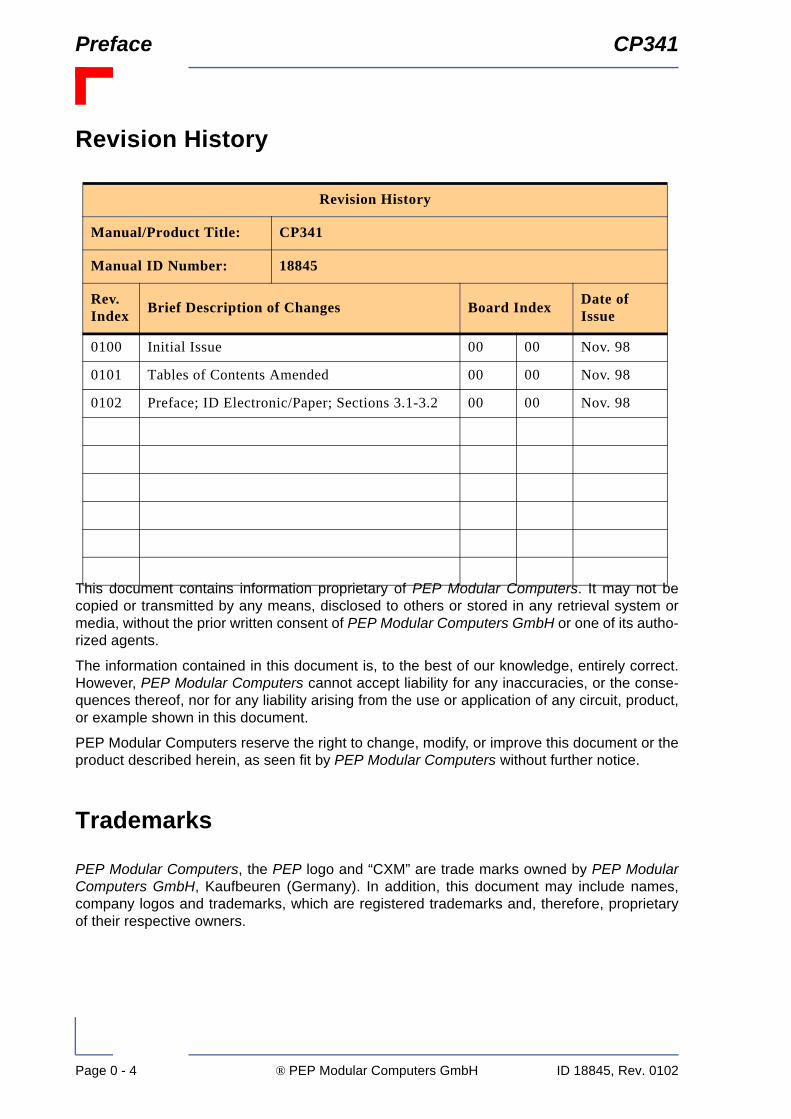
Revision History
This document contains information proprietary of PEP Modular Computers. It may not becopied or transmitted by any means, disclosed to others or stored in any retrieval system ormedia, without the prior written consent of PEP Modular Computers GmbH or one of its autho-rized agents.
The information contained in this document is, to the best of our knowledge, entirely correct.However, PEP Modular Computers cannot accept liability for any inaccuracies, or the conse-quences thereof, nor for any liability arising from the use or application of any circuit, product,or example shown in this document.
PEP Modular Computers reserve the right to change, modify, or improve this document or theproduct described herein, as seen fit by PEP Modular Computers without further notice.
Trademarks
PEP Modular Computers, the PEP logo and “CXM” are trade marks owned by PEP ModularComputers GmbH, Kaufbeuren (Germany). In addition, this document may include names,company logos and trademarks, which are registered trademarks and, therefore, proprietaryof their respective owners.
ID 18845, Rev. 0102Page 0 - 4 ® PEP Modular Computers GmbH
Revision History
Manual/Product Title: CP341
Manual ID Number: 18845
Rev. Index
Brief Description of Changes Board IndexDate of Issue
0100 Initial Issue 00 00 Nov. 98
0101 Tables of Contents Amended 00 00 Nov. 98
0102 Preface; ID Electronic/Paper; Sections 3.1-3.2 00 00 Nov. 98
PrefaceCP341
ID 18845, Rev. 0102 Page 0 - 5® PEP Modular Computers GmbH
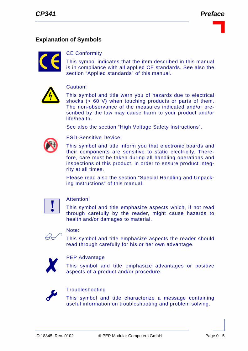
Explanation of Symbols
CE Conformity
This symbol indicates that the item described in this manualis in compliance with all applied CE standards. See also thesection “Applied standards” of this manual.
Caution!
This symbol and title warn you of hazards due to electricalshocks (> 60 V) when touching products or parts of them.The non-observance of the measures indicated and/or pre-scribed by the law may cause harm to your product and/orlife/health.
See also the section “High Voltage Safety Instructions”.
ESD-Sensitive Device!
This symbol and title inform you that electronic boards andtheir components are sensitive to static electricity. There-fore, care must be taken during all handling operations andinspections of this product, in order to ensure product integ-rity at all times.
Please read also the section “Special Handling and Unpack-ing Instructions” of this manual.
Attention!
This symbol and title emphasize aspects which, if not readthrough carefully by the reader, might cause hazards tohealth and/or damages to material.
Note:
This symbol and title emphasize aspects the reader shouldread through carefully for his or her own advantage.
PEP Advantage
This symbol and title emphasize advantages or positiveaspects of a product and/or procedure.
Troubleshooting
This symbol and title characterize a message containinguseful information on troubleshooting and problem solving.
!
$
CP341Preface
For your safety
Your new PEP product was developed and tested carefully to provide all features necessaryto ensure the renown electrical safety requirements. It was also designed for a long fault-freelife. However, the life expectancy of your product can be drastically reduced by improper treat-ment during unpacking and installation. Therefore, in the interests of your own safety and ofthe correct operation of your new PEP product, you are requested to conform with the follow-ing guidelines.
High Voltage Safety Instructions
Special Handling and Unpacking Instructions
$ Do not handle this product out of its protective enclosure while it is not used for opera-tional purposes, unless it is otherwise protected.
$ Whenever possible, unpack or pack this product only at EOS/ESD safe work stations.Where safe work stations are not guaranteed, it is important for the user to be electri-cally discharged before touching the product with his/her hands or tools. This is mosteasily done by touching a metal part of your system housing.
$ It is particularly important to observe standard anti-static precautions when changingpiggybacks, ROM devices, jumper settings etc. If the product contains batteries for RTCor memory back-up, ensure that the board is not placed on conductive surfaces, includ-ing anti-static plastics or sponges. They can cause short circuits and damage the batter-ies or tracks on the board.
Warning!
All operations on this device must be carried out by sufficientlyskilled personnel only.
Caution!
However, serious electrical shock hazards exist during all installa-tion, repair and maintenance operations with this product. There-fore, always unplug the power cable to avoid exposure tohazardous voltage.Before installing your new PEP product into a system alwaysensure that your mains power is switched off. This applies also tothe installation of piggybacks.
ESD Sensitive Device!
Electronic boards and their components are sensitive to staticelectricity. Therefore, care must be taken during all handling oper-ations and inspections of this product, in order to ensure productintegrity at all times.
!
ID 16566, Rev. 0102Page 0 - 6 ® PEP Modular Computers GmbH
PrefaceCP341
General Instructions on Usage
$ In order to maintain PEP’s product warranty, this product must not be altered or modifiedin any way. Changes or modifications to the device, which are not explicitly approved byPEP Modular Computers and described in this manual or received from PEP TechnicalSupport as a special handling instruction, will void your warranty.
$ This device should only be installed in or connected to systems that fulfill all necessarytechnical and specific environmental requirements. This applies also to the operationaltemperature range of the specific board version, which must not be exceeded. If batter-ies are present, their temperature restrictions must be taken into account.
$ In performing all necessary installation and application operations, please, follow onlythe instructions supplied by the present manual.
$ Keep all the original packaging material for future storage or warranty shipments. If it isnecessary to store or ship the board please re-pack it as nearly as possible in the man-ner in which it was delivered.
$ Special care is necessary when handling or unpacking the product. Please, consult thespecial handling and unpacking instruction on the following page of this manual.
ID 18845, Rev. 0102 Page 0 - 7® PEP Modular Computers GmbH
CP341Preface
Two Years Warranty
PEP Modular Computers grants the original purchaser of PEP products a TWO YEARS LIMITEDHARDWARE WARRANTY as described in the following. However, no other warranties that may begranted or implied by anyone on behalf of PEP are valid unless the consumer has the expresswritten consent of PEP Modular Computers.
PEP Modular Computers warrants their own products, excluding software, to be free frommanufacturing and material defects for a period of 24 consecutive months from the date ofpurchase. This warranty is not transferable nor extendible to cover any other users or long-term storage of the product. It does not cover products which have been modified, altered orrepaired by any other party than PEP Modular Computers or their authorized agents. Further-more, any product which has been, or is suspected of being damaged as a result of negli-gence, improper use, incorrect handling, servicing or maintenance, or which has beendamaged as a result of excessive current/voltage or temperature, or which has had its serialnumber(s), any other markings or parts thereof altered, defaced or removed will also beexcluded from this warranty.
If the customer’s eligibility for warranty has not been voided, in the event of any claim, he mayreturn the product at the earliest possible convenience to the original place of purchase,together with a copy of the original document of purchase, a full description of the applicationthe product is used on and a description of the defect. Pack the product in such a way as toensure safe transportation (see our safety instructions).
PEP provides for repair or replacement of any part, assembly or sub-assembly at their owndiscretion, or to refund the original cost of purchase, if appropriate. In the event of repair,refunding or replacement of any part, the ownership of the removed or replaced parts revertsto PEP Modular Computers, and the remaining part of the original guarantee, or any newguarantee to cover the repaired or replaced items, will be transferred to cover the new orrepaired items. Any extensions to the original guarantee are considered gestures of goodwill,and will be defined in the “Repair Report” issued by PEP with the repaired or replaced item.
PEP Modular Computers will not accept liability for any further claims resulting directly or indi-rectly from any warranty claim, other than the above specified repair, replacement or refund-ing. In particular, all claims for damage to any system or process in which the product wasemployed, or any loss incurred as a result of the product not functioning at any given time, areexcluded. The extent of PEP Modular Computers liability to the customer shall not exceed theoriginal purchase price of the item for which the claim exists.
PEP Modular Computers issues no warranty or representation, either explicit or implicit, withrespect to its products’ reliability, fitness, quality, marketability or ability to fulfil any particularapplication or purpose. As a result, the products are sold “as is,” and the responsibility toensure their suitability for any given task remains that of the purchaser. In no event will PEPbe liable for direct, indirect or consequential damages resulting from the use of our hardwareor software products, or documentation, even if PEP were advised of the possibility of suchclaims prior to the purchase of the product or during any period since the date of its purchase.
Please remember that no PEP Modular Computers employee, dealer or agent is authorized tomake any modification or addition to the above specified terms, either verbally or in any otherform, written or electronically transmitted, without the company’s consent.
ID 18845, Rev. 0102Page 0 - 8 ® PEP Modular Computers GmbH
CP341 Preface
ID 18845, Rev. 0102 Page 0 - 9® PEP Modular Computers GmbH
Table of Contents
Chapt 1Chapter 1 1. Introduction............................................................ 1 - 3
1.1 System Overview............................................. 1 - 3
1.2 System Components ....................................... 1 - 4
1.3 Board Introduction ........................................... 1 - 7
1.4 Board Overview ............................................... 1 - 7
1.5 Main Features.................................................. 1 - 8
1.6 Main Features................................................ 1 - 10
1.7 Applied Standards ......................................... 1 - 11
1.8 Related Publications...................................... 1 - 11
Chapter 2 2. Configuration ......................................................... 2 - 3
Chapter 3 3. Installation ............................................................. 3 - 3
3.1 Hardware Installation....................................... 3 - 3
3.2 Driver Installation............................................. 3 - 5
3.3 Troubleshooting............................................... 3 - 7

® PEP Modular Computers GmbH
This page was intentionally left blank.
CP341 Introduction
Introduction
ID 18845, Rev. 0102 Page 1 - 1® PEP Modular Computers GmbH
1.1 System Overview.................................................................. 1 - 3
1.1.1 Note on CompactPCI ................................................... 1 - 3
1.1.2 Main Features of CompactPCI Systems...................... 1 - 3
1.2 System Components ............................................................ 1 - 4
1.3 Board Introduction ................................................................ 1 - 7
1.4 Board Overview.................................................................... 1 - 7
1.5 Main Features ...................................................................... 1 - 8
1.5.1 LAN Controller ............................................................. 1 - 8
1.5.2 Memory ........................................................................ 1 - 8
1.5.3 Board Interfaces........................................................... 1 - 8
1.5.4 Front Panel .................................................................. 1 - 9
1.6 Specifications ..................................................................... 1 - 10
1.7 Applied Standards .............................................................. 1 - 11
1.7.1 CE Compliance .......................................................... 1 - 11
1.7.2 Mechanical Compliance............................................. 1 - 11
1.7.3 Environmental Tests .................................................. 1 - 11
1.8 Related Publications........................................................... 1 - 11
Chapter 1

® PEP Modular Computers GmbH
This page was intentionally left blank.
CP341 Introduction
ID 18845, Rev. 0102 Page 1 - 3® PEP Modular Computers GmbH
1. Introduction
1.1 System Overview
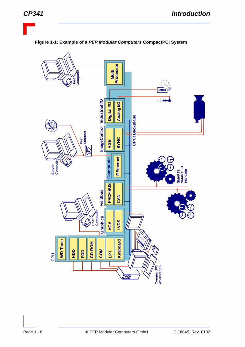
The PEP Modular Computers CompactPCI systems described in this chapter operatewith the PCI bus architecture to support additional I/O and memory-mapped devices asrequired by various industrial applications. In the following you will find the most impor-tant information on all system-relevant CompactPCI features. For more detailed infor-mation concerning the CompactPCI standard, please consult the complete PeripheralComponent Interconnect (PCI) and CompactPCI Specifications. You can connect to thehomepage of the PCI Industrial Computer Manufacturers Group (PICMG) by clickinginto the highlighted area.
1.1.1 Note on CompactPCI
CompactPCI is an extension of the PCI specification. It has been optimized for industrialand/or embedded applications that require a more robust mechanical form factor ascompared to Desktop PCI. CompactPCI systems use industry standard mechanicalcomponents and high performance connector technologies to provide systems that arewell suited for rugged applications. CompactPCI stands for systems that are electricallycompatible with the PCI Specification, allowing low-cost PCI components to be used.CompactPCI is an open specification supported by the PICMG, which is a consortium ofcompanies involved in utilizing PCI for embedded applications.
1.1.2 Main Features of CompactPCI Systems
Some of the outstanding features of the CompactPCI systems compliant with Specifica-tion 2.0, Release 2.1 are:
• PCI signalling• 32- and 64-bit data transfer at 33 MHz• up to 8 PCI slots per backplane• industry standard software support• 3U small form factor (100 mm by 160 mm)• 6U form factor (233 mm by 160 mm)• Eurocard packaging• wide variety of available I/O functions
CP341 Introduction
ID 18845, Rev. 0102Page 1 - 4 ® PEP Modular Computers GmbH
• industry support from over 350 members.
1.2 System Components
PEP Modular Computers have devised their CompactPCI systems as a comprehensiveopen solution for industrial environments, offering different workstation configurationswhich are capable of including all the components necessary to fulfill the requirementsof virtually all existing system functionalities.
CompactPCI Backplane(s)
• 4-slot backplane;• 6-slot backplane;• 8-slot backplane;• 16-slot backplane.
CPU Function
PEP Modular Computers provides CPU boards corresponding in size and characteris-tics to the special features of the PEP systems.
Display-Related Functions
Display-related functions such as graphics control and frame grabbing are supported bydedicated boards.
Communication
Communication boards are provided for the currently relevant industrial communicationsystems such as, for instance, Fast Ethernet.
Fieldbus Control
Fieldbus control boards provide data exchange with field control and automation sub-systems like, for example, PEP Modular Computers’ SMART2 or VMEbus systems,using up-to-date transmission standards e.g.:
• CAN fieldbus control• PROFIBUS control
Industrial I/O Functions
PEP’s CompactPCI systems support an ever increasing number of industrial I/O func-tionalities in the fields of:
PEP Advantage
PEP Modular Computers’ CompactPCI systems are designed asopen systems, able to be expanded at any time, so that their back-planes can be equipped with precisely the CPCI boards that corre-spond to a customer’s specific needs. However, in order to supplyyou with an appropriate choice of workstations, the PEP basicequipment is divided into pre-configured sets and custom solutions.
CP341 Introduction
ID 18845, Rev. 0102 Page 1 - 5® PEP Modular Computers GmbH
• Digital I/O• Analog I/O
Self-Testing
A special PEP self-testing board provides a trouble-spotting capability within your PEPsystem.
System Hardware
The PEP CompactPCI system hardware includes housings, storage devices, powersupply units, network adapters etc. The most important system hardware elements withwhich to configure your CompactPCI system are as follows:
Multiprocessor
In a CompactPCI multi-processer system, a system controller (CP610) communicateswith other CPU’s through a non-transparent PCI / PCI bridge
Housings
• Board cages for 19-inch or wall mounting• PCI tower• PCI desktop housing
Mass Storage Devices
• Hard-disk drive• Floppy-disk drive• CD-ROM drive
Power Supply Units
• 19-inch “M”, 180 W, 120/230 V AC, 3.3V/14A, 5.1V/20A, 12V/2A, -12V/1A• “ATX”, 235 W, 120/230 VAC, 3.3V/14A, 5V/22A, 12V/8A,-12V/1A, -5V/0.5A,
5VSB/0.1A
Please note that the following units of measurement are used to express the dimensionsof PEP cards and housings:
• Height: 1 U = 44.45 mm• Width: 1 HP = 5.08 mm
For a detailed description of the PEP Modular Computers CompactPCI modules pleaseconsult the specific components’ manuals or data sheets.
PEP Advantage
As the PEP Modular Computers CompactPCI system providescomprehensive open solutions, new features and functionalitiesmay be added to our range. To keep abreast of the latest develop-ments, please contact your local PEP Sales Office or visit the PEPWeb Site.
CP341 Introduction
ID 18845, Rev. 0102Page 1 - 6 ® PEP Modular Computers GmbH
Figure 1-1: Example of a PEP Modular Computers CompactPCI System
Imag
e Con
trol
WD
Tim
er
HD
D
FD
D
CD
-RO
M
CO
M
LP
T
Key
bo
ard
SM
AR
T2
SM
AR
T I/
OP
EP
9300
Ho
stC
om
pu
ter
Co
mp
actP
CI
Wo
rkst
atio
n
WW
W
CP
US
erve
rC
om
pu
ter
Fas
tE
ther
net
VG
A
LVD
S
Gra
ph
ics
F. E
ther
net
Co
mm
un
ic.
RG
B
SY
NC
Ind
ust
rial
I/O
Dig
ital I
/O
Ana
log
I/O
CP
CI B
ackp
lan
e
Fie
ldb
us
PR
OFI
BU
S
CA
N
Ho
stC
om
pu
ter
Mu
lti
Pro
cess
or
CP341 Introduction
ID 18845, Rev. 0102 Page 1 - 7® PEP Modular Computers GmbH
1.3 Board Introduction
The CP-341 board by PEP Modular Computers is a CompactPCI network controllerbased on the Intel Fast Ethernet PCI Bus LAN Controller 82558.
Some of the CP341’s outstanding features are:
• Dual independent Fast Ethernet interfaces• Multiple server-to-client networking• 10Base-T and 100Base-TX auto-negotiation• Integrated physical layer interface (PHY)• 6 kByte FIFO buffer• Galvanic de-coupling
1.4 Board Overview
The CP341 board by PEP Modular Computers is a Compact PCI Fast Ethernet LANcontroller for multiple server-to-client networking functions. It provides dual independentfast Ethernet Interfaces. Both interfaces are based on the Intel Fast Ethernet PCI BusLAN Controller 82558 with integrated physical layer interface (PHY).
CP341 is a 3U CPCI Ethernet board suitable for both 10Base-T and 100Base-TX con-nections and includes all necessary features for auto-negotiation. Thus, both 10 Mbit/sand 100 Mbit/s transfer rates are supported by the board. In fact, provided that your net-work has the speed capability, the CP341 switches automatically from 10 Mbit/s to 100M/bit/s. Additionally, if the addressed network station is compatible, it switches automat-ically to full-duplex mode.
The 3.3V/5V signalling board is designed to permit a very high PCI data bandwidth,which is achieved thanks to a large, 3 kByte-in/3 kByte-out FIFO buffer.
An Advanced Configuration Power Interface (ACPI) guarantees various power-downstates and the ability to wake up on a single package addressed to the system, whileremote stations may be returned to full power by any remote machine being networked.
The board does not have any jumpers and, therefore, does not require configuration.This is due to the use of a standard Windows NT driver (both Windows NT 3.5 and 4.0drivers are supplied with the board). To make installation, repairs and updates easier, aLANDesk Service Agent allows the system to be started from a different operating sys-tem via network.
CP341 Introduction
ID 18845, Rev. 0102Page 1 - 8 ® PEP Modular Computers GmbH
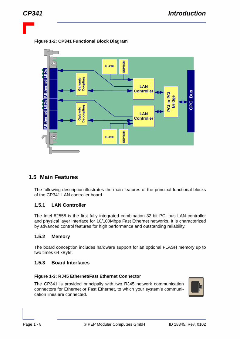
Figure 1-2: CP341 Functional Block Diagram
1.5 Main Features
The following description illustrates the main features of the principal functional blocksof the CP341 LAN controller board.
1.5.1 LAN Controller
The Intel 82558 is the first fully integrated combination 32-bit PCI bus LAN controllerand physical layer interface for 10/100Mbps Fast Ethernet networks. It is characterizedby advanced control features for high performance and outstanding reliability.
1.5.2 Memory
The board conception includes hardware support for an optional FLASH memory up totwo times 64 kByte.
1.5.3 Board Interfaces
Figure 1-3: RJ45 Ethernet/Fast Ethernet Connector
The CP341 is provided principally with two RJ45 network communicationconnectors for Ethernet or Fast Ethernet, to which your system’s communi-cation lines are connected.
CP
CI B
us
FLASH
EE
PR
OM
F.E
ther
net
Gal
van
ic
F.E
ther
net
LE
Ds
LE
Ds
Co
up
ling
FLASH
EE
PR
OM
Gal
van
icD
eco
up
ling
LANController
LANController
PC
I-to
-PC
IB
rid
ge
CP341 Introduction
ID 18845, Rev. 0102 Page 1 - 9® PEP Modular Computers GmbH
Ethernet and Fast Ethernet
The CP341 LAN controller board envisages the use of the renown CSMA/CD protocol(Carrier Sense Multiple Access/Collision Detection), enabling data to move betweenEthernet and Fast Ethernet nodes on the LAN without any protocol translation.
Ethernet and Fast Ethernet are ruled by standards issued by IEEE (Institute of Electricaland Electronic Engineers). Ethernet supports a transfer speed of 10 Mbit/s, Fast Ether-net of 100 Mbit/s.
Cable Types
CP341 is designed to support star topology 2-pair category 5 UTP/STP cables whichare one of the most widely available cable types on the market.
”UTP” stands for ”Unshielded Twisted-Pair” cables, while ”STP” stands for ”ShieldedTwisted-Pair” cables. The purpose of wire twisting and shielding is to reduce electro-magnetic interference between cable wires.
1.5.4 Front Panel
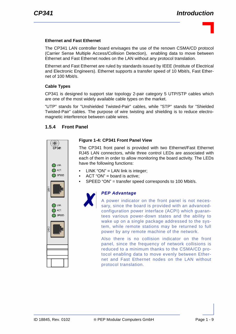
Figure 1-4: CP341 Front Panel View
The CP341 front panel is provided with two Ethernet/Fast EthernetRJ45 LAN connectors, while three control LEDs are associated witheach of them in order to allow monitoring the board activity. The LEDshave the following functions:
• LINK “ON” = LAN link is integer;• ACT “ON” = board is active;• SPEED “ON” = transfer speed corresponds to 100 Mbit/s.
PEP Advantage
A power indicator on the front panel is not neces-sary, since the board is provided with an advanced-configuration power interface (ACPI) which guaran-tees various power-down states and the ability towake up on a single package addressed to the sys-tem, while remote stations may be returned to fullpower by any remote machine of the network.
Also there is no collision indicator on the frontpanel, since the frequency of network collisions isreduced to a minimum thanks to the CSMA/CD pro-tocol enabling data to move evenly between Ether-net and Fast Ethernet nodes on the LAN withoutprotocol translation.
CP341 Introduction
ID 18845, Rev. 0102Page 1 - 10 ® PEP Modular Computers GmbH
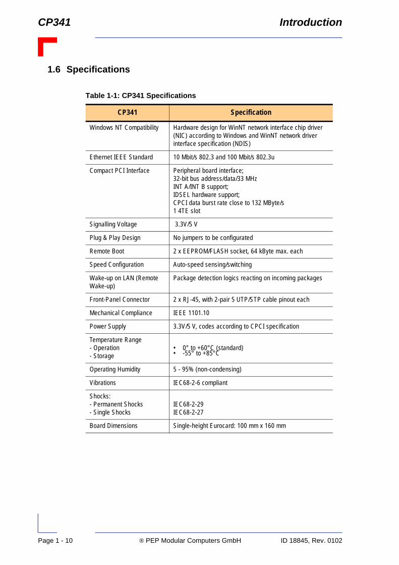
1.6 Specifications
Table 1-1: CP341 Specifications
CP341 Specification
Windows NT Compatibility Hardware design for WinNT network interface chip driver (NIC) according to Windows and WinNT network driver interface specification (NDIS)
Ethernet IEEE Standard 10 Mbit/s 802.3 and 100 Mbit/s 802.3u
Compact PCI Interface Peripheral board interface;32-bit bus address/data/33 MHzINT A/INT B support;IDSEL hardware support;CPCI data burst rate close to 132 MByte/s1 4TE slot
Signalling Voltage 3.3V/5 V
Plug & Play Design No jumpers to be configurated
Remote Boot 2 x EEPROM/FLASH socket, 64 kByte max. each
Speed Configuration Auto-speed sensing/switching
Wake-up on LAN (Remote Wake-up)
Package detection logics reacting on incoming packages
Front-Panel Connector 2 x RJ-45, with 2-pair 5 UTP/STP cable pinout each
Mechanical Compliance IEEE 1101.10
Power Supply 3.3V/5 V, codes according to CPCI specification
Temperature Range- Operation- Storage
• 0° to +60°C (standard)• -55° to +85°C
Operating Humidity 5 - 95% (non-condensing)
Vibrations IEC68-2-6 compliant
Shocks:- Permanent Shocks- Single Shocks
IEC68-2-29IEC68-2-27
Board Dimensions Single-height Eurocard: 100 mm x 160 mm
CP341 Introduction
ID 18845, Rev. 0102 Page 1 - 11® PEP Modular Computers GmbH
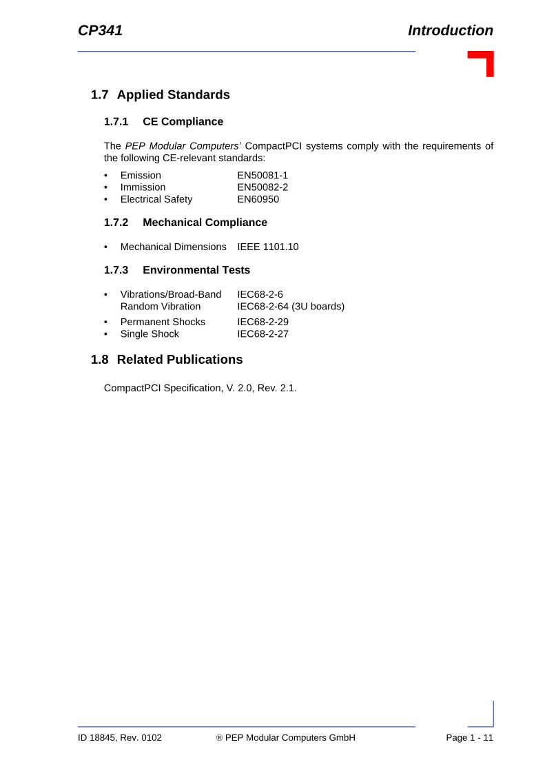
1.7 Applied Standards
1.7.1 CE Compliance
The PEP Modular Computers’ CompactPCI systems comply with the requirements ofthe following CE-relevant standards:
• Emission EN50081-1• Immission EN50082-2• Electrical Safety EN60950
1.7.2 Mechanical Compliance
• Mechanical Dimensions IEEE 1101.10
1.7.3 Environmental Tests
• Vibrations/Broad-Band IEC68-2-6Random Vibration IEC68-2-64 (3U boards)
• Permanent Shocks IEC68-2-29• Single Shock IEC68-2-27
1.8 Related Publications
CompactPCI Specification, V. 2.0, Rev. 2.1.

® PEP Modular Computers GmbH
This page was intentionally left blank.
CP341
ID 18845, Rev. 0102
Configuration
Page 2 - 1® PEP Modular Computers GmbH
Configuration
Chapter 2

® PEP Modular Computers GmbH
This page was intentionally left blank.
CP341 Configuration
ID 18845, Rev. 0102 Page 2 - 3® PEP Modular Computers GmbH
2. Configuration
The CP341 accords fully with the plug & play philosophy. Since it uses a standard Win-dows NT driver It does not need any jumpers and, therefore, does not require configura-tion. A complete set of drivers is located on the PEP Modular Computers “Drivers” disksupplied with the CP341.
Simply insert the cable terminal into the CP341 Ethernet/Fast Ethernet RJ-45 socket,run the automatic configuration software, install the network drivers and — it’s ready!
$$Important!
Useful hints on driver installation and configuration of the CP341board via software as well as the relevant troubleshooting optionsare provided in Chapter 3 of this manual.

® PEP Modular Computers GmbH
This page was intentionally left blank.
CP341
ID 18845, Rev. 0102
Installation
Page 3 - 1® PEP Modular Computers GmbH
Installation
3.1 Hardware Installation........................................................... 3 - 3
3.1.1 Cable Connections...................................................... 3 - 3
3.1.2 Board Placement ........................................................ 3 - 3
3.1.3 Board Installation ........................................................ 3 - 4
3.1.4 Board Connection ....................................................... 3 - 4
3.1.5 AC Power Connection................................................. 3 - 5
3.2 Software Installation ............................................................ 3 - 5
3.2.1 Automatic Configuration.............................................. 3 - 5
3.2.2 Installation of Network Drivers .................................... 3 - 5
3.2.3 Configuration Utility PROSET ..................................... 3 - 6
3.2.4 Adapter Fault Tolerance Mode ................................... 3 - 7
3.3 Troubleshooting................................................................... 3 - 7
Chapter 3

® PEP Modular Computers GmbH
This page was intentionally left blank.
CP341 Installation
ID 18845, Rev. 0102 Page 3 - 3® PEP Modular Computers GmbH
3. Installation
As a sophisticated electronic device using AC power, your CP341 must be set up andused correctly to maintain safe and proper functioning. Please follow the instructions inthis chapter fully to ensure successful installation and long lasting, trouble-free opera-tion.
3.1 Hardware Installation
3.1.1 Cable Connections
To ensure correct operation of your network, you must use cables of permitted typesand lengths with your CP341, since some cable types are subject to mandatory limita-tions in this regard. Cable categories are governed by the relevant EIA (ElectronicIndustries Association) standards.
CP341 is designed to support star topology 2-pair Category 5 UTP/STP cables.
3.1.2 Board Placement
In deciding on a location for the unit which will house your CP341, the following factorsmust be considered:
• length of each cable connection between devices;• environmental factors.
Distance between Devices
If your network connections consist of twisted-pair connections, the maximum distancebetween devices is 100 meters (328 feet). Using this cable type, the maximum length ofcabling between any two end nodes, including any uplink connection, is 205 meters.These limits include every bit of cabling between the CP341 and other devices, bothinside and outside walls and wiring closets.
Environmental Factors
Your CP341 must be operated within specific environmental limits. It must not beexposed to direct sunlight, strong magnetic fields, extremely dusty or humid air, extremeheat or cold, or temperature shocks. For detailed guidance on these operating condi-tions, please consult table 2-1 of this manual.
$$Important!
Mount your CP341 only after having ensured that the tower youintend to fit it into is placed in a suitable location.
CP341 Installation
ID 18845, Rev. 0102Page 3 - 4 ® PEP Modular Computers GmbH
3.1.3 Board Installation
The CP341 is fully compatible with the plug & play philosophy. As it uses standard Win-dows NT drivers it does not need any jumper setting and, therefore, does not requireany hardware configuration. A complete set of drivers is located on the PEP ModularComputers Driver disk supplied with the CP341.
However, if your system runs into an error message while booting, its configuration mayrequire additional steps. In this case, please refer to the readme.lst file on the Driverdisk.
3.1.4 Board Connection
To connect the CP341 Ethernet/Fast Ethernet adapter please simply insert the networkcable into the board’s RJ-45 socket. Then run the automatic configuration software andinstall the network drivers,
Caution!
If your board type is not specifically qualified as hot-swap capable,please switch off the CompactPCI system before installing theboard in a free CompactPCI slot. Failure to do so could endangeryour life/health and may damage your board or system.
$$Note:
Certain CompactPCI boards require bus master and/or rear I/Ocapability. If you are in doubt whether such features are requiredfor the board you intend to install, please check your specificboard and/or system documentation to make sure your system isprovided with an appropriate free slot to insert the board.
ESD Equipment!
Your CompactPCI board contains electrostatically sensitivedevices. Please observe the necessary precautions to avoid dam-age to your board:
• Discharge your clothing before touching the assembly. Toolsmust be discharged before use.
• Do not touch components, connector-pins or traces.
• If working at an anti-static workbench with professional dis-charging equipment, please do not omit to use it.
$$Important!
Make connections to your CP341 only after having mounted it in asuitable location (see section “Board Placement” of this manual).
CP341 Installation
ID 18845, Rev. 0102 Page 3 - 5® PEP Modular Computers GmbH
However, if your system runs into an error during network connection, its configurationmay require additional steps. In this case, please refer to the readme.lst file on theDriver disk.
3.1.5 AC Power Connection
3.2 Software Installation
The CP340 is fully compatible with the plug & play philosophy. As it uses standard Win-dows NT drivers it does not need any jumper setting and, therefore, does not requireany hardware configuration. A complete set of drivers is located on the PEP ModularComputers Drivers disk supplied with the CP340.
3.2.1 Automatic Configuration
CompactPCI systems automatically detect and configure PCI-compliant interfaceboards while booting. The CP341 IRQ level and I/O address are automatically set byBIOS each time you start your system.
Thus, for configuring your computer after having mounted the CP341 board, just boot it.Configuration is complete when Windows NT starts or the DOS prompt appears.
3.2.2 Installation of Network Drivers
After having inserted your CP341 board into the CompactPCI backplane and startedWindows NT, you need to install the Intel board drivers and test your CP341 board. Pro-ceed as follows:
• Double-click the “Network” icon in the “Control panel”.• Click “Adapters” tab.
!Attention!
Before reconnecting the computer your CP341 was fitted into to ACpower, replace the dummy front panels of your tower. Failure to doso could endanger your life and may damage the board and/orcomputer.
$$Important!
Connect the computer your CP341 is fitted into to AC power onlyafter having mounted it in a suitable location and correctly com-pleted all network connections.
$$Important!
To ensure full functionality please use the Intel 82558 Ethernetdriver disk supplied with your adapter board.
CP341 Installation
ID 18845, Rev. 0102Page 3 - 6 ® PEP Modular Computers GmbH
• Click “Add”. You will see a list of adapters.• Do not select an adapter from the list. Instead, insert your PEP Modular Computers
“Drivers” disk into your floppy drive and click “Have disk”.• Type A:\ (or B:\) in the dialog box and click “OK”. Then follow the interactive instruc-
tions to install the drivers. When the CP341 board is added, you will see its namelisted in the “Network adapters” list.
• Select the CP341 interface board and click “Properties” to run PROSet to view theboard configuration or test diagnosis. Board diagnostics are available only while thedrivers are not loaded, i.e. before restarting your computer. Driver diagnostics areavailable when the drivers are loaded.
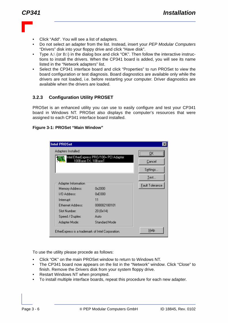
3.2.3 Configuration Utility PROSET
PROSet is an enhanced utility you can use to easily configure and test your CP341board in Windows NT. PROSet also displays the computer’s resources that wereassigned to each CP341 interface board installed.
Figure 3-1: PROSet “Main Window”
To use the utility please procede as follows:
• Click “OK” on the main PROSet window to return to Windows NT.• The CP341 board now appears on the list in the “Network” window. Click “Close” to
finish. Remove the Drivers disk from your system floppy drive.• Restart Windows NT when prompted.• To install multiple interface boards, repeat this procedure for each new adapter.
CP341 Installation
ID 18845, Rev. 0102 Page 3 - 7® PEP Modular Computers GmbH
3.2.4 Adapter Fault Tolerance Mode
Adapter Fault Tolerance (AFT) is a simple, effective, and fail-safe approach to increasethe reliability of server connections. AFT gives you the ability to set up link recovery tothe server adapter in the event of a cable, port, or network interface card failure. Byassigning two single-port CP340 adapters or one twin-port CP341 adapter as a team,AFT enables you to maintain uninterrupted network performance.
AFT is implemented with two Ethernet adapters: a primary adapter and a backup, orsecondary, adapter. During normal operation, the backup will have transmit disabled. Ifthe link to the primary adapter fails, the link to the backup adapter automatically takesover.
3.3 Troubleshooting
Further information on troubleshooting is available on the Driver disk. Please refer to thereadme.lst file on the disk.
$$Notes:
This feature is currently available for NetWare* 4.1x and WindowsNT* 4.0 only.
For more information about AFT, please see the NetWare or Win-dows NT AFT readme files for setup instructions

® PEP Modular Computers GmbH
This page was intentionally left blank.