failure modes of in-filled frames - citeseerx
TRANSCRIPT
Electronic Journal of Structural Engineering 11(1) 2011
11
1 INTRODUCTION
It has been known for long that masonry infill walls affect the strength and stiffness of in-filled frame structures. In seismic areas, ignoring the frame-infill panel interaction is not always on the safe side, since, under lateral loads, the infill walls dramatical-ly increase the stiffness by acting as a diagonal strut, resulting, thus, in a possible change of the seismic demand due to significant reduction in the natural period of the composite structural system (El-Dakhakhni et al., 2003 and 2006; Fardis and Panag-iotakos, 1997; Kose, 2009). However, it is worth no-ticing that the contribution of the infill wall to the frame lateral stiffness is greatly reduced when the structure is subjected to reversed cyclic loading, as in real structures under earthquake conditions. The relevant experimental findings (Vintzileou and Tas-sios, 1989; Paulay and Priestley, 1992) showed a considerable reduction in the response of in-filled frames under reversed cyclic loading. This behav-iour is due to the rapid degradation of stiffness, strength and low energy dissipation capacity, result-ing from the brittle and sudden damage of the unre-inforced masonry (URM) infill walls.
The validation of numerical models for in-filled frames subjected to seismic loads requires experi-
mental results that are obtained from tests realistical-ly designed to accurately represent the structural configuration (i.e., geometrical and material proper-ties, boundary conditions and infill openings). Un-fortunately, most previous experiments on frames with in-fills have been focused on the simplest struc-tural configuration of infill panels without openings subjected to static monotonic loads, raising doubts whether these results can be extrapolated to the commonly met case of an infill panel with opening subjected to earthquake loading (Mosalam, 1996; Mosalam et al., 1997).
The aim of this paper is to formulate and present a general classification scheme of the failure modes of in-filled frame. At first, different failure modes (crack patterns) of masonry in-filled frames are pro-posed and classified into distinct modes. Second, based on recent experimental results on frames in-filled with unreinforced masonry walls with open-ings and subjected to slowly applied cyclic lateral loads, the failure modes of in-filled frames with openings (such as doors and windows) have been investigated from a theoretical, as well as an exper-imental point of view by conducting ad-hoc experi-ments. The experiments consisted of testing ten one-bay, one-story specimens of reinforced concrete frames built at one-third scale. The effect of opening shape, its size (as percentage of the infill area) and
Failure Modes of In-filled Frames
P.G. Asteris Computational Mechanics Laboratory, School of Pedagogical & Technological Education, Athens, Greece, E-mail: [email protected] ; [email protected]
D.J. Kakaletsis Reinforced Concrete Laboratory, Technological Educational Institution of Serres, 62124 Serres, Greece
C.Z. Chrysostomou Dept. of Civil Engineering & Geomatics, Cyprus University of Technology, 3603 Limassol, Cyprus
E.E. Smyrou Laboratory for Earthquake Engineering, National Technical University of Athens, 15700 Athens, Greece
ABSTRACT: The main objective of this paper is to present a general classification scheme of the failure modes of in-filled frames, both with and without openings. For the former, the existing classification is sum-marized based on a literature review. For the latter, recent experimental results on frames in-filled with unre-inforced masonry walls with openings and subjected to slowly applied cyclic lateral loads are used, and a number of different failure modes (crack patterns) of masonry in-filled frames are identified and classified in-to distinct categories. Such a classification of failure modes improves substantially the understanding of the earthquake resistant behaviour of in-filled frames and leads to better methodological approaches regarding their modelling, analysis and design.
KEYWORDS: Crack pattern, Cyclic loads, Failure modes, In-filled frames, In-fills with openings
Electronic Journal of Structural Engineering 11(1) 2011
12
the opening location within the frame was studied in five specimens with window openings and three specimens with door openings. Such a classification of failure modes improves substantially the under-standing of the earthquake resistant behaviour of in-filled frames and leads to better methodological ap-proaches regarding their modelling, analysis and de-sign.
2 BACKGROUND
The rationale behind neglecting infill walls in the design process is partly attributed to incomplete knowledge of the behaviour of quasi-brittle materi-als such as URM, of the composite behaviour of the frame and the infill, as well as due to the lack of conclusive experimental and analytical results to substantiate a reliable design procedure for this type of structures, despite the extensive experimental ef-forts over the past decades (Smith 1966; Smith and Carter 1969; Page et al 1985; Mehrabi et al., 1996; Buonopane and White, 1999; Santhi et al., 2005 a & b), and analytical investigations (Liauw and Kwan, 1984; Dhanasekar and Page, 1986; Chrysostomou 1991; Saneinejad and Hobbs 1995; Combescure and Pegon, 1996; Chrysostomou et al., 2002; Asteris, 2003; Moghaddam, 2004; Asteris, 2005 and 2008; Kakaletsis et al., 2007, 2008 and 2009).
Moreover, due to the large number of interacting parameters, if the infill wall is to be considered in the analysis and design stages, a modelling problem arises because of the many possible failure modes that need to be evaluated with a high degree of un-certainty. Therefore, it is not surprising that no con-sensus has emerged leading to a unified approach for the design of in-filled frame systems in spite of more than five decades of research. However, it is gener-ally accepted that under lateral loads an infill wall acts as a diagonal strut connecting the two loaded corners, an approach that is only applicable to the case of infill walls without openings on the diagonal of the infill panel. The reader is referred to Moghad-dam and Dowling (1987) for an extensive review of research on testing and modelling of masonry in-filled frames up to 1987, while a comprehensive re-port of the relevant literature published between 1987 and 1997 is presented by Madan et al. (1997), in addition to the state-of-the-art CEB report (1996) and the in-depth report by Crisafulli et al. (2000).
Recent advances in research ( arni et al., 2001; Moghaddam, 2004; Rodrigues et al., 2008; Dolšek and Fajfar, 2008; Kose, 2009) have shown that there is a strong interaction between the infill masonry wall and the surrounding frame, leading to:
The behaviour of the composite frame to be de-pendant not only on the relative stiffness of the frame and the infill and the frame geometry, but also critically influenced by the strength proper-ties of the masonry.
Considerable increase of the overall stiffness and of the in plane moment of inertia of the composite frame, as well as an increase of dissi-pated energy.
Redistribution of action-effects, which is ig-nored by the present code formulae, leading to an over-estimate of the shear forces along the height of the frame since they do not consider the effect of infill panels (Santhi et al., 2005a & b) and sometimes unpredictable damage along the frame due to the formation of short columns, and hence large shear forces, by the introduction of openings on in-fills next to columns, which are not considered in the analysis and design,
Substantial impact on the earthquake response of in-filled frames with openings (such as doors and windows), which can lead to torsional un-balance and stiffness discontinuities that are particularly pronounced in the case of Pilotis (Asteris, 2003, 2005 and 2008).
3 BEHAVIOUR OF IN-FILLED FRAMES
The modelling of the behaviour of in-filled frames under lateral loading (and mainly earthquake in-duced loads) is a complex issue because these struc-tures exhibit a highly non-linear response resulting from the interaction between the masonry infill pan-el and the surrounding frame. Masonry is mostly de-signed to “allowable stress” standard, although it may be better to carry out the design under “ultimate strength” methods in terms of cost effectiveness. However, in the case of designing a structure for ul-timate strength, the corresponding failure modes need to be known and the failure loads for different modes of failure have to be computed in order to de-termine the ultimate capacity of the structure and additionally the serviceability criteria have to be checked using working loads.
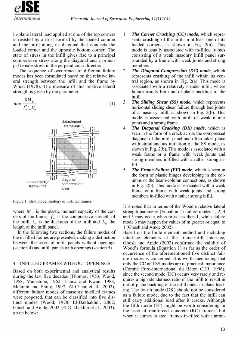
At moderate loading levels the infill of a non-integral in-filled frame separates from the surround-ing frame and the infill acts as a diagonal strut (Fig. 1). As the racking load increases, failure occurs eventually in either the frame or the infill. The usual mode of frame failure is either due to tension in the windward column or due to shear on the column or beams. However, if the frame strength is sufficient enough to prevent its failure by one of these modes, the increasing racking load eventually produces fail-ure of the infill. In the most common situations, the
Electronic Journal of Structural Engineering 11(1) 2011
13
in-plane lateral load applied at one of the top corners is resisted by a truss formed by the loaded column and the infill along its diagonal that connects the loaded corner and the opposite bottom corner. The state of stress in the infill gives rise to a principal compressive stress along the diagonal and a princi-pal tensile stress in the perpendicular direction.
The sequence of occurrence of different failure modes has been formulated based on the relative lat-eral strength between the infill and the frame by Wood (1978). The measure of this relative lateral strength is given by the parameter
2
8
www
p
Ltf
Mm
(1)
detachment
frame-infill
detachmentframe-infill
diagonalcompressionarea
Figure 1. Strut model analogy of in-filled frames.
where pM is the plastic moment capacity of the cor-ners of the frame, wf is the compressive strength of the infill, wt is the thickness of the infill and wL the length of the infill panel.
In the following two sections, the failure modes of the in-filled frames are presented, making a distinction between the cases of infill panels without openings (section 4) and infill panels with openings (section 5).
4 INFILLED FRAMES WITHOUT OPENINGS
Based on both experimental and analytical results during the last five decades (Thomas, 1953; Wood, 1958; Mainstone, 1962; Liauw and Kwan, 1983; Mehrabi and Shing, 1997, Al-Chaar et al., 2002), different failure modes of masonry in-filled frames were proposed, that can be classified into five dis-tinct modes (Wood, 1978; El-Dakhakhni, 2002; Ghosh and Amde, 2002; El-Dakhakhni et al., 2003), given below:
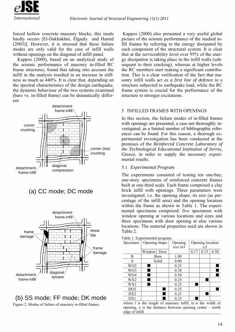
1. The Corner Crushing (CC) mode, which repre-sents crushing of the infill in at least one of its loaded corners, as shown in Fig. 2(a). This mode is usually associated with in-filled frames consisting of a weak masonry infill panel sur-rounded by a frame with weak joints and strong members.
2. The Diagonal Compression (DC) mode, which represents crushing of the infill within its cen-tral region, as shown in Fig. 2(a). This mode is associated with a relatively slender infill, where failure results from out-of-plane buckling of the infill.
3. The Sliding Shear (SS) mode, which represents horizontal sliding shear failure through bed joints of a masonry infill, as shown in Fig. 2(b). This mode is associated with infill of weak mortar joints and a strong frame.
4. The Diagonal Cracking (DK) mode, which is seen in the form of a crack across the compressed diagonal of the infill panel and often takes place with simultaneous initiation of the SS mode, as shown in Fig. 2(b). This mode is associated with a weak frame or a frame with weak joints and strong members in-filled with a rather strong in-fill.
5. The Frame Failure (FF) mode, which is seen in the form of plastic hinges developing in the col-umns or the beam-column connections, as shown in Fig. 2(b). This mode is associated with a weak frame or a frame with weak joints and strong members in-filled with a rather strong infill.
It is noted that in terms of the Wood’s relative lateral strength parameter (Equation 1) failure modes 1, 2, 4 and 5 may occur when m is less than 1, while failure mode 3 may happen for values of m greater or equal to 1 (Ghosh and Amde 2002) Based on the finite element method and including interface elements at the frame-infill interface, Ghosh and Amde (2002) confirmed the validity of Wood’s formula (Equation 1) as far as the order of occurrence of the aforementioned five distinct fail-ure modes is concerned. It is worth mentioning that only the CC and SS modes are of practical importance (Comité Euro-International du Béton CEB, 1996), since the second mode (DC) occurs very rarely and re-quires a high slenderness ratio of the infill to result in out-of-plane buckling of the infill under in-plane load-ing. The fourth mode (DK) should not be considered as a failure mode, due to the fact that the infill can still carry additional load after it cracks. Although the fifth mode (FF) might be worth considering in the case of reinforced concrete (RC) frames, but when it comes to steel frames in-filled with unrein-
Electronic Journal of Structural Engineering 11(1) 2011
14
forced hollow concrete masonry blocks, this mode hardly occurs [El-Dakhakhni, Elgaaly and Hamid (2003)]. However, it is stressed that these failure modes are only valid for the case of infill walls without openings on the diagonal of infill panel.
Kappos (2000), based on an analytical study of the seismic performance of masonry in-filled RC frame structures, found that taking into account the infill in the analysis resulted in an increase in stiff-ness as much as 440%. It is clear that, depending on the spectral characteristics of the design earthquake, the dynamic behaviour of the two systems examined (bare vs. in-filled frame) can be dramatically differ-ent
detachmentframe-infill
detachmentframe-infill
cornercrushing
corner (toe)crushing
diagonalcompression
(a) CC mode; DC mode
detachmentframe-infill
detachmentframe-infill
(b) SS mode; FF mode; DK mode
shearslip
framedamage
framedamage
diagonaltension
Figure 2. Modes of failure of masonry in-filled frames.
Kappos (2000) also presented a very useful global picture of the seismic performance of the studied in-fill frames by referring to the energy dissipated by each component of the structural system. It is clear that at the serviceability level over 95% of the ener-gy dissipation is taking place in the infill walls (sub-sequent to their cracking), whereas at higher levels the RC members start making a significant contribu-tion. This is a clear verification of the fact that ma-sonry infill walls act as a first line of defence in a structure subjected to earthquake load, while the RC frame system is crucial for the performance of the structure to stronger excitations.
5 INFILLED FRAMES WITH OPENINGS
In this section, the failure modes of in-filled frames with openings are presented, a case not thoroughly in-vestigated, as a limited number of bibliographic refer-ences can be found. For this reason, a thorough ex-perimental investigation has been conducted at the premises of the Reinforced Concrete Laboratory of the Technological Educational Institution of Serres, Greece, in order to supply the necessary experi-mental results.
5.1 Experimental Program
The experiments consisted of testing ten one-bay, one-story specimens of reinforced concrete frames built at one-third scale. Each frame comprised a clay brick infill with openings. Three parameters were investigated, i.e. the opening shape, its size (as per-centage of the infill area) and the opening location within the frame as shown in Table 1. The experi-mental specimens comprised: five specimens with window opening at various locations and sizes and three specimens with door opening at also various locations. The material properties used are shown in Table 2.
Table 1. Experimental program. Specimen Opening shape Opening
size la/l Opening location
x/lWindow Door 0.17 0.33 0.50
B Bare 1.00 S Solid 0.00
WO2 0.25 WO3 0.38 WO4 0.50 WX2 0.25 WX1 0.25 DO2 0.25 DX2 0.25 DX1 0.25
where l is the length of masonry infill, la is the width of opening, x is the distance between opening centre – north edge of infill
Electronic Journal of Structural Engineering 11(1) 2011
15
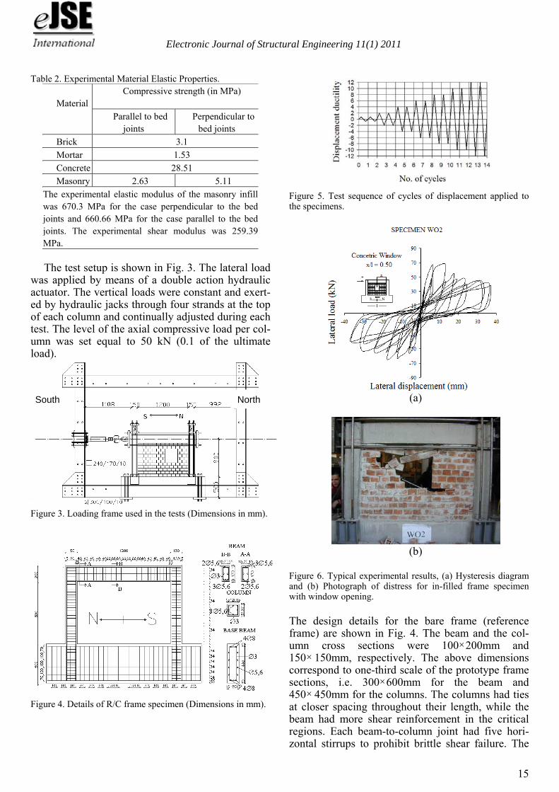
Table 2. Experimental Material Elastic Properties. Material
Compressive strength (in MPa)
Parallel to bed joints
Perpendicular to bed joints
Brick 3.1
Mortar 1.53
Concrete 28.51
Masonry 2.63 5.11
The experimental elastic modulus of the masonry infill was 670.3 MPa for the case perpendicular to the bed joints and 660.66 MPa for the case parallel to the bed joints. The experimental shear modulus was 259.39 MPa. The test setup is shown in Fig. 3. The lateral load
was applied by means of a double action hydraulic actuator. The vertical loads were constant and exert-ed by hydraulic jacks through four strands at the top of each column and continually adjusted during each test. The level of the axial compressive load per col-umn was set equal to 50 kN (0.1 of the ultimate load).
Figure 3. Loading frame used in the tests (Dimensions in mm).
Figure 4. Details of R/C frame specimen (Dimensions in mm).
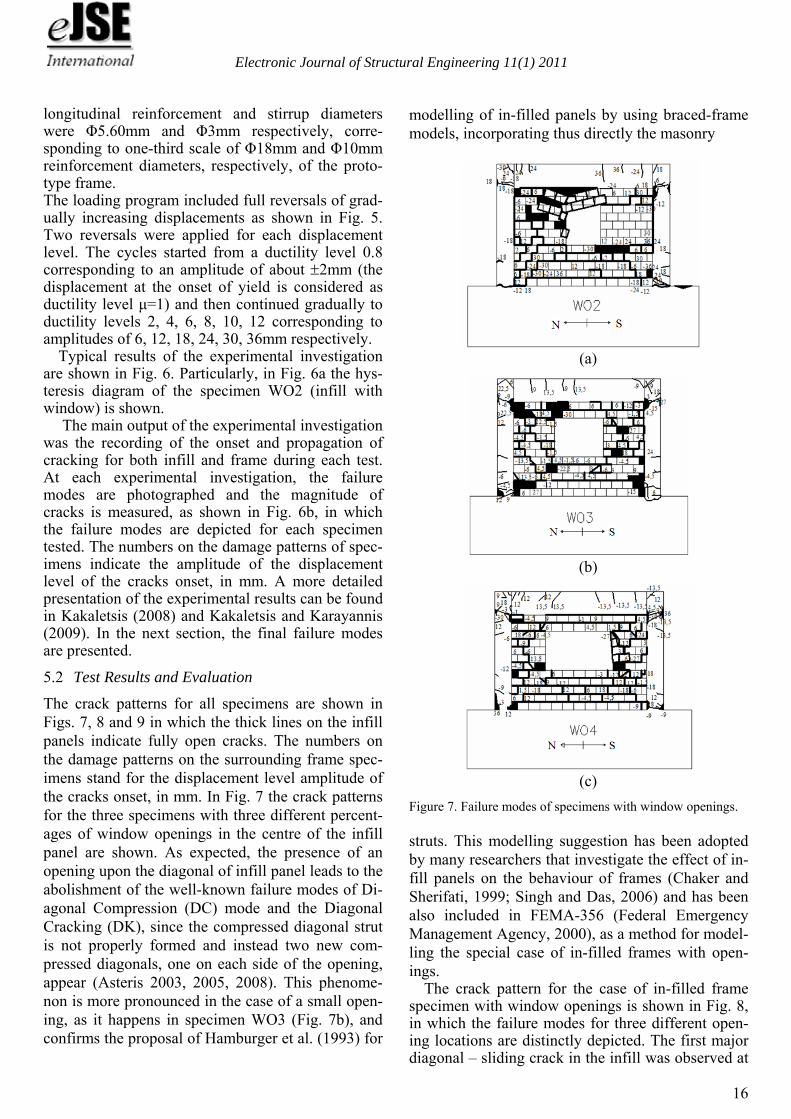
Figure 5. Test sequence of cycles of displacement applied to the specimens.
(a)
(b)
Figure 6. Typical experimental results, (a) Hysteresis diagram and (b) Photograph of distress for in-filled frame specimen with window opening. The design details for the bare frame (reference frame) are shown in Fig. 4. The beam and the col-umn cross sections were 100200mm and 150 150mm, respectively. The above dimensions correspond to one-third scale of the prototype frame sections, i.e. 300600mm for the beam and 450 450mm for the columns. The columns had ties at closer spacing throughout their length, while the beam had more shear reinforcement in the critical regions. Each beam-to-column joint had five hori-zontal stirrups to prohibit brittle shear failure. The
North South
Electronic Journal of Structural Engineering 11(1) 2011
16
longitudinal reinforcement and stirrup diameters were Φ5.60mm and Φ3mm respectively, corre-sponding to one-third scale of Φ18mm and Φ10mm reinforcement diameters, respectively, of the proto-type frame. The loading program included full reversals of grad-ually increasing displacements as shown in Fig. 5. Two reversals were applied for each displacement level. The cycles started from a ductility level 0.8 corresponding to an amplitude of about 2mm (the displacement at the onset of yield is considered as ductility level μ=1) and then continued gradually to ductility levels 2, 4, 6, 8, 10, 12 corresponding to amplitudes of 6, 12, 18, 24, 30, 36mm respectively.
Typical results of the experimental investigation are shown in Fig. 6. Particularly, in Fig. 6a the hys-teresis diagram of the specimen WO2 (infill with window) is shown.
The main output of the experimental investigation was the recording of the onset and propagation of cracking for both infill and frame during each test. At each experimental investigation, the failure modes are photographed and the magnitude of cracks is measured, as shown in Fig. 6b, in which the failure modes are depicted for each specimen tested. The numbers on the damage patterns of spec-imens indicate the amplitude of the displacement level of the cracks onset, in mm. A more detailed presentation of the experimental results can be found in Kakaletsis (2008) and Kakaletsis and Karayannis (2009). In the next section, the final failure modes are presented.
5.2 Test Results and Evaluation
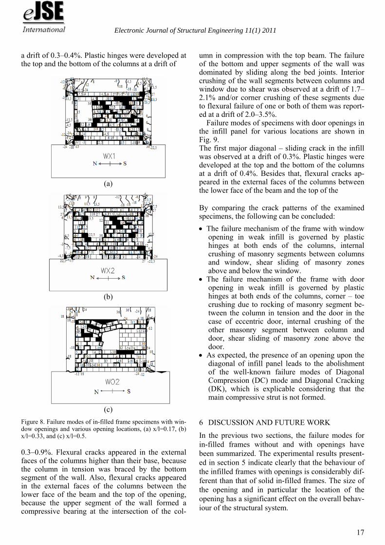
The crack patterns for all specimens are shown in Figs. 7, 8 and 9 in which the thick lines on the infill panels indicate fully open cracks. The numbers on the damage patterns on the surrounding frame spec-imens stand for the displacement level amplitude of the cracks onset, in mm. In Fig. 7 the crack patterns for the three specimens with three different percent-ages of window openings in the centre of the infill panel are shown. As expected, the presence of an opening upon the diagonal of infill panel leads to the abolishment of the well-known failure modes of Di-agonal Compression (DC) mode and the Diagonal Cracking (DK), since the compressed diagonal strut is not properly formed and instead two new com-pressed diagonals, one on each side of the opening, appear (Asteris 2003, 2005, 2008). This phenome-non is more pronounced in the case of a small open-ing, as it happens in specimen WO3 (Fig. 7b), and confirms the proposal of Hamburger et al. (1993) for
modelling of in-filled panels by using braced-frame models, incorporating thus directly the masonry
(a)
(b)
(c)
Figure 7. Failure modes of specimens with window openings. struts. This modelling suggestion has been adopted by many researchers that investigate the effect of in-fill panels on the behaviour of frames (Chaker and Sherifati, 1999; Singh and Das, 2006) and has been also included in FEMA-356 (Federal Emergency Management Agency, 2000), as a method for model-ling the special case of in-filled frames with open-ings.
The crack pattern for the case of in-filled frame specimen with window openings is shown in Fig. 8, in which the failure modes for three different open-ing locations are distinctly depicted. The first major diagonal – sliding crack in the infill was observed at
Electronic Journal of Structural Engineering 11(1) 2011
17
a drift of 0.3–0.4%. Plastic hinges were developed at the top and the bottom of the columns at a drift of
(a)
(b)
(c)
Figure 8. Failure modes of in-filled frame specimens with win-dow openings and various opening locations, (a) x/l=0.17, (b) x/l=0.33, and (c) x/l=0.5. 0.3–0.9%. Flexural cracks appeared in the external faces of the columns higher than their base, because the column in tension was braced by the bottom segment of the wall. Also, flexural cracks appeared in the external faces of the columns between the lower face of the beam and the top of the opening, because the upper segment of the wall formed a compressive bearing at the intersection of the col-
umn in compression with the top beam. The failure of the bottom and upper segments of the wall was dominated by sliding along the bed joints. Interior crushing of the wall segments between columns and window due to shear was observed at a drift of 1.7–2.1% and/or corner crushing of these segments due to flexural failure of one or both of them was report-ed at a drift of 2.0–3.5%.
Failure modes of specimens with door openings in the infill panel for various locations are shown in Fig. 9. The first major diagonal – sliding crack in the infill was observed at a drift of 0.3%. Plastic hinges were developed at the top and the bottom of the columns at a drift of 0.4%. Besides that, flexural cracks ap-peared in the external faces of the columns between the lower face of the beam and the top of the
By comparing the crack patterns of the examined specimens, the following can be concluded:
The failure mechanism of the frame with window opening in weak infill is governed by plastic hinges at both ends of the columns, internal crushing of masonry segments between columns and window, shear sliding of masonry zones above and below the window.
The failure mechanism of the frame with door opening in weak infill is governed by plastic hinges at both ends of the columns, corner – toe crushing due to rocking of masonry segment be-tween the column in tension and the door in the case of eccentric door, internal crushing of the other masonry segment between column and door, shear sliding of masonry zone above the door.
As expected, the presence of an opening upon the diagonal of infill panel leads to the abolishment of the well-known failure modes of Diagonal Compression (DC) mode and Diagonal Cracking (DK), which is explicable considering that the main compressive strut is not formed.
6 DISCUSSION AND FUTURE WORK
In the previous two sections, the failure modes for in-filled frames without and with openings have been summarized. The experimental results present-ed in section 5 indicate clearly that the behaviour of the infilled frames with openings is considerably dif-ferent than that of solid in-filled frames. The size of the opening and in particular the location of the opening has a significant effect on the overall behav-iour of the structural system.
Electronic Journal of Structural Engineering 11(1) 2011
18
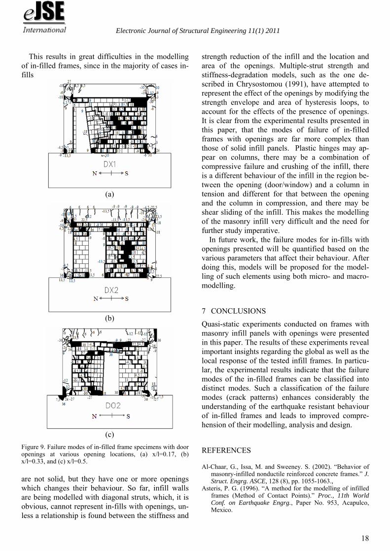
This results in great difficulties in the modelling of in-filled frames, since in the majority of cases in-fills
(a)
(b)
(c)
Figure 9. Failure modes of in-filled frame specimens with door openings at various opening locations, (a) x/l=0.17, (b) x/l=0.33, and (c) x/l=0.5.
are not solid, but they have one or more openings which changes their behaviour. So far, infill walls are being modelled with diagonal struts, which, it is obvious, cannot represent in-fills with openings, un-less a relationship is found between the stiffness and
strength reduction of the infill and the location and area of the openings. Multiple-strut strength and stiffness-degradation models, such as the one de-scribed in Chrysostomou (1991), have attempted to represent the effect of the openings by modifying the strength envelope and area of hysteresis loops, to account for the effects of the presence of openings. It is clear from the experimental results presented in this paper, that the modes of failure of in-filled frames with openings are far more complex than those of solid infill panels. Plastic hinges may ap-pear on columns, there may be a combination of compressive failure and crushing of the infill, there is a different behaviour of the infill in the region be-tween the opening (door/window) and a column in tension and different for that between the opening and the column in compression, and there may be shear sliding of the infill. This makes the modelling of the masonry infill very difficult and the need for further study imperative.
In future work, the failure modes for in-fills with openings presented will be quantified based on the various parameters that affect their behaviour. After doing this, models will be proposed for the model-ling of such elements using both micro- and macro-modelling.
7 CONCLUSIONS
Quasi-static experiments conducted on frames with masonry infill panels with openings were presented in this paper. The results of these experiments reveal important insights regarding the global as well as the local response of the tested infill frames. In particu-lar, the experimental results indicate that the failure modes of the in-filled frames can be classified into distinct modes. Such a classification of the failure modes (crack patterns) enhances considerably the understanding of the earthquake resistant behaviour of in-filled frames and leads to improved compre-hension of their modelling, analysis and design.
REFERENCES
Al-Chaar, G., Issa, M. and Sweeney. S. (2002). “Behavior of masonry-infilled nonductile reinforced concrete frames.” J. Struct. Engrg. ASCE, 128 (8), pp. 1055-1063.,
Asteris, P. G. (1996). “A method for the modelling of infilled frames (Method of Contact Points).” Proc., 11th World Conf. on Earthquake Engrg., Paper No. 953, Acapulco, Mexico.
Electronic Journal of Structural Engineering 11(1) 2011
19
Asteris, P.G. (2003). “Lateral stiffness of brick masonry in-filled plane frames.” J. Struct. Eng., 129 (8), 1071-1079.
Asteris, P.G. (2005). “Closure to “Lateral Stiffness of Brick Masonry Infilled Plane Frames" by P. G. Asteris.” J. Struct. Engrg. ASCE, 131(3), 523-524.
Asteris, P.G. (2008). “Finite Element Micro-Modeling of In-filled Frames.” Electronic Journal of Structural Engineer-ing, Vol. 8, pp.1-11.
Asteris, P.G. (2010). “A simple heuristic algorithm to deter-mine the set of closed surfaces of the cubic tensor polyno-mial.” The Open Applied Mathematics Journal, vol. 4, pp.1-5.
Buonopane, S. G. and White, R. N. (1999). “Pseudodynamic Testing of Masonry Infilled Reinforced Concrete Frame.” J. Struct. Eng., ASCE, 125(6), 578-589.
Chaker, A, A., and Sherifati, A. (1999). “Influence of masonry infill panels on the vibration and stiffness characteristics of R/C frame buildings.” Earthquake Engng., Struct. Dyn. 28, 1061-1065.
Chrysostomou, C. Z. (1991). “Effects of degrading infill walls on the nonlinear seismic response of two-dimensional steel frames.” PhD thesis, Cornell University, Ithaca, N.Y.
Chrysostomou, C.Z., Gergely, P. and Abel, J. F. (2002), “A six-strut model for nonlinear dynamic analysis of steel in-filled frames,” International Journal of Structural Stability and Dynamics, Vol. 2, No. 3, 335-353.
Combescure, D. and Pegon, P. (1996). “Numerical studies on one-bay masonry infilled R/C frames.” ELSA Res. Rep. No. I.96.35, European Laboratory for Structural Assess-ment, Ispra, Italy.
Comité Euro-International du Béton (CEB). (1996). “RC frames under earthquake loading.” State of the Art Rep., Tomas Telford Services, Ltd., London.
Crisafulli, F. J., Carr, A, J., Park, R. (2000). “Analytical Mod-elling of Infilled Frame Structures-A General Review.” Bulletin of the New Zealand Society for Earthquake Engi-neering, Vol. 33, No. 1, pp. 30-47.
Crisafulli, F. G. (1997), “Seismic Behaviour of Reinforced Concrete Structures with Masonry Infills.” Ph.D. Thesis, University of Canterbury, Christchurch, New Zealand.
Dhanasekar, M., and Page, A. W. (1986). “Influence of brick masonry infill properties on the behaviour of infilled frames.” Proc., Instn. Civ. Engrs., London, Part 2, 81, 593-605.
Dolšek, M., and Fajfar, P. (2008). “The effect of masonry in-fills on the seismic response of a four-storey reinforced concrete frame — a deterministic assessment.” Engineering Structures, 30 (7), 1991-2001.
El-Dakhakhni, W. W. (2002). “Experimental and analytical seismic evaluation of concrete masonry-infilled steel frames retrofitted using GFRP laminates.” PhD thesis, Drexel University.
El-Dakhakhni, W. W., Elgaaly, M., and Hamid, A. A. (2003). “Three-Strut model for concrete masonry-infilled frames.” J. Struct. Eng., ASCE, 129(2), 177-185.
El-Dakhakhni, W. W., Hamid, A. A., Hakam, Z. H.R., Elgaaly, M. (2006). “Hazard mitigation and strengthening of unrein-forced masonry walls using composites.” Composite Struc-tures, 73, 458-477.
EN 998-2 (2001), Specification for mortar for masonry, Euro-pean Committee for Standardization, Brussels.
Fardis, M. N. and Panagiotakos, T.B. (1997). “Seismic design and response of bare and masonry-infilled reinforced con-crete buildings. Part II: infilled structures.” J. Earthq. Eng., 1(3), pp.475-503.
Federal Emergency Management Agency (2000). “Prestandard and commentary for the Seismic Rehabilitation of Build-ings.” FEMA-356, American Society of Civil Engineers, Washington, DC.
Ghosh, A. K., Amde, A.M. (2002). “Finite element analysis of infilled frames.” J. Struct. Engrg., ASCE, 128(7), 881-889.
Holmes, M. (1961). “Steel frames with brickwork and concrete infilling.” Proc., Instn. Civ. Engrs., London, Part 2, 19, 473-478.
Hamburger, R.O., and Chakradeo, A.S. (1993). “Methodology for seismic-Capacity Evaluation of Steel-Frame Buildings with Infill Unreinforced Masonry.” Proc. of the National Earthquake Conference, Central U.S. Earthquake Consorti-um, Memphis, Tennessee, Vol. II, 173-191.
Kakaletsis, D.J. (2008). “Investigation of the Behavior of Or-thogonal Masonry Infilled Reinforced Concrete Frames With Openings Under Horizontal Large Amplitude Cyclic Displacements.” Ph.D. Thesis, Democritus University of Thrace, Greece.
Kakaletsis, D.J., and Karayannis, C.G. (2007). “Experimental investigation of infilled R/C frames with eccentric open-ings”, Structural Engineering and Mechanics, an Interna-tional Journal, Vol. 26, No3, pp. 231-250.
Kakaletsis, D.J., and Karayannis, C.G. (2008). “Influence of masonry strength and openings on infilled R/C frames un-der cycling loading”, Journal of Earthquake Engineering. Vol. 12, No2, pp. 197-221.
Kakaletsis, D.J., and Karayannis C.G. (2009). “Experimental Investigation of Infilled Reinforced Concrete Frames with Openings.” ACI Structural Journal, 106(2), 132-141.
Kappos, A. J. (2000). “Seismic Design and Performance As-sessment of Masonry Infilled R/C Frames.” Proceedings of the 12th World Conference on Earthquake Engineering, Paper No. 989 on CD-ROM, New Zealand.
Kose, M.M. (2009). “Parameters affecting the fundamental pe-riod of RC buildings with infill walls.” Engineering Struc-tures, Volume 31, Issue 1, January 2009, Pages 93-102
Liauw, T. C., and Kwan, K. H. (1983). “Plastic theory of non-integral infilled frames”, Proceedings of the Institution of Civil Engineers (London), Part 2, 75, 1983, pp. 379-396.
Liauw, T. C., and Kwan, K. H. (1984). “Nonlinear behaviour of non-integral infilled frames.” Comp. and Struct., 18, 551-560.
Madan, A., Reinhorn, A. M., Mander, J. B., and Valles, R. E. (1997). “Modeling of Masonry Infill Panels for Structural Analysis.” J. Struct. Engrg., ASCE, 123(10), 1295-1302.
Mainstone, R. J. (1962). “Discussion on steel frames with brickwork and concrete infilling.” Proc., Instn. Civ. Engrs., 23, 94-99.
Mehrabi, A. B., Shing, P. B., Schuller, M., and Noland, J. (1996). “Experimental evaluation of masonry-infilled RC frames.” J. Struct. Engrg., ASCE, 122(3), 228-237.
Mehrabi, A. B., Shing, P. B. (1997). “Finite element modeling of masonry-infilled RC frames.” J. Struct. Engrg., ASCE, 123(5), 604-613.
Moghaddam, H. A. (2004). “Lateral Load Behavior of Mason-ry Infilled Steel Frames with Repair and Retrofit.” J. Struct. Engrg., ASCE, 130(1), 56-63.
Moghadam, H.A. and Dowling, P.J. (1987). “The State-of-the-Art in Infilled Frames.” ESEE Res. Rep. No. 87-2, Imperial Coll. of Sci. and Technol., Civ. Engrg. Dept., London, U.K.
Mosalam, K. M. (1996). “Experimental and computational strategies for the seismic behavior evaluation of frames with infill walls.” Ph.D. dissertations, Cornell University, Ithaca, N.Y.
Electronic Journal of Structural Engineering 11(1) 2011
20
Mosalam, K. M., White, R.N., and Gergely P. (1997). “Static response of infilled frames using quasi-static experimentta-tion.” J. Struct. Eng., 123 (11), 1462-1469.
Page, A. W., Kleeman, P. W. and Dhanasekar, M. (1985). “An In-Plane Finite Element Analysis Model for Brick Mason-ry.” Proc. of a session held in conjunction with Structures Congress’85, Chicago, Ill, 1-18.
Paulay, T., and Priestley, M. J. N. (1992). Seismic Design of Reinforced Concrete and Masonry Buildings, John Wiley, New York, 744 p.
Rodrigues, H.,Varum, H., Costa, A. (2010). “Simplified Mac-ro-Model for Infill Masonry Panels.” Journal of Earth-quake Engineering, Volume 14(3),390 – 416.
Saneinejad, A., and Hobbs, B. (1995). “Inelastic design of in-filled frames.” J. Struct. Engrg., ASCE, 121(4), 634-650.
Santhi, M. H., Knight, G. M. S., and Muthumani, K. (2005a). “Evaluation of seismic response of soft-storey infilled frames.” Computers and Concrete, 2 (6), 423-437.
Santhi, M. H., Knight, G. M. S., and Muthumani, K. (2005b). “Evaluation of Seismic Performance of Gravity Load De-signed Reinforced Concrete Frames.” Journal of Perfor-mance of Constructed Facilities, 19(4), 277-282.
Singh, Y., and Das, D. (2006). “Effect of URM infills on seis-mic performance of RC frame buildings.” Proceedings of the 4th International Conference on Earthquake Engineer-ing, Taipei, Taiwan, Paper No. 064.
Smith, B. S. (1966). “Behavior of square infilled frames.” J. Struct. Div., ASCE, ST1, 381-403.
Smith, B. S., and Carter, C. (1969). “A method of analysis for infilled frames.” Proc., Instn. Civ. Engrs., 44, 31-48.
Syrmakezis, C.A., Asteris, P.G. (2001). “Masonry Failure Cri-terion Under Biaxial Stress State.” Journal Of Materials in Civil Engineering; American Society of Civil Engineers (ASCE), Vol. 13, Issue 1, pp. 58-64.
Thomas, F. G. (1953). “The strength of brickwork.” Struct. Engrg., 31(2), 44-46.
Vintzileou, E., and Tassios, T. P. (1989). “Seismic behaviour and design of infilled R.C. frames.” Proc., J. of European Earthquake Engrg., 2, 22-28.
Wood, R. H. (1958). “The stability of tall buildings.” Proc., Instn. Civ. Engrs., 11, 69-102.
Wood, R. H. (1978). “Plasticity, composite action and collapse design of unreinforced shear wall panels in frames.” Proc., Instn. Civ. Engrs., Part 2, 65, 381-411.
arni , R., Gosti , S., Crewe, A.J., and Taylor, C.A. (2001). “Shaking table tests of 1:4 reduced-scale models of mason-ry infilled reinforced concrete frame buildings.” Earthquake Engineering & Structural Dynamics, 30(2), 819-834.