extending inet framework for directional and asymmetrical wireless communications
TRANSCRIPT

Extending INET Framework for Directional and
Asymmetrical Wireless Communications
Paula Uribe, Juan-Carlos Maureira, Olivier Dalle
To cite this version:
Paula Uribe, Juan-Carlos Maureira, Olivier Dalle. Extending INET Framework for Direc-tional and Asymmetrical Wireless Communications. [Research Report] RR-7120, INRIA. 2010.<inria-00448033>
HAL Id: inria-00448033
https://hal.inria.fr/inria-00448033
Submitted on 18 Jan 2010
HAL is a multi-disciplinary open accessarchive for the deposit and dissemination of sci-entific research documents, whether they are pub-lished or not. The documents may come fromteaching and research institutions in France orabroad, or from public or private research centers.
L’archive ouverte pluridisciplinaire HAL, estdestinee au depot et a la diffusion de documentsscientifiques de niveau recherche, publies ou non,emanant des etablissements d’enseignement et derecherche francais ou etrangers, des laboratoirespublics ou prives.

appor t de r ech er ch e
ISS
N02
49-6
399
ISR
NIN
RIA
/RR
--71
20--
FR
+E
NG
Thème COM
INSTITUT NATIONAL DE RECHERCHE EN INFORMATIQUE ET EN AUTOMATIQUE
Extending INET Framework for Directional andAsymmetrical Wireless Communications
Paula Uribe — Juan-Carlos Maureira — Olivier Dalle
N° 7120
November 2009


Centre de recherche INRIA Sophia Antipolis – Méditerranée2004, route des Lucioles, BP 93, 06902 Sophia Antipolis Cedex
Téléphone : +33 4 92 38 77 77 — Télécopie : +33 4 92 38 77 65
Extending INET Framework for Directional and
Asymmetrical Wireless Communications
Paula Uribe∗, Juan-Carlos Maureira†, Olivier Dalle‡
Theme COM — Systemes communicantsEquipes-Projets Mascotte
Rapport de recherche n° 7120 — November 2009 — 19 pages
Abstract: This paper reports our work on extending the OMNeT++ INETFramework with a directional radio model, putting a special emphasis on theimplementation of asymmetrical communications. We first analyze the originalINET radio model, focusing on its design and components. Then we discussthe modifications that have been done to support directional communications.Our preliminary results show that the new model is flexible enough to allow theuser to provide any antenna pattern shape, with only an additional reasonablecomputational cost.
Key-words: OMNeT++, INET Framework, Directional Radios, Asymmet-rical communication

Extending INET Framework for Directional and
Asymmetrical Wireless Communications
Resume : Ce rapport presente nos travaux pour etendre le cadre de simula-tions de reseau INET (base sur OMNET++) en lui ajoutant un modele de radiosdirectionnelles. Nous mettons ici l’accent particulierement sur l’implementationde communications asymetriques. Dans un premier temps, nous analysons laconception et les composants du modele actuel de radio d’INET. Dans un secondtemps, nous en proposons des modifications qui permettent des communicationsdirectionnelles. Nos resultats preliminaires montrent que cette nouvelle exten-sion est assez flexible : elle permet a l’utilisateur, au prix d’un nombre limit decalculs supplementaires, de modliser n’importe quel forme de rayonnement del’antenne.
Mots-cles : Resea sans fil, Handover, Simulation, Connectivite sur la route,OMNeT++

Directional and Asymmetrical Communications 3
1 Introduction
Mobile Ad-hoc Networks (MANETs) are receiving more attention in the lastfew years. In many cases, the behavior of these networks depends on the per-formance of the radio communications in various directions around the emittersor receivers. This performance may be uniform in all directions, when usingomni-directional antennas, or non-uniform, when using directional antennas. Inthe latter case, the antennas have a preferential direction of radiation, and apattern of secondary emissions, at lower levels of radiation, in other directions.Thanks to such directional antennas, the network coverage can be increasedand, at the same time, the use of less number of antennas becomes possible,hence reducing the interference effects.Since simulation tools are commonly used to design and evaluate the perfor-mance of such radio networks, simulation models of directional antennas areneeded. Unfortunately, only a few simulation tools offer the ability to modeldirectional antennas, such as OPNET [opn00], GloMoSim [glo98], NS-2 [ns2], orQualNet [qua]. Indeed, modeling directional antennas is more complicated thanmodeling the omni-directional ones, because emitted or received power dependson the direction and a specific attenuation pattern that depends on the antenna.These patterns often consist of a main lobe in the direction of the antenna, andpossibly some side and back lobes. The latter ones have a much lower ampli-fication gain, but still cannot be neglected, in particular for the interferencescalculation. In most of the simulators mentioned above, an antenna’s radiationpattern is described in a configuration file built by using mapping techniques.The gain values of the antenna are given for different points in space to de-termine the gain in all directions. However, there are some simulators thatmodel the antenna using other techniques than mapping. In [HGT+08], Hard-wick et al. use statistics to estimate the main and side lobes values for sizeand position, while in [GH09], Gharavi and Bin propose a 2D model, consistingof a “pie-wedge” pattern shape with circular constant gain for side and backlobes. In [KKY07], Kucuk et al. build a model of a smart antenna on top ofOMNeT++ ’s Mobility Framework for sensor networks applications, focusing onthe performance evaluation, on the number of nodes, the traffic and the energyconsumption.In this paper, we report on our work on extending the OMNeT++ INETFramework for supporting directional wireless communications. We proposea DirectionalRadio module based on Gharavi and Bin’s model [GH09], whichallows the implementation of several antenna patterns. These patterns are de-fined by means of plugins that calculate the directional gain of the antenna ina two dimensional plane. Additionally, we present the modifications made tothe INET radio model in order to incorporate asymmetrical communications tosupport directional communications. We verify the correctness of the implemen-tation by comparing the antenna patterns observed in simulations against theexpected theoretical patterns. We also evaluate our proposed radio model fromthe computational point of view by providing quantitative data of the impactof including asymmetrical communications in the overall execution time.
The paper is organized as follows: In Section 2, the current INET imple-mentation and features are analyzed. Section 3 depicts our proposed extensionto the INET radio model for the directional antenna representation. Section4 presents the model implementation, its main features, parameters and limi-
RR n° 7120
4 Uribe, Maureira & Dalle
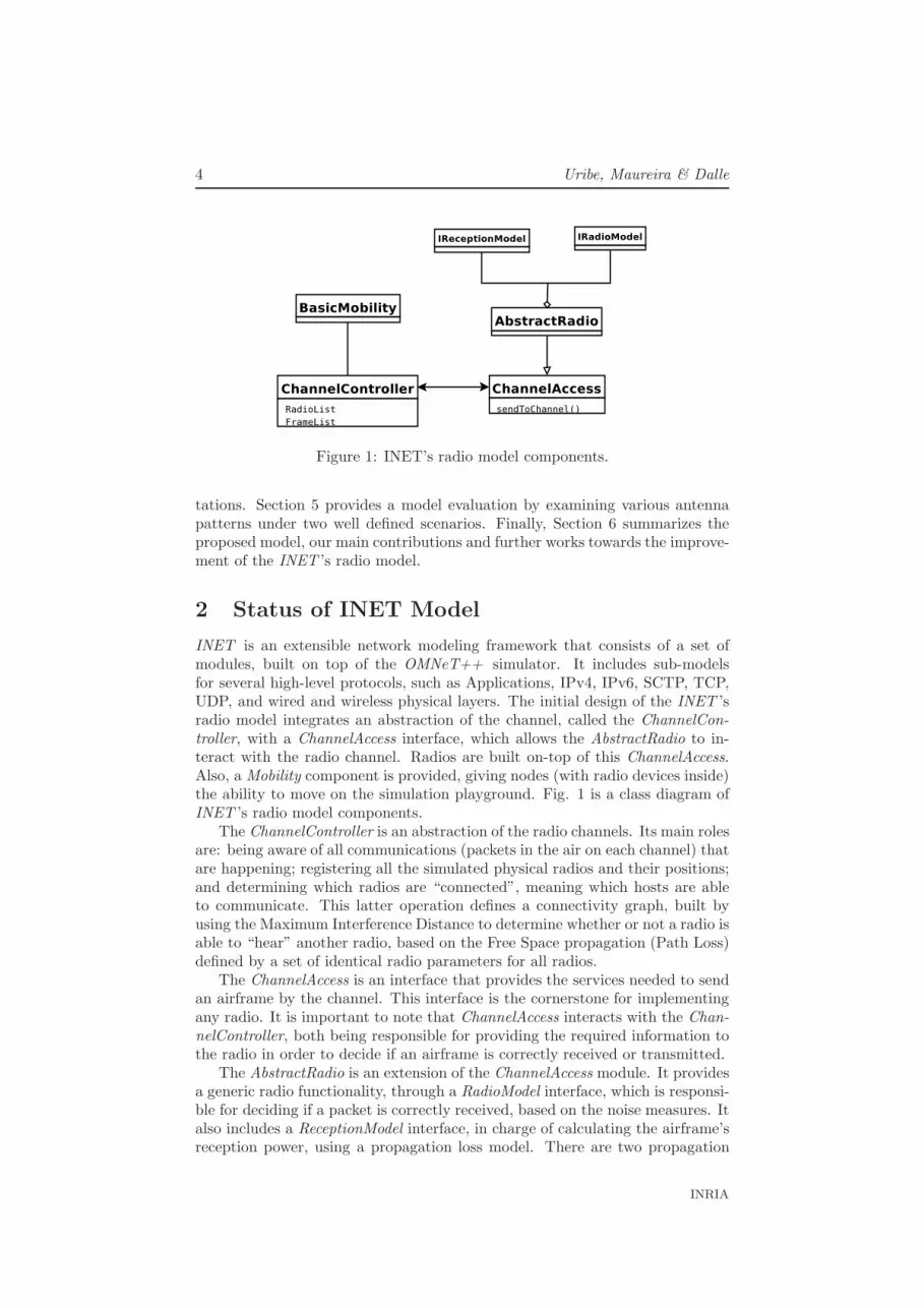
Figure 1: INET’s radio model components.
tations. Section 5 provides a model evaluation by examining various antennapatterns under two well defined scenarios. Finally, Section 6 summarizes theproposed model, our main contributions and further works towards the improve-ment of the INET ’s radio model.
2 Status of INET Model
INET is an extensible network modeling framework that consists of a set ofmodules, built on top of the OMNeT++ simulator. It includes sub-modelsfor several high-level protocols, such as Applications, IPv4, IPv6, SCTP, TCP,UDP, and wired and wireless physical layers. The initial design of the INET ’sradio model integrates an abstraction of the channel, called the ChannelCon-troller, with a ChannelAccess interface, which allows the AbstractRadio to in-teract with the radio channel. Radios are built on-top of this ChannelAccess.Also, a Mobility component is provided, giving nodes (with radio devices inside)the ability to move on the simulation playground. Fig. 1 is a class diagram ofINET ’s radio model components.
The ChannelController is an abstraction of the radio channels. Its main rolesare: being aware of all communications (packets in the air on each channel) thatare happening; registering all the simulated physical radios and their positions;and determining which radios are “connected”, meaning which hosts are ableto communicate. This latter operation defines a connectivity graph, built byusing the Maximum Interference Distance to determine whether or not a radio isable to “hear” another radio, based on the Free Space propagation (Path Loss)defined by a set of identical radio parameters for all radios.
The ChannelAccess is an interface that provides the services needed to sendan airframe by the channel. This interface is the cornerstone for implementingany radio. It is important to note that ChannelAccess interacts with the Chan-nelController, both being responsible for providing the required information tothe radio in order to decide if an airframe is correctly received or transmitted.
The AbstractRadio is an extension of the ChannelAccess module. It providesa generic radio functionality, through a RadioModel interface, which is responsi-ble for deciding if a packet is correctly received, based on the noise measures. Italso includes a ReceptionModel interface, in charge of calculating the airframe’sreception power, using a propagation loss model. There are two propagation
INRIA
Directional and Asymmetrical Communications 5
models already implemented: the classical Free Space Pathloss and the Two-raywith ground reflection.
Hosts (or nodes) contain one (or several) radio modules and one of theavailable Mobility modules (circular, linear, random, etc.).
The ChannelController keeps the important information needed for the Ab-stractRadio. Therefore, the ChannelAccess must provide means for the radio toaccess that information, since it is the entity that connects both sides. More-over, as mentioned above, the ChannelController must build the connectivitygraph (or hosts neighbors list), that indicates with which nodes communicationscan occur. This graph varies only in response to a mobility event, which impliesthat the module that triggers the graph’s update is the BasicMobility, throughthe ChannelController. In the current version of INET , the communicationsfollow a symmetrical model: For a pair of hosts h1 and h2, h2 is considered theneighbor of h1 if it is within its maximum interference distance, which, recip-rocally, always implies that h1 is neighbor of h2 (the ChannelController usesthe same maximum transmission power for all radios, when calculating theirmaximum interference distance).
Currently1, there are several INET branches that introduce improvementsin different ways. In particular, the branch supporting multiple radios assignsa neighbors list to each host’s radio instead of to a single list to the host.Therefore, each host has as many lists as radios. This change implies that theresponsibility for building and updating the connectivity graph is transferredfrom the host to the radios of the host when a mobility event occurs.
3 Extensions to INET’s Radio Model
In this section, we introduce our proposed extension to INET ’s radio modelto support directional wireless communications. We start with some technicalconcepts, followed by the description of our proposed extension. Then, wepresent an extended module for the INET model, that supports directional andomni-directional communications. Notice that the problem of asymmetricalcommunications addressed hereafter is deeper studied in Section 4.
3.1 Concepts
Antenna patterns are commonly used when studying propagation of radio sig-nals in the space. The antenna pattern [Bal05] is a polar chart that describesthe dependence of the radiation power (usually in relative decibels, dB) and thedirection of communication in 360°. For omni-directional antennas, the theoret-ical pattern is a circle. For directional antennas, it is an irregular shape, havingin general a principal or main lobe and side/back lobes. For directional patterns,the main lobe corresponds to the region where the largest amount of power isradiated, and can be characterized by its maximum gain and its Beam Width,corresponding to the beam wideness, often defined by a 3dB-threshold [Car01]that delimits it. Side/back lobes regions can also be distinguished, where smalleramounts of power are radiated (generally seen as losses) with no preferential di-rection. These losses are often characterized by their maximum gain. In orderto quantify the signal propagation, the Link Budget [Rap02] equation is used.
1as of November 2009.
RR n° 7120

6 Uribe, Maureira & Dalle
This equation corresponds to an account of the transmission power, antennasgains and losses. The main contributions are the transmission power, antennasgains and free space propagation loss.
3.2 Proposed Extension for the Radio Model
Our proposed extension to the INET ’s radio model allows representation of anyantenna pattern, and specifically, to represent any gain function when calculat-ing the Link Budget for a wireless communication. Our extension separates theLink Budget into two phases: the calculation of the antenna’s gain in a plug-gable external module, and the calculation of the effective reception power onthe receiving end. In this model, the transmission and reception gain patternsare assumed to be identical, due to the Reciprocity theorem [Kra88]. This helpsto apply the same procedure for the gain calculation, both for transmittingand receiving an airframe. In more detail, the external pluggable module is anabstraction of an antenna pattern, that gives the gain value in the direction oftwo-nodes communication. Our proposed extension uses this external module tocalculate the Link Budget when determining the effective transmission power ofan airframe. For two wireless hosts, the communication angle can be calculatedfrom the transmitter’s and receiver’s coordinates, and consequently, the antennagain in that direction can be determined. The effective transmission power isobtained by adding this gain and the nominal antenna transmission power. Asimilar calculation is performed to determine the effective reception power, butusing the received power (i.e. the difference between the effective transmissionpower and the path loss) instead of the nominal transmission power. Moreformally, for omni-directional communications, the simplified Link Budget ex-pression is as follows:
Prx = Ptx − PL (1)
when considering the antenna gains for directional comunication, the expresionbecomes as:
Prx = Ptx +Gtx − PL+Grx (2)
where Ptx is the nominal transmission power, Gtx is the transmitter gain, Grx
is the receiver gain, PL is the path loss and Prx is the effective received power.The advantages of separating the antenna gain from the Link Budget is
the flexibility introduced by the externalization of the antenna gain calcula-tion, allowing us to implement any antenna pattern without changing the radiofunctionalities. Directional and omni-directional antenna patterns can be im-plemented by describing the antenna gain with mathematical curves, as well asby mapping techniques. We used a simplified Link Budget expression that onlyconsiders the antenna gains and propagation losses, as expressed in Equation2, while losses due to cables, connectors, or any other type of losses are notconsidered.
We use the previous described extensions to implement four directional an-tenna patterns, based on the “pie-wedge” model described by Gharavi et al.in [GH09]. The radiation pattern is represented by two main components: amain lobe and side/back lobes. We used different mathematical curves (folium,cardioid, circle and rose) to analytically define the main lobe’s gain function
INRIA
Directional and Asymmetrical Communications 7
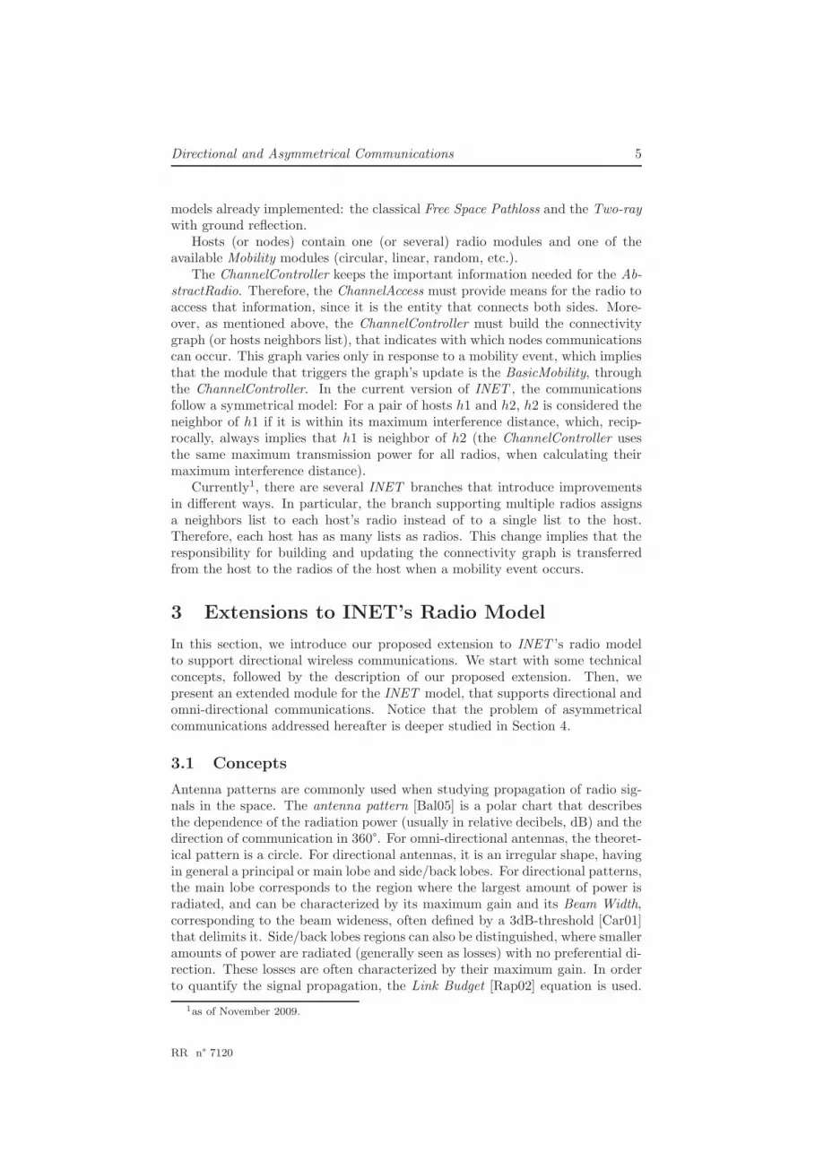
Figure 2: Example of antenna pattern and the scaled antenna pattern.
in every direction (from 0°to 360°); and a circle with an unity-gain (onmi-directional communication) to represent the side/back lobes. Then, while thegain of the main lobe varies according to the mathematical formula evaluatedin different points, defined by the transmission/reception angle, the gain of theside/back lobes remains constant. For practical reasons, we scale the original an-alytical curve that defines the main lobe gain pattern, in order to obtain a curvewith a maximum gain of Gm in the main beam direction. Also, the side/backlobes are represented by a circular unity-gain pattern, which multiplied by theside/back lobes gain, gives the circular pattern with radius Gs/b. Fig. 2 depictsthe original and the scaled analytical curves used by the proposed directionalradio, where we observe the gain function before and after the scaling. Note thatthe maximum gain remains the same, but now the gain function corresponds tothe maximum between the main lobe scaled gain and the side/back lobes gain.This means that within the area defined by the 3dB-threshold, the main lobegain dominates, while within the rest of the space, the gain value alternatesbetween the main lobe scaled curve and the the side/back lobes circle.
4 Model Implementation
In this Section, we describe the implementation of our proposed directionalradio module. This implementation can be separated into two differentparts: i) the modifications that have to be made to current INET versionwhen implementing asymmetrical communications; and, ii) the changes madeto incorporate directional communications, including four different antennapatterns and the proposed Link Budget calculation presented in the previoussection.
RR n° 7120
8 Uribe, Maureira & Dalle
4.1 Asymmetrical Communications
Our INET branch extends the multiple radios branch to support asymmetricalcommunications, where radios no longer are assumed to have the same antennapattern and transmission power. It also allows the user to select one of theimplemented antenna patterns, or create a new one. This improvement forcesto change the way the neighbor lists are calculated and updated, since thepremise if you hear me, I can hear you, is not always true [KNG+04] whenconsidering asymmetrical communications.
The first step to implement asymmetrical communications on the currentINET radio model, is to relieve the ChannelController of the responsibility ofcalculating the maximum interference distance. According to an asymmetri-cal radio model, radios may have different coverages (in range and in shape).Thus, this task should be assigned to the radio itself, implementing it at theAbstractRadio level. Consequently, the ChannelAccess interface would rely onthe ChannelController to build the neighbors list, but now using a method pro-vided by the radio to determine when a node is under its radio coverage. Thismethod, called isInCoverageArea, relies on the ReceptionModel to determine themaximum interference distance, according to the antenna’s radiation shape, andalso to the radio signal propagation model.
Regarding the connectivity graph determination, the event that triggers anupdate in our implementation is not only a mobility event, but a mobility eventor a transmission request, since the neighbor list of any node must be updatedwhen transmitting a packet, and so, be faithful with the radio signals that eachnode receives. Additionally, this update is now related to all nodes (and radios)in the simulation, and not only to the node that has changed its position. Thesemodifications have a detrimental impact on the overall execution time. Firstly,the neighbor discovery algorithm has now a complexity of O(n2m), n being thenumber of hosts, and m the number of radios per host; and secondly, this algo-rithm is executed more often. Preliminary results shown that the computationalcost is higher enough to make the model not attractive to users when using thisalgorithm of “brute force” to update the neighbor lists. So, we developed analternative algorithm that exploits the locality of nodes to calculate their neigh-bors lists and supports different coverage ranges. In Section 5.2, we analyze thecomputational cost of both algorithms in terms of the execution time. The nextsection presents the proposed algorithm for the neighbor list calculation.
4.2 NeighborsGraph Algorithm
In the previous section, we showed the need for an efficient algorithm to over-come the increase of the model’s execution time when using asymmetrical com-munications. This algorithm should exploit the locality of nodes, since when asingle node moves, let’s say node N1, the neighbors lists that must be updatedare only those that change due to N1’s movement, meaning the inclusion or theexclusion of N1 as a neighbor. Updating a node that is far away from N1 isuseless, in terms of the propagation model and noise levels. This leads to ourselective neighbor list update algorithm.
This algorithm uses a data structure, similar to a sparse matrix, but keepingthe positions of nodes (in fact, radio positions) and a coverage area (Figure 3).This area, Cs, is the square box that contains the real coverage area Cr. The
INRIA

Directional and Asymmetrical Communications 9
boxed coverage area Cs is defined by the maximum interference distance givena propagation model, when the received power is equal to the noise level. In thecase of the Pathloss model, this distance depends on the transmitter power, car-rier frequency and Pathloss coefficient. This distance defines Cs, which is usedby the algorithm to compute the neighbors list within this region. Afterwards,a refinement of this list can be made by using the isInCoverageArea method ofeach radio to get the real neighbors list (nodes within Cr). It is worth to noticethat the isInCoverageArea method is now applied to a reduced set of nodes,instead of all nodes in the simulation. Additionally, the neighbor list calculationreturns the list of nodes to be updated as a consequence of N1’s displacement.For all those nodes, their neighbor lists are tagged as invalid, forcing them to beupdated when the node wants to transmit a packet. The algorithm determines
Figure 3: NeighborsGraph data structure
the neighbor list for a node N1 by exploring the sparse matrix axes on eachdirection: x-left, y-right, x-right and y-left; finding the header nodes withinthe region Cs. It also determines the updated list by finding the boundary nodesthat are traversed by N1. Each node’s position (header and boundary nodes)is updated every time the node moves in a O(log(n)) operation, since the ma-trix axes are red-black trees [GS78]. A formal pseudo-code for the proposedalgorithm is shown in Algorithm 1.
The function pos(node, axe) returns the position of the node on the givenaxe; boundary(node, direction) returns the Cs boundary limit in the given di-rection; and owner(node) returns the reference to the host/radio of the node.
RR n° 7120

10 Uribe, Maureira & Dalle
Input: node n, empty neighbors and toUpdate listsOutput: updated neighbors list and toUpdate list
begin1
directions ← { x-left,y-right,x-right,y-left }2
foreach direction in directions do3
axe ← axe of direction4
limit ← pos(n,axe) + boundary(n,direction)5
current ← header node of n on axe6
while pos(current,axe) not reach limit do7
n‘ ← owner(current)8
if type(current) = header node then9
p ← pos(n‘,in the contrary axe)10
if inRange(n, p) then11
add n‘ to neighbors12
end13
end14
if type(current) = boundary node then15
b1 ← inRange(n‘,pos(n,axe))16
b2 ← inRange(n‘,prevpos(n,axe))17
if b1 6= b2 then18
add n‘ to toUpdate19
end20
end21
current ← next node in direction22
end23
end24
remove from neighbors repeated nodes25
remove from toUpdate repeated nodes26
end27
Algorithm 1: The NeighborsGraph Algorithm.
As Figure 3 shows, each host has a header node, referencing the host positionon each axe, and four boundary nodes, referencing the limits of the region Cs.All these nodes have a direct reference to their host/radio module. Finally, thefunction inRange(node, position) returns whether the given position is withinthe Cs region, or not. As we already mentioned, after the execution of this al-gorithm, the real coverage of each radio inside the node n is evaluated for eachneighbor host, in order to determine the real neighbors list. All neighbor listsbelonging to a host contained in the toUpdate list are invalidated, thus, forcingthem to be updated when the host sends a packet to the channel.
The complexity of this algorithm may be higher than the brute force updatealgorithm on a single host, since it visits each node at least two times (x and ydirections). But, we improve the performance by doing this operation only forthe nodes affected when a certain node moves, instead of updating the neighborlist of all nodes in the simulation. Performance evaluation results are given inSection 5.2.
INRIA

Directional and Asymmetrical Communications 11
4.3 DirectionalRadio Module
Based on the proposed extension of INET ’s radio model, we created the Di-rectionalRadio module, which complements the current radio implementationwith new functionality. In order to make this module flexible enough to allowseveral antenna patterns, an AntennaPattern interface has been added. Thisinterface contains the specific operations of a directional antenna and enablesthe implementation of new antenna patterns, without interfering with existingbasic radio operations.
As stated in Section 3, the main lobe curve is scaled to 1 (i.e. its maximumvalue is Gm), according to the main lobe width as specified in the configurationfile. For a given direction of communication, the gain is given by the highervalue between the main lobe’s and the side/back lobes’ gain.
We provide four antenna patterns, which use known mathematical curves:CircularPattern, CardioidPattern, FoliumPattern and RosePattern. These an-tenna patterns are customizable by changing the settings in the configurationfile.
There are some parameters common to all patterns, proper to directionalantennas: the beamWidth, the angular distance that indicates the main lobewidth, in degrees; the mainLobeGain, the maximum gain of the main lobe,measured in dB; the sideLobeGain, the maximum gain of the side/back lobes,in dBi; the mainLobeOrientation, which indicates the direction at which themain lobe is pointing, in degrees; the dBThreshold, the threshold value thatdefines the main lobe area, in dB; and the patternType, the selected antennapattern shape, specified by its name. There are also some specific parametersto each case. For example, if using the CircularPattern, the radio r must be set,or the a and b parameters for the FoliumPattern.
5 Model Evaluation
We evaluated two aspects of our proposed directional radio module implemen-tation: its correctness and its computational cost. The correctness of the modelimplementation is evaluated by comparing our simulation results with similarones found in the literature. The computational cost is estimated by measuringthe execution time of the same simulation model with three different scenarios:a symmetrical model scenario, an asymmetrical model scenario with full updateof neighbors, and an asymmetrical model scenario with the neighbors-graphalgorithm to compute and update the neighbors.
5.1 Correctness of the Proposed DirectionalRadio Module
We designed two simulations to validate and evaluate the correctness of ourimplementation of the DirectionalRadio module. The first one is intended toobtain and analyze the simulated antenna pattern. The second is intended tocompare the performance of omni-directional and directional communications.
5.1.1 Obtaining an Antenna Pattern
This simulation has two objectives: to exhibit the antenna pattern, and to ver-ify how it changes according to the transmitter-receiver distance and the path
RR n° 7120
12 Uribe, Maureira & Dalle
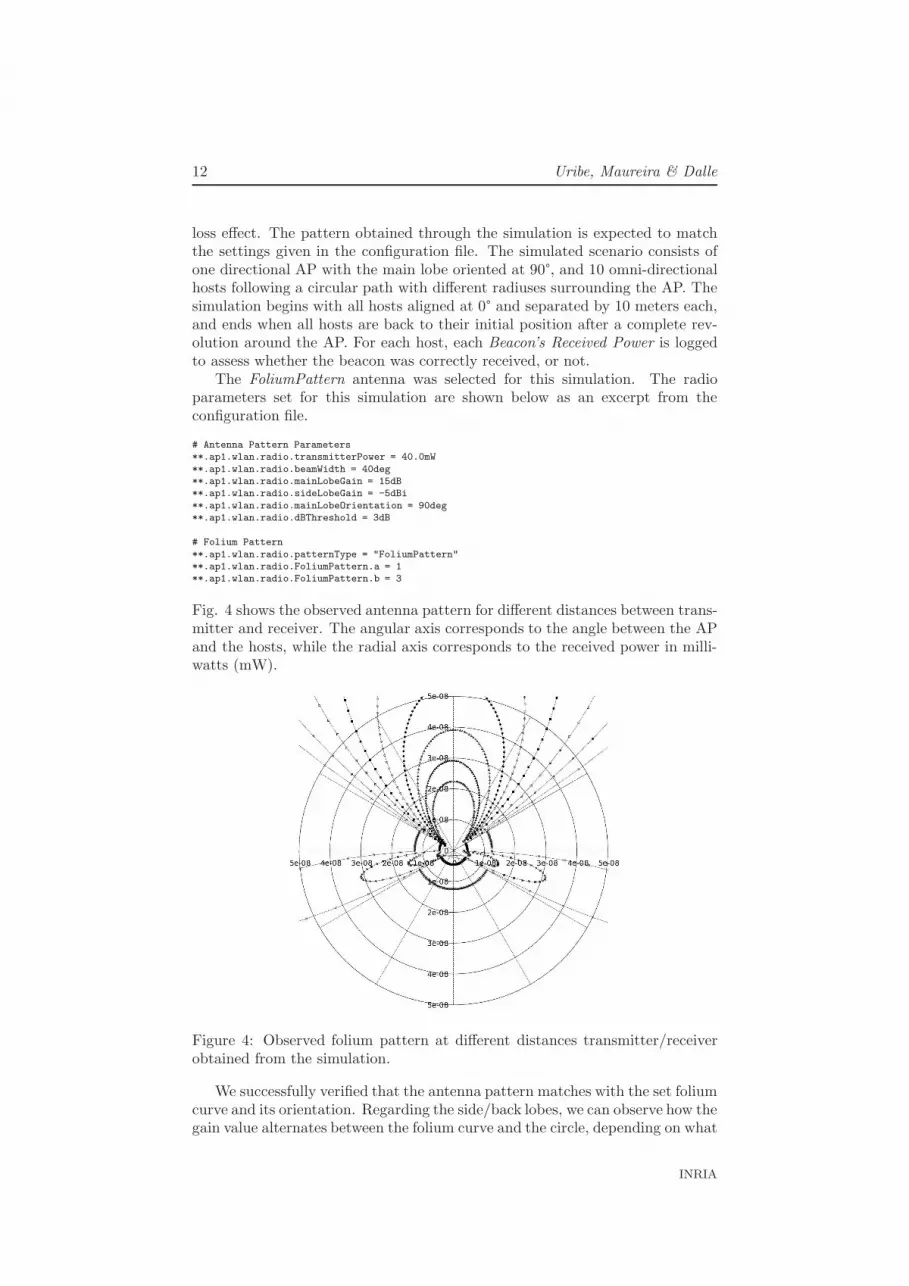
loss effect. The pattern obtained through the simulation is expected to matchthe settings given in the configuration file. The simulated scenario consists ofone directional AP with the main lobe oriented at 90°, and 10 omni-directionalhosts following a circular path with different radiuses surrounding the AP. Thesimulation begins with all hosts aligned at 0° and separated by 10 meters each,and ends when all hosts are back to their initial position after a complete rev-olution around the AP. For each host, each Beacon’s Received Power is loggedto assess whether the beacon was correctly received, or not.
The FoliumPattern antenna was selected for this simulation. The radioparameters set for this simulation are shown below as an excerpt from theconfiguration file.
# Antenna Pattern Parameters
**.ap1.wlan.radio.transmitterPower = 40.0mW
**.ap1.wlan.radio.beamWidth = 40deg
**.ap1.wlan.radio.mainLobeGain = 15dB
**.ap1.wlan.radio.sideLobeGain = -5dBi
**.ap1.wlan.radio.mainLobeOrientation = 90deg
**.ap1.wlan.radio.dBThreshold = 3dB
# Folium Pattern
**.ap1.wlan.radio.patternType = "FoliumPattern"
**.ap1.wlan.radio.FoliumPattern.a = 1
**.ap1.wlan.radio.FoliumPattern.b = 3
Fig. 4 shows the observed antenna pattern for different distances between trans-mitter and receiver. The angular axis corresponds to the angle between the APand the hosts, while the radial axis corresponds to the received power in milli-watts (mW).
Figure 4: Observed folium pattern at different distances transmitter/receiverobtained from the simulation.
We successfully verified that the antenna pattern matches with the set foliumcurve and its orientation. Regarding the side/back lobes, we can observe how thegain value alternates between the folium curve and the circle, depending on what
INRIA

Directional and Asymmetrical Communications 13
is the higher value, as described in the implementation section. We can observethat the received power varies according to the distance between transmitterand receiver due to the path loss effect. Following one radial direction, thedifference between two consecutive level curves corresponds to the path losswhen the radio signal travels 10 meters.
5.1.2 Omni-directional vs. Directional Communications
The goal of the second simulation is to evaluate our DirectionalRadio by com-paring the network throughput when using omni-directional and directional an-tennas. For this purpose, we build a mesh network simulation, with 10 nodescontaining 2 bridged radio interfaces, and 2 client hosts with a single radio in-terface. In this scenario, the radio parameters for the hosts are chosen suchthat directional antennas are able to “hear” up to 5 antennas placed in theirsame direction of orientation, even when they are supposed to communicateonly with their immediate neighbors. We determined that using a network with10 hosts is enough to create strong interference between antennas and to clearlyobserve the behavior of communications. All antennas in the simulation havethe same maximum transmission range, and the radio interfaces are configuredas shown in Fig. 5, using the same channel. In this scenario, a TCP stream istransmitted first time from client1 to client2 through the mesh network, usingomni-directional antennas (1st case) and then, a second time using directionalantennas (2nd case); network throughput was monitored during the experiment.
Figure 5: Second evaluation scenario. Mesh network with multiple radio inter-faces nodes.
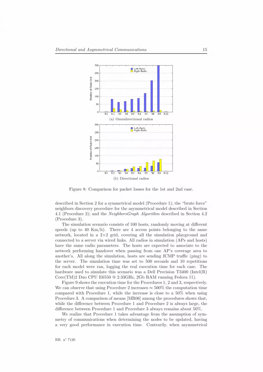
Fig. 6 presents a comparison of the network throughput for the two casesdescribed above. In the 1st case, we observe that the network throughput isabout half of the theoretical one, which is consistent with previously obtainedresults [MIKR07]. In Fig. 7(a) we can see that the number of collisions usingomni-directional nodes is constant for all radios, while for directional antennas(Fig. 7(b)) the number varies depending on the node’s position. This is becausethe coverage range for directional antennas is set to be greater, thus allowingtwo distant antennas to “hear” each other. The left radio of N8, for instance,is able to hear from N2 to N7, leading to a greater number of collisions whenreceiving. The packet loss, however, is reduced when using directional antennas,as shown in Fig. 8(b), compared to the case that uses omni-directional antennas(Fig. 8(a)).
RR n° 7120

14 Uribe, Maureira & Dalle
Figure 6: Comparison of TCP throughput for the 1st and 2nd case for 30repetitions of the simulation.
(a) Omnidirectional radios
(b) Directional radios
Figure 7: Comparison for packet collisions for the 1st and 2nd case.
5.2 Computational cost Analysis
The introduction of asymmetrical communications generates an increase in theexecution time of the neighbors discovery procedure, since it can not be assumedreciprocity when building (or updating) the neighbor list. However, the compu-tational cost can be partially decreased if a more refined algorithm is used. Inorder to evaluate the performance of each algorithm, we compare the simulationtime for the same scenario when using: the current neighbor discovery procedure
INRIA
Directional and Asymmetrical Communications 15
(a) Omnidirectional radios
(b) Directional radios
Figure 8: Comparison for packet losses for the 1st and 2nd case.
described in Section 2 for a symmetrical model (Procedure 1); the “brute force”neighbors discovery procedure for the asymmetrical model described in Section4.1 (Procedure 2); and the NeighborsGraph Algorithm described in Section 4.2(Procedure 3).
The simulation scenario consists of 100 hosts, randomly moving at differentspeeds (up to 40 Km/h). There are 4 access points belonging to the samenetwork, located in a 2×2 grid, covering all the simulation playground andconnected to a server via wired links. All radios in simulation (APs and hosts)have the same radio parameters. The hosts are expected to associate to thenetwork performing handover when passing from one AP’s coverage area toanother’s. All along the simulation, hosts are sending ICMP traffic (ping) tothe server. The simulation time was set to 500 seconds and 10 repetitionsfor each model were ran, logging the real execution time for each case. Thehardware used to simulate this scenario was a Dell Precision T3400 (Intel(R)Core(TM)2 Duo CPU E6550 @ 2.33GHz, 2Gb RAM running Fedora 11).
Figure 9 shows the execution time for the Procedures 1, 2 and 3, respectively.We can observe that using Procedure 2 increases ≈ 500% the computation timecompared with Procedure 1, while the increase is close to a 50% when usingProcedure 3. A comparison of means [MR06] among the procedures shows that,while the difference between Procedure 1 and Procedure 2 is always large, thedifference between Procedure 1 and Procedure 3 always remains about 50%.
We realize that Procedure 1 takes advantage from the assumption of sym-metry of communications when determining the nodes to be updated, havinga very good performance in execution time. Contrarily, when asymmetrical
RR n° 7120

16 Uribe, Maureira & Dalle
Figure 9: Execution time for Symmetrical and Asymmetrical model with differ-ent neighbors list update algorithms.
communications are used, the neighbors list must be updated much more oftento honor the SNR and noise calculation and this is done for all nodes whena host moves or transmits an airframe. Thus, the execution time is increaseddramatically. Nevertheless, our proposed algorithm to calculate the neighborsovercomes this impact, reducing the increase in execution time reasonably whenusing an asymmetrical communications radio model.
Extending these results to larger simulations, we estimate that the executiontime of our proposed algorithm will be always higher than the execution timewhen symmetrical communications are used. However, further experimentationhas shown that this difference is always around 50%. As we stated in Section4.2, the execution time of the neighbors graph algorithm is expected to behigher since each neighbor node is visited at least twice (axe-x and axe-y).But, a possible alternative to overcome this overhead could be to perform thisexploration in a parallel way (exploiting the multi-core architectures). Whetheror not the execution time of the neighbors graph algorithm could be improved, itwill never be better than the algorithm for symmetrical communications, sincethe assumption of symmetry gives the best case when all radio coverages areequal. On the contrary, our algorithm ensures a good approximation of theoptimal case when calculating the neighbors lists for a node, not only whenradios coverages are equal, but also in cases where radios coverages are differentin shape and size.
6 Conclusions
In this work, we presented an extension of the OMNeT++ ’s INET Frameworkfor directional and asymmetrical wireless communications. This new extensionis based on the existing INET multi-radio branch and introduces the followingcontributions: an asymmetrical Radio Model to support directional antenna
INRIA

Directional and Asymmetrical Communications 17
patterns; a NeighborsGraph Algorithm to speed up the neighbor nodes updatecomputation; and an implementation of a Directional Radio module with fourantenna patterns. The included antenna patterns use mathematical curves torepresent the gain pattern in a pie-wedge directional radiation model.
Although the proposed model still has several simplifications, we demon-strated through simulations that the results obtained agree with the resultsfound in the literature when using directional radios in mesh networks.
Furthermore, despite the increase in execution time could be potentially highwhen using asymmetrical communications, we showed it is possible to reasonablyreduce it by using our NeighborsGraph algorithm.
In this work, we also identified open issues, such as the accuracy of antennagain in the plane, or the use of multi-core architectures to speed-up the construc-tion/update of the neighbors list. First, antenna gain can be described througha set of points by using mapping techniques; and second, the use of threading toexplore on each axe direction when using the NeighborsGraph algorithm.
Finally, we consider that our contributions are a first attempt to provide anasymmetrical communications support within the OMNeT++/INET Frame-work.
References
[Bal05] Constantine A. Balanis. Antenna Theory: Analysis and Design.Wiley-Interscience, 2005.
[BB09] Michael Bredel and Martin Bergner. On the accuracy of ieee 802.11gwireless lan simulations using omnet++. In Simutools ’09: Pro-ceedings of the 2nd International Conference on Simulation Toolsand Techniques, pages 1–5, ICST, Brussels, Belgium, Belgium,2009. ICST (Institute for Computer Sciences, Social-Informatics andTelecommunications Engineering).
[Car01] Joseph J. Carr. Practical antenna handbook PRACTICAL AN-TENNA HANDBOOK. TAB Mastering Electronics Series, TabElectronics. McGraw-Hill Professional, 4, illustrated, annotated edi-tion, 2001.
[GH09] H. Gharavi and Bin Hu. Directional antenna for multipath ad hocrouting. In Consumer Communications and Networking Conference,2009. CCNC 2009. 6th IEEE, pages 1–5, Jan. 2009.
[glo98] Glomosim. In http://pcl.cs.ucla.edu/projects/glomosim, 1998.
[GS78] Leo J. Guibas and Robert Sedgewick. A dichromatic framework forbalanced trees. In SFCS ’78: Proceedings of the 19th Annual Sympo-sium on Foundations of Computer Science, pages 8–21, Washington,DC, USA, 1978. IEEE Computer Society.
[HGT+08] Kery Hardwick, Dennis Goeckel, Don Towsley, Kin Leung, andZhiguo Ding. Antenna beam pattern model for cooperative ad-hocnetworks. In ACITA, 2008, pages 209–216, 2008.
RR n° 7120
18 Uribe, Maureira & Dalle
[KKY07] K. Kucuk, A. Kavak, and H. Yigit. A smart antenna module usingomnet++ for wireless sensor network simulation. In Wireless Com-munication Systems, 2007. ISWCS 2007. 4th International Sympo-sium on, pages 747–751, 2007.
[KNG+04] David Kotz, Calvin Newport, Robert S. Gray, Jason Liu, YouguYuan, and Chip Elliott. Experimental evaluation of wireless simu-lation assumptions. In MSWiM ’04: Proceedings of the 7th ACMinternational symposium on Modeling, analysis and simulation ofwireless and mobile systems, pages 78–82, New York, NY, USA,2004. ACM.
[Kra88] John D. Kraus. Antennas. McGraw-Hill Education, May 1988.
[MIKR07] S.N. Muthaiah, A. Iyer, A. Karnik, and C. Rosenberg. Design of highthroughput scheduled mesh networks: A case for directional anten-nas. In Global Telecommunications Conference, 2007. GLOBECOM’07. IEEE, pages 5080–5085, Nov. 2007.
[MR06] Douglas C. Montgomery and George C. Runger. Applied Statisticsand Probability for Engineers, 4th Edition. John Wiley & Sons, May2006.
[ns2] The network simulator - ns-2. In http://www.isi.edu/nsnam/ns.
[opn00] Opnet modeler 7.0 gives network designers boost to optimize per-formance of wireless infrastructures. 2000.
[qua] Qualnet network simulator. In http://www.qualnet.com.
[Rap02] Theodore S. Rappaport. Wireless Communications: Principles andPractice (2nd Edition). Prentice Hall PTR, 2 edition, January 2002.
INRIA

Directional and Asymmetrical Communications 19
Contents
1 Introduction 3
2 Status of INET Model 4
3 Extensions to INET’s Radio Model 5
3.1 Concepts . . . . . . . . . . . . . . . . . . . . . . . . . . . . . . . 53.2 Proposed Extension for the Radio Model . . . . . . . . . . . . . . 6
4 Model Implementation 7
4.1 Asymmetrical Communications . . . . . . . . . . . . . . . . . . . 84.2 NeighborsGraph Algorithm . . . . . . . . . . . . . . . . . . . . . 84.3 DirectionalRadio Module . . . . . . . . . . . . . . . . . . . . . . 11
5 Model Evaluation 11
5.1 Correctness of the Proposed DirectionalRadio Module . . . . . . 115.1.1 Obtaining an Antenna Pattern . . . . . . . . . . . . . . . 115.1.2 Omni-directional vs. Directional Communications . . . . 13
5.2 Computational cost Analysis . . . . . . . . . . . . . . . . . . . . 14
6 Conclusions 16
RR n° 7120

Centre de recherche INRIA Sophia Antipolis – Méditerranée2004, route des Lucioles - BP 93 - 06902 Sophia Antipolis Cedex (France)
Centre de recherche INRIA Bordeaux – Sud Ouest : Domaine Universitaire - 351, cours de la Libération - 33405 Talence CedexCentre de recherche INRIA Grenoble – Rhône-Alpes : 655, avenue de l’Europe - 38334 Montbonnot Saint-Ismier
Centre de recherche INRIA Lille – Nord Europe : Parc Scientifique de la Haute Borne - 40, avenue Halley - 59650 Villeneuve d’AscqCentre de recherche INRIA Nancy – Grand Est : LORIA, Technopôle de Nancy-Brabois - Campus scientifique
615, rue du Jardin Botanique - BP 101 - 54602 Villers-lès-Nancy CedexCentre de recherche INRIA Paris – Rocquencourt : Domaine de Voluceau - Rocquencourt - BP 105 - 78153 Le Chesnay CedexCentre de recherche INRIA Rennes – Bretagne Atlantique : IRISA, Campus universitaire de Beaulieu - 35042 Rennes Cedex
Centre de recherche INRIA Saclay – Île-de-France : Parc Orsay Université - ZAC des Vignes : 4, rue Jacques Monod - 91893 Orsay Cedex
ÉditeurINRIA - Domaine de Voluceau - Rocquencourt, BP 105 - 78153 Le Chesnay Cedex (France)
http://www.inria.fr
ISSN 0249-6399