experimental investigation of a side-emitting optical fibre mop
TRANSCRIPT
Experimental investigation of a side-emitting optical fi bre mop fan for air cleaningXiaoli Ma, Michael Birnie, S. B. Riffat (corresponding author) and Mark GillottInstitute of Sustainable Energy Technology, School of the Built Environment, University of Nottingham, Nottingham, NG7 2RD, UKE-mail: [email protected]
Abstract A photocatalytic side-emitting optical fi bre mop fan prototype was designed, constructed and tested. The performance was compared with a previously tested polymer fi bre mop fan. It was found that the system has better effi ciency than the polymer fi bre mop fan due to a more reasonable UV lamp arrangement and even UV-light transmittance. It was also found that the fi nal room pollutant concentration depends on the pollutant generating rate by using the photocatalyst mop fan air cleaning system. The system is more compact than the polymer fi bre mop fan.
Keywords optical fi bre mop fan; reaction; photocatalyst; pollutant concentration; air cleaning
1. Introduction
Environmental remediation using photocatalysts has been the most intriguing issue in many countries for the past decade [1]. As traditional air purifi ers use fi lters to remove particulate matters or use sorption materials (e.g., granular activated carbon) to adsorb gases or odors, these techniques only transfer the contaminants to another phase rather than eliminating them, and additional disposal or handling steps are subsequently required. As an alternative remediation technology, the use of hetero-geneous photocatalytic oxidation (PCO) offers a number of advantages over con-ventional technologies [2]. Attractive advantages with photocatalysis for air treatment and purifi cation are ambient temperature and pressure operation, use of molecular oxygen as the oxidant, and fi nal oxidation products that are usually innocuous (CO2 and H2O for the oxidation of small hydrocarbons) [3]. It has been shown that PCO operating at ambient conditions can be employed to destroy a wide variety of organic compounds which are representative of common indoor air contaminants [4].
The photocatalytic reactors include honeycomb monolith reactors, fl uidized-bed reactors, annular reactors, Pyrex glass tube reactor, etc [2] [5–7]. All the above reactors are static equipment and can not move air; therefore, these systems need the separate equipment, such as air blowers, to introduce the air into the reactors. The photocatalytic mop fan introduced in this paper can act as an air impellor as well as a fi lter for removal of particulate pollutants. The photocatalytic mop fan system is therefore compact and robust, and requires little or no maintenance. The system has low energy consumption, as, unlike conventional air cleaning devices, there is negligible pressure drop incurred in its operation.
The photocatalyst mop fan system comprises of a fl exible fi bre mop, which is mounted on a shaft within a centrifugal fan casing, and is rotated by a direct drive, high effi ciency motor. The system performs self-cleaning when circulating indoor
International Journal of Low Carbon Technologies 3/2
Dow
nloaded from https://academ
ic.oup.com/ijlct/article/3/2/126/693631 by guest on 11 January 2022
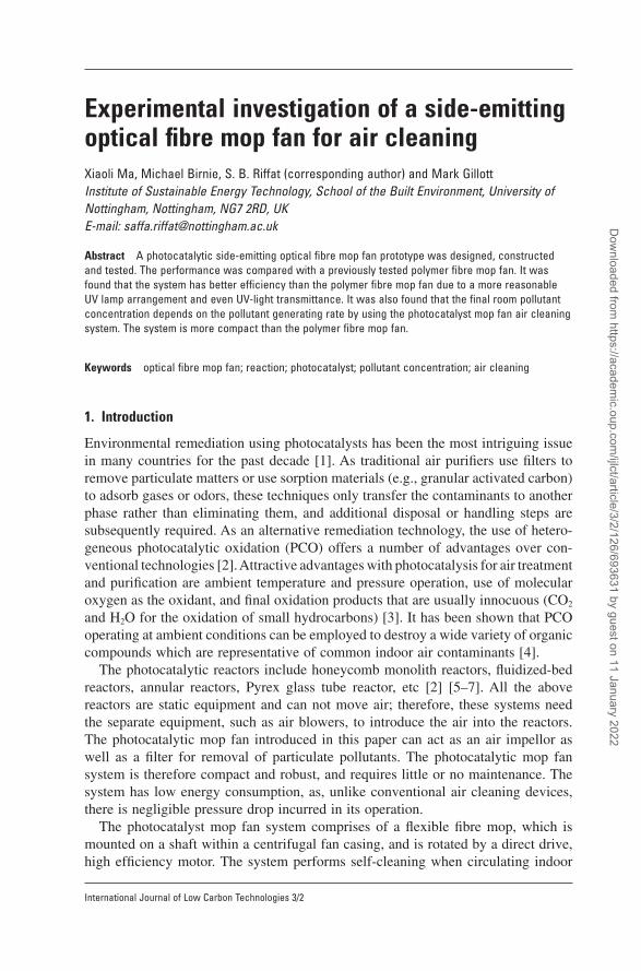
air throughout the building space, thus reducing the need of outdoor fresh air and energy for heating/cooling the air. The fi bre mop is constructed of many fl exible fi bres, each coated with the photocatalyst, titanium dioxide (TiO2). In operation, the air being moved by the mop fan will pass over the large surface area of the fl exible fi bres. The UV lamps are used to facilitate photocatalytic oxidation. The titanium dioxide coated on the fi bers, activated by the UV radiation, chemically oxidize vola-tile organic pollutants, thus converting them primarily to carbon dioxide and water. The internal surface of the fan casing is coated with a highly refl ective material, to spread the light evenly over the mop, and fi nished with a layer of TiO2 to achieve self cleaning.
The major part of the photocatalytic mop fan system is a fl exible fi bre mop, such as the polymer fi bre mop. As an alternative arrangement, using side-emitting fi bre optics as the fl exible fi bres of the mop has several advantages, i.e., the UV-lamp can be positioned at the centre of the mop, so the light is carried along the length of the fi bres and spreads more evenly over the mop, and the system is more compact and effi cient.
2. The experimental side-emitting optical fi bre mop fan prototype system
In order to describe the experimental side-emitting optical fi bre mop fan prototype system, a polymer fi bre mop fan prototype system, which has been investigated previously by authors, is shown in Fig. 1 for the purpose of comparison. As shown in Fig. 1, the polymer fi bre mop, similar in appearance to a chimney sweep brush,
Experimental investigation of a side-emitting optical fi bre mop fan for air cleaning 127
International Journal of Low Carbon Technologies 3/2
Figure 1. Photocatalytic Mop Fan.
Dow
nloaded from https://academ
ic.oup.com/ijlct/article/3/2/126/693631 by guest on 11 January 2022
128 X. Ma et al.
International Journal of Low Carbon Technologies 3/2
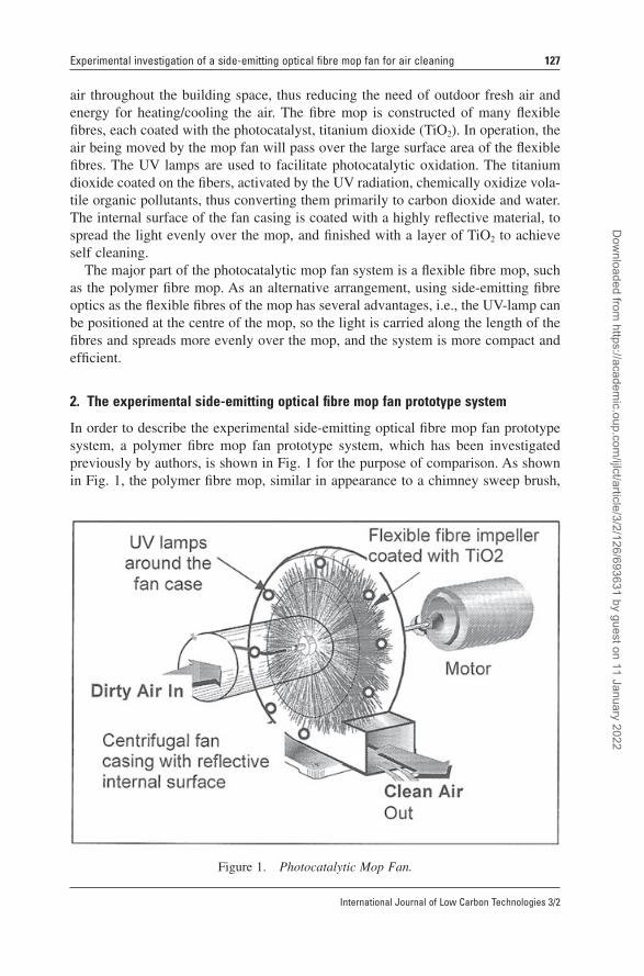
is constructed of 240 bunches of fl exible polymer fi bres, each fi bre is coated with the photocatalyst, titanium diode (TiO2) by the dip coated method. Eight small UV lamps with the wave length of between 300–370 nm are installed within the fan casing (around the fan casing, see Fig. 1) to facilitate photocatalytic oxidation. The power of each bulb is 4 watts. As an alternative arrangement, the side-emitting optical fi bre mop fan was constructed, which has the same scale as the previous polymer fi bre mop fan (the same diameter, same thickness, the same number of fi bre bunches and the same length of the fi bre, using the same sizes of hub and fan casing). The side-emitting optical fi bre mop fan uses side-emitting fi bre optics as the fl exible fi bres of the mop; in this case, the UV lamp is positioned in the hollow hub and fi xed on the fan casing. The system is shown in Fig. 2 and Fig. 3. The optical fi bre mop is also constructed of 240 bunches of side-emitting optical-fi bres, the end of each bundle is mounted on the hub of the mop fan and has a diameter of Φ3 mm, each fi bre has the length of 10 cm and is coated with the photocatalyst, titanium dioxide (TiO2) by the dip coated method. The mop fan has the airfl ow rate of 0.019 m3/s, 0.027 m3/s, 0.033 m3/s and 0.040 m3/s at the fan speed of 120 rpm, 180 rpm, 240 rpm and 300 rpm respectively. The UV lamp has a wave length of between 300–370 nm and the power of lamp is 25 watts. To transmit more light to the fi bre surface, the space between the fi bre bundles are utilized – there are 240 small holes on the hub surface, the small holes are distributed on the interval space of the fi bre bundles (see Fig. 2); each hole has a diameter of Φ3 mm. The UV light
Figure 2. The structure of the optical fi bre mop fan.
Dow
nloaded from https://academ
ic.oup.com/ijlct/article/3/2/126/693631 by guest on 11 January 2022
Experimental investigation of a side-emitting optical fi bre mop fan for air cleaning 129
International Journal of Low Carbon Technologies 3/2
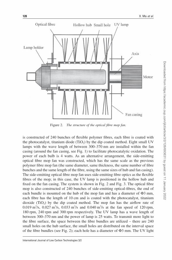
can go through both the side-emitting optical fi bres and the small holes and dissipate on the optical fi bre surface; the UV light therefore illuminates the fi bre surface. The mop fan is located in a big wooden box (1.2 m × 1.2 m × 1.2 m).
The side emitting optical fi bre distributes the light from the illuminator along the entire length of the fi bre and is usually used in fi bre optic lighting systems in any commercial, industrial or residential lighting application. In a side-emitting fi bre, light refracts out of the fi bre by way of deliberate imperfections at the boundary of the core and cladding.
3. Testing results and discussion
3.1 Testing method and analysisTo monitor the reaction process when the side-emitting optical mop fan is operating, the concentrations of the pollutant, carbon dioxide as well as the temperature and relative humidity inside the box were monitored during the test. The methanol was used as a pollutant for the experimental investigation. The temperature and relative humidity was monitored using a Vaisala HMP35DGT temperature and humidity probe. A B&K multi-gas analyzer 1302 was used continuously to measure the con-centrations of methanol, carbon dioxide and water vapour inside the box. The B&K analyser uses the photo-acoustic infra-red detection method. Infra-red light passes through an optical fi lter resulting in an infra-red source with a narrow band width. A mechanical modulator pulses this light before a gas sample is exposed to it. The resulting temperature and pressure fl uctuations are measured by microphones. The measured intensity is proportional to the gas concentration. The B&K analyser was calibrated regularly to ensure that the measuring error was to be less then 1%.
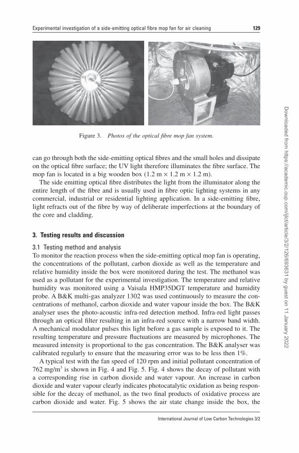
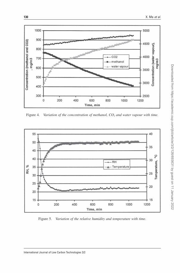
A typical test with the fan speed of 120 rpm and initial pollutant concentration of 762 mg/m3 is shown in Fig. 4 and Fig. 5. Fig. 4 shows the decay of pollutant with a corresponding rise in carbon dioxide and water vapour. An increase in carbon dioxide and water vapour clearly indicates photocatalytic oxidation as being respon-sible for the decay of methanol, as the two fi nal products of oxidative process are carbon dioxide and water. Fig. 5 shows the air state change inside the box, the
Figure 3. Photos of the optical fi bre mop fan system.
Dow
nloaded from https://academ
ic.oup.com/ijlct/article/3/2/126/693631 by guest on 11 January 2022
130 X. Ma et al.
International Journal of Low Carbon Technologies 3/2
Figure 4. Variation of the concentration of methanol, CO2 and water vapour with time.
Figure 5. Variation of the relative humidity and temperature with time.
Dow
nloaded from https://academ
ic.oup.com/ijlct/article/3/2/126/693631 by guest on 11 January 2022
Experimental investigation of a side-emitting optical fi bre mop fan for air cleaning 131
International Journal of Low Carbon Technologies 3/2
temperature rose from 19.5ºC to 36.2ºC in the fi rst 250 minutes due to the rotation of the mop fan motor producing heat continuously and then the temperature kept constant because the thermal balance was achieved at the temperature inside the box of 36.2ºC, while the amount of the heat transfer from the box to the ambient was equal to the heat production by the motor rotation. (For a certain box, the time required for the thermal balance achievement is determined by the heat production rate of the motor rotation and the ambient temperature.) The relative humidity decreased in the fi rst 250 minutes because the temperature inside the box increased although the oxidative process produced water vapour and after 250 minutes it rose slightly because the produced water vapour and the temperature inside the box became constant.
3.2 Comparison of the test results of the polymer fi bre mop fan and the optical fi bre mop fanTests were carried out to compare the performance of the polymer fi bre mop fan (shown in Fig. 1) and the side-emitting optical fi bre mop fan. The results are shown in Fig. 6 and Fig. 7.
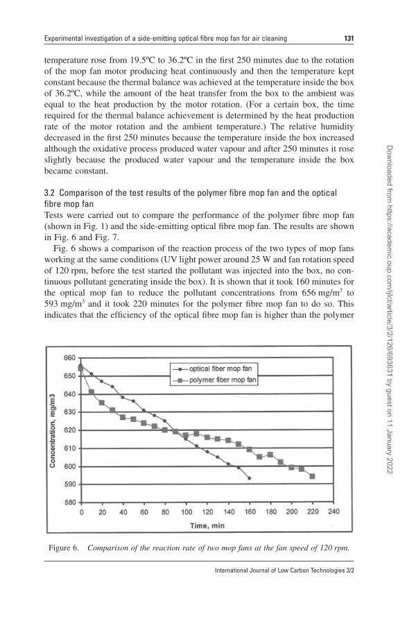
Fig. 6 shows a comparison of the reaction process of the two types of mop fans working at the same conditions (UV light power around 25 W and fan rotation speed of 120 rpm, before the test started the pollutant was injected into the box, no con-tinuous pollutant generating inside the box). It is shown that it took 160 minutes for the optical mop fan to reduce the pollutant concentrations from 656 mg/m3 to 593 mg/m3 and it took 220 minutes for the polymer fi bre mop fan to do so. This indicates that the effi ciency of the optical fi bre mop fan is higher than the polymer
Figure 6. Comparison of the reaction rate of two mop fans at the fan speed of 120 rpm.
Dow
nloaded from https://academ
ic.oup.com/ijlct/article/3/2/126/693631 by guest on 11 January 2022
132 X. Ma et al.
International Journal of Low Carbon Technologies 3/2
fi bre mop fan. However, in the fi rst 90 minutes the pollutant concentration reduction rate using the polymer mop fan seems higher than that using optical mop fan. This was caused by initial uneven distribution of the pollutant inside the box. When the test started, a syringe was used to inject a small amount of pollutant into the box to obtain the initial concentrations. While the polymer mop fan test was being carried out, the pollutant was injected into the box through the small door of the box that is a little farther from the sampling point. While the optical mop fan test was being carried out, the pollutant was injected into the box through another hole that can hold the syringe pump and this hole is a little closer to the sampling point. Therefore, at the beginning the measured pollutant concentration for the optical mop fan test is higher compared to that of fi bre mop fan test. After 90 minutes the distribution of the pollutant inside the box became even, due to the continuous running of the mop fan, and then the merit of the optical mop fan can be seen. The same phenom-enon can be seen in Fig. 7.
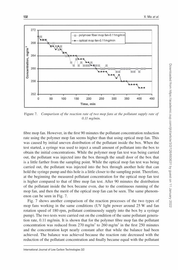
Fig. 7 shows another comparison of the reaction processes of the two types of mop fans working in the same conditions (UV light power around 25 W and fan rotation speed of 180 rpm, pollutant continuously supply into the box by a syringe pump). The two tests were carried out on the condition of the same pollutant genera-tion rate, 0.11 mg/min. It is shown that for the polymer fi bre mop fan the pollutant concentration was reduced from 270 mg/m3 to 260 mg/m3 in the fi rst 250 minutes and the concentration kept nearly constant after that while the balance had been achieved. The balance was achieved because the reaction rate decreased with the reduction of the pollutant concentration and fi nally became equal with the pollutant
Figure 7. Comparison of the reaction rate of two mop fans at the pollutant supply rate of 0.11 mg/min.
Dow
nloaded from https://academ
ic.oup.com/ijlct/article/3/2/126/693631 by guest on 11 January 2022
Experimental investigation of a side-emitting optical fi bre mop fan for air cleaning 133
International Journal of Low Carbon Technologies 3/2
generation rate. For the photocatalytic oxidation, the reaction rate decreases with the reduction of the pollutant concentration in a certain range because the lower the concentration, the less molecules can contact the mop fan fi bres and are adsorbed. For the optical mop fan test the pollutant concentration was reduced from 270 mg/m3 to 254 mg/m3 in 420 minutes and then the balance had not been achieved yet. This indicates that the reaction rate was still higher than the pollutant generating rate when the pollutant concentration reached the 254 mg/m3.
The above comparison of the test results shows that the optical fi bre mop fan has better effi ciency than the polymer fi bre mop fan. This is because the UV light in the optical mop fan can distribute on the mop fi bres more evenly and more effectively.
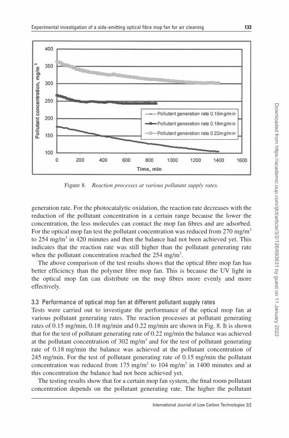
3.3 Performance of optical mop fan at different pollutant supply ratesTests were carried out to investigate the performance of the optical mop fan at various pollutant generating rates. The reaction processes at pollutant generating rates of 0.15 mg/min, 0.18 mg/min and 0.22 mg/min are shown in Fig. 8. It is shown that for the test of pollutant generating rate of 0.22 mg/min the balance was achieved at the pollutant concentration of 302 mg/m3 and for the test of pollutant generating rate of 0.18 mg/min the balance was achieved at the pollutant concentration of 245 mg/min. For the test of pollutant generating rate of 0.15 mg/min the pollutant concentration was reduced from 175 mg/m3 to 104 mg/m3 in 1400 minutes and at this concentration the balance had not been achieved yet.
The testing results show that for a certain mop fan system, the fi nal room pollutant concentration depends on the pollutant generating rate. The higher the pollutant
Figure 8. Reaction processes at various pollutant supply rates.
Dow
nloaded from https://academ
ic.oup.com/ijlct/article/3/2/126/693631 by guest on 11 January 2022
134 X. Ma et al.
International Journal of Low Carbon Technologies 3/2
generating rate, the higher the fi nal pollutant concentration. To achieve a desired (low) concentration, more than one mop fans could be used. The relationship between the number of mop fans required for a desired concentration need to be investigated further.
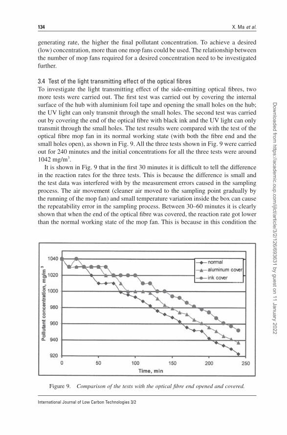
3.4 Test of the light transmitting effect of the optical fi bresTo investigate the light transmitting effect of the side-emitting optical fi bres, two more tests were carried out. The fi rst test was carried out by covering the internal surface of the hub with aluminium foil tape and opening the small holes on the hub; the UV light can only transmit through the small holes. The second test was carried out by covering the end of the optical fi bre with black ink and the UV light can only transmit through the small holes. The test results were compared with the test of the optical fi bre mop fan in its normal working state (with both the fi bre end and the small holes open), as shown in Fig. 9. All the three tests shown in Fig. 9 were carried out for 240 minutes and the initial concentrations for all the three tests were around 1042 mg/m3.
It is shown in Fig. 9 that in the fi rst 30 minutes it is diffi cult to tell the difference in the reaction rates for the three tests. This is because the difference is small and the test data was interfered with by the measurement errors caused in the sampling process. The air movement (cleaner air moved to the sampling point gradually by the running of the mop fan) and small temperature variation inside the box can cause the repeatability error in the sampling process. Between 30–60 minutes it is clearly shown that when the end of the optical fi bre was covered, the reaction rate got lower than the normal working state of the mop fan. This is because in this condition the
Figure 9. Comparison of the tests with the optical fi bre end opened and covered.
Dow
nloaded from https://academ
ic.oup.com/ijlct/article/3/2/126/693631 by guest on 11 January 2022
Experimental investigation of a side-emitting optical fi bre mop fan for air cleaning 135
International Journal of Low Carbon Technologies 3/2
optical fi bre acts as a normal glass fi bre and doesn’t transmit the light, and the UV light can only transmit through the small holes. The light intensity on the fi bre surface is lower. This result verifi ed that the side-emitting optical fi bres of the mop fan can transmit the UV light effectively. Between 30–60 minutes it is also shown that when the ends of the optical fi bres were covered with black ink the reaction rate got much lower than the test covered with aluminium foil tape. This is because the aluminium foil is a highly UV refl ective material, which can resist the UV light being absorbed by the plastic hub. This result indicates that the mop fan can be improved by coating the internal surface of the hub with UV refl ective material. After 60 minutes the concentration reduction rates of the three tests were nearly same. This is because after 60 minutes the concentrations got lower and at lower concentration the increased light intensity does not increase the reaction rates as the reaction rate is also limited by its concentration.
4. Conclusions
A photocatalytic side-emitting optical fi bre mop fan prototype is more compact and effi cient compared to the polymer mop fan because the UV light can be positioned at the centre of the mop and therefore, the light is carried along the length of the fi bres and distributed on the mop fi bres more evenly and more effectively.
The performance of the optical mop fan at three different pollutant generating rates was been investigated. It is found that the fi nal room pollutant concentration depends on the pollutant generating rate. The higher the pollutant generating rate, the higher the fi nal pollutant concentration. It is suggested that to achieve a desired (low) concentration, more than one mop fan could be used, which needs to be inves-tigated further.
Tests were also carried out to investigate the light transmitting effect of the side-emitting optical fi bres on the photocatalytic oxidation. It has been verifi ed that the side-emitting optical fi bres of the mop fan can transmit the light to the fi bre surface effectively. The tests also indicate that the mop fan can be improved by coating the internal surface of the hub with UV refl ective material. The test also found that increasing the light intensity does not always increase the effi ciency of the mop fan because the reaction rate is also limited by the pollutant concentration.
Acknowledgement
This work was supported by Engineering and Physical Sciences Research Council (EPSRC), UK.
References
[1] H. Joo, H. Jeong, Myungseok and II Moon, ‘The Use of Plastic Optical Fibers in Photocatalysis of Trichlorothylene’, Solar Energy Materials & Solar Cells, 79 (2003), 93–101.
[2] J. Zhao and X. Yang, ‘Photocatalytic oxidation for indoor air purifi cation: a literature review’, Building and Environment, 38 (2003), 645–654.
Dow
nloaded from https://academ
ic.oup.com/ijlct/article/3/2/126/693631 by guest on 11 January 2022
136 X. Ma et al.
International Journal of Low Carbon Technologies 3/2
[3] M. L, Sauer and D. F. Ollis, ‘Acetone oxidation in a photocatalytic monolith reactor’, Journal of Catalysis, 149 (1994), 81–91.
[4] Md. M. Hossain and G. B. Raupp, ‘Radiation fi eld modeling in a photocatalytic monolith reactor’, Chemical Engineering Science, 53(22) (1998), 3771–3780.
[5] G. B. Raupp, A. Alexiadis, Md. M. Hossain and R. Changrani, ‘First-principles modeling, scaling laws and design of structured photocatalytic oxidation reactors for air purifi cation’, Catalysis Today, 69 (2001), 41–49.
[6] D. F. Ollis, ‘Photocatalytic purifi cation and remediation of contaminated air and water’, Chemistry, 3 (2000), 405–411.
[7] F. Shiraishi, S. Yamaguchi and Y. Ohbuchi, ‘A rapid treatment of for formaldehyde in a highly tight room using a photocatalytic reactor combined with a continuous adsorption and desorption appara-tus’, Chemical Engineering Science, 58 (2003), 929–934.
Dow
nloaded from https://academ
ic.oup.com/ijlct/article/3/2/126/693631 by guest on 11 January 2022