highly efficient multilayer organic pure blue light emitting diodes with substituted carbazoles...
TRANSCRIPT
1
HIGHLY EFFICIENT MULTILAYER ORGANIC PURE-BLUE-LIGHT EMITTING DIODES WITH SUBSTITUTED CARBAZOLES COMPOUNDS IN THE EMITTING LAYER.
A. Fischer1, S. Chénais1, S. Forget1, M.-C. Castex1, D. Adès2, A.
Siove2, C. Denis3, P. Maisse3 and B. Geffroy3 1Laboratoire de Physique des Lasers (LPL, CNRS), Institut Galilée, Université Paris 13,
93430 Villetaneuse, France. 2Biomatériaux et Polymères de Spécialité (BPS/B2OA, CNRS), Institut Galilée, Université
Paris 13, Villetaneuse/Faculté de Médecine Lariboisière-St Louis, Université Paris 7, 75010
Paris, France. 3Laboratoire Cellules et Composants, CEA/LITEN/DSEN, CEA Saclay, 91191 Gif-sur-
Yvette, France.
e-mail : [email protected]
Abstract : Bright blue organic light-emitting diodes (OLEDs) based on 1,4,5,8,N-pentamethylcarbazole (PMC) and on dimer of N-ethylcarbazole (N,N’-diethyl-3,3’-bicarbazyl) (DEC) as emitting layers or as dopants in a 4,4’-bis(2,2’-diphenylvinyl)-1,1’-biphenyl (DPVBi) matrix are described. Pure blue-light with the C.I.E. coordinates x = 0.153 y = 0.100, electroluminescence efficiency ηEL of 0.4 cd/A, external quantum efficiency ηext. of 0.6% and luminance L of 236 cd/m2 (at 60 mA/cm2) were obtained with PMC as an emitter and the 2,9-dimethyl-4,7-diphenyl-1,10-phenantroline (BCP) as a hole-blocking material in five-layer emitting devices. The highest efficiencies ηEL. of 4.7 cd/A, and ηext = 3.3% were obtained with a four-layer structure and a DPVBi DEC-doped active layer (CIE coordinates x = 0.158, y=0.169, λpeak = 456 nm). The ηext. value is one the highest reported at this wavelength for blue OLEDs and is related to an internal quantum efficiency up to 20%
2
1. Introduction Over the last decade, blue Organic Light Emitting Diodes (blue OLEDs) with high efficiencies have
attracted considerable attention for their potential applications to the full colour ultra-thin flat panel
display [1-7]. Moreover, blue light can be converted into green or red with the use of proper dyes
giving the possibility to generate all colours from the blue emitter. This latter property leads to an
important simplification in the design of the OLED displays. Very recently, Gebeyehu et al.[4]
reported on efficient blue OLEDs with doped transport layers in a p-i-n type structure. From the
material point of view, carbazole derivatives have appeared since the nineties to be one of the most
promising among various blue-emitting materials [5-9]. For example, efficient blue-light emission has
been reported with multilayer diodes using distyrylarylenes (DSA) as emitters: Hosokawa et al.[5]
reported an external quantum efficiency (ηext) of 2.4 % using DSA doped with amino-substitued DSA,
whereas Liao et al.[6] recently published a external quantum efficiency of 8.7% thanks to the use of a
composite hole transport layer. However, the former exhibited a greenish-blue tint as the peak of the
emitted light is 480 nm, and the later is sky-blue with Commission Internationale de l’Eclairage (CIE)
coordinates of (x=0.15, y=0.29).
In an earlier work, we have reported that a carbazolic dimer i.e N,N’-diethyl-3,3’-bicarbazyl (DEC) is
a thermally and electrochemically stable organic compound [10,11] which exhibits interesting pure
blue electroluminescence in single double layer and triple layer LED configurations [12-14]. Since the
charges injection and the transport were not optimized, quantum efficiencies of the devices remained
small (ηext. of about 0.1%). Recently, carbazoles such as 4,4’-bis(N-carbazolyl)-biphenyl (CBP) [15-
18] or dimers and trimers of N-octylcarbazole [19] have been used as host materials for triplet emitters
in electrophosphorescent devices.
In this letter, we report on blue OLEDs based on the dimer N,N’-diethyl-3,3’-bicarbazyl (DEC)
and on the novel stable carbazole i.e. 1,4,5,8,N-pentamethylcarbazole (PMC). Both can be used either
in a five-layer structures with the 2,9-dimethyl-4,7-diphenyl-1,10-phenantroline (bathocuproine, BCP)
as a hole-blocking layer or as a doping material in a four-layer structure with a 4,4’-bis(2,2’-
diphenylvinyl)-1,1’-biphenyl (DPVBi) matrix. The devices that uses the PMC as an emitting material
3
exhibited the purest bright blue-light with the chromatic coordinates (C.I.E.) x = 0.153, y = 0.100 and
with an electroluminescence efficiency (EL) ηEL= 0.4 cd/A and an external quantum efficiency ηext of
0.6%. Much higher EL performances were obtained from four-layer structures using DEC as a dopant
of DPVBi. For an optimized doping ratio of 2%, devices displayed intense blue-light peaking at 456
nm (CIE coordinates x=0.158 y=0.169), with ηEL and ηext as high as 4.7cd/A and 3.3% (at 10mA/cm2)
and with a luminance L of 2835 cd/m2 (at 60mA/cm2). This ηext value is among the highest reported
for blue OLEDs with comparable CIE coordinates. Moreover, a two-days half life time has been
observed for devices tested constinuously with a 9V voltage, under ambient atmosphere and without
any encapsulation.
2.Experimental
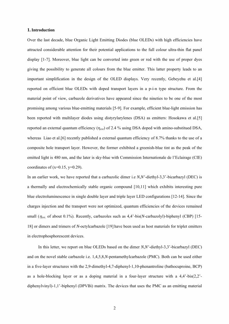
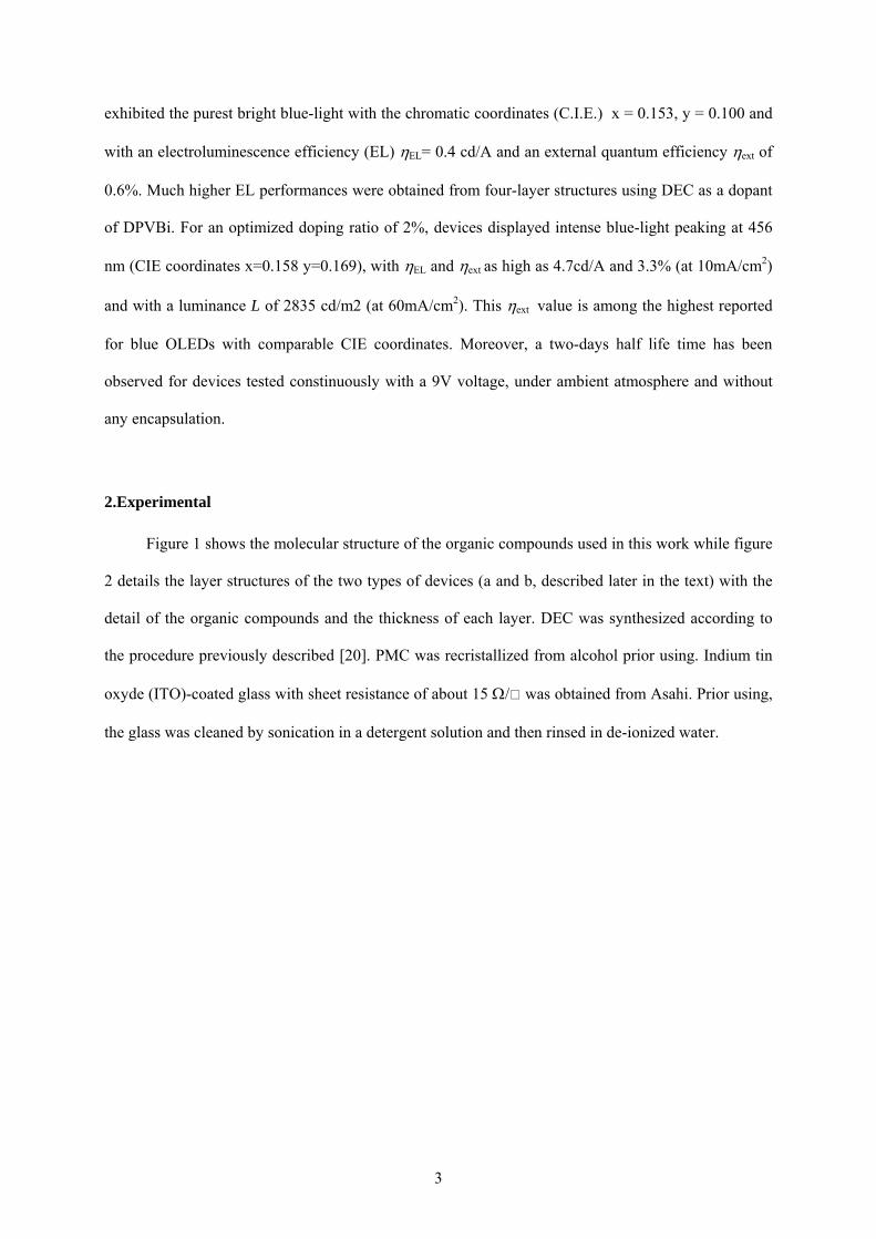
Figure 1 shows the molecular structure of the organic compounds used in this work while figure
2 details the layer structures of the two types of devices (a and b, described later in the text) with the
detail of the organic compounds and the thickness of each layer. DEC was synthesized according to
the procedure previously described [20]. PMC was recristallized from alcohol prior using. Indium tin
oxyde (ITO)-coated glass with sheet resistance of about 15 Ω/ was obtained from Asahi. Prior using,
the glass was cleaned by sonication in a detergent solution and then rinsed in de-ionized water.
4
CH3 CH3
CH3 CH3
CH3
N
C2H5
C2H5
N
N
PMC DEC
N
N
N
N
N
N
NNCu
CH3
N
CH3
N
N
O
AlO
N
O
N
CuPc Alq3 BCP
N N
NPB DPVBi
Figure 1 : Molecular Structures of the organic materials used for the Blue-Oled.
CuPc 10nm
NPB 50nm
PMC or DEC 50nm
BCP 10 nm Alq3 10nm
LiF 1.2nm/Al 100nm
(a)
ITO Glass
CuPc 10nm
NPB 50nm
DPVBi (PMC or DEC) 50nm
Alq3 10nm
LiF 1.2nm/Al 100nm
(b)
ITO glass
Figure 2 : OLED structure with the detail of the tickness and the organic material used in each layers; (a) the emissive layer is DEC or PMC, (b) the emissive layer is
DPVBi-doped with DEC or with PMC.
5
The organic compounds are deposited onto the ITO anode by sublimation under high vacuum (10-7
Torr) with a rate of 0.2 – 0.3 nm/s. An in-situ quartz crystal was used to monitor the thickness of the
vacuum depositions. The active area of each OLED was 0.3 cm2. In (a) configuration (Fig.2(a)), we
sequentially deposited onto the ITO anode : CuPc (copper phtalocyanine) as a hole-injecting layer
(HIL), (NPB) (N,N’-bis(1-naphtyl)-N,N’-diphenyl-1,1’-biphenyl-4,4’-diamine) as a hole-transporting
layer (HTL), DEC or PMC as an emitting layer (EML), BCP (bathocuproine; 2,9-dimethyl-4,7-
diphenyl-1,10-phenantroline,) as a hole-blocking layer (HBL), Alq3 (tris(8-quinolinoato)aluminium) as
the electron-transporting layer (ETL), and finally a LiF/Al top cathode. LiF has been found to increase
by a 50-fold factor the device efficiency of blue OLEDs DPVBi-based compared to a device with a
aluminium cathode only [21]. In another strucure Fig.2 (b), both the DEC (or PMC) layer and BCP
layers are replaced by a single DPVBi-DEC (or DPVBi-PMC) doped active layer. The latter is
obtained by co-evaporation from two separated evaporation sources. The organic materials (host and
dopant) were co-evaporated from two resistively heated evaporation cells which were controlled by a
temperature controller and monitored through a thermocouple inserted into the bottom of the cell. By
careful control of the evaporation cell temperature, it was possible to precisely deposit a determined
amount of dopant molecule dispersed into the emitting layer. The evaporation rates were monitored
with two separate quartz monitors and the accuracy of the doping is estimated to 10%.
The doping ratios (in weight %) were optimized to be 2% of DEC (or 5% of PMC) in the DPVBi
matrix. EL spectra and chromaticity coordinates were recorded with a PR 650 SpectraScan
spectrophotometer. The Current-Voltage and Current-Luminance (I-V and I-L) characteristics of the
diodes were measured with a regulated power supply (ACT 10 Fontaine) combined with a multimeter
and a 1 cm2 area silicon calibrated photodiode (Hamamatsu). All the measurements were performed
under ambient atmosphere.
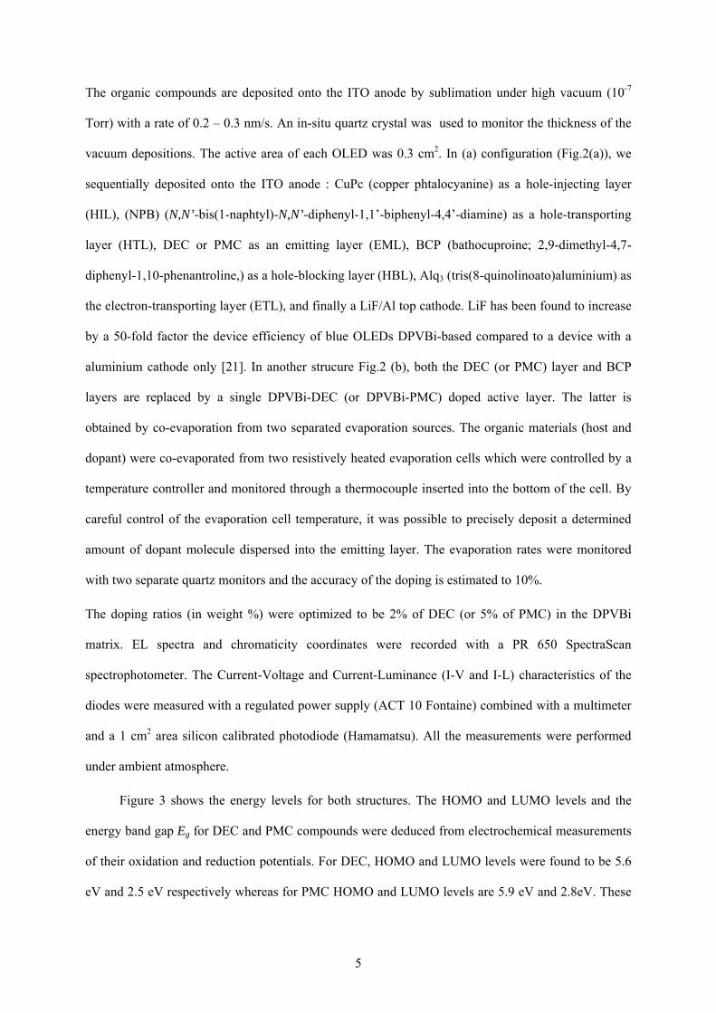
Figure 3 shows the energy levels for both structures. The HOMO and LUMO levels and the
energy band gap Eg for DEC and PMC compounds were deduced from electrochemical measurements
of their oxidation and reduction potentials. For DEC, HOMO and LUMO levels were found to be 5.6
eV and 2.5 eV respectively whereas for PMC HOMO and LUMO levels are 5.9 eV and 2.8eV. These
6
values agree quite well with those deduced from the absorption threshold of the optical spectra [22].
3.Results and discussion
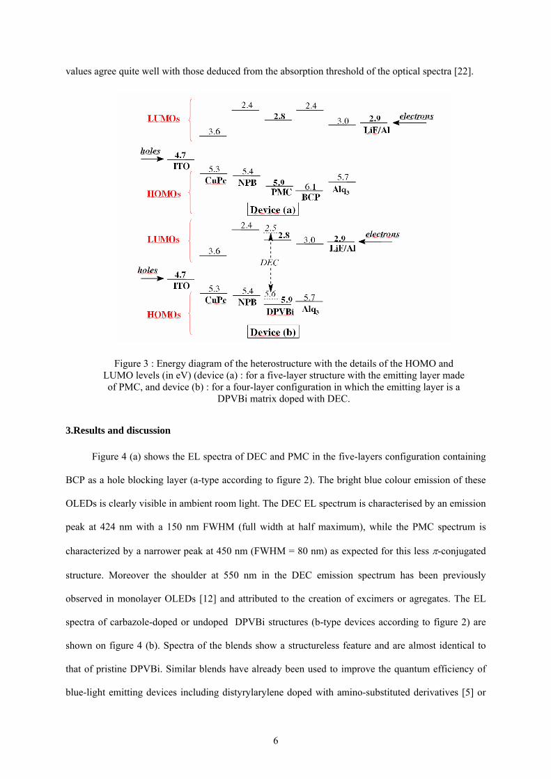
Figure 4 (a) shows the EL spectra of DEC and PMC in the five-layers configuration containing
BCP as a hole blocking layer (a-type according to figure 2). The bright blue colour emission of these
OLEDs is clearly visible in ambient room light. The DEC EL spectrum is characterised by an emission
peak at 424 nm with a 150 nm FWHM (full width at half maximum), while the PMC spectrum is
characterized by a narrower peak at 450 nm (FWHM = 80 nm) as expected for this less π-conjugated
structure. Moreover the shoulder at 550 nm in the DEC emission spectrum has been previously
observed in monolayer OLEDs [12] and attributed to the creation of excimers or agregates. The EL
spectra of carbazole-doped or undoped DPVBi structures (b-type devices according to figure 2) are
shown on figure 4 (b). Spectra of the blends show a structureless feature and are almost identical to
that of pristine DPVBi. Similar blends have already been used to improve the quantum efficiency of
blue-light emitting devices including distyrylarylene doped with amino-substituted derivatives [5] or
Figure 3 : Energy diagram of the heterostructure with the details of the HOMO and LUMO levels (in eV) (device (a) : for a five-layer structure with the emitting layer made of PMC, and device (b) : for a four-layer configuration in which the emitting layer is a
DPVBi matrix doped with DEC.
7
BCzVBi (an analog of DPVBi in which diphenyl end-groups are replaced by carbazole rings) doped in
CBP [7].
Figure 4 : Electroluminescence spectra of five-layer (a) and four-layer (b) devices
a
b
8
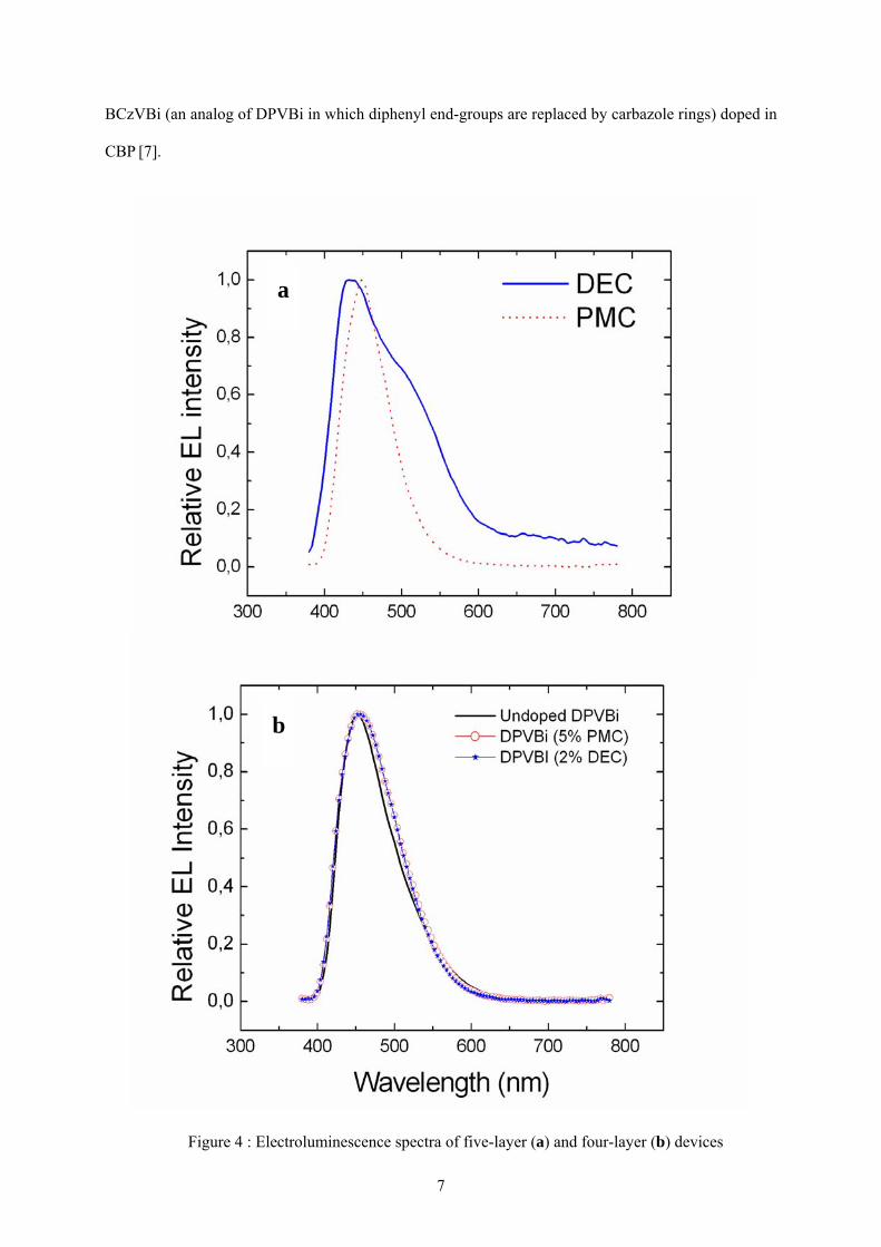
We plot in the figure 5 a typical exemple of the evolution of the efficiency (in cd/A) with the
applied voltage for our devices (here for a b-type device with 5% of PMC in the DPVBi host).
The electroluminescence parameters for all the devices are presented in the table 1. In optimal
DPVBi-carbazole doping ratio (in weight %) the electroluminescence efficiencies of doped devices
were improved by a nearly two-fold factor compared to that of nondoped devices. The DPVBi DEC-
doped device exhibits a quantum efficiency of ηext = 3.3%. This value is to our knowledge one of the
highest reported for deep-blue light emitting diodes, close value beeing obtained with a CBP-doped
device [7] or with spiro-anthracene or derivative of TPD in pin type device [4].
Figure 5 : efficiency (in candela/ampere) versus voltage for a type-b device (5% PMC doped DPVBi)
9
Device (a)
PMC
Device (a)
DEC
Device (b) DPVBi PMC- doped (5%)
Device (b) DPVBi DEC- doped (2%)
Device (b) DPVBi
nondoped
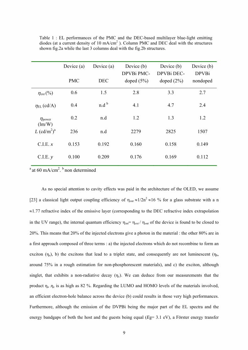
ηext (%) 0.6 1.5 2.8 3.3 2.7
ηEL (cd/A) 0.4 n.d b 4.1 4.7 2.4
ηpower (lm/W)
0.2 n.d 1.2 1.3 1.2
L (cd/m2)a 236 n.d 2279 2825 1507
C.I.E. x 0.153 0.192 0.160 0.158 0.149
C.I.E. y 0.100 0.209 0.176 0.169 0.112
a at 60 mA/cm2. b non determined
As no special attention to cavity effects was paid in the architecture of the OLED, we assume
[23] a classical light output coupling efficiency of ηout ≈1/2n2 ≈16 % for a glass substrate with a n
≈1.77 refractive index of the emissive layer (corresponding to the DEC refractive index extrapolation
in the UV range), the internal quantum efficiency ηint= ηext / ηout of the device is found to be closed to
20%. This means that 20% of the injected electrons give a photon in the material : the other 80% are in
a first approach composed of three terms : a) the injected electrons which do not recombine to form an
exciton (ηa), b) the excitons that lead to a triplet state, and consequently are not luminescent (ηb,
around 75% in a rough estimation for non-phosphorescent materials), and c) the exciton, although
singlet, that exhibits a non-radiative decay (ηc). We can deduce from our measurements that the
product ηa .ηc is as high as 82 %. Regarding the LUMO and HOMO levels of the materials involved,
an efficient electron-hole balance across the device (b) could results in those very high performances.
Furthermore, although the emission of the DVPBi being the major part of the EL spectra and the
energy bandgaps of both the host and the guests being equal (Eg= 3.1 eV), a Förster energy transfer
Table 1 : EL performances of the PMC and the DEC-based multilayer blue-light emitting diodes (at a current density of 10 mA/cm2 ). Column PMC and DEC deal with the structures shown fig.2a while the last 3 columns deal with the fig.2b structures.
10
can not be completely ruled out [24], and dopant excitation could arise from a better electron-hole
recombination with the carbazole compounds playing the role of the carrier traps according to the trap
mechanism [25].
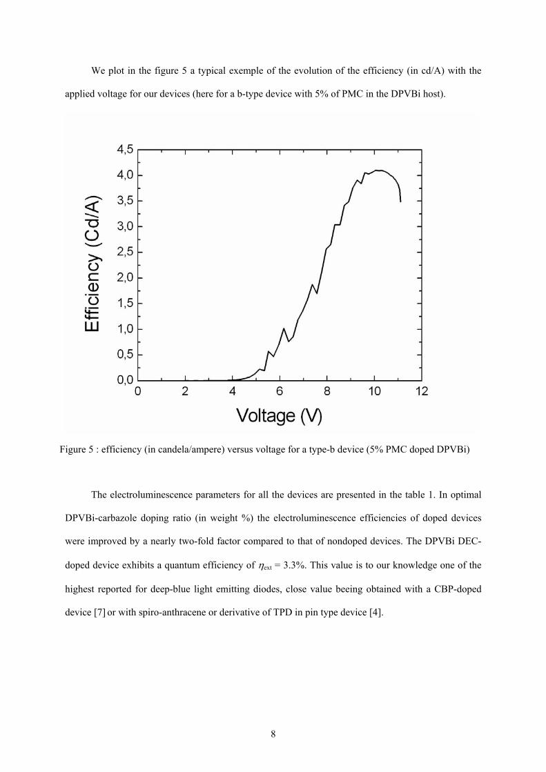
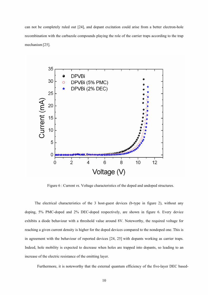
The electrical characteristics of the 3 host-guest devices (b-type in figure 2), without any
doping, 5% PMC-doped and 2% DEC-doped respectively, are shown in figure 6. Every device
exhibits a diode behaviour with a threshold value around 8V. Noteworthy, the required voltage for
reaching a given current density is higher for the doped devices compared to the nondoped one. This is
in agreement with the behaviour of reported devices [24, 25] with dopants working as carrier traps.
Indeed, hole mobility is expected to decrease when holes are trapped into dopants, so leading to an
increase of the electric resistance of the emitting layer.
Furthermore, it is noteworthy that the external quantum efficiency of the five-layer DEC based-
Figure 6 : Current vs. Voltage characteristics of the doped and undoped structures.
11
diode (a-type) is one order of magnitude higher than the one obtained for the previously described
double-layer devices [12-14], the power conversion efficiency beeing two orders of magnitude higher.
This drastic improvement can be easily understood by considering the different HOMO and LUMO levels
of the energy diagram shown in figure 3. Progressive steps between ITO and DEC facilitate the holes to
diffuse across the junction. The energy barrier between the HOMO level of the DEC and that of the
DPVBi or the BCP (∆E ~ 0.3 to 0.5 eV) is large enough to block the hole diffusion into the emitting layer
and thus to confine the electron-hole recombination in the active layer. Moreover the BCP, DPVBi, DEC
and PMC LUMO levels match pretty well and thus favor the electron transport from the cathode. Hence,
the radiative recombination is confined inside the emitting layer. Nevertheless, the energy barrier between
the LUMO level of the BCP and that of the LiF/Al cathode (∆E=0.6 eV) needs to be reduced for further
improvement of the EL performances. That shows up in the results obtained with DPVBi (table 1).
Indeed, this molecule allows a better adjustment of the considered LUMOs (∆E= 0.1 eV).
The C.I.E. coordinates reported in table 1 show that all the devices emitted a pure blue light and
that the DVPBi host tends to take the emission colour of the carbazolic guest. Noteworthy the use of
PMC as an emitting layer in a five-layer structure (device shown fig.2(a)) produces a blue light at the
frontier of the violet-blue (C.I.E x = 0.153, y = 0.100). Furthermore, the electroluminescence of the
blue OLEDs were tested under ambient atmosphere without any encapsulation, during a continuous
two-days test. PMC-based active layer structures appear to live slighty longer than other structures
with DEC. During that 2-days test, the active surfaces were progressively polluted with dark spots and
EL performances were half lower. Three distinct degradation mechanisms have been identified in
small-molecule based OLEDs [26], dark-spot degradation, catastrophic failure and intrinsic
degradation. The dark-spot degradation is known to come from the aluminium cathode oxidation or
delamination due to moisture. Nevertheless this degradation mode can be reasonably solved by means
of adequate control over device fabrication conditions (clean room, glove-box, encapsulation).
In conclusion, highly efficient blue-light-emitting-diodes based on two carbazole molecular
derivatives i.e. the dimer of N-ethylcarbazole (DEC) and the 1,4,5,8,N-pentamethyl-carbazole (PMC)
as wide-band gap emitters were achieved. We emphasized the advantages of matching both the
12
HOMOs and the LUMOs of the various organic materials in order to improve the electron-hole
balance accros the junction. In such a way, efficient multilayer bright-blue light emitting diodes have
been fabricated. The DPVBi DEC-doped devices exhibits a state-of-the-art external quantum
efficiency of 3.3% related to a high internal efficiency of 20 %, whereas the theoretical maximum of
the singlet emission is 25%.
13
References
[1] Gao Z Q, Lee C S, Bello I, Lee S T, Chen R M, Luh T Y, Shi J and Tang C W 1999 Appl. Phys. Lett. 74, 865 [2] Kulkarni A P, Gifford A P, Tonzola C J and Jenekhea S A 2005 Appl. Phys. Lett. 86, 061106-1 [3] Shi J M and Tang C W 2002 Appl. Phys. Lett. 80, 3201 [4] Gebeyehu D, Walzer K, He G, Pfeiffer M, Leo K, Brandt J, Gerhard A, Stössel P and Vestweber H 2005 Synth. Met. 148, 205 [5] Hosokawa C, Higashi H, Nakamura H and Kusumoto T 1995 Appl. Phys. Lett. 67, 3853 [6] Liao C H, Lee M T, Tsai C H and Chen C H 2005 Appl. Phys. Lett. 86, 203507 [7] Wu Y Z, Zheng X Y, Zhu W Q, Sun R G, Jiang X Y, Zhang Z L and Xu S H 2003 Appl. Phys. Lett. 83, 5077 [8] Morin J F, Leclerc M, Adès D and Siove A 2005 Macromol. Rapid Commun. 26, 761 [9] Hosokawa C, Tokailin H, Higashi H and Kusumoto T 1995 J. Appl. Phys. 78, 5831 [10] Siove A and Belorgey G 1993 Polymer. Bull. 31, 105 [11] Siove A, Ades D, Ngbilo E and Chevrot C 1990 Synth. Met. 38, 3, 331 [12] Romero D B, Schaer M, Leclerc M, Adès D, Siove A and Zuppiroli L 1996 Synth. Met. 80, 271 [13] Romero D B, Nuesch F, Benazzi T, Adès D, Siove A and Zuppiroli L 1997 Adv. Mater. 9, 15, 1158 [14] Bacsa W S, Schaer M, Zuppiroli L, Adès D and Siove A 1998 J. Appl. Phys. 84, 10, 5733 [15] O’Brien D F, Baldo M A, Thompson M E and Forrest S R 1999 Appl. Phys. Lett. 74, 442 [16] Baldo M A, Lamansky S, Burrows P E, Thompson M E and Forrest S R 1999 Appl. Phys Lett. 75, 4 [17] Baldo M A, Thompson M E and Forrest S R 2000 Nature 403, 750 [18] Watanabe T, Nakamura K, Kawami S, Fukuda Y, Tsuji T, Wakimoto T, Miyaguchi S, Yahiro M, Yang M J and Tsusui T 2001 Synth. Met. 122, 203 [19] Brunner K, Djiken A V, Börner H, Bastiannsen J J A M, Kiggen N M M and Langeveld B M W 2004 J. Am. Chem. Soc. 126, 6035 [20] Siove A, David R, Adès D, Roux C, and Leclerc M 1995 J. Chim. Phys. 92, 787 [21] Shaheen S E, Jabbour G E, Morrell M M, Kawabe Y, Kippelen B, Peyghambarian N, Nabor N M, Schlaf R, Mash E A and Armstrong N R 1998 J. Appl. Phys. 84, 4, 2324 [22] Siove A and Adès D 2004 Polymer 45, 4045 [23] Greenham N C, Friend R H and Bradley D D C 1994 Adv. Mater.6, 6, 491 [24] Tang C W, VanSlyke S A and Chen C H 1989 J. Appl. Phys. 65, 9, 3610 [25] Littman J and Martic P 1992 J. Appl. Phys. 72, 1957 [26] Aziz H and Popovic Z D 2004 Chem. Mater. 16, 4522