excellence in motiontm
TRANSCRIPT

T
intelligent motion systems, inc.
Excellence in MotionTM
OPERATING INSTRUCTIONS
TM
Patent Pending

The information in this book has been carefully checked and is believedto be accurate; however, no responsibility is assumed for inaccuracies.
Intelligent Motion Systems, Inc., reserves the right to make changeswithout further notice to any products herein to improve reliability, functionor design. Intelligent Motion Systems, Inc., does not assume any liabilityarising out of the application or use of any product or circuit describedherein; neither does it convey any license under its patent rights of others.Intelligent Motion Systems and are trademarks of IntelligentMotion Systems, Inc.
Intelligent Motion Systems, Inc.’s general policy does not recommend theuse of its products in life support or aircraft applications wherein a failureor malfunction of the product may directly threaten life or injury. PerIntelligent Motion Systems, Inc.’s terms and conditions of sales, the userof Intelligent Motion Systems, Inc., products in life support or aircraftapplications assumes all risks of such use and indemnifies IntelligentMotion Systems, Inc., against all damages.
TM
MDrive Operating InstructionsRevision 042905
© Intelligent Motion Systems, Inc.All Rights Reserved
1
Table of Contents
Notes and Warnings ..................................................................................... 5IMPORTANT! READ THIS FIRST! ....................................................................... 5
The Product Manual ...................................................................................... 5
PART 1: General Connection and Configuration
Section 1.1: The MDrive Integral Motor+Driver ............................................... 8Section Overview ........................................................................................... 8Introduction to the Microstepping MDrive ...................................................... 8Features and Benefits of the Microstepping MDrive ..................................... 9Introduction to the MDrive Speed Control ...................................................10Features and Benefits of the MDrive Speed Control .................................. 11
Section 1.2: Interfacing The Microstepping MDrive .......................................12Section Overview .........................................................................................12Layout and Interface Guidelines .................................................................12Interfacing Power and Logic Inputs (Connector P1) ..................................13Interfacing the MDrive SPI Interface (Connector P2) ..................................18Minimum Required Connections ...............................................................19Securing MDrive Power, Logic and Encoder Leads ...................................19
Section 1.3: Interfacing An Encoder ................................................................20Section Overview .........................................................................................20Factory-Mounted Encoder ...........................................................................20General Specifications ................................................................................21Pin Configuration ........................................................................................21Encoder Signals ..........................................................................................22
Single-End Encoder .............................................................................22Differential Encoder .............................................................................22
Characteristics ............................................................................................22Encoder Profiles ..........................................................................................23Encoder Cables ..........................................................................................26Recommended Encoder Mating Connectors .............................................26
Section 1.4: Configuring The Microstepping MDrive .....................................27Section Overview .........................................................................................27The IMS Motor Interface ...............................................................................27Installing the IMS SPI Interface ...................................................................27Startup .........................................................................................................29The IMS Motor Interface GUI Configuration Utility .......................................29Changing Parameters ................................................................................30Illegal Parameters/Tool Tips .......................................................................30Returning to Factory Defaults .....................................................................31Configuration Parameters ..........................................................................32Microselect Values ......................................................................................33Configuring the MDrive Using SPI ..............................................................33Timing Notes ...............................................................................................33SPI Read/Write Example .............................................................................35
2
Section 1.5: Interfacing The MDrive Speed Control .......................................37Section Overview .........................................................................................37Layout and Interface Guidelines .................................................................37Interfacing Power and Speed Control Inputs (Connector P1) ....................38Interfacing the MDrive SPI Interface (Connector P2) ..................................41Minimum Required Connections ...............................................................42Securing MDrive Power, Logic and Encoder Leads ...................................42
Section 1.6: Interfacing The MDrive17 And MDrive23 With “C Connector” 43Section Overview .........................................................................................43Interface Guidelines ....................................................................................43Interfacing the I/O ........................................................................................43Minimum Required Connections ...............................................................47Connecting the SPI Interface ......................................................................48
Section 1.7: Configuring The MDrive Speed Control .....................................50Section Overview .........................................................................................50The IMS Analog Speed Control Utility ..........................................................50Installing the IMS SPI Interface ...................................................................50Configuration Parameters Explained .........................................................51Setting the Configuration Parameters ........................................................54Configuring the MDrive17/23 Speed Control with User Defined SPI .........58
PART 2: MDrive17 Integrated Motor and ElectronicsSection 2.1: MDrive17 Power Supply & Thermal Requirements ..................63
Power Supply Specifications .......................................................................63Thermal Specifications ...............................................................................63
Section 2.2: Rotary MDrive17 Specifications ................................................64Section Overview .........................................................................................64Mechanical Specifications ...........................................................................64Motor Specifications ....................................................................................65Electrical Specifications ..............................................................................67
Section 2.3: Linear MDrive17 Specifications .................................................68Section Overview .........................................................................................68Mechanical Specifications ...........................................................................68Motor Specifications ....................................................................................68
PART 3: MDrive23 Integrated Motor and Electronics
Section 3.1: MDrive23 Power & Thermal Requirements ..............................72Recommended IMS Power Supplies .........................................................72Thermal Specifications ...............................................................................72
Section 3.2: Rotary MDrive23 Specifications ................................................73Section Overview .........................................................................................73Mechanical Specifications ...........................................................................73Motor Specifications ....................................................................................74Electrical Specifications ..............................................................................76
Section 3.3: Linear MDrive23 Specifications .................................................77Section Overview .........................................................................................77Mechanical Specifications ...........................................................................77Motor Specifications (Linear) ......................................................................77
APPENDIX A - Recommended Cable Configurations ....................................80ADDENDUM - MDrive with Planetary Gearbox ..............................................84
PART 2: MDrive17 Integrated Motor and Electronics
PART 3: MDrive23 Integrated Motor and Electronics
3
List of FiguresFigure 1.2.1 Microstepping MDrive Block Diagram ................................................. 13Figure 1.2.2 Connector P1 Pin Configuration for the Microstepping MDrive .......... 13Figure 1.2.3 Optocoupler Inputs ............................................................................. 14Figure 1.2.4 Open Collector Interface ..................................................................... 16Figure 1.2.5 TTL Interface ....................................................................................... 17Figure 1.2.6 Switch Interface ................................................................................. 17Figure 1.2.7 Parameter Setup Cable for MDrive 17/23 ........................................... 18Figure 1.2.8 SPI Interface Wiring and Connections ................................................ 18Figure 1.2.9 SPI Logic Level Shifting and Conditioning Schematic ........................ 19Figure 1.2.10 Minimum Required Connections .......................................................... 19Figure 1.2.11 Typical MDrive17 with Power Leads, Data Leads and
Optional Encoder Leads Secured ...................................................... 19Figure 1.3.1 Single-End Encoder Pin Configuration ................................................ 21Figure 1.3.2 Differential Encoder Pin Configuration ............................................... 21Figure 1.3.3 Single-End Encoder Signal Timing ...................................................... 22Figure 1.3.4 Differential Encoder Signal Timing ...................................................... 22Figure 1.3.5 MDrive17 with Encoder, Side Profile .................................................. 23Figure 1.3.6 MDrive23 with 100-1000 Line Encoder, Side Profile .......................... 23Figure 1.3.7 MDrive17 with Encoder, Rear Profile ................................................. 24Figure 1.3.8 MDrive23 with Encoder, Rear Profile ................................................. 24Figure 1.3.9 MDrive23 with 2000 Line Encoder, Side Profile ................................. 25Figure 1.3.10 MDrive23 with 2000 Line Encoder, Rear Profile ................................ 25Figure 1.4.1 The IMS CD Main Index Page .............................................................. 28Figure 1.4.2 The IMS CD Software Selection Page ................................................ 28Figure 1.4.3 The SPI Setup Dialog Box ................................................................... 28Figure 1.4.4 Typical MDMF, MDMP GUI .................................................................... 29Figure 1.4.5 Typical MDMC GUI ............................................................................... 30Figure 1.4.6 Changing the Parameter Settings ....................................................... 30Figure 1.4.7 Illegal Parameters/Tool Tips ................................................................ 31Figure 1.4.8 Returning to Factory Defaults ............................................................ 31Figure 1.4.9 SPI Read/Write .................................................................................... 35Figure 1.4.10 SPI Waveforms & Timing Diagram ...................................................... 36Figure 1.5.1 MDrive Speed Control Block Diagram ................................................. 38Figure 1.5.2 P1 Pin Configuration for the MDrive Speed Control ............................ 38Figure 1.5.3 Interfacing the MDrive Speed Control
Using Switches and a Potentiometer ................................. 39Figure 1.5.4 Interfacing the MDrive Speed Control
Using a 4-20mA / 0-20mA Analog or PWM Output ............. 39Figure 1.5.5 Parameter Setup Cable for MDrive 17/23 ........................................... 41Figure 1.5.6 SPI Interface Wiring and Connections ................................................ 41Figure 1.5.7 SPI Logic Level Shifting and Conditioning Schematic ........................ 42Figure 1.5.8 Minimum Required Connections .......................................................... 42Figure 1.5.9 Typical MDrive17 with Power Leads, Data Leads and
Optional Encoder Leads Secured ...................................................... 42Figure 1.6.1 Typical Setup, Adapter, Prototype Development Cable Connections
for MDrive17/23 with C Connector .................................... 44Figure 1.6.2 I/O Interface Connections with C Connector ..................................... 45Figure 1.6.3 Sourcing or Sinking the MDrive with C Connector ............................. 47Figure 1.6.4 Minimum Required Connections with C Connector ............................ 47Figure 1.6.5 SPI Interface Connections with C Connector ..................................... 48Figure 1.6.6 SPI Master with Single MDrive17/23 .................................................. 49Figure 1.6.7 SPI Master with Multiple MDrive17/23 ................................................ 49Figure 1.7.1 Speed Control Configuration Utility Screen ........................................ 51Figure 1.7.2 Changing Counts Readout to Volts ..................................................... 55
4
List of Tables
Table 1.2.1 P1 Pin Descriptions for the Microstepping MDrive ............................... 13Table 1.2.2 Microstepping MDrive Logic Input Electrical Characteristics .............. 14Table 1.2.3 Logic Input Timing ................................................................................. 16Table 1.2.4 Recommended Input Current Limiting Resistor Values ........................ 17Table 1.2.5 P2 Pin Assignment and Description ..................................................... 18Table 1.4.1 Fault Indication ...................................................................................... 31Table 1.4.2 Setup Parameters ................................................................................. 32Table 1.4.3 Microstep Resolution Settings .............................................................. 33Table 1.4.4 SPI Command Summary ....................................................................... 34Table 1.5.1 P1 Pin Description for the MDrive Speed Control ................................. 38Table 1.5.2 P2 Pin Assignment and Description ..................................................... 41Table 1.6.1 C Connector Contact and Tool Part Numbers ...................................... 45Table 1.6.2 C Connector I/O PIn Assignment and Description ................................ 45Table 1.6.3 C Connector SPI Pin Assignment and Description ............................... 48Table 1.7.1 MDrive Speed Control Parameter Summary ......................................... 51Table 1.7.2 RANGE Parameter Settings .................................................................. 53Table 1.7.3 MSEL Parameter Settings ..................................................................... 53Table 1.7.4 Fault Indication ...................................................................................... 58Table 1.7.5 MDrive17&23 Speed Control SPI Command Summary ......................... 59Table 2.1.1 MDrive17 Recommended Power Supply Specifications ..................... 63Table 2.2.1 Rotary MDrive1713 Motor Specifications ............................................ 65Table 2.2.2 Rotary MDrive1715 Motor Specifications ............................................ 66Table 2.2.3 Rotary MDrive1719 Motor Specifications ............................................ 66Table 2.3.1 Linear Actuator MDrive 17 Motor Specifcations .................................. 68Table 2.3.2 Acme Screws for the MDrive17 Linear Actuator ................................ 69Table 3.1.1 MDrive23 Recommended Power Supply Specifications ..................... 72Table 3.2.1 Rotary MDrive2218 Motor Specifications ............................................ 74Table 3.2.2 Rotary MDrive2222 Motor Specifications ............................................ 75Table 3.2.3 Rotary MDrive2231 Motor Specifications ............................................ 75Table 3.3.1 Linear Actuator MDrive23 Motor Specifcations ................................... 77Table 3.3.2 Acme Screws for the MDrive23 Linear Actuator ................................ 79
Figure 1.7.3 Illegal Parameters/Tool Tips ................................................................ 55Figure 1.7.4 Returning to Default Parameters ........................................................ 56Figure 1.7.5 Initialization Mode ................................................................................ 57Figure 1.7.6 Accepting Analog Initialization Values ................................................ 57Figure 1.7.7 SPI Waveforms & Timing Diagram ...................................................... 61Figure 2.2.1 Rotary MDrive17 Mechanical Specifications ...................................... 64Figure 2.2.2 Interface Options ................................................................................ 65Figure 2.2.3 Rotary MDrive 1713 Torque/Speed Data ............................................ 65Figure 2.2.4 Rotary MDrive 1715 Speed/Torque Data ........................................... 66Figure 2.2.5 Rotary MDrive 1719 Speed/Torque Data ........................................... 66Figure 2.3.1 Linear Actuator MDrive17 Mechanical Specifications ........................ 68Figure 2.3.2 Force/Speed Curve - 24VDC .............................................................. 69Figure 2.3.3 Force/Speed Curve - 45VDC .............................................................. 69Figure 2.3.4 MDrive17 Mounting Screw Depth ....................................................... 70Figure 3.2.1 Rotary MDrive23 Mechanical Specifications ...................................... 73Figure 3.2.2 Interface Options ................................................................................ 74Figure 3.2.3 Rotary MDrive 2218 Speed/Torque Data ............................................ 74Figure 3.2.4 Rotary MDrive 2222 Speed/Torque Data ............................................ 75Figure 3.2.5 Rotary MDrive 2231 Speed/Torque Data ............................................ 75Figure 3.3.1 Linear Actuator MDrive23 Mechanical Specifications ........................ 77Figure 3.3.2 Force/Speed Curve - 24VDC .............................................................. 78Figure 3.3.3 Force/Speed Curve - 45VDC .............................................................. 78Figure 3.3.4 Force/Speed Curve - 75VDC .............................................................. 79
5
IMPORTANT! READ THIS F IRST!
N o t e s a n d W a r n i n g s
A characteristic of all motors is back EMF. Back EMF is a source of current thatcan push the output of a power supply beyond the maximum operating voltage ofthe driver. As a result, damage to the stepper driver could occur over a period oftime. Care should be taken so that the back EMF does not exceed the maximuminput voltage rating of the MDrive17 and MDrive23.
WARNING! The MDrive has components which aresensitive to Electrostatic Discharge (ESD). All handlingshould be done at an ESD protected workstation.
WARNING! Hazardous voltage levels may be present ifusing an open frame power supply to power your MDriveproduct.
WARNING! Ensure that the power supply output voltagedoes not exceed the maximum input voltage of the MDriveproduct that you are using!
T h e P r o d u c t M a n u a l
U s i n g T h i s M a n u a l
This manual is divided into three parts:Part 1 is General Information, which covers details common to the entireMDrive product line such as operational theory, connection and interfaceinstructions, and troubleshooting.Part 2 is MDrive17 Hardware Reference. This part contains sections withinformation specific to each individual MDrive17 version. Here you will finddetails such as mechanical, electrical and thermal specifications and otherproduct specific details.Part 3 is MDrive23 Hardware Reference. This part contains sections withinformation specific to each individual MDrive23 version. Here you will finddetails such as mechanical, electrical and thermal specifications and otherproduct specific details.Do not attempt to connect or use your MDrive without first consultingthe section specific to the type of MDrive you purchased!
WARNING! The maximum Input Voltage of the MDrive17 and MDrive23includes Motor Back EMF, Power Supply Ripple and High Line.
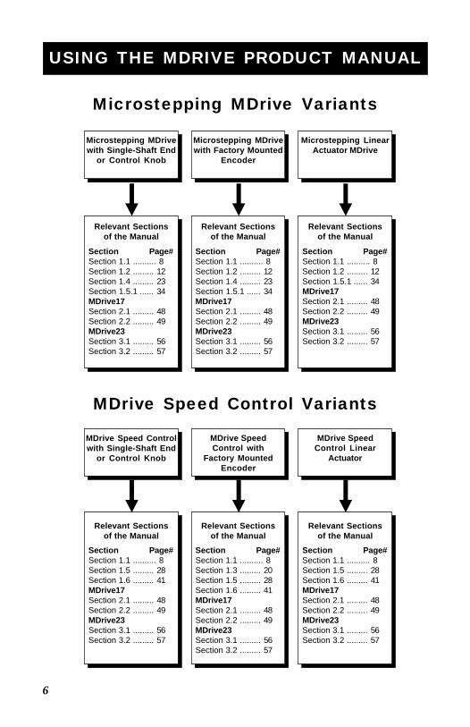
As this document covers all of the variations of the MDrive, please use thechart on the following page to help guide you through the sections of thismanual relevant to the version of the MDrive you purchased.
6
Microstepping MDrive Variants
MDrive Speed Control Variants
Microstepping MDrivewith Single-Shaft End
or Control Knob
Microstepping MDrivewith Factory Mounted
Encoder
Microstepping LinearActuator MDrive
MDrive Speed Controlwith Single-Shaft End
or Control Knob
MDrive SpeedControl with
Factory MountedEncoder
MDrive SpeedControl Linear
Actuator
Section Page#Section 1.1 .......... 8Section 1.2 ......... 12Section 1.4 ......... 23Section 1.5.1 ...... 34MDrive17Section 2.1 ......... 48Section 2.2 ......... 49MDrive23Section 3.1 ......... 56Section 3.2 ......... 57
Section Page#Section 1.1 .......... 8Section 1.2 ......... 12Section 1.5.1 ...... 34MDrive17Section 2.1 ......... 48Section 2.2 ......... 49MDrive23Section 3.1 ......... 56Section 3.2 ......... 57
Section Page#Section 1.1 .......... 8Section 1.2 ......... 12Section 1.4 ......... 23Section 1.5.1 ...... 34MDrive17Section 2.1 ......... 48Section 2.2 ......... 49MDrive23Section 3.1 ......... 56Section 3.2 ......... 57
Section Page#Section 1.1 .......... 8Section 1.5 ......... 28Section 1.6 ......... 41MDrive17Section 2.1 ......... 48Section 2.2 ......... 49MDrive23Section 3.1 ......... 56Section 3.2 ......... 57
Section Page#Section 1.1 .......... 8Section 1.3 ......... 20Section 1.5 ......... 28Section 1.6 ......... 41MDrive17Section 2.1 ......... 48Section 2.2 ......... 49MDrive23Section 3.1 ......... 56Section 3.2 ......... 57
Section Page#Section 1.1 .......... 8Section 1.5 ......... 28Section 1.6 ......... 41MDrive17Section 2.1 ......... 48Section 2.2 ......... 49MDrive23Section 3.1 ......... 56Section 3.2 ......... 57
Relevant Sectionsof the Manual
Relevant Sectionsof the Manual
Relevant Sectionsof the Manual
Relevant Sectionsof the Manual
Relevant Sectionsof the Manual
Relevant Sectionsof the Manual
USING THE MDRIVE PRODUCT MANUAL
7
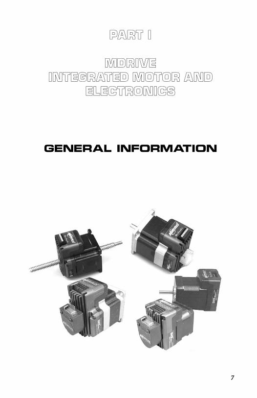
PART I
MDriveIntegrated Motor and
Electronics
General Information
8
S e c t i o n 1 . 1The MDr i v e I n t e g r a l Mo t o r +D r i v e r
S e c t i o n O v e r v i e w
The purpose of this section is to introduce the user to the MDrive integratedhigh torque motor and microstepping driver. Covered are:
Introduction to the Microstepping MDriveMicrostepping MDrive Features and BenefitsIntroduction to the Speed MDrive ControlMDrive Speed Control Features and Benefits
I n t r o d u c t i o n t o t h e M i c r o s t e p p i n g M D r i v e
The MDrive high-torque Integrated Motor and Driver is ideal for designerswho want the simplicity of a motor with on-board electronics, but without theexpense of an indexer on each axis. The low cost MDrive puts the systemdesigner in the driver’s seat to decide the best method of control. The Drive’sintegrated electronics eliminates the need to run the motor cabling through themachine, reducing the potential for problems due to electrical noise.The MDrive uses a NEMA 17 or NEMA 23 1.8° motor combined with amicrostepping drive, and accepts up to 14 resolution settings from 1/2 to 256microsteps per step. Setup parameters include Microstep Resolution, Runand Hold currents, Motor Direction vs. Direction Input and can be changedon-the-fly or downloaded and stored in non-volatile memory with the use of asimple user interface program which is provided, eliminating the need forexternal switches or resistors. Parameters are changed via an SPI (SerialPeripheral Interface) port located on connector P2. This port connects to theprinter port on your PC. Operating voltage for the MDrive17 ranges from+12 to +48 VDC. The MDrive23 is available in two voltage ranges, either +12to +48 or +24 to +75 VDC.The versatile, compact MDrive is available in multiple configurations to fitvarious system needs including a single shaft stand-alone device, a rotarymotor with optical encoder, a planetary gearbox, an Acme screw linearactuator, or with an optional rear knob for hand operation of the motor. Therotary MDrive is available in three different stack lengths: 13, 15 & 19 for theMDrive17; and 18, 22 & 31 for the MDrive23. Interface connections areaccomplished using either a 7 position terminal block, 12” (30.5cm) flyingleads, or optional 12-position keyed and locking pin and receptacle(C Connector).The MDrive is a small, powerful and inexpensive solution that will reducesystem cost, design and assembly time for a large range of stepping motorapplications.
9
I M S M o t o r I n t e r f a c e S o f t w a r e
The IMS Motor Interface Software is accessed through the IMS SPI Interfacewhich is an easy to install and use software program. The SPI Interface isincluded on the CD that ships with the MDrive or is available for download atwww.imshome.com. Use of this utility and the optional 6 foot MD-CC100-000 Parameter Setup Cable is the suggested method of configuring theMDrive17 and MDrive23. Purchase of this cable is recommended with thefirst order as it includes built-in logic level shifting circuitry to make theMDrive17/23 SPI port compatible with all PC LPT (printer) port voltagelevels. The Cable Part # is MD-CC100-000.Features include:
Easy installation.Ease of use via single screen interface.Automatic communication configuration.Will not allow out-of-range values to be set.Tool-tips display valid range settings for each option.
F e a t u r e s a n d B e n e f i t s o f t h e M i c r o s t e p p i n gM D r i v e
Integrated Microstepping Drive/NEMA 17 or 23 Motor+12 to +48 VDC (MD17)/+12 to +48 or +24 to +75 VDC (MD23)Input VoltageLow CostExtremely CompactOptically Isolated Logic InputsAutomatic Current ReductionConfigurable:
Motor Run/Hold CurrentMicrostep Resolution to 256 Microsteps/Step
Available Configurations:Single Shaft*Planetary Gearbox*Linear ActuatorFactory-Mounted Optical Encoder*Double Shaft End with Knob For Manual Positioning*
Available in Three Stack Sizes*Current and Resolution May Be Switched On-The-FlySingle SupplyInterface Uses a Pluggable Terminal Strip, 12” (30.5 cm) FlyingLeads, or 12-Position Keyed and Locking Pin and Receptacle(C Connector)Graphical User Interface (GUI) for Quick and Easy ParameterSetup
*Rotary Motor Only
10
I n t r o d u c t i o n t o t h e M D r i v e S p e e d C o n t r o l
The MDrive Speed Control offers the system designer low cost, intelligentvelocity control integrated with a NEMA 17 or NEMA 23 enhanced torquestepping motor and a +12 to +48 (MD17 and MD23-4) or +24 to +75(MD23-7) volt microstepping drive.The MDrive Speed Control features a digital oscillator for accurate velocitycontrol with an output frequency of up to 100 kilohertz. Output frequencywill vary with the voltage level on the speed control input. The speed controlinput can be adjusted by using one of the following methods:
10k Potentiometer.
0 to +5V applied directly to the input.
15 - 25kHz (0 to 100% duty cycle) PWM applied to the input.
4 - 20mA or 0 - 20mA applied to input.
There are two basic modes of operation: bidirectional and unidirectional. Inbidirectional mode, both speed and direction are controlled by the analogspeed control input. In unidirectional mode, only velocity is controlled by thespeed control input; direction is controlled by a separate digital input.The MDrive Speed Control has 12 setup parameters which are configured byusing the included IMS Speed Control Interface. These enable the user toconfigure all of the operational parameters of the MDrive which are stored innon-volatile memory.The versatile, compact MDrive Speed Control is available in multipleconfigurations to fit various system needs. These options include: a singleshaft stand-alone device, a rotary motor with optical encoder, a planetarygearbox, control knob, or an Acme screw linear actuator. The rotary MDriveSpeed Control is also available in three different stack lengths: 13, 15 and 19for the MD17 and 18, 22 & 31 for the MD23. Interface connections areaccomplished using either a 7 position terminal block or optional 12” (30.5cm)flying leads.S p e e d C o n t r o l I n t e r f a c e
The IMS Speed Control Interface Software is accessed through the IMS SPIInterface which is easy to install and use graphical user interface (GUI) forconfiguring the MDrive from the parallel/SPI port on your computer. It isrequired for configuring your MDrive Speed Control and is included on a CDwith the product, or it may be downloaded at www.imshome.com.The IMS Speed Control Interface Software features include:
Easy installation.
Automatic communication configuration.
Will not set out-of-range values.
Tool-tips display valid range setting for each option.
Ease of use via single screen interface.
11
Features and Benefits of the MDrive Speed Control
Integrated Speed Control, Driver and NEMA17 or 23 Motor+12 to +48 (MDO17 and MDO23-4) or +24 to +75 VDC (MDO23-7)Input VoltageDigital Oscillator for Accurate Speed ControlLow CostExtremely CompactAvailable Configurations:
Single Shaft*Planetary Gearbox*Linear ActuatorFactory-Mounted Optical Encoder*Double Shaft End with Knob For Manual Positioning*
Available in Three Stack Sizes*Electronically Configurable (Eliminates Potentiometers):
Motor Run/Hold CurrentAcceleration/DecelerationInitial and Max VelocityMicrostep Resolution to 256 Microsteps/Step
2 Modes of Operation: Bidirectional or Unidirectional0 to +5 VDC, 4 - 20mA, 0 - 20mA or 15 - 25kHz PWM SpeedControl Input with programmable center pointSingle SupplyInterface Uses Pluggable Terminal Strip or Optional 12” (30.5 cm)Flying LeadsGraphical User Interface (GUI) for Quick and Easy ParameterSetup
*Rotary Motor Only
12
S e c t i o n 1 . 2I n t e r f a c i n g T he M i c r o s t epp i n g MDr i v e
S e c t i o n O v e r v i e w
This section will acquaint the user with connecting and using the microsteppingMDrive products. If your MDrive is equipped with a factory mounted encoder,also refer to Section 1.3: Interfacing an Encoder. Covered in this section are:
Layout and Interface GuidelinesInterfacing Power and Logic Inputs (Connector P1)Interfacing the SPI Interface (Connector P2)
L a y o u t a n d I n t e r f a c e G u i d e l i n e s
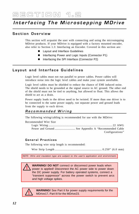
Logic level cables must not run parallel to power cables. Power cables willintroduce noise into the logic level cables and make your system unreliable.
Logic level cables must be shielded to reduce the chance of EMI induced noise.The shield needs to be grounded at the signal source to AC ground. The other endof the shield must not be tied to anything, but allowed to float. This allows theshield to act as a drain.
Power supply leads to the driver need to be twisted. If more than one driver is tobe connected to the same power supply, run separate power and ground leadsfrom the supply to each driver.
R e c o m m e n d e d W i r i n g
The following wiring/cabling is recommended for use with the MDrive:Recommended Wire Size
Logic Wiring ........................................................................................... 22 AWGPower and Ground ............................. See Appendix A “Recommended Cable
Configurations”
G e n e r a l P r a c t i c e s
The following wire strip length is recommended:
Wire Strip Length ................................................................... 0.250” (6.0 mm)
NOTE: Wire and insulation type are subject to the user’s application and environment.
WARNING! DO NOT connect or disconnect power leads whenpower is applied! Disconnect the AC power side to power downthe DC power supply. For battery operated systems, connect a“transient suppressor” across the power switch to prevent arcsand high voltage spikes.
WARNING! See Part II for power supply requirements for theMDrive17, Part III for the MDrive23.
13
OP
TO
SP
PLY
NC
SC
LK
DIR
EN
GN
D
+V
PIN
1
Table 1.2.1: P1 Pin Descriptions for the Microstepping MDrive
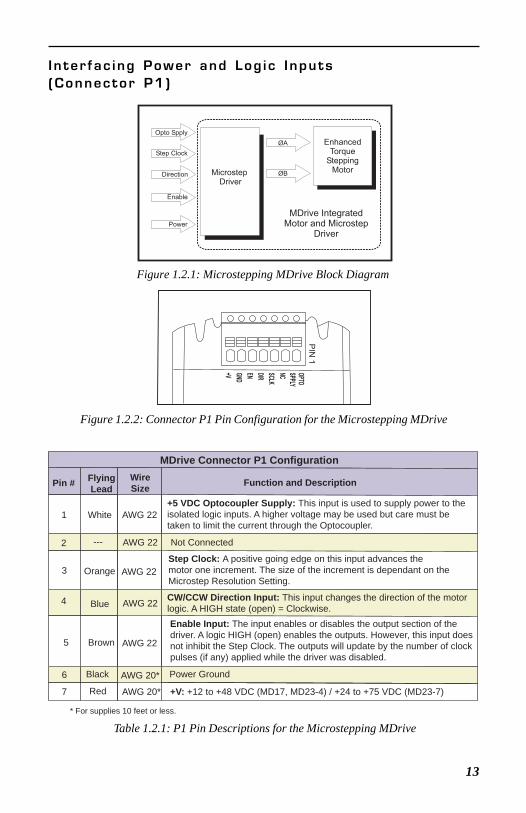
I n ter fac ing Power and Log ic Inputs(Connector P1)
Figure 1.2.2: Connector P1 Pin Configuration for the Microstepping MDrive
EnhancedTorque
SteppingMotorMicrostep
Driver
ØA
ØB
Opto Spply
Step Clock
Direction
Enable
Power
MDrive IntegratedMotor and Microstep
Driver
Figure 1.2.1: Microstepping MDrive Block Diagram
MDrive Connector P1 Configuration
Pin # FlyingLead
WireSize Function and Description
1 White AWG 22+5 VDC Optocoupler Supply: This input is used to supply power to theisolated logic inputs. A higher voltage may be used but care must be taken to limit the current through the Optocoupler.
2 Not Connected
3 Orange AWG 22Step Clock: A positive going edge on this input advances the motor one increment. The size of the increment is dependant on the Microstep Resolution Setting.
4 Blue AWG 22 CW/CCW Direction Input: This input changes the direction of the motorlogic. A HIGH state (open) = Clockwise.
5 Brown AWG 22
Enable Input: The input enables or disables the output section of thedriver. A logic HIGH (open) enables the outputs. However, this input doesnot inhibit the Step Clock. The outputs will update by the number of clockpulses (if any) applied while the driver was disabled.
6 Power Ground
7 Red AWG 20* +V: +12 to +48 VDC (MD17, MD23-4) / +24 to +75 VDC (MD23-7)
* For supplies 10 feet or less.
---
Black
AWG 22
AWG 20*
14
I n t e r f a c i n g t h e M D r i v e L o g i c I n p u t s
L o g i c I n p u t E l e c t r i c a l S p e c i f i c a t i o n s
HCPL0630
HCPL0630
PS2701-1
470
470
750
Optocoupler Supply P1:1+5VDC
Step Clock P1:3
CW/CCW Direction P1:4
Enable/Disable P1:5
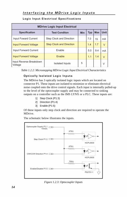
Figure 1.2.3: Optocoupler Inputs
O p t i c a l l y I s o l a t e d L o g i c I n p u t s
The MDrive has 3 optically isolated logic inputs which are located onconnector P1. These inputs are isolated to minimize or eliminate electricalnoise coupled onto the drive control signals. Each input is internally pulled-upto the level of the optocoupler supply and may be connected to sinkingoutputs on a controller such as the IMS LYNX or a PLC. These inputs are:
1] Step Clock (P1:3)2] Direction (P1:4)3] Enable (P1:5)
Of these inputs only step clock and direction are required to operate theMDrive.The schematic below illustrates the inputs.
Table 1.2.2: Microstepping MDrive Logic Input Electrical Characteristics
MDrive Logic Input Electrical
Specification Test Conditon Min Typ Max Unit
Input Foward Current Step Clock and Direction 7.0 15 mA
Input Forward Voltage Step Clock and Direction 1.4 1.7 V
Input Forward Current Enable 5.0 9.4 mA
Input Forward Voltage Enable 1.1 1.4 V
Input Reverse Breakdown
VoltageIsolated Inputs 5 V
15
P o w e r i n g t h e O p t o c o u p l e r s
In order to maintain isolation, the optocouplers must be powered by anexternal power supply connected to P1:1, with the opto supply groundconnected to the ground of the input control circuitry. The logic inputs areinternally limited to allow for a +5VDC power supply.A power supply in excess of +5 volts may be used, however a current limitingresistor MUST be placed in series with the input to limit the input forwardcurrent to the recommended 7 milliamps. At no time can the input forwardcurrent exceed 15 milliamps or damage may occur to the driver portion of theMDrive.
I s o l a t e d L o g i c I n p u t C h a r a c t e r i s t i c s
S t e p C l o c k ( P 1 : 3 )
The step clock input is where the motion clock from your control circuitrywill be connected. The motor will advance one microstep in the plus or minusdirection (based upon the state of the direction input) on the rising edge ofeach clock pulse. The size of this increment or decrement will depend on themicrostep resolution setting.D i r e c t i o n ( P 1 : 4 )
The direction input controls the CW/CCW direction of the motor. A logicHIGH (default, unconnected) will cause the motor to rotate in the CWdirection (seen while looking at the face of the motor). A logic LOW on theinput will cause the motor to rotate in the CCW direction. This input issynchronized to the positive going edge of the Step Clock input.E n a b l e ( P 1 : 5 )
This input can be used to enable or disable the driver output circuitry. Whenin a logic HIGH (default, unconnected) state the driver outputs will be enabledand step clock pulses will cause the motor to advance. When this input ispulled LOW, by means of a switch or sinking output, the driver outputcircuitry will be disabled. Please note that the internal sine/cosine positiongenerator will continue to increment or decrement as long as step clock pulsesare being received by the MDrive.This input is asynchronous to any other input and may be changed at anytime.
WARNING! The isolated logic inputs on the MDrive are internallylimited to allow for an optocoupler supply voltage of +5 VDC. Ifusing a higher voltage supply, a current limiting resistor must beplaced in series with the input or damage will occur to theMDrive’s input circuitry, rendering the drive inoperable.
16
I n p u t T i m i n g
The direction input and the microstep resolution inputs are internallysynchronized to the positive going edge of the step clock input. When a stepclock pulse goes HIGH, the state of the direction input and microstepresolution settings are latched. Any changes made to the direction and/ormicrostep resolution will occur on the rising edge of the step clock pulsefollowing this change.Run and Hold Current changes are updated immediately.The table below lists the timing specifications.
Table 1.2.3: Logic Input Timing
I n t e r f a c e O p t i o n s
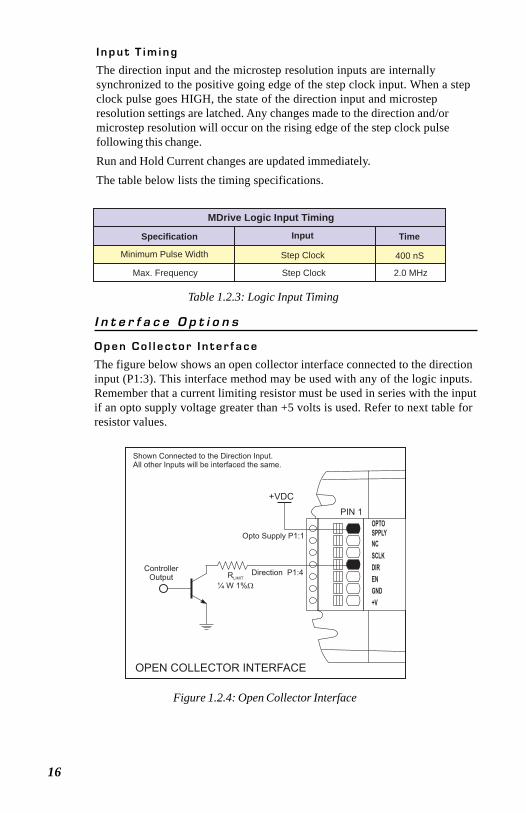
O p e n C o l l e c t o r I n t e r f a c e
The figure below shows an open collector interface connected to the directioninput (P1:3). This interface method may be used with any of the logic inputs.Remember that a current limiting resistor must be used in series with the inputif an opto supply voltage greater than +5 volts is used. Refer to next table forresistor values.
PIN 1
OPTO
SPPLY
NC
SCLK
DIR
EN
GND
+V
+VDC
ControllerOutput R
¼ W 1%LIMIT
Opto Supply P1:1
Direction P1:4
Shown Connected to the Direction Input.All other Inputs will be interfaced the same.
OPEN COLLECTOR INTERFACE
Figure 1.2.4: Open Collector Interface
MDrive Logic Input Timing
Specification Input Time
Minimum Pulse Width Step Clock 400 nS
Max. Frequency Step Clock 2.0 MHz
17Table 1.2.4: Recommended Input Current Limiting Resistor Values
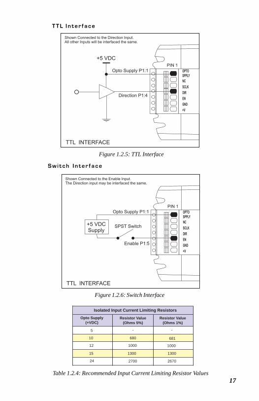
T T L I n t e r f a c e
PIN 1
OPTO
SPPLY
NC
SCLK
DIR
EN
GND
+V
Shown Connected to the Direction Input.All other Inputs will be interfaced the same.
TTL INTERFACE
+5 VDC
Opto Supply P1:1
Direction P1:4
Figure 1.2.5: TTL Interface
S w i t c h I n t e r f a c e
PIN 1
OPTO
SPPLY
NC
SCLK
DIR
EN
GND
+V
Shown Connected to the Enable Input.The Direction input may be interfaced the same.
TTL INTERFACE
+5 VDCSupply
Opto Supply P1:1
SPST Switch
Enable P1:5
Figure 1.2.6: Switch Interface
Isolated Input Current Limiting Resistors
Opto Supply(+VDC)
Resistor Value(Ohms 5%)
Resistor Value(Ohms 1%)
5 - -
10 680 681
12 1000 1000
15 1300 1300
24 2700 2670
18
GND - PIN 5MOSI - PIN 7
PIN 4 - CSPIN 6 +5VDC OUT*
PIN 10 - MISOPIN 8 - CLOCK
10 Pin HeaderP2
DB25 StandardPC Parallel / SPI Port
Ground
PIN 1
2 3 4
15
19
Logic Level Shifting andConditioningInterface
*Use ONLY to power IMS MD-CC100-000
The SPI communication wiring mayrequire a logic level shifting interface.
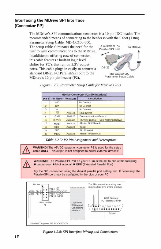
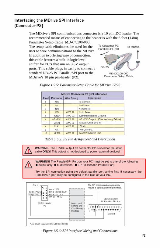
Figure 1.2.8: SPI Interface Wiring and Connections
MDrive Connector P2 (SPI Interface)Pin # Pin Name
No Connect1 N/C
N/CN/C
N/C
23
4
567
8910
AWG 22AWG 22
AWG 22
AWG 22AWG 22
AWG 22
No ConnectNo Connect
DescriptionWire Size
GND+5 VDCMOSICLK
MISO
Chip SelectCommunications Ground+5 VDC Output (See Warning Below)Master Out/Slave InClockNo ConnectMaster In/Slave Out
CS
Table 1.2.5: P2 Pin Assignment and Description
Interfacing the MDrive SPI Interface(Connector P2)
The MDrive’s SPI communications connector is a 10 pin IDC header. Therecommended means of connecting to the header is with the 6 foot (1.8m)Parameter Setup Cable MD-CC100-000.The setup cable eliminates the need for theuser to wire communications to the MDrive.In addition to offering ease of connection,this cable features a built-in logic levelshifter for PC’s that run on 3.3V outputports. This cable plugs in easily to connect astandard DB-25 PC Parallel/SPI port to theMDrive’s 10 pin pin-header (P2).
To MDriveTo Customer PCParallel/SPI Port
MD-CC100-000Parameter Setup Cable
DB-25
Figure 1.2.7: Parameter Setup Cable for MDrive 17/23
WARNING! The +5VDC output on connector P2 is used for the setupcable ONLY! This output is not designed to power external devices!
WARNING! The Parallel/SPI Port on your PC must be set to one of the following: output only bi-directional EPP (Extended Parallel Port)
Try the SPI connection using the default parallel port setting first. If necessary, theParallel/SPI port may be configured in the bios of your PC.
19
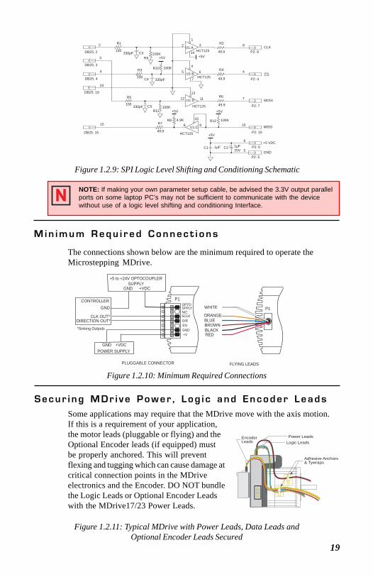
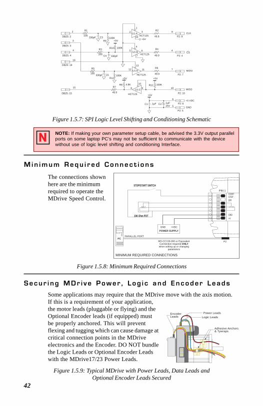
M i n i m u m R e q u i r e d C o n n e c t i o n s
The connections shown below are the minimum required to operate theMicrostepping MDrive.
Figure 1.2.10: Minimum Required Connections
+5 to +24V OPTOCOUPLERSUPPLY
BLUEORANGE
WHITE
REDBLACK
GND +VDC
CONTROLLER
CLK OUT*DIRECTION OUT*
*Sinking Outputs
GND
GND +VDCPOWER SUPPLY
FLYING LEADSPLUGGABLE CONNECTOR
BROWN
P1
P1OPTOSPPLYN/CSCLKDIRENGND+V
S e c u r i n g M D r i v e P o w e r , L o g i c a n d E n c o d e r L e a d s
Figure 1.2.11: Typical MDrive with Power Leads, Data Leads andOptional Encoder Leads Secured
Some applications may require that the MDrive move with the axis motion.If this is a requirement of your application,the motor leads (pluggable or flying) and theOptional Encoder leads (if equipped) mustbe properly anchored. This will preventflexing and tugging which can cause damage atcritical connection points in the MDriveelectronics and the Encoder. DO NOT bundlethe Logic Leads or Optional Encoder Leadswith the MDrive17/23 Power Leads.
EncoderLeads
Power LeadsLogic Leads
Adhesive Anchors & Tywraps
Figure 1.2.9: SPI Logic Level Shifting and Conditioning Schematic
NOTE: If making your own parameter setup cable, be advised the 3.3V output parallelports on some laptop PC’s may not be sufficient to communicate with the devicewithout use of a logic level shifting and conditioning Interface.
U1:A
U1:B
U1:D
U1:C
HCT125
HCT125
HCT125
HCT1252
1
14
45
7
1312 11
10
8 9
6
32 R1
100
+5V
R2
49.9 P2: 8CLK
+5V
P2: 4
P2: 7
P2: 10
P2: 6
P2: 5
CS
MOSI
MISO
+5 VDC
GND5
6
10
7
4
8
3
4
19
DB25: 2
DB25: 3
DB25: 4
DB25: 19
DB25: 15
15
C3330pFR9
100K
R10 100K R4
49.9
R6
49.9
C4 330pF
R3
100
R5
100 C5330pFR11
100K+5V
R12 100K
+5V
R8 4.9KR7
49.9+5V
C1 C2.1µF 1µF25V
+
20
S e c t i o n 1 . 3I n t e r f a c i n g An En code r
S e c t i o n O v e r v i e w
This section will cover interfacing the Factory Mounted Encoder version ofthe Microstepping MDrive17/23. Included are the pin configurations for boththe single-end and differential models and the recommended cables andconnectors.
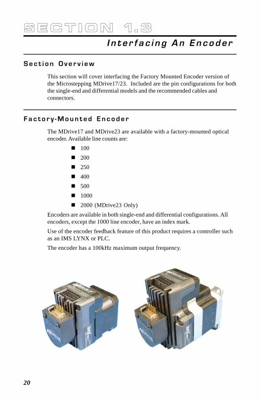
F a c t o r y - M o u n t e d E n c o d e r
The MDrive17 and MDrive23 are available with a factory-mounted opticalencoder. Available line counts are:
10020025040050010002000 (MDrive23 Only)
Encoders are available in both single-end and differential configurations. Allencoders, except the 1000 line encoder, have an index mark.Use of the encoder feedback feature of this product requires a controller suchas an IMS LYNX or PLC.The encoder has a 100kHz maximum output frequency.
21
G e n e r a l S p e c i f i c a t i o n s
Min Typ Max UnitsSupply Voltage (VDC) ............................... -0.5 ................................ 7 ........ VoltsSupply Current ............................................ 30 ............. 57 ............. 85 .......... mAOutput Voltage ........................................... -0.5 .............................. Vcc ...... VoltsOutput Current (Per Channel) ................... -1.0 ................................ 5 ........... mAMaximum Frequency .................................................................................. 100kHzInertia ......................................................... 0.565 g-cm2 (8.0 x 10⁻⁶ oz-in-sec2)Temperature
Operating ........................................................................ -40 to +100° CStorage ............................................................................. -40 to +100° C
Humidity .............................................................................. 90% (noncondensing)
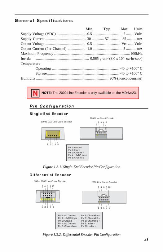
P i n C o n f i g u r a t i o n
S ing le -End Encoder
NOTE: The 2000 Line Encoder is only available on the MDrive23.
D i f f e r e n t i a l E n c o d e r
Figure 1.3.1: Single-End Encoder Pin Configuration
Figure 1.3.2: Differential Encoder Pin Configuration
1 2 3 4 5
2000 Line Count Encoder
1 2 3 4 5
100 to 1000 Line Count Encoder
Pin 1: GroundPin 2: IndexPin 3: Channel APin 4: +5VDC InputPin 5: Channel B
2 4 6 8 10
1 3 5 7 9
2000 Line Count Encoder
2 4 6 8 10
1 3 5 7 9
Pin 1: No ConnectPin 2: +5VDC InputPin 3: GroundPin 4: No ConnectPin 5: Channel A –
Pin 6: Channel A +Pin 7: Channel B –Pin 8: Channel B +Pin 9: Index –Pin 10: Index +
100 to 1000 Line Count Encoder
22
C
t1t2
Po
X Y
Z
2.4 V0.4 V
2.4 V0.4 V
2.4 V0.4 V
Channel A
Channel B
Index
Rotation:100 to 1000 LinesCW – B Leads ACCW – A Leads B
2000 LinesCW – A Leads BCCW – B Leads A
C
t1t2
Po
X Y
Z
2.4 V0.4 V
2.4 V0.4 V
2.4 V0.4 V
2.4 V0.4 V
2.4 V0.4 V
2.4 V0.4 V
Channel A +
Channel B +
Index +
Channel A -
Channel B -
Index -
Rotation:100 to 1000 LinesCW – B Leads ACCW – A Leads B
2000 LinesCW – A Leads BCCW – B Leads A
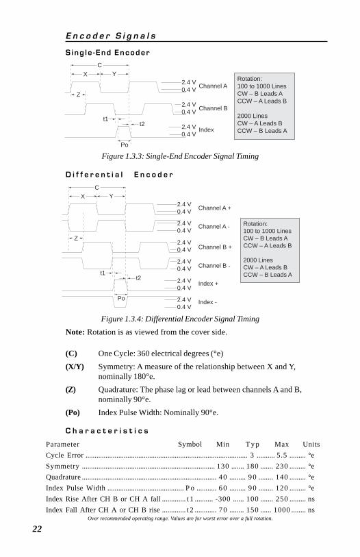
(C) One Cycle: 360 electrical degrees (°e)(X/Y) Symmetry: A measure of the relationship between X and Y,
nominally 180°e.(Z) Quadrature: The phase lag or lead between channels A and B,
nominally 90°e.(Po) Index Pulse Width: Nominally 90°e.
E n c o d e r S i g n a l s
S ing le -End Encoder
D i f f e r e n t i a l E n c o d e r
C h a r a c t e r i s t i c s
Parameter Symbol Min T y p Max UnitsCycle Error ......................................................................................... 3 .......... 5.5 ......... °eSymmetry ......................................................................... 130 ....... 180 ....... 230 ......... °eQuadrature .......................................................................... 40 ......... 90 ........ 140 ......... °eIndex Pulse Width .......................................... P o ........... 60 ......... 90 ........ 120 ......... °eIndex Rise After CH B or CH A fall ............. t 1 .......... -300 ...... 100 ....... 250 ......... nsIndex Fall After CH A or CH B rise ............. t 2 ............ 70 ........ 150 ...... 1000 ........ ns
Over recommended operating range. Values are for worst error over a full rotation.
Figure 1.3.3: Single-End Encoder Signal Timing
Figure 1.3.4: Differential Encoder Signal TimingNote: Rotation is as viewed from the cover side.
23
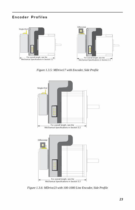
E n c o d e r P r o f i l e s
Figure 1.3.5: MDrive17 with Encoder, Side Profile
Figure 1.3.6: MDrive23 with 100-1000 Line Encoder, Side Profile
For overall length, see the Mechanical Specifications in Section 2.2
Single-EndDifferential
For overall length, see the Mechanical Specifications in Section 2.2
Single-End
For overall length, see the Mechanical Specifications in Section 3.2
For overall length, see the Mechanical Specifications in Section 3.2
Differential
24
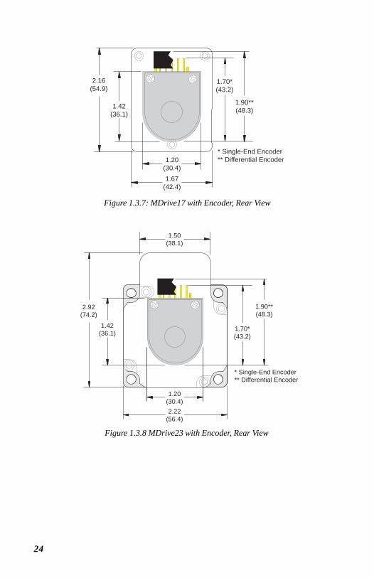
1.20(30.4)
1.50(38.1)
2.22(56.4)
1.70*(43.2)
1.90**(48.3)
2.92(74.2)
* Single-End Encoder** Differential Encoder
1.42(36.1)
Figure 1.3.8 MDrive23 with Encoder, Rear View
1.20(30.4)1.67
(42.4)
1.70*(43.2)
1.90**(48.3)
2.16(54.9)
* Single-End Encoder** Differential Encoder
1.42(36.1)
Figure 1.3.7: MDrive17 with Encoder, Rear View
25
For overall length, see the Mechanical Specifications in Section 3.2
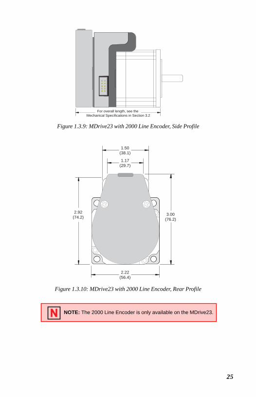
Figure 1.3.9: MDrive23 with 2000 Line Encoder, Side Profile
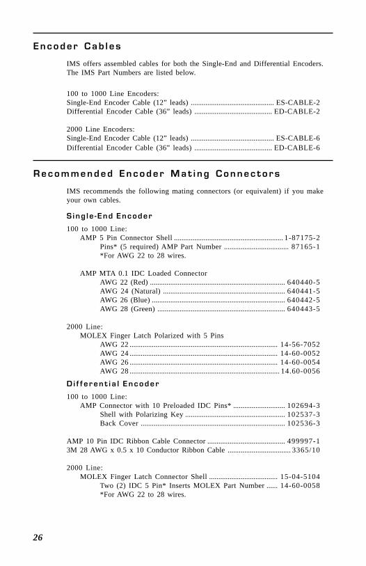
Figure 1.3.10: MDrive23 with 2000 Line Encoder, Rear Profile
NOTE: The 2000 Line Encoder is only available on the MDrive23.
1.50(38.1)
1.17(29.7)
2.22(56.4)
3.00(76.2)
2.92(74.2)
26
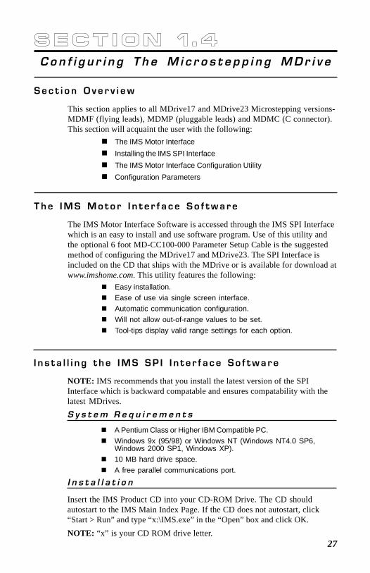
E n c o d e r C a b l e s
IMS offers assembled cables for both the Single-End and Differential Encoders.The IMS Part Numbers are listed below.
100 to 1000 Line Encoders:Single-End Encoder Cable (12” leads) ............................................. ES-CABLE-2Differential Encoder Cable (36” leads) .......................................... ED-CABLE-2
2000 Line Encoders:Single-End Encoder Cable (12” leads) ............................................. ES-CABLE-6Differential Encoder Cable (36” leads) .......................................... ED-CABLE-6
R e c o m m e n d e d E n c o d e r M a t i n g C o n n e c t o r s
IMS recommends the following mating connectors (or equivalent) if you makeyour own cables.
S ing le -End Encoder
100 to 1000 Line:AMP 5 Pin Connector Shell ........................................................... 1-87175-2
Pins* (5 required) AMP Part Number ................................... 87165-1*For AWG 22 to 28 wires.
AMP MTA 0.1 IDC Loaded ConnectorAWG 22 (Red) ......................................................................... 640440-5AWG 24 (Natural) .................................................................. 640441-5AWG 26 (Blue) ........................................................................ 640442-5AWG 28 (Green) ..................................................................... 640443-5
2000 Line:MOLEX Finger Latch Polarized with 5 Pins
AWG 22 ................................................................................ 14-56-7052AWG 24 ................................................................................ 14-60-0052AWG 26 ................................................................................ 14-60-0054AWG 28 ................................................................................. 14.60-0056
D i f f e r e n t i a l E n c o d e r
100 to 1000 Line:AMP Connector with 10 Preloaded IDC Pins* ............................ 102694-3
Shell with Polarizing Key ...................................................... 102537-3Back Cover .............................................................................. 102536-3
AMP 10 Pin IDC Ribbon Cable Connector .......................................... 499997-13M 28 AWG x 0.5 x 10 Conductor Ribbon Cable .................................. 3365/10
2000 Line:MOLEX Finger Latch Connector Shell ..................................... 15-04-5104
Two (2) IDC 5 Pin* Inserts MOLEX Part Number ...... 14-60-0058*For AWG 22 to 28 wires.
27
S e c t i o n 1 . 4C o n f i g u r i n g T h e M i c r o s t e p p i n g M D r i v e
S e c t i o n O v e r v i e w
This section applies to all MDrive17 and MDrive23 Microstepping versions-MDMF (flying leads), MDMP (pluggable leads) and MDMC (C connector).This section will acquaint the user with the following:
The IMS Motor InterfaceInstalling the IMS SPI InterfaceThe IMS Motor Interface Configuration UtilityConfiguration Parameters
T h e I M S M o t o r I n t e r f a c e S o f t w a r e
The IMS Motor Interface Software is accessed through the IMS SPI Interfacewhich is an easy to install and use software program. Use of this utility andthe optional 6 foot MD-CC100-000 Parameter Setup Cable is the suggestedmethod of configuring the MDrive17 and MDrive23. The SPI Interface isincluded on the CD that ships with the MDrive or is available for download atwww.imshome.com. This utility features the following:
Easy installation.Ease of use via single screen interface.Automatic communication configuration.Will not allow out-of-range values to be set.Tool-tips display valid range settings for each option.
I n s t a l l i n g t h e I M S S P I I n t e r f a c e S o f t w a r e
NOTE: IMS recommends that you install the latest version of the SPIInterface which is backward compatable and ensures compatability with thelatest MDrives.S y s t e m R e q u i r e m e n t s
A Pentium Class or Higher IBM Compatible PC.Windows 9x (95/98) or Windows NT (Windows NT4.0 SP6,Windows 2000 SP1, Windows XP).10 MB hard drive space.A free parallel communications port.
I n s t a l l a t i o n
Insert the IMS Product CD into your CD-ROM Drive. The CD shouldautostart to the IMS Main Index Page. If the CD does not autostart, click“Start > Run” and type “x:\IMS.exe” in the “Open” box and click OK.NOTE: “x” is your CD ROM drive letter.
28
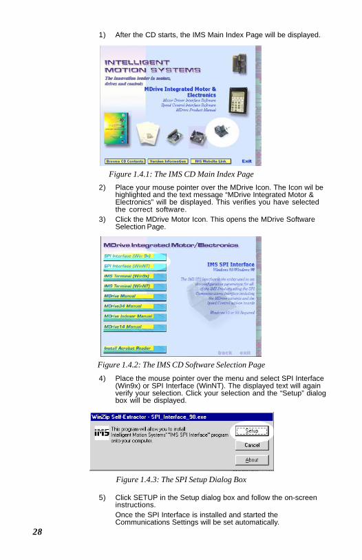
1) After the CD starts, the IMS Main Index Page will be displayed.
2) Place your mouse pointer over the MDrive Icon. The Icon wil behighlighted and the text message “MDrive Integrated Motor &Electronics” will be displayed. This verifies you have selectedthe correct software.
3) Click the MDrive Motor Icon. This opens the MDrive SoftwareSelection Page.
4) Place the mouse pointer over the menu and select SPI Interface(Win9x) or SPI Interface (WinNT). The displayed text will againverify your selection. Click your selection and the “Setup” dialogbox will be displayed.
5) Click SETUP in the Setup dialog box and follow the on-screeninstructions.Once the SPI Interface is installed and started theCommunications Settings will be set automatically.
Figure 1.4.1: The IMS CD Main Index Page
Figure 1.4.2: The IMS CD Software Selection Page
Figure 1.4.3: The SPI Setup Dialog Box
29
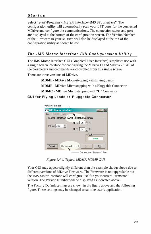
S t a r t u p
Select “Start>Programs>IMS SPI Interface>IMS SPI Interface”. Theconfiguration utility will automatically scan your LPT ports for the connectedMDrive and configure the communications. The connection status and portare displayed at the bottom of the configuration screen. The Version Numberof the Firmware in your MDrive will also be displayed at the top of theconfiguration utility as shown below.
T h e I M S M o t o r I n t e r f a c e G U I C o n f i g u r a t i o n U t i l i t y
The IMS Motor Interface GUI (Graphical User Interface) simplifies use witha single screen interface for configuring the MDrive17 and MDrive23. All ofthe parameters and commands are controlled from this single screen.There are three versions of MDrive.
MDMF - MDrive Microstepping with Flying LeadsMDMP - MDrive Microstepping with a Pluggable ConnectorMDMC - MDrive Microstepping with “C” Connector
G U I f o r F l y i n g L e a d s o r P l u g g a b l e C o n n e c t o r
Figure 1.4.4: Typical MDMF, MDMP GUI
Your GUI may appear slightly different than the example shown above due todifferent versions of MDrive Firmware. The Firmware is not upgradable butthe IMS Motor Interface will configure itself to your current Firmwareversion. The Version Number will be displayed as indicated above.The Factory Default settings are shown in the figure above and the followingfigure. These settings may be changed to suit the user’s application.
Connection Status & Port
Version Number
30
Parameter changes turn blue...
...then click "Set"
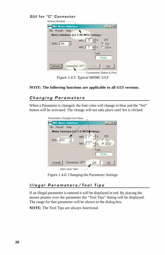
C h a n g i n g P a r a m e t e r s
When a Parameter is changed, the font color will change to blue and the “Set”button will be activated. The change will not take place until Set is clicked.
Figure 1.4.6: Changing the Parameter Settings
Figure 1.4.5: Typical MDMC GUI
G U I f o r “ C ” C o n n e c t o r
Connection Status & Port
Version Number
I l l e g a l P a r a m e t e r s / To o l T i p s
If an illegal parameter is entered it will be displayed in red. By placing themouse pointer over the parameter the “Tool Tips” dialog will be displayed.The range for that parameter will be shown in the dialog box.NOTE: The Tool Tips are always functional.
NOTE: The following functions are applicable to all GUI versions.
31
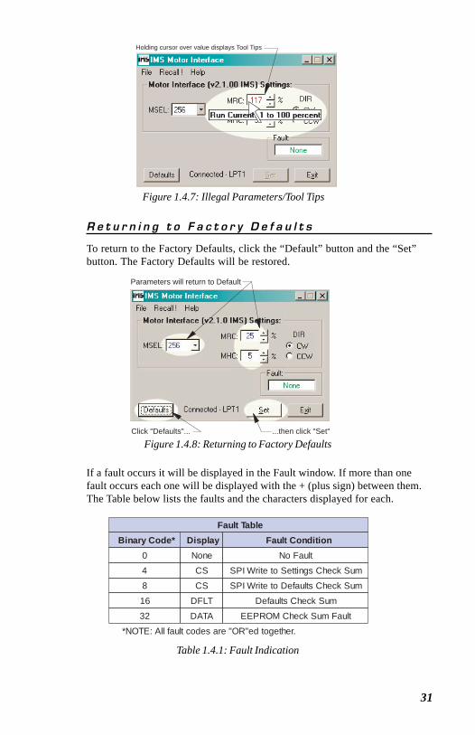
Figure 1.4.8: Returning to Factory Defaults
R e t u r n i n g t o F a c t o r y D e f a u l t s
To return to the Factory Defaults, click the “Default” button and the “Set”button. The Factory Defaults will be restored.
Table 1.4.1: Fault Indication
If a fault occurs it will be displayed in the Fault window. If more than onefault occurs each one will be displayed with the + (plus sign) between them.The Table below lists the faults and the characters displayed for each.
Click "Defaults"... ...then click "Set"
Parameters will return to Default
Fault TableBinary Code* Display Fault Condition
0 None No Fault
4 CS SPI Write to Settings Check Sum
8 CS SPI Write to Defaults Check Sum
16 DFLT Defaults Check Sum
32 DATA EEPROM Check Sum Fault
*NOTE: All fault codes are "OR"ed together.
Holding cursor over value displays Tool Tips
Figure 1.4.7: Illegal Parameters/Tool Tips
32
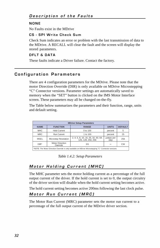
C o n f i g u r a t i o n P a r a m e t e r s
There are 4 configuration parameters for the MDrive. Please note that themotor Direction Override (DIR) is only available on MDrive Microstepping“C” Connector versions. Parameter settings are automatically saved tomemory when the “SET” button is clicked on the IMS Motor Interfacescreen. These parameters may all be changed on-the-fly.The Table below summarizes the parameters and their function, range, unitsand default setting.
MDrive Setup Parameters
NAME FUNCTION RANGE UNITS DEFAULT
MHC Hold Current 0 to 100 percent 5
MRC Run Current 1 to 100 percent 25
MSEL Microstep Resolution 2, 4, 5, 8, 10, 16, 25, 32, 50, 64,125, 128, 250, 256
µsteps perstep 256
DIR* Motor DirectionOverride 0/1 CW
*NOTE: The Motor Direction Override is only available on MDrive Microstepping "C" Connector versions.
–
Table 1.4.2: Setup Parameters
M o t o r H o l d i n g C u r r e n t ( M H C )
The MHC parameter sets the motor holding current as a percentage of the fulloutput current of the driver. If the hold current is set to 0, the output circuitryof the driver section will disable when the hold current setting becomes active.The hold current setting becomes active 200ms following the last clock pulse.M o t o r R u n C u r r e n t ( M R C )
The Motor Run Current (MRC) parameter sets the motor run current to apercentage of the full output current of the MDrive driver section.
D e s c r i p t i o n o f t h e F a u l t s
N O N E
No Faults exist in the MDriveC S - S P I W r i t e C h e c k S u m
Check Sum indicates an error or problem with the last transmission of data tothe MDrive. A RECALL will clear the fault and the screen will display thestored parameters.D F L T & D A T A
These faults indicate a Driver failure. Contact the factory.
33
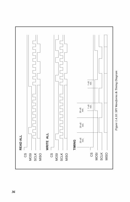
T i m i n g N o t e s
1) MSb (most significant bit) and MSB (most significant byte) first2) 8 bit bytes3) 25kHz SCK4) Data In (MOSI) on rising clock5) Data Out (MISO) on falling clock
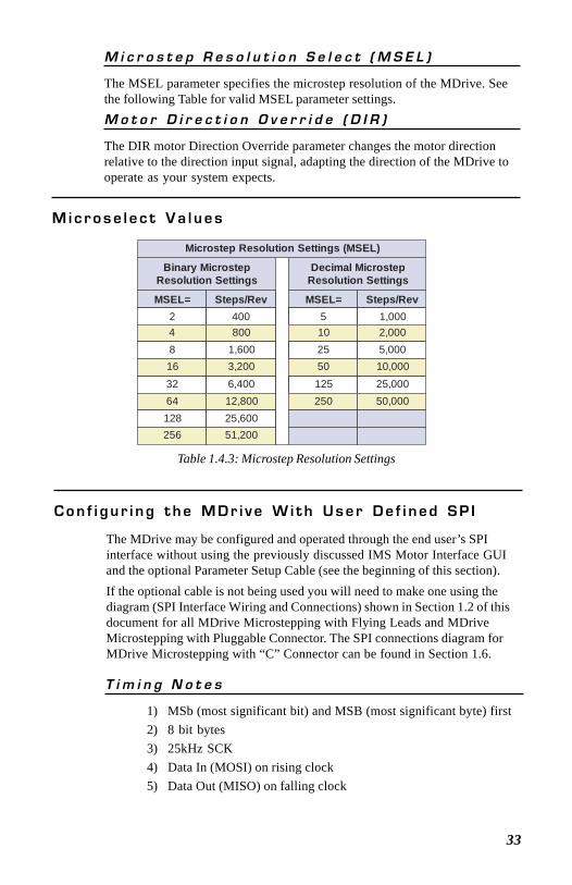
Microstep Resolution Settings (MSEL)
Binary MicrostepResolution Settings
Decimal MicrostepResolution Settings
MSEL= Steps/Rev MSEL= Steps/Rev2 400 5 1,0004 800 10 2,0008 1,600 25 5,00016 3,200 50 10,00032 6,400 125 25,00064 12,800 250 50,000128 25,600256 51,200
C o n f i g u r i n g t h e M D r i v e W i t h U s e r D e f i n e d S P I
The MDrive may be configured and operated through the end user’s SPIinterface without using the previously discussed IMS Motor Interface GUIand the optional Parameter Setup Cable (see the beginning of this section).If the optional cable is not being used you will need to make one using thediagram (SPI Interface Wiring and Connections) shown in Section 1.2 of thisdocument for all MDrive Microstepping with Flying Leads and MDriveMicrostepping with Pluggable Connector. The SPI connections diagram forMDrive Microstepping with “C” Connector can be found in Section 1.6.
Table 1.4.3: Microstep Resolution Settings
M i c r o s e l e c t V a l u e s
M i c r o s t e p R e s o l u t i o n S e l e c t ( M S E L )
The MSEL parameter specifies the microstep resolution of the MDrive. Seethe following Table for valid MSEL parameter settings.M o t o r D i r e c t i o n O v e r r i d e ( D I R )
The DIR motor Direction Override parameter changes the motor directionrelative to the direction input signal, adapting the direction of the MDrive tooperate as your system expects.
34
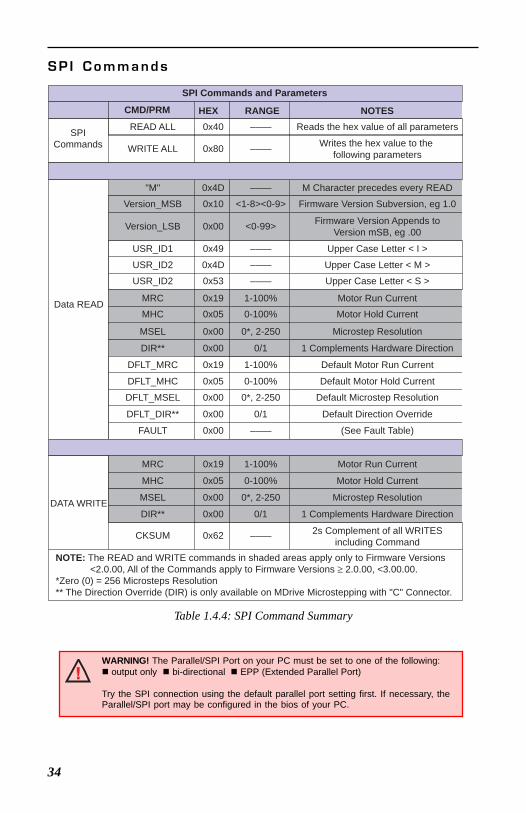
Table 1.4.4: SPI Command Summary
S P I C o m m a n d s
SPI Commands and Parameters
CMD/PRM HEX RANGE NOTES
SPICommands
Data READ
DATA WRITE
READ ALL
WRITE ALL
"M"
Version_MSB
Version_LSB
USR_ID1
USR_ID2
USR_ID2
MRC
MHC
MSEL
DIR**
DFLT_MRC
DFLT_MHC
DFLT_MSEL
DFLT_DIR**
FAULT
MRC
MHC
MSEL
DIR**
CKSUM
0x40
0x80
0x4D
0x10
0x00
0x49
0x4D
0x53
0x19
0x05
0x00
0x00
0x19
0x05
0x00
0x00
0x00
0x19
0x05
0x00
0x00
0x62
––––
––––
––––
<1-8><0-9>
<0-99>
––––
––––
––––
1-100%
0-100%
0*, 2-250
0/1
1-100%
0-100%
0*, 2-250
0/1
––––
1-100%
0-100%
0*, 2-250
0/1
––––
Reads the hex value of all parameters
Writes the hex value to the following parameters
M Character precedes every READ
Firmware Version Subversion, eg 1.0
Firmware Version Appends toVersion mSB, eg .00
Upper Case Letter < I >
Upper Case Letter < M >
Upper Case Letter < S >
Motor Run Current
Motor Hold Current
Microstep Resolution
1 Complements Hardware Direction
Default Motor Run Current
Default Motor Hold Current
Default Microstep Resolution
Default Direction Override
(See Fault Table)
Motor Run Current
Motor Hold Current
Microstep Resolution
1 Complements Hardware Direction
2s Complement of all WRITESincluding Command
NOTE: The READ and WRITE commands in shaded areas apply only to Firmware Versions <2.0.00, All of the Commands apply to Firmware Versions ≥ 2.0.00, <3.00.00.*Zero (0) = 256 Microsteps Resolution** The Direction Override (DIR) is only available on MDrive Microstepping with "C" Connector.
WARNING! The Parallel/SPI Port on your PC must be set to one of the following: output only bi-directional EPP (Extended Parallel Port)
Try the SPI connection using the default parallel port setting first. If necessary, theParallel/SPI port may be configured in the bios of your PC.
35
S P I R e a d / W r i t e E x a m p l e
READ ALL
MOSI:
MISO:
WRITE ALL
MOSI:
MISO:
FAULTDFLT_DIR_OVRIDDFLT_MSELDFLT_MHCDFLT_MRCDIR_OVRIDMSELMHCMRCUSR_ID3USR_ID2USR_ID1VERSIONDEVICE
MRCMHCMSELDIR_OVRIDCKSUM
0005250256525SMI1.0.00M
255256062
80 19 05 00 00 62
XX FF FF FF FF FF
FF FF40 FFFFFFFFFFFFFFFFFFFFFFFFFF
104D 00 49 4D 53 19 05 00 00 19 05 00 00 00XX
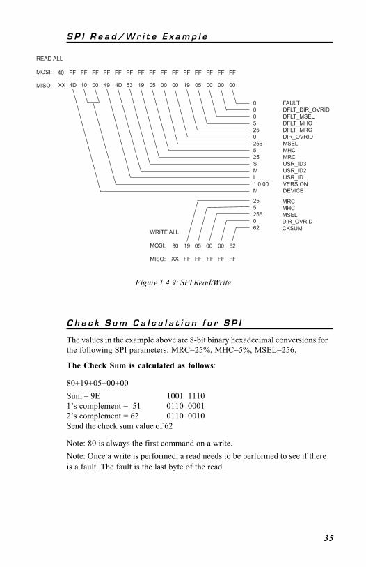
Figure 1.4.9: SPI Read/Write
C h e c k S u m C a l c u l a t i o n f o r S P I
The values in the example above are 8-bit binary hexadecimal conversions forthe following SPI parameters: MRC=25%, MHC=5%, MSEL=256.
The Check Sum is calculated as follows:
80+19+05+00+00Sum = 9E 1001 11101’s complement = 51 0110 00012’s complement = 62 0110 0010Send the check sum value of 62
Note: 80 is always the first command on a write.Note: Once a write is performed, a read needs to be performed to see if thereis a fault. The fault is the last byte of the read.
36
Figu
re 1
.4.1
0: S
PI W
avef
orm
s & T
imin
g D
iagr
am
37
S e c t i o n 1 . 5I n t e r f a c i n g T h e MDr i v e Sp e ed Con t r o l
S e c t i o n O v e r v i e w
This section covers the hardware interface of the MDrive versions withintegrated speed control electronics. Refer to Section 1.6 for Parameter setupand configuration. Covered in the section are:
Layout and Interface GuidelinesInterfacing Power and Speed Control Inputs (Connector P1)Interfacing the SPI Interface (Connector P2)
L a y o u t a n d I n t e r f a c e G u i d e l i n e s
Logic level cables must not run parallel to power cables. Power cables willintroduce noise into the logic level cables and make your system unreliable.Logic level cables must be shielded to reduce the chance of EMI induced noise.The shield needs to be grounded at the signal source to AC ground. The otherend of the shield must not be tied to anything, but allowed to float. Thisallows the shield to act as a drain.Power supply leads to the driver need to be twisted. If more than one MDriveis to be connected to the same power supply, run separate power and groundleads from the supply to each MDrive.
R e c o m m e n d e d W i r i n g
The following wiring/cabling is recommended for use with the MDrive:Recommended Wire Size
Logic Wiring ............................................................................... 22 AWGPower and Ground .................... See Appendix A “Recommended Cable
Configurations”
G e n e r a l P r a c t i c e s
The following wire strip length is recommended:Wire Strip Length ........................................................... 0.250” (6.0 mm)
NOTE: Wire and insulation type are subject to the user’s application and environment.
WARNING! DO NOT connect or disconnect power leads whenpower is applied! Disconnect the AC power side to power downthe DC power supply. For battery operated systems, connect a“transient suppressor” across the power switch to prevent arcsand high voltage spikes.
WARNING! See Part II for power supply requirements for theMDrive17, Part III for the MDrive23.
38
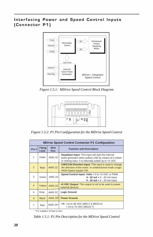
I n t e r f a c i n g P o w e r a n d S p e e d C o n t r o l I n p u t s( C o n n e c t o r P 1 )
STA
RT
STO
P
DIR
GN
D
+V
PIN
1
Figure 1.5.2: P1 Pin Configuration for the MDrive Speed Control
Table 1.5.1: P1 Pin Description for the MDrive Speed Control
InternalClock PulseGenerator
EnhancedTorque
SteppingMotor
Microstep Driver
Step Clock
ØA
ØB
Start/Stop
Speed In
Direction
Enable
Power
MDrive + IntegratedSpeed Control
Figure 1.5.1: MDrive Speed Control Block Diagram
MDrive Speed Control Connector P1 Configuration
Pin # FlyingLead
WireSize
Function and Description
1 AWG 22VioletStop/Start Input: This input will start the internalpulse generator when pulled LOW by means of a switchor sinking input. It is internally pulled up to +5 VDC.
2 Blue AWG 22CW/CCW Direction Input: This input is used to changethe direction of the motor. In unidirectional mode a logicHIGH (open) equals CW.
3 Green AWG 22Speed Control Input: Volts = 0 to +5 VDC or PWM 4 - 20 mA = 4 - 20 mA Input 0 - 20 mA = 0 - 20 mA Input
4 Yellow AWG 22 +5 VDC Output: This output is not to be used to powerexternal devices.
5 Gray AWG 22 Logic Ground
6 Black AWG 20* Power Ground
7 Red AWG 20* +V: +12 to 48 VDC (MD17 & MD23-4) + 24 to 75 VDC (MD23-7)
* For supplies 10 feet or less.
39
STOP/START SWITCH
DIRECTION SWITCH
10KOhm POT
P1
PIN 1STARTSTOP
DIR
IN
+5V
COM
GND
+V
FLYING LEADSPLUGGABLE CONNECTOR
P1VIOLET
BLUE
GREEN
YELLOW
GRAY
BLACK
RED
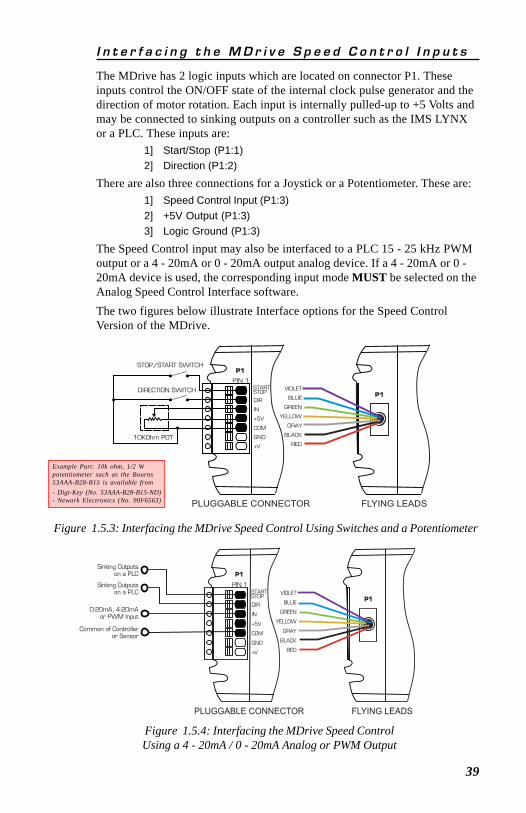
I n t e r f a c i n g t h e M D r i v e S p e e d C o n t r o l I n p u t s
The MDrive has 2 logic inputs which are located on connector P1. Theseinputs control the ON/OFF state of the internal clock pulse generator and thedirection of motor rotation. Each input is internally pulled-up to +5 Volts andmay be connected to sinking outputs on a controller such as the IMS LYNXor a PLC. These inputs are:
1] Start/Stop (P1:1)2] Direction (P1:2)
There are also three connections for a Joystick or a Potentiometer. These are:1] Speed Control Input (P1:3)2] +5V Output (P1:3)3] Logic Ground (P1:3)
The Speed Control input may also be interfaced to a PLC 15 - 25 kHz PWMoutput or a 4 - 20mA or 0 - 20mA output analog device. If a 4 - 20mA or 0 -20mA device is used, the corresponding input mode MUST be selected on theAnalog Speed Control Interface software.The two figures below illustrate Interface options for the Speed ControlVersion of the MDrive.
Figure 1.5.3: Interfacing the MDrive Speed Control Using Switches and a Potentiometer
Sinking Outputson a PLC P1
PIN 1STARTSTOP
DIR
IN
+5V
COM
GND
+V
FLYING LEADSPLUGGABLE CONNECTOR
P1VIOLET
BLUE
GREEN
YELLOW
GRAY
BLACK
RED
Sinking Outputson a PLC
0-20mA, 4-20mAor PWM Input
Common of Controlleror Sensor
Figure 1.5.4: Interfacing the MDrive Speed ControlUsing a 4 - 20mA / 0 - 20mA Analog or PWM Output
Example Part: 10k ohm, 1/2 Wpotentiometer such as the Bourns53AAA-B28-B15 is available from- Digi-Key (No. 53AAA-B28-B15-ND)- Newark Electronics (No. 90F6563)
40
V e l o c i t y C o n t r o l I n p u t C h a r a c t e r i s t i c s
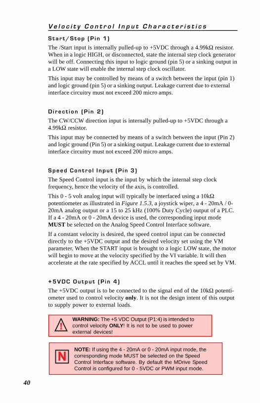
S t a r t / S t o p ( P i n 1 )
The /Start input is internally pulled-up to +5VDC through a 4.99kΩ resistor.When in a logic HIGH, or disconnected, state the internal step clock generatorwill be off. Connecting this input to logic ground (pin 5) or a sinking output ina LOW state will enable the internal step clock oscillator.This input may be controlled by means of a switch between the input (pin 1)and logic ground (pin 5) or a sinking output. Leakage current due to externalinterface circuitry must not exceed 200 micro amps.
D i r e c t i o n ( P i n 2 )
The CW/CCW direction input is internally pulled-up to +5VDC through a4.99kΩ resistor.This input may be connected by means of a switch between the input (Pin 2)and logic ground (Pin 5) or a sinking output. Leakage current due to externalinterface circuitry must not exceed 200 micro amps.
S p e e d C o n t r o l I n p u t ( P i n 3 )
The Speed Control input is the input by which the internal step clockfrequency, hence the velocity of the axis, is controlled.This 0 - 5 volt analog input will typically be interfaced using a 10kΩpotentiometer as illustrated in Figure 1.5.3, a joystick wiper, a 4 - 20mA / 0-20mA analog output or a 15 to 25 kHz (100% Duty Cycle) output of a PLC.If a 4 - 20mA or 0 - 20mA device is used, the corresponding input modeMUST be selected on the Analog Speed Control Interface software.If a constant velocity is desired, the speed control input can be connecteddirectly to the +5VDC output and the desired velocity set using the VMparameter. When the START input is brought to a logic LOW state, the motorwill begin to move at the velocity specified by the VI variable. It will thenaccelerate at the rate specified by ACCL until it reaches the speed set by VM.
+ 5 V D C O u t p u t ( P i n 4 )
The +5VDC output is to be connected to the signal end of the 10kΩ potenti-ometer used to control velocity only. It is not the design intent of this outputto supply power to external loads.
NOTE: If using the 4 - 20mA or 0 - 20mA input mode, thecorresponding mode MUST be selected on the SpeedControl Interface software. By default the MDrive SpeedControl is configured for 0 - 5VDC or PWM input mode.
WARNING: The +5 VDC Output (P1:4) is intended tocontrol velocity ONLY! It is not to be used to powerexternal devices!
41
Interfacing the MDrive SPI Interface(Connector P2)
The MDrive’s SPI communications connector is a 10 pin IDC header. Therecommended means of connecting to the header is with the 6 foot (1.8m)Parameter Setup Cable MD-CC100-000.The setup cable eliminates the need for theuser to wire communications to the MDrive.In addition to offering ease of connection,this cable features a built-in logic levelshifter for PC’s that run on 3.3V outputports. This cable plugs in easily to connect astandard DB-25 PC Parallel/SPI port to theMDrive’s 10 pin pin-header (P2).
To MDriveTo Customer PCParallel/SPI Port
MD-CC100-000Parameter Setup Cable
DB-25
GND - PIN 5MOSI - PIN 7
PIN 4 - CSPIN 6 +5VDC OUT*
PIN 10 - MISOPIN 8 - CLOCK
10 Pin HeaderP2
DB25 StandardPC Parallel / SPI Port
Ground
PIN 1
2 3 4
15
19
Logic Level Shifting andConditioningInterface
*Use ONLY to power IMS MD-CC100-000
The SPI communication wiring mayrequire a logic level shifting interface.
MDrive Connector P2 (SPI Interface)Pin # Pin Name
No Connect1 N/C
N/CN/C
N/C
23
4
567
8910
AWG 22AWG 22
AWG 22
AWG 22AWG 22
AWG 22
No ConnectNo Connect
DescriptionWire Size
CSGND
+5 VDCMOSICLK
MISO
Chip SelectCommunications Ground+5 VDC Output (See Warning Below)Master Out/Slave InClockNo ConnectMaster In/Slave Out
Table 1.5.2: P2 Pin Assignment and Description
Figure 1.5.6: SPI Interface Wiring and Connections
Figure 1.5.5: Parameter Setup Cable for MDrive 17/23
WARNING! The +5VDC output on connector P2 is used for the setupcable ONLY! This output is not designed to power external devices!
WARNING! The Parallel/SPI Port on your PC must be set to one of the following: output only bi-directional EPP (Extended Parallel Port)
Try the SPI connection using the default parallel port setting first. If necessary, theParallel/SPI port may be configured in the bios of your PC.
42
M i n i m u m R e q u i r e d C o n n e c t i o n s
PIN 1
MINIMUM REQUIRED CONNECTIONS
POWER SUPPLY
PC
+VDC
P2
GND
PARALLEL PORT
MD-CC100-000 or EquivalentConnection required when setting up or changing
parameters
ONLY
STARTSTOPDIR
GND+V
STOP/START SWITCH
10K Ohm POT
Figure 1.5.8: Minimum Required Connections
Figure 1.5.7: SPI Logic Level Shifting and Conditioning Schematic
U1:A
U1:B
U1:D
U1:C
HCT125
HCT125
HCT125
HCT1252
1
14
45
7
1312 11
10
8 9
6
32 R1
100
+5V
R2
49.9 P2: 8CLK
+5V
P2: 4
P2: 7
P2: 10
P2: 6
P2: 5
CS
MOSI
MISO
+5 VDC
GND5
6
10
7
4
8
3
4
19
DB25: 2
DB25: 3
DB25: 4
DB25: 19
DB25: 15
15
C3330pFR9
100K
R10 100K R4
49.9
R6
49.9
C4 330pF
R3
100
R5
100 C5330pFR11
100K+5V
R12 100K
+5V
R8 4.9KR7
49.9+5V
C1 C2.1µF 1µF25V
+
NOTE: If making your own parameter setup cable, be advised the 3.3V output parallelports on some laptop PC’s may not be sufficient to communicate with the devicewithout use of logic level shifting and conditioning Interface.
S e c u r i n g M D r i v e P o w e r , L o g i c a n d E n c o d e r L e a d s
Figure 1.5.9: Typical MDrive with Power Leads, Data Leads andOptional Encoder Leads Secured
Some applications may require that the MDrive move with the axis motion.If this is a requirement of your application,the motor leads (pluggable or flying) and theOptional Encoder leads (if equipped) mustbe properly anchored. This will preventflexing and tugging which can cause damage atcritical connection points in the MDriveelectronics and the Encoder. DO NOT bundlethe Logic Leads or Optional Encoder Leadswith the MDrive17/23 Power Leads.
EncoderLeads
Power LeadsLogic Leads
Adhesive Anchors & Tywraps
The connections shownhere are the minimumrequired to operate theMDrive Speed Control.
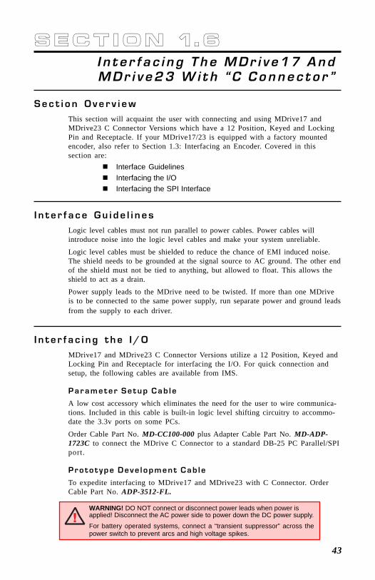
43
S e c t i o n 1 . 6I n t e r f a c i n g T h e MDr i v e17 AndMDr i v e23 W i t h “ C Conne c t o r ”
S e c t i o n O v e r v i e wThis section will acquaint the user with connecting and using MDrive17 andMDrive23 C Connector Versions which have a 12 Position, Keyed and LockingPin and Receptacle. If your MDrive17/23 is equipped with a factory mountedencoder, also refer to Section 1.3: Interfacing an Encoder. Covered in thissection are:
Interface GuidelinesInterfacing the I/OInterfacing the SPI Interface
I n t e r f a c e G u i d e l i n e sLogic level cables must not run parallel to power cables. Power cables willintroduce noise into the logic level cables and make your system unreliable.
Logic level cables must be shielded to reduce the chance of EMI induced noise.The shield needs to be grounded at the signal source to AC ground. The other endof the shield must not be tied to anything, but allowed to float. This allows theshield to act as a drain.
Power supply leads to the MDrive need to be twisted. If more than one MDriveis to be connected to the same power supply, run separate power and ground leadsfrom the supply to each driver.
I n t e r f a c i n g t h e I / OMDrive17 and MDrive23 C Connector Versions utilize a 12 Position, Keyed andLocking Pin and Receptacle for interfacing the I/O. For quick connection andsetup, the following cables are available from IMS.
P a r a m e t e r S e t u p C a b l e
A low cost accessory which eliminates the need for the user to wire communica-tions. Included in this cable is built-in logic level shifting circuitry to accommo-date the 3.3v ports on some PCs.
Order Cable Part No. MD-CC100-000 plus Adapter Cable Part No. MD-ADP-1723C to connect the MDrive C Connector to a standard DB-25 PC Parallel/SPIport.
P r o t o t y p e D e v e l o p m e n t C a b l e
To expedite interfacing to MDrive17 and MDrive23 with C Connector. OrderCable Part No. ADP-3512-FL.
WARNING! DO NOT connect or disconnect power leads when power isapplied! Disconnect the AC power side to power down the DC power supply.For battery operated systems, connect a “transient suppressor” across thepower switch to prevent arcs and high voltage spikes.
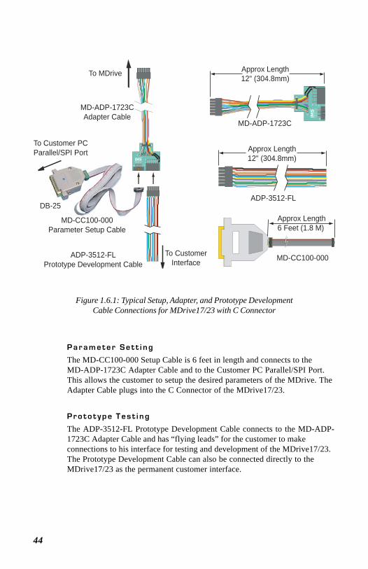
44
Figure 1.6.1: Typical Setup, Adapter, and Prototype DevelopmentCable Connections for MDrive17/23 with C Connector
P a r a m e t e r S e t t i n g
The MD-CC100-000 Setup Cable is 6 feet in length and connects to theMD-ADP-1723C Adapter Cable and to the Customer PC Parallel/SPI Port.This allows the customer to setup the desired parameters of the MDrive. TheAdapter Cable plugs into the C Connector of the MDrive17/23.
P r o t o t y p e T e s t i n g
The ADP-3512-FL Prototype Development Cable connects to the MD-ADP-1723C Adapter Cable and has “flying leads” for the customer to makeconnections to his interface for testing and development of the MDrive17/23.The Prototype Development Cable can also be connected directly to theMDrive17/23 as the permanent customer interface.
12
12
11
2
1
1
P1P2
ADAPTER P/NMD-ADP-14C
TM
To MDrive
To Customer PCParallel/SPI Port
To CustomerInterface
MD-ADP-1723CAdapter Cable
MD-CC100-000Parameter Setup Cable
ADP-3512-FLPrototype Development Cable
12
12
11
2
1
1
P1
P2A
DAPTER
P/
NM
D-A
DP-1
4CTM
Approx Length12" (304.8mm)
MD-ADP-1723C
Approx Length12" (304.8mm)
ADP-3512-FLDB-25
Approx Length6 Feet (1.8 M)
MD-CC100-000
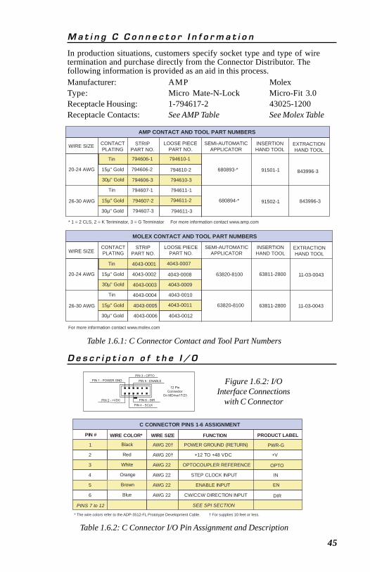
45
M a t i n g C C o n n e c t o r I n f o r m a t i o n
In production situations, customers specify socket type and type of wiretermination and purchase directly from the Connector Distributor. Thefollowing information is provided as an aid in this process.Manufacturer: AMP MolexType: Micro Mate-N-Lock Micro-Fit 3.0Receptacle Housing: 1-794617-2 43025-1200Receptacle Contacts: See AMP Table See Molex Table
C CONNECTOR PINS 1-6 ASSIGNMENT
PIN # WIRE COLOR* WIRE SIZE FUNCTION
1 Black AWG 20† POWER GROUND (RETURN)
2 Red AWG 20† +12 TO +48 VDC
3 White AWG 22 OPTOCOUPLER REFERENCE
4 Orange AWG 22 STEP CLOCK INPUT
5 Brown AWG 22 ENABLE INPUT
6 Blue AWG 22 CW/CCW DIRECTION INPUT
PINS 7 to 12 SEE SPI SECTION
* The wire colors refer to the ADP-3512-FL Prototype Development Cable. † For supplies 10 feet or less.
PRODUCT LABEL
PWR-G
+V
OPTO
IN
EN
DIR
Table 1.6.2: C Connector I/O Pin Assignment and Description
12 PinConnector
On MDrive17/23
PIN 6 - DIR
PIN 5 - ENABLE
PIN 4 - SCLK
PIN 3 - OPTO
PIN 2 - +VDC
PIN 1 - POWER GND Figure 1.6.2: I/OInterface Connections
with C Connector
D e s c r i p t i o n o f t h e I / O
Table 1.6.1: C Connector Contact and Tool Part Numbers
AMP CONTACT AND TOOL PART NUMBERS
WIRE SIZE
* 1 = 2 CLS, 2 = K Teriminator, 3 = G Terminator For more information contact www.amp.com
CONTACTPLATING
STRIPPART NO.
LOOSE PIECEPART NO.
SEMI-AUTOMATICAPPLICATOR
INSERTIONHAND TOOL
20-24 AWG
26-30 AWG
Tin
15µ" Gold
30µ" Gold
30µ" Gold
15µ" Gold
Tin
794606-1
794606-2
794606-3
794607-1
794607-2
794607-3
794610-1
794610-2
794610-3
794611-1
794611-2
794611-3
680893-*
680894-*
91501-1
91502-1
MOLEX CONTACT AND TOOL PART NUMBERS
WIRE SIZE
20-24 AWG
26-30 AWG
Tin
15µ" Gold
30µ" Gold
30µ" Gold
15µ" Gold
Tin
4043-0001
4043-0002
4043-0003
4043-0004
4043-0005
4043-0006
4043-0007
4043-0008
4043-0009
4043-0010
4043-0011
4043-0012
63820-8100
63820-8100
63811-2800
63811-2800
EXTRACTIONHAND TOOL
843996-3
843996-3
11-03-0043
11-03-0043
CONTACTPLATING
STRIPPART NO.
LOOSE PIECEPART NO.
SEMI-AUTOMATICAPPLICATOR
INSERTIONHAND TOOL
EXTRACTIONHAND TOOL
For more information contact www.molex.com
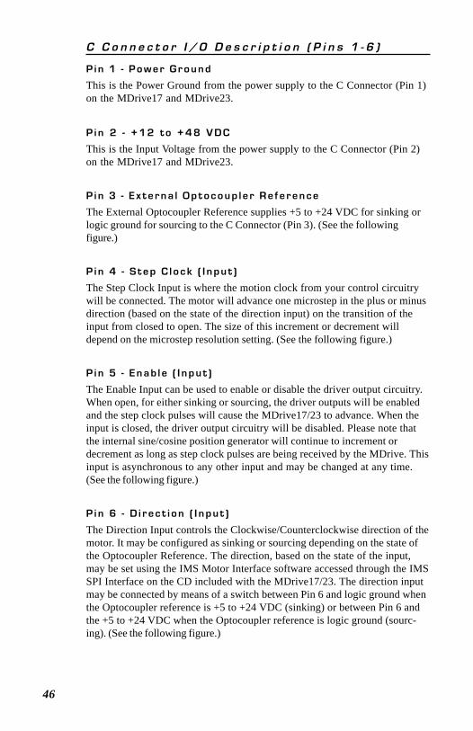
46
C C o n n e c t o r I / O D e s c r i p t i o n ( P i n s 1 - 6 )
P i n 1 - P o w e r G r o u n d
This is the Power Ground from the power supply to the C Connector (Pin 1)on the MDrive17 and MDrive23.
P i n 2 - + 1 2 t o + 4 8 V D C
This is the Input Voltage from the power supply to the C Connector (Pin 2)on the MDrive17 and MDrive23.
P i n 3 - E x t e r n a l O p t o c o u p l e r R e f e r e n c e
The External Optocoupler Reference supplies +5 to +24 VDC for sinking orlogic ground for sourcing to the C Connector (Pin 3). (See the followingfigure.)
P i n 4 - S t e p C l o c k ( I n p u t )
The Step Clock Input is where the motion clock from your control circuitrywill be connected. The motor will advance one microstep in the plus or minusdirection (based on the state of the direction input) on the transition of theinput from closed to open. The size of this increment or decrement willdepend on the microstep resolution setting. (See the following figure.)
P i n 5 - E n a b l e ( I n p u t )
The Enable Input can be used to enable or disable the driver output circuitry.When open, for either sinking or sourcing, the driver outputs will be enabledand the step clock pulses will cause the MDrive17/23 to advance. When theinput is closed, the driver output circuitry will be disabled. Please note thatthe internal sine/cosine position generator will continue to increment ordecrement as long as step clock pulses are being received by the MDrive. Thisinput is asynchronous to any other input and may be changed at any time.(See the following figure.)
P i n 6 - D i r e c t i o n ( I n p u t )
The Direction Input controls the Clockwise/Counterclockwise direction of themotor. It may be configured as sinking or sourcing depending on the state ofthe Optocoupler Reference. The direction, based on the state of the input,may be set using the IMS Motor Interface software accessed through the IMSSPI Interface on the CD included with the MDrive17/23. The direction inputmay be connected by means of a switch between Pin 6 and logic ground whenthe Optocoupler reference is +5 to +24 VDC (sinking) or between Pin 6 andthe +5 to +24 VDC when the Optocoupler reference is logic ground (sourc-ing). (See the following figure.)
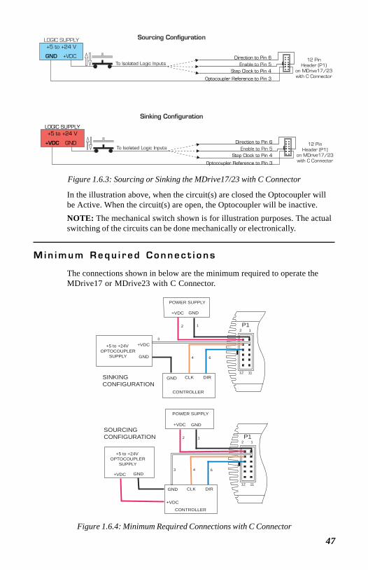
47
M i n i m u m R e q u i r e d C o n n e c t i o n s
The connections shown in below are the minimum required to operate theMDrive17 or MDrive23 with C Connector.
Figure 1.6.4: Minimum Required Connections with C Connector
Figure 1.6.3: Sourcing or Sinking the MDrive17/23 with C Connector
In the illustration above, when the circuit(s) are closed the Optocoupler willbe Active. When the circuit(s) are open, the Optocoupler will be inactive.NOTE: The mechanical switch shown is for illustration purposes. The actualswitching of the circuits can be done mechanically or electronically.
+5 to +24V OPTOCOUPLER
SUPPLY
GND+VDC
CONTROLLER
CLK DIRGND
GND
+VDC
POWER SUPPLY
SINKING CONFIGURATION
P12 1
12 11
12
3
4 6
SOURCING CONFIGURATION
+5 to +24V OPTOCOUPLER
SUPPLY
GND+VDC
CONTROLLER
CLK DIRGND
GND+VDC
POWER SUPPLY
P12 1
12 11
12
3 4 6
+VDC
GND +VDC
+5 to +24 VLOGIC SUPPLY
LOGIC SUPPLY
Step Clock to Pin 4
Optocoupler Reference to Pin 3
Direction to Pin 6 12 PinHeader (P1)
on MDrive17/23with C Connector
Enable to Pin 5
Step Clock to Pin 4
Optocoupler Reference to Pin 3
Direction to Pin 6 12 PinHeader (P1)
on MDrive17/23with C Connector
Enable to Pin 5
To Isolated Logic Inputs
To Isolated Logic Inputs
Sinking Configuration
Sourcing Configuration
GND+VDC
+5 to +24 V
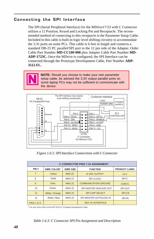
48
PIN 11 - CS
PIN 9 - GND
PIN 12 - MOSI
PIN 8 - CLOCK
PIN 10 - MISO
2
3
4
15
19
12 PinC Connector
On MDrive17/23
DB-25
PC Parallel/SPI Port
PIN 7 - +5 VDC
The SPI Interface may require
level shifting components
PIN 6 - DIR PIN 5 - ENABLE
PIN 4 - SCLK PIN 3 - OPTO
+VDC
POWER GNDPOWER
SUPPLY
PLC
CONTROLLERPIN 2 PIN 1
Customer Interface
Ground
C CONNECTOR PINS 7-12 ASSIGNMENT
PIN # WIRE COLOR* WIRE SIZE FUNCTION
7 Yellow AWG 22 +5 VDC OUTPUT
8 Violet AWG 22 SPI CLOCK
9 Grey AWG 22 COMMUNICATION GROUND
10 Green AWG 22 SPI MASTER IN/SLAVE OUT
11 White / Orange AWG 22 SPI CHIP SELECT
12 White / Blue AWG 22 SPI MASTER OUT/SLAVE IN
PINS 1 to 6 SEE I/O INTERFACE
* The wire colors refer to the ADP-3512-FL Prototype Development Cable.
PRODUCT LABEL
+5 V
SPI-C
COM-G
SPI-OUT
SPI-CS
SPI-IN
C o n n e c t i n g t h e S P I I n t e r f a c e
The SPI (Serial Peripheral Interface) for the MDrive17/23 with C Connectorutilizes a 12 Position, Keyed and Locking Pin and Receptacle. The recom-mended method of connecting to this receptacle is the Parameter Setup Cable.Included in this cable is built-in logic level shifting circuitry to accommodatethe 3.3v ports on some PCs. This cable is 6 feet in length and connects astandard DB-25 PC parallel/SPI port to the 12 pin side of the Adapter. OrderCable Part Number MD-CC100-000 plus Adapter Cable Part Number MD-ADP-1723C. Once the MDrive is configured, the SPI Interface can beconnected through the Prototype Development Cable, Part Number ADP-3512-FL.
NOTE: Should you choose to make your own parametersetup cable, be advised the 3.3V output parallel ports onsome laptop PCs may not be sufficient to communicate withthe device.
N
Figure 1.6.5: SPI Interface Connections with C Connector
Table 1.6.3: C Connector SPI Pin Assignment and Description
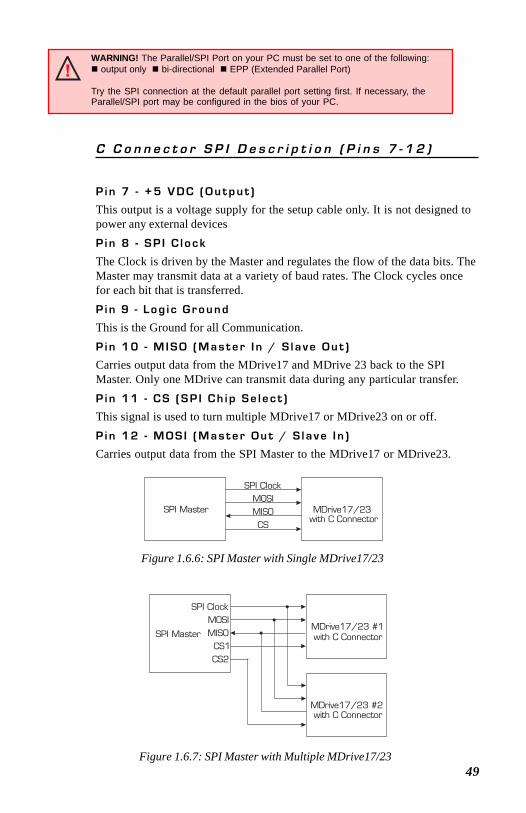
49
SPI Master MDrive17/23
SPI ClockMOSIMISOCS
SPI MasterMDrive17/23 #1
MDrive17/23 #2
SPI ClockMOSIMISO
CS1CS2
with C Connector
with C Connector
with C Connector
C C o n n e c t o r S P I D e s c r i p t i o n ( P i n s 7 - 1 2 )
P i n 7 - + 5 V D C ( O u t p u t )
This output is a voltage supply for the setup cable only. It is not designed topower any external devicesP i n 8 - S P I C l o c k
The Clock is driven by the Master and regulates the flow of the data bits. TheMaster may transmit data at a variety of baud rates. The Clock cycles oncefor each bit that is transferred.P i n 9 - L o g i c G r o u n d
This is the Ground for all Communication.P i n 1 0 - M I S O ( M a s t e r I n / S l a v e O u t )
Carries output data from the MDrive17 and MDrive 23 back to the SPIMaster. Only one MDrive can transmit data during any particular transfer.P i n 1 1 - C S ( S P I C h i p S e l e c t )
This signal is used to turn multiple MDrive17 or MDrive23 on or off.P i n 1 2 - M O S I ( M a s t e r O u t / S l a v e I n )
Carries output data from the SPI Master to the MDrive17 or MDrive23.
Figure 1.6.6: SPI Master with Single MDrive17/23
Figure 1.6.7: SPI Master with Multiple MDrive17/23
WARNING! The Parallel/SPI Port on your PC must be set to one of the following: output only bi-directional EPP (Extended Parallel Port)
Try the SPI connection at the default parallel port setting first. If necessary, theParallel/SPI port may be configured in the bios of your PC.
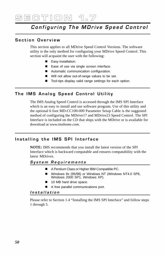
50
S e c t i o n 1 . 7Con f i g u r i n g T h e MDr i v e Speed Con t r o l
S e c t i o n O v e r v i e w
This section applies to all MDrive Speed Control Versions. The softwareutility is the only method for configuring your MDrive Speed Control. Thissection will acquaint the user with the following:
Easy installation.Ease of use via single screen interface.Automatic communication configuration.Will not allow out-of-range values to be set.Tool-tips display valid range settings for each option.
T h e I M S A n a l o g S p e e d C o n t r o l U t i l i t y
The IMS Analog Speed Control is accessed through the IMS SPI Interfacewhich is an easy to install and use software program. Use of this utility andthe optional 6 foot MD-CC100-000 Parameter Setup Cable is the suggestedmethod of configuring the MDrive17 and MDrive23 Speed Control. The SPIInterface is included on the CD that ships with the MDrive or is available fordownload at www.imshome.com.
I n s t a l l i n g t h e I M S S P I I n t e r f a c e
NOTE: IMS recommends that you install the latest version of the SPIInterface which is backward compatable and ensures compatability with thelatest MDrives.S y s t e m R e q u i r e m e n t s
A Pentium Class or Higher IBM Compatible PC.Windows 9x (95/98) or Windows NT (Windows NT4.0 SP6,Windows 2000 SP1, Windows XP).10 MB hard drive space.A free parallel communications port.
I n s t a l l a t i o n
Please refer to Section 1.4 “Installing the IMS SPI Interface” and follow steps1 through 5.
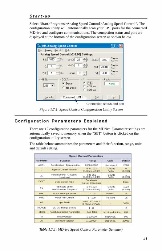
51
Figure 1.7.1: Speed Control Configuration Utility ScreenConnection status and port
S t a r t - u p
Select “Start>Programs>Analog Speed Control>Analog Speed Control”. Theconfiguration utility will automatically scan your LPT ports for the connectedMDrive and configure communications. The connection status and port aredisplayed at the bottom of the configuration screen as shown below.
C o n f i g u r a t i o n P a r a m e t e r s E x p l a i n e d
There are 12 configuration parameters for the MDrive. Parameter settings areautomatically saved to memory when the “SET” button is clicked on theconfiguration utility screen.The table below summarizes the parameters and their function, range, unitsand default setting.
Speed Control Parameters
Parameter Function Range Units Default
ACCL Acceleration / Deceleration 2000-65000 Steps/sec2 2000
C Joystick Center Position 0 to 1022(0.005 to 4.995)
Counts(Volts)
0(0.000)
DB Potentiometer / Joystick Deadband
0 to 255(0.000 to 1.245)
Counts(Volts)
1(0.005)
DCLT Deceleration TypeDecelerate
Do Not Decelerate – Decel
FS Full Scale of thePotentiometer / Joystick
1 to 1023(0.005 to 4.995)
Counts(Volts)
1023(4.995)
MHC Motor Holding Current 0 - 100 Percent 5
MRC Motor Run Current 1 - 100 Percent 25
A1 Input Mode Volts / 4-20mA /0-20mA or PWM – Volts
RANGE VI / VM Range Setting 1 - 8 – 3
MSEL Resolution Select Parameter See Table per-step-division 256
VI Initial Velocity 1-100000 Steps/sec. 800
VM Maximum Velocity 1-100000 Steps/sec. 20000
Table 1.7.1: MDrive Speed Control Parameter Summary

52
USAGE NOTE: If the motor oscillates between twovelocities, increase the potentiometer deadband to a highervalue. This will add coarseness to the pot and eliminate theoscillation.
With DB=1 it is possible that the motor will oscillate between two velocities.This can be eliminated by setting the deadband to a higher value.Note that when the voltage seen at the speed control input is ≤ 0.005V, thestep clock output of the oscillator will be zero (0). When the potentiometer orjoystick deflects to the level specified by the DB parameter the axis will startto accelerate, beginning at the velocity specified by the VI, or initial velocityparameter.
D e c e l e r a t i o n T y p e ( D C L T )
This parameter sets the motor deceleartion to an ON/OFF state. If Decel isselected on the speed control utility, the motor will decelerate to stop at therate specified by the ACCL parameter. If No Decel is selected, the motor willhard stop.F u l l S c a l e ( F S )
The full scale parameter sets the deflection of the potentiometer or joystick.While the min/max range of the speed control input is 0 to 1023 counts (0.005to 4.995 volts) (0 counts = no motion, 1023 counts = max velocity, or VM)the user has the option of setting the full scale to a different value. Forinstance, setting FS=500 counts (2.411 volts) will cause the MDrive’soscillator to output the appropriate step clock frequency set for VM whenthe voltage on the speed control input is 2.411V.
A c c e l e r a t i o n ( A C C L )
The ACCL parameter sets the acceleration and deceleration in steps persecond2.J o y s t i c k C e n t e r P o s i t i o n ( C )
The parameter sets the center position of the joystick. It can be set by twomethods. Using method one the user will manually enter a value between 0(default) and 1022 into the parameter box. This count will represent thevoltage that the MDrive will interpret as the zero-reference position. Anyvoltage seen on the speed control input will accelerate from 0 to the maximumset velocity. The second method is to select Analog>Initialize from the menubar of the configuration utility. Move the joystick or rotate the pot to the endof travel on bothe directions, move or rotate the input device to the desiredcenter and click the “Accept” button. See the setup procedure located in“Setting the Configuration Parameters”, the next subsection of this document.P o t e n t i o m e t e r D e a d b a n d ( D B )
The DB parameter sets the deadband of the potentiometer. The range for thisparameter is a relative term as the actual deadband value is based upon thesettings of the VI and VM parameters. The deadband is the amount ofdeflection seen on the potentiometer until the velocity is changed.
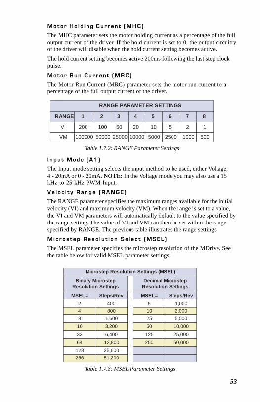
53
RANGE PARAMETER SETTINGS
RANGE 1 2 3 4 5 6 7 8
VI 200 100 50 20 10 5 2 1
VM 100000 50000 25000 10000 5000 2500 1000 500
Table 1.7.2: RANGE Parameter Settings
M o t o r H o l d i n g C u r r e n t ( M H C )
The MHC parameter sets the motor holding current as a percentage of the fulloutput current of the driver. If the hold current is set to 0, the output circuitryof the driver will disable when the hold current setting becomes active.The hold current setting becomes active 200ms following the last step clockpulse.M o t o r R u n C u r r e n t ( M R C )
The Motor Run Current (MRC) parameter sets the motor run current to apercentage of the full output current of the driver.
I n p u t M o d e ( A 1 )
The Input mode setting selects the input method to be used, either Voltage,4 - 20mA or 0 - 20mA. NOTE: In the Voltage mode you may also use a 15kHz to 25 kHz PWM Input.V e l o c i t y R a n g e ( R A N G E )
The RANGE parameter specifies the maximum ranges available for the initialvelocity (VI) and maximum velocity (VM). When the range is set to a value,the VI and VM parameters will automatically default to the value specified bythe range setting. The value of VI and VM can then be set within the rangespecified by RANGE. The previous table illustrates the range settings.M i c r o s t e p R e s o l u t i o n S e l e c t ( M S E L )
The MSEL parameter specifies the microstep resolution of the MDrive. Seethe table below for valid MSEL parameter settings.
Microstep Resolution Settings (MSEL)
Binary MicrostepResolution Settings
Decimal MicrostepResolution Settings
MSEL= Steps/Rev MSEL= Steps/Rev2 400 5 1,0004 800 10 2,0008 1,600 25 5,00016 3,200 50 10,00032 6,400 125 25,00064 12,800 250 50,000128 25,600256 51,200
Table 1.7.3: MSEL Parameter Settings
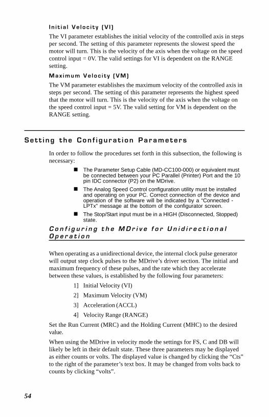
54
S e t t i n g t h e C o n f i g u r a t i o n P a r a m e t e r s
In order to follow the procedures set forth in this subsection, the following isnecessary:
The Parameter Setup Cable (MD-CC100-000) or equivalent mustbe connected between your PC Parallel (Printer) Port and the 10pin IDC connector (P2) on the MDrive.The Analog Speed Control configuration utility must be installedand operating on your PC. Correct connection of the device andoperation of the software will be indicated by a “Connected -LPTx” message at the bottom of the configurator screen.The Stop/Start input must be in a HIGH (Disconnected, Stopped)state.
C o n f i g u r i n g t h e M D r i v e f o r U n i d i r e c t i o n a lO p e r a t i o n
When operating as a unidirectional device, the internal clock pulse generatorwill output step clock pulses to the MDrive’s driver section. The initial andmaximum frequency of these pulses, and the rate which they acceleratebetween these values, is established by the following four parameters:
1] Initial Velocity (VI)2] Maximum Velocity (VM)3] Acceleration (ACCL)4] Velocity Range (RANGE)
Set the Run Current (MRC) and the Holding Current (MHC) to the desiredvalue.When using the MDrive in velocity mode the settings for FS, C and DB willlikely be left in their default state. These three parameters may be displayedas either counts or volts. The displayed value is changed by clicking the “Cts”to the right of the parameter’s text box. It may be changed from volts back tocounts by clicking “volts”.
I n i t i a l V e l o c i t y ( V I )
The VI parameter establishes the initial velocity of the controlled axis in stepsper second. The setting of this parameter represents the slowest speed themotor will turn. This is the velocity of the axis when the voltage on the speedcontrol input = 0V. The valid settings for VI is dependent on the RANGEsetting.M a x i m u m V e l o c i t y ( V M )
The VM parameter establishes the maximum velocity of the controlled axis insteps per second. The setting of this parameter represents the highest speedthat the motor will turn. This is the velocity of the axis when the voltage onthe speed control input = 5V. The valid setting for VM is dependent on theRANGE setting.
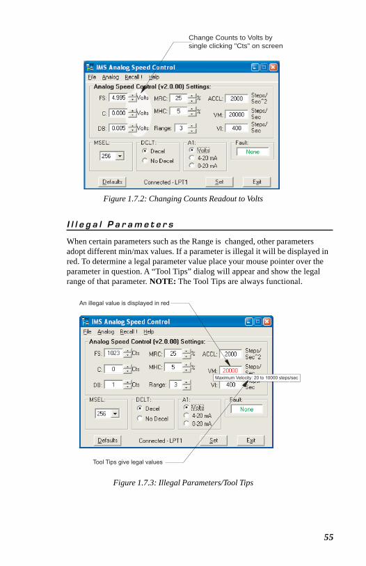
55
Figure 1.7.2: Changing Counts Readout to Volts
Change Counts to Volts bysingle clicking "Cts" on screen
I l l e g a l P a r a m e t e r s
When certain parameters such as the Range is changed, other parametersadopt different min/max values. If a parameter is illegal it will be displayed inred. To determine a legal parameter value place your mouse pointer over theparameter in question. A “Tool Tips” dialog will appear and show the legalrange of that parameter. NOTE: The Tool Tips are always functional.
Figure 1.7.3: Illegal Parameters/Tool Tips
Maximum Velocity: 20 to 10000 steps/sec
An illegal value is displayed in red
Tool Tips give legal values
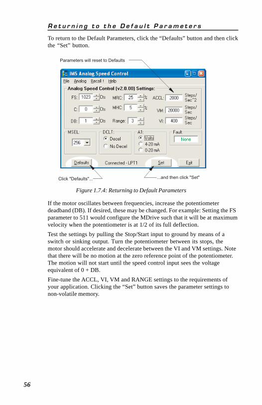
56
If the motor oscillates between frequencies, increase the potentiometerdeadband (DB). If desired, these may be changed. For example: Setting the FSparameter to 511 would configure the MDrive such that it will be at maximumvelocity when the potentiometer is at 1/2 of its full deflection.Test the settings by pulling the Stop/Start input to ground by means of aswitch or sinking output. Turn the potentiometer between its stops, themotor should accelerate and decelerate between the VI and VM settings. Notethat there will be no motion at the zero reference point of the potentiometer.The motion will not start until the speed control input sees the voltageequivalent of 0 + DB.Fine-tune the ACCL, VI, VM and RANGE settings to the requirements ofyour application. Clicking the “Set” button saves the parameter settings tonon-volatile memory.
R e t u r n i n g t o t h e D e f a u l t P a r a m e t e r s
To return to the Default Parameters, click the “Defaults” button and then clickthe “Set” button.
Figure 1.7.4: Returning to Default Parameters
Parameters will reset to Defaults
Click "Defaults"... ...and then click "Set"
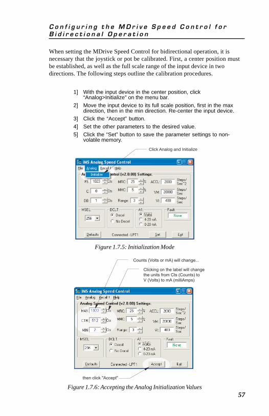
57
C o n f i g u r i n g t h e M D r i v e S p e e d C o n t r o l f o rB i d i r e c t i o n a l O p e r a t i o n
When setting the MDrive Speed Control for bidirectional operation, it isnecessary that the joystick or pot be calibrated. First, a center position mustbe established, as well as the full scale range of the input device in twodirections. The following steps outline the calibration procedures.
1] With the input device in the center position, click“Analog>Initialize” on the menu bar.
2] Move the input device to its full scale position, first in the maxdirection, then in the min direction. Re-center the input device.
3] Click the “Accept” button.4] Set the other parameters to the desired value.5] Click the “Set” button to save the parameter settings to non-
volatile memory.
Figure 1.7.5: Initialization Mode
Click Analog and Initialize
Figure 1.7.6: Accepting the Analog Initialization Values
Counts (Volts or mA) will change...
then click "Accept"
Clicking on the label will change
the units from Cts (Counts) to
V (Volts) to mA (milliAmps)
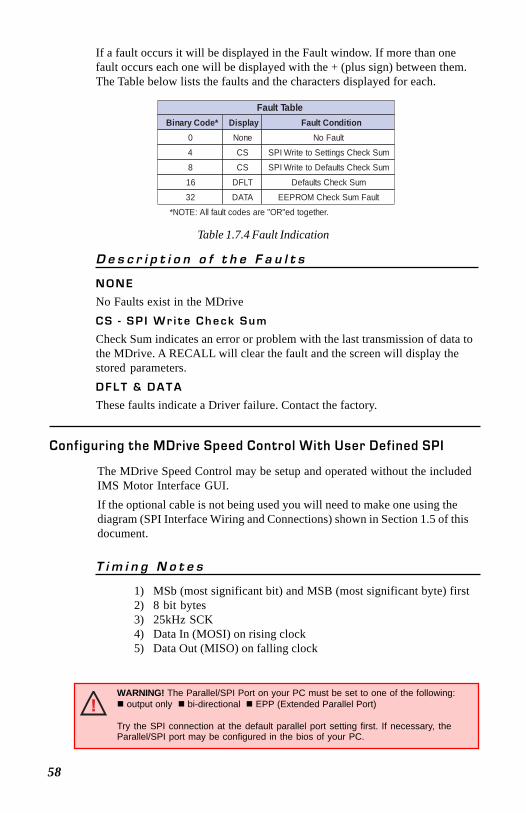
58
Table 1.7.4 Fault Indication
If a fault occurs it will be displayed in the Fault window. If more than onefault occurs each one will be displayed with the + (plus sign) between them.The Table below lists the faults and the characters displayed for each.
Fault TableBinary Code* Display Fault Condition
0 None No Fault
4 CS SPI Write to Settings Check Sum
8 CS SPI Write to Defaults Check Sum
16 DFLT Defaults Check Sum
32 DATA EEPROM Check Sum Fault
*NOTE: All fault codes are "OR"ed together.
D e s c r i p t i o n o f t h e F a u l t s
N O N E
No Faults exist in the MDriveC S - S P I W r i t e C h e c k S u m
Check Sum indicates an error or problem with the last transmission of data tothe MDrive. A RECALL will clear the fault and the screen will display thestored parameters.D F L T & D A T A
These faults indicate a Driver failure. Contact the factory.
Configuring the MDrive Speed Control With User Defined SPI
The MDrive Speed Control may be setup and operated without the includedIMS Motor Interface GUI.If the optional cable is not being used you will need to make one using thediagram (SPI Interface Wiring and Connections) shown in Section 1.5 of thisdocument.
T i m i n g N o t e s
1) MSb (most significant bit) and MSB (most significant byte) first2) 8 bit bytes3) 25kHz SCK4) Data In (MOSI) on rising clock5) Data Out (MISO) on falling clock
WARNING! The Parallel/SPI Port on your PC must be set to one of the following: output only bi-directional EPP (Extended Parallel Port)
Try the SPI connection at the default parallel port setting first. If necessary, theParallel/SPI port may be configured in the bios of your PC.
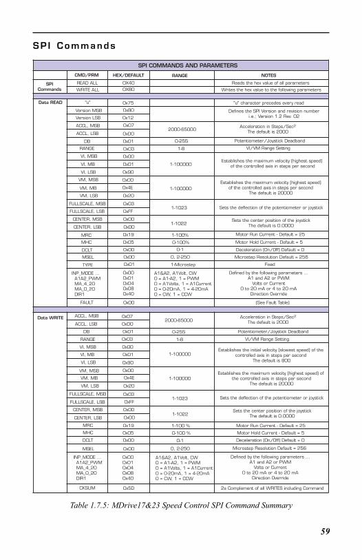
59
Table 1.7.5: MDrive17&23 Speed Control SPI Command Summary
S P I C o m m a n d s
READ ALL 0X40
CMD/PRM HEX/DEFAULT RANGE NOTES
SPICommands
Reads the hex value of all parameters
WRITE ALL 0X80 Writes the hex value to the following parameters
Data READ "u" 0x75 "u" character precedes every read
Version MSB 0x80
Version LSB 0x12
Defines the SPI Version and revision numberi.e.; Version 1.2 Rev. 02
ACCL, MSB 0x07
ACCL, LSB 0xD0
Acceleration in Steps/Sec2
The default is 2000
DB 0x01
2000-65000
0-255 Potentiometer/Joystick Deadband
RANGE 0x03 1-8 VI/VM Range Setting
VI, MSB 0x00
VI, MB 0x01
VI, LSB
1-100000Establishes the maximum velocity (highest speed)
of the controlled axis in steps per second0x90
VM, MSB 0x00
VM, MB 0x4E
VM, LSB 0x20
1-100000Establishes the maximum velocity (highest speed)
of the controlled axis in steps per secondThe default is 20000
FULLSCALE, MSB 0x03
FULLSCALE, LSB 0xFF1-1023 Sets the deflection of the potentiometer or joystick
CENTER, MSB 0x00
CENTER, LSB 0x001-1022
Sets the center position of the joystickThe default is 0.0000
MRC 0x19 1-100% Motor Run Current - Default = 25
MHC 0x05 0-100% Motor Hold Current - Default = 5
DCLT 0x00 0-1 Deceleration (On/Off) Default = 0
MSEL 0x00 0, 2-250 Microstep Resolution Default = 256
TYPE 0x01 1-Microstep Fixed
INP_MODE ... A1A2_PWM MA_4_20 MA_0_20 DIR1
0x000x010x040x080x40
A1&A2, A1Volt, CW0 = A1-A2, 1 = PWM0 = A1Volts, 1 = A1Current0 = 0-20mA, 1 = 4-20mA0 = CW, 1 = CCW
Defined by the following parameters ...A1 and A2 or PWM
Volts or Current0 to 20 mA or 4 to 20 mA
Direction Override
Data WRITE ACCL, MSB 0x07
ACCL, LSB 0xD02000-65000
Acceleration in Steps/Sec2
The default is 2000
DB 0x01 0-255 Potentiometer/Joystick Deadband
RANGE 0x03 1-8 VI/VM Range Setting
VI, MSB 0x00
VI, MB 0x01
VI, LSB 0x90
1-100000Establishes the initial velocity (slowest speed) of the
controlled axis in steps per second The default is 800
VM, MSB 0x00
VM, MB 0x4E
VM, LSB 0x20
1-100000Establishes the maximum velocity (highest speed) of
the controlled axis in steps per secondThe default is 20000
FULLSCALE, MSB 0x03
FULLSCALE, LSB 0xFF1-1023 Sets the deflection of the potentiometer or joystick
CENTER, MSB 0x00
CENTER, LSB 0x001-1022
Sets the center position of the joystickThe default is 0.0000
MRC 0x19
MHC 0x05
1-100 %
0-100 %
Motor Run Current - Default = 25
Motor Hold Current - Default = 5
DCLT 0x00 0-1 Deceleration (On/Off) Default = 0
MSEL 0x00 0, 2-250 Microstep Resolution Default = 256
CKSUM 0x5D 2s Complement of all WRITES including Command
SPI COMMANDS AND PARAMETERS
INP_MODE ... A1A2_PWM MA_4_20 MA_0_20 DIR1
0x000x010x040x080x40
A1&A2, A1Volt, CW0 = A1-A2, 1 = PWM0 = A1Volts, 1 = A1Current0 = 0-20mA, 1 = 4-20mA0 = CW, 1 = CCW
Defined by the following parameters ...A1 and A2 or PWM
Volts or Current0 to 20 mA or 4 to 20 mA
Direction Override
FAULT 0x00 (See Fault Table)
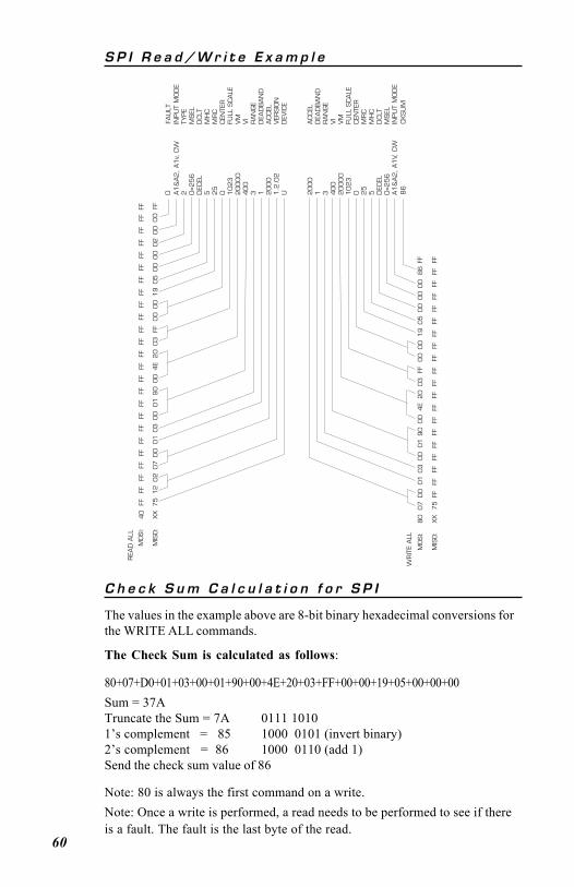
60
S P I R e a d / W r i t e E x a m p l e
C h e c k S u m C a l c u l a t i o n f o r S P I
The values in the example above are 8-bit binary hexadecimal conversions forthe WRITE ALL commands.
The Check Sum is calculated as follows:
80+07+D0+01+03+00+01+90+00+4E+20+03+FF+00+00+19+05+00+00+00Sum = 37ATruncate the Sum = 7A 0111 10101’s complement = 85 1000 0101 (invert binary)2’s complement = 86 1000 0110 (add 1)Send the check sum value of 86
Note: 80 is always the first command on a write.Note: Once a write is performed, a read needs to be performed to see if thereis a fault. The fault is the last byte of the read.
MOSI:
40
FFFF
FFFF
FFFF
FFFF
FFFF
FFFF
FFFF
FFFF
FFFF
FFFF
FFFF
FFFF
MIS
O:
XX
75
12
02
07
D0
01
03
00
01
90
00
4E
20
03
FF0
00
01
90
50
00
00
20
0FF
MOSI:
80
FFFF
FFFF
FFFF
FFFF
FFFF
FFFF
FFFF
FFFF
FFFF
FFM
ISO:
XX
75
07
D0
01
03
00
01
90
00
4E
20
03
FF0
00
01
90
50
00
00
08
6
A1
&A2
, A1
v , C
W2 0=2
56
DEC
EL5 2
50 1
02
32
00
00
40
03 1 2
00
01
.2.0
2U
INPU
T M
OD
ETY
PE
MSEL
DCLT
MH
CM
RC
CEN
TER
FULL
SCALE
VM
VI
RAN
GE
DEA
DB
AN
DACCEL
VER
SIO
ND
EVIC
E
ACCEL
DEA
DB
AN
DR
AN
GE
VI
VM
FULL
SCALE
CEN
TER
MR
CM
HC
DCLT
MSEL
INPU
T M
OD
E
20
00
1 3 40
02
00
00
10
23
0 25
5 DEC
EL0
=25
6A1
&A2
, A1
V , C
W
REA
D A
LL
WR
ITE
ALL
0
00
FAU
LT
FF
FFFF
CKSU
M8
6
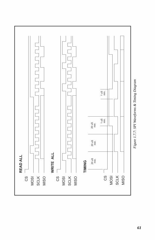
61
Figu
re 1
.7.7
: SPI
Wav
efor
ms &
Tim
ing
Dia
gram
62
PART II
MDrive 17Integrated Motor and
Electronics
Rotary
Linear Actuator
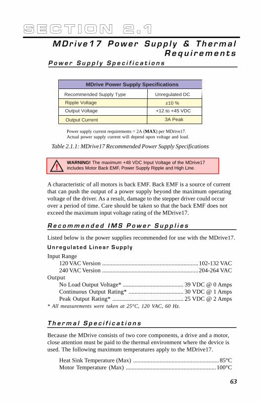
63
R e c o m m e n d e d I M S P o w e r S u p p l i e s
Listed below is the power supplies recommended for use with the MDrive17.U n r e g u l a t e d L i n e a r S u p p l y
Input Range120 VAC Version .................................................................102-132 VAC240 VAC Version .................................................................204-264 VAC
OutputNo Load Output Voltage* ......................................... 39 VDC @ 0 AmpsContinuous Output Rating* ..................................... 30 VDC @ 1 AmpsPeak Output Rating* ................................................ 25 VDC @ 2 Amps
* All measurements were taken at 25°C, 120 VAC, 60 Hz.
Table 2.1.1: MDrive17 Recommended Power Supply Specifications
S e c t i o n 2 . 1MDr i v e17 Powe r S upp l y & T h e rma l
R e q u i r e m e n t s
MDrive Power Supply Specifications
Recommended Supply Type Unregulated DC
Ripple Voltage ±10 %Output Voltage +12 to +45 VDC
Output Current 3A Peak
P o w e r S u p p l y S p e c i f i c a t i o n s
Power supply current requirements = 2A (MAX) per MDrive17.Actual power supply current will depend upon voltage and load.
T h e r m a l S p e c i f i c a t i o n s
Because the MDrive consists of two core components, a drive and a motor,close attention must be paid to the thermal environment where the device isused. The following maximum temperatures apply to the MDrive17.
Heat Sink Temperature (Max) .......................................................... 85°CMotor Temperature (Max) .............................................................100°C
A characteristic of all motors is back EMF. Back EMF is a source of currentthat can push the output of a power supply beyond the maximum operatingvoltage of the driver. As a result, damage to the stepper driver could occurover a period of time. Care should be taken so that the back EMF does notexceed the maximum input voltage rating of the MDrive17.
WARNING! The maximum +48 VDC Input Voltage of the MDrive17includes Motor Back EMF, Power Supply Ripple and High Line.
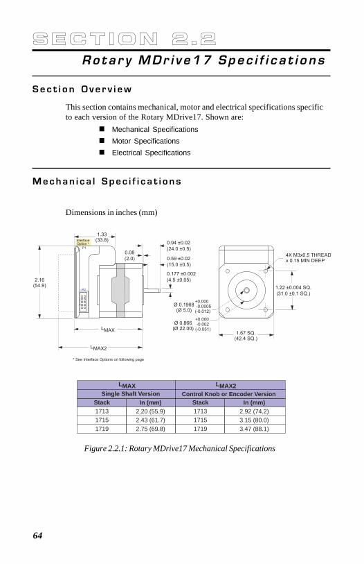
64
S e c t i o n 2 . 2Ro ta r y MDr i v e17 Spec i f i c a t i o n s
S e c t i o n O v e r v i e w
This section contains mechanical, motor and electrical specifications specificto each version of the Rotary MDrive17. Shown are:
Mechanical SpecificationsMotor SpecificationsElectrical Specifications
M e c h a n i c a l S p e c i f i c a t i o n s
Dimensions in inches (mm)
Figure 2.2.1: Rotary MDrive17 Mechanical Specifications
Single Shaft Version Control Knob or Encoder VersionLMAX LMAX2
Stack171317151719
Stack171317151719
In (mm)2.20 (55.9)2.43 (61.7)2.75 (69.8)
In (mm)2.92 (74.2)3.15 (80.0)3.47 (88.1)
1.22 ±0.004 SQ.
(31.0 ±0.1 SQ.)
0.177 ±0.002
(4.5 ±0.05)
InterfaceOption *
0.59 ±0.02
(15.0 ±0.5)
0.08
(2.0)
Ø 0.1968(Ø 5.0)
+0.000 -0.0005(-0.012)
4X M3x0.5 THREADx 0.15 MIN DEEP
LMAX
LMAX2
P2
P1
1.33(33.8)
0.94 ±0.02
(24.0 ±0.5)
2.16(54.9)
1.67 SQ.(42.4 SQ.)
Ø 0.866(Ø 22.00)
+0.000 -0.002(-0.051)
* See Interface Options on following page

65Figure 2.2.3: Rotary MDrive 1713 Torque/Speed Data (100% Current)
M o t o r S p e c i f i c a t i o n s
NOTE! The following specifications apply to all rotary variantsof the MDrive17, the standard rotary as well as the encoderand control knob versions.
Table 2.2.1: MD1713 Motor Specifications
M D r i v e 1 7 1 3 M o t o r S p e c i f i c a t i o n s a n d S p e e d / T o r q u eCurves
Figure 2.2.2: Interface Options
I n t e r f a c e O p t i o n s - M D r i v e 1 7
MD1713Holding Torque oz-in (N-cm) 32 (22.6)
Detent Torque oz-in (N-cm) 1.66 (1.17)
Rotor Inertia oz-in-sec (kg-cm )22 0.00053 (0.038)Weight (Motor & Driver) oz (g) 9.8 (277.8)
Torq
ue in
Oz-
InTorque in N
-cm
Speed in Full Steps per Second
500 1000 2000 3000 4000 5000 6000 7000
25
20
15
10
5
0
24 VDC45 VDC 18
14
11
7
4
Flying Leads Pluggable ClampType Terminal Block
C Connector*
0.44(11.2)12.00
+1.0/-0.0
(304.8)(+25.4/-0.0)
0.36(9.1)
* Not available for MDO17 Speed Control
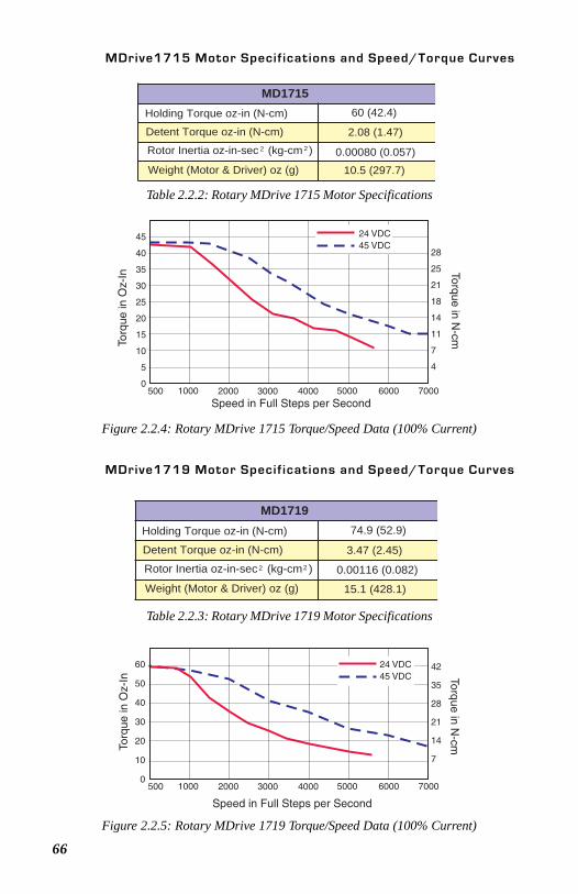
66
Table 2.2.2: Rotary MDrive 1715 Motor Specifications
Figure 2.2.4: Rotary MDrive 1715 Torque/Speed Data (100% Current)
MDrive1715 Motor Specif ications and Speed/Torque Curves
MD1715Holding Torque oz-in (N-cm) 60 (42.4)
Detent Torque oz-in (N-cm) 2.08 (1.47)
Rotor Inertia oz-in-sec (kg-cm )22 0.00080 (0.057)Weight (Motor & Driver) oz (g) 10.5 (297.7)
Table 2.2.3: Rotary MDrive 1719 Motor Specifications
MDrive1719 Motor Specif ications and Speed/Torque Curves
Figure 2.2.5: Rotary MDrive 1719 Torque/Speed Data (100% Current)
45
40
35
30
25
20
15
10
5
0500 1000 2000 3000 4000 5000 6000 7000
Speed in Full Steps per Second
Torq
ue in
Oz-
In Torque in N-cm
24 VDC45 VDC
28
25
21
18
14
11
7
4
60
50
40
30
20
10
0500 1000 2000 3000 4000 5000 6000 7000
Speed in Full Steps per Second
Torq
ue in
Oz-
In Torque in N-cm
42
35
28
21
14
7
24 VDC45 VDC
MD1719Holding Torque oz-in (N-cm) 74.9 (52.9)
Detent Torque oz-in (N-cm) 3.47 (2.45)
Rotor Inertia oz-in-sec (kg-cm )22 0.00116 (0.082)
Weight (Motor & Driver) oz (g) 15.1 (428.1)
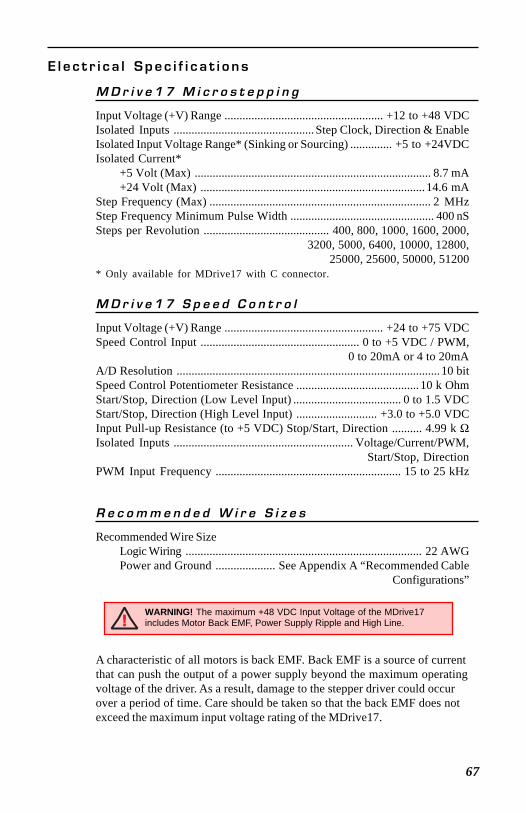
67
A characteristic of all motors is back EMF. Back EMF is a source of currentthat can push the output of a power supply beyond the maximum operatingvoltage of the driver. As a result, damage to the stepper driver could occurover a period of time. Care should be taken so that the back EMF does notexceed the maximum input voltage rating of the MDrive17.
WARNING! The maximum +48 VDC Input Voltage of the MDrive17includes Motor Back EMF, Power Supply Ripple and High Line.
E l e c t r i c a l S p e c i f i c a t i o n s
M D r i v e 1 7 M i c r o s t e p p i n g
Input Voltage (+V) Range ..................................................... +12 to +48 VDCIsolated Inputs ............................................... Step Clock, Direction & EnableIsolated Input Voltage Range* (Sinking or Sourcing) .............. +5 to +24VDCIsolated Current*
+5 Volt (Max) ............................................................................... 8.7 mA+24 Volt (Max) ........................................................................... 14.6 mA
Step Frequency (Max) .......................................................................... 2 MHzStep Frequency Minimum Pulse Width ................................................ 400 nSSteps per Revolution .......................................... 400, 800, 1000, 1600, 2000,
3200, 5000, 6400, 10000, 12800,25000, 25600, 50000, 51200
* Only available for MDrive17 with C connector.
M D r i v e 1 7 S p e e d C o n t r o l
Input Voltage (+V) Range ..................................................... +24 to +75 VDCSpeed Control Input ..................................................... 0 to +5 VDC / PWM,
0 to 20mA or 4 to 20mAA/D Resolution ........................................................................................ 10 bitSpeed Control Potentiometer Resistance ......................................... 10 k OhmStart/Stop, Direction (Low Level Input) .................................... 0 to 1.5 VDCStart/Stop, Direction (High Level Input) ........................... +3.0 to +5.0 VDCInput Pull-up Resistance (to +5 VDC) Stop/Start, Direction .......... 4.99 k ΩIsolated Inputs ............................................................ Voltage/Current/PWM,
Start/Stop, DirectionPWM Input Frequency .............................................................. 15 to 25 kHz
R e c o m m e n d e d W i r e S i z e s
Recommended Wire SizeLogic Wiring ............................................................................... 22 AWGPower and Ground .................... See Appendix A “Recommended Cable
Configurations”
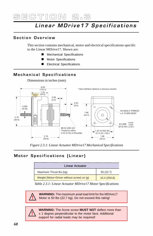
68
S e c t i o n 2 . 3L i n ea r MDr i v e17 Spec i f i c a t i o n s
S e c t i o n O v e r v i e w
This section contains mechanical, motor and electrical specifications specificto the Linear MDrive17. Shown are:
Mechanical SpecificationsMotor SpecificationsElectrical Specifications
M e c h a n i c a l S p e c i f i c a t i o n sDimensions in inches (mm)
Figure 2.3.1: Linear Actuator MDrive17 Mechanical Specifications
M o t o r S p e c i f i c a t i o n s ( L i n e a r )
Linear Actuator
Weight (Motor+Driver without screw) oz (g)
Maximum Thrust lbs (kg)
10.4 (294.8)
50 (22.7)
Table 2.3.1: Linear Actuator MDrive17 Motor Specifications
WARNING: The maximum axial load limit for the MDrive17Motor is 50 lbs (22.7 kg). Do not exceed this rating!
WARNING: The Acme screw MUST NOT deflect more than± 1 degree perpendicular to the motor face. Additionalsupport for radial loads may be required!
1.22 ±0.004 SQ.
(31.0 ±0.1 SQ.)
6.00(152.4)
0.250(6.35)
0.08
(2.0)
0.25
(6.4)
1.66
(42.2)
#8-32 UNC-2A
Thread to within
0.03 (0.76) of Shoulder
2.19
(55.6)
1.66
(42.2)
4X M3x0.5 THREAD
x 0.15 MIN DEEP
Ø 0.866
(Ø 22.00)
+0.000 -0.002(-0.051)
2.16
(54.9)
P2
P1
1.33(33.8)Interface *
Option
* See Interface Options in previous section
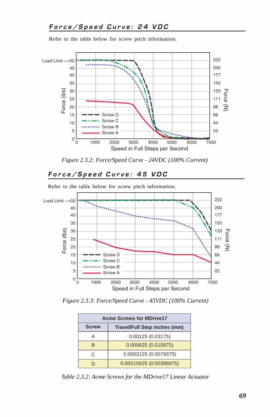
69
Table 2.3.2: Acme Screws for the MDrive17 Linear Actuator
F o r c e / S p e e d C u r v e : 4 5 V D C
Refer to the table below for screw pitch information.
Figure 2.3.3: Force/Speed Curve - 45VDC (100% Current)
F o r c e / S p e e d C u r v e : 2 4 V D C
Refer to the table below for screw pitch information.
Figure 2.3.2: Force/Speed Curve - 24VDC (100% Current)
Acme Screws for MDrive17Screw Travel/Full Step inches (mm)
A 0.00125 (0.03175)
B 0.000625 (0.015875)
C 0.0003125 (0.0079375)
D 0.00015625 (0.00396875)
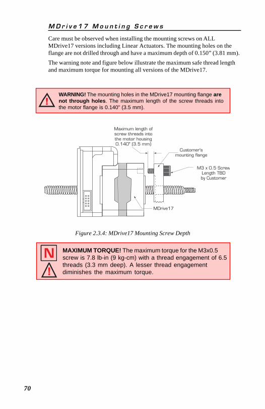
70
Figure 2.3.4: MDrive17 Mounting Screw Depth
WARNING! The mounting holes in the MDrive17 mounting flange arenot through holes. The maximum length of the screw threads intothe motor flange is 0.140” (3.5 mm).
M D r i v e 1 7 M o u n t i n g S c r e w s
Care must be observed when installing the mounting screws on ALLMDrive17 versions including Linear Actuators. The mounting holes on theflange are not drilled through and have a maximum depth of 0.150” (3.81 mm).The warning note and figure below illustrate the maximum safe thread lengthand maximum torque for mounting all versions of the MDrive17.
MAXIMUM TORQUE! The maximum torque for the M3x0.5screw is 7.8 lb-in (9 kg-cm) with a thread engagement of 6.5threads (3.3 mm deep). A lesser thread engagementdiminishes the maximum torque.
M3 x 0.5 ScrewLength TBDby Customer
Maximum length ofscrew threads intothe motor housing0.140" (3.5 mm)
Customer'smounting flange
MDrive17
71
PART III
MDrive 23Integrated Motor and
Electronics
Rotary
Linear Actuator
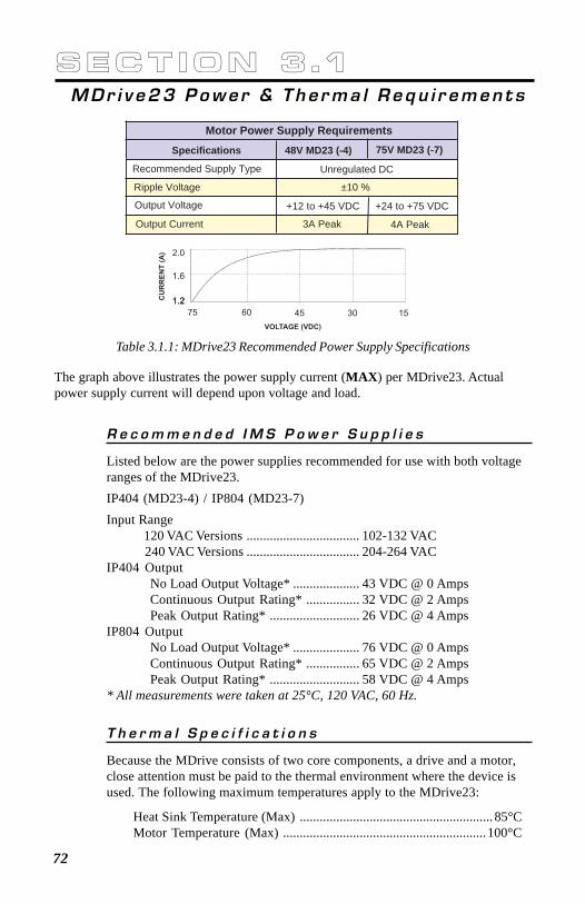
72
Motor Power Supply Requirements
Recommended Supply Type
Specifications 48V MD23 (-4) 75V MD23 (-7)
Unregulated DC
Ripple Voltage ±10 %
Output Voltage +12 to +45 VDC +24 to +75 VDC
Output Current 3A Peak 4A Peak
R e c o m m e n d e d I M S P o w e r S u p p l i e s
Listed below are the power supplies recommended for use with both voltageranges of the MDrive23.IP404 (MD23-4) / IP804 (MD23-7)Input Range
120 VAC Versions .................................. 102-132 VAC240 VAC Versions .................................. 204-264 VAC
IP404 OutputNo Load Output Voltage* .................... 43 VDC @ 0 AmpsContinuous Output Rating* ................ 32 VDC @ 2 AmpsPeak Output Rating* ........................... 26 VDC @ 4 Amps
IP804 OutputNo Load Output Voltage* .................... 76 VDC @ 0 AmpsContinuous Output Rating* ................ 65 VDC @ 2 AmpsPeak Output Rating* ........................... 58 VDC @ 4 Amps
* All measurements were taken at 25°C, 120 VAC, 60 Hz.
Table 3.1.1: MDrive23 Recommended Power Supply Specifications
S e c t i o n 3 . 1MDr i v e23 Powe r & The rma l Requ i r emen t s
The graph above illustrates the power supply current (MAX) per MDrive23. Actualpower supply current will depend upon voltage and load.
T h e r m a l S p e c i f i c a t i o n s
Because the MDrive consists of two core components, a drive and a motor,close attention must be paid to the thermal environment where the device isused. The following maximum temperatures apply to the MDrive23:
Heat Sink Temperature (Max) .......................................................... 85°CMotor Temperature (Max) .............................................................100°C
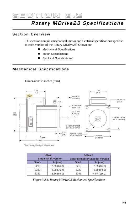
73
Single Shaft Version Control Knob or Encoder VersionLMAX LMAX2
Stack221822222231
Stack221822222231
In (mm)2.63 (66.8)3.00 (76.2)3.86 (98.0)
In (mm)3.35 (85.1)3.70 (94.0)4.57 (116.1)
S e c t i o n 3 . 2Ro ta r y MDr i v e23 Spec i f i c a t i o n s
S e c t i o n O v e r v i e w
This section contains mechanical, motor and electrical specifications specificto each version of the Rotary MDrive23. Shown are:
Mechanical SpecificationsMotor SpecificationsElectrical Specifications
M e c h a n i c a l S p e c i f i c a t i o n s
Dimensions in inches (mm)
Figure 3.2.1: Rotary MDrive23 Mechanical Specifications
1.63(41.4)
2.22 SQ.(56.4 SQ.)
1.50(38.1)
2.92(74.2)
1.856 ±0.008 SQ.(47.14 ±0.2 SQ.)
4X Ø 0.197(Ø 5.0)
0.81 ±0.02(20.6 ±0.5)
0.59 ±0.008(15.0 ±0.2)
0.06(1.6)
L MAX
L MAX2
0.23 ±0.004(5.8 ±0.1)
Ø 0.250 +0/-0.0005(Ø 6.35 +0/-0.013)
InterfaceOption *
P2
P1
Ø 1.500 ±0.002(Ø 38.10 ±0.05)
0.19(4.8)
* See Interface Options on following page
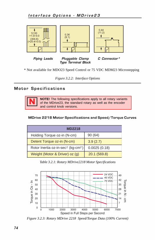
74
MD2218
Holding Torque oz-in (N-cm) 90 (64)
Detent Torque oz-in (N-cm) 3.9 (2.7)
Rotor Inertia oz-in-sec (kg-cm )22 0.0025 (0.18)
Weight (Motor & Driver) oz (g) 20.1 (569.8)
Figure 3.2.2: Interface Options
M o t o r S p e c i f i c a t i o n s
NOTE! The following specifications apply to all rotary variantsof the MDrive23, the standard rotary as well as the encoderand control knob versions.
Table 3.2.1: Rotary MDrive2218 Motor Specifications
MDrive 2218 Motor Specifications and Speed/Torque Curves
I n t e r f a c e O p t i o n s - M D r i v e 2 3
Figure 3.2.3: Rotary MDrive 2218 Speed/Torque Data (100% Current)
70
60
50
40
30
20
10
0
49
42
35
28
21
14
7
0 1000 2000 3000 4000 5000 6000 7000
Speed in Full Steps per Second
Torq
ue in
Oz
- In
Torque in N - cm
24 VDC45 VDC75 VDC
Flying Leads Pluggable ClampType Terminal Block
C Connector*
0.44(11.2)12.00
+1.0/-0.0
(304.8)(+25.4/-0.0)
0.36(9.1)
* Not available for MDO23 Speed Control or 75 VDC MDM23 Microstepping
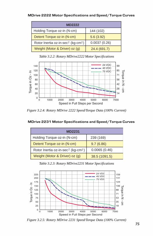
75
Table 3.2.3: Rotary MDrive2231 Motor Specifications
200
225
175
150
125
100
75
50
25
0
141
159
124
106
88
71
53
35
18
0 1000 2000 3000 4000 5000 6000 7000
Speed in Full Steps per Second
Torq
ue in
Oz
- In Torque in N
- cm
24 VDC45 VDC75 VDC
Figure 3.2.5: Rotary MDrive 2231 Speed/Torque Data (100% Current)
MDrive 2231 Motor Specifications and Speed/Torque Curves
MD2231Holding Torque oz-in (N-cm) 239 (169)
Detent Torque oz-in (N-cm) 9.7 (6.86)
Rotor Inertia oz-in-sec (kg-cm )2 2 0.0065 (0.46)
Weight (Motor & Driver) oz (g) 38.5 (1091.5)
Table 3.2.2: Rotary MDrive2222 Motor Specifications
140
120
100
80
60
40
20
0
99
85
71
56
42
28
14
0 1000 2000 3000 4000 5000 6000 7000
Speed in Full Steps per Second
Torq
ue in
Oz
- In
Torque in N - cm
24 VDC45 VDC75 VDC
Figure 3.2.4: Rotary MDrive 2222 Speed/Torque Data (100% Current)
MDrive 2222 Motor Specifications and Speed/Torque Curves
MD2222Holding Torque oz-in (N-cm) 144 (102)
Detent Torque oz-in (N-cm) 5.6 (3.92)
Rotor Inertia oz-in-sec (kg-cm )2 2 0.0037 (0.26)
Weight (Motor & Driver) oz (g) 24.4 (691.7)

76
A characteristic of all motors is back EMF. Back EMF is a source of currentthat can push the output of a power supply beyond the maximum operatingvoltage of the driver. As a result, damage to the stepper driver could occurover a period of time. Care should be taken so that the back EMF does notexceed the maximum input voltage rating of the MDrive23.
E l e c t r i c a l S p e c i f i c a t i o n s
M D r i v e 2 3 M i c r o s t e p p i n g
Input Voltage (+V) Range .............................. +12 to +48* / +24 to +75 VDCIsolated Inputs ............................................... Step Clock, Direction & EnableIsolated Input Voltage Range** (Sinking or Sourcing) ............ +5 to +24VDCIsolated Current**
+5 Volt (Max) ............................................................................... 8.7 mA+24 Volt (Max) ........................................................................... 14.6 mA
Step Frequency (Max) .......................................................................... 2 MHzStep Frequency Minimum Pulse Width ................................................ 400 nSSteps per Revolution .......................................... 400, 800, 1000, 1600, 2000,
3200, 5000, 6400, 10000, 12800,25000, 25600, 50000, 51200
* 12-48 VDC is the only input voltage available for MDrive23 with C Connector.** Only available for MDrive23 with C connector.
M D r i v e 2 3 S p e e d C o n t r o l
Input Voltage (+V) Range ................................ +12 to +48 / +24 to +75 VDCSpeed Control Input ..................................................... 0 to +5 VDC / PWM,
0 to 20mA or 4 to 20mAA/D Resolution ........................................................................................ 10 bitSpeed Control Potentiometer Resistance ......................................... 10 k OhmStart/Stop, Direction (Low Level Input) .................................... 0 to 1.5 VDCStart/Stop, Direction (High Level Input) ........................... +3.0 to +5.0 VDCInput Pull-up Resistance (to +5 VDC) Stop/Start, Direction .......... 4.99 k ΩIsolated Inputs ............................................................ Voltage/Current/PWM,
Start/Stop, DirectionPWM Input Frequency .............................................................. 15 to 25 kHz
R e c o m m e n d e d W i r e S i z e s
Recommended Wire SizeLogic Wiring ............................................................................... 22 AWGPower and Ground .................... See Appendix A “Recommended Cable
Configurations”
WARNING! The maximum +48 or +75 VDC Input Voltage of theMDrive23 includes Motor Back EMF, Power Supply Ripple and High Line.
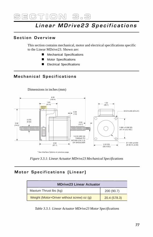
77
S e c t i o n 3 . 3L i n ea r MDr i v e23 Spec i f i c a t i o n s
S e c t i o n O v e r v i e w
This section contains mechanical, motor and electrical specifications specificto the Linear MDrive23. Shown are:
Mechanical SpecificationsMotor SpecificationsElectrical Specifications
M e c h a n i c a l S p e c i f i c a t i o n s
Dimensions in inches (mm)
Figure 3.3.1: Linear Actuator MDrive23 Mechanical Specifications
M o t o r S p e c i f i c a t i o n s ( L i n e a r )
MDrive23 Linear Actuator
Weight (Motor+Driver without screw) oz (g)
Maxium Thrust lbs (kg)
20.4 (578.3)
200 (90.7)
Table 3.3.1: Linear Actuator MDrive23 Motor Specifications
1.63(41.4)
2.22 SQ.(56.4 SQ.)
1.50(38.1)
2.92(74.2)
1.856 ±0.008 SQ.(47.14 ±0.2 SQ.)
4X Ø 0.205 (Ø 5.21)0.06(1.6)
6.00(152.4)
1/4-20 UNC-2ATHREAD TO
WITHIN 0.05 (1.3)OF SHOULDER
0.375(9.52)
2.64(67.1)
InterfaceOption *
P1
0.50(12.7)
Ø 1.500 ±0.002(Ø 38.10 ±0.05)
P2
* See Interface Options on previous page
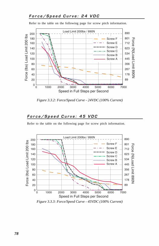
78
F o r c e / S p e e d C u r v e : 4 5 V D C
Refer to the table on the following page for screw pitch information.
F o r c e / S p e e d C u r v e : 2 4 V D C
Refer to the table on the following page for screw pitch information.
Figure 3.3.2: Force/Speed Curve - 24VDC (100% Current)
Figure 3.3.3: Force/Speed Curve - 45VDC (100% Current)
160
180
200
140
120
100
80
60
40
20
0
712
890
623
801
534
445
356
267
178
89
0 1000 2000 3000 4000 5000 6000 7000
Speed in Full Steps per Second
For
ce (
lbs)
Loa
d Li
mit
200
lbs F
orce (N)Load Lim
it 890N
w D
Scre E
w Cw Bw A
Screw F
Scre
w
ScreScreScre
Load Limit 200lbs / 890N
160
180
200
140
120
100
80
60
40
20
0
712
890
623
801
534
445
356
267
178
89
0 1000 2000 3000 4000 5000 6000 7000
Speed in Full Steps per Second
For
ce (
lbs)
Loa
d Li
mit
200
lbs F
orce (N)Load Lim
it 890N
Screw F
Screw D
Screw E
Screw CScrew BScrew A
Load Limit 200lbs / 890N
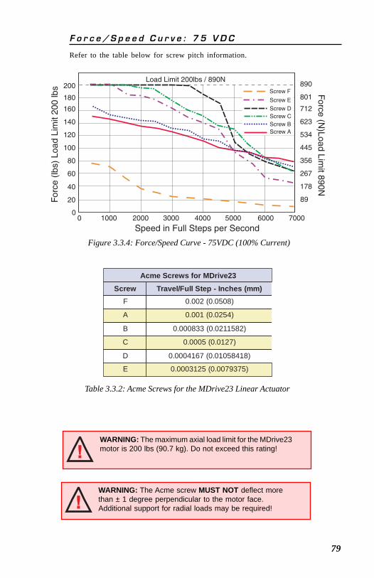
79
F o r c e / S p e e d C u r v e : 7 5 V D C
Refer to the table below for screw pitch information.
Table 3.3.2: Acme Screws for the MDrive23 Linear Actuator
Figure 3.3.4: Force/Speed Curve - 75VDC (100% Current)
WARNING: The Acme screw MUST NOT deflect morethan ± 1 degree perpendicular to the motor face.Additional support for radial loads may be required!
WARNING: The maximum axial load limit for the MDrive23motor is 200 lbs (90.7 kg). Do not exceed this rating!
Acme Screws for MDrive23
Screw Travel/Full Step - Inches (mm)F 0.002 (0.0508)
A 0.001 (0.0254)
B 0.000833 (0.0211582)
C 0.0005 (0.0127)
D 0.0004167 (0.01058418)
E 0.0003125 (0.0079375)
160
180
200
140
120
100
80
60
40
20
0
712
890
623
801
534
445
356
267
178
89
0 1000 2000 3000 4000 5000 6000 7000
Speed in Full Steps per Second
For
ce (
lbs)
Loa
d Li
mit
200
lbs F
orce (N)Load Lim
it 890N
Screw D
Screw E
Screw CScrew BScrew A
Screw F
Load Limit 200lbs / 890N
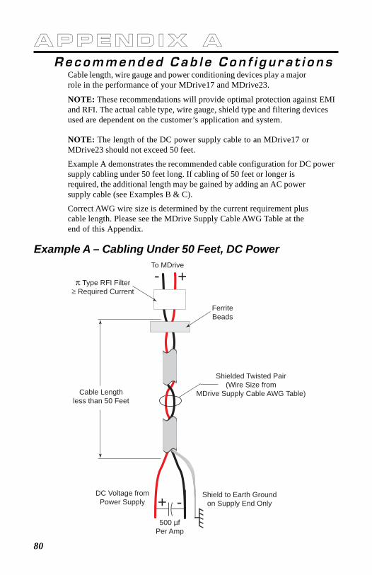
80
A P P E N D I X ARecommended Cab l e Con f i g u r a t i o n s
Cable length, wire gauge and power conditioning devices play a majorrole in the performance of your MDrive17 and MDrive23.
NOTE: These recommendations will provide optimal protection against EMIand RFI. The actual cable type, wire gauge, shield type and filtering devicesused are dependent on the customer’s application and system.
NOTE: The length of the DC power supply cable to an MDrive17 orMDrive23 should not exceed 50 feet.
Example A demonstrates the recommended cable configuration for DC powersupply cabling under 50 feet long. If cabling of 50 feet or longer isrequired, the additional length may be gained by adding an AC powersupply cable (see Examples B & C).
Correct AWG wire size is determined by the current requirement pluscable length. Please see the MDrive Supply Cable AWG Table at theend of this Appendix.
Example A – Cabling Under 50 Feet, DC Power
Shield to Earth Groundon Supply End Only
DC Voltage fromPower Supply
500 µfPer Amp
+ -
Shielded Twisted Pair(Wire Size from
MDrive Supply Cable AWG Table)
FerriteBeads
π Type RFI Filter≥ Required Current
+-To MDrive
Cable Lengthless than 50 Feet
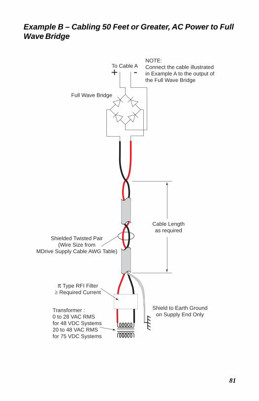
81
Example B – Cabling 50 Feet or Greater, AC Power to FullWave Bridge
Shield to Earth Groundon Supply End Only
Shielded Twisted Pair(Wire Size from
MDrive Supply Cable AWG Table)
π Type RFI Filter≥ Required Current
Cable Lengthas required
Transformer : 0 to 28 VAC RMS for 48 VDC Systems20 to 48 VAC RMSfor 75 VDC Systems
Full Wave Bridge
+ -To Cable ANOTE:Connect the cable illustratedin Example A to the output ofthe Full Wave Bridge
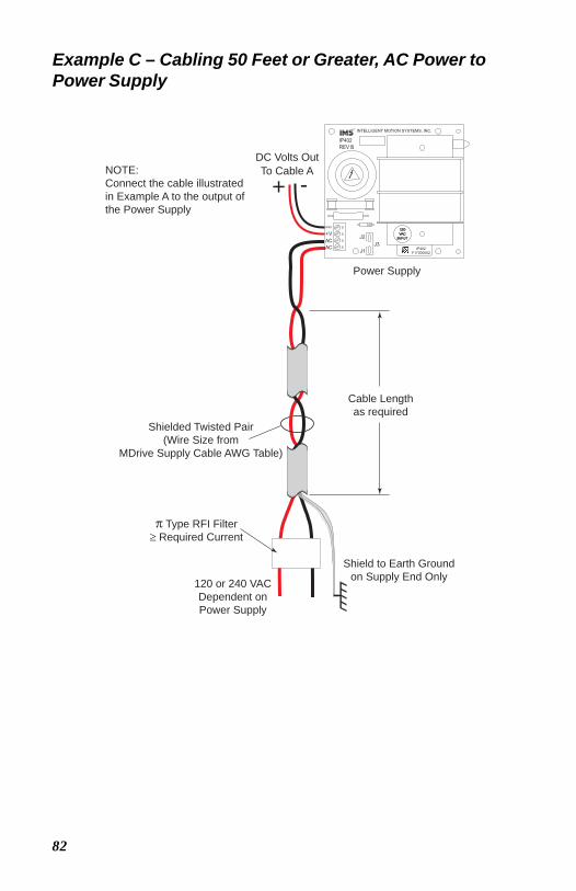
82
Example C – Cabling 50 Feet or Greater, AC Power toPower Supply
Shield to Earth Groundon Supply End Only
Shielded Twisted Pair(Wire Size from
MDrive Supply Cable AWG Table)
π Type RFI Filter≥ Required Current
Cable Lengthas required
120 or 240 VACDependent onPower Supply
Power Supply+ -
To Cable ADC Volts Out
NOTE:Connect the cable illustratedin Example A to the output ofthe Power Supply
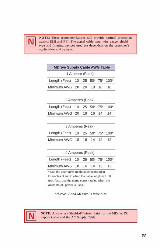
83
MDrive17 and MDrive23 Wire Size
NOTE: These recommendations will provide optimal protectionagainst EMI and RFI. The actual cable type, wire gauge, shieldtype and filtering devices used are dependent on the customer’sapplication and system.
MDrive Supply Cable AWG Table
1 Ampere (Peak)
2 Amperes (Peak)
3 Amperes (Peak)
4 Amperes (Peak)
Length (Feet)
Minimum AWG
Length (Feet)
Minimum AWG
Length (Feet)
Minimum AWG
Length (Feet)
Minimum AWG
10 25 50* 75* 100*
10 25 50* 75* 100*
10 25 50* 75* 100*
10 25 50* 75* 100*
20 20 18 18 16
20 18 16 14 14
18 16 14 12 12
18 16 14 12 12* Use the alternative methods innustrated inExamples B and C when the cable length is ≥ 50feet. Also, use the same current rating when thealternate AC power is used.
NOTE: Always use Shielded/Twisted Pairs for the MDrive DCSupply Cable and the AC Supply Cable.
84
a d d e n d u mMDr i v e w i t h P l a n e t a r y G ea r b o x
S e c t i o n O v e r v i e w
This section contains guidelines and specifications for MDrives equippedwith an optional Planetary Gearbox, and may include product sizes notrelevant to this manual.Shown are:
Product OverviewSelecting a Planetary GearboxMechanical Specifications
P r o d u c t O v e r v i e w
All gearboxes are factory installed.M o d e o f F u n c t i o n
Optional Planetary Gearbox operate as their name implies: the motor-drivensun wheel is in the center, transmitting its movement to three circumferentialplanet gears which form one stage. They are arranged on the bearing pins of aplanet carrier. The last planet carrier in each sequence is rigidly linked to theoutput shaft and so ensures the power transmission to the output shaft. Theplanet gears run in an internally toothed outer ring gear.S e r v i c e L i f e
Depending on ambient and environmental conditions and the operationalspecification of the driving system, the useful service life of a PlanetaryGearbox is up to 10,000 hours. The wide variety of potential applicationsprohibits generalizing values for the useful service life.L u b r i c a t i o n
All Planetary Gearbox are grease-packed and therefore maintenance-freethroughout their life. The best possible lubricant is used for our MDrive/Planetary Gearbox combinations.M o u n t i n g P o s i t i o n
The grease lubrication and the different sealing modes allow the PlanetaryGearbox to be installed in any position.O p e r a t i n g Te m p e r a t u r e
The temperature range for the Planetary Gearbox is between –30 and +140°C. However, the temperature range recommended for the Heat Sink of theMDrive is 0 to +85º C.
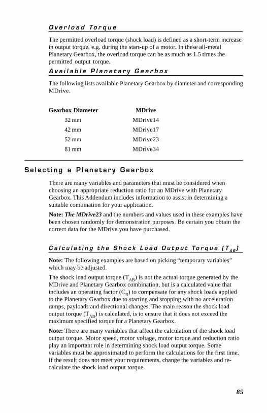
85
O v e r l o a d To r q u e
The permitted overload torque (shock load) is defined as a short-term increasein output torque, e.g. during the start-up of a motor. In these all-metalPlanetary Gearbox, the overload torque can be as much as 1.5 times thepermitted output torque.A v a i l a b l e P l a n e t a r y G e a r b o x
The following lists available Planetary Gearbox by diameter and correspondingMDrive.
Gearbox Diameter MDrive32 mm MDrive1442 mm MDrive1752 mm MDrive2381 mm MDrive34
S e l e c t i n g a P l a n e t a r y G e a r b o x
There are many variables and parameters that must be considered whenchoosing an appropriate reduction ratio for an MDrive with PlanetaryGearbox. This Addendum includes information to assist in determining asuitable combination for your application.Note: The MDrive23 and the numbers and values used in these examples havebeen chosen randomly for demonstration purposes. Be certain you obtain thecorrect data for the MDrive you have purchased.
C a l c u l a t i n g t h e S h o c k L o a d O u t p u t To r q u e ( T A B )
Note: The following examples are based on picking “temporary variables”which may be adjusted.The shock load output torque (TAB) is not the actual torque generated by theMDrive and Planetary Gearbox combination, but is a calculated value thatincludes an operating factor (CB) to compensate for any shock loads appliedto the Planetary Gearbox due to starting and stopping with no accelerationramps, payloads and directional changes. The main reason the shock loadoutput torque (TAB) is calculated, is to ensure that it does not exceed themaximum specified torque for a Planetary Gearbox.Note: There are many variables that affect the calculation of the shock loadoutput torque. Motor speed, motor voltage, motor torque and reduction ratioplay an important role in determining shock load output torque. Somevariables must be approximated to perform the calculations for the first time.If the result does not meet your requirements, change the variables and re-calculate the shock load output torque.

86
Use the equation compendium below to calculate the shock load outputtorque.
F a c t o r s
i = Reduction Ratio - The ratio of the Planetary Gearbox.nM = Motor Speed - In Revolutions Per Minute (Full Steps/
Second).nAB = Output Speed - The speed at the output shaft of the
Planetary Gearbox.TN = Nominal Output Torque - The output torque at the
output shaft of the Planetary Gearbox.TM = Motor Torque - The base MDrive torque. Refer to
MDrive Speed Torque Tables.η = Gear Efficiency - A value factored into the calculation to
allow for any friction in the gears.TAB = Shock Load Output Torque - A torque value calculated to
allow for short term loads greater than the nominal outputtorque.
CB = Operating Factor - A value that is used to factor theshock load output torque.
sf = Safety Factor - A 0.5 to 0.7 factor used to create a marginfor the MDrive torque requirement.
R e d u c t i o n R a t i o
Reduction ratio (i) is used to reduce a relatively high motor speed (nM) to alower output speed (nAB).With: i = nM ÷ nAB or: motor speed ÷ output speed = reduction ratioExample:The required speed at the output shaft of the Planetary Gearbox is90 RPM.You would divide motor speed (nM) by output speed (nAB) to calculate theproper gearbox ratio.The MDrive speed you would like to run is approximately 2000 full steps/second or 600 RPM.NOTE: In reference to the MDrive speed values, they are given in full steps/second on the Speed/Torque Tables. Most speed specifications for thePlanetary Gearbox will be given in RPM (revolutions per minute). To convertfull steps/second to RPM, divide by 200 and multiply by 60.
Where: 200 is the full steps per revolution of a 1.8° stepping motor.
2000 full steps/second ÷ 200 = 10 RPS (revolutions per second)× 60 Seconds = 600 RPM
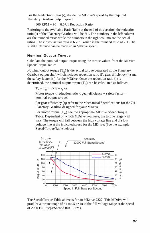
87
For the Reduction Ratio (i), divide the MDrive’s speed by the requiredPlanetary Gearbox output speed.
600 RPM ÷ 90 = 6.67:1 Reduction RatioReferring to the Available Ratio Table at the end of this section, the reductionratio (i) of the Planetary Gearbox will be 7:1. The numbers in the left columnare the rounded ratios while the numbers in the right column are the actualratios. The closest actual ratio is 6.75:1 which is the rounded ratio of 7:1. Theslight difference can be made up in MDrive speed.
N o m i n a l O u t p u t T o r q u e
Calculate the nominal output torque using the torque values from the MDriveSpeed/Torque Tables.Nominal output torque (TN) is the actual torque generated at the PlanetaryGearbox output shaft which includes reduction ratio (i), gear efficiency (η) andthe safety factor (sf) for the MDrive. Once the reduction ratio (i) isdetermined, the nominal output torque (TN) can be calculated as follows:
TN = TM × i × η ÷ sf or:Motor torque × reduction ratio × gear efficiency ÷ safety factor =nominal output torque.For gear efficiency (η) refer to the Mechanical Specifications for the 7:1Planetary Gearbox designed for your MDrive.For motor torque (TM) see the appropriate MDrive Speed/TorqueTable. Dependent on which MDrive you have, the torque range willvary. The torque will fall between the high voltage line and the lowvoltage line at the indicated speed for the MDrive. (See the exampleSpeed/Torque Table below.)
The Speed/Torque Table above is for an MDrive 2222. This MDrive willproduce a torque range of 51 to 95 oz-in in the full voltage range at the speedof 2000 Full Steps/Second (600 RPM).
140
120
100
80
60
40
20
0
99
85
71
56
42
28
14
0 1000 2000 3000 4000 5000 6000 7000
Speed in Full Steps per Second
Torq
ue in
Oz
- In
Torque in N - cm
24 VDC45 VDC
600 RPM(2000 Full Steps/Second)
95 oz-inat +45VDC
51 oz-inat +24VDC

88
Please note that this is not the usable torque range. The torque output to thePlanetary Gearbox must include a safety factor (sf) to allow for any voltageand current deviations supplied to the MDrive.
The motor torque must include a safety factor (sf) ranging from 0.5to 0.7. This must be factored into the nominal outputtorque calculation. A 0.5 safety factor is aggressive while a 0.7safety factor is more conservative.Example:The available motor torque (TM) is 51 to 95 oz-in.
NOTE: You may specify a torque less than but not greater than the motortorque range.
For this example the motor torque (TM) will be 35 oz-in.A 6.75:1 reduction ratio (i) has been determined.Gear efficiency (η) = 80% from the appropriate table for thePlanetary Gearbox which is used with an MDrive23.Nominal output torque would be:Motor torque (TM = 35) × reduction ratio (i = 6.75) × gearefficiency (η = 0.8) ÷ safety factor (sf = 0.5 or 0.7)35 × 6.75 = 236.25 × 0.8 = 189 ÷ 0.5 = 378 oz-in nominaloutput torque (TN)or35 × 6.75 = 236.25 × 0.8 = 189 ÷ 0.7 = 270 oz-in nominal outputtorque (TN)
With the safety factor (sf) and gear efficiency (η) included in the calculation,the nominal output torque (TN) may be greater than the user requirement.
S h o c k L o a d O u t p u t T o r q u e
The nominal output torque (TN) is the actual working torque the PlanetaryGearbox will generate. The shock load output torque (TAB) is the additionaltorque that can be generated by starting and stopping with no accelerationramps, payloads, inertia and directional changes. Although the nominal outputtorque (TN) of the Planetary Gearbox is accurately calculated, shock loads cangreatly increase the dynamic torque on the Planetary Gearbox.Each Planetary Gearbox has a maximum specified output torque. In thisexample a 7:1 single stage MDrive23 Planetary Gearbox is being used. Themaximum specified output torque is 566 oz-in. By calculating the shock loadoutput torque (TAB) you can verify that value is not exceeding the maximumspecified output torque.
89
When calculating the shock load output torque (TAB), the calculated nominaloutput torque (TN) and the operating factor (CB) are taken into account. CB ismerely a factor which addresses the different working conditions of aPlanetary Gearbox and is the result of your subjective appraisal. It is thereforeonly meant as a guide value. The following factors are included in theapproximate estimation of the operating factor (CB):
direction of rotation (constant or alternating)load (shocks)daily operating time
Note: The higher the operating factor (CB), the closer the shock load outputtorque (TAB) will be to the maximum specified output torque for the PlanetaryGearbox. Refer to the table below to calculate the approximate operatingfactor (CB).
With the most extreme conditions which would be a CB of 1.9, the shock loadoutput torque (TAB) is over the maximum specified torque of the PlanetaryGearbox with a 0.5 safety factor but under with a 0.7 safety factor.
The nominal output torque (TN) × the operating factor (CB) =shock load or maximum output torque (TAB).
With a 0.5 safety factor, the shock load output torque is greaterthan the maximum output torque specification of the MDrive23Planetary Gearbox. (378 × 1.9 = 718.2 oz-in.)
With a 0.7 safety factor the shock load output torque is withinmaximum output torque specification of the MDrive23 PlanetaryGearbox. (270 × 1.9 = 513 oz-in.)
The 0.5 safety factor could only be used with a lower operating factor (CB)such as 1.5 or less, or a lower motor torque.
Note: All published torque specifications are based on CB = 1.0. Therefore,the shock load output torque (TAB) = nominal output torque (TN).
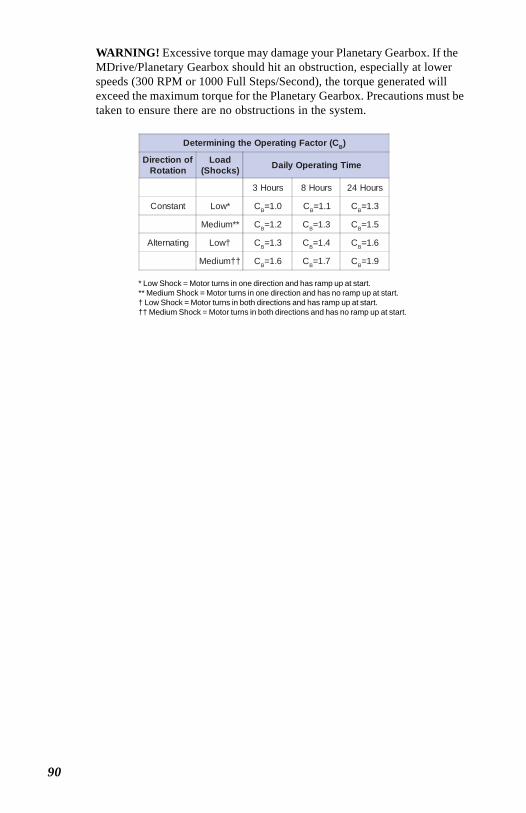
90
WARNING! Excessive torque may damage your Planetary Gearbox. If theMDrive/Planetary Gearbox should hit an obstruction, especially at lowerspeeds (300 RPM or 1000 Full Steps/Second), the torque generated willexceed the maximum torque for the Planetary Gearbox. Precautions must betaken to ensure there are no obstructions in the system.
Determining the Operating Factor (CB)
Direction ofRotation
Load(Shocks) Daily Operating Time
3 Hours 8 Hours 24 Hours
Constant Low* CB=1.0 CB=1.1 CB=1.3
Medium** CB=1.2 CB=1.3 CB=1.5
Alternating Low† CB=1.3 CB=1.4 CB=1.6
Medium†† CB=1.6 CB=1.7 CB=1.9
* Low Shock = Motor turns in one direction and has ramp up at start.** Medium Shock = Motor turns in one direction and has no ramp up at start.† Low Shock = Motor turns in both directions and has ramp up at start.†† Medium Shock = Motor turns in both directions and has no ramp up at start.
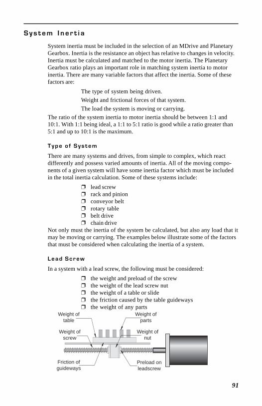
91
S y s t e m I n e r t i a
System inertia must be included in the selection of an MDrive and PlanetaryGearbox. Inertia is the resistance an object has relative to changes in velocity.Inertia must be calculated and matched to the motor inertia. The PlanetaryGearbox ratio plays an important role in matching system inertia to motorinertia. There are many variable factors that affect the inertia. Some of thesefactors are:
The type of system being driven.Weight and frictional forces of that system.The load the system is moving or carrying.
The ratio of the system inertia to motor inertia should be between 1:1 and10:1. With 1:1 being ideal, a 1:1 to 5:1 ratio is good while a ratio greater than5:1 and up to 10:1 is the maximum.
T y p e o f S y s t e m
There are many systems and drives, from simple to complex, which reactdifferently and possess varied amounts of inertia. All of the moving compo-nents of a given system will have some inertia factor which must be includedin the total inertia calculation. Some of these systems include:
lead screw rack and pinion conveyor belt rotary table belt drive chain drive
Not only must the inertia of the system be calculated, but also any load that itmay be moving or carrying. The examples below illustrate some of the factorsthat must be considered when calculating the inertia of a system.
L e a d S c r e w
In a system with a lead screw, the following must be considered: the weight and preload of the screw the weight of the lead screw nut the weight of a table or slide the friction caused by the table guideways the weight of any parts
Preload onleadscrew
Weight oftable
Weight ofparts
Friction ofguideways
Weight ofnut
Weight ofscrew
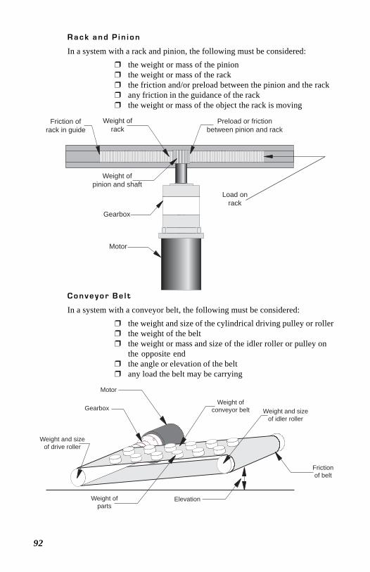
92
R a c k a n d P i n i o n
In a system with a rack and pinion, the following must be considered: the weight or mass of the pinion the weight or mass of the rack the friction and/or preload between the pinion and the rack any friction in the guidance of the rack the weight or mass of the object the rack is moving
Weight ofpinion and shaft
Preload or frictionbetween pinion and rack
Load onrack
Weight ofrack
Friction ofrack in guide
Gearbox
Motor
C o n v e y o r B e l t
In a system with a conveyor belt, the following must be considered: the weight and size of the cylindrical driving pulley or roller the weight of the belt the weight or mass and size of the idler roller or pulley on
the opposite end the angle or elevation of the belt any load the belt may be carrying
Weight and sizeof drive roller
Weight and sizeof idler roller
Weight ofconveyor belt
Weight ofparts
Frictionof belt
Elevation
Motor
Gearbox
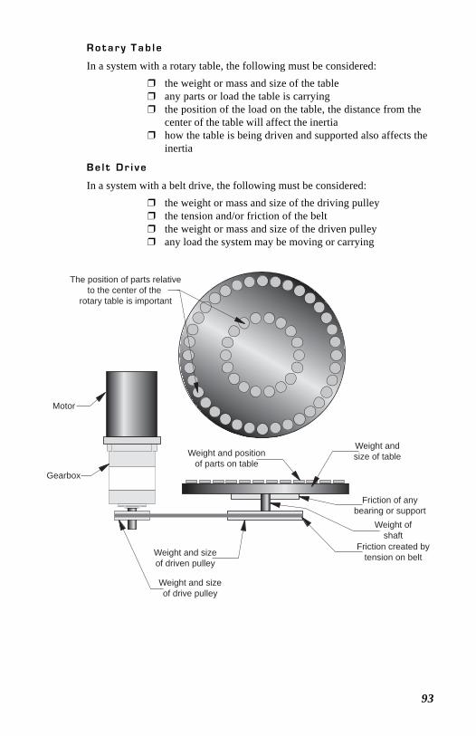
93
R o t a r y T a b l e
In a system with a rotary table, the following must be considered: the weight or mass and size of the table any parts or load the table is carrying the position of the load on the table, the distance from the
center of the table will affect the inertia how the table is being driven and supported also affects the
inertia
Weight and sizeof drive pulley
Weight and sizeof driven pulley
Friction created bytension on belt
Weight ofshaft
Weight andsize of tableWeight and position
of parts on table
The position of parts relativeto the center of the
rotary table is important
Friction of anybearing or support
Motor
Gearbox
B e l t D r i v e
In a system with a belt drive, the following must be considered: the weight or mass and size of the driving pulley the tension and/or friction of the belt the weight or mass and size of the driven pulley any load the system may be moving or carrying
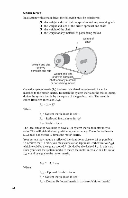
94
C h a i n D r i v e
In a system with a chain drive, the following must be considered: the weight and size of drive sprocket and any attaching hub the weight and size of the driven sprocket and shaft the weight of the chain the weight of any material or parts being moved
Weight ofchain
Weight and sizeof drive
sprocket and hubWeight and size
of driven sprocket,shaft and any material or parts being moved
Once the system inertia (JL) has been calculated in oz-in-sec2, it can bematched to the motor inertia. To match the system inertia to the motor inertia,divide the system inertia by the square of the gearbox ratio. The result iscalled Reflected Inertia or (Jref).
Jref = JL ÷ Ζ2
Where:JL = System Inertia in oz-in-sec2
Jref = Reflected Inertia in oz-in-sec2
Z = Gearbox RatioThe ideal situation would be to have a 1:1 system inertia to motor inertiaratio. This will yield the best positioning and accuracy. The reflected inertia(Jref) must not exceed 10 times the motor inertia.Your system may require a reflected inertia ratio as close to 1:1 as possible.To achieve the 1:1 ratio, you must calculate an Optimal Gearbox Ratio (Zopt)which would be the square root of JL divided by the desired Jref. In this casesince you want the system inertia to match the motor inertia with a 1:1 ratio,Jref would be equal to the motor inertia.
Zopt = JL ÷ Jref
Where:Zopt = Optimal Gearbox RatioJL = System Inertia in oz-in-sec2
Jref = Desired Reflected Inertia in oz-in-sec2 (Motor Inertia)
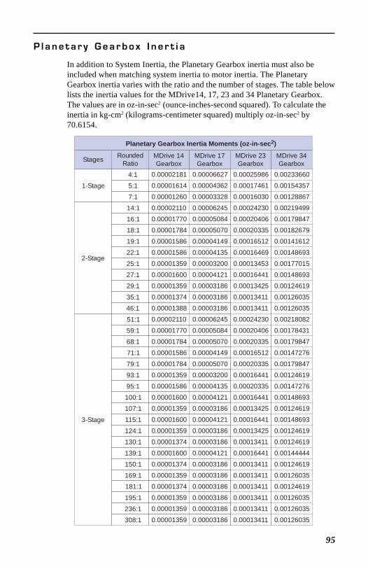
95
P l a n e t a r y G e a r b o x I n e r t i a
In addition to System Inertia, the Planetary Gearbox inertia must also beincluded when matching system inertia to motor inertia. The PlanetaryGearbox inertia varies with the ratio and the number of stages. The table belowlists the inertia values for the MDrive14, 17, 23 and 34 Planetary Gearbox.The values are in oz-in-sec2 (ounce-inches-second squared). To calculate theinertia in kg-cm2 (kilograms-centimeter squared) multiply oz-in-sec2 by70.6154.
Stages RoundedRatio
1-Stage4:15:1
7:1
2-Stage
14:1
16:1
18:1
19:1
22:1
25:1
27:1
29:1
35:1
46:1
3-Stage
51:1
59:1
68:1
71:1
79:1
93:1
95:1
100:1
107:1
115:1
124:1
130:1
139:1
150:1
169:1
181:1
195:1
236:1
308:1
MDrive 14Gearbox
MDrive 17Gearbox
MDrive 23Gearbox
MDrive 34Gearbox
0.00002181
0.00001614
0.00001260
0.00002110
0.00001770
0.00001784
0.00001586
0.00001586
0.00001359
0.00001600
0.00001359
0.00001374
0.00001388
0.00002110
0.00001770
0.00001784
0.00001586
0.00001784
0.00001359
0.00001586
0.00001600
0.00001359
0.00001600
0.00001359
0.00001374
0.00001600
0.00001374
0.00001359
0.00001374
0.00001359
0.00001359
0.00001359
0.00006627
0.00004362
0.00003328
0.00006245
0.00005084
0.00005070
0.00004149
0.00004135
0.00003200
0.00004121
0.00003186
0.00003186
0.00003186
0.00006245
0.00005084
0.00005070
0.00004149
0.00005070
0.00003200
0.00004135
0.00004121
0.00003186
0.00004121
0.00003186
0.00003186
0.00004121
0.00003186
0.00003186
0.00003186
0.00003186
0.00003186
0.00003186
0.00025986
0.00017461
0.00016030
0.00024230
0.00020406
0.00020335
0.00016512
0.00016469
0.00013453
0.00016441
0.00013425
0.00013411
0.00013411
0.00024230
0.00020406
0.00020335
0.00016512
0.00020335
0.00016441
0.00020335
0.00016441
0.00013425
0.00016441
0.00013425
0.00013411
0.00016441
0.00013411
0.00013411
0.00013411
0.00013411
0.00013411
0.00013411
0.00233660
0.00154357
0.00128867
0.00219499
0.00179847
0.00182679
0.00141612
0.00148693
0.00177015
0.00148693
0.00124619
0.00126035
0.00126035
0.00218082
0.00178431
0.00179847
0.00147276
0.00179847
0.00124619
0.00147276
0.00148693
0.00124619
0.00148693
0.00124619
0.00124619
0.00144444
0.00124619
0.00126035
0.00124619
0.00126035
0.00126035
0.00126035
Planetary Gearbox Inertia Moments (oz-in-sec2)
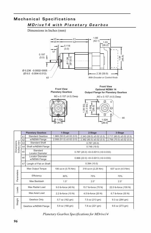
96
M e c h a n i c a l S p e c i f i c a t i o n s
Planetary Gearbox Specifications for MDrive14
Ø 1
.26
(Ø 3
2.0)
k1
0.118(3.0)
k21.66(42.1)
2.36 (59.9)
1.84
(46.
8)
1.03(26.2)
M3 x 0.157 (4.0) Deep
1.02
4(2
6.0)
1.39
SQ
.(3
5.3
SQ
.)
1.024(26.0)
Front ViewOptional NEMA 14
Output Flange for Planetary GearboxFront View
Planetary Gearbox
M3 x 0.157 (4.0) Deep
Ø 1.024(Ø 26.0)
k3k4
With Encoder or Control Knob
Ø 0.236 -0.0002/-0005(Ø 6.0 -0.004/-0.012)
0.197(5.0)
k5
k6
k7
M D r i v e 1 4 w i t h P l a n e t a r y G e a r b o x
Dimensions in Inches (mm)
Planetary Gearbox 1-Stage 2-Stage 3-StageStandard Gearboxw/NEMA FlangeStandard Shaft
k1k2k3k4
k5
k6
Shaft w/NEMA Flange
StandardLocator DiameterLocator Diameterw/NEMA Flange
Max Output Torque
Efficiency
Max Backlash
Max Radial Load
Max Axial Load
Gearbox Only
Gearbox w/NEMA FlangeWei
ght
Load
sP
aram
eter
sD
imen
sion
sIn
ches
(mm
)
1.969 (50.0) ±0.02 (0.5)2.008 (51.0) ±0.02 (0.5)
2.343 (59.5) ±0.02 (0.5)2.382 (60.5) ±0.02 (0.5)
2.717 (60.0) ±0.02 (0.5)2.756 (70.0) ±0.02 (0.5)
0.787 (20.0)0.748 (19.0)
0.787 (20.0) +0/-0.0013 (+0/-0.033)
0.866 (22.0) +0/-0.0013 (+0/-0.033)
106 oz-in (0.75 Nm) 318 oz-in (2.25 Nm) 637 oz-in (4.5 Nm)
80% 75% 70%
1.5° 2.0° 2.5°
9.0 lb-force (40 N)
2.2 lb-force (10 N)
5.7 oz (162 gm)
5.9 oz (168 gm)
15.7 lb-force (70 N)
4.5 lb-force (20 N)
7.5 oz (213 gm)
7.8 oz (221 gm)
22.0 lb-force (100 N)
6.7 lb-force (30 N)
9.3 oz (264 gm)
9.6 oz (273 gm)
k7 Length of Flat on Shaft 0.394 (10.0)
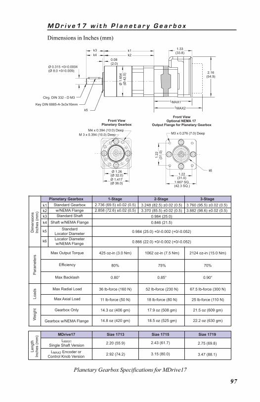
97
Planetary Gearbox 1-Stage 2-Stage 3-StageStandard Gearboxw/NEMA FlangeStandard Shaft
k1k2k3k4
k5
k6
Shaft w/NEMA Flange
StandardLocator DiameterLocator Diameterw/NEMA Flange
Max Output Torque
Efficiency
Max Backlash
Max Radial Load
Max Axial Load
Gearbox Only
Gearbox w/NEMA FlangeWei
ght
Load
sP
aram
eter
sD
imen
sion
sIn
ches
(mm
)
2.736 (69.5) ±0.02 (0.5)2.858 (72.6) ±0.02 (0.5)
3.248 (82.5) ±0.02 (0.5)3.370 (85.5) ±0.02 (0.5)
3.760 (95.5) ±0.02 (0.5)3.882 (98.6) ±0.02 (0.5)
0.984 (25.0)0.846 (21.5)
0.984 (25.0) +0/-0.002 (+0/-0.052)
0.866 (22.0) +0/-0.002 (+0/-0.052)
425 oz-in (3.0 Nm) 1062 oz-in (7.5 Nm) 2124 oz-in (15.0 Nm)
80% 75% 70%
0.80° 0.85° 0.90°
36 lb-force (160 N)
11 lb-force (50 N)
14.3 oz (406 gm)
14.8 oz (420 gm)
52 lb-force (230 N)
18 lb-force (80 N)
17.9 oz (508 gm)
18.5 oz (525 gm)
67.5 lb-force (300 N)
25 lb-force (110 N)
21.5 oz (609 gm)
22.2 oz (630 gm)
MDrive17 Size 1713 Size 1715 Size 1719LMAX1
Single Shaft Version
LMAX2 Encoder orControl Knob Version
2.20 (55.9)
2.92 (74.2)
2.43 (61.7)
3.15 (80.0)
2.75 (69.8)
3.47 (88.1)
Leng
thIn
ches
(mm
)
Planetary Gearbox Specifications for MDrive17
M D r i v e 1 7 w i t h P l a n e t a r y G e a r b o x
Dimensions in Inches (mm)
M4 x 0.394 (10.0) DeepM 3 x 0.394 (10.0) Deep
Front ViewPlanetary Gearbox
Ø 1.26(Ø 32.0)Ø 1.417(Ø 36.0)
M3 x 0.276 (7.0) Deep
Front ViewOptional NEMA 17
Output Flange for Planetary Gearbox
1.22
(31.
0)
1.22(31.0)
1.667 SQ.(42.3 SQ.)
Key DIN 6885-A-3x3x16mm
Ctrg. DIN 332 - D M3
0.08(2.0)
Ø 0.315 +0/-0.0004(Ø 8.0 +0/-0.009)
k1
Ø 1
.654
(Ø 4
2.0)
1.33(33.8)
2.16(54.9)
MAX1
MAX2
L
L
k2k3k4
k5
k6
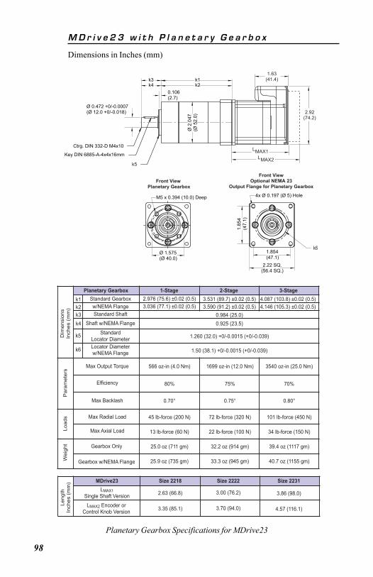
98
M D r i v e 2 3 w i t h P l a n e t a r y G e a r b o x
Dimensions in Inches (mm)
Planetary Gearbox 1-Stage 2-Stage 3-StageStandard Gearboxw/NEMA FlangeStandard Shaft
k1k2k3k4
k5
k6
Shaft w/NEMA Flange
StandardLocator DiameterLocator Diameterw/NEMA Flange
Max Output Torque
Efficiency
Max Backlash
Max Radial Load
Max Axial Load
Gearbox Only
Gearbox w/NEMA FlangeWei
ght
Load
sP
aram
eter
sD
imen
sion
sIn
ches
(mm
)
2.976 (75.6) ±0.02 (0.5)3.036 (77.1) ±0.02 (0.5)
3.531 (89.7) ±0.02 (0.5)3.590 (91.2) ±0.02 (0.5)
4.087 (103.8) ±0.02 (0.5)4.146 (105.3) ±0.02 (0.5)
0.984 (25.0)0.925 (23.5)
1.260 (32.0) +0/-0.0015 (+0/-0.039)
1.50 (38.1) +0/-0.0015 (+0/-0.039)
566 oz-in (4.0 Nm) 1699 oz-in (12.0 Nm) 3540 oz-in (25.0 Nm)
80% 75% 70%
0.70° 0.75° 0.80°
45 lb-force (200 N)
13 lb-force (60 N)
25.0 oz (711 gm)
25.9 oz (735 gm)
72 lb-force (320 N)
22 lb-force (100 N)
32.2 oz (914 gm)
33.3 oz (945 gm)
101 lb-force (450 N)
34 lb-force (150 N)
39.4 oz (1117 gm)
40.7 oz (1155 gm)
MDrive23 Size 2218 Size 2222 Size 2231LMAX1
Single Shaft Version
LMAX2 Encoder orControl Knob Version
2.63 (66.8)
3.35 (85.1)
3.00 (76.2)
3.70 (94.0)
3.86 (98.0)
4.57 (116.1)
Leng
thIn
ches
(mm
)
Planetary Gearbox Specifications for MDrive23
Key DIN 6885-A-4x4x16mm
Ctrg. DIN 332-D M4x10
0.106(2.7)
Ø 2
.047
(Ø 5
2.0)
k1k2
Ø 0.472 +0/-0.0007(Ø 12.0 +0/-0.018)
1.63(41.4)
2.92(74.2)
LMAX1LMAX2
k3k4
4x Ø 0.197 (Ø 5) Hole
1.854(47.1)
1.85
4(4
7.1)
2.22 SQ.(56.4 SQ.)
Front ViewOptional NEMA 23
Output Flange for Planetary Gearbox
M5 x 0.394 (10.0) Deep
Front View Planetary Gearbox
Ø 1.575(Ø 40.0)
k6
k5
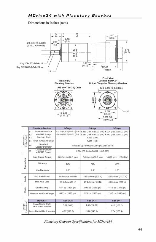
99
Planetary Gearbox 1-Stage 2-Stage 3-StageStandard Gearboxw/NEMA FlangeStandard Shaft
k1k2k3k4
k5
k6
Shaft w/NEMA Flange
StandardLocator DiameterLocator Diameterw/NEMA Flange
Max Output Torque
Efficiency
Max Backlash
Max Radial Load
Max Axial Load
Gearbox Only
Gearbox w/NEMA FlangeWei
ght
Load
sP
aram
eter
sD
imen
sion
sIn
ches
(mm
)
4.315 (109.6) ±0.02 (0.5)4.433 (112.6) ±0.02 (0.5)
5.169 (131.3) ±0.02 (0.5)5.287 (134.3) ±0.02 (0.5)
6.024 (153.0) ±0.02 (0.5)6.142 (156.0) ±0.02 (0.5)
1.929 (49.0)1.811 (46.0)
1.969 (50.0) +0.0006/-0.0004 (+0.015/-0.010)
2.874 (73.0) +0/-0.0012 (+0/-0.030)
2832 oz-in (20.0 Nm) 8496 oz-in (60.0 Nm) 16992 oz-in (120.0 Nm)
80% 75% 70%
1.0° 1.5° 2.0°
90 lb-force (400 N)
18 lb-force (80 N)
64.4 oz (1827 gm)
66.7 oz (1890 gm)
135 lb-force (600 N)
27 lb-force (120 N)
89.5 oz (2538 gm)
92.6 oz (2625 gm)
225 lb-force (1000 N)
45 lb-force (200 N)
114.6 oz (3248 gm)
118.5 oz (3360 gm)
MDrive34 Size 3424 Size 3431 Size 3447LMAX1 Single Shaftor Encoder Version
LMAX2 Control Knob Version
3.81 (96.8)
4.97 (126.2)
4.60 (116.80)
5.76 (146.3)
6.17 (156.7)
7.34 (186.4)
Leng
thIn
ches
(mm
)
Planetary Gearbox Specifications for MDrive34
M D r i v e 3 4 w i t h P l a n e t a r y G e a r b o x
Dimensions in Inches (mm)
Key DIN 6885-A-6x6x28mm
Ctrg. DIN 332-D M6x16
0.197 (5.0)
k1
1.575(40.0)
Ø 3
.189
(Ø 8
1.0)
Ø 0.748 +0/-0.0008(Ø 19.0 +0/-0.021)
LMAX1
3.73(94.7)
0.39(10.0)
LMAX2
2.07(52.6)
k3k2k4
4x Ø 0.217 (Ø 5.5) Hole
3.386 SQ.(86.0 SQ.)
2.739(69.58)
2.73
9(6
9.58
)
Front ViewOptional NEMA 34
Output Flange for Planetary Gearbox
M6 x 0.472 (12.0) DeepM6 x 0.472 (12.0) Deep
Ø 2.56(Ø 65.0)
Front ViewPlanetary Gearbox
k6
k5
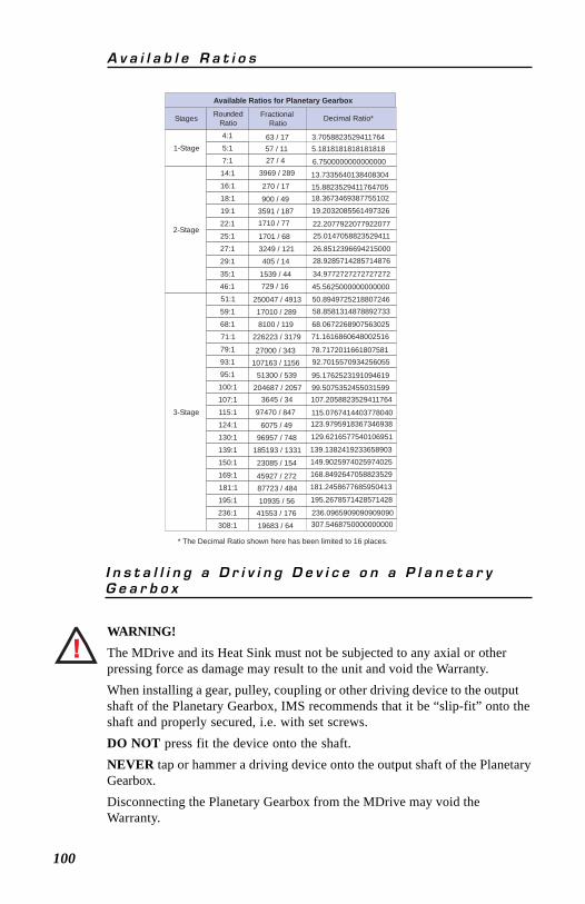
100
WARNING!The MDrive and its Heat Sink must not be subjected to any axial or otherpressing force as damage may result to the unit and void the Warranty.When installing a gear, pulley, coupling or other driving device to the outputshaft of the Planetary Gearbox, IMS recommends that it be “slip-fit” onto theshaft and properly secured, i.e. with set screws.DO NOT press fit the device onto the shaft.NEVER tap or hammer a driving device onto the output shaft of the PlanetaryGearbox.Disconnecting the Planetary Gearbox from the MDrive may void theWarranty.
A v a i l a b l e R a t i o s
I n s t a l l i n g a D r i v i n g D e v i c e o n a P l a n e t a r yG e a r b o x
Stages RoundedRatio
1-Stage4:15:1
7:1
2-Stage
14:1
16:1
18:1
19:1
22:1
25:1
27:1
29:1
35:1
46:1
3-Stage
51:1
59:1
68:1
71:1
79:1
93:1
95:1
100:1
107:1
115:1
124:1
130:1
139:1
150:1
169:1
181:1
195:1
236:1
308:1
Fractional Ratio Decimal Ratio*
Available Ratios for Planetary Gearbox
3.70588235294117645.1818181818181818
13.733564013840830415.8823529411764705
6.7500000000000000
18.3673469387755102
19.2032085561497326
22.207792207792207725.0147058823529411
26.851239669421500028.9285714285714876
34.9772727272727272
45.5625000000000000
50.894972521880724658.8581314878892733
68.067226890756302571.1616860648002516
78.717201166180758192.7015570934256055
95.176252319109461999.5075352455031599107.2058823529411764
115.0767414403778040123.9795918367346938
129.6216577540106951
139.1382419233658903149.9025974025974025168.8492647058823529
181.2458677685950413
195.2678571428571428
236.0965909090909090307.5468750000000000
63 / 1757 / 1127 / 4
3969 / 289
270 / 17
900 / 493591 / 1871710 / 77
1701 / 683249 / 121405 / 14
1539 / 44729 / 16
250047 / 491317010 / 2898100 / 119
226223 / 3179
27000 / 343107163 / 1156
51300 / 539204687 / 2057
3645 / 34
97470 / 847
6075 / 4996957 / 748
185193 / 1331
23085 / 154
45927 / 27287723 / 484
10935 / 5641553 / 176
19683 / 64
* The Decimal Ratio shown here has been limited to 16 places.

WARRANTY
TWENTY-FOUR (24) MONTH LIMITED WARRANTYIntelligent Motion Systems, Inc. (“IMS”), warrants only to the purchaser of the Product
from IMS (the “Customer”) that the product purchased from IMS (the “Product”) will be freefrom defects in materials and workmanship under the normal use and service for whichthe Product was designed for a period of 24 months from the date of purchase of theProduct by the Customer. Customer’s exclusive remedy under this Limited Warranty shallbe the repair or replacement, at Company’s sole option, of the Product, or any part of theProduct, determined by IMS to be defective. In order to exercise its warranty rights,Customer must notify Company in accordance with the instructions described under theheading “Obtaining Warranty Service.”
This Limited Warranty does not extend to any Product damaged by reason of alteration,accident, abuse, neglect or misuse or improper or inadequate handling; improper orinadequate wiring utilized or installed in connection with the Product; installation, operationor use of the Product not made in strict accordance with the specifications and writteninstructions provided by IMS; use of the Product for any purpose other than those forwhich it was designed; ordinary wear and tear; disasters or Acts of God; unauthorizedattachments, alterations or modifications to the Product; the misuse or failure of any itemor equipment connected to the Product not supplied by IMS; improper maintenance orrepair of the Product; or any other reason or event not caused by IMS.
IMS HEREBY DISCLAIMS ALL OTHER WARRANTIES, WHETHER WRITTEN OR ORAL,EXPRESS OR IMPLIED BY LAW OR OTHERWISE, INCLUDING WITHOUT LIMITATION, ANYWARRANTIES OF MERCHANTABILITY OR FITNESS FOR ANY PARTICULAR PURPOSE.CUSTOMER’S SOLE REMEDY FOR ANY DEFECTIVE PRODUCT WILL BE AS STATED ABOVE,AND IN NO EVENT WILL THE IMS BE LIABLE FOR INCIDENTAL, CONSEQUENTIAL, SPECIALOR INDIRECT DAMAGES IN CONNECTION WITH THE PRODUCT.
This Limited Warranty shall be void if the Customer fails to comply with all of the termsset forth in this Limited Warranty. This Limited Warranty is the sole warranty offered byIMS with respect to the Product. IMS does not assume any other liability in connection withthe sale of the Product. No representative of IMS is authorized to extend this LimitedWarranty or to change it in any manner whatsoever. No warranty applies to any partyother than the original Customer.
IMS and its directors, officers, employees, subsidiaries and affiliates shall not be liablefor any damages arising from any loss of equipment, loss or distortion of data, loss of time,loss or destruction of software or other property, loss of production or profits, overheadcosts, claims of third parties, labor or materials, penalties or liquidated damages or punitivedamages, whatsoever, whether based upon breach of warranty, breach of contract,negligence, strict liability or any other legal theory, or other losses or expenses incurredby the Customer or any third party.OBTAINING WARRANTY SERVICE
Warranty service may obtained by a distributor, if the Product was purchased from IMSby a distributor, or by the Customer directly from IMS, if the Product was purchaseddirectly from IMS. Prior to returning the Product for service, a Returned Material Authorization(RMA) number must be obtained. Complete the form at http://www.imshome.com/rma.htmlafter which an RMA Authorization Form with RMA number will then be faxed to you. Anyquestions, contact IMS Customer Service (860) 295-6102.
Include a copy of the RMA Authorization Form, contact name and address, and anyadditional notes regarding the Product failure with shipment. Return Product in its originalpackaging, or packaged so it is protected against electrostatic discharge or physicaldamage in transit. The RMA number MUST appear on the box or packing slip. Send Productto: Intelligent Motion Systems, Inc., 370 N. Main Street, Marlborough, CT 06447.
Customer shall prepay shipping changes for Products returned to IMS for warrantyservice and IMS shall pay for return of Products to Customer by ground transportation.However, Customer shall pay all shipping charges, duties and taxes for Products returnedto IMS from outside the United States.
MDrive17/23 Operating Instructions
P.O. Box 457, 370 North Main StreetMarlborough, CT 06447 U.S.A.
Phone: 860/295-6102Fax: 860/295-6107E-mail: [email protected] Page: www.imshome.com
TECHNICAL SUPPORTEastern U.S.Phone: 860/295-6102Fax: 860/295-6107E-mail: [email protected] U.S.Phone: 760/966-3162Fax: 760/966-3165E-mail: [email protected]
IMS MOTORS DIVISION105 Copperwood Way, Suite HOceanside, CA 92054Phone: 760/966-3162Fax: 760/966-3165E-mail: [email protected]
IMS EUROPE GmbHHahnstrasse 10, VS-SchwenningenGermany D-78054Phone: +49/7720/94138-0Fax: +49/7720/94138-2European Sales Management4 Quai Des Etroits69005 Lyon, FrancePhone: +33/4 7256 5113Fax: +33/4 7838 1537German Sales/Technical SupportPhone: +49/35205/4587-8Fax: +49/35205/4587-9E-mail: [email protected]
Revision 042905