engineering drawing i - high approach
TRANSCRIPT
Government of NepalMinistry of Education, Science and TechnologyCurriculum Development Centre
Sanothimi, BhaktapurPhone : 5639122/6634373/6635046/6630088
Website : www.moecdc.gov.np
Engineering Drawing I
Electrical Engineering 9
Technical and Vocational Stream
Learning Resource Material
Engineering Drawing - I
(Grade 9)
Secondary Level
Electrical Engineering
Government of Nepal
Ministry of Education, Science and Technology
Curriculum Development Centre Sanothimi, Bhaktapur
Feedback Copy

Publisher : Government of Nepal
Ministry of Education, Science and Technology
Curriculum Development Centre
Sanothimi, Bhaktapur
© Publisher
Layout by Khados Sunuwar
All rights reserved. No part of this publication may be reproduced, stored in a retrieval system or transmitted, in any other form or by any means for commercial purpose without the prior permission in writing of Curriculum Development Centre.

Preface The curriculum and curricular materials have been developed and revised on a regular basis with the aim of making education objective-oriented, practical, relevant and job oriented. It is necessary to instill the feelings of nationalism, national integrity and democratic spirit in students and equip them with morality, discipline and self-reliance, creativity and thoughtfulness. It is essential to develop in them the linguistic and mathematical skills, knowledge of science, information and communication technology, environment, health and population and life skills. it is also necessary to bring in them the feeling of preserving and promoting arts and aesthetics, humanistic norms, values and ideals. It has become the need of the present time to make them aware of respect for ethnicity, gender, disabilities, languages, religions, cultures, regional diversity, human rights and social values so as to make them capable of playing the role of responsible citizens with applied technical and vocational knowledge and skills. This Learning Resource Material for Electrical Engineering has been developed in line with the Secondary Level Electrical Engineering Curriculum with an aim to facilitate the students in their study and learning on the subject by incorporating the recommendations and feedback obtained from various schools, workshops and seminars, interaction programs attended by teachers, students and parents.
In bringing out the learning resource material in this form, the contribution of the Director General of CDC Dr. Lekhnath Poudel, Pro.Dr. Indraman Tamrakar, Prashant Kumar Ghimire, Akhileshwar Mishra, Rupesha Maharjan, Arjun Devkota, Sanju Shrestha, Rashna Shrestha, Ananta Dhungana, Shivaram Shrestha, is highly acknowledged. The book is written by Nabin Adhikari and the subject matter of the book was edited by Badrinath Timalsina and Khilanath Dhamala. CDC extends sincere thanks to all those who have contributed in developing this book in this form.
This book is a supplimentary learning resource material for students and teachrs. In addition they have to make use of other relevnt materials to ensure all the learning outcomes set in the curriculum. The teachers, students and all other stakeholders are expected to make constructive comments and suggestions to make it a more useful learning resource material.
2076 BS Ministry of Education, Science and Technology Curriculum Development Centre

Content
S.N. Subjects Page No. Unit 1 : INTRODUCTION OF DRAWING 1
Unit 2 : Introduction of Line and Geometrical Shape 12
Unit 3 : Freehand Practicing 20
Unit 4 : LETTERING 20
Unit 5 : Practicing the Line and Circle using Drawing Instruments 25
Unit 6 : SCALES 38
Unit 7 : Geometrical Constructions 45
Unit 8 : Divisions 58
Unit 9 : Tangent 61
Unit 10 : Engineering Curves 68
Unit 11 : Conic Sections 74
Unit 12 : Dimensioning 86
Unit 13 : Orthographic Projections 96
Unit 14 : Isometric Projection 108
Unit 15 : Projection of Points and True Length of Line 131
Unit 16 : Section 146
Unit 17 : Development of Surfaces 161
Unit 18 : Intersection of Two Solids 181
Unit 19 : Land Measurement 186

Engineering Drawing 1 : Grade 9 1
Unit: 1
INTRODUCTION OF DRAWING Learning outcomes
After completion of this unit, the students will be able to;
Understand the drawing types.
Handel the drawing tools and material properly.
Understand about the geometric shape and its parts.
Measure the site plan in the field.
Introduction to Drawing
Drawing is a form of visual art in which a person uses various drawing instruments
to mark paper or another two-dimensional medium. Instruments include graphite
pencils, pen and ink, various kinds of paints, inked brushes, colored pencils,
crayons, charcoal, chalk, pastels, various kinds of erasers, markers, styluses, and
various metals (like silverpoint).
"Digital drawing" is the act of using a computer to draw. Common methods of
digital drawing include a stylus or finger on a touch -screen device, stylus-to-
touchpad, finger-to-touchpad, or in some cases, a mouse.
A drawing instrument releases a small amount of material onto a surface, leaving a
visible mark. The most common support for drawing is paper, although other
materials, such as cardboard, plastic, leather, canvas, and board, may be used.
Temporary drawings may be made on blackboard or whiteboard or indeed
almost anything. The medium has been a popular and fundamental means of public
expression throughout human history. It is one of the simplest and most efficient
means of communicating visual ideas. The wide availability of drawing instruments
makes drawing one of the most common artistic activities.
In addition to its more artistic forms, drawing is frequently used in commercial
illustration, animation, architecture, engineering and technical drawing. A quick,
freehand drawing, usually not intended as a finished work, is sometimes called
2 Engineering Drawing 1 : Grade 9
a sketch. An artist who practices or works in technical drawing may be called
a drafter, draftsman or a draughtsman.
Types of drawing
Illustration Drawing
These are drawings that are created to represent the lay-out of a particular
document. They include all the basic details of the project concerned clearly stating
its purpose, style, size, color, character, and effect.
Life Drawing
Drawings that result from direct or real observations are life drawings. Life
drawing, also known as still-life drawing or figure drawing, portrays all the
expressions that are viewed by the artist and captured in the picture. The human
figure forms one of the most enduring themes in life drawing that is applied to
portraiture, sculpture, medical illustration, cartooning and comic book illustration,
and other fields.
Emotive Drawing
Similar to painting, emotive drawing emphasizes the exploration and expression of
different emotions, feelings, and moods. These are generally depicted in the form
of a personality.
Analytic Drawing
Sketches that are created for clear understanding and representation of observations
made by an artist are called analytic drawings. In simple words, analytic drawing is
undertaken to divide observations into small parts for a better perspective.
Perspective Drawing
Perspective drawing is used by artists to create three-dimensional images on a two-
dimensional picture plane, such as paper. It represents space, distance, volume,
light, surface planes, and scale, all viewed from a particular eye-level.
Diagrammatic Drawing
When concepts and ideas are explored and investigated, these are documented on

Engineering Drawing 1 : Grade 9 3
paper through diagrammatic drawing. Diagrams are created to depict adjacencies
and happenstance that are likely to take place in the immediate future. Thus,
diagrammatic drawings serve as active design process for the instant ideas so
conceived.
Geometric Drawing
Geometric drawing is used, particularly, in construction fields that demand specific
dimensions. Measured scales, true sides, sections, and various other descriptive
views are represented through geometric drawing.
Engineering Drawing
Engineering drawing is a two dimensional representation of three dimensional
objects. In general, it provides necessary information about the shape, size, surface
quality, material, manufacturing process, etc., of the object. It is the graphic
language from which a trained person can visualize objects.
Drawings prepared in one country may be utilized in any other country
irrespective of the language spoken. Hence, engineering drawing is called the
universal language of engineers. Any language to be communicative should
follow certain rules so that it conveys the same meaning to everyone.
Similarly, drawing practice must follow certain rules, if it is to serve as a
means of communication. For this purpose, Bureau of Indian Standards (BIS)
adapted the International Standards on code of practice for drawing. The
other foreign standards are: DIN of Germany, BS of Britain and ANSI of
America.
Role of Engineering Drawing
The ability to read drawing is the most important requirement of all technical people
in any profession. As compared to verbal or written description, this method is brief
and more clear. Some of the applications are: building drawing for civil engineers,
machine drawing for mechanical engineers, circuit diagrams for electrical and
electronics engineers, computer graphics for one and all.
The subject in general is designed to impart the following skills.

4 Engineering Drawing 1 : Grade 9
1. Ability to read and prepare engineering drawings.
2. Ability to make free - hand sketching of objects.
3. Power to imagine analyses and communicate, and 4.Capacity to understand
other subjects.
Drawing Instrument and Aids
The Instruments and other aids used in drafting work are listed below:
1. Drawing board
2. Mini drafting
3. Instrument box
4. Set squares
5. Protractor
6. Set of scales
7. French curves
8. Drawing sheets
9. Pencils
10. Templates
Drawing boards
Recently drawing boards used are made of well-seasoned softwood of about 25 mm
thick with a working edge for T-square. Nowadays mini-draftingis used instead of
T-squares which can be fixed on any board. The standard size of board depends on
the size of drawing sheet size required.
Mini-Drafting
Mini-drafting consists of an angle formed by two arms with scales marked and
rigidly hinged to each other (Fig. I. I ). It combines the functions off-square, set-
squares, scales and protractor. It is used for drawing horizontal, vertical and inclined
lines, parallel and perpendicular lines and for measuring lines and angles.

Engineering Drawing 1 : Grade 9 5
Instrument Box Instrument box contains:-
1. Compass
2. Dividers and
3. Inking pens.
What is important is the position of the pencil lead with respect to the tip of the
compass. It should be at least I mm because the tip goes into the board for grip by
1 mm.
Set of Scales
Mini Drafter
6 Engineering Drawing 1 : Grade 9
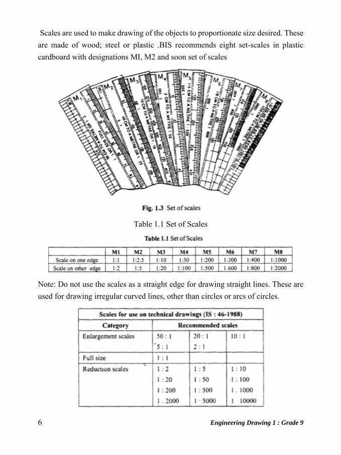
Scales are used to make drawing of the objects to proportionate size desired. These
are made of wood; steel or plastic .BIS recommends eight set-scales in plastic
cardboard with designations MI, M2 and soon set of scales
Table 1.1 Set of Scales
Note: Do not use the scales as a straight edge for drawing straight lines. These are
used for drawing irregular curved lines, other than circles or arcs of circles.
Engineering Drawing 1 : Grade 9 7
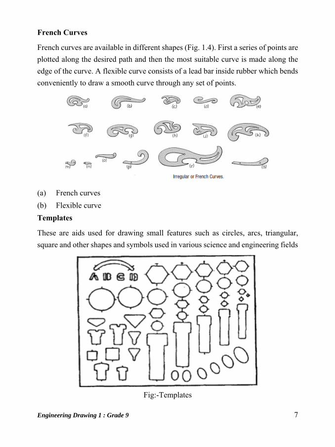
French Curves
French curves are available in different shapes (Fig. 1.4). First a series of points are
plotted along the desired path and then the most suitable curve is made along the
edge of the curve. A flexible curve consists of a lead bar inside rubber which bends
conveniently to draw a smooth curve through any set of points.
(a) French curves
(b) Flexible curve
Templates
These are aids used for drawing small features such as circles, arcs, triangular,
square and other shapes and symbols used in various science and engineering fields
Fig:-Templates

8 Engineering Drawing 1 : Grade 9
Pencils
Pencils with leads of different degrees of hardness or grades are available in the
market. The hardness or softness of te lead is indicated by 3H, 2H, H, HB, B, 2B,
3B, etc. The grade HB denotes medium hardness oflead used for general purpose.
The lead becomes softer, as the value of the numeral before B increases
Fig:-pencil leads
The selection of the grade depends on the line quality desired for the drawing.
Pencils of grades H or 2H may be used for finishing a pencil drawing as these give
a sharp black line. Softer grade pencils are used for sketching work. HB grade is
recommended for lettering and dimensioning. Nowadays mechanical pencils are
widely used in place of wooden pencils. When these are used, much of the
sharpening time can be saved. The number 0.5,0.70 of the pen indicates the
thickness of the line obtained with the lead and the size of the lead diameter. Micro-
tip pencils with 0.5 mm thick leads with the following grades are recommended.
HB Soft grade for Border lines, lettering and free sketching H Medium grade for
visible outlines, visible edges and boundary lines 2H Hard grade for construction
lines, Dimension lines, Leader lines, Extension lines, Centre lines, Hatching lines
and Hidden lines.
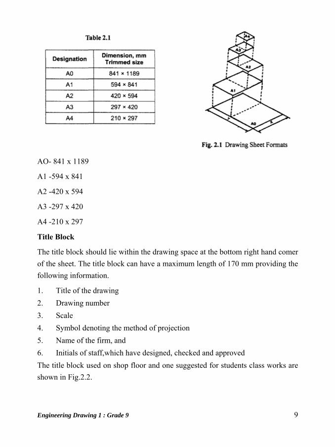
Drawing Sheet
The standard drawing sheet sizes are arrived at on the basic Principal of x: y = 1 : -
..12 and xy = 1 where x and yare the sides of the sheet. For example AO, having a
surface area of 1 Sq.m; x = 841 rom and y = 1189 mm. The successive sizes are
obtained by either by halving along the length or. Doubling the width, the area being
in the ratio 1: 2. Designation of sizes is given in Fig.2.l and their sizes are given in
Table 2.1. For class work use of A2 size drawing sheet is preferred.
Engineering Drawing 1 : Grade 9 9
AO- 841 x 1189
A1 -594 x 841
A2 -420 x 594
A3 -297 x 420
A4 -210 x 297
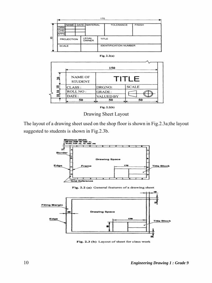
Title Block
The title block should lie within the drawing space at the bottom right hand comer
of the sheet. The title block can have a maximum length of 170 mm providing the
following information.
1. Title of the drawing
2. Drawing number
3. Scale
4. Symbol denoting the method of projection
5. Name of the firm, and
6. Initials of staff,which have designed, checked and approved
The title block used on shop floor and one suggested for students class works are
shown in Fig.2.2.
10 Engineering Drawing 1 : Grade 9
Drawing Sheet Layout
The layout of a drawing sheet used on the shop floor is shown in Fig.2.3a;the layout
suggested to students is shown in Fig.2.3b.

Engineering Drawing 1 : Grade 9 11
Folding of Drawing Sheets
IS: 11664 - 1999 specifies the method of folding drawing sheets. Two methods of
folding of drawing sheets, one suitable for filing or binding and the other method
for keeping in filing cabinets are specified by BIS. In both the methods offolding,
the Title Block is always visible.
12 Engineering Drawing 1 : Grade 9
Unit: 2
Introduction of Line and Geometrical Shape Geometric Nomenclature
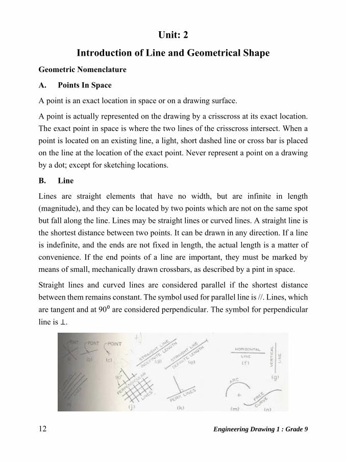
A. Points In Space
A point is an exact location in space or on a drawing surface.
A point is actually represented on the drawing by a crisscross at its exact location.
The exact point in space is where the two lines of the crisscross intersect. When a
point is located on an existing line, a light, short dashed line or cross bar is placed
on the line at the location of the exact point. Never represent a point on a drawing
by a dot; except for sketching locations.
B. Line
Lines are straight elements that have no width, but are infinite in length
(magnitude), and they can be located by two points which are not on the same spot
but fall along the line. Lines may be straight lines or curved lines. A straight line is
the shortest distance between two points. It can be drawn in any direction. If a line
is indefinite, and the ends are not fixed in length, the actual length is a matter of
convenience. If the end points of a line are important, they must be marked by
means of small, mechanically drawn crossbars, as described by a pint in space.
Straight lines and curved lines are considered parallel if the shortest distance
between them remains constant. The symbol used for parallel line is //. Lines, which
are tangent and at 90⁰ are considered perpendicular. The symbol for perpendicular
line is ⊥.

Engineering Drawing 1 : Grade 9 13
C. Angle
An angle is formed by the intersection of two lines. There are five major kinds of
angles: acute angles, right angels, obtuse angles, straight angle and
reflex angles
Acute angle: Angle is an angle less than 900.
Right angle: The right angle is an angle of 90⁰
Obtuse angle:An obtuse angle is an angle more than 90⁰ but less than 180o.
Straight angle: A straight line is 180⁰.
Reflex angle: An obtuse angle is an angle more than 180⁰ but less than 360o.
Complete angle: A complete angle measures exactly 360o.
To draw an angle, use the drafting machine, a triangle, or a protractor.
D. Triangles
A triangle is a closed plane figure with three straight sides and their interior angles
sum up exactly 1800. The various kinds of triangles: a right triangle, an equilateral
triangle, an isosceles triangle, and an obtuse angled triangle.
14 Engineering Drawing 1 : Grade 9
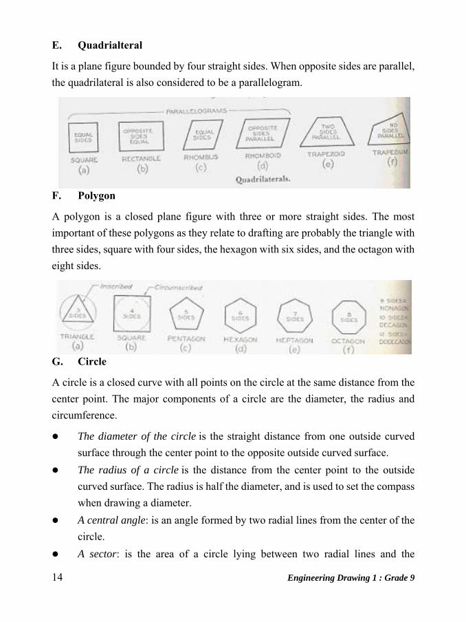
E. Quadrialteral
It is a plane figure bounded by four straight sides. When opposite sides are parallel,
the quadrilateral is also considered to be a parallelogram.
F. Polygon
A polygon is a closed plane figure with three or more straight sides. The most
important of these polygons as they relate to drafting are probably the triangle with
three sides, square with four sides, the hexagon with six sides, and the octagon with
eight sides.
G. Circle
A circle is a closed curve with all points on the circle at the same distance from the
center point. The major components of a circle are the diameter, the radius and
circumference.
The diameter of the circle is the straight distance from one outside curved
surface through the center point to the opposite outside curved surface.
The radius of a circle is the distance from the center point to the outside
curved surface. The radius is half the diameter, and is used to set the compass
when drawing a diameter.
A central angle: is an angle formed by two radial lines from the center of the
circle.
A sector: is the area of a circle lying between two radial lines and the
Engineering Drawing 1 : Grade 9 15
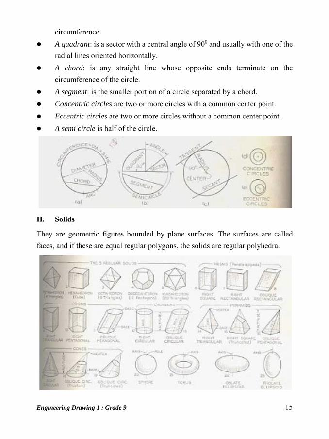
circumference.
A quadrant: is a sector with a central angle of 900 and usually with one of the
radial lines oriented horizontally.
A chord: is any straight line whose opposite ends terminate on the
circumference of the circle.
A segment: is the smaller portion of a circle separated by a chord.
Concentric circles are two or more circles with a common center point.
Eccentric circles are two or more circles without a common center point.
A semi circle is half of the circle.
H. Solids
They are geometric figures bounded by plane surfaces. The surfaces are called
faces, and if these are equal regular polygons, the solids are regular polyhedra.

16 Engineering Drawing 1 : Grade 9
Unit: 3
Freehand Practicing
Introduction
Freehand drawing is a form, which is done only by means of hand and eye
coordination. In simple terms, this type of drawing is done by a person without use
of any tools like rulers, protractor, etc., or by using tracing or any other such
techniques and without using any mechanical tools. Many people who enjoy
drawing as a hobby use this method of drawing, just by carrying a sketchbook and
pencils, and sketching any subjects they like.
For freehand sketching, one needs to have good sense of proportions, a smooth
motion of hand that allows to draw neat lines, and some shading skills to give more
depth to the drawing. These skills take time, patience, and practice, and advice from
a teacher or an artist will help a person to learn freehand drawing by the right way.
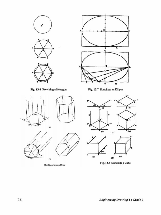
Sketching of different shapes

Engineering Drawing 1 : Grade 9 17
18 Engineering Drawing 1 : Grade 9

Engineering Drawing 1 : Grade 9 19
20 Engineering Drawing 1 : Grade 9
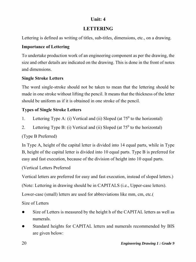
Unit: 4
LETTERING
Lettering is defined as writing of titles, sub-titles, dimensions, etc., on a drawing.
Importance of Lettering
To undertake production work of an engineering component as per the drawing, the
size and other details are indicated on the drawing. This is done in the front of notes
and dimensions.
Single Stroke Letters
The word single-stroke should not be taken to mean that the lettering should be
made in one stroke without lifting the pencil. It means that the thickness of the letter
should be uniform as if it is obtained in one stroke of the pencil.
Types of Single Stroke Letters
1. Lettering Type A: (i) Vertical and (ii) Sloped (at 750 to the horizontal)
2. Lettering Type B: (i) Vertical and (ii) Sloped (at 750 to the horizontal)
(Type B Preferred)
In Type A, height of the capital letter is divided into 14 equal parts, while in Type
B, height of the capital letter is divided into 10 equal parts. Type B is preferred for
easy and fast execution, because of the division of height into 10 equal parts.
(Vertical Letters Preferred
Vertical letters are preferred for easy and fast execution, instead of sloped letters.)
(Note: Lettering in drawing should be in CAPITALS (i.e., Upper-case letters).
Lower-case (small) letters are used for abbreviations like mm, cm, etc.(
Size of Letters
Size of Letters is measured by the height h of the CAPITAL letters as well as
numerals.
Standard heights for CAPITAL letters and numerals recommended by BIS
are given below:
Engineering Drawing 1 : Grade 9 21
1.8, 2.5, 3.5, 5, 6, 10, 14 and 20 mm (Note: Size of the letters may be selected based upon the size of drawing.)
Guide Lines
In order to obtain correct and uniform height ofletters and numerals, guide lines are
drawn, using 2H pencil with light pressure. HB grade conical end pencil is used for
lettering.
Procedure for Lettering
1. Thin horizontal guide lines are drawn first at a distance 'h' apart.
2. Lettering Technique: Horizontal lines of the letters are drawn from left to
right. Vertical, inclined and curved lines are drawn from top to bottom.
3. After lettering has been completed, the guidelines are not erased.
Dimensioning of Type B Letters
BIS denotes the characteristics of lettering as:
h (height of capita) letters), ci (height of lower-case letters), c 2 (tail of lower-case
letters), c 3 (stem of lower-case letters), a (spacing between characters), bl& b2
(spacing between baselines), e (spacing between words) and d (line thickness).
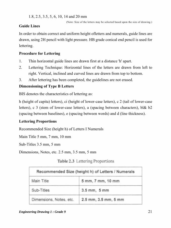
Lettering Proportions
Recommended Size (height h) of Letters I Numerals
Main Title 5 mm, 7 mm, 10 mm
Sub-Titles 3.5 mm, 5 mm
Dimensions, Notes, etc. 2.5 mm, 3.5 mm, 5 mm

22 Engineering Drawing 1 : Grade 9
Lettering practice
Practice of lettering capital and lower case letters and numerals of type B
The following are some of the guide lines for lettering:-
1. Drawing numbers, title block and letters denoting cutting planes, sections are
written in 10 mm size
2. Drawing title is written in 7 mm size
3. Hatching, sub-titles, materials, dimensions, notes, etc., are written in 3.5 mm
size
4. Space between lines = ~ h
5. Space between words may be equal to the width of alphabet M or 3/5 h

Engineering Drawing 1 : Grade 9 23
6. Space between letters should be approximately equal to 115 h. Poor spacing
will affect the visual effect
7. The spacing between two characters may be reduced by half if it gives a better
visual effect, as for example LA, TV; over lapped in case of say LT, TA etc.,
and the space is increased for letters with adjoining stems
CAPITAL Letters
Ratio of height to width for most of the CAPITAL letters is approximately =
10:6
However, for M and W, the ratio = 10:8 for I the ratio = 10:2
Lower-case Letters • Height of lower-case letters with stem I tail (b, d, f, g,
h, j, k, I, p, q, t, y) = Cz = c3 = h • Ratio of height to width for lower-case
letters with stem or tail = 10:5
Height of lower-case letters without stems or tail c1 is approximately = (7/10)
h
Ratio of height to width for most lower-case letters without stem or tail = 7:
5 • However, for m and w, the ratio = 7: 7. For I and I, the ratio = 10:2
Numerals
24 Engineering Drawing 1 : Grade 9
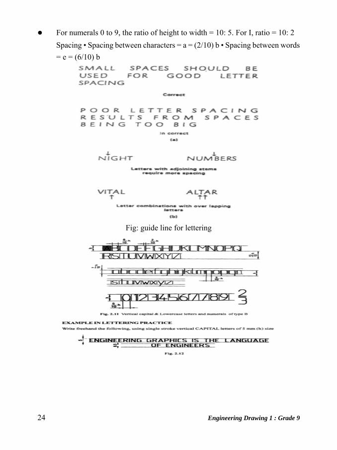
For numerals 0 to 9, the ratio of height to width = 10: 5. For I, ratio = 10: 2
Spacing • Spacing between characters = a = (2/10) b • Spacing between words
= e = (6/10) b
Fig: guide line for lettering
Engineering Drawing 1 : Grade 9 25
Unit: 5
Practicing the Line and Circle using Drawing Instruments
Technical Drawings : These are detailed drawings drawn accurately and precisely.
They are pictures that have been prepared with the aid of mathematical instruments
in order to record and transmit technical information. They provide an exact and
complete description of things that are to be built or manufactured. Technical
drawings do not portray the objects the way they directly appear to the eye. They
make use of many specialized symbols and conventions in order to transmit
technical information clearly and exactly. To understand and correctly interpret
technical drawings, one needs to acquaint oneself with the fundamentals of
technical drawing – hence the purpose of this course.
Handling of drawing tools and instruments
The different tools and equipments have been already been discussed in the first
chapter. These tools and equipments need to be handled with proper care for making
the drawing more effective and clear. The proper care and maintenance of drawing
instruments, supplies and equipment are the following:
1. Pencil
a. Never sharpen the pencil over the drawing or close to any of your equipment.
b. Always keep the lead sharp.
2. T-square, triangles and French curves
a. Do not use the T-square for any rough purposes.
b. Never cut paper along its working edge, since the plastics can easily be
damaged.
Even light nick can ruin the T-square.
3. Ruler or scale
a. Scales should not be pricked with needle points of either the divider or
compass when measurements are taken.
b. Do not use scale as a ruler.

26 Engineering Drawing 1 : Grade 9
4. Speedball pens and lettering pens
a. After using, clean the speed ballpen by wiping-off or scraping the ink on it
with clean cloth, which is a little wet or you may use blade for scrapping.
b. Lettering pens, like technical pens, should be clean at once with clean water
and soap. Wipe it off with clean cloth.
5. Pen holders
Always keep it together with speedball pens.
6. Dividers and compasses
a. Do not oil the joints of the legs of the dividers.
b. Do not use the divider as substitute for thumbtacks in fastening the drawing
paper on the drawing board or table top.
c. The needle points must be sharp and of equal length.
7. Ruling pen
a. Sharpen the nibs or blade of the ruling pen when it is no longer in a parabolical
shape.
b. Rub the dried ink on the nibs with the use of paper to avoid clogging at its
end when in use.
8. Drawing paper
a. It should be stored in rolled form.
b. It should not be crumpled or wet or kept in a moist or cold place.
c. Oslo papers or bond papers must be kept in a large envelope.
9. Masking tape or scrotch tape, eraser and erasing shield
a. Should be kept together with other supplies to avoid losing it.
10. Water color
a. Tube water colors should be left uncovered to avoid drying up.
11. Drawing board or drawing tape
a. It should always be in good (drawing) working condition.
b. It must always be clean on or before using.

Engineering Drawing 1 : Grade 9 27
c. Do not leave any kind of marks on your board to retain its smoothness.
Lines
Lines In Engineering Drawing, we make use of different lines and line styles to
convey the desired message. These lines differ in (i) thickness and (ii) style. Typical
uses of these lines are summarized below.
Drawing Angles
Drawing Angles less than 180° with a Protractor
To draw an angle with a protractor, proceed as follows:
Draw a straight line (i.e. an arm of the angle).
Place a dot at one end of the arm. This dot represents the vertex of the angle.
Place the centre of the protractor at the vertex dot and the baseline of the protractor
along the arm of the angle.
28 Engineering Drawing 1 : Grade 9
Find the required angle on the scale and then mark a small dot at the edge of the
protractor.
Join the small dot to the vertex with a ruler to form the second arm of the angle.
Label the angle with capital letters.
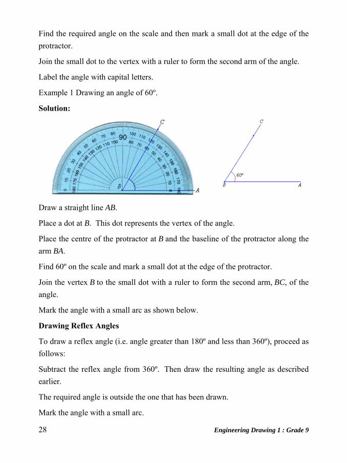
Example 1 Drawing an angle of 60o.
Solution:
Draw a straight line AB.
Place a dot at B. This dot represents the vertex of the angle.
Place the centre of the protractor at B and the baseline of the protractor along the
arm BA.
Find 60º on the scale and mark a small dot at the edge of the protractor.
Join the vertex B to the small dot with a ruler to form the second arm, BC, of the
angle.
Mark the angle with a small arc as shown below.
Drawing Reflex Angles
To draw a reflex angle (i.e. angle greater than 180º and less than 360º), proceed as
follows:
Subtract the reflex angle from 360º. Then draw the resulting angle as described
earlier.
The required angle is outside the one that has been drawn.
Mark the angle with a small arc.
Engineering Drawing 1 : Grade 9 29
Label the angle.
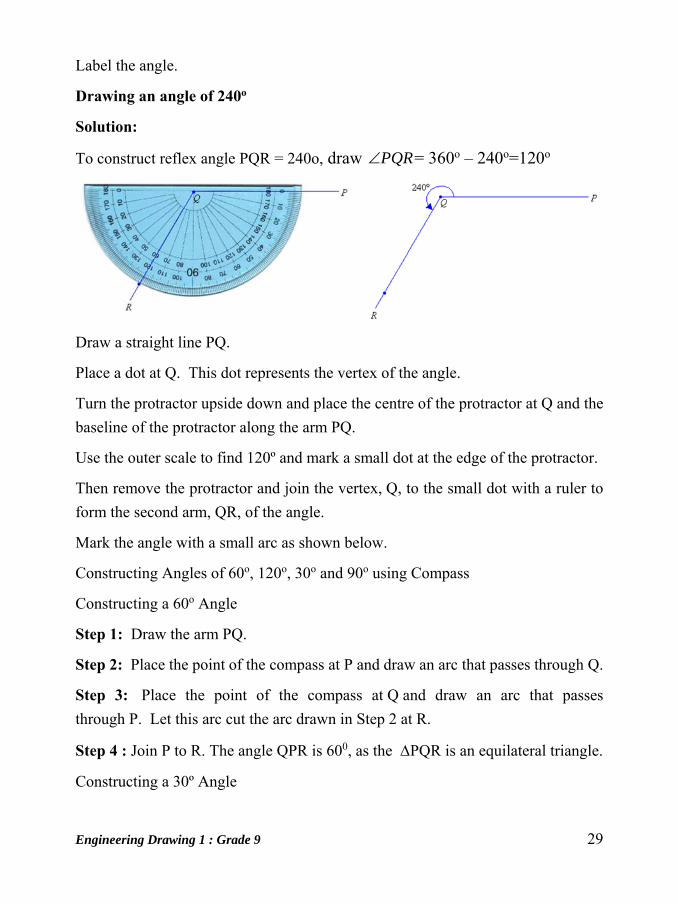
Drawing an angle of 240o
Solution:
To construct reflex angle PQR = 240o, draw PQR = 360o – 240o=120o
Draw a straight line PQ.
Place a dot at Q. This dot represents the vertex of the angle.
Turn the protractor upside down and place the centre of the protractor at Q and the
baseline of the protractor along the arm PQ.
Use the outer scale to find 120º and mark a small dot at the edge of the protractor.
Then remove the protractor and join the vertex, Q, to the small dot with a ruler to
form the second arm, QR, of the angle.
Mark the angle with a small arc as shown below.
Constructing Angles of 60o, 120o, 30o and 90o using Compass
Constructing a 60o Angle
Step 1: Draw the arm PQ.
Step 2: Place the point of the compass at P and draw an arc that passes through Q.
Step 3: Place the point of the compass at Q and draw an arc that passes
through P. Let this arc cut the arc drawn in Step 2 at R.
Step 4 : Join P to R. The angle QPR is 600, as the PQR is an equilateral triangle.
Constructing a 30º Angle

30 Engineering Drawing 1 : Grade 9
We know that:
Step 1: Draw the arm PQ.
Step 2: Place the point of
the compass at P and draw an arc that
passes through Q.
Step 3: Place the point of the
compass at Q and draw an arc that cuts the arc drawn in Step 2 at R.
Step 4: With the point of the compass still at Q, draw an arc near T as shown.
Step 5: With the point of the compass at R, draw an arc to cut the arc drawn in Step
4 at T.
Step 6: Join T to P. The angle QPT is 30º.
Constructing a 120º Angle
We know that:
600 + 1200 = 1800
Constructing a 90º Angle
Step 1: Draw the arm PA.
Step 2: Place the point of
the compass at P and draw
an arc that cuts the arm at Q.
Step 3: Place the point of
the compass at Q and draw an arc of radius PQ that cuts the arc drawn in Step 2
at R.
Step 4: With the point of the compass at R, draw an arc of radius PQ to cut the arc
drawn in Step 2 at S.
Step 5: With the point of the compass still at R, draw another arc of
Engineering Drawing 1 : Grade 9 31
radius PQ near T as shown.
Step 6: With the point of the compass at S, draw an arc of radius PQ to cut the arc
drawn in step 5 at T.
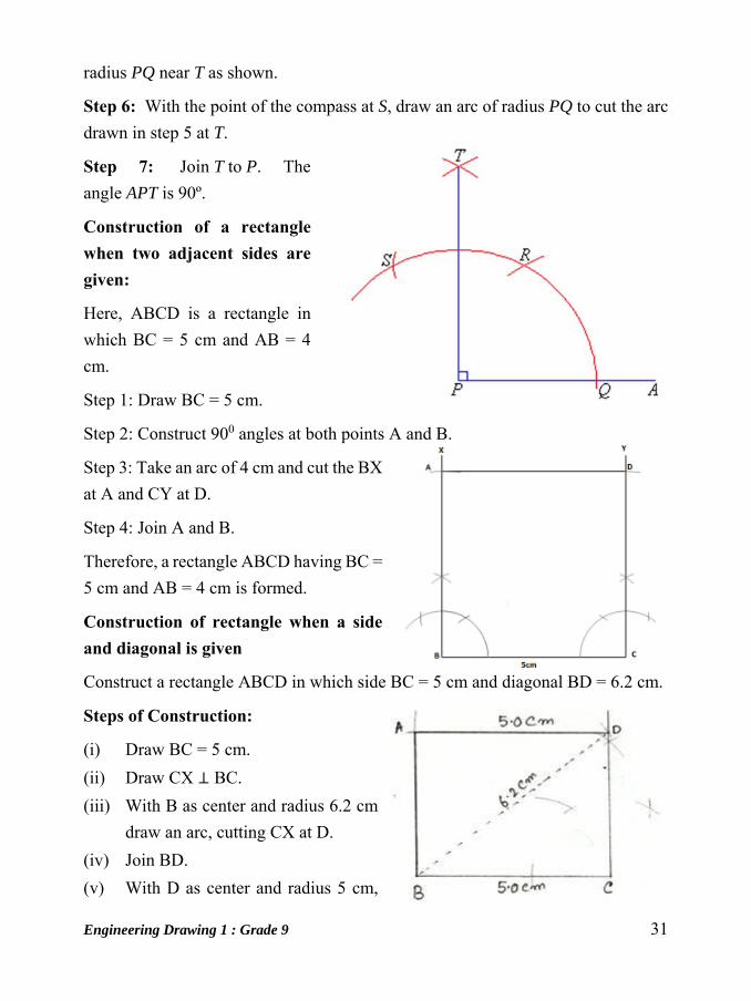
Step 7: Join T to P. The
angle APT is 90º.
Construction of a rectangle when two adjacent sides are given:
Here, ABCD is a rectangle in
which BC = 5 cm and AB = 4
cm.
Step 1: Draw BC = 5 cm.
Step 2: Construct 900 angles at both points A and B.
Step 3: Take an arc of 4 cm and cut the BX
at A and CY at D.
Step 4: Join A and B.
Therefore, a rectangle ABCD having BC =
5 cm and AB = 4 cm is formed.
Construction of rectangle when a side and diagonal is given
Construct a rectangle ABCD in which side BC = 5 cm and diagonal BD = 6.2 cm.
Steps of Construction:
(i) Draw BC = 5 cm.
(ii) Draw CX ⊥ BC.
(iii) With B as center and radius 6.2 cm
draw an arc, cutting CX at D.
(iv) Join BD.
(v) With D as center and radius 5 cm,

32 Engineering Drawing 1 : Grade 9
draw an arc.
(vi) With B as center and radius equal to CD draw another arc, cutting the previous
arc at A.
(vii) Join AB and AD.
Construction of a rectangle when diagonal and an angle made by them are given:
Here, ABCD is a rectangle in which
AC = BD = 5 cm and an angle = 450.
Step 1: Draw AC = 5 cm.
Step 2: Find the mid-point O of the
line AC with the help of perpendicular
bisector method.
Step 3: Construct 450 angle at O.
Produce the line XO straight upto Y on other side.
Step 4: Take an arc of 2.5 cm and cut OX at D and OY at B.
Step 5: Join A and B, B and C, C and D, D and A.
Therefore, a rectangle ABCD having AC = BD = 5 cm and an angle = 450 is formed.
Construction of a parallelogram when two diagonals and an angle contained by them are given:
Here, PR = 6 cm, QS = 8 cm
and angle between these two
diagonals is 450.
Step 1: Draw PR = 6 cm.
Step 2: Draw the bisector of PR
and find the mid-point O.
Step 3: At O, draw an angle of
450.
Step 4: Take a radius of 4 cm
Engineering Drawing 1 : Grade 9 33
(half of QS) and cut OX at S and OY at Q.
Step 5: Join P and Q, Q and R, R and S, S and P.
Therefore, the required parallelogram PQRS is formed.
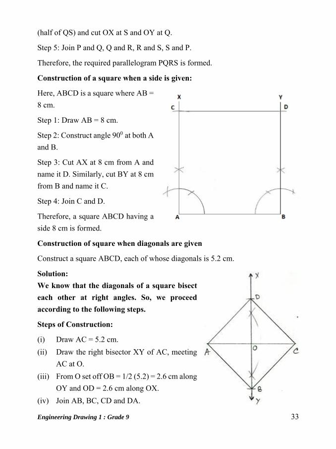
Construction of a square when a side is given:
Here, ABCD is a square where AB =
8 cm.
Step 1: Draw AB = 8 cm.
Step 2: Construct angle 900 at both A
and B.
Step 3: Cut AX at 8 cm from A and
name it D. Similarly, cut BY at 8 cm
from B and name it C.
Step 4: Join C and D.
Therefore, a square ABCD having a
side 8 cm is formed.
Construction of square when diagonals are given
Construct a square ABCD, each of whose diagonals is 5.2 cm.
Solution: We know that the diagonals of a square bisect each other at right angles. So, we proceed according to the following steps.
Steps of Construction:
(i) Draw AC = 5.2 cm.
(ii) Draw the right bisector XY of AC, meeting
AC at O.
(iii) From O set off OB = 1/2 (5.2) = 2.6 cm along
OY and OD = 2.6 cm along OX.
(iv) Join AB, BC, CD and DA.
34 Engineering Drawing 1 : Grade 9
Then, ABCD is the required square.
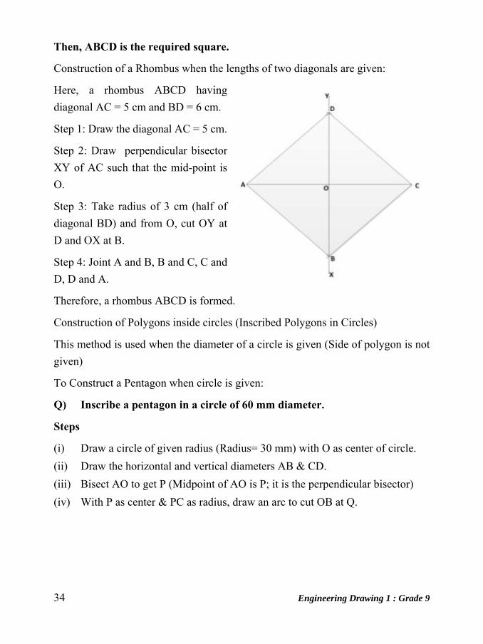
Construction of a Rhombus when the lengths of two diagonals are given:
Here, a rhombus ABCD having
diagonal AC = 5 cm and BD = 6 cm.
Step 1: Draw the diagonal AC = 5 cm.
Step 2: Draw perpendicular bisector
XY of AC such that the mid-point is
O.
Step 3: Take radius of 3 cm (half of
diagonal BD) and from O, cut OY at
D and OX at B.
Step 4: Joint A and B, B and C, C and
D, D and A.
Therefore, a rhombus ABCD is formed.
Construction of Polygons inside circles (Inscribed Polygons in Circles)
This method is used when the diameter of a circle is given (Side of polygon is not
given)
To Construct a Pentagon when circle is given:
Q) Inscribe a pentagon in a circle of 60 mm diameter.
Steps
(i) Draw a circle of given radius (Radius= 30 mm) with O as center of circle.
(ii) Draw the horizontal and vertical diameters AB & CD.
(iii) Bisect AO to get P (Midpoint of AO is P; it is the perpendicular bisector)
(iv) With P as center & PC as radius, draw an arc to cut OB at Q.

Engineering Drawing 1 : Grade 9 35
(v) With C as center & CQ as radius, draw an arc to cut the circle at E & F. CE
or CF is the side of pentagon.
(vi) Join CE & CF to get 2 sides of pentagon. With E & F as centers & radius =
CE, cut arcs on the circle to get G & H.
(vii) Join CEGHF to get the required pentagon inside the circle of 60 mm diameter
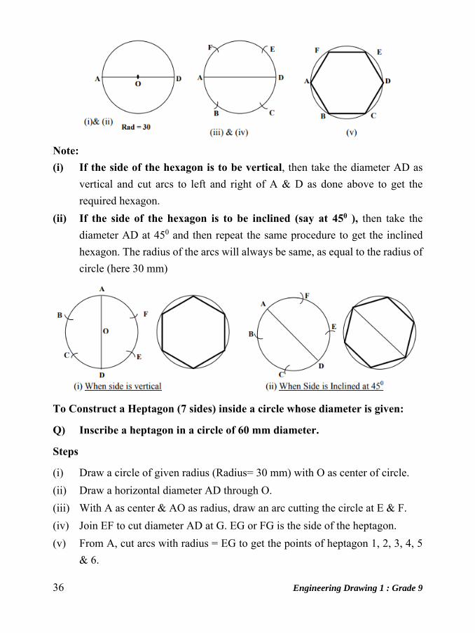
To Construct a Hexagon inside a circle whose diameter is given:
Q) Inscribe a hexagon in a circle of 60 mm diameter.
Steps
(i) Draw a circle of given radius (Radius= 30 mm) with O as center of circle.
(ii) Draw a horizontal diameter AD through O.
(iii) With radius = 30 & A as center, cut 2 arcs on the circle below & above A to
get B & F.
(iv) With same radius (30) & D as center, cut arcs above & below D to get E &
C.
(v) Join ABCDEF to get the required hexagon inside the circle of given diameter
(60 mm).
36 Engineering Drawing 1 : Grade 9
Note: (i) If the side of the hexagon is to be vertical, then take the diameter AD as
vertical and cut arcs to left and right of A & D as done above to get the
required hexagon.
(ii) If the side of the hexagon is to be inclined (say at 450 ), then take the
diameter AD at 450 and then repeat the same procedure to get the inclined
hexagon. The radius of the arcs will always be same, as equal to the radius of
circle (here 30 mm)
To Construct a Heptagon (7 sides) inside a circle whose diameter is given:
Q) Inscribe a heptagon in a circle of 60 mm diameter.
Steps
(i) Draw a circle of given radius (Radius= 30 mm) with O as center of circle.
(ii) Draw a horizontal diameter AD through O.
(iii) With A as center & AO as radius, draw an arc cutting the circle at E & F.
(iv) Join EF to cut diameter AD at G. EG or FG is the side of the heptagon.
(v) From A, cut arcs with radius = EG to get the points of heptagon 1, 2, 3, 4, 5
& 6.
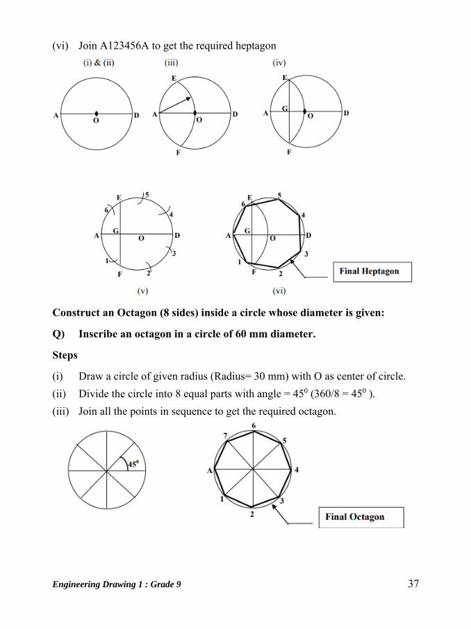
Engineering Drawing 1 : Grade 9 37
(vi) Join A123456A to get the required heptagon
Construct an Octagon (8 sides) inside a circle whose diameter is given:
Q) Inscribe an octagon in a circle of 60 mm diameter.
Steps
(i) Draw a circle of given radius (Radius= 30 mm) with O as center of circle.
(ii) Divide the circle into 8 equal parts with angle = 450 (360/8 = 450 ).
(iii) Join all the points in sequence to get the required octagon.
38 Engineering Drawing 1 : Grade 9
Unit: 6
SCALES Introduction
It is not always possible to make drawings of an object to its actual size. If the actual
linear dimensions of an object are shown in its drawing, the scale used is said to be
a full size scale. Wherever possible, it is desirable to make drawings to full size.
Reducing and Enlarging Scales
Objects which are very big in size cannot be represented in drawing to full size. In
such cases the object is represented in reduced size by making use of reducing
scales. Reducing scales are used to represent objects such as large machine parts,
buildings, town plans etc. A reducing scale, say 1: 10 means that 10 units length on
the object is represented by 1 unit length on the drawing.
Similarly, for drawing small objects such as watch parts, instrument components
etc., and use scale may not be useful to represent the object clearly. In those cases
enlarging scales are used. An enlarging scale, say 10: 1 means one unit length on
the object is represented by 10 units on the drawing.
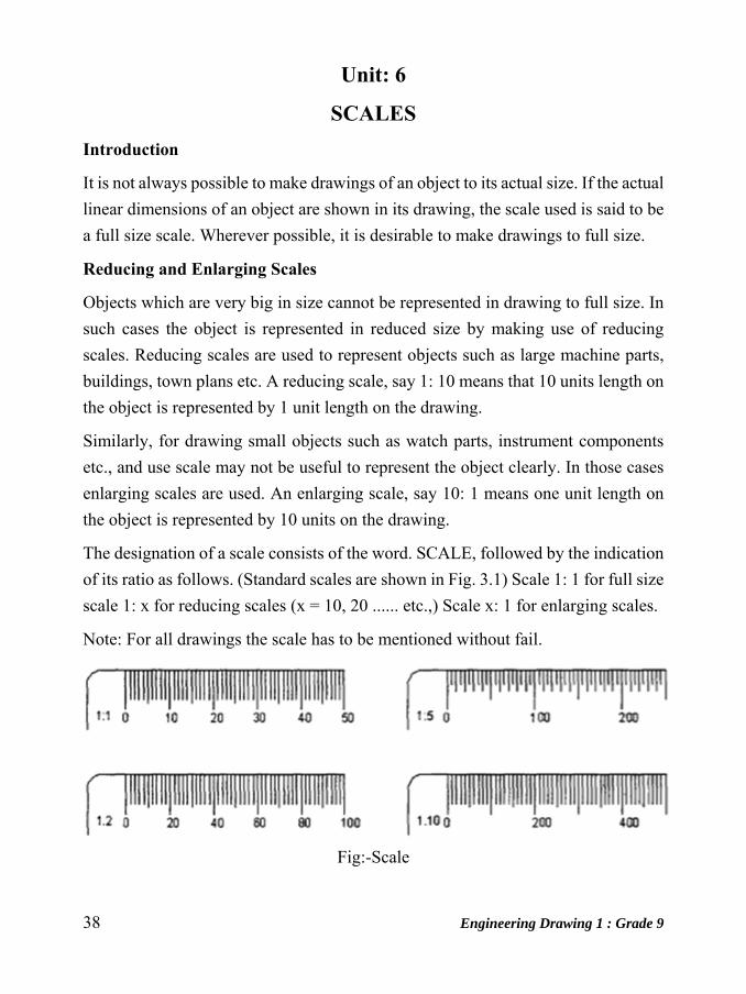
The designation of a scale consists of the word. SCALE, followed by the indication
of its ratio as follows. (Standard scales are shown in Fig. 3.1) Scale 1: 1 for full size
scale 1: x for reducing scales (x = 10, 20 ...... etc.,) Scale x: 1 for enlarging scales.
Note: For all drawings the scale has to be mentioned without fail.
Fig:-Scale

Engineering Drawing 1 : Grade 9 39
Representative Fraction (RF)
The ratio of the dimension of the object shown on the drawing to its actual
size is called the Representative Fraction (RF).
If the desired scale is not available in the set of scales it may be constructed and
then used.
Metric Measurements:-
10 millimeters (mm) = 1 centimeter (cm)
10 centimeters (cm) = 1 decimeter (cm)
10 decimeter (cm) = 1 meter (m)
10 meters (m) = 1 decameter (dam)
10 decameter (dam) = 1 hectometer (cm)
10 hectometers (cm) = 1 kilometer (km)
1 hectare = 10,000 m2
Types of Scales
The types of scales normally used are
1. Plain scales
2. Diagonal Scales
3. Vernier Scales
Plain Scales
A plain scale is simply a line which is divided into a suitable number of equal parts,
the first of which is further sub-divided into small parts. It is used to represent either
40 Engineering Drawing 1 : Grade 9
two units or a unit and its fraction such as km and cm, m etc.
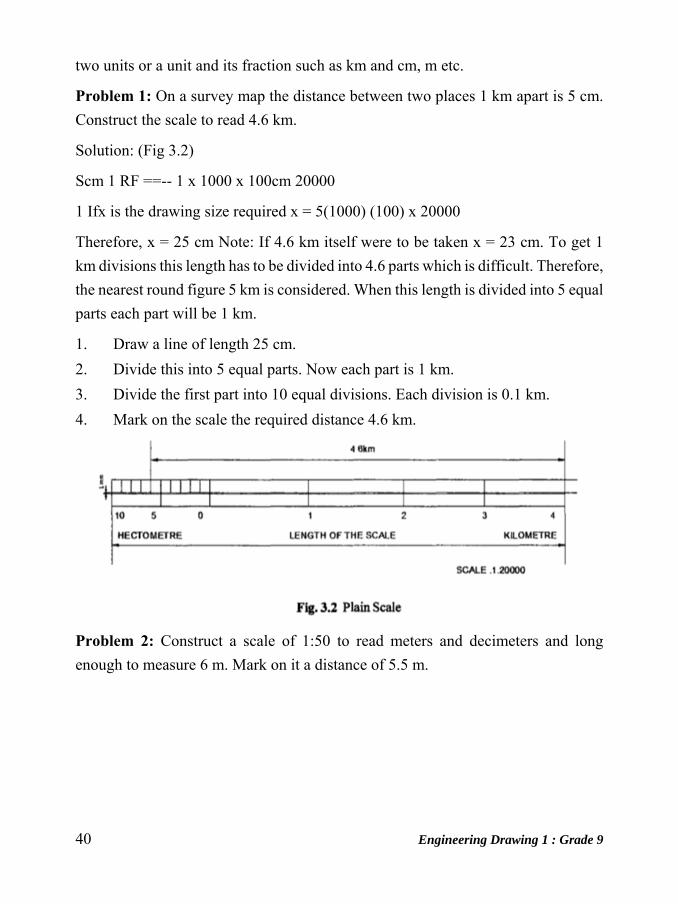
Problem 1: On a survey map the distance between two places 1 km apart is 5 cm.
Construct the scale to read 4.6 km.
Solution: (Fig 3.2)
Scm 1 RF ==-- 1 x 1000 x 100cm 20000
1 Ifx is the drawing size required x = 5(1000) (100) x 20000
Therefore, x = 25 cm Note: If 4.6 km itself were to be taken x = 23 cm. To get 1
km divisions this length has to be divided into 4.6 parts which is difficult. Therefore,
the nearest round figure 5 km is considered. When this length is divided into 5 equal
parts each part will be 1 km.
1. Draw a line of length 25 cm.
2. Divide this into 5 equal parts. Now each part is 1 km.
3. Divide the first part into 10 equal divisions. Each division is 0.1 km.
4. Mark on the scale the required distance 4.6 km.
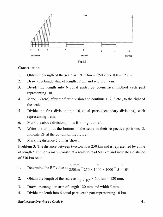
Problem 2: Construct a scale of 1:50 to read meters and decimeters and long
enough to measure 6 m. Mark on it a distance of 5.5 m.
Engineering Drawing 1 : Grade 9 41
Construction
1. Obtain the length of the scale as: RF x 6m = 1/50 x 6 x 100 = 12 cm
2. Draw a rectangle strip of length 12 cm and width 0.5 cm.
3. Divide the length into 6 equal parts, by geometrical method each part
representing 1m.
4. Mark O (zero) after the first division and continue 1, 2, 3 etc., to the right of
the scale.
5. Divide the first division into 10 equal parts (secondary divisions), each
representing 1 cm.
6. Mark the above division points from right to left.
7. Write the units at the bottom of the scale in their respective positions. 8.
Indicate RF at the bottom of the figure.
9. Mark the distance 5.5 m as shown.
Problem 3: The distance between two towns is 250 km and is represented by a line
of length 50mm on a map. Construct a scale to read 600 km and indicate a distance
of 530 km on it.
1. Determine the RF value as 50mm250km =
50250 × 1000 × 1000 =
15 × 106
2. Obtain the length of the scale as : 1
5 × 106 × 600 km = 120 mm.
3. Draw a rectangular strip of length 120 mm and width 5 mm.
4. Divide the lenth into 6 equal parts, each part representing 10 km.
42 Engineering Drawing 1 : Grade 9
5. Repeat the steps 4 to 8 of construction in Fig 3.2 suitably.
6. Mark the distance 530 km as shown.
Solution: (Fig 3.4)
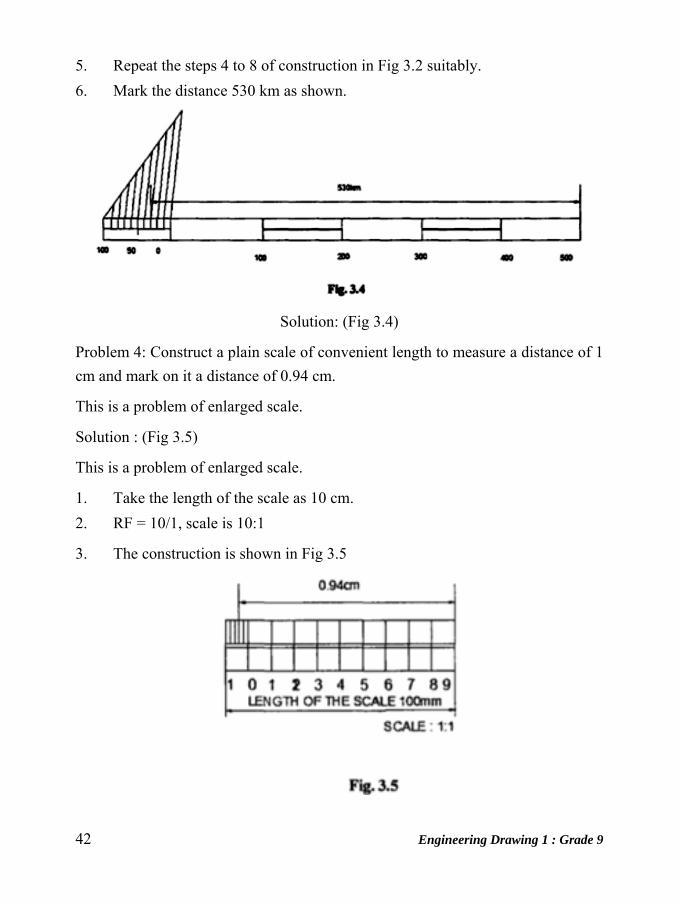
Problem 4: Construct a plain scale of convenient length to measure a distance of 1
cm and mark on it a distance of 0.94 cm.
This is a problem of enlarged scale.
Solution : (Fig 3.5)
This is a problem of enlarged scale.
1. Take the length of the scale as 10 cm.
2. RF = 10/1, scale is 10:1
3. The construction is shown in Fig 3.5
Engineering Drawing 1 : Grade 9 43
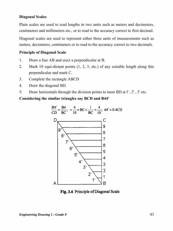
Diagonal Scales
Plain scales are used to read lengths in two units such as meters and decimeters,
centimeters and millimeters etc., or to read to the accuracy correct to first decimal.
Diagonal scales are used to represent either three units of measurements such as
meters, decimeters, centimeters or to read to the accuracy correct to two decimals.
Principle of Diagonal Scale
1. Draw a line AB and erect a perpendicular at B.
2. Mark 10 equi-distant points (1, 2, 3, etc.) of any suitable length along this
perpendicular and mark C.
3. Complete the rectangle ABCD
4. Draw the diagonal BD.
5. Draw horizontals through the division points to meet BD at l' , 2' , 3' etc.
Considering the similar triangles say BCD and B44'
44 Engineering Drawing 1 : Grade 9
EXERCISES
1. Construct a plain scale of 1:50 to measure a distance of 7 meters. Mark a
distance of 3.6 meters on it.
2. The length of a scale with a RF of 2:3 are 20 cm. Construct this scale and
mark a distance of 16.5 cm on it.
3. Construct a scale of 2 cm = 1 decimeter to read upto 1 meter and mark on it a
length of 0.67 meter.
4. Construct a plain scale of RF = 1 :50,000 to show kilometers and hectometers
and long enough to measure upto 7 km. Mark a distance of 5:3 kilometers on
the scale.
5. On a map, the distance between two places 5 km apart is 10 cm. Construct
the scale to read 8 km. What is the RF of the scale?
6. Construct a diagonal scale ofRF = 1150, to read meters, decimeters and
centimeters. Mark a distance of 4.35 km on it.
7. Construct a diagonal scale of five times full size, to read accurately upto 0.2
mm and mark a distance of 3 .65 cm on it.
8. Construct a diagonal scale to read upto 0.1 mm and mark on it a 'distance of
1.63 cm and 6.77 cm. Take the scale as 3: 1.
9. Draw a diagonal scale of 1 cm = 2.5krn and mark on the scale a length of26.7
km.
10. Construct a diagonal scale to read 2krn when it’s RF=I: 20,000. Mark on it a
distance of 1:15 km.
11. Draw a vernier scale of meters when mm represents 25cm and mark on it a
length of 24.4 cm and 23.1 mm. What is the RF?
12. The LC of a forward reading vernier scale is 1 cm. Its vernier scale division
represents 9 cm. There are 40 m on the scale. It is drawn to 1: 25 scale.
Construct the scale and mark on it a distance ofO.91m.
13. 15cm of a vernier scale represents 1 cm. construct a backward reading vernier
scale of RF 1: 4.8 to show decimeters cm and mm. The scale should be
capable of reading upto 12 decimeters. Mark on the scale 2.69 decimeters and
5.57 decimeters.

Engineering Drawing 1 : Grade 9 45
Unit: 7
Geometrical Constructions Introduction
Strict interpretation of geometric construction allows use of only the compass and
an instrument for drawing straight lines and accomplishes his solutions. In technical
drawing, the principles of geometry are employed constantly using the instruments
like T-squares, triangles, scales, curves etc. to make constructions with speed and
accuracy.
To Draw A Triangle With Known Lengths Of Sides
Given: lengths 1, 2, and 3.
Step 1: Draw the longest length line, in this example length 3, with ends A and B.
Swing an arc (R1) from point A whose radius is either length 1 or length 2; in this
example length 1.
Step 2; using the radius length not used in step 1, swing an arc (R2) from point B
to intercept the arc swung from point A at point.
Step 3: Connect A to C and B to C to complete the triangle.
To Draw A Square Method-1 Given: The locations of the center and the required distance across the sides of a
square.
46 Engineering Drawing 1 : Grade 9
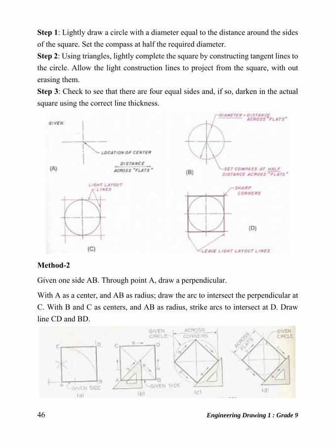
Step 1: Lightly draw a circle with a diameter equal to the distance around the sides
of the square. Set the compass at half the required diameter.
Step 2: Using triangles, lightly complete the square by constructing tangent lines to
the circle. Allow the light construction lines to project from the square, with out
erasing them.
Step 3: Check to see that there are four equal sides and, if so, darken in the actual
square using the correct line thickness.
Method-2
Given one side AB. Through point A, draw a perpendicular.
With A as a center, and AB as radius; draw the arc to intersect the perpendicular at
C. With B and C as centers, and AB as radius, strike arcs to intersect at D. Draw
line CD and BD.
Engineering Drawing 1 : Grade 9 47
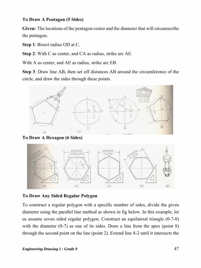
To Draw A Pentagon (5 Sides)
Given: The locations of the pentagon center and the diameter that will circumscribe
the pentagon.
Step 1: Bisect radius OD at C.
Step 2: With C as center, and CA as radius, strike arc AE.
With A as center, and AE as radius, strike arc EB.
Step 3: Draw line AB, then set off distances AB around the circumference of the
circle, and draw the sides through these points.
To Draw A Hexagon (6 Sides)
To Draw Any Sided Regular Polygon
To construct a regular polygon with a specific number of sides, divide the given
diameter using the parallel line method as shown in fig below. In this example, let
us assume seven sided regular polygon. Construct an equilateral triangle (0-7-8)
with the diameter (0-7) as one of its sides. Draw a line from the apex (point 8)
through the second point on the line (point 2). Extend line 8-2 until it intersects the
48 Engineering Drawing 1 : Grade 9
circle at point 9.
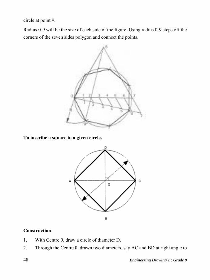
Radius 0-9 will be the size of each side of the figure. Using radius 0-9 steps off the
corners of the seven sides polygon and connect the points.
To inscribe a square in a given circle.
Construction
1. With Centre 0, draw a circle of diameter D.
2. Through the Centre 0, drawn two diameters, say AC and BD at right angle to

Engineering Drawing 1 : Grade 9 49
each other.
3. Join A-B, B-C, and C- D, and D-A. ABCD is the required square.
To inscribe a regular polygon of any number of sides in a given circle.
Construction
1. Draw the given circle with AD as
diameter.
2. Divide the diameter AD into N equal
parts say 6.
3. With AD as radius and A and D as
centers, draw arcs intersecting each other
at G
4. Join G-2 and extend to intersect the circle
at B.
5. JoinA-B which is the length of the side of
the required polygon.
6. Set the compass to the length AB and
starting from B mark off on the circumference of the circles, obtaining the
points C, D, etc.
The figure obtained by joing the points A, B, C etc., is the required polygon.
To inscribe a hexagon in a given circle.
50 Engineering Drawing 1 : Grade 9
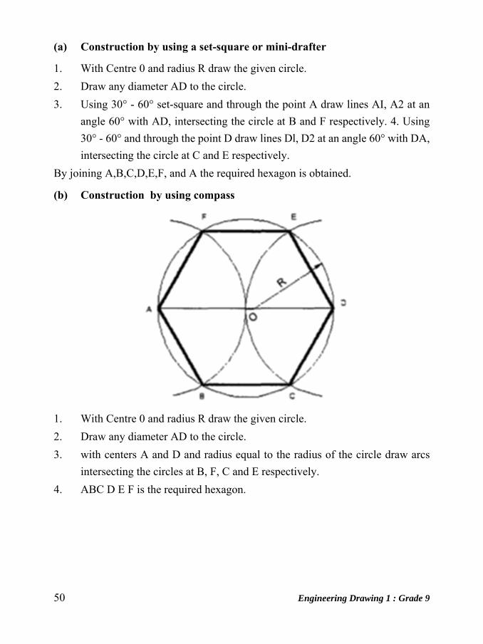
(a) Construction by using a set-square or mini-drafter
1. With Centre 0 and radius R draw the given circle.
2. Draw any diameter AD to the circle.
3. Using 30° - 60° set-square and through the point A draw lines AI, A2 at an
angle 60° with AD, intersecting the circle at B and F respectively. 4. Using
30° - 60° and through the point D draw lines Dl, D2 at an angle 60° with DA,
intersecting the circle at C and E respectively.
By joining A,B,C,D,E,F, and A the required hexagon is obtained.
(b) Construction by using compass
1. With Centre 0 and radius R draw the given circle.
2. Draw any diameter AD to the circle.
3. with centers A and D and radius equal to the radius of the circle draw arcs
intersecting the circles at B, F, C and E respectively.
4. ABC D E F is the required hexagon.
Engineering Drawing 1 : Grade 9 51
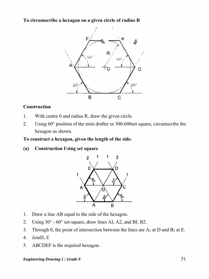
To circumscribe a hexagon on a given circle of radius R
Construction
1. With centre 0 and radius R, draw the given circle.
2. Using 60° position of the mini drafter or 300-600set square, circumscribe the
hexagon as shown.
To construct a hexagon, given the length of the side.
(a) Construction Using set square
1. Draw a line AB equal to the side of the hexagon.
2. Using 30° - 60° set-square, draw lines AI, A2, and BI, B2.
3. Through 0, the point of intersection between the lines are A2 at D and B2 at E.
4. JoinD, E
5. ABCDEF is the required hexagon.

52 Engineering Drawing 1 : Grade 9
(b) By using compass
1. Draw a line AB equal to the side of the hexagon.
2. With centers A and B and radius AB, draw arcs intersecting at 0, the Centre
of the hexagon.
3. With centers 0 and B and radius OB (=AB), draw arcs intersecting at C. 4.
Obtain points D, E and F in a similar manner.
To construct a regular polygon (say a pentagon) given the length of the side.
Construction
1. Draw a line AB equal to the side and extend to P such that AB = BP
2. Draw a semicircle on AP and divide it into 5 equal parts by trial and error.
3. Join B to second division 2. Irrespective of the number of sides of the polygon
B is always joined to the second division. 4. Draw the perpendicular bisectors
of AB and B2 to intersect at O. 5. Draw a circle with 0 as Centre and OB as
Engineering Drawing 1 : Grade 9 53
radius. 6. WithAB as radius intersect the circle successively at D and E.
Thenjoin CD. DE and EA.
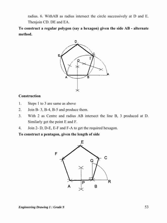
To construct a regular polygon (say a hexagon) given the side AB - alternate method.
Construction
1. Steps 1 to 3 are same as above
2. Join B- 3, B-4, B-5 and produce them.
3. With 2 as Centre and radius AB intersect the line B, 3 produced at D.
Similarly get the point E and F.
4. Join 2- D, D-E, E-F and F-A to get the required hexagon.
To construct a pentagon, given the length of side
54 Engineering Drawing 1 : Grade 9
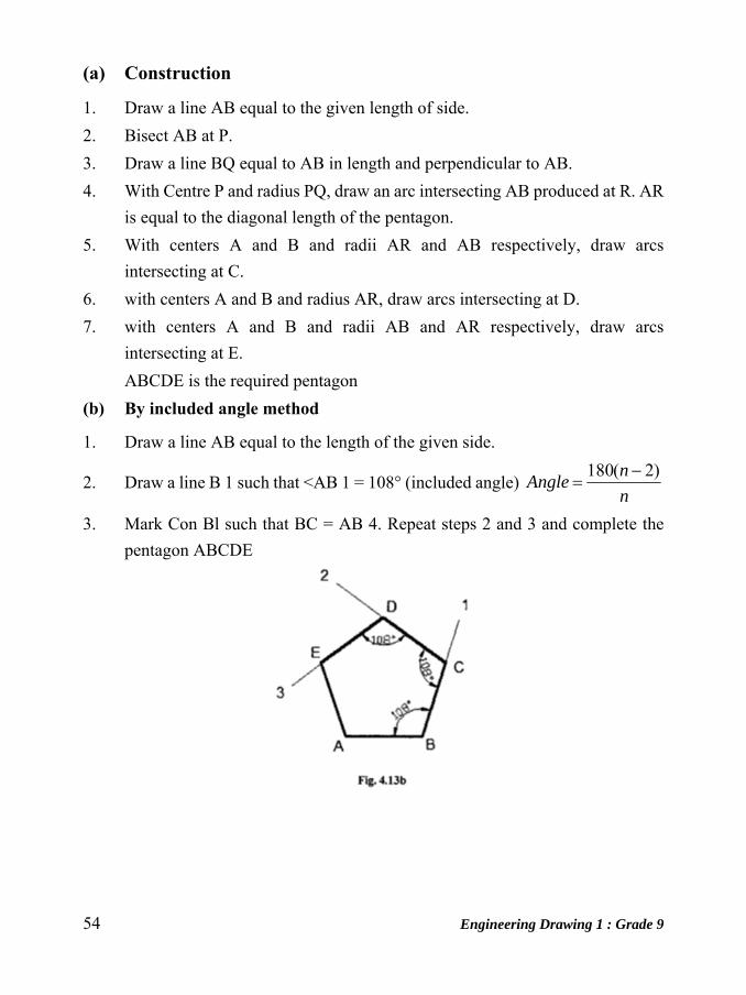
(a) Construction
1. Draw a line AB equal to the given length of side.
2. Bisect AB at P.
3. Draw a line BQ equal to AB in length and perpendicular to AB.
4. With Centre P and radius PQ, draw an arc intersecting AB produced at R. AR
is equal to the diagonal length of the pentagon.
5. With centers A and B and radii AR and AB respectively, draw arcs
intersecting at C.
6. with centers A and B and radius AR, draw arcs intersecting at D.
7. with centers A and B and radii AB and AR respectively, draw arcs
intersecting at E.
ABCDE is the required pentagon
(b) By included angle method
1. Draw a line AB equal to the length of the given side.
2. Draw a line B 1 such that <AB 1 = 108° (included angle) n
nAngle
)2(180
3. Mark Con Bl such that BC = AB 4. Repeat steps 2 and 3 and complete the
pentagon ABCDE
Engineering Drawing 1 : Grade 9 55
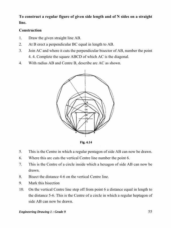
To construct a regular figure of given side length and of N sides on a straight line.
Construction
1. Draw the given straight line AB.
2. At B erect a perpendicular BC equal in length to AB.
3. Join AC and where it cuts the perpendicular bisector of AB, number the point
4. 4. Complete the square ABCD of which AC is the diagonal.
4. With radius AB and Centre B, describe arc AC as shown.
5. This is the Centre in which a regular pentagon of side AB can now be drawn.
6. Where this arc cuts the vertical Centre line number the point 6.
7. This is the Centre of a circle inside which a hexagon of side AB can now be
drawn.
8. Bisect the distance 4-6 on the vertical Centre line.
9. Mark this bisection
10. On the vertical Centre line step off from point 6 a distance equal in length to
the distance 5-6. This is the Centre of a circle in which a regular heptagon of
side AB can now be drawn.

56 Engineering Drawing 1 : Grade 9
11. If further distances 5-6 are now stepped off along the vertical Centre line and
are numbered consecutively, each will be the Centre of a circle in which a
regular polygon can be inscribed with sine of length AB and with a number
of sides denoted by the number against the Centre.
To inscribe a square in a triangle
Construction
1. Draw the given triangle ABC.
2. From C drop a perpendicular to cut the base AB at D.
3. From C draw CE parallel toAB and equal in length to CD.
4. Draw AE and where it cuts the line CB mark F.
5. From F draw FG parallel to AB.
6. From F draw F J parallel to CD.
7. From G draw GH parallel to CD. 8. Join H to 1. Then HJFG is the required
square.
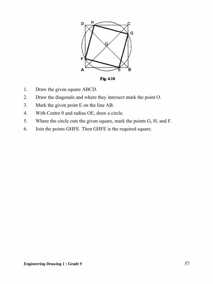
To inscribe within a given square ABCD, another square, one angle of the required square to touch a side of the given square at a given point construction (Fig 4.16)
Engineering Drawing 1 : Grade 9 57
1. Draw the given square ABCD.
2. Draw the diagonals and where they intersect mark the point O.
3. Mark the given point E on the line AB.
4. With Centre 0 and radius OE, draw a circle.
5. Where the circle cuts the given square, mark the points G, H, and F.
6. Join the points GHFE. Then GHFE is the required square.

58 Engineering Drawing 1 : Grade 9
Unit: 8
Divisions Introduction
Engineering drawing consists of a number of geometrical constructions that
includes the division of the lines into different segments. A few methods are
illustrated here without mathematical proofs.
To bisect a given angle.
Construction
1. Draw a line AB and AC making the given angle.
2. With centerA and any convenient radius R, draw an arc intersecting the sides
at D and E.
3. With centers D and E and radius larger than half the chord length DE, draw
arcs intersecting at F 4. JoinAF, <BAF = <PAC.
To divide a straight line into a given number of equal parts say 5.
Engineering Drawing 1 : Grade 9 59
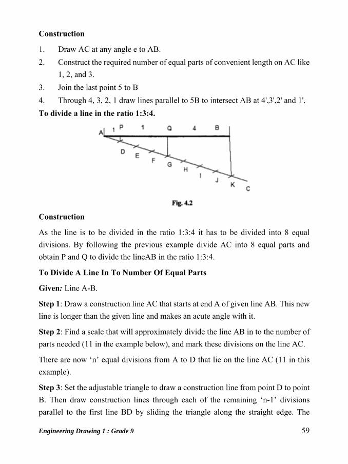
Construction
1. Draw AC at any angle e to AB.
2. Construct the required number of equal parts of convenient length on AC like
1, 2, and 3.
3. Join the last point 5 to B
4. Through 4, 3, 2, 1 draw lines parallel to 5B to intersect AB at 4',3',2' and 1'.
To divide a line in the ratio 1:3:4.
Construction
As the line is to be divided in the ratio 1:3:4 it has to be divided into 8 equal
divisions. By following the previous example divide AC into 8 equal parts and
obtain P and Q to divide the lineAB in the ratio 1:3:4.
To Divide A Line In To Number Of Equal Parts
Given: Line A-B.
Step 1: Draw a construction line AC that starts at end A of given line AB. This new
line is longer than the given line and makes an acute angle with it.
Step 2: Find a scale that will approximately divide the line AB in to the number of
parts needed (11 in the example below), and mark these divisions on the line AC.
There are now ‘n’ equal divisions from A to D that lie on the line AC (11 in this
example).
Step 3: Set the adjustable triangle to draw a construction line from point D to point
B. Then draw construction lines through each of the remaining ‘n-1’ divisions
parallel to the first line BD by sliding the triangle along the straight edge. The

60 Engineering Drawing 1 : Grade 9
original line AB will now be accurately divided.
To divide the circle into any number of equal parts
1. Two Equal parts
Construction
a. Draw the circle of given radius (diameter)
b. Draw the chord passing through the centre.
1. Four Equal parts
Construction
a. Draw the circle of given radius (diameter)
b. Draw the chord passing through the centre, AB.
c. Draw a perpendicular line at the centre to the line AB.
Engineering Drawing 1 : Grade 9 61
Unit: 9
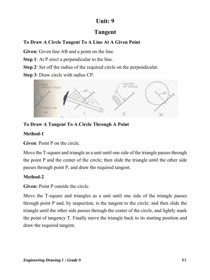
Tangent To Draw A Circle Tangent To A Line At A Given Point
Given: Given line AB and a point on the line.
Step 1: At P erect a perpendicular to the line.
Step 2: Set off the radius of the required circle on the perpendicular.
Step 3: Draw circle with radius CP.
To Draw A Tangent To A Circle Through A Point
Method-1
Given: Point P on the circle.
Move the T-square and triangle as a unit until one side of the triangle passes through
the point P and the center of the circle; then slide the triangle until the other side
passes through point P, and draw the required tangent.
Method-2
Given: Point P outside the circle.
Move the T-square and triangles as a unit until one side of the triangle passes
through point P and, by inspection, is the tangent to the circle; and then slide the
triangle until the other side passes through the center of the circle, and lightly mark
the point of tangency T. Finally move the triangle back to its starting position and
draw the required tangent.
62 Engineering Drawing 1 : Grade 9
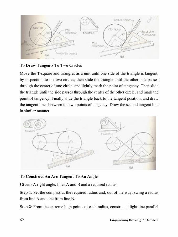
To Draw Tangents To Two Circles
Move the T-square and triangles as a unit until one side of the triangle is tangent,
by inspection, to the two circles; then slide the triangle until the other side passes
through the center of one circle, and lightly mark the point of tangency. Then slide
the triangle until the side passes through the center of the other circle, and mark the
point of tangency. Finally slide the triangle back to the tangent position, and draw
the tangent lines between the two points of tangency. Draw the second tangent line
in similar manner.
To Construct An Arc Tangent To An Angle
Given: A right angle, lines A and B and a required radius
Step 1: Set the compass at the required radius and, out of the way, swing a radius
from line A and one from line B.
Step 2: From the extreme high points of each radius, construct a light line parallel

Engineering Drawing 1 : Grade 9 63
to line A and another line parallel to line B.
Step 3: Where these lines intersect is the exact location of the required swing point.
Set the compass point on the swing point and lightly construct the required radius.
Allow the radius swing to extend past the required area. It is important to locate all
tangent points (T.P) before darkening in.
Step 4: Check all work and darken in the radius using the correct line thickness.
Darken in connecting straight lines as required. Always construct compass work
first, followed by straight lines. Leave all light construction lines.
To draw an arc of given radius touching two straight lines at right 8rngles to each other
Construction
Let r be the given radius and AB and AC the given
straight lines. With A as centre and radius equal to r draw
arcs cutting AB at P and Q. With P and Q as centers draw
arcs to meet at O. With 0 as Centre and radius equal to r
draw the required arc.

64 Engineering Drawing 1 : Grade 9
To draw an arc of a given radius, touching two given straight lines making an angle between them.
Construction
Let AB and CD are the two straight lines and r, the radius. Draw a line PQ parallel
to AB at a distance r from AB. Similarly, draw a line RS parallel to CD. Extend
them to meet at O. With 0 as Centre and radius equal to r draw the arc to the two
given lines.
To Construct An Arc Tangent To Two Radii Or Diameters
Given: Diameter A and arc B with center points located, and the required radius.
Step 1: Set the compass at the required radius and, out of the way, swing a radius
of the required length from a point on the circumference of given diameter A. Out
of the way, swing a required radius from a point on the circumference of a given
arc B.
Step 2: From the extreme high points of each radius, construct a light radius outside
of the given radii A and B.
Step 3: Where these arcs intersect is the exact location of the required swing point.
Set the compass point on the swing point and lightly construct the required radius.
Allow the radius swing to extend past the required area.
Step 4: Check all work; darken in the radii using the correct line thickness. Darken
in the arcs or radii in consecutive order from left to right or from right to left, thus
constructing a smooth connecting line having no apparent change in direction.
Engineering Drawing 1 : Grade 9 65
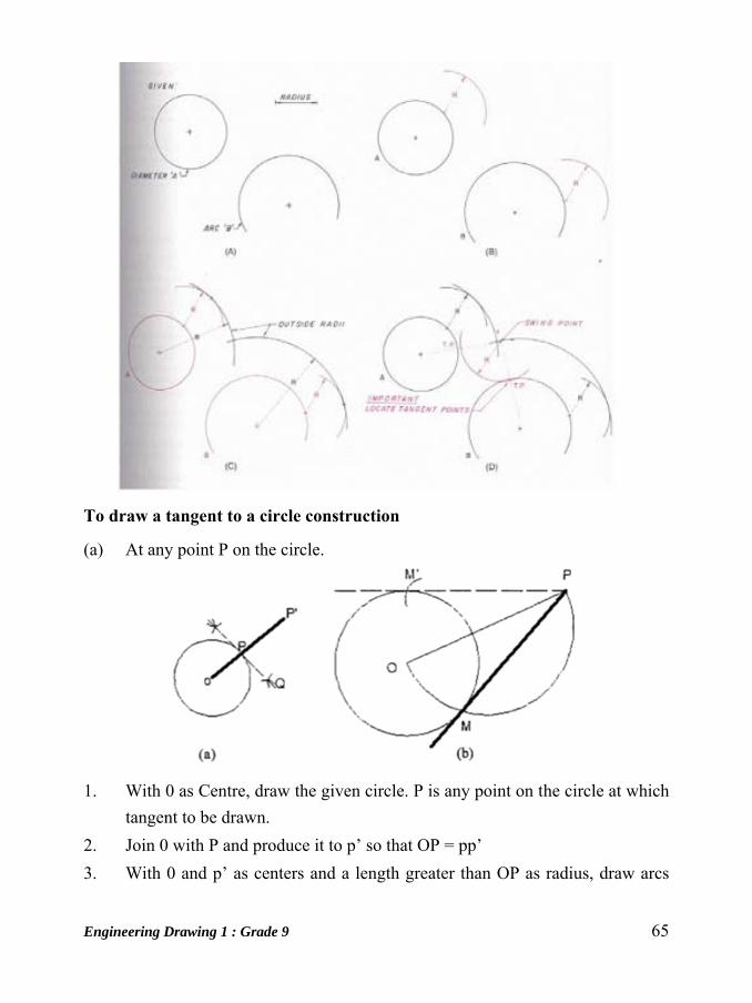
To draw a tangent to a circle construction
(a) At any point P on the circle.
1. With 0 as Centre, draw the given circle. P is any point on the circle at which
tangent to be drawn.
2. Join 0 with P and produce it to p’ so that OP = pp’
3. With 0 and p’ as centers and a length greater than OP as radius, draw arcs
66 Engineering Drawing 1 : Grade 9
intersecting each other at Q.
4. Draw a line through P and Q. This line is the required tangent that will be
perpendicular to OP at P.
(b) From any point outside the circle.
1. With 0 as Centre, draw the given circle. P is the point outside the circle from
which tangent is to be drawn to the circle.
2. Join 0 with P. With OP as diameter, draw a semi-circle intersecting the given
circle at M. Then, the line drawn through P and M is the required tangent.
3. If the semi-circle is drawn on the other side, it will cut the given circle at MI.
Then the line through P and MI will also be a tangent to the circle from P.
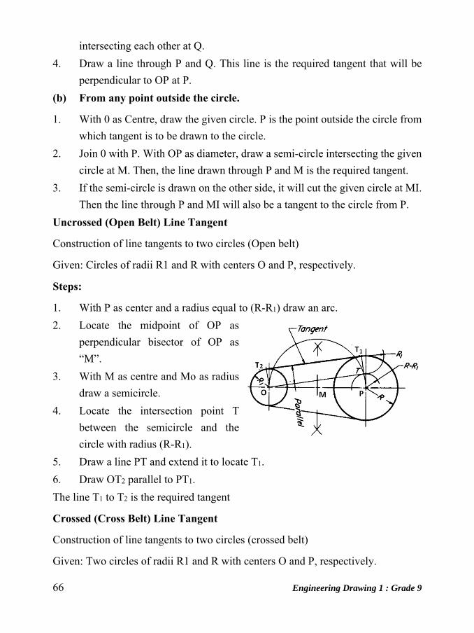
Uncrossed (Open Belt) Line Tangent
Construction of line tangents to two circles (Open belt)
Given: Circles of radii R1 and R with centers O and P, respectively.
Steps:
1. With P as center and a radius equal to (R-R1) draw an arc.
2. Locate the midpoint of OP as
perpendicular bisector of OP as
“M”.
3. With M as centre and Mo as radius
draw a semicircle.
4. Locate the intersection point T
between the semicircle and the
circle with radius (R-R1).
5. Draw a line PT and extend it to locate T1.
6. Draw OT2 parallel to PT1.
The line T1 to T2 is the required tangent
Crossed (Cross Belt) Line Tangent
Construction of line tangents to two circles (crossed belt)
Given: Two circles of radii R1 and R with centers O and P, respectively.
Engineering Drawing 1 : Grade 9 67
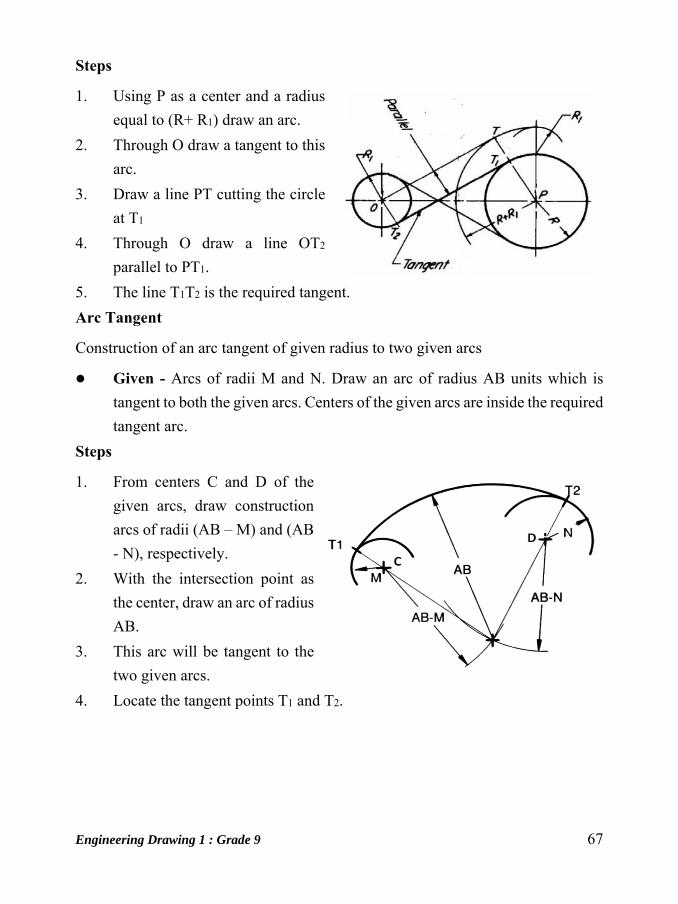
Steps
1. Using P as a center and a radius
equal to (R+ R1) draw an arc.
2. Through O draw a tangent to this
arc.
3. Draw a line PT cutting the circle
at T1
4. Through O draw a line OT2
parallel to PT1.
5. The line T1T2 is the required tangent.
Arc Tangent
Construction of an arc tangent of given radius to two given arcs
Given - Arcs of radii M and N. Draw an arc of radius AB units which is
tangent to both the given arcs. Centers of the given arcs are inside the required
tangent arc. Steps
1. From centers C and D of the
given arcs, draw construction
arcs of radii (AB – M) and (AB
- N), respectively.
2. With the intersection point as
the center, draw an arc of radius
AB.
3. This arc will be tangent to the
two given arcs.
4. Locate the tangent points T1 and T2.
68 Engineering Drawing 1 : Grade 9
Unit: 10
Engineering Curves Special Curves
Cycloid curves are generated by a fixed point in the circumference of a circle when
it rolls without slipping along a fixed straight line or circular path. The rolling circle
is called the generating circle, the fixed straight line, the directing line and the fixed
circle, the directing circle.
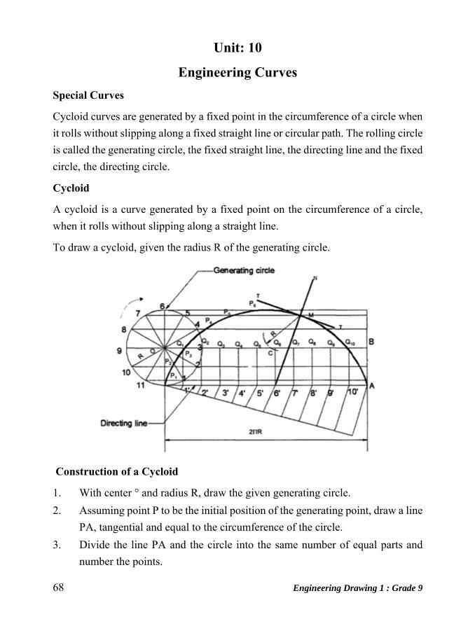
Cycloid
A cycloid is a curve generated by a fixed point on the circumference of a circle,
when it rolls without slipping along a straight line.
To draw a cycloid, given the radius R of the generating circle.
Construction of a Cycloid
1. With center ° and radius R, draw the given generating circle.
2. Assuming point P to be the initial position of the generating point, draw a line
PA, tangential and equal to the circumference of the circle.
3. Divide the line PA and the circle into the same number of equal parts and
number the points.

Engineering Drawing 1 : Grade 9 69
4. Draw the line OB, parallel and equal to PA. OB is the locus of the center of
the generating circle.
5. Erect perpendiculars at 1 I, 2I, 3I, etc., meeting OB at °1, 0z' 03' etc.
6. Through the points 1, 2, 3 etc., draw lines parallel to PA.
7. With center 0, and radius R, draw an arc intersecting the line through 1 at PI'
PI is the position of the generating point, when the center of the generating
circle moves to °1, S. Similarly locate the points P2, P3 etc.
9. A smooth curve passing through the points P, P I' P z,P 3 etc., is the required
cycloid.
Note: T-T is the tangent and NM is the normal to the curve at point M.
Epi-Cycloid and Hypo-Cycloid
An epi-cycloid is a curve traced by a point on the circumference of a generating
circle, when it rolls without slipping on another circle (directing circle) outside it.
If the generating circle rolls inside the directing circle, the curve traced by the point
in called hypo-cycloid.
Involutes
An involute is a curve traced by a point on a perfectly flexible string, while
unwinding from around a circle or polygon the string being kept taut (tight). It is
also a curve traced by a point on a straight line while the line is rolling around a
circle or polygon without slipping.
To draw an involute of a given square.
1. Draw the given square ABCD of side a.
2. Taking A as the starting point, with center B and radius BA=a, draw an arc to
intersect the line CB produced at P1.
3. With Centre C and radius CP1= 2a, draw on arc to intersect the line DC
produced at P2.
4. Similarly, locate the points P3 and P4.
The curve through A, PI' P2 , P3 and P4 is the required involute.
A P 4 is equal to the perimeter of the square.
70 Engineering Drawing 1 : Grade 9
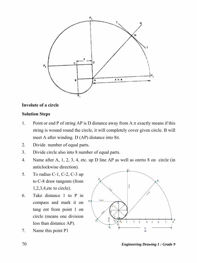
Involute of a circle
Solution Steps
1. Point or end P of string AP is D distance away from A. exactly means if this
string is wound round the circle, it will completely cover given circle. B will
meet A after winding. D (AP) distance into 8.
2. Divide number of equal parts.
3. Divide circle also into 8 number of equal parts.
4. Name after A, 1, 2, 3, 4, etc. up D line AP as well as onto 8 on circle (in
anticlockwise direction).
5. To radius C-1, C-2, C-3 up
to C-8 draw tangents (from
1,2,3,4,etc to circle).
6. Take distance 1 to P in
compass and mark it on
tang ent from point 1 on
circle (means one division
less than distance AP).
7. Name this point P1

Engineering Drawing 1 : Grade 9 71
8. Take 2-B distance in compass and mark it on the tangent from point 2. Name
it point P2.
9. Similarly take 3 to P, 4 to P, 5 to P up to 7 to P distance in compass and mark
on respective tangents and locate P3, P4, P5 up to P8 (i.e. A) points and join
them in smooth curve it is an INVOLUTE of a given circle.
Similarly the involutes of a triangle, pentagon and hexagon are shown below.
Archimedian Spiral
Solution (Radius of 40mm)
Steps
1. With PO radius draw a circle and divide it in EIGHT parts. Name those
1,2,3,4, etc. up to 8.
2. Similarly divided line PO also in EIGHT parts and name those 1,2,3,-- as
shown.
3. Take o-1 distance from op line and draw an arc up to O1 radius vector. Name
the point P1.

72 Engineering Drawing 1 : Grade 9
4. Similarly mark points P2 , P3 , P4 up to P8.
And join those in a smooth curve. It is a SPIRAL of one convolution.
Cylindrical Helix
Draw a helix of one convolution, upon a cylinder. Given 80 mm pitch and 50 mm
diameter of a cylinder. (The axial advance during one complete revolution is called
the pitch of the helix)
SOLUTION:
Draw projections of a cylinder.
Divide circle and axis in to same no. of equal parts. ( 8 )
Name those as shown. Mark initial position of point ‘P’
Mark various positions of P as shown in the figure.
Join all points by smooth possible curve.
Engineering Drawing 1 : Grade 9 73
Make upper half dotted, as it is going behind the
solid and hence will not be seen from front side.
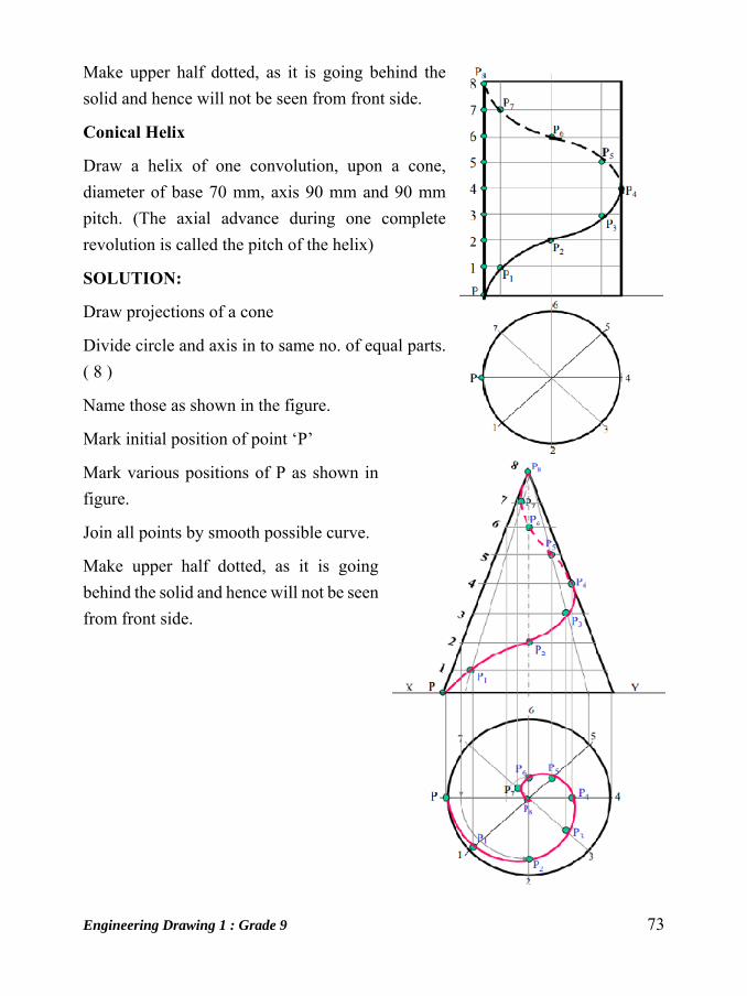
Conical Helix
Draw a helix of one convolution, upon a cone,
diameter of base 70 mm, axis 90 mm and 90 mm
pitch. (The axial advance during one complete
revolution is called the pitch of the helix)
SOLUTION:
Draw projections of a cone
Divide circle and axis in to same no. of equal parts.
( 8 )
Name those as shown in the figure.
Mark initial position of point ‘P’
Mark various positions of P as shown in
figure.
Join all points by smooth possible curve.
Make upper half dotted, as it is going
behind the solid and hence will not be seen
from front side.

74 Engineering Drawing 1 : Grade 9
Unit: 11
Conic Sections
Cone is formed when a right angled triangle with an apex and angle e is rotated
about its altitude as the axis. The length or height of the cone is equal to the altitude
of the triangle and the radius of the base of the cone is equal to the base of the
triangle. The apex angle of the cone is 2.
When a cone is cut by a plane, the curve formed along the section is known as a
conic. For this purpose, the cone may be cut by different section planes and the
conic sections obtained.
Engineering Drawing 1 : Grade 9 75
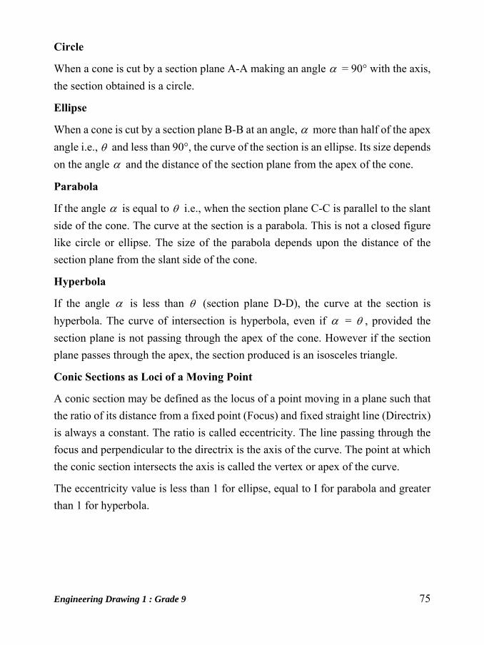
Circle
When a cone is cut by a section plane A-A making an angle = 90° with the axis,
the section obtained is a circle.
Ellipse
When a cone is cut by a section plane B-B at an angle, more than half of the apex
angle i.e., and less than 90°, the curve of the section is an ellipse. Its size depends
on the angle and the distance of the section plane from the apex of the cone.
Parabola
If the angle is equal to i.e., when the section plane C-C is parallel to the slant
side of the cone. The curve at the section is a parabola. This is not a closed figure
like circle or ellipse. The size of the parabola depends upon the distance of the
section plane from the slant side of the cone.
Hyperbola
If the angle is less than (section plane D-D), the curve at the section is
hyperbola. The curve of intersection is hyperbola, even if = , provided the
section plane is not passing through the apex of the cone. However if the section
plane passes through the apex, the section produced is an isosceles triangle.
Conic Sections as Loci of a Moving Point
A conic section may be defined as the locus of a point moving in a plane such that
the ratio of its distance from a fixed point (Focus) and fixed straight line (Directrix)
is always a constant. The ratio is called eccentricity. The line passing through the
focus and perpendicular to the directrix is the axis of the curve. The point at which
the conic section intersects the axis is called the vertex or apex of the curve.
The eccentricity value is less than 1 for ellipse, equal to I for parabola and greater
than 1 for hyperbola.
76 Engineering Drawing 1 : Grade 9
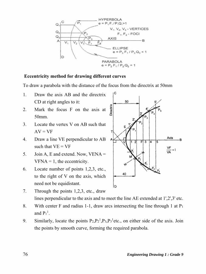
Eccentricity method for drawing different curves
To draw a parabola with the distance of the focus from the directrix at 50mm
1. Draw the axis AB and the directrix
CD at right angles to it:
2. Mark the focus F on the axis at
50mm.
3. Locate the vertex V on AB such that
AV = VF
4. Draw a line VE perpendicular to AB
such that VE = VF
5. Join A, E and extend. Now, VENA =
VFNA = 1, the eccentricity.
6. Locate number of points 1,2,3, etc.,
to the right of V on the axis, which
need not be equidistant.
7. Through the points 1,2,3, etc., draw
lines perpendicular to the axis and to meet the line AE extended at 1',2',3' etc.
8. With center F and radius 1-1, draw arcs intersecting the line through 1 at P1
and P11.
9. Similarly, locate the points P2,P21,P3,P3
1etc., on either side of the axis. Join
the points by smooth curve, forming the required parabola.

Engineering Drawing 1 : Grade 9 77
To draw a normal and tangent through a point 40mm from the directrix
To draw a tangent and normal to the parabola. locate the point M which is at 40 mm
from the directrix. Then join M to F and draw a line through F, perpendicular to MF
to meet the directrix at T. The line joining T and M and extended is the tangent and
a line NN, through M and perpendicular to TM is the normal to the curve.
Ellipse with eccentricity equal to 2/3 for the above problem
Construction is similar to the construction of parabola. To draw an ellipse including
the tangent and normal, only the eccentricity is taken as 2/3 instead of one.
Hyperbola with eccentricity equal to 3/2 for the above problem
The construction of hyperobola is similar to the above problems except that the
eccentricity ratio VF/VA = 3/2 in this case.
Note : The ellipse is a closed curve and has two foci and two directrices. A
hyperbola is an open curve.
Ellipse Hyperbola
Methods for drawing an ellipse
When the dimensions of major and minor axes are given, the ellipse can be drawn
by :
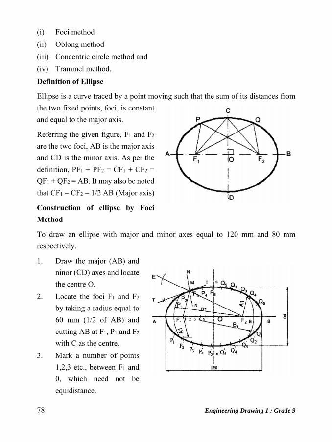
78 Engineering Drawing 1 : Grade 9
(i) Foci method
(ii) Oblong method
(iii) Concentric circle method and
(iv) Trammel method.
Definition of Ellipse
Ellipse is a curve traced by a point moving such that the sum of its distances from
the two fixed points, foci, is constant
and equal to the major axis.
Referring the given figure, F1 and F2
are the two foci, AB is the major axis
and CD is the minor axis. As per the
definition, PF1 + PF2 = CF1 + CF2 =
QF1 + QF2 = AB. It may also be noted
that CF1 = CF2 = 1/2 AB (Major axis)
Construction of ellipse by Foci Method
To draw an ellipse with major and minor axes equal to 120 mm and 80 mm
respectively.
1. Draw the major (AB) and
ninor (CD) axes and locate
the centre O.
2. Locate the foci F1 and F2
by taking a radius equal to
60 mm (1/2 of AB) and
cutting AB at F1, P1 and F2
with C as the centre.
3. Mark a number of points
1,2,3 etc., between F1 and
0, which need not be
equidistance.
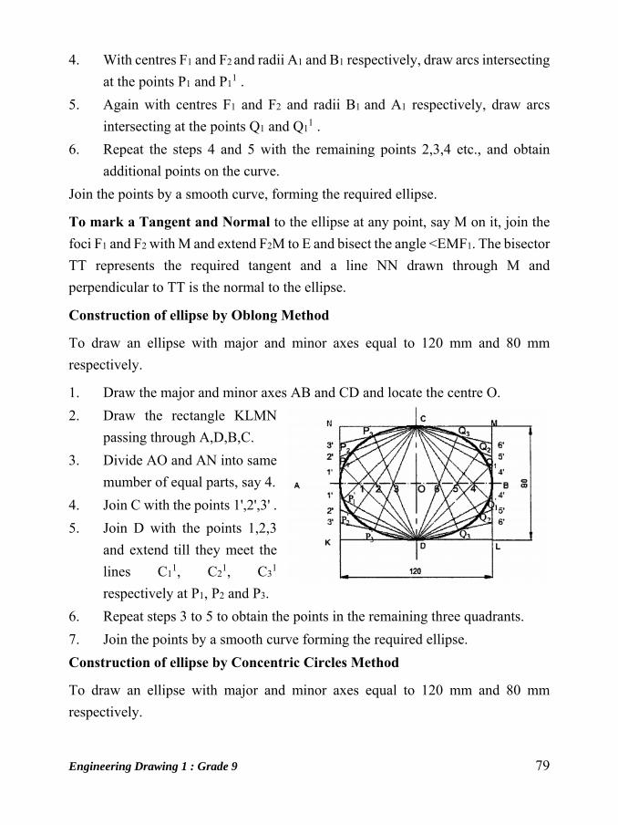
Engineering Drawing 1 : Grade 9 79
4. With centres F1 and F2 and radii A1 and B1 respectively, draw arcs intersecting
at the points P1 and P11 .
5. Again with centres F1 and F2 and radii B1 and A1 respectively, draw arcs
intersecting at the points Q1 and Q11 .
6. Repeat the steps 4 and 5 with the remaining points 2,3,4 etc., and obtain
additional points on the curve.
Join the points by a smooth curve, forming the required ellipse.
To mark a Tangent and Normal to the ellipse at any point, say M on it, join the
foci F1 and F2 with M and extend F2M to E and bisect the angle <EMF1. The bisector
TT represents the required tangent and a line NN drawn through M and
perpendicular to TT is the normal to the ellipse.
Construction of ellipse by Oblong Method
To draw an ellipse with major and minor axes equal to 120 mm and 80 mm
respectively.
1. Draw the major and minor axes AB and CD and locate the centre O.
2. Draw the rectangle KLMN
passing through A,D,B,C.
3. Divide AO and AN into same
mumber of equal parts, say 4.
4. Join C with the points 1',2',3' .
5. Join D with the points 1,2,3
and extend till they meet the
lines C11, C2
1, C31
respectively at P1, P2 and P3.
6. Repeat steps 3 to 5 to obtain the points in the remaining three quadrants.
7. Join the points by a smooth curve forming the required ellipse.
Construction of ellipse by Concentric Circles Method
To draw an ellipse with major and minor axes equal to 120 mm and 80 mm
respectively.
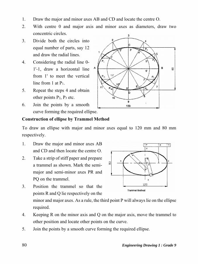
80 Engineering Drawing 1 : Grade 9
1. Draw the major and minor axes AB and CD and locate the centre O.
2. With centre 0 and major axis and minor axes as diameters, draw two
concentric circles.
3. Divide both the circles into
equal number of parts, say 12
and draw the radial lines.
4. Considering the radial line 0-
1'-1, draw a horizontal line
from 1' to meet the vertical
line from 1 at P1.
5. Repeat the steps 4 and obtain
other points P2, P3 etc.
6. Join the points by a smooth
curve forming the required ellipse.
Construction of ellipse by Trammel Method
To draw an ellipse with major and minor axes equal to 120 mm and 80 mm
respectively.
1. Draw the major and minor axes AB
and CD and then locate the centre O.
2. Take a strip of stiff paper and prepare
a trammel as shown. Mark the semi-
major and semi-minor axes PR and
PQ on the trammel.
3. Position the trammel so that the
points R and Q lie respectively on the
minor and major axes. As a rule, the third point P will always lie on the ellipse
required.
4. Keeping R on the minor axis and Q on the major axis, move the trammel to
other position and locate other points on the curve.
5. Join the points by a smooth curve forming the required ellipse.
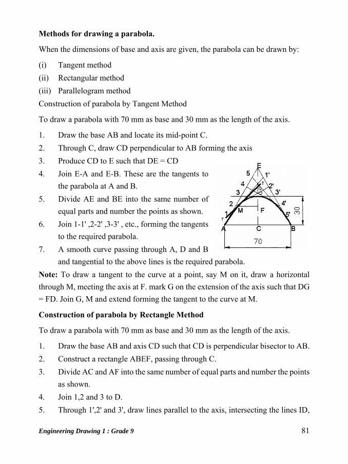
Engineering Drawing 1 : Grade 9 81
Methods for drawing a parabola.
When the dimensions of base and axis are given, the parabola can be drawn by:
(i) Tangent method
(ii) Rectangular method
(iii) Parallelogram method
Construction of parabola by Tangent Method
To draw a parabola with 70 mm as base and 30 mm as the length of the axis.
1. Draw the base AB and locate its mid-point C.
2. Through C, draw CD perpendicular to AB forming the axis
3. Produce CD to E such that DE = CD
4. Join E-A and E-B. These are the tangents to
the parabola at A and B.
5. Divide AE and BE into the same number of
equal parts and number the points as shown.
6. Join 1-1' ,2-2' ,3-3' , etc., forming the tangents
to the required parabola.
7. A smooth curve passing through A, D and B
and tangential to the above lines is the required parabola.
Note: To draw a tangent to the curve at a point, say M on it, draw a horizontal
through M, meeting the axis at F. mark G on the extension of the axis such that DG
= FD. Join G, M and extend forming the tangent to the curve at M.
Construction of parabola by Rectangle Method
To draw a parabola with 70 mm as base and 30 mm as the length of the axis.
1. Draw the base AB and axis CD such that CD is perpendicular bisector to AB.
2. Construct a rectangle ABEF, passing through C.
3. Divide AC and AF into the same number of equal parts and number the points
as shown.
4. Join 1,2 and 3 to D.
5. Through 1',2' and 3', draw lines parallel to the axis, intersecting the lines ID,

82 Engineering Drawing 1 : Grade 9
2D and 3D at P1, P2 and P3
respectively.
6. Obtain the points P11, P21, and P31,
which are symmetrically placed to P1,
P2 and P3 with respect to the axis CD.
7. Join the points by a smooth curve
forming the required parabola.
Construction of parabola by Parallelogram Method
1. Construct the parallelogram PQRS (PS = 120 mm PQ = 60 mm and angle
QPS = 75°). Bisect PS at 0 and draw VO parallel to PQ.
2. Divide PO and SR into any number of (4) equal parts as 1, 2, 3 and 11,21 , 31
respectively starting from P on PQ and from S on SR. Join V1, V2 & V3.
Also join V1', V2', and V3'
3. Divide PO and OS into 4 equal parts as 11,21,31 and 11' ,21' ,31' respectively
starting from P on PO and from S on SO.
4. From 11 draw a line parallel to PQ to meet the line V1 at P1 similarly obtain
the points P2 and P3.
5. Also from 11' ,21' ,31' draw lines parallel to RS to meet the lines V1', V2', and
V3' at P1', P2', and P3' respectively and draw a smooth parabola
Hyperbola
A hyperbola is a curve generated by a point moving such that the difference of its
distances from two fixed points called foci is always constant and equal to the
distance between the vertices of the two branches of hyperbola. This distance is also
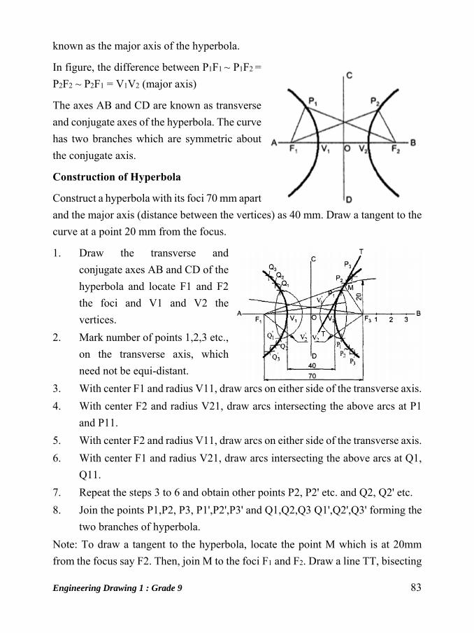
Engineering Drawing 1 : Grade 9 83
known as the major axis of the hyperbola.
In figure, the difference between P1F1 ~ P1F2 =
P2F2 ~ P2F1 = V1V2 (major axis)
The axes AB and CD are known as transverse
and conjugate axes of the hyperbola. The curve
has two branches which are symmetric about
the conjugate axis.
Construction of Hyperbola
Construct a hyperbola with its foci 70 mm apart
and the major axis (distance between the vertices) as 40 mm. Draw a tangent to the
curve at a point 20 mm from the focus.
1. Draw the transverse and
conjugate axes AB and CD of the
hyperbola and locate F1 and F2
the foci and V1 and V2 the
vertices.
2. Mark number of points 1,2,3 etc.,
on the transverse axis, which
need not be equi-distant.
3. With center F1 and radius V11, draw arcs on either side of the transverse axis.
4. With center F2 and radius V21, draw arcs intersecting the above arcs at P1
and P11.
5. With center F2 and radius V11, draw arcs on either side of the transverse axis.
6. With center F1 and radius V21, draw arcs intersecting the above arcs at Q1,
Q11.
7. Repeat the steps 3 to 6 and obtain other points P2, P2' etc. and Q2, Q2' etc.
8. Join the points P1,P2, P3, P1',P2',P3' and Q1,Q2,Q3 Q1',Q2',Q3' forming the
two branches of hyperbola.
Note: To draw a tangent to the hyperbola, locate the point M which is at 20mm
from the focus say F2. Then, join M to the foci F1 and F2. Draw a line TT, bisecting
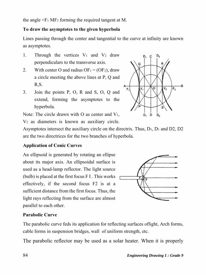
84 Engineering Drawing 1 : Grade 9
the angle <F1 MF2 forming the required tangent at M.
To draw the asymptotes to the given hyperbola
Lines passing through the center and tangential to the curve at infinity are known
as asymptotes.
1. Through the vertices V1 and V2 draw
perpendiculars to the transverse axis.
2. With center O and radius OF1 = (OF2), draw
a circle meeting the above lines at P, Q and
R,S.
3. Join the points P, O, R and S, O, Q and
extend, forming the asymptotes to the
hyperbola.
Note: The circle drawn with O as center and V1,
V2 as diameters is known as auxiliary circle.
Asymptotes intersect the auxiliary circle on the directrix. Thus, D1, D1 and D2, D2
are the two directrices for the two branches of hyperbola.
Application of Conic Curves
An ellipsoid is generated by rotating an ellipse
about its major axis. An ellipsoidal surface is
used as a head-lamp reflector. The light source
(bulb) is placed at the first focus F I . This works
effectively, if the second focus F2 is at a
sufficient distance from the first focus. Thus, the
light rays reflecting from the surface are almost
parallel to each other.
Parabolic Curve
The parabolic curve feds its application for reflecting surfaces oflight, Arch forms,
cable forms in suspension bridges, wall of uniform strength, etc.
The parabolic reflector may be used as a solar heater. When it is properly
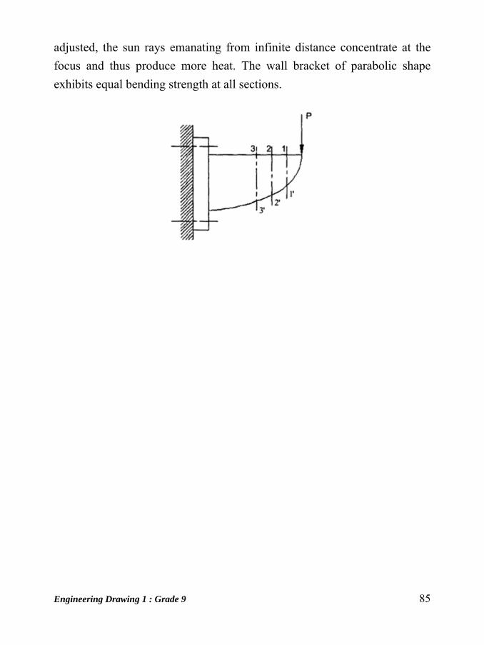
Engineering Drawing 1 : Grade 9 85
adjusted, the sun rays emanating from infinite distance concentrate at the
focus and thus produce more heat. The wall bracket of parabolic shape
exhibits equal bending strength at all sections.

86 Engineering Drawing 1 : Grade 9
Unit: 12
Dimensioning Drawing of a component, in addition to providing complete shape description, must
also furnish information regarding the size description. These are provided through
the distances between the surfaces, location of holes, nature of surface finish, type
of material, etc. The expression of these features on a drawing, using lines, symbols,
figures and notes is called dimensioning.
Fig:- Elements of Dimensioning
Principles of Dimensioning
Some of the basic principles of dimensioning are given below.

Engineering Drawing 1 : Grade 9 87
I. All dimensional information necessary to describe a component clearly and
completely shall be written directly on a drawing.
2. Each feature shall be dimensioned once only on a drawing, i.e., dimension
marked in one view need not be repeated in another view.
3. Dimension should be placed on the view where the shape is best seen
(Fig.2.14)
4. As far as possible, dimensions should be expressed in one unit only preferably
in millimeters, without showing the unit symbol (mm).
5. As far as possible dimensions should be placed outside the view (Fig.2.15).
6. Dimensions should be taken from visible outlines rather than from hidden
lines (Fig.2.16).
7. No gap should be left between the feature and the start of the extension line
(Fig.2.I7).

88 Engineering Drawing 1 : Grade 9
8. Crossing of center lines should be done by a long dash and not a short dash
(Fig.2.I8).
Execution of Dimensions
1. Projection and dimension lines should be drawn as thin continuous lines.
Projection lines should extend slightly beyond the respective dimension line.
Projection lines should be drawn Perpendicular to the feature being
dimensioned. If the space for dimensioning is insufficient, the arrow heads
may be reversed and the adjacent arrow heads may be replaced by a dot
(Fig.2.19). However, they may be drawn obliquely, but parallel to each other
in special cases, such as on tapered feature (Fig.2.20).

Engineering Drawing 1 : Grade 9 89
2. A leader line is a line referring to a feature (object, outline, and dimension).
Leader lines should be inclined to the horizontal at an angle greater than 30°.
Leader line should terminate, (a) with a dot, if they end within the outline
ofan object (Fig.2.21a). (b) With an arrow head, if they end on outside of the
object (Fig.2.21b).
(c) Without a dot or arrow head, if they end on dimension line (Fig.2.21c).
Dimension Termination and Origin Indication
Dimension lines should show distinct termination in the front of arrow heads or
oblique strokes or where applicable an origin indication (Fig.2.22). The arrow head
included angle is 15°. The origin indication is drawn as a small open circle of
approximately 3 mm in diameter. The proportion length to depth 3 : 1 of arrow head
is shown in Fig.2.23.
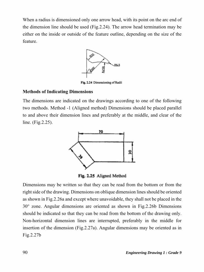
90 Engineering Drawing 1 : Grade 9
When a radius is dimensioned only one arrow head, with its point on the arc end of
the dimension line should be used (Fig.2.24). The arrow head termination may be
either on the inside or outside of the feature outline, depending on the size of the
feature.
Methods of Indicating Dimensions
The dimensions are indicated on the drawings according to one of the following
two methods. Method -1 (Aligned method) Dimensions should be placed parallel
to and above their dimension lines and preferably at the middle, and clear of the
line. (Fig.2.25).
Dimensions may be written so that they can be read from the bottom or from the
right side of the drawing. Dimensions on oblique dimension lines should be oriented
as shown in Fig.2.26a and except where unavoidable, they shall not be placed in the
30° zone. Angular dimensions are oriented as shown in Fig.2.26b Dimensions
should be indicated so that they can be read from the bottom of the drawing only.
Non-horizontal dimension lines are interrupted, preferably in the middle for
insertion of the dimension (Fig.2.27a). Angular dimensions may be oriented as in
Fig.2.27b
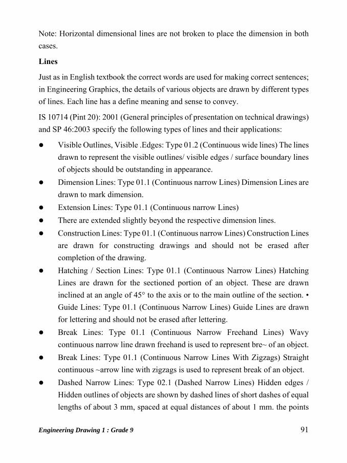
Engineering Drawing 1 : Grade 9 91
Note: Horizontal dimensional lines are not broken to place the dimension in both
cases.
Lines
Just as in English textbook the correct words are used for making correct sentences;
in Engineering Graphics, the details of various objects are drawn by different types
of lines. Each line has a define meaning and sense to convey.
IS 10714 (Pint 20): 2001 (General principles of presentation on technical drawings)
and SP 46:2003 specify the following types of lines and their applications:
Visible Outlines, Visible .Edges: Type 01.2 (Continuous wide lines) The lines
drawn to represent the visible outlines/ visible edges / surface boundary lines
of objects should be outstanding in appearance.
Dimension Lines: Type 01.1 (Continuous narrow Lines) Dimension Lines are
drawn to mark dimension.
Extension Lines: Type 01.1 (Continuous narrow Lines)
There are extended slightly beyond the respective dimension lines.
Construction Lines: Type 01.1 (Continuous narrow Lines) Construction Lines
are drawn for constructing drawings and should not be erased after
completion of the drawing.
Hatching / Section Lines: Type 01.1 (Continuous Narrow Lines) Hatching
Lines are drawn for the sectioned portion of an object. These are drawn
inclined at an angle of 45° to the axis or to the main outline of the section. •
Guide Lines: Type 01.1 (Continuous Narrow Lines) Guide Lines are drawn
for lettering and should not be erased after lettering.
Break Lines: Type 01.1 (Continuous Narrow Freehand Lines) Wavy
continuous narrow line drawn freehand is used to represent bre~ of an object.
Break Lines: Type 01.1 (Continuous Narrow Lines With Zigzags) Straight
continuous ~arrow line with zigzags is used to represent break of an object.
Dashed Narrow Lines: Type 02.1 (Dashed Narrow Lines) Hidden edges /
Hidden outlines of objects are shown by dashed lines of short dashes of equal
lengths of about 3 mm, spaced at equal distances of about 1 mm. the points

92 Engineering Drawing 1 : Grade 9
of intersection of these lines with the outlines / another hidden line should be
clearly shown.
Center Lines: Type 04.1 (Long-Dashed Dotted Narrow Lines) Center Lines
are drawn at the center of the drawings symmetrical about an axis or both the
axes. These are extended by a short distance beyond the outline of the
drawing.
“Cutting Plane Lines: Type 04.1 and Type 04.2 Cutting Plane Line is drawn
to show the location of a cutting plane. It is long-dashed dotted narrow line,
made wide at the ends, bends and change of direction. The direction of
viewing is shown by means of arrows resting on the cutting plane line.
Border Lines: Border Lines are continuous wide lines of minimum thickness
0.7 mm
Understanding the various types of lines used in drawing (i.e.,) their thickness, style
of construction and appearance as per BIS and following them meticulously may
be considered as the foundation of good drawing skills. Table 2.2 shows various
types of lines with the recommended applications.
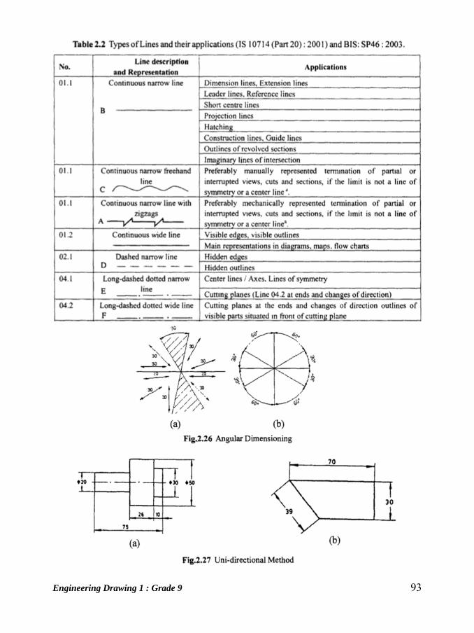
Engineering Drawing 1 : Grade 9 93
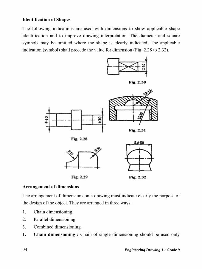
94 Engineering Drawing 1 : Grade 9
Identification of Shapes
The following indications are used with dimensions to show applicable shape
identification and to improve drawing interpretation. The diameter and square
symbols may be omitted where the shape is clearly indicated. The applicable
indication (symbol) shall precede the value for dimension (Fig. 2.28 to 2.32).
Arrangement of dimensions
The arrangement of dimensions on a drawing must indicate clearly the purpose of
the design of the object. They are arranged in three ways.
1. Chain dimensioning
2. Parallel dimensioning
3. Combined dimensioning.
1. Chain dimensioning : Chain of single dimensioning should be used only
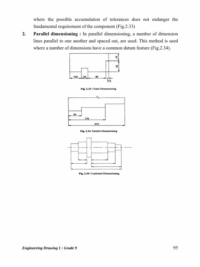
Engineering Drawing 1 : Grade 9 95
where the possible accumulation of tolerances does not endanger the
fundamental requirement of the component (Fig.2.33)
2. Parallel dimensioning : In parallel dimensioning, a number of dimension
lines parallel to one another and spaced out, are used. This method is used
where a number of dimensions have a common datum feature (Fig.2.34).

96 Engineering Drawing 1 : Grade 9
Unit: 13
Orthographic Projections Introduction
Engineering drawing, particularly solid geometry is the graphic language used in
the industry to record the ideas and information’s necessary in the form of blue
prints to make machines, buildings, structures etc., by engineers and technicians
who design, develop, manufacture and market the products.
Projection
As per the optical physics, an object is seen when the light rays called visual rays
coming from the object strike the observer's eye. The size of the image formed in
the retina depends on the distance of the observer from the object.
If an imaginary transparent plane is introduced such that the object is in between
the observer and the plane, the image obtained on the screen is as shown in figure
below. This is called perspective view of the object. Here, straight lines (rays) are
drawn from various points on the contour of the object to meet the transparent plane,
thus the object is said to be projected on that plane.
Fig.Perspective Projection
The figure or view formed by joining, in correct sequence, the points at which these
lines meet the plane is called the projection of the object. The lines or rays drawn
from the object to the plane are called projectors. The transparent plane on which
the projections are drawn is known as plane of projection.
Engineering Drawing 1 : Grade 9 97
Types of Projections
1. Pictorial projections
(i) Perspective projection
(ii) Isometric projection
(iii) Oblique projection
2. Orthographic Projections
1. Pictorial Projections
The Projections in which the description of the object is completely understood in
one view is known as pictorial projection. They have the advantage of conveying
an immediate impression of the general shape and details of the object, but not its
true dimensions or sizes.
2. Orthographic Projection
'ORTHO' means right angle and orthographic means right angled drawing. When
the projectors are perpendicular to the plane on which the projection is obtained, it
is known as orthographic projection.
Method of Obtaining Front View
Imagine an observer looking at the object from an infinite distance. The rays are
parallel to each other and perpendicular to both the front surface of the object and
the plane. When the observer is at a finite distance from the object, the rays
converge to the eye as in the case of perspective projection. When the observer
looks from the front surface F or the block, its true shape and size is seen. When the
rays or projectors are extended further they meet the vertical plane (V.P) located
behind the object. By joining the projectors meeting the plane in correct sequence
the Front view is obtained.
Front view shows only two dimensions of the object, Viz. length L and height H. It
does not show the breadth B. Thus one view or projection is insufficient for the
complete description of the object.
As Front view alone is insufficient for the complete description of the object,
another plane called Horizontal plane (H.P) is assumed such that it is hinged and

98 Engineering Drawing 1 : Grade 9
perpendicular to V.P and the object is in front of the V.P and above the H.P
Fig:-Method of Obtaining Front View
Method of Obtaining Top View
Looking from the top, the projection of the top surface is the Top view (TV). Both
top surface and Top view are of exactly the same shape and size. Thus, Top view
gives the True length L and breadth B of the block but not the height H.
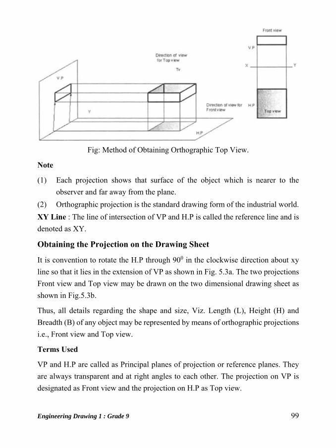
Engineering Drawing 1 : Grade 9 99
Fig: Method of Obtaining Orthographic Top View.
Note
(1) Each projection shows that surface of the object which is nearer to the
observer and far away from the plane.
(2) Orthographic projection is the standard drawing form of the industrial world.
XY Line : The line of intersection of VP and H.P is called the reference line and is
denoted as XY.
Obtaining the Projection on the Drawing Sheet
It is convention to rotate the H.P through 900 in the clockwise direction about xy
line so that it lies in the extension of VP as shown in Fig. 5.3a. The two projections
Front view and Top view may be drawn on the two dimensional drawing sheet as
shown in Fig.5.3b.
Thus, all details regarding the shape and size, Viz. Length (L), Height (H) and
Breadth (B) of any object may be represented by means of orthographic projections
i.e., Front view and Top view.
Terms Used
VP and H.P are called as Principal planes of projection or reference planes. They
are always transparent and at right angles to each other. The projection on VP is
designated as Front view and the projection on H.P as Top view.

100 Engineering Drawing 1 : Grade 9
Four Quadrants
When the planes of projections are extended beyond their line of intersection, they
form Four Quadrants. These quadrants are numbered as I, II, ill and IV in clockwise
direction when rotated about reference line xy as shown in figure.
Fig. Four Quadrants
In figure 5.5 the object is in the first quadrant and the projections obtained are "First
angle projections" i.e., the object lies in between the observer and the planes of
projection. Front view shows the length (L) and height (H) of the object, and Top
view shows the length (L) and the breadth (B) of it.
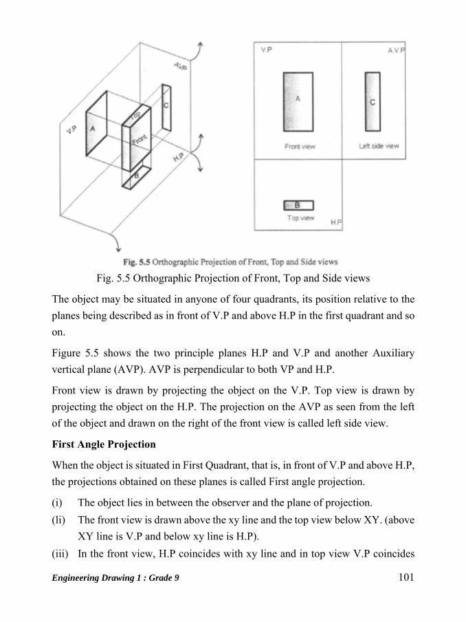
Engineering Drawing 1 : Grade 9 101
Fig. 5.5 Orthographic Projection of Front, Top and Side views
The object may be situated in anyone of four quadrants, its position relative to the
planes being described as in front of V.P and above H.P in the first quadrant and so
on.
Figure 5.5 shows the two principle planes H.P and V.P and another Auxiliary
vertical plane (AVP). AVP is perpendicular to both VP and H.P.
Front view is drawn by projecting the object on the V.P. Top view is drawn by
projecting the object on the H.P. The projection on the AVP as seen from the left
of the object and drawn on the right of the front view is called left side view.
First Angle Projection
When the object is situated in First Quadrant, that is, in front of V.P and above H.P,
the projections obtained on these planes is called First angle projection.
(i) The object lies in between the observer and the plane of projection.
(li) The front view is drawn above the xy line and the top view below XY. (above
XY line is V.P and below xy line is H.P).
(iii) In the front view, H.P coincides with xy line and in top view V.P coincides

102 Engineering Drawing 1 : Grade 9
with XY line.
(iv) Front view shows the length (L) and height (H) of the object and Top view
shows the length (L) and breadth (B) or width (W) or thickness (T) of it.
Third Angle Projection
In this, the object is situated in Third Quadrant. The Planes of projection lie between
the object and the observer. The front view comes below the xy line and the top
view about it.
Comparison between first angle and third angle projection
First Angle Projection Third Angle Projection The object is imagined to be in first
quadrant.
The object is imagined to be in third
quadrant.
The object lies between the observer
and plane of projection.
The plane of projection lies
between the observer and the
object.
The plane of projection is assumed
to be non transparent.
The plane of projection is assumed
to be transparent.
When view are drawn in their When views are drawn in their

Engineering Drawing 1 : Grade 9 103
relative position, top view comes
below front view, right side view is
drawn to the left side of elevation.
relative position, top view comes
above front view, right side view is
drawn to the right side of elevation.
Projection of Solids
Introduction
A solid has three dimensions, the length, breadth and thickness or height. A solid
may be represented by orthographic views, the number of which depends on the
type of solid and its orientation with respect to the planes of projection. Solids are
classified into two major groups. (i) Polyhedral, and (ii) Solids of revolution
Polyhedra

104 Engineering Drawing 1 : Grade 9
A polyhedra is defined as a solid bounded by plane surfaces called faces.They are :
(i) Regular polyhedra
(ii) Prisms and
(iii) Pyramids.
Regular Polyhedra
A polyhedron is said to be regular if its surfaces are regular polygons. The following
are some of the regular plolyhedra.
(a) Tetrahedron: It consists of four equal faces, each one being a equilateral
triangle.
(b) 'Hexahedron(cube): It consists of six equal faces, each a square.
(c) Octahedron: It has eight equal faces, each an equilateral triangle.
(d) Dodecahedron: It has twelve regular and equal pentagonal faces.
(e) Icosahedron: It has twenty equal, equilateral triangular faces.
Prisms
A prism is a polyhedron having two equal ends called the bases parallel I to each
other. The two bases are joined by faces, which are rectangular in shape. The
imaginary line passing through the centers of the bases is called the axis of the
prism. A prism is named after the shape of its base. For example, a prism with
square base is called a square prism, the one with a pentagonal base is called a

Engineering Drawing 1 : Grade 9 105
pentagonal prism, and so on (Fig.6.2) The nomenclature of the square prism is
given in Fig.6.3.
Pyramids
A pyramid is a polyhedron having one base, with a number of isosceles triangular
faces, meeting at a point called the apex. The imaginary line passing through the
center of the base and the apex is called the axis of the pyramid.
The pyramid is named after the shape of the base. Thus, a square pyramid has a
square base and pentagonal pyramid has pentagonal base and so on (Fig.6.4 ( a)).
The nomenclature of a pyramid is shown in Fig.6.4 (b).
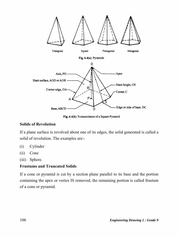
106 Engineering Drawing 1 : Grade 9
Solids of Revolution
If a plane surface is revolved about one of its edges, the solid generated is called a
solid of revolution. The examples are:-
(i) Cylinder
(ii) Cone
(iii) Sphere.
Frustums and Truncated Solids
If a cone or pyramid is cut by a section plane parallel to its base and the portion
containing the apex or vertex IS removed, the remaining portion is called frustum
of a cone or pyramid.
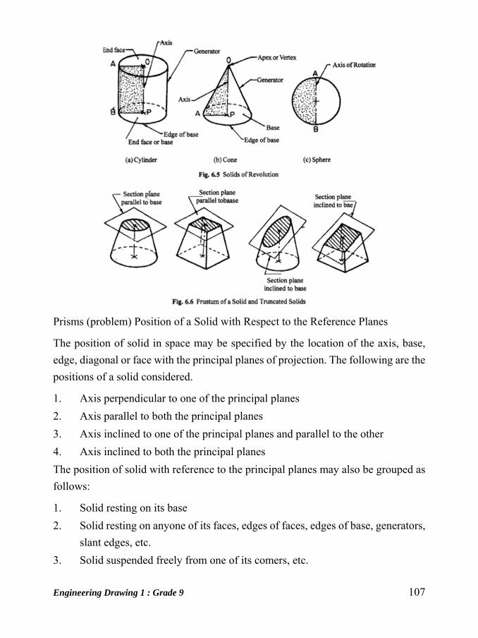
Engineering Drawing 1 : Grade 9 107
Prisms (problem) Position of a Solid with Respect to the Reference Planes
The position of solid in space may be specified by the location of the axis, base,
edge, diagonal or face with the principal planes of projection. The following are the
positions of a solid considered.
1. Axis perpendicular to one of the principal planes
2. Axis parallel to both the principal planes
3. Axis inclined to one of the principal planes and parallel to the other
4. Axis inclined to both the principal planes
The position of solid with reference to the principal planes may also be grouped as
follows:
1. Solid resting on its base
2. Solid resting on anyone of its faces, edges of faces, edges of base, generators,
slant edges, etc.
3. Solid suspended freely from one of its comers, etc.

108 Engineering Drawing 1 : Grade 9
Unit: 14
Isometric Projection Introduction
Pictorial projections are used for presenting ideas which may be easily understood
by persons even without technical training and knowledge of multi-view drawing.
The Pictorial drawing shows several faces of an object in one view, approximately
as it appears to the eye.
Principle of Isometric Projections
It is a pictorial orthographic projection of an object in which a transparent cube
containing the object is tilted until one of the solid diagonals of the cube becomes
perpendicular to the vertical plane and the three axes are equally inclined to this
vertical plane.
Isometric projection of a cube in steps is shown in Fig.9.1. Here ABCDEFGH is
the isometric projection of the cube.
The front view of the cube, resting on one of its corners (G) is the isometric
projection of the cube. The isometric projection of the cube is reproduced in Fig.9.2.
Isometric Scale
In the isometric projection of a cube shown in Fig.9.2, the top face ABED is sloping
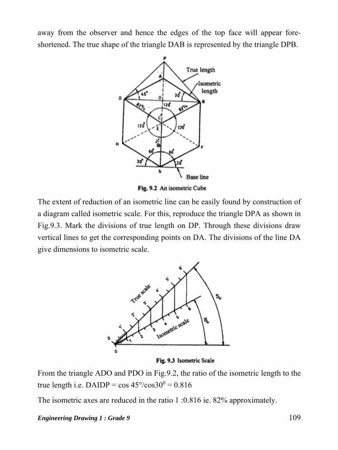
Engineering Drawing 1 : Grade 9 109
away from the observer and hence the edges of the top face will appear fore-
shortened. The true shape of the triangle DAB is represented by the triangle DPB.
The extent of reduction of an isometric line can be easily found by construction of
a diagram called isometric scale. For this, reproduce the triangle DPA as shown in
Fig.9.3. Mark the divisions of true length on DP. Through these divisions draw
vertical lines to get the corresponding points on DA. The divisions of the line DA
give dimensions to isometric scale.
From the triangle ADO and PDO in Fig.9.2, the ratio of the isometric length to the
true length i.e. DAIDP = cos 45°/cos300 = 0.816
The isometric axes are reduced in the ratio 1 :0.816 ie. 82% approximately.

110 Engineering Drawing 1 : Grade 9
Lines in Isometric Projection
The following are the relations between the lines in isometric projection which are
evident from Fig.9.2.
1. The lines that are parallel on the object are parallel in the isometric porjection.
2. Vertical lines on the object appear vertical in the isometric projection.
3. Horizontal lines on the object are drawn at an angle of 3 0° with the horizontal
in the isometric projection.
4. A line parallel to an isometric axis is called an isometric line and it is fore
shortened to 82%.
5. A line which is not parallel to any isometric axis is called non-isometric line
and the extent of fore-shortening of non-isometric lines are different if their
inclinations with the vertical planes are different.
Figure 9.4(a) shows a rectangular block in pictorial form and Fig. 9.4(b), the steps
for drawing an isometric projection using the isometric scale.
Isometric Drawing
Drawing of objects is seldom drawn in true isometric projections, as the use of an
isometric scale is inconvenient. Instead, a convenient method in which the fore
shortening of lengths is ignored and actual or true lengths are used to obtain the
projections, called isometric drawing or isometric view is normally used. This is
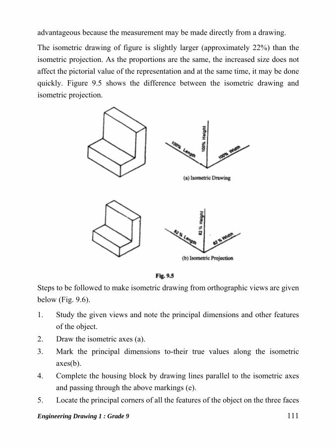
Engineering Drawing 1 : Grade 9 111
advantageous because the measurement may be made directly from a drawing.
The isometric drawing of figure is slightly larger (approximately 22%) than the
isometric projection. As the proportions are the same, the increased size does not
affect the pictorial value of the representation and at the same time, it may be done
quickly. Figure 9.5 shows the difference between the isometric drawing and
isometric projection.
Steps to be followed to make isometric drawing from orthographic views are given
below (Fig. 9.6).
1. Study the given views and note the principal dimensions and other features
of the object.
2. Draw the isometric axes (a).
3. Mark the principal dimensions to-their true values along the isometric
axes(b).
4. Complete the housing block by drawing lines parallel to the isometric axes
and passing through the above markings (e).
5. Locate the principal corners of all the features of the object on the three faces

112 Engineering Drawing 1 : Grade 9
of the housing block (d ). 6. Draw lines parallel to the axes and passing
through the above points and obtain the isometric drawing of the object by
darkening the visible edges (e).
Non-Isometric Lines
In an isometric projection or drawing, the lines that are not parallel to the isometric
axes are called non-isometric lines. These lines obviously do not appear in their true
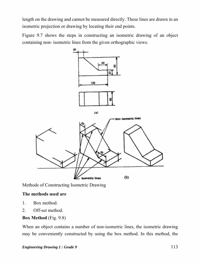
Engineering Drawing 1 : Grade 9 113
length on the drawing and cannot be measured directly. These lines are drawn in an
isometric projection or drawing by locating their end points.
Figure 9.7 shows the steps in constructing an isometric drawing of an object
containing non- isometric lines from the given orthographic views.
Methods of Constructing Isometric Drawing
The methods used are
1. Box method.
2. Off-set method.
Box Method (Fig. 9.8)
When an object contains a number of non-isometric lines, the isometric drawing
may be conveniently constructed by using the box method. In this method, the
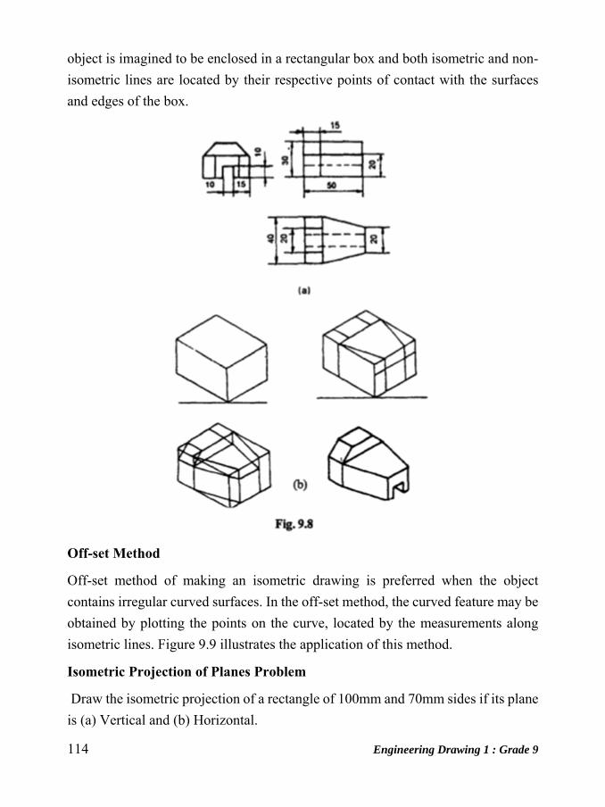
114 Engineering Drawing 1 : Grade 9
object is imagined to be enclosed in a rectangular box and both isometric and non-
isometric lines are located by their respective points of contact with the surfaces
and edges of the box.
Off-set Method
Off-set method of making an isometric drawing is preferred when the object
contains irregular curved surfaces. In the off-set method, the curved feature may be
obtained by plotting the points on the curve, located by the measurements along
isometric lines. Figure 9.9 illustrates the application of this method.
Isometric Projection of Planes Problem
Draw the isometric projection of a rectangle of 100mm and 70mm sides if its plane
is (a) Vertical and (b) Horizontal.
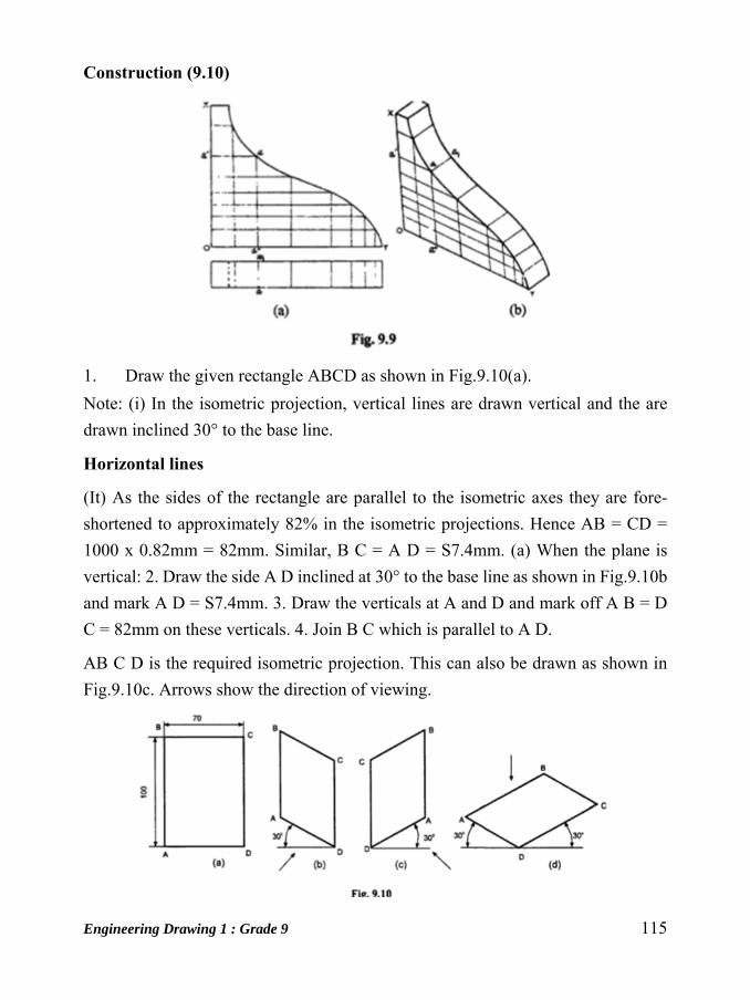
Engineering Drawing 1 : Grade 9 115
Construction (9.10)
1. Draw the given rectangle ABCD as shown in Fig.9.10(a).
Note: (i) In the isometric projection, vertical lines are drawn vertical and the are
drawn inclined 30° to the base line.
Horizontal lines
(It) As the sides of the rectangle are parallel to the isometric axes they are fore-
shortened to approximately 82% in the isometric projections. Hence AB = CD =
1000 x 0.82mm = 82mm. Similar, B C = A D = S7.4mm. (a) When the plane is
vertical: 2. Draw the side A D inclined at 30° to the base line as shown in Fig.9.10b
and mark A D = S7.4mm. 3. Draw the verticals at A and D and mark off A B = D
C = 82mm on these verticals. 4. Join B C which is parallel to A D.
AB C D is the required isometric projection. This can also be drawn as shown in
Fig.9.10c. Arrows show the direction of viewing.

116 Engineering Drawing 1 : Grade 9
(b) When the plane is horizontal.
5. Draw the sides AD and DC inclined at 30° to be base line and complete the
isometric projectionAB C D as shown in Fig. 9.10. Arrow at the top shows
the direction of viewing.
To draw the isometric projection of a square plane. (Fig. 9.11a)
Construction (Fig. 9.11)
Case 1 Vertical plane (Fig. 9. 11 b) 1. Draw a line at 30° to the horizontal and mark
the isometric length on it. 2. Draw verticals at the ends of the line and mark the
isometric length on these parallel lines. 3. Join the ends by a straight line which is
also inclined at 30° to the horizontal.
There are two possible positions for the plane
Case IT Horizontal plane (Fig. 9.11c) 1. Draw two lines at 30° to the horizontal and
mark the isometric length along the line. 2. Complete the figure by drawing 30°
inclined lines at the ends till the lines intersect.
Note (i) the shape of the isometric projection or drawing of a square is a Rhombus.
(ii) While dimensioning an isometric projection or isometric drawing true
dimensional values only must be used.
Problem
Figure 9.12a shows the projection of a pentagonal plane. Draw the isometric
drawing of the plane (i) when the surface is parallel to v.p and (ii) parallel to H.P.
Construction (Fig. 9.12)

Engineering Drawing 1 : Grade 9 117
1. Enclose the given pentagon in a rectangle 1234.
2. Make the isometric drawing of the rectangle 1234 by using true lengths.
3. Locate the points A and B such that Ia = lA and 1b = IB.
4. Similarly locate point C, D and E such that 2c = 2C, 3d = 3D and e4 = E4. 5.
ABCDE is the isometric drawing of the pentagon. 6. Following the above
princple of construction 9.12c can be
Problem
Draw the isometric view of a pentagonal plane of 30mm side when one of its sides
is parallel to H.p, (a) When it is horizontal and (b) vertical.
Construction (9.13)
1. Draw the pentagon ABCDE and enclose it in a rectangle 1-2-3-4 as shown in
Fig.9.'3a.
(a) When it is horizontal the isometric view of the pentagon can be represented
by ABCDE as shown in Fig. 9.13b.
(b) When the plane is vertical it can be represented by ABCDE as shown in
Fig.9.13c or d.
Note: It may be noted that the point A on the isometric view can be marked after
drawing the isometric view of the rectangle 1-2-3-4 for this, mark 1AI = IA and so
on.

118 Engineering Drawing 1 : Grade 9
Problem
Figure 9.l4a shows the orthographic view of a hexagonal plane of side 30mm. Draw
the isometric drawing (view) of the plane keeping it (a) horizontal and (b) vertical.
Construction (Fig. 9.14)
Following the principle of construction of Fig.9.13 obtain the figure 9 .14b and 9
.14c respectively for horizontal and vertical position of the plane.
Problem:
Draw the isometric view of a circular plane of diameter 60mm whose surface is (aJ
Horizontal, (b) Vertical.

Engineering Drawing 1 : Grade 9 119
Construction (Fig. 9.15) using the method of points
1. Enclose the circle in a square 1-2-3-4 and draw diagonals, as shown in Fig.
9.1Sa. Also draw lines YA horizontally and XA vertically.
To draw the isometric view of the square 1-2-3-4 as shown in Fig.9.lSb.
2. Mark the mid points of the sides of the square as B 0 F and H.
3. Locate the points X and Y on lines 1-4 and 1-2 respectively.
4. Through the point X, draw A X parallel to line 1-2 to get point A on the
diagonal 1-3. The point A can be obtained also by drawing Y A through the
point Y and parallel to the line 1-4. S. Similarly obtain other points C, E and
G
6. Draw a smooth curve passing through all the points to obtain the required
isometric view of the horizontal circular plane.
7. Similarly obtain isometric view of the vertical circular plane as shown in
Fig.9.1Sc and d.
Problem:Draw the isometric projection oj a circular plane oj diameter 60mm
whose surface is (aJ Horizontal and (b) Vertical-use Jour-centre method
Construction (Fig.9.16)
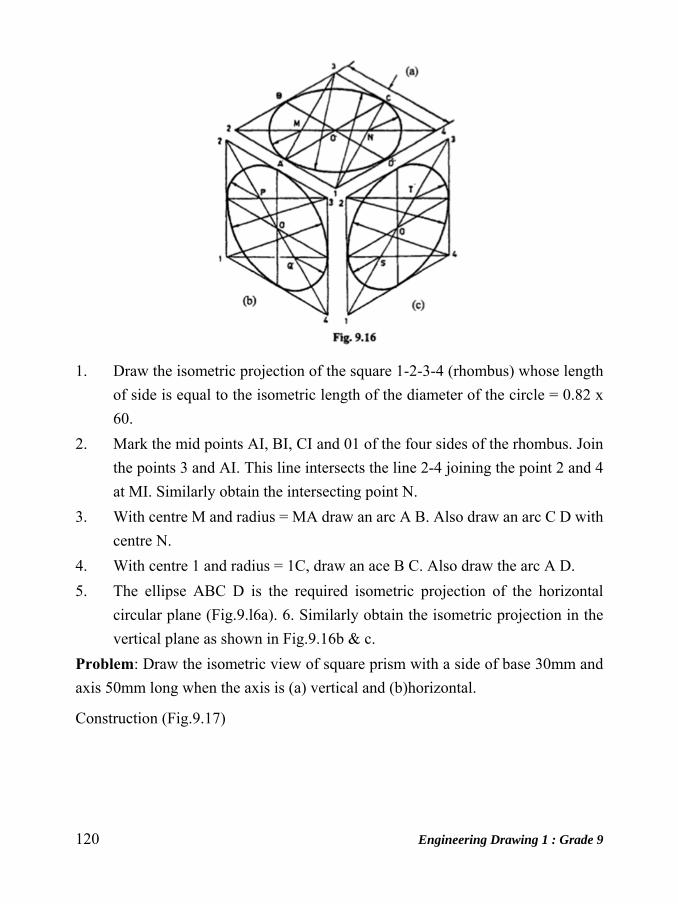
120 Engineering Drawing 1 : Grade 9
1. Draw the isometric projection of the square 1-2-3-4 (rhombus) whose length
of side is equal to the isometric length of the diameter of the circle = 0.82 x
60.
2. Mark the mid points AI, BI, CI and 01 of the four sides of the rhombus. Join
the points 3 and AI. This line intersects the line 2-4 joining the point 2 and 4
at MI. Similarly obtain the intersecting point N.
3. With centre M and radius = MA draw an arc A B. Also draw an arc C D with
centre N.
4. With centre 1 and radius = 1C, draw an ace B C. Also draw the arc A D.
5. The ellipse ABC D is the required isometric projection of the horizontal
circular plane (Fig.9.l6a). 6. Similarly obtain the isometric projection in the
vertical plane as shown in Fig.9.16b & c.
Problem: Draw the isometric view of square prism with a side of base 30mm and
axis 50mm long when the axis is (a) vertical and (b)horizontal.
Construction (Fig.9.17)
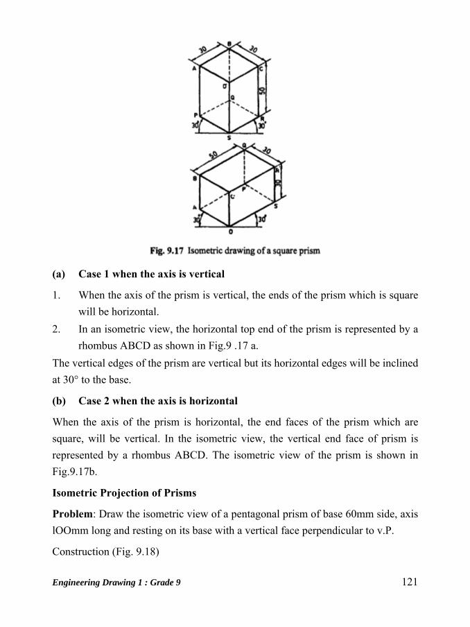
Engineering Drawing 1 : Grade 9 121
(a) Case 1 when the axis is vertical
1. When the axis of the prism is vertical, the ends of the prism which is square
will be horizontal.
2. In an isometric view, the horizontal top end of the prism is represented by a
rhombus ABCD as shown in Fig.9 .17 a.
The vertical edges of the prism are vertical but its horizontal edges will be inclined
at 30° to the base.
(b) Case 2 when the axis is horizontal
When the axis of the prism is horizontal, the end faces of the prism which are
square, will be vertical. In the isometric view, the vertical end face of prism is
represented by a rhombus ABCD. The isometric view of the prism is shown in
Fig.9.17b.
Isometric Projection of Prisms
Problem: Draw the isometric view of a pentagonal prism of base 60mm side, axis
lOOmm long and resting on its base with a vertical face perpendicular to v.P.
Construction (Fig. 9.18)

122 Engineering Drawing 1 : Grade 9
1. The front and top views of the prism are shown in Fig,9.18a.
2. 2, Enclose the prism in a rectangular box and draw the isometric view as
shown in Fig.9.18b using the box method.
Problem:
A hexagonal prism of base of side 30mm and height 60mm is resting on its base on
H.P. Draw the isometric drawing of the prism.
Construction (Fig.9.19)
1. Draw the orthographic views of the prism as shown in Fig.9.l9a.
2. Enclose the views in a rectangle (ie the top view -base- and front views).
3. Determine the distances (off-sets) of the corners of the base from the edges
of the box.

Engineering Drawing 1 : Grade 9 123
4. Join the points and darken the visible edges to get the isometric view.
Isometric Projection of Cylinder
Problem:
Make the isometric drawing of a cylinder of base diameter 20mm and axis 35mm
long.
Construction (Fig. 9.20)
1. Enclose the cylinder in a box and draw its isometric drawing.
2. Draw ellipses corresponding to the bottom and top bases by four centre
method.
3. Join the bases by two common tangents.
Isometric Projection of Pyramid
Problem: A pentagonal pyramid of side of base 30mm and height 70mm is resting
with its base on H.P. Draw the isometric drawing of the pyramid.
Construction (Fig. 9.21)
1. Draw the projections of the pyramid (Fig.9.21a).
2. Enclose the top view in a rectangle arced and measure the off-sets of all the
corners of the base and the vertex.
3. Draw the isometric view of the rectangle Abcd.
4. Using the off-sets locate the corners of the base 1, 2, etc. and the vertex o.
5. Join 0-1,0-2,0-3, etc. and darken the visible e~!. And obtain the required view.
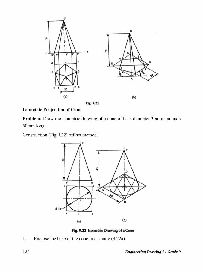
124 Engineering Drawing 1 : Grade 9
Isometric Projection of Cone
Problem: Draw the isometric drawing of a cone of base diameter 30mm and axis
50mm long.
Construction (Fig.9.22) off-set method.
1. Enclose the base of the cone in a square (9.22a).

Engineering Drawing 1 : Grade 9 125
2. Draw the ellipse corresponding to the circular base of the cone.
3. From the centre of the ellipse draw a vertical centre line and locate the apex
at a height of 5Omm.
4. Draw the two outer most generators from the apex to the ellipse and complete
the drawing.
Isometric Projection Truncated Cone
Problem:
A right circular cone of base diameter 60mm and height 75mm is cut by a plane
making an angle of 300 with the horizontal. The plane passes through the midpoint
of the axis. Draw the isometric view of the truncated solid.
Construction (Fig.9.23)
1. Draw the front and top views of the cone and name the points (Fig.9.23a)
2. Draw a rectangular prism enclosing the complete pyramid.
3. Mark the plane containing the truncated surface of the pyramid. This plane
intersects the box at PP in the front view and PPPP in the top view.
4. Draw the isometric view of the cone and mark the plane P PPP, containing
the truncated surface of the pyramid as shown in Fig. 9.23b.
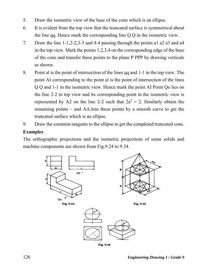
126 Engineering Drawing 1 : Grade 9
5. Draw the isometric view of the base of the cone which is an ellipse.
6. It is evident from the top view that the truncated surface is symmetrical about
the line qq. Hence mark the corresponding line Q Q in the isometric view.
7. Draw the line 1-1,2-2,3-3 and 4-4 passing through the points a1 a2 a3 and a4
in the top view. Mark the points 1,2,3,4 on the corresponding edge of the base
of the cone and transfer these points to the plane P PPP by drawing verticals
as shown.
8. Point al is the point of intersection of the lines qq and 1-1 in the top view. The
point AI corresponding to the point al is the point of intersection of the lines
Q Q and 1-1 in the isometric view. Hence mark the point AI Point Qo lies on
the line 2-2 in top view and its corresponding point in the isometric view is
represented by A2 on the line 2-2 such that 2a2 = 2. Similarly obtain the
remaining points ~ and AA.loin these points by a smooth curve to get the
truncated surface which is an ellipse.
9. Draw the common tangents to the ellipse to get the completed truncated cone.
Examples The orthographic projections and the isometric projections of some solids and
machine components are shown from Fig.9.24 to 9.34.
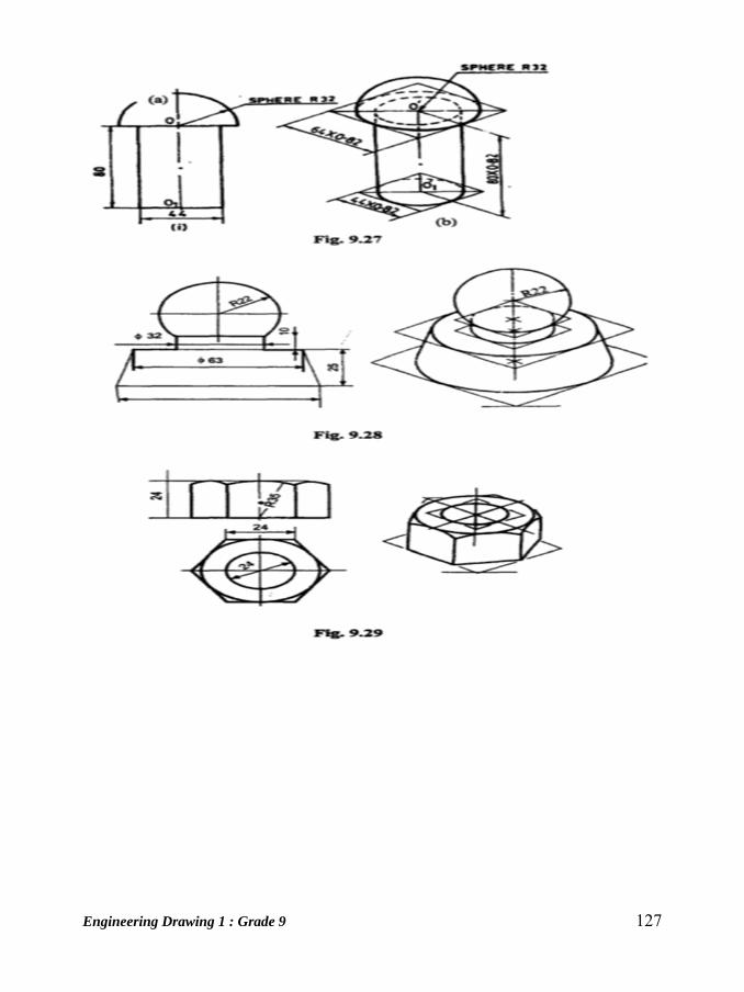
Engineering Drawing 1 : Grade 9 127
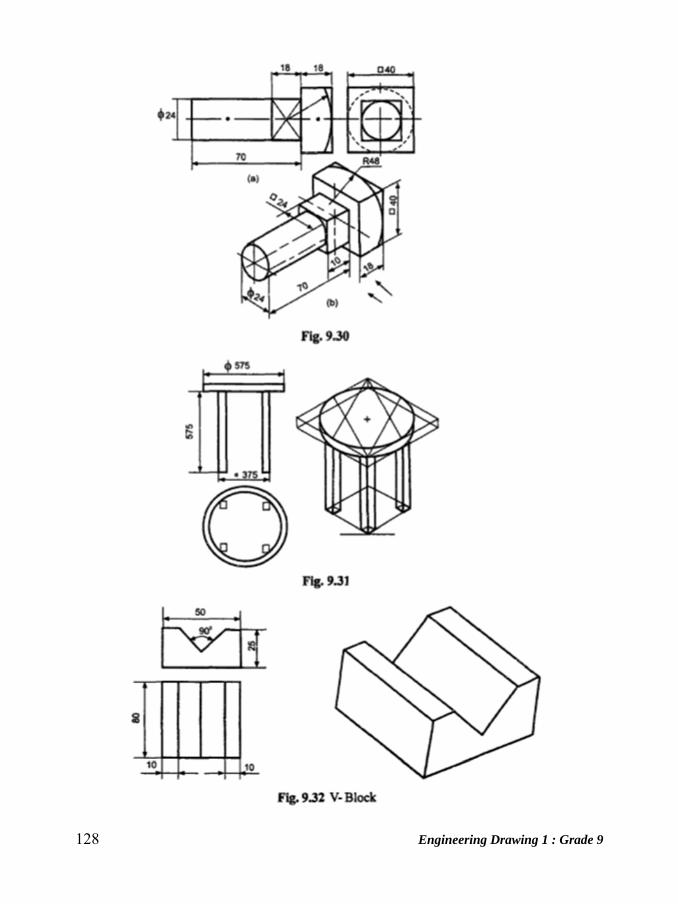
128 Engineering Drawing 1 : Grade 9

Engineering Drawing 1 : Grade 9 129

130 Engineering Drawing 1 : Grade 9
Engineering Drawing 1 : Grade 9 131
Unit: 15 Projection of Points and True Length of Line
A solid consists of a number of planes, a plane consists of a number of lines and a
line in turn
consists of number of points. From this, it is obvious that a solid may be
generated by a plane.
A point may be situated in space or in any of the four quadrants formed by
the two principle planes of projection or may lie in any one or both of them.
Its projections are obtained by extending projectors perpendicular to the
planes.
One of the planes is then rotated so that the first and third quadrants are
opened out. The projections are shown on a flat surface in their respective
positions either above or below or in XY.
Points in Space
A point may lie in space in anyone of the four quadrants. The positions of a point
are:
1. First quadrant, when it lies above H.P and in front of V.P.
2. Second quadrant, when it lies above H.P. and behind V.P.
3. Third quadrant, when it lies below H.P and behind V.P.
4. Fourth quadrant, when it lies below H.P and in front of V.P.
Knowing the distances of a point from H.P and V.P, projections on H.P and V.P are
found by extending the projections perpendicular to both the planes. Projection on
H.P is called top view and projection on V.P is called Front view
Notation followed
1. Actual points in space are denoted by capital letters A, B, C.
2. Their front views are denoted by their corresponding lower case letters with
dashes a', b', c' etc., and their top views by the lower case letters a, b, c etc.
3. Projectors are always drawn as continuous thin lines.
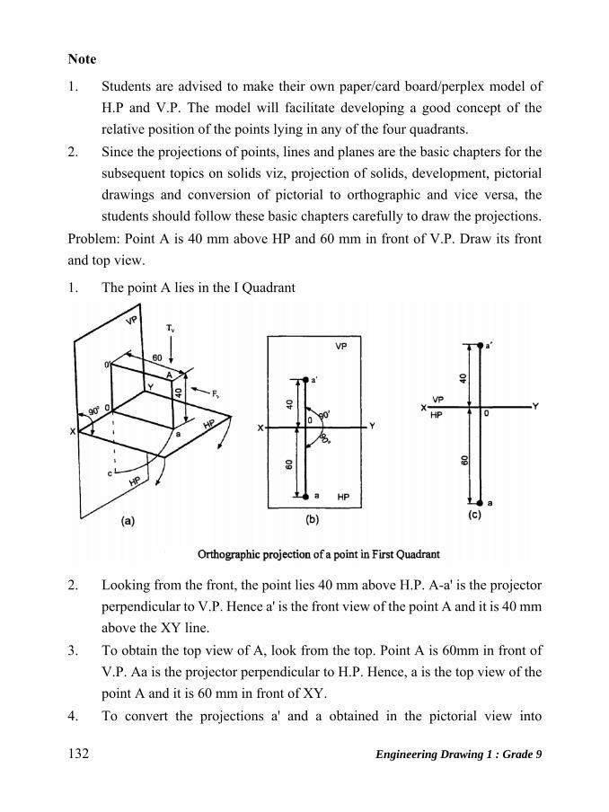
132 Engineering Drawing 1 : Grade 9
Note
1. Students are advised to make their own paper/card board/perplex model of
H.P and V.P. The model will facilitate developing a good concept of the
relative position of the points lying in any of the four quadrants.
2. Since the projections of points, lines and planes are the basic chapters for the
subsequent topics on solids viz, projection of solids, development, pictorial
drawings and conversion of pictorial to orthographic and vice versa, the
students should follow these basic chapters carefully to draw the projections.
Problem: Point A is 40 mm above HP and 60 mm in front of V.P. Draw its front
and top view.
1. The point A lies in the I Quadrant
2. Looking from the front, the point lies 40 mm above H.P. A-a' is the projector
perpendicular to V.P. Hence a' is the front view of the point A and it is 40 mm
above the XY line.
3. To obtain the top view of A, look from the top. Point A is 60mm in front of
V.P. Aa is the projector perpendicular to H.P. Hence, a is the top view of the
point A and it is 60 mm in front of XY.
4. To convert the projections a' and a obtained in the pictorial view into
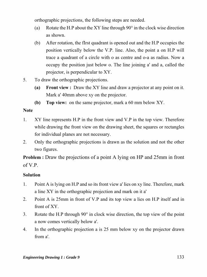
Engineering Drawing 1 : Grade 9 133
orthographic projections, the following steps are needed.
(a) Rotate the H.P about the XY line through 90° in the clock wise direction
as shown.
(b) After rotation, the fIrst quadrant is opened out and the H.P occupies the
position vertically below the V.P. line. Also, the point a on H.P will
trace a quadrant of a circle with o as centre and o-a as radius. Now a
occupy the position just below o. The line joining a' and a, called the
projector, is perpendicular to XY.
5. To draw the orthographic projections.
(a) Front view : Draw the XY line and draw a projector at any point on it.
Mark a' 40mm above xy on the projector.
(b) Top view: on the same projector, mark a 60 mm below XY.
Note
1. XY line represents H.P in the front view and V.P in the top view. Therefore
while drawing the front view on the drawing sheet, the squares or rectangles
for individual planes are not necessary.
2. Only the orthographic projections is drawn as the solution and not the other
two figures.
Problem : Draw the projections of a point A lying on HP and 25mm in front
of V.P.
Solution
1. Point A is lying on H.P and so its front view a' lies on xy line. Therefore, mark
a line XY in the orthographic projection and mark on it a'
2. Point A is 25mm in front of V.P and its top view a lies on H.P itself and in
front of XY.
3. Rotate the H.P through 90° in clock wise direction, the top view of the point
a now comes vertically below a'.
4. In the orthographic projection a is 25 mm below xy on the projector drawn
from a'.

134 Engineering Drawing 1 : Grade 9
Problem: Draw the projections of a point A lying on V.P and 70 mm above HP.
Solution
1. Looking at the pictorial view from the front the point A is 70 mm above H.P
and so a' is 70 mm above xy. Hence, mark a' the orthographic projection 70
mm above xy
2. Looking at the pictorial view from the top, point a is on V.P and its view lies
on xy itself. The top view a does not lie on the H.P. So in this case the H.P
need not be rotated. Therefore mark a on xy on the projector drawn from a'.
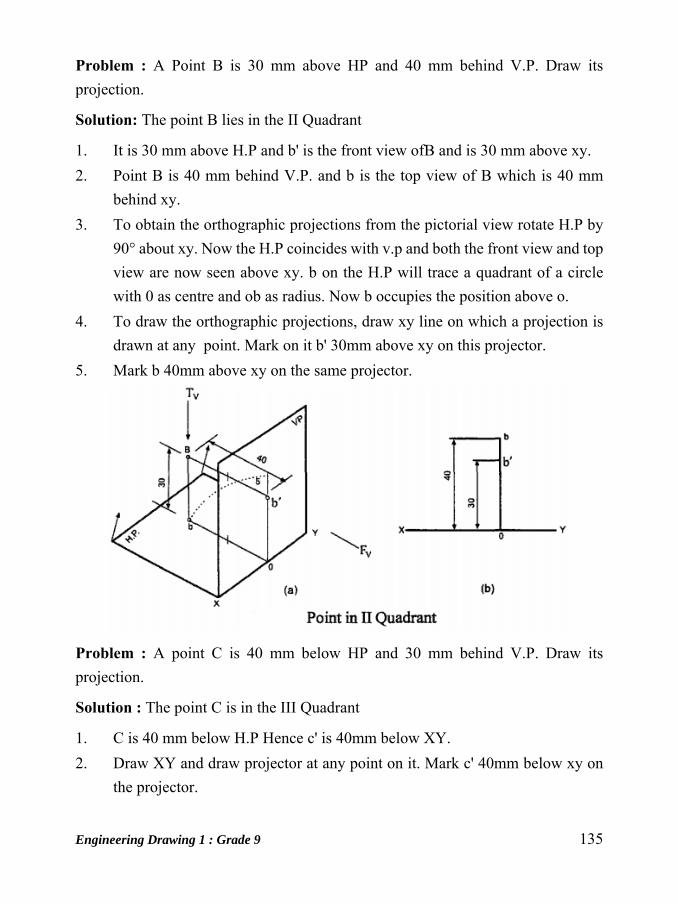
Engineering Drawing 1 : Grade 9 135
Problem : A Point B is 30 mm above HP and 40 mm behind V.P. Draw its
projection.
Solution: The point B lies in the II Quadrant
1. It is 30 mm above H.P and b' is the front view ofB and is 30 mm above xy.
2. Point B is 40 mm behind V.P. and b is the top view of B which is 40 mm
behind xy.
3. To obtain the orthographic projections from the pictorial view rotate H.P by
90° about xy. Now the H.P coincides with v.p and both the front view and top
view are now seen above xy. b on the H.P will trace a quadrant of a circle
with 0 as centre and ob as radius. Now b occupies the position above o.
4. To draw the orthographic projections, draw xy line on which a projection is
drawn at any point. Mark on it b' 30mm above xy on this projector.
5. Mark b 40mm above xy on the same projector.
Problem : A point C is 40 mm below HP and 30 mm behind V.P. Draw its
projection.
Solution : The point C is in the III Quadrant
1. C is 40 mm below H.P Hence c' is 40mm below XY.
2. Draw XY and draw projector at any point on it. Mark c' 40mm below xy on
the projector.
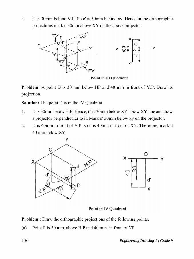
136 Engineering Drawing 1 : Grade 9
3. C is 30mm behind V.P. So c' is 30mm behind xy. Hence in the orthographic
projections mark c 30mm above XY on the above projector.
Problem: A point D is 30 mm below HP and 40 mm in front of V.P. Draw its
projection.
Solution: The point D is in the IV Quadrant.
1. D is 30mm below H.P. Hence, d' is 30mm below XY. Draw XY line and draw
a projector perpendicular to it. Mark d' 30mm below xy on the projector.
2. D is 40mm in front of V.P; so d is 40mm in front of XY. Therefore, mark d
40 mm below XY.
Problem : Draw the orthographic projections of the following points.
(a) Point P is 30 mm. above H.P and 40 mm. in front of VP

Engineering Drawing 1 : Grade 9 137
(b) Point Q is 25 mm. above H.P and 35 mm. behind VP
(c) Point R is 32 mm. below H.P and 45 mm behind VP
(d) Point S is 35 mm. below H.P and 42 mm in front of VP
(e) Point T is in H.P and 30 mm. is behind VP
(f) Point U is in V.P and 40 mm. below HP
(g) Point V is in V.P and 35 mm. above H.P
(h) Point W is in H.P and 48 mm. in front of VP
Solution
The location of the given points is the appropriate quadrants and their orthographic
projections are shown below
Projection of Lines
The shortest distance between two points is called a straight line. The projectors of
a straight line are drawn therefore by joining the projections of its end points. The
possible projections of straight lines with respect to V.P and H.P in the first quadrant
are as follows:
I. Perpendicular to one plane and parallel to the other
2. Parallel to both the planes
3. Parallel to one plane and inclined to the other
4. Inclined to both the planes
1. Line perpendicular to H.P and parallel to V.P
The pictorial view of a straight line AB in the First Quadrant is shown in figure a.
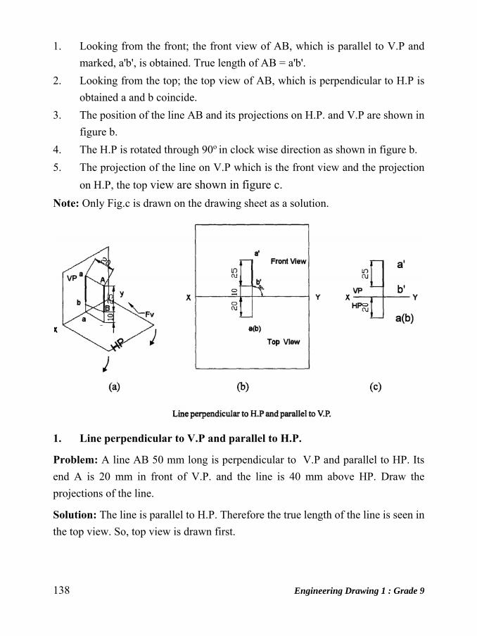
138 Engineering Drawing 1 : Grade 9
1. Looking from the front; the front view of AB, which is parallel to V.P and
marked, a'b', is obtained. True length of AB = a'b'.
2. Looking from the top; the top view of AB, which is perpendicular to H.P is
obtained a and b coincide.
3. The position of the line AB and its projections on H.P. and V.P are shown in
figure b.
4. The H.P is rotated through 90o in clock wise direction as shown in figure b.
5. The projection of the line on V.P which is the front view and the projection
on H.P, the top view are shown in figure c.
Note: Only Fig.c is drawn on the drawing sheet as a solution.
1. Line perpendicular to V.P and parallel to H.P.
Problem: A line AB 50 mm long is perpendicular to V.P and parallel to HP. Its
end A is 20 mm in front of V.P. and the line is 40 mm above HP. Draw the
projections of the line.
Solution: The line is parallel to H.P. Therefore the true length of the line is seen in
the top view. So, top view is drawn first.
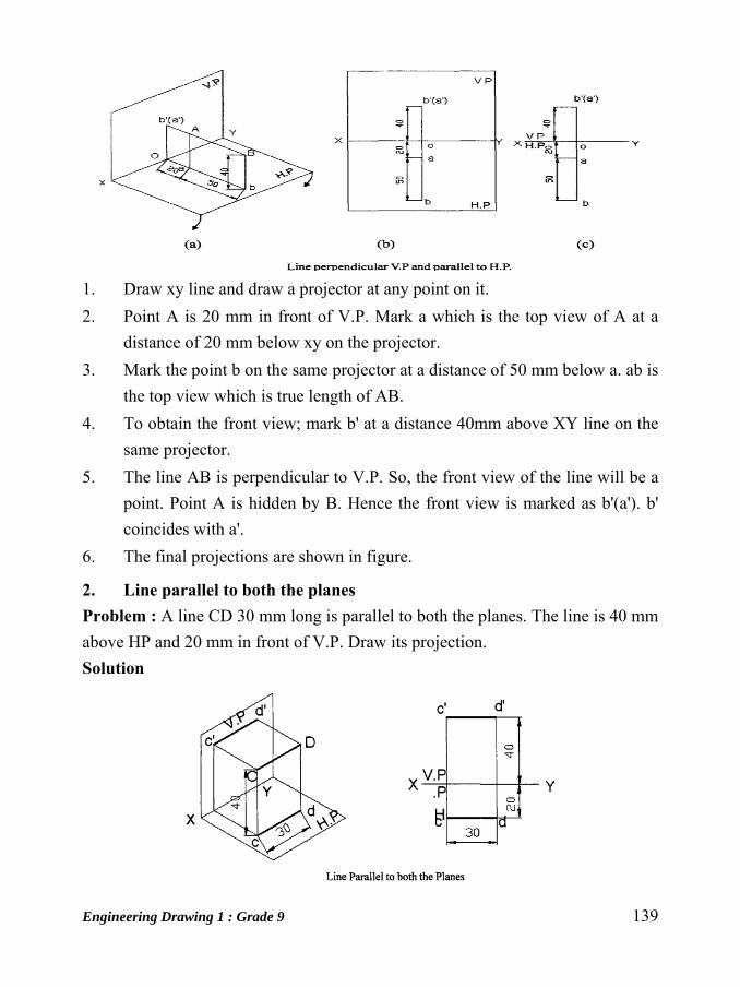
Engineering Drawing 1 : Grade 9 139
1. Draw xy line and draw a projector at any point on it.
2. Point A is 20 mm in front of V.P. Mark a which is the top view of A at a
distance of 20 mm below xy on the projector.
3. Mark the point b on the same projector at a distance of 50 mm below a. ab is
the top view which is true length of AB.
4. To obtain the front view; mark b' at a distance 40mm above XY line on the
same projector.
5. The line AB is perpendicular to V.P. So, the front view of the line will be a
point. Point A is hidden by B. Hence the front view is marked as b'(a'). b'
coincides with a'.
6. The final projections are shown in figure.
2. Line parallel to both the planes Problem : A line CD 30 mm long is parallel to both the planes. The line is 40 mm
above HP and 20 mm in front of V.P. Draw its projection.
Solution

140 Engineering Drawing 1 : Grade 9
1. Draw the XY line and draw a projector at any point on it.
2. To obtain the front view mark c' at a distance of 40mm above XY (H.P.). The
line CD is parallel to both the planes. Front view is true length and is parallel
to XY. Draw c' d' parallel to xy such that c' d' = CD = 30 mm, which is the
true length.
3. To obtain the top view; the line is also parallel to V.P and 20 mm in front of
V.P. Therefore, on the projector from c', mark c at distance 20 mm below XY
line.
4. Top view is also true length and parallel to XY. Hence, cd parallel to XY such
that cd=CD=30mm is the true length.
3. Line parallel to V.P and inclined to HP.
Problem: A line AB 40 mm long is parallel to V.P and inclined at an angle
of 30o to HP. The end A is 15 mm above HP and 20 mm in front of V.P. Draw
the projections of the line.
Solution
1. A is 15 mm above H.P mark a', 15 mm above XY.
2. A is 20 mm in front of V.P. Hence mark a 20 mm below XY.
3. To obtain the front view a'b'; as AB is parallel to V.P and inclined at an angle
a to H.P, a'b' will be equal to its true length and inclined at an angle of 300 to
H.P. Therefore draw a line from a' at an angle 30° to XY and mark b' such
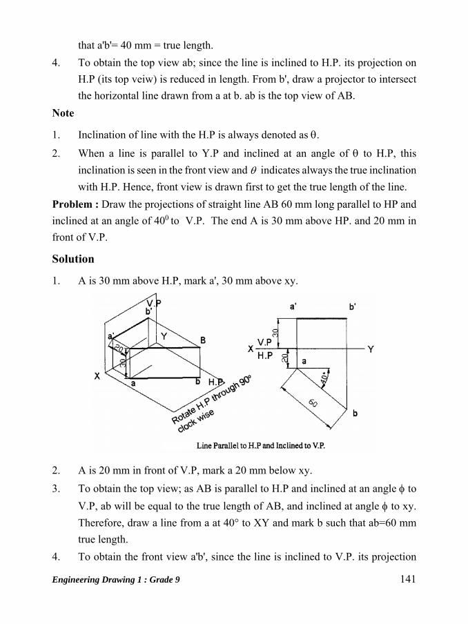
Engineering Drawing 1 : Grade 9 141
that a'b'= 40 mm = true length.
4. To obtain the top view ab; since the line is inclined to H.P. its projection on
H.P (its top veiw) is reduced in length. From b', draw a projector to intersect
the horizontal line drawn from a at b. ab is the top view of AB.
Note
1. Inclination of line with the H.P is always denoted as .
2. When a line is parallel to Y.P and inclined at an angle of to H.P, this
inclination is seen in the front view and indicates always the true inclination
with H.P. Hence, front view is drawn first to get the true length of the line.
Problem : Draw the projections of straight line AB 60 mm long parallel to HP and
inclined at an angle of 400 to V.P. The end A is 30 mm above HP. and 20 mm in
front of V.P.
Solution
1. A is 30 mm above H.P, mark a', 30 mm above xy.
2. A is 20 mm in front of V.P, mark a 20 mm below xy.
3. To obtain the top view; as AB is parallel to H.P and inclined at an angle to
V.P, ab will be equal to the true length of AB, and inclined at angle to xy.
Therefore, draw a line from a at 40° to XY and mark b such that ab=60 mm
true length.
4. To obtain the front view a'b', since the line is inclined to V.P. its projection
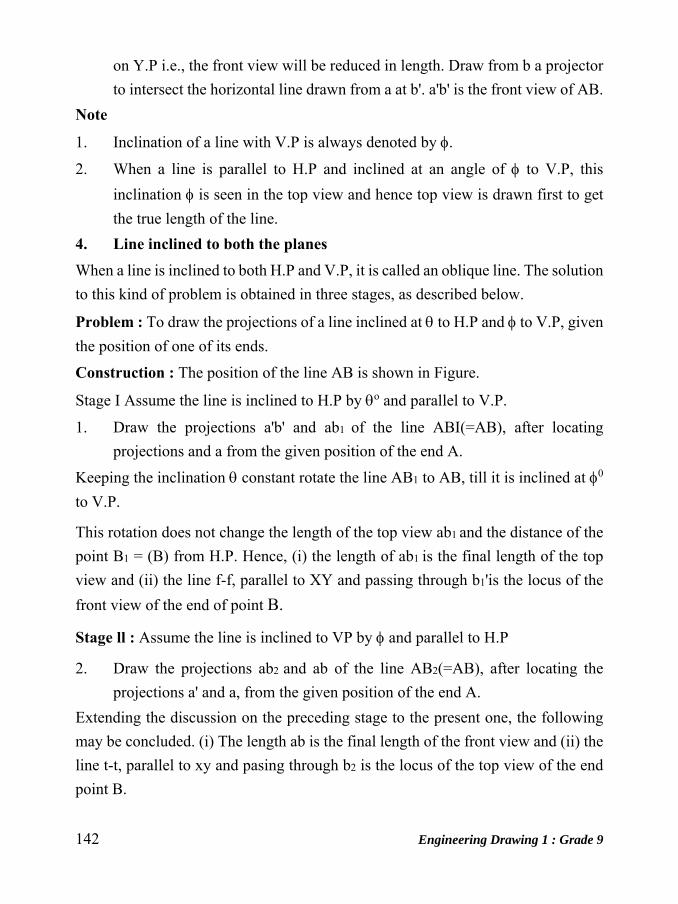
142 Engineering Drawing 1 : Grade 9
on Y.P i.e., the front view will be reduced in length. Draw from b a projector
to intersect the horizontal line drawn from a at b'. a'b' is the front view of AB.
Note
1. Inclination of a line with V.P is always denoted by .
2. When a line is parallel to H.P and inclined at an angle of to V.P, this
inclination is seen in the top view and hence top view is drawn first to get
the true length of the line.
4. Line inclined to both the planes When a line is inclined to both H.P and V.P, it is called an oblique line. The solution
to this kind of problem is obtained in three stages, as described below.
Problem : To draw the projections of a line inclined at to H.P and to V.P, given
the position of one of its ends.
Construction : The position of the line AB is shown in Figure.
Stage I Assume the line is inclined to H.P by o and parallel to V.P.
1. Draw the projections a'b' and ab1 of the line ABI(=AB), after locating
projections and a from the given position of the end A.
Keeping the inclination constant rotate the line AB1 to AB, till it is inclined at 0
to V.P.
This rotation does not change the length of the top view ab1 and the distance of the
point B1 = (B) from H.P. Hence, (i) the length of ab1 is the final length of the top
view and (ii) the line f-f, parallel to XY and passing through b1'is the locus of the
front view of the end of point B.
Stage ll : Assume the line is inclined to VP by and parallel to H.P
2. Draw the projections ab2 and ab of the line AB2(=AB), after locating the
projections a' and a, from the given position of the end A.
Extending the discussion on the preceding stage to the present one, the following
may be concluded. (i) The length ab is the final length of the front view and (ii) the
line t-t, parallel to xy and pasing through b2 is the locus of the top view of the end
point B.
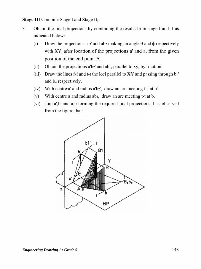
Engineering Drawing 1 : Grade 9 143
Stage III Combine Stage I and Stage II,
3. Obtain the fmal projections by combining the results from stage I and II as
indicated below:
(i) Draw the projections a'b' and ab2 making an angle and respectively
with XY, after location of the projections a' and a, from the given
position of the end point A.
(ii) Obtain the projections a'b2' and ab1, parallel to xy, by rotation.
(iii) Draw the lines f-f and t-t the loci parallel to XY and passing through b1'
and b2 respectively.
(iv) With centre a' and radius a'b2', draw an arc meeting f-f at b'.
(v) With centre a and radius ab1, draw an arc meeting t-t at b.
(vi) Join a',b' and a,b forming the required final projections. It is observed
from the figure that:

144 Engineering Drawing 1 : Grade 9
Line inclined to both planes
1. The points b' and b lie on a single projection
2. The projections a'b' and ab make angles and with XY, which are greater
than and .
The angles and are known as apparent angles.
To determine the true length of a line, given its projections - Rotating line method
In this, each view is made parallel to the reference line and the other view is
projected from it. This is exactly reversal of the procedure adopted in the preceding
construction.
Construction

Engineering Drawing 1 : Grade 9 145
1. Draw the given projections a'b' and ab.
2. Draw f-f and t-t, the loci passing through b' and b and parallel to XY.
3. Rotate a'b' to a'b2', parallel to XY.
4. Draw a projector through b2'to meet the line t-t at b2.
5. Rotate ab1 parallel to XY.
6. Draw a projector through b1, to meet the line f-f at b1'.
7. Join a', b1'and a, b2.
8. Measure and mark the angles and
The length a'b1' (=ab2) is the true length of the given line and the angles and ,
the true inclinations of the line with H.P and V.P. respectively.
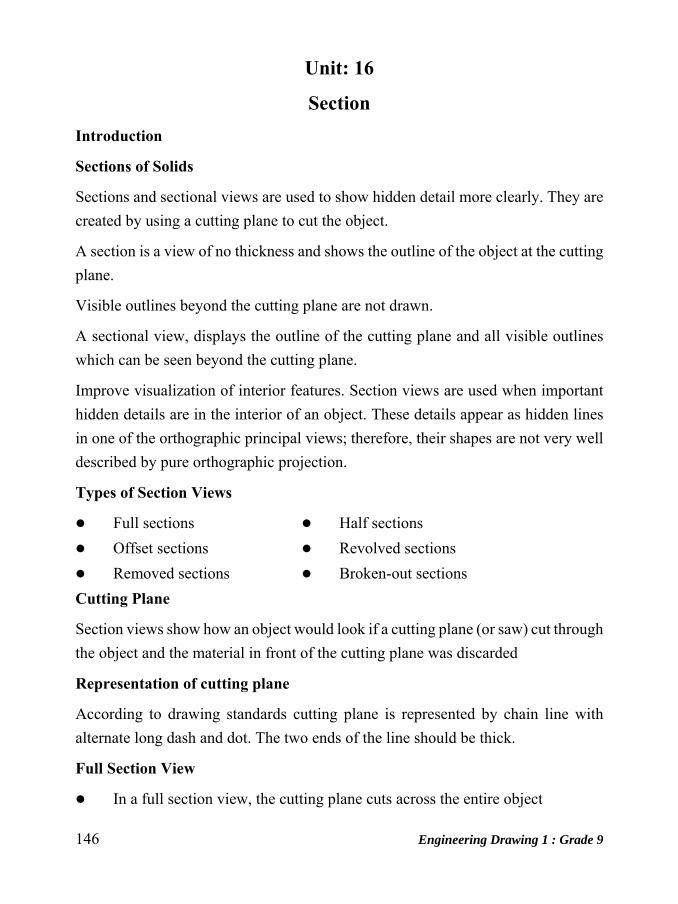
146 Engineering Drawing 1 : Grade 9
Unit: 16
Section Introduction
Sections of Solids
Sections and sectional views are used to show hidden detail more clearly. They are
created by using a cutting plane to cut the object.
A section is a view of no thickness and shows the outline of the object at the cutting
plane.
Visible outlines beyond the cutting plane are not drawn.
A sectional view, displays the outline of the cutting plane and all visible outlines
which can be seen beyond the cutting plane.
Improve visualization of interior features. Section views are used when important
hidden details are in the interior of an object. These details appear as hidden lines
in one of the orthographic principal views; therefore, their shapes are not very well
described by pure orthographic projection.
Types of Section Views
Full sections Half sections
Offset sections Revolved sections
Removed sections Broken-out sections
Cutting Plane
Section views show how an object would look if a cutting plane (or saw) cut through
the object and the material in front of the cutting plane was discarded
Representation of cutting plane
According to drawing standards cutting plane is represented by chain line with
alternate long dash and dot. The two ends of the line should be thick.
Full Section View
In a full section view, the cutting plane cuts across the entire object

Engineering Drawing 1 : Grade 9 147
Note that hidden lines become visible in a section view
Hatching
On sections and sectional views solid area should be hatched to indicate this fact.
Hatching is drawn with a thin continuous line, equally spaced (preferably about
4mm apart, though never less than Imm) and preferably at an angle of 4S degrees.
(i) Hatching a single object
When you are hatching an object, but the objects have areas that are separated. All
areas of the object should be hatched in the same direction and with the same
spacing.
(ii) Hatching Adjacent objects
When hatching assembled parts, the direction of the hatching should ideally be
reversed on adjacent parts. If more than two parts are adjacent, then the hatching
should be staggered to emphasise the fact that these parts are separate.
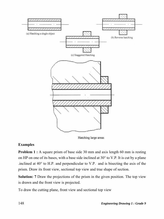
148 Engineering Drawing 1 : Grade 9
Examples
Problem 1 : A square prism of base side 30 mm and axis length 60 mm is resting
on HP on one of its bases, with a base side inclined at 30° to V.P. It is cut by a plane
.inclined at 40° to H.P. and perpendicular to V.P. and is bisecting the axis of the
prism. Draw its front view, sectional top view and true shape of section.
Solution: 7 Draw the projections of the prism in the given position. The top view
is drawn and the front view is projected.
To draw the cutting plane, front view and sectional top view
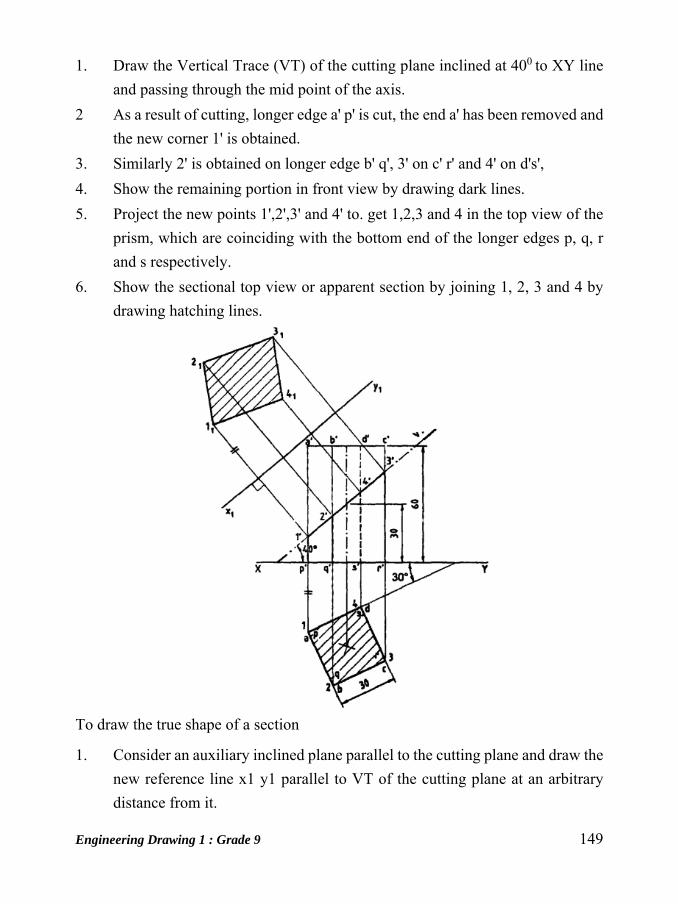
Engineering Drawing 1 : Grade 9 149
1. Draw the Vertical Trace (VT) of the cutting plane inclined at 400 to XY line
and passing through the mid point of the axis.
2 As a result of cutting, longer edge a' p' is cut, the end a' has been removed and
the new corner 1' is obtained.
3. Similarly 2' is obtained on longer edge b' q', 3' on c' r' and 4' on d's',
4. Show the remaining portion in front view by drawing dark lines.
5. Project the new points 1',2',3' and 4' to. get 1,2,3 and 4 in the top view of the
prism, which are coinciding with the bottom end of the longer edges p, q, r
and s respectively.
6. Show the sectional top view or apparent section by joining 1, 2, 3 and 4 by
drawing hatching lines.
To draw the true shape of a section
1. Consider an auxiliary inclined plane parallel to the cutting plane and draw the
new reference line x1 y1 parallel to VT of the cutting plane at an arbitrary
distance from it.
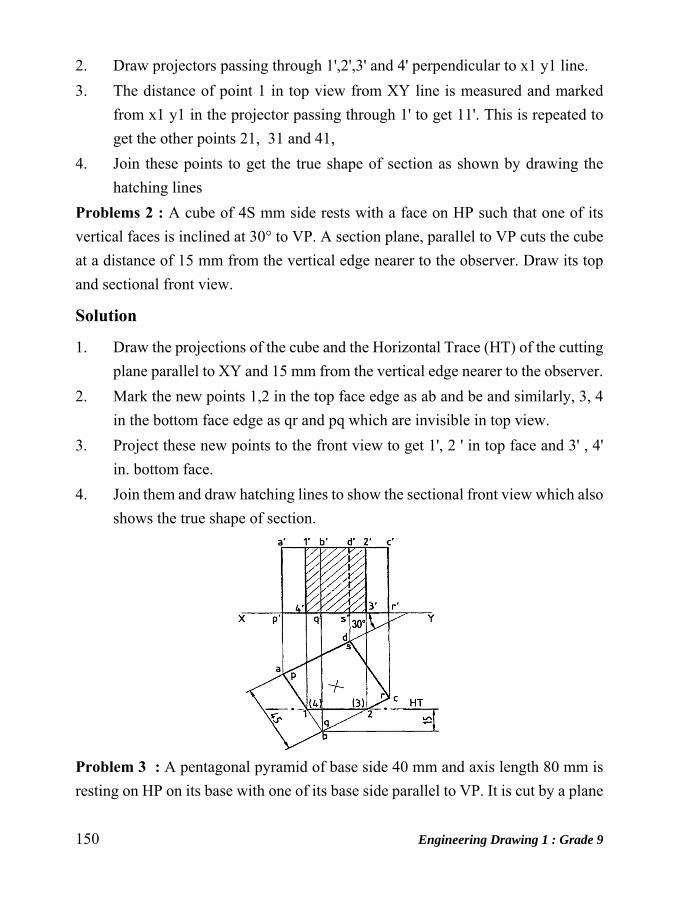
150 Engineering Drawing 1 : Grade 9
2. Draw projectors passing through 1',2',3' and 4' perpendicular to x1 y1 line.
3. The distance of point 1 in top view from XY line is measured and marked
from x1 y1 in the projector passing through 1' to get 11'. This is repeated to
get the other points 21, 31 and 41,
4. Join these points to get the true shape of section as shown by drawing the
hatching lines
Problems 2 : A cube of 4S mm side rests with a face on HP such that one of its
vertical faces is inclined at 30° to VP. A section plane, parallel to VP cuts the cube
at a distance of 15 mm from the vertical edge nearer to the observer. Draw its top
and sectional front view.
Solution
1. Draw the projections of the cube and the Horizontal Trace (HT) of the cutting
plane parallel to XY and 15 mm from the vertical edge nearer to the observer.
2. Mark the new points 1,2 in the top face edge as ab and be and similarly, 3, 4
in the bottom face edge as qr and pq which are invisible in top view.
3. Project these new points to the front view to get 1', 2 ' in top face and 3' , 4'
in. bottom face.
4. Join them and draw hatching lines to show the sectional front view which also
shows the true shape of section.
Problem 3 : A pentagonal pyramid of base side 40 mm and axis length 80 mm is
resting on HP on its base with one of its base side parallel to VP. It is cut by a plane

Engineering Drawing 1 : Grade 9 151
inclined at 30° to HP and perpendicular to VP and is bisecting the axis. Draw its
front view, sectional top view, and the true shape of section.
Solution: Draw the projection of the pyramid in the given position. The top view
is drawn and the front view is projected.
To draw the cutting plane, front view and sectional top view
1. Draw the VT of the cutting plane inclined at 30° to XY line and passing
through the midpoint of the axis.
2. As a result of cutting, new comers 1', 2', 3', 4' and 5' are obtained on slant
edges a '0', b '0',c '0', d'o' and e '0' respectively.
3. Show the remaining portion in front view by drawing dark lines.
4. Project the new points to get 1,2,3,4 and 5 in the top view on the respective
slant edges.
5. Note that 2' is extended horizontally to meet the extreme slant edge a ' 0 ' at
m', it is projected to meet ao in top view at m. Considering 0 as centre, om as
radius, draw an arc to get 2 on bo.
6. Join these points and show the sectional top view by drawing hatching lines.

152 Engineering Drawing 1 : Grade 9
To draw true shape of section.
1. Draw the new reference.line x1y1 parallel to VT of the cutting plane.
2. Projectors from 1',2' etc. are drawn perpendicular to X1Y1 line.
3. The distance of point 1 in top view from XY line is measured and marked
from X1Y1 in the projector passing through 1' to get 11' This is repeated to get
21,31 etc.
4. Join these points and draw hatching lines to show the true shape of section.
Problem 4: A hexagonal prism of base side 30 mm and axis length 60 mm is resting
on HP on one of its bases with two of the vertical faces perpendicular to VP. It is
cut by a plane inclined at 600 to HP and perpendicular to VP and passing through a
point at a distance 12 mm from the top base. Draw its front view, sectional top view
and true shape of section.
Solution: Draw the projections of the prism in the given position. The top view is
drawn and the front view is projected.

Engineering Drawing 1 : Grade 9 153
To draw the cutting plane, front view and sectional top view
1. Draw the VT of the cutting plane inclined at 60° to XY and passing through
a point in the axis, at a distance 12 mm from the top base.
2. New points 1',2', etc. are marked as mentioned earlier. Note that the cutting
plane cuts the top base, the new point 3' is marked on base side b' c' and 4'
marked on (d') ( e') which is invisible.
3. Project the new points 1',2', etc. to get 1,2, etc. in the top view.
4. Join these points and draw the hatching lines to show the sectional top view.
To draw true shape of section
1. Draw new reference line X1Y 1 parallel to the VT of the cutting plane.
2. Draw the projectors passing through 1', 2', etc. perpendicular to X1Y1 line.
3. The distance of point 1 in top view from XY line is measured and marked
from X1Y1 in the projector passing through 1' to get 11 This is repeated to get
other points 21, 31 etc.
4. Join these points to get the true shape of section and this is shown by hatching
lines.
Problem 5 : A cylinder of base diameter 40 mm and height 60 mm rests on its base on HP. It is cut by a plane perpendicular to VP and inclined at 30° to HP and meets the axis at a distance 30 mm from base. Draw the front view, sectional top view, and the true shape of section.

154 Engineering Drawing 1 : Grade 9
Solution : Draw the projections of the cylinder. The top view is drawn and the front
view is projected. Consider generators bY dividing the circle into equal number of
parts and project them to the front view.
To draw the cutting plane, front view and sectional top view
1. Draw the VT of the cutting plane inclined at 30° to XY line and passing
through a point on the axis at a distance 30 mm from base.
2. The new point 1', 2' etc. are marked on the generators a' p', h' q' etc.
3. Project the new points to the top view to get 1, 2, etc. which are coinciding
with p, q, etc. on the base circle.
4. Join these points and draw the hatching lines to show the sectional top view.
To draw true shape of section.
1. Draw X1Y1 line parallel to VT of the cutting plane.
2. Draw the projectors through 1',2', etc. perpendicular to X1Y1 line.
3. The distance of point 1 in top view from XY line is measured and marked
from X1Y1 in the projector passing through 1' to get 11' This is repeated to get
other points 21,31 etc.
4. Join these points by drawing smooth curve to get the true shape of section and
this is shown by hatching lines.
Problem 6 : A cone of base diameter 50 mm and axis length 75 mm, resting on HP
on its base is cut by a plane in lined at 45° to HP and perpendicular to VP and is
bisecting the axis. Draw the front view and sectional top view and true shape of this
section.
Solution: Draw the projections of the cone. Consider generators by dividing the
circle into equal number of parts and project them to the front view.
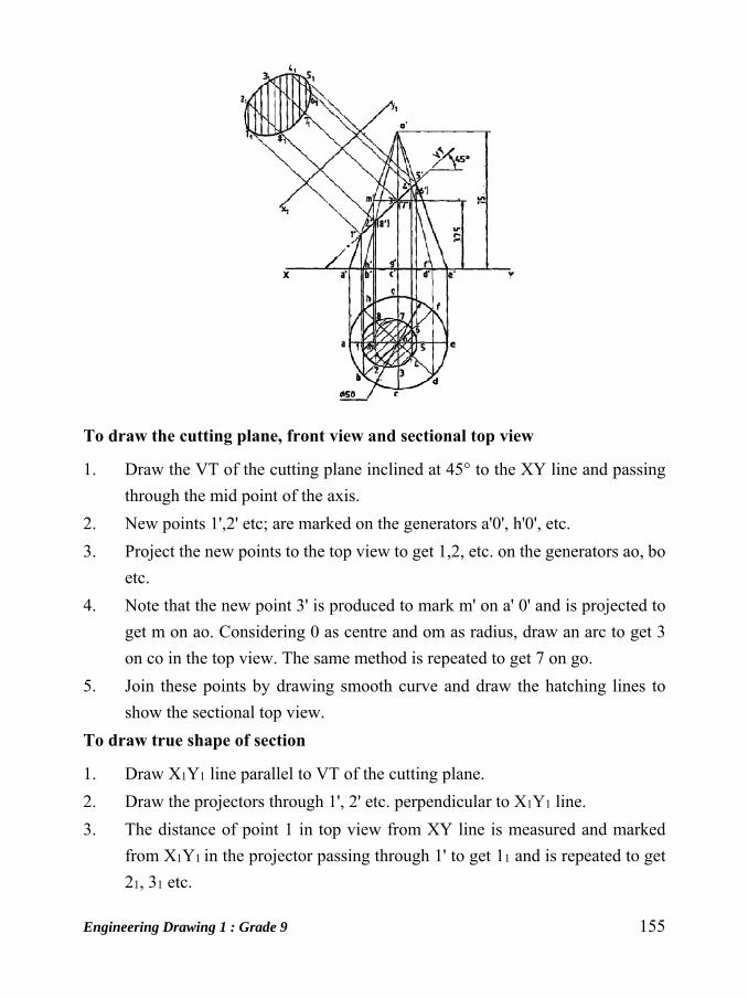
Engineering Drawing 1 : Grade 9 155
To draw the cutting plane, front view and sectional top view
1. Draw the VT of the cutting plane inclined at 45° to the XY line and passing
through the mid point of the axis.
2. New points 1',2' etc; are marked on the generators a'0', h'0', etc.
3. Project the new points to the top view to get 1,2, etc. on the generators ao, bo
etc.
4. Note that the new point 3' is produced to mark m' on a' 0' and is projected to
get m on ao. Considering 0 as centre and om as radius, draw an arc to get 3
on co in the top view. The same method is repeated to get 7 on go.
5. Join these points by drawing smooth curve and draw the hatching lines to
show the sectional top view.
To draw true shape of section
1. Draw X1Y1 line parallel to VT of the cutting plane.
2. Draw the projectors through 1', 2' etc. perpendicular to X1Y1 line.
3. The distance of point 1 in top view from XY line is measured and marked
from X1Y1 in the projector passing through 1' to get 11 and is repeated to get
21, 31 etc.

156 Engineering Drawing 1 : Grade 9
4. Join these points by drawing smooth curve to get the true shape of section and
is shown by hatching lines.
Problem 7: A pentagonal prism of base side 30 mm and axis length 60 mm is
resting on HP on one of its rectangular faces, with its axis perpendicular to VP. It
is cut by a plane inclined at 50° to VP and perpendicular to HP and passing through
a point 25 mm from rear base of the prism. Draw its top view, sectional front view
and true shape of section.
Solution: To draw the cutting plane, top view and sectional front view
1. Draw the projections of the prism. Draw the HI' of the cutting plane at 50° to
XY and passing through the point on the axis at a distance of 25 mm from the
rear base.
2. Mark the new points 1 on ap, 2 on bq etc.
3. Show the remaining portion in top view by drawing dark lines.
4. Project the new point 1, 2, etc. to the front view to get 1', 2' etc. which are
coinciding with the rear end of the longer edges p', q' etc.
5. Show the sectional front view by joining 1', 2' etc. and draw hatching lines.
To draw the true shape of section
1. Consider an AVP and draw X1Y1 line parallel to HT of the cutting plane.
2. Draw projectors through 1,2 etc. perpendicular to X1Y1 line.
3. The distance of I' in front view from XY line is measured and marked from
X1Y1 in the projector passing through 1 to get 11', and this is repeated to get
21',31' etc.
4. Join them and show the true shape of section by drawing hatching lines.

Engineering Drawing 1 : Grade 9 157
Problem 8 : A cylinder of base diameter 45 and axis length 60 mm is resting on
HP on one its generators with its axis perpendicular to VP. It is cut by a plane
inclined 30° to VP and perpendicular to HP 'and is bisecting the axis of the cylinder.
Draw its top view, sectional front view and true shape of section.
Solution: Draw the projections of the cylinder. Consider generators by dividing the
circle into equal number of parts and project them to the top view.
To draw the cutting plane, top view and sectional, front view
1. Draw the HT of the cutting plane inclined at 300 to XY and passing through
the midpoint of the axis.
2. The new points 1,2, etc. are marked on generators ap, hq, etc.
3. Project the new points to the front view to get 1',2' etc. which are coinciding
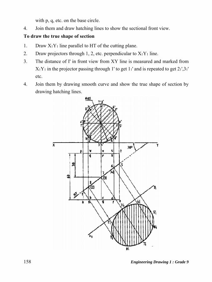
158 Engineering Drawing 1 : Grade 9
with p, q, etc. on the base circle.
4. Join them and draw hatching lines to show the sectional front view.
To draw the true shape of section
1. Draw X1Y1 line parallel to HT of the cutting plane.
2. Draw projectors through 1, 2, etc. perpendicular to X1Y1 line.
3. The distance of I' in front view from XY line is measured and marked from
X1Y1 in the projector passing through 1' to get 11' and is repeated to get 21',31'
etc.
4. Join them by drawing smooth curve and show the true shape of section by
drawing hatching lines.
Engineering Drawing 1 : Grade 9 159
Exercises
1. A cube of side 35 mm rests on the ground with one of its vertical faces
inclined at 300 to the V.P. A vertical section plane parallel to V.P. and
perpendicular to H.P. and at a distance of 35 mm from V.P. cuts the solid.
Draw the sectional front view and top view.
2. A regular hexagonal pyramid of side 30 mm and height 65 mm is resting on
its base on H.P. one of its base sides is parallel to V.P. It is cut by a cutting
plane which is parallel to H.P. and perpendicular to V.P. and passing through
at a height of 45 mm from its bottom. Draw its sectional front view and top
view.
3. A regular hexagonal prism of side 30 mm and height 70 mm is standing on
V.P. with its axis perpendicular to V.P. being one of its rectangular faces
parallel to H.P. It is cut by a section plane inclined at 600 to the H.P.
perpendicular to V.P. and passing through the mid-point of the bottom side
on the front face which is parallel to H.P. Draw its sectional front view and
top view. Also draw the true shape.
4. A regular pentagonal prism of side 35 mm and height 75 mm has its base in
H.P. and one of the rectangular faces makes an angle of 450 to V.P. It is cut
by a section plane inclined at 600 to H.P. perpendicular to V.P. and passing
through one of the vertical edges at a distance of 25 mm above the base Draw
its
(a) Sectional front view (b) Sectional top view and (c) True shape.
5. A cone of diameter 60 mm and height 70 mm is resting on ground on its base.
It is cut by a section plane perpendicular to V.P. inclined at 450 to H.P. and
cutting the axis at a point 40 mm from the bottom. Draw the front view,
sectional top view and true shape.
6. A right circular cylinder of diameter 60 mm and height 75 mm rests on its
base such that its axis is inclined at 450 to H.P. and parallel to V.P. A cutting
plane parallel to H.P. and perpendicular to V.P. cuts the axis at a distance of
50mm from the bottom face. Draw the front view and sectional top view.
7. A regular pentagonal pyramid of side 30 mm and height 60 mm is lying on

160 Engineering Drawing 1 : Grade 9
the H.P. on one of its triangular faces in such a way that its base edge is at
right angles to V.P. It is cut by a plane at 300 to the V.P. and at right angle to
the H.P. bisecting its axis. Draw the sectional view from the front, the view
from above and the true shape of the section.
8. A square pyramid base 50 mm side and axis 75 mm long is resting on the
ground with its axis vertical and side of the base equally inclined to the
vertical plane. It is cut by a section plane perpendicular to V.P. inclined at 450
to the H.P. and bisecting the axis. Draw its sectional top view and true shape
of the section.
9. A hexagonal pyramid of base side 30 mm and height 75 mm is resting on the
ground with its axis vertical. It is cut by plane inclined at 300to the H.P. and
passing through a point on the axis at 20 mm form the vertex. Draw the
elevation and sectional plane.
10. A cut of 40 mm side rests on the H.P. on one of its faces with a vertical face
inclined on 300 to V.P. A plane perpendicular to the H.P. and inclined at 600to
the V.P. cuts the cube 5mm away from the axis. Draw the top view and the
sectional front view.
11. A cylinder 40 mm dia. and 60 mm long is lying in the H.P. with the axis
parallel to both the planes. It is cut by a vertical section plane inclined at 300
to V.P. so that the axis is cut a point 20 mm from one of its ends. Draw top
view, sectional front view and true shape of section.

Engineering Drawing 1 : Grade 9 161
Unit: 17
Development of Surfaces Introduction A layout of the complete surface of a three dimensional object on a plane is called
the development of the surface or flat pattern of the object. The development of
surfaces is very important in the fabrication of articles made of sheet metal.
The objects such as containers, boxes, boilers, hoppers, vessels, funnels, trays etc.,
are made of sheet metal by using the principle of development of surfaces.
In making the development of a surface, an opening of the surface should be
determined first. Every line used in making the development must represent the true
length of the line (edge) on the object.
The steps to be followed for making objects, using sheet metal are given below:
1. Draw the orthographic views of the object to full size.
2. Draw the development on a sheet of paper.
3. Transfer the development to the sheet metal.
4. Cut the development from the sheet.
5. Form the shape of the object by bending.
6. Join the closing edges.
Note: In actual practice, allowances have to be given for extra material required for
joints and bends. These allowances are not considered in the topics presented in this
chapter.
Methods of Development
The method to be followed for making the development of a solid depends upon
the nature of its lateral surfaces. Based on the classification of solids, the following
are the methods of development.
Parallel-line Development
It is used for developing prisms and single curved surfaces like cylinders in which
all the edges / generators of lateral surfaces are parallel to each other.

162 Engineering Drawing 1 : Grade 9
Radial-line Development
It is employed for pyramids and single curved surfaces like cones in which the apex
is taken as centre and the slant edge or generator (which are the true lengths) as
radius for its development.
Development of Prism
To draw the development of a square prism of side of base 30mm and height 5Omm.
Construction (Fig.7.1)
1. Assume the prism is resting on its base on H.P. with an edge of the base
parallel to V.P and draw the orthographic views of the square prism.
2. Draw the stretch-out line 1-1 (equal in length to the circumference of the
square prism) and mark off the sides of the base along this line in success on
i.e 1-2,2-3,3-4 and 4-1.
3. Erect perpendiculars through 1,2,3 etc., and mark the edges (folding lines) I-
A, 2-B, etc., equal to the height of the prism 50 mm.
4. Add the bottom and top bases 1234 and ABCD by the side of the base edges.
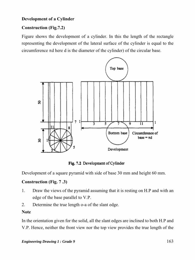
Engineering Drawing 1 : Grade 9 163
Development of a Cylinder
Construction (Fig.7.2)
Figure shows the development of a cylinder. In this the length of the rectangle
representing the development of the lateral surface of the cylinder is equal to the
circumference d here d is the diameter of the cylinder) of the circular base.
Development of a square pyramid with side of base 30 mm and height 60 mm.
Construction (Fig. 7 .3)
1. Draw the views of the pyramid assuming that it is resting on H.P and with an
edge of the base parallel to V.P.
2. Determine the true length o-a of the slant edge.
Note
In the orientation given for the solid, all the slant edges are inclined to both H.P and
V.P. Hence, neither the front view nor the top view provides the true length of the

164 Engineering Drawing 1 : Grade 9
slant edge. To determine the true lehiter of the slant edge, say OA, rotate oa till it is
parallel to xy to the position.oal. Through al ' draw a projector to meet the line xy
at all' Then Oil all represents the true length of the slant edge OA. This method of
determining the true length is also known as rotation method.
3. withcentre 0 and radius o’a’draw an arc.
4. starting from A along the arc, mark the edges of the base i.e. AB, BC, CD and
DA. I 5. Join 0 to A,B,C, etc., representing the lines of folding and thus
completing the development.
Development of Pentagonal Pyramid
Construction (Fig.7.4)
1. Draw the orthographic views of the pyramid ABCDE with its base on H.P
and axis parallel to V.P.

Engineering Drawing 1 : Grade 9 165
2. With center 0 of the pyramid and radius equal to the true length of the slant
edge draw an arc
3. Mark off the edges starting from A along the arc and join them to 0
representing the lines of folding.
4. Add the base at a suitable location.
Development of a Cone
Construction (Fig. 7 .5)
The development of the lateral surface of a cone is a sector of a circle. The radius
and length of the arc are equal to the slant height and circumference of the base of
the cone respectively. The included angle of the sector is given by (r / s) x 360°,
where r is the radius of the base of the cone and s is the true length.
Problem: A Pentagonal prism of side of base 20 mm and height 50 mm stands
vertically on its base with a rectangular face perpendicular to V.P. A cutting plane
perpendicular to V.P and inclined at 600 to the axis passes through the edges of the
top base of the prism. Develop the lower portion of the lateral surface of the prism.
Construction (Fig. 7 .6)

166 Engineering Drawing 1 : Grade 9
1. Draw the projections of the prism.
2. Draw the trace (V.T.) of the cutting plane intersecting the edges at points
1,2,3, etc.
3. Draw the stretch-out AA and mark-off the sides of the base along this in
succession i.e., AB, BC, CD, DE and EA.
4. Erect perpendiculars through A,B,C etc., and mark the edges AA 1 , BB I'
equal to the height of the prism.
5. Project the points 11,21,31 etc., and obtain 1,2,3 etc., respectively on the
corresponding edges in the development.
6. Join the points 1,2,3 etc., by straight lines and darken the sides corresponding
to the truncated portion of the solid.
Note
1. Generally, the opening is made along the shortest edge to save time and
soldering.
2. Stretch-out line is drawn in-line with bottom base of the front view to save
time in drawing the development.
3. AAI-AIA is the development of the complete prism.
4. Locate the points of intersection 11, 21, etc., between VT and the edges of the
prism and draw horizontal lines through them and obtain 1,2, etc., on the
corresponding edges in the development
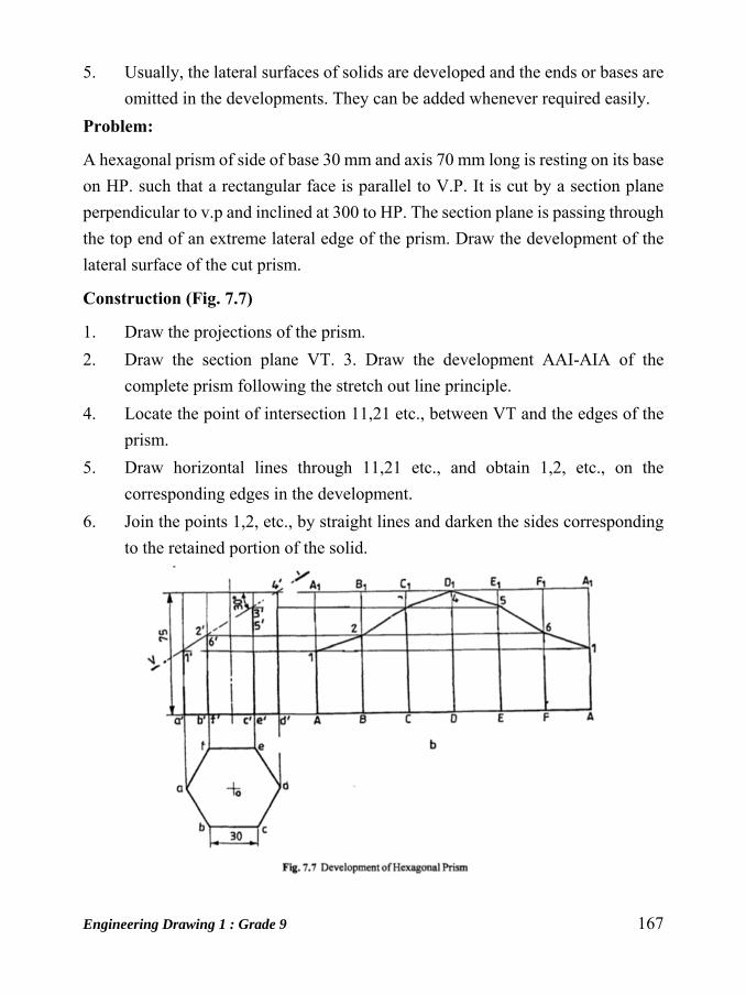
Engineering Drawing 1 : Grade 9 167
5. Usually, the lateral surfaces of solids are developed and the ends or bases are
omitted in the developments. They can be added whenever required easily.
Problem:
A hexagonal prism of side of base 30 mm and axis 70 mm long is resting on its base
on HP. such that a rectangular face is parallel to V.P. It is cut by a section plane
perpendicular to v.p and inclined at 300 to HP. The section plane is passing through
the top end of an extreme lateral edge of the prism. Draw the development of the
lateral surface of the cut prism.
Construction (Fig. 7.7)
1. Draw the projections of the prism.
2. Draw the section plane VT. 3. Draw the development AAI-AIA of the
complete prism following the stretch out line principle.
4. Locate the point of intersection 11,21 etc., between VT and the edges of the
prism.
5. Draw horizontal lines through 11,21 etc., and obtain 1,2, etc., on the
corresponding edges in the development.
6. Join the points 1,2, etc., by straight lines and darken the sides corresponding
to the retained portion of the solid.
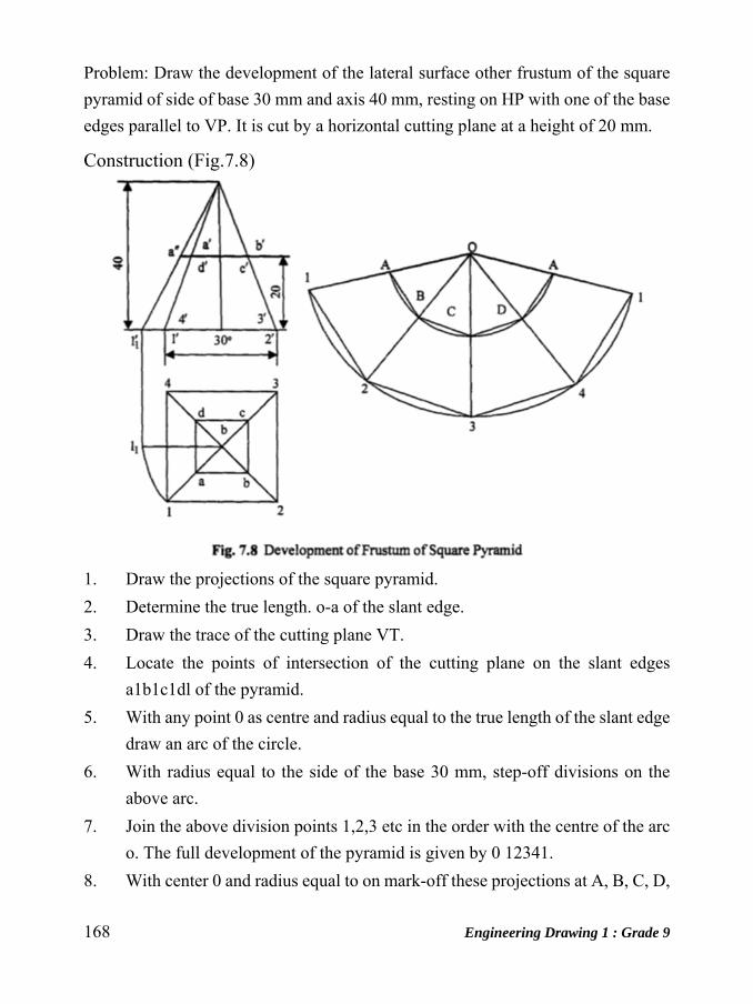
168 Engineering Drawing 1 : Grade 9
Problem: Draw the development of the lateral surface other frustum of the square
pyramid of side of base 30 mm and axis 40 mm, resting on HP with one of the base
edges parallel to VP. It is cut by a horizontal cutting plane at a height of 20 mm.
Construction (Fig.7.8)
1. Draw the projections of the square pyramid.
2. Determine the true length. o-a of the slant edge.
3. Draw the trace of the cutting plane VT.
4. Locate the points of intersection of the cutting plane on the slant edges
a1b1c1dl of the pyramid.
5. With any point 0 as centre and radius equal to the true length of the slant edge
draw an arc of the circle.
6. With radius equal to the side of the base 30 mm, step-off divisions on the
above arc.
7. Join the above division points 1,2,3 etc in the order with the centre of the arc
o. The full development of the pyramid is given by 0 12341.
8. With center 0 and radius equal to on mark-off these projections at A, B, C, D,

Engineering Drawing 1 : Grade 9 169
A. Join A-B, B-C etc. ABCDA-12341 is the development of the frustum of
the square pyramid.
Problem:
A cone of diameter of base ./5 mm and height 60 mm is cut by horizontal cutting
plane at 20 mm from the apex. Draw the development of the truncated cone.
Construction (Fig.7.12)
1. Draw the two views of the given cone and indicate the cutting plane.
2. Draw the lateral surface of the complete cone by a sector of a circle with
radius and arc length equal to the slant height and circumference of the base
respectively. The included angle of the sector is given by (360 x rls), where r
is the radius of the base and s is the slant height.
3. Divide the base (top view) into an equal number of parts, say 8.
4. Draw the generators in the front view corresponding to the above division
points a,b,c etc.
5. With d 11 as radius draw an arc cutting the generators at 1, 2,3 etc.
6. The truncated sector AJ-IIA gives the development of the truncated cone.
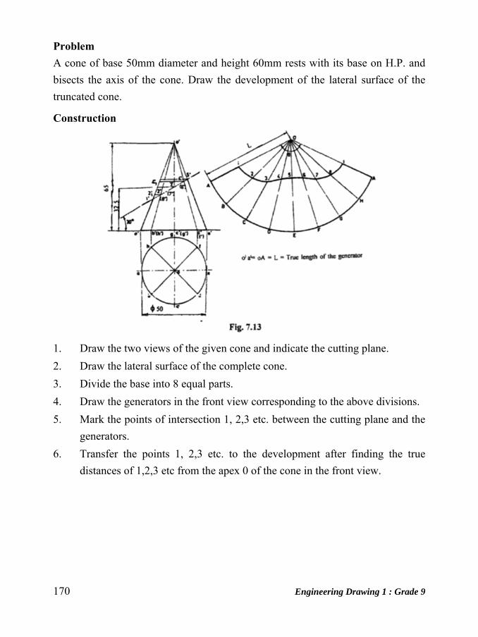
170 Engineering Drawing 1 : Grade 9
Problem A cone of base 50mm diameter and height 60mm rests with its base on H.P. and
bisects the axis of the cone. Draw the development of the lateral surface of the
truncated cone.
Construction
1. Draw the two views of the given cone and indicate the cutting plane.
2. Draw the lateral surface of the complete cone.
3. Divide the base into 8 equal parts.
4. Draw the generators in the front view corresponding to the above divisions.
5. Mark the points of intersection 1, 2,3 etc. between the cutting plane and the
generators.
6. Transfer the points 1, 2,3 etc. to the development after finding the true
distances of 1,2,3 etc from the apex 0 of the cone in the front view.
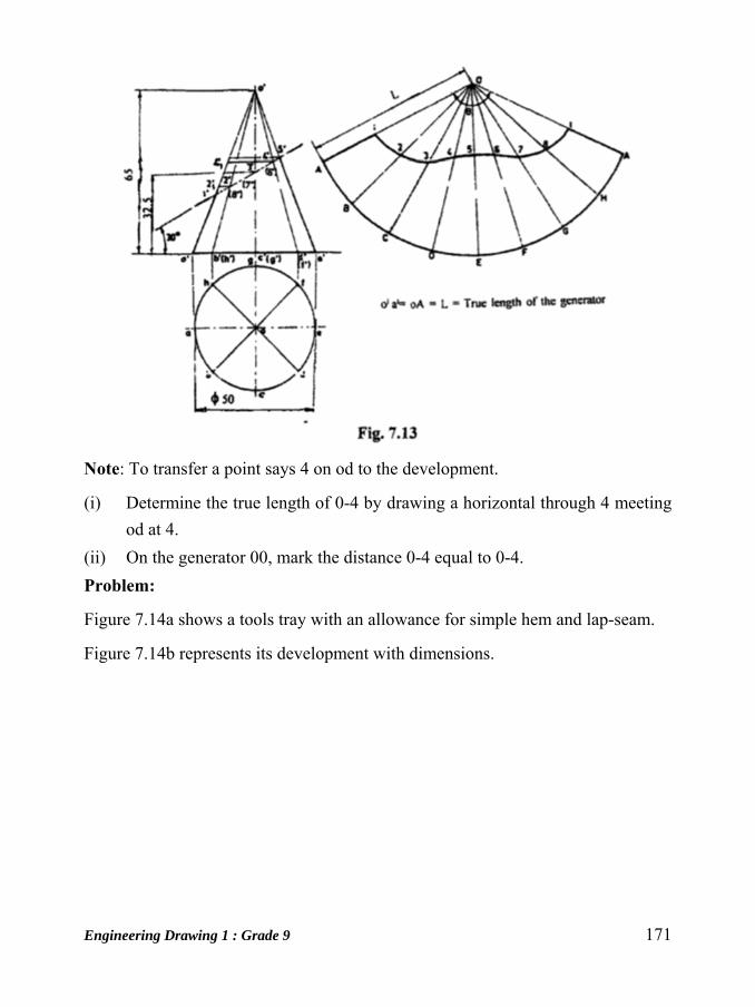
Engineering Drawing 1 : Grade 9 171
Note: To transfer a point says 4 on od to the development.
(i) Determine the true length of 0-4 by drawing a horizontal through 4 meeting
od at 4.
(ii) On the generator 00, mark the distance 0-4 equal to 0-4.
Problem:
Figure 7.14a shows a tools tray with an allowance for simple hem and lap-seam.
Figure 7.14b represents its development with dimensions.
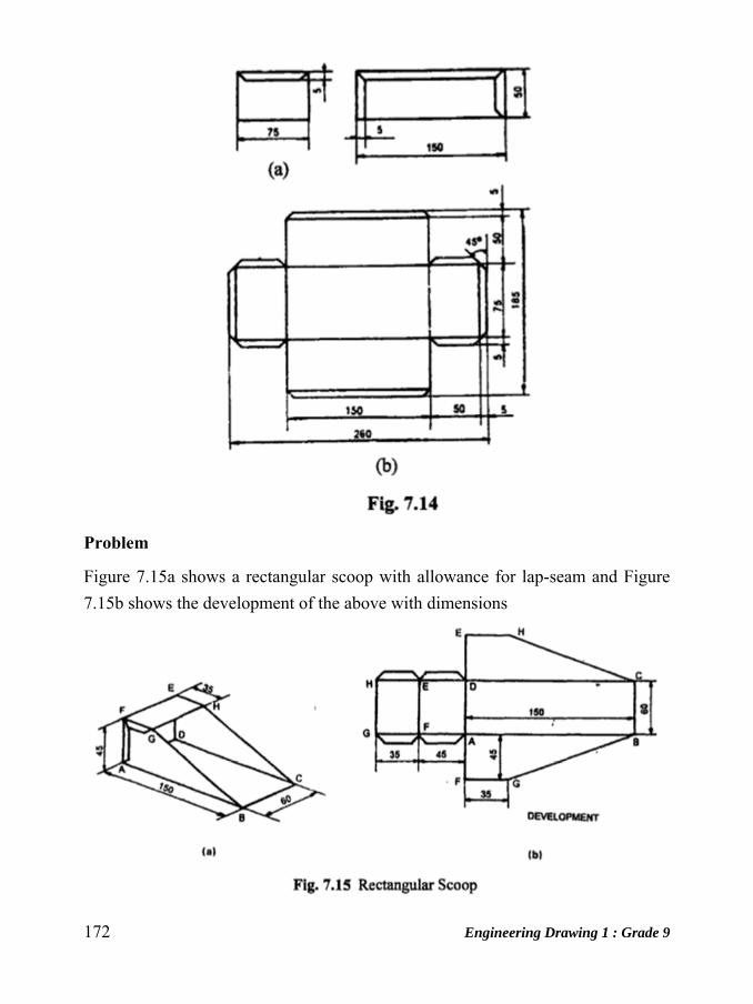
172 Engineering Drawing 1 : Grade 9
Problem
Figure 7.15a shows a rectangular scoop with allowance for lap-seam and Figure
7.15b shows the development of the above with dimensions

Engineering Drawing 1 : Grade 9 173
Problem
Figure 7.16a shows the pictorial view of a rectangular 90° elbow and Figure 7.16b
its development in two parts.
Problem:
Figure 7.17a represents the projection of a round scoop and Figure 7.17b its
development.

174 Engineering Drawing 1 : Grade 9
Problem
Figure 7.20 shows the orthographic projection of a chute and the development of
the parts.
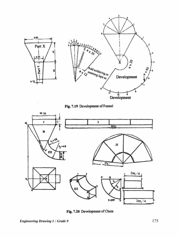
Engineering Drawing 1 : Grade 9 175
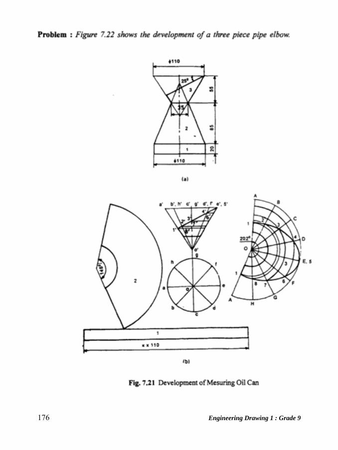
176 Engineering Drawing 1 : Grade 9
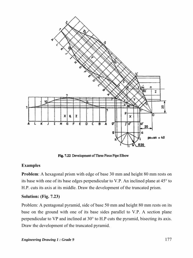
Engineering Drawing 1 : Grade 9 177
Examples
Problem: A hexagonal prism with edge of base 30 mm and height 80 mm rests on
its base with one of its base edges perpendicular to V.P. An inclined plane at 45° to
H.P. cuts its axis at its middle. Draw the development of the truncated prism.
Solution: (Fig. 7.23)
Problem: A pentagonal pyramid, side of base 50 mm and height 80 mm rests on its
base on the ground with one of its base sides parallel to V.P. A section plane
perpendicular to VP and inclined at 30° to H.P cuts the pyramid, bisecting its axis.
Draw the development of the truncated pyramid.
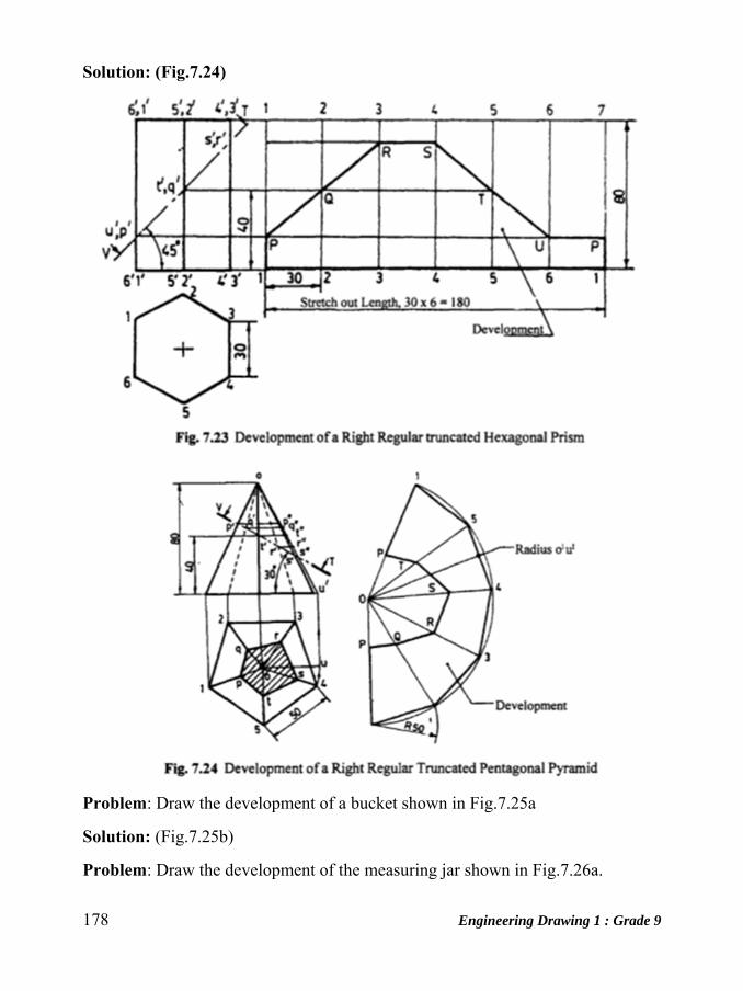
178 Engineering Drawing 1 : Grade 9
Solution: (Fig.7.24)
Problem: Draw the development of a bucket shown in Fig.7.25a
Solution: (Fig.7.25b)
Problem: Draw the development of the measuring jar shown in Fig.7.26a.

Engineering Drawing 1 : Grade 9 179
Solution: ( Fig7.26b)
Exercise
Development of Surfaces 1. A frustum of a square pyramid has its base 50 mm side, top 25 mm side and
height 60 mm. It is resting with its base on HP, with two of its sides parallel
to VP. Draw the projections of the frustum and show the development of its
lateral surface.
2. A cone of diameter 60 mm and height 80 mm is cut by a section plane
such that the plane passes through the mid-point of the axis and
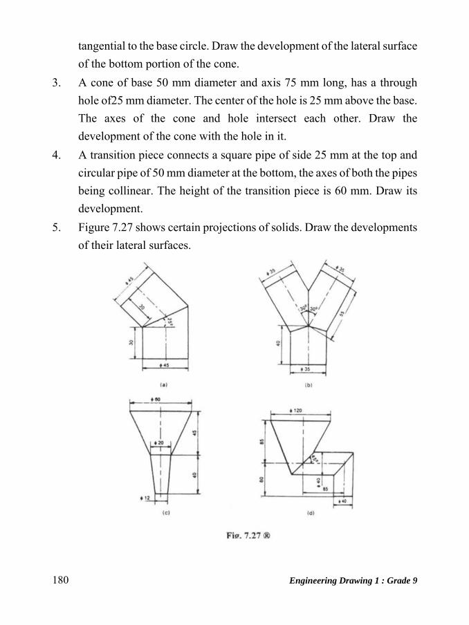
180 Engineering Drawing 1 : Grade 9
tangential to the base circle. Draw the development of the lateral surface
of the bottom portion of the cone.
3. A cone of base 50 mm diameter and axis 75 mm long, has a through
hole of25 mm diameter. The center of the hole is 25 mm above the base.
The axes of the cone and hole intersect each other. Draw the
development of the cone with the hole in it.
4. A transition piece connects a square pipe of side 25 mm at the top and
circular pipe of 50 mm diameter at the bottom, the axes of both the pipes
being collinear. The height of the transition piece is 60 mm. Draw its
development.
5. Figure 7.27 shows certain projections of solids. Draw the developments
of their lateral surfaces.
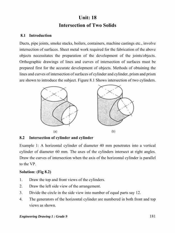
Engineering Drawing 1 : Grade 9 181
Unit: 18 Intersection of Two Solids
8.1 Introduction
Ducts, pipe joints, smoke stacks, boilers, containers, machine castings etc., involve
intersection of surfaces. Sheet metal work required for the fabrication of the above
objects necessitates the preparation of the development of the joints/objects.
Orthographic drawings of lines and curves of intersection of surfaces must be
prepared first for the accurate development of objects. Methods of obtaining the
lines and curves of intersection of surfaces of cylinder and cylinder, prism and prism
are shown to introduce the subject. Figure 8.1 Shows intersection of two cylinders.
8.2 Intersection of cylinder and cylinder
Example 1: A horizontal cylinder of diameter 40 mm penetrates into a vertical
cylinder of diameter 60 mm. The axes of the cylinders intersect at right angles.
Draw the curves of intersection when the axis of the horizontal cylinder is parallel
to the VP.
Solution: (Fig 8.2)
1. Draw the top and front views of the cylinders.
2. Draw the left side view of the arrangement.
3. Divide the circle in the side view into number of equal parts say 12.
4. The generators of the horizontal cylinder are numbered in both front and top
views as shown.
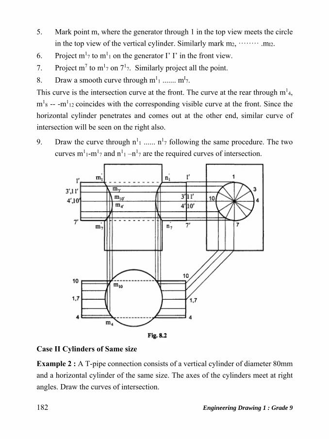
182 Engineering Drawing 1 : Grade 9
5. Mark point m, where the generator through 1 in the top view meets the circle
in the top view of the vertical cylinder. Similarly mark m2, ꞏꞏꞏꞏꞏꞏꞏꞏ .mI2.
6. Project m17 to m1
1 on the generator I’ I’ in the front view.
7. Project m7 to m17 on 71
7. Similarly project all the point.
8. Draw a smooth curve through m11 ....... mI
7.
This curve is the intersection curve at the front. The curve at the rear through m14,
m18 -- -m1
12 coincides with the corresponding visible curve at the front. Since the
horizontal cylinder penetrates and comes out at the other end, similar curve of
intersection will be seen on the right also.
9. Draw the curve through n11 ...... n1
7 following the same procedure. The two
curves m11-m1
7 and n11 –n1
7 are the required curves of intersection.
Case II Cylinders of Same size
Example 2 : A T-pipe connection consists of a vertical cylinder of diameter 80mm
and a horizontal cylinder of the same size. The axes of the cylinders meet at right
angles. Draw the curves of intersection.
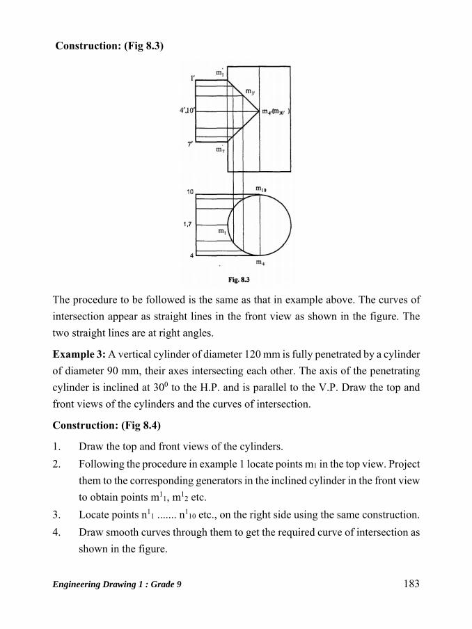
Engineering Drawing 1 : Grade 9 183
Construction: (Fig 8.3)
The procedure to be followed is the same as that in example above. The curves of
intersection appear as straight lines in the front view as shown in the figure. The
two straight lines are at right angles.
Example 3: A vertical cylinder of diameter 120 mm is fully penetrated by a cylinder
of diameter 90 mm, their axes intersecting each other. The axis of the penetrating
cylinder is inclined at 300 to the H.P. and is parallel to the V.P. Draw the top and
front views of the cylinders and the curves of intersection.
Construction: (Fig 8.4)
1. Draw the top and front views of the cylinders.
2. Following the procedure in example 1 locate points m1 in the top view. Project
them to the corresponding generators in the inclined cylinder in the front view
to obtain points m11, m1
2 etc.
3. Locate points n11 ....... n1
10 etc., on the right side using the same construction.
4. Draw smooth curves through them to get the required curve of intersection as
shown in the figure.

184 Engineering Drawing 1 : Grade 9
8.3 Intersection of prism and prism
When a prism penetrates another prism, plane surface of one prism intersects the
plane surfaces of another prism and hence the lines of intersection will be straight
lines. In these cases, lines on the surface of one of the solids need not necessarily
be drawn as it is done with cylinders. Instead, the points of intersections of the edges
with the surface are located by mere inspection. These points are projected in the
other view and the lines of intersection obtained.
Example 4: A square prism of base side 60 mm rests on one of its ends on the HP
with the base sides equally inclined to the VP. It is penetrated fully by another
square prism of base side 45 mm with the base side equally inclined to the HP. The
axes intersect at right angles. The axis of the penetrating prism is parallel to both
the HP and the VP. Draw the projections of the prisms and show the lines of
intersection.
Construction: (Fig 8.5)
1. Draw the top and front view of the prisms in the given position.
2. Locate the points of intersection of the penetrating prism with the surfaces of
the vertical prism in the top view by inspection. Here, the edges 2-21, of the

Engineering Drawing 1 : Grade 9 185
horizontal prism intersect the edge point of the vertical prism at m2 in the top
view. n4 corresponds to the edge 4-41 , and the immediately below m2 , m1
and m3 relate to I-II, and 3-31 respectively.
3. Similarly locate points n1, n2, n3 and n4.
4. Project m1 onto 11- 111 in the front view as m1
1. Similarly project all other
points. M13 coincides with m1
1 and n13 coincides with n1
1.
5. Join m12 m1
1 and m11 m1
4 by straight lines. Join n12 n1
1 and n11 n1
4 also by
straight lines.

186 Engineering Drawing 1 : Grade 9
Unit: 19
Land Measurement The most popular units of land measurement in Nepal are Aana, Kattha, Bigha,
Ropani, Dhur etc. In the cities, Terai belt of Nepal like Butwal, Bhairahawa,
Nepaljung, Biratnagar etc haat, kattha, bigha etc units are much popular while in
Kathmandu valley Aana, Ropani and square foot are in much use. In coming years
square meter will be the widely used for land measurement in Nepal.
A Bigha is a customary unit of measurement in Nepal, equal to about 6,773 square
meters. Officially, most measurements of lands use units of either Bigha in Terai
region or Ropani in Hilly regions). Metric system is very rarely used officially in
measuring area of Land.
Below are some of the most used and searched conversion rates of different land
measurement units of Nepal.
Different Land Measurement Units in Nepal 1 Bigha (la3f) = 20 Kattha (s¶f)
1 Bigha (la3f) = 6772.63m2
1 Bigha (la3f) = 72900 sq. ft.
1 Bigha (la3f) = 13.31 Ropani(/f]kgL)
1 Kattha (s¶f) = 20 Dhur(w'/)
1 Kattha (s¶f) = 338.63m2
1 Kattha (s¶f) = 3645sq. ft.
1 Dhur (w'/)= 16.93 m2
1 Dhur (w'/) = 182.25 sq.ft.
1 Ropani (/f]kgL) = 16 aana (cfgf)
1 Ropani (/f]kgL) = 64 paisa (k};f)
1 Ropani (/f]kgL) = 508.72m2
1 Ropani (/f]kgL) = 5476 sq. ft.
1 Ropani (/f]kgL) = 256 Daam (bfd)
1 Ropani (/f]kgL) = 4 Matomuri
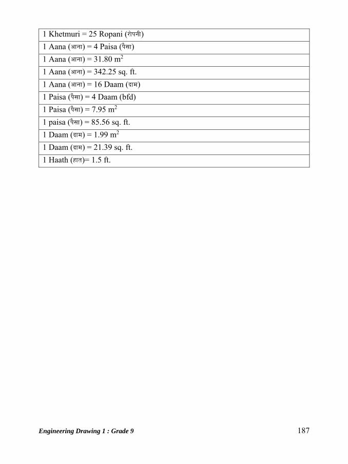
Engineering Drawing 1 : Grade 9 187
1 Khetmuri = 25 Ropani (/f]kgL)
1 Aana (cfgf) = 4 Paisa (k};f)
1 Aana (cfgf) = 31.80 m2
1 Aana (cfgf) = 342.25 sq. ft.
1 Aana (cfgf) = 16 Daam (bfd)
1 Paisa (k};f) = 4 Daam (bfd)
1 Paisa (k};f) = 7.95 m2
1 paisa (k};f) = 85.56 sq. ft.
1 Daam (bfd) = 1.99 m2
1 Daam (bfd) = 21.39 sq. ft.
1 Haath (xft)= 1.5 ft.