machine drawing - 00 engineering graphics - cover pages
TRANSCRIPT
40 ENGINEERING GRAPHICS
A. DRAWING OF MACHINE PARTS
2.1 INTRODUCTION
2.2 SCREW THREAD
In our day to day life, we come across many objects where bolts and nuts are used to join two
pieces together. For example we use wooden furnitures like desks, stools, tables etc. in school,
showing bolts, nuts and screws. Such machine parts which are used to connect two pieces
together are called as fasteners. There are two types of fasteners, viz, temporary fasteners and
permanent fasteners. Threaded fasteners like bolt and nut are temporary fasteners. The process
of joining different machine parts of machine or engineering products is called as fastening.
Permanent fastening such as welding, riveting etc. join two parts together permanently and they
cannot be separated without breaking the fastening, but in the case of temporary fastening, the
parts are joined together temporarily and can be separated easily without breaking the
fastening.
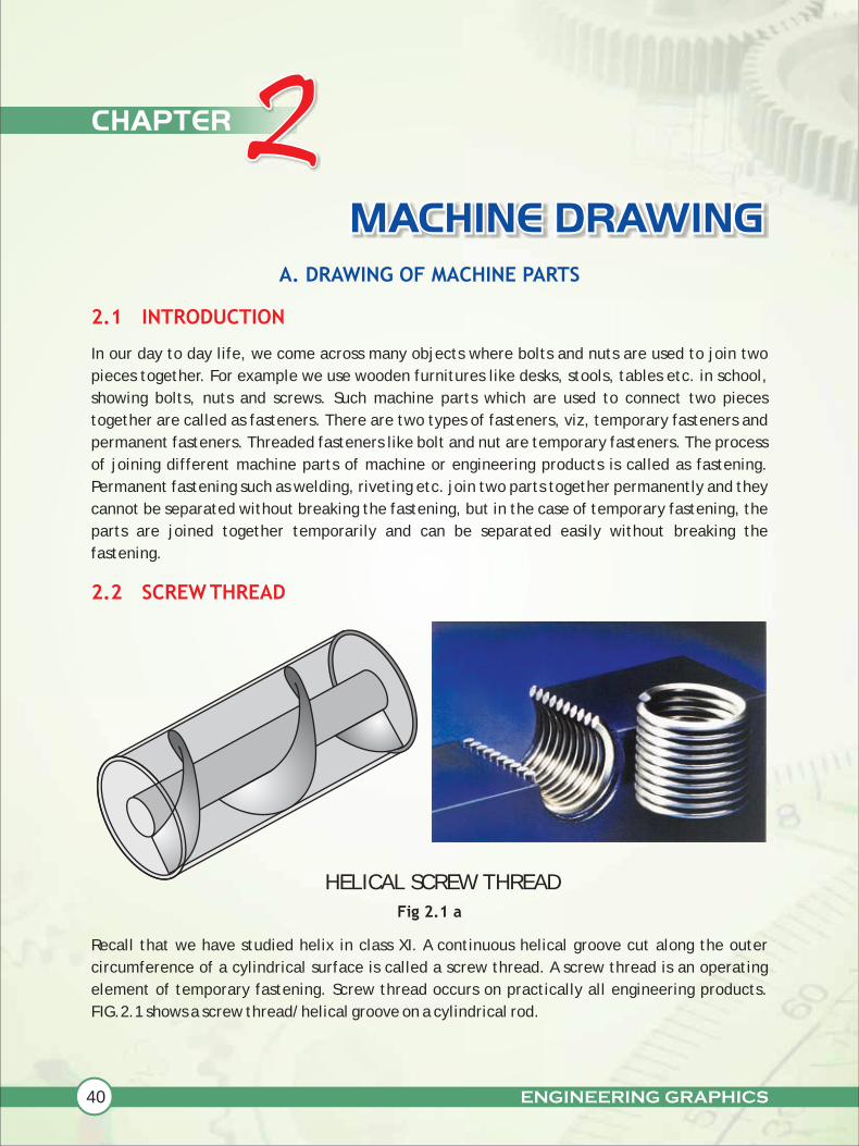
Fig 2.1 a
Recall that we have studied helix in class XI. A continuous helical groove cut along the outer
circumference of a cylindrical surface is called a screw thread. A screw thread is an operating
element of temporary fastening. Screw thread occurs on practically all engineering products.
FIG.2.1 shows a screw thread/helical groove on a cylindrical rod.
MACHINE DRAWING
CHAPTER 2
HELICAL SCREW THREAD

ENGINEERING GRAPHICS 41
Fig 2.1 b :
Screw threads are widely used for temporary fastening as well as for transmission of power from
one machine parts to another
The various terms in connection with screw threads are given below. Refer Fig.2.2
2.3 TERMS USED IN THREADS / SCREW THREADS
Fig.2.2
Outside dia. Depth
Lead
Flank
Angle
Root or core dia.
Slope
Crest
Root
Pitch
(A) EXTERNAL RIGHT HAND THREAD
(B) INTERNAL LEFT HAND THREAD
(C) EXTERNAL LEFT HAND THREAD
MACHINE DRAWING
Nominal Dia.
Axis
SCREW THREAD
42 ENGINEERING GRAPHICS
MACHINE DRAWING
(i) EXTERNAL THREAD
It is a continuous helical groove or ridge cut along the external surface of the
cylinder, e.g. threads on bolts studs, screws etc. FIG 2.2(a) shows an external
thread.
(ii) INTERNAL THREAD
It is a thread on the internal surface of a hollow cylinder. FIG 2.2(b) shows the
internal threads, e.g. threads of a nut.
(iii) SCREW PAIR
The bolt and nut together called as screw pair. One or more such pairs are used to
join two parts.
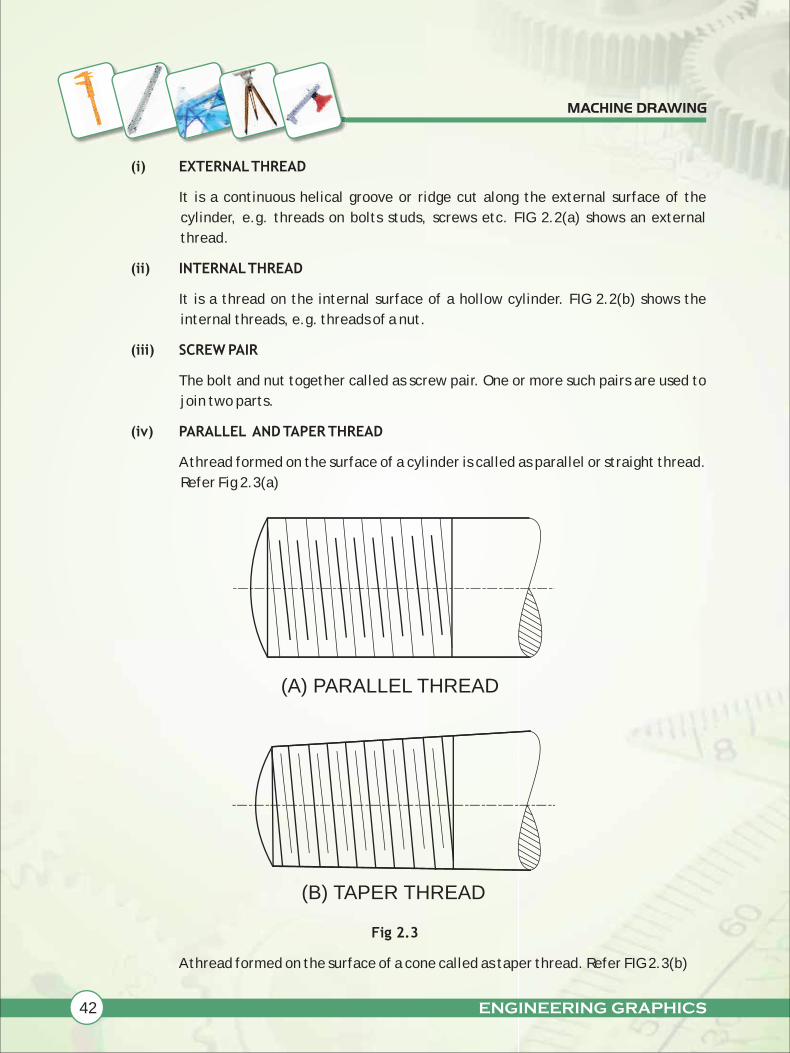
(iv) PARALLEL AND TAPER THREAD
A thread formed on the surface of a cylinder is called as parallel or straight thread.
Refer Fig 2.3(a)
Fig 2.3
A thread formed on the surface of a cone called as taper thread. Refer FIG 2.3(b)
(B) TAPER THREAD
(A) PARALLEL THREAD

ENGINEERING GRAPHICS 43
(v) RIGHT HAND AND LEFT HAND THREADS
Consider any nut and bolt. Hold the bolt firmly in left hand and rotate the nut
clockwise by the right hand, the nut will screw on the bolt of the threads are right
handed. It is abbreviated as RH thread. A left hand screws thread when assembled
with a stationary mating bolt, screws off the bolt for clockwise rotation. It is
abbreviated as LH thread.
Observe that mostly the bolts and nuts that we use in daily life have RH thread.
Also we can observe that all the jewellery mating pieces have LH thread.
(vi) PITCH, P
It is "the distance between the corresponding points on the adjacent threads,
measured parallel to the axis". Refer FIG2.2 (a)
(vii) LEAD,L
It is "the distance moved by a nut or bolt in the axial direction in one complete
rotation".
(viii) SINGLE START AND MULTI START THREADS
When only one helix, forming the thread runs on a cylinder, it is called as single
start thread. If more then one helices run on a cylinder, it is called as multi start
threads.
i.e. L=P in the case of single start
L=2P in the case of double start
L=3P for triple start and so on.
(ix) CREST
It is the edge of the thread surface farthest from the axis, in case of external
thread and nearest to the axis, in case of internal thread
(x) ROOT
It is the edge of the thread surface nearest to the axis in case of external thread
and farthest from the axis, in case of internal thread.
(xi) FLANK
The surface connecting crest and root is called as flank.
(xii) THREAD ANGLE
It is "the angle between the flanks measured in an axial plane".
MACHINE DRAWING
44 ENGINEERING GRAPHICS
MACHINE DRAWING
(xiii) MAJOR DIAMETER OR OUTSIDE DIAMETER
It is the diameter of an imaginary coaxial cylinder just touching the crest of
external threads or roots of internal threads. It is the largest diameter of a screw
thread.
(xiv) MINOR DIAMETER OR ROOT DIAMETER OR CORE DIAMETER
It is the diameter of an imaginary co-axial cylinder just touching the roots of
external threads or crest of internal threads.
(xv) NOMINAL DIAMETER
It is the diameter of the cylinder from which external threads are cut out. The
screw/bolt is specified by this diameter.
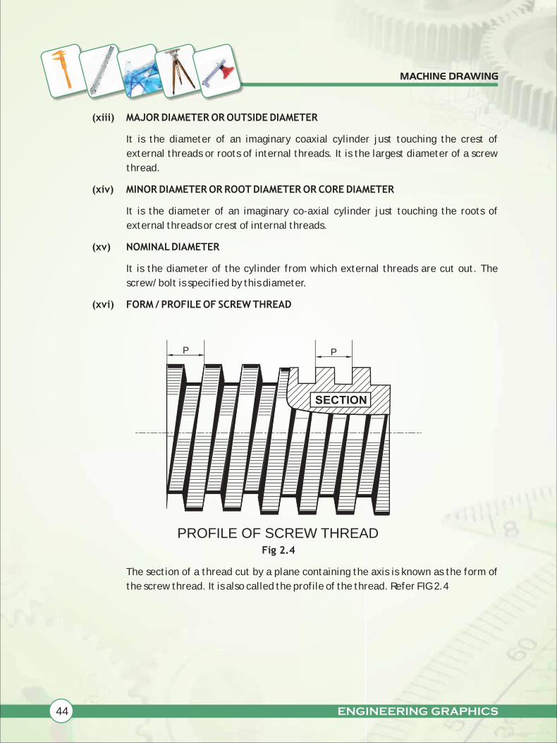
(xvi) FORM / PROFILE OF SCREW THREAD
Fig 2.4
The section of a thread cut by a plane containing the axis is known as the form of
the screw thread. It is also called the profile of the thread. Refer FIG 2.4
SECTION
P P
PROFILE OF SCREW THREAD
ENGINEERING GRAPHICS 45
MACHINE DRAWING
2.4 STANDARD PROFILE / FORM OF SCREW THREADS
There are two basic screw thread profiles. viz.
(a) Triangular or 'V' thread
(b) Square thread.
When the thread has a triangular or V-cross section, it is called as V-threads. All types of V-
threads have inclined flanks making an angle between them. In the practical use of the
threads, a clearance must be provided between the external and internal threads. V
threads are used "to tighten two parts together" as in bolts and nuts, studs and nuts,
screws etc.
For interchangeability between the screws and nuts of the same nominal diameter and
form, various countries have standardized V-thread profiles. A few such standard thread
forms are given in our syllabus namely
(i) B.S.W. thread
(ii) Metric thread
When the thread has square cross section it is called as square thread. Flanks of square
threads are vertical and parallel to each other. "square threads are used for power
transmission" on feed mechanism of machine tools, screw jacks etc, when less friction
means saving of power as they offer less frictional resistance. In our syllabus we are going
to study about the standard profile/ form of a few square threads viz.
(i) Square thread
(ii) Knuckle thread
British standard whitworth (B.S.W.) thread is the most widely used form in British
practice. Let us now learn to draw the standard profile of B.S.W. thread.
Draw to scale 1:1, standard profile of B.S.W. thread, taking pitch = 40 mm. Give
standard dimensions.
(a) TRIANGULAR OR 'V' THREAD
(b) SQUARE THREAD
2.4.1 PROFILE OF B.S.W. THREAD
Example 1:
46 ENGINEERING GRAPHICS
MACHINE DRAWING
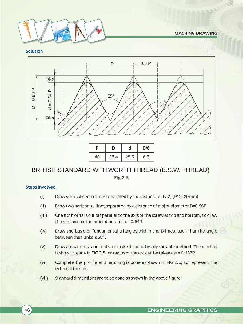
Solution
Steps Involved
Fig 2.5
(i) Draw vertical centre lines separated by the distance of P/2, (P/2=20 mm).
(ii) Draw two horizontal lines separated by a distance of major diameter D=0.96P.
(iii) One sixth of 'D' is cut off parallel to the axis of the screw at top and bottom, to draw
the horizontals for minor diameter, d= 0.64P.
(iv) Draw the basic or fundamental triangles within the D lines, such that the angle
between the flanks is 55°.
(v) Draw arcs at crest and roots, to make it round by any suitable method. The method
is shown clearly in FIG 2.5, or radius of the arc can be taken as r= 0.137P.
(vi) Complete the profile and hatching is done as shown in FIG 2.5, to represent the
external thread.
(vii) Standard dimensions are to be done as shown in the above figure.
BRITISH STANDARD WHITWORTH THREAD (B.S.W. THREAD)
P 0.5 P
d =
0.6
4 P
D =
0.9
6 P
D 6D 6
P
40
D
38.4
d
25.6
D/6
6.5
55°
ENGINEERING GRAPHICS 47
MACHINE DRAWING
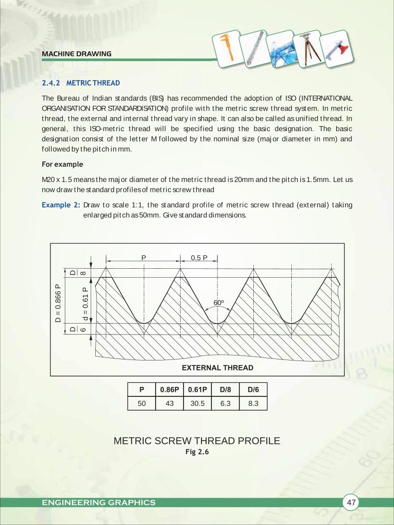
2.4.2 METRIC THREAD
Example 2:
The Bureau of Indian standards (BIS) has recommended the adoption of ISO (INTERNATIONAL
ORGANISATION FOR STANDARDISATION) profile with the metric screw thread system. In metric
thread, the external and internal thread vary in shape. It can also be called as unified thread. In
general, this ISO-metric thread will be specified using the basic designation. The basic
designation consist of the letter M followed by the nominal size (major diameter in mm) and
followed by the pitch in mm.
For example
M20 x 1.5 means the major diameter of the metric thread is 20mm and the pitch is 1.5mm. Let us
now draw the standard profiles of metric screw thread
Draw to scale 1:1, the standard profile of metric screw thread (external) taking
enlarged pitch as 50mm. Give standard dimensions.
Fig 2.6
d =
0.6
1 P
D =
0.8
66 P
METRIC SCREW THREAD PROFILE
D 6
D 8
EXTERNAL THREAD
60º
P
50
0.86P
43
0.61P
30.5
D/8
6.3
D/6
8.3
P 0.5 P
48 ENGINEERING GRAPHICS
MACHINE DRAWING
Solution:
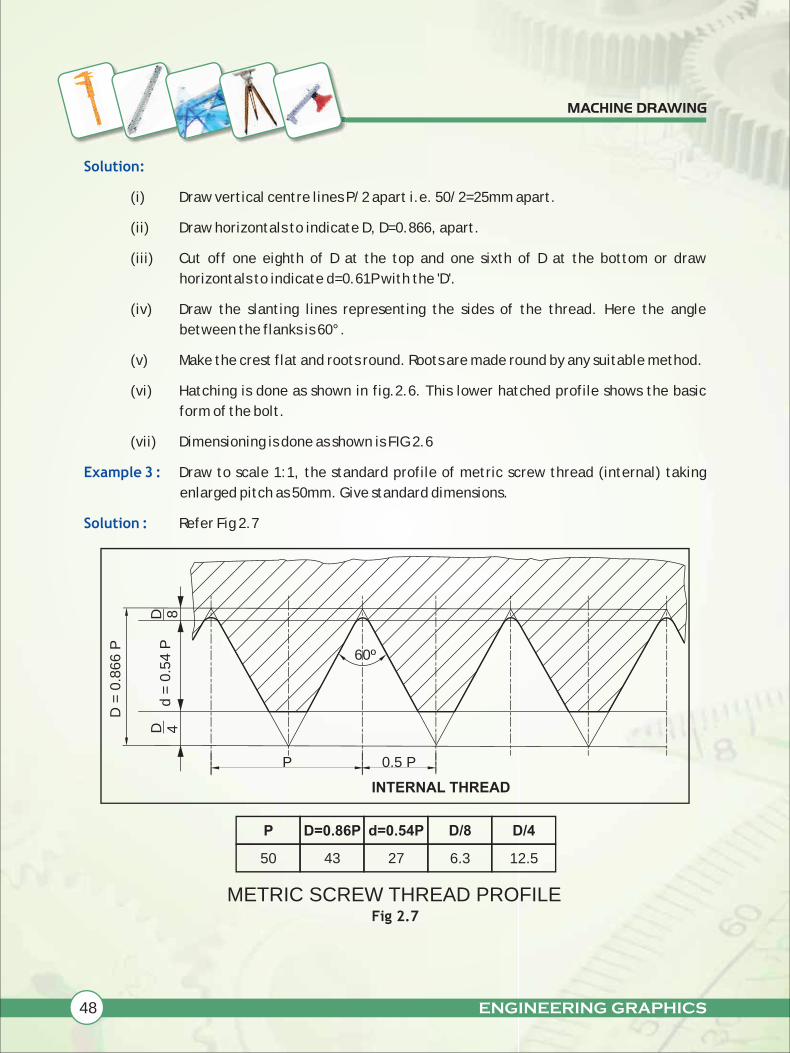
Example 3 :
Solution :
(i) Draw vertical centre lines P/2 apart i.e. 50/2=25mm apart.
(ii) Draw horizontals to indicate D, D=0.866, apart.
(iii) Cut off one eighth of D at the top and one sixth of D at the bottom or draw
horizontals to indicate d=0.61P with the 'D'.
(iv) Draw the slanting lines representing the sides of the thread. Here the angle
between the flanks is 60°.
(v) Make the crest flat and roots round. Roots are made round by any suitable method.
(vi) Hatching is done as shown in fig.2.6. This lower hatched profile shows the basic
form of the bolt.
(vii) Dimensioning is done as shown is FIG 2.6
Draw to scale 1:1, the standard profile of metric screw thread (internal) taking
enlarged pitch as 50mm. Give standard dimensions.
Refer Fig 2.7
Fig 2.7
d =
0.5
4 P
D =
0.8
66 P
D 8
INTERNAL THREAD
P 0.5 P
60º
D 4
P
50
D=0.86P
43
d=0.54P
27
D/8
6.3
D/4
12.5
METRIC SCREW THREAD PROFILE

ENGINEERING GRAPHICS 49
MACHINE DRAWING
Steps involved are similar to the previous example. Here the upper hatched profile shows the
basic form of nut.
Mechanisms of machine tools, valves, spindles, vice screws etc. are generally provided with
square threads. A "square thread (SQ) is specified by nominal diameter and pitch". For example a
square thread of nominal diameter = 40 mm and pitch = 4mm is designated as SQ 40x4
Let us now learn to draw the standard profile of a square thread, taking enlarged pitch as 60mm.
Refer Fig 2.8
(i) Draw two horizontals, P/2 apart i.e. 60/2= 30mm apart.
(ii) Draw a number of perpendiculars, 30mm apart so as to have a row of squares.
(iii) Hatching and dimensioning is done as shown in fig 2.8
Fig 2.8
Knuckle thread is a modified form of square thread. Knuckle thread is a special purpose thread. It
is used in railway carriage coupling screws and on the neck of glass bottles.
Let us now draw the standard profile of Knuckle thread.
2.4.3 SQUARE THREAD
Solution :
Steps Involved
2.4.4 KNUCKLE THREAD
P 0.5P
0.5
P
90º
P
60
0.5P
30
ANGLE
90°
PROFILE OF SQUARE SCREW THREAD
50 ENGINEERING GRAPHICS
MACHINE DRAWING
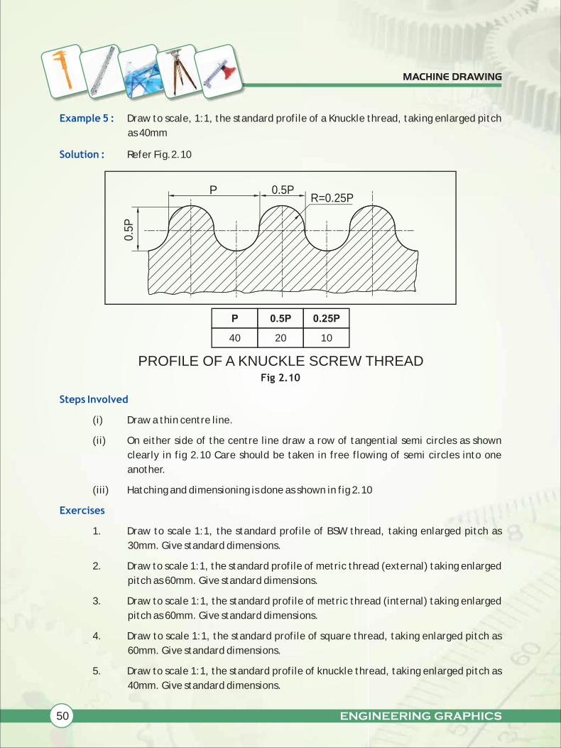
Example 5 :
Solution :
Steps Involved
Exercises
Draw to scale, 1:1, the standard profile of a Knuckle thread, taking enlarged pitch
as 40mm
Refer Fig.2.10
Fig 2.10
(i) Draw a thin centre line.
(ii) On either side of the centre line draw a row of tangential semi circles as shown
clearly in fig 2.10 Care should be taken in free flowing of semi circles into one
another.
(iii) Hatching and dimensioning is done as shown in fig 2.10
1. Draw to scale 1:1, the standard profile of BSW thread, taking enlarged pitch as
30mm. Give standard dimensions.
2. Draw to scale 1:1, the standard profile of metric thread (external) taking enlarged
pitch as 60mm. Give standard dimensions.
3. Draw to scale 1:1, the standard profile of metric thread (internal) taking enlarged
pitch as 60mm. Give standard dimensions.
4. Draw to scale 1:1, the standard profile of square thread, taking enlarged pitch as
60mm. Give standard dimensions.
5. Draw to scale 1:1, the standard profile of knuckle thread, taking enlarged pitch as
40mm. Give standard dimensions.
P 0.5P
0.5P
P
40
0.5P
20
0.25P
10
R=0.25P
PROFILE OF A KNUCKLE SCREW THREAD
ENGINEERING GRAPHICS 51
MACHINE DRAWING
2.5 BOLTS
In day to day life, we can observe many machine parts joined by bolt and nut. Now, let us study
about the bolts.
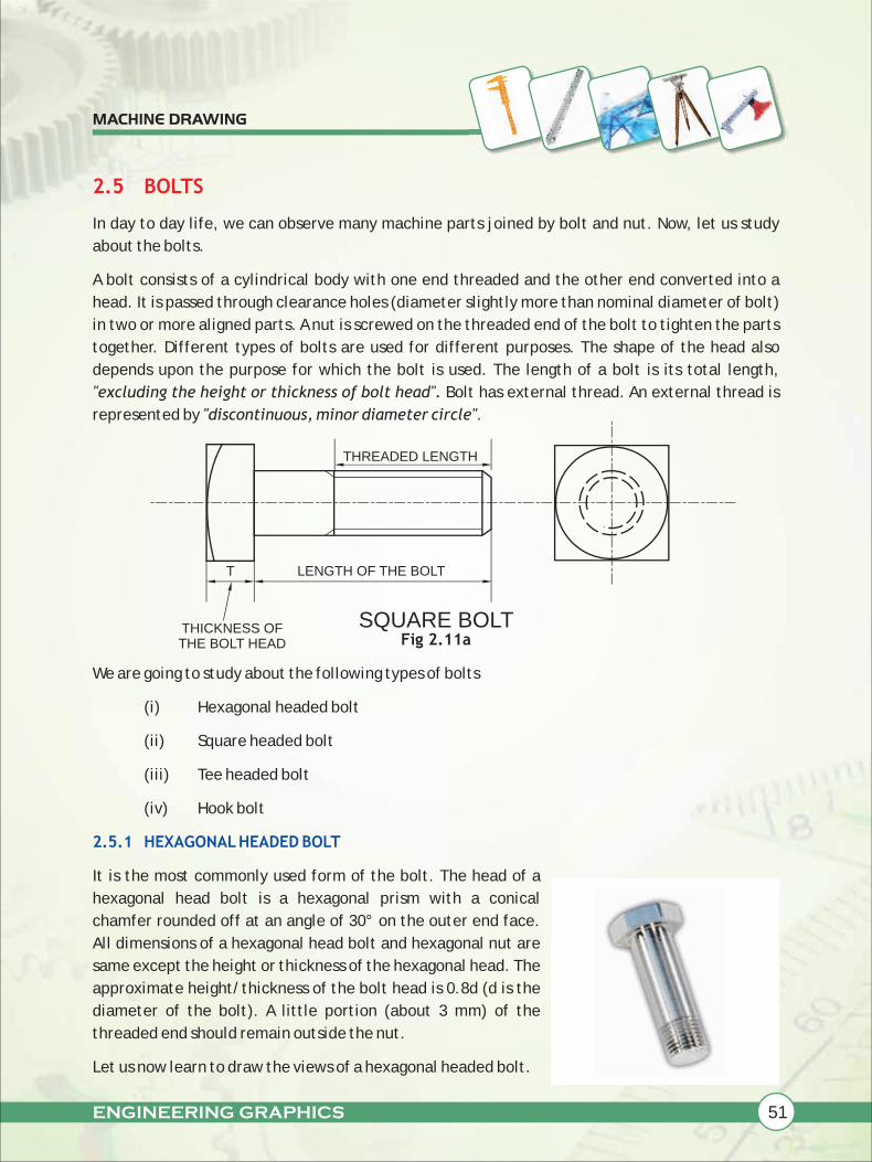
A bolt consists of a cylindrical body with one end threaded and the other end converted into a
head. It is passed through clearance holes (diameter slightly more than nominal diameter of bolt)
in two or more aligned parts. A nut is screwed on the threaded end of the bolt to tighten the parts
together. Different types of bolts are used for different purposes. The shape of the head also
depends upon the purpose for which the bolt is used. The length of a bolt is its total length,
"excluding the height or thickness of bolt head". Bolt has external thread. An external thread is
represented by "discontinuous, minor diameter circle".
Fig 2.11a
We are going to study about the following types of bolts
(i) Hexagonal headed bolt
(ii) Square headed bolt
(iii) Tee headed bolt
(iv) Hook bolt
It is the most commonly used form of the bolt. The head of a
hexagonal head bolt is a hexagonal prism with a conical
chamfer rounded off at an angle of 30° on the outer end face.
All dimensions of a hexagonal head bolt and hexagonal nut are
same except the height or thickness of the hexagonal head. The
approximate height/thickness of the bolt head is 0.8d (d is the
diameter of the bolt). A little portion (about 3 mm) of the
threaded end should remain outside the nut.
Let us now learn to draw the views of a hexagonal headed bolt.
2.5.1 HEXAGONAL HEADED BOLT
THREADED LENGTH
T LENGTH OF THE BOLT
THICKNESS OF THE BOLT HEAD
SQUARE BOLT
52 ENGINEERING GRAPHICS
MACHINE DRAWING
EXAMPLE 6:
Solution:
Steps Involved
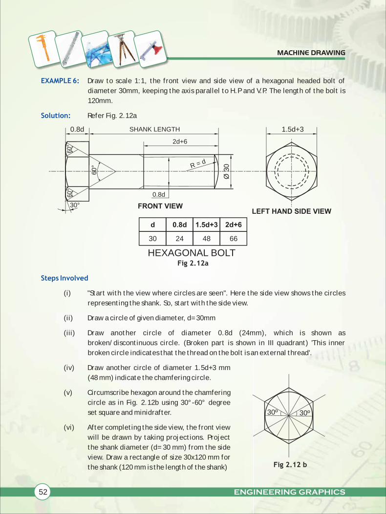
Draw to scale 1:1, the front view and side view of a hexagonal headed bolt of
diameter 30mm, keeping the axis parallel to H.P and V.P. The length of the bolt is
120mm.
Refer Fig. 2.12a
Fig 2.12a
(i) "Start with the view where circles are seen". Here the side view shows the circles
representing the shank. So, start with the side view.
(ii) Draw a circle of given diameter, d= 30mm
(iii) Draw another circle of diameter 0.8d (24mm), which is shown as
broken/discontinuous circle. (Broken part is shown in III quadrant) 'This inner
broken circle indicates that the thread on the bolt is an external thread'.
(iv) Draw another circle of diameter 1.5d+3 mm
(48 mm) indicate the chamfering circle.
(v) Circumscribe hexagon around the chamfering
circle as in Fig. 2.12b using 30°-60° degree
set square and minidrafter.
(vi) After completing the side view, the front view
will be drawn by taking projections. Project
the shank diameter (d= 30 mm) from the side
view. Draw a rectangle of size 30x120 mm for
the shank (120 mm is the length of the shank)
1.5d+3
LEFT HAND SIDE VIEW
0.8d SHANK LENGTH
2d+6
0.8d
R = d
Ø 3
0
60°
60°
60°
30°
d
30
0.8d
24
1.5d+3
48
2d+6
66
FRONT VIEW
Fig 2.12 b
30º30º
HEXAGONAL BOLT
ENGINEERING GRAPHICS 53
MACHINE DRAWING
(vii) The end of the bolt is rounded and is done with the radius equal to the diameter of
the bolt. (R = d = 30mm)
(viii) Indicate the threaded portion (by projecting the 0.8d = 24mm circle with "thin
continuous lines") at the end of the shank for the length of 2d+6 mm =66mm
(ix) Draw the head of the bolt in the front view, by projecting the hexagon from the
side view. Size A/C (across corners) will be projected to get the width of the head.
Height of the head is taken as 0.8d= 24mm.
(x) The three faces of the hexagonal head with chamfering arcs is drawn by any of the
appropriate method.
(xi) The centers of chamfering arcs for the three faces may be located as shown in the
Fig 2.12a
Keep in your mind that, on elevation showing "three faces" of the hexagonal head,
show the upper corners of the head chamfered. On elevations showing "two faces"
of the hexagonal head, show the upper corners square.
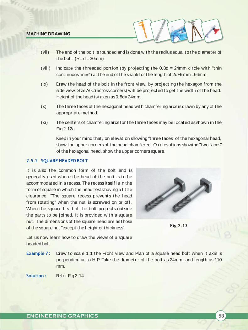
It is also the common form of the bolt and is
generally used where the head of the bolt is to be
accommodated in a recess. The recess itself is in the
form of square in which the head rests having a little
clearance. "The square recess prevents the head
from rotating" when the nut is screwed on or off.
When the square head of the bolt projects outside
the parts to be joined, it is provided with a square
nut. The dimensions of the square head are as those
of the square nut "except the height or thickness"
Let us now learn how to draw the views of a square
headed bolt.
Draw to scale 1:1 the Front view and Plan of a square head bolt when it axis is
perpendicular to H.P. Take the diameter of the bolt as 24mm, and length as 110
mm.
Refer Fig 2.14
2.5.2 SQUARE HEADED BOLT
Example 7 :
Solution :
Fig 2.13

54 ENGINEERING GRAPHICS
MACHINE DRAWING
Steps Involved
(i) Since the circles are seen in the top
view, start with the top view. Draw a
circle of diameter, d= 24 mm.
(ii) Within the'd' circle, draw an another
discontinuous/broken circle of
diameter = 0.8d say 19.2 mm to the
bolt.
(iii) Draw the chamfering circle of
diameter =1.5d+3 mm, say 39 mm.
(iv) Circumscribe square around the
chamfering circle.
(v) Project the Front view from the top
view. Construct a rectangle of size
Ød x length of the bolt, 24x110mm.
The end of the bolt is rounded and is
done with the radius equal to the
diameter of the bolt. (R = d = 24 mm)
Indicate the threaded portion at the
end of the shank for the length of 2d+6
mm = 54 mm.
(vi) Bolt head is drawn by projecting the
front view. Construct a rectangle of
(1.5d+3)x0.8d say 39x19.2 mm.
(vii) Chamfering arc is drawn with radius of
R = 2d = 48 mm.
(viii) All the standard dimensions are given
as shown in the Fig. 2.14
1.5
d+
30.8
dS
HA
NK
LE
NG
TH
R=
d
0.8
d
R=
2d
2d
+6
Fig. 2.14
d
24
0.8d
19.2
1.5d+3
39
2d+6
54
2d
48
Ø d
FRONT VIEW
SQUARE BOLT
TOP VIEW
ENGINEERING GRAPHICS 55
MACHINE DRAWING
2.5.3 T-BOLT
Example 8 :
Solution:
Fig 2.15
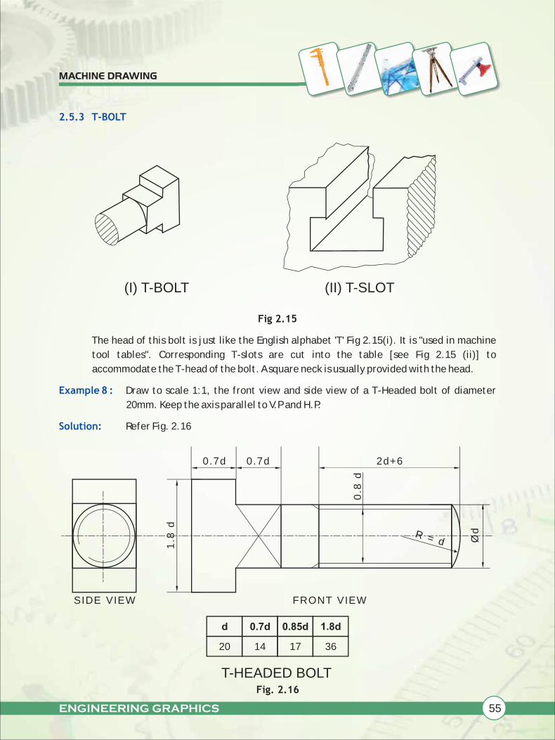
The head of this bolt is just like the English alphabet 'T' Fig 2.15(i). It is "used in machine
tool tables". Corresponding T-slots are cut into the table [see Fig 2.15 (ii)] to
accommodate the T-head of the bolt. A square neck is usually provided with the head.
Draw to scale 1:1, the front view and side view of a T-Headed bolt of diameter
20mm. Keep the axis parallel to V.P and H.P.
Refer Fig. 2.16
Fig. 2.16
(I) T-BOLT (II) T-SLOT
R = d
2d+60.7d0.7d
Ød
0.8
d
S IDE VIEW FRONT VIEW
d
20
0.7d
14
0.85d
17
1.8d
36
1.8
d
T-HEADED BOLT
56 ENGINEERING GRAPHICS
MACHINE DRAWING
Steps Involved
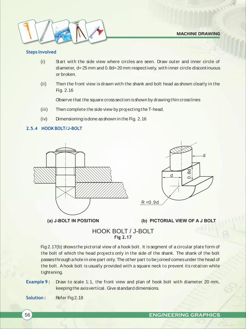
2.5.4 HOOK BOLT/J-BOLT
Example 9 :
Solution :
(i) Start with the side view where circles are seen. Draw outer and inner circle of
diameter, d= 25 mm and 0.8d= 20 mm respectively, with inner circle discontinuous
or broken.
(ii) Then the front view is drawn with the shank and bolt head as shown clearly in the
Fig. 2.16
Observe that the square cross section is shown by drawing thin cross lines
(iii) Then complete the side view by projecting the T-head.
(iv) Dimensioning is done as shown in the Fig. 2.16
Fig 2.17
Fig 2.17(b) shows the pictorial view of a hook bolt. It is segment of a circular plate form of
the bolt of which the head projects only in the side of the shank. The shank of the bolt
passes through a hole in one part only. The other part to be joined comes under the head of
the bolt. A hook bolt is usually provided with a square neck to prevent its rotation while
tightening.
Draw to scale 1:1, the front view and plan of hook bolt with diameter 20 mm,
keeping the axis vertical. Give standard dimensions.
Refer Fig 2.18
d
0.8
d
d
R = 0.9d
(b) PICTORIAL VIEW OF A J BOLT(a) J -BOLT I N POSITION
HOOK BOLT / J-BOLT

ENGINEERING GRAPHICS 57
MACHINE DRAWING
Steps Involved
Exercises
(i) Start with the view having
circles. Here start with the
top view. Draw centre lines
and draw outer and inner
circle of diameter d= 20mm
and 0.8d= 16mm respectively.
To indicate the external
thread of the bolt, 0.8d circle
is drawn broken.
(ii) Complete the shank portion of
the front view as shown
clearly in the Fig. 2.18
(iii) Head portion of the front view
is complete and the square
cross section is shown as thin
cross lines.
(iv) Complete the hook portion of
the top view by projecting the
front view.
(v) Dimensioning is done as
shown in the Fig 2.18
NOTE: Assume missing dimensions proportionately
1. Draw to scale 1:1, the Front view, Top view and side view of a hexagonal head bolt of
diameter 24mm, keeping the axis parallel to H.P and V.P. The two opposite sides of the
hexagonal head is parallel to V.P. The length of the bolt is 120 mm.
2 Draw to scale 1:1, the Front elevation and Side view of a hexagonal headed bolt of
diameter 20mm, keeping the axis parallel to V.P and H.P. Give standard dimensions.
3 Draw to scale 1:1, the Front elevation and Plan of a hexagonal head bolt of M3O size,
keeping the axis vertical. Give standard dimensions.
4 Draw to scale 1:1, the Front view and Side view of a hexagonal headed bolt of diameter
24mm, keeping the axis parallel to V.P and H.P. Two opposite sides of the hexagonal head is
perpendicular to V.P. Take the following dimensions.
Length of the bolt = 120mm
Threaded length of the bolt = 80mm
TOP VIEW
FRONT VIEW
0.7
d2
d+
6Radius = 0.9d
Ød
R =
d
d 20
0.7d 14
0.8d 16
0.9d 18
HOOK BOLT / J-BOLTFig 2.18

58 ENGINEERING GRAPHICS
MACHINE DRAWING
5 Draw to scale full size, the Front view, Top view and Side view of a square head bolt of
diameter 24mm, keeping its axis horizontal.
6 Draw to scale 1:1, the Elevation and Plan of a square head bolt of diameter 30mm, when
its axis is perpendicular to H.P. Give standard dimensions.
7 Draw to scale 1:1, the Front view and Side view of a T-head bolt of diameter 20mm. keep
the axis of the bolt parallel to V.P and H.P.
8 Draw to scale 1:1, the Front elevation and Plan of a tee head bolt of diameter 24mm,
keeping the axis perpendicular to H.P.
9 Draw to scale full size, the Elevation and Plan of a hook bolt with diameter = 20mm,
keeping the axis vertical. Give standard dimensions.
10 Draw to scale 1:1, the Front view, Side view of a hook bolt with diameter 25mm, when its
axis parallel to V.P and H.P. Give standard dimensions.
A nut is a machine element having a threaded hole that engages with the threaded end of the bolt.
There are different types of nuts in use. In our syllabus, we are going to study about hexagonal nut
and square nut.
Refer Fig 2.19
The most commonly used type of nut is the
hexagonal nut. It is a hexagonal prism
provided with a threaded hole. Upper
corners of a nut are "chamfered" or
"rounded- off". Chamfering is done to
remove sharp corners to ensure the safety
of the user. The angle of chamfer is usually
"30° with the base of the nut". The
chamfering gives arcs on the vertical faces
of the nut and circle on the top surface of
the nut. The chamfering circle on the top
surface touches the mid points of all the
side of the nut which can be seen in the
top view.
Let us now learn to draw the views of a hexagonal nut.
2.6 NUTS
2.6.1 HEXAGONAL NUT
Fig 2.19

ENGINEERING GRAPHICS 59
MACHINE DRAWING
Example 10 :
Solution
Steps Involved
Draw to scale 1:1, the front view, top view and side view of a hexagonal nut of size
M30, keeping the axis perpendicular to H.P. Give standard dimensions.
Refer Fig 2.20
Fig 2.20
(i) Start with the top view, where circles are
seen. Draw a circle of diameter d = 30mm.
Describe this circle as discontinuous circle to
indicate the internal thread of a nut.
(ii) Draw an another circle of diameter 0.8d =
24mm
(iii) Draw the third circle which is of chamfering
circle of diameter 1.5d+3 = 48mm.
(iv) Circumscribe a hexagon around the
chamfering circle using the 30°- 60° degree
set square and mini drafter as shown in fig
2.21.Fig 2.21
TOP VIEW
FRONT VIEW
Ød
60°
60°
30°
d1.5
d+
3
0.8d
R =
d
LEFT HAND SIDE VIEW
NOTE : The size of chamfer
circle can be taken 1.5d
or 1.5d+3 in square / hex.
head bolt and nut.
d 30
0.8d 24
1.5d+3 48
30º30º
HEXAGONAL NUT
HEXAGONAL NUT

60 ENGINEERING GRAPHICS
MACHINE DRAWING
(v) Project the top view to get front view. Front view has three faces if nut is placed
across corner (A/C) and front view has two faces if the nut is placed across flats
(A/F). This is the common position for the nut.
(vi) Chamfering arcs in the front view may be done by any suitable method. One of the
methods is clearly shown in figure 2.20.
The alternate method is given below for your reference.
• On the front view, describe arc ABC [fig.2.22] of radius 1.2d = 3mm. It cuts
the verticals in A and C. Here d = 25mm.
• Bisect the chord between D and A and between C and E.
• On the bisectors we shall expect to find the center of the arcs which flow
through DKA and CE.
• Join DK and bisect at right angles, thus locating the center of arc DKA.
Note that arc CE will also have the same radius.
(vii) Side view is projected from front view and top view. Side view and front view have
same height but different width.
(viii) Give the standard dimensions as shown in fig 2.20.
Fig 2.22
SIZE ACROSS CORNERS
K
D A B C E
30°
d
R =
1.2
d
d 25
1.2d 30
1.5d+3 40.5
Ød
HEXAGONAL NUT

ENGINEERING GRAPHICS 61
MACHINE DRAWING
2.6.2 SQUARE NUTS
Example 11:
Solution:
Steps Involved
Fig 2.23
A square nut is also one of the main forms of nuts. It is a square prism provided with a
threaded hole. The upper corners of a square nut are chamfered in the same way as of
hexagonal nut. Now, let us learn to draw the view of a square nut.
Draw to scale 1:1, the Front elevation and Plan of a square nut of diameter 25mm,
keeping its axis vertical and two of the opposite edges of the square face parallel
to V.P.
Refer Fig 2.24
(i) Start with the top view. With same point as center, draw three circles of diameter d
= 25 mm, 0.8d = 20 mm, 1.5d =37.5 mm respectively.
Indicate the internal thread of the nut by drawing Ød circle discontinuous.
(ii) Circumscribe square around the chamfering circle of diameter 1.5d (37.5 mm)
(iii) Project the top view to get the front view. Front view is a rectangle of size
(1.5dxd) 37.5x25 mm.
(v) Chamfering arc in the front view is drawn with the radius R = 2d = 50 mm.
NOTE: that if one face the square nut is seen in the front view, make the corners squared.
(at 90° degree)
(v) Dimensioning is done as shown in Fig. 2.24
SQUARE NUTS

62 ENGINEERING GRAPHICS
MACHINE DRAWING
Fig 2.24
Draw to scale full size the Front View and Top View of a square nut of diameter
25mm, keeping its axis vertical with the diagonal on the square face parallel to V.P.
Example 12 :
Fig 2.25
d
R =
2d
FRONT VIEW1.5
d
TOP VIEW
0.8dØdd 25
0.8d 20
1.5d 37.5
d
37.5
0.8d
20
1.5d
25
FRONT VIEW
1.5 d
TOP VIEW
0.8d
Ød
60°60°
30°
d
SQUARE NUT ACROSS FLAT
SQUARE NUT ACROSS CORNER

ENGINEERING GRAPHICS 63
MACHINE DRAWING
Solution :
Steps Involved :
Exercises :
Refer Fig. 2.25
(i) Start with the top view. Describe three circles of diameter d = 25mm, 0.8d =
20mm, 1.5d = 37.5mm respectively. (Ød circle is broken to represent the internal
thread of the nut.)
(ii) Circumscribe square around the chamfering circle as shown in Fig 2.25
(iii) Project the Top View to draw the Front View
(iv) Complete the Front View as shown in Fig. 2.25.
NOTE: that when two faces of square nut are seen in front view, the corners are
chamfered.
ADDITIONAL INFORMATION
The hexagonal nut takes preference over the other nuts. A spanner is used to turn
the nut on or off the bolt. The jaws of the spanner come across the opposite flats of
the nut. The angle through which the spanner will have to be turned to get another
hold is only 60 in case of a hexagonal nut but 90° for a square nut. Though the angle
is 45 in case of the octagonal nut, it is rarely used due to its complicated process of
construction. So, it is more convenient to screw on a hexagonal nut than a square
nut in a limited space for turning the spanner.
NOTE : Assume missing dimensions proportionately
1. Draw to scale 1:1, the front elevation and plan of a hexagonal nut keeping axis
vertical, when two of the opposite sides of the hexagon are parallel to V.P. Give
standard dimensions.
2. Draw to scale 1:1, the Plan and Front View of a hexagonal nut, taking nominal
diameter of the bolt = 30mm, keeping the axis perpendicular to H.P and two
opposite sides of the hexagon perpendicular to V.P. Give standard dimensions.
3. Draw to scale 1:1, the Front View and Plan of square nut, taking nominal diameter
= 30mm, keeping the axis perpendicular to H.P and two opposite sides of the
square parallel to V.P. Give standard dimensions.
4. Draw to scale 1:1, the Front View and Top View of a square nut, taking nominal
diameter =30mm, keeping the axis perpendicular to H.P and two opposite sides of
the square perpendicular to V.P. Give standard dimensions.
64 ENGINEERING GRAPHICS
MACHINE DRAWING
5. Draw to scale 1:1, the front view and plan of a square nut, taking d = 30mm,
keeping the axis perpendicular to H.P and the diagonal of the square face parallel
to V.P. Give standard dimensions.
You must have seen the circular plate called washer fitted in your mini drafter. Even, in jewellery
item like ear tops/studs, washer may be used to tighten the screw. There are two main kinds of
washer used in machinery, namely
(i) Plain washer.
(ii) Spring washer.
We are going to study only about the plain washer in our syllabus.
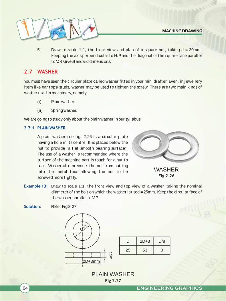
A plain washer see fig. 2.26 is a circular plate
having a hole in its centre. It is placed below the
nut to provide "a flat smooth bearing surface".
The use of a washer is recommended where the
surface of the machine part is rough for a nut to
seat. Washer also prevents the nut from cutting
into the metal thus allowing the nut to be
screwed more tightly.
Draw to scale 1:1, the front view and top view of a washer, taking the nominal
diameter of the bolt on which the washer is used = 25mm. Keep the circular face of
the washer parallel to V.P
Refer Fig 2.27
2.7 WASHER
2.7.1 PLAIN WASHER
Example 13:
Solution:
Fig 2.26
Fig 2.27
D+1
D8
2D+3mm
D
3
2D+3
53
D/8
25
PLAIN WASHER
WASHER

ENGINEERING GRAPHICS 65
MACHINE DRAWING
Steps Involved
Example 14:
Solution:
(i) Start with the Front View, which comprises two circles with diameter D+1 = 26mm,
2D+3 = 53mm.
(ii) Project the front view to get the Top View which is a rectangle of size,[(2D+3) x
D/8], 53x3 mm. Complete the Top View as shown in the Fig 2.27
In common machineries used at home, we might have observed the assembly of bolt, nut and
washer to connect two parts together. See Fig 2.28
Fig 2.28
In the earlier topics, we learnt how to draw the views of bolt, nut and washer separately. Here,
we expect to understand the views of the assembly of bolt, nut and washer.
Draw to scale 1:1, the Front View, Top View and side view of a hexagonal headed
bolt of diameter 25mm with hexagonal nut and washer, keeping the axis parallel to
V.P and H.P
Refer Fig 2.29
2.8 COMBINATION OF BOLT, NUT AND WASHER FOR ASSEMBLING TWO
PARTS TOGETHER
Bolt
Nut
Washer
NUT, BOLT AND WASHER

66 ENGINEERING GRAPHICS
MACHINE DRAWING
Fig 2.29
(i) Since the axis is parallel to both V.P and H.P, the side view reveals more
information about the shape of the object. So start with side view, where circles
are seen.
(ii) Draw two circles of diameter d = 25mm and 0.8d = 20mm, in dotted lines to
indicate the invisible feature from left side.
(iii) Draw the chamfering circle of diameter, 1.5d + 3mm =40.5mm
(iv) Circumscribe hexagon around the chamfering circle, using set-square and
minidrafter.
(v) Then draw a circle of diameter 2d + 3mm = 53mm for washer.
(vi) Project the side view to front view and top-view.
(vii) Both the views are completed as shown in the Fig 2.29
Steps Involed:
TOP VIEW
W
FRONT VIEW
W
WASHERBOLT UPTO 2d+6
NUT
0.8d
R = d
SIDE VIEW
Ø2
d
Ød
Ø2
d+
3
d
COMBINATION OF HEXAGONAL HEADED BOLT WITH HEXAGONAL NUT & WASHER
30°
ENGINEERING GRAPHICS 67
MACHINE DRAWING
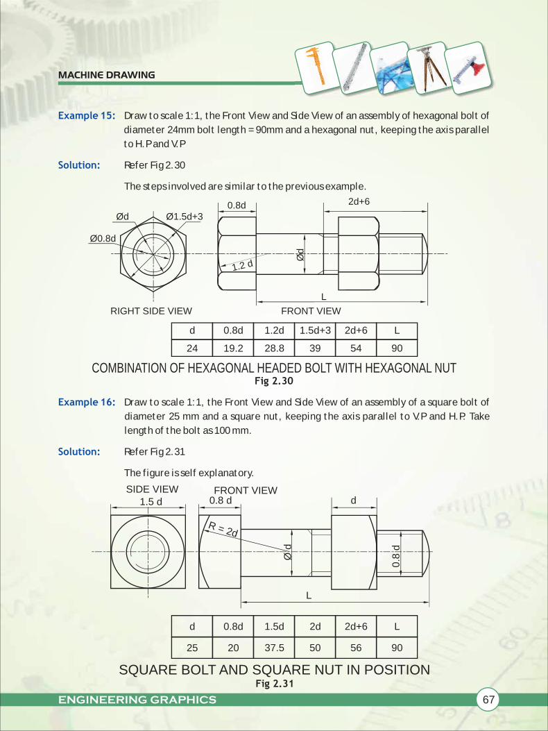
Example 15:
Solution:
Example 16:
Solution:
Draw to scale 1:1, the Front View and Side View of an assembly of hexagonal bolt of
diameter 24mm bolt length = 90mm and a hexagonal nut, keeping the axis parallel
to H.P and V.P
Refer Fig 2.30
The steps involved are similar to the previous example.
Fig 2.30
Draw to scale 1:1, the Front View and Side View of an assembly of a square bolt of
diameter 25 mm and a square nut, keeping the axis parallel to V.P and H.P. Take
length of the bolt as 100 mm.
Refer Fig 2.31
The figure is self explanatory.
1.2 d
RIGHT SIDE VIEW FRONT VIEW
2d+60.8d
L
d
28.8 39 54
0.8d
19.2
1.2d 1.5d+3 2d+6
24
SIDE VIEW FRONT VIEW1.5 d 0.8 d
R = 2d
Ø d
d
L
Fig 2.31
d
37.5 50 56
0.8d
20
1.5d 2d 2d+6
25
Ø1.5d+3Ød
Ø0.8d
0.8
d
COMBINATION OF HEXAGONAL HEADED BOLT WITH HEXAGONAL NUT
SQUARE BOLT AND SQUARE NUT IN POSITION
Ød
90
L
90
L
68 ENGINEERING GRAPHICS
MACHINE DRAWING
Exercises:
NOTE: Assume missing dimensions proportionately
1. Draw to scale 1:1, the front view, top view and side view of an assembly of
hexagonal headed bolt of 30mm diameter with hexagonal nut and washer, keeping
the axis parallel to V.P and H.P. Give standard dimensions.
2. Draw to scale 1:1, the front view and side view of an assembly of a hexagonal bolt
of diameter 30mm and a hexagonal nut, keeping the axis parallel to V.P and H.P.
3. Draw to scale 1:1, the front view and side view of a square headed bolt of size M24,
fitted with a square nut, keeping their common axis parallel to V.P and H.P.
4. Draw to scale 1:1, the front view and side view of the assembly of square headed
bolt with a hexagonal nut and a washer, with the diameter of bolt as 30mm,
keeping their axis parallel to V.P and H.P and two of the opposite sides of the
square head of the bolt and of the hexagonal nut, parallel to V.P.
We are familiar with riveted joints with our kitchen wares likes pressure cooker and frying pan. In
pressure cooker, the handle is joined to the body by means of rivets. We can even notice the rivets
fitted, in shoes belts etc.
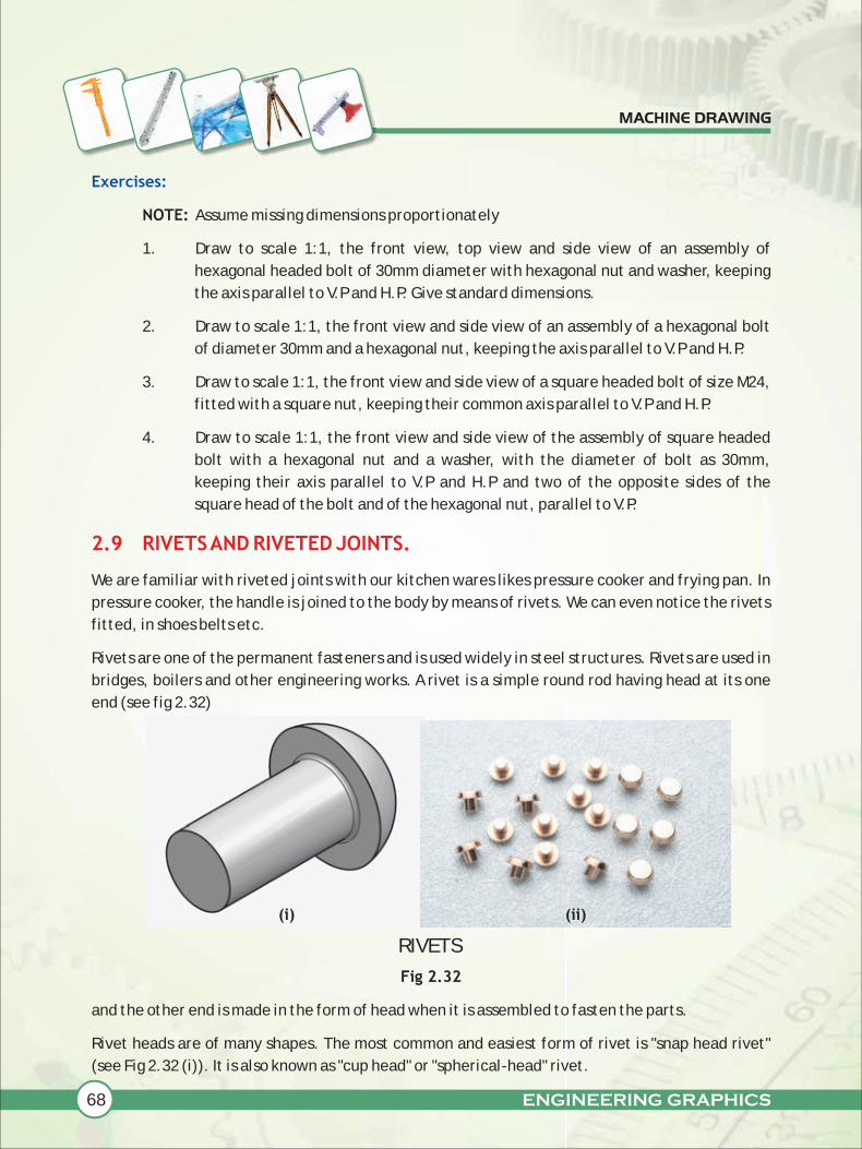
Rivets are one of the permanent fasteners and is used widely in steel structures. Rivets are used in
bridges, boilers and other engineering works. A rivet is a simple round rod having head at its one
end (see fig 2.32)
Fig 2.32
and the other end is made in the form of head when it is assembled to fasten the parts.
Rivet heads are of many shapes. The most common and easiest form of rivet is "snap head rivet"
(see Fig 2.32 (i)). It is also known as "cup head" or "spherical-head" rivet.
2.9 RIVETS AND RIVETED JOINTS.
(i) (ii)
RIVETS
ENGINEERING GRAPHICS 69
MACHINE DRAWING
Riveted joints are of two types namely
(i) Lap joint
(ii) Butt joint
Lap joints may be single, double and multiple riveted. In class XII, we are going to study the views
of "single" riveted lap joint.
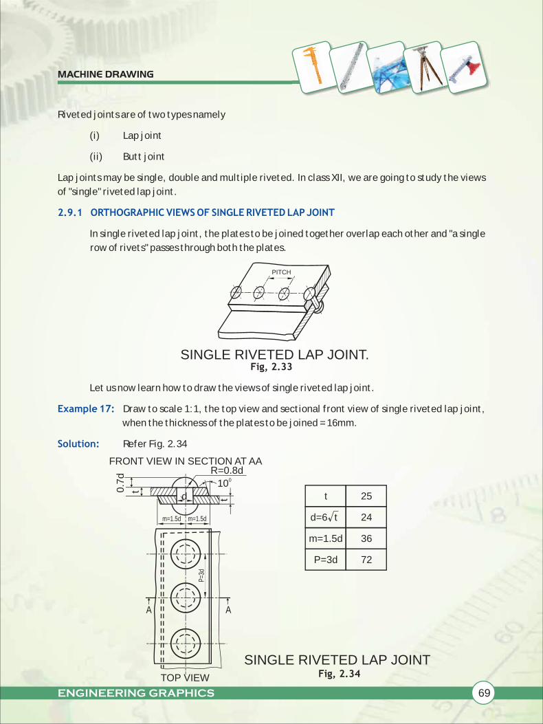
In single riveted lap joint, the plates to be joined together overlap each other and "a single
row of rivets" passes through both the plates.
Fig, 2.33
Let us now learn how to draw the views of single riveted lap joint.
Draw to scale 1:1, the top view and sectional front view of single riveted lap joint,
when the thickness of the plates to be joined = 16mm.
Refer Fig. 2.34
2.9.1 ORTHOGRAPHIC VIEWS OF SINGLE RIVETED LAP JOINT
Example 17:
Solution:
Fig, 2.34
m=1.5d
010
FRONT VIEW IN SECTION AT AA
TOP VIEW
AA
d t 25
d=6 t√ 24
m=1.5d
P=3d
36
72
PITCH
R=0.8d
0.7
d
t
t
m=1.5d
P=3
d
SINGLE RIVETED LAP JOINT.
SINGLE RIVETED LAP JOINT
70 ENGINEERING GRAPHICS
MACHINE DRAWING
Steps Involved:
Exercises
Before starting the view, the standard dimensions are to be calculated as follows.
Let't' be the thickness of the plates to be be joined. Here t =16mm
The empirical formula for calculating the diameter'd' of the rivet to be used is given as
d = 6√t mm
So, d = √16
= 6x4 mm
d = 24 mm is the diameter of the rivet to be used in this case.
The margin 'm' is "the distance from the centre of the rivet to the nearest edge of the
plate", and is taken as m = 1.5d
= 1.5x24
= 36 mm
The pitch 'p' is the distance between the centres of the adjacent rivets, and is taken as
P = 3d
= 3x24
= 72mm
The angle 10 degree is made by the fullering tool (a special punch or chisel) to make the
joint leak proof. (The process of fullering is beyond the scope of this book.)
Then the top view and the sectional front view are to be done as shown clearly in fig 2.34.
The edges of the plates in the top view are shown in wavy lines to represent that "a part of
plates" are shown.
NOTE: Assume the missing dimensions proportionately
1. Draw to scale full size, the full sectional front view of a single riveted lap joint,
taking thickness of the plates as 09mm. Give standard dimensions.
2. Draw to scale 1:1, the front view in section and plan of a single riveted lap joint,
taking the thickness of the plates as 25mm. Give standard dimensions.

ENGINEERING GRAPHICS 71
MACHINE DRAWING
2.10 INTRODUCTION
2.11 CONVENTIONAL REPRESENTATION OF THREADS
FREE HAND SKETCHES OF MACHINE PARTS
2.11.1CONVENTIONAL REPRESENTATION OF EXTERNAL V-THREADS
In freehand sketches of machine parts, the students must do the drawing without the use
of scale, instrument etc., Appropriate measurement is taken and correspondingly a table
for each figure must be made showing calculated values. The figure must show the
dimensions in terms of diameter 'd'.
In actual projection, the edges of threads would be represented by helical curves. It takes a lot of
time to draw helical curves. So, for convenience sake threads are generally shown by
conventional methods recommended by B.I.S
The Bureau of Indian standards has recommended a very simple method of representing V-
threads. Fig 2.35 shows the simplified representation of external V-threads. According to
this convention, two continuous thick lines and two continuous thin lines are drawn to
represent crest and roots of the thread respectively. The limit of useful length of the
thread is indicated by a thick line perpendicular to the axis.
Fig 2.35
The other way of representing external V-thread is as follows.
(i) Draw a rectangle (see fig 2.36) representing a cylinder with diameter equal to the
nominal diameter of the bolt.
(ii) Draw a line AB perpendicular to the bolt.
(iii) Make a point B' such that BB' = 0.5xpitch. BB is called as slope = 0.5P for a single
start thread. B' is located on the lower line for a right hand thread (RH thread)
Fig 2.36RIGHT HAND V-THREAD
A
B B'
SLOPE = 0.5 P
P
CONVENTIONAL REPRESENTATION OF EXTERNAL V-THREADS
72 ENGINEERING GRAPHICS
MACHINE DRAWING
(iv) Fig 2.36 is the representation of RH thread. In the case of RH thread, for a
clockwise rotation, the thread is screwed on.
(v) Draw two thin lines parallel to the axis representing the roots of the thread.
(vi) On the thick line, mark the divisions equal to pitch. On the thin line, mark the
divisions = (p/2) such that they form the shape of 'V'
(vii) Join root to root points with thick lines and crest to crest points with thin lines
(viii) The side view has two circles representing the crest and root of the thread. Crest
circle is thick and continuous, whereas root circle is drawn thin and incomplete to
represent the external thread.
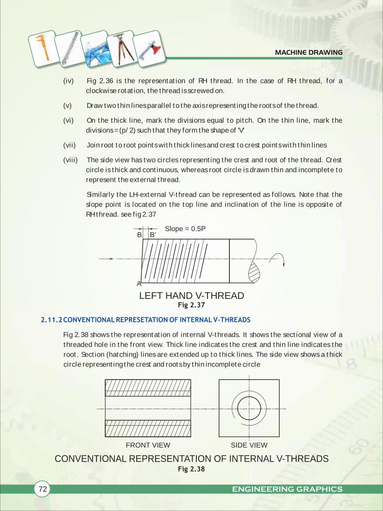
Similarly the LH-external V-thread can be represented as follows. Note that the
slope point is located on the top line and inclination of the line is opposite of
RH thread. see fig 2.37
Fig 2.37
Fig 2.38 shows the representation of internal V-threads. It shows the sectional view of a
threaded hole in the front view. Thick line indicates the crest and thin line indicates the
root. Section (hatching) lines are extended up to thick lines. The side view shows a thick
circle representing the crest and roots by thin incomplete circle
Fig 2.38
2.11.2CONVENTIONAL REPRESETATION OF INTERNAL V-THREADS
FRONT VIEW SIDE VIEW
A
B B'Slope = 0.5P
LEFT HAND V-THREAD
CONVENTIONAL REPRESENTATION OF INTERNAL V-THREADS

ENGINEERING GRAPHICS 73
MACHINE DRAWING
2.11.3CONVENTIONAL REPRESENTATION OF EXTERNAL SQUARE THREADS
2.11.4CONVENTIONAL REPRESENTATION OF INTERNAL SQUARE THREADS
Fig 2.39(i) shows the conventional representation of external RH square threads. The
figure is self explanatory. Fig 2.39(ii) shows the LH square threads.
Fig 2.40(i) shows the representation of RH internal square threads and fig 2.40(ii) shown
LH internal square thread.
P
RIGHT HAND SQUARE THREAD
P
Slope = 0.5 P
Fig 2.39(i)
Fig 2.39(ii)
Fig 2.40 (i)
LEFT HAND THREAD (INTERNAL)
Fig 2.40 (ii)
RIGHT HAND THREAD (INTERNAL)
LEFT HAND SQUARE THREAD
74 ENGINEERING GRAPHICS
MACHINE DRAWING
Exercises
Note: Take p = 5mm and other dimensions suitably
1. Sketch freehand the conventional representation of internal and external 'V'
threads.
2. Sketch freehand the single start conventional LH external square threads.
3. Sketch freehand the single start conventional RH external square threads.
4. Sketch freehand the conventional representation of internal and external square
threads.
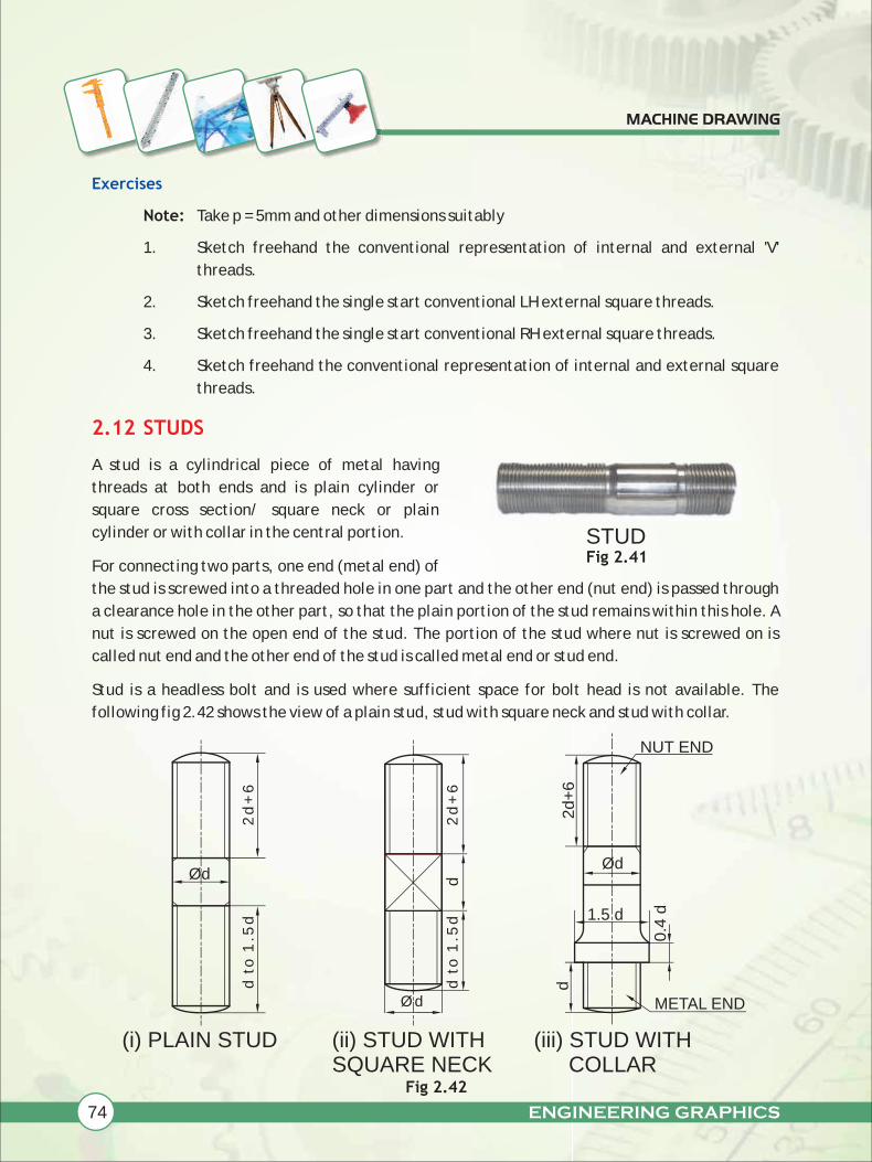
A stud is a cylindrical piece of metal having
threads at both ends and is plain cylinder or
square cross section/ square neck or plain
cylinder or with collar in the central portion.
For connecting two parts, one end (metal end) of
the stud is screwed into a threaded hole in one part and the other end (nut end) is passed through
a clearance hole in the other part, so that the plain portion of the stud remains within this hole. A
nut is screwed on the open end of the stud. The portion of the stud where nut is screwed on is
called nut end and the other end of the stud is called metal end or stud end.
Stud is a headless bolt and is used where sufficient space for bolt head is not available. The
following fig 2.42 shows the view of a plain stud, stud with square neck and stud with collar.
2.12 STUDS
ØdØd
(i) PLAIN STUD
Ø d
(ii) STUD WITH SQUARE NECK
2d
+6
1.5 d
0.4
d
d
(iii) STUD WITH COLLAR
Fig 2.41
NUT END
METAL END
STUD
d
Fig 2.42
d t
o 1
.5d
2d
+6
d t
o 1
.5d
2d
+6

ENGINEERING GRAPHICS 75
MACHINE DRAWING
Example 18:
Solution:
Steps Involved:
Example 19:
Solution
Sketch freehand the Front view and
Top view of a Plain stud of diameter =
20mm, keeping its axis vertical.
Fefer Fig 2.43
(i) Calculate the values of standard
dimensions.
(ii) Draw free hand two circles of
diameters d =20mm and 0.85d = 17
mm as top view.
(iii) Draw a rectangle for the front view
with approximate measurements.
(iv) The metal end is chamfered and the
nut end is either chamfered or
rounded.
(v) Dimension the views in term of 'd'.
Sketch free hand the Front view and Side view of a collar stud with diameter 20
mm, when its axis is parallel to V.P and H.P. Give standard dimensions.
NU
T E
ND
SID
E
2d
+6
AN
Y
ME
TA
L
EN
D S
IDE
d t
o 1
.5 d
0.85 d
Ø d
FRONT VIEW
d 20
0.85d 17
1.5d 30
2d+6 46
TOP VIEW
PLAIN STUDFig 2.43
COLLAR STUD Fig 2.44
d
20
1.5d
30
2d+6
46
0.4d
08
FRONT VIEW
2d+6
0.4d
SIDE VIEW
Ø d
Ø 1
.5 d
R=d
76 ENGINEERING GRAPHICS
MACHINE DRAWING
Exercises:
NOTE: Assume missing dimensions proportionately
1. Sketch freehand the Front view and Top view of a Plain stud of diameter = 25mm,
keeping its axis perpendicular to H.P. Give standard dimensions.
2. Sketch freehand the Front elevation and Side view of a Plain stud of diameter d =
25mm, with its axis parallel to V.P and H.P.Give standard dimensions.
3. Sketch freehand the Front view and Top view of a stud with a square neck, keeping
the axis perpendicular to H.P. Give standard dimensions.
4. Sketch freehand the Front elevation and Side view of a stud with a square neck,
keeping the axis parallel to V.P.Give standard dimensions.
5. Sketch freehand, the Front view and Plan of a stud with collar, keeping the axis
vertical. Give standard dimensions.
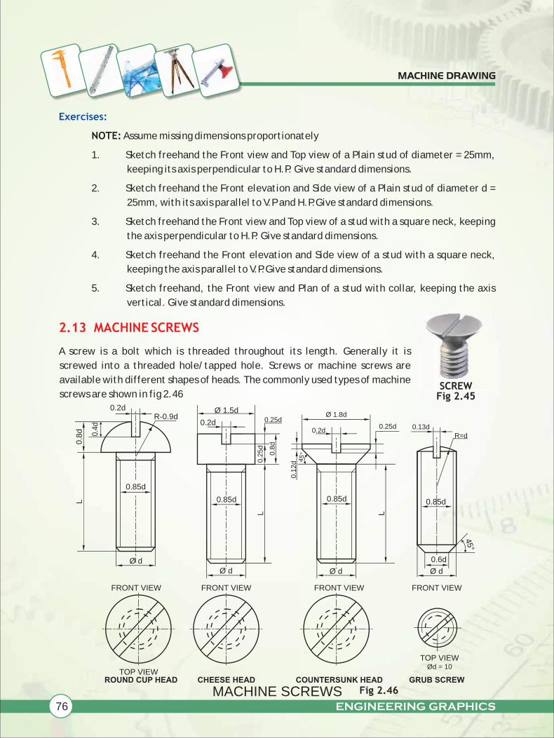
A screw is a bolt which is threaded throughout its length. Generally it is
screwed into a threaded hole/tapped hole. Screws or machine screws are
available with different shapes of heads. The commonly used types of machine
screws are shown in fig 2.46
2.13 MACHINE SCREWS
TOP VIEW
FRONT VIEW FRONT VIEW
TOP VIEW
ROUND CUP HEAD COUNTERSUNK HEAD GRUB SCREWCHEESE HEAD
0.85d
FRONT VIEW
0.8
d 0.4d
0.2dR-0.9d
0.85d
0.2d
Ø 1.5d
0.8
d
0.2
5d
0.25d
0.2d
Ø 1.8d
0.1
2d
0.85d
0.6d
FRONT VIEW
0.25d 0.13d
R=d
45°
45°
Fig 2.45
L
L L
0.85d
SCREW
Ød = 10
MACHINE SCREWS Fig 2.46
Ø dØ d Ø d Ø d

ENGINEERING GRAPHICS 77
MACHINE DRAWING
Example 20:
Solution:
Sketch freehand the front view and top view of a cheese head screw of size M2O,
keeping its axis vertical. Give standard dimensions.
Refer Fig 2.47
SOCKET HEAD SCREW
Fig 2.46
0.8
d
LEFT SIDE VIEW
L
0.8
5d
Ø d
d
FRONT VIEW
0.5d
0.12d
Ø 1
.5 d
Fig 2.47
FRONT VIEW
1.5d
0.2d
0.8
d
0.2
5d
0.85d
Ø d
TOP VIEW
d 20
0.2d
0.85d
04
17
0.25d
0.8d
05
16
1.5d 30

78 ENGINEERING GRAPHICS
MACHINE DRAWING
Example 21:
Solution:
Example 22:
Sketch freehand the front view and top view of a 90° flat counter sunk machine
screw of size M2O, keeping its axis vertical. Give standard dimensions.
Refer Fig 2.48
Fig 2.48
Sketch freehand the front view and top view of a socket head machine screw of
size M10, keeping its axis perpendicular to H.P. Give standard dimensions.
d 20
0.2d 4
0.25d 5
d/8 2.5
0.85d 17
1.8d 36
d 10
0.8d 8
0.85d 8.5
1.5d 15
0.12d 1.2
0.5d 5
SOCKET HEAD
MACHINE SCREWFig 2.49
TOP VIEW
0.85d
1.8d
45°
0.2
5d
0.2d
Ø d
FRONT VIEW
90° FLAT CSK SCREW
0.85d
Ø d
0.8d
TOP VIEW
0.85d
FRONT VIEW
0.1
2d
0.5
d
ENGINEERING GRAPHICS 79
MACHINE DRAWING
Exercises
NOTE: Assume missing dimensions proportionately
1. Sketch freehand the Front view and Side view of a round head screw of size M10,
keeping its axis horizontal. Give standard dimensions.
2. Sketch freehand the Front view and Top view of cheese head machine screw of size
M10, keeping its axis vertical. Give standard dimensions.
3. Sketch freehand the Front view and Top view of a 90 degree flat counter sunk
machine screw of size M10, keeping its axis vertical. Give standard dimensions.
4. Sketch freehand the Front view and Side view of a hexagonal socket head machine
screw of size M2O, keeping its axis parallel to V.P and H.P. Give standard
dimensions.
5. Sketch freehand the Front view and Top view of a grub screw of size M10, keeping
its axis vertical. Give standard dimensions.
6. Sketch freehand the Front view and Top view of a grub screw of size M2O, keeping
its axis vertical. Give standard dimensions.
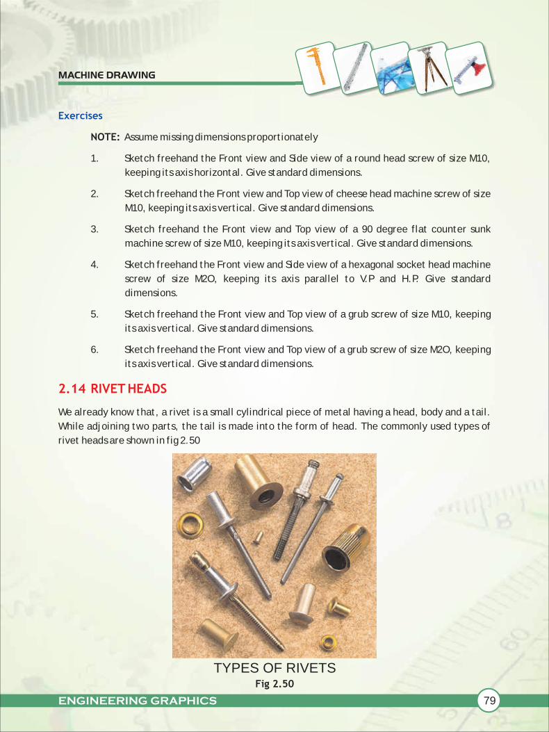
We already know that, a rivet is a small cylindrical piece of metal having a head, body and a tail.
While adjoining two parts, the tail is made into the form of head. The commonly used types of
rivet heads are shown in fig 2.50
2.14 RIVET HEADS
TYPES OF RIVETSFig 2.50
80 ENGINEERING GRAPHICS
MACHINE DRAWING
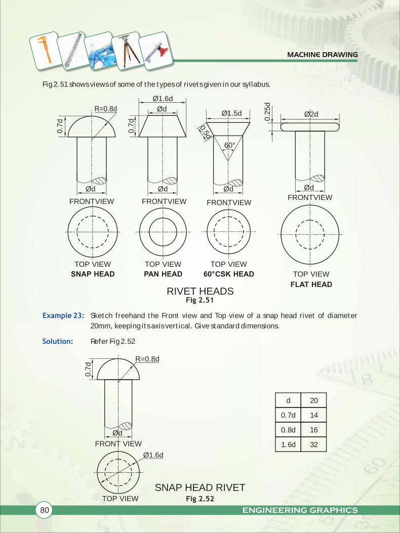
Fig 2.51 shows views of some of the types of rivets given in our syllabus.
Fig 2.51
Sketch freehand the Front view and Top view of a snap head rivet of diameter
20mm, keeping its axis vertical. Give standard dimensions.
Refer Fig 2.52
Example 23:
Solution:
0.7
d
0.7
d
R=0.8d
Ød
FRONT VIEW
TOP VIEWTOP VIEW
SNAP HEAD PAN HEAD 60° CSK HEAD
FLAT HEAD
FRONT VIEW
Ød
Ød
Ø1.6d
0.5d
FRONT VIEW
Ød
Ø1.5d
0.2
5d
Ø2d
60°
FRONT VIEW
Ød
TOP VIEW
TOP VIEW
Ød
Ø1.6d
TOP VIEW
0.7
d
FRONT VIEW
R=0.8d
d 20
0.7d 14
0.8d
1.6d 32
16
SNAP HEAD RIVETFig 2.52
RIVET HEADS
ENGINEERING GRAPHICS 81
MACHINE DRAWING
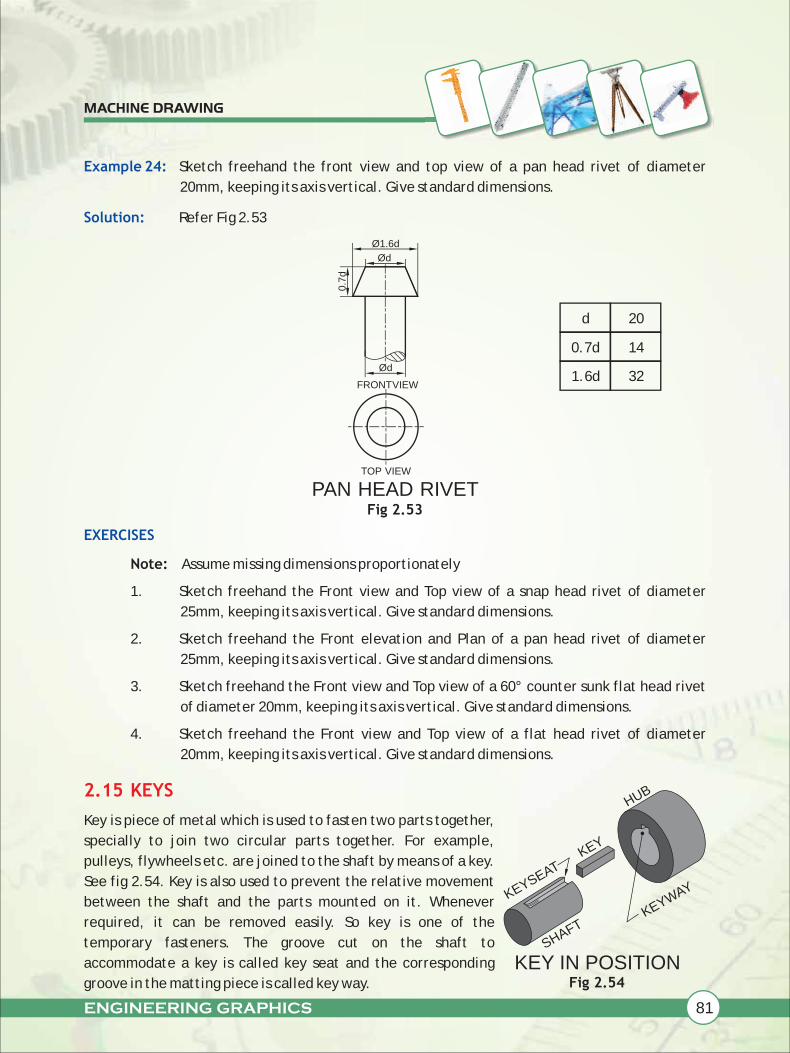
Example 24:
Solution:
EXERCISES
Sketch freehand the front view and top view of a pan head rivet of diameter
20mm, keeping its axis vertical. Give standard dimensions.
Refer Fig 2.53
Fig 2.53
Note: Assume missing dimensions proportionately
1. Sketch freehand the Front view and Top view of a snap head rivet of diameter
25mm, keeping its axis vertical. Give standard dimensions.
2. Sketch freehand the Front elevation and Plan of a pan head rivet of diameter
25mm, keeping its axis vertical. Give standard dimensions.
3. Sketch freehand the Front view and Top view of a 60° counter sunk flat head rivet
of diameter 20mm, keeping its axis vertical. Give standard dimensions.
4. Sketch freehand the Front view and Top view of a flat head rivet of diameter
20mm, keeping its axis vertical. Give standard dimensions.
Key is piece of metal which is used to fasten two parts together,
specially to join two circular parts together. For example,
pulleys, flywheels etc. are joined to the shaft by means of a key.
See fig 2.54. Key is also used to prevent the relative movement
between the shaft and the parts mounted on it. Whenever
required, it can be removed easily. So key is one of the
temporary fasteners. The groove cut on the shaft to
accommodate a key is called key seat and the corresponding
groove in the matting piece is called key way.
2.15 KEYS
Fig 2.54
PAN HEAD RIVET
KEY IN POSITION
0.7
d
TOP VIEW
FRONT VIEW
Ød
Ød
Ø1.6d
d 20
0.7d 14
1.6d 32
KEYSEAT KEY
KEYWAY
SHAFT
HUB

82 ENGINEERING GRAPHICS
MACHINE DRAWING
2.15.1 TYPES OF SUNK KEYS
2.15.1.1 RECTANGULAR TAPER KEY
A sunk key is designated by its width x thickness x
length. (w x T x L) see fig 2.55
Sunk keys means, half of the thickness (0.5T)
(measured at the side not on centre line) k within the
key seat and the other half thickness (0.5T) is within
the keyway (see fig 2.57). There are different types
of sunk keys viz.
(i) rectangular taper key
(ii) woodruff key
(iii) double head feather key
Let us now learn how to draw the views of these sunk keys.
Rectangular sunk taper key is of rectangular cross section, with the thickness not uniform
throughout the length of the key. See fig 2.56
Fig 2.56
Drawing proportions for a rectangular taper key are as follows.
Let 'D' be the diameter of the shaft, then width of the key, W=D/4
Thickness of the key, T=D/6
Length=1.5D to 2D, Taper = 1 in 100
The taper key prevent relative rotational as well as axial movement between the two
mating piece. Generally, the upper surface of the key is tapered and hence the keyway is
also correspondingly tapered. The tapered end is hammered to remove the key from the
joint.
W L
T
Fig 2.55
TAPER 1 IN 100
FRONT VIEW
TW(i) RECTANGULAR TAPER KEY
L
TOP VIEW
VIEWS OF A RECTANGULAR TAPER KEY
SIDE VIEW
W L
T
RECTANGULAR SUNK KEY
ENGINEERING GRAPHICS 83
MACHINE DRAWING
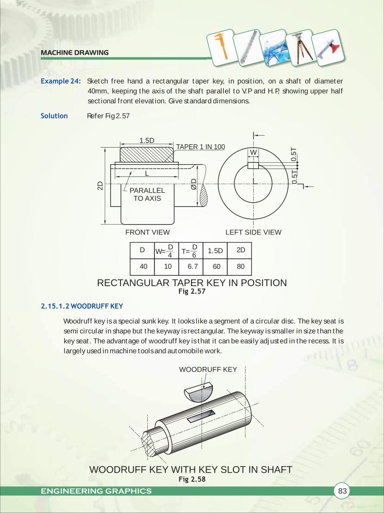
Example 24:
Solution
2.15.1.2 WOODRUFF KEY
Sketch free hand a rectangular taper key, in position, on a shaft of diameter
40mm, keeping the axis of the shaft parallel to V.P and H.P, showing upper half
sectional front elevation. Give standard dimensions.
Refer Fig 2.57
Fig 2.57
Woodruff key is a special sunk key. It looks like a segment of a circular disc. The key seat is
semi circular in shape but the keyway is rectangular. The keyway is smaller in size than the
key seat. The advantage of woodruff key is that it can be easily adjusted in the recess. It is
largely used in machine tools and automobile work.
40
D
10 6.7 60
1.5D 2D
80
W=D4
T=D6
1.5DTAPER 1 IN 100
2D
PARALLELTO AXIS
ØD
L
FRONT VIEW
0.5
TW
LEFT SIDE VIEW
WOODRUFF KEY
Fig 2.58
0.5
T
RECTANGULAR TAPER KEY IN POSITION
WOODRUFF KEY WITH KEY SLOT IN SHAFT
84 ENGINEERING GRAPHICS
MACHINE DRAWING
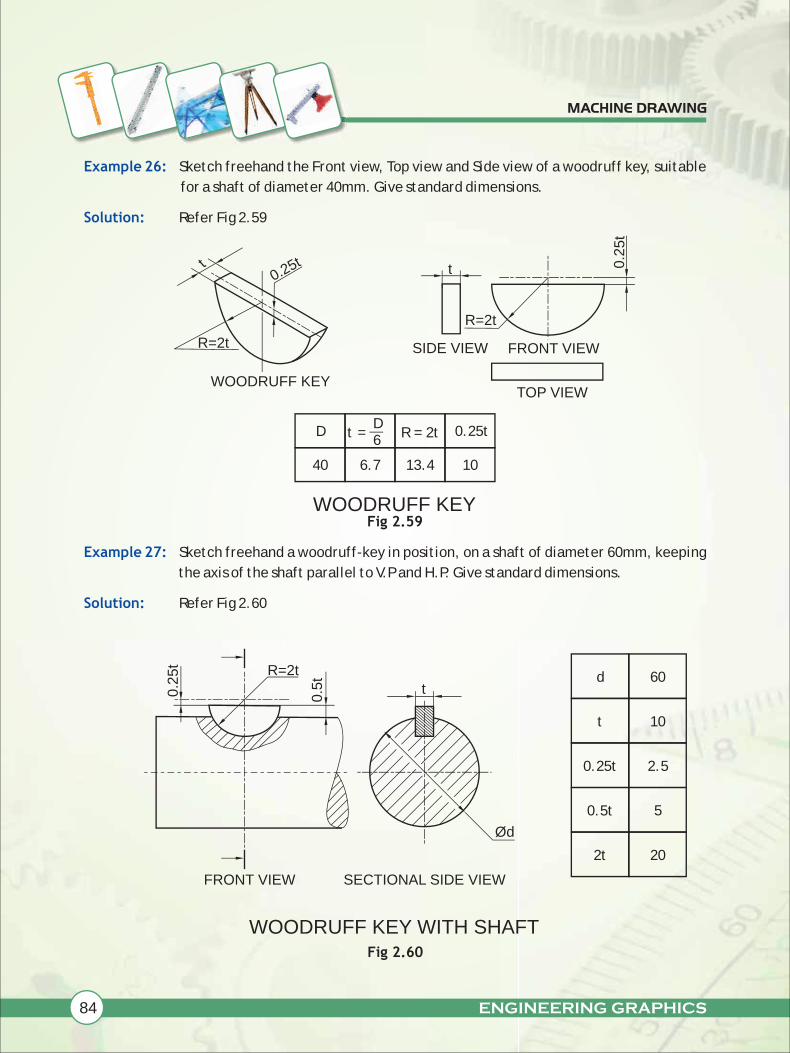
Example 26:
Solution:
Example 27:
Solution:
Sketch freehand the Front view, Top view and Side view of a woodruff key, suitable
for a shaft of diameter 40mm. Give standard dimensions.
Refer Fig 2.59
Fig 2.59
Sketch freehand a woodruff-key in position, on a shaft of diameter 60mm, keeping
the axis of the shaft parallel to V.P and H.P. Give standard dimensions.
Refer Fig 2.60
0.25tt t
R=2t
TOP VIEW
FRONT VIEWR=2t
WOODRUFF KEY
SIDE VIEW
40
D
6.7 13.4 10
0.25tt =D6
R = 2t
Ød
R=2t
SECTIONAL SIDE VIEWFRONT VIEW
WOODRUFF KEY WITH SHAFT
0.2
5t
0.5
t
td 60
10t
0.25t
0.5t
2t 20
5
2.5
Fig 2.60
WOODRUFF KEY
0.2
5t
ENGINEERING GRAPHICS 85
MACHINE DRAWING
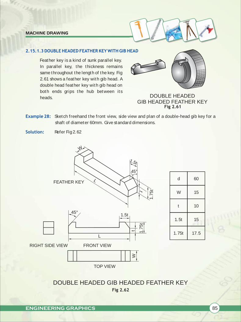
2.15.1.3 DOUBLE HEADED FEATHER KEY WITH GIB HEAD
Example 28:
Solution:
Feather key is a kind of sunk parallel key.
In parallel key, the thickness remains
same throughout the length of the key. Fig
2.61 shows a feather key with gib head. A
double head feather key with gib head on
both ends grips the hub between its
heads.
Sketch freehand the front view, side view and plan of a double-head gib key for a
shaft of diameter 60mm. Give standard dimensions.
Refer Fig 2.62
Fig 2.61
FEATHER KEY
W
L
1.5t
1.7
5tt
45°
W
TOP VIEW
RIGHT SIDE VIEW FRONT VIEW
45°
L
1.7
5t
d 60
15
10
W
t
1.5t
1.75t 17.5
15
Fig 2.62
t
1.5t
DOUBLE HEADED GIB HEADED FEATHER KEY
DOUBLE HEADED GIB HEADED FEATHER KEY
86 ENGINEERING GRAPHICS
MACHINE DRAWING
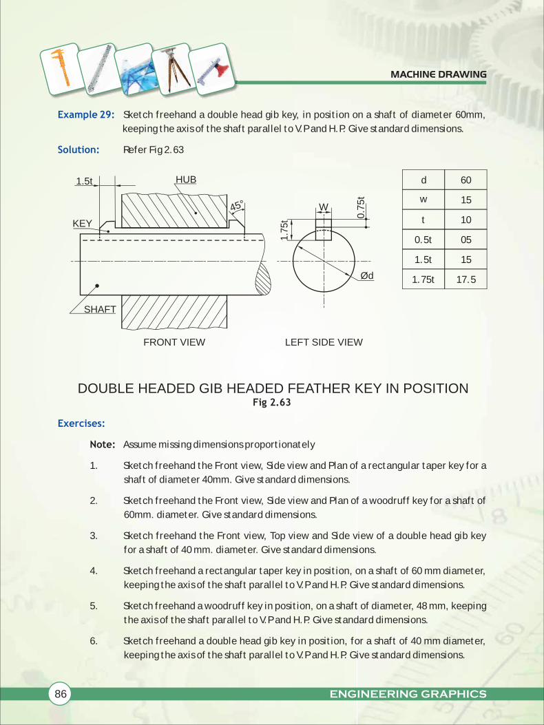
Example 29:
Solution:
Exercises:
Sketch freehand a double head gib key, in position on a shaft of diameter 60mm,
keeping the axis of the shaft parallel to V.P and H.P. Give standard dimensions.
Refer Fig 2.63
Fig 2.63
Note: Assume missing dimensions proportionately
1. Sketch freehand the Front view, Side view and Plan of a rectangular taper key for a
shaft of diameter 40mm. Give standard dimensions.
2. Sketch freehand the Front view, Side view and Plan of a woodruff key for a shaft of
60mm. diameter. Give standard dimensions.
3. Sketch freehand the Front view, Top view and Side view of a double head gib key
for a shaft of 40 mm. diameter. Give standard dimensions.
4. Sketch freehand a rectangular taper key in position, on a shaft of 60 mm diameter,
keeping the axis of the shaft parallel to V.P and H.P. Give standard dimensions.
5. Sketch freehand a woodruff key in position, on a shaft of diameter, 48 mm, keeping
the axis of the shaft parallel to V.P and H.P. Give standard dimensions.
6. Sketch freehand a double head gib key in position, for a shaft of 40 mm diameter,
keeping the axis of the shaft parallel to V.P and H.P. Give standard dimensions.
SHAFT
FRONT VIEW LEFT SIDE VIEW
1.5t
KEY
HUB
45°
1.7
5t
W
0.7
5t
d
w
t
0.5t 05
1.5t
1.75t 17.5
15
10
15
Ød
60
DOUBLE HEADED GIB HEADED FEATHER KEY IN POSITION