engineering design and analysis report - fort ord cleanup
TRANSCRIPT
ENGINEERING DESIGN AND ANALYSIS REPORT TREATMENT AUGMENTATION
SITES 2 AND 12 GROUNDWATER REMEDY EXPANSION FORMER FORT ORD, CALIFORNIA
TOTAL ENVIRONMENTAL RESTORATION CONTRACT II CONTRACT NO. DACW05-96-0011
Submitted to:
U.S. Department of the Army Corps of Engineers
1325 "J" Street Sacramento, California 95814-2922
Submitted by:
Shaw Environmental, Inc. 4005 Port Chicago Highway Concord, California 94520
Revision C
May 2005
Issued to:___________________________ Date:_______________
Copy #:_______ P Controlled R Uncontrolled
ENGINEERING DESIGN AND ANALYSIS REPORT
TREATMENT AUGMENTATION SITES 2 AND 12 GROUNDWATER REMEDY EXPANSION
FORMER FORT ORD, CALIFORNIA
TOTAL ENVIRONMENTAL RESTORATION CONTRACT II CONTRACT NO. DACW05-96-0011
Submitted to:
U.S. Department of the Army Corps of Engineers
1325 "J" Street Sacramento, California 95814-2922
Revision C
May 2005
Approved by: ________________________________ Date: _________________
Ron Hayashi, P.E. Project Engineer Approved by: ________________________________ Date: __________________
Tom Ghigliotto Contractor Quality Control Systems Manager Approved by: _________________________________ Date: _________________
Peter Kelsall Project Manager
i Engineering Design and Analysis Report Treatment Augmentation Sites 2 and 12 Groundwater Remedy Expansion Former Fort Ord, California
Preface
Shaw Environmental Inc. prepared this Engineering Design and Analysis Report (Design) under the direction of the U.S. Department of the Army (Army) for the use by the Army and the signatories of the Federal Facilities Agreement, including the U.S. Environmental Protection Agency, the Department of Toxic Substances Control, and the Regional Water Quality Control Board - Central Coast Region. This Design recommends one technical approach to more cost effectively mitigate the elevated vinyl chloride concentrations in the influent to the existing Sites 2 and 12 groundwater remedy. Interpretations, recommendations and conclusions herein are based on information presented in the referenced documents.
ii Engineering Design and Analysis Report Treatment Augmentation Sites 2 and 12 Groundwater Remedy Expansion Former Fort Ord, California
Table of Contents________________________________________________
List of Tables .................................................................................................................................................iv List of Figures ................................................................................................................................................iv List of Appendices .........................................................................................................................................iv List of Acronyms ............................................................................................................................................ v Executive Summary................................................................................................................................. ES-1 1.0 Introduction ..................................................................................................................................... 1-1
1.1 Design Basis Problem .......................................................................................................... 1-1 1.2 Design Basis Objective......................................................................................................... 1-1 1.3 Site Location and Description............................................................................................... 1-2 1.4 Existing Groundwater Remedy............................................................................................. 1-3 1.5 Groundwater Remedy Operation.......................................................................................... 1-3 1.6 Vinyl Chloride Occurrence.................................................................................................... 1-4 1.7 Current Review of Vinyl Chloride Trends.............................................................................. 1-5
2.0 Separation and Adsorption Technology .......................................................................................... 2-1 2.1 Liquid-Phase Efficiency ........................................................................................................ 2-1 2.2 Design Criteria and Limitations............................................................................................. 2-1 2.3 Liquid and Vapor Phase Adsorption ..................................................................................... 2-2 2.4 Aeration/Air Stripping............................................................................................................ 2-2
2.4.1 Packed-Column Air Stripper .................................................................................... 2-3 2.4.2 Low Profile Air Stripper............................................................................................ 2-3 2.4.3 Diffused Aeration Stripper ....................................................................................... 2-4 2.4.4 Aeration/Air Stripping Summary .............................................................................. 2-4
2.5 Vapor Phase Emission ......................................................................................................... 2-5 2.5.1 Air Emission Limitations .......................................................................................... 2-5 2.5.2 Determining Project Risk ......................................................................................... 2-6 2.5.3 Technical Approach to Determine Risk ................................................................... 2-6 2.5.4 Air Emission Model Results..................................................................................... 2-7 2.5.5 Risk Determination .................................................................................................. 2-8 2.5.6 Risk Assessment Sensitivity.................................................................................... 2-9
2.6 Potassium Permanganate Alternatives............................................................................... 2-10 3.0 Preferred Treatment Configuration ................................................................................................. 3-1
3.1 Process Flow Diagram ......................................................................................................... 3-1 3.2 Value Engineering ................................................................................................................ 3-1
3.2.1 Low Profile Air Stripper............................................................................................ 3-1 3.2.2 Treatment Platform.................................................................................................. 3-2 3.2.3 Existing Sulfuric Acid System .................................................................................. 3-2 3.2.4 Air Handling............................................................................................................. 3-2 3.2.5 Vapor Phase Treatment .......................................................................................... 3-2 3.2.6 Air Heat Exchanger ................................................................................................. 3-3 3.2.7 Process Instrumentation.......................................................................................... 3-3
4.0 Project Impacts and Justification..................................................................................................... 4-1 4.1 Effect of Salt Water Intrusion................................................................................................ 4-1
iii Engineering Design and Analysis Report Treatment Augmentation Sites 2 and 12 Groundwater Remedy Expansion Former Fort Ord, California
Table of Contents (continued) ______________________________________
4.2 Recommended Flow Regime ............................................................................................... 4-2 4.3 Effect on the Treatment Plant’s Influent Concentration ........................................................ 4-2 4.4 Effect on the Operable Unit 2 Effluent Water Flow ............................................................... 4-4 4.5 Effect on the Remediation Time Estimate ............................................................................ 4-4
5.0 Design Advantages and Proposed Approach ................................................................................. 5-1 5.1 Design Advantages .............................................................................................................. 5-1 5.2 Proposed Approach.............................................................................................................. 5-2
6.0 References ..................................................................................................................................... 6-1
iv Engineering Design and Analysis Report Treatment Augmentation Sites 2 and 12 Groundwater Remedy Expansion Former Fort Ord, California
List of Tables ___________________________________________________
Table 2-1 Low Profile Air Stripper Table 2-2 Chemicals of Concern, Design Liquid Phase Influent Concentration Table 2-3 Screen3 Model Run Table 2-4 Unabated Air Stripper Emission Rates Table 2-5 Health Risk Assessment Results Table 2-6 Cancer Risk Assessment Table 2-7 Chronic Risk Assessment Table 2-8 Acute Risk Assessment Table 4-1 Select Groundwater Parameters Table 4-2 Blended Influent Concentrations
List of Figures __________________________________________________
Figure 1-1 Location Map Figure 1-2 Sites 2/12 Groundwater Extraction and Treatment System
List of Appendices_______________________________________________
Appendix A Preliminary Construction Drawings Appendix B Preliminary Construction Specifications

v Engineering Design and Analysis Report Treatment Augmentation Sites 2 and 12 Groundwater Remedy Expansion Former Fort Ord, California
List of Acronyms________________________________________________
ACL aquifer cleanup level cfm cubic feet per minute cis-1,2 DCE cis-1,2-dichloroethene COC chemical of concern Design Engineering Design and Analysis Report EPA U.S. Environmental Protection Agency EW extraction well gpm gallon per minute GWTP groundwater treatment plant GRAWP Groundwater Remedial Action Work Plan LPGAC liquid phase granular activated carbon MBUAPCD Monterey Bay Unified Air Pollution Control District MCC motor control center MCL maximum contaminant level mg/L milligrams per liter MW Monitoring Well O&M operation and maintenance OSHA Occupational Safety and Health Administration OU2 Operable Unit 2 PCE perchloroethene PLC programmable logic controller PRG preliminary remediation goal RI Sites ROD Record of Decision, Basewide Remedial Investigation Sites Sites 2/12 Sites 2 and 12 TCE trichloroethene VPGAC vapor phase granular activated carbon ug/L micrograms per liter ug/m3 micrograms per cubic meter USACE U.S. Army Corps of Engineers VOC volatile organic compound

ES - 1 Engineering Design and Analysis Report Treatment Augmentation Sites 2 and 12 Groundwater Remedy Expansion Former Fort Ord, California
Executive Summary
This Engineering Design and Analysis Report (Design) recommends a technically and economically viable approach to augment the existing Sites 2 and 12 (Sites 2/12) groundwater remedy system, specifically to more cost-effectively remediate the chemicals of concern (COC), including vinyl chloride. This Design builds on previous focused studies of various remediation alternatives and approaches. Shaw Environmental, Inc. (Shaw) has successfully implemented an innovative approach to treat vapor phase vinyl chloride during a pilot study at the Operable Unit 2 (OU2) Landfill. This Design expands this approach, and presents a 70+ percent engineering design as an augmentation to the existing Sites 2/12 groundwater remedy.
From a combined technical and economic standpoint, a modified low profile air stripper, with vapor treatment by a substrate impregnated with potassium permanganate, is the preferred option. This is based on recent improvements and increased commercial availability of vapor phase resins and substrates with surface oxidants.
The following is a list of advantages in selecting and implementing this technology:
• Implementation of this Design has a high potential to substantially decrease the estimated remediation time. The operation and maintenance goal should be to maximize the COC removal rate by increasing the untreated groundwater flowrate from wells with the highest COC concentration, while operating within the capabilities of the treatment system.
• This Design will act as a polishing step, and will comply with the groundwater remedy stipulated in the existing Record of Decision, Basewide Remedial Investigation Sites (Army, 1997). Partially treated water from the existing liquid phase granular activated carbon treatment will be polished and discharged to Site 2.
• Pilot testing is not required, and the system can be procured and installed now. The liquid phase unit operation is mature technology that will be process optimized for vinyl chloride and cis-1,2-dichloroethene separation. The vapor phase remediation is innovative technology, but its use will be low risk since unabated air emissions are projected to be below the Monterey Bay Unified Air Pollution Control District’s (MBUAPCD) threshold for carcinogenic air emissions.
• The existing extraction and injection system can be used. Future wellhead or in-well modifications, such as pump size changes, may be appropriate to adjust the flow rate from select wells. Future increased injection capacity may also be warranted to increase the treated water flow rate from OU2.
• The existing the groundwater treatment plant building can be used without substantial changes to the outside appearance, since the augmentation uses the existing available
ES - 2 Engineering Design and Analysis Report Treatment Augmentation Sites 2 and 12 Groundwater Remedy Expansion Former Fort Ord, California
interior floor space. There will be an exhaust stack on the roof and a moderately large intake on the east side of the building.
The following is the recommended sequence of events for installation of this technology:
1. Submit this Design to the regulatory agencies. The air emission modeling and air risk analysis meets the regulatory intent of the MBUAPCD’s Rule 1000, and related regional and national regulations. Projected unabated air emissions, assuming the worst case scenario with low equipment flow rate and no wind, are below the thresholds used by the MBUAPCD to assess health risk based on a lifetime of continuous exposure. The anticipated higher equipment air flow rate along with the prevailing winds, further reduces this risk. The low emission levels justify both infrequent air sampling and a relatively low vapor phase COC reduction efficiency.
2. Begin developing the construction-related Work Plan, Quality Control Plan, Health and Safety Plan, and Sampling and Analysis Plan focusing on the construction, commissioning, start-up and initial operational aspects of the recommended augmentation.
3. Begin procurement for the low profile air stripper. The selected vendor’s layout configuration and equipment specification sets the platform size, vapor phase treatment equipment, and operator accessibility requirements.
4. Upon augmentation startup, maximize the extraction well water flow from the wells with the highest vinyl chloride and trichloroethene concentrations (EW-12-01-180-M and EW-12–02-180-M), while lowering the overall treatment plant’s flow rate from the December 2004 average of about 330 to 250 gallons per minute. This should have minimal impact on plume capture since flow can be reduced in those extraction wells that are now pumping groundwater with COC concentrations at or below the aquifer cleanup level. Plume capture can be confirmed by groundwater modeling that is being conducted as part of a broader-scope groundwater optimization evaluation.
1-1 Engineering Design and Analysis Report Treatment Augmentation Sites 2 and 12 Groundwater Remedy Expansion Former Fort Ord, California
1.0 Introduction
This Engineering Design and Analysis Report (Design) recommends a technically and economically viable approach to augment the existing Sites 2 and 12 (Sites 2/12) groundwater remedy system, specifically to more cost-effectively remediate the chemicals of concern (COC), including vinyl chloride. This Design builds on previous focused studies of various remediation alternatives and approaches. Shaw Environmental, Inc. (Shaw) has successfully implemented an innovative approach to treat vapor phase vinyl chloride during a pilot study at the Operable Unit 2 (OU2) Landfill. This Design expands this approach, and presents a 70+ percent engineering design as an augmentation to the existing Sites 2/12 groundwater remedy.
1.1 Design Basis Problem The existing Sites 2/12 groundwater remedy employs liquid–phase granular activated carbon (LPGAC) to remove the COCs. Although LPGAC readily adsorbs the longer chain COCs, vinyl chloride is present at low concentrations and only weakly adsorbs onto LPGAC. At startup during year 1999, the low levels of vinyl chloride were effectively managed by the groundwater remedy. After startup, vinyl chloride concentrations gradually increased, leading to a sequential reduction in flow from those wells containing the highest vinyl chloride concentration. A discussion on influent concentrations can be found in Section 4.3.
Treatment plant flow has been maintained by increasing the flow rate from wells with lower COC concentrations. While the system is mechanically operating efficiently, the COC mass removal rate is not maximized. Extracting less than the maximum may extend the remediation time, and prolong the need to expend annual funds for the operation and maintenance (O&M) of the existing groundwater remedy. Because most of the annual O&M costs are relatively fixed, the aggregate treatment cost may be increased.
1.2 Design Basis Objective The objective of this Design is to recommend and develop a technically and economically viable augmentation to the existing Sites 2/12 groundwater remedy. Since the augmentation acts as a polishing step, the groundwater remedy of extraction and treatment through LPGAC, as stipulated in the existing Record of Decision, Basewide Remedial Investigation Sites (RI Sites ROD) (Army, 1997) remains the same. Implementation of this Design may reduce the anticipated Sites 2/12 groundwater remedy remediation time, and decrease the overall project cost.

1-2 Engineering Design and Analysis Report Treatment Augmentation Sites 2 and 12 Groundwater Remedy Expansion Former Fort Ord, California
1.3 Site Location and Description The former Fort Ord is located in northwestern Monterey County, approximately 80 miles south of San Francisco, California (Figure 1-1). The former military installation covered about 28,000 acres, is bounded by Monterey Bay to the west and the Santa Lucia Range to the south, and is surrounded by the cities of Del Rey Oaks, Marina, Sand City, and Seaside. State Highway 1 and the Southern Pacific Railroad traverse through the western portion of the former Base, separating the Monterey Bay beach front from the rest of the installation. The installation served as a training and staging facility for infantry troops from its opening in 1917 until it closed in 1993. In 1990, the former Fort Ord was placed on the U.S. Environmental Protection Agency (EPA) National Priority List, primarily due to volatile organic compounds (VOCs) found in groundwater beneath the OU2 Landfills.
Sites 2/12 are located to the west of the OU2 Landfills (Figure 1-2). Site 2 is west of State Highway 1 between the 8th and 12th Street over crossings; Site 12 is located to the east of State Highway 1. A thorough discussion of pertinent historical and waste disposal information for the sites is detailed in the Final Basewide Remedial Investigation/Feasibility Study, Fort Ord, California, Remedial Investigation Sites 2 and 12 (HLA, 1995) and the Draft Final Remedial Action Confirmation Report, Site 12, Fort Ord, California (IT, 1999a).
The two groundwater aquifers of interest beneath Sites 2/12 are the unconfined Upper 180-foot aquifer and the confined Lower 180-foot aquifer (Draft Final Remedial Action Work Plan, Sites 2 and 12 Groundwater Remediation, Appendix B, Technical Memorandum No. 2), (GRAWP) (IT, 1999b). Both aquifers consist predominantly of fine to coarse-grained sands. The two aquifers are separated by the Intermediate 180-foot aquitard, which consists of silty clay grading to silty or clayey fine-grained sand. Depth to groundwater in the Upper 180-foot aquifer is between 40 and 95 feet below ground surface. Groundwater in this aquifer flows generally to the southwest toward Monterey Bay. Groundwater in the Lower 180-foot aquifer generally flows east toward the Salinas Valley.
Saltwater intrusion, defined by a total dissolved solids concentration of greater than 3,000 milligrams per liter (mg/L), is migrating from Monterey Bay into both aquifers. The saltwater intrusion is due, in part, to historical groundwater pumping in the Salinas Valley to the east and to normal saltwater/freshwater interactions found in coastal aquifers. Saltwater intrusion extends as a wedge, thinning from west to east into the Upper 180-foot aquifer beneath Site 2. Prior to startup, the easternmost extent of saltwater intrusion into the Upper 180-foot aquifer extended to beneath State Highway 1. General water quality parameters, including total dissolved solids, sodium, and chloride levels, were similar across the eight extraction wells (EW) screened at various depths. Salt water intrusion is discussed further in Section 4.1 below.
1-3 Engineering Design and Analysis Report Treatment Augmentation Sites 2 and 12 Groundwater Remedy Expansion Former Fort Ord, California
1.4 Existing Groundwater Remedy The Sites 2/12 groundwater plume, in the Upper 180-foot aquifer, is defined by the occurrence of eight COCs, consisting of VOCs present at concentrations that exceed aquifer cleanup levels (ACL) established in the RI Sites ROD (Army, 1997). The groundwater remedy was designed to extract impacted groundwater from the Upper 180-foot aquifer, remove the COCs from the impacted water, and to produce an effluent meeting the discharge levels as defined in the RI Sites ROD. No chlorinated VOCs have been detected above the ACLs in the Lower 180-foot aquifer. Trichloroethene (TCE) is the most widespread of the eight COCs. The other seven COCs include chloroform, 1,1-dichloroethene, 1,2-dichloroethane, cis-1,2-dichloroethene (cis-1,2-DCE), perchloroethene (PCE), vinyl chloride, and total 1,3-dichloropropene.
The Sites 2/12 groundwater remedy consists of an extraction system, comprising eight EWs in Site 12 networked by pipeline to the groundwater treatment plant (GWTP); the groundwater treatment system, employing LPGAC as the primary treatment; and the injection system, consisting of a discharge pipeline to Site 2 networked to two injection wells and three infiltration galleries. The GWTP, which houses the treatment system, contains two 13,000-pound capacity LPGAC adsorption vessels normally operated in series, a 10,000 gallon backwash tank and a sulfuric acid injection system. Treated water from the LPGAC adsorption vessel flows to the effluent storage tank prior to aquifer injection. The backwash tank is used for maintenance washes while the sulfuric acid system is used to slightly depress the incoming pH.
1.5 Groundwater Remedy Operation The Sites 2/12 groundwater remedy treatment operation began on April 13, 1999, extracting about 300 gallons per minute (gpm) from beneath Site 12 and recharging the aquifer beneath Site 2. Commencing on June 23, 1999, up to 350 gpm of excess, treated water began flowing from the existing OU2 GWTP to Site 2. The combined 650 gpm Sites 2/12 and OU2 treated water flow is conveyed west of State Highway 1 for aquifer recharge.
The RI Sites ROD (Army, 1997) lists the discharge limit and ACL for vinyl chloride as 0.1 micrograms per liter (ug/L). In February 2002, the Army received Regulatory Agency approval to temporarily increase the maximum discharge level for vinyl chloride to the State of California maximum contaminant level (MCL) of 0.5 ug/L. In February, 2003, the discharge level was revised to 0.3 ug/L, and has remained there with Regulatory Agency concurrence. The ACL for vinyl chloride has remained at 0.1 ug/L. The elevated discharge limit for vinyl chloride allows the groundwater treatment system to be operated closer to the initial individual well design flow capacity.
The treated water that is transferred from OU2 to Sites 2/12 can be critical to the Sites 2/12 operation. When the combined discharge flow of 650 gpm is twice that from Sites 2/12, and

1-4 Engineering Design and Analysis Report Treatment Augmentation Sites 2 and 12 Groundwater Remedy Expansion Former Fort Ord, California
when the vinyl chloride concentration in the blended Site 2 treated water approaches one-half of the discharge criteria, then operation of the Sites 2/12 groundwater remedy may be impacted by water discharge fluctuations from the OU2 groundwater remedy. For example, if the OU2 groundwater remedy is temporarily shut down, then the Sites 2/12 GWTP may need to be temporarily shut down. If the OU2 GWTP is shut down for an extended period, then flow from select Sites 2/12 EWs may need adjustment to ensure that the vinyl chloride level remains below the discharge criteria.
1.6 Vinyl Chloride Occurrence The focused field studies in support of the GRAWP (IT, 1999b) indicated that vinyl chloride appeared confined to the area near Monitoring Well (MW) MW-12-10-180. Using the highest vinyl chloride concentration observed from available quarterly monitoring, the blended design concentration, or the influent, untreated vinyl chloride concentration at the GWTP, was calculated to be below the ACL. For this reason, the installed Sites 2/12 groundwater remedy did not employ additional treatment technology to remediate vinyl chloride. Instead, a conceptual flow diagram was placed in the GRAWP detailing one technical approach to treating a low flow, vinyl chloride impacted water stream. An additional double-contained pipeline was pre-installed from the four wells closest to MW-12-10-180 back to the GWTP, for use should additional, segregated treatment be warranted.
After the Sites 2/12 groundwater remedy was placed in operation in 1999, analytical data indicated that vinyl chloride was present at levels above the detection limit in more than one well. After operating under various pumping configurations, vinyl chloride has been detected in seven of the eight wells.
During 1999, Shaw participated in a series of technical project planning meetings with the U.S. Army Corps of Engineers (USACE) and MACTEC Engineering and Consulting, Inc. to evaluate alternative methods to address the vinyl chloride. These included reviewing natural attenuation options (not considered acceptable in the GRAWP) (IT, 1999b), adjusting the sampling compliance points (implemented in 2001), adjusting the discharge criteria (implemented as a one-year trial in 2002, and subsequently extended), employing in situ methods (injected potassium permanganate in 2002, referenced in Sites 2 and 12, In-Situ Chemical Oxidation Pilot Study Report) (AGSC, 2002), and studying the feasibility of various other in situ and ex situ treatment plant modifications (various IT Corporation and Shaw technical memoranda).
In situ and ex situ methods studied ranged from wellhead to treatment plant modifications, covering both classical and innovative technologies. Technologies included metal contact (iron fillings, reaction walls, funnel and gate); oxidants with and without energy enhancements
1-5 Engineering Design and Analysis Report Treatment Augmentation Sites 2 and 12 Groundwater Remedy Expansion Former Fort Ord, California
(permanganate, peroxide, ozone, and others); air sparging and ancillary soil vapor enhancements; and more traditional groundwater treatment technologies.
From a combined technical and economic standpoint, aeration/air stripping with various methods of treating the vapor phase remained the preferred option, as first presented in the GRAWP (IT, 1999b). An innovative vapor phase treatment technology was preferred, but the low commercial availability of the resin in the late 1990s prevented a strong recommendation, and had an assumed moderate risk of failure. A lower risk option presented in the GRAWP, employing air stripping with catalytic oxidation of the vapor phase, was not immediately pursued at the direction of the USACE because of the potential high installation costs.
As part of the ongoing optimization of the groundwater remedy, a more formal review of options to shorten the overall remediation time was documented in the Draft Final Technical Memorandum, Summary of Preferred Alternative Groundwater Exit Strategies, Sites 2/12 and Operable Unit 2 (Mactec, 2004). One promising alternative that could greatly reduce the time to site closure with the lowest overall project cost, require an aggressive approach to extracting and treating the vinyl chloride.
1.7 Current Review of Vinyl Chloride Trends As stated previously, procedural refinements now allow the groundwater treatment system to be operated closer to the initial design flow capacity. In general for the eight COCs, “…operation of the 2/12 groundwater remedy is affecting the plume and generally producing statistically significant decreasing concentration trends…” This conclusion comes from the Sites 2/12 Extraction Well Organic Data, Annual Evaluation Report, Site 2/12 Groundwater Remedy, January – December 2003 (AGSC, 2004). Although the treatment system may be operating efficiently from a mechanical viewpoint, the original system was designed for a 30-year cleanup.
The relative vinyl chloride concentration, as compared to the MCL, presents an economic challenge, but does not present a difficult technical challenge. The next section discusses the alternatives and viability of treating the vinyl chloride. An innovative vapor phase treatment technology is being revisited based on recent improvements and increased commercial availability of resins and substrates with surface oxidants. The associated cost and the risk of failure of implementing this Design have been reduced. A recent pilot scale test at the OU2 Landfill employed this innovative technology to reduce the levels of vinyl chloride in the vapor phase.
2-1 Engineering Design and Analysis Report Treatment Augmentation Sites 2 and 12 Groundwater Remedy Expansion Former Fort Ord, California
2.0 Separation and Adsorption Technology
This section reviews the aeration/air stripping technologies that were investigated prior to recommending the preferred treatment configuration.
2.1 Liquid-Phase Efficiency As stated previously, vinyl chloride weakly adsorbs on to LPGAC, and is thus the first breakthrough COC, or the first compound to be detected in the effluent stream, when present in the influent stream. The second breakthrough COC is cis-1,2-DCE. Although the plant will be operated with other components in the vapor stream, these two COCs will be most prevalent. For this report vinyl chloride removal is the primary design objective, but there are economic and technical advantages in designing for both the first and second breakthrough COC.
2.2 Design Criteria and Limitations In order to provide a consistent design basis to compare the differing technologies, the following design criteria and design limitations were used where appropriate:
• Untreated groundwater flow rate of 250 gpm, • Ambient groundwater temperature of 15 degrees Celsius, • Ambient air temperature of 15 degrees Celsius, • Ambient air pressure of 760 millimeters of mercury, • Liquid influent vinyl chloride concentration of 2 ug/L, • Liquid effluent vinyl chloride concentration of 0.025 ug/L, • Liquid influent cis-1,2-DCE concentration of 5 ug/L, • Liquid effluent cis-1,2-DCE concentration of 0.25 ug/L, • COC air emissions meeting regional air district requirements, • Maximum permissible equipment height of 20 feet, and • Equipment footprint to fit in existing Sites 2/12 GWTP building.
The design flowrate is adjusted downward from the December, 2004, monthly average of 330 gpm to 250 gpm. A flowrate discussion follows in Section 4.2.
Based on both the relative volatility and the influent concentration ratio of vinyl chloride to the other COCs, cis-1,2-DCE is the key design COC. The design effluent concentration for cis-1,2-DCE is one-half of the discharge level of 0.5 ug/L, while the design effluent concentration for vinyl chloride is one-quarter of the original discharge level of 0.1 ug/L. The relative ratios between the influent and effluent concentrations for both cis-1,2-DCE and vinyl chloride correspond to roughly equalize their respective remediation reduction efficiencies. In other words, the 20:1 cis-1,2-DCE reduction roughly corresponds to an 80:1 vinyl chloride
2-2 Engineering Design and Analysis Report Treatment Augmentation Sites 2 and 12 Groundwater Remedy Expansion Former Fort Ord, California
reduction. The influent concentration for cis-1,2-DCE is set at 5 ug/L, since other COCs would begin to breakthrough the LPGAC at about this level. The actual breakthrough concentration value will be dependent on a number of factors, including the source, structure and size distribution of the LPGAC, and the relative influent COC and inorganic concentration.
The general design equations (described below) used to calculate the liquid-to-air separation efficiency are roughly linear through the reported range. Therefore, the 80:1 reduction ratio of the influent to effluent concentration (2 ug/L to 0.025 ug/L) can be adjusted to other effluent discharge goals. If the effluent vinyl chloride concentration goal is one-half of the treated water effluent criteria, or 0.15 ug/L, then the effective influent concentration could increase to 12 ug/L. Assuming a 250 gpm flowrate, and using the individual EW historical high vinyl chloride level, the maximum influent vinyl chloride concentration theoretically calculates to 1.6 ug/L. The design influent concentration for vinyl chloride is therefore set at 2 ug/L.
2.3 Liquid and Vapor Phase Adsorption Alternate resins were reviewed to enhance the existing LPGAC treatment system (wellhead treatment), or to augment the existing system with a downstream liquid phase adsorption system. The ideal resin would economically liquid-phase adsorb (or treat) either a relatively dilute mix of short chain hydrocarbons while allowing longer chains to pass through (preferred as a small system located at the wellhead) or a stream containing only a relatively dilute concentration of vinyl chloride (preferred as an augmentation to the existing GWTP).
Alternate liquid-phase resins were found to possess a relatively low adsorption (or treatment) rate, requiring frequent regeneration or replacement frequency. Both installation and operating costs will escalate, the latter mainly due to increased gas and electric utility use. The requirement for an installed regeneration capacity reduces the economic viability of an augmented liquid-phase adsorption treatment system. No liquid-phase resin was identified that significantly improves liquid phase adsorption of low molecular weight hydrocarbons without incurring a significant installation and operating cost.
In contrast, adsorption in the vapor phase can greatly improve the efficiency of the adsorption material. But before vapor phase adsorption can take place, the VOCs must be transferred from the liquid to the vapor phase.
2.4 Aeration/Air Stripping Aeration/air stripping exploits the interfacial mass transfer during equilibrium conditions between the liquid and gas phase. The mass transfer rate is controlled by the hydrodynamic conditions of the system and the diffusion properties of the compound. System hydrodynamic influences are noted for the conceptual designs discussed below. Although the diffusion

2-3 Engineering Design and Analysis Report Treatment Augmentation Sites 2 and 12 Groundwater Remedy Expansion Former Fort Ord, California
properties are influenced by the Henry’s constant, temperature, and the overall mass transfer load, the design conditions stated in Section 2.2 above roughly standardize the results for more direct comparison. Aeration/air stripping unit operations considered include a packed-column air stripper, a low profile air stripper, and a diffused aeration stripper.
2.4.1 Packed-Column Air Stripper A packed-column air stripper consists of a vertical cylindrical shell containing a top liquid distribution plate and a bottom support plate, with packing material in the center. The packing material increases the downward flowing liquid’s surface area against the counter-current air stream flowing upward. Surface area can be increased by adding more packing material. The air to water ratio is generally lower than for low profile air strippers. Packed columns are generally more difficult to clean and maintain then the low profile air stripper or diffused aeration stripper.
The Onda model (Perry, 1984) was used to outline the tower dimensions and air flow requirements under different operating conditions. Random placed, two-inch polyethylene packing was chosen as the packing material. The model suggested that a 4 foot diameter vessel with a 500 to 700 cubic feet per minute (cfm) airflow would be required. The packed-column air stripper, with bottom sump tank, top mist scrubbers, after placement on a structural pad above the existing concrete mat, would likely exceed the 20-foot height restriction.
The air stripper protrusion would be on the east side of the existing building, facing 1st Avenue. The existing building would require structural modification to allow tower installation from above and maintenance access near the top of the building. There would be an additional protrusion for the treated emission exhaust. Due to potential aesthetic concerns and the cost to reinforce the roof, the packed-column air stripper was not considered further.
2.4.2 Low Profile Air Stripper A low profile air stripper consists of a series of stacked trays with small, perforated holes. Instead of using packing material to maximize the liquid to vapor surface area, bubbles produced from air rising through the small holes create the surface area in the cross-current liquid stream. Surface area can be increased by either increasing the air flow rate or decreasing the bubble size. Low profiles are generally the easiest type of air stripper to clean, but require the most energy input.
The STAT Modeling Program Version 3.2, by CarbonAir Environmental Systems, was used to outline the low profile air stripper under different operating conditions. Table 2-1 summarizes the variability of one vendor’s low profile air stripper model.
The low profile air stripper, after placement on a structural pad above the existing concrete mat, will be below the 20-foot height restriction. The height of the low profile air stripper is vendor

2-4 Engineering Design and Analysis Report Treatment Augmentation Sites 2 and 12 Groundwater Remedy Expansion Former Fort Ord, California
specific, varies with the number of aeration trays, and may range between 4 and 6 trays. With six trays, the equipment height is approximately 11 feet. The emission exhaust protrusion will be on the east side of the existing building, facing 1st Avenue. This single protrusion will not require normal top-of-building maintenance access.
The low profile air stripper alternative may require an area of approximately 14-foot square, and can fit within the existing building. Employing this technology appears viable and is discussed further.
2.4.3 Diffused Aeration Stripper A diffused aeration stripper consists of a chamber, or series of chambers, with bottom-mounted gas diffusers. The diffusers, which can be specified for a specific bubble size range, distribute the air through the water. Surface area can be increased by either increasing the air flow rate or decreasing the bubble size. Aeration strippers generally require the least energy input.
The analysis and optimization of the air stripping system was based on the following formula (AWWA, 1990), where Hv is the Henry’s constant :
)]/exp(1[1
1
GvLv QHaVKHnncentratioInfluentConncentratioEffluentCo
−−+=
The liquid volume in the aeration chamber is considered completely mixed, with the air rising as a plug flow. When the term KLaV/HvQG is less than 4, the air and water reach equilibrium and the driving force drops to zero at a point within the chamber.
As the number of chambers increase, the required total airflow rate decreases, with an apparent cost breakeven at three chambers. A technically viable diffused aeration basin design appears to require three chambers in series, and installed at descending elevations to promote gravity flow, which reduces the requirement for individual transfer pumps. Since the minimum chamber size configuration exceeded the available area within the Sites 2/12 building, the diffused aeration air stripper was not considered further.
2.4.4 Aeration/Air Stripping Summary The three aeration/air stripping technologies discussed above can each be designed to reduce the vinyl chloride and cis-1,2-DCE concentrations to the desired effluent level. Since the three technologies exploit the same interfacial mass transfer between the liquid and gas phase, which means that the effect of temperature and pressure should be equal, a sensitivity analysis was not performed. Instead, a conservative liquid and ambient air temperature, as stated in Section 2.2 was used for each technology.

2-5 Engineering Design and Analysis Report Treatment Augmentation Sites 2 and 12 Groundwater Remedy Expansion Former Fort Ord, California
Technically, all three technologies can be designed to work. Aesthetically, the column-packed air stripper ranks low because it will protrude above the top of the existing building. The diffused aeration air stripper ranks low due to interior building footprint limitations. A modified, low profile air stripper is the preferred alternative.
The primary process improvement for the modified low profile air stripper over standard off-the-shelf equipment will be to decrease the cross-current air flow rate. Commercial off-the-shelf low profile air strippers typically are designed for high air flow rates. Reducing the air flow rate will accomplish two objectives: it reduces the installation cost by decreasing the equipment size and it reduces the operational cost by concentrating the COC in a lower flow vapor stream, allowing for more efficient remediation.
2.5 Vapor Phase Emission At the design criteria conditions stated in Section 2.2 above, with the vinyl chloride concentration in the liquid phase at 2 ug/L (influent) and 0.025 ug/L (effluent), and at an air flow rate of 1,000 cfm, the vapor phase vinyl chloride concentration exiting the low profile air stripper, but prior to COC vapor phase treatment, will be about 65 micrograms per cubic meter (ug/m3). The unabated cis-1,2-DCE concentration will be about 200 ug/m3.
2.5.1 Air Emission Limitations The Occupational Safety and Health Administration (OSHA) permissible exposure limit for vinyl chloride is 2,600 ug/m3 (1 part per million by volume) and for cis-1,2-DCE it is 800,000 ug/m3 (200 parts per million by volume). Assuming the 1000 cfm air flow rate, both the vinyl chloride and cis-1,2-DCE emission concentrations will be well below OSHA levels at the stack, even without further vapor treatment.
The Monterey Bay Unified Air Pollution Control District (MBUAPCD) lists vinyl chloride as a carcinogenic toxic air contaminant, and regulates new source emissions through their Rule 1000. One criterion limits vinyl chloride exposure to 6.2 ug/m3 (equals 1 part per million by volume OSHA limit divided by 420) at a receptor located outside the property line. A second criterion requires a risk assessment to conclude that there will be no more than 1 increase in cancer incidence per 100,000 population. A third criterion mandates the use of best control technology on emissions. MBUAPCD does not list cis-1,2-DCE as a carcinogenic toxic air contaminant.
The non-site specific, EPA Region 9 preliminary remediation goal (PRG) (EPA, 2004) for vinyl chloride is 0.11 ug/m3, and cis-1,2-DCE is 37 ug/m3. This EPA PRG equates to an increase of 1 cancer incidence per 1,000,000 population. Both the MBUAPCD and EPA PRG thresholds will be used below for comparison purposes.
2-6 Engineering Design and Analysis Report Treatment Augmentation Sites 2 and 12 Groundwater Remedy Expansion Former Fort Ord, California
2.5.2 Determining Project Risk Since the unabated emission from the proposed low profile air stripper exceeds an initial comparison to the MBUAPCD levels at the stack, use of a screening air emission model is warranted to determine risk at potential receptor sites. The proposed low profile air stripper emission contains certain compounds that are considered to be toxic by EPA and MBUAPCD. If these toxic compounds attain sufficiently high concentrations in the air, the risk of adverse health impacts to the surrounding community may be unacceptable. These potential adverse impacts include the risk of cancer, chronic health problems such as asthma, or acute impacts such as suffocation. The need to evaluate risk is the purpose for conducting this risk assessment.
Risk is a function of the concentration of each constituent in the air in which a sensitive receptor comes into contact. Once the emission rates (measured in pounds per hour or grams per second) of each toxic compound from the air stripper’s emission air stream are known, an estimation of the ground level concentration (in micrograms per cubic meter of air) can be calculated. Combining each compound’s ground level concentration at the point of contact with the respective exposure levels lead to a measure of the risk posed by each compound. The sum of the risk posed by each compound represents the total risk of exposure.
Three measures of risk are included in this assessment:
• Cancer – Health impacts based on a lifetime exposure to toxic compounds. Lifetime is defined as 70 years of continuous exposure. This risk is given in terms of the additional probability that cancer will occur in a person remaining at a single location for 70 years.
• Chronic – Non-cancer health impacts based on exposure to an annual average concentration of toxic pollutants. Asthma is an example of a health impact in this category.
• Acute – Non-cancer health impacts based on exposure to a one-hour maximum concentration of toxic pollutants. Nausea and suffocation are examples of a health impact in this category.
2.5.3 Technical Approach to Determine Risk Table 2-2 shows in the first three columns: the eight COCs; their respective maximum concentration from any EW during the month of December 2004; and the theoretical blended concentration assuming only the three EWs with the highest COCs were pumping. For purposes of this risk assessment, and to present the worst case scenario, it is assumed that all COCs break through the LPGAC and pass through the low profile air stripper. This is shown as the fourth column in Table 2-2. Although the low profile air stripper will be optimized to remove only the most volatile COCs, including vinyl chloride and cis-1,2-DCE, this risk assessment assumes that all COCs passing through the LPGAC are removed by the air stripper, and are completely

2-7 Engineering Design and Analysis Report Treatment Augmentation Sites 2 and 12 Groundwater Remedy Expansion Former Fort Ord, California
transferred to the vapor stream. A discussion of the long term average scenario of only vinyl chloride and cis-1,2-DCE in the vapor stream will follow in Section 2.5.6 for comparison purposes.
A screening level risk assessment is a conservative approach to determining risk. To determine the concentration of each pollutant at the nearest sensitive receptor (resident), the EPA SCREEN3 air dispersion model, the most conservative of the EPA dispersion models, was used. The SCREEN3 air dispersion model estimates the rate of dilution of the emitted compounds from each source as a function of distance from that source. The output concentrations in the air are linear with the source input emission rate. Because of this linearity, a single model run with an emission rate of 1.0 gram/second can be performed. The model output is the maximum pollutant air concentration based on the 1.0 gram/second emission rate. The model output, presented in micrograms per cubic meter per gram per second or Χ/Q, is then multiplied by the actual pollutant emission rate in grams/second to calculate the maximum pollutant air concentration. The SCREEN3 model used the regulatory default options for mixing height, anemometer height and worst case meteorological data to maximize the ground level concentration and exposure.
2.5.4 Air Emission Model Results For the purposes of this assessment, it will be assumed that an individual will be located at the point that has the highest modeled concentration. The individual at this point will be designated as the Maximum Exposed Individual. Residential housing located within the SCREEN3 modeled area is not currently occupied, but the land around the Sites 2/12 GWTP may be developed and residential housing could be constructed and occupied in the future. Since State Highway 1 is immediately to the west of the Sites 2/12 GWTP, the highest risk can occur north, east, or south of the property boundary.
The SCREEN3 model was run conservatively using the input values and approach discussed in the previous sections. Because a low profile air stripper uses a blower to force atmospheric air through the process equipment, the vapor phase will exit the Sites 2/12 GWTP quickly through a pipe at the top of the building. The vapor phase velocity through this pipe induces mixing with the ambient air. The SCREEN3 model assumes a worst case scenario (i.e. resulting in the highest calculated risk) in which the wind speed is set at zero. In this scenario, the exiting vapor phase gradually settles down to the ground in the vicinity of the treatment plant. The model then calculates the distance from the emission point where the maximum concentration occurs.
The model suggests that on a day with no wind, the maximum calculated unabated vinyl chloride concentration at the ground surface is 0.16 ug/m3 at a distance of 21 meters from the emission point. This value, which assumes the worst possible case with neither liquid phase nor vapor

2-8 Engineering Design and Analysis Report Treatment Augmentation Sites 2 and 12 Groundwater Remedy Expansion Former Fort Ord, California
phase treatment, is below the MBUAPCD threshold, but above the EPA PRG threshold. At a distance of 10 meters from the emission point, near the street and at the assumed future property line, the modeled concentration is lower. At a distance of just under 60 meters from the emission point, the calculated unabated vinyl chloride concentration drops below 0.11 ug/L, which is the EPA PRG threshold. The SCREEN3 results are presented in Table 2-3, and unabated air emission rates are presented in Table 2-4.
The model suggests that on a day with no wind, the maximum calculated unabated cis-1,2-DCE concentration is 3.4 ug/m3 at a distance of 21 meters from the emission point. This value, which assumes the worst possible case with neither liquid phase nor vapor phase treatment, is below the EPA PRG threshold of 37 ug/L. MBUAPCD does not list cis-1,2-DCE as a carcinogenic toxic air contaminant.
A sensitivity analysis was performed to find the liquid phase concentration of vinyl chloride where either liquid phase or vapor phase treatment would be required based on exceeding the MBUAPCD threshold. The results indicate that the maximum ground level concentration exceeds the MBUAPCD threshold of 6.2 ug/m3 only if the vinyl chloride concentration in the liquid phase is increased to 77 ug/L (over 38 times the design criteria of 2.0 ug/L). The corresponding EPA PRG threshold for cis-1,2-DCE in the liquid phase is 461 ug/L, where the model suggests that at 21 meters, the calculated unabated cis-1,2-DCE concentration is 37 ug/m3.
The air emission modeling suggests that at the Section 2.2 design criteria, or even the more conservative Table 2-2 criteria, vapor phase emissions do not exceed the MBUAPCD thresholds at either the property line or at the Maximum Exposed Individual. Since vapor phase treatment is still required under MBUAPCD’s Rule 1000, which mandates the use of best control technology on vinyl chloride emissions, a screening risk analysis follows.
2.5.5 Risk Determination A single pathway analysis by inhalation was conducted. The cancer risk was calculated for all compounds of concern that have a cancer unit risk factor. The chronic and acute exposure effects were evaluated by calculating the hazard index for each COC and summing the indices. Toxicity values include both slope factors for potentially carcinogenic chemicals and reference doses for non-cancer effects of chemicals. The toxicity values were obtained from the Office of Environmental Health Hazard Assessment online toxicity database.
The cancer risk screening analysis level of concern recognized by the MBUAPCD is a cancer risk equal to or greater than ten cancer deaths per one million individuals. The chronic exposure screening analysis level of concern is a hazard index for a compound equal to or greater than one, or the sums of the hazard indices by target organ equal to or greater than one. The acute exposure screening analysis level of concern is a hazard index for a compound equal to or greater
2-9 Engineering Design and Analysis Report Treatment Augmentation Sites 2 and 12 Groundwater Remedy Expansion Former Fort Ord, California
than one (1.0), or the sums of the hazard indices by target organ equal to or greater than one (1.0).
The cancer risk screening analysis results, chronic exposure screening analysis, and acute exposure screening analysis results are presented in Table 2-5, Health Risk Assessment Results. Using unabated air stripper emissions, and assuming no adsorption from the LPGAC, the estimated cancer risk is 2.8 cancer deaths per one million individuals, below the level of concern of 10 per million. The detailed calculations for cancer, chronic, and acute risk for the estimated unabated air stripper effluent emissions are presented in Tables 2-6 through 2-8.
The chronic exposure screening analysis results were all well below the level of concern. The individual hazard indices calculated for each compound were all significantly less than one. The sums of the hazard indices for each target organ were also significantly less than one (0.0049).
The acute exposure analysis results were also well below the level of concern. The individual hazard indices calculated for each compound were all significantly less than one. The sums of the hazard indices for each target organ were also significantly less than one (0.00034).
2.5.6 Risk Assessment Sensitivity The risk assessment above presents the worst case scenario beginning with the design liquid phase influent concentration (Table 2-2), including the presence of four COCs that are below the detection level in the liquid phase influent and would be removed if present by the LPGAC (chloroform, 1,1-dichloroethene, 1,2-dichloroethane, and total 1,3-dichloropropene); two COCs that are present and are removed by LPGAC (PCE and TCE); and two COCs that are partially removed by the LPGAC (vinyl chloride and cis-1,2-DCE). The COC liquid phase concentration used in the risk assessment therefore assumes that the existing LPGAC is not functioning as designed, and as historically operated. This is not the case, as significant project confidence has been obtained during the last several years of operation. The existing LPGAC can economically remove all but two of the COCs.
During normal operations, vinyl chloride will breakthrough the LPGAC within a few days, and cis-1,2-DCE within several weeks after a carbon change out. Using the low profile air stripper design parameters from Section 2.2, only allowing the vinyl chloride and cis-1,2-DCE to transfer to the vapor stream, and not treating the vapor stream allowing the two stripped COCs to emit untreated to the atmosphere, the estimated cancer risk reduces from 2.8 to 1.4 cancer deaths per one million individuals. The recalculated chronic exposure screening analysis results were also well below the level of concern. The sums of the hazard indices for each target organ dropped from 4.9x10⁻³ to 0.35x10x10-3. The recalculated acute exposure analysis results were also well below the level of concern. The sums of the hazard indices for each target organ dropped from 3.4x10⁻⁴ to 0.28x10⁻⁴.

2-10 Engineering Design and Analysis Report Treatment Augmentation Sites 2 and 12 Groundwater Remedy Expansion Former Fort Ord, California
The modeling was performed assuming a conservative, low air flow rate of 1,000 cfm. The risk described above represents the worse case scenario. Based on vendor bid packages, it may be more economical to install a higher air flow rate system. A higher air flow rate through the low profile air stripper will translate to more atmospheric dilution, and consequently a lower risk. A larger nominal airflow being considered is 1800 cfm. The equipment design discussed below is based on this higher flow rate. If this higher flowrate equipment is purchased, and if water sampling after this Design is installed suggests that influent vinyl chloride concentrations could exceed 5 ug/L, the air model could be run again to establish a higher flowrate and a maximum vinyl chloride liquid phase concentration that remains below the above stated risk levels.
2.6 Potassium Permanganate Alternatives Limited design data is available in the use of substrates impregnated with potassium permanganate, or other oxidants, for vapor-phase use. The oxidation reaction appears fast and requires a short retention time of about one second. Design parameters appear to limit the relative humidity just below condensing and above 60 percent. Equipment configuration for the discussion below is normalized around twin 2,000-pound capacity vessels with an interconnected manifold.
Various vendors have commercially available substrates impregnated with an oxidant. They appear to follow two approaches, with different substrates. The first is vapor phase granular activated carbon (VPGAC) impregnated with potassium permanganate; and the second is a zeolite, impregnated with a 6 percent solution of potassium (or sodium) permanganate.
Calgon Carbon Corporation distributes a VPGAC–based substrate called PelletBG. Substrate usage rate for vinyl chloride only, assuming an 80 ug/m3 inlet vapor stream and a vendor supplied isotherm, is about one 2,000 pound change out per year. This usage rate is not a definitive design point, and will vary depending on inlet temperature and relative humidity, which was not defined on the vendor’s isotherm.
Various vendors, including US Filter and CarbonAir, distribute Hydrosil International’s HS-600 media. The media is a zeolite-based substrate with 3.6 pounds of active potassium permanganate per cubic foot of media. This is the media that has been used to treat vinyl chloride in landfill gas at the OU2 landfill. Substrate usage rate for vinyl chloride only, assuming an 80 ug/m3 inlet vapor stream and substrate use data from the OU2 Landfill, is about three 2,000-pound change outs per year.

3-1 Engineering Design and Analysis Report Treatment Augmentation Sites 2 and 12 Groundwater Remedy Expansion Former Fort Ord, California
3.0 Preferred Treatment Configuration
Based on the evaluation of the technologies discussed above, a modified low profile air stripper, with vapor treatment by a substrate impregnated with potassium permanganate appears technically viable as an augmentation to the existing GWTP. This preferred treatment configuration is now discussed further. Preliminary Construction Drawings are located in Appendix A. Preliminary Construction Specifications are located in Appendix B.
3.1 Process Flow Diagram Currently, groundwater is pumped from up to eight EWs to the GWTP, through two vessels containing LPGAC, installed in series. The effluent from the LPGAC vessels is combined with excess treated water from the OU2 GWTP, and is injected back into the aquifer.
The proposed augmentation includes a modified low profile air stripper to treat the effluent from the LPGAC vessels, as shown on the Process Flow Diagram (File Number 783751-E095). Treated water will then flow to the existing effluent tank, and be pumped to the aquifer. Vinyl chloride and cis-1,2-DCE will be allowed to break through the LPGAC. When the cis-1,2-DCE reaches about 5 ug/L, or when a third breakthrough COC approaches ½ of the discharge limit, then the spent LPGAC within the existing, lead vessel will be replaced, and the vessels will be reversed.
Filtered atmospheric air will enter the building, be pumped through a heat exchanger to warm the low profile air stripper’s off-gas, and sent to the low profile air stripper. Off gas from the modified low profile air stripper will flow through the heat exchanger to reduce its condensing potential, treated through two vapor-phase potassium permanganate impregnated substrate units installed in series, and then emitted to the atmosphere.
3.2 Value Engineering Procurement packages for each of the following unit operations must include the design enhancements discussed below. Value engineering should be considered to minimize the overall cost, including both installation and long-term O&M issues.
3.2.1 Low Profile Air Stripper The liquid throughput rating for the low profile air stripper must be minimized. See Section 4.2 for a discussion on the sizing.
The low profile air stripper will also be specified to minimize the counter-current volumetric air flow rate while meeting project objectives. Because most low profile air strippers are

3-2 Engineering Design and Analysis Report Treatment Augmentation Sites 2 and 12 Groundwater Remedy Expansion Former Fort Ord, California
hydraulically limited, having a set fluid depth and weir arrangement, the design variability is in the air flow regime. The procurement package must account for seasonal or project changes in both air and liquid flow rates, as well as liquid and air temperature variations, while minimizing the air flow to reduce solids buildup. The variable speed controllers on the parallel blowers are used for this purpose.
3.2.2 Treatment Platform The low profile air stripper is elevated to allow the treated water to gravity flow from the air stripper’s sump into the existing Effluent Tank. The cost to install the platform is balanced by the elimination of parallel 7.5 horsepower pumps with variable speed drives, MCC upgrades, and associated electrical, instrument and electronic costs. Electrical savings for the 7.5 horsepower pump alone run to about $6,300 per year. The raised platform provides better lateral access during periodic tray maintenance. The blowers and heat exchanger installed below the platform allows for more efficient use of floor space.
3.2.3 Existing Sulfuric Acid System The existing sulfuric acid system will be required to dispense about twice the rate of acid into the line. It was originally sized for this purpose. The acid is required to neutralize the total dissolved solids coming out of solution as carbon dioxide is stripped out. The increased total dissolved solids content also increases the potential for solids buildup. By maintaining the effluent pH at or just slightly below the influent pH, less solids will precipitate. The infrastructure for a secondary injection of an anti-scale solution will be pre-installed. Sulfuric acid injection is preferred, since it costs about one-fifth of the anti-scale solution.
3.2.4 Air Handling The air inlet must be filtered to reduce dust and dirt infiltration into the low profile air stripper. The blower size will be dependent on the final low profile air stripper design, but is estimated at 25 horsepower. Since a 25 horsepower blower requires about $21,000 in annual energy costs, a variable speed drive is recommended for economical operation.
3.2.5 Vapor Phase Treatment The 1,000 or 2,000-pound capacity vapor phase treatment vessels will be configured and manifolded similar to the dual-vessel liquid phase treatment, allowing lead/lag operation. Flex hose is recommended to allow greater system operational flexibility. The vessel size offers a sufficient retention time to allow the target COCs to contact the substrate and potassium permanganate covered surface, while minimizing pressure drop through the vessel.
3-3 Engineering Design and Analysis Report Treatment Augmentation Sites 2 and 12 Groundwater Remedy Expansion Former Fort Ord, California
3.2.6 Air Heat Exchanger The vapor phase treatment changeout frequency is anticipated to be over one year. Because the air stream exiting the low profile air stripper is 100 percent saturated with water, and because of daily temperature fluctuations, a heat exchanger will be installed to recycle heat generated off the blower and transfer it to the stream exiting the air stripper. Raising the temperature by only five degrees Fahrenheit will reduce the relative humidity and create a non-condensing air stream, requiring a low-pressure loss heat exchanger. The blower, depending on the size and pressure rating, will generate between 40 and 60 degrees of heat.
Instrumentation, control and process feedback will be integrated in the design to prevent high and low relative humidity, and high heat situations. The energy and installation cost for an electric heater to provide the 5 degrees of heat exceeds the cost of the air to air heat exchanger.
3.2.7 Process Instrumentation The existing electrical motor control center (MCC) and programmable logic controller (PLC) are expandable to allow for the increased electrical and instrumentation load. The MCC panel has pre-installed space for additional circuit breakers and other ancillary items. Since the existing overhead wire tray can be used for the additional wire load, electrical conduits are only required for the vertical runs. The PLC has pre-installed cards with additional digital and analog space. A new resistance temperature detector module provides the heat exchanger with control capacity.
Project impacts to the existing groundwater remedy, and project justifications to implement this design are discussed in the next section.
4-1 Engineering Design and Analysis Report Treatment Augmentation Sites 2 and 12 Groundwater Remedy Expansion Former Fort Ord, California
4.0 Project Impacts and Justification
Implementing this Design can have a significant impact on the current groundwater remedy. The following topics are discussed in more detail: salt water intrusion, recommended flow regime, influent concentration, OU2 excess water flow rate, and the remediation time estimate.
4.1 Effect of Salt Water Intrusion The GRAWP (IT, 1999b) predicted that the total dissolved solids, and their associated chemical components, would increase as the remedy proceeded. As expected, brackish-impacted water is being drawn into three of the four deeper Site 12 EWs. These three wells historically have been pumped the most, suggesting that the current EW flow regime has extended the brackish water to approximately the Site 12 EWs. This observation is derived from the Annual Evaluation Report, Table 8 (AGSC, 2004). Although a few nearby MWs exhibit the general regional trend of slowly being impacted by salt water intrusion, none of the extraction or MWs appear substantially impacted by EW pumping. Table 4-1 presents a comparison of select groundwater parameters from August 1997 (or 1999), August 2003, and August 2004.
The migration of salt water to Site 12 can occur horizontally (most likely) or vertically (upwelling through the thin Intermediate 180-foot aquitard by aggressive pumping). Since salt water intrusion is defined as 3,000 mg/L or above, this trend should be observed more closely, and if required, pumping rates from these wells should be reduced. This Design reduces the overall Site 12 flowrate from a December 2004 average of about 330 gpm to an average 250 gpm, mainly by reducing the flow from EWs with COCs at or below the ACLs.
Table 4-1 states that by August 2004, chloride levels of 550, 710, and 410 mg/L were detected at EWs EW-12-02-180M, -03-180M and -04-180M, respectively. The chloride levels are approaching levels where they will begin to negatively impact the structural integrity of the stainless steel well screens. These wells should be observed more closely to ensure that inorganic constituent levels do not continue to significantly rise. A handheld meter test for specific conductivity should be implemented on a monthly basis to more closely monitor for brackish water intrusion. Reducing the flowrate from low COC EW-12-03-180M and -04-180M has the potential to reduce the effect of brackish water intrusion.

4-2 Engineering Design and Analysis Report Treatment Augmentation Sites 2 and 12 Groundwater Remedy Expansion Former Fort Ord, California
4.2 Recommended Flow Regime Because an additional treatment train to remove the vinyl chloride is a significant incremental cost to the operation and maintenance of the existing groundwater remedy, it will be appropriate to maximize the removal of the COCs, once the additional treatment train is placed on-line. The following specific recommendations should be considered:
• Maximize the flow rate from the two EWs with the highest levels of vinyl chloride and TCE, (EWs EW-12-01-180M and -02-180M).
• Consider installing larger pumps in these wells.
• Reduce or shut down flow from EWs with no influent COCs above the discharge level (EW-12-03-180U and -04-180U).
• Reduce flow from EWs with COCs at or near the ACL, and where impacts to the water quality may be occurring (EW-12-03-180M and -04-180M).
Implementing the above recommendations will reduce the Site 12 flow from about 330 to about 250 gpm, and will have the following benefits:
• Reduce the gradient for brackish and salt water intrusion (Section 4.1).
• Increase the average influent vinyl chloride concentration (Section 4.3).
• Increase the average influent COC concentration (Section 4.3).
• Extend the Sites 2/12 operational lifetime by reducing the inflow of high chloride water (lowers corrosion rate).
• Reduce installation costs by allowing smaller treatment equipment to be used.
• Reduce operations and maintenance costs with the smaller installed equipment.
4.3 Effect on the Treatment Plant’s Influent Concentration As stated in Section 1.1, the Sites 2/12 GWTP is mechanically operating efficiently, but the COC mass removal rate is not maximized. The blended, or average, COC concentration at the influent to the Sites 2/12 GWTP is used in this discussion. Table 4-2 presents by rows, four blended influent snapshots: the pre-startup COC concentration based on April 1999 analytical results; the average influent concentration in June 1999 following two months of operation; the calculated influent concentration for December 2004 using the December 2004 average flow rates; and the calculated influent concentration for December 2004 with the three highest concentration wells operating at 75 gpm each.

4-3 Engineering Design and Analysis Report Treatment Augmentation Sites 2 and 12 Groundwater Remedy Expansion Former Fort Ord, California
Table 4-2 also presents by columns: the blended influent concentration for TCE, the key compound for the remediation time estimate; the blended influent concentration for vinyl chloride and cis-1,2-DCE, the first two LPGAC breakthrough constituents; and the blended aggregate influent concentration, accounting for all 8 COCs.
Within two months of operating the GWTP at the GRAWP (IT, 1999b) initial design flowrates, the blended influent concentration more than doubled. The existing treatment system was able to economically treat the increased COC influent concentration, except for vinyl chloride. Flow from select EWs, those with the highest vinyl chloride concentration, were sequentially reduced and eventually turned off over the next year to meet the treated water discharge criteria.
Vinyl Chloride Concentrations
0.0
0.5
1.0
1.5
2.0
2.5
3.0
3.5
4.0
4.5
4/13
/199
9
6/13
/199
9
8/13
/199
9
10/1
3/19
99
12/1
3/19
99
2/13
/200
0
4/13
/200
0
6/13
/200
0
8/13
/200
0
10/1
3/20
00
12/1
3/20
00
2/13
/200
1
4/13
/200
1
6/13
/200
1
8/13
/200
1
10/1
3/20
01
12/1
3/20
01
2/13
/200
2
4/13
/200
2
6/13
/200
2
8/13
/200
2
Viny
l Chl
orid
e, m
icro
gram
s pe
r lite
r
EW-12-01-180M EW-12-01-180U EW-12-02-180M
EW-12-01-180M and EW-12-02-180M shut dow n in June 1999
EW-12-01-180U shut dow n in March 2000
Insitu pilot test
This Design is specifically intended to allow for higher flow rates from EWs with the highest COC concentrations. Table 4-2 suggests that implementation of this design will allow the influent concentrations to triple, over current operating rates. Actual influent concentrations may be higher or lower, based not only on the number of wells and their respective pumping rates, but also on the concentration trend as a particular well is pumped at a higher rate. For example, EW-12-01-180M, which has the highest COC concentrations, will likely trend upward when
4-4 Engineering Design and Analysis Report Treatment Augmentation Sites 2 and 12 Groundwater Remedy Expansion Former Fort Ord, California
more aggressively pumped. This well has seen vinyl chloride levels above 4 ug/L, and a nearby piezometer, PZ-12-04-180, historically had readings above 10 ug/L.
The chart above indicates vinyl chloride levels during the first few years of operation. Specifically, the highest levels are indicated when a particular pump was operated for an extended period. Levels generally receded when an extraction pump was turned off.
4.4 Effect on the Operable Unit 2 Effluent Water Flow Water flow to Site 2 is limited primarily by infiltration capacity. In year 2003, average flow from the OU2 GWTP to Site 2 averaged 332 gpm, while Sites 2/12 averaged 290 gpm (AGSC, 2004). Lowering the maximum flow rate from Sites 2/12 may allow the OU2 excess average flow rate to average above 400 gpm. The OU2 to Site 12 pump is a 40 horsepower pump, and is capable of pumping higher flow rates.
4.5 Effect on the Remediation Time Estimate The initial remediation time estimate was calculated using available pre-startup EW concentrations, and was presented in the GRAWP (IT, 1999b). COC distribution was found to be generally proportional over the eight EWs, with the highest TCE wells corresponding to the highest vinyl chloride wells. Using conservative values based on both historical well monitoring data and results obtained during the GRAWP preparation, TCE was calculated to be the key COC that drives the remediation time estimate. At the original discharge limits, vinyl chloride at 0.1 ug/L ran a close second as the key COC. With the vinyl chloride discharge criteria being set closer to the California MCL, TCE remains the key driver. Remediation progress observed in recent years suggests the 30-year cleanup estimate is conservative and achievable (Mactec, 2004).
To minimize the estimated remediation time, well production must be maximized at wells with the highest concentration of TCE and vinyl chloride. Implementation of this design has the potential to substantially reduce the estimated time to cleanup, from 30 years to less than 7 years. (Mactec, 2004).
5-1 Engineering Design and Analysis Report Treatment Augmentation Sites 2 and 12 Groundwater Remedy Expansion Former Fort Ord, California
5.0 Design Advantages and Proposed Approach
Based on the evaluation of the technologies discussed above, a modified low profile air stripper, with vapor treatment by a substrate impregnated with potassium permanganate appears both technically and economically viable. Implementing this Design will help reduce the overall estimated remediation time by allowing active extraction from wells with the highest COC concentrations. A summary of the design advantages and the proposed approach follows.
5.1 Design Advantages The following is a list of advantages in selecting and implementing this technology:
• Implementation of this Design has a high potential to substantially decrease the estimated remediation time, to less than 7 years (Mactec, 2004). The original remediation time was estimated in the 30-year range (IT, 1999b). The O&M goal should be to maximize the COC removal rate by increasing the untreated groundwater flowrate from wells with the highest COC concentration, while operating within the capabilities of the treatment system.
• Implementation of this Design will act as a polishing step, and will comply with the groundwater remedy stipulated in the existing RI Sites ROD) (Army, 1997). Partially treated water from the existing LPGAC treatment will be polished and discharged to Site 2.
• Pilot testing is not required, and the system can be procured and installed. The liquid phase unit operation is mature technology that will be process optimized for vinyl chloride and cis-1,2-dichloroethene separation. The vapor phase remediation is innovative technology, but its use will be low risk since unabated air emissions are projected to be below the MBUAPCD’s threshold for carcinogenic air emissions.
• The existing extraction system can be used without modification. Future wellhead or in-well modifications, such as pump size changes, may be appropriate to adjust the flow rate from select wells.
• The existing LPGAC treatment will be used to remediate the longer chain hydrocarbons. The first breakthrough COC, vinyl chloride, will be stripped and remediated in the augmented design. LPGAC change out frequency may increase, due primarily to higher average influent COC concentrations, but the operational cost per pound removed will decrease. The second breakthrough COC, cis-1,2-DCE, will also be stripped and remediated. The removal efficiency of the second breakthrough will be maximized during regular O&M.
• The existing GWTP building can be used without substantial changes to the outside appearance, since the augmentation uses the existing available interior floor space. There will be an exhaust stack on the roof and a moderately large intake on the east
5-2 Engineering Design and Analysis Report Treatment Augmentation Sites 2 and 12 Groundwater Remedy Expansion Former Fort Ord, California
side of the building. Alternate treatment designs require an increased footprint or vertical roof extension, which will require more substantial building modifications.
• No utility gas requirement translates to a large decrease in installation and operating costs. The existing electrical infrastructure can cover anticipated energy needs, although new MCC buckets and ancillary wiring may be required.
• The existing injection system can be used without modification; the existing Site 2 injection system accepted a 2003 yearly average of 641 gpm. Provided that Site 12 extraction is reduced, additional injection capacity is not required at Site 2. The reduced Site 12 extraction rate allows for a moderate increase in excess water from the OU2 GWTP. This augmentation has no effect on the Site 2 injection capacity, which may be independently increased should increased infiltration capacity be desired.
5.2 Proposed Approach Based on the evaluation of the technologies discussed above, Shaw recommends the implementation of a modified low profile air stripper, with vapor treatment by a substrate impregnated with potassium permanganate. The following is the recommended sequence of events for installation of this technology:
1. Submit this Design to the regulatory agencies. The air emission modeling and air risk analysis meets the regulatory intent of the MBUAPCD’s Rule 1000, and related regional and national regulations. Projected unabated air emissions, assuming the worst case scenario with low equipment flow rate and no wind, are below the thresholds used by the MBUAPCD to assess health risk based on a lifetime of continuous exposure. The anticipated higher equipment air flow rate along with the prevailing winds, further reduces this risk. The low emission levels justify both infrequent air sampling and a relatively low vapor phase COC reduction efficiency.
2. Begin developing the construction-related Work Plan, Quality Control Plan, Health and Safety Plan, and Sampling and Analysis Plan focusing on the construction, commissioning, start-up and initial operational aspects of the recommended augmentation.
3. Begin procurement for the low profile air stripper. The selected vendor’s layout configuration and equipment specification sets the platform size, vapor phase treatment equipment, and operator accessibility requirements.
4. Upon augmentation startup, maximize the EW water flow from the wells with the highest vinyl chloride and TCE concentration (EW-12-01-180-M and EW-12-02-180-M), while
5-3 Engineering Design and Analysis Report Treatment Augmentation Sites 2 and 12 Groundwater Remedy Expansion Former Fort Ord, California
lowering the overall treatment plant’s flow rate from December 2004 average of about 330 gpm to 250 gpm. This should have minimal impact on plume capture since a few operating EWs are pumping groundwater with COC concentrations at or below the ACL. Plume capture can be confirmed by groundwater modeling that is being conducted as part of a broader-scope groundwater optimization evaluation.
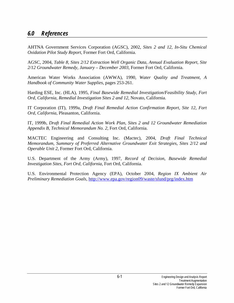
6-1 Engineering Design and Analysis Report Treatment Augmentation Sites 2 and 12 Groundwater Remedy Expansion Former Fort Ord, California
6.0 References
AHTNA Government Services Corporation (AGSC), 2002, Sites 2 and 12, In-Situ Chemical Oxidation Pilot Study Report, Former Fort Ord, California.
AGSC, 2004, Table 8, Sites 2/12 Extraction Well Organic Data, Annual Evaluation Report, Site 2/12 Groundwater Remedy, January – December 2003, Former Fort Ord, California.
American Water Works Association (AWWA), 1990, Water Quality and Treatment, A Handbook of Community Water Supplies, pages 253-261.
Harding ESE, Inc. (HLA), 1995, Final Basewide Remedial Investigation/Feasibility Study, Fort Ord, California, Remedial Investigation Sites 2 and 12, Novato, California.
IT Corporation (IT), 1999a, Draft Final Remedial Action Confirmation Report, Site 12, Fort Ord, California, Pleasanton, California.
IT, 1999b, Draft Final Remedial Action Work Plan, Sites 2 and 12 Groundwater Remediation Appendix B, Technical Memorandum No. 2, Fort Ord, California.
MACTEC Engineering and Consulting Inc. (Mactec), 2004, Draft Final Technical Memorandum, Summary of Preferred Alternative Groundwater Exit Strategies, Sites 2/12 and Operable Unit 2, Former Fort Ord, California.
U.S. Department of the Army (Army), 1997, Record of Decision, Basewide Remedial Investigation Sites, Fort Ord, California, Fort Ord, California.
U.S. Environmental Protection Agency (EPA), October 2004, Region IX Ambient Air Preliminary Remediation Goals, http://www.epa.gov/region09/waste/sfund/prg/index.htm