elektor electronics march 2007
TRANSCRIPT
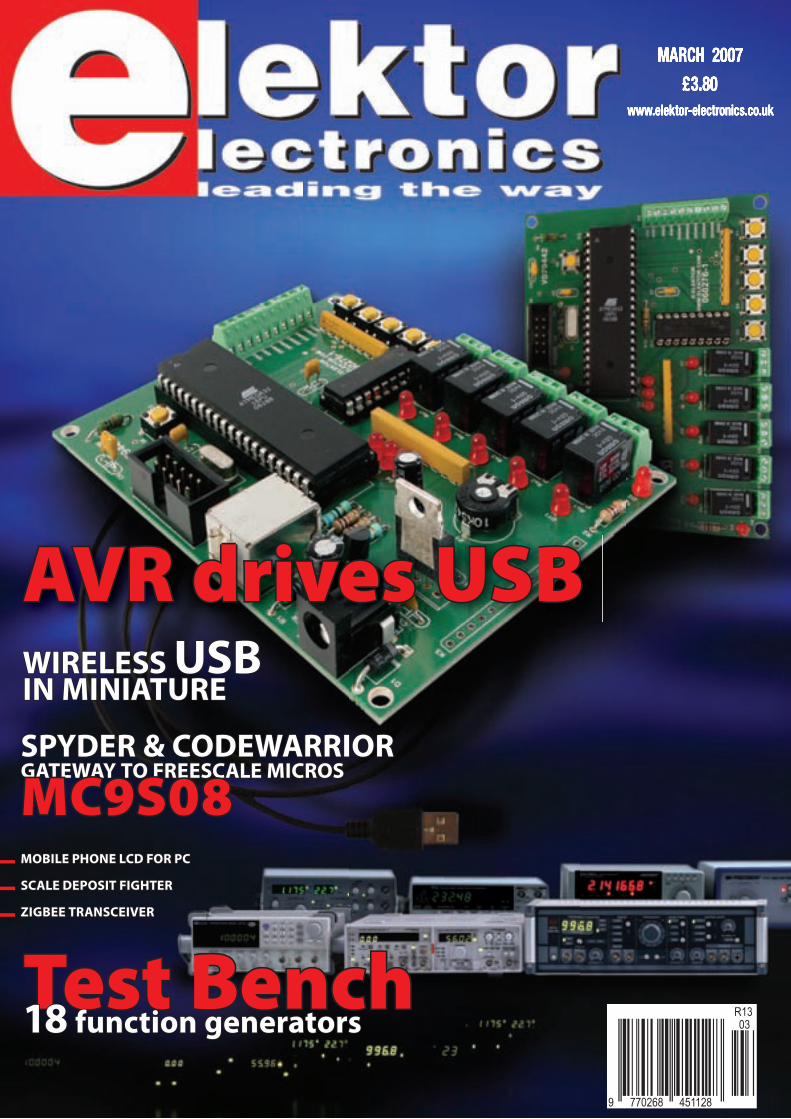
MARCH 2007 £3.80
www.elektor-electronics.co.uk
SPYDER & CODEWARRIORSPYDER & CODEWARRIORGATEWAY TO FREESCALE MICROSGATEWAY TO FREESCALE MICROS
MC9S08MC9S08
WIRELESS WIRELESS USBUSB IN MINIATUREIN MINIATURE
Test BenchTest Bench1818 function generators function generators
AVR drives USBAVR drives USB
MOBILE PHONE LCD FOR PCMOBILE PHONE LCD FOR PC
SCALE DEPOSIT FIGHTERSCALE DEPOSIT FIGHTER
ZIGBEE TRANSCEIVERZIGBEE TRANSCEIVER

0800 032 7241(Monday - Friday 09.00 to 17.30 GMT + 10 hours only).
For those who want to write: 100 Silverwater RdSilverwater NSW 2128 Sydney AUSTRALIA
Free 410+ pageCatalogue
All pricesin £ Stg
POST AND PACKING CHARGES:Order Value Cost£20 - £49.99 £5£50 - £99.99 £10£100 - £199.99 £20
Order Value Cost£200 - £499.99 £30£500+ £40
Max weight 12lb (5kg). Heavierparcels POA. Minimum order £20.Note: Products are dispatched from Australia,local customs duty and taxes may apply.
Claw your way through
our FREE copy of our 410+ page
catalog, log onto our website
www.jaycar.com/catalog
and get your copy.
All prices in £Stg.
Magnetic Cartridge Pre-ampKC-5433 £11.75 + post & packingThis kit is used to amplify the 3-4mV signals from a phono cartridge to line level, so you canuse your turntable with the CD or tuner inputs onyour Hi-Fi amplifier. The design is suitable for 12"LPs, and also allows for RIAA equalisation of allthe really old 78s. Please note that the inputsensitivity of this design means it'sonly suitable for moving-magnet,not moving-coil cartridges. Kitincludes PCB with overlayand all electroniccomponents.• Requires 12VAC
power
DC Relay SwitchKC-5434 £4.50 + post & packingAn extremely useful and versatile kit thatenables you to use a tiny trigger current - aslow as 400µA at 12V to switch up to 30Aat 50VDC. It has an isolated input,and is suitable for a variety oftriggering options. The kitincludes PCB with overlayand all electroniccomponents withclear Englishinstructions.
Speedo Corrector MkII KC-5435 £14.50 + post & packing
When you modify your gearbox, diff ratio orchange to a large circumference tyre, it mayresult in an inaccurate speedometer. This kitalters the speedometer signal up or down from0% to 99% of the original signal. With thisimproved model, the input set-up selection canbe automatically selected and it also features anLED indicator to show when the inputsignal is being received. Kitsupplied with PCB withoverlay and all electroniccomponents withclear Englishinstructions.
Radar Speed Gun KC-5429 £29.00 + post & packingThis Doppler radar gun reads speed in km/h or mph up to 250 km/h or155 mph. It has a resolution of 1 km/h or 1 mphwith an accuracy of 1%, and also has a hold switchso you can freeze the reading.There's a jiffy box to mount theelectronics in, and the enclosurefor the radar gun assembly ismade from 2 x coffee tins orsimilar. Details included. Kitincludes PCB and all specifiedcomponents with clearEnglish instructions. • Requires 12VDC power.
ImprovedModel!
Log on towww.jaycarelectronics.co.uk/elektor
for your FREE catalogue!
Powertool Battery Charger Controller
KC-5436 £11.75 + post & packingCordless drills are fantastic & cheap but, the
batteries in them don't last with the simple chargersupplied. This controller turns the cheap chargerinto a contractor grade intelligent charger. Itincorporates charge timeout, min and maxtemperature monitoring,Delta charge detection,power and charge LEDindicator, adjustableDelta V, temperaturesettings, and optionaladjustable tricklecharge. Suits both Ni-Cdand Ni-MH cells. Kit includes PCBwith overlay, case, all electronic componentsand clear English instructions.
Two-Way SPDIF/Toslink DigitalAudio Converter Kit KC-5425 £7.25 + post and packingThis kit converts coaxial digital audio signals intooptical or vice-versa. Use this bit streamconverter in situations where one piece ofequipment has an optical audio input and theother a coaxial digital output. Kit includes Toslinkoptical modules, PCB with overlay, case withscreen printed lid, allelectronic components andclear English instructions.
Requires 9-12VDC wall adapter
(Maplin #UG01B £13.99)
Starship EnterpriseTM
Door Sound Simulator KC-5423 £11.75 + post & packingThis easy-to-build kit emulatesthe unique noise made whenthe cabin doors on the StarshipEnterpriseTM open and close.The sound emulator can betriggered by switch contacts(normally open), which meansyou can use a reed magnetswitch, IR beam or PIRdetector. Kit includes amachined, silkscreened and pre-drilled case, speaker and allelectronics components withclear English instructions.
For all youTrekkie fans
Not to be used toconfuse Policeequipment
Requires 9-12VDC wall adapter
(Maplin #UG01B £13.99)
Requires 9-12VDCwall adapter (Maplin
#UG01B £13.99)
Theremin Synthesizer MKIIKC-5426 £43.50 + post & packingBy moving your hand between the metalantennae, create unusual sound effects! TheTheremin MkII improves on its predecessor byallowing adjustments to the tonal quality byproviding a better waveform. With a multitude ofcontrols, this instrument's musical potential is onlylimited by the skill and imagination of its player.Kit includes stand, PCB with overlay, machinedcase with silkscreen printed lid, loudspeaker, pitchantennae, all specified electronic components andclear English instructions.
As used in the
Beach Boys
classic hit ‘Good
Vibrations’
ImprovedModel!
Usesexistingcharger!
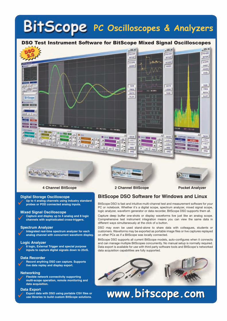
Mixed Signal OscilloscopeCapture and display up to 4 analog and 8 logicchannels with sophisticated cross-triggers.
Digital Storage OscilloscopeUp to 4 analog channels using industry standardprobes or POD connected analog inputs.
Spectrum AnalyzerIntegrated real-time spectrum analyzer for eachanalog channel with concurrent waveform display.
Logic Analyzer8 logic, External Trigger and special purposeinputs to capture digital signals down to 25nS.
Data RecorderRecord anything DSO can capture. Supports live data replay and display export.
BitScope DSO is fast and intuitive multi-channel test and measurement software for yourPC or notebook. Whether it's a digital scope, spectrum analyzer, mixed signal scope,logic analyzer, waveform generator or data recorder, BitScope DSO supports them all.
Capture deep buffer one-shots or display waveforms live just like an analog scope.Comprehensive test instrument integration means you can view the same data indifferent ways simultaneously at the click of a button.
DSO may even be used stand-alone to share data with colleagues, students orcustomers. Waveforms may be exported as portable image files or live captures replayedon other PCs as if a BitScope was locally connected.
BitScope DSO supports all current BitScope models, auto-configures when it connectsand can manage multiple BitScopes concurrently. No manual setup is normally required.Data export is available for use with third party software tools and BitScope's networkeddata acquisition capabilities are fully supported.
PC Oscilloscopes & AnalyzersDSO Test Instrument Software for BitScope Mixed Signal Oscilloscopes
Networking
Flexible network connectivity supporting multi-scope operation, remote monitoring anddata acquisition.
Data Export
Export data with DSO using portable CSV files oruse libraries to build custom BitScope solutions. www.bitscope.comwww.bitscope.com
BitScope DSO Software for Windows and Linux
4 Channel BitScope 2 Channel BitScope Pocket Analyzer
DSO2.0
DSO2.0
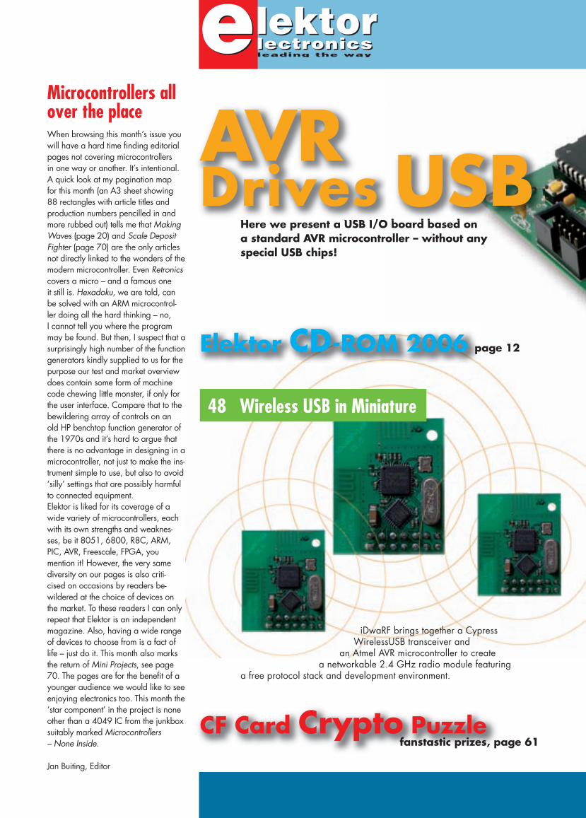
iDwaRF brings together a Cypress WirelessUSB transceiver and
an Atmel AVR microcontroller to create a networkable 2.4 GHz radio module featuring
a free protocol stack and development environment.
Here we present a USB I/O board based on a standard AVR microcontroller – without any special USB chips!
AVR Drives USB
48 Wireless USB in Miniature
Microcontrollers all over the placeWhen browsing this month’s issue you will have a hard time fi nding editorial pages not covering microcontrollers in one way or another. It’s intentional. A quick look at my pagination map for this month (an A3 sheet showing 88 rectangles with article titles and production numbers pencilled in and more rubbed out) tells me that Making Waves (page 20) and Scale Deposit Fighter (page 70) are the only articles not directly linked to the wonders of the modern microcontroller. Even Retronicscovers a micro – and a famous one it still is. Hexadoku, we are told, can be solved with an ARM microcontrol-ler doing all the hard thinking – no, I can not tell you where the program may be found. But then, I suspect that a surprisingly high number of the function generators kindly supplied to us for the purpose our test and market overview does contain some form of machine code chewing little monster, if only for the user interface. Compare that to the bewildering array of controls on an old HP benchtop function generator of the 1970s and it’s hard to argue that there is no advantage in designing in a microcontroller, not just to make the ins-trument simple to use, but also to avoid ‘silly’ settings that are possibly harmful to connected equipment. Elektor is liked for its coverage of a wide variety of microcontrollers, each with its own strengths and weaknes-ses, be it 8051, 6800, R8C, ARM, PIC, AVR, Freescale, FPGA, you men tion it! However, the very same diversity on our pages is also criti-cised on occasions by readers be-wildered at the choice of devices on the market. To these readers I can only repeat that Elektor is an independent magazine. Also, having a wide range of devices to choose from is a fact of life – just do it. This month also marks the return of Mini Projects, see page 70. The pages are for the benefi t of a younger audience we would like to see enjoying electronics too. This month the ‘star component’ in the project is none other than a 4049 IC from the junkbox suitably marked Microcontrollers – None Inside.
Jan Buiting, Editor
CF Card Crypto Puzzlefanstastic prizes, page 61
Elektor CD-ROM 2006 page 12
More advanced (but still 100% free) simulation this month with a VSM model for media storage card devices added to our PIC24F system (all virtual, of course). To cap it all, solve a CF card crypto puzzle and win fantastic prizes sponsored by Microchip and Labcenter.
Volume 33March 2007no. 363
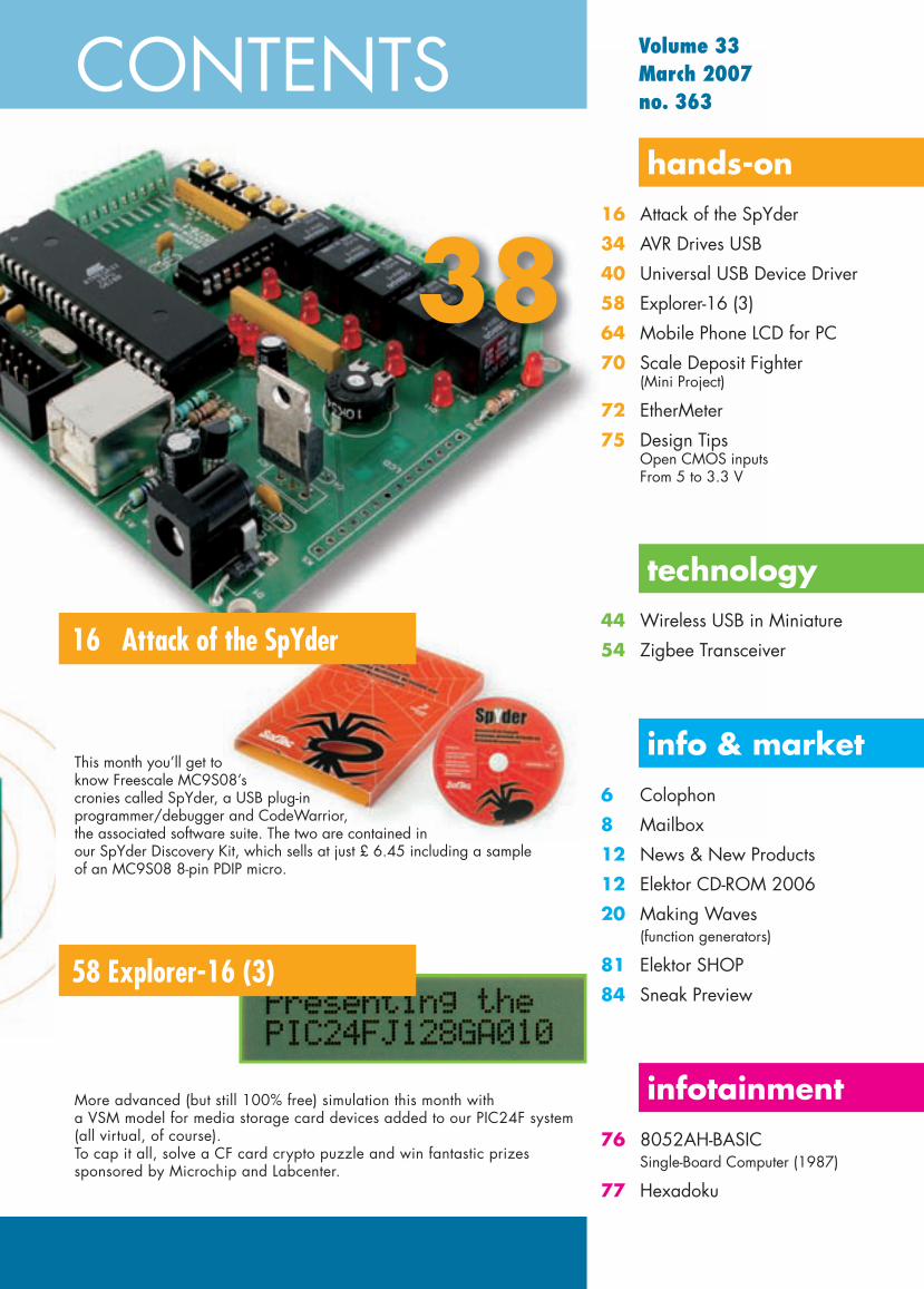
16 Attack of the SpYder
58 Explorer-16 (3)
16 Attack of the SpYder
34 AVR Drives USB
40 Universal USB Device Driver
58 Explorer-16 (3)
64 Mobile Phone LCD for PC
70 Scale Deposit Fighter (Mini Project)
72 EtherMeter
75 Design Tips Open CMOS inputs From 5 to 3.3 V
44 Wireless USB in Miniature
54 Zigbee Transceiver
6 Colophon
8 Mailbox
12 News & New Products
12 Elektor CD-ROM 2006
20 Making Waves (function generators)
81 Elektor SHOP
84 Sneak Preview
76 8052AH-BASIC Single-Board Computer (1987)
77 Hexadoku
hands-on
technology
info & market
infotainment
38
This month you’ll get to know Freescale MC9S08’s cronies called SpYder, a USB plug-in programmer/debugger and CodeWarrior, the associated software suite. The two are contained in our SpYder Discovery Kit, which sells at just £ 6.45 including a sample of an MC9S08 8-pin PDIP micro.
CONTENTS

6 elektor electronics - 3/2007
Volume 33, Number 363, March 2007 ISSN 0268/4519
Elektor Electronics aims at inspiring people to master electronics at any personal level by presenting construction projects and spotting developments in electronics and information technology.
Publishers: Elektor Electronics (Publishing), Regus Brentford, 1000 Great West Road, Brentford TW8 9HH, England. Tel. (+44) 208 261 4509, fax: (+44) 208 261 4447 www.elektor-electronics.co.uk
The magazine is available from newsagents, bookshops and electronics retail outlets, or on subscription. Elektor Electronics is published 11 times a year with a double issue for July & August.
Under the name Elektor and Elektuur, the magazine is also published in French, Spanish, German and Dutch. Together with franchised editions the magazine is on circulation in more than 50 countries.
International Editor: Mat Heffels ([email protected])
Editor: Jan Buiting ([email protected])
International editorial staff: Harry Baggen, Thijs Beckers, Ernst Krempelsauer, Jens Nickel, Guy Raedersdorf.
Design staff: Ton Giesberts, Paul Goossens, Luc Lemmens, Christian Vossen
Editorial secretariat: Hedwig Hennekens ([email protected])
Graphic design / DTP: Giel Dols
Managing Director / Publisher: Paul Snakkers
Marketing: Carlo van Nistelrooy
Customer Services: Margriet Debeij ([email protected])
Subscriptions: Elektor Electronics (Publishing), Regus Brentford, 1000 Great West Road, Brentford TW8 9HH, England. Tel. (+44) 208 261 4509, fax: (+44) 208 261 4447Internet: www.elektor-electronics.co.ukEmail: [email protected] and terms are given on the Subscription Order Form
Head Offi ce: Segment b.v. P.O. Box 75 NL-6190-AB Beek The NetherlandsTelephone: (+31) 46 4389444, Fax: (+31) 46 4370161
Distribution: Seymour, 2 East Poultry Street, London EC1A, EnglandTelephone:+44 207 429 4073
UK Advertising: Huson International Media, Cambridge House, Gogmore Lane, Chertsey, Surrey KT16 9AP, England.Telephone: +44 1932 564999, Fax: +44 1932 564998Email: [email protected]: www.husonmedia.comAdvertising rates and terms available on request.
International Advertising: Frank van de Raadt, address as Head Offi ceEmail: [email protected] Advertising rates and terms available on request.
Copyright NoticeThe circuits described in this magazine are for domestic use only. All drawings, photographs, printed circuit board layouts, programmed integrated circuits, disks, CD-ROMs, software carriers and article texts published in our books and magazines (other than third-party advertisements) are copyright Segment. b.v. and may not be reproduced or transmitted in any form or by any means, including photocopying, scanning an recording, in whole or in part without prior written permission from the Publishers. Such written permission must also be obtained before any part of this publication is stored in a retrieval system of any nature. Patent protection may exist in respect of circuits, devices, components etc. described in this magazine. The Publisher does not accept responsibility for failing to identify such patent(s) or other protection. The submission of designs or articles implies permis-sion to the Publishers to alter the text and design, and to use the contents in other Segment publica-
tions and activities. The Publishers cannot guarantee to return any material submitted to them.
DisclaimerPrices and descriptions of publication-related items subject to change. Errors and omissions excluded.
© Segment b.v. 2007 Printed in the NetherlandsAdvertisement
3/2007 - elektor electronics 7
positions vacant
Free-lance Deputy PublishersOur publishing house is growing fast and we aim at extending our currentteam of publishers.
The successful candidate(s) will be responsible for- acquiring manuscripts and other material for books and digital media
(CDs/DVDs) that can be published in English, German or French, and, ifsuitable, in other languages.
- Staging workshops and masterclasses covering various areas of electronics.
RequirementsHigher Education or academic background coupled with goodcommunicative skills.Formal education in, or strong affinity with, electronics, highly commended.Ability to read German or Dutch as a second language, commended.Payment based on hours contract or on commission basis.
InformationFor further information, please contactEnglish: Jan Buiting, (+44) 208 2614509, [email protected]: Raimund Krings, (+49) 241 8890 915, [email protected]: Denis Meyer, (+31) 46 4389444, [email protected]
Candidates are invited to first email or telephone the above persons. Aninterview with our CEO will be arranged after the initial contact.
Applications in writing may be sent toElektor b.v.Mrs. N. Adriaansen / Staff OfficePeter Treckpoelstraat 2-4NL-6191-VK Beek (Lb)The NetherlandsEmail: [email protected]
Elektor aims at inspiring people to master electronics and information technology at anypersonal level by means of magazines, books, digital media, Internet, workshops, seminars andelectronic products. The company is international with its head office based in The Netherlands
8 elektor electronics - 3/2007
INFO & MARKET MAILBOX
Explorer-16Hi Jan — very interested in the new series featuring the Explorer-16 project (January & February 2007, Ed.). In the summer I went to a Microchip 1-day seminar on the PIC24 and dsPIC devices. It cost me from memory, just over £90 and included refresh-ments, buffet lunch and a free Explorer-16 board plus PIC24 and dsPIC33 mounted PIMs. The presentation and demos were very good. They also gave out a voucher for 20% off Microchip products.Spurred on by the new series I have ordered an ICD 2 Debugger and have already uninstalled my MPLAB IDE to update to the latest version.One small erratum, on the inset panel on p.25, step 5 refers to the selection of Build All from the Debugger menu. I think that should be the Project menu.Looking forward to the next article, with thanks for an inte-resting magazine. I am a de-serting Electronics (Wireless) World reader! I stopped my subscription because the format changed completely and concentrated on ‘waffl e’ articles.I am part professional, part amateur electronics engineer. I manufacture industrial mo-dems for the railways and uti-lities, slow speed 1200 baud FSK V23 protocol and 300 Baud Dial up V21 duplex ty-pes. My interest in Microchip was to produce a fi rmware version based on a dsPIC. Microchip have already made the software available as a download but it is for another platform. Some work to do there!Andrew Binning
Thanks for the feedback Andrew and hope you also en-joy Explorer-16 instalments 2
(February 2007) and 3 (this is-sue). We confi rm the error in the text; a correction is published on the Explorer-16 project page on our website. Fortunately it does not seem to have deterred too many readers from successfully running the fi rst simulation.
ECG using a SoundcardHi Elektor — I’ve read the ar-ticle in Elektor October 2006. The project looks simple and I want to build it. However, the software looks daunting. I downloaded the zipped fi les and when I opened them, there are many things inside.How do I make a start? I am familiar with Delphi, C++, Visual Basic, but have not tried out Java. Please advise.Norman Kim (Australia)
Martin Klaper replies:Hi Norman, thanks for your e-mail from Sydney, Australia.For a jump start, I recommend using the precompiled version, i.e. double-click on the EKG-MonitorV1.0.jar fi le. The only prerequisite is an installed JAVA runtime environment (JRE). Usually this is already on your computer. In case you need to install it, go to www.java.com/de/download/index.jsp and download the JRE.
Here you can download the Java development environment (JDK): http://java.sun.com/ja-vase/downloads/index.jsp.
If you are familiar with Delphi, Visual Basic and especially C++, it should not be too diffi cult to learn a fourth programming lan-guage. My project is structured in three parts: IO, GUI and sig-nal processing, so it should be possible to concentrate on one or another aspect. A good en-try point to Java is www.BlueJ.org, although many other excel-
lent Java tutorials and books are available in bookstores and on the net. Some useful web links are in my Elektor article and on the Elektor website.A circuit board is available from Elektor, see the project page on their website.[foto als NL mailbox 2/2007]
Help batteries through the winterDear Editor — I’ve a small question about the charger for sealed lead-acid batteries. Can I use this circuit as a charger for ordinary lead-acid batteries as used in vehicles? I mean the variety you can top up with distilled water. Or should I go for the lead-acid battery charge controller? The battery involved is a 12-V type for my motorcycle, and I really need a circuit to help the battery survive the winter period during which it is not used on the bike. Consequently it has to remain on the charger con-stantly over a period of about three months, will that be a problem?Roy (by email)
A motorcycle battery is best used in combination with our Motive-Battery Charger from the October 1994 issue as that cir-cuit takes into account the lower capacity of a motorcycle battery as compared with a car battery. To prevent sulphation, you could connect the Lead-Acid Battery Revitaliser from the September 2001 edition of Elektor in pa-
rallel. This circuit will charge the battery every few seconds with a short but strong pulse that serves to destroy sulphate cry-stals on the battery plates. Best results are obtained, we believe, by fi rst charging the battery with the charger and then allow the Revitaliser to improve the con-dition. Inevitably, this circuit will draw a little current from the bat-tery to build up the energy for the pulses. If the battery is in danger of going fl at, you charge it again using the charger.
Nixie clock parts sourcingDear Jan — I am happy to inform you that that those rare birds, the 74141 TL ICs for the Sputnik Timer Machine clock (January 2007, Ed.), are available from us under order number HLT0579. Suitable Nixie tubes like the types Z590M and B5870 are also in stock.
Further offers relating to Nixie clocks are found on the web-site http://www.askjanfi rst.com/r5.htm which is also the source of the picture showing the acrylic glass Nixie clock with blue socket lighting.Jan Wüsten, Ask Jan First GmbH & Co. KG (Germany)
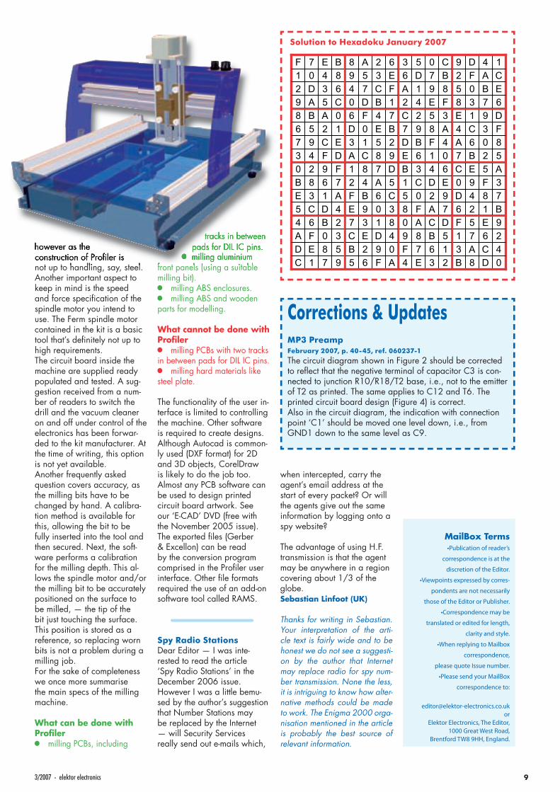
Profi ler (3)The ‘Profi ler milling machine from a kit’ publication in our January 2007 edition has given rise to a number of questions that are asked repeatedly, by email or through our forum. Among these questions: whether or not aluminium can be milled with this machine? The answer is: yes it can. Milling harder materials is not recommended
93/2007 - elektor electronics
however as the construction of Profi ler is not up to handling, say, steel. Another important aspect to keep in mind is the speed and force specifi cation of the spindle motor you intend to use. The Ferm spindle motor contained in the kit is a basic tool that’s defi nitely not up to high requirements.The circuit board inside the machine are supplied ready populated and tested. A sug-gestion received from a num-ber of readers to switch the drill and the vacuum cleaner on and off under control of the electronics has been forwar-ded to the kit manufacturer. At the time of writing, this option is not yet available.Another frequently asked question covers accuracy, as the milling bits have to be changed by hand. A calibra-tion method is available for this, allowing the bit to be fully inserted into the tool and then secured. Next, the soft-ware performs a calibration for the milling depth. This al-lows the spindle motor and/or the milling bit to be accurately positioned on the surface to be milled, — the tip of the bit just touching the surface. This position is stored as a reference, so replacing worn bits is not a problem during a milling job.For the sake of completeness we once more summarise the main specs of the milling machine.
What can be done with Profi ler•• milling PCBs, including
Solution to Hexadoku January 2007
tracks in between pads for DIL IC pins.
• milling aluminium front panels (using a suitable milling bit).•• milling ABS enclosures.•• milling ABS and wooden parts for modelling.
What cannot be done with Profi ler•• milling PCBs with two tracks in between pads for DIL IC pins.•• milling hard materials like steel plate.
The functionality of the user in-terface is limited to controlling the machine. Other software is required to create designs. Although Autocad is common-ly used (DXF format) for 2D and 3D objects, CorelDraw is likely to do the job too. Almost any PCB software can be used to design printed circuit board artwork. See our ‘E-CAD’ DVD (free with the November 2005 issue). The exported fi les (Gerber & Excellon) can be read by the conversion program comprised in the Profi ler user interface. Other fi le formats required the use of an add-on software tool called RAMS.
Spy Radio StationsDear Editor — I was inte-rested to read the article ‘Spy Radio Stations’ in the December 2006 issue. However I was a little bemu-sed by the author’s suggestion that Number Stations may be replaced by the Internet — will Security Services really send out e-mails which,
when intercepted, carry the agent’s email address at the start of every packet? Or will the agents give out the same information by logging onto a spy website?
The advantage of using H.F. transmission is that the agent may be anywhere in a region covering about 1/3 of the globe.Sebastian Linfoot (UK)
Thanks for writing in Sebastian. Your interpretation of the arti-cle text is fairly wide and to be honest we do not see a suggesti-on by the author that Internet may replace radio for spy num-ber transmission. None the less, it is intriguing to know how alter-native methods could be made to work. The Enigma 2000 orga-nisation mentioned in the article is probably the best source of relevant information.
Corrections & UpdatesMP3 Preamp February 2007, p. 40-45, ref. 060237-1
The circuit diagram shown in Figure 2 should be corrected to refl ect that the negative terminal of capacitor C3 is con-nected to junction R10/R18/T2 base, i.e., not to the emitter of T2 as printed. The same applies to C12 and T6. The printed circuit board design (Figure 4) is correct.Also in the circuit diagram, the indication with connection point ‘C1’ should be moved one level down, i.e., from GND1 down to the same level as C9.
MailBox Terms•Publication of reader’s
correspondence is at the
discretion of the Editor.
•Viewpoints expressed by corres-
pondents are not necessarily
those of the Editor or Publisher.
•Correspondence may be
translated or edited for length,
clarity and style.
•When replying to Mailbox
correspondence,
please quote Issue number.
•Please send your MailBox
correspondence to:
orElektor Electronics, The Editor,
1000 Great West Road, Brentford TW8 9HH, England.
10 elektor electronics - 3/2007
INFO & MARKET MAILBOX
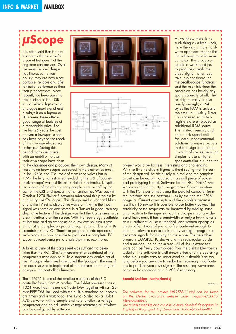
µScopeIt is often said that the oscil-loscope is the most useful piece of test gear that the engineer can possess. Over the years ‘scope’ design has improved tremen-dously; they are now more portable, reliable and offer far better performance than their predecessors. More recently we have seen the introduction of the ‘USB scope’ which digitizes the analogue input signal and displays it on a laptop or PC screen, these offer a good range of features at a reasonable price. For the last 25 years the cost of even a low-spec scope has been beyond the reach of the average electronics enthusiast. During this period many designers with an ambition to own their own scope have risen to the challenge and produced their own design. Many of these home brew scopes appeared in the electronics press in the 1960s and 70s, most of them used valves but in 1975 the fully transistorised (excluding the CRT of course) ‘Elektorscope’ was published in Elektor Electronics. Despite the success of the design many people were put off by the cost of the CRT and special mains transformer. Way back in October 1978 Elektor Electronics addressed this problem by publishing the ‘TV scope’. This design used a standard black and white TV set to display the waveforms while the input signal was sampled and stored in a ‘bucket brigade’ memory chip. One feature of the design was that the X axis (time) was drawn vertically on the screen. With the technology available at that time and an emphasis on a low cost solution it was still a rather complex project and required a number of PCBs containing many ICs. Thanks to progress in microprocessor technology it is now possible to produce the complete ‘TV scope’ concept using just a single 8-pin microcontroller.
A brief scrutiny of the data sheet was suffi cient to deter-mine that the PIC 12F675 microcontroller contained all the components necessary to build a modern day equivalent of the TV scope which we have called the ‘µScope’. The aim of the exercise was to implement all the features of the original design in the controller’s fi rmware.
The 12F675 is one of the smallest members of the PIC controller family from Microchip. The 14-bit processor has a 1024 word fl ash memory, 64-byte RAM together with a 128-byte EEPROM. Included with the built-in standard peripherals are timers and a watchdog. The 12F675 also has a 10-bit A/D converter with a sample and hold function, a voltage comparator and an adjustable voltage reference all of which can be confi gured by software.
As we know there is no such thing as a free lunch, here the very simple hard-ware approach means that the software must be more complex. The processor needs to work hard just to produce a real-time video signal, when you take into consideration the oscilloscope functions and the user interface the processor has hardly any spare capacity at all. The on-chip memory is also barely enough; at 64 bytes the RAM is actually too small but luckily Timer 1 is not used so its two registers are employed as additional RAM space. The limited memory and chip clock speed call for some unconventional solutions to ensure success in this design application. It would of course be much simpler to use a higher-spec controller but then the
project would be far less interesting and challenging.With so little hardware it goes without saying that the cost of the design will be absolutely minimal and the complete circuit can be accommodated on a small piece of solder-pad prototyping board. Software for the PIC 12F675 was written using the ‘tait style’ programmer. Communication with the PC is performed using the parallel computer (prin-ter) interface and the software runs by starting the ‘PP06’ program. Current consumption of the complete circuit is less than 10 mA so it is possible to use battery power. The sensitivity of the scope can be improved by adding some amplifi cation to the input signal; the µScope is not a wide-band instrument, it has a bandwidth of only a few kilohertz so it is suffi cient to use a standard specifi cation opamp as an amplifi er. Those of you who feel confi dent enough to alter the software can experiment by writing a program to generate signals for display on the scope. The assembler program EXAMPLE.PIC draws a white rectangular border and a dashed line on the screen. All of the relevant soft-ware can be freely downloaded from the Elektor Electronics website. The software is well documented and the operating principle is quite easy to understand so it shouldn’t be too long before you are able to make the necessary modifi cati-ons to produce your own signals. The resulting waveforms can also be recorded onto a VCR if necessary.
Ronald Dekker (Netherlands)(060278-11)
The software for this project (060278-11.zip) can be found on the Elektor Electronics website under magazine/2007/ March/Mailbox.The author’s website also contains a more detailed description (in English) of the project: http://members.chello.nl/r.dekker49/

The Microchip name and logo, PIC, and dsPIC are registered trademarks of Microchip Technology Incorporated in the USA and other countries. All other trademarks and registered trademarks are the property of their respective owners.©2007 Microchip Technology Inc. All rights reserved. ME154Eng/01.07-ELUK-B
www.microchip.com/16bit
16-bit Microcontrollers
Visualise...16-bit Microcontrollerswith 32-bit Performance and 8-bit Simplicity
Over 50 PIC24 Microcontrollers and dsPIC Digital Signal Controllers sampling today.For data sheets, samples and pricing go to www.microchip.com/16bit
Unified 16-bit Architecture• PIC24F, low-cost entry level• PIC24H, 40 MIPS high
performance• dsPIC30F/33F for seamless
DSP integration
Low-Risk Design• Easy migration from 8-bit MCUs• Common core instruction set
and architecture• Peripheral and Pin compatible
families• One development tool platform
for all products• Free MPLAB® IDE Integrated
Development Environment• Other tools include C-compiler,
programmer and In-CircuitEmulator
16-bit PIC24 MCUsand dsPIC® DigitalSignal Controllers
Today’s embedded systems demand more. The 16-bitPIC® microcontroller families from Microchip give youthe performance and flexibility you need with 8-bitsimplicity. Pin and code compatibility lowers risk, andallows re-use of development tools, software and
hardware designs. For the most demanding applicationsthe dsPIC digital signal controller families seamlesslyintegrate high-performance DSP capabilities with thePIC microcontroller core.
See the
EXPLORER-16
Hands-On
PIC24F Design Series
on page 58!
INFO & MARKET NEWS & NEW PRODUCTS
12 elektor electronics - 3/2007
The Elektor Volume 2006 CD-ROM that’s published along with this March 2007 issue has a rather different look and feel than previous editions — it’s gone through a makeover in more than one way.
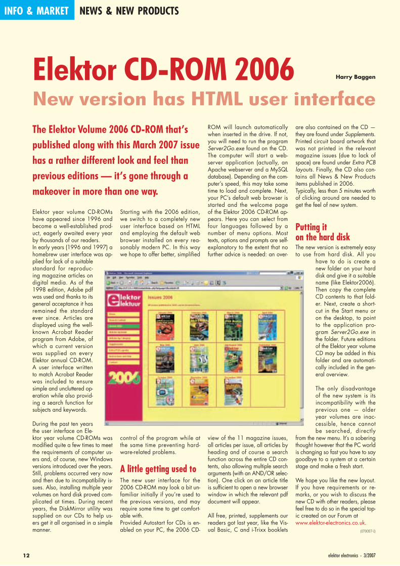
Starting with the 2006 edition, we switch to a completely new user interface based on HTML and employing the default web browser installed on every rea-sonably modern PC. In this way we hope to offer better, simplifi ed
control of the program while at the same time preventing hard-ware-related problems.
A little getting used toThe new user interface for the 2006 CD-ROM may look a bit un-familiar initially if you’re used to the previous versions, and may require some time to get comfort-able with.Provided Autostart for CDs is en-abled on your PC, the 2006 CD-
ROM will launch automatically when inserted in the drive. If not, you will need to run the program Server2Go.exe found on the CD. The computer will start a web-server application (actually, an Apache webserver and a MySQL database). Depending on the com-puter’s speed, this may take some time to load and complete. Next, your PC’s default web browser is started and the welcome page of the Elektor 2006 CD-ROM ap-pears. Here you can select from four languages followed by a number of menu options. Most texts, options and prompts are self-explanatory to the extent that no further advice is needed: an over-
view of the 11 magazine issues, all articles per issue, all articles by heading and of course a search function across the entire CD con-tents, also allowing multiple search arguments (with an AND/OR selec-tion). One click on an article title is suffi cient to open a new browser window in which the relevant pdf document will appear.
All free, printed, supplements our readers got last year, like the Vis-ual Basic, C and i-Trixx booklets
are also contained on the CD — they are found under Supplements. Printed circuit board artwork that was not printed in the relevant magazine issues (due to lack of space) are found under Extra PCB layouts. Finally, the CD also con-tains all News & New Products items published in 2006.Typically, less than 5 minutes worth of clicking around are needed to get the feel of new system.
Putting it on the hard diskThe new version is extremely easy to use from hard disk. All you
have to do is create a new folder on your hard disk and give it a suitable name (like Elektor2006). Then copy the complete CD contents to that fold-er. Next, create a short-cut in the Start menu or on the desktop, to point to the application pro-gram Server2Go.exe in the folder. Future editions of the Elektor year volume CD may be added in this folder and are automati-cally included in the gen-eral overview.
The only disadvantage of the new system is its incompatibility with the previous one — older year volumes are inac-cessible, hence cannot be searched, directly
from the new menu. It’s a sobering thought however that the PC world is changing so fast you have to say goodbye to a system at a certain stage and make a fresh start.
We hope you like the new layout. If you have requirements or re-marks, or you wish to discuss the new CD with other readers, please feel free to do so in the special top-ic created on our Forum atwww.elektor-electronics.co.uk.
(070057-I)
New version has HTML user interfaceHarry Baggen
Elektor year volume CD-ROMs have appeared since 1996 and become a well-established prod-uct, eagerly awaited every year by thousands of our readers.In early years (1996 and 1997) a homebrew user interface was ap-plied for lack of a suitable standard for reproduc-ing magazine articles on digital media. As of the 1998 edition, Adobe pdf was used and thanks to its general acceptance it has remained the standard ever since. Articles are displayed using the well-known Acrobat Reader program from Adobe, of which a current version was supplied on every Elektor annual CD-ROM. A user interface written to match Acrobat Reader was included to ensure simple and uncluttered op-eration while also provid-ing a search function for subjects and keywords.
During the past ten years the user interface on Ele-ktor year volume CD-ROMs was modifi ed quite a few times to meet the requirements of computer us-ers and, of course, new Windows versions introduced over the years. Still, problems occurred very now and then due to incompatibility is-sues. Also, installing multiple year volumes on hard disk proved com-plicated at times. During recent years, the DiskMirror utility was supplied on our CDs to help us-ers get it all organised in a simple manner.
Elektor CD-ROM 2006
133/2007 - elektor electronics
Vinculum IC speeds USB fl ash drive connectivity to microcontrollersBy Fred Dart (MD, FTDI)
Although this media has been readily available for a number of years, use of USB fl ash drives has, to date, been restricted to platforms with adequate processing power such as PCs and 32-bit embedded systems. FTDI has now opened up the use of USB fl ash disks to micro-controllers with the introduction of their Vinculum series of intelligent USB host controllers.
The Vinculum VNC1L IC pro-vides USB host interface and data transfer, and supports the most popular device classes; mass stor-age, printer and human interface device (HID). HID class devices typically include USB keyboards, joysticks and mice. When inter-facing to flash drives, Vinculum manages the fi le allocation table (FAT) structure by using a straight-forward command set. The device has an 8-bit core together with a 32-bit co-processor, dual DMA controllers, 64 k embedded fl ash and 4 k internal SRAM memory. Vinculum features two USB 2.0 low and full speed, host and slave ports, universal asynchronous re-ceiver transmitter (UART), serial pe-ripheral interface (SPI) and parallel fi rst in fi rst out (FIFO) interfaces. It also has two PS2 legacy ports for keyboard and mouse, and up to 28 general-purpose input output (GPIO) pins depending on con-figuration. The current Vinculum handles both low and full speed USB 2.0, which provides data link at up to 12Mbytes/s and will in-terface to all USB2.0 peripherals, as well as older USB1.1 devices. This is more than suffi cient for USB fl ash drive applications and is de-liberately targeted to keep the size, cost and power down to a level that is acceptable for embedded applications. Power consumption is 25 mA for the 3.3 V core and the 5-V-safe I/O interface.
Vinculum provides USB host ca-pability to microcontroller-based products that previously did not have the hardware resources avail-able. A wide range of consumer and industrial products, such as intelligent domestic appliances, meter readers and vending ma-chines, can now incorporate USB peripheral connectivity. For prod-
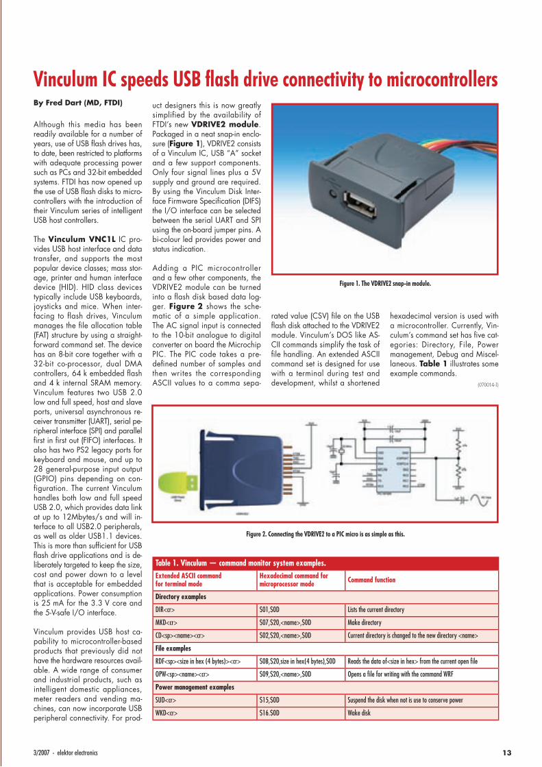
uct designers this is now greatly simplified by the availability of FTDI’s new VDRIVE2 module. Packaged in a neat snap-in enclo-sure (Figure 1), VDRIVE2 consists of a Vinculum IC, USB “A” socket and a few support components. Only four signal lines plus a 5V supply and ground are required. By using the Vinculum Disk Inter-face Firmware Specifi cation (DIFS) the I/O interface can be selected between the serial UART and SPI using the on-board jumper pins. A bi-colour led provides power and status indication.
Adding a PIC microcontroller and a few other components, the VDRIVE2 module can be turned into a fl ash disk based data log-ger. Figure 2 shows the sche-matic of a simple application. The AC signal input is connected to the 10-bit analogue to digital converter on board the Microchip PIC. The PIC code takes a pre-defi ned number of samples and then writes the corresponding ASCII values to a comma sepa-
rated value (CSV) fi le on the USB fl ash disk attached to the VDRIVE2 module. Vinculum’s DOS like AS-CII commands simplify the task of fi le handling. An extended ASCII command set is designed for use with a terminal during test and development, whilst a shortened
hexadecimal version is used with a microcontroller. Currently, Vin-culum’s command set has fi ve cat-egories: Directory, File, Power management, Debug and Miscel-laneous. Table 1 illustrates some example commands.
(070014-I)
Table 1. Vinculum — command monitor system examples.Extended ASCII command for terminal mode
Hexadecimal command for microprocessor mode Command function
Directory examples
DIR<cr> $01,$0D Lists the current directory
MKD<cr> $07,$20,<name>,$0D Make directory
CD<sp><name><cr> $02,$20,<name>,$0D Current directory is changed to the new directory <name>
File examples
RDF<sp><size in hex (4 bytes)><cr> $0B,$20,size in hex(4 bytes),$0D Reads the data of<size in hex> from the current open fi le
OPW<sp><name><cr> $09,$20,<name>,$0D Opens a fi le for writing with the command WRF
Power management examples
SUD<cr> $15,$0D Suspend the disk when not is use to conserve power
WKD<cr> $16.$0D Wake disk
Figure 2. Connecting the VDRIVE2 to a PIC micro is as simple as this.
Figure 1. The VDRIVE2 snap-in module.
INFO & MARKET NEWS & NEW PRODUCTS
14 elektor electronics - 3/2007
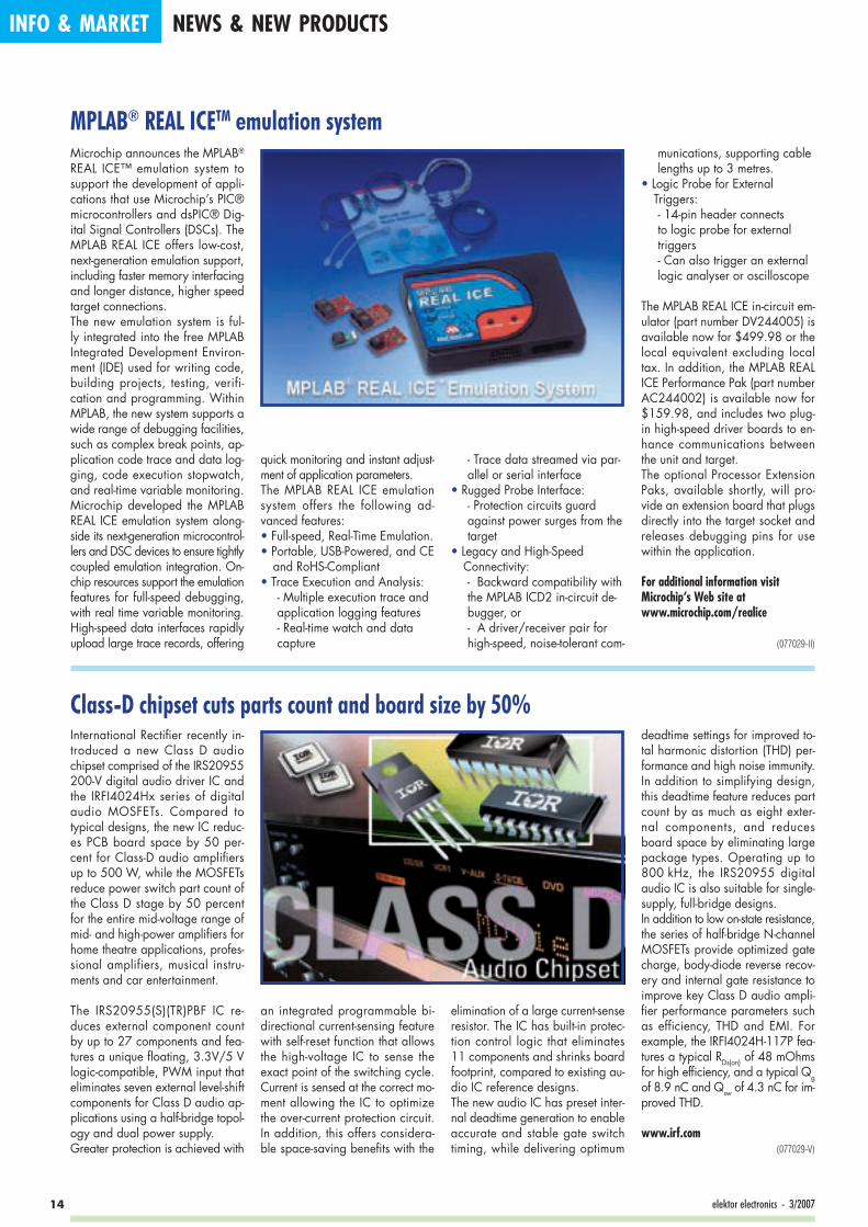
MPLAB® REAL ICETM emulation systemMicrochip announces the MPLAB® REAL ICE™ emulation system to support the development of appli-cations that use Microchip’s PIC® microcontrollers and dsPIC® Dig-ital Signal Controllers (DSCs). The MPLAB REAL ICE offers low-cost, next-generation emulation support, including faster memory interfacing and longer distance, higher speed target connections.The new emulation system is ful-ly integrated into the free MPLAB Integrated Development Environ-ment (IDE) used for writing code, building projects, testing, verifi-cation and programming. Within MPLAB, the new system supports a wide range of debugging facilities, such as complex break points, ap-plication code trace and data log-ging, code execution stopwatch, and real-time variable monitoring. Microchip developed the MPLAB REAL ICE emulation system along-side its next-generation microcontrol-lers and DSC devices to ensure tightly coupled emulation integration. On-chip resources support the emulation features for full-speed debugging, with real time variable monitoring. High-speed data interfaces rapidly upload large trace records, offering
quick monitoring and instant adjust-ment of application parameters.The MPLAB REAL ICE emulation system offers the following ad-vanced features:• Full-speed, Real-Time Emulation.• Portable, USB-Powered, and CE
and RoHS-Compliant• Trace Execution and Analysis:
- Multiple execution trace and application logging features- Real-time watch and data capture
- Trace data streamed via par-allel or serial interface
• Rugged Probe Interface: - Protection circuits guard against power surges from the target
• Legacy and High-Speed Connectivity:- Backward compatibility with the MPLAB ICD2 in-circuit de-bugger, or- A driver/receiver pair for high-speed, noise-tolerant com-
munications, supporting cable lengths up to 3 metres.
• Logic Probe for External Triggers: - 14-pin header connects to logic probe for external triggers- Can also trigger an external logic analyser or oscilloscope
The MPLAB REAL ICE in-circuit em-ulator (part number DV244005) is available now for $499.98 or the local equivalent excluding local tax. In addition, the MPLAB REAL ICE Performance Pak (part number AC244002) is available now for $159.98, and includes two plug-in high-speed driver boards to en-hance communications between the unit and target.The optional Processor Extension Paks, available shortly, will pro-vide an extension board that plugs directly into the target socket and releases debugging pins for use within the application.
For additional information visit Microchip’s Web site at www.microchip.com/realice
(077029-II)
Class-D chipset cuts parts count and board size by 50%International Rectifi er recently in-troduced a new Class D audio chipset comprised of the IRS20955 200-V digital audio driver IC and the IRFI4024Hx series of digital audio MOSFETs. Compared to typical designs, the new IC reduc-es PCB board space by 50 per-cent for Class-D audio amplifi ers up to 500 W, while the MOSFETs reduce power switch part count of the Class D stage by 50 percent for the entire mid-voltage range of mid- and high-power amplifi ers for home theatre applications, profes-sional amplifiers, musical instru-ments and car entertainment.
The IRS20955(S)(TR)PBF IC re-duces external component count by up to 27 components and fea-tures a unique fl oating, 3.3V/5 V logic-compatible, PWM input that eliminates seven external level-shift components for Class D audio ap-plications using a half-bridge topol-ogy and dual power supply. Greater protection is achieved with
an integrated programmable bi-directional current-sensing feature with self-reset function that allows the high-voltage IC to sense the exact point of the switching cycle. Current is sensed at the correct mo-ment allowing the IC to optimize the over-current protection circuit. In addition, this offers considera-ble space-saving benefi ts with the
elimination of a large current-sense resistor. The IC has built-in protec-tion control logic that eliminates 11 components and shrinks board footprint, compared to existing au-dio IC reference designs. The new audio IC has preset inter-nal deadtime generation to enable accurate and stable gate switch timing, while delivering optimum
deadtime settings for improved to-tal harmonic distortion (THD) per-formance and high noise immunity. In addition to simplifying design, this deadtime feature reduces part count by as much as eight exter-nal components, and reduces board space by eliminating large package types. Operating up to 800 kHz, the IRS20955 digital audio IC is also suitable for single-supply, full-bridge designs.In addition to low on-state resistance, the series of half-bridge N-channel MOSFETs provide optimized gate charge, body-diode reverse recov-ery and internal gate resistance to improve key Class D audio ampli-fi er performance parameters such as efficiency, THD and EMI. For example, the IRFI4024H-117P fea-tures a typical RDs(on) of 48 mOhms for high effi ciency, and a typical Qg of 8.9 nC and Qsw of 4.3 nC for im-proved THD.
www.irf.com(077029-V)

153/2007 - elektor electronics
Cost-effective mid-power 24Vin micro modulesVicor announces the addition of seven mid-power Micro DC-DC converters to the 24Vdc input fam-ily: 50W models at 3.3, 12, 15, 24, 28, and 48Vout. The modules — which incorporate Vicor’s pat-ented low-noise Zero-Current and Zero-Voltage Switching (ZCS/ZVS) — are appropriate for power sys-tem applications in industrial and process control, distributed power, medical, ATE, communications, de-fence, and aerospace. The addition of these modules dou-bles the size of the high-power den-sity 24Vin family, which previously consisted of 75W at 3.3Vout and 100W at 5, 12, 15, 24, 28 and 48Vout. The converters operate from 24V nominal input, with an input range of 18V to 36V and will
operate down to 16V after startup. Effi ciencies range up to 89% for the higher output voltages.
These models, which are RoHS compliant (with F or G pin option) are 57.9 x 36.8 x 12.7 mm in
size with a height above board of 10.9mm.These mid-power products provide customers a cost-effective solution for applications that do not require the full-power capability of the Mi-cro module, but would benefi t from the low-noise performance and full-feature set provided by te Micro platform.
Vicor’s comprehensive line of pow-er solutions includes modular, high-density AC-DC and DC-DC mod-ules and accessory components, fully confi gurable AC-DC and DC-DC power supplies, and complete custom power systems.
www.vicorpower.com (077029-I)
Current sensors for automotive battery-monitoring applicationsLEM has introduced two new members of its IT family of cur-rent transducers to address high-current applications. The IT 400-S and the IT 700-S are specifi ed re-spectively for 400 and 700 ARMS nominal. As with other members of the family, they offer very high accuracy, based on resolution bet-ter than 0.05 ppm, linearity better than 3 ppm and an initial offset between 30 and 50 ppm. Thermal offset drift is extremely low, at only 0.5 ppm/K.
Featuring galvanic isolation, the IT 400-S and IT 700-S can be used for current measurement of any kind of waveforms (including DC, AC, mixed and complex). They have been designed to op-erate from a bipolar ±15 V DC
power supply and will accom-modate round primary conduc-tors of 26 and 30 mm diameter respectively.
In addition to their normal current output, the transducers offer an ad-ditional output indicating the trans-ducer state (opened or closed con-
tacts), and an external LED show-ing the normal operation.
With an operating temperature range of +10 to +50°C, the trans-ducers will fi nd applications in high-precision power supplies and high-performance gradient amplifi ers for MRI (Magnetic Resonance Imag-ing), as well as medical equipment such as medical X-Ray imaging, but also calibration test benches in laboratories and test departments. They can also be used as interfaces for power analysers when high ac-curacy is required.The transducers are CE marked and supplied with a two-year warranty.
www.lem.com(077029-III)
Weatherproof LED data displayLascar Electronics has introduced the EM32-4-LED, a 4-digit LED data display well suited for use in micro-controller based applications. The display area comprises four 7-seg-ment LED digits and three decimal places, each of which can be in-dividually addressed using serial communication. The low-power red LEDs provide a vivid display that can be easily read in most lighting conditions whilst draw-ing just 20mA at 5V. Connection to the EM32-4-LED is via a 12-pin DIL connection with industry stand-ard 2.54mm (0.1”) pitch.The EM32-4-LED is housed in an attractive round metal alloy and
glass enclosure that provides envi-ronmental protection to IP-67 when correctly mounted.The EM32-4-LED is available imme-diately from Lascar Electronics with prices starting at £24.95 (£14.97 at quantities of 250+ pcs).
For further information regarding this product, or to discuss a poten-tial application please contact the Lascar sales team on
+44(0)1794 884567 or by e-mail: [email protected] or from the Lascar website www.lascarelectronics.com.
(077029-IV)
HANDS-ON FREESCALE MICROS
16 elektor electronics - 3/2007
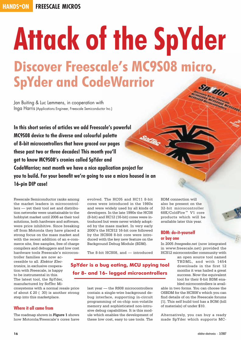
Attack of the SpYderDiscover Freescale’s MC9S08 micro, SpYder and CodeWarriorJan Buiting & Luc Lemmens, in cooperation withInga Harris (Applications Engineer, Freescale Semiconductor Inc.)
In this short series of articles we add Freescale’s powerful MC9S08 device to the diverse and colourful palette of 8-bit microcontrollers that have graced our pages these past two or three decades! This month you’ll get to know MC9S08’s cronies called SpYder and CodeWarrior; next month we have a nice application project for you to build. For your benefi t we’re going to use a micro housed in an 16-pin DIP case!
Freescale Semiconductor ranks among the market leaders in microcontrol-lers — yet their tool set and distribu-tion networks were unattainable to the hobbyist market until 2006 as their tool solutions, both hardware and software, were price inhibitive. Since breaking off from Motorola they have placed a strong focus on the mass market and with the recent addition of an e-com-merce site, free samples, free of charge compilers and debuggers and low cost hardware tools Freescale’s microcon-troller families are now ac-cessible to all. Elektor Elec-tronics, in exclusive coopera-tion with Freescale, is happy to be instrumental in this.The latest tool, the SpYder, manufactured by SofTec Mi-crosystems with a normal resale price of about £ 20 ( 30) is another strong step into this marketplace.
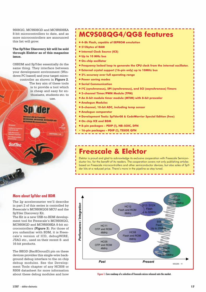
Where it all came fromThe roadmap shown in Figure 1 shows how Motorola/Freescale’s cores have
evolved. The HC05 and HC11 8-bit cores were introduced in the 1980s and were widely used by all kinds of developers. In the late 1990s the HC08 (8-bit) and HC12 (16-bit) cores were in-troduced but were never widely adopt-ed by the mass market. In very early 2000’s the HCS12 16-bit core followed by the HCS08 8-bit core were intro-duced with the key new feature on the Background Debug Module (BDM).
The 8-bit HCS08, and — introduced
last year — the RS08 microcontrollers contain a single-wire background de-bug interface, supporting in-circuit programming of on-chip non-volatile memory and sophisticated non-intru-sive debug capabilities. It is this mod-ule which enables the development of these low cost, easy to use tools. The
BDM connection will also be present on the 32-bit microcontroller 68K/ColdFire™ V1 core products which will be available later this year.
BDM: do-it-yourself or buy oneIn 2005 freegeeks.net (now integrated in www.freescale.net) provided the HCS12 microcontroller community with
an open source tool named TBDML, and with 1454 downloads in the first 12 months it was hailed a great success. Now the equivalent tool for their 8-bit BDM ena-bled microcontrollers is avail-
able in two forms. You can choose the OSBDM for the HCS08’s which you can fi nd details of on the Freescale forums [1]. This self build tool has a BOM (bill of materials) of under $10.
Alternatively, you can buy a ready made SpYder which supports MC-
SpYder is a bug eating, MCU spying tool
for 8- and 16- legged microcontrollers
173/2007 - elektor electronics
9S08QG, MC9S08QD and MC9RS08KA 8-bit microcontrollers to date, and as more microcontrollers are announced this list will grow.
The SpYder Discovery kit will be sold through Elektor as of this magazine issue.
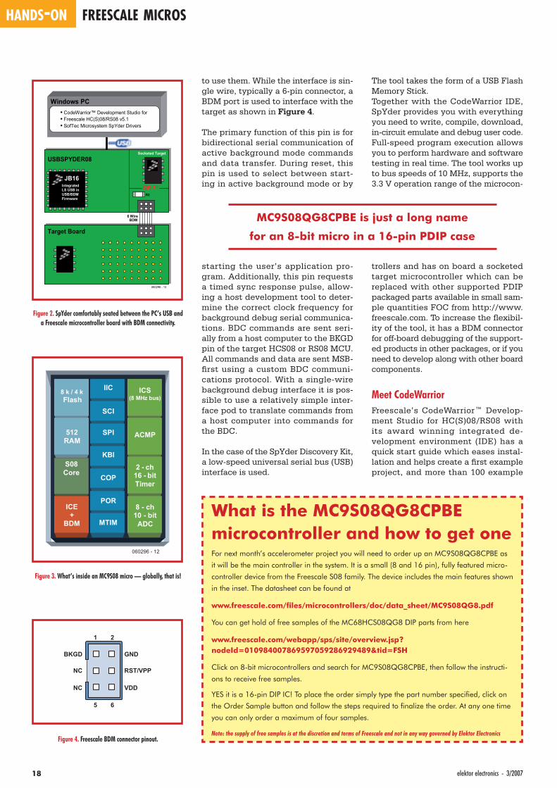
OSBDM and SpYder essentially do the same thing. They interface between your development environment (Win-dows PC based) and your target micro-
controller as shown in Figure 2. The key aim of these tools is to provide a tool which is cheap and easy for en-thusiasts, students etc. to
use.
More about SpYder and BDMThe 2g accelerometer we’ll describe in part 2 of this series is controlled by Freescale’s MC9S08QG8 MCU and the SpYder Discovery Kit.The Kit is a new USB-to-BDM develop-ment tool for Freescale’s MC9S08QG, MC9S08QD and MC9RS08KA 8-bit mi-crocontrollers (Figure 3). For those of you unfamiliar with BDM, it is Frees-cale’s version of ICD, debugWIRE, JTAG etc., used on their recent 8- and 16-bit products.
The BKGD (BacKGrounD) pin on these devices provides this single-wire back-ground debug interface to the on chip debug modules. See the Develop-ment Tools chapter of any HCS08 or RS08 datasheet for more information about these debug modules and how
HC05 OTP and ROM
4MHz
HC11 OTP and ROM
4MHz HC08Flash and ROM
8MHz
S12 / S12XFlash
Perf
orm
ance
/ In
tegr
atio
n
Past Present
HC12Flash and ROM
8MHz
CFv1 Flash
Up to 25MHz
S08 Flash
Up to 25MHz
RS08 Flash
Up to 10MHz
060296 - 11
Figure 1. Core roadmap of a selection of Freescale micros released onto the market.
Freescale & ElektorElektor is proud and glad to acknowledge its exclusive cooperation with Freescale Semicon-ductor Inc. for the benefi t of its readers. The cooperation covers not only publishing articles based on Freescale microcontrollers and other semiconductor devices, but also sales of SpY-der kits at a reduced price. There’s more in the pipeline so stay tuned.
MC9S08QG4/QG8 features•• 4-8k Flash, capable of EEPROM emulation
•• 512bytes of RAM
•• Internal Clock Source (ICS)
•• Up to 10 MHz bus
•• On-chip oscillator
•• Frequency locked loop to generate the CPU clock from the internal oscillator.
•• External crystal support (16-pin only) up to 10MHz bus
•• 2% accuracy over full operating range
•• Power saving modes
•• Serial Communication
•• I2C (synchronous), SPI (synchronous), and SCI (asynchronous) Timers
•• 2-channel Timer/PWM Module (TPM)
•• An 8-bit modulo timer module (MTIM) with 8-bit prescaler
•• Analogue Modules
•• 8-channel, 10-bit ADC, including temp sensor
•• Analogue comparator
•• Development Tools: SpYder08 & CodeWarrior Special Edition (free)
•• On chip ICE and BDM
•• 8-pin packages – PDIP (!), NB-SOIC, DFN
• 16-pin packages – PDIP (!), TSSOP, QFN
HANDS-ON FREESCALE MICROS
18 elektor electronics - 3/2007
The tool takes the form of a USB Flash Memory Stick.Together with the CodeWarrior IDE, SpYder provides you with everything you need to write, compile, download, in-circuit emulate and debug user code. Full-speed program execution allows you to perform hardware and software testing in real time. The tool works up to bus speeds of 10 MHz, supports the 3.3 V operation range of the microcon-
trollers and has on board a socketed target microcontroller which can be replaced with other supported PDIP packaged parts available in small sam-ple quantities FOC from http://www.freescale.com. To increase the fl exibil-ity of the tool, it has a BDM connector for off-board debugging of the support-ed products in other packages, or if you need to develop along with other board components.
Meet CodeWarriorFreescale’s CodeWarrior™ Develop-ment Studio for HC(S)08/RS08 with its award winning integrated de-velopment environment (IDE) has a quick start guide which eases instal-lation and helps create a fi rst example project, and more than 100 example
to use them. While the interface is sin-gle wire, typically a 6-pin connector, a BDM port is used to interface with the target as shown in Figure 4.
The primary function of this pin is for bidirectional serial communication of active background mode commands and data transfer. During reset, this pin is used to select between start-ing in active background mode or by
starting the user’s application pro-gram. Additionally, this pin requests a timed sync response pulse, allow-ing a host development tool to deter-mine the correct clock frequency for background debug serial communica-tions. BDC commands are sent seri-ally from a host computer to the BKGD pin of the target HCS08 or RS08 MCU. All commands and data are sent MSB-fi rst using a custom BDC communi-cations protocol. With a single-wire background debug interface it is pos-sible to use a relatively simple inter-face pod to translate commands from a host computer into commands for the BDC.
In the case of the SpYder Discovery Kit, a low-speed universal serial bus (USB) interface is used.
What is the MC9S08QG8CPBE microcontroller and how to get oneFor next month’s accelerometer project you will need to order up an MC9S08QG8CPBE as
it will be the main controller in the system. It is a small (8 and 16 pin), fully featured micro-
controller device from the Freescale S08 family. The device includes the main features shown
in the inset. The datasheet can be found at
www.freescale.com/fi les/microcontrollers/doc/data_sheet/MC9S08QG8.pdf
You can get hold of free samples of the MC68HCS08QG8 DIP parts from here
www.freescale.com/webapp/sps/site/overview.jsp? nodeId=010984007869597059286929489&tid=FSH
Click on 8-bit microcontrollers and search for MC9S08QG8CPBE, then follow the instructi-
ons to receive free samples.
YES it is a 16-pin DIP IC! To place the order simply type the part number specifi ed, click on
the Order Sample button and follow the steps required to fi nalize the order. At any one time
you can only order a maximum of four samples.
Note: the supply of free samples is at the discretion and terms of Freescale and not in any way governed by Elektor Electronics
Windows PC
USBSPYDER08
Target Board
6 Wire BDM
JB16
Integrated LS USB in USB/BDM Firmware
• CodeWarrior™ Development Studio for • Freescale HC(S)08/RS08 v5.1 • SofTec Microsystem SpYder Drivers
R2
060296 - 13
Socketed Target
OR !!!
Figure 2. SpYder comfortably seated between the PC’s USB and a Freescale microcontroller board with BDM connectivity.
8 k / 4 k Flash
512 RAM
IIC
SCI
SPI
KBI
ICS (8 MHz bus)
ACMP
2 - ch 16 - bit Timer
8 - ch 10 - bit ADC
COP
POR
MTIM
S08 Core
ICE +
BDM
060296 - 12
Figure 3. What’s inside an MC9S08 micro — globally, that is!
1 2
GND
RST/VPP
VDD
BKGD
NC
NC
5 6
Figure 4. Freescale BDM connector pinout.
MC9S08QG8CPBE is just a long name
for an 8-bit micro in a 16-pin PDIP case
193/2007 - elektor electronics
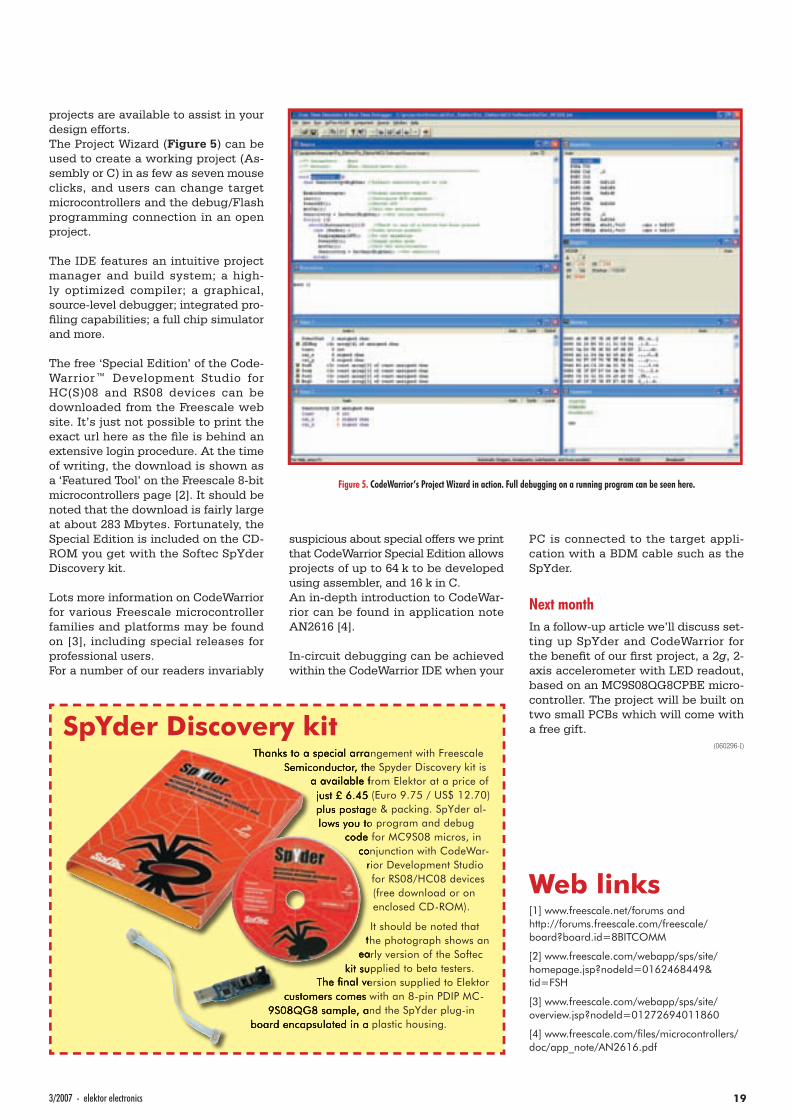
projects are available to assist in your design efforts.The Project Wizard (Figure 5) can be used to create a working project (As-sembly or C) in as few as seven mouse clicks, and users can change target microcontrollers and the debug/Flash programming connection in an open project.
The IDE features an intuitive project manager and build system; a high-ly optimized compiler; a graphical, source-level debugger; integrated pro-fi ling capabilities; a full chip simulator and more.
The free ‘Special Edition’ of the Code-Warrior™ Development Studio for HC(S)08 and RS08 devices can be downloaded from the Freescale web site. It’s just not possible to print the exact url here as the fi le is behind an extensive login procedure. At the time of writing, the download is shown as a ‘Featured Tool’ on the Freescale 8-bit microcontrollers page [2]. It should be noted that the download is fairly large at about 283 Mbytes. Fortunately, the Special Edition is included on the CD-ROM you get with the Softec SpYder Discovery kit.
Lots more information on CodeWarrior for various Freescale microcontroller families and platforms may be found on [3], including special releases for professional users.For a number of our readers invariably
suspicious about special offers we print that CodeWarrior Special Edition allows projects of up to 64 k to be developed using assembler, and 16 k in C.An in-depth introduction to CodeWar-rior can be found in application note AN2616 [4].
In-circuit debugging can be achieved within the CodeWarrior IDE when your
PC is connected to the target appli-cation with a BDM cable such as the SpYder.
Next monthIn a follow-up article we’ll discuss set-ting up SpYder and CodeWarrior for the benefi t of our fi rst project, a 2g, 2-axis accelerometer with LED readout, based on an MC9S08QG8CPBE micro-controller. The project will be built on two small PCBs which will come with a free gift.
(060296-I)
Web links[1] www.freescale.net/forums and http://forums.freescale.com/freescale/board?board.id=8BITCOMM
[2] www.freescale.com/webapp/sps/site/homepage.jsp?nodeId=0162468449& tid=FSH
[3] www.freescale.com/webapp/sps/site/overview.jsp?nodeId=01272694011860
[4] www.freescale.com/fi les/microcontrollers/doc/app_note/AN2616.pdf
SpYder Discovery kit Thanks to a special arrangement with Freescale
Semiconductor, the Spyder Discovery kit is a available from Elektor at a price of just £ 6.45 (Euro 9.75 / US$ 12.70) plus postage & packing. SpYder al-lows you to program and debug
code for MC9S08 micros, in conjunction with CodeWar-
rior Development Studio for RS08/HC08 devices (free download or on enclosed CD-ROM).
It should be noted that the photograph shows an
early version of the Softec kit supplied to beta testers.
The fi nal version supplied to Elektor customers comes with an 8-pin PDIP MC-
9S08QG8 sample, and the SpYder plug-in board encapsulated in a plastic housing.
Figure 5. CodeWarrior’s Project Wizard in action. Full debugging on a running program can be seen here.
INFO & MARKET GENERATORS
20 elektor electronics - 3/2007
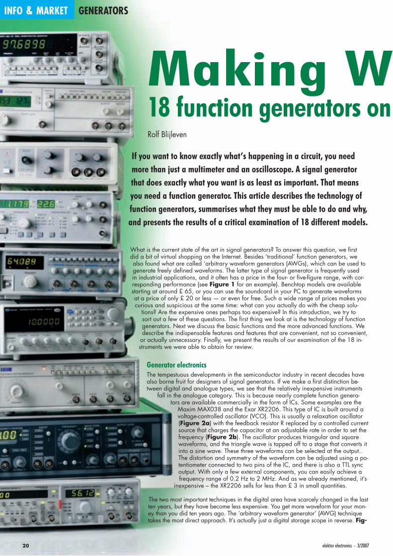
What is the current state of the art in signal generators? To answer this question, we fi rst did a bit of virtual shopping on the Internet. Besides ‘traditional’ function generators, we also found what are called ‘arbitrary waveform generators (AWGs), which can be used to generate freely defi ned waveforms. The latter type of signal generator is frequently used in industrial applications, and it often has a price in the four- or fi ve-fi gure range, with cor-responding performance (see Figure 1 for an example). Benchtop models are available starting at around £ 65, or you can use the soundcard in your PC to generate waveforms at a price of only £ 20 or less — or even for free. Such a wide range of prices makes you curious and suspicious at the same time: what can you actually do with the cheap solu-
tions? Are the expensive ones perhaps too expensive? In this introduction, we try to sort out a few of these questions. The fi rst thing we look at is the technology of function generators. Next we discuss the basic functions and the more advanced functions. We describe the indispensable features and features that are convenient, not so convenient,
or actually unnecessary. Finally, we present the results of our examination of the 18 in-struments we were able to obtain for review.
Generator electronicsThe tempestuous developments in the semiconductor industry in recent decades have also borne fruit for designers of signal generators. If we make a fi rst distinction be-tween digital and analogue types, we see that the relatively inexpensive instruments
fall in the analogue category. This is because nearly complete function genera-tors are available commercially in the form of ICs. Some examples are the
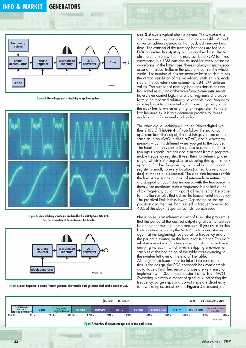
Maxim MAX038 and the Exar XR2206. This type of IC is built around a voltage-controlled oscillator (VCO). This is usually a relaxation oscillator (Figure 2a) with the feedback resistor R replaced by a controlled current source that charges the capacitor at an adjustable rate in order to set the frequency (Figure 2b). The oscillator produces triangular and square waveforms, and the triangle wave is tapped off to a stage that converts it into a sine wave. These three waveforms can be selected at the output.. The distortion and symmetry of the waveform can be adjusted using a po-tentiometer connected to two pins of the IC, and there is also a TTL sync output. With only a few external components, you can easily achieve a frequency range of 0.2 Hz to 2 MHz. And as we already mentioned, it’s
inexpensive – the XR2206 sells for less than £ 3 in small quantities.
The two most important techniques in the digital area have scarcely changed in the last ten years, but they have become less expensive. You get more waveform for your mon-ey than you did ten years ago. The ‘arbitrary waveform generator’ (AWG) technique takes the most direct approach. It’s actually just a digital storage scope in reverse. Fig-
Making W18 function generators on Rolf Blijleven
If you want to know exactly what’s happening in a circuit, you need more than just a multimeter and an oscilloscope. A signal generator that does exactly what you want is as least as important. That means you need a function generator. This article describes the technology of function generators, summarises what they must be able to do and why, and presents the results of a critical examination of 18 different models.
213/2007 - elektor electronics
avesthe test bench
R
10k10k
C
C
060312 - 11
P
Vref
a b
S
VCO
sineshaper
Figure 2. Basic circuits of analogue signal generator ICs. 2a: The simplest circuit consists of an oscillator formed by an opamp, a few resistors, and a capacitor.
2b: The oscillator circuit is used as a voltage-controlled oscillator (VCO) in function generator ICs. The triangle wave is shaped into a sine wave in a separate stage. This yields a choice of three waveforms.
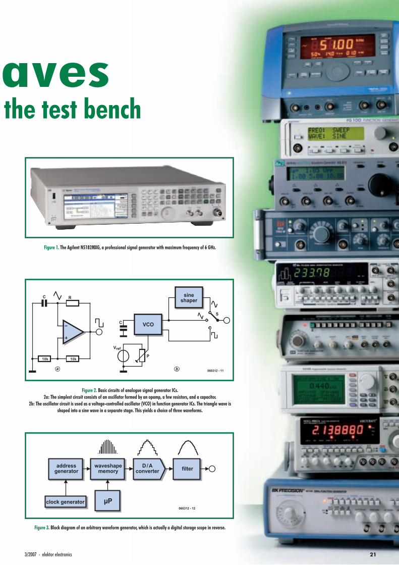
Figure 1. The Agilent N5182MXG, a professional signal generator with maximum frequency of 6 GHz.
waveshapememory
µP
filterD / Aconverter
addressgenerator
clock generator060312 - 12
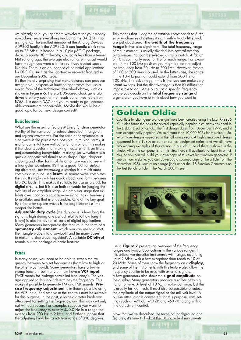
Figure 3. Block diagram of an arbitrary waveform generator, which is actually a digital storage scope in reverse.
INFO & MARKET GENERATORS
22 elektor electronics - 3/2007
ure 3 shows a typical block diagram. The waveform is stored in a memory that serves as a look-up table. A clock drives an address generator that reads out memory loca-tions. The contents of the memory locations are fed to a D/A converter. Its output signal is smoothed by a fi lter to eliminate harmonics. The memory can be a ROM for fi xed waveforms, but RAM can also be used for freely defi nable waveforms. In the latter case, there is always a microproc-essor or microcontroller in the picture to control the whole works. The number of bits per memory location determines the vertical resolution of the waveform. With 14 bits, each step of the waveform can assume 16,384 (214) different values. The number of memory locations determines the horizontal resolution of the waveform. Some instruments have clever control logic that allows segments of a wave-form to be repeated arbitrarily. A variable clock frequency or sampling rate is essential with this arrangement, since the clock has to run faster at higher frequencies. For very low frequencies, it is fairly common practice to ‘freeze’ each location for several clock pulses.
The other digital technique is called ‘direct digital syn-thesis’ (DDS) (Figure 4). If you follow the signal path upstream from the output, the fi rst things you see are the same as in an AWG: a fi lter, a DAC, and a waveform memory – but it’s different when you get to the source. The heart of this system is the phase accumulator. It has two input signals: a clock and a number from a program-mable frequency register. It uses them to defi ne a phase angle, which is the step size for stepping through the look-up table. For low frequencies, the number in the phase register is small, so every location (or nearly every loca-tion) of the table is accessed. The step size increases with the frequency, so the number of intermediate entries that are skipped on each step increases with the frequency. In theory, the maximum output frequency is one-half of the clock frequency, but at this point all that’s left of the wave-form is the samples that defi ne the fundamental frequency. The practical limit is thus lower. Depending on the ap-plication and the fi lter than is used, a frequency equal to 40% of the clock frequency can still be achieved.
Phase noise is an inherent aspect of DDS. The problem is that the period of the desired output signal cannot always be an integer multiple of the step size. If you try to fi x this by truncation (ignoring the ‘extra’ portion and starting again at the beginning), you obtain a frequency error: the period is shorter, so the frequency is higher. This isn’t what you want in a function generator. Another option is carrying the count, which means skipping a number of samples at the beginning of the table corresponding to the number left over at the end of the table.Although these issues must be taken into considera-tion in the design, the DDS approach has considerable advantages. First, frequency changes are very easy to implement with DDS – much easier than with an AWG. Sweeping is simply a matter of gradually increasing the frequency. Large steps and abrupt steps are dead easy (a few examples are shown in Figure 5). Second, as
waveshapememory filterD / A
converterphase
registerphase
accumulator
frequencyregister
clock060312 - 13
Figure 4. Block diagram of a direct digital synthesis system.
Figure 5. Some arbitrary waveforms produced by the M&R Systems WG-810. See the description of this instrument for details.
waveshapememory
D / Aconverter
addresscounter
clock generator060312 - 15
Figure 6. Block diagram of a simple function generator. The variable clock generator block can be based on DDS.
measurement,control &
process technology audio
0.001 Hz 30 Hz 20 kHz 300 kHz 1.7 MHz 26 MHz 88 MHz 108 MHz 174 MHz 300 MHz 3 GHz 30 GHz
060312 - 16
AM radio shortwave VHF TV
CB radio
FM radio airband & PMR UHF TV UHF TV, radarlong wave,high-end audio
radar, microwave,satellites
RC models GSM WiFi, Bluetooth, ZigBee
Figure 7. Overview of frequency ranges and related applications.
233/2007 - elektor electronics
we already said, you get more waveform for your money nowadays, since everything (including the DAC) fi ts into a single IC. The smallest member of the Analog Devices AD9800 family is the AD9833. It can handle clock rates up to 25 MHz, is housed in a 10-pin µSOIC package, draws a scanty 30 milliwatts, and costs less than a tenner. Not so long ago, the average electronics enthusiast would have thought you were a bit crazy if you quoted specs like this. There is an abundance of potential applications for DDS ICs, such as the short-wave receiver featured in our December 2006 issue.It’s thus hardly surprising that manufacturers can produce acceptable, inexpensive function generators that use a mixed form of the techniques described above, such as shown in Figure 6. Here a DDS-based clock generator drives a binary counter that reads out a fi xed table from ROM. Just add a DAC and you’re ready to go. Innumer-able variants are conceivable. Maybe this would be a good topic for our next design contest?
Basic featuresWhat are the essential features? Every function generator worthy of the name can produce sinusoidal, triangular, and square waveforms. For the sake of completeness, a sine wave is the purest tone possible. In musical terms, it is a fundamental tone without any harmonics. This makes it the ideal waveform for making measurements on fi lters and determining bandwidths. A triangular waveform is a quick diagnostic aid thanks to its shape. Dips, dropouts, clipping and other forms of distortion are easy to see with a triangular waveform. It’s thus a good tool for detect-ing distortion, but measuring distortion is a much more complex discipline (see inset). A square wave completes the trio. It simply switches quickly back and forth between two DC levels. This makes it suitable for use as a clock for digital circuits, but it is also indispensable for judging the stability of an amplifi er stage. An amplifi er stage that ex-hibits overshoot on a square-wave signal has a tendency to oscillate, and that is undesirable. One of the key qual-ity criteria for square waves is the edge steepness: the steeper the better.Adjustable duty cycle (the duty cycle is how long the signal is high during one period relative to how long it is low) is also handy for all sorts of digital applications.. Many generators incorporate this feature in the form of a symmetry adjustment, which you can use to distort the triangle wave into a sawtooth and (in many cases) to make the sine wave ‘lopsided’. A variable DC offset rounds out the package of basic features.
ExtrasIn many cases, you need to be able to sweep the fre-quency between two set frequencies (from low to high or the other way round). Some generators have a built-in sweep function, but many of them have a VCF input (‘VCF stands for ‘voltage-controlled frequency’). The volt-age applied to this input determines the frequency. This makes it possible to generate FM and FSK signals. Pre-cise frequency adjustment is in theory possible using the VCF input, and otherwise the controls must be suitable for this purpose. In the past, a large-diameter knob was often used for setting the frequency, and this was certainly not without reason. For example, suppose you want to adjust the frequency to exactly 440.0 Hz in a range that extends from 200 Hz to 2 kHz, and further suppose that the adjusting knob has a rotation range of 330 degrees.
This means that 1 degree of rotation corresponds to 5 Hz, so your chances of getting it right with a fi ddly little knob are just about zero. The width of the frequency range is thus also signifi cant. The total frequency range of the instrument is usually divided into several overlap-ping ranges that can be selected using a switch. A factor of 10 is commonly used for the for each range. For exam-ple, in the 100-kHz position you might be able to adjust the frequency from 20 kHz to 200 kHz. However, factors of 100 or 200 are also used. In the latter case, the range in the 10-kHz position could extend from 500 Hz to 100 kHz. The advantage if this is that you can make very broad sweeps, but the disadvantage is that it’s diffi cult or impossible to adjust the output to a specifi c frequency.Before you decide on the total frequency range of a generator, you have to think about how you want to
use it. Figure 7 presents an overview of the frequency ranges and typical applications in the various ranges. In this article, we describe instruments with ranges extending up to 2 MHz, with a few exceptions than reach to 10 or 20 MHz. Some of them show the frequency on a display, and some of the instruments with this feature also allow the frequency counter to be used with external signals.A few generators also show the signal amplitude on the display. Many generators produce a rather hefty sig-nal amplitude. A level of 10 Vpp is not uncommon, but this is usually far too much. It must also be possible to reduce the amplitude of the output signal to the millivolt level. A built-in attenuator is convenient for this purpose, with set-tings such as –20 dB, –40 dB and –60 dB, along with a fi ne adjustment control.
Now that we’ve described the technical background and features, it’s time to look at the 18 individual instruments.
Golden OldieCountless function generator designs have been created using the Exar XR2206 IC. It also forms the basis for several especially popular instruments designed in the Elektor Electronics lab. The fi rst design dates from December 1977, and it was exceptionally popular. We sold more than 10,000 PCBs for this circuit. Se-veral more designs appeared in the following years. A highly improved design appeared in the 1980s as part of our test equipment series, and we still have two working examples of this version in our lab. One of them is shown in the photo. All of the components for this circuit are still available (at least in princi-ple), so you can still build your own copy of this excellent function generator. If you visit our website, you can download a scanned copy of the article from the December 1984 issue at no charge (look under the ’18 Function Generators on the Test Bench’ article in the March 2007 issue).

INFO & MARKET GENERATORS
24 elektor electronics - 3/2007
H-Tronic FG-200This is one of the least expensive signal gene-rators in the test. Built around a 2206, this in-strument generates sine, triangle and square waves in six selectable ranges extending from 1 Hz to 100 kHz, continuously adjusta-ble from 0.2 to 2.4 times the selected decade value. The frequency range thus extends from 0.2 Hz to 240 kHz. There is only one knob to set the output level, so the adjustment is rather coarse. There are two AC outputs with overlapping ranges extending from 10 mVpp to 12 Vpp, and a DC output with a range of 100 mVpp to 10 Vpp. The DC offset is conti-nuously adjustable from –5 V to +4 V.
All of these measurements correspond exact-ly to the specs in the user’s guide, which only amounts to two pages. The operating instructions are essentially nothing more than ‘read what’s next the knobs and eve-rything will be obvious’. The distortion spec is 1%. At the upper end of the frequency range, the sine wave is dented and the trian-gle wave looks like a tent with a strong side wind. Nevertheless, the FG-200 is distinctly better than the only less expensive option (soundcard function generators). If you can manage without luxury, this instrument offers outstanding value for money.
Goodwill Instek GFG-8015GIt looks like something from the former East Bloc with its dark-grey case, sloping ed-ges and hooded panel, but it comes from Taiwan. The user’s guide includes not only extensive specifi cations and an explanation of what the knobs do, but also a detailed description of the schematic.
This is an analogue signal generator with all the standard features. The controls are laid out nicely and show evidence of ca-reful consideration: you can disable the offset instead of just adjusting it to zero, a two-position attenuator with steps of
20 dB enables minimum output levels be-low 10 mVpp, there is an inversion switch, and there is a VCF input that can be used with an external sweep signal.
A small drawback is that the frequency ad-justment is rather coarse, but otherwise this is a very reasonable signal generator at a highly competitive price.
ELV SFG-7002 MThe German user’s guide is very extensive and includes all the schematics. That’s be-cause this instrument is designed as a kit, and it is also available as such (with a less expensive case) starting at about £ 90. Our test model was the most expensive (£ 138), ready-made version in a metal case. Our fi rst impression was that it has to be located at eye level, since otherwise it’s diffi cult to see what you’re doing. It doesn’t have any sort of tilt stand. It doesn’t have a display, but it does have internal sweep capability in addition to the standard set of functions, as well as symmetry and off-
set controls. The range switch has four po-sitions that don’t do anything, but there aren’t any markings on the panel for these positions, so it’s probably supposed to be that way. The symmetry knob doesn’t affect the sine wave, and the triangle wave turns into a DC voltage when you turn it fully to the right. Nevertheless, this is still a good choice for hobbyists in particular, since it offers a lot of capability at a low price. It is built around the MAX038, which has been discontinued, so don’t wait too long.

253/2007 - elektor electronics
Voltcraft 7202This signal generator makes a rather nice visual impression with its many pushbuttons and knobs, which can be used to set or ad-just just about everything imaginable – es-pecially if you look at the price at the same time: £ 152 ex VAT. A fi ve-digit frequency counter provides direct readout of the fre-quency setting. We needed the spare fuse provided with this Voltcraft 7202, since it didn’t do anything at fi rst after we unpac-ked it (but it worked perfectly afterwards). The price is very competitive considering its extensive set of features (see the table), but on closer examination its specifi cations
are rather weak compared with its closest neighbours in this price class. The square wave looks more like a sine wave in the upper portion of the frequency range, the adjustment is very coarse with a factor of 200 between the minimum and maximum frequencies, and the lowest output ampli-tude is 125 mVpp, which is rather high. It’s made in Korea, presumably in the same factory as the FG8220, the Dynatek DSG 310 and the Voltcraft MXG-9802A. Alt-hough this is the best of the four in terms of ease of use, it unfortunately falls a bit short.
Thurlby Thandar Instruments TG210This is one of the lower-priced signal ge-nerators in the TTI product line. Compa-red with its more expensive brother, the TG513, it has a maximum frequency of 2 MHz instead of 3 MHz, no display, and only a 20-dB attenuator, but it does have a symmetry control, a DC offset control with a zero detent, a sweep input, an Aux output, and signal outputs with two different impe-dances (600 ohms and 50 ohms). The mi-nimum output level is 20 mVpp with the 20-dB attenuator selected, and it has a small dead zone when the knob is turned all the way to the left, but the knobs are still large
enough for decently precise adjustment.
A special feature in comparison with the other instruments is that it can also gene-rate very low frequencies – much lower than specifi ed (we measured approxima-tely 5 milliherz).
For the rest, it’s a solid instrument that is pleasant to use and does what it promises plus bit more. In a word, good.
Digimess FG200It’s a bit strange that although the FG200 is less expensive than the Digimess FG100 and has a slightly smaller feature set, it has several nice extras compared with the in-struments closest to it in its price class. It has built-in linear and logarithmic sweep functions and a frequency counter that can also be used with external signals. The fre-quency control is a ten-turn potentiometer, but unfortunately the suggestion of incre-ased accuracy is not borne out in practice. Maybe the problem is with the frequency counter, but the two least signifi cant digits of the four-digit frequency display were al-
most always fl ickering back and forth bet-ween two values. This was synchronised with the fl ashing of the Gate LED. The in-cluded user’s guide is rather precursory. It doesn’t say anything at all about the Gate LED, for instance, or about several other features. The instrument does have a lot of LEDs, but that’s a matter of taste.
Although it’s a reasonably versatile instru-ment at a reasonable price, it doesn’t live up to the legend of German solidity sugge-sted by its name.

INFO & MARKET GENERATORS
26 elektor electronics - 3/2007
M&R Systems WG-810Modern styling with separate buttons for the basic functions and a menu button, selec-tion knobs, and a rotary knob for naviga-ting through the menus on the LCD screen. Everything is nicely arranged and functi-onal. Besides the standard set of signals, it can generate a sawtooth, noise, and much more: this generator can produce genuine arbitrary waveforms. It has seven built-in extra waveforms, of which two can be morphed (stretched out of shape). One of them is a square wave where you can pull the corners down toward the baseline until it changes into a sine wave, and the
other is a sine wave with adjustable phase cut. With 8-bit resolution and an upper fre-quency of 10 MHz (hence the name), it has relatively modest resolution and distortion (see table), but its real power is hidden be-hind the rear-panel RS232 connector. In combination with the separately available Spro program or a terminal emulator pro-gram available on the Mair & Roher web-site, you can use it to download your own waveforms.
A very versatile instrument at a competitive price: that’s professional!
B+K Precision 4010AThis rather sizeable instrument was desig-ned in the US, but it is made in Taiwan. It has a good front-panel layout. The scale of the frequency adjustment knob covers only half of its range of rotation, so there are ‘dead zones’ at each end. It has a sync output, which is a relatively rare feature, and it can be switched to CMOS mode. The output level can be adjusted between 4 V and 14 V in CMOS mode. The swit-ching levels of CMOS are 1/3 and 2/3 of the supply voltage, so a lower limit of 4 V is too high if the supply voltage is 5 V or less – which is entirely possible with bat-
tery-powered circuits. Maybe it’s handy for working with relay control logic, but in our opinion it is of limited use. The INV knob doesn’t do anything, which is irritating. The 4010A falls short in comparison with other instruments in the same price class. The specifi cations are nothing special, the sine-wave distortion is quite high (4% at 1 kHz), and it takes up a lot of space on the bench.
There are cheaper instruments available with better performance.
Voltcraft MXG-9802AThis instrument is also available under the Metex brand name, and like the previously mentioned FG8220 and DSG 310, it co-mes from Korea. The four-language user’s guide is limited to a brief description of the functions. The instrument has an RS232 port, but unfortunately there’s no descrip-tion anywhere of how to use it. As a func-tion generator, it is reasonably complete with all the standard features and a built-in sweep function, which behaves the same way as the DWG 315 sweep (see the des-cription there). It has a 4.5-turn potentiome-ter for setting the frequency, which is better
than what its companions have to offer and makes quite precise adjustment possible. Unfortunately, the frequency counter is very coarse below 1 kHz and requires a lot of juggling with the gate and reset controls. The longest gate time gives the best accu-racy, but then you have to wait around 20 seconds each time you change the frequen-cy before you can read the new value. It has two counter inputs. The high-frequency input works up to 2.7 GHz, but it gets tho-roughly confused if the input signal level drops below approximately 1 Vpp. Con-clusion: it can do a lot, but it has quite a
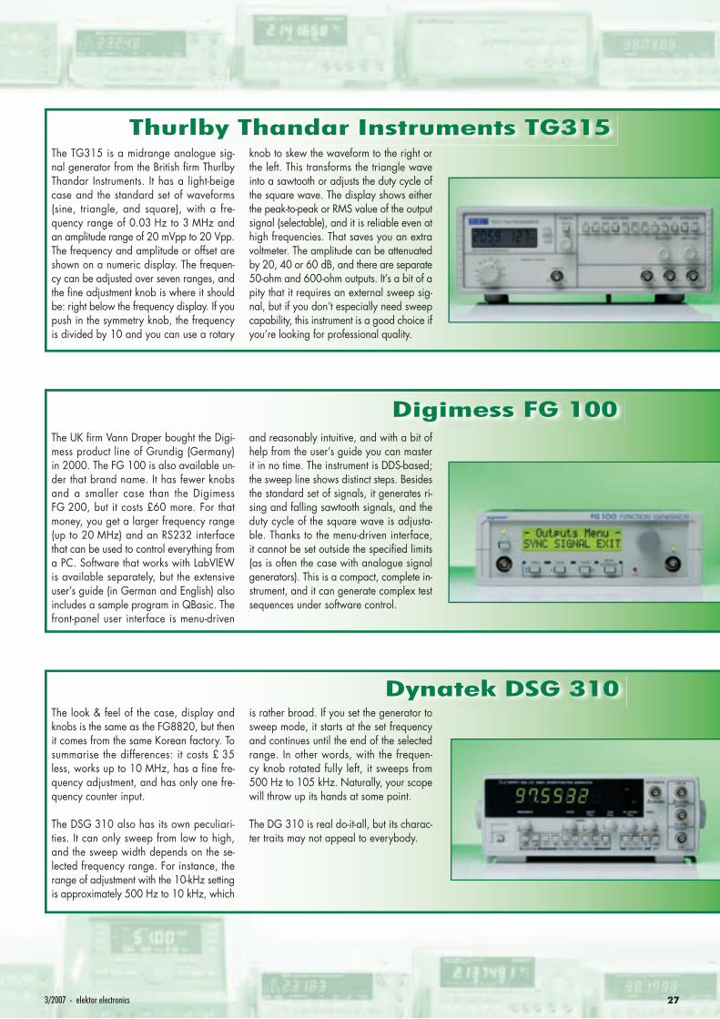
273/2007 - elektor electronics
Digimess FG 100The UK fi rm Vann Draper bought the Digi-mess product line of Grundig (Germany) in 2000. The FG 100 is also available un-der that brand name. It has fewer knobs and a smaller case than the Digimess FG 200, but it costs £60 more. For that money, you get a larger frequency range (up to 20 MHz) and an RS232 interface that can be used to control everything from a PC. Software that works with LabVIEW is available separately, but the extensive user’s guide (in German and English) also includes a sample program in QBasic. The front-panel user interface is menu-driven
and reasonably intuitive, and with a bit of help from the user’s guide you can master it in no time. The instrument is DDS-based; the sweep line shows distinct steps. Besides the standard set of signals, it generates ri-sing and falling sawtooth signals, and the duty cycle of the square wave is adjusta-ble. Thanks to the menu-driven interface, it cannot be set outside the specifi ed limits (as is often the case with analogue signal generators). This is a compact, complete in-strument, and it can generate complex test sequences under software control.
Dynatek DSG 310The look & feel of the case, display and knobs is the same as the FG8820, but then it comes from the same Korean factory. To summarise the differences: it costs £ 35 less, works up to 10 MHz, has a fi ne fre-quency adjustment, and has only one fre-quency counter input.
The DSG 310 also has its own peculiari-ties. It can only sweep from low to high, and the sweep width depends on the se-lected frequency range. For instance, the range of adjustment with the 10-kHz setting is approximately 500 Hz to 10 kHz, which
is rather broad. If you set the generator to sweep mode, it starts at the set frequency and continues until the end of the selected range. In other words, with the frequen-cy knob rotated fully left, it sweeps from 500 Hz to 105 kHz. Naturally, your scope will throw up its hands at some point.
The DG 310 is real do-it-all, but its charac-ter traits may not appeal to everybody.
Thurlby Thandar Instruments TG315The TG315 is a midrange analogue sig-nal generator from the British fi rm Thurlby Thandar Instruments. It has a light-beige case and the standard set of waveforms (sine, triangle, and square), with a fre-quency range of 0.03 Hz to 3 MHz and an amplitude range of 20 mVpp to 20 Vpp. The frequency and amplitude or offset are shown on a numeric display. The frequen-cy can be adjusted over seven ranges, and the fi ne adjustment knob is where it should be: right below the frequency display. If you push in the symmetry knob, the frequency is divided by 10 and you can use a rotary
knob to skew the waveform to the right or the left. This transforms the triangle wave into a sawtooth or adjusts the duty cycle of the square wave. The display shows either the peak-to-peak or RMS value of the output signal (selectable), and it is reliable even at high frequencies. That saves you an extra voltmeter. The amplitude can be attenuated by 20, 40 or 60 dB, and there are separate 50-ohm and 600-ohm outputs. It’s a bit of a pity that it requires an external sweep sig-nal, but if you don’t especially need sweep capability, this instrument is a good choice if you’re looking for professional quality.

INFO & MARKET GENERATORS
28 elektor electronics - 3/2007
Seintek G5100This compact instrument is DDS-based, and it has eight programs that you can confi gu-re and recall as desired. That’s apparently how it is intended to be used: set it up once and then leave it alone. Its capabilities are otherwise rather standard (see table). The user interface is on the diffi cult side: the twelve buttons for the regular functions and another eight for navigating the menu are inconveniently close together. It also has a rotary knob with clicks, but confusingly enough, only every second click does any-thing. As a result, selecting and confi guring parameters takes a lot of button pushing
and knob turning, but absolutely everything can be confi gured. Too much fl exibility can create a maze.
Unfortunately, the software provided with the instrument does not add any functiona-lity. You can’t run a sequence of programs, which is truly a missed opportunity – this instrument is ideally suited for use in long-term testing under PC control, which ap-pears to be a more natural habitat for it than a lab bench.
Goodwill Instek SFG-2110This synthesized function generator has all the standard functions and much more. It is DDS-based, so it the user interface is dif-ferent from the usual analogue generators. You can set the frequency quickly and pre-cisely by entering the value with a numeric keypad and pressing the appropriate units button. You can also select any digit of the display separately and increase or decre-ase the value by rotating a knob with a nice click action. It can also sweep, over a nar-row or wide range and slowly or quickly. Another handy feature is that you can store up to ten confi gurations and recall them
as desired. The built-in frequency counter can also be used for external signals up to an impressive 150 MHz. It’s true that the counter doesn’t work properly below 9 Hz, although the specifi ed lower limit is 5 Hz, but that’s a minor detail. In terms of functi-onality, and especially in terms of ease of use, the SFG-2100 stands head and shoul-ders above the other instruments in its price class. If you don’t need an RS232 interface or frequencies above 10 MHz, but you do want to have a frequency counter, this is by far the best choice.
ELV MFG 9001MThe MFG 9001 comes from the German fi rm ELV and is available with several dif-ferent cases, either fully assembled or as a kit. The instrument we tested was housed in a solid metal case. The case is rather size-able, but the broad front panel provides a lot of functions. It has all the standard func-tions and built-in sweep.
The lower and upper sweep limits can be set precisely, with a maximum width factor of 10. The built-in frequency counter can also be used with external frequencies, and it has a separate offset (a rare feature). It
has a sweep output, and remarkably enou-gh, it can output signals at amplitudes down to the low millivolt level.
It lacks a tilt stand, so it must be placed at eye level, and the positioning of the BNC connectors is somewhat cramped, but it is fairly easy to use – we didn’t have to con-sult the user’s guide (in German only).
The MFG 9001 has an outstanding price/quality ratio as a ready-made instrument, and it’s a good deal better as a kit.
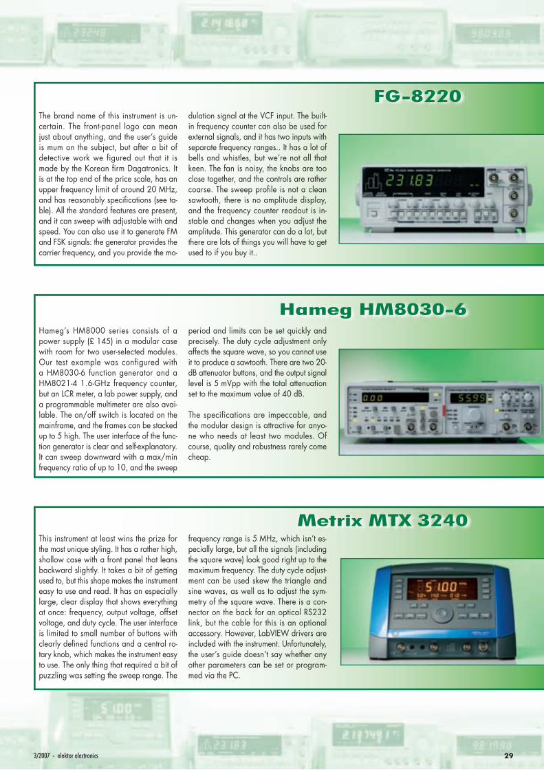
293/2007 - elektor electronics
Hameg HM8030-6Hameg’s HM8000 series consists of a power supply (£ 145) in a modular case with room for two user-selected modules. Our test example was configured with a HM8030-6 function generator and a HM8021-4 1.6-GHz frequency counter, but an LCR meter, a lab power supply, and a programmable multimeter are also avai-lable. The on/off switch is located on the mainframe, and the frames can be stacked up to 5 high. The user interface of the func-tion generator is clear and self-explanatory. It can sweep downward with a max/min frequency ratio of up to 10, and the sweep
period and limits can be set quickly and precisely. The duty cycle adjustment only affects the square wave, so you cannot use it to produce a sawtooth. There are two 20-dB attenuator buttons, and the output signal level is 5 mVpp with the total attenuation set to the maximum value of 40 dB.
The specifications are impeccable, and the modular design is attractive for anyo-ne who needs at least two modules. Of course, quality and robustness rarely come cheap.
Metrix MTX 3240This instrument at least wins the prize for the most unique styling. It has a rather high, shallow case with a front panel that leans backward slightly. It takes a bit of getting used to, but this shape makes the instrument easy to use and read. It has an especially large, clear display that shows everything at once: frequency, output voltage, offset voltage, and duty cycle. The user interface is limited to small number of buttons with clearly defi ned functions and a central ro-tary knob, which makes the instrument easy to use. The only thing that required a bit of puzzling was setting the sweep range. The
frequency range is 5 MHz, which isn’t es-pecially large, but all the signals (including the square wave) look good right up to the maximum frequency. The duty cycle adjust-ment can be used skew the triangle and sine waves, as well as to adjust the sym-metry of the square wave. There is a con-nector on the back for an optical RS232 link, but the cable for this is an optional accessory. However, LabVIEW drivers are included with the instrument. Unfortunately, the user’s guide doesn’t say whether any other parameters can be set or program-med via the PC.
FG-8220The brand name of this instrument is un-certain. The front-panel logo can mean just about anything, and the user’s guide is mum on the subject, but after a bit of detective work we figured out that it is made by the Korean fi rm Dagatronics. It is at the top end of the price scale, has an upper frequency limit of around 20 MHz, and has reasonably specifi cations (see ta-ble). All the standard features are present, and it can sweep with adjustable with and speed. You can also use it to generate FM and FSK signals: the generator provides the carrier frequency, and you provide the mo-
dulation signal at the VCF input. The built-in frequency counter can also be used for external signals, and it has two inputs with separate frequency ranges.. It has a lot of bells and whistles, but we’re not all that keen. The fan is noisy, the knobs are too close together, and the controls are rather coarse. The sweep profi le is not a clean sawtooth, there is no amplitude display, and the frequency counter readout is in-stable and changes when you adjust the amplitude. This generator can do a lot, but there are lots of things you will have to get used to if you buy it..
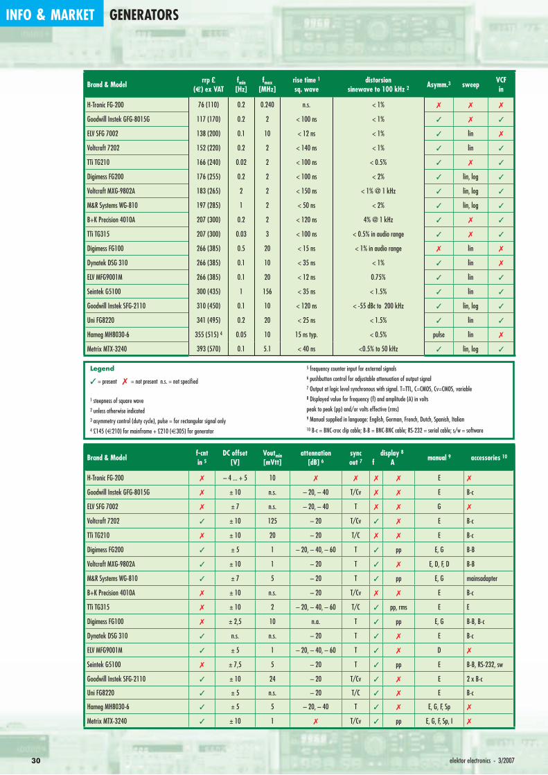
INFO & MARKET GENERATORS
30 elektor electronics - 3/2007
Brand & Model rrp £(€) ex VAT
fmin[Hz]
fmax[MHz]
rise time 1sq. wave
distorsion sinewave to 100 kHz 2 Asymm.3 sweep VCF
in
H-Tronic FG-200 76 (110) 0.2 0.240 n.s. < 1%
Goodwill Instek GFG-8015G 117 (170) 0.2 2 < 100 ns < 1%
ELV SFG 7002 138 (200) 0.1 10 < 12 ns < 1% lin
Voltcraft 7202 152 (220) 0.2 2 < 140 ns < 1% lin
TTi TG210 166 (240) 0.02 2 < 100 ns < 0.5%
Digimess FG200 176 (255) 0.2 2 < 100 ns < 2% lin, log
Voltcraft MXG-9802A 183 (265) 2 2 < 150 ns < 1% @ 1 kHz lin, log
M&R Systems WG-810 197 (285) 1 2 < 50 ns < 2% lin, log
B+K Precision 4010A 207 (300) 0.2 2 < 120 ns 4% @ 1 kHz
TTi TG315 207 (300) 0.03 3 < 100 ns < 0.5% in audio range
Digimess FG100 266 (385) 0.5 20 < 15 ns < 1% in audio range lin
Dynatek DSG 310 266 (385) 0.1 10 < 35 ns < 1% lin
ELV MFG9001M 266 (385) 0.1 20 < 12 ns 0.75% lin
Seintek G5100 300 (435) 1 156 < 35 ns < 1.5% lin
Goodwill Instek SFG-2110 310 (450) 0.1 10 < 120 ns < -55 dBc to 200 kHz lin, log
Uni FG8220 341 (495) 0.2 20 < 25 ns < 1.5% lin
Hameg MH8030-6 355 (515) 4 0.05 10 15 ns typ. < 0.5% pulse lin
Metrix MTX-3240 393 (570) 0.1 5.1 < 40 ns <0.5% to 50 kHz lin, log
Legend
= present = not present n.s. = not specifi ed
1 steepness of square wave2 unless otherwise indicated3 asymmetry control (duty cycle), pulse = for rectangular signal only4 £145 (€210) for mainframe + £210 (€305) for generator
5 frequency counter input for external signals6 pushbutton control for adjustable attenuation of output signal7 Output at logic level synchronous with signal. T=TTL, C=CMOS, Cv=CMOS, variable8 Displayed value for frequency (f) and amplitude (A) in volts
peak to peak (pp) and/or volts effective (rms)9 Manual supplied in language: English, German, French, Dutch, Spanish, Italian10 B-c = BNC-croc clip cable; B-B = BNC-BNC cable; RS-232 = serial cable; s/w = software
Brand & Model f-cnt in 5
DC offset[V]
Voutmin[mVtt]
attennation [dB] 6
syncout 7
display 8f A manual 9 accessories 10
H-Tronic FG-200 – 4 ... + 5 10 E
Goodwill Instek GFG-8015G ± 10 n.s. – 20, – 40 T/Cv E B-c
ELV SFG 7002 ± 7 n.s. – 20, – 40 T G
Voltcraft 7202 ± 10 125 – 20 T/Cv E B-c
TTi TG210 ± 10 20 – 20 T/C E B-c
Digimess FG200 ± 5 1 – 20, – 40, – 60 T pp E, G B-B
Voltcraft MXG-9802A ± 10 1 – 20 T E, D, F, D B-B
M&R Systems WG-810 ± 7 5 – 20 T pp E, G mainsadapter
B+K Precision 4010A ± 10 n.s. – 20 T/Cv E B-c
TTi TG315 ± 10 2 – 20, – 40, – 60 T/C pp, rms E E
Digimess FG100 ± 2,5 10 n.a. T pp E, G B-B, B-c
Dynatek DSG 310 n.s. n.s. – 20 T E B-c
ELV MFG9001M ± 5 1 – 20, – 40, – 60 T D
Seintek G5100 ± 7,5 5 – 20 T pp E B-B, RS-232, sw
Goodwill Instek SFG-2110 ± 10 24 – 20 T/Cv E 2 x B-c
Uni FG8220 ± 5 n.s. – 20 T/C E B-c
Hameg MH8030-6 ± 5 5 – 20, – 40 T E, G, F, Sp
Metrix MTX-3240 ± 10 1 T/Cv pp E, G, F, Sp, I
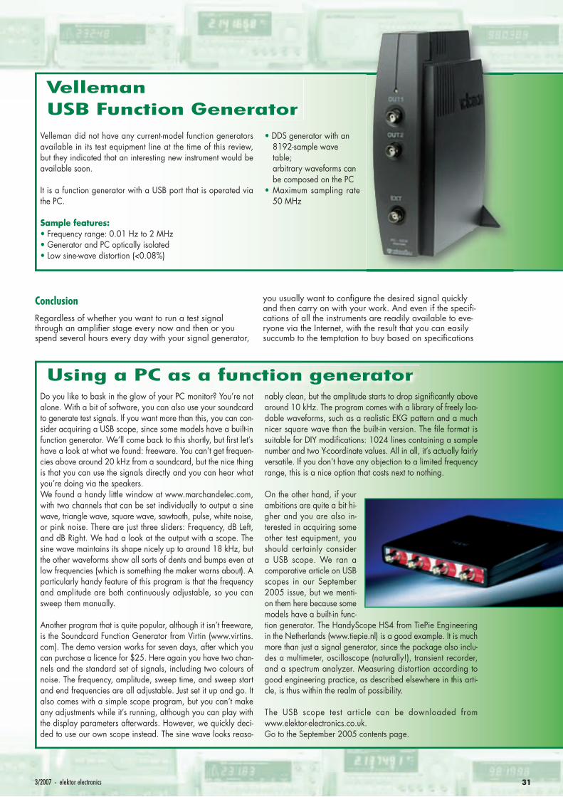
313/2007 - elektor electronics
ConclusionRegardless of whether you want to run a test signal through an amplifi er stage every now and then or you spend several hours every day with your signal generator,
you usually want to confi gure the desired signal quickly and then carry on with your work. And even if the specifi -cations of all the instruments are readily available to eve-ryone via the Internet, with the result that you can easily succumb to the temptation to buy based on specifi cations
Velleman USB Function Generator
Velleman did not have any current-model function generators available in its test equipment line at the time of this review, but they indicated that an interesting new instrument would be available soon.
It is a function generator with a USB port that is operated via the PC.
Sample features:• Frequency range: 0.01 Hz to 2 MHz• Generator and PC optically isolated• Low sine-wave distortion (<0.08%)
• DDS generator with an 8192-sample wave table; arbitrary waveforms can be composed on the PC
• Maximum sampling rate 50 MHz
Using a PC as a function generatorDo you like to bask in the glow of your PC monitor? You’re not alone. With a bit of software, you can also use your soundcard to generate test signals. If you want more than this, you can con-sider acquiring a USB scope, since some models have a built-in function generator. We’ll come back to this shortly, but fi rst let’s have a look at what we found: freeware. You can’t get frequen-cies above around 20 kHz from a soundcard, but the nice thing is that you can use the signals directly and you can hear what you’re doing via the speakers. We found a handy little window at www.marchandelec.com, with two channels that can be set individually to output a sine wave, triangle wave, square wave, sawtooth, pulse, white noise, or pink noise. There are just three sliders: Frequency, dB Left, and dB Right. We had a look at the output with a scope. The sine wave maintains its shape nicely up to around 18 kHz, but the other waveforms show all sorts of dents and bumps even at low frequencies (which is something the maker warns about). A particularly handy feature of this program is that the frequency and amplitude are both continuously adjustable, so you can sweep them manually.
Another program that is quite popular, although it isn’t freeware, is the Soundcard Function Generator from Virtin (www.virtins.com). The demo version works for seven days, after which you can purchase a licence for $25. Here again you have two chan-nels and the standard set of signals, including two colours of noise. The frequency, amplitude, sweep time, and sweep start and end frequencies are all adjustable. Just set it up and go. It also comes with a simple scope program, but you can’t make any adjustments while it’s running, although you can play with the display parameters afterwards. However, we quickly deci-ded to use our own scope instead. The sine wave looks reaso-
nably clean, but the amplitude starts to drop signifi cantly above around 10 kHz. The program comes with a library of freely loa-dable waveforms, such as a realistic EKG pattern and a much nicer square wave than the built-in version. The fi le format is suitable for DIY modifi cations: 1024 lines containing a sample number and two Y-coordinate values. All in all, it’s actually fairly versatile. If you don’t have any objection to a limited frequency range, this is a nice option that costs next to nothing.
On the other hand, if your ambitions are quite a bit hi-gher and you are also in-terested in acquiring some other test equipment, you should certainly consider a USB scope. We ran a comparative article on USB scopes in our September 2005 issue, but we menti-on them here because some models have a built-in func-tion generator. The HandyScope HS4 from TiePie Engineering in the Netherlands (www.tiepie.nl) is a good example. It is much more than just a signal generator, since the package also inclu-des a multimeter, oscilloscope (naturally!), transient recorder, and a spectrum analyzer. Measuring distortion according to good engineering practice, as described elsewhere in this arti-cle, is thus within the realm of possibility.
The USB scope test article can be downloaded from www.elektor-electronics.co.uk. Go to the September 2005 contents page.
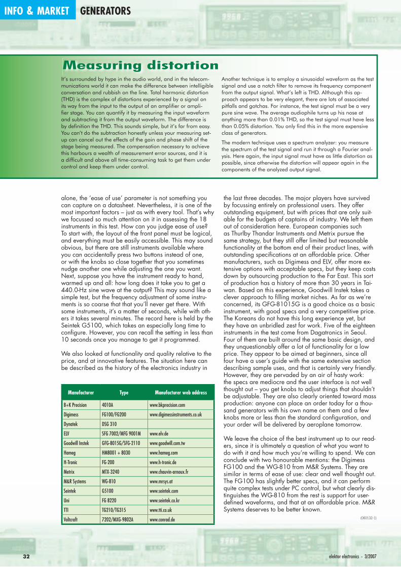
INFO & MARKET GENERATORS
32 elektor electronics - 3/2007
alone, the ‘ease of use’ parameter is not something you can capture on a datasheet. Nevertheless, it is one of the most important factors – just as with every tool. That’s why we focussed so much attention on it in assessing the 18 instruments in this test. How can you judge ease of use? To start with, the layout of the front panel must be logical, and everything must be easily accessible. This may sound obvious, but there are still instruments available where you can accidentally press two buttons instead of one, or with the knobs so close together that you sometimes nudge another one while adjusting the one you want. Next, suppose you have the instrument ready to hand, warmed up and all: how long does it take you to get a 440.0-Hz sine wave at the output? This may sound like a simple test, but the frequency adjustment of some instru-ments is so coarse that that you’ll never get there. With some instruments, it’s a matter of seconds, while with oth-ers it takes several minutes. The record here is held by the Seintek G5100, which takes an especially long time to confi gure. However, you can recall the setting in less than 10 seconds once you manage to get it programmed.
We also looked at functionality and quality relative to the price, and at innovative features. The situation here can be described as the history of the electronics industry in
the last three decades. The major players have survived by focussing entirely on professional users. They offer outstanding equipment, but with prices that are only suit-able for the budgets of captains of industry. We left them out of consideration here. European companies such as Thurlby Thandar Instruments and Metrix pursue the same strategy, but they still offer limited but reasonable functionality at the bottom end of their product lines, with outstanding specifi cations at an affordable price. Other manufacturers, such as Digimess and ELV, offer more ex-tensive options with acceptable specs, but they keep costs down by outsourcing production to the Far East. This sort of production has a history of more than 30 years in Tai-wan. Based on this experience, Goodwill Instek takes a clever approach to fi lling market niches. As far as we’re concerned, its GFG-81015G is a good choice as a basic instrument, with good specs and a very competitive price. The Koreans do not have this long experience yet, but they have an unbridled zest for work. Five of the eighteen instruments in the test come from Dagatronics in Seoul. Four of them are built around the same basic design, and they unquestionably offer a lot of functionality for a low price. They appear to be aimed at beginners, since all four have a user’s guide with the same extensive section describing sample uses, and that is certainly very friendly. However, they are pervaded by an air of hasty work: the specs are mediocre and the user interface is not well thought out – you get knobs to adjust things that shouldn’t be adjustable. They are also clearly oriented toward mass production: anyone can place an order today for a thou-sand generators with his own name on them and a few knobs more or less than the standard confi guration, and your order will be delivered by aeroplane tomorrow.
We leave the choice of the best instrument up to our read-ers, since it is ultimately a question of what you want to do with it and how much you’re willing to spend. We can conclude with two honourable mentions: the Digimess FG100 and the WG-810 from M&R Systems. They are similar in terms of ease of use: clear and well thought out. The FG100 has slightly better specs, and it can perform quite complex tests under PC control, but what clearly dis-tinguishes the WG-810 from the rest is support for user-defi ned waveforms, and that at an affordable price. M&R Systems deserves to be better known.
(060132-1)
Manufacturer Type Manufacturer web address
B+K Precision 4010A www.bkprecision.com
Digimess FG100/FG200 www.digimessinstruments.co.uk
Dynatek DSG 310
ELV SFG 7002/MFG 9001M www.elv.de
Goodwill Instek GFG-8015G/SFG-2110 www.goodwill.com.tw
Hameg HM8001 + 8030 www.hameg.com
H-Tronic FG-200 www.h-tronic.de
Metrix MTX-3240 www.chauvin-arnoux.fr
M&R Systems WG-810 www.mrsys.at
Seintek G5100 www.seintek.com
Uni FG 8220 www.seintek.co.kr
TTI TG210/TG315 www.tti.co.uk
Voltcraft 7202/MXG-9802A www.conrad.de
Measuring distortionIt’s surrounded by hype in the audio world, and in the telecom-munications world it can make the difference between intelligible conversation and rubbish on the line. Total harmonic distortion (THD) is the complex of distortions experienced by a signal on its way from the input to the output of an amplifi er or ampli-fi er stage. You can quantify it by measuring the input waveform and subtracting it from the output waveform. The difference is by defi nition the THD. This sounds simple, but it’s far from easy. You can’t do the subtraction honestly unless your measuring set-up can cancel out the effects of the gain and phase shift of the stage being measured. The compensation necessary to achieve this harbours a wealth of measurement error sources, and it is a diffi cult and above all time-consuming task to get them under control and keep them under control.
Another technique is to employ a sinusoidal waveform as the test signal and use a notch fi lter to remove its frequency component from the output signal. What’s left is THD. Although this ap-proach appears to be very elegant, there are lots of associated pitfalls and gotchas. For instance, the test signal must be a very pure sine wave. The average audiophile turns up his nose at anything more than 0.01% THD, so the test signal must have less than 0.05% distortion. You only fi nd this in the more expensive class of generators.
The modern technique uses a spectrum analyzer: you measure the spectrum of the test signal and run it through a Fourier anal-ysis. Here again, the input signal must have as little distortion as possible, since otherwise the distortion will appear again in the components of the analyzed output signal.

mikroElektronika
Please visit our web page for more info http://www.mikroe.com
Find your distributor: http://www.mikroe.com/en/distributors/
CAN-1 Board - InterfaceCAN via MCP2551
$18.00 USD
CAN-2 Board - Make CANnetwork with SPI interface
$21.00 USD
RS485 Board - Connectdevices into RS-485 network
$17.00 USD
Serial Ethernet - Make ethernet network with SPIInterface (ENC28J60)
$28.00 USD
CF Board - Easy way touse Compact flash in yourdesign $18.00 USD
MMC/SD Board - Easy wayto use MMC and SD cards inyour design $18.00 USD
EEPROM Board - SerialEEPROM board via I2Cinterface $9.00 USD
RTC Board - PCF8583 RTCwith battery backup
$16.00 USD
ADC Board - 12-bit analog-to-digital converter(ADC)with 4 inputs $22.00 USD
DAC Board - 12-bit digital-to-analog converter(DAC)with SPI $18.00 USD
Keypad 4x4 Board - Addkeypad to your application
$9.00 USD
Accel. Board - Accel. is anelectronic device that willmeasure acceleration forces
$16.00 USD
PICFlash programmer – anultra fast USB 2.0 programmerfor PIC microcontrollers.Continuing its tradition as oneof the fastest PIC programmeron the market, the newPICFlash with mikroICD nowsupports more PIC MCUs giv-ing the developer a widerchoice of PIC MCU for furtherprototype development.mikroICD debugger enablesyou to execute mikroC /mikroPascal / mikroBasic pro-grams on a host PIC micro-controller and view variablevalues, Special Function Regi-sters (SFR), memory andEEPROM as the program isrunning.................$89.00 USD
EasyPIC4 Development Boardwith on-board USB 2.0 programmer and mikroICD
EasyPIC4 development board:Following in the tradition of theEasyPIC3 as one of the best PICdevelopment systems on themarket, the EasyPIC4 has morenew features for the same price.The system supports 8, 14, 18,20, 28 and 40 pin PIC microcon-
trollers (it comes with a PIC16F877A).
3 1inSYSTEMDEVELOPMENT
HARDWARE
ICD ON-BOARD
USB 2.0
ON-BOARD
PROGRAMMER
HIGH
PERFORMANCE
DEVELOPMENT
BOARD
mikroICD is a highly effective tool for Real-Time debugging on ahardware level. The ICD debugger enables you to execute amikroC/mikroPascal/mikroBasic program on a host PIC microcon-troller and view variable values, Special Function Registers (SFR),memory and EEPROM as the program is running.
On-board USB 2.0 PICFlash programmer – an ultra fast USB 2.0programmer for fast MCU programming. Continuing its tradition asthe fastest PIC programmer on the market, the new PICFlash withmikroICD now supports more PIC MCUs giving the developer a widerchoice of PIC MCU for further prototype development.
Package contains: EasyPIC4 development system, USB cable,Serial cable, User’s manual, MikroICD manual, CD with software,drivers and examples in C, BASIC and Pascal language. Note: LCD, DS1820 temp sensor and GLCD are optional.
EasyPIC4 Development System ................................ $119.00 USDOptional:2x16 LCD and DS1820 temperature sensor ............. $15.00 USDGraphic LCD 128x64 dots .......................................... $17.00 USD
BIGPIC4 Development Boardwith on-board USB 2.0 programmer and mikroICDFollowing in the tradition of its predecessor, the BIGPIC3 as one of the best80-pin PIC development systems on the market, BIGPIC4 continues traditionwith more new features for same price. System supports the latest 64 and 80-pin PIC microcontrollers (it is delivered with PIC18F8520). Many ready madeexamples guarantee successful use of the system. Ultra fast on-board pro-grammer and mikroICD (In-circuit Debugger) enables very efficient debug-ging and faster prototype developing. Examples in C, BASIC and Pascal lan-guage are provided with the board.
BIGPIC4 Development System .............................................. $132.00 USD
EasydsPIC3 Development Boardwith on-board USB 2.0 programmer
System supports 18, 28 and 40 pin microcontrollers (it comes withdsPIC30F4013 general purpose microcontroller with internal 12 bit ADC).EasydsPIC3 has many features that make your development easy. Manyready made examples in C, BASIC and PASCAL language guarantee suc-cessful use of the system. On-board USB 2.0 programmer allows for fasterprototype development.
EasydsPIC3 Development System ......................................... $119.00 USD
dsPICPRO2 Development Boardwith on-board USB 2.0 programmer System supports dsPIC microcontrollers in 64 and 80 pin packages. It isdelivered with dsPIC30F6014A microcontroller. The dsPICPRO2 develop-ment system is a full-featured development board for Microchip dsPIC MCU.dsPICPRO2 board allows microcontroller to be interfaced with external cir-cuits and a broad range of peripheral devices. This development board hasan on-board USB 2.0 programmer and integrated connectors for SD/CFmemory cards, 2 x RS232 port, RS485, CAN, DAC etc..
dsPICPRO2 Development System ......................................... $239.00 USD
EasyAVR4 Development Boardwith on-board USB 2.0 programmerSystem supports 8, 20, 28 and 40 pin microcontrollers (it comes withATMEGA16). Each jumper, element and pin is clearly marked on the board.It is possible to test most of the industrial needs on the system: temperaturecontrollers, counters, timers etc. EasyAVR4 is an easy to use Atmel AVRdevelopment system. On-board USB 2.0 programmer makes your develop-ment easy. Examples in BASIC and Pascal language are provided with theboard.
EasyAVR4 Development System ........................................... $114.00 USD
EasyARM Development Boardwith on-board USB 2.0 programmerEasyARM board comes with Philips LPC2214 microcontroller. Each jumper,element and pin is clearly marked on the board. It is possible to test most ofthe industrial needs on the system: temperature controllers, counters, timersetc. EasyARM has many feature to make your development easy. One ofthem is on-board USB 2.0 programmer with automatic switch between ‘run’and ‘programming’ mode. Examples in C language are provided with theboard.
EasyARM Development System ............................................ $149.00 USD
Easy8051A Development Boardwith on-board USB 2.0 programmer System is compatible with 14, 16, 20 and 40 pin microcontrollers (it comeswith AT89S8252). USB 2.0 programmer is built in and programming can bedone without removing the microcontroller. Many industrial applications canbe tested on the system : temperature controllers, counters.. Easy8051Adevelopment system is a full-featured development board for 8051 microcon-trollers. It was designed to allow students or engineers to easily exercise andexplore the capabilities of the 8051 microcontrollers.
Easy8051A Development System ........................................... $114.00 USD
- All of our products are shipped in special protective boxes.
- On-line secure ordering provides a fast and safe way to buy our products.
DEVELOPMENT TOOLS | COMPILERS | BOOKS
EasyPSoC3 Development Boardwith on-board USB 2.0 programmer System supports 8, 20, 28 and 48 pin microcontrollers (it comes withCY8C27843). Each jumper, element and pin is clearly marked on the board.EasyPSoC3 is an easy to use PSoC development system. On-board USB 2.0programmer provides fast and easy in system programming.
EasyPSoC3 Development System ......................................... $169.00 USD
LV24-33 Development BoardThe Complete Hardware and Software solution with on-board USB 2.0programmer and mikroICDSystem supports 64, 80 and 100 pin PIC24F/24H/dsPIC33F microcontrollers(it comes with PIC24FJ96GA010 - PIC24 16-bit Microcontroller, 96 KB FlashMemory, 8 KB RAM in 100 Pin Package). Examples in BASIC, PASCAL andC are included with the system. You can choose between USB or ExternalPower supply. LV 24-33 has many features that makes your developmenteasy. Explore new PIC24F/24H/dsPIC33F PIC MCU's with LV 24-33 andexperience all advantages of this microcontrollers.
LV24-33 Development System .............................................. $149.00 USD
Uni-DS 3 Development Boardwith on-board USB 2.0 programmer System supports PIC, AVR, 8051, ARM and PSoC microcontrollers with alarge number of peripherals. It is enough to switch a card and continue work-ing in the same development environment but with a different chip. UNI-DS3has many features that makes your development easy. You can choosebetween USB or External Power supply. Each MCU card has own USB 2.0programmer on it !
Uni-DS 3 Development System [with one MCU card]............ $199.00 USD
Regular price:mikroBasic(PIC) $149.00 USDmikroPascal(PIC) $149.00 USDmikroC(PIC) $249.00 USD
Price with discount:mikroBasic(PIC) (-30%) $99.00 USDmikroPascal(PIC) (-30%) $99.00 USDmikroC(PIC) (-30%) $175.00 USD
mikroBasic(dsPIC) $149.00 USDmikroPascal(dsPIC) $249.00 USDmikroC(dsPIC) $249.00 USD
mikroBasic(dsPIC) (-30%) $99.00 USDmikroPascal(dsPIC) (-20%)$199.00 USDmikroC(dsPIC) (-30%) $175.00 USD
mikroBasic(AVR) $149.00 USDmikroPascal(AVR) $149.00 USD
mikroBasic(AVR) (-30%) $99.00 USDmikroPascal(AVR) (-30%) $99.00 USD
SupportingAan impre-ssive range of micro-controllers, an easy-to-useaIDE, hundredsof ready-to-use func-tions and manyainte-grated toolsAmakesMikroElektronika co-mpilers one of the
best choices on the market today. Besides mikroICD, mikroElektro-nika compilers offer a statistical module, simulator, bitmap generatorfor graphic displays, 7-segment display conversion tool, ASCII table,HTML code export, communications tools for SD/MMC, UDP(Ethernet) and USB , EEPROM editor, programming mode manage-ment, etc.Each compiler has many routines and examples such as EEPROM,FLASH and MMC, SD and CF card reading/writing, writing to charac-ter and graphic LCDs, manipulation of push-buttons, 4x4 keyboardand PS/2 keyboard input, generation of signals and sounds, characterstring manipulation, mathematical calculations, I2C, SPI, RS232,CAN, USB, RS485 and OneWire communications, Manchester codingmanagement, logical and numerical conversion, PWM signals, inter-rupts, etc. The CD-ROM contains many ready-written and tested pro-grams for use with our development boards.
S O F T W A R E A N D H A R D W A R E S O L U T I O N S F O R E M B E D D E D W O R L D
mikroElektronika CompilersPascal, Basic and C Compilers for various microcontrollers
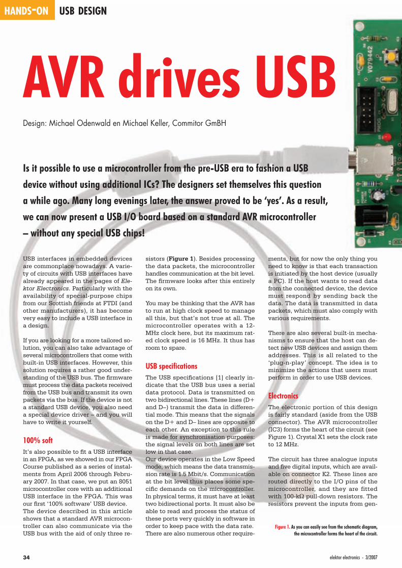
HANDS-ON USB DESIGN
34 elektor electronics - 3/2007
AVR drives USBDesign: Michael Odenwald en Michael Keller, Commitor GmBH
Is it possible to use a microcontroller from the pre-USB era to fashion a USB
device without using additional ICs? The designers set themselves this question
a while ago. Many long evenings later, the answer proved to be ‘yes’. As a result,
we can now present a USB I/O board based on a standard AVR microcontroller
– without any special USB chips!
USB interfaces in embedded devices are commonplace nowadays. A varie-ty of circuits with USB interfaces have already appeared in the pages of Ele-ktor Electronics. Particularly with the availability of special-purpose chips from our Scottish friends at FTDI (and other manufacturers), it has become very easy to include a USB interface in a design.
If you are looking for a more tailored so-lution, you can also take advantage of several microcontrollers that come with built-in USB interfaces. However, this solution requires a rather good under-standing of the USB bus. The fi rmware must process the data packets received from the USB bus and transmit its own packets via the bus. If the device is not a standard USB device, you also need a special device driver – and you will have to write it yourself.
100% softIt’s also possible to fi t a USB interface in an FPGA, as we showed in our FPGA Course published as a series of instal-ments from April 2006 through Febru-ary 2007. In that case, we put an 8051 microcontroller core with an additional USB interface in the FPGA. This was our fi rst ‘100% software’ USB device.The device described in this article shows that a standard AVR microcon-troller can also communicate via the USB bus with the aid of only three re-
sistors (Figure 1). Besides processing the data packets, the microcontroller handles communication at the bit level. The fi rmware looks after this entirely on its own.
You may be thinking that the AVR has to run at high clock speed to manage all this, but that’s not true at all. The microcontroller operates with a 12-MHz clock here, but its maximum rat-ed clock speed is 16 MHz. It thus has room to spare.
USB specifi cationsThe USB specifi cations [1] clearly in-dicate that the USB bus uses a serial data protocol. Data is transmitted on two bidirectional lines. These lines (D+ and D–) transmit the data in differen-tial mode. This means that the signals on the D+ and D– lines are opposite to each other. An exception to this rule is made for synchronisation purposes: the signal levels on both lines are set low in that case.Our device operates in the Low Speed mode, which means the data transmis-sion rate is 1.5 Mbit/s. Communication at the bit level thus places some spe-cifi c demands on the microcontroller. In physical terms, it must have at least two bidirectional ports. It must also be able to read and process the status of these ports very quickly in software in order to keep pace with the data rate.There are also numerous other require-
ments, but for now the only thing you need to know is that each transaction is initiated by the host device (usually a PC). If the host wants to read data from the connected device, the device must respond by sending back the data. The data is transmitted in data packets, which must also comply with various requirements.
There are also several built-in mecha-nisms to ensure that the host can de-tect new USB devices and assign them addresses. This is all related to the ‘plug-n-play’ concept. The idea is to minimize the actions that users must perform in order to use USB devices.
ElectronicsThe electronic portion of this design is fairly standard (aside from the USB connector). The AVR microcontroller (IC3) forms the heart of the circuit (see Figure 1). Crystal X1 sets the clock rate to 12 MHz.
The circuit has three analogue inputs and fi ve digital inputs, which are avail-able on connector K2. These lines are routed directly to the I/O pins of the microcontroller, and they are fitted with 100-kΩ pull-down resistors. The resistors prevent the inputs from gen-
Figure 1. As you can easily see from the schematic diagram, the microcontroller forms the heart of the circuit.
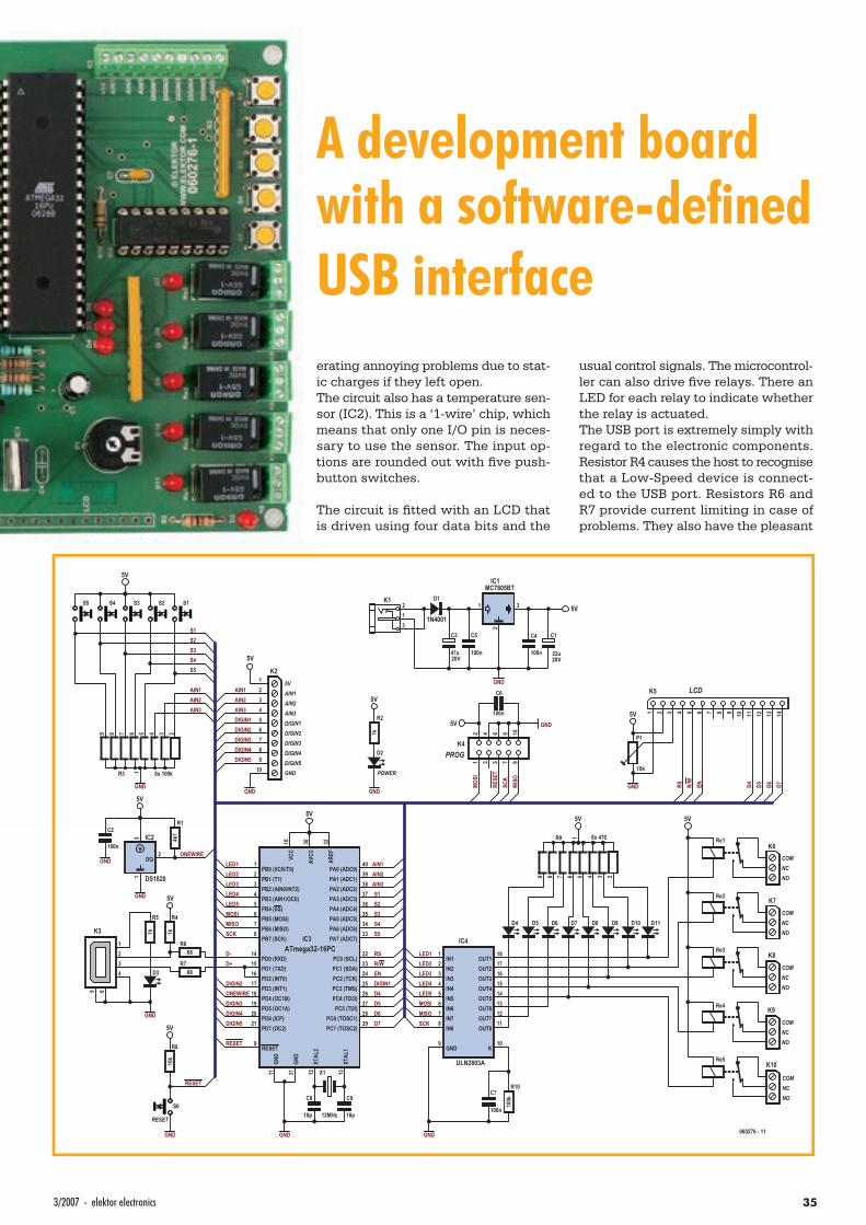
353/2007 - elektor electronics
A development board with a software-defi ned USB interfaceerating annoying problems due to stat-ic charges if they left open.The circuit also has a temperature sen-sor (IC2). This is a ‘1-wire’ chip, which means that only one I/O pin is neces-sary to use the sensor. The input op-tions are rounded out with fi ve push-button switches.
The circuit is fi tted with an LCD that is driven using four data bits and the
usual control signals. The microcontrol-ler can also drive fi ve relays. There an LED for each relay to indicate whether the relay is actuated.The USB port is extremely simply with regard to the electronic components. Resistor R4 causes the host to recognise that a Low-Speed device is connect-ed to the USB port. Resistors R6 and R7 provide current limiting in case of problems. They also have the pleasant
RESET
LED1LED2LED3LED4LED5MOSIMISOSCK
K10
IN66
OUT712
IN77
OUT613
OUT514
IN33
OUT415
IN11
OUT316
IN22
OUT811
GND9
IN44
IN88
IN55
OUT118
OUT217
IC4
ULN2803A
GND
LED1LED2LED3LED4LED5MOSIMISOSCK
D4 D7 D8 D11
5V
8x 4701
23456789
R9
5V
D+D-
DQ2
13 IC2
DS1820
GND
C2
100nONEWIRE
ONEWIRE
S1S2S3S4S5
AIN1AIN2AIN3
D7D6D5D4
ENR/WRS
X1
12MHz
C8
18p
C9
18p
GND
DIGIN1DIGIN2
DIGIN3DIGIN4DIGIN5
1
23456789
R3 8x 100k
S1S2S3S4S5
GND
123456789
10
K2
5V
GND
AIN1AIN2AIN3
R1
4k7
5V
DIGIN1DIGIN2DIGIN3DIGIN4DIGIN5
S6
R8
10k
GND
5V
RESET
1234
5 6
K3
R668
R768
R4
1k
RESET
5V
K6
K7
K8
K9
K10
COMNCNO
COMNCNO
COMNCNO
COMNCNO
COMNCNO
D2
GND
R2
1k
5V
POWER
12
34
56
78
910
K4
GND5V
RESE
TSC
KMI
SO
C6
100n
C7
100n
1 2 3 4 5 6 7 8 9 10 11 12 13 14
K5
GND
5V
P1
10k
RS R/W
EN D7D6D5D4
LCD
PROG
AIN15V
AIN2AIN3DIGIN1DIGIN2DIGIN3DIGIN4DIGIN5GND
D1
1N4001
GND
20V
C3
47u
1 3
2
IC1MC7805BT
C5
100n
C4
100n20V
C1
22u
5V2
31
K1
Re1
PB0 (XCK/T0)1
PB1 (T1)2
PB2 (AIN0/INT2)3
PB3 (AIN1/OC0)4
PB4 (SS)5
PB5 (MOSI)6
PB6 (MISO)7
PB7 (SCK)8
RESET9
PD0 (RXD)14
PD1 (TXD)15
PD2 (INT0)16
PD3 (INT1)17
PD4 (OC1B)18
PD5 (OC1A)19
PD6 (ICP)20
PD7 (OC2)21
XTAL
212
XTAL
113
GND
11
PC0 (SCL)22
PC1 (SDA)23
PC2 (TCK)24
PC3 (TMS)25
PC4 (TDO)26
PC5 (TDI)27
PC6 (TOSC1)28
PC7 (TOSC2)29
AREF
32
AVCC
30GN
D31
PA7 (ADC7)33
PA6 (ADC6)34
PA5 (ADC5)35
PA4 (ADC4)36
PA3 (ADC3)37
PA2 (ADC2)38
PA1 (ADC1)39
PA0 (ADC0)40
VCC
10
IC3ATmega32-16PC
D5 D6 D9 D10
Re2
Re3
Re4
Re5
R10
100k
5V
5V
D3
GND
R5
1k
GND
AIN1AIN2AIN3
S1S2S3S4S5
MOSI
060276 - 11
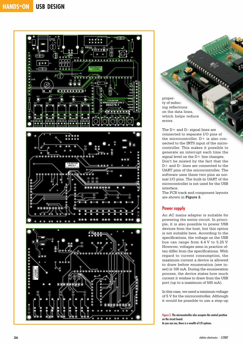
HANDS-ON USB DESIGN
36 elektor electronics - 3/2007
proper-ty of reduc-ing refl ections on the data lines, which helps reduce errors.
The D+ and D– signal lines are connected to separate I/O pins of the microcontroller. D+ is also con-nected to the INT0 input of the micro-controller. This makes it possible to generate an interrupt each time the signal level on the D+ line changes.Don’t be misled by the fact that the D+ and D– lines are connected to the UART pins of the microcontroller. The software uses these two pins as nor-mal I/O pins. The built-in UART of the microcontroller is not used for the USB interface.The PCB track and component layouts are shown in Figure 2.
Power supplyAn AC mains adapter is suitable for powering the entire circuit. In princi-ple, it is also possible to power USB devices from the host, but this option is not suitable here. According to the specifi cations, the voltage on the USB bus can range from 4.4 V to 5.25 V. However, voltages seen in practice of-ten differ from the specifi cations. With regard to current consumption, the maximum current a device is allowed to draw before enumeration (see in-set) is 100 mA. During the enumeration process, the device states how much current it wishes to draw from the USB port (up to a maximum of 500 mA).
In this case, we need a minimum voltage of 5 V for the microcontroller. Although it would be possible to use a step-up
Figure 2. The microcontroller also occupies the central position on the circuit board. As you can see, there is a wealth of I/O options.
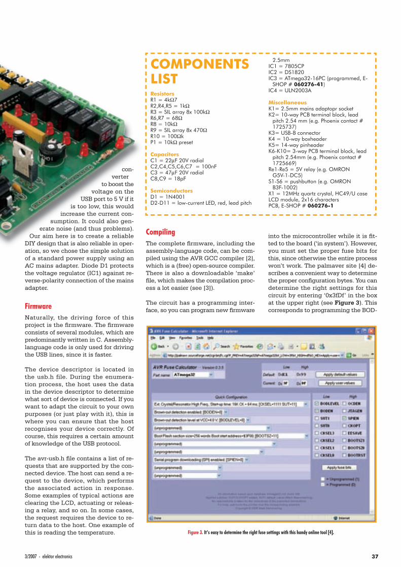
373/2007 - elektor electronics
con-verter
to boost the voltage on the
USB port to 5 V if it is too low, this would
increase the current con-sumption. It could also gen-
erate noise (and thus problems). Our aim here is to create a reliable
DIY design that is also reliable in oper-ation, so we chose the simple solution of a standard power supply using an AC mains adapter. Diode D1 protects the voltage regulator (IC1) against re-verse-polarity connection of the mains adapter.
FirmwareNaturally, the driving force of this project is the fi rmware. The fi rmware consists of several modules, which are predominantly written in C. Assembly-language code is only used for driving the USB lines, since it is faster.
The device descriptor is located in the usb.h file. During the enumera-tion process, the host uses the data in the device descriptor to determine what sort of device is connected. If you want to adapt the circuit to your own purposes (or just play with it), this is where you can ensure that the host recognises your device correctly. Of course, this requires a certain amount of knowledge of the USB protocol.
The avr-usb.h fi le contains a list of re-quests that are supported by the con-nected device. The host can send a re-quest to the device, which performs the associated action in response. Some examples of typical actions are clearing the LCD, actuating or releas-ing a relay, and so on. In some cases, the request requires the device to re-turn data to the host. One example of this is reading the temperature.
CompilingThe complete fi rmware, including the assembly-language code, can be com-piled using the AVR GCC compiler [2], which is a (free) open-source compiler. There is also a downloadable ‘make’ fi le, which makes the compilation proc-ess a lot easier (see [3]).
The circuit has a programming inter-face, so you can program new fi rmware
into the microcontroller while it is fi t-ted to the board (‘in system’). However, you must set the proper fuse bits for this, since otherwise the entire process won’t work. The palmaver site [4] de-scribes a convenient way to determine the proper confi guration bytes. You can determine the right settings for this circuit by entering ‘0x3fDf’ in the box at the upper right (see Figure 3). This corresponds to programming the BOD-
COMPONENTS LISTResistorsR1 = 4kΩ7R2,R4,R5 = 1kΩR3 = SIL array 8x 100kΩR6,R7 = 68ΩR8 = 10kΩR9 = SIL array 8x 470ΩR10 = 100ΩkP1 = 10kΩ preset
CapacitorsC1 = 22µF 20V radialC2,C4,C5,C6,C7 = 100nFC3 = 47µF 20V radialC8,C9 = 18pF
SemiconductorsD1 = 1N4001D2-D11 = low-current LED, red, lead pitch
2.5mmIC1 = 7805CPIC2 = DS1820IC3 = ATmega32-16PC (programmed, E-
SHOP # 060276-41)IC4 = ULN2003A
MiscellaneousK1= 2.5mm mains adaptopr socketK2= 10-way PCB terminal block, lead
pitch 2.54 mm (e.g. Phoenix contact # 1725737)
K3= USB-B connectorK4 = 10-way boxheaderK5= 14-way pinheaderK6-K10= 3-way PCB terminal block, lead
pitch 2.54mm (e.g. Phoenix contact # 1725669)
Re1-Re5 = 5V relay (e.g. OMRON G5V-1-DC5)
S1-S6 = pushbutton (e.g. OMRON B3F-1002)
X1 = 12MHz quartz crystal, HC49/U caseLCD module, 2x16 charactersPCB, E-SHOP # 060276-1
Figure 3. It’s easy to determine the right fuse settings with this handy online tool [4].
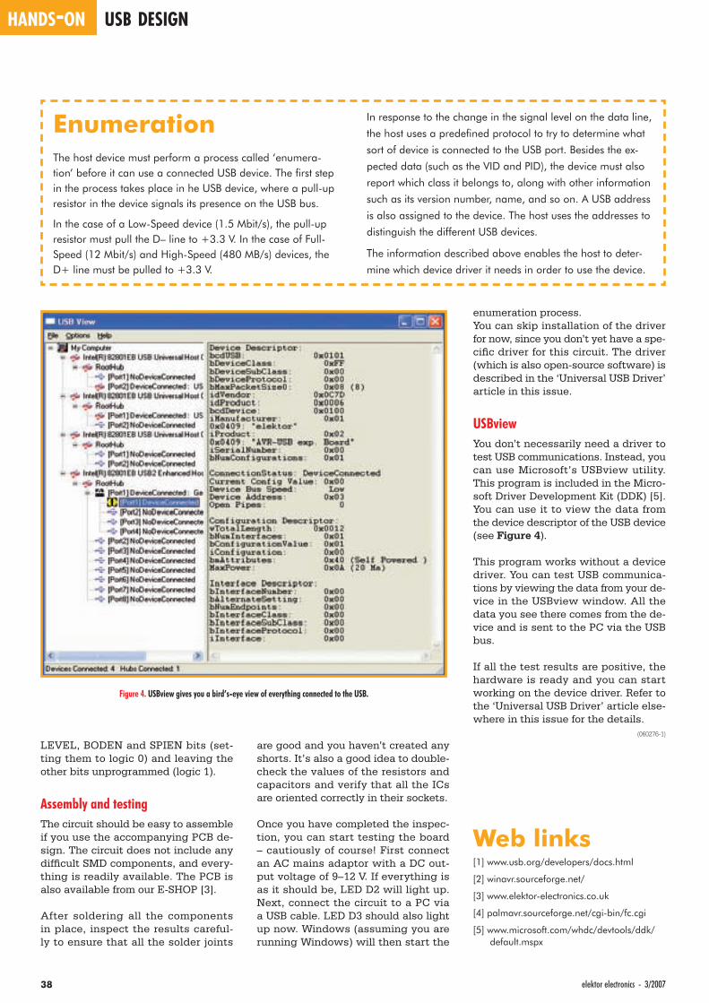
HANDS-ON USB DESIGN
38 elektor electronics - 3/2007
LEVEL, BODEN and SPIEN bits (set-ting them to logic 0) and leaving the other bits unprogrammed (logic 1).
Assembly and testingThe circuit should be easy to assemble if you use the accompanying PCB de-sign. The circuit does not include any diffi cult SMD components, and every-thing is readily available. The PCB is also available from our E-SHOP [3].
After soldering all the components in place, inspect the results careful-ly to ensure that all the solder joints
enumeration process.You can skip installation of the driver for now, since you don’t yet have a spe-cifi c driver for this circuit. The driver (which is also open-source software) is described in the ‘Universal USB Driver’ article in this issue.
USBviewYou don’t necessarily need a driver to test USB communications. Instead, you can use Microsoft’s USBview utility. This program is included in the Micro-soft Driver Development Kit (DDK) [5]. You can use it to view the data from the device descriptor of the USB device (see Figure 4).
This program works without a device driver. You can test USB communica-tions by viewing the data from your de-vice in the USBview window. All the data you see there comes from the de-vice and is sent to the PC via the USB bus.
If all the test results are positive, the hardware is ready and you can start working on the device driver. Refer to the ‘Universal USB Driver’ article else-where in this issue for the details.
(060276-1)
Web links[1] www.usb.org/developers/docs.html
[2] winavr.sourceforge.net/
[3] www.elektor-electronics.co.uk
[4] palmavr.sourceforge.net/cgi-bin/fc.cgi
[5] www.microsoft.com/whdc/devtools/ddk/default.mspx
are good and you haven’t created any shorts. It’s also a good idea to double-check the values of the resistors and capacitors and verify that all the ICs are oriented correctly in their sockets.
Once you have completed the inspec-tion, you can start testing the board – cautiously of course! First connect an AC mains adaptor with a DC out-put voltage of 9–12 V. If everything is as it should be, LED D2 will light up. Next, connect the circuit to a PC via a USB cable. LED D3 should also light up now. Windows (assuming you are running Windows) will then start the
EnumerationThe host device must perform a process called ‘enumera-tion’ before it can use a connected USB device. The fi rst step in the process takes place in he USB device, where a pull-up resistor in the device signals its presence on the USB bus.
In the case of a Low-Speed device (1.5 Mbit/s), the pull-up resistor must pull the D– line to +3.3 V. In the case of Full-Speed (12 Mbit/s) and High-Speed (480 MB/s) devices, the D+ line must be pulled to +3.3 V.
In response to the change in the signal level on the data line,
the host uses a predefi ned protocol to try to determine what
sort of device is connected to the USB port. Besides the ex-
pected data (such as the VID and PID), the device must also
report which class it belongs to, along with other information
such as its version number, name, and so on. A USB address
is also assigned to the device. The host uses the addresses to
distinguish the different USB devices.
The information described above enables the host to deter-
mine which device driver it needs in order to use the device.
Figure 4. USBview gives you a bird’s-eye view of everything connected to the USB.

Microcontroller Development Tools
Paltronix Limited www.paltronix.com
Robo-BOX 3.0 Robot Kit—£99 PoScope USB Oscilloscope/Logic Analyser—only £99
• Complete robot kit including con-troller, programming software andall mechanical parts.
• Build different robot configura-tions from one kit, includingwheel-based and track-based.
• Program intelligence to followlight, detect collisions and tracelines.
• Low-cost PC-based instrumentfeaturing oscilloscope, spectrumanalyser, logic analyser, patterngenerator, and chart recorder.
• Decodes serial buses includingUART, SPI, I2C and 1-wire.
• Supplied with logic analyser testlead set, two oscilloscope probes,USB cable and software.
Digital Logic Training System—£99
• Teaches both assembly languageprogramming and interfacing.
• Based on the popular PIC16F877A.
• Includes USB programmer.
• Features built-in I/O devices andsolderless breadboard.
• Supplied with tutorial and programexamples.
PICmicro Microcontroller Training System—£99
• Ideal for learning about and experi-menting with digital logic devices.
• Built-in logic and pulse switches,LEDs, 7-segment displays, piezospeaker, pulse generator, logicprobe and solderless breadboard.
• Supplied with useful range of ICs,jumper wire and mains adapter.
The new EasyPIC4 development board now supports even more PICsincluding 8, 14, 18, 20, 28 and 40-pin devices from the 10F, 12F, 16Fand 18F families. With its on-board USB programmer, mikroICD in-circuit debugger and useful I/O devices, the EasyPIC4 must be thebest-value development board on the market. Our Starter Pack in-cludes the EasyPIC4 board, USB cable, 16x2 LCD, 128x64 GLCD,DS1820 temperature sensor and a starter’s guide with example pro-grams in assembly language, BASIC, C and Pascal.
MikroElektronika’s popular mikroBASIC, mikroC and mikroPascalcompilers now include the mikroICD in-circuit debugger for use withthe EasyPIC4 and BIGPIC4 development boards—programs can nowbe executed on a target PIC with variable values, special functionregisters, memory and EEPROM viewed on the PC screen. Greatvalue at £85 each for mikroBASIC/mikroPascal and £145 for mikroC,or when bought with an EasyPIC4/BIGPIC4 only £59.50 each formikroBASIC/mikroPascal, and £101.50 for mikroC.
PICmicro Starter Pack now with ICD—still £99
• High-quality development boardwith on-board USB programmerand built-in I/O devices.
• Supports 8, 14, 18, 20, 28 and 40-pin PICs in 10F, 12F, 16F and 18Ffamilies.
• Now features mikroICD in-circuitdebugger.
• Supplied with PIC16F877A.
PICmicro BASIC, C and Pascal Compilers—from £59.50
• Easy to use with user-friendly IDE.
• Features simulator and mikroICDin-circuit debugger.
• Plentiful ready-written routines andexample programs.
• 30% discount for customers pur-chasing EasyPIC4/BIGPIC4 devel-opment boards.
The PICmicro Microcontroller Training System is an ideal platform forstudents and hobbyists alike to learn about PIC microcontrollers. Theexperiment board features a range of built-in I/O devices and a solder-less breadboard on which experiments may be conducted. Circuits areconnected using the provided jumper wires. A USB programmer isalso supplied and connects to the experiment board to program thePIC. Also included are a mains power adapter, 16x2 character LCD,connecting leads and a tutorial with example programs.
The Digital Logic Training System makes learning about digital logicand experimenting with discrete logic ICs easy. The experiment boardfeatures a range of built-in I/O devices and a solderless breadboard onwhich experiments may be conducted. Circuits are connected usingthe provided jumper wires and the system includes features such as apower supply, pulse generator and logic probe. Also included is amains power adapter, selection of ICs and a tutorial with examplecircuits.
Educational Products
Robots and Accessories Test Equipment
Tel: 0845 226 9451 Fax: 0845 226 9452 Email: [email protected]
Learn about, experiment and have fun with robotics with Robo-BOX3.0—an incredibly easy-to-build yet adaptable and expandable robot.Various wheel-based and track-based robots can be built from thestandard kit including light-following, collision-detecting and line-tracing models. Programming is carried out in graphical Logo. A rangeof low-cost options allow for easy expansion and the development ofmore sophisticated robots. We also stock similar robot kits based onPICmicro, 8051 and 68HC11 microcontrollers.
PoScope has to be one of the best-value pieces of test equipmentavailable and features a dual channel oscilloscope (100Hz to 200kHzsample rate), 16 channel logic analyser (1kHz to 8MHz sample rate),and 8-channel pattern generator (1kHz to 1MHz). What makes thePoScope really useful to those working with microcontrollers is itsability to decode serial communications including RS-232, I2C, SPIand 1-wire. Priced at only £99, the PoScope comes with a USB cable,logic analyser test lead set, two oscilloscope probes and software.
All prices exclude UK delivery (£5 standard/£10 next-day) and VAT. Major credit and debit cards accepted. Secure online ordering.
We also stock other trainers, circuit labs and solderless breadboards—please see our website for details
We also stock development tools for 8051, ARM, AVR, dsPIC, PICmicro, PSoC and other devices—please see our website for details
Naamloos-2 1Naamloos-2 1 29-11-2006 17:02:3929-11-2006 17:02:39
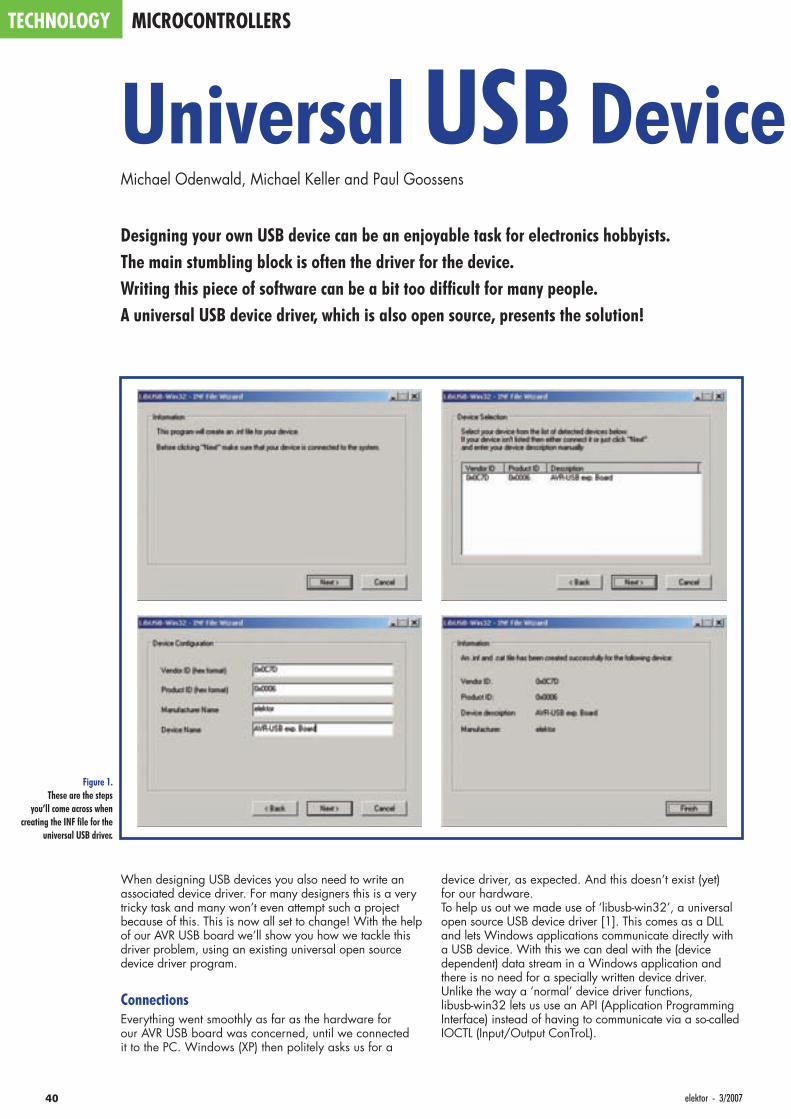
40 elektor - 3/2007
TECHNOLOGY MICROCONTROLLERS
When designing USB devices you also need to write an associated device driver. For many designers this is a very tricky task and many won’t even attempt such a project because of this. This is now all set to change! With the help of our AVR USB board we’ll show you how we tackle this driver problem, using an existing universal open source device driver program.
ConnectionsEverything went smoothly as far as the hardware for our AVR USB board was concerned, until we connected it to the PC. Windows (XP) then politely asks us for a
device driver, as expected. And this doesn’t exist (yet) for our hardware.To help us out we made use of ‘libusb-win32’, a universal open source USB device driver [1]. This comes as a DLL and lets Windows applications communicate directly with a USB device. With this we can deal with the (device dependent) data stream in a Windows application and there is no need for a specially written device driver.Unlike the way a ‘normal’ device driver functions, libusb-win32 lets us use an API (Application Programming Interface) instead of having to communicate via a so-called IOCTL (Input/Output ConTroL).
Universal USB Device Michael Odenwald, Michael Keller and Paul Goossens
Designing your own USB device can be an enjoyable task for electronics hobbyists. The main stumbling block is often the driver for the device. Writing this piece of software can be a bit too diffi cult for many people. A universal USB device driver, which is also open source, presents the solution!
Figure 1.These are the steps
you’ll come across when creating the INF fi le for the
universal USB driver.
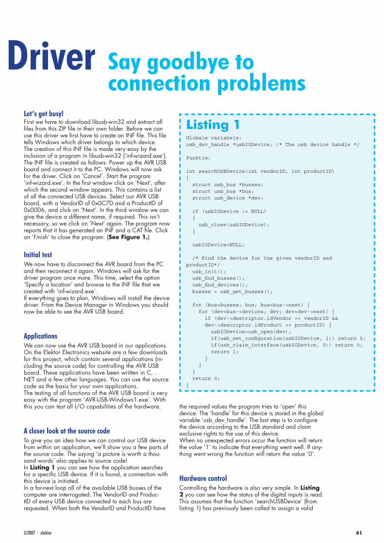
413/2007 - elektor
Let’s get busy!First we have to download libusb-win32 and extract all fi les from this ZIP fi le in their own folder. Before we can use this driver we fi rst have to create an INF fi le. This fi le tells Windows which driver belongs to which device. The creation of this INF fi le is made very easy by the inclusion of a program in libusb-win32 (‘inf-wizard.exe’).The INF fi le is created as follows: Power up the AVR USB board and connect it to the PC. Windows will now ask for the driver. Click on ‘Cancel’. Start the program ‘inf-wizard.exe’. In the fi rst window click on ‘Next’, after which the second window appears. This contains a list of all the connected USB devices. Select our AVR USB board, with a VendorID of 0x0C7D and a ProductID of 0x0006, and click on ‘Next’. In the third window we can give the device a different name, if required. This isn’t necessary, so we click on ‘Next’ again. The program now reports that it has generated an INF and a CAT fi le. Click on ‘Finish’ to close the program. (See Figure 1.)
Initial test We now have to disconnect the AVR board from the PC and then reconnect it again. Windows will ask for the driver program once more. This time, select the option ‘Specify a location’ and browse to the INF fi le that we created with ‘inf-wizard.exe’.If everything goes to plan, Windows will install the device driver. From the Device Manager in Windows you should now be able to see the AVR USB board.
Applications We can now use the AVR USB board in our applications. On the Elektor Electronics website are a few downloads for this project, which contain several applications (in-cluding the source code) for controlling the AVR USB board. These applications have been written in C, .NET and a few other languages. You can use the source code as the basis for your own applications.The testing of all functions of the AVR USB board is very easy with the program ‘AVR-USB-Windows1.exe’. With this you can test all I/O capabilities of the hardware.
A closer look at the source codeTo give you an idea how we can control our USB device from within an application, we’ll show you a few parts of the source code. The saying ‘a picture is worth a thou-sand words’ also applies to source code!In Listing 1 you can see how the application searches for a specifi c USB device. If it is found, a connection with this device is initiated.In a for-next loop all of the available USB busses of the computer are interrogated. The VendorID and Produc-tID of every USB device connected to each bus are requested. When both the VendorID and ProductID have
the required values the program tries to ‘open’ this device. The ‘handle’ for this device is stored in the global variable ‘usb_dev_handle’. The last step is to confi gure the device according to the USB standard and claim exclusive rights to the use of this device.When no unexpected errors occur the function will return the value ‘1’ to indicate that everything went well. If any-thing went wrong the function will return the value ‘0’.
Hardware controlControlling the hardware is also very simple. In Listing 2 you can see how the status of the digital inputs is read. This assumes that the function ‘searchUSBDevice’ (from listing 1) has previously been called to assign a valid
Driver Say goodbye to connection problems
Listing 1Globale variabele:usb_dev_handle *usbIODevice; /* The usb device handle */
Funktie:
int searchUSBDevice(int vendorID, int productID) struct usb_bus *busses; struct usb_bus *bus; struct usb_device *dev;
if (usbIODevice != NULL) usb_close(usbIODevice);
usbIODevice=NULL;
/* Find the device for the given vendorID and productID*/ usb_init(); usb_fi nd_busses(); usb_fi nd_devices(); busses = usb_get_busses();
for (bus=busses; bus; bus=bus->next) for (dev=bus->devices; dev; dev=dev->next) if (dev->descriptor.idVendor == vendorID && dev->descriptor.idProduct == productID) usbIODevice=usb_open(dev); if(usb_set_confi guration(usbIODevice, 1)) return 0; if(usb_claim_interface(usbIODevice, 0)) return 0; return 1; return 0;
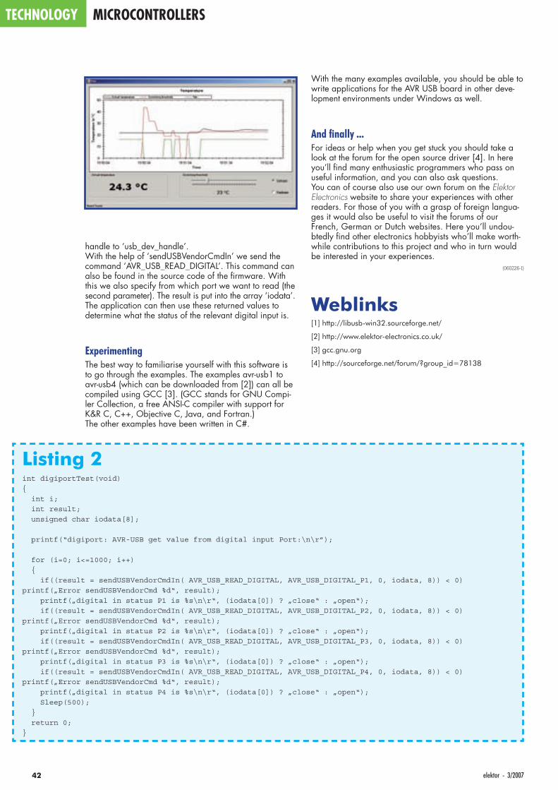
42 elektor - 3/2007
TECHNOLOGY MICROCONTROLLERS
handle to ‘usb_dev_handle’.With the help of ‘sendUSBVendorCmdIn’ we send the command ‘AVR_USB_READ_DIGITAL’. This command can also be found in the source code of the fi rmware. With this we also specify from which port we want to read (the second parameter). The result is put into the array ‘iodata’. The application can then use these returned values to determine what the status of the relevant digital input is.
Experimenting The best way to familiarise yourself with this software is to go through the examples. The examples avr-usb1 to avr-usb4 (which can be downloaded from [2]) can all be compiled using GCC [3]. (GCC stands for GNU Compi-ler Collection, a free ANSI-C compiler with support for K&R C, C++, Objective C, Java, and Fortran.) The other examples have been written in C#.
With the many examples available, you should be able to write applications for the AVR USB board in other deve-lopment environments under Windows as well.
And fi nally ... For ideas or help when you get stuck you should take a look at the forum for the open source driver [4]. In here you’ll fi nd many enthusiastic programmers who pass on useful information, and you can also ask questions. You can of course also use our own forum on the Elektor Electronics website to share your experiences with other readers. For those of you with a grasp of foreign langua-ges it would also be useful to visit the forums of our French, German or Dutch websites. Here you’ll undou-btedly fi nd other electronics hobbyists who’ll make worth-while contributions to this project and who in turn would be interested in your experiences.
(060226-I)
Weblinks[1] http://libusb-win32.sourceforge.net/
[2] http://www.elektor-electronics.co.uk/
[3] gcc.gnu.org
[4] http://sourceforge.net/forum/?group_id=78138
Listing 2int digiportTest(void)
int i;
int result;
unsigned char iodata[8];
printf(“digiport: AVR-USB get value from digital input Port:\n\r”);
for (i=0; i<=1000; i++)
if((result = sendUSBVendorCmdIn( AVR_USB_READ_DIGITAL, AVR_USB_DIGITAL_P1, 0, iodata, 8)) < 0)
printf(„Error sendUSBVendorCmd %d“, result);
printf(„digital in status P1 is %s\n\r“, (iodata[0]) ? „close“ : „open“);
if((result = sendUSBVendorCmdIn( AVR_USB_READ_DIGITAL, AVR_USB_DIGITAL_P2, 0, iodata, 8)) < 0)
printf(„Error sendUSBVendorCmd %d“, result);
printf(„digital in status P2 is %s\n\r“, (iodata[0]) ? „close“ : „open“);
if((result = sendUSBVendorCmdIn( AVR_USB_READ_DIGITAL, AVR_USB_DIGITAL_P3, 0, iodata, 8)) < 0)
printf(„Error sendUSBVendorCmd %d“, result);
printf(„digital in status P3 is %s\n\r“, (iodata[0]) ? „close“ : „open“);
if((result = sendUSBVendorCmdIn( AVR_USB_READ_DIGITAL, AVR_USB_DIGITAL_P4, 0, iodata, 8)) < 0)
printf(„Error sendUSBVendorCmd %d“, result);
printf(„digital in status P4 is %s\n\r“, (iodata[0]) ? „close“ : „open“);
Sleep(500);
return 0;

3/2007 - elektor electronics 43
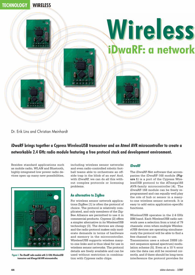
TECHNOLOGY WIRELESS
44 elektor electronics - 3/2007
Wireless iDwaRF: a network
Dr. Erik Lins and Christian Meinhardt
iDwaRF brings together a Cypress WirelessUSB transceiver and an Atmel AVR microcontroller to create a networkable 2.4 GHz radio module featuring a free protocol stack and development environment.
Besides standard applications such as mobile radio, WLAN and Bluetooth, highly-integrated low power radio de-vices open up many new possibilities,
including wireless sensor networks and even radio-controlled robotic foot-ball teams able to orchestrate an off-side trap in the blink of an eye! And, with iDwaRF, we can do all this with-out complex protocols or licensing problems.
An alternative to ZigBeeFor wireless sensor network applica-tions ZigBee [1] is often the protocol of choice. The protocol is relatively com-plicated, and only members of the Zig-Bee Alliance are permitted to use it in commercial products. Cypress [2] offers a simpler alternative in its WirelessUSB technology [3]. The devices are cheap and the radio protocol makes only mod-erate demands in terms of hardware and memory in the microcontroller. WirelessUSB supports wireless many-to-one links and is thus ideal for use in wireless sensor networks. The protocol details are freely available and can be used without restriction in combina-tion with Cypress radio chips.
iDwaRF
The iDwaRF-Net software that accom-panies the iDwaRF-168 module (Fig-ure 1) is a port of the Cypress Wire-lessUSB protocol to the ATmega168 AVR-family microcontroller [4]. The iDwaRF-168 module can be freely re-programmed and can equally well play the role of hub or sensor in a many-to-one wireless sensor network. It is easy to add extra application-specifi c functions.
WirelessUSB operates in the 2.4 GHz ISM band. Each WirelessUSB radio net-work uses a selection from a total of 79 channels: even when multiple Wireles-sUSB devices are operating simultane-ously the protocol will be able to fi nd a free channel to use.Transmission uses a robust DSSS (di-rect sequence spread spectrum) modu-lation scheme [5]. Even at a 10 % error rate the data can still be received cor-rectly, and if there should be long-term interference the protocol provides for
Figure 1. The iDwaRF radio module with 2.4 GHz WirelessUSB transceiver and ATmega168 AVR microcontroller.
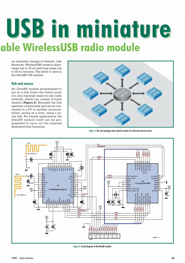
453/2007 - elektor electronics
USB in miniatureable WirelessUSB radio module
an automatic change of channel. Like Bluetooth, WirelessUSB comes in short-range (up to 10 m) and long-range (up to 50 m) versions. The latter is used in the iDwaRF-168 module.
Hub and sensorsAn iDwaRF module programmed to act as a hub forms the centre point of a star-topology many-to-one radio network, which can consist of many sensors (Figure 2). Normally the hub operates continuously and can be con-nected to a PC or another microcon-troller, acting as a host, using a se-rial link. For simple applications the iDwaRF module itself can be pro-grammed to carry out the required dedicated host functions.
Figure 2. The star-topology radio network consists of a hub and several sensors.
RFI
N46
RFOUT5
X13
38
X13IN35
X13OUT26
/PD33
/RES
ET14
PACTL34
DIO
20D
IOVA
L19
IRQ
21
MO
SI23
MIS
O24
SCK25
/SS
22
VCC6
VCC9
VCC
16
VCC28
VCC29
VCC32
VCC
41VC
C42
VCC
44VC
C45
GN
D13 E
NC1
NC2
NC3
NC4
NC7
NC8
NC10
NC11
NC12
NC
15
NC
17
NC
18
NC27
NC30
NC31
NC36
NC
37
NC
39N
C40
NC
43
NC
47N
C48
U1
CYWUSB6935-48LFX
1ANT2
ANT_WIGGLE_L
1
ANT1
ANT_WIGGLE_R
ISOMISOMOSIMOSIM
SCK
SCK
SS/SS/
/PD
/INT0
/INT0
/WUSBRESET
/WUSBRESET
1234567891011121314
CON1
MIS
OVC
CSC
KM
OSI
/RES
ETG
ND
POR
T1PO
RT0
POR
T3PO
RT2
POR
T1PO
RT0
POR
T0PO
RT7
POR
T7
POR
T5PO
RT4
PORT6INT1 OC2B PD3
1
XCK T0 PD42
GND3
VCC4
GND5
VCC6
XTAL1 TOSC1 PB67
XTAL2 TOSC2 PB78
OC
0B T
1 PD
59
OC
0A A
IN0
PD6
10
AIN
1 PD
711
CLK
O IC
P PB
012
OC
1A P
B1
13
/SS
OC
1B P
B2
14
MO
SI O
C2
PB3
15
MIS
O P
B4
16
PB5 SCK17
AVCC18
ADC619
AREF20
GND21
ADC722
PC0 ADC023
PC1 ADC124
PC2
AD
C2
25PC
3 A
DC
326
PC4
AD
C4
SDA
27PC
5 A
DC
5 SC
L28
PC6
/RES
ET29
PD0
RXD
30PD
1 TX
D31
PD2
INT0
32
U2ATmega168-20MI
PORT6
POR
T0PO
RT1
POR
T2PO
RT3
POR
T4PO
RT5
POR
T6PO
RT7
X13OUT
C1
1p8
C6
100n
C7
100n
C8
100n
C9
100n
C11
100n
C10
100n
VCCVCC
VCC
C2
NOLOAD
C4
10p
L1
3nH9
X1
13MHz
C12
100n
C14
22p
050402 - 11
X2
xxMHzC13
22p
VCC
VCC
C15
100n
C5
10u
/RESET
VCC
VCC
Figure 3. Circuit diagram of the iDwaRF module.
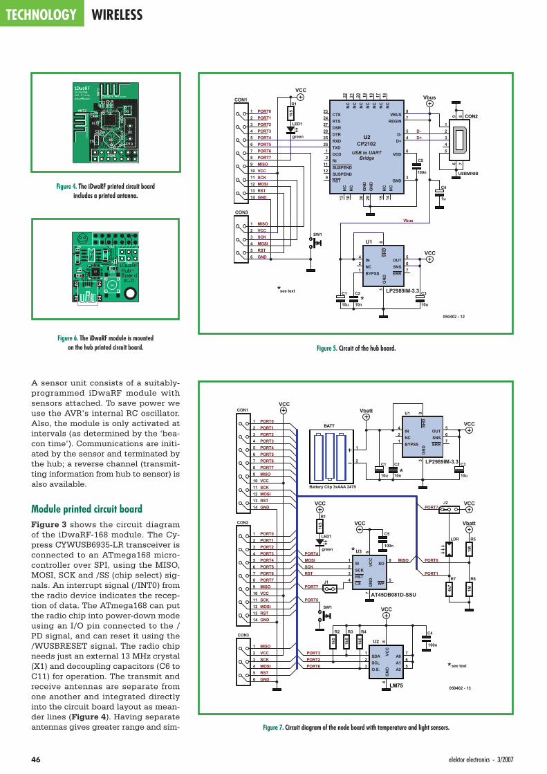
TECHNOLOGY WIRELESS
46 elektor electronics - 3/2007
A sensor unit consists of a suitably-programmed iDwaRF module with sensors attached. To save power we use the AVR’s internal RC oscillator. Also, the module is only activated at intervals (as determined by the ‘bea-con time’). Communications are initi-ated by the sensor and terminated by the hub; a reverse channel (transmit-ting information from hub to sensor) is also available.
Module printed circuit boardFigure 3 shows the circuit diagram of the iDwaRF-168 module. The Cy-press CYWUSB6935-LR transceiver is connected to an ATmega168 micro-controller over SPI, using the MISO, MOSI, SCK and /SS (chip select) sig-nals. An interrupt signal (/INT0) from the radio device indicates the recep-tion of data. The ATmega168 can put the radio chip into power-down mode using an I/O pin connected to the /PD signal, and can reset it using the /WUSBRESET signal. The radio chip needs just an external 13 MHz crystal (X1) and decoupling capacitors (C6 to C11) for operation. The transmit and receive antennas are separate from one another and integrated directly into the circuit board layout as mean-der lines (Figure 4). Having separate antennas gives greater range and sim-
Figure 4. The iDwaRF printed circuit board includes a printed antenna.
MISOVCCSCKMOSIRSTGND
PORT0PORT1PORT2PORT3PORT4PORT5PORT6PORT7
GNDRSTMOSISCKVCCMISO
REGIN7
VDD6
GND3
VBUS8
D-5
D+4
RST9
SUSPEND12
SUSPEND11
RI2
DCD1
DTR28
DSR27
TXD26
RXD25
RTS24
CTS23
NC
10N
C13
NC
14N
C15
NC
16N
C17
NC
18N
C19
NC
20N
C21
NC
22
GN
D29
GN
D30
U2CP2102
D+D-
12345
9 876
CON2
USBMINIB
123456
CON3
1234567891011121314
CON1
BYPSS1
IN4
GN
D3
OUT5
SNS6
ERR7
SHD
8
NC2
U1
LP2989IM-3.3C2see text
**
10n
C3
10u
050402 - 12
C1
10u
VCC
VbusR1
1k5
green
LED1
SW1
VCC
USB to UARTBridge C5
100n
C4
1u
Vbus
Figure 5. Circuit of the hub board.Figure 6. The iDwaRF module is mounted
on the hub printed circuit board.
1
2
BATT
Battery Clip 3xAAA 2479
PORT6
SI1
SCK2
RST3
CS4
WP5
VCC
6G
ND
7
SO8
U3
AT45DB081D-SSU
SDA1
SCL2
O.S.3
GN
D4
A25
A16
A07VC
C8U2
LM75
SCKOSIMISOM
RST
PORT2PORT3
PORT0
PORT7
PORT1
MISOVCCSCKMOSIRSTGND
PORT0PORT1PORT2PORT3PORT4PORT5PORT6PORT7
GNDRSTMOSISCKVCCMISO1
23456
CON3
1234567891011121314
CON1
R1
1k5
green
LED1
VCC
SW1
BYPSS1
IN4
GN
D3
OUT5
SNS6
ERR7
SHD
8
NC2
U1
LP2989IM-3.3C2
10n
C3
10u
C1
10u
VCC
MISOVCCSCKMOSIRSTGND
PORT0PORT1PORT2PORT3PORT4PORT5PORT6PORT7
1234567891011121314
CON2
R5
1M
R6
1M
R2
1k5
R3
1k5
R4
1k5
C5
100n
C4
100n
VCC
VCC
J2
LDR
R7
4k7
J1
Vbatt
VbattVCC
PORT5
PORT4
PORT7VCC
050402 - 13
see text
*
*
*
Figure 7. Circuit diagram of the node board with temperature and light sensors.
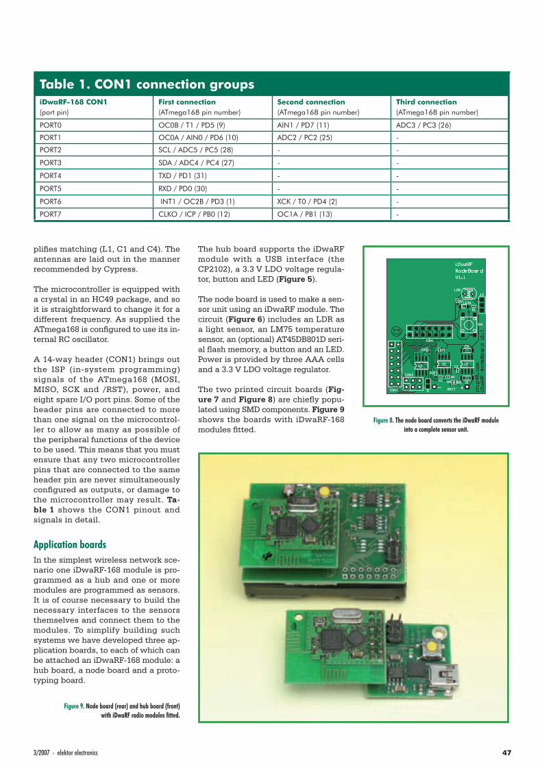
473/2007 - elektor electronics
plifi es matching (L1, C1 and C4). The antennas are laid out in the manner recommended by Cypress.
The microcontroller is equipped with a crystal in an HC49 package, and so it is straightforward to change it for a different frequency. As supplied the ATmega168 is confi gured to use its in-ternal RC oscillator.
A 14-way header (CON1) brings out the ISP (in-system programming) signals of the ATmega168 (MOSI, MISO, SCK and /RST), power, and eight spare I/O port pins. Some of the header pins are connected to more than one signal on the microcontrol-ler to allow as many as possible of the peripheral functions of the device to be used. This means that you must ensure that any two microcontroller pins that are connected to the same header pin are never simultaneously confi gured as outputs, or damage to the microcontroller may result. Ta-ble 1 shows the CON1 pinout and signals in detail.
Application boardsIn the simplest wireless network sce-nario one iDwaRF-168 module is pro-grammed as a hub and one or more modules are programmed as sensors. It is of course necessary to build the necessary interfaces to the sensors themselves and connect them to the modules. To simplify building such systems we have developed three ap-plication boards, to each of which can be attached an iDwaRF-168 module: a hub board, a node board and a proto-typing board.
The hub board supports the iDwaRF module with a USB interface (the CP2102), a 3.3 V LDO voltage regula-tor, button and LED (Figure 5).
The node board is used to make a sen-sor unit using an iDwaRF module. The circuit (Figure 6) includes an LDR as a light sensor, an LM75 temperature sensor, an (optional) AT45DB801D seri-al fl ash memory, a button and an LED. Power is provided by three AAA cells and a 3.3 V LDO voltage regulator.
The two printed circuit boards (Fig-ure 7 and Figure 8) are chiefl y popu-lated using SMD components. Figure 9 shows the boards with iDwaRF-168 modules fi tted.
Table 1. CON1 connection groupsiDwaRF-168 CON1(port pin)
First connection(ATmega168 pin number)
Second connection(ATmega168 pin number)
Third connection(ATmega168 pin number)
PORT0 OC0B / T1 / PD5 (9) AIN1 / PD7 (11) ADC3 / PC3 (26)
PORT1 OC0A / AIN0 / PD6 (10) ADC2 / PC2 (25) -
PORT2 SCL / ADC5 / PC5 (28) - -
PORT3 SDA / ADC4 / PC4 (27) - -
PORT4 TXD / PD1 (31) - -
PORT5 RXD / PD0 (30) - -
PORT6 INT1 / OC2B / PD3 (1) XCK / T0 / PD4 (2) -
PORT7 CLKO / ICP / PB0 (12) OC1A / PB1 (13) -
Figure 8. The node board converts the iDwaRF module into a complete sensor unit.
Figure 9. Node board (rear) and hub board (front) with iDwaRF radio modules fi tted.
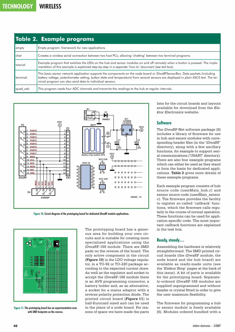
TECHNOLOGY WIRELESS
48 elektor electronics - 3/2007
lists for the circuit boards and layouts available for download from the Ele-ktor Electronics website.
SoftwareThe iDwaRF-Net software package [6] includes a library of fi rmware for use in hub and sensor modules with corre-sponding header fi les (in the ‘iDwaRF’ directory), along with a few ancillary functions, for example to support seri-al communications (‘USART’ directory). There are also four example programs which can either be used as they stand or form the basis for dedicated appli-cations. Table 2 gives more details of these example programs.
Each example program consists of hub source code (userMain_hub.c) and sensor source code (userMain_sensor.c). The fi rmware provides the facility to register so-called ‘callback’ func-tions, which the fi rmware calls regu-larly in the course of normal operation. These functions can be used for appli-cation-specifi c code. The most impor-tant callback functions are explained in the text box.
Ready, steady…Assembling the hardware is relatively straightforward. The SMD printed cir-cuit boards (the iDwaRF module, the node board and the hub board) are available as ready-made units (see the ‘Elektor Shop’ pages at the back of this issue). A kit of parts is available for the prototyping board. Separate-ly-ordered iDwaRF-168 modules are supplied unprogrammed and without header or crystal fi tted in order to give the user maximum fl exibility.
The fi rmware for programming a hub or sensor module is freely available [6]. Modules ordered bundled with a
The prototyping board has a gener-ous area for building your own cir-cuits and is suitable for creating more specialised applications using the iDwaRF-168 module. There are SMD pads on the reverse of the board. The only active component in the circuit (Figure 10) is the LDO voltage regula-tor, in a TO-92 or TO-220 package ac-cording to the expected current draw. As well as the regulator and socket to accept the iDwaRF-168 module there is an AVR programming connector, a battery holder and, as an alternative, a socket for a mains adaptor with a reverse polarity protection diode. The printed circuit board (Figure 11) is half-Eurocard sized and can be used in the place of a node board. For rea-sons of space we have made the parts
Table 2. Example programsempty Empty program: framework for new applications.
chat Creates a wireless serial connection between two host PCs, allowing ‘chatting’ between two terminal programs.
tutorialExample program that switches the LEDs on the hub and sensor modules on and off remotely when a button is pressed. The imple-mentation of this example is explained step-by-step in a separate ‘how to’ document (see text box).
terminalThis basic sensor network application supports the components on the node board or iDwaRFSensorBox. Data packets (including battery voltage, potentiometer setting, button state and temperature) from several sensors are displayed in plain ASCII text. The ter-minal program can also send data to individual sensors.
quad_adc This program reads four ADC channels and transmits the readings to the hub at regular intervals.
MISOVCCSCKMOSIRSTGND
PORT0PORT1PORT2PORT3PORT4PORT5PORT6PORT7
GN
DR
STM
OSI
SCK
VCC
MIS
O1 2 3 4 5 6
K4
1234567891011121314
K2
123456789
1011121314
K3
1
2
BATT
Battery Clip 3xAAA 2479
D1
1N4001
1 3
2LF33CV
IC1LP2950
2
31
K1
25V
C1
1u25V
C2
1u
iDwaRF
AVRISP
EXT
VCC
VCC
050402 - 14
SOIC-24
SOT-23/6
SOT-23/6
VCC
Figure 10. Circuit diagram of the prototyping board for dedicated iDwaRF module applications.
Figure 11. The prototyping board has an experimentation area with SMD footprints on the reverse.
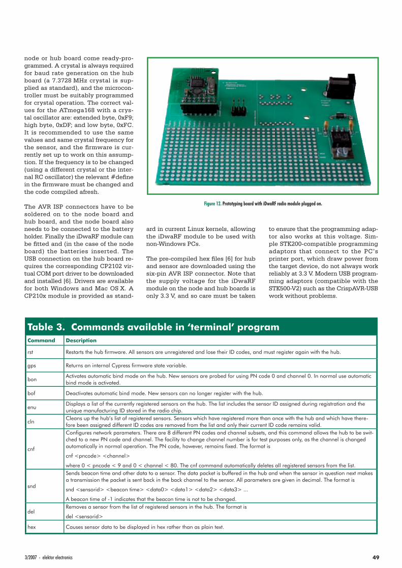
493/2007 - elektor electronics
node or hub board come ready-pro-grammed. A crystal is always required for baud rate generation on the hub board (a 7.3728 MHz crystal is sup-plied as standard), and the microcon-troller must be suitably programmed for crystal operation. The correct val-ues for the ATmega168 with a crys-tal oscillator are: extended byte, 0xF9; high byte, 0xDF; and low byte, 0xFC. It is recommended to use the same values and same crystal frequency for the sensor, and the fi rmware is cur-rently set up to work on this assump-tion. If the frequency is to be changed (using a different crystal or the inter-nal RC oscillator) the relevant #defi ne in the fi rmware must be changed and the code compiled afresh.
The AVR ISP connectors have to be soldered on to the node board and hub board, and the node board also needs to be connected to the battery holder. Finally the iDwaRF module can be fi tted and (in the case of the node board) the batteries inserted. The USB connection on the hub board re-quires the corresponding CP2102 vir-tual COM port driver to be downloaded and installed [6]. Drivers are available for both Windows and Mac OS X. A CP210x module is provided as stand-
ard in current Linux kernels, allowing the iDwaRF module to be used with non-Windows PCs.
The pre-compiled hex fi les [6] for hub and sensor are downloaded using the six-pin AVR ISP connector. Note that the supply voltage for the iDwaRF module on the node and hub boards is only 3.3 V, and so care must be taken
to ensure that the programming adap-tor also works at this voltage. Sim-ple STK200-compatible programming adaptors that connect to the PC’s printer port, which draw power from the target device, do not always work reliably at 3.3 V. Modern USB program-ming adaptors (compatible with the STK500-V2) such as the CrispAVR-USB work without problems.
Table 3. Commands available in ‘terminal’ programCommand Description
rst Restarts the hub fi rmware. All sensors are unregistered and lose their ID codes, and must register again with the hub.
gps Returns an internal Cypress fi rmware state variable.
bonActivates automatic bind mode on the hub. New sensors are probed for using PN code 0 and channel 0. In normal use automatic bind mode is activated.
bof Deactivates automatic bind mode. New sensors can no longer register with the hub.
enuDisplays a list of the currently registered sensors on the hub. The list includes the sensor ID assigned during registration and the unique manufacturing ID stored in the radio chip.
clnCleans up the hub’s list of registered sensors. Sensors which have registered more than once with the hub and which have there-fore been assigned different ID codes are removed from the list and only their current ID code remains valid.
cnf
Confi gures network parameters. There are 8 different PN codes and channel subsets, and this command allows the hub to be swit-ched to a new PN code and channel. The facility to change channel number is for test purposes only, as the channel is changed automatically in normal operation. The PN code, however, remains fi xed. The format is
cnf <pncode> <channel>
where 0 < pncode < 9 and 0 < channel < 80. The cnf command automatically deletes all registered sensors from the list.
snd
Sends beacon time and other data to a sensor. The data packet is buffered in the hub and when the sensor in question next makes a transmission the packet is sent back in the back channel to the sensor. All parameters are given in decimal. The format is
snd <sensorid> <beacon time> <data0> <data1> <data2> <data3> ...
A beacon time of -1 indicates that the beacon time is not to be changed.
delRemoves a sensor from the list of registered sensors in the hub. The format is
del <sensorid>
hex Causes sensor data to be displayed in hex rather than as plain text.
Figure 12. Prototyping board with iDwaRF radio module plugged on.
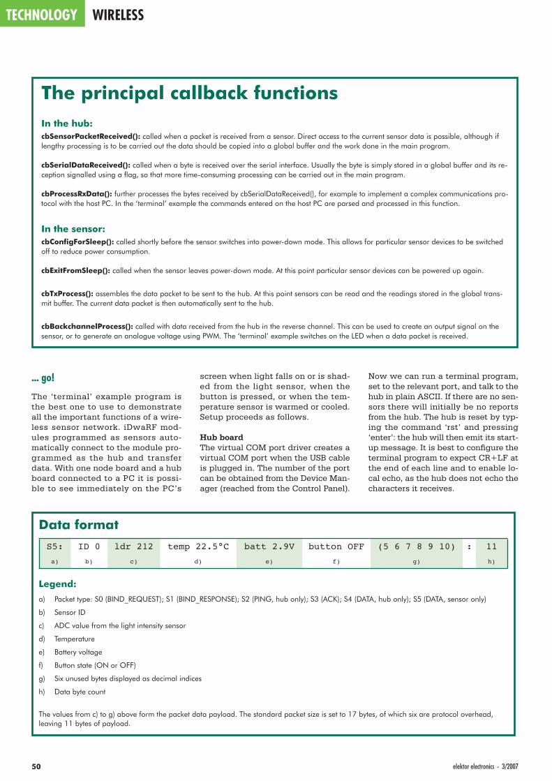
TECHNOLOGY WIRELESS
50 elektor electronics - 3/2007
... go!
The ‘terminal’ example program is the best one to use to demonstrate all the important functions of a wire-less sensor network. iDwaRF mod-ules programmed as sensors auto-matically connect to the module pro-grammed as the hub and transfer data. With one node board and a hub board connected to a PC it is possi-ble to see immediately on the PC’s
Now we can run a terminal program, set to the relevant port, and talk to the hub in plain ASCII. If there are no sen-sors there will initially be no reports from the hub. The hub is reset by typ-ing the command ‘rst’ and pressing ‘enter’: the hub will then emit its start-up message. It is best to confi gure the terminal program to expect CR+LF at the end of each line and to enable lo-cal echo, as the hub does not echo the characters it receives.
screen when light falls on or is shad-ed from the light sensor, when the button is pressed, or when the tem-perature sensor is warmed or cooled. Setup proceeds as follows.
Hub boardThe virtual COM port driver creates a virtual COM port when the USB cable is plugged in. The number of the port can be obtained from the Device Man-ager (reached from the Control Panel).
Data format
S5: ID 0 ldr 212 temp 22.5°C batt 2.9V button OFF (5 6 7 8 9 10) : 11
a) b) c) d) e) f) g) h)
Legend:
a) Packet type: S0 (BIND_REQUEST); S1 (BIND_RESPONSE); S2 (PING, hub only); S3 (ACK); S4 (DATA, hub only); S5 (DATA, sensor only)
b) Sensor ID
c) ADC value from the light intensity sensor
d) Temperature
e) Battery voltage
f) Button state (ON or OFF)
g) Six unused bytes displayed as decimal indices
h) Data byte count
The values from c) to g) above form the packet data payload. The standard packet size is set to 17 bytes, of which six are protocol overhead, leaving 11 bytes of payload.
The principal callback functionsIn the hub:cbSensorPacketReceived(): called when a packet is received from a sensor. Direct access to the current sensor data is possible, although if lengthy processing is to be carried out the data should be copied into a global buffer and the work done in the main program.
cbSerialDataReceived(): called when a byte is received over the serial interface. Usually the byte is simply stored in a global buffer and its re-ception signalled using a fl ag, so that more time-consuming processing can be carried out in the main program.
cbProcessRxData(): further processes the bytes received by cbSerialDataReceived(), for example to implement a complex communications pro-tocol with the host PC. In the ‘terminal’ example the commands entered on the host PC are parsed and processed in this function.
In the sensor:cbConfi gForSleep(): called shortly before the sensor switches into power-down mode. This allows for particular sensor devices to be switched off to reduce power consumption.
cbExitFromSleep(): called when the sensor leaves power-down mode. At this point particular sensor devices can be powered up again.
cbTxProcess(): assembles the data packet to be sent to the hub. At this point sensors can be read and the readings stored in the global trans-mit buffer. The current data packet is then automatically sent to the hub.
cbBackchannelProcess(): called with data received from the hub in the reverse channel. This can be used to create an output signal on the sensor, or to generate an analogue voltage using PWM. The ‘terminal’ example switches on the LED when a data packet is received.
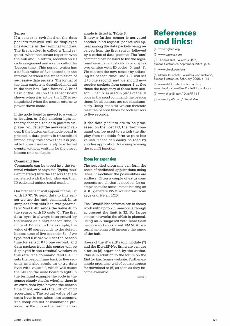
513/2007 - elektor electronics
SensorIf a sensor is switched on the data packets received will be displayed line-by-line in the terminal window. The first packet is called a ‘bind re-quest’ where the sensor registers with the hub and, in return, receives an ID code assignment and a value called the ‘beacon time’. This period, which has a default value of fi ve seconds, is the interval between the transmission of successive data packets. The format of the data packets is described in detail in the text box ‘Data format’. A brief fl ash of the LED on the sensor board shows when it is active; the LED is ex-tinguished when the sensor returns to power-down mode.
If the node board is moved to a warm-er location, or if the ambient light in-tensity changes, the data packets dis-played will refl ect the new sensor val-ues. If the button on the node board is pressed a data packet is transmitted immediately: this shows that it is pos-sible to react immediately to external events, without waiting for the preset beacon time to elapse.
Command lineCommands can be typed into the ter-minal window at any time. Typing ‘enu’ (‘enumerate’) lists the sensors that are registered with the hub, showing their ID code and unique serial number.
Our fi rst sensor will appear in this list with ID ‘0’. To send data to this sen-sor we use the ‘snd’ command. In its simplest form this has two parame-ters: ‘snd 0 40’ sends the value 40 to the sensor with ID code ‘0’. The fi rst data byte is always interpreted by the sensor as a new beacon time, in units of 125 ms. In this example, the value of 40 corresponds to the default beacon time of fi ve seconds. So, if we type ‘snd 0 8’ we will set the beacon time for sensor 0 to one second, and data packets from this sensor will be displayed in the terminal window at this rate. The command ‘snd 0 40 1’ sets the beacon time back to fi ve sec-onds and also sends an extra data byte with value ‘1’, which will cause the LED on the node board to light. In the terminal example the code in the sensor simply checks whether there is an extra data byte beyond the beacon time or not, and sets the LED on or off accordingly. The actual value of the extra byte is not taken into account. The complete set of commands pro-vided by the hub in the ‘terminal’ ex-
ample is listed in Table 3.If now a further sensor is activated another ‘bind request’ packet will ap-pear among the data packets being re-ceived from the fi rst sensor, followed by a series of data packets. The ‘enu’ command can be used to list the regis-tered sensors, and should now display two entries with ID codes ‘0’ and ‘1’. We can test the new sensor by adjust-ing its beacon time: ‘snd 1 8’ will set it to one second, and we should now receive packets from sensor 1 at fi ve times the frequency of those from sen-sor 0. If an ‘x’ is used in place of the ID code in the send command, the beacon times for all sensors are set simultane-ously. Using ‘snd x 40’ we can therefore reset the beacon times for both sensors to fi ve seconds.
If the data packets are to be proc-essed on the host PC, the ‘hex’ com-mand can be used to switch the dis-play from readable form to pure hex values. These can easily be read by another application, for example using the scanf() function.
Room for expansionThe supplied programs can form the basis of dedicated applications using iDwaRF modules: the possibilities are endless. Often a couple of extra com-ponents are all that is needed, for ex-ample to make measurements using an ADC, generate PWM waveforms, scan keys or drive an LCD.
The iDwaRF-Net software can in theory work with up to 255 sensors, although at present the limit is 32. For larger sensor networks the xHub is planned, using an ATmega128 with more fl ash memory and an external SRAM. An ex-ternal antenna will increase the range of the hub.
Users of the iDwaRF radio module [7] and the iDwaRF-Net fi rmware can use a forum [8] organised by the author. This is in addition to the forum on the Elektor Electronics website. Further ex-ample programs will of course appear for download at [6] as soon as they be-come available.
(050402-I)
References and links:[1] www.zigbee.org
[2] www.cypress.com
[3] Thomas Biel: ‘Wireless USB’, Elektor Electronics, September 2004, p. 8
[4] www.atmel.com/avr
[5] Stefan Tauschek: ‘Wireless Connectivity’, Elektor Electronics, February 2005, p. 14
[6] www.elektor-electronics.co.uk or www.chip45.com/iDwaRF-168_Downloads
[7] www.chip45.com/iDwaRF-168
[8] www.chip45.com/iDwaRF-Net
Naamloos-2 2Naamloos-2 2 24-11-2006 11:32:3224-11-2006 11:32:32

Naamloos-2 3Naamloos-2 3 24-11-2006 11:32:3624-11-2006 11:32:36
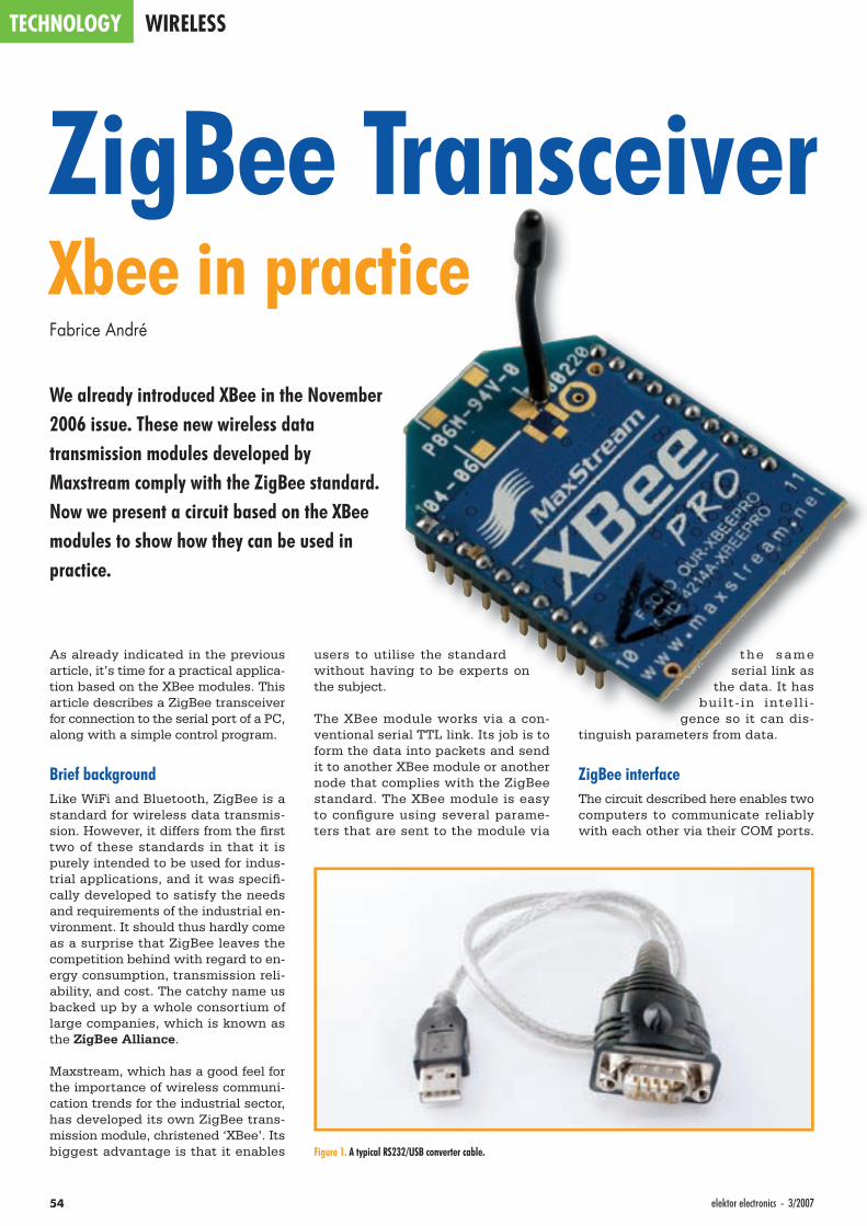
TECHNOLOGY WIRELESS
54 elektor electronics - 3/2007
ZigBee TransceiverXbee in practiceFabrice André
We already introduced XBee in the November 2006 issue. These new wireless data transmission modules developed by Maxstream comply with the ZigBee standard. Now we present a circuit based on the XBee modules to show how they can be used in practice.
As already indicated in the previous article, it’s time for a practical applica-tion based on the XBee modules. This article describes a ZigBee transceiver for connection to the serial port of a PC, along with a simple control program.
Brief backgroundLike WiFi and Bluetooth, ZigBee is a standard for wireless data transmis-sion. However, it differs from the fi rst two of these standards in that it is purely intended to be used for indus-trial applications, and it was specifi -cally developed to satisfy the needs and requirements of the industrial en-vironment. It should thus hardly come as a surprise that ZigBee leaves the competition behind with regard to en-ergy consumption, transmission reli-ability, and cost. The catchy name us backed up by a whole consortium of large companies, which is known as the ZigBee Alliance.
Maxstream, which has a good feel for the importance of wireless communi-cation trends for the industrial sector, has developed its own ZigBee trans-mission module, christened ‘XBee’. Its biggest advantage is that it enables
users to utilise the standard without having to be experts on the subject.
The XBee module works via a con-ventional serial TTL link. Its job is to form the data into packets and send it to another XBee module or another node that complies with the ZigBee standard. The XBee module is easy to confi gure using several parame-ters that are sent to the module via
the same serial link as
the data. It has bui l t - in intel l i -
gence so it can dis-tinguish parameters from data.
ZigBee interfaceThe circuit described here enables two computers to communicate reliably with each other via their COM ports.
Figure 1. A typical RS232/USB converter cable.
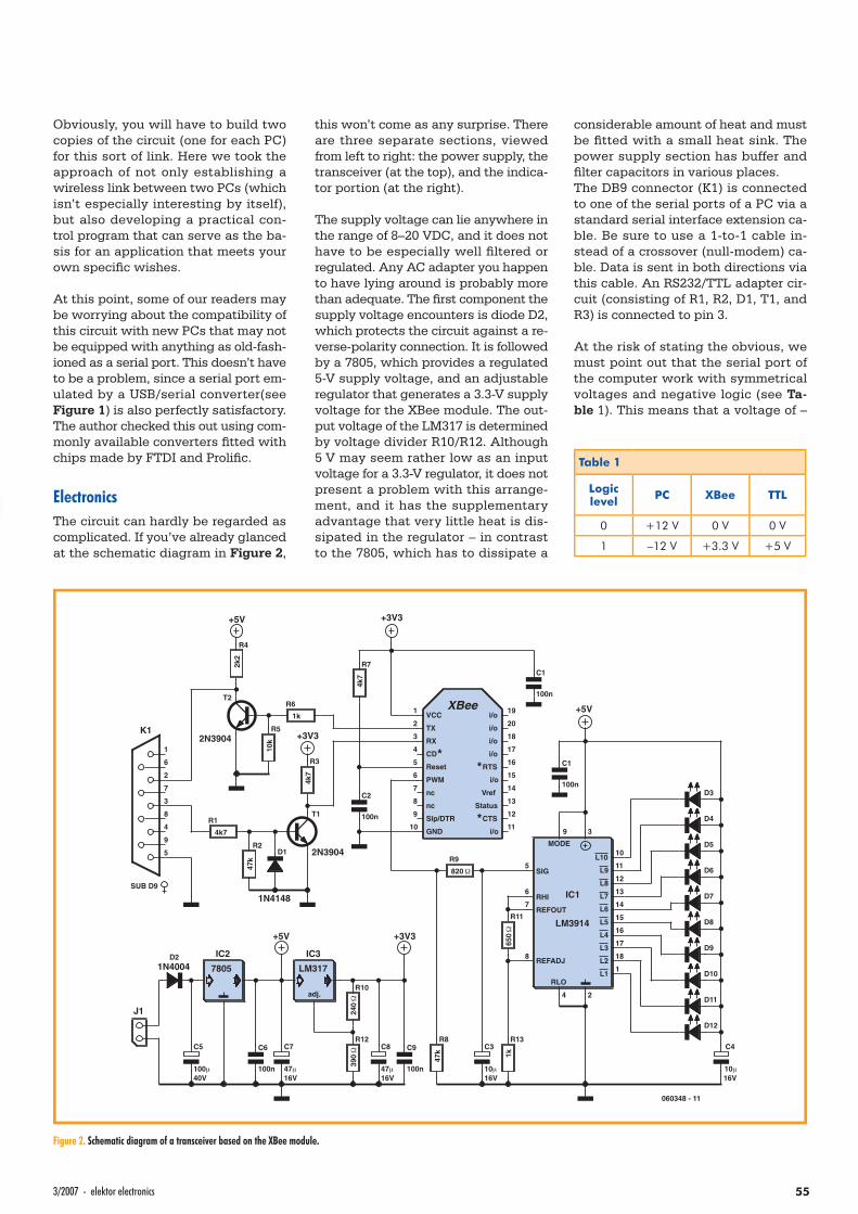
K1
SUB D9
1
2
3
4
5
6
7
8
9
J1
D21N4004
C5
100μ40V
7805
IC2
C7
47μ16V
C8
47μ16V
C6
100n
C9
100n
R10
240Ω
R12
390Ω
LM317
IC3
adj.
+5V +3V3
D1
1N4148
D3
D4
D5
D6
D7
D8
D9
D10
D11
D12
C4
10μ16V
R13
1k
R11
650Ω
REFOUT
REFADJ
LM3914
IC1
MODE
SIG
RHI
RLO
L10
17
16
15
14
13
12
11
10
L9
L8
L7
L6
L5
L4
L3
L1
18L2
9
5
8
4
6
7
3
2
1
C1
100n
R9
820Ω
C3
10μ16V
R8
47k
+5V
Slp/DTR
Status
Reset
XBee
Vref
GND
PWM
VCC
i/o
CTS
i/o
RTS
i/o
i/o
i/o
i/o
10
nc
nc
CD
RX
TX
11
12
13
14
15
16
17
18
19
20
9
8
7
6
5
4
3
1
2
**
*
C1
100n
+3V3
R7
4k7
C2
100n
R3
4k7
T1
2N3904R2
47k
R1
4k7
R6
1k
R5
10k
T2
2N3904
R4
2k2
+5V
+3V3
060348 - 11
553/2007 - elektor electronics
Obviously, you will have to build two copies of the circuit (one for each PC) for this sort of link. Here we took the approach of not only establishing a wireless link between two PCs (which isn’t especially interesting by itself), but also developing a practical con-trol program that can serve as the ba-sis for an application that meets your own specifi c wishes.
At this point, some of our readers may be worrying about the compatibility of this circuit with new PCs that may not be equipped with anything as old-fash-ioned as a serial port. This doesn’t have to be a problem, since a serial port em-ulated by a USB/serial converter(see Figure 1) is also perfectly satisfactory. The author checked this out using com-monly available converters fi tted with chips made by FTDI and Prolifi c.
ElectronicsThe circuit can hardly be regarded as complicated. If you’ve already glanced at the schematic diagram in Figure 2,
this won’t come as any surprise. There are three separate sections, viewed from left to right: the power supply, the transceiver (at the top), and the indica-tor portion (at the right).
The supply voltage can lie anywhere in the range of 8–20 VDC, and it does not have to be especially well fi ltered or regulated. Any AC adapter you happen to have lying around is probably more than adequate. The fi rst component the supply voltage encounters is diode D2, which protects the circuit against a re-verse-polarity connection. It is followed by a 7805, which provides a regulated 5-V supply voltage, and an adjustable regulator that generates a 3.3-V supply voltage for the XBee module. The out-put voltage of the LM317 is determined by voltage divider R10/R12. Although 5 V may seem rather low as an input voltage for a 3.3-V regulator, it does not present a problem with this arrange-ment, and it has the supplementary advantage that very little heat is dis-sipated in the regulator – in contrast to the 7805, which has to dissipate a
considerable amount of heat and must be fi tted with a small heat sink. The power supply section has buffer and fi lter capacitors in various places.The DB9 connector (K1) is connected to one of the serial ports of a PC via a standard serial interface extension ca-ble. Be sure to use a 1-to-1 cable in-stead of a crossover (null-modem) ca-ble. Data is sent in both directions via this cable. An RS232/TTL adapter cir-cuit (consisting of R1, R2, D1, T1, and R3) is connected to pin 3.
At the risk of stating the obvious, we must point out that the serial port of the computer work with symmetrical voltages and negative logic (see Ta-ble 1). This means that a voltage of –
Figure 2. Schematic diagram of a transceiver based on the XBee module.
Table 1
Logic level PC XBee TTL
0 +12 V 0 V 0 V
1 –12 V +3.3 V +5 V
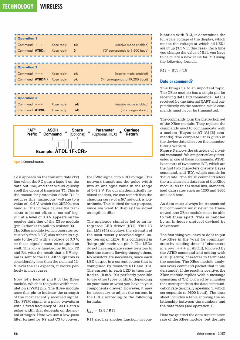
TECHNOLOGY WIRELESS
56 elektor electronics - 3/2007
12 V appears on the transmit data (Tx) line when the PC puts a logic 1 on the data out line, and that would quickly spell the doom of transistor T1. This is the reason for protection diode D1. It reduces this ‘hazardous’ voltage to a value of –0.6 V, which the 2N3904 can handle. This voltage causes the tran-sistor to be cut off, so a ‘normal’ log-ic 1 at a level of 3.3 V appears on the receive data line of the XBee module (pin 3) thanks to pull-up resistor R3.The XBee module (which operates ex-clusively from 3.3 V) also transmits sig-nals to the PC with a voltage of 3.3 V, so these signals must be adapted as well. This job is handled by R6, R5, T2 and R4, with the result that a 5-V sig-nal is sent to the PC. Although this is considerably less than the nominal 12-V level the PC expects, it works per-fectly in most cases.
Now let’s look at pin 6 of the XBee module, which is the pulse width mod-ulation (PWM) pin. The XBee module uses this pin to indicate the strength of the most recently received signal. The PWM signal is a pulse waveform with a fi xed frequency of 120 Hz and a pulse width that depends on the sig-nal strength. Here we use a low-pass fi lter formed by R9 and C3 to convert
the PWM signal into a DC voltage. This network transforms the pulse width into an analogue value in the range of 0–3.3 V. For our mathematically in-clined readers, we can remark that the charging curve of a RC network is log-arithmic. This is ideal for our purpose, since we want to display the signal strength in dBm.
The analogue signal is fed to an in-tegrated LED driver (IC1). This IC (an LM3914) displays the strength of the most recently received signal us-ing ten small LEDs. It is confi gured in ‘bargraph’ mode via pin 9. The LEDs do not have separate series resistors to limit the current fl owing through them. No resistors are necessary, since each LED output is a current source that is confi gured by resistors R11 and R13. The current in each LED is thus lim-ited to 18 mA. It’s perfectly possible to use other types of LEDs, depending on your taste or what you have in your components drawer. However, it may be necessary to adjust the current in the LEDs according to the following formula:
ILED = 12.5 / R11
R11 also has another function: in com-
bination with R13, it determines the full-scale voltage of the display, which means the voltage at which all LEDs are lit up (3.1 V in this case). Each time you change the value of R11, you have to calculate a new value for R13 using the following formula:
R13 = R11 × 1.5
Data or command?This brings us to an important topic. The XBee module has a single pin for receiving data and commands. Data is received by the internal UART and out-put directly via the antenna, while com-mands must never be transmitted.
The commands form the instruction set of the XBee module. They replace the commands used to communicate with a modem (Hayes or AT [A] [B] com-mands). The complete list is given in the device data sheet on the manufac-turer’s website.Figure 3 shows the structure of a typi-cal command. We are particularly inter-ested in one of these commands: ATBD. It consists of two terms: ‘AT’, which are the fi rst two characters of every Hayes command, and ‘BD’, which stands for ‘baud rate’. The ATBD command refers the transmission data rate of the XBee module. As this is serial link, standard-ised data rates such as 1200 and 9600 are used here.
As data must always be transmitted but commands must never be trans-mitted, the XBee module must be able to tell them apart. This is handled by an in-house protocol devised by Maxstream.
The fi rst thing you have to do is to put the XBee in the ‘wait for command’ state by sending three ‘+’ characters in a row (+++ in ASCII), followed by the ATBD command and ending with a CR (Return) character to terminate the session. The XBee module analy-ses every command packet that it ‘un-derstands’. If the result is positive, the XBee module replies with a message consisting of ‘OK’ followed by a number that corresponds to the data communi-cation rate (normally speaking 3, which corresponds to 9600 baud). The data sheet includes a table showing the re-lationship between the numbers and the data rates (see operation 1).
Here we queried the data transmission rate of the XBee module, but the rate
Operation 1
Command +++ Xbee reply ok (receive mode enabled)
Command ATBD↵ Xbee reply 3 (‘3’ corresponds to 9 600 baud)
Operation 2
Command +++ Xbee reply ok (receive mode enabled)
Command ATBD4↵ Xbee reply ok (‘4’ corresponds to 19,200 baud)
Operation 3
Command +++ Xbee reply ok (receive mode enabled)
Command ATWR↵ Xbee reply ok (all changes stored)
Example: ATDL 1F<CR>
"AT"Prefix
ASCIICommand
CarriageReturn
Space(Optional)
Parameter(Optional, HEX)+ + + +
Figure 3. Command structure.
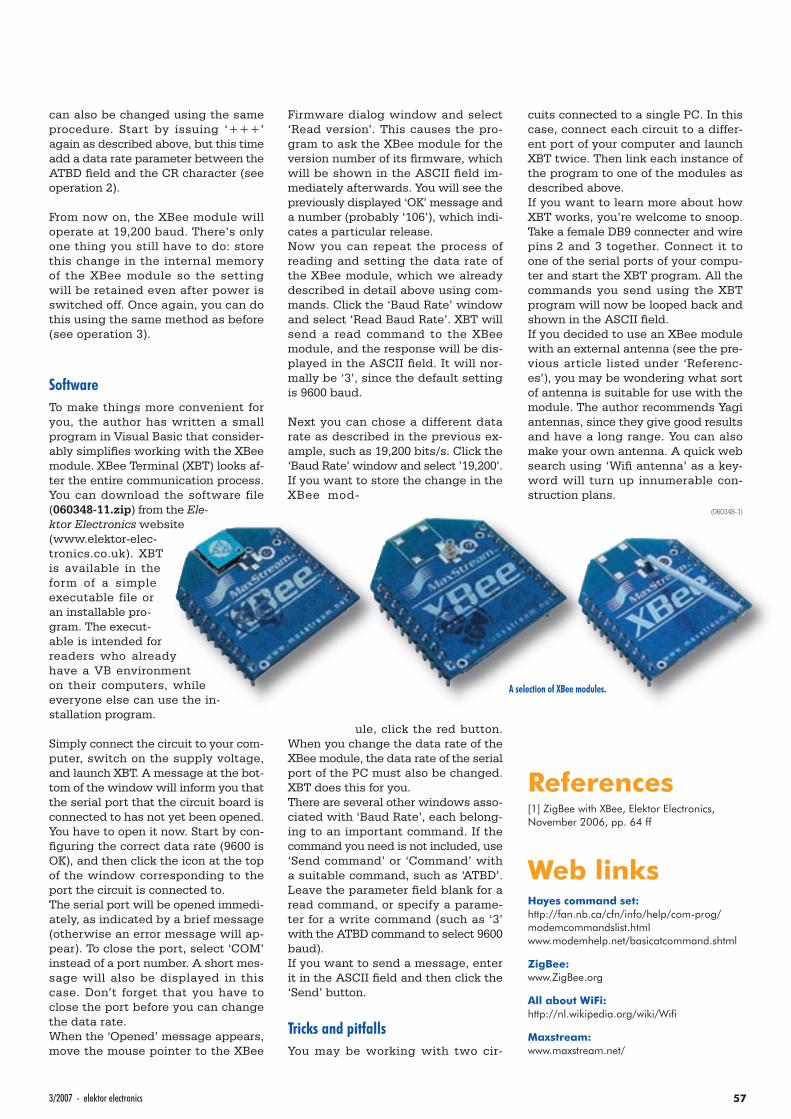
A selection of XBee modules.
573/2007 - elektor electronics
can also be changed using the same procedure. Start by issuing ‘+++’ again as described above, but this time add a data rate parameter between the ATBD fi eld and the CR character (see operation 2).
From now on, the XBee module will operate at 19,200 baud. There’s only one thing you still have to do: store this change in the internal memory of the XBee module so the setting will be retained even after power is switched off. Once again, you can do this using the same method as before (see operation 3).
SoftwareTo make things more convenient for you, the author has written a small program in Visual Basic that consider-ably simplifi es working with the XBee module. XBee Terminal (XBT) looks af-ter the entire communication process. You can download the software file (060348-11.zip) from the Ele-ktor Electronics website (www.elektor-elec-tronics.co.uk). XBT is available in the form of a simple executable file or an installable pro-gram. The execut-able is intended for readers who already have a VB environment on their computers, while everyone else can use the in-stallation program.
Simply connect the circuit to your com-puter, switch on the supply voltage, and launch XBT. A message at the bot-tom of the window will inform you that the serial port that the circuit board is connected to has not yet been opened. You have to open it now. Start by con-fi guring the correct data rate (9600 is OK), and then click the icon at the top of the window corresponding to the port the circuit is connected to.The serial port will be opened immedi-ately, as indicated by a brief message (otherwise an error message will ap-pear). To close the port, select ‘COM’ instead of a port number. A short mes-sage will also be displayed in this case. Don’t forget that you have to close the port before you can change the data rate.When the ‘Opened’ message appears, move the mouse pointer to the XBee
Firmware dialog window and select ‘Read version’. This causes the pro-gram to ask the XBee module for the version number of its fi rmware, which will be shown in the ASCII fi eld im-mediately afterwards. You will see the previously displayed ‘OK’ message and a number (probably ‘106’), which indi-cates a particular release.Now you can repeat the process of reading and setting the data rate of the XBee module, which we already described in detail above using com-mands. Click the ‘Baud Rate’ window and select ‘Read Baud Rate’. XBT will send a read command to the XBee module, and the response will be dis-played in the ASCII fi eld. It will nor-mally be ‘3’, since the default setting is 9600 baud.
Next you can chose a different data rate as described in the previous ex-ample, such as 19,200 bits/s. Click the ‘Baud Rate’ window and select ’19,200’. If you want to store the change in the XBee mod-
ule, click the red button. When you change the data rate of the XBee module, the data rate of the serial port of the PC must also be changed. XBT does this for you.There are several other windows asso-ciated with ‘Baud Rate’, each belong-ing to an important command. If the command you need is not included, use ‘Send command’ or ‘Command’ with a suitable command, such as ‘ATBD’. Leave the parameter fi eld blank for a read command, or specify a parame-ter for a write command (such as ‘3’ with the ATBD command to select 9600 baud).If you want to send a message, enter it in the ASCII fi eld and then click the ‘Send’ button.
Tricks and pitfallsYou may be working with two cir-
cuits connected to a single PC. In this case, connect each circuit to a differ-ent port of your computer and launch XBT twice. Then link each instance of the program to one of the modules as described above.If you want to learn more about how XBT works, you’re welcome to snoop. Take a female DB9 connecter and wire pins 2 and 3 together. Connect it to one of the serial ports of your compu-ter and start the XBT program. All the commands you send using the XBT program will now be looped back and shown in the ASCII fi eld.If you decided to use an XBee module with an external antenna (see the pre-vious article listed under ‘Referenc-es’), you may be wondering what sort of antenna is suitable for use with the module. The author recommends Yagi antennas, since they give good results and have a long range. You can also make your own antenna. A quick web search using ‘Wifi antenna’ as a key-word will turn up innumerable con-struction plans.
(060348-1)
References[1] ZigBee with XBee, Elektor Electronics, November 2006, pp. 64 ff
Web linksHayes command set:http://fan.nb.ca/cfn/info/help/com-prog/modemcommandslist.htmlwww.modemhelp.net/basicatcommand.shtml
ZigBee:www.ZigBee.org
All about WiFi:http://nl.wikipedia.org/wiki/Wifi
Maxstream:www.maxstream.net/
HANDS-ON PIC24F DESIGN SERIES
58 elektor electronics - 3/2007
Explorer-16 (3)Part 3: Speaking Thermometer, CF card simulation and Crypto PuzzleJan Buiting & Luc Lemmens, in cooperation with Microchip Technology and Labcenter Electronics
More advanced (but still 100% free) simulation this month
with a VSM model for media storage card devices added to our PIC24F system (all virtual, of course). To cap it all, solve a CF card crypto puzzle and win fantastic prizes sponsored by Microchip and Labcenter. But let’s fi rst revert to last month’s Speaking Thermometer project.
Last month’s Speaking Thermometer is not just a simulation you can run using three main components: (1) Labcenter’s Proteus VSM, (2) Microchip Technolo-gy’s MPLAB (both from your Explorer-16 CD-ROM) and (3) Elektor’s archive fi le called Demo2.zip. All components, by the way, are free, the CD-ROM hav-ing come as a gift with the full print run of our January 2007 issue.
If you haven’t done so already, please do run the January 2007 ‘Demo1’ simu-lation of the Explor-er-16 board itself. In the virtual envi-ronment created by Proteus VSM, press buttons and click away on other con-trols to your heart’s content and see how the system responds with its vari-ous indicators.
‘Demo2’ from the February 2007 issue is funnier to see… and hear in actual use! Particularly if you simulate tem-perature variations and manage to cre-ate your own voice fi les.The aim of these simulations is to
teach you how both simple and com-plex PIC24F MCU software can be created and debugged to the high-est possible level in combination with hardware devices like sensors and voice output (how’s that for an actuator device). The hardware/soft-ware interaction can be put through its paces in VSM/MPLAB without having real components cluttering your desk or even appearing on the boss’ Project Purchasing sheets. If
you need still stronger encourage-ment: with simulation your PC does most of the design work for you, sav-ing time and money compared to working with hardware components to achieve a design goal.
While awe stricken with the power of the simulations and the degree of inte-gration between the Labcenter and Mi-crochip Technology products, let’s not
forget that the Speaking Thermometer design can be made to work in hard-ware too. For this, all you need to know is how to program the PIC24F PIM on the Explorer-16 demo board that’s part of our Explorer-16 Value Pack.
Speaking ThermometerThe following is described to help you become acquainted with the hard-ware contained in the Explorer-16 Val-
ue Pack. Extensive product descrip-tions, user manu-als and software installation guides being supplied on CD-ROMs in the
Pack (take your time to read it all, it’s worth the effort), we can concentrate on our specifi c requirements. An up to speed description is given assuming of course that you are reasonably conver-sant with PCs.
1. Plug the Audio PICtail board into the PICtail bus connector on the Explorer-16 board. Check that the PIC24F PIM is fi tted on the demo board.
the simulations teach you how both simple and complex PIC24F MCU software can be created and debugged
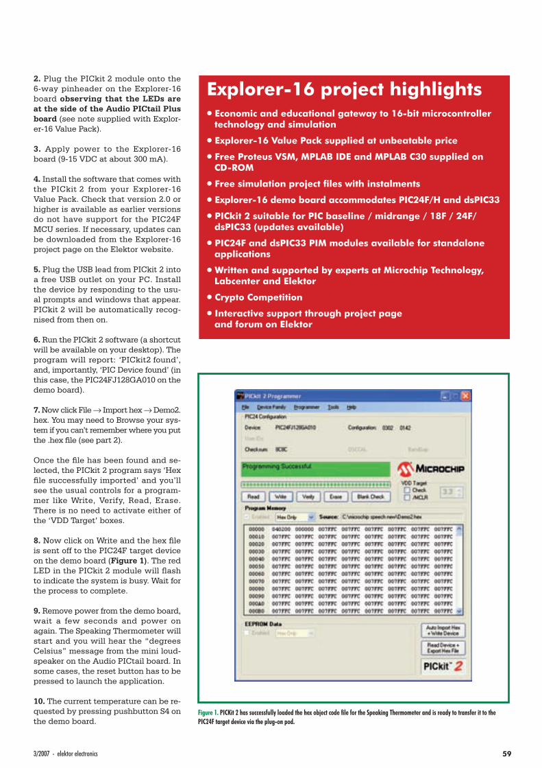
593/2007 - elektor electronics
2. Plug the PICkit 2 module onto the 6-way pinheader on the Explorer-16 board observing that the LEDs are at the side of the Audio PICtail Plus board (see note supplied with Explor-er-16 Value Pack).
3. Apply power to the Explorer-16 board (9-15 VDC at about 300 mA).
4. Install the software that comes with the PICkit 2 from your Explorer-16 Value Pack. Check that version 2.0 or higher is available as earlier versions do not have support for the PIC24F MCU series. If necessary, updates can be downloaded from the Explorer-16 project page on the Elektor website.
5. Plug the USB lead from PICkit 2 into a free USB outlet on your PC. Install the device by responding to the usu-al prompts and windows that appear. PICkit 2 will be automatically recog-nised from then on.
6. Run the PICkit 2 software (a shortcut will be available on your desktop). The program will report: ‘PICkit2 found’, and, importantly, ‘PIC Device found’ (in this case, the PIC24FJ128GA010 on the demo board).
7. Now click File → Import hex → Demo2.hex. You may need to Browse your sys-tem if you can’t remember where you put the .hex fi le (see part 2).
Once the fi le has been found and se-lected, the PICkit 2 program says ‘Hex fi le successfully imported’ and you’ll see the usual controls for a program-mer like Write, Verify, Read, Erase. There is no need to activate either of the ‘VDD Target’ boxes.
8. Now click on Write and the hex fi le is sent off to the PIC24F target device on the demo board (Figure 1). The red LED in the PICkit 2 module will fl ash to indicate the system is busy. Wait for the process to complete.
9. Remove power from the demo board, wait a few seconds and power on again. The Speaking Thermometer will start and you will hear the “degrees Celsius” message from the mini loud-speaker on the Audio PICtail board. In some cases, the reset button has to be pressed to launch the application.
10. The current temperature can be re-quested by pressing pushbutton S4 on the demo board.
Figure 1. PICKit 2 has successfully loaded the hex object code fi le for the Speaking Thermometer and is ready to transfer it to the PIC24F target device via the plug-on pod.
Explorer-16 project highlights•• Economic and educational gateway to 16-bit microcontroller
technology and simulation
•• Explorer-16 Value Pack supplied at unbeatable price
•• Free Proteus VSM, MPLAB IDE and MPLAB C30 supplied on CD-ROM
•• Free simulation project fi les with instalments
•• Explorer-16 demo board accommodates PIC24F/H and dsPIC33
•• PICkit 2 suitable for PIC baseline / midrange / 18F / 24F/ dsPIC33 (updates available)
•• PIC24F and dsPIC33 PIM modules available for standalone applications
•• Written and supported by experts at Microchip Technology, Labcenter and Elektor
•• Crypto Competition
•• Interactive support through project page and forum on Elektor website
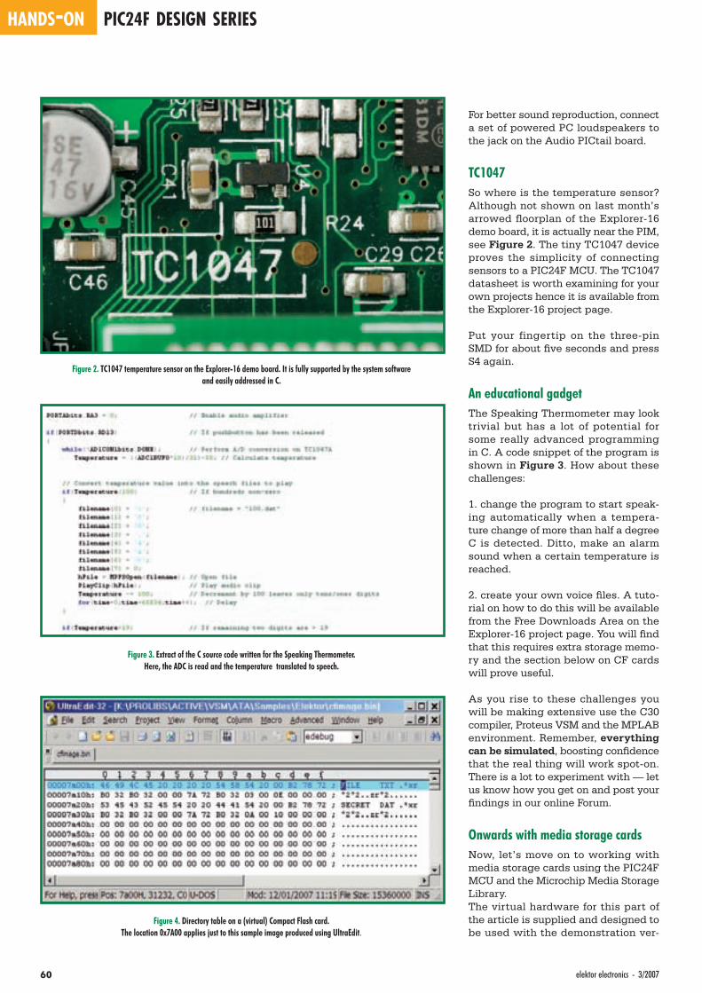
HANDS-ON PIC24F DESIGN SERIES
60 elektor electronics - 3/2007
For better sound reproduction, connect a set of powered PC loudspeakers to the jack on the Audio PICtail board.
TC1047So where is the temperature sensor? Although not shown on last month’s arrowed fl oorplan of the Explorer-16 demo board, it is actually near the PIM, see Figure 2. The tiny TC1047 device proves the simplicity of connecting sensors to a PIC24F MCU. The TC1047 datasheet is worth examining for your own projects hence it is available from the Explorer-16 project page.
Put your fingertip on the three-pin SMD for about fi ve seconds and press S4 again.
An educational gadgetThe Speaking Thermometer may look trivial but has a lot of potential for some really advanced programming in C. A code snippet of the program is shown in Figure 3. How about these challenges:
1. change the program to start speak-ing automatically when a tempera-ture change of more than half a degree C is detected. Ditto, make an alarm sound when a certain temperature is reached.
2. create your own voice fi les. A tuto-rial on how to do this will be available from the Free Downloads Area on the Explorer-16 project page. You will fi nd that this requires extra storage memo-ry and the section below on CF cards will prove useful.
As you rise to these challenges you will be making extensive use the C30 compiler, Proteus VSM and the MPLAB environment. Remember, everything can be simulated, boosting confi dence that the real thing will work spot-on. There is a lot to experiment with — let us know how you get on and post your fi ndings in our online Forum.
Onwards with media storage cardsNow, let’s move on to working with media storage cards using the PIC24F MCU and the Microchip Media Storage Library.The virtual hardware for this part of the article is supplied and designed to be used with the demonstration ver-
Figure 2. TC1047 temperature sensor on the Explorer-16 demo board. It is fully supported by the system softwareand easily addressed in C.
Figure 3. Extract of the C source code written for the Speaking Thermometer.Here, the ADC is read and the temperature translated to speech.
Figure 4. Directory table on a (virtual) Compact Flash card. The location 0x7A00 applies just to this sample image produced using UltraEdit.
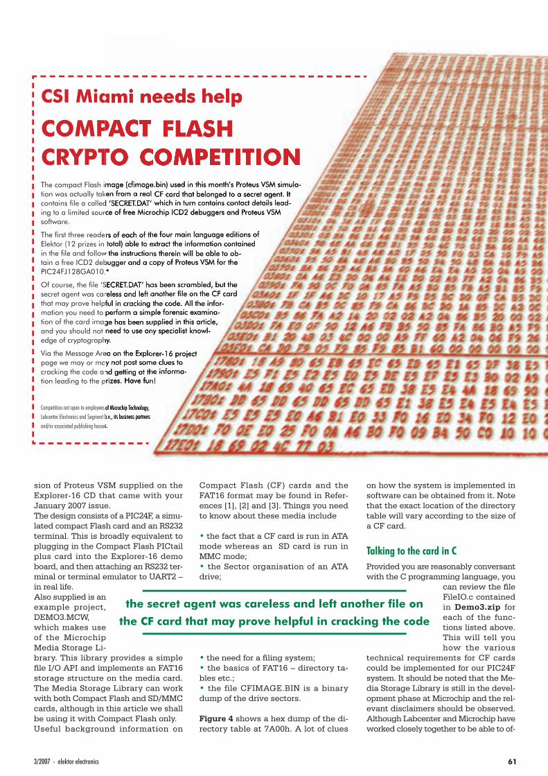
613/2007 - elektor electronics
sion of Proteus VSM supplied on the Explorer-16 CD that came with your January 2007 issue. The design consists of a PIC24F, a simu-lated compact Flash card and an RS232 terminal. This is broadly equivalent to plugging in the Compact Flash PICtail plus card into the Explorer-16 demo board, and then attaching an RS232 ter-minal or terminal emulator to UART2 – in real life.Also supplied is an example project, DEMO3.MCW, which makes use of the Microchip Media Storage Li-brary. This library provides a simple fi le I/O API and implements an FAT16 storage structure on the media card. The Media Storage Library can work with both Compact Flash and SD/MMC cards, although in this article we shall be using it with Compact Flash only.Useful background information on
Compact Flash (CF) cards and the FAT16 format may be found in Refer-ences [1], [2] and [3]. Things you need to know about these media include
• the fact that a CF card is run in ATA mode whereas an SD card is run in MMC mode;• the Sector organisation of an ATA drive;
• the need for a fi ling system;• the basics of FAT16 – directory ta-bles etc.;• the file CFIMAGE.BIN is a binary dump of the drive sectors.
Figure 4 shows a hex dump of the di-rectory table at 7A00h. A lot of clues
on how the system is implemented in software can be obtained from it. Note that the exact location of the directory table will vary according to the size of a CF card.
Talking to the card in CProvided you are reasonably conversant with the C programming language, you
can review the fi le FileIO.c contained in Demo3.zip for each of the func-tions listed above. This will tell you how the various
technical requirements for CF cards could be implemented for our PIC24F system. It should be noted that the Me-dia Storage Library is still in the devel-opment phase at Microchip and the rel-evant disclaimers should be observed. Although Labcenter and Microchip have worked closely together to be able to of-
CSI Miami needs help
COMPACT FLASH CRYPTO COMPETITIONThe compact Flash image (cfi mage.bin) used in this month’s Proteus VSM simula-tion was actually taken from a real CF card that belonged to a secret agent. It contains fi le a called ‘SECRET.DAT’ which in turn contains contact details lead-ing to a limited source of free Microchip ICD2 debuggers and Proteus VSM software.
The fi rst three readers of each of the four main language editions of Elektor (12 prizes in total) able to extract the information contained in the fi le and follow the instructions therein will be able to ob-tain a free ICD2 debugger and a copy of Proteus VSM for the PIC24FJ128GA010.*
Of course, the fi le ‘SECRET.DAT’ has been scrambled, but the secret agent was careless and left another fi le on the CF card that may prove helpful in cracking the code. All the infor-mation you need to perform a simple forensic examina-tion of the card image has been supplied in this article, and you should not need to use any specialist knowl-edge of cryptography.
Via the Message Area on the Explorer-16 project page we may or may not post some clues to cracking the code and getting at the informa-tion leading to the prizes. Have fun!
Competition not open to employees of Microchip Technology, Labcenter Electronics and Segment b.v., its business partners and/or associated publishing houses.
the secret agent was careless and left another fi le on
the CF card that may prove helpful in cracking the code
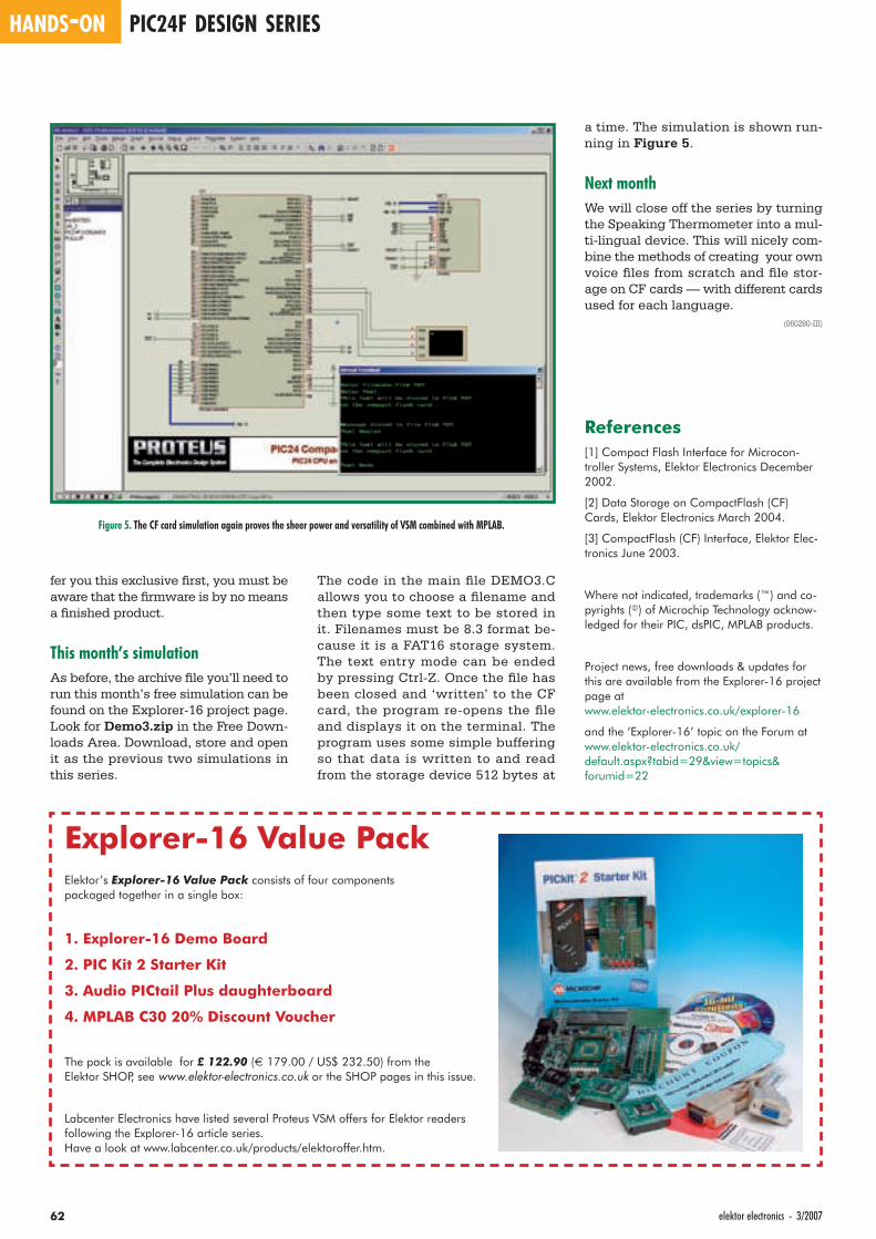
HANDS-ON PIC24F DESIGN SERIES
62 elektor electronics - 3/2007
fer you this exclusive fi rst, you must be aware that the fi rmware is by no means a fi nished product.
This month’s simulationAs before, the archive fi le you’ll need to run this month’s free simulation can be found on the Explorer-16 project page. Look for Demo3.zip in the Free Down-loads Area. Download, store and open it as the previous two simulations in this series.
a time. The simulation is shown run-ning in Figure 5.
Next monthWe will close off the series by turning the Speaking Thermometer into a mul-ti-lingual device. This will nicely com-bine the methods of creating your own voice fi les from scratch and fi le stor-age on CF cards — with different cards used for each language.
(060280-III)
References[1] Compact Flash Interface for Microcon-troller Systems, Elektor Electronics December 2002.
[2] Data Storage on CompactFlash (CF) Cards, Elektor Electronics March 2004.
[3] CompactFlash (CF) Interface, Elektor Elec-tronics June 2003.
Where not indicated, trademarks (™) and co-pyrights (©) of Microchip Technology acknow-ledged for their PIC, dsPIC, MPLAB products.
Project news, free downloads & updates for this are available from the Explorer-16 project page atwww.elektor-electronics.co.uk/explorer-16
and the ‘Explorer-16’ topic on the Forum atwww.elektor-electronics.co.uk/default.aspx?tabid=29&view=topics& forumid=22
The code in the main fi le DEMO3.C allows you to choose a fi lename and then type some text to be stored in it. Filenames must be 8.3 format be-cause it is a FAT16 storage system. The text entry mode can be ended by pressing Ctrl-Z. Once the fi le has been closed and ‘written’ to the CF card, the program re-opens the fi le and displays it on the terminal. The program uses some simple buffering so that data is written to and read from the storage device 512 bytes at
Figure 5. The CF card simulation again proves the sheer power and versatility of VSM combined with MPLAB.
Explorer-16 Value PackElektor’s Explorer-16 Value Pack consists of four components packaged together in a single box:
1. Explorer-16 Demo Board
2. PIC Kit 2 Starter Kit
3. Audio PICtail Plus daughterboard
4. MPLAB C30 20% Discount Voucher
The pack is available for £ 122.90 (€ 179.00 / US$ 232.50) from the Elektor SHOP, see www.elektor-electronics.co.uk or the SHOP pages in this issue.
Labcenter Electronics have listed several Proteus VSM offers for Elektor readers following the Explorer-16 article series. Have a look at www.labcenter.co.uk/products/elektoroffer.htm.
3/2007 - elektor electronics 63

HANDS-ON MICROCONTROLLERS
64 elektor electronics - 3/2007
Mobile Phone Mobile Phone LCD for PCLCD for PC
Recycling Alcatel LCDsRecycling Alcatel LCDsMichael Gaus
The biggest obstacle to reusing old mobile phone parts is usually the lack of datasheets. Undeterred, the author has managed to work out how to use the display from an Alcatel phone purely by analysing the printed circuit board and data protocol. As a result he has made it possible to drive the display from an ATmega16 microcontroller.
The display that we exper-imented with for this project
came from an old ‘Alcatel OTE db’ mobile phone. The most important
information about the display is given in the inset. The display is controlled serially using the SPI protocol and so only a few wires are required to drive it from a microcontroller. The pinout and protocol were deduced by ‘reverse en-gineering’ a (still working) phone with the aid of an oscilloscope to spy on the signal lines. This research enabled us to determine how to drive the display and its character set. The tangible re-sult of all this is the ATmega16 board described here and the fi rmware re-siding in it, which together provide an LCD interface that can be connected to the serial port of a PC and controlled using a terminal program. The freeware program LCDHype lets the display be coupled to the Winamp MP3 player to
display track title information. A plug-in is available for LCDHype that allows you to track the progress of Ebay auc-tions on the salvaged LCD, and you will no doubt think of other applica-tions (and post them on the Elektor Electronics forums!).
MobilewareIn the mobile phone the LCD, keypad and LED backlight are all mounted on the same printed circuit board (see photograph). The simplest approach is not to try to desolder the LCD but to use the circuit board as it stands. The control signals can easily be attached to using the solder pads labelled J800 (Figure 1). It may even be possible to fi nd a use for the keypad, which is wired in a matrix organisation. It is also possible to detach the LCD from the circuit board without damaging it
Display characteristicsDisplay type: Alphanumeric
plus 8 annunciators
Rows: Two plus annunciator row
Characters per row: 12
Annunciators: 8
Interface: SPI
Operating voltage: approximately 3 V (in the mobile phone, 2.9 V)
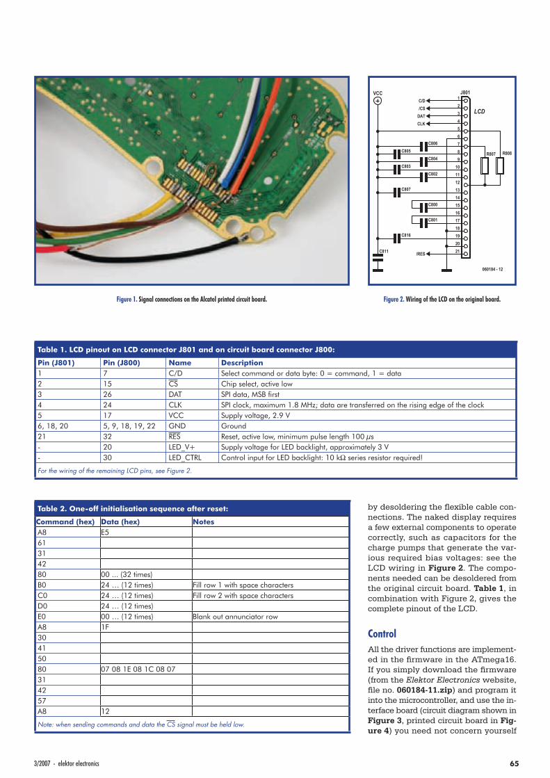
653/2007 - elektor electronics
by desoldering the fl exible cable con-nections. The naked display requires a few external components to operate correctly, such as capacitors for the charge pumps that generate the var-ious required bias voltages: see the LCD wiring in Figure 2. The compo-nents needed can be desoldered from the original circuit board. Table 1, in combination with Figure 2, gives the complete pinout of the LCD.
ControlAll the driver functions are implement-ed in the fi rmware in the ATmega16. If you simply download the fi rmware (from the Elektor Electronics website, fi le no. 060184-11.zip) and program it into the microcontroller, and use the in-terface board (circuit diagram shown in Figure 3, printed circuit board in Fig-ure 4) you need not concern yourself
Figure 1. Signal connections on the Alcatel printed circuit board.
123456789
101112131415161718192021
J801
LCD
R807 R808
C816
C811
C801
C800
C807
C802C803
C804C805
C806
VCC
060184 - 12
C/D/CS
DATCLK
/RES
Figure 2. Wiring of the LCD on the original board.
Table 1. LCD pinout on LCD connector J801 and on circuit board connector J800:
Pin (J801) Pin (J800) Name Description1 7 C/D Select command or data byte: 0 = command, 1 = data2 15 CS Chip select, active low3 26 DAT SPI data, MSB fi rst4 24 CLK SPI clock, maximum 1.8 MHz; data are transferred on the rising edge of the clock5 17 VCC Supply voltage, 2.9 V6, 18, 20 5, 9, 18, 19, 22 GND Ground21 32 RES Reset, active low, minimum pulse length 100 µs- 20 LED_V+ Supply voltage for LED backlight, approximately 3 V- 30 LED_CTRL Control input for LED backlight: 10 kΩ series resistor required!
For the wiring of the remaining LCD pins, see Figure 2.
Table 2. One-off initialisation sequence after reset:
Command (hex) Data (hex) NotesA8 E561314280 00 ... (32 times)B0 24 … (12 times) Fill row 1 with space charactersC0 24 … (12 times) Fill row 2 with space charactersD0 24 … (12 times)E0 00 … (12 times) Blank out annunciator rowA8 1F30415080 07 08 1E 08 1C 08 07314257A8 12
Note: when sending commands and data the CS signal must be held low.
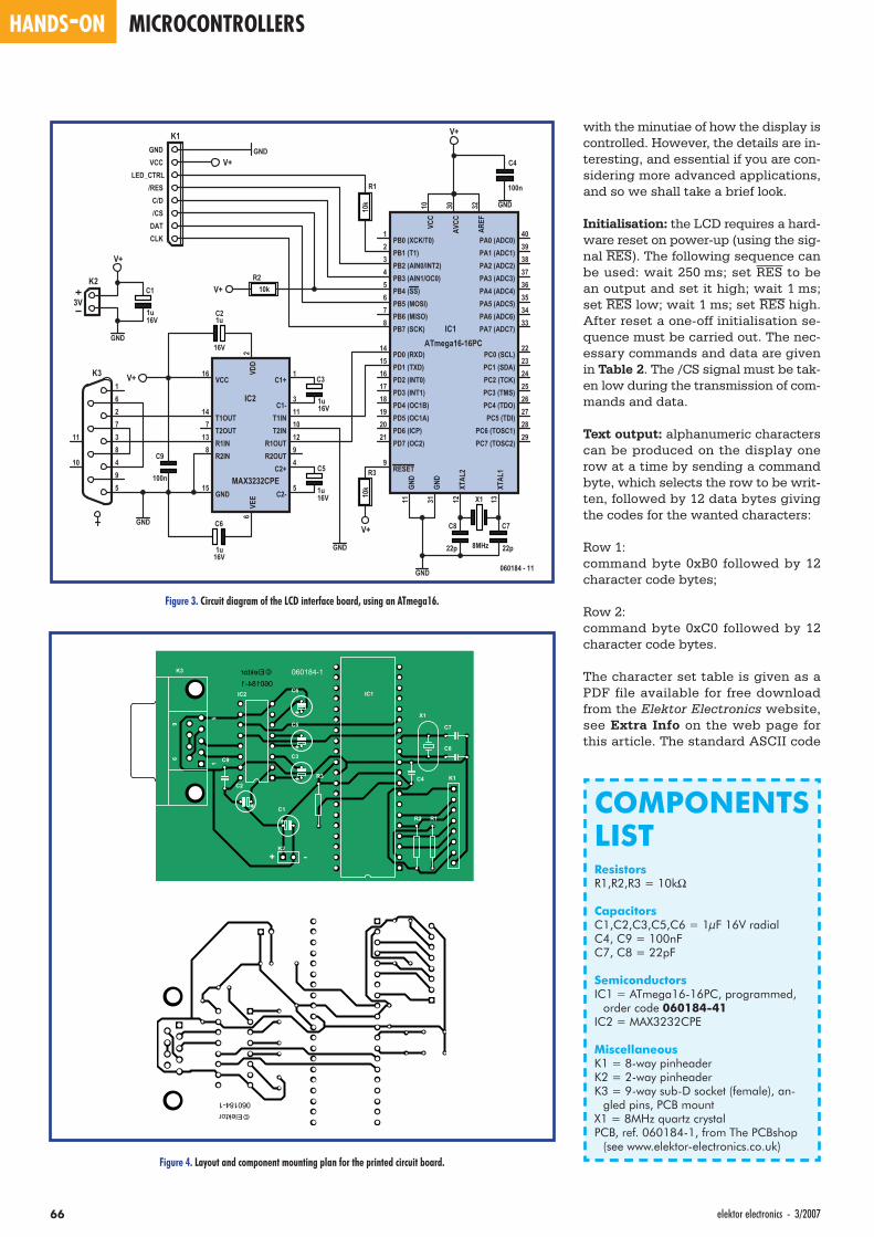
HANDS-ON MICROCONTROLLERS
66 elektor electronics - 3/2007
with the minutiae of how the display is controlled. However, the details are in-teresting, and essential if you are con-sidering more advanced applications, and so we shall take a brief look.
Initialisation: the LCD requires a hard-ware reset on power-up (using the sig-nal RES). The following sequence can be used: wait 250 ms; set RES to be an output and set it high; wait 1 ms; set RES low; wait 1 ms; set RES high. After reset a one-off initialisation se-quence must be carried out. The nec-essary commands and data are given in Table 2. The /CS signal must be tak-en low during the transmission of com-mands and data.
Text output: alphanumeric characters can be produced on the display one row at a time by sending a command byte, which selects the row to be writ-ten, followed by 12 data bytes giving the codes for the wanted characters:
Row 1:command byte 0xB0 followed by 12 character code bytes;
Row 2: command byte 0xC0 followed by 12 character code bytes.
The character set table is given as a PDF file available for free download from the Elektor Electronics website, see Extra Info on the web page for this article. The standard ASCII code
PB0 (XCK/T0)1
PB1 (T1)2
PB2 (AIN0/INT2)3
PB3 (AIN1/OC0)4
PB4 (SS)5
PB5 (MOSI)6
PB6 (MISO)7
PB7 (SCK)8
RESET9
PD0 (RXD)14
PD1 (TXD)15
PD2 (INT0)16
PD3 (INT1)17
PD4 (OC1B)18
PD5 (OC1A)19
PD6 (ICP)20
PD7 (OC2)21
XTAL
212
XTAL
113
GND
11
PC0 (SCL)22
PC1 (SDA)23
PC2 (TCK)24
PC3 (TMS)25
PC4 (TDO)26
PC5 (TDI)27
PC6 (TOSC1)28
PC7 (TOSC2)29
AREF
32
AVCC
30GN
D31
PA7 (ADC7)33
PA6 (ADC6)34
PA5 (ADC5)35
PA4 (ADC4)36
PA3 (ADC3)37
PA2 (ADC2)38
PA1 (ADC1)39
PA0 (ADC0)40
VCC
10
IC1ATmega16-16PC
R1
10k
R210k
R3
10k
K1
V+
V+GND
V+
V+
GND
X1
8MHz
C8
22p
C7
22p
C1+1VD
D2
C1-3
C2+4
C2-5
VEE
6
T2OUT7
R2IN8
R2OUT9
T2IN10
T1IN11
R1OUT12
R1IN13
T1OUT14
GND15
VCC16
IC2
MAX3232CPE
16V
C21u
16V
C6
1u
16V
C3
1u
16V
C5
1u
V+
C4
100n
C9
100n
1
2
3
4
5
6
7
8
9
11
10
K3
GND
K2
GND
V+
16V
C1
1u
GNDVCC
LED_CTRL/RES
C/D/CS
DATCLK
GND
060184 - 11
GND
3V
Figure 3. Circuit diagram of the LCD interface board, using an ATmega16.
Figure 4. Layout and component mounting plan for the printed circuit board.
COMPONENTS LISTResistorsR1,R2,R3 = 10kΩ
CapacitorsC1,C2,C3,C5,C6 = 1µF 16V radialC4, C9 = 100nFC7, C8 = 22pF
SemiconductorsIC1 = ATmega16-16PC, programmed,
order code 060184-41IC2 = MAX3232CPE
MiscellaneousK1 = 8-way pinheaderK2 = 2-way pinheaderK3 = 9-way sub-D socket (female), an-
gled pins, PCB mountX1 = 8MHz quartz crystalPCB, ref. 060184-1, from The PCBshop
(see www.elektor-electronics.co.uk)
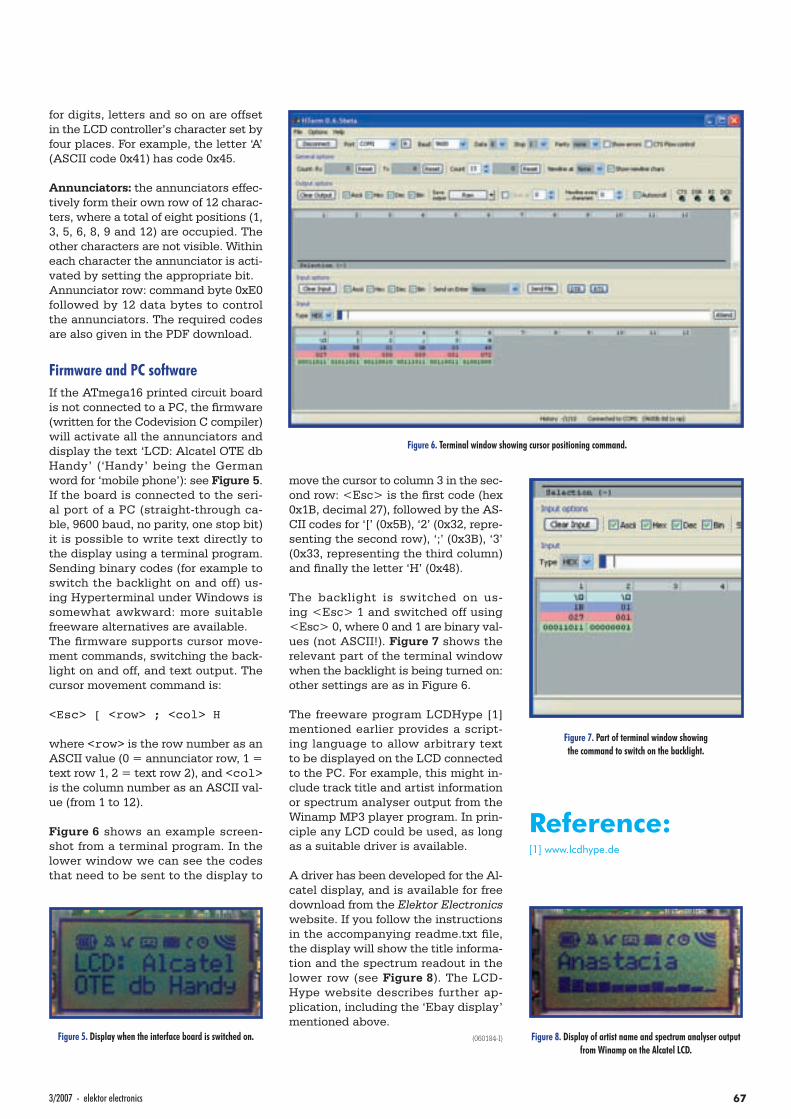
673/2007 - elektor electronics
for digits, letters and so on are offset in the LCD controller’s character set by four places. For example, the letter ‘A’ (ASCII code 0x41) has code 0x45.
Annunciators: the annunciators effec-tively form their own row of 12 charac-ters, where a total of eight positions (1, 3, 5, 6, 8, 9 and 12) are occupied. The other characters are not visible. Within each character the annunciator is acti-vated by setting the appropriate bit.Annunciator row: command byte 0xE0 followed by 12 data bytes to control the annunciators. The required codes are also given in the PDF download.
Firmware and PC softwareIf the ATmega16 printed circuit board is not connected to a PC, the fi rmware (written for the Codevision C compiler) will activate all the annunciators and display the text ‘LCD: Alcatel OTE db Handy’ (‘Handy’ being the German word for ‘mobile phone’): see Figure 5. If the board is connected to the seri-al port of a PC (straight-through ca-ble, 9600 baud, no parity, one stop bit) it is possible to write text directly to the display using a terminal program. Sending binary codes (for example to switch the backlight on and off) us-ing Hyperterminal under Windows is somewhat awkward: more suitable freeware alternatives are available.The fi rmware supports cursor move-ment commands, switching the back-light on and off, and text output. The cursor movement command is:
<Esc> [ <row> ; <col> H
where <row> is the row number as an ASCII value (0 = annunciator row, 1 = text row 1, 2 = text row 2), and <col> is the column number as an ASCII val-ue (from 1 to 12).
Figure 6 shows an example screen-shot from a terminal program. In the lower window we can see the codes that need to be sent to the display to
move the cursor to column 3 in the sec-ond row: <Esc> is the fi rst code (hex 0x1B, decimal 27), followed by the AS-CII codes for ‘[’ (0x5B), ‘2’ (0x32, repre-senting the second row), ‘;’ (0x3B), ‘3’ (0x33, representing the third column) and fi nally the letter ‘H’ (0x48).
The backlight is switched on us-ing <Esc> 1 and switched off using <Esc> 0, where 0 and 1 are binary val-ues (not ASCII!). Figure 7 shows the relevant part of the terminal window when the backlight is being turned on: other settings are as in Figure 6.
The freeware program LCDHype [1] mentioned earlier provides a script-ing language to allow arbitrary text to be displayed on the LCD connected to the PC. For example, this might in-clude track title and artist information or spectrum analyser output from the Winamp MP3 player program. In prin-ciple any LCD could be used, as long as a suitable driver is available.
A driver has been developed for the Al-catel display, and is available for free download from the Elektor Electronics website. If you follow the instructions in the accompanying readme.txt fi le, the display will show the title informa-tion and the spectrum readout in the lower row (see Figure 8). The LCD-Hype website describes further ap-plication, including the ‘Ebay display’ mentioned above.
(060184-I)
Reference:[1] www.lcdhype.de
Figure 5. Display when the interface board is switched on.
Figure 6. Terminal window showing cursor positioning command.
Figure 8. Display of artist name and spectrum analyser output from Winamp on the Alcatel LCD.
Figure 7. Part of terminal window showing the command to switch on the backlight.

FlashMicrocontroller Starter KitElektor Hardware & Software
Step into the fascinating world of microcontrollers
with the Elektor Electronics Flash Microcontroller
Starter Kit. Order now the ready-assembled PCB
incl. software, cable, adapter & related articles.
Contents of Starter Kit:
• 89S8253 Flash Microcontroller board
(ready-assembled and tested PCB)
• 300-mA mains adapter
• Serial cable for COM port
• Software bundle on CD-ROM
• Article compilation on CD-ROM
More information on www.elektor-electronics.co.uk
Step into the fascinating world of microcontrollers
Elektor Electronics (Publishing)
Regus Brentford
1000 Great West Road
Brentford TW8 9HH
United Kingdom
Telephone +44 (0) 208 261 4509
Fax +44 (0) 208 261 4447
Email: [email protected]
Order now using the Order Form
in the Readers Services section in this issue.
Microcontroller BasicsBurkhard Kainka
Microcontrollers have become an indispensable part of modern electronics.They make things possible that vastly exceed what could be done previously.Innumerable applications show that almost nothing is impossible. There’s thus every reason to learn more about them, but that raises the question of where to find a good introduction to this fascinating technology. The answer is easy:this Microcontroller Basics book, combined with the 89S8252 Flash Board project published by Elektor Electronics. This book clearly explains the technology using various microcontroller circuits and programs written in several different programming languages. In the course of the book, the reader gradually develops increased competence in converting his or her ideas into microcontroller circuitry.
ISBN 978-0-905705-67-5230 Pages£18.70 / US$ 33.70
£69.00US$ 112.50
Upgrade for FlashMicrocontroller Board
AT89S8253 supersedes AT89S8252
Enchancements AT89S8253 versus AT89S8252:
• 12 kbytes of flash memory instead of 8 kbytes
• Page Mode for faster programming
• Doubled processing speed using X2 clock option
• Power-on reset function and brown-out detection
• Supply voltage from 2.7 V to 5.5 V
ELEK UK0702 Micro+starterkit.ind1 1 05-01-2007 10:10:23

Quasar Electronics Limited PO Box 6935, Bishops Stortford CM23 4WP, United Kingdom Tel: 0870 246 1826 Fax: 0870 460 1045 E-mail: [email protected] Web: www.QuasarElectronics.com
Postage & Packing Options (Up to 2Kg gross weight): UK Standard 3-7 Day Delivery - £3.95; UK Mainland Next Day Delivery - £8.95; Europe (EU) - £6.95; Rest of World - £9.95 (up to 0.5Kg) !Order online for reduced price UK Postage! We accept all major credit/debit cards. Make cheques/PO’s payable to Quasar Electronics. Prices include 17.5% VAT. Call now for our FREE CATALOGUE with details of over 300 kits, projects, modules and publications. Discounts for bulk quantities.
Secure Online Ordering Facilities Full Product Listing, Descriptions & Photos Kit Documentation & Software Downloads
Infrared RC Relay Board Individually control 12 on-board relays with included infrared remote control unit. Toggle or momentary. 15m+ range. 112x122mm. Supply: 12Vdc/0.5A Kit Order Code: 3142KT - £47.95 Assembled Order Code: AS3142 - £66.95
NEW! USB & Serial Port PIC Programmer
USB/Serial connection. Header cable for ICSP. Free Windows XP software. Wide range of supported PICs - see website for complete listing. ZIF Socket/USB
lead not included. Supply: 16-18Vdc. Kit Order Code: 3149EKT - £37.95 Assembled Order Code: AS3149E - £52.95 NEW! USB 'All-Flash' PIC Programmer USB PIC programmer for all ‘Flash’ devices. No external power supply making it truly portable. Supplied with box and Windows Software. ZIF Socket and USB lead not included. Assembled Order Code: AS3128 - £44.95 “PICALL” PIC Programmer
“PICALL” will program virtu-ally all 8 to 40 pin serial-mode AND parallel-mode (PIC16C5x family) pro-
grammed PIC micro controllers. Free fully functional software. Blank chip auto detect for super fast bulk programming. Parallel port connection. Supply: 16-18Vdc. Assembled Order Code: AS3117 - £24.95 ATMEL 89xxxx Programmer Uses serial port and any standard terminal comms program. Program/ Read/ Verify Code Data, Write Fuse/Lock Bits, Erase and Blank Check. 4 LED’s display the status. ZIF sockets not included. Supply: 16-18Vdc. Kit Order Code: 3123KT - £24.95 Assembled Order Code: AS3123 - £34.95
PIC & ATMEL Programmers
We have a wide range of low cost PIC and ATMEL Programmers. Complete range and documentation available from our web site.
Programmer Accessories: 40-pin Wide ZIF socket (ZIF40W) £15.00 18Vdc Power supply (PSU010) £19.95 Leads: Parallel (LDC136) £4.95 / Serial (LDC441) £4.95 / USB (LDC644) £2.95
Serial Isolated I/O Relay Module Computer controlled 8-channel relay board. 5A mains rated relay outputs. 4 isolated digital inputs. Useful in a variety of con-trol and sensing applica-tions. Controlled via serial port for programming
(using our new Windows interface, terminal emulator or batch files). Includes plastic case 130x100x30mm. Supply: 12Vdc/500mA. Kit Order Code: 3108KT - £54.95 Assembled Order Code: AS3108 - £64.95 Computer Temperature Data Logger
4-channel temperature log-ger for serial port. °C or °F. Continuously logs up to 4 separate sensors located 200m+ from board. Wide range of free software appli-
cations for storing/using data. PCB just 38x38mm. Powered by PC. Includes one DS1820 sensor and four header cables. Kit Order Code: 3145KT - £18.95 Assembled Order Code: AS3145 - £25.95 Additional DS1820 Sensors - £3.95 each Rolling Code 4-Channel UHF Remote State-of-the-Art. High security. 4 channels. Momentary or latching relay output. Range up to 40m. Up to 15 Tx’s can be learnt by one Rx (kit in-cludes one Tx but more avail-able separately). 4 indicator LED ’s. Rx: PCB 77x85mm, 12Vdc/6mA (standby). Two and
Ten channel versions also available. Kit Order Code: 3180KT - £44.95 Assembled Order Code: AS3180 - £51.95 NEW! DTMF Telephone Relay Switcher Call your phone number using a DTMF phone from anywhere in the world and remotely turn on/off any of the 4 relays as desired. User settable Security Password, Anti-Tamper, Rings to Answer, Auto Hang-up and Lockout. Includes plastic case. Not BT ap-proved. 130x110x30mm. Power: 12Vdc. Kit Order Code: 3140KT - £46.95 Assembled Order Code: AS3140 - £64.95
Controllers & Loggers
Here are just a few of the controller and data acquisition and control units we have. See website for full details. Suitable PSU for all units: Order Code PSU445 £8.95
NEW! PC / Standalone Unipolar Stepper Motor Driver Drives any 5, 6 or 8-lead unipolar stepper motor rated up to 6 Amps max. Provides speed and direc-tion control. Operates in stand-alone or PC-controlled mode. Up to six 3179 driver boards can be connected to a single parallel port. Supply: 9Vdc. PCB: 80x50mm. Kit Order Code: 3179KT - £11.95 Assembled Order Code: AS3179 - £19.95 NEW! Bi-Polar Stepper Motor Driver Drive any bi-polar stepper motor using externally sup-plied 5V levels for stepping and direction control. These usually come from software running on a computer. Supply: 8-30Vdc. PCB: 75x85mm. Kit Order Code: 3158KT - £15.95 Assembled Order Code: AS3158 - £29.95 NEW! Bidirectional DC Motor Controller
Controls the speed of most common DC motors (rated up to 16Vdc/5A) in both the forward and reverse direction. The range
of control is from fully OFF to fully ON in both directions. The direction and speed are con-trolled using a single potentiometer. Screw terminal block for connections. Kit Order Code: 3166KT - £16.95 Assembled Order Code: AS3166 - £25.95 DC Motor Speed Controller (100V/7.5A)
Control the speed of almost any common DC motor rated up to 100V/7.5A. Pulse width modulation output for maximum motor torque
at all speeds. Supply: 5-15Vdc. Box supplied. Dimensions (mm): 60Wx100Lx60H. Kit Order Code: 3067KT - £13.95 Assembled Order Code: AS3067 - £20.95
Most items are available in kit form (KT suffix) or assembled and ready for use (AS prefix).
Motor Drivers/Controllers
Here are just a few of our controller and driver modules for AC, DC, unipolar/bipolar stepper motors and servo motors. See website for full details.
Get Plugged In!Get Plugged In!Get Plugged In!Get Plugged In!
Credit Card
Sales
_ p _ g
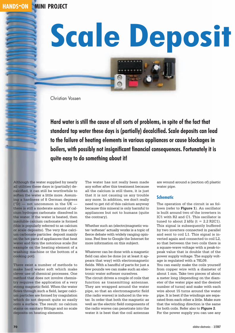
HANDS-ON MINI PROJECT
70 elektor electronics - 3/2007
Scale Deposit
Christian Vossen
Hard water is still the cause of all sorts of problems, in spite of the fact that standard tap water these days is (partially) decalcifi ed. Scale deposits can lead to the failure of heating elements in various appliances or cause blockages in boilers, with possibly not insignifi cant fi nancial consequences. Fortunately it is quite easy to do something about it!
Although the water supplied by nearly all utilities these days is (partially) de-calcifi ed, it can still be worthwhile to soften the water a little more. Assum-ing a hardness of 8 German degrees (°D) — not uncommon in the UK — there is still a moderate amount of cal-cium hydrogen carbonate dissolved in the water. If the water is heated, then insoluble calcium carbonate is formed (this is popularly referred to as calcium or scale deposits). The very fi ne calci-um carbonate particles deposit mainly on the hot parts of appliances that heat water and form the notorious scale (for example on the heating element of a washing machine or the bottom of a cooking pot).
There exist a number of methods to make hard water soft which make clever use of chemical processes. One method that does not involve chemis-try requires the application of a very strong magnetic fi eld. When the water fl ows through such a fi eld, larger calci-um particles are formed by coagulation which do not deposit quite so easily onto a surface. The result: no calcium stains on sanitary fi ttings and no scale deposits on heating elements.
The water has not really been made any softer after this treatment because all the calcium is still there, it is just that it is not causing us any trouble any more. In addition, we don't really need to get rid of this calcium anyway because this mineral is only harmful to appliances but not to humans (quite the contrary).
Whether such an (electro)magnetic wa-ter-‘softener’ actually works is a topic of fi erce debate with widely ranging opin-ions. Feel free to Google the Internet for more information on this subject.
Whatever can be done with a magnetic fi eld can also be done (or at least it ap-pears that way) with electromagnetic fi elds. With a handful of parts for just a few pounds we can make such an elec-tronic water softener ourselves.The circuit drives a couple of coils that function as transmitting antennas. They are wrapped around the water pipe, so that an electromagnetic fi eld (the radio waves) is induced in the wa-ter. In order that both the magnetic as well as the electric fi eld components of the radio waves can penetrate into the water it is best that the coil antennas
are wound around a (section of) plastic water pipe.
SchematicThe operation of the circuit is as fol-lows (refer to Figure 1). An oscillator is built around two of the inverters in IC1 with R2 and C1. This oscillator is tuned to about 2 kHz (t = 2.2 R2C1). This signal is subsequently buffered by two inverters connected in parallel and sent to coil L1. This signal is in-verted again and connected to coil L2, so that between the two coils there is a square-wave voltage with a peak-to-peak value that is double that of the power supply voltage. The supply volt-age is regulated with a 78L09.You can easily make the coils yourself from copper wire with a diameter of about 1 mm. Take two pieces of about a meter long (depending on the diam-eter of the water pipe and the desired number of turns) and make with each wire about 15 turns around the water pipe. It is best if the windings are sepa-rated from each other a little. Make sure that the winding direction is the same for both coils. Refer also to Figure 2.For the power supply you can use any

713/2007 - elektor electronics
Fighter a simple water softener
spare mains wall adapter that supplies a DC voltage in the range from 12 to 15 V.
ExperimentingThere is of course plenty of scope to ex-periment with this circuit: you can put the windings closer together, increase the frequency, reverse the winding di-
rection of the coils, change the loca-tion of the coils on the water pipe, try whether the coils work better around a copper pipe or a plastic one (the latter has our preference), and many more.How much effect this circuit ultimately has can only be established over the long term. Some users of such elec-tronic water softeners (which includes
a few colleagues) are wildly enthusi-astic about them, while others assert that they notice absolutely no differ-ence. So just try it for yourself, you can build this circuit for a mere few pounds and that is considerably cheaper than similar read-made devices that can be bought in the shops for this purpose.
(070001-I)
7 61
IC1C9 101
IC1D3 21
IC1A
11 121
IC1E
5 41
IC1B
14 151
IC1F
R23k3
R1
1k
C1
220n
L1
K1
see text
IC1 = 4049
1 3
2
IC278L09
25V
C2
47u
C3
100n25V
C4
47u
C5
100n
1
8
C6
100nIC1
L2
K2
+9V
070001 - 11
*
*
*
Figure 1. The schematic comprises only 10 components and 2 connectors.
Figure 2. The coils L1 and L2 consist of about 15 turns which are placed next to each other.
COMPONENTS LISTResistorsR1,R2 = 1kΩ
CapacitorsC1 = 220nFC2,C4 = 47µF 25VC3,C5,C6 = 100nF
SemiconductorsIC1 = 4049IC2 = 78L09
MiscellaneousK1 = 2-way PCB terminal block, lead
pitch 5mmK2 = DC adapter socketPCB, ref. 070001-1, from ThePCBShop
(see www.elektor-electronics.co.uk)
Figure 3. The PCB layout is not very diffi cult at all with so few components.
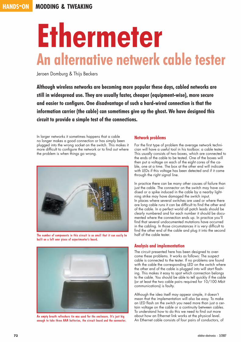
HANDS-ON MODDING & TWEAKING
72 elektor electronics - 3/2007
In larger networks it sometimes happens that a cable no longer makes a good connection or has simply been plugged into the wrong socket on the switch. This makes it more diffi cult to confi gure the network or to fi nd out where the problem is when things go wrong.
Network problemsFor the fi rst type of problem the average network techni-cian will have a useful tool in his toolbox: a cable tester. This usually consists of two boxes, which are connected to the ends of the cable to be tested. One of the boxes will then put a voltage on each of the eight cores of the ca-ble, one at a time. The box at the other end will indicate with LEDs if this voltage has been detected and if it came through the right signal line.
In practice there can be many other causes of failure than just the cable. The connector on the switch may have oxi-dised or a spike induced in the cable by a nearby light-ning strike may have damaged the switch input.In places where several switches are used or where there are long cable runs it can be diffi cult to fi nd the other end of the cable. In a perfect world all patch leads should be clearly numbered and for each number it should be docu-mented where the connection ends up. In practice you’ll fi nd that several undocumented mutations have occurred in the cabling. In those circumstances it is very diffi cult to fi nd the other end of the cable and plug it into the second half of the cable tester.
Analysis and implementationThe circuit presented here has been designed to over-come these problems. It works as follows: The suspect cable is connected to the tester. If no problems are found with the cable the corresponding LED on the switch where the other end of the cable is plugged into will start fl ash-ing. This makes it easy to spot which connection belongs to the cable. You should be able to tell quickly if the cable (or at least the two cable pairs required for 10/100 Mbit communications) is faulty.
Although the idea itself may appear simple, it doesn’t mean that the implementation will also be easy. To make an LED fl ash on the switch you need more than just a cer-tain voltage on the cable or a continuity between cables. To understand how to do this we need to fi nd out more about how an Ethernet link works at the physical level.An Ethernet cable consists of four pairs of conductors, of
EthermeterAn alternative netwerk cable testerJeroen Domburg & Thijs Beckers
Although wireless networks are becoming more popular these days, cabled networks are still in widespread use. They are usually faster, cheaper (equipment-wise), more secure and easier to confi gure. One disadvantage of such a hard-wired connection is that the information carrier (the cable) can sometimes give up the ghost. We have designed this circuit to provide a simple test of the connections.
An empty breath refreshers tin was used for the enclosure. It’s just big enough to take three AAA batteries, the circuit board and the connector.
The number of components in this circuit is so small that it can easily be built on a left over piece of experimenter’s board.
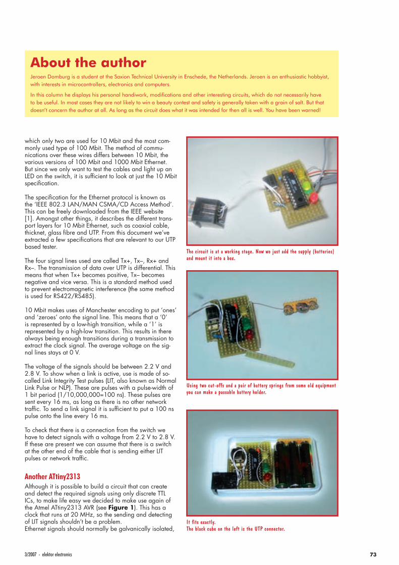
733/2007 - elektor electronics
which only two are used for 10 Mbit and the most com-monly used type of 100 Mbit. The method of commu-nications over these wires differs between 10 Mbit, the various versions of 100 Mbit and 1000 Mbit Ethernet. But since we only want to test the cables and light up an LED on the switch, it is suffi cient to look at just the 10 Mbit specifi cation.
The specifi cation for the Ethernet protocol is known as the ‘IEEE 802.3 LAN/MAN CSMA/CD Access Method’. This can be freely downloaded from the IEEE website [1]. Amongst other things, it describes the different trans-port layers for 10 Mbit Ethernet, such as coaxial cable, thicknet, glass fi bre and UTP. From this document we’ve extracted a few specifi cations that are relevant to our UTP based tester.
The four signal lines used are called Tx+, Tx–, Rx+ and Rx–. The transmission of data over UTP is differential. This means that when Tx+ becomes positive, Tx– becomes negative and vice versa. This is a standard method used to prevent electromagnetic interference (the same method is used for RS422/RS485).
10 Mbit makes uses of Manchester encoding to put ‘ones’ and ‘zeroes’ onto the signal line. This means that a ‘0’ is represented by a low-high transition, while a ‘1’ is represented by a high-low transition. This results in there always being enough transitions during a transmission to extract the clock signal. The average voltage on the sig-nal lines stays at 0 V.
The voltage of the signals should be between 2.2 V and 2.8 V. To show when a link is active, use is made of so-called Link Integrity Test pulses (LIT, also known as Normal Link Pulse or NLP). These are pulses with a pulse-width of 1 bit period (1/10,000,000=100 ns). These pulses are sent every 16 ms, as long as there is no other network traffi c. To send a link signal it is suffi cient to put a 100 ns pulse onto the line every 16 ms.
To check that there is a connection from the switch we have to detect signals with a voltage from 2.2 V to 2.8 V. If these are present we can assume that there is a switch at the other end of the cable that is sending either LIT pulses or network traffi c.
Another ATtiny2313Although it is possible to build a circuit that can create and detect the required signals using only discrete TTL ICs, to make life easy we decided to make use again of the Atmel ATtiny2313 AVR (see Figure 1). This has a clock that runs at 20 MHz, so the sending and detecting of LIT signals shouldn’t be a problem.Ethernet signals should normally be galvanically isolated,
Using two cut-offs and a pair of battery springs from some old equipment you can make a passable battery holder.
The circuit is at a working stage. Now we just add the supply (batteries) and mount it into a box.
It fi ts exactly. The black cube on the left is the UTP connector.
About the authorJeroen Domburg is a student at the Saxion Technical University in Enschede, the Netherlands. Jeroen is an enthusiastic hobbyist, with interests in microcontrollers, electronics and computers.
In this column he displays his personal handiwork, modifi cations and other interesting circuits, which do not necessarily have to be useful. In most cases they are not likely to win a beauty contest and safety is generally taken with a grain of salt. But that doesn’t concern the author at all. As long as the circuit does what it was intended for then all is well. You have been warned!
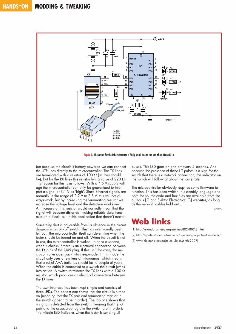
HANDS-ON MODDING & TWEAKING
74 elektor electronics - 3/2007
but because the circuit is battery-powered we can connect the UTP lines directly to the microcontroller. The TX lines are terminated with a resistor of 100 Ω (as they should be), but for the RX lines this resistor has a value of 220 Ω. The reason for this is as follows: With a 4.5 V supply volt-age the microcontroller can only be guaranteed to inter-pret a signal of 3.1 V as 'high'. Since Ethernet signals are normally in the range of 2.2 V to 2.8 V, this will not al-ways work. But by increasing the terminating resistor we increase the voltage level and the detection works well. An increase of this resistor would normally mean that the signal will become distorted, making reliable data trans-mission diffi cult, but in this application that doesn’t matter.
Something that is noticeable from its absence in the circuit diagram is an on/off switch. This has intentionally been left out. The microcontroller itself can determine when the tester should be turned on and off. When the circuit is not in use, the microcontroller is woken up once a second, when it checks if there is an electrical connection between the TX pins of the RJ45 plug. If this isn’t the case, the mi-crocontroller goes back into sleep-mode. In this mode the circuit only uses a few tens of microamps, which means that a set of AAA batteries should last a couple of years.When the cable is connected to a switch the circuit jumps into action. A switch terminates the TX lines with a 100 Ω resistor, which produces an electrical connection between the TX lines.
The user interface has been kept simple and consists of three LEDs. The bottom one shows that the circuit is turned on (meaning that the TX pair and terminating resistor in the switch appear to be in order). The top one shows that a signal is detected from the switch (meaning that the RX pair and the associated logic in the switch are in order). The middle LED indicates when the tester is sending LIT
pulses. This LED goes on and off every 4 seconds. And because the presence of these LIT pulses is a sign for the switch that there is a network connection, the indicator on the switch will follow at about the same rate.
The microcontroller obviously requires some fi rmware to function. This has been written in assembly language and both the source code and hex fi les are available from the author's [2] and Elektor Electronics' [3] websites, as long as the network cables hold out...
(075035)
Web links[1] http://standards.ieee.org/getieee802/802.3.html
[2] http://sprite.student.utwente.nl/~jeroen/projects/ethermeter/
[3] www.elektor-electronics.co.uk/ (March 2007)
RJ45
K11
2
3
4
5
6
7
8
UTP
R1
100 ΩTX+
TX–
RX+
RX–
1 =2 =3 =6 =
TX+
RX pair
TX pair
TX–RX+RX–
R2
220
Ω
ATTiny2313
RESET
IC1
PB7
PB6PB5
PB4
PB3
PB2 PB1
PB0
PD0
PD1
PD2
PD3
PD4
PD5
PD6
10
XIXO
20
19
1817
16
15
14 13
12
11
1
54
2
3
6
7
8
9
X1
20MHz
C1
22p
C2
22p
D3
POWER
D1
RX
D2
TX
R3
470 Ω
R4
470 Ω
R5
470 Ω
BT14V5
C3
1µ
C4
100n
+4V5
075035 - 11
1 2 3 4 5 6 7 8
Figure 1. The circuit for the Ethernet tester is fairly small due to the use of an ATtiny2313.
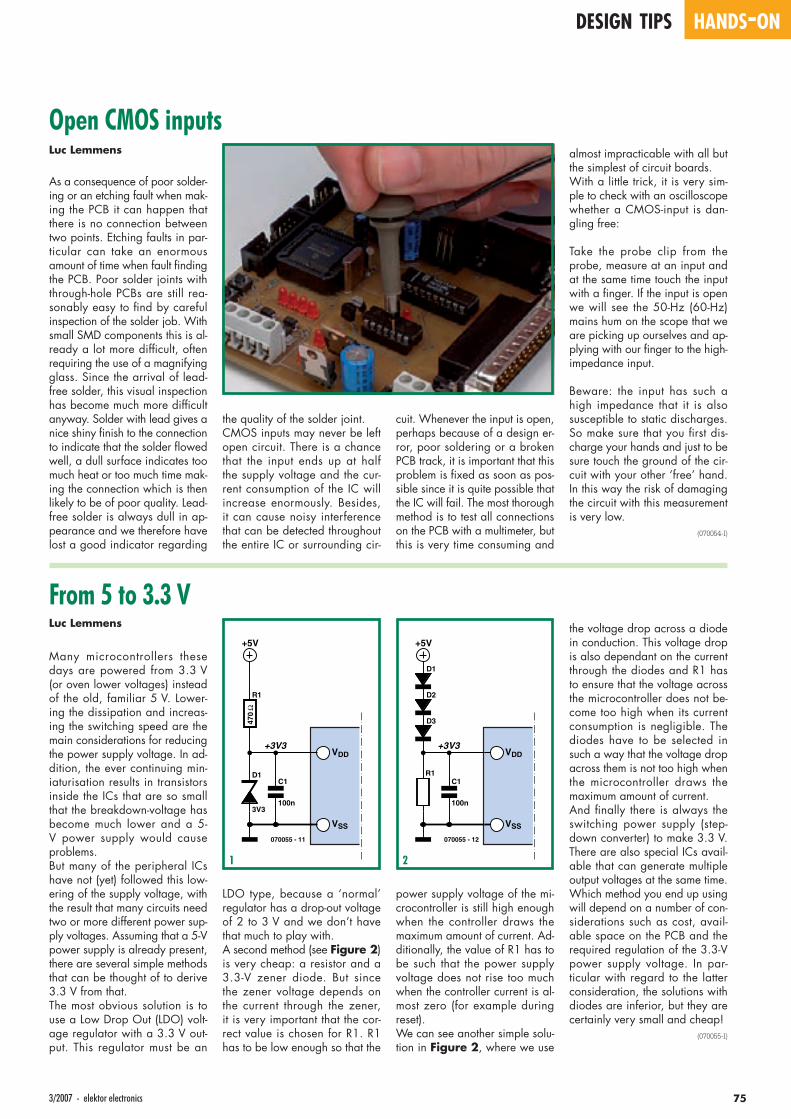
Open CMOS inputsLuc Lemmens
As a consequence of poor solder-ing or an etching fault when mak-ing the PCB it can happen that there is no connection between two points. Etching faults in par-ticular can take an enormous amount of time when fault fi nding the PCB. Poor solder joints with through-hole PCBs are still rea-sonably easy to fi nd by careful inspection of the solder job. With small SMD components this is al-ready a lot more diffi cult, often requiring the use of a magnifying glass. Since the arrival of lead-free solder, this visual inspection has become much more diffi cult anyway. Solder with lead gives a nice shiny fi nish to the connection to indicate that the solder fl owed well, a dull surface indicates too much heat or too much time mak-ing the connection which is then likely to be of poor quality. Lead-free solder is always dull in ap-pearance and we therefore have lost a good indicator regarding
the quality of the solder joint.CMOS inputs may never be left open circuit. There is a chance that the input ends up at half the supply voltage and the cur-rent consumption of the IC will increase enormously. Besides, it can cause noisy interference that can be detected throughout the entire IC or surrounding cir-
cuit. Whenever the input is open, perhaps because of a design er-ror, poor soldering or a broken PCB track, it is important that this problem is fi xed as soon as pos-sible since it is quite possible that the IC will fail. The most thorough method is to test all connections on the PCB with a multimeter, but this is very time consuming and
almost impracticable with all but the simplest of circuit boards.With a little trick, it is very sim-ple to check with an oscilloscope whether a CMOS-input is dan-gling free:
Take the probe clip from the probe, measure at an input and at the same time touch the input with a fi nger. If the input is open we will see the 50-Hz (60-Hz) mains hum on the scope that we are picking up ourselves and ap-plying with our fi nger to the high-impedance input.
Beware: the input has such a high impedance that it is also susceptible to static discharges. So make sure that you fi rst dis-charge your hands and just to be sure touch the ground of the cir-cuit with your other ‘free’ hand. In this way the risk of damaging the circuit with this measurement is very low.
(070054-I)
From 5 to 3.3 VLuc Lemmens
Many microcontrollers these days are powered from 3.3 V (or oven lower voltages) instead of the old, familiar 5 V. Lower-ing the dissipation and increas-ing the switching speed are the main considerations for reducing the power supply voltage. In ad-dition, the ever continuing min-iaturisation results in transistors inside the ICs that are so small that the breakdown-voltage has become much lower and a 5-V power supply would cause problems.But many of the peripheral ICs have not (yet) followed this low-ering of the supply voltage, with the result that many circuits need two or more different power sup-ply voltages. Assuming that a 5-V power supply is already present, there are several simple methods that can be thought of to derive 3.3 V from that.The most obvious solution is to use a Low Drop Out (LDO) volt-age regulator with a 3.3 V out-put. This regulator must be an
LDO type, because a ‘normal’ regulator has a drop-out voltage of 2 to 3 V and we don’t have that much to play with.A second method (see Figure 2) is very cheap: a resistor and a 3.3-V zener diode. But since the zener voltage depends on the current through the zener, it is very important that the cor-rect value is chosen for R1. R1 has to be low enough so that the
power supply voltage of the mi-crocontroller is still high enough when the controller draws the maximum amount of current. Ad-ditionally, the value of R1 has to be such that the power supply voltage does not rise too much when the controller current is al-most zero (for example during reset).We can see another simple solu-tion in Figure 2, where we use
+5V
R1
470
Ω
D1
3V3
C1
100n
+3V3
070055 - 11
VDD
VSS
the voltage drop across a diode in conduction. This voltage drop is also dependant on the current through the diodes and R1 has to ensure that the voltage across the microcontroller does not be-come too high when its current consumption is negligible. The diodes have to be selected in such a way that the voltage drop across them is not too high when the microcontroller draws the maximum amount of current.And fi nally there is always the switching power supply (step-down converter) to make 3.3 V. There are also special ICs avail-able that can generate multiple output voltages at the same time. Which method you end up using will depend on a number of con-siderations such as cost, avail-able space on the PCB and the required regulation of the 3.3-V power supply voltage. In par-ticular with regard to the latter consideration, the solutions with diodes are inferior, but they are certainly very small and cheap!
(070055-I)
+5V
C1
100n
+3V3
070055 - 12
R1
VDD
VSS
D1
D2
D3
1 2
753/2007 - elektor electronics
DESIGN TIPS HANDS-ON
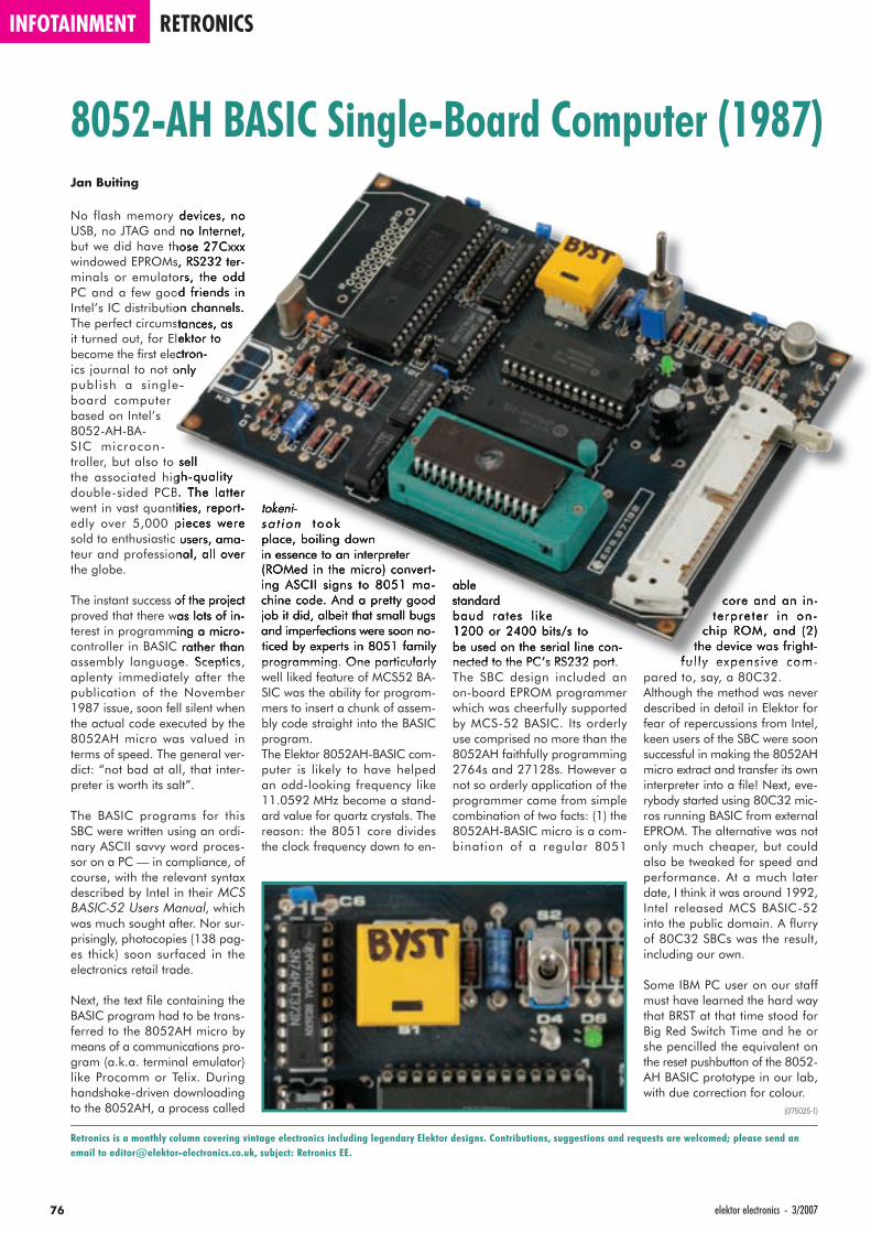
INFOTAINMENT RETRONICS
76 elektor electronics - 3/2007
Jan Buiting
No flash memory devices, no USB, no JTAG and no Internet, but we did have those 27Cxxx windowed EPROMs, RS232 ter-minals or emulators, the odd PC and a few good friends in Intel’s IC distribution channels. The perfect circumstances, as it turned out, for Elektor to become the fi rst electron-ics journal to not only publish a single-board computer based on Intel’s 8052-AH-BA-SIC microcon-troller, but also to sell the associated high-quality double-sided PCB. The latter went in vast quantities, report-edly over 5,000 pieces were sold to enthusiastic users, ama-teur and professional, all over the globe.
The instant success of the project proved that there was lots of in-terest in programming a micro-controller in BASIC rather than assembly language. Sceptics, aplenty immediately after the publication of the November 1987 issue, soon fell silent when the actual code executed by the 8052AH micro was valued in terms of speed. The general ver-dict: “not bad at all, that inter-preter is worth its salt”.
The BASIC programs for this SBC were written using an ordi-nary ASCII savvy word proces-sor on a PC — in compliance, of course, with the relevant syntax described by Intel in their MCS BASIC-52 Users Manual, which was much sought after. Nor sur-prisingly, photocopies (138 pag-es thick) soon surfaced in the electronics retail trade.
Next, the text fi le containing the BASIC program had to be trans-ferred to the 8052AH micro by means of a communications pro-gram (a.k.a. terminal emulator) like Procomm or Telix. During handshake-driven downloading to the 8052AH, a process called
tokeni-sa t ion took place, boiling down in essence to an interpreter (ROMed in the micro) convert-ing ASCII signs to 8051 ma-chine code. And a pretty good job it did, albeit that small bugs and imperfections were soon no-ticed by experts in 8051 family programming. One particularly well liked feature of MCS52 BA-SIC was the ability for program-mers to insert a chunk of assem-bly code straight into the BASIC program.The Elektor 8052AH-BASIC com-puter is likely to have helped an odd-looking frequency like 11.0592 MHz become a stand-ard value for quartz crystals. The reason: the 8051 core divides the clock frequency down to en-
able standard baud rates like 1200 or 2400 bits/s to be used on the serial line con-nected to the PC’s RS232 port.The SBC design included an on-board EPROM programmer which was cheerfully supported by MCS-52 BASIC. Its orderly use comprised no more than the 8052AH faithfully programming 2764s and 27128s. However a not so orderly application of the programmer came from simple combination of two facts: (1) the 8052AH-BASIC micro is a com-bination of a regular 8051
core and an in-terpreter in on-
chip ROM, and (2) the device was fright-
ful ly expensive com-pared to, say, a 80C32.Although the method was never described in detail in Elektor for fear of repercussions from Intel, keen users of the SBC were soon successful in making the 8052AH micro extract and transfer its own interpreter into a fi le! Next, eve-rybody started using 80C32 mic-ros running BASIC from external EPROM. The alternative was not only much cheaper, but could also be tweaked for speed and performance. At a much later date, I think it was around 1992, Intel released MCS BASIC-52 into the public domain. A fl urry of 80C32 SBCs was the result, including our own.
Some IBM PC user on our staff must have learned the hard way that BRST at that time stood for Big Red Switch Time and he or she pencilled the equivalent on the reset pushbutton of the 8052-AH BASIC prototype in our lab, with due correction for colour.
(075025-I)
8052-AH BASIC Single-Board Computer (1987)
Retronics is a monthly column covering vintage electronics including legendary Elektor designs. Contributions, suggestions and requests are welcomed; please send an email to [email protected], subject: Retronics EE.

Solve Hexadoku and win!Correct solutions received
enter a prize draw for an
E-blocks Starter Kit Professional worth £248.55
and three Elektor Electronics SHOP Vouchers worth £35.00 each.
We believe these prizes should encourage all our readers to participate!
The instructions for this puzzle are straightforward. In the di-agram composed of 16 x 16 boxes, enter numbers such that all hexadecimal numbers 0 through F (that’s 0-9 and A-F) occur once only in each row, once in each column and in each of the 4x4 boxes (marked by the thicker black lines). A number of clues are given in the puzzle and these
determine the start situation.All correct entries received for each month’s puzzle go into a draw for a main prize and three lesser prizes. All you need to do is send us the numbers in the grey boxes.
The puzzle is also available as a free download from our website (Magazine → 2007 →
March).
Prize winnersThe solution of the January 2007 Hexadoku is: 038FA.
The E-blocks Starter Kit Professional goes to:
Peter Hinchcliffe, Fleet (UK).
An Elektor SHOP voucher worth £35.00 goes to:
Bjarne Lassen (DK);
Harald Paulsen (N);
Andrew Collister (UK)
Congratulations everybody!
Participate!Please send your solution (the numbers in the grey boxes) by email to:
[email protected]: hexadoku 03-2007.
Alternatively, by fax or post to:
Elektor Electronics HexadokuRegus Brentford1000 Great West RoadBrentford TW8 9HHUnited Kingdom.
Fax (+44)(0)208 2614447
The closing date is 1 April 2007.
The competition is not open to employees of Segment b.v., its business partners and/or associated publishing houses.
HexadokuPuzzle with an electronic touchHexadoku is drawing not just hundreds of correct answers every
month but also encouraging feedback and other kind words from
you all. Needless to say we’re very pleased to see that Hexadoku
has become an established part of the magazine.
D 6 8 A 2 B 9 F2 1 3 6 7 8
4 3 C D 0 5 1 A 2 E7 F 3 5 1
C B 3 F 4 5 87 1 9 8 0 D C 3
4 F 0 A 5 C 7 8 E D6 5 C 2 B E F 1 9 7A D F 0 7 2
1 9 C F 8 B D 47 3 5 8 1 DF 4 0 E 9 B C 18 D 3 1 2 7 C 54 F A 7 5 D 8 3E 9 A 6 4 2 0 D F5 7 8 9 2
(c) PZZL.com
PUZZLE INFOTAINMENT
773/2007 - elektor electronics
elektor electronics - 3/200778
E L E K T O R S H O W C A S ETo book your showcase space contact Huson International MediaTel. 0044 (0) 1932 564999 Fax 0044 (0) 1932 564998
HEROS TECHNOLOGY LTDwww.herostechnology.co.ukIntroducing Modular Concept for microcontrollers.Suitable for Developers, Pre-production,Educational and Hobby applications.• WinPIC2006 USB full speed programmer.• CPU microcontroller modules.• Peripheral modules for all microcontrollers.
LONDON ELECTRONICS COLLEGEhttp://www.lec.org.ukVocational training and education for nationalqualifications in Electronics Engineering andInformation Technology (BTEC First National,Higher National NVQs, GCSEs and AdvancedQualifications). Also Technical Management andLanguages.
MODular ElecTRONicswww.modetron.com• Plug and Program• FREE application s/w • Hobbyist ease-of-use• Professional finish with enclosure
and LEXAN faceplate• We will design and brand your
custom application • Growing range of PSU’s, i/o modules, displays
and microcontrollers
MQP ELECTRONICSwww.mqp.com• Low cost USB Bus Analysers• High, Full or Low speed captures• Graphical analysis and filtering• Automatic speed detection• Bus powered from high speed PC• Capture buttons and feature connector• Optional analysis classes
ATC SEMITEC LTDwww.atcsemitec.co.ukThermal and current-sensitive componentsfor temperature control and circuit protection;• NTC Thermistors • Current Diodes• Thermostats • Re-settable Fuses• Thermal Fuses • Temperature SensorsCall today for free samples and pricingTel: 01606 871680 Fax: 01606 872938
AVIT RESEARCHwww.avitresearch.co.ukUSB has never been so simple...with our USB to Microcontroller Interface cable.Appears just like a serial port to both PC andMicrocontroller, for really easy USB connection toyour projects, or replacement of existing RS232
interfaces.See our webpage for moredetails. From £15.00.
BAEChttp://baec.tripod.com"The British Amateur Electronics Club Archive Website. Archiving extracts from 140+ Newsletters from 1966-2002. Currently have interesting and usefulselected articles from 12 Newsletters. Also asection about built electronics projects withschematics and photos. Plus useful info.,downloads and links. NO ADVERTS!"
BETA LAYOUTwww.pcb-pool.comBeta layout Ltd Award-winning site in both English and German offers prototype PCBs at a fraction of the cost of the usualmanufacturer’s prices.
CONFORD ELECTRONICShttp://www.confordelec.co.ukLightweight portable battery/mains audio unitsoffering the highest technical performance.Microphone, Phantom Power and HeadphoneAmplifiers. Balanced/unbalanced signal lineswith extensive RFI protection.
EASYSYNChttp://www.easysync.co.ukEasySync Ltd sells a wide range of single and multi-port USB to RS232/RS422 and RS485 converters at competitive prices.
ELNEC www.elnec.com • device programmer
manufacturer • selling through contracted
distributors all over the world • universal and dedicated device programmers • excellent support and after sale support • free SW updates • reliable HW• once a months new SW release • three years warranty for most programmers
FIRST TECHNOLOGY TRANSFER LTD.http://www.ftt.co.uk/PICProTrng.htmlMicrochip Professional C and Assembly Programming Courses.The future is embedded.Microchip Consultant / Training Partner developedcourses:• Distance learning / instructor led• Assembly / C-Programming of PIC16, PIC18,
PIC24, dsPIC microcontrollers• Foundation / Intermediate
FUTURE TECHNOLOGY DEVICEShttp://www.ftdichip.comFTDI designs and sellsUSB-UART and USB-FIFOinterface i.c.’s.Complete with PC drivers,these devices simplify the task of designing orupgrading peripherals to USB

3/2007 - elektor electronics 79
NEW WAVE CONCEPTSwww.new-wave-concepts.comSoftware for Hobbyists:• Livewire - circuit simulation
software, only £34.99 • PCB Wizard - PCB design
software, only £34.99 • Circuit Wizard - circuit, PCB and breadboard
design software, only £59.99Available from all Maplin Electronics stores andwww.maplin.co.uk
PCB WORLDhttp://www.pcbworld.org.ukWorld-class site: Your magazine project orprototype PCB from the artwork of your choicefor less. Call Lee on 07946 846159 for details.Prompt service.
ROBOT ELECTRONICShttp://www.robot-electronics.co.ukAdvanced Sensors and Electronics for Robotics• Ultrasonic Range Finders• Compass modules• Infra-Red Thermal sensors• Motor Controllers• Vision Systems• Wireless Telemetry Links• Embedded Controllers
Elektor Electronics has a feature to helpcustomers promote their business, Showcase - a permanent feature of themagazine where you will be able toshowcase your products and services.
• For just £220 + VAT (£20 per issue foreleven issues) Elektor will publish yourcompany name, website adress and a 30-word description
• For £330 + VAT for the year (£30 perissue for eleven issues) we will publish the above plus run a 3cm deep full colour
image - e.g. a product shot, a screen shotfrom your site, a company logo - yourchoice
Places are limited and spaces will go on astrictly first come, first served basis.So please fax back your order today!
I wish to promote my company, please book my space:• Text insertion only for £220 + VAT • Text and photo for £330 + VAT
NAME:......................................................................................................ORGANISATION: ........................................................................................
JOB TITLE:.......................................................................................................................................................................................................................
ADDRESS:........................................................................................................................................................................................................................
...........................................................................................................................................................................................................................................
...................................................................................................................TEL: ...............................................................................................................
PLEASE COMPLETE COUPON BELOW AND FAX BACK TO 00-44-(0)1932 564998
COMPANY NAME ..........................................................................................................................................................................................................
WEB ADDRESS...............................................................................................................................................................................................................
30-WORD DESCRIPTION..............................................................................................................................................................................................
...........................................................................................................................................................................................................................................
...........................................................................................................................................................................................................................................
...........................................................................................................................................................................................................................................
...........................................................................................................................................................................................................................................
SHOWCASE YOUR COMPANY HERE
SOURCEBOOST TECHNOLOGIEShttp://www.sourceboost.comNext generation C compiler and development products at highly affordable prices:• C, C++, and Basic compilers for PIC12, PIC16,
PIC18 • Modern IDE, with PIC simulator, source level
debugger and virtual devices.• RTOS for PICmicro.• PIC based controller and Development boards.• Download and try for Free from
http://www.sourceboost.com
SYTRONIC TECHNOLOGY LTDwww.m2mtelemetry.comSupplier of wireless modules and accessories forremote monitoring M2M applications.• GSM/GPRS TCP/IP modules• Embedded GSM/GPRS modem• Development Kits• GPS modules• GSM/GPS antennas• Adapter cablesOnline ordering facilities.Tel: 01728 685802
p r o d u c t s a n d s e r v i c e s d i r e c t o r y
ULTRALEDShttp://www.ultraleds.co.uktel: 0871 7110413Large range of low cost Ultra bright leds and Ledrelated lighting products. Major credit cardstaken online with same day depatch.
USB INSTRUMENTShttp://www.usb-instruments.comUSB Instruments specialises in PC based instrumentation products and software such as Oscilloscopes, Data Loggers, Logic Analaysers which interface to your PC via USB.
VIRTINS TECHNOLOGYwww.virtins.comPC and Pocket PC basedvirtual instrument such assound card real timeoscilloscope, spectrumanalyzer, signal generator,multimeter, sound meter,distortion analyzer, LCR meter.Free to download and try.

Students qualify for a discount of no less than 20% compared to the normal price of an annual subscription
Subscribers get up to 40% discount on special Elektor products
No queues, travelling, parking fees or ‘sold out’ Elektor is supplied to your doorstep every month
Always up to date – read your copy before everyone else
www.elektor-electronics.co.uk/subsTel. +44 (0) 208 261 4509
* Only available in UK. Ask for the conditions.
“Elektor? If our teachers knew just how easily some concepts can be explained…”
– Daniel Judd, 23, student –
the world-leading network for electronics
Secure a head start in electronics with a Student Subscription!*
Advantages to subscribers:
Electronics at all the right levels
RZ_3+4+5+6_2007_GB.indd 1RZ_3+4+5+6_2007_GB.indd 1 31.01.2007 13:39:07 Uhr31.01.2007 13:39:07 Uhr

More information on www.elektor-electronics.co.uk
Telephone +44 208 261 4509Fax +44 208 261 4447Email: [email protected] Order now using the Order Form in
the Readers Services section in this issue.
CD-ROM BESTSELLERS
Elektor Electronics (Publishing) Regus Brentford 1000 Great West RoadBrentford TW8 9HH United Kingdom
Home AutomationThis CD-ROM provides an
overview of what manufacturers
offer today in the field of Home
Networking, both wired and
wireless. The CD-ROM contains
specifications, stan dards and
protocols of commercially avai-
lable bus and network systems.
For developers, there are data-
sheets of specific components
and various items with application
data. End-users and hobbyists will find ready-made
applications that can be used immediately.
£12.95 (US$ 22.90)
2
USB TOOLBOXThis CD-ROM contains techni-
cal data about the USB inter-
face. It also includes a large
collec tion of data sheets for
specific USB components from
a wide range of manu facturers.
There are two ways to incorpo-
rate a USB interface in a micro-
controller circuit: add a USB
controller to an existing circuit, or use a microcon-
troller with an integrated USB interface. Included on
this CD-ROM are USB Basic Facts, several useful
design tools for hardware and software, and all
Elektor Electronics articles on the subject of USB.
1
£18.95 (US$ 34.95)
BESTSELLING BOOKS
Top-5
Visual Basic for Electronics Engineering Applications ISBN 978-0-905705-68-2 £27.50 (US$ 51.50)
Microcontroller Basics ISBN 978-0-905705-67-5 £18.70 (US$ 33.70)
PC-Interfaces under Windows ISBN 978-0-905705-65-1 £25.95 (US$ 52.00)
Modern High-end Valve Amplifiers ISBN 978-0-905705-63-7 £25.95 (US$ 52.00)
Handbook for Sound Technicians ISBN 978-0-905705-48-4 £20.75 (US$ 42.00)
2
3
4
5
1
More bestsellers on www.elektor-electronics.co.uk
Visual Basicfor Electronics Engineering Applications
This book is targeted towards those people that
want to control existing or home made hardware
from their computer. After famil ia rizing yourself
with Visual Basic, its development environment
and the toolset it offers are discussed in detail.
Each topic is accompanied by clear, ready to
run code, and where necessary, schematics are
provided that will get your projects up to speed
in no time.
ISBN 978-0-905705-68-2
476 Pages
£27.50 (US$ 51.50)
Audio Collection 2A unique CD-ROM for the true
audio lover, containing no fewer
than 75 audio designs from the
past five year volumes of
Elektor Electronics maga zine.
The articles on the CD-ROM
cover test & measurement equip-
ment, amplifiers, digital audio
and loudspeaker technology.
Highlights include the Crescendo
Millennium Edition, Audio-DAC 2000, Audio-ADC
2000 and the IR-S/PDIF Transmitter and Receiver.
Using the included Acrobat Reader you are able to
browse the articles on your computer, as well as
print texts, circuit diagrams and PCB layouts.
£12.05 (US$ 21.25)
3
PC-Interfaces under Windows
PC Interfaces can be used for more than just
the printer, mouse, modem and joy-stick!
While it was relatively easy to directly access
PC interfaces using a DOS computer, under
Windows things are not all that simple.
This book (CD-ROM incl.) shows you how it
can be done. The authors describe the DIY
construction and programming of a number of
highly interesting circuits.
ISBN 0-905705-65-3
265 Pages
£25.95 (US$ 52.00)
ELEK UK0703 shop.indd 1ELEK UK0703 shop.indd 1 01-02-2007 14:12:4901-02-2007 14:12:49

MORE READY-BUILT PROJECTS £ $ClariTy 300-W Class-T Amplifier
030217-91 Amplifier board with SMDs pre-fitted; cores for L1 & L2 34.50 55.70Electrosmog Tester
050008-91 PCB, ready built and tested 50.00 94.25050008-71 Matching enclosure 10.25 19.30
Flash Microcontroller Starter Kit010208-91 Ready-assembled PCB incl. software, cable, adapter & related articles 69.00 112.50
Gameboy Digital Sampling Oscilloscope (GBDSO)990082-91 Ready-assembled board, incl. the PC software and related articles 103.00 183.00
LPC210x ARMee Development System040444-91 Processor board, ready-made and tested 25.50 48.05
Micro Webserver with MSC1210 Board030060-91 Microprocessor Board, ready-assembled 75.90 142.95044026-91 Network Extension Board, ready-assembled 44.50 83.95044026-92 Combined package (030060-91 & 044026-91 & related articles) 117.50 220.95
No. 363 MARCH 2007Attack of the SpYder
060296-91 SpYder Discovery Kit 6.45 12.70AVR drives USB
060276-1 PCB, bare www.thepcbshop.com060276-11 CD-ROM, project software incl. source code 5.20 9.75060276-41 ATmega32-16PC, programmed 8.95 16.85
Wireless USB in Miniature050402-1 PCB, bare, iDwarf prototyping board 8.30 15.60050402-91 iDwarf -168 Transmitter module (built & tested) 24.10 45.45050402-92 iDwarf Node Board (built & tested) 17.20 32.45050402-93 iDwarf Hub Board (built & tested) 17.20 32.45
Mobile Phone LCD for PC060184-1 PCB, bare www.thepcbshop.com060184-11 CD-ROM, project software 5.20 9.75060184-41 ATmega16-16PC, programmed 8.95 16.85
Scale Deposit Fighter070001-1 PCB, bare www.thepcbshop.com
No. 362 FEBRUARY 2007… 3, 2, 1 Takeoff!
050238-1 Transmitter PCB, bare www.thepcbshop.com050238-2 Receiver PCB, bare www.thepcbshop.com
MP3 Preamp060237-1 PCB, bare www.thepcbshop.com
A Telling Way of Telling the Time050311-1 PCB, bare www.thepcbshop.com050311-31 CPLD, programmed 35.50 66.95
FPGA Course (9)060025-9-11 CD-ROM, course software incl. source code 5.20 9.75
Explorer-16 Value Pack060280-91 Four components packaged together in a single box 122.90 232.50
No. 361 JANUARY 2007Sputnik Time Machine
050018-1 PCB www.thepcbshop.com050018-11 CD-ROM, project software (incl. source code) 5.20 9.75050018-41 AT89C2051, programmed 3.40 6.45
Very Simple Clock060350-1 PCB www.thepcbshop.com060350-11 CD-ROM, project software (incl. source code) 5.20 9.75060350-41 PIC16F628-20, programmed 5.50 10.35
FPGA Course (8)060025-8-1 Software (incl. source code) 5.20 9.75
No. 360 DECEMBER 2006Shortwave Capture
030417-1 PCB, bare (receiver board) www.thepcbshop.com030417-2 PCB, bare (control & display boards) www.thepcbshop.com030417-41 AT90S8515-8PC, programmed 11.40 21.45
No. 359 NOVEMBER 2006USB Stick with ARM and RS232
060006-1 PCB, bare 11.00 20.75060006-41 AT91SAM7S64, programmed 27.60 51.95060006-91 Assembled & tested board 79.90 149.95060006-81 CD-ROM, all project software 5.20 9.75
Order now using the Order Form in the Readers Services section in this issue.
ELEK UK 0603 1-1 shop.indd 1 25-01-2006 21:47:27
Order onwww.elektor-ele
Explorer-16 Value Pack(January/February 2007)
Thanks to an exclusiveand one-off arrangementwith Microchip UK, theExplorer-16 Value Pack isboth unique (you won’tfind it anywhere else inthis configuration) as wellas much cheaper than theindividual components.
Explorer-16 Demo BoardIncluding PIC24F and dsPIC33F PIMs, CD-ROM, cable
PIC Kit 2 Starter KitIncluding Low Pin Count Demo Board for 8-, 14-, and 20-pin PICmicros.
Audio PICtail Plus daughterboard
MPLAB C30 Discount Voucher
060280-91
£ 122.90 / $ 232.50
SpYder Discovery KitFor Freescale MC9RS08KA, MC9S08QD, MC9S08QG and MC9S08SH microcontrollers
(March 2007)
Contains USBProgrammer/-Debugger BDM, CD-ROM and oneMC9S08 8-pin PDIPmicrocontroller.
060296-91
Normal resale price: £ 20ELEKTOR PRICE:£ 6.45 / $ 12.70
FREE WITH EVERY ELEKTOR KIT OR MODULE!
Order an Elektor kit or module and receive a free SpYderDiscovery Kit. Act fast as the offer is limited to stocks.
Elektor Kits & Modules are listed onwww.elektor-electronics.co.uk/kits
_ p _ g
Products for older projects (if available) may be found on our website www.elektor-electronics.co.uk
home construction = fun and added value
No. 358 OCTOBER 2006PIC In-Circuit Debugger/Programmer
050348-1 PCB 5.20 9.75050348-41 PIC16F877, programmed 17.90 33.75050348-71 Kit, incl. PCB, controller, all parts 34.50 64.95
GBECG – Gameboy ElectroCardioGraph050280-91 PCB, ready built and tested 55.20 103.95
ECG using a Sound Card040479-1 PCB 5.20 9.75040479-81 CD-ROM, all project software 5.20 9.75
No. 357 SEPTEMBER 2006Elektor RFID Reader
060132-91 PCB, ready assembled & tested, with USB cable 41.50 77.95030451-72 Standard back-lit LC display 7.25 13.65060132-71 Matching enclosure 8.90 16.85060132-81 CD-ROM, all project software 5.20 9.75
Experimental RFID Reader060221-11 Disk, all project software 5.20 9.75060221-41 ATmega16, programmed 8.90 16.85
DiSEqC Monitor040398-11 Disk, PIC source & hex code 5.20 9.75040398-41 PIC16F628A-20/P, programmed 5.50 10.35
USB/DMX512 Converter060012-11 Disk, all project software 5.20 9.75060012-41 PIC16C745, programmed 6.90 12.95
No. 356 JULY/AUGUST 2006RC Servo Tester/Exerciser
040172-11 Disk, project software 5.20 9.75040172-41 PIC16F84(A), programmed 10.30 19.40040172-71 Kit, incl. PCB, controller, all parts 22.70 42.85
LED Thermometer030190-11 Disk, project software 5.20 9.75030190-41 PIC16F873-20/SP, programmed 16.50 31.00
Toothbrush Timer050146-11 Disk, project software 5.20 9.75050146-41 AT90S2313-10PC, programmed 6.90 12.95
Easy Home Control050233-11 Disk, project software 5.20 9.75050233-41 PIC16F84, programmed 10.30 19.40
Universal LCD Module050259-11 Disk, project software 5.20 9.75050259-41 AT90S2313, programmed 6.90 12.95
1-Wire Thermometer with LCD060090-11 Disk, project software 5.20 9.75060090-41 PIC16F84A-04CP, programmed 10.30 19.40
GBPLC - Gameboy PLC050190-1+2 PCBs, bare, GBPLC Module & Programming Interface 11.70 22.00050190-51 Programmed PAL, EEPROM and Flash IC 11.00 20.75050190-91 Ready-built and tested GBPLC Module and Programming Interface 84.95 159.95
GBPLC - I2C I/O Box060098-1 PCB, bare 17.90 33.75060098-91 Ready-built and tested board 84.95 159.95
Binary Clock020390-11 Disk, project software 5.20 9.75020390-41 PIC6C54-04/P, programmed 8.05 15.10
No. 355 JUNE 2006FM Stereo Test Transmitter
050268-1 PCB 11.70 22.00Network Cable Analyser
050302-1 PCB 8.20 15.55050302-11 Disk, PIC source code 5.20 9.75050302-41 PIC16F874-20/P 16.90 31.85
No. 354 MAY 2006Onboard OBD-2 Analyser
050176-72 Kit of parts, incl. 050176-1, 050176-2, 050176-42, all components, excl. LCD and Case 24.80 46.70
050176-73 LCD, 4x20 characters with backlight 28.80 54.50
Kits & Modules
online at electronics.co.uk
Due to practical constraints, final illustrations and specifications may differ from published designs. Prices subject to change. See www.elektor-electronics.co.uk for up to date information.
Elektor Electronics (Publishing)Regus Brentford 1000 Great West Road Brentford TW8 9HH United Kingdom Tel.: +44 (0) 208 261 4509 Fax: +44 (0) 208 261 4447 Email: [email protected]
Elektor RFID Reader(September 2006)
Ready-built and tested PCB with USB port for connectionto the PC. Including USB cable; not including display andenclosure.
- Read and write 13.56 MHz RFID cards- MIFARE and ISO 14443-A compatible- Programmable
060132-91
£ 41.50 / $ 77.95
LC display030451-72
£ 7.25 / $ 13.65
Matching enclosure060132-71
£ 8.90 / $ 16.85
CD-ROM (all project software)060132-81
£ 5.20 / $ 9.75
GameBoyElectroCardioGraph(October 2006)
PCB, ready built and tested
050280-91
£ 55.20 / $ 103.95
USB Stick with ARMand RS232(November 2006)
Assembled and tested board
060006-91
£ 79.90 / $ 149.95
_ p _ g

NEWSAGENTS ORDER FORMSHOP SAVE / HOME DELIVERYPlease save / deliver one copy of Elektor Electronics magazine for me each month
Name: . . . . . . . . . . . . . . . . . . . . . . . . . . . . . . . . . . . .Address: . . . . . . . . . . . . . . . . . . . . . . . . . . . . . . . . . . . .Post code: . . . . . . . . . . . . . . . . . . . . . . . . . . . . . . . . . . . .Telephone: . . . . . . . . . . . . . . . . . . . . . . . . . . . . . . . . . . . .Date: . . . . . . . . . . . . . . . . . . . . . . . . . . . . . . . . . . . .Signature: . . . . . . . . . . . . . . . . . . . . . . . . . . . . . . . . . . . .
Please cut out or photocopy this form, complete details and hand to your newsagent.Elektor Electronics is published on the third Thursday of each month, except in July.Distribution S.O.R. by Seymour (NS).
All magazine articles back to volume 2000 are available online in pdf format. The article summary and parts list (if applicable) can be instantly viewed to help you positively identify an article. Article related items are also shown, including software down-loads, circuit boards, programmed ICs and corrections and updates if applicable. Complete magazine issues may also be downloaded.
In the Elektor Electronics Shop you’ll fi nd all other products sold by the publishers, like CD-ROMs, kits and books. A powerful search function allows you to search for items and references across the entire website.
Also on the Elektor Electronics website:•Electronics news and Elektor announcements•Readers Forum •PCB, software and e-magazine downloads•Surveys and polls•FAQ, Author Guidelines and Contact
Elektor Electronics on the web
RESERVE YOUR COPY NOW! The April 2007 issue goes on sale on Thursday 29 March 2007 (UK distribution only).
UK mainland subscribers will receive the magazine between 24 and 27 March 2007. Article titles and magazine contents subject to change, please check www.elektor-electronics.co.uk.
w.elektor-electronics.co.uk www.elektor-electronics.co.uk www.elektor-electronics.co
Two-Axis AccelerometerThe April 2007 issue will have our fi rst, educationally aimed, application for the SpYder kit — an accelerometer with an LED readout for direction or and amount (up to 2 g) acceleration (+g ) or deceleration (–g). Install the circuit in your car, on your bike, motorbike or scooter and discover if your driving habits cause any of the red LEDs to light! The project is built on two small, stacked PCBs, purposely designed to take ordinary leaded components. It goes to show the ease of getting a Freescale MC9S08 microcontroller to work using the low-cost SpYder & CodeWarrior environment for programming and debugging. The two PCBs come with a free accelerometer device ready-mounted on a small carrier board.
Versatile Battery Charger / DischargerMore and more battery-powered electronics devices appear on the market. Although portability is great in itself, manufacturers have a habit of using batteries with many different sizes and technologies, resulting in lots of different chargers being required at the customer end. In the April 2007 issue we describe a compact unit combining the functions of charger, discharger and capacity tester for NiMH, NiCd, LiPo and LiIon batteries. The unit supplies 0.2 A to 4.5 A in charger mode, and sinks 0.2 A to 5 A in discharger mode. Up to eight NiMH/NiCd cells, or two LiPo/LiIon cells may be charged or discharged in series.
Freescale 68HC08 ProgrammerApart from the microcontrollers described in this month’s SpYder article, Freescale also produces devices
from a heritage family known as 68HC08. We describe a small but useful programmer/debugger for connection between the serial port on the PC and the MON08 connector on the HC08 target board.
Also… Explorer-16 (4); Free Energy?; Solar Cell Technology; Simple Solar Charger; Power Inverter; Mini Project; Hexadoku.
INFO & MARKET SNEAK PREVIEW
84 elektor electronics - 2/2007
Orde
r For
mOr
der F
orm
03-2
007
03-2
007
Sub
scrip
tion
Please supply the following. For PCBs, front panel foils, EPROMs, PALs, GALs, microcontrollers and diskettes, state the part number and description; for books, state the full title; for photocopies of articles, state full name of article and month and year of publication.PLEASE USE BLOCK CAPITALS.
SpYder Discovery Kit £ 6.45
Explorer-16 Value Pack £ 122.90
CD-ROM Elektor 2006 £ 16.25
CD-ROM USB Toolbox £ 18.95
Visual Basic for Electronics Engineering Applications £ 27.50
Description Price each Qty. Total Order Code
Sub-total
P&P
Total paid
Please send this order form to *(see reverse for conditions)
Elektor Electronics (Publishing)
Regus Brentford1000 Great West RoadBrentford TW8 9HHUnited Kingdom
Tel.: +44 208 261 4509Fax: +44 208 261 4447www.elektor-electronics.co.uk.sales@elektor-electronics.co.uk
*USA and Canada residents may (but are not obliged to) use $ prices, and send the order form to: Old Colony Sound LabP.O. Box 876, Peterborough NH 03458-0876. Tel. (603) 924-6371, 924-6526,Fax: (603) 924-9467 Email: [email protected]
Please send this order form to
Elektor Electronics (Publishing)
Regus Brentford1000 Great West RoadBrentford TW8 9HHUnited Kingdom
Tel.: +44 208 261 4509Fax: +44 208 261 4447www.elektor-electronics.co.uk.subscriptions@elektor-electronics.co.uk
METHOD OF PAYMENT(see reverse before ticking as appropriate)
Bank transfer
Cheque (UK-resident customers ONLY)
Giro transfer
Expiry date: .................................................
Verification code: .........................................
SWITCH ONLY:
Start date: ....................................................
Issue number : ..............................................
Prices and item descriptions subject to change. The publishers reserve the right to change prices without prior notification. Prices and item descriptions shown here supersede those in previous issues. E. & O.E.
EL03
EL03
Name
Address + Post code
Tel. Email
Date – – 2007 Signature
Name
Address + Post code
Tel. Email
Date – – 2007 Signature
* cross out what is not applicable
* Offer available to Subscribers who have not held a subscription to Elektor Electronics during the last 12 months. Offer subject to availability. See reverse for rates and conditions.
NEW
METHOD OF PAYMENT(see reverse before ticking as appropriate)
Bank transfer
Cheque (UK-resident customers ONLY)
Giro transfer
Expiry date: .................................................
Verification code: .........................................
SWITCH ONLY:
Start date: ....................................................
Issue number : ..............................................
NEW
cribers who have not held a subscription
Yes, I am taking out an annual subscription to Elektor Electronics and receive a free 1GB MP3 player.
I would like:
Standard Subscription (11 issues)
Subscription-Plus(11 issues plus the Elektor Volume 2007 CD-ROM)
FREE WITH EVERY
ELEKTOR KIT OR MODULE
ELEK UK0703 Orderform.indd 1ELEK UK0703 Orderform.indd 1 01-02-2007 14:09:2801-02-2007 14:09:28
ORDERING INSTRUCTIONS, P&P CHARGES
Except in the USA and Canada, all orders, except for subscriptions (for which see below), must be sent BY POST or FAX to our Brentford address using the Order Form overleaf. On-line ordering: http://www.elektor-electronics.co.ukReaders in the USA and Canada may (but are not obliged to) send orders, except for subscriptions (for which see below), to the USA address given on the order form. Please apply to Old Colony Sound for applicable P&P charges. Please allow 4-6 weeks for delivery.Orders placed on our Brentford office must include P&P charges (Priority or Standard) as follows:UK: £4.00 Europe: £5.00 (Standard) or £7.00 (Priority) Outside Europe: £8.00 (Standard) or £12.00 (Priority)
HOW TO PAY
All orders must be accompanied by the full payment, including postage and packing charges as stated above or advised by Customer Services staff.
Bank transfer into account no. 40209520 held by Elektor Electronics (Publishing) / Segment b.v. with ABN-AMRO Bank, London. IBAN: GB35 ABNA 4050 3040 2095 20. BIC: ABNAGB2L. Currency: sterling (UKP). Please ensure your full name and address gets communicated to us.Cheque sent by post, made payable to Elektor Electronics (Publishing) / Segment b.v.. We can only accept sterling cheques and bank drafts from UK-resident customers or subscribers. We regret that no cheques can be accepted from customers or subscribers in any other country.Giro transfer into account no. 34-152-3801, held by Elektor Electronics (Publishing) / Segment b.v. Please do not send giro transfer/deposit forms directly to us, but instead use the National Giro postage paid envelope and send it to your National Giro Centre.Credit card VISA, Access, MasterCard, JCBCard and Switch cards can be processed by mail, email, web, fax and telephone. Online ordering through our website is SSL-protected for your security.
COMPONENTS
Components for projects appearing in Elektor Elec tronics are usually available from certain advertisers in this magazine. If difficulties in the supply of components are envisaged, a source will normally be advised in the article. Note, however, that the source(s) given is (are) not exclusive.
TERMS OF BUSINESS
Delivery Although every effort will be made to dispatch your order within 2-3 weeks from receipt of your instructions, we can not guarantee this time scale for all orders. Returns Faulty goods or goods sent in error may be returned for replacement or refund, but not before obtaining our consent. All goods returned should be packed securely in a padded bag or box, enclosing a covering letter stating the dispatch note number. If the goods are returned because of a mistake on our part, we will refund the return postage. Damaged goods Claims for damaged goods must be received at our Brentford office within 10-days (UK); 14-days (Europe) or 21-days (all other countries). Cancelled orders All cancelled orders will be subject to a 10% handling charge with a minimum charge of £5·00. Patents Patent protection may exist in respect of circuits, devices, components, and so on, described in our books and magazines. Elektor Electronics (Publishing) does not accept responsibility or liability for failing to identify such patent or other protection. Copyright All drawings, photographs, articles, printed circuit boards, programmed integrated circuits, diskettes and software carriers published in our books and magazines (other than in third-party advertisements) are copyright and may not be reproduced or transmitted in any form or by any means, including photocopying and recording, in whole or in part, without the prior permission of Elektor Electro nics (Publishing) in writing. Such written permission must also be obtained before any part of these publications is stored in a retrieval system of any nature. Notwithstanding the above, printed-circuit boards may be produced for private and personal use without prior permission. Limitation of liability Elektor Electronics (Publishing) shall not be liable in contract, tort, or otherwise, for any loss or damage suffered by the purchaser whatsoever or howsoever arising out of, or in connexion with, the supply of goods or services by Elektor Electronics (Publishing) other than to supply goods as described or, at the option of Elektor Electronics (Publishing), to refund the purchaser any money paid in respect of the goods. Law Any question relating to the supply of goods and services by Elektor Electronics (Publishing) shall be determined in all respects by the laws of England. January 2007
HOW TO PAY
Bank transfer into account no. 40209520 held by Elektor Electronics (Publishing) / Segment b.v. with ABN-AMRO Bank, London. IBAN: GB35 ABNA 4050 3040 2095 20. BIC: ABNAGB2L. Currency: sterling (UKP). Please ensure your full name and address gets communicated to us.
Cheque sent by post, made payable to Elektor Electronics (Publishing) / Segment b.v.. We can only accept sterling cheques and bank drafts from UK-resident customers or subscribers. We regret that no cheques can be accepted from customers or subscribers in any other country.
Giro transfer into account no. 34-152-3801, held by Elektor Electronics (Publishing) / Segment b.v. Please do not send giro transfer/deposit forms directly to us, but instead use the National Giro postage paid envelope and send it to your National Giro Centre.
Credit card VISA, Access, MasterCard, JCBCard and Switch cards can be processed by mail, email, web, fax and telephone. Online ordering through our website is SSL-protected for your security.
SUBSCRIPTION CONDITIONS
The standard subscription order period is twelve months. If a perma-nent change of address during the subscription period means that copies have to be despatched by a more expensive service, no extra charge will be made. Conversely, no refund will be made, nor expiry date extended, if a change of address allows the use of a cheaper service.Student applications, which qualify for a 20% (twenty per cent) reduc-tion in current rates, must be supported by evidence of studentship signed by the head of the college, school or university faculty. A standard Student Subscription costs £33.50, a Student Subscription-Plus costs £40.40 (UK only).Please note that new subscriptions take about four weeks from receipt of order to become effective.Cancelled subscriptions will be subject to a charge of 25% (twenty-five per cent) of the full subscription price or £7.50, whichever is the higher, plus the cost of any issues already dispatched. Subsciptions cannot be cancelled after they have run for six months or more.
January 2007
SUBSCRIPTION RATES FOR ANNUAL
SUBSCRIPTION
Standard PlusUnited Kingdom £41.90 £48.80Surface MailRest of the World £54.50 £61.40USA & Canada US$ 95.50 US$106.50AirmailRest of the World £68.90 £75.80USA & Canada US$120.00 US$131.00
ELEK UK0703 Orderform.indd 2ELEK UK0703 Orderform.indd 2 01-02-2007 14:09:3101-02-2007 14:09:31
3/2007 - elektor electronics 87
New CD-ROM Elektor 2006
This CD-ROM contains all editorial
articles, with the exception of New
Products items, published in Elektor
Electronics magazine Volume 2006.
Using the supplied Acrobat Reader
program, articles are presented in
the same layout as originally found in the magazine.
The DiskMirror utility on this CD-ROM allows your earlier Elektor
year volume CD-ROMs (1997-2005) to be added to a large archive
on hard disk for fast access and easy reference.
A built-in search function allows you to find references in any article
from the archive on hard disk, or from individual year volume
CD-ROMs you have available.
See also www.elektor-electronics.co.uk
Order now using the Order Form in the
Readers Services section in this issue.
Elektor Electronics (Publishing)
Regus Brentford
1000 Great West Road
Brentford TW8 9HH
United Kingdom
Tel. +44 208 261 4509
All articles in
Elektor Electronics
Volume 2006 on CD-ROM
£16.25 / US$ 28.75ISBN 978-90-5381-207-5
INDEX OF ADVERTISERS
ATC Semitec Ltd, Showcase . . . . . . . . . .www.atcsemitec.co.uk . . . . . . . . . . . . . . . . . . .78
Avit Research, Showcase . . . . . . . . . . . . .www.avitresearch.co.uk . . . . . . . . . . . . . . . . . .78
BAEC, Showcase . . . . . . . . . . . . . . . . . . .http://baec.tripod.com . . . . . . . . . . . . . . . . . . .78
Beijing Draco . . . . . . . . . . . . . . . . . . . . . .www.ezpcb.com . . . . . . . . . . . . . . . . . . . . . . . .63
Beta Layout, Showcase . . . . . . . . . . . . . .www.pcb-pool.com . . . . . . . . . . . . . . . . . . .43, 78
Bitscope Designs . . . . . . . . . . . . . . . . . .www.bitscope.com . . . . . . . . . . . . . . . . . . . . . . .3
Bitwise . . . . . . . . . . . . . . . . . . . . . . . . . .www.bitwisesys.com . . . . . . . . . . . . . . . . . . . .43
Conford Electronics, Showcase . . . . . . . .www.confordelec.co.uk . . . . . . . . . . . . . . . . . . .78
Cricklewood . . . . . . . . . . . . . . . . . . . . . . .www.cctvcentre.co.uk . . . . . . . . . . . . . . . . . . . .63
Easysync, Showcase . . . . . . . . . . . . . . . .www.easysync.co.uk . . . . . . . . . . . . . . . . . . . . .78
Elnec, Showcase . . . . . . . . . . . . . . . . . . .www.elnec.com . . . . . . . . . . . . . . . . . . . . . . . .78
Eurocircuits . . . . . . . . . . . . . . . . . . . . . . .www.eurocircuits.com . . . . . . . . . . . . . . . . . . . .6
First Technology Transfer Ltd, Showcase .www.ftt.co.uk . . . . . . . . . . . . . . . . . . . . . . . . . .78
Future Technology Devices, Showcase . . .www.ftdichip.com . . . . . . . . . . . . . . . . . . . . . . .78
Heros Technology, Showcase . . . . . . . . . .www.herostechnology.co.uk . . . . . . . . . . . . . . .78
Jaycar Electronics . . . . . . . . . . . . . . . . . .www.jaycarelectronics.co.uk . . . . . . . . . . . . . . . .2
JB Systems, Showcase . . . . . . . . . . . . . .www.modetron.com . . . . . . . . . . . . . . . . . . . . .78
KCS TraceMe . . . . . . . . . . . . . . . . . . . . . .www.TraceMe.eu . . . . . . . . . . . . . . . . . . . .52, 53
Labcenter . . . . . . . . . . . . . . . . . . . . . . . .www.labcenter.co.uk . . . . . . . . . . . . . . . . . . . . .88
London Electronics College, Showcase . .www.lec.org.uk . . . . . . . . . . . . . . . . . . . . . . . . .78
Microchip . . . . . . . . . . . . . . . . . . . . . . . .www.microchip.com . . . . . . . . . . . . . . . . . . . . .11
Mikro Elektronika . . . . . . . . . . . . . . . . . . .www.mikroe.com . . . . . . . . . . . . . . . . . . . . . . .33
MQP Electronics, Showcase . . . . . . . . . .www.mqp.com . . . . . . . . . . . . . . . . . . . . . . . . .78
New Wave Concepts, Showcase . . . . . . .www.new-wave-concepts.com . . . . . . . . . . . . .79
Newbury Electronics . . . . . . . . . . . . . . . .www.newburyelectronics.co.uk . . . . . . . . . . . . .63
Number One Systems . . . . . . . . . . . . . . .www.numberone.com . . . . . . . . . . . . . . . . . . . .43
Nurve Networks . . . . . . . . . . . . . . . . . . . .www.xgamestation.com . . . . . . . . . . . . . . . . . .63
Paltronix . . . . . . . . . . . . . . . . . . . . . . . . .www.paltronix.com . . . . . . . . . . . . . . . . . . . . . .39
PCB World, Showcase . . . . . . . . . . . . . . .www.pcbworld.org.uk . . . . . . . . . . . . . . . . . . . .79
Pico . . . . . . . . . . . . . . . . . . . . . . . . . . . . .www.picotech.com . . . . . . . . . . . . . . . . . . . . . . .7
Quasar Electronics . . . . . . . . . . . . . . . . . .www.quasarelectronics.com . . . . . . . . . . . . . . .69
Robot Electronics, Showcase . . . . . . . . . .www.robot-electronics.co.uk . . . . . . . . . . . . . .79
Scantool . . . . . . . . . . . . . . . . . . . . . . . . .www.ElmScan5.com/elektor . . . . . . . . . . . . . . . .6
Schaeffer AG . . . . . . . . . . . . . . . . . . . . . .www.schaeffer-ag.de . . . . . . . . . . . . . . . . . . . . .7
Showcase . . . . . . . . . . . . . . . . . . . . . . . . . . . . . . . . . . . . . . . . . . . . . . . . . . . . . . . . . .78, 79
SourceBoost Technologies, Showcase . . .www.sourceboost.com . . . . . . . . . . . . . . . . . . .79
Sytronic Technology Ltd, Showcase . . . . .www.m2mtelemetry.com . . . . . . . . . . . . . . . . .79
Ultraleds, Showcase . . . . . . . . . . . . . . . .www.ultraleds.co.uk . . . . . . . . . . . . . . . . . . . . .79
USB Instruments, Showcase . . . . . . . . . .www.usb-instruments.com . . . . . . . . . . . . . . . .79
Virtins Technology, Showcase . . . . . . . . .www.virtins.com . . . . . . . . . . . . . . . . . . . . . . . .79
Advertising space for the issue of 23 April 2007 may be reserved not later than 27 March 2007
with Huson International Media – Cambridge House – Gogmore Lane – Chertsey, Surrey KT16 9AP – England – Telephone 01932 564 999 – Fax 01932 564998 – e-mail: [email protected] to whom all
correspondence, copy instructions and artwork should be addressed.

_ p _ g