electrical resistance and heat generation of polypyrrole-coated polyacrylonitrile nanofibrous and...
TRANSCRIPT
Electrical resistance and heat generation ofpolypyrrole-coated polyacrylonitrilenanofibrous and regular fibrous matsAzam Oroumei, Hossein Tavanai* and Mohammad Morshed
This article reports the effect of fiber diameter on the electrical resistance and heat generation of fibrous polyacry-lonitrile (PAN) mats coated with polypyrrole during chemical in situ polymerization. Polypyrrole is one of the impor-tant intrinsically conducting polymers that perform similar to semiconductors. The electrical resistance ofpolypyrrole-coated mats depends on the fiber diameter, the applied pressure on the surface of the mats, and themat thickness. The electrical resistance of polypyrrole-coated PAN fibrous mats decreases as fiber diameterdecreases. Moreover, electrical resistance decreases considerably as the mat thickness as well as the applied pres-sure on it increases. It was also observed that the heat generated in polypyrrole-coated PAN fibrous mats increaseswith voltage and duration of the applied voltage. Lower fiber diameter also leads to higher heat generation. Further-more, electrical current increases rapidly in the initial stages of applying voltage and then shows a marginal in-crease. Considering their high specific surface area, nanofibers convey considerable improvement in the electricalconductivity as well as heat generation capacity of the mats made from them. Copyright © 2011 John Wiley & Sons,Ltd.
Keywords: polypyrrole; fiber diameter; nanofibers; electrical resistance; heat generation
INTRODUCTION
Electrical conductivity is an interesting characteristic for a poly-mer. The discovery and development of intrinsically conductingpolymers (ICPs), such as polyacetylene, polyaniline, polythio-phene, and polypyrrole (PPy), has produced many potentialapplications, namely, rechargeable batteries, [1] sensors, [2] capa-citors, [3] electromagnetic shields, [4] heating devices, [5] artificialmuscles, [6] and tissue engineering scaffolds. [7,8] Among ICPs,PPy has received more attention because of its excellent conduc-tivity and good environmental stability. [9] PPy can be easily syn-thesized by two main methods of chemical and electrochemicalpolymerization. Both polymerization methods are initiated bythe oxidation of a monomer, which leads to the formation of cat-ion radicals, named polarons. Two polarons react with each otherand form a di-cation, named bipolaron. Polymerization proceedsvia further reaction between bipolarons and pyrrole monomersand so on. [10]
The PPy polymer can have an electrical conductivity of around10�5 S/cm. [11] The electrical conductivity of PPy can be im-proved by a process called doping, [12] in which the polymerbackbone is oxidized or reduced by an electron acceptor or a do-nor called dopant. The electrical conductivity of PPy and otherICPs is explained by the band theory in solid state physics. [11]
According to the band theory, the highest occupied electroniclevel of a material is called the valence band, whereas the lowestunoccupied level forms the conduction band. The distance be-tween these two bands constitute the band gap whose widthdetermines the electrical properties of a material. No band gapshows a high electrical conductivity as in metals. The width ofthe band gap in almost all ICPs, which are considered as
semiconductors, is bigger than 1.5 eV. This band gap can be re-duced by using a dopant through creating defects in the formof polarons and bipolarons leading to higher electrical conduc-tivity. [13,14]
The heat-generating capacity of ICPs connected to a powersupply constitutes one of their important characteristics, [15]
which relates to their electrical conductivity. This phenomenonis explained by the Joule effect, [16,17] also called resistive heat-ing. [15,18] It has been shown that electrical resistance of ICP filmsdecreases with increasing temperature. [19]
As poor mechanical properties and lack of process ability suchas insolubility and infusibility have limited the applications ofPPy, [20,21] efforts have been made to render PPy soluble viachemical modification. Substitution on the polymer backboneis an example of making PPy soluble. However, chemical modifi-cation leads to a drastic decrease in electrical conductivity. [11]
The coating of various materials is a convenient way to actualizepotential applications of PPy. Fibers with high surface to mass ra-tio, good mechanical properties, and flexibility are good candi-dates to be coated by PPy. [8,22] The first work on the chemicalin situ polymerization of PPy on textiles was reported by Kuhnet al. in 1989. [20,23] Thereafter, numerous researchers studied
* Correspondence to: Hossein Tavanai, Department of Textile Engineering,Center of Excellence in Applied Nanotechnology, Isfahan University of Technol-ogy, Isfahan, 84156-83111, Iran.E-mail: [email protected]
A. Oroumei, H. Tavanai, M. MorshedDepartment of Textile Engineering, Center of Excellence in Applied Nanotech-nology, Isfahan University of Technology, Isfahan, 84156-83111, Iran
Polym. Adv. Technol. (2011) Copyright © 2011 John Wiley & Sons, Ltd.
Research Article
Received: 19 April 2011, Revised: 23 June 2011, Accepted: 19 July 2011, Published online in Wiley Online Library
(wileyonlinelibrary.com) DOI: 10.1002/pat.2049
the effect of different polymerization parameters such as time,temperature, and reactants on the electrical conductivity ofPPy-coated textiles. [24–26] As far as the characteristics of fibroussubstrates as well as the application of nanofibers are concerned,literature review shows the following reports. Hakansson et al. [27]
demonstrated that the stretching of the fabric during the chem-ical in situ polymerization of PPy improves electrical conductivity.This was related to the higher accessibility of reactants onto thefabric. Kaynak et al. [28] showed that among PPy-coated nylon,cotton, and wool yarns, cotton had a lower electrical resistancethan others. Higher oxidant take-up because of the higherhydrophilicity of cotton was considered to be responsible forthe difference. Tavanai and Kaynak [29] investigated the effectof alkaline weight reduction pretreatment on the electrical con-ductivity and heat generation capability of PPy-coated polyethyl-ene terephthalate and found that PPy-coated, weight-reducedpolyethylene terephthalate enjoys a lower electrical resistanceas well as a higher heat generation capacity because of the sur-face roughness of the treated fibers. Lee et al. [30] reported thatthe surface resistivity of PPy-coated polylactic co-glycolic acidnanofibrous mats varies with the direction of the alignment ofnanofibers in the mat. In other words, surface resistivity isindependent of the direction of measurement in random mats.Laforgue and Robitaille [31] showed that low oxidant concentra-tion is a vital parameter for the prevention of filling the poresof the nanofiber mats.
This work aimed at studying the effect of fiber diameter on theelectrical and thermal properties of PPy-coated polyacrylonitrile(PAN) fibrous mats, as literature review showed scarce informa-tion on this subject.
EXPERIMENTAL
Materials
Pyrrole (≥97%) as monomer, ferric chloride hexahydrate(FeCl3�6H2O) as oxidant, anthraquinone-2-sulfonic acid sodiumsalt (C14H7NaO5S) as dopant, and dimethylformamide and aceticacid as solvents were purchased from Merck, Germany. PANpowder was provided by Iran Polyacryl, which was required forthe electrospinning of PAN nanofibrous mats that we produced.All chemicals were used as received. Regular PAN fibers with dia-meters of 20mm (3.7 dtex), 29 mm (7.8 dtex), 35 mm (11 dtex), and43mm (17 dtex) were provided by Naphtha Co., Belarus.
Preparation of regular fibrous mats
To prepare regular fibrous mats, we cleaned the aforementionedPAN fibers by soxhlation first with petroleum ether and then eth-anol to remove impurities. Then, the fibers were fed to a labora-tory carding machine producing the fibrous mats. The mats werestitched for better integrity. The size and the weight of all matswere 10� 12 cm and 2 g, respectively.
Preparation of nanofibrous mats
PAN nanofibrous mats were produced by electrospinning 13, 15,18, and 20wt% PAN solutions in dimethylformamide separately.The average diameters of nanofibers obtained were 188, 218,381, and 569 nm, respectively. The voltage and the nozzle-drumcollector distance was 11 kV and 15 cm, respectively. Rectangularframes were put around the drum collector to prepare
rectangular mats with dimensions of 6� 12 cm. The weight ofeach nanofibrous mat was 0.02 g.
In situ chemical polymerization coating of fibrous mats
The coating of fibrous mats by PPy was carried out at room tem-perature, according to Tavanai and Kaynak, [29] by first soaking inhomogenous pyrrole solution in distilled water (250ml/l) con-taining the dopant (8 g/l) and acetic acid for 3min, and then inferric chloride, also dissolved in distilled water (250 g/l) for3min. After in situ polymerization, the PPy-coated fibrous matswere allowed to dry in the fume hood overnight and then rinsedby an abundant amount of cold water to remove the bulk poly-mer particles deposited on the surface and between fibers asmuch as possible.
PPy-coated mat characterization
Morphology and fiber diameter
An optical microscope (Motic, England) was used to observe thecross section of regular fibers before and after coating. To pre-pare cross sections, we embedded fibers in an epoxy resin andcut them using a microtome (Cut 4055, SLEE Technik GmbH,Germany). Scanning electron microscope (SEM; LEO1455VP;Angstrom Scientific, England) was used to prepare micrographsfor the observation of nanofiber morphology as well as for mea-suring the diameter of nanofibers before and after coatingwith the help of manual microstructure distance measurement(Nahamin Pardazan Asia Co., Iran). For the average diameter ofnanofibers in each mat, we considered at least 100 nanofibers.PPy layer thickness on each fiber was calculated from the differ-ence between the uncoated fiber diameter and the flat parts ofPPy-coated fibers.
Electrical resistance
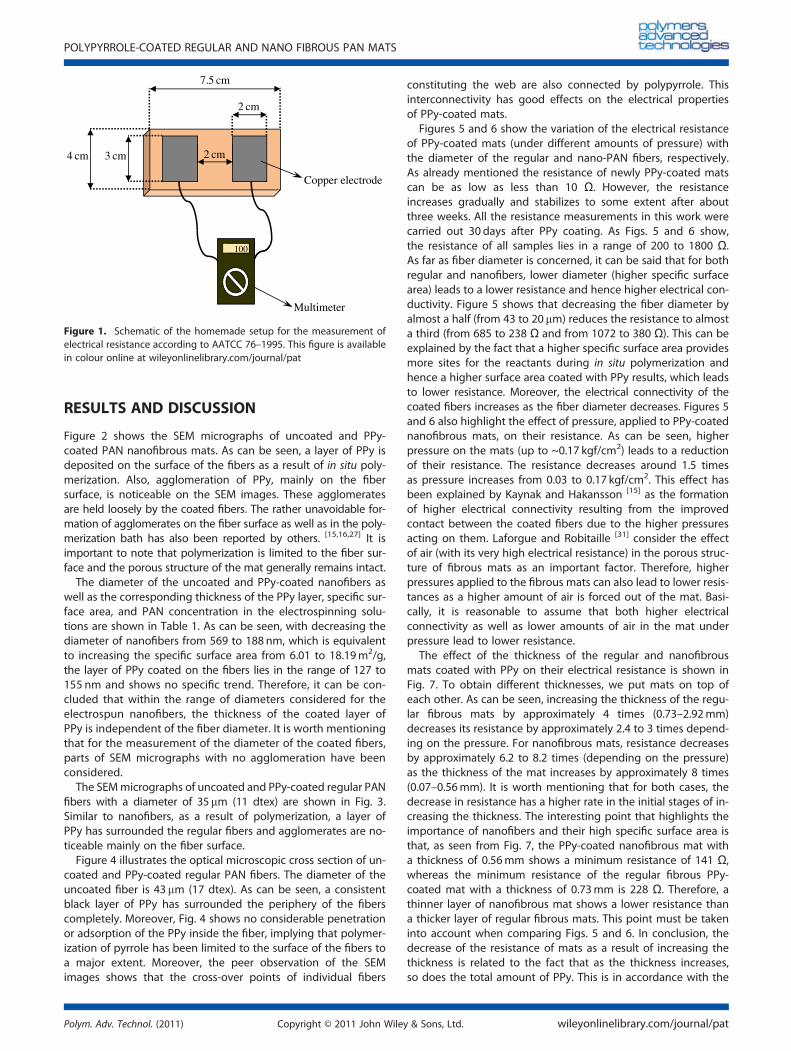
For the comparative study of the conductivity of PPy-coatedsamples, we measured electrical resistance of the mats 30 daysafter coating, with the final 24 hours in the conditioning room(20�C and 65% R.H.). Experiments showed that the electrical re-sistance increases almost daily for up to 3weeks and then slowsdown. Attention is drawn to the fact that in days 1 or 2 aftercoating, the electrical resistance can be less than 10 Ω, whichcan lead to fire during heat generation experiments if the volt-age and current of the heat generating setup are not in a suit-able range. Resistance measurements were carried out using ahomemade setup according to AATCC (American Association ofTextile Chemist and Colorists) standard test method 76–1995as shown in Fig. 1. The setup was placed on each sample witha range of pressures (0.03, 0.06, 0.08, 0.11, 0.14, and 0.17 kgf/cm2) applied to the sample. Electrical resistance measurementwas repeated 10 times for each sample and the mean valuewas calculated.
Heat generation
Heat was generated in PPy-coated mats by a DC power supplycapable of generating a constant voltage of up to 35 V (maxi-mum allowable current, 1500mA). The temperature of thesamples was recorded by an infrared noncontact thermometer(TM-969; Lutron, Taiwan). Current was measured simultaneouslyby a multimeter positioned in the circuit consisting of the matand the power supply.
A. OROUMEI ET AL.
wileyonlinelibrary.com/journal/pat Copyright © 2011 John Wiley & Sons, Ltd. Polym. Adv. Technol. (2011)
RESULTS AND DISCUSSION
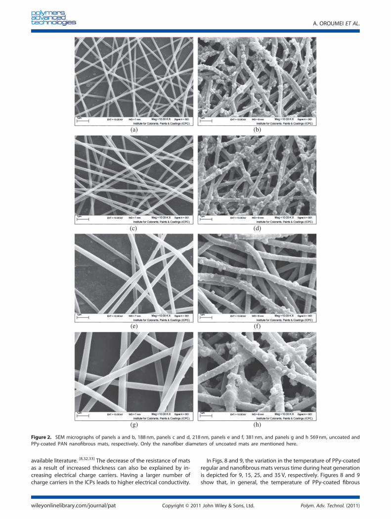
Figure 2 shows the SEM micrographs of uncoated and PPy-coated PAN nanofibrous mats. As can be seen, a layer of PPy isdeposited on the surface of the fibers as a result of in situ poly-merization. Also, agglomeration of PPy, mainly on the fibersurface, is noticeable on the SEM images. These agglomeratesare held loosely by the coated fibers. The rather unavoidable for-mation of agglomerates on the fiber surface as well as in the poly-merization bath has also been reported by others. [15,16,27] It isimportant to note that polymerization is limited to the fiber sur-face and the porous structure of the mat generally remains intact.The diameter of the uncoated and PPy-coated nanofibers as
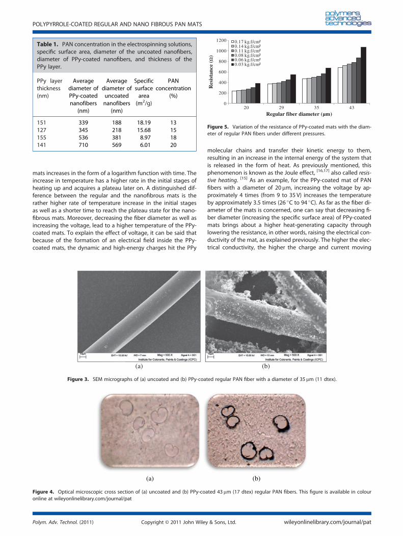
well as the corresponding thickness of the PPy layer, specific sur-face area, and PAN concentration in the electrospinning solu-tions are shown in Table 1. As can be seen, with decreasing thediameter of nanofibers from 569 to 188 nm, which is equivalentto increasing the specific surface area from 6.01 to 18.19m2/g,the layer of PPy coated on the fibers lies in the range of 127 to155 nm and shows no specific trend. Therefore, it can be con-cluded that within the range of diameters considered for theelectrospun nanofibers, the thickness of the coated layer ofPPy is independent of the fiber diameter. It is worth mentioningthat for the measurement of the diameter of the coated fibers,parts of SEM micrographs with no agglomeration have beenconsidered.The SEMmicrographs of uncoated and PPy-coated regular PAN
fibers with a diameter of 35mm (11 dtex) are shown in Fig. 3.Similar to nanofibers, as a result of polymerization, a layer ofPPy has surrounded the regular fibers and agglomerates are no-ticeable mainly on the fiber surface.Figure 4 illustrates the optical microscopic cross section of un-
coated and PPy-coated regular PAN fibers. The diameter of theuncoated fiber is 43mm (17 dtex). As can be seen, a consistentblack layer of PPy has surrounded the periphery of the fiberscompletely. Moreover, Fig. 4 shows no considerable penetrationor adsorption of the PPy inside the fiber, implying that polymer-ization of pyrrole has been limited to the surface of the fibers toa major extent. Moreover, the peer observation of the SEMimages shows that the cross-over points of individual fibers
constituting the web are also connected by polypyrrole. Thisinterconnectivity has good effects on the electrical propertiesof PPy-coated mats.
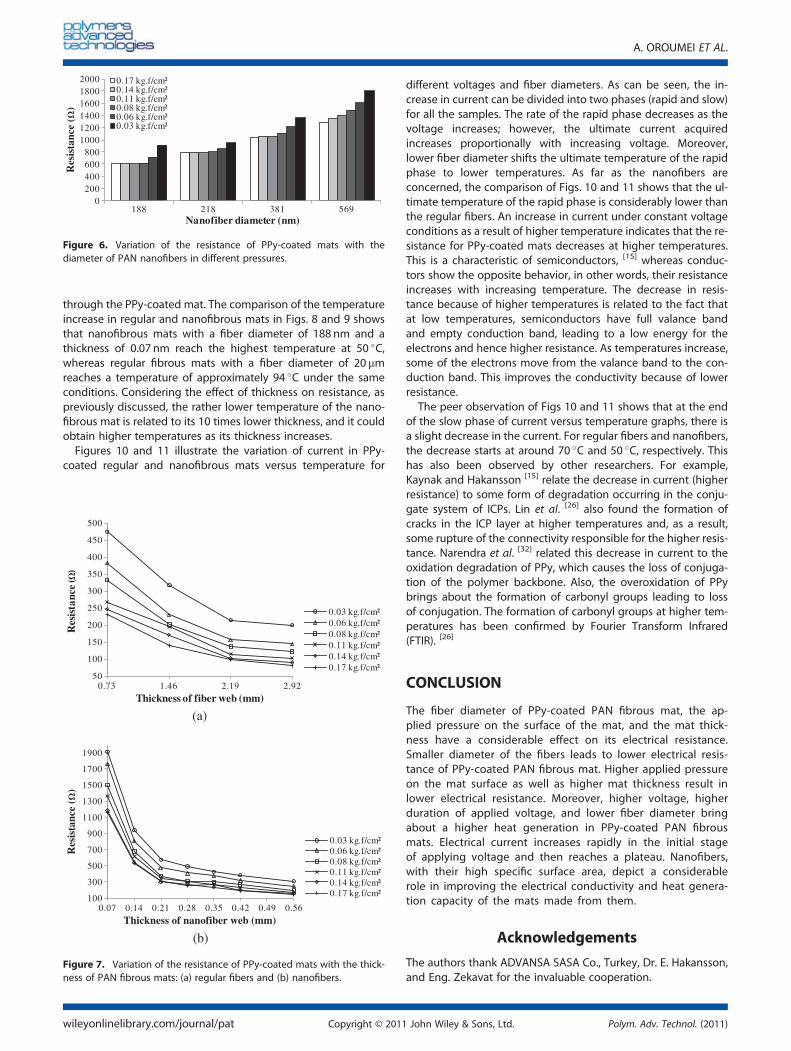
Figures 5 and 6 show the variation of the electrical resistanceof PPy-coated mats (under different amounts of pressure) withthe diameter of the regular and nano-PAN fibers, respectively.As already mentioned the resistance of newly PPy-coated matscan be as low as less than 10 Ω. However, the resistanceincreases gradually and stabilizes to some extent after aboutthree weeks. All the resistance measurements in this work werecarried out 30 days after PPy coating. As Figs. 5 and 6 show,the resistance of all samples lies in a range of 200 to 1800 Ω.As far as fiber diameter is concerned, it can be said that for bothregular and nanofibers, lower diameter (higher specific surfacearea) leads to a lower resistance and hence higher electrical con-ductivity. Figure 5 shows that decreasing the fiber diameter byalmost a half (from 43 to 20 mm) reduces the resistance to almosta third (from 685 to 238 Ω and from 1072 to 380 Ω). This can beexplained by the fact that a higher specific surface area providesmore sites for the reactants during in situ polymerization andhence a higher surface area coated with PPy results, which leadsto lower resistance. Moreover, the electrical connectivity of thecoated fibers increases as the fiber diameter decreases. Figures 5and 6 also highlight the effect of pressure, applied to PPy-coatednanofibrous mats, on their resistance. As can be seen, higherpressure on the mats (up to ~0.17 kgf/cm2) leads to a reductionof their resistance. The resistance decreases around 1.5 timesas pressure increases from 0.03 to 0.17 kgf/cm2. This effect hasbeen explained by Kaynak and Hakansson [15] as the formationof higher electrical connectivity resulting from the improvedcontact between the coated fibers due to the higher pressuresacting on them. Laforgue and Robitaille [31] consider the effectof air (with its very high electrical resistance) in the porous struc-ture of fibrous mats as an important factor. Therefore, higherpressures applied to the fibrous mats can also lead to lower resis-tances as a higher amount of air is forced out of the mat. Basi-cally, it is reasonable to assume that both higher electricalconnectivity as well as lower amounts of air in the mat underpressure lead to lower resistance.
The effect of the thickness of the regular and nanofibrousmats coated with PPy on their electrical resistance is shown inFig. 7. To obtain different thicknesses, we put mats on top ofeach other. As can be seen, increasing the thickness of the regu-lar fibrous mats by approximately 4 times (0.73–2.92mm)decreases its resistance by approximately 2.4 to 3 times depend-ing on the pressure. For nanofibrous mats, resistance decreasesby approximately 6.2 to 8.2 times (depending on the pressure)as the thickness of the mat increases by approximately 8 times(0.07–0.56mm). It is worth mentioning that for both cases, thedecrease in resistance has a higher rate in the initial stages of in-creasing the thickness. The interesting point that highlights theimportance of nanofibers and their high specific surface area isthat, as seen from Fig. 7, the PPy-coated nanofibrous mat witha thickness of 0.56mm shows a minimum resistance of 141 Ω,whereas the minimum resistance of the regular fibrous PPy-coated mat with a thickness of 0.73mm is 228 Ω. Therefore, athinner layer of nanofibrous mat shows a lower resistance thana thicker layer of regular fibrous mats. This point must be takeninto account when comparing Figs. 5 and 6. In conclusion, thedecrease of the resistance of mats as a result of increasing thethickness is related to the fact that as the thickness increases,so does the total amount of PPy. This is in accordance with the
cm2
cm3
100
Multimeter
Copper electrode
cm4
cm7.5
2 cm
Figure 1. Schematic of the homemade setup for the measurement ofelectrical resistance according to AATCC 76–1995. This figure is availablein colour online at wileyonlinelibrary.com/journal/pat
POLYPYRROLE-COATED REGULAR AND NANO FIBROUS PAN MATS
Polym. Adv. Technol. (2011) Copyright © 2011 John Wiley & Sons, Ltd. wileyonlinelibrary.com/journal/pat
available literature. [8,32,33] The decrease of the resistance of matsas a result of increased thickness can also be explained by in-creasing electrical charge carriers. Having a larger number ofcharge carriers in the ICPs leads to higher electrical conductivity.
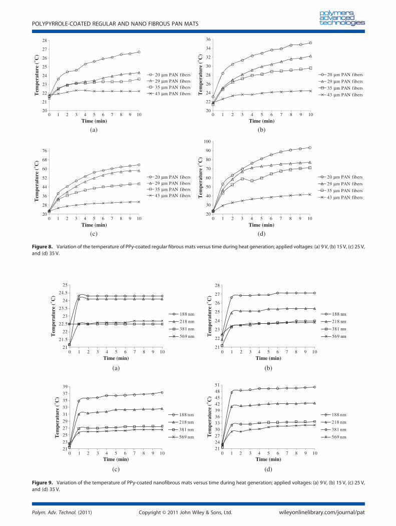
In Figs. 8 and 9, the variation in the temperature of PPy-coatedregular and nanofibrous mats versus time during heat generationis depicted for 9, 15, 25, and 35 V, respectively. Figures 8 and 9show that, in general, the temperature of PPy-coated fibrous
(a) (b)
(c) (d)
(e) (f)
(g) (h)
Figure 2. SEM micrographs of panels a and b, 188 nm, panels c and d, 218 nm, panels e and f, 381 nm, and panels g and h 569 nm, uncoated andPPy-coated PAN nanofibrous mats, respectively. Only the nanofiber diameters of uncoated mats are mentioned here.
A. OROUMEI ET AL.
wileyonlinelibrary.com/journal/pat Copyright © 2011 John Wiley & Sons, Ltd. Polym. Adv. Technol. (2011)
mats increases in the form of a logarithm function with time. Theincrease in temperature has a higher rate in the initial stages ofheating up and acquires a plateau later on. A distinguished dif-ference between the regular and the nanofibrous mats is therather higher rate of temperature increase in the initial stagesas well as a shorter time to reach the plateau state for the nano-fibrous mats. Moreover, decreasing the fiber diameter as well asincreasing the voltage, lead to a higher temperature of the PPy-coated mats. To explain the effect of voltage, it can be said thatbecause of the formation of an electrical field inside the PPy-coated mats, the dynamic and high-energy charges hit the PPy
molecular chains and transfer their kinetic energy to them,resulting in an increase in the internal energy of the system thatis released in the form of heat. As previously mentioned, thisphenomenon is known as the Joule effect, [16,17] also called resis-tive heating. [15] As an example, for the PPy-coated mat of PANfibers with a diameter of 20mm, increasing the voltage by ap-proximately 4 times (from 9 to 35 V) increases the temperatureby approximately 3.5 times (26 �C to 94 �C). As far as the fiber di-ameter of the mats is concerned, one can say that decreasing fi-ber diameter (increasing the specific surface area) of PPy-coatedmats brings about a higher heat-generating capacity throughlowering the resistance, in other words, raising the electrical con-ductivity of the mat, as explained previously. The higher the elec-trical conductivity, the higher the charge and current moving
0
200
400
600
800
1000
1200
20 29 35 43
Res
ista
nce
()
Regular fiber diameter ( m)
0.17 kg.f/cm²0.14 kg.f/cm²0.11 kg.f/cm²0.08 kg.f/cm²0.06 kg.f/cm²0.03 kg.f/cm²
Figure 5. Variation of the resistance of PPy-coated mats with the diam-eter of regular PAN fibers under different pressures.
Table 1. PAN concentration in the electrospinning solutions,specific surface area, diameter of the uncoated nanofibers,diameter of PPy-coated nanofibers, and thickness of thePPy layer.
PPy layerthickness(nm)
Averagediameter ofPPy-coatednanofibers
(nm)
Averagediameter ofuncoatednanofibers
(nm)
Specificsurfacearea(m2/g)
PANconcentration
(%)
151 339 188 18.19 13127 345 218 15.68 15155 536 381 8.97 18141 710 569 6.01 20
(a) (b)
Figure 3. SEM micrographs of (a) uncoated and (b) PPy-coated regular PAN fiber with a diameter of 35mm (11 dtex).
(a) (b)
Figure 4. Optical microscopic cross section of (a) uncoated and (b) PPy-coated 43mm (17 dtex) regular PAN fibers. This figure is available in colouronline at wileyonlinelibrary.com/journal/pat
POLYPYRROLE-COATED REGULAR AND NANO FIBROUS PAN MATS
Polym. Adv. Technol. (2011) Copyright © 2011 John Wiley & Sons, Ltd. wileyonlinelibrary.com/journal/pat
through the PPy-coated mat. The comparison of the temperatureincrease in regular and nanofibrous mats in Figs. 8 and 9 showsthat nanofibrous mats with a fiber diameter of 188 nm and athickness of 0.07 nm reach the highest temperature at 50 �C,whereas regular fibrous mats with a fiber diameter of 20 mmreaches a temperature of approximately 94 �C under the sameconditions. Considering the effect of thickness on resistance, aspreviously discussed, the rather lower temperature of the nano-fibrous mat is related to its 10 times lower thickness, and it couldobtain higher temperatures as its thickness increases.
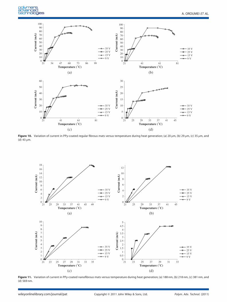
Figures 10 and 11 illustrate the variation of current in PPy-coated regular and nanofibrous mats versus temperature for
different voltages and fiber diameters. As can be seen, the in-crease in current can be divided into two phases (rapid and slow)for all the samples. The rate of the rapid phase decreases as thevoltage increases; however, the ultimate current acquiredincreases proportionally with increasing voltage. Moreover,lower fiber diameter shifts the ultimate temperature of the rapidphase to lower temperatures. As far as the nanofibers areconcerned, the comparison of Figs. 10 and 11 shows that the ul-timate temperature of the rapid phase is considerably lower thanthe regular fibers. An increase in current under constant voltageconditions as a result of higher temperature indicates that the re-sistance for PPy-coated mats decreases at higher temperatures.This is a characteristic of semiconductors, [15] whereas conduc-tors show the opposite behavior, in other words, their resistanceincreases with increasing temperature. The decrease in resis-tance because of higher temperatures is related to the fact thatat low temperatures, semiconductors have full valance bandand empty conduction band, leading to a low energy for theelectrons and hence higher resistance. As temperatures increase,some of the electrons move from the valance band to the con-duction band. This improves the conductivity because of lowerresistance.The peer observation of Figs 10 and 11 shows that at the end
of the slow phase of current versus temperature graphs, there isa slight decrease in the current. For regular fibers and nanofibers,the decrease starts at around 70 �C and 50 �C, respectively. Thishas also been observed by other researchers. For example,Kaynak and Hakansson [15] relate the decrease in current (higherresistance) to some form of degradation occurring in the conju-gate system of ICPs. Lin et al. [26] also found the formation ofcracks in the ICP layer at higher temperatures and, as a result,some rupture of the connectivity responsible for the higher resis-tance. Narendra et al. [32] related this decrease in current to theoxidation degradation of PPy, which causes the loss of conjuga-tion of the polymer backbone. Also, the overoxidation of PPybrings about the formation of carbonyl groups leading to lossof conjugation. The formation of carbonyl groups at higher tem-peratures has been confirmed by Fourier Transform Infrared(FTIR). [26]
CONCLUSION
The fiber diameter of PPy-coated PAN fibrous mat, the ap-plied pressure on the surface of the mat, and the mat thick-ness have a considerable effect on its electrical resistance.Smaller diameter of the fibers leads to lower electrical resis-tance of PPy-coated PAN fibrous mat. Higher applied pressureon the mat surface as well as higher mat thickness result inlower electrical resistance. Moreover, higher voltage, higherduration of applied voltage, and lower fiber diameter bringabout a higher heat generation in PPy-coated PAN fibrousmats. Electrical current increases rapidly in the initial stageof applying voltage and then reaches a plateau. Nanofibers,with their high specific surface area, depict a considerablerole in improving the electrical conductivity and heat genera-tion capacity of the mats made from them.
Acknowledgements
The authors thank ADVANSA SASA Co., Turkey, Dr. E. Hakansson,and Eng. Zekavat for the invaluable cooperation.
0200400600800
100012001400160018002000
188 218 381 569Nanofiber diameter (nm)
0.17 kg.f/cm²0.14 kg.f/cm²0.11 kg.f/cm²0.08 kg.f/cm²0.06 kg.f/cm²0.03 kg.f/cm²
Res
ista
nce
()
Figure 6. Variation of the resistance of PPy-coated mats with thediameter of PAN nanofibers in different pressures.
50
100
150
200
250
300
350
400
450
500
0.73 1.46 2.19 2.92
Res
ista
nce
( )
Thickness of fiber web (mm)
0.03 kg.f/cm²0.06 kg.f/cm²0.08 kg.f/cm²0.11 kg.f/cm²0.14 kg.f/cm²0.17 kg.f/cm²
(a)
100
300
500
700
900
1100
1300
1500
1700
1900
0.07 0.14 0.21 0.28 0.35 0.42 0.49 0.56
Res
ista
nce
()
Thickness of nanofiber web (mm)
0.03 kg.f/cm²0.06 kg.f/cm²0.08 kg.f/cm²0.11 kg.f/cm²0.14 kg.f/cm²0.17 kg.f/cm²
(b)
Figure 7. Variation of the resistance of PPy-coated mats with the thick-ness of PAN fibrous mats: (a) regular fibers and (b) nanofibers.
A. OROUMEI ET AL.
wileyonlinelibrary.com/journal/pat Copyright © 2011 John Wiley & Sons, Ltd. Polym. Adv. Technol. (2011)
21
21.5
22
22.5
23
23.5
24
24.5
25
0 1 2 3 4 5 6 7 8 9 10
Tem
pera
ture
(° C
)T
empe
ratu
re (
° C)
Tem
pera
ture
(° C
)T
empe
ratu
re (
° C)
Time (min)
188 nm
218 nm
381 nm
569 nm
21
22
23
24
25
26
27
28
0 1 2 3 4 5 6 7 8 9 10
Time (min)
188 nm
218 nm
381 nm
569 nm
21
23
25
27
29
31
33
35
37
39
0 1 2 3 4 5 6 7 8 9 10Time (min)
188 nm
218 nm
381 nm
569 nm
2124273033363942454851
0 1 2 3 4 5 6 7 8 9 10Time (min)
188 nm
218 nm
381 nm
569 nm
(a) (b)
(c) (d)
Figure 9. Variation of the temperature of PPy-coated nanofibrous mats versus time during heat generation; applied voltages: (a) 9 V, (b) 15 V, (c) 25 V,and (d) 35 V.
20
21
22
23
24
25
26
27
28
0 1 2 3 4 5 6 7 8 9 10
Tem
pera
ture
(° C
)
Tem
pera
ture
(° C
)T
empe
ratu
re (
° C)
Tem
pera
ture
(° C
)
Time (min)
20 µm PAN fibers29 µm PAN fibers 35 µm PAN fibers 43 µm PAN fibers
20
22
24
26
28
30
32
34
36
0 1 2 3 4 5 6 7 8 9 10
Time (min)
20 µm PAN fibers
29 µm PAN fibers
35 µm PAN fibers
43 µm PAN fibers
20
28
36
44
52
60
68
76
0 1 2 3 4 5 6 7 8 9 10
Time (min)
20 µm PAN fibers29 µm PAN fibers35 µm PAN fibers43 µm PAN fibers
20
30
40
50
60
70
80
90
100
0 1 2 3 4 5 6 7 8 9 10
Time (min)
20 µm PAN fibers
29 µm PAN fibers
35 µm PAN fibers
43 µm PAN fibers
(a)
(c)
(b)
(d)
Figure 8. Variation of the temperature of PPy-coated regular fibrous mats versus time during heat generation; applied voltages: (a) 9 V, (b) 15 V, (c) 25 V,and (d) 35 V.
POLYPYRROLE-COATED REGULAR AND NANO FIBROUS PAN MATS
Polym. Adv. Technol. (2011) Copyright © 2011 John Wiley & Sons, Ltd. wileyonlinelibrary.com/journal/pat
0
2
4
6
8
10
12
14
16
18
21 25 29 33 37 41 45 49
Cur
rent
(m
A)
Temperature (°C) Temperature (°C)
Temperature (°C) Temperature (°C)
35 V25 V15 V9 V
0
2
4
6
8
10
12
21 25 29 33 37 41 45
Cur
rent
(m
A)
35 V25 V15 V9 V
0
1
2
3
4
5
6
7
8
9
10
21 23 25 27 29 31 33 35
Cur
rent
(m
A)
35 V25 V15 V9 V
00.5
11.5
22.5
33.5
44.5
5
21 23 25 27 29 31 33
Cur
rent
(m
A)
35 V25 V15 V9 V
(a) (b)
(c) (d)
Figure 11. Variation of current in PPy-coated nanofibrous mats versus temperature during heat generation; (a) 188 nm, (b) 218 nm, (c) 381 nm, and(d) 569 nm.
0102030405060708090
100
21 34 47 60 73 86 99
Cur
rent
(m
A)
Temperature (°C) Temperature (°C)
Temperature (°C)Temperature (°C)
35 V25 V15 V9 V
0102030405060708090
100
21 41 61 81
Cur
rent
(m
A)
35 V25 V15 V9 V
0
10
20
30
40
50
60
21 41 61 81
Cur
rent
(m
A)
35 V25 V15 V9 V
0
5
10
15
20
25
30
21 25 29 33 37 41 45
Cur
rent
(m
A)
35 V25 V15 V9 V
(a) (b)
(c) (d)
Figure 10. Variation of current in PPy-coated regular fibrous mats versus temperature during heat generation; (a) 20 mm, (b) 29 mm, (c) 35 mm, and(d) 43 mm.
A. OROUMEI ET AL.
wileyonlinelibrary.com/journal/pat Copyright © 2011 John Wiley & Sons, Ltd. Polym. Adv. Technol. (2011)
REFERENCES[1] J. Wang, C. Y. Wang, C. O. Too, G. G. Wallace, J. Power Sourc. 2006,
161, 1458.[2] Y. Li, X. Y. Cheng, M. Y. Leung, J. Tsang, X. M. Tao, M. C. W. Yuen, Syn-
thetic Met. 2005, 155, 89.[3] J. Jang, J. Bae, M. Choi, S. H. Yoon, Carbon 2005, 43, 2730.[4] M. S. Kim, H. K. Kim, S. W. Byun, S. H. Jeong, Y. K. Hong, J. S. Joo,
K. T. Song, J. K. Kim, C. J. Lee, J. Y. Lee, Synthetic Met. 2002, 126, 233.[5] C. A. Sparavigna, L. Florio, J. Avloni, A. Henn,Mater. Sci. Appl. 2010; 1,
252.[6] T. F. Otero, M. Broschart, J. Appl. Electrochem. 2006; 36, 205.[7] Z. Zhang, R. Roy, F. J. Dugre, D. Tessier, L. H. Dao, J. Biomed. Mater.
Res. 2001, 57, 63.[8] I. Cucchi, A. Boschi, C. Arosio, F. Bertini, G. Freddi, M. Catellani, Syn-
thetic Met. 2009, 159, 246.[9] P. Xue, X. M. Tao, J. Appl. Polymer Sci. 2005, 98, 1844.[10] G. G. Wallace, G. M. Spinks, L. A. P. Kane-Maguire, P. R. Teasdale, Con-
ductive electroactive polymers, CRC Press, Boca Raton, 2009.[11] S. F. Michael, A. D. Bhavana, Self-doped conducting polymers, Wiley,
Canada, 2007.[12] P. Lekpittaya, N. Yanumet, B. P. Grady, E. A. O’Rear, Appl. Polymer Sci.
2004, 92, 2629.[13] J. L. Bredas, J. C. Scott, K. Yakushi, G. B. Street, Physical Review B
1984, 30, 1023.[14] J. L. Bredas, G. B. Street, Acc. Chem. Res. 1985, 18, 309.[15] A. Kaynak, E. Hakansson, Adv. Polymer Tech. 2005, 24, 194.[16] A. Varesano, L. Dall’Acqua, C. Tonin, Polymer Degrad. Stab. 2005,
89, 125.
[17] J. Y. Lee, D. W. Park, J. O. Lim, Macromol. Res. 2003, 11, 481.[18] A. Kaynak, E. Hakansson, A. Amiet, Synthetic Met. 2009, 159,
1373.[19] A. Varesano, A. Aluigi, L. Florio, R. Fabris, Synthetic Met. 2009, 159,
1082.[20] G. G. Wallace, T. G. Campbell, P. C. Innis, Fibers and Polymers 2007, 8,
135.[21] A. Malinauskas, Polymer 2001, 42, 3957.[22] M. Cvetkovska, T. Grchev, T. Obradovic, J. Appl. Polymer Sci. 1996, 60,
2049.[23] H. H. Kuhn, A. D. Child, in Handbook of conducting polymers, Second
ed. (Eds.: T. A. Sothern, M. Corporation, T. Arizona, R. L. Elsenbaumer,J. R. Reynolds), Marcel Dekker, Texas, 1998.
[24] A. Kaynak, R. Beltran, Polymer Int. 2003, 52, 1021.[25] G. A. Wood, J. O. Iroh, Polymer Eng. Sci. 1996, 36, 2389.[26] T. Lin, L. Wang, X. Wang, A. Kaynak, Thin Solid Films 2005, 479,
77.[27] E. Hakansson, A. Kaynak, T. Lin, S. Nahavandi, T. Jones, E. Hu, Syn-
thetic Met. 2004, 144, 21.[28] A. Kaynak, S. Shaikhzadeh Najar, R. C. Foitzik, Synthetic Met. 2008;
158, 1.[29] H. Tavanai, A. Kaynak, Synthetic Met. 2007, 157, 764.[30] J. Y. Lee, C. A. Bashur, A. S. Goldstein, C. E. Schimdt, Biomaterials
2009, 30, 4325.[31] A. Laforgue, L. Robitaille, Chem. mater. 2010, 22, 2474.[32] V. B. Narendra, T. S. Devender, M. N. Mandar, V. G. Ajit, J. Appl. Poly-
mer Sci. 2006, 102, 4690.[33] A. Boschi, C. Arosio, I. Cucchi, F. Bertini, M. Catellani, G. Freddi, Fibers
and Polymers 2008, 9, 698.
POLYPYRROLE-COATED REGULAR AND NANO FIBROUS PAN MATS
Polym. Adv. Technol. (2011) Copyright © 2011 John Wiley & Sons, Ltd. wileyonlinelibrary.com/journal/pat