ehedg - yearbook 2015/2016
TRANSCRIPT
EHEDGYearbook 2015/2016
European HygienicEngineering & Design Group
EHEDGYearbook 2015/2016
European HygienicEngineering & Design Group
European Hygienic Engineering & Design Group
Contents
Articles PageGreeting from the President, Knuth Lorenzen, EHEDG President 5
News from the Treasurer, Piet Steenaard, EHEDG Treasurer 6
News from the Secretariat, Susanne Flenner, EHEDG Secretariat 7
EHEDG Presideny, Board and Committees 8
EHEDG Company and Institute members 10
EHEDG membership 15
EHEDG Test and Certification Institutes 17
Online monitoring and cleaning of off-flavours in the food and beverage industry, 18 by By Frank Schulze, Jürgen Löhrke GmbH
A method and apparatus for foam removal in aseptic environments, 20 by Viivi Nuottajärvi, Juha Lehtioksa and Mika Peltola, Lamican Oy
Wanted: Ideal pharmaceutical material, 24 by Julia Eckstein, Freudenberg Process Seals GmbH & Co. KG and Theresa Miller, Freudenberg Forschungsdienste SE & Co. KG
Aspects of designing with elastomers, by Anders G. Christensen, AVK GUMMI A/S 29
Solving problems with damaged and/or corroded walls and ceilings 32 in a food safe production environment, by Nick Van den Bosschelle, PolySto
Hygienic flooring: design, selection and checklist, by Philip Ansell, BASF Plc 34
Floor and drainage systems for hygienic applications – minimising risks 42 by Peter Jennings, ACO Technologies plc, Martin Fairley, ACO Technologies plc and Robert Bentley, BASF
Hygienic operation of floor drainage components, 48 by Martin Fairley ACO Technologies plc, Debra Smith, Vikan Ltd. and Hein Timmerman, Sealed Air
Water savings and food safety challenges in drain design, by Søren Davidsen, BLÜCHER 56
Hygienic fast action doors and their importance to the food industry, 60 by Sebastian Werner, Oliver Riebe and Friedrich von Rheinbaben, HygCen Centrum für Hygiene und Produktsicherheit GmbH
Recommendations for the calibration and preventive maintenance of orbital welding equipment, 62 by Patricia Leroy, Polysoude S.A.S.
A 100% hygienic welding procedure, by Jeppe Troelsen, Aviatec 64
Improved hygienic design of air filters for food recovery, 68 by Dr.-Ing. Hans-Joachim Adlhoch, Herding GmbH Filtertechnik
Achieving food safety and quality by using the right compressed air, 70 by Uwe Greißl, Festo AG & Co. KG
Machine components suitable for hygienic applications: A case study on cable glands, 72 by Markus Keller and Gabriela Baum, Fraunhofer Institute for Manufacturing Engineering and Automation IPA, Department of Ultraclean Technology and Micro Manufacturing
It´s “Only” Food, by Dr. Ing. Johannes Lottermann, REMBE GmbH Safety + Control 83
Contents 3
Baby formula mixing requires hygienic equipment, 86 by Dipl.-Ing. Matthias Böning, amixon GmbH
Optimising hygienic requirements for food processing machinery according to 3-A Sanitary Standards, 90 by Reinhard Moß, Research & Development, GEA Westfalia Separator Group GmbH
Cleaning of food fouling layers from tank walls impinging liquid jets, 92 by D.I. Wilson, J.F. Davidson, T. Wang Department of Chemical Engineering & Biotechnology, University of Cambridge, H. Köhler, Technische Universität Dresden, Faculty of Mechanical Engineering, Institute of Processing Machines and Mobile Machines and J.-P. Majschak, Fraunhofer IVV, Branch Lab for Processing Machinery and Packaging Technology AVV
Rotary jet head ‘burst’ cleaning technology delivers significant savings in cleaning costs, 96 by Kim Kjellberg, Alfa Laval
First Twin-Screw Pump Receives EHEDG Type EL Aseptic Class I Certificate, 100 by Jens Dralle, ITT Bornemann GmbH
Optimising the hygienic design of pumps, by Willi Wiedenmann, Evoguard GmbH 102
The 5 key features of a cleanable centrifugal pump, by Bart Van Bastelaere,Packo Pumps 104
The hygienic advantages of the P³-diaphragm in aseptic processing, 108 by Dietmar Ladenburger, Pentair Südmo
Advanced flowmeter design delivers hygienic needs, 114 by John van Loon, Bürkert Fluid Control Systems
Lubricant-free magnetic gearboxes offer a hygienic alternative, 116 by Andreas Vonderschmidt, GEORGII KOBOLD GmbH & Co. KG
New hygienic lagging for drum motors utilises premium polyurethane to enhance cleanability, 120 by Thomas Becker, Interroll Trommelmotoren GmbH
International Hygienic Study Award 2014, by Dr. Peter Golz, VDMA 122
EHEDG Regional Sections Chairmen and contacts 124
EHEDG Regional Sections 124
EHEDG Armenia 127
EHEDG Belgium 129
EHEDG Croatia 130
EHEDG Czech Republic 130
EHEDG Denmark 131
EHEDG France 131
EHEDG Germany 132
EHEDG India 134
EHEDG Italy 135
EHEDG Japan 136
EHEDG Lithuania 138
EHEDG Macedonia 138
EHEDG Mexico 140
EHEDG Nordic 141
EHEDG Poland 142
EHEDG Russia 143
EHEDG Serbia 144
4 Contents
EHEDG Spain 145
EHEDG Taiwan 146
EHEDG Thailand 148
EHEDG UK and Ireland 149
EHEDG United States 150
EHEDG Guidelines 151
EHEDG World Congress 161
EHEDG Working Groups 162
EHEDG Working Group “Air Handling” 163
EHEDG Working Group Group “Bakery Equipment” 163
EHEDG Working Group “Hygienic Building Design” 164
EHEDG Working Group “Cleaning in Place” 165
EHEDG Working Group “Conveyor Systems” 166
EHEDG Working Group “Dry Materials Handling” 166
EHEDG Working Group “Fish Processing” 167
EHEDG Working Group “Food Refrigeration Equipment” 168
EHEDG Working Group “Heat Treatment” 170
EHEDG Working Group “Pumps, Homogenisers and Dampening Devices” 171
EHEDG Working Group “Seals” 171
EHEDG Working Group “Tank Cleaning” 172
EHEDG Working Group “Test Methods” 172
EHEDG Working Group “Training and Education” 174
EHEDG Working Group “Valves” 175
EHEDG application forms 176
Imprint 178
European Hygienic Engineering & Design Group
Greeting from the President Knuth Lorenzen, e-mail: [email protected]
Ladies and Gentlemen,
The rapid growth and worldwide expansion of EHEDG in recent years gave us reason to develop new strategies in order to fulfil our future tasks and challenges.
After several years of comprehensive planning and preparation work by a Strategy Taskforce and the EHEDG Executive Committee, our organisational realignment has been successfully implemented. Following the first elections held in December 2014, our new Board and the new Sub-Committees officially started their work in January 2015 in order to govern EHEDG to the benefit of all members as well as to make the organisation as transparent as possible.
The Sub-Committee “Regional Development” supports the activities of the EHEDG Regional Sections in many countries worldwide and helps establishing new Sections after thorough assessment. The Sub-Committee “Product Portfolio” monitors the high quality of the EHEDG guidelines as well as the development of new documents, training modules and EHEDG test methods. The Sub- Committee “Communication” is in charge of our membership relations, events and public relations. The Sub-Committees are manned by experienced Executive Committee members and long-term EHEDG experts who are willing to dedicate themselves to the task of actively taking responsibility for the major activity clusters of EHEDG.
In the future, the establishment of new EHEDG Regional Sections and Working Groups will be initiated upon detailed analyses of our “markets” and target groups. The EHEDG portfolio will be thoroughly defined, monitored and guided with the aim of meeting the needs of our members and of consolidating the global recognition of EHEDG.
EHEDG represents all segments of food-related industries, equipment manufacturing and mechanical engineering. Our stakeholders are interested in contributing to a safe food production by hygienic engineering and design, which is reflected by the activities of the entire organisation. The EHEDG membership is meant to be well-balanced by covering all sizes and natures of the business of our members.
As a non-profit organisation funded by our strongly committed members, we are relying upon their voluntary contribution and active involvement. I hereby express my sincere thanks to all dedicated experts for their sustained contribution and distinguished input as well as to our member companies and institutes who are continuously supporting us – without YOU we would not be in a position to offer our wide range of educational services.
Aiming to offer practical guidance to the industry, I am glad to inform you that a good portion of our training modules based on the EHEDG guideline know-how has been completed meanwhile. With this material, we are in a position to offer academic programs in cooperation with universities to realize Bachelor and Master studies in Hygienic Engineering & Design on an international level.
I am proud to say that we build on a well-structured and transparent organisation today. We are striving for high efficiency to the benefit of our members who are often the innovation and market leaders in their field. Thank you for continuously supporting us and for contributing to our common objectives.
Yours
Knuth Lorenzen
President of EHEDG
European Hygienic Engineering & Design Group
News from the TreasurerPiet Steenaard, e-mail: [email protected]
Dear Readers of the EHEDG Yearbook,
It has been my pleasure to serve the EHEDG as the Treasurer in past years and I am very glad to have been re-elected for another term starting from 2016.
The increasing number of members means more opportunities for EHEDG to bring experts together whose common goal is the development of our high-quality guidelines as well as to keep these documents updated based on state-of-the art technical requirements.
The growing interest in EHEDG also offers us the possibility to organize all kinds of events in many countries in order to disseminate the EHEDG knowledge.
We are busy to develop new test methods for open equipment, so that we will be in a position to offer our members a wider range of certification of their equipment in the future.
The development of our guidance documents and test methods as well as the organisation of meetings and high-level events requires significant financial investments, but I am happy to inform you that EHEDG is a healthy organisation also from a financial point of view.
Our good financial situation will allow us to continue our important work in the future.
The importance of a safe food production and thus of EHEDG within the food manufacturing industry is increasing rapidly. This can be seen from the growing number of companies and institutes who are supporting the activities of EHEDG.
EHEDG is a non-profit organisation and an institution for general benefit (a so-called “ANBI” according to Dutch law), aiming to serve its members in a best possible way. Thus we have to make sure that the contributions of our members are adequately used, as they are financing EHEDG to an extent of 90 %. We are aware of this financial responsibility which we will follow at all times. I am glad to let you know that EHEDG members are authorized to fully deduct their donations to EHEDG from their tax payments based on our ANBI status which obliges us at the same time to make our work as transparent as possible.
To underline this transparency, anyone can find our annual results and financial reports published in the disclaimer of the EHEDG website.
It is my personal aim to enhance the activities of EHEDG by making it possible that our volunteers can travel, organize events and workshops, translate documents, participate in our meetings and trade shows etc. Many of the EHEDG experts are supported by their companies whom we sincerely thank for their outstanding commitment. We are well aware of the innumerable work-hours involved which are all made on a voluntary basis.
It gives me a good feeling to know that we all have the passion to make food safer. Therefore I look forward to continue my job as EHEDG Treasurer in coming years.
Thank you all for your ongoing commitment.
Piet Steenaard
Treasurer of EHEDG
European Hygienic Engineering & Design Group
News from the Secretariat Susanne Flenner, EHEDG Secretariat, [email protected]
Dear Reader,
With its issue 2015/2016, the EHEDG Yearbook reflects again the capability of our member companies in designing equipment and process lines which are meeting the highest hygienic requirements of the industries concerned with the safe production of food. The book summarizes recent scientific results in the cleaning and hygienically safe food processing and last not least, it informs you of our wide range of activities and the most important EHEDG facts and figures.
Having celebrated its 25th anniversary in 2014, EHEDG proudly looks back on a lot of achievements in recent years. With about 330 member companies in 55 countries at the time of publication of this book, 25 Regional Sections all over the world and 20 Working Groups covering a variety of topics in the field of hygienic equipment design as well as in safe processing and packaging of food products, the EHEDG has consolidated its position as a globally respected and well-known source of hygienic engineering & design excellence. Our strength bases on our willingness and capability to always adapt to the dynamic needs of our members and markets.
Simultaneously, the success of our growing organisation entails new challenges. After three years of strategic planning and profound organisational realignment aimed at further professionalizing our expert network, several key positions in EHEDG were elected at the end of 2014 for the first time. The new Board established in the year 2015 will help managing the EHEDG at its best jointly with the EHEDG Executive Committee and the Sub-Committees. The work of these Committees will focus on the future Regional Development, the EHEDG Product Portfolio (composed of Guidelines, Training and Certification) as well as on the
alignment and optimization of our internal and external Communication channels. The new organisational structure and tasks are described in more detail in the new EHEDG Statutes (adopted in January 2014), in the related Bylaws as well as in a number of comprehensive Standard Operating Procedures which are currently drafted and implemented by the Sub-Committees. All these guidance documents are intended to be filled with life and are going to be a part of the EHEDG workaday life from now.
In order to make EHEDG an ongoing success story, we at the EHEDG Secretariat will be closely involved in all these activities and will help converting the EHEDG mission into daily operational practice. We are your first contact point in EHEDG and will further on help our members in making their commitment to our organisation a real benefit.
Finally, this is to thank once again the great many of voluntary experts who are actively contributing to the good work of EHEDG in our Regional Sections, Working Groups and Committees who are all concerned with disseminating the know-how in Hygienic Engineering & Design as well as in continuously building up, driving and managing our expert network. In EHEDG, our members find a platform for the dialogue between equipment manufacturers, food producers, scientists and public health authorities by using the bundled know-how of each other. Newcomers are always invited to share in the good work of EHEDG. If you like to learn more about, you are welcome to contact us!
Contact:Susanne FlennerHead Office ManagerEHEDG SecretariatLyoner Str. 1860528 Frankfurt am MainGermanyPhone: +49 69 6603-1217Fax: +49 69 6603-2217E-mail: [email protected] Web: www.ehedg.org
European Hygienic Engineering & Design Group
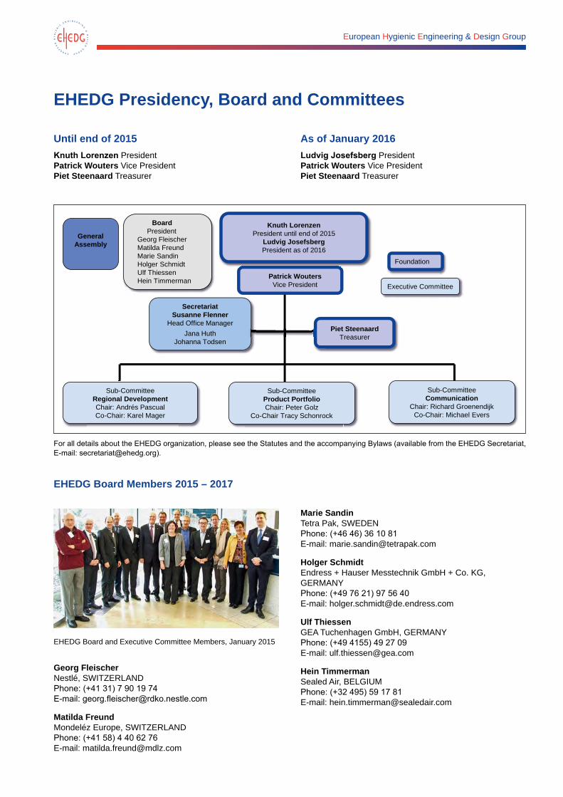
EHEDG Board Members 2015 – 2017
EHEDG Board and Executive Committee Members, January 2015
Georg Fleischer Nestlé, SWITZERLAND Phone: (+41 31) 7 90 19 74 E-mail: [email protected]
Matilda Freund Mondeléz Europe, SWITZERLAND Phone: (+41 58) 4 40 62 76 E-mail: [email protected]
Marie Sandin Tetra Pak, SWEDEN Phone: (+46 46) 36 10 81 E-mail: [email protected]
Holger Schmidt Endress + Hauser Messtechnik GmbH + Co. KG, GERMANY Phone: (+49 76 21) 97 56 40 E-mail: [email protected]
Ulf Thiessen GEA Tuchenhagen GmbH, GERMANY Phone: (+49 4155) 49 27 09 E-mail: [email protected]
Hein Timmerman Sealed Air, BELGIUM Phone: (+32 495) 59 17 81 E-mail: [email protected]
EHEDG Presidency, Board and Committees
Until end of 2015Knuth Lorenzen President Patrick Wouters Vice PresidentPiet Steenaard Treasurer
As of January 2016Ludvig Josefsberg PresidentPatrick Wouters Vice PresidentPiet Steenaard Treasurer
BoardPresident
Georg FleischerMatilda FreundMarie SandinHolger SchmidtUlf ThiessenHein Timmerman
Piet SteenaardTreasurer
Sub-CommitteeProduct PortfolioChair: Peter Golz
Co-Chair Tracy Schonrock
SecretariatSusanne Flenner
Head Office ManagerJana Huth
Johanna Todsen
Sub-CommitteeCommunication
Chair: Richard GroenendijkCo-Chair: Michael Evers
Sub-CommitteeRegional DevelopmentChair: Andrés PascualCo-Chair: Karel Mager
Foundation
Patrick WoutersVice President
Knuth LorenzenPresident until end of 2015
Ludvig JosefsbergPresident as of 2016
Executive Committee
General Assembly
For all details about the EHEDG organization, please see the Statutes and the accompanying Bylaws (available from the EHEDG Secretariat, E-mail: [email protected]).
EHEDG Presidency, Board and Committees 9
EHEDG Executive Committee Members and Sub-Committee Chairpersons (as of January 2015)
For individual positions, please see the organizational chart of EHEDG on page 8.
*Chair of Sub-Committee, **Co-Chair of Sub-Committee, ***Honorary Member
Ludvig Josefsberg Tetra Pak Processing Systems SWEDEN Phone: (+46 46) 36 60 01 E-mail: [email protected]
Huub Lelieveld*** NETHERLANDS Phone: (+31 30) 2 25 38 96 E-mail:[email protected]
Knuth Lorenzen GERMANY Phone: (+49 4173) 83 64 E-mail: [email protected]
Piet Steenaard NETHERLANDS Phone: (+31 35) 5 38 36 38 E-mail: [email protected]
Patrick Wouters Cargill B.V. NETHERLANDS Phone: (+31 20) 5 00 67 65 E-mail: [email protected]
Michael Evers** RITTAL BV NETHERLANDS Phone: (+31 62) 2 05 09 80 E-mail: [email protected]
Peter Golz* VDMA Fachverband Nahrungsmittelmaschinen und Verpackungsmaschinen GERMANY Phone: (+49 69) 66 03-16 56 E-mail: [email protected]
Richard Groenendijk* Stork Food & Dairy Systems B.V NETHERLANDS Phone: (+31 20) 6 34 86 48 E-mail: [email protected]
Karel Mager** Givaudan Nederland B.V. NETHERLANDS Phone: (+31 35) 6 99 21 86 E-mail: [email protected]
Andrés Pascual* ainia centro tecnológico SPAIN Phone: (+34 96) 1 36 60 90 E-mail: [email protected]
Tracy Schonrock** UNITED STATES OF AMERICA Phone: (+1 703) 5 03 29 71 E-mail: [email protected]
EHEDG SecretariatSusanne Flenner Head Office Manager EHEDG Secretariat GERMANY Phone: (+49 69) 66 03-12 17 E-mail: [email protected]
Jana Alicia Huth EHEDG Secretariat GERMANY Phone: (+49 69) 66 03-14 30 E-mail: [email protected]
Johanna Todsen EHEDG Secretariat GERMANY Phone: (+49 69) 6603-18 82 E-mail: [email protected]
From left to right: Johanna Todsen, Susanne Flenner, Jana Alicia Huth and Knuth Lorenzen
European Hygienic Engineering & Design Group
EHEDG Company and Institute membersEHEDG thanks its members for their continued support
ACO Industries, k.s., Czech Republic
www.aco.com
AFRISO-EURO-INDEX GmbH, Germany
www.afriso.de
AGORIA Federation Multisectorielle de L'Industrie Technologique, Belgium
www.agoria.be
ainia centro tecnológico, Spain www.ainia.es
AK System GmbH, Germany www.ak-processing.com
Akvatekhavtomatika CJSC, Armenia
www.akvatekh.narod.ru
Alfa Laval Tumba AB, Sweden www.alfalaval.com
Altermij-De Gouwe BV Netherlands
www.altermij-degouwe.nl
Alvibra A/S, Denmark www.alvibra.com
AMH Technologies Sdn Bhd, Malaysia
www.amh.com.my
amixon GmbH, Germany www.amixon.de
AMMAG GmbH, Austria www.ammag.com
Ammeraal Beltech srl, Italy www.ammeraalbeltech.it
Anderol Europe BV, The Netherlands
www.anderol-europe.com
Andreasen & Elmgaard A/S, Denmark
www.aoge.as
ANKO FOOD MACHINE CO., LTD., Taiwan
www.anko.com.tw
Argelith Bodenkeramik H. Gitter GmbH, Germany
www.argelith.com
Armaturenbau GmbH, Germany www.armaturenbau.com
Armaturenwerk Hötensleben GmbH, Germany
www.awh.de
ARSOPI S.A., Portugal www.arsopi.pt
ARYZTA Food Europe AG, Switzerland
www.aryzta.com
Aurecon New Zealand Limited, New Zealand
www.aurecongroup.com
AVENTICS GmbH, Germany www.aventics.com
Aviatec, Denmark www.aviatec.dk
AViTEQ Vibrationstechnik GmbH, Germany
www.aviteq.de
AVK GUMMI A/S, Denmark www.avkgummi.dk
AVS Ing. J.C. Römer GmbH, Germany
www.avs-roemer.de
AZO GmbH & Co. KG, Germany www.azo.de
B. Foods Product International Co.Ltd., Thailand
www.betagro.com
B+B Engineering GmbH, Germany www.b-b-engineering.de
Bactoforce A/S, Denmark www.bactoforce.com
Balluff GmbH, Germany www.balluff.com
Barry Callebaut (UK) Ltd., United Kingdom
www.barry-callebaut.com
BASF Stavebni hmoty Ceska republika s.r.o., Czech Republic
www.basf.com
Baumer GmbH, Germany www.baumergroup.com
Bawaco AG, Switzerland www.bawaco.com
Bayerisches Landesamt für Gesundheit und Lebensmittelsicherheit, Germany
www.lgl.bayern.de
BERCO B.V., Netherlands www.berco-rvs.nl
Berhord A&D SRL, Moldova www.berhord.com
BGN - Berufsgenossenschaft Nahrungsmittel und Gastgewerbe, Germany
www.bgn.de
Birfood GmbH & Co. KG, Germany www.birfood.de
BJ-Gear A/S, Denmark www.bj-gear.com
Blücher A/S, Denmark www.blucher.dk
BOKU – University of Natural Resources and Life Sciences, Austria
www.dlwt.boku.ac.at
ITT Bornemann GmbH, Germany www.bornemann.com
Robert Bosch Packaging Technology B.V., Netherlands
www.boschpackaging.com
BOSSAR PACKAGING S.A., Spain
www.bossar.com
BP Biofuels UK Ltd, United Kingdom
www.bp.com/biofuels
Brabender Technologie KG, Germany
www.brabender-technologie.com
Brinox Engineering d.o.o., Slovenia www.brinox.si
Bühler AG, Switzerland www.buhlergroup.com
Bürkert GmbH & Co. KG, Germany www.buerkert.com
Burggraaf & Partners B.V., Netherlands
www.burggraaf.cc
Campden BRI, United Kingdom www.campden.co.uk
Cargill, Belgium www.cerestar.com
EHEDG Company and Institute members 11
Cederroth AB, Sweden www.cederroth.com
Central Hygiene Ltd www.central-hygiene.co.uk
CFT S.p.a., Italy www.cftrossicatelli.com
CHIN YING FA MECHANICAL IND. CO., LTD., Taiwan
www.cyf.com.tw
Ciptec Services, Finland www.ciptec.fi
Clyde Materials Handling, United Kingdom
www.clydematerials.com
Ciemmecalabria srl, Italy www.cmcindustries.com
CMS S.p.A., Italy www.gruppocms.com
Cocker Consulting Ltd., Ireland
www.cocker.ie
Concetti S.p.A., Italy www.concetti.com
Consulting & Training Center KEY, Macedonia
www.key.com.mk
cool it Isoliersysteme GmbH, Germany
www.coolit.de
Coperion K-Tron Schweiz GmbH, Switzerland
www.ktron.com
Coperion Waeschle GmbH & Co. KG, Germany
www.coperion.com
COSTER Tecnologie S.p.A. www.coster.com
CSE. Chiang Sung Enterprises Co., Ltd., Taiwan
www.csee.com.tw
CSF Inox S.p.A., Italy www.csf.it
Danfoss (Thailand) Co., Ltd., Thailand
www.danfoss.com
Dantec, S.A. de C.V., Mexico www.dantec.com.mx
Ing. Johann Daxner GmbH, Austria
www.daxner-international.com
Derichs GmbH, Germany www.derichs.de
DGL Deutsche Gesellschaft für Lebensmittelsicherheit, Wasser- und Umwelt, Germany
www.dgl-com.de
dieEntwickler Elektronik GmbH, Austria
www.dieentwickler.at
DIL Deutsches Institut für Lebensmitteltechnik e.V., Germany
www.dil-ev.de
Dinnissen BV, Netherlands www.dinnissen.nl
Diversey - A Sealed Air Company, Netherlands
www.diversey.com
DMN WESTINGHOUSE, Netherlands
www.dmnwestinghouse.com
Dockweiler AG, Germany www.dockweiler.com
Donaldson Filter Components Ltd, United Kingdom
www.donaldsonmembranes.com
DTU Technical University of Denmark National Food Institute, Denmark
www.food.dtu.dk
DÜBÖR Food Tech GmbH, Germany
www.dueboer-foodtech.com
DuPont, USA www.dupont.com
Eaton Industries GmbH, Germany www.eaton.com
EBRO Armaturen Gebr. Bröer GmbH, Germany
www.ebro-armaturen.com
Ecolab Deutschland GmbH, Germany
www.ecolab.com
Ei.T. Ingenieria y Proyectos S.R.L., Argentina
www.eitgroup.co
Elmar Europe GmbH, Germany www.elmarworldwide.com
Emergo Steel BV, Netherlands www.glaesum.nl/emergo
Emsland-Stärke GmbH, Germany www.emsland-group.com
Endress+Hauser Messtechnik GmbH
www.endress.com
EPIC Consultancy and Training Ltd., United Kingdom
www.epic-consultancy.com
ERIKS bv, Netherlands www.eriks.nl
Esenda Ingeniería, S.C., Spain www.esenda.es
Eurobinox S.A., France www.eurobinox.com
Euromixers Ltd., United Kingdom www.euromixers.co.uk
Faculty of Agriculture – Institute of Food Technology – Dep. of Industrial Microbiology University of Belgrade, Serbia
www.bg.ac.rs
Faculty of Technology and Technical Sciences Veles, Macedonia
www.ttfv.uklo.edu.mk
FEIBP, Netherlands www.eurobrush.com
Festo AG & Co. KG www.festo.de
Fike Europe B.v.b.a., Belgium www.fike.com
FIRDI Food Industry Research and Development Institute, Thailand
www.firdi.org.tw
Flottweg SE, Germany www.flottweg.com
Flowservice s.r.o., Czech Republic
www.flowservice.cz
FLUKO Equipment Shanghai Co. Ltd., China
www.fluko.com
Food Industry Swisslion Ltd., Macedonia
www.swisslion.com.mk
Food Masters Ltd. Israel www.foodmast.com
FRAGOL GmbH+Co. KG, Germany www.fragol.de
Fraunhofer IPA, Germany www.ipa.fraunhofer.de
12 EHEDG Company and Institute members
Freudenberg Filtration Technologies KG, Germany
www.freudenberg-filter.de
Freudenberg Process Seals GmbH & Co. KG, Germany
www.freudenberg-process-seals.de
FrieslandCampina BV Nederland B.V., Netherlands
www.frieslandcampina.com
FUCHS LUBRITECH GmbH, Germany
www.fuchs-lubritech.com
Funke Wärmeaustauscher Apparatebau GmbH, G ermany
www.funke.de
G.A. Kiesel GmbH, Germany www.kiesel-online.de
Gail Ceramics International GmbH, Germany
www.gail.de
Garlock GmbH, Germany www.garlock.de
GEA Group www.geagroup.com
GEMÜ Gebr. Müller Apparatebau GmbH & Co. KG, Germany
www.gemue.de
GEORGII KOBOLD GmbH & Co. KG, Germany
www.georgii-kobold.de
Gericke GmbH, Germany www.gericke.net
Gida Güvenligi Dernegi – TFSA – Turkish Food Safety Association, Turkey
www.ggd.org.tr
Goudsmit Magnetic Systems BV, Netherlands
www.goudsmit-magnetix.nl
GPI B.V., Netherlands www.gpi.nl
Gram Equipment A/S, Denmark www.gram-equipment.com
GRUNDFOS Ltd., Thailand www.grundfos.co.th
Gulbinat Systemtechnik GmbH & Co. KG, Germany
www.gulbinat.de
Wilhelm Guth Ventiltechnik GmbH & Co. KG, Germany
www.guthventiltechnik.de
Haas Food Equipment GmbH, Austria
www.haas.com
Habasit AG, Switzerland www.habasit.com
häwa GmbH & Co. KG, Germany www.haewa.de
Haynes Lubricants, USA www.haynesmfg.com
Hecht Anlagenbau GmbH, Germany
www.hecht.eu
H.J. Heinz & Co Ltd, United Kingdom
www.heinz.com
Hengesbach GmbH & Co. KG, Germany
www.hengesbach.biz
Henkel Beiz- und Elektropolier-technik GmbH & Co. KG, Germany
www.henkel-epol.com
Herding GmbH Filtertechnik, Germany
www.herding.de
HES-SO University of Applied Sciences Western Switzerland, Switzerland
www.hevs.ch
Hochschule Fulda – FB Lebens-mitteltechnologie Fachgebiet Lebensmittelverfahrenstechnik
www.lt.hs-fulda.de
Holchem Laboratories Ltd, United Kingdom
www.holchem.co.uk
Hosokawa Micron BV, Netherlands www.hosokawamicron.nl
IDMC Limited, India www.idmc.coop
Ilinox Srl, Italy www.ilinox.com
Interroll Engineering GmbH, Germany
www.interroll.ch
Intralox L.L.C. Europe, Netherlands www.intralox.com
IPS Belgium sa, Belgium www.group-ips.com
IsernHäger GmbH & Co. KG, Germany
www.vorteig.de
Islamic University of Science & Technology, India
www.islamicuniversity.edu.in
Jentec GmbH Ingenieurbüro & Maschinenbau, Germany
www.jentec24.de
John Crane GmbH, Germany www.johncrane.com
J-TEC Material Handling, Belgium www.j-tec.com
Kanto Kongoki Industrial Ltd., Japan
kanto-mixer.co.jp
Kek-Gardner Ltd, United Kingdom www.kekgardner.com
Keofitt A/S, Denmark www.keofitt.dk
KHS GmbH, Germany www.khs.com
Kieselmann GmbH, Germany www.kieselmann.de
King Mongkut's Institute Bangkok www.kmitl.ac.th
Maschinenbau Kitz GmbH, Germany
www.maschinenbau-kitz.de
Klüber Lubrication München SE & Co. KG, Germany
www.klueber.com
KNOLL Maschinenbau GmbH, Germany
www.knoll-mb.de
KOBOLD Messring GmbH, Germany
www.kobold.com
Kollmorgen, USA www.kollmorgen.com
Koninklijke Euroma B.V., Netherlands
www.euroma.com
Krones AG, Germany www.krones.com
Kuipers Woudsend B.V., Netherlands
www.kuiperswoudsend.nl
LABOM Mess- u. Regeltechnik GmbH, Germany
www.labom.com
Lamican Oy, Finland www.lamican.com
EHEDG Company and Institute members 13
LATU – Laboratorio Tecnológico del Uruguay, Uruguay
www.latu.org.uy
LECHLER GmbH, Germany www.lechler.de
Leibinger GmbH, Germany www.leibinger.eu
Lely Industries N.V., Netherlands www.lely.com
LEWA GmbH, Germany www.lewa.de
LIAG-LAEUFER International AG, Germany
www.laeufer-ag.de
GEBRÜDER LÖDIGE Maschinenbau GmbH, Germany
www.loedige.de
Jürgen Löhrke GmbH, Germany www.loehrke.com
Lübbers Anlagen und Umwelttechnik GmbH, Germany
www.luebbers.org
M&S Armaturen GmbH, Germany
www.ms-armaturen.de
Maga Metalúrgica, S.L., Spain www.maga-inox.com
Magnetrol International N.V., Belgium
www.magnetrol.com
Marcegaglia S.p.A., Italy www.marcegaglia.com
Marel Food Systems B.V., Netherlands
www.marel.com
Martec of Whitwell Ltd. United Kingdom
www.martec-conservation.com
MBA Instruments GmbH, Germany
www.mba-instruments.de
Meidinger AG, Switzerland www.meidinger.ch
METAX Kupplungs- und Dichtungstechnik GmbH, Germany
www.metax-gmbh.de
Mettler Toledo AG, Switzerland www.mt.com
MGT Liquid Process Systems Industrial, Israel
www.mgt.co.il
Microzero Corporation, Japan www.microzero.co.jp
M.I.G. Sarl, Luxembourg www.mig-online.lu
MikroPul GmbH, Germany www.mikropul.de
MOLDA EVOLUTION GmbH, Germany
www.molda-evolution.de
Mondelez / Kraft Foods R&D Inc., Germany
www.mondelez-international.com
MOOG Cleaning Systems, Switzerland
www.moog.ch
MQA s.r.o., Czech Republic www.mqa.cz
MST Stainless Steel Sdn. Bhd., Malaysia
www.minox.biz
Mueller AG Cleaning Solution, Switzerland
www.muellercleaning.com
MULTIPOND Wägetechnik GmbH, Germany
www.multipond.com
MULTIVAC Sepp Haggenmüller GmbH & Co. KG, Germany
www.multivac.de
M+W Industries GmbH, Germany www.pi.mwgroup.net
National Institute of R&D for Machines & Installations for Agriculture and Food Industries, Romania
www.inma.ro
Negele Messtechnik GmbH, Germany
www.anderson-negele.com
Nestec Ltd., Switzerland www.nestle.com
Neugart GmbH, Germany www.neugart.com
NEUMO GmbH + Co. KG, Germany
www.neumo.de
NGI A/S, Denmark www.ngi.dk
Nocado GmbH & Co. KG, Germany www.nocado.de
Nordic Dairy Technology ApS, Denmark
www.ndt.biz
Nordischer Maschinenbau Rud. Baader GmbH & Co. KG, Germany
www.baader.com
North-Caucasus Federal University, Russia
www.ncfu.ru
NovoNox Inox Components, Germany
www.novonox.com
Novozymes A/S, Denmark www.novozymes.com
NSF Safety and Quality UK Limited, United Kingdom
www.nsf.org
Otto Ganter GmbH, Germany www.ganter-griff.de
Pack4Food, Belgium www.pack4food.be
Packo Inox nv, Belgium www.packo.com
Pannonia Ethanol Zrt., Hungary www.eerl.com
PATKOL PLC., Thailand www.patkol.com
PAYPER, S.A., Spain www.payper.com
Pepperl+Fuchs GmbH www.pepperl-fuchs.com
Phibo Industries bvba, Belgium www.sublimotion-process.com
Phoenix Contact GmbH & Co.KG, Germany
www.phoenixcontact.com
Pneumatic Scale Angelus,Italy Srl, Italy
www.psangelus.com
PNR Italia, Italy www.pnr.it/
Poligrat GmbH, Germany www.poligrat.de
PolySto, Belgium www.polysto.com
POWER Engineers, Inc., United Kingdom
www.powereng.com
Premier Tech Chronos B.V., Netherlands
www.ptchronos.com
14 EHEDG Company and Institute members
Proaseptic Technologies S.L., Spain
www.proaseptic.com
ProCert Mexico / USA, Mexico www.procert.ch
Produsafe B.V., Netherlands www.produsafe.com
Radar process S.L., Spain www.radarprocess.com
Rademaker BV, Netherlands www.rademaker.nl
Reitz Holding GmbH & Co. KG, Germany
www.reitz-ventilatoren.de
REMBE GmbH Safety + Control, Germany
www.rembe.de
Gebr. Rieger GmbH + Co. KG, Germany
www.rr-rieger.de
Rittal GmbH & Co. KG, Germany www.rittal.de
Rivestimenti Speciali Srl, Italy www.rivestimentispeciali.it
RONDO Burgdorf AG, Switzerland www.rondo-online.com
Rondotest GmbH & Co. KG, Germany
www.rondotest.de
RULAND Engineering & Consulting GmbH, Germany
www.rulandec.de
Rulmeca Germany GmbH www.rulmeca.de
Russell Finex Ltd, United Kingdom
www.russelfinex.com
Samson S.A., France www.samson.fr
Scanjet Systems AB, Sweden www.scanjetsystems.com
Scan-Vibro A/S, Denmark www.scan-vibro.com
K.A. Schmersal GmbH & Co. KG, Germany
www.schmersal.com
SED Flow Control GmbH, Germany www.sed-flowcontrol.com
Seepex GmbH, Germany www.seepex.com
SEW Food & Process bv, Netherlands
www.seworks.nl
SF&DS B.V., Netherlands www.sfds.eu
SGS INSTITUT FRESENIUS GmbH, Germany
www.de.sgs.com, www.institut-fresenius.de
SICK AG, Germany www.sick.de
Sidel Spa, Italy www.sidel.com
Sika Deutschland GmbH, Germany
www.sika.com
SISTO Armaturen S.A., Luxembourg
www.ksb.com/ksb-de/SISTO-Armaturen
SKF Industrie S.p.A., Italy www.skf.com
SMC Pneumatik GmbH www.smc-pneumatik.de
Sociedad Mexicana de Inocuidad y Calidadpara Consumidores de Alimentos AC (SOMEICCAAC), Mexico
www.someicca.com.mx
Solids Components Migsa, S.L., Spain
www.migsa.es
Solids system-technik s.l., Spain www.solids.es
Soliqa Group B.V., Netherlands www.soliquagroup.nl
Sommer & Strassburger GmbH & Co. KG, Germany
www.sus-bretten.de
SONTEC Sensorbau GmbH, Germany
www.sontec.de
SORMAC B.V., Netherlands www.sormac.nl
Spray Nozzle Engineering Pty. Ltd., Australia
S.S.T. Schüttguttechnik GmbH, Germany
www.solids.de
SPX Flow Technology Rosista GmbH, Germany
www.spx.com
Steeldesign GmbH, Germany www.steeldesign.de
Gebr. Steimel GmbH & Co. Maschinenfabrik, Germany
www.steimel.com
Stephan Machinery GmbH, Germany
www.stephan-machinery.com
Stranda Prolog AS, Norway www.stranda.net
STW – Stainless Tube Welding GmbH, Germany
www.stw-gmbh.de
Südmo Components GmbH, Germany
www.suedmo.de
Taiwan Filler Tech. Co., Ltd, Thailand
www.twftc.com
Tanis Food Tec b.v., Netherlands www.tanisfoodtec.com
TBMA EUROPE B.V., Netherlands www.tbma.com
Tech4Food – Engineering & Innovation, Lda., Portugal
www.tech4food.pt
Tensio BVBA, Belgium www.tensio.be
Tetra Pak Packaging Solutions AB, Sweden
www.tetrapak.com
The University of Tennessee, USA www.utk.edu
thermowave GmbH, Germany www.thermowave.de
TNO, The Netherlands www.tno.nl
TMR Turbo-Misch und Rühranlagen, Germany
www.tmr-ruehrtechnik.de
Tomra Sorting Solutions (Food), Ireland
www.tomrasorting.com/food
TPI Chile S.A., RCH www.tpi.cl
TRINOX Engineering AG, Switzerland
www.trinox.com
TU Dresden, Germany www.tu-dresden.de
Forschungszentrum Weihenstephan für Brau- und Lebensmittelqualität Technische Universität München, Germany
www.blq-weihenstephan.de
EHEDG Company and Institute members 15
Turatti SrL, Italy www.turatti.com
ULMA Packaging Technological Center, Spain
www.ulmapackaging.com
Unilever Food and Health Research, Netherlands
www.unilever.com
University of Cambridge United Kingdom
www.www.cam.ac.uk
University of Osijek, Faculty of Food Technology, Croatia
www.ptfos.unios.hr
University of Parma, Italy www.unipr.it
URESH AG, Switzerland www.uresh.ch
Valsteam ADCA Engineering, S.A., Portugal
www.valsteam.com
Van Beek, Netherlands www.van-beek.nl
Van Meeuwen Smeertechniek B.V., Netherlands
www.vanmeeuwen.nl
Vanilla Food, Macedonia
VDMA Fachverband Nahrungsmittelmaschinen und Verpackungsmaschinen, Germany
www.vdma.org
VEGA Grieshaber KG, Germany www.vega.com
Vienna University of Technology / Institute of Chemical Engineering, Austria
wwwvt.tuwien.ac.at
Viessmann Kühlsysteme GmbH, Germany
www.viessmann-kaeltetechnik.de
Vikan A/S, Denmark www.vikan.com
VISCO JET Rührsysteme GmbH, Germany
www.viscojet.com
Volta Belting Technology Ltd., Netherlands
www.voltabelting.com
von Rohr Armaturen AG, Switzerland
www.von-rohr.ch
WAM GmbH, Germany www.wamgroup.com
Weber Maschinenbau GmbH, Germany
www.weberweb.com
wenglor fluid GmbH, Germany www.wenglor.com
Wennekes Welding Support BV, Netherlands
www.weldingsupport.nl
WIKA Alexander Wiegand SE & Co. KG, Germany
www.wika.com
Hans G. Werner Industrietechnik GmbH, Germany
www.werco.de
Wipotec Wiege- und Positionier-systeme GmbH, Germany
www.wipotec.com
Wire Belt Co Ltd, United Kingdom www.wirebelt.co.uk
WITTENSTEIN alpha GmbH, Germany
www.wittenstein-alpha.de
WP Bakerygroup, Germany www.wpbakerygroup.org
Wright Flow Technologies Ltd, United Kingdom
www.idexcorp.com
Xenos Ltd., New Zealand www.xenos.co.nz
Xylem, Inc., Germany www.xylemflowcontrol.com
Zeppelin Systems GmbH, Germany
www.reimelt.de
Zürcher Hochschule für Angewandte Wissenschaften, Switzerland
www.zhaw.ch
List status as of February 2015
EHEDG membership
The EHEDG network is open to companies, universities and institutes, research centres and governmental authorities as well as to individuals. EHEDG Members are the representatives of
• Companies for the manufacturing of food or of equipment for the production of food, pharmaceuticals and/or cosmetics
• Companies supplying engineering services
• Scientific and research organisations
• Health authorities
EHEDG is an “Institution for General Benefit” (ANBI, see http://www.ehedg.org/index.php?nr=16&lang=de) and donations may be fully deducted from tax.
Good reasons to become an EHEDG member• EHEDG creates a central, internationally recognized
source of excellence on hygienic engineering
• EHEDG provides networking on an international level, opportunities for the establishment of global contacts and are interlinking our Regional Sections
• EHEDG is a platform for an exchange of state-of-the-art know-how and offer advancement in hygienic engineering knowledge
• EHEDG provides influence in setting global standards and rules and have impact on regulatory bodies
• EHEDG offers a legal basis by practically demonstrating how to follow existing requirements and standards
16 EHEDG membership
• EHEDG guidelines are referenced by international organisations and provide practical know-how
• EHEDG guidelines are created by gathering the expert know-how of our members who are equipment manufacturers of food and packaging machinery as well as food processing companies, research institutes and health authorities
• EHEDG follows up new trends and help to share, disseminate and canalize hygienic design expertise
• The EHEDG mission is extended to ‘environmental issues’ and aiming to support food safety and sustainability
• EHEDG evaluates hygienic design in relation to shelf-life
• EHEDG provides international, high-level training & education and our training material is developed by recognized experts in the field
• EHEDG provides equipment certification by EHEDG-accredited test institutes
• The EHEDG certification methods are continuously further developed and complemented by new test methods
• EHEDG provides reference publications like the EHEDG Yearbook and press articles in scientific journals and trade magazines
• EHEDG enhances the reputation of its member companies and helps them to become leaders in hygienic design and processing
• EHEDG provides an information and meeting platform on occasion of high-level international events, e. g. the EHEDG World Congress on Hygienic Engineering & Design which is held biannually in varying countries.
Benefits for Company and Institute Members:• Full set of the EHEDG guidelines including future updates
in all language versions for complimentary download from the EHEDG website by all staff members
• Free listing of active staff members (number depending on the company’s contribution)
• Use of the EHEDG member logo under agreed conditions
• Publication of the company’s logo and name in the EHEDG member lists and website interlinking
• Discounted or free of charge participation in EHEDG-sponsored events and discounts on EHEDG training course participation
T +32 50 25 06 61F +32 50 20 12 45
Torhoutsesteenweg 1548210 Zedelgem, Belgium
Probably the most hygienic mobile Cleaning-In-Place unit in the world✔ Hygienic design avoids both internal and external contamination
✔ Quality of cleaning made measurable, reproducible and traceable
✔ Productivity ensured through quick cleaning and fewer incidents
✔ Easy to move, connect to various installations and operate
✔ Efficient use of energy, water and cleaning products
Innovative stainless steel equipment for hygiene sensitive industries
Packo Industry
ADV-EHEDG.indd 1 14/11/14 08:44
Advertisement
European Hygienic Engineering & Design Group
Test and Certification InstitutesThe following institutes and organisations are authorised by EHEDG to test and certify equipment:
DENMARKDTU National Food Institute Søltoftsplads 2212800 Kgs. LyngbyTesting and Evaluation:Mr Henrik Ebbe FallesenPhone: +45 4525 2631E-mail: [email protected] / [email protected] Jon J. KoldPhone: +45 8870 7515E-mail: [email protected] Lissi HolmPhone: +45 4525 2558E-mail: [email protected]
FRANCEACTALIA Sécurité des alimentsCentre d’ Expertise Agroalimentaire, Dept. ResearchBoulevard 13 Juin 194414310 Villers BocageDr. Nicolas RossiPhone: +33 2 31 25 43 00E-Mail: [email protected]
GERMANYTU München Forschungszentrum Weihenstephan für Brau- und Lebensmittelqualität Alte Akademie 385354 FreisingDr. Jürgen HofmannPhone: +49 8161 87 68 799E-mail: [email protected], [email protected]/leistungen/hygienic-design.html
NETHERLANDSTÜV Rheinland Nederland B.V., P.O. Box 5417300 AM Apeldoorn Mr Richard van KuringenPhone: +31 88 8 88 78 88E-Mail: [email protected] and Evaluation:TNO, Mr Jacques KasteleinPhone: +31 88 86 61877 E-mail: [email protected] www.tno.nl
SPAINainia centro tecnológico Departamento de Calidad y Medio Ambiente Parque Tecnológico de Valencia c/Benjamin Franklin, n° 5-1146980 Paterna (Valencia)Mr Rafael SoroPhone: +34 961 366 090E-mail: [email protected]/web/acerca-de-ainia
UNITED KINGDOMCampden BRIStation RoadChipping Campden, GLOS , GL55 6LD Mr Lawrence StaniforthPhone: +44 13 86 84 20 42E-mail: [email protected] Andy TimperleyPhone: +44 17 89 49 00 81 E-mail: [email protected] Roy BettsPhone: +44 13 86 84 20 75E-mail: [email protected]
USAThe University of Tennessee2510 River DriveKnoxville, TN 27996-4539Mr Mark T. MorganPhone: +1 865 974 74 99E-mail: [email protected]
In addition to the certification organisations above, the following research institutes participate in the development of EHEDG test methods:
• Agence Francaise de Sécurité Sanitaire des Aliments, France
• Institut Nationale de la Recherche Agronomique, France
• Lund University, Department of Food Engineering, Sweden
• SIK – Swedish Institute for Food Research
• Unilever Research Vlaardingen, The Netherlands
• VTT Biotechnology and Food Research, Finland
For further information on EHEDG Test and Certification Institutes please refer to www.ehedg.org.
Status: November 2014
European Hygienic Engineering & Design Group
Online monitoring and cleaning of off-flavours in the food and beverage industryAn increasing number of food and beverage producers are facing the problem of flavour transfer. This article explores the causes and problem-solving approaches to this challenge. By Frank Schulze, R&D at Jürgen Löhrke GmbH, Lübeck, Germany, e-mail: [email protected] Phone +49 451 29 307-67, www.LOEHRKE.com
Near-water and energy drinks are recording double-digit annual growth rates and are best-sellers for beverage bottlers.1 However, trendy flavours used for food and beverage production frequently lead to technical problems. Since the 1980s, the variety of flavours used and their concentration within the final product have risen.2 As a consequence, the phenomenon of flavour transfer is also on the rise. This is a contamination of neutral or slightly flavoured products with off-flavours, mostly caused by products from a preceding batch. In addition to the waste of a complete production batch and the destruction of resources, recall actions and loss of reputation are further serious consequences for the producer.
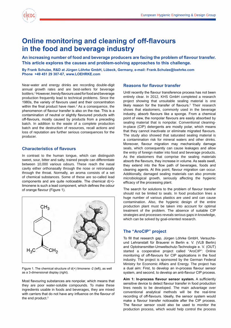
Characteristics of flavoursIn contrast to the human tongue, which can distinguish sweet, sour, bitter and salty, trained people can differentiate between 10,000 various odours. These reach the nasal cavity either orthonasally through the nose or retronasally through the throat. Normally, an aroma consists of a set of chemical substances. Some of these are so-called lead components and are quite noticeable. The chemical d(+)-limonene is such a lead component, which defines the odour of orange flavour (Figure 1).
Figure 1. The chemical structure of d(+) limonene -2 (left), as well as a 3-dimensional display (right).
Most flavouring substances are nonpolar, which means that they are poor water-soluble compounds. To make these ingredients usable in foods and beverages, they are mixed with carriers that do not have any influence on the flavour of the end product.3
Reasons for flavour transferUntil recently the flavour transference process has not been entirely clear. In 2012, KHS GmbH completed a research project showing that unsuitable sealing material is one likely reason for the transfer of flavours.2 Their research shows that elastomers, commonly used in the beverage industry, absorb flavours like a sponge. From a chemical point of view, the nonpolar flavours are easily absorbed by sealing material that is nonpolar. Conventional cleaning-in-place (CIP) detergents are mostly polar, which means that they cannot inactivate or eliminate migrated flavours. The study also showed that saturated sealing material is a contamination risk for mineral waters and other drinks. Moreover, flavour migration may mechanically damage seals, which consequently can cause leakages and allow the entry of foreign matter into food and beverage products. As the elastomers that comprise the sealing materials absorb the flavours, they increase in volume. As seals swell, they extend into the flow path of beverages, foods and cleaning agents. At this point, flavour migration can occur. Additionally, damaged sealing materials can also promote microbiological growth, seriously affecting the hygienic efficacy of the processing plant.
The search for solutions to the problem of flavour transfer should not be limited to seals. In food production lines a huge number of various plastics are used and can cause contamination. Also, the hygienic design of the entire production plant must be taken into account for optimal treatment of the problem. The absence of suitable CIP strategies and processes reveals serious gaps in knowledge, which can be solved by goal-oriented research.
The “AroCIP” projectTo fill that research gap, Jürgen Löhrke GmbH, Versuchs- und Lehranstalt für Brauerei in Berlin e. V. (VLB Berlin) and Optotransmitter-Umweltschutz-Technologie e. V. (OUT) started a cooperative project called “AroCIP”: Online monitoring of off-flavours for CIP applications in the food industry. The project is sponsored by the German Federal Ministry for Economic Affairs and Energy. The project has a dual aim: First, to develop an in-process flavour sensor system, and second, to develop an anti-flavour CIP process.
Aim 1: In-process flavour sensor system. A sufficiently sensitive device to detect flavour transfer in food production lines needs to be developed. The main advantage over conventional analytical methods will be the real-time recording of off-flavours. Ideally, the sensor system would make a flavour transfer noticeable after the CIP process. The flavour sensor could also be used to monitor the production process, which would help control the process
Online monitoring and cleaning of off-flavours in the food and beverage industry 19
itself and allow operators to intervene promptly as problems are detected. Manual and error-prone sampling, as well as time-consuming intermediate examinations by sensory panels, would no longer be needed.
Requirements for the flavour sensor system under development are high and cannot be fulfilled by state-of-the-art technology. On the one hand, the sensor must identify lead components within very low concentrations (i. e. in parts-per-million and parts-per-trillion ranges). On the other hand, the sensor must be rugged for industrial applications.
Aim 2: Anti-flavour CIP process. Existing cleaning systems and agents are not suitable to remove traces of flavours from food production lines. Therefore, the second aim of the AroCIP project is the development of new CIP applications to target the deodorisation of filling lines. In searching for effective cleaning agents, temperatures and concentrations, the resistance of used materials must be taken into account. Further, part of the current research is to develop avoidance strategies. If flavourings are not sticking to production lines, there is no need for expensive cleaning. It is vital to find materials that are resistant to flavours, and at the same time, fulfil the high demands of food safety and industrial suitability.
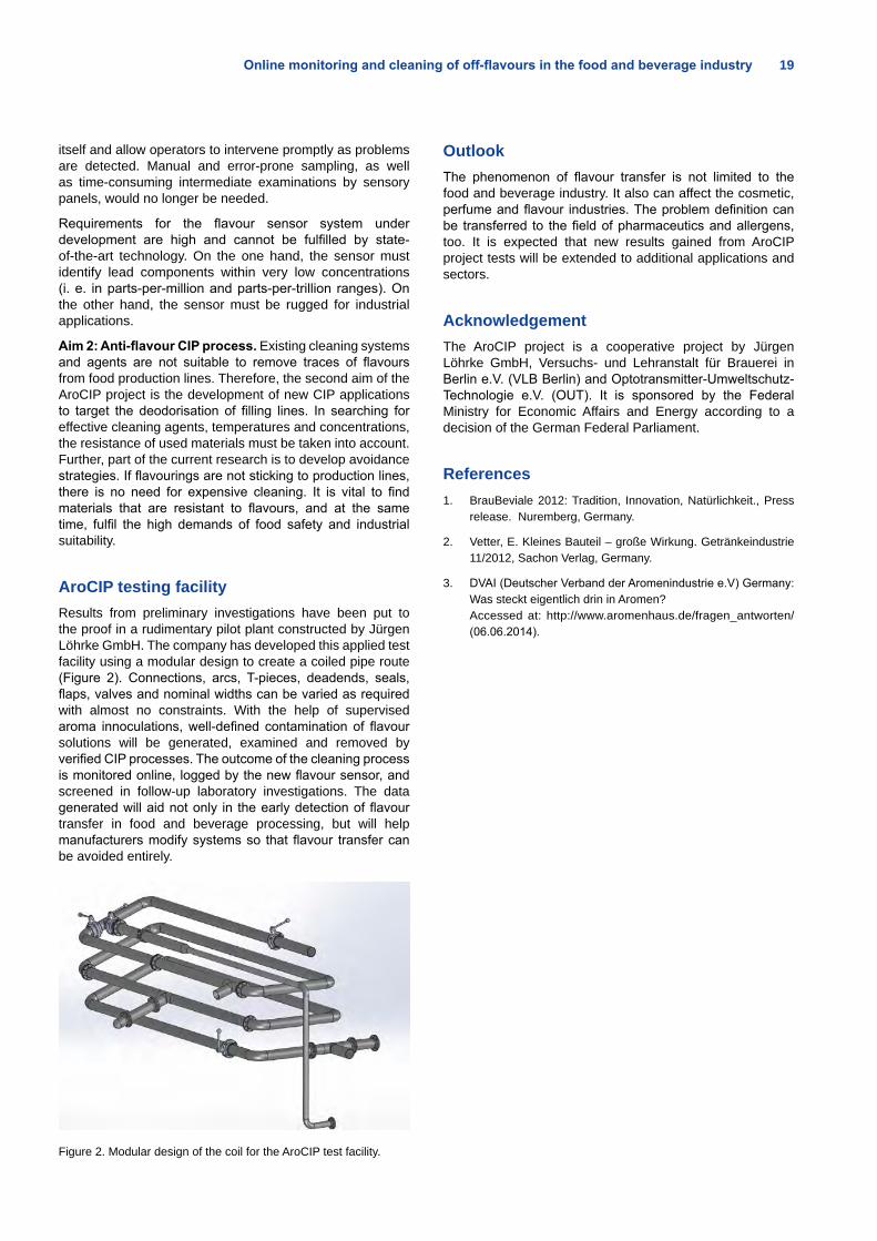
AroCIP testing facilityResults from preliminary investigations have been put to the proof in a rudimentary pilot plant constructed by Jürgen Löhrke GmbH. The company has developed this applied test facility using a modular design to create a coiled pipe route (Figure 2). Connections, arcs, T-pieces, deadends, seals, flaps, valves and nominal widths can be varied as required with almost no constraints. With the help of supervised aroma innoculations, well-defined contamination of flavour solutions will be generated, examined and removed by verified CIP processes. The outcome of the cleaning process is monitored online, logged by the new flavour sensor, and screened in follow-up laboratory investigations. The data generated will aid not only in the early detection of flavour transfer in food and beverage processing, but will help manufacturers modify systems so that flavour transfer can be avoided entirely.
Figure 2. Modular design of the coil for the AroCIP test facility.
OutlookThe phenomenon of flavour transfer is not limited to the food and beverage industry. It also can affect the cosmetic, perfume and flavour industries. The problem definition can be transferred to the field of pharmaceutics and allergens, too. It is expected that new results gained from AroCIP project tests will be extended to additional applications and sectors.
AcknowledgementThe AroCIP project is a cooperative project by Jürgen Löhrke GmbH, Versuchs- und Lehranstalt für Brauerei in Berlin e.V. (VLB Berlin) and Optotransmitter-Umweltschutz-Technologie e.V. (OUT). It is sponsored by the Federal Ministry for Economic Affairs and Energy according to a decision of the German Federal Parliament.
References1. BrauBeviale 2012: Tradition, Innovation, Natürlichkeit., Press
release. Nuremberg, Germany.
2. Vetter, E. Kleines Bauteil – große Wirkung. Getränkeindustrie 11/2012, Sachon Verlag, Germany.
3. DVAI (Deutscher Verband der Aromenindustrie e.V) Germany: Was steckt eigentlich drin in Aromen? Accessed at: http://www.aromenhaus.de/fragen_antworten/ (06.06.2014).
European Hygienic Engineering & Design Group
A method and apparatus for foam removal in aseptic environmentsPackaging machines produce thousands of sealed liquid containers on an hourly basis by forming, filling and sealing the containers. However, when containers are filled with products such as milk, protein drinks and fruit juices, foam can form above the liquid level. In order to improve sealing efficiency, the foam has to be removed before closing the container. In this article, an ultrasonic foam removal method and apparatus is introduced. The initial goal of this design was to utilise an ultrasonic defoaming method in an aseptic environment.By Viivi Nuottajärvi, Juha Lehtioksa and Mika Peltola, Lamican Oy, P.O. Box 28, Valkeakoski, Finland, e-mail: [email protected]
Introduction When containers are filled with foaming products, foam can form above the liquid level. During the aseptic filling process, the foam has to be removed inside the aseptic chamber before closing the container. The foam removal improves the quality of the seam.
Methods and devices exist for removing the foam above the liquid level. Foam can be removed, for example, by a suction pipe that removes the foam from the level of a liquid by sucking it into a tank. Alternatively, the foam can be removed by an elimination method and apparatus, wherein the foam bubbles are collapsed by the application of high frequency wave radiation. This approach was introduced by Erwin and Jagenberg (1981). In their solution, individual sonotrodes are distributed over the underside of an aluminium block in such a way that the cross-sectional area of a container is approximately covered.
In this article a de-foaming apparatus and method to be used in specific aseptic packaging machines is introduced. The method provides significant advantages to prior art; for example, foam can be removed in aseptic chambers by effective apparatus with the reduced risk of contaminating microorganisms. In addition, with this method several containers can be defoamed at the same time. There also may be two or more ultrasonic defoaming apparatuses in parallel inside an aseptic chamber of a packaging machine. Moreover, the ultrasonic defoaming apparatus can be effectively cleaned and sterilised.
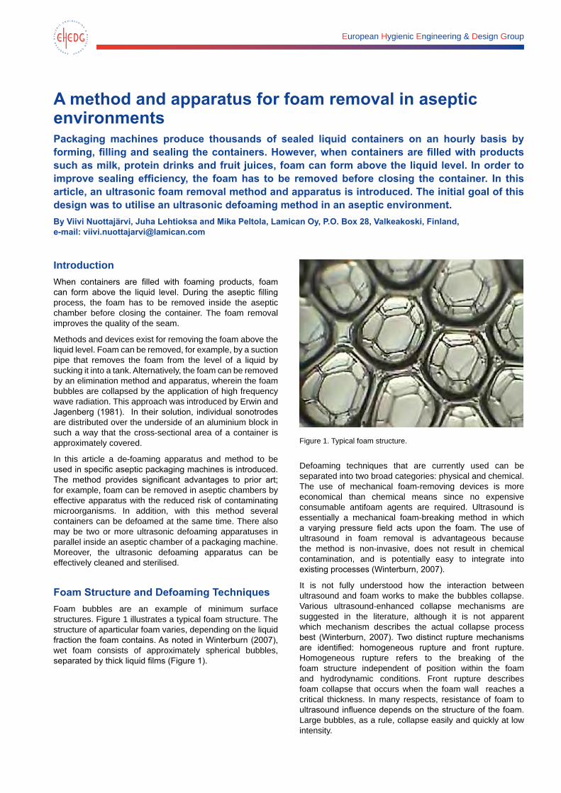
Foam Structure and Defoaming TechniquesFoam bubbles are an example of minimum surface structures. Figure 1 illustrates a typical foam structure. The structure of aparticular foam varies, depending on the liquid fraction the foam contains. As noted in Winterburn (2007), wet foam consists of approximately spherical bubbles, separated by thick liquid films (Figure 1).
Figure 1. Typical foam structure.
Defoaming techniques that are currently used can be separated into two broad categories: physical and chemical. The use of mechanical foam-removing devices is more economical than chemical means since no expensive consumable antifoam agents are required. Ultrasound is essentially a mechanical foam-breaking method in which a varying pressure field acts upon the foam. The use of ultrasound in foam removal is advantageous because the method is non-invasive, does not result in chemical contamination, and is potentially easy to integrate into existing processes (Winterburn, 2007).
It is not fully understood how the interaction between ultrasound and foam works to make the bubbles collapse. Various ultrasound-enhanced collapse mechanisms are suggested in the literature, although it is not apparent which mechanism describes the actual collapse process best (Winterburn, 2007). Two distinct rupture mechanisms are identified: homogeneous rupture and front rupture. Homogeneous rupture refers to the breaking of the foam structure independent of position within the foam and hydrodynamic conditions. Front rupture describes foam collapse that occurs when the foam wall reaches a critical thickness. In many respects, resistance of foam to ultrasound influence depends on the structure of the foam. Large bubbles, as a rule, collapse easily and quickly at low intensity.
A method and apparatus for foam removal in aseptic environments 21
Foams consisting of fine bubbles demand a higher intensity for foam removal. The structure of foam defines not only effective intensity of a sound wave, but also its optimum frequency. For collapsing fine bubbles, utilisation of high frequency sound waves is recommended (Khmelev et al., 2007).
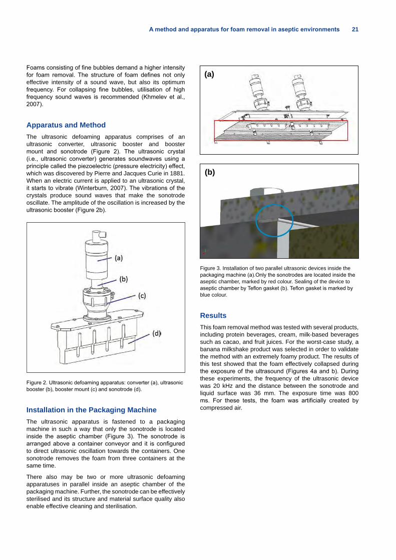
Apparatus and MethodThe ultrasonic defoaming apparatus comprises of an ultrasonic converter, ultrasonic booster and booster mount and sonotrode (Figure 2). The ultrasonic crystal (i.e., ultrasonic converter) generates soundwaves using a principle called the piezoelectric (pressure electricity) effect, which was discovered by Pierre and Jacques Curie in 1881. When an electric current is applied to an ultrasonic crystal, it starts to vibrate (Winterburn, 2007). The vibrations of the crystals produce sound waves that make the sonotrode oscillate. The amplitude of the oscillation is increased by the ultrasonic booster (Figure 2b).
Figure 2. Ultrasonic defoaming apparatus: converter (a), ultrasonic booster (b), booster mount (c) and sonotrode (d).
Installation in the Packaging MachineThe ultrasonic apparatus is fastened to a packaging machine in such a way that only the sonotrode is located inside the aseptic chamber (Figure 3). The sonotrode is arranged above a container conveyor and it is configured to direct ultrasonic oscillation towards the containers. One sonotrode removes the foam from three containers at the same time.
There also may be two or more ultrasonic defoaming apparatuses in parallel inside an aseptic chamber of the packaging machine. Further, the sonotrode can be effectively sterilised and its structure and material surface quality also enable effective cleaning and sterilisation.
(a)
(b)
Figure 3. Installation of two parallel ultrasonic devices inside the packaging machine (a).Only the sonotrodes are located inside the aseptic chamber, marked by red colour. Sealing of the device to aseptic chamber by Teflon gasket (b). Teflon gasket is marked by blue colour.
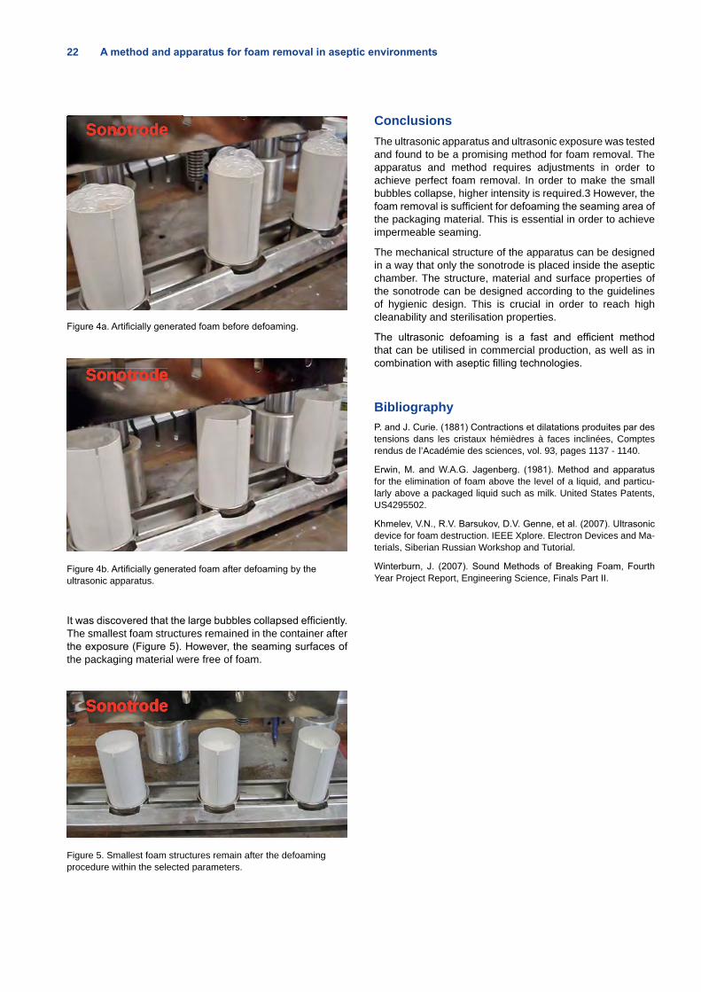
ResultsThis foam removal method was tested with several products, including protein beverages, cream, milk-based beverages such as cacao, and fruit juices. For the worst-case study, a banana milkshake product was selected in order to validate the method with an extremely foamy product. The results of this test showed that the foam effectively collapsed during the exposure of the ultrasound (Figures 4a and b). During these experiments, the frequency of the ultrasonic device was 20 kHz and the distance between the sonotrode and liquid surface was 36 mm. The exposure time was 800 ms. For these tests, the foam was artificially created by compressed air.
22 A method and apparatus for foam removal in aseptic environments
Sonotrode
Figure 4a. Artificially generated foam before defoaming.
SonotrodeSonotrodeSonotrodeSonotrodeSonotrodeSonotrodeSonotrodeSonotrodeSonotrodeSonotrode
Figure 4b. Artificially generated foam after defoaming by the ultrasonic apparatus.
It was discovered that the large bubbles collapsed efficiently. The smallest foam structures remained in the container after the exposure (Figure 5). However, the seaming surfaces of the packaging material were free of foam.
SonotrodeSonotrodeSonotrodeSonotrodeSonotrodeSonotrodeSonotrodeSonotrodeSonotrodeSonotrode
Figure 5. Smallest foam structures remain after the defoaming procedure within the selected parameters.
ConclusionsThe ultrasonic apparatus and ultrasonic exposure was tested and found to be a promising method for foam removal. The apparatus and method requires adjustments in order to achieve perfect foam removal. In order to make the small bubbles collapse, higher intensity is required.3 However, the foam removal is sufficient for defoaming the seaming area of the packaging material. This is essential in order to achieve impermeable seaming.
The mechanical structure of the apparatus can be designed in a way that only the sonotrode is placed inside the aseptic chamber. The structure, material and surface properties of the sonotrode can be designed according to the guidelines of hygienic design. This is crucial in order to reach high cleanability and sterilisation properties.
The ultrasonic defoaming is a fast and efficient method that can be utilised in commercial production, as well as in combination with aseptic filling technologies.
BibliographyP. and J. Curie. (1881) Contractions et dilatations produites par des tensions dans les cristaux hémièdres à faces inclinées, Comptes rendus de l’Académie des sciences, vol. 93, pages 1137 - 1140.
Erwin, M. and W.A.G. Jagenberg. (1981). Method and apparatus for the elimination of foam above the level of a liquid, and particu-larly above a packaged liquid such as milk. United States Patents, US4295502.
Khmelev, V.N., R.V. Barsukov, D.V. Genne, et al. (2007). Ultrasonic device for foam destruction. IEEE Xplore. Electron Devices and Ma-terials, Siberian Russian Workshop and Tutorial.
Winterburn, J. (2007). Sound Methods of Breaking Foam, Fourth Year Project Report, Engineering Science, Finals Part II.
ACO is committed to ultimate hygienic performance
We designs solutions with cost efficiency in mind but with absolutely no compromise in terms of food safety.
We apply the design principles reserved for food contact equipment on our drainage systems to deliver fully hygienic solutions. Our complete portfolio allows us to control water as it passes along the system to ensure it can be ecologically and economically reused in a viable way.
Learn more at: aco-foodprocessingdrainage.com
Drainage systems for the Food & Beverage Industry
European Hygienic Engineering & Design Group
Wanted: Ideal pharmaceutical material Freudenberg Sealing Technologies has carried out an extractables study of various ethylene-propylene diene monomer (EPDM) compounds to identify extractable ingredients in elastomer compounds. By Julia Eckstein, Application Consultant, Freudenberg Process Seals GmbH & Co. KG; Germany, e-mail: [email protected],
Theresa Miller, Physical Testing, Freudenberg Forschungsdienste SE & Co. KG, Germany, e-mail: [email protected]
Elastomers in the food and pharmaceutical industries are subject to especially high purity requirements, extending to the user’s desire to be informed about all recipe components. But this does not provide the evidence and knowledge that people are looking for: namely, what reactions may occur.
That is why food, beverage and pharmaceutical producers have to check packaging materials for possible interactions with the product preparation. For example, they would like to know how an O-ring behaves when it seals an inhalation spray head in contact with the medication. In addition, the effect of seals on the product should be known and kept to a minimum during manufacturing and storage.
While studies involving environmental conditions, such as dealing with integrity of the packaging, storage conditions, and test substances (leachables study), are important, testing for the worst-case scenario is critical. Such testing may include how components perform when exposed to increased temperatures and solvent strengths (i. e., an extractables study). Aside from quantification, it is especially important to identify migrated substances for later toxicological analysis.
Unlike storage situations, manufacturing involves multiples of the medium volume flowing by the seal. The ratio of surface-to-volume – and thus the concentration of potentially leached compounds – is much smaller as a consequence.
The structure of elastomers differ much from that of plastics. Not all ingredients are chemically bonded, so less strength is needed to hold the constituent in the rubber matrix. As a consequence, the material developer have to avoid using these substances as much as possible in order to maintain the performance.
Known harmful ingredients are not part of materials that will come into contact with food and drugs. There are many regulations and laws in place to minimise noxious substances in all kind of products. Even so, some technical goods come with inadvertent impurities. The policy of a good sealing manufacturer is to use only the purest of raw materials available.
The interaction between the seal material or the soluble ingredient of the elastomer compound and the active ingredient cannot be eliminated. But the change of the pharmaceutical or food product can be minimised to ensure that there is no impairment of its quality.
If food, beverage or pharmaceutical manufacturers are aware of the interactions between the seals in valves or other equipment components and the products inside them, potential contamination can be evaluated at the manufacturing stage with the goal of preventing it, if possible. This safeguards the process, ensures the purity that the products require, and protects public health.
Unobjectionable materials for the production of foods and medicine Sealing materials must meet special requirements. First, the type and quantity of the recipe components and auxiliary agents used in the compounds during manufacturing must meet the requirements of the US Food and Drug Administration (FDA 21 CFR 177.2600) and the Federal Institute for Risk Assessment (BfR) recommendations. In addition, proof of bio-compatibility under the United States Pharmacopeia (USP) must be presented.
A European provision, EU Regulation 1935/2004, describes the general requirements for materials and articles that are designated to come into contact with foods. Specific individual measures to ascertain compliance with the requirements are described for plastics in EU Regulation 10/201, which specifies various test media as food simulants. The specific migration values must be set in relation to a certain size or quantity of the food. The difficulty is that there are no exact guidelines for elastomers. As a result, Freudenberg Sealing Technologies has investigated its own elastomer compounds for the food, beverage and pharmaceutical industry with regard to their migration behavior and established a benchmark using comparable compounds from relevant competitors.
In addition, an extractables study was carried out on O-rings with various media at high temperatures. Where defined, the studies adhered to the specifications of USP 381 and FDA provisions (21 CFR 177.2600). In addition to three Freudenberg materials, there were five other ethylene-propylene diene monomer (EPDM) materials that were analysed. All materials studied are rated USP Class VI and are approved for use in the pharmaceutical industry. White, mineral-filled elastomer compounds were involved in the cases of three of the investigated materials. The remainder were black, and thus were likely carbon-black-filled compounds. Their hardness varied between 70 and 85 Shore A (Table 1).
Wanted: Ideal pharmaceutical material 25
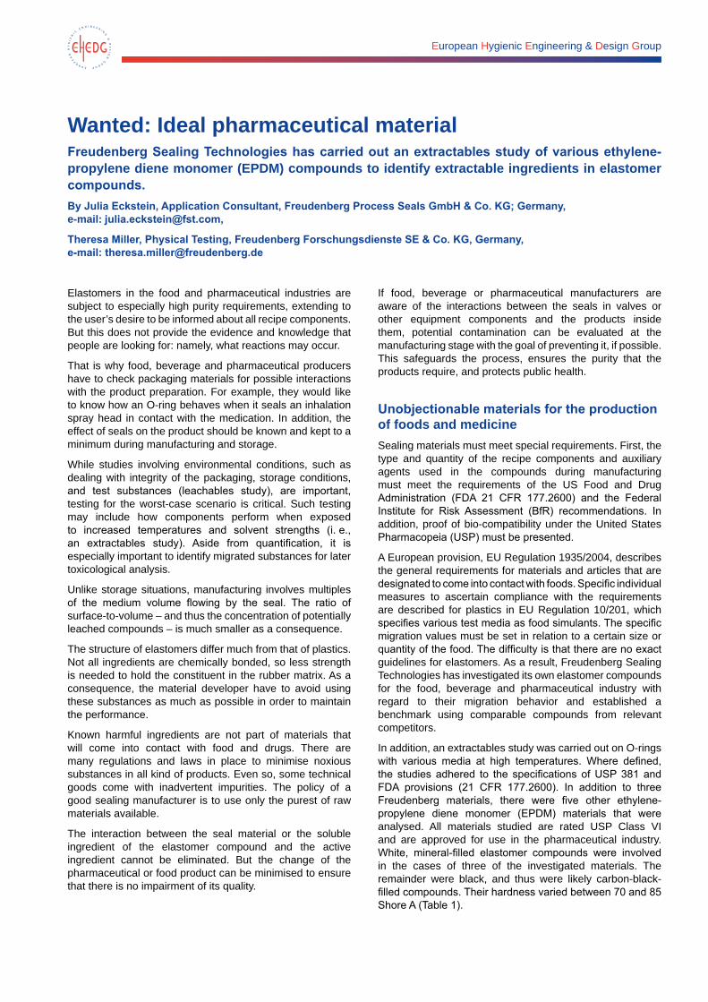
Table 1. Extractables study, EPDM materials.
Name Color Hardness
EPDM 291 (Freudenberg) Black 70
EPDM 292 (Freudenberg) Black 85
Producer 1 Black 70
Producer 2 Black 80
Producer 3 Black 70
EPDM 253815 (Freudenberg) White 70
Producer 4 White 70
Producer 5 White 70
The whole uncutted O-rings were leached without prior cleaning in a low proportion of elastomer to extraction agent for 24 hours in reflux to keep the conditions as harsh as possible for the evaluation. Due to the different sizes of the samples, the ratio of surface-to-media volume was kept constant. That means the results for various rings could be compared. The following media were used in accordance with the recommendations of the FDA, the BfR and other relevant sources:
• ethanol
• n-hexane
• phosphate buffer pH 2.5 (apply with potassium dihydrogen phosphate solution, formulated with phosphoric acid
• phosphate buffer pH 9.5 (applied with potassium dihydrogen phosphate solution, formulated with caustic potash)
In addition to a gravimetric evaluation, the extractable portions were analysed with gas chromatography/mass spectrometry (GC/MS). Here, the vaporised extracts are dissolved in the appropriate extraction solution or with methanol in the case of buffer solutions and sprayed into the gas stream. Chromatograms in the same scale size are plotted. The amount of the detected material is determined with an analysis of the total surface and evaluated by identifying the main compounds found.
In addition, total organic carbon (TOC) studies have been undertaken on the extraction solutions for phosphate buffers to measure organic impurities. The quantity of TOC found in the fluid samples has been quantitatively evaluated in proportions comparable to the elastomer sample.
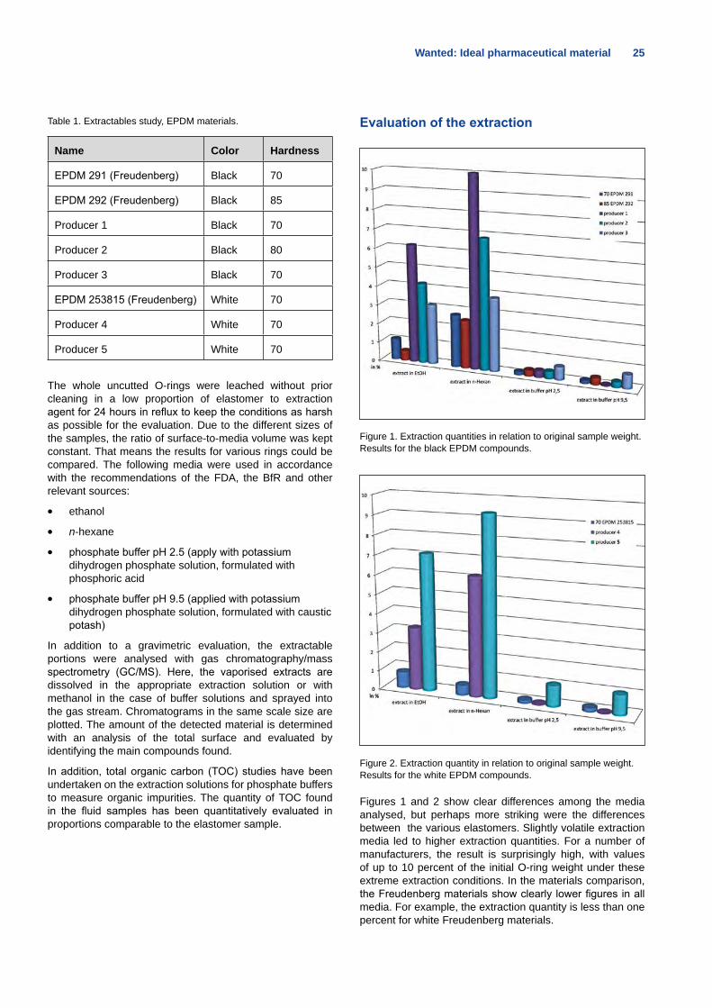
Evaluation of the extraction
Figure 1. Extraction quantities in relation to original sample weight. Results for the black EPDM compounds.
Figure 2. Extraction quantity in relation to original sample weight. Results for the white EPDM compounds.
Figures 1 and 2 show clear differences among the media analysed, but perhaps more striking were the differences between the various elastomers. Slightly volatile extraction media led to higher extraction quantities. For a number of manufacturers, the result is surprisingly high, with values of up to 10 percent of the initial O-ring weight under these extreme extraction conditions. In the materials comparison, the Freudenberg materials show clearly lower figures in all media. For example, the extraction quantity is less than one percent for white Freudenberg materials.
26 Wanted: Ideal pharmaceutical material
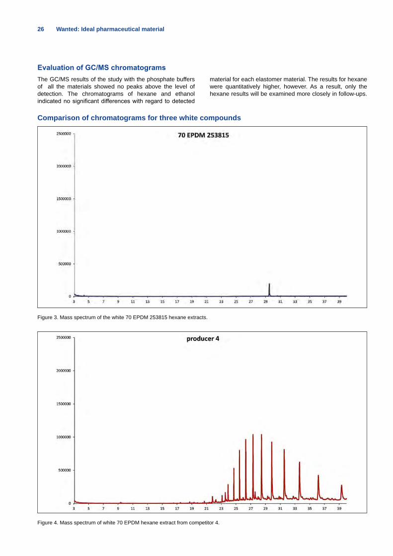
Evaluation of GC/MS chromatogramsThe GC/MS results of the study with the phosphate buffers of all the materials showed no peaks above the level of detection. The chromatograms of hexane and ethanol indicated no significant differences with regard to detected
material for each elastomer material. The results for hexane were quantitatively higher, however. As a result, only the hexane results will be examined more closely in follow-ups.
Comparison of chromatograms for three white compounds
Figure 3. Mass spectrum of the white 70 EPDM 253815 hexane extracts.
Figure 4. Mass spectrum of white 70 EPDM hexane extract from competitor 4.
INSPIRING ANSWERS | FLOWave
„Who s to say that therehave to be sensor elementsin the measuring tube of aflowmeter?“
Using the patented SAW technologyour new FLOWave flowmeters need nosensor elements in the measuring tube.So they provide reliable results even inchallenging hygienic applications.
www.inspiring-answers.com
28 Wanted: Ideal pharmaceutical material
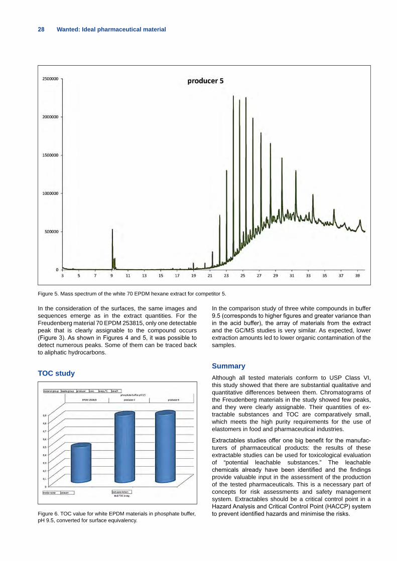
Figure 5. Mass spectrum of the white 70 EPDM hexane extract for competitor 5.
In the consideration of the surfaces, the same images and sequences emerge as in the extract quantities. For the Freudenberg material 70 EPDM 253815, only one detectable peak that is clearly assignable to the compound occurs (Figure 3). As shown in Figures 4 and 5, it was possible to detect numerous peaks. Some of them can be traced back to aliphatic hydrocarbons.
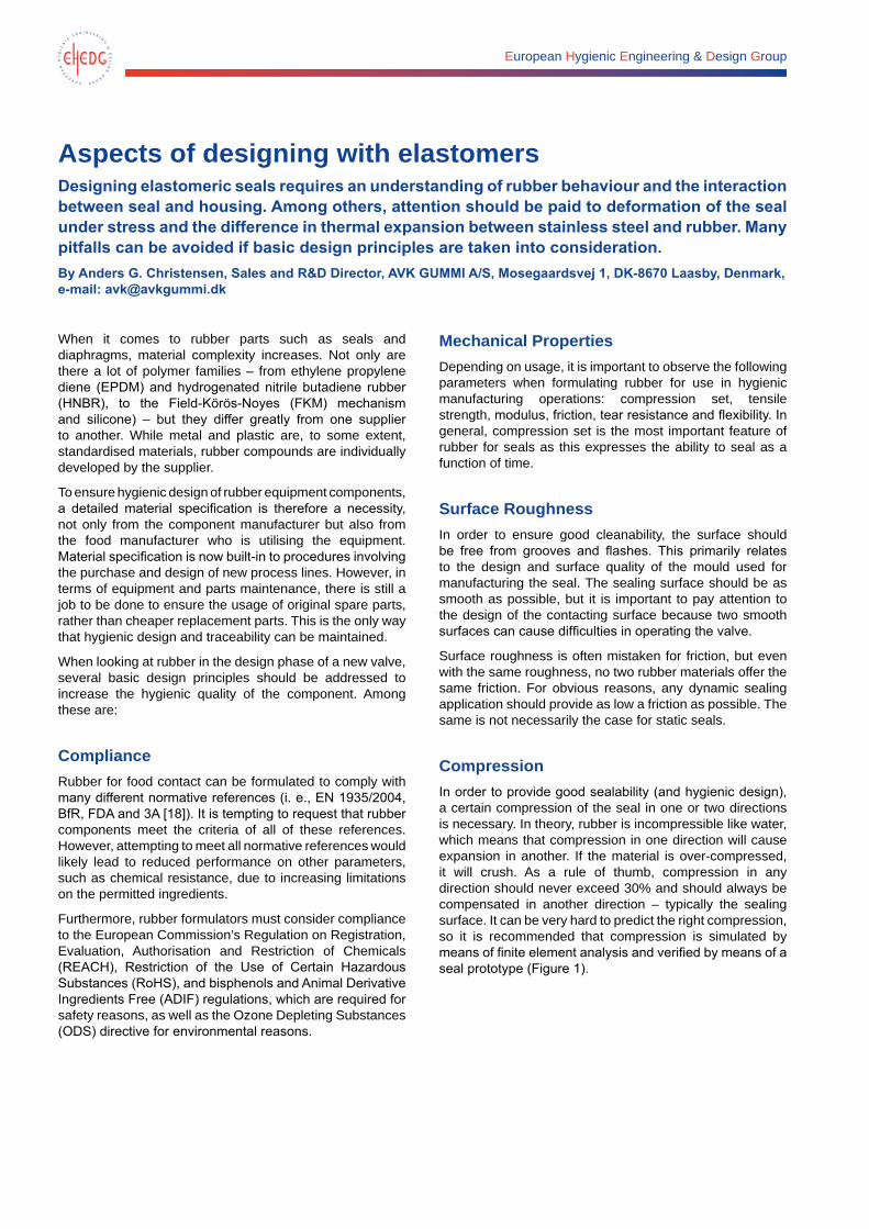
TOC study
Figure 6. TOC value for white EPDM materials in phosphate buffer, pH 9.5, converted for surface equivalency.
In the comparison study of three white compounds in buffer 9.5 (corresponds to higher figures and greater variance than in the acid buffer), the array of materials from the extract and the GC/MS studies is very similar. As expected, lower extraction amounts led to lower organic contamination of the samples.
SummaryAlthough all tested materials conform to USP Class VI, this study showed that there are substantial qualitative and quantitative differences between them. Chromatograms of the Freudenberg materials in the study showed few peaks, and they were clearly assignable. Their quantities of ex-tractable substances and TOC are comparatively small, which meets the high purity requirements for the use of elastomers in food and pharmaceutical industries.
Extractables studies offer one big benefit for the manufac-turers of pharmaceutical products: the results of these extractable studies can be used for toxicological evaluation of “potential leachable substances.” The leachable chemicals already have been identified and the findings provide valuable input in the assessment of the production of the tested pharmaceuticals. This is a necessary part of concepts for risk assessments and safety management system. Extractables should be a critical control point in a Hazard Analysis and Critical Control Point (HACCP) system to prevent identified hazards and minimise the risks.
European Hygienic Engineering & Design Group
Aspects of designing with elastomersDesigning elastomeric seals requires an understanding of rubber behaviour and the interaction between seal and housing. Among others, attention should be paid to deformation of the seal under stress and the difference in thermal expansion between stainless steel and rubber. Many pitfalls can be avoided if basic design principles are taken into consideration.By Anders G. Christensen, Sales and R&D Director, AVK GUMMI A/S, Mosegaardsvej 1, DK-8670 Laasby, Denmark, e-mail: [email protected]
When it comes to rubber parts such as seals and diaphragms, material complexity increases. Not only are there a lot of polymer families – from ethylene propylene diene (EPDM) and hydrogenated nitrile butadiene rubber (HNBR), to the Field-Körös-Noyes (FKM) mechanism and silicone) – but they differ greatly from one supplier to another. While metal and plastic are, to some extent, standardised materials, rubber compounds are individually developed by the supplier.
To ensure hygienic design of rubber equipment components, a detailed material specification is therefore a necessity, not only from the component manufacturer but also from the food manufacturer who is utilising the equipment. Material specification is now built-in to procedures involving the purchase and design of new process lines. However, in terms of equipment and parts maintenance, there is still a job to be done to ensure the usage of original spare parts, rather than cheaper replacement parts. This is the only way that hygienic design and traceability can be maintained.
When looking at rubber in the design phase of a new valve, several basic design principles should be addressed to increase the hygienic quality of the component. Among these are:
ComplianceRubber for food contact can be formulated to comply with many different normative references (i. e., EN 1935/2004, BfR, FDA and 3A [18]). It is tempting to request that rubber components meet the criteria of all of these references. However, attempting to meet all normative references would likely lead to reduced performance on other parameters, such as chemical resistance, due to increasing limitations on the permitted ingredients.
Furthermore, rubber formulators must consider compliance to the European Commission’s Regulation on Registration, Evaluation, Authorisation and Restriction of Chemicals (REACH), Restriction of the Use of Certain Hazardous Substances (RoHS), and bisphenols and Animal Derivative Ingredients Free (ADIF) regulations, which are required for safety reasons, as well as the Ozone Depleting Substances (ODS) directive for environmental reasons.
Mechanical PropertiesDepending on usage, it is important to observe the following parameters when formulating rubber for use in hygienic manufacturing operations: compression set, tensile strength, modulus, friction, tear resistance and flexibility. In general, compression set is the most important feature of rubber for seals as this expresses the ability to seal as a function of time.
Surface RoughnessIn order to ensure good cleanability, the surface should be free from grooves and flashes. This primarily relates to the design and surface quality of the mould used for manufacturing the seal. The sealing surface should be as smooth as possible, but it is important to pay attention to the design of the contacting surface because two smooth surfaces can cause difficulties in operating the valve.
Surface roughness is often mistaken for friction, but even with the same roughness, no two rubber materials offer the same friction. For obvious reasons, any dynamic sealing application should provide as low a friction as possible. The same is not necessarily the case for static seals.
Compression In order to provide good sealability (and hygienic design), a certain compression of the seal in one or two directions is necessary. In theory, rubber is incompressible like water, which means that compression in one direction will cause expansion in another. If the material is over-compressed, it will crush. As a rule of thumb, compression in any direction should never exceed 30% and should always be compensated in another direction – typically the sealing surface. It can be very hard to predict the right compression, so it is recommended that compression is simulated by means of finite element analysis and verified by means of a seal prototype (Figure 1).
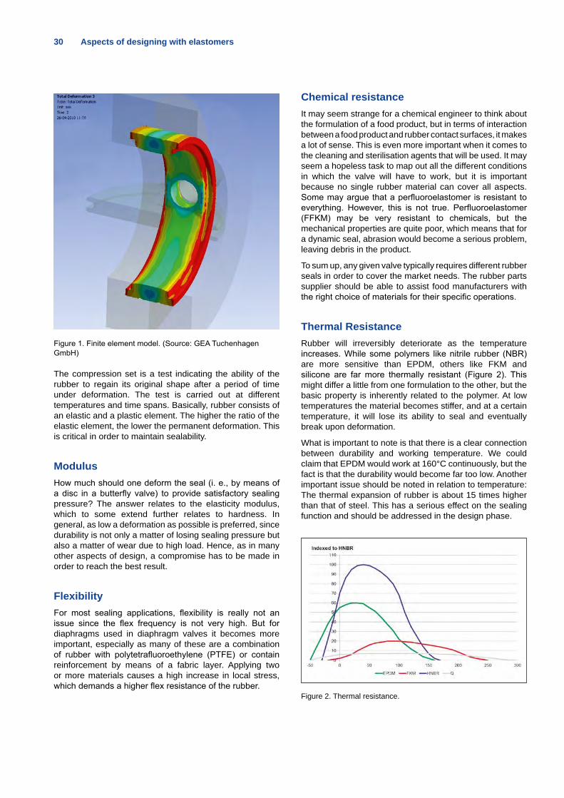
30 Aspects of designing with elastomers
Figure 1. Finite element model. (Source: GEA Tuchenhagen GmbH)
The compression set is a test indicating the ability of the rubber to regain its original shape after a period of time under deformation. The test is carried out at different temperatures and time spans. Basically, rubber consists of an elastic and a plastic element. The higher the ratio of the elastic element, the lower the permanent deformation. This is critical in order to maintain sealability.
ModulusHow much should one deform the seal (i. e., by means of a disc in a butterfly valve) to provide satisfactory sealing pressure? The answer relates to the elasticity modulus, which to some extend further relates to hardness. In general, as low a deformation as possible is preferred, since durability is not only a matter of losing sealing pressure but also a matter of wear due to high load. Hence, as in many other aspects of design, a compromise has to be made in order to reach the best result.
FlexibilityFor most sealing applications, flexibility is really not an issue since the flex frequency is not very high. But for diaphragms used in diaphragm valves it becomes more important, especially as many of these are a combination of rubber with polytetrafluoroethylene (PTFE) or contain reinforcement by means of a fabric layer. Applying two or more materials causes a high increase in local stress, which demands a higher flex resistance of the rubber.
Chemical resistanceIt may seem strange for a chemical engineer to think about the formulation of a food product, but in terms of interaction between a food product and rubber contact surfaces, it makes a lot of sense. This is even more important when it comes to the cleaning and sterilisation agents that will be used. It may seem a hopeless task to map out all the different conditions in which the valve will have to work, but it is important because no single rubber material can cover all aspects. Some may argue that a perfluoroelastomer is resistant to everything. However, this is not true. Perfluoroelastomer (FFKM) may be very resistant to chemicals, but the mechanical properties are quite poor, which means that for a dynamic seal, abrasion would become a serious problem, leaving debris in the product.
To sum up, any given valve typically requires different rubber seals in order to cover the market needs. The rubber parts supplier should be able to assist food manufacturers with the right choice of materials for their specific operations.
Thermal ResistanceRubber will irreversibly deteriorate as the temperature increases. While some polymers like nitrile rubber (NBR) are more sensitive than EPDM, others like FKM and silicone are far more thermally resistant (Figure 2). This might differ a little from one formulation to the other, but the basic property is inherently related to the polymer. At low temperatures the material becomes stiffer, and at a certain temperature, it will lose its ability to seal and eventually break upon deformation.
What is important to note is that there is a clear connection between durability and working temperature. We could claim that EPDM would work at 160°C continuously, but the fact is that the durability would become far too low. Another important issue should be noted in relation to temperature: The thermal expansion of rubber is about 15 times higher than that of steel. This has a serious effect on the sealing function and should be addressed in the design phase.
Figure 2. Thermal resistance.
Aspects of designing with elastomers 31
DurabilityFinally, durability of the elastomer is a very important aspect in the hygienic design of valves. A poorly designed valve will cause very rapid leakage or destruction of the seal. Needless to say, there is a difference if one is manufacturing hot marmalade or cold milk, so the environment in which the valve is used must be considered during the design phase.
Thus, only when all independent variables have been fixed and a comparative test has been carried out is it possible to predict the durability. Many valve manufacturers have consequently built test equipment in order to verify the seal lifetime under near real-world conditions.
HIGH PERFORMANCERUBBER COMPONENTS
- for food and healthcare applications with high demands on hygienic design and traceability
www.avkgummi.dk
Advertisement
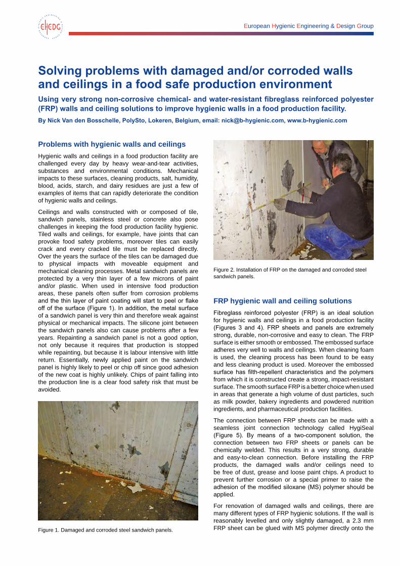
European Hygienic Engineering & Design Group
Solving problems with damaged and/or corroded walls and ceilings in a food safe production environmentUsing very strong non-corrosive chemical- and water-resistant fibreglass reinforced polyester (FRP) walls and ceiling solutions to improve hygienic walls in a food production facility.By Nick Van den Bosschelle, PolySto, Lokeren, Belgium, email: [email protected], www.b-hygienic.com
Problems with hygienic walls and ceilingsHygienic walls and ceilings in a food production facility are challenged every day by heavy wear-and-tear activities, substances and environmental conditions. Mechanical impacts to these surfaces, cleaning products, salt, humidity, blood, acids, starch, and dairy residues are just a few of examples of items that can rapidly deteriorate the condition of hygienic walls and ceilings.
Ceilings and walls constructed with or composed of tile, sandwich panels, stainless steel or concrete also pose challenges in keeping the food production facility hygienic. Tiled walls and ceilings, for example, have joints that can provoke food safety problems, moreover tiles can easily crack and every cracked tile must be replaced directly. Over the years the surface of the tiles can be damaged due to physical impacts with moveable equipment and mechanical cleaning processes. Metal sandwich panels are protected by a very thin layer of a few microns of paint and/or plastic. When used in intensive food production areas, these panels often suffer from corrosion problems and the thin layer of paint coating will start to peel or flake off of the surface (Figure 1). In addition, the metal surface of a sandwich panel is very thin and therefore weak against physical or mechanical impacts. The silicone joint between the sandwich panels also can cause problems after a few years. Repainting a sandwich panel is not a good option, not only because it requires that production is stopped while repainting, but because it is labour intensive with little return. Essentially, newly applied paint on the sandwich panel is highly likely to peel or chip off since good adhesion of the new coat is highly unlikely. Chips of paint falling into the production line is a clear food safety risk that must be avoided.
Figure 1. Damaged and corroded steel sandwich panels.
Figure 2. Installation of FRP on the damaged and corroded steel sandwich panels.
FRP hygienic wall and ceiling solutionsFibreglass reinforced polyester (FRP) is an ideal solution for hygienic walls and ceilings in a food production facility (Figures 3 and 4). FRP sheets and panels are extremely strong, durable, non-corrosive and easy to clean. The FRP surface is either smooth or embossed. The embossed surface adheres very well to walls and ceilings. When cleaning foam is used, the cleaning process has been found to be easy and less cleaning product is used. Moreover the embossed surface has filth-repellent characteristics and the polymers from which it is constructed create a strong, impact-resistant surface. The smooth surface FRP is a better choice when used in areas that generate a high volume of dust particles, such as milk powder, bakery ingredients and powdered nutrition ingredients, and pharmaceutical production facilities.
The connection between FRP sheets can be made with a seamless joint connection technology called HygiSeal (Figure 5). By means of a two-component solution, the connection between two FRP sheets or panels can be chemically welded. This results in a very strong, durable and easy-to-clean connection. Before installing the FRP products, the damaged walls and/or ceilings need to be free of dust, grease and loose paint chips. A product to prevent further corrosion or a special primer to raise the adhesion of the modified siloxane (MS) polymer should be applied.
For renovation of damaged walls and ceilings, there are many different types of FRP hygienic solutions. If the wall is reasonably levelled and only slightly damaged, a 2.3 mm FRP sheet can be glued with MS polymer directly onto the
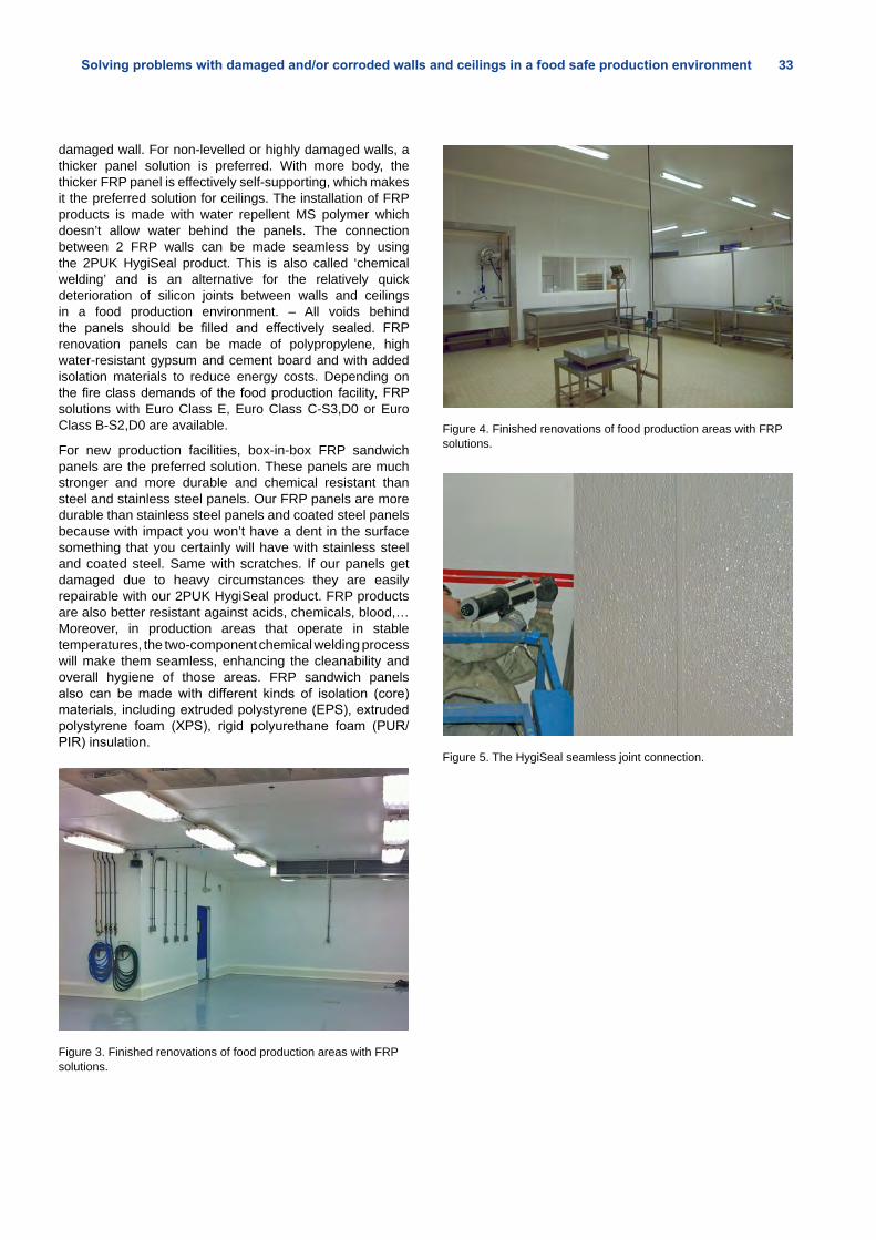
Solving problems with damaged and/or corroded walls and ceilings in a food safe production environment 33
damaged wall. For non-levelled or highly damaged walls, a thicker panel solution is preferred. With more body, the thicker FRP panel is effectively self-supporting, which makes it the preferred solution for ceilings. The installation of FRP products is made with water repellent MS polymer which doesn’t allow water behind the panels. The connection between 2 FRP walls can be made seamless by using the 2PUK HygiSeal product. This is also called ‘chemical welding’ and is an alternative for the relatively quick deterioration of silicon joints between walls and ceilings in a food production environment. – All voids behind the panels should be filled and effectively sealed. FRP renovation panels can be made of polypropylene, high water-resistant gypsum and cement board and with added isolation materials to reduce energy costs. Depending on the fire class demands of the food production facility, FRP solutions with Euro Class E, Euro Class C-S3,D0 or Euro Class B-S2,D0 are available.
For new production facilities, box-in-box FRP sandwich panels are the preferred solution. These panels are much stronger and more durable and chemical resistant than steel and stainless steel panels. Our FRP panels are more durable than stainless steel panels and coated steel panels because with impact you won’t have a dent in the surface something that you certainly will have with stainless steel and coated steel. Same with scratches. If our panels get damaged due to heavy circumstances they are easily repairable with our 2PUK HygiSeal product. FRP products are also better resistant against acids, chemicals, blood,…Moreover, in production areas that operate in stable temperatures, the two-component chemical welding process will make them seamless, enhancing the cleanability and overall hygiene of those areas. FRP sandwich panels also can be made with different kinds of isolation (core) materials, including extruded polystyrene (EPS), extruded polystyrene foam (XPS), rigid polyurethane foam (PUR/PIR) insulation.
Figure 3. Finished renovations of food production areas with FRP solutions.
Figure 4. Finished renovations of food production areas with FRP solutions.
Figure 5. The HygiSeal seamless joint connection.
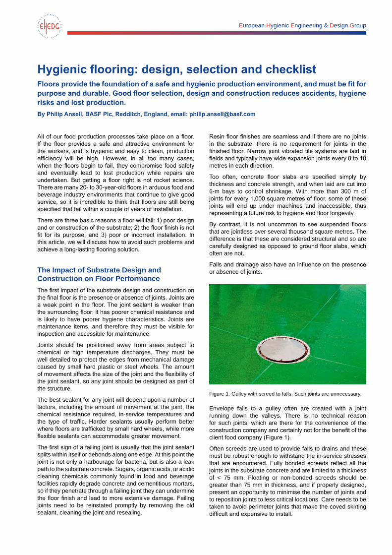
European Hygienic Engineering & Design Group
Hygienic flooring: design, selection and checklistFloors provide the foundation of a safe and hygienic production environment, and must be fit for purpose and durable. Good floor selection, design and construction reduces accidents, hygiene risks and lost production. By Philip Ansell, BASF Plc, Redditch, England, email: [email protected]
All of our food production processes take place on a floor. If the floor provides a safe and attractive environment for the workers, and is hygienic and easy to clean, production efficiency will be high. However, in all too many cases, when the floors begin to fail, they compromise food safety and eventually lead to lost production while repairs are undertaken. But getting a floor right is not rocket science. There are many 20- to 30-year-old floors in arduous food and beverage industry environments that continue to give good service, so it is incredible to think that floors are still being specified that fail within a couple of years of installation.
There are three basic reasons a floor will fail: 1) poor design and or construction of the substrate; 2) the floor finish is not fit for its purpose; and 3) poor or incorrect installation. In this article, we will discuss how to avoid such problems and achieve a long-lasting flooring solution.
The Impact of Substrate Design and Construction on Floor PerformanceThe first impact of the substrate design and construction on the final floor is the presence or absence of joints. Joints are a weak point in the floor. The joint sealant is weaker than the surrounding floor; it has poorer chemical resistance and is likely to have poorer hygiene characteristics. Joints are maintenance items, and therefore they must be visible for inspection and accessible for maintenance.
Joints should be positioned away from areas subject to chemical or high temperature discharges. They must be well detailed to protect the edges from mechanical damage caused by small hard plastic or steel wheels. The amount of movement affects the size of the joint and the flexibility of the joint sealant, so any joint should be designed as part of the structure.
The best sealant for any joint will depend upon a number of factors, including the amount of movement at the joint, the chemical resistance required, in-service temperatures and the type of traffic. Harder sealants usually perform better where floors are trafficked by small hard wheels, while more flexible sealants can accommodate greater movement.
The first sign of a failing joint is usually that the joint sealant splits within itself or debonds along one edge. At this point the joint is not only a harbourage for bacteria, but is also a leak path to the substrate concrete. Sugars, organic acids, or acidic cleaning chemicals commonly found in food and beverage facilities rapidly degrade concrete and cementitious mortars, so if they penetrate through a failing joint they can undermine the floor finish and lead to more extensive damage. Failing joints need to be reinstated promptly by removing the old sealant, cleaning the joint and resealing.
Resin floor finishes are seamless and if there are no joints in the substrate, there is no requirement for joints in the finished floor. Narrow joint vibrated tile systems are laid in fields and typically have wide expansion joints every 8 to 10 metres in each direction.
Too often, concrete floor slabs are specified simply by thickness and concrete strength, and when laid are cut into 6-m bays to control shrinkage. With more than 300 m of joints for every 1,000 square metres of floor, some of these joints will end up under machines and inaccessible, thus representing a future risk to hygiene and floor longevity.
By contrast, it is not uncommon to see suspended floors that are jointless over several thousand square metres. The difference is that these are considered structural and so are carefully designed as opposed to ground floor slabs, which often are not.
Falls and drainage also have an influence on the presence or absence of joints.
Figure 1. Gulley with screed to falls. Such joints are unnecessary.
Envelope falls to a gulley often are created with a joint running down the valleys. There is no technical reason for such joints, which are there for the convenience of the construction company and certainly not for the benefit of the client food company (Figure 1).
Often screeds are used to provide falls to drains and these must be robust enough to withstand the in-service stresses that are encountered. Fully bonded screeds reflect all the joints in the substrate concrete and are limited to a thickness of < 75 mm. Floating or non-bonded screeds should be greater than 75 mm in thickness, and if properly designed, present an opportunity to minimise the number of joints and to reposition joints to less critical locations. Care needs to be taken to avoid perimeter joints that make the coved skirting difficult and expensive to install.
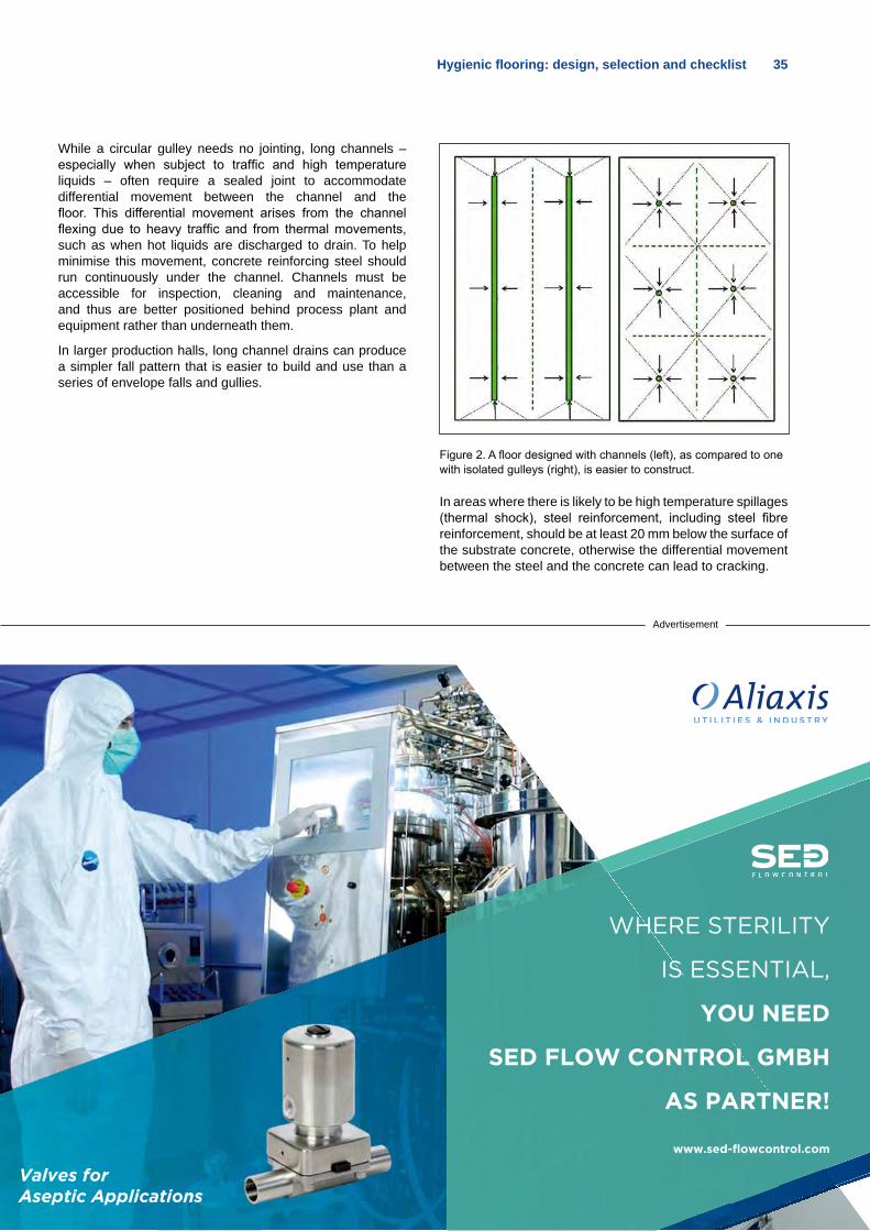
Hygienic flooring: design, selection and checklist 35
While a circular gulley needs no jointing, long channels – especially when subject to traffic and high temperature liquids – often require a sealed joint to accommodate differential movement between the channel and the floor. This differential movement arises from the channel flexing due to heavy traffic and from thermal movements, such as when hot liquids are discharged to drain. To help minimise this movement, concrete reinforcing steel should run continuously under the channel. Channels must be accessible for inspection, cleaning and maintenance, and thus are better positioned behind process plant and equipment rather than underneath them.
In larger production halls, long channel drains can produce a simpler fall pattern that is easier to build and use than a series of envelope falls and gullies.
Figure 2. A floor designed with channels (left), as compared to one with isolated gulleys (right), is easier to construct.
In areas where there is likely to be high temperature spillages (thermal shock), steel reinforcement, including steel fibre reinforcement, should be at least 20 mm below the surface of the substrate concrete, otherwise the differential movement between the steel and the concrete can lead to cracking.
Advertisement
WHERE STERILITY
IS ESSENTIAL,
YOU NEED
SED FLOW CONTROL GMBH
AS PARTNER!
www.sed-flowcontrol.comValves forAseptic Applications
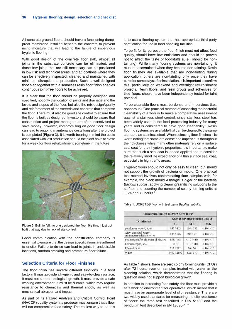
36 Hygienic flooring: design, selection and checklist
All concrete ground floors should have a functioning damp-proof membrane installed beneath the concrete to prevent rising moisture that will lead to the failure of impervious hygienic flooring.
With good design of the concrete floor slab, almost all joints in the substrate concrete can be eliminated, and those few joints that are still necessary can be positioned in low risk and technical areas, and at locations where they can be effectively inspected, cleaned and maintained with minimum disruption to production. Such a well-designed floor slab together with a seamless resin floor finish enables continuous joint-free floors to be achieved.
It is clear that the floor should be properly designed and specified, not only the location of joints and drainage and the levels and slopes of the floor, but also the mix design/quality and reinforcement of the screeds and concrete that comprise the floor. There must also be good site control to ensure that the floor is built as designed. Investors should be aware that construction and project managers are often incentivised to save money; however, compromising on good floor design can lead to ongoing maintenance costs long after the project is completed (Figure 3). It is worth bearing in mind the costs associated with lost production should the plant have to close for a week for floor refurbishment sometime in the future.
Figure 3. Built to fail; no one designed the floor like this, it just got built that way due to lack of site control.
Good communication with the construction company is essential to ensure that the design specifications are adhered to onsite. Failure to do so can lead to joints in undesirable locations, random cracking and premature floor failure.
Selection Criteria for Floor FinishesThe floor finish has several different functions in a food factory. It must provide a hygienic and easy-to-clean surface. It must not support biological growth. It must provide a safe working environment. It must be durable, which may require resistance to chemicals and thermal shock, as well as mechanical abrasion and impact.
As part of its Hazard Analysis and Critical Control Point (HACCP) quality system, a producer must ensure that a floor will not compromise food safety. The easiest way to do this
is to use a flooring system that has appropriate third-party certification for use in food handling facilities.
To be fit for its purpose the floor finish must not affect food quality, should have low emissions and should be proven not to affect the taste of foodstuffs (i. e., should be non-tainting). While many flooring systems are non-tainting, it must be ascertained when they become non-tainting. Resin floor finishes are available that are non-tainting during application; others are non-tainting only once they have cured or some days after installation. It is important to confirm this, particularly on weekend and overnight refurbishment projects. Resin floors, and resin grouts and adhesives for tiled floors, should have been independently tested for taint potential.
To be cleanable floors must be dense and impervious (i.e., nonporous). One practical method of assessing the bacterial cleanability of a floor is to make a comparative assessment against a stainless steel control, since stainless steel has been widely used in the food processing industry for many years and is considered to have good cleanability.1 Resin flooring systems are available that can be cleaned to the same standard as stainless steel. When selecting floor finishes it is worth noting that some are dense and impervious throughout their thickness while many other materials rely on a surface seal coat for their hygienic properties. It is important to make sure that such a seal coat is indeed applied and to consider the relatively short life expectancy of a thin surface seal coat, especially in high traffic areas.
Hygienic floors should not only be easy to clean, but should not support the growth of bacteria or mould. One practical test method involves contaminating floor samples with, for example, the black mould Aspergillus niger or the bacteria Bacillus subtilis, applying cleaning/sanitizing solutions to the surface and counting the number of colony forming units at 1, 24 and 72 hours.2
Table 1. UCRETE® floor with test germ Bacillus subtilis.
As Table 1 shows, there are zero colony forming units (CFUs) after 72 hours, even on samples treated with water as the cleaning solution, which demonstrates that the flooring in question does not support biological growth.
In addition to increasing food safety, the floor must provide a safe working environment for operatives, which means that it must have an appropriate level of slip resistance. There are two widely used standards for measuring the slip resistance of floors: the ramp test described in DIN 51130 and the pendulum test described in EN 13036-4.3,4
Hygienic flooring: design, selection and checklist 37
The food and beverage industry produces myriad types of finished products in a wide range of environments. As product moves from incoming raw materials receipt, through processing and cooking, to packing and dispatch, the requirements for hygiene and slip resistance change. This means that each production facility is likely to require a range of surface finishes. In Germany, the Hauptverband der gewerblichen Berufsgenossenschaften issue guidelines on appropriate levels of slip resistance to DIN 51130 in work environments, which makes a good starting point when considering floor finishes.5
More slip-resistant floors generally have greater surface roughness, so there is often a trade-off between ease of cleaning and slip resistance. The best compromise between these two factors depends on the frequency of cleaning, the type of activities taking place upon the floor, and the rate at which soil builds up on the floor. In principle, the texture needs to be sufficient to provide a safe floor until the next cleaning. Thus, in a given environment, the more frequently you clean the less profile is required. This best compromise will be different in different locations throughout a factory and even within one production hall. It should be noted, however, that modern floor cleaning machines are very effective at cleaning even heavily textured floors and that there are floors available with highly slip-resistant profiles that are cleanable to the same standard as stainless steel.
Durability comes from a combination of physical and chemical properties. Resin floors made with the same type of resin binder can have very different properties depending upon the formulation of the mortar and in particular the resin content. Low resin content materials are cheap but they often rely on a thin surface sealcoat for their hygienic properties. Such a surface coat has a short life expectancy, especially when subjected to hard wheeled traffic; once it has gone, the mortars underneath have poor durability, chemical resistance and cleanability.
Many suppliers and installers use lean resin mortars to produce coved skirting details. These have low resin content and so are porous and should be avoided. When these are used on insulated panel walls, it is possible for bacteria and moisture to pass through a cove, under a wall and through the cove on the other side of the wall to contaminate the adjacent environment. It is important to use resin-rich thixotropic coving mortars that are dense and impervious throughout their thickness. Alternatively, the use of concrete curbs, or preformed curbs made of stainless steel or polyester concrete, minimise the risk of bacteria passing under an insulated panel wall.
Advertisement
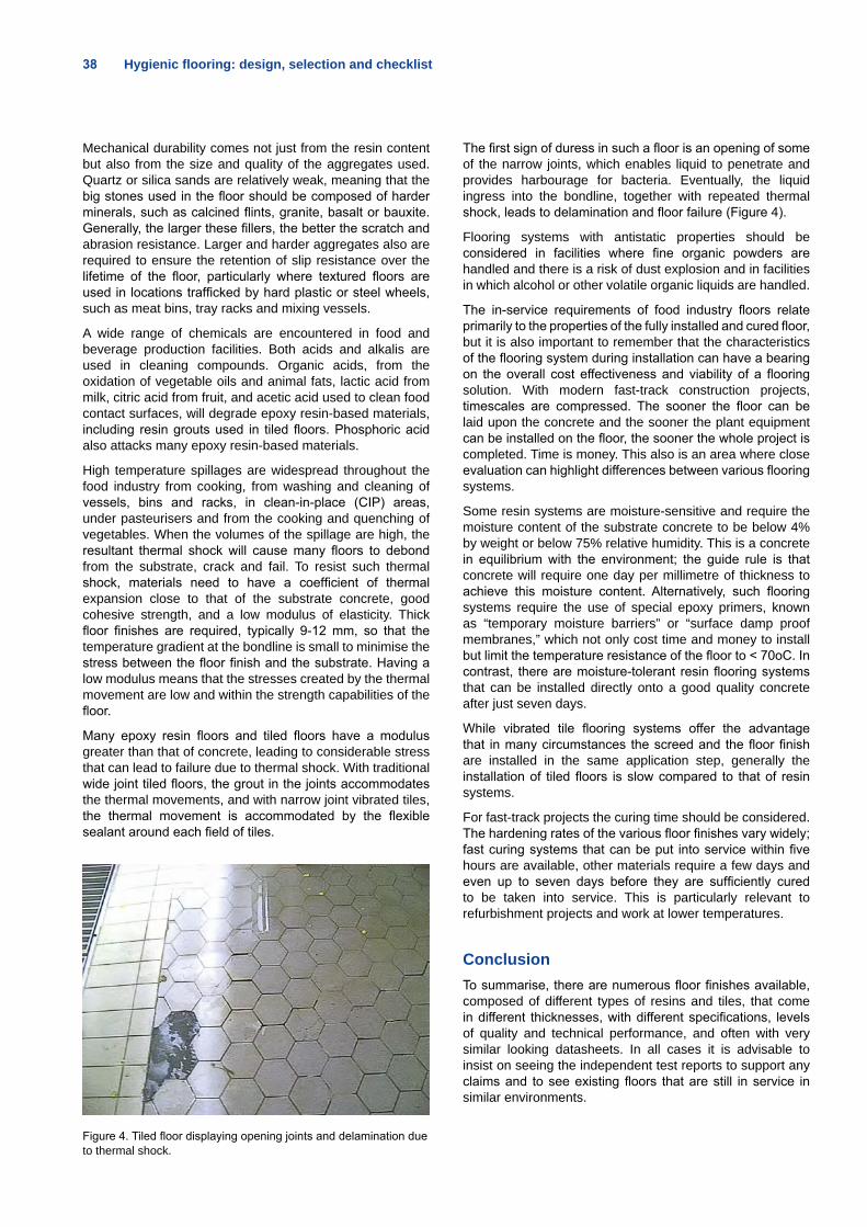
38 Hygienic flooring: design, selection and checklist
Mechanical durability comes not just from the resin content but also from the size and quality of the aggregates used. Quartz or silica sands are relatively weak, meaning that the big stones used in the floor should be composed of harder minerals, such as calcined flints, granite, basalt or bauxite. Generally, the larger these fillers, the better the scratch and abrasion resistance. Larger and harder aggregates also are required to ensure the retention of slip resistance over the lifetime of the floor, particularly where textured floors are used in locations trafficked by hard plastic or steel wheels, such as meat bins, tray racks and mixing vessels.
A wide range of chemicals are encountered in food and beverage production facilities. Both acids and alkalis are used in cleaning compounds. Organic acids, from the oxidation of vegetable oils and animal fats, lactic acid from milk, citric acid from fruit, and acetic acid used to clean food contact surfaces, will degrade epoxy resin-based materials, including resin grouts used in tiled floors. Phosphoric acid also attacks many epoxy resin-based materials.
High temperature spillages are widespread throughout the food industry from cooking, from washing and cleaning of vessels, bins and racks, in clean-in-place (CIP) areas, under pasteurisers and from the cooking and quenching of vegetables. When the volumes of the spillage are high, the resultant thermal shock will cause many floors to debond from the substrate, crack and fail. To resist such thermal shock, materials need to have a coefficient of thermal expansion close to that of the substrate concrete, good cohesive strength, and a low modulus of elasticity. Thick floor finishes are required, typically 9-12 mm, so that the temperature gradient at the bondline is small to minimise the stress between the floor finish and the substrate. Having a low modulus means that the stresses created by the thermal movement are low and within the strength capabilities of the floor.
Many epoxy resin floors and tiled floors have a modulus greater than that of concrete, leading to considerable stress that can lead to failure due to thermal shock. With traditional wide joint tiled floors, the grout in the joints accommodates the thermal movements, and with narrow joint vibrated tiles, the thermal movement is accommodated by the flexible sealant around each field of tiles.
Figure 4. Tiled floor displaying opening joints and delamination due to thermal shock.
The first sign of duress in such a floor is an opening of some of the narrow joints, which enables liquid to penetrate and provides harbourage for bacteria. Eventually, the liquid ingress into the bondline, together with repeated thermal shock, leads to delamination and floor failure (Figure 4).
Flooring systems with antistatic properties should be considered in facilities where fine organic powders are handled and there is a risk of dust explosion and in facilities in which alcohol or other volatile organic liquids are handled.
The in-service requirements of food industry floors relate primarily to the properties of the fully installed and cured floor, but it is also important to remember that the characteristics of the flooring system during installation can have a bearing on the overall cost effectiveness and viability of a flooring solution. With modern fast-track construction projects, timescales are compressed. The sooner the floor can be laid upon the concrete and the sooner the plant equipment can be installed on the floor, the sooner the whole project is completed. Time is money. This also is an area where close evaluation can highlight differences between various flooring systems.
Some resin systems are moisture-sensitive and require the moisture content of the substrate concrete to be below 4% by weight or below 75% relative humidity. This is a concrete in equilibrium with the environment; the guide rule is that concrete will require one day per millimetre of thickness to achieve this moisture content. Alternatively, such flooring systems require the use of special epoxy primers, known as “temporary moisture barriers” or “surface damp proof membranes,” which not only cost time and money to install but limit the temperature resistance of the floor to < 70oC. In contrast, there are moisture-tolerant resin flooring systems that can be installed directly onto a good quality concrete after just seven days.
While vibrated tile flooring systems offer the advantage that in many circumstances the screed and the floor finish are installed in the same application step, generally the installation of tiled floors is slow compared to that of resin systems.
For fast-track projects the curing time should be considered. The hardening rates of the various floor finishes vary widely; fast curing systems that can be put into service within five hours are available, other materials require a few days and even up to seven days before they are sufficiently cured to be taken into service. This is particularly relevant to refurbishment projects and work at lower temperatures.
ConclusionTo summarise, there are numerous floor finishes available, composed of different types of resins and tiles, that come in different thicknesses, with different specifications, levels of quality and technical performance, and often with very similar looking datasheets. In all cases it is advisable to insist on seeing the independent test reports to support any claims and to see existing floors that are still in service in similar environments.
The most expensive floors are those that fail, leading to accidents and lost production and all the costs associated with managing the floor failure and the necessary repair work. It is usually best to choose floor finishes that can demonstrate their longevity.
When drilling through floors to anchor plant equipment, resin fixings should be used because these will reinstate the floor protection. Mechanical anchors leave holes in the floor finish that might allow water ingress and provide a harbourage for bacterial or fungal growth.
In addition to the importance of correctly installing the substrate concrete, it is equally important to ensure that the floor finish is correctly installed by an experienced specialist applicator who is familiar with the flooring system to be installed and can be relied upon to do the work in accordance with the manufacturer’s instructions and good site practice. On refurbishment projects, the flooring contractor should be experienced working within a food industry environment. It is important that the routes of access to the work area and facilities, the location of the mixing station, and the areas of materials and waste storage are agreed and followed so that contamination of adjacent production areas can be avoided. It is advisable to ask the manufacturer of the chosen floor finish to provide the names of suitably experienced installation contractors.
SÜDMO
Pentair Südmo is introducing the brand new Aseptic Double Seat Valve Secure.• P3-Diaphragm replaces PTFE/metal bellows• Hermetic separation even during lifting • Self-draining, sump and dome-free• Easy to clean and sterilize• High operating pressures of up to 10 bar• High operating temperatures of up to 150 °C
Find out more on www.suedmo.de.
NEW
EXCELLENCEIN ASEPTICAPPLICATIONS
ehedg_suedmo_104x297_def.indd 1 24.06.2014 12:50:09
Adv
ertis
emen
t
40 Hygienic flooring: design, selection and checklist
ChecklistSubstrate design
• Position drainage where it is visible and accessible, and consider the impact of drainage on the design of the concrete floor.
• Design the substrate concrete and screeds to reduce the number of joints and to locate those joints that are required where they are visible and accessible and in non-critical areas.
• Ensure that the substrate concrete and screeds are designed to accommodate the stresses of the in-service environment.
Floor selection
• Is the floor finish HACCP-compliant? Is this supported by independent verification?
• Can the flooring manufacturer demonstrate that his floor is non-tainting, is easy to clean and does not support microbial growth? Is this confirmed by third-party certification?
• Does the floor finish have the required chemical, temperature and thermal shock resistance?
• Does the floor finish meet the various needs for slip resistance?
• In areas subject to hard wheeled traffic, does the floor finish use the hard aggregates required to maintain the slip resistance for the life of the floor?
• Where relevant, can the floor finish be installed onto high-moisture content concrete, or does it require the use of special primers?
• Can the floor finish be put back into service within the required time interval?
• Are coving mortars dense and impervious to prevent moisture ingress?
• Can the manufacturer demonstrate a successful track record in similar environments over many years?
Installation
• Does the construction company understand the concrete floor and screed design and will they ensure that it is built as required?
• Does the specialist flooring contractor have experience installing the chosen floor finish and can he demonstrate a track record on similar installations within the food and beverage industry?
• Ensure that special primers and topcoats, when required, are included and itemised in the floor finish contractor’s tender documents.
• Require the construction company and the floor finish contractor to work together to ensure that the floor is installed to the correct levels, falls and tolerance, with substrate preparation, detailing and application as required to achieve the best floor possible.
References1. Taylor, J.H. and J.T. Holah. 1996. A comparative evaluation
with respect to the bacterial cleanability of a range of wall and floor surface materials in the food industry. Journal of Applied Microbiology, 81, pp. 257-261.
2. Gebel, J., H.P. Werner, A. Kirsch-Altena, K. Bansemir, et al. Standardmethoden der DGHM zur Prüfung chemischer Desinfektionsverfahren. Stand 1. 9. 2001. mhp-Verlag GmbH: Wiesbaden, 2002
3. DIN 51130 (Germany). Testing of floor coverings – Determination of the anti-slip property – Workrooms and fields of activities with slip danger, walking method – Ramp test.
4. EN 13036 (British Standard). Road and airfield surface characteristics – Test methods. Part 4: Method of measurement of the slip/skid resistance of a surface: The pendulum test.
5. BGR 181. Fußböden in Arbeitsräumen und Arbeitsbereichen mit Rutschgefahr. Hauptverband der gewerblichen Berufs-genossenschaften.
Tetra Pak, and PROTECTS WHAT´S GOOD are trademarks belonging to the Tetra Pak Group.
Take full controlWe build our equipment in accordance with the principles of Hygienic Design, with easy cleanability. Assuring that only food-approved materials will ever come in contact with your products. Using automation to enable full inte-gration,with minimal risk of human error and with outstanding traceability. Food safety is all about full control. Make sure you get it!
Learn more at www.tetrapak.com
Certified equipment conforming to the guidelines of EHEDG, of which the Tetra Pak® Group is an active member.
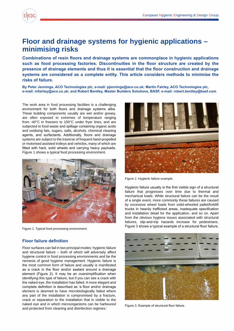
European Hygienic Engineering & Design Group
Floor and drainage systems for hygienic applications – minimising risksCombinations of resin floors and drainage systems are commonplace in hygienic applications such as food processing factories. Discontinuities in the floor structure are created by the presence of drainage elements and thus it is essential that the floor construction and drainage systems are considered as a complete entity. This article considers methods to minimise the risks of failure.By Peter Jennings, ACO Technologies plc, e-mail: [email protected]; Martin Fairley, ACO Technologies plc, e-mail: [email protected]; and Robert Bentley, Master Builders Solutions, BASF, e-mail: [email protected]
The work area in food processing facilities is a challenging environment for both floors and drainage systems alike. These building components usually are wet and/or greasy, are often exposed to extremes of temperature ranging from -40°C in freezers to 150°C under fryer lines, and are subjected to food waste and spillage containing organic acids and oxidising fats, sugars, salts, alcohols, chemical cleaning agents, and surfactants. Additionally, floors and drainage systems are subject to the traverse of frequent hand-propelled or motorised assisted trolleys and vehicles, many of which are fitted with hard, solid wheels and carrying heavy payloads. Figure 1 shows a typical food processing environment.
Figure 1. Typical food processing environment.
Floor failure definitionFloor surfaces can fail in two principal modes: hygienic failure and structural failure – both of which will adversely affect hygiene control in food processing envrionments and be the nemesis of good hygiene management. Hygienic failure is the most common form of failure and usually is manifested as a crack in the floor and/or sealant around a drainage element (Figure 2). It may be an oversimplification when identifying this type of failure, but if you can see a crack with the naked eye, the installation has failed. A more elegant and complete definition is described as ‘a floor and/or drainage element is deemed to have microbiologically failed where any part of the installation is compromised by a fracture, crack or separation to the installation that is visible to the naked eye and in which microorganisms can be harboured and protected from cleaning and disinfection regimes.’
Figure 2. Hygienic failure example.
Hygienic failure usually is the first visible sign of a structural failure that progresses over time due to thermal and mechanical loads. While structural failure can be the result of a single event, more commonly these failures are caused by excessive wheel loads from solid-wheeled pallet/forklift trucks in heavily trafficked areas, inadequate specification and installation detail for the application, and so on. Apart from the obvious hygiene issues associated with structural failures, slip-and-trip hazards increase for pedestrians. Figure 3 shows a typical example of a structural floor failure.
Figure 3. Example of structural floor failure.
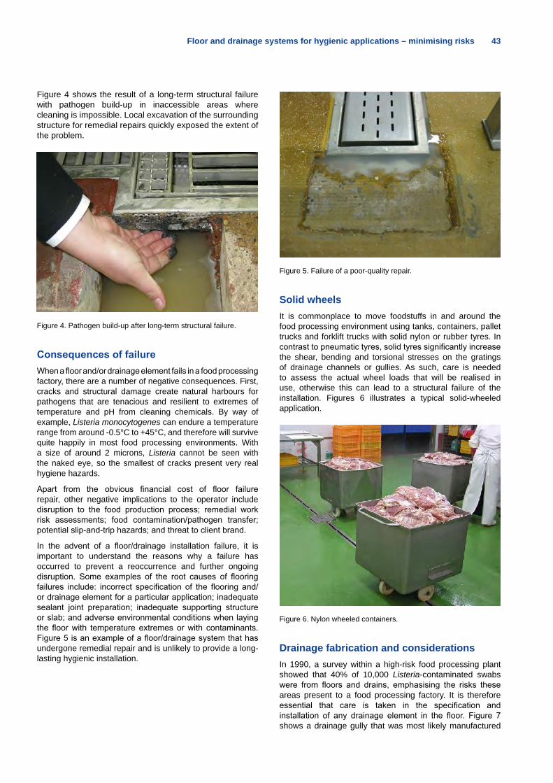
Floor and drainage systems for hygienic applications – minimising risks 43
Figure 4 shows the result of a long-term structural failure with pathogen build-up in inaccessible areas where cleaning is impossible. Local excavation of the surrounding structure for remedial repairs quickly exposed the extent of the problem.
Figure 4. Pathogen build-up after long-term structural failure.
Consequences of failureWhen a floor and/or drainage element fails in a food processing factory, there are a number of negative consequences. First, cracks and structural damage create natural harbours for pathogens that are tenacious and resilient to extremes of temperature and pH from cleaning chemicals. By way of example, Listeria monocytogenes can endure a temperature range from around -0.5°C to +45°C, and therefore will survive quite happily in most food processing environments. With a size of around 2 microns, Listeria cannot be seen with the naked eye, so the smallest of cracks present very real hygiene hazards.
Apart from the obvious financial cost of floor failure repair, other negative implications to the operator include disruption to the food production process; remedial work risk assessments; food contamination/pathogen transfer; potential slip-and-trip hazards; and threat to client brand.
In the advent of a floor/drainage installation failure, it is important to understand the reasons why a failure has occurred to prevent a reoccurrence and further ongoing disruption. Some examples of the root causes of flooring failures include: incorrect specification of the flooring and/or drainage element for a particular application; inadequate sealant joint preparation; inadequate supporting structure or slab; and adverse environmental conditions when laying the floor with temperature extremes or with contaminants. Figure 5 is an example of a floor/drainage system that has undergone remedial repair and is unlikely to provide a long-lasting hygienic installation.
Figure 5. Failure of a poor-quality repair.
Solid wheelsIt is commonplace to move foodstuffs in and around the food processing environment using tanks, containers, pallet trucks and forklift trucks with solid nylon or rubber tyres. In contrast to pneumatic tyres, solid tyres significantly increase the shear, bending and torsional stresses on the gratings of drainage channels or gullies. As such, care is needed to assess the actual wheel loads that will be realised in use, otherwise this can lead to a structural failure of the installation. Figures 6 illustrates a typical solid-wheeled application.
Figure 6. Nylon wheeled containers.
Drainage fabrication and considerationsIn 1990, a survey within a high-risk food processing plant showed that 40% of 10,000 Listeria-contaminated swabs were from floors and drains, emphasising the risks these areas present to a food processing factory. It is therefore essential that care is taken in the specification and installation of any drainage element in the floor. Figure 7 shows a drainage gully that was most likely manufactured
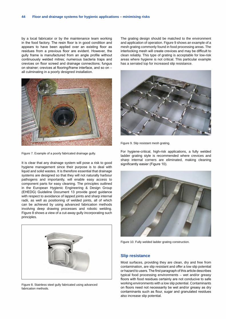
44 Floor and drainage systems for hygienic applications – minimising risks
by a local fabricator or by the maintenance team working in the food factory. The resin floor is in good condition and appears to have been applied over an existing floor as residues from a previous floor are evident. However, the gully frame is manufactured from an angle profile without continuously welded mitres; numerous bacteria traps and crevices on floor screed and drainage connections; fungus on strainer; crevices at flooring/frame interface, and so on – all culminating in a poorly designed installation.
Figure 7. Example of a poorly fabricated drainage gully.
It is clear that any drainage system will pose a risk to good hygiene management since their purpose is to deal with liquid and solid wastes. It is therefore essential that drainage systems are designed so that they will not naturally harbour pathogens and importantly, will enable easy access to component parts for easy cleaning. The principles outlined in the European Hygienic Engineering & Design Group (EHEDG) Guideline Document 13 provide good guidance with respect to avoidance of lapped joints and sharp internal radii, as well as positioning of welded joints, all of which can be achieved by using advanced fabrication methods involving deep drawing processes and robotic welding. Figure 8 shows a view of a cut-away gully incorporating such principles.
Figure 8. Stainless steel gully fabricated using advanced fabrication methods.
The grating design should be matched to the environment and application of operation. Figure 9 shows an example of a mesh grating commonly found in food processing areas. The interlocking mesh will create crevices and may be difficult to clean reliably. This type of grating is acceptable for low-risk areas where hygiene is not critical. This particular example has a serrated top for increased slip resistance.
Figure 9. Slip resistant mesh grating.
For hygiene-critical, high-risk applications, a fully welded ladder grating style is recommended where crevices and sharp internal corners are eliminated, making cleaning significantly easier (Figure 10).
Figure 10. Fully welded ladder grating construction.
Slip resistanceMost surfaces, providing they are clean, dry and free from contamination, are slip resistant and offer a low slip potential or hazard to users. The first paragraph of this article describes typical food processing environments – wet and/or greasy floors with food residues certainly are not conducive to safe working environments with a low slip potential. Contaminants on floors need not necessarily be wet and/or greasy as dry contaminants such as flour, sugar and granulated residues also increase slip potential.
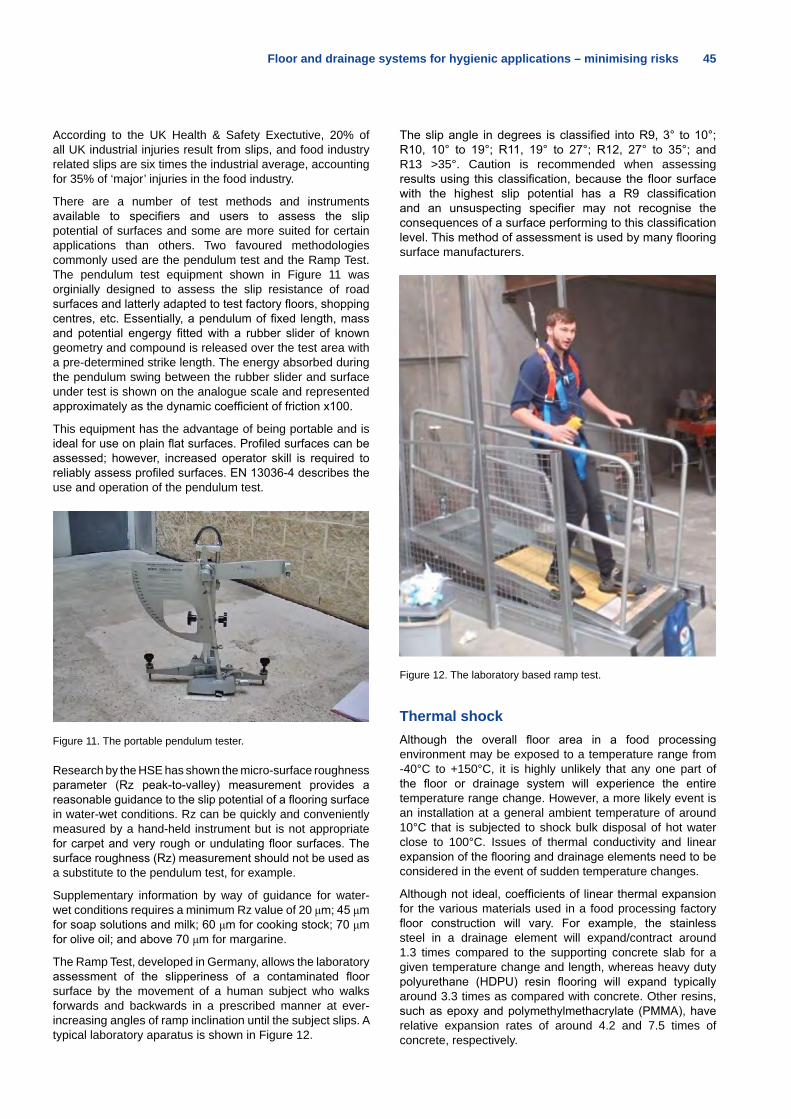
Floor and drainage systems for hygienic applications – minimising risks 45
According to the UK Health & Safety Exectutive, 20% of all UK industrial injuries result from slips, and food industry related slips are six times the industrial average, accounting for 35% of ‘major’ injuries in the food industry.
There are a number of test methods and instruments available to specifiers and users to assess the slip potential of surfaces and some are more suited for certain applications than others. Two favoured methodologies commonly used are the pendulum test and the Ramp Test. The pendulum test equipment shown in Figure 11 was orginially designed to assess the slip resistance of road surfaces and latterly adapted to test factory floors, shopping centres, etc. Essentially, a pendulum of fixed length, mass and potential engergy fitted with a rubber slider of known geometry and compound is released over the test area with a pre-determined strike length. The energy absorbed during the pendulum swing between the rubber slider and surface under test is shown on the analogue scale and represented approximately as the dynamic coefficient of friction x100.
This equipment has the advantage of being portable and is ideal for use on plain flat surfaces. Profiled surfaces can be assessed; however, increased operator skill is required to reliably assess profiled surfaces. EN 13036-4 describes the use and operation of the pendulum test.
Figure 11. The portable pendulum tester.
Research by the HSE has shown the micro-surface roughness parameter (Rz peak-to-valley) measurement provides a reasonable guidance to the slip potential of a flooring surface in water-wet conditions. Rz can be quickly and conveniently measured by a hand-held instrument but is not appropriate for carpet and very rough or undulating floor surfaces. The surface roughness (Rz) measurement should not be used as a substitute to the pendulum test, for example.
Supplementary information by way of guidance for water-wet conditions requires a minimum Rz value of 20 μm; 45 μm for soap solutions and milk; 60 μm for cooking stock; 70 μm for olive oil; and above 70 μm for margarine.
The Ramp Test, developed in Germany, allows the laboratory assessment of the slipperiness of a contaminated floor surface by the movement of a human subject who walks forwards and backwards in a prescribed manner at ever-increasing angles of ramp inclination until the subject slips. A typical laboratory aparatus is shown in Figure 12.
The slip angle in degrees is classified into R9, 3° to 10°; R10, 10° to 19°; R11, 19° to 27°; R12, 27° to 35°; and R13 >35°. Caution is recommended when assessing results using this classification, because the floor surface with the highest slip potential has a R9 classification and an unsuspecting specifier may not recognise the consequences of a surface performing to this classification level. This method of assessment is used by many flooring surface manufacturers.
Figure 12. The laboratory based ramp test.
Thermal shockAlthough the overall floor area in a food processing environment may be exposed to a temperature range from -40°C to +150°C, it is highly unlikely that any one part of the floor or drainage system will experience the entire temperature range change. However, a more likely event is an installation at a general ambient temperature of around 10°C that is subjected to shock bulk disposal of hot water close to 100°C. Issues of thermal conductivity and linear expansion of the flooring and drainage elements need to be considered in the event of sudden temperature changes.
Although not ideal, coefficients of linear thermal expansion for the various materials used in a food processing factory floor construction will vary. For example, the stainless steel in a drainage element will expand/contract around 1.3 times compared to the supporting concrete slab for a given temperature change and length, whereas heavy duty polyurethane (HDPU) resin flooring will expand typically around 3.3 times as compared with concrete. Other resins, such as epoxy and polymethylmethacrylate (PMMA), have relative expansion rates of around 4.2 and 7.5 times of concrete, respectively.
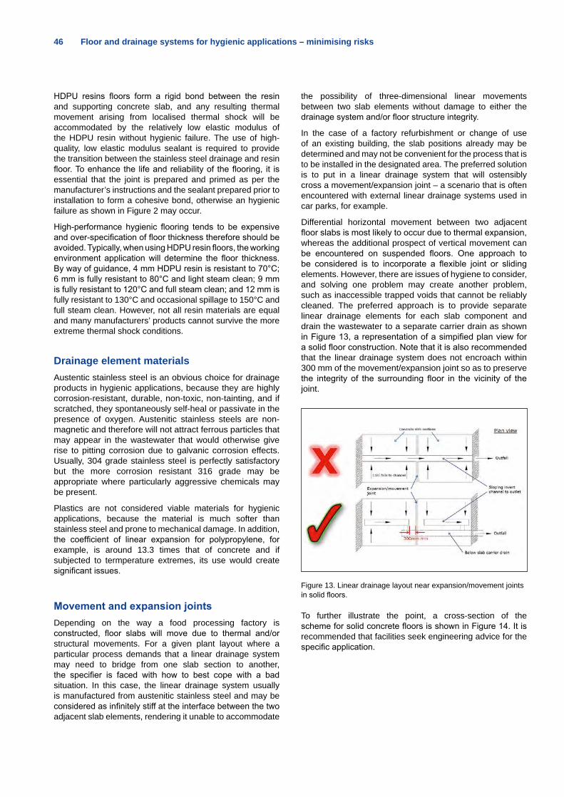
46 Floor and drainage systems for hygienic applications – minimising risks
HDPU resins floors form a rigid bond between the resin and supporting concrete slab, and any resulting thermal movement arising from localised thermal shock will be accommodated by the relatively low elastic modulus of the HDPU resin without hygienic failure. The use of high-quality, low elastic modulus sealant is required to provide the transition between the stainless steel drainage and resin floor. To enhance the life and reliability of the flooring, it is essential that the joint is prepared and primed as per the manufacturer’s instructions and the sealant prepared prior to installation to form a cohesive bond, otherwise an hygienic failure as shown in Figure 2 may occur.
High-performance hygienic flooring tends to be expensive and over-specification of floor thickness therefore should be avoided. Typically, when using HDPU resin floors, the working environment application will determine the floor thickness. By way of guidance, 4 mm HDPU resin is resistant to 70°C; 6 mm is fully resistant to 80°C and light steam clean; 9 mm is fully resistant to 120°C and full steam clean; and 12 mm is fully resistant to 130°C and occasional spillage to 150°C and full steam clean. However, not all resin materials are equal and many manufacturers’ products cannot survive the more extreme thermal shock conditions.
Drainage element materialsAustentic stainless steel is an obvious choice for drainage products in hygienic applications, because they are highly corrosion-resistant, durable, non-toxic, non-tainting, and if scratched, they spontaneously self-heal or passivate in the presence of oxygen. Austenitic stainless steels are non-magnetic and therefore will not attract ferrous particles that may appear in the wastewater that would otherwise give rise to pitting corrosion due to galvanic corrosion effects. Usually, 304 grade stainless steel is perfectly satisfactory but the more corrosion resistant 316 grade may be appropriate where particularly aggressive chemicals may be present.
Plastics are not considered viable materials for hygienic applications, because the material is much softer than stainless steel and prone to mechanical damage. In addition, the coefficient of linear expansion for polypropylene, for example, is around 13.3 times that of concrete and if subjected to termperature extremes, its use would create significant issues.
Movement and expansion jointsDepending on the way a food processing factory is constructed, floor slabs will move due to thermal and/or structural movements. For a given plant layout where a particular process demands that a linear drainage system may need to bridge from one slab section to another, the specifier is faced with how to best cope with a bad situation. In this case, the linear drainage system usually is manufactured from austenitic stainless steel and may be considered as infinitely stiff at the interface between the two adjacent slab elements, rendering it unable to accommodate
the possibility of three-dimensional linear movements between two slab elements without damage to either the drainage system and/or floor structure integrity.
In the case of a factory refurbishment or change of use of an existing building, the slab positions already may be determined and may not be convenient for the process that is to be installed in the designated area. The preferred solution is to put in a linear drainage system that will ostensibly cross a movement/expansion joint – a scenario that is often encountered with external linear drainage systems used in car parks, for example.
Differential horizontal movement between two adjacent floor slabs is most likely to occur due to thermal expansion, whereas the additional prospect of vertical movement can be encountered on suspended floors. One approach to be considered is to incorporate a flexible joint or sliding elements. However, there are issues of hygiene to consider, and solving one problem may create another problem, such as inaccessible trapped voids that cannot be reliably cleaned. The preferred approach is to provide separate linear drainage elements for each slab component and drain the wastewater to a separate carrier drain as shown in Figure 13, a representation of a simpified plan view for a solid floor construction. Note that it is also recommended that the linear drainage system does not encroach within 300 mm of the movement/expansion joint so as to preserve the integrity of the surrounding floor in the vicinity of the joint.
Figure 13. Linear drainage layout near expansion/movement joints in solid floors.
To further illustrate the point, a cross-section of the scheme for solid concrete floors is shown in Figure 14. It is recommended that facilities seek engineering advice for the specific application.
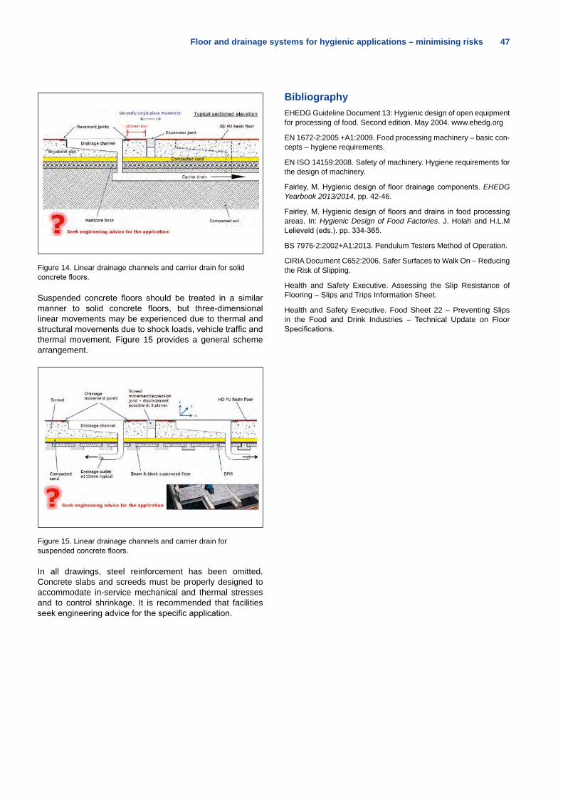
Floor and drainage systems for hygienic applications – minimising risks 47
Figure 14. Linear drainage channels and carrier drain for solid concrete floors.
Suspended concrete floors should be treated in a similar manner to solid concrete floors, but three-dimensional linear movements may be experienced due to thermal and structural movements due to shock loads, vehicle traffic and thermal movement. Figure 15 provides a general scheme arrangement.
Figure 15. Linear drainage channels and carrier drain for suspended concrete floors.
In all drawings, steel reinforcement has been omitted. Concrete slabs and screeds must be properly designed to accommodate in-service mechanical and thermal stresses and to control shrinkage. It is recommended that facilities seek engineering advice for the specific application.
BibliographyEHEDG Guideline Document 13: Hygienic design of open equipment for processing of food. Second edition. May 2004. www.ehedg.org
EN 1672-2:2005 +A1:2009. Food processing machinery – basic con-cepts – hygiene requirements.
EN ISO 14159:2008. Safety of machinery. Hygiene requirements for the design of machinery.
Fairley, M. Hygienic design of floor drainage components. EHEDG Yearbook 2013/2014, pp. 42-46.
Fairley, M. Hygienic design of floors and drains in food processing areas. In: Hygienic Design of Food Factories. J. Holah and H.L.M Lelieveld (eds.). pp. 334-365.
BS 7976-2:2002+A1:2013. Pendulum Testers Method of Operation.
CIRIA Document C652:2006. Safer Surfaces to Walk On – Reducing the Risk of Slipping.
Health and Safety Executive. Assessing the Slip Resistance of Flooring – Slips and Trips Information Sheet.
Health and Safety Executive. Food Sheet 22 – Preventing Slips in the Food and Drink Industries – Technical Update on Floor Specifications.
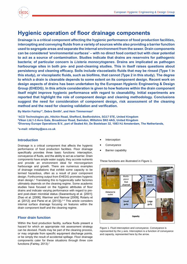
European Hygienic Engineering & Design Group
Hygienic operation of floor drainage componentsDrainage is a critical component affecting the hygienic performance of food production facilities, intercepting and conveying fluids from a variety of sources while also providing a barrier function used to segregate areas and separate the internal environment from the sewer. Drain components can be considered ‘environmental surfaces’ – with no direct food contact but with clear potential to act as a source of contamination. Studies indicate that drains are reservoirs for pathogenic bacteria; of particular concern is Listeria monocytogenes. Drains are implicated as pathogen harbourage sites in both pre- and post-cleaning studies. This in itself raises questions about persistency and cleaning efficacy. Soils include viscoelastic fluids that may be rinsed (Type 1 in this study), or viscoplastic fluids, such as biofilms, that cannot (Type 2 in this study). The degree to which a drain is cleanable depends to some extent on its component design. Recent work on design aspects of drains has been undertaken by the European Hygienic Engineering & Design Group (EHEDG). In this article consideration is given to how features within the drain component itself might improve hygienic performance with regard to cleanability. Initial experiments are reported that highlight the role of component design and cleaning methodology. Conclusions suggest the need for consideration of component design, risk assessment of the cleaning method and the need for cleaning validation and verification. By Martin Fairley1*, Debra Smith2, and Hein Timmerman3
1ACO Technologies plc, Hitchin Road, Shefford, Bedfordshire, SG17 5TE, United Kingdom 2Vikan Ltd,1-3 Avro Gate, Broadmoor Road, Swindon, Wiltshire SN3 4AG, United Kingdom 3Diversey Europe Operations B.V., part of Sealed Air, De Boelelaan 32, 1083 HJ Amsterdam, The Netherlands,
*e-mail: [email protected]
IntroductionDrainage is a critical component that affects the hygienic performance of food production facilities. Floor drainage specifically provides three basic functions: interception, conveyance of fluids, and the ability to act as a barrier. Drain components have ample water supply, they accrete nutrients and provide an environment ideal for microorganism harbourage and growth. There are numerous examples of drainage installations that exhibit some capacity to be termed hazardous, often as a result of poor component design. Forthcoming output from EHEDG promotes hygienic drain design.1 Translating this to hygienically safer factories ultimately depends on the cleaning regime. Some academic studies have focused on the hygienic attributes of floor drains and indicate varying performance with regard to pre- and post-clean microbial status (Swanenburg et al. [2001]; Zhao et al. [2006]; Warriner and Namvar [2009]; Rotariu et al. [2012]; and Parisi et al. [2013]).2–6 This article considers internal surface drainage focusing on features within the drain component itself and the cleaning regime.
Floor drain functionWithin the food production facility, surface fluids present a hazard for which an appropriate risk assessment strategy can be devised. Fluids may be part of the cleaning process, or may originate from specific equipment discharge points, or be simply the result of accidental spillage. Floor drainage components cater for these situations through three core functions (Fairley, 2013):7
• Interception
• Conveyance
• Barrier capability
These functions are illustrated in Figure 1.
Figure 1. Fluid interception and conveyance. Conveyance is represented by the y axis. Interception is a function of conveyance and capacity, represented here by the arrow.
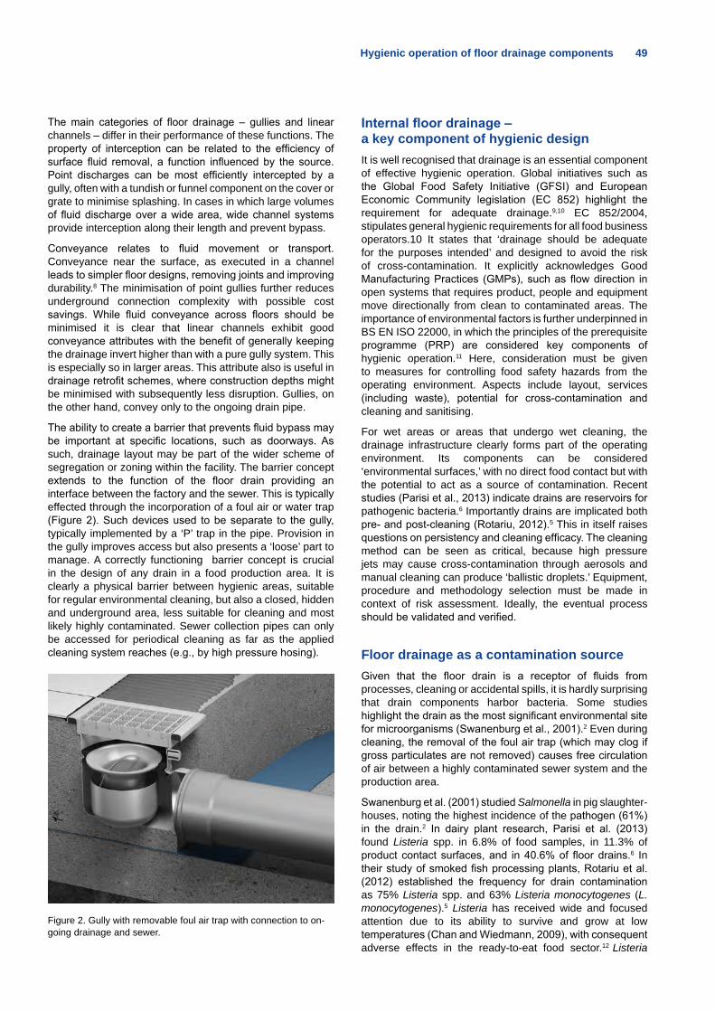
Hygienic operation of floor drainage components 49
The main categories of floor drainage – gullies and linear channels – differ in their performance of these functions. The property of interception can be related to the efficiency of surface fluid removal, a function influenced by the source. Point discharges can be most efficiently intercepted by a gully, often with a tundish or funnel component on the cover or grate to minimise splashing. In cases in which large volumes of fluid discharge over a wide area, wide channel systems provide interception along their length and prevent bypass.
Conveyance relates to fluid movement or transport. Conveyance near the surface, as executed in a channel leads to simpler floor designs, removing joints and improving durability.8 The minimisation of point gullies further reduces underground connection complexity with possible cost savings. While fluid conveyance across floors should be minimised it is clear that linear channels exhibit good conveyance attributes with the benefit of generally keeping the drainage invert higher than with a pure gully system. This is especially so in larger areas. This attribute also is useful in drainage retrofit schemes, where construction depths might be minimised with subsequently less disruption. Gullies, on the other hand, convey only to the ongoing drain pipe.
The ability to create a barrier that prevents fluid bypass may be important at specific locations, such as doorways. As such, drainage layout may be part of the wider scheme of segregation or zoning within the facility. The barrier concept extends to the function of the floor drain providing an interface between the factory and the sewer. This is typically effected through the incorporation of a foul air or water trap (Figure 2). Such devices used to be separate to the gully, typically implemented by a ‘P’ trap in the pipe. Provision in the gully improves access but also presents a ‘loose’ part to manage. A correctly functioning barrier concept is crucial in the design of any drain in a food production area. It is clearly a physical barrier between hygienic areas, suitable for regular environmental cleaning, but also a closed, hidden and underground area, less suitable for cleaning and most likely highly contaminated. Sewer collection pipes can only be accessed for periodical cleaning as far as the applied cleaning system reaches (e.g., by high pressure hosing).
Figure 2. Gully with removable foul air trap with connection to on-going drainage and sewer.
Internal floor drainage – a key component of hygienic designIt is well recognised that drainage is an essential component of effective hygienic operation. Global initiatives such as the Global Food Safety Initiative (GFSI) and European Economic Community legislation (EC 852) highlight the requirement for adequate drainage.9,10 EC 852/2004, stipulates general hygienic requirements for all food business operators.10 It states that ‘drainage should be adequate for the purposes intended’ and designed to avoid the risk of cross-contamination. It explicitly acknowledges Good Manufacturing Practices (GMPs), such as flow direction in open systems that requires product, people and equipment move directionally from clean to contaminated areas. The importance of environmental factors is further underpinned in BS EN ISO 22000, in which the principles of the prerequisite programme (PRP) are considered key components of hygienic operation.11 Here, consideration must be given to measures for controlling food safety hazards from the operating environment. Aspects include layout, services (including waste), potential for cross-contamination and cleaning and sanitising.
For wet areas or areas that undergo wet cleaning, the drainage infrastructure clearly forms part of the operating environment. Its components can be considered ‘environmental surfaces,’ with no direct food contact but with the potential to act as a source of contamination. Recent studies (Parisi et al., 2013) indicate drains are reservoirs for pathogenic bacteria.6 Importantly drains are implicated both pre- and post-cleaning (Rotariu, 2012).5 This in itself raises questions on persistency and cleaning efficacy. The cleaning method can be seen as critical, because high pressure jets may cause cross-contamination through aerosols and manual cleaning can produce ‘ballistic droplets.’ Equipment, procedure and methodology selection must be made in context of risk assessment. Ideally, the eventual process should be validated and verified.
Floor drainage as a contamination sourceGiven that the floor drain is a receptor of fluids from processes, cleaning or accidental spills, it is hardly surprising that drain components harbor bacteria. Some studies highlight the drain as the most significant environmental site for microorganisms (Swanenburg et al., 2001).2 Even during cleaning, the removal of the foul air trap (which may clog if gross particulates are not removed) causes free circulation of air between a highly contaminated sewer system and the production area.
Swanenburg et al. (2001) studied Salmonella in pig slaughter-houses, noting the highest incidence of the pathogen (61%) in the drain.2 In dairy plant research, Parisi et al. (2013) found Listeria spp. in 6.8% of food samples, in 11.3% of product contact surfaces, and in 40.6% of floor drains.6 In their study of smoked fish processing plants, Rotariu et al. (2012) established the frequency for drain contamination as 75% Listeria spp. and 63% Listeria monocytogenes (L. monocytogenes).5 Listeria has received wide and focused attention due to its ability to survive and grow at low temperatures (Chan and Wiedmann, 2009), with consequent adverse effects in the ready-to-eat food sector.12 Listeria
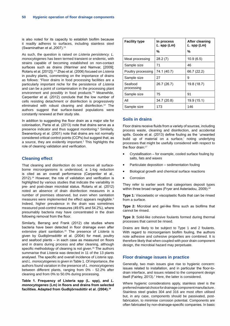
50 Hygienic operation of floor drainage components
is also noted for its capacity to establish biofilm because it readily adheres to surfaces, including stainless steel (Swaminathan et al.,2007).13
As such, the question is raised on Listeria persistency. L. monocytogenes has been termed transient or endemic, with strains capable of becoming established on non-contact surfaces such as drains (Warriner and Namvar, [2009]; Rotariu et al. [2012]).4,5 Zhao et al. (2006) focused on Listeria in poultry plants, commenting on the importance of drains as follows: “Floor drains in food processing facilities are a particularly important niche for the persistence of Listeria and can be a point of contamination in the processing plant environment and possibly in food products.”3 Meanwhile, Carpentier et al. (2012) conclude that the low number of cells resisting detachment or disinfection is progressively eliminated with robust cleaning and disinfection.14 The authors suggest that surface-based populations were constantly renewed at their study site.
In addition to suggesting the floor drain as a major site for colonisation, Parisi et al. (2013) note that drains serve as a presence indicator and thus suggest monitoring.6 Similarly, Swanenburg et al. (2001) note that drains are not normally considered critical control points (CCPs) but suggest that, as a source, they are evidently important.2 This highlights the role of cleaning validation and verification.
Cleaning effectThat cleaning and disinfection do not remove all surface-borne microorganisms is understood, a 1-log reduction is cited as an overall performance (Carpentier et al., 2012).14 However, the role of validation and verification is highlighted by various studies that indicate the variability in pre- and post-clean microbial status. Rotariu et al. (2012) noted an absence of drain disinfection measures in a number of premises observed, but even when sanitation measures were implemented the effect appears negligible.5 Indeed, higher prevalence in the drain was sometimes measured post-control measures (49.6% and 54.2%), where presumably bacteria may have concentrated in the drain following removal from the floor.
Similarly, Berrang and Frank (2012) cite studies where bacteria have been detected in floor drainage even after extensive plant sanitation.15 The presence of Listeria is given by Gudbjörnsdóttir et al. (2004) for meat, poultry and seafood plants – in each case as measured on floors and in drains during process and after cleaning, although specific methodology of cleaning is not given.16 The authors summarise that Listeria was detected in 11 of the 13 plants analysed. The specific and overall incidence of Listeria spp. and L. monocytogenes is given in Table 1. Of importance, the authors found variation in the presence of L. monocytogenes between different plants, ranging from 0% - 52.2% after cleaning and from 0% to 50.0% during processing.
Table 1. Frequency of Listeria spp (L. spp), and L. monocytogenes (Lm) in floors and drains from selected facilities. Adapted from Gudbjörnsdóttir et al. (2004).16
Facility type In process L. spp (Lm)
%
After cleaning L. spp (Lm)
%
Meat processing 28.2 (7) 10.9 (6.5)
Sample size 71 46
Poultry processing 74.1 (40.7) 66.7 (22.2)
Sample size 27 9
Seafood processing
26.7 (26.7) 19.8 (18.7)
Sample size 75 91
All 34.7 (20.8) 19.9 (15.1)
Sample size 173 146
Soils in drainsFloor drains receive fluids from a variety of sources, including process waste, cleaning and disinfection, and accidental spills. Goode et al. (2013) define fouling as the ´unwanted build up of material on a surface,’ noting underlying processes that might be usefully considered with respect to the floor drain:17
• Crystallisation – for example, cooled surface fouling by salts, fats and waxes
• Particulate deposition – sedimentation fouling
• Biological growth and chemical surface reactions
• Corrosion
They refer to earlier work that categorises deposit types within three broad ranges (Fryer and Asteriadou, 2009):18
Type 1: Viscoelastic or viscoplastic fluids that can be rinsed from a surface.
Type 2: Microbial and gel-like films such as biofilms that cannot be rinsed.
Type 3: Solid-like cohesive foulants formed during thermal processes that cannot be rinsed.
Drains are likely to be subject to Type 1 and 2 foulants. With regard to microorganism biofilm fouling, the authors note adhesive and cohesive properties are combined. It is therefore likely that when coupled with poor drain component design, the microbial hazard may perpetuate.
Floor drainage issues in practiceGenerally, two main issues give rise to hygienic concern: issues related to installation, and in particular the floor-to-drain interface, and issues related to the component design itself (Fairley, 2013).7 Here, the latter is considered.
Where hygienic considerations apply, stainless steel is the preferred material choice for drainage component manufacture. Stainless steel grades 304 and 316 are most often utilised but, in any case, components should be passivated, post-fabrication, to minimise corrosion potential. Components are often fabricated by non-drainage-specific companies. In basic
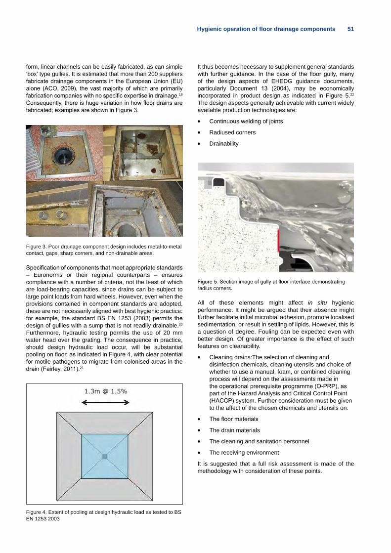
Hygienic operation of floor drainage components 51
form, linear channels can be easily fabricated, as can simple ‘box’ type gullies. It is estimated that more than 200 suppliers fabricate drainage components in the European Union (EU) alone (ACO, 2009), the vast majority of which are primarily fabrication companies with no specific expertise in drainage.19 Consequently, there is huge variation in how floor drains are fabricated; examples are shown in Figure 3.
Figure 3. Poor drainage component design includes metal-to-metal contact, gaps, sharp corners, and non-drainable areas.
Specification of components that meet appropriate standards – Euronorms or their regional counterparts – ensures compliance with a number of criteria, not the least of which are load-bearing capacities, since drains can be subject to large point loads from hard wheels. However, even when the provisions contained in component standards are adopted, these are not necessarily aligned with best hygienic practice: for example, the standard BS EN 1253 (2003) permits the design of gullies with a sump that is not readily drainable.20
Furthermore, hydraulic testing permits the use of 20 mm water head over the grating. The consequence in practice, should design hydraulic load occur, will be substantial pooling on floor, as indicated in Figure 4, with clear potential for motile pathogens to migrate from colonised areas in the drain (Fairley, 2011).21
Figure 4. Extent of pooling at design hydraulic load as tested to BS EN 1253 2003
It thus becomes necessary to supplement general standards with further guidance. In the case of the floor gully, many of the design aspects of EHEDG guidance documents, particularly Document 13 (2004), may be economically incorporated in product design as indicated in Figure 5.22
The design aspects generally achievable with current widely available production technologies are:
• Continuous welding of joints
• Radiused corners
• Drainability
Figure 5. Section image of gully at floor interface demonstrating radius corners.
All of these elements might affect in situ hygienic performance. It might be argued that their absence might further facilitate initial microbial adhesion, promote localised sedimentation, or result in settling of lipids. However, this is a question of degree. Fouling can be expected even with better design. Of greater importance is the effect of such features on cleanability.
• Cleaning drains:The selection of cleaning and disinfection chemicals, cleaning utensils and choice of whether to use a manual, foam, or combined cleaning process will depend on the assessments made in the operational prerequisite programme (O-PRP), as part of the Hazard Analysis and Critical Control Point (HACCP) system. Further consideration must be given to the affect of the chosen chemicals and utensils on:
• The floor materials
• The drain materials
• The cleaning and sanitation personnel
• The receiving environment
It is suggested that a full risk assessment is made of the methodology with consideration of these points.
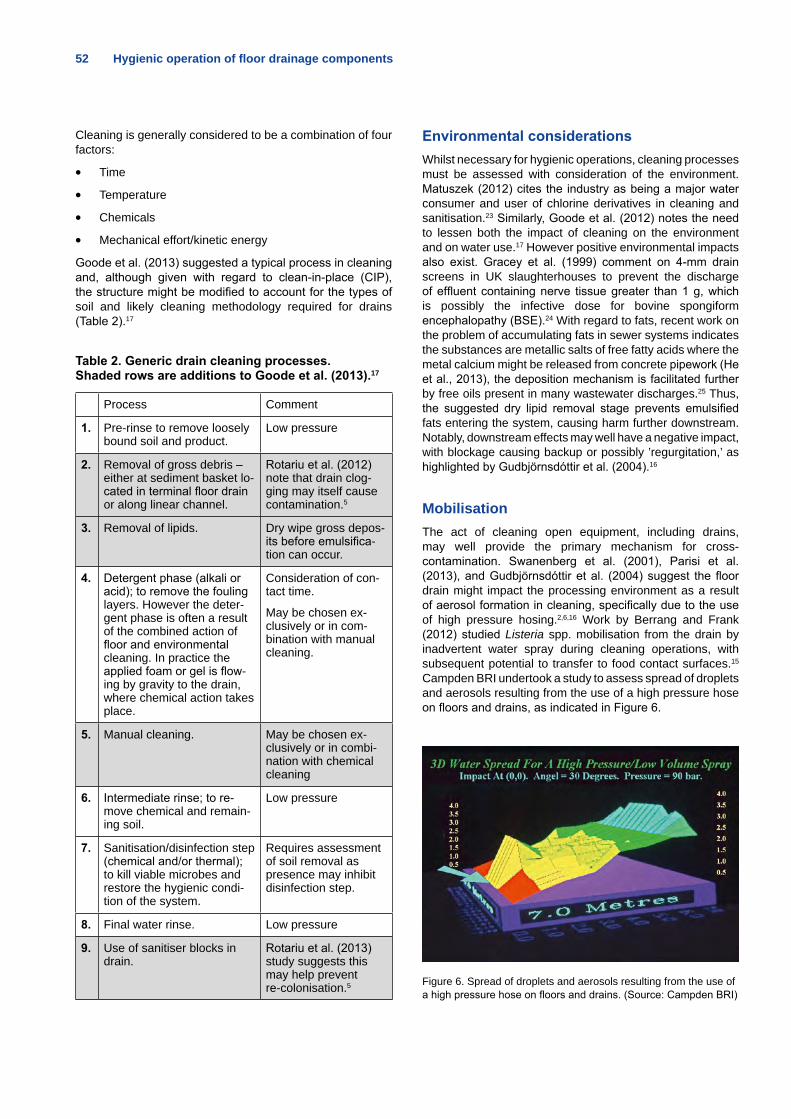
52 Hygienic operation of floor drainage components
Cleaning is generally considered to be a combination of four factors:
• Time
• Temperature
• Chemicals
• Mechanical effort/kinetic energy
Goode et al. (2013) suggested a typical process in cleaning and, although given with regard to clean-in-place (CIP), the structure might be modified to account for the types of soil and likely cleaning methodology required for drains (Table 2).17
Table 2. Generic drain cleaning processes. Shaded rows are additions to Goode et al. (2013).17
Process Comment
1. Pre-rinse to remove loosely bound soil and product.
Low pressure
2. Removal of gross debris – either at sediment basket lo-cated in terminal floor drain or along linear channel.
Rotariu et al. (2012) note that drain clog-ging may itself cause contamination.5
3. Removal of lipids. Dry wipe gross depos-its before emulsifica-tion can occur.
4. Detergent phase (alkali or acid); to remove the fouling layers. However the deter-gent phase is often a result of the combined action of floor and environmental cleaning. In practice the applied foam or gel is flow-ing by gravity to the drain, where chemical action takes place.
Consideration of con-tact time.
May be chosen ex-clusively or in com-bination with manual cleaning.
5. Manual cleaning. May be chosen ex-clusively or in combi-nation with chemical cleaning
6. Intermediate rinse; to re-move chemical and remain-ing soil.
Low pressure
7. Sanitisation/disinfection step (chemical and/or thermal); to kill viable microbes and restore the hygienic condi-tion of the system.
Requires assessment of soil removal as presence may inhibit disinfection step.
8. Final water rinse. Low pressure
9. Use of sanitiser blocks in drain.
Rotariu et al. (2013) study suggests this may help prevent re-colonisation.5
Environmental considerations Whilst necessary for hygienic operations, cleaning processes must be assessed with consideration of the environment. Matuszek (2012) cites the industry as being a major water consumer and user of chlorine derivatives in cleaning and sanitisation.23 Similarly, Goode et al. (2012) notes the need to lessen both the impact of cleaning on the environment and on water use.17 However positive environmental impacts also exist. Gracey et al. (1999) comment on 4-mm drain screens in UK slaughterhouses to prevent the discharge of effluent containing nerve tissue greater than 1 g, which is possibly the infective dose for bovine spongiform encephalopathy (BSE).24 With regard to fats, recent work on the problem of accumulating fats in sewer systems indicates the substances are metallic salts of free fatty acids where the metal calcium might be released from concrete pipework (He et al., 2013), the deposition mechanism is facilitated further by free oils present in many wastewater discharges.25 Thus, the suggested dry lipid removal stage prevents emulsified fats entering the system, causing harm further downstream. Notably, downstream effects may well have a negative impact, with blockage causing backup or possibly ’regurgitation,’ as highlighted by Gudbjörnsdóttir et al. (2004).16
MobilisationThe act of cleaning open equipment, including drains, may well provide the primary mechanism for cross-contamination. Swanenberg et al. (2001), Parisi et al. (2013), and Gudbjörnsdóttir et al. (2004) suggest the floor drain might impact the processing environment as a result of aerosol formation in cleaning, specifically due to the use of high pressure hosing.2,6,16 Work by Berrang and Frank (2012) studied Listeria spp. mobilisation from the drain by inadvertent water spray during cleaning operations, with subsequent potential to transfer to food contact surfaces.15
Campden BRI undertook a study to assess spread of droplets and aerosols resulting from the use of a high pressure hose on floors and drains, as indicated in Figure 6.
Figure 6. Spread of droplets and aerosols resulting from the use of a high pressure hose on floors and drains. (Source: Campden BRI)
From the data generated, it can be seen that such cleaning activities enable the spread of contamination from the floors and drains over a considerable distance and to a height at which subsequent deposition of the aerosols could cross-contaminate food contact surfaces. Similarly, D. Smith (personal communication, 19 August 2013) has used the term ’ballistic droplet generation’ to refer to the potential impact of brushes and other manual cleaning tools on contamination spread. Aerosols and droplets are not the only mechanisms for possible contamination transfer, simple splashing also needs to be considered. Rotariu et al. (2012) list issues associated with, among others, mid-shift wet cleaning, and report that 17 of 23 companies undertook such processes.5
Clearly, method, material and execution all affect risk of contaminant spread. Drain cleaning therefore should be considered as a necessary element of the operational pre-requisite programme.
ValidationThe Rotariu et al. (2012) study indicated the presence of bacteria both pre- and post-cleaning, and thus the authors recommended monitoring cleaning effectiveness.5 Timmerman (2012) notes that validation is defined as ‘obtaining documented evidence that cleaning and/or disinfection processes are consistently effective at reaching a predefined level of hygiene’, and goes on to suggest that around 80% of all cleaning operations in the industry are not validated or documented.26 As previously mentioned, complete contaminant removal is unlikely, or may be prohibitively costly with respect to benefit. It is therefore necessary to understand residue types and limits, and selection of analytical method (Timmerman, 2012).26
As a precursor to a full consideration of drain component cleanability, ACO and Vikan undertook a provisional assessment of newly incorporated hygienic features with a drain gully comparing the ‘hygienic’ component with a gully with no direct hygienic consideration in its design. Key findings are presented in Table 3. For these simple experiments an ultraviolet (UV)-sensitive lotion was used to coat internal surfaces. The lotion was left for one and 18 hours to represent Type 1 and Type 2 soils, respectively (Fryer and Asteriadou, 2009).18 Removal methods included only low pressure water rinse and manual cleaning.
Ruland Engineering & Consulting GmbHIm Altenschemel 55, D-67435 NeustadtPhone: +49 6327 3820 www.rulandec.de
Tailor-made solutions for the food, beverage and pharmaceutical industries. Consulting, engineering, construction and service - all from a single source.
Hygienic design at its best.
Process systems for your product.Customised. Best practice. Hygienic.
RULAND_Anzeige_EHEDG-Yearbook-2015_297x104.indd 1 08.07.2014 17:00:34
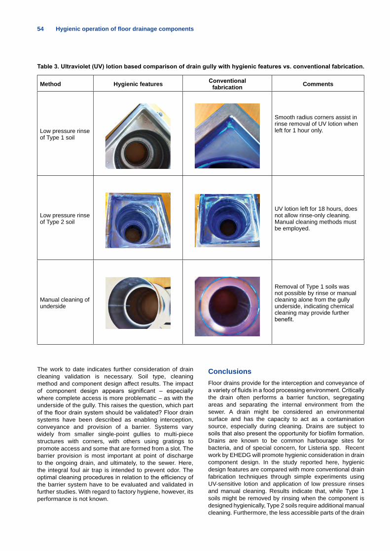
54 Hygienic operation of floor drainage components
Table 3. Ultraviolet (UV) lotion based comparison of drain gully with hygienic features vs. conventional fabrication.
Method Hygienic features Conventional fabrication Comments
Low pressure rinse of Type 1 soil
Smooth radius corners assist in rinse removal of UV lotion when left for 1 hour only.
Low pressure rinse of Type 2 soil
UV lotion left for 18 hours, does not allow rinse-only cleaning. Manual cleaning methods must be employed.
Manual cleaning of underside
Removal of Type 1 soils was not possible by rinse or manual cleaning alone from the gully underside, indicating chemical cleaning may provide further benefit.
The work to date indicates further consideration of drain cleaning validation is necessary. Soil type, cleaning method and component design affect results. The impact of component design appears significant – especially where complete access is more problematic – as with the underside of the gully. This raises the question, which part of the floor drain system should be validated? Floor drain systems have been described as enabling interception, conveyance and provision of a barrier. Systems vary widely from smaller single-point gullies to multi-piece structures with corners, with others using gratings to promote access and some that are formed from a slot. The barrier provision is most important at point of discharge to the ongoing drain, and ultimately, to the sewer. Here, the integral foul air trap is intended to prevent odor. The optimal cleaning procedures in relation to the efficiency of the barrier system have to be evaluated and validated in further studies. With regard to factory hygiene, however, its performance is not known.
ConclusionsFloor drains provide for the interception and conveyance of a variety of fluids in a food processing environment. Critically the drain often performs a barrier function, segregating areas and separating the internal environment from the sewer. A drain might be considered an environmental surface and has the capacity to act as a contamination source, especially during cleaning. Drains are subject to soils that also present the opportunity for biofilm formation. Drains are known to be common harbourage sites for bacteria, and of special concern, for Listeria spp. Recent work by EHEDG will promote hygienic consideration in drain component design. In the study reported here, hygienic design features are compared with more conventional drain fabrication techniques through simple experiments using UV-sensitive lotion and application of low pressure rinses and manual cleaning. Results indicate that, while Type 1 soils might be removed by rinsing when the component is designed hygienically, Type 2 soils require additional manual cleaning. Furthermore, the less accessible parts of the drain
Hygienic operation of floor drainage components 55
remained soiled even after manual cleaning supporting the use of chemical cleaning. Prior to cleaning it is suggested gross solids and fats are removed from the drain as far as possible. A risk assessment should be made of the cleaning methodology with regard to effective soil removal and spread of contamination. These results together with results from other studies which report pathogen presence in drains pre- and post-cleaning suggest a strong case for drain cleaning validation and verification where hygienic operation is required.
References 1. European Hygienic Engineering & Design Group. (2013). EHEDG Working Group: Building Design. www.ehedg.org.
2. Swanenburg, M., H.A.P. Urlings, J.M.A. Snijders, D.A. Keuzen-kamp, and F. van Knapen. (2001). Salmonella in slaughter pigs: prevalence serotypes and critical control points during slaughter in two slaughterhouses. International Journal of Food Microbiology, 70, pp. 243-254.
3. Zhao, T., C.T. Podtburg, P. Zhao, E.B. Schmidt, A.D. Baker, B. Cords, and M.P. Doyle. (2006). Control of Listeria spp. by competi-tive-exclusion bacteria in floor drains of a poultry processing plant. Applied and Environmental Microbiology, Vol. 72, pp. 5.
4. Warriner, K. and A. Namvar. (2009). What is the hysteria with Listeria? Trends in Food Science & Technology, 20, pp.375-434.
5. Rotariu, O., D.J.I. Thomas, K. Goodburn, M.L. Hutchison, and N.J.C. Strachan. (2012). Smoked salmon industry practices and their association with Listeria monocytogenes. Food Control, 35. www.foodbase.org.uk/results.php?&f_report_id=775. Accessed 10 Nov. 2013.
6. Parisi, A., A. Latorre, R. Fraccalvieri, A. Miccolupo, G. Norman-no, M.G. Caruso, and G. Santagada. (2013). Occurrence of Listeria spp. in dairy plants in Southern Italy and molecular subtyping of iso-lates using AFLP. Food Control, 29, pp. 91-97.
7. Fairley, M. (2013). Hygienic design of floor drainage components. EHEDG Yearbook 2013/14, pp. 42- 46.
8. Ansell, P. (2013). Hygiene by design: How floor and wall design and materials can help hygiene. Presentation at Campden BRI Cleaning and Disinfection Conference.
9. Global Food Safety Initiative. (2012). GFSI Guidance Document, Sixth Ed. Issue 3, Version 6.2. www.mygfsi.com/technical-resourc-es/guidance-document/issue-3-version-62.html. Accessed 10 Octo-ber 2013.
10. European Parliament and of the Council. (2004). Regulation (EC) 852/2004 on the hygiene of foodstuffs. Official Journal of the European Union, L 139.
11. British Standards Institution. (2005). BS EN ISO 22000:2005. Food safety management systems – Requirements for any organi-zation in the food chain. London.
12. Chan, Y.C. and M. Wiedmann. (2009). Physiology and genet-ics of Listeria monocytogenes survival and growth at cold tempera-tures. Critical Reviews in Food Science and Nutrition, Vol. 49, Issue 3, pp. 237-253.
13. Swaminathan, B., D. Cabanes, W. Zhang, and P. Cossart. (2007). Listeria monocytogenes. In: Food Microbiology Fundamen-tals and Frontiers, 3rd Ed.. M.P. Doyle and L.R. Beuchat (Eds.). ASM Press. Washington, DC. pp. 457-491.
14. Carpentier, B., E. Khamiss, O. Firmesse, and S. Christieans. (2012). Bacterial persistence and transient survival on open surfac-es. Journal of Hygienic Engineering and Design, Vol. 1, pp. 54-56.
15. Berrang, B.E., and J.E. Frank. (2012). Generation of airborne Listeria innocua from model floor drains. Journal of Food Protection, Vol. 75, pp. 7.
16. Gudbjörnsdóttir, B., M.-L. Suihko, P. Gustavsson, G. Thorkels-son, S. Salo, A.-M. Sjöberg, O. Niclasen, and S. Bredholt. (2004). The incidence of Listeria monocytogenes in meat, poultry and sea-food plants in the Nordic countries. Food Microbiology, 21, pp. 217-225.
17. Goode, K.R., K. Asteriadou, P.T. Robbins, and P.J. Fryer. (2013). Fouling and cleaning studies in the food and beverage in-dustry classified by cleaning type. Comprehensive Reviews in Food Science and Food Safety, Vol. 12, Issue 2, pp. 121-143.
18. Fryer, P.J. and K. Asteriadou. (2009). A prototype cleaning map: A classification of industrial cleaning processes. Trends in Food Sci-ence & Technology, 20, pp.121-143.
19. ACO. (2009). Market survey of drainage component producers in Europe. Internal report.
20. British Standards Institution. (2003). BS EN 1253:2003. Gullies for buildings. London.
21. Fairley, M. (2011). Hygienic design of floor drains in food pro-cessing areas. In: Hygienic Design of Food Factories. J. Holah and H.L.M. Lelieveld (eds.). Woodhead, pp. 334-365.
22. EHEDG. (2004). Document 13: Hygienic design of open equipment for processing of food. www.world-of-engineering.eu/EHEDG:::390.html. Access 20 June 2014.
23. Matuszek, T. (2012). Cleaning effectiveness and environmental criteria. Journal of Hygienic Engineering and Design, Vol. 1, pp. 44-46.
24. Gracey, J.F., D.S. Collins, and R.J. Huey. (1999). Meat Hygiene. 10th Ed. WB Saunders Co. Ltd.
25. He, X., F.L. de los Reyes,, M.L. Leming, L.O. Dean, S.E. Lappi, and J.J. Ducoste. (2013). Mechanisms of fat, oil and grease (FOG) deposit formation in sewer lines. Water Research, 47, pp.4451-4459.
26.Timmerman, Hein. (2012). Cleaning validation, practical consid-erations. Journal of Hygienic Engineering and Design, Volume 2, pp. 3-5.
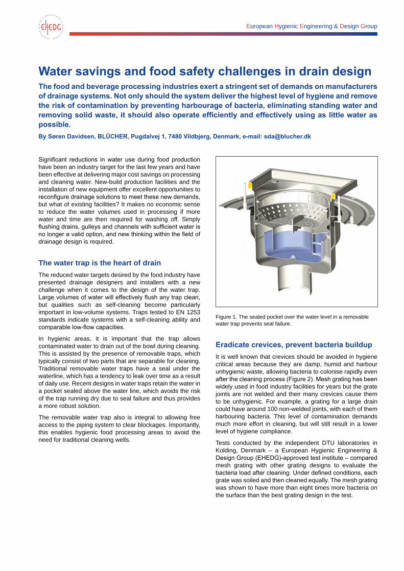
European Hygienic Engineering & Design Group
Water savings and food safety challenges in drain designThe food and beverage processing industries exert a stringent set of demands on manufacturers of drainage systems. Not only should the system deliver the highest level of hygiene and remove the risk of contamination by preventing harbourage of bacteria, eliminating standing water and removing solid waste, it should also operate efficiently and effectively using as little water as possible. By Søren Davidsen, BLÜCHER, Pugdalvej 1, 7480 Vildbjerg, Denmark, e-mail: [email protected]
Significant reductions in water use during food production have been an industry target for the last few years and have been effective at delivering major cost savings on processing and cleaning water. New-build production facilities and the installation of new equipment offer excellent opportunities to reconfigure drainage solutions to meet these new demands, but what of existing facilities? It makes no economic sense to reduce the water volumes used in processing if more water and time are then required for washing off. Simply flushing drains, gulleys and channels with sufficient water is no longer a valid option, and new thinking within the field of drainage design is required.
The water trap is the heart of drainThe reduced water targets desired by the food industry have presented drainage designers and installers with a new challenge when it comes to the design of the water trap. Large volumes of water will effectively flush any trap clean, but qualities such as self-cleaning become particularly important in low-volume systems. Traps tested to EN 1253 standards indicate systems with a self-cleaning ability and comparable low-flow capacities.
In hygienic areas, it is important that the trap allows contaminated water to drain out of the bowl during cleaning. This is assisted by the presence of removable traps, which typically consist of two parts that are separable for cleaning. Traditional removable water traps have a seal under the waterline, which has a tendency to leak over time as a result of daily use. Recent designs in water traps retain the water in a pocket sealed above the water line, which avoids the risk of the trap running dry due to seal failure and thus provides a more robust solution.
The removable water trap also is integral to allowing free access to the piping system to clear blockages. Importantly, this enables hygienic food processing areas to avoid the need for traditional cleaning wells.
Figure 1. The sealed pocket over the water level in a removable water trap prevents seal failure.
Eradicate crevices, prevent bacteria buildupIt is well known that crevices should be avoided in hygiene critical areas because they are damp, humid and harbour unhygienic waste, allowing bacteria to colonise rapidly even after the cleaning process (Figure 2). Mesh grating has been widely used in food industry facilities for years but the grate joints are not welded and their many crevices cause them to be unhygienic. For example, a grating for a large drain could have around 100 non-welded joints, with each of them harbouring bacteria. This level of contamination demands much more effort in cleaning, but will still result in a lower level of hygiene compliance.
Tests conducted by the independent DTU laboratories in Kolding, Denmark – a European Hygienic Engineering & Design Group (EHEDG)-approved test institute – compared mesh grating with other grating designs to evaluate the bacteria load after cleaning. Under defined conditions, each grate was soiled and then cleaned equally. The mesh grating was shown to have more than eight times more bacteria on the surface than the best grating design in the test.
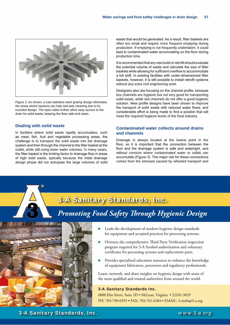
Water savings and food safety challenges in drain design 57
Figure 2. As shown, a cast stainless steel grating design eliminates the areas where bacteria can hide and aids cleaning due to its rounded design. The open sides further allow easy access to the drain for solid waste, keeping the floor safe and clean.
Dealing with solid wasteIn facilities where solid waste rapidly accumulates, such as meat, fish, fruit and vegetable processing areas, the challenge is to transport the solid waste into the drainage system and then through the channel to the filter basket at the outlet, while still using lower water volumes. In many cases, the filter basket is the limiting factor to drainage flow in areas of high solid waste, typically because the initial drainage design phase did not anticipate the large volumes of solid
waste that would be generated. As a result, filter baskets are often too small and require more frequent emptying during production. If emptying is not frequently undertaken, it could lead to contaminated water accumulating on the floor during production time.
It is recommended that any new build or retrofit should evaluate the potential volume of waste and calculate the size of filter baskets while allowing for sufficient overflow to accommodate a full shift. In existing facilities with under-dimensioned filter baskets, however, it is still possible to install retrofit systems without any extra civil engineering work.
Designers also are focusing on the channel profile, because box channels are hygienic but not very good for transporting solid waste, while slot channels do not offer a good hygienic solution. New profile designs have been shown to improve the transport of solid waste with reduced water flows, and considerable effort is being made to find a solution that will meet the required hygiene levels of the food industry.
Contaminated water collects around drains and channelsDrainage is always located at the lowest point in the floor, so it is important that the connection between the floor and the drainage system is safe and watertight, and without crevices where contaminated water or solids can accumulate (Figure 3). The major risk for these connections comes from the stresses caused by wheeled transport and
3-A Sanitary Standards, Inc.
Leads the development of modern hygienic design standards for equipment and accepted practices for processing systems.
Oversees the comprehensive � ird Party Veri� cation inspection program required for 3-A Symbol authorization and voluntary certi� cates for processing systems and replacement parts.
Provides specialized education resources to enhance the knowledge of equipment fabricators, processors and regulatory professionals.
Learn, network, and share insights on hygienic design with some of the most quali� ed and trusted authorities from around the world.
www.3-a.org
3-A Sanitary Standards, Inc.
Promoting Food Safety � rough Hygienic Design
3-A Sanitary Standards Inc.6888 Elm Street, Suite 2D • McLean, Virginia • 22101-3829PH: 703-790-0295 • FAX: 703-761-6284 • EMAIL: [email protected]
3-A ad EHEDG Yearbook 2013-14_fin.indd 1 10/8/2012 8:38:10 PM
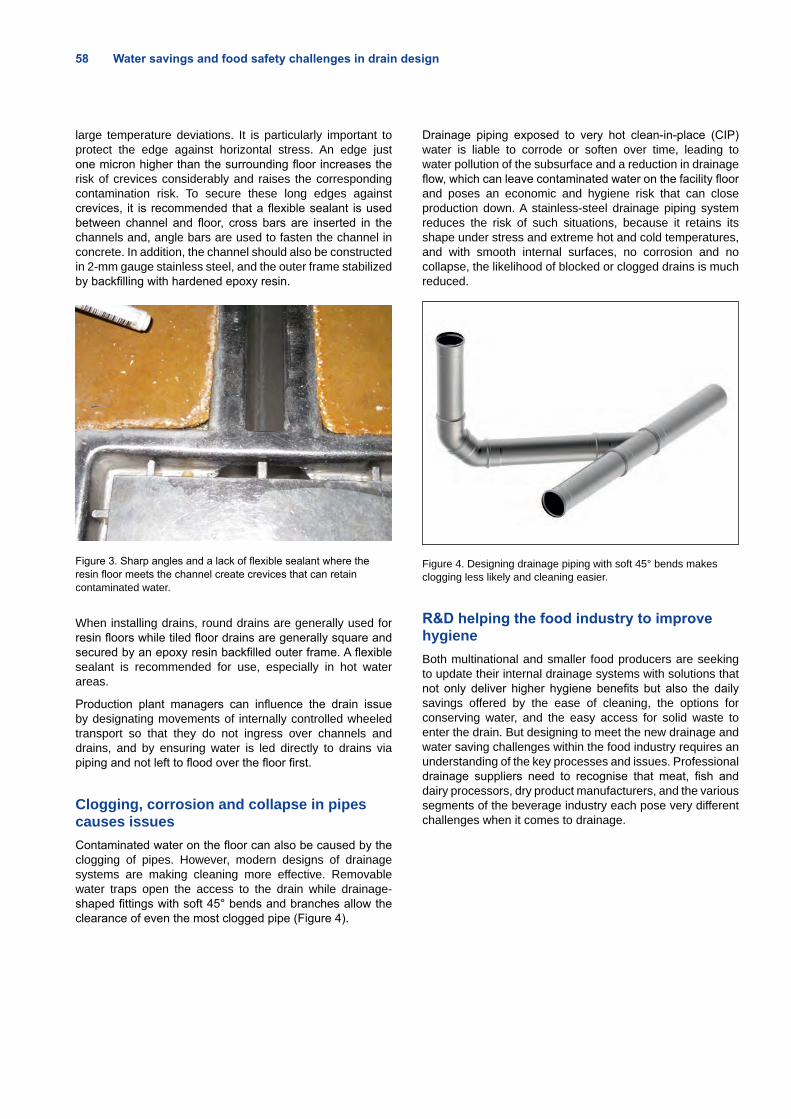
58 Water savings and food safety challenges in drain design
large temperature deviations. It is particularly important to protect the edge against horizontal stress. An edge just one micron higher than the surrounding floor increases the risk of crevices considerably and raises the corresponding contamination risk. To secure these long edges against crevices, it is recommended that a flexible sealant is used between channel and floor, cross bars are inserted in the channels and, angle bars are used to fasten the channel in concrete. In addition, the channel should also be constructed in 2-mm gauge stainless steel, and the outer frame stabilized by backfilling with hardened epoxy resin.
Figure 3. Sharp angles and a lack of flexible sealant where the resin floor meets the channel create crevices that can retain contaminated water.
When installing drains, round drains are generally used for resin floors while tiled floor drains are generally square and secured by an epoxy resin backfilled outer frame. A flexible sealant is recommended for use, especially in hot water areas.
Production plant managers can influence the drain issue by designating movements of internally controlled wheeled transport so that they do not ingress over channels and drains, and by ensuring water is led directly to drains via piping and not left to flood over the floor first.
Clogging, corrosion and collapse in pipes causes issuesContaminated water on the floor can also be caused by the clogging of pipes. However, modern designs of drainage systems are making cleaning more effective. Removable water traps open the access to the drain while drainage-shaped fittings with soft 45° bends and branches allow the clearance of even the most clogged pipe (Figure 4).
Drainage piping exposed to very hot clean-in-place (CIP) water is liable to corrode or soften over time, leading to water pollution of the subsurface and a reduction in drainage flow, which can leave contaminated water on the facility floor and poses an economic and hygiene risk that can close production down. A stainless-steel drainage piping system reduces the risk of such situations, because it retains its shape under stress and extreme hot and cold temperatures, and with smooth internal surfaces, no corrosion and no collapse, the likelihood of blocked or clogged drains is much reduced.
Figure 4. Designing drainage piping with soft 45° bends makes clogging less likely and cleaning easier.
R&D helping the food industry to improve hygieneBoth multinational and smaller food producers are seeking to update their internal drainage systems with solutions that not only deliver higher hygiene benefits but also the daily savings offered by the ease of cleaning, the options for conserving water, and the easy access for solid waste to enter the drain. But designing to meet the new drainage and water saving challenges within the food industry requires an understanding of the key processes and issues. Professional drainage suppliers need to recognise that meat, fish and dairy processors, dry product manufacturers, and the various segments of the beverage industry each pose very different challenges when it comes to drainage.
Your hygiene, our challenge.
With their optimal flow and electrolytically polished cold-rolled stainless steel, Packo Pumpsare designed to be cleanable. Packo Pumps offers the most extensive range of EHEDG certifiedcentrifugal pumps in the market. Up to 600 m³/h – 12 bar – 90 kW. Even an EHEDG certified CIP return pump (type CRP) is available. Go for higher efficiency while reducing energy and maintenance costs.
Packo Pumps Belgium • Tel. +32 51 51 92 80 • [email protected] • www.packopumps.com
We optimize your flow
Watch the Packo Pumps video.
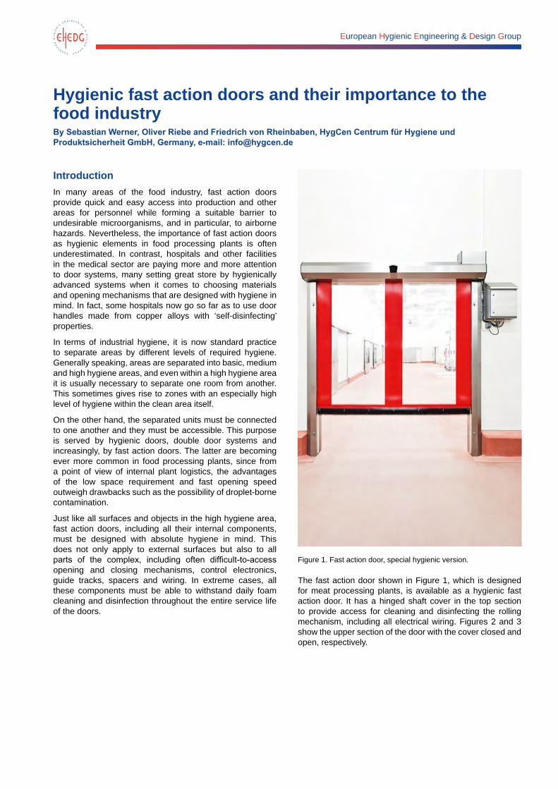
European Hygienic Engineering & Design Group
Hygienic fast action doors and their importance to the food industry By Sebastian Werner, Oliver Riebe and Friedrich von Rheinbaben, HygCen Centrum für Hygiene und Produktsicherheit GmbH, Germany, e-mail: [email protected]
IntroductionIn many areas of the food industry, fast action doors provide quick and easy access into production and other areas for personnel while forming a suitable barrier to undesirable microorganisms, and in particular, to airborne hazards. Nevertheless, the importance of fast action doors as hygienic elements in food processing plants is often underestimated. In contrast, hospitals and other facilities in the medical sector are paying more and more attention to door systems, many setting great store by hygienically advanced systems when it comes to choosing materials and opening mechanisms that are designed with hygiene in mind. In fact, some hospitals now go so far as to use door handles made from copper alloys with ‘self-disinfecting’ properties.
In terms of industrial hygiene, it is now standard practice to separate areas by different levels of required hygiene. Generally speaking, areas are separated into basic, medium and high hygiene areas, and even within a high hygiene area it is usually necessary to separate one room from another. This sometimes gives rise to zones with an especially high level of hygiene within the clean area itself.
On the other hand, the separated units must be connected to one another and they must be accessible. This purpose is served by hygienic doors, double door systems and increasingly, by fast action doors. The latter are becoming ever more common in food processing plants, since from a point of view of internal plant logistics, the advantages of the low space requirement and fast opening speed outweigh drawbacks such as the possibility of droplet-borne contamination.
Just like all surfaces and objects in the high hygiene area, fast action doors, including all their internal components, must be designed with absolute hygiene in mind. This does not only apply to external surfaces but also to all parts of the complex, including often difficult-to-access opening and closing mechanisms, control electronics, guide tracks, spacers and wiring. In extreme cases, all these components must be able to withstand daily foam cleaning and disinfection throughout the entire service life of the doors.
Figure 1. Fast action door, special hygienic version.
The fast action door shown in Figure 1, which is designed for meat processing plants, is available as a hygienic fast action door. It has a hinged shaft cover in the top section to provide access for cleaning and disinfecting the rolling mechanism, including all electrical wiring. Figures 2 and 3 show the upper section of the door with the cover closed and open, respectively.
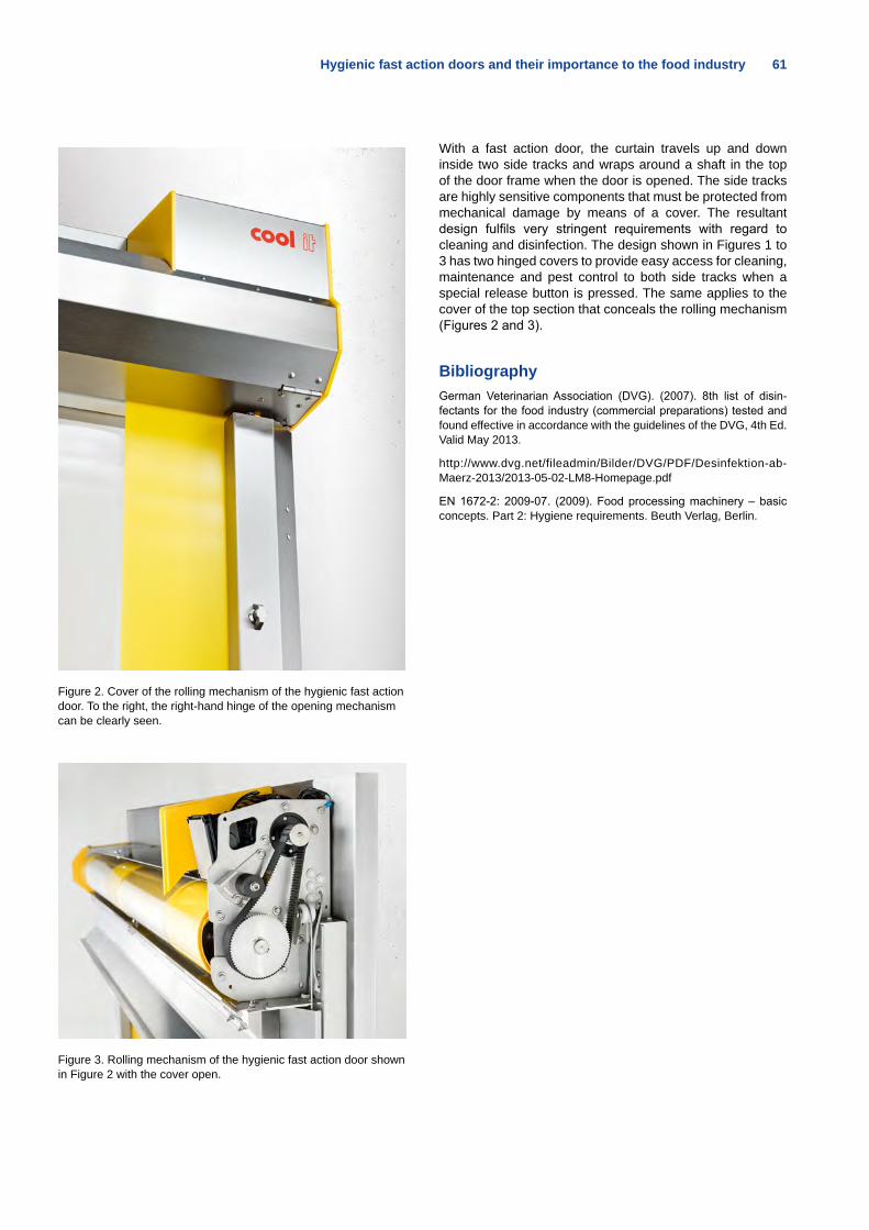
Hygienic fast action doors and their importance to the food industry 61
Figure 2. Cover of the rolling mechanism of the hygienic fast action door. To the right, the right-hand hinge of the opening mechanism can be clearly seen.
Figure 3. Rolling mechanism of the hygienic fast action door shown in Figure 2 with the cover open.
With a fast action door, the curtain travels up and down inside two side tracks and wraps around a shaft in the top of the door frame when the door is opened. The side tracks are highly sensitive components that must be protected from mechanical damage by means of a cover. The resultant design fulfils very stringent requirements with regard to cleaning and disinfection. The design shown in Figures 1 to 3 has two hinged covers to provide easy access for cleaning, maintenance and pest control to both side tracks when a special release button is pressed. The same applies to the cover of the top section that conceals the rolling mechanism (Figures 2 and 3).
BibliographyGerman Veterinarian Association (DVG). (2007). 8th list of disin-fectants for the food industry (commercial preparations) tested and found effective in accordance with the guidelines of the DVG, 4th Ed. Valid May 2013.
http://www.dvg.net/fileadmin/Bilder/DVG/PDF/Desinfektion-ab-Maerz-2013/2013-05-02-LM8-Homepage.pdf
EN 1672-2: 2009-07. (2009). Food processing machinery – basic concepts. Part 2: Hygiene requirements. Beuth Verlag, Berlin.
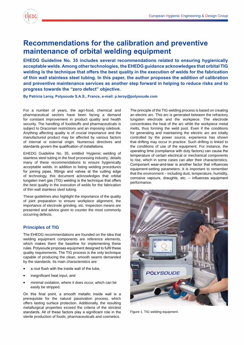
European Hygienic Engineering & Design Group
Recommendations for the calibration and preventive maintenance of orbital welding equipmentEHEDG Guideline No. 35 includes several recommendations related to ensuring hygienically acceptable welds. Among other technologies, the EHEDG guidance acknowledges that orbital TIG welding is the technique that offers the best quality in the execution of welds for the fabrication of thin wall stainless steel tubing. In this paper, the author proposes the addition of calibration and preventive maintenance services as another step forward in helping to reduce risks and to progress towards the “zero defect” objective.By Patricia Leroy, Polysoude S.A.S., France, e-mail: [email protected]
For a number of years, the agri-food, chemical and pharmaceutical sectors have been facing a demand for constant improvement in product quality and health security. The handling of foodstuffs and pharmaceuticals is subject to Draconian restrictions and an imposing rulebook. Anything affecting quality is of crucial importance and the manufactured product may be affected by various factors of internal or external origin. Numerous directives and standards govern the qualification of installations.
EHEDG Guideline No. 35, entitled ‘Hygienic welding of stainless steel tubing in the food processing industry,’ details many of these recommendations to ensure hygienically acceptable welds. In addition to listing welding procedures for joining pipes, fittings and valves at the cutting edge of technology, this document acknowledges that orbital tungsten inert gas (TIG) welding is the technique that offers the best quality in the execution of welds for the fabrication of thin wall stainless steel tubing.
These guidelines also highlight the importance of the quality of joint preparation to ensure workpiece alignment, the importance of electrode grinding, etc. Inspection means are presented and advice given to counter the most commonly occurring defects.
Principles of TIGThe EHEDG recommendations are founded on the idea that welding equipment components are reference elements, which makes them the baseline for implementing these rules. Polysoude proposes equipment designed to fulfil these quality requirements. The TIG process is the only technique capable of producing the clean, smooth seams demanded by the standards. Its main characteristics are:
• a root flush with the inside wall of the tube,
• insignificant heat input, and
• minimal oxidation, where it does occur, which can be easily be stripped.
On this final point, a smooth metallic inside wall is a prerequisite for the natural passivation process, which offers lasting surface protection. Additionally, the resulting metallurgical properties exceed the criteria of the strictest standards. All of these factors play a significant role in the sterile production of foods, pharmaceuticals and cosmetics.
The principle of the TIG welding process is based on creating an electric arc. This arc is generated between the refractory tungsten electrode and the workpiece. The electrode concentrates the heat of the arc while the workpiece metal melts, thus forming the weld pool. Even if the conditions for generating and maintaining the electric arc are totally controlled by the power source, experience has shown that drifting may occur in practice. Such drifting is linked to the conditions of use of the equipment. For instance, the operating time (compliance with duty factors) can cause the temperature of certain electrical or mechanical components to rise, which in some cases can alter their characteristics. Component wear-and-tear is another factor that influences equipment-setting parameters. It is important to remember that the environment – including dust, temperature, humidity, corrosive vapours, draughts, etc. – influences equipment performance.
Figure 1. TIG welding equipment.
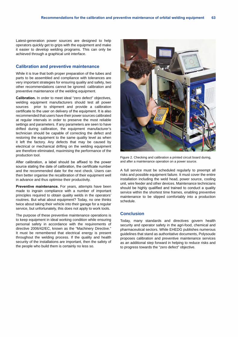
Recommendations for the calibration and preventive maintenance of orbital welding equipment 63
Latest-generation power sources are designed to help operators quickly get to grips with the equipment and make it easier to develop welding programs. This can only be achieved through a graphical unit interface.
Calibration and preventive maintenanceWhile it is true that both proper preparation of the tubes and parts to be assembled and compliance with tolerances are very important strategies for ensuring quality and safety, two other recommendations cannot be ignored: calibration and preventive maintenance of the welding equipment.
Calibration. In order to meet ideal “zero defect” objectives, welding equipment manufacturers should test all power sources prior to shipment and provide a calibration certificate to the user on delivery of the equipment. It is also recommended that users have their power sources calibrated at regular intervals in order to preserve the most reliable settings and parameters. If any parameters are seen to have drifted during calibration, the equipment manufacturer’s technician should be capable of correcting the defect and restoring the equipment to the same quality level as when it left the factory. Any defects that may be caused by electrical or mechanical drifting on the welding equipment are therefore eliminated, maximising the performance of the production tool.
After calibration, a label should be affixed to the power source stating the date of calibration, the certificate number and the recommended date for the next check. Users can then better organise the recalibration of their equipment well in advance and thus optimise their productivity.
Preventive maintenance. For years, attempts have been made to ingrain compliance with a number of important principles required to obtain quality welds in the operators’ routines. But what about equipment? Today, no one thinks twice about taking their vehicle into their garage for a regular service, but unfortunately, this does not apply to work tools.
The purpose of these preventive maintenance operations is to keep equipment in ideal working condition while ensuring personal safety in accordance with the requirements of directive 2006/42/EC, known as the “Machinery Directive.” It must be remembered that electrical energy is present throughout the welding process. If the quality and health security of the installations are important, then the safety of the people who build them is certainly no less so.
Figure 2. Checking and calibration a printed circuit board during, and after a maintenance operation on a power source.
A full service must be scheduled regularly to preempt all risks and possible equipment failure. It must cover the entire installation including the weld head, power source, cooling unit, wire feeder and other devices. Maintenance technicians should be highly qualified and trained to conduct a quality service within the shortest time frames, enabling preventive maintenance to be slipped comfortably into a production schedule.
ConclusionToday, many standards and directives govern health security and operator safety in the agri-food, chemical and pharmaceutical sectors. While EHEDG publishes numerous guidelines that stand as authoritative documents, Polysoude proposes calibration and preventive maintenance services as an additional step forward in helping to reduce risks and to progress towards the “zero defect” objective.
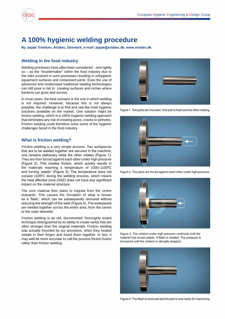
European Hygienic Engineering & Design Group
A 100% hygienic welding procedureBy Jeppe Troelsen, Aviatec, Denmark, e-mail: [email protected], www.aviatec.dk
Welding in the food industryWelding processes have often been considered – and rightly so – as the “troublemaker” within the food industry due to the risks involved in such processes resulting in unhygienic equipment surfaces and component joints. Even the use of advanced and modernised traditional welding technologies can still pose a risk in creating surfaces and niches where bacteria can grow and survive.
In most cases, the best scenario is the one in which welding is not required. However, because this is not always possible, the challenge is to find and use the most hygienic solutions available on the market. One solution might be friction welding, which is a 100% hygienic welding approach that eliminates any risk of creating pores, cracks or pinholes. Friction welding could therefore solve some of the hygienic challenges faced in the food industry.
What is friction welding?Friction welding is a very simple process. Two workpieces that are to be welded together are secured in the machine; one remains stationary while the other rotates (Figure 1). They are then forced against each other under high pressure (Figure 2). This creates friction, which quickly results in the materials reaching a temperature of 1000–1100ºC and turning ‘plastic’ (Figure 3). The temperature does not exceed 1100ºC during the welding process, which means the heat affected zone (HAZ) does not have any significant impact on the material structure.
The core material then starts to migrate from the centre outwards. This causes the formation of what is known as a ‘flash,’ which can be subsequently removed without reducing the strength of the weld (Figure 4). The workpieces are welded together across the entire area, from the centre to the outer diameter.
Friction welding is an old, documented, thoroughly tested technique distinguished by its ability to create welds that are often stronger than the original materials. Friction welding was actually invented by our ancestors, when they heated metals in their forges and fused them together. In fact, it may well be more accurate to call the process friction fusion rather than friction welding.
Figure 1. Two parts are mounted. One part is fixed and the other rotating.
Figure 2. The parts are forced against each other under high pressure.
Figure 3. The rotation under high pressure continues until the material has turned plastic. A flash is created. The pressure is increased until the rotation is abruptly stopped.
Figure 4. The flash is removed and the part is now ready for machining.
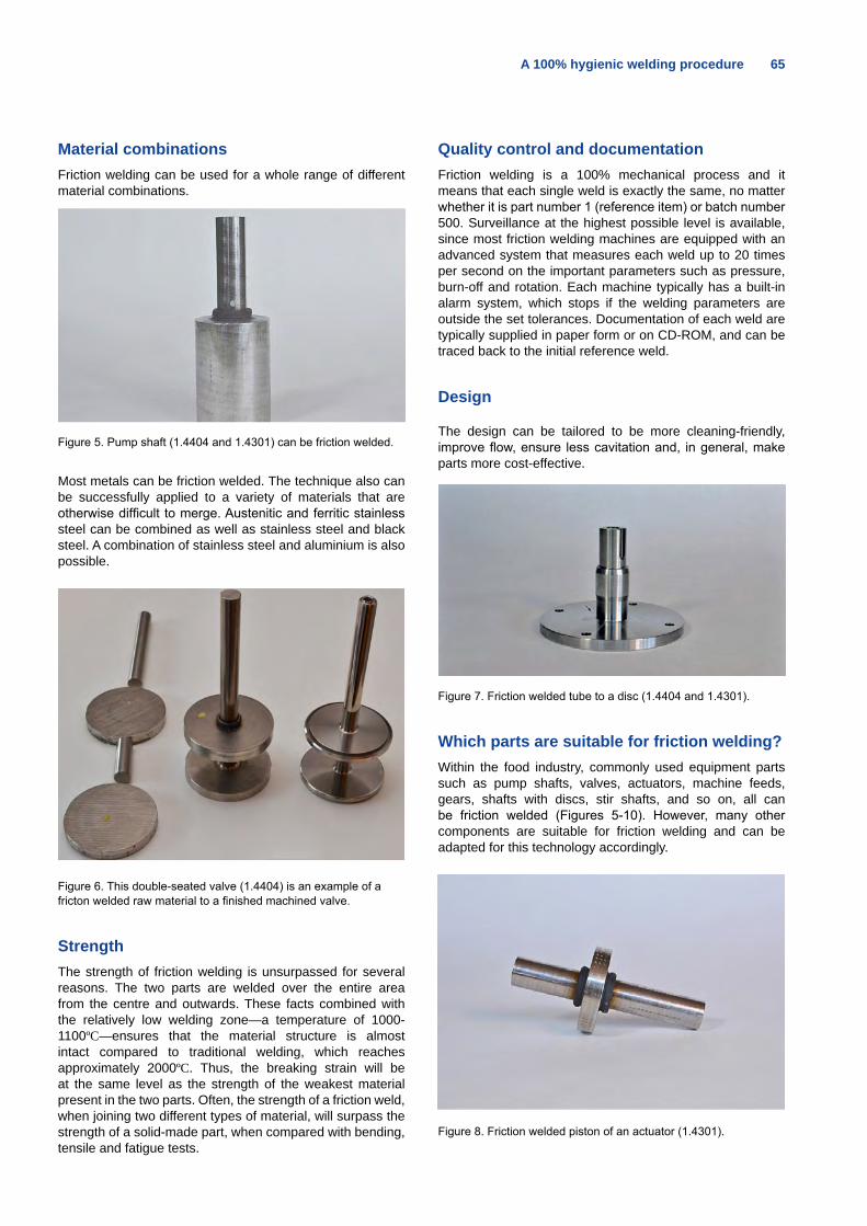
A 100% hygienic welding procedure 65
Material combinationsFriction welding can be used for a whole range of different material combinations.
Figure 5. Pump shaft (1.4404 and 1.4301) can be friction welded.
Most metals can be friction welded. The technique also can be successfully applied to a variety of materials that are otherwise difficult to merge. Austenitic and ferritic stainless steel can be combined as well as stainless steel and black steel. A combination of stainless steel and aluminium is also possible.
Figure 6. This double-seated valve (1.4404) is an example of a fricton welded raw material to a finished machined valve.
StrengthThe strength of friction welding is unsurpassed for several reasons. The two parts are welded over the entire area from the centre and outwards. These facts combined with the relatively low welding zone—a temperature of 1000-1100ºC—ensures that the material structure is almost intact compared to traditional welding, which reaches approximately 2000ºC. Thus, the breaking strain will be at the same level as the strength of the weakest material present in the two parts. Often, the strength of a friction weld, when joining two different types of material, will surpass the strength of a solid-made part, when compared with bending, tensile and fatigue tests.
Quality control and documentationFriction welding is a 100% mechanical process and it means that each single weld is exactly the same, no matter whether it is part number 1 (reference item) or batch number 500. Surveillance at the highest possible level is available, since most friction welding machines are equipped with an advanced system that measures each weld up to 20 times per second on the important parameters such as pressure, burn-off and rotation. Each machine typically has a built-in alarm system, which stops if the welding parameters are outside the set tolerances. Documentation of each weld are typically supplied in paper form or on CD-ROM, and can be traced back to the initial reference weld.
Design
The design can be tailored to be more cleaning-friendly, improve flow, ensure less cavitation and, in general, make parts more cost-effective.
Figure 7. Friction welded tube to a disc (1.4404 and 1.4301).
Which parts are suitable for friction welding?Within the food industry, commonly used equipment parts such as pump shafts, valves, actuators, machine feeds, gears, shafts with discs, stir shafts, and so on, all can be friction welded (Figures 5-10). However, many other components are suitable for friction welding and can be adapted for this technology accordingly.
Figure 8. Friction welded piston of an actuator (1.4301).
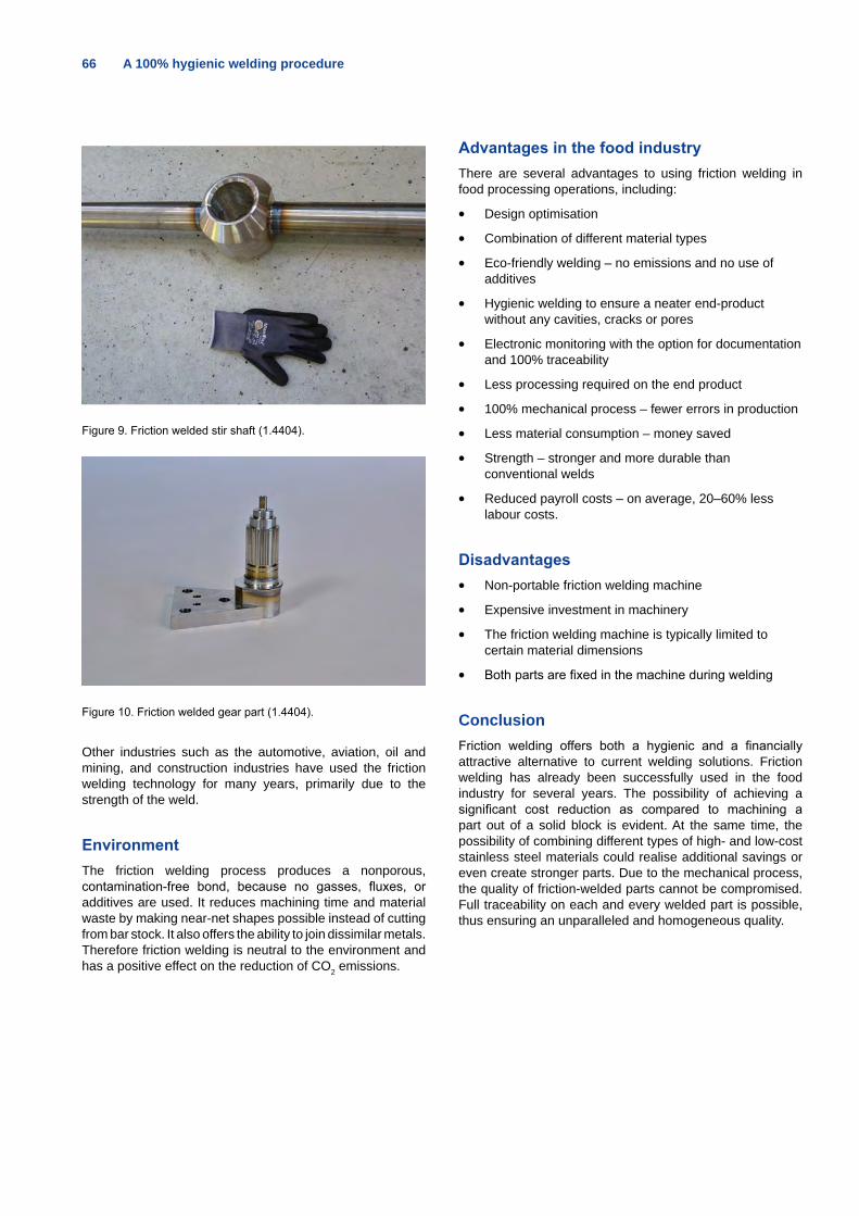
66 A 100% hygienic welding procedure
Figure 9. Friction welded stir shaft (1.4404).
Figure 10. Friction welded gear part (1.4404).
Other industries such as the automotive, aviation, oil and mining, and construction industries have used the friction welding technology for many years, primarily due to the strength of the weld.
EnvironmentThe friction welding process produces a nonporous, contamination-free bond, because no gasses, fluxes, or additives are used. It reduces machining time and material waste by making near-net shapes possible instead of cutting from bar stock. It also offers the ability to join dissimilar metals. Therefore friction welding is neutral to the environment and has a positive effect on the reduction of CO2 emissions.
Advantages in the food industryThere are several advantages to using friction welding in food processing operations, including:
• Design optimisation
• Combination of different material types
• Eco-friendly welding – no emissions and no use of additives
• Hygienic welding to ensure a neater end-product without any cavities, cracks or pores
• Electronic monitoring with the option for documentation and 100% traceability
• Less processing required on the end product
• 100% mechanical process – fewer errors in production
• Less material consumption – money saved
• Strength – stronger and more durable than conventional welds
• Reduced payroll costs – on average, 20–60% less labour costs.
Disadvantages• Non-portable friction welding machine
• Expensive investment in machinery
• The friction welding machine is typically limited to certain material dimensions
• Both parts are fixed in the machine during welding
ConclusionFriction welding offers both a hygienic and a financially attractive alternative to current welding solutions. Friction welding has already been successfully used in the food industry for several years. The possibility of achieving a significant cost reduction as compared to machining a part out of a solid block is evident. At the same time, the possibility of combining different types of high- and low-cost stainless steel materials could realise additional savings or even create stronger parts. Due to the mechanical process, the quality of friction-welded parts cannot be compromised. Full traceability on each and every welded part is possible, thus ensuring an unparalleled and homogeneous quality.
Custom-designed: LEWA EcoPrime® chromatography systems
From pilot to production LEWA EcoPrime‘s key benefi ts are:
– Widest dynamic fl ow range 150:1– Signifi cant reduction in pulsation and hold-up volume– Low shear to process biomolecules– Full linear gradient capability from 1.0 % to 99.0 %
www.lewa.com
LEWA_AZ_Clean_EHEDG_V4.indd 1 30.06.14 10:46
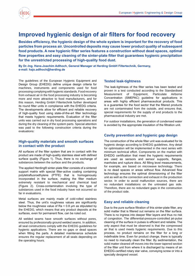
European Hygienic Engineering & Design Group
Improved hygienic design of air filters for food recoveryBesides efficiency, the hygienic design of the whole system is important for the recovery of food particles from process air. Uncontrolled deposits may cause lower product quality of subsequent food products. A new hygienic filter series features a construction without dead spaces, optimal flow properties and easy cleaning of the sinter-plate filter that guarantees hygienic precipitation for the unrestricted processing of high-quality food dust.By Dr.-Ing. Hans-Joachim Adlhoch, General Manager at Herding GmbH Filtertechnik, Germany, e-mail: [email protected]
The guidelines of the European Hygienic Equipment and Design Group (EHEDG) define unique design criteria for machines, instruments and components used for food processing complying with hygienic standards. Food recovery from exhaust air in the food processing industry is becoming more and more attractive to food manufacturers, and for this reason, Herding GmbH Filtertechnik further developed its round filter units in compliance with the EHEDG criteria. The developments allow for efficient and reliable recovery of high-quality food using state-of-the-art filter technology that meets hygienic requirements. Evaluation of the filter units was carried out in dry food processing operations and during the dry cleaning of the system parts. Special attention was paid to the following construction criteria during the evaluations:
High-quality materials and smooth surfaces in contact with the productAll surfaces of the filter system that are in contact with the product are made of high-quality stainless steel with defined surface quality (Figure 1). Thus, there is no exchange of substances between the surface and the products.
The applied Herding® sinter-plate filter consists of a sintered support matrix with special filter-active coating containing polytetrafluoroethylene (PTFE) that is homogenously incorporated in the surface, making the filter medium extremely resistant to mechanical and chemical load (Figure 2). Cross-contamination involving the type of substances used in the food industry have not occurred so far in evaluations.
Metal surfaces are mainly made of cold-rolled stainless steel. Thus, the unit’s roughness values are significantly below the roughness value of Ra < 0.8 μm as stipulated by the EHEDG, which means that any product deposits at the surfaces, even for permanent flow, can be ruled out.
All welded seams have smooth surfaces without pores, ensured by professionally ground welded seams. In addition, all seal constructions comply with the EHEDG guidelines for hygienic applications. There are no gaps or dead spaces when fitting the parts. A detailed maintenance schedule ensures the regular replacement of all seals depending on the operating hours.
Tested leak-tightnessThe leak-tightness of the filter series has been tested and proven in a test conducted according to the Standardised Measurement of Equipment, Particulate Airborne Concentration (SMEPAC) guideline for applications in areas with highly efficient pharmaceutical products. This is a guarantee for the food sector that the filtered products are not contaminated from the outside, and ensures that, special requirements for the supply of end products to the pharmaceutical industry are met.
For outdoor installations, the generation of condensed water is avoided by the appropriate insulation of the filtration unit.
Cavity prevention and hygienic gap designThe construction of the whole filter unit was evaluated for its hygienic design according to EHEDG guidelines. Any detail for optimisation will be implemented in the next series with minimum technical effort. Components on the market with EHEDG certification that meet the hygienic requirements are used as sensors and sensor supports, flanges, manholes and rupture discs. All filling level measurements, for example, are based on microwave technology. There is no dead spaces or areas without flow. Advanced flow technology ensures the optimal dimensioning of the filter unit as well as the connection and exhaust in the production sector. In order to avoid malfunction sources, there are no redundant installations on the untreated gas side. Therefore, there are no redundant gaps in the construction of the product side.
Easy and reliable cleaningDue to the pure surface filtration of this sinter-plate filter, any solid matter that is filtered out remains on the filter surface. There is no ingress into deeper filter layers and thus no risk of congestion. The differential-pressure-controlled jet-pulse cleaning of the surface in pulses is efficient and reliable. The only aspect that must be observed is that the compressed air that is used meets hygienic requirements. Due to this process, no product remains on the filter for a long or indefinable time. Even for product change, there is typically no need to manually clean the filter. By sedimentation, the solid matter cleaned off moves into the lower tapered section of the filter unit from where it is discharged by means of an EHEDG-certified rotary star valve, conveying screw or into a specially designed vessel.
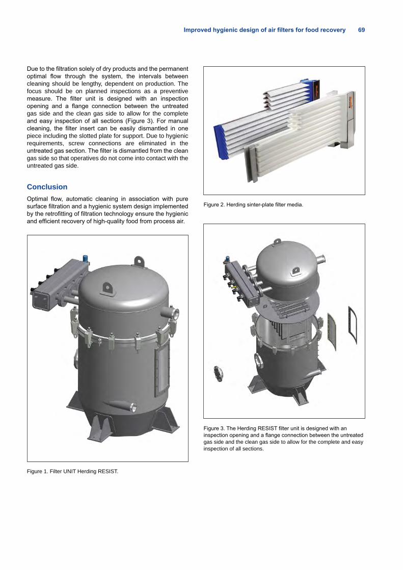
Improved hygienic design of air filters for food recovery 69
Due to the filtration solely of dry products and the permanent optimal flow through the system, the intervals between cleaning should be lengthy, dependent on production. The focus should be on planned inspections as a preventive measure. The filter unit is designed with an inspection opening and a flange connection between the untreated gas side and the clean gas side to allow for the complete and easy inspection of all sections (Figure 3). For manual cleaning, the filter insert can be easily dismantled in one piece including the slotted plate for support. Due to hygienic requirements, screw connections are eliminated in the untreated gas section. The filter is dismantled from the clean gas side so that operatives do not come into contact with the untreated gas side.
ConclusionOptimal flow, automatic cleaning in association with pure surface filtration and a hygienic system design implemented by the retrofitting of filtration technology ensure the hygienic and efficient recovery of high-quality food from process air.
Figure 1. Filter UNIT Herding RESIST.
Figure 2. Herding sinter-plate filter media.
Figure 3. The Herding RESIST filter unit is designed with an inspection opening and a flange connection between the untreated gas side and the clean gas side to allow for the complete and easy inspection of all sections.
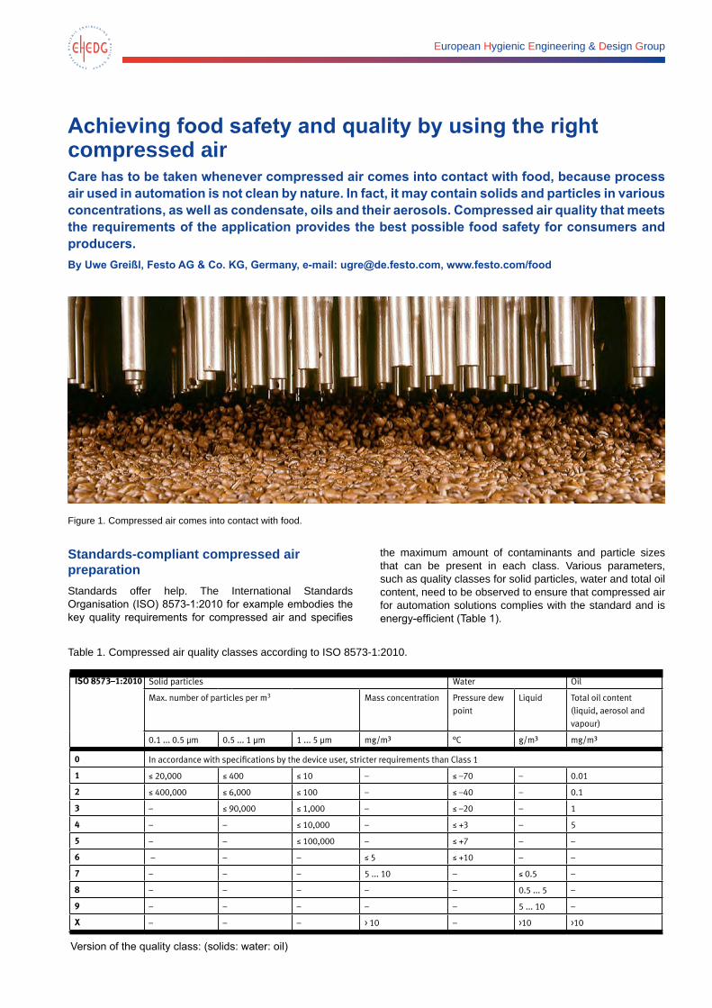
European Hygienic Engineering & Design Group
Achieving food safety and quality by using the right compressed air Care has to be taken whenever compressed air comes into contact with food, because process air used in automation is not clean by nature. In fact, it may contain solids and particles in various concentrations, as well as condensate, oils and their aerosols. Compressed air quality that meets the requirements of the application provides the best possible food safety for consumers and producers.By Uwe Greißl, Festo AG & Co. KG, Germany, e-mail: [email protected], www.festo.com/food
Figure 1. Compressed air comes into contact with food.
Standards-compliant compressed air preparation Standards offer help. The International Standards Organisation (ISO) 8573-1:2010 for example embodies the key quality requirements for compressed air and specifies
the maximum amount of contaminants and particle sizes that can be present in each class. Various parameters, such as quality classes for solid particles, water and total oil content, need to be observed to ensure that compressed air for automation solutions complies with the standard and is energy-efficient (Table 1).
Table 1. Compressed air quality classes according to ISO 8573-1:2010.Compressed air quality classes to ISO 8573-1:2010
ISO 8573–1:2010 Solid particles Water Oil
Max. number of particles per m3 Mass concentration Pressure dew point
Liquid Total oil content (liquid, aerosol and vapour)
0.1 ... 0.5 µm 0.5 ... 1 µm 1 ... 5 µm mg/m³ °C g/m³ mg/m³
0 In accordance with specifications by the device user, stricter requirements than Class 1
1 ≤ 20,000 ≤ 400 ≤ 10 – ≤ –70 – 0.01
2 ≤ 400,000 ≤ 6,000 ≤ 100 – ≤ –40 – 0.1
3 – ≤ 90,000 ≤ 1,000 – ≤ –20 – 1
4 – – ≤ 10,000 – ≤ +3 – 5
5 – – ≤ 100,000 – ≤ +7 – –
6 – – – ≤ 5 ≤ +10 – –
7 – – – 5 ... 10 – ≤ 0.5 –
8 – – – – – 0.5 ... 5 –
9 – – – – – 5 ... 10 –
X – – – > 10 – >10 >10
Version of the quality class: (solids: water: oil)
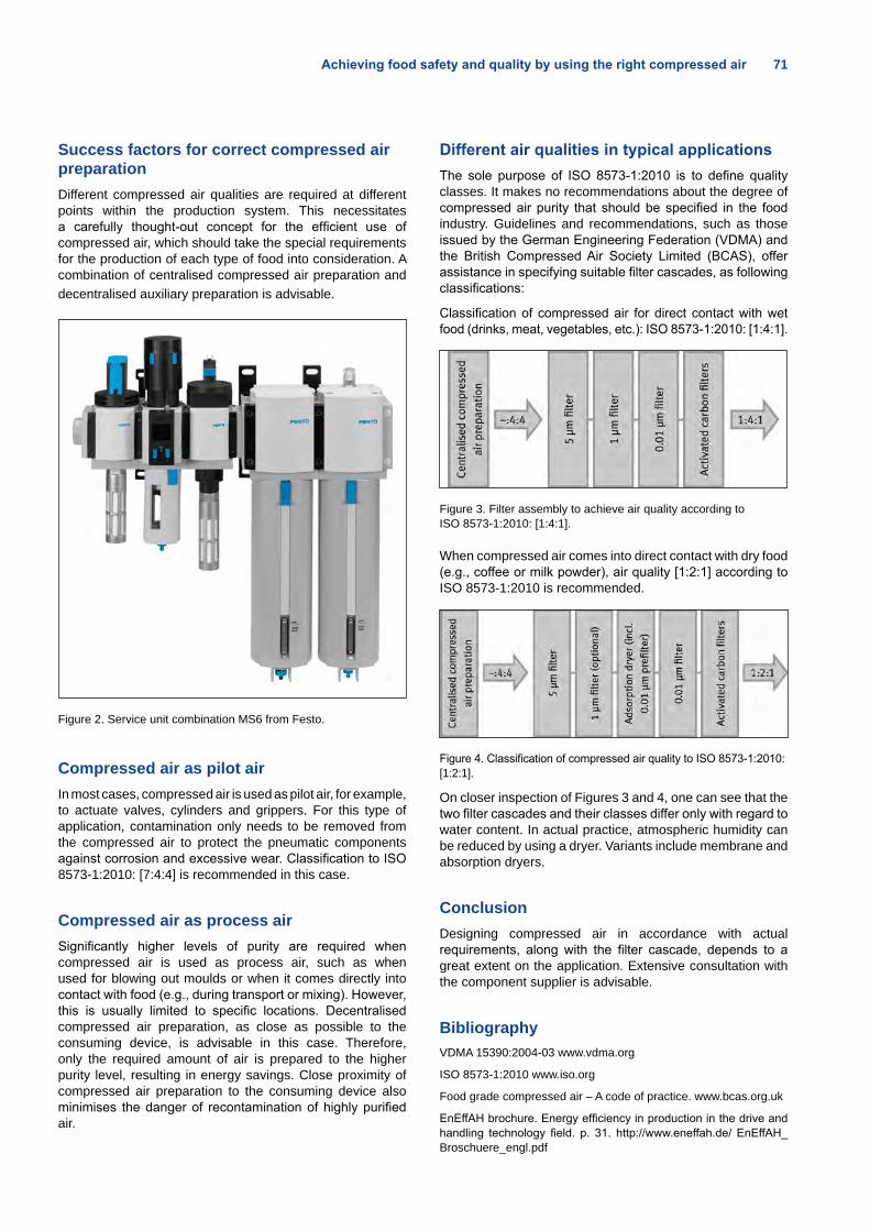
Achieving food safety and quality by using the right compressed air 71
Success factors for correct compressed air preparationDifferent compressed air qualities are required at different points within the production system. This necessitates a carefully thought-out concept for the efficient use of compressed air, which should take the special requirements for the production of each type of food into consideration. A combination of centralised compressed air preparation and decentralised auxiliary preparation is advisable.
Figure 2. Service unit combination MS6 from Festo.
Compressed air as pilot airIn most cases, compressed air is used as pilot air, for example, to actuate valves, cylinders and grippers. For this type of application, contamination only needs to be removed from the compressed air to protect the pneumatic components against corrosion and excessive wear. Classification to ISO 8573-1:2010: [7:4:4] is recommended in this case.
Compressed air as process airSignificantly higher levels of purity are required when compressed air is used as process air, such as when used for blowing out moulds or when it comes directly into contact with food (e.g., during transport or mixing). However, this is usually limited to specific locations. Decentralised compressed air preparation, as close as possible to the consuming device, is advisable in this case. Therefore, only the required amount of air is prepared to the higher purity level, resulting in energy savings. Close proximity of compressed air preparation to the consuming device also minimises the danger of recontamination of highly purified air.
Different air qualities in typical applicationsThe sole purpose of ISO 8573-1:2010 is to define quality classes. It makes no recommendations about the degree of compressed air purity that should be specified in the food industry. Guidelines and recommendations, such as those issued by the German Engineering Federation (VDMA) and the British Compressed Air Society Limited (BCAS), offer assistance in specifying suitable filter cascades, as following classifications:
Classification of compressed air for direct contact with wet food (drinks, meat, vegetables, etc.): ISO 8573-1:2010: [1:4:1].
Figure 3. Filter assembly to achieve air quality according to ISO 8573-1:2010: [1:4:1].
When compressed air comes into direct contact with dry food (e.g., coffee or milk powder), air quality [1:2:1] according to ISO 8573-1:2010 is recommended.
Figure 4. Classification of compressed air quality to ISO 8573-1:2010: [1:2:1].
On closer inspection of Figures 3 and 4, one can see that the two filter cascades and their classes differ only with regard to water content. In actual practice, atmospheric humidity can be reduced by using a dryer. Variants include membrane and absorption dryers.
Conclusion Designing compressed air in accordance with actual requirements, along with the filter cascade, depends to a great extent on the application. Extensive consultation with the component supplier is advisable.
BibliographyVDMA 15390:2004-03 www.vdma.org
ISO 8573-1:2010 www.iso.org
Food grade compressed air – A code of practice. www.bcas.org.uk
EnEffAH brochure. Energy efficiency in production in the drive and handling technology field. p. 31. http://www.eneffah.de/ EnEffAH_Broschuere_engl.pdf
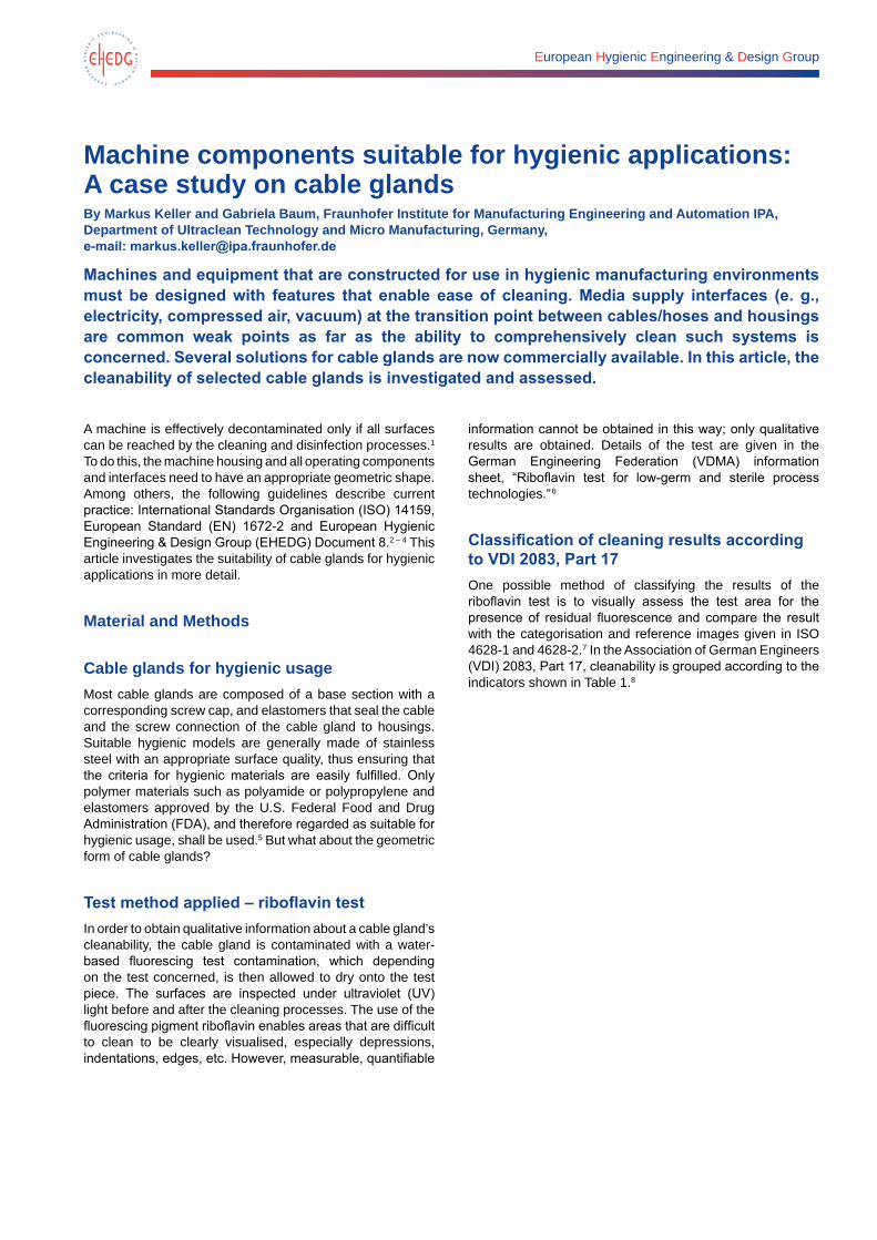
European Hygienic Engineering & Design Group
Machine components suitable for hygienic applications: A case study on cable glandsBy Markus Keller and Gabriela Baum, Fraunhofer Institute for Manufacturing Engineering and Automation IPA, Department of Ultraclean Technology and Micro Manufacturing, Germany, e-mail: [email protected]
Machines and equipment that are constructed for use in hygienic manufacturing environments must be designed with features that enable ease of cleaning. Media supply interfaces (e. g., electricity, compressed air, vacuum) at the transition point between cables/hoses and housings are common weak points as far as the ability to comprehensively clean such systems is concerned. Several solutions for cable glands are now commercially available. In this article, the cleanability of selected cable glands is investigated and assessed.
A machine is effectively decontaminated only if all surfaces can be reached by the cleaning and disinfection processes.1 To do this, the machine housing and all operating components and interfaces need to have an appropriate geometric shape. Among others, the following guidelines describe current practice: International Standards Organisation (ISO) 14159, European Standard (EN) 1672-2 and European Hygienic Engineering & Design Group (EHEDG) Document 8.2 – 4 This article investigates the suitability of cable glands for hygienic applications in more detail.
Material and Methods Cable glands for hygienic usageMost cable glands are composed of a base section with a corresponding screw cap, and elastomers that seal the cable and the screw connection of the cable gland to housings. Suitable hygienic models are generally made of stainless steel with an appropriate surface quality, thus ensuring that the criteria for hygienic materials are easily fulfilled. Only polymer materials such as polyamide or polypropylene and elastomers approved by the U.S. Federal Food and Drug Administration (FDA), and therefore regarded as suitable for hygienic usage, shall be used.5 But what about the geometric form of cable glands?
Test method applied – riboflavin test In order to obtain qualitative information about a cable gland’s cleanability, the cable gland is contaminated with a water-based fluorescing test contamination, which depending on the test concerned, is then allowed to dry onto the test piece. The surfaces are inspected under ultraviolet (UV) light before and after the cleaning processes. The use of the fluorescing pigment riboflavin enables areas that are difficult to clean to be clearly visualised, especially depressions, indentations, edges, etc. However, measurable, quantifiable
information cannot be obtained in this way; only qualitative results are obtained. Details of the test are given in the German Engineering Federation (VDMA) information sheet, “Riboflavin test for low-germ and sterile process technologies.”6
Classification of cleaning results according to VDI 2083, Part 17One possible method of classifying the results of the riboflavin test is to visually assess the test area for the presence of residual fluorescence and compare the result with the categorisation and reference images given in ISO 4628-1 and 4628-2.7 In the Association of German Engineers (VDI) 2083, Part 17, cleanability is grouped according to the indicators shown in Table 1.8
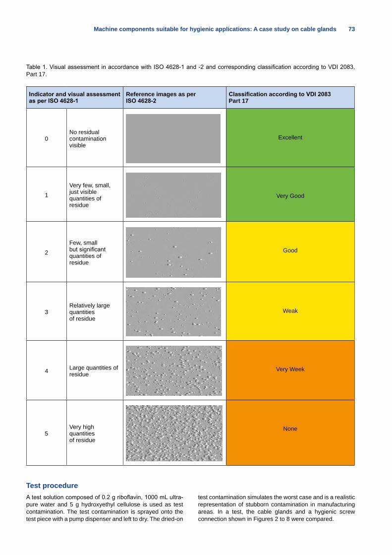
Machine components suitable for hygienic applications: A case study on cable glands 73
Table 1. Visual assessment in accordance with ISO 4628-1 and -2 and corresponding classification according to VDI 2083, Part 17.
Indicator and visual assessment as per ISO 4628-1
Reference images as per ISO 4628-2
Classification according to VDI 2083 Part 17
0No residual contamination visible
Excellent
1
Very few, small, just visible quantities of resid ue
Very Good
2
Few, small but significant quantities of residue
Good
3Relatively large quantities of residue
Weak
4 Large quantities of residue
Very Week
5Very high quantities of residue
None
Test procedureA test solution composed of 0.2 g riboflavin, 1000 mL ultra-pure water and 5 g hydroxyethyl cellulose is used as test contamination. The test contamination is sprayed onto the test piece with a pump dispenser and left to dry. The dried-on
test contamination simulates the worst case and is a realistic representation of stubborn contamination in manufacturing areas. In a test, the cable glands and a hygienic screw connection shown in Figures 2 to 8 were compared.
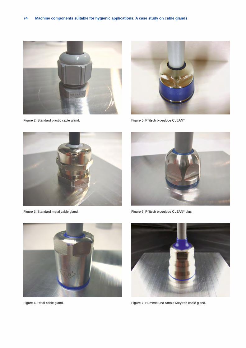
74 Machine components suitable for hygienic applications: A case study on cable glands
Figure 2. Standard plastic cable gland.
Figure 3. Standard metal cable gland.
Figure 4. Rittal cable gland.
Figure 5. Pflitsch blueglobe CLEAN®.
Figure 6. Pflitsch blueglobe CLEAN® plus.
Figure 7. Hummel und Arnold Meytron cable gland.
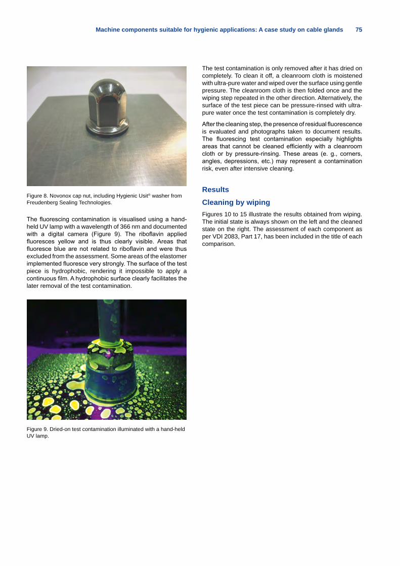
Machine components suitable for hygienic applications: A case study on cable glands 75
Figure 8. Novonox cap nut, including Hygienic Usit® washer from Freudenberg Sealing Technologies.
The fluorescing contamination is visualised using a hand-held UV lamp with a wavelength of 366 nm and documented with a digital camera (Figure 9). The riboflavin applied fluoresces yellow and is thus clearly visible. Areas that fluoresce blue are not related to riboflavin and were thus excluded from the assessment. Some areas of the elastomer implemented fluoresce very strongly. The surface of the test piece is hydrophobic, rendering it impossible to apply a continuous film. A hydrophobic surface clearly facilitates the later removal of the test contamination.
Figure 9. Dried-on test contamination illuminated with a hand-held UV lamp.
The test contamination is only removed after it has dried on completely. To clean it off, a cleanroom cloth is moistened with ultra-pure water and wiped over the surface using gentle pressure. The cleanroom cloth is then folded once and the wiping step repeated in the other direction. Alternatively, the surface of the test piece can be pressure-rinsed with ultra-pure water once the test contamination is completely dry.
After the cleaning step, the presence of residual fluorescence is evaluated and photographs taken to document results. The fluorescing test contamination especially highlights areas that cannot be cleaned efficiently with a cleanroom cloth or by pressure-rinsing. These areas (e. g., corners, angles, depressions, etc.) may represent a contamination risk, even after intensive cleaning.
ResultsCleaning by wipingFigures 10 to 15 illustrate the results obtained from wiping. The initial state is always shown on the left and the cleaned state on the right. The assessment of each component as per VDI 2083, Part 17, has been included in the title of each comparison.
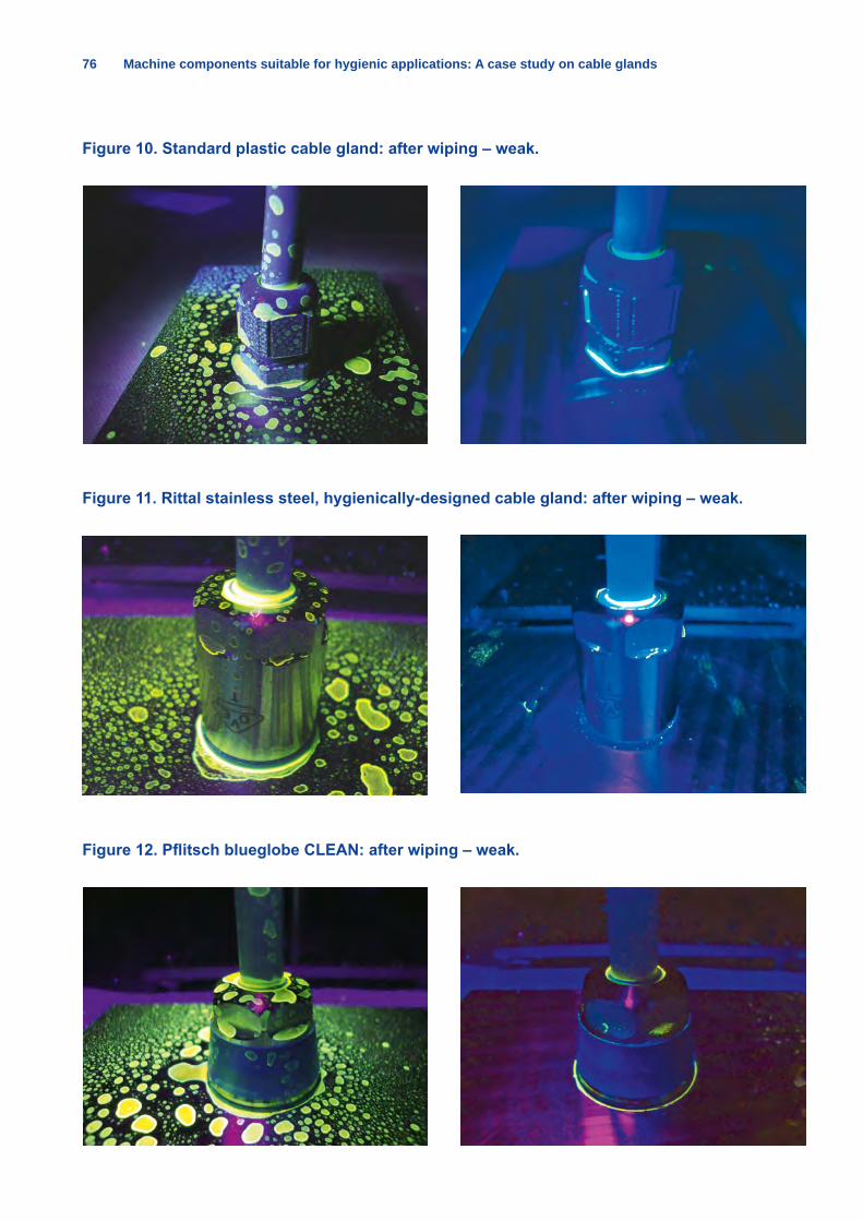
76 Machine components suitable for hygienic applications: A case study on cable glands
Figure 10. Standard plastic cable gland: after wiping – weak.
Figure 11. Rittal stainless steel, hygienically-designed cable gland: after wiping – weak.
Figure 12. Pflitsch blueglobe CLEAN: after wiping – weak.
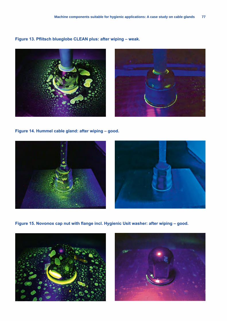
Machine components suitable for hygienic applications: A case study on cable glands 77
Figure 13. Pflitsch blueglobe CLEAN plus: after wiping – weak.
Figure 14. Hummel cable gland: after wiping – good.
Figure 15. Novonox cap nut with flange incl. Hygienic Usit washer: after wiping – good.
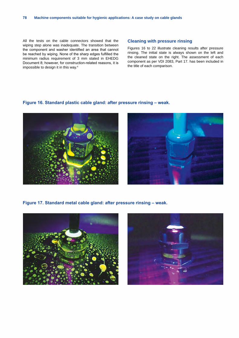
78 Machine components suitable for hygienic applications: A case study on cable glands
All the tests on the cable connectors showed that the wiping step alone was inadequate. The transition between the component and washer identified an area that cannot be reached by wiping. None of the sharp edges fulfilled the minimum radius requirement of 3 mm stated in EHEDG Document 8; however, for construction-related reasons, it is impossible to design it in this way.4
Cleaning with pressure rinsing Figures 16 to 22 illustrate cleaning results after pressure rinsing. The initial state is always shown on the left and the cleaned state on the right. The assessment of each component as per VDI 2083, Part 17. has been included in the title of each comparison.
Figure 16. Standard plastic cable gland: after pressure rinsing – weak.
Figure 17. Standard metal cable gland: after pressure rinsing – weak.
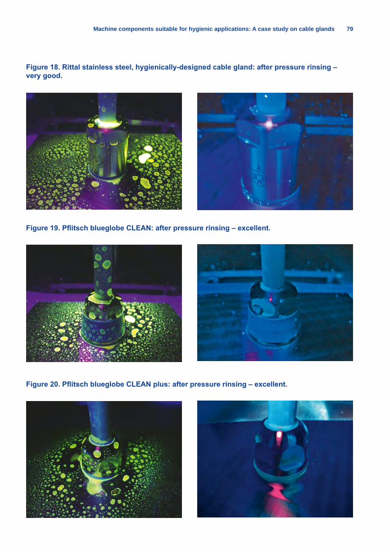
Machine components suitable for hygienic applications: A case study on cable glands 79
Figure 18. Rittal stainless steel, hygienically-designed cable gland: after pressure rinsing – very good.
Figure 19. Pflitsch blueglobe CLEAN: after pressure rinsing – excellent.
Figure 20. Pflitsch blueglobe CLEAN plus: after pressure rinsing – excellent.
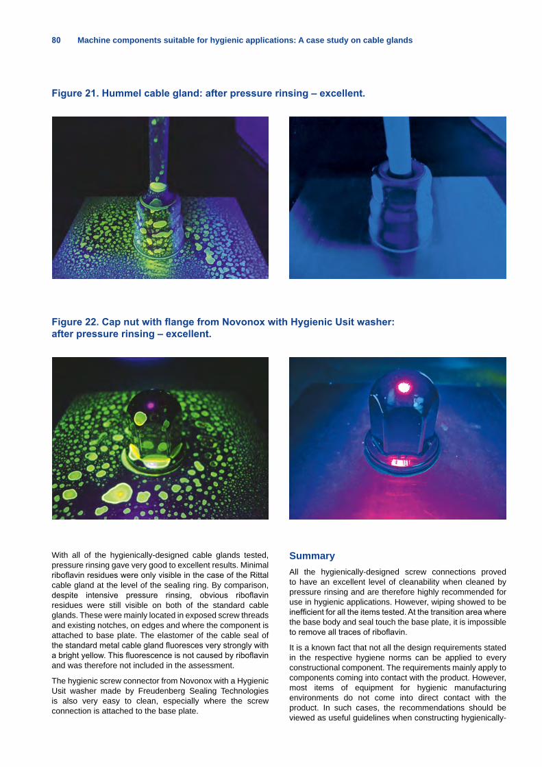
80 Machine components suitable for hygienic applications: A case study on cable glands
With all of the hygienically-designed cable glands tested, pressure rinsing gave very good to excellent results. Minimal riboflavin residues were only visible in the case of the Rittal cable gland at the level of the sealing ring. By comparison, despite intensive pressure rinsing, obvious riboflavin residues were still visible on both of the standard cable glands. These were mainly located in exposed screw threads and existing notches, on edges and where the component is attached to base plate. The elastomer of the cable seal of the standard metal cable gland fluoresces very strongly with a bright yellow. This fluorescence is not caused by riboflavin and was therefore not included in the assessment.
The hygienic screw connector from Novonox with a Hygienic Usit washer made by Freudenberg Sealing Technologies is also very easy to clean, especially where the screw connection is attached to the base plate.
SummaryAll the hygienically-designed screw connections proved to have an excellent level of cleanability when cleaned by pressure rinsing and are therefore highly recommended for use in hygienic applications. However, wiping showed to be inefficient for all the items tested. At the transition area where the base body and seal touch the base plate, it is impossible to remove all traces of riboflavin.
It is a known fact that not all the design requirements stated in the respective hygiene norms can be applied to every constructional component. The requirements mainly apply to components coming into contact with the product. However, most items of equipment for hygienic manufacturing environments do not come into direct contact with the product. In such cases, the recommendations should be viewed as useful guidelines when constructing hygienically-
Figure 21. Hummel cable gland: after pressure rinsing – excellent.
Figure 22. Cap nut with flange from Novonox with Hygienic Usit washer: after pressure rinsing – excellent.
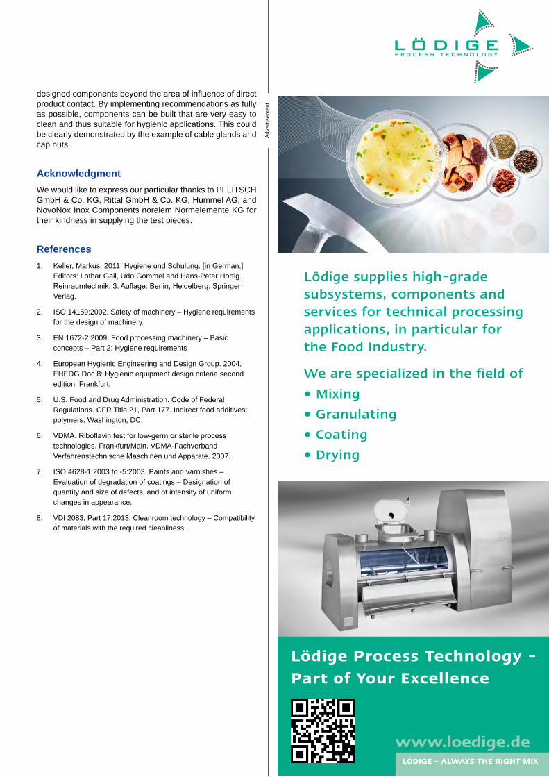
designed components beyond the area of influence of direct product contact. By implementing recommendations as fully as possible, components can be built that are very easy to clean and thus suitable for hygienic applications. This could be clearly demonstrated by the example of cable glands and cap nuts.
AcknowledgmentWe would like to express our particular thanks to PFLITSCH GmbH & Co. KG, Rittal GmbH & Co. KG, Hummel AG, and NovoNox Inox Components norelem Normelemente KG for their kindness in supplying the test pieces.
References1. Keller, Markus. 2011. Hygiene und Schulung. [in German.]
Editors: Lothar Gail, Udo Gommel and Hans-Peter Hortig. Reinraumtechnik. 3. Auflage. Berlin, Heidelberg. Springer Verlag.
2. ISO 14159:2002. Safety of machinery – Hygiene requirements for the design of machinery.
3. EN 1672-2:2009. Food processing machinery – Basic concepts – Part 2: Hygiene requirements
4. European Hygienic Engineering and Design Group. 2004.EHEDG Doc 8: Hygienic equipment design criteria second edition. Frankfurt.
5. U.S. Food and Drug Administration. Code of Federal Regulations. CFR Title 21, Part 177. Indirect food additives: polymers. Washington, DC.
6. VDMA. Riboflavin test for low-germ or sterile process technologies. Frankfurt/Main. VDMA-Fachverband Verfahrenstechnische Maschinen und Apparate. 2007.
7. ISO 4628-1:2003 to -5:2003. Paints and varnishes – Evaluation of degradation of coatings – Designation of quantity and size of defects, and of intensity of uniform changes in appearance.
8. VDI 2083, Part 17:2013. Cleanroom technology – Compatibility of materials with the required cleanliness.
Adv
ertis
emen
t
Lödige Process Technology -Part of Your Excellence
We are specialized in the field of
• Mixing
• Granulating
• Coating
• Drying
Lödige supplies high-gradesubsystems, components andservices for technical processingapplications, in particular forthe Food Industry.
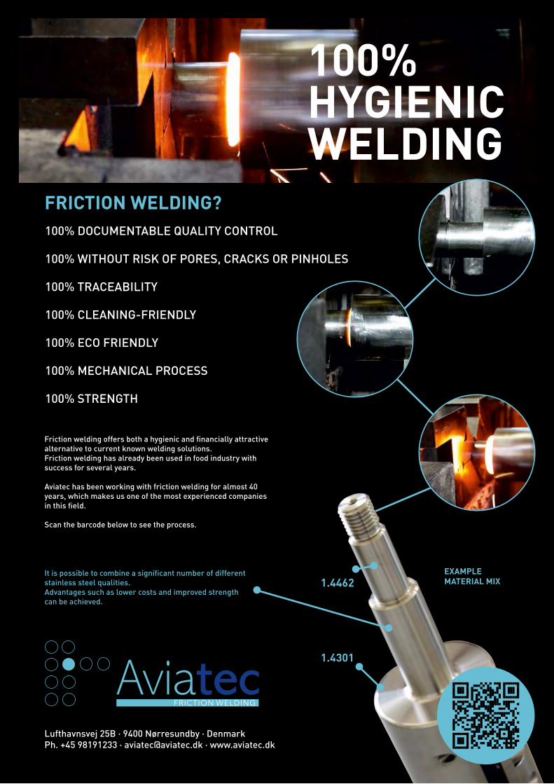
100% HYGIENIC WELDING
100% DOCUMENTABLE QUALITY CONTROL
100% WITHOUT RISK OF PORES, CRACKS OR PINHOLES
100% TRACEABILITY
100% CLEANING-FRIENDLY
100% ECO FRIENDLY
100% MECHANICAL PROCESS
100% STRENGTH
FRICTION WELDING?
AviatecFRICTION WELDING
Lufthavnsvej 25B · 9400 Nørresundby · Denmark Ph. +45 98191233 · [email protected] · www.aviatec.dk
EXAMPLE MATERIAL MIX
1.4301
Friction welding offers both a hygienic and financially attractivealternative to current known welding solutions.Friction welding has already been used in food industry withsuccess for several years.
Aviatec has been working with friction welding for almost 40 years, which makes us one of the most experienced companiesin this field.
Scan the barcode below to see the process.
1.4462It is possible to combine a significant number of different stainless steel qualities.Advantages such as lower costs and improved strength can be achieved.

European Hygienic Engineering & Design Group
100% HYGIENIC WELDING
100% DOCUMENTABLE QUALITY CONTROL
100% WITHOUT RISK OF PORES, CRACKS OR PINHOLES
100% TRACEABILITY
100% CLEANING-FRIENDLY
100% ECO FRIENDLY
100% MECHANICAL PROCESS
100% STRENGTH
FRICTION WELDING?
AviatecFRICTION WELDING
Lufthavnsvej 25B · 9400 Nørresundby · Denmark Ph. +45 98191233 · [email protected] · www.aviatec.dk
EXAMPLE MATERIAL MIX
1.4301
Friction welding offers both a hygienic and financially attractivealternative to current known welding solutions.Friction welding has already been used in food industry withsuccess for several years.
Aviatec has been working with friction welding for almost 40 years, which makes us one of the most experienced companiesin this field.
Scan the barcode below to see the process.
1.4462It is possible to combine a significant number of different stainless steel qualities.Advantages such as lower costs and improved strength can be achieved.
It´s “Only” FoodThis article discusses the underestimated explosion hazards in food handling facilities with regard to sanitary/hygienic design requirements.By Dr. Ing. Johannes Lottermann, REMBE GmbH Safety + Control, Brilon, Germany, e-mail: [email protected]
Any airborne organic dust that can burn, such as milk powder, could lead to an explosive atmosphere in a food handling facility. If there is a combination of such dusts with a sufficient ignition source, explosions can occur. The European (EU) Directive 99/92/EC requires in its general duty clause that employers provide a “…place of employment which is free from recognized hazards…,” which mandates that measures must be taken to avoid or reduce the damage caused by such explosions.
The risk of combustible dust explosions is often underestimated. For example, powdered milk is used as an ingredient in many foods and consumers handle such powder in their kitchens and living rooms, and in coffee shops and on airplanes. When stored at home in small amounts or even in big bags in warehouses, milk powder is considered a harmless product. This is true as long as fine dust particles are not airborne, dispersed and in contact with a source of ignition, such as a mechanically created spark, a spark created by discharging static electricity, a hot surface, or an open fire. The following elements have to be in place to create an explosion:
• combustible dust
• a confined area
• oxygen
• an ignition source
• perfect dispersion of dust particles
Nearly all food processing installations operate with one or more of these conditions, resulting in a high ratio of explosions in the food industry in comparison to other industries (Table 1).
Table 1. Ratio of combustible dust explosions in industry.
Material/Industry Explosion Ratio (%)
Food (e.g. Milk Powder, Starch) 26.7
Wood 27.9
Paper 1.3
Coal 10.5
Plastics 10.9
Metals 12.9
Others 9.8 (Source: http://www.dguv.de/ifa/Publikationen/Reports-Download/BIA-Reports-1997-bis-1998/BIA-Report-13-97/index.jsp)
An example is spray dryers, which are primarily deployed in the food industry, especially in the production of powdered milk, instant coffee, convenience foods and infant formula. The working principle of a spray dryer is that the slurries (such as milk) are atomised in a drying tower by means of pressure nozzles or rotating discs. The powdery commodity is dried through a hot current or counter-current of gas. These processes are extremely explosive, as all of the previously mentioned elements for a dust explosion are in place:
• combustible dust → the dried product
• a confined area → the drying chamber
• oxygen à provided by the hot air
• an ignition source → embers, mechanical sparks created by broken atomising discs, etc.
• perfect dispersion of dust particles à the drying process requires a dispersion
Unfortunately, these conditions are also present in other elements of typical spray drying installations (e.g., cyclones, bag filters, fluid bed dryers, and screens). Thus, if an explosion occurs, no matter where it starts, it can propagate to all interconnected vessels. For this reason, it is necessary to equip the spray drying process with appropriate protective measures.
How to protect against explosion hazards in food processing installationsThe explosion safety concept for food processing plants typically is made up of a combination of explosion prevention measures (to reduce the likelihood of explosion) and explosion protection measures (to reduce the effects of an explosion to an acceptable level).
Explosion prevention means taking measures to prevent the formation of explosive dust clouds as well as avoiding ignition sources by dedusting, housekeeping, grounding, proper maintenance and/or spark extinguishers.
Even if all preventive measures are applied (especially with regard to the latter), this approach might lead to misapplication of spark extinguishers, which:
• might not work if particles are large,
• cannot suppress an explosion,
• are only addressing the ignition risk arising from small, hot particles, and
• do not prevent ignition sources from tramp metal or hot surfaces.
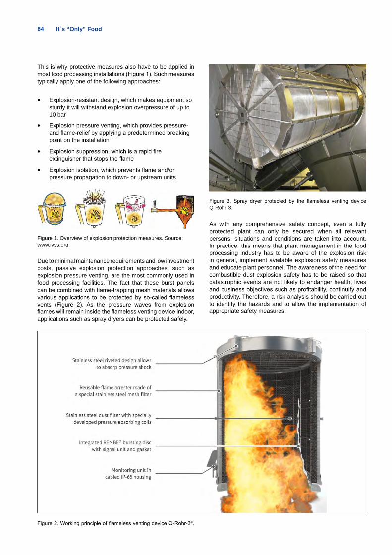
84 It´s “Only” Food
This is why protective measures also have to be applied in most food processing installations (Figure 1). Such measures typically apply one of the following approaches:
• Explosion-resistant design, which makes equipment so sturdy it will withstand explosion overpressure of up to 10 bar
• Explosion pressure venting, which provides pressure- and flame-relief by applying a predetermined breaking point on the installation
• Explosion suppression, which is a rapid fire extinguisher that stops the flame
• Explosion isolation, which prevents flame and/or pressure propagation to down- or upstream units
Figure 1. Overview of explosion protection measures. Source: www.ivss.org.
Due to minimal maintenance requirements and low investment costs, passive explosion protection approaches, such as explosion pressure venting, are the most commonly used in food processing facilities. The fact that these burst panels can be combined with flame-trapping mesh materials allows various applications to be protected by so-called flameless vents (Figure 2). As the pressure waves from explosion flames will remain inside the flameless venting device indoor, applications such as spray dryers can be protected safely.
Figure 2. Working principle of flameless venting device Q-Rohr-3®.
Figure 3. Spray dryer protected by the flameless venting device Q-Rohr-3.
As with any comprehensive safety concept, even a fully protected plant can only be secured when all relevant persons, situations and conditions are taken into account. In practice, this means that plant management in the food processing industry has to be aware of the explosion risk in general, implement available explosion safety measures and educate plant personnel. The awareness of the need for combustible dust explosion safety has to be raised so that catastrophic events are not likely to endanger health, lives and business objectives such as profitability, continuity and productivity. Therefore, a risk analysis should be carried out to identify the hazards and to allow the implementation of appropriate safety measures.
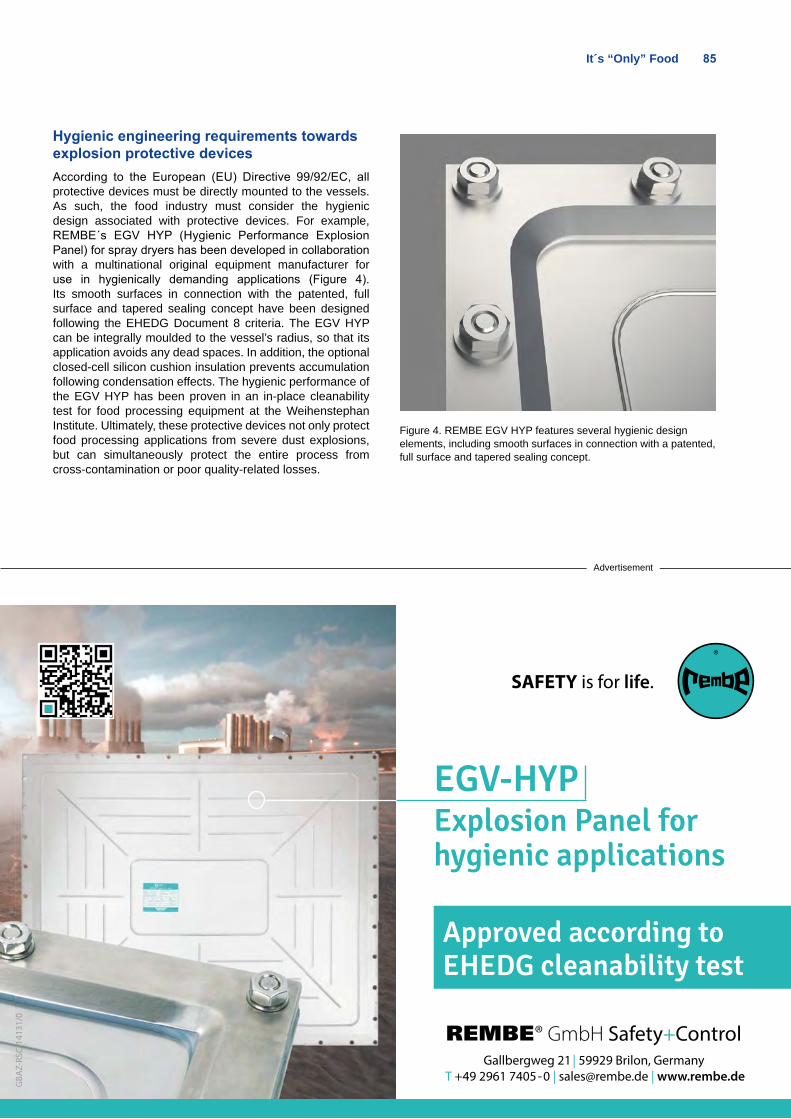
It´s “Only” Food 85
Hygienic engineering requirements towards explosion protective devicesAccording to the European (EU) Directive 99/92/EC, all protective devices must be directly mounted to the vessels. As such, the food industry must consider the hygienic design associated with protective devices. For example, REMBE´s EGV HYP (Hygienic Performance Explosion Panel) for spray dryers has been developed in collaboration with a multinational original equipment manufacturer for use in hygienically demanding applications (Figure 4). Its smooth surfaces in connection with the patented, full surface and tapered sealing concept have been designed following the EHEDG Document 8 criteria. The EGV HYP can be integrally moulded to the vessel’s radius, so that its application avoids any dead spaces. In addition, the optional closed-cell silicon cushion insulation prevents accumulation following condensation effects. The hygienic performance of the EGV HYP has been proven in an in-place cleanability test for food processing equipment at the Weihenstephan Institute. Ultimately, these protective devices not only protect food processing applications from severe dust explosions, but can simultaneously protect the entire process from cross-contamination or poor quality-related losses.
Figure 4. REMBE EGV HYP features several hygienic design elements, including smooth surfaces in connection with a patented, full surface and tapered sealing concept.
Advertisement
REMBE® GmbH Safety+ControlGallbergweg 21 | 59929 Brilon, Germany
T +49 2961 7405-0 | [email protected] | www.rembe.de
GBA
Z-RS
C-14
131/
0
Approved according to EHEDG cleanability test
®
SAFETY is for life.
EGV-HYP Explosion Panel for hygienic applications
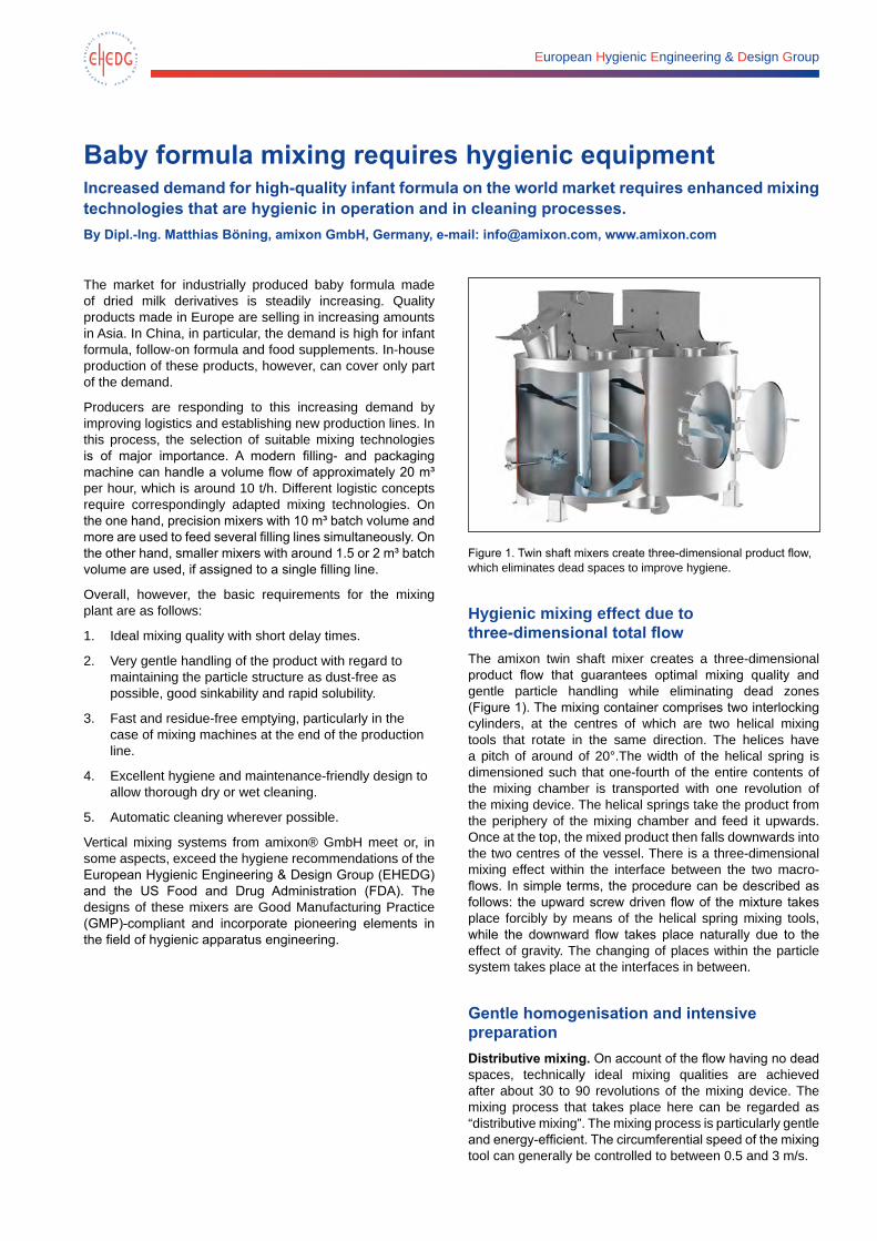
European Hygienic Engineering & Design Group
Baby formula mixing requires hygienic equipmentIncreased demand for high-quality infant formula on the world market requires enhanced mixing technologies that are hygienic in operation and in cleaning processes.By Dipl.-Ing. Matthias Böning, amixon GmbH, Germany, e-mail: [email protected], www.amixon.com
The market for industrially produced baby formula made of dried milk derivatives is steadily increasing. Quality products made in Europe are selling in increasing amounts in Asia. In China, in particular, the demand is high for infant formula, follow-on formula and food supplements. In-house production of these products, however, can cover only part of the demand.
Producers are responding to this increasing demand by improving logistics and establishing new production lines. In this process, the selection of suitable mixing technologies is of major importance. A modern filling- and packaging machine can handle a volume flow of approximately 20 m³ per hour, which is around 10 t/h. Different logistic concepts require correspondingly adapted mixing technologies. On the one hand, precision mixers with 10 m³ batch volume and more are used to feed several filling lines simultaneously. On the other hand, smaller mixers with around 1.5 or 2 m³ batch volume are used, if assigned to a single filling line.
Overall, however, the basic requirements for the mixing plant are as follows:
1. Ideal mixing quality with short delay times.
2. Very gentle handling of the product with regard to maintaining the particle structure as dust-free as possible, good sinkability and rapid solubility.
3. Fast and residue-free emptying, particularly in the case of mixing machines at the end of the production line.
4. Excellent hygiene and maintenance-friendly design to allow thorough dry or wet cleaning.
5. Automatic cleaning wherever possible.
Vertical mixing systems from amixon® GmbH meet or, in some aspects, exceed the hygiene recommendations of the European Hygienic Engineering & Design Group (EHEDG) and the US Food and Drug Administration (FDA). The designs of these mixers are Good Manufacturing Practice (GMP)-compliant and incorporate pioneering elements in the field of hygienic apparatus engineering.
Figure 1. Twin shaft mixers create three-dimensional product flow, which eliminates dead spaces to improve hygiene.
Hygienic mixing effect due to three-dimensional total flowThe amixon twin shaft mixer creates a three-dimensional product flow that guarantees optimal mixing quality and gentle particle handling while eliminating dead zones (Figure 1). The mixing container comprises two interlocking cylinders, at the centres of which are two helical mixing tools that rotate in the same direction. The helices have a pitch of around of 20°.The width of the helical spring is dimensioned such that one-fourth of the entire contents of the mixing chamber is transported with one revolution of the mixing device. The helical springs take the product from the periphery of the mixing chamber and feed it upwards. Once at the top, the mixed product then falls downwards into the two centres of the vessel. There is a three-dimensional mixing effect within the interface between the two macro-flows. In simple terms, the procedure can be described as follows: the upward screw driven flow of the mixture takes place forcibly by means of the helical spring mixing tools, while the downward flow takes place naturally due to the effect of gravity. The changing of places within the particle system takes place at the interfaces in between.
Gentle homogenisation and intensive preparationDistributive mixing. On account of the flow having no dead spaces, technically ideal mixing qualities are achieved after about 30 to 90 revolutions of the mixing device. The mixing process that takes place here can be regarded as “distributive mixing”. The mixing process is particularly gentle and energy-efficient. The circumferential speed of the mixing tool can generally be controlled to between 0.5 and 3 m/s.
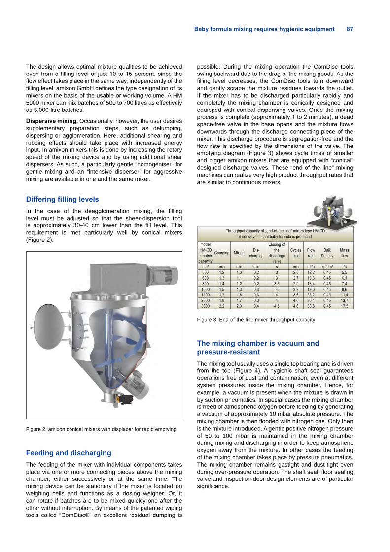
Baby formula mixing requires hygienic equipment 87
The design allows optimal mixture qualities to be achieved even from a filling level of just 10 to 15 percent, since the flow effect takes place in the same way, independently of the filling level. amixon GmbH defines the type designation of its mixers on the basis of the usable or working volume. A HM 5000 mixer can mix batches of 500 to 700 litres as effectively as 5,000-litre batches.
Dispersive mixing. Occasionally, however, the user desires supplementary preparation steps, such as delumping, dispersing or agglomeration. Here, additional shearing and rubbing effects should take place with increased energy input. In amixon mixers this is done by increasing the rotary speed of the mixing device and by using additional shear dispersers. As such, a particularly gentle “homogeniser” for gentle mixing and an “intensive disperser” for aggressive mixing are available in one and the same mixer.
Differing filling levelsIn the case of the deagglomeration mixing, the filling level must be adjusted so that the sheer-dispersion tool is approximately 30-40 cm lower than the fill level. This requirement is met particularly well by conical mixers (Figure 2).
Figure 2. amixon conical mixers with displacer for rapid emptying.
Feeding and dischargingThe feeding of the mixer with individual components takes place via one or more connecting pieces above the mixing chamber, either successively or at the same time. The mixing device can be stationary if the mixer is located on weighing cells and functions as a dosing weigher. Or, it can rotate if batches are to be mixed quickly one after the other without interruption. By means of the patented wiping tools called “ComDisc®” an excellent residual dumping is
possible. During the mixing operation the ComDisc tools swing backward due to the drag of the mixing goods. As the filling level decreases, the ComDisc tools turn downward and gently scrape the mixture residues towards the outlet. If the mixer has to be discharged particularly rapidly and completely the mixing chamber is conically designed and equipped with conical dispensing valves. Once the mixing process is complete (approximately 1 to 2 minutes), a dead space-free valve in the base opens and the mixture flows downwards through the discharge connecting piece of the mixer. This discharge procedure is segregation-free and the flow rate is specified by the dimensions of the valve. The emptying diagram (Figure 3) shows cycle times of smaller and bigger amixon mixers that are equipped with “conical” designed discharge valves. These “end of the line” mixing machines can realize very high product throughput rates that are similar to continuous mixers.
Figure 3. End-of-the-line mixer throughput capacity
The mixing chamber is vacuum and pressure-resistantThe mixing tool usually uses a single top bearing and is driven from the top (Figure 4). A hygienic shaft seal guarantees operations free of dust and contamination, even at different system pressures inside the mixing chamber. Hence, for example, a vacuum is present when the mixture is drawn in by suction pneumatics. In special cases the mixing chamber is freed of atmospheric oxygen before feeding by generating a vacuum of approximately 10 mbar absolute pressure. The mixing chamber is then flooded with nitrogen gas. Only then is the mixture introduced. A gentle positive nitrogen pressure of 50 to 100 mbar is maintained in the mixing chamber during mixing and discharging in order to keep atmospheric oxygen away from the mixture. In other cases the feeding of the mixing chamber takes place by pressure pneumatics. The mixing chamber remains gastight and dust-tight even during over-pressure operation. The shaft seal, floor sealing valve and inspection-door design elements are of particular significance.
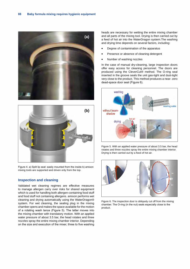
88 Baby formula mixing requires hygienic equipment
(b)
Figure 4. a) Split lip seal: easily mounted from the inside b) amixon mixing tools are supported and driven only from the top.
Inspection and cleaningValidated wet cleaning regimes are effective measures to manage allergen carry over risks for shared equipment which is used for handling both allergen-containing food stuff and food stuff not containing allergens. amixon performs wet cleaning and drying automatically using the WaterDragon® system. For wet cleaning, the sealing plug in the mixing chamber opens and makes the space available for the motion of a rotating wash lance (Figure 5). The latter moves into the mixing chamber with translatory motion. With an applied water pressure of about 3.5 bar, the head rotates and three nozzles spray the entire mixing chamber interior. Depending on the size and execution of the mixer, three to five washing
heads are necessary for wetting the entire mixing chamber and all parts of the mixing tool. Drying is then carried out by a feed of hot air into the WaterDragon system.The washing and drying time depends on several factors, including:
• Degree of contamination of the apparatus
• Presence or absence of cleaning detergent
• Number of washing nozzles
In the case of manual dry-cleaning, large inspection doors offer easy access for cleaning personnel. The doors are produced using the CleverCut® method. The O-ring seal inserted in the groove seals the unit gas-tight and dust-tight very close to the product. This method produces a near- zero dead-space door seal (Figure 6).
Figure 5. With an applied water pressure of about 3.5 bar, the head rotates and three nozzles spray the entire mixing chamber interior. Drying is then carried out by a feed of hot air.
Figure 6. The inspection door is obliquely cut off from the mixing chamber. The O-ring (in the nut) seals especially close to the product.
(a)
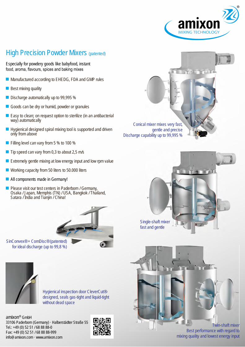
amixon® GmbH33106 Paderborn (Germany) · Halberstädter Straße 55Tel.: +49 (0) 52 51 / 68 88 88-0 Fax: +49 (0) 52 51 / 68 88 [email protected] · www.amixon.com
Twin-shaft mixerBest performance with regard to
mixing quality and lowest energy input
Conical mixer mixes very fast, gentle and precise
Discharge capability up to 99,995 %
Single-shaft mixerfast and gentle
SinConvex® + ComDisc® (patented) for ideal discharge (up to 99,8 %)
Hygienical inspection door CleverCut®- designed, seals gas-tight and liquid-tight without dead space
Manufactured according to EHEDG, FDA and GMP rules
Best mixing quality
Discharge automatically up to 99,995 %
Goods can be dry or humid, powder or granules
Easy to clean; on request option to sterilize (in an antibacterial way) automatically
Hygienical designed spiral mixing tool is supported and driven only from above
Filling level can vary from 5 % to 100 %
Tip speed can vary from 0,3 to about 2,5 m/s
Extremely gentle mixing at low energy input and low rpm value
Working capacity from 50 liters to 50.000 liters
All components made in Germany!
Please visit our test centers in Paderborn / Germany, Osaka / Japan, Memphis (TN) / USA, Bangkok / Thailand, Satara / India and Tianjin / China!
High Precision Powder Mixers (patented)
Especially for powdery goods like babyfood, instant food, aroma, fl avours, spices and baking mixes
European Hygienic Engineering & Design Group
Optimising hygienic requirements for food processing machinery according to 3-A Sanitary StandardsThroughout the world, food processers specify very high requirements for optimum hygiene standards for their machines. The 3-A Sanitary Standards have played a pioneering role with worldwide significance in the US dairy industry. By Reinhard Moß, Research & Development, GEA Westfalia Separator Group GmbH, Germany, e-mail: [email protected] and Lilian Schmalenstroer, Manager Public Relations, GEA Westfalia Separator Group GmbH, Germany e-mail: [email protected]
3-A Sanitary Standards, Inc. (3-A SSI), is a not-for-profit hygiene organisation serving the US food industry. It defines specifications and recommendations for the development, production, installation and use of dairy and food processing equipment that comes into contact with the product. 3-A Sanitary Standards were created in the 1920’s in the American dairy and milk distribution industries in order to prevent health hazards to consumers as a result of the process of the industrialization of food production.
The US-based International Association of Dairy and Milk Inspectors set up a committee on dairy equipment in cooperation with milk and dairy product manufacturers to develop generally accepted standards. The three “A’s” stand for the three groups: machine producers, milk processors and hygiene inspectors. The first standard was developed in 1929 and related to hygienic fittings. The 3-A standards achieved greater recognition after the Second World War. Today, more than 70 different standards have been elaborated by 3-A SSI, and more than 430 companies in the US and 26 other countries are authorised to put the 3-A symbol on their machines and installations.
3-A is a purely American standard that, in principle, is only implemented in the US. However, in addition to the US, there is increasing demand for the 3-A standard in other countries, particularly those nations that deliver end products to the US. One reason for this increased interest is that American import authorities frequently demand evidence of hygienic design in line with 3-A Sanitary Standards, specifically in the case of deliveries to public sector clients. Proof of conformance to the standard is achieved by means of independent tests that are carried out when the products are imported, as well as regularly during operation.
The most important requirements The most important requirements of the 3-A standard applicable for food-processing machines, including separators, are as follows:
• Surfaces must not exceed a maximum roughness of Ra 0.8 µm (roughness average) of all components that come into contact with product.
• No dead spaces at junctions.
• No gaps, or gaps reduced to a minimum level.
• All radii of pipework must exceed a minimum level in order to ensure that equipment is easier to clean.
• The materials that are used must be approved for use in conjunction with food. For instance, this is the case with all stainless steels. Materials must not discharge anything into the product. There are strict regulations in this regard, particularly for plastic and rubber seals whose contents must be virtually edible in the event that pieces of a sealing fall into the product.
• Sealing materials are always porous (i.e., because they absorb and discharge substances), so migration from the sealing must not exceed a specific level, which is verified by relevant tests. For example, if levels are exceeded, it might be possible for milk to migrate into a sealing, become contaminated, discharge again and thus contaminate fresh milk.
Close cooperation with EHEDGInternationally, 3-A SSI works closely together with the European Hygienic Engineering & Design Group (EHEDG). Both organisations have the same hygiene objectives, work hand-in-hand with comparable regulations, and aim to further harmonise regulations. By way of contrast with 3-A, EHEDG has worldwide operations.
Guarantee of standard: 3-A labelling on separatorsThe 3-A standards for the hygienic design of separators was completed in 2005. Since that time, GEA Westfalia Separator Group has been certified in accordance with this standards. Since 2008, GEA Westfalia Separator Group has been delivering all dairy separators to the US exclusively to the 3-A standard (Figure 1). For the dairy industry, GEA Westfalia Separator Group not only manufactures dairy separators in accordance with the 3-A standard, it also demonstrates this by means of clear labelling on the machines (Figure 2). Strict sanctions are imposed if machines with this label fail to comply with a regulation: The manufacturer is put on a blacklist that is published on the Internet, and is given a period of three months to remedy the error. For the machine operators in the dairy and food industry, the labelling of the 3-A standard thus represents maximum security.
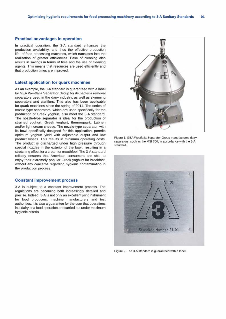
Optimising hygienic requirements for food processing machinery according to 3-A Sanitary Standards 91
Practical advantages in operationIn practical operation, the 3-A standard enhances the production availability, and thus the effective production life, of food processing machines, which translates into the realisation of greater efficiencies. Ease of cleaning also results in savings in terms of time and the use of cleaning agents. This means that resources are used efficiently and that production times are improved.
Latest application for quark machinesAs an example, the 3-A standard is guaranteed with a label by GEA Westfalia Separator Group for its bacteria removal separators used in the dairy industry, as well as skimming separators and clarifiers. This also has been applicable for quark machines since the spring of 2014. The series of nozzle-type separators, which are used specifically for the production of Greek yoghurt, also meet the 3-A standard. The nozzle-type separator is ideal for the production of strained yoghurt, Greek yoghurt, thermoquark, Labneh and/or light cream cheese. The nozzle-type separator, with its bowl specifically designed for this application, permits optimum yoghurt yield with adjustable output and low product losses. This results in minimum operating costs. The product is discharged under high pressure through special nozzles in the exterior of the bowl, resulting in a stretching effect for a creamier mouthfeel. The 3-A standard reliably ensures that American consumers are able to enjoy their extremely popular Greek yoghurt for breakfast, without any concerns regarding hygienic contamination in the production process.
Constant improvement process3-A is subject to a constant improvement process. The regulations are becoming both increasingly detailed and precise. Indeed, 3-A is not only an excellent joint instrument for food producers, machine manufacturers and test authorities, it is also a guarantee for the user that operations in a dairy or a food operation are carried out under maximum hygienic criteria.
Figure 1. GEA Westfalia Separator Group manufactures dairy separators, such as the MSI 700, in accordance with the 3-A standard.
Figure 2. The 3-A standard is guaranteed with a label.
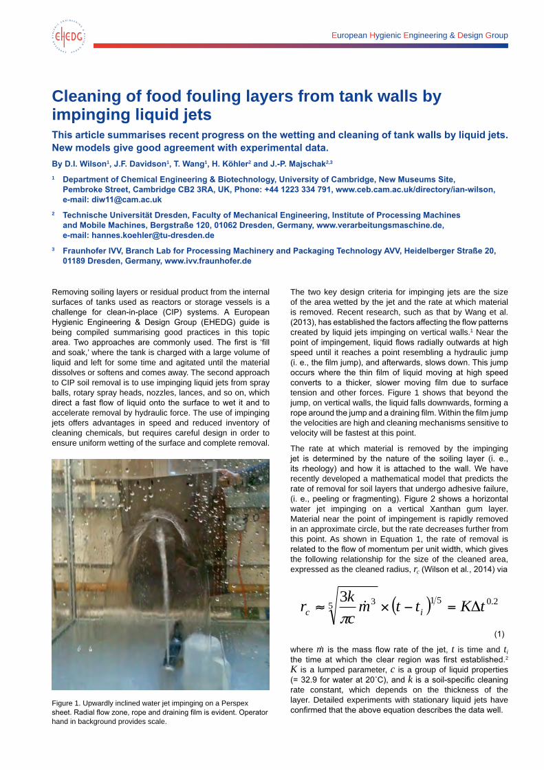
European Hygienic Engineering & Design Group
Cleaning of food fouling layers from tank walls by impinging liquid jetsThis article summarises recent progress on the wetting and cleaning of tank walls by liquid jets. New models give good agreement with experimental data.By D.I. Wilson1, J.F. Davidson1, T. Wang1, H. Köhler2 and J.-P. Majschak2,3
1 Department of Chemical Engineering & Biotechnology, University of Cambridge, New Museums Site, Pembroke Street, Cambridge CB2 3RA, UK, Phone: +44 1223 334 791, www.ceb.cam.ac.uk/directory/ian-wilson, e-mail: [email protected]
2 Technische Universität Dresden, Faculty of Mechanical Engineering, Institute of Processing Machines and Mobile Machines, Bergstraße 120, 01062 Dresden, Germany, www.verarbeitungsmaschine.de, e-mail: [email protected]
3 Fraunhofer IVV, Branch Lab for Processing Machinery and Packaging Technology AVV, Heidelberger Straße 20, 01189 Dresden, Germany, www.ivv.fraunhofer.de
Removing soiling layers or residual product from the internal surfaces of tanks used as reactors or storage vessels is a challenge for clean-in-place (CIP) systems. A European Hygienic Engineering & Design Group (EHEDG) guide is being compiled summarising good practices in this topic area. Two approaches are commonly used. The first is ‘fill and soak,’ where the tank is charged with a large volume of liquid and left for some time and agitated until the material dissolves or softens and comes away. The second approach to CIP soil removal is to use impinging liquid jets from spray balls, rotary spray heads, nozzles, lances, and so on, which direct a fast flow of liquid onto the surface to wet it and to accelerate removal by hydraulic force. The use of impinging jets offers advantages in speed and reduced inventory of cleaning chemicals, but requires careful design in order to ensure uniform wetting of the surface and complete removal.
Figure 1. Upwardly inclined water jet impinging on a Perspex sheet. Radial flow zone, rope and draining film is evident. Operator hand in background provides scale.
The two key design criteria for impinging jets are the size of the area wetted by the jet and the rate at which material is removed. Recent research, such as that by Wang et al. (2013), has established the factors affecting the flow patterns created by liquid jets impinging on vertical walls.1 Near the point of impingement, liquid flows radially outwards at high speed until it reaches a point resembling a hydraulic jump (i. e., the film jump), and afterwards, slows down. This jump occurs where the thin film of liquid moving at high speed converts to a thicker, slower moving film due to surface tension and other forces. Figure 1 shows that beyond the jump, on vertical walls, the liquid falls downwards, forming a rope around the jump and a draining film. Within the film jump the velocities are high and cleaning mechanisms sensitive to velocity will be fastest at this point.
The rate at which material is removed by the impinging jet is determined by the nature of the soiling layer (i. e., its rheology) and how it is attached to the wall. We have recently developed a mathematical model that predicts the rate of removal for soil layers that undergo adhesive failure, (i. e., peeling or fragmenting). Figure 2 shows a horizontal water jet impinging on a vertical Xanthan gum layer. Material near the point of impingement is rapidly removed in an approximate circle, but the rate decreases further from this point. As shown in Equation 1, the rate of removal is related to the flow of momentum per unit width, which gives the following relationship for the size of the cleaned area, expressed as the cleaned radius, rc (Wilson et al., 2014) via
( ) 2.0515 33 tKttmckr ic =
(1)
where m is the mass flow rate of the jet, t is time and ti the time at which the clear region was first established.2 K is a lumped parameter, c is a group of liquid properties (= 32.9 for water at 20˚C), and k is a soil-specific cleaning rate constant, which depends on the thickness of the layer. Detailed experiments with stationary liquid jets have confirmed that the above equation describes the data well.
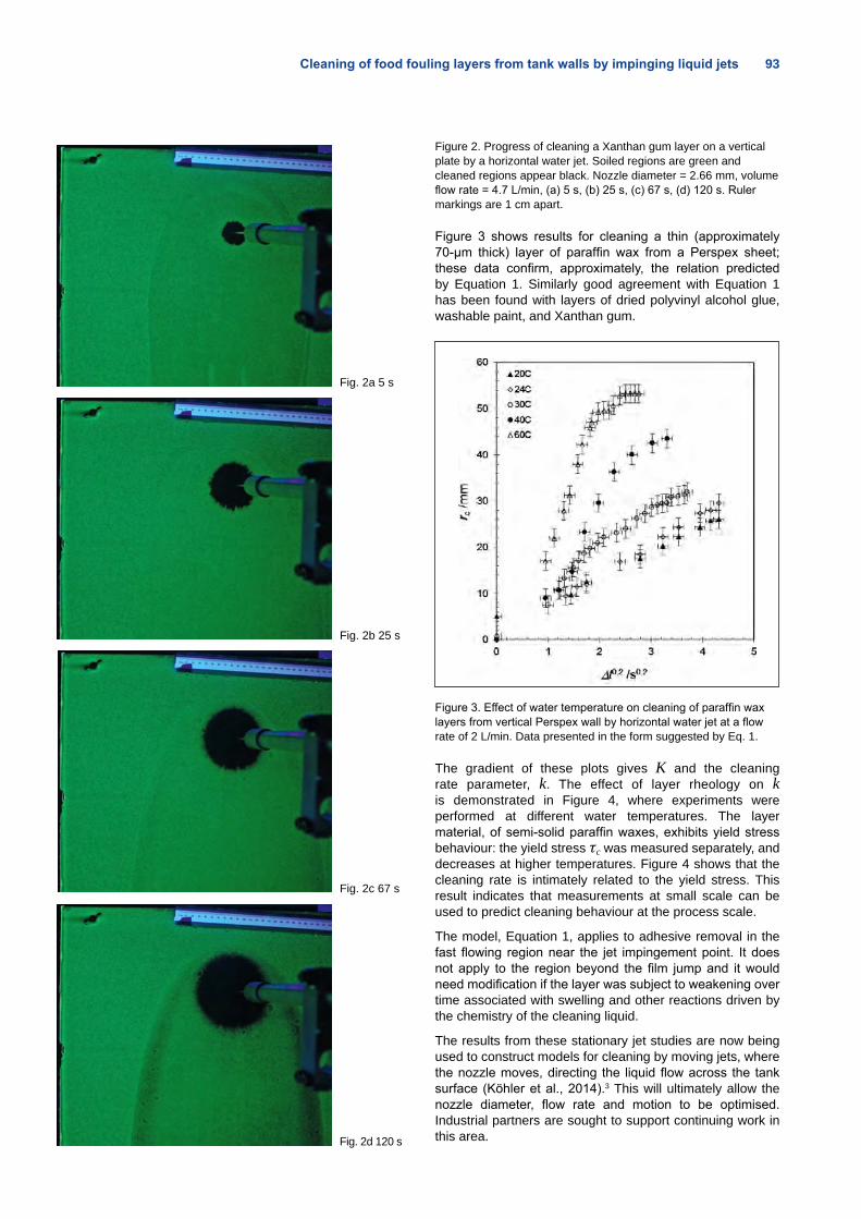
Cleaning of food fouling layers from tank walls by impinging liquid jets 93
Fig. 2a 5 s
Fig. 2b 25 s
Fig. 2c 67 s
Fig. 2d 120 s
Figure 2. Progress of cleaning a Xanthan gum layer on a vertical plate by a horizontal water jet. Soiled regions are green and cleaned regions appear black. Nozzle diameter = 2.66 mm, volume flow rate = 4.7 L/min, (a) 5 s, (b) 25 s, (c) 67 s, (d) 120 s. Ruler markings are 1 cm apart.
Figure 3 shows results for cleaning a thin (approximately 70-μm thick) layer of paraffin wax from a Perspex sheet; these data confirm, approximately, the relation predicted by Equation 1. Similarly good agreement with Equation 1 has been found with layers of dried polyvinyl alcohol glue, washable paint, and Xanthan gum.
Figure 3. Effect of water temperature on cleaning of paraffin wax layers from vertical Perspex wall by horizontal water jet at a flow rate of 2 L/min. Data presented in the form suggested by Eq. 1.
The gradient of these plots gives K and the cleaning rate parameter, k. The effect of layer rheology on k is demonstrated in Figure 4, where experiments were performed at different water temperatures. The layer material, of semi-solid paraffin waxes, exhibits yield stress behaviour: the yield stress τc was measured separately, and decreases at higher temperatures. Figure 4 shows that the cleaning rate is intimately related to the yield stress. This result indicates that measurements at small scale can be used to predict cleaning behaviour at the process scale.
The model, Equation 1, applies to adhesive removal in the fast flowing region near the jet impingement point. It does not apply to the region beyond the film jump and it would need modification if the layer was subject to weakening over time associated with swelling and other reactions driven by the chemistry of the cleaning liquid.
The results from these stationary jet studies are now being used to construct models for cleaning by moving jets, where the nozzle moves, directing the liquid flow across the tank surface (Köhler et al., 2014).3 This will ultimately allow the nozzle diameter, flow rate and motion to be optimised. Industrial partners are sought to support continuing work in this area.
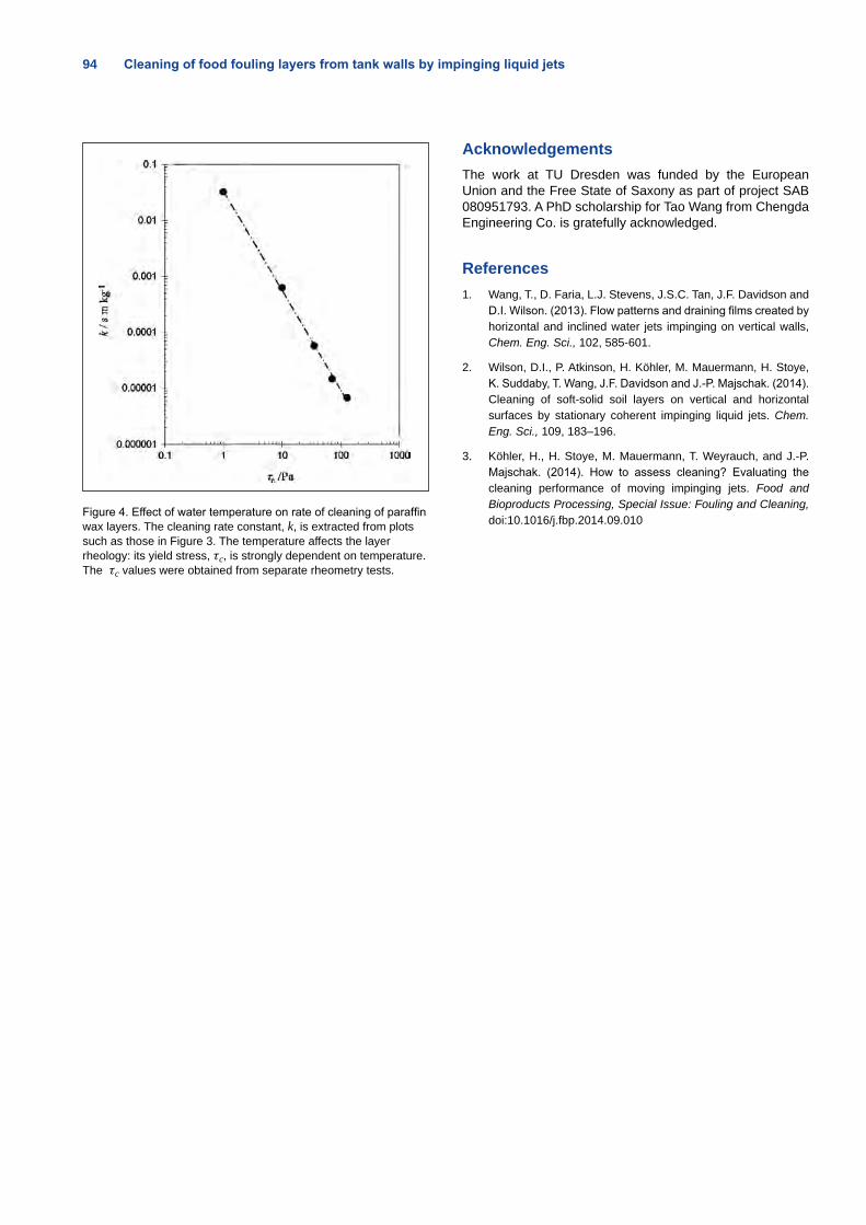
94 Cleaning of food fouling layers from tank walls by impinging liquid jets
Figure 4. Effect of water temperature on rate of cleaning of paraffin wax layers. The cleaning rate constant, k, is extracted from plots such as those in Figure 3. The temperature affects the layer rheology: its yield stress, τc, is strongly dependent on temperature. The τc values were obtained from separate rheometry tests.
AcknowledgementsThe work at TU Dresden was funded by the European Union and the Free State of Saxony as part of project SAB 080951793. A PhD scholarship for Tao Wang from Chengda Engineering Co. is gratefully acknowledged.
References1. Wang, T., D. Faria, L.J. Stevens, J.S.C. Tan, J.F. Davidson and
D.I. Wilson. (2013). Flow patterns and draining films created by horizontal and inclined water jets impinging on vertical walls, Chem. Eng. Sci., 102, 585-601.
2. Wilson, D.I., P. Atkinson, H. Köhler, M. Mauermann, H. Stoye, K. Suddaby, T. Wang, J.F. Davidson and J.-P. Majschak. (2014). Cleaning of soft-solid soil layers on vertical and horizontal surfaces by stationary coherent impinging liquid jets. Chem. Eng. Sci., 109, 183–196.
3. Köhler, H., H. Stoye, M. Mauermann, T. Weyrauch, and J.-P. Majschak. (2014). How to assess cleaning? Evaluating the cleaning performance of moving impinging jets. Food and Bioproducts Processing, Special Issue: Fouling and Cleaning, doi:10.1016/j.fbp.2014.09.010
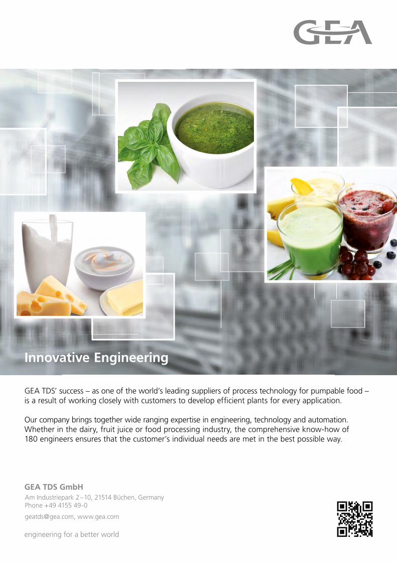
GEA TDS’ success – as one of the world’s leading suppliers of process technology for pumpable food – is a result of working closely with customers to develop effi cient plants for every application.
Our company brings together wide ranging expertise in engineering, technology and automation. Whether in the dairy, fruit juice or food processing industry, the comprehensive know-how of 180 engineers ensures that the customer’s individual needs are met in the best possible way.
engineering for a better world
GEA TDS GmbHAm Industriepark 2 – 10, 21514 Büchen, GermanyPhone +49 4155 49-0
[email protected], www.gea.com
Innovative Engineering
GEA_TDS_Image_210x297mm_engl_RZ.indd 1 02.06.14 15:46
European Hygienic Engineering & Design Group
Rotary jet head ‘burst’ cleaning technology delivers significant savings in cleaning costsBy Kim Kjellberg, Tank Cleaning Portfolio Manager, Alfa Laval, Denmark, e-mail: [email protected]
Tank cleaning strategies generally involve the use of high mechanical energy associated with rotary jet head technology or long exposure time to the cleaning liquid associated with static spray ball technology. Now there is a new tank-cleaning strategy involving advanced ‘burst cleaning’, which combines the best of both technologies and delivers significant savings in time, cleaning fluid and overall cleaning costs.
Hygienic processes in the food manufacturing, pharma-ceutical manufacturing, chemical processing and fer-mentation industries call for the tank interior to be free of unwanted debris and contaminants that may have a negative impact on the quality of the finished product. Difficult-to-clean areas often require special attention. One such area is the tub ring, which is the area around the interior circumference of a tank that indicates the level to which the tank is filled (Figure 1).
Figure 1. A hard-to-clean tub ring in a beer fermenter. (Photo courtesy of Sopura)
Cleaning areas with stubborn soils like the tub ring usually require the use of high mechanical energy, such as that provided by rotary jet head technology, or exposure to cleaning fluids for a long period of time, such as that provided by static spray ball technology. However, using a continuous flow of cleaning fluid over a long period of time often results in high consumption of cleaning fluid and therefore higher costs than when using high mechanical energy.
Burst cleaningBurst cleaning is a technique for cleaning stubborn soils using less water and cleaning fluid than traditional tank cleaning methods. As the first step in the clean-in-place (CIP) process, a thin layer of cleaning fluids is periodically applied in a uniform manner onto the tank surface over a short period of time.
This replaces the normal water pre-rinse step that takes place during a standard cleaning cycle. By applying the cleaning fluid to a dry soil, the cleaning fluid more effectively penetrates the soil because the soil acts as a dry sponge, quickly absorbing the cleaning liquid, in contrast to the soil acting as a wet sponge as is the case when performing the water pre-rinse prior to the application of cleaning fluid.
Each cleaning fluid burst step is followed by a wait time, which enables the cleaning fluids to act upon the soiled area. After three burst steps are completed, the next step is acidic disinfection, which is then followed by a water rinse.
Traditional burst cleaningFor years, traditional burst cleaning has been carried out using static spray ball technology. Because the static spray ball devices are able to cover the entire tank circumference with cleaning fluids, the static spray ball devices provide fast wetting of the tank surface. While this fast-acting coverage has its advantages, static spray ball technology has some disadvantages, including:
• Limited reach and coverage of larger diameter tanks
• Risk of non-wetted zones on the tank wall and tank top, since the distribution of liquid relies on a falling film effect that is easily diverted due to irregularities, such as lumps of soil, on the tank wall
• Very limited mechanical impact provided by static spray devices
Table 1 shows the length of time, amount of cleaning fluid required and cost of traditional burst cleaning of a standard beer fermenter on a static spray ball.
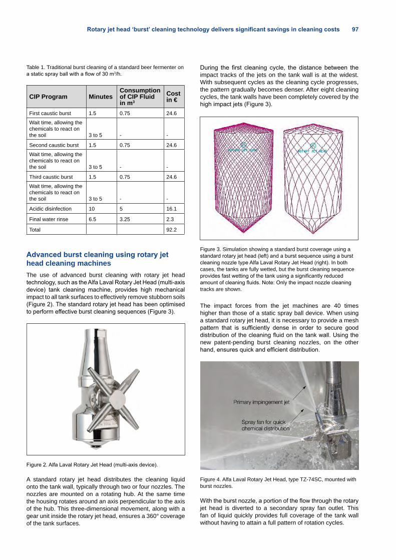
Rotary jet head ‘burst’ cleaning technology delivers significant savings in cleaning costs 97
Table 1. Traditional burst cleaning of a standard beer fermenter on a static spray ball with a flow of 30 m3/h.
CIP Program MinutesConsumption of CIP Fluid in m3
Cost in €
First caustic burst 1.5 0.75 24.6
Wait time, allowing the chemicals to react on the soil 3 to 5 - -
Second caustic burst 1.5 0.75 24.6
Wait time, allowing the chemicals to react on the soil 3 to 5 - -
Third caustic burst 1.5 0.75 24.6
Wait time, allowing the chemicals to react on the soil 3 to 5 - -
Acidic disinfection 10 5 16.1
Final water rinse 6.5 3.25 2.3
Total 92.2
Advanced burst cleaning using rotary jet head cleaning machines
The use of advanced burst cleaning with rotary jet head technology, such as the Alfa Laval Rotary Jet Head (multi-axis device) tank cleaning machine, provides high mechanical impact to all tank surfaces to effectively remove stubborn soils (Figure 2). The standard rotary jet head has been optimised to perform effective burst cleaning sequences (Figure 3).
Figure 2. Alfa Laval Rotary Jet Head (multi-axis device).
A standard rotary jet head distributes the cleaning liquid onto the tank wall, typically through two or four nozzles. The nozzles are mounted on a rotating hub. At the same time the housing rotates around an axis perpendicular to the axis of the hub. This three-dimensional movement, along with a gear unit inside the rotary jet head, ensures a 360° coverage of the tank surfaces.
During the first cleaning cycle, the distance between the impact tracks of the jets on the tank wall is at the widest. With subsequent cycles as the cleaning cycle progresses, the pattern gradually becomes denser. After eight cleaning cycles, the tank walls have been completely covered by the high impact jets (Figure 3).
Figure 3. Simulation showing a standard burst coverage using a standard rotary jet head (left) and a burst sequence using a burst cleaning nozzle type Alfa Laval Rotary Jet Head (right). In both cases, the tanks are fully wetted, but the burst cleaning sequence provides fast wetting of the tank using a significantly reduced amount of cleaning fluids. Note: Only the impact nozzle cleaning tracks are shown.
The impact forces from the jet machines are 40 times higher than those of a static spray ball device. When using a standard rotary jet head, it is necessary to provide a mesh pattern that is sufficiently dense in order to secure good distribution of the cleaning fluid on the tank wall. Using the new patent-pending burst cleaning nozzles, on the other hand, ensures quick and efficient distribution.
Figure 4. Alfa Laval Rotary Jet Head, type TZ-74SC, mounted with burst nozzles.
With the burst nozzle, a portion of the flow through the rotary jet head is diverted to a secondary spray fan outlet. This fan of liquid quickly provides full coverage of the tank wall without having to attain a full pattern of rotation cycles.
98 Rotary jet head ‘burst’ cleaning technology delivers significant savings in cleaning costs
This coverage is achieved because the fan has a wider wetting characteristic than the primary flow from the nozzle jets.
The spray fan does not interfere with the impact force of the primary jet flow. Consequently, the rotary jet head with burst nozzle technology provides the optimal combination of fast coverage of the tank walls from the secondary fan spray and maximum impact force from the primary nozzle flow for optimal burst cleaning (Table 2).
The rotary jet head with the burst nozzle technology combines the best of both worlds: the fast wetting of tank surfaces that is achieved by using static spray ball technology and the high impact made possible by the Alfa Laval Rotary Jet Head.
Table 2. Advanced burst cleaning of a standard beer fermenter using an Alfa Laval Rotary Jet Head with burst cleaning nozzle with a flow of 11.7m3/h.
CIP Data MinutesConsumption of CIP Fluid in m3
Cost in €
First caustic burst 0.8 0.15 4.9Wait time, allowing the chemicals to react on the soil 3 to 5 - -Second caustic burst 0.8 0.15 4.9Wait time, allowing the chemicals to react on the soil 3 to 5 - -
Third caustic burst 0.8 0.15 4.9Wait time, allowing the chemicals to react on the soil 3 to 5 - -
Acidic disinfection 9.5 1.77 5.7
Final water rinse 6.5 1.21 1.7
Total 22.2
ConclusionThe new rotary jet head cleaning machine with burst nozzles provides the optimum combination of fast coverage of tank surfaces and minimal chemical consumption of burst cleaning technology and the maximum impact forces and effective soil removal of the rotary jet head technology. This unique combination ensures the most effective cleaning of stubborn soils and minimal use of water, chemicals and cleaning time.

EVAPORATORS • DRYERS • HOMOGENIZERS • HEAT EXCHANGERS • MIXERS
SEPARATORS • VALVES • PROCESS SYSTEMS • PUMPS
SUSTAINABLE SOLUTIONS, PROCESSING EXPERTISE AND PRODUCT INNOVATION WITH SPX
If you are planning to invest in the future of your dairy, food or beverage plant, do it
today with tomorrow’s technology. As a leading global supplier for the food process-
ing industry, SPX offers a comprehensive selection of fl exible and cost-effective
solutions. From engineered components to customized systems, SPX helps you
make products your way. SPX and its industry leading brands provide continued
equipment, dependability, support and process expertise. To fi nd out more about our
recently launched solutions that can help you meet the challenges you face.
To learn more visit us at www.spx.com
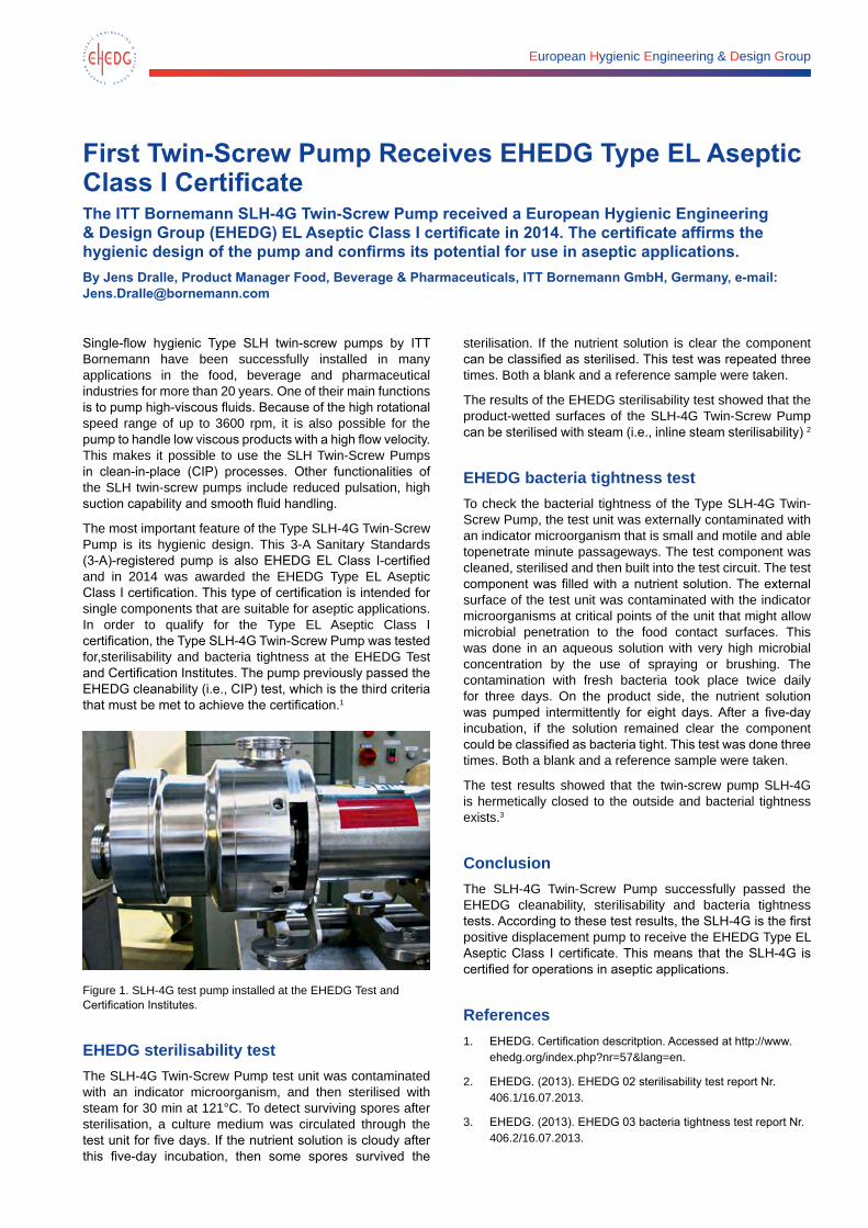
European Hygienic Engineering & Design Group
First Twin-Screw Pump Receives EHEDG Type EL Aseptic Class I CertificateThe ITT Bornemann SLH-4G Twin-Screw Pump received a European Hygienic Engineering & Design Group (EHEDG) EL Aseptic Class I certificate in 2014. The certificate affirms the hygienic design of the pump and confirms its potential for use in aseptic applications.By Jens Dralle, Product Manager Food, Beverage & Pharmaceuticals, ITT Bornemann GmbH, Germany, e-mail: [email protected]
Single-flow hygienic Type SLH twin-screw pumps by ITT Bornemann have been successfully installed in many applications in the food, beverage and pharmaceutical industries for more than 20 years. One of their main functions is to pump high-viscous fluids. Because of the high rotational speed range of up to 3600 rpm, it is also possible for the pump to handle low viscous products with a high flow velocity. This makes it possible to use the SLH Twin-Screw Pumps in clean-in-place (CIP) processes. Other functionalities of the SLH twin-screw pumps include reduced pulsation, high suction capability and smooth fluid handling.
The most important feature of the Type SLH-4G Twin-Screw Pump is its hygienic design. This 3-A Sanitary Standards (3-A)-registered pump is also EHEDG EL Class I-certified and in 2014 was awarded the EHEDG Type EL Aseptic Class I certification. This type of certification is intended for single components that are suitable for aseptic applications. In order to qualify for the Type EL Aseptic Class I certification, the Type SLH-4G Twin-Screw Pump was tested for,sterilisability and bacteria tightness at the EHEDG Test and Certification Institutes. The pump previously passed the EHEDG cleanability (i.e., CIP) test, which is the third criteria that must be met to achieve the certification.1
Figure 1. SLH-4G test pump installed at the EHEDG Test and Certification Institutes.
EHEDG sterilisability testThe SLH-4G Twin-Screw Pump test unit was contaminated with an indicator microorganism, and then sterilised with steam for 30 min at 121°C. To detect surviving spores after sterilisation, a culture medium was circulated through the test unit for five days. If the nutrient solution is cloudy after this five-day incubation, then some spores survived the
sterilisation. If the nutrient solution is clear the component can be classified as sterilised. This test was repeated three times. Both a blank and a reference sample were taken.
The results of the EHEDG sterilisability test showed that the product-wetted surfaces of the SLH-4G Twin-Screw Pump can be sterilised with steam (i.e., inline steam sterilisability) 2
EHEDG bacteria tightness testTo check the bacterial tightness of the Type SLH-4G Twin-Screw Pump, the test unit was externally contaminated with an indicator microorganism that is small and motile and able topenetrate minute passageways. The test component was cleaned, sterilised and then built into the test circuit. The test component was filled with a nutrient solution. The external surface of the test unit was contaminated with the indicator microorganisms at critical points of the unit that might allow microbial penetration to the food contact surfaces. This was done in an aqueous solution with very high microbial concentration by the use of spraying or brushing. The contamination with fresh bacteria took place twice daily for three days. On the product side, the nutrient solution was pumped intermittently for eight days. After a five-day incubation, if the solution remained clear the component could be classified as bacteria tight. This test was done three times. Both a blank and a reference sample were taken.
The test results showed that the twin-screw pump SLH-4G is hermetically closed to the outside and bacterial tightness exists.3
ConclusionThe SLH-4G Twin-Screw Pump successfully passed the EHEDG cleanability, sterilisability and bacteria tightness tests. According to these test results, the SLH-4G is the first positive displacement pump to receive the EHEDG Type EL Aseptic Class I certificate. This means that the SLH-4G is certified for operations in aseptic applications.
References1. EHEDG. Certification descritption. Accessed at http://www.
ehedg.org/index.php?nr=57&lang=en.
2. EHEDG. (2013). EHEDG 02 sterilisability test report Nr. 406.1/16.07.2013.
3. EHEDG. (2013). EHEDG 03 bacteria tightness test report Nr. 406.2/16.07.2013.
engineering for a better world GEA Mechanical Equipment
GEA Westfalia Separator Group ensures that highest demands are met in dairy processes. With a corresponding label on each certified separator, we guarantee compliance with the 3-A standard. For maximum hygienic safety in the production process of our customers.
Obviously Guaranteed!
DA
-01-
019
GEA Westfalia Separator Group GmbHWerner-Habig-Straße 1, 59302 Oelde, Germany Phone: +49 2522 77-0, Fax: +49 2522 77-2089 [email protected], www.gea.com
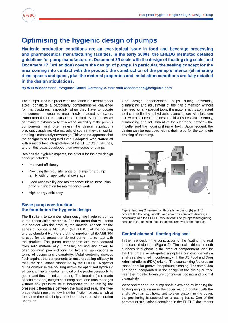
European Hygienic Engineering & Design Group
Optimising the hygienic design of pumps Hygienic production conditions are an ever-topical issue in food and beverage processing and pharmaceutical manufacturing facilities. In the early 2000s, the EHEDG instituted detailed guidelines for pump manufacturers: Document 25 deals with the design of floating ring seals, and Document 17 (3rd edition) covers the design of pumps. In particular, the sealing concept for the area coming into contact with the product, the construction of the pump’s interior (eliminating dead spaces and gaps), plus the material properties and installation conditions are fully detailed in the design stipulations.By Willi Wiedenmann, Evoguard GmbH, Germany, e-mail: [email protected]
The pumps used in a production line, often in different model sizes, constitute a particularly comprehensive challenge for manufacturers, especially when they have to update components in order to meet newly enacted standards. Pump manufacturers also are confronted by the necessity of having to exhaustively review the suitability of the pump’s components, and often revise the design stipulations previously applying. Alternatively, of course, they can opt for creating a completely new design. This was the approach that the designers at Evoguard GmbH adopted, who started off with a meticulous interpretation of the EHEDG’s guidelines, and on this basis developed their new series of pumps.
Besides the hygienic aspects, the criteria for the new design concept included:
• Improved efficiency
• Providing the requisite range of ratings for a pump family with full applicational coverage
• Good accessibility and maintenance-friendliness, plus error minimisation for maintenance work
• High energy-efficiency
Basic pump construction – the foundation for hygienic design The first item to consider when designing hygienic pumps is the construction materials. For the areas that will come into contact with the product, the material chosen for the series of pumps is AISI 316L (Ra ≤ 0.8 µ at the housing and as standard Ra ≤ 0.8 µ at the impeller), while AISI 304 is used for the areas that do not come into contact with the product. The pump components are manufactured from solid material (e.g., impeller, housing and cover) to offer optimum preconditions for hygienic applications in terms of design and cleanability. Metal centering devices flush against the components to ensure sealing efficacy to meet the stipulations mandated by the EHEDG. A special guide contour in the housing allows for optimised hydraulic efficiency. The tangential removal of the product supports its gentle and flow-optimised routing. The impeller (also made of solid material) integrates fuming bars, and thus manages without any pressure relief boreholes for equalising the pressure differentials between the front and rear. The five-blade design ensures low impeller friction losses, which at the same time also helps to reduce noise emissions during operation.
One design enhancement helps during assembly, dismantling and adjustment of the gap dimension without the need for any special tools: the motor shaft is connected to the impeller by a hydraulic clamping set with just one screw in a self-centering design. This ensures fast assembly, dismantling and adjustment of the clearance between the impeller and the housing (Figure 1a-d). Upon request, the design can be equipped with a drain plug for the complete draining of the pump.
a
b
d
c
Figure 1a-d. (a) Cross-section through the pump; (b) and (c) seals at the housing, impeller and cover for complete draining in conformity with the EHEDG stipulations; and (d) optimised guiding contour in the housing, plus tangential removal of the product.
Central element: floating ring sealIn the new design, the construction of the floating ring seal is a central element (Figure 2). The seal exhibits smooth surfaces throughout in the product compartment, and for the first time also integrates a gapless construction with a shaft seal designed in conformity with the US Food and Drug Administration’s (FDA) criteria. The counter-ring features an “open” annular groove for optimum cleaning. The same idea has been incorporated in the design of the sliding surface near the impeller to ensure continuous cooling and optimal cleanability.
Wear and tear on the pump shaft is avoided by keeping the floating ring stationary in the cover without contact with the shaft. With an additional anti-torsion system in the cover, the positioning is secured on a lasting basis. One of the paramount stipulations contained in the EHEDG documents
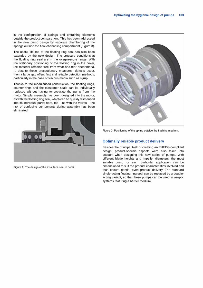
Optimising the hygienic design of pumps 103
is the configuration of springs and entraining elements outside the product compartment. This has been addressed in the new pump design by separate chambering of the springs outside the flow-channeling compartment (Figure 3).
The useful lifetime of the floating ring seal has also been extended by the new design. The pressure conditions at the floating ring seal are in the overpressure range. With the stationary positioning of the floating ring in the cover, the material remains free from wear-and-tear phenomena. If, despite these precautionary measures, defects occur, then a large gap offers fast and reliable detection methods, particularly in the case of viscous media such as syrup.
Thanks to the modularised construction, the floating rings, counter-rings and the elastomer seals can be individually replaced without having to separate the pump from the motor. Simple assembly has been designed into the motor, as with the floating ring seal, which can be quickly dismantled into its individual parts; here, too – as with the valves – the risk of confusing components during assembly has been eliminated.
Figure 2. The design of the axial face seal in detail.
Figure 3. Positioning of the spring outside the flushing medium.
Optimally reliable product deliveryBesides the principal task of creating an EHEDG-compliant design, product-specific aspects were also taken into account when designing this new series of pumps. With different blade heights and impeller diameters, the most suitable pump for each particular application can be dimensioned to suit the product characteristics involved and thus ensure gentle, even product delivery. The standard single-acting floating ring seal can be replaced by a double-acting variant, so that these pumps can be used in aseptic systems featuring a barrier medium.
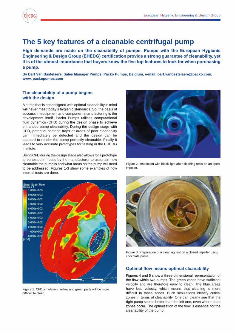
European Hygienic Engineering & Design Group
The 5 key features of a cleanable centrifugal pumpHigh demands are made on the cleanability of pumps. Pumps with the European Hygienic Engineering & Design Group (EHEDG) certification provide a strong guarantee of cleanability, yet it is of the utmost importance that buyers know the five top features to look for when purchasing a pump. By Bart Van Bastelaere, Sales Manager Pumps, Packo Pumps, Belgium, e-mail: [email protected], www. packopumps.com
The cleanability of a pump begins with the designA pump that is not designed with optimal cleanability in mind will never meet today’s hygienic standards. So, the basis of success in equipment and component manufacturing is the development itself. Packo Pumps utilises computational fluid dynamics (CFD) during the design phase to achieve enhanced pump cleanability. During the design stage with CFD, potential bacteria traps or areas of poor cleanabilty can immediately be detected and the design can be adapted to render the pump perfectly cleanable. Finally it leads to very accurate prototypes for testing in the EHEDG Institute.
Using CFD during the design stage also allows for a prototype to be tested in-house by the manufacturer to ascertain how cleanable the pump is and what areas on the pump will need to be addressed. Figures 1-3 show some examples of how internal tests are done.
Figure 1. CFD simulation, yellow and green parts will be more difficult to clean.
Figure 2. Inspection with black light after cleaning tests on an open impeller.
Figure 3. Preparation of a cleaning test on a closed impeller using chocolate paste.
Optimal flow means optimal cleanabilityFigures 4 and 5 show a three-dimensional representation of the flow within two pumps. The green zones have sufficient velocity and are therefore easy to clean. The blue areas have less velocity, which means that cleaning is more difficult in these zones. Such simulations identify critical zones in terms of cleanability. One can clearly see that the right pump scores better than the left one, even where dead zones occur. The optimisation of the flow is essential for the cleanability of the pump.
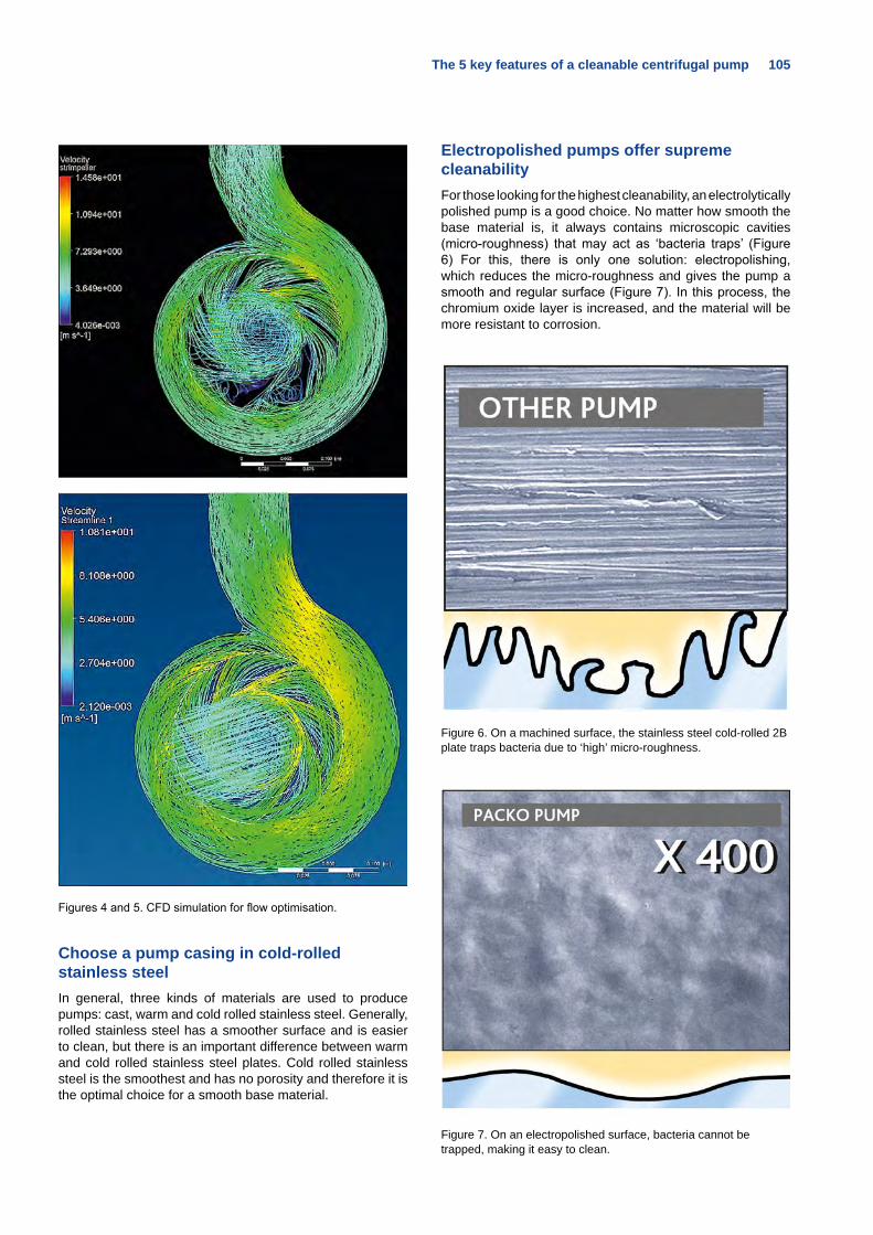
The 5 key features of a cleanable centrifugal pump 105
Figures 4 and 5. CFD simulation for flow optimisation.
Choose a pump casing in cold-rolled stainless steelIn general, three kinds of materials are used to produce pumps: cast, warm and cold rolled stainless steel. Generally, rolled stainless steel has a smoother surface and is easier to clean, but there is an important difference between warm and cold rolled stainless steel plates. Cold rolled stainless steel is the smoothest and has no porosity and therefore it is the optimal choice for a smooth base material.
Electropolished pumps offer supreme cleanabilityFor those looking for the highest cleanability, an electrolytically polished pump is a good choice. No matter how smooth the base material is, it always contains microscopic cavities (micro-roughness) that may act as ‘bacteria traps’ (Figure 6) For this, there is only one solution: electropolishing, which reduces the micro-roughness and gives the pump a smooth and regular surface (Figure 7). In this process, the chromium oxide layer is increased, and the material will be more resistant to corrosion.
Figure 6. On a machined surface, the stainless steel cold-rolled 2B plate traps bacteria due to ‘high’ micro-roughness.
Figure 7. On an electropolished surface, bacteria cannot be trapped, making it easy to clean.
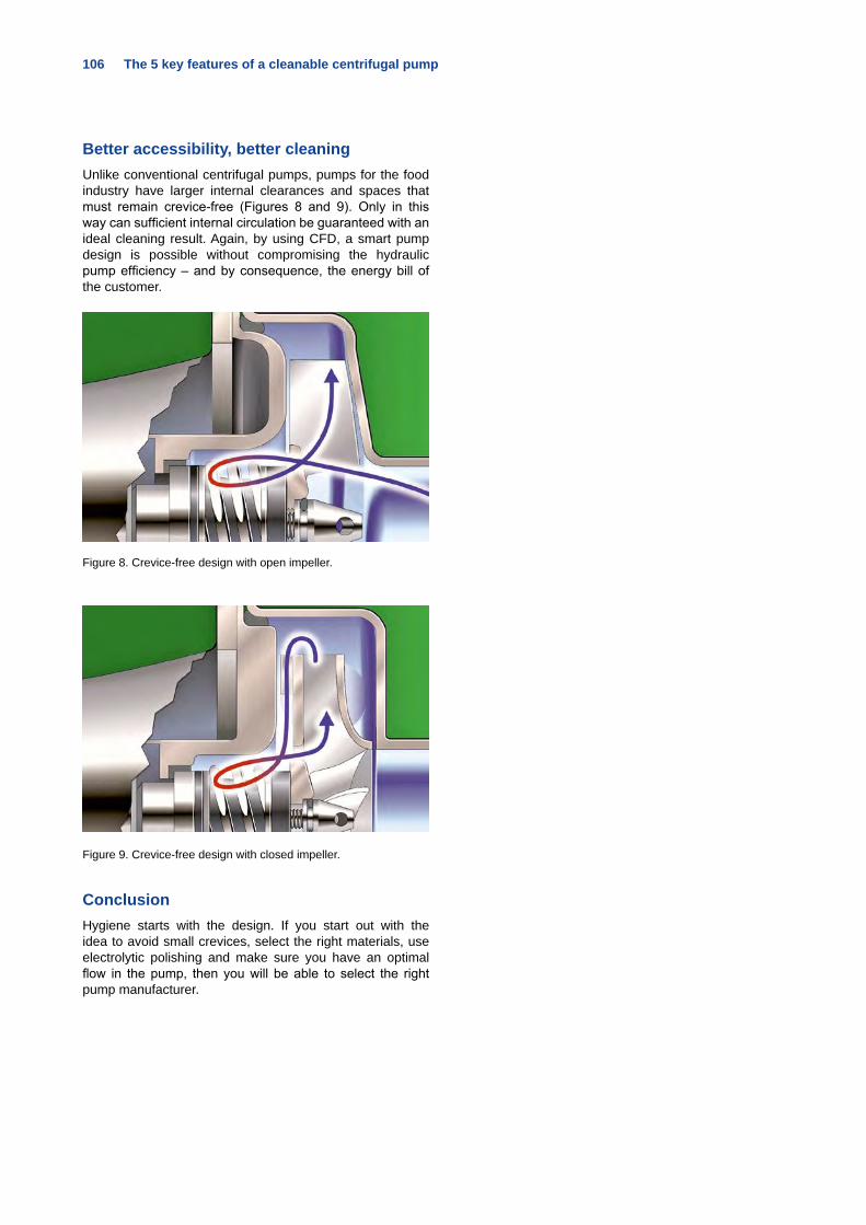
106 The 5 key features of a cleanable centrifugal pump
Better accessibility, better cleaningUnlike conventional centrifugal pumps, pumps for the food industry have larger internal clearances and spaces that must remain crevice-free (Figures 8 and 9). Only in this way can sufficient internal circulation be guaranteed with an ideal cleaning result. Again, by using CFD, a smart pump design is possible without compromising the hydraulic pump efficiency – and by consequence, the energy bill of the customer.
Figure 8. Crevice-free design with open impeller.
Figure 9. Crevice-free design with closed impeller.
ConclusionHygiene starts with the design. If you start out with the idea to avoid small crevices, select the right materials, use electrolytic polishing and make sure you have an optimal flow in the pump, then you will be able to select the right pump manufacturer.
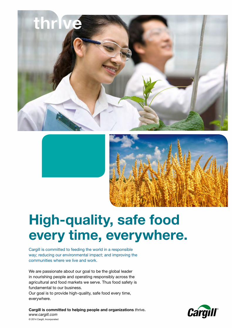
High-quality, safe food every time, everywhere.
Cargill is committed to helping people and organizations thrive.www.cargill.com© 2014 Cargill, Incorporated
Cargill is committed to feeding the world in a responsible way; reducing our environmental impact; and improving the communities where we live and work.
We are passionate about our goal to be the global leader in nourishing people and operating responsibly across the agricultural and food markets we serve. Thus food safety is fundamental to our business. Our goal is to provide high-quality, safe food every time, everywhere.
Untitled-1.indd 3 22/12/2014 11:04:19
European Hygienic Engineering & Design Group
The hygienic advantages of the P³-diaphragm in aseptic processingThe fundamental requirement of aseptic processing plants is the secure hermetic separation of the product-facing sectors from the surrounding area to eliminate the risk of microbiological contamination. To achieve this hermetic separation in the process, the “elevator effect” that occurs during the operation of the spindle valves must be prevented. This article presents an innovative diaphragm solution for single- and double-seat valves that offers significant advantages over the commonly used polytetrafluoroethylene (PTFE) and metal bellows.By Dietmar Ladenburger, Pentair Südmo, Riesbürg, Germany, e-mail: [email protected], www.suedmo.de
The use of aseptic production and packaging has increased in the drinks, food and dairy industries. Changing consumer trends are one reason for this. For example, consumers demand that their foods be as natural as possible and free from chemical preservations. However, such ‘unpreserved’ or minimally processed products are often more microbiologically sensitive. At the same time, longer shelf-life and higher quality standards are required by the trade. Due to product liability, it is necessary to protect consumers from the risk of health-damaging microorganisms. In this context, there is an increase in both procedural and economic optimisation requirements that are imposed by food manufacturers on the equipment and component for hygienically designed machinery. This includes the possibility of an automatic clean-in-place/sterilse-in-place (CIP/SIP) system, the minimisation of cleaning times and cost-effective, simple and fast maintenance.
Built-in valves occupy a key position in the aseptic production chain. They not only control the product lines but also facilitate the automated CIP/SIP cleaning in the processing plant. These valves are the interface between the product, the process and the surrounding area – and the dynamic independent changing operating conditions.
During the construction of a modern, aseptic optimised processing and valve technology, the criteria shown below from the European Hygienic Engineering & Design Group (EHEDG) guidelines “Hygienic equipment design criteria” and the 3-A Sanitary Standards are to be observed:1,2
• Stainless steel, materials 1.4301 (AISI 304) or 1.4404/1.4435 (AISI 316L)
• Conform elastomers, adhesives and lubricants according to US Food and Drug Administration (FDA) 21 Code of Federal Regulations (CFR)
• No undercuts and dead areas -> free from crevices
• Self-draining and easily cleanable -> without domes and sumps
• Quality surfaces (Ra ≤ 0.8 µm) and radii (≥ 1.59 mm) in product-related areas
• Avoidance of outside contamination -> hermetic separation
• Visual recognition of leakages, clear monitoring of leakage
• Inspection window between actuator and valve casing 25.4 mm = 1 inch
• Easy-to-maintain components
Bellows are practical but are not optimalWith regard to the required hermetic separation, the valve spindle is a very sensitive component. The focus here is on the section that comes into contact with the atmosphere through a lifting movement, which consequently creates a potential entry point for product contamination. The level of elimination for this so-called “elevator effect” is therefore a fundamental difference between hygienic and aseptic valves. For hygienic valves, current elastomer shaft seal designs are used, which are not completely able to eliminate a potential product contamination. For aseptic processing valves, the required hermetic protection of the spindle travel was, until now, mostly assured through a flexible PTFE or metal bellows.
However, it is apparent that bellows are actually at odds with this when one refers to the required EHEDG characteristics for the aseptic processing design. It is evident that the large, uneven surface of a bellow is not optimal with respect to its cleanability. The impaired flow conditions inside of the valve and an unpreventable dome formation from larger movements also impede cleanability (Figure 1).
Figure 1. Example of a dome.4
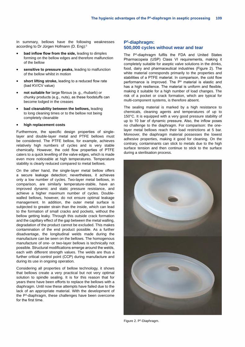
The hygienic advantages of the P³-diaphragm in aseptic processing 109
In summary, bellows have the following weaknesses according to Dr Jürgen Hofmann (D. Eng):3
• bad inflow flow from the side, leading to dimples forming on the bellow edges and therefore malfunction of the bellow
• sensitive to pressure peaks, leading to malfunction of the bellow whilst in motion
• short lifting stroke, leading to a reduced flow rate (bad KV/CV value)
• not suitable for large fibrous (e. g., rhubarb) or chunky products (e.g., nuts), as these foodstuffs can become lodged in the creases
• bad cleanability between the bellows, leading to long cleaning times or to the bellow not being completely cleanable
• high replacement costs
Furthermore, the specific design properties of single-layer and double-layer metal and PTFE bellows must be considered. The PTFE bellow, for example, achieves relatively high numbers of cycles and is very stable chemically. However, the cold flow properties of PTFE caters to a quick levelling of the valve edges, which is made even more noticeable at high temperatures. Temperature stability is clearly reduced compared to metal bellows.
On the other hand, the single-layer metal bellow offers a secure leakage detection; nevertheless, it achieves only a low number of cycles. Two-layer metal bellows, in comparison, are similarly temperature-stable, have an improved dynamic and static pressure resistance, and achieve a higher maximum number of cycles. Double-walled bellows, however, do not ensure optimal leakage management. In addition, the outer metal surface is subjected to greater strain than the inside, which can lead to the formation of small cracks and pockets, without the bellow getting leaky. Through this outside crack formation and the capillary effect of the gap between the metal walling, degradation of the product cannot be excluded. This makes contamination of the end product possible. As a further disadvantage, the longitudinal welds made during the manufacture can be seen on the bellows. The homogenous manufacture of one- or two-layer bellows is technically not possible. Structural modifications emerge around the welds, each with different strength values. The welds are thus a further critical control point (CCP) during manufacture and during its use in ongoing operation.
Considering all properties of bellow technology, it shows that bellows create a very practical but not very optimal solution to spindle sealing. It is for this reason that for years there have been efforts to replace the bellows with a diaphragm. Until now these attempts have failed due to the lack of an appropriate material. With the development of the P3-diaphragm, these challenges have been overcome for the first time.
P3-diaphragm: 500,000 cycles without wear and tearThe P3-diaphragm fulfils the FDA and United States Pharmacopeia (USP) Class VI requirements, making it completely suitable for aseptic valve solutions in the drinks, food, dairy and pharmaceutical industries (Figure 2). The white material corresponds primarily to the properties and stabilities of a PTFE material. In comparison, the cold flow performance is improved. The P³ material is elastic and has a high resilience. The material is uniform and flexible, making it suitable for a high number of load changes. The risk of a pocket or crack formation, which are typical for multi-component systems, is therefore absent.
The sealing material is marked by a high resistance to chemicals, cleaning agents and temperatures of up to 150°C. It is equipped with a very good pressure stability of up to 10 bar of dynamic pressure. Also, the inflow poses no challenge to the diaphragm. For comparison: the one-layer metal bellows reach their load restrictions at 5 bar. Moreover, the diaphragm material possesses the lowest adhesive properties, making it good for cleaning. On the contrary, contaminants can stick to metals due to the high surface tension and then continue to stick to the surface during a sterilisation process.
Figure 2. P3-Diaphragm.
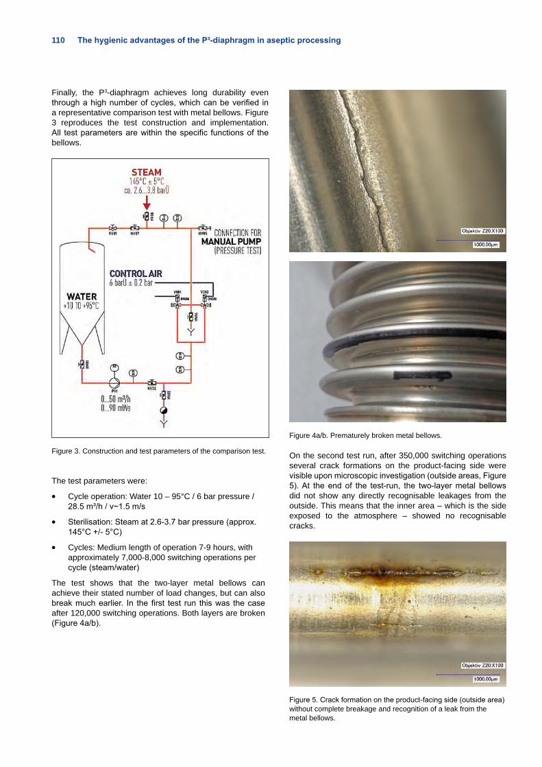
110 The hygienic advantages of the P³-diaphragm in aseptic processing
Finally, the P3-diaphragm achieves long durability even through a high number of cycles, which can be verified in a representative comparison test with metal bellows. Figure 3 reproduces the test construction and implementation. All test parameters are within the specific functions of the bellows.
Figure 3. Construction and test parameters of the comparison test.
The test parameters were:
• Cycle operation: Water 10 – 95°C / 6 bar pressure / 28.5 m³/h / v~1.5 m/s
• Sterilisation: Steam at 2.6-3.7 bar pressure (approx. 145°C +/- 5°C)
• Cycles: Medium length of operation 7-9 hours, with approximately 7,000-8,000 switching operations per cycle (steam/water)
The test shows that the two-layer metal bellows can achieve their stated number of load changes, but can also break much earlier. In the first test run this was the case after 120,000 switching operations. Both layers are broken (Figure 4a/b).
Figure 4a/b. Prematurely broken metal bellows.
On the second test run, after 350,000 switching operations several crack formations on the product-facing side were visible upon microscopic investigation (outside areas, Figure 5). At the end of the test-run, the two-layer metal bellows did not show any directly recognisable leakages from the outside. This means that the inner area – which is the side exposed to the atmosphere – showed no recognisable cracks.
Figure 5. Crack formation on the product-facing side (outside area) without complete breakage and recognition of a leak from the metal bellows.
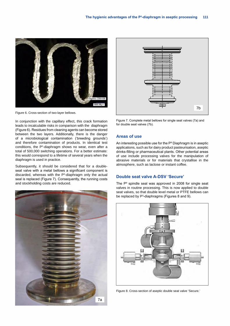
The hygienic advantages of the P³-diaphragm in aseptic processing 111
Figure 6. Cross-section of two-layer bellows.
In conjunction with the capillary effect, this crack formation leads to incalculable risks in comparison with the diaphragm (Figure 6). Residues from cleaning agents can become stored between the two layers. Additionally, there is the danger of a microbiological contamination (‘breeding grounds’) and therefore contamination of products. In identical test conditions, the P3-diaphragm shows no wear, even after a total of 500,000 switching operations. For a better estimate: this would correspond to a lifetime of several years when the diaphragm is used in practice.
Subsequently, it should be considered that for a double-seat valve with a metal bellows a significant component is discarded, whereas with the P3-diaphragm only the actual seal is replaced (Figure 7). Consequently, the running costs and stockholding costs are reduced.
7a
7b
Figure 7. Complete metal bellows for single seat valves (7a) and for double seat valves (7b).
Areas of useAn interesting possible use for the P³ Diaphragm is in aseptic applications, such as for dairy product pasteurisation, aseptic drinks-filling or pharmaceutical plants. Other potential areas of use include processing valves for the manipulation of abrasive materials or for materials that crystallise in the atmosphere, such as lactose or instant coffee.
Double seat valve A-DSV ‘Secure’The P³ spindle seal was approved in 2008 for single seat valves in routine processing. This is now applied to double seat valves, so that double level metal or PTFE bellows can be replaced by P3-diaphragms (Figures 8 and 9).
Figure 8. Cross-section of aseptic double seat valve ‘Secure.’
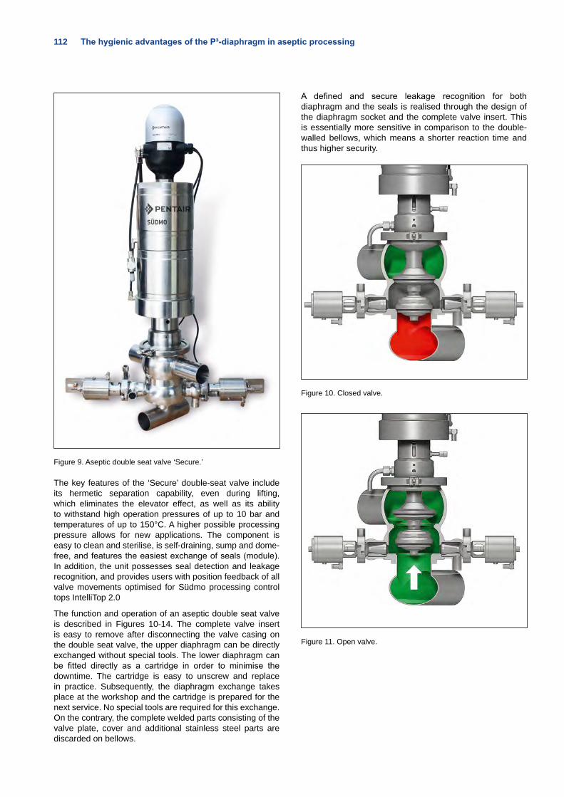
112 The hygienic advantages of the P³-diaphragm in aseptic processing
Figure 9. Aseptic double seat valve ‘Secure.’
The key features of the ‘Secure’ double-seat valve include its hermetic separation capability, even during lifting, which eliminates the elevator effect, as well as its ability to withstand high operation pressures of up to 10 bar and temperatures of up to 150°C. A higher possible processing pressure allows for new applications. The component is easy to clean and sterilise, is self-draining, sump and dome-free, and features the easiest exchange of seals (module). In addition, the unit possesses seal detection and leakage recognition, and provides users with position feedback of all valve movements optimised for Südmo processing control tops IntelliTop 2.0
The function and operation of an aseptic double seat valve is described in Figures 10-14. The complete valve insert is easy to remove after disconnecting the valve casing on the double seat valve, the upper diaphragm can be directly exchanged without special tools. The lower diaphragm can be fitted directly as a cartridge in order to minimise the downtime. The cartridge is easy to unscrew and replace in practice. Subsequently, the diaphragm exchange takes place at the workshop and the cartridge is prepared for the next service. No special tools are required for this exchange. On the contrary, the complete welded parts consisting of the valve plate, cover and additional stainless steel parts are discarded on bellows.
A defined and secure leakage recognition for both diaphragm and the seals is realised through the design of the diaphragm socket and the complete valve insert. This is essentially more sensitive in comparison to the double-walled bellows, which means a shorter reaction time and thus higher security.
Figure 10. Closed valve.
Figure 11. Open valve.
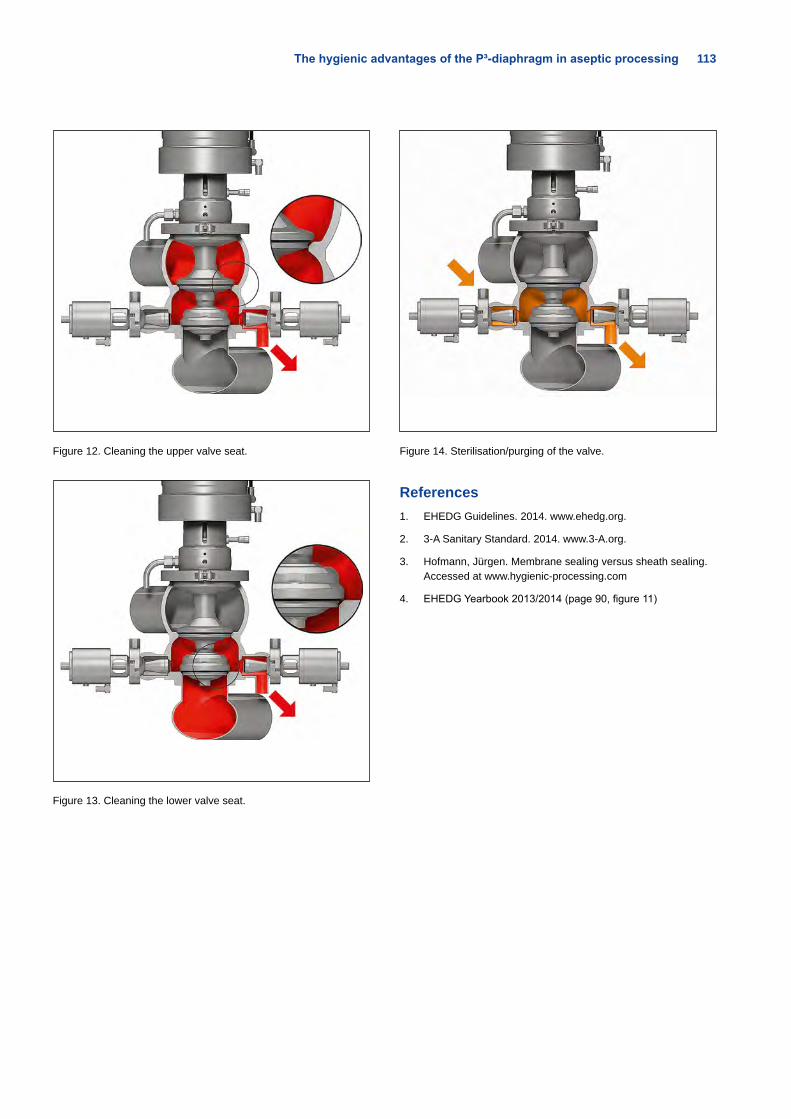
The hygienic advantages of the P³-diaphragm in aseptic processing 113
Figure 12. Cleaning the upper valve seat.
Figure 13. Cleaning the lower valve seat.
Figure 14. Sterilisation/purging of the valve.
References1. EHEDG Guidelines. 2014. www.ehedg.org.
2. 3-A Sanitary Standard. 2014. www.3-A.org.
3. Hofmann, Jürgen. Membrane sealing versus sheath sealing. Accessed at www.hygienic-processing.com
4. EHEDG Yearbook 2013/2014 (page 90, figure 11)
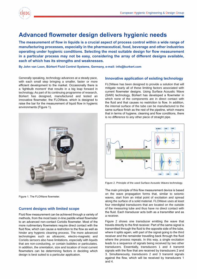
European Hygienic Engineering & Design Group
Advanced flowmeter design delivers hygienic needsThe measurement of flow in liquids is a crucial aspect of process control within a wide range of manufacturing processes, especially in the pharmaceutical, food, beverage and other industries operating under hygienic conditions. Selecting the most suitable design for flow measurement in a particular process may not be easy, considering the array of different designs available, each of which has its strengths and weaknesses. By John van Loon, Bürkert Fluid Control Systems, Germany, e-mail: [email protected]
Generally speaking, technology advances at a steady pace, with each small step bringing a smaller, faster or more efficient development to the market. Occasionally there is a ‘lightbulb moment’ that results in a big leap forward in technology. As part of its continuing programme of research, Bürkert has designed, manufactured and tested an innovative flowmeter, the FLOWave, which is designed to raise the bar for the measurement of liquid flow in hygienic environments (Figure 1).
Figure 1. The FLOWave flowmeter.
Current designs with limited scopeFluid flow measurement can be achieved through a variety of methods, from the most basic in-line paddle wheel flowmeter to an advanced non-contact Coriolis flowmeter. Most of the more rudimentary flowmeters require direct contact with the fluid flow, which can cause a restriction to the flow as well as hinder any hygienic cleaning process. The more advanced technologies such as ultrasonic, electro-magnetic and Coriolis sensors also have limitations, especially with liquids that are non-conducting, or contain bubbles or particulates. In addition, the orientation, size and location of most current flowmeters can be determining factors in deciding which design is best suited to a particular application.
Innovative application of existing technologyFLOWave has been designed to provide a solution that will mitigate nearly all of these limiting factors associated with current flowmeter designs. Using Surface Acoustic Wave (SAW) technology, Bürkert has developed a flowmeter in which none of the components are in direct contact with the fluid and that causes no restriction to flow. In addition, the internal surface of the tube can be manufactured to the same surface finish as the rest of the pipeline, which means that in terms of hygiene, cleaning and flow conditions, there is no difference to any other piece of straight pipe.
Figure 2. Principle of the used Surface Acoustic Waves technology.
The main principle of this flow measurement device is based on the wave propagation forms that, similar to seismic waves, start from an initial point of excitation and spread along the surface of a solid material. FLOWave uses at least four interdigital transducers that are located on the outside of the measuring tube and thus have no direct contact with the fluid. Each transducer acts both as a transmitter and as a receiver.
Figure 2 shows one transducer emitting the wave that travels directly to the first receiver. Part of the same signal is transmitted through the fluid to the opposite side of the tube, where it splits again, with part of the signal going to the third receiver and the remainder travelling back through the fluid where the process repeats. In this way, a single excitation leads to a sequence of signals being received by two other transducers. Essentially, transducers 1 and 4 transmit signals with the flow that are received by transducers 2 and 3. Simultaneously, transducers 2 and 3 transmit signals against the flow, which will be received by transducers 1 and 4.
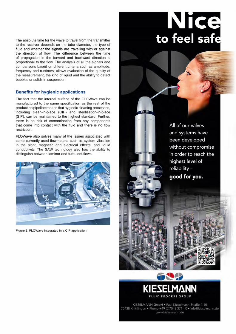
The absolute time for the wave to travel from the transmitter to the receiver depends on the tube diameter, the type of fluid and whether the signals are travelling with or against the direction of flow. The difference between the time of propagation in the forward and backward direction is proportional to the flow. The analysis of all the signals and comparisons based on different criteria such as amplitude, frequency and runtimes, allows evaluation of the quality of the measurement, the kind of liquid and the ability to detect bubbles or solids in suspension.
Benefits for hygienic applicationsThe fact that the internal surface of the FLOWave can be manufactured to the same specification as the rest of the production pipeline means that hygienic cleaning processes, including clean-in-place (CIP) and sterilisation-in-place (SIP), can be maintained to the highest standard. Further, there is no risk of contamination from any components that come into contact with the fluid and there is no flow restriction.
FLOWave also solves many of the issues associated with some currently used flowmeters, such as system vibration in the plant, magnetic and electrical effects, and liquid conductivity. The SAW technology also has the ability to distinguish between laminar and turbulent flows.
Figure 3. FLOWave integrated in a CIP application.
KIESELMANN GmbH • Paul Kieselmann-Straße 4-10 75438 Knittlingen • Phone +49 (0)7043 371 - 0 • [email protected]
www.kieselmann.de
All of our valves and systems have been developed without compromise in order to reach the highest level of reliability -
good for you.
Nice to feel safe
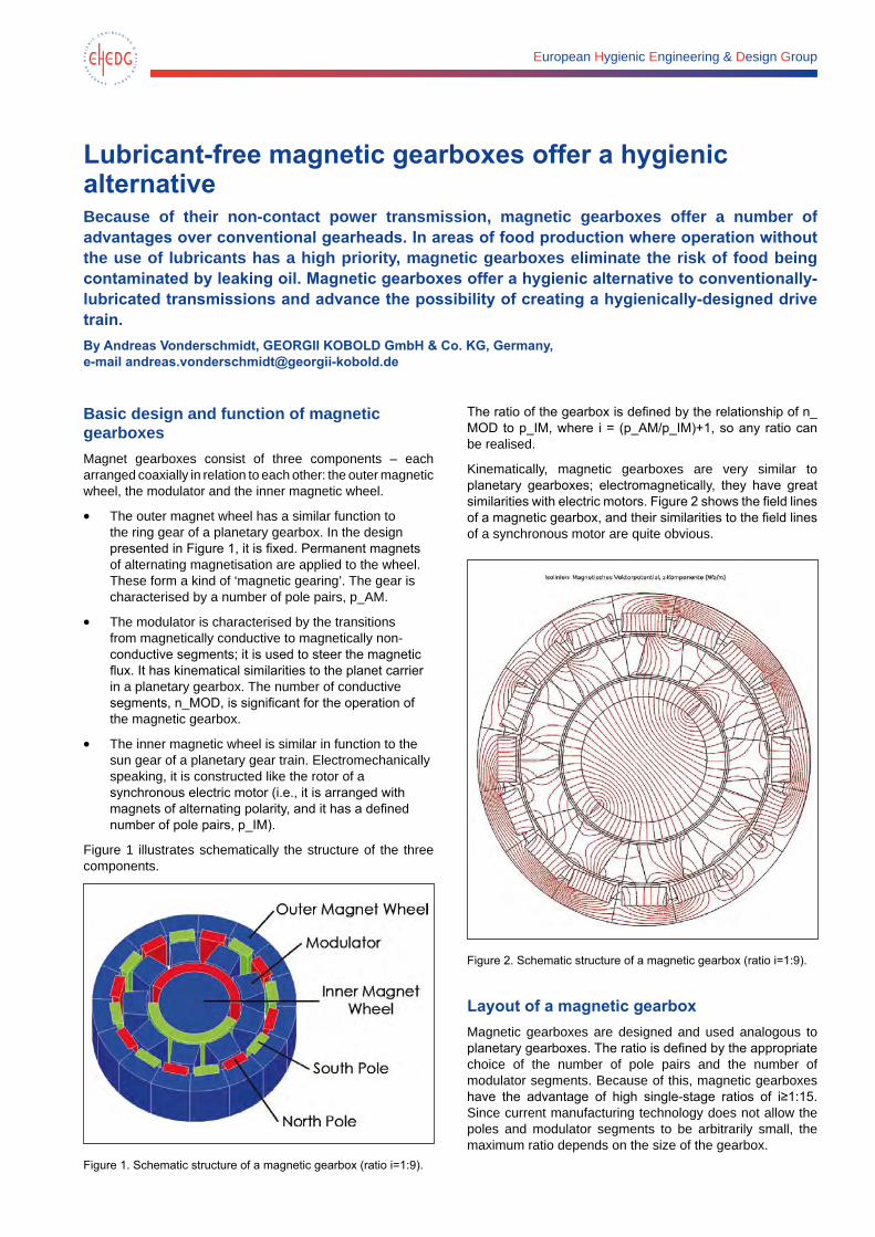
European Hygienic Engineering & Design Group
Lubricant-free magnetic gearboxes offer a hygienic alternativeBecause of their non-contact power transmission, magnetic gearboxes offer a number of advantages over conventional gearheads. In areas of food production where operation without the use of lubricants has a high priority, magnetic gearboxes eliminate the risk of food being contaminated by leaking oil. Magnetic gearboxes offer a hygienic alternative to conventionally-lubricated transmissions and advance the possibility of creating a hygienically-designed drive train.By Andreas Vonderschmidt, GEORGII KOBOLD GmbH & Co. KG, Germany, e-mail [email protected]
Basic design and function of magnetic gearboxesMagnet gearboxes consist of three components – each arranged coaxially in relation to each other: the outer magnetic wheel, the modulator and the inner magnetic wheel.
• The outer magnet wheel has a similar function to the ring gear of a planetary gearbox. In the design presented in Figure 1, it is fixed. Permanent magnets of alternating magnetisation are applied to the wheel. These form a kind of ‘magnetic gearing’. The gear is characterised by a number of pole pairs, p_AM.
• The modulator is characterised by the transitions from magnetically conductive to magnetically non-conductive segments; it is used to steer the magnetic flux. It has kinematical similarities to the planet carrier in a planetary gearbox. The number of conductive segments, n_MOD, is significant for the operation of the magnetic gearbox.
• The inner magnetic wheel is similar in function to the sun gear of a planetary gear train. Electromechanically speaking, it is constructed like the rotor of a synchronous electric motor (i.e., it is arranged with magnets of alternating polarity, and it has a defined number of pole pairs, p_IM).
Figure 1 illustrates schematically the structure of the three components.
Figure 1. Schematic structure of a magnetic gearbox (ratio i=1:9).
The ratio of the gearbox is defined by the relationship of n_MOD to p_IM, where i = (p_AM/p_IM)+1, so any ratio can be realised.
Kinematically, magnetic gearboxes are very similar to planetary gearboxes; electromagnetically, they have great similarities with electric motors. Figure 2 shows the field lines of a magnetic gearbox, and their similarities to the field lines of a synchronous motor are quite obvious.
Figure 2. Schematic structure of a magnetic gearbox (ratio i=1:9).
Layout of a magnetic gearboxMagnetic gearboxes are designed and used analogous to planetary gearboxes. The ratio is defined by the appropriate choice of the number of pole pairs and the number of modulator segments. Because of this, magnetic gearboxes have the advantage of high single-stage ratios of i≥1:15. Since current manufacturing technology does not allow the poles and modulator segments to be arbitrarily small, the maximum ratio depends on the size of the gearbox.
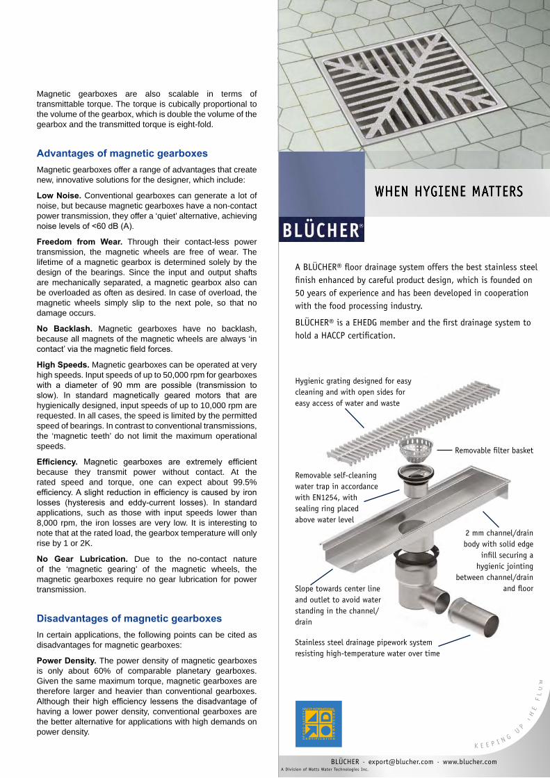
Magnetic gearboxes are also scalable in terms of transmittable torque. The torque is cubically proportional to the volume of the gearbox, which is double the volume of the gearbox and the transmitted torque is eight-fold.
Advantages of magnetic gearboxesMagnetic gearboxes offer a range of advantages that create new, innovative solutions for the designer, which include:
Low Noise. Conventional gearboxes can generate a lot of noise, but because magnetic gearboxes have a non-contact power transmission, they offer a ‘quiet’ alternative, achieving noise levels of <60 dB (A).
Freedom from Wear. Through their contact-less power transmission, the magnetic wheels are free of wear. The lifetime of a magnetic gearbox is determined solely by the design of the bearings. Since the input and output shafts are mechanically separated, a magnetic gearbox also can be overloaded as often as desired. In case of overload, the magnetic wheels simply slip to the next pole, so that no damage occurs.
No Backlash. Magnetic gearboxes have no backlash, because all magnets of the magnetic wheels are always ‘in contact’ via the magnetic field forces.
High Speeds. Magnetic gearboxes can be operated at very high speeds. Input speeds of up to 50,000 rpm for gearboxes with a diameter of 90 mm are possible (transmission to slow). In standard magnetically geared motors that are hygienically designed, input speeds of up to 10,000 rpm are requested. In all cases, the speed is limited by the permitted speed of bearings. In contrast to conventional transmissions, the ‘magnetic teeth’ do not limit the maximum operational speeds.
Efficiency. Magnetic gearboxes are extremely efficient because they transmit power without contact. At the rated speed and torque, one can expect about 99.5% efficiency. A slight reduction in efficiency is caused by iron losses (hysteresis and eddy-current losses). In standard applications, such as those with input speeds lower than 8,000 rpm, the iron losses are very low. It is interesting to note that at the rated load, the gearbox temperature will only rise by 1 or 2K.
No Gear Lubrication. Due to the no-contact nature of the ‘magnetic gearing’ of the magnetic wheels, the magnetic gearboxes require no gear lubrication for power transmission.
Disadvantages of magnetic gearboxesIn certain applications, the following points can be cited as disadvantages for magnetic gearboxes:
Power Density. The power density of magnetic gearboxes is only about 60% of comparable planetary gearboxes. Given the same maximum torque, magnetic gearboxes are therefore larger and heavier than conventional gearboxes. Although their high efficiency lessens the disadvantage of having a lower power density, conventional gearboxes are the better alternative for applications with high demands on power density.
WHEN HYGIENE MATTERS
A BLÜCHER® floor drainage system offers the best stainless steel finish enhanced by careful product design, which is founded on 50 years of experience and has been developed in cooperation with the food processing industry.
BLÜCHER® is a EHEDG member and the first drainage system to hold a HACCP certification.
WHEN HYGIENE MATTERS
BLÜCHER · [email protected] · www.blucher.com A Division of Watts Water Technologies Inc.
Hygienic grating designed for easycleaning and with open sides for easy access of water and waste
Removable filter basket
Removable self-cleaningwater trap in accordance with EN1254, with sealing ring placed above water level
Slope towards center line and outlet to avoid water standing in the channel/ drain
2 mm channel/drainbody with solid edge
infill securing a hygienic jointing
between channel/drain and floor
Stainless steel drainage pipework system resisting high-temperature water over time
34202_104x297_EHEDG yearbook.indd 1 28-10-2014 12:49:04
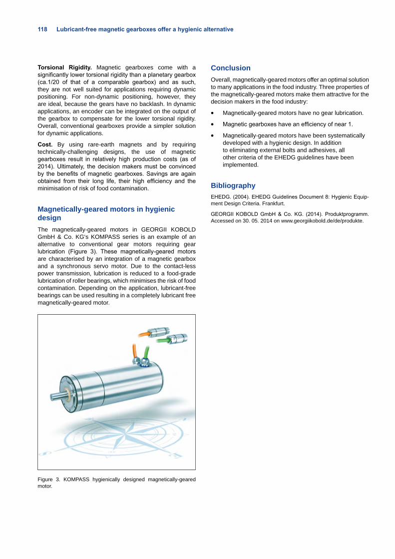
118 Lubricant-free magnetic gearboxes offer a hygienic alternative
Torsional Rigidity. Magnetic gearboxes come with a significantly lower torsional rigidity than a planetary gearbox (ca.1/20 of that of a comparable gearbox) and as such, they are not well suited for applications requiring dynamic positioning. For non-dynamic positioning, however, they are ideal, because the gears have no backlash. In dynamic applications, an encoder can be integrated on the output of the gearbox to compensate for the lower torsional rigidity. Overall, conventional gearboxes provide a simpler solution for dynamic applications.
Cost. By using rare-earth magnets and by requiring technically-challenging designs, the use of magnetic gearboxes result in relatively high production costs (as of 2014). Ultimately, the decision makers must be convinced by the benefits of magnetic gearboxes. Savings are again obtained from their long life, their high efficiency and the minimisation of risk of food contamination.
Magnetically-geared motors in hygienic designThe magnetically-geared motors in GEORGII KOBOLD GmbH & Co. KG‘s KOMPASS series is an example of an alternative to conventional gear motors requiring gear lubrication (Figure 3). These magnetically-geared motors are characterised by an integration of a magnetic gearbox and a synchronous servo motor. Due to the contact-less power transmission, lubrication is reduced to a food-grade lubrication of roller bearings, which minimises the risk of food contamination. Depending on the application, lubricant-free bearings can be used resulting in a completely lubricant free magnetically-geared motor.
Figure 3. KOMPASS hygienically designed magnetically-geared motor.
ConclusionOverall, magnetically-geared motors offer an optimal solution to many applications in the food industry. Three properties of the magnetically-geared motors make them attractive for the decision makers in the food industry:
• Magnetically-geared motors have no gear lubrication.
• Magnetic gearboxes have an efficiency of near 1.
• Magnetically-geared motors have been systematically developed with a hygienic design. In addition to eliminating external bolts and adhesives, all other criteria of the EHEDG guidelines have been implemented.
BibliographyEHEDG. (2004). EHEDG Guidelines Document 8: Hygienic Equip-ment Design Criteria. Frankfurt.
GEORGII KOBOLD GmbH & Co. KG. (2014). Produktprogramm. Accessed on 30. 05. 2014 on www.georgiikobold.de/de/produkte.
www.polysoude.com
A Member of
Zero defects in orbital TIG welding
Anzeige_EHEDGE_Yearbook_2014.indd 1 28/05/2014 09:36:41
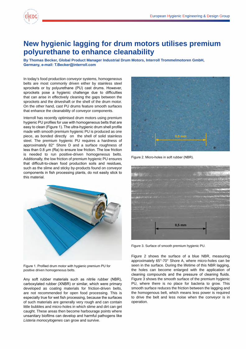
European Hygienic Engineering & Design Group
New hygienic lagging for drum motors utilises premium polyurethane to enhance cleanabilityBy Thomas Becker, Global Product Manager Industrial Drum Motors, Interroll Trommelmotoren GmbH, Germany, e-mail: [email protected]
In today’s food production conveyor systems, homogeneous belts are most commonly driven either by stainless steel sprockets or by polyurethane (PU) cast drums. However, sprockets pose a hygienic challenge due to difficulties that can arise in effectively cleaning the gaps between the sprockets and the driveshaft or the shell of the drum motor. On the other hand, cast PU drums feature smooth surfaces that enhance the cleanability of conveyor components.
Interroll has recently optimised drum motors using premium hygienic PU profiles for use with homogeneous belts that are easy to clean (Figure 1). The ultra-hygienic drum shell profile made with smooth premium hygienic PU is produced as one piece, as bonded directly on the shell of solid stainless steel. The premium hygienic PU requires a hardness of approximately 82° Shore D and a surface roughness of less than 0.8 µm (Ra) to ensure low friction. The low friction is needed to run positive-driven homogeneous belts. Additionally, the low friction of premium hygienic PU ensures that difficult-to-clean food production soils and residues, such as the slime and sticky by-products found on conveyor components in fish processing plants, do not easily stick to this material.
Figure 1. Profiled drum motor with hygienic premium PU for positive driven homogeneous belts.
Any soft rubber materials such as nitrile rubber (NBR), carboxylated rubber (XNBR) or similar, which were primary developed as coating materials for friction-driven belts, are not recommended for open food processing. This is especially true for wet fish processing, because the surfaces of such materials are generally very rough and can contain little bubbles and micro-holes in which slime and dirt can get caught. These areas then become harbourage points where unsanitary biofilms can develop and harmful pathogens like Listeria monocytogenes can grow and survive.
0,5 mm
Figure 2. Micro-holes in soft rubber (NBR).
0,5 mm
Figure 3. Surface of smooth premium hygienic PU.
Figure 2 shows the surface of a blue NBR, measuring approximately 65°-70° Shore A, where micro-holes can be seen in the surface. During the lifetime of this NBR lagging, the holes can become enlarged with the application of cleaning compounds and the pressure of cleaning fluids. Figure 3 shows the smooth surface of the premium hygienic PU, where there is no place for bacteria to grow. This smooth surface reduces the friction between the lagging and the homogenous belt, which means less power is required to drive the belt and less noise when the conveyor is in operation.
magnetrol.com • +32 (0)52 45 11 11 • [email protected] • hygienicsolutions.magnetrol.comEuropean Headquarter – Heikenstraat 6 – 9240 Zele - Belgium
PROVIDING LEVEL & FLOW INSTRUMENTATIONFOR HYGIENIC PROCESSING
Level/Volume measurement High level switch
Flow switch
Multiple bending of the Eclipse® GWR allows the rod to be pro-fi led to the shape of any individual vessel, measurement is possible down to the probe tip, eliminating the “dead” volume in the bottom of a tank that cannot usually be measured. With quick and easy loop tuning via PACTware™, the ECLIPSE 705 can provide unsurpassed level measurement of process media regardless of internal vessel obstructions and challenging pro-cess conditions such as foaming, agitation and vapours which can badly affect other measurement technologies. Magnetrol’s hygienic product range also includes Ultrasonic liq-uid level switches and Thermal dispersion level, fl ow and inter-face switches.
Watch our movie by scanning the QR code.
FEBRUARY 2003 FEBRUARY 2003 FEBRUARY 2003
Ad Hygienic 210 x 297 (be).indd 1 5/11/14 14:14
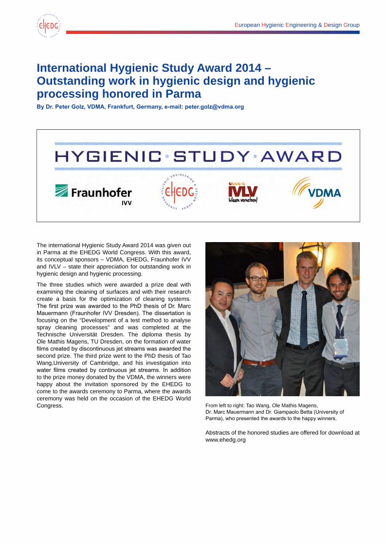
European Hygienic Engineering & Design Group
International Hygienic Study Award 2014 – Outstanding work in hygienic design and hygienic processing honored in ParmaBy Dr. Peter Golz, VDMA, Frankfurt, Germany, e-mail: [email protected]
The international Hygienic Study Award 2014 was given out in Parma at the EHEDG World Congress. With this award, its conceptual sponsors – VDMA, EHEDG, Fraunhofer IVV and IVLV – state their appreciation for outstanding work in hygienic design and hygienic processing.
The three studies which were awarded a prize deal with examining the cleaning of surfaces and with their research create a basis for the optimization of cleaning systems. The first prize was awarded to the PhD thesis of Dr. Marc Mauermann (Fraunhofer IVV Dresden). The dissertation is focusing on the “Development of a test method to analyse spray cleaning processes” and was completed at the Technische Universität Dresden. The diploma thesis by Ole Mathis Magens, TU Dresden, on the formation of water films created by discontinuous jet streams was awarded the second prize. The third prize went to the PhD thesis of Tao Wang,University of Cambridge, and his investigation into water films created by continuous jet streams. In addition to the prize money donated by the VDMA, the winners were happy about the invitation sponsored by the EHEDG to come to the awards ceremony to Parma, where the awards ceremony was held on the occasion of the EHEDG World Congress.
From left to right: Tao Wang, Ole Mathis Magens, Dr. Marc Mauermann and Dr. Giampaolo Betta (University of Parma), who presented the awards to the happy winners.
Abstracts of the honored studies are offered for download at www.ehedg.org
You develop efficient production systems.Food safety is your claim.Together we’ll achieve your goal – worldwide.
The valve terminal MPA-C: Clean Design to perfection!Extremely easy to clean and resistant to corrosion and cleaning agents. IP69K protection with redundant sealing system, FDA compliant materials and NSF-H1 grease – nothing is left to be desired. www.festo.com/food
Ad_Product_MPAC_en_A4_4c_V03.indd 1 23.06.2014 14:30:14
European Hygienic Engineering & Design Group
EHEDG Regional SectionsChairmen and contacts
The Regional Sections are the local extensions of the EHEDG and are created to promote hygienic manufacturing of food through regional activities. EHEDG has established Regional Sections in various countries in Europe and overseas. These groups organise local meetings, courses and workshops.
ARMENIA
• Professor Dr. Karina Grigoryan Armenian Society of Food Science and Technology (ASFoST) Phone: (+374 77) 31 39 88 e-mail: [email protected]
• Dr. Suren Martirosyan Armenian Society of Food Science and Technology (ASFoST) Phone: (+374 10) 56 40 29 E-mail: [email protected]
BELGIUM
• Hein Timmerman Sealed Air div. Food Care Phone: (+32 495) 59 17 81 E-mail: [email protected]
• Frank Moerman, Secretary and Consultant Phone: (+32 9) 38 65 44 E-mail: [email protected]
CROATIA
• Ass. Prof. Helga Medic University of Zagreb, Faculty of Food Technology & Biotechnology Phone: (+385 1) 4 60 51 26 E-mail: [email protected]
• Dr. Sanja Vidacek University of Zagreb, Faculty of Food Technology & Biotechnology Phone: (+385 1) 4 60 51 26 E-mail: [email protected]
CZECH REPUBLIC
• Ivan Chadima MQA s.r.o. State Veterinary Authority of the Czech Republic Phone: (+420 607) 90 99 47 E-mail: [email protected]
• Petr Otáhal MQA s.r.o. Phone: (+420 724) 13 81 68 E-mail: [email protected]
DENMARK
• Bjarne Darré GEA Liquid Processing Phone: (+45 87) 94 11 38 E-mail: [email protected]
• Jon Kold Stålcentrum Phone: (+45 88) 70 75 15 E-mail: [email protected]
FRANCE
• Erwan Billet Hydiac Phone: (+33 61) 2 49 85 84 E-mail: [email protected]
• Nicolas Chomel Laval Mayenne Technopole Phone: (+33 243) 49 75 24 E-mail: [email protected]
GERMANY
• Dr. Jürgen Hofmann Hygienic Design Weihenstephan Phone: (+49 8161) 8 76 87 99 E-mail: [email protected]
• Dr. Sven Fischer SIG Combibloc Phone: (+49 2462) 79 13 68 E-mail: [email protected]
INDIA
• Dr. V. Prakash Distinguished Scientist of CSIR, Hon. Director of Research, Innovation & Development Phone: (+91 821) 2 54 83 07 E-Mail:[email protected]
• Dr. Ali Abas Wani Department of Food Technology Islamic University of Science & Technology Phone: (+91 1933) 24 79 54 E-mail: [email protected]
EHEDG Regional Sections 125
ITALY
• Dr. Giampaolo Betta University of Parma Phone: (+39 05) 21 90 62 34 E-mail: [email protected]
JAPAN
• Takashi Hayashi Kanto Kongoki Industrial Ltd. Phone: (+81 3) 39 66 86 51 E-mail: [email protected]
• Hiroyuki Ohmura JFMA – The Japan Food Machinery Manufacturers’ Association Phone: (+81 3) 54 84-09 81 E-mail: [email protected]
LITHUANIA
• Dr. Raimondas Narkevicius Kaunas University of Technology Phone: (+370 68) 4 32 26 E-mail: [email protected]
• Prof. Dr. Rimantas Venskutonis Kaunas University of Technology Phone: (+370 37) 30 01 88 E-mail: [email protected]
MACEDONIA
• Professor Dr. Vladimir Kakurinov Consulting and Training Center KEY Phone: (+389 070) 68 86 52 E-mail: [email protected]
MEXICO
• Professor Marco Antonio León Félix Mexican Society for Food Safety and Quality for Food Consumers (SOMEICCA) Phone: (+52 55) 56 77 86 57 E-mail: [email protected]
NETHERLANDS
• Ernst Paardekooper Foundation Food Micro & Innovation Phone: (+31 30) 2 28 83 16 E-Mail: [email protected]
• Michael Evers Rittal BV Phone: (+31 62) 20 50 98 0 E-Mail: [email protected]
NORDIC (FI, N, S)
• Stefan Akesson Tetra Pak Processing Systems AB Phone: (+46 46) 36 58 69 E-mail: [email protected]
POLAND
• Dr. Tadeusz Matuszek Gdansk University Phone: (+48 58) 3 47 16 74 E-mail: [email protected]
RUSSIA
• Professor Dr. Mark Shamtsyan St. Petersburg State Institute of Technology Phone: (+7 960) 2 72 81 68 E-mail: [email protected]
SERBIA
• Professor Dr. Miomir Nikšić University of Belgrade, Faculty of Agriculture Phone: (+381 63) 7 79 85 76 E-mail: [email protected]
• Professor Dr. Victor Nedović University of Belgrade, Faculty of Agriculture Phone: (+381 11) 2 61 53 15 E-mail: [email protected]
SPAIN
• Rafael Soro AINIA Centro Tecnológico Phone: (+34 96) 13 66 09 0 E-mail: [email protected]
• Irene Llorca AINIA Centro Tecnológico Phone: (+34 96) 13 66 09 0 E-mail: [email protected]
SWITZERLAND
• Rudolf Schmitt HES-SO Valais, Institute of Life Sciences Phone: (+41 27) 6 06 86 52 E-mail: [email protected]
• Matthias Schäfer GEA Tuchenhagen GmbH Phone: (+41 61) 9 36 37 40 E-mail: [email protected]
TAIWAN
• Dr. Binghuei Barry Yang FIRDI – Food Industry Research and Development Institute Phone: (+886 6) 3 84 73 01 E-mail: [email protected]
THAILAND
• Dr. Navaphattra Nunak King Mongkut’s Institute of Technology, Bangkok Phone: (+66 2) 7 39 23 48 E-mail: [email protected]
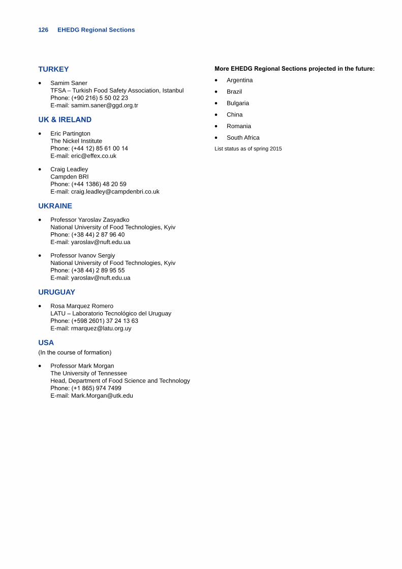
126 EHEDG Regional Sections
TURKEY
• Samim Saner TFSA – Turkish Food Safety Association, Istanbul Phone: (+90 216) 5 50 02 23 E-mail: [email protected]
UK & IRELAND
• Eric Partington The Nickel Institute Phone: (+44 12) 85 61 00 14 E-mail: [email protected]
• Craig Leadley Campden BRI Phone: (+44 1386) 48 20 59 E-mail: [email protected]
UKRAINE
• Professor Yaroslav Zasyadko National University of Food Technologies, Kyiv Phone: (+38 44) 2 87 96 40 E-mail: [email protected]
• Professor Ivanov Sergiy National University of Food Technologies, Kyiv Phone: (+38 44) 2 89 95 55 E-mail: [email protected]
URUGUAY
• Rosa Marquez Romero LATU – Laboratorio Tecnológico del Uruguay Phone: (+598 2601) 37 24 13 63 E-mail: [email protected]
USA (In the course of formation)
• Professor Mark Morgan The University of Tennessee Head, Department of Food Science and Technology Phone: (+1 865) 974 7499 E-mail: [email protected]
More EHEDG Regional Sections projected in the future:
• Argentina
• Brazil
• Bulgaria
• China
• Romania
• South Africa
List status as of spring 2015
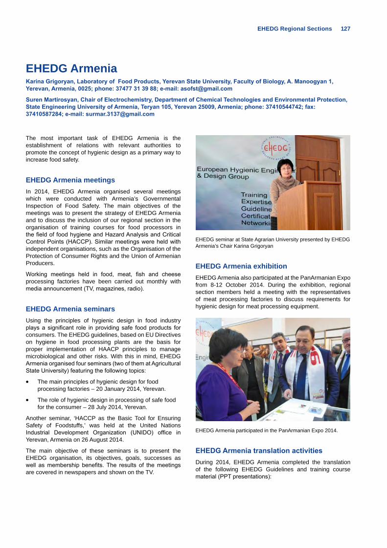
EHEDG Regional Sections 127
EHEDG ArmeniaKarina Grigoryan, Laboratory of Food Products, Yerevan State University, Faculty of Biology, A. Manoogyan 1, Yerevan, Armenia, 0025; phone: 37477 31 39 88; e-mail: [email protected]
Suren Martirosyan, Chair of Electrochemistry, Department of Chemical Technologies and Environmental Protection, State Engineering University of Armenia, Teryan 105, Yerevan 25009, Armenia; phone: 37410544742; fax: 37410587284; e-mail: [email protected]
The most important task of EHEDG Armenia is the establishment of relations with relevant authorities to promote the concept of hygienic design as a primary way to increase food safety.
EHEDG Armenia meetingsIn 2014, EHEDG Armenia organised several meetings which were conducted with Armenia’s Governmental Inspection of Food Safety. The main objectives of the meetings was to present the strategy of EHEDG Armenia and to discuss the inclusion of our regional section in the organisation of training courses for food processors in the field of food hygiene and Hazard Analysis and Critical Control Points (HACCP). Similar meetings were held with independent organisations, such as the Organisation of the Protection of Consumer Rights and the Union of Armenian Producers.
Working meetings held in food, meat, fish and cheese processing factories have been carried out monthly with media announcement (TV, magazines, radio).
EHEDG Armenia seminars Using the principles of hygienic design in food industry plays a significant role in providing safe food products for consumers. The EHEDG guidelines, based on EU Directives on hygiene in food processing plants are the basis for proper implementation of HAACP principles to manage microbiological and other risks. With this in mind, EHEDG Armenia organised four seminars (two of them at Agricultural State University) featuring the following topics:
• The main principles of hygienic design for food processing factories – 20 January 2014, Yerevan.
• The role of hygienic design in processing of safe food for the consumer – 28 July 2014, Yerevan.
Another seminar, ‘HACCP as the Basic Tool for Ensuring Safety of Foodstuffs,’ was held at the United Nations Industrial Development Organization (UNIDO) office in Yerevan, Armenia on 26 August 2014.
The main objective of these seminars is to present the EHEDG organisation, its objectives, goals, successes as well as membership benefits. The results of the meetings are covered in newspapers and shown on the TV.
EHEDG seminar at State Agrarian University presented by EHEDG Armenia’s Chair Karina Grigoryan
EHEDG Armenia exhibitionEHEDG Armenia also participated at the PanArmanian Expo from 8-12 October 2014. During the exhibition, regional section members held a meeting with the representatives of meat processing factories to discuss requirements for hygienic design for meat processing equipment.
EHEDG Armenia participated in the PanArmanian Expo 2014.
EHEDG Armenia translation activitiesDuring 2014, EHEDG Armenia completed the translation of the following EHEDG Guidelines and training course material (PPT presentations):
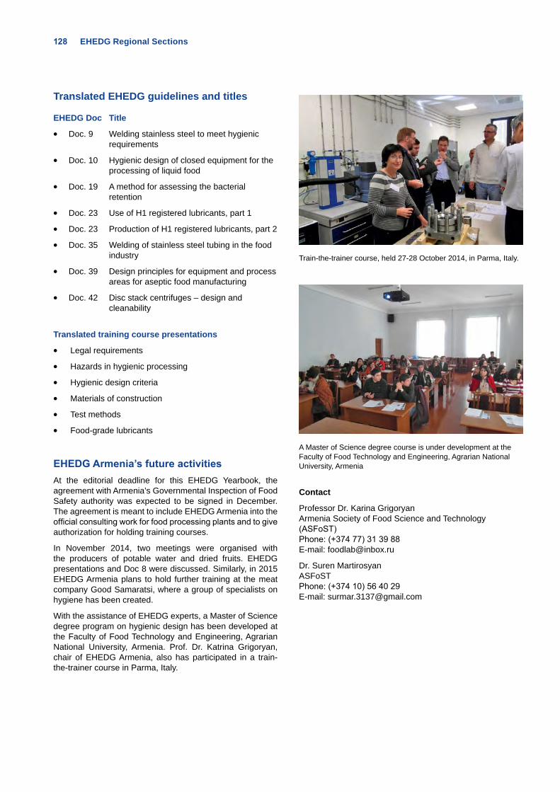
128 EHEDG Regional Sections
Translated EHEDG guidelines and titles
EHEDG Doc Title
• Doc. 9 Welding stainless steel to meet hygienic requirements
• Doc. 10 Hygienic design of closed equipment for the processing of liquid food
• Doc. 19 A method for assessing the bacterial retention
• Doc. 23 Use of H1 registered lubricants, part 1
• Doc. 23 Production of H1 registered lubricants, part 2
• Doc. 35 Welding of stainless steel tubing in the food industry
• Doc. 39 Design principles for equipment and process areas for aseptic food manufacturing
• Doc. 42 Disc stack centrifuges – design and cleanability
Translated training course presentations
• Legal requirements
• Hazards in hygienic processing
• Hygienic design criteria
• Materials of construction
• Test methods
• Food-grade lubricants
EHEDG Armenia’s future activities At the editorial deadline for this EHEDG Yearbook, the agreement with Armenia’s Governmental Inspection of Food Safety authority was expected to be signed in December. The agreement is meant to include EHEDG Armenia into the official consulting work for food processing plants and to give authorization for holding training courses.
In November 2014, two meetings were organised with the producers of potable water and dried fruits. EHEDG presentations and Doc 8 were discussed. Similarly, in 2015 EHEDG Armenia plans to hold further training at the meat company Good Samaratsi, where a group of specialists on hygiene has been created.
With the assistance of EHEDG experts, a Master of Science degree program on hygienic design has been developed at the Faculty of Food Technology and Engineering, Agrarian National University, Armenia. Prof. Dr. Katrina Grigoryan, chair of EHEDG Armenia, also has participated in a train-the-trainer course in Parma, Italy.
Train-the-trainer course, held 27-28 October 2014, in Parma, Italy.
A Master of Science degree course is under development at the Faculty of Food Technology and Engineering, Agrarian National University, Armenia
Contact
Professor Dr. Karina Grigoryan Armenia Society of Food Science and Technology (ASFoST) Phone: (+374 77) 31 39 88 E-mail: [email protected]
Dr. Suren Martirosyan ASFoST Phone: (+374 10) 56 40 29 E-mail: [email protected]
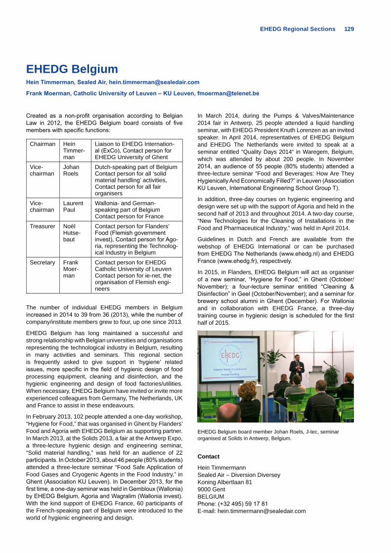
EHEDG Regional Sections 129
EHEDG BelgiumHein Timmerman, Sealed Air, [email protected]
Frank Moerman, Catholic University of Leuven – KU Leuven, [email protected]
Created as a non-profit organisation according to Belgian Law in 2012, the EHEDG Belgium board consists of five members with specific functions:
Chairman Hein Timmer-man
Liaison to EHEDG Internation-al (ExCo), Contact person for EHEDG University of Ghent
Vice-chairman
Johan Roels
Dutch-speaking part of Belgium Contact person for all ‘solid material handling’ activities, Contact person for all fair organisers
Vice-chairman
Laurent Paul
Wallonia- and German- speaking part of Belgium Contact person for France
Treasurer Noël Hutse-baut
Contact person for Flanders’ Food (Flemish government invest), Contact person for Ago-ria, representing the Technolog-ical Industry in Belgium
Secretary Frank Moer-man
Contact person for EHEDG Catholic University of Leuven Contact person for ie-net, the organisation of Flemish engi-neers
The number of individual EHEDG members in Belgium increased in 2014 to 39 from 36 (2013), while the number of company/institute members grew to four, up one since 2013.
EHEDG Belgium has long maintained a successful and strong relationship with Belgian universities and organisations representing the technological industry in Belgium, resulting in many activities and seminars. This regional section is frequently asked to give support in ‘hygiene’ related issues, more specific in the field of hygienic design of food processing equipment, cleaning and disinfection, and the hygienic engineering and design of food factories/utilities. When necessary, EHEDG Belgium have invited or invite more experienced colleagues from Germany, The Netherlands, UK and France to assist in these endeavours.
In February 2013, 102 people attended a one-day workshop, “Hygiene for Food,” that was organised in Ghent by Flanders’ Food and Agoria with EHEDG Belgium as supporting partner. In March 2013, at the Solids 2013, a fair at the Antwerp Expo, a three-lecture hygienic design and engineering seminar, “Solid material handling,” was held for an audience of 22 participants. In October 2013, about 46 people (80% students) attended a three-lecture seminar “Food Safe Application of Food Gases and Cryogenic Agents in the Food Industry,” in Ghent (Association KU Leuven). In December 2013, for the first time, a one-day seminar was held in Gembloux (Wallonia) by EHEDG Belgium, Agoria and Wagralim (Wallonia invest). With the kind support of EHEDG France, 60 participants of the French-speaking part of Belgium were introduced to the world of hygienic engineering and design.
In March 2014, during the Pumps & Valves/Maintenance 2014 fair in Antwerp, 25 people attended a liquid handling seminar, with EHEDG President Knuth Lorenzen as an invited speaker. In April 2014, representatives of EHEDG Belgium and EHEDG The Netherlands were invited to speak at a seminar entitled “Quality Days 2014“ in Waregem, Belgium, which was attended by about 200 people. In November 2014, an audience of 55 people (80% students) attended a three-lecture seminar “Food and Beverages: How Are They Hygienically And Economically Filled?” in Leuven (Association KU Leuven, International Engineering School Group T).
In addition, three-day courses on hygienic engineering and design were set up with the support of Agoria and held in the second half of 2013 and throughout 2014. A two-day course, “New Technologies for the Cleaning of Installations in the Food and Pharmaceutical Industry,” was held in April 2014.
Guidelines in Dutch and French are available from the webshop of EHEDG International or can be purchased from EHEDG The Netherlands (www.ehedg.nl) and EHEDG France (www.ehedg.fr), respectively.
In 2015, in Flanders, EHEDG Belgium will act as organiser of a new seminar, “Hygiene for Food,” in Ghent (October/November); a four-lecture seminar entitled “Cleaning & Disinfection” in Geel (October/November); and a seminar for brewery school alumni in Ghent (December). For Wallonia and in collaboration with EHEDG France, a three-day training course in hygienic design is scheduled for the first half of 2015.
EHEDG Belgium board member Johan Roels, J-tec, seminar organised at Solids in Antwerp, Belgium.
Contact
Hein TimmermannSealed Air – Diversion DiverseyKoning Albertlaan 819000 GentBELGIUMPhone: (+32 495) 59 17 81E-mail: [email protected]
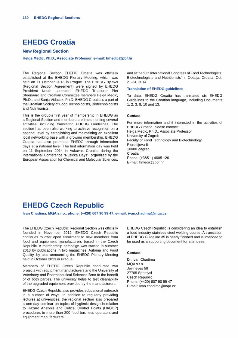
130 EHEDG Regional Sections
EHEDG Croatia New Regional Section Helga Medic, Ph.D., Associate Professor, e-mail: [email protected]
The Regional Section EHEDG Croatia was officially established at the EHEDG Plenary Meeting, which was held on 11 October 2013 in Prague. The EHEDG Bylaws (Regional Section Agreement) were signed by EHEDG President Knuth Lorenzen, EHEDG Treasurer Piet Steenaard and Croatian Committee members Helga Medic, Ph.D., and Sanja Vidacek, Ph.D. EHEDG Croatia is a part of the Croatian Society of Food Technologists, Biotechnologists and Nutritionists.
This is the group’s first year of membership in EHEDG as a Regional Section and members are implementing several activities, including translating EHEDG Guidelines. The section has been also working to achieve recognition on a national level by establishing and maintaining an excellent local networking base with a growing membership. EHEDG Croatia has also promoted EHEDG through information days at a national level. The first information day was held on 11 September 2014 in Vukovar, Croatia, during the International Conference “Ruzicka Days”, organized by the European Association for Chemical and Molecular Sciences,
and at the “8th International Congress of Food Technologists, Biotechnologists and Nutritionists” in Opatija, Croatia, Oct. 21-24, 2014.
Translation of EHEDG guidelines
To date, EHEDG Croatia has translated six EHEDG Guidelines to the Croatian language, including Documents 1, 2, 3, 8, 10 and 13.
Contact
For more information and if interested in the activities of EHEDG Croatia, please contact:Helga Medic, Ph.D., Associate ProfessorUniversity of ZagrebFaculty of Food Technology and BiotechnologyPierottijeva 610000 ZagrebCroatiaPhone: (+385 1) 4605 126E-mail: [email protected]
EHEDG Czech Republic Ivan Chadima, MQA s.r.o., phone: (+420) 607 90 99 47, e-mail: [email protected]
The EHEDG Czech Republic Regional Section was officially founded in November 2012. EHEDG Czech Republic continues to offer open enrollment to new members from food and equipment manufacturers based in the Czech Republic. A membership campaign was started in summer 2013 by publications in two magazines, Automa and Food Quality, by also announcing the EHEDG Plenary Meeting held in October 2013 in Prague.
Members of EHEDG Czech Republic conducted two projects with equipment manufacturers and the University of Veterinary and Pharmaceutical Sciences Brno to the benefit of of both parties. The university helps to test cleanability of the upgraded equipment provided by the manufacturers.
EHEDG Czech Republic also provides educational outreach in a number of ways. In addition to regularly providing lectures at universities, the regional section also prepared a one-day seminar on topics of hygienic design in relation to Hazard Analysis and Critical Control Points (HACCP) procedures to more than 200 food business operators and equipment manufacturers.
EHEDG Czech Republic is considering an idea to establish a food industry stainless steel welding course. A translation of EHEDG Guideline 35 is nearly finished and is intended to be used as a supporting document for attendees.
Contact
Dr. Ivan ChadimaMQA s.r.o.Jevineves 5827705 SpomyslCzech Republic Phone: (+420) 607 90 99 47E-mail: [email protected]
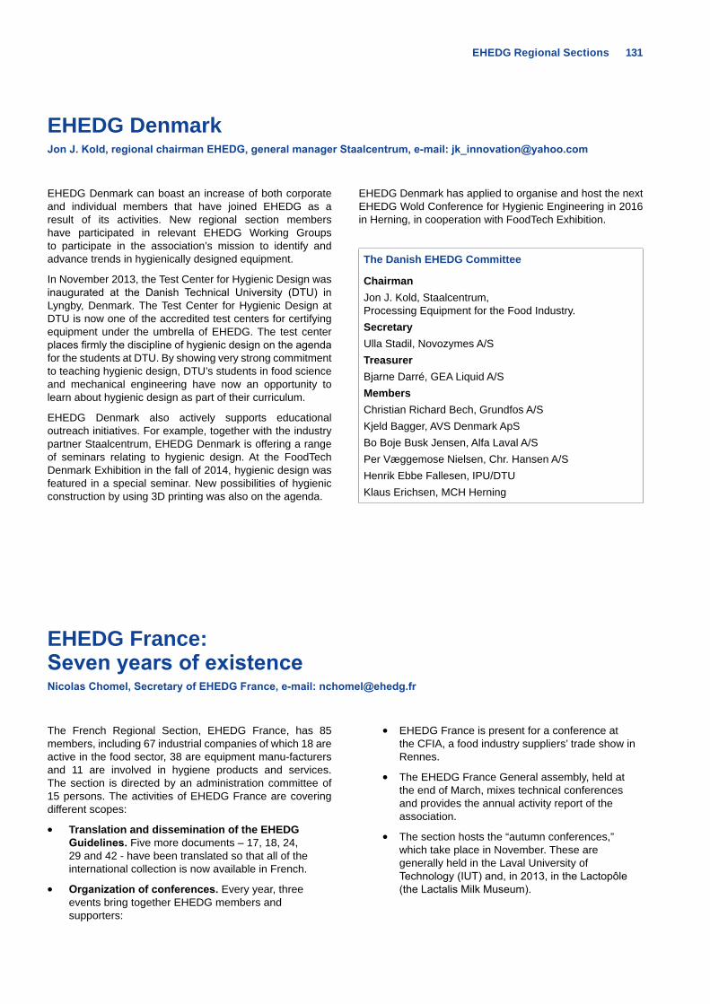
EHEDG Regional Sections 131
EHEDG France: Seven years of existenceNicolas Chomel, Secretary of EHEDG France, e-mail: [email protected]
The French Regional Section, EHEDG France, has 85 members, including 67 industrial companies of which 18 are active in the food sector, 38 are equipment manu-facturers and 11 are involved in hygiene products and services. The section is directed by an administration committee of 15 persons. The activities of EHEDG France are covering different scopes:
• Translation and dissemination of the EHEDG Guidelines. Five more documents – 17, 18, 24, 29 and 42 - have been translated so that all of the international collection is now available in French.
• Organization of conferences. Every year, three events bring together EHEDG members and supporters:
• EHEDG France is present for a conference at the CFIA, a food industry suppliers’ trade show in Rennes.
• The EHEDG France General assembly, held at the end of March, mixes technical conferences and provides the annual activity report of the association.
• The section hosts the “autumn conferences,” which take place in November. These are generally held in the Laval University of Technology (IUT) and, in 2013, in the Lactopôle (the Lactalis Milk Museum).
EHEDG Denmark Jon J. Kold, regional chairman EHEDG, general manager Staalcentrum, e-mail: [email protected]
EHEDG Denmark can boast an increase of both corporate and individual members that have joined EHEDG as a result of its activities. New regional section members have participated in relevant EHEDG Working Groups to participate in the association’s mission to identify and advance trends in hygienically designed equipment.
In November 2013, the Test Center for Hygienic Design was inaugurated at the Danish Technical University (DTU) in Lyngby, Denmark. The Test Center for Hygienic Design at DTU is now one of the accredited test centers for certifying equipment under the umbrella of EHEDG. The test center places firmly the discipline of hygienic design on the agenda for the students at DTU. By showing very strong commitment to teaching hygienic design, DTU’s students in food science and mechanical engineering have now an opportunity to learn about hygienic design as part of their curriculum.
EHEDG Denmark also actively supports educational outreach initiatives. For example, together with the industry partner Staalcentrum, EHEDG Denmark is offering a range of seminars relating to hygienic design. At the FoodTech Denmark Exhibition in the fall of 2014, hygienic design was featured in a special seminar. New possibilities of hygienic construction by using 3D printing was also on the agenda.
EHEDG Denmark has applied to organise and host the next EHEDG Wold Conference for Hygienic Engineering in 2016 in Herning, in cooperation with FoodTech Exhibition.
The Danish EHEDG Committee
ChairmanJon J. Kold, Staalcentrum, Processing Equipment for the Food Industry.SecretaryUlla Stadil, Novozymes A/STreasurerBjarne Darré, GEA Liquid A/SMembersChristian Richard Bech, Grundfos A/SKjeld Bagger, AVS Denmark ApSBo Boje Busk Jensen, Alfa Laval A/SPer Væggemose Nielsen, Chr. Hansen A/SHenrik Ebbe Fallesen, IPU/DTUKlaus Erichsen, MCH Herning
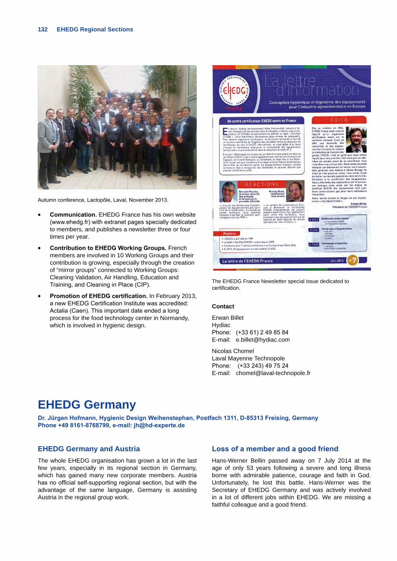
132 EHEDG Regional Sections
Autumn conference, Lactopôle, Laval, November 2013.
• Communication. EHEDG France has his own website (www.ehedg.fr) with extranet pages specially dedicated to members, and publishes a newsletter three or four times per year.
• Contribution to EHEDG Working Groups. French members are involved in 10 Working Groups and their contribution is growing, especially through the creation of “mirror groups” connected to Working Groups: Cleaning Validation, Air Handling, Education and Training, and Cleaning in Place (CIP).
• Promotion of EHEDG certification. In February 2013, a new EHEDG Certification Institute was accredited: Actalia (Caen). This important date ended a long process for the food technology center in Normandy, which is involved in hygienic design.
The EHEDG France Newsletter special issue dedicated to certification.
Contact
Erwan BilletHydiacPhone: (+33 61) 2 49 85 84E-mail: [email protected]
Nicolas ChomelLaval Mayenne TechnopolePhone: (+33 243) 49 75 24E-mail: [email protected]
EHEDG GermanyDr. Jürgen Hofmann, Hygienic Design Weihenstephan, Postfach 1311, D-85313 Freising, Germany Phone +49 8161-8768799, e-mail: [email protected]
EHEDG Germany and AustriaThe whole EHEDG organisation has grown a lot in the last few years, especially in its regional section in Germany, which has gained many new corporate members. Austria has no official self-supporting regional section, but with the advantage of the same language, Germany is assisting Austria in the regional group work.
Loss of a member and a good friendHans-Werner Bellin passed away on 7 July 2014 at the age of only 53 years following a severe and long illness borne with admirable patience, courage and faith in God. Unfortunately, he lost this battle. Hans-Werner was the Secretary of EHEDG Germany and was actively involved in a lot of different jobs within EHEDG. We are missing a faithful colleague and a good friend.
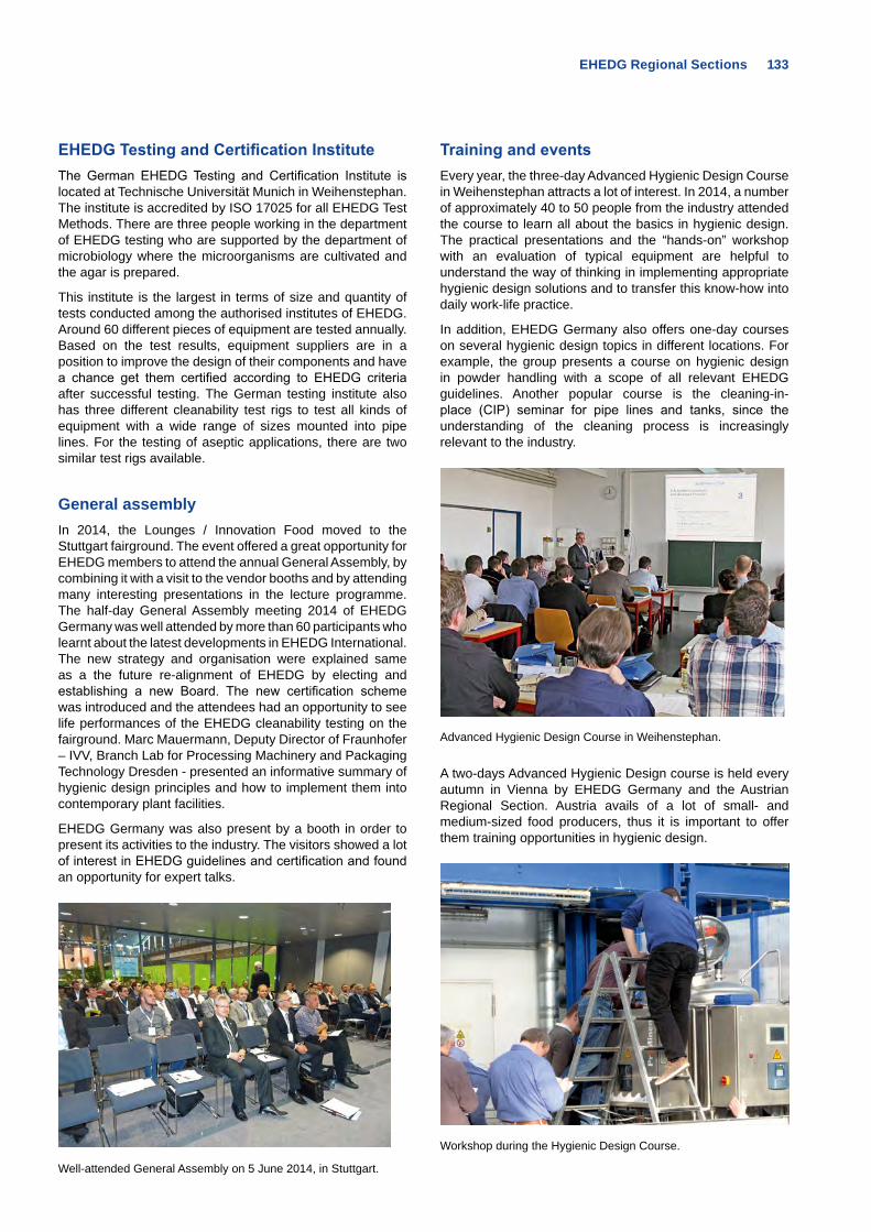
EHEDG Regional Sections 133
EHEDG Testing and Certification InstituteThe German EHEDG Testing and Certification Institute is located at Technische Universität Munich in Weihenstephan. The institute is accredited by ISO 17025 for all EHEDG Test Methods. There are three people working in the department of EHEDG testing who are supported by the department of microbiology where the microorganisms are cultivated and the agar is prepared.
This institute is the largest in terms of size and quantity of tests conducted among the authorised institutes of EHEDG. Around 60 different pieces of equipment are tested annually. Based on the test results, equipment suppliers are in a position to improve the design of their components and have a chance get them certified according to EHEDG criteria after successful testing. The German testing institute also has three different cleanability test rigs to test all kinds of equipment with a wide range of sizes mounted into pipe lines. For the testing of aseptic applications, there are two similar test rigs available.
General assemblyIn 2014, the Lounges / Innovation Food moved to the Stuttgart fairground. The event offered a great opportunity for EHEDG members to attend the annual General Assembly, by combining it with a visit to the vendor booths and by attending many interesting presentations in the lecture programme. The half-day General Assembly meeting 2014 of EHEDG Germany was well attended by more than 60 participants who learnt about the latest developments in EHEDG International. The new strategy and organisation were explained same as a the future re-alignment of EHEDG by electing and establishing a new Board. The new certification scheme was introduced and the attendees had an opportunity to see life performances of the EHEDG cleanability testing on the fairground. Marc Mauermann, Deputy Director of Fraunhofer – IVV, Branch Lab for Processing Machinery and Packaging Technology Dresden - presented an informative summary of hygienic design principles and how to implement them into contemporary plant facilities.
EHEDG Germany was also present by a booth in order to present its activities to the industry. The visitors showed a lot of interest in EHEDG guidelines and certification and found an opportunity for expert talks.
Well-attended General Assembly on 5 June 2014, in Stuttgart.
Training and eventsEvery year, the three-day Advanced Hygienic Design Course in Weihenstephan attracts a lot of interest. In 2014, a number of approximately 40 to 50 people from the industry attended the course to learn all about the basics in hygienic design. The practical presentations and the “hands-on” workshop with an evaluation of typical equipment are helpful to understand the way of thinking in implementing appropriate hygienic design solutions and to transfer this know-how into daily work-life practice.
In addition, EHEDG Germany also offers one-day courses on several hygienic design topics in different locations. For example, the group presents a course on hygienic design in powder handling with a scope of all relevant EHEDG guidelines. Another popular course is the cleaning-in-place (CIP) seminar for pipe lines and tanks, since the understanding of the cleaning process is increasingly relevant to the industry.
Advanced Hygienic Design Course in Weihenstephan.
A two-days Advanced Hygienic Design course is held every autumn in Vienna by EHEDG Germany and the Austrian Regional Section. Austria avails of a lot of small- and medium-sized food producers, thus it is important to offer them training opportunities in hygienic design.
Workshop during the Hygienic Design Course.
134 EHEDG Regional Sections
In 2013, EHEDG took part in the International Drinktec fair in Munich with an own booth and a hygienic design session in the Drinktec forum. Hans-Werner Bellin chaired this session which offered presentations about cleaning, biofilm building and materials of construction. The feedback about all EHEDG activities during this fair was very good and a lot of new contacts were established.
PublicationsThe major task of a regional group is the translation of the EHEDG Guidelines. EHEDG Germany has translated and published existing guidelines into German language. Due to the fact that a larger number of guidelines will be updated in near future, only the revised ones will be translated.
Our company members have published information about EHEDG in various journals, including certification topics and solutions provided by EHEDG for adequate hygienic design. Latest information about EHEDG and its activities is regularly published by the media partner “Lebensmitteltechnik” which is a popular journal for the food and mechanical engineering industry. Each year, the journal features a special EHEDG edition including a list of EHEDG-certified equipment. With a print volume of 11,000 copies, the journal is very popular and also distributed on occasion of many EHEDG events and seminars.
Contact
Chairman:Dr. Jürgen HofmannHygienic Design WeihenstephanPostfach 131185313 FreisingGERMANYE-Mail: [email protected]
Media Partner of EHEDG Germany.
EHEDG-IndiaNew Regional Section Prof. V. Prakash, JSS Group of Institutions, Mysore-570 004, India, e-mail: [email protected]
Dr. Ali Abas Wani, Department of Food Technology, Islamic University of Science & Technology, India, e-mail: [email protected]
EHEDG India was established in October 2013 at the EHEDG Plenary Meeting held in Prague. Since its inception, EHEDG India has been quite involved with establishing industrial and academic contacts to increase the memberships and its presence in the world’s second most populated country.
Dr. Wani has initiated contacts with medium- to small-scale industries in India. In January 2014, he delivered a series of lectures at Mother Dairy, New Delhi, one of the largest milk processors in the region. The lecture series was attended by at least 15 factory managers from various Mother Dairy
units across India. During his presentation, Dr. Wani gave an overview on basic hygienic design and the role of EHEDG to achieve the highest standards of hygiene and food safety. EHEDG India also will organise training courses in the future to promote scientific know-how and EHEDG guidelines among the food processors, and educational and research institutes. The training will be offered by certified trainers to industry, academic and professional delegates. The Indian food industry is growing rapidly and the role of EHEDG India will be of the utmost importance to these new and existing industries to increase food safety standards.
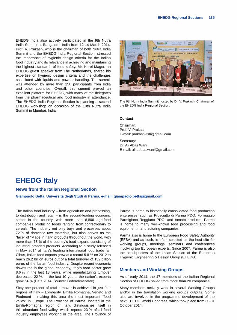
EHEDG Regional Sections 135
EHEDG ItalyNews from the Italian Regional Section Giampaolo Betta, Università degli Studi di Parma, e-mail: [email protected]
The Italian food industry – from agriculture and processing, to distribution and retail – is the second-leading economic sector in the country, with more than 6,800 agri-food companies producing foods ranging from confectionary to cereals. The industry not only buys and processes about 72 % of domestic raw materials, but also serves as the “face” of “Made in Italy” products throughout the world, with more than 75 % of the country’s food exports consisting of industrial branded products. According to a study released in May 2014 at Italy’s leading international food trade fair Cibus, Italian food exports grew at a record 5.8 % on 2012 to reach 26.2 billion euros out of a total turnover of 132 billion euros of the Italian food industry. Despite recent economic downturns in the global economy, Italy’s food sector grew 8.6 % in the last 13 years, while manufacturing turnover decreased 22 %. In the last 10 years, the nation’s exports grew 54 % (Data 2014, Source: Federalimentare).
Sixty-one percent of total turnover is achieved in just four regions of Italy – Lombardy, Emilia Romagna, Veneto and Piedmont – making this area the most important “food valley” in Europe. The Province of Parma, located in the Emila-Romagna region of Italy, distinguishes itself in this abundant food valley, which reports 23 % of all food industry employees working in the area. The Province of
Parma is home to historically consolidated food production enterprises, such as Prosciutto di Parma PDO, Formaggio Parmigiano Reggiano PDO, and tomato products. Parma is home to many well-known food processing and food equipment manufacturing companies.
Parma also is home to the European Food Safety Authority (EFSA) and as such, is often selected as the host site for working groups, meetings, seminars and conferences involving top European experts. Since 2007, Parma is also the headquarters of the Italian Section of the European Hygienic Engineering & Design Group (EHEDG).
Members and Working GroupsAs of early 2014, the 47 members of the Italian Regional Section of EHEDG hailed from more than 20 companies.
Many members actively work in several Working Groups and/or in the translation working groups outputs. Some also are involved in the programme development of the next EHEDG World Congress, which took place from 30-31 October 2014.
EHEDG India also actively participated in the 9th Nutra India Summit at Bangalore, India from 12-14 March 2014. Prof. V. Prakash, who is the chairman of both Nutra India Summit and the EHEDG India Regional Section, stressed the importance of hygienic design criteria for the Indian food industry and its relevance in achieving and maintaining the highest standards of food safety. Mr. Karel Mager, an EHEDG guest speaker from The Netherlands, shared his expertise on hygienic design criteria and the challenges associated with liquids and powder handling. The summit was attended by more than 250 participants from India and other countries. Overall, this summit proved an excellent platform for EHEDG, with many of the delegates from the pharmaceutical and food industry in attendance. The EHEDG India Regional Section is planning a second EHEDG workshop on occasion of the 10th Nutra India Summit in Mumbai, India.
The 9th Nutra India Summit hosted by Dr. V. Prakash, Chairman of the EHEDG India Regional Section.
Contact
Chairman:Prof. V. PrakashE-mail: [email protected]
Secretary:Dr. Ali Abas WaniE-mail: [email protected]
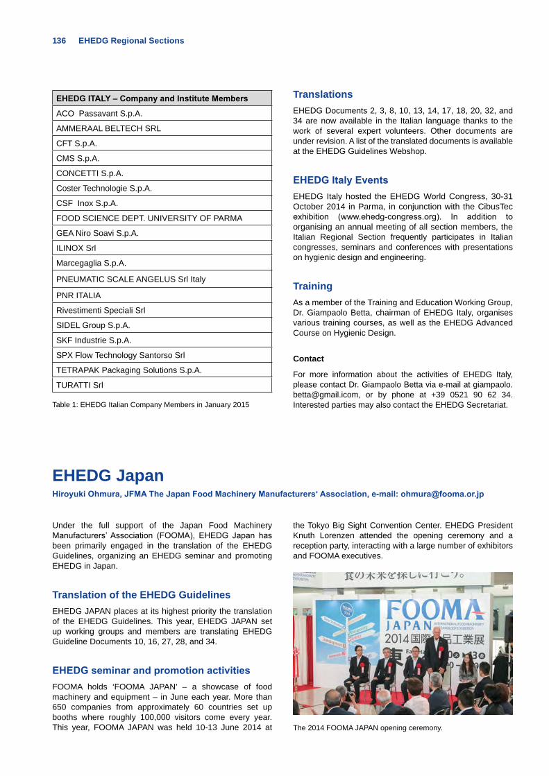
136 EHEDG Regional Sections
EHEDG ITALY – Company and Institute Members
ACO Passavant S.p.A.
AMMERAAL BELTECH SRL
CFT S.p.A.
CMS S.p.A.
CONCETTI S.p.A.
Coster Technologie S.p.A.
CSF Inox S.p.A.
FOOD SCIENCE DEPT. UNIVERSITY OF PARMA
GEA Niro Soavi S.p.A.
ILINOX Srl
Marcegaglia S.p.A.
PNEUMATIC SCALE ANGELUS Srl Italy
PNR ITALIA
Rivestimenti Speciali Srl
SIDEL Group S.p.A.
SKF Industrie S.p.A.
SPX Flow Technology Santorso Srl
TETRAPAK Packaging Solutions S.p.A.
TURATTI Srl Table 1: EHEDG Italian Company Members in January 2015
TranslationsEHEDG Documents 2, 3, 8, 10, 13, 14, 17, 18, 20, 32, and 34 are now available in the Italian language thanks to the work of several expert volunteers. Other documents are under revision. A list of the translated documents is available at the EHEDG Guidelines Webshop.
EHEDG Italy EventsEHEDG Italy hosted the EHEDG World Congress, 30-31 October 2014 in Parma, in conjunction with the CibusTec exhibition (www.ehedg-congress.org). In addition to organising an annual meeting of all section members, the Italian Regional Section frequently participates in Italian congresses, seminars and conferences with presentations on hygienic design and engineering.
TrainingAs a member of the Training and Education Working Group, Dr. Giampaolo Betta, chairman of EHEDG Italy, organises various training courses, as well as the EHEDG Advanced Course on Hygienic Design.
Contact
For more information about the activities of EHEDG Italy, please contact Dr. Giampaolo Betta via e-mail at [email protected], or by phone at +39 0521 90 62 34. Interested parties may also contact the EHEDG Secretariat.
EHEDG JapanHiroyuki Ohmura, JFMA The Japan Food Machinery Manufacturers‘ Association, e-mail: [email protected]
Under the full support of the Japan Food Machinery Manufacturers’ Association (FOOMA), EHEDG Japan has been primarily engaged in the translation of the EHEDG Guidelines, organizing an EHEDG seminar and promoting EHEDG in Japan.
Translation of the EHEDG GuidelinesEHEDG JAPAN places at its highest priority the translation of the EHEDG Guidelines. This year, EHEDG JAPAN set up working groups and members are translating EHEDG Guideline Documents 10, 16, 27, 28, and 34.
EHEDG seminar and promotion activitiesFOOMA holds ‘FOOMA JAPAN’ – a showcase of food machinery and equipment – in June each year. More than 650 companies from approximately 60 countries set up booths where roughly 100,000 visitors come every year. This year, FOOMA JAPAN was held 10-13 June 2014 at
the Tokyo Big Sight Convention Center. EHEDG President Knuth Lorenzen attended the opening ceremony and a reception party, interacting with a large number of exhibitors and FOOMA executives.
The 2014 FOOMA JAPAN opening ceremony.
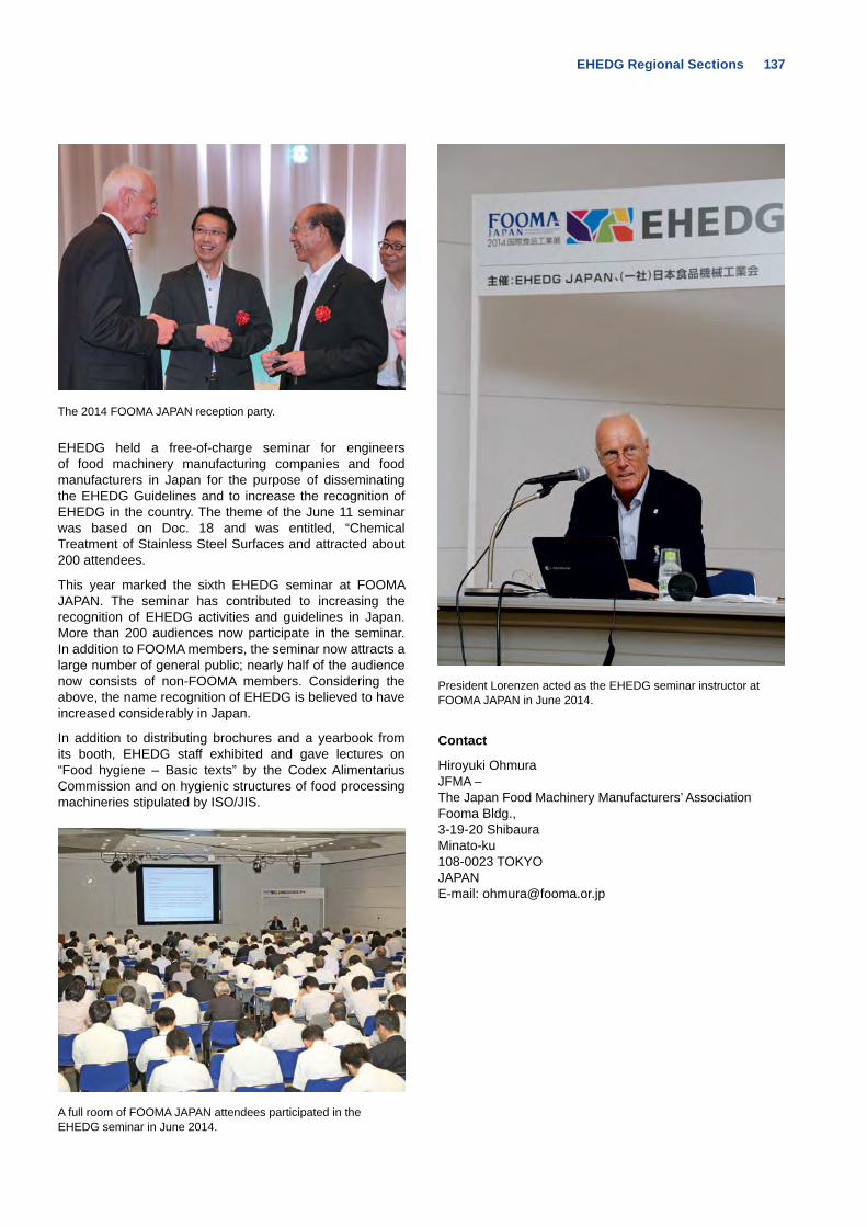
EHEDG Regional Sections 137
The 2014 FOOMA JAPAN reception party.
EHEDG held a free-of-charge seminar for engineers of food machinery manufacturing companies and food manufacturers in Japan for the purpose of disseminating the EHEDG Guidelines and to increase the recognition of EHEDG in the country. The theme of the June 11 seminar was based on Doc. 18 and was entitled, “Chemical Treatment of Stainless Steel Surfaces and attracted about 200 attendees.
This year marked the sixth EHEDG seminar at FOOMA JAPAN. The seminar has contributed to increasing the recognition of EHEDG activities and guidelines in Japan. More than 200 audiences now participate in the seminar. In addition to FOOMA members, the seminar now attracts a large number of general public; nearly half of the audience now consists of non-FOOMA members. Considering the above, the name recognition of EHEDG is believed to have increased considerably in Japan.
In addition to distributing brochures and a yearbook from its booth, EHEDG staff exhibited and gave lectures on “Food hygiene – Basic texts” by the Codex Alimentarius Commission and on hygienic structures of food processing machineries stipulated by ISO/JIS.
A full room of FOOMA JAPAN attendees participated in the EHEDG seminar in June 2014.
President Lorenzen acted as the EHEDG seminar instructor at FOOMA JAPAN in June 2014.
Contact
Hiroyuki OhmuraJFMA –The Japan Food Machinery Manufacturers’ AssociationFooma Bldg., 3-19-20 ShibauraMinato-ku108-0023 TOKYOJAPANE-mail: [email protected]
138 EHEDG Regional Sections
EHEDG Lithuania Dr. Raimondas Narkevicius, Regional Chairman EHEDG, Food Institute of Kaunas University of Technology, e-mail: [email protected]
One of the main goals of the EHEDG Lithuania Regional Section is to increase awareness about EHEDG among the Lithuanian food manufacturing, academic and research communities. To achieve this goal, the activities of EHEDG Lithuania have been focused on translating into the Lithuanian language selected content on the EHEDG website and several of the EHEDG Guideline documents. In addition, the section has been actively organising and participating in events aimed at promoting hygienic design in food manufacturing and increasing awareness of EHEDG’s mission and activities. EHEDG Lithuania also has worked to strengthen the knowledge of EHEDG amongst Lithuanian food manufacturers by paying direct visits to several companies.
Translation of EHEDG guidelinesThe translation of EHEDG Guidelines is an important task of the EHEDG Lithuania Regional Section’s regular activities. In 2014, section members translated the following documents into the in Lithuanian language:
• EHEDG Glossary (EHEDG specialiųjų terminų žodynas)
• Doc. 8, Hygienic equipment design criteria (Higieniško įrangos projektavimo kriterijai)
• Doc. 10, Hygienic design of closed equipment for processing of liquid food (Higieniškas uždaros įrangos, skirtos skystų maisto produktų perdirbimui, projektavimas)
• Doc. 13, Hygienic design of open equipment for processing of food (Higieniškas atviros įrangos, skirtos maisto produktų perdirbimui, projektavimas)
• Doc. 22 ,General hygienic design criteria for the safe processing of dry particulate materials (Bendrieji higieniško projektavimo kriterijai saugiam sausų birių medžiagų perdirbimui)
• Doc. 23, Use of H1 registered lubricants. Part I (H1 klasės tepimo priemonių naudojimas. I dalis)
• Doc. 23, Use of H1 registered lubricants. Part II (H1 klasės tepimo priemonių naudojimas. II dalis)
• Doc. 27, Safe storage and distribution of water in food factories (Saugus vandens saugojimas ir paskirstymas maisto gamybos įmonėse)
Promoting EHEDG membershipA full-scale presentation about the EHEDG organisation and an overview of the membership benefits was provided to the representatives of Lithuanian food processors and the nation’s food research community at the 2013 and 2014 annual conferences of the Food Institute of Kaunas University of Technology, as well as at four seminars for fish and meat processors of Lithuania. Presentations about EHEDG activities also were made during direct visits to six fish processing and dairy companies in the past year.
For more information please contact
Raimondas NarkeviciusKaunas University of TechnologyDepartment of Food TechnologyTaikos pr. 9250254 KAUNASLITHUANIAPhone: +370 68 4 32 26E-mail: [email protected]
EHEDG MacedoniaProf. Dr. Vladimir Kakurinov, Consulting and Training Centre KEY, Macedonian Regional Section Chairman, e-mail: [email protected]
EHEDG in-country roundtables In 2013, EHEDG Macedonia held two roundtables, one in Gevgelija on 29 March 2013 and the other in Strumica on 19 April 2013. The goal was to start the dialogue on harmonisation of relevant policies for hygienic engineering and design between representatives of national institutions and those at the local level. Both roundtables were
very productive. In both municipalities, links between all stakeholders on the local and national levels were established for the first time, specifically with regard to efforts for uniform application of hygienic engineering standards and codes. It was recommended that the national bodies should create links with the regional and international organisations that had already adopted and applied these standards.
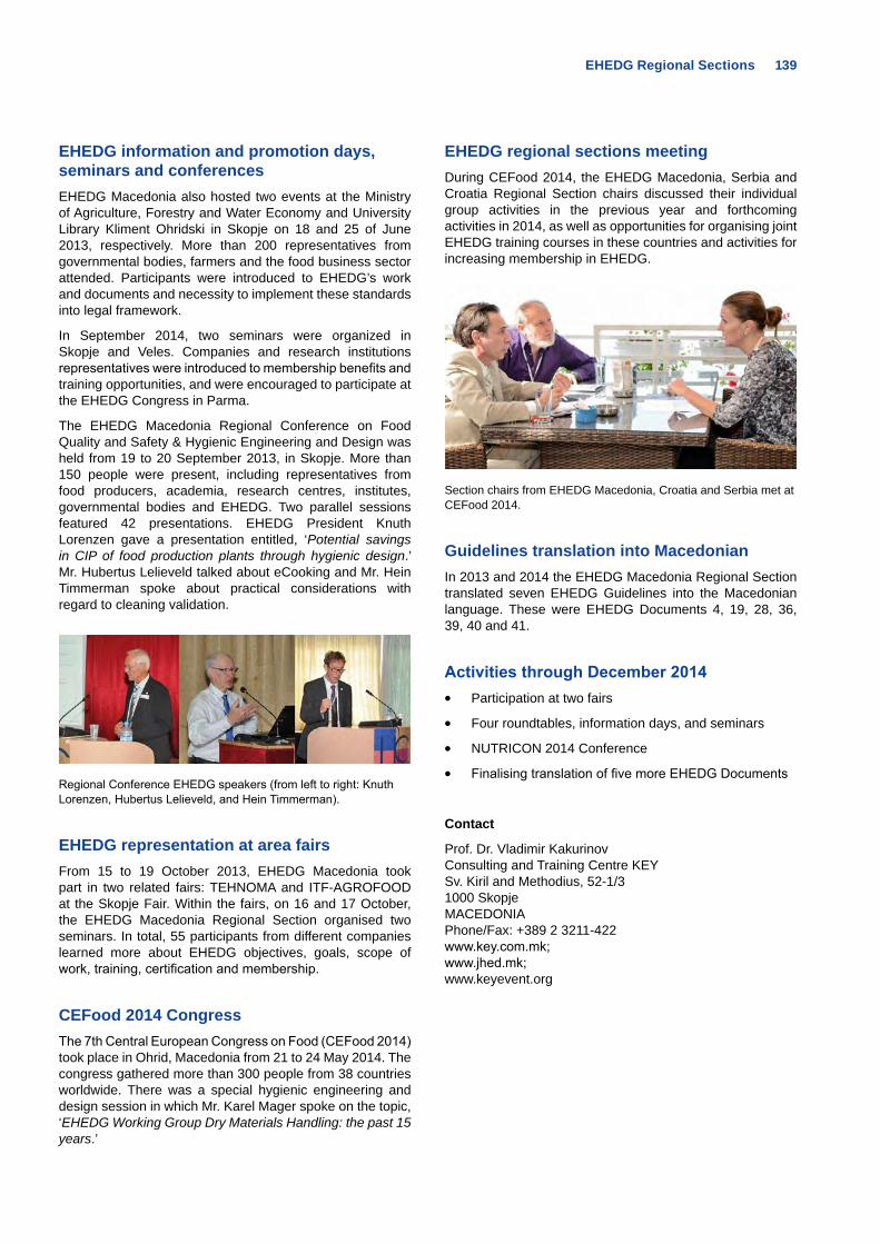
EHEDG Regional Sections 139
EHEDG information and promotion days, seminars and conferences EHEDG Macedonia also hosted two events at the Ministry of Agriculture, Forestry and Water Economy and University Library Kliment Ohridski in Skopje on 18 and 25 of June 2013, respectively. More than 200 representatives from governmental bodies, farmers and the food business sector attended. Participants were introduced to EHEDG’s work and documents and necessity to implement these standards into legal framework.
In September 2014, two seminars were organized in Skopje and Veles. Companies and research institutions representatives were introduced to membership benefits and training opportunities, and were encouraged to participate at the EHEDG Congress in Parma.
The EHEDG Macedonia Regional Conference on Food Quality and Safety & Hygienic Engineering and Design was held from 19 to 20 September 2013, in Skopje. More than 150 people were present, including representatives from food producers, academia, research centres, institutes, governmental bodies and EHEDG. Two parallel sessions featured 42 presentations. EHEDG President Knuth Lorenzen gave a presentation entitled, ‘Potential savings in CIP of food production plants through hygienic design.’ Mr. Hubertus Lelieveld talked about eCooking and Mr. Hein Timmerman spoke about practical considerations with regard to cleaning validation.
Regional Conference EHEDG speakers (from left to right: Knuth Lorenzen, Hubertus Lelieveld, and Hein Timmerman).
EHEDG representation at area fairs From 15 to 19 October 2013, EHEDG Macedonia took part in two related fairs: TEHNOMA and ITF-AGROFOOD at the Skopje Fair. Within the fairs, on 16 and 17 October, the EHEDG Macedonia Regional Section organised two seminars. In total, 55 participants from different companies learned more about EHEDG objectives, goals, scope of work, training, certification and membership.
CEFood 2014 CongressThe 7th Central European Congress on Food (CEFood 2014) took place in Ohrid, Macedonia from 21 to 24 May 2014. The congress gathered more than 300 people from 38 countries worldwide. There was a special hygienic engineering and design session in which Mr. Karel Mager spoke on the topic, ‘EHEDG Working Group Dry Materials Handling: the past 15 years.’
EHEDG regional sections meetingDuring CEFood 2014, the EHEDG Macedonia, Serbia and Croatia Regional Section chairs discussed their individual group activities in the previous year and forthcoming activities in 2014, as well as opportunities for organising joint EHEDG training courses in these countries and activities for increasing membership in EHEDG.
Section chairs from EHEDG Macedonia, Croatia and Serbia met at CEFood 2014.
Guidelines translation into MacedonianIn 2013 and 2014 the EHEDG Macedonia Regional Section translated seven EHEDG Guidelines into the Macedonian language. These were EHEDG Documents 4, 19, 28, 36, 39, 40 and 41.
Activities through December 2014• Participation at two fairs
• Four roundtables, information days, and seminars
• NUTRICON 2014 Conference
• Finalising translation of five more EHEDG Documents
Contact
Prof. Dr. Vladimir KakurinovConsulting and Training Centre KEYSv. Kiril and Methodius, 52-1/31000 SkopjeMACEDONIAPhone/Fax: +389 2 3211-422www.key.com.mk; www.jhed.mk; www.keyevent.org
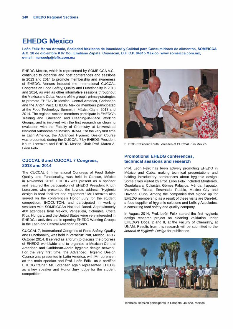
140 EHEDG Regional Sections
EHEDG MexicoLeón Félix Marco Antonio, Sociedad Mexicana de Inocuidad y Calidad para Consumidores de alimentos, SOMEICCA A.C. 28 de diciembre # 87 Col. Emiliano Zapata. Coyoacán, D.F. C.P. 04815.México. www.someicca.com.mx, e-mail: [email protected]
EHEDG Mexico, which is represented by SOMEICCA A.C., continued to organise and host conferences and sessions in 2013 and 2014 to promote membership and awareness of EHEDG. Venues included the International CUCCAL Congress on Food Safety, Quality and Functionality in 2013 and 2014, as well as other informative sessions throughout the Mexico and Cuba. As one of the group’s primary strategies to promote EHEDG in Mexico, Central America, Caribbean and the Andin Pact, EHEDG Mexico members participated at the Food Technology Summit in México City in 2013 and 2014. The regional section members participate in EHEDG’s Training and Education and Cleaning-in-Place Working Groups, and is involved with the first research on cleaning evaluation with the Faculty of Chemistry at Universidad Nacional Autónoma de Mexico UNAM. For the very first time in Latin America, the Advanced Hygienic Design Course was presented, during the CUCCAL 7 by EHEDG President Knuth Lorenzen and EHEDG Mexico Chair Prof. Marco A. León Félix.
CUCCAL 6 and CUCCAL 7 Congress, 2013 and 2014The CUCCAL 6, International Congress of Food Safety, Quality and Functionality, was held in Cancun, México in November 2013. EHEDG was present as a sponsor and featured the participation of EHEDG President Knuth Lorenzen, who presented the keynote address, ‘Hygienic design in food facilities and equipment.’ Mr Lorenzen also served on the conference’s Honor Jury for the student competition, INOCUITON, and participated in working sessions with SOMEICCA’s National Board. Approximately 400 attendees from Mexico, Venezuela, Colombia, Costa Rica, Hungary, and the United States were very interested in EHEDG’s activities and in opening EHEDG Working Groups in the Latin and Central American regions.
CUCCAL 7, International Congress of Food Safety, Quality and Functionality, was held in Veracruz Port, Mexico, 13-17 October 2014. It served as a forum to discuss the progress of EHEDG worldwide and to organise a Mexican-Central American and Caribbean-Andin hygienic design network. For the very first time, the Advanced Hygienic Design Course was presented in Latin America, with Mr. Lorenzen as the main speaker and Prof. León Félix, as a certified EHEDG trainer. Mr. Lorenzen again represented EHEDG as a key speaker and Honor Jury judge for the student competition.
EHEDG President Knuth Lorenzen at CUCCAL 6 in Mexico.
Promotional EHEDG conferences, technical sessions and researchProf. León Félix has been actively promoting EHEDG in México and Cuba, making technical presentations and holding introductory conferences about hygienic design. Some cities visited by Prof. León Félix included Monterrey, Guadalajara, Culiacán, Gómez Palacios, Mérida, Irapuato, Mazatlán, Toluca, Ensenada, Puebla, Mexico City and Havana, Cuba. Among the companies that signed up for EHEDG membership as a result of these visits are Dan-tek, a food supplier of hygienic solutions and Lefix y Asociados, a consulting food safety and quality company
In August 2014, Prof. León Félix started the first hygienic design research project on cleaning validation under EHEDG‘s Docs. 2 and 8, at the Faculty of Chemistry, at UNAM. Results from this research will be submitted to the Journal of Hygienic Design for publication.
Technical session participants in Chapala, Jalisco, Mexico.
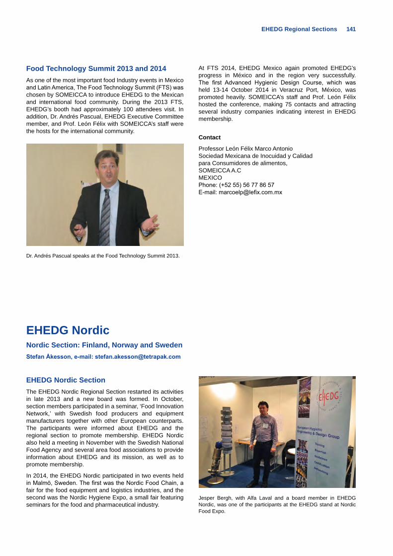
EHEDG Regional Sections 141
Food Technology Summit 2013 and 2014As one of the most important food Industry events in Mexico and Latin America, The Food Technology Summit (FTS) was chosen by SOMEICCA to introduce EHEDG to the Mexican and international food community. During the 2013 FTS, EHEDG’s booth had approximately 100 attendees visit. In addition, Dr. Andrés Pascual, EHEDG Executive Committee member, and Prof. León Félix with SOMEICCA’s staff were the hosts for the international community.
Dr. Andrés Pascual speaks at the Food Technology Summit 2013.
At FTS 2014, EHEDG Mexico again promoted EHEDG’s progress in México and in the region very successfully. The first Advanced Hygienic Design Course, which was held 13-14 October 2014 in Veracruz Port, México, was promoted heavily. SOMEICCA’s staff and Prof. León Félix hosted the conference, making 75 contacts and attracting several industry companies indicating interest in EHEDG membership.
Contact
Professor León Félix Marco AntonioSociedad Mexicana de Inocuidad y Calidad para Consumidores de alimentos, SOMEICCA A.CMEXICOPhone: (+52 55) 56 77 86 57E-mail: [email protected]
EHEDG NordicNordic Section: Finland, Norway and SwedenStefan Åkesson, e-mail: [email protected]
EHEDG Nordic SectionThe EHEDG Nordic Regional Section restarted its activities in late 2013 and a new board was formed. In October, section members participated in a seminar, ‘Food Innovation Network,’ with Swedish food producers and equipment manufacturers together with other European counterparts. The participants were informed about EHEDG and the regional section to promote membership. EHEDG Nordic also held a meeting in November with the Swedish National Food Agency and several area food associations to provide information about EHEDG and its mission, as well as to promote membership.
In 2014, the EHEDG Nordic participated in two events held in Malmö, Sweden. The first was the Nordic Food Chain, a fair for the food equipment and logistics industries, and the second was the Nordic Hygiene Expo, a small fair featuring seminars for the food and pharmaceutical industry.
Jesper Bergh, with Alfa Laval and a board member in EHEDG Nordic, was one of the participants at the EHEDG stand at Nordic Food Expo.
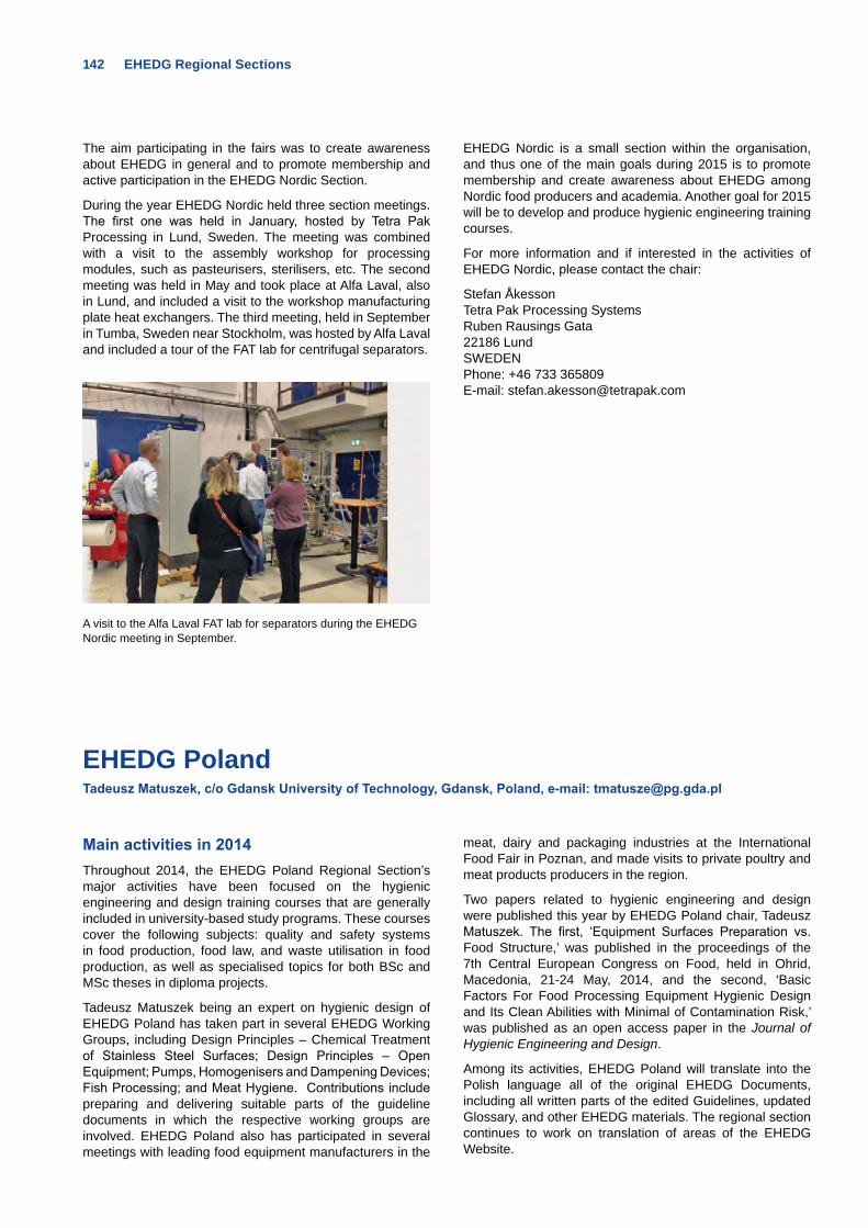
142 EHEDG Regional Sections
The aim participating in the fairs was to create awareness about EHEDG in general and to promote membership and active participation in the EHEDG Nordic Section.
During the year EHEDG Nordic held three section meetings. The first one was held in January, hosted by Tetra Pak Processing in Lund, Sweden. The meeting was combined with a visit to the assembly workshop for processing modules, such as pasteurisers, sterilisers, etc. The second meeting was held in May and took place at Alfa Laval, also in Lund, and included a visit to the workshop manufacturing plate heat exchangers. The third meeting, held in September in Tumba, Sweden near Stockholm, was hosted by Alfa Laval and included a tour of the FAT lab for centrifugal separators.
A visit to the Alfa Laval FAT lab for separators during the EHEDG Nordic meeting in September.
EHEDG Nordic is a small section within the organisation, and thus one of the main goals during 2015 is to promote membership and create awareness about EHEDG among Nordic food producers and academia. Another goal for 2015 will be to develop and produce hygienic engineering training courses.
For more information and if interested in the activities of EHEDG Nordic, please contact the chair:
Stefan ÅkessonTetra Pak Processing SystemsRuben Rausings Gata22186 LundSWEDENPhone: +46 733 365809E-mail: [email protected]
EHEDG Poland Tadeusz Matuszek, c/o Gdansk University of Technology, Gdansk, Poland, e-mail: [email protected]
Main activities in 2014Throughout 2014, the EHEDG Poland Regional Section’s major activities have been focused on the hygienic engineering and design training courses that are generally included in university-based study programs. These courses cover the following subjects: quality and safety systems in food production, food law, and waste utilisation in food production, as well as specialised topics for both BSc and MSc theses in diploma projects.
Tadeusz Matuszek being an expert on hygienic design of EHEDG Poland has taken part in several EHEDG Working Groups, including Design Principles – Chemical Treatment of Stainless Steel Surfaces; Design Principles – Open Equipment; Pumps, Homogenisers and Dampening Devices; Fish Processing; and Meat Hygiene. Contributions include preparing and delivering suitable parts of the guideline documents in which the respective working groups are involved. EHEDG Poland also has participated in several meetings with leading food equipment manufacturers in the
meat, dairy and packaging industries at the International Food Fair in Poznan, and made visits to private poultry and meat products producers in the region.
Two papers related to hygienic engineering and design were published this year by EHEDG Poland chair, Tadeusz Matuszek. The first, ‘Equipment Surfaces Preparation vs. Food Structure,’ was published in the proceedings of the 7th Central European Congress on Food, held in Ohrid, Macedonia, 21-24 May, 2014, and the second, ‘Basic Factors For Food Processing Equipment Hygienic Design and Its Clean Abilities with Minimal of Contamination Risk,’ was published as an open access paper in the Journal of Hygienic Engineering and Design.
Among its activities, EHEDG Poland will translate into the Polish language all of the original EHEDG Documents, including all written parts of the edited Guidelines, updated Glossary, and other EHEDG materials. The regional section continues to work on translation of areas of the EHEDG Website.
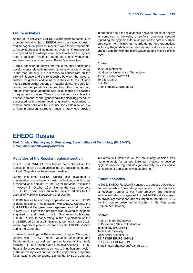
EHEDG Regional Sections 143
Future activitiesAs for future activities, EHEDG Poland plans to continue to promote the principles of EHEDG, from the hygienic design and management process, machines and their components, to factory facilities and maintenance systems. The section will also spread the knowledge about how to achieve the highest food production hygienic standards during workshops, seminars, and study courses at Poland’s universities.
Further, considering today’s enormous material engineering developments related to nanostructures and nanotechnology in the food industry, it is necessary to concentrate on the strong influence and the relationship between the value of surface roughness and value of adhesive forces of food micro-structures that depend on material plates, time duration contact and temperature changes. From this one can gain indirect information about the soil residues that are attached to equipment surfaces. Then it is possible to calculate the adequate amount of energy needed in the cleaning procedure associated with various food engineering equipment to remove such soils and thus reduce the contamination risk to food production. Moreover, such a study can provide
information about the relationship between optimum energy as compared to the value of surface roughness needed regarding the hygienic criteria, as well as the cost of surface preparation for minimising hazards during food production, including Reynolds Number, density, and velocity of liquids and air, together with the micro wet angle and micro biofilms layer.
Contact
Tadeusz Matuszek c/o Gdansk University of Technology 11/12 G. Narutowicza St 80-233 Gdansk, POLAND E-mail: [email protected]
EHEDG RussiaProf. Dr. Mark Shamtsyan, St. Petersburg, State Institute of Technology (RUSFoST), e-mail: [email protected]
Activities of the Russian regional sectionIn 2013 and 2014, EHEDG Russia concentrated on the translation of EHEDG guidelines into the Russian language. In total, 22 guidelines have been translated.
During this time, EHEDG Russia also developed a presentation on the hygienic design of buildings, which was presented at a seminar at the “AgroProdMash” exhibition in Moscow in October 2014. During the year, members of EHEDG Russia have submitted several articles to the Journal of Hygienic Engineering and Design.
EHEDG Russia has actively cooperated with other EHEDG regional sections. In cooperation with EHEDG Ukraine, the 2nd NEEFood Congress was organised and held in Kiev in May 2013. Part of the program was devoted to hygienic engineering and design. With Romanian colleagues, EHEDG Russia is cooperating in the organisation of the 3rd NEEFood Congress in Brasov, to be held in May 2015, where organisers plan to present a special EHEDG session during the Congress.
In several meetings in Kiev, Yerevan, Prague, Ohrid, and Brasov with EHEDG Armenia, Ukraine, Macedonia, and Serbia sections, as well as representatives of the newly forming EHEDG Lithuania and Romania sections, EHEDG Russia discussed measures on how to bring hygienic design to the university level and to develop appropriate programs for a master’s degree course. During the EHEDG Congress
in Parma in October 2014, the preliminary decision was made to apply for various European projects to develop hygienic engineering and design university courses and a consortium of participants was established.
Future activitiesIn 2015, EHEDG Russia will continue to translate guidelines, and will publish a Russian-language version of the Handbook of Hygiene Control in the Food Industry. The regional section will also co-organise the 3rd NEEFood Congress as previously mentioned and will organise the first EHEDG training course presented in Russian in St. Petersburg (September-October).
Contact
Prof. Dr. Mark Shamtsyan St Petersburg State of Institute of Technology (RUSFoST) Technical University Moskovsky prospect 26 ST. PETERSBURG 198013 RUSSIAN FEDERATION E-mail: [email protected]
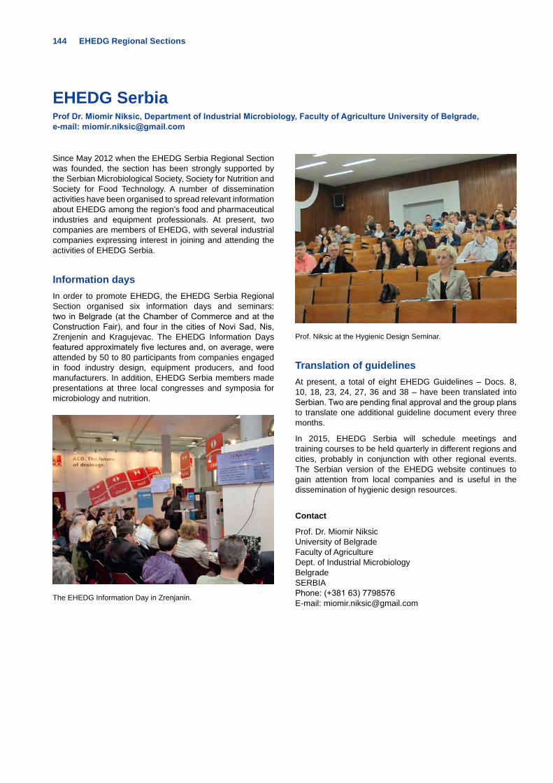
144 EHEDG Regional Sections
EHEDG SerbiaProf Dr. Miomir Niksic, Department of Industrial Microbiology, Faculty of Agriculture University of Belgrade, e-mail: [email protected]
Since May 2012 when the EHEDG Serbia Regional Section was founded, the section has been strongly supported by the Serbian Microbiological Society, Society for Nutrition and Society for Food Technology. A number of dissemination activities have been organised to spread relevant information about EHEDG among the region’s food and pharmaceutical industries and equipment professionals. At present, two companies are members of EHEDG, with several industrial companies expressing interest in joining and attending the activities of EHEDG Serbia.
Information days In order to promote EHEDG, the EHEDG Serbia Regional Section organised six information days and seminars: two in Belgrade (at the Chamber of Commerce and at the Construction Fair), and four in the cities of Novi Sad, Nis, Zrenjenin and Kragujevac. The EHEDG Information Days featured approximately five lectures and, on average, were attended by 50 to 80 participants from companies engaged in food industry design, equipment producers, and food manufacturers. In addition, EHEDG Serbia members made presentations at three local congresses and symposia for microbiology and nutrition.
The EHEDG Information Day in Zrenjanin.
Prof. Niksic at the Hygienic Design Seminar.
Translation of guidelines At present, a total of eight EHEDG Guidelines – Docs. 8, 10, 18, 23, 24, 27, 36 and 38 – have been translated into Serbian. Two are pending final approval and the group plans to translate one additional guideline document every three months.
In 2015, EHEDG Serbia will schedule meetings and training courses to be held quarterly in different regions and cities, probably in conjunction with other regional events. The Serbian version of the EHEDG website continues to gain attention from local companies and is useful in the dissemination of hygienic design resources.
Contact
Prof. Dr. Miomir NiksicUniversity of BelgradeFaculty of AgricultureDept. of Industrial MicrobiologyBelgradeSERBIAPhone: (+381 63) 7798576E-mail: [email protected]
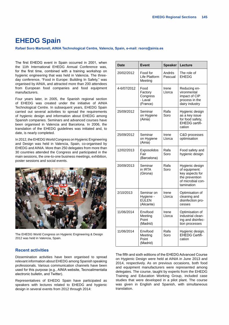
EHEDG Regional Sections 145
EHEDG SpainRafael Soro Martorell, AINIA Technological Centre, Valencia, Spain, e-mail: [email protected]
The first EHEDG event in Spain occurred in 2001, when the 11th International EHEDG Annual Conference was, for the first time, combined with a training workshop on hygienic engineering that was held in Valencia. The three-day conference, “Food in Europe: Building In Safety,” was organised by AINIA, and attracted more than 200 attendees from European food companies and food equipment manufacturers.
Four years later, in 2005, the Spanish regional section of EHEDG was created under the initiative of AINIA Technological Centre. In subsequent years, EHEDG Spain carried out several activities to spread the requirements of hygienic design and information about EHEDG among Spanish companies. Seminars and advanced courses have been organised in Valencia and Barcelona. In 2006, the translation of the EHEDG guidelines was initiated and, to date, is nearly completed.
In 2012, the EHEDG World Congress on Hygienic Engineering and Design was held in Valencia, Spain, co-organised by EHEDG and AINIA. More than 250 delegates from more than 30 countries attended the Congress and participated in the main sessions, the one-to-one business meetings, exhibition, poster sessions and social events.
The EHEDG World Congress on Hygienic Engineering & Design 2012 was held in Valencia, Spain.
Recent activitiesDissemination activities have been organised to spread relevant information about EHEDG among Spanish speaking professionals. Various communication channels have been used for this purpose (e.g., AINIA website, Tecnoalimentalia electronic bulletin, and Twitter).
Representatives of EHEDG Spain have participated as speakers with lectures related to EHEDG and hygienic design in several events from 2012 through 2014:
Date Event Speaker Lecture
20/02/2012 Food for Life Platform Meeting
Andrés Pascual
The role of EHEDG
4-6/07/2012 Food Factory Congress - Laval (France)
Irene Llorca
Reducing en-vironmental impact of CIP process in the dairy industry
25/09/2012 Seminar on Hygiene (Ainia)
Rafa Soro
Hygienic design as a key issue for food safety, EHEDG certifi-cation
25/09/2012 Seminar on Hygiene (Ainia)
Irene Llorca
C&D processes optimisation
12/02/2013 Exposolidos Fair (Barcelona)
Rafa Soro
Food safety and hygienic design
20/09/2013 Seminar in IRTA (Girona)
Rafa Soro
Hygienic design of equipment: key aspects for the prevention of microbial con-tamination
2/10/2013 Seminar on Hygiene - EULEN (Alicante)
Irene Llorca
Optimisation of cleaning and disinfection pro-cesses
11/06/2014 Envifood Meeting Point (Madrid)
Irene Llorca
Optimisation of industrial clean-ing and disinfec-tion processes
11/06/2014 Envifood Meeting Point (Madrid)
Rafa Soro
Hygienic design. EHEDG Certifi-cation
The fifth and sixth editions of the EHEDG Advanced Course on Hygienic Design were held at AINIA in June 2013 and 2014, respectively. As on previous occasions, both food and equipment manufacturers were represented among delegates. The course, taught by experts from the EHEDG Training and Education Working Group, included case studies that were developed in a pilot plant. The course was given in English and Spanish, with simultaneous translation.
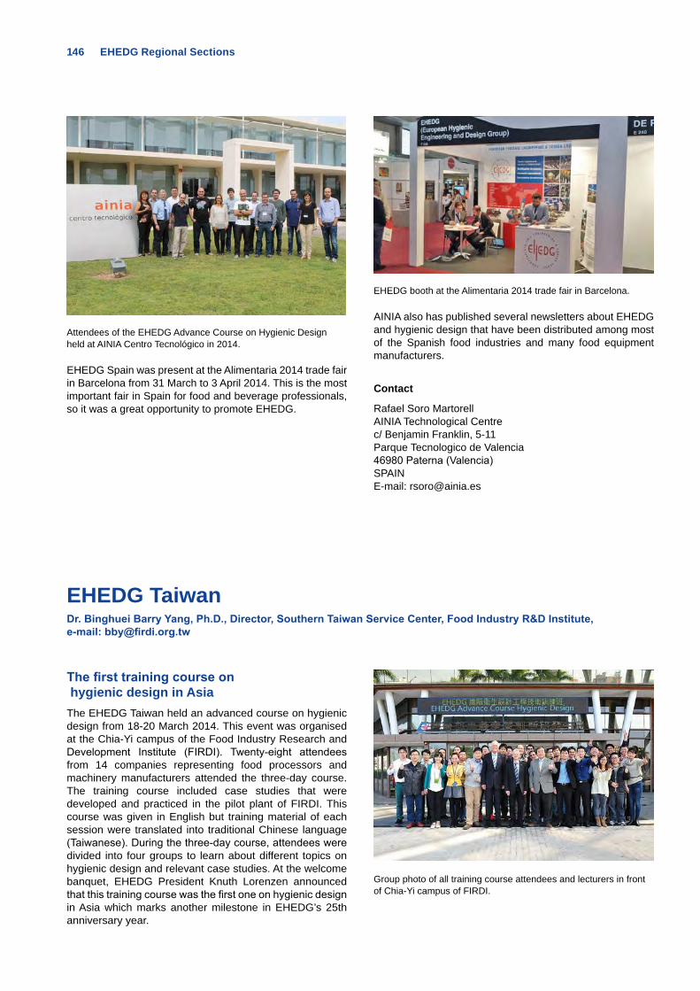
146 EHEDG Regional Sections
Attendees of the EHEDG Advance Course on Hygienic Design held at AINIA Centro Tecnológico in 2014.
EHEDG Spain was present at the Alimentaria 2014 trade fair in Barcelona from 31 March to 3 April 2014. This is the most important fair in Spain for food and beverage professionals, so it was a great opportunity to promote EHEDG.
EHEDG booth at the Alimentaria 2014 trade fair in Barcelona.
AINIA also has published several newsletters about EHEDG and hygienic design that have been distributed among most of the Spanish food industries and many food equipment manufacturers.
Contact
Rafael Soro MartorellAINIA Technological Centrec/ Benjamin Franklin, 5-11Parque Tecnologico de Valencia46980 Paterna (Valencia)SPAINE-mail: [email protected]
EHEDG TaiwanDr. Binghuei Barry Yang, Ph.D., Director, Southern Taiwan Service Center, Food Industry R&D Institute, e-mail: [email protected]
The first training course on hygienic design in AsiaThe EHEDG Taiwan held an advanced course on hygienic design from 18-20 March 2014. This event was organised at the Chia-Yi campus of the Food Industry Research and Development Institute (FIRDI). Twenty-eight attendees from 14 companies representing food processors and machinery manufacturers attended the three-day course. The training course included case studies that were developed and practiced in the pilot plant of FIRDI. This course was given in English but training material of each session were translated into traditional Chinese language (Taiwanese). During the three-day course, attendees were divided into four groups to learn about different topics on hygienic design and relevant case studies. At the welcome banquet, EHEDG President Knuth Lorenzen announced that this training course was the first one on hygienic design in Asia which marks another milestone in EHEDG’s 25th anniversary year.
Group photo of all training course attendees and lecturers in front of Chia-Yi campus of FIRDI.
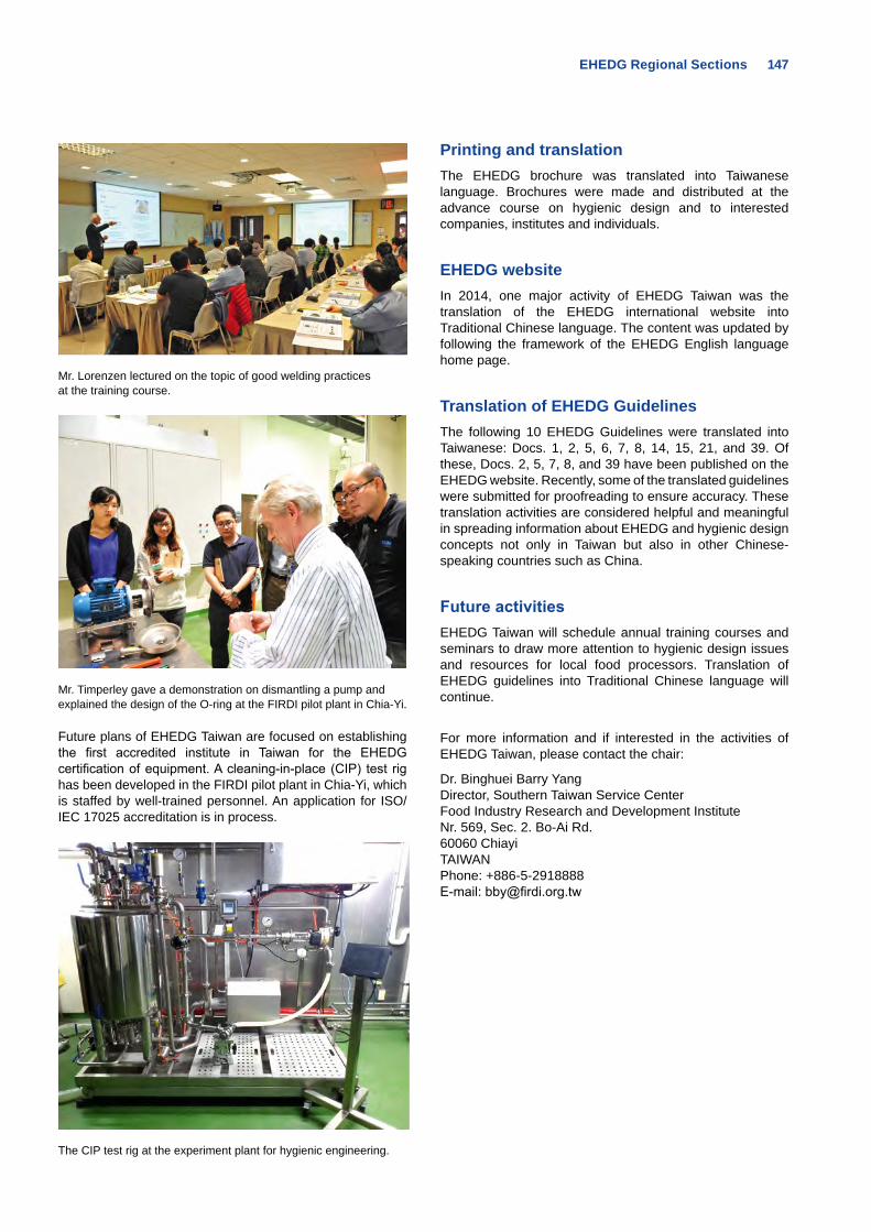
EHEDG Regional Sections 147
Mr. Lorenzen lectured on the topic of good welding practices at the training course.
Mr. Timperley gave a demonstration on dismantling a pump and explained the design of the O-ring at the FIRDI pilot plant in Chia-Yi.
Future plans of EHEDG Taiwan are focused on establishing the first accredited institute in Taiwan for the EHEDG certification of equipment. A cleaning-in-place (CIP) test rig has been developed in the FIRDI pilot plant in Chia-Yi, which is staffed by well-trained personnel. An application for ISO/IEC 17025 accreditation is in process.
The CIP test rig at the experiment plant for hygienic engineering.
Printing and translation The EHEDG brochure was translated into Taiwanese language. Brochures were made and distributed at the advance course on hygienic design and to interested companies, institutes and individuals.
EHEDG websiteIn 2014, one major activity of EHEDG Taiwan was the translation of the EHEDG international website into Traditional Chinese language. The content was updated by following the framework of the EHEDG English language home page.
Translation of EHEDG GuidelinesThe following 10 EHEDG Guidelines were translated into Taiwanese: Docs. 1, 2, 5, 6, 7, 8, 14, 15, 21, and 39. Of these, Docs. 2, 5, 7, 8, and 39 have been published on the EHEDG website. Recently, some of the translated guidelines were submitted for proofreading to ensure accuracy. These translation activities are considered helpful and meaningful in spreading information about EHEDG and hygienic design concepts not only in Taiwan but also in other Chinese-speaking countries such as China.
Future activitiesEHEDG Taiwan will schedule annual training courses and seminars to draw more attention to hygienic design issues and resources for local food processors. Translation of EHEDG guidelines into Traditional Chinese language will continue.
For more information and if interested in the activities of EHEDG Taiwan, please contact the chair:
Dr. Binghuei Barry Yang Director, Southern Taiwan Service Center Food Industry Research and Development Institute Nr. 569, Sec. 2. Bo-Ai Rd. 60060 Chiayi TAIWAN Phone: +886-5-2918888 E-mail: [email protected]
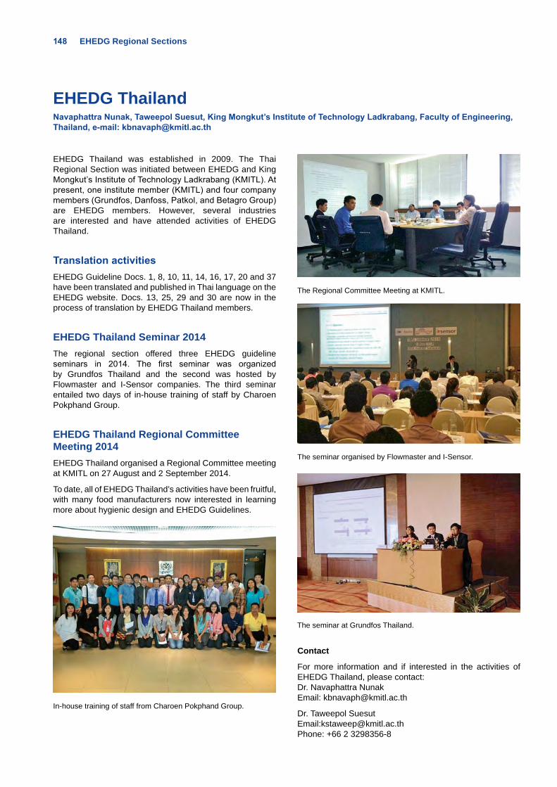
148 EHEDG Regional Sections
EHEDG Thailand Navaphattra Nunak, Taweepol Suesut, King Mongkut’s Institute of Technology Ladkrabang, Faculty of Engineering, Thailand, e-mail: [email protected]
EHEDG Thailand was established in 2009. The Thai Regional Section was initiated between EHEDG and King Mongkut’s Institute of Technology Ladkrabang (KMITL). At present, one institute member (KMITL) and four company members (Grundfos, Danfoss, Patkol, and Betagro Group) are EHEDG members. However, several industries are interested and have attended activities of EHEDG Thailand.
Translation activities EHEDG Guideline Docs. 1, 8, 10, 11, 14, 16, 17, 20 and 37 have been translated and published in Thai language on the EHEDG website. Docs. 13, 25, 29 and 30 are now in the process of translation by EHEDG Thailand members.
EHEDG Thailand Seminar 2014The regional section offered three EHEDG guideline seminars in 2014. The first seminar was organized by Grundfos Thailand and the second was hosted by Flowmaster and I-Sensor companies. The third seminar entailed two days of in-house training of staff by Charoen Pokphand Group.
EHEDG Thailand Regional Committee Meeting 2014EHEDG Thailand organised a Regional Committee meeting at KMITL on 27 August and 2 September 2014.
To date, all of EHEDG Thailand’s activities have been fruitful, with many food manufacturers now interested in learning more about hygienic design and EHEDG Guidelines.
In-house training of staff from Charoen Pokphand Group.
The Regional Committee Meeting at KMITL.
The seminar organised by Flowmaster and I-Sensor.
The seminar at Grundfos Thailand.
Contact
For more information and if interested in the activities of EHEDG Thailand, please contact:Dr. Navaphattra NunakEmail: [email protected]
Dr. Taweepol SuesutEmail:[email protected]: +66 2 3298356-8
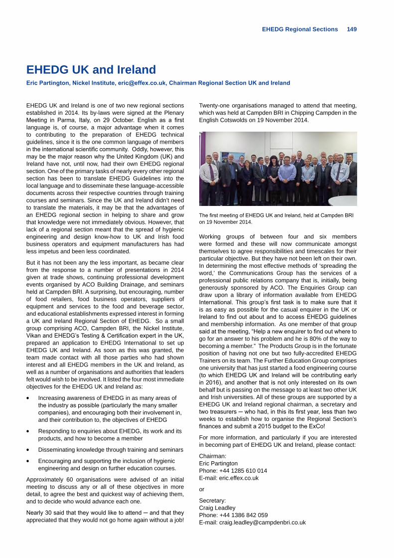
EHEDG Regional Sections 149
EHEDG UK and Ireland Eric Partington, Nickel Institute, [email protected], Chairman Regional Section UK and Ireland
EHEDG UK and Ireland is one of two new regional sections established in 2014. Its by-laws were signed at the Plenary Meeting in Parma, Italy, on 29 October. English as a first language is, of course, a major advantage when it comes to contributing to the preparation of EHEDG technical guidelines, since it is the one common language of members in the international scientific community. Oddly, however, this may be the major reason why the United Kingdom (UK) and Ireland have not, until now, had their own EHEDG regional section. One of the primary tasks of nearly every other regional section has been to translate EHEDG Guidelines into the local language and to disseminate these language-accessible documents across their respective countries through training courses and seminars. Since the UK and Ireland didn’t need to translate the materials, it may be that the advantages of an EHEDG regional section in helping to share and grow that knowledge were not immediately obvious. However, that lack of a regional section meant that the spread of hygienic engineering and design know-how to UK and Irish food business operators and equipment manufacturers has had less impetus and been less coordinated.
But it has not been any the less important, as became clear from the response to a number of presentations in 2014 given at trade shows, continuing professional development events organised by ACO Building Drainage, and seminars held at Campden BRI. A surprising, but encouraging, number of food retailers, food business operators, suppliers of equipment and services to the food and beverage sector, and educational establishments expressed interest in forming a UK and Ireland Regional Section of EHEDG. So a small group comprising ACO, Campden BRI, the Nickel Institute, Vikan and EHEDG’s Testing & Certification expert in the UK, prepared an application to EHEDG International to set up EHEDG UK and Ireland. As soon as this was granted, the team made contact with all those parties who had shown interest and all EHEDG members in the UK and Ireland, as well as a number of organisations and authorities that leaders felt would wish to be involved. It listed the four most immediate objectives for the EHEDG UK and Ireland as:
• Increasing awareness of EHEDG in as many areas of the industry as possible (particularly the many smaller companies), and encouraging both their involvement in, and their contribution to, the objectives of EHEDG
• Responding to enquiries about EHEDG, its work and its products, and how to become a member
• Disseminating knowledge through training and seminars
• Encouraging and supporting the inclusion of hygienic engineering and design on further education courses.
Approximately 60 organisations were advised of an initial meeting to discuss any or all of these objectives in more detail, to agree the best and quickest way of achieving them, and to decide who would advance each one.
Nearly 30 said that they would like to attend ─ and that they appreciated that they would not go home again without a job!
Twenty-one organisations managed to attend that meeting, which was held at Campden BRI in Chipping Campden in the English Cotswolds on 19 November 2014.
The first meeting of EHEDG UK and Ireland, held at Campden BRI on 19 November 2014.
Working groups of between four and six members were formed and these will now communicate amongst themselves to agree responsibilities and timescales for their particular objective. But they have not been left on their own. In determining the most effective methods of ‘spreading the word,’ the Communications Group has the services of a professional public relations company that is, initially, being generously sponsored by ACO. The Enquiries Group can draw upon a library of information available from EHEDG International. This group’s first task is to make sure that it is as easy as possible for the casual enquirer in the UK or Ireland to find out about and to access EHEDG guidelines and membership information. As one member of that group said at the meeting, “Help a new enquirer to find out where to go for an answer to his problem and he is 80% of the way to becoming a member.” The Products Group is in the fortunate position of having not one but two fully-accredited EHEDG Trainers on its team. The Further Education Group comprises one university that has just started a food engineering course (to which EHEDG UK and Ireland will be contributing early in 2016), and another that is not only interested on its own behalf but is passing on the message to at least two other UK and Irish universities. All of these groups are supported by a EHEDG UK and Ireland regional chairman, a secretary and two treasurers ─ who had, in this its first year, less than two weeks to establish how to organise the Regional Section’s finances and submit a 2015 budget to the ExCo!
For more information, and particularly if you are interested in becoming part of EHEDG UK and Ireland, please contact:
Chairman: Eric Partington Phone: +44 1285 610 014 E-mail: eric.effex.co.uk
or
Secretary: Craig Leadley Phone: +44 1386 842 059 E-mail: [email protected]
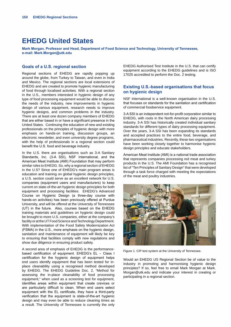
150 EHEDG Regional Sections
EHEDG United StatesMark Morgan, Professor and Head, Department of Food Science and Technology, University of Tennessee, e-mail: [email protected]
Goals of a U.S. regional sectionRegional sections of EHEDG are rapidly popping up around the globe, from Turkey to Taiwan, and even in India and Mexico. The regional sections are local extensions of EHEDG and are created to promote hygienic manufacturing of food through localised activities. With a regional section in the U.S., members interested in hygienic design of any type of food processing equipment would be able to discuss the needs of the industry, new improvements in hygienic design of various equipment, research needs to improve hygienic designs, and common problems in the industry. There are at least one dozen company members of EHEDG that are either based in or have a significant presence in the United States. Continuing the education of new and existing professionals on the principles of hygienic design with more emphasis on hands-on training, discussion groups, an electronic newsletter, and even university degree programs, with the help of professionals in a regional section could benefit the U.S. food and beverage industry.
In the U.S. there are organisations such as 3-A Sanitary Standards, Inc. (3-A SSI), NSF International, and the American Meat Institute (AMI) Foundation that may perform similar roles to EHEDG. So, why a regional section of EHEDG in the U.S? Since one of EHEDG’s main program areas is education and training on global hygienic design principles, a U.S. section could serve as an excellent network for U.S. companies (equipment users and manufacturers) to keep current on state-of-the-art hygienic design principles for both equipment and processing facilities. EHEDG’s Advanced Course on Hygienic Design (a three-day course with hands-on activities) has been previously offered at Purdue University, and will be offered at the University of Tennessee (UT) in the future. Also, courses based on the EHEDG training materials and guidelines on hygienic design could be brought to more U.S. companies, either at the company’s facility or at the UT Food Science and Technology Department. With implementation of the Food Safety Modernization Act (FSMA) in the U.S., more emphasis on the hygienic design, sanitation and maintenance of equipment will likely be key to ensuring that facilities comply with new regulations and show due diligence in ensuring product safety.
A second area of emphasis of EHEDG is the performance-based certification of equipment. EHEDG’s EL – Class I certification for the hygienic design of equipment helps end users identify equipment that has been tested for in-place cleanability using a recognised method developed by EHEDG. The EHEDG Guideline Doc. 2, “Method for assessing the in-place cleanability of food processing equipment,“ when used as a screening test for equipment, identifies areas within equipment that create crevices or are particularly difficult to clean. When end users select equipment with the EL certificate, they have a third-party verification that the equipment is state-of-the-art hygienic design and may even be able to reduce cleaning times as a result. The University of Tennessee is currently the only
EHEDG Authorised Test Institute in the U.S. that can certify equipment according to the EHEDG guidelines and is ISO 17025 accredited to perform the Doc. 2 testing.
Existing U.S.-based organisations that focus on hygienic designNSF International is a well-known organisation in the U.S. that focuses on standards for the sanitation and certification of commercial foodservice equipment.
3-A SSI is an independent not-for-profit corporation similar to EHEDG, with roots in the North American dairy processing industry. 3-A SSI has historically created individual sanitary standards for different types of dairy processing equipment. Over the years, 3-A SSI has been expanding its standards and accepted practices to the entire food, beverage, and pharmaceutical industries. Recently, these two organisations have been working closely together to harmonise hygienic design principles and educate stakeholders.
American Meat Institute (AMI) is a national trade association that represents companies processing red meat and turkey products in the U.S. The AMI Foundation has a recognised list of “Ten Principles of Sanitary Design“ that were developed through a task force charged with meeting the expectations of the meat and poultry industries.
Figure 1. CIP test system at the University of Tennessee.
Would an EHEDG US Regional Section be of value to the industry in promoting and harmonising hygienic design principles? If so, feel free to email Mark Morgan at [email protected] and indicate your interest in creating or participating in a regional section.
European Hygienic Engineering & Design Group
EHEDG Guidelines
EHEDG Guidelines can be ordered from the Webshop www.vdmashop.de/EHEDG by non-members and individual members. They are free for EHEDG Company and Institute Members while Individual EHEDG Members receive a 50 % discount.
Doc. 1. Microbiologically safe continuous pasteurisation of liquid foods
First edition, November 1992 (17 pages) – currently under revision
There are many reasons why, in practice pasteurised products sometimes present a microbiological health hazard. Due to distribution in residence time, not all products may reach the temperature required for pasteurisation or may do so for too short a time. Further there may be a risk of contamination with a non-pasteurised product, or the cooling medium. This document describes the requirements particularly for liquid foods without particulates.
Languages available: Armenian, Croatian, Dutch, English, French, Spanish, Thai, Ukrainian
Doc. 2. A method for assessing the in-place cleanability of food processing equipment
Third edition, June 2007 (16 pages)
The method is intended as a screening test for hygienic equipment design and is not indicative of the performance of industrial cleaning processes (which depend on the type of soil). See Doc 15 for a test procedure designed for moderately-sized equipment.
Training DVD available. Languages available: Armenian, Dutch, English, French, German, Italian, Macedonian, Russian, Spanish
Doc. 3. Microbiologically safe aseptic packing of food productsFirst edition, January 1993 (15 pages) – currently under revision
This guideline stresses the need to identify the sources of micro-organisms that may contaminate food in the packaging process, and to determine which contamination rates are acceptably low. It clarifies the difference in risk of infection between aseptic processing and aseptic packing and recommends that aseptic packing machines be equipped with fillers that are easily cleanable, suitable for decontamination and bacteria-tight. Requirements
for the machine interior include monitoring of critical decontamination parameters. See also Doc. 21 on challenge tests.
Languages available: Armenian, Croatian, Dutch, English, French, Italian, Macedonian, Russian, Spanish, Ukrainian
Doc. 4. A method for the assessment of in-line pasteurisation of food processing equipmentFirst edition, February 1993 (12 pages)
Food processing equipment that cannot be or does not need to be sterilised may need to be pasteurised to inactivate relevant vegetative micro-organisms and fungal spores. It is important to test the hygienic characteristics of such equipment to ensure that it can be pasteurised effectively. This document describes a test procedure to determine whether equipment can be pasteurised by circulation with hot water.
Training DVD available. Languages available: Armenian, Dutch, English, French, Macedonian, Spanish, Ukrainian
Doc. 5. A method for the assessment ofin-line sterilisability of food processing equipmentSecond edition, July 2004 (9 pages)
Food processing equipment may need to be sterilised before use, and it is important to ensure that the sterilisation method applied is effective. Thus, it is necessary to determine under which conditions equipment can be sterilised. This paper details the recommended procedure for assessing the suitability of an item of food processing equipment for in-line sterilisation. It is advisable to conduct in-place cleanability trials (ref. Doc.2) prior to this test in order to verify the hygienic design of the equipment.
Training DVD available. Languages available: Armenian, Chinese (Taiwan), Dutch, English, French, German, Macedonian, Spanish, Ukrainian
Doc. 6. The microbiologically safe continuous flow thermal sterilisation of liquid foodsFirst edition, April 1993 (26 pages) – currently under revision
Thermal sterilisation is aimed at eliminating the risk of food poisoning and, when used in conjunction with aseptic filling, at achieving extended product storage life under ambient conditions. Whereas pasteurisation destroys vegetative micro-organisms, sterilisation destroys both vegetative
152 EHEDG Guidelines
micro-organisms and relevant bacterial spores. This document presents guidelines on the microbiologically safe continuous sterilisation of liquid products. The technique of Ohmic heating was not considered in this paper but may be included in an update being prepared. See Doc. 1 for guidelines on continuous pasteurisation of liquid foods.
Training DVD available. Languages available: Armenian, Dutch, English, French, Macedonian, Spanish, Ukrainian
Doc. 7. A method for the assessment of bacteria tightness of food processing equipmentSecond edition, July 2004 (10 pages)
This document details the test procedure for assessing whether an item of food processing equipment, intended for aseptic operation, is impermeable to micro-organisms. Small motile bacteria penetrate far more easily through microscopic passages than (non-motile) moulds and yeasts. The facultative anaerobic bacterium Serratia marcescens (CBS 291.93) is therefore used to test bacteria-tightness or the impermeability of equipment to micro-organisms. The method is suitable for equipment that is already known to be in-line steam sterilisable (see also Doc. 5).
Training DVD available. Languages available: Armenian, Dutch, English, French, German, Macedonian, Spanish, Ukrainian
Doc. 8. Hygienic equipment design criteriaSecond edition, April 2004 (16 pages)
This guideline describes the criteria for the hygienic design of equipment intended for the processing of foods. Its fundamental objective is the prevention of the microbial contamination of food products. It is intended to appraise qualified engineers who design equipment for food processing with the additional demands of hygienic engineering in order to ensure the microbiological safety of the end product. Upgrading an existing design to meet hygiene requirements can be prohibitively expensive and may be unsuccessful and so these are most effectively incorporated into the initial design stage. The long term benefits of doing so are not only product safety but also increased life expectancy of equipment, reduced maintenance and consequently lower operating costs.
This document, first published in 1993, describes in more detail the hygienic requirements of the Machinery Directive (98/37/EC ref.1). Parts of it have subsequently been incorporated in the standards EN1672-2 and EN ISO 14159.
Training DVD available. Languages available: Armenian, Chinese (Taiwan), Dutch, English, French, German, Italian, Japanese, Lithuanian, Macedonian, Portuguese (Brazil),Russian, Serbian, Spanish, Thai, Ukrainian
Doc. 9. Welding stainless steel to meet hygienic requirementsFirst edition, July 1993 (21 pages) – currently under revision in conjunction with Doc. 35
This document describes the techniques required to produce hygienically acceptable welds in thin walled (< 3 mm) stainless steel applications. The main objective was to convey the reasons and requirements for hygienic welding and to provide information on how this may best be achieved. This document is superseded by Doc 35, recently published. The working group will continue with a guideline on inspection of the quality of welds in food processing machinery.
Training DVD available. Languages available: Dutch, English, French, Japanese, Macedonian, Spanish, Ukrainian
Doc. 10. Hygienic design of closed equipment for the processing of liquid foodSecond edition, May 2007 (22 pages)
Using the general criteria for the hygienic design of equipment identified in Doc 8, this paper illustrates the application of these criteria in the construction and fabrication of closed process equipment. Examples, with drawings, show how to avoid crevices, shadow zones and areas with stagnating product, and how to connect and position equipment in a process line to ensure unhampered draining and cleaning in-place. Attention is drawn to ways of preventing problems with joints, which might otherwise cause leakage or contamination of product.
Training DVD available. Languages available: Armenian, Dutch, English, French, German, Italian, Lithuanian, Macedonian, Portuguese (Brazil), Russian, Serbian, Thai, Ukrainian
Doc. 11. Hygienic packing of food productsFirst edition, December 1993 (15 pages) – currently under revision
Products with a short shelf-life, or whose shelf life is extended by cold storage or in-pack heat treatments, do not have to conform to such strict microbiological requirements as aseptically packaged foods (Doc 3 discusses aseptic packing). This paper discusses the packing of food products that do not need aseptic packing but which nevertheless need to be protected against unacceptable microbial contamination. It describes guidelines for the hygienic design of packing machines, the handling of packing materials and the environment of the packing machines. See also Doc. 21.
Languages available: Dutch, English, French, Macedonian, Spanish, Thai, Ukrainian
EHEDG Guidelines 153
Doc. 12. The continuous or semi- continuous flow thermal treatment of particulate foodsFirst edition, March 1994 (28 pages)
Thermal sterilisation is a process aimed at eliminating the risk of food poisoning and, when used in conjunction with aseptic filling, it aims to extend product storage life under ambient conditions. This is achieved by the destruction of vegetative micro-organisms and relevant bacterial spores.
Liquid foods containing particulates are inherently more difficult to process than homogenous liquids due to heat transfer limitations in particulate-liquid mixtures and the additional problems of transport and handling. This paper presents guidelines on the design of continuous and semi-continuous plants for the heat treatment of particulate foods. Ohmic heating techniques are not covered. See also Doc. 1 on continuous pasteurisation and Doc. 6 on sterilisation of liquid products without particles.
Languages available: Dutch, English, French, Spanish, Ukrainian
Doc. 13. Hygienic design of equipment for open processingSecond edition, May 2004 (24 pages)
It is important that the plant design takes into account factors affecting the hygienic operation and cleanability of the plant. The risk of contamination of food products during open processing increases with the concentration of micro-organisms in the environment and their opportunity to grow in poorly designed equipment. This means that in open plants, environmental conditions, in addition to appropriate equipment design, have an important influence on hygienic operation. The type of product and the stage of the manufacturing process must also be taken into consideration.
This paper deals with the principal hygienic requirements for equipment for open processing and applies to many different types, including machines for the preparation of dairy products, alcoholic and non-alcoholic drinks, sweet oils, coffee products, cereals, vegetables, fruit, bakery products, meat and fish. It describes methods of construction and fabrication, giving examples as to how the principal criteria can be met. See also guidelines on hygienic design criteria Doc 8, hygienic welding Doc 9, and the hygienic design of equipment for closed processing Doc 10.)
Languages available: Second Edition, May 2004: English, French, German, Italian, Japanese, Macedonian, Serbian, Ukrainian
First Edition, 1996: Dutch
Doc. 14. Hygienic design of valves for food processingSecond edition, July 2004 (17 pages) – currently under revision
Valves are essential components of all food processing plants and the quality used strongly influences the microbiological safety of the food production process. These valves must therefore comply with strict hygienic requirements
The guidelines apply to all valves used in contact with food or food constituents that are to be processed hygienically or aseptically. Aside from general requirements with regard to materials, drainability, microbial impermeability and other aspects, additional requirements for specific valve types are also described. See also Doc. 20 on double-seat mixproof valves.
Training DVD available. Languages available: Dutch, English, French, Italian,Japanese, Macedonian, Spanish, Thai
Doc. 15. A method for the assessment of in-place cleanability of moderately-sized food processing equipmentFirst edition, February 1997 (12 pages)
This document describes a test procedure for assessing the in-place cleanability of moderately sized equipment, such as homogenisers. The degree of cleanliness is based on the removal of a fat spread soil, and is assessed by evaluating the amount of soil remaining after cleaning by visual inspection and swabbing of the surface. This method is not as sensitive as the microbiological method described in Doc. 2.
Languages available: Armenian, Dutch, English, French, German, Macedonian, Spanish, Ukrainian
Doc. 16. Hygienic pipe couplingsFirst edition, September 1997 (21 pages)
This paper identifies and defines critical design parameters for welded pipe couplings: easily cleanable in-place; easily sterilisable in place; impervious to micro-organisms, reliable and easy to install.
Gaskets of various types were tested for reliability and hygienic aspects using EHEDG cleanability test methods and repeated sterilisation. The objective was to provide a reliable dismountable joint which is bacteria-tight at the product side under the conditions of processing, cleaning and sanitation.
Training DVD available. Languages available: English, French, German, Macedonian, Ukrainian
154 EHEDG Guidelines
Doc. 17 Hygienic design of pumps, homogenisers and dampening devicesThird Edition, April 2013 (41 pages)
This updated guideline is meant to specify the technical requirements of pumps, homogenizers and dampening devices including their hygienic application in order to ensure a safe processing and production of food under hygienic conditions. The requirements described in the guideline apply to all pumps intended for the use in safe food processing, including centrifugal pumps, piston pumps, lobe rotor pumps, peristaltic pumps, diaphragm pumps, progressive cavity pumps, screw pumps as well as to homogenizers and dampening devices. The document includes a classification of pumps which is complemented by illustrations and pictures for a better understanding of the hygiene-related issues and potential problem areas (such as gaps and dead-ends) as well as of state-of-the-art hygienic design solutions. Special needs for CIP/SIP-capability, gentle product handling and easy maintenance have to be duly considered for pumps, homogenizers and dampening devices used in food processing. These demands, their implementation and related design principles are described in detail in EHEDG Doc. 17. Based on the EC-Machinery Directive 2006/42/EC, the document specifies additional requirements to such equipment in order to fulfil good mechanical and hydraulic properties as well as thermal efficiency by following modern design practices and ensuring low-cost manufacture.
Training DVD available. Languages available: Third Edition, April 2013: Dutch English, German,
Second Edition, September 2004: French, Italian, Macedonian, Thai
Doc. 18. Chemical Treatment of Stainless Steel SurfacesSecond Edition, January 2014 (19 pages)
This guideline issued in January 2014 replaces Doc. 18 “Passivation of Stainless Steel” (1998) and includes new sections on pickling and electropolishing of stainless steels. Chemical surface treatments such as pickling, passivation and electropolishing can help to assure the successful functional and corrosion-resistant performance of stainless steels for product contact surfaces in the food and beverage industry. This document explains the general principles of those three processes above: Why they are necessary, when and how they should be applied, how they work and which chemicals are used.
Training DVD available. Languages available: Second Edition, January 2014: English, Italian, Serbian
First Edition, August 1998: Armenian, Dutch, French, German, Japanese, Macedonian, Russian, Spanish
Doc. 19. A method for assessing the bacterial impermeability of hydrophobic membrane filtersSecond Edition, June 2012 (9 pages)
Research has shown that hydrophobic membrane filters, with a pore size of 0.22µm, do not retain micro-organisms under all process conditions. Investigations were conducted into risk assessment of sterilising hydrophobic membrane filters, evaluating the performance of the filters under a range of operating conditions.
To validate the performance of sterilizing grade hydrophobic membrane filters, a bacterial aerosol challenge test methodology (TBAC) was developed. The method was used to qualify filter systems for air filtration and exhaust gas filtration on fermenters. In these applications, filters are intended to prevent micro-organisms from contaminating the environment.
Languages available: Second Edition, June 2012: Dutch, English, German, Macedonian
First Edition, June 2000: Armenian, French, Spanish
Doc. 20. Hygienic design and safe use of double-seat mixproof valvesFirst edition, July 2000 (20 pages) – currently under revision
This document describes the basic hygienic design and safe use of single-body double-seat mixproof valves. Today, food process plants incorporate various multifunctional flow paths. Often one piping system is cleaned while another still contains product. This simultaneous cleaning can potentially result in the dangerous situation where product and cleaning liquid are separated by just one single valve seat. Any cleaning liquid that leaks across such a seat will contaminate the product. Therefore, often two or three single seat valves in a “block-and-bleed” arrangement are applied.
Training DVD available. Languages available: Dutch, English, French, Japanese, Macedonian, Russian
Doc. 21. Challenge tests for the evaluation of the hygienic characteristics of packing machines for liquid and semi-liquid productsFirst edition, July 2000 (32 pages) – currently under revision
After documents 3 and 11, this is the third test method in the series. It discusses how packing machines should be designed to comply with hygiene design criteria and thereby with the requirements specified in Annex 1 of the Machinery Directive1. To determine whether those criteria are met requires validation of the design and measurement
EHEDG Guidelines 155
of essential parameters. Proven methods for testing the performance of the various functions of packing machines are described.
These methods may also be used by the manufacturer to optimise or redesign a packing machine and by the food processor who may want to compare different packing machines.
Upon delivery, a packing machine needs to be checked by a commissioning procedure to be agreed in advance between the food processor and the supplier. Commissioning may include physical as well as microbiological tests. Additional tests are specified for commissioning of machines for aseptic packing.
1 Machinery Directive 98/37/EC – Annex 1, point 2.1, Agri-foodstuffs machinery
Languages available: Armenian, Dutch, English, French, Macedonian, Russian, Spanish
Doc. 22. General hygienic design criteria for the safe processing of dry particulate materialsSecond Edition, March 2014 (28 pages)
In the food industry many different types of dry particulate food related materials are produced and handled. This requires different design criteria for specific process equipment and process lines in relation with the various food safety requirements of each material.
The first edition of this document was the first EHEDG guideline in which the requirements for powder handling processes were highlighted. Previous EHEDG guidelines were mainly focused on the hygienic design criteria in liquid processing of foods. This general and updated document relates to processing of powders, agglomerates and granular materials. Fluid and moist solid materials like slurries and wet cakes are not taken into account. Typical aspects of hygienic equipment design involve cleaning of equipment, prevention of any physical, chemical or biological contamination and microbial survival and growth, all in relation to dry particulate materials. If wet cleaning is applied, the design criteria are similar to those as described in other EHEDG documents (ref. 1, 2, 3 and 5). Sometimes other procedures (such as dry cleaning) need to be used and these are described in this document.
Languages available Second Edition, March 2014: English, German, Lithuanian
First Edition, March 2001: Dutch, French, Macedonian, Russian, Spanish
Doc. 23. Production and use of food-grade lubricants, Part 1 and 2Second edition, May 2009 (Part 1: Use of H1 Registered Lubricants – 23 Pages / Part 2: Production of H1 Registered Lubricants – 10 Pages)
Lubricants, grease and oil are necessary components for the lubrication, heat transfer, power transmission and corrosion protection of machinery, machine parts, instruments and equipment. Incidental contact between lubricants and food cannot always be fully excluded and may result in contamination of the food product. This risk applies to all lubricants equally. PART 1 of this guideline covers the hazards that may occur when using food grade lubricants and describes the actions and activities required to eliminate them or to reduce their impact or occurrence to an acceptable level. PART 2 of this guideline lays down the general requirements and recommendations for the hygienic manufacturing and supply of food-safe lubricants.
Training DVD available. Languages available: Armenian, Dutch, English, French, German, Japanese, Lithuanian, Macedonian,Portuguese (Brazil), Russian, Serbian, Spanish
Doc. 24. The prevention and control of legionella spp (incl. legionnaires’ disease) in food factoriesFirst edition, August 2002 (21 pages)
There are many locations in food industry sites where the potential for the proliferation of Legionella spp in water systems exists. These bacteria can give rise to a potentially fatal disease in humans, which is identified as legionellosis or legionnaires’ disease.
This document applies to the control of Legionella spp. in any undertaking involving a work activity and to premises controlled in connection with a trade, business or other undertaking where water is used or stored and where there is a means of transmitting water droplets which may be inhaled, thereby causing a reasonably foreseeable risk of exposure to Legionella spp.
The guidelines summarises the best practice for controlling Legionella in water systems. It consists of two parts; namely, Management Practices and Guidance on the Control of Legionella spp. in Water Systems.
The first section describes a management programme: risk identification and assessment; risk management (incl personnel responsibilities); preventing or controlling risk of exposure to the bacteria; and record keeping.
The second part provides guidance on the design and construction of hot and cold water systems as well as the management and monitoring of these systems. Water treatment programmes, with attention to cleaning and disinfection, are also discussed.
Languages available: Dutch, English, French, Macedonian, Portuguese (Brazil), Serbian, Russian
156 EHEDG Guidelines
Doc. 25. Design of mechanical seals for hygienic and aseptic applications
First edition, August 2002 (15 pages) – currently under revision
This guideline compares the design aspects of different mechanical seals with respect to ease of cleaning, microbial impermeability, sterilisability or pasteurisability. It can serve as a guide for suppliers and users of this important component. Using EHEDG definitions, mechanical seals are classified according to use in the food industry into three categories: Aseptic, Hygienic equipment Class I, and Hygienic Equipment Class II. Both single and dual mechanical seals fall under the first two categories, which by definition, are subject to more stringent hygienic demands. General design criteria and basic material requirements for food applications are explained. Materials covered include carbon-graphite, ceramics, elastomers and metals. Hygienic implications of seal elements and components are also discussed. Finally, installation requirements are described and illustrated, taking into account the product environment side, the flushing side and the cartridge design.
Languages available: Armenian, Dutch, English, German, Macedonian, Russian
Doc. 26. Hygienic engineering of plants for the processing of dry particulate materials
First edition, November 2003 (28 pages) – currently under revision
This document describes general engineering guidelines to be applied to ensure that buildings, individual equipment items and accessibility of equipment when integrated within the plant layout are designed so that aspects of the process operation, cleaning and maintenance comply with hygienic design standards. It details requirements related to plant enclosure, including hygienic zoning, building structures and ele¬ments (from floor to ceiling) as well as process line installation. Attention is also given to air stream and water related aspects within the plant as well as cleaning and contamination aspects. See also Doc. 22.
Languages available: Dutch, English, French, Macedonian, Russian, Spanish
Doc. 27. Safe storage and distribution of water in food factories
First edition, April 2004 (16 pages)
Water is a vital medium used for many different purposes in the food industry. Systems for storing and distributing water can involve hazards, which could cause water quality to fall below acceptable standards. It is therefore critical
to ensure that water storage and distribution in a food manufacturing operation takes place in a controlled, safe way. This Guideline summarizes the best practice for three water categories used in the food industry: product water, domestic water and utility water. See also Doc. 24.
Languages available: Armenian, Dutch, English, French,Lithuanian, Macedonian, Russian, Serbian, Spanish
Doc. 28. Safe and Hygienic Water Treatment in Food Factories
First Edition, December 2004 (21 pages)
This guideline summarizes the best practice for the management and operation of water storage and distribution systems in a food manufacturing plant. System requirements are described for three categories of water used: domestic, product and utility water. The product water distribution system within the plant must be hygienically designed. Water storage tanks should be enclosed, fitted with an air vent and a backflow prevention device and be completely drainable. A suitable-sized tank based on water consumption is essential to minimize stagnation. Chemical or thermal disinfection is recommended. Hazards and risks associated with utility water can have significant implications on process reliability. The document provides some recommendations with regard to specific utility water applications in the food industry, both for hot water and cold water. Attention is given to once through cooling systems, those using cooling towers and some examples of closed circuit systems.
Languages available: Armenian, English, French, Macedonian, Russian, Spanish
Doc. 29. Hygienic design of packing systems for solid foodstuffs
First edition, December 2004 (24 pages)
This document addresses packing systems of solid food products and supplements earlier guidelines. Solid food is characterised as having a water activity of >0.97, low acid, not pasteurised or sterilised after packaging, and distributed through the cool chain. Examples include fresh meat and some meat products, cheeses, ready meals, cut vegetables, etc. Hygiene requirements of the packaging operations, machinery as well as personnel, are described and reference is made to the American Meat Institute’s principles of sanitary design. See also Docs. 3 and 11.
Languages available: Armenian, Dutch, English, French, Macedonian, Russian
EHEDG Guidelines 157
Doc. 30. Guidelines on air handling in the food industry
First edition, March 2005 (43 pages) – update in progress and due for publication in 2015
The quality of air within factory buildings is controlled by many manufacturers of food products. Environmental air of a specified quality (temperature, humidity and particle concentration) and quantity (fresh air volume) is required for the comfort and safety of employees. For the manufacture of some products it is necessary to impose additional controls on environmental air quality to reduce the possibility of contamination and/or to maintain work place safety. Also, process air that comes in contact with food must be controlled to a suitable standard.
The controlled properties of air, especially temperature and humidity, may be used to prevent or reduce the growth rate of some micro-organisms in manufacturing and storage areas. The particle content - dust and micro-organisms - can also be controlled to limit the risk of product contamination and hence contribute to safe food manufacture. Airborne contaminants are commonly removed by filtration. The extent and rate of their removal can be adjusted according to acceptable risks of product contamination and also in response to any need for dust control.
These guidelines are intended to assist food producers in the design, selection, installation, and operation of air handling systems to meet the air quality and hygienic requirements of the food manufacturing process. Information is provided on the role of air systems in achieving and maintaining microbiological standards in food products. The guidelines cover the choice of systems, air filtration types, system concepts, construction, maintenance, sanitation, testing, commissioning, validation and system monitoring. These guidelines are not intended to be a specification for construction of any item of equipment installed as part of an air handling system. Each installation needs to take account of local requirements. It is suggested that suitable specialists and air quality engineers should be consulted, to assist in the design and operation of the equipment.
Languages available: Armenian, English, French, Macedonian, Russian
Doc. 31. Hygienic engineering of fluid bed and spray dryer plantsFirst edition, May 2005 (19 pages) – currently under revision
Because these plants handle moist products in an airborne state, they are susceptible to hygiene risks, including a possible transfer of allergens between products. It is therefore critical to apply hygienic design considerations to both the process and machinery to prevent occurrence of such risks.
Starting from the basics with regard to design, construction materials, layout, and zone classification of the drying systems to meet hygienic requirements, this paper outlines component design aspects of the processing chamber, with particular attention to the atomization assembly and the
distribution grids for fluidization. Systems for both supply and exhaust air should operate in a hygienic manner and recommendations for the use and installation of various types of filters are listed. Finally, operational aspects, including sampling, control and general housekeeping are briefly discussed.
Languages available: Dutch, English, French, Russian, Spanish
Doc. 32. Materials of construction for equipment in contact with foodFirst edition, August 2005 (48 pages) – currently under revision
This guideline aims to offer a practical ‘handbook’ for those responsible for the specification, design and manufacture of food processing equipment. It offers guidance on the ways in which materials may behave such that they can be selected and used as effectively as possible. The properties and selection procedures with regard to metals, elastomers and plastics are covered in detail. Potential failure mechanisms and influenced of manufacturing processes are also discussed. A more general overview of composites, ceramics and glass and materials is provided.
The guideline can serve as an aide-memoir during the design process, so that equipment manufacturers and end-users can together ensure that all aspects of materials behaviour are taken into account in designing safe, hygienic, reliable and efficient equipment which can be operated, maintained and managed economically.
Training DVD available. Languages available: Armenian, English, French, Italian, Japanese, Macedonian Russian
Doc. 33. Hygienic engineering of discharging systems for dry particulate materialsFirst edition, September 2005 (16 pages)
The introduction of the product into the processing system is a key step in maintaining the sanitation and integrity of the entire process. Discharging systems are designed to transfer, in this case dry solids, from one system into another without powder spillage, contamination or environmental pollution. Many dry systems do not have any additional protective heating steps, as they are merely specialty blending processes. Therefore, any contamination that enters the system will appear in the finished product.
Guidelines for the design of bag, big bag, container and truck discharging systems are presented. They are intended for use by persons involved in the design, sizing, and installation of bag, big bag and truck discharging systems operating under hygienic conditions.
Languages available: Dutch, English, French, Russian, Spanish
158 EHEDG Guidelines
Doc. 34. Integration of hygienic and aseptic systems
First edition, March 2006 (45 pages) – currently under revision
Hygienic and/or aseptic systems comprise inter alia individual components, machinery, measurement systems, management systems and automation that are used to produce for example food products, medicines, cosmetics, home & personal products and even water products. This horizontal guideline is about the hygienically safe integration of hygienic (including aseptic) systems in a food production/ processing facility.
Systems and components are frequently put together in a way that creates new hazards, especially microbiological ones. Deficiencies during the sequence of design, contract, design-change, fabrication, installation and commissioning are often the cause of these failures, even when specific design guidelines are available and are thought to be well understood. Errors in sequencing and content can also result in major penalties in terms of delays and in costs of components and construction. This document examines integration aspects that can affect hygienic design, installation, operation, automation, cleaning and maintenance and uses system flow charts and case studies describing the integration processes and decision steps. It does not provide detailed guidance on specific manufacturing processes, products, buildings or equipment.
Training DVD available. Languages available: Armenian, English, French, Italian, Macedonian, Russian
Doc. 35 Welding of stainless steel tubing in the food industry
First edition, July 2006 (29 pages) – currently under revision in conjunction with Doc. 9
Abundantly illustrated, this paper provides guidelines for the correct execution of on-axis hygienic (sanitary) welding between pipe segments, or between a tube and a control component (e.g. valve, flow meter, instrument tee, etc.) It deals with tube and pipe systems with less than 3.5 mm wall thickness, built in AISI 304(L) (1.4301, 1.4306 or 1.4307), 316(L) (1.4401, 1.4404 or 1.4435), 316Ti (1.4571) or 904L (1.4539) and their equivalents. The requirements for a weld destined for hygienic uses are first described, then the possible defects which can affect the weld are listed, and at the end the procedure for a state-of-the-art welding execution is illustrated, including preparation of pipe ends, final inspection and a trouble shooting guide.
It mainly refers to the part of the weld in contact with the finished or intermediate product and the only welding method considered is the GTAW (Gas Tungsten Arc Welding, commonly known as TIG) without filler material (autogenous weld), since this technique is capable of assuring the best performance in the execution of welds for the fabrication of thin wall stainless steel tubing. Inspection of welds will be covered in more detail in the next project.
Training DVD available. Languages available: Dutch, English, French, German, Japanese, Macedonian, Russian, Spanish
Doc. 36. Hygienic engineering of transfer systems for dry particulate materials
First edition, June 2007 (21 pages)
Transfer (also known as transport or conveying) of dry particulate materials (products) between or within plant components in a process line is well practiced in the food industry. The transfer operation must be carried out in a hygienic and safe manner and the physical powder properties must not be affected during this operation. In this document, hygienic transfer systems for transport of bulk materials within a food processing plant are described. This document also covers situations where transfer systems are used as a dosing procedure.
In principle, the less the need for product transfer within a food processing plant, the easier it is to make a factory hygienically safe. Furthermore, with a minimum of product transfer between equipment, there are the added advantages of a more compact plant, lower energy consumption and reduced cleaning time. Less product handling results in less adverse effects on product properties.
This guideline is intended for use by persons involved in the design, technical specification, installation and use of transfer systems for dry bulk particulate materials operating under hygienic conditions.
Languages available: Dutch, English, French, Macedonian, Russian, Serbian
Doc. 37. Hygienic design and application of sensors
First edition, November 2007 (35 pages)
According to their working principles, all sensors rely on an interaction with the material to be processed. Therefore, the use of sensors is commonly associated with hygiene risks. In many cases, the basic measuring aspect of a sensor and the optimum hygienic design may conflict.
This guideline is intended to advise both, sensor designers and manufacturers as well as those in charge of production machinery, plants and processes about the appropriate choice of sensors and the most suitable way for application in dry and wet processes.
EHEDG Guidelines 159
Sensors are crucial in the monitoring of the critical process steps as well as the CCP´s as established by the HACCP study of the process. Therefore validation and calibration of sensors in time sequences are essential.
This guideline applies to all sensors coming into contact with liquids and other products to be processed hygienically. However, it focuses upon sensors for the most common process parameters, particularly temperature, pressure, conductivity, flow, level, pH value, dissolved oxygen concentration and optical systems like turbidity or colour measurements.
Languages available: English, French, German, Japanese, Macedonian, Russian, Thai
Doc. 38. Hygienic engineering of rotary valves in process lines for dry particulate materialsFirst edition, September 2007 (13 pages)
Rotary valve selection and operation has a considerable influence on the hygiene standard of a process line and thus, the end-product quality of the dry material handled. Incorrect selection of valve type and size must be regarded as a serious hygienic risk in the food industry. Hence, only valves strictly conforming to hygienic design standards and suited for hygienic operations must be used.
This guideline applies to rotary valves that are in contact with dry particulate food and/or food related materials being processed hygienically in designated dry particulate material processing areas. The objective of this guideline is to provide guidance on the essential requirements for hygienic rotary valve design and operation. The guideline is intended for persons involved in the design, selection, sizing, installation and maintenance of rotary valves required to operate under hygienic conditions.
Languages available: Armenian, Dutch, English, French, Macedonian, Russian, Serbian, Spanish
Doc. 39. Design principles for equipment and process areas for aseptic food manufacturingFirst edition, June 2009 (14 pages)
In many areas there is an increasing demand for self stable products. However, microbial product contamination limits the shelf life of sensitive products which are not protected by any preservatives or stabilised by their formulation. Products which fail this inherent protection have to be sterilised and in consequence, the equipment must be cleanable and sterilisable. Micro-organisms which are protected by product residues or biofilms are very difficult or impossible to inactivate and the same applies to process areas if resulting in a recontamination risk. This guideline is intended to describe the basic demands for equipment and process areas for aseptic food manufacturing.
Languages available: Armenian, Chinese (Taiwan), English, French, German, Macedonian, Russian, Serbian, Spanish
Doc. 40. Hygienic engineering of valves in process lines for dry particulate materialsFirst edition, October 2010 (26 pages)
Every process plant is equipped with valves. In dry particulate materials processing, valves fulfil numerous functions: shut-off and opening of flow lines, direction and flow control, protection against excessive or insufficient pressure and against intermixing of incompatible media at intersection points in the process. The quality of the valve has a considerable influence on the quality of the production process and hence, the product itself. Hygienic deficiencies resulting from poor valve design must be regarded as a production risk in the food industry which must ensure that only valves strictly conforming to hygienic requirements are used. This Guideline describes in detail the hygienic requirements of butterfly valves, slide gate valves and ball segment valves. It also briefly mentions pinch-off valves, ball and plug valves as well as cone valves. The hygienic design requirements of rotary and diverter valves are subject of separate EHEDG Documents (Doc. 38 and 41).
Languages available: English, French, Russian, Spanish
Doc. 41. Hygienic engineering of diverter valves in process lines for dry particulate materialsFirst edition, August 2011 (22 pages)
Every process plant is equipped with valves, which fulfil numerous functions. These include line shut-off, opening, change-over and control of product flow, while also giving protection against both excessive or insufficient pressure and intermixing of incompatible media at intersection points in the process line.
When dry particulate material (product) flow has to be diverted into several directions during processing or product coming from different lines converges into one line, diverter valves are applied. In the area of dry product handling, these valves need a dedicated design.
This Guideline deals with the hygienic aspects of diverter valve design.
Valve construction, however, has a considerable influence on the quality of the production process and hence, the product itself. Hygienic deficiencies resulting from poor valve design must be regarded as a production risk in the food industry which must ensure that only valves strictly conforming to hygienic requirements are used.
Languages available: English, French, Macedonian, Russian, Spanish
160 EHEDG Guidelines
Doc. 42. Disc stack centrifugesFirst edition, April 2013 (24 pages)
Special demands are made with regard to CIP-capability of disc stack centrifuges used in the food processing and pharmaceutical industry. These requirements, their implementation and related design principles are handled in detail in this guideline.
This guideline covers the hygienic aspects of disc stack centrifuges used to separate fractions of liquid food products or to remove dense solid matter from products. The hygienic operation of a disc stack centrifuge, which is a complex machine with the purpose of collecting non-milk-solids (NMS) or other solid matter from liquid products, relies on proper cleaning by CIP/COP. Therefore, this guideline deals with cleaning as well as design.
The guideline does not cover cyclonic types of separators, decanters, basket centrifuges or other types of devices.
Languages available: Armenian, English, Spanish
Doc. 44 Hygienic Design Principles for Food FactoriesFirst Edition, September 2014 (133 pages)
This document provides those responsible for the design and construction of food factories with best hygienic practice guidelines. Following the advice in this document should, therefore, ensure that the building will be designed to the minimum hygienic building design standards that are applicable worldwide. Whilst primarily aimed at food manufacturing sites, this guidance is also applicable to food service buildings.
This document does not consider any international or national building standards or safety standards (e.g. fire). It also does not cover hygiene within the construction process which is intended to be provided via EHEDG guidance on maintenance procedures.
This document does, however, assume that buildings will be constructed following general civil engineering best practice as failures in the construction process will lead to potential unhygienic features related to hazard harbourage and the reduction of cleaning efficacy.
It is also recognised that during the project development, the scope of some hygienic design features may have changed in an effort to reduce costs. In such cases it may be possible to argue for the hygienic approach based upon the long term costs of any additional measures necessary to ensure the hygienic functioning of the alternative approach, e.g. the extra cost per day of any additional hygienic practices required.
Language available: English
Due for publication in 2015:Hygienic design of belt conveyors for the food industry
This document provides guidance specifically for the hygienic design of belt conveyors and is supplementary to the general requirements and standards for hygienic equipment. The guidance applies where the foodstuff is in direct contact with the conveyor and also in those areas where there is a risk from indirect contamination. Although applicable for use in all food production environments, care must be taken when using these guidelines in considering the actual conditions, product types and the risks of contamination.
General principles of cleaning validation in the food Industry
The objective of cleaning validation is to prove that the equipment is consistently cleaned of product, microbial residues, allergens and chemicals to an acceptable level, to prevent possible contamination and cross-contamination. This document focuses on the overall concept of cleaning validation and is intended as a general guideline for use by food manufacturers and inspectors. It is not the intention to be prescriptive in specific validation requirements. This document serves as general guidance only, and the principles may be considered useful in its application in the production of safe food, and in the development of guidelines for the validation of specialized cleaning or inactivation processes.
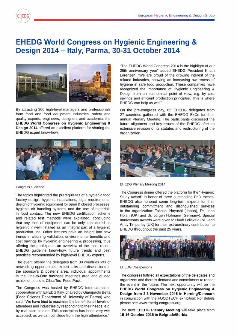
European Hygienic Engineering & Design Group
EHEDG World Congress on Hygienic Engineering & Design 2014 – Italy, Parma, 30-31 October 2014
By attracting 300 high-level managers and professionals from food and food equipment industries, safety and quality experts, engineers, designers and academia, the EHEDG World Congress on Hygienic Engineering & Design 2014 offered an excellent platform for sharing the EHEDG expert know-how.
Congress audience
The topics highlighted the prerequisites of a hygienic food factory design, hygienic installations, legal requirements, design of hygienic equipment for open & closed processes, hygienic air handling systems and the use of materials in food contact. The new EHEDG certification scheme and related test methods were explained, concluding that any kind of equipment can be only considered as hygienic if well-installed as an integral part of a hygienic production line. Other lectures gave an insight into new trends in cleaning validation, environmental benefits and cost savings by hygienic engineering & processing, thus offering the participants an overview of the most recent EHEDG guideline know-how, future trends and best practices recommended by high-level EHEDG experts.
The event offered the delegates from 30 countries lots of networking opportunities, expert talks and discussions in the sponsor’s & poster’s area, individual appointments in the One-to-One business meetings area and guided exhibition tours at CibusTec–Food Pack.
The Congress was hosted by EHEDG International in cooperation with EHEDG Italy, chaired by Giampaolo Betta (Food Scienes Department of University of Parma) who said: “We have tried to maximize the benefit for all levels of attendees and industries by responding to their needs, e.g. by real case studies. This conception has been very well accepted, as we can conclude from the high attendance.”
“The EHEDG World Congress 2014 is the highlight of our 25th anniversary year” added EHEDG President Knuth Lorenzen. “We are proud of the growing interest of the related industries, showing an increasing awareness of hygiene in safe food production. These companies have recognized the importance of Hygienic Engineering & Design from an economical point of view, e.g. by cost savings and efficient production principles. This is where EHEDG can help as well”.
On the pre-congress day, 65 EHEDG delegates from 27 countries gathered with the EHEDG ExCo for their annual Plenary Meeting. The participants discussed the future alignment and key issues of the EHEDG after an extensive revision of its statutes and restructuring of the organization.
EHEDG Plenary Meeting 2014
The Congress dinner offered the platform for the “Hygienic Study Award” in honor of three outstanding PhD theses. EHEDG also honored some long-term experts for their outstanding commitment and distinguished services to the organization: Takashi Hayashi (Japan), Dr. John Holah (UK) and Dr. Jürgen Hofmann (Germany). Special anniversary awards were given to Huub Lelieveld (NL) and Andy Timperley (UK) for their extraordinary contribution to EHEDG throughout the past 25 years.
EHEDG Chairpersons
The congress fulfilled all expectations of the delegates and organizers and there is demand and commitment to repeat the event in the future. The next opportunity will be the EHEDG World Congress on Hygienic Engineering & Design from 2-3 November 2016 in Herning/Denmark in conjunction with the FOODTECH exhibition: For details please see www.ehedg-congress.org.
The next EHEDG Plenary Meeting will take place from 15-16 October 2015 in Belgrade/Serbia.
European Hygienic Engineering & Design Group
EHEDG Working Groups To date, about 400 experts are active in the EHEDG Working Groups. They have developed and published more than 40 guidelines which are subject to regularly update. Various other topics are under progress and will complement this document series. Each Working Group is responsible for an area of expertise, and within each area certain specific scopes are defined.
The international EHEDG working group experts meet regularly to update existing and draw up new Guidelines. The EHEDG documents offer their readers guidance and practical advice in implementing national and international legislation into their design practices and manufacturing processes. Specialists with the relevant expertise are always welcome to join these Working Groups and contribute by their expertise.
EHEDG is grateful for the participation of these volunteers who share their expertise and invest their time for the advancement of EHEDG – for the good of all. Without these excellent specialists the good work of EHEDG would not be possible as it is.
New guidelines still in the process of being drawn up are:• Bakery equipment
• Cleaning in place
• Food refrigeration equipment
• Hygienic engineering of pack-off systems in process lines for dry particulate materials
• Hygienic design requirements for the processing of fresh fish
• Meat processing between slaughtering and packaging
• Seals
• EHEDG test methods (subject to permanent update)
• Tank cleaning systems
Currently under revision and in progress of being updated:• Microbiologically safe continuous pasteurization of
liquid food (Doc. 1)
• Microbiologically safe aseptic packing of food product (Doc. 3)
• The microbiologically safe continuous flow thermal sterilisation of liquid foods (Doc. 6)
• Hygienic welding of stainless steel tubing in the food processing industry (Doc. 9)
• Hygienic packing of food products (Doc. 11)
• Hygienic design of equipment for open processing (Doc. 13)
• Hygienic design of valves for food processing (Doc.14)
• Hygienic design and safe use of double-seat mixproof valves (Doc. 20)
• Challenge tests for the evaluation of the hygienic characteristics of packing machines for liquid and semi-liquid products (Doc. 21)
• Design of mechanical seals for hygienic and aseptic applications (Doc. 25)
• Hygienic engineering of plants for the processing of dry particulate materials (Doc. 26)
• Materials of construction for equipment in contact with food (Doc. 32)
• Hygienic System Integration (Doc. 34)
• Hygienic welding of stainless steel tubing in the food processing industry (Doc. 35)
New and updated guidelines due for publication in 2015:• Doc. 30
Guidelines on air handling in the food industry – Air quality control for food process environments and direct food contact
• Doc. 43 Hygienic design of belt conveyors for the food industry
• Doc. 45 General principles of cleaning validation in the food industry
EHEDG Working Groups 163
EHEDG Working Group “Bakery Equipment” Dr. Gerhard Hauser, e-mail: [email protected]
The bakery industry and equipment manufacturers are increasingly interested in the benefits that can be achieved by hygienic engineering and design. On one hand, it is demanded by law on the other hand it significantly contributes to the production of excellent bakery products by easy-to-clean machinery and safe processes. Hygienically designed equipment also helps to facilitate more efficient maintenance and service.
At the international IBA Exhibition in Munich in September 2012, a workshop was arranged by the Association of the German Bakery Industry (VdB) and EHEDG. Together with experts from all fields of the bakery industry, a proposal was made to draft an EHEDG Guideline on hygienic design of bakery equipment.
On 21 February 2013 in Frankfurt, the Working Group “Bakery Equipment” was officially founded by 24 experts from various fields in the bakery industry from Austria, Belgium, Germany, The Netherlands and Switzerland. The participants, together with EHEDG President Knuth Lorenzen, decided to use German as the official language within the working group because all members were able to understand and speak this language. It was agreed that all minutes, results and drafts would be translated immediately into English to make them accessible to all interested EHEDG members.
The most important aspect in which companies in the bakery industry differ from other food businesses is that the raw materials are powders (flour), liquids (water, oil) and grains. During processing there is a change to viscous products (dough) that are baked (bread, rolls) or frozen before delivery. Therefore, a wide range of different equipment with various product properties has to be hygienically designed including closed and open machinery for dry and wet processes.
Some of the main tasks for the working group arise from these characteristic features. The experts stressed that important general issues should include the right choice of specific materials; easily cleanable surfaces (e. g., by wet cloths); avoidance of dead areas; easy and safe handling (even by non-experts); accessibility of equipment without hampering the manufacturing process; and fast and easy disassembly of equipment without tools, where possible. Specific requirements are separation of product area and drive assembly/guidance; easy-to-remove collector troughs and collector belts; and permanently fixed screws (due to the hazard of foreign bodies). In addition, the power unit and electronic equipment must be protected against water.
EHEDG Working Group “Air Handling”Dr. Thomas Caesar, Freudenberg Filtration Technologies SE & Co. KG, e-mail: [email protected]
The Working Group “Air Handling” is currently reviewing the final draft of the revised EHEDG Guideline Doc. 30, ‘Guidelines on air handling in the food industry,’ to bring it up to date. The last issue dates back to 2005 and is in need of revision. Publication of the revised document is expected in 2015.
As noted in Doc. 30, a wide range of food products will be protected against airborne contamination during the manufacture and primary packing stages. Subject to product risk assessment, air hygiene and quality control is one of a number of factors necessary to promote good manufacturing practices to ensure that safe, wholesome food is produced. These guidelines are intended to assist food producers in the design, selection, installation and operation of air handling systems with regard to hygienic requirements. Information is provided on the role of air systems in maintaining and achieving microbiological standards in food products. The guidelines cover the choice of systems, filtration types, system concepts, construction, maintenance, sanitation, testing, commissioning, validation and system monitoring.
Compared to the previous version, the revised Doc. 30 narrows the scope and focuses on air handling systems used for building ventilation and makeup atmospheric pressure process supply air. Supply systems for pressurised air and exhaust air systems such as grease filter systems or dust removal units are excluded from the scope of the document. These systems are significantly different from the air handling systems dealt with in the previous document and thus require their own guidelines. Consequently, a new subtitle has been added to the document.
Chairman:
Dr. Thomas CaesarFreudenberg Filtration Technologies SE & Co. KG69465 WeinheimGERMANYPhone: +49 (6201) 80-2596Fax: +49 (6201) 88-2596E-mail: [email protected]
164 EHEDG Working Groups
To handle this wide range of requirements, three project teams were set up consisting of experts for the basic subareas:
• Raw materials management and dough manufacture
• Further processing up to the oven
• Oven and cooling
The three groups started discussions about their goals separately. After framing the basic structure of their work, they formulated topics for further study and drafted tables containing the various aspects of specific equipment and the related hygienic design requirements.
The results of the working groups showed that numerous requirements are recurring. Therefore, the whole working group started to draft a general part for the guideline containing overall requirements of construction. Specific
parts shall revise to these general items. In addition, the specific properties of the bakery process in relation to hygienic design will be demonstrated in this part.
In the meantime, the EHEDG Working Group “Bakery Equipment,” consisting of about 35 members, met five times and advanced with substantial issues and with drafting the general part of the guideline. It is projected to circulate the results for comments in the near future.
Chairman:
Dr. Gerhard HauserGoethestr. 4385386 EchingGERMANYE-mail: [email protected]
EHEDG Working Group “Hygienic Building Design” Dr. John Holah, e-mail: [email protected], Holchem Laboratories Ltd., UK
The first meeting of the Working Group “Hygienic Building Design” was on 4 October 2011. Since that meeting, 34 EHEDG members have attended working group meetings and, together with corresponding members, have worked as a dedicated consortium to produce a guidance document on the Hygienic Design Principles for Food Factories. The final draft was presented to the EHEDG in October 2014. The Chairman thanks the working group members for their expertise and commitment throughout this timely process.
Guidance documentEHEDG Guideline Document 44, ‘Hygienic Design Principles for Food Factories,’ is perhaps the most comprehensive of the EHEDG guidelines and covers all aspects of factory design. The “Hygienic Building Design” Working Group debated whether the document should be published in sections, though the majority of members felt that a comprehensive document would be more easily used by food manufacturers.
The document first describes the scope of hygienic building design which provides:
• Defence against external factory hazards
• Defence against internal factory hazards - no harbourage sites and ease of cleaning
• Internal flows of people, product, packaging, air and wastes to prevent cross-contamination
• Security against deliberate contamination
• The maintenance of hygienic conditions via structural rigidity (e. g., appropriate foundations, steelwork, floor slabs)
• The maintenance of hygienic conditions via material durability
• Compliance with customer/Global Food Safety Initiative (GFSI) best practices
The document then has design sections on the factory site, the factory building envelope, internal segregation and zoning, the building fabric, and,services. These sections historically have been fundamental to building design, but this document has been innovative in focusing such sections on hygiene requirements, particularly the control of microbial pathogens and other hazards.
The design of the factory site and building envelope focuses on the requirement for food manufacturers to recognise all external hazards to the foodstuffs to be manufactured inside the factory and to provide building control solutions to mitigate such hazards.
Factory segregation and zoning provided the biggest difficulty for the Working Group “Hygienic Building Design,” both in the clarification of the confusing plethora of terms used to describe factory zones (e.g., low risk, low care, low hygiene, Good Manufacturing Practices [GMP], medium hygiene, high care, high risk, clean room, high hygiene, etc.) and to new interpretations into the microbiological segregation of foods. Zoning according to microbiological segregation has been primarily undertaken on raw and decontaminated (e.g., cooked or biocide washed) products, in which pathogenic microorganisms can subsequently grow during storage, distribution and sale. These are primarily ready-to-eat (RTE) products with a high moisture content (e.g., fresh produce), cooked meats, ready meals and dairy desserts. New considerations, however, also have recognised that
EHEDG Working Groups 165
food products that have been decontaminated and in which pathogenic microorganisms can survive, also should be segregated. Such products include many of the traditional dry foods, such as chocolate, cereals and powdered milk and ingredients, in which Salmonella has been found to survive. The proposed zoning consists of:
• Non-food production areas (e.g., offices and canteens).
• Basic hygiene areas in which raw materials are initially processed (e.g., sorted and cleaned of soiling) and where ingredients and finished products are stored whilst contained within their primary and/or secondary packaging.
• Medium hygiene areas in which raw materials are prepared as food ingredients and/or food products are processed and packed.
• High hygiene areas in which products typically described as RTE are further manipulated following a microbiological reduction process (heating, frying, roasting, washing, etc.) and in which pathogenic microorganisms can grow and/or survive.
The building fabric section contains best hygienic design practice on foundations, superstructures, roofs, floors, drains, walls, doors, ceilings, etc. Hygienic innovation has been described for the design of floors and drains and the document stresses how these elements should be integrated at the design and building construction stages to provide best hygienic performance.
The services section contains best advice on the general installation of services with particular attention to lighting and electrical services. There also is some information on air and water systems, though these should be read in conjunction with other specific EHEDG documents on air and water (Guidelines 24, 27, 28, 30).
The final chapter of the guidance document is a hygienic design checklist, which emphasises the key elements of each section of the document and is intended to be used in the building specification process, for auditing the hygienic aspects of existing factories and for training purposes.
Chairman:
Dr. John HolahHolchem Laboratories Ltd.Technical DirectorGateway HousePilsworth Road Pilsworth Industrial EstateBury BL9 8RDUNITED KINGDOME-mail: John.Holah@[email protected]
EHEDG Working Group “Cleaning in Place”Hein Timmerman, e-mail: [email protected]
Although cleaning-in-place (CIP) is a well-known and well-described technology, there is a lack of standardisation and common approaches within this key operation in hygienic processing. Often the CIP installation is a combination of older and assembled tanks, pumps and valves, and is placed in a hidden area of a factory, without the proper and required attention. Every individual supplier or integrator has his own opinion on CIP, and all installations are different. Installations are copied and often based on past experiences, mainly based on traditional dairy technology. The older systems are not validated, the newer installations are hardly optimised for cleaning result and operational running costs.
It is the aim of the EHEDG Working Group “Cleaning in Place” to create a guideline that provides the latest knowledge on hygienic design when planning to buy a new cleaning station or to upgrade an existing CIP installation. The new guideline will interact with several other EHEDG documents and Working Groups to integrate the existing know-how. Due to the fact that a CIP installation is an assembly of multiple process elements, such as tanks, pumps, valves and instruments, the principles of hygienic design, such as those mentioned in the EHEDG published guidelines, also
are valid for this guideline on CIP. The guideline will cover the specific design needs for a CIP station and its distribution and return piping network, as well as the basic requirements for the objects to be cleaned.
Not included in the CIP guideline will be:
• Design criteria for open equipment cleaning/cleaning-out-of-place (COP)
• Steaming-in-place (SIP)
• Pigging, which is product recovery by means of a pig, a synthetic plug pushed through a piping system in order to recover a maximum of product. This is mainly used in the production of high-viscous food products.
• Specific cleaning issues or cleaning programs on special equipment like tanks, evaporators, fillers, sterilisers, and fluid beds. They will be regarded as a ‘black box,’ with an in-and-out cleaning specification. Tank cleaning is described in the tank cleaning guideline.
• Large diameter piping systems, where CIP parameters are not feasible.
166 EHEDG Working Groups
EHEDG Working Group “Dry Materials Handling”Karel Mager, e-mail: [email protected]
Published guidelinesWhen EHEDG was established in 1989, most of the available knowledge on hygienic design focused on liquid handling and liquid processing equipment. In the following years, a couple of documents about test methods and design principles concerning this topic were published. In the area of dry particulate materials (powders), there was a need for similar documents addressing the design principles and guidance on hygienic engineering for the safe processing of dry particulate materials. The EHEDG Working Group “Dry Materials Handling” was launched in 1998, and has published eight EHEDG documents:
• Doc. 22, General hygienic design criteria for the safe processing of dry particulate materials (2001). (Updated version available since March 2014)
• Doc. 26, Hygienic engineering of plants for the processing of dry particulate materials (2003)
• Doc. 31, Hygienic engineering of fluid bed and spray dryer plants (2005)
• Doc. 33, Hygienic engineering of discharging systems for dry particulate materials (2005)
• Doc. 36, Hygienic engineering of transfer systems for dry particulate materials (2007)
• Doc. 38, Hygienic engineering of rotary valves in process lines for dry particulate materials (2008)
• Doc. 40, Hygienic engineering of valves in process lines for dry particulate materials (2010)
• Doc. 41, Hygienic engineering of diverter valves in the dry materials handling area (2011)
Recently, the working group published an update of Doc. 22, ‘General hygienic design criteria for the safe processing of dry particulate materials,’ in which the microbiological hazards in
The Working Group combines three quarterly Webex meetings, combined with one or two review meetings. The Working Group has 24 members, representing equipment manufacturers, consultants and end users.
The new guideline is expected to be ready for publication by end of 2015.
Chairman:
Hein TimmermanGlobal Sector Expert – Food CareHaachtesteenweg 672B-1910 KampenhoutBELGIUMPhone: +32 495 591781E-mail: [email protected]
EHEDG Working Group “Conveyor Systems”Jon J. Kold, e-mail: [email protected]
In January 2011 the EHEDG Working Group “Conveyor Systems” became active. The purpose of the Working Group is to prepare a new EHEDG Guideline on the hygienic design of conveyor systems to be used in food manufacturing or processing. The Working Group currently consists of 14 companies and institutions, which underlines the industry’s broad interest in the subject. In total, more than 25 individuals have been involved in preparing the draft for the guideline. The group has collected a huge amount of material and is in the process of editing the content.
In Spring 2014, a draft was sent to hearing within the EHEDG organisation. By June, the group received comments. At the time of writing this article for the EHEDG Yearbook, the guideline should be in the second draft stage, with publication following soon after.
Chairman:
Jon KoldFredensvang 387600 STRUERDENMARKPhone: +45 40 57 13 46E-mail: [email protected]
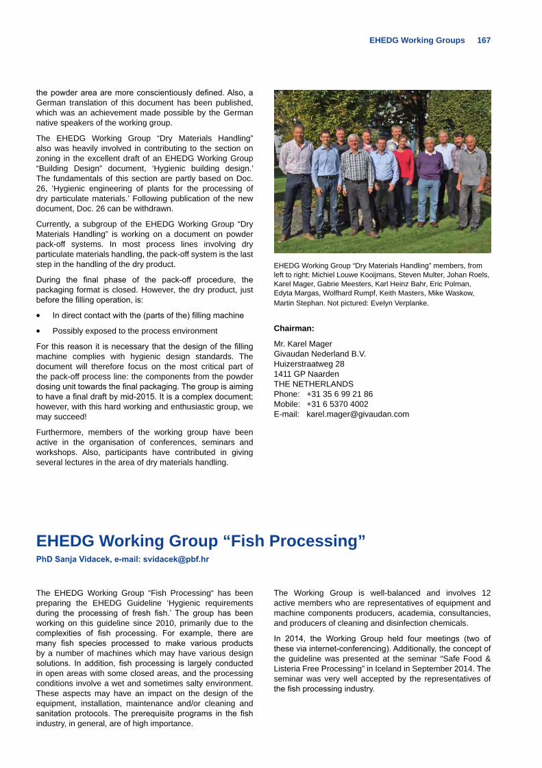
EHEDG Working Groups 167
the powder area are more conscientiously defined. Also, a German translation of this document has been published, which was an achievement made possible by the German native speakers of the working group.
The EHEDG Working Group “Dry Materials Handling” also was heavily involved in contributing to the section on zoning in the excellent draft of an EHEDG Working Group “Building Design” document, ‘Hygienic building design.’ The fundamentals of this section are partly based on Doc. 26, ‘Hygienic engineering of plants for the processing of dry particulate materials.’ Following publication of the new document, Doc. 26 can be withdrawn.
Currently, a subgroup of the EHEDG Working Group “Dry Materials Handling” is working on a document on powder pack-off systems. In most process lines involving dry particulate materials handling, the pack-off system is the last step in the handling of the dry product.
During the final phase of the pack-off procedure, the packaging format is closed. However, the dry product, just before the filling operation, is:
• In direct contact with the (parts of the) filling machine
• Possibly exposed to the process environment
For this reason it is necessary that the design of the filling machine complies with hygienic design standards. The document will therefore focus on the most critical part of the pack-off process line: the components from the powder dosing unit towards the final packaging. The group is aiming to have a final draft by mid-2015. It is a complex document; however, with this hard working and enthusiastic group, we may succeed!
Furthermore, members of the working group have been active in the organisation of conferences, seminars and workshops. Also, participants have contributed in giving several lectures in the area of dry materials handling.
EHEDG Working Group “Dry Materials Handling” members, from left to right: Michiel Louwe Kooijmans, Steven Multer, Johan Roels, Karel Mager, Gabrie Meesters, Karl Heinz Bahr, Eric Polman, Edyta Margas, Wolfhard Rumpf, Keith Masters, Mike Waskow, Martin Stephan. Not pictured: Evelyn Verplanke.
Chairman:
Mr. Karel Mager Givaudan Nederland B.V.Huizerstraatweg 281411 GP NaardenTHE NETHERLANDSPhone: +31 35 6 99 21 86Mobile: +31 6 5370 4002E-mail: [email protected]
EHEDG Working Group “Fish Processing”PhD Sanja Vidacek, e-mail: [email protected]
The EHEDG Working Group “Fish Processing“ has been preparing the EHEDG Guideline ‘Hygienic requirements during the processing of fresh fish.’ The group has been working on this guideline since 2010, primarily due to the complexities of fish processing. For example, there are many fish species processed to make various products by a number of machines which may have various design solutions. In addition, fish processing is largely conducted in open areas with some closed areas, and the processing conditions involve a wet and sometimes salty environment. These aspects may have an impact on the design of the equipment, installation, maintenance and/or cleaning and sanitation protocols. The prerequisite programs in the fish industry, in general, are of high importance.
The Working Group is well-balanced and involves 12 active members who are representatives of equipment and machine components producers, academia, consultancies, and producers of cleaning and disinfection chemicals.
In 2014, the Working Group held four meetings (two of these via internet-conferencing). Additionally, the concept of the guideline was presented at the seminar “Safe Food & Listeria Free Processing” in Iceland in September 2014. The seminar was very well accepted by the representatives of the fish processing industry.
168 EHEDG Working Groups
The guideline involves the following chapters:
• Processing conditions: product properties, steps in fish processing, processing environment
• Hygienic requirements during the processing of fresh fish – equipment
• Hygienic requirements during the processing of fresh fish – processing lines
• Best practices in cleaning and disinfection
• Microbiological sampling
• Procurement process of the equipment
• Assessment based on guideline content
It is anticipated that the EHEDG Working Group “Fish Processing” will have its draft proposal in place in 2015.
Chairman:
PhD Sanja VidacekFaculty of Food Technology and BiotechnologyUniversity of ZagrebPierottijeva 610000 ZagrebCROATIAPhone: +385-91-5119268E-mail: [email protected]
EHEDG Working Group “Food Refrigeration Equipment”Ass. Prof. Kostadin Fikiin, e-mail: [email protected]
A new EHEDG Working Group on Food Refrigeration Equipment was set up in 2013, which actively liaises with other international organisations involved with food refrigeration (such as IIR, IAR, ECSLA, Global Cold Chain Alliance – IARW/WFLO, etc.) in order to integrate state-of-the-art hygienic design solutions in modern refrigeration technologies. The kick-off meeting and the second regular meeting took place in Amsterdam, The Netherlands, on 6 December 2013 and 21 March 2014, respectively. These meetings brought together top experts and key companies in refrigerated food processing across Europe.
EHEDG Working Group “Food Refrigeration Equipment” held its kick-off meeting on 6 December 2013.
These two meetings were attended by representatives of the following companies, universities, institutes and consultancies: Technical University of Sofia, Bulgaria, FRPERC, University Centre Grimsby, UK Norwegian
University of Science and Technology, Norway, KU Leuven, Belgium, JBT FoodTech – Frigoscandia, Sweden, University College Limburg, Belgium, Air Liquide, France, Mayekawa Europe, Belgium, Dybvad Stål Industri, Denmark, StarFrost, UK, Wilyman Technical Services, representing Air Products, UK, Packo Inox, Belgium, Viessmann Kältetechnik, Germany, TÜV SÜD Industrie Service, Germany, Ammeraal Beltech, The Netherlands, Ashworth Belts, The Netherlands, Epta Group, Italy, Unilever, The Netherlands.
Moreover, the abovementioned gatherings were remotely supported by many non-attending professionals of the about 40-member working party, who are keen on contributing to the group’s present and future activities by sharing knowledge and providing professional advice whenever necessary.
Special attention was paid to the first EHEDG Guideline to be produced by the Working Group. This guideline, entitled ‘Hygienic design of processing equipment for chilling and freezing of food,’ focuses on applying adequate hygienic design solutions to advanced food refrigeration (chilling and freezing) technologies. Although the hygienic risks in chilled and frozen food production are of different nature, the industrial chilling and freezing systems possess numerous design similarities, which require a uniform approach. Thus, the document will include common (immersion, multiplate, air blast, fluidised-bed, air impingement and cryogenic) industrial systems for chilling and freezing of solid, semi-solid or liquid products of plant or animal origin (fruits, vegetables, meat, fish and dairy products).
More specifically, the table of contents of the anticipated guideline consists of the following chapters and sections:
EHEDG Working Groups 169
1. Introduction
• Objectives and thematic scope
• Purpose of chilling, freezing and partial freezing
• Need for hygienic design of refrigerated process
• Product-specific hygienic design in relation to risk (physical, chemical, microbiological, allergens, etc.) equipment
2. Overview of industrial chilling and freezing equipment
• Surface top icing
• Systems using immersion in non-boiling liquids orice slurries
• Plate contact systems
• Contact belt systems
• Air blast systems (tunnel, spiral, etc.)
• Fluidised-bed systems
• Air impingement systems
• Water spray systems
• Vacuum systems
• Evaporative systems
• Cryogenic systems (immersion and spraying)
3. Refrigerating media and related hygienic requirements
• Refrigerating media of industrial use: (i) air and gases; (ii) solid substances – ice, dry ice, salt-ice mixtures; (iii) non-boiling liquids (brines, sugar-ethanol solutions, etc); (iv) pumpable ice slurries; (v) cryogens
• Air quality for blast systems
• Liquid quality for immersion or spray systems
• Liquefied gases’ specification for cryogenic systems
• Condensation in air chilling systems
4. Materials of construction and their hygienic design features
• General requirements
• Classification of materials
• Hazard identification
• Product contact area
• Operating temperatures
• Physical and chemical resistance
5. Basic principles of hygienic design and construction
• Surface finish
• Key components of refrigeration plant, such as evaporating coils, fins, drip trays and fans
• Frame and enclosure
• Conveyors and belts
• Covers and guards
• Handles, knobs and locks
• Joints, fastenings and gaskets
• Exhaust pipe and drain outlets
• Control panels and services
• CE standards
6. Hygienic manufacturing of refrigeration equipment
• Welding techniques after polishing
• Machining
• Mixing of materials
• Good hygienic practices of manufacturing
• Traceability of materials of construction and equipment components
7. Proper installation of refrigeration equipment
• Proper positioning for easy access and cleaning
• Suitable piping, ducting, cabling, etc.
• Appropriate platforms, ladders and stairs
• Hygienic design and installation of supplies and services
8. Hygienic operations of refrigeration equipment
• Cleaning and disinfection: objectives; detergents, disinfectants and aromatizers; tools; validation
• Good practices during maintenance operations
9. References
10. Annexes
• Normative references
• Glossary and definitions
• Physical and chemical resistance of thermoplastics
• Physical and chemical resistance of elastomers
• Use of Ingress Protection (IP) ratings
• EU drinking water standards
• Air quality in the food industry
It is anticipated that a complete guideline draft will be prepared and in progress through the third quarter of 2015, with publication in late 2015 or early 2016.
170 EHEDG Working Groups
Two Working Group members, Kostadin Fikiin and Frank Moerman, delivered oral presentations at the 7th Central European Congress on Food (CEFood 2014), 21-24 May 2014, in Ohrid, Macedonia, co-supported by EHEDG, IIR, EFFoST, GHI and EuCheMS. A number of members also took part in the EHEDG World Congress on Hygienic Engineering and Design, held on 30-31 October 2014 in Parma, Italy.
Future Working Group activities and publications will address refrigeration facilities and equipment throughout the entire cold chain for refrigerated processing, warehousing (cold storage), distribution and retail of chilled and frozen food commodities. Novel and emerging food refrigeration technologies and their implications for hygienic engineering and design will be explored as well. In that context, the organisation of a refrigeration-related international conference might be a future target.
The Working Group is still open for new participants. Whether you are representing a large multinational company, а dynamic SME (producing or operating industrial food chilling and freezing systems) or a famous academic and research centre, do not miss the unique chance to become part of this exciting international initiative that is going to shape the future of food refrigeration businesses on both a European and a worldwide scale.
Chairman:
Ass. Prof. Kostadin FikiinRefrigeration Science and TechnologyTechnical University of Sofia8 Kliment Ohridski Blvd.BG-1756 SofiaBULGARIAPhone/Fax: +359 2 965 33 22E-mail: [email protected]
EHEDG Working Group “Heat Treatment”Bengt Eliasson, e-mail: [email protected]
The EHEDG Working Group “Heat Treatment” started in April 2013, tasked with revising two of the first EHEDG guidelines created: Doc. 1, ‘Microbiologically safe continuous pasteurisation of liquid food’ (1992), and Doc. 6, ‘Microbiologically safe continuous flow thermal sterilisation of liquid food’ (1993). The overall aim of these guidelines is to minimise the risk that pasteurised or sterilised product is not safe to consume. The guidelines cover design, operation, process control and monitoring, as well as inspection and maintenance of continuous pasteurisers and sterilisers.
The guidelines are in need of a major revision because the content structure does not reflect recent standards and some of the content is not up to date since it is more than 20 years old. Another issue is that the focus of the guidelines is on milk products only.
The Working Group has 11 active members, with a good mix of participants from equipment manufacturing and food manufacturing. The group is very pleased to have Mr. Huub Lelieveld, one of the original authors and chairman of Doc. 1, in the group.
Timescale to publishThe Working Group holds regular quarterly meetings and is making a good progress. The guidelines will be ready to publish in 2015.
Chairman:
Bengt EliassonManager – Dairy Aseptic SolutionsTetra Pak Processing SolutionsRuben Rausings Gata221 86 LundSWEDENPhone: +46 46 36 55 68Mobile: +46 733 36 55 68E-mail: [email protected]
EHEDG Working Groups 171
EHEDG Working Group “Pumps, Homogenisers and Dampening Devices”Ralf Stahlkopf, e-mail: [email protected]
The EHEDG Pumps, Homogenisers and Dampening Devices Working Group is focused on revising and updating EHEDG Doc. 17. “Hygienic design of pumps, homogenisers and dampening devices.“ This document sets the minimum requirements for pumps, homogenisers and dampening devices for hygienic applications. The scope includes all pumps intended for use in food processing, including centrifugal, piston, lobe, rotor, diaphragm, screw and gear pumps. The requirements also apply to valves integral to the pump head and the complete homogeniser head. Design aspects and the characteristics of materials, surfaces and seals are discussed. The revised and third edition of Doc. 17 was published in April 2013.
The constituent session for a fourth edition is planned in 2015. The following topics are possible:
• Approximation and differences between EHEDG and 3A Sanitary Standards
• Materials (hygienic/unhygienic examples)
• Demarcation between aseptic and hygienic pumps
The Working Group expects that it will take a minimum of eight meetings and up to four years to produce a revised guideline.
Currently, a training DVD is available. The 3rd Edition is available in English and German. As of September 2004, the 2nd Edition is available in French, Italian, Macedonian and Thai.
Chairman:
Ralf StahlkopfGEA Tuchenhagen GmbHAm Industriepark 2-1021514 BüchenGERMANYPhone: +49 4155 49 25 78Fax: +49 4155 48 27 76E-mail: [email protected]
EHEDG Working Group “Seals”Angelika Ruhm, [email protected]
The EHEDG Seals Working Group is developing a EHEDG Guideline that will cover the hygienic aspects of elastomeric seals in equipment used for food processing and packaging. It intends to create awareness of the basic design principles, especially at the interfaces between seals and product contact surfaces.
The choice of the appropriate seal material, which depends on the operating conditions and the behaviour of the material under influence of temperature and pressure, are discussed in the guideline, as well as the effects of media on the seal. It also highlights the general design principles that have to be taken into consideration when designing a sealing point and offers a practical guide to failure analysis.
In conjunction with the EHEDG Working Group “Materials of Construction,” it was decided that EHEDG Guideline Doc. 32, “Materials of construction” describes the properties of elastomers, whereas the EHEDG Guideline on elastomeric seals will focus on the basic seal design and hardware design principles and will discuss the parameters taken into consideration according to the operating conditions. In addition, information is provided for the packaging and storage of seals.
The legislation on rubber products for food and for drinking water is complex. There is no single European standard. The appendix will present a selection of legal rules that must be observed in this segment. The EHEDG Guideline on elastomeric seals will refer to both European and international regulations.
Figures used in the document will represent the problems graphically and will clarify possible solutions.
Chairman:
Angelika Ruhm Freudenberg Process Seals GmbH & Co. KGLorscher Strasse 1369469 WeinheimGERMANYPhone: +49 6201 80 891911Fax: +49 6201 88 891911E-mail: [email protected]
172 EHEDG Working Groups
EHEDG Working Group “Tank Cleaning”The EHEDG Working Group “Tank Cleaning” was established in 2012 to develop a guideline outlining the design of tanks for cleanability and use of cleaning devices. Cleaning tanks is an important part of any cleaning operation in the food industry. This can be a time- and resource-demanding task if not done using the most appropriate tank cleaning technology for the task in hand and if the tank has a poor hygienic design. This new EHEDG guideline sets recommendations for tank and appurtenance design and selection guide for appropriate tank cleaning device.Bo Boye Busk Jensen, Alfa Laval, [email protected]
The objective of the guideline has been discussed by the Tank Cleaning Working Group and is currently written as: “This guideline is intended to provide recommendations on cleaning aspects and hygienic design of vessels. It is limited to product contact surfaces of tanks for liquid processing, both vertical, horizontal and of any arbitrary shape. Excluded are the selection of chemistry and temperature for cleaning specific products.”
The guideline will cover many different aspects related to hygienic design of tanks, appurtenances, the installation of such in tanks, and the cleaning technology applied for cleaning-in-place (CIP) systems. The guideline will focus on how the differences in the choice of tank cleaning technology influence the hygienic design criteria for appurtenances used in and on tanks. The cleaning mechanisms during tank cleaning are somewhat different than those in a closed pipe system, since the tanks are seldom cleaned by a pressurised liquid flowing through the tank, but rather a free falling film or a local high impact cleaning regime (i.e., the wall and appurtenances are not under constant pressure as seen in a pipe system). Also, the category of soil may influence the best value-for-money choice when selecting tank cleaning technology and cleaning strategy. Finally validation of tank cleaning is also included as this is a prerequisite for a satisfactory and consistent cleaning of a tank.
During 2013 and 2014, a total of five Working Group meetings have been held with a total of 47 participants. The participants represent end-users, contractors, hygienic design experts and tank cleaning fabricators. Currently, the content of the guideline is being refined and discussed in the Tank Cleaning Working Group and this work will continue in the near future. If any tank builders are available, their contribution would be highly appreciated.
Chairman:
Bo Boye Busk JensenAlfa Laval Tank Equipment A/SBaldershoej 192635 ISHOEJDENMARKPhone: (+45 43) 55 86 88Fax: (+45 43) 55 86 03E-mail: [email protected]
EHEDG Working Group “Test Methods”Andrew Timperley, e-mail: [email protected]
The EHEDG Test Methods Working Group was one of the first groups established by EHEDG and is responsible for publishing test methods, defining validation criteria and providing assessments of equipment according to the hygienic design criteria of EHEDG in conjunction with administration of the EHEDG Certification Scheme.
2014 has been a year of change within EHEDG, leading to many improvements. These changes also have given opportunities for improvements within the Working Group “Test Methods.” The formation of a focused Sub Committee Products Portfolio has assisted with the formulation of updated and formalised procedures to describe the certification scheme and evaluation processes in more
detail. Consequently, the group’s efforts this year have been concentrated on further refinements to the certification scheme in close liaison with the EHEDG Executive Committee and the Sub Committee Products Portfolio.
The significant updates to the scheme are the creation of a specific certification class for auxiliary components, Type EL CLASS I AUX, production of redesigned logos for placing on the equipment, and the introduction of a formalised re-certification process based on a five-year renewal cycle (Figures 1 and 2).
The generation and publication of additional flow sheets describing the evaluation and certification procedures is also intended to assist the industry in gaining a clearer
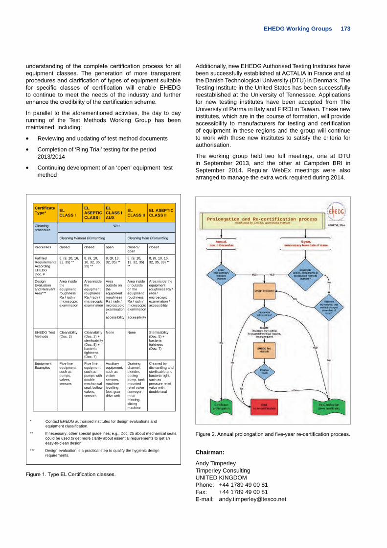
EHEDG Working Groups 173
understanding of the complete certification process for all equipment classes. The generation of more transparent procedures and clarification of types of equipment suitable for specific classes of certification will enable EHEDG to continue to meet the needs of the industry and further enhance the credibility of the certification scheme.
In parallel to the aforementioned activities, the day to day running of the Test Methods Working Group has been maintained, including:
• Reviewing and updating of test method documents
• Completion of ‘Ring Trial’ testing for the period 2013/2014
• Continuing development of an ‘open’ equipment test method
Certificate Type* EL
CLASS I EL ASEPTIC CLASS I
EL CLASS I AUX
EL CLASS II EL ASEPTIC
CLASS II Cleaning procedure Wet
Cleaning Without Dismantling Cleaning With Dismantling Processes closed closed open closed /
open closed Fulfilled RequirementsAccording EHEDG Doc. #
8, (9, 10, 16, 32, 35) ** 8, (9, 10,
16, 32, 35, 39) **
8, (9, 13, 32, 35) ** 8, (9, 10,
13, 32, 35) **
8, (9, 10, 16, 32, 35, 39) **
Design Evaluation and Relevant Area***
Area inside the equipment roughness Ra / radii / microscopic examination
Area inside the equipment roughness Ra / radii / microscopicexamination
Area outside on the equipment roughness Ra / radii / microscopic examination/ accessibility
Area inside or outside on the equipment roughness Ra / radii / microscopicexamination/ accessibility
Area inside the equipment roughness Ra / radii / microscopic examination / accessibility
EHEDG Test Methods Cleanability
(Doc. 2) Cleanability (Doc. 2) + sterilisability (Doc. 5) + bacteria tightness (Doc. 7)
None None Sterilisability (Doc. 5) + bacteria tightness (Doc. 7)
Equipment Examples Pipe line
equipment, such as pumps, valves, sensors
Pipe line equipment, such as pumps with double mechanical seal, bellow valves, sensors
Auxiliary equipment, such as vision sensors, machine levelling feet, gear drive unit
Draining channel, blender, dosing pump, tank mounted relief valve conveyor, meat mincing, slicing machine
Cleaned by dismantling and sterilisable and bacteria-tight, such as pressure relief valve with double seal
* Contact EHEDG authorised institutes for design evaluations and equipment classification.
** If necessary, other special guidelines; e.g., Doc. 25 about mechanical seals, could be used to get more clarity about essential requirements to get an easy-to-clean design.
*** Design evaluation is a practical step to qualify the hygienic design requirements.
Figure 1. Type EL Certification classes.
Additionally, new EHEDG Authorised Testing Institutes have been successfully established at ACTALIA in France and at the Danish Technological University (DTU) in Denmark. The Testing Institute in the United States has been successfully reestablished at the University of Tennessee. Applications for new testing institutes have been accepted from The University of Parma in Italy and FIRDI in Taiwan. These new institutes, which are in the course of formation, will provide accessibility to manufacturers for testing and certification of equipment in these regions and the group will continue to work with these new institutes to satisfy the criteria for authorisation.
The working group held two full meetings, one at DTU in September 2013, and the other at Campden BRI in September 2014. Regular WebEx meetings were also arranged to manage the extra work required during 2014.
Figure 2. Annual prolongation and five-year re-certification process.
Chairman:
Andy TimperleyTimperley ConsultingUNITED KINGDOMPhone: +44 1789 49 00 81Fax: +44 1789 49 00 81E-mail: [email protected]
174 EHEDG Working Groups
EHEDG Working Group “Training and Education”Knuth Lorenzen, e-mail: [email protected]
Background to the subject EHEDG training courses worldwide in local languages require a set of training materials that can be used by authorised EHEDG trainers to pass our uniform message of hygienic design on to all participants. We are running EHEDG training courses in Belgium, Denmark, France, Germany, Japan, Macedonia, Mexico, The Netherlands, Spain, Taiwan, Thailand, United Kingdom and the United States, educating approximately 200 people from the industry every year. This reaches only a limited number of people. Broader dissemination of hygienic design can be achieved by lecturing our modules at the university level. In this way, future engineers are educated early, before they join the industry.
Number of participants/meetings in 2014The Training and Education Working Group has 28 active members who come from universities, faculties, institutes, and consultancies, as well as from food and beverage processing and machinery manufacturing companies. These members offer their expertise and input to accomplish ready-to-use presentation materials, which enable EHEDG trainers to arrange and execute training courses worldwide and university professors to offer hygienic design modules to their students. With the support of the members of the EHEDG regional sections this material has been and will continue to be translated. This makes lecturing in the local languages of the various member countries possible.
To produce this training material we create and deliver easy-to-understand examples in hygienic design for a variety of different process applications. We share our knowledge in our daily work and at our four Working Group meetings every year.
Proposed presentation material contentsThe ready-to-use presentation material, in both visual aids and on DVDs, demonstrates the importance of hygienic engineering and design for improving food process installations and maintenance in order to comply with all legal requirements and to achieve safe food.
The training modules cover the following topics:
• Legal requirements
• Hazards in hygienic processing
• Hygiene design criteria
• Materials of construction
• Welding stainless steel
• Static seals and couplings
• Cleaning and disinfection
• Valves
• Pumps, homogenisers, dynamic seals
• Tank cleaning
• Packaging machines
• Dry materials
• Verification of hygienic design, test methods and certification
• Building and process layout
• Installation and maintenance
• Food grade lubricants
A questionnaire with 47 questions was developed and is used for the participants’ final exam.
Timescale to publishingWe have the full set of training materials ready. This enables us to run the three day Advanced Course in Hygienic Engineering and Design globally.
At present, we are offering the EHEDG training course in the following languages:
• Chinese (Taiwan), English, French, German, Spanish
Modules of the EHEDG training material are used by our authorised EHEDG trainers globally at seminars, symposia, workshops or at universities where EHEDG is involved.
Special serviceAll authorised EHEDG trainers and those participants who have successfully attended the EHEDG Advanced Course in Hygienic Engineering and Design are listed on the EHEDG web page.
Chairman:
Knuth LorenzenEHEDG PresidentFlurstr. 37 21445 WulfsenGERMANY Phone: +49 4173 8364E-mail: [email protected]
EHEDG Working Groups 175
EHEDG Working Group “Valves”Ulf Thiessen, e-mail: [email protected]
The revision time for EHEDG Guideline, Doc. 14, ‘Requirements for valves in hygienic and aseptic processes’ by the EHEDG Working Group “Valves” was extended due to a number of additional topics found during the writing phase. The Working Group decided to reopen the document and to take additional time to make the necessary amendments and supplements. In addition, new and updated art and drawings were added to enhance the readers’ understanding of the hygienic aspects of valves. The final release of the revised Doc. 14 is now scheduled for the end of 2015.
Since 2012, the Working Group “Valves” also has been revising Doc. 20, ‘Hygienic design and safe use of double-seat mixproof valves.’ The original document was initially released in 2000, and as such, the majority of the illustrations and artwork used was a bit behind the state-of-the-art. The Working Group has been working to replace a large number of these illustrations and also to revise the content of the guideline so that it is updated to reflect today’s hygienic standard requirements and technical capabilities of the manufacturing industry.
As predicted in the previous EHEDG Yearbook, it will take some time before the Working Group can enter into the EHEDG Guideline Approval Process with the new edition.
Chairman:
Ulf ThiessenGEA Mechanical EquipmentGEA Tuchenhagen GmbHAm Industriepark 2-10D-21514 BüchenGERMANYPhone: +49 4155 49 2709Mobile: +49 172 4552427E-mail: [email protected]
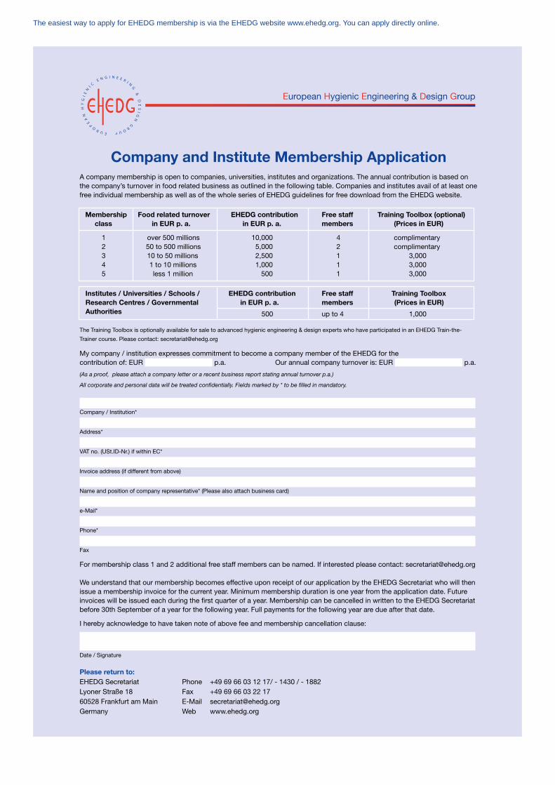
The easiest way to apply for EHEDG membership is via the EHEDG website www.ehedg.org. You can apply directly online.
European Hygienic Engineering & Design Group
Company and Institute Membership ApplicationA company membership is open to companies, universities, institutes and organizations. The annual contribution is based onthe company’s turnover in food related business as outlined in the following table. Companies and institutes avail of at least onefree individual membership as well as of the whole series of EHEDG guidelines for free download from the EHEDG website.
Membership Food related turnover EHEDG contribution Free staff Training Toolbox (optional)class in EUR p. a. in EUR p. a. members (Prices in EUR)
1 over 500 millions 10,000 4 complimentary2 50 to 500 millions 5,000 2 complimentary3 10 to 50 millions 2,500 1 3,0004 1 to 10 millions 1,000 1 3,0005 less 1 million 500 1 3,000
Institutes / Universities / Schools / EHEDG contribution Free staff Training ToolboxResearch Centres / Governmental in EUR p. a. members (Prices in EUR)Authorities 500 up to 4 1,000
The Training Toolbox is optionally available for sale to advanced hygienic engineering & design experts who have participated in an EHEDG Train-the-
Trainer course. Please contact: [email protected]
My company / institution expresses commitment to become a company member of the EHEDG for thecontribution of: EUR p.a. Our annual company turnover is: EUR p.a.
(As a proof, please attach a company letter or a recent business report stating annual turnover p.a.)
All corporate and personal data will be treated confidentially. Fields marked by * to be filled in mandatory.
Company / Institution*
Address*
VAT no. (USt.ID-Nr.) if within EC*
Invoice address (if different from above)
Name and position of company representative* (Please also attach business card)
e-Mail*
Phone*
Fax
For membership class 1 and 2 additional free staff members can be named. If interested please contact: [email protected]
We understand that our membership becomes effective upon receipt of our application by the EHEDG Secretariat who will thenissue a membership invoice for the current year. Minimum membership duration is one year from the application date. Future invoices will be issued each during the first quarter of a year. Membership can be cancelled in written to the EHEDG Secretariatbefore 30th September of a year for the following year. Full payments for the following year are due after that date.
I hereby acknowledge to have taken note of above fee and membership cancellation clause:
Date / Signature
Please return to:EHEDG Secretariat Phone +49 69 66 03 12 17/ - 1430 / - 1882Lyoner Straße 18 Fax +49 69 66 03 22 1760528 Frankfurt am Main E-Mail [email protected] Web www.ehedg.org
150561_EHEDG_Mitgliedsformulare_k4_Mitgliedsformulare 02.09.14 17:13 Seite 2
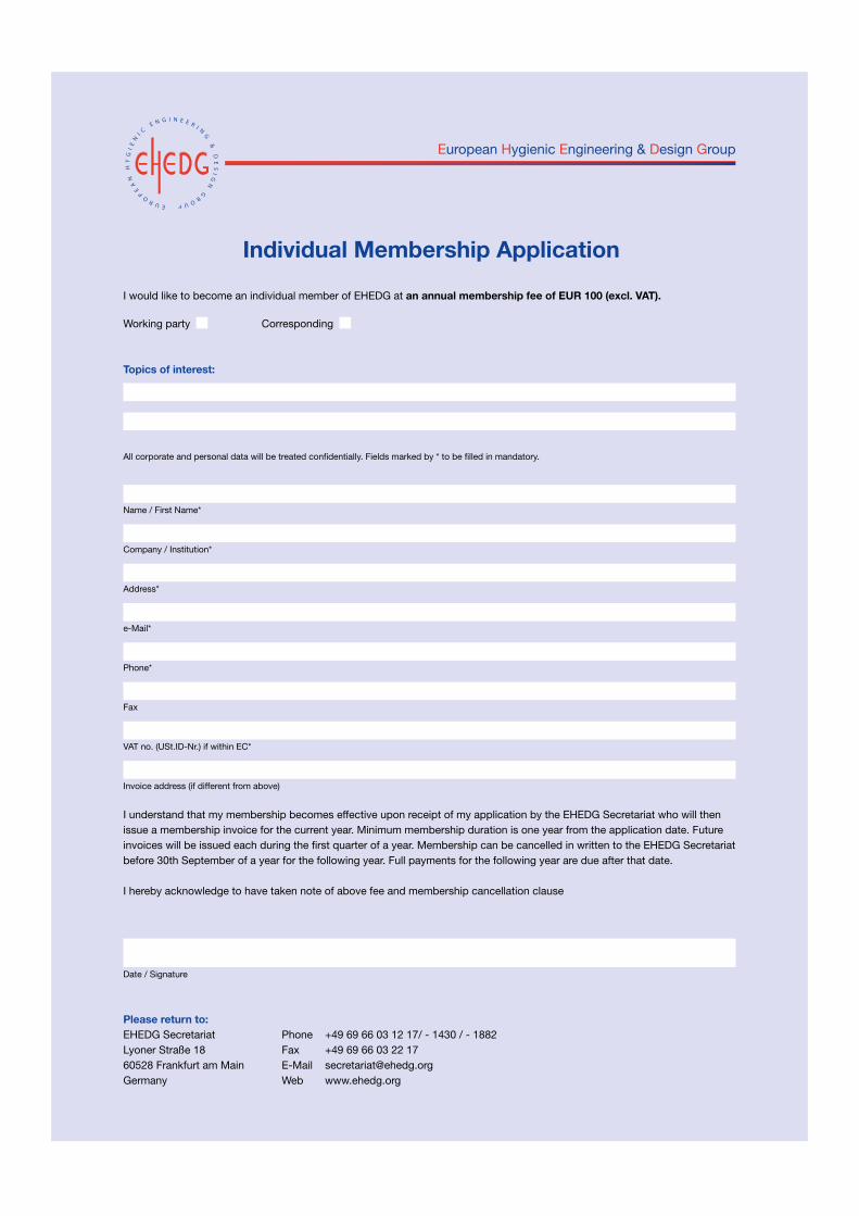
European Hygienic Engineering & Design Group
Individual Membership ApplicationI would like to become an individual member of EHEDG at an annual membership fee of EUR 100 (excl. VAT).
Working party Corresponding
Topics of interest:
All corporate and personal data will be treated confidentially. Fields marked by * to be filled in mandatory.
Name / First Name*
Company / Institution*
Address*
e-Mail*
Phone*
Fax
VAT no. (USt.ID-Nr.) if within EC*
Invoice address (if different from above)
I understand that my membership becomes effective upon receipt of my application by the EHEDG Secretariat who will thenissue a membership invoice for the current year. Minimum membership duration is one year from the application date. Future invoices will be issued each during the first quarter of a year. Membership can be cancelled in written to the EHEDG Secretariatbefore 30th September of a year for the following year. Full payments for the following year are due after that date.
I hereby acknowledge to have taken note of above fee and membership cancellation clause
Date / Signature
Please return to:EHEDG Secretariat Phone +49 69 66 03 12 17/ - 1430 / - 1882Lyoner Straße 18 Fax +49 69 66 03 22 1760528 Frankfurt am Main E-Mail [email protected] Web www.ehedg.org
150561_EHEDG_Mitgliedsformulare_k4_Mitgliedsformulare 02.09.14 17:13 Seite 1
European Hygienic Engineering & Design Group
Published byEHEDG European Hygienic Engineering and Design GroupLyoner Str. 1860528 FrankfurtGERMANY
ISBN978-3-8163-0667-2
Publishing HouseVDMA Verlag GmbHLyoner Str. 1860528 FrankfurtGERMANY
PrintingFranz Kuthal GmbH & Co. KGJohann-Dahlem-Str. 5463814 MainaschaffGERMANY
Executive Editor Julie M. BricherQuiddity Communications, Inc.677 SW Tanglewood CircleMcMinnville, OR 97128UNITED STATES OF AMERICA
Copy EditorJohanna Todsen EHEDG SecretariatFrankfurtGERMANY
Editorial BoardDr. John Holah, Holchem Laboratories Ltd., UNITED KINGDOMDr. Johan Innings, Tetra Pak, Packaging Solutions AB, SWEDENKnuth Lorenzen, Wulfsen, GERMANYDr. Keith Masters, SparyDryConsult, DENMARKDirk Nikoleiski, Mondelez International, GERMANYTracy Schonrock, 3-A Sanitary Standards, UNITED STATES OF AMERICA
CopyrightCopyright rests with EHEDG. All rights reserved.
The copyright of the pictures and illustrations within the articles belongs to the authors, respectively the companies or institutes they represent unless otherwise stated.
IllustrationsCover:1. Jürgen Löhrke GmbH, D-Lübeck,
www.LOEHRKE.com2. Marel, NL-Boxmeer, www.marel.com3. Magnetrol International NV, B-Zele,
www.magnetrol.com4. Aviatec, DK-Nørresundby, www.aviatec.dk 5. Polysoude S.A.S., F-Nantes, www.polysoude.com6. GEORGII KOBOLD GmbH & Co. KG,
D-Horb am Neckar, www.georgii-kobold.de7. Freudenberg Process Seals GmbH & Co.KG
D-Weinheim, www.fst.com8. ACO Group, CZ- Přibyslav,
www.aco-buildingdrainage.com
ContactEHEDG Secretariat Lyoner Str. 1860528 Frankfurt GERMANYPhone (+49 69) 66 03-12 17 / - 1430 / - 1882 FAX (+49 69) 66 03-22 17E-mail: [email protected]: www.ehedg.org

EHEDG SecretariatLyoner Strasse 18 60528 Frankfurt am MainGermany
Phone +49 69 6603-1217 /-1430 /-1882Fax +49 69 6603-2217 /-2430 /-2882E-mail [email protected] www.ehedg.org
ISBN 978-3-8163-0667-2