economical simply supported reinforced concrete
TRANSCRIPT
ISSN(Online) : 2319-8753 ISSN (Print) : 2347-6710
International Journal of Innovative Research in Science, Engineering and Technology
(An ISO 3297: 2007 Certified Organization)
Website: www.ijirset.com
Vol. 6, Issue 3, March 2017
Copyright to IJIRSET DOI:10.15680/IJIRSET.2017.0603001 3101
Economical Simply Supported Reinforced Concrete Rectangular Beam Design
Using STAAD Pro
Talib Abdul Jabbar AL-Eyssawi Lecturer, Babylon Technical Institute, Al-Furat Alawsat Technical University, Babylon, Republic of Iraq
ABSTRACT: This study aims to minimize the cost of simply supported reinforced concrete(RC) rectangular beam and approach the economical beam design which has total cost close to lowest value for that beam, with a standardbeam cross section. The total cost of beam includes cost of concrete, reinforcement, and formwork, whereas the stirrups cost incorporated in the reinforcement cost. The design variables considered in this study are the loading, width of beam, height to width ratio, length of beam, compressive strength of concrete, unit cost of concrete and unit cost of formwork. STAAD Pro which is one of widespread engineering software for structural analysis and design has been used to design the beams for moment and shear. All calculations are done based on elastic analysis and the ultimate strength method of design as per ACI 318M-14 code requirements. The results of economical beams total costs database indicate that the average cost ratio of concrete, reinforcement and formwork to total cost are 32%, 32% and 36% respectively, whereas stirrups cost constitutes 9% of the total cost. Economical beam design can be attained from several iterations in total cost calculations, and more attempts for section dimensions of the beam provide more economical beam design.Numerical equations for the economical beam deign have been developed and can be used swiftly to estimate the beam width and height without prior understanding of optimization. KEYWORDS: Economical Beam, Cost, Simply Supported Beam, Reinforced Concrete, Design for Moment and Shear, STAAD Pro
NOTATIONS
Af = area of formwork, m2 Av = minimum area of shear reinforcement, mm2 푏 = width of beam, mm 푏w = web width, mm Cc = cost of concrete, US$ Cf = cost of formwork, US$ Cs = cost of steel reinforcement, US$ Ct = total cost of the beam, US$ ct = total cost per unit length of the beam, US$/m F = moment factor 푓 = specified compressive strength of concrete, MPa 푓 = specified yield strength of reinforcement, MPa
ISSN(Online) : 2319-8753 ISSN (Print) : 2347-6710
International Journal of Innovative Research in Science, Engineering and Technology
(An ISO 3297: 2007 Certified Organization)
Website: www.ijirset.com
Vol. 6, Issue 3, March 2017
Copyright to IJIRSET DOI:10.15680/IJIRSET.2017.0603001 3102
fyt =specified yield strength of transverse reinforcement, MPa
h = height of beam (total depth), mm l = span length of beam, m Me = external ultimate bending moment, kN.m Mu = ultimate bending moment, kN.m RC = Reinforced Concrete s =spacing of stirrups, mm Sc = complete section modulus (bh2), mm3 Uc = unit cost of concrete, US$/m3 Uf = unit cost of formwork, US$/m2 Us = unit cost of steel reinforcement, US$/kg Vc = nominal shear strength of concrete, N Vco = volume of concrete, m3 Vs = nominal shear strength of shear reinforcement, N Vu = ultimate shear strength, N Ws = weight of steel reinforcement, kg Wls = weight of longitudinal steel reinforcement, kg Wts = weight of transverse steel reinforcement (stirrups), kg wd = unfactored dead load per unit length of the beam, kN/m wl = unfactored live load per unit length of the beam, kN/m ϕ =strength reduction factor, which is equal 0.90 for bending with tension controlled or equal 0.75 for shear ρ =ratio of Ast to bd ρw =ratio of Ast to bwd 휖 = maximum usable strain at extreme concrete compression fiber 휖 = net tensile strain in extreme layer of longitudinal tension reinforcement at nominal strength
I. INTRODUCTION Economy plays an important role in the chosen of reinforced concrete (RC) for construction of buildings and other projects [1]. Through the last few decades there is emphasis on the economyand aesthetics of structural design, so that to ensure the cost of the structure may not be exorbitant and far from aesthetics [2]. Cost indicators are important during the design phase to minimize the construction cost, asthe RC elements represent about one third of the total cost of the construction [3]. Optimal sizing and reinforcing for beam and columnmembers in RC structures results in cost savings over typical-practice design solutions[4]. As noted in the earlier literature, the structural design should satisfy the design codes requirements, and the optimum design is an iterative technique and economic design[5]. Different studies have been study the optimum design of RC beams using different mathematical software programs[4, 5, 6, 7, 8, 9, 10, 11…etc]. The economical beam design can be obtained for shorter beams (up to 25 ft or around 7.5 m) when the ratio d/b is in the range of 1.5 to 2. For longer beams, better economy is usually found if deep, narrow sections are used with d/bin the range of 3 to 4[12].
ISSN(Online) : 2319-8753 ISSN (Print) : 2347-6710
International Journal of Innovative Research in Science, Engineering and Technology
(An ISO 3297: 2007 Certified Organization)
Website: www.ijirset.com
Vol. 6, Issue 3, March 2017
Copyright to IJIRSET DOI:10.15680/IJIRSET.2017.0603001 3103
For different spans of singly RC beams in the range of 4 m to 32 m, uniformly distributed live load of 25 kN/m, steel reinforcement of grade M60 and different grades of concrete, there is small change in the cost when the d/b is 1.5 to 2.5,but the ratio of 2.5 gives the most economical beam design[11]. It is recommended to use beams with h/b in the range of 1.5 to 2 [2, 13]. It may be higher( up to 3 or even more) for beams subjected to heavy loads. Increasing the height of the beam is always useful to improve moment resisting capacity,flexural stiffness, and hence, less deflections, curvatures and crack-widths[2]. Increasing the concrete section of the beam may save the steel and the beam will be more economical and would be preferred, except beam section dimensions must be minimized for architectural or functional reasons[14]. Steel is quite expensive [12], and using over-reinforcing will lead to uneconomical beam design[15].For economical beam design, the reinforcement ratios will typically vary between 50% ρmax and 75% ρmax [14],whereas this ratios vary between 50% ρmaxand 67% ρmax[16], so that to keep the concrete strain at or above the tension-controlled limit of 0.005. For optimum cost of beams subjected to external bending moment of 300, 500, 700 and 900 kN.m, f = 25 MPa and fy = 400 MPa, the recommended reinforcement ratio was found in the range of 0.01 to 0.02 with an average of 0.015. The study used STAAD III software and Excel spread sheet to calculate the total cost of beams including concrete unit price and steel unit price[3]. Formwork constitutes about 40% [17], and can be as high as 60% of total cost of a cast-in place concrete structure.For this reason it is important to create a structural system that will minimize the cost of formwork, and it is essential that costs of formwork to be included in the cost evaluation of concrete structural frames. [18]. Formwork cost can be reduced through reusing the same forms from area to area and floor to floor. It is usually uneconomical to use least amount of concrete and steel by exactly calculating the size of everybeam and column to fit the loads exactly. Furthermore, changing section sizes often leads to increased design complexity and consequentlyerror through construction. Economic structure can be achieved by adopting the design requirements and saving the time of design and construction [16]. Economical beam design should be based on cost of the beam rather than its weight optimization [5, 19, 20], as the weight constitutes a significant part of the cost [21].Also, the unit costs of concrete, steel, and formwork play a significant role in determining of the optimumbeam and column section dimensions[22]. The beams database [23] were studied using different unit costs of concrete, steel and formwork of 105 $/m3, 0.9 $/kg and 92 $/m2 respectively to make the total cost component theminimum based on two meta-heuristic algorithms using Matlab software [24]. Also, beams database were studied using different unit costs of concrete, steel and formwork of 100 $/m3, 1 $/kg and 25 $/m2 respectively in the first case, 110 $/m3, 2.1 $/kg and 27 $/m2, respectively in the second case to minimize the beam total cost based on the harmony search algorithm using Fortran programming language [22]. As the optimum section will not necessarilyprovide anoptimum design for theentire structure [5, 25], and using uniform width and depth of beams throughout the frame [16] or may be through the building [18] has been recommended for economy, this study has been performed in order to minimize the cost of simply supported RC rectangular beam and approach swiftly the economical beam design without prior understanding of optimization by using a wide range of unit costs of concrete and formwork. STAAD Pro software [26] and EXCEL spreadsheet [12] have been used for the calculations based on the elastic analysis and the ultimate strength method of design as per ACI 318M-14 code requirements for moment and shear [27].STAADPro software is one of the popular and widespread structural software program [28], very easy to learn and work, accurate for both analysis and design practically all types of structures, more preferred because of its flexibility and ease of workabilityused to find the shear forces, bending moments, deflections and reinforcement details for the

ISSN(Online) : 2319-8753 ISSN (Print) : 2347-6710
International Journal of Innovative Research in Science, Engineering and Technology
(An ISO 3297: 2007 Certified Organization)
Website: www.ijirset.com
Vol. 6, Issue 3, March 2017
Copyright to IJIRSET DOI:10.15680/IJIRSET.2017.0603001 3104
structural components of building (such asbeams, columns&slabs) to develop the economic design [29].StaadPro software has been used to determine iteratively [30] the total cost of different simply supported RC rectangular beams.
II. SCOPE AND METHODOLOGY
A. OBJECTIVE This study aims to minimize the cost of simply supported RC rectangular beam and approach the economical beam design which has total cost per unit length of the beam [20, 31] close to lowest value for that beam, with a standard beam cross section and without prior understanding of optimization. The total cost of beam includes cost of concrete, reinforcement, and formwork, whereas the stirrups cost incorporated in the reinforcement cost. Total cost of beam includes material, labor and equipment costs of concrete, reinforcement, formwork, overhead and profit [4, 7]. The total cost per unit length can be calculated by the following equations, Ct=Cc + Cs + Cf(1a ) Ct=Vco . Uc+ Ws . Us+ Af . Uf(1b ) Ct=(b . h . l) Uc+ (Wls+ Wts) Us+ l (b+2h) Uf(1c ) ct= Ct/ l(1d ) B. FORMULATION OF THE PROBLEM B.1 SOLUTION PROCEDURE Both longitudinal and transverse reinforcement (stirrups) of each beam can be found by using STAAD Pro structural software in design the beams. All calculations are done based on elastic analysis and the ultimate strength method of design as per ACI 318M-14 code requirements for moment and shear. B.2 DESIGN VARIABLES The various variables considered in this study are the loadings (wd and wl), width of beam (b), height to widthratio (h/b), length of beam (l), compressive strength of concrete (푓 ), unit cost of concrete (Uc) and unit cost of formwork(Uf). B.3 DESIGN FOR MOMENT The ACI code provides two factors of safety, one is called the load factors and equal to 1.2 and 1.6 for dead and live load respectively, and the other is called the strength reduction factor (ϕ). The strength reduction factor (ϕ) varies from 0.90 to o.65.Applying the conditions of equilibrium and compatibility of strains with maximum concrete compressive strain at crushing of the concrete equal to (ϵc=0.003) and other assumptions of the code fortension controlled beams where the strength reduction factor (ϕ) is equal 0.90 [14, 30],
푎 =.
(2)
Mu =0.9퐴 푓 ( d − )(3)
The limitation of the area of tension reinforcement (As) for the maximum reinforcement ratio and the minimum reinforcement ratio is given by:
ISSN(Online) : 2319-8753 ISSN (Print) : 2347-6710
International Journal of Innovative Research in Science, Engineering and Technology
(An ISO 3297: 2007 Certified Organization)
Website: www.ijirset.com
Vol. 6, Issue 3, March 2017
Copyright to IJIRSET DOI:10.15680/IJIRSET.2017.0603001 3105
ρmax(ϵs=0.005) = 0.31875β1 (4)
ρmin =.
≥ .
(5)
where β1is equal to 0.85 for 푓 up to and including 28 MPaand 0.05 less for each 7 MPa of strength in excess of 28 MPa, but β1 shall not be taken less than 0.65. Also, thestrains of concrete and steelare (휖 = 0.003)and(휖푠 =0.005)respectively.
For 푓 equals 21, 24 and 28MPa and 푓 equals 420 MPa which are widely used and studied in the following numerical examples, the tension reinforcement ratio (ρ) should satisfy the following constraints for the maximum reinforcement ratio and the minimum reinforcement ratio [12, 32]:
0.0033 ≤ ρ ≤ 0.0135 for 푓 equals 21 MPa(6a)
0.0033 ≤ ρ ≤ 0.0155 for 푓 equals 24MPa(6b)
0.0033 ≤ ρ ≤ 0.0181 for 푓 equals 28MPa(6c)
where ρ is equal to:
ρ =
(7)
B.4 DESIGN FOR SHEAR The ACI code provides larger safety factor (ϕ) against shear failure than that provided for bending to have ductile members with warning of sudden failure [12].
The ultimate shear strength (Vu) is consisting of shear strength of concrete (ϕVc) and shear strength of shear reinforcement (ϕVs):
Vu = ϕVc + ϕVs(8)
The ACI code provides the following requirements in the Eqs. (9) through (13) for shear design :
The concrete shear force (Vc) shall be calculated by:
Vc = 0.17 푓 bw d (9)
For more detailed calculation, the least of following equations can be taken to calculate the shear strength of concrete (Vc) for normal weight of concrete:
ISSN(Online) : 2319-8753 ISSN (Print) : 2347-6710
International Journal of Innovative Research in Science, Engineering and Technology
(An ISO 3297: 2007 Certified Organization)
Website: www.ijirset.com
Vol. 6, Issue 3, March 2017
Copyright to IJIRSET DOI:10.15680/IJIRSET.2017.0603001 3106
Vc = (0.16 푓 +17ρw
) bw d(10.a)
Vc = ( 0.16 푓 + 17 ρw ) bw d (10.b)
Vc = 0.29 푓 bw d (10.c)
The minimum area of shear reinforcement (Av,min) shall be provided using stirrups in all regions where:
Vu> 0.5 ϕ Vc(11)
To avoid brittle failure [33], the ACI code stipulates the minimum area of shear reinforcement (Av,min) shall be satisfied the greater of:
Av,min= 0.062 푓 푏푤푠푓푦푡
(12.a)
Av,min= 0.35
(12.b)
Also, the ACI code stipulates the maximum spacing of stirrups (s) shall be :
For Vs ≤ 0.33 푓 푏 푑, the least of d/2nor 600 mm(13.a)
For Vs ≥ 0.33 푓 푏 푑 , the least of d/4 nor 300 mm (13.b)
Whereas, the theoretical spacing of stirrups (s) can be calculated by the following equation [12]:
Theoretical s =
(14)
III. NUMERICAL EXAMPLES
A. SELECTION OF BEAMS
A series of 2880 beams database with different variables are selected to investigate the simply supported RC rectangular beamtotal cost per unit lengthand approach the economical beam design. Various variables are deemed in this study as shown in Table (1).

ISSN(Online) : 2319-8753 ISSN (Print) : 2347-6710
International Journal of Innovative Research in Science, Engineering and Technology
(An ISO 3297: 2007 Certified Organization)
Website: www.ijirset.com
Vol. 6, Issue 3, March 2017
Copyright to IJIRSET DOI:10.15680/IJIRSET.2017.0603001 3107
Table (1) – Range of variables
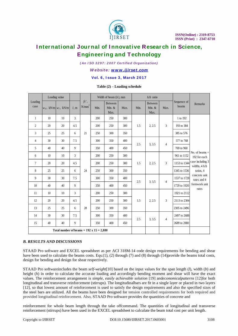
The loading schedule for all beams is clarified in Table (2), where the unfactored dead load (wd) and unfactored live load (wl) are 10 kN, 20 kN, 25 kN, 30 kN and 40 kN, the standard widths (b) are 200 mm, 250 mm, 300 mm, 350 mm, 400 mm and 450 mm, the height to width ratios (h/b) are (1.5, 2.0, 2.5 and 3.0) and (2.5, 3.0, 3.5 and 4.0) for shorter beams of length (3.0 m, 4.5 m, 6 m) and longer beams of length (7.5 m, 9 m) respectively, and concrete strengths are 21, 24 and 28 MPa.
All beams heights (h) are selected in such a way that satisfy the serviceability requirements of the ACI code for deflection. For all beams, the yield stress of steel (푓 ), clear cover of reinforcement, unit weight of RC, unit weight of steel reinforcement, cost of reinforcement (Us) are 420 MPa, 40 mm [20, 24], 24 kN/m3 [4, 12], 7850 kg/m3 [3, 31] and 1 US$/kg [22] respectively. The sizes of the longitudinal bars are : 12mm, 16mm, 20mm, 25mm and 32mm , while the size of transverse bar (stirrups) is 10 mm, which are commonly used and available at the market.
Min. Between Min. & Max.
Max.
w d , kN/m 10 20, 25, 30 40
w l , kN/m 10 20, 25, 30 40
b , mm 200250, 300, 350,
400450
Three widths for each case as shown in Table 2
h / b ratio 1.5 2, 2.5, 3, 3.5 4
Four h/b ratios for each case, h varies from 300 to 1800 mm, all h values satisfy the Code requirement for deflection
l , m 3 4.5, 6, 7.5 9 5 Shorter and longer beams
fc' , N/mm2 21 24 28 3 Normal strength concretes [12]
80 100, 120 140Unit cost for concrete of fc' = 21 N/mm2
90 110, 130 150Unit cost for concrete of fc' = 24 N/mm2
100 120, 140 160Unit cost for concrete of fc' = 28 N/mm2
Unit cost of formwork (U f ),
US$/m25 10, 20 30 4
2,880Total number of var. (beams) = 12 x 5 x 3 x 4 x 4
TypeValues
RemarksNumber
Two uniform loadings are applied each case as shown in Table 2
12
Unit cost of concrete (U c ),
US$/m34
ISSN(Online) : 2319-8753 ISSN (Print) : 2347-6710
International Journal of Innovative Research in Science, Engineering and Technology
(An ISO 3297: 2007 Certified Organization)
Website: www.ijirset.com
Vol. 6, Issue 3, March 2017
Copyright to IJIRSET DOI:10.15680/IJIRSET.2017.0603001 3108
Table (2) – Loading schedule
B. RESULTS AND DISCUSSIONS
STAAD Pro software and EXCEL spreadsheet as per ACI 318M-14 code design requirements for bending and shear have been used to calculate the beams costs. Eqs.(1), (2) through (7) and (8) through (14)provide the beams total costs, design for bending and design for shear respectively. STAAD Pro softwareincludes the beam self-weight[10] based on the input values for the span length (l), width (b) and height (h) in order to calculate the accurate loading and accordingly bending moment and shear will have the exact values. The reinforcement arrangement is simple, easily achievable solution [19] andeconomicalpatterns [12]for both longitudinal and transverse reinforcement (stirrups). The longitudinalbars are fit in a single layer or placed in two layers [12], so that lowest amount of reinforcement is used to satisfy the design requirements and also the specified sizes of the steel bars are utilized. All the beams have been designed for tension controlled requirements for both required and provided longitudinal reinforcement. Also, STAAD Pro software provides the quantities of concrete and reinforcement for whole beam length through the take offcommand. The quantities of longitudinal and transverse reinforcement (stirrups) have been used in the EXCEL spreadsheet to calculate the beam total cost per unit length.
w d , kN/m w l , kN/m l , m Min.Between Min. & Max.
Max. Min.Between Min. & Max.
Max.
1 10 10 3 200 250 300 1 to 192
2 20 20 4.5 200 250 300 193 to 384
3 25 25 6 250 300 350 385 to 576
4 30 30 7.5 300 350 400 577 to 768
5 40 40 9 350 400 450 769 to 960
6 10 10 3 200 250 300 961 to 1152
7 20 20 4.5 200 250 300 1153 to 1344
8 25 25 6 250 300 350 1345 to 1536
9 30 30 7.5 300 350 400 1537 to 1728
10 40 40 9 350 400 450 1729 to 1920
11 10 10 3 200 250 300 1921 to 2112
12 20 20 4.5 200 250 300 2113 to 2304
13 25 25 6 250 300 350 2305 to 2496
14 30 30 7.5 300 350 400 2497 to 2688
15 40 40 9 350 400 450 2689 to 2880
2.5 3, 3.5 4
28
1.5 2, 2.5 3
2.5 3, 3.5 4
2.5
24
1.5 2, 2.5 3
Width of beam (b ), mm
RemarksLoading case
Total number of beams = 192 x 15 = 2,880
Sequence of beams
Loading value h/b ratiofc' ,
N/mm2
21
1.5 2, 2.5 3
43, 3.5
No. of beams = 192 for each
case including 3 widths, 4 h/b
ratios, 4 concrete unit rates and 4
formwork unit rates
ISSN(Online) : 2319-8753 ISSN (Print) : 2347-6710
International Journal of Innovative Research in Science, Engineering and Technology
(An ISO 3297: 2007 Certified Organization)
Website: www.ijirset.com
Vol. 6, Issue 3, March 2017
Copyright to IJIRSET DOI:10.15680/IJIRSET.2017.0603001 3109
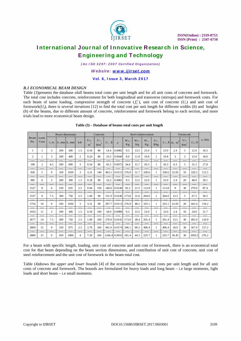
B.1 ECONOMICAL BEAM DESIGN Table (3)presents the database ofall beams total costs per unit length and for all unit costs of concrete and formwork. The total cost includes concrete, reinforcement for both longitudinal and transverse (stirrups) and formwork costs. For each beam of same loading, compressive strength of concrete (푓 ), unit cost of concrete (Uc) and unit cost of formwork(Uf), there is several iterations [12] to find the total cost per unit length for different widths (b) and heights (h) of the beams, due to different amount of concrete, reinforcement and formwork belong to each section, and more trials lead to more economical beam design.
Table (3) – Database of beams total costs per unit length
For a beam with specific length, loading, unit cost of concrete and unit cost of formwork, there is an economical total cost for that beam depending on the beam section dimensions, and contribution of unit cost of concrete, unit cost of steel reinforcement and the unit cost of formwork in the beam total cost. Table (4)shows the upper and lower bounds [4] of the economical beams total costs per unit length and for all unit costs of concrete and formwork. The bounds are formulated for heavy loads and long beam – i.e large moments, light loads and short beam – i.e small moments.
l , m b , mm h , mm h/bV co ,
m3 U c ,
$/m3 C c ,$ ρW ls , Kg
W ts , Kg
W s , Kg
U s , $/kg
C s , $ A f , m2 U f ,
$/m2 C f , $
1 1 3 200 300 1.5 0.18 80 14.4 0.0082 9.5 13.5 23.0 1 23.0 2.4 5 12.0 16.5
2 1 3 200 400 2 0.24 80 19.2 0.0040 8.0 11.8 19.8 1 19.8 3 5 15.0 18.0---- ---- ---- ---- ---- ---- ---- ---- ---- ---- ---- ---- ---- ---- ---- ---- ---- ---- ----196 2 4.5 200 600 3 0.54 80 43.2 0.0075 34.6 15.7 50.3 1 50.3 6.3 5 31.5 27.8---- ---- ---- ---- ---- ---- ---- ---- ---- ---- ---- ---- ---- ---- ---- ---- ---- ---- ----926 5 9 350 1050 3 3.31 140 463.1 0.0115 276.9 51.7 328.6 1 328.6 22.05 10 220.5 112.5---- ---- ---- ---- ---- ---- ---- ---- ---- ---- ---- ---- ---- ---- ---- ---- ---- ---- ----985 6 3 200 300 1.5 0.18 90 16.2 0.0081 9.5 13.5 23.0 1 23.0 2.4 20 48.0 29.1---- ---- ---- ---- ---- ---- ---- ---- ---- ---- ---- ---- ---- ---- ---- ---- ---- ---- ----
1527 8 6 250 625 2.5 0.94 150 140.6 0.0140 92.3 21.5 113.8 1 113.8 9 30 270.0 87.4---- ---- ---- ---- ---- ---- ---- ---- ---- ---- ---- ---- ---- ---- ---- ---- ---- ---- ----
1537 9 7.5 300 750 2.5 1.69 90 151.9 0.0146 173.0 31.0 204.0 1 204.0 13.5 5 67.5 56.5---- ---- ---- ---- ---- ---- ---- ---- ---- ---- ---- ---- ---- ---- ---- ---- ---- ---- ----
1754 10 9 350 1050 3 3.31 90 297.7 0.0113 276.9 48.2 325.1 1 325.1 22.05 20 441.0 118.2---- ---- ---- ---- ---- ---- ---- ---- ---- ---- ---- ---- ---- ---- ---- ---- ---- ---- ----
1933 11 3 200 300 1.5 0.18 100 18.0 0.0080 9.5 13.5 23.0 1 23.0 2.4 10 24.0 21.7---- ---- ---- ---- ---- ---- ---- ---- ---- ---- ---- ---- ---- ---- ---- ---- ---- ---- ----
2677 14 7.5 300 750 2.5 1.69 160 270.0 0.0142 173.0 28.4 201.4 1 201.4 13.5 30 405.0 116.9---- ---- ---- ---- ---- ---- ---- ---- ---- ---- ---- ---- ---- ---- ---- ---- ---- ---- ----
2869 15 9 350 875 2.5 2.76 160 441.0 0.0174 346.1 60.3 406.4 1 406.4 18.9 30 567.0 157.2---- ---- ---- ---- ---- ---- ---- ---- ---- ---- ---- ---- ---- ---- ---- ---- ---- ---- ----
2880 15 9 450 1800 4 7.29 160 1166.4 0.0033 181.4 44.3 225.7 1 225.7 36.45 30 1093.5 276.2
Beam dimensions Concrete Steel reinforcement Formwork
ct, $/mBeam No.
Load. Case

ISSN(Online) : 2319-8753 ISSN (Print) : 2347-6710
International Journal of Innovative Research in Science, Engineering and Technology
(An ISO 3297: 2007 Certified Organization)
Website: www.ijirset.com
Vol. 6, Issue 3, March 2017
Copyright to IJIRSET DOI:10.15680/IJIRSET.2017.0603001 3110
Table (4) – Upper and lower bounds of economical beams total costs per unit length
Table (5)shows the cost ratio of concrete, reinforcement, formwork and stirrups to total cost can be up to 44%, 48%, 60% and 27% while the average cost ratio are 32%, 32%, 36% and 9% respectively whereas the stirrups cost is a part of steel cost , for concrete unit costs in the range of 80 $/m3 to 160 $/m3 and formwork unit costs in the range of 5 $/m2 to 30 $/m2.
l , m b , mm h , mm h/bV co ,
m3
U c ,
$/m3 C c ,$ ρW ls , Kg
W ts , Kg
W s , Kg
U s , $/kg
C s , $ A f , m2 U f ,
$/m2 C f , $
1 1 3 200 300 1.5 0.18 80 14.4 0.0082 9.5 13.5 23.0 1 23.0 2.4 5 12.0 16.5---- ---- ---- ---- ---- ---- ---- ---- ---- ---- ---- ---- ---- ---- ---- ---- ---- ---- ----181 1 3 200 300 1.5 0.18 140 25.2 0.0082 9.5 13.5 23.0 1 23.0 2.4 30 72.0 40.1---- ---- ---- ---- ---- ---- ---- ---- ---- ---- ---- ---- ---- ---- ---- ---- ---- ---- ----770 5 9 350 1050 3 3.31 80 264.6 0.0115 276.9 51.7 328.6 1 328.6 22.05 5 110.3 78.2---- ---- ---- ---- ---- ---- ---- ---- ---- ---- ---- ---- ---- ---- ---- ---- ---- ---- ----950 5 9 350 1050 3 3.31 140 463.1 0.0115 276.9 51.7 328.6 1 328.6 22.05 30 661.5 161.5---- ---- ---- ---- ---- ---- ---- ---- ---- ---- ---- ---- ---- ---- ---- ---- ---- ---- ----961 6 3 200 300 1.5 0.18 90 16.2 0.0081 9.5 13.5 23.0 1 23.0 2.4 5 12.0 17.1---- ---- ---- ---- ---- ---- ---- ---- ---- ---- ---- ---- ---- ---- ---- ---- ---- ---- ----
1141 6 3 200 300 1.5 0.18 150 27.0 0.0081 9.5 13.5 23.0 1 23.0 2.4 30 72.0 40.7---- ---- ---- ---- ---- ---- ---- ---- ---- ---- ---- ---- ---- ---- ---- ---- ---- ---- ----
1730 10 9 350 1050 3 3.31 90 297.7 0.0113 276.9 48.2 325.1 1 325.1 22.05 5 110.3 81.4---- ---- ---- ---- ---- ---- ---- ---- ---- ---- ---- ---- ---- ---- ---- ---- ---- ---- ----
1910 10 9 350 1050 3 3.31 150 496.1 0.0113 276.9 48.2 325.1 1 325.1 22.05 30 661.5 164.7---- ---- ---- ---- ---- ---- ---- ---- ---- ---- ---- ---- ---- ---- ---- ---- ---- ---- ----
1921 11 3 200 300 1.5 0.18 100 18.0 0.0080 9.5 13.5 23.0 1 23.0 2.4 5 12.0 17.7---- ---- ---- ---- ---- ---- ---- ---- ---- ---- ---- ---- ---- ---- ---- ---- ---- ---- ----
2101 11 3 200 300 1.5 0.18 160 28.8 0.0080 9.5 13.5 23.0 1 23.0 2.4 30 72.0 41.3---- ---- ---- ---- ---- ---- ---- ---- ---- ---- ---- ---- ---- ---- ---- ---- ---- ---- ----
2690 15 9 350 1050 3 3.31 100 330.8 0.0111 265.8 44.8 310.6 1 310.6 22.05 5 110.3 83.5---- ---- ---- ---- ---- ---- ---- ---- ---- ---- ---- ---- ---- ---- ---- ---- ---- ---- ----
2869 15 9 350 875 2.5 2.76 160 441.0 0.0174 346.1 60.3 406.4 1 406.4 18.9 30 567.0 157.2
Beam No.
Load. Case
Beam dimensions Concrete Steel reinforcement Formwork
ct, $/m

ISSN(Online) : 2319-8753 ISSN (Print) : 2347-6710
International Journal of Innovative Research in Science, Engineering and Technology
(An ISO 3297: 2007 Certified Organization)
Website: www.ijirset.com
Vol. 6, Issue 3, March 2017
Copyright to IJIRSET DOI:10.15680/IJIRSET.2017.0603001 3111
Table (5) – Cost ratio of economical beams total costs per unit length
B.2 EFFECT OF REINFORCEMENT RATIO Table (4)shows the longitudinal reinforcement ratios (ρ) for various economical beams in the range of 0.0082 to 0.0115, 0.0081 to 0.0113 and 0.0080 to 0.0174 with an average of 0.0099, 0.0097 and 0.0127 for concrete strengths 21, 24 and 28 MPa respectively.All the longitudinal reinforcement ratios for both required and provided area of steel reinforcement are within the ACI code limits for tension controlled of Eq. (6). The lower limits of longitudinal reinforcement ratio are almost the same for various concrete strengths while the upper limits are increased as the maximum reinforcement ratio increased in the Eq. (6).The lower reinforcement ratio will lead to increase the height of the beam and attain the ductile failure. The ductile failure is gradual, giving ample prior warning of the impending collapse by way of increased curvatures, deflections and cracking, while brittle failure occurs explosively without warning [30, 34]. Also, using small reinforcement ratio will fix the steel bars smoothly without complex and congestion[16]. Different researches emphasize that the ductility of singly (RC) beams decreases when the percentage of reinforcement increases [35, 36, 37]. Structural designers believe that keeping steel percentagesfairly low will result in good economy [12]. Also, saving the quantity of reinforcement will reduce the carbon footprint, and improve the sustainability of RCconstruction [38, 39]. B.3 EFFECT OF HEIGHT TO WIDTH RATIO Table (4)indicates that economical beam designmay occurred when h/b ratio in the range of 1.5 to 3 for beams up to and including 9 m in length and concrete strengths 21, 24 and 28 MPa. It seems that there is no direct relationship between the height to width ratio (h/b) and the economical beam design due to the contribution of unit cost of concrete, unit cost of steel reinforcement and the unit cost of formwork in the beamtotal costper unit length.
In general, using deep and narrow beams leads to satisfy both design requirements and economy, while sometimes and from standpoint of economy smallreduction in that deep height leads to better economy when the cost of concrete and formwork is expensive as shown in Table (4).
Concrete Formwork
U c , $/m3 U f , $/m2 Concrete/ Total
Steel/ Total
Formwork/Total
Stirrups/ Total
1 1 80 5 29% 47% 24% 27% fc' =21 N/mm2
---- ---- ---- ---- ---- ---- ---- ---- ----181 1 140 30 21% 19% 60% 11% fc' =21 N/mm2
---- ---- ---- ---- ---- ---- ---- ---- ----388 3 80 5 39% 38% 23% 9% fc' =21 N/mm2
---- ---- ---- ---- ---- ---- ---- ---- ----758 4 140 30 31% 18% 51% 3% fc' =21 N/mm2
---- ---- ---- ---- ---- ---- ---- ---- ----1335 7 150 30 23% 20% 56% 5% fc' =24 N/mm2
---- ---- ---- ---- ---- ---- ---- ---- ----1348 8 90 5 42% 37% 22% 8% fc' =24 N/mm2
---- ---- ---- ---- ---- ---- ---- ---- ----1537 9 90 5 36% 48% 16% 7% fc' =24 N/mm2
---- ---- ---- ---- ---- ---- ---- ---- ----1717 9 150 30 29% 24% 47% 4% fc' =24 N/mm2
---- ---- ---- ---- ---- ---- ---- ---- ----2295 12 160 30 25% 20% 55% 5% fc' =28 N/mm2
---- ---- ---- ---- ---- ---- ---- ---- ----2307 13 100 5 38% 44% 18% 9% fc' =28 N/mm2
---- ---- ---- ---- ---- ---- ---- ---- ----2690 15 100 5 44% 41% 15% 6% fc' =28 N/mm2
---- ---- ---- ---- ---- ---- ---- ---- ----2869 15 160 30 31% 29% 40% 4% fc' =28 N/mm2
44% 48% 60% 27% Stirrups cost is a part of steel cost
32% 32% 36% 9% Stirrups cost is a part of steel cost
RemarksCost ratio
Average of economical beams total costs
Maximum of economical beams total costs
Beam No.
Load. Case
ISSN(Online) : 2319-8753 ISSN (Print) : 2347-6710
International Journal of Innovative Research in Science, Engineering and Technology
(An ISO 3297: 2007 Certified Organization)
Website: www.ijirset.com
Vol. 6, Issue 3, March 2017
Copyright to IJIRSET DOI:10.15680/IJIRSET.2017.0603001 3112
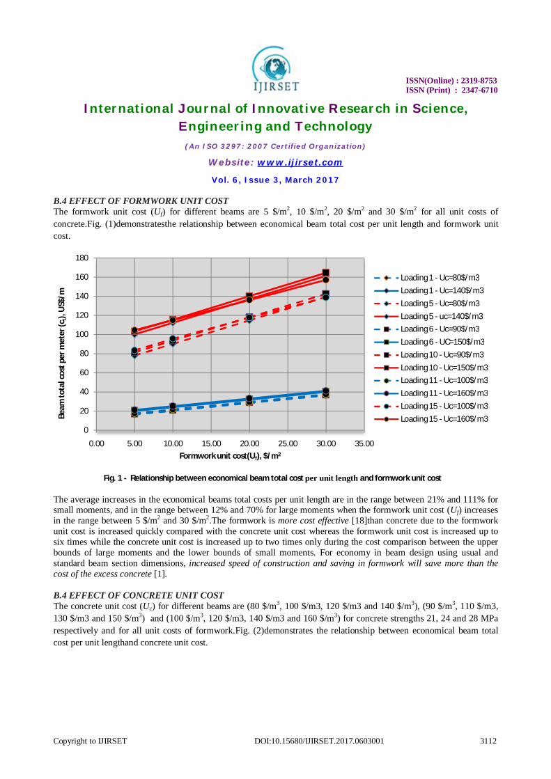
B.4 EFFECT OF FORMWORK UNIT COST The formwork unit cost (Uf) for different beams are 5 $/m2, 10 $/m2, 20 $/m2 and 30 $/m2 for all unit costs of concrete.Fig. (1)demonstratesthe relationship between economical beam total cost per unit length and formwork unit cost.
Fig. 1 - Relationship between economical beam total cost per unit length and formwork unit cost
The average increases in the economical beams total costs per unit length are in the range between 21% and 111% for small moments, and in the range between 12% and 70% for large moments when the formwork unit cost (Uf) increases in the range between 5 $/m2 and 30 $/m2.The formwork is more cost effective [18]than concrete due to the formwork unit cost is increased quickly compared with the concrete unit cost whereas the formwork unit cost is increased up to six times while the concrete unit cost is increased up to two times only during the cost comparison between the upper bounds of large moments and the lower bounds of small moments. For economy in beam design using usual and standard beam section dimensions, increased speed of construction and saving in formwork will save more than the cost of the excess concrete [1]. B.4 EFFECT OF CONCRETE UNIT COST The concrete unit cost (Uc) for different beams are (80 $/m3, 100 $/m3, 120 $/m3 and 140 $/m3), (90 $/m3, 110 $/m3, 130 $/m3 and 150 $/m3) and (100 $/m3, 120 $/m3, 140 $/m3 and 160 $/m3) for concrete strengths 21, 24 and 28 MPa respectively and for all unit costs of formwork.Fig. (2)demonstrates the relationship between economical beam total cost per unit lengthand concrete unit cost.
0
20
40
60
80
100
120
140
160
180
0.00 5.00 10.00 15.00 20.00 25.00 30.00 35.00
Beam
tota
l cos
t per
met
er (c
t), U
S$/m
Formwork unit cost(Uf), $/m2
Loading 1 - Uc=80$/m3Loading 1 - Uc=140$/m3Loading 5 - Uc=80$/m3Loading 5 - uc=140$/m3Loading 6 - Uc=90$/m3Loading 6 - UC=150$/m3Loading 10 - Uc=90$/m3Loading 10 - Uc=150$/m3Loading 11 - Uc=100$/m3Loading 11 - Uc=160$/m3Loading 15 - Uc=100$/m3Loading 15 - Uc=160$/m3
ISSN(Online) : 2319-8753 ISSN (Print) : 2347-6710
International Journal of Innovative Research in Science, Engineering and Technology
(An ISO 3297: 2007 Certified Organization)
Website: www.ijirset.com
Vol. 6, Issue 3, March 2017
Copyright to IJIRSET DOI:10.15680/IJIRSET.2017.0603001 3113
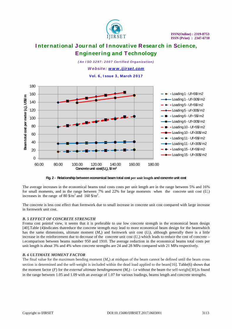
Fig. 2 - Relationship between economical beam total cost per unit length and concrete unit cost
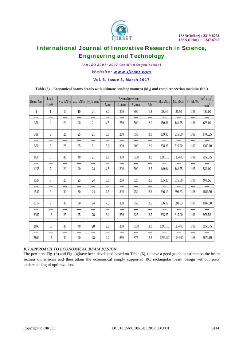
The average increases in the economical beams total costs costs per unit length are in the range between 5% and 16% for small moments, and in the range between 7% and 22% for large moments when the concrete unit cost (Uc) increases in the range of 80 $/m2 and 160 $/m2. The concrete is less cost effect than formwork due to small increase in concrete unit cost compared with large increase in formwork unit cost. B. 5 EFFECT OF CONCRETE STRENGTH Froma cost pointof view, it seems that it is preferable to use low concrete strength in the economical beam design [40].Table (4)indicates thatreduce the concrete strength may lead to more economical beam design for the beamwhich has the same dimensions, ultimate moment (Mu) and formwork unit cost (Uf), although generally there is a little increase in the reinforcement due to decrease of the concrete unit cost (Uc) which leads to reduce the cost of concrete – i.ecomparison between beams number 950 and 1910. The average reduction in the economical beams total costs per unit length is about 3% and 4% when concrete strengths are 24 and 28 MPa compared with 21 MPa respectively. B. 6 ULTIMATE MOMENT FACTOR The final value for the maximum bending moment (Mu) at midspan of the beam cannot be defined until the beam cross section is determined and the self-weight is included within the dead load applied to the beam[16]. Table(6) shows that the moment factor (F) for the external ultimate bendingmoment (Me) - i.e without the beam the self-weight[30],is found in the range between 1.05 and 1.09 with an average of 1.07 for various loadings, beams length and concrete strengths.
0
20
40
60
80
100
120
140
160
180
60.00 80.00 100.00 120.00 140.00 160.00 180.00
Beam
tota
l cos
t per
met
er (c
t), U
S$/m
Concrete unit cost(Uc), $/m3
Loading 1 - Uf=5$/m2Loading 1 - Uf=30$/m2Loading 5 - Uf=5$/m2Loading 5 - uf=30$/m2Loading 6 - Uf= 5$/m2Loading 6 - Uf=30$/m2Loading 10 - Uf=5$/m2Loading 10 - Uf=30$/m2Loading 11 - Uf=5$/m2Loading 11 - Uf=30$/m2Loading 15 - Uf=5$/m2Loading 15 - Uf=30$/m2
ISSN(Online) : 2319-8753 ISSN (Print) : 2347-6710
International Journal of Innovative Research in Science, Engineering and Technology
(An ISO 3297: 2007 Certified Organization)
Website: www.ijirset.com
Vol. 6, Issue 3, March 2017
Copyright to IJIRSET DOI:10.15680/IJIRSET.2017.0603001 3114
Table (6) – Economical beams details with ultimate bending moment (Mu) and complete section modulus (bh2)
B.7 APPROACH TO ECONOMICAL BEAM DESIGN The pertinent Fig. (3) and Fig. (4)have been developed based on Table (6), to have a good guide in estimation the beam section dimensions and then attain the economical simply supported RC rectangular beam design without prior understanding of optimization.
l , m b , mm h , mm h/b
1 1 10 10 21 3.0 200 300 1.5 33.44 31.50 1.06 180.00---- ---- ---- ---- ---- ---- ---- ---- ---- ---- ---- ---- ----378 2 20 20 21 4.5 250 500 2.0 150.86 141.75 1.06 625.00---- ---- ---- ---- ---- ---- ---- ---- ---- ---- ---- ---- ----388 3 25 25 21 6.0 250 750 3.0 339.30 315.00 1.08 1406.25---- ---- ---- ---- ---- ---- ---- ---- ---- ---- ---- ---- ----570 3 25 25 21 6.0 300 600 2.0 338.33 315.00 1.07 1080.00---- ---- ---- ---- ---- ---- ---- ---- ---- ---- ---- ---- ----950 5 40 40 21 9.0 350 1050 3.0 1241.16 1134.00 1.09 3858.75---- ---- ---- ---- ---- ---- ---- ---- ---- ---- ---- ---- ----
1155 7 20 20 24 4.5 200 500 2.5 149.04 141.75 1.05 500.00---- ---- ---- ---- ---- ---- ---- ---- ---- ---- ---- ---- ----
1527 8 25 25 24 6.0 250 625 2.5 335.25 315.00 1.06 976.56---- ---- ---- ---- ---- ---- ---- ---- ---- ---- ---- ---- ----
1537 9 30 30 24 7.5 300 750 2.5 636.19 590.63 1.08 1687.50---- ---- ---- ---- ---- ---- ---- ---- ---- ---- ---- ---- ----
1717 9 30 30 24 7.5 300 750 2.5 636.19 590.63 1.08 1687.50---- ---- ---- ---- ---- ---- ---- ---- ---- ---- ---- ---- ----
2307 13 25 25 28 6.0 250 625 2.5 335.25 315.00 1.06 976.56---- ---- ---- ---- ---- ---- ---- ---- ---- ---- ---- ---- ----
2690 15 40 40 28 9.0 350 1050 3.0 1241.16 1134.00 1.09 3858.75---- ---- ---- ---- ---- ---- ---- ---- ---- ---- ---- ---- ----
2869 15 40 40 28 9.0 350 875 2.5 1223.30 1134.00 1.08 2679.69
Load. Case
Beam dimensionsMu, kN.m Me, kN.m F = Mu/Me
bh2 x 105, mm3w d , kN/m w l , kN/m fc' , N/mm2Beam No.

ISSN(Online) : 2319-8753 ISSN (Print) : 2347-6710
International Journal of Innovative Research in Science, Engineering and Technology
(An ISO 3297: 2007 Certified Organization)
Website: www.ijirset.com
Vol. 6, Issue 3, March 2017
Copyright to IJIRSET DOI:10.15680/IJIRSET.2017.0603001 3115
Fig. 3 - Relationship between ultimate bending moment (Mu) and beam width (b)
To avoid exaggeration and to get a logical and simple equations for the best fitted relationship, a linear relation with a strong correlation coefficient have been chosen between the ultimate moment (Mu) and the beam width (b) for Fig. (3), while Fig. (4)provides the relationship between the ultimate moment (Mu) and the complete section modulus (bh2).
Fig. 4 - Relationship betweenultimate bending moment (Mu) and complete section modulus (bh2)
fc'=21 N/mm2y = 0.119x + 212.65
R² = 0.8540fc'=24 N/mm2
y = 0.1316x + 196.89R² = 0.9511
fc'=28 N/mm2y = 0.1326x + 196.70
R² = 0.9522
0
50
100
150
200
250
300
350
400
0 200 400 600 800 1000 1200 1400
Beam
wid
th (b
), m
m
Mu, kN.m
fc'=21N/mm2
fc'=24N/mm2
fc'=28N/mm2
Linear (fc'=21N/mm2)
Linear (fc'=24N/mm2)
Linear (fc'=28N/mm2)
fc'=21 N/mm2y = 3.0453x + 209.400
R² = 0.9855
fc'=24 N/mm2y = 2.9896x + 50.266
R² = 0.9833
fc'=28 N/mm2y = 2.5638x + 99.156
R² = 0.9492
0
500
1000
1500
2000
2500
3000
3500
4000
4500
0 200 400 600 800 1000 1200 1400
Beam
com
plet
e se
ctio
n m
odul
us (b
h2x
105 )
, mm
3
Mu, kN.m
fc'=21N/mm2
fc'=24N/mm2
fc'=28N/mm2
Linear (fc'=21N/mm2)
Linear (fc'=24N/mm2)
Linear (fc'=28N/mm2)

ISSN(Online) : 2319-8753 ISSN (Print) : 2347-6710
International Journal of Innovative Research in Science, Engineering and Technology
(An ISO 3297: 2007 Certified Organization)
Website: www.ijirset.com
Vol. 6, Issue 3, March 2017
Copyright to IJIRSET DOI:10.15680/IJIRSET.2017.0603001 3116
The results of this study show that the standard widths of economical beam design are 200, 250, 300 and 350 mm as illustrated in Fig. (3). Both parametric design curves – i.e Fig. (3) and Fig. (4)are comprised numerical equations for concrete strengths 21, 24 and 28 MPa to calculate the beam width (b) and the complete section modulus (bh2) respectively. Economical beam design can be approached based on the following iterative method [12]:
1. Calculate the external factored moment(Me) – i.e without the beam self-weight. 2. Determine approximate Mu including the beam self-weight by multiplyingMeby the average moment factor
(F) which is equal 1.07. 3. Find the width of the beam (b) from the appropriate equation of Fig. (3)androunding it to nearest 50 mm. 4. Find the complete section modulus (bh2) from the appropriate equation of Fig. (4), then use the above b to
calculate the height of the beam (h)and also rounding it to nearest 50 mm. 5. Calculate the amount of steel reinforcement required for bending and shear design by using computer
methods like STAAD Pro software or hand calculations[15]. 6. Calculate the beam total cost per unit lengthas per the EXCEL spreadsheet of Table (3). 7. Select another h by rounding up or down the dimension of step 4 to nearest 50 mm. 8. Complete the cycle of economical beam total costper unit length.
Several iterations in total cost calculations by rounding up or down the width of the beam (b) of step 3 to nearest 50 mm, and consequently the height of the beam (h) lead to more economical beam design. The preceding approach to the economical beam design is straightforward, without enormous iterations and tedious calculations which is time consuming, provide applicable solution in practice [19] and satisfy the design requirements of ACI 318M-14 code for bending and shear.
IV. CONCLUSIONS
The main cost results for the economical simply supported RC rectangular beamdesignby using STAAD Pro software as per ACI 318M-14 code can be indicated as following:
1. The average costs ratio of concrete, reinforcement and formwork to total cost are 32%, 32% and 36% respectively, whereas the stirrups cost constitutes 9% of the total cost.
2. The average reinforcement ratio (ρ) is approximately 1%for concrete strengths 21, 24 MPaand 1.25% for concrete strength 28 MPa.
3. The h/b ratio is in the range of 1.5 to 3 for beams up to and including 9 m in length. In general, using deep and narrow beams leads to satisfy both design requirements and economy.
4. The formwork unit cost (Uf) is more effect than concrete unit cost (Uc), and the average increases in the economical beams total costs costs per unit length are in the range between 21% and 111% for small moments, and in the range between 12% and 70% for large moments when the formwork unit cost (Uf) increases in the range between5 $/m2 and 30 $/m2.
5. The average increases in the economical beams total costs costs per unit lengthare in the range between 5% and 16% for small moments, and in the range between 7% and 22% for large moments when the concrete unit cost (Uc) increases in the range of 80 $/m2 and 160 $/m2.
6. Froma cost pointof view, it seems that it is preferable to use low concrete strength in the economical beam design.
7. The moment factor (F) is in the range between 1.05 and 1.09 with an average of 1.07. 8. Economical beam design can be attained from several iterations in total cost calculations, and more
attempts to find the beam section dimensions provide more economical beam design. Numerical equations for the economical beam deign have been developed and can be used swiftly to estimate the beam width and height without prior understanding of optimization for concrete strengths 21, 24 and 28 MPa.
ISSN(Online) : 2319-8753 ISSN (Print) : 2347-6710
International Journal of Innovative Research in Science, Engineering and Technology
(An ISO 3297: 2007 Certified Organization)
Website: www.ijirset.com
Vol. 6, Issue 3, March 2017
Copyright to IJIRSET DOI:10.15680/IJIRSET.2017.0603001 3117
REFERENCES
[1]Merritt, F., S. and Ricketts, J., T., 2001, “Building Design and Construction Handbook”, 6th Ed., McGraw-Hill. [2]Menon, D. and Pillai, S., 2009, “Reinforced Concrete Design”, 3rd Ed., Tata McGraw-Hill Education Pvt. Ltd., New Delhi. [3]Alreshaid, K., Mahdi, I., M. and Soliman, E., 2004, “Cost Optimization of Reinforced Concrete Elements”, Asian Journal of Civil Engineering (Building and Housing), Vol. 5, No. 3-4, pp. 161-174. [4]Guerra, A. and Kiousis, P., D., 2006, “Design Optimization of Reinforced Concrete Structures”, Journal of Computers and Concrete, Vol. 3, No. 5, pp. 313-334. [5]Yousif, S., T., Alsaffar, I., S. and Ahmed, S., M., 2010, “Optimum Design of Singly and Doubly Reinforced Concrete Rectangular Beam Sections: Artificial Neural Networks Application”, Iraqi Journal of Civil Engineering, Vol. 6, No. 3, pp. 1-19. [6]Yousif, S. and Najem, R., M., 2012, “Optimum Cost Design of Reinforced Concrete Beams Using Genetic Algorithms”, Iraqi Journal For Mechanical And Material Engineering, Vol. 12, No. 4, pp 680-693. [7]Yousif, S. and Najem, R., M., 2014, “Effects of Materials Properties on Strength and Deflection of Optimized R.C. Beams: Genetic Algorithms”, Al-Rafidain Engineering Journal, Vol. 22, No. 5, pp 149-165. [8]Galeb, A., C., 2009, “Optimum Design of Reinforced Concrete Rectangular Beams Using Simulated Annealing ”, Iraqi Journal For Mechanical And Material Engineering, Special Issue (B), pp 201-210. [9]Bhalchandra, S., A. and Adsul, P., K., 2012, “Cost Optimization Of Doubly Reinforced Rectangular Beam Section”, International Journal of Modern Engineering Research, Vol. 2, No. 5, pp 3939-3942. [10]Abdul-Razzaq, K., S., 2010, “Decision Making to Identify Section Dimensions That Produce Economic Design for Reinforced Concrete Beams”, First Engineering Scientific Conference, College of Engineering –University of Diyala, Diyala Journal of Engineering Sciences, pp. 268-285. [11]Prakash, P., Jayakarthik, K. and Narmadha, M., 2016, “Effect of d/b Ratio and Grade of Concrete in the Economical Design of RCC Beams”, International Journal of Innovative Research in Science, Engineering and Technology, Vol. 5, No. 2, pp 1930-1936. [12]McCormac, J., C. and Nelson, J., K., 2006, “Design of Reinforced Concrete”, 7th Ed., John Wiley and Sons, Inc. [13]Wang, C., K., Salmon, C., G. and Pincheira, J., A., 2006, “Reinforced Concrete Design”, 7th Ed., John Wiley and Sons, Inc. [14]Nilson, A., H., Darwin, D. and Dolan, C., W., 2010, “ Design of Concrete Structures”, 14th Ed., McGraw-Hill. [15]Arya, C., 2009, “Design of Structural Elements”, 3rd Ed., Taylor & Francis. [16]Wight J. K. and MacGregor J. G., 2012, “Reinforced Concrete Mechanics and Design”, 6th Ed., Pearson, Inc., New Jersey, pp. 12-39. [17]Pawar S. P. and Atterde P. M., 2014, “Comparative Analysis of Formwork in Multistory Building”, International Journal of Research in Engineering and Technology, Vol. 3, No.9, pp 22-24. [18]Kamara, M., E. and Novak, L., C., 2011, “Simplified Design of Reinforced Concrete Buildings”, 4th Ed., Portland Cement Association, Old Orchard Road, Skokie, Illinois, pp 279. [19]Milajic A., Beljakovic D. and Culic N., 2014, “Optimal Structural Design Based on Applicability in Practice”, International Scientific Conference People, Buildings and Environment, pp. 306-315. [20]Kaveh A. and Sabzi O., 2012, “Optimal design of reinforced concrete frames Using big bang-big crunch algorithm ”, International Journal of Civil Engineering, Vol. 10, No. 3, pp. 189-200. [21]Adeli H. and Sarma K. C., 2006, “Cost Optimization of Structures”, John Wiley & Sons Ltd. [22]Akin A. and Saka M. P., 2015, “Harmony Search Algorithm Based Optimum Detailed Design of Reinforced Concrete Plane Frames Subject to ACI 318-05 Provisions”, Computers and Structures, Vol. 147, pp 79-95. [23]Kwak H. G. and Kim J., 2008, “ Optimum Design of Reinforced Concrete Plane Frames Based on Predetermined Section Database”, Computer Aided Design, No. 40, pp. 396 – 408. [24]Kaveh A. and Sabzi O., 2011, “A comparative study of two meta-heuristic algorithms for optimum design of reinforced concrete frames”, International Journal of Civil Engineering, Vol. 9, No. 3, pp. 193-206. [25]ArnulfoLuevanos-Rojas, A., 2016, “Numerical experimentation for the optimal design of reinforced rectangular concrete beams for singly reinforced sections”, Dyna Journal, Vol. 83, No. 196, pp. 134-142. [26]Bently Systems Inc., 2006, “Staad. Pro for windows”, Pennsylvania. [27]ACI Committee 318, 2014, “Building Code Requirements for Structural Concrete and Commentary (ACI 318M-14)”, American Concrete Institute, Farmington Hills, MI. [28]Hibbeler, R., C., 2012, “Structural Analysis” 8th Ed, Pearson, Inc., New Jersey, pp. 300-308. [29]Ramya, D. and Sai Kumar, A., V., 2015, “Comparative Study on Design and Analysis of Multistoreyed Building (G+10) by Staad.Pro and EtabsSoftware’s”, International Journal of Engineering Sciences and Research, Vol. 4, No. 10, pp 125-130. [30]Nawy E. G., 2009, “Reinforced Concrete”, 6th Ed., Pearson Education, Inc., New Jersey. [31]Ozturk, H., T., Durmus, Ay. and Durmus, Ah., 2012, “Optimum Design of a Reinforced Concrete Beam using Artificial Bee Colony Algorithm”, Computers and Concrete, Vol. 10, No. 3, pp. 295-306.
ISSN(Online) : 2319-8753 ISSN (Print) : 2347-6710
International Journal of Innovative Research in Science, Engineering and Technology
(An ISO 3297: 2007 Certified Organization)
Website: www.ijirset.com
Vol. 6, Issue 3, March 2017
Copyright to IJIRSET DOI:10.15680/IJIRSET.2017.0603001 3118
[32]Hassoun, M., N. and Al-Manaseer, A., 2008, “Structural Concrete”, 4th Ed., John Wiley and Sons, Inc. [33]Setiawan, A. and Saptono, K., 2012, “Shear Capacity of Reinforced Concrete Beam with Different Cross Section Types of Lateral Reinforcement on Minimum Ratio”, International Conference on Advances Science and Contemporary Engineering, Procedia Engineering Journal, Vol. 50, pp. 576 – 585. [34]Subramanian, N., 2010, “Limiting reinforcement ratios for RC flexural members”, The Indian Concrete Journal, pp. 71-80. [35]Hasan, W., M., El-Khatieb, M. and Al-Ani, H., 2011, “Steel Reinforcement Ratio Dependency of Plastic Rotational Capacity of Reinforced Concrete Beams”, Jordan Journal of Civil Engineering, Volume 5, No. 4, pp. 480-491. [36]Kheyroddin, A. and Naderpour, H., 2007, “Plastic Hinge Rotation Capacity of Reinforced Concrete Beams”, International Journal of Civil Engineerng, Vol. 5, No. 1, pp. 30-47. [37]Siddique, M., A. and Rouf, M., A., 2006, “Effect of Material Properties on Ductility Factor of Singly RC Beam Sections”, 6th Asia-Pacific Structural Engineering and Construction Conference, Kuala Lumpur, pp. A83-A90. [38]Aschheim M., Hernandez-Montes E. and Gil-Martin L. M., 2008, “ Design of Optimally Reinforced RC Beam, Column, And Wall Sections”, Journal of structural Engineering ASCE, Vol. 134, No. 2, pp. 231 – 239. [39]Gil-Martin L. M, Hernandez-Montes E. and Aschheim M., 2010, “Optimal Reinforcement of RC Columns for Biaxial Bending”, Materials and Structures, No. 43, pp. 1245 – 1256. [40]Jasim, N., A., Ibrahim, N., A., Galeb, A., C. and Abdulelah, Z., 2005, “Optimal Design of Reinforced Concrete T- Beam Floors”, Basrah Journal for Engineering Science, Vol. 5, No. 1, pp. 1 – 16.