eco r4 inset eco r5 inset eco r6 inset eco r6 slimline inset
TRANSCRIPT
1
Eco R4 Inset Eco R5 Inset Eco R6 Inset
Eco R6 Slimline Inset
Wood Burning Inset Stove
Instructions for: Installation/Operating/Maintenance/Servicing Instructions
JINEDLUIN REV B 27/03/2019
2
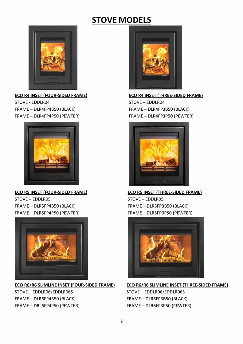
STOVE MODELS
ECO R4 INSET (FOUR-SIDED FRAME) ECO R4 INSET (THREE-SIDED FRAME) STOVE - EDDLR04 STOVE – EDDLR04 FRAME – DLR4FP4B50 (BLACK) FRAME – DLR4FP3B50 (BLACK) FRAME – DLR4FP4P50 (PEWTER) FRAME – DLR4FP3P50 (PEWTER)
ECO R5 INSET (FOUR-SIDED FRAME) ECO R5 INSET (THREE-SIDED FRAME) STOVE – EDDLR05 STOVE – EDDLR05 FRAME – DLR5FP4B50 (BLACK) FRAME – DLR5FP3B50 (BLACK) FRAME – DLR5FP4P50 (PEWTER) FRAME – DLR5FP3P50 (PEWTER)
ECO R6/R6 SLIMLINE INSET (FOUR-SIDED FRAME) ECO R6/R6 SLIMLINE INSET (THREE-SIDED FRAME) STOVE – EDDLR06/EDDLR06S STOVE – EDDLR06/EDDLR06S FRAME – DLR6FP4B50 (BLACK) FRAME – DLR6FP3B50 (BLACK) FRAME – DRL6FP4P50 (PEWTER) FRAME – DLR6FP3P50 (PEWTER)
3
CONTENTS INDEX:
STOVE MODELS………………………………………………………………………………………………… 2 TECHNICAL SPECIFICATION……………………………………………………………………………… 4 GENERAL GUIDANCE………………………………………………………………………………………… 5/6 SAFETY……………………………………………………………………………………………………………… 6/7 INSTALLATION APPLIANCE DIMENSIONS…………………………………………………………………………………… 7 - 9 FLUE REQUIREMENTS……………………………………………………………………………………….. 9/10 DI LUSSO ECO R4 INSTALLATION………………………………………………………………………. 10 - 14 DI LUSSO ECO R5 INSTALLATION………………………………………………………………………. 14 – 17 DI LUSSO ECO R6 INSTALLATION………………………………………………………………………. 17 - 19 FITTING THE STOVE – ALL ……………………………………….………………………………………. 19 - 27 DI LUSSO ECO R4 FLUE CONNECTION……………………………………………………………….. 21/22 DI LUSSO ECO R5 FLUE CONNECTION……………………………………………………………….. 22/23 DI LUSSO ECO R6/R6 SLIMLINE FLUE CONNECTION ……………………………………………. 23/24 DI LUSSO ECO R5/R6/R6 SLIMLINE ENCLOSURE INSTALLATION…………………………… 26 - 27 RE-ASSEMBLING THE STOVE……………………………………………………………………………… 31 OPERATING INSTRUCTIONS………………………………………………………………………………. 31 - 34 MAINTENANCE…………………………………………………………………………………………………. 34/35 TROUBLESHOOTING…………………………………………………………………………………………. 36/37 SPARES…………………………………………………………………………………………………………….. 38- 42 INSTALLATION AND COMMISSIONING CHECK LIST…………………………………………… 43 SERVICE RECORDS……………………………………………………………………………………………. 44 FULL WARRANTY INFORMATION……………………………………………………………………… 45/46
Welcome to the Hunter Stoves family and thank you for purchasing an Eco Di Lusso Inset stove. This stove was designed and built to be
a high-performance heating appliance, and we hope it will bring you great enjoyment. The natural environment is important to us,
so our stoves are manufactured to provide you with a clean and efficient burn that will keep you warm through cold winter nights.
4
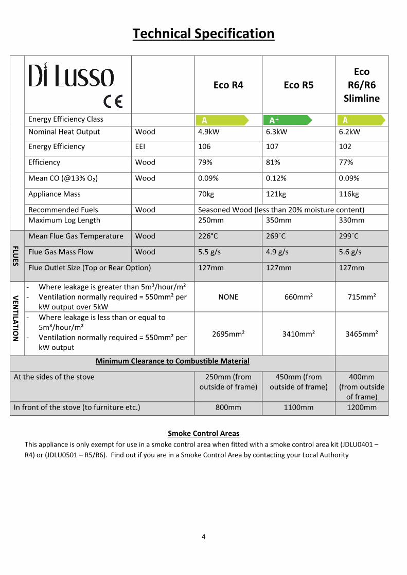
Technical Specification
Eco R4 Eco R5 Eco
R6/R6 Slimline
Energy Efficiency Class Nominal Heat Output Wood 4.9kW 6.3kW 6.2kW
Energy Efficiency EEI 106 107 102
Efficiency Wood 79% 81% 77%
Mean CO (@13% O₂) Wood 0.09% 0.12% 0.09%
Appliance Mass 70kg 121kg 116kg
Recommended Fuels Wood Seasoned Wood (less than 20% moisture content) Maximum Log Length 250mm 350mm 330mm
FLUES
Mean Flue Gas Temperature Wood 226°C 269˚C 299˚C
Flue Gas Mass Flow Wood 5.5 g/s 4.9 g/s 5.6 g/s
Flue Outlet Size (Top or Rear Option) 127mm 127mm 127mm
VENTILATIO
N
- Where leakage is greater than 5m³/hour/m² - Ventilation normally required = 550mm² per
kW output over 5kW NONE 660mm² 715mm²
- Where leakage is less than or equal to 5m³/hour/m²
- Ventilation normally required = 550mm² per kW output
2695mm² 3410mm² 3465mm²
Minimum Clearance to Combustible Material
At the sides of the stove 250mm (from outside of frame)
450mm (from outside of frame)
400mm (from outside
of frame) In front of the stove (to furniture etc.) 800mm 1100mm 1200mm
Smoke Control Areas This appliance is only exempt for use in a smoke control area when fitted with a smoke control area kit (JDLU0401 – R4) or (JDLU0501 – R5/R6). Find out if you are in a Smoke Control Area by contacting your Local Authority
5
General Guidance It is important that your stove is correctly installed and operated as Hunter Stoves Group cannot accept responsibility for any fault arising through incorrect installation, use, maintenance or servicing.
These instructions cover the basic principles to ensure satisfactory installation of the stove, although detail may need slight modification to suit local site conditions.
The installation must comply with current Building Regulations, National and European Standards, Local Authority Byelaws and other specifications or regulations as they affect the installation of the appliance.
The Building Regulations requirements may also be met by adopting the relevant recommendations in the current issues of British Standards BS 8303 and BS EN 15287-1.
Only use approved fuels on this appliance. Information about this can be found on Pages 32.
This is a Domestic Appliance and must only be used in accordance with these instructions. Do not place articles that are affected by high temperatures on, or near, this appliance. Do not place furniture or other items within 1 metre of the front of this appliance. See the note on material clearances on pages – R4 – 10 - 12 and R5 – 14 - 16 and R6/R6 Slimline – 17 - 19.
Fitting a stove in a room which also contains an extractor fan and/or cooker hood should be avoided where possible. If this is unavoidable, the suitability of the space for fitting this appliance must be decided at the discretion of a qualified installer, and a flue draught interference test must be performed. Do not obstruct the ventilation required for the safe use of this appliance.
Competent Persons Scheme Members of the following schemes may self-certify the installation of this stove. If the installer is not a member of one of these schemes, your local Building Control Department must approve the installation.
Health And Safety Precautions Special care must be taken when installing the stove such that the requirements of the Health and Safety at Work Act are met.
Packaging All packaging supplied with this stove can be re-used or recycled. Please contact your local authority for information on recycling schemes in your area.
Scheme Web address Telephone
APHC (Association of Plumbing and Heating Contractors (Certification) Limited www.aphc.co.uk 02476 470 626
Building Engineering Services Competence Accreditation (BESCA Limited) www.hvca.org.uk / www.besca.org.uk 0800 652 5533
HETAS Ltd (Heating Equipment Testing and Approval Scheme) www.hetas.co.uk 01462 634721
NAPIT Registration Ltd www.napit.org.uk 0870 444 1392
NICEIC Group Ltd www.niceic.org.uk 0800 013 0900
PLEASE READ THESE INSTRUCTIONS PRIOR TO INSTALLATION AND OPERATION. KEEP THESE INSTRUCTIONS IN A SAFE PLACE FOR FUTURE REFERENCE AND SERVICING.
THIS APPLIANCE WILL BECOME VERY HOT WHEN USED IN ACCORDANCE WITH THESE INSTRUCTIONS, HUNTER STOVES RECOMMEND THAT AN APPROVED GUARD IS USED TO PROTECT THE YOUNG, ELDERLY
OR INFIRM FROM HARM.
THE INSTALLER COMMISSIONING SHEET CAN BE FOUND ON THE BACK COVER. PLEASE ENSURE THAT IT IS COMPLETED PRIOR TO USE.
6
Handling Adequate facilities must be available for loading, unloading and site handling.
Fire Cement Some types of fire cement are caustic and should not be allowed to come into contact with the skin. In case of contact, wash immediately with plenty of water.
Asbetos This stove contains no asbestos. If there is a possibility of disturbing any asbestos in the course of installation then please seek specialist guidance and use appropriate protective equipment.
Metal Parts When installing or servicing this stove, care should be taken to avoid the possibility of personal injury.
Air Supply The room or space containing this appliance should have purpose provided ventilation (where necessary) in accordance with Building Regulations. Due consideration should be given to air requirements for any other appliance in the same room or space. Any air opening must be kept clear from blockage or obstruction.
Modification No unauthorised modification of this appliance should be carried out.
Safety WARNING – This appliance will be hot when in operation and due care should be taken. The supplied operating tool or gloves may be used to open the door and operate the air controls.
Aerosols Do not use an aerosol spray on or near the stove when it is alight.
Fires Can Be Dangerous Always use a fireguard in the presence of children, the elderly or the infirm. The fireguard should be manufactured in accordance with BS8423 – Fireguards for use with solid fuel appliances.
Do Not Over-Fire It is possible to fire the stove beyond its design capacity. This could damage the stove so watch for signs of over-firing. If any part of the stove starts to glow red, the stove is in an over-fire situation and the controls should be adjusted accordingly. Never leave the stove unattended for lengthy periods without first adjusting the controls to a safe setting. Careful air supply control should be exercised at all times.
Fume Emission Properly installed and operated, this appliance will not emit fumes. Occasional fumes from de-ashing and refueling may occur. Persistent fume emission must not be tolerated.
This appliance should not be operated with the door open.
If fume emission does persist then the following action should be taken immediately –
• Open Doors and windows to ventilate room. • Let the fire out or eject and safely dispose of fuel from the appliance. • Check for flue/chimney blockage and clean if required. • Do not attempt to relight the fire until the cause has been identified and corrected. • If necessary, seek professional advice.
Adverse Weather In a small number of installations, occasional local weather conditions (e.g. wind from a particular direction) may cause downdraught in the flue and the stove to emit fumes. In these circumstances, the stove should not be used. A professional flue installer will be able to advise on solutions to this problem (e.g. anti-downdraught cowl).
7
IN THE EVENT OF A CHIMNEY FIRE - • Raise the alarm • Call the Fire Brigade • Close appliance air controls • Move furniture, ornaments etc. away • Place a fireguard in front of stove • Check the chimney breast for signs of excessive heat.
If the wall is becoming excessively hot, move furniture away. Ensure the Fire Brigade can gain access to your roof space in order to check for fire spread.
Installation (N.B. All dimensions are in Millimetres)
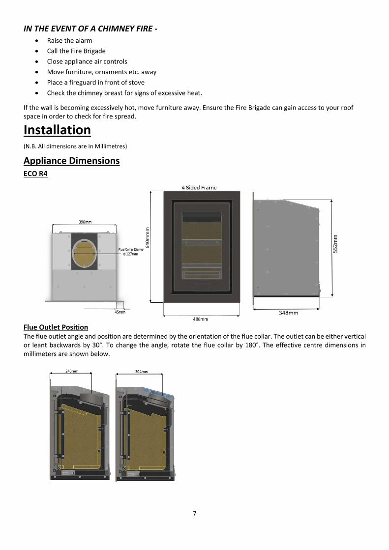
Appliance Dimensions ECO R4
Flue Outlet Position The flue outlet angle and position are determined by the orientation of the flue collar. The outlet can be either vertical or leant backwards by 30°. To change the angle, rotate the flue collar by 180°. The effective centre dimensions in millimeters are shown below.
8
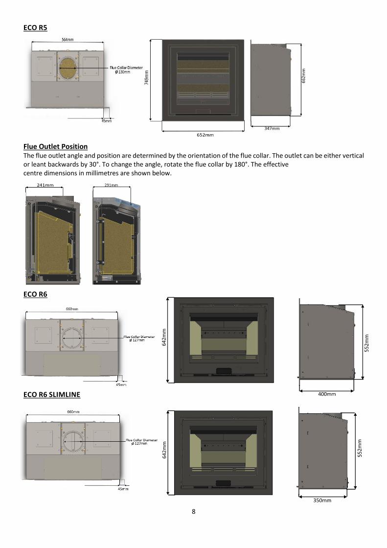
ECO R5
Flue Outlet Position The flue outlet angle and position are determined by the orientation of the flue collar. The outlet can be either vertical or leant backwards by 30°. To change the angle, rotate the flue collar by 180°. The effective centre dimensions in millimetres are shown below. ECO R6
ECO R6 SLIMLINE
9
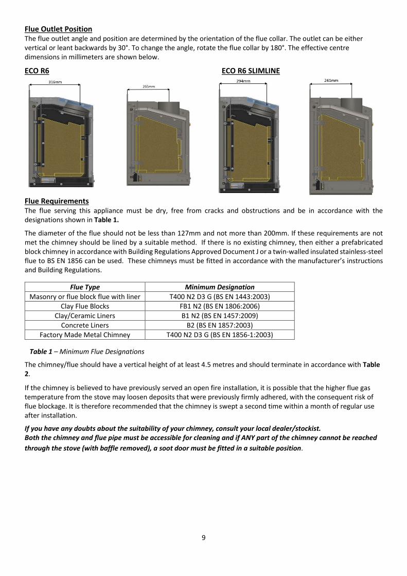
Flue Outlet Position The flue outlet angle and position are determined by the orientation of the flue collar. The outlet can be either vertical or leant backwards by 30°. To change the angle, rotate the flue collar by 180°. The effective centre dimensions in millimeters are shown below.
ECO R6 ECO R6 SLIMLINE
Flue Requirements The flue serving this appliance must be dry, free from cracks and obstructions and be in accordance with the designations shown in Table 1.
The diameter of the flue should not be less than 127mm and not more than 200mm. If these requirements are not met the chimney should be lined by a suitable method. If there is no existing chimney, then either a prefabricated block chimney in accordance with Building Regulations Approved Document J or a twin-walled insulated stainless-steel flue to BS EN 1856 can be used. These chimneys must be fitted in accordance with the manufacturer’s instructions and Building Regulations.
The chimney/flue should have a vertical height of at least 4.5 metres and should terminate in accordance with Table 2.
If the chimney is believed to have previously served an open fire installation, it is possible that the higher flue gas temperature from the stove may loosen deposits that were previously firmly adhered, with the consequent risk of flue blockage. It is therefore recommended that the chimney is swept a second time within a month of regular use after installation.
If you have any doubts about the suitability of your chimney, consult your local dealer/stockist. Both the chimney and flue pipe must be accessible for cleaning and if ANY part of the chimney cannot be reached through the stove (with baffle removed), a soot door must be fitted in a suitable position.
Flue Type Minimum Designation Masonry or flue block flue with liner T400 N2 D3 G (BS EN 1443:2003)
Clay Flue Blocks FB1 N2 (BS EN 1806:2006) Clay/Ceramic Liners B1 N2 (BS EN 1457:2009)
Concrete Liners B2 (BS EN 1857:2003) Factory Made Metal Chimney T400 N2 D3 G (BS EN 1856-1:2003)
Table 1 – Minimum Flue Designations
10
Table 2. Flue Draught If the draught exceeds the recommended maximum, a draught stabiliser must be fitted so that the rate of burning can be controlled and to prevent over firing.
If the reading is less than the recommended minimum, then the performance of the appliance will be compromised. The flue draught should be checked under fire at high output. Minimum Draught – 1.2mm Water Gauge Maximum Draught – 2.5mm Water Gauge
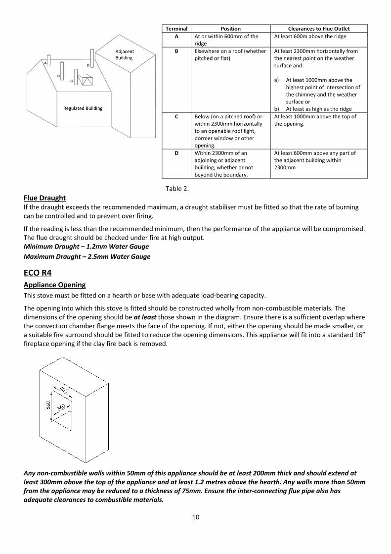
ECO R4 Appliance Opening This stove must be fitted on a hearth or base with adequate load-bearing capacity.
The opening into which this stove is fitted should be constructed wholly from non-combustible materials. The dimensions of the opening should be at least those shown in the diagram. Ensure there is a sufficient overlap where the convection chamber flange meets the face of the opening. If not, either the opening should be made smaller, or a suitable fire surround should be fitted to reduce the opening dimensions. This appliance will fit into a standard 16” fireplace opening if the clay fire back is removed. Any non-combustible walls within 50mm of this appliance should be at least 200mm thick and should extend at least 300mm above the top of the appliance and at least 1.2 metres above the hearth. Any walls more than 50mm from the appliance may be reduced to a thickness of 75mm. Ensure the inter-connecting flue pipe also has adequate clearances to combustible materials.
Terminal Position Clearances to Flue Outlet A At or within 600mm of the
ridge At least 600m above the ridge
B Elsewhere on a roof (whether pitched or flat)
At least 2300mm horizontally from the nearest point on the weather surface and: a) At least 1000mm above the
highest point of intersection of the chimney and the weather surface or
b) At least as high as the ridge C Below (on a pitched roof) or
within 2300mm horizontally to an openable roof light, dormer window or other opening.
At least 1000mm above the top of the opening.
D Within 2300mm of an adjoining or adjacent building, whether or not beyond the boundary.
At least 600mm above any part of the adjacent building within 2300mm
11
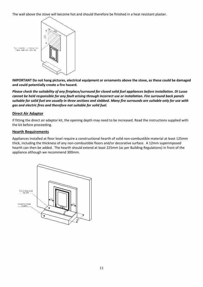
The wall above the stove will become hot and should therefore be finished in a heat resistant plaster.
IMPORTANT Do not hang pictures, electrical equipment or ornaments above the stove, as these could be damaged and could potentially create a fire hazard.
Please check the suitability of any fireplace/surround for closed solid fuel appliances before installation. Di Lusso cannot be held responsible for any fault arising through incorrect use or installation. Fire surround back panels suitable for solid fuel are usually in three sections and slabbed. Many fire surrounds are suitable only for use with gas and electric fires and therefore not suitable for solid fuel.
Direct Air Adaptor
If fitting the direct air adaptor kit, the opening depth may need to be increased. Read the instructions supplied with the kit before proceeding.
Hearth Requirements
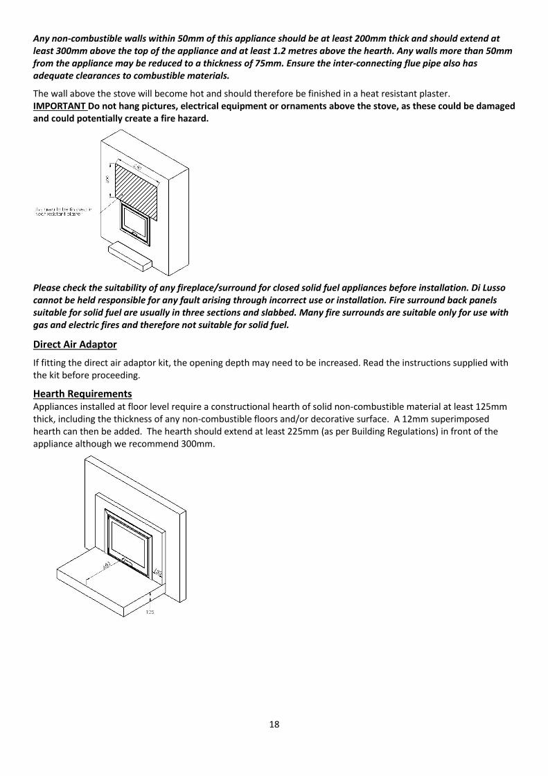
Appliances installed at floor level require a constructional hearth of solid non-combustible material at least 125mm thick, including the thickness of any non-combustible floors and/or decorative surface. A 12mm superimposed hearth can then be added. The hearth should extend at least 225mm (as per Building Regulations) in front of the appliance although we recommend 300mm.
12
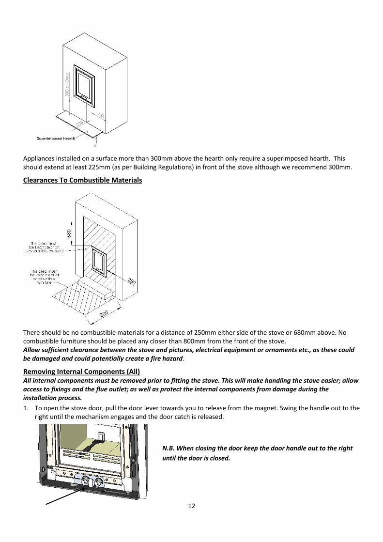
Appliances installed on a surface more than 300mm above the hearth only require a superimposed hearth. This should extend at least 225mm (as per Building Regulations) in front of the stove although we recommend 300mm.
Clearances To Combustible Materials
There should be no combustible materials for a distance of 250mm either side of the stove or 680mm above. No combustible furniture should be placed any closer than 800mm from the front of the stove. Allow sufficient clearance between the stove and pictures, electrical equipment or ornaments etc., as these could be damaged and could potentially create a fire hazard.
Removing Internal Components (All) All internal components must be removed prior to fitting the stove. This will make handling the stove easier; allow access to fixings and the flue outlet; as well as protect the internal components from damage during the installation process.
1. To open the stove door, pull the door lever towards you to release from the magnet. Swing the handle out to the right until the mechanism engages and the door catch is released.
N.B. When closing the door keep the door handle out to the right until the door is closed.
13
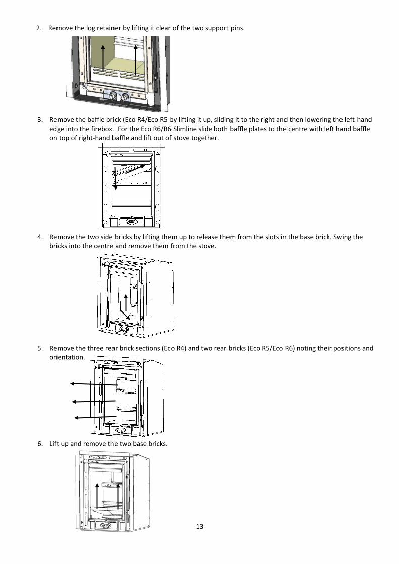
2. Remove the log retainer by lifting it clear of the two support pins.
3. Remove the baffle brick (Eco R4/Eco R5 by lifting it up, sliding it to the right and then lowering the left-hand edge into the firebox. For the Eco R6/R6 Slimline slide both baffle plates to the centre with left hand baffle on top of right-hand baffle and lift out of stove together.
4. Remove the two side bricks by lifting them up to release them from the slots in the base brick. Swing the bricks into the centre and remove them from the stove.
5. Remove the three rear brick sections (Eco R4) and two rear bricks (Eco R5/Eco R6) noting their positions and orientation.
6. Lift up and remove the two base bricks.
14
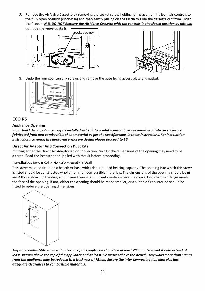
7. Remove the Air Valve Cassette by removing the socket screw holding it in place, turning both air controls to the fully open position (clockwise) and then gently pulling on the fascia to slide the cassette out from under the firebox. N.B. DO NOT Remove the Air Valve Cassette with the controls in the closed position as this will damage the valve gaskets.
8. Undo the four countersunk screws and remove the base fixing access plate and gasket.
ECO R5 Appliance Opening Important! This appliance may be installed either into a solid non-combustible opening or into an enclosure fabricated from non-combustible sheet material as per the specifications in these instructions. For installation instructions covering the approved enclosure design please proceed to 26.
Direct Air Adaptor And Convection Duct Kits If fitting either the Direct Air Adaptor Kit or Convection Duct Kit the dimensions of the opening may need to be altered. Read the instructions supplied with the kit before proceeding.
Installation Into A Solid Non-Combustible Wall This stove must be fitted on a hearth or base with adequate load bearing capacity. The opening into which this stove is fitted should be constructed wholly from non-combustible materials. The dimensions of the opening should be at least those shown in the diagram. Ensure there is a sufficient overlap where the convection chamber flange meets the face of the opening. If not, either the opening should be made smaller, or a suitable fire surround should be fitted to reduce the opening dimensions.
Any non-combustible walls within 50mm of this appliance should be at least 200mm thick and should extend at least 300mm above the top of the appliance and at least 1.2 metres above the hearth. Any walls more than 50mm from the appliance may be reduced to a thickness of 75mm. Ensure the inter-connecting flue pipe also has adequate clearances to combustible materials.
Socket screw
15
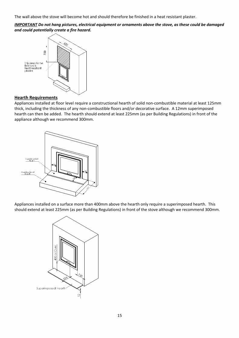
The wall above the stove will become hot and should therefore be finished in a heat resistant plaster.
IMPORTANT Do not hang pictures, electrical equipment or ornaments above the stove, as these could be damaged and could potentially create a fire hazard.
Hearth Requirements Appliances installed at floor level require a constructional hearth of solid non-combustible material at least 125mm thick, including the thickness of any non-combustible floors and/or decorative surface. A 12mm superimposed hearth can then be added. The hearth should extend at least 225mm (as per Building Regulations) in front of the appliance although we recommend 300mm.
Appliances installed on a surface more than 400mm above the hearth only require a superimposed hearth. This should extend at least 225mm (as per Building Regulations) in front of the stove although we recommend 300mm.
16
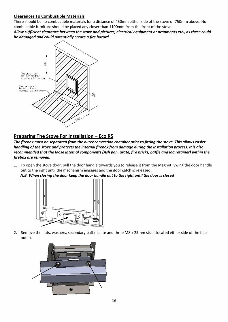
Clearances To Combustible Materials There should be no combustible materials for a distance of 450mm either side of the stove or 750mm above. No combustible furniture should be placed any closer than 1100mm from the front of the stove. Allow sufficient clearance between the stove and pictures, electrical equipment or ornaments etc., as these could be damaged and could potentially create a fire hazard.
Preparing The Stove For Installation – Eco R5 The firebox must be separated from the outer convection chamber prior to fitting the stove. This allows easier handling of the stove and protects the internal firebox from damage during the installation process. It is also recommended that the loose internal components (Ash pan, grate, fire bricks, baffle and log retainer) within the firebox are removed.
1. To open the stove door, pull the door handle towards you to release it from the Magnet. Swing the door handle out to the right until the mechanism engages and the door catch is released. N.B. When closing the door keep the door handle out to the right until the door is closed
2. Remove the nuts, washers, secondary baffle plate and three M8 x 25mm studs located either side of the flue outlet.
17
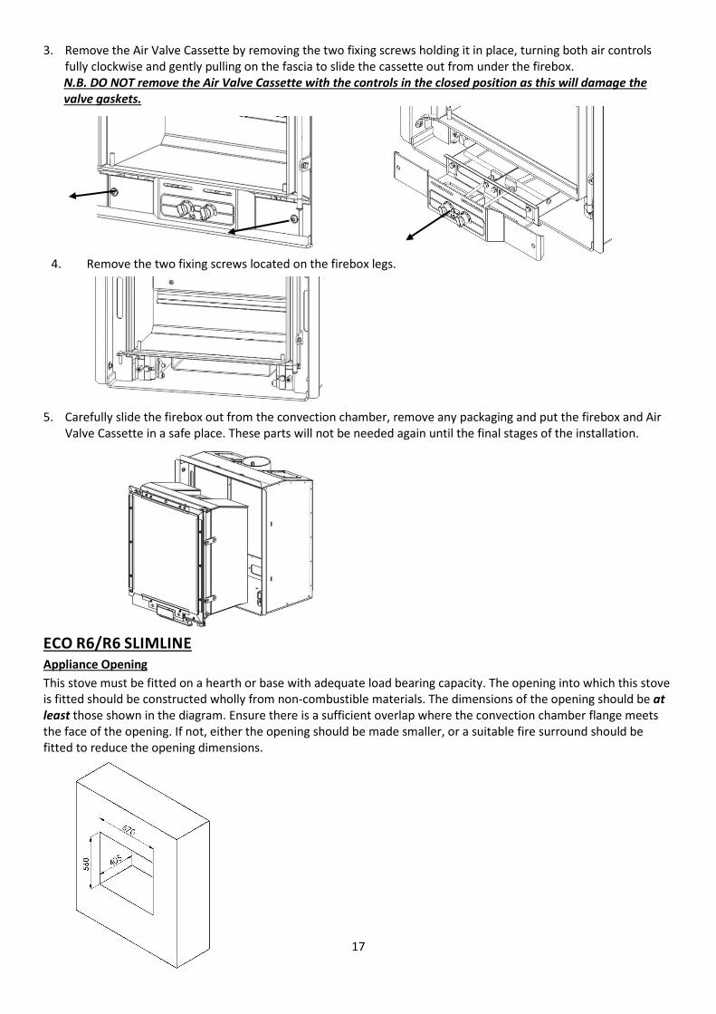
3. Remove the Air Valve Cassette by removing the two fixing screws holding it in place, turning both air controls fully clockwise and gently pulling on the fascia to slide the cassette out from under the firebox. N.B. DO NOT remove the Air Valve Cassette with the controls in the closed position as this will damage the valve gaskets.
4. Remove the two fixing screws located on the firebox legs.
5. Carefully slide the firebox out from the convection chamber, remove any packaging and put the firebox and Air Valve Cassette in a safe place. These parts will not be needed again until the final stages of the installation.
ECO R6/R6 SLIMLINE Appliance Opening This stove must be fitted on a hearth or base with adequate load bearing capacity. The opening into which this stove is fitted should be constructed wholly from non-combustible materials. The dimensions of the opening should be at least those shown in the diagram. Ensure there is a sufficient overlap where the convection chamber flange meets the face of the opening. If not, either the opening should be made smaller, or a suitable fire surround should be fitted to reduce the opening dimensions.
18
Any non-combustible walls within 50mm of this appliance should be at least 200mm thick and should extend at least 300mm above the top of the appliance and at least 1.2 metres above the hearth. Any walls more than 50mm from the appliance may be reduced to a thickness of 75mm. Ensure the inter-connecting flue pipe also has adequate clearances to combustible materials.
The wall above the stove will become hot and should therefore be finished in a heat resistant plaster. IMPORTANT Do not hang pictures, electrical equipment or ornaments above the stove, as these could be damaged and could potentially create a fire hazard.
Please check the suitability of any fireplace/surround for closed solid fuel appliances before installation. Di Lusso cannot be held responsible for any fault arising through incorrect use or installation. Fire surround back panels suitable for solid fuel are usually in three sections and slabbed. Many fire surrounds are suitable only for use with gas and electric fires and therefore not suitable for solid fuel.
Direct Air Adaptor
If fitting the direct air adaptor kit, the opening depth may need to be increased. Read the instructions supplied with the kit before proceeding.
Hearth Requirements Appliances installed at floor level require a constructional hearth of solid non-combustible material at least 125mm thick, including the thickness of any non-combustible floors and/or decorative surface. A 12mm superimposed hearth can then be added. The hearth should extend at least 225mm (as per Building Regulations) in front of the appliance although we recommend 300mm.
19
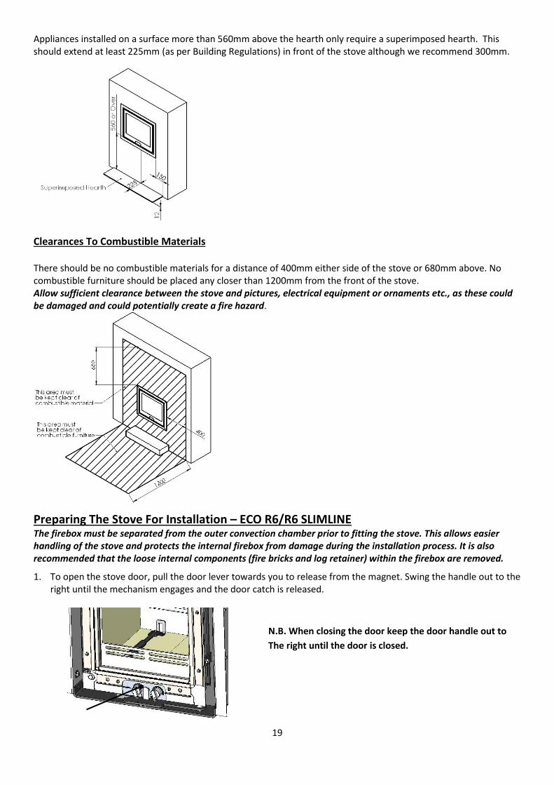
Appliances installed on a surface more than 560mm above the hearth only require a superimposed hearth. This should extend at least 225mm (as per Building Regulations) in front of the stove although we recommend 300mm.
Clearances To Combustible Materials
There should be no combustible materials for a distance of 400mm either side of the stove or 680mm above. No combustible furniture should be placed any closer than 1200mm from the front of the stove. Allow sufficient clearance between the stove and pictures, electrical equipment or ornaments etc., as these could be damaged and could potentially create a fire hazard.
Preparing The Stove For Installation – ECO R6/R6 SLIMLINE The firebox must be separated from the outer convection chamber prior to fitting the stove. This allows easier handling of the stove and protects the internal firebox from damage during the installation process. It is also recommended that the loose internal components (fire bricks and log retainer) within the firebox are removed.
1. To open the stove door, pull the door lever towards you to release from the magnet. Swing the handle out to the right until the mechanism engages and the door catch is released.
N.B. When closing the door keep the door handle out to The right until the door is closed.
20
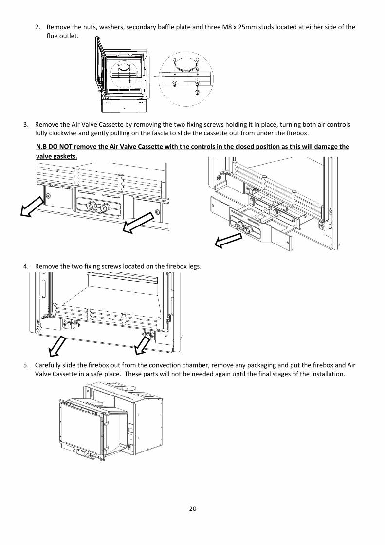
2. Remove the nuts, washers, secondary baffle plate and three M8 x 25mm studs located at either side of the flue outlet.
3. Remove the Air Valve Cassette by removing the two fixing screws holding it in place, turning both air controls fully clockwise and gently pulling on the fascia to slide the cassette out from under the firebox.
N.B DO NOT remove the Air Valve Cassette with the controls in the closed position as this will damage the valve gaskets.
4. Remove the two fixing screws located on the firebox legs.
5. Carefully slide the firebox out from the convection chamber, remove any packaging and put the firebox and Air Valve Cassette in a safe place. These parts will not be needed again until the final stages of the installation.
21
Fitting The Stove – ECO R4 and R5 IMPORTANT – Read this section carefully and ensure that any required access holes, register plates or flue connections are in place before carrying out the installation. If the installation is to be back filled with vermiculite concrete the convection chamber flange should be sealed to the fireplace using fire cement, heat proof silicone or similar. All seams in the convection chamber should also be sealed.
It is recommended that the convection chamber flange is sealed to the fireplace in all cases as this will reduce the chance of airflow into any voids reducing the stoves efficiency or the ingress of unpleasant smells into the room. If fitting the Direct Air Adaptor Kit, the instructions supplied with the kit should be read in conjunction with these instructions. R4 Offer the stove into position in the recess pushing it back far enough so that the flanges on the edge of the convection chamber are pushed up tightly against the front of the chimney breast/fireplace.
R5 Offer the convection chamber into position in the recess pushing it back far enough so that the flanges on the edges are pushed up tightly against the front face of the chimney breast/fireplace. Then - Drill a 6mm hole into the hearth in the centre of the base plate fixing hole. Use the screw supplied to fix the stove in place.
Any voids around the stove must be In-filled with vermiculite concrete with a recommended mix of six parts vermiculite to one-part Ordinary Portland Cement. This may be carried out once the flue has been fitted provided a suitable access hole for backfilling is made in the chimney breast (see section on connecting to a masonry chimney). Sufficient water should be added so that when a handful of the mixture is squeezed no more than one or two drops of water are released.
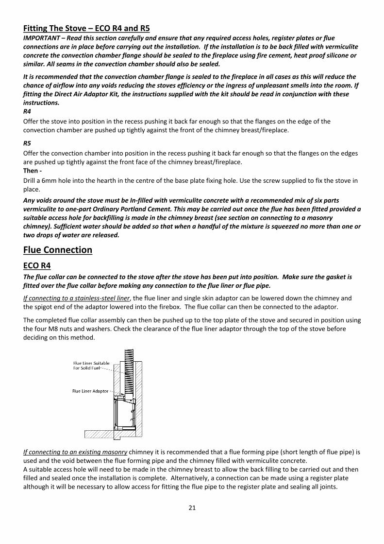
Flue Connection ECO R4 The flue collar can be connected to the stove after the stove has been put into position. Make sure the gasket is fitted over the flue collar before making any connection to the flue liner or flue pipe.
If connecting to a stainless-steel liner, the flue liner and single skin adaptor can be lowered down the chimney and the spigot end of the adaptor lowered into the firebox. The flue collar can then be connected to the adaptor.
The completed flue collar assembly can then be pushed up to the top plate of the stove and secured in position using the four M8 nuts and washers. Check the clearance of the flue liner adaptor through the top of the stove before deciding on this method.
If connecting to an existing masonry chimney it is recommended that a flue forming pipe (short length of flue pipe) is used and the void between the flue forming pipe and the chimney filled with vermiculite concrete. A suitable access hole will need to be made in the chimney breast to allow the back filling to be carried out and then filled and sealed once the installation is complete. Alternatively, a connection can be made using a register plate although it will be necessary to allow access for fitting the flue pipe to the register plate and sealing all joints.
22
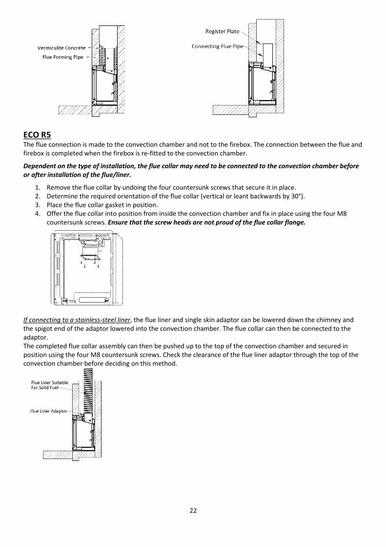
ECO R5 The flue connection is made to the convection chamber and not to the firebox. The connection between the flue and firebox is completed when the firebox is re-fitted to the convection chamber.
Dependent on the type of installation, the flue collar may need to be connected to the convection chamber before or after installation of the flue/liner.
1. Remove the flue collar by undoing the four countersunk screws that secure it in place. 2. Determine the required orientation of the flue collar (vertical or leant backwards by 30°). 3. Place the flue collar gasket in position. 4. Offer the flue collar into position from inside the convection chamber and fix in place using the four M8
countersunk screws. Ensure that the screw heads are not proud of the flue collar flange.
If connecting to a stainless-steel liner, the flue liner and single skin adaptor can be lowered down the chimney and the spigot end of the adaptor lowered into the convection chamber. The flue collar can then be connected to the adaptor. The completed flue collar assembly can then be pushed up to the top of the convection chamber and secured in position using the four M8 countersunk screws. Check the clearance of the flue liner adaptor through the top of the convection chamber before deciding on this method.
23
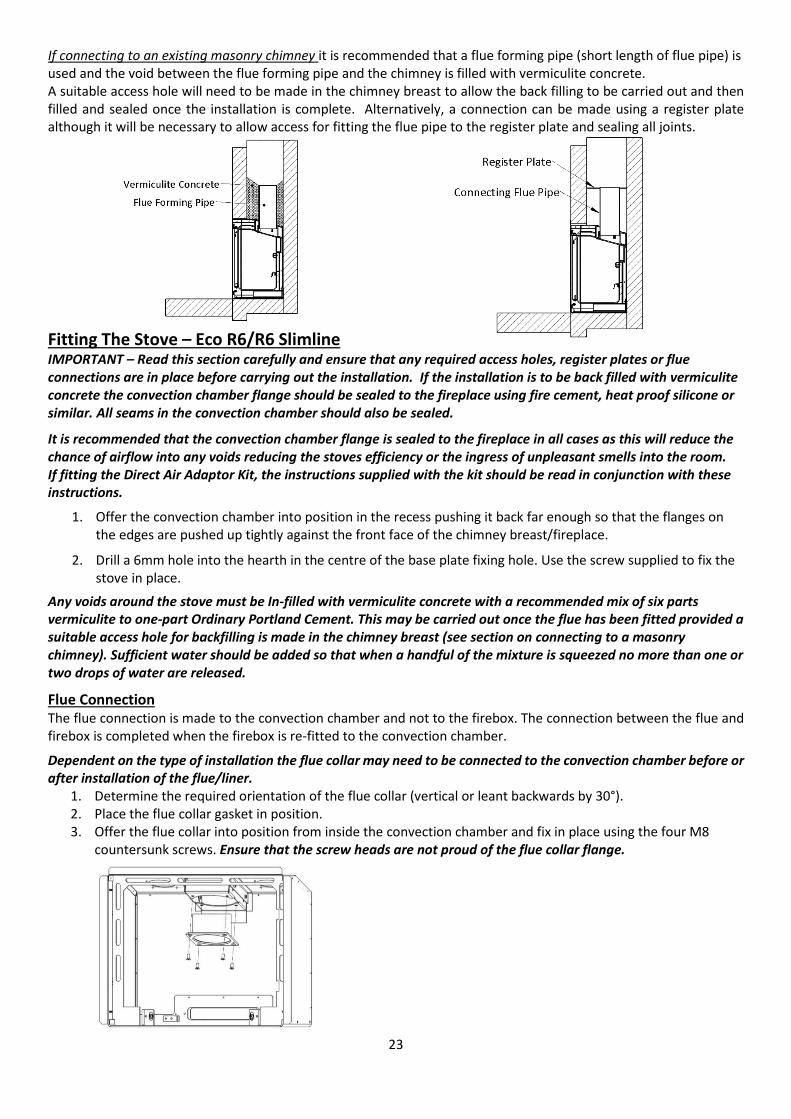
If connecting to an existing masonry chimney it is recommended that a flue forming pipe (short length of flue pipe) is used and the void between the flue forming pipe and the chimney is filled with vermiculite concrete. A suitable access hole will need to be made in the chimney breast to allow the back filling to be carried out and then filled and sealed once the installation is complete. Alternatively, a connection can be made using a register plate although it will be necessary to allow access for fitting the flue pipe to the register plate and sealing all joints.
Fitting The Stove – Eco R6/R6 Slimline IMPORTANT – Read this section carefully and ensure that any required access holes, register plates or flue connections are in place before carrying out the installation. If the installation is to be back filled with vermiculite concrete the convection chamber flange should be sealed to the fireplace using fire cement, heat proof silicone or similar. All seams in the convection chamber should also be sealed.
It is recommended that the convection chamber flange is sealed to the fireplace in all cases as this will reduce the chance of airflow into any voids reducing the stoves efficiency or the ingress of unpleasant smells into the room. If fitting the Direct Air Adaptor Kit, the instructions supplied with the kit should be read in conjunction with these instructions.
1. Offer the convection chamber into position in the recess pushing it back far enough so that the flanges on the edges are pushed up tightly against the front face of the chimney breast/fireplace.
2. Drill a 6mm hole into the hearth in the centre of the base plate fixing hole. Use the screw supplied to fix the stove in place.
Any voids around the stove must be In-filled with vermiculite concrete with a recommended mix of six parts vermiculite to one-part Ordinary Portland Cement. This may be carried out once the flue has been fitted provided a suitable access hole for backfilling is made in the chimney breast (see section on connecting to a masonry chimney). Sufficient water should be added so that when a handful of the mixture is squeezed no more than one or two drops of water are released.
Flue Connection The flue connection is made to the convection chamber and not to the firebox. The connection between the flue and firebox is completed when the firebox is re-fitted to the convection chamber.
Dependent on the type of installation the flue collar may need to be connected to the convection chamber before or after installation of the flue/liner.
1. Determine the required orientation of the flue collar (vertical or leant backwards by 30°). 2. Place the flue collar gasket in position. 3. Offer the flue collar into position from inside the convection chamber and fix in place using the four M8
countersunk screws. Ensure that the screw heads are not proud of the flue collar flange.
24
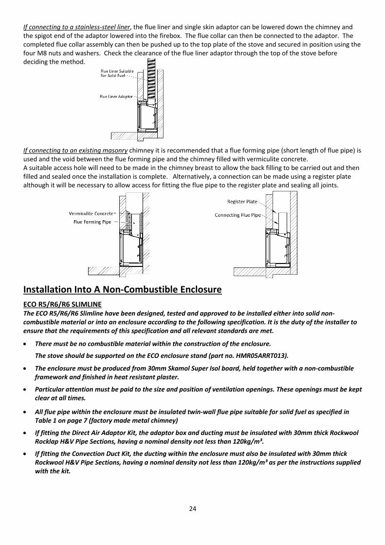
If connecting to a stainless-steel liner, the flue liner and single skin adaptor can be lowered down the chimney and the spigot end of the adaptor lowered into the firebox. The flue collar can then be connected to the adaptor. The completed flue collar assembly can then be pushed up to the top plate of the stove and secured in position using the four M8 nuts and washers. Check the clearance of the flue liner adaptor through the top of the stove before deciding the method.
If connecting to an existing masonry chimney it is recommended that a flue forming pipe (short length of flue pipe) is used and the void between the flue forming pipe and the chimney filled with vermiculite concrete. A suitable access hole will need to be made in the chimney breast to allow the back filling to be carried out and then filled and sealed once the installation is complete. Alternatively, a connection can be made using a register plate although it will be necessary to allow access for fitting the flue pipe to the register plate and sealing all joints.
Installation Into A Non-Combustible Enclosure
ECO R5/R6/R6 SLIMLINE The ECO R5/R6/R6 Slimline have been designed, tested and approved to be installed either into solid non-combustible material or into an enclosure according to the following specification. It is the duty of the installer to ensure that the requirements of this specification and all relevant standards are met.
• There must be no combustible material within the construction of the enclosure.
• The stove should be supported on the ECO enclosure stand (part no. HMR05ARRT013).
• The enclosure must be produced from 30mm Skamol Super Isol board, held together with a non-combustible framework and finished in heat resistant plaster.
• Particular attention must be paid to the size and position of ventilation openings. These openings must be kept clear at all times.
• All flue pipe within the enclosure must be insulated twin-wall flue pipe suitable for solid fuel as specified in Table 1 on page 7 (factory made metal chimney)
• If fitting the Direct Air Adaptor Kit, the adaptor box and ducting must be insulated with 30mm thick Rockwool Rocklap H&V Pipe Sections, having a nominal density not less than 120kg/m³.
• If fitting the Convection Duct Kit, the ducting within the enclosure must also be insulated with 30mm thick Rockwool H&V Pipe Sections, having a nominal density not less than 120kg/m³ as per the instructions supplied with the kit.
25
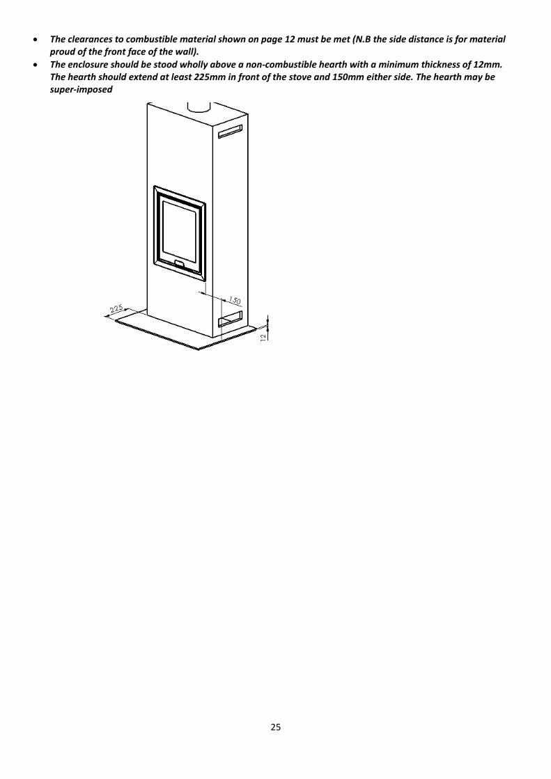
• The clearances to combustible material shown on page 12 must be met (N.B the side distance is for material proud of the front face of the wall).
• The enclosure should be stood wholly above a non-combustible hearth with a minimum thickness of 12mm. The hearth should extend at least 225mm in front of the stove and 150mm either side. The hearth may be super-imposed
26
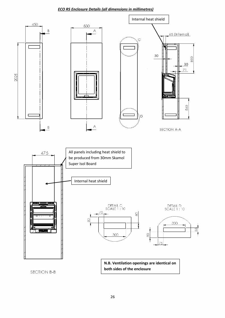
ECO R5 Enclosure Details (all dimensions in millimetres)
Internal heat shield
All panels including heat shield to be produced from 30mm Skamol Super Isol Board
Internal heat shield
N.B. Ventilation openings are identical on both sides of the enclosure
27
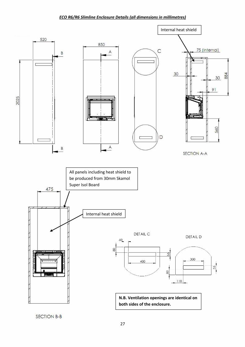
ECO R6/R6 Slimline Enclosure Details (all dimensions in millimetres)
Internal heat shield
All panels including heat shield to be produced from 30mm Skamol Super Isol Board
Internal heat shield
N.B. Ventilation openings are identical on both sides of the enclosure.
28
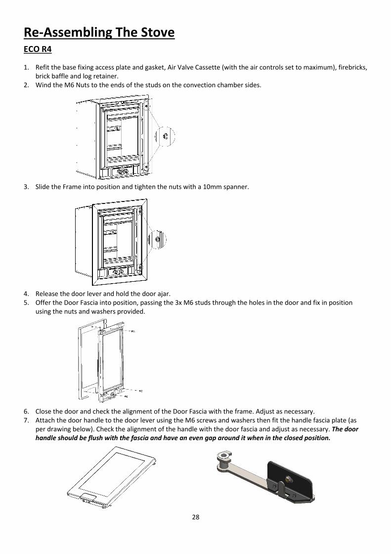
Re-Assembling The Stove ECO R4
1. Refit the base fixing access plate and gasket, Air Valve Cassette (with the air controls set to maximum), firebricks, brick baffle and log retainer.
2. Wind the M6 Nuts to the ends of the studs on the convection chamber sides.
3. Slide the Frame into position and tighten the nuts with a 10mm spanner.
4. Release the door lever and hold the door ajar. 5. Offer the Door Fascia into position, passing the 3x M6 studs through the holes in the door and fix in position
using the nuts and washers provided.
6. Close the door and check the alignment of the Door Fascia with the frame. Adjust as necessary. 7. Attach the door handle to the door lever using the M6 screws and washers then fit the handle fascia plate (as
per drawing below). Check the alignment of the handle with the door fascia and adjust as necessary. The door handle should be flush with the fascia and have an even gap around it when in the closed position.
29
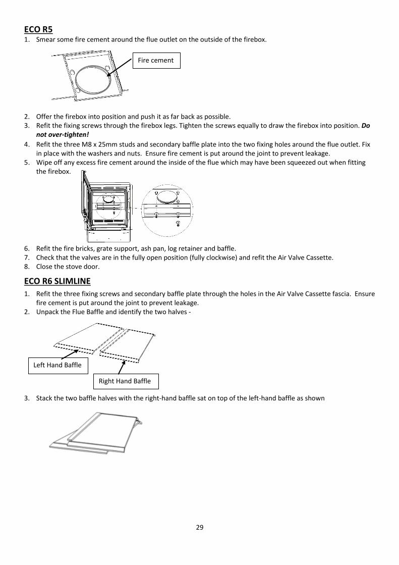
ECO R5 1. Smear some fire cement around the flue outlet on the outside of the firebox.
2. Offer the firebox into position and push it as far back as possible. 3. Refit the fixing screws through the firebox legs. Tighten the screws equally to draw the firebox into position. Do
not over-tighten!
4. Refit the three M8 x 25mm studs and secondary baffle plate into the two fixing holes around the flue outlet. Fix in place with the washers and nuts. Ensure fire cement is put around the joint to prevent leakage.
5. Wipe off any excess fire cement around the inside of the flue which may have been squeezed out when fitting the firebox.
6. Refit the fire bricks, grate support, ash pan, log retainer and baffle. 7. Check that the valves are in the fully open position (fully clockwise) and refit the Air Valve Cassette. 8. Close the stove door.
ECO R6 SLIMLINE
1. Refit the three fixing screws and secondary baffle plate through the holes in the Air Valve Cassette fascia. Ensure fire cement is put around the joint to prevent leakage.
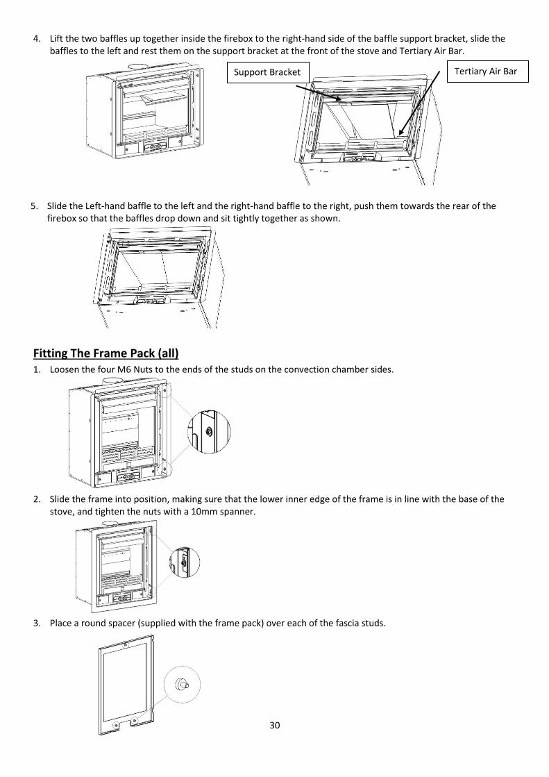
2. Unpack the Flue Baffle and identify the two halves -
3. Stack the two baffle halves with the right-hand baffle sat on top of the left-hand baffle as shown
Fire cement
Left Hand Baffle
Right Hand Baffle
30
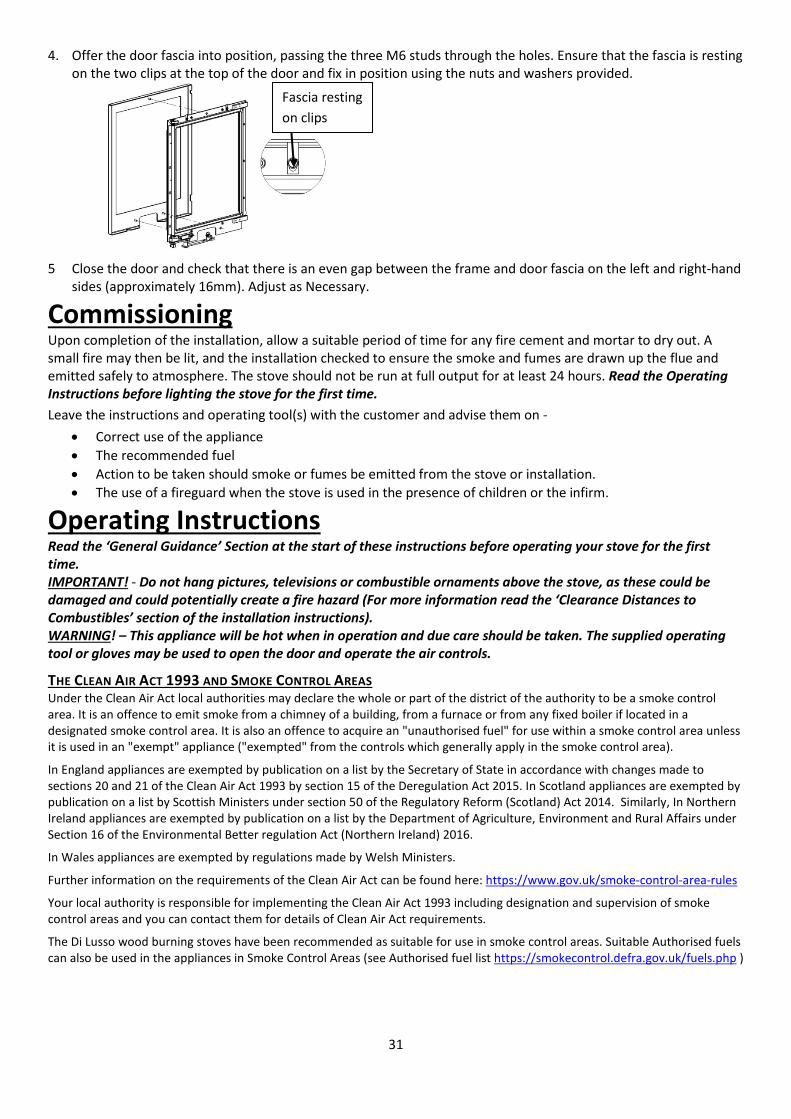
4. Lift the two baffles up together inside the firebox to the right-hand side of the baffle support bracket, slide the baffles to the left and rest them on the support bracket at the front of the stove and Tertiary Air Bar.
5. Slide the Left-hand baffle to the left and the right-hand baffle to the right, push them towards the rear of the firebox so that the baffles drop down and sit tightly together as shown.
Fitting The Frame Pack (all) 1. Loosen the four M6 Nuts to the ends of the studs on the convection chamber sides.
2. Slide the frame into position, making sure that the lower inner edge of the frame is in line with the base of the stove, and tighten the nuts with a 10mm spanner.
3. Place a round spacer (supplied with the frame pack) over each of the fascia studs.
Tertiary Air Bar Support Bracket
31
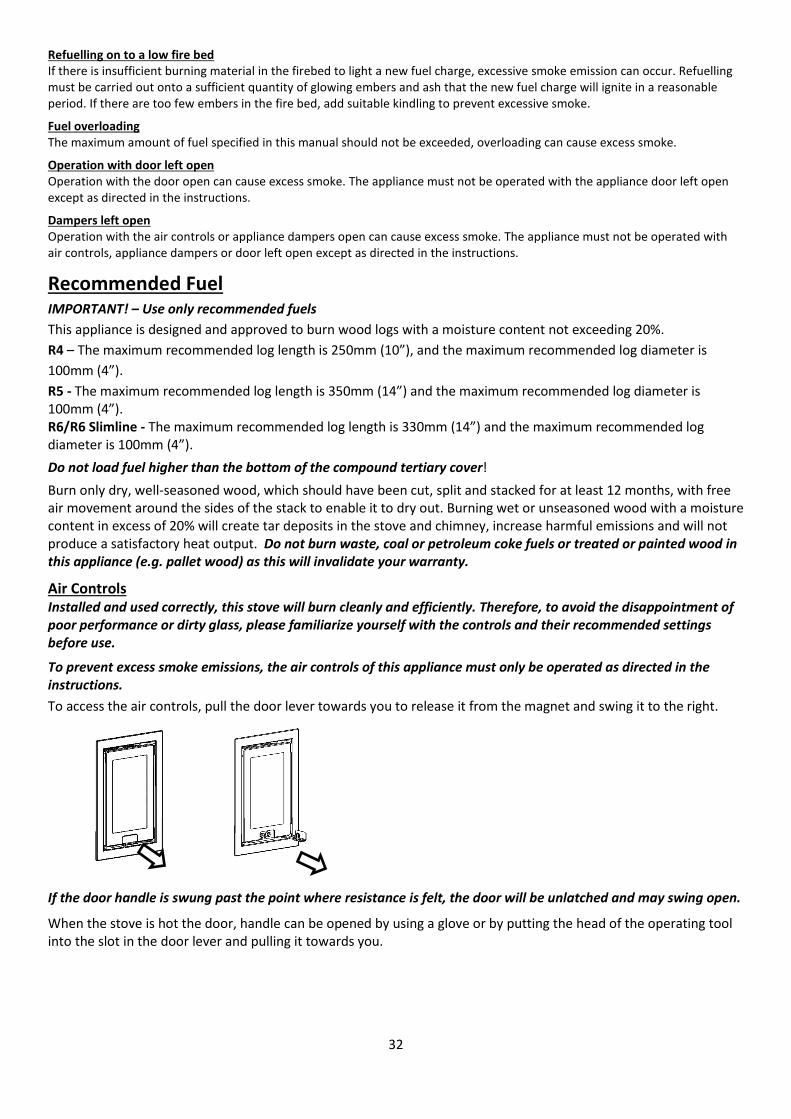
4. Offer the door fascia into position, passing the three M6 studs through the holes. Ensure that the fascia is resting on the two clips at the top of the door and fix in position using the nuts and washers provided.
5 Close the door and check that there is an even gap between the frame and door fascia on the left and right-hand sides (approximately 16mm). Adjust as Necessary.
Commissioning Upon completion of the installation, allow a suitable period of time for any fire cement and mortar to dry out. A small fire may then be lit, and the installation checked to ensure the smoke and fumes are drawn up the flue and emitted safely to atmosphere. The stove should not be run at full output for at least 24 hours. Read the Operating Instructions before lighting the stove for the first time.
Leave the instructions and operating tool(s) with the customer and advise them on -
• Correct use of the appliance • The recommended fuel • Action to be taken should smoke or fumes be emitted from the stove or installation. • The use of a fireguard when the stove is used in the presence of children or the infirm.
Operating Instructions Read the ‘General Guidance’ Section at the start of these instructions before operating your stove for the first time. IMPORTANT! - Do not hang pictures, televisions or combustible ornaments above the stove, as these could be damaged and could potentially create a fire hazard (For more information read the ‘Clearance Distances to Combustibles’ section of the installation instructions). WARNING! – This appliance will be hot when in operation and due care should be taken. The supplied operating tool or gloves may be used to open the door and operate the air controls.
THE CLEAN AIR ACT 1993 AND SMOKE CONTROL AREAS Under the Clean Air Act local authorities may declare the whole or part of the district of the authority to be a smoke control area. It is an offence to emit smoke from a chimney of a building, from a furnace or from any fixed boiler if located in a designated smoke control area. It is also an offence to acquire an "unauthorised fuel" for use within a smoke control area unless it is used in an "exempt" appliance ("exempted" from the controls which generally apply in the smoke control area).
In England appliances are exempted by publication on a list by the Secretary of State in accordance with changes made to sections 20 and 21 of the Clean Air Act 1993 by section 15 of the Deregulation Act 2015. In Scotland appliances are exempted by publication on a list by Scottish Ministers under section 50 of the Regulatory Reform (Scotland) Act 2014. Similarly, In Northern Ireland appliances are exempted by publication on a list by the Department of Agriculture, Environment and Rural Affairs under Section 16 of the Environmental Better regulation Act (Northern Ireland) 2016.
In Wales appliances are exempted by regulations made by Welsh Ministers.
Further information on the requirements of the Clean Air Act can be found here: https://www.gov.uk/smoke-control-area-rules
Your local authority is responsible for implementing the Clean Air Act 1993 including designation and supervision of smoke control areas and you can contact them for details of Clean Air Act requirements.
The Di Lusso wood burning stoves have been recommended as suitable for use in smoke control areas. Suitable Authorised fuels can also be used in the appliances in Smoke Control Areas (see Authorised fuel list https://smokecontrol.defra.gov.uk/fuels.php )
Fascia resting on clips
32
Refuelling on to a low fire bed If there is insufficient burning material in the firebed to light a new fuel charge, excessive smoke emission can occur. Refuelling must be carried out onto a sufficient quantity of glowing embers and ash that the new fuel charge will ignite in a reasonable period. If there are too few embers in the fire bed, add suitable kindling to prevent excessive smoke.
Fuel overloading The maximum amount of fuel specified in this manual should not be exceeded, overloading can cause excess smoke.
Operation with door left open Operation with the door open can cause excess smoke. The appliance must not be operated with the appliance door left open except as directed in the instructions.
Dampers left open Operation with the air controls or appliance dampers open can cause excess smoke. The appliance must not be operated with air controls, appliance dampers or door left open except as directed in the instructions.
Recommended Fuel IMPORTANT! – Use only recommended fuels This appliance is designed and approved to burn wood logs with a moisture content not exceeding 20%. R4 – The maximum recommended log length is 250mm (10”), and the maximum recommended log diameter is 100mm (4”). R5 - The maximum recommended log length is 350mm (14”) and the maximum recommended log diameter is 100mm (4”). R6/R6 Slimline - The maximum recommended log length is 330mm (14”) and the maximum recommended log diameter is 100mm (4”).
Do not load fuel higher than the bottom of the compound tertiary cover!
Burn only dry, well-seasoned wood, which should have been cut, split and stacked for at least 12 months, with free air movement around the sides of the stack to enable it to dry out. Burning wet or unseasoned wood with a moisture content in excess of 20% will create tar deposits in the stove and chimney, increase harmful emissions and will not produce a satisfactory heat output. Do not burn waste, coal or petroleum coke fuels or treated or painted wood in this appliance (e.g. pallet wood) as this will invalidate your warranty.
Air Controls Installed and used correctly, this stove will burn cleanly and efficiently. Therefore, to avoid the disappointment of poor performance or dirty glass, please familiarize yourself with the controls and their recommended settings before use.
To prevent excess smoke emissions, the air controls of this appliance must only be operated as directed in the instructions.
To access the air controls, pull the door lever towards you to release it from the magnet and swing it to the right.
If the door handle is swung past the point where resistance is felt, the door will be unlatched and may swing open.
When the stove is hot the door, handle can be opened by using a glove or by putting the head of the operating tool into the slot in the door lever and pulling it towards you.
33
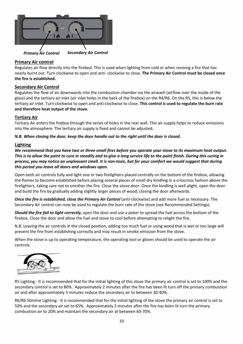
Primary Air control Regulates air flow directly into the firebed. This is used when lighting from cold or when reviving a fire that has nearly burnt out. Turn clockwise to open and anti- clockwise to close. The Primary Air Control must be closed once the fire is established.
Secondary Air Control Regulates the flow of air downwards into the combustion chamber via the airwash (airflow over the inside of the glass) and the tertiary air inlet (air inlet holes in the back of the firebox) on the R4/R6. On the R5, this is below the tertiary air inlet. Turn clockwise to open and anti-clockwise to close. This control is used to regulate the burn rate and therefore heat output of the stove.
Tertiary Air Tertiary Air enters the firebox through the series of holes in the rear wall. This air supply helps to reduce emissions into the atmosphere. The tertiary air supply is fixed and cannot be adjusted.
N.B. When closing the door, keep the door handle out to the right until the door is closed.
Lighting We recommend that you have two or three small fires before you operate your stove to its maximum heat output. This is to allow the paint to cure in steadily and to give a long service life to the paint finish. During this curing in process, you may notice an unpleasant smell. It is non-toxic, but for your comfort we would suggest that during this period you leave all doors and windows open.
Open both air controls fully and light one or two firelighters placed centrally on the bottom of the firebox, allowing the flames to become established before placing several pieces of small dry kindling in a crisscross fashion above the firelighters, taking care not to smother the fire. Close the stove door. Once the kindling is well alight, open the door and build the fire by gradually adding slightly larger pieces of wood, closing the door afterwards.
Once the fire is established, close the Primary Air Control (anti-clockwise) and add more fuel as necessary. The Secondary Air control can now be used to regulate the burn rate of the stove (see Recommended Settings).
Should the fire fail to light correctly, open the door and use a poker to spread the fuel across the bottom of the firebox. Close the door and allow the fuel and stove to cool before attempting to relight the fire.
N.B. Leaving the air controls in the closed position, adding too much fuel or using wood that is wet or too large will prevent the fire from establishing correctly and may result in smoke emission from the stove.
When the stove is up to operating temperature, the operating tool or gloves should be used to operate the air controls.
R5 Lighting - It is recommended that for the initial lighting of this stove the primary air control is set to 100% and the secondary control is set to 80%. Approximately 2 minutes after the fire has been lit turn off the primary combustion air and after approximately 3 minutes reduce the secondary air to between 30-40%.
R6/R6 Slimline Lighting - It is recommended that for the initial lighting of the stove the primary air control is set to 50% and the secondary air set to 65%. Approximately 2 minutes after the fire has been lit turn the primary combustion air to 20% and maintain the secondary air at between 60-70%.
Secondary Air Control Primary Air Control
34
Recommended Setting Once the fire is established, the Primary Air Control should be fully closed, and the Secondary Air Control turned to a setting of approximately- R4 – 50 -60% open R5 – 30-40% open R6/R6 Slimline – Primary 20% and Secondary 60-70% open
This setting should allow the nominal output and efficiency to be achieved. Avoid running the stove on very low air settings as this could result in a reduction in efficiency and increase emissions into the atmosphere.
Refuelling Avoid refueling on to a low firebed as this may cause excessive smoke emission. Ensure there are sufficient embers to ignite the new fuel load rapidly. Alternatively add some more kindling before adding larger pieces of firewood.
Do not add firewood above the level of the bottom of the compound air inlet cover at the back of the stove. Exceeding this amount can result in the production of excessive smoke.
R5 – It is recommended that 3 logs are used with an approximate length of 190mm and a combined weight of 1.6kg with the bark removed.
R6/R6 Slimline – It is recommended that 2 logs are used with an approximate length of 240mm and a combined weight of 1.6kg with the bark removed.
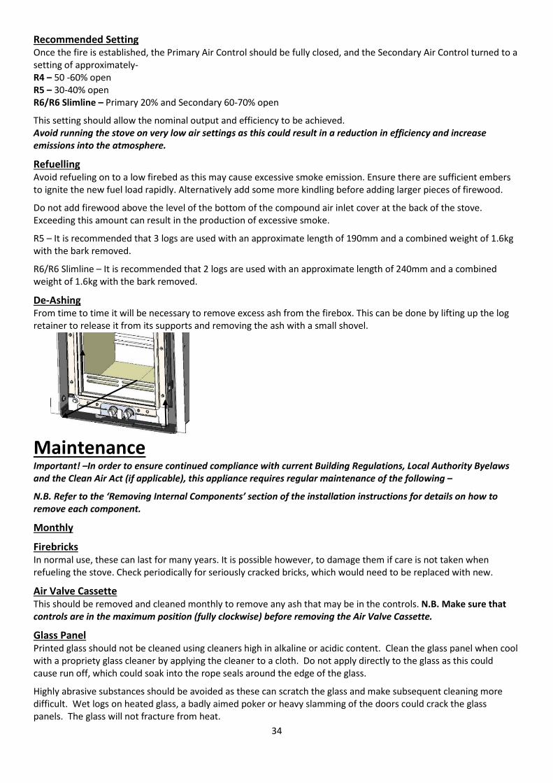
De-Ashing From time to time it will be necessary to remove excess ash from the firebox. This can be done by lifting up the log retainer to release it from its supports and removing the ash with a small shovel.
Maintenance Important! –In order to ensure continued compliance with current Building Regulations, Local Authority Byelaws and the Clean Air Act (if applicable), this appliance requires regular maintenance of the following –
N.B. Refer to the ‘Removing Internal Components’ section of the installation instructions for details on how to remove each component.
Monthly
Firebricks In normal use, these can last for many years. It is possible however, to damage them if care is not taken when refueling the stove. Check periodically for seriously cracked bricks, which would need to be replaced with new.
Air Valve Cassette This should be removed and cleaned monthly to remove any ash that may be in the controls. N.B. Make sure that controls are in the maximum position (fully clockwise) before removing the Air Valve Cassette.
Glass Panel Printed glass should not be cleaned using cleaners high in alkaline or acidic content. Clean the glass panel when cool with a propriety glass cleaner by applying the cleaner to a cloth. Do not apply directly to the glass as this could cause run off, which could soak into the rope seals around the edge of the glass.
Highly abrasive substances should be avoided as these can scratch the glass and make subsequent cleaning more difficult. Wet logs on heated glass, a badly aimed poker or heavy slamming of the doors could crack the glass panels. The glass will not fracture from heat.
35
Rope If the rope around the door is becoming detached use, proprietary rope adhesive to re-attach it. If the rope is in poor condition, it will need replacing.
All spares can be ordered from our website www.hunterstoves.co.uk/spares or from your dealer.
Annually Annual maintenance of the following should be carried out by a competent person –
Baffle Brick/Steel Baffle This should be removed and cleaned annually (or more if needed) to prevent any buildup of soot or ash that could lead to blocked flue ways. With the baffle removed, the chimney can be swept through the appliance.
Chimney And Flue Ways It is important that the chimney, flue ways and any connecting pipe are swept regularly. This means at least twice a year for Woodburning appliances. Only wire-centred sweeps’ brushes fitted with a guide wheel should be used. If it is not possible to sweep all parts of the chimney through the appliance, ensure there is adequate access to cleaning doors.
If the stove is fitted in place of an open fire, the chimney should be swept one month after installation to clear any soot falls which may have occurred due to the difference in combustion between the stove and the open fire.
Periods Of Prolonged Non-Use If the stove is to be left unused for a prolonged period, then it should be given a thorough clean to remove ash and unburned fuel residues. To enable a good flow of air through the appliance to reduce condensation and subsequent damage, leave the air controls fully open.
If the appliance has been unused for a prolonged period, such as the spring and summer months, a competent person should check the chimney for potential obstructions before lighting the stove i.e. get the chimney swept before the start of the heating season.
As Necessary
Stove Body The stove is finished with a heat resistant paint and this can be cleaned with a dry microfiber cloth or a dry soft brush only. Do not clean whilst the stove is hot. At no point should any water based or other cleaning products be used on the stove. The finish can be renovated with Hunter Stoves paint.
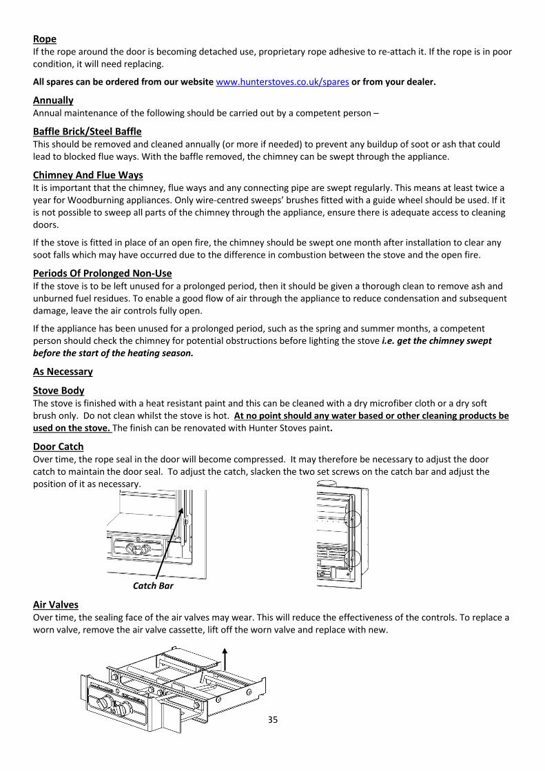
Door Catch Over time, the rope seal in the door will become compressed. It may therefore be necessary to adjust the door catch to maintain the door seal. To adjust the catch, slacken the two set screws on the catch bar and adjust the position of it as necessary.
Air Valves Over time, the sealing face of the air valves may wear. This will reduce the effectiveness of the controls. To replace a worn valve, remove the air valve cassette, lift off the worn valve and replace with new.
Catch Bar
36
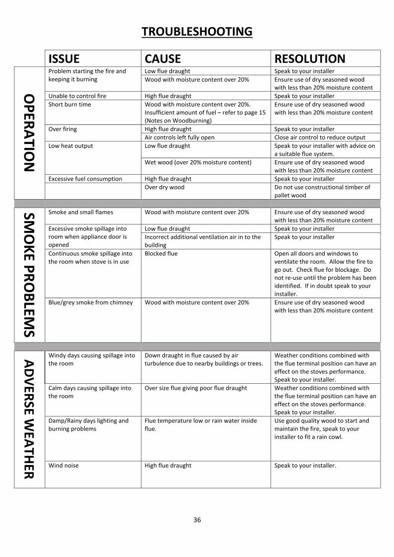
TROUBLESHOOTING
ISSUE CAUSE RESOLUTION
OPERATIO
N
Problem starting the fire and keeping it burning
Low flue draught Speak to your installer Wood with moisture content over 20% Ensure use of dry seasoned wood
with less than 20% moisture content Unable to control fire High flue draught Speak to your installer Short burn time Wood with moisture content over 20%.
Insufficient amount of fuel – refer to page 15 (Notes on Woodburning)
Ensure use of dry seasoned wood with less than 20% moisture content
Over firing High flue draught Speak to your installer Air controls left fully open Close air control to reduce output
Low heat output Low flue draught Speak to your installer with advice on a suitable flue system.
Wet wood (over 20% moisture content) Ensure use of dry seasoned wood with less than 20% moisture content
Excessive fuel consumption High flue draught Speak to your installer Over dry wood Do not use constructional timber of
pallet wood SM
OKE PRO
BLEMS
Smoke and small flames Wood with moisture content over 20% Ensure use of dry seasoned wood with less than 20% moisture content
Excessive smoke spillage into room when appliance door is opened
Low flue draught Speak to your installer Incorrect additional ventilation air in to the building
Speak to your installer
Continuous smoke spillage into the room when stove is in use
Blocked flue Open all doors and windows to ventilate the room. Allow the fire to go out. Check flue for blockage. Do not re-use until the problem has been identified. If in doubt speak to your installer.
Blue/grey smoke from chimney Wood with moisture content over 20% Ensure use of dry seasoned wood with less than 20% moisture content
ADVERSE WEATHER
Windy days causing spillage into the room
Down draught in flue caused by air turbulence due to nearby buildings or trees.
Weather conditions combined with the flue terminal position can have an effect on the stoves performance. Speak to your installer.
Calm days causing spillage into the room
Over size flue giving poor flue draught Weather conditions combined with the flue terminal position can have an effect on the stoves performance. Speak to your installer.
Damp/Rainy days lighting and burning problems
Flue temperature low or rain water inside flue.
Use good quality wood to start and maintain the fire, speak to your installer to fit a rain cowl.
Wind noise High flue draught Speak to your installer.
37
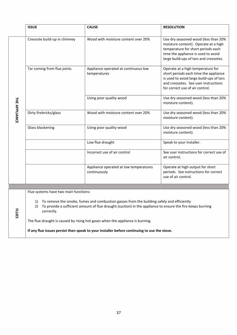
ISSUE CAUSE RESOLUTION
THE APPLIANCE
Creosote build-up in chimney Wood with moisture content over 20% Use dry seasoned wood (less than 20% moisture content). Operate at a high temperature for short periods each time the appliance is used to avoid large build-ups of tars and creosotes.
Tar coming from flue joints Appliance operated at continuous low temperatures
Operate at a high temperature for short periods each time the appliance is used to avoid large build-ups of tars and creosotes. See user instructions for correct use of air control.
Using poor quality wood Use dry seasoned wood (less than 20% moisture content).
Dirty firebricks/glass Wood with moisture content over 20% Use dry seasoned wood (less than 20% moisture content).
Glass blackening Using poor quality wood Use dry seasoned wood (less than 20% moisture content).
Low flue draught Speak to your installer.
Incorrect use of air control See user instructions for correct use of air control.
Appliance operated at low temperatures continuously
Operate at high output for short periods. See instructions for correct use of air control.
FLUES
Flue systems have two main functions:
1) To remove the smoke, fumes and combustion gasses from the building safely and efficiently 2) To provide a sufficient amount of flue draught (suction) in the appliance to ensure the fire keeps burning
correctly. The flue draught is caused by rising hot gases when the appliance is burning. If any flue issues persist then speak to your installer before continuing to use the stove.
38
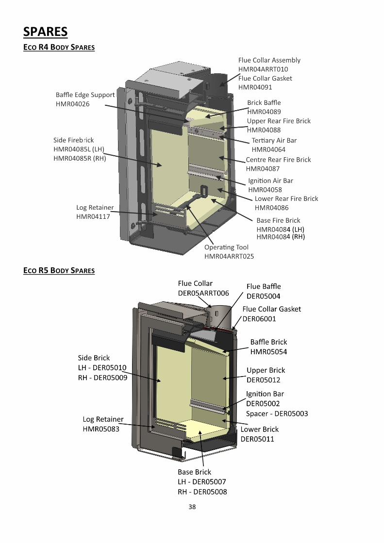
SPARES ECO R4 BODY SPARES
ECO R5 BODY SPARES
39
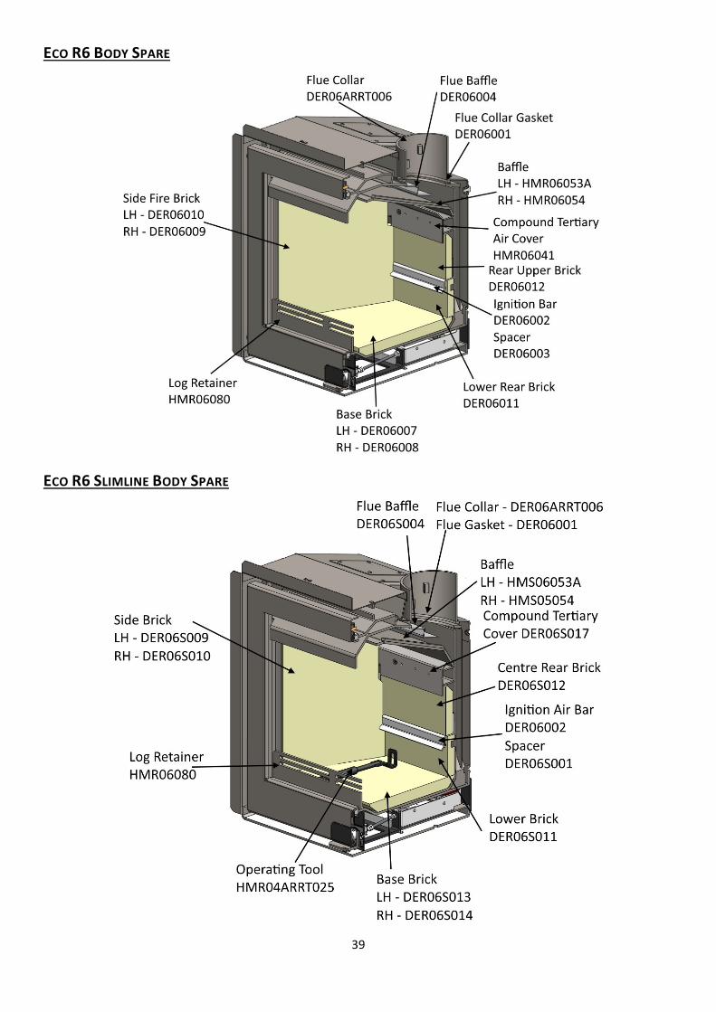
ECO R6 BODY SPARE
ECO R6 SLIMLINE BODY SPARE
40
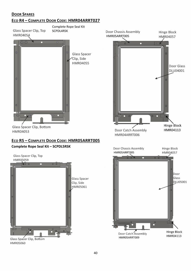
DOOR SPARES ECO R4 – COMPLETE DOOR CODE: HMR04ARRT027
ECO R5 – COMPLETE DOOR CODE: HMR05ARRT005 Complete Rope Seal Kit – SCPDL5RSK
Stove Spares AIR VALVE CASSETTE SPARES
41
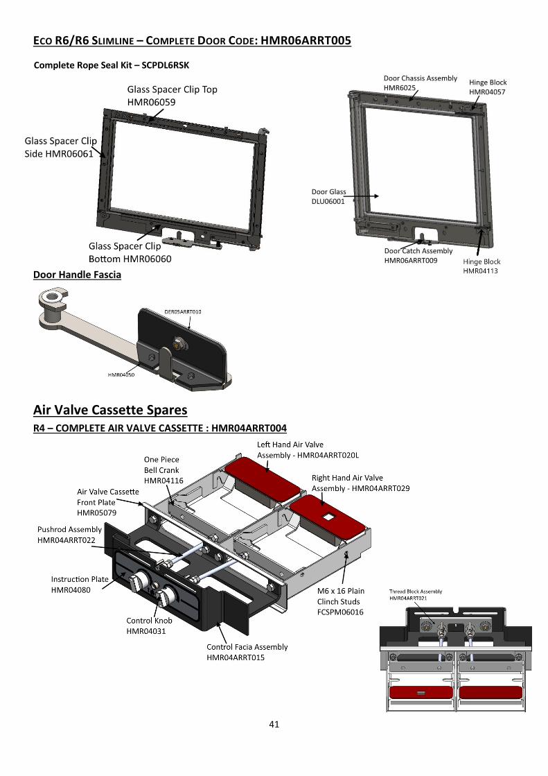
ECO R6/R6 SLIMLINE – COMPLETE DOOR CODE: HMR06ARRT005
Door Handle Fascia
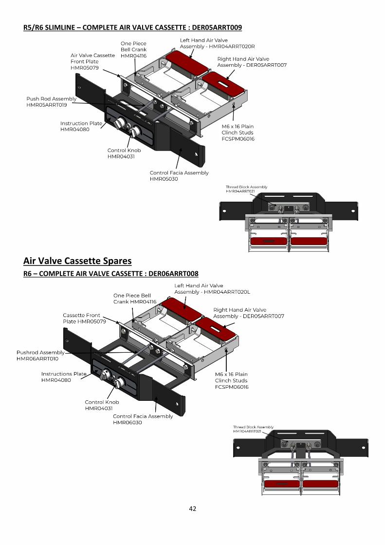
Air Valve Cassette Spares R4 – COMPLETE AIR VALVE CASSETTE : HMR04ARRT004
Complete Rope Seal Kit – SCPDL6RSK
42
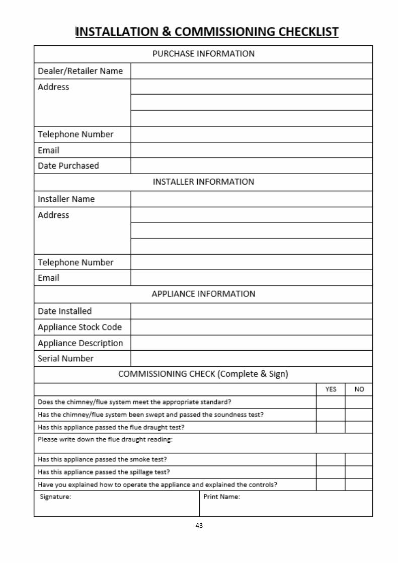
R5/R6 SLIMLINE – COMPLETE AIR VALVE CASSETTE : DER05ARRT009
Air Valve Cassette Spares R6 – COMPLETE AIR VALVE CASSETTE : DER06ARRT008
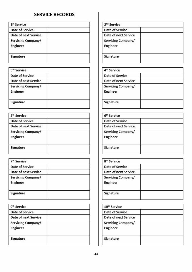
43
44
45
Hunter Stoves Group Ltd Extended 5 and 10 Year Warranty 2 Year Standard Warranty
Any appliance bought through the showroom of an authorised Hunter Stoves Group dealership will automatically be covered by our standard 2-year conditional guarantee.
However, this standard 2-year warranty can be extended to a 5 year or 10-year conditional warranty dependent on the model type (5 years- Boiler model and Gas models, 10 years- Room heater).
To qualify for this extended warranty option, you need to:
1. Register your purchase online at https://www.hunterstoves.co.uk/ProductRegistration 2. Retain your proof of purchase.
Warranty Conditions
For the Standard 2 year or extended 5/10-year warranty to be valid and to remain in force throughout the warranty period the following must have been carried out:
1. The appliance must have been installed by an appropriately qualified engineer (from the Competent Person Scheme/Gas Safe) in accordance with the manufacturer’s instructions and in compliance of any relevant national or local building regulations. Please visit the following links for details on the Competent Person Scheme: https://www.gov.uk/guidance/competent-person-scheme-current-schemes-and-how-schemes-are-authorised and Gas Safe register: https://www.gassaferegister.co.uk/
2. The appliance will need to be registered within two months of purchase and the commissioning and installation documentation completed (these need to be kept by the end user).
3. The appliance must be serviced within 12 months of the installation date for the second year of the standard warranty to be valid, and within every 12-month anniversary thereafter to maintain the validity and coverage of any extended warranty. For this purpose, the installation and user instructions, supplied with the appliance, makes a provision for receipts and annual services to be recorded. This is needed in the event of a claim during the warranty period.
4. Only genuine Hunter Stoves spare parts or consumables can be used in the servicing and maintenance of the appliance during any standard or extended warranty period. These can be sourced from your authorised supplier directly or through our website spares portal. www.hunterstoves.co.uk/spares.
5. Any problems or issues giving rise to any claim under the standard or extended warranty must be submitted to the authorised Hunter Stoves Group retailer from whom you originally purchased the appliance. Hunter Stoves Group will then offer appropriate support and help through your original authorised supplier to solve any issues.
6. The standard or extended warranty option is not transferable. It is solely for the benefit of the original purchaser of the appliance. For this purpose, please retain the proof of purchase.
Warranty Exclusions No warranty period is extended to naturally wearing replaceable consumables and spare parts within the appliance. Such parts include, but are not limited to: For Solid Fuel Stoves: Glass and rope/ceramic seals Fire bricks Baffles/Throat plates Log retainers, grate supports & catch bars Grate parts Ash-pans Clip-in Boilers For Gas Stoves: Gas pilot assemblies Thermocouples and Oxy pilots Ceramic log & coal 'fuel -effects' Batteries
46
Paint and Surface Coverings The paint or surface covering of the appliance will be covered (for 2 years after installation) provided the warranty conditions are met. However, damage due to the following events will not be covered:
1. Damage to the paint surface caused by the appliance being stored in a damp and cold environment is not covered under warranty. Please be aware that any moisture within the room where the stove is installed e.g. through clothes drying, can be a cause of paint issues.
2. In the course of the initial firings of the appliance the paint or enamel surface may change colour. This is normal and as such is therefore not covered under warranty.
3. Damaged caused by over firing, resulting in cracking, bubbling or discolouration to the paint or enamelled surface finish is not covered under warranty.
Warranty Limitations
1. Damage to the appliance due to specific local conditions caused by draft or chimney defects.
2. Damage resulting from installation and use where installation is not in accordance with the manufacturer’s instructions or local building and/or safety regulations.
3. Damage or premature wear caused by burning inappropriate fuels such as Bituminous coal, “Petro-Coke” or any other Petroleum based coals. Please visit the HETAS website, www.hetas.co.uk, for a full list of approved fuels which are covered by the warranty. Fuels outside of this list are not covered by the warranty.
4. Damage caused by burning material with high creosote content or any other painted/treated timber.
5. Consequential loss to associated non-Hunter Stoves Group products is not covered under the warranty.
6. Consequential loss relating to decorations, soft furnishings or other household assets is not covered under the warranty.
7. Cost associated with the removal and re-installation of an appliance subject to a warranty claim. Hunter Stoves Group total liability will only extend to the total purchase price paid for the goods in any warranty claim. Hunter Stoves Group reserve the right to replace, repair or refund to value of goods purchased. ANY HUNTERS STOVES GROUP PRODUCT PURCHASED VIA AN INTERNET SUPPLIER, OR THROUGH AN UNAUTHORISED STOCKIST WILL ONLY BE SUPPORTED BY THE STATUTORY, 12 MONTH GUARANTEE AND WILL NOT QUALIFY FOR ANY EXTENDED 5- OR 10-YEAR WARRANTY. The Hunter Stoves Group extended warranty option does not affect your statutory rights. This revised standard or extended 5 or 10-year warranty option comes into effect on 1st September 2015 and will apply to all appliances sold from that date. This standard/extended warranty applies to purchases of Hunter Stoves within the United Kingdom and the Republic of Ireland. Purchases in all other countries are subject to the warranty conditions specified by the distributer in those markets.
Hunter Stoves Ltd, 8 Emperor Way, Exeter Business Park, Exeter, Devon, EX1 3QS www.hunterstoves.co.uk Email: [email protected]
Further Information For extra guidance on using your stove, please visit our YouTube channel by searching ‘Hunter Stoves Group’ or see the helpful hints section of our website; www.hunterstoves.co.uk.
This appliance is suitable for intermittent burning. This appliance should not be used in a shared flue.
All genuine Hunter Group spares can be purchased through our website www.hunterstoves.co.uk/spares or through your authorised dealer.