eco - ecp - winco generators
TRANSCRIPT
SELF-REGULATING ALTERNATORS SERIES ECO-ECP
OPERATING AND MAINTENANCE INSTRUCTIONS
ALTERNATORI AUTOREGOLATI SERIE ECO-ECP
ISTRUZIONI PER L’USO E LA MANUTENZIONE
ALTERNATEURS AUTO-REGULES SERIE ECO-ECP
MANUEL D’INSTRUCTION ET DE MAINTENANCE
SELBSTREGELNDER GENERATOR SERIE ECO-ECP
BETRIEBS-UND WARTUNGSANLEITUNG
ALTERNADORES AUTOREGULADOS SERIE ECO-ECP
INSTRUCCIONES PARA USO Y MANTENIMIENTO
自调节式发电机 ECO-ECP系列 操作及保养手册
САМОРЕГУЛИРУЕМАЯ ГЕНЕРАТОРЫ СЕРИИ ECO-ECP
ЭКСПЛУАТАЦИЯ И ТЕХНИЧЕСКОЕ ОБСЛУЖИВАНИЕ ИНСТРУКЦИЯ
SAMOREGULAČNÍ ALTERN SERIES ECO-ECP
OPERACE A ÚDRŽBU
ÖNSZABÁLYOZÓ GENERÁTOR SERIES ECO-ECP
ÜZEMELTETÉSI ÉS KARBANTARTÁSI UTASÍTÁSOK
SAMOREGULUJĄCY SERIES ALTERNATORY ECO-ECP
OPERACJE I KONSERWACJI
AUTOREGLARE ALTERNATOARE SERIA ECO-ECP
OPERAȚIUNI INSTRUCȚIUNILOR DE ÎNTREȚINERE ȘI
SAMOREGULAČNÉ ALTERNA SERIES ECO-ECP
OPERÁCIE A ÚDRŽBU
ECO - ECP
GB
IT
F
D
E
CN
SK
RO
RU
CZ
HU
PL
2 ECO-ECP iMANUAL December 2013 Rev. 03
ECO - ECP MANUAL ENGLISH
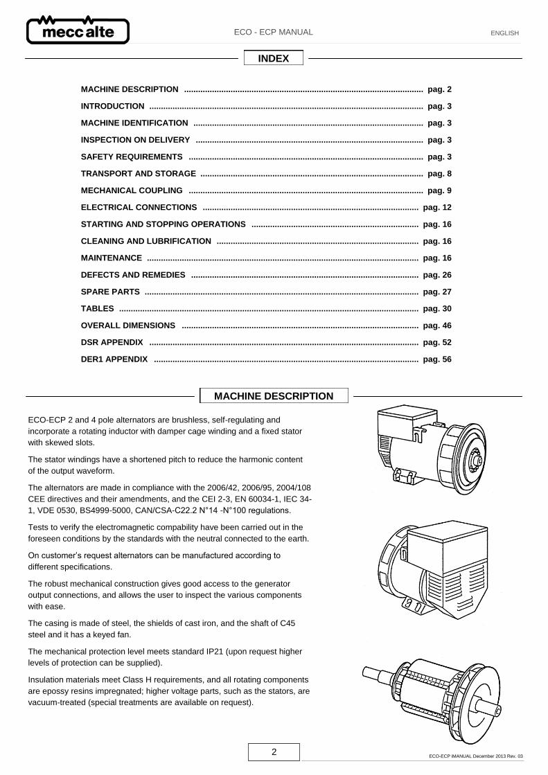
ECO-ECP 2 and 4 pole alternators are brushless, self-regulating and
incorporate a rotating inductor with damper cage winding and a fixed stator
with skewed slots.
The stator windings have a shortened pitch to reduce the harmonic content
of the output waveform.
The alternators are made in compliance with the 2006/42, 2006/95, 2004/108
CEE directives and their amendments, and the CEI 2-3, EN 60034-1, IEC 34-
1, VDE 0530, BS4999-5000, CAN/CSA-C22.2 N°14 -N°100 regulations.
Tests to verify the electromagnetic compability have been carried out in the
foreseen conditions by the standards with the neutral connected to the earth.
On customer’s request alternators can be manufactured according to
different specifications.
The robust mechanical construction gives good access to the generator
output connections, and allows the user to inspect the various components
with ease.
The casing is made of steel, the shields of cast iron, and the shaft of C45
steel and it has a keyed fan.
The mechanical protection level meets standard IP21 (upon request higher
levels of protection can be supplied).
Insulation materials meet Class H requirements, and all rotating components
are epossy resins impregnated; higher voltage parts, such as the stators, are
vacuum-treated (special treatments are available on request).
MACHINE DESCRIPTION
INDEX
MACHINE DESCRIPTION ....................................................................................................... pag. 2
INTRODUCTION ...................................................................................................................... pag. 3
MACHINE IDENTIFICATION ................................................................................................... pag. 3
INSPECTION ON DELIVERY .................................................................................................. pag. 3
SAFETY REQUIREMENTS ..................................................................................................... pag. 3
TRANSPORT AND STORAGE ................................................................................................ pag. 8
MECHANICAL COUPLING ..................................................................................................... pag. 9
ELECTRICAL CONNECTIONS ............................................................................................. pag. 12
STARTING AND STOPPING OPERATIONS ........................................................................ pag. 16
CLEANING AND LUBRIFICATION ....................................................................................... pag. 16
MAINTENANCE ..................................................................................................................... pag. 16
DEFECTS AND REMEDIES .................................................................................................. pag. 26
SPARE PARTS ...................................................................................................................... pag. 27
TABLES ................................................................................................................................. pag. 30
OVERALL DIMENSIONS ...................................................................................................... pag. 46
DSR APPENDIX .................................................................................................................... pag. 52
DER1 APPENDIX .................................................................................................................. pag. 56
3 ECO-ECP iMANUAL December 2013 Rev. 03
ECO - ECP MANUAL ENGLISH
The ECO-ECP alternators comply with the EEC 2006/42, 2006/95,
2004/108 directives and their amendments; therefore they pose no
danger to the operator if they are installed, used and maintained
according to the instructions given by Mecc Alte and provided the
safety devices are kept in perfect working conditions.
Therefore a strict observance of these instructions is required.
Any reproduction of this manual is forbidden.
INTRODUCTION
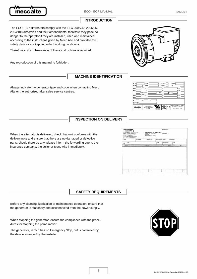
Always indicate the generator type and code when contacting Mecc
Alte or the authorized after sales service centres.
MACHINE IDENTIFICATION
When the alternator is delivered, check that unit conforms with the
delivery note and ensure that there are no damaged or defective
parts; should there be any, please inform the forwarding agent, the
insurance company, the seller or Mecc Alte immediately.
INSPECTION ON DELIVERY
Before any cleaning, lubrication or maintenance operation, ensure that
the generator is stationary and disconnected from the power supply.
When stopping the generator, ensure the compliance with the proce-
dures for stopping the prime mover.
The generator, in fact, has no Emergency Stop, but is controlled by
the device arranged by the installer.
SAFETY REQUIREMENTS
4 ECO-ECP iMANUAL December 2013 Rev. 03
ECO - ECP MANUAL ENGLISH
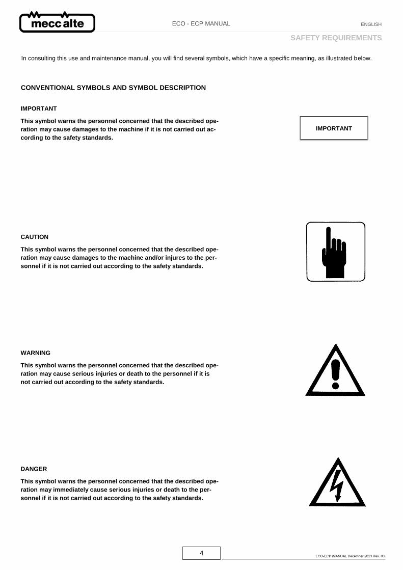
In consulting this use and maintenance manual, you will find several symbols, which have a specific meaning, as illustrated below.
CONVENTIONAL SYMBOLS AND SYMBOL DESCRIPTION
IMPORTANT
This symbol warns the personnel concerned that the described ope-
ration may cause damages to the machine if it is not carried out ac-
cording to the safety standards.
CAUTION
This symbol warns the personnel concerned that the described ope-
ration may cause damages to the machine and/or injures to the per-
sonnel if it is not carried out according to the safety standards.
WARNING
This symbol warns the personnel concerned that the described ope-
ration may cause serious injuries or death to the personnel if it is
not carried out according to the safety standards.
DANGER
This symbol warns the personnel concerned that the described ope-
ration may immediately cause serious injuries or death to the per-
sonnel if it is not carried out according to the safety standards.
IMPORTANT
SAFETY REQUIREMENTS
5 ECO-ECP iMANUAL December 2013 Rev. 03
ECO - ECP MANUAL ENGLISH
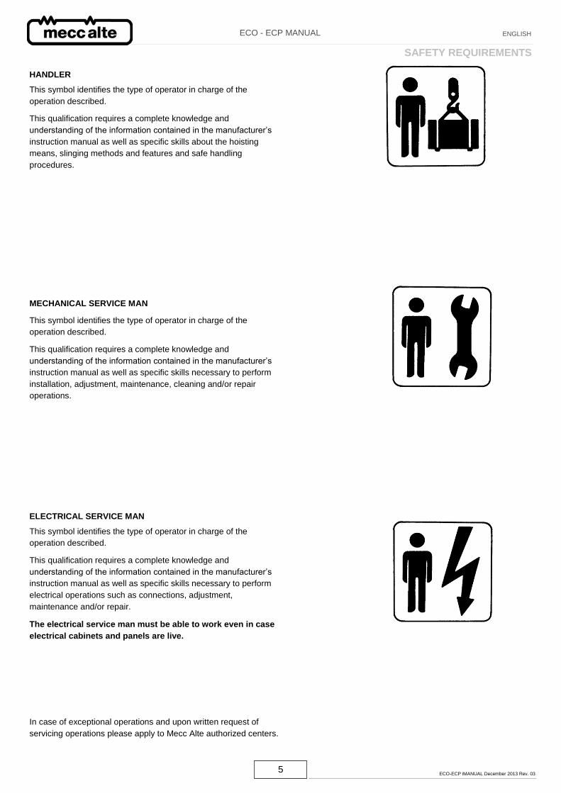
HANDLER
This symbol identifies the type of operator in charge of the
operation described.
This qualification requires a complete knowledge and
understanding of the information contained in the manufacturer’s
instruction manual as well as specific skills about the hoisting
means, slinging methods and features and safe handling
procedures.
MECHANICAL SERVICE MAN
This symbol identifies the type of operator in charge of the
operation described.
This qualification requires a complete knowledge and
understanding of the information contained in the manufacturer’s
instruction manual as well as specific skills necessary to perform
installation, adjustment, maintenance, cleaning and/or repair
operations.
ELECTRICAL SERVICE MAN
This symbol identifies the type of operator in charge of the
operation described.
This qualification requires a complete knowledge and
understanding of the information contained in the manufacturer’s
instruction manual as well as specific skills necessary to perform
electrical operations such as connections, adjustment,
maintenance and/or repair.
The electrical service man must be able to work even in case
electrical cabinets and panels are live.
In case of exceptional operations and upon written request of
servicing operations please apply to Mecc Alte authorized centers.
SAFETY REQUIREMENTS

6 ECO-ECP iMANUAL December 2013 Rev. 03
ECO - ECP MANUAL ENGLISH
Before installing the generator, arrangements must be made to
earth the machine.
This is the reason why you must make sure that the grounding sy-
stem is in good conditions and in compliance with the regulations of
the country where the generator will be installed.
CAUTION
THE FINAL INSTALLER IS RESPONSIBLE FOR THE INSTALLA-
TION OF ALL THE PROTECTIONS (SECTIONING DEVICES,
PROTECTIONS AGAINST DIRECT AND INDIRECT CONTACTS,
OVERCURRENT AND OVERVOLTAGE PROTECTIONS, EMER-
GENCY STOP, ETC.) NECESSARY FOR THE MACHINE TO
COMPLY WITH THE EXISTING INTERNATIONAL/EUROPEAN
SAFETY REGULATIONS.
For handling the unpacked generators, always use the special
eyebolts only; use ropes having a suitable carrying capacity and do
not lift the generator too much from the floor (max 30 cm.).
When the machine is worn cut, contact the companies in charge of
the disposal of ferrous material and do not throw away its parts into
the environment.
The operators in charge of the installation, operation and mainte-
nance of the generators must be skilled technicians who know the
characteristics of the generators.
The people in charge of the handling must always wear work gloves
and safety shoes. In case the generator or the whole plant must be
lifted from the floor, the operators must wear a safety helmet.
The generator must be installed in an airy room. If there is not
enough air, a malfunction or an overheating may occur (table 25
pag. 44). All entry doors into generator room should be clearly mar-
ked “Authorized persons only”.
Make sure that genset foundations and baseframe are suitable to
bear the combined weight of the alternators and prime mover.
The installer is responsible for the correct coupling of the generator
to the engine and for the performance of all precautions necessary
to guarantee the correct operation of the generator and avoid abnor-
mal stress, which could damage the generator (such as vibrations,
misalignment, strange noises or vibrations, etc.)
The machine was designed to guarantee the nominal power in envi-
ronments with a maximum temperature of 40° C, at altitudes lower
than 1000 m asl (EN60034-1), unless otherwise specified; for diffe-
rent operating conditions, see the commercial catalogue (brochure).
SAFETY REQUIREMENTS
7 ECO-ECP iMANUAL December 2013 Rev. 03
ECO - ECP MANUAL ENGLISH
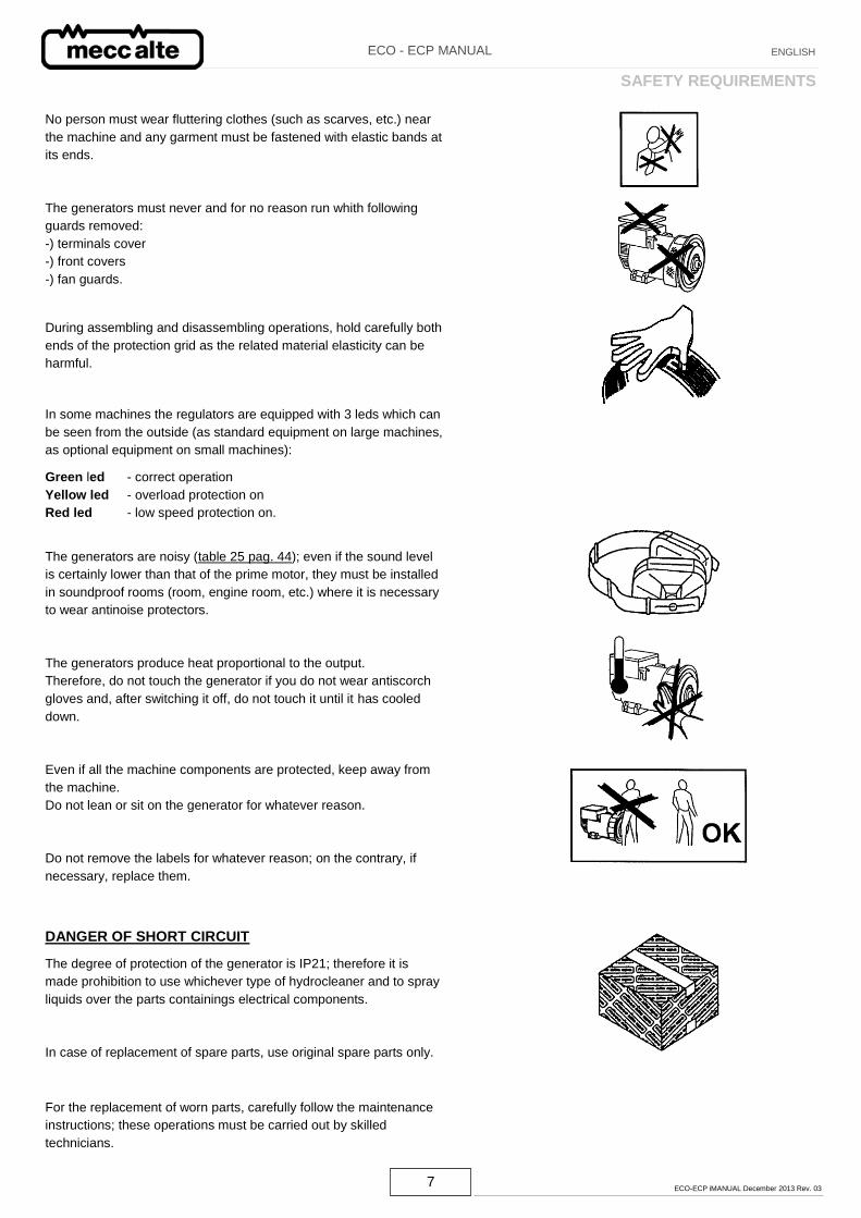
No person must wear fluttering clothes (such as scarves, etc.) near
the machine and any garment must be fastened with elastic bands at
its ends.
The generators must never and for no reason run whith following
guards removed:
-) terminals cover
-) front covers
-) fan guards.
During assembling and disassembling operations, hold carefully both
ends of the protection grid as the related material elasticity can be
harmful.
In some machines the regulators are equipped with 3 leds which can
be seen from the outside (as standard equipment on large machines,
as optional equipment on small machines):
Green led - correct operation
Yellow led - overload protection on
Red led - low speed protection on.
The generators are noisy (table 25 pag. 44); even if the sound level
is certainly lower than that of the prime motor, they must be installed
in soundproof rooms (room, engine room, etc.) where it is necessary
to wear antinoise protectors.
The generators produce heat proportional to the output.
Therefore, do not touch the generator if you do not wear antiscorch
gloves and, after switching it off, do not touch it until it has cooled
down.
Even if all the machine components are protected, keep away from
the machine.
Do not lean or sit on the generator for whatever reason.
Do not remove the labels for whatever reason; on the contrary, if
necessary, replace them.
DANGER OF SHORT CIRCUIT
The degree of protection of the generator is IP21; therefore it is
made prohibition to use whichever type of hydrocleaner and to spray
liquids over the parts containings electrical components.
In case of replacement of spare parts, use original spare parts only.
For the replacement of worn parts, carefully follow the maintenance
instructions; these operations must be carried out by skilled
technicians.
SAFETY REQUIREMENTS
8 ECO-ECP iMANUAL December 2013 Rev. 03
ECO - ECP MANUAL ENGLISH
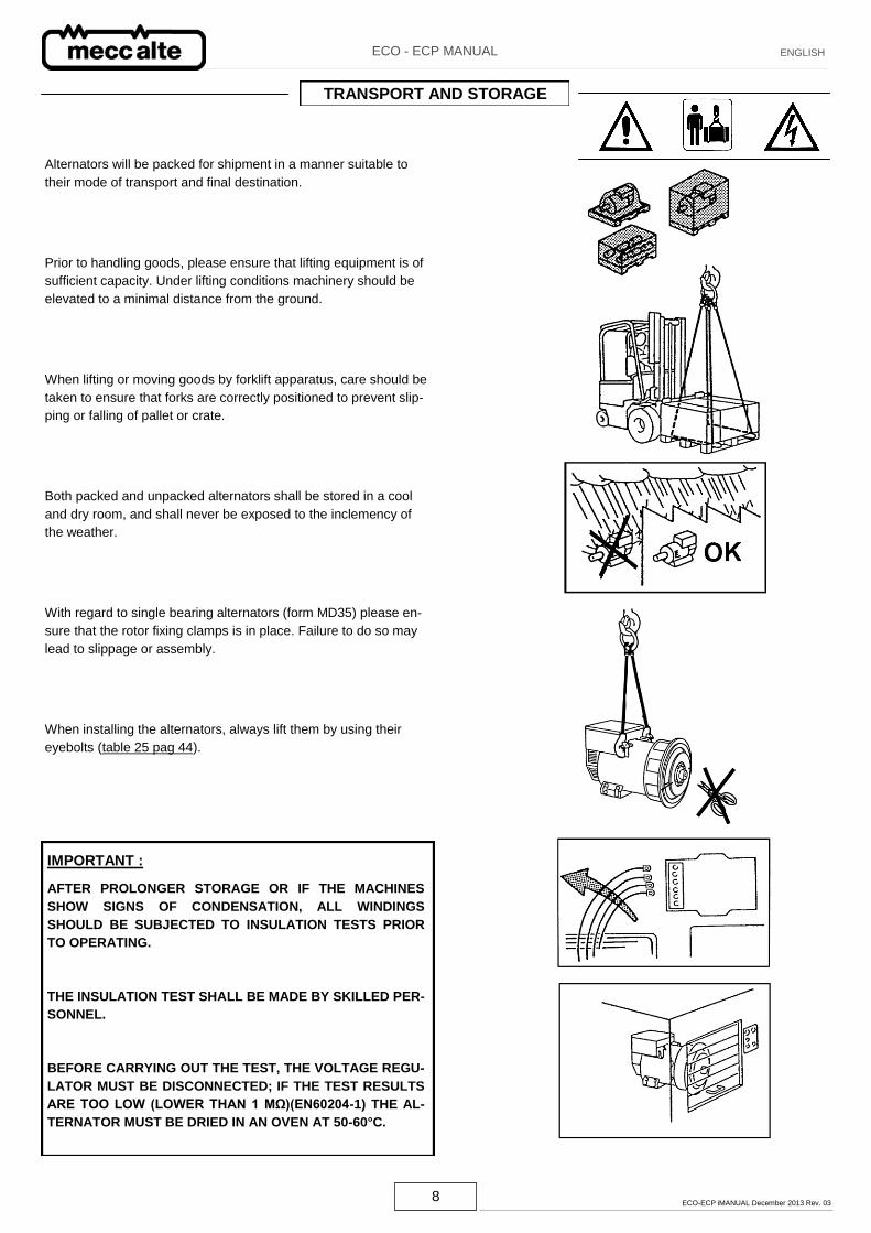
Alternators will be packed for shipment in a manner suitable to
their mode of transport and final destination.
Prior to handling goods, please ensure that lifting equipment is of
sufficient capacity. Under lifting conditions machinery should be
elevated to a minimal distance from the ground.
When lifting or moving goods by forklift apparatus, care should be
taken to ensure that forks are correctly positioned to prevent slip-
ping or falling of pallet or crate.
Both packed and unpacked alternators shall be stored in a cool
and dry room, and shall never be exposed to the inclemency of
the weather.
With regard to single bearing alternators (form MD35) please en-
sure that the rotor fixing clamps is in place. Failure to do so may
lead to slippage or assembly.
When installing the alternators, always lift them by using their
eyebolts (table 25 pag 44).
IMPORTANT :
AFTER PROLONGER STORAGE OR IF THE MACHINES
SHOW SIGNS OF CONDENSATION, ALL WINDINGS
SHOULD BE SUBJECTED TO INSULATION TESTS PRIOR
TO OPERATING.
THE INSULATION TEST SHALL BE MADE BY SKILLED PER-
SONNEL.
BEFORE CARRYING OUT THE TEST, THE VOLTAGE REGU-
LATOR MUST BE DISCONNECTED; IF THE TEST RESULTS
ARE TOO LOW (LOWER THAN 1 MΩ)(EN60204-1) THE AL-
TERNATOR MUST BE DRIED IN AN OVEN AT 50-60°C.
TRANSPORT AND STORAGE
9 ECO-ECP iMANUAL December 2013 Rev. 03
ECO - ECP MANUAL ENGLISH
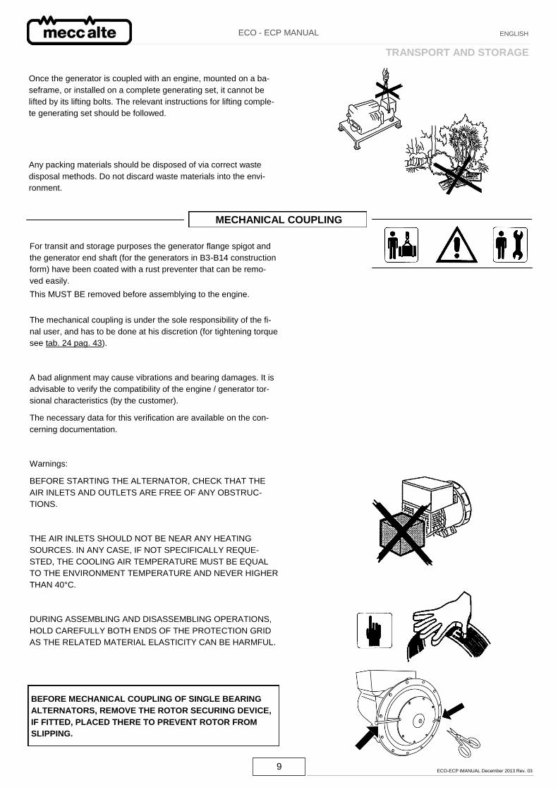
Once the generator is coupled with an engine, mounted on a ba-
seframe, or installed on a complete generating set, it cannot be
lifted by its lifting bolts. The relevant instructions for lifting comple-
te generating set should be followed.
Any packing materials should be disposed of via correct waste
disposal methods. Do not discard waste materials into the envi-
ronment.
MECHANICAL COUPLING
The mechanical coupling is under the sole responsibility of the fi-
nal user, and has to be done at his discretion (for tightening torque
see tab. 24 pag. 43).
A bad alignment may cause vibrations and bearing damages. It is
advisable to verify the compatibility of the engine / generator tor-
sional characteristics (by the customer).
The necessary data for this verification are available on the con-
cerning documentation.
Warnings:
BEFORE STARTING THE ALTERNATOR, CHECK THAT THE
AIR INLETS AND OUTLETS ARE FREE OF ANY OBSTRUC-
TIONS.
THE AIR INLETS SHOULD NOT BE NEAR ANY HEATING
SOURCES. IN ANY CASE, IF NOT SPECIFICALLY REQUE-
STED, THE COOLING AIR TEMPERATURE MUST BE EQUAL
TO THE ENVIRONMENT TEMPERATURE AND NEVER HIGHER
THAN 40°C.
DURING ASSEMBLING AND DISASSEMBLING OPERATIONS,
HOLD CAREFULLY BOTH ENDS OF THE PROTECTION GRID
AS THE RELATED MATERIAL ELASTICITY CAN BE HARMFUL.
BEFORE MECHANICAL COUPLING OF SINGLE BEARING
ALTERNATORS, REMOVE THE ROTOR SECURING DEVICE,
IF FITTED, PLACED THERE TO PREVENT ROTOR FROM
SLIPPING.
For transit and storage purposes the generator flange spigot and
the generator end shaft (for the generators in B3-B14 construction
form) have been coated with a rust preventer that can be remo-
ved easily.
This MUST BE removed before assemblying to the engine.
TRANSPORT AND STORAGE
10 ECO-ECP iMANUAL December 2013 Rev. 03
ECO - ECP MANUAL ENGLISH
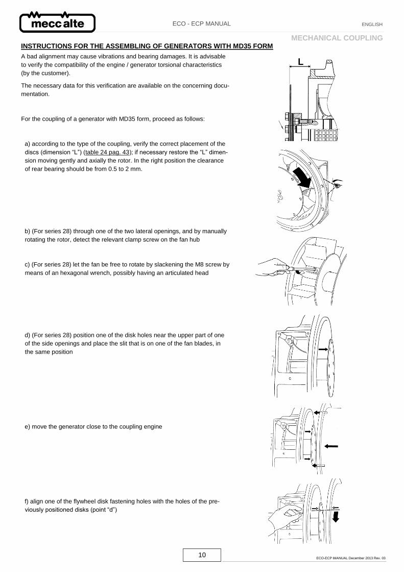
A bad alignment may cause vibrations and bearing damages. It is advisable
to verify the compatibility of the engine / generator torsional characteristics
(by the customer).
The necessary data for this verification are available on the concerning docu-
mentation.
For the coupling of a generator with MD35 form, proceed as follows:
a) according to the type of the coupling, verify the correct placement of the
discs (dimension “L”) (table 24 pag. 43); if necessary restore the “L” dimen-
sion moving gently and axially the rotor. In the right position the clearance
of rear bearing should be from 0.5 to 2 mm.
b) (For series 28) through one of the two lateral openings, and by manually
rotating the rotor, detect the relevant clamp screw on the fan hub
c) (For series 28) let the fan be free to rotate by slackening the M8 screw by
means of an hexagonal wrench, possibly having an articulated head
d) (For series 28) position one of the disk holes near the upper part of one
of the side openings and place the slit that is on one of the fan blades, in
the same position
e) move the generator close to the coupling engine
f) align one of the flywheel disk fastening holes with the holes of the pre-
viously positioned disks (point “d”)
INSTRUCTIONS FOR THE ASSEMBLING OF GENERATORS WITH MD35 FORM MECHANICAL COUPLING
11 ECO-ECP iMANUAL December 2013 Rev. 03
ECO - ECP MANUAL ENGLISH
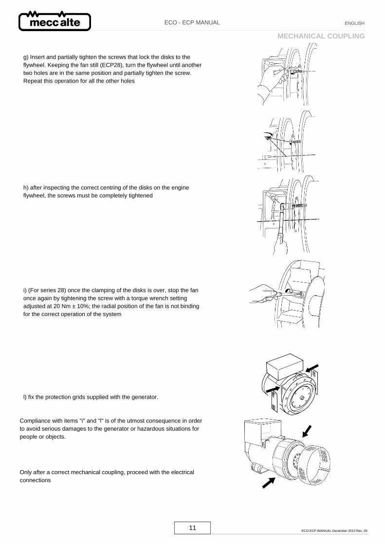
g) Insert and partially tighten the screws that lock the disks to the
flywheel. Keeping the fan still (ECP28), turn the flywheel until another
two holes are in the same position and partially tighten the screw.
Repeat this operation for all the other holes
h) after inspecting the correct centring of the disks on the engine
flywheel, the screws must be completely tightened
i) (For series 28) once the clamping of the disks is over, stop the fan
once again by tightening the screw with a torque wrench setting
adjusted at 20 Nm ± 10%; the radial position of the fan is not binding
for the correct operation of the system
l) fix the protection grids supplied with the generator.
Compliance with items "i" and "l" is of the utmost consequence in order
to avoid serious damages to the generator or hazardous situations for
people or objects.
Only after a correct mechanical coupling, proceed with the electrical
connections
MECHANICAL COUPLING
12 ECO-ECP iMANUAL December 2013 Rev. 03
ECO - ECP MANUAL ENGLISH
ELECTRICAL CONNECTIONS
All electrical output connections are the responsibility of, and are
at the discretion of, the end user.
When making terminal box connections, all cable and terminal lugs
should meet the relevant standards of the country of final destina-
tion.
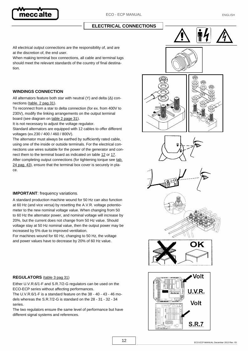
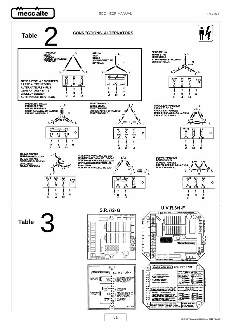
WINDINGS CONNECTION
All alternators feature both star with neutral (Y) and delta (Δ) con-
nections (table. 2 pag.31).
To reconnect from a star to delta connection (for ex. from 400V to
230V), modify the linking arrangements on the output terminal
board (see diagram on table 2 page 31).
It is not necessary to adjust the voltage regulator.
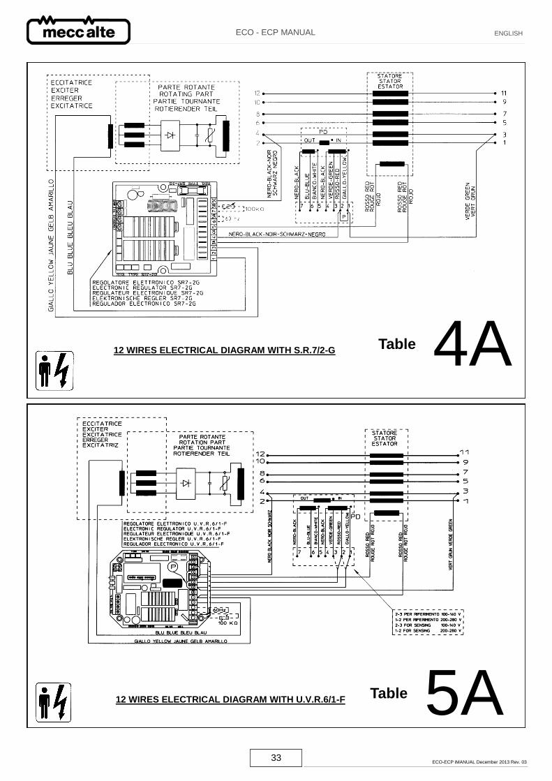
Standard alternators are equipped with 12 cables to offer different
voltages (ex.230 / 400 / 460 / 800V).
The alternator must always be earthed by sufficiently rated cable,
using one of the inside or outside terminals. For the electrical con-
nections use wires suitable for the power of the generator and con-
nect them to the terminal board as indicated on table 12 or 17.
After completing output connections (for tightening torque see tab.
24 pag. 43), ensure that the terminal box cover is securely in pla-
ce.
IMPORTANT: frequency variations.
A standard production machine wound for 50 Hz can also function
at 60 Hz (and vice versa) by resetting the A.V.R. voltage potentio-
meter to the new nominal voltage value. When changing from 50
to 60 Hz the alternator power, and nominal voltage will increase by
20%, but the current does not change from 50 Hz value. Should
voltage stay at 50 Hz nominal value, then the output power may be
increased by 5% due to improved ventilation.
For machines wound for 60 Hz, changing to 50 Hz, the voltage
and power values have to decrease by 20% of 60 Hz value.
REGULATORS (table 3 pag 31)
Either U.V.R.6/1-F and S.R.7/2-G regulators can be used on the
ECO-ECP series without affecting performances.
The U.V.R.6/1-F is a standard feature on the 38 - 40 - 43 - 46 mo-
dels whereas the S.R.7/2-G is standard on the 28 - 31 - 32 - 34
series.
The two regulators ensure the same level of performance but have
different signal systems and references.
13 ECO-ECP iMANUAL December 2013 Rev. 03
ECO - ECP MANUAL ENGLISH
IMPORTANT:
the generator output voltage must be checked under no-load con-
ditions, with the correct setting of frequency.
The voltage may be adjusted by ± 5% of the nominal, by acting
upon the voltage potenziometer on the electronic regulators.
It is possible to get a remote voltage regulation of ± 5% inserting in
the proper terminals a 100K potentiometer (for the 6 lead units) or
a 100K potentiometer with a 100K resistance in series (for the 12
lead units)
Instructions to follow for the external potentiometer connection :
CAUTION: in order to get a correct working of the alternator, it is
necessary to follow the following procedure, connecting the exter-
nal potentiometer.
1) Turn the VOLT trimmer of the electronic regulator completely
anticlockwise.
2) Set the external potentiometer at half turn and connect it to the
proper terminals of the electronic regulator.
3) Adjust the voltage at the nominal value by the VOLT trimmer of
the electronic regulator.
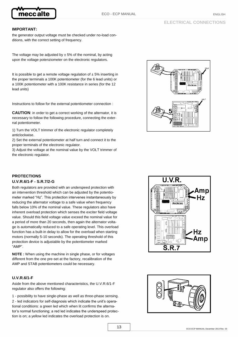
PROTECTIONS
U.V.R.6/1-F - S.R.7/2-G
Both regulators are provided with an underspeed protection with
an intervention threshold which can be adjusted by the potentio-
meter marked “Hz”. This protection intervenes instantaneously by
reducing the alternator voltage to a safe value when frequency
falls below 10% of the nominal value. These regulators also have
inherent overload protection which senses the exciter field voltage
value. Should this field voltage value exceed the nominal value for
a period of more than 20 seconds, then again the alternator volta-
ge is automatically reduced to a safe operating level. This overload
function has a built-in delay to allow for the overload when starting
motors (normally 5-10 seconds). The operating threshold of this
protection device is adjustable by the potentiometer marked
“AMP”.
NOTE : When using the machine in single phase, or for voltages
different from the one pre-set at the factory, recalibration of the
AMP and STAB potentiometers could be necessary.
U.V.R.6/1-F
Aside from the above mentioned characteristics, the U.V.R.6/1-F
regulator also offers the following:
1 - possibility to have single-phase as well as three-phase sensing.
2 - led indicators for self-diagnosis which indicate the unit’s opera-
tional conditions: a green led which when lit confirms the alterna-
tor’s normal functioning; a red led indicates the underspeed protec-
tion is on; a yellow led indicates the overload protection is on.
ELECTRICAL CONNECTIONS
14 ECO-ECP iMANUAL December 2013 Rev. 03
ECO - ECP MANUAL ENGLISH
IMPORTANT
In normal functioning, only the green led has to be lit.
All these indicators can be remotely controlled and adjusted, for any type of
use, by utilizing the SPD96/A accessory which is available on request.
INTERVENTION OF PROTECTION DEVICES CAUSES.
Underspeed protection instantaneous intervention:
1 - speed reduced by 10% of nominal RPM.
Delayed intervention of overload protection:
2 - overload by 20% of nominal rating.
3 - power factor (cos φ) lower than the nominal-one.
4 - ambient temperature above 50°C.
Intervention of both protections:
5 - combination of factor 1 with factors 2, 3, 4.
In case of intervention the output voltage will drop down to a value which
will depend on the fault.
The voltage will return automatically to its nominal value as soon as the
fault is removed.
For further details on regulators, please see the specific manual.
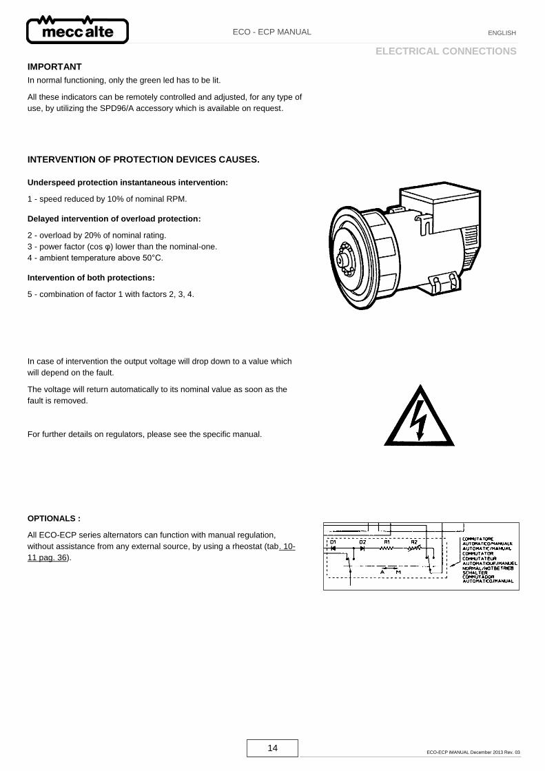
OPTIONALS :
All ECO-ECP series alternators can function with manual regulation,
without assistance from any external source, by using a rheostat (tab. 10-
11 pag. 36).
ELECTRICAL CONNECTIONS
15 ECO-ECP iMANUAL December 2013 Rev. 03
ECO - ECP MANUAL ENGLISH
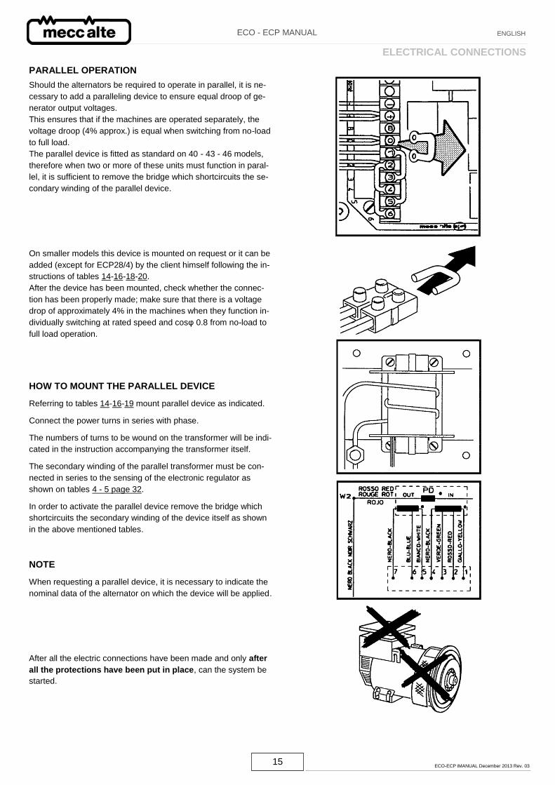
PARALLEL OPERATION
Should the alternators be required to operate in parallel, it is ne-
cessary to add a paralleling device to ensure equal droop of ge-
nerator output voltages.
This ensures that if the machines are operated separately, the
voltage droop (4% approx.) is equal when switching from no-load
to full load.
The parallel device is fitted as standard on 40 - 43 - 46 models,
therefore when two or more of these units must function in paral-
lel, it is sufficient to remove the bridge which shortcircuits the se-
condary winding of the parallel device.
On smaller models this device is mounted on request or it can be
added (except for ECP28/4) by the client himself following the in-
structions of tables 14-16-18-20.
After the device has been mounted, check whether the connec-
tion has been properly made; make sure that there is a voltage
drop of approximately 4% in the machines when they function in-
dividually switching at rated speed and cosφ 0.8 from no-load to
full load operation.
HOW TO MOUNT THE PARALLEL DEVICE
Referring to tables 14-16-19 mount parallel device as indicated.
Connect the power turns in series with phase.
The numbers of turns to be wound on the transformer will be indi-
cated in the instruction accompanying the transformer itself.
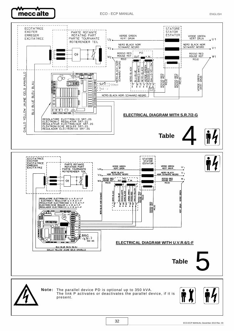
The secondary winding of the parallel transformer must be con-
nected in series to the sensing of the electronic regulator as
shown on tables 4 - 5 page 32.
In order to activate the parallel device remove the bridge which
shortcircuits the secondary winding of the device itself as shown
in the above mentioned tables.
NOTE
When requesting a parallel device, it is necessary to indicate the
nominal data of the alternator on which the device will be applied.
After all the electric connections have been made and only after
all the protections have been put in place, can the system be
started.
ELECTRICAL CONNECTIONS
16 ECO-ECP iMANUAL December 2013 Rev. 03
ECO - ECP MANUAL ENGLISH
All the instrumentation for starting, running and stopping the sy-
stem shall be provided by the installer.
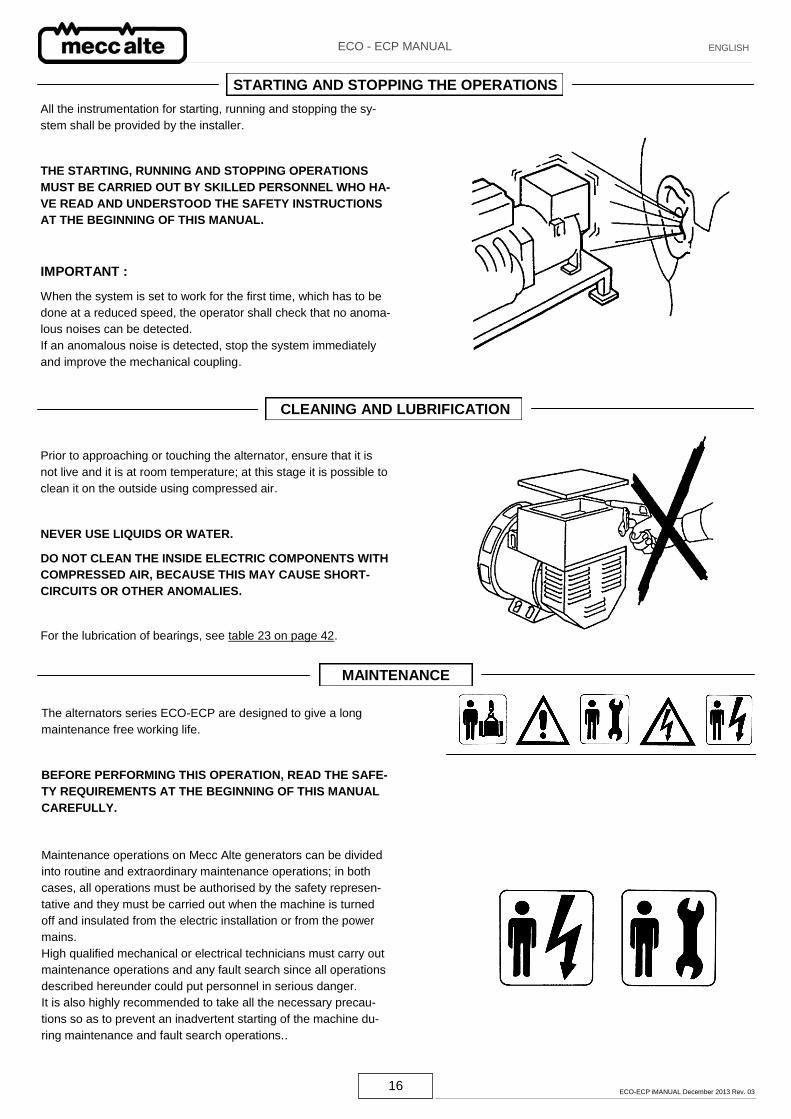
THE STARTING, RUNNING AND STOPPING OPERATIONS
MUST BE CARRIED OUT BY SKILLED PERSONNEL WHO HA-
VE READ AND UNDERSTOOD THE SAFETY INSTRUCTIONS
AT THE BEGINNING OF THIS MANUAL.
IMPORTANT :
When the system is set to work for the first time, which has to be
done at a reduced speed, the operator shall check that no anoma-
lous noises can be detected.
If an anomalous noise is detected, stop the system immediately
and improve the mechanical coupling.
CLEANING AND LUBRIFICATION
Prior to approaching or touching the alternator, ensure that it is
not live and it is at room temperature; at this stage it is possible to
clean it on the outside using compressed air.
NEVER USE LIQUIDS OR WATER.
DO NOT CLEAN THE INSIDE ELECTRIC COMPONENTS WITH
COMPRESSED AIR, BECAUSE THIS MAY CAUSE SHORT-
CIRCUITS OR OTHER ANOMALIES.
For the lubrication of bearings, see table 23 on page 42.
MAINTENANCE
The alternators series ECO-ECP are designed to give a long
maintenance free working life.
BEFORE PERFORMING THIS OPERATION, READ THE SAFE-
TY REQUIREMENTS AT THE BEGINNING OF THIS MANUAL
CAREFULLY.
Maintenance operations on Mecc Alte generators can be divided
into routine and extraordinary maintenance operations; in both
cases, all operations must be authorised by the safety represen-
tative and they must be carried out when the machine is turned
off and insulated from the electric installation or from the power
mains.
High qualified mechanical or electrical technicians must carry out
maintenance operations and any fault search since all operations
described hereunder could put personnel in serious danger.
It is also highly recommended to take all the necessary precau-
tions so as to prevent an inadvertent starting of the machine du-
ring maintenance and fault search operations..
STARTING AND STOPPING THE OPERATIONS
17 ECO-ECP iMANUAL December 2013 Rev. 03
ECO - ECP MANUAL ENGLISH
fig. a
fig. b
fig. c
MAINTENANCE
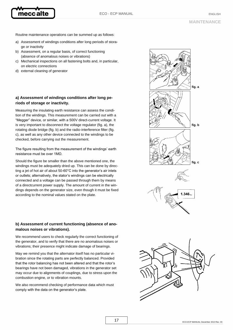
Routine maintenance operations can be summed up as follows:
a) Assessment of windings conditions after long periods of stora-
ge or inactivity
b) Assessment, on a regular basis, of correct functioning
(absence of anomalous noises or vibrations)
c) Mechanical inspections on all fastening bolts and, in particular,
on electric connections
d) external cleaning of generator
a) Assessment of windings conditions after long pe-
riods of storage or inactivity.
Measuring the insulating earth resistance can assess the condi-
tion of the windings. This measurement can be carried out with a
“Megger” device, or similar, with a 500V direct-current voltage. It
is very important to disconnect the voltage regulator (fig. a), the
rotating diode bridge (fig. b) and the radio-interference filter (fig.
c), as well as any other device connected to the windings to be
checked, before carrying out the measurement.
The figure resulting from the measurement of the windings’ earth
resistance must be over 1MΩ.
Should the figure be smaller than the above mentioned one, the
windings must be adequately dried up. This can be done by direc-
ting a jet of hot air of about 50-60°C into the generator’s air inlets
or outlets; alternatively, the stator’s windings can be electrically
connected and a voltage can be passed through them by means
of a directcurrent power supply. The amount of current in the win-
dings depends on the generator size, even though it must be fixed
according to the nominal values stated on the plate.
b) Assessment of current functioning (absence of ano-
malous noises or vibrations).
We recommend users to check regularly the correct functioning of
the generator, and to verify that there are no anomalous noises or
vibrations; their presence might indicate damage of bearings.
May we remind you that the alternator itself has no particular vi-
bration since the rotating parts are perfectly balanced. Provided
that the rotor balancing has not been altered and that the rotor’s
bearings have not been damaged, vibrations in the generator set
may occur due to alignments of couplings, due to stress upon the
combustion engine, or to vibration mounts.
We also recommend checking of performance data which must
comply with the data on the generator’s plate.
18 ECO-ECP iMANUAL December 2013 Rev. 03
ECO - ECP MANUAL ENGLISH
MAINTENANCE
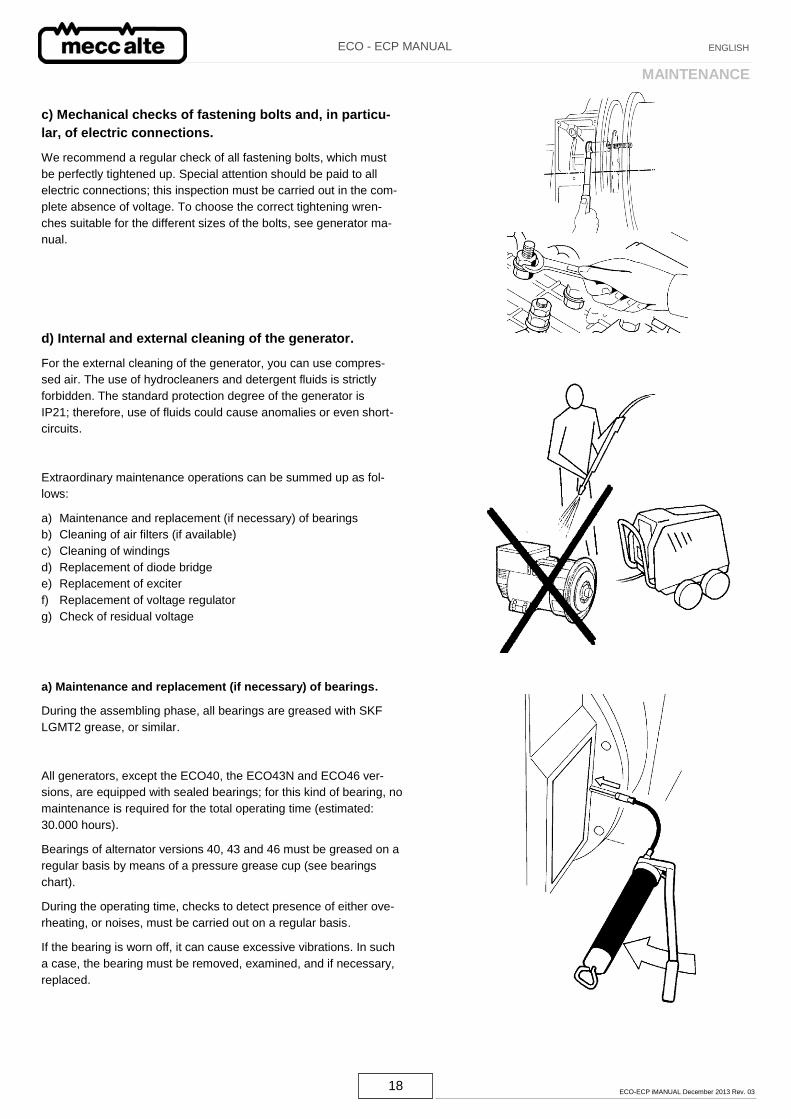
c) Mechanical checks of fastening bolts and, in particu-
lar, of electric connections.
We recommend a regular check of all fastening bolts, which must
be perfectly tightened up. Special attention should be paid to all
electric connections; this inspection must be carried out in the com-
plete absence of voltage. To choose the correct tightening wren-
ches suitable for the different sizes of the bolts, see generator ma-
nual.
d) Internal and external cleaning of the generator.
For the external cleaning of the generator, you can use compres-
sed air. The use of hydrocleaners and detergent fluids is strictly
forbidden. The standard protection degree of the generator is
IP21; therefore, use of fluids could cause anomalies or even short-
circuits.
Extraordinary maintenance operations can be summed up as fol-
lows:
a) Maintenance and replacement (if necessary) of bearings
b) Cleaning of air filters (if available)
c) Cleaning of windings
d) Replacement of diode bridge
e) Replacement of exciter
f) Replacement of voltage regulator
g) Check of residual voltage
a) Maintenance and replacement (if necessary) of bearings.
During the assembling phase, all bearings are greased with SKF
LGMT2 grease, or similar.
All generators, except the ECO40, the ECO43N and ECO46 ver-
sions, are equipped with sealed bearings; for this kind of bearing, no
maintenance is required for the total operating time (estimated:
30.000 hours).
Bearings of alternator versions 40, 43 and 46 must be greased on a
regular basis by means of a pressure grease cup (see bearings
chart).
During the operating time, checks to detect presence of either ove-
rheating, or noises, must be carried out on a regular basis.
If the bearing is worn off, it can cause excessive vibrations. In such
a case, the bearing must be removed, examined, and if necessary,
replaced.
19 ECO-ECP iMANUAL December 2013 Rev. 03
ECO - ECP MANUAL ENGLISH
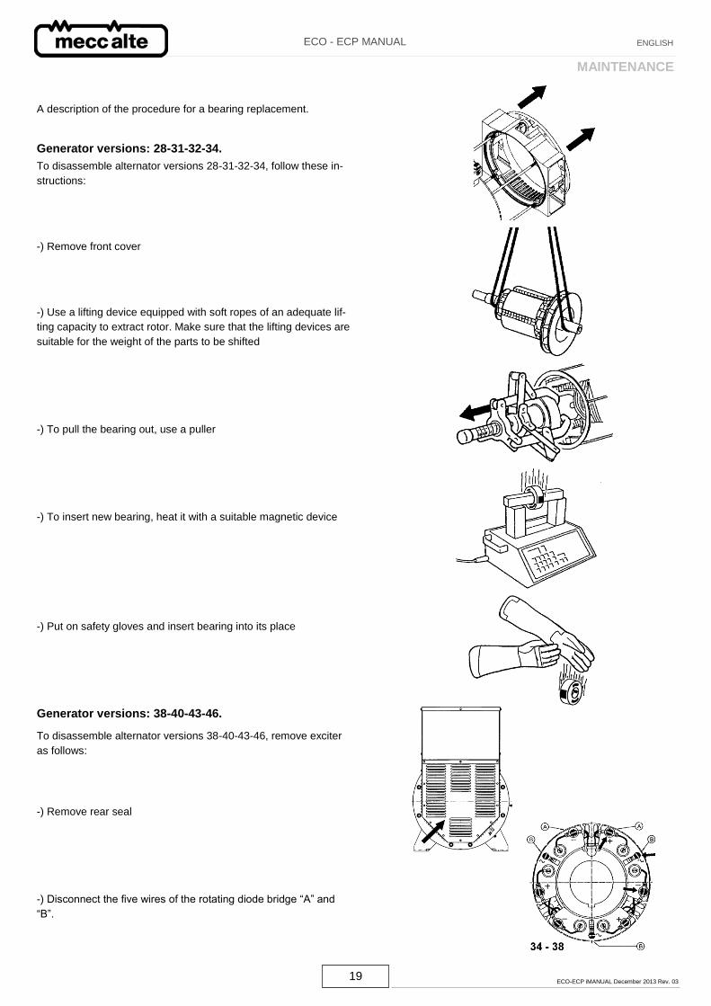
A description of the procedure for a bearing replacement.
Generator versions: 28-31-32-34.
To disassemble alternator versions 28-31-32-34, follow these in-
structions:
-) Remove front cover
-) Use a lifting device equipped with soft ropes of an adequate lif-
ting capacity to extract rotor. Make sure that the lifting devices are
suitable for the weight of the parts to be shifted
-) To pull the bearing out, use a puller
-) To insert new bearing, heat it with a suitable magnetic device
-) Put on safety gloves and insert bearing into its place
Generator versions: 38-40-43-46.
To disassemble alternator versions 38-40-43-46, remove exciter
as follows:
-) Remove rear seal
-) Disconnect the five wires of the rotating diode bridge “A” and
“B”.
MAINTENANCE
20 ECO-ECP iMANUAL December 2013 Rev. 03
ECO - ECP MANUAL ENGLISH
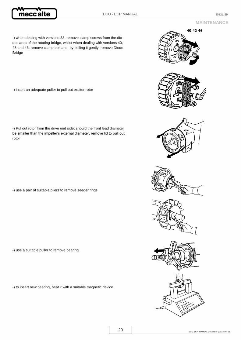
-) when dealing with versions 38, remove clamp screws from the dio-
des area of the rotating bridge, whilst when dealing with versions 40,
43 and 46, remove clamp bolt and, by pulling it gently, remove Diode
Bridge
-) insert an adequate puller to pull out exciter rotor
-) Pul out rotor from the drive end side; should the front lead diameter
be smaller than the impeller’s external diameter, remove lid to pull out
rotor
-) use a pair of suitable pliers to remove seeger rings
-) use a suitable puller to remove bearing
-) to insert new bearing, heat it with a suitable magnetic device
MAINTENANCE
21 ECO-ECP iMANUAL December 2013 Rev. 03
ECO - ECP MANUAL ENGLISH
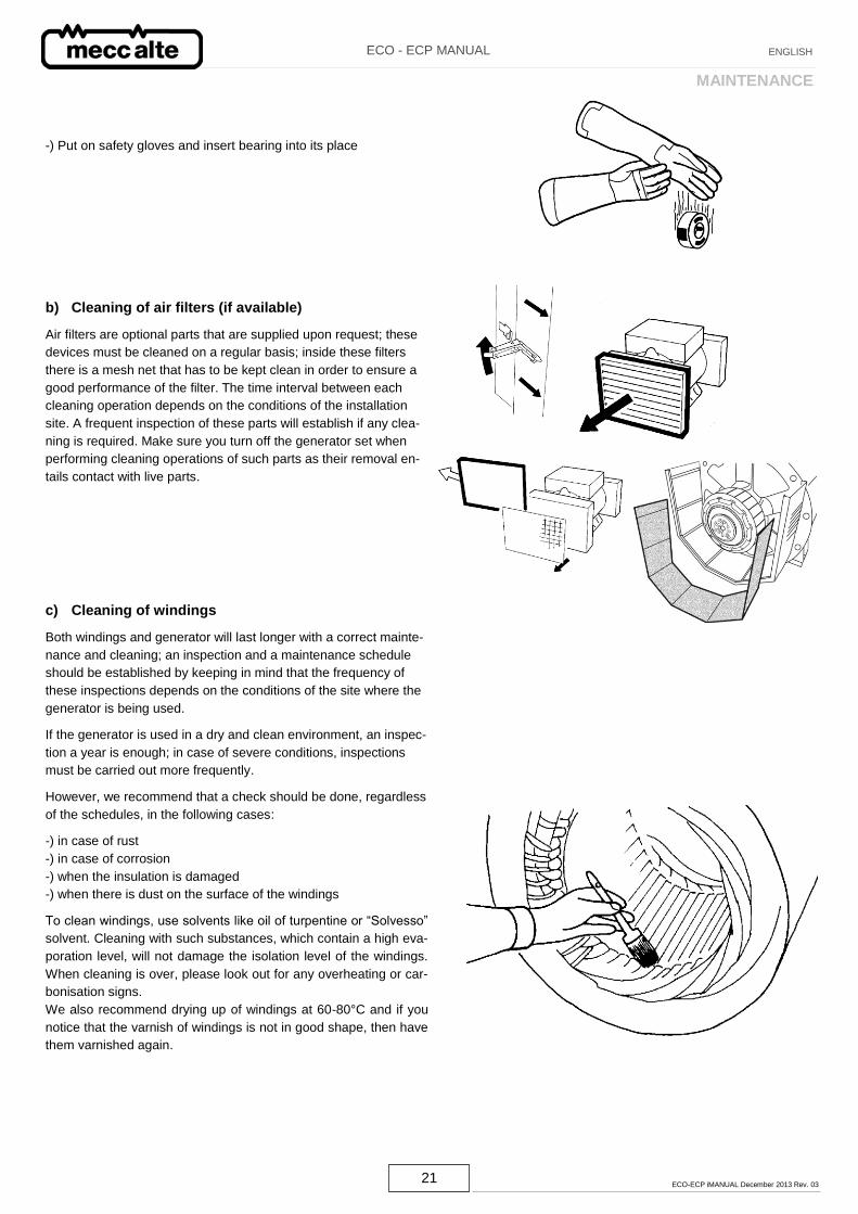
-) Put on safety gloves and insert bearing into its place
b) Cleaning of air filters (if available)
Air filters are optional parts that are supplied upon request; these
devices must be cleaned on a regular basis; inside these filters
there is a mesh net that has to be kept clean in order to ensure a
good performance of the filter. The time interval between each
cleaning operation depends on the conditions of the installation
site. A frequent inspection of these parts will establish if any clea-
ning is required. Make sure you turn off the generator set when
performing cleaning operations of such parts as their removal en-
tails contact with live parts.
c) Cleaning of windings
Both windings and generator will last longer with a correct mainte-
nance and cleaning; an inspection and a maintenance schedule
should be established by keeping in mind that the frequency of
these inspections depends on the conditions of the site where the
generator is being used.
If the generator is used in a dry and clean environment, an inspec-
tion a year is enough; in case of severe conditions, inspections
must be carried out more frequently.
However, we recommend that a check should be done, regardless
of the schedules, in the following cases:
-) in case of rust
-) in case of corrosion
-) when the insulation is damaged
-) when there is dust on the surface of the windings
To clean windings, use solvents like oil of turpentine or “Solvesso”
solvent. Cleaning with such substances, which contain a high eva-
poration level, will not damage the isolation level of the windings.
When cleaning is over, please look out for any overheating or car-
bonisation signs.
We also recommend drying up of windings at 60-80°C and if you
notice that the varnish of windings is not in good shape, then have
them varnished again.
MAINTENANCE
22 ECO-ECP iMANUAL December 2013 Rev. 03
ECO - ECP MANUAL ENGLISH
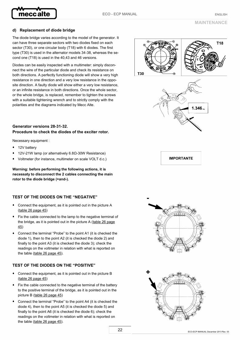
d) Replacement of diode bridge
The diode bridge varies according to the model of the generator. It can have three separate sectors with two diodes fixed on each sector (T30), or one circular body (T18) with 6 diodes. The first type (T30) is used in the alternator models 34-38, whereas the se-cond one (T18) is used in the 40,43 and 46 versions.
Diodes can be easily inspected with a multimeter: simply discon-nect the wire of the particular diode and check its resistance on both directions. A perfectly functioning diode will show a very high resistance in one direction and a very low resistance in the oppo-site direction. A faulty diode will show either a very low resistance, or an infinite resistance in both directions. Once the whole sector, or the whole bridge, is replaced, remember to tighten the screws with a suitable tightening wrench and to strictly comply with the polarities and the diagrams indicated by Mecc Alte.
Generator versions 28-31-32. Procedure to check the diodes of the exciter rotor.
Necessary equipment :
12V battery 12V-21W lamp (or alternatively 6.8Ω-30W Resistance) Voltmeter (for instance, multimeter on scale VOLT d.c.)
Warning: before performing the following actions, it is necessaty to disconnect the 2 cables connecting the main rotor to the diode bridge (+and-).
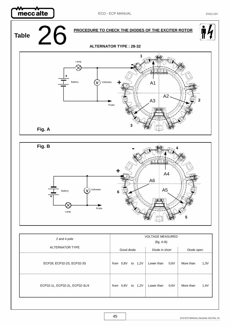
TEST OF THE DIODES ON THE “NEGATIVE”
Connect the equipment, as it is pointed out in the picture A (table 26 page 45)
Fix the cable connected to the lamp to the negative terminal of the bridge, as it is pointed out in the picture A (table 26 page 45)
Connect the terminal “Probe” to the point A1 (it is checked the diode 1), then to the point A2 (it is checked the diode 2) and finally to the point A3 (it is checked the diode 3); check the readings on the voltmeter in relation with what is reported on the table (table 26 page 45).
TEST OF THE DIODES ON THE “POSITIVE”
Connect the equipment, as it is pointed out in the picture B (table 26 page 45)
Fix the cable connected to the negative terminal of the battery to the positive terminal of the bridge, as it is pointed out in the picture B (table 26 page 45)
Connect the terminal “Probe” to the point A4 (it is checked the diode 4), then to the point A5 (it is checked the diode 5) and finally to the point A6 (it is checked the diode 6); check the readings on the voltmeter in relation with what is reported on the table (table 26 page 45).
MAINTENANCE
IMPORTANTE
-
+
23 ECO-ECP iMANUAL December 2013 Rev. 03
ECO - ECP MANUAL ENGLISH
MAINTENANCE
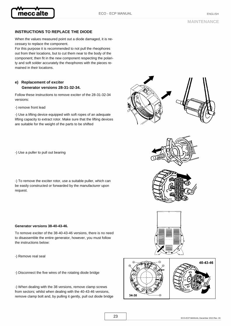
INSTRUCTIONS TO REPLACE THE DIODE
When the values measured point out a diode damaged, it is ne-
cessary to replace the component.
For this purpose it is recommended to not pull the rheophores
out from their locations, but to cut them near to the body of the
component; then fit in the new component respecting the polari-
ty and soft solder accurately the rheophores with the pieces re-
mained in their locations.
e) Replacement of exciter
Generator versions 28-31-32-34.
Follow these instructions to remove exciter of the 28-31-32-34
versions:
-) remove front lead
-) Use a lifting device equipped with soft ropes of an adequate
lifting capacity to extract rotor. Make sure that the lifting devices
are suitable for the weight of the parts to be shifted
-) Use a puller to pull out bearing
-) To remove the exciter rotor, use a suitable puller, which can
be easily constructed or forwarded by the manufacturer upon
request.
Generator versions 38-40-43-46.
To remove exciter of the 38-40-43-46 versions, there is no need
to disassemble the entire generator, however, you must follow
the instructions below:
-) Remove real seal
-) Disconnect the five wires of the rotating diode bridge
-) When dealing with the 38 versions, remove clamp screws
from sectors; whilst when dealing with the 40-43-46 versions,
remove clamp bolt and, by pulling it gently, pull out diode bridge
24 ECO-ECP iMANUAL December 2013 Rev. 03
ECO - ECP MANUAL ENGLISH
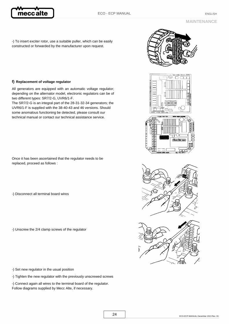
-) To insert exciter rotor, use a suitable puller, which can be easily
constructed or forwarded by the manufacturer upon request.
f) Replacement of voltage regulator
All generators are equipped with an automatic voltage regulator;
depending on the alternator model, electronic regulators can be of
two different types: SR7/2-G, UVR6/1-F.
The SR7/2-G is an integral part of the 28-31-32-34 generators; the
UVR6/1-F is supplied with the 38-40-43 and 46 versions. Should
some anomalous functioning be detected, please consult our
technical manual or contact our technical assistance service.
Once it has been ascertained that the regulator needs to be
replaced, proceed as follows :
-) Disconnect all terminal board wires
-) Unscrew the 2/4 clamp screws of the regulator
-) Set new regulator in the usual position
-) Tighten the new regulator with the previously unscrewed screws
-) Connect again all wires to the terminal board of the regulator.
Follow diagrams supplied by Mecc Alte, if necessary.
MAINTENANCE
25 ECO-ECP iMANUAL December 2013 Rev. 03
ECO - ECP MANUAL ENGLISH
MAINTENANCE
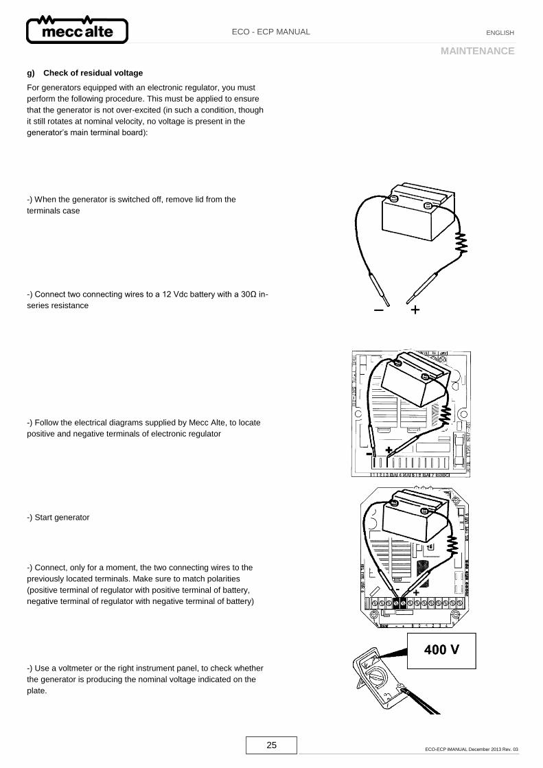
g) Check of residual voltage
For generators equipped with an electronic regulator, you must
perform the following procedure. This must be applied to ensure
that the generator is not over-excited (in such a condition, though
it still rotates at nominal velocity, no voltage is present in the
generator’s main terminal board):
-) When the generator is switched off, remove lid from the
terminals case
-) Connect two connecting wires to a 12 Vdc battery with a 30Ω in-
series resistance
-) Follow the electrical diagrams supplied by Mecc Alte, to locate
positive and negative terminals of electronic regulator
-) Start generator
-) Connect, only for a moment, the two connecting wires to the
previously located terminals. Make sure to match polarities
(positive terminal of regulator with positive terminal of battery,
negative terminal of regulator with negative terminal of battery)
-) Use a voltmeter or the right instrument panel, to check whether
the generator is producing the nominal voltage indicated on the
plate.
26 ECO-ECP iMANUAL December 2013 Rev. 03
ECO - ECP MANUAL ENGLISH
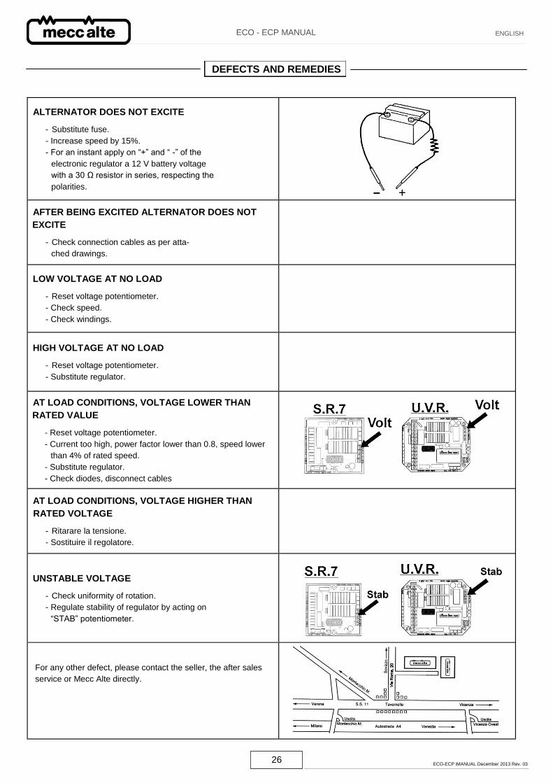
DEFECTS AND REMEDIES
ALTERNATOR DOES NOT EXCITE
- Substitute fuse.
- Increase speed by 15%.
- For an instant apply on “+” and “ -” of the
electronic regulator a 12 V battery voltage
with a 30 Ω resistor in series, respecting the
polarities.
AFTER BEING EXCITED ALTERNATOR DOES NOT
EXCITE
- Check connection cables as per atta-
ched drawings.
LOW VOLTAGE AT NO LOAD
- Reset voltage potentiometer.
- Check speed.
- Check windings.
HIGH VOLTAGE AT NO LOAD
- Reset voltage potentiometer.
- Substitute regulator.
AT LOAD CONDITIONS, VOLTAGE LOWER THAN
RATED VALUE
- Reset voltage potentiometer.
- Current too high, power factor lower than 0.8, speed lower
than 4% of rated speed.
- Substitute regulator.
- Check diodes, disconnect cables
AT LOAD CONDITIONS, VOLTAGE HIGHER THAN
RATED VOLTAGE
- Ritarare la tensione.
- Sostituire il regolatore.
UNSTABLE VOLTAGE
- Check uniformity of rotation.
- Regulate stability of regulator by acting on
“STAB” potentiometer.
For any other defect, please contact the seller, the after sales
service or Mecc Alte directly.
27 ECO-ECP iMANUAL December 2013 Rev. 03
ECO - ECP MANUAL ENGLISH
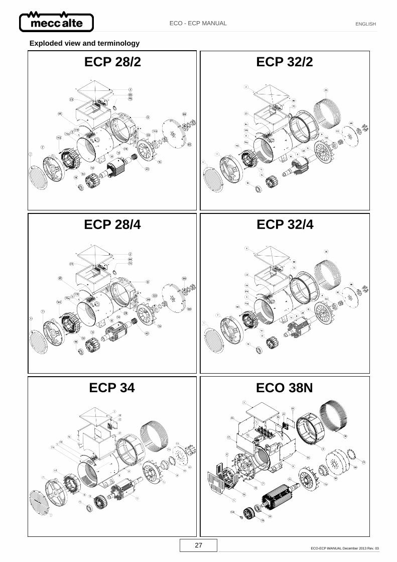
ECP 34
ECP 32/4
ECP 28/2
ECO 38N
ECP 32/2
ECP 28/4
Exploded view and terminology
28 ECO-ECP iMANUAL December 2013 Rev. 03
ECO - ECP MANUAL ENGLISH
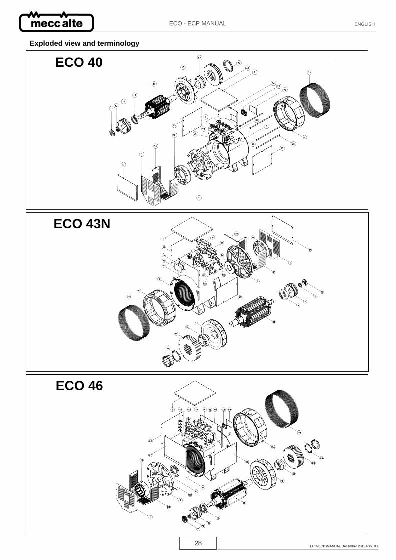
ECO 40
ECO 43N
ECO 46
Exploded view and terminology
29 ECO-ECP iMANUAL December 2013 Rev. 03
ECO - ECP MANUAL ENGLISH
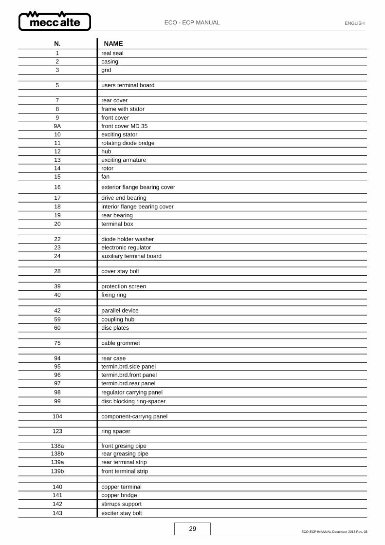
N. NAME
1 real seal
2 casing
3 grid
5 users terminal board
7 rear cover
8 frame with stator
9 front cover
9A front cover MD 35
10 exciting stator
11 rotating diode bridge
12 hub
13 exciting armature
14 rotor
15 fan
16 exterior flange bearing cover
17 drive end bearing
18 interior flange bearing cover
19 rear bearing
20 terminal box
22 diode holder washer
23 electronic regulator
24 auxiliary terminal board
28 cover stay bolt
39 protection screen
40 fixing ring
42 parallel device
59 coupling hub
60 disc plates
75 cable grommet
94 rear case
95 termin.brd.side panel
96 termin.brd.front panel
97 termin.brd.rear panel
98 regulator carrying panel
99 disc blocking ring-spacer
104 component-carryng panel
123 ring spacer
138a front gresing pipe
138b rear greasing pipe
139a rear terminal strip
139b front terminal strip
140 copper terminal
141 copper bridge
142 stirrups support
143 exciter stay bolt
30 ECO-ECP iMANUAL December 2013 Rev. 03
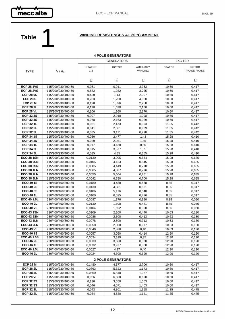
ECO - ECP MANUAL ENGLISH
1 Table
4 POLE GENERATORS
TYPE V / Hz
GENERATORS EXCITER
STATOR
1-2
Ω
ROTOR
Ω
AUXILIARY
WINDING
Ω
STATOR
Ω
ROTOR
PHASE-PHASE
Ω
ECP 28 1VS 115/200/230/400-50 0,951 0,911 3.753 10,60 0,417
ECP 28 2VS 115/200/230/400-50 0,582 1,032 3,225 10,60 0,417
ECP 28 0S 115/200/230/400-50 0,430 1,13 2,957 10,60 0,417
ECP 28 S 115/200/230/400-50 0,283 1,260 4,060 10,60 0,417
ECP 28 M 115/200/230/400-50 0,198 1,396 2,250 10,60 0,417
ECP 28 2L 115/200/230/400-50 0,128 1,670 2,150 10,60 0,417
ECP 28 VL 115/200/230/400-50 0,106 1,860 2,170 10,60 0,417
ECP 32 2S 115/200/230/400-50 0,097 2,010 1,098 10,60 0,417
ECP 32 3S 115/200/230/400-50 0,078 2,163 0,929 10,60 0,417
ECP 32 1L 115/200/230/400-50 0,061 2,473 0,993 11,35 0,442
ECP 32 2L 115/200/230/400-50 0,041 2,861 0,909 11,35 0,442
ECP 32 3L 115/200/230/400-50 0,035 3,171 0,790 11,35 0,442
ECP 34 1S 115/200/230/400-50 0,030 2,477 1,43 15,28 0,410
ECP 34 2S 115/200/230/400-50 0,020 2,951 1,35 15,28 0,410
ECP 34 1L 115/200/230/400-50 0,017 4,138 0,80 15,28 0,410
ECP 34 2L 115/200/230/400-50 0,015 3,577 1,05 15,28 0,410
ECP 34 3L 115/200/230/400-50 0,015 4,35 0,855 15,28 0,410
ECO 38 1SN 115/200/230/400-50 0,0130 3,905 0,854 15,28 0,685
ECO 38 2SN 115/200/230/400-50 0,0105 4,133 0,845 15,28 0,685
ECO 38 3SN 115/200/230/400-50 0,0085 4,449 0,778 15,28 0,685
ECO 38 1LN 115/200/230/400-50 0,0065 4,887 0,796 15,28 0,685
ECO 38 2LN 115/200/230/400-50 0,0055 5,604 0,751 15,28 0,685
ECO 38 3LN 115/200/230/400-50 0,0042 6,780 0,700 15,28 0,685
ECO 40 1S 230/400/460/800-50 0,0180 4,488 0,558 8,85 0,317
ECO 40 2S 230/400/460/800-50 0,0130 4,881 0,521 8,85 0,317
ECO 40 3S 230/400/460/800-50 0,0106 5,176 0,540 8,85 0,317
ECO 40 1L 230/400/460/800-50 0,0100 6,025 0,476 8,85 0,317
ECO 40 1.5L 230/400/460/800-50 0,0087 1,376 0,550 8,85 0,050
ECO 40 2L 230/400/460/800-50 0,0130 1,500 0,481 8,85 0,050
ECO 40 VL 230/400/460/800-50 0,0104 1,592 0,300 8,85 0,050
ECO 43 1SN 230/400/460/800-50 0,0109 2,100 0,440 10,63 0,130
ECO 43 2SN 230/400/460/800-50 0,0086 2,300 0,413 10,63 0,130
ECO 43 1LN 230/400/460/800-50 0,0078 2,500 0,713 10,63 0,130
ECO 43 2LN 230/400/460/800-50 0,0058 2,800 0,677 10,63 0,130
ECO 43 VL 230/400/460/800-50 0,0046 2,886 0,40 10,63 0,130
ECO 46 1S 230/400/460/800-50 0,0057 3,050 0,414 12,90 0,120
ECO 46 1.5S 230/400/460/800-50 0,0034 3,319 0,35 12,90 0,120
ECO 46 2S 230/400/460/800-50 0,0039 3,500 0,330 12,90 0,120
ECO 46 1L 230/400/460/800-50 0,0032 3,977 0,360 12,90 0,120
ECO 46 1.5L 230/400/460/800-50 0,0027 4,27 0,40 12,90 0,120
ECO 46 2L 230/400/460/800-50 0,0024 4,500 0,390 12,90 0,120
2 POLE GENERATORS
ECP 28 M 115/200/230/400-50 0,1480 4,877 2,706 10,60 0,417
ECP 28 2L 115/200/230/400-50 0,0863 5,523 1,173 10,60 0,417
ECP 28 3L 115/200/230/400-50 0,0860 5,848 1,087 10,60 0,417
ECP 28 VL 115/200/230/400-50 0,056 6,500 0,690 10,60 0,417
ECP 32 2S 115/200/230/400-50 0,110 3,650 1,553 10,60 0,417
ECP 32 3S 115/200/230/400-50 0,046 4,071 1,403 10,60 0,417
ECP 32 1L 115/200/230/400-50 0,043 4,301 1,358 11.35 0,475
ECP 32 2L 115/200/230/400-50 0,034 4,680 1,141 11.35 0,475
WINDING RESISTENCES AT 20 °C AMBIENT
31 ECO-ECP iMANUAL December 2013 Rev. 03
ECO - ECP MANUAL ENGLISH
2 Table CONNECTIONS ALTERNATORS
3 Table
32 ECO-ECP iMANUAL December 2013 Rev. 03
ECO - ECP MANUAL ENGLISH
ELECTRICAL DIAGRAM WITH S.R.7/2-G
4 Table
ELECTRICAL DIAGRAM WITH U.V.R.6/1-F
5 Table
Note: The para l le l device PD is opt ional up to 350 kVA. The l ink P act i vates or deact ivates the para l le l device, i f i t is present .
33 ECO-ECP iMANUAL December 2013 Rev. 03
ECO - ECP MANUAL ENGLISH
4A Table 12 WIRES ELECTRICAL DIAGRAM WITH S.R.7/2-G
12 WIRES ELECTRICAL DIAGRAM WITH U.V.R.6/1-F 5A Table
34 ECO-ECP iMANUAL December 2013 Rev. 03
ECO - ECP MANUAL ENGLISH
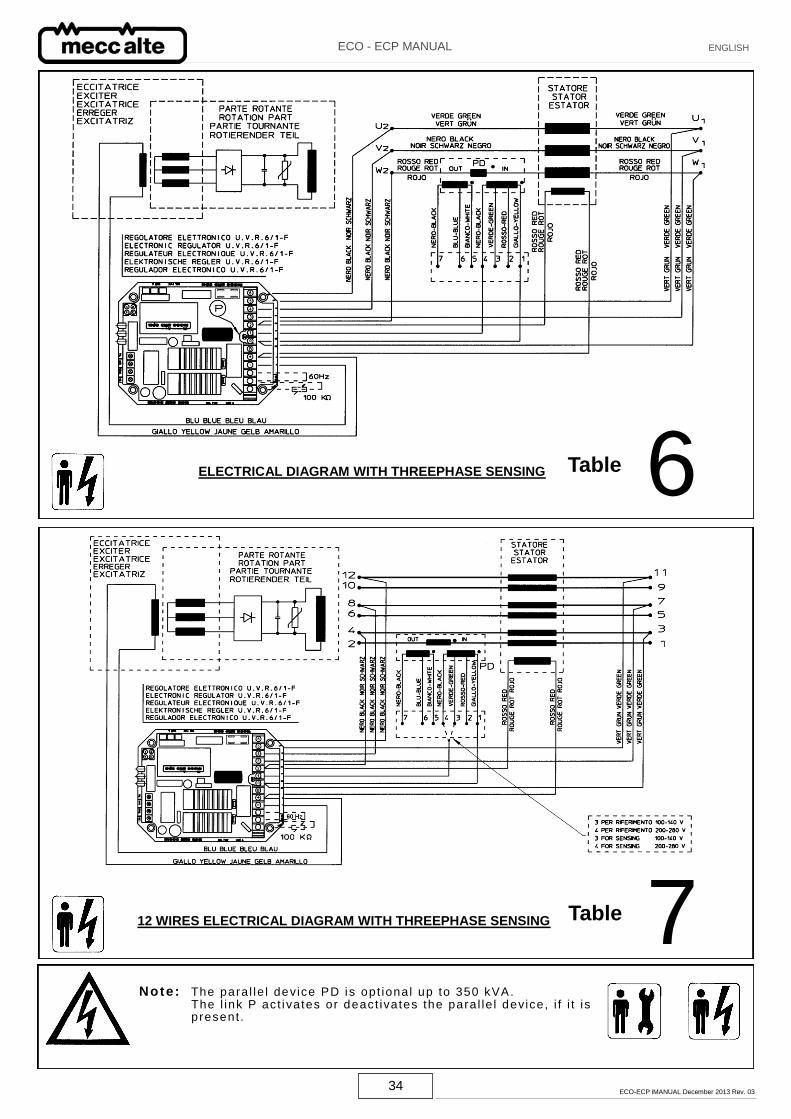
ELECTRICAL DIAGRAM WITH THREEPHASE SENSING
12 WIRES ELECTRICAL DIAGRAM WITH THREEPHASE SENSING
6 Table
7 Table
Note: The para l le l device PD is opt ional up to 350 kVA. The l ink P act i vates or deact ivates the para l le l device, i f i t is present .
35 ECO-ECP iMANUAL December 2013 Rev. 03
ECO - ECP MANUAL ENGLISH
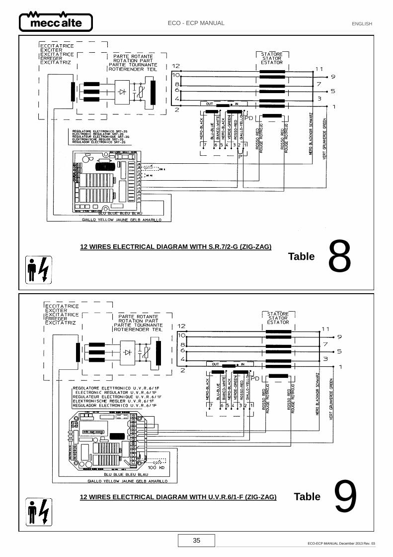
12 WIRES ELECTRICAL DIAGRAM WITH S.R.7/2-G (ZIG-ZAG)
12 WIRES ELECTRICAL DIAGRAM WITH U.V.R.6/1-F (ZIG-ZAG)
8 Table
9 Table
36 ECO-ECP iMANUAL December 2013 Rev. 03
ECO - ECP MANUAL ENGLISH
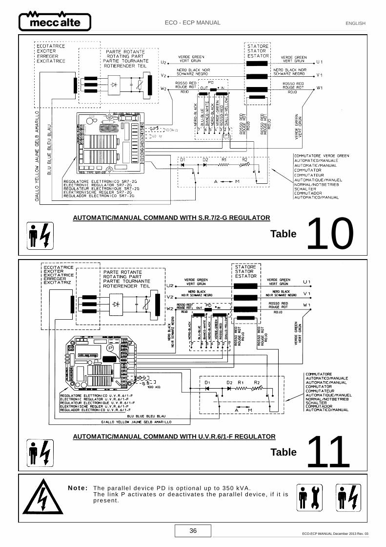
Table 10 AUTOMATIC/MANUAL COMMAND WITH S.R.7/2-G REGULATOR
AUTOMATIC/MANUAL COMMAND WITH U.V.R.6/1-F REGULATOR
Table 11 Note: The para l le l device PD is opt ional up to 350 kVA.
The l ink P act i vates or deact ivates the para l le l device, i f i t is present .
37 ECO-ECP iMANUAL December 2013 Rev. 03
ECO - ECP MANUAL ENGLISH
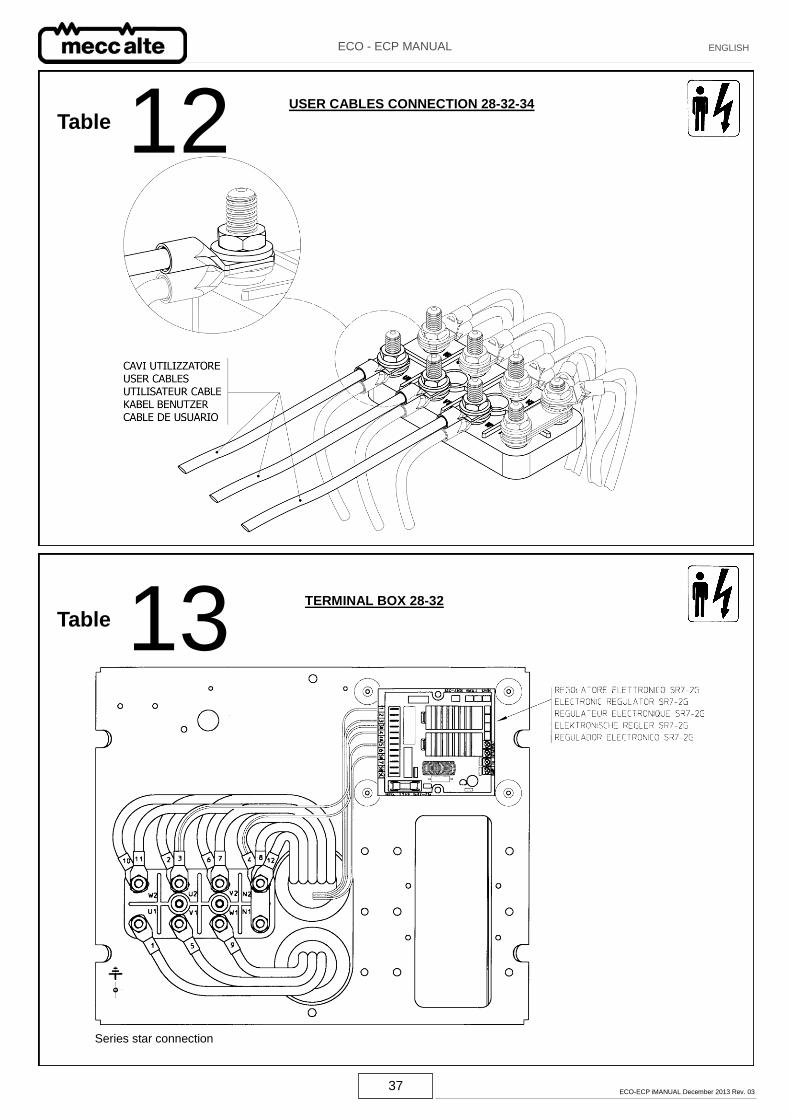
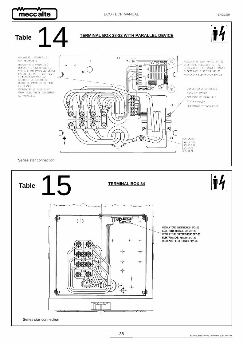
TERMINAL BOX 28-32
Series star connection
Table 12 USER CABLES CONNECTION 28-32-34
Table 13
38 ECO-ECP iMANUAL December 2013 Rev. 03
ECO - ECP MANUAL ENGLISH
14 TERMINAL BOX 28-32 WITH PARALLEL DEVICE
Series star connection
15 TERMINAL BOX 34
Series star connection
Table
Table
39 ECO-ECP iMANUAL December 2013 Rev. 03
ECO - ECP MANUAL ENGLISH
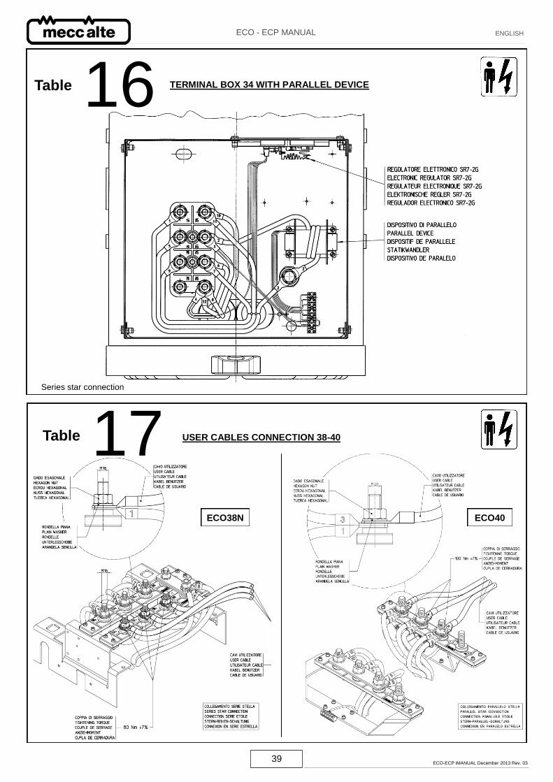
16
17 Series star connection
TERMINAL BOX 34 WITH PARALLEL DEVICE
Table USER CABLES CONNECTION 38-40
Table
ECO40 ECO38N
40 ECO-ECP iMANUAL December 2013 Rev. 03
ECO - ECP MANUAL ENGLISH
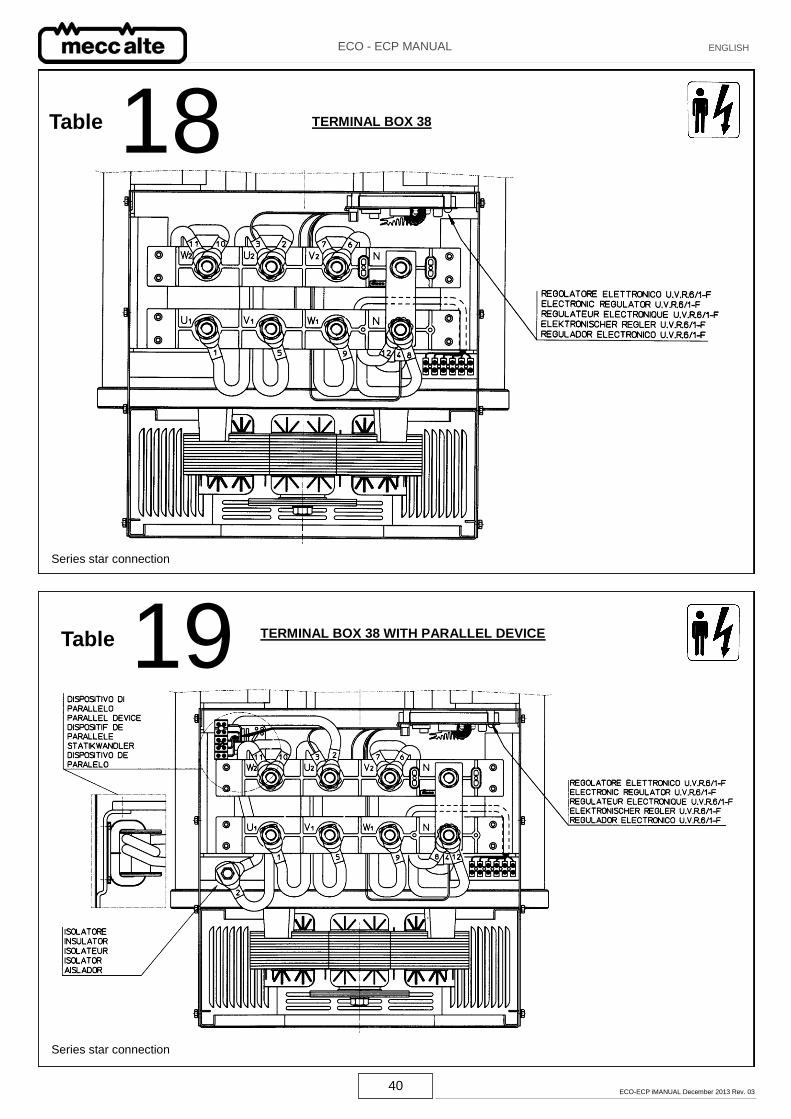
18 Table
19 Table
TERMINAL BOX 38
TERMINAL BOX 38 WITH PARALLEL DEVICE
Series star connection
Series star connection
41 ECO-ECP iMANUAL December 2013 Rev. 03
ECO - ECP MANUAL ENGLISH
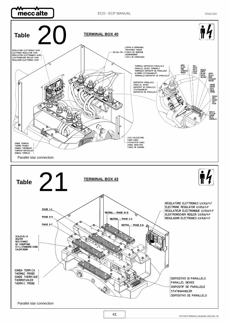
20 Table
21
TERMINAL BOX 40
TERMINAL BOX 43
Parallel star connection
Table
Parallel star connection
42 ECO-ECP iMANUAL December 2013 Rev. 03
ECO - ECP MANUAL ENGLISH
23
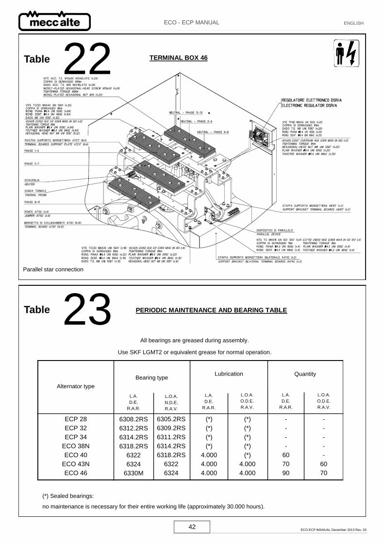
Table 22 TERMINAL BOX 46
Parallel star connection
All bearings are greased during assembly.
Use SKF LGMT2 or equivalent grease for normal operation.
(*) Sealed bearings:
no maintenance is necessary for their entire working life (approximately 30.000 hours).
PERIODIC MAINTENANCE AND BEARING TABLE Table
Alternator type
Bearing type Lubrication Quantity
L.A.
D.E.
R.A.R.
L.O.A.
N.D.E.
R.A.V.
L.A.
D.E.
R.A.R.
L.O.A.
O.D.E.
R.A.V.
L.O.A.
O.D.E.
R.A.V.
L.A.
D.E.
R.A.R.
6308.2RS
6312.2RS
6314.2RS
6318.2RS
6322
6324
6330M
6305.2RS
6309.2RS
6311.2RS
6314.2RS
6318.2RS
6322
6324
(*)
(*)
(*)
(*)
4.000
4.000
4.000
(*)
(*)
(*)
(*)
(*)
4.000
4.000
-
-
-
-
60
70
90
-
-
-
-
-
60
70
ECP 28
ECP 32
ECP 34
ECO 38N
ECO 40
ECO 43N
ECO 46
43 ECO-ECP iMANUAL December 2013 Rev. 03
ECO - ECP MANUAL ENGLISH
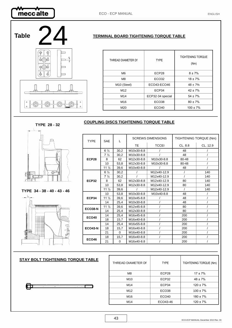
TERMINAL BOARD TIGHTENING TORQUE TABLE
THREAD DIAMETER Df TYPE TIGHTENING TORQUE
(Nm)
M6 ECP28 8 ± 7%
M8 ECO32 18 ± 7%
M10 (Steel) ECO43-ECO46 48 ± 7%
M12 ECP34 42 ± 7%
M14 ECP32-34 special 54 ± 7%
M16 ECO38 80 ± 7%
M20 ECO40 100 ± 7%
TYPE SAE SCREWS DIMENSIONS TIGHTENING TORQUE (Nm)
L
TE TCCEI CL. 8.8 CL. 12.9
ECP28
6 ½ 30,2 M10x30-8.8 / 48 /
7 ½ 30,2 M10x30-8.8 / 48 /
8 62 M12x30-8.8 M10x30-8.8 80-48 /
10 53,8 M12x30-8.8 M10x30-8.8 80-48 /
11 ½ 39,6 M10x40-8.8 / 48 /
ECP32
6 ½ 30,2 / M12x40-12.9 / 140
7 ½ 30,2 / M12x40-12.9 / 140
8 62 M12x30-8.8 M12x40-12.9 80 140
10 53,8 M12x30-8.8 M12x40-12.9 80 140
11 ½ 39,6 / M12x40-12.9 / 140
ECP34
10 53,8 M10x30-8.8 M10x40-8.8 48 /
11 ½ 39,6 M10x45-8.8 / 48 /
14 25,4 M10x30-8.8 / 48 /
ECO38-N 11 ½ 39,6 M12x45-8.8 / 80 /
14 25,4 M12x30-8.8 / 80 /
ECO40 14 25,4 M16x45-8.8 / 200 /
18 15,7 M16x40-8.8 / 200 /
ECO43-N
14 25,4 M16x55-8.8 / 200 /
18 15,7 M16x40-8.8 / 200 /
21 0 M16x40-8.8 / 200 /
ECO46 18 15,7 M16x40-8.8 / 200 /
21 0 M16x40-8.8 / 200 /
TYPE 34 - 38 - 40 - 43 - 46
TYPE 28 - 32 COUPLING DISCS TIGHTENING TORQUE TABLE
THREAD DIAMETER Df TYPE TIGHTENING TORQUE (Nm)
M8 ECP28 17 ± 7%
M10 ECP32 48 ± 7%
M14 ECP34 120 ± 7%
M12 ECO38 100 ± 7%
M16 ECO40 180 ± 7%
M14 ECO43-46 120 ± 7%
STAY BOLT TIGHTENING TORQUE TABLE
24 Table
44 ECO-ECP iMANUAL December 2013 Rev. 03
ECO - ECP MANUAL ENGLISH
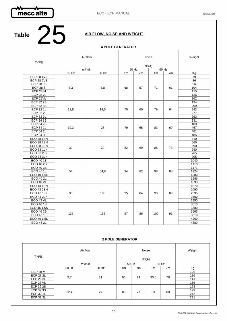
AIR FLOW, NOISE AND WEIGHT
TYPE
Air flow Noise Weight
dB(A) m³/min 50 Hz 60 Hz
50 Hz 60 Hz 1m 7m 1m 7m Kg
ECP 28 1VS
5,3 5,8 68 57 71 61
79 ECP 28 2VS 86 ECP 28 0S 96 ECP 28 S 104
ECP 28 M 115 ECP 28 2L 136 ECP 28VL 162
ECP 32 2S
11,8 14,5 75 60 79 64
194 ECP 32 3S 209
ECP 32 1L 243 ECP 32 2L 277 ECP 32 3L 293
19,3 23 79 65 83 69
ECP 34 1S 331 ECP 34 2S 409 ECP 34 1L 467
ECP 34 2L 481
ECP 34 3L 485
ECO 38 1SN
32 39 82 69 86 73
510 ECO 38 2SN 560 ECO 38 3SN 590
ECO 38 1LN 680 ECO 38 2LN 765 ECO 38 3LN 905
ECO 40 1S
54 64,8 94 82 98 88
1040 ECO 40 2S 1118
ECO 40 3S 1171 ECO 40 1L 1324
ECO 40 1.5L 1380
ECO 40 2L 1586 ECO 40 VL 1693
ECO 43 1SN
90 108 95 84 99 89
1870 ECO 43 2SN 2090
ECO 43 1LN 2395
ECO 43 2LN 2660
ECO 43 VL 2950
ECO 46 1S
135 162 97 86 100 91
3010 ECO 46 1.5S 3380
ECO 46 2S 3565 ECO 46 1L 3810
ECO 46 1.5L 4260
ECO 46 2L 4380
25 4 POLE GENERATOR
Air flow Noise Weight
TYPE dB(A)
m³/min 50 Hz 60 Hz 50 Hz 60 Hz 1m 7m 1m 7m Kg
ECP 28 M
9,7 11 86 74 90,5 78
126
ECP 28 2L 136 ECP 28 3L 141
ECP 28 VL 156
ECP 32 2S
22,4 27 88 77 93 80
173
ECP 32 3S 199
ECP 32 1L 212 ECP 32 2L 231
2 POLE GENERATOR
Table
45 ECO-ECP iMANUAL December 2013 Rev. 03
ECO - ECP MANUAL ENGLISH
V A1
A2 A3
+
Lamp
Voltmeter Battery
Fig. A
Probe
+
-
1
2
3
V
A4
A5
A6
+
Lamp
Voltmeter Battery
Probe
Fig. B
+
-
5
6
4
VOLTAGE MEASURED
(fig. A-B) 2 and 4 pole
ALTERNATOR TYPE Good diode Diode in short Diode open
ECP28, ECP32-2S, ECP32-3S from 0,8V to 1,2V Lower than 0,6V More than 1,3V
ECP32-1L, ECP32-2L, ECP32-3L/4 from 0,8V to 1,2V Lower than 0,6V More than 1,4V
PROCEDURE TO CHECK THE DIODES OF THE EXCITER ROTOR
ALTERNATOR TYPE : 28-32 26 Table
46 ECO-ECP iMANUAL December 2013 Rev. 03
ECO - ECP MANUAL ENGLISH
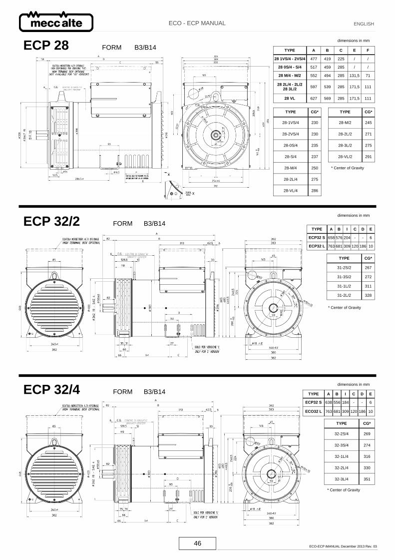
ECP 28 FORM B3/B14 dimensions in mm
ECP 32/2 FORM B3/B14
dimensions in mm
ECP 32/4 FORM B3/B14
dimensions in mm
TYPE CG*
28-1VS/4 230
28-2VS/4 230
28-0S/4 235
28-S/4 237
28-M/4 250
28-2L/4 275
28-VL/4 286
TYPE CG*
28-M/2 245
28-2L/2 271
28-3L/2 275
28-VL/2 291
TYPE A B C E F
28 1VS/4 - 2VS/4 477 419 225 / /
28 0S/4 - S/4 517 459 285 / /
28 M/4 - M/2 552 494 285 131,5 71
28 2L/4 - 2L/2 28 3L/2
597 539 285 171,5 111
28 VL 627 569 285 171,5 111
* Center of Gravity
TYPE CG*
31-2S/2 267
31-3S/2 272
31-1L/2 311
31-2L/2 328
* Center of Gravity
TYPE A B I C D E
ECP32 S 658 576 204 - - 6
ECP32 L 763 681 309 120 186 10
TYPE CG*
32-2S/4 269
32-3S/4 274
32-1L/4 316
32-2L/4 330
32-3L/4 351
* Center of Gravity
TYPE A B I C D E
ECP32 S 638 556 184 - - 6
ECO32 L 763 681 309 120 186 10
47 ECO-ECP iMANUAL December 2013 Rev. 03
ECO - ECP MANUAL ENGLISH
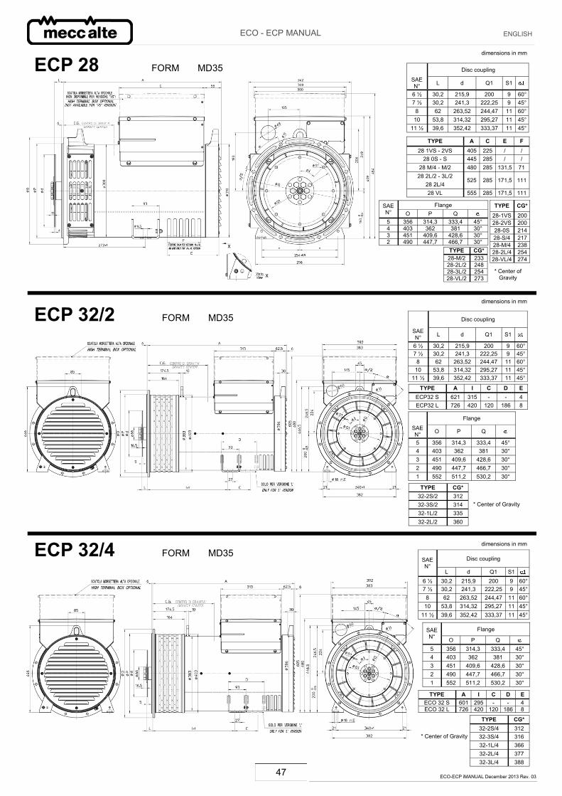
ECP 28 FORM MD35
dimensions in mm
ECP 32/2 FORM MD35
dimensions in mm
ECP 32/4 FORM MD35 dimensions in mm
Flange SAEN° O P Q 5 356 314,3 333,4 45° 4 403 362 381 30° 3 451 409,6 428,6 30° 2 490 447,7 466,7 30°
Disc coupling
SAE N° L d Q1 S1
6 ½ 30,2 215,9 200 9 60° 7 ½ 30,2 241,3 222,25 9 45°
8 62 263,52 244,47 11 60° 10 53,8 314,32 295,27 11 45°
11 ½ 39,6 352,42 333,37 11 45°
TYPE CG* 28-M/2 233 28-2L/2 248 28-3L/2 254 28-VL/2 273
TYPE CG* 28-1VS 200 28-2VS 200 28-0S 214 28-S/4 217 28-M/4 238 28-2L/4 254 28-VL/4 274
* Center of Gravity
TYPE A C E F 28 1VS - 2VS 405 225 / /
28 0S - S 445 285 / / 28 M/4 - M/2 480 285 131,5 71
28 2L/2 - 3L/2 285 525 171,5 111
28 2L/4 28 VL 555 285 171,5 111
Flange
SAE N° O P Q
5 356 314,3 333,4 45° 4 403 362 381 30° 3 451 409,6 428,6 30° 2 490 447,7 466,7 30° 1 552 511,2 530,2 30°
Disc coupling
SAE N° L d Q1 S1
6 ½ 30,2 215,9 200 9 60° 7 ½ 30,2 241,3 222,25 9 45°
8 62 263,52 244,47 11 60° 10 53,8 314,32 295,27 11 45°
11 ½ 39,6 352,42 333,37 11 45°
TYPE CG* 32-2S/2 312 32-3S/2 314 32-1L/2 335 32-2L/2 360
* Center of Gravity
TYPE A I C D E ECP32 S 621 315 - - 4 ECP32 L 726 420 120 186 8
Flange SAE N° O P Q 5 356 314,3 333,4 45° 4 403 362 381 30° 3 451 409,6 428,6 30° 2 490 447,7 466,7 30° 1 552 511,2 530,2 30°
Disc coupling SAE N°
L d Q1 S1 6 ½ 30,2 215,9 200 9 60° 7 ½ 30,2 241,3 222,25 9 45°
8 62 263,52 244,47 11 60° 10 53,8 314,32 295,27 11 45°
11 ½ 39,6 352,42 333,37 11 45°
TYPE CG* 32-2S/4 312 32-3S/4 316 32-1L/4 366 32-2L/4 377 32-3L/4 388
* Center of Gravity
TYPE A I C D E ECO 32 S 601 295 - - 4 ECO 32 L 726 420 120 186 8
48 ECO-ECP iMANUAL December 2013 Rev. 03
ECO - ECP MANUAL ENGLISH
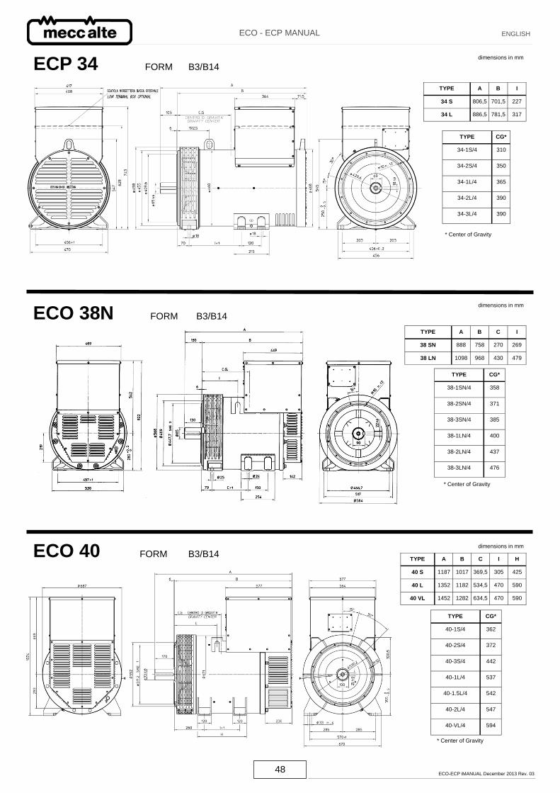
ECO 38N FORM B3/B14
ECO 40 FORM B3/B14
dimensions in mm
dimensions in mm
ECP 34 FORM B3/B14 dimensions in mm
TYPE CG*
34-1S/4 310
34-2S/4 350
34-1L/4 365
34-2L/4 390
34-3L/4 390
* Center of Gravity
TYPE A B I
34 S 806,5 701,5 227
34 L 886,5 781,5 317
TYPE CG*
38-1SN/4 358
38-2SN/4 371
38-3SN/4 385
38-1LN/4 400
38-2LN/4 437
38-3LN/4 476
TYPE A B C I
38 SN 888 758 270 269
38 LN 1098 968 430 479
* Center of Gravity
TYPE CG*
40-1S/4 362
40-2S/4 372
40-3S/4 442
40-1L/4 537
40-1.5L/4 542
40-2L/4 547
40-VL/4 594
* Center of Gravity
TYPE A B C I H
40 S 1187 1017 369,5 305 425
40 L 1352 1182 534,5 470 590
40 VL 1452 1282 634,5 470 590
49 ECO-ECP iMANUAL December 2013 Rev. 03
ECO - ECP MANUAL ENGLISH
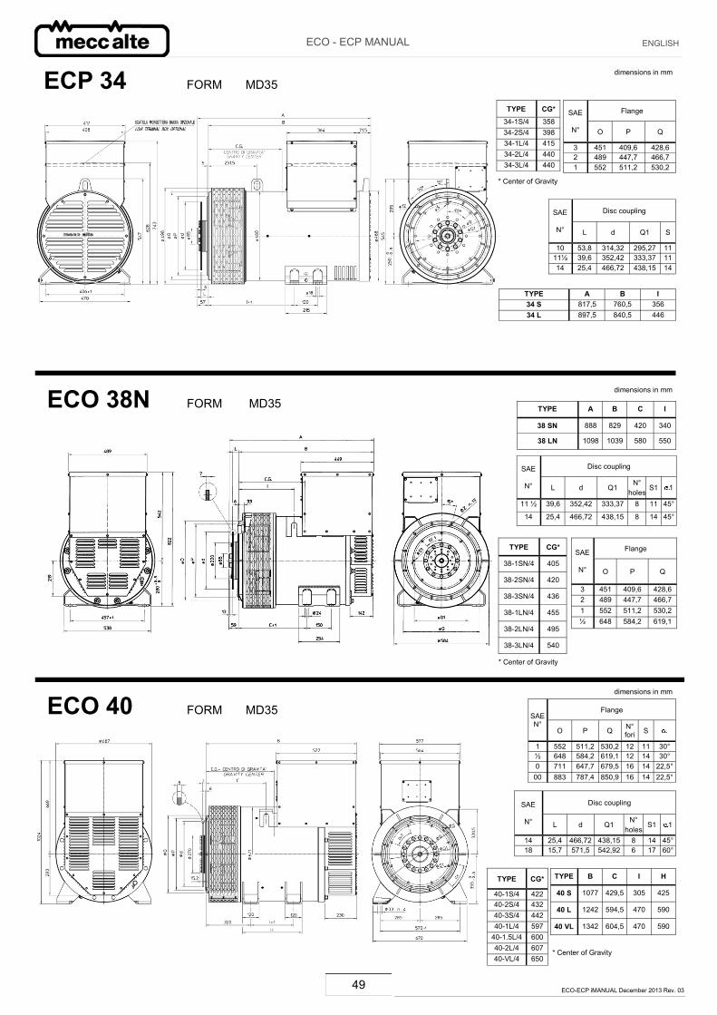
ECO 38N FORM MD35
ECO 40 FORM MD35 dimensions in mm
dimensions in mm
ECP 34 FORM MD35 dimensions in mm
TYPE CG* 34-1S/4 358 34-2S/4 398 34-1L/4 415 34-2L/4 440 34-3L/4 440
TYPE A B I 34 S 817,5 760,5 356 34 L 897,5 840,5 446
Disc coupling SAE
N° L d Q1 S
10 53,8 314,32 295,27 11 11½ 39,6 352,42 333,37 11 14 25,4 466,72 438,15 14
Flange SAE
N° O P Q
3 451 409,6 428,6 2 489 447,7 466,7 1 552 511,2 530,2
* Center of Gravity
TYPE CG*
38-1SN/4 405
38-2SN/4 420
38-3SN/4 436
38-1LN/4 455
38-2LN/4 495
38-3LN/4 540
TYPE A B C I
38 SN 888 829 420 340
38 LN 1098 1039 580 550
Flange SAE
N° O P Q
3 451 409,6 428,6 2 489 447,7 466,7 1 552 511,2 530,2 ½ 648 584,2 619,1
Disc coupling SAE
N° L d Q1 N°
holes S1 1
11 ½ 39,6 352,42 333,37 8 11 45°
14 25,4 466,72 438,15 8 14 45°
* Center of Gravity
TYPE CG*
40-1S/4 422 40-2S/4 432 40-3S/4 442 40-1L/4 597
40-1.5L/4 600 40-2L/4 607 40-VL/4 650
TYPE B C I H
40 S 1077 429,5 305 425
40 L 1242 594,5 470 590
40 VL 1342 604,5 470 590
Flange SAE N°
O P Q N° fori S
1 552 511,2 530,2 12 11 30° ½ 648 584,2 619,1 12 14 30° 0 711 647,7 679,5 16 14 22,5°
00 883 787,4 850,9 16 14 22,5°
Disc coupling SAE
N° L d Q1 N°
holes S1 1
14 25,4 466,72 438,15 8 14 45° 18 15,7 571,5 542,92 6 17 60°
* Center of Gravity
50 ECO-ECP iMANUAL December 2013 Rev. 03
ECO - ECP MANUAL ENGLISH
* Center of Gravity
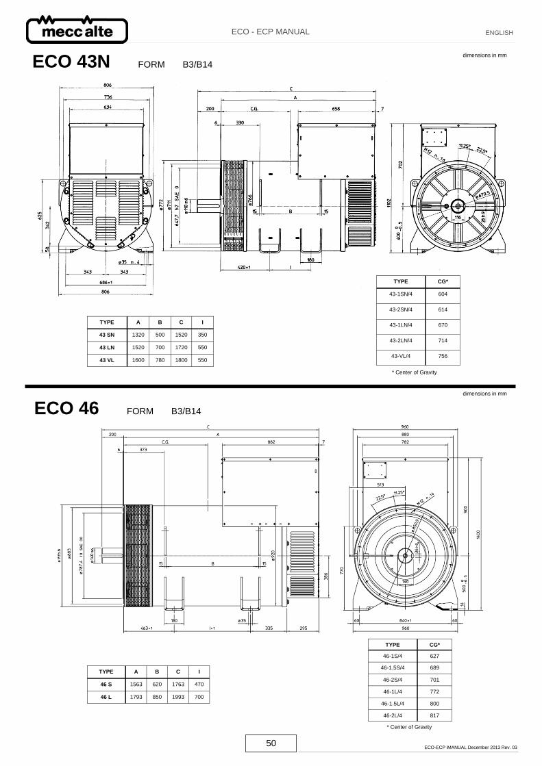
ECO 43N FORM B3/B14 dimensions in mm
ECO 46 FORM B3/B14
dimensions in mm
TYPE CG*
43-1SN/4 604
43-2SN/4 614
43-1LN/4 670
43-2LN/4 714
43-VL/4 756
TYPE A B C I
43 SN 1320 500 1520 350
43 LN 1520 700 1720 550
43 VL 1600 780 1800 550
* Center of Gravity
TYPE A B C I
46 S 1563 620 1763 470
46 L 1793 850 1993 700
TYPE CG*
46-1S/4 627
46-1.5S/4 689
46-2S/4 701
46-1L/4 772
46-1.5L/4 800
46-2L/4 817
51 ECO-ECP iMANUAL December 2013 Rev. 03
ECO - ECP MANUAL ENGLISH
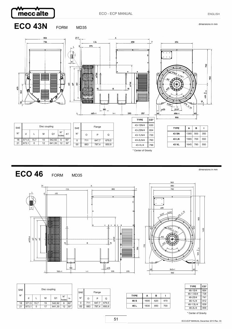
ECO 43N FORM MD35 dimensions in mm
ECO 46 FORM MD35 dimensions in mm
* Center of Gravity
TYPE A B I
43 SN 1365 500 350
43 LN 1565 700 550
43 VL 1645 780 550
Flange SAE
N° O P Q
0 711 647,7 679,5
00 883 787,4 850,9
TYPE CG*
43-1SN/4 630
43-2SN/4 654
43-1LN/4 720
43-2LN/4 760
43-VL/4 796
Disc coupling SAE
N° d L M Q1 N°
holes 1
18 571,5 15,7 10 542,92 6 60° 21 673,1 0 12 641,35 12 30°
* Center of Gravity
TYPE A B I
46 S 1600 620 470
46 L 1830 850 700
Flange SAE
N° O P Q
0 711 647,7 679,5 00 883 787,4 850,9
Disc coupling SAE
N° d L M Q1
N° holes
18 571,5 15,7 15 542,92 6 60° 21 673,1 0 17 641,35 12 30°
TYPE CG* 46-1S/4 664
46-1.5S/4 728 46-2S/4 741 46-1L/4 812
46-1.5L/4 839 46-2L/4 856
52 ECO-ECP iMANUAL December 2013 Rev. 03
ECO - ECP MANUAL ENGLISH
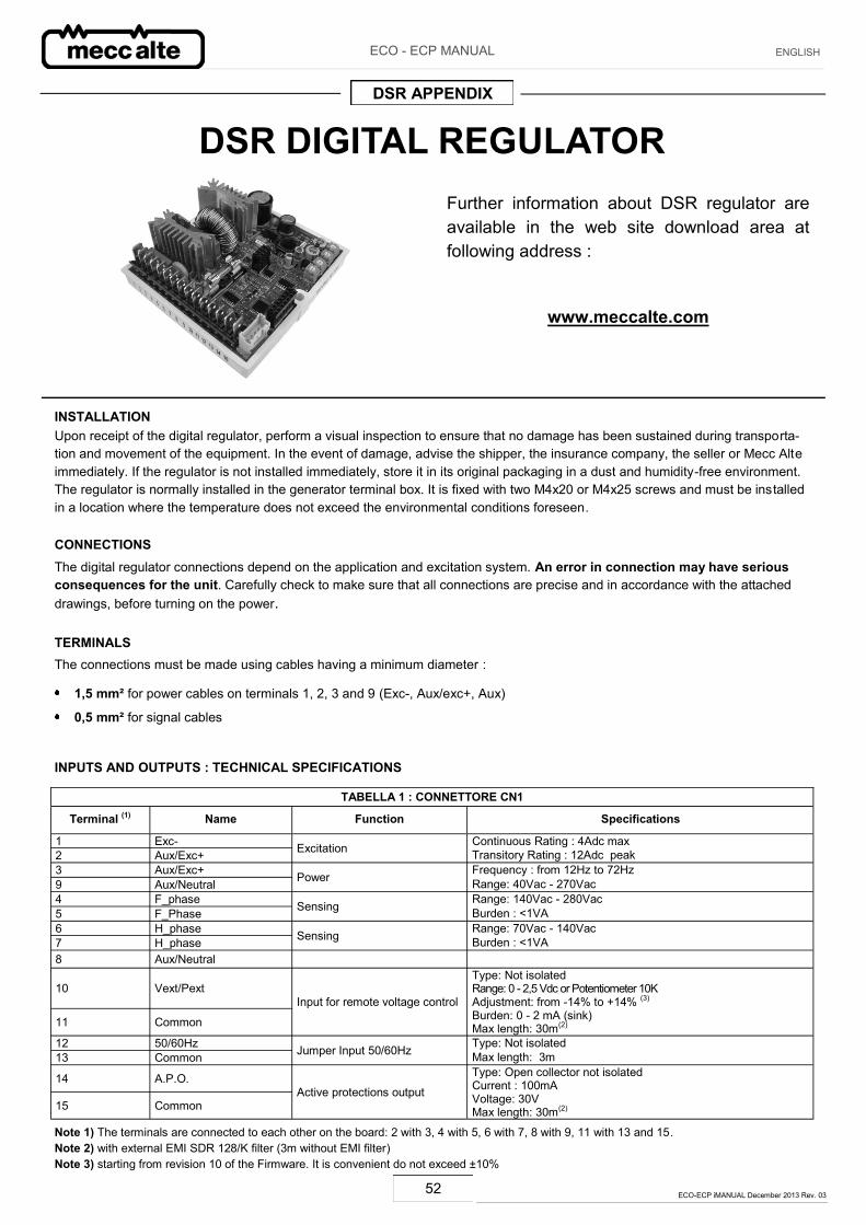
DSR DIGITAL REGULATOR Further information about DSR regulator are available in the web site download area at following address :
www.meccalte.com
INSTALLATION Upon receipt of the digital regulator, perform a visual inspection to ensure that no damage has been sustained during transporta-tion and movement of the equipment. In the event of damage, advise the shipper, the insurance company, the seller or Mecc Alte immediately. If the regulator is not installed immediately, store it in its original packaging in a dust and humidity-free environment. The regulator is normally installed in the generator terminal box. It is fixed with two M4x20 or M4x25 screws and must be installed in a location where the temperature does not exceed the environmental conditions foreseen.
CONNECTIONS
The digital regulator connections depend on the application and excitation system. An error in connection may have serious consequences for the unit. Carefully check to make sure that all connections are precise and in accordance with the attached drawings, before turning on the power.
TERMINALS
The connections must be made using cables having a minimum diameter :
1,5 mm² for power cables on terminals 1, 2, 3 and 9 (Exc-, Aux/exc+, Aux)
0,5 mm² for signal cables
INPUTS AND OUTPUTS : TECHNICAL SPECIFICATIONS
TABELLA 1 : CONNETTORE CN1
Terminal (1) Name Function Specifications
1 Exc- Excitation Continuous Rating : 4Adc max 2 Aux/Exc+ Transitory Rating : 12Adc peak 3 Aux/Exc+ Power Frequency : from 12Hz to 72Hz 9 Aux/Neutral Range: 40Vac - 270Vac 4 F_phase Sensing Range: 140Vac - 280Vac 5 F_Phase Burden : <1VA 6 H_phase Sensing Range: 70Vac - 140Vac 7 H_phase Burden : <1VA 8 Aux/Neutral
10 Vext/Pext Input for remote voltage control
Type: Not isolated Range: 0 - 2,5 Vdc or Potentiometer 10KAdjustment: from -14% to +14% (3)
11 Common Burden: 0 - 2 mA (sink) Max length: 30m(2)
12 50/60Hz Jumper Input 50/60Hz Type: Not isolated 13 Common Max length: 3m
14 A.P.O. Type: Open collector not isolated Current : 100mA
Active protections output 15 Common Voltage: 30V
Max length: 30m(2)
Note 1) The terminals are connected to each other on the board: 2 with 3, 4 with 5, 6 with 7, 8 with 9, 11 with 13 and 15. Note 2) with external EMI SDR 128/K filter (3m without EMI filter) Note 3) starting from revision 10 of the Firmware. It is convenient do not exceed ±10%
DSR APPENDIX
53 ECO-ECP iMANUAL December 2013 Rev. 03
ECO - ECP MANUAL ENGLISH
DSR regulator, on board of new generators, is already calibrated; in case of loose regulators (ie spare parts) or in case of wiring modi-fications or adjusting, to guarantee its correct working, it must be accurately set . Basic settings can be done directly on the regulator by its four trimmers (VOLT - STAB - Hz - AMP), the jumper 50/60 and the Vext input. More detailed settings or measures can be done exclusively by software using for example the MeccAlte communication interfa-ce DI1 and the program DSR_Terminal or DSR_Reader.
Vext Input The Vext input (connector CN1 – terminals 10 and 11) permits analogical remote control of output voltage through a 10Kohm poten-tiometer with a programmable variation range through parameter 16 with respect to the value set (by default the setting is ±14% star-ting from revision 10 of the Firmware); if you want to use continuous voltage, it will be effective if it is in the range between 0V and +2,5V. The input tolerates voltages from -5V to +5V, but for values exceeding the limits of 0V / +2,5V (or in the event of disconnec-tion), two options are possible: not to take the set point of external input (default configuration) and return to regulation to the voltage value set with the trimmer (if enabled) or with parameter 19, or keep the minimum (or maximum) value of voltage that can be reached. The two options can be set with the RAM Voltage CTRL flag in the Configuration menu corresponding to the bit B7 of the configura-tion word P[10]. NOTE : The DC voltage generator must be able to sink al least 2mA. In making adjustments it is reccomended not to exceed the no-minal value of voltage of the alternator beyond ± 10%
50/60 Signal
A jumper is located on the 50/60 input (connector CN1, terminals 12 and 13); it provokes the commutation of the underspeed protec-tion threshold from 50·(100%-αHz%) to 60·(100%-αHz%), where αHz% represents the position relative to the Hz trimmer.
APO Contact
The acronym APO stands for Active Protection Output: (connector CN1 – terminals 14 and 15) 30V-100mA non-insulated open col-lector transistor, normally opened, is closed (with a delay that can be programmed by software from 1 to 15 seconds) when, among all the alarms, one or more of the active ones can be selected separately by software.
The VOLT trimmer allows adjustment from about 70V to about 140V when using for sensing terminals 4 and 5, or from about 140V to about 280V when using terminals 6 and 7.
The STAB trimmer adjusts the dynamic response (statism) of the alternator under transient conditions.
The AMP trimmer adjusts the excitation overcurrent protection intervention threshold.
Use the following procedure in order to calibrate the overload protection:
1) Rotate the Hz trimmer entirely in the counter clockwise direction
2) Apply the nominal load to the alternator.
3) Decrease the speed by 10%
4) Rotate the AMP trimmer completely in the counter clockwise direction.
5) After a few seconds, there should be a decrease in the voltage value of the generator and alarm 5 should come on (visible due to a change in the flashing indicator light) .
6) Under these conditions, rotate the AMP trimmer slowly in the clockwise direction, until the output voltage value is 97% of the no-minal value: alarm 5 is still activated.
7) Return to the nominal speed; alarm 5 should disappear in a few seconds and the generator voltage should increase to the nomi-nal value.
8) Re-adjust the trimmer as indicated in the following paragraph.
The Hz trimmer allows to calibrate the threshold of the intervention of the under frequency protection up to -20% with respect to the
nominal speed value set by jumper 50/60 (at 50 Hz the threshold can be calibrated from 40 Hz to 50 Hz, at 60 Hz the threshold can
be calibrated from 48 Hz to 60 Hz).
The intervention of this protection reduce the output generator voltage and, to calibrate it, use the following procedure : 1) Rotate the Hz trimmer entirely in the counter clockwise direction.
2) If the machine has to operate at 60 Hz, ensure that the bridge is inserted between terminals 12 and 13 of the CN1 connector.
3) Bring the generator to 90% of the nominal speed.
4) Slowly turn the “Hz” trimmer, rotating it clockwise until the generator voltage begins to drop and ascertain that the indicator light simultaneously begins flashing rapidly.
5) By increasing speed, the generator voltage will normalise and the alarm will disappear.
6) Set the speed to the nominal value.
During normal operation and a duty cycle of 50% an indicator light mounted on the board flashes every 2 seconds; it flashes different-ly in the event of intervention or alarm, as indicated in figure 1.
NOTE: Notwithstanding DSR maintains the voltage regulation, it goes in shutdown mode if the frequency decreases under 20Hz. The reset needs the Gen-Set switching off.
54 ECO-ECP iMANUAL December 2013 Rev. 03
ECO - ECP MANUAL ENGLISH
OK
CHECKSUM
SHORT CIRCUIT
Hz or O.S.
AMP
AMP and (Hz or O.S.)
STOP
Allarm intervention 1 2 t [sec]
LED
LED ON LED OFF LED ON
SCC0100/00
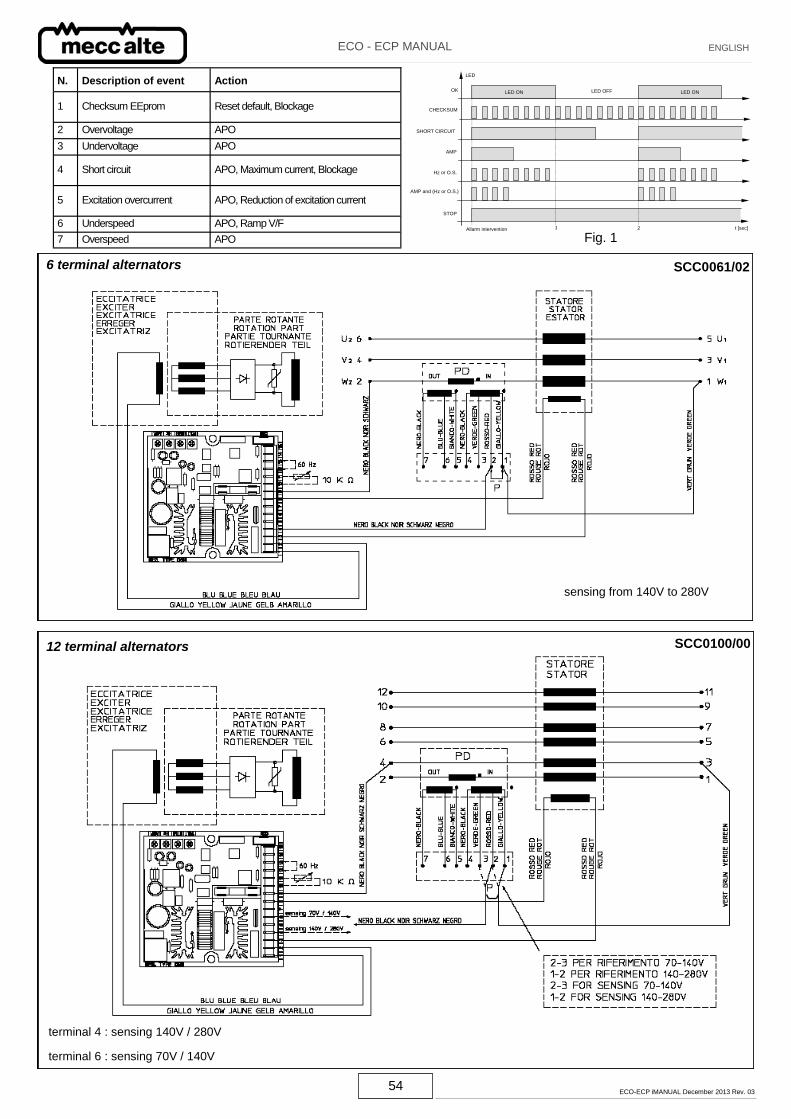
6 terminal alternators SCC0061/02
12 terminal alternators
sensing from 140V to 280V
Fig. 1
terminal 4 : sensing 140V / 280V
terminal 6 : sensing 70V / 140V
N. Description of event Action
1 Checksum EEprom Reset default, Blockage
2 Overvoltage APO
3 Undervoltage APO
4 Short circuit APO, Maximum current, Blockage
5 Excitation overcurrent APO, Reduction of excitation current
6 Underspeed APO, Ramp V/F
7 Overspeed APO
55 ECO-ECP iMANUAL December 2013 Rev. 03
ECO - ECP MANUAL ENGLISH
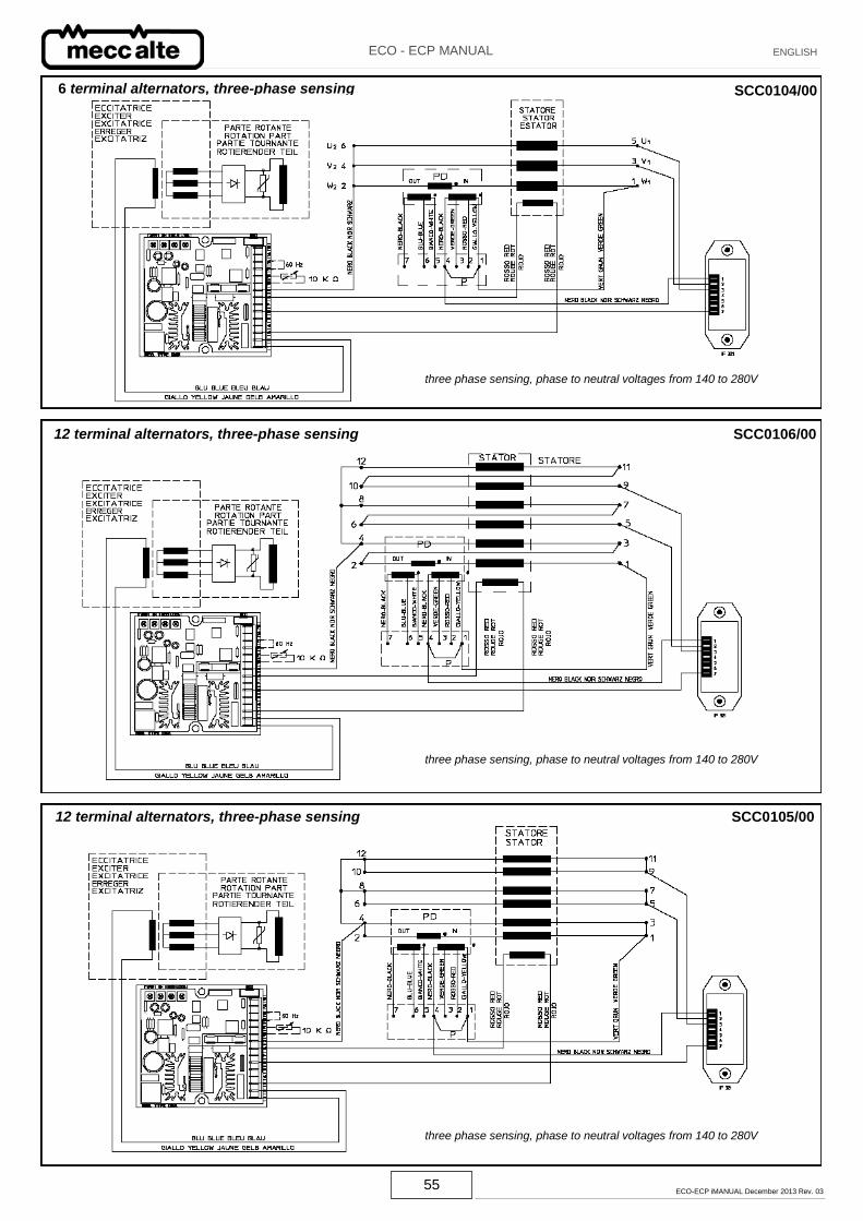
12 terminal alternators, three-phase sensing SCC0105/00
SCC0106/00 12 terminal alternators, three-phase sensing
three phase sensing, phase to neutral voltages from 140 to 280V
three phase sensing, phase to neutral voltages from 140 to 280V
6 terminal alternators, three-phase sensing SCC0104/00
three phase sensing, phase to neutral voltages from 140 to 280V
56 ECO-ECP iMANUAL December 2013 Rev. 03
ECO - ECP MANUAL ENGLISH
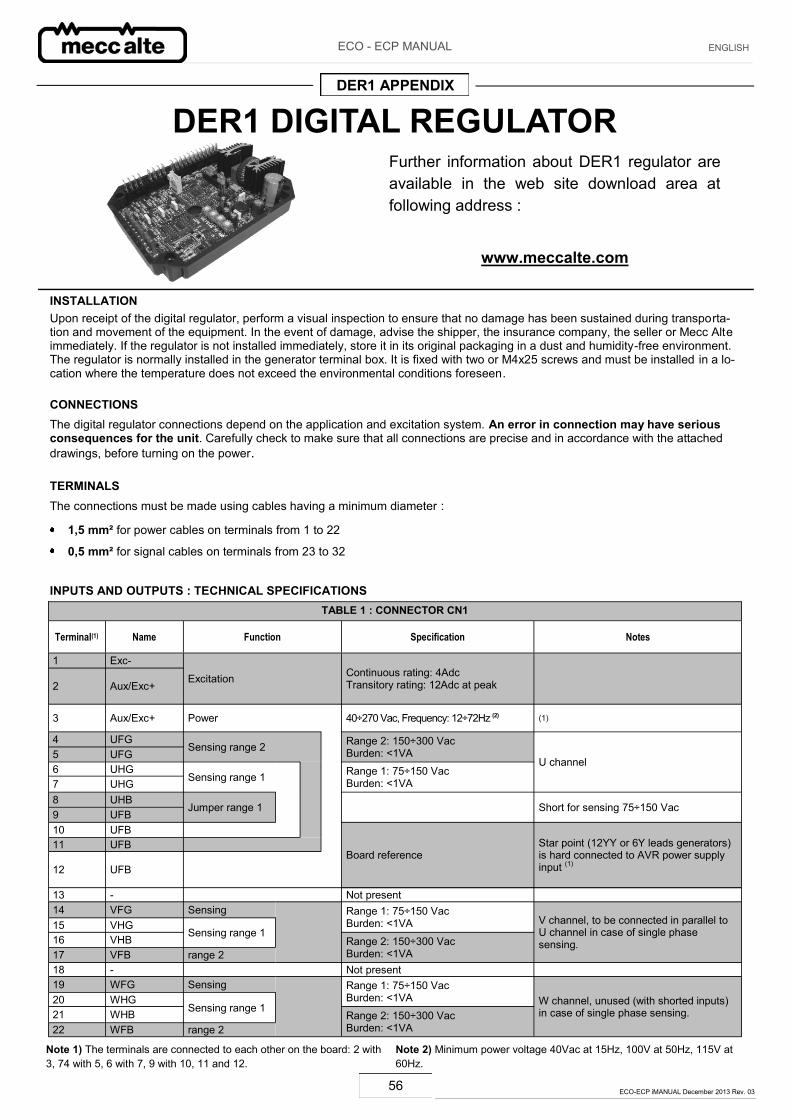
DER1 DIGITAL REGULATOR
INSTALLATION Upon receipt of the digital regulator, perform a visual inspection to ensure that no damage has been sustained during transporta-tion and movement of the equipment. In the event of damage, advise the shipper, the insurance company, the seller or Mecc Alte immediately. If the regulator is not installed immediately, store it in its original packaging in a dust and humidity-free environment. The regulator is normally installed in the generator terminal box. It is fixed with two or M4x25 screws and must be installed in a lo-cation where the temperature does not exceed the environmental conditions foreseen.
CONNECTIONS The digital regulator connections depend on the application and excitation system. An error in connection may have serious consequences for the unit. Carefully check to make sure that all connections are precise and in accordance with the attached drawings, before turning on the power.
TERMINALS
The connections must be made using cables having a minimum diameter :
1,5 mm² for power cables on terminals from 1 to 22
0,5 mm² for signal cables on terminals from 23 to 32
INPUTS AND OUTPUTS : TECHNICAL SPECIFICATIONS
Note 1) The terminals are connected to each other on the board: 2 with 3, 74 with 5, 6 with 7, 9 with 10, 11 and 12.
Note 2) Minimum power voltage 40Vac at 15Hz, 100V at 50Hz, 115V at 60Hz.
DER1 APPENDIX
TABLE 1 : CONNECTOR CN1
Terminal(1) Name Function Specification Notes
1 Exc-
Excitation Continuous rating: 4Adc Transitory rating: 12Adc at peak 2 Aux/Exc+
3 Aux/Exc+ Power 40÷270 Vac, Frequency: 12÷72Hz (2) (1)
4 UFG Sensing range 2
Range 2: 150÷300 Vac Burden: <1VA
U channel 5 UFG 6 UHG
Sensing range 1
Range 1: 75÷150 Vac Burden: <1VA 7 UHG
8 UHB Jumper range 1 Short for sensing 75÷150 Vac 9 UFB
10 UFB
Board reference Star point (12YY or 6Y leads generators) is hard connected to AVR power supply input (1)
11 UFB
12 UFB
13 - Not present14 VFG Sensing
Range 1: 75÷150 Vac Burden: <1VA V channel, to be connected in parallel to
U channel in case of single phase sensing.
15 VHG Sensing range 1
16 VHB Range 2: 150÷300 Vac Burden: <1VA 17 VFB range 2
18 - Not present 19 WFG Sensing
Range 1: 75÷150 Vac Burden: <1VA W channel, unused (with shorted inputs)
in case of single phase sensing. 20 WHG
Sensing range 1 21 WHB Range 2: 150÷300 Vac Burden: <1VA 22 WFB range 2
Further information about DER1 regulator are available in the web site download area at following address :
www.meccalte.com
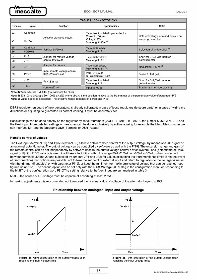
57 ECO-ECP iMANUAL December 2013 Rev. 03
ECO - ECP MANUAL ENGLISH
TABLE 2 : CONNECTOR CN3
Terminal Name Function Specifications Notes
23 Common
Active protections output Type: Not insulated open collector Current: 100mA Voltage: 30V Max lenght: 30m (3)
Both activating alarm and delay time are programmable. 24 A.P.O.
25 Common Jumper 50/60Hz Type: Not insulated
Max lenght: 3m Selection of underspeed (4)
26 50/60Hz
27 0EXT Jumper for remote voltage control 0÷2,5Vdc
Type: Not insulated Max lenght: 3m
Short for 0÷2,5Vdc input or potentiometer 28 JP1
29 Jumper for remote Type: Not insulated Max lenght: 3m (3)
Regulation: ±10 % (5) Input remote voltage control 0÷2,5Vdc or Pext
30 PEXT Input : 0÷2,5Vdc
or Potentiometer 100K Burden: 0÷1mA (sink)
31 JP2 Type: Not insulated Max lenght: 3m
Short for 0÷2,5Vdc input or potentiometer
32 control±10 Vdc Input: ±10Vdc Burden: ±1mA (source/sink)
Nota 3) With external EMI filter (3m without EMI filter) Nota 4) 50·(100%-αHz%) o 60·(100%-αHz%) where αHz% is the position relative to the Hz trimmer or the percentage value of parameter P[21] Nota 5) Value not to be exceeded. The effective range depends on parameter P[16]
DER1 regulator, on board of new generators, is already calibrated; in case of loose regulators (ie spare parts) or in case of wiring mo-difications or adjusting, to guarantee its correct working, it must be accurately set .
Basic settings can be done directly on the regulator by its four trimmers (VOLT - STAB - Hz - AMP), the jumper 50/60, JP1, JP2 and the Pext input. More detailed settings or measures can be done exclusively by software using for example the MeccAlte communica-tion interface DI1 and the programs DSR_Terminal or DSR_Reader.
Remote control of voltage
The Pext input (terminal 30) and ±10V (terminal 32) allow to obtain remote control of the output voltage by means of a DC signal or an external potentiometer. The output voltage can be controlled by software as well with the P[19]. The excursion range and gain of the remote control can be set independently by software despite the output voltage control device system used (potentiometer, VDC signal or P[19]). If DC voltage is used, it will take effect if it is within the range 0Vdc/2,5Vdc or -10Vdc/+10Vdc, when connected between terminals 30 and 29 and subjected by jumpers JP1 and JP2; for values exceeding the aforementioned limits (or in the event of disconnection), two options are possible: not to take the set point of external input and return to regulation to the voltage value set with the trimmer (if enabled) or with parameter P[19], or keep the minimum (or maximum) value of voltage that can be reached (see figures 3a and 3b). The second option can be set only with the RAM Voltage CTRL flag in the configuration menu corresponding to the bit B7 of the configuration word P[10]The setting relative to the Vext input are summarised in table 3.
NOTE: the source of DC voltage must be capable of absorbing at least 2 mA.
In making adjustments it is reccomended not to exceed the nominal value of voltage of the alternator beyond ± 10%
Relationship between analogical input and output voltage
Figure 3a: without saturation of the output voltage upon reaching the input voltage limits
Figure 3b: with saturation of the output voltage upon reaching the input voltage limits
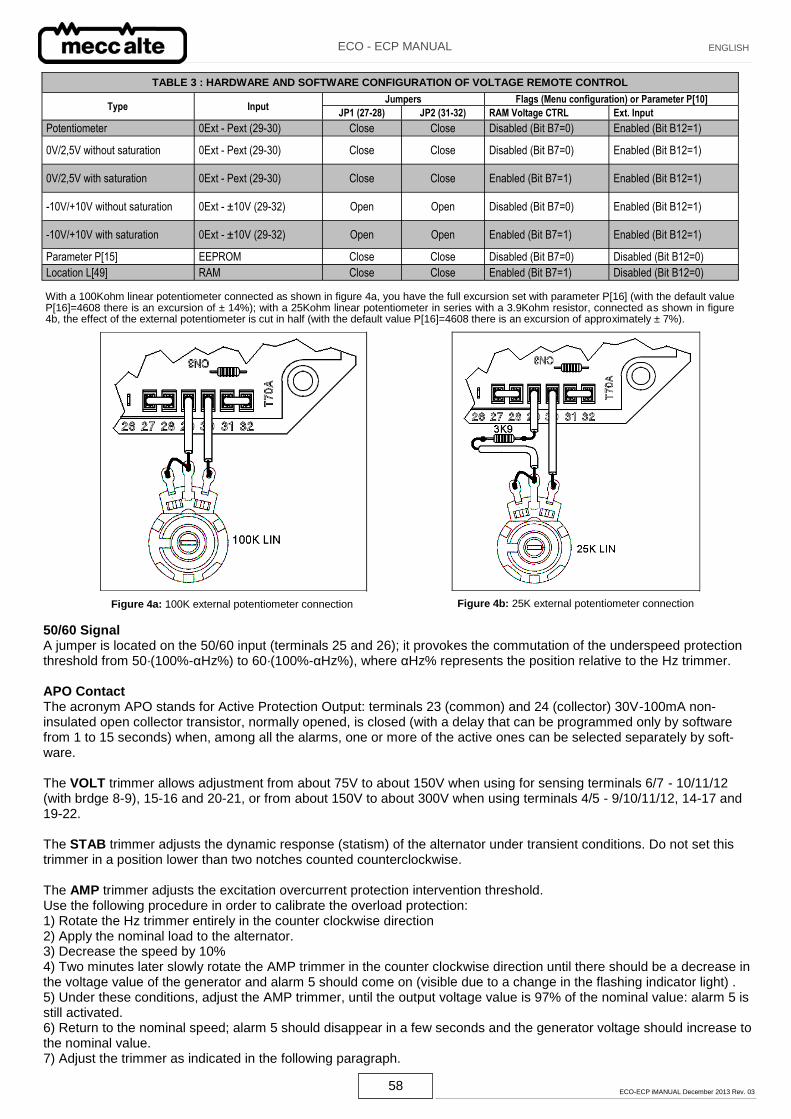
58 ECO-ECP iMANUAL December 2013 Rev. 03
ECO - ECP MANUAL ENGLISH
TABLE 3 : HARDWARE AND SOFTWARE CONFIGURATION OF VOLTAGE REMOTE CONTROL
Input Jumpers Flags (Menu configuration) or Parameter P[10]
Type JP1 (27-28) JP2 (31-32) RAM Voltage CTRL Ext. Input
Potentiometer 0Ext - Pext (29-30) Close Close Disabled (Bit B7=0) Enabled (Bit B12=1)
0V/2,5V without saturation 0Ext - Pext (29-30) Close Close Disabled (Bit B7=0) Enabled (Bit B12=1)
0V/2,5V with saturation 0Ext - Pext (29-30) Close Close Enabled (Bit B7=1) Enabled (Bit B12=1)
-10V/+10V without saturation 0Ext - ±10V (29-32) Open Open Disabled (Bit B7=0) Enabled (Bit B12=1)
-10V/+10V with saturation 0Ext - ±10V (29-32) Open Open Enabled (Bit B7=1) Enabled (Bit B12=1)
Parameter P[15] EEPROM Close Close Disabled (Bit B7=0) Disabled (Bit B12=0)
Location L[49] RAM Close Close Enabled (Bit B7=1) Disabled (Bit B12=0)
With a 100Kohm linear potentiometer connected as shown in figure 4a, you have the full excursion set with parameter P[16] (with the default value P[16]=4608 there is an excursion of ± 14%); with a 25Kohm linear potentiometer in series with a 3.9Kohm resistor, connected as shown in figure 4b, the effect of the external potentiometer is cut in half (with the default value P[16]=4608 there is an excursion of approximately ± 7%).
Figure 4a: 100K external potentiometer connection Figure 4b: 25K external potentiometer connection
50/60 Signal A jumper is located on the 50/60 input (terminals 25 and 26); it provokes the commutation of the underspeed protection threshold from 50·(100%-αHz%) to 60·(100%-αHz%), where αHz% represents the position relative to the Hz trimmer. APO Contact The acronym APO stands for Active Protection Output: terminals 23 (common) and 24 (collector) 30V-100mA non-insulated open collector transistor, normally opened, is closed (with a delay that can be programmed only by software from 1 to 15 seconds) when, among all the alarms, one or more of the active ones can be selected separately by soft-ware. The VOLT trimmer allows adjustment from about 75V to about 150V when using for sensing terminals 6/7 - 10/11/12 (with brdge 8-9), 15-16 and 20-21, or from about 150V to about 300V when using terminals 4/5 - 9/10/11/12, 14-17 and 19-22. The STAB trimmer adjusts the dynamic response (statism) of the alternator under transient conditions. Do not set this trimmer in a position lower than two notches counted counterclockwise. The AMP trimmer adjusts the excitation overcurrent protection intervention threshold. Use the following procedure in order to calibrate the overload protection: 1) Rotate the Hz trimmer entirely in the counter clockwise direction 2) Apply the nominal load to the alternator. 3) Decrease the speed by 10% 4) Two minutes later slowly rotate the AMP trimmer in the counter clockwise direction until there should be a decrease in the voltage value of the generator and alarm 5 should come on (visible due to a change in the flashing indicator light) . 5) Under these conditions, adjust the AMP trimmer, until the output voltage value is 97% of the nominal value: alarm 5 is still activated. 6) Return to the nominal speed; alarm 5 should disappear in a few seconds and the generator voltage should increase to the nominal value. 7) Adjust the trimmer as indicated in the following paragraph.
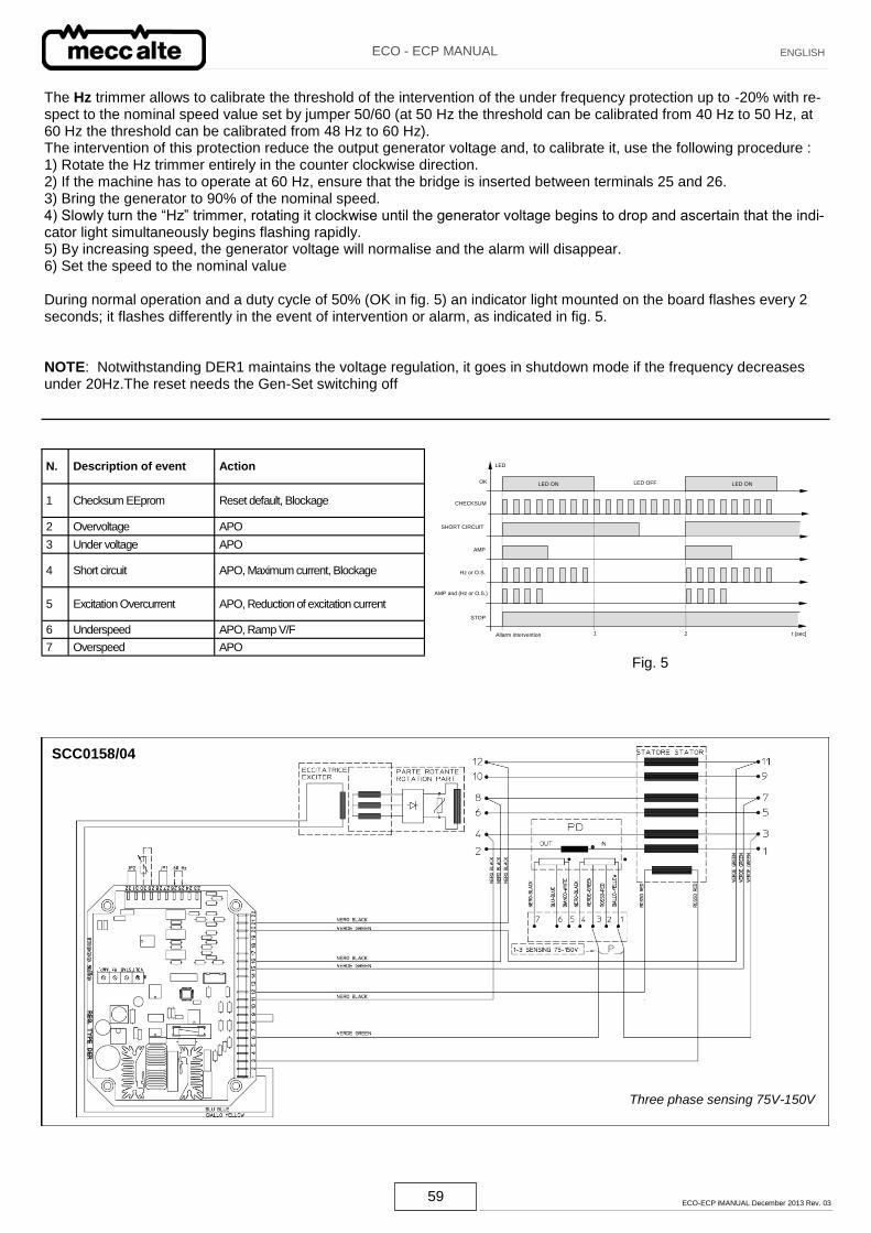
59 ECO-ECP iMANUAL December 2013 Rev. 03
ECO - ECP MANUAL ENGLISH
The Hz trimmer allows to calibrate the threshold of the intervention of the under frequency protection up to -20% with re-spect to the nominal speed value set by jumper 50/60 (at 50 Hz the threshold can be calibrated from 40 Hz to 50 Hz, at 60 Hz the threshold can be calibrated from 48 Hz to 60 Hz). The intervention of this protection reduce the output generator voltage and, to calibrate it, use the following procedure : 1) Rotate the Hz trimmer entirely in the counter clockwise direction. 2) If the machine has to operate at 60 Hz, ensure that the bridge is inserted between terminals 25 and 26. 3) Bring the generator to 90% of the nominal speed. 4) Slowly turn the “Hz” trimmer, rotating it clockwise until the generator voltage begins to drop and ascertain that the indi-cator light simultaneously begins flashing rapidly. 5) By increasing speed, the generator voltage will normalise and the alarm will disappear. 6) Set the speed to the nominal value During normal operation and a duty cycle of 50% (OK in fig. 5) an indicator light mounted on the board flashes every 2 seconds; it flashes differently in the event of intervention or alarm, as indicated in fig. 5. NOTE: Notwithstanding DER1 maintains the voltage regulation, it goes in shutdown mode if the frequency decreases under 20Hz.The reset needs the Gen-Set switching off
N. Description of event Action
1 Checksum EEprom Reset default, Blockage
2 Overvoltage APO
3 Under voltage APO
4 Short circuit APO, Maximum current, Blockage
5 Excitation Overcurrent APO, Reduction of excitation current
6 Underspeed APO, Ramp V/F
7 Overspeed APO
OK
CHECKSUM
SHORT CIRCUIT
Hz or O.S.
AMP
AMP and (Hz or O.S.)
STOP
Allarm intervention 1 2 t [sec]
LED
LED ON LED OFF LED ON
Fig. 5
SCC0158/04
Three phase sensing 75V-150V
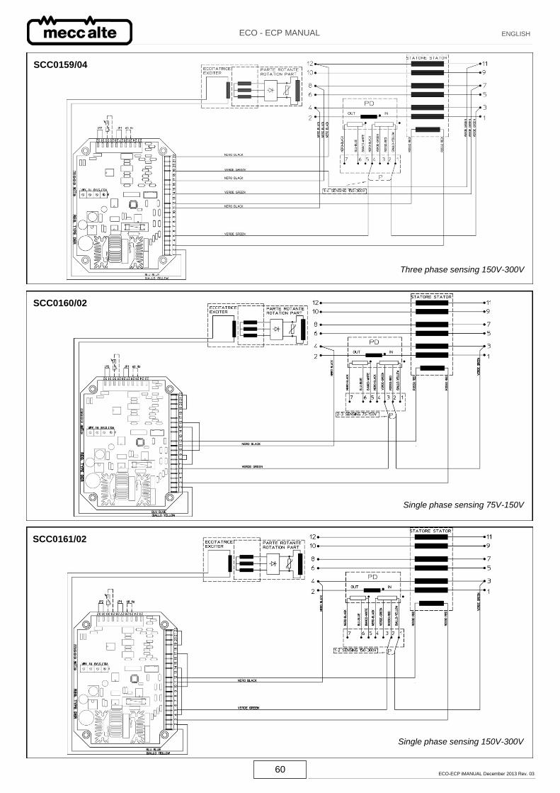
60 ECO-ECP iMANUAL December 2013 Rev. 03
ECO - ECP MANUAL ENGLISH
SCC0159/04
Three phase sensing 150V-300V
SCC0160/02
Single phase sensing 75V-150V
SCC0161/02
Single phase sensing 150V-300V
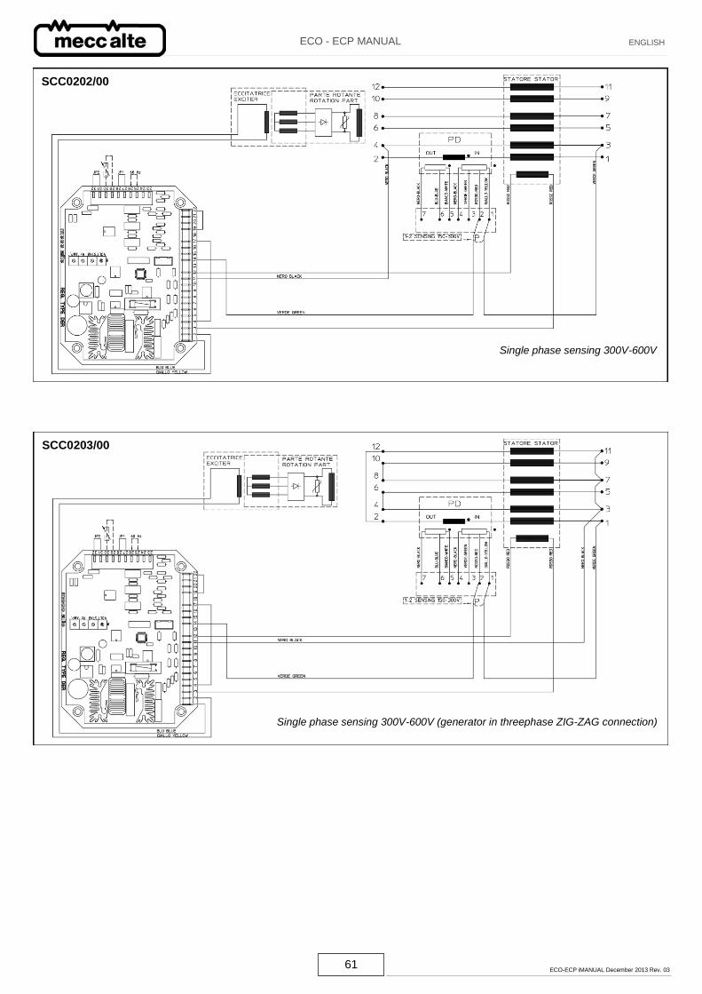
61 ECO-ECP iMANUAL December 2013 Rev. 03
ECO - ECP MANUAL ENGLISH
SCC0203/00
Single phase sensing 300V-600V (generator in threephase ZIG-ZAG connection)
SCC0202/00
Single phase sensing 300V-600V
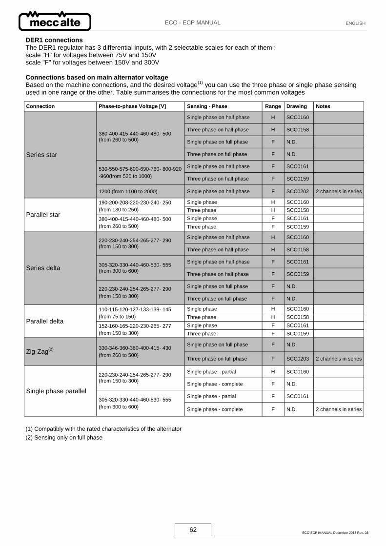
62 ECO-ECP iMANUAL December 2013 Rev. 03
ECO - ECP MANUAL ENGLISH
Connection Phase-to-phase Voltage [V] Sensing - Phase Range Drawing Notes
Series star
380-400-415-440-460-480- 500 (from 260 to 500)
Single phase on half phase H SCC0160
Three phase on half phase H SCC0158
Single phase on full phase F N.D.
Three phase on full phase F N.D.
530-550-575-600-690-760- 800-920
-960(from 520 to 1000)
Single phase on half phase F SCC0161
Three phase on half phase F SCC0159
1200 (from 1100 to 2000) Single phase on half phase F SCC0202 2 channels in series
Parallel star
190-200-208-220-230-240- 250
(from 130 to 250)
Single phase H SCC0160
Three phase H SCC0158
380-400-415-440-460-480- 500
(from 260 to 500)
Single phase F SCC0161
Three phase F SCC0159
Series delta
220-230-240-254-265-277- 290 (from 150 to 300)
Single phase on half phase H SCC0160
Three phase on half phase H SCC0158
305-320-330-440-460-530- 555 (from 300 to 600)
Single phase on half phase F SCC0161
Three phase on half phase F SCC0159
220-230-240-254-265-277- 290
(from 150 to 300)
Single phase on full phase F N.D.
Three phase on full phase F N.D.
Parallel delta
110-115-120-127-133-138- 145
(from 75 to 150)
Single phase H SCC0160
Three phase H SCC0158
152-160-165-220-230-265- 277
(from 150 to 300)
Single phase F SCC0161
Three phase F SCC0159
Zig-Zag(2)
330-346-360-380-400-415- 430
(from 260 to 500)
Single phase on full phase F N.D.
Three phase on full phase F SCC0203 2 channels in series
Single phase parallel
220-230-240-254-265-277- 290 (from 150 to 300)
Single phase - partial H SCC0160
Single phase - complete F N.D.
305-320-330-440-460-530- 555
(from 300 to 600)
Single phase - partial F SCC0161
Single phase - complete F N.D. 2 channels in series
DER1 connections The DER1 regulator has 3 differential inputs, with 2 selectable scales for each of them : scale "H" for voltages between 75V and 150V scale "F" for voltages between 150V and 300V Connections based on main alternator voltage Based on the machine connections, and the desired voltage
(1) you can use the three phase or single phase sensing
used in one range or the other. Table summarises the connections for the most common voltages
(1) Compatibly with the rated characteristics of the alternator
(2) Sensing only on full phase