easy 1-c powder coating equipment
TRANSCRIPT
Issue
d 05
/00
Operating Instructions and Spare parts list
EASY 1-C
Powder Coating Equipment
E
20 EASY 1-C
Issue
d 05
/00
Mains connectionAuxGun
1.1 IN
5 ... 10 bar73...145 PSI
1.4 2.2 2.3
2.1
1.3
1.2 1.5
Input voltage:
Input power:
Degree of protection:
Output:
Corresponding guns:
85 – 264 V
47 – 440 Hz
65 VA
IP 54
10 V 1,2 A
EasySelect
POWDER GUN CONTROL
TYPE EASYTRONIC
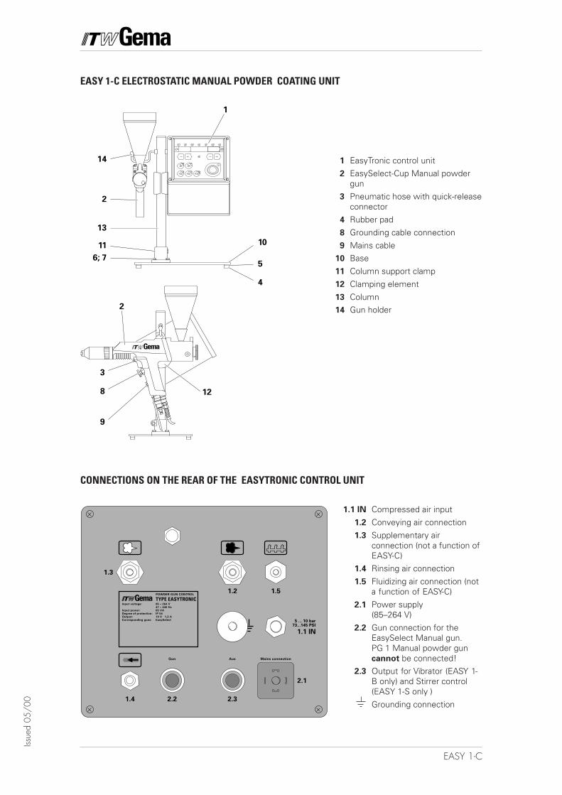
CONNECTIONS ON THE REAR OF THE EASYTRONIC CONTROL UNIT
1011
2
6; 7
14
13
4
5
1
2
3
8
9
12
1 EasyTronic control unit
2 EasySelect-Cup Manual powdergun
3 Pneumatic hose with quick-releaseconnector
4 Rubber pad
8 Grounding cable connection
9 Mains cable10 Base
11 Column support clamp
12 Clamping element
13 Column14 Gun holder
EASY 1-C ELECTROSTATIC MANUAL POWDER COATING UNIT
1.1 IN Compressed air input
1.2 Conveying air connection
1.3 Supplementary airconnection (not a function ofEASY-C)
1.4 Rinsing air connection
1.5 Fluidizing air connection (nota function of EASY-C)
2.1 Power supply(85–264 V)
2.2 Gun connection for theEasySelect Manual gun.PG 1 Manual powder guncannot be connected!
2.3 Output for Vibrator (EASY 1-B only) and Stirrer control(EASY 1-S only )
Grounding connection
19EASY 1-C
Issue
d 05
/00
Table of Contents
Directions for use
Safety rules for electrostatic powder coating
Technical Data of the EASY 1-C Powder Manual Coating Equipment
About these Operating Instructions . . . . . . . . . . . . . . . . . . . . . . . . . . . . . . . . . . . . . . . . . . . . 1
EASY 1-C Electrostatic Powder Manual Equipment . . . . . . . . . . . . . . . . . . . . . . . . . . . . . . . 2
1. Field of Application . . . . . . . . . . . . . . . . . . . . . . . . . . . . . . . . . . . . . . . . . . . . . . . 22. Scope of delivery for EASY 1-C . . . . . . . . . . . . . . . . . . . . . . . . . . . . . . . . . . . . . 2
Installation of the powder coating equipment . . . . . . . . . . . . . . . . . . . . . . . . . . . . . . . . . . . 3
Description of Function . . . . . . . . . . . . . . . . . . . . . . . . . . . . . . . . . . . . . . . . . . . . . . . . . . . . . . 4
EasyTronic Control unit . . . . . . . . . . . . . . . . . . . . . . . . . . . . . . . . . . . . . . . . . . . . . . . . . . . . . . 5
Preparation for Start up . . . . . . . . . . . . . . . . . . . . . . . . . . . . . . . . . . . . . . . . . . . . . . . . . . . . . . 6
a) Filling the powder funnel . . . . . . . . . . . . . . . . . . . . . . . . . . . . . . . . . . . . . . . . . . 6b) Switch the booth on . . . . . . . . . . . . . . . . . . . . . . . . . . . . . . . . . . . . . . . . . . . . . . 6c) Function check . . . . . . . . . . . . . . . . . . . . . . . . . . . . . . . . . . . . . . . . . . . . . . . . . . 6
Daily Start up . . . . . . . . . . . . . . . . . . . . . . . . . . . . . . . . . . . . . . . . . . . . . . . . . . . . . . . . . . . . . . . 7
a) Powder fluidizing (Fluidized cup) . . . . . . . . . . . . . . . . . . . . . . . . . . . . . . . . . . . . . 7b) Regulate the powder output, and powder cloud . . . . . . . . . . . . . . . . . . . . . . . . 7
Set Total air volume . . . . . . . . . . . . . . . . . . . . . . . . . . . . . . . . . . . . . . . . . . . 7Select powder output volume . . . . . . . . . . . . . . . . . . . . . . . . . . . . . . . . . . . 7Select electrode rinsing . . . . . . . . . . . . . . . . . . . . . . . . . . . . . . . . . . . . . . . . 7
c) Powder coating . . . . . . . . . . . . . . . . . . . . . . . . . . . . . . . . . . . . . . . . . . . . . . . . . . 8d) Remote control through the powder gun . . . . . . . . . . . . . . . . . . . . . . . . . . . . . . 8e) Switching off . . . . . . . . . . . . . . . . . . . . . . . . . . . . . . . . . . . . . . . . . . . . . . . . . . . . 8
Colour change . . . . . . . . . . . . . . . . . . . . . . . . . . . . . . . . . . . . . . . . . . . . . . . . . . . . . . . . . . . . . . 9
Maintenance schedule . . . . . . . . . . . . . . . . . . . . . . . . . . . . . . . . . . . . . . . . . . . . . . . . . . . . . . . 9
a) Daily maintenance . . . . . . . . . . . . . . . . . . . . . . . . . . . . . . . . . . . . . . . . . . . . . . . . 9b) Weekly maintenance . . . . . . . . . . . . . . . . . . . . . . . . . . . . . . . . . . . . . . . . . . . . . 9c) When the powder coating equipment is not used for a number of days . . . . . . 9
Cleaning . . . . . . . . . . . . . . . . . . . . . . . . . . . . . . . . . . . . . . . . . . . . . . . . . . . . . . . . . . . . . . . . . . 10
Cleaning the EasySelect-Cup Manual powder gun . . . . . . . . . . . . . . . . . . . . . . . . 10
Troubleshooting guide . . . . . . . . . . . . . . . . . . . . . . . . . . . . . . . . . . . . . . . . . . . . . . . . . . . . . . 11
Pneumatic Diagram - EASY 1-C . . . . . . . . . . . . . . . . . . . . . . . . . . . . . . . . . . . . . . . . . . . . . . . 13
Block Diagram . . . . . . . . . . . . . . . . . . . . . . . . . . . . . . . . . . . . . . . . . . . . . . . . . . . . . . . . . . . . . 14
Spare parts list . . . . . . . . . . . . . . . . . . . . . . . . . . . . . . . . . . . . . . . . . . . . . . . . . . . . . . . . . . . . 15
Ordering Spare parts . . . . . . . . . . . . . . . . . . . . . . . . . . . . . . . . . . . . . . . . . . . . . . . 15EASY 1-C Powder coating equipment . . . . . . . . . . . . . . . . . . . . . . . . . . . . . . . . . 16

20 EASY 1-C
Issue
d 05
/00
21EASY 1-C
Issue
d 05
/00
DIRECTIONS FOR USE
ELECTROSTATIC MANUAL SPRAYING EQUIPMENT FOR POWDER COATING
consists of: - EasySelect-Cup Electrostatic Manual Spray Gun- EasyTronic Control unit
This equipment is matched and should only be operated in this configu-ration.
SAFETY RULES FOR ELECTROSTATIC POWDER COATING
1. This equipment can be dangerous when not operated accordingto the following standards:EN 50 050 (or VDE 0745 Part 100),EN 50 053 Part 2 (or VDE 0745 Part 102),and specification sheet, ZH 1/443 Electrostatic Powder Coating.
2. All electrically conductive parts, within 5 m of the coating area,especially the workpieces, must be grounded.
3. The floor in the coating area must be electrically conductive(normal concrete is generally conductive).
4. The operating personnel must wear electrically conductivefootwear (i.e. leather soles).
5. The operating personnel should hold the powder gun in the barehand. If gloves are worn they must be electrically conductive.
6. Connect the grounding cable (green/yellow) supplied to thegrounding screw of the electrostatic manual powder coatingequipment. The grounding cable must have a good metal tometal connection with the powder coating booth, the powderrecovery equipment and the chain conveyor or the hangers of theobjects.
7. The electrical cables and powder hose to the guns must be laidout so that they are protected from possible mechanical damage.
8. The powder coating equipment must switch on only after thepowder booth is in operation. If the booth breaks down, then thepowder coating equipment must switch off.
9. The grounding of all conductive parts is to be checked at leastonce a week.
10. When cleaning the powder gun and when replacing nozzles thecontrol unit must be switched off.
22 EASY 1-C
Issue
d 05
/00
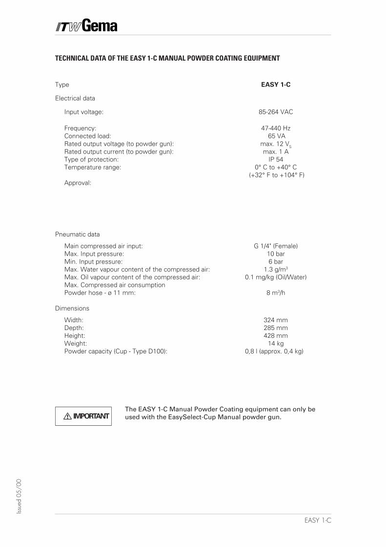
TECHNICAL DATA OF THE EASY 1-C MANUAL POWDER COATING EQUIPMENT
Type EASY 1-C
Electrical data
Input voltage: 85-264 VAC
Frequency: 47-440 HzConnected load: 65 VARated output voltage (to powder gun): max. 12 VS
Rated output current (to powder gun): max. 1 AType of protection: IP 54Temperature range: 0° C to +40° C
(+32° F to +104° F)Approval:
Pneumatic data
Main compressed air input: G 1/4" (Female)Max. Input pressure: 10 barMin. Input pressure: 6 barMax. Water vapour content of the compressed air: 1.3 g/m3
Max. Oil vapour content of the compressed air: 0.1 mg/kg (Oil/Water)Max. Compressed air consumptionPowder hose - ø 11 mm: 8 m3/h
Dimensions
Width: 324 mmDepth: 285 mmHeight: 428 mmWeight: 14 kgPowder capacity (Cup - Type D100): 0,8 l (approx. 0,4 kg)
IMPORTANTThe EASY 1-C Manual Powder Coating equipment can only beused with the EasySelect-Cup Manual powder gun.
1EASY 1-C
Issue
d 05
/00
ABOUT THESE OPERATING INSTRUCTIONS
These operating instructions contain all the important informationwhich is required to operate the EASY powder coating equipment. Itwill guide you safely through the installation stage, and also give notesand tips for the optimum use of your new powder coating system.The information about the functioning of the individual system compo-nents - EasyTronic powder gun control or EasySelect-Cup manualpowder gun will be found in the respective accompanying documenta-tion.
2 EASY 1-C
Issue
d 05
/00
EASY 1-C ELECTROSTATIC POWDER MANUAL EQUIPMENT
1. FIELD OF APPLICATION
The EASY 1-C Electrostatic Manual Powder Coating equipment withthe EasySelect-Cup Manual powder gun is ideally suited for manualcoating of objects in paint laboratories and for coating trials, and alsoespecially for powder quality checks.
2. SCOPE OF DELIVERY FOR EASY 1-C
An EasyTronic control unit (1) in a metal housing with a Mains connec-tion cable.
A base (10) with a column (13) and a gun holder (14).
An EasySelect-Cup Manual powder gun (2) with electric cable, rinsinghose and standard nozzle set (see EasySelect-Cup Manual powder gunoperating instructions).
Pneumatic hoses (3) for conveying air (red), connection (transparent).
3EASY 1-C
Issue
d 05
/00
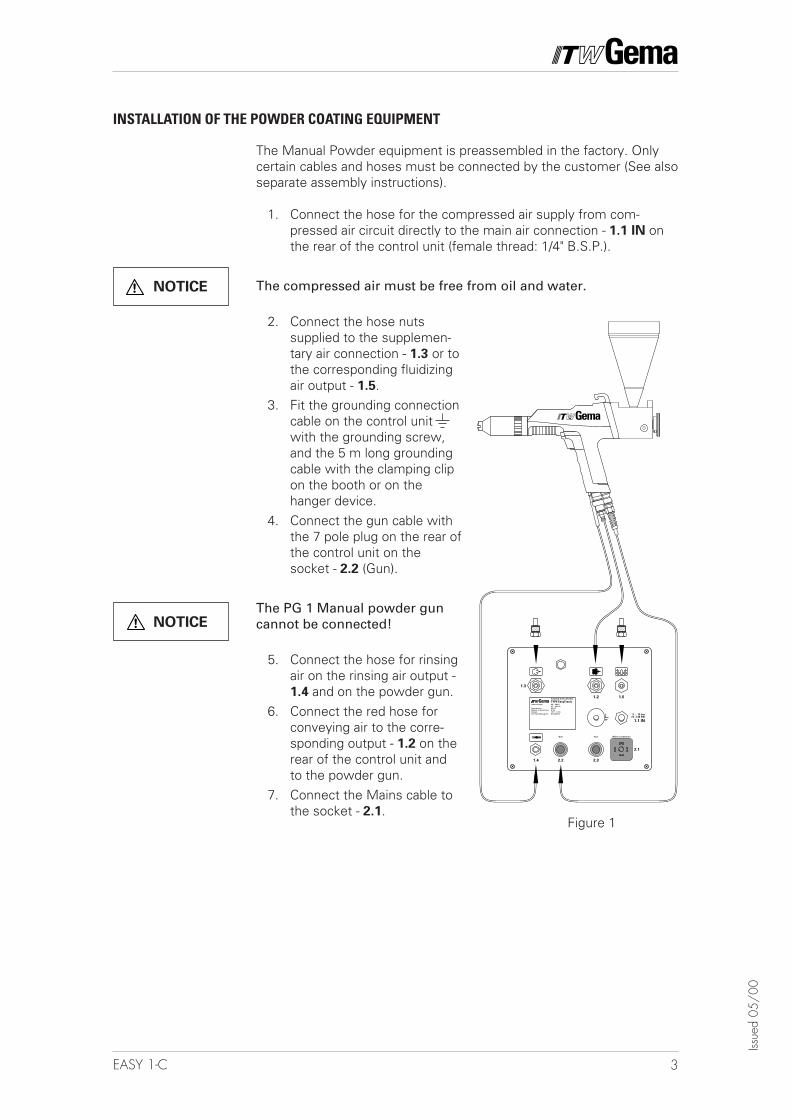
Figure 1
INSTALLATION OF THE POWDER COATING EQUIPMENT
The Manual Powder equipment is preassembled in the factory. Onlycertain cables and hoses must be connected by the customer (See alsoseparate assembly instructions).
1. Connect the hose for the compressed air supply from com-pressed air circuit directly to the main air connection - 1.1 IN onthe rear of the control unit (female thread: 1/4" B.S.P.).
The compressed air must be free from oil and water.
2. Connect the hose nutssupplied to the supplemen-tary air connection - 1.3 or tothe corresponding fluidizingair output - 1.5.
3. Fit the grounding connectioncable on the control unitwith the grounding screw,and the 5 m long groundingcable with the clamping clipon the booth or on thehanger device.
4. Connect the gun cable withthe 7 pole plug on the rear ofthe control unit on thesocket - 2.2 (Gun).
The PG 1 Manual powder guncannot be connected!
5. Connect the hose for rinsingair on the rinsing air output -1.4 and on the powder gun.
6. Connect the red hose forconveying air to the corre-sponding output - 1.2 on therear of the control unit andto the powder gun.
7. Connect the Mains cable tothe socket - 2.1.
NOTICE
NOTICE
Mains connectionAuxGun
1.1 IN
5 ... 10 bar73...145 PSI
1.4 2.2 2.3
2.1
1.3
1.2 1.5
Input voltage:
Input power:
Degree of protection:
Output:
Corresponding guns:
85 – 264 V
47 – 440 Hz
65 VA
IP 54
10 V 1,2 A
EasySelect
POWDER GUN CONTROL
TYPE EasyTronic
���
4 EASY 1-C
Issue
d 05
/00
1
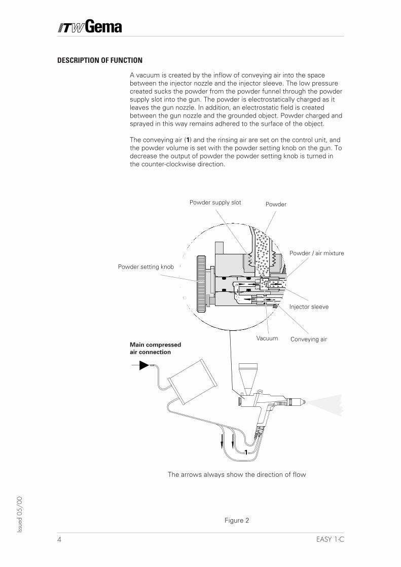
DESCRIPTION OF FUNCTION
Main compressed
air connection
The arrows always show the direction of flow
Figure 2
A vacuum is created by the inflow of conveying air into the spacebetween the injector nozzle and the injector sleeve. The low pressurecreated sucks the powder from the powder funnel through the powdersupply slot into the gun. The powder is electrostatically charged as itleaves the gun nozzle. In addition, an electrostatic field is createdbetween the gun nozzle and the grounded object. Powder charged andsprayed in this way remains adhered to the surface of the object.
The conveying air (1) and the rinsing air are set on the control unit, andthe powder volume is set with the powder setting knob on the gun. Todecrease the output of powder the powder setting knob is turned inthe counter-clockwise direction.
Powder / air mixture
PowderPowder supply slot
Powder setting knob
Injector sleeve
Conveying airVacuum
5EASY 1-C
Issue
d 05
/00
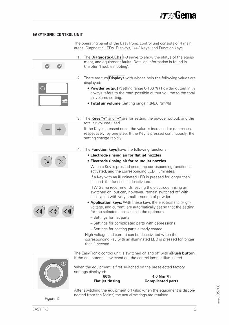
The operating panel of the EasyTronic control unit consists of 4 mainareas: Diagnostic LEDs, Displays, "+/–" Keys, and Function keys.
1. The Diagnostic-LEDs 1-8 serve to show the status of the equip-ment, and equipment faults. Detailed information is found inChapter "Troubleshooting".
2. There are two Displays with whose help the following values aredisplayed:
• Powder output (Setting range 0-100 %) Powder output in %always refers to the max. possible output volume to the totalair volume setting.
• Total air volume (Setting range 1.6-6.0 Nm3/h)
3. The Keys "+" and "–" are for setting the powder output, and thetotal air volume used.If the Key is pressed once, the value is increased or decreases,respectively, by one step. If the Key is pressed continuously, thesetting change rapidly.
4. The Function keys have the following functions:• Electrode rinsing air for flat jet nozzles
• Electrode rinsing air for round jet nozzles
When a Key is pressed once, the corresponding function isactivated, and the corresponding LED illuminates.If a Key with an illuminated LED is pressed for longer than 1second, the function is deactivated.ITW Gema recommends leaving the electrode rinsing airswitched on, but can, however, remain switched off withapplication with very small amounts of powder.
• Application keys: With these keys the electrostatic (High-voltage, and current) are automatically set so that the settingfor the selected application is the optimum.– Settings for flat parts– Settings for complicated parts with depressions– Settings for coating parts already coated
High-voltage and current can be deactivated when thecorresponding key with an illuminated LED is pressed for longerthan 1 second
The EasyTronic control unit is switched on and off with a Push button.If the equipment is switched on, the control lamp is illuminated.
When the equipment is first switched on the preselected factorysettings displayed:
60% 4.0 Nm3/h
Flat jet rinsing Complicated parts
After switching the equipment off (also when the equipment is discon-nected from the Mains) the actual settings are retained.
Figure 3
EASYTRONIC CONTROL UNIT
6 EASY 1-C
Issue
d 05
/00
PREPARATION FOR START UP
1. Remove the powder funnel cover.2. Fill with powder: Type ø 100 = approximately 0.4 dm3.
Type ø 125 = approximately 0.75 dm3,Fluidized cup = approximately 0.375 dm3
Do not fill the fluidized cup too much, otherwise the fluidizedpowder can escape from the cover.
3. Carefully replace the cover of the powder funnel again.
B) SWITCH THE BOOTH ON
Switch the powder coating booth on according to the operating instruc-tions.
C) FUNCTION CHECK
1. Press the main switch on the control unit. The control lamp in theswitch illuminates.The equipment carries out the calibration automatically. Anincrease in sound can be heard inside the control unit. Bothdisplays show 888. The equipment is ready for operation afternot more than 20 seconds and switches to the factory settings.
2. Take the powder gun in the hand and point at a grounded objectin the booth, distance approx. 20 cm.
3. Press the gun trigger.The LED No. 8 illuminates. The High-voltage is switched on andpowder is conveyed.
If all tests are positive, the control unit, and the powder gun are readyfor operation. If one of the functions is not operating as expected,check this in the "Troubleshooting Guide", on pages 11 and 12.
A) FILLING THE POWDER FUNNEL
7EASY 1-C
Issue
d 05
/00
DAILY START UP
A) POWDER FLUIDIZING (FLUIDIZED CUP)
The fluidizing of the powder is dependent on the type of powder, thehumidity of the air, and the ambient temperature. The fluidizing oper-ates when control unit is switched on.Proceed as follows:
1. Slowly increase the fluidizing air with the regulating screw on thefluidized funnel.The powder should only “boil” lightly, but continuously.
B) REGULATE THE POWDER OUTPUT, AND POWDER CLOUD
The powder output is dependent on the powder, and the total airvolume setting.
1. Switch on the control unit2. Set the total air volume max. 4 m3/h.
The selection takes place with the aid of the + and – keys on thecontrol unit.
3. Select the powder output volume 100%The selection takes place with the aid of the + and – keys on the
control unitThe total air volume is maintained constant automatically.
(4.) Check the fluidizing of the powder (in the Fluidized cup)5. Point the powder gun into the booth and press the powder gun
trigger6. Turn the powder setting knob in the clockwise direction to the
end stop on the gun = Maximum output.To decrease the powder output turn the powder setting knob inthe counter-clockwise direction.
7. Select the correct electrode rinsing.When using flat jet nozzles:
- Press the key with the corresponding symbol . The LED ofthe corresponding key illuminates.When using round jet nozzles with air rinsed deflector plates:
- Press the Key with the corresponding symbol . The LED of thecorresponding Key illuminates.
(continued)
SET TOTAL AIRVOLUME
SELECT POWDEROUTPUT VOLUME
SELECT ELECTRODERINSING
8 EASY 1-C
Issue
d 05
/00
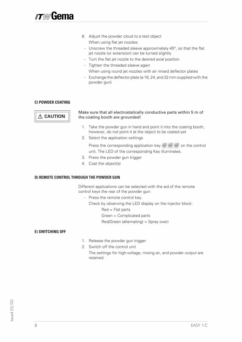
C) POWDER COATING
CAUTIONMake sure that all electrostatically conductive parts within 5 m ofthe coating booth are grounded!
1. Take the powder gun in hand and point it into the coating booth,however, do not point it at the object to be coated yet
2. Select the application settings
Press the corresponding application key on the controlunit. The LED of the corresponding Key illuminates.
3. Press the powder gun trigger4. Coat the object(s)
E) SWITCHING OFF
1. Release the powder gun trigger2. Switch off the control unit
The settings for high-voltage, rinsing air, and powder output areretained.
8. Adjust the powder cloud to a test objectWhen using flat jet nozzles:
- Unscrew the threaded sleeve approximately 45°, so that the flatjet nozzle (or extension) can be turned slightly
- Turn the flat jet nozzle to the desired axial position- Tighten the threaded sleeve again
When using round jet nozzles with air rinsed deflector plates- Exchange the deflector plate (ø 16, 24, and 32 mm supplied with the
powder gun)
D) REMOTE CONTROL THROUGH THE POWDER GUN
Different applications can be selected with the aid of the remotecontrol keys the rear of the powder gun:
- Press the remote control key.Check by observing the LED display on the injector block:
Red = Flat partsGreen = Complicated partsRed/Green (alternating) = Spray over)
9EASY 1-C
Issue
d 05
/00
COLOUR CHANGE
1. Empty the powder funnel and clean2. Clean the injector block with compressed air.3. Blow out the powder tube with compressed air and with the
spiral brush supplied (see EasySelect-Cup Manual powder gunoperating instructions).
4. Prepare the coating equipment for start-up with new powder (see"Filling the powder funnel" page 6)
MAINTENANCE SCHEDULE
Regular and conscientious maintenance increases the operating life ofthe unit and ensures a longer constant coating quality!
A) DAILY MAINTENANCE:
1a Clean the gun, see EasySelect-Cup Manual powder gun operatinginstructions
B) WEEKLY MAINTENANCE:
1b Clean the powder gun, only fill the powder funnel shortly beforerestarting operation.
2b Check the grounding connections between the control unit andthe coating booth, the object hanger device or the chain conveyor
C) WHEN THE POWDER COATING EQUIPMENT IS NOT USED FOR A NUMBER OF DAYS:
1c Remove the Mains plug2c Clean the coating equipment, see Point 1b3c Turn off the main compressed air supply
10 EASY 1-C
Issue
d 05
/00
CLEANING
CLEANING THE EASYSELECT-CUP MANUAL POWDER GUN
CAUTION
Frequent cleaning of the powder gun ensures the quality of the coat-ing.
Switched off the control unit before cleaning the powder gun. Thecompressed air used for cleaning must be free from oil and water.
Daily:
1. Blow off the exterior of the powder gun, and wipe clean etc.
Weekly:
2. Remove the powder funnel from the powder gun and clean.3. Remove the nozzle from the powder gun and clean.4. Blow the gun through from the injector block with compressed
air in the direction of flow.5. Clean the powder gun tube with the spiral brush supplied.6. Blow the powder gun through with compressed air again.7. Assemble the powder gun and reconnect.
11EASY 1-C
Issue
d 05
/00
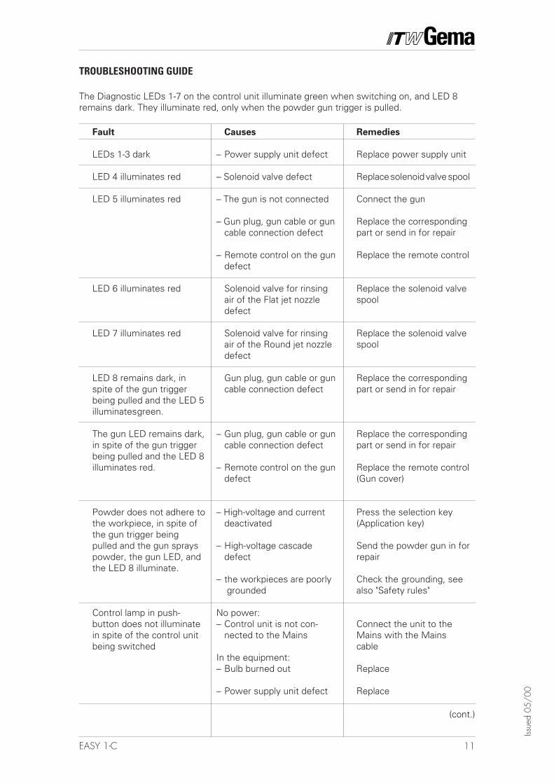
Remedies
Replace power supply unit
Replace solenoid valve spool
Connect the gun
Replace the correspondingpart or send in for repair
Replace the remote control
Replace the solenoid valvespool
Replace the solenoid valvespool
Replace the correspondingpart or send in for repair
Replace the correspondingpart or send in for repair
Replace the remote control(Gun cover)
Press the selection key(Application key)
Send the powder gun in forrepair
Check the grounding, seealso "Safety rules"
Connect the unit to theMains with the Mainscable
Replace
Replace
Fault
LEDs 1-3 dark
LED 4 illuminates red
LED 5 illuminates red
LED 6 illuminates red
LED 7 illuminates red
LED 8 remains dark, inspite of the gun triggerbeing pulled and the LED 5illuminatesgreen.
The gun LED remains dark,in spite of the gun triggerbeing pulled and the LED 8illuminates red.
Powder does not adhere tothe workpiece, in spite ofthe gun trigger beingpulled and the gun sprayspowder, the gun LED, andthe LED 8 illuminate.
Control lamp in push-button does not illuminatein spite of the control unitbeing switched
Causes
– Power supply unit defect
– Solenoid valve defect
– The gun is not connected
– Gun plug, gun cable or guncable connection defect
– Remote control on the gundefect
Solenoid valve for rinsingair of the Flat jet nozzledefect
Solenoid valve for rinsingair of the Round jet nozzledefect
Gun plug, gun cable or guncable connection defect
– Gun plug, gun cable or guncable connection defect
– Remote control on the gundefect
– High-voltage and currentdeactivated
– High-voltage cascadedefect
– the workpieces are poorly grounded
No power:– Control unit is not con-
nected to the Mains
In the equipment:– Bulb burned out
– Power supply unit defect
TROUBLESHOOTING GUIDE
(cont.)
The Diagnostic LEDs 1-7 on the control unit illuminate green when switching on, and LED 8remains dark. They illuminate red, only when the powder gun trigger is pulled.
12 EASY 1-C
Issue
d 05
/00
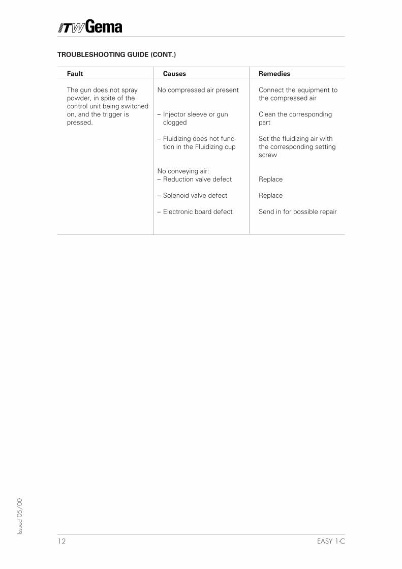
Fault
The gun does not spraypowder, in spite of thecontrol unit being switchedon, and the trigger ispressed.
Causes
No compressed air present
– Injector sleeve or gunclogged
– Fluidizing does not func-tion in the Fluidizing cup
No conveying air:– Reduction valve defect
– Solenoid valve defect
– Electronic board defect
Remedies
Connect the equipment tothe compressed air
Clean the correspondingpart
Set the fluidizing air withthe corresponding settingscrew
Replace
Replace
Send in for possible repair
TROUBLESHOOTING GUIDE (CONT.)
13EASY 1-C
Issue
d 05
/00
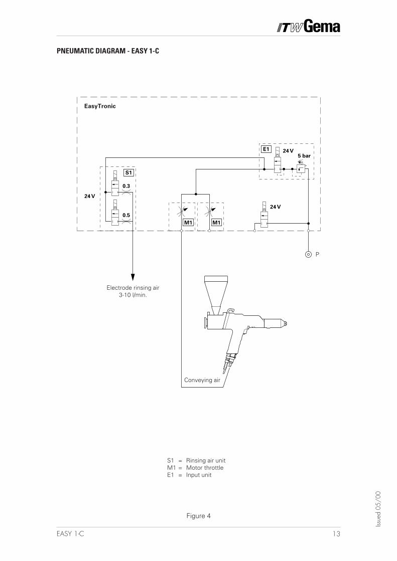
PNEUMATIC DIAGRAM - EASY 1-C
Figure 4
EasyTronic
Conveying air
Electrode rinsing air3-10 l/min.
P
S1 = Rinsing air unitM1 = Motor throttleE1 = Input unit
14 EASY 1-C
Issue
d 05
/00
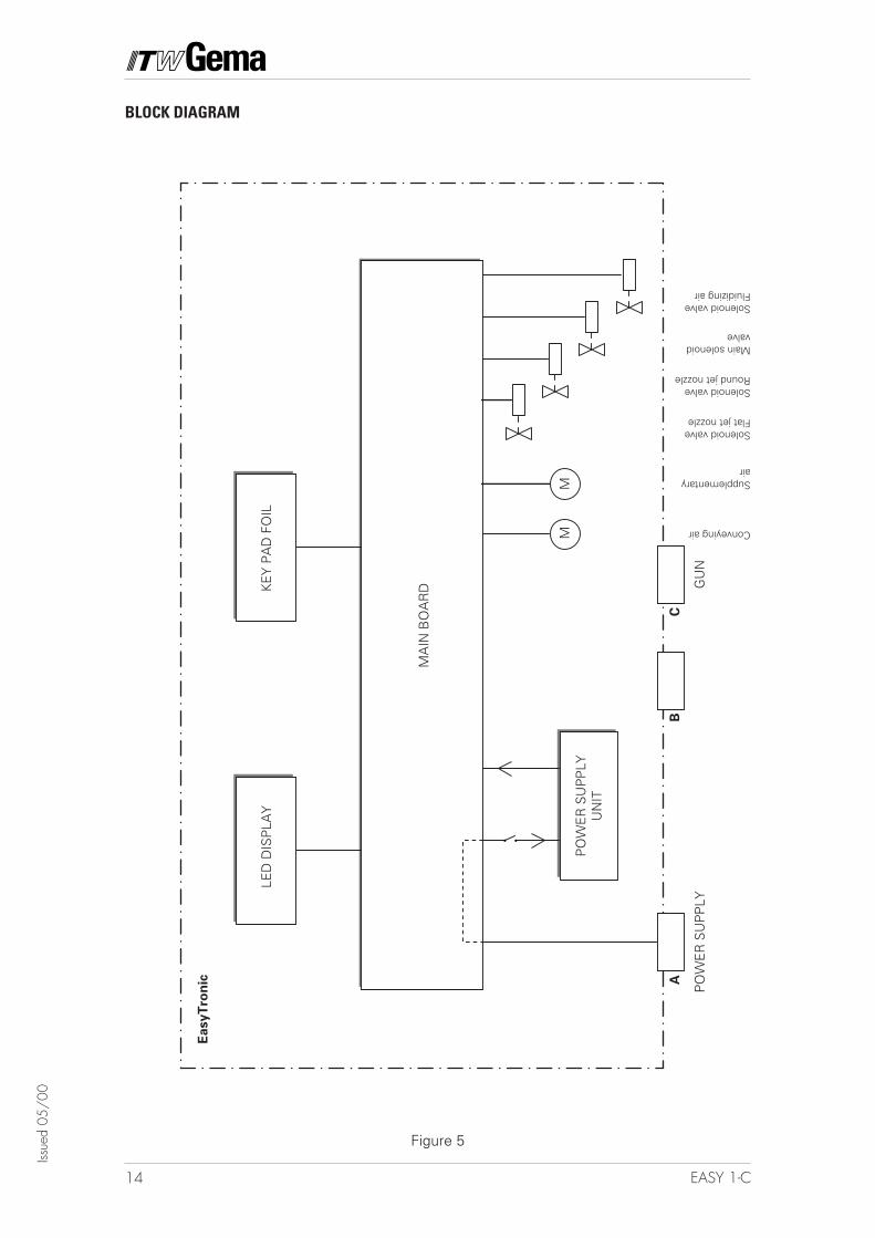
Figure 5
BLOCK DIAGRAM
Conveying airG
UN
CB
PO
WE
R S
UP
PLY
A
PO
WE
R S
UP
PLY
UN
IT
LED
DIS
PLA
YK
EY
PA
D F
OIL
MM
MA
IN B
OA
RD
EasyT
ron
ic
Supplementaryair
Solenoid valveFlat jet nozzle
Solenoid valveRound jet nozzle
Main solenoidvalve
Solenoid valveFluidizing air
15EASY 1-C
Issue
d 05
/00
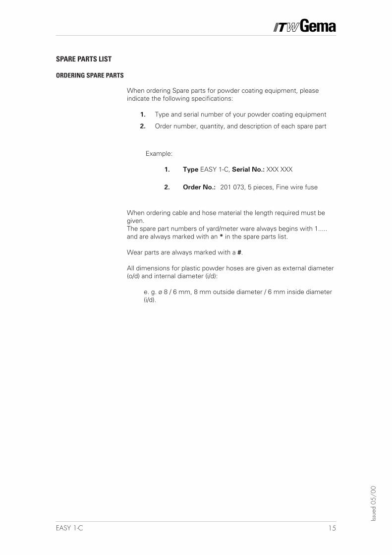
SPARE PARTS LIST
ORDERING SPARE PARTS
When ordering Spare parts for powder coating equipment, pleaseindicate the following specifications:
1. Type and serial number of your powder coating equipment
2. Order number, quantity, and description of each spare part
Example:
1. Type EASY 1-C, Serial No.: XXX XXX
2. Order No.: 201 073, 5 pieces, Fine wire fuse
When ordering cable and hose material the length required must begiven.The spare part numbers of yard/meter ware always begins with 1.....and are always marked with an * in the spare parts list.
Wear parts are always marked with a #.
All dimensions for plastic powder hoses are given as external diameter(o/d) and internal diameter (i/d):
e. g. ø 8 / 6 mm, 8 mm outside diameter / 6 mm inside diameter(i/d).
16 EASY 1-C
Issue
d 05
/00
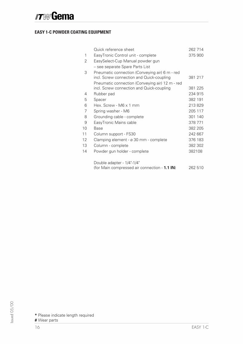
* Please indicate length required# Wear parts
EASY 1-C POWDER COATING EQUIPMENT
Quick reference sheet 262 7141 EasyTronic Control unit - complete 375 9002 EasySelect-Cup Manual powder gun
– see separate Spare Parts List3 Pneumatic connection (Conveying air) 6 m - red
incl. Screw connection and Quick-coupling 381 217Pneumatic connection (Conveying air) 12 m - redincl. Screw connection and Quick-coupling 381 225
4 Rubber pad 234 9155 Spacer 382 1916 Hex. Screw - M6 x 1 mm 213 8297 Spring washer - M6 205 1178 Grounding cable - complete 301 1409 EasyTronic Mains cable 378 771
10 Base 382 20511 Column support - FS30 242 66712 Clamping element - ø 30 mm - complete 376 18313 Column - complete 382 30214 Powder gun holder - complete 382108
Double adapter - 1/4"-1/4"(for Main compressed air connection - 1.1 IN) 262 510
17EASY 1-C
Issue
d 05
/00
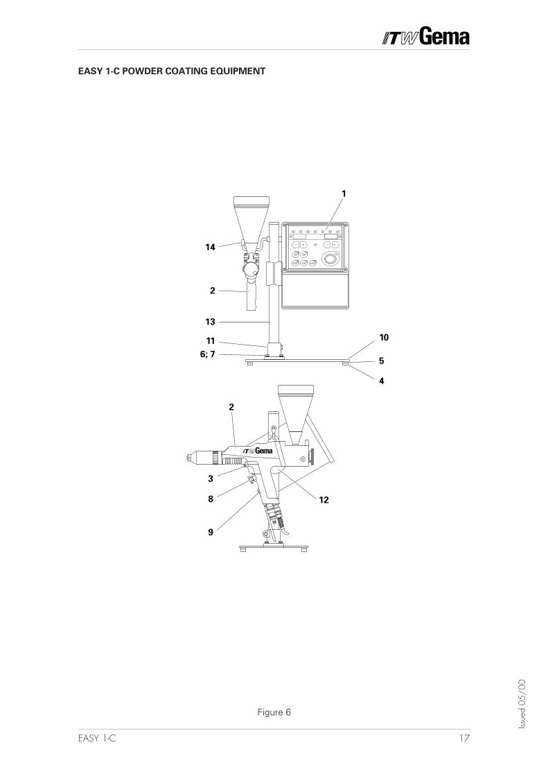
EASY 1-C POWDER COATING EQUIPMENT
Figure 6
1011
2
6; 7
14
13
4
5
1
2
3
8
9
12
18 EASY 1-C
Issue
d 05
/00
Documentation EASY 1-C
© Copyright 2000 ITW Gema AG, CH - 9015 St. GallAll technical products from ITW Gema AG are constantly being developed based onour continuing research and applications. The data found in this publication maytherefore change at any time without prior notification.
Printed in the Switzerland