autodome easy - bosch security
TRANSCRIPT
AutoDome EasyVEZ Series
en Installation and Configuration Manual

AutoDome, Bilinx, Bosch, the Bosch logo, DiBos, FastAddress and VIDOS are registered trademarks of Bosch Security Systems, inc.The following trademarks are registered with the United States Patent and Trademark Office:Pentium is a registered trademark of Intel Corporation.NET, DirectX, Internet Explorer, Microsoft, Windows, Windows 2000 and Windows XP are registered trademarks of Microsoft Corporation
Due to the nature of this material, this document refers to numerous hardware and software products by their trade names, In most, if not all cases, these designations are claimed as trademarks or registered trademarks by their respective companies in the United States of America. It is not this publisher’s intent to use any of these names generically. The reader is therefore cautioned to investigate all claimed trademark rights be-fore using any of these names other than to refer to the product described.

AutoDome Easy | en iii
Bosch Security Systems, Inc. Installation and Configuration Manual December 06, 2006 | F01U074570 | 3.0
PrefaceThis guide describes how to install the AutoDome Easy.
AudienceThis guide is intended for qualified installation and service personnel who are familiar with the applicable national and local electrical codes.
Document Conventions
SymbolsYou may encounter these symbols within the document. Explanatory text accompanies each symbol, which provides additional information detailing the operation or highlighting safety information.
Convention MeaningBold Denotes a part, item, or assembly.Italic Denotes a reference to another paragraph, figure or table.Underline Used to emphasize a point.courier Denotes the actual name of an object, the exact code that should be typed or a message
returned from a system.
iNOTICE! Notices inform you of essential but non-critical information. Read these messages carefully as any directions or instructions contained therein can help you avoid making mistakes.
!CAUTION! Cautionary messages provide critical information that help you reduce the chance of losing data or damaging the system. Please heed these messages.
!WARNING! Warnings highlight information, that if overlooked may cause damage to the system or result in personal injury. Take warnings seriously.
DANGER! Danger messages denote the presence of electrical equipment that may cause electric shock or electrocution. Take care when you see this symbol to avoid serious injury or death.

iv en | AutoDome Easy
December 06, 2006 | F01U074570 | 3.0 Installation and Configuration Manual Bosch Security Systems, Inc.
Customer Support and ServiceIf this unit needs service, contact the nearest Bosch Security Systems Service Center for authorization to return and shipping instructions.
Service Centers USAPhone: 800-366-2283 or 585-340-4162 Fax: 800-366-1329 Email: [email protected] SupportPhone: 800-326-1450Email: [email protected] Spare Parts Phone: 800-894-5215 or 408-957-3065 Fax: 408-935-5938 Email: [email protected] Canada Phone: 514-738-2434 Fax: 514-738-8480 Europe, Middle East & Asia Pacific Region Phone: 44 (0) 1495 274558 Fax: 44 (0) 1495 274280 Email: [email protected] For additional information, see www.boschsecurity.com
Safety Precautions | en v
Bosch Security Systems, Inc.
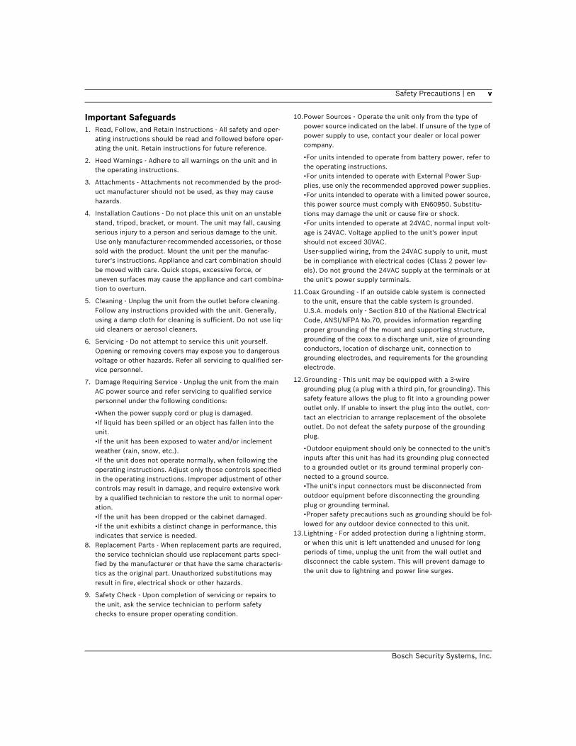
Important Safeguards1. Read, Follow, and Retain Instructions - All safety and oper-
ating instructions should be read and followed before oper-ating the unit. Retain instructions for future reference.
2. Heed Warnings - Adhere to all warnings on the unit and in the operating instructions.
3. Attachments - Attachments not recommended by the prod-uct manufacturer should not be used, as they may cause hazards.
4. Installation Cautions - Do not place this unit on an unstable stand, tripod, bracket, or mount. The unit may fall, causing serious injury to a person and serious damage to the unit. Use only manufacturer-recommended accessories, or those sold with the product. Mount the unit per the manufac-turer's instructions. Appliance and cart combination should be moved with care. Quick stops, excessive force, or uneven surfaces may cause the appliance and cart combina-tion to overturn.
5. Cleaning - Unplug the unit from the outlet before cleaning. Follow any instructions provided with the unit. Generally, using a damp cloth for cleaning is sufficient. Do not use liq-uid cleaners or aerosol cleaners.
6. Servicing - Do not attempt to service this unit yourself. Opening or removing covers may expose you to dangerous voltage or other hazards. Refer all servicing to qualified ser-vice personnel.
7. Damage Requiring Service - Unplug the unit from the main AC power source and refer servicing to qualified service personnel under the following conditions:
•When the power supply cord or plug is damaged.•If liquid has been spilled or an object has fallen into the unit.•If the unit has been exposed to water and/or inclement weather (rain, snow, etc.).•If the unit does not operate normally, when following the operating instructions. Adjust only those controls specified in the operating instructions. Improper adjustment of other controls may result in damage, and require extensive work by a qualified technician to restore the unit to normal oper-ation.•If the unit has been dropped or the cabinet damaged.•If the unit exhibits a distinct change in performance, this indicates that service is needed.
8. Replacement Parts - When replacement parts are required, the service technician should use replacement parts speci-fied by the manufacturer or that have the same characteris-tics as the original part. Unauthorized substitutions may result in fire, electrical shock or other hazards.
9. Safety Check - Upon completion of servicing or repairs to the unit, ask the service technician to perform safety checks to ensure proper operating condition.
10.Power Sources - Operate the unit only from the type of power source indicated on the label. If unsure of the type of power supply to use, contact your dealer or local power company.
•For units intended to operate from battery power, refer to the operating instructions. •For units intended to operate with External Power Sup-plies, use only the recommended approved power supplies. •For units intended to operate with a limited power source, this power source must comply with EN60950. Substitu-tions may damage the unit or cause fire or shock.•For units intended to operate at 24VAC, normal input volt-age is 24VAC. Voltage applied to the unit's power input should not exceed 30VAC. User-supplied wiring, from the 24VAC supply to unit, must be in compliance with electrical codes (Class 2 power lev-els). Do not ground the 24VAC supply at the terminals or at the unit's power supply terminals.
11.Coax Grounding - If an outside cable system is connected to the unit, ensure that the cable system is grounded. U.S.A. models only - Section 810 of the National Electrical Code, ANSI/NFPA No.70, provides information regarding proper grounding of the mount and supporting structure, grounding of the coax to a discharge unit, size of grounding conductors, location of discharge unit, connection to grounding electrodes, and requirements for the grounding electrode.
12.Grounding - This unit may be equipped with a 3-wire grounding plug (a plug with a third pin, for grounding). This safety feature allows the plug to fit into a grounding power outlet only. If unable to insert the plug into the outlet, con-tact an electrician to arrange replacement of the obsolete outlet. Do not defeat the safety purpose of the grounding plug.
•Outdoor equipment should only be connected to the unit's inputs after this unit has had its grounding plug connected to a grounded outlet or its ground terminal properly con-nected to a ground source.•The unit's input connectors must be disconnected from outdoor equipment before disconnecting the grounding plug or grounding terminal.•Proper safety precautions such as grounding should be fol-lowed for any outdoor device connected to this unit.
13.Lightning - For added protection during a lightning storm, or when this unit is left unattended and unused for long periods of time, unplug the unit from the wall outlet and disconnect the cable system. This will prevent damage to the unit due to lightning and power line surges.

vi en | Safety Precautions
Bosch Security Systems, Inc.
Safety PrecautionsFor Indoor Product1. Water and Moisture - Do not use this unit near water -
for example, in a wet basement, in an unprotected out-door installation or in any area classified as a wet loca-tion.
2. Object and Liquid Entry - Never push objects of any kind into this unit through openings, as they might touch dan-gerous voltage points or create short circuits, resulting in a fire or electrical shock. Never spill liquid of any kind on the unit.
Power Cord and Power Cord Protection - For units intended to operate with 230VAC, 50Hz, the input and output power cord must comply with the latest versions of IEC Publication 227 or IEC Publication 245.
3. Power supply cords should be routed so they are not likely to be walked on or pinched. Pay particular atten-tion to location of cords and plugs, convenience recep-tacles, and the point of exit from the appliance.
4. Overloading - Do not overload outlets and extension cords; this can result in a risk of fire or electrical shock.
For Outdoor ProductPower Lines - An outdoor system should not be located in the vicinity of overhead power lines, electric lights or power circuits, or where it may contact such power lines or circuits. When installing an outdoor system, extreme care should be taken to keep from touching power lines or circuits, as this contact might be fatal. U.S.A. models only - refer to the National Electrical Code Article 820 regarding installation of CATV systems.
For Rack-mount Product1. Ventilation - Do not place this equipment in a built-in
installation or rack, unless proper ventilation is pro-vided, or the manufacturer's instructions were followed. The equipment must not exceed its maximum operating temperature requirements.
2. Mechanical Loading - When rack-mounting the equip-ment, ensure that a hazardous condition is not created by uneven mechanical loading.
This symbol indicates the presence of uninsulated “dangerous voltage” within the product’s enclo-sure that can cause an electric shock.
This symbol indicates the presence of important operating and maintenance (servicing) instruc-tions in the literature accompanying the appli-ance.
Installation should be performed by qualified ser-vice personnel only in accordance with the National Electrical Code or applicable local codes.
Power Disconnect. Units with or without ON-OFF switches have power supplied to the unit when-ever the power cord is inserted into the power source; however, the unit is operational only when the ON-OFF switch is in the ON position. The power cord is the main power disconnect for all units.
ModificationsCaution: Changes or modifications not expressly approved by the party responsible for compliance could void the user’s authority to operate the equipment.
CAUTION: TO REDUCE THE RISK OF ELECTRIC SHOCK, DO NOT REMOVE COVER (OR BACK). NO USER SERVICEABLE PARTS INSIDE. REFER SERVICING TO QUALIFIED SERVICE PERSONNEL.

Safety Precautions | en vii
Bosch Security Systems, Inc.
FCC & ICES INFORMATION(U.S.A. and Canadian Models Only)
This device complies with part 15 of the FCC Rules. Operation is subject to the following two conditions:
(1)This device may not cause harmful interference, and
(2)This device must accept any interference received, includ-ing interference that may cause undesired operation.
NOTE: This equipment has been tested and found to comply with the limits for a Class A digital device, pursuant to Part 15 of the FCC Rules and ICES-003 of Industry Canada. These lim-its are designed to provide reasonable protection against harmful interference when the equipment is operated in a commercial environment. This equipment generates, uses and radiates radio frequency energy, and if not installed and used in accordance with the instruction manual, may cause harmful interference to radio communications. Operation of this equip-ment in a residential area is likely to cause harmful interfer-ence, in which case the user will be required to correct the interference at his expense.
Intentional or unintentional changes or modifications, not expressly approved by the party responsible for compliance, shall not be made. Any such changes or modifications could void the user’s authority to operate the equipment. If neces-sary, the user should consult the dealer or an experienced radio/television technician for corrective action. The user may find the following booklet, prepared by the Federal Communi-cations Commission, helpful: How to Identify and Resolve Radio-TV Interference Problems. This booklet is available from the U.S. Government Printing Office, Washington, DC 20402, Stock No. 004-000-00345-4.
SécuritéAttention : l'installation doit exclusivement être réalisée par du
WARNING: This is a Class A product. In a domestic environ-ment, this product may cause radio interference, in which case, the user may be required to take adequate measures.
Ce symbole signale que le produit renferme une « tension potentiellement dangereuse » non isolée susceptible de provoquer une électrocution.
Ce symbole invite l'utilisateur à consulter les instructions d'utilisation et d'entretien (dépan-nage) reprises dans la documentation qui accompagne l'appareil.
Attention: l'installation doit exclusivement être réalisée par du personnel qualifié, conformément au code national d'électricité américain (NEC) ou au code d'électricité local en vigueur.
Coupure de l'alimentation. Qu'ils soient pourvus ou non d'un commutateur ON/OFF, tous les appar-eils reçoivent de l'énergie une fois le cordon branché sur la source d'alimentation. Toutefois, l'appareil ne fonctionne réellement que lorsque le commutateur est réglé sur ON. Le débranchement du cordon d'alimentation permet de couper l'ali-mentation des appareils.
ATTENTION : POUR ÉVITER TOUT RISQUE D'ÉLECTROCU-TION, N'ESSAYEZ PAS DE RETIRER LE CAPOT (OU LE PAN-NEAU ARRIÈRE). CET APPAREIL NE CONTIENT AUCUN COMPOSANT SUSCEPTIBLE D'ÊTRE RÉPARÉ PAR L'UTILI-SATEUR. CONFIEZ LA RÉPARATION DE L'APPAREIL À DU PERSONNEL QUALIFIÉ.
viii en | Safety Precautions
Bosch Security Systems, Inc.
Sicherheitshinweise Precauciones de Seguridad
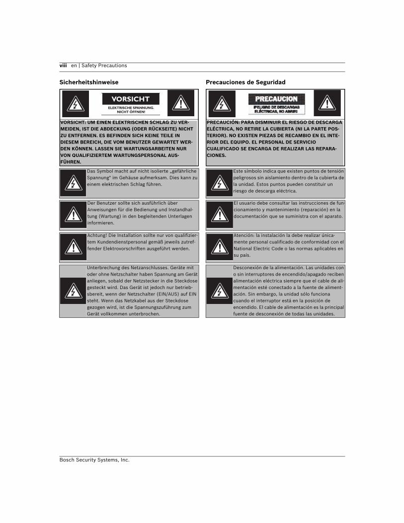
Das Symbol macht auf nicht isolierte „gefährliche Spannung" im Gehäuse aufmerksam. Dies kann zu einem elektrischen Schlag führen.
Der Benutzer sollte sich ausführlich über Anweisungen für die Bedienung und Instandhal-tung (Wartung) in den begleitenden Unterlagen informieren.
Achtung! Die Installation sollte nur von qualifizier-tem Kundendienstpersonal gemäß jeweils zutref-fender Elektrovorschriften ausgeführt werden.
Unterbrechung des Netzanschlusses. Geräte mit oder ohne Netzschalter haben Spannung am Gerät anliegen, sobald der Netzstecker in die Steckdose gesteckt wird. Das Gerät ist jedoch nur betrieb-sbereit, wenn der Netzschalter (EIN/AUS) auf EIN steht. Wenn das Netzkabel aus der Steckdose gezogen wird, ist die Spannungszuführung zum Gerät vollkommen unterbrochen.
VORSICHT: UM EINEN ELEKTRISCHEN SCHLAG ZU VER-MEIDEN, IST DIE ABDECKUNG (ODER RÜCKSEITE) NICHT ZU ENTFERNEN. ES BEFINDEN SICH KEINE TEILE IN DIESEM BEREICH, DIE VOM BENUTZER GEWARTET WER-DEN KÖNNEN. LASSEN SIE WARTUNGSARBEITEN NUR VON QUALIFIZIERTEM WARTUNGSPERSONAL AUS-FÜHREN.
Este símbolo indica que existen puntos de tensión peligrosos sin aislamiento dentro de la cubierta de la unidad. Estos puntos pueden constituir un riesgo de descarga eléctrica.
El usuario debe consultar las instrucciones de fun-cionamiento y mantenimiento (reparación) en la documentación que se suministra con el aparato.
Atención: la instalación la debe realizar única-mente personal cualificado de conformidad con el National Electric Code o las normas aplicables en su país.
Desconexión de la alimentación. Las unidades con o sin interruptores de encendido/apagado reciben alimentación eléctrica siempre que el cable de ali-mentación esté conectado a la fuente de aliment-ación. Sin embargo, la unidad sólo funciona cuando el interruptor está en la posición de encendido. El cable de alimentación es la principal fuente de desconexión de todas las unidades.
PRECAUCIÓN: PARA DISMINUIR EL RIESGO DE DESCARGA ELÉCTRICA, NO RETIRE LA CUBIERTA (NI LA PARTE POS-TERIOR). NO EXISTEN PIEZAS DE RECAMBIO EN EL INTE-RIOR DEL EQUIPO. EL PERSONAL DE SERVICIO CUALIFICADO SE ENCARGA DE REALIZAR LAS REPARA-CIONES.

Safety Precautions | en ix
Bosch Security Systems, Inc.
Veiligheidsmaatregelen Sicurezza
Dit symbool geeft aan dat er binnen in het appa-raat ongeïsoleerde, gevaarlijke spanning aanwezig is die mogelijk elektrische schokken kan veroorza-ken.
De gebruiker dient de bedienings- en onderhouds-voorschriften te raadplegen in de documentatie die werd meegeleverd met het apparaat.
Attentie: het apparaat mag alleen door gekwalifi-ceerd personeel worden geïnstalleerd. De instal-latie dient in overeenstemming met de nationale elektrische richtlijnen of de van toepassing zijnde lokale richtlijnen te worden uitgevoerd.
Spanning uitschakelen. Apparatuur met of zonder-aan-uitschakelaar staat onder spanning zolang de stekker is aangesloten op de wandcontactdoos. De apparatuur is uitsluitend in werking als de aan-uitschakelaar aan staat. Het netsnoer is de "hoofd-schakelaar" voor alle apparatuur.
VOORZICHTIG: OPEN DE BEHUIZING OF DE ACHTERKANT VAN HET APPARAAT NIET. ZO VERMINDERT U HET RISICO OP ELEKTRISCHE SCHOKKEN. IN HET APPARAAT BEVIN-DEN ZICH GEEN ONDERDELEN DIE U ZELF KUNT REPARE-REN. LAAT SERVICE EN ONDERHOUD UITVOEREN DOOR GEKWALIFICEERD PERSONEEL.
Questo simbolo indica la presenza di "tensione pericolosa" non isolata all'interno del contenitore del prodotto. Ciò comporta un potenziale rischio di scosse elettriche.
Si consiglia di consultare le istruzioni operative e di manutenzione (interventi tecnici) contenute nella documentazione fornita con il dispositivo.
Attenzione: l'installazione deve essere effettuata esclusivamente da personale tecnico qualificato in conformità con il National Electrical Code o con le normative locali vigenti.
Scollegamento dell'alimentazione. Le unità dotate o sprovviste di interruttori ON-OFF vengono ali-mentate quando si inserisce il cavo nella presa dell'alimentazione. L'unità è tuttavia in funzione solo quando l'interruttore ON-OFF si trova nella posizione ON. Il cavo di alimentazione costituisce il dispositivo di scollegamento dell'alimentazione principale per tutte le unità.
ATTENZIONE: PER RIDURRE IL RISCHIO DI SCOSSE ELETTRICHE NON RIMUOVERE LA COPERTURA (O IL PAN-NELLO POSTERIORE). L'UNITÀ NON CONTIENE COMPO-NENTI INTERNI RIPARABILI DALL'UTENTE. PER QUALSIASI INTERVENTO, RIVOLGERSI A PERSONALE TECNICO QUAL-IFICATO.

x en | Safety Precautions
Bosch Security Systems, Inc.
Medidas de Segurança Zasady bezpieczenstwa
Este símbolo indica a presença de "tensão peri-gosa" não isolada dentro da estrutura do produto, o que pode constituir risco de choque eléctrico.
O utilizador deve consultar as instruções de funci-onamento e manutenção (assistência) nos docu-mentos que acompanham o aparelho.
Atenção: a instalação deve ser executada apenas por técnicos qualificados da assistência, de acordo com o código eléctrico nacional ou os códigos locais aplicáveis.
Corte de corrente. As unidades com ou sem inter-ruptores ON-OFF (ligar/desligar) recebem cor-rente sempre que o fio de alimentação está introduzido na fonte de alimentação; contudo, a unidade apenas está operacional quando o inter-ruptor ON-OFF está na posição ON. O fio de ali-mentação destina-se a desligar a corrente em todas as unidades.
CUIDADO: PARA REDUZIR O RISCO DE CHOQUE ELÉC-TRICO, NÃO RETIRE A TAMPA (OU A PARTE POSTERIOR). NO INTERIOR, NÃO EXISTEM PEÇAS QUE POSSAM SER REPARADAS PELO UTILIZADOR. REMETA A ASSISTÊNCIA PARA OS TÉCNICOS QUALIFICADOS.
Blyskawica ze strzalka wewnatrz trójkata równob-ocznego maza zadanie zwrócic uwage uzytkownika na obecnoscnieizolowanego “niebezpiecznego napiecia” wewnatrzobudowy urzadzenia, o wielko-sci stwarzajacejniebezpieczenstwo porazenia pra-dem.
Wykrzyknik wewnatrz trójkata równobocznego ma zazadanie zwrócic uwage uzytkownika na waznec-zynnosci, zwiazane z obsluga i konserwacja urza-dzenia,zamieszczone w Instrukcji obslugi.
OSTRZEZENIE: ABY UNIKNAC POZARU LUB PORAZENIAPRA-DEM NIE WOLNO WYSTAWIAC NA DZIALANIE DESZCZU LUB WILGOCI URZADZEN,KTÓRE NIE ZOSTALY ZAPROJEKTOWANE DO UZYWANIA SPECJALNIE NA OTWARTYM POWIETRZU.
Uwaga: Instalacje urzadzenia powinien wykonac tylkowykwalifikowany personel, zgodnie z przepisami NEClub odpowiednimi przepisami mie-jscowymi.
Odlaczanie zasilania. Urzadzenia zarówno nie posiadajace, jaki posiadajace wylaczniki WL-WYL znajduja sie podnapieciem, jezeli tylko przewód zasilajacy jest polaczony zezródlem zasilania. Jed-nakze urzadzenie dziala tylko wtedy, gdywylacznik znajduje sie w polozeniu WL. Przewódzasilajacy jestglównym odlacznikiem zasilania dla wszystkich rodzajówurzadzen.
UWAGA: ZE WZGLEDU NA NIEBEZPIECZENSTWOPORAZE-NIA PRADEM NIE WOLNO OTWIERAC POKRYWY. W SRODKU NIE MA ZADNYCH ELEMENTÓW, KTÓRE MOGA BYC NAPRAWIANE PRZEZUZYTKOWNIKA. NAPRAWE NALEZY POWIERZYCAUTORYZOWANEMU PUNKTOWI SER-WISOWEMU.

Safety Precautions | en xi
Bosch Security Systems, Inc.

xii en | Safety Precautions
Bosch Security Systems, Inc.
AutoDome Easy Table of Contents | en xii
Bosch Security Systems, Inc. Installation and Configuration Manual December 06, 2006 | F01U074570 | 3.0
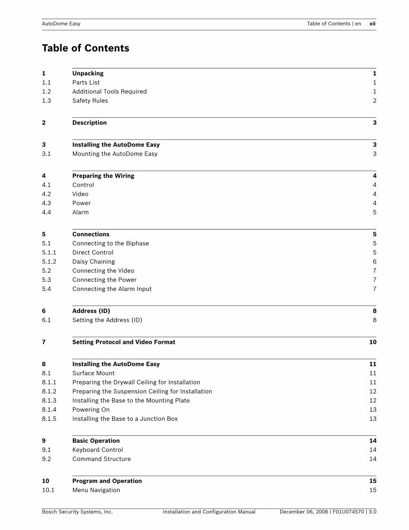
Table of Contents
1 Unpacking 11.1 Parts List 11.2 Additional Tools Required 11.3 Safety Rules 2
2 Description 3
3 Installing the AutoDome Easy 33.1 Mounting the AutoDome Easy 3
4 Preparing the Wiring 44.1 Control 44.2 Video 44.3 Power 44.4 Alarm 5
5 Connections 55.1 Connecting to the Biphase 55.1.1 Direct Control 55.1.2 Daisy Chaining 65.2 Connecting the Video 75.3 Connecting the Power 75.4 Connecting the Alarm Input 7
6 Address (ID) 86.1 Setting the Address (ID) 8
7 Setting Protocol and Video Format 10
8 Installing the AutoDome Easy 118.1 Surface Mount 118.1.1 Preparing the Drywall Ceiling for Installation 118.1.2 Preparing the Suspension Ceiling for Installation 128.1.3 Installing the Base to the Mounting Plate 128.1.4 Powering On 138.1.5 Installing the Base to a Junction Box 13
9 Basic Operation 149.1 Keyboard Control 149.2 Command Structure 14
10 Program and Operation 1510.1 Menu Navigation 15
xiii en | Table of Contents AutoDome Easy
December 06, 2006 | F01U074570 | 3.0 Installation and Configuration Manual Bosch Security Systems, Inc.
10.2 Main Menu 1510.3 Preset Menu 1610.3.1 Setting and Saving Presets 1610.3.2 Recalling a Preset Position 17
11 Creating Titles 17
12 Tour Menu 1812.1 Setting a Tour 1812.2 Running / Stopping a Tour 19
13 Auto Pan Menu 1913.1 Set Auto Scans 1913.2 Run Auto Pan 20
14 Sector Menu 20
15 Alarm Menu 2115.1 Releasing an Alarm 21
16 Camera Setup Menu 2216.1 Focus Control Menu 2216.2 WB Control Menu 2316.3 AE Control Menu 2416.4 L/L Control Menu 2616.5 Picture Menu 2716.6 Initialize Camera Menu 27
17 Dome Setup Menu 2817.1 Home Function 2917.2 Initialize Dome Menu 3017.3 Dome Information Menu 30
18 Keyboard Commands by Number 31
19 Troubleshooting 32
20 Preventive Maintenance 32
21 Spare Parts List 32

AutoDome Easy Unpacking 1
Bosch Security Systems, Inc. Installation and Configuration Manual December 06, 2006 | F01U074570 | 3.0
1 UnpackingThis equipment should be unpacked and handled with care. If an item appears to have been damaged in shipment, notify the shipper immediately.Verify that all the parts listed in Section 1.1: Parts List are included. If any items are missing, notify your Bosch Security Systems Sales or Customer Service Representative. The original packing carton is the safest container in which to transport the unit and must be used if returning the unit for service. Save it for possible future use.
1.1 Parts ListThe AutoDome Easy includes the following components:• One (1) PTZ Dome (Dome camera)• One (1) accessory kit including (part number - 9965 300 00648)
One (1) Locking Torx Wrench (T-10)One (1) Locking Torx Wrench (T-20)Three (3) tapping screwsThree (3) plastic anchors
• One (1) mounting bracket• One (1) user manual
1.2 Additional Tools Required• No. 2 Phillips screwdriver
2 Unpacking AutoDome Easy
December 06, 2006 | F01U074570 | 3.0 Installation and Configuration Manual Bosch Security Systems, Inc.
1.3 Safety RulesTo ensure safety, the following warnings are specified:• The device must be installed and maintained by skilled technical personnel.• Connect the device to a power source corresponding to the indications given on the
marking label.• Use only the attachments/accessories specified by the manufacturer.• Unplug the device during lightning storms or when unused for long periods of time.• Do not use the device near water.• Do not use the device in the presence of inflammable substances.• Do not allow children or unauthorized personnel to use the device.• Do not block any ventilation openings.• Keep this manual for future reference.
AutoDome Easy Description 3
Bosch Security Systems, Inc. Installation and Configuration Manual December 06, 2006 | F01U074570 | 3.0
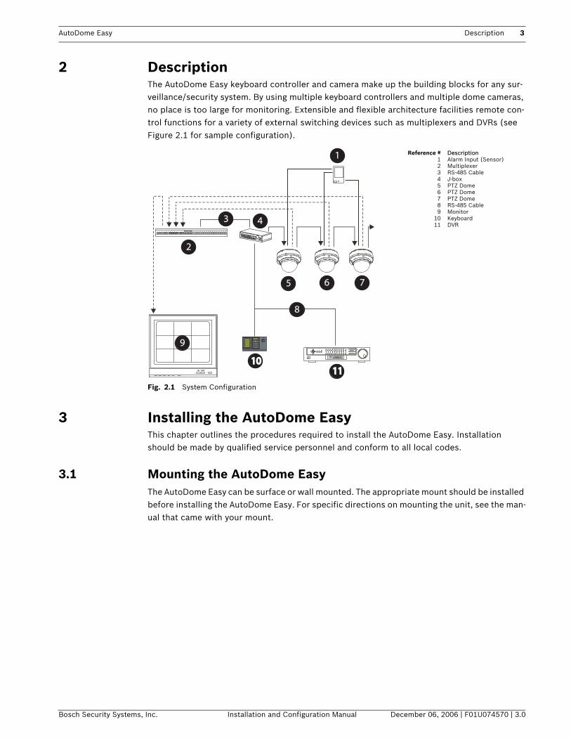
2 DescriptionThe AutoDome Easy keyboard controller and camera make up the building blocks for any sur-veillance/security system. By using multiple keyboard controllers and multiple dome cameras, no place is too large for monitoring. Extensible and flexible architecture facilities remote con-trol functions for a variety of external switching devices such as multiplexers and DVRs (see Figure 2.1 for sample configuration).
Fig. 2.1 System Configuration
3 Installing the AutoDome EasyThis chapter outlines the procedures required to install the AutoDome Easy. Installation should be made by qualified service personnel and conform to all local codes.
3.1 Mounting the AutoDome EasyThe AutoDome Easy can be surface or wall mounted. The appropriate mount should be installed before installing the AutoDome Easy. For specific directions on mounting the unit, see the man-ual that came with your mount.
2
3 4
1
5 6 7
8
10101111
9 1 2 34 5 6
7 8 90
S h o t
M o nP ro d
C lr
Reference #123456789
1011
DescriptionAlarm Input (Sensor)MultiplexerRS-485 CableJ-boxPTZ DomePTZ DomePTZ DomeRS-485 CableMonitorKeyboardDVR
4 Preparing the Wiring AutoDome Easy
December 06, 2006 | F01U074570 | 3.0 Installation and Configuration Manual Bosch Security Systems, Inc.
4 Preparing the WiringThere are four (4) types of wires required: control, video, power, and alarm. Each section pro-vides the specifications for the recommended wire.
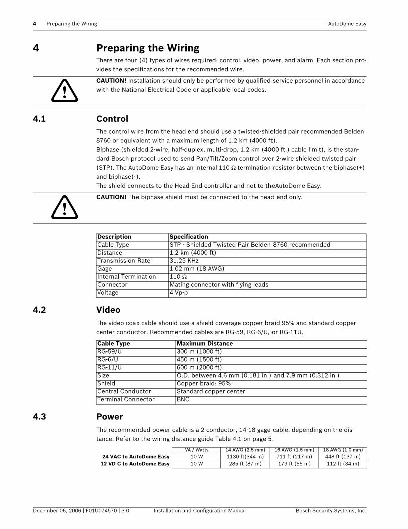
4.1 ControlThe control wire from the head end should use a twisted-shielded pair recommended Belden 8760 or equivalent with a maximum length of 1.2 km (4000 ft). Biphase (shielded 2-wire, half-duplex, multi-drop, 1.2 km (4000 ft.) cable limit), is the stan-dard Bosch protocol used to send Pan/Tilt/Zoom control over 2-wire shielded twisted pair (STP). The AutoDome Easy has an internal 110 Ω termination resistor between the biphase(+) and biphase(-).The shield connects to the Head End controller and not to theAutoDome Easy.
4.2 VideoThe video coax cable should use a shield coverage copper braid 95% and standard copper center conductor. Recommended cables are RG-59, RG-6/U, or RG-11U.
4.3 PowerThe recommended power cable is a 2-conductor, 14-18 gage cable, depending on the dis-tance. Refer to the wiring distance guide Table 4.1 on page 5.
!CAUTION! Installation should only be performed by qualified service personnel in accordance with the National Electrical Code or applicable local codes.
!CAUTION! The biphase shield must be connected to the head end only.
Description SpecificationCable Type STP - Shielded Twisted Pair Belden 8760 recommendedDistance 1.2 km (4000 ft) Transmission Rate 31.25 KHzGage 1.02 mm (18 AWG)Internal Termination 110 ΩConnector Mating connector with flying leadsVoltage 4 Vp-p
Cable Type Maximum DistanceRG-59/U 300 m (1000 ft)RG-6/U 450 m (1500 ft)RG-11/U 600 m (2000 ft)Size O.D. between 4.6 mm (0.181 in.) and 7.9 mm (0.312 in.)Shield Copper braid: 95%Central Conductor Standard copper centerTerminal Connector BNC
VA / Watts 14 AWG (2.5 mm) 16 AWG (1.5 mm) 18 AWG (1.0 mm)24 VAC to AutoDome Easy 10 W 1130 ft(344 m) 711 ft (217 m) 448 ft (137 m)
12 VD C to AutoDome Easy 10 W 285 ft (87 m) 179 ft (55 m) 112 ft (34 m)

AutoDome Easy Connections 5
Bosch Security Systems, Inc. Installation and Configuration Manual December 06, 2006 | F01U074570 | 3.0
4.4 AlarmThe recommended optional alarm input cable is a 2-conductor, 18-22 gage cable, depending on the distance. Refer to the wiring distance guide Table 4.1 on page 5.
Table 4.1 Wiring Distance Guide
5 ConnectionsFollow the instructions below to terminate all connections as described.
Table 5.1 Connection Cable Description
5.1 Connecting to the Biphase The AutoDome Easy camera can be controlled remotely by an external device or control sys-tem, such as a control keyboard, using biphase.
5.1.1 Direct ControlTo connect the biphase configuration, do the following:1. Locate the cable assembly with a two (2) pin black mating connector on one end and the
brown and black flying leads on the other end.2. Connect the biphase+ from the controller to the black lead and secure.3. Connect the biphase- from the controller to the brown lead and secure.4. Connect shield of the cable to the Head End controller.
Fig. 5.1 Biphase Direct Control
Wire Size Maximum Distance
AWG mm feet meters
22 0.644 500 152.4
18 1.024 800 243.8
Color Description
Black Biphase (+)
Brown Biphase (-)
Red AC24 V / DC12 V
Orange AC24 V / DC12 V
Blue ALARM COMMON
Violet ALARM IN
C-
C+
SHIELD
Head EndBiphase
BrownBlack
Not Connected X
AutoDome Easy
6 Connections AutoDome Easy
December 06, 2006 | F01U074570 | 3.0 Installation and Configuration Manual Bosch Security Systems, Inc.
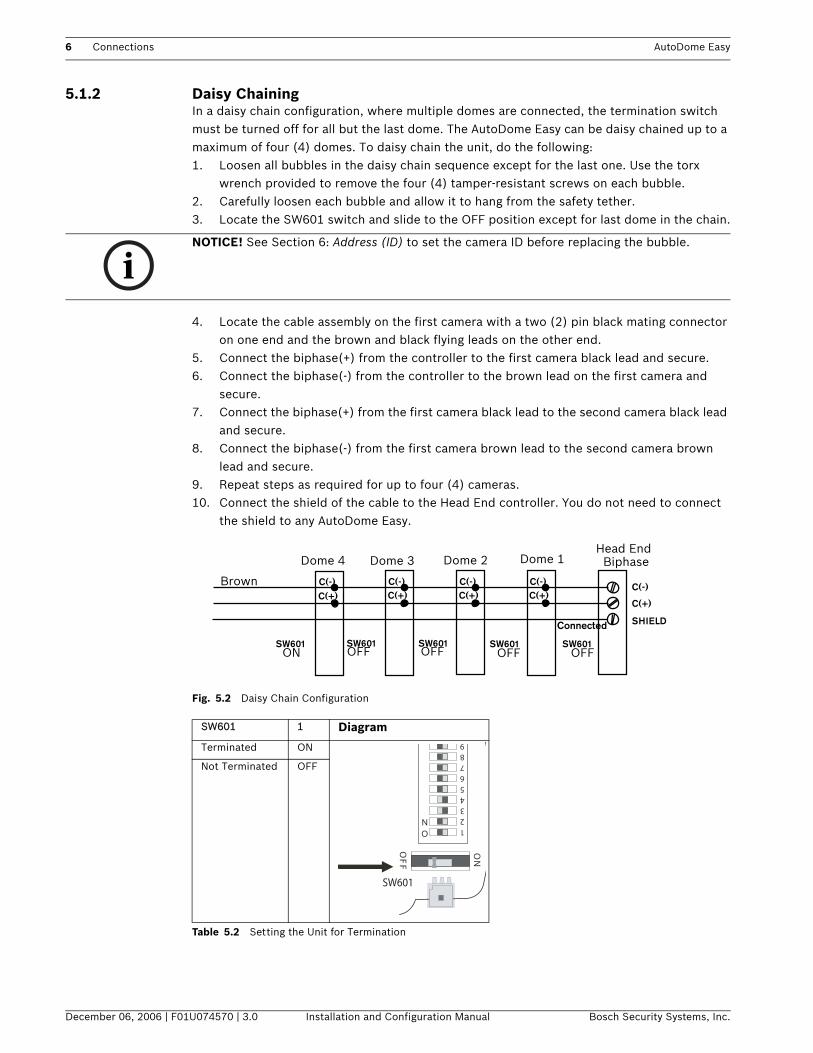
5.1.2 Daisy Chaining In a daisy chain configuration, where multiple domes are connected, the termination switch must be turned off for all but the last dome. The AutoDome Easy can be daisy chained up to a maximum of four (4) domes. To daisy chain the unit, do the following:1. Loosen all bubbles in the daisy chain sequence except for the last one. Use the torx
wrench provided to remove the four (4) tamper-resistant screws on each bubble.2. Carefully loosen each bubble and allow it to hang from the safety tether.3. Locate the SW601 switch and slide to the OFF position except for last dome in the chain.
4. Locate the cable assembly on the first camera with a two (2) pin black mating connector on one end and the brown and black flying leads on the other end.
5. Connect the biphase(+) from the controller to the first camera black lead and secure.6. Connect the biphase(-) from the controller to the brown lead on the first camera and
secure.7. Connect the biphase(+) from the first camera black lead to the second camera black lead
and secure.8. Connect the biphase(-) from the first camera brown lead to the second camera brown
lead and secure.9. Repeat steps as required for up to four (4) cameras.10. Connect the shield of the cable to the Head End controller. You do not need to connect
the shield to any AutoDome Easy.
Fig. 5.2 Daisy Chain Configuration
Table 5.2 Setting the Unit for Termination
iNOTICE! See Section 6: Address (ID) to set the camera ID before replacing the bubble.
SW601 1 Diagram
Terminated ON
Not Terminated OFF
C(-)
C(+)
SHIELD
C(-)C(+)
C(-)C(+)
C(-)C(+)
C(-)C(+)
SW601 SW601 SW601 SW601 SW601
Connected
Head EndBiphaseDome 1Dome 2Dome 3Dome 4
OFF OFF OFF OFFON
Brown
123456789
ON
OF
F
ON
SW601
AutoDome Easy Connections 7
Bosch Security Systems, Inc. Installation and Configuration Manual December 06, 2006 | F01U074570 | 3.0
5.2 Connecting the VideoCoaxial cable terminated with BNC connectors is the most common method for transmitting composite video. To connect the video, do the following:1. Terminate the coaxial cable from the head end system with a male BNC connector.2. Connect the head end video cable to the yellow Video Out connector from the base of the
camera.
5.3 Connecting the PowerTo connect the power, do the following:
1. Locate the cable assembly with a two (2) pin mating connector on one end and the orange and red flying leads on the other end.
2. Connect one lead of the 12 V DC or 24 VAC power source to the red wire.3. Connect one lead of the 12 V DC or 24 VAC power source to the orange wire.
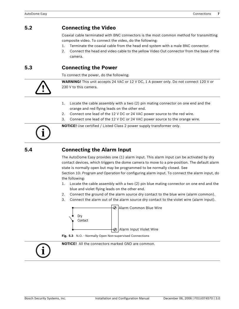
5.4 Connecting the Alarm InputThe AutoDome Easy provides one (1) alarm input. This alarm input can be activated by dry contact devices, which triggers the dome camera to move to a pre-position. The default alarm state is normally open but may be programmed to be normally closed. See Section 10: Program and Operation for configuring alarm input. To connect the alarm input, do the following:1. Locate the cable assembly with a two (2) pin blue mating connector on one end and the
blue and violet flying leads on the other end.2. Connect the ground of the alarm source dry contact to the blue wire (alarm common).3. Connect the alarm out of the alarm source dry contact to the violet wire (alarm input).
Fig. 5.3 N.O. - Normally Open Non-supervised Connections
!WARNING! This unit accepts 24 VAC or 12 V DC, 1 A power only. Do not connect 120 V or 230 V to this camera.
iNOTICE! Use certified / Listed Class 2 power supply transformer only.
DryContact
Alarm Common Blue Wire
Alarm Input Violet Wire
iNOTICE! All the connectors marked GND are common.

8 Address (ID) AutoDome Easy
December 06, 2006 | F01U074570 | 3.0 Installation and Configuration Manual Bosch Security Systems, Inc.
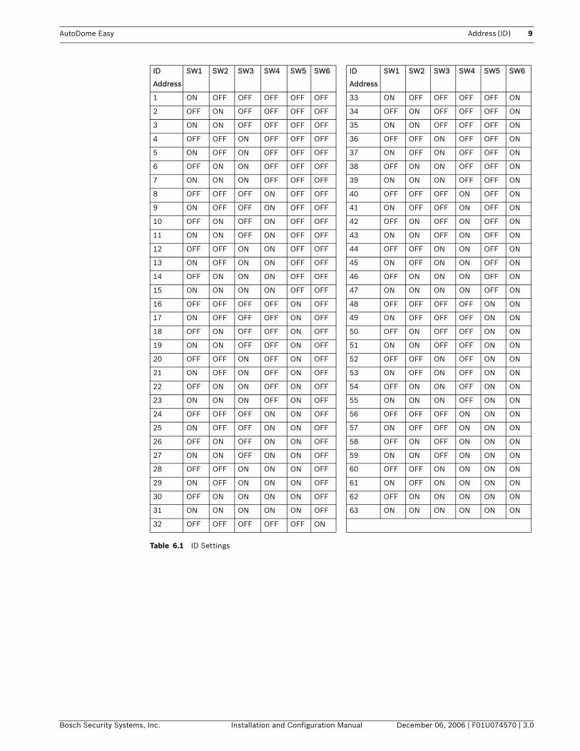
6 Address (ID)Each AutoDome Easy camera must have a unique address (ID). When installing multiple dome cameras using a DVR, it is suggested that the dome camera address match the DVR input num-ber (for example: Input 1 = Dome 1, Input 2 = Dome 2, etc...). Set a unique camera address (ID) using the switch selections inside the bubble.
6.1 Setting the Address (ID)To set the unique AutoDome Easy ID address, do the following:1. Loosen the bubble’s four (4) tamper-resistant screws using the torx wrench provided.2. Carefully lift the bubble and set it aside.3. Locate the SW501 switch. 4. Set the switches based on Table 6.1.
Fig. 6.1 Setting the AutoDome Easy Address (ID)
AutoDome Easy Address (ID) 9
Bosch Security Systems, Inc. Installation and Configuration Manual December 06, 2006 | F01U074570 | 3.0
Table 6.1 ID Settings
ID
Address
SW1 SW2 SW3 SW4 SW5 SW6 ID
Address
SW1 SW2 SW3 SW4 SW5 SW6
1 ON OFF OFF OFF OFF OFF 33 ON OFF OFF OFF OFF ON
2 OFF ON OFF OFF OFF OFF 34 OFF ON OFF OFF OFF ON
3 ON ON OFF OFF OFF OFF 35 ON ON OFF OFF OFF ON
4 OFF OFF ON OFF OFF OFF 36 OFF OFF ON OFF OFF ON
5 ON OFF ON OFF OFF OFF 37 ON OFF ON OFF OFF ON
6 OFF ON ON OFF OFF OFF 38 OFF ON ON OFF OFF ON
7 ON ON ON OFF OFF OFF 39 ON ON ON OFF OFF ON
8 OFF OFF OFF ON OFF OFF 40 OFF OFF OFF ON OFF ON
9 ON OFF OFF ON OFF OFF 41 ON OFF OFF ON OFF ON
10 OFF ON OFF ON OFF OFF 42 OFF ON OFF ON OFF ON
11 ON ON OFF ON OFF OFF 43 ON ON OFF ON OFF ON
12 OFF OFF ON ON OFF OFF 44 OFF OFF ON ON OFF ON
13 ON OFF ON ON OFF OFF 45 ON OFF ON ON OFF ON
14 OFF ON ON ON OFF OFF 46 OFF ON ON ON OFF ON
15 ON ON ON ON OFF OFF 47 ON ON ON ON OFF ON
16 OFF OFF OFF OFF ON OFF 48 OFF OFF OFF OFF ON ON
17 ON OFF OFF OFF ON OFF 49 ON OFF OFF OFF ON ON
18 OFF ON OFF OFF ON OFF 50 OFF ON OFF OFF ON ON
19 ON ON OFF OFF ON OFF 51 ON ON OFF OFF ON ON
20 OFF OFF ON OFF ON OFF 52 OFF OFF ON OFF ON ON
21 ON OFF ON OFF ON OFF 53 ON OFF ON OFF ON ON
22 OFF ON ON OFF ON OFF 54 OFF ON ON OFF ON ON
23 ON ON ON OFF ON OFF 55 ON ON ON OFF ON ON
24 OFF OFF OFF ON ON OFF 56 OFF OFF OFF ON ON ON
25 ON OFF OFF ON ON OFF 57 ON OFF OFF ON ON ON
26 OFF ON OFF ON ON OFF 58 OFF ON OFF ON ON ON
27 ON ON OFF ON ON OFF 59 ON ON OFF ON ON ON
28 OFF OFF ON ON ON OFF 60 OFF OFF ON ON ON ON
29 ON OFF ON ON ON OFF 61 ON OFF ON ON ON ON
30 OFF ON ON ON ON OFF 62 OFF ON ON ON ON ON
31 ON ON ON ON ON OFF 63 ON ON ON ON ON ON
32 OFF OFF OFF OFF OFF ON

10 Setting Protocol and Video Format AutoDome Easy
December 06, 2006 | F01U074570 | 3.0 Installation and Configuration Manual Bosch Security Systems, Inc.
7 Setting Protocol and Video FormatThe factory default settings for switches 8, 9, and 0 are set for the correct operation. How-ever, if the camera is operating incorrectly, the proper configuration is the following:
• Switch 8 - set to match the appropriate video format; NTSC (60 Hz) ON- or -PAL (50 Hz) OFF.
• Switches 9 and 0 - set to biphase protocol (see Table 7.1).
Fig. 7.1 AutoDome Easy Camera Function and Protocol Selection Switches
Table 7.1 Dome Camera Function
Table 7.2 Dome Camera Protocol Function
iNOTICE! The error message: PROTOCOL IS NOT MATCHED is displayed during the power-up cycle if switches 9 and 0 are not set correctly.
Reference # Description
1 Dome Camera Function
2 PDome Camera Protocol Function
S/W No. ON OFF Function
8 NTSC PAL NTSC/PAL
No. 9 No. 0 Protocol
ON OFF Biphase
1234567890
ON
1234567890
ON
OF
F
ON
1
2
Black = ON
AutoDome Easy Installing the AutoDome Easy 11
Bosch Security Systems, Inc. Installation and Configuration Manual December 06, 2006 | F01U074570 | 3.0
8 Installing the AutoDome EasyThis chapter details how to install the AutoDome Easy for an in-ceiling, wall, or pipe mount.
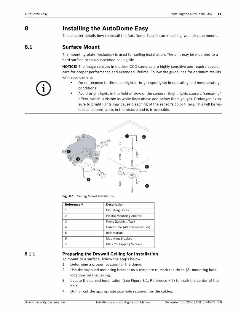
8.1 Surface MountThe mounting plate (included) is used for ceiling installation. The unit may be mounted to a hard surface or to a suspended ceiling tile.
Fig. 8.1 Ceiling Mount Installation
8.1.1 Preparing the Drywall Ceiling for InstallationTo mount to a surface, follow the steps below:1. Determine a proper location for the dome.2. Use the supplied mounting bracket as a template to mark the three (3) mounting hole
locations on the ceiling. 3. Locate the curved indentation (see Figure 8.1, Reference # 5) to mark the center of the
hole. 4. Drill or cut the appropriate size hole required for the cables.
i
NOTICE! The image sensors in modern CCD cameras are highly sensitive and require special care for proper performance and extended lifetime. Follow the guidelines for optimum results with your camera:
• Do not expose to direct sunlight or bright spotlights in operating and nonoperating conditions.
• Avoid bright lights in the field of view of the camera. Bright lights cause a "smearing" effect, which is visible as white lines above and below the highlight. Prolonged expo-sure to bright lights may cause bleaching of the sensor's color filters. This will be vis-ible as colored spots in the picture and is irreversible.
Reference # Description
1 Mounting Holes
2 Plastic Mounting Anchor
3 Front (Locking Tab)
4 Cable Hole (40 mm maximum)
5 Indentation
6 Mounting Bracket
7 M4 x 25 Tapping Screws
40.0 mm
90.0 mm
1 2
5
6
4
4
3
1.57 in.
3.54 in.
12 Installing the AutoDome Easy AutoDome Easy
December 06, 2006 | F01U074570 | 3.0 Installation and Configuration Manual Bosch Security Systems, Inc.
5. Drill the appropriate holes for the supplied anchors.6. Insert the anchors.7. Position the locking tab, as seen in Figure 8.1 reference #3, of the mounting plate facing
the center toward the field of view for a 180 degree position.8. Secure the mounting plate to the ceiling with the supplied screws.
8.1.2 Preparing the Suspension Ceiling for Installation To mount to a rigid suspended ceiling, follow the steps below:
1. Determine a proper location for the dome, and remove an adjacent ceiling tile.2. Use the supplied mounting bracket as a template to mark the three (3) mounting hole
locations on the ceiling. 3. Locate the curved indentation (see Figure 8.1, Reference # 5) to mark the center of the
hole. 4. Drill or cut the appropriate size hole required for the cables.5. Drill the appropriate holes for the mounting screws (not supplied).6. Orient the locking tab, as seen in Figure 8.1 reference #3, of the mounting plate facing
the center toward the field of view for a 180 degree position.7. Secure the mounting plate to the ceiling with the appropriate screws (not supplied).
8.1.3 Installing the Base to the Mounting PlateTo install the base to a drywall or suspended ceiling using the supplied mounting plate, do the
following:
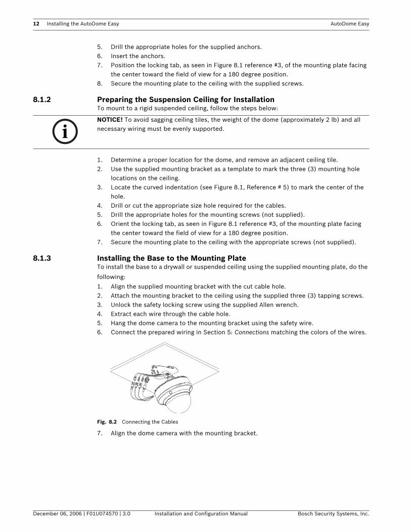
1. Align the supplied mounting bracket with the cut cable hole.2. Attach the mounting bracket to the ceiling using the supplied three (3) tapping screws.3. Unlock the safety locking screw using the supplied Allen wrench.4. Extract each wire through the cable hole. 5. Hang the dome camera to the mounting bracket using the safety wire.6. Connect the prepared wiring in Section 5: Connections matching the colors of the wires.
Fig. 8.2 Connecting the Cables
7. Align the dome camera with the mounting bracket.
iNOTICE! To avoid sagging ceiling tiles, the weight of the dome (approximately 2 lb) and all necessary wiring must be evenly supported.

AutoDome Easy Installing the AutoDome Easy 13
Bosch Security Systems, Inc. Installation and Configuration Manual December 06, 2006 | F01U074570 | 3.0
Fig. 8.3 Installing the Dome
8. Turn the dome camera to the right approximately 15 degrees.9. Secure the safety locking screw.
8.1.4 Powering OnWhen AutoDome Easy’s power is turned on, there is a five (5) second pause before the dome starts its homing phase. During the homing phase, the camera pans left and right and tilts up and down. It also adjusts the lens focus. The entire homing phase lasts approximately 40 sec-onds and displays the following splash screen throughout its homing phase START UP BOSCH Version 2.0.x.
8.1.5 Installing the Base to a Junction BoxIf it is not possible to drill a hole in the ceiling for wiring, it is recommended to use a junction box (not supplied). To mount a junction box, follow all standard procedures.
To install the AutoDome Easy to a junction box, follow the steps below:1. Carefully loosen the bubble by using the torx wrench provided to remove the four (4)
tamper-resistant screws. Allow the bubble to hang from the safety tether.2. Remove the appropriate two (2) (see Figure 8.4) black rubber plugs from the camera
base.
Fig. 8.4 Removing the Plugs from the Camera Base
iNOTICE! The error message: PROTOCOL IS NOT MATCHED is displayed during the power-up cycle if switches 9 and 0 are not set correctly.
iNOTICE! This mounting method does not require use of the supplied mounting plate.
14 Basic Operation AutoDome Easy
December 06, 2006 | F01U074570 | 3.0 Installation and Configuration Manual Bosch Security Systems, Inc.
3. Connect the prepared wiring in Section 5: Connections matching the colors of the wires.4. Align the two (2) screws (not provided) with the junction box and secure the dome.5. Re-attach the bubble.
9 Basic OperationThis section describes how to use the keyboard and details the keyboard command structure.
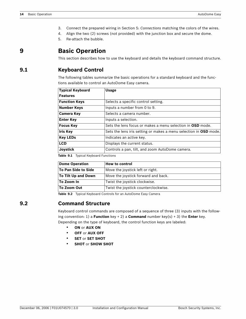
9.1 Keyboard ControlThe following tables summarize the basic operations for a standard keyboard and the func-tions available to control an AutoDome Easy camera.
9.2 Command StructureKeyboard control commands are composed of a sequence of three (3) inputs with the follow-ing convention: 1) a Function key + 2) a Command number key(s) + 3) the Enter key.Depending on the type of keyboard, the control function keys are labeled:
• ON or AUX ON• OFF or AUX OFF• SET or SET SHOT• SHOT or SHOW SHOT
Typical Keyboard Features
Usage
Function Keys Selects a specific control setting.
Number Keys Inputs a number from 0 to 9.
Camera Key Selects a camera number.
Enter Key Inputs a selection.
Focus Key Sets the lens focus or makes a menu selection in OSD mode.
Iris Key Sets the lens iris setting or makes a menu selection in OSD mode.
Key LEDs Indicates an active key.
LCD Displays the current status.
Joystick Controls a pan, tilt, and zoom AutoDome camera.
Table 9.1 Typical Keyboard Functions
Dome Operation How to control
To Pan Side to Side Move the joystick left or right.
To Tilt Up and Down Move the joystick forward and back.
To Zoom In Twist the joystick clockwise.
To Zoom Out Twist the joystick counterclockwise.
Table 9.2 Typical Keyboard Controls for an AutoDome Easy Camera

AutoDome Easy Program and Operation 15
Bosch Security Systems, Inc. Installation and Configuration Manual December 06, 2006 | F01U074570 | 3.0
10 Program and OperationThe AutoDome Easy is programmed through the on-screen display (OSD) menus. Each on-screen display (OSD) shows a list of parameters or submenus that can be selected by the operator.
10.1 Menu NavigationTo access the OSD menus, open the Main menu by pressing ON + 4 + 6 + ENTER.
Use the joystick to navigate through the menu. To navigate throughout the OSD menus, do the following:
• To scroll through the parameters, move the joystick up and down . • To edit the parameters or enter a submenu, move the joystick left and right .• To exit the submenu, move the cursor to EXIT, then move the joystick to the right
.
10.2 Main MenuThe Main menu provides access to all programmable AutoDome Easy settings. Press ON + 4 + 6 + ENTER to display the Main menu.
iNOTICE! The main menu can not be accessed when an auto pan or preset tour is running. Press the joystick in any direction to stop the tour or auto pan.
MAIN MENUPRESETTOURAUTO PANSECTORALARMCAMERA SETUPDOME SETUPEXIT
Menu Description
Preset Pre-selects and stores combinations of pan, tilt and zoom positions which allow a
set view to be recalled. Also known as preset shot.
Tour Accesses a sequence of preset shots combined to provide a pre-programmed tour
of the area covered by an AutoDome Easy camera.
Auto Pan Accesses a range of 1-4 for customized auto pan tours.
Sector Breaks the total 360 degrees into eight sectors of 45 degrees each. Individual titles
may be assigned to each sector.
Alarm Accesses the alarm settings such as: input type, timeout options, and dwell time.
Camera Setup Accesses adjustable camera settings such as: white balance, gain, sharpness, sync,
backlight, and shutter.
Dome Setup Controls miscellaneous dome operations such as: OSD, auto pivot, home function,
and initialization (reset to factory defaults).
Exit Exits the menu without saving the data.
16 Program and Operation AutoDome Easy
December 06, 2006 | F01U074570 | 3.0 Installation and Configuration Manual Bosch Security Systems, Inc.
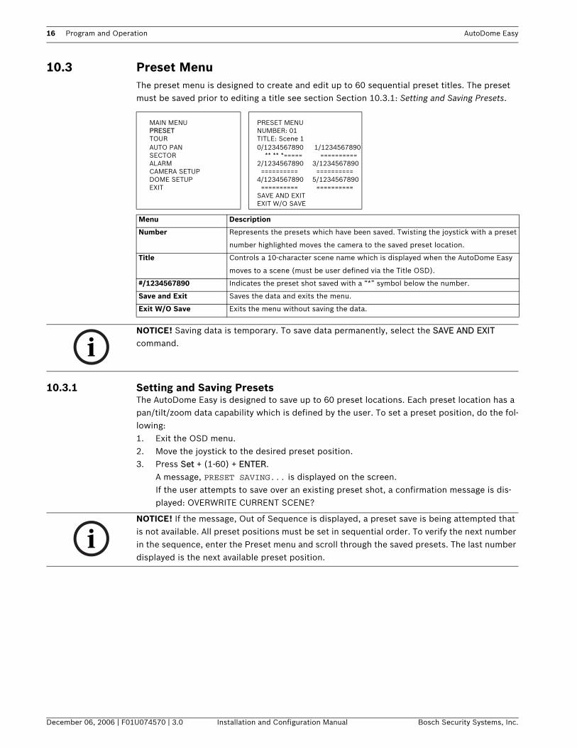
10.3 Preset Menu The preset menu is designed to create and edit up to 60 sequential preset titles. The preset must be saved prior to editing a title see section Section 10.3.1: Setting and Saving Presets.
10.3.1 Setting and Saving Presets The AutoDome Easy is designed to save up to 60 preset locations. Each preset location has a pan/tilt/zoom data capability which is defined by the user. To set a preset position, do the fol-lowing:1. Exit the OSD menu. 2. Move the joystick to the desired preset position.3. Press Set + (1-60) + ENTER.
A message, PRESET SAVING... is displayed on the screen. If the user attempts to save over an existing preset shot, a confirmation message is dis-played: OVERWRITE CURRENT SCENE?
MAIN MENU PRESET MENUPRESET NUMBER: 01TOUR TITLE: Scene 1AUTO PAN 0/1234567890 1/1234567890SECTOR --- ** ** *===== --- ========== ALARM 2/1234567890 3/1234567890CAMERA SETUP - ========== - ========== DOME SETUP 4/1234567890 5/1234567890EXIT - ========== - ==========
SAVE AND EXITEXIT W/O SAVE
Menu Description
Number Represents the presets which have been saved. Twisting the joystick with a preset
number highlighted moves the camera to the saved preset location.
Title Controls a 10-character scene name which is displayed when the AutoDome Easy
moves to a scene (must be user defined via the Title OSD).
#/1234567890 Indicates the preset shot saved with a “*” symbol below the number.
Save and Exit Saves the data and exits the menu.
Exit W/O Save Exits the menu without saving the data.
iNOTICE! Saving data is temporary. To save data permanently, select the SAVE AND EXIT command.
iNOTICE! If the message, Out of Sequence is displayed, a preset save is being attempted that is not available. All preset positions must be set in sequential order. To verify the next number in the sequence, enter the Preset menu and scroll through the saved presets. The last number displayed is the next available preset position.
AutoDome Easy Creating Titles 17
Bosch Security Systems, Inc. Installation and Configuration Manual December 06, 2006 | F01U074570 | 3.0
10.3.2 Recalling a Preset PositionThe AutoDome Easy is designed to recall up to 60 preset locations. To recall a preset position do the following:
Press Shot + (screen shot # 1-60) + ENTER. The AutoDome Easy displays the preset posi-tion with a user defined title in the upper left-hand corner. If the user attempts to recall a shot that has not been preset, an error, DATA NOT PROGRAMMED is displayed on the screen.
11 Creating TitlesThe AutoDome Easy is designed to display a user defined title for individual preset locations, preset tours, and auto pan tours. To insert a title, do the following:1. Press ON + 4 + 6 + ENTER to access the main menu.2. Select PRESET, TOUR, or AUTO PAN.3. Select the appropriate number for the preset, preset tour, or auto pan to be edited.4. Select the TITLE: ========== field, twist the joystick. A character is displayed and the
cursor starts blinking indicating it is in edit mode.5. Twist the joystick knob to the right or left to begin scrolling through the characters. Twist
the joystick right to go forward or twist the joystick knob left to go backwards. 6. Press the joystick to the right after reaching the desired letter or number. The letter
stops blinking. The next sequential character is changed to a blank space, twist the joy-stick and repeat step 5.
7. When satisfied with the title, select SAVE AND EXIT. To exit without saving, select EXIT W/O SAVE.
iNOTICE! The preset position can not be accessed when an auto pan or preset tour is running. Press the joystick in any direction to stop the tour or auto pan.

18 Tour Menu AutoDome Easy
December 06, 2006 | F01U074570 | 3.0 Installation and Configuration Manual Bosch Security Systems, Inc.
12 Tour Menu The Tour menu provides access to preset tours that are customized to run a sequence of user selected presets.
12.1 Setting a TourThe AutoDome Easy is designed to set up to four (4) customized sequences of preset shots covered by the AutoDome Easy camera. To set a tour, do the following:1. Press ON + 4 + 6 + ENTER to access the main menu.2. Select TOUR.3. Select desired tour number (1-4).4. To edit the title see Section 11: Creating Titles. 5. Select the DWELL TIME field.6. Press the joystick right to increase the time or left to decrease the time.7. Select the ========== field, to set the sequence of preset shots. Twist the joystick knob.
A number is displayed and the cursor starts blinking indicating it is in edit mode.8. Twist the joystick to the right or left to begin scrolling through the saved presets. Twist
the joystick right to go forward or twist the joystick left to go backwards. 9. Press the joystick to the right after reaching the desired number. The number stops blink-
ing. The next sequential number is changed to blinking = =, twist the joystick and repeat step 8.
10. When satisfied with the preset tour, select SAVE AND EXIT. To exit without saving, select EXIT W/O SAVE.
MAIN MENU TOUR MENUPRESET TOUR: 1TOUR TITLE: ==========AUTO PAN DWELL TIME: 05 SECSECTOR 01 03 05 = = = =ALARM = = = = = = = = CAMERA SETUP DELETE DATADOME SETUP SAVE AND EXITEXIT EXIT W/O SAVE
Menu Description
Tour Accesses a sequence of preset shots combined to provide a pre-programmed tour
of the area covered by an AutoDome Easy camera.
Title Controls a 10-character scene name which is displayed when the AutoDome Easy
runs the preset tour (must be user defined via the Title OSD).
Dwell Time Allows a range of 5-99 sec. The camera pauses at each preset for the specified
amount of time. Default is 5.
01 03 05 = = = =
= = = = = = = =
Controls a customized sequence of preset shots which are combined to provide a
pre-programmed tour of the area covered by an AutoDome Easy camera.
Delete Data Deletes the previously saved tour.
Save and Exit Saves the data and exits the menu.
Exit W/O Save Exits the menu without saving the data.
AutoDome Easy Auto Pan Menu 19
Bosch Security Systems, Inc. Installation and Configuration Manual December 06, 2006 | F01U074570 | 3.0
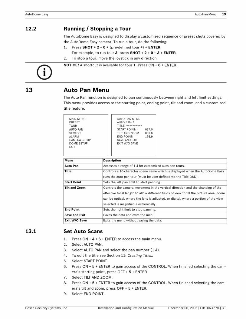
12.2 Running / Stopping a Tour The AutoDome Easy is designed to display a customized sequence of preset shots covered by the AutoDome Easy camera. To run a tour, do the following:1. Press SHOT + 2 + 0 + (pre-defined tour #) + ENTER.
For example, to run tour 3, press SHOT + 2 + 0 + 3 + ENTER.2. To stop a tour, move the joystick in any direction.
13 Auto Pan Menu The Auto Pan function is designed to pan continuously between right and left limit settings. This menu provides access to the starting point, ending point, tilt and zoom, and a customized title feature.
13.1 Set Auto Scans 1. Press ON + 4 + 6 + ENTER to access the main menu.2. Select AUTO PAN.3. Select AUTO PAN and select the pan number (1-4).4. To edit the title see Section 11: Creating Titles. 5. Select START POINT. 6. Press ON + 5 + ENTER to gain access of the CONTROL. When finished selecting the cam-
era’s starting point, press OFF + 5 + ENTER.7. Select TILT AND ZOOM.8. Press ON + 5 + ENTER to gain access of the CONTROL. When finished selecting the cam-
era’s tilt and zoom, press OFF + 5 + ENTER.9. Select END POINT.
iNOTICE! A shortcut is available for tour 1. Press ON + 8 + ENTER.
MAIN MENU AUTO PAN MENUPRESET AUTO PAN: 1TOUR TITLE: ==========AUTO PAN START POINT: 017.0SECTOR TILT AND ZOOM 002.6ALARM END POINT: 176.9CAMERA SETUP SAVE AND EXITDOME SETUP EXIT W/O SAVEEXIT
Menu Description
Auto Pan Accesses a range of 1-4 for customized auto pan tours.
Title Controls a 10-character scene name which is displayed when the AutoDome Easy
runs the auto pan tour (must be user defined via the Title OSD).
Start Point Sets the left pan limit to start panning.
Tilt and Zoom Controls the camera movement in the vertical direction and the changing of the
effective focal length to allow different fields of view to fill the picture area. Zoom
can be optical, where the lens is adjusted, or digital, where a portion of the view
selected is magnified electronically.
End Point Sets the right limit to stop panning.
Save and Exit Saves the data and exits the menu.
Exit W/O Save Exits the menu without saving the data.

20 Sector Menu AutoDome Easy
December 06, 2006 | F01U074570 | 3.0 Installation and Configuration Manual Bosch Security Systems, Inc.
10. Press ON + 5 + ENTER to gain access of the CONTROL. When finished selecting the cam-era’s end point, press OFF + 5 + ENTER.
11. When satisfied, select SAVE AND EXIT. To exit without saving, select EXIT W/O SAVE.
13.2 Run Auto Pan The AutoDome Easy is designed to display a customized auto pan between limits. To run the auto pan feature, do the following:1. Exit the OSD menu. 2. Press Shot + 3 + 0 + (Auto Pan number) + ENTER. For example, to run the auto scan for
course 4, press Shot + 3 + 0 + 4 + ENTER. Note: This is invalid if in menu mode.
14 Sector Menu The sector function provides access to customizing individual sectors and titles. The factory default is eight (8) evenly spaced sectors with titles from SECTOR1 to SECTOR8.
iNOTICE! Two shortcuts are available for auto pan. Press ON + 1 + ENTER to activate a continuous pan from 0 to 360 degrees starting at the cur-rent tilt and zoom positions.Press ON + 2 + ENTER to activate auto pan 1.
MAIN MENU SECTOR MENUPRESET SECTOR: 1TOUR TITLE: ==========AUTO PAN START POINT: 017.0SECTOR END POINT: 176.9ALARM DELETE DATACAMERA SETUP SAVE AND EXITDOME SETUP EXIT W/O SAVEEXIT
Menu Description
Sector Accesses a range of 1-8 for customized sectors.
Title Controls a 10-character scene name which is displayed when the AutoDome Easy
pans in any direction (must be user defined via the Title OSD).
Start Point Sets the left pan limit to display the sector title.
End Point Sets the right limit to display the sector title.
Delete Data Deletes the previously saved sectors.
Save and Exit Saves the data and exits the menu.
Exit W/O Save Exits the menu without saving the data.
iNOTICE! Sector titles are displayed any time the camera moves and disappears three (3) seconds after the camera stops.

AutoDome Easy Alarm Menu 21
Bosch Security Systems, Inc. Installation and Configuration Manual December 06, 2006 | F01U074570 | 3.0
15 Alarm MenuThe Alarm menu provides access to edit the alarm options.
15.1 Releasing an Alarm There are two modes of operation. Time out releases the alarm after the dwell time. However, time out may also be released by pressing OFF + 6 + 5 + ENTER. Momentary can only be released with the following sequence: press OFF + 6 + 5 + ENTER.
MAIN MENU ALARM MENUPRESET INPUT: NOTOUR OPTION: MOMENTARYAUTO PAN PRESET: 05SECTOR DWELL TIMEALARM SAVE AND EXITCAMERA SETUP EXIT W/O SAVEDOME SETUPEXIT
Menu Description Options Default
Input Defines the type of physical
input.
NC - Normally Closed
NO - Normally Open
OFF - Alarm input is disregarded
OFF
Option Defines the mode of operation. Time Out - Upon alarm activation, the cam-
era moves to the defined preset and
remains in alarm for the specified dwell
time. When the time has expired the cam-
era reverts back to the previous operation
prior to the alarm being activated.
Momentary - Upon alarm activation, the
camera moves to the pre-defined preset
position and remains in alarm mode until
OFF + 65 + ENTER is pressed. After the
alarm is acknowledged, the camera reverts
back to the previous operation prior to the
alarm being activated.
Time Out
Preset Moves to the defined preset,
upon alarm activation,
All saved presets are available. 1
Dwell Time In time out mode, the camera
remains in alarm mode for the
specified dwell time.
Allows a range of 5-99 sec. 5
Save and Exit Saves and exits the menu.
Exit W/O Save Exits the menu without saving the
data.
22 Camera Setup Menu AutoDome Easy
December 06, 2006 | F01U074570 | 3.0 Installation and Configuration Manual Bosch Security Systems, Inc.
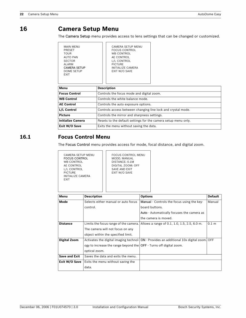
16 Camera Setup Menu The Camera Setup menu provides access to lens settings that can be changed or customized.
16.1 Focus Control MenuThe Focus Control menu provides access for mode, focal distance, and digital zoom.
MAIN MENU CAMERA SETUP MENUPRESET FOCUS CONTROLTOUR WB CONTROLAUTO PAN AE CONTROLSECTOR L/L CONTROLALARM PICTURECAMERA SETUP INITIALIZE CAMERADOME SETUP EXIT W/O SAVEEXIT
Menu Description
Focus Control Controls the focus mode and digital zoom.
WB Control Controls the white balance mode.
AE Control Controls the auto exposure options.
L/L Control Controls access between changing line lock and crystal mode.
Picture Controls the mirror and sharpness settings.
Initialize Camera Resets to the default settings for the camera setup menu only.
Exit W/O Save Exits the menu without saving the data.
CAMERA SETUP MENU FOCUS CONTROL MENUFOCUS CONTROL MODE: MANUALWB CONTROL DISTANCE: 0.1MAE CONTROL DIGITAL ZOOM: OFFL/L CONTROL SAVE AND EXITPICTURE EXIT W/O SAVEINITIALIZE CAMERAEXIT
Menu Description Options Default
Mode Selects either manual or auto focus
control.
Manual - Controls the focus using the key-
board buttons.
Auto - Automatically focuses the camera as
the camera is moved.
Manual
Distance Limits the focus range of the camera.
The camera will not focus on any
object within the specified limit.
Allows a range of 0.1, 1.0, 1.5, 2.5, 6.0 m. 0.1 m
Digital Zoom Activates the digital imaging technol-
ogy to increase the range beyond the
optical zoom.
ON - Provides an additional 10x digital zoom.
OFF - Turns off digital zoom.
OFF
Save and Exit Saves the data and exits the menu.
Exit W/O Save Exits the menu without saving the
data.
AutoDome Easy Camera Setup Menu 23
Bosch Security Systems, Inc. Installation and Configuration Manual December 06, 2006 | F01U074570 | 3.0
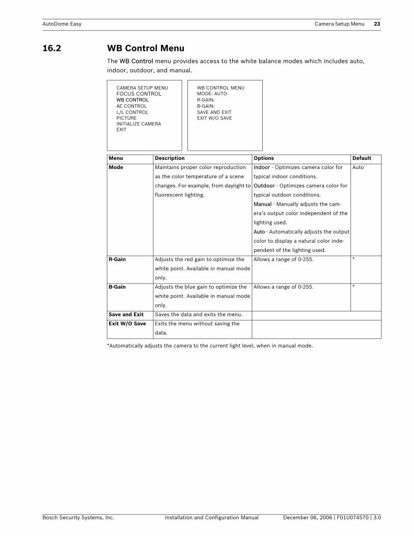
16.2 WB Control MenuThe WB Control menu provides access to the white balance modes which includes auto, indoor, outdoor, and manual.
*Automatically adjusts the camera to the current light level, when in manual mode.
CAMERA SETUP MENU WB CONTROL MENUFOCUS CONTROL MODE: AUTOWB CONTROL R-GAIN:AE CONTROL B-GAIN:L/L CONTROL SAVE AND EXITPICTURE EXIT W/O SAVEINITIALIZE CAMERAEXIT
Menu Description Options Default
Mode Maintains proper color reproduction
as the color temperature of a scene
changes. For example, from daylight to
fluorescent lighting.
Indoor - Optimizes camera color for
typical indoor conditions.
Outdoor - Optimizes camera color for
typical outdoor conditions.
Manual - Manually adjusts the cam-
era’s output color independent of the
lighting used.
Auto - Automatically adjusts the output
color to display a natural color inde-
pendent of the lighting used.
Auto
R-Gain Adjusts the red gain to optimize the
white point. Available in manual mode
only.
Allows a range of 0-255. *
B-Gain Adjusts the blue gain to optimize the
white point. Available in manual mode
only.
Allows a range of 0-255. *
Save and Exit Saves the data and exits the menu.
Exit W/O Save Exits the menu without saving the
data.

24 Camera Setup Menu AutoDome Easy
December 06, 2006 | F01U074570 | 3.0 Installation and Configuration Manual Bosch Security Systems, Inc.
16.3 AE Control MenuThe AE Control menu provides access to auto exposure options which includes modes, iris, gain, shutter, and brightness.
CAMERA SETUP MENU AE CONTROL MENUFOCUS CONTROL MODE: AUTOWB CONTROL IRIS:AE CONTROL GAIN:L/L CONTROL SHUTTER:PICTURE BRIGHT: 30INITIALIZE CAMERA BACK LIGHT: OFFEXIT SAVE AND EXIT
EXIT W/O SAVE
Menu Description Options Default
Mode Provides gain control
modes.
Auto - The camera automatically adjusts iris, gain, and
shutter speeds. Brightness may be pre-defined.
Shutter PRI - The camera automatically adjusts iris and
gain. The shutter and brightness may be pre-defined.
Iris PRI - The camera automatically adjusts the gain
and shutter. The iris and brightness may be pre-
defined.
Manual - The camera operates in the manual mode.
The iris, gain, and shutter must be pre-defined.
Flickerless - The camera automatically removes flicker,
when camera signal format does not coincide with the
power source frequency. For example, when an NTSC
camera is used with 50 Hz power.
AUTO
Iris Controls the lens's F stop
value to manually adjust
for various light levels.
Available with iris PRI
and manual mode only.
F1.8, 2, 2.4, 2.8, 3.4, 4, 5.6, 6.8, 8, 9.6, 11, 14,
16, 19, 22, CLOSE
F2.8
Gain Electronics that regulate
the gain or amplification
of the video signal. Avail-
able in manual mode
only.
Allows a range of 0-30. 0
Shutter Manually adjusts the
shutter speed. Available
in shutter PRI and man-
ual mode only.
NORMAL (60 NTSC and 50 PAL), 100, 120, 250, 500,
1000, 2000, 5000, 10000
100
Bright Reduces the camera's iris
level for proper expo-
sure.
Allows a range of 0-90. 30

AutoDome Easy Camera Setup Menu 25
Bosch Security Systems, Inc. Installation and Configuration Manual December 06, 2006 | F01U074570 | 3.0
Table 16.1 Mode Options
Back Light Selectively amplifies
parts of the image to
compensate for large
contrast differences
when only a portion of
the image is brightly lit
(e.g. a person in a sunlit
doorway).
ON, OFF OFF
Save and Exit Saves the data and exits
the menu.
Exit W/O Save Exits the menu.
Mode Iris Gain Shutter Brightness Back Light
Auto
Shutter PRI
Iris PRI
Manual
Menu Description Options Default
26 Camera Setup Menu AutoDome Easy
December 06, 2006 | F01U074570 | 3.0 Installation and Configuration Manual Bosch Security Systems, Inc.
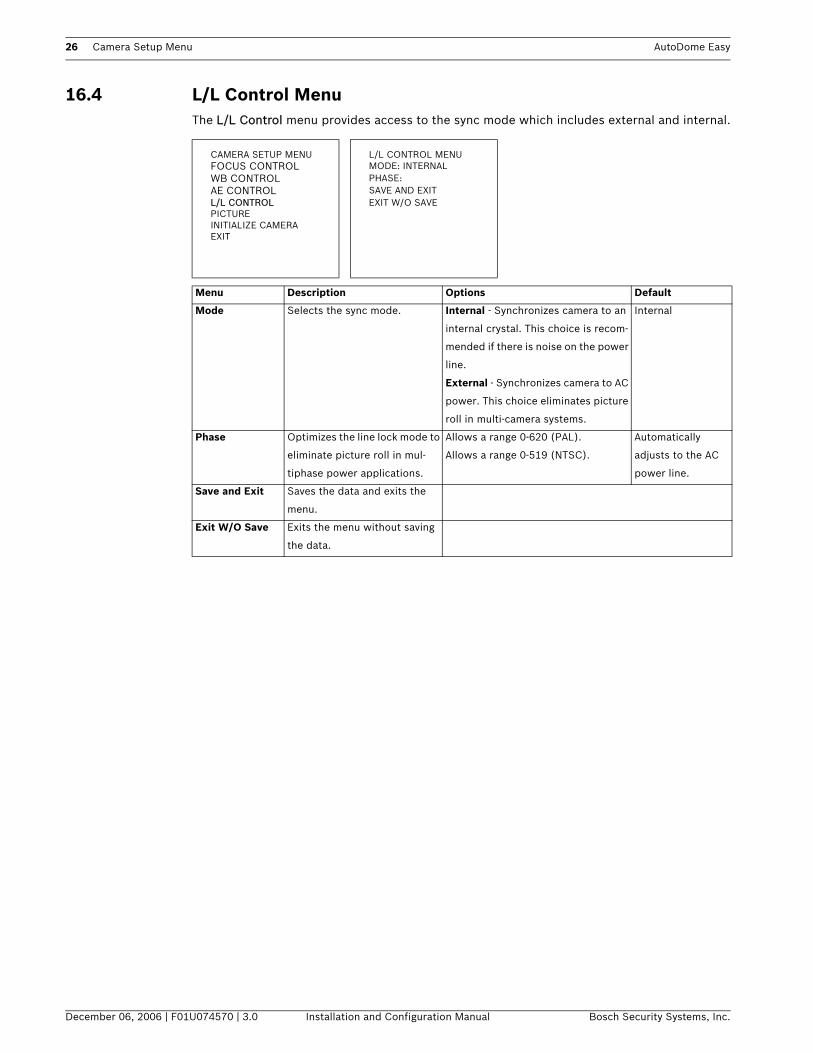
16.4 L/L Control MenuThe L/L Control menu provides access to the sync mode which includes external and internal.
CAMERA SETUP MENU L/L CONTROL MENUFOCUS CONTROL MODE: INTERNALWB CONTROL PHASE:AE CONTROL SAVE AND EXITL/L CONTROL EXIT W/O SAVEPICTUREINITIALIZE CAMERAEXIT
Menu Description Options Default
Mode Selects the sync mode. Internal - Synchronizes camera to an
internal crystal. This choice is recom-
mended if there is noise on the power
line.
External - Synchronizes camera to AC
power. This choice eliminates picture
roll in multi-camera systems.
Internal
Phase Optimizes the line lock mode to
eliminate picture roll in mul-
tiphase power applications.
Allows a range 0-620 (PAL).
Allows a range 0-519 (NTSC).
Automatically
adjusts to the AC
power line.
Save and Exit Saves the data and exits the
menu.
Exit W/O Save Exits the menu without saving
the data.

AutoDome Easy Camera Setup Menu 27
Bosch Security Systems, Inc. Installation and Configuration Manual December 06, 2006 | F01U074570 | 3.0
16.5 Picture MenuThe Picture menu provides access to miscellaneous video settings which includes mirror and sharpness.
16.6 Initialize Camera MenuThe Initialize Camera menu allows you to reset all camera settings to the default setting. Press the joystick to the right to display the following message: CAMERA WILL BE INITIALIZED!! ARE YOU SURE?
CAMERA SETUP MENU PICTURE MENUFOCUS CONTROL MIRROR: OFFWB CONTROL SHARPNESS: 09AE CONTROL SAVE AND EXITL/L CONTROL EXIT W/O SAVEPICTUREINITIALIZE CAMERAEXIT
Menu Description Options Default
Mirror Selects a mirror image. ON, OFF OFF
Sharpness Adjusts the sharpness of the pic-
ture.
Allows a range of 0-15. 8
Save and Exit Saves the data and exits the
menu.
Exit W/O Save Exits the menu without saving
the data.
CAMERA SETUP MENUFOCUS CONTROL
CAMERA WILL BE INITIALIZED!! ARE YOU SURE?
WB CONTROL NOAE CONTROL YESL/L CONTROLPICTUREINITIALIZE CAMERAEXIT
28 Dome Setup Menu AutoDome Easy
December 06, 2006 | F01U074570 | 3.0 Installation and Configuration Manual Bosch Security Systems, Inc.
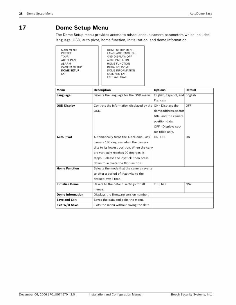
17 Dome Setup Menu The Dome Setup menu provides access to miscellaneous camera parameters which includes: language, OSD, auto pivot, home function, initialization, and dome information.
MAIN MENU DOME SETUP MENUPRESET LANGUAGE: ENGLISHTOUR OSD DISPLAY: OFFAUTO PAN AUTO PIVOT: ONALARM HOME FUNCTIONCAMERA SETUP INITIALIZE DOMEDOME SETUP DOME INFORMATIONEXIT SAVE AND EXIT
EXIT W/O SAVE
Menu Description Options Default
Language Selects the language for the OSD menu. English, Espanol, and
Francais
English
OSD Display Controls the information displayed by the
OSD.
ON - Displays the
dome address, sector
title, and the camera
position data.
OFF - Displays sec-
tor titles only.
OFF
Auto Pivot Automatically turns the AutoDome Easy
camera 180 degrees when the camera
tilts to its lowest position. When the cam-
era vertically reaches 90 degrees, it
stops. Release the joystick, then press
down to activate the flip function.
ON, OFF ON
Home Function Selects the mode that the camera reverts
to after a period of inactivity to the
defined dwell time.
Initialize Dome Resets to the default settings for all
menus.
YES, NO N/A
Dome Information Displays the firmware version number.
Save and Exit Saves the data and exits the menu.
Exit W/O Save Exits the menu without saving the data.
AutoDome Easy Dome Setup Menu 29
Bosch Security Systems, Inc. Installation and Configuration Manual December 06, 2006 | F01U074570 | 3.0
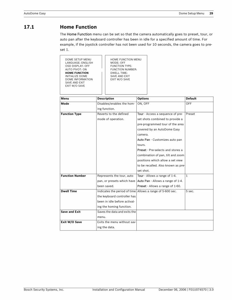
17.1 Home FunctionThe Home Function menu can be set so that the camera automatically goes to preset, tour, or auto pan after the keyboard controller has been in idle for a specified amount of time. For example, if the joystick controller has not been used for 10 seconds, the camera goes to pre-set 1.
DOME SETUP MENU HOME FUNCTION MENULANGUAGE: ENGLISH MODE: OFFOSD DISPLAY: OFF FUNCTION TYPE:AUTO PIVOT: ON FUNCTION NUMBER:HOME FUNCTION DWELL TIME:INITIALIZE DOME SAVE AND EXITDOME INFORMATION EXIT W/O SAVESAVE AND EXITEXIT W/O SAVE
Menu Description Options Default
Mode Disables/enables the hom-
ing function.
ON, OFF OFF
Function Type Reverts to the defined
mode of operation.
Tour - Access a sequence of pre-
set shots combined to provide a
pre-programmed tour of the area
covered by an AutoDome Easy
camera.
Auto Pan - Customizes auto pan
tours.
Preset - Pre-selects and stores a
combination of pan, tilt and zoom
positions which allow a set view
to be recalled. Also known as pre-
set shot.
Preset
Function Number Represents the tour, auto
pan, or presets which have
been saved.
Tour - Allows a range of 1-4.
Auto Pan - Allows a range of 1-4.
Preset - Allows a range of 1-60.
1
Dwell Time Indicates the period of time
the keyboard controller has
been in idle before activat-
ing the homing function.
Allows a range of 5-600 sec. 5 sec.
Save and Exit Saves the data and exits the
menu.
Exit W/O Save Exits the menu without sav-
ing the data.
30 Dome Setup Menu AutoDome Easy
December 06, 2006 | F01U074570 | 3.0 Installation and Configuration Manual Bosch Security Systems, Inc.
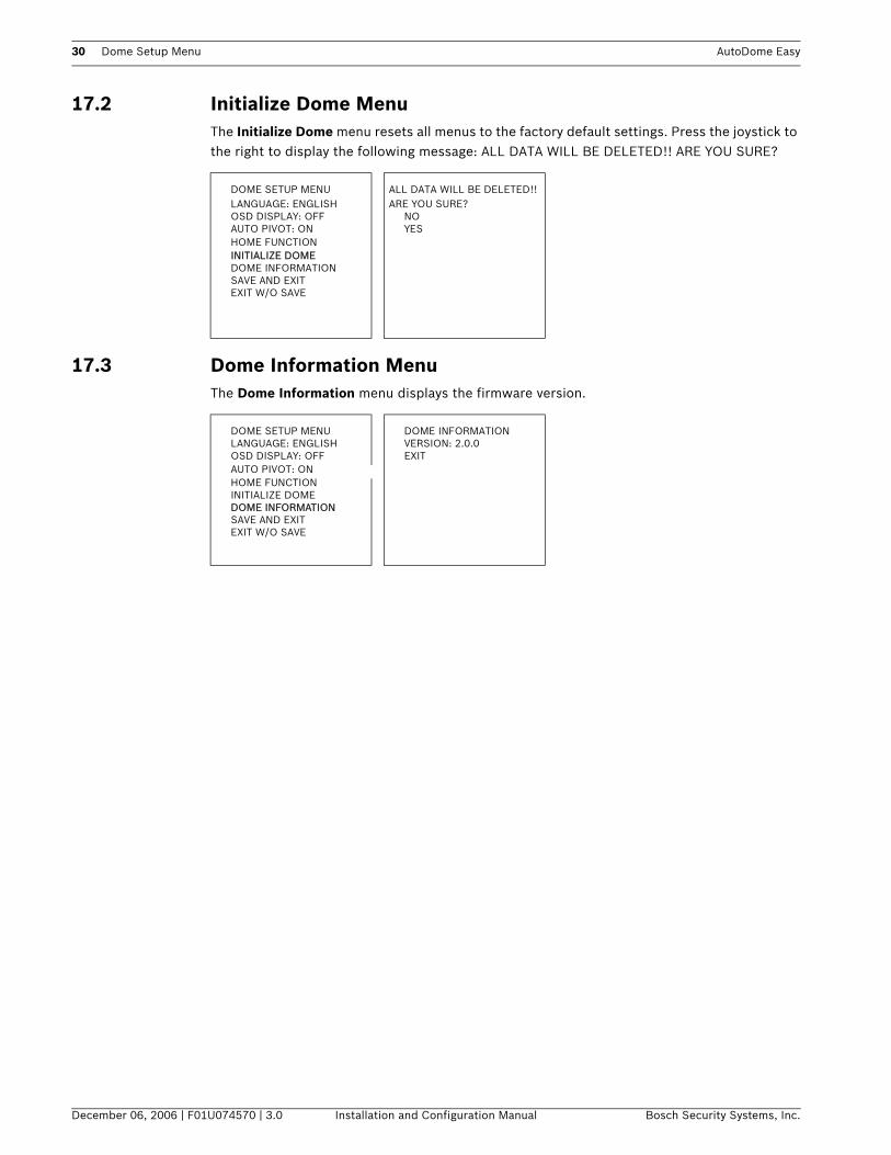
17.2 Initialize Dome MenuThe Initialize Dome menu resets all menus to the factory default settings. Press the joystick to the right to display the following message: ALL DATA WILL BE DELETED!! ARE YOU SURE?
17.3 Dome Information MenuThe Dome Information menu displays the firmware version.
DOME SETUP MENULANGUAGE: ENGLISH
ALL DATA WILL BE DELETED!! ARE YOU SURE?
OSD DISPLAY: OFF NOAUTO PIVOT: ON YESHOME FUNCTIONINITIALIZE DOMEDOME INFORMATIONSAVE AND EXITEXIT W/O SAVE
DOME SETUP MENU DOME INFORMATIONLANGUAGE: ENGLISH VERSION: 2.0.0OSD DISPLAY: OFF EXITAUTO PIVOT: ONHOME FUNCTIONINITIALIZE DOME DOME INFORMATIONSAVE AND EXITEXIT W/O SAVE

AutoDome Easy Keyboard Commands by Number 31
Bosch Security Systems, Inc. Installation and Configuration Manual December 06, 2006 | F01U074570 | 3.0
18 Keyboard Commands by NumberFunction
KeyComm
No.Command Description
On/Off 1 Scan 360 degrees Autopans from 0-360 degrees.
On/Off 2 Activates autopan 1 Autopan between defined limits.
On/Off 8 Play pre-position Tour 1 Activate/deactivate.
Off 65 Alarm acknowledge Acknowledge alarm or deactivate physi-cal outputs.
On 66 Displays firmware version Displays firmware version number.
Set “1-60” Pre-position programming Set ##–programs a preset view.
Shot “1-60” Pre-position recall Shot ##–recall programmed preset.
Set 110 Factory P/T home position Set–recalibrate home position.
Shot “201-204”
Run tour Activates preset tour 1-4.
Shot “301-304”
Run auto pan Activates auto pan 1-4.
32 Troubleshooting AutoDome Easy
December 06, 2006 | F01U074570 | 3.0 Installation and Configuration Manual Bosch Security Systems, Inc.
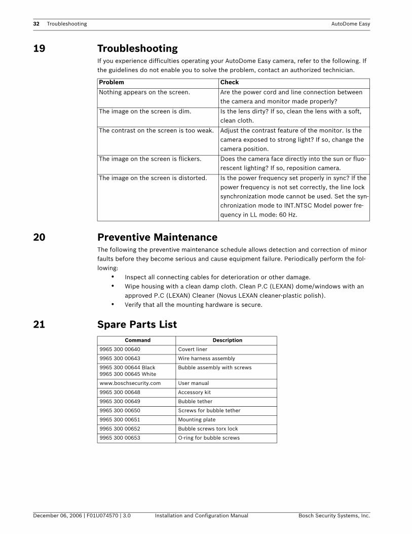
19 Troubleshooting If you experience difficulties operating your AutoDome Easy camera, refer to the following. If the guidelines do not enable you to solve the problem, contact an authorized technician.
20 Preventive Maintenance The following the preventive maintenance schedule allows detection and correction of minor faults before they become serious and cause equipment failure. Periodically perform the fol-lowing:
• Inspect all connecting cables for deterioration or other damage. • Wipe housing with a clean damp cloth. Clean P.C (LEXAN) dome/windows with an
approved P.C (LEXAN) Cleaner (Novus LEXAN cleaner-plastic polish).• Verify that all the mounting hardware is secure.
21 Spare Parts List
Problem Check
Nothing appears on the screen. Are the power cord and line connection between the camera and monitor made properly?
The image on the screen is dim. Is the lens dirty? If so, clean the lens with a soft, clean cloth.
The contrast on the screen is too weak. Adjust the contrast feature of the monitor. Is the camera exposed to strong light? If so, change the camera position.
The image on the screen is flickers. Does the camera face directly into the sun or fluo-rescent lighting? If so, reposition camera.
The image on the screen is distorted. Is the power frequency set properly in sync? If the power frequency is not set correctly, the line lock synchronization mode cannot be used. Set the syn-chronization mode to INT.NTSC Model power fre-quency in LL mode: 60 Hz.
Command Description
9965 300 00640 Covert liner
9965 300 00643 Wire harness assembly
9965 300 00644 Black9965 300 00645 White
Bubble assembly with screws
www.boschsecurity.com User manual
9965 300 00648 Accessory kit
9965 300 00649 Bubble tether
9965 300 00650 Screws for bubble tether
9965 300 00651 Mounting plate
9965 300 00652 Bubble screws torx lock
9965 300 00653 O-ring for bubble screws


Americas:Bosch Security Systems130 Perinton ParkwayFairport, New York, 14450USAPhone +1 800 289 0096Fax +1 585 223 9180www.boschsecurity.us
Europe, Middle East, Asia:Bosch Security Systems B.V.Postbus 800025600 JB EindhovenPhone: +31 40 2577 200Fax: +31 40 2577 202nl.securitysystems@bosch.comwww.boschsecurity.nlwww.boschsecurity.com
www.boschsecurity.comAsia-Pacific:Bosch Security Systems Pte Ltd.38C Jalan PemimpinSingapore 577180Phone +65 6319 3450Fax +65 63139 3499www.boschsecurity.com
© Bosch Security Systems, Inc., 2006; F01U074570 | 3.0 | 2006.12