earthquake-induced liquefaction around marine structures
TRANSCRIPT

Earthquake-Induced Liquefaction around Marine StructuresB. Mutlu Sumer1; Atilla Ansal2; K. Onder Cetin3; Jesper Damgaard4; A. Riza Gunbak5;
Niels-Erik Ottesen Hansen6; Andrzej Sawicki7; Costas E. Synolakis8; Ahmet Cevdet Yalciner9;Yalcin Yuksel10; and Kouki Zen11
Abstract: This paper gives a state-of-the-art review of seismic-induced liquefaction with special reference to marine structures. Thepaper is organized in seven sections: �1� introduction; �2� seismic-induced liquefaction in which a general account of soil liquefaction ispresented; �3� existing codes/guidelines regarding seismic-induced liquefaction and its implications for marine structures; �4� review ofthe Japanese experience, giving a brief history of earthquakes and design codes, describing the current design code/standard for port andharbor facilities including counter measures and remediation; �5� review of the liquefaction damage inflicted on marine structures in the1999 Turkey Kocaeli Earthquake, including recommendations which draw on the lessons learned; �6� assessment of postliquefactionground deformation �more specifically of lateral ground spreading�; and �7� tsunamis and their impact. The present paper and the existingguidelines �CEN, ASCE, and PIANC� form a complementary source of information on earthquake-induced liquefaction with specialreference to its impact on marine structures.
DOI: 10.1061/�ASCE�0733-950X�2007�133:1�55�
CE Database subject headings: Coastal structures; Earthquakes; Guidelines; Liquefaction; Offshore structures; Seismic effects.
Introduction
Earthquakes are an open, direct threat to marine structures �suchas quay walls, piers, dolphins, breakwaters, buried pipelines,sheet-piled structures, containers/silos/warehouses/storage tanks
1Professor, MEK, Coastal, Maritime, and Structural EngineeringSection, Technical Univ. of Denmark, Building 403, Lyngby DK-2800,Denmark �corresponding author�. E-mail: [email protected]
2Professor, Kandilli Observatory and Earthquake Research Center,Bogazici Univ., Cengelkoy 82110, Istanbul, Turkey.
3Associate Professor, Dept. of Civil Engineering, METU, Ankara06531, Turkey.
4General Manager, Industrial and Infrastructure �Middle East�,WorleyParsons, P.O. Box 44169, Abu Dhabi, UAE; formerly, ProjectManager, HR Wallingford Ltd.
5Professor, Technical Adviser for Marine Works, STFA ConstructionCo., Altunizade Uskudar, Istanbul 81190, Turkey.
6Director, LICengineering A/S, Ehlersvej 24, Hellerup 2900,Denmark.
7Professor, Institute of Hydroengineering, Polish Academy ofSciences, Koscierska 7, Gdansk 80-953, Poland.
8Professor, School of Engineering, Univ. of Southern California, LosAngeles, CA 90089-2531.
9Associate Professor, Civil Engineering Dept., Ocean EngineeringResearch Center, METU, Ankara 06531, Turkey.
10Professor and Dean, Dept. of Civil Engineering, Yildiz TechnicalUniv., Istanbul, Turkey.
11Professor, Dept. of Civil and Structural Engineering, Faculty ofEngineering, Kyushu Univ., Hakozaki 6-10-1, Higashiku, Fukuoka812-8581, Japan.
Note. Discussion open until June 1, 2007. Separate discussions mustbe submitted for individual papers. To extend the closing date by onemonth, a written request must be filed with the ASCE Managing Editor.The manuscript for this paper was submitted for review and possiblepublication on November 7, 2005; approved on November 7, 2005. Thispaper is part of the Journal of Waterway, Port, Coastal, and OceanEngineering, Vol. 133, No. 1, January 1, 2007. ©ASCE, ISSN 0733-
950X/2007/1-55–82/$25.00.JOURNAL OF WATERWAY, PORT, COASTAL, AND
Downloaded 16 Dec 2008 to 144.122.100.198. Redistribution subject to
located in coastal areas, etc.� when structures are located at/nearthe epicenter. The structure in this case will be exposed to thedevastating shaking effect of the seismic action, and the result canbe catastrophic.
Earthquakes may also be a threat to marine structures in anindirect way, through the shaking of the supporting soil. The sta-bility and integrity of structures will be at risk if the soil fails dueto liquefaction as a result of the shaking of the soil. This kind offailure also can be catastrophic, as observed in the recent earth-quakes in Japan and in Turkey �see sections entitled “JapaneseExperience of Earthquake-Induced Liquefaction Damage on Ma-rine Structures” and “Turkey Kocaeli Earthquake and Liquefac-tion Damage on Marine Structures”�.
Liquefaction-induced damage to marine structures has beendocumented quite extensively in the literature: Wyllie et al.�1986� �Chile�; Iai and Kameoka �1993� �Japan�; Iai et al. �1994��Japan�; Hall �1995� �USA�; Sugano et al. �1999� �Taiwan�; Bou-langer et al. �2000� �Turkey�; Sumer et al. �2002� �Turkey�; andKatopodi and Iosifidou �2004� �Greece�, to give just a few ex-amples. A partial list of well-documented case histories can befound in PIANC �2001�.
The questions that design engineers face in the case of lique-faction failure are mainly: �1� Can the soil be liquefied under agiven “design” earthquake? �2� If the soil is liquefiable, how ex-tensive will the damage be to the structure? �3� Is this damageacceptable �i.e., is it within the limit of damage criteria�? �4� Ifnot, what will the damage �if any� be when some form of “reme-diation” is implemented? �5� Is the latter damage �if any� withinthe limit of damage criteria? etc.
A substantial amount of knowledge on the seismic design ofmarine structures has accumulated over the past 40 years, whichhas lead to excellent treatments on the general subject “seismicdesign guidelines for marine structures,” the most important ofwhich are
• European Committee for Standardization �CEN� 1994OCEAN ENGINEERING © ASCE / JANUARY/FEBRUARY 2007 / 55
ASCE license or copyright; see http://pubs.asce.org/copyright

Eurocode 8: Design Provisions for Earthquake Resistance ofStructures;
• ASCE 1998, Seismic Guidelines for Ports; and• PIANC 2001, Seismic Design Guidelines for Port Structures.The aforementioned publications also cover �to some degree� liq-uefaction design guidelines as well.
The focus of the present paper is seismic-induced liquefactionand its implications for marine structures. The paper is organizedas follows. The next section presents a general review of seismic-induced liquefaction including the basic concepts, description ofthe physical process of soil liquefaction under seismic loadingand a general overview. The following section gives a detailedreview of the existing codes/guidelines regarding seismic-inducedliquefaction and its implications for marine structures. This sec-tion is followed by two detailed reviews, namely, the Japaneseexperience of earthquake-induced liquefaction damage on marinestructures, and the 1999 Turkey Kocaeli Earthquake and liquefac-tion damage on marine structures. In these reviews, many, well-documented case histories of seismic-induced liquefactiondamage are summarized/illustrated; and recommendations whichdraw on the lessons learned are given. The following sectionscontinue to review two other issues central to marine structures.These are, respectively, assessment of liquefaction-induced lateralground deformations and tsunamis and their implications.
With these contributions and new set of information/data/recommendations described, the present paper and the previouslymentioned guidelines �CEN, ASCE, and PIANC� form a comple-mentary source of information on earthquake-induced liquefac-tion with special reference to marine structures.
The section entitled “Seismic-Induced Liquefaction—General” has been written by Atilla Ansal; the following sectionentitled “Review of the Existing Codes/Guidelines with SpecialReference to Marine Structures” by Niels-Erik Ottesen Hansenand Jesper Damgaard; “Japanese Experience of Earthquake-Induced Liquefaction Damage on Marine Structures” by KoukiZen; the following section “Turkey Kocaeli Earthquake and Liq-uefaction Damage on Marine Structures” by Ali Riza Gunbak,Yalcin Yuksel, Niels-Erik Ottesen Hansen, Adrzej Sawicki, and B.Mutlu Sumer; “Assessment of Liquefaction-Induced LateralGround Deformations” by K. Onder Cetin; and finally the sectionentitled “Tsunamis and Their Impacts” by Ahmet Cevdet Yalcinerand Costas Synolakis. The paper has been coordinated and editedby B. Mutlu Sumer.
Seismic-Induced Liquefaction—General
Soil liquefaction has been a major cause of damage to soil struc-tures, lifeline facilities, and building foundations in past earth-quakes and poses a significant threat for future earthquakes.Liquefaction potential depends on the nature of ground shakingand material susceptibility to liquefaction. For potential liquefi-ability, saturation is an additional necessary condition besidesmaterial susceptibility. The cyclic loading induced by seismicexcitation represents an ideal loading type for initiation of soilliquefaction.
Liquefaction may be defined as the transformation of a granu-lar material from a solid to a liquefied state as a consequence ofincreased pore water pressure and reduced effective stress �Martinet al. 1975; Marcuson 1978; Castro and Poulos 1977�. The ten-dency of granular materials to decrease in volume when subjectedto cyclic shear deformations leads to a positive increase in pore
water pressure resulting in a decrease of effective stress within the56 / JOURNAL OF WATERWAY, PORT, COASTAL, AND OCEAN ENGINEE
Downloaded 16 Dec 2008 to 144.122.100.198. Redistribution subject to
soil mass. The change of state occurs most readily in loose tomoderately dense granular soils, such as silty sands and sands andgravels capped by or containing seams of impermeable sediments.As liquefaction occurs soil stratum softens, allowing large cyclicdeformations to occur. In loose materials, softening is also accom-panied by a loss of shear strength that may lead to large sheardeformations or even flow failure under moderate to high shearstresses; such stress conditions can develop beneath a foundationor in a sloping ground. In moderately dense to dense materials,liquefaction leads to transient softening and increased cyclic shearstrains, but a tendency to dilate during shear inhibits majorstrength loss and large ground deformations. A condition of cyclicmobility or cyclic liquefaction may develop following liquefac-tion of moderately dense materials �Youd et al. 2001�.
The term “liquefaction” has different meanings with respect tovarious soil conditions. According to Ishihara �1996�, the follow-ing definitions apply to cohesionless soils: For loose sand, the�initial� liquefaction is the state of softening in which indefinitelylarge deformation is produced suddenly with �near� complete lossof strength during or immediately following the 100% pore waterpressure buildup. For medium dense to dense sand, a state ofsoftening �limited liquefaction, cycling softening, or cycling mo-bility� is also produced with the 100% pore water pressurebuildup accompanied by about 5% double amplitude axial strainbut the deformation thereafter does not grow indefinitely largeand complete loss of strength does not take place in the sampleeven after the onset of initial liquefaction. In silty sands or sandysilts, the plasticity of fines has a determinant role in liquefiability�Ishihara and Koseki 1989�. Silty soils with nonplastic fines �likemany tailings materials� are as easily liquefiable as clean sands.
Cohesive fines �as in fluvial deposits� generally increase thecyclic resistance of silty soils. The previous definitions of lique-faction for sands are usually applicable to �slightly cohesive� siltysoils also.
Even though soil liquefaction has been observed in history,intense investigations to assess liquefaction susceptibility havebeen initiated after the two major events of 1964, the Niigata andthe Alaska Earthquakes. Both of these earthquakes have produceddevastating effects due to liquefaction and attracted the attentionof the research media. Since then, significant efforts have beenmade to determine the factors affecting liquefaction susceptibilitybased on laboratory and field tests.
Two variables are required for the assessment of liquefactionresistance of soils: �1� the seismic demand on a soil layer, ex-pressed in terms of cyclic stress ratio �CSR�; and �2� the capacityof the soil to resist liquefaction, expressed in terms of the cyclicresistance ratio �CRR�. Triggering of liquefaction is generally rep-resented through a series of relationships between the CSR re-quired to produce 5% double-amplitude axial strain �the assumedonset of liquefaction or cyclic mobility� and the number of cycles�N� of a uniform, constant amplitude cycling loading. The CSR isdefined as the ratio of the maximum cyclically applied shearstress to the effective normal stress acting at the beginning ofshaking on the plane where shear stress is applied. The cyclic �ordynamic� strength is defined as the CSR value at N=10 or 20cycles. The parameters affecting the liquefaction potential ofloose, saturated granular soils that have been investigated in adetailed manner and can be summarized as: relative density orvoid ratio; confining pressure; fines content; grain characteristics;
plasticity of fines; method of sample preparation �because of theRING © ASCE / JANUARY/FEBRUARY 2007
ASCE license or copyright; see http://pubs.asce.org/copyright
resulting soil structure�; and the degree of saturation. Other fac-tors include prior seismic straining, the coefficient of earth pres-sure at rest, K0, the overconsolidation ratio of the soil deposit, andincreased time under pressure.
Quantitative assessment of the likelihood of triggering or ini-tiation of liquefaction is the necessary first step for most projectsinvolving potential seismically induced liquefaction. There aretwo general types of approaches available for this: �1� use oflaboratory testing of undisturbed samples; and �2� use of empiri-cal relationships based on correlation of observed field behaviorwith various in situ “index” tests.
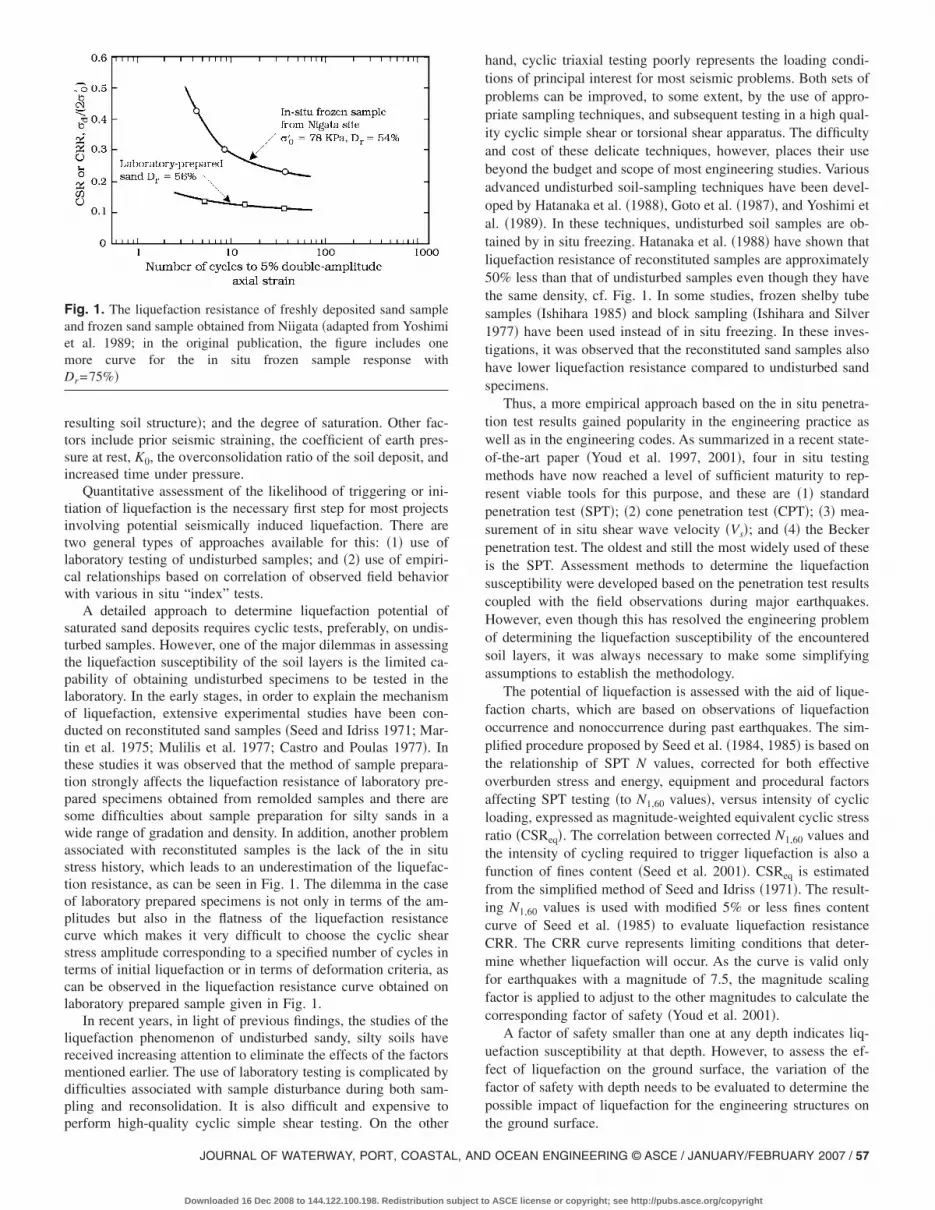
A detailed approach to determine liquefaction potential ofsaturated sand deposits requires cyclic tests, preferably, on undis-turbed samples. However, one of the major dilemmas in assessingthe liquefaction susceptibility of the soil layers is the limited ca-pability of obtaining undisturbed specimens to be tested in thelaboratory. In the early stages, in order to explain the mechanismof liquefaction, extensive experimental studies have been con-ducted on reconstituted sand samples �Seed and Idriss 1971; Mar-tin et al. 1975; Mulilis et al. 1977; Castro and Poulas 1977�. Inthese studies it was observed that the method of sample prepara-tion strongly affects the liquefaction resistance of laboratory pre-pared specimens obtained from remolded samples and there aresome difficulties about sample preparation for silty sands in awide range of gradation and density. In addition, another problemassociated with reconstituted samples is the lack of the in situstress history, which leads to an underestimation of the liquefac-tion resistance, as can be seen in Fig. 1. The dilemma in the caseof laboratory prepared specimens is not only in terms of the am-plitudes but also in the flatness of the liquefaction resistancecurve which makes it very difficult to choose the cyclic shearstress amplitude corresponding to a specified number of cycles interms of initial liquefaction or in terms of deformation criteria, ascan be observed in the liquefaction resistance curve obtained onlaboratory prepared sample given in Fig. 1.
In recent years, in light of previous findings, the studies of theliquefaction phenomenon of undisturbed sandy, silty soils havereceived increasing attention to eliminate the effects of the factorsmentioned earlier. The use of laboratory testing is complicated bydifficulties associated with sample disturbance during both sam-pling and reconsolidation. It is also difficult and expensive to
Fig. 1. The liquefaction resistance of freshly deposited sand sampleand frozen sand sample obtained from Niigata �adapted from Yoshimiet al. 1989; in the original publication, the figure includes onemore curve for the in situ frozen sample response withDr=75%�
perform high-quality cyclic simple shear testing. On the other
JOURNAL OF WATERWAY, PORT, COASTAL, AND
Downloaded 16 Dec 2008 to 144.122.100.198. Redistribution subject to
hand, cyclic triaxial testing poorly represents the loading condi-tions of principal interest for most seismic problems. Both sets ofproblems can be improved, to some extent, by the use of appro-priate sampling techniques, and subsequent testing in a high qual-ity cyclic simple shear or torsional shear apparatus. The difficultyand cost of these delicate techniques, however, places their usebeyond the budget and scope of most engineering studies. Variousadvanced undisturbed soil-sampling techniques have been devel-oped by Hatanaka et al. �1988�, Goto et al. �1987�, and Yoshimi etal. �1989�. In these techniques, undisturbed soil samples are ob-tained by in situ freezing. Hatanaka et al. �1988� have shown thatliquefaction resistance of reconstituted samples are approximately50% less than that of undisturbed samples even though they havethe same density, cf. Fig. 1. In some studies, frozen shelby tubesamples �Ishihara 1985� and block sampling �Ishihara and Silver1977� have been used instead of in situ freezing. In these inves-tigations, it was observed that the reconstituted sand samples alsohave lower liquefaction resistance compared to undisturbed sandspecimens.
Thus, a more empirical approach based on the in situ penetra-tion test results gained popularity in the engineering practice aswell as in the engineering codes. As summarized in a recent state-of-the-art paper �Youd et al. 1997, 2001�, four in situ testingmethods have now reached a level of sufficient maturity to rep-resent viable tools for this purpose, and these are �1� standardpenetration test �SPT�; �2� cone penetration test �CPT�; �3� mea-surement of in situ shear wave velocity �Vs�; and �4� the Beckerpenetration test. The oldest and still the most widely used of theseis the SPT. Assessment methods to determine the liquefactionsusceptibility were developed based on the penetration test resultscoupled with the field observations during major earthquakes.However, even though this has resolved the engineering problemof determining the liquefaction susceptibility of the encounteredsoil layers, it was always necessary to make some simplifyingassumptions to establish the methodology.
The potential of liquefaction is assessed with the aid of lique-faction charts, which are based on observations of liquefactionoccurrence and nonoccurrence during past earthquakes. The sim-plified procedure proposed by Seed et al. �1984, 1985� is based onthe relationship of SPT N values, corrected for both effectiveoverburden stress and energy, equipment and procedural factorsaffecting SPT testing �to N1,60 values�, versus intensity of cyclicloading, expressed as magnitude-weighted equivalent cyclic stressratio �CSReq�. The correlation between corrected N1,60 values andthe intensity of cycling required to trigger liquefaction is also afunction of fines content �Seed et al. 2001�. CSReq is estimatedfrom the simplified method of Seed and Idriss �1971�. The result-ing N1,60 values is used with modified 5% or less fines contentcurve of Seed et al. �1985� to evaluate liquefaction resistanceCRR. The CRR curve represents limiting conditions that deter-mine whether liquefaction will occur. As the curve is valid onlyfor earthquakes with a magnitude of 7.5, the magnitude scalingfactor is applied to adjust to the other magnitudes to calculate thecorresponding factor of safety �Youd et al. 2001�.
A factor of safety smaller than one at any depth indicates liq-uefaction susceptibility at that depth. However, to assess the ef-fect of liquefaction on the ground surface, the variation of thefactor of safety with depth needs to be evaluated to determine thepossible impact of liquefaction for the engineering structures on
the ground surface.OCEAN ENGINEERING © ASCE / JANUARY/FEBRUARY 2007 / 57
ASCE license or copyright; see http://pubs.asce.org/copyright

The data sets used to derive the empirical relationships utilizethe observed field evidence of liquefaction as one parameter. Butin most cases the liquefaction observations are limited by theliquefaction manifestations observed in the ground surface. It isstill necessary to make some simplifications to estimate the depthof liquefaction occurrence in order to derive a correlation betweenliquefaction potential and penetration resistance.
There are still very few pore pressure records obtained duringmajor earthquakes indicating liquefaction and concerning thechange of liquefaction potential with depth based on actual pi-ezometer measurements.
Soil layers as well as modifying properties of earthquake ex-citations would also be affected by earthquake induced cyclicstresses and their stress-strain and shear strength characteristicsmay change as in the case of liquefaction. Soil layers act as afilter and lead to changes in earthquake characteristics such aspeak ground acceleration and frequency content. However at thesame time, due to the earthquake-induced cyclic stresses andstrains in the soil layers, the soil stiffness and quasistatic shearstrength properties of soil layers are affected and degradation inthese properties are observed. Settlements due to dissipation ofexcess pore pressures and due to densification in coarse grainedsoils may take place. The volume change characteristics of sandhave been studied in the laboratory tests by Lee and Albaisa�1974�, Tatsuoka et al. �1984�, and Nagase and Ishihara �1988�.As a result of these studies, it has become apparent that the volu-metric strain after liquefaction is influenced not only by the den-sity but also more importantly by the maximum shear strainwhich the sand has undergone during the application of cyclicloads.
To decide whether liquefaction will or will not inflict damageon the ground surface; the thickness of the liquefiable layer can becompared with the thickness of the surface crust using the criteriagiven by Ishihara �1985�. Iwasaki et al. �1982� quantified theseverity of possible liquefaction at any site by introducing a factorcalled the liquefaction potential index. This index gives the liq-uefiable zone majority in the top 20 m depths of soil depositsthrough the integration of a function of factor of safety withdepth.
Review of the Existing Codes/Guidelines withSpecial Reference to Marine Structures
There are many aspects that need to be considered when review-ing codes of practices. There are damage and collapse require-ments, compliance criteria, and so on. This particular reviewfocuses on how liquefaction aspects in general are treated. Theemphasis is placed on:• Is liquefaction described in the code of practice?• Which soils are considered liquefiable?• Are analyses of liquefaction integrated with the other types of
earthquake analyses?• Are special geotechnical investigations specified?• Are special rules of thumbs �or similar� specified for remedial
action?Earthquake engineering is extensively treated in national and
international codes of practices for countries, which are located inthe high-intensity earthquake zones �Zone 3 and above, with theearthquake intensity �0.25–0.35 g �see PIANC 2001, p. 4�. Thezones defined in the abovementioned publication should not beconfused with other similar definitions �see Table 2 and Fig. 4�.
Load systems, damage criteria, and state-of-the-art methods of58 / JOURNAL OF WATERWAY, PORT, COASTAL, AND OCEAN ENGINEE
Downloaded 16 Dec 2008 to 144.122.100.198. Redistribution subject to
analyses are defined. Geophysical aspects are also covered asstate of the art. The liquefaction problems in marine structures arenot so prominently treated, however. They are mostly mentionedand cautioned against. Generally it is specified that the liquefac-tion potential shall be investigated by certain methods from theliterature, in addition to simple rules of thumb for calculationsand remediation.
For the European area the Eurocode complex is the governingcode. It is denoted Eurocode 8, Design Provision for EarthquakeResistance of Structures �CEN 1997�. The liquefaction aspects aretreated in Part 5 Foundations. Definitions are presented, andmethods to evaluate susceptibility to liquefaction are recom-mended. For susceptibility, the traditional field test methods ofSPT and CPT are specified. Also the so-called “field correlationapproach” is mentioned, where future-designed earthquakes arequantified, based on historical earthquakes, which have causedliquefaction.
With respect to remediation, the code specifically mentions thetraditional ground improvement methods, compaction, and drain-age, or deep foundations transferring foundation loads to non-liquefiable strata. It also specifies that densification of soils inconnection with cyclic load and liquefaction shall be considered.
The specified liquefaction analyses are not integrated with theother dynamic load effects in the complete analysis of structures.The liquefaction aspects are treated in much less detail thanaspects such as earthquake design provisions, repair, andstrengthening.
Turkey, a country which lies politically in Europe andgeographically both in Europe and Asia, although geographershave never agreed on the physical or natural borders ofEurope �http://ec.europa.eu/enlargement/questions_and_answers/myths_en.htm� is one of a few European countries which lie inZone 3 �PIANC 2001, p. 4�. Turkey has a detailed code of prac-tice for earthquake engineering. The Turkish Code of Practice�1998� for earthquake disaster prevention has a main effect inevaluating the structures on land. Marine structures are not cov-ered specifically. But methods for structures such as retainingwalls, etc., on land can also be applied to marine structures.
The Turkish code is very detailed in presenting analysis meth-ods for the earthquakes, both equivalent loads spectral methodsand time domain methods. It is also very explicit concerningstructural details and foundation details for land structures. But itis somewhat limited with respect to treating liquefaction. It speci-fies that the “liquefaction potential” shall be investigated for thesoils indicated in Table 1 by “appropriate analytical methods”based on in situ laboratory tests. It is to be noted that the codespecifies that materials such as soft clay and silty clay also maybe liquefiable �Table 1�. As far as these materials are concerned,there are amendments to the code which are under preparation.Remedial actions are not specified in the code.
Table 1. Turkish Code of Practice Requirements for InvestigatingLiquefaction Potential
Soilgroup
Descriptionof soilgroups
Standardpenetration
for N
Relativedensity
ID
Unconfinedcompressstrength�kPa�
Shearwave
velocity�m/s�
D Soft deepalluvial layers
— �200
Loose sand �10 �0.35 �200
Soft clay, silty clay �8 �100 �200
Moving from Europe to Asia, although located in Zone 0
RING © ASCE / JANUARY/FEBRUARY 2007
ASCE license or copyright; see http://pubs.asce.org/copyright

�0.00–0.05 g, PIANC 2001, p. 4�, India has a code of practice foran earthquake-resistant design of structures �Indian Standards In-stitution 1986�. It covers civil works in general and not so muchmarine structures. Structures as, for instance, dams and bridgessimilar to marine structures are covered for general earthquakeanalysis as state of the art.
The rules deal with liquefaction as follows:• Submerged loose sands and soils falling under classification
SP with standard penetration values less than the values speci-fied in Table 2, shakings caused by earthquake may causeliquefaction or excessive total and differential settlements. Inimportant projects this aspect of the problem need to be inves-tigated and appropriate methods of compaction or stabilizationadopted to achieve suitable N. Alternatively, deep pile founda-tions may be provided and taken to depths well into the layer,which are not likely to liquefy. Marine clays and other sensi-tive clays are also known to liquefy due to the collapse of soilskeleton/texture and will need special treatment according tosite conditions.
• The piles should be designed for lateral loads, neglecting lat-eral resistance of soil layers liable to liquefy; and
• Desirable field values of N are given in Table 2.Japan, one of the few countries in the world with very high
earthquake intensity �located in Zone 5 with the earthquake inten-sity in the range 0.45–0.55 g, see PIANC 2001, p. 4� has severalcodes of practice. A detailed account is given of the latter in thesection entitled “Japanese Experience of Earthquake-Induced Liq-uefaction Damage on Marine Structures.”
Reviewing the codes of practices for the European and Asianareas, it may be concluded that, generally, they address earth-quake engineering as state of the art. Liquefaction is mentioned inless detail �except the Japanese codes�. This is not because it hasbeen considered unimportant. But the tendency has been to referto literature. Some recommendations, however, are given, butthey are not treated in great detail. Marine structures are not con-sidered in any detail.
There are also “guidelines,” issued by organizations/societies,which are very detailed. An example is the Seismic Guidelines forPorts published by ASCE �1998�. In this publication, liquefactionis defined clearly and mitigation measures are listed �Chap. 4�.Very detailed tables are presented with remedial measures. Fur-ther, the available design methods, including the assessing of liq-uefaction, that of reduced effective stresses and that of excesspore pressure, are reviewed �Chap. 5�. For the soil structure in-teraction �SSI�, reference is generally made to the literature.There is a special chapter �Chap. 6� with guidelines for waterfront structures. This chapter is very explicit, concerning bothdesign and methods of analysis. The methods refer to piled struc-
Table 2. Soils Susceptible to Liquefaction in Indian Code of Practice
Zone
Depth belowground level
�m� N values Remarks
III, IV, and V Up to 5 15 For values of depthbetween 5 and 10 mlinear interpolationis recommended
10 25
I and II�for importantstructures only�
Up to 5 10
10 20
tures, sheet piling, gravity structures, and crib walls.
JOURNAL OF WATERWAY, PORT, COASTAL, AND
Downloaded 16 Dec 2008 to 144.122.100.198. Redistribution subject to
The partial conclusion reviewing the ASCE ports recommen-dations are that an “uncoupled approach” can be used if the soilor fill is potentially liquefiable. Therefore, the recommended pro-cedure is• Determine the vertical distribution of reduced effective
stresses and pore-water pressure buildup;• Determine settlements caused by the reduced stresses and
pore-water pressure buildup; and• Use the reduced stresses in the traditional geotechnical
methodology.The ASCE guidelines also recommends coupled SSI models
where the simultaneous development of reduced effective stressesand the corresponding response of the structure are considered.The models, however, are highly specialized and difficult tooperate.
The conclusion is that the recommendations and references ofthe ASCE guidelines of 1998 are very detailed and operative andextremely comprehensive. The only missing item, however, ishow to analyze the dynamics of lateral spreading, the process inwhich liquefied soil displaces in the lateral direction, e.g., thedisplacement along a slope; a detailed account of lateral spreadingis given in the section entitled “Assessment of Liquefaction-Induced Lateral Ground Deformations.” In the latter code, theeffect of lateral spreading on pile foundations is mentioned, butthe method of analysis is not given.
The ASCE recommendations of 1998 clearly formed an inspi-ration for the publication of another excellent guideline, SeismicDesign Guideline for Port Structures �PIANC 2001�. Thispublication presents the most extensive guidelines on the “mar-ket” concerning handling of the liquefaction problem for marinestructures:• Detailed phenomenological descriptions;• Case histories;• Liquefiable soils;• Field measurement methodology;• Laboratory tests;• Criteria for developing liquefaction;• Method of analysis; and• Remedial action.The guidelines cover both simplified and more advanced dynamicanalyses. With the simplified methodology it is possible to deter-mine liquefaction for various different earthquakes, provided thelayers are horizontal. Examples are given.
Like the ASCE guidelines it recommends that mathematicalmodels be used for the development of reduced effective stresses,excess pore water pressure, and deformations �settlements� due tothe reduction in effective stresses. With this input the traditionalgeotechnical methods with bearing capacity features and P-Ycurves can be used for the foundation design �the uncoupled ap-proach�. The guideline also advocates that coupled models can beused in the soil-structure-interaction analysis. The applied meth-ods do not cover phenomena such as:• The liquefiability of clay and silt materials; and• Analysis of loads caused by lateral spreading.The U.S. Corps of Engineers and other American engineeringdesign documents often refer to The Seismic Design of WaterfrontRetaining Structures �Ebeling and Morrison 1993� published bythe U.S. Naval Civil Engineering Laboratory. The technical reportmainly deals with the calculation of active and passive earthpressures on water and flood retaining structures. It provides
guidelines for the calculation of design loads for partial and fullOCEAN ENGINEERING © ASCE / JANUARY/FEBRUARY 2007 / 59
ASCE license or copyright; see http://pubs.asce.org/copyright

liquefaction of fill. Interestingly, it also contains an appendix onthe Westergaard method �Westergaard 1933; see also PIANC2001, p. 314� for calculating dynamic hydrodynamic pressures onretaining walls during earthquakes. It clearly states that for posi-tive wall base accelerations the hydrodynamic pressure is a ten-sile. This is important because positive base acceleration �i.e.,wall moving against the fill and away from the water� easily canbe the design case: in this situation both the lateral earth pressureson the fill side and the dynamic hydrodynamic pressure on thewater side generate overturning moments.
Another useful engineering guideline is the Handbook on Liq-uefaction Remediation of Reclaimed Land by the Japanese Portand Harbor Research Institute �1997�. The book is based on ex-tensive Japanese experience in dealing with the liquefaction riskof reclaimed land and it is therefore relevant for the design ofmarine structures. The measurement of relevant soil parametersand the prediction of liquefaction probability are described indetail. The initial “screening” of the grain size distribution is rec-ommended, and the book contains gradation curve envelopes forsoil that historically have liquefied. If the soil is within the rangeof significant liquefaction risk, the subsequent steps are predomi-nantly based on evaluation of the SPT N values.
Mitigation guidance is provided in the sections on remediationof liquefiable soils. The book divides the basic strategies into soilimprovement or structural design mitigation. The soil improve-ment approaches, in turn, are divided into drainage techniquesand soil improvement techniques �e.g., compaction, consolida-tion, cementation, etc.�.
In California the available guidance on liquefaction hazards isquite advanced. The Guidelines for Evaluating and MitigatingSeismic Hazards in California published in 1997 �CaliforniaDivision of Mines and Geology 1997� contains a chapter dedi-cated to the analysis and mitigation of liquefaction hazards. Thepublication specifies so-called “screening investigations” forliquefaction potential. The screening investigations are aimed ataddressing the following issues:• Presence of potentially liquefiable soils;• Degree of saturation of potentially liquefiable soils;• Geometry of potentially liquefiable soils; and• In situ soil densities.
If, on the basis of the screening investigations, the responsibleengineering body considers that the liquefaction risk is low theymay forego the quantitative evaluation of liquefaction resistancethat would otherwise be required. The quantitative evaluation ofliquefaction resistance is described in the guidelines as well asmitigation measures.
The guidelines also contain a chapter on liquefaction-inducedlateral spreading. It is recommended that the lateral spreadinghazard is assessed mainly on the basis of SPT or CPT measure-ments as the inevitable disturbance of samples may render labo-ratory tests misguiding. For empirical quantification of lateralspreading risk, the guidelines refer to Bartlett and Youd �1995�.
Building on the guidelines described earlier, the Naval Facili-ties Engineering Center in California published the Seismic Cri-teria for California Marine Oil Terminals in 1999 �Ferrito et al.1999�. The document discusses performance goals and designperformance limit states for marine facilities. Chap. 4 specificallydeals with evaluation of liquefaction hazards. It contains a usefulflow chart for the evaluation of liquefaction hazards for pile sup-ported structures. Finally various mitigation options are pre-sented. Again, they fall into the main categories of: compaction,cementation/grouting, improved drainage, or replacement.
It is concluded that a series of recent very detailed recommen-
60 / JOURNAL OF WATERWAY, PORT, COASTAL, AND OCEAN ENGINEE
Downloaded 16 Dec 2008 to 144.122.100.198. Redistribution subject to
dations for engineering and the analysis of earthquake-inducedliquefaction for marine structures exists—particularly the ASCESeismic Guidelines for Ports �1998�, and the PIANC Seismic De-sign Guidelines for Port Structures �2001�. Following these rec-ommendations most marine structures can be treated.
Guidelines for two topics, namely �1� liquefaction in silty andclayey soils; and �2� methods of analysis for lateral spreading,have not been adequately included in the existing codes/publications, however, although these subjects are discussed in anumber of recent publications, notably in Seed et al. �2003�.Biondi et al. �2002� discusses the methods of analysis for lateralspreading. See the section entitled “Assessment of Liquefaction-Induced Lateral Ground Deformations” for a detailed account ofthis issue.
Japanese Experience of Earthquake-InducedLiquefaction Damage on Marine Structures
Brief History of Earthquakes and Design Codes
Large earthquakes have occurred in Japan almost every three orfour years during the past 40 years as shown in Table 3. Theyhappened mostly along the boundaries between the Pacific andPhilippine plates or the North American and Eurasian plates andcaused severe damage to port and harbor facilities located in thecoastal zone.
The 1964 Niigata Earthquake was an epoch-making event interms of the liquefaction-associated disaster; lots of apartmentbuildings settled down or tilted due to the bearing capacity loss/reduction of foundation. The girders of the Showa Bridge felldown from piers due to large permanent ground displacement. Arailway embankment was destroyed by flow failure resulting inother relevant damage. The runway of the Niigata Airport re-vealed sand boiling, differential settlement, and permanentground displacement. Buried light-weight structures such asmanholes and pipelines floated up from the subsoil. A foundationpile was broken due to permanent ground displacement afterliquefaction.
Port and harbor facilities were not the only exception. Manyquay walls and other facilities were damaged due to liquefaction.In this earthquake, many varieties of liquefaction-associated dam-age were presented, as if it were a showcase of a department storeon liquefaction disaster. Since then, the significance of seismic-induced liquefaction problem was widely recognized amongresearchers and engineers, triggering the subsequent research ac-tivities and engineering practice. After five years, a procedure toassess liquefaction potential using the grain size distributioncurve and SPT N value was reported in 1970 based on the resultsof laboratory shaking table tests and field investigations madeafter the 1968 Tokach-oki Earthquake �Tsuchida 1970�. These ad-vanced outcomes were introduced into the Supplements for De-sign Standards for Ports and Harbor Structures in Japan �MOT1971� and the Technical Standard for Port and Harbor Facilitieswith Commentary �MOT 1979�.
The 1983 Nihonkai-chubu Earthquake urged consolidation ofthe existing guidelines on liquefaction measures, as most of theheavily damaged quay walls were associated with the liquefactionof fill behind quay walls as shown in Fig. 2. The research resultsrelevant to measures against liquefaction, such as philosophy ofmeasures, in situ soil investigation, laboratory test, earthquakeresponse analysis, liquefaction assessment, countermeasures, etc.,
made by many researchers and engineers were compiled andRING © ASCE / JANUARY/FEBRUARY 2007
ASCE license or copyright; see http://pubs.asce.org/copyright

a
micr the
for�.ds forT 1971�.
dtary
OTame outt andtaryrsion
es,was
ediation�, and its
dtary,
k onclaimedhnical
visedismic
formanceduced in
pectiven.
es,nted in
drafted in a guideline in 1984. An assessment procedure of lique-faction potential using cyclic triaxial tests on undisturbed sampleswas introduced to supplement the existing procedure. New find-ings and knowledge on soil dynamics were also included in it.The guideline was not disclosed to the public but was reflected tothe Technical Standard for Port and Harbor Facilities with Com-mentary published in 1989 �MOT 1989�. Its English version waspublished in 1991 �MOT 1991�.
In 1993, after the 1993 Hokkaido-nansei-oki Earthquake, theHandbook on Liquefaction Remediation of Reclaimed Land waspublished �MOT 1993� and its English version was published in1997 �PHRI 1997�. The handbook describes methods for evaluat-ing liquefaction potential and countermeasures against liquefac-tion in reclaimed land. It provides for state-of-the-art technologiesto supplement the existing design code/standard. In 1997, after
Table 3. Major Earthquakes and Codes �Japanese Experience�
Earthquakes Date Magnitude Major da
1964 Niigata June 16, 1964 7.5 Niigata
1968 Tokachi-oki May 16, 1968 7.9 Tomakomai, MHakodate, AomHachinohe
1973 Nemurohanto-oki June 17, 1973 7.4 Hanasaki
1978 Miyagiken-oki June 12, 1978 7.4 Sendai, ShiogaIshinomaki, So
1982 Urakawa-oki March 21, 1982 7.1 Tokachi
1983 Nihonkai-chubu May 26, 1983 7.7 Akita, Noshiro
1993 Kushiro-oki January 15, 1993 7.8 Kushiro
1993 Hokkaido-nansei-oki July 12, 1993 7.8 Hakodate, Oku
1995 Hyogoken-nanbu January 17, 1995 7.2 Kobe,Amagasaki-NiHigashiharimaMurotsu, Akas
2000 Tottoriken-seibu October 6, 2000 7.3 Sakai, Yonago
2003 Sanriku-minami May 26, 2003 7.1 Ofunato
2003 Tokachi-oki September 26, 2003 8.0 Kushiro, Toka
the 1995 Hyogoken-nanbu Earthquake �EDIC 1995�, the hand-
JOURNAL OF WATERWAY, PORT, COASTAL, AND
Downloaded 16 Dec 2008 to 144.122.100.198. Redistribution subject to
book was revised taking into account the lessons and experienceslearned from the catastrophic disasters of port and harbor facili-ties at Kobe Port and its vicinities �see Fig. 3, as an example�. TheTechnical Standard for Port and Harbor Facilities with Commen-tary was revised in 1999 �MOT 1999�, including the content ofthe handbook. �In 1995, an official notice was made public fromMOT reflecting the lessons learned from the Kobe Earthquake.�Levels 1 and 2 earthquake motions were specified for designpractice and performance-based design concept was introduced inmeasures against liquefaction. Here, the two levels of earthquakemotions are defined as follows: Level 1 is the level of earthquakemotions that are likely to occur during the life span of the struc-ture and Level 2 is the level of earthquake motions associatedwith infrequent rare events, which typically involve very strong
portsEstimated loss
�billion yen, Tsuchida 2003� Events/codes
22 Liquefaction was recognized assignificant practical engineeringproblem. A complete set of seiswave records was acquired neadamaged structures.
, 1.7 Liquefaction criterion proposeddesign practice �Tsuchida 1970Supplements for design standarports and harbor structures �MO
0.5
3.5 Technical Standards for Port anHarbor Facilities with Commen�MOT 1979�.
0.4
10.5 Guideline for Measures againstLiquefaction �first drafted in a Mreport in 1984�, its final form cas Technical Standards for PorHarbor Facilities with Commen�MOT 1989� and its English ve�MOT 1991�.
12.9 Effectiveness of countermeasurdensification and gravel drain,presented in port areas.
13 Handbook on Liquefaction Remof Reclaimed Land �MOT 1993English version �PHRI 1997�.
iya-Ashiya,a,
590 Technical Standards for Port anHarbor Facilities with Commenrevised �MOT 1999�. HandbooLiquefaction Remediation of ReLand, revised �PHRI 1997�. TecStandards for Port and HarborFacilities with Commentary, re�MOT 1999�. Levels 1 and 2 semotions were specified and perbased design concept was introliquefaction measures.
4.3
Damage was very limited, irresof the occurrence of liquefactio
Effectiveness of countermeasurcement stabilization, was preseKushiro Port.
maged
uroranori,
ma,uma
shiri
shinom, Iwayhi
chi
ground shaking.
OCEAN ENGINEERING © ASCE / JANUARY/FEBRUARY 2007 / 61
ASCE license or copyright; see http://pubs.asce.org/copyright

Current Design Code/Standard for Port and HarborFacilities
Earthquake Motion in the Base LayerThe earthquake motion in the base layer, used as the input for thecalculation of acceleration, velocity, strain, and stress in the ob-jective layers, is specified by the maximum acceleration given in
Fig. 2. Damage of quay wall at Aki
Fig. 3. Destroyed container crane on quay wa
62 / JOURNAL OF WATERWAY, PORT, COASTAL, AND OCEAN ENGINEE
Downloaded 16 Dec 2008 to 144.122.100.198. Redistribution subject to
Fig. 4. �Here Gal is a unit widely used in geotechnical engineer-ing literature for earthquake acceleration; 1,000 Gal means 1 g inwhich g�acceleration due to gravity�. In Fig. 4, the locations forseismic hazard estimation are 190 coastal regions in Japan. Themaximum acceleration is calculated to present on the basis of theexpected maximum acceleration with a return period of 75 years
�1983 Nihonkai-chubu Earthquake�
obe Port �1995 Hyogoken-nanbu Earthquake�
ta Port
ll at K
RING © ASCE / JANUARY/FEBRUARY 2007
ASCE license or copyright; see http://pubs.asce.org/copyright

for the coastal region of Japan, using the past earthquake dataacquired for the period of 97 years from 1885 to 1981 with ref-erence to the older data from 1200 to 1884. It is noted that theearthquake motion used herein corresponds to Level 1 earthquakemotion. It is also noted that the following description refers tohorizontal grounds.
Acceleration Waveform in the Base LayerThe waveforms affect the evaluation of liquefaction as they differin the predominant frequency contents depending on the charac-teristics of objective layers. Among the limited number of recordson the strong earthquake motion with a large magnitude of ap-proximately 8.0, the two types of recorded waveforms shown inFig. 5 are recommended to use for the liquefaction assessment indesign practice: One is the waveform calculated by deconvolutionfrom the wave recorded at the ground surface of the HachinohePort during the 1968 Tokachi-oki Earthquake with a magnitude of7.9 �referred, S-252 NS Base�. The other is the waveform directlyrecorded on the base rock at Ofunato Port during the 1978Miyagi-ken-oki Earthquake with a magnitude of 7.4 �referred,S-1210 E 41 S�.
Assessment of Liquefaction PotentialThe procedure for liquefaction potential assessment is dividedinto two. The first step utilizes the grain size distribution of soiland N value by the standard penetration test �SPT N value�. If theliquefaction potential by the first step is found to be close to the
Fig. 4. Regional divisions for maximum acceleration used for design�base layer�
Fig. 5. Acceleration wave forms used for earthquake responseanalysis in design �base layer�
JOURNAL OF WATERWAY, PORT, COASTAL, AND
Downloaded 16 Dec 2008 to 144.122.100.198. Redistribution subject to
borderline between liquefaction and nonliquefaction, then the sec-ond step using the cyclic triaxial test is introduced to supplementthe first step.
1. Grain size distribution: The grain size distribution curveobtained from a soil sampled in situ is drawn in Fig. 6. Inthis case, either one of the panels in Fig. 6 is selectedbased on the coefficient of uniformity of the soil denotedby Uc. If the curve falls outside of the “possibility ofliquefaction,” the soil is considered nonliquefiable. On theother hand, if it falls inside the possibility of liquefaction,
Fig. 6. Grain size distribution curves having the possibility ofliquefaction
Fig. 7. Liquefaction potential assessment based on equivalentacceleration and equivalent N value
OCEAN ENGINEERING © ASCE / JANUARY/FEBRUARY 2007 / 63
ASCE license or copyright; see http://pubs.asce.org/copyright

the liquefaction potential assessment moves onto the nextstep.
2. Design chart for clean sands based on the equivalent ac-celeration and N value: The liquefaction potential is deter-mined by using the design chart shown in Fig. 7. This chartis applied only to clean sands with the fine content �finegrained soils of less than 75 �m� less than 5%. In Fig. 7, theequivalent acceleration, �eq is evaluated by
�eq = 0.7�max
�v�g �1�
where �max�maximum shear stress in the layer calculatedwith response analysis and �v��effective overburden pres-sure. In the response analysis, the waves in the base layermentioned in the previous section �Fig. 5� are utilized.
The equivalent N value, N65, is calculated using the mea-sured SPT N value, Nm, with the following equation:
N65 =Nm − 0.019��v� − 65�
0.0041��v� − 65� + 1.0�2�
The equivalent N value, N65, refers to the SPT N value cor-rected for an effective overburden pressure of 65 kPa. Theconversion reflects the past design practice in which the as-sessment of liquefaction potential was performed in the vi-cinity of the ground water level. Thus, every SPT N valuemeasured along the depth of the layer is converted to theequivalent N value. Here �v� �kPa� is to be inserted in theprevious equation.
Being determined from the �eq and N65, the plot falls ontoeither Zones I, II, III, or IV. The liquefaction potential isassessed by the zone where the plot belongs in Fig. 7. Themeanings of Zones I–IV are tabulated in Table 4.
3. Correction for silty soils: The equivalent N value is cor-rected for a soil with the fine content more than 5% and/orfor a soil with plasticity. For such soils, usually the equiva-lent N value is lowered than that for clean sands. Thedetailed procedure is found in elsewhere �MOT 1999; orPIANC 2001, p. 202�.
4. Assessment with cyclic triaxial tests: When the assessmentof liquefaction possibility cannot be determined, say whenthe plot falls in Zones II or III, the evaluation can be made bytaking advantage of cyclic triaxial tests on undisturbedsamples. Liquefaction potential is predicted by using the
Table 4. Prediction/Assessment of Liquefaction Potential
Zone
Prediction�possibility ofliquefaction� Assessment
I Very high Decide that liquefaction will occur.
II High Decide either to determine that liquefactionwill occur, or to conduct further evaluationbased on cyclic triaxial tests.
III Low Decide either to determine that liquefactionwill not occur, or to conduct further evaluationbased on cyclic triaxial tests. When it isnecessary to allow a significant safety marginfor a structure, decide either to determine thatliquefaction will occur, or to conduct furtherevaluation based on cyclic triaxial tests.
IV Very low Decide that liquefaction will not occur. Cyclictriaxial tests are not required.
following procedure.
64 / JOURNAL OF WATERWAY, PORT, COASTAL, AND OCEAN ENGINEE
Downloaded 16 Dec 2008 to 144.122.100.198. Redistribution subject to
Time history of the shear stress generated within the soil layeris computed with an earthquake response analysis �where thewaves in the base layer mentioned in the previous section, Fig. 5,are utilized�. The maximum shear stress ratio, Lmax at the depth ofa layer is determined from the effective overburden pressure, �v�,and computed maximum shear stress, �max
Lmax =�max
�v��3�
The Lmax value is computed for each representative depth of layerand its value is plotted with depth as a distribution.
The cyclic triaxial test is performed on undisturbed/reconstituted samples to obtain the relationship between the cy-clic shear stress ratio, �l /�v� and the number of load cycles tocause liquefaction, Nl. From this relationship, the liquefactionstrength ratio Rmax is evaluated by making the corrections asfollows:
Rmax =0.9
Ck
1 + 2K0
3� �l
�c��
Nl=20
�4�
where �c��effective confining pressure in the test,�c�=�v��1+2K0� /3; K0�coefficient of lateral earth pressure atrest; and Ck�conversion coefficient for waveform pattern, say0.55 for impact type of waveform pattern and 0.7 for vibrationtype. The value of cyclic shear stress ratio, �l /�c� at the number ofload cycles, Nl=20, is used in the equation.
The safety factor against liquefaction, FL, is estimated with thefollowing equation:
FL =Rmax
Lmax�5�
The liquefaction potential is determined with FL. If FL is smallerthan 1.0, the soil is expected to liquefy.
If only some portion of a soil layer undergoes liquefaction, therequirement for remedial measures has to be finally assessed byan overall consideration of whether or not damage is to be caused
Table 5. Remedial Measures against Liquefaction
Object Principle Methods designation
Soil Compaction Sand compaction pile method,vibrorod method, vibrofloatationmethod, dynamic compactionmethod, compaction groutingmethod, and static densificationpile method
Cementation andsolidification
Deep mixing method, premixingmethod, and chemical groutingmethod
Replacement Replacement method
Stress history/overconsolidation
Preloading method
Porewater
Pore water pressuredissipation
Gravel drain method, piles witha drainage device
Lowering of groundwater level
Deep well method
Replacement of porewater
Chemical grouting method
Structure Shear strain restraint Underground wall method
Structuralreinforcement
Pile foundation, sheet pile, etc.
in the facilities, taking the sliding failure of foundation, settle-
RING © ASCE / JANUARY/FEBRUARY 2007
ASCE license or copyright; see http://pubs.asce.org/copyright

JOURNAL OF WATERWAY, PORT, COASTAL, AND
Downloaded 16 Dec 2008 to 144.122.100.198. Redistribution subject to
ment, and horizontal deformation of structures into account. Asmore sophisticated analysis coupling soil-water-structure interac-tion, dynamic earthquake response analysis can be utilized�PIANC 2001�.
Mitigations/Remediation
When a site is assessed as liquefiable, usually remedial solutionsagainst liquefaction are applied. Table 5 indicates the major re-mediation currently used at the port and harbor areas in Japan.Remediation against liquefaction can be classified into three cat-egories by the object of improvement: �1� improvement of soilskeleton; �2� improvement of pore water; and �3� structural rein-forcement. Even in each category, the principle of improvement isquite different, reflecting the mechanism of liquefaction phenom-ena. A detailed description of each method is mentioned else-where �JGS 1998�. In practice, selection of method is made first,and then the advantages and disadvantages of different solutions
on pile method
d method
Fig. 8. Sand compacti
Fig. 9. Premixing method
Fig. 10. Vibroro
OCEAN ENGINEERING © ASCE / JANUARY/FEBRUARY 2007 / 65
ASCE license or copyright; see http://pubs.asce.org/copyright

are compared for a specific project. Sometimes two or more coun-termeasures are combined. Figs. 8–10 show the typical cross sec-tions of the quay wall, respectively, gravity type, sheet pile type,and open-type pier, where remedial solutions are adapted in actualconstruction projects. The effectiveness of countermeasures de-veloped on the basis of the fundamental principles, such as den-sification �compaction�, drainage, and cementation, is presentedin the practice experienced in the past large earthquakes in Japan,as mentioned in Table 3.
Concluding Remarks
The coastal zone, where many port and harbor facilities aredensely located, is one of the most liquefiable areas in Japan.After the 1964 Niigata Earthquake, many researchers and engi-neers made efforts to understand the mechanism of liquefactionand to establish design codes/standards to overcome the disastercaused by seismic-induced liquefaction. Forty years since then,the measures against seismic-induced liquefaction have notablyprogressed in both design and practice. However, liquefaction isstill a complicated and thus not fully understood phenomenon.Research works on the most appropriate, optimum, and rationalmeasures against liquefaction require be further consideration.
Turkey Kocaeli Earthquake and LiquefactionDamage on Marine Structures
Background
In 1999, Turkey experienced two earthquakes: �1� August 17,1999 Kocaeli Earthquake; and �2� November 12, 1999 DuzceEarthquake. Both occurred on the North Anatolian Fault in north-western Turkey �Fig. 11�. The Kocaeli earthquake, which had amagnitude of Mw �the moment magnitude��7.4 with its epicenterlocated rather close to the southeast corner of the Izmit Bay�Fig. 12� and lasted 42 s with the largest horizontal accelerationof 0.407 g �Safak et al., 2000�, caused extensive damage to ma-rine structures along the coast of the Izmit Bay.
Several papers/reports reported the damage. Boulanger et al.�2000� discuss the damage to and the performance of the marinestructures in a special volume of the journal Earthquake Spectra�2000� dedicated to this earthquake. Gunbak et al. �2000� give a
Fig. 11. The North Anatolian fault �adapted from Lettis et al. �2000��
66 / JOURNAL OF WATERWAY, PORT, COASTAL, AND OCEAN ENGINEE
Downloaded 16 Dec 2008 to 144.122.100.198. Redistribution subject to
detailed list of the damage over more than 20 marine structures,whereas Yuksel et al. �2003� elaborate further on the effects of theKocaeli Earthquake on the majority of the marine structures in theregion. Sumer et al. �2002� give an “inventory” of the damage tomarine structures caused by soil liquefaction alone. The followingaccount is mainly taken from the latter publication.
Damage Caused by Liquefaction and Lessons Learned
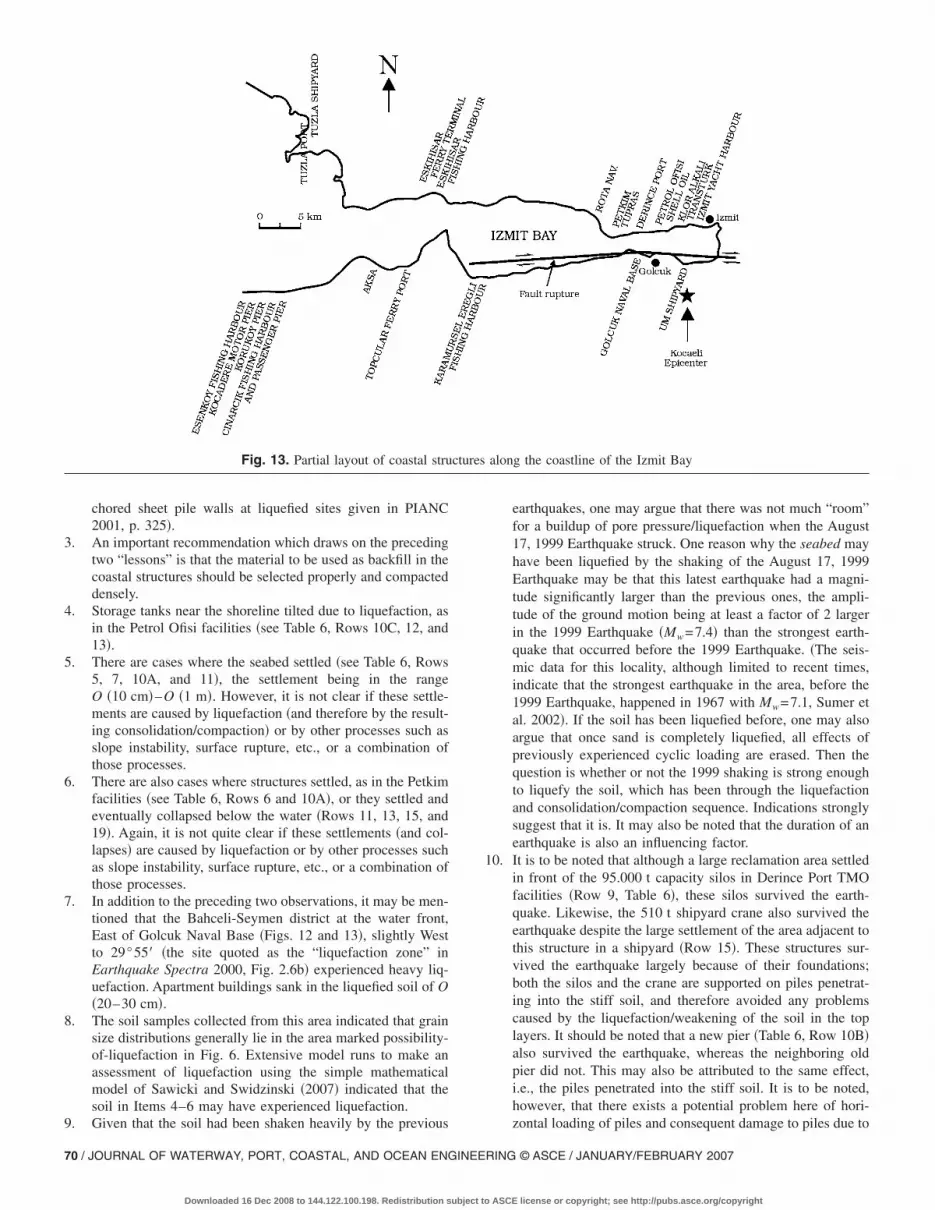
Table 6 presents a detailed inventory of the damage to marinestructures along the coastline of the Izmit Bay. The names of thestructures/facilities given in Column 2 in Table 6 are indicated inFig. 13. The following observations can be made from Table 6.1. Almost invariably, backfill areas behind quay walls and
sheet-piled structures failed due to liquefaction �see Table 6,Rows 1, 2C, 3A, 3B, 8A, 8B, 11, 14, 15, 16B, 17B, 18, 20,and 24B� although, in some cases, the failure in the backfillareas may have been influenced by other factors as well.From Table 6, the settlement in the backfill areas varies fromO �10 cm� to O �1 m�. The magnitude of the settlement gen-erally decreases with the distance from the epicenter of theearthquake �Table 6 and Fig. 13�, as anticipated. One of theimplications of this kind of failure is that rail foundations forcranes present in the area settle unevenly, leading to tilting of�and eventually damage to� cranes, as revealed clearly in thecase of Derince Port �Table 6, Rows 8A and 8B�. Althoughthe backfill material varied from one case to another, it wastypically hydraulically placed sand from the seabed. In thecase of Derince Port, Yuksel et al. �2003� report that �1� notmuch information could be obtained about the backfill mate-rial, but it was probably a kind of deltaic sediment, because ithad been dredged from a river mouth in the sea and �2�samples taken from liquefied sand were within the liquefiablegrain size limits �Yuksel et al. 2003, Fig. 12�. A relevantquestion here is: Could the liquefaction failure have beenavoided had the backfill material been replaced with acoarser material, a material which is sufficiently permeableso that all pore pressures developed in the backfill woulddissipate as rapidly as they develop? Unfortunately, data donot exist in conjunction with the August 17, 1999 Earthquaketo reveal whether this is the case, and, if so, how coarse thismaterial should be.
2. Quay walls and sheet-piled structures were displaced sea-ward �see Table 6, Rows 1, 2C, 8A, 14, and 16B�, the dis-placements being in the range from O �10 cm� to O �1 m��c.f. the ranges of displacement of gravity walls and an-
Fig. 12. Map of the area stricken by the August 17, 1999 Kocaeli,Turkey Earthquake
RING © ASCE / JANUARY/FEBRUARY 2007
ASCE license or copyright; see http://pubs.asce.org/copyright

Table 6. “Inventory” of the Damage to Coastal Structures Caused by Liquefaction in the August 17, 1999 Kocaeli, Turkey Earthquake
Name Structure Damage?
Damagecaused by
liquefaction? Comments Reference
Tuzla Port Block-type quay wallwith coarse limestonebackfill
Yes No? • Quay wall was displaced seaward byO �40 cm�.• Backfill settled by O �10 cm�. Nodirect evidence of liquefaction�i.e., no sand boils�.
Boulanger et al. �2000�
Tuzla Shipyard Rubble-moundbreakwater
No Gunbak et al. �2000�;Yuksel et al. �2000�
Block-typebreakwater
No
Block-type quay wall Yes Yes? • The backfill area settled byO �20 cm�.• Two rows of blocks between −1.7and −6 m depth moved seawardrelative to neighboring blocks byO �20 cm�.
Eskihisar FerryTerminal
Block-type quay wall Yes Yes? • The backfill area settled byO �1–2 cm�.
Gunbak et al. �2000�;Yuksel et al. �2000�
Sheet-piled structure Yes Yes? • A sink hole of O �20 m2� wasobserved behind the sheet piledstructure.
Gunbak et al. �2000�;Yuksel et al. �2000�
EskihisarFishing Harbor
Rubble-moundbreakwater
Very slight damage No? Gunbak et al. �2000�;Yuksel et al. �2000�
Block-type quay wall Very slight damage No?
Rota NavigationTrade Pier
Pier supported onsteel pipe piles
No • Diver inspection showedO �70 cm� settlement of theseabed. No settlement of/ damage tothe piles.
Gunbak et al. �2000�;Yuksel et al. �2000�
Petkim�YarimcaPetrochemicalComplex�
Pier supported onreinforced-concretepiles, and two loadingdolphins supported onreinforced concretepiles and two onsteel-pipe piles
Yes No? • Reinforced concrete piles weredamaged above the water surface.• The pier head experiencedO �5–10 cm� sinking relative to theaccess trestle. Further, lateralmovements of O �40 cm� were alsoexperienced.
Boulanger et al. �2000�;Sumer et al. �2002�
Tupras Refinery Pier supported onsteel pipe piles;the piles filled withconcrete
Yes No • Steel piles were buckled at/above thewater surface.• Ground deformations and crackingalong the shoreline were observed nearthe pier.• There were cracks around thejunction between the piles and thebeams in the cases when diagonalconcrete piles joined at the top.
Boulanger et al. �2000�;Gunbak et al. �2000�;Yuksel et al. �2003�
Derince Port Block-type quay wall�Berths 6–8�
Yes Yes • The quay walls were displacedtowards the sea byO �0.1–0.5 m�.• The backfill area settled byO �0.5–1 m�.• There were very clear indications ofliquefaction of the backfill area �andalso in and around two warehouseslocated in this area�, in the form ofsand boils. Sand volcanoes the sizeO �30 cm� were observed very clearly.
Boulanger et al. �2000�;Gunbak et al. �2000�;Yüksel et al. �2001�;Yuksel et al. �2003�;Sumer et al. �2002�
Quay wall withsteel-pile-supporteddeck and sheet-pilewall �Berths 3–5�
Yes Yes? • Minor damage at pile caps in somesmall number of piles.• The backfill area settled. No sandboils were observed, however.
JOURNAL OF WATERWAY, PORT, COASTAL, AND OCEAN ENGINEERING © ASCE / JANUARY/FEBRUARY 2007 / 67
Downloaded 16 Dec 2008 to 144.122.100.198. Redistribution subject to ASCE license or copyright; see http://pubs.asce.org/copyright

Table 6. �Continued.�
Name Structure Damage?
Damagecaused by
liquefaction? Comments Reference
Derince Port,TMO Silos
Pile-supported, large,95.000 t capacity silosnear the shoreline
Very minor Yes? • A large reclamation area in front ofthe silos settled �by O �1.5–3 m��.However, practically no damageoccurred to the silos except there is avery minor damage at the top of thecorner pile in the first row at theseaside.
Boulanger et al. �2000�;Sumer et al. �2002�
Petrol Ofisi Old pier: Piersupported onreinforced concretepiles, the piles beingalmost entirely in thesoft soil
Yes No? • The pier was tilted and displacedlaterally �away from the new one�, andone segment of the pier settled byO �7 cm�.• The sea bottom settled.• Divers reportedly did not feel safenear the sea bottom because thesediment appeared unstable.
Boulanger et al. �2000�;Gunbak et al. �2000�;Yuksel et al. �2003�
New pier: Piersupported onreinforced concretepiles for the first60 m, and onsteel-pipe piles for theouter 100 m,constructed near theold pier and parallelto it, the pilespenetrating into thestiff soil
Yes No? The new reinforced concrete pier wastilted and displaced away from theadjacent pier.
Tanks near theshoreline
Yes Yes? • One of the two tanks, full at the timeof the earthquake, tilted O �2–3% �.• Ground cracking and deformationswere visible in the fill between thetanks and the shoreline wall.
Shell Oil Piers Two piers supportedon steel-pipe piles;18 m by 12 mdolphin on steel piles;fill area of 5 m by57 m, encircled byreinforced concretesheet piles
Yes ? • The piers were extensively damagedand largely collapsed below water.• The fill area collapsed below water• The dolphin also collapsed belowwater.• A large rupture hole was observed inthe seabed at the tip of the pier; thishole was later filled with sediment dueto natural processes.
Boulanger et al. �2000�;Gunbak et al. �2000�;Yuksel et al. �2000�;Sumer et al. �2002�
Klor Alkali Pier supported onreinforced concretepiles
Yes Yes? • The pier largely collapsed belowwater.• Storage tanks near the shorelinetilted.
Yuksel et al. �2000�;Sumer et al. �2002�
Transturk Two piers supportedon steel-pipe piles
Yes ? • One of the piers largely collapsedbelow water.• The other pier remained intact.• One of the tanks closest to theshoreline was visibly tilted.
Boulanger et al. �2000�
Izmit YachtHarbor �PublicMarina�
Quay walls made upof 24 m long concretesegments supportedon four row of piles,the inner three rowsof piles beingreinforced concreteand the outer rowconsisting of closelyspacedconcrete-infilled steelpipe piles
Yes Yes? • The backfill area adjacent to theshoreline section settled by as much asO �80 cm� due to liquefaction.• One segment of the wall wasdisplaced towards the sea byO �10–30 cm�.• Separation between neighboringsegments of O �3–8 cm� wasobserved.• Piers extending perpendicular to thequay wall experienced a separation ofO �3 cm� at the wall ends.
Boulanger et al. �2000�;Gunbak et al. �2000�;Yuksel et al. �2000�;Sumer et al. �2002�
68 / JOURNAL OF WATERWAY, PORT, COASTAL, AND OCEAN ENGINEERING © ASCE / JANUARY/FEBRUARY 2007
Downloaded 16 Dec 2008 to 144.122.100.198. Redistribution subject to ASCE license or copyright; see http://pubs.asce.org/copyright

Table 6. �Continued.�
Name Structure Damage?
Damagecaused by
liquefaction? Comments Reference
UM Shipyard Pier supported onsteel pipe piles
Yes Yes? •The pier was completely damaged andcollapsed below water. According toeyewitnesses, the collapse was gradual,implying that the failure was likely dueto liquefaction, slope instability orboth.• The fill area containing part of theship yard on the shore settled over anarea of O �50 m� and disappeared intothe sea, the settlement being O �1 m�near the shoreline.• The 510 t shipyard crane survivedthe earthquake with minor damage.
Boulanger et al. �2000�;Gunbak et al. �2000�;Yuksel et al. �2000�;Sumer et al. �2002�
Golcuk NavalBase
Seven piers supportedon reinforced concretepiles
Yes ? • Extensive damage due to surfacerupture and ground failure, or acombination of both. Note that thefault rupture, involving as much as5.5 m right-lateral slip and 2.5 m localvertical displacements �EarthquakeSpectra 2000, Chap. 2�, ran throughthe Golcuk Naval Base, see Fig. 3.
Boulanger et al. �2000�;Yuksel et al. �2000�;Gunbak et al. �2000�
Sheet-piled quay wall Yes ? • Extensive seaward deformation of thesheet piling due to surface rupture andground failure.• The backfill settled by O �1 m�.
Dockyards Yes ? • Extensive damage due to surfacerupture and ground failure, or acombination of both.
KaramurselEregli FishingHarbor
Rubble-moundbreakwater
Very slight damage Yes • A differential movement between theneighboring wave screens of O�10 cm�.• The breakwater settled approximately1.5 m along its entire axis.
Gunbak et al. �2000�;Yuksel et al. �2004�
Block-type quay wall Yes Yes • Crack between the crown wall andbackfill of O �30 cm�.• The backfill area settled byO�25 cm�.
Topcular FerryPier
Two piers supportedon steel pipe piles
Yes Yes? • The fill area settled by O �15 cm�. Yuksel et al. �2000�;Gunbak et al. �2000�
Aksa Piers andDolphins
Two trestlessupported onreinforced concretepiles and six dolphinssupported on steelpipe piles
Yes ? • One trestle was displaced laterally byO �25 cm�.• The other trestle largely collapsedbelow water.• Four dolphins collapsed below water.
Yuksel et al. �2000�;Gunbak et al. �2000�
CinarcikFishing Harbor
Rubble-moundbreakwater
? • Crack of width O �30 cm� along thebreakwater crown wall near thebackfill area.• Concrete slabs in the backfill areawere separated �O �15–20 cm�� byswelling and sinking.
Yuksel et al. �2000�;Gunbak et al. �2000�
CinarcikPassenger Pier
Pier supported onsteel piles
No Yuksel et al. �2000�;Gunbak et al. �2000�
Korukoy Pier Pier supported onreinforced concretepiles
No Yuksel et al. �2000�;Gunbak et al. �2000�
Kocadere MotorPier
? No Yuksel et al. �2000�;Gunbak et al. �2000�
EsenkoyFishing Harbor
Rubble-moundbreakwater
Minor damage ? • Cracks along the crown wall Yuksel et al. �2000�;Gunbak et al. �2000�
Block-type quay walls Yes Yes? • The backfill settled by O �3 cm�
JOURNAL OF WATERWAY, PORT, COASTAL, AND OCEAN ENGINEERING © ASCE / JANUARY/FEBRUARY 2007 / 69
Downloaded 16 Dec 2008 to 144.122.100.198. Redistribution subject to ASCE license or copyright; see http://pubs.asce.org/copyright
chored sheet pile walls at liquefied sites given in PIANC2001, p. 325�.
3. An important recommendation which draws on the precedingtwo “lessons” is that the material to be used as backfill in thecoastal structures should be selected properly and compacteddensely.
4. Storage tanks near the shoreline tilted due to liquefaction, asin the Petrol Ofisi facilities �see Table 6, Rows 10C, 12, and13�.
5. There are cases where the seabed settled �see Table 6, Rows5, 7, 10A, and 11�, the settlement being in the rangeO �10 cm�–O �1 m�. However, it is not clear if these settle-ments are caused by liquefaction �and therefore by the result-ing consolidation/compaction� or by other processes such asslope instability, surface rupture, etc., or a combination ofthose processes.
6. There are also cases where structures settled, as in the Petkimfacilities �see Table 6, Rows 6 and 10A�, or they settled andeventually collapsed below the water �Rows 11, 13, 15, and19�. Again, it is not quite clear if these settlements �and col-lapses� are caused by liquefaction or by other processes suchas slope instability, surface rupture, etc., or a combination ofthose processes.
7. In addition to the preceding two observations, it may be men-tioned that the Bahceli-Seymen district at the water front,East of Golcuk Naval Base �Figs. 12 and 13�, slightly Westto 29°55� �the site quoted as the “liquefaction zone” inEarthquake Spectra 2000, Fig. 2.6b� experienced heavy liq-uefaction. Apartment buildings sank in the liquefied soil of O�20–30 cm�.
8. The soil samples collected from this area indicated that grainsize distributions generally lie in the area marked possibility-of-liquefaction in Fig. 6. Extensive model runs to make anassessment of liquefaction using the simple mathematicalmodel of Sawicki and Swidzinski �2007� indicated that thesoil in Items 4–6 may have experienced liquefaction.
Fig. 13. Partial layout of coastal stru
9. Given that the soil had been shaken heavily by the previous
70 / JOURNAL OF WATERWAY, PORT, COASTAL, AND OCEAN ENGINEE
Downloaded 16 Dec 2008 to 144.122.100.198. Redistribution subject to
earthquakes, one may argue that there was not much “room”for a buildup of pore pressure/liquefaction when the August17, 1999 Earthquake struck. One reason why the seabed mayhave been liquefied by the shaking of the August 17, 1999Earthquake may be that this latest earthquake had a magni-tude significantly larger than the previous ones, the ampli-tude of the ground motion being at least a factor of 2 largerin the 1999 Earthquake �Mw=7.4� than the strongest earth-quake that occurred before the 1999 Earthquake. �The seis-mic data for this locality, although limited to recent times,indicate that the strongest earthquake in the area, before the1999 Earthquake, happened in 1967 with Mw=7.1, Sumer etal. 2002�. If the soil has been liquefied before, one may alsoargue that once sand is completely liquefied, all effects ofpreviously experienced cyclic loading are erased. Then thequestion is whether or not the 1999 shaking is strong enoughto liquefy the soil, which has been through the liquefactionand consolidation/compaction sequence. Indications stronglysuggest that it is. It may also be noted that the duration of anearthquake is also an influencing factor.
10. It is to be noted that although a large reclamation area settledin front of the 95.000 t capacity silos in Derince Port TMOfacilities �Row 9, Table 6�, these silos survived the earth-quake. Likewise, the 510 t shipyard crane also survived theearthquake despite the large settlement of the area adjacent tothis structure in a shipyard �Row 15�. These structures sur-vived the earthquake largely because of their foundations;both the silos and the crane are supported on piles penetrat-ing into the stiff soil, and therefore avoided any problemscaused by the liquefaction/weakening of the soil in the toplayers. It should be noted that a new pier �Table 6, Row 10B�also survived the earthquake, whereas the neighboring oldpier did not. This may also be attributed to the same effect,i.e., the piles penetrated into the stiff soil. It is to be noted,however, that there exists a potential problem here of hori-
along the coastline of the Izmit Bay
ctureszontal loading of piles and consequent damage to piles due to
RING © ASCE / JANUARY/FEBRUARY 2007
ASCE license or copyright; see http://pubs.asce.org/copyright

the liquefaction of layers between the stiff soil and the pilehead.
11. The rubble-mound breakwaters in the area largely survivedthe earthquake �see Table 6, Rows 2A, 4A, 20, and 24�. Noinformation is available as to whether these breakwaters arefounded on sand or otherwise. This is with the exception thatthe Eskihisar breakwater �Table 6, Row 4A� is founded onsandy coarse gravel, not prone to liquefaction, as the soilinformation from the neighboring structures point to thisdirection.
12. However, some damage occurred to the rubble-mound break-water in the Karamursel Eregli Fishing Harbor �Row 17A�.The damage was mostly in the form of flattening of the crosssection, sliding of the slope, and intrusion of the lowermound material into the loose sand �Yuksel et al. 2004�. Yuk-sel et al. report that the breakwater settled approximately1.5 m along its entire axis. Their analysis to assess the im-pact of the earthquake on the structure �using a dynamicfinite difference model� showed that liquefaction/consolidation caused 1.2 m total settlement, largely in agree-ment with the observed settlement. Soil profile at the break-water location contains medium-fine sand overlying stiff-hard silty clay. It was observed that, with these structures acrack of few centimeters exist along the crest or slightly backat the fill area. This crack may demonstrate an initiation of aslip circle which terminates by an increase of friction imme-diately after initiation.
13. As seen, liquefaction caused significant problems for otherstructural components of ports, such as breakwaters, cranes,container terminals, and warehouses. For this reason specialcaution must be taken if the natural ground contains liquefi-able soil, sand, and silt. The data relevant to geology,geomorphology, and seismology should be collected and ex-amined with regard to liquefaction. To prevent serious dam-age, soil improvement techniques should be applied before
Fig. 14. Liquefaction-induced lateral spreading cases after the 1999 KPark; �b� Soccer Field �Source: �http://peer.berkeley.edu/turkey/adapa
construction.
JOURNAL OF WATERWAY, PORT, COASTAL, AND
Downloaded 16 Dec 2008 to 144.122.100.198. Redistribution subject to
Assessment of Liquefaction-Induced Lateral GroundDeformations
Introduction
Over the past decade, major advances have occurred in both un-derstanding and practice with regard to engineering treatment ofseismic soil liquefaction. Initially, this progress was largely con-fined to improved ability to assess the likelihood of initiation �or“triggering”� of liquefaction in soils. As the years passed, andearthquakes continued to provide lessons and data, researchersand practitioners became increasingly aware of the issue ofpostliquefaction strength, and stress-deformation behavior alsobegan to attract increased attention. Within the confines of thissection it was intended to present a brief discussion on existingpredictive methods for the assessment of postliquefaction grounddeformation problems, more specifically of lateral ground spread-ing problem.
When soil liquefaction is accompanied by different forms ofground deformation, then the consequences are destructive to thesurrounding environment. During an earthquake shaking, when asubsurface soil sublayer liquefies, the intact surface soil blockswill move down to a gentle slope and/or toward a vertical freeface. Therefore, due to soil liquefaction during past earthquakeevents, large areas and masses of soils were observed to havemoved and shifted laterally to new positions, resulting in signifi-cant destructive effects for both infrastructures and the overlyingsurface constructions. Fig. 14, taken by Izmit Bay after the 1999Kocaeli Earthquake, presents vivid examples of liquefaction-induced lateral spread. The magnitudes of these liquefaction-induced lateral spreads range from a few centimeters to more thancouple of meters. Fig. 15 illustrates a schematic diagram to de-scribe a seismic soil liquefaction-induced lateral spread during anearthquake event, and the associated critical consequences. When
i �Izmit�-Turkey within the Izmit Bay area, from the sites of: �a� Bay
ocaelzari��a liquefiable soil sub-layer exists as an underlying stratum, the
OCEAN ENGINEERING © ASCE / JANUARY/FEBRUARY 2007 / 71
ASCE license or copyright; see http://pubs.asce.org/copyright

overlying soil may slide during an earthquake shaking; eventhough the ground surface is level or gently sloping with coupleof degrees.
Existing Lateral Spread Predictive Models
Several different approaches for predicting the lateral grounddeformation magnitudes have been introduced, and from the tech-nical point of view, they can be categorized as: �1� numericalanalyses in the form of finite-element and/or finite-differencetechniques �e.g., Finn et al. 1994; Arulanandan et al. 2000; Liaoet al. 2002�; �2� soft computing techniques �e.g., Wang and Rah-man 1999�; �3� simplified analytical methods �e.g., Newmark1965; Towhata et al. 1992; Kokusho and Fujita 2002�; and �4�empirical methods developed based on the assessment of eitherlaboratory test data or statistical analyses of lateral spreading casehistories �e.g., Hamada et al. 1986; Shamoto et al. 1998; Youd etal. 2002�. Due to their simplicity and ease of use, empirical/semiempirical and laboratory based methods have been widelyused and will be the scope of this section. A discussion of cur-
Fig. 15. Schematic examples of liquefaction-induced global site insta
rently available empirical/semiempirical models �Hamada et al.
72 / JOURNAL OF WATERWAY, PORT, COASTAL, AND OCEAN ENGINEE
Downloaded 16 Dec 2008 to 144.122.100.198. Redistribution subject to
1986; Rauch 1997; Youd et al. 2002�, and of laboratory basedmethods �Ishihara and Yoshimine, 1992; Shamoto et al. 1998�will be presented next.
Empirical or Semiempirical Models
A number of researchers proposed empirical predictive methods,based on regression analyses of large suites of previous lateralspreading case histories. The simplest of all these models wasproposed as part of the pioneer studies by Hamada et al. �1986�.In his model, the magnitude of horizontal ground deformations ata site composed of potentially liquefiable layers is predicted onlyin terms of slope and thickness of the liquefied layers
D = 0.75H0.75�0.33 �6�
where D�horizontal displacement �m�; ��slope �%� of groundsurface or the base of the liquefied soil; and H�total thickness�m� of the liquefied layers.
In another study, Rauch �1997� followed a different methodol-
and/or large displacement horizontal deformations �Seed et al. 2003�
bilityogy where liquefaction-induced ground deformations were mod-
RING © ASCE / JANUARY/FEBRUARY 2007
ASCE license or copyright; see http://pubs.asce.org/copyright

eled as slides of finite area rather than displacement points wheredisplacement vectors were mapped. Multiple-linear-regressionwas used as the tool to estimate model parameters. As a conclu-sion, an empirical model was proposed for the estimation ofliquefaction-induced lateral ground displacements
DR = �613Mw − 13.9Rf − 2,420Amax − 11.4Td�/1,000 �7�
DS = �50.6ZFSmin − 86.1Zliq�/1,000 �8�
DG = �DR − 2.21�2 + 0.149 �9�
D = �DR + DS + DG − 2.44�2 + 0.124 �10�
where D�average horizontal displacement �m�; Rf�shortest hori-zontal distance �km� to fault rupture; Mw�moment magnitude ofthe earthquake; Amax�peak horizontal soil acceleration �g� at theground surface; Td�duration �s� of strong earthquake motions�0.05 g�; Lslide�length �m� of slide area from head to toe;Stop�average slope �%� across the surface of lateral spread;ZFSmin�average depth �m� from ground surface to the top of thesoil layer with a minimum factor of safety against liquefaction;and Zliq�average depth �m� from ground surface to top liquefiedlayer.
Similarly, starting in the early 1990s Bartlett and Youd �1992,1995� introduced empirical methods for predicting lateral spreaddisplacements at liquefiable sites. The procedure of Youd et al.�2002� is a refinement of these early efforts and the new andimproved predictive models for either �1� sloping ground condi-tions or �2� relatively level ground conditions with a “free face”toward which lateral displacements may occur, were developedthrough multilinear regression of a large case history database.The proposed predictive models for the sloping ground and freeface conditions are given in the following equations along withtopography related descriptive variables given in Fig. 16:
log DH = − 16.213 + 1.532M − 1.406 log R* − 0.012R
+ 0.338 log S + 0.540 log T15 + 3.413 log�100 − F15�
− 0.795 log�D5015 + 0.1 mm� �11�
log DH = − 16.713 + 1.532M − 1.406 log R* − 0.012R
+ 0.592 log W + 0.540 log T15 + 3.413 log�100 − F15�
− 0.795 log�D5015 + 0.1 mm� �11�
where DH�horizontal ground displacement in meters predictedby multiple linear regression model; M�earthquake magnitude�Mw was primarily used whenever reported�; R�horizontal dis-tance to the nearest seismic source or to nearest fault rupture�km�; R*=R+R0, and R0=10�0.89M−5.64�; S�gradient of surface to-
Fig. 16. Topography-related descriptive variables
pography or ground slope �%�; W�free-face ratio, defined as the
JOURNAL OF WATERWAY, PORT, COASTAL, AND
Downloaded 16 Dec 2008 to 144.122.100.198. Redistribution subject to
height of the free face divided by its distance to calculation point;T15�thickness of saturated layers with �N1�6015; F15�averagefines content �particles �0.075 mm� in T15 �%�; andD5015�average D50 in T15.
Laboratory-Based ModelsLaboratory-based predictive models require the estimation of in-duced cyclic shear strains which will be further used to estimatecontribution of each potentially liquefiable layer to the overalllateral ground deformation. Employing high quality cyclic test�triaxial, simple shear, or torsional shear test� results, Tokimatsuand Seed �1984�, Ishihara and Yoshimine �1992�, and Shamoto etal. �1998� proposed charts for the estimation of shear strains forcohesionless soils under cyclic loading. Different definitions ofcyclic shear strain were adopted by these researchers. Tokimatsuand Seed �1984� use limiting shear strain, �l, defined as the strainlevel that commence following liquefaction but is arrested after afinite displacement, usually as a consequence of dilatancy causedpore pressure drop and accompanying increase of effective stress.These deformations are accompanied by transient loss of shearresistance rather than permanent loss of shear strength. Shamotoet al. �1998� adopted residual �permanent� shear strain definitionas opposed to Ishihara and Yoshimine’s �1992� maximum shearstrain definition. As shown in Figs. 17 and 18�a–c�, for both Toki-matsu and Seed �1984� and Shamoto et al. �1998�, the capacityand demand terms of shear strain predictive models were chosenas corrected/adjusted standard penetration test blow counts, Na,fines content and CSR �or shear stress ratio defined as the ratio ofuniform cyclic shear stress, � to vertical effective stress, ��� cor-rected for effective stress conditions, in situ static shear stresses,and duration of earthquake. However, Ishihara and Yoshimine�1992�, still using corrected standard penetration test blow counts�N1� as the capacity term, preferred factor of safety, FSL, as thedemand term and proposed Fig. 19 for the estimation of
Fig. 17. Limiting shear strain potential chart �adapted fromTokimatsu and Seed �1984��
liquefaction-induced maximum shear strains ��max�. In Fig. 19, Dr
OCEAN ENGINEERING © ASCE / JANUARY/FEBRUARY 2007 / 73
ASCE license or copyright; see http://pubs.asce.org/copyright

denotes relative density, qct and �v denote cone tip resistance andvolumetric strain, respectively. Employing these laboratory basedestimates of liquefaction-induced limiting shear strains coupledwith an empirical adjustment factor to relate these laboratory val-ues to observed field behavior. Shamoto et al. �1998� proposed anew predictive approach for the estimation of liquefaction-induced ground deformations. After having determined residualshear strain potential through available methods of Tokimatsu andSeed �1984�, or Ishihara and Yoshimine �1992�, or Shamoto et al.�1998�, liquefaction-induced lateral ground deformations can beevaluated by simply multiplying these values by the thickness ofthe soil substrata of potentially liquefiable. As proposed by Sha-moto et al. �1998�, the summation of these lateral deformationvalues are further multiplied by an empirical factor of 1.0 or 0.16in order to predict lateral displacements at the sites with or with-
Fig. 18. Residual shear strain potential
out free face ground conditions, respectively.
74 / JOURNAL OF WATERWAY, PORT, COASTAL, AND OCEAN ENGINEE
Downloaded 16 Dec 2008 to 144.122.100.198. Redistribution subject to
Final Remarks
Due to either difficulties �uncertainties� in estimating model inputparameters �i.e., estimating the representative CSR, factor ofsafety against liquefaction, representative standard penetrationblow counts, and fines content in the critical strata, etc.� orpredictive model inaccuracies, or both �these currently availablepredictive models, best of their kind, may occasionally producelateral ground deformation predictions that are off by a factor ofmore than 3 �e.g., Cetin et al., 2004��. This is also illustrated byFig. 20. Thus, these models, before widely accepted as reliableengineering tools, need to be further calibrated and improved. Asa conclusion, their predictions, especially in the range of small tomoderately significant lateral ground deformations �lateral dis-placements of approximately 0.1–2.5 m� should be interpreted as
�adapted from Shamoto et al. �1998��
chartsan order of magnitude guidance rather than the results of reliable
RING © ASCE / JANUARY/FEBRUARY 2007
ASCE license or copyright; see http://pubs.asce.org/copyright

and well-calibrated engineering tools and for the projects ofhigher relative importance, higher order tools including numericalsimulations calibrated with observations from documented casehistories, should be preferred for more reliable assessments.
Tsunamis and Their Impacts
Introduction
It is known that tsunami attacks cause erosion and scour on shore-lines and at structures. A recent laboratory study �Tonkin et al.2003� on scour around piles exposed to a tsunami wave showedthat very rapid, transient scour at the back of the pile during thedrawdown stage of the tsunami is, for the most part, governed bythe upward directed pore-pressure gradients, causing a substantialreduction in the effective stress in the soil and therefore enhancedscour. It is reported in the latter publication that, although tran-sient, this brief but very rapid scour creates the deepest scourholes. This effect was also mentioned by Sumer et al. �2002� in aprevious publication in conjunction with the Turkey KocaeliEarthquake.
Although scour around marine structures has been studiedquite extensively in the past �Sumer and Fredsøe 2002�, this tran-sient scour caused by tsunami waves has been brought into lightonly recently. The mechanism in which the effective stress in thesoil is reduced resembles the mechanism of the so-called momen-tary liquefaction under waves �Sumer and Fredsøe 2002, Chap.
Fig. 19. Chart for determination of postliquefaction volumetric strainas a function of factor of safety �adapted from Ishiara and Yoshmine1992�
10�. �These pressure gradients are generated during the drawdown
JOURNAL OF WATERWAY, PORT, COASTAL, AND
Downloaded 16 Dec 2008 to 144.122.100.198. Redistribution subject to
stage in the case of the tsunami, whereas they are generated dur-ing the passage of the wave trough in the case of the momentaryliquefaction.�
As the scour hole caused by this effect is deepest, tsunami-generated scour should be a design consideration for structuressuch as bridge piers, piles, piers, etc., in coastal areas. In general,it is difficult to identify tsunami-induced liquefaction in field sur-veys, as flooding from subsequent waves often erases the lique-faction signature. It is thus harder to differentiate liquefactionscour from the effects of the tsunami hydrodynamic forcesthemselves.
Another tsunami related process concerns forces on quay wallsand sheet-piled structures. Referring to the tsunami experiencedin the Izmit Bay triggered by the Turkey Kocaeli Earthquake,Yalciner et al. �2000� reported that the sea first receded and sub-sequently rose and flooded the in-land areas. As mentioned earlierin conjunction with the Turkey Kocaeli Earthquake, backfill areasbehind quay walls and sheet-piled structures on the shorelinefailed due to liquefaction. With regard to forces on quay walls andsheet-piled structures, Sumer et al. �2002� commented that, withthe water receded during the tsunami immediately after the earth-quake, hydrostatic forces on quay walls at the water sidedecreased �or completely vanished�, and therefore quay walls un-derwent relatively larger, seaward resultant pressure forces �com-prising the hydrostatic pressure force and the pressure force dueto the accumulated excess pore pressure in the liquefied backfillsoil�. Sumer et al. �2002� pointed out that this effect may haveplayed a significant role in the seaward displacement of quaywalls and sheet-piled structures, reported to be in the rangeO �10 cm�–O �1 m� �see the section entitled “Turkey KocaeliEarthquake and Liquefaction Damage on Marine Structures”�.Clearly, worst-case design scenarios in which the quay walls andsheet-piled structures are subject to maximum forces when thebackfill soil is liquefied should accommodate tsunami attacks,particularly at the stage where the water recedes.
Fig. 20. Comparisons of the predicted and measured lateral spreadvalues Bartlett and Youd �1995�
Tsunamis are clearly a colossal threat to coastal structures not
OCEAN ENGINEERING © ASCE / JANUARY/FEBRUARY 2007 / 75
ASCE license or copyright; see http://pubs.asce.org/copyright

only due to the sheer size of the forces that they generate but alsodue to the previously mentioned processes, which involve soil/structure/wave interaction. For this reason, and because no guide-lines currently exist relating flow characteristics to structure per-formance, a short account of tsunamis and their impacts isincluded in the present paper, giving a state-of-the-art review.
Tsunamis are water waves generated by large-scale short-duration energy transfer to the entire water column by earth-quakes, coastal and submarine landslides, volcanic eruptions,caldera collapse, or meteor impact. The number of waves andpolarity of the initial wave depend on the seafloor motion, and thesubsequent evolution over the seafloor terrain is in the classicmanner predicted by long wave theory �Synolakis 2003�.
Tsunamis and landslide waves may attain large amplitudes inclosed basins or shallow regions �Yalciner et al. 2001; 2002;2004; and 2005�. They are generally classified as long periodwaves and now all are referred to as tsunamis. Tsunamis have firstbeen described in history 2500 years ago by Thucydides, Hero-dotus, Aristotle, and later Strabo �Schonberg 1997�. Thucydides�1972� in the History of the Peloponnesian War explained therelation between earthquakes, great waves, and topography, ob-serving the frequent earthquakes and a tsunami in 426 B.C. Hedescribed the action of the sea as it “subsided from what was thenthe shore and afterwards swept up again in a huge wave” �Thucy-dides 247; 3.89�. More modern observations and analysis confirmthe persistence of leading depression tsunami waves. �Tadepalliand Synolakis 1996�. A leading depression wave may drop theshoreline mean water level �MWL� rapidly, thus creating lique-faction potential.
The word “tsunami” appears to have been communicated out-side Japan in the aftermath of the 1896 Great Meiji Tsunamiwhich claimed 22,000 people. It translates into harbor wave, quitepossible because the more common occurrences of tsunamis inJapan had been as unusual waves in small bays and ports. TheEnglish term tidal wave is a translation of the Greek terminology,and it reflects that in the Aegean Sea, tsunamis often manifestthemselves along the coast as surges or rapid changes in the waterlevel.
Landslide generated waves generally have only nearfield im-pact. They are of a shorter wavelength than tectonic tsunamis, andtheir initial amplitude depends on the depth, thickness, and initialacceleration of the triggering slide. The amplitude of tectonic tsu-namis depends on the length of fault rupture and the slip. Gener-ally tectonic tsunamis radiate energy in a direction perpendicularto the length of the triggering fault �Ben-Menahem and Rosenman1972�, whereas landslide tsunamis radiate energy in a radial fash-ion. The runup distribution on adjacent shorelines is so differentbetween landslide waves and tsunamis that it allows discrimina-tion of the source �Okal and Synolakis 2004�.
The current paradigm is to model tsunamis with the nonlinearshallow water �NSW� equations �Synolakis et al. 1997; Synolakis2003�. Different numerical solution methods of these equationsexist �Yeh et al. 1996�. The current state of the art for somemodels such as MOST �Titov and Synolakis 1998� allows for realtime tsunami inundation forecasting by incorporating real-timedata from tsunameters. MOST, TUNAMI-N2, and COMCOT cal-culate tsunami inundation by computing the wave evolution ondry land and have been validated by comparing their results withexact analytical solutions and laboratory measurements, and re-sults from field surveys. The model MOST is used most often inthe United States for developing inundation maps �Borrero et al.2003�. TUNAMI N2 was originally authored by Imamura �1988�,
Imamura and Goto �1988�, and Imamura and Shuto �1989�, for76 / JOURNAL OF WATERWAY, PORT, COASTAL, AND OCEAN ENGINEE
Downloaded 16 Dec 2008 to 144.122.100.198. Redistribution subject to
the Tsunami Inundation Modeling Exchange Program �Goto et al.1997; Shuto et al. 1990�. It is a registered copyright of ProfessorImamura, Professor Yalciner, and Professor Synolakis and hasbeen applied to several tsunami events �Imamura 1996; Yalcineret al. 2000, 2001, 2002, 2004; Zahibo et al. 2003� and also forcomputation of resonant oscillations of basins for understandingthe indirect effects of tsunamis.
Direct Effects of Tsunamis on Coastal Structures
As tsunamis approach coastlines or enter bays, they initiallyevolve in the classic manner predicted by linear long wave theory�Synolakis and Skjelbreia 1993�. Close to shore, nonlinear effectsoften become important, as the height increases and wavelengthdecreases. If breaking occurs, bores often result as first docu-mented in the 1960 Chilean Tsunami impact in Hilo, Hawaii, oras seen in the tens of amateur video clips from the beaches ofThailand, following the December 26, 2004 mega tsunami. Be-cause the offshore wavelength of tsunamis can be tens of kilome-ters, the resulting bores can penetrate a few kilometers inland.
Direct effects of tsunamis on coastal and marine structures canbe extensive and often disastrous. Tsunami waves can �1� moveentire structures off their foundations and carry them inland; �2�damage buildings through impact with vessels carried from off-shore and other debris accumulated as the wave advances inland;�3� undercut foundations and pilings with erosion caused by re-ceding waves; �4� overturn structures by suction of receding orthrust of advancing waves; and �5� cause the impact of large shipswith docks during oil or cargo transfer operations, often causingfires. The damage can be quite unexpected. During the 1998Hokkaido-Nansei-Oki Tsunami, Aonae in Okushiri was consumedby fires triggered after the waves subsided.
In terms of economic impact, Borrero et al. �2005� report thatthe losses resulting from a landslide in the San Pedro Escarpmentin California triggering a tsunami and impacting the ports of LosAngeles and Long Beach will range from $7 to $42 billion, inaddition to the losses due to structural damage.
Impact forces can cause collapse of coastal structures. Theestimation of impact forces and currents is still an art, and far lessunderstood than hydrodynamic evolution and inundation compu-tations. Existing analyses only extend to suggesting methods forcalculating forces on piles, impact forces on seawalls and struc-tures, with provisions available for breaking wave loads. Nomethods exist for calculating debris impact, beyond the sugges-tions provided in the Coastal Construction Manual, which werederived from results from steady flows. A comprehensive discus-sion may be found in Synolakis �2003�.
There are no existing guidelines for erosion due to tsunamis,although a large amount of data on the erosion and depositionduring a tsunami attack have been accumulated �Gelfenbaum andJaffe 2003�, they have yet to be translated into standards andguidelines for engineered structures. Although there are a largenumber of studies of scour around cylindrical piers, for steadyflows and combinations of steady flows and waves �Sumer andFredsøe 2002�, only Tonkin et al. �2003� describe a laboratoryexperiment with erosion from a solitary wave �simulating atsunami� attacking a circular cylinder �see the discussion in thebeginning of this section�. One of the results they obtained con-cluded that the time scale of the tsunami attack is critical in thescouring process. Another interesting result from the study is thatthe upward directed pore-pressure gradient in their laboratory test
reached as much as 0.5, and the pore-pressure gradient requiredRING © ASCE / JANUARY/FEBRUARY 2007
ASCE license or copyright; see http://pubs.asce.org/copyright

for full liquefaction was approximately 0.9, indicating a consid-erable reduction in the effective stress, as mentioned in the pre-ceding paragraphs.
Indirect Effects of Earthquakes and Tsunamis—Resonant Oscillations in Enclosed Basins
Tsunamis may cause resonant oscillations in lakes, basins, andharbors, as tsunami periods are often in the range of resonantfrequencies of large, closed, or semienclosed water bodies. Theprocess is also referred to as sloshing or seiching. Even smalltsunamis can trigger resonance and can cause damage. Resonancecan also be triggered directly by the earthquake shaking, as ob-served during the 1994 Northridge Earthquake in the Los AngelesReservoir in Northridge, Calif. Further, seiching may persist forseveral hours after the tsunami’s arrival and continue loading cy-clically foundations already weakened by the tsunami. Therefore,seiching needs to be investigated when evaluating liquefactionpotential.
The problem of sloshing is a classical problem of hydrody-namics and was first described in the context of moving atmo-spheric fronts in Lac Leman in the 19th century �Wilson 1972�.Raichlen �1966� described the problem of harbor resonance andpresented a simple analytical method for calculating harboroscillations.
Most modern harbors have individual interconnected basinsand are protected by attached or detached breakwaters. Althoughelegant semianalytic methods exist �Lee 1969� to calculate ampli-fication, complex boundaries, and variable depth often requiremore sophisticated approaches. Lepelletier and Raichlen �1987�introduced a finite-element solution of a nonlinear-dispersive-dissipative model and compared their predictions to laboratorymeasurements from a narrow constant depth rectangular harborand a sloping harbor with excellent results, even for transientwaves. Zelt and Raichlen �1990� used a Lagrangian formulationto solve a two-dimensional Boussinesq-type model and calculatedthe evolution of a solitary waves in a parabolic bay.
It is now standard practice to combine the effects of diffractionand refraction and use the mild slope equation �MSE�, a linear,steady-state, depth-averaged elliptic partial differential equation,which however, assumes that changes in topography are smallwithin one wavelength. The equation has been rederived byBerkhoff �1972� and most recently solved by Tsay and Liu�1983�, Mei �1989�, Chen and Huston �1987�. As written byDemirbilek and Panchang �1998� it is
��CCS� � + �Cs/C��2 = 0 �13�
C=� /k�phase velocity; Cs=�� /�k�group velocity; ��diver-
Fig. 21. A segment of time history of water surface fluctuation at apoint inside the enclosed square flat basin �5,013.3 m dimension and100 m deep� agitated by a single sinusoidal wave of 1 m amplitudeand 10 s period
gence operator; ��frequency; k�wave number; and �wave
JOURNAL OF WATERWAY, PORT, COASTAL, AND
Downloaded 16 Dec 2008 to 144.122.100.198. Redistribution subject to
amplitude. The MSE is not easy to solve numerically, as its solu-tion spectrum covers waves of arbitrary wavelength. In thecontext of tsunami impact studies, it is impractical to extractwaveforms at the entrance of a harbor/basin to initiate solution ofthe MSE, as the MSE formulation is steady state. Tsunami impactis transient, and although the Lepelletier and Raichlen �1987� for-mulation is still the “gold” standard, it is too computationallyintense for real time use. Thus, one interesting problem is whetherthe shallow water �SW� equations can model adequate harborresonance for tsunami attacks, as presumably the forcing consistsof long waves.
Yalciner et al. �1996� solved the classic problem of a closedbasin and compared the periods of free oscillations with theoret-ical values. The periods of free oscillations �Tn� inside a closedbasin with vertical, solid, smooth, and impermeable boundariescan theoretically be determined as T=2l / �n��gh�, wherel�length in the direction of the wave; d�water depth of thebasin; and n�integer. Yalciner et al. �1996� used a 5,013.33 msquare-shaped and 100 m deep closed test basin and forced itwith a by 1 m amplitude, 10 s period of single sinusoid, to deter-mine its impulse response, hence the natural frequencies �seeFig. 21�.
Table 7 compares theoretical predictions for the resonantfrequencies with the NSW numerical results for different modesinside the rectangular test basin. NSW identifies the resonant fre-quencies within 1–3%, at a small computational cost. Furthercomparisons of NSW predictions of resonant frequencies for thePorts of Los Angeles and Long Beach agree with the classic re-sults of Lee �1969� within 3% and the variance may also be due todifferences in bathymetric resolution. Comparisons with predic-
Table 7. Comparison of Numerically Determined Periods of FreeOscillations �s� with the Theoretical Values for an Enclosed Square�5,013 m Side Length� Flat �100 m Deep� Basin
Theoretical Numerical
1 320.13 312.08
2 160.06 156.04
3 106.71 105.70
4 80.03 78.96
10 32.01 31.81
20 16.01 15.98
30 10.67 10.76
Fig. 22. Initial condition used to excite Izmit bay for computingresonant oscillations; the points indicate monitoring locations fordetermining resonant frequencies
OCEAN ENGINEERING © ASCE / JANUARY/FEBRUARY 2007 / 77
ASCE license or copyright; see http://pubs.asce.org/copyright

tions from CGWAVE �Demirbilek and Pachang 1998� suggestthat the NSW model can calculate amplification factors within10–20% of the results of CGWAVE. This is perplexing, yet so isthe almost ubiquitous ability of NSW theory to adequately modeltsunami evolution problems. Although our results do not implythat the NSW model can, in general, adequately model amplifi-cation factors, for liquefaction analysis what is needed is the de-termination of whether resonant excitation may occur.
We conjecture that this methodology can be extended to largerwater bodies, where presumably NSW may be more appropriateand study the periods of free oscillations of Izmit Bay, severelyimpacted by the Izmit Tsunami in the 1999 Turkey Kocaeli Earth-quake. For computing the periods of resonant oscillations of Izmitbay, we agitated it separately in two normal directions by twodifferent N-wave initial impulses as shown in Fig. 22. Resonantperiods were obtained by identifying spectral peaks in the timehistories of water surface fluctuations at multiple coastal loca-tions. Results indicate that the resonant periods in north-southdirection have periods ranging from 5.75 to 3.03 min. In the east-west direction the periods range from 16.39 to 3.03 min. Tsuna-mis with energy at these periods or in the other resonance periodsmay cause seiching, which would impact coastal structures inaddition to any direct effects from the causative earthquake andtsunami.
In summary, when evaluating liquefaction potential, it is rec-ommended that the objective be to determine resonance periodsand the amplification at resonance. The most likely impact is theinterruption of oil or cargo transfer operations, and the damage towharfs and docks from impact with vessels. Impact forces can becalculated as needed from the previous section.
Final Remarks and Guidelines for Protecting CoastalStructures
As preliminary survey results from the December 26, 2004Megatsunami suggest �Synolakis et al. 2005; Dalrymple and Krie-bel 2005�, simple mitigation measures can work, and protectingstructures from tsunami attacks and associated cotsunami effects,such as liquefaction, is not as complex as protecting high-risebuildings from aircrafts used as missiles.
As no guidelines currently exist that relate earthquake or shak-ing measures to flooding parameters, liquefaction potential mustbe undertaken in the context of comprehensive inundation studies.Specific tasks for preparedness and mitigation studies for marineterminals and other harbor facilities are the following:1. Identification of offshore hazards, such as submarine land-
slide sources and submarine faults. In many areas around theworld, offshore hazards remain unmapped. For example, inCalifornia, only approximately 50% of the coastline ismapped at resolution to permit hazard evaluation, but for theother regions in the world it is much less.
2. Recurrence interval estimates by increasing the coverage andquality of the historic and prehistoric tsunami information.Analysis of near field and far field sources and estimation ofcredible probabilities for the events.
3. Inundation maps reflecting specific scenarios for evacuationplanning and for emergency port operations are necessary.Thus, inundation modeling to evaluate the consequences ofthe generated tsunamis for relevant geologic sources for thelocalities must also be performed.
4. Determination of 100- and 500-year recurrences for specificflow depths. The choice of 100- and 500-year intervals is
guided by how existing flood hazard maps are produced,78 / JOURNAL OF WATERWAY, PORT, COASTAL, AND OCEAN ENGINEE
Downloaded 16 Dec 2008 to 144.122.100.198. Redistribution subject to
much as the existing maps do not include tsunami hazards.The same intervals would permit easier evaluation of relativeflooding hazards. Also, insurance companies generally evalu-ate actuarian flooding risk on 100- and 500-year intervals.
5. Evaluation of the strength of critical coastal structures withtsunami force estimates, using wave heights, inundationdepths, and currents identified by the detailed numerical in-undation modeling per the previous discussion.
6. Evaluation of harbor response to determine whether a sce-nario tsunami could trigger seiching.
Conclusions
1. Earthquakes may be a threat to stability and integrity of ma-rine structures due to soil liquefaction.
2. Special caution must be exercised if the natural ground con-tains liquefiable soil, sand, and silt. To identify whether thesoil is liquefiable or not, methods described in the existingcodes should be implemented �see the sections entitled“Review of the Existing Codes/Guidelines with SpecialReference to Marine Structures” and “Japanese Experienceof Earthquake-Induced Liquefaction Damage on MarineStructures”�.
3. If there is a potential of liquefaction of the soil, soilimprovement/remediation techniques should be applied be-fore construction to prevent serious damage �see the sectionentitled “Japanese Experience of Earthquake-Induced Lique-faction Damage on Marine Structures”�.
4. Recommendations, which draw on lessons learned from therecent earthquakes, are useful guidelines in the design of“liquefaction-resistance” marine structures �see the sectionsentitled “Japanese Experience of Earthquake-Induced Lique-faction Damage on Marine Structures” and “The Turkey Ko-caeli Earthquake and Liquefaction Damage on MarineStructures”�.
5. The present state-of-the-art lateral spreading indicates thatthere exists predictive models through which lateral grounddeformation may be assessed. However, these models mayproduce predictions off by a factor of 3 or more. For projectsof larger relative importance, higher order tools includingnumerical simulations �calibrated with observations fromdocumented case histories� should be preferred for more re-liable assessments �see the section entitled “Assessment ofLiquefaction-Induced Lateral Ground Deformations”�.
6. Tsunamis may be a large threat to coastal structures due tosoil-wave-structure interaction. Two examples are: �1� en-hanced erosion and scour during the drawdown stage of thetsunami where the soil strength is reduced by the reductionof the effective stresses; and �2� pressure forces on quaywalls exerted by the liquefied backfill soil. This force is larg-est during the stage where the water recedes. In both cases,tsunamis should be modeled/calculated �see the section en-titled “Tsunamis and Their Impacts”� to make assessments ofthe impact of the tsunamis with regard to the previouslymentioned design conditions.
7. The present state-of-the-art new techniques in modeling toolsprovides satisfactory estimation for the level of tsunami ef-fects near the selected localities �see the section entitled
“Tsunamis and Their Impacts”�.RING © ASCE / JANUARY/FEBRUARY 2007
ASCE license or copyright; see http://pubs.asce.org/copyright

Acknowledgments
This study has been partially funded by the European Commis-sion Research Directorates’ FP5 specific program ”Energy, Envi-ronment, and Sustainable Development,” Contract No. EVK3-CT-2000-00038, Liquefaction around Marine Structures �LIMAS�and by the Danish Technical Research Council �STVF� of DanishResearch Agency, Ministry of Science, Technology, and Innova-tion Research Frame Program Exploitation and Protection ofCoastal Zones �EPCOAST� Sagsnr. 26-00-0144. The tenth writeracknowledges the support from Yildiz Technical University,STFA A.S., IMO Ankara, General Directorate of Railways, Port,and Airports of Turkish Ministry of Transportation, GULSANA.S.
Notation
The following symbols are used in this paper:D � horizontal displacement;
Dr � relative density;FL � safety factor against liquefaction;FC � fine content;
FSL � factor of safety;g � acceleration due to gravity;H � total thickness of the liquefied layers;
K0 � coefficient of lateral earth pressure at rest;Mw � moment magnitude of earthquake;
N � number of cycles �N� of a uniform, constantamplitude cycling loading;
N � standard penetration resistance �see e.g.,Kramer 1996, p. 209�;
Na � corrected/adjusted standard penetration test blowcounts;
Nl � number of load cycles to cause liquefaction;Nm � measured SPT N value �standard penetration
resistance, see e.g., Kramer 1996, p. 209�;N1 � corrected standard penetration test blow counts;
N65 � equivalent N value;�eq � equivalent acceleration;�l � limiting shear strain defined as the strain levels
that commence following liquefaction but arearrested after a finite displacement;
��r�max � maximum residual shear strain;�v � volumetric strain;� � slope of ground surface or the base of the
liquefied soil;�d � cyclic deviatoric stress, �1−�3;�v� � the effective overburden pressure;�0� � vertical effective stress at rest;
�max � maximum shear stress in the layer;�0v � maximum cyclic shear stress acting on the
horizontal plane; and� /�� � cyclic stress ratio �i.e., ratio of uniform cyclic
shear stress, �, to vertical effective stress, ���corrected for effective stress conditions, in situstatic shear stresses and duration of earthquake�Figs. 18�a–c��.
References
Arulanandan, K., Li, X. S., and Sivathasan, K. �2000�. “Numerical simu-
lation of liquefaction-induced deformation.” J. Geotech. Geoenviron.JOURNAL OF WATERWAY, PORT, COASTAL, AND
Downloaded 16 Dec 2008 to 144.122.100.198. Redistribution subject to
Eng., 126�7�, 657–666.ASCE. �1998�. Seismic guidelines for ports, Ports Committee of the
Technical Council on Lifetime Earthquake Engineering, MonographNo. 12. S. D. Werner, ed., New York.
Bartlett, S. F., and Youd, T. L. �1992�. “Empirical analysis of horizontalground displacement generated by liquefaction-induced lateralspreads.” Technical Rep. No. NCEER-92-0021, National Center forEarthquake Engineering Research, State Univ. of New York, Buffalo,N.Y., 5-14–5-15.
Bartlett, S. F., and Youd, T. L. �1995�. “Empirical prediction ofliquefaction-induced lateral spread.” J. Geotech. Engrg., 121�4�, 316–329.
Ben-Menahem, A., and Rosenman, M. �1972�. “Amplitude patterns oftsunami waves from submarine earthquakes.” J. Geophys. Res.,77�17�, 3097–3128.
Berkhoff, J. C. W. �1972�. “Computation of combined refraction-diffraction.” Proc., 13th Conf. on Coastal Engineering, ASCE, NewYork, 471–490.
Biondi, G., Cascone, E., and Mangui, M. �2002�. “Flow and deformationfailure of sandy slopes.” Soil Dyn. Earthquake Eng., 22�9–12�, 1103–1104.
Borrero, J. C., Cho, S., Moore, J. E., Richardson, H. W., and Synolakis,C. E. �2005�. “Could it happen here.” Civ. Eng. (N.Y.), 75�4�, 55–67.
Borrero, J. C., Yalciner, A. C., Kanoğlu, U., Titov, V., McCathy, D., andSynolakis, C. E. �2003�. “Producing tsunami inundation maps in Cali-fornia.” Submarine landslides and tsunamis, Kluwer Academic, Dor-drecht, The Netherlands, 315–329.
Boulanger, R., Iai, S., Ansal, A., Cetin, K. O., Idriss, I. M., Sunman, B.,and Sunman, K. �2000�. “Performance of waterfront structures.” 1999Kocaeli, Turkey, Earthquake Reconnaissance Rep., Chap. 13, Supple-ment A to Earthquake Spectra, Vol. 16, T. L. Youd, J.-P. Bardet, and J.D. Bray, eds., 295–310.
California Division of Mines and Geology. �1997�. “Guidelines for evalu-ating and mitigating seismic hazards in California.” Special Publica-tion No. 117, California Dept. of Conservation, Sacramento, Calif.
Castro, G., and Poulos, S. J. �1977�. “Factors affecting liquefaction andcyclic mobility.” J. Geotech. Engrg. Div., 103�6�, 501–506.
Cetin, K. O., et al. �2004�. “Liquefaction-induced lateral spreading atIzmit Bay during the 1999 Kocaeli �Izmit� Turkey Earthquake.” J.Geotech. Geoenviron. Eng., 130�12�, 1300–1313.
Chen, H. S., and Houston, J. R. �1987�. “Calculation of water oscillationin coastal harbors.” CERC-87-2, USACE/WES, Coastal EngineeringResearch Center, Vicksburg, Miss.
Dalrymple, R. A., and Kriebel, D. L. �2005�. “Lessons in engineeringfrom the tsunami in Thailand.” The Bridge, National Academy of En-gineering, NW, Washington, D.C., 35�2�, 1–8.
Demirbilek, Z., and Panchang, V. �1998�. “CGWAVE: A coastal surfacewater wave model of the mild slope equation,” Technical Rep.,Coastal Hydraulic Laboratory, U.S. Army Corps of Engineers, Vicks-burg, Miss.
Earthquake Damage Investigation Committee �EDIC�, ed. �1995�. “Studyon damage to port structures during Hyogoken-Nambu earthquake.”Technical Note of Port and Harbour Research Institute, �PHRI�Port and Harbor Research Institute, Ministry of Transport, No. 813�in Japanese�.
Earthquake spectra. �2000�. “Earthquake of August reconnaissancereport.” Supplement Vol. 16, Earthquake Engineering Research Insti-tute, Oakland, Calif.
Ebeling, R. M., and Morrison, E. E. �1993�. “The seismic design ofwaterfront retaining structures.” Technical Rep. No. ITL-92-11, NCELTR-939, Information Technology Laboratory, Dept. of Army, Water-ways Experiment Station, Corps of Engineers, Vicksburg, Miss.
European Committee for Standardization �CEN�. �1994�. Eurocode 8:Design provisions for earthquake resistance of structures, Part 1-1—General rules for structures (ENV-1998-1-1); Part 5—Formations,
retaining structures and geotechnical aspects (ENV 1998-5).OCEAN ENGINEERING © ASCE / JANUARY/FEBRUARY 2007 / 79
ASCE license or copyright; see http://pubs.asce.org/copyright

European Committee for Standardisation �CEN�. �1997�. Eurocode 7:Geotechnical design. Part 3: Geotechnical design assisted by fieldtests, ENV-1997-3, Brussels, Belgium.
Ferritto, J., Dickenson, S., Priestley, N., Werner, S., and Taylor, C.�1999�. “Seismic criteria for California marine oil terminals.” NavalFacilities Engineering Center, Port Hueneme, Calif.
Finn, W. D. L., Ledbetter, R. H., and Wu, G. �1994�. “Liquefaction insilty soils: Design and analysis. Ground failures under seismic condi-tions.” Geotechnical Special Publication No. 44, S. Prakash andP. Dakoulas, eds., ASCE, Reston, Va., 51–76.
Gelfenbaum, G., and Jaffe, B. �2003�. “Erosion and sedimentation fromthe July 17, 1998 Papua New Guinea Tsunami.” Pure Appl. Geophys.,160, 1969–2000.
Goto, C., Ogawa, Y., Shuto, N., and Imamura, F. �1997�. “Numericalmethod of tsunami simulation with the leap-frog scheme �IUGG/IOCTime Project�.” IOC manual, UNESCO, Paris, No. 35.
Goto, S., Syamoto, Y., and Tamaoki, S. �1987�. “Dynamic properties ofundisturbed grave samples obtained by in situ freezing method.”Proc., 8th Asian Regional Conf. on Soil Mechanics and FoundationEngineering, Kyoto, Japan, 233–236.
Gunbak, A. R., Muyesser, O., and Yuksel, Y. �2000�. “Damages recordedat the coastal and port structures around Izmit Bay under the August17, 1999 Earthquake.” PIANC Buenos Aires Conf., 1–19.
Hall, J. F., ed. �1995�. “Northridge Earthquake of January 17, 1994.”Reconnaissance Rep., Vol. 1, Earthquake Spectra, Supplement C toVol. 11.
Hamada, M., Yasuda, S., Isoyama, R., and Emoto, K. �1986�. “Study onliquefaction induced permanent ground displacement.” Rep. publishedby Association for the Development of Earthquake Prediction, Tokyo.
Hatanaka, M., Suzuki, Y., Kawasaki, T., and Masaaki, E. �1988�. “Cyclicundrained shear properties of high quality undisturbed Tokyo gravel.”Soils Found., 28�4�, 57–68.
Iai, S., et al. �1994�. “Effects of remedial measures against liquefaction at1993 Kushiro-Oki Earthquake.” Proc., 5th U.S.-Japan Workshop onEarthquake Resistant Design of Lifeline Facilities and Counter Mea-sures against Soil Liquefaction, NCEER-94-0026, National Center forEarthquake Engineering Research, 135–152, Buffalo, N.Y.
Iai, S., and Kameoka, T. �1993�. “Finite element analysis of earthquake-induced damage to anchored sheet pile quay walls.” Soils Found.,33�1�, 71–91.
Imamura, F. �1988�. “Numerical simulations of the transoceanic propaga-tion of tsunamis.” 6th Congress Asian and Pacific Regional Division,International Association for Hydraulic Research, Kyoto, Japan.
Imamura, F. �1996�. “Review of tsunami simulation with a finite differ-ence method.” Long-wave runup models, H. Yeh, P. Liu, and C. Syno-lakis, eds., World Scientific, New York, 25–42.
Imamura, F., and Goto, C. �1988�. “Truncation error in numerical tsunamisimulation by the finite difference method.” Coastal Engineering inJapan, 31�2�, 245–263.
Imamura, F., and Shuto, N. �1989�. “Numerical simulation of the 1960Chilean Tsunami.” Proc., Japan-China (Taipei) Joint Seminar onNatural Hazard Mitigation, Kyoto, Japan.
Indian Standards Institution. �1986�. “Criteria for earthquake resistantdesign of structures.” Rev. 4. UDC 699-841; 624-042-7, New Delhi.
Ishihara, K. �1985�. “Stability of natural deposits during earthquakes.”Proc., 11th Int. Conf. on Soil Mechanics and Foundation Engineering,San Francisco, Vol. 1, 321–376.
Ishihara, K. �1996�. Soil behaviour in earthquake engineering, Claren-don, Oxford, U.K., 350
Ishihara, K., and Koseki, J. �1989�. “Cyclic shear strength of fines-containing sands, earthquake geotechnical engineering.” Proc., Dis-cussion Session on Influence of Local Conditions on Seismic Re-sponse, 12th ICSMFE, Rio de Janeiro, Brazil, 101–106.
Ishihara, K., and Silver, M. L. �1977�. “Large diameter sand sampling toprovide specimens for liquefaction testing.” Proc., 9th Int. Conf. onSoil Mechanics and Foundation Engineering, Tokyo, Specialty Ses-
sion 2, 1–6.80 / JOURNAL OF WATERWAY, PORT, COASTAL, AND OCEAN ENGINEE
Downloaded 16 Dec 2008 to 144.122.100.198. Redistribution subject to
Ishihara, K., and Yoshimine, M. �1992�. “Evaluation of settlements insand deposits following liquefaction during earthquakes.” SoilsFound., 32�1�, 173–188.
Iwasaki, T., Tokida, K., Tatsuoka, F., Watanabe, S., Yasuda, S., and Sato,H. �1982�. “Microzonation for soil liquefaction potential using sim-plified methods.” Proc., 3rd Int. Conf. on Microzonation, Seattle, Vol.3, 1319–1330, National Science Foundation.
The Japanese Geotechnical Society �JGS�, ed. �1998�. Remedial measuresagainst soil liquefaction, Balkema, Rotterdam, The Netherlands.
Katopodi, I., and Iosifidou, K. �2004�. “Impact of the Lefkada earthquake�14-08-2003� on marine works and coastal regions.” Proc., 7th Pan-hellenic Geographical Conf., Mytilene, Greece, 363–370.
Kokusho, T., and Fujita, K. �2002�. “Site investigations for involvementof water films in lateral flow in liquefied ground.” J. Geotech. Geoen-viron. Eng., 128�11�, 917–925.
Kramer, S. L. �1996�. Geotechnical earthquake engineering, Prentice-Hall, Englewood Cliffs, N.J.
Lee, J. J. �1969�. “Wave-induced oscillations in arbors of arbitraryshape.” Ph.D. thesis, California Institute of Technology, Pasadena,Calif.
Lee, K. L., and Albaisa, A. �1974�. “Earthquake-induced settlements insaturated sands.” J. Geotech. Engrg. Div., 100�4�, 387–406.
Lepelletier, G. T., and Raichlen, F. �1987�. “Harbor oscillations-inducedby nonlinear transient long waves.” J. Waterway, Port, Coastal,Ocean Eng., 113�4�, 381–400.
Lettis, W., et al. �2000�. “Geology and seismicity.” Earth Spectra, Chapter1, in 1999 Kocaeli, Turkey, Earthquake Reconnaissance Report,Supplement A to Earthquake Spectra, Vol. 16, T. L. Youd, J.-P.,Bardet, J. D. Bray, eds., pp. 1–9.
Liao, T., McGillivray, A., Mayne, P. W., Zavala, G., and Elhakim, A.�2002�. “Seismic ground deformation modeling.” Final Rep. for MAEHD-7a (Year 1), Geosystems Engineering/School of Civil and Envi-ronmental Engineering, Georgia Institute of Technology, Atlanta.
Marcuson, W. F., III. �1978�. “Definition of terms related to liquefaction.”J. Geotech. Engrg. Div., 104�9�, 1197–1200.
Martin, G. R., Finn, W. D. L., and Seed, H. B. �1975�. “Fundamentals ofliquefaction under cyclic loading.” J. Geotech. Engrg. Div., 101�5�,423–438.
Mei, C. C. �1989�. The applied dynamics of ocean surface waves, WorldScientific, London.
Ministry of Transport �MOT�. �1971�. Supplements for design standardsfor port and harbour structures, Ports and Harbours Bureau, JapanPorts and Harbours Association, Tokyo �in Japanese�.
Ministry of Transport �MOT�. �1979�. Technical standards for port andharbour facilities with commentary, Ports and Harbours Bureau,Japan Ports and Harbours Association, Tokyo �in Japanese�.
Ministry of Transport �MOT�. �1989�. Technical standards for port andharbour facilities with commentary, Ports and Harbours Bureau,Japan Ports and Harbours Association, Tokyo �in Japanese�.
Ministry of Transport �MOT�. �1991�. Technical standards for port andharbour facilities in Japan, New Ed., Ports and Harbours Bureau, TheOverseas Coastal Area Development Institute of Japan �OCDI�,Tokyo.
Ministry of Transport �MOT�. �1993�. Handbook on liquefaction reme-diation of reclaimed land, Ports and Harbours Bureau, Coastal Devel-opment Institute of Technology, Tokyo �in Japanese�.
Ministry of Transport �MOT�. �1999�. Technical standards for port andharbour facilities with commentary, Ports and Harbours Bureau,Japan Ports and Harbours Association, Tokyo �in Japanese�.
Mulilis, J. B., Arulanandan, K., Mitchell, J. K., Chan, C. K., and Seed, H.B. �1977�. “Effects of sample preparation on sand liquefaction.” J.Geotech. Engrg. Div., 103�2�, 91–108.
Nagase, H., and Ishihara, K. �1988�. “Liquefaction-induced compactionand settlement of sand during earthquake.” Soils Found., 28�1�,66–76.
Newmark, N. M. �1965�. “Effects of earthquakes on embankments and
dams.” Geotechnique, 15�2�, 139–160.RING © ASCE / JANUARY/FEBRUARY 2007
ASCE license or copyright; see http://pubs.asce.org/copyright

Okal, E. A., and Synolakis, C. E. �2004�. “Source discriminants for near-field tsunamis.” Geophys. J. Int., 158�3�, 899–912.
PIANC. �2001�. Seismic design guidelines for port structures, WorkingGroup No. 34 of the Maritime Navigation Commission, InternationalNavigation Association, Balkema, Rotterdam, The Netherlands.
Port and Harbour Research Institute �PHRI�, ed. �1997�. Handbook onliquefaction remediation of reclaimed land, Balkema, Rotterdam, TheNetherlands.
Raichlen, F. �1966�. “Harbor resonance.” Coastline and estuarine hydro-dynamics, A. T. Ippen, ed., McGraw Hill, New York.
Rauch, A. F. �1997�. “EPOLLS: An empirical method for predicting sur-face displacement due to liquefaction-induced lateral spreading inearthquakes.” Ph.D. thesis, Virginia Polytechnic Institute, Blacksburg,Va.
Safak, E., et al. �2000�. “Recorded main shock and aftershock motions.”1999 Kocaeli, Turkey, Earthquake Reconnaissance Rep., SupplementA to Earthquake Spectra, Vol. 16, Chap. 5, T. L. Youd and J.-P. Bardet,eds., 97–112.
Sawicki, A., and Swidzinski, W. �2007�. “A simple mathematical modelfor assessment of seismic-induced liquefaction of soils.” J. Waterway,Port, Coastal, Ocean Eng., 133�1�, 50–54.
Schonberg, J. �1997�. “The Spartan Earthquake of 464 B.C.” Brown Clas-sical J., 11, �http://.brown.edu/Departments/bcj/11-02.html�.
Seed, R. B., et al. �2003�. “Recent advances in soil liquefaction engineer-ing: A unified and consistent framework.” White Paper for KeynotePresentation, 26th Annual Los Angeles Geotechnical Spring Seminar,ASCE, Reston, Va.
Seed, R. B., Cetin, K. O., Moss, R. E. S., Kammerer, A. M., Wu, J.,Pestana, J. M., and Riemer, M. F. �2001�. “Recent advances in soilliquefaction engineering and seismic site response evaluation.” Proc.,4th Int. Conf. Recent Advances in Geotechnical Earthquake Engineer-ing and Soil Dynamics, San Diego.
Seed, H. B., and Idriss, I. M. �1971�. “Simplified procedure for evaluatingsoil liquefaction potential.” J. Soil Mech. and Found. Div., 97�9�,1249–1273.
Seed, H. B., Tokimatsu, K., Harder, L. F., and Chung, R. M. �1984�. “Theinfluence of SPT procedures in soil liquefaction resistance evalua-tions.” Earthquake Engineering Research Center Rep. No. UCB/EERC-84/15, Univ. of California at Berkeley, Berkeley, Calif.
Seed, H. B., Tokimatsu, K., Harder, L. F., and Chung, R. M. �1985�.“Influence of SPT procedures in soil liquefaction resistance evalua-tions.” J. Geotech. Engrg., 111�12�, 1425–1445.
Shamoto, Y., Zhang, J. M., and Tokimatsu, K. �1998�. “Methods forevaluating residual post-liquefaction ground settlement and horizontaldisplacement.” Soils Found., 38�S2�, 69–84.
Shuto, N., Goto, C., and Imamura, F. �1990�. “Numerical simulation as ameans of warning for near field tsunamis.” Coastal Engineering inJapan, 33�2�, 173–193.
Sugano, T., Kaneko, H., and Yamamoto, S. �1999�. “Damage to portfacilities. The 1999 Ji-Ji Earthquake, Taiwan, investigation into thedamage to civil engineering structures.” J. Japan. Soc. Civ. Eng.,5-1–5-7.
Sumer, B. M., and Fredsøe, J. �2002�. The mechanics of scour in themarine environment, World Scientific, Singapore.
Sumer, B. M., Kaya, A., and Hansen, N.-E. O. �2002�. “Impact of lique-faction on coastal structures in the 1999 Kocaeli, Turkey Earthquake.”Proc., 12th Int. Offshore and Polar Engineering Conf., KitaKyushu,Japan, Vol. II, 504–511.
Synolakis, C. E. �2003�. “Tsunamis and seiches.” Earthquake engineeringhandbook, W. F. Chow and C. Scawthorn, eds., CRC, Boca Raton,Fla., 9-1–9-90.
Synolakis, C. E., Liu, P.L-F., Yeh, H., and Carrier, G. �1997�. “Tsunami-genic seafloor deformations.” Science, 278�5338�, 598–600.
Synolakis, C. E., Okal, E. A., and Bernard, E. N. �2005�. “The megatsu-nami of December 26, 2004.” The Bridge, National Academy of En-gineering, 35�2�, 35–48.
Synolakis, C. E., and Skjelbreia, J. E. �1993�. “Evolution of maximum
amplitude of solitary waves on plane beaches.” J. Waterway, Port,JOURNAL OF WATERWAY, PORT, COASTAL, AND
Downloaded 16 Dec 2008 to 144.122.100.198. Redistribution subject to
Coastal, Ocean Eng., 119�3�, 323–342.Tadepalli, S., and Synolakis, C. E. �1996�. “Model for the leading waves
of tsunamis.” Phys. Rev. Lett., 77�10�, 2141–2144.Tatsuoka, F., Sasaki, T., and Yamada, S. �1984�. “Settlements in saturated
sand-induced by cyclic undrained simple shear.” Proc., 8th WorldConf. on Earthquake Engineering, San Francisco, Vol. 3, 95–102.
“Thucydides �425BC�.” �1972�. History of the Peloponnesian War, Trans.Rex Warner, London.
Titov, V. V., and Synolakis, C. E. �1998�. “Numerical modeling of tidalwave runup.” J. Waterway, Port, Coastal, Ocean Eng., 124�4�,157–171.
Tokimatsu, K., and Seed, H. B. �1984�. “Simplified procedures for theevaluation of settlements in clean sands.” Technical Rep. No. UCB/EERC-84-16, Earthquake Engineering Research Center, Univ. of Cali-fornia, Berkeley, Calif.
Tonkin, S., Yeh, H., Kato, F., and Sato, S. �2003�. “Tsunami scour arounda cylinder: An effective stress approach.” J. Fluid Mech., 496,165–192.
Towhata, I., Sasaki, Y., Tokida, K.-I., Matsumoto, H., Tamari, Y., andYamada, K. �1992�. “Prediction of permanent displacement of lique-fied ground by means of minimum energy principle.” Soils Found.32�3�, 97–116.
Tsay, T.-K., and Liu, P. L.-F. �1983�. “A finite element model for waverefraction and diffraction.” Appl. Ocean. Res., 5�1�, 30–37.
Tsuchida, H. �1970�. “Prediction of and measures against liquefaction ofsandy ground.” Seminar Rep., Port and Harbour Research Institute,3-1–3-33 �in Japanese�.
Tsuchida, H. �2003�. “History of earthquake-induced damage on port fa-cilities in Japan.” J. Foundation Engineering & Equipment, 31�5�,2–4 �in Japanese�.
Turkish Code of Practice. �1998�. “Specification for structures to be builtin disaster areas. Part III: Earthquake disaster prevention, issued2.9.1977.” Official Gazette No. 33098 �Effective from January 1,1998, amended on July 2, 1998, Official Gazette No. 23390�.
Wang, J. G., and Rahman, M. S. �1999�. “A neural network model forliquefaction-induced horizontal ground displacement.” Soil Dyn.Earthquake Eng., 18�8�, 555–568.
Westergaard, H. M. �1933�. “Water pressure on dams during earth-quakes.” Trans. Am. Soc. Civ. Eng., 98�1850�, 418–472.
Wilson, B. W. �1972�. “Seiches.” Advances in hydroscience, Vol. 8, V. T.Chow, ed., Academic, New York.
Wyllie, L. A., et al. �1986�. “The Chile earthquake of March 3, 1985.”Earthquake Spectra, 2�2�, 293–371.
Yalciner, A. C., et al. �2001�. “Field surveys and modeling 1999 IzmitTsunami.” Int. Tsunami Symp. ITS 2001, Seattle, Paper 4-6, 557–563.
Yalciner, A. C., Alpar, B., Altinok, Y., Ozbay, I., and Imamura, F. �2002�.“Tsunamis in the Sea of Marmara: Historical documents for the past,models for future.” Marine Geology, 190�1–2�, 445–463.
Yalciner, A. C., Altinok, Y., and Synolakis, C. E. �2000�. “Tsunami wavesin Izmit Bay after the Kocaeli Earthquake.” Chap. 13, Kocaeli earth-quake, Earthquake Engineering Research Institute, Oakland, Calif.
Yalciner, A. C., Pelinovsky, E., Çakiroglu, Y., and Imamura, F. �1996�.“The properties of resonance due to the geometry of the basins XXV.”Tsunamis impacting on the European coasts: Modelling, observation,and warning, Session NH5, General Assembly of European Geophys-ical Society, The Hague, The Netherlands.
Yalciner, A., Pelinovsky, E., Talipova, T., Kurkin, A., Kozelkov, A., andZaitsev, A. �2004�. “Tsunamis in the Black Sea.” J. Geophys. Res.,109�C12�, C12023.1–C12023.13.
Yalciner, A. C., Perincek, D., Ersoy, S., Prasetya, G., Rahman, H., andMcAdoo, B. �2005�. “Report on January 21–31, 2005 North Sumatrasurvey on December, 26, 2004 Indian Ocean Tsunami.” ITST ofUNESCO IOC, �http://ioc.unesco.org/iosurveys/Indonesia/yalciner/yalciner.htm � �Nov. 11, 2006�.
Yeh, H., Liu, P.-L. F., and Synolakis, C. E. �1996�. Long wave runupmodels, World Scientific, London.
Yoshimi, Y., Tokimatsu, K., and Hosaka, Y. �1989�. “Evaluation of lique-
faction resistance of clean sands based on high-quality undisturbedOCEAN ENGINEERING © ASCE / JANUARY/FEBRUARY 2007 / 81
ASCE license or copyright; see http://pubs.asce.org/copyright
samples.” Soils Found., 29�1�, 93–104.Youd, T. L., et al. �1997�. “Summary Paper.” Proc., NCEER Workshop on
Evaluation of Liquefaction Resistance of Soils, NCEER- 97-0022,Buffalo, N.Y.
Youd, T. L., et al. �2001�. “Liquefaction resistance of soils: Summaryreport from the 1996 NCEER and 1998 NCEER/NSF workshops onevaluation of liquefaction resistance of soils.” J. Geotech. Geoenvi-ron. Eng., 127�10�, 817–833.
Youd, T. L., Hansen, C. M., and Bartlett, S. F. �2002�. “Revised multilin-ear equations for prediction of lateral spread displacement.” J. Geo-tech. Geoenviron. Eng., 128�12�, 1007–1017.
Yüksel, Y., et al. �2000�. “Effects of the Eastern Marmara Earthquake onthe marine structures and coastal areas, report-1.” AFP No. 99-05-01-01, Yildiz Technical Univ., Yildiz, Turkey �in Turkish�.
Yüksel, Y., Alpar, B., Yalciner, A., Cevik, E., Ozguven, O., and Celiko-
glu, Y. �2003�. “Effects of the Eastern Marmara Earthquake on the82 / JOURNAL OF WATERWAY, PORT, COASTAL, AND OCEAN ENGINEE
Downloaded 16 Dec 2008 to 144.122.100.198. Redistribution subject to
marine structures and coastal areas.” Proc., Institution of Civil Eng.(ICE, UK), Water and Maritime Engineering, Vol. 156, Issue WM2,147–163.
Yüksel, Y., Cetin, K. O., Ozguven, O., Isik, N. S., Cevik, E., and Sumer,B. M. �2004�. “Seismic response of a rubble mound breakwater inTurkey.” Proc., Institution of Civil Engineering (ICE, UK), MaritimeEngineering, Vol. 157, Issue MA4, 151–161.
Yüksel, Y., Çevik, E., Çelikoğlu, Y., Bostan, T., Özmen, H. I., andÖzgüven, O. �2001�. “Damages due to Eastern Marmara Earthquake�EME� at port structures.” Proc., 11th Int. Offshore and Polar Engi-neering Conf., ISOPE 2001, Norway.
Zahibo, N., Pelinovsky, E., Yalciner, A. C., Kurkin, A., Kozelkov, A.,and Zaitsev, A. �2003�. “The 1867 Virgin Island tsunami.” Oceano-logica Acta, 26�5–6�, 609–621.
Zelt, J. A., and Raichlen, F. �1990�. “A Lagrangian model for wave-
induced harbor oscillations.” J. Fluid Mech., 213, 203-225.RING © ASCE / JANUARY/FEBRUARY 2007
ASCE license or copyright; see http://pubs.asce.org/copyright