liquefaction and soil failure during 1994 northridge earthquake
TRANSCRIPT

4
LIQUEFACTION AND SOIL FAILURE DURING 1994NORTHRIDGE EARTHQUAKE
By Thomas L. Holzer,1 Michael J. Bennett,2 Daniel J. Ponti,3 and John C. Tinsley III4
ABSTRACT: The 1994 Northridge, Calif., earthquake caused widespread permanent ground deformation on thegently sloping alluvial fan surface of the San Fernando Valley. The ground cracks and distributed deformationdamaged both pipelines and surface structures. To evaluate the mechanism of soil failure, detailed subsurfaceinvestigations were conducted at four sites. Three sites are underlain by saturated sandy silts with low standardpenetration test and cone penetration test values. These soils are similar to those that liquefied during the 1971San Fernando earthquake, and are shown by widely used empirical relationships to be susceptible to liquefaction.The remaining site is underlain by saturated clay whose undrained shear strength is approximately half the valueof the earthquake-induced shear stress at this location. This study demonstrates that the heterogeneous nature ofalluvial fan sediments in combination with variations in the ground-water table can be responsible for complexpatterns of permanent ground deformation. It may also help to explain some of the spatial variability of strongground motion observed during the 1994 earthquake.
INTRODUCTION
The Northridge, California, earthquake (M = 6.7; Ms = 6.8)of January 17, 1994 was the most costly earthquake ever tostrike the United States. It was also the largest earthquake tooccur in the Los Angeles metropolitan area since the 1971 SanFernando Valley (M = 6.6) earthquake (‘‘The magnitude’’1994). Estimated property losses ranged from $20 to $30 bil-lion. Although ground shaking directly caused most of theearthquake damage, permanent ground deformation locallycaused significant damage to pipelines, sewers, and surfacestructures. Ground failures ranged from slope failures in themountains to ground cracking in alluvium-filled valleys(‘‘USGS’’ 1996). The earthquake, which was associated witha blind reverse fault, did not produce primary surface faulting.
Permanent ground deformation in alluvium underlying thegently sloping valley floor of the San Fernando Valley wasparticularly enigmatic. Although ground cracks and distributedpermanent ground deformation severely damaged buried util-ities and foundations of structures (O’Rourke et al. 1996;O’Rourke and Toprak 1997), the specific mechanism of failureat many sites was unclear. Cracks formed on gently slopingground remote from free faces or known areas of cut and fill.Most failures were not accompanied by sand boils, indicativeof liquefaction. The general absence of sand boils prompteddiverse speculation about the mechanism of failure. Proposedcauses of failure ranged from coseismic faulting on nonseis-mogenic faults (Cruikshank et al. 1996; Johnson et al. 1996)to localized shallow soil failure caused by ground shaking(Holzer et al. 1996; Stewart et al. 1996). To resolve this am-biguity, detailed geotechnical investigations were conducted todetermine subsurface conditions at selected sites where per-manent ground deformation was observed. The writers con-clude that soil failure was caused primarily by liquefaction of
1Engrg. Geologist, U.S. Geological Survey, 345 Middlefield Rd., MS977, Menlo Park, CA 94025. E-mail: [email protected]
2Operational Geologist, U.S. Geological Survey, 345 Middlefield Rd.,MS 977, Menlo Park, CA.
3Res. Geologist, U.S. Geological Survey, 345 Middlefield Rd., MS977, Menlo Park, CA.
4Res. Geologist, U.S. Geological Survey, 345 Middlefield Rd., MS977, Menlo Park, CA.
Note. Discussion open until November 1, 1999. To extend the closingdate one month, a written request must be filed with the ASCE Managerof Journals. The manuscript for this paper was submitted for review andpossible publication on March 12, 1998. This paper is part of the Journalof Geotechnical and Geoenvironmental Engineering, Vol. 125, No. 6,June, 1999. qASCE, ISSN 1090-0241/99/0006-0438–0452/$8.00 1 $.50per page. Paper No. 17861.
38 / JOURNAL OF GEOTECHNICAL AND GEOENVIRONMENTAL ENGI
silty sand, although dynamic failure of lean clay is indicatedat one site.
The present paper updates the work of Holzer et al. (1996),which presented preliminary conclusions, with additional dataand analysis. Complete geotechnical data, including boringlogs, on which the present paper is based are available in Ben-nett et al. (1998).
METHOD OF STUDY
Detailed subsurface investigations were conducted at foursites to determine both geotechnical properties of shallow ma-terials and geologic structure (Fig. 1). Three sites are in theSan Fernando Valley near the 1994 earthquake epicenter; theirlocations range from the margin of the valley to the gentlysloping valley floor. The fourth site, Potrero Canyon, is a nar-row sediment-filled valley located 22 km north of the epicen-tral region. All three San Fernando Valley sites experiencedlevels of horizontal ground acceleration $0.5g; PotreroCanyon experienced slightly lower shaking, $0.3g (Chang etal. 1996). The four sites were selected primarily because bothfoundations and buried utilities were damaged, and U.S. Geo-logical Survey investigators had carefully documented patternsof ground deformation during postearthquake investigations.
Each site was explored by establishing approximately lineararrays of 15–20 m deep cone penetration test (CPT) soundingsand hollow-stem auger borings across the zone of ground fail-ure. Access was generally limited to streets. CPTs were con-ducted first to define local soil units, and then standard pene-tration tests (SPTs) and Shelby tube sampling were conductedin nearby auger borings to confirm texture and to characterizegeotechnical properties of soil units. In general, SPTs wereconducted in material that was suspected to be susceptible toliquefaction on the basis of CPT measurements. Sixty-twoCPT soundings and 29 auger borings for SPT measurementswere performed. In addition to penetration tests and Shelbytube sampling, in-situ shear strengths were measured to depthsof 6 m with a 19 mm field shear vane and shallow groundwater was monitored with piezometers. The vane was rotatedat 907/min, which is much higher than the 67/min rate rec-ommended for field vanes by ASTM D 2573 (Standard 1993).Although the vane shear did not impose a cyclic load, it wasfelt that the higher rotation rate produced a better measure ofthe dynamic strength of the soil. Shear failure during vanetesting occurred in about 20–40 s, which is slightly longerthan the approximately 10 s duration of strong shaking (>0.1g)in the epicentral region.
NEERING / JUNE 1999

FIG. 1. Map of Sites of Geotechnical Investigation and Strong Motion Recording Stations; Ground Motion Contours Are from Changet al. (1996)
REGIONAL GEOLOGICAL SETTING
The San Fernando Valley is a structural valley in southernCalifornia, which is filled with up to 4,500 m of Tertiary sed-imentary rock and alluvial sediment (Wentworth and Yerkes1971). Holocene age (<10,000 yr) alluvial gravels, sands, andfiner sediment with an aggregate thickness ranging from about8 to 12 m immediately underlie the gently sloping valley floor.This alluvium was deposited by sediment-laden floodwatersthat flowed out of the surrounding mountain canyons. Beforemodern flood control efforts began in the 1920s, extensivevalley-wide flooding occurred about every 5 yr. The textureof the Holocene sediment is primarily determined by its sourcematerial in the surrounding mountains. At the four study sites,fine-grained Cenozoic and Mesozoic strata are the principalsource rocks. In general, Holocene materials rest on either latePleistocene alluvium of Saugus Formation, which, in the studyarea, consists of slightly indurated fluvial sediment of late-Pliocene to mid-Pleistocene age. Some of the material identi-fied as Holocene may be slightly older than 10,000 yr; depo-sition rates increased markedly in the San Fernando Valleywhen regional climatic conditions shifted from pluvial to semi-arid slightly before the formal beginning of the Holocene ep-och.
DESCRIPTION OF STUDY SITES
Balboa Boulevard
The Balboa Boulevard site is on the northern margin of theSan Fernando Valley, where a 5 km long complex belt ofground cracks formed in the Granada and Mission Hills
JOURNAL OF GEOTEC
(Hecker et al. 1995). These cracks were the most areally ex-tensive and damaging ground failure to occur during theNorthridge earthquake. Both buried utilities and foundationswere damaged. Ground cracks in most of the belt developedin Holocene alluvium on a gentle south-sloping surface. Manycracks in the eastern third of the belt, however, formed onsteep slopes in Miocene and Pliocene marine sediment andPleistocene alluvium, which is exposed at the surface.
The present investigation concentrated on a 1 km long by0.5 km wide zone of permanent ground deformation at thewestern end of the 5 km long belt of ground cracks. Crackingin the western zone was generally perpendicular to the 1.6%southern regional topographic gradient, and was more system-atic than elsewhere in the 5 km long belt. Displacementsacross cracks defining the northern margin of the deformationzone indicated failure was by extension, whereas displace-ments across cracks along the southern margin of the zoneindicated failure was by compression. Aggregate displace-ments across the northern and southern margins of the failurezone were each about 0.5 m as computed from street centerlinesurveys. Horizontal displacements across individual crackswere small, less than a few centimeters.
Subsurface exploration was conducted along a north-south(NS) 570 m long line in an unnamed alley, 40 m west ofBalboa Boulevard [Fig. 2(a)]. The site is underlain by Holo-cene silty sand to lean clay that ranges in thickness from ap-proximately 8 to 10 m [units A, B, and C, Fig. 2(b)]. Theuppermost unit, A, is less than 1 m thick, and consists of filland reworked sandy silt and lean clay with sand. The upperpart of the primary Holocene section, unit B, consists of sheetflood and debris flow deposits; the lower part, unit C, consists
HNICAL AND GEOENVIRONMENTAL ENGINEERING / JUNE 1999 / 439

440/JO
UR
NA
LO
FG
EO
TE
CH
NIC
AL
AN
DG
EO
EN
VIR
ON
ME
NTA
LE
NG
INE
ER
ING
/JU
NE
19
99
FIG. surface Cross Section across Failure Zone ShowingSoil U )
2. Map of: (a) Ground Cracks, Major Pipeline Breaks, and Location of Cross Section at Balboa Boulevard Site; (b) Subnits, CPT Soundings, and Liquefaction-Susceptible Intervals of Soil Inferred from CPT and SPT (Fs Is Factor of Safety

TABLE 1. Engineering Properties of Soil Units (61s)
Soilunit(1)
Depthrange, m
(2)
D50
mm(3)
Nblows/ft
(4)
(N1)60CS
blows/ft(5)
qC1CS
MN/m2
(6)
Fines %<75 mm
(7)
Clay %<5 mm
(8)
Watercontent
(9)
Atterberglimit PL
(10)
Atterberglimit LL
(11)USC(12)
(a) Balboa Boulevard
B 0.8–5.5 0.109 12 — — 59 6 16 20 6 8 17 6 4 21 6 2 33 6 5 CL–SMC 5.5–10.0 0.083 — — — 57 6 17 19 6 7 22 6 5 20 6 2 32 6 7 ML/SMSaturated C 8.0–10.0 0.110 — 21 6 4 8.3 6 3.0 52 6 17 18 6 8 23 6 4 19 6 3 30 6 8 ML/SMD >10.0 0.207 — 59 6 42 15.0 6 4.9 48 6 21 14 6 9 23 6 7 22 6 3 36 6 9 SM/ML
(b) Malden Street
A 0–2.5 0.019 4 — — 75 6 8 31 6 7 23 6 6 22 6 2 35 6 6 CLB 2.5–8.5 0.016 7 — — 80 6 8 37 6 10 33 6 4 22 6 3 40 6 6 CLD >8.5 0.252 — 43 6 11 14.4 6 7.4 43 6 17 18 6 10 — 19 6 1 31 6 4 SM
(c) Wynne Avenue
A 0–2.5 0.094 8 — — 51 6 13 18 6 6 — — — SM/MLB 2.5–6 0.027 3 — — 69 6 13 26 6 7 29 6 5 22 6 3 38 6 5 CL–SMC 6–15.5 0.041 — — — 75 6 20 32 6 11 30 6 7 21 6 3 40 6 2 CL–MLC1 6.0–75 0.153 — 20 6 6 13.5 6 5.8 38 6 23 10 6 7 24 6 5 — — SMC2 10.0–11.5 0.161 — 27 6 10 17.3 6 8.9 38 6 16 12 6 6 — — — SMD >15.5 0.111 — 68 17.7 6 5.2 38 11 — — — SM
(d ) Potrero Canyon
A 2.5–7.0 0.029 2 — — 78 6 12 24 6 9 28 6 5 24 6 3 33 6 5 CL/MLC 2.5–1.0 0.033 6 — — 76 6 12 21 6 5 26 6 6 23 6 3 28 6 3 CL/MLC1 Variable 0.095 — 15 6 2 12.5 6 3.3 57 6 18 11 6 3 23 6 4 24 6 1 29 6 4 SM/MLD >11.0 0.280 — 57 6 22 18.1 6 5.7 31 6 19 7 6 7 18 6 2 19 6 1 24 6 1 SM
Note: See Figs. 2, 4, 6, and 7 for identification of soil units. D50 is median grain size; USC is the Unified Soil Classification system. (N1)60CS andqC1CS were computed only for material with clay <15% and are equivalent clean sand values. Textural data are for samples from both Shelby tube andSPT.
of fluvial deposits. The most conspicuous stratigraphic horizonis the contact between the Holocene sediment and the under-lying Pleistocene silty sand [unit D, Fig. 2(b)], which the writ-ers interpret to be part of the Saugus Formation on the basisof its clast lithologies and carbonate soil development.
Permanent ground deformation at Balboa Boulevard is lim-ited in the profile to an interval where the water table is withinHolocene sediment. As illustrated in Fig. 2(b), locations ofmaximum compression and extension correlate closely withwhere the water table falls below the base of the Holocenefluvial unit, C. The zone of lateral ground displacement is wellmarked on its southern and northern margins by surface cracksand deformation features. Depth to ground water in the failurezone ranged from 7.2 to 10.7 m. Only the basal part of unitC (and none of unit B) was below the water table. Maximumsaturated thickness of unit C was about 3 m.
Because many water pipes broke and leaked during theearthquake, the writers were concerned that water levels mea-sured in July 1995, about 18 months after the earthquake, didnot represent preearthquake conditions. Accordingly, piezom-eters were installed in seven auger holes. Remeasurement ofwater levels in March, June, and December 1996 indicatedwater levels were stable, which suggests the 1995 measure-ments were representative of preearthquake conditions. In ad-dition to stable water levels, the darker color of saturated sed-iment indicated reducing conditions, which suggests that the1995 water levels reflected a long-term hydrologic situation.
Geotechnical properties of units B, C, and D are shown inTable 1. All units are heterogeneous, ranging from clays tosilty sands. Both Holocene units, B and C, have average fines(<75 mm) and clay (<5 mm) contents of about 58% and 20%,respectively, as determined from both Shelby tube and SPTsamples. The part of unit C that was below the water table hasan average fines content of 52% and clay content of 18%, anddoes not differ materially from the dry part of C. Only eightSPTs could be performed in the part of unit C that was belowthe water table; four SPT tests had clay contents <15%. Forthese four tests, the average equivalent clean sand corrected
JOURNAL OF GEOTECH
normalized blow count (Youd and Idriss 1997), (N1)60CS , is 21blows/ft and the average fines content is 42%. In general, theSPTs are texturally biased because they specifically targetedsandy units inferred from CPT logs. Unit D is much coarsergrained, but is still very silty. Its average fines content, basedon both Shelby tube and SPT samples, is 48%. Forty-fourSPTs were performed in unit D, 29 of which had clay contents<15%. The average (N1)60CS and fines contents of the 29 testsare 59 blows/ft and 36%, respectively.
Hydrogeologic and stratigraphic evidence suggests a pre-1994 fault zone is present at the south end of the profile, al-though no fault plane was directly observed. Hydrogeologicevidence consists of the abrupt increase in depth to groundwater of more than 8.3 m between borings BAL-13.5 and -16[Fig. 2(b)], which are 160 m apart. The abrupt change in waterlevel is consistent with a fault acting as a ground-water barrier.The primary stratigraphic evidence for a fault is an organic-rich sandy lens on the south end of the profile. It terminatesabruptly to the north and may be a sag pond deposit thatformed adjacent to a Pleistocene fault scarp. There is also amarked change in clast lithology and a light increase in thethickness of the Holocene material across the suspected faultzone.
Malden Street
Ground failure at the Malden Street site was part of an ap-proximately 0.5 km long east-west (EW) system of cracks thatbroke sewers and water lines and damaged foundations of sev-eral single-family dwellings (Fig. 3). Although cracks at thewestern and eastern ends of the failure zone showed left-lateraland right-lateral components of offset, respectively, failure atthe study site consisted of a 4 m wide down-dropped block.Permanent vertical offset across cracks bounding the down-dropped block at the study site ranged from 100 to 200 mm.The trend of the failure zone was approximately perpendicularto the 1% regional southeastern topographic gradient. Thetopographic gradient at the study site, however, slopes to the
NICAL AND GEOENVIRONMENTAL ENGINEERING / JUNE 1999 / 441
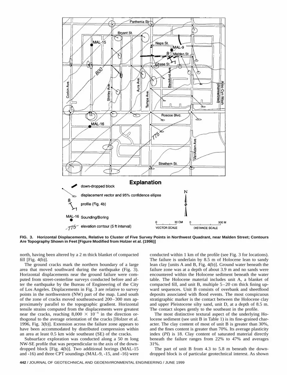
FIG. 3. Horizontal Displacements, Relative to Cluster of Five Survey Points in Northwest Quadrant, near Malden Street; ContoursAre Topography Shown in Feet [Figure Modified from Holzer et al. (1996)]
north, having been altered by a 2 m thick blanket of compactedfill [Fig. 4(b)].
The ground cracks mark the northern boundary of a largearea that moved southward during the earthquake (Fig. 3).Horizontal displacements near the ground failure were com-puted from street-centerline surveys conducted before and af-ter the earthquake by the Bureau of Engineering of the Cityof Los Angeles. Displacements in Fig. 3 are relative to surveypoints in the northwestern (NW) part of the map. Land southof the zone of cracks moved southeastward 200–300 mm ap-proximately parallel to the topographic gradient. Horizontaltensile strains computed from the displacements were greatestnear the cracks, reaching 8,000 3 1026 in the direction or-thogonal to the average orientation of the cracks [Holzer et al.1996, Fig. 3(b)]. Extension across the failure zone appears tohave been accommodated by distributed compression withinan area at least 0.5 km wide southeast (SE) of the cracks.
Subsurface exploration was conducted along a 50 m longNW-SE profile that was perpendicular to the axis of the down-dropped block [Fig. 4(b)]. Two additional borings (MAL-15and -16) and three CPT soundings (MAL-9, -15, and -16) were
442 / JOURNAL OF GEOTECHNICAL AND GEOENVIRONMENTAL ENGIN
conducted within 1 km of the profile (see Fig. 3 for locations).The failure is underlain by 8.5 m of Holocene lean to sandylean clay [units A and B, Fig. 4(b)]. Ground water beneath thefailure zone was at a depth of about 3.9 m and no sands wereencountered within the Holocene sediment beneath the watertable. The Holocene material includes unit A, a blanket ofcompacted fill, and unit B, multiple 5–20 cm thick fining up-ward sequences. Unit B consists of overbank and sheetflooddeposits associated with flood events. The most conspicuousstratigraphic marker is the contact between the Holocene clayand upper Pleistocene silty sand, unit D, at a depth of 8.5 m.The contact slopes gently to the southeast in the profile.
The most distinctive textural aspect of the underlying Ho-locene sediment (see unit B in Table 1) is its fine-grained char-acter. The clay content of most of unit B is greater than 30%,and the fines content is greater than 70%. Its average plasticityindex (PI) is 18. Clay content of saturated material directlybeneath the failure ranges from 22% to 47% and averages31%.
The part of unit B from 4.3 to 5.8 m beneath the down-dropped block is of particular geotechnical interest. As shown
EERING / JUNE 1999
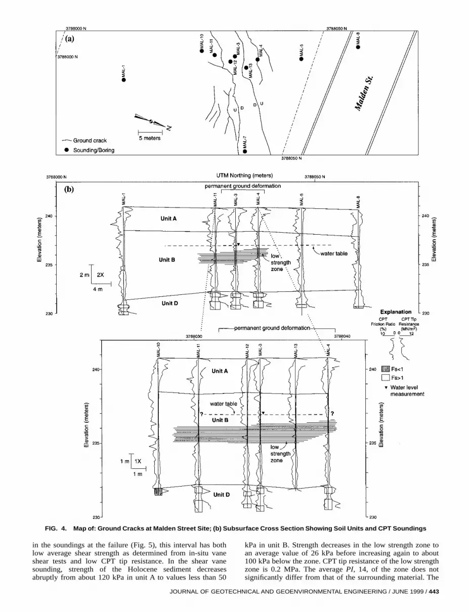
FIG. 4. Map of: Ground Cracks at Malden Street Site; (b) Subsurface Cross Section Showing Soil Units and CPT Soundings
in the soundings at the failure (Fig. 5), this interval has bothlow average shear strength as determined from in-situ vaneshear tests and low CPT tip resistance. In the shear vanesounding, strength of the Holocene sediment decreasesabruptly from about 120 kPa in unit A to values less than 50
JOURNAL OF GEOTECH
kPa in unit B. Strength decreases in the low strength zone toan average value of 26 kPa before increasing again to about100 kPa below the zone. CPT tip resistance of the low strengthzone is 0.2 MPa. The average PI, 14, of the zone does notsignificantly differ from that of the surrounding material. The
NICAL AND GEOENVIRONMENTAL ENGINEERING / JUNE 1999 / 443
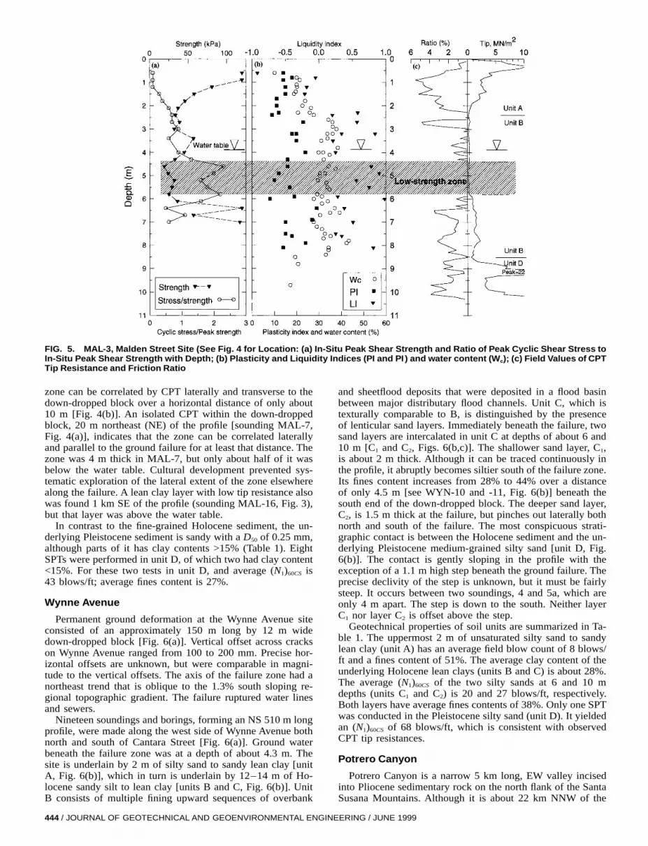
FIG. 5. MAL-3, Malden Street Site (See Fig. 4 for Location: (a) In-Situ Peak Shear Strength and Ratio of Peak Cyclic Shear Stress toIn-Situ Peak Shear Strength with Depth; (b) Plasticity and Liquidity Indices (PI and PI ) and water content (Wc); (c) Field Values of CPTTip Resistance and Friction Ratio
zone can be correlated by CPT laterally and transverse to thedown-dropped block over a horizontal distance of only about10 m [Fig. 4(b)]. An isolated CPT within the down-droppedblock, 20 m northeast (NE) of the profile [sounding MAL-7,Fig. 4(a)], indicates that the zone can be correlated laterallyand parallel to the ground failure for at least that distance. Thezone was 4 m thick in MAL-7, but only about half of it wasbelow the water table. Cultural development prevented sys-tematic exploration of the lateral extent of the zone elsewherealong the failure. A lean clay layer with low tip resistance alsowas found 1 km SE of the profile (sounding MAL-16, Fig. 3),but that layer was above the water table.
In contrast to the fine-grained Holocene sediment, the un-derlying Pleistocene sediment is sandy with a D50 of 0.25 mm,although parts of it has clay contents >15% (Table 1). EightSPTs were performed in unit D, of which two had clay content<15%. For these two tests in unit D, and average (N1)60CS is43 blows/ft; average fines content is 27%.
Wynne Avenue
Permanent ground deformation at the Wynne Avenue siteconsisted of an approximately 150 m long by 12 m widedown-dropped block [Fig. 6(a)]. Vertical offset across crackson Wynne Avenue ranged from 100 to 200 mm. Precise hor-izontal offsets are unknown, but were comparable in magni-tude to the vertical offsets. The axis of the failure zone had anortheast trend that is oblique to the 1.3% south sloping re-gional topographic gradient. The failure ruptured water linesand sewers.
Nineteen soundings and borings, forming an NS 510 m longprofile, were made along the west side of Wynne Avenue bothnorth and south of Cantara Street [Fig. 6(a)]. Ground waterbeneath the failure zone was at a depth of about 4.3 m. Thesite is underlain by 2 m of silty sand to sandy lean clay [unitA, Fig. 6(b)], which in turn is underlain by 12–14 m of Ho-locene sandy silt to lean clay [units B and C, Fig. 6(b)]. UnitB consists of multiple fining upward sequences of overbank
444 / JOURNAL OF GEOTECHNICAL AND GEOENVIRONMENTAL ENGIN
and sheetflood deposits that were deposited in a flood basinbetween major distributary flood channels. Unit C, which istexturally comparable to B, is distinguished by the presenceof lenticular sand layers. Immediately beneath the failure, twosand layers are intercalated in unit C at depths of about 6 and10 m [C1 and C2, Figs. 6(b,c)]. The shallower sand layer, C1,is about 2 m thick. Although it can be traced continuously inthe profile, it abruptly becomes siltier south of the failure zone.Its fines content increases from 28% to 44% over a distanceof only 4.5 m [see WYN-10 and -11, Fig. 6(b)] beneath thesouth end of the down-dropped block. The deeper sand layer,C2, is 1.5 m thick at the failure, but pinches out laterally bothnorth and south of the failure. The most conspicuous strati-graphic contact is between the Holocene sediment and the un-derlying Pleistocene medium-grained silty sand [unit D, Fig.6(b)]. The contact is gently sloping in the profile with theexception of a 1.1 m high step beneath the ground failure. Theprecise declivity of the step is unknown, but it must be fairlysteep. It occurs between two soundings, 4 and 5a, which areonly 4 m apart. The step is down to the south. Neither layerC1 nor layer C2 is offset above the step.
Geotechnical properties of soil units are summarized in Ta-ble 1. The uppermost 2 m of unsaturated silty sand to sandylean clay (unit A) has an average field blow count of 8 blows/ft and a fines content of 51%. The average clay content of theunderlying Holocene lean clays (units B and C) is about 28%.The average (N1)60CS of the two silty sands at 6 and 10 mdepths (units C1 and C2) is 20 and 27 blows/ft, respectively.Both layers have average fines contents of 38%. Only one SPTwas conducted in the Pleistocene silty sand (unit D). It yieldedan (N1)60CS of 68 blows/ft, which is consistent with observedCPT tip resistances.
Potrero Canyon
Potrero Canyon is a narrow 5 km long, EW valley incisedinto Pliocene sedimentary rock on the north flank of the SantaSusana Mountains. Although it is about 22 km NNW of the
EERING / JUNE 1999

JOU
RN
AL
OF
GE
OT
EC
HN
ICA
LA
ND
GE
OE
NV
IRO
NM
EN
TA
LE
NG
INE
ER
ING
/JU
NE
19
99
/445
nd Liquefaction-Susceptible Intervals of Soil
FIG. 6. Map of: (a) Ground Cracks at Wynne Avenue Site; (b) Subsurface Cross Section Showing Soil Units, CPT Soundings, aInferred from CPT and SPT (Fs is factor of Safety)
FIG. 7. Map of Ground Cracks, Sand Boils, Gas Transmission Line Breaks, and Geotechnical Sounding Locations at PotreroCanyon;Map Covers Western Half of Failure Zone; Scale Is Shown on Margins of Map
epicenter of the Northridge earthquake, it is near the updipprojection of the seismogenic rupture surface.
Ground failure in Potrero Canyon consisted of two zonesof ground cracks along the north and south edges of the valley(Fig. 7). Cracks formed in alluvium at or near the contactbetween the valley fill and the Pliocene bedrock forming theadjacent valley walls (Rymer et al. 1995). Each zone was asmuch as 30 m wide. Permanent ground deformation was pre-dominantly extensional. Horizontal displacements, inferredfrom aggregate openings across ground cracks, were at least10 cm. Vertical components of displacement ranged from afew centimeters to 60 cm. Compressional features, includingsmall thrust faults and broad ridges or mole tracks, were ob-served on the south side of the valley. These features promptedspeculation immediately after the earthquake that the crackingwas associated with primary tectonic faulting. Multiple breaksoccurred in a 12-in. gas transmission line in the valley (Fig.7).
A few sand boils vented in the valley (Fig. 7). Most formedon the southern margin of the valley, away from the incisedstream that flows near the northern margin of the valley. Sandboils were 1–3 m in diameter and locally coalesced into zonestens of meters long.
Twelve soundings and four borings comprising two profiles,140 and 207 m long, were performed across Potrero Canyonnear the western end of the ground failure (Fig. 7). Each pro-file spanned the valley. The valley is underlain by fine-grainedHolocene sediment, units A and C, (Fig. 8), most of which isbelow the water table. Depth to ground water was about 2.5m. The uppermost unit, A, is a homogeneous lean clay to siltwith an average thickness of 2.7 m. The remainder of theHolocene section, unit C, consists of lean clay to sand silt withlenses of silt and silty sand, units C1 (see material susceptibleto liquefaction in unit C in Fig. 8). Lenses cannot be unam-
446 / JOURNAL OF GEOTECHNICAL AND GEOENVIRONMENTAL ENGIN
biguously correlated between adjacent soundings, which av-eraged 35 m apart. In general, lens thickness is less than 1 mand vertical spacing ranges from 2 to 3 m. Because not allsoundings completely penetrated the Holocene section, itsmaximum total thickness is not known, although it is at least15 m. A commercial 31 m deep wash boring hole in the valleyfill near the profiles encountered materials with field blowcounts $100 blow/ft at 24 m and siltstone at 29 m (R. T.Frankian and Associates, personal communication, 1997). Inaddition, a seismic survey coincident with the profile definedby soundings POT-1–POT-12 (Fig. 7) indicates low P-wavevelocity (<1.0 km/s) sediment extends to a depth of approxi-mately 15 m (Catchings et al. 1998). The Holocene sedimentrests on dense silty sand, which may be either Pleistocene orpart of the Pliocene Pico Formation (unit D, Fig. 8).
Geotechnical properties of the valley fill are summarized inTable 1. The average (N1)60CS of the coarser-grained lenses,units C1, within the Holocene sediment is 15 blows/ft. Theaverage fines content of the lenses is 57% and typically ex-ceeds 35%. Clay contents of these lenses average 11%. Claycontents of units A and C, in which units C1 are interbedded,typically exceed 15%. Five SPTs were performed in unit D,of which four had clay contents <15%. The average (N1)60CS
is 57 blows/ft for the four tests. The average fines content ofunit D is 31%.
POTENTIAL MECHANISMS OF GROUND FAILURE
Liquefaction
Liquefaction Potential
Liquefaction potential was evaluated at all four sites withthe simplified procedure of Seed et al. (1985), as modified byYoud and Idriss (1997). Although the original procedure em-
EERING / JUNE 1999

JOU
RN
AL
OF
GE
OT
EC
HN
ICA
LA
ND
GE
OE
NV
IRO
NM
EN
TA
LE
NG
INE
ER
ING
/JU
NE
19
99
/447
FI Liquefaction-Susceptible Intervals of Soil (Unit C1)In
G. 8. (a,b) Subsurface Cross Sections through Valley Fill in Potrero Canyon Showing Soil Units, CPT Soundings, andferred from CPT and SPT (Fs Is Factor of Safety); See Fig. 7 for Location of Profiles

FIG. 9. Liquefaction Potential Based on SPT Blow Counts in Susceptible Holocene and Pleistocene Soil at USGS Study Sites (Youdand Idriss 1997); (N1)60s Were Converted to Equivalent Values for Clean Sand: (a) Balboa Boulevard; (b) Malden Street; (c) Wynne Av-enue; (d) Potrero Canyon
phasized SPT blow counts, it has been extended to includeCPT measurements as an alternative basis for assessing liq-uefaction potential. The simplified procedure assumes thatonly saturated sands with clay contents <15% are susceptibleto liquefaction. Per standard practice, field blow counts werenormalized to an effective overburden stress of 1 ton/sq ft andcorrected for hammer efficiency and rod length; tip resistancealso was normalized to 1 ton/sq ft and was corrected for layerthickness. To facilitate the comparison of materials with dif-ferent fines contents, blow counts and tip resistances were alsocorrected to equivalent values for clean sand (Youd and Idriss1997). Equivalent values are indicated by the subscript CS.
For the SPT-based liquefaction analysis, there was the con-cern that thin clayey interbeds might bias estimates of lique-faction potential. Many SPT samples with clay contents <15%were not homogeneous, but included thin interbeds with claycontents >15% within the 12 in. SPT testing interval. Theclayey interbeds, which are not liquefiable, reduce the blowcount. Because the low blow counts might prompt overesti-mates of liquefaction potential, SPTs that sampled substantialintervals of interbeds with clay contents >15% were excludedfrom the analysis.
For the CPT-based analysis, point values of cone resistancemeasured at 10 cm intervals were used. Use of CPT pointvalues increases the scatter relative to the SPT, which inte-grates penetration resistance over a 30 cm interval. In eachCPT sounding, to avoid undue reliance on isolated values, sin-gle or double CPT point values that predicted susceptible ma-terial were ignored if they were surrounded by CPT measure-ments that indicated adjacent material was nonsusceptible. Inother words, CPT measurements in a given sounding that in-dicated clay contents <15% over a 10–20 cm interval wereignored if adjacent CPT measurements indicated the surround-ing material had clay contents >15%.
At Balboa Boulevard, all of the SPTs in susceptible Holo-cene sediment beneath the water table indicate sampled inter-vals should have liquefied at the intensity of ground shakingexperienced during the main shock [Fig. 9(a)]. Values of(N1)60CS plot well to the left of the boundary between lique-faction and nonliquefaction. In addition to liquefaction of Ho-
448 / JOURNAL OF GEOTECHNICAL AND GEOENVIRONMENTAL ENGIN
locene sediment, some Pleistocene sediment may have lique-fied. Seven of the 29 SPTs in the Pleistocene sediment withclay contents <15% yielded factors of safety against liquefac-tion of less than one. Collectively, however, the Holocene sed-iment appears to be significantly more liquefiable than thePleistocene sediment. CPT measurements confirm the SPTmeasurements, although they suggest that more of the Pleis-tocene sediment may be liquefiable than do the SPTs [Fig.10(a)]. Tip resistances of Pleistocene sand, however, plotcloser to the nonliquefaction boundary than do Holocene val-ues, indicating a higher factor of safety (Fs). The CPTs alsoprovide insight into the thickness of material that liquefied. InFig. 2(b), the vertical bars centered on each sounding indicatesusceptible material and Fs greater or less than one. The ag-gregate thickness of liquefied material is inferred to range from1 to 2 m on the south margin of the lateral spread to less than1 m on the north margin. The analysis of liquefaction potentialused a peak horizontal ground acceleration of 0.84g, whichwas recorded 2.3 km east of the study site at strong motionstation RRS (Los Angeles Department of Water and PowerRinaldi Receiving Station, Fig. 1). Other nearby recorded ac-celerations were as high as 0.94g; contoured regional maps ofpeak acceleration imply a value of 0.85g (Chang et al. 1996).
Pipeline deformation in the southern margin of the failurezone beneath Balboa Boulevard is consistent with a liquefac-tion-induced soil failure. Although permanent offset across thesouthern margin of the failure zone was compressive, inspec-tion of two ruptured steel gas pipelines—a 22 in. high-pres-sure transmission and a 6 in. distribution line—indicated thatthe associated breaks in these lines were subjected to repeatedreversals of axial motion, in the range of 150–300 mm ormore (R. Gailing, Southern California Gas, personal commu-nication, 1997). This suggests ground oscillation, a phenom-enon associated with liquefaction (Liquefaction 1985; Peaseand O’Rourke 1997), accompanied the lateral spreading.
At Wynne Avenue and Potrero Canyon, the simplified pro-cedure using both SPT and CPT predicts the sand lenses in-terbedded in the fine-grained Holocene sediment liquefied dur-ing the main shock [Figs. 9(c,d) and 10(c,d)]. The remainingHolocene sediment is not considered susceptible to liquefac-
EERING / JUNE 1999
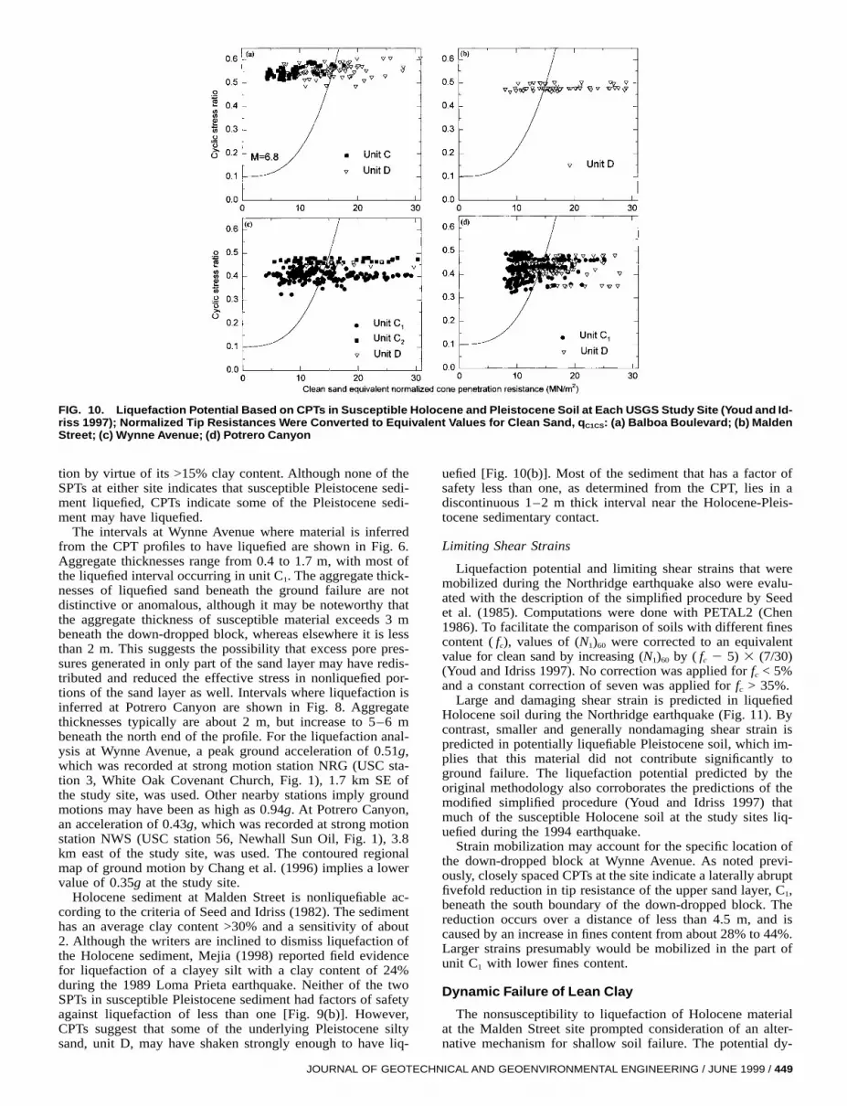
FIG. 10. Liquefaction Potential Based on CPTs in Susceptible Holocene and Pleistocene Soil at Each USGS Study Site (Youd and Id-riss 1997); Normalized Tip Resistances Were Converted to Equivalent Values for Clean Sand, qC1CS: (a) Balboa Boulevard; (b) MaldenStreet; (c) Wynne Avenue; (d) Potrero Canyon
tion by virtue of its >15% clay content. Although none of theSPTs at either site indicates that susceptible Pleistocene sedi-ment liquefied, CPTs indicate some of the Pleistocene sedi-ment may have liquefied.
The intervals at Wynne Avenue where material is inferredfrom the CPT profiles to have liquefied are shown in Fig. 6.Aggregate thicknesses range from 0.4 to 1.7 m, with most ofthe liquefied interval occurring in unit C1. The aggregate thick-nesses of liquefied sand beneath the ground failure are notdistinctive or anomalous, although it may be noteworthy thatthe aggregate thickness of susceptible material exceeds 3 mbeneath the down-dropped block, whereas elsewhere it is lessthan 2 m. This suggests the possibility that excess pore pres-sures generated in only part of the sand layer may have redis-tributed and reduced the effective stress in nonliquefied por-tions of the sand layer as well. Intervals where liquefaction isinferred at Potrero Canyon are shown in Fig. 8. Aggregatethicknesses typically are about 2 m, but increase to 5–6 mbeneath the north end of the profile. For the liquefaction anal-ysis at Wynne Avenue, a peak ground acceleration of 0.51g,which was recorded at strong motion station NRG (USC sta-tion 3, White Oak Covenant Church, Fig. 1), 1.7 km SE ofthe study site, was used. Other nearby stations imply groundmotions may have been as high as 0.94g. At Potrero Canyon,an acceleration of 0.43g, which was recorded at strong motionstation NWS (USC station 56, Newhall Sun Oil, Fig. 1), 3.8km east of the study site, was used. The contoured regionalmap of ground motion by Chang et al. (1996) implies a lowervalue of 0.35g at the study site.
Holocene sediment at Malden Street is nonliquefiable ac-cording to the criteria of Seed and Idriss (1982). The sedimenthas an average clay content >30% and a sensitivity of about2. Although the writers are inclined to dismiss liquefaction ofthe Holocene sediment, Mejia (1998) reported field evidencefor liquefaction of a clayey silt with a clay content of 24%during the 1989 Loma Prieta earthquake. Neither of the twoSPTs in susceptible Pleistocene sediment had factors of safetyagainst liquefaction of less than one [Fig. 9(b)]. However,CPTs suggest that some of the underlying Pleistocene siltysand, unit D, may have shaken strongly enough to have liq-
JOURNAL OF GEOTECH
uefied [Fig. 10(b)]. Most of the sediment that has a factor ofsafety less than one, as determined from the CPT, lies in adiscontinuous 1–2 m thick interval near the Holocene-Pleis-tocene sedimentary contact.
Limiting Shear Strains
Liquefaction potential and limiting shear strains that weremobilized during the Northridge earthquake also were evalu-ated with the description of the simplified procedure by Seedet al. (1985). Computations were done with PETAL2 (Chen1986). To facilitate the comparison of soils with different finescontent ( fc), values of (N1)60 were corrected to an equivalentvalue for clean sand by increasing (N1)60 by ( fc 2 5) 3 (7/30)(Youd and Idriss 1997). No correction was applied for fc < 5%and a constant correction of seven was applied for fc > 35%.
Large and damaging shear strain is predicted in liquefiedHolocene soil during the Northridge earthquake (Fig. 11). Bycontrast, smaller and generally nondamaging shear strain ispredicted in potentially liquefiable Pleistocene soil, which im-plies that this material did not contribute significantly toground failure. The liquefaction potential predicted by theoriginal methodology also corroborates the predictions of themodified simplified procedure (Youd and Idriss 1997) thatmuch of the susceptible Holocene soil at the study sites liq-uefied during the 1994 earthquake.
Strain mobilization may account for the specific location ofthe down-dropped block at Wynne Avenue. As noted previ-ously, closely spaced CPTs at the site indicate a laterally abruptfivefold reduction in tip resistance of the upper sand layer, C1,beneath the south boundary of the down-dropped block. Thereduction occurs over a distance of less than 4.5 m, and iscaused by an increase in fines content from about 28% to 44%.Larger strains presumably would be mobilized in the part ofunit C1 with lower fines content.
Dynamic Failure of Lean Clay
The nonsusceptibility to liquefaction of Holocene materialat the Malden Street site prompted consideration of an alter-native mechanism for shallow soil failure. The potential dy-
NICAL AND GEOENVIRONMENTAL ENGINEERING / JUNE 1999 / 449
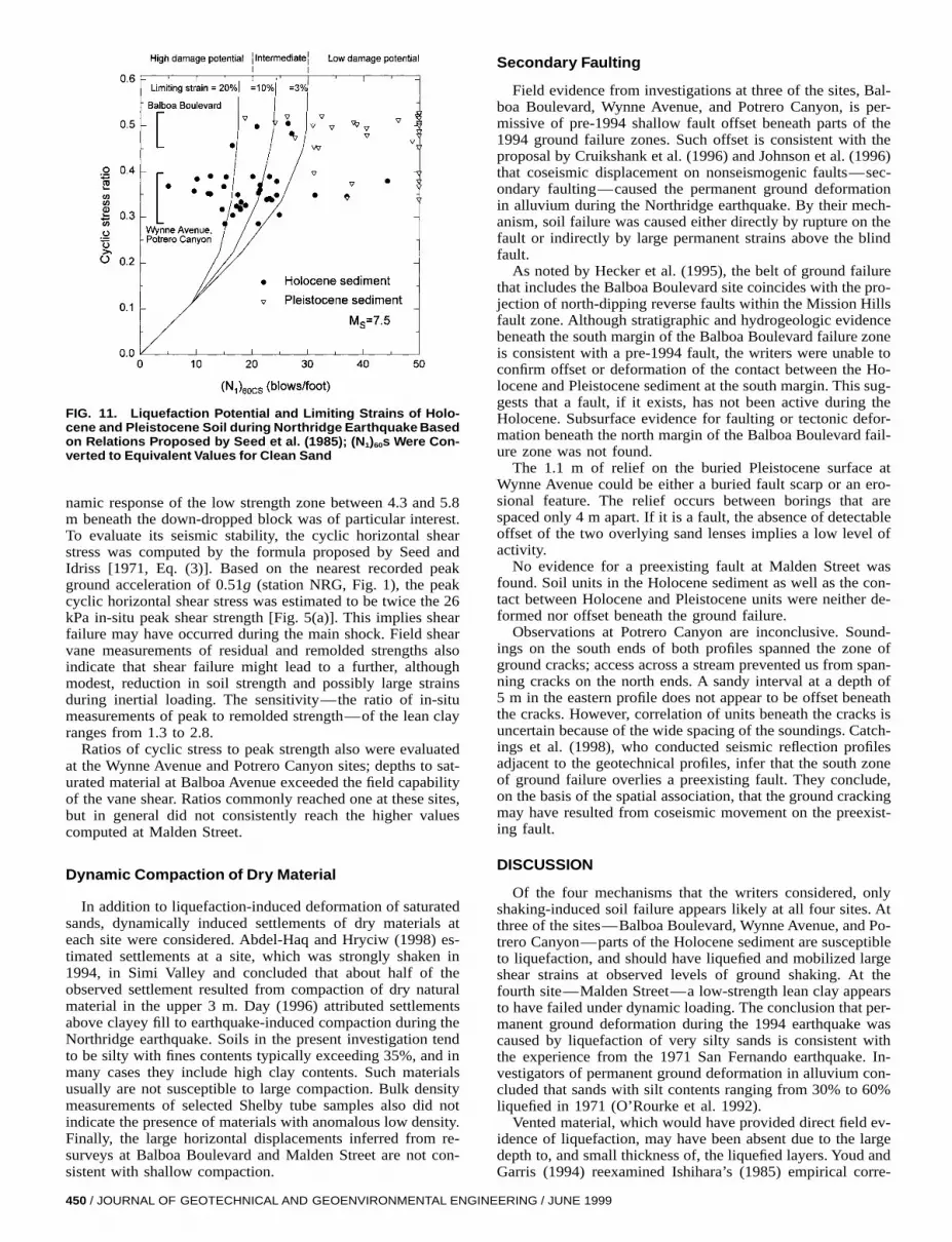
FIG. 11. Liquefaction Potential and Limiting Strains of Holo-cene and Pleistocene Soil during Northridge Earthquake Basedon Relations Proposed by Seed et al. (1985); (N1)60s Were Con-verted to Equivalent Values for Clean Sand
namic response of the low strength zone between 4.3 and 5.8m beneath the down-dropped block was of particular interest.To evaluate its seismic stability, the cyclic horizontal shearstress was computed by the formula proposed by Seed andIdriss [1971, Eq. (3)]. Based on the nearest recorded peakground acceleration of 0.51g (station NRG, Fig. 1), the peakcyclic horizontal shear stress was estimated to be twice the 26kPa in-situ peak shear strength [Fig. 5(a)]. This implies shearfailure may have occurred during the main shock. Field shearvane measurements of residual and remolded strengths alsoindicate that shear failure might lead to a further, althoughmodest, reduction in soil strength and possibly large strainsduring inertial loading. The sensitivity—the ratio of in-situmeasurements of peak to remolded strength—of the lean clayranges from 1.3 to 2.8.
Ratios of cyclic stress to peak strength also were evaluatedat the Wynne Avenue and Potrero Canyon sites; depths to sat-urated material at Balboa Avenue exceeded the field capabilityof the vane shear. Ratios commonly reached one at these sites,but in general did not consistently reach the higher valuescomputed at Malden Street.
Dynamic Compaction of Dry Material
In addition to liquefaction-induced deformation of saturatedsands, dynamically induced settlements of dry materials ateach site were considered. Abdel-Haq and Hryciw (1998) es-timated settlements at a site, which was strongly shaken in1994, in Simi Valley and concluded that about half of theobserved settlement resulted from compaction of dry naturalmaterial in the upper 3 m. Day (1996) attributed settlementsabove clayey fill to earthquake-induced compaction during theNorthridge earthquake. Soils in the present investigation tendto be silty with fines contents typically exceeding 35%, and inmany cases they include high clay contents. Such materialsusually are not susceptible to large compaction. Bulk densitymeasurements of selected Shelby tube samples also did notindicate the presence of materials with anomalous low density.Finally, the large horizontal displacements inferred from re-surveys at Balboa Boulevard and Malden Street are not con-sistent with shallow compaction.
450 / JOURNAL OF GEOTECHNICAL AND GEOENVIRONMENTAL ENGI
Secondary Faulting
Field evidence from investigations at three of the sites, Bal-boa Boulevard, Wynne Avenue, and Potrero Canyon, is per-missive of pre-1994 shallow fault offset beneath parts of the1994 ground failure zones. Such offset is consistent with theproposal by Cruikshank et al. (1996) and Johnson et al. (1996)that coseismic displacement on nonseismogenic faults—sec-ondary faulting—caused the permanent ground deformationin alluvium during the Northridge earthquake. By their mech-anism, soil failure was caused either directly by rupture on thefault or indirectly by large permanent strains above the blindfault.
As noted by Hecker et al. (1995), the belt of ground failurethat includes the Balboa Boulevard site coincides with the pro-jection of north-dipping reverse faults within the Mission Hillsfault zone. Although stratigraphic and hydrogeologic evidencebeneath the south margin of the Balboa Boulevard failure zoneis consistent with a pre-1994 fault, the writers were unable toconfirm offset or deformation of the contact between the Ho-locene and Pleistocene sediment at the south margin. This sug-gests that a fault, if it exists, has not been active during theHolocene. Subsurface evidence for faulting or tectonic defor-mation beneath the north margin of the Balboa Boulevard fail-ure zone was not found.
The 1.1 m of relief on the buried Pleistocene surface atWynne Avenue could be either a buried fault scarp or an ero-sional feature. The relief occurs between borings that arespaced only 4 m apart. If it is a fault, the absence of detectableoffset of the two overlying sand lenses implies a low level ofactivity.
No evidence for a preexisting fault at Malden Street wasfound. Soil units in the Holocene sediment as well as the con-tact between Holocene and Pleistocene units were neither de-formed nor offset beneath the ground failure.
Observations at Potrero Canyon are inconclusive. Sound-ings on the south ends of both profiles spanned the zone ofground cracks; access across a stream prevented us from span-ning cracks on the north ends. A sandy interval at a depth of5 m in the eastern profile does not appear to be offset beneaththe cracks. However, correlation of units beneath the cracks isuncertain because of the wide spacing of the soundings. Catch-ings et al. (1998), who conducted seismic reflection profilesadjacent to the geotechnical profiles, infer that the south zoneof ground failure overlies a preexisting fault. They conclude,on the basis of the spatial association, that the ground crackingmay have resulted from coseismic movement on the preexist-ing fault.
DISCUSSION
Of the four mechanisms that the writers considered, onlyshaking-induced soil failure appears likely at all four sites. Atthree of the sites—Balboa Boulevard, Wynne Avenue, and Po-trero Canyon—parts of the Holocene sediment are susceptibleto liquefaction, and should have liquefied and mobilized largeshear strains at observed levels of ground shaking. At thefourth site—Malden Street—a low-strength lean clay appearsto have failed under dynamic loading. The conclusion that per-manent ground deformation during the 1994 earthquake wascaused by liquefaction of very silty sands is consistent withthe experience from the 1971 San Fernando earthquake. In-vestigators of permanent ground deformation in alluvium con-cluded that sands with silt contents ranging from 30% to 60%liquefied in 1971 (O’Rourke et al. 1992).
Vented material, which would have provided direct field ev-idence of liquefaction, may have been absent due to the largedepth to, and small thickness of, the liquefied layers. Youd andGarris (1994) reexamined Ishihara’s (1985) empirical corre-
NEERING / JUNE 1999

FIG. 12. Comparison of Average Thicknesses (61s) of Holo-cene Liquefied Material and Surface Layers at Study Sites toBoundary Curves Proposed by Ishihara (1985)
lation of liquefaction-induced surface effects with depth to,and thickness of, the liquefied layer, and concluded thatground cracking without venting of sand boils is more likelyas the depth and thickness of the liquefied layer increase anddecrease, respectively. The present investigation supports theirconclusion. For each site, aggregate thickness of all liquefiedHolocene material versus the depth to the top of the shallowestliquefied layer was plotted (Fig. 12). Both the Balboa Boule-vard and the Wynne Avenue sites fall outside Ishihara’s bound-ary for the occurrence of surface effects. The Potrero Canyonsite, where a few sand boils were observed, plots near theboundary.
The absence of shallow liquefiable material and the presenceof a seismically weak lean clay beneath the ground failure atMalden Street is of particular interest. The seismic stability ofclays beneath gently sloping ground in alluvial fan environ-ments usually is not evaluated in geotechnical site investiga-tions. The present investigation implies that the seismic sta-bility of these soils should be addressed when high levels ofground shaking are possible. In-situ shear strength measure-ments may be one method for addressing this problem. Dy-namic soil failure also may be a mechanism for nonlinear soilamplification at high shaking levels.
Although the writers cannot dismiss secondary faulting dur-ing the Northridge earthquake as the cause of ground defor-mation, collective consideration of the four study sites doesnot offer consistent and compelling field evidence of such.Parts of some failure zones may be underlain by pre-1994faults, but evidence for either tectonic faulting or deformationis not found beneath all of the failures.
Finally, the heterogeneous nature of the alluvial fan sedi-ments and variations in the ground-water table beneath the1994 ground failures have implications for (1) understandingthe spatial distribution of permanent ground deformation; and(2) regional mapping of liquefaction potential. The present in-vestigation documents the significance of variations of localconditions in alluvial fan environments to the specific loca-tions of permanent ground deformation as well as the need torecognize and heed detailed subsurface conditions at a specificsite. This heterogeneity of local subsurface conditions mayalso help to explain localized variations in recorded transientground motions that are not readily attributable to seismicsource and basin effects. In addition, the present study sug-gests that geologically based regional mapping of areas thatare susceptible to liquefaction in alluvial fan environments
JOURNAL OF GEOTECH
may be more challenging than in floodplain or fluvial envi-ronments. In floodplain environments, detailed surficial geo-logic mapping can delineate areas that are highly susceptibleto liquefaction (Tinsley and Dupre 1992; Holzer et al. 1994).This success presumably derives from the mappable facies as-sociated with the greater continuity and cleanness of fluvialsands relative to alluvial fan deposits. The present investiga-tion suggests that identification of sites that are susceptible toliquefaction is more difficult in alluvial fan deposits derivedfrom fine-grained source rocks. Sands and silts in this envi-ronment tend to be clay rich and discontinuous. Delineatingareas of saturated Holocene sediment may be the conservativealternative approach for mapping in most alluvial fan settings.
ACKNOWLEDGMENTS
This investigation was partially supported by the National EarthquakeHazards Reduction Program Northridge earthquake supplement to theU.S. Geological Survey. The writers are grateful to the following indi-viduals for assistance: C. Criley, J. J. Butelo, S. Hecker, T. E. Fumal, J.Hamilton, S. Gilstrap, C. C. Conway, and R. E. Kayen. The writersgreatly appreciate helpful comments by T. D. O’Rourke and T. L. Youd,who reviewed an early draft of the manuscript, and the anonymous ASCEreviewers.
APPENDIX. REFERENCES
Abdel-Haq, A., and Hryciw, R. D. (1998). ‘‘Ground settlement in SimiValley following the Northridge earthquake.’’ J. Geotech. and Geoen-vir. Engrg., ASCE, 124(1), 80–89.
Bennett, M. J., Criley, C., Tinsley, J. C. III, Ponti, D. J., and Holzer, T.L., and Conaway, C. H. (1998). ‘‘Subsurface geotechnical investiga-tions near sites of permanent ground deformation caused by the January17, 1994 Northridge, California, earthquake.’’ U.S. Geological SurveyOpen-File Rep. 98-373, U.S. Geological Survey, Menlo Park, Calif.
Catchings, R. D., Goldman, M. R., Lee, W. H. K., Rymer, M. J., andPonti, D. J. (1998). ‘‘Faulting apparently related to the 1994 North-ridge, California, earthquake and possible co-seismic origin of surfacecracks in Potrero Canyon, Los Angeles County, California.’’ Seismo-logical Soc. of America Bull. 88(6), 1379–1391.
Chang, S. W., Bray, J. D., and Seed, R. B. (1996). ‘‘Engineering impli-cations of ground motions from the Northridge earthquake.’’ Seismo-logical Soc. of America Bull., 86(1B), 270–288.
Chen, A. T. F. (1986). ‘‘PETAL2: Penetration testing and liquefaction—An interactive computer program.’’ U.S. Geological Survey Open-FileRep. 86–178, U.S. Geological Survey, Menlo Park, Calif.
Cruikshank, K. M., Johnson, A. M., Fleming, R. W., and Jones, R. (1996).‘‘Winnetka deformation zone: Surface expression of coactive slip on ablind fault during the Northridge earthquake sequence, California.’’U.S. Geological Survey Open-File Rep. 96-698, U.S. Geological Sur-vey, Denver, Colo.
Day, R. W. (1996). ‘‘Damage due to Northridge earthquake-induced set-tlement of clayey fill.’’ Envir. and Engrg. Geosci., 2(1), 99–105.
Hecker, S., Ponti, D. J., Garvin, C. D., and Hamilton, J. C. (1995). ‘‘Char-acteristics and origin of ground deformation produced in Granada Hillsand Mission Hills during the January 17, 1994 Northridge, California,earthquake.’’ The Northridge, California, earthquake of 17 January1994, M. C. Woods and W. R. Sieple, eds., California Div. of Minesand Geol. Spec. Publ. 116, California Division of Mines and Geology,Sacramento, Calif., 111–131.
Holzer, T. L., Bennett, M. J., Tinsley, J. C. III, Ponti, D. J., and Sharp,R. V. (1996). ‘‘Causes of ground failure in alluvium during the North-ridge, California, earthquake of January 17, 1994.’’ Proc., 6th U.S.-Japan Workshop on Earthquake Resistant Des. of Lifeline Facilitiesand Countermeasures for Soil Liquefaction, Tech. Rep. NCEER-96-0012, National Center for Earthquake Engineering Research, Buffalo,345–360.
Holzer, T. L., Tinsley, J. C., Bennett, M. J., and Mueller, C. S. (1994).‘‘Observed and predicted ground deformation—Miller Farm lateralspread, Watsonville, California.’’ Proc., 5th U.S.-Japan Workshop onEarthquake Resistant Des. of Lifeline Facilities and Countermeasuresfor Soil Liquefaction, Tech. Rep. NCEER-94-0026, National Center forEarthquake Engineering Research, Buffalo, 79–99.
Ishihara, K. (1985). ‘‘Stability of natural deposits during earthquakes.’’Proc., 11th Int. Conf. on Soil Mech. and Found Engrg., Balkema, Rot-terdam, The Netherlands, 321–376.
Johnson, A. M., Fleming, R. M., Cruikshank, K. M., and Packard, R. F.
NICAL AND GEOENVIRONMENTAL ENGINEERING / JUNE 1999 / 451
(1996). ‘‘Coactive fault of the Northridge earthquake—Granada Hillsarea, California.’’ U.S. Geological Survey Open-File Rep. 96-253, U.S.Geological Survey, Denver, Colo.
Liquefaction of soils during earthquakes: Committee on Earthquake En-gineering. (1985). National Academy Press, Washington, D.C.
‘‘The magnitude 6.7 Northridge, California, earthquake of 17 January1994.’’ Science, (1994). 266, 389–397.
Mejia, L. H. (1998). ‘‘Liquefaction at Moss Landing.’’ The Loma Prieta,California, earthquake of October 17, 1989—Liquefaction, T. L. Hol-zer, ed., U.S. Geological Survey Profl. Paper 1551-B, U.S. GeologicalSurvey, Menlo Park, Calif., B129–B150.
O’Rourke, T. D., Roth, B. L., and Hamada, M. (1992). ‘‘Large grounddeformations and their effect on lifeline facilities: 1971 San Fernandoearthquake.’’ Case histories of liquefaction and lifeline performanceduring past earthquakes, T. D. O’Rourke and M. Hamada, eds., Tech.Rep. NCEER-92-0002, National Center for Earthquake Engineering Re-search, Buffalo, 3-1–3-85.
O’Rourke, T., and Toprak, S. (1997). ‘‘Using GIS to assess water supplydamage from the Northridge earthquake.’’ NCEER Bull., 11(3), 10–13.
O’Rourke, T. D., Toprak, S., and Sano, Y. (1996). ‘‘Los Angeles waterpipeline system response to the 1994 Northridge earthquake.’’ Proc.,6th U.S.-Japan Workshop on Earthquake Resistant Design of LifelineFacilities and Countermeasures for Soil Liquefaction, Tech. Rep.NCEER-96-0012, National Center for Earthquake Engineering Re-search, Buffalo, 1–17.
Pease, J. W., and O’Rourke, T. D. (1997). ‘‘Seismic response of lique-faction sites.’’ J. Geotech. and Geoenvir. Engrg., ASCE, 123(1), 37–45.
Rymer, M. J., Fumal, T. E., Schwartz, D. P., Powers, T. J., and Cinti, F.R. (1995). ‘‘Distribution and recurrence of surface fractures in PotreroCanyon associated with the 1994 Northridge, California, earthquake.’’The Northridge, California, earthquake of 17 January 1994, M. C.Woods and W. R. Seiple, eds., California Div. of Mines and Geol. Spec.Publ. 116, California Division of Mines and Geology, Sacramento,Calif., 133–146.
Seed, H. B., and Idriss, I. M. (1971). ‘‘Simplified procedure for evaluating
452 / JOURNAL OF GEOTECHNICAL AND GEOENVIRONMENTAL ENGIN
soil liquefaction potential.’’ J. Soil Mech. and Found. Div., ASCE,97(9), 1249–1273.
Seed, H. B., and Idriss, I. M. (1983). ‘‘Ground motions and soil lique-faction during earthquakes.’’ Earthquake Engrg. Res. Inst. Monograph,Earthquake Engineering Research Institute, El Cerrito, Calif.
Seed, H. B., Tokimatsu, K., Harder. L. F., and Chung, R. M. (1985).‘‘Influence of SPT procedures in soil liquefaction resistance investi-gations.’’ J. Geotech. Engrg., ASCE, 111(12), 1425–1445.
Standard method for field vane shear test in cohesive soil. (1983). Annualbook of ASTM standards, Vol. 4.08: Soil and rock; building stones.ASTM, West Conshohoken, Pa., 404–407.
Stewart, J. P., Seed, R. B., and Bray, J. D. (1996). ‘‘Incidents of groundfailure from the 1994 Northridge earthquake.’’ Seismological Soc. ofAmerica Bull., 86(1B), 300–318.
Tinsley, J. C. III, and Dupre, W. R. (1992). ‘‘Liquefaction hazard map-ping, depositional facies, and lateral spreading ground failure in theMonterey Bay area during the 10/17/89 Loma Prieta earthquake.’’Proc., 4th U.S.-Japan Workshop on Earthquake Resistant Des. of Life-line Facilities and Countermeasures for Soil Liquefaction, Tech. Rep.NCEER-92-0019, National Center for Earthquake Engineering Re-search, Buffalo, 71–85.
‘‘USGS response to an urban earthquake, Northridge ’94.’’ (1996). U.S.Geological Survey Open-File Rep. 96-263, U.S. Geological Survey,Menlo Park, Calif.
Wentworth, C. M., and Yerkes, R. F. (1971). ‘‘Geologic setting and ac-tivity of faults in the San Fernando area, California.’’ The San Fer-nando, California, earthquake of February 9, 1971. U.S. GeologicalSurvey Profl. Paper 733, U.S. Geological Survey, Menlo Park, Calif.,6–16.
Youd, T. L., and Garris, C. T. (1994). ‘‘Liquefaction-induced ground sur-face disruption.’’ Proc., 5th U.S.-Japan Workshop on Earthquake Re-sistant Des. of Lifeline Facilities and Countermeasures for Soil Liq-uefaction, Tech. Rep. NCEER-94-0026, National Center for EarthquakeEngineering Research, Buffalo, 27–40.
Youd, T. L., and Idriss, I. M., eds. (1997). ‘‘NCEER workshop on eval-uation of liquefaction resistance of soils.’’ Tech. Rep. NCEER-97-0022,National Center for Earthquake Engineering Research, Buffalo.
EERING / JUNE 1999