earthing in shielded cabling
TRANSCRIPT
Expertise Reports
Address:Andreas Iliou
81739 Munich
Technical Report
I will use simple language to make you understand , earthing is Drainage system of Electrical wastage, let us assume the system is waste water drainage system, and we are using pipes to drain the waste water.
if the drainage is not proper,that means either you have chosen wrong pipe size which is incapable to drain therequired waste, then, your water will be stored in the pipe,and the force of water will increase in the pipe, same case is happening in earthing system,
if you do not have the required conductor to dissipate the fault then stress will be in your system, so if you will increase the conductor size by making a mesh that means you are increasing the number of pipes to drain the required waste water.
same thing happening in a mesh, the more soil is associated with the conductor the rate of dissipation will be more, so it will create a low impedance path to fault current A Systems Approach to Earthing
The ‘protective conductor’ must also provide a functional earth to the equipment operating on the system thatis, it has to provide a path for the leakage currents (at the fundamental frequency) and the high frequency noise currents arising from, for example, switched mode power supplies via radio frequency interference (RFI) filters as well as being a voltage reference for signal interfaces.
The magnitude of leakage currents varies around the installation. Since the earth leakage current originatesmainly from single-phase equipment on each of the three phases, balanced components of thefundamental from each phase will tend to cancel, so that the current in the protective conductor may increase or decrease as circuits are combined along a distribution system.
High frequency currents can be a bigger problem as far as functionality is concerned. Much of theequipment that produces noise on the earth is also sensitive to it – but there is a difference; the equipmentproduces noise currents and it is sensitive to noise voltages. If the noise currents can be transported to earthwithout producing noise voltage drop, all will be well. This requires a connection to earth that has low impedance at all frequencies. To decrease radiated noise, the earth path for the noise current should runclose to the supply conductors.
Building protective conductor arrangement--Fault current--Leakage current--Signal reference plane--Electromagnetic compatibility
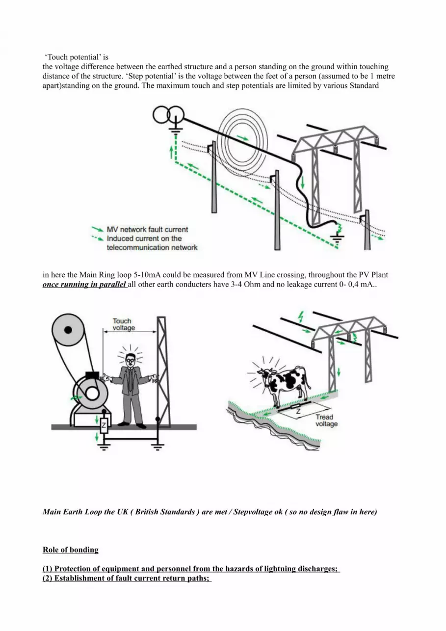
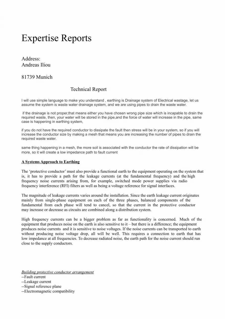
‘Touch potential’ isthe voltage difference between the earthed structure and a person standing on the ground within touchingdistance of the structure. ‘Step potential’ is the voltage between the feet of a person (assumed to be 1 metre apart)standing on the ground. The maximum touch and step potentials are limited by various Standard
in here the Main Ring loop 5-10mA could be measured from MV Line crossing, throughout the PV Plant once running in parallel all other earth conducters have 3-4 Ohm and no leakage current 0- 0,4 mA..
Main Earth Loop the UK ( British Standards ) are met / Stepvoltage ok ( so no design flaw in here)
Role of bonding
(1) Protection of equipment and personnel from the hazards of lightning discharges; (2) Establishment of fault current return paths;

(3) Establishment of homogeneous and stable paths for signal currents; (4) Minimization of RF potentials on enclosures and housings; (5) Protection of personnel from shock hazards arising from accidental power ground; and (6) Prevention of static charge accumulation.
Effects of poor bonds. With proper design and implementation, bonds minimize differences in potential between points within the fault protection, signal reference, shielding, and lightning protection networks of an electronic system.
Bonding is also important to the performance of other interference control measures. For example, adequate bonding of connector shells to equipment enclosures is essential to the maintenance of the integrity of cable shields and to the retention of the low loss transmission properties of the cables. The careful bonding of seams and joints in EM shields is essential to the achievement of a high degree of shielding effectiveness. Interference reduction components and devices also must be well bonded for optimum performance.
Role of grounding
The grounding system consists of four subsystems, (1) the earth electrode subsystem,(2) the fault protection subsystem,(3) the lightning protection subsystem,and (4) the signal reference subsystem.The purpose of the earth electrode subsystem is to provide a path to earth for the discharge of lightningstrokes, prevent shock hazard to personnel, and assist in the control of noise.
Role of shielding
Shielding involves the use of metallic barriers to prevent the direct radiation of incident energy into the system and internal enclosures and to minimize the coupling of energy to cables and other collectors that may penetrate these barriers. Shielding is the basic element of any barrier design, and little EMP protection is possible without its proper use.
PV Plant and Energy Audit e.g:
The Panel was not grounded at All.
In an IT environment and Noise generated a 16mm (thin wire) is needed. ( Was it testwise removed ?! Lot of different type of earthing datacables was surveyed)
No Grounding towards Earth Bar , no Grounding towards distribution board ( 230 VAC ) via UPS system.
There was also no plugpoint installed at the wall (outlet) cable was stripped and than fixed with Isolationtape. The PE (Earth ) was not terminated at the Earthing Point (wire was hanging loose).
The only contact towards Earth was the metallic enclosure of the Wall from Container via 4 screws !!

PE wire visually with Isotape wrapped and not connected.No one could tell who connected up this side of installation.
Cable towards UPS unit was done from team (previously) Mounting of Panels (only /no wiring done) from electrician.
16mm Chassis Grounding (needed )

J- Box implementation ( best practice )
if PE ( Earh Bar ) is 0,5 mtr away from connecting up device ( surge arrestor) a V Shape connection 1x towards Earth bar existing with 4mm and a second ( back to it s source ) should be installed in herePlus and Minuscable ( armoured shield) with 16mm
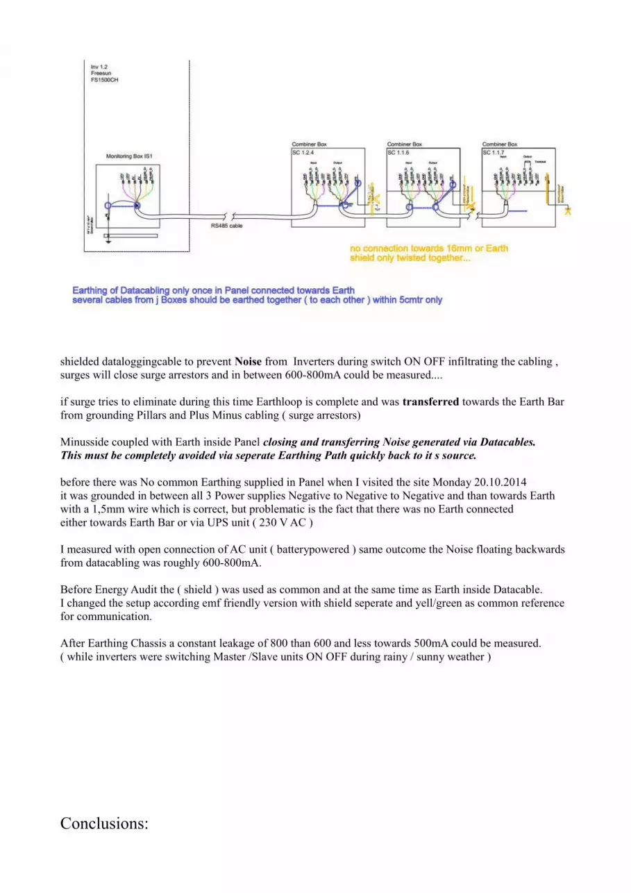
shielded dataloggingcable to prevent Noise from Inverters during switch ON OFF infiltrating the cabling , surges will close surge arrestors and in between 600-800mA could be measured....
if surge tries to eliminate during this time Earthloop is complete and was transferred towards the Earth Barfrom grounding Pillars and Plus Minus cabling ( surge arrestors)
Minusside coupled with Earth inside Panel closing and transferring Noise generated via Datacables.This must be completely avoided via seperate Earthing Path quickly back to it s source.
before there was No common Earthing supplied in Panel when I visited the site Monday 20.10.2014it was grounded in between all 3 Power supplies Negative to Negative to Negative and than towards Earth with a 1,5mm wire which is correct, but problematic is the fact that there was no Earth connectedeither towards Earth Bar or via UPS unit ( 230 V AC )
I measured with open connection of AC unit ( batterypowered ) same outcome the Noise floating backwardsfrom datacabling was roughly 600-800mA.
Before Energy Audit the ( shield ) was used as common and at the same time as Earth inside Datacable.I changed the setup according emf friendly version with shield seperate and yell/green as common reference for communication.
After Earthing Chassis a constant leakage of 800 than 600 and less towards 500mA could be measured.( while inverters were switching Master /Slave units ON OFF during rainy / sunny weather )
Conclusions:

Following action has to be implemented ( inside Transformer/Inverters)
-Earthing Panel via db board ( bigger Path back to source ) not via 230 V AC cables
-Earthing Panel via Earth Bar
-Earthing DB Board and Earth Bar ( all with 16mm thinwire)
-Earthing J Boxes via V Shape Earthing ( sec. time using Plus/Minus armoured shield)
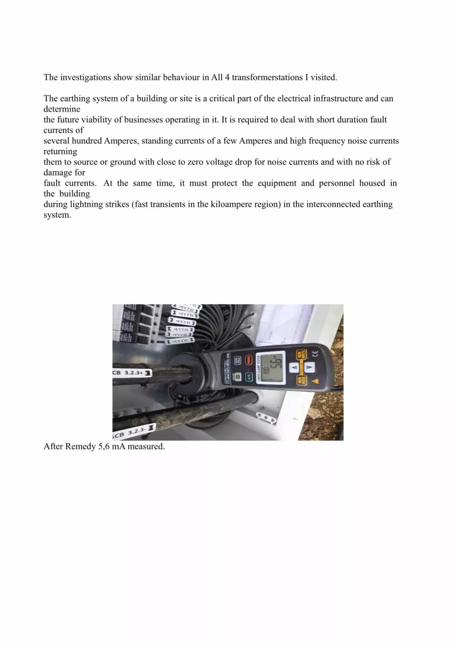
The investigations show similar behaviour in All 4 transformerstations I visited.
The earthing system of a building or site is a critical part of the electrical infrastructure and can determinethe future viability of businesses operating in it. It is required to deal with short duration fault currents ofseveral hundred Amperes, standing currents of a few Amperes and high frequency noise currents returningthem to source or ground with close to zero voltage drop for noise currents and with no risk of damage forfault currents. At the same time, it must protect the equipment and personnel housed in the buildingduring lightning strikes (fast transients in the kiloampere region) in the interconnected earthing system.
After Remedy 5,6 mA measured.
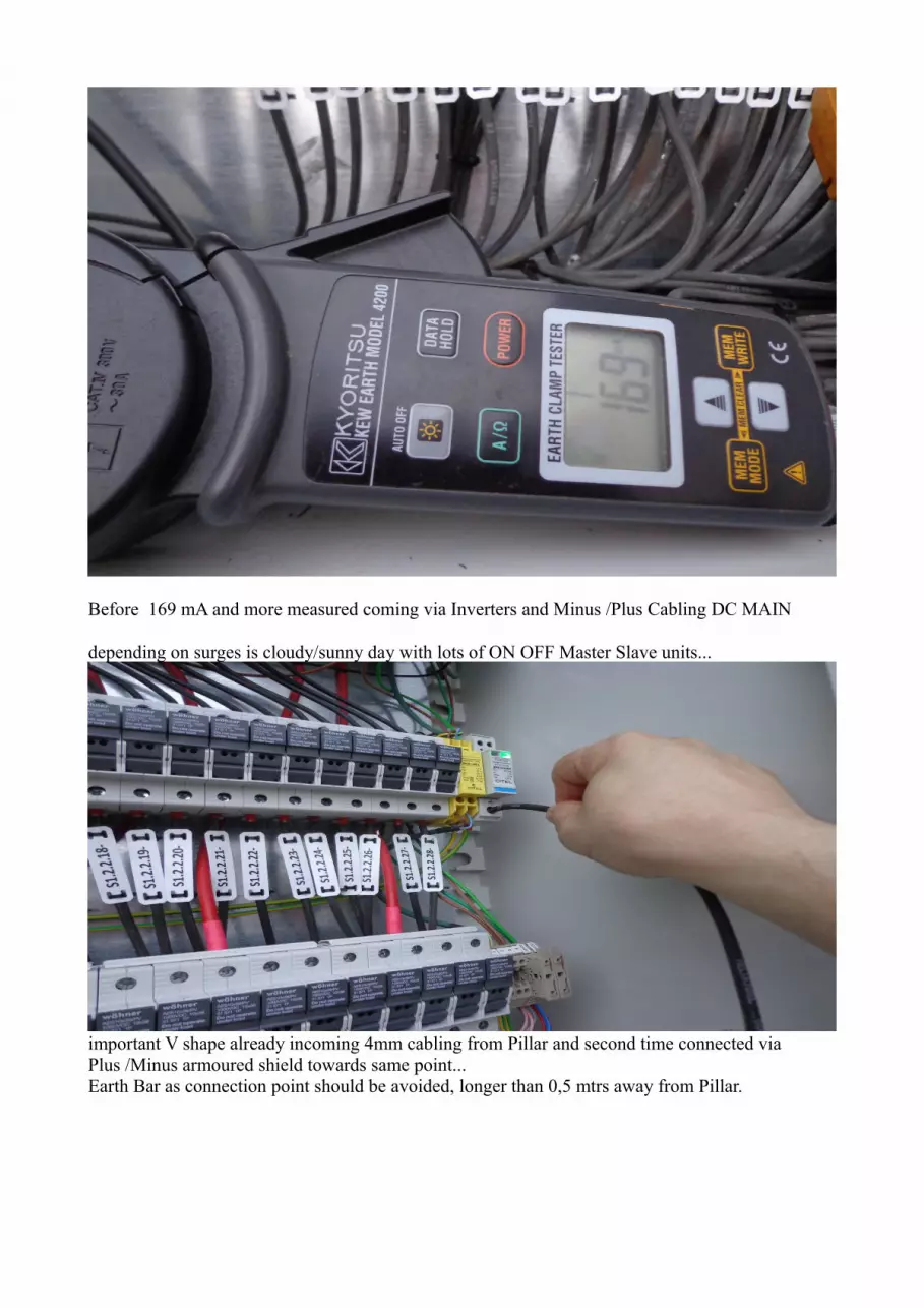
Before 169 mA and more measured coming via Inverters and Minus /Plus Cabling DC MAIN
depending on surges is cloudy/sunny day with lots of ON OFF Master Slave units...
important V shape already incoming 4mm cabling from Pillar and second time connected via Plus /Minus armoured shield towards same point...Earth Bar as connection point should be avoided, longer than 0,5 mtrs away from Pillar.

Previously earthed system ( shield used – didn t work) from outside towards Panel

tested onsite with last 2 days.....working floating back to it s sourceno leakage current via datalogging anymore – must be implemented as quick as possible on all J Boxes.....
REMEDY (possible):
all 4 transformers should get same Remedy action plan as described in PV Plant Report
Munich , 28.10 2015
Andreas Iliou