dynamics of a pair of paramagnetic janus particles under a
TRANSCRIPT
Missouri University of Science and Technology Missouri University of Science and Technology
Scholars' Mine Scholars' Mine
Mechanical and Aerospace Engineering Faculty Research & Creative Works Mechanical and Aerospace Engineering
19 Jan 2021
Dynamics of a Pair of Paramagnetic Janus Particles under a Dynamics of a Pair of Paramagnetic Janus Particles under a
Uniform Magnetic Field and Simple Shear Flow Uniform Magnetic Field and Simple Shear Flow
Christopher Sobecki
Jie Zhang
Cheng Wang Missouri University of Science and Technology, [email protected]
Follow this and additional works at: https://scholarsmine.mst.edu/mec_aereng_facwork
Part of the Mechanical Engineering Commons
Recommended Citation Recommended Citation C. Sobecki et al., "Dynamics of a Pair of Paramagnetic Janus Particles under a Uniform Magnetic Field and Simple Shear Flow," Magnetochemistry, vol. 7, no. 1, pp. 1-20, MDPI, Jan 2021. The definitive version is available at https://doi.org/10.3390/magnetochemistry7010016
This Article - Journal is brought to you for free and open access by Scholars' Mine. It has been accepted for inclusion in Mechanical and Aerospace Engineering Faculty Research & Creative Works by an authorized administrator of Scholars' Mine. This work is protected by U. S. Copyright Law. Unauthorized use including reproduction for redistribution requires the permission of the copyright holder. For more information, please contact [email protected].
Dynamics of a pair of paramagnetic particlesin shear flows under a uniform magnetic field
Cite as: Phys. Fluids 33, 043302 (2021); doi: 10.1063/5.0044395Submitted: 15 January 2021 . Accepted: 18 March 2021 .Published Online: 5 April 2021
Jie Zhang, Md Rifat Hassan, and Cheng Wanga)
AFFILIATIONS
Department of Mechanical and Aerospace Engineering, Missouri University of Science and Technology, 400 W. 13th St., Rolla,Missouri 65409, USA
a)Author to whom correspondence should be addressed: [email protected]
ABSTRACT
We numerically investigated the particle–particle interaction and relative motion of a pair of equal-sized magnetic particles in simple shearand plane Poiseuille flows. Two-dimensional numerical models were created by using direct numerical simulations, which are based on thefinite element method and arbitrary Lagrangian–Eulerian approach with full consideration of particle–particle, particle–magnetic field, parti-cle–flow field interactions. The effects of direction and strength of magnetic field on the dynamics of the particles in simple shear and planePoiseuille flows were investigated, respectively. In the simple shear flow, the presence of magnetic field can show stabilizing or destabilizingeffect on the particle trajectories, depending on the direction of the magnetic field. Specifically, the particles initially located at closed trajecto-ries moved closer and closer when the magnetic field is applied at 0�and 135�, while they moved further apart and separated when the field isapplied at 90�. In the plane Poiseuille flow, the magnetic field changed the relative motion of two particles: it induced two particles to form achain when a strong magnetic field is applied at 0�and 135�; it separated the two particles when a strong magnetic field is applied at 45�and90�. This work offers insights toward understanding the mechanisms of particle–particle interaction in magnetorheological fluids in simpleshear or plane Poiseuille flows under a uniform magnetic field.
Published under license by AIP Publishing. https://doi.org/10.1063/5.0044395
I. INTRODUCTION
Magnetic particles have been used in a wide range of applicationsin chemical, biological, and industrial fields.1–3 One of the mostimportant applications is magnetorheological fluids (MRFs).4 MRFsare two-phase fluids containing large amounts of micro-sized mag-netic particles. Mineral oils, silicone oils, and water are the typical car-rier media. MRFs are intelligent materials. Without an appliedmagnetic field, it has similar properties as the carrier medium, while itshows a significant increased apparent viscosity, viscoelasticity, andyield stress in the presence of magnetic field. These field-dependentproperties make the MRFs a good candidate for applications in shockabsorbers, control valves, clutches, dampers, brakes, chucking, andlocking devices.
Due to the high density of magnetic particle in MRFs, the effectof particle–particle interactions becomes significant. There exist lots ofnumerical studies on the motion and particle–particle interaction ofmagnetic particles in a quiescent fluid under a magnetic field. Melleand Martin5 proposed an athermal chain model for MRFs on arotating magnetic field, which is based on the balance between hydro-dynamic and magnetostatic forces. Petousis et al.6 developed a
pin-jointed mechanism model to investigate the motion of magneticparticle chains under a rotating magnetic field. Stuart et al.7 presenteda particle tracking method for fluid flow simulations on unstructuredgrids to study the particle behaviors in complex geometries. However,the methods presented above belong to the particle-based method,which are based on the point-dipole approximation and Stokes draglaw. The particle–particle interaction was studied by the dipole model,where the particle is considered as a point. The hydrodynamic andmagnetic effects on the interaction between the finite-sized particlesare neglected, which may cause inaccurate results. A dipole modelwith locally higher order multipoles was developed by Keavery andMaxey8 to study the near-field interactions between two magnetic par-ticles. Later, a particle-based numerical method based on magneticdipole moments and Oseen–Burgers tensor was reported by Gaoet al.9 to investigate the dynamics of magnetic particle chains under arotating magnetic field. A direct numerical simulation (DNS) modelbased on the finite element method (FEM) and fictitious domainapproach was reported by Kang et al.10,11 to investigate the motionand interactions between two particles in a quiescent fluid underuniform or rotating magnetic field. Suh and Kang,12 Kang and Suh13
Phys. Fluids 33, 043302 (2021); doi: 10.1063/5.0044395 33, 043302-1
Published under license by AIP Publishing
Physics of Fluids ARTICLE scitation.org/journal/phf
proposed a DNS model based on immersed boundary method tostudy the motion of the particles under a uniform magnetic field. Theyfound the similar results as Kang et al.10
Even though there were many studies in a quiescent fluid, theworking conditions of most device using MRFs are actually in shearflows. The shearing can be classified as three different modes: thedirect shear mode, the valve mode (i.e., pressure-driven flow mode)and the squeeze mode (bi-axial elongational flow mode).4,14 The devi-ces working in direct shear mode includes brakes, clutches, chucking,and locking devices. The devices working in pressure-drive flow modeincludes dampers, servo-valves and shock absorbers. The bi-axial elon-gational flow mode is usually employed by the slow motion and highforce applications.
In the literature, there is a long history to study the hydrody-namic interaction between two particles in shear flows. Beginningfrom 1960s, there have been a series of works on interaction of a pairsof equal-sized spheres in a simple shear flow by Mason group.15–21 Linet al.22 used the spherical bipolar coordinates to obtain the equationsfor the creeping motion of two spheres of arbitrary size and orienta-tion. In one special case, the free motion of two equal spheres in a sim-ple shear flow was reported, and the trajectories of sphere obtainedagreed very well with the observation in the experiment. Batchelor andGreen23,24 reported a systematic investigation on the interactionbetween two force-free and couple-free rigid spheres in a simple shearflow. The trajectories and stresslets of two particles were used to scaleup the results and obtained the expression for the bulk stress in a sus-pension. The closed pair trajectories were analytically and numericallydescribed. Following Batchelor and Green’s work, Felderhof25 derivedthe hydrodynamic interaction of two unequal-sized spheres by usingbispherical coordinates. Jeffrey and Onishi,26 and Jeffrey27 calculatedthe resistance and mobility functions of two unequal particles in lowReynolds-number unbounded flow. Kim and Mifflin28 presented theresistance and mobility functions of two equal-sized particles in a sim-ple shear flow. Haber and Brenner29 analytically studied the hydrody-namic interactions of two spheres suspended in a quadratic flow andan axisymmetric flow. They found that the quadratic nature of theflow field coupled with particle–particle interaction is the reason forthe net radial motion of two particles. Zurita-Gotor et al.30 reportedthat there exist swapping trajectories between two spherical particlesin a confined shear flow, where two particles swap their transversepositions. Cardinaels and Stone31 used lubrication analysis to investi-gate the effect of geometrical confinement on the interaction of twocylindrical particles in a low Reynolds-number shear flow. Fouxonet al.32 theoretically analyzed the interaction of two spheres in wall-bounded shear flow.
Even though there exist numerous experimental, theoretical, andnumerical studies in a quiescent fluid with magnetic fields and in shearflows without magnetic fields, little research on the interactionbetween two particles in shear flows under a uniform magnetic field isreported. In this work, we presented a transient multi-physics numeri-cal model to study the dynamics of a pair of particles in both simpleshear and pressure-driven flows under the action of a uniform mag-netic field. This paper is organized as follows: Sec. II describes themathematical model, numerical set-up, and material properties usedin the simulations. Section III presents the results. First, we validatethe numerical model with previous investigations in Sec. IIIA. Then,the results of interaction and relative motion two circular particles in a
simple shear flow are presented in Sec. III B. The effect of initial posi-tion of the particles, in two different regions, is discussed, respectively.The effect of magnetic field on the particle motion and interaction isthen investigated. Finally, the results in a plane Poiseuille flow are pre-sented in Sec. IIIC. The effect of direction and strength of magneticfield on the interaction and relative motions of a pair of equal-sizedmagnetic particles are studied. In Sec. IV, we conclude by summariz-ing the key findings in this work.
II. NUMERICAL MODELA. Mathematical model
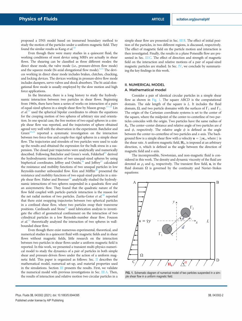
Consider a pair of identical circular particles in a simple shearflow as shown in Fig. 1. The square ABCD is the computationaldomain. The side length of the square is L. It includes the fluiddomain, X, and two particle domains with the surfaces of C1 and C2.The origin of the Cartesian coordinate systems is set to the center ofthe square, where the midpoint of the center-to-centerline of two par-ticles coincides with the origin. Two particles have the same radius ofR0. The center–center distance and relative angle of two particles are dand /, respectively. The relative angle / is defined as the anglebetween the center-to-centerline of two particles and x-axis. The back-ground flow is a simple shear flow with a velocity u ¼ _cyex , where _c isthe shear rate. A uniformmagnetic field,H0, is imposed at an arbitrarydirection, a, which is defined as the angle between the direction ofmagnetic field and x-axis.
The incompressible, Newtonian, and non-magnetic fluid is con-sidered in this work. The density and dynamic viscosity of the fluid aredenoted as qf and gf, respectively. The transient flow field, u, in thefluid domain X is governed by the continuity and Navier–Stokesequations:
FIG. 1. Schematic diagram of numerical model of two particles suspended in a sim-ple shear flow in a uniform magnetic field.
Physics of Fluids ARTICLE scitation.org/journal/phf
Phys. Fluids 33, 043302 (2021); doi: 10.1063/5.0044395 33, 043302-2
Published under license by AIP Publishing
r � u ¼ 0;
qf@u@tþ ðu � rÞu
� �¼ �rpþr � gf ruþ ðruÞT
� �;
(1)
where p is pressure.To impose a simple shear flow, the boundaries AB and CD are
set to have velocities of 6 12 _cLex , respectively. The periodic flow condi-
tions are applied at boundaries AC and BD. No-slip conditions areapplied on the particle surfaces, C1 and C2, so we can get the velocitieson C1 andC2:
upi ¼ Upi þ xpi � xsi � xpið Þ; (2)
where i¼ 1 or 2 represents the first or second particle. Upi and xpi aretranslational and rotational velocities of ith particle, respectively. xsiand xpi are position vectors of the surface and the center of the ith par-ticle, respectively. Thus, the corresponding hydrodynamic force andtorque working on the first and second particle are expressed by
Fhi ¼ð
shi � nð ÞdCi;
Lhi ¼ð
shi � xsi � xpið Þ � nð ÞdCi;
(3)
where shi ¼ gf ðrui þ ðruiÞTÞ is the hydrodynamic stress tensorworking on the ith particle surface Ci.
The magnetic field is applied in the entire domain including fluiddomain and particle domains, which is governed by the static Maxwellequations,
r�H ¼ 0;
r � B ¼ 0;(4)
where magnetic field H and magnetic flux density B are related byconstitutive equation: B ¼ lH. l ¼ l0ð1þ vÞ is the magnetic perme-ability of a linear isotropic material, where l0 ¼ 4p� 10�7 H/m isthe magnetic permeability in vacuum.
To apply the magnetic field in an arbitrary direction, the mag-netic scalar potential differences are set between boundaries AB andCD, and boundaries BD and AC to generate a uniform magnetic field.The zero magnetic potential Vm¼ 0 is applied at boundaries AB andBD. The magnetic scalar potentials Vm sinðaÞ and Vm cosðaÞ areapplied at boundaries CD and AC, respectively. The relationshipbetween magnetic scalar potential and magnetic field isH ¼ �rVm.
Assume that magnetic properties of the fluid and the particles arehomogeneous and isotropic, where the magnetic susceptibility of fluidand paramagnetic particles are denoted as vf and vp, respectively. Themagnetic force and torque working on the ithe particle are given by33
Fmi ¼ð
smi � nð ÞdCi
Lmi ¼ð
smi � xsi � xpið Þ � nð ÞdCi;
(5)
where Maxwell stress tensor acting on the ith particle surface Ci isgiven by smi ¼ l HH� 1
2H2I
� �, where H2 ¼ H �H and I is an iden-
tity tensor.Due to two-dimensional simulations considered in this work, the
rotational motion of the particles is on x-y plane, thus xpi ¼ xpiez;Lhi ¼ Lhiez; and Lmi ¼ Lmiez .The Newton’s second law and Euler’s
equation governs the translational and rotational motion of theparticles,
mpidUpi
dt¼ Fhi þ Fmi;
Ipidxpi
dt¼ Lhi þ Lmi;
(6)
where mpi and Ipi are the mass and the moment of inertia of the ithparticle, respectively.
The position of the ith particle xpi ¼ ðxpi; ypiÞ is calculated by
xpiðtÞ ¼ xpið0Þ þðt0Upi t
0ð Þdt0; (7)
where xpið0Þ is the initial position of the ith particle.The flow field, magnetic field, and the particle motions are cou-
pled via Eqs, (2), (3), and (5)–(7). The fluid–structure interaction (FSI)model is created by direct numerical simulation (DNS) which is basedon finite element method (FEM) and arbitrary Lagrangian–Eulerian(ALE) approach. The magnetic field, flow field, and particle motionare calculated at the same time. The similar methods are successfullyapplied in the previous research.34–41 The numerical model is imple-mented and solved by the commercial FEM software—COMSOLMultiphysics. The time-dependent solver via ALE method is used tosolve two-way coupling of the particle–fluid–magnetic interactionmodel, which solves the magnetic field, fluid field, and tracks the parti-cle motion simultaneously. The magnetic field is solved on the entiredomain including the fluid and particle domains in Lagrangian frameby using the magnetostatics module. The magnetic module is coupledwith FSI, which uses ALE to solve particle motion in the fluid field. InFSI, the particle domains are fixed, while the fluid domain is free todeform which is tracked by moving mesh interface. The mesh qualityis decreased as the mesh deforms. The re-meshing process begins asthe mesh quality is decreased to 0.2. The total number of about 28,000elements is used in the entire domain, and about 250 elements areused on each particle surface to get the stable and mesh-independentresults.
B. Material properties
In this work, we used the water as the fluid medium, which isconsidered as non-magnetic with vf ¼ 0. The density and dynamicviscosity of the water are qf¼ 1000 kg/m3 and gf ¼ 1� 10�3 Pa � s.The shear rate of the flow is _c ¼ 200 s�1. Since polystyrene paramag-netic particles containing magnetic nanoparticles have been used in awide number of applications, the properties of those particles are usedin this work. A common paramagnetic particle with the density ofqp ¼ 1100 kg/m3 and the magnetic susceptibility of vp ¼ 0:26 is used,which also used in previous experiments.42,43 The radius of the particleis R0 ¼ 3:5 lm. The side length of the square domain L ¼ 50R0 isused to avoid the effect on particle–particle interaction due to thesidewall.
III. RESULTS AND DISCUSSIONA. Validation
First, we validate our numerical model by comparing the simula-tion results to the results of references for particle–particle interactionsof a pair of particles without an applied magnetic field. The theory of
Physics of Fluids ARTICLE scitation.org/journal/phf
Phys. Fluids 33, 043302 (2021); doi: 10.1063/5.0044395 33, 043302-3
Published under license by AIP Publishing
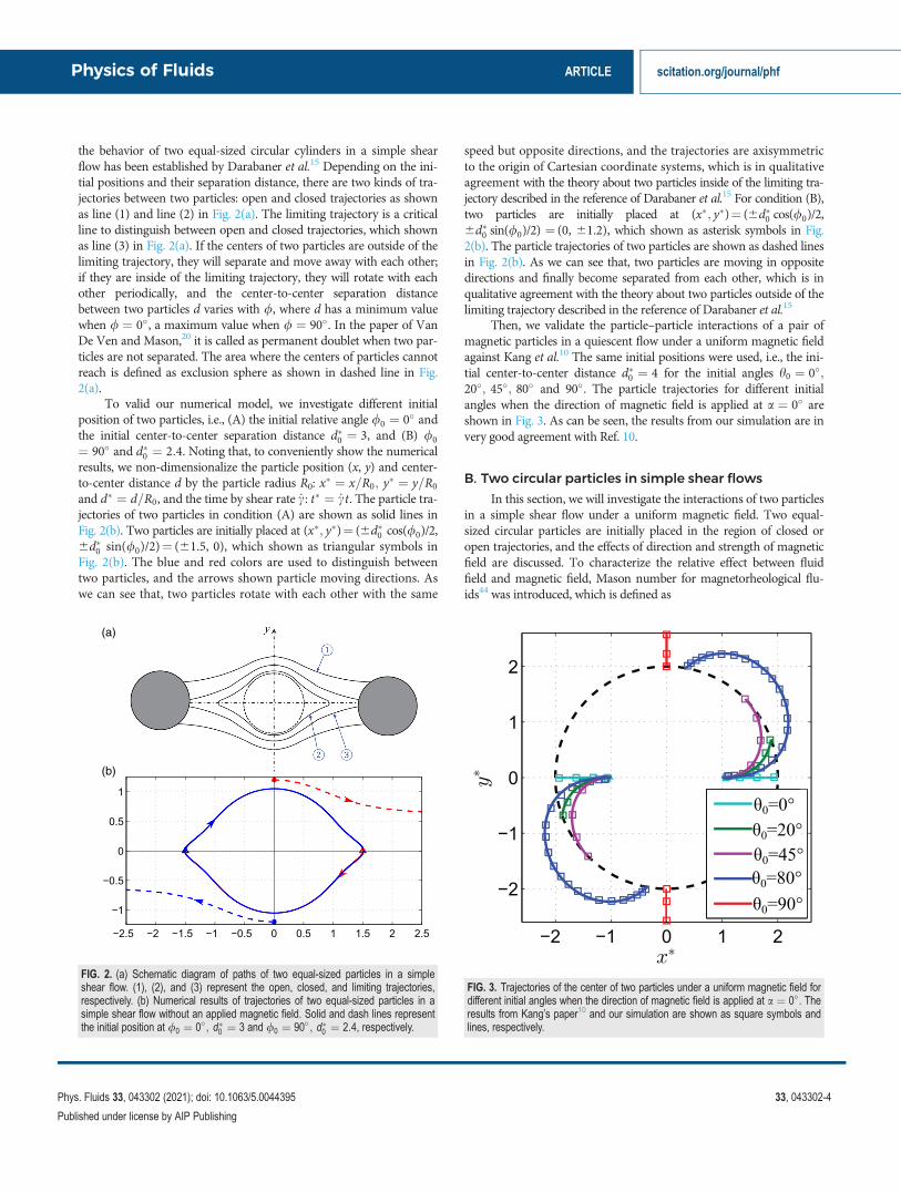
the behavior of two equal-sized circular cylinders in a simple shearflow has been established by Darabaner et al.15 Depending on the ini-tial positions and their separation distance, there are two kinds of tra-jectories between two particles: open and closed trajectories as shownas line (1) and line (2) in Fig. 2(a). The limiting trajectory is a criticalline to distinguish between open and closed trajectories, which shownas line (3) in Fig. 2(a). If the centers of two particles are outside of thelimiting trajectory, they will separate and move away with each other;if they are inside of the limiting trajectory, they will rotate with eachother periodically, and the center-to-center separation distancebetween two particles d varies with /, where d has a minimum valuewhen / ¼ 0�, a maximum value when / ¼ 90�. In the paper of VanDe Ven and Mason,20 it is called as permanent doublet when two par-ticles are not separated. The area where the centers of particles cannotreach is defined as exclusion sphere as shown in dashed line in Fig.2(a).
To valid our numerical model, we investigate different initialposition of two particles, i.e., (A) the initial relative angle /0 ¼ 0� andthe initial center-to-center separation distance d�0 ¼ 3, and (B) /0¼ 90� and d�0 ¼ 2:4. Noting that, to conveniently show the numericalresults, we non-dimensionalize the particle position (x, y) and center-to-center distance d by the particle radius R0: x� ¼ x=R0; y� ¼ y=R0
and d� ¼ d=R0, and the time by shear rate _c: t� ¼ _ct. The particle tra-jectories of two particles in condition (A) are shown as solid lines inFig. 2(b). Two particles are initially placed at (x�; y�)¼ (6d�0 cos(/0)/2,6d�0 sin(/0)/2)¼ (61.5, 0), which shown as triangular symbols inFig. 2(b). The blue and red colors are used to distinguish betweentwo particles, and the arrows shown particle moving directions. Aswe can see that, two particles rotate with each other with the same
speed but opposite directions, and the trajectories are axisymmetricto the origin of Cartesian coordinate systems, which is in qualitativeagreement with the theory about two particles inside of the limiting tra-jectory described in the reference of Darabaner et al.15 For condition (B),two particles are initially placed at (x�; y�)¼ (6d�0 cos(/0)/2,6d�0 sin(/0)/2) ¼ (0, 61.2), which shown as asterisk symbols in Fig.2(b). The particle trajectories of two particles are shown as dashed linesin Fig. 2(b). As we can see that, two particles are moving in oppositedirections and finally become separated from each other, which is inqualitative agreement with the theory about two particles outside of thelimiting trajectory described in the reference of Darabaner et al.15
Then, we validate the particle–particle interactions of a pair ofmagnetic particles in a quiescent flow under a uniform magnetic fieldagainst Kang et al.10 The same initial positions were used, i.e., the ini-tial center-to-center distance d�0 ¼ 4 for the initial angles h0 ¼ 0�;20�; 45�; 80� and 90�. The particle trajectories for different initialangles when the direction of magnetic field is applied at a ¼ 0� areshown in Fig. 3. As can be seen, the results from our simulation are invery good agreement with Ref. 10.
B. Two circular particles in simple shear flows
In this section, we will investigate the interactions of two particlesin a simple shear flow under a uniform magnetic field. Two equal-sized circular particles are initially placed in the region of closed oropen trajectories, and the effects of direction and strength of magneticfield are discussed. To characterize the relative effect between fluidfield and magnetic field, Mason number for magnetorheological flu-ids44 was introduced, which is defined as
FIG. 2. (a) Schematic diagram of paths of two equal-sized particles in a simpleshear flow. (1), (2), and (3) represent the open, closed, and limiting trajectories,respectively. (b) Numerical results of trajectories of two equal-sized particles in asimple shear flow without an applied magnetic field. Solid and dash lines representthe initial position at /0 ¼ 0�; d�0 ¼ 3 and /0 ¼ 90�; d�0 ¼ 2:4, respectively.
FIG. 3. Trajectories of the center of two particles under a uniform magnetic field fordifferent initial angles when the direction of magnetic field is applied at a ¼ 0�. Theresults from Kang’s paper10 and our simulation are shown as square symbols andlines, respectively.
Physics of Fluids ARTICLE scitation.org/journal/phf
Phys. Fluids 33, 043302 (2021); doi: 10.1063/5.0044395 33, 043302-4
Published under license by AIP Publishing
Mn ¼gf _c
2l0lf b2MH
20
;
where bM ¼ ðlp � lf Þ=ðlp þ 2lf Þ. lf ¼ 1þ vf and lp ¼ 1þ vpare the relative permeability of the fluid and particle. For simple shearflow we discussed here, Mn¼ 12.5, 3.13, 0.500, 0.125 and 0.031 3 forH0¼ 1000A/m, 2000A/m, 5000A/m, 10 000A/m, and 20 000A/m,respectively.
1. Initially located in the closed trajectories region
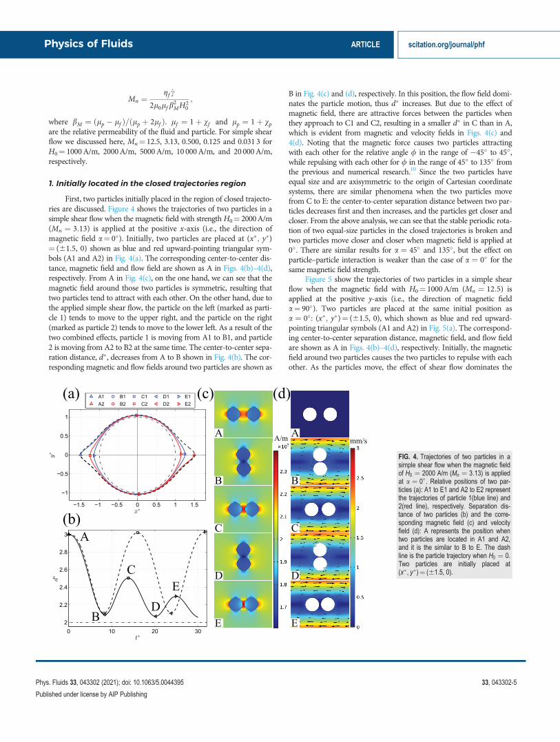
First, two particles initially placed in the region of closed trajecto-ries are discussed. Figure 4 shows the trajectories of two particles in asimple shear flow when the magnetic field with strengthH0¼ 2000A/m(Mn ¼ 3:13) is applied at the positive x-axis (i.e., the direction ofmagnetic field a¼ 0�). Initially, two particles are placed at (x�; y�)¼ (61.5, 0) shown as blue and red upward-pointing triangular sym-bols (A1 and A2) in Fig. 4(a). The corresponding center-to-center dis-tance, magnetic field and flow field are shown as A in Figs. 4(b)–4(d),respectively. From A in Fig. 4(c), on the one hand, we can see that themagnetic field around those two particles is symmetric, resulting thattwo particles tend to attract with each other. On the other hand, due tothe applied simple shear flow, the particle on the left (marked as parti-cle 1) tends to move to the upper right, and the particle on the right(marked as particle 2) tends to move to the lower left. As a result of thetwo combined effects, particle 1 is moving from A1 to B1, and particle2 is moving from A2 to B2 at the same time. The center-to-center sepa-ration distance, d�, decreases from A to B shown in Fig. 4(b). The cor-responding magnetic and flow fields around two particles are shown as
B in Fig. 4(c) and (d), respectively. In this position, the flow field domi-nates the particle motion, thus d� increases. But due to the effect ofmagnetic field, there are attractive forces between the particles whenthey approach to C1 and C2, resulting in a smaller d� in C than in A,which is evident from magnetic and velocity fields in Figs. 4(c) and4(d). Noting that the magnetic force causes two particles attractingwith each other for the relative angle / in the range of �45� to 45�,while repulsing with each other for / in the range of 45� to 135� fromthe previous and numerical research.10 Since the two particles haveequal size and are axisymmetric to the origin of Cartesian coordinatesystems, there are similar phenomena when the two particles movefrom C to E: the center-to-center separation distance between two par-ticles decreases first and then increases, and the particles get closer andcloser. From the above analysis, we can see that the stable periodic rota-tion of two equal-size particles in the closed trajectories is broken andtwo particles move closer and closer when magnetic field is applied at0�. There are similar results for a ¼ 45� and 135�, but the effect onparticle–particle interaction is weaker than the case of a ¼ 0� for thesame magnetic field strength.
Figure 5 show the trajectories of two particles in a simple shearflow when the magnetic field with H0¼ 1000A/m (Mn ¼ 12:5) isapplied at the positive y-axis (i.e., the direction of magnetic fielda¼ 90�). Two particles are placed at the same initial position asa ¼ 0�: (x�; y�)¼ (61.5, 0), which shown as blue and red upward-pointing triangular symbols (A1 and A2) in Fig. 5(a). The correspond-ing center-to-center separation distance, magnetic field, and flow fieldare shown as A in Figs. 4(b)–4(d), respectively. Initially, the magneticfield around two particles causes the two particles to repulse with eachother. As the particles move, the effect of shear flow dominates the
FIG. 4. Trajectories of two particles in asimple shear flow when the magnetic fieldof H0 ¼ 2000 A/m (Mn ¼ 3:13) is appliedat a ¼ 0�. Relative positions of two par-ticles (a): A1 to E1 and A2 to E2 representthe trajectories of particle 1(blue line) and2(red line), respectively. Separation dis-tance of two particles (b) and the corre-sponding magnetic field (c) and velocityfield (d): A represents the position whentwo particles are located in A1 and A2,and it is the similar to B to E. The dashline is the particle trajectory when H0 ¼ 0.Two particles are initially placed at(x�; y�)¼ (61.5, 0).
Physics of Fluids ARTICLE scitation.org/journal/phf
Phys. Fluids 33, 043302 (2021); doi: 10.1063/5.0044395 33, 043302-5
Published under license by AIP Publishing
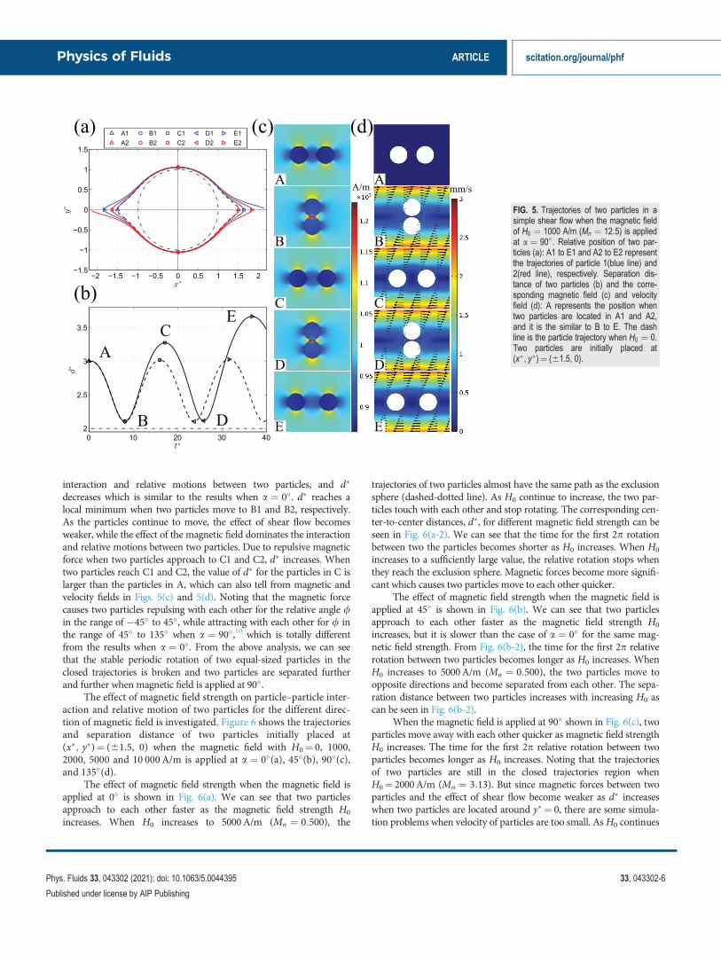
interaction and relative motions between two particles, and d�
decreases which is similar to the results when a ¼ 0�. d� reaches alocal minimum when two particles move to B1 and B2, respectively.As the particles continue to move, the effect of shear flow becomesweaker, while the effect of the magnetic field dominates the interactionand relative motions between two particles. Due to repulsive magneticforce when two particles approach to C1 and C2, d� increases. Whentwo particles reach C1 and C2, the value of d� for the particles in C islarger than the particles in A, which can also tell from magnetic andvelocity fields in Figs. 5(c) and 5(d). Noting that the magnetic forcecauses two particles repulsing with each other for the relative angle /in the range of �45� to 45�, while attracting with each other for / inthe range of 45� to 135� when a ¼ 90�,10 which is totally differentfrom the results when a ¼ 0�. From the above analysis, we can seethat the stable periodic rotation of two equal-sized particles in theclosed trajectories is broken and two particles are separated furtherand further when magnetic field is applied at 90�.
The effect of magnetic field strength on particle–particle inter-action and relative motion of two particles for the different direc-tion of magnetic field is investigated. Figure 6 shows the trajectoriesand separation distance of two particles initially placed at(x�; y�)¼ (61.5, 0) when the magnetic field with H0¼ 0, 1000,2000, 5000 and 10 000A/m is applied at a ¼ 0�(a), 45�(b), 90�(c),and 135�(d).
The effect of magnetic field strength when the magnetic field isapplied at 0� is shown in Fig. 6(a). We can see that two particlesapproach to each other faster as the magnetic field strength H0
increases. When H0 increases to 5000A/m (Mn ¼ 0:500), the
trajectories of two particles almost have the same path as the exclusionsphere (dashed-dotted line). As H0 continue to increase, the two par-ticles touch with each other and stop rotating. The corresponding cen-ter-to-center distances, d�, for different magnetic field strength can beseen in Fig. 6(a-2). We can see that the time for the first 2p rotationbetween two the particles becomes shorter as H0 increases. When H0
increases to a sufficiently large value, the relative rotation stops whenthey reach the exclusion sphere. Magnetic forces become more signifi-cant which causes two particles move to each other quicker.
The effect of magnetic field strength when the magnetic field isapplied at 45� is shown in Fig. 6(b). We can see that two particlesapproach to each other faster as the magnetic field strength H0
increases, but it is slower than the case of a ¼ 0� for the same mag-netic field strength. From Fig. 6(b-2), the time for the first 2p relativerotation between two particles becomes longer as H0 increases. WhenH0 increases to 5000A/m (Mn ¼ 0:500), the two particles move toopposite directions and become separated from each other. The sepa-ration distance between two particles increases with increasing H0 ascan be seen in Fig. 6(b-2).
When the magnetic field is applied at 90� shown in Fig. 6(c), twoparticles move away with each other quicker as magnetic field strengthH0 increases. The time for the first 2p relative rotation between twoparticles becomes longer as H0 increases. Noting that the trajectoriesof two particles are still in the closed trajectories region whenH0¼ 2000A/m (Mn ¼ 3:13). But since magnetic forces between twoparticles and the effect of shear flow become weaker as d� increaseswhen two particles are located around y� ¼ 0, there are some simula-tion problems when velocity of particles are too small. AsH0 continues
FIG. 5. Trajectories of two particles in asimple shear flow when the magnetic fieldof H0 ¼ 1000 A/m (Mn ¼ 12:5) is appliedat a ¼ 90� . Relative position of two par-ticles (a): A1 to E1 and A2 to E2 representthe trajectories of particle 1(blue line) and2(red line), respectively. Separation dis-tance of two particles (b) and the corre-sponding magnetic field (c) and velocityfield (d): A represents the position whentwo particles are located in A1 and A2,and it is the similar to B to E. The dashline is the particle trajectory when H0 ¼ 0.Two particles are initially placed at(x�; y�)¼ (61.5, 0).
Physics of Fluids ARTICLE scitation.org/journal/phf
Phys. Fluids 33, 043302 (2021); doi: 10.1063/5.0044395 33, 043302-6
Published under license by AIP Publishing
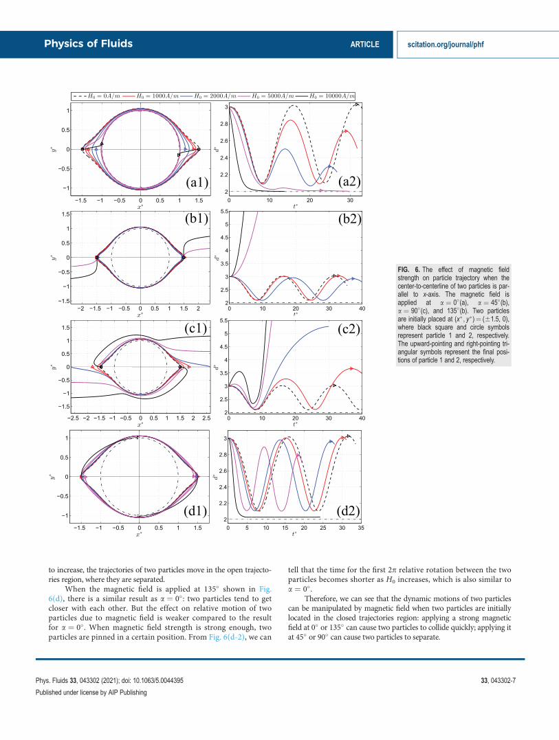
to increase, the trajectories of two particles move in the open trajecto-ries region, where they are separated.
When the magnetic field is applied at 135� shown in Fig.6(d), there is a similar result as a ¼ 0�: two particles tend to getcloser with each other. But the effect on relative motion of twoparticles due to magnetic field is weaker compared to the resultfor a ¼ 0�. When magnetic field strength is strong enough, twoparticles are pinned in a certain position. From Fig. 6(d-2), we can
tell that the time for the first 2p relative rotation between the twoparticles becomes shorter as H0 increases, which is also similar toa ¼ 0�.
Therefore, we can see that the dynamic motions of two particlescan be manipulated by magnetic field when two particles are initiallylocated in the closed trajectories region: applying a strong magneticfield at 0� or 135� can cause two particles to collide quickly; applying itat 45� or 90� can cause two particles to separate.
FIG. 6. The effect of magnetic fieldstrength on particle trajectory when thecenter-to-centerline of two particles is par-allel to x-axis. The magnetic field isapplied at a ¼ 0�(a), a ¼ 45�(b),a ¼ 90�(c), and 135�(b). Two particlesare initially placed at (x�; y�)¼ (61.5, 0),where black square and circle symbolsrepresent particle 1 and 2, respectively.The upward-pointing and right-pointing tri-angular symbols represent the final posi-tions of particle 1 and 2, respectively.
Physics of Fluids ARTICLE scitation.org/journal/phf
Phys. Fluids 33, 043302 (2021); doi: 10.1063/5.0044395 33, 043302-7
Published under license by AIP Publishing
2. Initially located in the open trajectories region
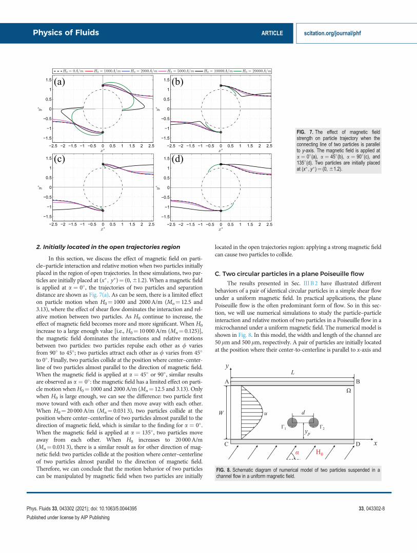
In this section, we discuss the effect of magnetic field on parti-cle–particle interaction and relative motion when two particles initiallyplaced in the region of open trajectories. In these simulations, two par-ticles are initially placed at (x�; y�)¼ (0, 61.2). When a magnetic fieldis applied at a ¼ 0�, the trajectories of two particles and separationdistance are shown as Fig. 7(a). As can be seen, there is a limited effecton particle motion when H0¼ 1000 and 2000A/m (Mn¼ 12.5 and3.13), where the effect of shear flow dominates the interaction and rel-ative motion between two particles. As H0 continue to increase, theeffect of magnetic field becomes more and more significant. When H0
increase to a large enough value [i.e., H0¼ 10 000A/m (Mn¼ 0.125)],the magnetic field dominates the interactions and relative motionsbetween two particles: two particles repulse each other as / variesfrom 90� to 45�; two particles attract each other as / varies from 45�
to 0�. Finally, two particles collide at the position where center–center-line of two particles almost parallel to the direction of magnetic field.When the magnetic field is applied at a ¼ 45� or 90�, similar resultsare observed as a ¼ 0�: the magnetic field has a limited effect on parti-cle motion whenH0¼ 1000 and 2000A/m (Mn¼ 12.5 and 3.13). Onlywhen H0 is large enough, we can see the difference: two particle firstmove toward with each other and then move away with each other.When H0¼ 20 000A/m (Mn¼ 0.031 3), two particles collide at theposition where center–centerline of two particles almost parallel to thedirection of magnetic field, which is similar to the finding for a ¼ 0�.When the magnetic field is applied at a ¼ 135�, two particles moveaway from each other. When H0 increases to 20 000A/m(Mn¼ 0.031 3), there is a similar result as for other direction of mag-netic field: two particles collide at the position where center–centerlineof two particles almost parallel to the direction of magnetic field.Therefore, we can conclude that the motion behavior of two particlescan be manipulated by magnetic field when two particles are initially
located in the open trajectories region: applying a strong magnetic fieldcan cause two particles to collide.
C. Two circular particles in a plane Poiseuille flow
The results presented in Sec. III B 2 have illustrated differentbehaviors of a pair of identical circular particles in a simple shear flowunder a uniform magnetic field. In practical applications, the planePoiseuille flow is the often predominant form of flow. So in this sec-tion, we will use numerical simulations to study the particle–particleinteraction and relative motion of two particles in a Poiseuille flow in amicrochannel under a uniform magnetic field. The numerical model isshown in Fig. 8. In this model, the width and length of the channel are50lm and 500lm, respectively. A pair of particles are initially locatedat the position where their center-to-centerline is parallel to x-axis and
FIG. 7. The effect of magnetic fieldstrength on particle trajectory when theconnecting line of two particles is parallelto y-axis. The magnetic field is applied ata ¼ 0�(a), a ¼ 45�(b), a ¼ 90�(c), and135�(d). Two particles are initially placedat (x�; y�)¼ (0, 61.2).
FIG. 8. Schematic diagram of numerical model of two particles suspended in achannel flow in a uniform magnetic field.
Physics of Fluids ARTICLE scitation.org/journal/phf
Phys. Fluids 33, 043302 (2021); doi: 10.1063/5.0044395 33, 043302-8
Published under license by AIP Publishing
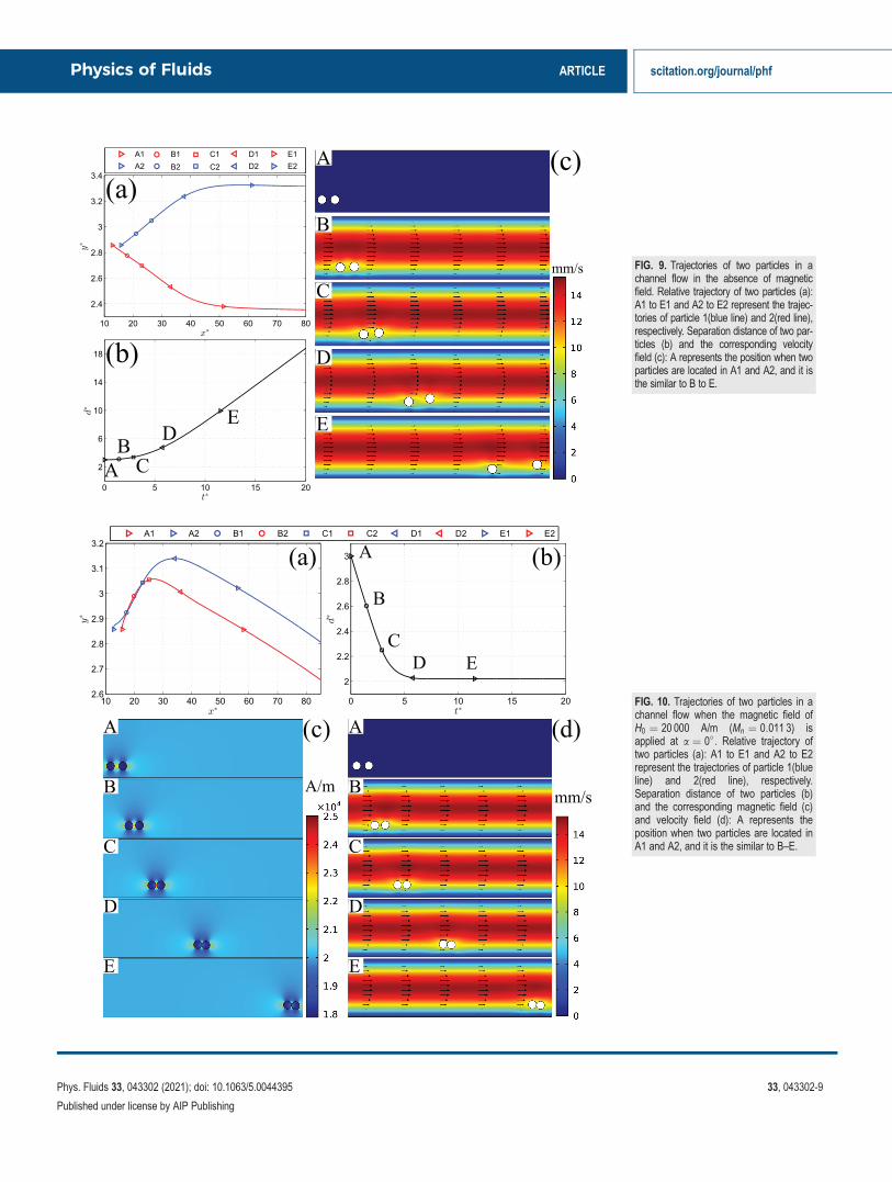
FIG. 9. Trajectories of two particles in achannel flow in the absence of magneticfield. Relative trajectory of two particles (a):A1 to E1 and A2 to E2 represent the trajec-tories of particle 1(blue line) and 2(red line),respectively. Separation distance of two par-ticles (b) and the corresponding velocityfield (c): A represents the position when twoparticles are located in A1 and A2, and it isthe similar to B to E.
FIG. 10. Trajectories of two particles in achannel flow when the magnetic field ofH0 ¼ 20 000 A/m (Mn ¼ 0:011 3) isapplied at a ¼ 0�. Relative trajectory oftwo particles (a): A1 to E1 and A2 to E2represent the trajectories of particle 1(blueline) and 2(red line), respectively.Separation distance of two particles (b)and the corresponding magnetic field (c)and velocity field (d): A represents theposition when two particles are located inA1 and A2, and it is the similar to B–E.
Physics of Fluids ARTICLE scitation.org/journal/phf
Phys. Fluids 33, 043302 (2021); doi: 10.1063/5.0044395 33, 043302-9
Published under license by AIP Publishing
particle–wall distance, yp¼ 10lm. The average inlet flow velocity is1 cm/s. The magnetic field is imposed at an arbitrary direction, a. Toconveniently show the numerical results, the dimensionless particleposition (x�; y�), center-to-center distance d� and time t� have thesame definition as Sec. IIIA. Here, we use the shear rate at the par-ticle’s initial position to non-dimensionalize the time and calculateManson number. In the following discussion, two particles are initiallyplaced at (x�; y�)¼ (12.78, 2.86) and (15.78, 2.86), respectively.Mn¼ 0.045 0, 0.020 0, and 0.011 3 for H0¼ 10 000A/m, 15 000A/m,and 20 000A/m, respectively.
Before discussing about the results in the presence of magneticfield, we first investigate the dynamics of two particles in a channelflow in the absence of magnetic field. Figure 9 shows the dimensionlesstrajectories, separation distance, and the corresponding flow field oftwo particles in a channel flow in the absence of magnetic field. FromFig. 9, we can see that, in the beginning (from A to C), one particletends to move away from the lower wall (blue line, marked as particle1), while the other particle tends to move toward the lower wall (redline, marked as particle 2). The corresponding dimensionless separa-tion distance, d�, slowly increases with time, t� shown in Fig. 9(b). Asthe particles continue to move away from each other (from C to E),the difference of shear rate and velocity in the position of two particlesbecomes larger and larger, which cause particle 1 to move faster thanparticle 2 in the x direction. The corresponding dimensionless separa-tion distance, d�, quickly increases with the dimensionless time, t�.When the two particles reach position E, the effect of particle–particle
and particle–wall interactions become weaker, while the effect of flowfield becomes more significant. As they continue to move, the separa-tion distance in y direction tend to stabilize and in x direction becomelarger, where the effect of particle–particle interaction is negligible andthe flow field dominates the particle motion.
1. The effect of direction of magnetic field
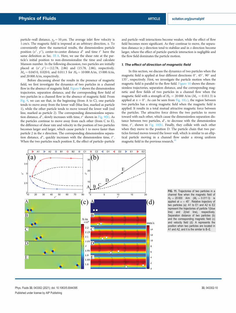
In this section, we discuss the dynamics of two particles when themagnetic field is applied at four different directions: 0�; 45�; 90� and135�, respectively. First, we investigate the particle motion when themagnetic field is parallel to the flow field. Figure 10 shows the dimen-sionless trajectories, separation distance, and the corresponding mag-netic and flow fields of two particles in a channel flow when themagnetic field with a strength of H0 ¼ 20 000 A/m (Mn ¼ 0:011 3) isapplied at a ¼ 0�. As can be seen from Fig. 10(c), the region betweentwo particles has a strong magnetic field when the magnetic field isapplied. It results in a total mutual attractive magnetic force betweenthe particles. The attractive force drives the two particles to movetoward with each other, which cause the dimensionless separation dis-tance between two particles, d�, to decrease with the dimensionlesstime, t�, shown in Fig. 10(b). Finally, they collide with each otherwhen they move to the position D. The particle chain that two par-ticles formed moves toward the lower wall, which is similar to an ellip-tical particle moving in a channel flow under a strong uniformmagnetic field in the previous research.39
FIG. 11. Trajectories of two particles in achannel flow when the magnetic field ofH0 ¼ 20 000 A/m (Mn ¼ 0:011 3) isapplied at a ¼ 45�. Relative trajectory oftwo particles (a): A1 to E1 and A2 to E2represent the trajectories of particle 1(blueline) and 2(red line), respectively.Separation distance of two particles (b)and the corresponding magnetic field (c)and velocity field (d): A represents theposition when two particles are located inA1 and A2, and it is the similar to B–E.
Physics of Fluids ARTICLE scitation.org/journal/phf
Phys. Fluids 33, 043302 (2021); doi: 10.1063/5.0044395 33, 043302-10
Published under license by AIP Publishing
Then, we investigate the dynamics of two particles when themagnetic field is applied at 45�. Figure 11 shows the dimensionlesstrajectories, separation distance, and the corresponding magneticand flow fields of two particles in a channel flow when the mag-netic field with H0 ¼ 20 000 A/m (Mn ¼ 0:011 3) is applied ata ¼ 45�. From Fig. 11(a), we can see that, in the beginning (from Ato C), the magnetic field has a major effect on particle–particleinteraction. Two particles move faster away from each other in they direction, but the dimensionless separation distance increasesslowly. As the particles continuing to move (from C to E), theeffect of magnetic becomes weaker, while the difference of shearrate and particle velocity between two particles becomes more sig-nificant. Two particles move faster away from each other in the xdirection, resulting in a quickly increasing d�. By comparing withthe results in the absence of magnetic field shown as the dash linein Figs. 11(a) and 11(b), we can see that two particles can be sepa-rated faster when the magnetic field is applied at 45�.
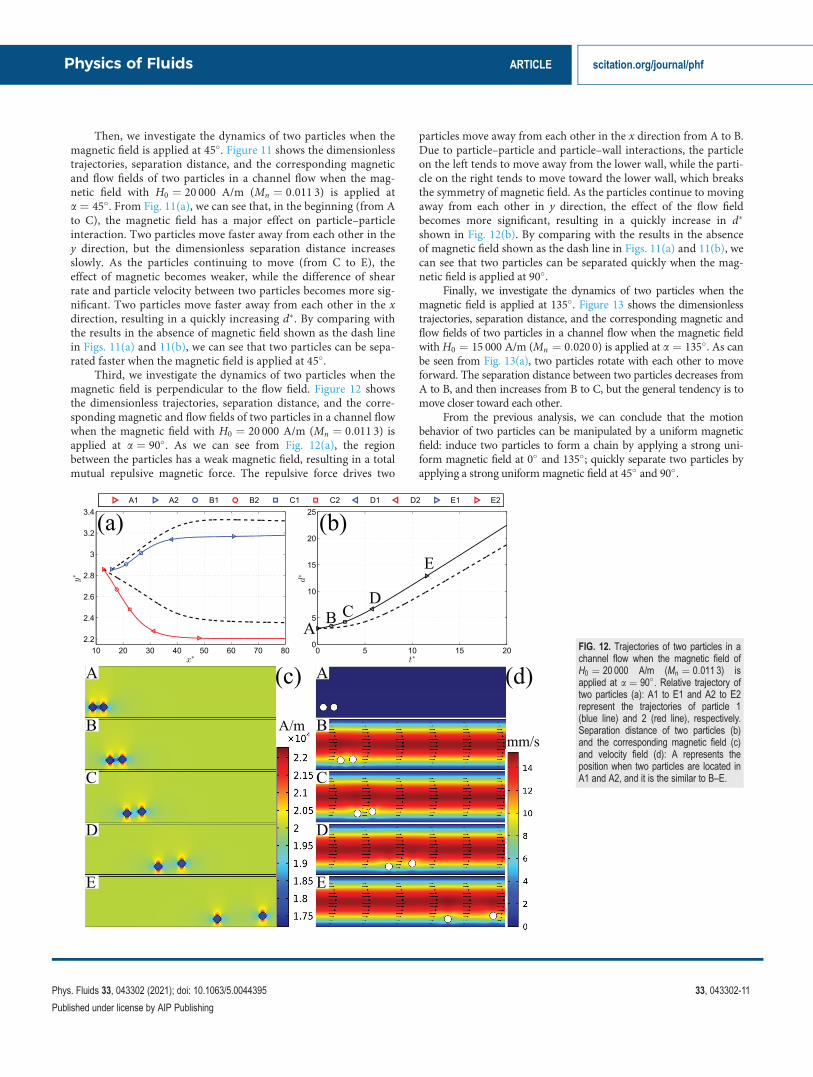
Third, we investigate the dynamics of two particles when themagnetic field is perpendicular to the flow field. Figure 12 showsthe dimensionless trajectories, separation distance, and the corre-sponding magnetic and flow fields of two particles in a channel flowwhen the magnetic field with H0 ¼ 20 000 A/m (Mn ¼ 0:011 3) isapplied at a ¼ 90�. As we can see from Fig. 12(a), the regionbetween the particles has a weak magnetic field, resulting in a totalmutual repulsive magnetic force. The repulsive force drives two
particles move away from each other in the x direction from A to B.Due to particle–particle and particle–wall interactions, the particleon the left tends to move away from the lower wall, while the parti-cle on the right tends to move toward the lower wall, which breaksthe symmetry of magnetic field. As the particles continue to movingaway from each other in y direction, the effect of the flow fieldbecomes more significant, resulting in a quickly increase in d�
shown in Fig. 12(b). By comparing with the results in the absenceof magnetic field shown as the dash line in Figs. 11(a) and 11(b), wecan see that two particles can be separated quickly when the mag-netic field is applied at 90�.
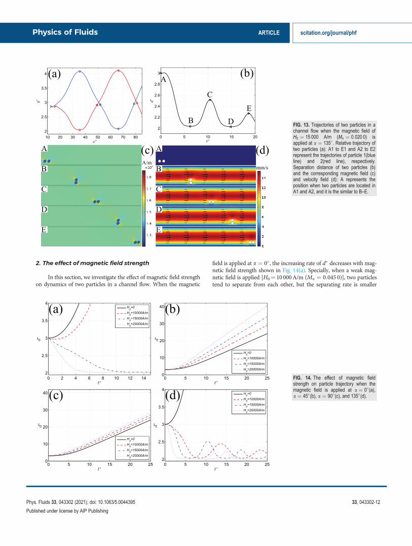
Finally, we investigate the dynamics of two particles when themagnetic field is applied at 135�. Figure 13 shows the dimensionlesstrajectories, separation distance, and the corresponding magnetic andflow fields of two particles in a channel flow when the magnetic fieldwithH0 ¼ 15 000 A/m (Mn ¼ 0:020 0) is applied at a ¼ 135�. As canbe seen from Fig. 13(a), two particles rotate with each other to moveforward. The separation distance between two particles decreases fromA to B, and then increases from B to C, but the general tendency is tomove closer toward each other.
From the previous analysis, we can conclude that the motionbehavior of two particles can be manipulated by a uniform magneticfield: induce two particles to form a chain by applying a strong uni-form magnetic field at 0� and 135�; quickly separate two particles byapplying a strong uniformmagnetic field at 45� and 90�.
FIG. 12. Trajectories of two particles in achannel flow when the magnetic field ofH0 ¼ 20 000 A/m (Mn ¼ 0:011 3) isapplied at a ¼ 90�. Relative trajectory oftwo particles (a): A1 to E1 and A2 to E2represent the trajectories of particle 1(blue line) and 2 (red line), respectively.Separation distance of two particles (b)and the corresponding magnetic field (c)and velocity field (d): A represents theposition when two particles are located inA1 and A2, and it is the similar to B–E.
Physics of Fluids ARTICLE scitation.org/journal/phf
Phys. Fluids 33, 043302 (2021); doi: 10.1063/5.0044395 33, 043302-11
Published under license by AIP Publishing
2. The effect of magnetic field strength
In this section, we investigate the effect of magnetic field strengthon dynamics of two particles in a channel flow. When the magnetic
field is applied at a ¼ 0�, the increasing rate of d� decreases with mag-netic field strength shown in Fig. 14(a). Specially, when a weak mag-netic field is applied [H0¼ 10 000A/m (Mn ¼ 0:045 0)], two particlestend to separate from each other, but the separating rate is smaller
FIG. 13. Trajectories of two particles in achannel flow when the magnetic field ofH0 ¼ 15 000 A/m (Mn ¼ 0:020 0) isapplied at a ¼ 135�. Relative trajectory oftwo particles (a): A1 to E1 and A2 to E2represent the trajectories of particle 1(blueline) and 2(red line), respectively.Separation distance of two particles (b)and the corresponding magnetic field (c)and velocity field (d): A represents theposition when two particles are located inA1 and A2, and it is the similar to B–E.
FIG. 14. The effect of magnetic fieldstrength on particle trajectory when themagnetic field is applied at a ¼ 0�(a),a ¼ 45�(b), a ¼ 90�(c), and 135�(d).
Physics of Fluids ARTICLE scitation.org/journal/phf
Phys. Fluids 33, 043302 (2021); doi: 10.1063/5.0044395 33, 043302-12
Published under license by AIP Publishing
than it in the absence of magnetic field. When the magnetic field isstrong enough, two particles tend to collide with each other. As H0
increases, two particles collide with each other faster. When a ¼ 45�
and 90�, the increasing rate of d� increases with the magnetic fieldstrength shown in Figs. 14(b) and 14(c), which means that two particleseparate with each other quicker. By comparing with the results ofa ¼ 45� and 90� in Figs. 14(b) and 14(c), we can see that the separat-ing rate of a ¼ 45� is larger than a ¼ 90� for a fixed magnetic field. Itmeans that it has a better separating performance when the magneticfield is applied at 45�. When a ¼ 135�, two particles approach eachother faster as the magnetic field strength increases.
IV. CONCLUSION
The direct numerical modeling based on the finite element andarbitrary Lagrangian–Eulerian methods was developed to investigatethe particle–particle interaction and dynamic motions of a pair ofequal-sized magnetic particles in simple shear and plane Poiseuilleflows under a uniform magnetic field. The coupled interactions amongparticle–fluid–magnetic fields are fully considered. By validationagainst previous numerical results, our numerical results are in quali-tative agreement with the theory about two particles inside and outsideof the limiting trajectory described in the reference of Darabaneret al.15 The dynamics of two circular particles in simple shear flows isfirst investigated. The results have shown that the magnetic fieldbreaks the stable particle trajectories. Initially located at the closed tra-jectories, the particles get closer and closer when the magnetic field isapplied at 0�, 45�, and 135�, while they get further and separated whenit is applied at 90�. These stabilizing (0�, 45�, and 135�) and destabiliz-ing (90�) effects become stronger with an increasing magnetic fieldstrength. When two particles are initially located at the open trajecto-ries, they collide when a sufficiently strong magnetic field is applied.According to these findings, the numerical simulation was performedto study the dynamics of two particles in a plane Poiseuille flow in amicrochannel under a uniform magnetic field. Without a magneticfield, two particles moved away from each other. When a strong mag-netic field is applied at 0�and 135�, the particles tend to form a chain;when it is applied at 45� and 90�, two particles become separatedfaster. Therefore, this work will give insights to understanding themechanisms of magnetic particle–particle interactions in simple shearor plane Poiseuille flows under a uniform magnetic field, which arefound in magnetorheological fluids.
ACKNOWLEDGMENTS
The authors greatly appreciate the support from theDepartment of Mechanical and Aerospace Engineering (MAE) andthe Center for Biomedical Research (CBR) at Missouri University ofScience and Technology.
DATA AVAILABILITY
The data that support the findings of this study are availablefrom the corresponding author upon reasonable request.
REFERENCES1M. A. Gijs, “Magnetic bead handling on-chip: New opportunities for analyticalapplications,” Microfluid. Nanofluid. 1, 22–40 (2004).
2M. A. Gijs, F. Lacharme, and U. Lehmann, “Microfluidic applications of mag-netic particles for biological analysis and catalysis,” Chem. Rev. 110,1518–1563 (2010).
3T. Jamshaid, E. T. T. Neto, M. M. Eissa, N. Zine, M. H. Kunita, A. E. El-Salhi,and A. Elaissari, “Magnetic particles: From preparation to lab-on-a-chip, bio-sensors, microsystems and microfluidics applications,” TrAC Trends Anal.Chem. 79, 344–362 (2016).
4J. De Vicente, D. J. Klingenberg, and R. Hidalgo-Alvarez, “Magnetorheologicalfluids: A review,” Soft Matter 7, 3701–3710 (2011).
5S. Melle and J. E. Martin, “Chain model of a magnetorheological suspension ina rotating field,” J. Chem. Phys. 118, 9875–9881 (2003).
6I. Petousis, E. Homburg, R. Derks, and A. Dietzel, “Transient behaviour ofmagnetic micro-bead chains rotating in a fluid by external fields,” Lab Chip 7,1746–1751 (2007).
7D. C. Stuart, C. Kleijn, and S. Kenjere�s, “An efficient and robust method forLagrangian magnetic particle tracking in fluid flow simulations on unstruc-tured grids,” Comput. Fluids 40, 188–194 (2011).
8E. E. Keaveny and M. R. Maxey, “Modeling the magnetic interactions betweenparamagnetic beads in magnetorheological fluids,” J. Comput. Phys. 227,9554–9571 (2008).
9Y. Gao, M. Hulsen, T. Kang, and J. Den Toonder, “Numerical and experimen-tal study of a rotating magnetic particle chain in a viscous fluid,” Phys. Rev. E86, 041503 (2012).
10T. G. Kang, M. A. Hulsen, J. M. den Toonder, P. D. Anderson, and H. E.Meijer, “A direct simulation method for flows with suspended paramagneticparticles,” J. Comput. Phys. 227, 4441–4458 (2008).
11T. G. Kang, Y. Gao, M. A. Hulsen, J. M. den Toonder, and P. D. Anderson,“Direct simulation of the dynamics of two spherical particles actuated magneti-cally in a viscous fluid,” Comput. Fluids 86, 569–581 (2013).
12Y. K. Suh and S. Kang, “Motion of paramagnetic particles in a viscous fluidunder a uniform magnetic field: Benchmark solutions,” J. Eng. Math. 69, 25–58(2011).
13S. Kang and Y. Suh, “Direct simulation of flows with suspended paramagneticparticles using one-stage smoothed profile method,” J. Fluids Struct. 27,266–282 (2011).
14A.-G. Olabi and A. Grunwald, “Design and application of magneto-rheologicalfluid,” Mater. Design 28, 2658–2664 (2007).
15C. Darabaner, J. Raasch, and S. Mason, “Particle motions in sheared suspen-sions xx: Circular cylinders,” Can. J. Chem. Eng. 45, 3–12 (1967).
16S. Wakiya, C. Darabaner, and S. Mason, “Particle motions in sheared suspen-sions xxi: Interactions of rigid spheres (theoretical),” Rheol. Acta 6, 264–273(1967).
17C. Darabaner and S. Mason, “Particle motions in sheared suspensions xxii:Interactions of rigid spheres (experimental),” Rheol. Acta 6, 273–284 (1967).
18P. Arp and S. Mason, “The kinetics of flowing dispersions: Viii. doublets ofrigid spheres (theoretical),” J. Colloid Interface Sci. 61, 21–43 (1977).
19P. Arp and S. Mason, “The kinetics of flowing dispersions: VIII. Doublets ofrigid spheres (experimental),” J. Colloid Interface Sci. 61, 44–61 (1977).
20T. Van de Ven and S. Mason, “The microrheology of colloidal dispersions: Iv.pairs of interacting spheres in shear flow,” J. Colloid Interface Sci. 57, 505–516(1976).
21T. G. van de Ven and S. Mason, “The microrheology of colloidal dispersions: V.primary and secondary doublets of spheres in shear flow,” J. Colloid InterfaceSci. 57, 517–534 (1976).
22C. Lin, K. Lee, and N. Sather, “Slow motion of two spheres in a shear field,”J. Fluid Mech. 43, 35–47 (1970).
23G. Batchelor and J. Green, “The hydrodynamic interaction of two small freely-moving spheres in a linear flow field,” J. Fluid Mech. 56, 375–400 (1972).
24G. Batchelor and J. Green, “The determination of the bulk stress in a suspen-sion of spherical particles to order c 2,” J. Fluid Mech. 56, 401–427 (1972).
25B. Felderhof, “Hydrodynamic interaction between two spheres,” Physica A 89,373–384 (1977).
26D. Jeffrey and Y. Onishi, “Calculation of the resistance and mobility functionsfor two unequal rigid spheres in low-Reynolds-number flow,” J. Fluid Mech.139, 261–290 (1984).
27D. Jeffrey, “The calculation of the low Reynolds number resistance functionsfor two unequal spheres,” Phys. Fluids A 4, 16–29 (1992).
Physics of Fluids ARTICLE scitation.org/journal/phf
Phys. Fluids 33, 043302 (2021); doi: 10.1063/5.0044395 33, 043302-13
Published under license by AIP Publishing
28S. Kim and R. T. Mifflin, “The resistance and mobility functions of two equalspheres in low-reynolds-number flow,” Phys. Fluids 28, 2033–2045 (1985).
29S. Haber and H. Brenner, “Hydrodynamic interactions of spherical particles inquadratic stokes flows,” Int. J. Multiphase Flow 25, 1009–1032 (1999).
30M. Zurita-Gotor, J. Blawzdziewicz, and E. Wajnryb, “Swapping trajectories: Anew wall-induced cross-streamline particle migration mechanism in a dilutesuspension of spheres,” preprint arXiv:cond-mat/0701539 (2007).
31R. Cardinaels and H. A. Stone, “Lubrication analysis of interacting rigid cylin-drical particles in confined shear flow,” Phys. Fluids 27, 072001 (2015).
32I. Fouxon, B. Rubinstein, Z. Ge, L. Brandt, and A. Leshansky, “Theory ofhydrodynamic interaction of two spheres in wall-bounded shear flow,” Phys.Rev. Fluids 5, 054101 (2020).
33J. A. Stratton, Electromagnetic Theory (John Wiley & Sons, 2007).34H. H. Hu, N. A. Patankar, and M. Zhu, “Direct numerical simulations of flu-id–solid systems using the arbitrary Lagrangian–Eulerian technique,”J. Comput. Phys. 169, 427–462 (2001).
35Y. Ai, A. Beskok, D. T. Gauthier, S. W. Joo, and S. Qian, “Dc electrokinetictransport of cylindrical cells in straight microchannels,” Biomicrofluidics 3,044110 (2009).
36Y. Ai, S. W. Joo, Y. Jiang, X. Xuan, and S. Qian, “Pressure-driven transport ofparticles through a converging-diverging microchannel,” Biomicrofluidics 3,022404 (2009).
37Y. Ai and S. Qian, “Dc dielectrophoretic particle–particle interactionsand their relative motions,” J. Colloid Interface Sci. 346, 448–454(2010).
38Y. Ai, Z. Zeng, and S. Qian, “Direct numerical simulation of ac dielectropho-retic particle–particle interactive motions,” J. Colloid Interface Sci. 417, 72–79(2014).
39J. Zhang and C. Wang, “Numerical study of lateral migration of elliptical mag-netic microparticles in microchannels in uniform magnetic fields,”Magnetochemistry 4, 16 (2018).
40J. Zhang, C. A. Sobecki, Y. Zhang, and C. Wang, “Numerical investigation ofdynamics of elliptical magnetic microparticles in shear flows,” Microfluid.Nanofluid. 22, 83 (2018).
41J. Zhang, R. Zhou, and C. Wang, “Dynamics of a pair of ellipsoidal micropar-ticles under a uniform magnetic field,” J. Micromech. Microeng. 29, 104002(2019).
42R. Zhou, F. Bai, and C. Wang, “Magnetic separation of microparticles byshape,” Lab Chip 17, 401–406 (2017).
43R. Zhou, C. A. Sobecki, J. Zhang, Y. Zhang, and C. Wang, “Magnetic control oflateral migration of ellipsoidal microparticles in microscale flows,” Phys. Rev.Appl. 8, 024019 (2017).
44D. J. Klingenberg, J. C. Ulicny, and M. A. Golden, “Mason numbers for magne-torheology,” J. Rheol. 51, 883–893 (2007).
Physics of Fluids ARTICLE scitation.org/journal/phf
Phys. Fluids 33, 043302 (2021); doi: 10.1063/5.0044395 33, 043302-14
Published under license by AIP Publishing